Embed Size (px)
Citation preview
© 2017 Schneider ElectricAll Rights Reserved 16-1
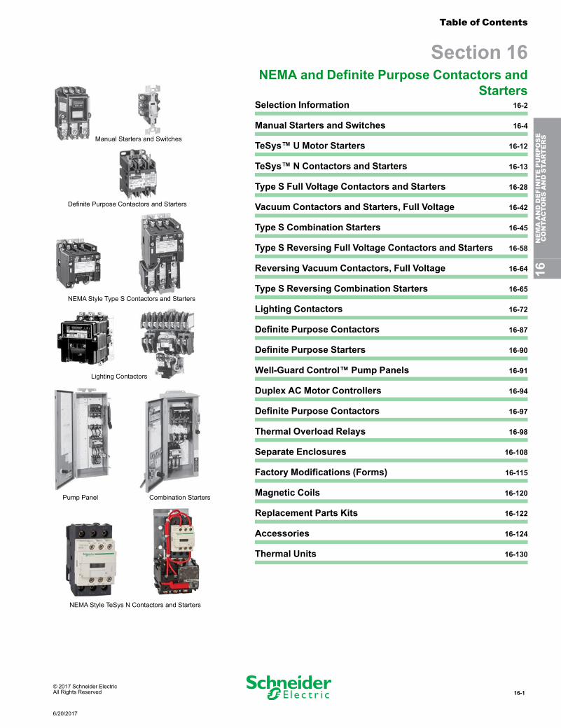
Manual Starters and Switches
Definite Purpose Contactors and Starters
NEMA Style Type S Contactors and Starters
Lighting Contactors
Pump Panel Combination Starters
NEMA Style TeSys N Contactors and Starters
Table of Contents
Section 16NEMA and Definite Purpose Contactors and
StartersSelection Information 16-2
Manual Starters and Switches 16-4
TeSys™ U Motor Starters 16-12
TeSys™ N Contactors and Starters 16-13
Type S Full Voltage Contactors and Starters 16-28
Vacuum Contactors and Starters, Full Voltage 16-42
Type S Combination Starters 16-45
Type S Reversing Full Voltage Contactors and Starters 16-58
Reversing Vacuum Contactors, Full Voltage 16-64
Type S Reversing Combination Starters 16-65
Lighting Contactors 16-72
Definite Purpose Contactors 16-87
Definite Purpose Starters 16-90
Well-Guard Control™ Pump Panels 16-91
Duplex AC Motor Controllers 16-94
Definite Purpose Contactors 16-97
Thermal Overload Relays 16-98
Separate Enclosures 16-108
Factory Modifications (Forms) 16-115
Magnetic Coils 16-120
Replacement Parts Kits 16-122
Accessories 16-124
Thermal Units 16-130
16NEMAANDDEFINITEPURPOSE
CONTA
CTORSANDSTA
RTERS
6/20/2017
16-2 © 2017 Schneider ElectricAll Rights Reserved
Selection Information NEMA and Definite Purpose Contactorsand Starters
schneider-electric.us
Selection Information
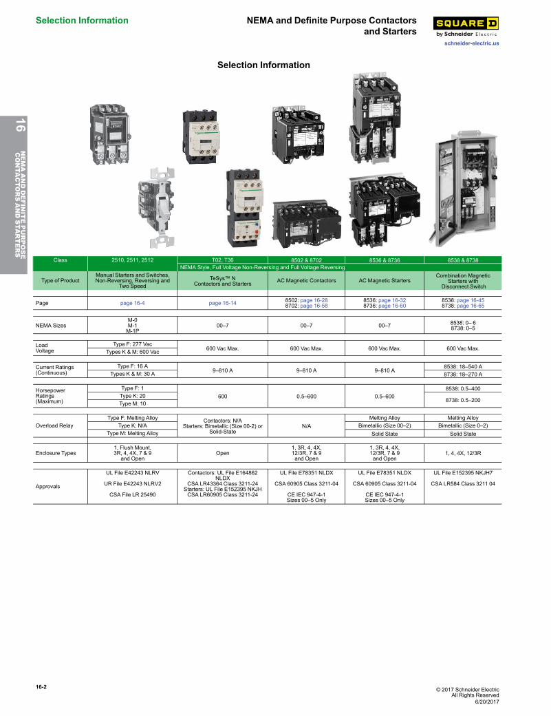
Class 2510, 2511, 2512 T02, T36 8502 & 8702 8536 & 8736 8538 & 8738NEMA Style, Full Voltage Non-Reversing and Full Voltage Reversing
Type of ProductManual Starters and Switches,Non-Reversing, Reversing and
Two SpeedTeSys™ N
Contactors and Starters AC Magnetic Contactors AC Magnetic StartersCombination Magnetic
Starters withDisconnect Switch
Page page 16-4 page 16-14 8502: page 16-288702: page 16-58
8536: page 16-328736: page 16-60
8538: page 16-458738: page 16-65
NEMA SizesM-0M-1M-1P
00–7 00–7 00–7 8538: 0– 68738: 0–5
LoadVoltage
Type F: 277 Vac600 Vac Max. 600 Vac Max. 600 Vac Max. 600 Vac Max.Types K & M: 600 Vac
Current Ratings(Continuous)
Type F: 16 A9–810 A 9–810 A 9–810 A
8538: 18–540 ATypes K & M: 30 A 8738: 18–270 A
HorsepowerRatings(Maximum)
Type F: 1600 0.5–600 0.5–600
8538: 0.5–400Type K: 20
8738: 0.5–200Type M: 10
Overload RelayType F: Melting Alloy Contactors: N/A
Starters: Bimetallic (Size 00-2) orSolid-State
N/AMelting Alloy Melting Alloy
Type K: N/A Bimetallic (Size 00–2) Bimetallic (Size 0–2)Type M: Melting Alloy Solid State Solid State
Enclosure Types1, Flush Mount,3R, 4, 4X, 7 & 9
and OpenOpen
1, 3R, 4, 4X,12/3R, 7 & 9and Open
1, 3R, 4, 4X,12/3R, 7 & 9and Open
1, 4, 4X, 12/3R
Approvals
UL File E42243 NLRV
UR File E42243 NLRV2
CSA File LR 25490
Contactors: UL File E164862NLDX
CSA LR43364 Class 3211-24Starters: UL File E152395 NKJHCSA LR60905 Class 3211-24
UL File E78351 NLDX
CSA 60905 Class 3211-04
CE IEC 947-4-1Sizes 00–5 Only
UL File E78351 NLDX
CSA 60905 Class 3211-04
CE IEC 947-4-1Sizes 00–5 Only
UL File E152395 NKJH7
CSA LR584 Class 3211 04
16NEMAANDDEFINITEPURPOSE
CONTA
CTORSANDSTA
RTERS
6/20/2017
© 2017 Schneider ElectricAll Rights Reserved
16-3
schneider-electric.us
Selection InformationNEMA and Definite Purpose Contactorsand Starters
Selection Information
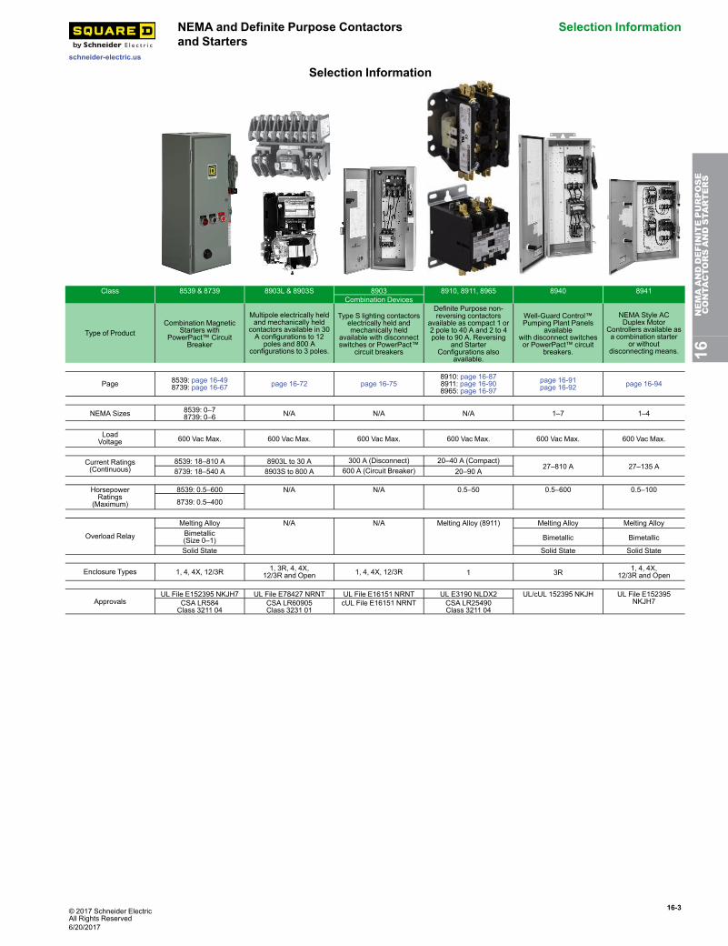
Class 8539 & 8739 8903L & 8903S 8903 8910, 8911, 8965 8940 8941Combination Devices
Type of ProductCombination Magnetic
Starters withPowerPact™ Circuit
Breaker
Multipole electrically heldand mechanically held
contactors available in 30A configurations to 12
poles and 800 Aconfigurations to 3 poles.
Type S lighting contactorselectrically held andmechanically held
available with disconnectswitches or PowerPact™
circuit breakers
Definite Purpose non-reversing contactors
available as compact 1 or2 pole to 40 A and 2 to 4pole to 90 A. Reversing
and StarterConfigurations also
available.
Well-Guard Control™Pumping Plant Panels
availablewith disconnect switchesor PowerPact™ circuit
breakers.
NEMA Style ACDuplex Motor
Controllers available asa combination starter
or withoutdisconnecting means.
Page 8539: page 16-498739: page 16-67 page 16-72 page 16-75
8910: page 16-878911: page 16-908965: page 16-97
page 16-91page 16-92 page 16-94
NEMA Sizes 8539: 0–78739: 0–6 N/A N/A N/A 1–7 1–4
LoadVoltage 600 Vac Max. 600 Vac Max. 600 Vac Max. 600 Vac Max. 600 Vac Max. 600 Vac Max.
Current Ratings(Continuous)
8539: 18–810 A 8903L to 30 A 300 A (Disconnect) 20–40 A (Compact)27–810 A 27–135 A
8739: 18–540 A 8903S to 800 A 600 A (Circuit Breaker) 20–90 A
HorsepowerRatings
(Maximum)
8539: 0.5–600 N/A N/A 0.5–50 0.5–600 0.5–100
8739: 0.5–400
Overload Relay
Melting Alloy N/A N/A Melting Alloy (8911) Melting Alloy Melting AlloyBimetallic(Size 0–1) Bimetallic Bimetallic
Solid State Solid State Solid State
Enclosure Types 1, 4, 4X, 12/3R 1, 3R, 4, 4X,12/3R and Open 1, 4, 4X, 12/3R 1 3R 1, 4, 4X,
12/3R and Open
ApprovalsUL File E152395 NKJH7 UL File E78427 NRNT UL File E16151 NRNT UL E3190 NLDX2 UL/cUL 152395 NKJH UL File E152395
NKJH7CSA LR584Class 3211 04
CSA LR60905Class 3231 01
cUL File E16151 NRNT CSA LR25490Class 3211 04
16NEMAANDDEFINITEPURPOSE
CONTA
CTORSANDSTA
RTERS
6/20/2017
16-4 © 2017 Schneider ElectricAll Rights Reserved
Manual Starters and Switches Manual Starters, Type F—FractionalHorsepower
schneider-electric.usClass 2510, 2512 / Refer to Catalog 2510CT9701
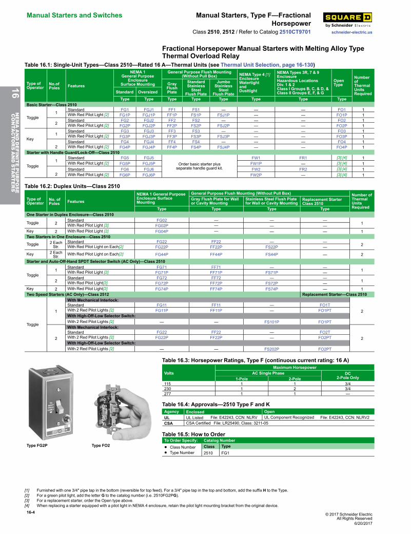
Fractional Horsepower Manual Starters with Melting Alloy TypeThermal Overload Relay
Table 16.1: Single-Unit Types—Class 2510—Rated 16 A—Thermal Units (see Thermal Unit Selection, page 16-130)
Type ofOperator
No.ofPoles Features
NEMA 1General Purpose
EnclosureSurface Mounting
General Purpose Flush Mounting(Without Pull Box) NEMAType 4 [1]
EnclosureWatertightandDusttight
NEMATypes 3R, 7 & 9EnclosureHazardous LocationsDiv. 1 & 2Class I Groups B, C, & D, &Class II Groups E, F, & G
OpenType
NumberofThermalUnitsRequired
GrayFlushPlate
StandardStainlessSteel
Flush Plate
JumboStainlessSteel
Flush PlateStandard OversizedType Type Type Type Type Type Type Type
Basic Starter—Class 2510
Toggle1
Standard FG1 FGJ1 FF1 FS1 — — — FO1 1With Red Pilot Light [2] FG1P FGJ1P FF1P FS1P FSJ1P — — FO1P 1
2Standard FG2 FGJ2 FF2 FS2 — — — FO2 1With Red Pilot Light [2] FG2P FGJ2P FF2P FS2P FSJ2P — — FO2P 1
Key1
Standard FG3 FGJ3 FF3 FS3 — — — FO3 1With Red Pilot Light [2] FG3P FGJ3P FF3P FS3P FSJ3P — — FO3P 1
2Standard FG4 FGJ4 FF4 FS4 — — — FO4 1With Red Pilot Light [2] FG4P FGJ4P FF4P FS4P FSJ4P — — FO4P 1
Starter with Handle Guard/Lock-Off—Class 2510
Toggle1
Standard FG5 FGJ5Order basic starter plus
separate handle guard kit.
FW1 FR1 [3] [4] 1With Red Pilot Light [2] FG5P FGJ5P FW1P — [3] [4] 1
2Standard FG6 FGJ6 FW2 FR2 [3] [4] 1With Red Pilot Light [2] FG6P FGJ6P FW2P — [3] [4] 1
Table 16.2: Duplex Units—Class 2510
Type ofOperator
No. ofPoles Features
NEMA 1 General PurposeEnclosure SurfaceMounting
General Purpose Flush Mounting (Without Pull Box) Number ofThermalUnitsRequired
Gray Flush Plate for Wallor Cavity Mounting
Stainless Steel Flush Platefor Wall or Cavity Mounting
Replacement StarterClass 2510
Type Type Type TypeOne Starter in Duplex Enclosure—Class 2510
Toggle 2Standard FG02 — — —
1With Red Pilot Light [2] FG02P — — —Key 2 With Red Pilot Light [2] FG04P — — — 1Two Starters in One Enclosure—Class 2510
Toggle 2 EachStr.
Standard FG22 FF22 — —2With Red Pilot Light on Each[2] FG22P FF22P FS22P —
Key 2 EachStr. With Red Pilot Light on Each[2] FG44P FF44P FS44P — 2
Starter and Auto-Off-Hand SPDT Selector Switch (AC Only)—Class 2510
Toggle1
Standard FG71 FF71 — —1With Red Pilot Light [2] FG71P FF71P FS71P —
2Standard FG72 FF72 — —
1With Red Pilot Light[2] FG72P FF72P FS72P —Key 2 With Red Pilot Light[2] FG74P FF74P FS74P — 1Two Speed Starters (AC Only)—Class 2512 Replacement Starter—Class 2510
Toggle
1
With Mechanical Interlock:
2Standard FG11 FF11 — FO1TWith 2 Red Pilot Lights [2] FG11P FF11P — FO1PTWith High-Off-Low Selector Switch:With 2 Red Pilot Lights [2] — — FS101P FO1PT
2
With Mechanical Interlock:
2Standard FG22 FF22 — FO2TWith 2 Red Pilot Lights [2] FG22P FF22P — FO2PTWith High-Off-Low Selector Switch:With 2 Red Pilot Lights [2] — — FS202P FO2PT
Type FG2P Type FO2
Table 16.3: Horsepower Ratings, Type F (continuous current rating: 16 A)
VoltsMaximum Horsepower
AC Single Phase DC2-Pole Only1-Pole 2-Pole
115 1 1 3/4230 1 2 3/4277 1 1 —
Table 16.4: Approvals—2510 Type F and KAgency Enclosed OpenUL UL Listed File: E42243, CCN: NLRV UL Component Recognized File: E42243, CCN: NLRV2CSA CSA Certified File: LR25490, Class: 3211-05
Table 16.5: How to OrderTo Order Specify: Catalog Number
• Class Number• Type Number
Class Type2510 FG1
16NEMAANDDEFINITEPURPOSE
CONTA
CTORSANDSTA
RTERS
[1] Furnished with one 3/4" pipe tap in the bottom (reversible for top feed). For a 3/4" pipe tap in the top and bottom, add the suffix H to the Type.[2] For a green pilot light, add the letter G to the catalog number (i.e. 2510FG2PG).[3] For a replacement starter, order the Open type above.[4] When replacing a starter equipped with a pilot light in NEMA 4 enclosure, retain the pilot light mounting bracket from the original device.
6/20/2017
© 2017 Schneider ElectricAll Rights Reserved
16-5
schneider-electric.us
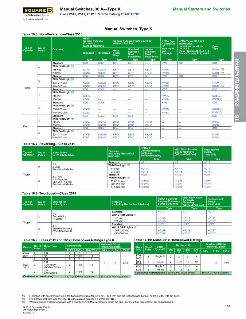
Manual Switches, 30 A—Type K Manual Starters and SwitchesClass 2510, 2511, 2512 / Refer to Catalog 2510CT9701
Manual Switches, Type KTable 16.6: Non-Reversing—Class 2510
Type ofOperator
No. ofPoles Features
NEMA 1General PurposeEnclosureSurface Mounting
General Purpose Flush Mounting(Without Pull Box)
NEMAType4 Enclosure[5]WatertightandDusttight
NEMATypes 3R, 7 & 9Enclosure[5]Hazardous LocationsDiv. 1 & 2Class I Groups B, C, & D, &Class II Groups E, F, and G
OpenType
Standard OversizedGrayFlushPlate
StandardStainlessSteelFlush Plate
JumboStainlessSteelFlush Plate
Type Type Type Type Type Type Type Type
Toggle
2
Standard KG1 KGJ1 KF1 KS1 — KW1 KR1 KO1With Pilot Light [6]115 Vac KG1A KGJ1A KF1A KS1A KSJ1A KW1A — KO1A [7]230 Vac KG1B KGJ1B KF1B KS1B KSJ1B KW1B — KO1B [7]
3
Standard KG2 KGJ2 KF2 KS2 — KW2 KR2 KO2With Pilot Light [6]208–277 Vac KG2B KGJ2B KF2B KS2B KSJ2B KW2B — KO2B [7]440–600 Vac KG2C KGJ2C KF2C KS2C KSJ2C KW2C — KO2C [7]
2
Standard KG5 KGJ5 — — — KW5 — KO5With Pilot Light [6]115 Vac KG5A — — — — KW5A — KO5A [7]230 Vac KG5B — — — — KW5B — KO5B [7]
3
Standard KG6 KGJ6 — — — KW6 — KO6With Pilot Light [6]208–277 Vac KG6B — — — — KW6B — KO6B [7]440–600 Vac KG6C — — — — KW6C — KO6C [7]
Key
2
Standard KG3 KGJ3 KF3 KS3 — — — KO3With Pilot Light [6]115 Vac KG3A KGJ3A KF3A KS3A KSJ3A — — KO3A230 Vac KG3B KGJ3B KF3B KS3B KSJ3B — — KO3B
3
Standard KG4 KGJ4 KF4 KS4 — — — KO4With Pilot Light [6]208–277 Vac KG4B KGJ4B KF4B KS4B KSJ4B — — KO4B440–600 Vac KG4C KGJ4C KF4C KS4C KSJ4C — — KO4C
Table 16.7: Reversing—Class 2511
Type ofOperator
No. ofPoles
Motor Typesfor Which Suitable
Features(Including MechanicalInterlock)
NEMA 1General PurposeEnclosureSurface Mounting
With Flush Plate forCavity Mounting(Without Pull Box)
ReplacementSwitchClass 2510
Type Type Type
Toggle
21 Ø3-LeadRepulsion-Induction
Standard KG11 KF11 KO1TWith Pilot Light [6]115 Vac KG11A KF11A KO1AT230 Vac KG11B KF11B KO1BT
33 Ø; Also1 Ø Capacitor,Split Ø, or 4-LeadRepulsion-Induction
Standard KG22 KF22 KO2TWith Pilot Light [6]110–120 Vac KG22A KF22A KO2AT208–220 Vac KG22B KF22B KO2BT440–600 Vac KG22C KF22C KO2CT
Table 16.8: Two Speed—Class 2512
Type ofOperator
No. ofPoles
Suitable forMotor Types
Features(Including Mechanical Interlock)
NEMA 1 GeneralPurpose EnclosureSurface Mounting
With Flush Platefor CavityMounting(Without Pull Box)
ReplacementSwitchClass 2510
Type Type Type
Toggle
21 ØTwo Winding(3-Lead)
Standard KG11 KF11 KO1TWith 2 Pilot Lights [6]115 Vac KG11A KF11A KO1AT230 Vac KG11B KF11B KO1BT
33 ØSeparate Winding(Wye-Connected)
Standard KG22 KF22 KO2TWith 2 Pilot Lights [6]
208–240 Vac KG22B KF22B KO2BT440–600 Vac KG22C KF22C KO2CT
Table 16.9: Class 2511 and 2512 Horsepower Ratings Type K
Device No. ofPoles
Motor TypeAC
Maximum Hp Maximum DC Hp(breaking 2 poles)
115 V 230 V 460–575 V 90 V 115 V 230 VClass2511
2 1 Ø 2 2 3
1 2 1-1/2
3 3Ø 2 7-1/2 10
Class2512
2 1 Ø 2 2 3
33 Ø,Constant orVariable Torque
2 7-1/2 10
3 3 Ø,Constant Hp 2 7-1/2 10
Continuous current rating 30 A at 600 Vac maximum 30 A at 24 Vdc maximum
Table 16.10: Class 2510 Horsepower Ratings
Class2510
No. ofPoles
MotorType AC
Maximum Hp Maximum DC Hp(breaking 2 poles)
115V
230V
460V
575V 90 V 115 V 230 V
KO1KO3 2 Single Ø 2 2 3 3
1 2 1-1/2KO2KO4 3 Three Ø 2 7-1/2 10 10
KO5 2 Single Ø 2 3 7-1/2 10KO6 3 Three Ø 2 7-1/2 15 20Continuous current rating 30 A at 600 Vac maximum 30 A at 24 Vdc maximum
16NEMAANDDEFINITEPURPOSE
CONTA
CTORSANDSTA
RTERS
[5] Furnished with one 3/4" pipe tap in the bottom (reversible for top feed). For a 3/4" pipe tap in the top and bottom, add the suffix H to the Type.[6] For a green pilot light, add the letter G to the catalog number (i.e. 2510FG2PG)[7] When replacing a starter equipped with a pilot light in NEMA 4 enclosure, retain the pilot light mounting bracket from the original device.
6/20/2017
16-6 © 2017 Schneider ElectricAll Rights Reserved
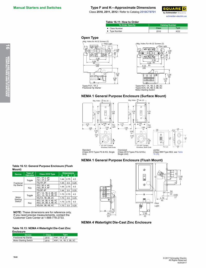
Manual Starters and Switches Type F and K—Approximate Dimensions
schneider-electric.us
Class 2510, 2511, 2512 / Refer to Catalog 2510CT9701
Table 16.11: How to OrderTo Order Specify: Catalog Number
• Class Number
• Type NumberClass Type
2510 KO2
Open Type
2.2256
1.5940
.8421
1.6943
4.13105
3.2883
2.3860
Mtg. Holes for #6-32 Screws (2)Pilot Light
OFF
1.7043
2.3460
2.38603.28
834.13105
1.6943
.8421
OFF
Mtg. Holes For #6-32 Screws (2)Pilot Light
Types FO1, 1P, 2Fractional Hp Starter
Types KO1, 1A, 1B, 2, 2B, 2CTypes KO5, 5A, 5B, 6, 6B, 6CMotor Starting Switch
NEMA 1 General Purpose Enclosure (Surface Mount)
2.7570
2.8873
4.25108
1.6341
0.56140.4110
1.0627
3.0076
OFF
2.4462
1/2–3/4" ConduitKnockout, Both Ends
PilotLight
Mtg. Holes dia. (2).256
2.7570
2.8873
4.25108
1.6341
0.5614
0.6917
1.0627
3.0076
OFF
2.8873
1/2–3/4" ConduitKnockout, Both Ends
Pilot Light
Mtg. Holes dia. (2).256
OFF
Pilot Light
4.86123 0.71
18
3.2883
3.0978
2.2056
4.35110
Standard(Class 2510 Types FG & KG, SingleUnit)
Oversized(Class 2510 Types FGJ & KGJ,Single Unit)
Jumbo(Class 9991Type KE2, see Table16.29)
NEMA 1 General Purpose Enclosure (Flush Mount)Table 16.12: General Purpose Enclosure (FlushMount)
Device Type ofOperator Class 2510 Type Dimensions
A B C
FractionalHp Starter
ToggleFF1, 1P, 2, 2P,FS1, 1P, 2, 2P 1.44 2.75 4.5
FSJ1P, 2P 1.44 3.5 5.25
KeyFF3, 3P, 4, 4P,FS3, 3P, 4, 4P 1.44 2.75 4.5
FSJ3P, 4P 1.44 3.5 5.25
MotorStartingSwitch
ToggleKF1, 1A, 1B, 2, 2B, 2CKS1, 1A, 1B, 2, 2B, 2C 1.75 2.75 4.5
KSJ1A, 1B, 2B, 2C 1.75 3.5 5.25
KeyKF3, 3A, 3B, 4, 4B, 4CKS3, 3A, 3B, 4, 4B, 4C 1.75 2.75 4.5
KSJ3A, 3B, 4B, 4C 1.75 3.5 5.25
NOTE: These dimensions are for reference only.If you need precise measurements, contact theCustomer Care Center at 1-888-778-2733.
.7519.91
23
A
OFF
PilotLight
D
D
1.6943
1.7845
0.6617
.5013
2.5665
B
C
NEMA 4 Watertight Die-Cast Zinc EnclosureTable 16.13: NEMA 4 Watertight Die-Cast ZincEnclosure
Device Class TypeFractional Hp Starter 2510 FW1, 1P, 2, 2PMotor Starting Switch 2510 KW1, 1A, 1B, 2, 2B, 2C
16NEMAANDDEFINITEPURPOSE
CONTA
CTORSANDSTA
RTERS
6/20/2017
© 2017 Schneider ElectricAll Rights Reserved
16-7
schneider-electric.us
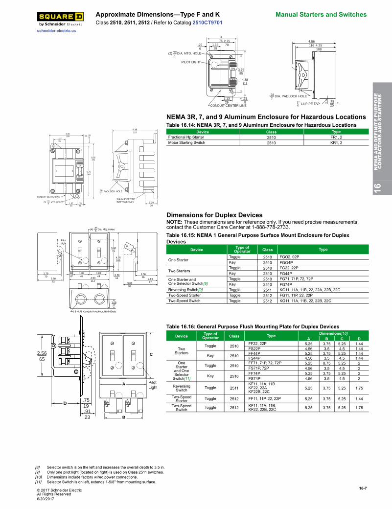
Approximate Dimensions—Type F and K Manual Starters and SwitchesClass 2510, 2511, 2512 / Refer to Catalog 2510CT9701
CONDUIT CENTER LINE
376
1.1329
.256
2.7570
(2) DIA. MTG. HOLE.226
PILOT LIGHT
ON
OFF
.318
1.1329
4.38111
3.7595
4.25108
4.56116
3"4 14 PIPE TAP
.287
.7820
DIA. PADLOCK HOLE
NEMA 3R, 7, and 9 Aluminum Enclosure for Hazardous Locations
1.3735
.7018
5.75146
.3081.37
35
6.36161
3.95100
ON
OFF
CONDUIT CENTERLINE
2X .318
MTG. HOLES
2X
4.35110
1.1930
3/4-14 PIPE TAP,BOTTOM ONLY
.287
PADLOCK HOLE
Table 16.14: NEMA 3R, 7, and 9 Aluminum Enclosure for Hazardous LocationsDevice Class Type
Fractional Hp Starter 2510 FR1, 2Motor Starting Switch 2510 KR1, 2
Dimensions for Duplex Devices
2.7570
2.8873
PilotLight
OFF OFF
(4) .256
3.0076
4.25108
Dia. Mtg. Holes
0.5614
1.8848
4.50114
1.0627
.3810
1.8848
0.5–0.75 Conduit Knockout, Both Ends
2.5665
2.63673.81
97
NOTE: These dimensions are for reference only. If you need precise measurements,contact the Customer Care Center at 1-888-778-2733.Table 16.15: NEMA 1 General Purpose Surface Mount Enclosure for DuplexDevices
Device Type ofOperator Class Type
One StarterToggle 2510 FGO2, 02PKey 2510 FGO4P
Two StartersToggle 2510 FG22, 22PKey 2510 FG44P
One Starter andOne Selector Switch[8]
Toggle 2510 FG71, 71P, 72, 72PKey 2510 FG74P
Reversing Switch[9] Toggle 2511 KG11, 11A, 11B, 22, 22A, 22B, 22CTwo-Speed Starter Toggle 2512 FG11, 11P, 22, 22PTwo-Speed Switch Toggle 2512 KG11, 11A, 11B, 22, 22B, 22C
.7519
2.5665
.9123
D
OFFOFF
PilotLight
A
B
C
Table 16.16: General Purpose Flush Mounting Plate for Duplex Devices
Device Type ofOperator Class Type Dimensions[10]
A B C D
TwoStarters
Toggle 2510 FF22, 22P 5.25 3.75 5.25 1.44 FS22P 4.56 3.5 4.5 1.44
Key 2510 FF44P 5.25 3.75 5.25 1.44 FS44P 4.56 3.5 4.5 1.44
OneStarterand OneSelectorSwitch[11]
Toggle 2510 FF71, 71P, 72, 72P 5.25 0.75 5.25 2 FS71P, 72P 4.56 3.5 4.5 2
Key 2510 FF74P 5.25 3.75 5.25 2 FS74P 4.56 3.5 4.5 2
ReversingSwitch Toggle 2511
KF11, 11A, 11B KF22, 22A KF22B, 22C
5.25 3.75 5.25 1.75
Two-SpeedStarter Toggle 2512 FF11, 11P, 22, 22P 5.25 3.75 5.25 1.44
Two-SpeedSwitch Toggle 2512 KF11, 11A, 11B,
KF22, 22B, 22C 5.25 3.75 5.25 1.75
16NEMAANDDEFINITEPURPOSE
CONTA
CTORSANDSTA
RTERS
[8] Selector switch is on the left and increases the overall depth to 3.5 in.[9] Only one pilot light (located on right) is used on Class 2511 switches.[10] Dimensions include factory wired power connections.[11] Selector Switch is on left, extends 1-5/8" from mounting surface.
6/20/2017
16-8 © 2017 Schneider ElectricAll Rights Reserved
Manual Starters and Switches Manual Starters, Type M and T—IntegralHorsepower
schneider-electric.usClass 2510, 2511, 2512 / Refer to Catalog 2510CT9701
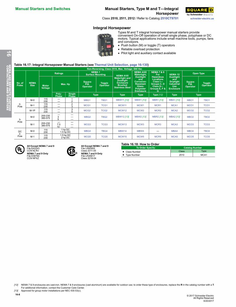
Integral HorsepowerTypes M and T integral horsepower manual starters provideconvenient On-Off operation of small single phase, polyphase or DCmotors. Typical applications include small machine tools, pumps, fansand conveyors.• Push button (M) or toggle (T) operators• Reliable overload protection• Pilot light and auxiliary contact available
Table 16.17: Integral Horsepower Manual Starters (see Thermal Unit Selection, page 16-130)Non-Reversing, Class 2510, Max. Voltage: 600 Vac
No. ofPoles
NEMASize
Ratings NEMA 1Surface Mounting NEMA 4/4X
Watertight andDusttightEnclosureBrushed
Stainless Steel
NEMA 4/4XWatertight,Dusttight
andCorrosion-ResistantGlass-
PolyesterEnclosure
NEMA 7 & 9For
HazardousLocationsClass I—
Groups C, DClass II—
Groups E, F &G
NEMA 12Dusttight
andDriptightIndustrial
UseEnclosure
Open Type
MotorVoltage
Max. HpSquareP.B.
OperatorToggleOperator
SquareP.B.
OperatorToggleOperator
Poly-Phase
SinglePhase Type Type Type Type [12] Type Type
2-Pole
M-0 115230
——
12 MBG1 TBG1 MBW11 [13] MBW1 [13] MBR1 [13] MBA1 [13] MBO1 TBO1
M-1 115230
——
23 MCG1 TCG1 MCW11 MCW1 MCR1 MCA1 MCO1 TCO1
M-1P 115230
——
35 MCG2 TCG2 MCW12 MCW2 MCR2 MCA2 MCO2 TCO2
3-Pole
M-0 200-230380-575
—35
———
MBG2 TBG2 MBW12 [13] MBW2 [13] MBR2 [13] MBA2 [13] MBO2 TBO2
M-1 200-230380-575
—7.510
———
MCG3 TCG3 MCW13 MCW3 MCR3 MCA3 MCO3 TCO3
DC2-Pole
M-0 115230
1 hp DC1.5 hp DC MBG4 TBG4 MBW14 MBW4 — MBA4 MBO4 TBO4
M-1 115230
1.5 hp DC2 hp DC MCG5 TCG5 MCW15 MCW5 MCR5 MCA5 MCO5 TCO5
All Except NEMA 7 and 9File E42243CCN NLRV
All Except NEMA 7 and 9File LR60905Class 3211-05
NEMA 7 and 9 OnlyFile E58760CCN NPXZ
NEMA 7 and 9 OnlyFile LR26817Class 3218-04
Table 16.18: How to OrderTo Order Specify: Catalog Number
• Class Number
• Type NumberClass Type
2510 MCA1
16NEMAANDDEFINITEPURPOSE
CONTA
CTORSANDSTA
RTERS
[12] NEMA 7 & 9 enclosures are cast-iron. NEMA 7 & 9 enclosures (cast aluminum) are available for outdoor use; to order these type of enclosures, replace the R in the catalog number with a T.For additional information, contact the Customer Care Center.
[13] Approved for group motor installations per NEC 430-53(c).
6/20/2017
© 2017 Schneider ElectricAll Rights Reserved
16-9
schneider-electric.us
Manual Starters, Type M and T—IntegralHorsepower
Manual Starters and Switches
Class 2510, 2511, 2512 / Refer to Catalog 2510CT9701
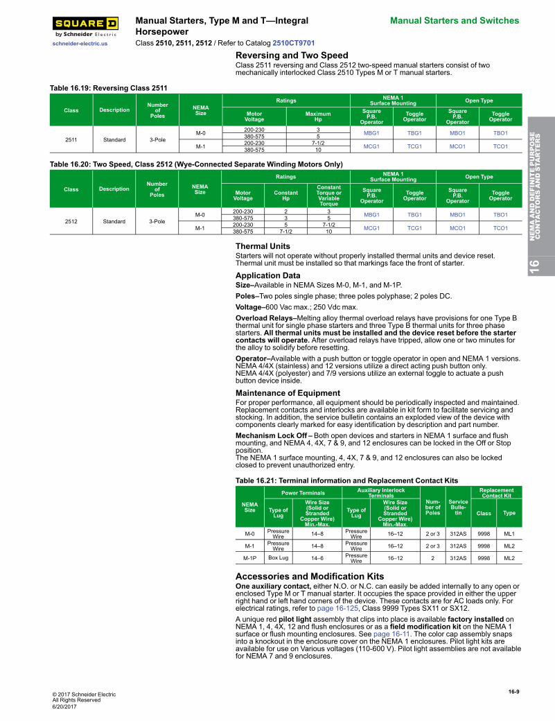
Reversing and Two SpeedClass 2511 reversing and Class 2512 two-speed manual starters consist of twomechanically interlocked Class 2510 Types M or T manual starters.
Table 16.19: Reversing Class 2511
Class DescriptionNumber
ofPoles
NEMASize
Ratings NEMA 1Surface Mounting Open Type
MotorVoltage
MaximumHp
SquareP.B.
OperatorToggleOperator
SquareP.B.
OperatorToggleOperator
2511 Standard 3-PoleM-0 200-230 3 MBG1 TBG1 MBO1 TBO1380-575 5
M-1 200-230 7-1/2 MCG1 TCG1 MCO1 TCO1380-575 10
Table 16.20: Two Speed, Class 2512 (Wye-Connected Separate Winding Motors Only)
Class DescriptionNumber
ofPoles
NEMASize
Ratings NEMA 1Surface Mounting Open Type
MotorVoltage
ConstantHp
ConstantTorque orVariableTorque
SquareP.B.
OperatorToggleOperator
SquareP.B.
OperatorToggleOperator
2512 Standard 3-PoleM-0 200-230 2 3 MBG1 TBG1 MBO1 TBO1380-575 3 5
M-1 200-230 5 7-1/2 MCG1 TCG1 MCO1 TCO1380-575 7-1/2 10
Thermal UnitsStarters will not operate without properly installed thermal units and device reset.Thermal unit must be installed so that markings face the front of starter.
Application DataSize–Available in NEMA Sizes M-0, M-1, and M-1P.Poles–Two poles single phase; three poles polyphase; 2 poles DC.Voltage–600 Vac max.; 250 Vdc max.Overload Relays–Melting alloy thermal overload relays have provisions for one Type Bthermal unit for single phase starters and three Type B thermal units for three phasestarters. All thermal units must be installed and the device reset before the startercontacts will operate. After overload relays have tripped, allow one or two minutes forthe alloy to solidify before resetting.Operator–Available with a push button or toggle operator in open and NEMA 1 versions.NEMA 4/4X (stainless) and 12 versions utilize a direct acting push button only.NEMA 4/4X (polyester) and 7/9 versions utilize an external toggle to actuate a pushbutton device inside.
Maintenance of EquipmentFor proper performance, all equipment should be periodically inspected and maintained.Replacement contacts and interlocks are available in kit form to facilitate servicing andstocking. In addition, the service bulletin contains an exploded view of the device withcomponents clearly marked for easy identification by description and part number.Mechanism Lock Off –Both open devices and starters in NEMA 1 surface and flushmounting, and NEMA 4, 4X, 7 & 9, and 12 enclosures can be locked in the Off or Stopposition.The NEMA 1 surface mounting, 4, 4X, 7 & 9, and 12 enclosures can also be lockedclosed to prevent unauthorized entry.
Table 16.21: Terminal information and Replacement Contact Kits
NEMASize
Power Terminals Auxiliary InterlockTerminals
Num-ber ofPoles
ServiceBulle-tin
ReplacementContact Kit
Type ofLug
Wire Size(Solid orStranded
Copper Wire)Min.-Max.
Type ofLug
Wire Size(Solid orStranded
Copper Wire)Min.-Max.
Class Type
M-0 PressureWire 14–8 Pressure
Wire 16–12 2 or 3 312AS 9998 ML1
M-1 PressureWire 14–8 Pressure
Wire 16–12 2 or 3 312AS 9998 ML2
M-1P Box Lug 14–6 PressureWire 16–12 2 312AS 9998 ML2
Accessories and Modification KitsOne auxiliary contact, either N.O. or N.C. can easily be added internally to any open orenclosed Type M or T manual starter. It occupies the space provided in either the upperright hand or left hand corners of the device. These contacts are for AC loads only. Forelectrical ratings, refer to page 16-125, Class 9999 Types SX11 or SX12.A unique red pilot light assembly that clips into place is available factory installed onNEMA 1, 4, 4X, 12 and flush enclosures or as a field modification kit on the NEMA 1surface or flush mounting enclosures. See page 16-11. The color cap assembly snapsinto a knockout in the enclosure cover on the NEMA 1 enclosures. Pilot light kits areavailable for use on Various voltages (110-600 V). Pilot light assemblies are not availablefor NEMA 7 and 9 enclosures.
16NEMAANDDEFINITEPURPOSE
CONTA
CTORSANDSTA
RTERS
6/20/2017
16-10 © 2017 Schneider ElectricAll Rights Reserved
Manual Starters and Switches Manual Starters, Type M and T—IntegralHorsepower
schneider-electric.usClass 2510, 2511, 2512 / Refer to Catalog 2510CT9701
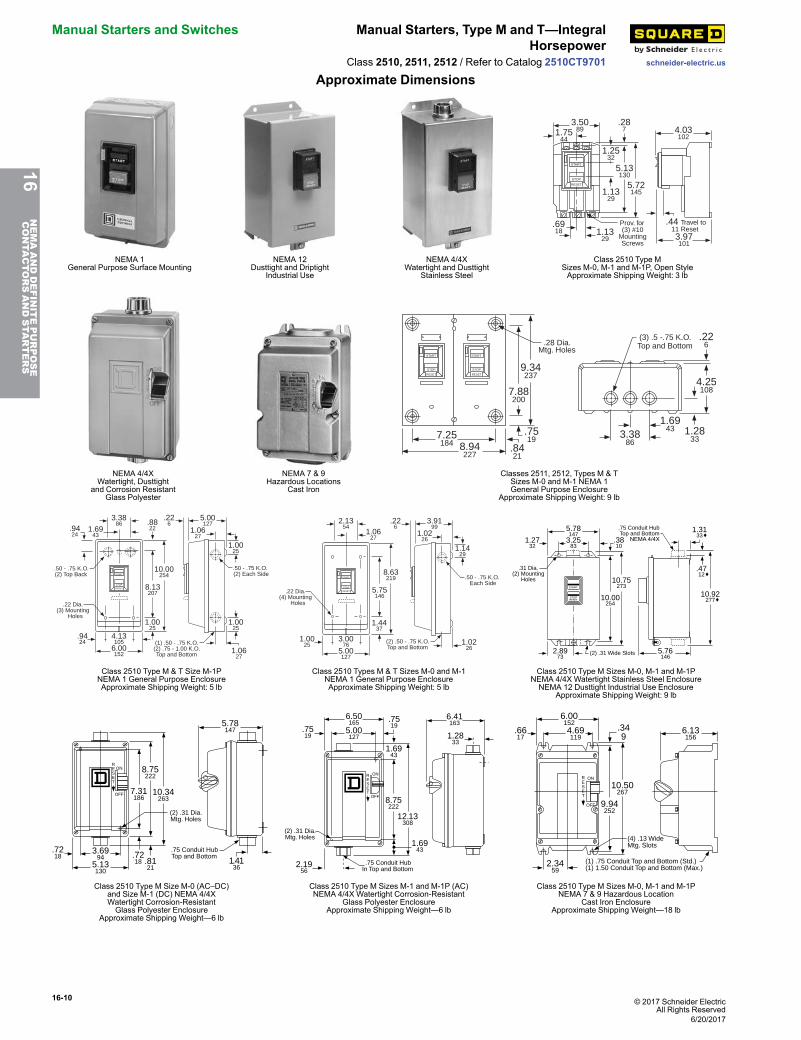
Approximate Dimensions
START
STOP
RESET
3.5089
5.72145
5.13130
1.2532
.287
1.1329
1.7544
.6918
.44 Travel to 11 Reset1.13
29 3.97101
4.03102
Prov. for(3) #10
MountingScrews
NEMA 1General Purpose Surface Mounting
NEMA 12Dusttight and Driptight
Industrial Use
NEMA 4/4XWatertight and Dusttight
Stainless Steel
Class 2510 Type MSizes M-0, M-1 and M-1P, Open StyleApproximate Shipping Weight: 3 lb
START
STOP
RESET
START
STOP
RESET
8.94227
7.25184
9.34237
7.88200
.8421
.7519
.28 Dia.Mtg. Holes
3.3886
1.6943
4.25108
1.2833
.226
(3) .5 -.75 K.O.Top and Bottom
NEMA 4/4XWatertight, Dusttight
and Corrosion ResistantGlass Polyester
NEMA 7 & 9Hazardous Locations
Cast Iron
Classes 2511, 2512, Types M & TSizes M-0 and M-1 NEMA 1General Purpose Enclosure
Approximate Shipping Weight: 9 lb
START
STOP
RESET
6.00152
4.13105
3.3886
.9424
10.00254
8.13207
1.0025
.8822
.226
1.6943
.9424
5.00127
1.0627
1.0025
1.0025
1.0627
.50 - .75 K.O.(2) Top Back
.50 - .75 K.O.(2) Each Side
(1) .50 - .75 K.O.(2) .75 - 1.00 K.O.Top and Bottom
.22 Dia.(3) Mounting
Holes
START
STOP
RESET
5.00127
3.0076
2.1354
1.0025
8.63219
5.75146
1.4437
.226
1.0627
3.9199
1.0226
1.1429
1.0226
(2) .50 - .75 K.O.Top and Bottom
.22 Dia.(4) Mounting
Holes
.50 - .75 K.O. Each Side
START
STOPRESET
10.75273
2.8973
3.2583
1.2732
10.00254
.3810
10.92277
(2) .31 Wide Slots 5.76146
5.78147
.75 Conduit HubTop and Bottom
NEMA 4/4X
1.3133
.4712
.31 Dia.(2) Mounting
Holes
Class 2510 Type M & T Size M-1PNEMA 1 General Purpose EnclosureApproximate Shipping Weight: 5 lb
Class 2510 Types M & T Sizes M-0 and M-1NEMA 1 General Purpose EnclosureApproximate Shipping Weight: 5 lb
Class 2510 Type M Sizes M-0, M-1 and M-1PNEMA 4/4X Watertight Stainless Steel EnclosureNEMA 12 Dusttight Industrial Use Enclosure
Approximate Shipping Weight: 9 lb
5.78147
3.6994
5.13130
1.4136
7.31186
.7218 .81
21
8.75222
10.34263
(2) .31 Dia.Mtg. Holes
ONRESET
OFF
.75 Conduit HubTop and Bottom
.7218
8.75222
.7519
1.6943
1.6943
.7519
12.13308
(2) .31 Dia. Mtg. Holes
.75 Conduit HubIn Top and Bottom
5.00127
2.1956
6.50165
6.41163
1.2833
ONRESET
OFF
10.50267
.349
9.94252
(4) .13 WideMtg. Slots
(1) .75 Conduit Top and Bottom (Std.)(1) 1.50 Conduit Top and Bottom (Max.)
6.001524.69119
2.3459
.6617
6.13156
ONRESET
OFF
Class 2510 Type M Size M-0 (AC–DC)and Size M-1 (DC) NEMA 4/4XWatertight Corrosion-ResistantGlass Polyester Enclosure
Approximate Shipping Weight—6 lb
Class 2510 Type M Sizes M-1 and M-1P (AC)NEMA 4/4X Watertight Corrosion-Resistant
Glass Polyester EnclosureApproximate Shipping Weight—6 lb
Class 2510 Type M Sizes M-0, M-1 and M-1PNEMA 7 & 9 Hazardous Location
Cast Iron EnclosureApproximate Shipping Weight—18 lb
16NEMAANDDEFINITEPURPOSE
CONTA
CTORSANDSTA
RTERS
6/20/2017

© 2017 Schneider ElectricAll Rights Reserved
16-11
schneider-electric.us
Accessories, Modifications, andReplacement Parts
Manual Starters and Switches
Class 2510, 2511, 2512 / Refer to Catalog 2510CT9701
Accessories, Modifications, and Replacement PartsTable 16.22: P11 Pilot Light Voltage CodesVoltage Code120 V V02200/208 V V08230 V V03460 V V06575 V V07
Table 16.23: Modifications (Types M & Tonly)Description Factory Modifications (Forms) Field Modification Kits, Class &
Type
Red Pilot Light [14] P11[15]9999MP1 (110–120 V )9999MP2 (208–240 V )9999MP3 (440–600 V )
Auxiliary Contacts [16]X1 (1 N.O.) 9999SX11 (N.O.)X2 (1 N.C.) 9999SX12 (N.C.)
Jumper Straps [17] N/A 9998SO31Contactor only Y76 N/A
Table 16.24: Accessories—Class 2510Types F and K
Description Class & TypeHandle Guard Kit with Padlock Provision [18] 2510FL1Emergency Off Actuator 2510PB1Additional Key for Key Operated Devices 2510FK1
Table 16.25: Pilot Light Kits—Class 2510 Types F and K
Application VoltageRed Pilot Light Green Pilot LightClass & Type Class & Type
Type KF, KG, KW [19]110–120 Vac 9999PL11 9999PL11G208–277 Vac 9999PL12 9999PL12G440–600 Vac 9999PL13 9999PL13G
Type FF, FG, FW [19] 115–240 Vac/dc 9999PL10 9999PL10G
Table 16.26: Replacement Nameplates—Class 2510 Types F and K
Description Application NameplateMarking
Nameplate Type Number—Class 2510
For Type K Switch For Type F Starter(includes Reset indication)
WithoutPilot Light
WithPilot Light
WithoutPilot Light
WithPilot Light
1-3/4" x 2-13/16" Nameplatewith Embossed Mounting Holesfor #6 Oval Head Screws
Standard commercial switchbox cover or flush plate, includingSquare D stainless steel plates
(Blank) FN1 — FN2 —(Special marking –specify the marking desired) FN5 — FN6 —
1-29/32" x 3-27/32"Flat Nameplatewith Mounting Holesfor #6 Pan Head Screws
Square D NEMA 1surface mounted enclosureor gray flush plate
(Blank) FN10 FN20 FN30 FN40High FN11 FN21 FN31 FN41Low FN12 FN22 FN32 FN42Forward FN13 — — —Reverse FN14 FN24 — —(Special marking—specify the marking desired) FN15 FN25 FN35 FN45
Contact KitsSee page 16-122 for Class 9998 Replacement Contact Kits.
Table 16.27: Replacement Part KitsEnclosure Product Description Kit Catalog No.Replacement Toggle KitsNEMA 4 Type FW and KW 9998HW1NEMA 7 & 9 Type FR and KR 9998HR2Replacement Handle Kits
NEMA 12Type MBA, MCA (Ser. A & B) 9998HWA1Type MBA, MCA (Ser. C) 31085-381-50
NEMA 4/4X (Stainless)Type MBW, MCW (Ser. A & B) 9998HWA1Type MBW, MCW (Ser. C) 31085-381-50
NEMA 4/4X (Polyester)Type MBW (Size 0) 9998HWA1Type MCW (Size 1) 9998HR3
NEMA 7 and 9 Type MBR, MCR 9998HR3Description Kit Catalog No.Internal Lever 9998IL1
Table 16.28: How to OrderTo Order Specify: Catalog Number
• Class Number
• Type NumberClass Type
9991 KE1
Table 16.29: EnclosuresFor use with Class 2510 Type Enclosure Catalog No.F and K
NEMA 1 Standard9991EN1
M: Sizes M-0 & M-1 9991MG1M: Size M-1P 9991MG2
MBO and MCO
NEMA 1 Flush Mount(with pull box and plaster adjustment) 9991MF1
NEMA 1 Flush Mount(without pullbox but with mounting strap) 9991MF2
NEMA 4X (Polyester) 9991MW1NEMA 4 (Stainless Steel) 9991MW11
FO1, FO1P, FO2, FO2P, FO3, FO3P, FO4, FO4P NEMA 1 Oversized 9991FE1KO1, KO1A, KO1B, KO2, KO2B, KO2C,KO3, KO3A, KO3B, KO4, KO4B, KO4C,KO5, KO5A, KO5B, KO6, KO6B, KO6C
NEMA 1 Oversized 9991KE1NEMA 1 Jumbo 9991KE2NEMA 3R 9991KE3
16NEMAANDDEFINITEPURPOSE
CONTA
CTORSANDSTA
RTERS
[14] May only be field-added to NEMA 1 enclosures. For green pilot light, order 9999SPG1 additionally.[15] Form P11 pilot lights require a voltage code. Refer to Table 16.22. Catalog number example: 2510MBG1V02P11.[16] For proper operation, only one auxiliary contact kit per device may be added.[17] Used to control a single phase motor utilizing a three phase starter.[18] Standard on Type K devices.[19] The lens cannot be replaced. The pilot light kits for NEMA 4 enclosed units are for replacement only.
6/20/2017
16-12 © 2017 Schneider ElectricAll Rights Reserved
TeSys™ U Motor Starters TeSys™ U Starter Components
schneider-electric.us
Refer to CatalogMKTED210011EN
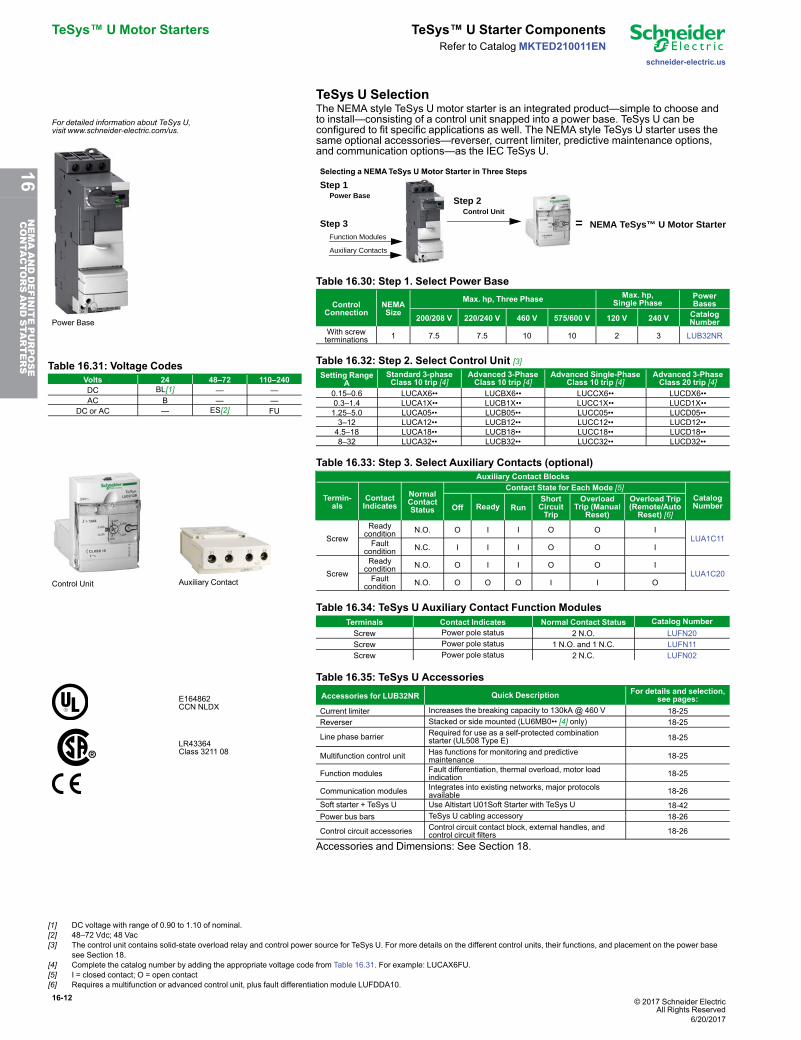
TeSys U Selection
For detailed information about TeSys U,visit www.schneider-electric.com/us.
Power Base
The NEMA style TeSys U motor starter is an integrated product—simple to choose andto install—consisting of a control unit snapped into a power base. TeSys U can beconfigured to fit specific applications as well. The NEMA style TeSys U starter uses thesame optional accessories—reverser, current limiter, predictive maintenance options,and communication options—as the IEC TeSys U.
Selecting a NEMATeSys U Motor Starter in Three Steps
Control Unit
Function Modules
Auxiliary Contacts
Power Base
NEMA TeSys™ U Motor Starter=
Step 1
Step 2
Step 3
Table 16.30: Step 1. Select Power Base
ControlConnection
NEMASize
Max. hp, Three Phase Max. hp,Single Phase
PowerBases
200/208 V 220/240 V 460 V 575/600 V 120 V 240 V CatalogNumber
With screwterminations 1 7.5 7.5 10 10 2 3 LUB32NR
Table 16.31: Voltage CodesVolts 24 48–72 110–240DC BL[1] — —AC B — —
DC or AC — ES[2] FU
Table 16.32: Step 2. Select Control Unit [3]Setting Range
AStandard 3-phaseClass 10 trip [4]
Advanced 3-PhaseClass 10 trip [4]
Advanced Single-PhaseClass 10 trip [4]
Advanced 3-PhaseClass 20 trip [4]
0.15–0.6 LUCAX6•• LUCBX6•• LUCCX6•• LUCDX6••0.3–1.4 LUCA1X•• LUCB1X•• LUCC1X•• LUCD1X••1.25–5.0 LUCA05•• LUCB05•• LUCC05•• LUCD05••3–12 LUCA12•• LUCB12•• LUCC12•• LUCD12••4.5–18 LUCA18•• LUCB18•• LUCC18•• LUCD18••8–32 LUCA32•• LUCB32•• LUCC32•• LUCD32••
Control Unit Auxiliary Contact
Table 16.33: Step 3. Select Auxiliary Contacts (optional)Auxiliary Contact Blocks
Termin-als
ContactIndicates
NormalContactStatus
Contact State for Each Mode [5]CatalogNumberOff Ready Run
ShortCircuitTrip
OverloadTrip (Manual
Reset)
Overload Trip(Remote/AutoReset) [6]
ScrewReadycondition N.O. O I I O O I
LUA1C11Faultcondition N.C. I I I O O I
ScrewReadycondition N.O. O I I O O I
LUA1C20Faultcondition N.O. O O O I I O
Table 16.34: TeSys U Auxiliary Contact Function ModulesTerminals Contact Indicates Normal Contact Status Catalog NumberScrew Power pole status 2 N.O. LUFN20Screw Power pole status 1 N.O. and 1 N.C. LUFN11Screw Power pole status 2 N.C. LUFN02
E164862CCN NLDX
LR43364Class 3211 08
Table 16.35: TeSys U AccessoriesAccessories for LUB32NR Quick Description For details and selection,
see pages:Current limiter Increases the breaking capacity to 130kA @ 460 V 18-25Reverser Stacked or side mounted (LU6MB0•• [4] only) 18-25
Line phase barrier Required for use as a self-protected combinationstarter (UL508 Type E) 18-25
Multifunction control unit Has functions for monitoring and predictivemaintenance 18-25
Function modules Fault differentiation, thermal overload, motor loadindication 18-25
Communication modules Integrates into existing networks, major protocolsavailable 18-26
Soft starter + TeSys U Use Altistart U01Soft Starter with TeSys U 18-42Power bus bars TeSys U cabling accessory 18-26
Control circuit accessories Control circuit contact block, external handles, andcontrol circuit filters 18-26
Accessories and Dimensions: See Section 18.
[1] DC voltage with range of 0.90 to 1.10 of nominal.[2] 48–72 Vdc; 48 Vac[3] The control unit contains solid-state overload relay and control power source for TeSys U. For more details on the different control units, their functions, and placement on the power base
see Section 18.[4] Complete the catalog number by adding the appropriate voltage code from Table 16.31. For example: LUCAX6FU.[5] I = closed contact; O = open contact[6] Requires a multifunction or advanced control unit, plus fault differentiation module LUFDDA10.
6/20/2017
16NEMAANDDEFINITEPURPOSE
CONTA
CTORSANDSTA
RTERS
© 2017 Schneider ElectricAll Rights Reserved
16-13
schneider-electric.us
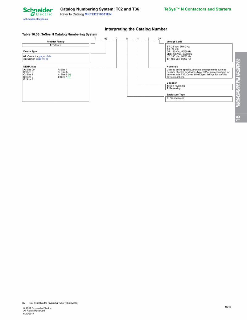
Catalog Numbering System: T02 and T36 TeSys™ N Contactors and StartersRefer to Catalog MKTED210011EN
Interpreting the Catalog NumberTable 16.36: TeSys N Catalog Numbering System
T 02 C N 1 3 G7Product Family Voltage Code
T: TeSys N B7: 24 Vac, 50/60 HzBD: 24 VdcG7: 120 Vac, 50/60 HzLE7: 208 Vac, 50/60 HzU7: 240 Vac, 50/60 HzT7: 480 Vac, 50/60 Hz
Device Type
02: Contactor, page 16-1436: Starter, page 16-16
NEMA Size NumeralsA: Size 00B: Size 0C: Size 1D: Size 2E: Size 3
F: Size 4G: Size 5H: Size 6 [1]J: Size 7 [1]
Used to define specific, physical arrangements such asnumber of poles for devices type T02 or protection type fordevices type T36. Consult the Digest listings for specificdevice numbers.
Direction1: Non-reversing2: Reversing
Enclosure TypeN: No enclosure
16NEMAANDDEFINITEPURPOSE
CONTA
CTORSANDSTA
RTERS
[1] Not available for reversing Type T36 devices.
6/20/2017
16-14 © 2017 Schneider ElectricAll Rights Reserved
TeSys™ N Contactors and Starters Non-Reversing Contactors
schneider-electric.us
Refer to CatalogMKTED210011EN
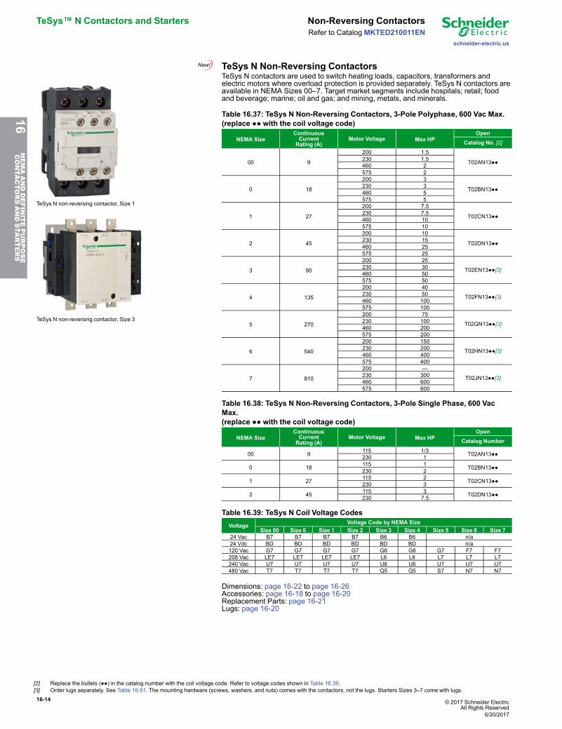
TeSys N Non-Reversing Contactors
TeSys N non-reversing contactor, Size 1
TeSys N non-reversing contactor, Size 3
TeSys N contactors are used to switch heating loads, capacitors, transformers andelectric motors where overload protection is provided separately. TeSys N contactors areavailable in NEMA Sizes 00–7. Target market segments include hospitals; retail; foodand beverage; marine; oil and gas; and mining, metals, and minerals.
Table 16.37: TeSys N Non-Reversing Contactors, 3-Pole Polyphase, 600 Vac Max.(replace ●● with the coil voltage code)
NEMA SizeContinuousCurrentRating (A)
Motor Voltage Max HPOpen
Catalog No. [2]
00 9
200 1.5
T02AN13●●230 1.5460 2575 2
0 18
200 3
T02BN13●●230 3460 5575 5
1 27
200 7.5
T02CN13●●230 7.5460 10575 10
2 45
200 10
T02DN13●●230 15460 25575 25
3 90
200 25
T02EN13●●[3]230 30460 50575 50
4 135
200 40
T02FN13●●[3]230 50460 100575 100
5 270
200 75
T02GN13●●[3]230 100460 200575 200
6 540
200 150
T02HN13●●[3]230 200460 400575 400
7 810
200 —
T02JN13●●[3]230 300460 600575 600
Table 16.38: TeSys N Non-Reversing Contactors, 3-Pole Single Phase, 600 VacMax.(replace ●● with the coil voltage code)
NEMA SizeContinuousCurrentRating (A)
Motor Voltage Max HPOpen
Catalog Number
00 9 115 1/3 T02AN13●●230 1
0 18 115 1 T02BN13●●230 2
1 27 115 2 T02CN13●●230 3
2 45 115 3 T02DN13●●230 7.5
Table 16.39: TeSys N Coil Voltage CodesVoltage Voltage Code by NEMA Size
Size 00 Size 0 Size 1 Size 2 Size 3 Size 4 Size 5 Size 6 Size 724 Vac B7 B7 B7 B7 B6 B6 n/a24 Vdc BD BD BD BD BD BD n/a120 Vac G7 G7 G7 G7 G6 G6 G7 F7 F7208 Vac LE7 LE7 LE7 LE7 L6 L6 L7 L7 L7240 Vac U7 U7 U7 U7 U6 U6 U7 U7 U7480 Vac T7 T7 T7 T7 Q5 Q5 S7 N7 N7
Dimensions: page 16-22 to page 16-26Accessories: page 16-18 to page 16-20Replacement Parts: page 16-21Lugs: page 16-20
[2] Replace the bullets (●●) in the catalog number with the coil voltage code. Refer to voltage codes shown in Table 16.39.[3] Order lugs separately. See Table 16.61. The mounting hardware (screws, washers, and nuts) comes with the contactors, not the lugs. Starters Sizes 3–7 come with lugs.
6/20/2017
16NEMAANDDEFINITEPURPOSE
CONTA
CTORSANDSTA
RTERS
© 2017 Schneider ElectricAll Rights Reserved
16-15
schneider-electric.us
Reversing Contactors TeSys™ N Contactors and StartersRefer to Catalog MKTED210011EN
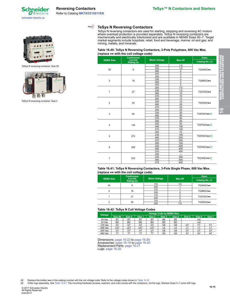
TeSys N Reversing Contactors
TeSys N reversing contactor, Size 00
TeSys N reversing contactor, Size 4
TeSys N reversing contactors are used for starting, stopping and reversing AC motorswhere overload protection is provided separately. TeSys N reversing contactors aremechanically and electrically interlocked and are available in NEMA Sizes 00–7. Targetmarket segments include hospitals; retail; food and beverage; marine; oil and gas; andmining, metals, and minerals.
Table 16.40: TeSys N Reversing Contactors, 3-Pole Polyphase, 600 Vac Max.(replace ●● with the coil voltage code)
NEMA SizeContinuousCurrentRating (A)
Motor Voltage Max HPOpen
Catalog No. [4]
00 9
200 1.5
T02AN23●●230 1.5460 2575 2
0 18
200 3
T02BN23●●230 3460 5575 5
1 27
200 7.5
T02CN23●●230 7.5460 10575 10
2 45
200 10
T02DN23●●230 15460 25575 25
3 90
200 25
T02EN23●●[5]230 30460 50575 50
4 135
200 40
T02FN23●●[5]230 50460 100575 100
5 270
200 75
T02GN23●●[5]230 100460 200575 200
6 540
200 150
T02HN23●●[5]230 200460 400575 400
7 810
200 —
T02JN23●●[5]230 300460 600575 600
Table 16.41: TeSys N Reversing Contactors, 3-Pole Single Phase, 600 Vac Max.(replace ●● with the coil voltage code)
NEMA SizeContinuousCurrentRating (A)
Motor Voltage Max HPOpen
Catalog No. [4]
00 9 115 1/3 T02AN23●●230 1
0 18 115 1 T02BN23●●230 2
1 27 115 2 T02CN23●●230 3
2 45 115 3 T02DN23●●230 7.5
Table 16.42: TeSys N Coil Voltage CodesVoltage Voltage Code by NEMA Size
Size 00 Size 0 Size 1 Size 2 Size 3 Size 4 Size 5 Size 6 Size 724 Vac B7 B7 B7 B7 B6 B6 n/a24 Vdc BD BD BD BD BD BD n/a120 Vac G7 G7 G7 G7 G6 G6 G7 F7 F7208 Vac LE7 LE7 LE7 LE7 L6 L6 L7 L7 L7240 Vac U7 U7 U7 U7 U6 U6 U7 U7 U7480 Vac T7 T7 T7 T7 Q5 Q5 S7 N7 N7
Dimensions: page 16-22 to page 16-26Accessories: page 16-18 to page 16-20Replacement Parts: page 16-21Lugs: page 16-20
16NEMAANDDEFINITEPURPOSE
CONTA
CTORSANDSTA
RTERS
[4] Replace the bullets (●●) in the catalog number with the coil voltage code. Refer to the voltage codes shown in Table 16.42.[5] Order lugs separately. See Table 16.61. The mounting hardware (screws, washers, and nuts) comes with the contactors, not the lugs. Starters Sizes 3–7 come with lugs.
6/20/2017
16-16 © 2017 Schneider ElectricAll Rights Reserved
TeSys™ N Contactors and Starters Non-Reversing Starters
schneider-electric.us
Refer to CatalogMKTED210011EN
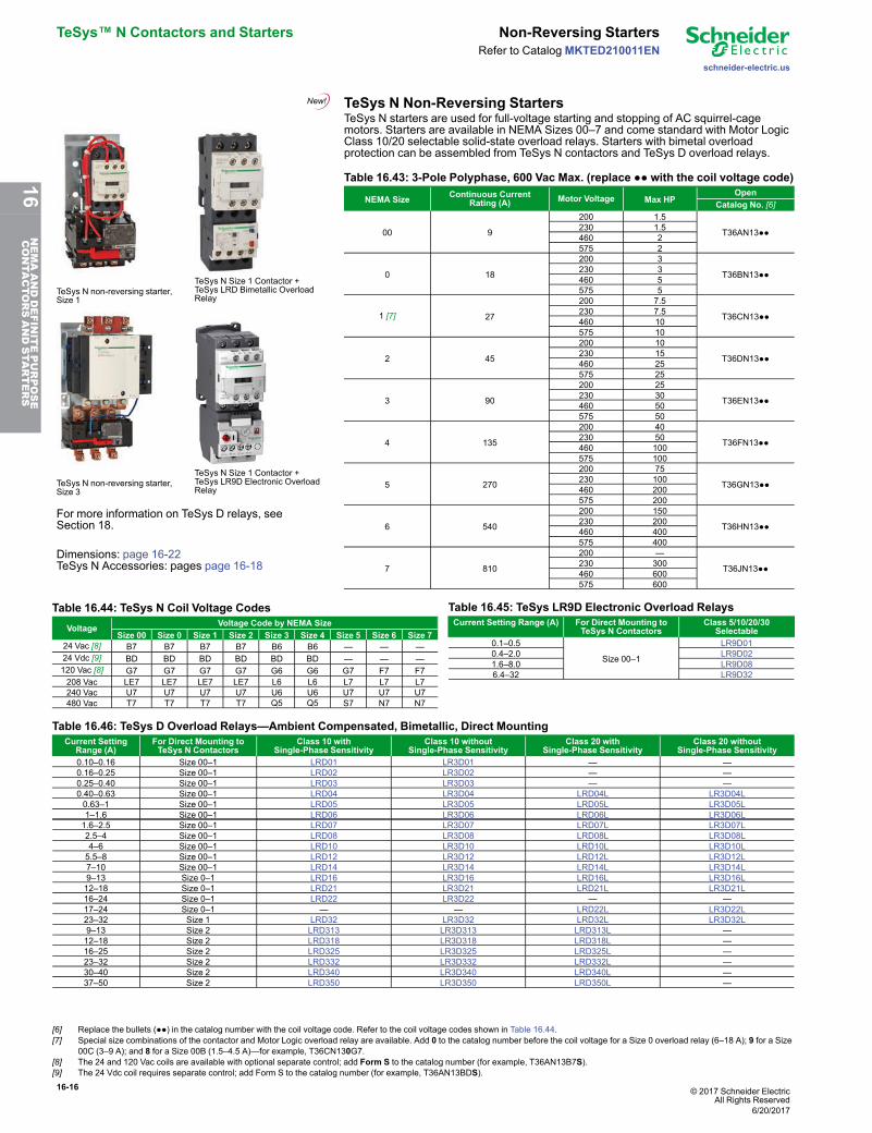
TeSys N Non-Reversing Starters
TeSys N non-reversing starter,Size 1
TeSys N Size 1 Contactor +TeSys LRD Bimetallic OverloadRelay
TeSys N non-reversing starter,Size 3
TeSys N Size 1 Contactor +TeSys LR9D Electronic OverloadRelay
For more information on TeSys D relays, seeSection 18.
Dimensions: page 16-22TeSys N Accessories: pages page 16-18
TeSys N starters are used for full-voltage starting and stopping of AC squirrel-cagemotors. Starters are available in NEMA Sizes 00–7 and come standard with Motor LogicClass 10/20 selectable solid-state overload relays. Starters with bimetal overloadprotection can be assembled from TeSys N contactors and TeSys D overload relays.
Table 16.43: 3-Pole Polyphase, 600 Vac Max. (replace ●● with the coil voltage code)
NEMA Size Continuous CurrentRating (A) Motor Voltage Max HP
OpenCatalog No. [6]
00 9
200 1.5
T36AN13●●230 1.5460 2575 2
0 18
200 3
T36BN13●●230 3460 5575 5
1 [7] 27
200 7.5
T36CN13●●230 7.5460 10575 10
2 45
200 10
T36DN13●●230 15460 25575 25
3 90
200 25
T36EN13●●230 30460 50575 50
4 135
200 40
T36FN13●●230 50460 100575 100
5 270
200 75
T36GN13●●230 100460 200575 200
6 540
200 150
T36HN13●●230 200460 400575 400
7 810
200 —
T36JN13●●230 300460 600575 600
Table 16.44: TeSys N Coil Voltage CodesVoltage Voltage Code by NEMA Size
Size 00 Size 0 Size 1 Size 2 Size 3 Size 4 Size 5 Size 6 Size 724 Vac [8] B7 B7 B7 B7 B6 B6 — — —24 Vdc [9] BD BD BD BD BD BD — — —120 Vac [8] G7 G7 G7 G7 G6 G6 G7 F7 F7208 Vac LE7 LE7 LE7 LE7 L6 L6 L7 L7 L7240 Vac U7 U7 U7 U7 U6 U6 U7 U7 U7480 Vac T7 T7 T7 T7 Q5 Q5 S7 N7 N7
Table 16.45: TeSys LR9D Electronic Overload RelaysCurrent Setting Range (A) For Direct Mounting to
TeSys N ContactorsClass 5/10/20/30
Selectable0.1–0.5
Size 00–1
LR9D010.4–2.0 LR9D021.6–8.0 LR9D086.4–32 LR9D32
Table 16.46: TeSys D Overload Relays—Ambient Compensated, Bimetallic, Direct MountingCurrent Setting
Range (A)For Direct Mounting toTeSys N Contactors
Class 10 withSingle-Phase Sensitivity
Class 10 withoutSingle-Phase Sensitivity
Class 20 withSingle-Phase Sensitivity
Class 20 withoutSingle-Phase Sensitivity
0.10–0.16 Size 00–1 LRD01 LR3D01 — —0.16–0.25 Size 00–1 LRD02 LR3D02 — —0.25–0.40 Size 00–1 LRD03 LR3D03 — —0.40–0.63 Size 00–1 LRD04 LR3D04 LRD04L LR3D04L0.63–1 Size 00–1 LRD05 LR3D05 LRD05L LR3D05L1–1.6 Size 00–1 LRD06 LR3D06 LRD06L LR3D06L1.6–2.5 Size 00–1 LRD07 LR3D07 LRD07L LR3D07L2.5–4 Size 00–1 LRD08 LR3D08 LRD08L LR3D08L4–6 Size 00–1 LRD10 LR3D10 LRD10L LR3D10L5.5–8 Size 00–1 LRD12 LR3D12 LRD12L LR3D12L7–10 Size 00–1 LRD14 LR3D14 LRD14L LR3D14L9–13 Size 0–1 LRD16 LR3D16 LRD16L LR3D16L12–18 Size 0–1 LRD21 LR3D21 LRD21L LR3D21L16–24 Size 0–1 LRD22 LR3D22 — —17–24 Size 0–1 — — LRD22L LR3D22L23–32 Size 1 LRD32 LR3D32 LRD32L LR3D32L9–13 Size 2 LRD313 LR3D313 LRD313L —12–18 Size 2 LRD318 LR3D318 LRD318L —16–25 Size 2 LRD325 LR3D325 LRD325L —23–32 Size 2 LRD332 LR3D332 LRD332L —30–40 Size 2 LRD340 LR3D340 LRD340L —37–50 Size 2 LRD350 LR3D350 LRD350L —
[6] Replace the bullets (●●) in the catalog number with the coil voltage code. Refer to the coil voltage codes shown in Table 16.44.[7] Special size combinations of the contactor and Motor Logic overload relay are available. Add 0 to the catalog number before the coil voltage for a Size 0 overload relay (6–18 A); 9 for a Size
00C (3–9 A); and 8 for a Size 00B (1.5–4.5 A)—for example, T36CN130G7.[8] The 24 and 120 Vac coils are available with optional separate control; add Form S to the catalog number (for example, T36AN13B7S).[9] The 24 Vdc coil requires separate control; add Form S to the catalog number (for example, T36AN13BDS).
6/20/2017
16NEMAANDDEFINITEPURPOSE
CONTA
CTORSANDSTA
RTERS
© 2017 Schneider ElectricAll Rights Reserved
16-17
schneider-electric.us
Reversing Starters TeSys™ N Contactors and StartersRefer to Catalog MKTED210011EN
TeSys N Reversing Starters
TeSys N reversing starter, Size 00
TeSys N reversing starter, Size 4
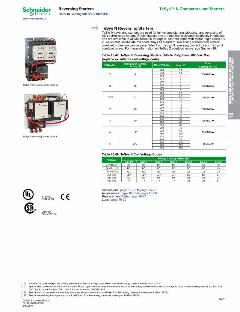
TeSys N reversing starters are used for full-voltage starting, stopping, and reversing ofAC squirrel cage motors. Reversing starters are mechanically and electrically interlockedand are available in NEMA Sizes 00 through 5. Starters come with Motor Logic Class 10/20 selectable solid-state overload relays as standard. Reversing starters with bimetaloverload protection can be assembled from TeSys N reversing contactors and TeSys Doverload relays. For more information on TeSys D overload relays, see Section 18.
Table 16.47: TeSys N Reversing Starters, 3-Pole Polyphase, 600 Vac Max.(replace ●● with the coil voltage code)
NEMA Size Continuous CurrentRating (A) Motor Voltage Max HP
OpenCatalog No. [10]
00 9
200 1.5
T36AN23●●230 1.5460 2575 2
0 18
200 3
T36BN23●●230 3460 5575 5
1[11] 27
200 7.5
T36CN23●●230 7.5460 10575 10
2 45
200 10
T36DN23●●230 15460 25575 25
3 90
200 25
T36EN23●●230 30460 50575 50
4 135
200 40
T36FN23●●230 50460 100575 100
5 270
200 75
T36GN23●●230 100460 200575 200
Table 16.48: TeSys N Coil Voltage CodesVoltage Voltage Code by NEMA Size
Size 00 Size 0 Size 1 Size 2 Size 3 Size 4 Size 524 Vac[12] B7 B7 B7 B7 B6 B6 n/a24 Vdc [13] BD BD BD BD BD BD n/a120 Vac[12] G7 G7 G7 G7 G6 G6 G7208 Vac LE7 LE7 LE7 LE7 L6 L6 L7240 Vac U7 U7 U7 U7 U6 U6 U7480 Vac T7 T7 T7 T7 Q5 Q5 S7
E164862CCN NLDX
LR43364Class 3211 04
Dimensions: page 16-22 to page 16-26Accessories: page 16-18 to page 16-20Replacement Parts: page 16-21Lugs: page 16-20
16NEMAANDDEFINITEPURPOSE
CONTA
CTORSANDSTA
RTERS
[10] Replace the bullets (●●) in the catalog number with the coil voltage code. Refer to the coil voltage codes shown in Table 16.48.[11] Special size combinations of the contactor and Motor Logic overload relay are available. Add 0 to the catalog number before the coil voltage for Size 0 overload relays (6–18 A); 9 for Size
00C (3–9 A); and 8 for Size 00B (1.5–4.5 A)—for example, T36CN230G7.[12] The 24 and 120 Vac coils are available with optional separate control; add Form S to the catalog number (for example, T36AN13B7S).[13] The 24 Vdc coil requires separate control; add Form S to the catalog number (for example, T36AN23BDS).
6/20/2017
16-18 © 2017 Schneider ElectricAll Rights Reserved
TeSys™ N Contactors and Starters Accessories
schneider-electric.us
Refer to CatalogMKTED210011EN
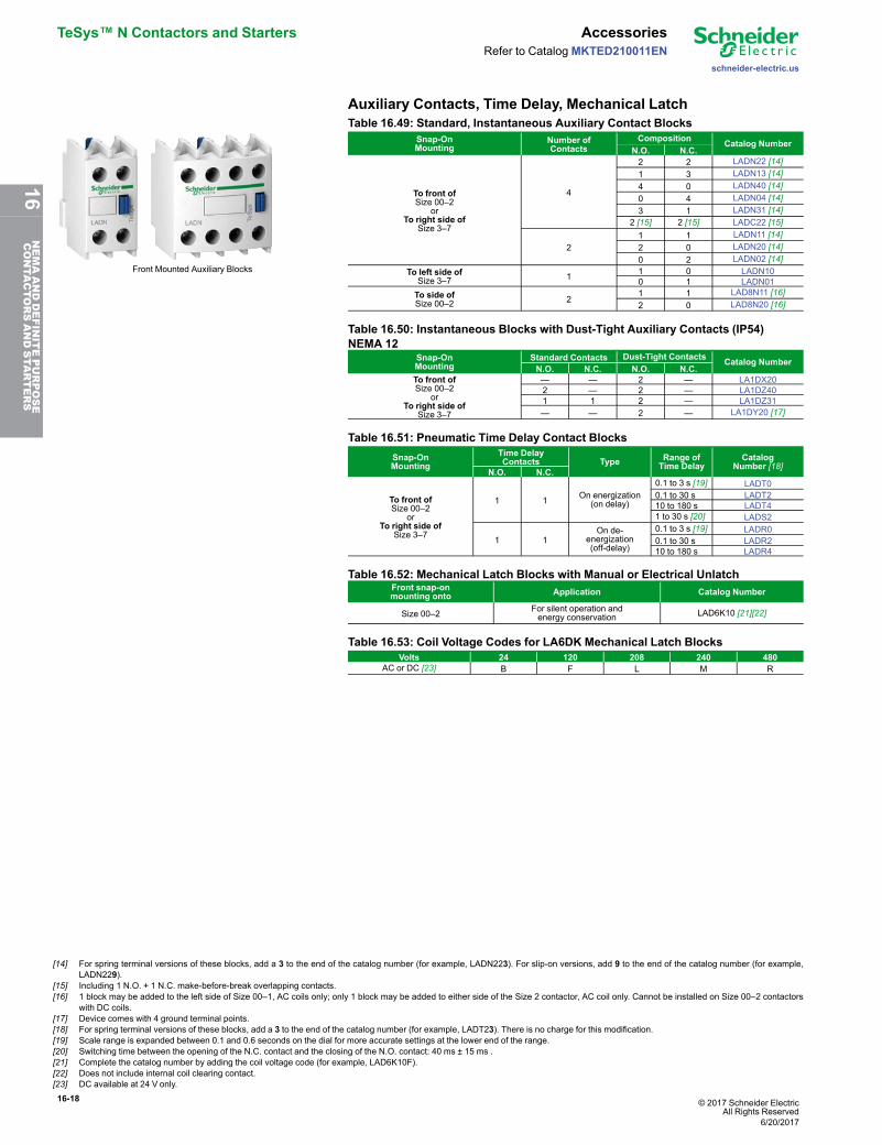
Auxiliary Contacts, Time Delay, Mechanical Latch
Front Mounted Auxiliary Blocks
Table 16.49: Standard, Instantaneous Auxiliary Contact BlocksSnap-OnMounting
Number ofContacts
Composition Catalog NumberN.O. N.C.
To front ofSize 00–2
orTo right side of
Size 3–7
4
2 2 LADN22 [14]1 3 LADN13 [14]4 0 LADN40 [14]0 4 LADN04 [14]3 1 LADN31 [14]
2 [15] 2 [15] LADC22 [15]
21 1 LADN11 [14]2 0 LADN20 [14]0 2 LADN02 [14]
To left side ofSize 3–7 1 1 0 LADN10
0 1 LADN01To side ofSize 00–2 2
1 1 LAD8N11 [16]2 0 LAD8N20 [16]
Table 16.50: Instantaneous Blocks with Dust-Tight Auxiliary Contacts (IP54)NEMA 12
Snap-OnMounting
Standard Contacts Dust-Tight Contacts Catalog NumberN.O. N.C. N.O. N.C.
To front ofSize 00–2
orTo right side of
Size 3–7
— — 2 — LA1DX202 — 2 — LA1DZ401 1 2 — LA1DZ31— — 2 — LA1DY20 [17]
Table 16.51: Pneumatic Time Delay Contact BlocksSnap-OnMounting
Time DelayContacts Type Range of
Time DelayCatalog
Number [18]N.O. N.C.
To front ofSize 00–2
orTo right side of
Size 3–7
1 1 On energization(on delay)
0.1 to 3 s [19] LADT00.1 to 30 s LADT210 to 180 s LADT41 to 30 s [20] LADS2
1 1On de-
energization(off-delay)
0.1 to 3 s [19] LADR00.1 to 30 s LADR210 to 180 s LADR4
Table 16.52: Mechanical Latch Blocks with Manual or Electrical UnlatchFront snap-onmounting onto Application Catalog Number
Size 00–2 For silent operation andenergy conservation LAD6K10 [21][22]
Table 16.53: Coil Voltage Codes for LA6DK Mechanical Latch BlocksVolts 24 120 208 240 480
AC or DC [23] B F L M R
[14] For spring terminal versions of these blocks, add a 3 to the end of the catalog number (for example, LADN223). For slip-on versions, add 9 to the end of the catalog number (for example,LADN229).
[15] Including 1 N.O. + 1 N.C. make-before-break overlapping contacts.[16] 1 block may be added to the left side of Size 00–1, AC coils only; only 1 block may be added to either side of the Size 2 contactor, AC coil only. Cannot be installed on Size 00–2 contactors
with DC coils.[17] Device comes with 4 ground terminal points.[18] For spring terminal versions of these blocks, add a 3 to the end of the catalog number (for example, LADT23). There is no charge for this modification.[19] Scale range is expanded between 0.1 and 0.6 seconds on the dial for more accurate settings at the lower end of the range.[20] Switching time between the opening of the N.C. contact and the closing of the N.O. contact: 40 ms ± 15 ms .[21] Complete the catalog number by adding the coil voltage code (for example, LAD6K10F).[22] Does not include internal coil clearing contact.[23] DC available at 24 V only.
6/20/2017
16NEMAANDDEFINITEPURPOSE
CONTA
CTORSANDSTA
RTERS
© 2017 Schneider ElectricAll Rights Reserved
16-19
schneider-electric.us
Accessories TeSys™ N Contactors and StartersRefer to Catalog MKTED210011EN
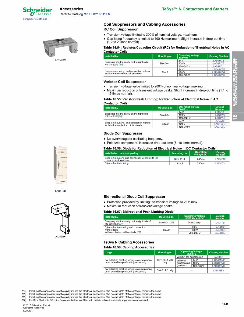
Coil Suppressors and Cabling AccessoriesRC Coil Suppressor
LA4DA1U
• Transient voltage limited to 300% of nominal voltage, maximum.• Oscillating frequency is limited to 400 Hz maximum. Slight increase in drop-out time(1.2 to 2 times normal).
Table 16.54: Resistor/Capacitor Circuit (RC) for Reduction of Electrical Noise in ACContactor CoilsInstalled by Mounting on Operating Voltage
50/60 Hz Catalog Number
Snapping into the cavity on the right sidewithout tools [24] Size 00–1
24 V LAD4RCE120 V LAD4RCG120–240 V LAD4RCU
Snap-on mounting, and connection withouttools to the contactor coil terminals Size 2
24 V LAD4RC3E120 V LAD4RC3G120-240 V LAD4RC3U
Varistor Coil Suppressor• Transient voltage value limited to 200% of nominal voltage, maximum.• Maximum reduction of transient voltage peaks. Slight increase in drop-out time (1.1 to1.5 times normal).
Table 16.55: Varistor (Peak Limiting) for Reduction of Electrical Noise in ACContactor CoilsInstalled by Mounting on Operating Voltage
50/60 HzCatalogNumber
Snapping into the cavity on the right sidewithout tools[25] Size 00–1
24 V LAD4VE120 V LAD4VG120–240 V LAD4VU
Snap-on mounting, and connection withouttools to the contactor coil terminals Size 2
24 V LAD4V3E120 V LAD4V3G120-240 V LAD4V3U
Diode Coil Suppressor
LAD4T3B
• No overvoltage or oscillating frequency.• Polarized component. Increased drop-out time (6–10 times normal).
Table 16.56: Diode for Reduction of Electrical Noise in DC Contactor CoilsInstalled on the upper part by Mounting on Operating
Voltage, DCCatalogNumber
Snap-on mounting and connection w/o tools to thecontactor coil terminals Size 00–1 24 Vdc LAD4DDL
Clip-on front mounting Size 2 24 Vdc LAD4D3U
Bidirectional Diode Coil Suppressor
LAD4BB• •
• Protection provided by limiting the transient voltage to 2 Uc max.• Maximum reduction of transient voltage peaks.
Table 16.57: Bidirectional Peak Limiting DiodeInstalled by Mounting on Operating Voltage
50/60 Hz and DCCatalogNumber
Snapping into the cavity on the right side ofthe contactor [26] Size 00–1[27] 24 (AC only) LAD4TB
Clip-on front mounting and connectionwithout toolsto the contactor coil terminals [27]
Size 224 V LAD4T3B120 V LAD4T3G
208–240 V LAD4T3U
TeSys N Cabling AccessoriesTable 16.58: Cabling AccessoriesUsage Mounting on Operating Voltage
50/60 Hz Catalog Number
For adapting existing wiring to a new productor for use with top-mounting accessory.
Size 00–1, AConly
Without coil suppression LAD4BBWith coilsuppression(varistor)
24 V LAD4BBVE120 V LAD4BBVG120-240 V LAD4BBVU
For adapting existing wiring to a new productor for use with top-mounting accessory Size 2, AC only — LAD4BB3
16NEMAANDDEFINITEPURPOSE
CONTA
CTORSANDSTA
RTERS
[24] Installing the suppressor into the cavity makes the electrical connection. The overall width of the contactor remains the same.[25] Installing the suppressor into the cavity makes the electrical connection. The overall width of the contactor remains the same.[26] Installing the suppressor into the cavity makes the electrical connection. The overall width of the contactor remains the same.[27] For Size 00–2 with DC coils, 3-pole contactors are fitted with built-in bidirectional diode suppression as standard.
6/20/2017
16-20 © 2017 Schneider ElectricAll Rights Reserved
TeSys™ N Contactors and Starters Accessories
schneider-electric.us
Refer to CatalogMKTED210011EN
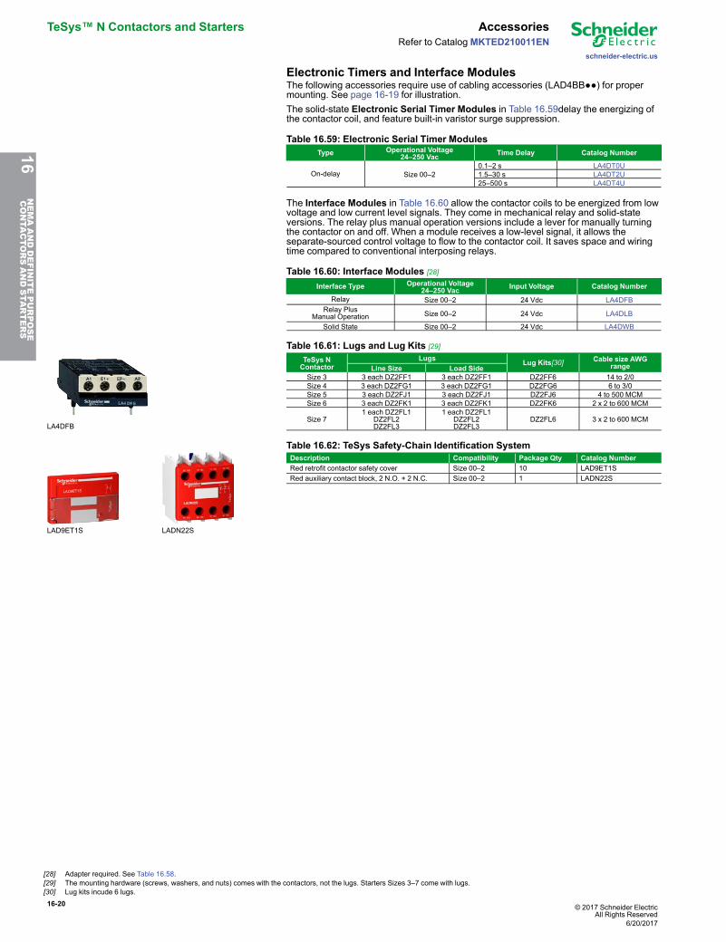
Electronic Timers and Interface ModulesThe following accessories require use of cabling accessories (LAD4BB●●) for propermounting. See page 16-19 for illustration.The solid-state Electronic Serial Timer Modules in Table 16.59delay the energizing ofthe contactor coil, and feature built-in varistor surge suppression.
Table 16.59: Electronic Serial Timer ModulesType Operational Voltage
24–250 Vac Time Delay Catalog Number
On-delay Size 00–20.1–2 s LA4DT0U1.5–30 s LA4DT2U25–500 s LA4DT4U
The Interface Modules in Table 16.60 allow the contactor coils to be energized from lowvoltage and low current level signals. They come in mechanical relay and solid-stateversions. The relay plus manual operation versions include a lever for manually turningthe contactor on and off. When a module receives a low-level signal, it allows theseparate-sourced control voltage to flow to the contactor coil. It saves space and wiringtime compared to conventional interposing relays.
Table 16.60: Interface Modules [28]
Interface Type Operational Voltage24–250 Vac Input Voltage Catalog Number
Relay Size 00–2 24 Vdc LA4DFBRelay Plus
Manual Operation Size 00–2 24 Vdc LA4DLB
Solid State Size 00–2 24 Vdc LA4DWB
LA4DFB
Table 16.61: Lugs and Lug Kits [29]
TeSys NContactor
Lugs Lug Kits[30] Cable size AWGrangeLine Size Load Side
Size 3 3 each DZ2FF1 3 each DZ2FF1 DZ2FF6 14 to 2/0Size 4 3 each DZ2FG1 3 each DZ2FG1 DZ2FG6 6 to 3/0Size 5 3 each DZ2FJ1 3 each DZ2FJ1 DZ2FJ6 4 to 500 MCMSize 6 3 each DZ2FK1 3 each DZ2FK1 DZ2FK6 2 x 2 to 600 MCM
Size 71 each DZ2FL1
DZ2FL2DZ2FL3
1 each DZ2FL1DZ2FL2DZ2FL3
DZ2FL6 3 x 2 to 600 MCM
LAD9ET1S LADN22S
Table 16.62: TeSys Safety-Chain Identification SystemDescription Compatibility Package Qty Catalog NumberRed retrofit contactor safety cover Size 00–2 10 LAD9ET1SRed auxiliary contact block, 2 N.O. + 2 N.C. Size 00–2 1 LADN22S
16NEMAANDDEFINITEPURPOSE
CONTA
CTORSANDSTA
RTERS
[28] Adapter required. See Table 16.58.[29] The mounting hardware (screws, washers, and nuts) comes with the contactors, not the lugs. Starters Sizes 3–7 come with lugs.[30] Lug kits incude 6 lugs.
6/20/2017
© 2017 Schneider ElectricAll Rights Reserved
16-21
schneider-electric.us
Replacement Parts TeSys™ N Contactors and StartersRefer to Catalog MKTED210011EN
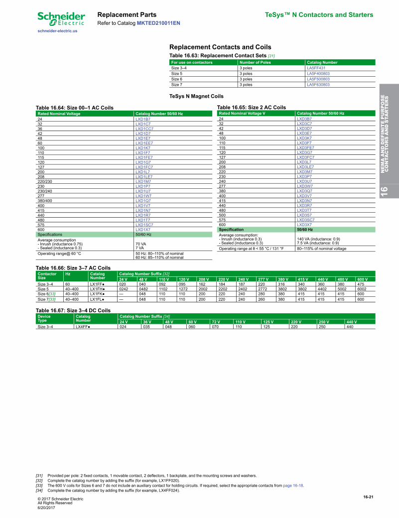
Replacement Contacts and CoilsTable 16.63: Replacement Contact Sets [31]For use on contactors Number of Poles Catalog NumberSize 3–4 3 poles LA5FF431Size 5 3 poles LA5F400803Size 6 3 poles LA5F500803Size 7 3 poles LA5F630803
TeSys N Magnet Coils
Table 16.64: Size 00–1 AC CoilsRated Nominal Voltage Catalog Number 50/60 Hz24 LXD1B732 LXD1C736 LXD1CC742 LXD1D748 LXD1E760 LXD1EE7100 LXD1K7110 LXD1F7115 LXD1FE7120 LXD1G7127 LXD1FC7200 LXD1L7208 LXD1LE7220/230 LXD1M7230 LXD1P7230/240 LXD1U7277 LXD1W7380/400 LXD1Q7400 LXD1V7415 LXD1N7440 LXD1R7480 LXD1T7575 LXD1SC7600 LXD1X7Specifications 50/60 HzAverage consumption- Inrush (inductance 0.75)- Sealed (inductance 0.3)
70 VA7 VA
Operating range@ 60 °C 50 Hz: 80–110% of nominal60 Hz: 85–110% of nominal
Table 16.65: Size 2 AC CoilsRated Nominal Voltage V Catalog Number 50/60 Hz24 LXD3B732 LXD3C742 LXD3D748 LXD3E7100 LXD3K7110 LXD3F7115 LXD3FE7120 LXD3G7127 LXD3FC7200 LXD3L7208 LXD3LE7220 LXD3M7230 LXD3P7240 LXD3U7277 LXD3W7380 LXD3Q7400 LXD3V7415 LXD3N7440 LXD3R7480 LXD3T7500 LXD3S7575 LXD3SC7600 LXD3X7Specification 50/60 HzAverage consumption:- Inrush (inductance 0.3)- Sealed (inductance 0.3)
140 VA (inductance: 0.9)7.5 VA (inductance: 0.9)
Operating range at θ < 55 °C / 131 °F 80–115% of nominal voltage
Table 16.66: Size 3–7 AC CoilsContactorSize
Hz CatalogNumber
Catalog Number Suffix [32]24 V 48 V 110 V 120 V 208 V 220 V 240 V 277 V 380 V 415 V 440 V 480 V 600 V
Size 3–4 60 LX1FF● 020 040 092 095 162 184 187 220 316 340 360 380 475Size 5 40–400 LX1FH● 0242 0482 1102 1272 2002 2202 2402 2772 3802 3802 4402 5002 6002Size 6[33] 40–400 LX1FK● — 048 110 110 200 220 240 280 380 415 415 415 600Size 7[33] 40–400 LX1FL● — 048 110 110 200 220 240 260 380 415 415 415 600
Table 16.67: Size 3–4 DC CoilsDeviceType
CatalogNumber
Catalog Number Suffix [34]24 V 36 V 48 V 60 V 72 V 110 V 125 V 220 V 250 V 440 V
Size 3–4 LX4FF● 024 035 048 060 070 110 125 220 250 440
16NEMAANDDEFINITEPURPOSE
CONTA
CTORSANDSTA
RTERS
[31] Provided per pole: 2 fixed contacts, 1 movable contact, 2 deflectors, 1 backplate, and the mounting screws and washers.[32] Complete the catalog number by adding the suffix (for example, LX1FF020).[33] The 600 V coils for Sizes 6 and 7 do not include an auxiliary contact for holding circuits. If required, select the appropriate contacts from page 16-18.[34] Complete the catalog number by adding the suffix (for example, LX4FF024).
6/20/2017
16-22 © 2017 Schneider ElectricAll Rights Reserved
TeSys™ N Contactors and Starters TeSys™ N Dimensions
schneider-electric.us
Refer to CatalogMKTED210011EN
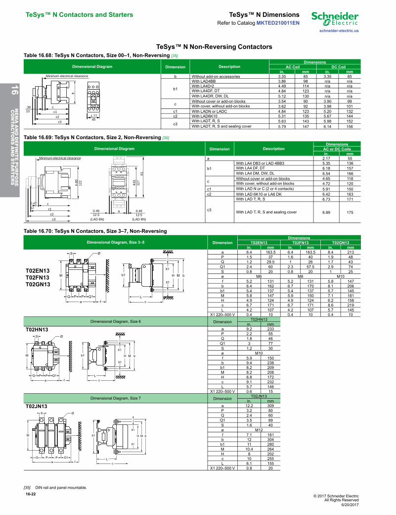
TeSys™ N Non-Reversing ContactorsTable 16.68: TeSys N Contactors, Size 00–1, Non-Reversing [35]
Dimensional Diagram Dimension DescriptionDimensions
AC Coil DC Coilin. mm in. mm
1.7745
b
c.3910 c1
c2
c3
Minimum electrical clearance b Without add-on accessories 3.35 85 3.35 85
b1
With LAD4BB 3.86 98 n/a n/aWith LA4D•2 4.49 114 n/a n/aWith LA4DF, DT 4.84 123 n/a n/aWith LA4DR, DW, DL 5.12 130 n/a n/a
cWithout cover or add-on blocks 3.54 90 3.90 99With cover, without add-on blocks 3.62 92 3.98 101
c1 With LADN or LADC 4.84 123 5.20 132c2 With LAD6K10 5.31 135 5.67 144
c3With LADT, R, S 5.63 143 5.98 152With LADT, R, S and sealing cover 5.79 147 6.14 156
Table 16.69: TeSys N Contactors, Size 2, Non-Reversing [35]
Dimensional Diagram Dimension DescriptionDimensions
AC or DC Coilsin. mm
4.61
117
4.80
122
a
(LAD 8N) (LAD 8N)
0.4912.5
c1
c2
c3
b1
0.4712
c
0.4912.5
Minimum electrical clearance a 2.17 55
b1With LA4 DB3 or LAD 4BB3 5.35 136With LA4 DF, DT 6.18 157With LA4 DM, DW, DL 6.54 166
cWithout cover or add-on blocks 4.65 118With cover, without add-on blocks 4.72 120
c1 With LAD N or C (2 or 4 contacts) 5.91 150c2 With LAD 6K10 or LA6 DK 6.42 163
c3
With LAD T, R, S 6.73 171
With LAD T, R, S and sealing cover 6.89 175
Table 16.70: TeSys N Contactors, Size 3–7, Non-Reversing
Dimensional Diagram, Size 3–5 DimensionDimensions
T02EN13 T02FN13 T02GN13in. mm in. mm in. mm
T02EN13T02FN13T02GN13
fa
P Q1PQ
M
ØS
X1
bMH
X1
Lc
b1
a 6.4 163.5 6.4 163.5 8.4 213P 1.5 37 1.6 40 1.9 48Q 1.2 29.5 1 26 1.7 43Q1 2.4 60 2.3 57.5 2.9 74S 0.8 20 0.8 20 1 25ø M6 M8 M10f 5.2 131 5.2 131 5.8 147b 6.4 162 6.7 170 8.1 206b1 5.4 137 5.4 137 5.7 145M 5.8 147 5.9 150 7.1 181H 4.9 124 4.9 124 6.2 158c 6.7 171 6.7 171 8.6 219L 4.2 107 4.2 107 5.7 145
X1 220–500 V 0.4 10 0.4 10 0.4 10
Dimensional Diagram, Size 6 Dimension T02HN13in. mm
T02HN13
P PQ
S
M
Q1
Ø
a f
X1
bMH
X1
Lc
b1
a 9.2 233P 2.2 55Q 1.8 46Q1 3 77S 1.2 30ø M10f 5.9 150b 9.4 238b1 8.2 209M 8.2 208H 6.8 172c 9.1 232L 5.7 146
X1 220–500 V 0.6 15
Dimensional Diagram, Size 7 Dimension T02JN13in. mm
T02JN13
P PQ
S
M
Q1
Ø
fa
X1
bMH
X1
L
c
b1
a 12.2 309P 3.2 80Q 2.4 60Q1 3.5 89S 1.6 40ø M12f 7.1 181b 12 304b1 11 280M 10.4 264H 8 202c 10 255L 6.1 155
X1 220–500 V 0.8 20
16NEMAANDDEFINITEPURPOSE
CONTA
CTORSANDSTA
RTERS
[35] DIN rail and panel mountable.
6/20/2017

© 2017 Schneider ElectricAll Rights Reserved
16-23
schneider-electric.us
TeSys™ N Dimensions TeSys™ N Contactors and StartersRefer to Catalog MKTED210011EN
TeSys™ N Reversing ContactorsTable 16.71: TeSys N Size 00–1, Reversing Contactors [36]
Dimensional Diagram DimensionDimensions
AC Coil DC Coilin. mm in. mm
2xM4
G
a
= =
60/7
0=
=c
be1
e2
a: Without side-mount accessories 3.54 90 3.54 90b: Contactor base 3.35 85 3.35 85c: With cover, without add-on blocks 3.62 92 3.98 101e1 0.35 9 0.35 9e2 0.20 5 0.20 5
G: Mounting holes 3.15 80 3.15 80
Table 16.72: TeSys N Size 2, Reversing Contactors [36]
Dimensional Diagram DescriptionDimensions
AC and DC Coilsin. mm
122
128
120
119
6418,7 18,7
26,537,5 37,5 6xM4 Width 4.69 119Height 4.80 122Depth with cover, without add-on blocks 4.72 120Load side mounting hole width 2.52 64Line side mounting hole width 3.40 101.5
Mounting hole height 5.04 128
Table 16.73: TeSys N Size 3–7, Reversing Contactors
Dimensional Diagram DimensionDimensions
T02EN23 T02FN23 T02GN23 T02HN23 T02JN23in. mm in. mm in. mm in. mm in. mm
LW R
H
M
N
X X
D D 0.38 9.7 0.38 9.7 0.56 14.2 0.56 14.2 0.56 14.2H 7.96 202.2 7.96 202.2 15.27 387.9 15.27 387.9 22.25 565.2L 11.75 298.5 11.75 298.5 18 457.2 18 457.2 30 762.0M 7 177.8 7 177.8 14 355.6 14 355.6 19.75 501.7N 0.49 12.5 0.49 12.5 0.62 15.8 0.62 15.8 1.25 31.8R 0.49 12.5 0.49 12.5 0.62 15.8 0.62 15.8 0.69 17.5W 12.71 322.8 12.71 322.8 19.27 489.5 19.27 489.5 31.38 797.0
X 5.16 131.0 5.16 131.0 5.79 147.0 5.91 150.0 7.13 181.0
16NEMAANDDEFINITEPURPOSE
CONTA
CTORSANDSTA
RTERS
[36] DIN rail and panel mountable.
6/20/2017
16-24 © 2017 Schneider ElectricAll Rights Reserved
TeSys™ N Contactors and Starters TeSys™ N Dimensions
schneider-electric.us
Refer to CatalogMKTED210011EN
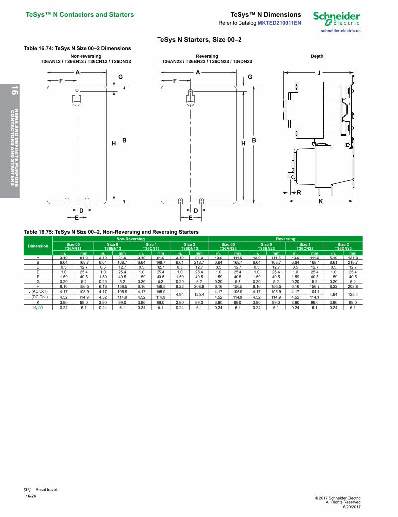
TeSys N Starters, Size 00–2Table 16.74: TeSys N Size 00–2 Dimensions
GA
F
H B
DE
GA
F
H B
DE
J
K
R
Non-reversingT36AN13 / T36BN13 / T36CN13 / T36DN13
ReversingT36AN23 / T36BN23 / T36CN23 / T36DN23
Depth
Table 16.75: TeSys N Size 00–2, Non-Reversing and Reversing Starters
Dimension
Non-Reversing ReversingSize 00T36AN13
Size 0T36BN13
Size 1T36CN13
Size 2T36DN13
Size 00T36AN23
Size 0T36BN23
Size 1T36CN23
Size 2T36DN23
in. mm in. mm in. mm in. mm in. mm in. mm in. mm in. mmA 3.19 81.0 3.19 81.0 3.19 81.0 3.19 81.0 43.9 111.5 43.9 111.5 43.9 111.5 5.19 131.8B 6.64 168.7 6.64 168.7 6.64 168.7 8.61 218.7 6.64 168.7 6.64 168.7 6.64 168.7 8.61 218.7D 0.5 12.7 0.5 12.7 0.5 12.7 0.5 12.7 0.5 12.7 0.5 12.7 0.5 12.7 0.5 12.7E 1.0 25.4 1.0 25.4 1.0 25.4 1.0 25.4 1.0 25.4 1.0 25.4 1.0 25.4 1.0 25.4F 1.59 40.5 1.59 40.5 1.59 40.5 1.59 40.5 1.59 40.5 1.59 40.5 1.59 40.5 1.59 40.5G 0.20 5.2 0.20 5.2 0.20 5.2 0.20 5.2 0.20 5.2 0.20 5.2 0.20 5.2 0.20 5.2H 6.16 156.5 6.16 156.5 6.16 156.5 8.22 208.8 6.16 156.5 6.16 156.5 6.16 156.5 8.22 208.8
J (AC Coil) 4.17 105.9 4.17 105.9 4.17 105.94.94 125.4
4.17 105.9 4.17 105.9 4.17 104.94.94 125.4J (DC Coil) 4.52 114.9 4.52 114.9 4.52 114.9 4.52 114.9 4.52 114.9 4.52 114.9
K 3.90 99.0 3.90 99.0 3.90 99.0 3.90 99.0 3.90 99.0 3.90 99.0 3.90 99.0 3.90 99.0R[37] 0.24 6.1 0.24 6.1 0.24 6.1 0.24 6.1 0.24 6.1 0.24 6.1 0.24 6.1 0.24 6.1
16NEMAANDDEFINITEPURPOSE
CONTA
CTORSANDSTA
RTERS
[37] Reset travel.
6/20/2017
© 2017 Schneider ElectricAll Rights Reserved
16-25
schneider-electric.us
TeSys™ N Dimensions TeSys™ N Contactors and StartersRefer to Catalog MKTED210011EN
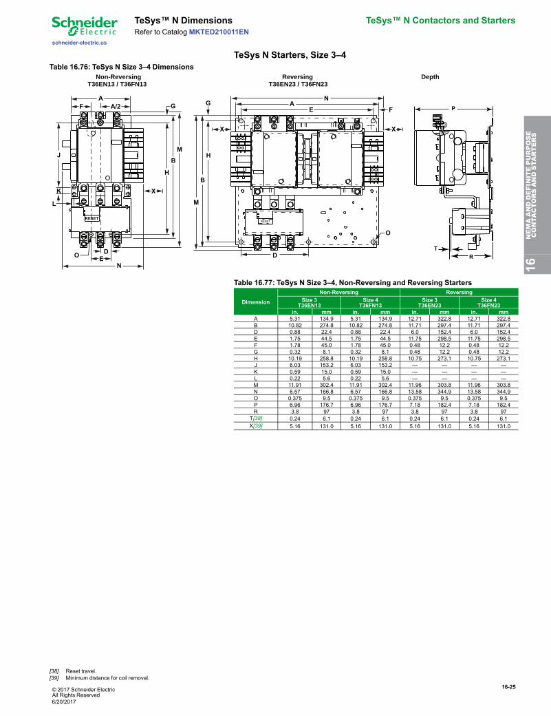
TeSys N Starters, Size 3–4Table 16.76: TeSys N Size 3–4 Dimensions
K
L
G
H
B
MJ
A
N
F A/2
DO
E
X
RESET
H
B
M
G AN
E F
O
D
XX
RESET
P
R
T
Non-ReversingT36EN13 / T36FN13
ReversingT36EN23 / T36FN23
Depth
Table 16.77: TeSys N Size 3–4, Non-Reversing and Reversing Starters
Dimension
Non-Reversing ReversingSize 3
T36EN13Size 4
T36FN13Size 3
T36EN23Size 4
T36FN23in. mm in. mm in. mm in. mm
A 5.31 134.9 5.31 134.9 12.71 322.8 12.71 322.8B 10.82 274.8 10.82 274.8 11.71 297.4 11.71 297.4D 0.88 22.4 0.88 22.4 6.0 152.4 6.0 152.4E 1.75 44.5 1.75 44.5 11.75 298.5 11.75 298.5F 1.78 45.0 1.78 45.0 0.48 12.2 0.48 12.2G 0.32 8.1 0.32 8.1 0.48 12.2 0.48 12.2H 10.19 258.8 10.19 258.8 10.75 273.1 10.75 273.1J 6.03 153.2 6.03 153.2 — — — —K 0.59 15.0 0.59 15.0 — — — —L 0.22 5.6 0.22 5.6 — — — —M 11.91 302.4 11.91 302.4 11.96 303.8 11.96 303.8N 6.57 166.8 6.57 166.8 13.58 344.9 13.58 344.9O 0.375 9.5 0.375 9.5 0.375 9.5 0.375 9.5P 6.96 176.7 6.96 176.7 7.18 182.4 7.18 182.4R 3.8 97 3.8 97 3.8 97 3.8 97
T[38] 0.24 6.1 0.24 6.1 0.24 6.1 0.24 6.1X[39] 5.16 131.0 5.16 131.0 5.16 131.0 5.16 131.0
16NEMAANDDEFINITEPURPOSE
CONTA
CTORSANDSTA
RTERS
[38] Reset travel.[39] Minimum distance for coil removal.
6/20/2017
16-26 © 2017 Schneider ElectricAll Rights Reserved
TeSys™ N Contactors and Starters TeSys™ N Dimensions
schneider-electric.us
Refer to CatalogMKTED210011EN
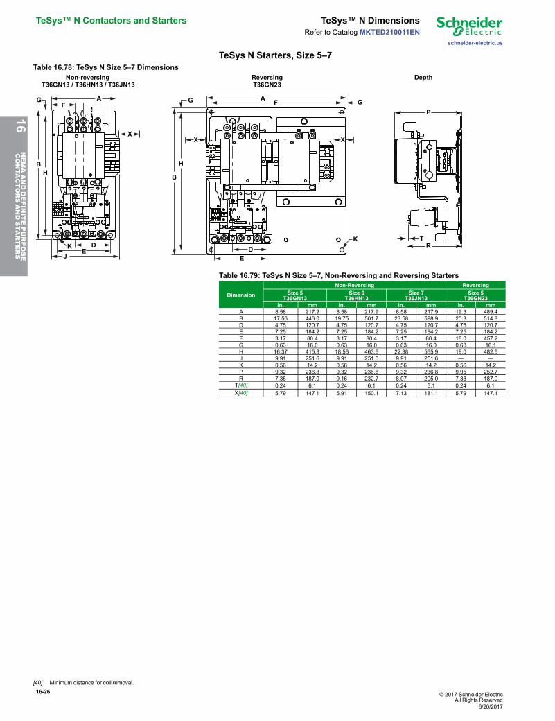
TeSys N Starters, Size 5–7Table 16.78: TeSys N Size 5–7 Dimensions
A
J
FG
HB
DE
X
K
RESET
AF G
H
B
G
K
X X
DE
RESET
P
RT
Non-reversingT36GN13 / T36HN13 / T36JN13
ReversingT36GN23
Depth
Table 16.79: TeSys N Size 5–7, Non-Reversing and Reversing Starters
Dimension
Non-Reversing ReversingSize 5
T36GN13Size 6
T36HN13Size 7
T36JN13Size 5
T36GN23in. mm in. mm in. mm in. mm
A 8.58 217.9 8.58 217.9 8.58 217.9 19.3 489.4B 17.56 446.0 19.75 501.7 23.58 598.9 20.3 514.8D 4.75 120.7 4.75 120.7 4.75 120.7 4.75 120.7E 7.25 184.2 7.25 184.2 7.25 184.2 7.25 184.2F 3.17 80.4 3.17 80.4 3.17 80.4 18.0 457.2G 0.63 16.0 0.63 16.0 0.63 16.0 0.63 16.1H 16.37 415.8 18.56 463.6 22.38 565.9 19.0 482.6J 9.91 251.6 9.91 251.6 9.91 251.6 — —K 0.56 14.2 0.56 14.2 0.56 14.2 0.56 14.2P 9.32 236.8 9.32 236.8 9.32 236.8 9.95 252.7R 7.38 187.0 9.16 232.7 8.07 205.0 7.38 187.0
T[40] 0.24 6.1 0.24 6.1 0.24 6.1 0.24 6.1X[40] 5.79 147 1 5.91 150.1 7.13 181.1 5.79 147.1
16NEMAANDDEFINITEPURPOSE
CONTA
CTORSANDSTA
RTERS
[40] Minimum distance for coil removal.
6/20/2017
© 2017 Schneider ElectricAll Rights Reserved
16-27
schneider-electric.us
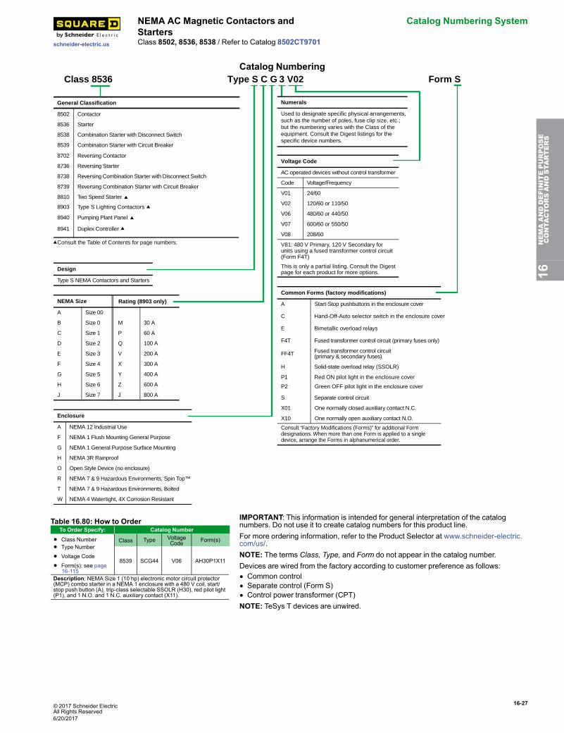
NEMA AC Magnetic Contactors andStarters
Catalog Numbering System
Class 8502, 8536, 8538 / Refer to Catalog 8502CT9701
Catalog Numbering
General Classification
8502 Contactor
8536 Starter
8538 Combination Starter with Disconnect Switch
8539 Combination Starter with Circuit Breaker
8702 Reversing Contactor
8736 Reversing Starter
8738 Reversing Combination Starter with Disconnect Switch
8739 Reversing Combination Starter with Circuit Breaker
8810 Two Speed Starter
8940 Pumping Plant Panel
8903 Type S Lighting Contactors
8
Consult the Table of Contents for page numbers.
941 Duplex Controller
Design
Type S NEMA Contactors and Starters
NEMA Size Rating (8903 only)
A Size 00
M 30 AB Size 0
P 60 AC Size 1
Q 100 AD Size 2
V 200 AE Size 3
X 300 AF Size 4
Y 400 AG Size 5
Z 600 AH Size 6
J 800 AJ Size 7
Enclosure
A NEMA 12 Industrial Use
F NEMA 1 Flush Mounting General Purpose
G NEMA 1 General Purpose Surface Mounting
H NEMA 3R Rainproof
O Open Style Device (no enclosure)
R NEMA 7 & 9 Hazardous Environments, Spin Top™
T NEMA 7 & 9 Hazardous Environments, Bolted
W NEMA 4 Watertight, 4X Corrosion Resistant
Class 8536 Type S C G 3 V02 Form S
Numerals
Used to designate specific physical arrangements, such as the number of poles, fuse clip size, etc.; but the numbering varies with the Class of theequipment. Consult the Digest listings for the specific device numbers.
Voltage Code
AC operated devices without control transformer
Code Voltage/Frequency
V01 24/60
V02 120/60 or 110/50
V06 480/60 or 440/50
V07 600/60 or 550/50
V08 208/60
V81: 480 V Primary, 120 V Secondary for units using a fused transformer control circuit (Form F4T)
This is only a partial listing. Consult the Digest page for each product for more options.
Common Forms (factory modifications)
A Start-Stop pushbuttons in the enclosure cover
C Hand-Off-Auto selector switch in the enclosure cover
E Bimetallic overload relays
F4T Fused transformer control circuit (primary fuses only)
FF4T Fused transformer control circuit(primary & secondary fuses)
H Solid-state overload relay (SSOLR)
P1 Red ON pilot light in the enclosure cover
S Separate control circuit
X01 One normally closed auxiliary contact N.C.
X10 One normally open auxiliary contact N.O.
Consult “Factory Modifications (Forms)” for additional Form designations. When more than one Form is applied to a single device, arrange the Forms in alphanumerical order.
P2 Green OFF pilot light in the enclosure cover
Table 16.80: How to OrderTo Order Specify: Catalog Number
• Class Number• Type Number
• Voltage Code
• Form(s): see page16-115
Class Type VoltageCode Form(s)
8539 SCG44 V06 AH30P1X11
Description: NEMA Size 1 (10 hp) electronic motor circuit protector(MCP) combo starter in a NEMA 1 enclosure with a 480 V coil, start/stop push button (A), trip-class selectable SSOLR (H30), red pilot light(P1), and 1 N.O. and 1 N.C. auxiliary contact (X11).
IMPORTANT: This information is intended for general interpretation of the catalognumbers. Do not use it to create catalog numbers for this product line.For more ordering information, refer to the Product Selector at www.schneider-electric.com/us/.NOTE: The terms Class, Type, and Form do not appear in the catalog number.Devices are wired from the factory according to customer preference as follows:• Common control• Separate control (Form S)• Control power transformer (CPT)NOTE: TeSys T devices are unwired.
16NEMAANDDEFINITEPURPOSE
CONTA
CTORSANDSTA
RTERS
6/20/2017
16-28 © 2017 Schneider ElectricAll Rights Reserved
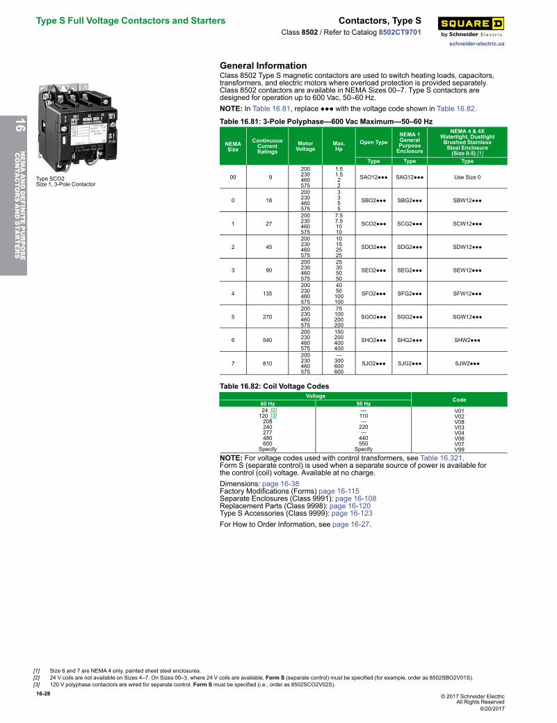
Type S Full Voltage Contactors and Starters Contactors, Type S
schneider-electric.us
Class 8502 / Refer to Catalog 8502CT9701
General Information
Type SCO2Size 1, 3-Pole Contactor
Class 8502 Type S magnetic contactors are used to switch heating loads, capacitors,transformers, and electric motors where overload protection is provided separately.Class 8502 contactors are available in NEMA Sizes 00–7. Type S contactors aredesigned for operation up to 600 Vac, 50–60 Hz.NOTE: In Table 16.81, replace ●●● with the voltage code shown in Table 16.82.
Table 16.81: 3-Pole Polyphase—600 Vac Maximum—50–60 Hz
NEMASize
ContinuousCurrentRatings
MotorVoltage
Max.Hp
Open TypeNEMA 1GeneralPurposeEnclosure
NEMA 4 & 4XWatertight, DusttightBrushed StainlessSteel Enclosure(Size 0-5) [1]
Type Type Type
00 9200230460575
1.51.522
SAO12●●● SAG12●●● Use Size 0
0 18200230460575
3355
SBO2●●● SBG2●●● SBW12●●●
1 27200230460575
7.57.51010
SCO2●●● SCG2●●● SCW12●●●
2 45200230460575
10152525
SDO2●●● SDG2●●● SDW12●●●
3 90200230460575
25305050
SEO2●●● SEG2●●● SEW12●●●
4 135200230460575
4050100100
SFO2●●● SFG2●●● SFW12●●●
5 270200230460575
75100200200
SGO2●●● SGG2●●● SGW12●●●
6 540200230460575
150200400400
SHO2●●● SHG2●●● SHW2●●●
7 810200230460575
—300600600
SJO2●●● SJG2●●● SJW2●●●
Table 16.82: Coil Voltage CodesVoltage
Code60 Hz 50 Hz 24 [2]120 [3]208240277480600
Specify
—110—220—440550
Specify
V01V02V08V03V04V06V07V99
NOTE: For voltage codes used with control transformers, see Table 16.321.Form S (separate control) is used when a separate source of power is available forthe control (coil) voltage. Available at no charge.Dimensions: page 16-38Factory Modifications (Forms) page 16-115Separate Enclosures (Class 9991): page 16-108Replacement Parts (Class 9998): page 16-120Type S Accessories (Class 9999): page 16-123For How to Order Information, see page 16-27.
[1] Size 6 and 7 are NEMA 4 only, painted sheet steel enclosures.[2] 24 V coils are not available on Sizes 4–7. On Sizes 00–3, where 24 V coils are available, Form S (separate control) must be specified (for example, order as 8502SBO2V01S).[3] 120 V polyphase contactors are wired for separate control. Form S must be specified (i.e., order as 8502SCO2V02S).
6/20/2017
16NEMAANDDEFINITEPURPOSE
CONTA
CTORSANDSTA
RTERS
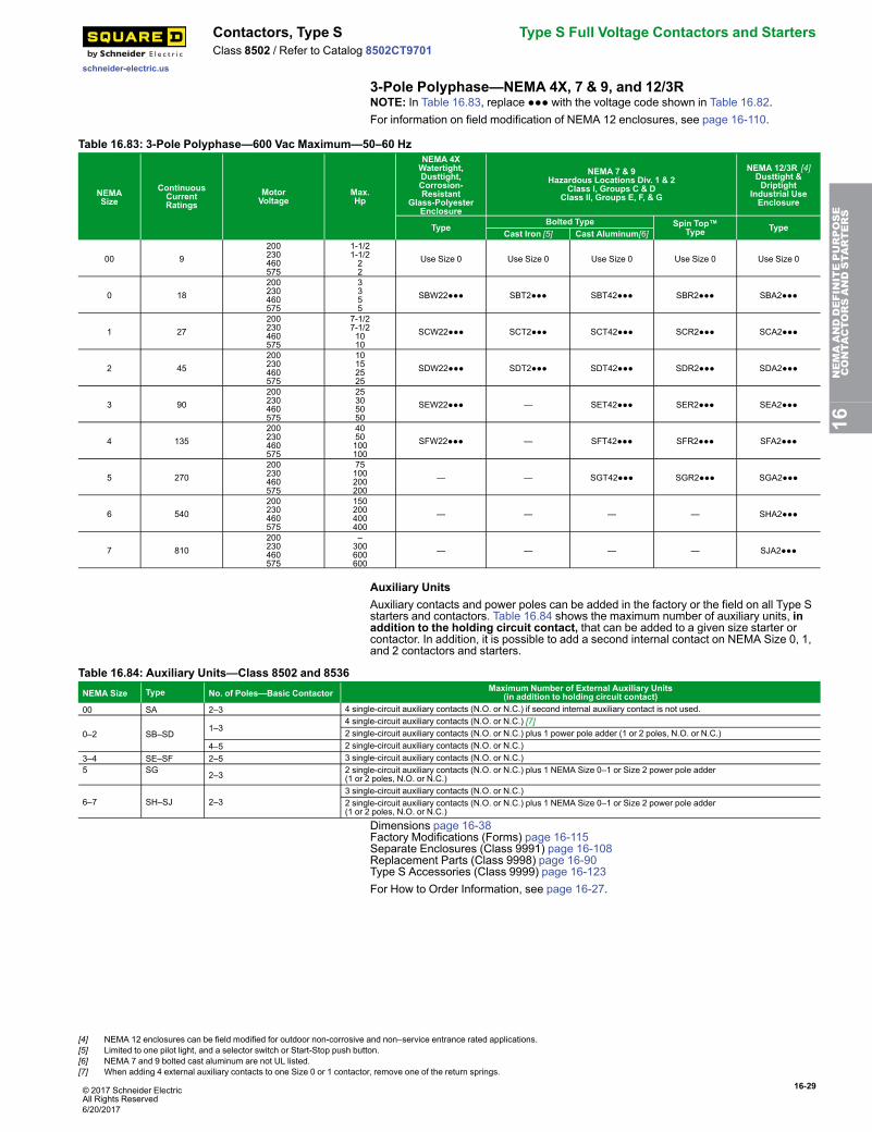
© 2017 Schneider ElectricAll Rights Reserved
16-29
schneider-electric.us
Contactors, Type S Type S Full Voltage Contactors and StartersClass 8502 / Refer to Catalog 8502CT9701
3-Pole Polyphase—NEMA 4X, 7 & 9, and 12/3RNOTE: In Table 16.83, replace ●●● with the voltage code shown in Table 16.82.For information on field modification of NEMA 12 enclosures, see page 16-110.
Table 16.83: 3-Pole Polyphase—600 Vac Maximum—50–60 Hz
NEMASize
ContinuousCurrentRatings
MotorVoltage
Max.Hp
NEMA 4XWatertight,Dusttight,Corrosion-Resistant
Glass-PolyesterEnclosure
NEMA 7 & 9Hazardous Locations Div. 1 & 2
Class I, Groups C & DClass II, Groups E, F, & G
NEMA 12/3R [4]Dusttight &Driptight
Industrial UseEnclosure
Type Bolted Type Spin Top™Type Type
Cast Iron [5] Cast Aluminum[6]
00 9200230460575
1-1/21-1/222
Use Size 0 Use Size 0 Use Size 0 Use Size 0 Use Size 0
0 18200230460575
3355
SBW22●●● SBT2●●● SBT42●●● SBR2●●● SBA2●●●
1 27200230460575
7-1/27-1/21010
SCW22●●● SCT2●●● SCT42●●● SCR2●●● SCA2●●●
2 45200230460575
10152525
SDW22●●● SDT2●●● SDT42●●● SDR2●●● SDA2●●●
3 90200230460575
25305050
SEW22●●● — SET42●●● SER2●●● SEA2●●●
4 135200230460575
4050100100
SFW22●●● — SFT42●●● SFR2●●● SFA2●●●
5 270200230460575
75100200200
— — SGT42●●● SGR2●●● SGA2●●●
6 540200230460575
150200400400
— — — — SHA2●●●
7 810200230460575
–300600600
— — — — SJA2●●●
Auxiliary UnitsAuxiliary contacts and power poles can be added in the factory or the field on all Type Sstarters and contactors. Table 16.84 shows the maximum number of auxiliary units, inaddition to the holding circuit contact, that can be added to a given size starter orcontactor. In addition, it is possible to add a second internal contact on NEMA Size 0, 1,and 2 contactors and starters.
Table 16.84: Auxiliary Units—Class 8502 and 8536NEMA Size Type No. of Poles—Basic Contactor Maximum Number of External Auxiliary Units
(in addition to holding circuit contact)00 SA 2–3 4 single-circuit auxiliary contacts (N.O. or N.C.) if second internal auxiliary contact is not used.
0–2 SB–SD1–3
4 single-circuit auxiliary contacts (N.O. or N.C.) [7]2 single-circuit auxiliary contacts (N.O. or N.C.) plus 1 power pole adder (1 or 2 poles, N.O. or N.C.)
4–5 2 single-circuit auxiliary contacts (N.O. or N.C.)3–4 SE–SF 2–5 3 single-circuit auxiliary contacts (N.O. or N.C.)5 SG 2–3 2 single-circuit auxiliary contacts (N.O. or N.C.) plus 1 NEMA Size 0–1 or Size 2 power pole adder
(1 or 2 poles, N.O. or N.C.)
6–7 SH–SJ 2–33 single-circuit auxiliary contacts (N.O. or N.C.)2 single-circuit auxiliary contacts (N.O. or N.C.) plus 1 NEMA Size 0–1 or Size 2 power pole adder(1 or 2 poles, N.O. or N.C.)
Dimensions page 16-38Factory Modifications (Forms) page 16-115Separate Enclosures (Class 9991) page 16-108Replacement Parts (Class 9998) page 16-90Type S Accessories (Class 9999) page 16-123For How to Order Information, see page 16-27.
16NEMAANDDEFINITEPURPOSE
CONTA
CTORSANDSTA
RTERS
[4] NEMA 12 enclosures can be field modified for outdoor non-corrosive and non–service entrance rated applications.[5] Limited to one pilot light, and a selector switch or Start-Stop push button.[6] NEMA 7 and 9 bolted cast aluminum are not UL listed.[7] When adding 4 external auxiliary contacts to one Size 0 or 1 contactor, remove one of the return springs.
6/20/2017
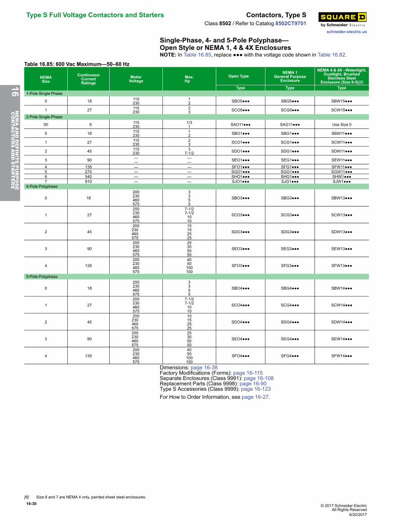
16-30 © 2017 Schneider ElectricAll Rights Reserved
Type S Full Voltage Contactors and Starters Contactors, Type S
schneider-electric.us
Class 8502 / Refer to Catalog 8502CT9701
Single-Phase, 4- and 5-Pole Polyphase—Open Style or NEMA 1, 4 & 4X EnclosuresNOTE: In Table 16.85, replace ●●● with the voltage code shown in Table 16.82.
Table 16.85: 600 Vac Maximum—50–60 Hz
NEMASize
ContinuousCurrentRatings
MotorVoltage
Max.Hp
Open TypeNEMA 1
General PurposeEnclosure
NEMA 4 & 4X –Watertight,Dusttight, BrushedStainless Steel
Enclosure (Size 0-5)[8]Type Type Type
1-Pole Single Phase
0 18 115230
12 SBO5●●● SBG5●●● SBW15●●●
1 27 115230
23 SCO5●●● SCG5●●● SCW15●●●
2-Pole Single Phase
00 9 115230
1/31 SAO11●●● SAG11●●● Use Size 0
0 18 115230
12 SBO1●●● SBG1●●● SBW11●●●
1 27 115230
23 SCO1●●● SCG1●●● SCW11●●●
2 45 115230
37-1/2 SDO1●●● SDG1●●● SDW11●●●
3 90 ——
—— SEO1●●● SEG1●●● SEW11●●●
4 135 — — SFO1●●● SFG1●●● SFW11●●●5 270 — — SGO1●●● SGG1●●● SGW11●●●6 540 — — SHO1●●● SHG1●●● SHW1●●●7 810 — — SJO1●●● SJG1●●● SJW1●●●
4-Pole Polyphase
0 18200230460575
3355
SBO3●●● SBG3●●● SBW13●●●
1 27200230460575
7-1/27-1/21010
SCO3●●● SCG3●●● SCW13●●●
2 45200230460575
10152525
SDO3●●● SDG3●●● SDW13●●●
3 90200230460575
25305050
SEO3●●● SEG3●●● SEW13●●●
4 135200230460575
4050100100
SFO3●●● SFG3●●● SFW13●●●
5-Pole Polyphase
0 18200230460575
3355
SBO4●●● SBG4●●● SBW14●●●
1 27200230460575
7-1/27-1/21010
SCO4●●● SCG4●●● SCW14●●●
2 45200230460575
10152525
SDO4●●● SDG4●●● SDW14●●●
3 90200230460575
25305050
SEO4●●● SEG4●●● SEW14●●●
4 135200230460575
4050100100
SFO4●●● SFG4●●● SFW14●●●
Dimensions: page 16-38Factory Modifications (Forms): page 16-115Separate Enclosures (Class 9991): page 16-108Replacement Parts (Class 9998): page 16-90Type S Accessories (Class 9999): page 16-123For How to Order Information, see page 16-27.
16NEMAANDDEFINITEPURPOSE
CONTA
CTORSANDSTA
RTERS
[8] Size 6 and 7 are NEMA 4 only, painted sheet steel enclosures.
6/20/2017
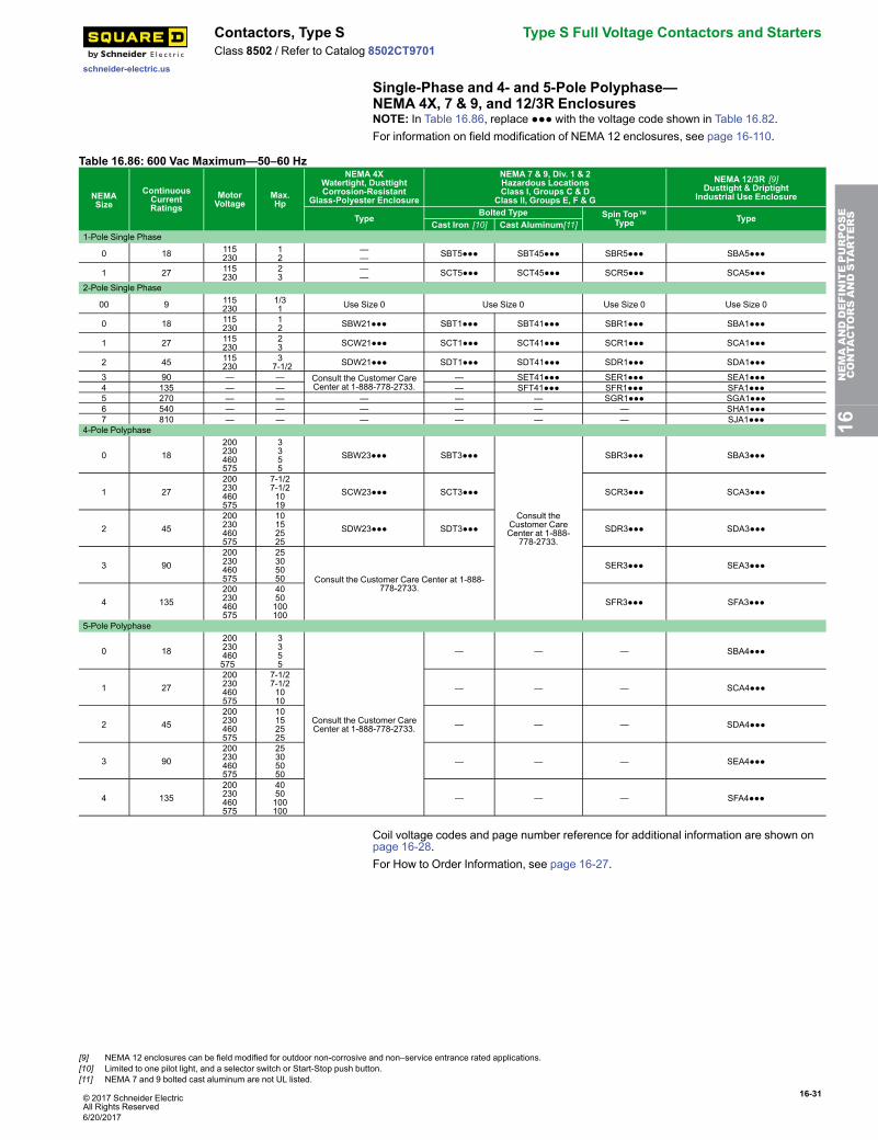
© 2017 Schneider ElectricAll Rights Reserved
16-31
schneider-electric.us
Contactors, Type S Type S Full Voltage Contactors and StartersClass 8502 / Refer to Catalog 8502CT9701
Single-Phase and 4- and 5-Pole Polyphase—NEMA 4X, 7 & 9, and 12/3R EnclosuresNOTE: In Table 16.86, replace ●●● with the voltage code shown in Table 16.82.For information on field modification of NEMA 12 enclosures, see page 16-110.
Table 16.86: 600 Vac Maximum—50–60 Hz
NEMASize
ContinuousCurrentRatings
MotorVoltage
Max.Hp
NEMA 4XWatertight, DusttightCorrosion-Resistant
Glass-Polyester Enclosure
NEMA 7 & 9, Div. 1 & 2Hazardous LocationsClass I, Groups C & D
Class II, Groups E, F & G
NEMA 12/3R [9]Dusttight & Driptight
Industrial Use Enclosure
Type Bolted Type Spin Top™Type Type
Cast Iron [10] Cast Aluminum[11]1-Pole Single Phase
0 18 115230
12
—— SBT5●●● SBT45●●● SBR5●●● SBA5●●●
1 27 115230
23
—— SCT5●●● SCT45●●● SCR5●●● SCA5●●●
2-Pole Single Phase
00 9 115230
1/31 Use Size 0 Use Size 0 Use Size 0 Use Size 0
0 18 115230
12 SBW21●●● SBT1●●● SBT41●●● SBR1●●● SBA1●●●
1 27 115230
23 SCW21●●● SCT1●●● SCT41●●● SCR1●●● SCA1●●●
2 45 115230
37-1/2 SDW21●●● SDT1●●● SDT41●●● SDR1●●● SDA1●●●
3 90 — — Consult the Customer CareCenter at 1-888-778-2733.
— SET41●●● SER1●●● SEA1●●●4 135 — — — SFT41●●● SFR1●●● SFA1●●●5 270 — — — — — SGR1●●● SGA1●●●6 540 — — — — — — SHA1●●●7 810 — — — — — — SJA1●●●
4-Pole Polyphase
0 18200230460575
3355
SBW23●●● SBT3●●●
Consult theCustomer CareCenter at 1-888-
778-2733.
SBR3●●● SBA3●●●
1 27200230460575
7-1/27-1/21019
SCW23●●● SCT3●●● SCR3●●● SCA3●●●
2 45200230460575
10152525
SDW23●●● SDT3●●● SDR3●●● SDA3●●●
3 90200230460575
25305050 Consult the Customer Care Center at 1-888-
778-2733.
SER3●●● SEA3●●●
4 135200230460575
4050100100
SFR3●●● SFA3●●●
5-Pole Polyphase
0 18200230460575
3355
Consult the Customer CareCenter at 1-888-778-2733.
— — — SBA4●●●
1 27200230460575
7-1/27-1/21010
— — — SCA4●●●
2 45200230460575
10152525
— — — SDA4●●●
3 90200230460575
25305050
— — — SEA4●●●
4 135200230460575
4050100100
— — — SFA4●●●
Coil voltage codes and page number reference for additional information are shown onpage 16-28.For How to Order Information, see page 16-27.
16NEMAANDDEFINITEPURPOSE
CONTA
CTORSANDSTA
RTERS
[9] NEMA 12 enclosures can be field modified for outdoor non-corrosive and non–service entrance rated applications.[10] Limited to one pilot light, and a selector switch or Start-Stop push button.[11] NEMA 7 and 9 bolted cast aluminum are not UL listed.
6/20/2017
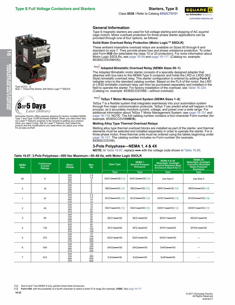
16-32 © 2017 Schneider ElectricAll Rights Reserved
Type S Full Voltage Contactors and Starters Starters, Type S
schneider-electric.us
Class 8536 / Refer to Catalog 8502CT9701
General Information
Type SCO3…SSize 1, Three-Pole Starter with Motor Logic™ SSOLR
Schneider Electric offers express shipping for factory modified NEMAType 1 and Type 12/3R Enclosed Starters. When you need them fast,our Laser™ Delivery program is the answer to getting your productwhen you need it most. Ask for Laser™ Delivery, then select theproduct and the modifications you need when you place your order.It’s as easy as that!
Type S magnetic starters are used for full-voltage starting and stopping of AC squirrelcage motors. Motor overload protection for three-phase starter applications can beprovided through one of four options, as follows:Solid-State Overload Relay Protection (Motor Logic™ SSOLR)These ambient insensitive overload relays are available on Sizes 00 through 6 andstandard on size 7. They provide phase loss and phase unbalance protection. To order,add Form H30 (for selectable trip class 10 or 20 protection). For more information aboutMotor Logic SSOLRs, see page 16-99 and page 16-117. (Catalog no. example:8536SCO3V06H30)
Adapted Bimetallic Overload Relay (NEMA Sizes 00–1)The Adapted Bimetallic motor starter consists of a specially designed adapter thatattaches with bus bars to the NEMAType S contactor and holds the LRD or LR3D (IECStyle) bimetallic overload relay. This starter configuration is ordered by adding Form E(adapter only) to the standard catalog number. Based on the FLA of the motor, the LRDor LR3D bimetallic overload relay can then be purchased separately and installed in thefield to operate the starter. For factory installation of the overload, see Table 16.324.(Catalog no. example: 8536SCO3V06E—without overload)
TeSys T Motor Management System (NEMA Sizes 1–6)TeSys T is a flexible system that integrates seamlessly into your automation systemthrough five major communication protocols. TeSys Tcan predict what will happen in theprocess, as it accurately monitors current, voltage, and power over a wide range. Foradditional information about TeSys T Motor Management System, see page 16-101 andpage 16-118. NOTE: The full catalog number contains a four-character Form number (forexample, 8536SCO3V06H616).Melting Alloy Type Thermal Overload RelaysMelting alloy type thermal overload blocks are installed as part of the starter, and thermalelements must be selected and installed separately in order to operate the starter. For athree-phase motor, three thermal units must be ordered using the tables beginning underpage 16-131. The catalog number includes no Form number (for example,8536SCO3V06).
3-Pole Polyphase—NEMA 1, 4 & 4XNOTE: In Table 16.87, replace ●●● with the voltage code shown in Table 16.89.
Table 16.87: 3-Pole Polyphase—600 Vac Maximum—50–60 Hz, with Motor Logic SSOLR
NEMASize
ContinuousCurrentRatings
MotorVoltage
Max.Hp
Open TypeNEMA 1
General PurposeEnclosure
NEMA 4 & 4XWatertight, Dusttight
Brushed Stainless SteelEnclosure (Size 0-5)[12]
NEMA 4XWatertight, Dusttight,Corrosion-ResistantGlass-Polyester
EnclosureType Type Type Type
00 9200230460575
1.51.522
SAO12●●●H30 [13] SAG12●●●H30 [13] Use Size 0 Use Size 0
0 18200230460575
3355
SBO2●●●H30 [13] SBG2●●●H30 [13] SBW12●●●H30 [13] SBW22●●●H30 [13]
1 27200230460575
7.57.51010
SCO3●●●H30 [13] SCG3●●●H30 [13] SCW13●●●H30 [13] SCW23●●●H30 [13]
2 45200230460575
10152525
SDO1●●●H30 [13] SDG1●●●H30 [13] SDW11●●●H30 [13] SDW21●●●H30 [13]
3 90200230460575
25305050
SEO1●●●H30 SEG1●●●H30 SEW11●●●H30 SEW21●●●H30
4 135200230460575
4050100100
SFO1●●●H30 SFG1●●●H30 SFW11●●●H30 SFW21●●●H30
5 270200230460575
75100200200
SGO1●●●H30 SGG1●●●H30 SGW11●●●H30 —
6 540200230460575
150200400400
SHO2●●●H30 SHG2●●●H30 SHW2●●●H30 —
7 810200230460575
—300600600
SJO2●●●H30 SJG2●●●H30 SJW2●●●H30 —
[12] Size 6 and 7 are NEMA 4 only, painted sheet steel enclosures.[13] Form H30, with the possibility of a fourth character to select a lower FLA range (for example, H308). See page 16-117
6/20/2017
16NEMAANDDEFINITEPURPOSE
CONTA
CTORSANDSTA
RTERS
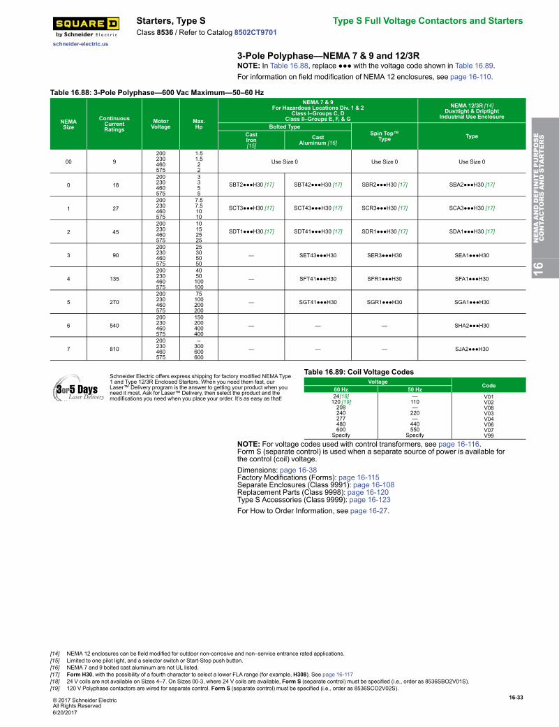
© 2017 Schneider ElectricAll Rights Reserved
16-33
schneider-electric.us
Starters, Type S Type S Full Voltage Contactors and StartersClass 8536 / Refer to Catalog 8502CT9701
3-Pole Polyphase—NEMA 7 & 9 and 12/3RNOTE: In Table 16.88, replace ●●● with the voltage code shown in Table 16.89.For information on field modification of NEMA 12 enclosures, see page 16-110.
Table 16.88: 3-Pole Polyphase—600 Vac Maximum—50–60 Hz
NEMASize
ContinuousCurrentRatings
MotorVoltage
Max.Hp
NEMA 7 & 9For Hazardous Locations Div. 1 & 2
Class I–Groups C, DClass II–Groups E, F, & G
NEMA 12/3R [14]Dusttight & Driptight
Industrial Use Enclosure
Bolted TypeSpin Top™
Type TypeCastIron[15]
CastAluminum [16]
00 9200230460575
1.51.522
Use Size 0 Use Size 0 Use Size 0
0 18200230460575
3355
SBT2●●●H30 [17] SBT42●●●H30 [17] SBR2●●●H30 [17] SBA2●●●H30 [17]
1 27200230460575
7.57.51010
SCT3●●●H30 [17] SCT43●●●H30 [17] SCR3●●●H30 [17] SCA3●●●H30 [17]
2 45200230460575
10152525
SDT1●●●H30 [17] SDT41●●●H30 [17] SDR1●●●H30 [17] SDA1●●●H30 [17]
3 90200230460575
25305050
— SET43●●●H30 SER3●●●H30 SEA1●●●H30
4 135200230460575
4050100100
— SFT41●●●H30 SFR1●●●H30 SFA1●●●H30
5 270200230460575
75100200200
— SGT41●●●H30 SGR1●●●H30 SGA1●●●H30
6 540200230460575
150200400400
— — — SHA2●●●H30
7 810200230460575
–300600600
— — — SJA2●●●H30
Schneider Electric offers express shipping for factory modified NEMAType1 and Type 12/3R Enclosed Starters. When you need them fast, ourLaser™ Delivery program is the answer to getting your product when youneed it most. Ask for Laser™ Delivery, then select the product and themodifications you need when you place your order. It’s as easy as that!
Table 16.89: Coil Voltage CodesVoltage
Code60 Hz 50 Hz24[18]120 [19]208240277480600
Specify
—110—220—440550
Specify
V01V02V08V03V04V06V07V99
NOTE: For voltage codes used with control transformers, see page 16-116.Form S (separate control) is used when a separate source of power is available forthe control (coil) voltage.Dimensions: page 16-38Factory Modifications (Forms): page 16-115Separate Enclosures (Class 9991): page 16-108Replacement Parts (Class 9998): page 16-120Type S Accessories (Class 9999): page 16-123For How to Order Information, see page 16-27.
16NEMAANDDEFINITEPURPOSE
CONTA
CTORSANDSTA
RTERS
[14] NEMA 12 enclosures can be field modified for outdoor non-corrosive and non–service entrance rated applications.[15] Limited to one pilot light, and a selector switch or Start-Stop push button.[16] NEMA 7 and 9 bolted cast aluminum are not UL listed.[17] Form H30, with the possibility of a fourth character to select a lower FLA range (for example, H308). See page 16-117[18] 24 V coils are not available on Sizes 4–7. On Sizes 00-3, where 24 V coils are available, Form S (separate control) must be specified (i.e., order as 8536SBO2V01S).[19] 120 V Polyphase contactors are wired for separate control. Form S (separate control) must be specified (i.e., order as 8536SCO2V02S).
6/20/2017
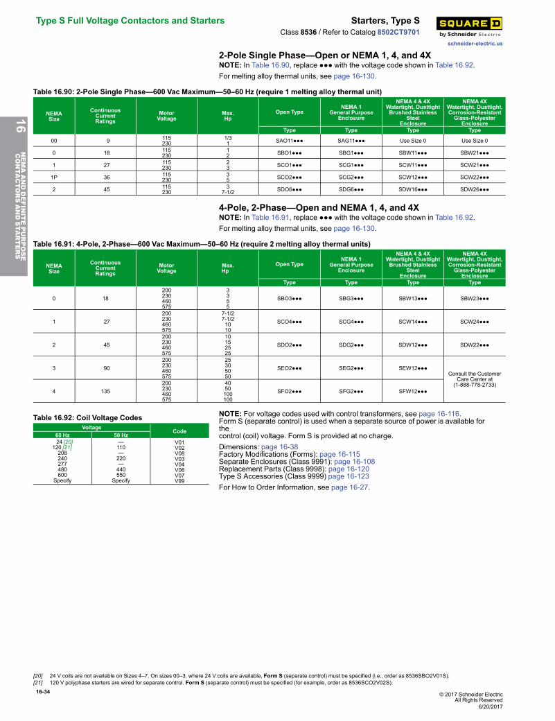
16-34 © 2017 Schneider ElectricAll Rights Reserved
Type S Full Voltage Contactors and Starters Starters, Type S
schneider-electric.us
Class 8536 / Refer to Catalog 8502CT9701
2-Pole Single Phase—Open or NEMA 1, 4, and 4XNOTE: In Table 16.90, replace ●●● with the voltage code shown in Table 16.92.For melting alloy thermal units, see page 16-130.
Table 16.90: 2-Pole Single Phase—600 Vac Maximum—50–60 Hz (require 1 melting alloy thermal unit)
NEMASize
ContinuousCurrentRatings
MotorVoltage
Max.Hp
Open TypeNEMA 1
General PurposeEnclosure
NEMA 4 & 4XWatertight, DusttightBrushed Stainless
SteelEnclosure
NEMA 4XWatertight, Dusttight,Corrosion-ResistantGlass-Polyester
EnclosureType Type Type Type
00 9 115230
1/31 SAO11●●● SAG11●●● Use Size 0 Use Size 0
0 18 115230
12 SBO1●●● SBG1●●● SBW11●●● SBW21●●●
1 27 115230
23 SCO1●●● SCG1●●● SCW11●●● SCW21●●●
1P 36 115230
35 SCO2●●● SCG2●●● SCW12●●● SCW22●●●
2 45 115230
37-1/2 SDO6●●● SDG6●●● SDW16●●● SDW26●●●
4-Pole, 2-Phase—Open and NEMA 1, 4, and 4XNOTE: In Table 16.91, replace ●●● with the voltage code shown in Table 16.92.For melting alloy thermal units, see page 16-130.
Table 16.91: 4-Pole, 2-Phase—600 Vac Maximum—50–60 Hz (require 2 melting alloy thermal units)
NEMASize
ContinuousCurrentRatings
MotorVoltage
Max.Hp
Open TypeNEMA 1
General PurposeEnclosure
NEMA 4 & 4XWatertight, DusttightBrushed Stainless
SteelEnclosure
NEMA 4XWatertight, Dusttight,Corrosion-ResistantGlass-Polyester
EnclosureType Type Type Type
0 18200230460575
3355
SBO3●●● SBG3●●● SBW13●●● SBW23●●●
1 27200230460575
7-1/27-1/21010
SCO4●●● SCG4●●● SCW14●●● SCW24●●●
2 45200230460575
10152525
SDO2●●● SDG2●●● SDW12●●● SDW22●●●
3 90200230460575
25305050
SEO2●●● SEG2●●● SEW12●●●Consult the Customer
Care Center at(1-888-778-2733)
4 135200230460575
4050100100
SFO2●●● SFG2●●● SFW12●●●
Table 16.92: Coil Voltage CodesVoltage
Code60 Hz 50 Hz 24 [20]120 [21]208240277480600
Specify
—110—220—440550
Specify
V01V02V08V03V04V06V07V99
NOTE: For voltage codes used with control transformers, see page 16-116.Form S (separate control) is used when a separate source of power is available forthecontrol (coil) voltage. Form S is provided at no charge.Dimensions: page 16-38Factory Modifications (Forms): page 16-115Separate Enclosures (Class 9991): page 16-108Replacement Parts (Class 9998): page 16-120Type S Accessories (Class 9999) page 16-123For How to Order Information, see page 16-27.
16NEMAANDDEFINITEPURPOSE
CONTA
CTORSANDSTA
RTERS
[20] 24 V coils are not available on Sizes 4–7. On sizes 00–3, where 24 V coils are available, Form S (separate control) must be specified (i.e., order as 8536SBO2V01S).[21] 120 V polyphase starters are wired for separate control. Form S (separate control) must be specified (for example, order as 8536SCO2V02S).
6/20/2017
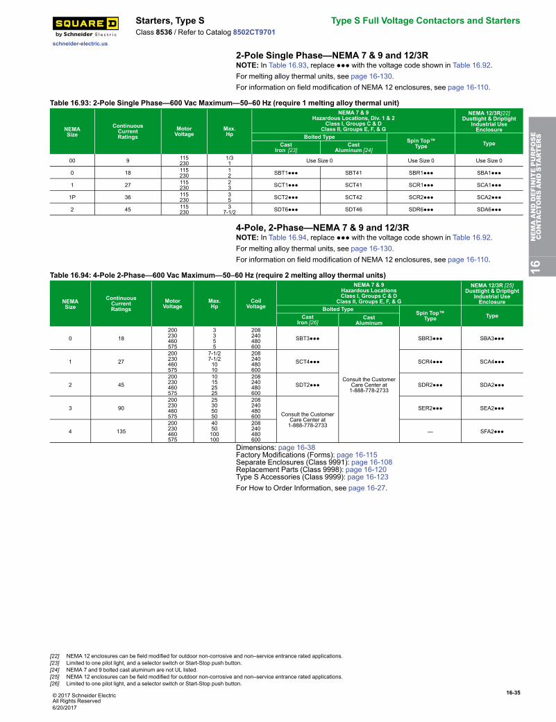
© 2017 Schneider ElectricAll Rights Reserved
16-35
schneider-electric.us
Starters, Type S Type S Full Voltage Contactors and StartersClass 8536 / Refer to Catalog 8502CT9701
2-Pole Single Phase—NEMA 7 & 9 and 12/3RNOTE: In Table 16.93, replace ●●● with the voltage code shown in Table 16.92.For melting alloy thermal units, see page 16-130.For information on field modification of NEMA 12 enclosures, see page 16-110.
Table 16.93: 2-Pole Single Phase—600 Vac Maximum—50–60 Hz (require 1 melting alloy thermal unit)
NEMASize
ContinuousCurrentRatings
MotorVoltage
Max.Hp
NEMA 7 & 9Hazardous Locations, Div. 1 & 2
Class I, Groups C & DClass II, Groups E, F, & G
NEMA 12/3R[22]Dusttight & Driptight
Industrial UseEnclosure
Bolted Type Spin Top™Type TypeCast
Iron [23]Cast
Aluminum [24]
00 9 115230
1/31 Use Size 0 Use Size 0 Use Size 0
0 18 115230
12 SBT1●●● SBT41 SBR1●●● SBA1●●●
1 27 115230
23 SCT1●●● SCT41 SCR1●●● SCA1●●●
1P 36 115230
35 SCT2●●● SCT42 SCR2●●● SCA2●●●
2 45 115230
37-1/2 SDT6●●● SDT46 SDR6●●● SDA6●●●
4-Pole, 2-Phase—NEMA 7 & 9 and 12/3RNOTE: In Table 16.94, replace ●●● with the voltage code shown in Table 16.92.For melting alloy thermal units, see page 16-130.For information on field modification of NEMA 12 enclosures, see page 16-110.
Table 16.94: 4-Pole 2-Phase—600 Vac Maximum—50–60 Hz (require 2 melting alloy thermal units)
NEMASize
ContinuousCurrentRatings
MotorVoltage
Max.Hp
CoilVoltage
NEMA 7 & 9Hazardous LocationsClass I, Groups C & D
Class II, Groups E, F, & G
NEMA 12/3R [25]Dusttight & Driptight
Industrial UseEnclosure
Bolted TypeSpin Top™
Type TypeCastIron [26]
CastAluminum
0 18200230460575
3355
208240480600
SBT3●●●
Consult the CustomerCare Center at1-888-778-2733
SBR3●●● SBA3●●●
1 27200230460575
7-1/27-1/21010
208240480600
SCT4●●● SCR4●●● SCA4●●●
2 45200230460575
10152525
208240480600
SDT2●●● SDR2●●● SDA2●●●
3 90200230460575
25305050
208240480600 Consult the Customer
Care Center at1-888-778-2733
SER2●●● SEA2●●●
4 135200230460575
4050100100
208240480600
— SFA2●●●
Dimensions: page 16-38Factory Modifications (Forms): page 16-115Separate Enclosures (Class 9991): page 16-108Replacement Parts (Class 9998): page 16-120Type S Accessories (Class 9999): page 16-123For How to Order Information, see page 16-27.
16NEMAANDDEFINITEPURPOSE
CONTA
CTORSANDSTA
RTERS
[22] NEMA 12 enclosures can be field modified for outdoor non-corrosive and non–service entrance rated applications.[23] Limited to one pilot light, and a selector switch or Start-Stop push button.[24] NEMA 7 and 9 bolted cast aluminum are not UL listed.[25] NEMA 12 enclosures can be field modified for outdoor non-corrosive and non–service entrance rated applications.[26] Limited to one pilot light, and a selector switch or Start-Stop push button.
6/20/2017
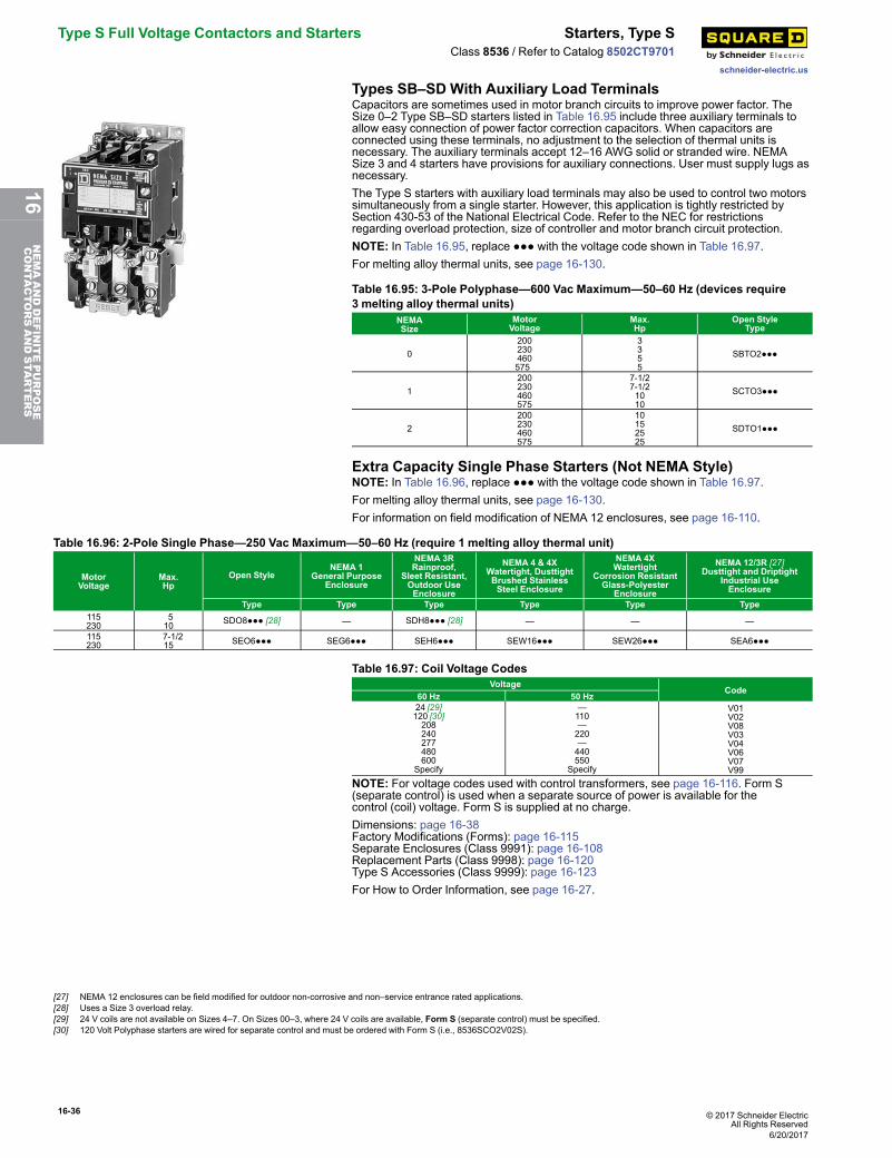
16-36 © 2017 Schneider ElectricAll Rights Reserved
Type S Full Voltage Contactors and Starters Starters, Type S
schneider-electric.us
Class 8536 / Refer to Catalog 8502CT9701
Types SB–SD With Auxiliary Load TerminalsCapacitors are sometimes used in motor branch circuits to improve power factor. TheSize 0–2 Type SB–SD starters listed in Table 16.95 include three auxiliary terminals toallow easy connection of power factor correction capacitors. When capacitors areconnected using these terminals, no adjustment to the selection of thermal units isnecessary. The auxiliary terminals accept 12–16 AWG solid or stranded wire. NEMASize 3 and 4 starters have provisions for auxiliary connections. User must supply lugs asnecessary.The Type S starters with auxiliary load terminals may also be used to control two motorssimultaneously from a single starter. However, this application is tightly restricted bySection 430-53 of the National Electrical Code. Refer to the NEC for restrictionsregarding overload protection, size of controller and motor branch circuit protection.NOTE: In Table 16.95, replace ●●● with the voltage code shown in Table 16.97.For melting alloy thermal units, see page 16-130.
Table 16.95: 3-Pole Polyphase—600 Vac Maximum—50–60 Hz (devices require3 melting alloy thermal units)
NEMASize
MotorVoltage
Max.Hp
Open StyleType
0200230460575
3355
SBTO2●●●
1200230460575
7-1/27-1/21010
SCTO3●●●
2200230460575
10152525
SDTO1●●●
Extra Capacity Single Phase Starters (Not NEMA Style)NOTE: In Table 16.96, replace ●●● with the voltage code shown in Table 16.97.For melting alloy thermal units, see page 16-130.For information on field modification of NEMA 12 enclosures, see page 16-110.
Table 16.96: 2-Pole Single Phase—250 Vac Maximum—50–60 Hz (require 1 melting alloy thermal unit)
MotorVoltage
Max.Hp
Open StyleNEMA 1
General PurposeEnclosure
NEMA 3RRainproof,
Sleet Resistant,Outdoor UseEnclosure
NEMA 4 & 4XWatertight, DusttightBrushed StainlessSteel Enclosure
NEMA 4XWatertight
Corrosion ResistantGlass-Polyester
Enclosure
NEMA 12/3R [27]Dusttight and Driptight
Industrial UseEnclosure
Type Type Type Type Type Type115230
510 SDO8●●● [28] — SDH8●●● [28] — — —
115230
7-1/215 SEO6●●● SEG6●●● SEH6●●● SEW16●●● SEW26●●● SEA6●●●
Table 16.97: Coil Voltage CodesVoltage
Code60 Hz 50 Hz24 [29]120 [30]208240277480600
Specify
—110—220—440550
Specify
V01V02V08V03V04V06V07V99
NOTE: For voltage codes used with control transformers, see page 16-116. Form S(separate control) is used when a separate source of power is available for thecontrol (coil) voltage. Form S is supplied at no charge.Dimensions: page 16-38Factory Modifications (Forms): page 16-115Separate Enclosures (Class 9991): page 16-108Replacement Parts (Class 9998): page 16-120Type S Accessories (Class 9999): page 16-123For How to Order Information, see page 16-27.
[27] NEMA 12 enclosures can be field modified for outdoor non-corrosive and non–service entrance rated applications.[28] Uses a Size 3 overload relay.[29] 24 V coils are not available on Sizes 4–7. On Sizes 00–3, where 24 V coils are available, Form S (separate control) must be specified.[30] 120 Volt Polyphase starters are wired for separate control and must be ordered with Form S (i.e., 8536SCO2V02S).
6/20/2017
16NEMAANDDEFINITEPURPOSE
CONTA
CTORSANDSTA
RTERS
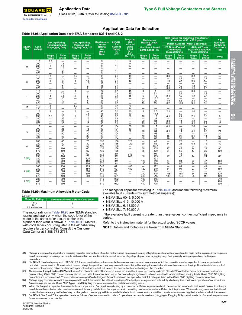
© 2017 Schneider ElectricAll Rights Reserved
16-37
schneider-electric.us
Application Data Type S Full Voltage Contactors and StartersClass 8502, 8536 / Refer to Catalog 8502CT9701
Application Data for SelectionTable 16.98: Application Data per NEMA Standards ICS-1 and ICS-2
NEMASize
LoadVoltage
Max. Hp Rating:Nonplugging andNonjogging Duty
Max. Hp Rating:Plugging and
Jogging Duty [31]
ContinuousCurrentRating(A)
600 VMax.
Service-Limit
CurrentRating(A)[32]
Tungstenand
InfraredLampLoad(A),250 V
Max. [33]
ResistanceHeating Loads
(KW)other than InfraredLamp Loads [34]
KVA Rating for Switching TransformerPrimaries at 50 or 60 Cycles 3 Ø
Rating forSwitchingCapacitors
[35]
Inrush Currents (Worst Case Peak)≤20 Times Peak of
ContinuousCurrent Rating
>20 to 40 TimesPeak of Continuous
Current RatingSinglePhase
Poly-phase
SinglePhase
Poly-phase
SinglePhase
Poly-phase
SinglePhase
Poly-phase
SinglePhase
Poly-phase KVAR
00
115200230380460575
0.5—1———
—1.51.51.522
——————
——————
999999
111111111111
555———
——————
——————
——————
——————
——————
——————
——————
0
115200230380460575
1—2———
—33555
0.5—1———
—1.51.51.522
181818181818
212121212121
101010———
——————
——————
0.6—1.2—2.43.0
—1.82.1—4.25.2
0.3—0.6—1.21.5
—0.91.0—2.12.6
——————
1
115200230380460575
2—3———
—7.57.5101010
1—2———
—33555
272727272727
323232323232
151515———
3—6—1215
59.11016.52025
1.2—2.4—4.96.2
—3.64.3—8.511.0
0.6—1.2—2.53.1
—1.82.1—4.35.3
——————
1P 115230
35
——
1.53
——
3636
4242
2424
——
——
——
——
——
——
——
2
115200230380460575
3—7.5———
—1015252525
2—5———
—7.510151515
454545454545
525252525252
303030———
5—10—2025
8.515.417283443
2.1—4.1—8.310.0
—6.37.2—1418
1.0—2.1—4.25.2
—3.13.6—7.28.9
——8—1620
3
115200230380460575
——————
—2530505050
——————
—1520303030
909090909090
104104104104104104
606060———
10—20—4050
173134566886
4.1—8.1—1620
—1214—2835
2.0—4.1—8.110
—6.17.0—1418
——27—5367
4
200230380460575
—————
405075100100
—————
2530506060
135135135135135
156156156156156
120120———
—30—6075
455286.7105130
—14—2734
2023—4759
—6.8—1417
1012—2329
—40—80100
5 [36]
200230380460575
—————
75100150200200
—————
6075125150150
270270270270270
311311311311311
240240———
—60—120150
91105173210260
—27—5468
4147—94117
—14—2734
2024—4759
—80—160200
6 [36]
200230380460575
—————
150200300400400
—————
125150250300300
540540540540540
621621621621621
480480———
—120—240300
182210342415515
—54—108135
8194—188234
—27—5468
4147—94117
—160—320400
7 [36]230460575
———
300600600
———
———
810810810
932932932
———
180360450
315625775
———
———
———
———
240480600
Table 16.99: Maximum Allowable Motor CodeLetter
Motor Hp Rating Maximum Allowable Motor Code Letter1.5–23–5
7.5 and above
LKH
The motor ratings in Table 16.98 are NEMA standardratings and apply only when the code letter of themotor is the same as or occurs earlier in thealphabet than what is shown in Table 16.99. Motorswith code letters occurring later in the alphabet mayrequire a larger controller. Consult the CustomerCare Center at 1-888-778-2733.
The ratings for capacitor switching in Table 16.98 assume the following maximumavailable fault currents (rms symmetrical amperes):• NEMA Size 00–3: 5,000 A• NEMA Size 4–5: 10,000 A• NEMA Size 6: 18,000 A• NEMA Size 7: 30,000 AIf the available fault current is greater than these values, connect sufficient impedance inseries.Refer to the instruction material for the actual tested SCCR values.NOTE: Tables and footnotes are taken from NEMA Standards.
16NEMAANDDEFINITEPURPOSE
CONTA
CTORSANDSTA
RTERS
[31] Ratings shown are for applications requiring repeated interruptions of stalled motor current or repeated closing of high transient currents encountered in rapid motor reversal, involving morethan five openings or closings per minute and more than ten in a ten-minute period, such as plug-stop, plug-reverse or jogging duty. Ratings apply to single speed and multi-speedcontrollers.
[32] Per NEMA Standards paragraph ICS 2-321.20, the service-limit current represents the maximum rms current, in Amperes, which the controller may be expected to carry for protractedperiods in normal service. At service-limit current ratings, temperature rises may exceed those obtained by testing the controller at its continuous current rating. The ultimate trip current ofover-current (overload) relays or other motor protective devices shall not exceed the service-limit current ratings of the controller.
[33] Fluorescent Lamp Loads—300 V and Less—The characteristics of fluorescent lamps are such that it is not necessary to derate Class 8502 contactors below their normal continuouscurrent rating. Class 8903 contactors may also be used with fluorescent lamp loads. For controlling tungsten and infrared lamp loads, and resistance heating loads, Class 8903 AC lightingcontactors are recommended. These contactors are specifically designed for such loads and are applied at their full rating as listed in the Class 8903 (lighting contactors) section.
[34] Ratings apply to contactors which are employed to switch the load at the utilization voltage of the heat producing element with a duty which requires continuous operation of not more thanfive openings per minute. Class 8903 Types L and S lighting contactors are rated for resistance heating loads.
[35] When discharged, a capacitor has essentially zero impedance. For repetitive switching by a contactor, sufficient impedance should be connected in series to limit inrush current to not morethan 6 times the contactor rated continuous current. In many installations, the impedance of connecting conductors may be sufficient for this purpose. When switching to connect additionalbanks, the banks already on the line may be charged and can supply additional available short-circuit current which should be considered when selecting the impedance to limit the current.
[36] For NEMA Size 6 and 7, the operation rate is as follows: Continuous operation rate is 3 operations per minute maximum; Jogging or Plugging Duty operation rate is 15 operations per minutefor a maximum of three minutes.
6/20/2017
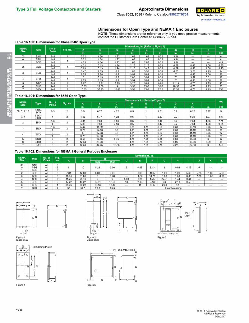
16-38 © 2017 Schneider ElectricAll Rights Reserved
Type S Full Voltage Contactors and Starters Approximate Dimensions
schneider-electric.us
Class 8502, 8536 / Refer to Catalog 8502CT9701
Dimensions for Open Type and NEMA 1 EnclosuresNOTE: These dimensions are for reference only. If you need precise measurements,contact the Customer Care Center at 1-888-778-2733.
Table 16.100: Dimensions for Class 8502 Open Type
NEMASize Type No. of
Poles Fig. No.Dimensions, in. (Refer to Figure 1)
WtA B C D E F G H Iin. in. in. in. in. in. in. in. in. (lb)
00 SAO 2–3 1 3.22 4.34 4.22 1.63 1.63 0.22 3.94 — — 40 SBO 1–3 1 3.22 4.34 4.22 1.63 1.63 0.22 3.94 — — 41 SCO 4–5 4.25 4.34 4.22 1.63 2.63 0.22 3.94 — — 4.5
2 SDO 2–3 1 4.31 5.13 4.94 2.16 2.16 0.22 4.59 0.53 1.06 6.754–5 5.63 5.13 4.94 2.16 3.47 0.22 4.59 0.53 1.06 8.25
3 SEO 2–3 1 5.47 7.09 6.5 1.88 3.53 0.31 6.03 3.25 4.75 144–5 9.75 7.88 6.5 3.94 5.81 0.31 7 4.53 9.06 22
4 SFO 2–3 1 6 8.19 6.5 2.06 3.94 0.31 7 3.59 5.31 184–5 9.75 8.19 6.5 3.94 5.81 0.31 7 4.53 9.06 22
5 SGO 2–3 1 8.67 12.31 8.75 3.25 5.81 0.63 11.13 4.75 7.25 456 SHO 2–3 1 10.55 28.06 9 3.53 7.03 5.06 18.56 4.75 7.25 807 SJO 2–3 1 10.55 37.25 10.88 3.53 7.03 7.22 22.38 4.75 7.25 135
Table 16.101: Dimensions for 8536 Open Type
NEMASize Type No. of
Poles Fig. No.Dimensions, in. (Refer to Figure 2)
WtA B C D E F G H Iin. in. in. in. in. in. in. in. in. (lb)
00, 0, 1, 1P SAO–SCO 2–3 2 3.5 6.77 4.22 0.5 1 1.61 0.2 6.25 3.97 5
0, 1 SBO–SCO 4 2 4.53 6.77 4.22 0.5 1 2.67 0.2 6.25 3.97 5.5
2 SDO 2–3 2 4.31 7.81 4.94 0.5 1 2.16 0.2 7.34 4.06 7.754 5.63 7.81 4.94 0.5 1 3.47 0.2 7.34 4.06 9.25
3 SEO 2–3 2 5.47 11.09 6.5 0.88 1.75 3.59 0.31 10.19 5.75 174 9.75 12.13 6.5 1.81 1.75 5.81 0.31 11.19 5.75 25
4 SFO 3 2 6 12.88 6.5 1.81 1.75 3.94 0.31 11.19 5.75 224 9.75 12.88 6.5 1.81 1.75 5.91 0.31 11.19 5.75 25
5 SGO 3 2 8.56 17.56 8.75 4.75 7.25 5.38 0.63 16.38 6 626 SHO 3 2 12.34 28.06 9 4.75 7.25 5.78 5.06 18.56 8.69 857 SJO 3 2 12.34 37.25 10.88 4.75 7.25 5.78 7.22 22.38 9 140
Table 16.102: Dimensions for NEMA 1 General Purpose Enclosure
NEMASize Type No. of
PolesFig.No.
Dimensions, in.
A B C D E F G H I J K L8502 85360001
SAGSBGSCG
AllAllAll
333
6 10 5.28 5.56 3 0.88 8.13 1 0.94 4.13 5 — —
2 SDG All 3 7.81 12.69 6.03 6.31 — 1.09 10.5 1.09 1.09 5.63 5.75 1.09 5.633 SEG All 3 11.44 21.81 8 8.38 — 1.53 18.75 1.53 1.53 8.38 7.75 1.53 8.384 SFG All 5 11.25 25.16 9 9 8.59 1.25 1.25 22.31 1.44 0.44 — — —5 SGG All 5 17.22 44.22 12.81 12.94 13 2.13 2.13 40 2.13 0.56 — — —6 SHG All 4 65.75 20.22 13.13 13.13 — 11 64.5 2.31 5.5 — — — —7 SJG All 4 93 34.5 23.5 23.5 Floor Mounting
A
B
C
IH
E F
G
D
A
B
C
ED
F G
H
I
RESET
K KD
A
L E
F B
RESET
CJ
PilotLight
GHH I
Figure 1Class 8502
Figure 2Class 8536
Figure 3
H
BE (3) Closing Plates
G
A
F
C
RESET
A(4) I Dia. Mtg. Holes
B
H
HCFDE
G
Figure 4 Figure 5
16NEMAANDDEFINITEPURPOSE
CONTA
CTORSANDSTA
RTERS
6/20/2017
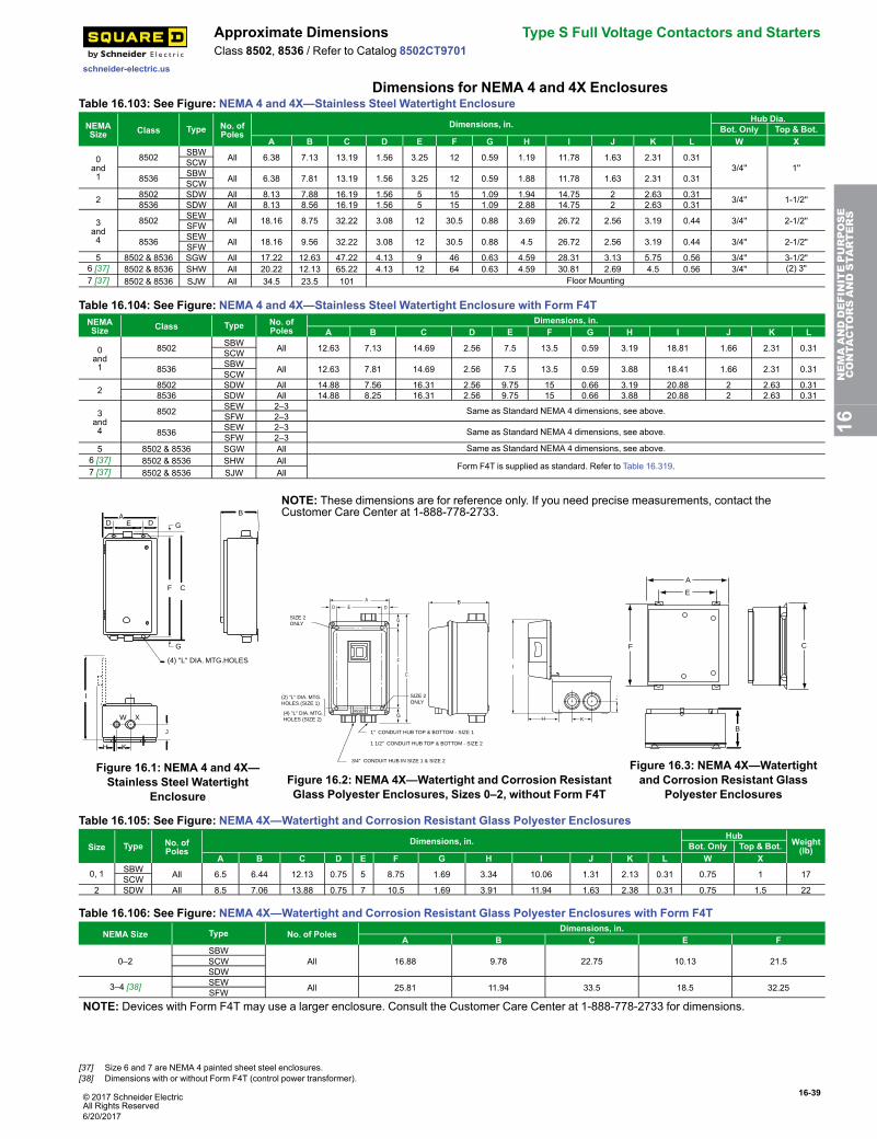
© 2017 Schneider ElectricAll Rights Reserved
16-39
schneider-electric.us
Approximate Dimensions Type S Full Voltage Contactors and StartersClass 8502, 8536 / Refer to Catalog 8502CT9701
Dimensions for NEMA 4 and 4X EnclosuresTable 16.103: See Figure: NEMA 4 and 4X—Stainless Steel Watertight Enclosure
NEMASize Class Type No. of
PolesDimensions, in. Hub Dia.
Bot. Only Top & Bot.A B C D E F G H I J K L W X
0and1
8502 SBW All 6.38 7.13 13.19 1.56 3.25 12 0.59 1.19 11.78 1.63 2.31 0.313/4'' 1''SCW
8536 SBW All 6.38 7.81 13.19 1.56 3.25 12 0.59 1.88 11.78 1.63 2.31 0.31SCW
2 8502 SDW All 8.13 7.88 16.19 1.56 5 15 1.09 1.94 14.75 2 2.63 0.31 3/4'' 1-1/2''8536 SDW All 8.13 8.56 16.19 1.56 5 15 1.09 2.88 14.75 2 2.63 0.31
3and4
8502 SEW All 18.16 8.75 32.22 3.08 12 30.5 0.88 3.69 26.72 2.56 3.19 0.44 3/4'' 2-1/2''SFW
8536 SEW All 18.16 9.56 32.22 3.08 12 30.5 0.88 4.5 26.72 2.56 3.19 0.44 3/4" 2-1/2"SFW5 8502 & 8536 SGW All 17.22 12.63 47.22 4.13 9 46 0.63 4.59 28.31 3.13 5.75 0.56 3/4" 3-1/2"
6 [37] 8502 & 8536 SHW All 20.22 12.13 65.22 4.13 12 64 0.63 4.59 30.81 2.69 4.5 0.56 3/4" (2) 3"7 [37] 8502 & 8536 SJW All 34.5 23.5 101 Floor Mounting
Table 16.104: See Figure: NEMA 4 and 4X—Stainless Steel Watertight Enclosure with Form F4TNEMASize Class Type No. of
PolesDimensions, in.
A B C D E F G H I J K L
0and1
8502 SBW All 12.63 7.13 14.69 2.56 7.5 13.5 0.59 3.19 18.81 1.66 2.31 0.31SCW
8536 SBW All 12.63 7.81 14.69 2.56 7.5 13.5 0.59 3.88 18.41 1.66 2.31 0.31SCW
2 8502 SDW All 14.88 7.56 16.31 2.56 9.75 15 0.66 3.19 20.88 2 2.63 0.318536 SDW All 14.88 8.25 16.31 2.56 9.75 15 0.66 3.88 20.88 2 2.63 0.31
3and4
8502 SEW 2–3 Same as Standard NEMA 4 dimensions, see above.SFW 2–3
8536 SEW 2–3 Same as Standard NEMA 4 dimensions, see above.SFW 2–3
5 8502 & 8536 SGW All Same as Standard NEMA 4 dimensions, see above.6 [37] 8502 & 8536 SHW All Form F4T is supplied as standard. Refer to Table 16.319.7 [37] 8502 & 8536 SJW All
B
C
EA
(4) "L" DIA. MTG.HOLES
I
W X
H
DD
K
J
F
G
G
Figure 16.1: NEMA 4 and 4X—Stainless Steel Watertight
Enclosure
NOTE: These dimensions are for reference only. If you need precise measurements, contact theCustomer Care Center at 1-888-778-2733.
RESET
AD E D
G
F
C
SIZE 2 ONLY
(2) "L" DIA. MTG. HOLES (SIZE 1)
(4) "L" DIA. MTG. HOLES (SIZE 2)
G
SIZE 2ONLY
1" CONDUIT HUB TOP & BOTTOM - SIZE 1 1 1/2" CONDUIT HUB TOP & BOTTOM - SIZE 2
B
3/4" CONDUIT HUB IN SIZE 1 & SIZE 2
H K
J
I
Figure 16.2: NEMA 4X—Watertight and Corrosion ResistantGlass Polyester Enclosures, Sizes 0–2, without Form F4T
A
E
F C
B
Figure 16.3: NEMA 4X—Watertightand Corrosion Resistant Glass
Polyester Enclosures
Table 16.105: See Figure: NEMA 4X—Watertight and Corrosion Resistant Glass Polyester Enclosures
Size Type No. ofPoles
Dimensions, in. HubWeight(lb)Bot. Only Top & Bot.
A B C D E F G H I J K L W X
0, 1 SBW All 6.5 6.44 12.13 0.75 5 8.75 1.69 3.34 10.06 1.31 2.13 0.31 0.75 1 17SCW2 SDW All 8.5 7.06 13.88 0.75 7 10.5 1.69 3.91 11.94 1.63 2.38 0.31 0.75 1.5 22
Table 16.106: See Figure: NEMA 4X—Watertight and Corrosion Resistant Glass Polyester Enclosures with Form F4T
NEMA Size Type No. of Poles Dimensions, in.A B C E F
0–2SBW
All 16.88 9.78 22.75 10.13 21.5SCWSDW
3–4 [38] SEW All 25.81 11.94 33.5 18.5 32.25SFWNOTE: Devices with Form F4T may use a larger enclosure. Consult the Customer Care Center at 1-888-778-2733 for dimensions.
16NEMAANDDEFINITEPURPOSE
CONTA
CTORSANDSTA
RTERS
[37] Size 6 and 7 are NEMA 4 painted sheet steel enclosures.[38] Dimensions with or without Form F4T (control power transformer).
6/20/2017
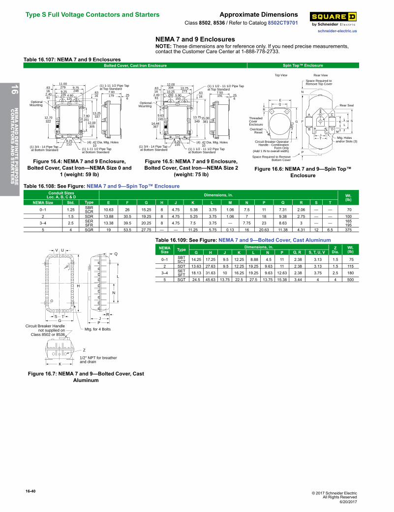
16-40 © 2017 Schneider ElectricAll Rights Reserved
Type S Full Voltage Contactors and Starters Approximate Dimensions
schneider-electric.us
Class 8502, 8536 / Refer to Catalog 8502CT9701
NEMA 7 and 9 EnclosuresNOTE: These dimensions are for reference only. If you need precise measurements,contact the Customer Care Center at 1-888-778-2733.
Table 16.107: NEMA 7 and 9 EnclosuresBolted Cover, Cast Iron Enclosure Spin Top™ Enclosure
(4) .42 Dia. Mtg. Holes
.6316
11.00279 9.75
2489.252352.40
614.90125
.6316
OptionalMounting
(1) 1-11 1/2 Pipe Tapat Top Standard
(1) 1-11 1/2 Pipe Tapat Bottom Standard
(1) 3/4 - 14 Pipe Tapat Bottom Standard
12.00305
7.90201
13.25337
10
8.25210
12.70322
7.00.256
179
Figure 16.4: NEMA 7 and 9 Enclosure,Bolted Cover, Cast Iron—NEMA Size 0 and
1 (weight: 59 lb)
(4) .42 Dia. Mtg. Holes
.6316
12.00304 10.75
27310.252602.40
615.90150
.6316
OptionalMounting
(1) 1 1/2 - 11 1/2 Pipe Tapat Top Standard
(1) 1 1/2 - 11 1/2 Pipe Tapat Bottom Standard
(1) 3/4 - 14 Pipe Tapat Bottom Standard
13.75349
15.00381
109.25235
14.44367
9.63245
7.50.256
191
Figure 16.5: NEMA 7 and 9 Enclosure,Bolted Cover, Cast Iron—NEMA Size 2
(weight: 75 lb)
N
A
B D
C
J
P
F
M
K H
Mtg. Holesand/or Slots (3)
Rear View
Space Required to RemoveBottom Cover
Space Required toRemove Top Cover
OverloadReset
ThreadedCoverEnclosure
EQ
R
G
Top View
T
L
Rear Seal
S
Circuit Breaker OperatorHandle - Combination
Form Only(Add 1 IN to overall width)
Figure 16.6: NEMA 7 and 9—Spin Top™Enclosure
Table 16.108: See Figure: NEMA 7 and 9—Spin Top™ EnclosureConduit SizesLoc. A, B, C & D Dimensions, in. Wt.
(lb)NEMA Size Std. Type E F G H J K L M N P Q R S T
0–1 1.25 SBRSCR 10.63 26 15.25 8 4.75 5.38 3.75 1.06 7.5 11 7.31 2.06 — — 70
2 1.5 SDR 13.88 30.5 19.25 8 4.75 5.25 3.75 1.06 7 18 9.38 2.75 — — 100
3–4 2.5 SERSFR 13.38 39.5 20.25 8 4.75 7.5 3.75 — 7.75 23 8.63 3 — — 165
1955 4 SGR 19 53.5 27.75 — — 11.25 5.75 0.13 16 20.63 11.38 4.31 12 6.5 375
S TG
K
V U
H
Mtg. for 4 Bolts
J
Z
P
N
L
1/2" NPT for breatherand drain
R
Q
Circuit Breaker Handlenot supplied on
Class 8502 or 8536
Figure 16.7: NEMA 7 and 9—Bolted Cover, CastAluminum
Table 16.109: See Figure: NEMA 7 and 9—Bolted Cover, Cast AluminumNEMASize Type Dimensions, in. Z
Dia.Wt.(lb)G H J K L N P Q, R S, T, U, V
0–1 SBTSCT 14.25 17.25 9.5 12.25 8.88 4.5 11 2.38 3.13 1.5 75
2 SDT 13.63 27.63 9.5 12.25 19.25 9.63 11 2.38 3.13 1.5 115
3–4 SETSFT 18.13 31.63 10 16.25 19.25 9.63 12.63 2.38 3.75 2.5 180
5 SGT 24.5 45.63 13.75 22.5 27.5 13.75 15.38 3.44 4 4 500
16NEMAANDDEFINITEPURPOSE
CONTA
CTORSANDSTA
RTERS
6/20/2017
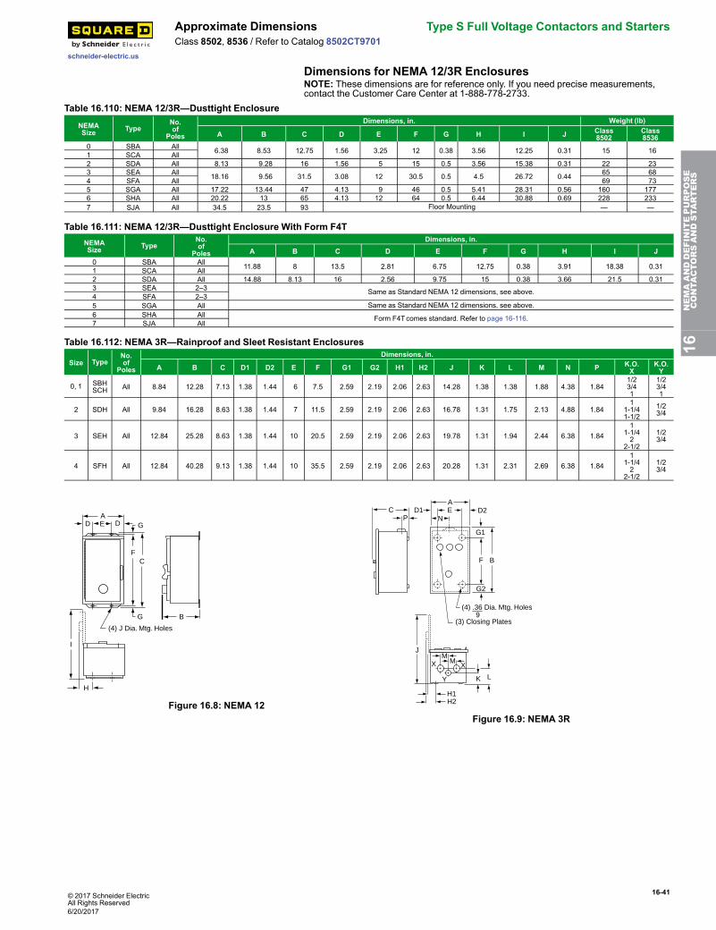
© 2017 Schneider ElectricAll Rights Reserved
16-41
schneider-electric.us
Approximate Dimensions Type S Full Voltage Contactors and StartersClass 8502, 8536 / Refer to Catalog 8502CT9701
Dimensions for NEMA 12/3R EnclosuresNOTE: These dimensions are for reference only. If you need precise measurements,contact the Customer Care Center at 1-888-778-2733.
Table 16.110: NEMA 12/3R—Dusttight Enclosure
NEMASize Type
No.of
Poles
Dimensions, in. Weight (lb)
A B C D E F G H I J Class8502
Class8536
0 SBA All 6.38 8.53 12.75 1.56 3.25 12 0.38 3.56 12.25 0.31 15 161 SCA All2 SDA All 8.13 9.28 16 1.56 5 15 0.5 3.56 15.38 0.31 22 233 SEA All 18.16 9.56 31.5 3.08 12 30.5 0.5 4.5 26.72 0.44 65 684 SFA All 69 735 SGA All 17.22 13.44 47 4.13 9 46 0.5 5.41 28.31 0.56 160 1776 SHA All 20.22 13 65 4.13 12 64 0.5 6.44 30.88 0.69 228 2337 SJA All 34.5 23.5 93 Floor Mounting — —
Table 16.111: NEMA 12/3R—Dusttight Enclosure With Form F4TNEMASize Type
No.of
Poles
Dimensions, in.A B C D E F G H I J
0 SBA All 11.88 8 13.5 2.81 6.75 12.75 0.38 3.91 18.38 0.311 SCA All2 SDA All 14.88 8.13 16 2.56 9.75 15 0.38 3.66 21.5 0.313 SEA 2–3 Same as Standard NEMA 12 dimensions, see above.4 SFA 2–35 SGA All Same as Standard NEMA 12 dimensions, see above.6 SHA All Form F4Tcomes standard. Refer to page 16-116.7 SJA All
Table 16.112: NEMA 3R—Rainproof and Sleet Resistant Enclosures
Size TypeNo.of
Poles
Dimensions, in.
A B C D1 D2 E F G1 G2 H1 H2 J K L M N P K.O.X
K.O.Y
0, 1 SBHSCH All 8.84 12.28 7.13 1.38 1.44 6 7.5 2.59 2.19 2.06 2.63 14.28 1.38 1.38 1.88 4.38 1.84
1/23/41
1/23/41
2 SDH All 9.84 16.28 8.63 1.38 1.44 7 11.5 2.59 2.19 2.06 2.63 16.78 1.31 1.75 2.13 4.88 1.841
1-1/41-1/2
1/23/4
3 SEH All 12.84 25.28 8.63 1.38 1.44 10 20.5 2.59 2.19 2.06 2.63 19.78 1.31 1.94 2.44 6.38 1.841
1-1/42
2-1/2
1/23/4
4 SFH All 12.84 40.28 9.13 1.38 1.44 10 35.5 2.59 2.19 2.06 2.63 20.28 1.31 2.31 2.69 6.38 1.841
1-1/42
2-1/2
1/23/4
DAE G
F
BG
D
(4) J Dia. Mtg. Holes
I
H
C
Figure 16.8: NEMA 12
AD1 E D2
N
G1
F B
G2
(4) .36 Dia. Mtg. Holes9
(3) Closing Plates
CP
J
X XM
M
Y K L
H1H2
Figure 16.9: NEMA 3R
16NEMAANDDEFINITEPURPOSE
CONTA
CTORSANDSTA
RTERS
6/20/2017
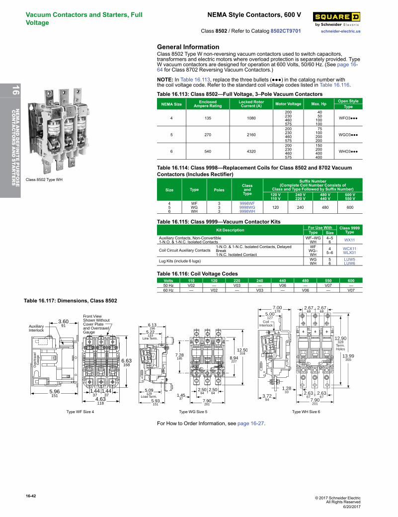
16-42 © 2017 Schneider ElectricAll Rights Reserved
Vacuum Contactors and Starters, FullVoltage
NEMA Style Contactors, 600 V
schneider-electric.usClass 8502 / Refer to Catalog 8502CT9701
General InformationClass 8502 Type W non-reversing vacuum contactors used to switch capacitors,transformers and electric motors where overload protection is separately provided. TypeW vacuum contactors are designed for operation at 600 Volts, 50/60 Hz. (See page 16-64 for Class 8702 Reversing Vacuum Contactors.)
Class 8502 Type WH
NOTE: In Table 16.113, replace the three bullets (●●●) in the catalog number withthe coil voltage code. Refer to the standard coil voltage codes listed in Table 16.116.
Table 16.113: Class 8502—Full Voltage, 3–Pole Vacuum Contactors
NEMA Size EnclosedAmpere Rating
Locked RotorCurrent (A) Motor Voltage Max. Hp
Open StyleType
4 135 1080200230460575
4050100100
WFO3●●●
5 270 2160200230460575
75100200200
WGO3●●●
6 540 4320200230460575
150200400400
WHO3●●●
Table 16.114: Class 9998—Replacement Coils for Class 8502 and 8702 VacuumContactors (Includes Rectifier)
Size Type PolesClassandType
Suffix Number(Complete Coil Number Consists of
Class and Type Followed by Suffix Number)120 V110 V
240 V220 V
480 V440 V
600 V550 V
456
WFWGWH
333
9998WF9998WG9998WH
120 240 480 600
Table 16.115: Class 9999—Vacuum Contactor KitsKit Description For Use With Class 9999
TypeType SizeAuxiliary Contacts, Non-Convertible1-N.O. & 1-N.C. Isolated Contacts
WF–WGWH
4–56 WX11
Coil Circuit Auxiliary Contacts1-N.O. & 1-N.C. Isolated Contacts, DelayedBreak1-N.C. Isolated Contact
WFWG–WH
45–6
WCX11WLX01
Lug Kits (include 6 lugs) WGWH
56
LUW5LUW6
Table 16.116: Coil Voltage CodesVolts 110 120 220 240 440 480 550 60050 Hz V02 — V03 — V06 — V07 —60 Hz — V02 — V03 — V06 — V07
Table 16.117: Dimensions, Class 8502
4.63118
6.63168
3.6091
1.4437
1.4437
5.96151
Front ViewShown WithoutCover Plateand OvertravelGauge
AuxiliaryInterlock
Ove
rtra
vel
Gau
ge
6.13156
5.22133
Line Term.
5.93151
5.09129
Load Term. 1.4537
7.28185 8.94
227
7.90201
2.5064
2.5064
12.50318
3.7294
7.00178
5.00127
7.90201
2.6367
2.6367
2.6768
2.6768
12.90328
Term.Holes
13.99355
1.2833
CoilInterlock
Type WF Size 4 Type WG Size 5 Type WH Size 6
For How to Order Information, see page 16-27.
6/20/2017
16NEMAANDDEFINITEPURPOSE
CONTA
CTORSANDSTA
RTERS
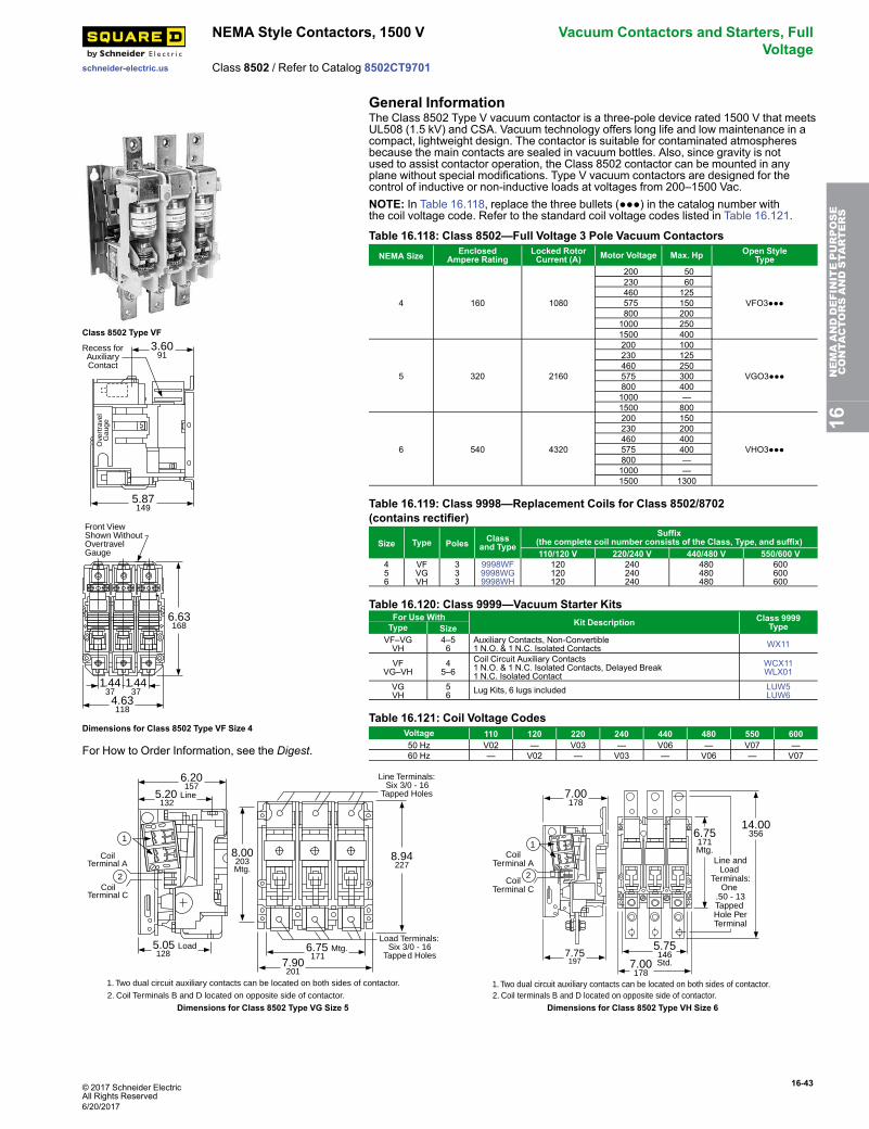
© 2017 Schneider ElectricAll Rights Reserved
16-43
schneider-electric.us
NEMA Style Contactors, 1500 V Vacuum Contactors and Starters, FullVoltage
Class 8502 / Refer to Catalog 8502CT9701
General Information
Class 8502 Type VF3.60
91
5.87149
Recess forAuxiliaryContact
Ove
rtra
vel
Gau
ge
4.63118
6.63168
1.4437
1.4437
Front ViewShown WithoutOvertravelGauge
Dimensions for Class 8502 Type VF Size 4
For How to Order Information, see the Digest.
The Class 8502 Type V vacuum contactor is a three-pole device rated 1500 V that meetsUL508 (1.5 kV) and CSA. Vacuum technology offers long life and low maintenance in acompact, lightweight design. The contactor is suitable for contaminated atmospheresbecause the main contacts are sealed in vacuum bottles. Also, since gravity is notused to assist contactor operation, the Class 8502 contactor can be mounted in anyplane without special modifications. Type V vacuum contactors are designed for thecontrol of inductive or non-inductive loads at voltages from 200–1500 Vac.NOTE: In Table 16.118, replace the three bullets (●●●) in the catalog number withthe coil voltage code. Refer to the standard coil voltage codes listed in Table 16.121.
Table 16.118: Class 8502—Full Voltage 3 Pole Vacuum ContactorsNEMA Size Enclosed
Ampere RatingLocked RotorCurrent (A) Motor Voltage Max. Hp Open Style
Type
4 160 1080
200 50
VFO3●●●
230 60 460 125 575 150 800 2001000 2501500 400
5 320 2160
200 100
VGO3●●●
230 125460 250575 300800 4001000 —1500 800
6 540 4320
200 150
VHO3●●●
230 200460 400575 400800 —1000 —1500 1300
Table 16.119: Class 9998—Replacement Coils for Class 8502/8702(contains rectifier)
Size Type Poles Classand Type
Suffix(the complete coil number consists of the Class, Type, and suffix)110/120 V 220/240 V 440/480 V 550/600 V
456
VFVGVH
333
9998WF9998WG9998WH
120120120
240240240
480480480
600600600
Table 16.120: Class 9999—Vacuum Starter KitsFor Use With Kit Description Class 9999
TypeType SizeVF–VGVH
4–56
Auxiliary Contacts, Non-Convertible1 N.O. & 1 N.C. Isolated Contacts WX11
VFVG–VH
45–6
Coil Circuit Auxiliary Contacts1 N.O. & 1 N.C. Isolated Contacts, Delayed Break1 N.C. Isolated Contact
WCX11WLX01
VGVH
56 Lug Kits, 6 lugs included LUW5
LUW6
Table 16.121: Coil Voltage CodesVoltage 110 120 220 240 440 480 550 60050 Hz V02 — V03 — V06 — V07 —60 Hz — V02 — V03 — V06 — V07
8.94227
8.00203Mtg.
6.75 Mtg. 171
6.20157
5.20 Line 132
5.05 Load 128
7.90201
Line Terminals:Six 3/0 - 16
Tapped Holes
Load Terminals:Six 3/0 - 16
Tapped Holes
1
1. Two dual circuit auxiliary contacts can be located on both sides of contactor.
2. Coil Terminals B and D located on opposite side of contactor.
2
CoilTerminal A
CoilTerminal C
7.75197
7.00178
7.00178
5.75146Std.
6.75171Mtg.
14.00356
Line andLoad
Terminals:One
.50 - 13Tapped Hole PerTerminal
1
2
CoilTerminal A
CoilTerminal C
1. Two dual circuit auxiliary contacts can be located on both sides of contactor.2. Coil terminals B and D located on opposite side of contactor.
Dimensions for Class 8502 Type VG Size 5 Dimensions for Class 8502 Type VH Size 6
16NEMAANDDEFINITEPURPOSE
CONTA
CTORSANDSTA
RTERS
6/20/2017
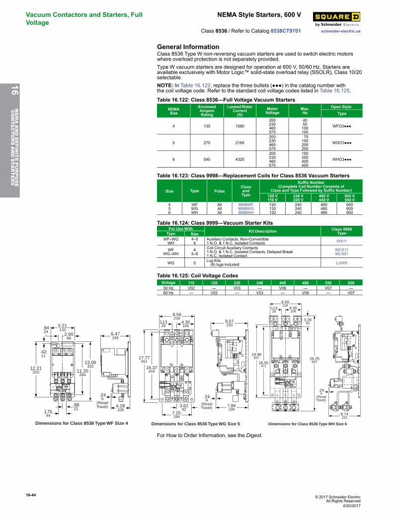
16-44 © 2017 Schneider ElectricAll Rights Reserved
Vacuum Contactors and Starters, FullVoltage
NEMA Style Starters, 600 V
schneider-electric.usClass 8536 / Refer to Catalog 8538CT9701
General InformationClass 8536 Type W non-reversing vacuum starters are used to switch electric motorswhere overload protection is not separately provided.Type W vacuum starters are designed for operation at 600 V, 50/60 Hz. Starters areavailable exclusively with Motor Logic™ solid-state overload relay (SSOLR), Class 10/20selectable.NOTE: In Table 16.122, replace the three bullets (●●●) in the catalog number withthe coil voltage code. Refer to the standard coil voltage codes listed in Table 16.125.
Table 16.122: Class 8536—Full Voltage Vacuum StartersNEMASize
EnclosedAmpereRating
Locked RotorCurrent(A)
MotorVoltage
Max.Hp
Open StyleType
4 135 1080200230460575
4050100100
WFO3●●●
5 270 2160200230460575
75100200200
WGO3●●●
6 540 4320200230460575
150200400400
WHO3●●●
Table 16.123: Class 9998—Replacement Coils for Class 8536 Vacuum Starters
Size Type PolesClassandType
Suffix Number(Complete Coil Number Consists of
Class and Type Followed by Suffix Number)120 V110 V
240 V220 V
480 V440 V
600 V550 V
456
WFWGWH
AllAllAll
9998WF9998WG9998WH
120120120
240240240
480480480
600600600
Table 16.124: Class 9999—Vacuum Starter KitsFor Use With Kit Description Class 9999
TypeType SizeWF–WGWH
4–56
Auxiliary Contacts, Non-Convertible1 N.O. & 1 N.C. Isolated Contacts WX11
WFWG–WH
45–6
Coil Circuit Auxiliary Contacts1 N.O. & 1 N.C. Isolated Contacts, Delayed Break1 N.C. Isolated Contact
WCX11WLX01
WG 5 Lug Kits(6) lugs included LUW5
Table 16.125: Coil Voltage CodesVoltage 110 120 220 240 440 480 550 60050 Hz V02 — V03 — V06 — V07 —60 Hz — V02 — V03 — V06 — V07
11.20284
12.21310
.8822
1.7544
13.06332
2.6066
6.47164
4.28109
.246
(ResetTravel)
.9424
.4211
5.21132
Reset
Dimensions for Class 8536 Type WF Size 4
16.37416
17.77451
3.6292
7.25184
4.30109
9.07230
7.84199
.246
(ResetTravel)
1.1329
8.59218
Dimensions for Class 8536 Type WG Size 5
Reset
26.25667
3.2883
18.56471
4.30109
1.1329
8.74222
.246
(ResetTravel)
8.59218
Dimensions for Class 8536 Type WH Size 6
19.96507
For How to Order Information, see the Digest.
16NEMAANDDEFINITEPURPOSE
CONTA
CTORSANDSTA
RTERS
6/20/2017

© 2017 Schneider ElectricAll Rights Reserved
16-45
schneider-electric.us
Non-Reversing Type S Combination StartersClass 8538 / Refer to Catalog 8538CT9701
Fusible Disconnect Switch Type3-Pole Polyphase—600 Vac Maximum—50–60 HzClass 8538 and 8539 Type S combination starters combine the requirements of motoroverload and short circuit protection into one package. These starters are manufacturedaccording to NEMA standards and are UL Listed (some Form numbers may not be listed—contact the Customer Care Center). Class 8538 and 8539 combination startersoperate at 600 Vac maximum, 50–60 Hz, and can be provided with one of fouroverloaded relay styles (refer to page 16-32).
Table 16.126: Class 8538 Fusible Full Voltage Type (Class H Fuse Clips), with Motor Logic SSOLR (replace ●●● with the voltage code)
RatingsFuseClipSize(A)
NEMA 1General PurposeEnclosure
NEMA 4 & 4XWatertight andDusttightEnclosureStainless Steel(304)(Sizes 0-5)[1]
NEMA 4XWatertight,Dusttight andCorrosionResistant PolyesterEnclosure
NEMA 12/3R[2]Dusttight and DriptightIndustrial Use Enclosure
MotorVoltage(StarterVoltage)
Max. HpPolyphase
NEMASize
WithExternal Reset
WithoutExternal Reset
Type [3] Type [3] Type [3] Type [3] Type [3]
200(208)
3 0 30 SBG12●●●H30 [4] SBW12●●●H30 [4] SBW22●●●H30 [4] SBA22●●●H30 [4] SBA12●●●H30 [4]
Schneider Electric offersexpress shipping for factorymodified NEMA ComboStarters. When you need themfast, our Laser™ Deliveryprogram is the answer togetting your product when youneed it most. Ask for Laser™Delivery, then select theproduct and the modificationsyou need when you place yourorder. It’s as easy as that!
51
30 SCG12●●●H30 [4] SCW12●●●H30 [4] SCW22●●●H30 [4] SCA22●●●H30 [4] SCA12●●●H30 [4]7-1/2 60 SCG13●●●H30 [4] SCW13●●●H30 [4] SCW23●●●H30 [4] SCA23●●●H30 [4] SCA13●●●H30 [4]10 2 60 SDG12●●●H30 [4] SDW12●●●H30 [4] SDW22●●●H30 [4] SDA22●●●H30 [4] SDA12●●●H30 [4]20 3 100 SEG15●●●H30 SEW15●●●H30 SEW25●●●H30 SEA25●●●H30 SEA15●●●H3025 200 SEG12●●●H30 SEW12●●●H30 — SEA22●●●H30 SEA12●●●H3040 4 200 SFG15●●●H30 SFW15●●●H30 — SFA25●●●H30 SFA15●●●H3075 5 400 SGG15●●●H30 SGW15●●●H30 — SGA25●●●H30 SGA15●●●H30150 6 600 SHG13●●●H30 SHW13●●●H30 — SHA23●●●H30 SHA13●●●H30
230(240)
3 0 30 SBG12●●●H30 [4] SBW12●●●H30 [4] SBW22●●●H30 [4] SBA22●●●H30 [4] SBA12●●●H30 [4]5
130 SCG12●●●H30 [4] SCW12●●●H30 [4] SCW22●●●H30 [4] SCA22●●●H30 [4] SCA12●●●H30 [4]
7-1/2 60 SCG13●●●H30 [4] SCW13●●●H30 [4] SCW23●●●H30 [4] SCA23●●●H30 [4] SCA13●●●H30 [4]1 2 60 SDG12●●●H30 [4] SDW12●●●H30 [4] SDW22●●●H30 [4] SDA22●●●H30 [4] SDA12●●●H30 [4]25 3 100 SEG15●●●H30 SEW15●●●H30 SEW25●●●H30 SEA25●●●H30 SEA15●●●H3030 200 SEG12●●●H30 SEW12●●●H30 — SEA22●●●H30 SEA12●●●H3050 4 200 SFG15●●●H30 SFW15●●●H30 — SFA25●●●H30 SFA15●●●H30100 5 400 SGG15●●●H30 SGW15●●●H30 — SGA25●●●H30 SGA15●●●H30200 6 600 SHG13●●●H30 SHW13●●●H30 — SHA23●●●H30 SHA13●●●H30
460(480)
5 0 30 SBG13●●●H30 [4] SBW13●●●H30 [4] SBW23●●●H30 [4] SBA23●●●H30 [4] SBA13●●●H30 [4]10 1 30 SCG14●●●H30 [4] SCW14●●●H30 [4] SCW24●●●H30 [4] SCA24●●●H30 [4] SCA14●●●H30 [4]15
230 SDG16●●●H30 [4] SDW16●●●H30 [4] SDW26●●●H30 [4] SDA26●●●H30 [4] SDA16●●●H30 [4]
25 60 SDG14●●●H30 [4] SDW14●●●H30 [4] SDW24●●●H30[4] SDA24●●●H30 [4] SDA14●●●H30 [4]50 3 100 SEG13●●●H30 SEW13●●●H30 SEW23●●●H30 SEA23●●●H30 SEA13●●●H30100 4 200 SFG13●●●H30 SFW13●●●H30 — SFA23●●●H30 SFA13●●●H30200 5 400 SGG13●●●H30 SGW13●●●H30 — SGA23●●●H30 SGA13●●●H30400 6 600 SHG12●●●H30 SHW12●●●H30 — SHA22●●●H30 SHA12●●●H30
575(600)
5 0 30 SBG13●●●H30 SBW13●●●H30 SBW23●●●H30 SBA23●●●H30 SBA13●●●H3010 1 30 SCG14●●●H30 SCW14●●●H30 SCW24●●●H30 SCA24●●●H30 SCA14●●●H3015 2 30 SDG16●●●H30 SDW16●●●H30 SDW26●●●H30 SDA26●●●H30 SDA16●●●H3025 60 SDG14●●●H30 SDW14●●●H30 SDW24●●●H30 SDA24●●●H30 SDA14●●●H3050 3 100 SEG13●●●H30 SEW13●●●H30 SEW23●●●H30 SEA23●●●H30 SEA13●●●H30100 4 200 SFG13●●●H30 SFW13●●●H30 — SFA23●●●H30 SFA13●●●H30200 5 400 SGG13●●●H30 SGW13●●●H30 — SGA23●●●H30 SGA13●●●H30400 6 600 SHG12●●●H30 SHW12●●●H30 — SHA22●●●H30 SHA12●●●H30
NOTE: Some control transformers may require the use of oversized enclosures. Refer to Table 16.155.
Table 16.127: Class 8538 Fusible Disconnect Switch Type (Class H Fuse Clips), Single Phase, [5][6] with Melting Alloy Overload Relays(see Thermal Unit Selection, page 16-130)
MotorVoltage
Max.Hp
CoilVoltage
NEMASize Poles
Fuse ClipSize(A)
NEMA 1General PurposeEnclosure
NEMA 4 & 4XWatertight andDusttight EnclosureStainless Steel(304)
NEMA 4XWatertight,Dusttight andCorrosion ResistantPolyester Enclosure
NEMA 12/3R[2]Dusttight and DriptightIndustrial Use EnclosureWithExternal Reset
WithoutExternal Reset
Type Type Type Type Type
120123
120012
2303060
SBG62V02SCG62V02SDG62V02
SBW62V02SCW62V02SDW62V02
SBW65V02SCW65V02SDW65V02
SBA65V02SCA65V02SDA65V02
SBA62V02SCA62V02SDA62V02
24023
7-1/2240
012
2303060
SBG62V03SCG62V03SDG62V03
SBW62V03SCW62V03SDW62V03
SBW65V03SCW65V03SDW65V03
SBA65V03SCA65V03SDA65V03
SBA62V03SCA62V03SDA62V03
For How to Order Information, see page 16-27.
16NEMAANDDEFINITEPURPOSE
CONTA
CTORSANDSTA
RTERS
[1] Size 6 starters are NEMA 4 painted sheet steel enclosures.[2] NEMA 12 enclosures can be field modified for outdoor non-corrosive and non–service entrance rated applications. See page 16-110 for more information.[3] Replace the three bullets (●●●) in the catalog number with the coil voltage code. Refer to the standard coil voltage codes shown in[4] Form H30, with the possibility of a fourth character to select a lower FLA range (for example, H308). See page 16-117[5] Single-phase units require one thermal unit. They are not available with Form H•• (solid-state overload relays).[6] Not included in the Laser™ Delivery program.
6/20/2017
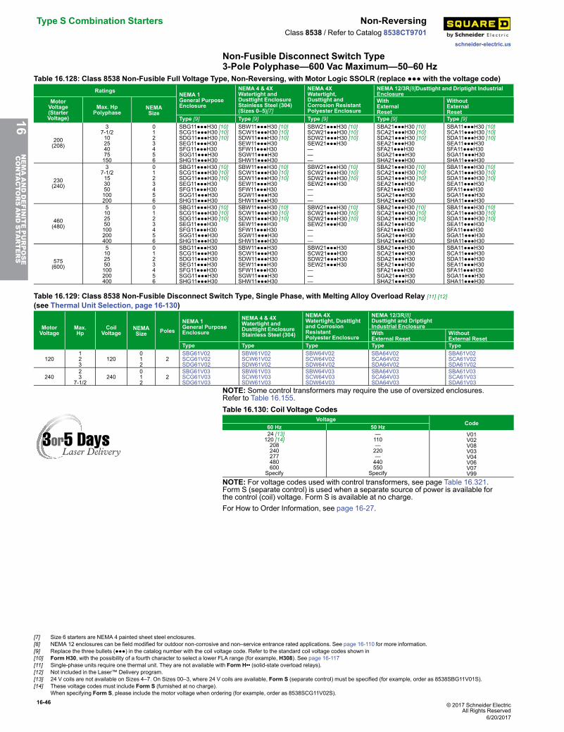
16-46 © 2017 Schneider ElectricAll Rights Reserved
Type S Combination Starters Non-Reversing
schneider-electric.us
Class 8538 / Refer to Catalog 8538CT9701
Non-Fusible Disconnect Switch Type3-Pole Polyphase—600 Vac Maximum—50–60 Hz
Table 16.128: Class 8538 Non-Fusible Full Voltage Type, Non-Reversing, with Motor Logic SSOLR (replace ●●● with the voltage code)Ratings
NEMA 1General PurposeEnclosure
NEMA 4 & 4XWatertight andDusttight EnclosureStainless Steel (304)(Sizes 0–5)[7]
NEMA 4XWatertight,Dusttight andCorrosion ResistantPolyester Enclosure
NEMA 12/3R[8]Dusttight and Driptight IndustrialEnclosure
MotorVoltage(StarterVoltage)
Max. HpPolyphase
NEMASize
WithExternalReset
WithoutExternalReset
Type [9] Type [9] Type [9] Type [9] Type [9]
200(208)
37-1/210254075150
0123456
SBG11●●●H30 [10]SCG11●●●H30 [10]SDG11●●●H30 [10]SEG11●●●H30SFG11●●●H30SGG11●●●H30SHG11●●●H30
SBW11●●●H30 [10]SCW11●●●H30 [10]SDW11●●●H30 [10]SEW11●●●H30SFW11●●●H30SGW11●●●H30SHW11●●●H30
SBW21●●●H30 [10]SCW21●●●H30 [10]SDW21●●●H30 [10]SEW21●●●H30———
SBA21●●●H30 [10]SCA21●●●H30 [10]SDA21●●●H30 [10]SEA21●●●H30SFA21●●●H30SGA21●●●H30SHA21●●●H30
SBA11●●●H30 [10]SCA11●●●H30 [10]SDA11●●●H30 [10]SEA11●●●H30SFA11●●●H30SGA11●●●H30SHA11●●●H30
230(240)
37-1/2153050100200
0123456
SBG11●●●H30 [10]SCG11●●●H30 [10]SDG11●●●H30 [10]SEG11●●●H30SFG11●●●H30SGG11●●●H30SHG11●●●H30
SBW11●●●H30 [10]SCW11●●●H30 [10]SDW11●●●H30 [10]SEW11●●●H30SFW11●●●H30SGW11●●●H30SHW11●●●H30
SBW21●●●H30 [10]SCW21●●●H30 [10]SDW21●●●H30 [10]SEW21●●●H30———
SBA21●●●H30 [10]SCA21●●●H30 [10]SDA21●●●H30 [10]SEA21●●●H30SFA21●●●H30SGA21●●●H30SHA21●●●H30
SBA11●●●H30 [10]SCA11●●●H30 [10]SDA11●●●H30 [10]SEA11●●●H30SFA11●●●H30SGA11●●●H30SHA11●●●H30
460(480)
5102550100200400
0123456
SBG11●●●H30 [10]SCG11●●●H30 [10]SDG11●●●H30 [10]SEG11●●●H30SFG11●●●H30SGG11●●●H30SHG11●●●H30
SBW11●●●H30 [10]SCW11●●●H30 [10]SDW11●●●H30 [10]SEW11●●●H30SFW11●●●H30SGW11●●●H30SHW11●●●H30
SBW21●●●H30 [10]SCW21●●●H30 [10]SDW21●●●H30 [10]SEW21●●●H30———
SBA21●●●H30 [10]SCA21●●●H30 [10]SDA21●●●H30 [10]SEA21●●●H30SFA21●●●H30SGA21●●●H30SHA21●●●H30
SBA11●●●H30 [10]SCA11●●●H30 [10]SDA11●●●H30 [10]SEA11●●●H30SFA11●●●H30SGA11●●●H30SHA11●●●H30
575(600)
5102550100200400
0123456
SBG11●●●H30SCG11●●●H30SDG11●●●H30SEG11●●●H30SFG11●●●H30SGG11●●●H30SHG11●●●H30
SBW11●●●H30SCW11●●●H30SDW11●●●H30SEW11●●●H30SFW11●●●H30SGW11●●●H30SHW11●●●H30
SBW21●●●H30SCW21●●●H30SDW21●●●H30SEW21●●●H30———
SBA21●●●H30SCA21●●●H30SDA21●●●H30SEA21●●●H30SFA21●●●H30SGA21●●●H30SHA21●●●H30
SBA11●●●H30SCA11●●●H30SDA11●●●H30SEA11●●●H30SFA11●●●H30SGA11●●●H30SHA11●●●H30
Table 16.129: Class 8538 Non-Fusible Disconnect Switch Type, Single Phase, with Melting Alloy Overload Relay [11] [12]
(see Thermal Unit Selection, page 16-130)
MotorVoltage
Max.Hp
CoilVoltage
NEMASize Poles
NEMA 1General PurposeEnclosure
NEMA 4 & 4XWatertight andDusttight EnclosureStainless Steel (304)
NEMA 4XWatertight, Dusttightand CorrosionResistantPolyester Enclosure
NEMA 12/3R[8]Dusttight and DriptightIndustrial EnclosureWithExternal Reset
WithoutExternal Reset
Type Type Type Type Type
120123
120012
2SBG61V02SCG61V02SDG61V02
SBW61V02SCW61V02SDW61V02
SBW64V02SCW64V02SDW64V02
SBA64V02SCA64V02SDA64V02
SBA61V02SCA61V02SDA61V02
24023
7-1/2240
012
2SBG61V03SCG61V03SDG61V03
SBW61V03SCW61V03SDW61V03
SBW64V03SCW64V03SDW64V03
SBA64V03SCA64V03SDA64V03
SBA61V03SCA61V03SDA61V03
NOTE: Some control transformers may require the use of oversized enclosures.Refer to Table 16.155.Table 16.130: Coil Voltage Codes
VoltageCode
60 Hz 50 Hz 24 [13]120 [14]208240277480600
Specify
—110—220—440550
Specify
V01V02V08V03V04V06V07V99
NOTE: For voltage codes used with control transformers, see page Table 16.321.Form S (separate control) is used when a separate source of power is available forthe control (coil) voltage. Form S is available at no charge.For How to Order Information, see page 16-27.
16NEMAANDDEFINITEPURPOSE
CONTA
CTORSANDSTA
RTERS
[7] Size 6 starters are NEMA 4 painted sheet steel enclosures.[8] NEMA 12 enclosures can be field modified for outdoor non-corrosive and non–service entrance rated applications. See page 16-110 for more information.[9] Replace the three bullets (●●●) in the catalog number with the coil voltage code. Refer to the standard coil voltage codes shown in[10] Form H30, with the possibility of a fourth character to select a lower FLA range (for example, H308). See page 16-117[11] Single-phase units require one thermal unit. They are not available with Form H•• (solid-state overload relays).[12] Not included in the Laser™ Delivery program.[13] 24 V coils are not available on Sizes 4–7. On Sizes 00–3, where 24 V coils are available, Form S (separate control) must be specified (for example, order as 8538SBG11V01S).[14] These voltage codes must include Form S (furnished at no charge).
When specifying Form S, please include the motor voltage when ordering (for example, order as 8538SCG11V02S).
6/20/2017
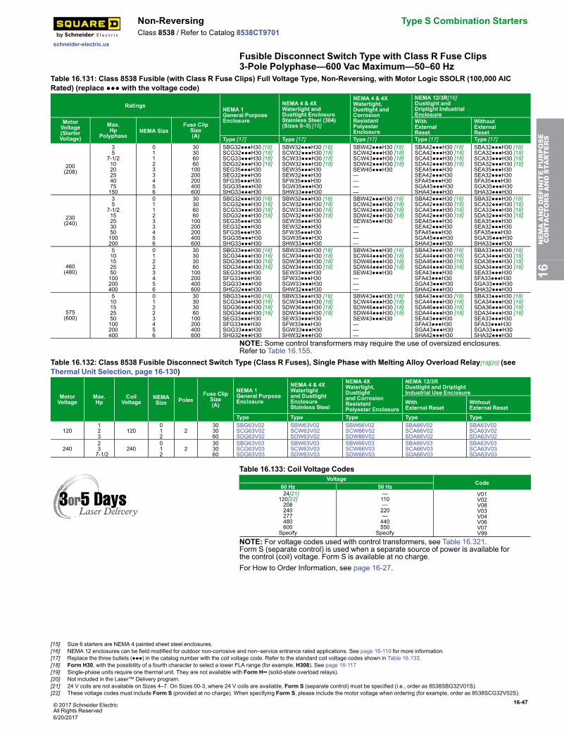
© 2017 Schneider ElectricAll Rights Reserved
16-47
schneider-electric.us
Non-Reversing Type S Combination StartersClass 8538 / Refer to Catalog 8538CT9701
Fusible Disconnect Switch Type with Class R Fuse Clips3-Pole Polyphase—600 Vac Maximum—50–60 Hz
Table 16.131: Class 8538 Fusible (with Class R Fuse Clips) Full Voltage Type, Non-Reversing, with Motor Logic SSOLR (100,000 AICRated) (replace ●●● with the voltage code)
RatingsNEMA 1General PurposeEnclosure
NEMA 4 & 4XWatertight andDusttight EnclosureStainless Steel (304)(Sizes 0–5) [15]
NEMA 4 & 4XWatertight,Dusttight andCorrosionResistantPolyesterEnclosure
NEMA 12/3R[16]Dusttight andDriptight IndustrialEnclosure
MotorVoltage(StarterVoltage)
Max.Hp
PolyphaseNEMA Size
Fuse ClipSize(A)
WithExternalReset
WithoutExternalReset
Type [17] Type [17] Type [17] Type [17] Type [17]
200(208)
35
7-1/21020254075150
011233456
30306060100200200400600
SBG32●●●H30 [18]SCG32●●●H30 [18]SCG33●●●H30 [18]SDG32●●●H30 [18]SEG35●●●H30SEG32●●●H30SFG35●●●H30SGG35●●●H30SHG33●●●H30
SBW32●●●H30 [18]SCW32●●●H30 [18]SCW33●●●H30 [18]SDW32●●●H30 [18]SEW35●●●H30SEW32●●●H30SFW35●●●H30SGW35●●●H30SHW33●●●H30
SBW42●●●H30 [18]SCW42●●●H30 [18]SCW43●●●H30 [18]SDW42●●●H30 [18]SEW45●●●H30————
SBA42●●●H30 [18]SCA42●●●H30 [18]SCA43●●●H30 [18]SDA42●●●H30 [18]SEA45●●●H30SEA42●●●H30SFA45●●●H30SGA45●●●H30SHA43●●●H30
SBA32●●●H30 [18]SCA32●●●H30 [18]SCA33●●●H30 [18]SDA32●●●H30 [18]SEA35●●●H30SEA32●●●H30SFA35●●●H30SGA35●●●H30SHA33●●●H30
230(240)
35
7-1/215253050100200
011233456
30306060100200200400600
SBG32●●●H30 [18]SCG32●●●H30 [18]SCG33●●●H30 [18]SDG32●●●H30 [18]SEG35●●●H30SEG32●●●H30SFG35●●●H30SGG35●●●H30SHG33●●●H30
SBW32●●●H30 [18]SCW32●●●H30 [18]SCW33●●●H30 [18]SDW32●●●H30 [18]SEW35●●●H30SEW32●●●H30SFW35●●●H30SGW35●●●H30SHW33●●●H30
SBW42●●●H30 [18]SCW42●●●H30 [18]SCW43●●●H30 [18]SDW42●●●H30 [18]SEW45●●●H30————
SBA42●●●H30 [18]SCA42●●●H30 [18]SCA43●●●H30 [18]SDA42●●●H30 [18]SEA45●●●H30SEA42●●●H30SFA45●●●H30SGA45●●●H30SHA43●●●H30
SBA32●●●H30 [18]SCA32●●●H30 [18]SCA33●●●H30 [18]SDA32●●●H30 [18]SEA35●●●H30SEA32●●●H30SFA35●●●H30SGA35●●●H30SHA33●●●H30
460(480)
510152550100200400
01223456
30303060100200400600
SBG33●●●H30 [18]SCG34●●●H30 [18]SDG36●●●H30 [18]SDG34●●●H30 [18]SEG33●●●H30SFG33●●●H30SGG33●●●H30SHG32●●●H30
SBW33●●●H30 [18]SCW34●●●H30 [18]SDW36●●●H30 [18]SDW34●●●H30 [18]SEW33●●●H30SFW33●●●H30SGW33●●●H30SHW32●●●H30
SBW43●●●H30 [18]SCW44●●●H30 [18]SDW46●●●H30 [18]SDW44●●●H30 [18]SEW43●●●H30———
SBA43●●●H30 [18]SCA44●●●H30 [18]SDA46●●●H30 [18]SDA44●●●H30 [18]SEA43●●●H30SFA43●●●H30SGA43●●●H30SHA42●●●H30
SBA33●●●H30 [18]SCA34●●●H30 [18]SDA36●●●H30 [18]SDA34●●●H30 [18]SEA33●●●H30SFA33●●●H30SGA33●●●H30SHA32●●●H30
575(600)
510152550100200400
01223456
30303060100200400600
SBG33●●●H30 [18]SCG34●●●H30 [18]SDG36●●●H30 [18]SDG34●●●H30 [18]SEG33●●●H30SFG33●●●H30SGG33●●●H30SHG32●●●H30
SBW33●●●H30 [18]SCW34●●●H30 [18]SDW36●●●H30 [18]SDW34●●●H30 [18]SEW33●●●H30SFW33●●●H30SGW33●●●H30SHW32●●●H30
SBW43●●●H30 [18]SCW44●●●H30 [18]SDW46●●●H30 [18]SDW44●●●H30 [18]SEW43●●●H30———
SBA43●●●H30 [18]SCA44●●●H30 [18]SDA46●●●H30 [18]SDA44●●●H30 [18]SEA43●●●H30SFA43●●●H30SGA43●●●H30SHA42●●●H30
SBA33●●●H30 [18]SCA34●●●H30 [18]SDA36●●●H30 [18]SDA34●●●H30 [18]SEA33●●●H30SFA33●●●H30SGA33●●●H30SHA32●●●H30
NOTE: Some control transformers may require the use of oversized enclosures.Refer to Table 16.155.
Table 16.132: Class 8538 Fusible Disconnect Switch Type (Class R Fuses), Single Phase with Melting Alloy Overload Relay[19][20] (seeThermal Unit Selection, page 16-130)
MotorVoltage
Max.Hp
CoilVoltage
NEMASize Poles
Fuse ClipSize(A)
NEMA 1General PurposeEnclosure
NEMA 4 & 4XWatertightand DusttightEnclosureStainless Steel
NEMA 4XWatertight,Dusttightand CorrosionResistantPolyester Enclosure
NEMA 12/3RDusttight and DriptightIndustrial Use EnclosureWithExternal Reset
WithoutExternal Reset
Type Type Type Type Type
120123
120012
2303060
SBG63V02SCG63V02SDG63V02
SBW63V02SCW63V02SDW63V02
SBW66V02SCW66V02SDW66V02
SBA66V02SCA66V02SDA66V02
SBA63V02SCA63V02SDA63V02
240237-1/2
240012
2303060
SBG63V03SCG63V03SDG63V03
SBW63V03SCW63V03SDW63V03
SBW66V03SCW66V03SDW66V03
SBA66V03SCA66V03SDA66V03
SBA63V03SCA63V03SDA63V03
Table 16.133: Coil Voltage CodesVoltage
Code60 Hz 50 Hz
24[21]120[22]208240277480600
Specify
—110—220—440550
Specify
V01V02V08V03V04V06V07V99
NOTE: For voltage codes used with control transformers, see Table 16.321.Form S (separate control) is used when a separate source of power is available forthe control (coil) voltage. Form S is available at no charge.For How to Order Information, see page 16-27.
16NEMAANDDEFINITEPURPOSE
CONTA
CTORSANDSTA
RTERS
[15] Size 6 starters are NEMA 4 painted sheet steel enclosures.[16] NEMA 12 enclosures can be field modified for outdoor non-corrosive and non–service entrance rated applications. See page 16-110 for more information.[17] Replace the three bullets (●●●) in the catalog number with the coil voltage code. Refer to the standard coil voltage codes shown in Table 16.133.[18] Form H30, with the possibility of a fourth character to select a lower FLA range (for example, H308). See page 16-117[19] Single-phase units require one thermal unit. They are not available with Form H•• (solid-state overload relays).[20] Not included in the Laser™ Delivery program.[21] 24 V coils are not available on Sizes 4–7. On Sizes 00-3, where 24 V coils are available, Form S (separate control) must be specified (i.e., order as 8538SBG32V01S).[22] These voltage codes must include Form S (provided at no charge). When specifying Form S, please include the motor voltage when ordering (for example, order as 8538SCG32V02S).
6/20/2017
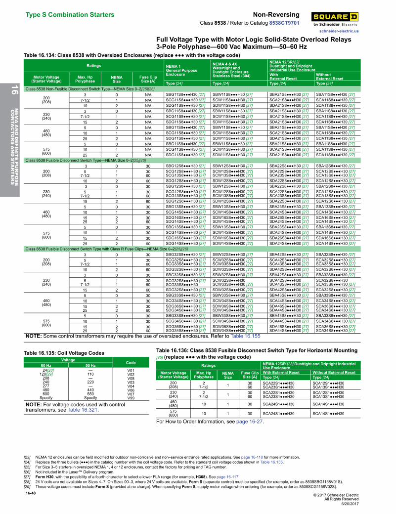
16-48 © 2017 Schneider ElectricAll Rights Reserved
Type S Combination Starters Non-Reversing
schneider-electric.us
Class 8538 / Refer to Catalog 8538CT9701
Full Voltage Type with Motor Logic Solid-State Overload Relays3-Pole Polyphase—600 Vac Maximum—50–60 Hz
Table 16.134: Class 8538 with Oversized Enclosures (replace ●●● with the voltage code)
Ratings NEMA 1General PurposeEnclosure
NEMA 4 & 4XWatertight andDustight EnclosureStainless Steel (304)
NEMA 12/3R[23]Dusttight and DriptightIndustrial Use Enclosure
Motor Voltage(Starter Voltage)
Max. HpPolyphase
NEMASize
Fuse ClipSize (A)
WithExternal Reset
WithoutExternal Reset
Type [24] Type [24] Type [24] Type [24]Class 8538 Non-Fusible Disconnect Switch Type—NEMA Size 0–2[25][26]
200(208)
3 0 N/A SBG11S8●●●H30 [27] SBW11S8●●●H30 [27] SBA21S8●●●H30 [27] SBA11S8●●●H30 [27]7-1/2 1 N/A SCG11S8●●●H30 [27] SCW11S8●●●H30 [27] SCA21S8●●●H30 [27] SCA11S8●●●H30 [27]10 2 N/A SDG11S8●●●H30 [27] SDW11S8●●●H30 [27] SDA21S8●●●H30 [27] SDA11S8●●●H30 [27]
230(240)
3 0 N/A SBG11S8●●●H30 [27] SBW11S8●●●H30 [27] SBA21S8●●●H30 [27] SBA11S8●●●H30 [27]7-1/2 1 N/A SCG11S8●●●H30 [27] SCW11S8●●●H30 [27] SCA21S8●●●H30 [27] SCA11S8●●●H30 [27]15 2 N/A SDG11S8●●●H30 [27] SDW11S8●●●H30 [27] SDA21S8●●●H30 [27] SDA11S8●●●H30 [27]
460(480)
5 0 N/A SBG11S8●●●H30 [27] SBW11S8●●●H30 [27] SBA21S8●●●H30 [27] SBA11S8●●●H30 [27]10 1 N/A SCG11S8●●●H30 [27] SCW11S8●●●H30 [27] SCA21S8●●●H30 [27] SCA11S8●●●H30 [27]25 2 N/A SDG11S8●●●H30 [27] SDW11S8●●●H30 [27] SDA21S8●●●H30 [27] SDA11S8●●●H30 [27]
575(600)
5 0 N/A SBG11S8●●●H30 [27] SBW11S8●●●H30 [27] SBA21S8●●●H30 [27] SBA11S8●●●H30 [27]10 1 N/A SCG11S8●●●H30 [27] SCW11S8●●●H30 [27] SCA21S8●●●H30 [27] SCA11S8●●●H30 [27]25 2 N/A SDG11S8●●●H30 [27] SDW11S8●●●H30 [27] SDA21S8●●●H30 [27] SDA11S8●●●H30 [27]
Class 8538 Fusible Disconnect Switch Type—NEMA Size 0–2[25][26]
200(208)
3 0 30 SBG12S8●●●H30 [27] SBW12S8●●●H30 [27] SBA22S8●●●H30 [27] SBA12S8●●●H30 [27]5
7-1/211
3060
SCG12S8●●●H30 [27]SCG13S8●●●H30 [27]
SCW12S8●●●H30 [27]SCW13S8●●●H30 [27]
SCA22S8●●●H30 [27]SCA23S8●●●H30 [27]
SCA12S8●●●H30 [27]SCA13S8●●●H30 [27]
10 2 60 SDG12S8●●●H30 [27] SDW12S8●●●H30 [27] SDA22S8●●●H30 [27] SDA12S8●●●H30 [27]
230(240)
3 0 30 SBG12S8●●●H30 [27] SBW12S8●●●H30 [27] SBA22S8●●●H30 [27] SBA12S8●●●H30 [27]5
7-1/211
3060
SCG12S8●●●H30 [27]SCG13S8●●●H30 [27]
SCW12S8●●●H30 [27]SCW13S8●●●H30 [27]
SCA22S8●●●H30 [27]SCA23S8●●●H30 [27]
SCA12S8●●●H30 [27]SCA13S8●●●H30 [27]
15 2 60 SDG12S8●●●H30 [27] SDW12S8●●●H30 [27] SDA22S8●●●H30 [27] SDA12S8●●●H30 [27]
460(480)
5 0 30 SBG13S8●●●H30 [27] SBW13S8●●●H30 [27] SBA23S8●●●H30 [27] SBA13S8●●●H30 [27]10 1 30 SCG14S8●●●H30 [27] SCW14S8●●●H30 [27] SCA24S8●●●H30 [27] SCA14S8●●●H30 [27]1525
22
3060
SDG16S8●●●H30 [27]SDG14S8●●●H30 [27]
SDW16S8●●●H30 [27]SDW14S8●●●H30 [27]
SDA26S8●●●H30 [27]SDA24S8●●●H30 [27]
SDA16S8●●●H30 [27]SDA14S8●●●H30 [27]
575(600)
5 0 30 SBG13S8●●●H30 [27] SBW13S8●●●H30 [27] SBA23S8●●●H30 [27] SBA13S8●●●H30 [27]10 1 30 SCG14S8●●●H30 [27] SCW14S8●●●H30 [27] SCA24S8●●●H30 [27] SCA14S8●●●H30 [27]15 2 30 SDG16S8●●●H30 [27] SDW16S8●●●H30 [27] SDA26S8●●●H30 [27] SDA16S8●●●H30 [27]25 2 60 SDG14S8●●●H30 [27] SDW14S8●●●H30 [27] SDA24S8●●●H30 [27] SDA14S8●●●H30 [27]
Class 8538 Fusible Disconnect Switch Type with Class R Fuse Clips—NEMA Size 0–2[25][26]
200(208)
3 0 30 SBG32S8●●●H30 [27] SBW32S8●●●H30 [27] SBA42S8●●●H30 [27] SBA32S8●●●H30 [27]5
7-1/211
3060
SCG32S8●●●H30 [27]SCG33S8●●●H30 [27]
SCW32S8●●●H30 [27]SCW33S8●●●H30 [27]
SCA42S8●●●H30 [27]SCA43S8●●●H30 [27]
SCA32S8●●●H30 [27]SCA33S8●●●H30 [27]
10 2 60 SDG32S8●●●H30 [27] SDW32S8●●●H30 [27] SDA42S8●●●H30 [27] SDA32S8●●●H30 [27]
230(240)
3 0 30 SBG32S8●●●H30 [27] SBW32S8●●●H30 [27] SBA42S8●●●H30 [27] SBA32S8●●●H30 [27]5
7-1/211
3060
SCG32S8●●●H30 [27]SCG33S8●●●H30
SCW32S8●●●H30SCW33S8●●●H30 [27]
SCA42S8●●●H30SCA43S8●●●H30 [27]
SCA32S8●●●H30SCA33S8●●●H30 [27]
15 2 60 SDG32S8●●●H30 [27] SDW32S8●●●H30 [27] SDA42S8●●●H30 [27] SDA32S8●●●H30 [27]
460(480)
5 0 30 SBG33S8●●●H30 [27] SBW33S8●●●H30 [27] SBA43S8●●●H30 [27] SBA33S8●●●H30 [27]10 1 30 SCG34S8●●●H30 [27] SCW34S8●●●H30 [27] SCA44S8●●●H30 [27] SCA34S8●●●H30 [27]1525
22
3060
SDG36S8●●●H30 [27]SDG34S8●●●H30 [27]
SDW36S8●●●H30 [27]SDW34S8●●●H30 [27]
SDA46S8●●●H30 [27]SDA44S8●●●H30 [27]
SDA36S8●●●H30 [27]SDA34S8●●●H30 [27]
575(600)
5 0 30 SBG33S8●●●H30 [27] SBW33S8●●●H30 [27] SBA43S8●●●H30 [27] SBA33S8●●●H30 [27]10 1 30 SCG34S8●●●H30 [27] SCW34S8●●●H30 [27] SCA44S8●●●H30 [27] SCA34S8●●●H30 [27]1525
22
3060
SDG36S8●●●H30 [27]SDG34S8●●●H30 [27]
SDW36S8●●●H30 [27]SDW34S8●●●H30 [27]
SDA46S8●●●H30 [27]SDA44S8●●●H30 [27]
SDA36S8●●●H30 [27]SDA34S8●●●H30 [27]
NOTE: Some control transformers may require the use of oversized enclosures. Refer to Table 16.155
Table 16.135: Coil Voltage CodesVoltage
Code60 Hz 50 Hz
24[28]120[29]208240277480600
Specify
—110—220—440550
Specify
V01V02V08V03V04V06V07V99
NOTE: For voltage codes used with controltransformers, see Table 16.321.
Table 16.136: Class 8538 Fusible Disconnect Switch Type for Horizontal Mounting[26] (replace ●●● with the voltage code)
Ratings NEMA 12/3R [23] Dusttight and Driptight IndustrialUse Enclosure
Motor Voltage(Starter Voltage)
Max. HpPolyphase
NEMASize
Fuse ClipSize (A)
With External Reset Without External ResetType [24] Type [24]
200(208)
27-1/2 1 30
60SCA22S1●●●H30SCA23S1●●●H30
SCA12S1●●●H30SCA13S1●●●H30
230(240)
27-1/2 1 30
60SCA22S1●●●H30SCA23S1●●●H30
SCA12S1●●●H30SCA13S1●●●H30
460(480) 10 1 30 SCA24S1●●●H30 SCA14S1●●●H30
575(600) 10 1 30 SCA24S1●●●H30 SCA14S1●●●H30
For How to Order Information, see page 16-27.
16NEMAANDDEFINITEPURPOSE
CONTA
CTORSANDSTA
RTERS
[23] NEMA 12 enclosures can be field modified for outdoor non-corrosive and non–service entrance rated applications. See page 16-110 for more information.[24] Replace the three bullets (●●●) in the catalog number with the coil voltage code. Refer to the standard coil voltage codes shown in Table 16.135.[25] For Size 3–5 starters in oversized NEMA 1, 4 or 12 enclosures, contact the factory for pricing and TAG number.[26] Not included in the Laser™ Delivery program.[27] Form H30, with the possibility of a fourth character to select a lower FLA range (for example, H308). See page 16-117[28] 24 V coils are not available on Sizes 4–7. On Sizes 00–3, where 24 V coils are available, Form S (separate control) must be specified (for example, order as 8538SBG1158V01S).[29] These voltage codes must include Form S (provided at no charge). When specifying Form S, supply motor voltage when ordering (for example, order as 8538SCG1158V02S).
6/20/2017
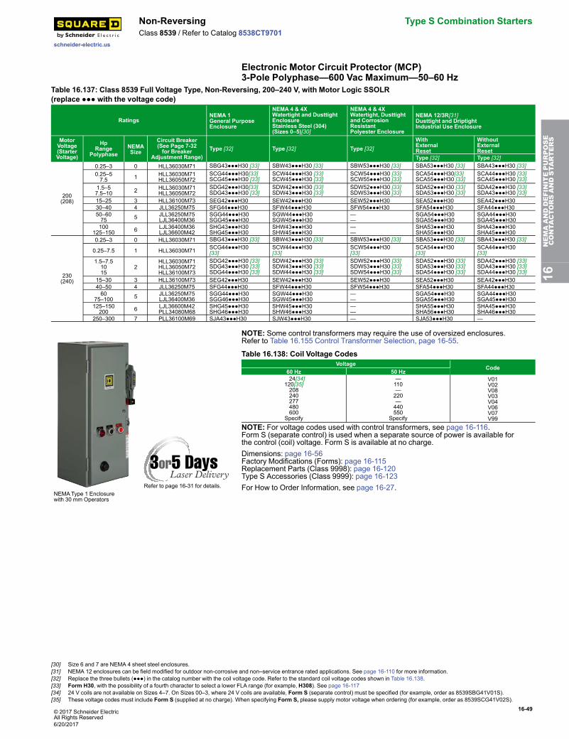
© 2017 Schneider ElectricAll Rights Reserved
16-49
schneider-electric.us
Non-Reversing Type S Combination StartersClass 8539 / Refer to Catalog 8538CT9701
Electronic Motor Circuit Protector (MCP)3-Pole Polyphase—600 Vac Maximum—50–60 Hz
Table 16.137: Class 8539 Full Voltage Type, Non-Reversing, 200–240 V, with Motor Logic SSOLR(replace ●●● with the voltage code)
RatingsNEMA 1General PurposeEnclosure
NEMA 4 & 4XWatertight and DusttightEnclosureStainless Steel (304)(Sizes 0–5)[30]
NEMA 4 & 4XWatertight, Dusttightand CorrosionResistantPolyester Enclosure
NEMA 12/3R[31]Dusttight and DriptightIndustrial Use Enclosure
MotorVoltage(StarterVoltage)
HpRange
PolyphaseNEMASize
Circuit Breaker(See Page 7-32for Breaker
Adjustment Range)Type [32] Type [32] Type [32]
WithExternalReset
WithoutExternalReset
Type [32] Type [32]
200(208)
0.25–3 0 HLL36030M71 SBG43●●●H30 [33] SBW43●●●H30 [33] SBW53●●●H30 [33] SBA53●●●H30 [33] SBA43●●●H30 [33]0.25–57.5 1 HLL36030M71
HLL36050M72SCG44●●●H30[33]SCG45●●●H30 [33]
SCW44●●●H30 [33]SCW45●●●H30 [33]
SCW54●●●H30 [33]SCW55●●●H30 [33]
SCA54●●●H30[33]SCA55●●●H30 [33]
SCA44●●●H30 [33]SCA45●●●H30 [33]
1.5–57.5–10 2 HLL36030M71
HLL36050M72SDG42●●●H30[33]SDG43●●●H30 [33]
SDW42●●●H30 [33]SDW43●●●H30 [33]
SDW52●●●H30 [33]SDW53●●●H30 [33]
SDA52●●●H30 [33]SDA53●●●H30 [33]
SDA42●●●H30 [33]SDA43●●●H30 [33]
15–25 3 HLL36100M73 SEG42●●●H30 SEW42●●●H30 SEW52●●●H30 SEA52●●●H30 SEA42●●●H3030–40 4 JLL36250M75 SFG44●●●H30 SFW44●●●H30 SFW54●●●H30 SFA54●●●H30 SFA44●●●H3050–6075 5 JLL36250M75
LJL36400M36SGG44●●●H30SGG45●●●H30
SGW44●●●H30SGW45●●●H30
——
SGA54●●●H30SGA55●●●H30
SGA44●●●H30SGA45●●●H30
100125–150 6 LJL36400M36
LJL36600M42SHG43●●●H30SHG45●●●H30
SHW43●●●H30SHW45●●●H30
——
SHA53●●●H30SHA55●●●H30
SHA43●●●H30SHA45●●●H30
230(240)
0.25–3 0 HLL36030M71 SBG43●●●H30 [33] SBW43●●●H30 [33] SBW53●●●H30 [33] SBA53●●●H30 [33] SBA43●●●H30 [33]
0.25–7.5 1 HLL36030M71 SCG44●●●H30[33]
SCW44●●●H30[33]
SCW54●●●H30[33]
SCA54●●●H30[33]
SCA44●●●H30[33]
1.5–7.51015
2HLL36030M71HLL36050M72HLL36100M73
SDG42●●●H30 [33]SDG43●●●H30 [33]SDG44●●●H30 [33]
SDW42●●●H30 [33]SDW43●●●H30 [33]SDW44●●●H30 [33]
SDW52●●●H30 [33]SDW53●●●H30 [33]SDW54●●●H30 [33]
SDA52●●●H30 [33]SDA53●●●H30 [33]SDA54●●●H30 [33]
SDA42●●●H30 [33]SDA43●●●H30 [33]SDA44●●●H30 [33]
15–30 3 HLL36100M73 SEG42●●●H30 SEW42●●●H30 SEW52●●●H30 SEA52●●●H30 SEA42●●●H3040–50 4 JLL36250M75 SFG44●●●H30 SFW44●●●H30 SFW54●●●H30 SFA54●●●H30 SFA44●●●H3060
75–100 5 JLL36250M75LJL36400M36
SGG44●●●H30SGG46●●●H30
SGW44●●●H30SGW45●●●H30
——
SGA54●●●H30SGA55●●●H30
SGA44●●●H30SGA45●●●H30
125–150200 6 LJL36600M42
PLL34080M68SHG45●●●H30SHG46●●●H30
SHW45●●●H30SHW46●●●H30
——
SHA55●●●H30SHA56●●●H30
SHA45●●●H30SHA46●●●H30
250–300 7 PLL36100M69 SJA43●●●H30 SJW43●●●H30 — SJA53●●●H30 —
Refer to page 16-31 for details.NEMAType 1 Enclosurewith 30 mm Operators
NOTE: Some control transformers may require the use of oversized enclosures.Refer to Table 16.155 Control Transformer Selection, page 16-55.
Table 16.138: Coil Voltage CodesVoltage
Code60 Hz 50 Hz
24[34]120[35]208240277480600
Specify
—110—220—440550
Specify
V01V02V08V03V04V06V07V99
NOTE: For voltage codes used with control transformers, see page 16-116.Form S (separate control) is used when a separate source of power is available forthe control (coil) voltage. Form S is available at no charge.Dimensions: page 16-56Factory Modifications (Forms): page 16-115Replacement Parts (Class 9998): page 16-120Type S Accessories (Class 9999): page 16-123For How to Order Information, see page 16-27.
16NEMAANDDEFINITEPURPOSE
CONTA
CTORSANDSTA
RTERS
[30] Size 6 and 7 are NEMA 4 sheet steel enclosures.[31] NEMA 12 enclosures can be field modified for outdoor non-corrosive and non–service entrance rated applications. See page 16-110 for more information.[32] Replace the three bullets (●●●) in the catalog number with the coil voltage code. Refer to the standard coil voltage codes shown in Table 16.138.[33] Form H30, with the possibility of a fourth character to select a lower FLA range (for example, H308). See page 16-117[34] 24 V coils are not available on Sizes 4–7. On Sizes 00–3, where 24 V coils are available, Form S (separate control) must be specified (for example, order as 8539SBG41V01S).[35] These voltage codes must include Form S (supplied at no charge). When specifying Form S, please supply motor voltage when ordering (for example, order as 8539SCG41V02S).
6/20/2017
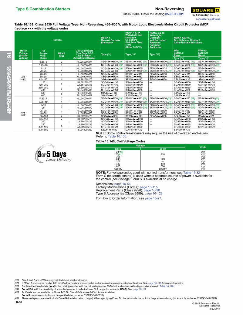
16-50 © 2017 Schneider ElectricAll Rights Reserved
Type S Combination Starters Non-Reversing
schneider-electric.us
Class 8539 / Refer to Catalog 8538CT9701
Table 16.139: Class 8539 Full Voltage Type, Non-Reversing, 460–600 V, with Motor Logic Electronic Motor Circuit Protector (MCP)(replace ●●● with the voltage code)
RatingsNEMA 1General PurposeEnclosure
NEMA 4 & 4XWatertight andDusttightEnclosureStainless Steel(304)(Sizes 0–5)[36]
NEMA 4 & 4XWatertight,Dusttightand CorrosionResistantPolyesterEnclosure
NEMA 12/3R[37]Dusttight and DriptightIndustrial Use Enclosure
MotorVoltage(StarterVoltage)
HpRangePoly-phase
NEMASize
Circuit Breaker(See Page 7-32for Breaker
Adjustment Range)Type [38] Type [38] Type [38]
WithExternalReset
WithoutExternalReset
Type [38] Type [38]
460(480)
0.25–5 0 HLL36030M71 SBG43●●●H30 [39] SBW43●●●H30 [39] SBW53●●●H30 [39] SBA53●●●H30 [39] SBA43●●●H30 [39]0.25–10 1 HLL36030M71 SCG44●●●H30 [39] SCW44●●●H30 [39] SCW54●●●H30 [39] SCA54●●●H30 [39] SCA44●●●H30 [39]5–1520–25 2 HLL36030M71
HLL36050M72SDG42●●●H30 [39]SDG43●●●H30
SDW42●●●H30SDW43●●●H30 [39]
SDW52●●●H30SDW53●●●H30 [39]
SDA52●●●H30SDA53●●●H30 [39]
SDA42●●●H30SDA43●●●H30 [39]
20–2530–50 3 HLL36050M72
HLL36100M73SEG41●●●H30SEG42●●●H30
SEW41●●●H30SEW42●●●H30
SEW51●●●H30SEW52●●●H30
SEA51●●●H30SEA52●●●H30
SEA41●●●H30SEA42●●●H30
60–100 4 JLL36250M75 SFG44●●●H30 SFW44●●●H30 SFW54●●●H30 SFA54●●●H30 SFA44●●●H30125
150–200 5 JLL36250M75LJL36400M36
SGG44●●●H30SGG45●●●H30
SGW44●●●H30SGW45●●●H30
——
SGA54●●●H30SGA55●●●H30
SGA44●●●H30SGA45●●●H30
250–350400 6 LJL36600M42
PLL34080M68SHG45●●●H30SHG46●●●H30
SHW45●●●H30SHW46●●●H30
——
SHA55●●●H30SHA56●●●H30
SHA45●●●H30SHA46●●●H30
500600 7 PLL36080M68
PLL36100M69SJA42●●●H30SJA43●●●H30
SJW42●●●H30SJW43●●●H30
——
SJA52●●●H30SJA53●●●H30
——
575(600)
0.25–5 0 HLL36030M71 SBG43●●●H30 [39] SBW43●●●H30 [39] SBW53●●●H30 [39] SBA53●●●H30 [39] SBA43●●●H30 [39]0.25–10 1 HLL36030M71 SCG44●●●H30 [39] SCW44●●●H30 [39] SCW54●●●H30 [39] SCA54●●●H30 [39] SCA44●●●H30 [39]5–2025 2 HLL36030M71
HLL36050M72SDG42●●●H30 [39]SDG43●●●H30 [39]
SDW42●●●H30 [39]SDW43●●●H30 [39]
SDW52●●●H30 [39]SDW53●●●H30 [39]
SDA52●●●H30 [39]SDA53●●●H30 [39]
SDA42●●●H30 [39]SDA43●●●H30 [39]
25–3040–50 3 HLL36050M72
HLL36100M73SEG41●●●H30SEG42●●●H30
SEW41●●●H30SEW42●●●H30
SEW51●●●H30SEW52●●●H30
SEA51●●●H30SEA52●●●H30
SEA41●●●H30SEA42●●●H30
60–100 4 JLL36250M75 SFG44●●●H30 SFW44●●●H30 SFW54●●●H30 SFA54●●●H30 SFA44●●●H30125–150200 5 JLL36250M75
LJL36400M36SGG44●●●H30SGG45●●●H30
SGW44●●●H30SGW45●●●H30
——
SGA54●●●H30SGA55●●●H30
SGA44●●●H30SGA45●●●H30
250300–400 6 LJL36400M36
LJL36600M42SHG43●●●H30SHG45●●●H30
SHW43●●●H30SHW45●●●H30
——
SHA53●●●H30SHA55●●●H30
SHA43●●●H30SHA45●●●H30
500–600 7 PLL34100M69 SJG41●●●H30 SJW41●●●H30 — SJA51●●●H30 —NOTE: Some control transformers may require the use of oversized enclosures.Refer to Table 16.155.Table 16.140: Coil Voltage Codes
VoltageCode
60 Hz 50 Hz 24[40]120[41]208240277480600
Specify
—110—220—440550
Specify
V01V02V08V03V04V06V07V99
NOTE: For voltage codes used with control transformers, see Table 16.321.Form S (separate control) is used when a separate source of power is available forthe control (coil) voltage. Form S is available at no charge.Dimensions: page 16-56Factory Modifications (Forms): page 16-115Replacement Parts (Class 9998): page 16-90Type S Accessories (Class 9999): page 16-123For How to Order Information, see page 16-27.
16NEMAANDDEFINITEPURPOSE
CONTA
CTORSANDSTA
RTERS
[36] Size 6 and 7 are NEMA 4 only, painted sheet steel enclosures.[37] NEMA 12 enclosures can be field modified for outdoor non-corrosive and non–service entrance rated applications. See page 16-110 for more information.[38] Replace the three bullets (●●●) in the catalog number with the coil voltage code. Refer to the standard coil voltage codes shown in Table 16.140.[39] Form H30, with the possibility of a fourth character to select a lower FLA range (for example, H308). See page 16-117[40] 24 V coils are not available on Sizes 4–7. On Sizes 00–3, where 24 V coils are available,
Form S (separate control) must be specified (i.e., order as 8539SBG41V01S).[41] These voltage codes must include Form S (furnished at no charge). When specifying Form S, please include the motor voltage when ordering (for example, order as 8539SCG41V02S).
6/20/2017
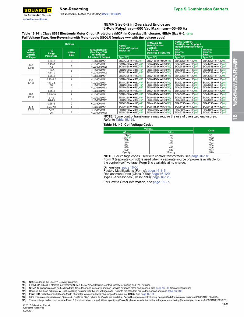
© 2017 Schneider ElectricAll Rights Reserved
16-51
schneider-electric.us
Non-Reversing Type S Combination StartersClass 8539 / Refer to Catalog 8538CT9701
NEMA Size 0–2 in Oversized Enclosure3-Pole Polyphase—600 Vac Maximum—50–60 Hz
Table 16.141: Class 8539 Electronic Motor Circuit Protectors (MCP) in Oversized Enclosure, NEMA Size 0–2[42][43]Full Voltage Type, Non-Reversing with Motor Logic SSOLR (replace ●●● with the voltage code)
RatingsNEMA 1General PurposeEnclosure
NEMA 4 & 4XWatertight andDusttightEnclosureStainless Steel (304)
NEMA 12/3R[44]Dusttight and DriptightIndustrial Use Enclosure
MotorVoltage(StarterVoltage)
HpRange
PolyphaseNEMASize
Circuit Breaker(See Page 7-32for Breaker
Adjustment Range)
WithExternalReset
WithoutExternalReset
Type [45] Type [45] Type [45] Type [45]
200(208)
0.25–3 0 HLL36030M71 SBG43S8●●●H30[46] SBW43S8●●●H30[46] SBA53S8●●●H30[46] SBA43S8●●●H30[46]0.25–57.5 1 HLL36030M71
HLL36050M72SCG44S8●●●H30[46]SCG45S8●●●H30[46]
SCW44S8●●●H30[46]SCW45S8●●●H30[46]
SCA54S8●●●H30[46]SCA55S8●●●H30[46]
SCA44S8●●●H30[46]SCA45S8●●●H30[46]
1.5–57.5–10 2 HLL36030M71
HLL36050M72SDG42S8●●●H30[46]SDG43S8●●●H30[46]
SDW42S8●●●H30[46]SDW43S8●●●H30[46]
SDA52S8●●●H30[46]SDA53S8●●●H30[46]
SDA42S8●●●H30[46]SDA43S8●●●H30[46]
230(240)
0.25–3 0 HLL36030M71 SBG43S8●●●H30[46] SBW43S8●●●H30[46] SBA53S8●●●H30[46] SBA43S8●●●H30[46]0.25–7.5 1 HLL36030M71 SCG44S8●●●H30[46] SCW44S8●●●H30[46] SCA54S8●●●H30[46] SCA44S8●●●H30[46]1.5–7.51015
2HLL36030M71HLL36050M72HLL36100M73
SDG42S8●●●H30[46]SDG43S8●●●H30[46]SDG44S8●●●H30[46]
SDW42S8●●●H30[46]SDW43S8●●●H30[46]SDW44S8●●●H30[46]
SDA52S8●●●H30[46]SDA53S8●●●H30[46]SDA54S8●●●H30[46]
SDA42S8●●●H30[46]SDA43S8●●●H30[46]SDA44S8●●●H30[46]
460(480)
0.25–5 0 HLL36030M71 SBG43S8●●●H30[46] SBW43S8●●●H30[46] SBA53S8●●●H30[46] SBA43S8●●●H30[46]0.25–10 1 HLL36030M71 SCG44S8●●●H30[46] SCW44S8●●●H30[46] SCA54S8●●●H30[46] SCA44S8●●●H30[46]5–1520–25 2 HLL36030M71
HLL36050M72SDG42S8●●●H30[46]SDG43S8●●●H30[46]
SDW42S8●●●H30[46]SDW43S8●●●H30[46]
SDA52S8●●●H30[46]SDA53S8●●●H30[46]
SDA42S8●●●H30[46]SDA43S8●●●H30[46]
575(600)
0.25–5 0 HLL36060M71 SBG43S8●●●H30[46] SBW43S8●●●H30[46] SBA53S8●●●H30[46] SBA43S8●●●H30[46]0.25–10 1 HLL36030M71 SCG44S8●●●H30[46] SCW44S8●●●H30[46] SCA54S8●●●H30[46] SCA44S8●●●H30[46]5–2025 2 HLL36030M71
HLL36050M72SDG42S8●●●H30[46]SDG43S8●●●H30[46]
SDW42S8●●●H30[46]SDW43S8●●●H30[46]
SDA52S8●●●H30[46]SDA53S8●●●H30[46]
SDA42S8●●●H30[46]SDA43S8●●●H30[46]
NOTE: Some control transformers may require the use of oversized enclosures.Refer to Table 16.155.Table 16.142: Coil Voltage Codes
VoltageCode
60 Hz 50 Hz 24[47]120[48]208240277480600
Specify
—110—220—440550
Specify
V01V02V08V03V04V06V07V99
NOTE: For voltage codes used with control transformers, see page 16-116.Form S (separate control) is used when a separate source of power is available forthe control (coil) voltage. Form S is available at no charge.Dimensions: page 16-56Factory Modifications (Forms): page 16-115Replacement Parts (Class 9998): page 16-120Type S Accessories (Class 9999): page 16-123For How to Order Information, see page 16-27.
16NEMAANDDEFINITEPURPOSE
CONTA
CTORSANDSTA
RTERS
[42] Not included in the Laser™ Delivery program.[43] For NEMA Size 3–5 starters in oversized NEMA 1, 4 or 12 enclosures, contact factory for pricing and TAG number.[44] NEMA 12 enclosures can be field modified for outdoor non-corrosive and non–service entrance rated applications. See page 16-110 for more information.[45] Replace the three bullets (●●●) in the catalog number with the coil voltage code. Refer to the standard coil voltage codes shown in Table 16.142.[46] Form H30, with the possibility of a fourth character to select a lower FLA range (for example, H308). See page 16-117[47] 24 V coils are not available on Sizes 4–7. On Sizes 00–3, where 24 V coils are available, Form S (separate control) must be specified (for example, order as 8539SBG41S8V01S).[48] These voltage codes must include Form S (provided at no charge). When specifying Form S, please include the motor voltage when ordering (for example, order as 8539SCG41S8V02S).
6/20/2017
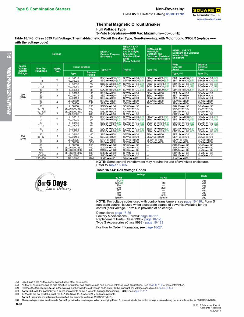
16-52 © 2017 Schneider ElectricAll Rights Reserved
Type S Combination Starters Non-Reversing
schneider-electric.us
Class 8539 / Refer to Catalog 8538CT9701
Thermal Magnetic Circuit BreakerFull Voltage Type3-Pole Polyphase—600 Vac Maximum—50–60 Hz
Table 16.143: Class 8539 Full Voltage, Thermal-Magnetic Circuit Breaker Type, Non-Reversing, with Motor Logic SSOLR (replace ●●●with the voltage code)
RatingsNEMA 1General PurposeEnclosure
NEMA 4 & 4XWatertightand DusttightEnclosureStainless Steel(304)(Sizes 0–5)[49]
NEMA 4 & 4XWatertight,Dusttight andCorrosion ResistantPolyester Enclosure
NEMA 12/3R[50]Dusttight and DriptightIndustrial UseEnclosure
MotorVoltage(StarterVoltage)
Max. HpPolyphase
NEMASize
Circuit BreakerType [51] Type [51] Type [51]
WithExternalReset
WithoutExternalReset
Type AmpereRating Type [51] Type [51]
200(208)
23 0 HLL36015
HLL360201520
SBG1●●●H30 [52]SBG3●●●H30 [52]
SBW1●●●H30 [52]SBW3●●●H30 [52]
SBW11●●●H30 [52]SBW13●●●H30 [52]
SBA11●●●H30 [52]SBA13●●●H30 [52]
SBA1●●●H30 [52]SBA3●●●H30 [52]
57-1/2 1 HLL36035
HLL360503550
SCG5●●●H30 [52]SCG2●●●H30 [52]
SCW5●●●H30 [52]SCW2●●●H30 [52]
SCW15●●●H30 [52]SCW12●●●H30 [52]
SCA15●●●H30 [52]SCA12●●●H30 [52]
SCA5●●●H30 [52]SCA2●●●H30 [52]
10 2 HLL36060 60 SDG1●●●H30 [52] SDW1●●●H30 [52] SDW11●●●H30 [52] SDA11●●●H30 [52] SDA1●●●H30 [52]152025
3HLL36100HLL36125HLL36150
100125150
SEG3●●●H30SEG1●●●H30SEG5●●●H30
SEW3●●●H30SEW1●●●H30SEW5●●●H30
SEW13●●●H30SEW11●●●H30SEW15●●●H30
SEA13●●●H30SEA11●●●H30SEA15●●●H30
SEA3●●●H30SEA1●●●H30SEA5●●●H30
3040 4 JLL36200
JLL36250200250
SFG3●●●H30SFG4●●●H30
SFW3●●●H30SFW4●●●H30
SFW13●●●H30SFW14●●●H30
SFA13●●●H30SFA14●●●H30
SFA3●●●H30SFA4●●●H30
5060–75 5 JLL36250
LLL36400U33X250400
SGG6●●●H30SGG4●●●H30
SGW6●●●H30SGW4●●●H30
——
SGA16●●●H30SGA14●●●H30
SGA6●●●H30SGA4●●●H30
100–125150 6 LLL36600U33X
MJL36800600800
SHG4●●●H30SHG5●●●H30
SHW4●●●H30SHW5●●●H30
——
SHA14●●●H30SHA15●●●H30
SHA4●●●H30SHA5●●●H30
230(240)
23 0 HLL36015
HLL360201520
SBG1●●●H30 [52]SBG3●●●H30 [52]
SBW1●●●H30 [52]SBW3●●●H30 [52]
SBW11●●●H30 [52]SBW13●●●H30 [52]
SBA11●●●H30 [52]SBA13●●●H30 [52]
SBA1●●●H30 [52]SBA3●●●H30 [52]
57-1/2 1 HLL36035
HLL360453545
SCG5●●●H30 [52]SCG6●●●H30 [52]
SCW5●●●H30 [52]SCW6●●●H30 [52]
SCW15●●●H30 [52]SCW16●●●H30 [52]
SCA15●●●H30 [52]SCA16●●●H30 [52]
SCA1●●●H30 [52]SCA6●●●H30 [52]
1015 2 HLL36060
HLL360906090
SDG1●●●H30 [52]SDG7●●●H30 [52]
SDW1●●●H30 [52]SDW7●●●H30 [52]
SDW11●●●H30 [52]SDW17●●●H30 [52]
SDA11●●●H30 [52]SDA17●●●H30 [52]
SDA1●●●H30 [52]SDA7●●●H30 [52]
2025–30 3 HLL36100
HLL36150100150
SEG3●●●H30SEG5●●●H30
SEW3●●●H30SEW5●●●H30
SEW13●●●H30SEW15●●●H30
SEA13●●●H30SEA15●●●H30
SEA3●●●H30SEA5●●●H30
4050 4 JLL36225
JLL36250225250
SFG1●●●H30SFG4●●●H30
SFW1●●●H30SFW4●●●H30
SFW11●●●H30SFW14●●●H30
SFA11●●●H30SFA14●●●H30
SFA1●●●H30SFA4●●●H30
6075100
5JLL36250
LLL36400U33XLLL36600U33X
250400600
SGG6●●●H30SGG4●●●H30SGG2●●●H30
SGW6●●●H30SGW4●●●H30SGW2●●●H30
———
SGA16●●●H30SGA14●●●H30SGA12●●●H30
SGA6●●●H30SGA4●●●H30SGA2●●●H30
125150–200 6 LLL36600U33X
MJL36800600800
SHG4●●●H30SHG5●●●H30
SHW4●●●H30SHW5●●●H30
——
SHA14●●●H30SHA15●●●H30
SHA4●●●H30SHA5●●●H30
250–300 7 PKL36100 1200 SJG3●●●H30 SJW3●●●H30 — SJA13●●●H30 —NOTE: Some control transformers may require the use of oversized enclosures.Refer to Table 16.155.Table 16.144: Coil Voltage Codes
VoltageCode
60 Hz 50 Hz 24[53]120[54]208240277480600
Specify
—110—220—440550
Specify
V01V02V08V03V04V06V07V99
NOTE: For voltage codes used with control transformers, see page 16-116.. Form S(separate control) is used when a separate source of power is available for thecontrol (coil) voltage. Form S is provided at no charge.Dimensions: page 16-56Factory Modifications (Forms): page 16-115Replacement Parts (Class 9998): page 16-120Type S Accessories (Class 9999): page 16-123For How to Order Information, see page 16-27.
16NEMAANDDEFINITEPURPOSE
CONTA
CTORSANDSTA
RTERS
[49] Size 6 and 7 are NEMA 4 only, painted sheet steel enclosures.[50] NEMA 12 enclosures can be field modified for outdoor non-corrosive and non–service entrance rated applications. See page 16-110 for more information.[51] Replace the three bullets (●●●) in the catalog number with the coil voltage code. Refer to the standard coil voltage codes listed in Table 16.144.[52] Form H30, with the possibility of a fourth character to select a lower FLA range (for example, H308). See page 16-117[53] 24 V coils are not available on Sizes 4–7. On Sizes 00–3, where 24 V coils are available,
Form S (separate control) must be specified (for example, order as 8539SBG1V01S).[54] These voltage codes must include Form S (provided at no charge). When specifying Form S, please include the motor voltage when ordering (for example, order as 8539SCG5V02S).
6/20/2017
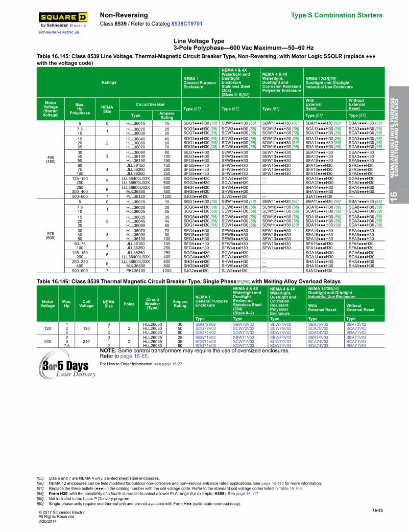
© 2017 Schneider ElectricAll Rights Reserved
16-53
schneider-electric.us
Non-Reversing Type S Combination StartersClass 8539 / Refer to Catalog 8538CT9701
Line Voltage Type3-Pole Polyphase—600 Vac Maximum—50–60 Hz
Table 16.145: Class 8539 Line Voltage, Thermal-Magnetic Circuit Breaker Type, Non-Reversing, with Motor Logic SSOLR (replace ●●●with the voltage code)
RatingsNEMA 1General PurposeEnclosure
NEMA 4 & 4XWatertight andDusttightEnclosureStainless Steel(304)(Sizes 0–5)[55]
NEMA 4 & 4XWatertight,Dusttight andCorrosion ResistantPolyester Enclosure
NEMA 12/3R[56]Dusttight and DriptightIndustrial Use Enclosure
MotorVoltage(StarterVoltage)
Max.Hp
PolyphaseNEMASize
Circuit BreakerType [57] Type [57] Type [57]
WithExternalReset
WithoutExternalReset
Type AmpereRating Type [57] Type [57]
460(480)
5 0 HLL36015 15 SBG1●●●H30 [58] SBW1●●●H30 [58] SBW11●●●H30 [58] SBA11●●●H30 [58] SBA1●●●H30 [58]7.510 1 HLL36025
HLL360302530
SCG3●●●H30 [58]SCG7●●●H30 [58]
SCW3●●●H30 [58]SCW7●●●H30 [58]
SCW13●●●H30 [58]SCW17●●●H30 [58]
SCA13●●●H30 [58]SCA17●●●H30 [58]
SCA3●●●H30 [58]SCA7●●●H30 [58]
152025
2HLL36045HLL36060HLL36070
456070
SDG3●●●H30 [58]SDG1●●●H30 [58]SDG5●●●H30 [58]
SDW3●●●H30 [58]SDW1●●●H30 [58]SDW5●●●H30 [58]
SDW13●●●H30 [58]SDW11●●●H30 [58]SDW15●●●H30 [58]
SDA13●●●H30 [58]SDA11●●●H30 [58]SDA15●●●H30 [58]
SDA3●●●H30 [58]SDA1●●●H30 [58]SDA5●●●H30 [58]
304050
3HLL36080HLL36100HLL36150
80100150
SEG7●●●H30SEG3●●●H30SEG5●●●H30
SEW7●●●H30SEW3●●●H30SEW5●●●H30
SEW17●●●H30SEW13●●●H30SEW15●●●H30
SEA17●●●H30SEA13●●●H30SEA15●●●H30
SEA7●●●H30SEA3●●●H30SEA5●●●H30
6075100
4JLL36150JLL36200JLL36250
150200250
SFG5●●●H30SFG3●●●H30SFG4●●●H30
SFW5●●●H30SFW3●●●H30SFW4●●●H30
SFW15●●●H30SFW13●●●H30SFW14●●●H30
SFA15●●●H30SFA13●●●H30SFA14●●●H30
SFA5●●●H30SFA3●●●H30SFA4●●●H30
125–150200 5 LLL36400U33X
LLL36600U33X400600
SGG4●●●H30SGG2●●●H30
SGW4●●●H30SGW2●●●H30
——
SGA14●●●H30SGA12●●●H30
SGA4●●●H30SGA2●●●H30
250300–400 6 LLL36600U33X
MJL36800600800
SHG4●●●H30SHG5●●●H30
SHW4●●●H30SHW5●●●H30
——
SHA14●●●H30SHA15●●●H30
SHA4●●●H30SHA5●●●H30
500–600 7 PLL36120 1200 SJG3●●●H30 SJW3●●●H30 — SJA13●●●H30 —
575(600)
5 0 HLL36015 15 SBG1●●●H30 [58] SBW1●●●H30 [58] SBW11●●●H30 [58] SBA11●●●H30 [58] SBA1●●●H30 [58]7.510 1 HLL36020
HLL360252025
SCG8●●●H30 [58]SCG3●●●H30 [58]
SCW8●●●H30 [58]SCW3●●●H30 [58]
SCW18●●●H30 [58]SCW13●●●H30 [58]
SCA18●●●H30 [58]SCA13●●●H30 [58]
SCA8●●●H30 [58]SCA3●●●H30 [58]
152025
2HLL36035HLL36045HLL36060
354560
SDG8●●●H30 [58]SDG3●●●H30 [58]SDG1●●●H30 [58]
SDW8●●●H30 [58]SDW3●●●H30 [58]SDW1●●●H30 [58]
SDW18●●●H30 [58]SDW13●●●H30 [58]SDW11●●●H30 [58]
SDA18●●●H30 [58]SDA13●●●H30 [58]SDA11●●●H30 [58]
SDA8●●●H30 [58]SDA3●●●H30 [58]SDA1●●●H30 [58]
304050
3HLL36070HLL36090HLL36100
7090100
SEG4●●●H30SEG6●●●H30SEG3●●●H30
SEW4●●●H30SEW6●●●H30SEW3●●●H30
SEW14●●●H30SEW16●●●H30SEW13●●●H30
SEA14●●●H30SEA16●●●H30SEA13●●●H30
SEA4●●●H30SEA6●●●H30SEA3●●●H30
60–75100 4 JLL36150
JLL36250150250
SFG5●●●H30SFG4●●●H30
SFW5●●●H30SFW4●●●H30
SFW15●●●H30SFW14●●●H30
SFA15●●●H30SFA14●●●H30
SFA5●●●H30SFA4●●●H30
125–150200 5 JLL36250
LLL36400U33X250400
SGG6●●●H30SGG4●●●H30
SGW6●●●H30SGW4●●●H30
——
SGA16●●●H30SGA14●●●H30
SGA6●●●H30SGA4●●●H30
250–350400 6 LLL36600U33X
MJL36800600800
SHG4●●●H30SHG5●●●H30
SHW4●●●H30SHW5●●●H30
——
SHA14●●●H30SHA15●●●H30
SHA4●●●H30SHA5●●●H30
500–600 7 PKL36100 1200 SJG2●●●H30 SJW2●●●H30 — SJA12●●●H30 —
Table 16.146: Class 8539 Thermal Magnetic Circuit Breaker Type, Single Phase[59][60] with Melting Alloy Overload Relays
MotorVoltage
Max.Hp
CoilVoltage
NEMASize Poles
CircuitBreaker(Type)
AmpereRating
NEMA 1General PurposeEnclosure
NEMA 4 & 4XWatertight andDusttightEnclosureStainless Steel(304)(Sizes 0–2)
NEMA 4 & 4XWatertight,Dusttight andCorrosionResistantPolyesterEnclosure
NEMA 12/3R[56]Dusttight and DriptightIndustrial Use Enclosure
WithExternal Reset
WithoutExternal Reset
Type Type Type Type Type
120123
120012
2HLL26030HLL26050HLL26080
305080
SBG72V02SCG72V02SDG71V02
SBW72V02SCW72V02SDW71V02
SBW75V02SCW75V02SDW74V02
SBA75V02SCA75V02SDA74V02
SBA72V02SCA72V02SDA71V02
240237.5
240012
2HLL26025HLL26035HLL26080
253580
SBG71V03SCG71V03SDG71V03
SBW71V03SCW71V03SDW71V03
SBW74V03SCW74V03SDW74V03
SBA74V03SCA74V03SDA74V03
SBA71V03SCA71V03SDA71V03
NOTE: Some control transformers may require the use of oversized enclosures.Refer to page 16-55.For How to Order Information, see page 16-27.
16NEMAANDDEFINITEPURPOSE
CONTA
CTORSANDSTA
RTERS
[55] Size 6 and 7 are NEMA 4 only, painted sheet steel enclosures.[56] NEMA 12 enclosures can be field modified for outdoor non-corrosive and non–service entrance rated applications. See page 16-110 for more information.[57] Replace the three bullets (●●●) in the catalog number with the coil voltage code. Refer to the standard coil voltage codes listed in Table 16.144.[58] Form H30, with the possibility of a fourth character to select a lower FLA range (for example, H308). See page 16-117[59] Not included in the Laser™ Delivery program.[60] Single-phase units require one thermal unit and are not available with Form H●● (solid-state overload relay).
6/20/2017
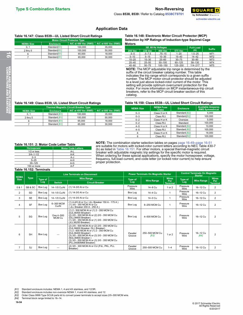
16-54 © 2017 Schneider ElectricAll Rights Reserved
Type S Combination Starters Non-Reversing
schneider-electric.us
Class 8538, 8539 / Refer to Catalog 8538CT9701
Application Data
Table 16.147: Class 8539—UL Listed Short Circuit RatingsMotor Circuit Protector Type
NEMA Size Enclosure AIC at 480 Vac (RMS) AIC at 600 Vac (RMS)0, 1 Standard[61] 100,000 35,000
2 thru 5 Standard[61] 100,000 50,0006 Standard[61] 65,000 18,0007 Standard[61] 65,000 30,000
Table 16.148: Electronic Motor Circuit Protector (MCP)Selection by HP Ratings of Induction-type Squirrel-CageMotors
3Ø, 60 Hz Voltages Full-Load(A) Suffix
200 Vac 230 Vac 460 Vac 575 Vac.5–5 .5–7.5 .75–15 1–20 1.5–25 M715–10 5–15 10–30 15–40 14–42 M7210–25 15–30 25–60 30–75 30–80 M7320–40 25–50 50–100 60–125 58–130 M7440–60 50–75 100–150 125–200 114–217 M75
NOTE: The MCP adjustable trip range is determined by thesuffix of the circuit breaker catalog number. This tableindicates the trip range which corresponds to a given suffixnumber. The MCP motor circuit protector should be adjustedto a level just above locked-rotor current of the motor. Thissetting will provide optimum overcurrent protection for themotor. For more information on MCP instantaneous-trip circuitbreakers, refer to the MCP circuit breaker section of thiscatalog.
Table 16.149: Class 8539, UL Listed Short Circuit RatingsThermal Magnetic Circuit Breaker Type
NEMA Size Enclosure AIC at 480 Vac (RMS) AIC at 600 Vac (RMS)0, 1 Standard [61] 100,000 35,000
2 thru 5 Standard [61] 100,000 50,0006 Standard [61] 65,000 18,0007 Standard [61] 65,000 30,000
Table 16.150: Class 8538—UL Listed Short Circuit RatingsNEMA Size NEMA Fuse
Class Enclosure Available AmperesRMS Symmetrical
0–3 Class H or K Standard [62] 5,0000–3 Class R/J Standard[62] 100,0000–2 Class H or K Oversize 5,0000–2 Class R/J Standard 100,0004–5 Class H or K Standard [62] 10,0004–5 Class R/J Standard [62] 100,0006 Class H or K Standard [62] 18,0006 Class R/J Standard[62] 100,000
Table 16.151: 2: Motor Code Letter TableHorsepower Motor Code Letters1/2 or less A-L3/4–1-1/2 A-K
2–3 A-J5–25 A-H30–125 A-G
150 or more A-F
NOTE: The combination starter selection tables on pages page 16-49–page 16-51are suitable for motors with locked-rotor current letters according to NEC Table 430-7(b) as listed in Table 16.151. For other motors, a special thermal-magnetic circuitbreaker with adjustable magnetic trip settings for the specific motor is required.When ordering for these special applications, specify the motor horsepower, voltage,frequency, full-load current, and code letter (or locked rotor current) to help ensureproper protection.
Table 16.152: Terminals
NEMASize Type
Line Terminals on Disconnect Power Terminals On Magnetic Starter Control Terminals On MagneticStarter
Type ofLug
Wire Range Type ofLug Wire Range
WiresPer
TerminalType ofLug Wire Range
WiresPer
TerminalSwitch Circuit Breaker
0 & 1 SB & SC Box Lug 14–1/0 Cu/Al (1) 14-3/0 Al or Cu PressureWire 14–8 Cu 1 or 2 Pressure
Wire 16–12 Cu 2
2 SD Box Lug 14–1/0 Cu/Al (1) 14-3/0 Al or Cu Box Lug 14–4 Cu 1 PressureWire 16–12 Cu 2
3 SE Box Lug 14–1/0 Cu/Al (1) 14-3/0 Al or Cu Box Lug 14–0 Cu 1 PressureWire 16–12 Cu 2
4 SF Box Lug 6–300 MCMCu/Al
(1) 4-4/0 Al or Cu ( JLL Breaker 150 A - 175 A )(1) 3/0 - 350 MCM Al or Cu( JLL Breaker 200 A - 250 A )
Box Lug 8–250 MCM Cu 1 PressureWire 16–12 Cu 2
5 SG Box Lug One 4–500MCM Cu
(1) 2 - 500 MCM Al or (1) 2 - 350 MCM Cu(DJL36400 Breaker)(2) 2/0 - 500 MCM Al or (2) 2/0 - 350 MCM Cu(DLL36600 Breaker)(1) 3/0 - 350 MCM Al or (1) 3/0 - 350 MCM Cu(JLL36250 Breaker)
Box Lug 4–500 MCM Cu 1 PressureWire 16–12 Cu 2
6 SH Box Lug —
(2) 2/0 - 500 MCM Al or (2) 2/0 - 350 MCM Cu(DJL36600 Breaker, DLL Breaker)(1) 2 - 600 MCM Al or (1) 2 - 350 MCM Cu(DJL36400 Breaker)(3) 3/0 - 500 MCM Al or (3) 3/0 - 350 MCM Cu(MJL36800 Breaker )(3) 3/0 - 500 MCM Al or (3) 3/0 - 350 MCM Cu(PLL34080M68 Breaker)
ParallelGroove
250–500 MCM Cu[63] 1 or 2 Pressure
Wire16–12 Cu
[64] 2
7 SJ Box Lug — (4) 3/0 - 300 MCM Al or CU (PJL, PKL, PLLBreaker)
ParallelGroove 250–500 MCM Cu 1–4 Pressure
Wire 16–12 Cu 2
[61] Standard enclosure includes: NEMA 1, 4 and 4X stainless, and 12/3R.[62] Standard enclosure includes non-oversize NEMA 1, 4 and 4X stainless, and 12.[63] Order Class 9999 Type SCU6 parts kit to convert power terminals to accept sizes 2/0–300 MCM wire.[64] Terminal block range limited to 16–14.
6/20/2017
16NEMAANDDEFINITEPURPOSE
CONTA
CTORSANDSTA
RTERS
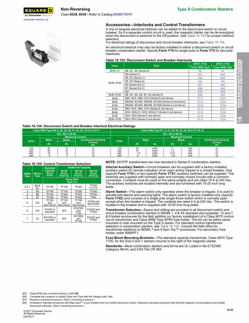
© 2017 Schneider ElectricAll Rights Reserved
16-55
schneider-electric.us
Non-Reversing Type S Combination StartersClass 8538, 8539 / Refer to Catalog 8538CT9701
Accessories—Interlocks and Control TransformersA one or twopole electrical interlock can be added to the disconnect switch or circuitbreaker. So if a separate control circuit is used, the magnetic starter can be de-energizedwhen the disconnect is switched to the Off position. See Table 16.153 for proper interlockselection.For electrical ratings of disconnect and circuit breaker interlocks, see Table 16.154.An electrical interlock may also be factory installed in either a disconnect switch or circuitbreaker combination starter. Specify Form Y74 for single-pole or Form Y75 for two-poleinterlocks.
Table 16.153: Disconnect Switch and Breaker InterlocksClass Type
SPDT (Y74) DPDT (Y75)Class 9999 Type Class 9999 Type
8538 [65] SB, SC, SD (Series B) R6 R7
8538, 8738
SD (Series C) R43 R44SB, SC (Series C) R45 R46SE, SF (Series A) R8 R9SE (Series B & C) R41 R42SF (Series B & C) R39 R40SG R35 R36
8539, 8739 SB, SC, SD, SE, SF, SG (Series K) R26 R278538 SBA, SCA, SBG, SCG (Series D and above) TC11 TC218538 SBAS8, SCAS8, SBGS8, SCGS8 (Series D and above) TC10 TC208738 SBAS8, SCAS8, SBGS8, SCGS8 (Series E and above) TC10 TC208738 SBA, SCA, SBG, SCG (Series E and above) TC11 TC218538 SDA, SDA[65], SDG, SDG[65] (Series D and above) TC10 TC208738 SDA, SDG (Series E and above) TC10 TC20
8538, 8738 SEA, SEG (Series D and above) TC10 TC20
Table 16.154: Disconnect Switch and Breaker Interlock Electrical RatingsClass 9999 Type R6, 8, 26, 35, 39, 41, 43, 45, TC10, & TC11 Class 9999 Type R7, 9, 27, 36, 40, 42, 44, 46 & TC 20, 21
AC—50 or 60 Hz AC—50 or 60 Hz
VoltsMaximum Current
VoltsMaximum Current
Make Break Continuous CarryingCurrent(A)
Make Break Continuous CarryingCurrent(A)(A) (A) (A) VA (A) VA
120240480600
4020108
151065
15151515
120240480600
3015 7.5 6
3450345034503450
3 1.50.75 0.6
345345345345
10101010
Table 16.155: Control Transformer Selection
NEMASize
StarterType
StandardCapacity(FormFF4T)
Additional Capacity50 VA(FormFF4T10)
100 VA(FormFF4T11)
200 VA(FormFF4T12)
Class 9070Type [66]
0 & 1 SB &SC TF100 TF150 TF200 TF300
[67][68]2 SD TF100 TF150 TF200 TF3003 SE TF150 TF200 TF300 TF5004 SF TF300 TF300 TF500 T500
5 SGTF100and
8501XO20
TF100and
8501XO20
TF150and
8501XO20TF300 and8501XO20
6 SH EO3S2 isstandard N/A
EO3FS2andT100
EO3S2 andTF200
7 SJ EO19S2 isstandard N/A
EO19S2and
TF100EO3S2 andTF200
NOTE: 9070TF transformers are now standard in Series K combination starters.Internal Auxiliary Switch—Circuit breakers can be supplied with a factory installedauxiliary switch for remote indication of an open and/or tripped or a closed breaker. One(specify Form Y741) or two (specify Form Y751) auxiliary switches can be supplied. Theswitches are supplied with normally open and normally closed circuits with a commonconnection. Contacts must be used on the same polarity and are rated 15 A at 240 Vac.The auxiliary switches are located internally and are furnished with 19-20 inch longleads.Alarm Switch—The alarm switch only operates when the breaker is tripped. It is used toactuate bell alarms and warning lights. The alarm switch is factory installed only (specifyForm Y742) and consists of a single pole single throw switch which is normally openexcept when the breaker is tripped. The contacts are rated 4 A at 240 Vac. This switch islocated in the breaker and is supplied with 19-20 inch long leads.Transformer Selection—Space and drilling are provided in all disconnect switch andcircuit breaker combination starters in NEMA 1, 4 & 4X stainless and polyester, 12 and 7& 9 bolted enclosures for the field addition (or factory installation) of a Class 9070 controlcircuit transformer and Class 9999 Type SFR4 fuse holder. This kit can be either panelmounted or side mounted on the Type S starter. For standard control transformerselection in combination starters, see Table 16.155. Consult the field office fortransformer additions to NEMA 7 and 9 Spin Top™ enclosures. For secondary fuseholder, order 9080PF1.Fuse Block Mounting Brackets—The standard capacity transformer, Class 9070 TypeT100, for the Size 0 and 1 starters mounts to the right of the magnetic starter.Standards—Most combination starters and forms are UL Listed in file E152395,Category NKJH, and CSA File CR 584.
16NEMAANDDEFINITEPURPOSE
CONTA
CTORSANDSTA
RTERS
[65] Class 8538 type numbers ending in suffix S8.[66] Complete the contactor or starter Class and Type with the voltage code. See .[67] Requires oversized enclosure. (Size 2 reversing enclosure.)[68] Available in standard enclosure with Mag-Gard™ circuit breaker and non-fusible disconnect switch. Requires oversized enclosure with thermal-magnetic circuit breakers and fusible
disconnect switches. (Size 2 reversing enclosure.)
6/20/2017
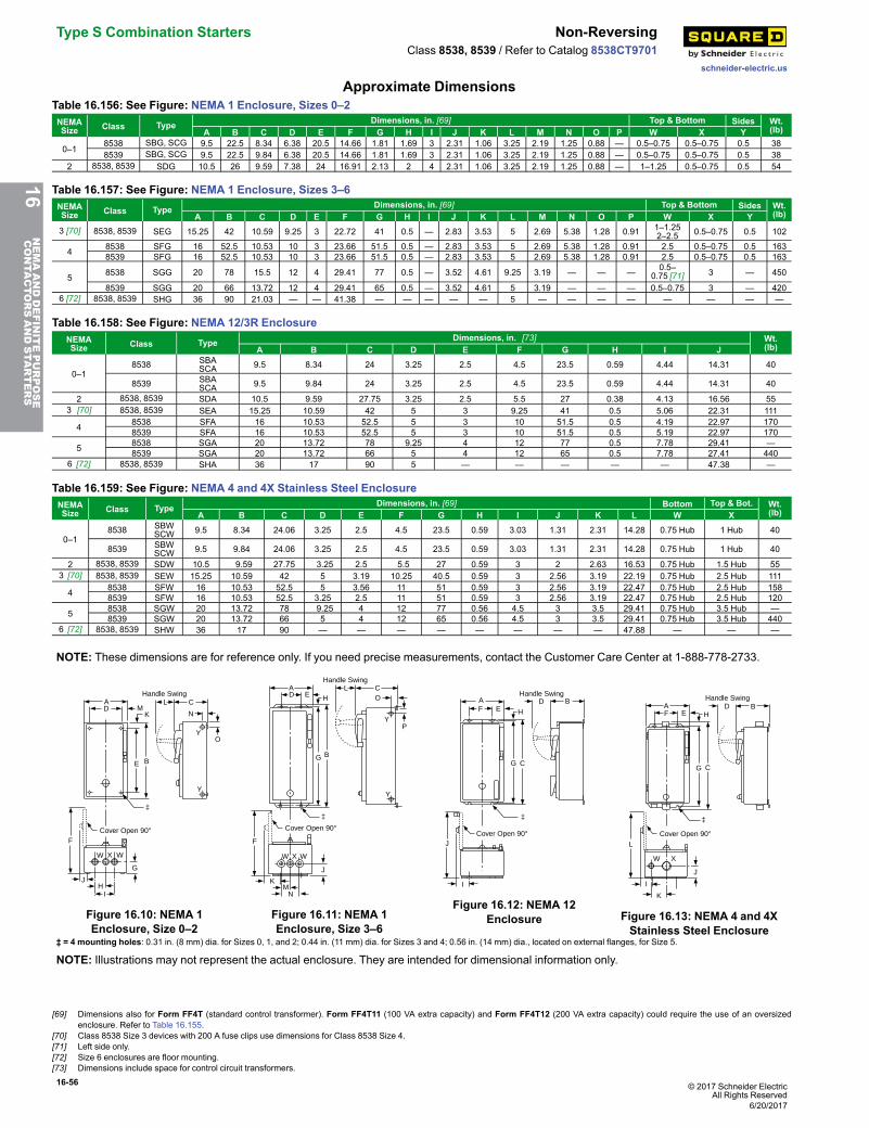
16-56 © 2017 Schneider ElectricAll Rights Reserved
Type S Combination Starters Non-Reversing
schneider-electric.us
Class 8538, 8539 / Refer to Catalog 8538CT9701
Approximate DimensionsTable 16.156: See Figure: NEMA 1 Enclosure, Sizes 0–2NEMASize Class Type Dimensions, in. [69] Top & Bottom Sides Wt.
(lb)A B C D E F G H I J K L M N O P W X Y
0–18538 SBG, SCG 9.5 22.5 8.34 6.38 20.5 14.66 1.81 1.69 3 2.31 1.06 3.25 2.19 1.25 0.88 — 0.5–0.75 0.5–0.75 0.5 388539 SBG, SCG 9.5 22.5 9.84 6.38 20.5 14.66 1.81 1.69 3 2.31 1.06 3.25 2.19 1.25 0.88 — 0.5–0.75 0.5–0.75 0.5 38
2 8538, 8539 SDG 10.5 26 9.59 7.38 24 16.91 2.13 2 4 2.31 1.06 3.25 2.19 1.25 0.88 — 1–1.25 0.5–0.75 0.5 54
Table 16.157: See Figure: NEMA 1 Enclosure, Sizes 3–6NEMASize Class Type Dimensions, in. [69] Top & Bottom Sides Wt.
(lb)A B C D E F G H I J K L M N O P W X Y3 [70] 8538, 8539 SEG 15.25 42 10.59 9.25 3 22.72 41 0.5 — 2.83 3.53 5 2.69 5.38 1.28 0.91 1–1.25
2–2.5 0.5–0.75 0.5 102
4 8538 SFG 16 52.5 10.53 10 3 23.66 51.5 0.5 — 2.83 3.53 5 2.69 5.38 1.28 0.91 2.5 0.5–0.75 0.5 1638539 SFG 16 52.5 10.53 10 3 23.66 51.5 0.5 — 2.83 3.53 5 2.69 5.38 1.28 0.91 2.5 0.5–0.75 0.5 163
5 8538 SGG 20 78 15.5 12 4 29.41 77 0.5 — 3.52 4.61 9.25 3.19 — — — 0.5–0.75 [71] 3 — 450
8539 SGG 20 66 13.72 12 4 29.41 65 0.5 — 3.52 4.61 5 3.19 — — — 0.5–0.75 3 — 4206 [72] 8538, 8539 SHG 36 90 21.03 — — 41.38 — — — — — 5 — — — — — — — —
Table 16.158: See Figure: NEMA 12/3R EnclosureNEMASize Class Type Dimensions, in. [73] Wt.
(lb)A B C D E F G H I J
0–18538 SBA
SCA 9.5 8.34 24 3.25 2.5 4.5 23.5 0.59 4.44 14.31 40
8539 SBASCA 9.5 9.84 24 3.25 2.5 4.5 23.5 0.59 4.44 14.31 40
2 8538, 8539 SDA 10.5 9.59 27.75 3.25 2.5 5.5 27 0.38 4.13 16.56 553 [70] 8538, 8539 SEA 15.25 10.59 42 5 3 9.25 41 0.5 5.06 22.31 111
4 8538 SFA 16 10.53 52.5 5 3 10 51.5 0.5 4.19 22.97 1708539 SFA 16 10.53 52.5 5 3 10 51.5 0.5 5.19 22.97 170
5 8538 SGA 20 13.72 78 9.25 4 12 77 0.5 7.78 29.41 —8539 SGA 20 13.72 66 5 4 12 65 0.5 7.78 27.41 440
6 [72] 8538, 8539 SHA 36 17 90 5 — — — — — 47.38 —
Table 16.159: See Figure: NEMA 4 and 4X Stainless Steel EnclosureNEMASize Class Type Dimensions, in. [69] Bottom Top & Bot. Wt.
(lb)A B C D E F G H I J K L W X
0–18538 SBW
SCW 9.5 8.34 24.06 3.25 2.5 4.5 23.5 0.59 3.03 1.31 2.31 14.28 0.75 Hub 1 Hub 40
8539 SBWSCW 9.5 9.84 24.06 3.25 2.5 4.5 23.5 0.59 3.03 1.31 2.31 14.28 0.75 Hub 1 Hub 40
2 8538, 8539 SDW 10.5 9.59 27.75 3.25 2.5 5.5 27 0.59 3 2 2.63 16.53 0.75 Hub 1.5 Hub 553 [70] 8538, 8539 SEW 15.25 10.59 42 5 3.19 10.25 40.5 0.59 3 2.56 3.19 22.19 0.75 Hub 2.5 Hub 111
4 8538 SFW 16 10.53 52.5 5 3.56 11 51 0.59 3 2.56 3.19 22.47 0.75 Hub 2.5 Hub 1588539 SFW 16 10.53 52.5 3.25 2.5 11 51 0.59 3 2.56 3.19 22.47 0.75 Hub 2.5 Hub 120
5 8538 SGW 20 13.72 78 9.25 4 12 77 0.56 4.5 3 3.5 29.41 0.75 Hub 3.5 Hub —8539 SGW 20 13.72 66 5 4 12 65 0.56 4.5 3 3.5 29.41 0.75 Hub 3.5 Hub 440
6 [72] 8538, 8539 SHW 36 17 90 — — — — — — — — 47.88 — — —
NOTE: These dimensions are for reference only. If you need precise measurements, contact the Customer Care Center at 1-888-778-2733.
YO
N
CHandle Swing
E B
KMD
A
Y
F
‡
W X W
G
JH
I
L
Cover Open 90°
Figure 16.10: NEMA 1Enclosure, Size 0–2
Handle Swing
DA
E HL C
P
O
Y
BG
Y
J
‡
NM
K
W X W
F
Cover Open 90°
Figure 16.11: NEMA 1Enclosure, Size 3–6
Handle Swing
Cover Open 90°
B
C
FA
J
‡
I
DE
G
H
Figure 16.12: NEMA 12Enclosure
Handle Swing
Cover Open 90°
B
C
FA
L
W X
I
DE
K
J
‡
G
H
Figure 16.13: NEMA 4 and 4XStainless Steel Enclosure
‡ = 4 mounting holes: 0.31 in. (8 mm) dia. for Sizes 0, 1, and 2; 0.44 in. (11 mm) dia. for Sizes 3 and 4; 0.56 in. (14 mm) dia., located on external flanges, for Size 5.
NOTE: Illustrations may not represent the actual enclosure. They are intended for dimensional information only.
16NEMAANDDEFINITEPURPOSE
CONTA
CTORSANDSTA
RTERS
[69] Dimensions also for Form FF4T (standard control transformer). Form FF4T11 (100 VA extra capacity) and Form FF4T12 (200 VA extra capacity) could require the use of an oversizedenclosure. Refer to Table 16.155.
[70] Class 8538 Size 3 devices with 200 A fuse clips use dimensions for Class 8538 Size 4.[71] Left side only.[72] Size 6 enclosures are floor mounting.[73] Dimensions include space for control circuit transformers.
6/20/2017
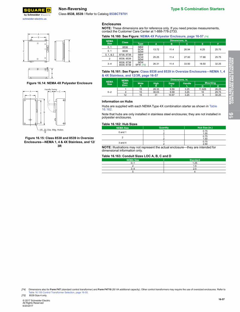
© 2017 Schneider ElectricAll Rights Reserved
16-57
schneider-electric.us
Non-Reversing Type S Combination StartersClass 8538, 8539 / Refer to Catalog 8538CT9701
Enclosures
A
E
F C
B
Figure 16.14: NEMA 4X Polyester Enclosure
CHandle Swing
E B
D
A
(4) .31 Dia. Mtg. Holes 8
L
Figure 16.15: Class 8538 and 8539 in OversizeEnclosures—NEMA 1, 4 & 4X Stainless, and 12/
3R
NOTE: These dimensions are for reference only. If you need precise measurements,contact the Customer Care Center at 1-888-778-2733.Table 16.160: See Figure: NEMA 4X Polyester Enclosure, page 16-57 [74]
NEMASize Class
Dimensions, in.Type A B C E F
0, 1 8538 SBWSCWSDW
13.72 11.4 26.94 6.25 25.750, 1 85390, 1, & 2 8738, 8739 SBW
SCWSDW
25.25 11.4 27.00 17.88 25.752 8538, 8539
3–4 8538, 87388539, 8739
SEWSFW [75] 26.31 11.4 33.50 18.50 32.25
Table 16.161: See Figure: Class 8538 and 8539 in Oversize Enclosures—NEMA 1, 4& 4X Stainless, and 12/3R, page 16-57
NEMASize
NEMATypeEncl.
Dimensions, in.WideA
HighB
DeepC
HandleL
MountingD E
0–21 15 28.33 9.59 3.25 11.625 26.254 15 30.03 9.59 3.25 10 29.7512 15 31 10.97 3.25 9 30.25
Information on HubsHubs are supplied with each NEMAType 4X combination starter as shown in Table16.162.Note that hubs are only installed in stainless steel enclosures; they are not installed inpolyester enclosures.
Table 16.162: Hub SizesNEMA Size Quantity Hub Size (in.)
0 and 1 12
0.751.00
2 12
0.751.50
3 and 4 12
0.752.50
NOTE: Illustrations may not represent the actual enclosure—they are intended fordimensional information only.
Table 16.163: Conduit Sizes LOC A, B, C and DNEMA Size Standard
0–1 1.252 1.53–4 2.55 4
16NEMAANDDEFINITEPURPOSE
CONTA
CTORSANDSTA
RTERS
[74] Dimensions also for Form F4T (standard control transformer) and Form F4T10 (50 VA additional capacity). Other control transformers may require the use of oversized enclosures. Refer toTable 16.155 Control Transformer Selection, page 16-55.
[75] 8539 Size 4 only.
6/20/2017
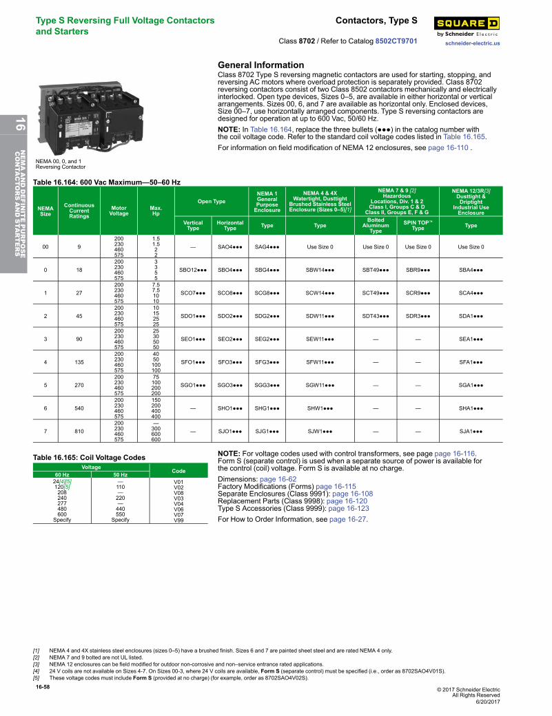
16-58 © 2017 Schneider ElectricAll Rights Reserved
Type S Reversing Full Voltage Contactorsand Starters
Contactors, Type S
schneider-electric.usClass 8702 / Refer to Catalog 8502CT9701
General Information
NEMA 00, 0, and 1Reversing Contactor
Class 8702 Type S reversing magnetic contactors are used for starting, stopping, andreversing AC motors where overload protection is separately provided. Class 8702reversing contactors consist of two Class 8502 contactors mechanically and electricallyinterlocked. Open type devices, Sizes 0–5, are available in either horizontal or verticalarrangements. Sizes 00, 6, and 7 are available as horizontal only. Enclosed devices,Size 00–7, use horizontally arranged components. Type S reversing contactors aredesigned for operation at up to 600 Vac, 50/60 Hz.NOTE: In Table 16.164, replace the three bullets (●●●) in the catalog number withthe coil voltage code. Refer to the standard coil voltage codes listed in Table 16.165.For information on field modification of NEMA 12 enclosures, see page 16-110 .
Table 16.164: 600 Vac Maximum—50–60 Hz
NEMASize
ContinuousCurrentRatings
MotorVoltage
Max.Hp
Open TypeNEMA 1GeneralPurposeEnclosure
NEMA 4 & 4XWatertight, Dusttight
Brushed Stainless SteelEnclosure (Sizes 0–5)[1]
NEMA 7 & 9 [2]Hazardous
Locations, Div. 1 & 2Class I, Groups C & D
Class II, Groups E, F & G
NEMA 12/3R[3]Dusttight &Driptight
Industrial UseEnclosure
VerticalType
HorizontalType Type Type
BoltedAluminum
TypeSPIN TOP™
Type Type
00 9200230460575
1.51.522
— SAO4●●● SAG4●●● Use Size 0 Use Size 0 Use Size 0 Use Size 0
0 18200230460575
3355
SBO12●●● SBO4●●● SBG4●●● SBW14●●● SBT49●●● SBR9●●● SBA4●●●
1 27200230460575
7.57.51010
SCO7●●● SCO8●●● SCG8●●● SCW14●●● SCT49●●● SCR9●●● SCA4●●●
2 45200230460575
10152525
SDO1●●● SDO2●●● SDG2●●● SDW11●●● SDT43●●● SDR3●●● SDA1●●●
3 90200230460575
25305050
SEO1●●● SEO2●●● SEG2●●● SEW11●●● — — SEA1●●●
4 135200230460575
4050100100
SFO1●●● SFO3●●● SFG3●●● SFW11●●● — — SFA1●●●
5 270200230460575
75100200200
SGO1●●● SGO3●●● SGG3●●● SGW11●●● — — SGA1●●●
6 540200230460575
150200400400
— SHO1●●● SHG1●●● SHW1●●● — — SHA1●●●
7 810200230460575
—300600600
— SJO1●●● SJG1●●● SJW1●●● — — SJA1●●●
Table 16.165: Coil Voltage CodesVoltage
Code60 Hz 50 Hz24[4][5]120[5]208240277480600
Specify
—110—220—440550
Specify
V01V02V08V03V04V06V07V99
NOTE: For voltage codes used with control transformers, see page page 16-116.Form S (separate control) is used when a separate source of power is available forthe control (coil) voltage. Form S is available at no charge.Dimensions: page 16-62Factory Modifications (Forms) page 16-115Separate Enclosures (Class 9991): page 16-108Replacement Parts (Class 9998): page 16-120Type S Accessories (Class 9999): page 16-123For How to Order Information, see page 16-27.
[1] NEMA 4 and 4X stainless steel enclosures (sizes 0–5) have a brushed finish. Sizes 6 and 7 are painted sheet steel and are rated NEMA 4 only.[2] NEMA 7 and 9 bolted are not UL listed.[3] NEMA 12 enclosures can be field modified for outdoor non-corrosive and non–service entrance rated applications.[4] 24 V coils are not available on Sizes 4-7. On Sizes 00-3, where 24 V coils are available, Form S (separate control) must be specified (i.e., order as 8702SAO4V01S).[5] These voltage codes must include Form S (provided at no charge) (for example, order as 8702SAO4V02S).
6/20/2017
16NEMAANDDEFINITEPURPOSE
CONTA
CTORSANDSTA
RTERS
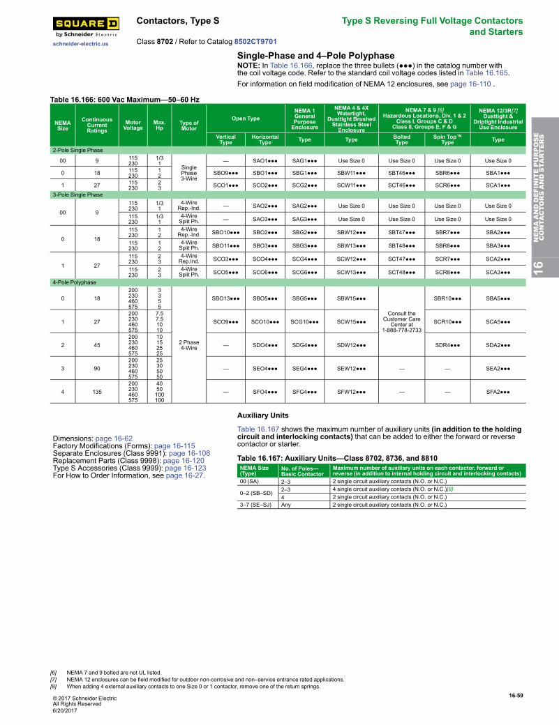
© 2017 Schneider ElectricAll Rights Reserved
16-59
schneider-electric.us
Contactors, Type S Type S Reversing Full Voltage Contactorsand Starters
Class 8702 / Refer to Catalog 8502CT9701
Single-Phase and 4–Pole PolyphaseNOTE: In Table 16.166, replace the three bullets (●●●) in the catalog number withthe coil voltage code. Refer to the standard coil voltage codes listed in Table 16.165.For information on field modification of NEMA 12 enclosures, see page 16-110 .
Table 16.166: 600 Vac Maximum—50–60 Hz
NEMASize
ContinuousCurrentRatings
MotorVoltage
Max.Hp
Type ofMotor
Open TypeNEMA 1GeneralPurposeEnclosure
NEMA 4 & 4XWatertight,
Dusttight BrushedStainless SteelEnclosure
NEMA 7 & 9 [6]Hazardous Locations, Div. 1 & 2
Class I, Groups C & DClass II, Groups E, F & G
NEMA 12/3R[7]Dusttight &
Driptight IndustrialUse Enclosure
VerticalType
HorizontalType Type Type Bolted
TypeSpin Top™
Type Type
2-Pole Single Phase
00 9 115230
1/31
SinglePhase3-Wire
— SAO1●●● SAG1●●● Use Size 0 Use Size 0 Use Size 0 Use Size 0
0 18 115230
12 SBO9●●● SBO1●●● SBG1●●● SBW11●●● SBT46●●● SBR6●●● SBA1●●●
1 27 115230
23 SCO1●●● SCO2●●● SCG2●●● SCW11●●● SCT46●●● SCR6●●● SCA1●●●
3-Pole Single Phase
00 9
115230
1/31
4-WireRep.-Ind. — SAO2●●● SAG2●●● Use Size 0 Use Size 0 Use Size 0 Use Size 0
115230
1/31
4-WireSplit Ph. — SAO3●●● SAG3●●● Use Size 0 Use Size 0 Use Size 0 Use Size 0
0 18
115230
12
4-WireRep.-Ind. SBO10●●● SBO2●●● SBG2●●● SBW12●●● SBT47●●● SBR7●●● SBA2●●●
115230
12
4-WireSplit Ph. SBO11●●● SBO3●●● SBG3●●● SBW13●●● SBT48●●● SBR8●●● SBA3●●●
1 27
115230
23
4-WireRep.Ind. SCO3●●● SCO4●●● SCG4●●● SCW12●●● SCT47●●● SCR7●●● SCA2●●●
115230
23
4-WireSplit Ph. SCO5●●● SCO6●●● SCG6●●● SCW13●●● SCT48●●● SCR8●●● SCA3●●●
4-Pole Polyphase
0 18200230460575
3355
2 Phase4-Wire
SBO13●●● SBO5●●● SBG5●●● SBW15●●●
Consult theCustomer Care
Center at1-888-778-2733
SBR10●●● SBA5●●●
1 27200230460575
7.57.51010
SCO9●●● SCO10●●● SCG10●●● SCW15●●● SCR10●●● SCA5●●●
2 45200230460575
10152525
— SDO4●●● SDG4●●● SDW12●●● SDR4●●● SDA2●●●
3 90200230460575
25305050
— SEO4●●● SEG4●●● SEW12●●● — — SEA2●●●
4 135200230460575
4050100100
— SFO4●●● SFG4●●● SFW12●●● — — SFA2●●●
Auxiliary Units
Dimensions: page 16-62Factory Modifications (Forms): page 16-115Separate Enclosures (Class 9991): page 16-108Replacement Parts (Class 9998): page 16-120Type S Accessories (Class 9999): page 16-123For How to Order Information, see page 16-27.
Table 16.167 shows the maximum number of auxiliary units (in addition to the holdingcircuit and interlocking contacts) that can be added to either the forward or reversecontactor or starter.
Table 16.167: Auxiliary Units—Class 8702, 8736, and 8810NEMA Size(Type)
No. of Poles—Basic Contactor
Maximum number of auxiliary units on each contactor, forward orreverse (in addition to internal holding circuit and interlocking contacts)
00 (SA) 2–3 2 single circuit auxiliary contacts (N.O. or N.C.)
0–2 (SB–SD) 2–3 4 single circuit auxiliary contacts (N.O. or N.C.)[8]4 2 single circuit auxiliary contacts (N.O. or N.C.)
3–7 (SE–SJ) Any 2 single circuit auxiliary contacts (N.O. or N.C.)
16NEMAANDDEFINITEPURPOSE
CONTA
CTORSANDSTA
RTERS
[6] NEMA 7 and 9 bolted are not UL listed.[7] NEMA 12 enclosures can be field modified for outdoor non-corrosive and non–service entrance rated applications.[8] When adding 4 external auxiliary contacts to one Size 0 or 1 contactor, remove one of the return springs.
6/20/2017
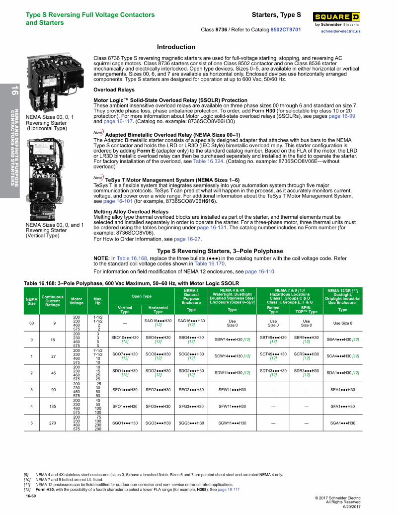
16-60 © 2017 Schneider ElectricAll Rights Reserved
Type S Reversing Full Voltage Contactorsand Starters
Starters, Type S
schneider-electric.usClass 8736 / Refer to Catalog 8502CT9701
Introduction
NEMA Sizes 00, 0, 1
Class 8736 Type S reversing magnetic starters are used for full-voltage starting, stopping, and reversing ACsquirrel cage motors. Class 8736 starters consist of one Class 8502 contactor and one Class 8536 startermechanically and electrically interlocked. Open type devices, Sizes 0–5, are available in either horizontal or verticalarrangements. Sizes 00, 6, and 7 are available as horizontal only. Enclosed devices use horizontally arrangedcomponents. Type S starters are designed for operation at up to 600 Vac, 50/60 Hz.
Overload Relays
Motor Logic™ Solid-State Overload Relay (SSOLR) ProtectionThese ambient insensitive overload relays are available on three phase sizes 00 through 6 and standard on size 7.They provide phase loss, phase unbalance protection. To order, add Form H30 (for selectable trip class 10 or 20protection). For more information about Motor Logic solid-state overload relays (SSOLRs), see pages page 16-99and page 16-117. (Catalog no. example: 8736SCO8V06H30)
Adapted Bimetallic Overload Relay (NEMA Sizes 00–1)The Adapted Bimetallic starter consists of a specially designed adapter that attaches with bus bars to the NEMAType S contactor and holds the LRD or LR3D (IEC Style) bimetallic overload relay. This starter configuration isordered by adding Form E (adapter only) to the standard catalog number. Based on the FLA of the motor, the LRDor LR3D bimetallic overload relay can then be purchased separately and installed in the field to operate the starter.For factory installation of the overload, see Table 16.324. (Catalog no. example: 8736SCO8V06E—withoutoverload)
TeSys T Motor Management System (NEMA Sizes 1–6)TeSys T is a flexible system that integrates seamlessly into your automation system through five majorcommunication protocols. TeSys Tcan predict what will happen in the process, as it accurately monitors current,voltage, and power over a wide range. For additional information about the TeSys T Motor Management System,see page 16-101 (for example, 8736SCO8V06H616).
Melting Alloy Overload RelaysMelting alloy type thermal overload blocks are installed as part of the starter, and thermal elements must beselected and installed separately in order to operate the starter. For a three-phase motor, three thermal units mustbe ordered using the tables beginning under page 16-131. The catalog number includes no Form number (forexample, 8736SCO8V06).
Reversing Starter(Horizontal Type)
NEMA Sizes 00, 0, and 1Reversing Starter(Vertical Type)
For How to Order Information, see page 16-27.
Type S Reversing Starters, 3–Pole PolyphaseNOTE: In Table 16.168, replace the three bullets (●●●) in the catalog number with the coil voltage code. Referto the standard coil voltage codes shown in Table 16.170.For information on field modification of NEMA 12 enclosures, see page 16-110.
Table 16.168: 3–Pole Polyphase, 600 Vac Maximum, 50–60 Hz, with Motor Logic SSOLR
NEMASize
ContinuousCurrentRatings
MotorVoltage
Max.Hp
Open TypeNEMA 1GeneralPurposeEnclosure
NEMA 4 & 4XWatertight, Dusttight
Brushed Stainless SteelEnclosure (Sizes 0–5)[9]
NEMA 7 & 9 [10]Hazardous LocationsClass I, Groups C & D
Class II, Groups E, F & G
NEMA 12/3R [11]Dusttight,
Driptight IndustrialUse Enclosure
VerticalType
HorizontalType Type Type Bolted
TypeSPIN-
TOP™ Type Type
00 9200230460575
1-1/21-1/222
— SAO16●●●H30[12]
SAG16●●●H30[12]
UseSize 0
UseSize 0
UseSize 0 Use Size 0
0 18200230460575
3355
SBO10●●●H30[12]
SBO4●●●H30[12]
SBG4●●●H30[12] SBW14●●●H30 [12] SBT49●●●H30
[12]SBR9●●●H30
[12] SBA4●●●H30 [12]
1 27200230460575
7-1/27-1/21010
SCO7●●●H30[12]
SCO8●●●H30[12]
SCG8●●●H30[12] SCW14●●●H30 [12] SCT49●●●H30
[12]SCR9●●●H30
[12] SCA4●●●H30 [12]
2 45200230460575
10152525
SDO1●●●H30[12]
SDO2●●●H30[12]
SDG2●●●H30[12] SDW11●●●H30 [12] SDT43●●●H30
[12]SDR3●●●H30
[12] SDA1●●●H30 [12]
3 90200230460575
25305050
SEO1●●●H30 SEO2●●●H30 SEG2●●●H30 SEW11●●●H30 — — SEA1●●●H30
4 135200230460575
4050100100
SFO1●●●H30 SFO3●●●H30 SFG3●●●H30 SFW11●●●H30 — — SFA1●●●H30
5 270200230460575
75100200200
SGO1●●●H30 SGO3●●●H30 SGG3●●●H30 SGW11●●●H30 — — SGA1●●●H30
16NEMAANDDEFINITEPURPOSE
CONTA
CTORSANDSTA
RTERS
[9] NEMA 4 and 4X stainless steel enclosures (sizes 0–5) have a brushed finish. Sizes 6 and 7 are painted sheet steel and are rated NEMA 4 only.[10] NEMA 7 and 9 bolted are not UL listed.[11] NEMA 12 enclosures can be field modified for outdoor non-corrosive and non–service entrance rated applications.[12] Form H30, with the possibility of a fourth character to select a lower FLA range (for example, H308). See page 16-117
6/20/2017
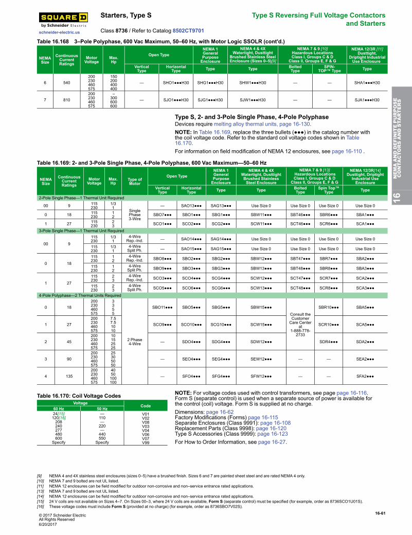
© 2017 Schneider ElectricAll Rights Reserved
16-61
schneider-electric.us
Starters, Type S Type S Reversing Full Voltage Contactorsand Starters
Class 8736 / Refer to Catalog 8502CT9701
Table 16.168 3–Pole Polyphase, 600 Vac Maximum, 50–60 Hz, with Motor Logic SSOLR (cont'd.)
NEMASize
ContinuousCurrentRatings
MotorVoltage
Max.Hp
Open TypeNEMA 1GeneralPurposeEnclosure
NEMA 4 & 4XWatertight, Dusttight
Brushed Stainless SteelEnclosure (Sizes 0–5)[9]
NEMA 7 & 9 [10]Hazardous LocationsClass I, Groups C & D
Class II, Groups E, F & G
NEMA 12/3R [11]Dusttight,
Driptight IndustrialUse Enclosure
VerticalType
HorizontalType Type Type Bolted
TypeSPIN-
TOP™ Type Type
6 540200230460575
150200400400
— SHO1●●●H30 SHG1●●●H30 SHW1●●●H30 — — SHA1●●●H30
7 810200230460575
–300600600
— SJO1●●●H30 SJG1●●●H30 SJW1●●●H30 — — SJA1●●●H30
Type S, 2- and 3-Pole Single Phase, 4-Pole PolyphaseDevices require melting alloy thermal units, page 16-130.NOTE: In Table 16.169, replace the three bullets (●●●) in the catalog number withthe coil voltage code. Refer to the standard coil voltage codes shown in Table16.170.For information on field modification of NEMA 12 enclosures, see page 16-110 .
Table 16.169: 2- and 3-Pole Single Phase, 4-Pole Polyphase, 600 Vac Maximum—50–60 Hz
NEMASize
ContinuousCurrentRatings
MotorVoltage
Max.Hp
Type ofMotor
Open TypeNEMA 1GeneralPurposeEnclosure
NEMA 4 & 4XWatertight, DusttightBrushed StainlessSteel Enclosure
NEMA 7 & 9 [13]Hazardous LocationsClass I, Groups C & D
Class II, Groups E, F & G
NEMA 12/3R[14]Dusttight, Driptight
Industrial UseEnclosure
VerticalType
HorizontalType Type Type Bolted
TypeSpin Top™
Type Type
2-Pole Single Phase—1 Thermal Unit Required
00 9 115230
1/31
SinglePhase3-Wire
— SAO13●●● SAG13●●● Use Size 0 Use Size 0 Use Size 0 Use Size 0
0 18 115230
12 SBO7●●● SBO1●●● SBG1●●● SBW11●●● SBT46●●● SBR6●●● SBA1●●●
1 27 115230
23 SCO1●●● SCO2●●● SCG2●●● SCW11●●● SCT46●●● SCR6●●● SCA1●●●
3-Pole Single Phase—1 Thermal Unit Required
00 9
115230
1/31
4-WireRep.-Ind. — SAO14●●● SAG14●●● Use Size 0 Use Size 0 Use Size 0 Use Size 0
115230
1/31
4-WireSplit Ph. — SAO15●●● SAG15●●● Use Size 0 Use Size 0 Use Size 0 Use Size 0
0 18
115230
12
4-WireRep.-Ind. SBO8●●● SBO2●●● SBG2●●● SBW12●●● SBT47●●● SBR7●●● SBA2●●●
115230
12
4-WireSplit Ph. SBO9●●● SBO3●●● SBG3●●● SBW13●●● SBT48●●● SBR8●●● SBA3●●●
1 27
115230
23
4-WireRep.-Ind. SCO3●●● SCO4●●● SCG4●●● SCW12●●● SCT47●●● SCR7●●● SCA2●●●
115230
23
4-WireSplit Ph. SCO5●●● SCO6●●● SCG6●●● SCW13●●● SCT48●●● SCR8●●● SCA3●●●
4-Pole Polyphase—2 Thermal Units Required
0 18200230460575
3355
2 Phase4-Wire
SBO11●●● SBO5●●● SBG5●●● SBW15●●●
Consult theCustomerCare Center
at1-888-778-
2733
SBR10●●● SBA5●●●
1 27200230460575
7.57.51010
SCO9●●● SCO10●●● SCG10●●● SCW15●●● SCR10●●● SCA5●●●
2 45200230460575
10152525
— SDO4●●● SDG4●●● SDW12●●● SDR4●●● SDA2●●●
3 90200230460575
25305050
— SEO4●●● SEG4●●● SEW12●●● — — SEA2●●●
4 135200230460575
4050100100
— SFO4●●● SFG4●●● SFW12●●● — — SFA2●●●
Table 16.170: Coil Voltage CodesVoltage
Code60 Hz 50 Hz24[15]120[16]208240277480600
Specify
—110—220—440550
Specify
V01V02V08V03V04V06V07V99
NOTE: For voltage codes used with control transformers, see page page 16-116.Form S (separate control) is used when a separate source of power is available forthe control (coil) voltage. Form S is supplied at no charge.Dimensions: page 16-62Factory Modifications (Forms) page 16-115Separate Enclosures (Class 9991): page 16-108Replacement Parts (Class 9998): page 16-120Type S Accessories (Class 9999): page 16-123For How to Order Information, see page 16-27.
16NEMAANDDEFINITEPURPOSE
CONTA
CTORSANDSTA
RTERS
[9] NEMA 4 and 4X stainless steel enclosures (sizes 0–5) have a brushed finish. Sizes 6 and 7 are painted sheet steel and are rated NEMA 4 only.[10] NEMA 7 and 9 bolted are not UL listed.[11] NEMA 12 enclosures can be field modified for outdoor non-corrosive and non–service entrance rated applications.[13] NEMA 7 and 9 bolted are not UL listed.[14] NEMA 12 enclosures can be field modified for outdoor non-corrosive and non–service entrance rated applications.[15] 24 V coils are not available on Sizes 4–7. On Sizes 00–3, where 24 V coils are available, Form S (separate control) must be specified (for example, order as 8736SCO1U01S).[16] These voltage codes must include Form S (provided at no charge) (for example, order as 8736SBO7V02S).
6/20/2017
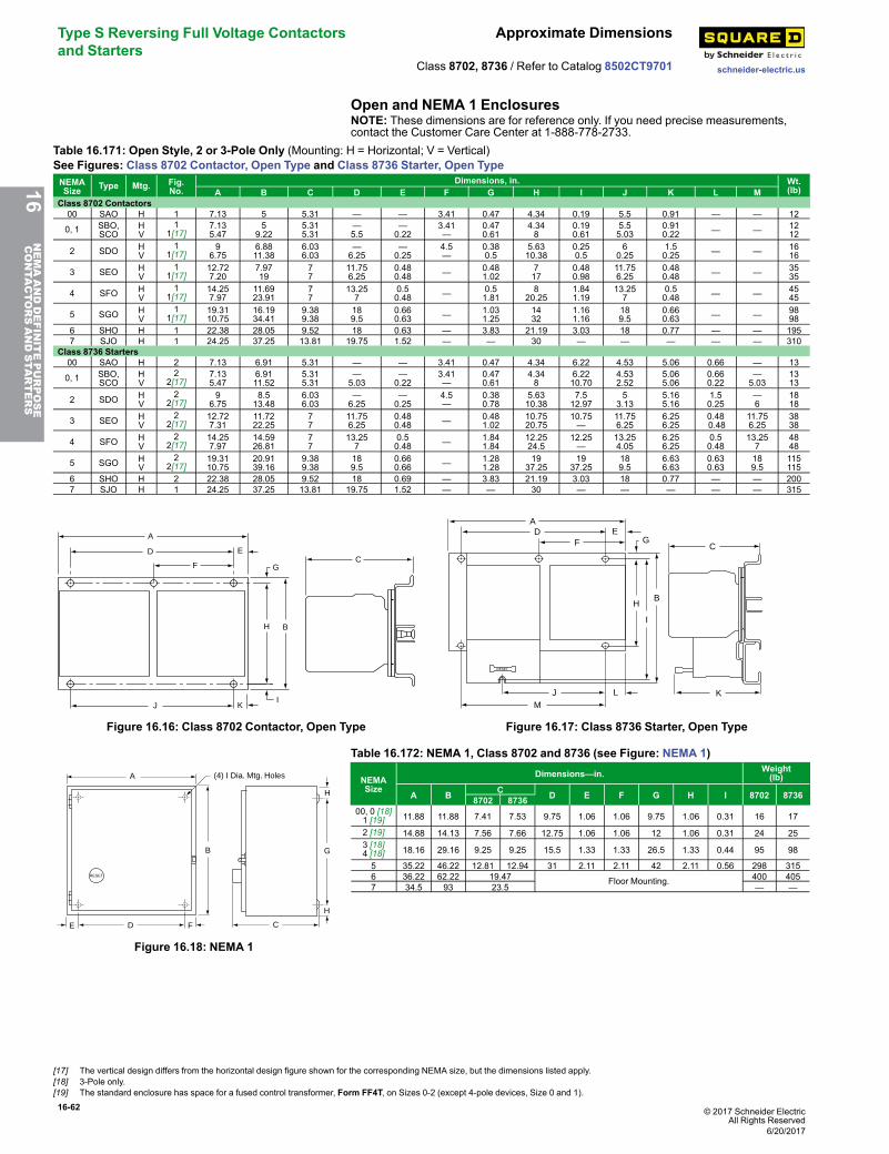
16-62 © 2017 Schneider ElectricAll Rights Reserved
Type S Reversing Full Voltage Contactorsand Starters
Approximate Dimensions
schneider-electric.usClass 8702, 8736 / Refer to Catalog 8502CT9701
Open and NEMA 1 EnclosuresNOTE: These dimensions are for reference only. If you need precise measurements,contact the Customer Care Center at 1-888-778-2733.
Table 16.171: Open Style, 2 or 3-Pole Only (Mounting: H = Horizontal; V = Vertical)See Figures: Class 8702 Contactor, Open Type and Class 8736 Starter, Open TypeNEMASize Type Mtg. Fig.
No.Dimensions, in. Wt.
(lb)A B C D E F G H I J K L MClass 8702 Contactors00 SAO H 1 7.13 5 5.31 — — 3.41 0.47 4.34 0.19 5.5 0.91 — — 12
0, 1 SBO,SCO
HV
11[17]
7.135.47
59.22
5.315.31
—5.5
—0.22
3.41—
0.470.61
4.348
0.190.61
5.55.03
0.910.22 — — 12
12
2 SDO HV
11[17]
96.75
6.8811.38
6.036.03
—6.25
—0.25
4.5—
0.380.5
5.6310.38
0.250.5
60.25
1.50.25 — — 16
16
3 SEO HV
11[17]
12.727.20
7.9719
77
11.756.25
0.480.48 — 0.48
1.02717
0.480.98
11.756.25
0.480.48 — — 35
35
4 SFO HV
11[17]
14.257.97
11.6923.91
77
13.257
0.50.48 — 0.5
1.818
20.251.841.19
13.257
0.50.48 — — 45
45
5 SGO HV
11[17]
19.3110.75
16.1934.41
9.389.38
189.5
0.660.63 — 1.03
1.251432
1.161.16
189.5
0.660.63 — — 98
986 SHO H 1 22.38 28.05 9.52 18 0.63 — 3.83 21.19 3.03 18 0.77 — — 1957 SJO H 1 24.25 37.25 13.81 19.75 1.52 — — 30 — — — — — 310
Class 8736 Starters00 SAO H 2 7.13 6.91 5.31 — — 3.41 0.47 4.34 6.22 4.53 5.06 0.66 — 13
0, 1 SBO,SCO
HV
22[17]
7.135.47
6.9111.52
5.315.31
—5.03
—0.22
3.41—
0.470.61
4.348
6.2210.70
4.532.52
5.065.06
0.660.22
—5.03
1313
2 SDO HV
22[17]
96.75
8.513.48
6.036.03
—6.25
—0.25
4.5—
0.380.78
5.6310.38
7.512.97
53.13
5.165.16
1.50.25
—6
1818
3 SEO HV
22[17]
12.727.31
11.7222.25
77
11.756.25
0.480.48 — 0.48
1.0210.7520.75
10.75—
11.756.25
6.256.25
0.480.48
11.756.25
3838
4 SFO HV
22[17]
14.257.97
14.5926.81
77
13.257
0.50.48 — 1.84
1.8412.2524.5
12.25—
13.254.05
6.256.25
0.50.48
13.257
4848
5 SGO HV
22[17]
19.3110.75
20.9139.16
9.389.38
189.5
0.660.66 — 1.28
1.2819
37.2519
37.25189.5
6.636.63
0.630.63
189.5
115115
6 SHO H 2 22.38 28.05 9.52 18 0.69 — 3.83 21.19 3.03 18 0.77 — — 2007 SJO H 1 24.25 37.25 13.81 19.75 1.52 — — 30 — — — — — 315
D
F
E
J K
G
H B
I
A
C
Figure 16.16: Class 8702 Contactor, Open Type
C
RESET
MJ L
H
I
B
GE
FD
A
K
Figure 16.17: Class 8736 Starter, Open Type
RESET
A
B
H
H
CFDE
G
(4) I Dia. Mtg. Holes
Figure 16.18: NEMA 1
Table 16.172: NEMA 1, Class 8702 and 8736 (see Figure: NEMA 1)
NEMASize
Dimensions—in. Weight(lb)
A B C D E F G H I 8702 87368702 873600, 0 [18]1 [19] 11.88 11.88 7.41 7.53 9.75 1.06 1.06 9.75 1.06 0.31 16 17
2 [19] 14.88 14.13 7.56 7.66 12.75 1.06 1.06 12 1.06 0.31 24 253 [18]4 [18] 18.16 29.16 9.25 9.25 15.5 1.33 1.33 26.5 1.33 0.44 95 98
5 35.22 46.22 12.81 12.94 31 2.11 2.11 42 2.11 0.56 298 3156 36.22 62.22 19.47 Floor Mounting. 400 4057 34.5 93 23.5 — —
16NEMAANDDEFINITEPURPOSE
CONTA
CTORSANDSTA
RTERS
[17] The vertical design differs from the horizontal design figure shown for the corresponding NEMA size, but the dimensions listed apply.[18] 3-Pole only.[19] The standard enclosure has space for a fused control transformer, Form FF4T, on Sizes 0-2 (except 4-pole devices, Size 0 and 1).
6/20/2017
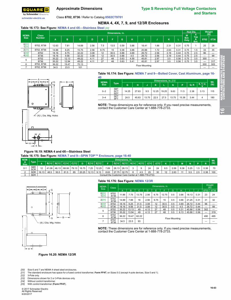
© 2017 Schneider ElectricAll Rights Reserved
16-63
schneider-electric.us
Approximate Dimensions Type S Reversing Full Voltage Contactorsand Starters
Class 8702, 8736 / Refer to Catalog 8502CT9701
NEMA 4, 4X, 7, 9, and 12/3R EnclosuresTable 16.173: See Figure: NEMA 4 and 4X—Stainless Steel [20]
NEMASize
ClassNumber
Dimensions, in. Hub Dia. Weight(lb)W
Bot.Only
XTop&
Bot.A B C D E F G H I J K L 8702 8736
0[21]1[21] 8702, 8736 12.63 7.81 14.69 2.56 7.5 13.5 0.59 3.88 18.41 1.66 2.31 0.31 0.75 1 25 26
2[21] 8702, 8736 14.88 8.25 15.75 2.56 9.75 15 0.38 3.88 20.88 1.72 2.63 0.31 0.75 1.5 33 353[22]4[22]
8702 18.16 8.75 32.22 3.08 12 30.5 0.88 3.69 26.72 2.56 3.19 0.44 0.75 2.5 96 —8736 18.16 9.56 32.22 3.08 12 30.5 0.88 4.5 26.72 2.56 3.19 0.44 0.75 2.5 — 99
5 8702 35.22 12.13 49.22 4.11 27 48 0.63 4.59 45.81 2.97 3.5 0.56 0.75 3.5 300 —8736 35.22 12.94 49.22 4.11 27 48 0.63 5.41 45.81 2.97 3.5 0.56 0.75 3.5 — 317
6 8702, 8736 36.22 19.47 70.13 Floor Mounting 500 5057 8702, 8736 34.5 23.5 101 — —
(4) L Dia. Mtg. Holes
GDEDA
CF
B
J
HK
W X
I
G
Figure 16.19: NEMA 4 and 4X—Stainless Steel
Table 16.174: See Figure: NEMA 7 and 9—Bolted Cover, Cast Aluminum, page 16-40NEMASize Type
Dimensions, in. [23] Wt.(lb)G H J K L N P Q, R S, T, U,
V
0–2SBTSCTSDT
14.25 27.63 9.5 12.25 19.25 9.63 11.5 2.38 3.13 115
3–4 SETSFT 24.5 45.63 13.75 22.5 27.5 13.75 15.38 3.44 4 180
NOTE: These dimensions are for reference only. If you need precise measurements,contact the Customer Care Center at 1-888-778-2733.
Table 16.175: See Figure: NEMA 7 and 9—SPIN TOP™ Enclosure, page 16-40NEM-A
SizeType
Dimensions, in. Wt.(lb)A B[24] B[25] C[24] C[25] D E[24] E[25] F G[24] G[25] H[24] H[25] J[24] J[25] K L M N P R
0-1 SBRSCR 12 41.06 46.13 68.06 79.13 16.75 7.25 12.25 7.69 26.13 26.13 3 9 24 24 8.5 2.06 9.38 5.25 1.5 0.38 70
2 SDR 16.13 48.5 50.5 81.5 85 20.25 12.13 9.13 8.63 27.75 32.75 8 4.5 25 30 12 2.63 11 5.5 2.5 0.38 1003 SER Consult the Customer Care Center at 1-888-778-2733.
AD D G
F C
E
G
I
H
(4) J Dia. Mtg. Holes
B
Figure 16.20: NEMA 12/3R
Table 16.176: See Figure: NEMA 12/3R
NEMASize Class
Dimensions, in. Weight(lb)
A B C D E F G H I J 8702 87360[21]1[21]
87028736 11.88 7.75 13.75 2.56 6.75 12.75 0.5 3.66 18.13 0.31 23 24
2[21] 87028736 14.88 7.88 16 2.56 9.75 15 0.5 3.66 21.25 0.31 31 32
3[22]4[22]
8702 18.16 9.25 31.5 3.08 12 30.5 0.5 3.69 26.72 0.44 96 —8736 18.16 9.56 31.5 3.08 12 30.5 0.5 4.5 26.72 0.44 — 99
5 8702 35.22 13.13 49 4.13 27 48 0.5 5.31 45.88 0.56 302 —8736 35.22 13.94 49 4.13 27 48 0.5 6.13 45.88 0.56 — 319
6 87028736 36.22 19.47 62.22
Floor Mounting490 495
7 87028736 34.5 23.5 93 — —
NOTE: These dimensions are for reference only. If you need precise measurements,contact the Customer Care Center at 1-888-778-2733.
16NEMAANDDEFINITEPURPOSE
CONTA
CTORSANDSTA
RTERS
[20] Size 6 and 7 are NEMA 4 sheet steel enclosures.[21] The standard enclosure has space for a fused control transformer, Form FF4T, on Sizes 0-2 (except 4-pole devices, Size 0 and 1).[22] 3-Pole only.[23] Dimensions shown for 2 or 3-Pole devices only.[24] Without control transformer.[25] With control transformer (Form FF4T).
6/20/2017
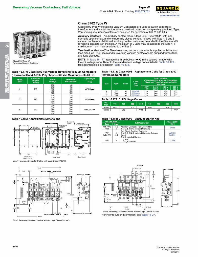
16-64 © 2017 Schneider ElectricAll Rights Reserved
Reversing Vacuum Contactors, Full Voltage Type W
schneider-electric.us
Class 8702 / Refer to Catalog 8502CT9701
Class 8702 Type W
Class 8702 Type WReversing Vacuum Contactor
Class 8702 Type W Reversing Vacuum Contactors are used to switch capacitors,transformers and electric motors where overload protection is separately provided. TypeW reversing vacuum contactors are designed for operation at 600 V, 50/60 Hz.Auxiliary Contacts—An auxiliary contact block, Class 9999 Type WX11, with onenormally open contact and one normally closed contact, is used with Size 4, 5 and 6vacuum contactors. Additional auxiliary contact units may be added to the Size 4 and 5reversing contactors in the field. A maximum of 2 units may be added to the Size 4; amaximum of 1 unit may be added to the Size 5.Termination Means—The Size 4 reversing vacuum contactor is supplied with line andload side lugs. The Size 5 and 6 reversing vacuum contactors are supplied without lineand load side lugs.NOTE: In Table 16.177, replace the three bullets (●●●) in the catalog number withthe coil voltage code. Refer to the standard coil voltage codes listed in Table 16.179.Replacement coils are listed in Table 16.178.
Table 16.177: Class 8702 Full Voltage Reversing Vacuum Contactors(Horizontal Only) 3-Pole Polyphase—600 Vac Maximum—50–60 Hz
NEMASize
EnclosedAmpereRating
MotorVoltage
MaximumHorsepower
Open StyleType
4 135
200230380460575
405075100100
WFO3●●●
5 270
200230380460575
75100150200200
WGO3●●●
6 540
200230380460575
150200300400400
WHO3V●●●
Table 16.178: Class 9998—Replacement Coils for Class 8702Reversing Contactors
Size Type PolesClassandType
Suffix Number(Complete Coil Number Consists ofClass and Type Followed by Suffix
Number)120 V110 V
240 V220 V
480 V440 V
600 V550 V
456
WFWGWH
AllAllAll
9998WF9998WG9998WH
120120120
240240240
480480480
600600600
Table 16.179: Coil Voltage CodesVol-tage 110 120 220 240 440 480 550 600
50 Hz V02 V03 V06 V0760 Hz V02 V03 V06 V07
Table 16.180: Approximate Dimensions
3.50
3 mtg. holes.281 dia Interlock
Auxiliary InterlockGauge
MechanicalRecess For
Over travel
.44
gaug
eov
e rtr a
vel
4.20
6.88
4.88
6.549.75
1.131.441.44
Rear View Front View Side ViewDrilling Plan
max8.80
7.00
6.00
Size 4 Reversing Contactor Outline with Lugs, Class 8702 WF
Table 16.181: Class 9999—Vacuum Starter KitsFor Use With Kit Description Class 9999
TypeType SizeWF–WGWH
4–56
Auxiliary Contacts, Non-Convertible1 N.O. & 1 N.C. Isolated Contacts WX11
WFWG–WH
45–6
Coil Circuit Auxiliary Contacts1 N.O. & 1 N.C. Isolated Contacts, DelayedBreak1 N.C. Isolated Contact
WCX11WLX01
WG 5 Lug Kits6 lugs included LUW5
PlateName
1.5
1.76 0.382.75
.60
5.81
22.00
4.002.50
3.65
2.00.86
6.90
14.0018.00
9.564.26
2.48
2.50 1.891.40
24.00
3.983.75
123
456
012
789
Size 5 Reversing Contactor Outline without Lugs, Class 8702 WG
2.70 2.70
4.40
3.40 3.90
6.50
16.40
14.0018.00
7.751.404.40
2.00
2.70 2.70
22.0024.00
PlateName
5.00
1.50
7.75
3.75
Size 6 Reversing Contactor Outline without Lugs, Class 8702 WH
For How to Order Information, see page 16-27.
6/20/2017
16NEMAANDDEFINITEPURPOSE
CONTA
CTORSANDSTA
RTERS
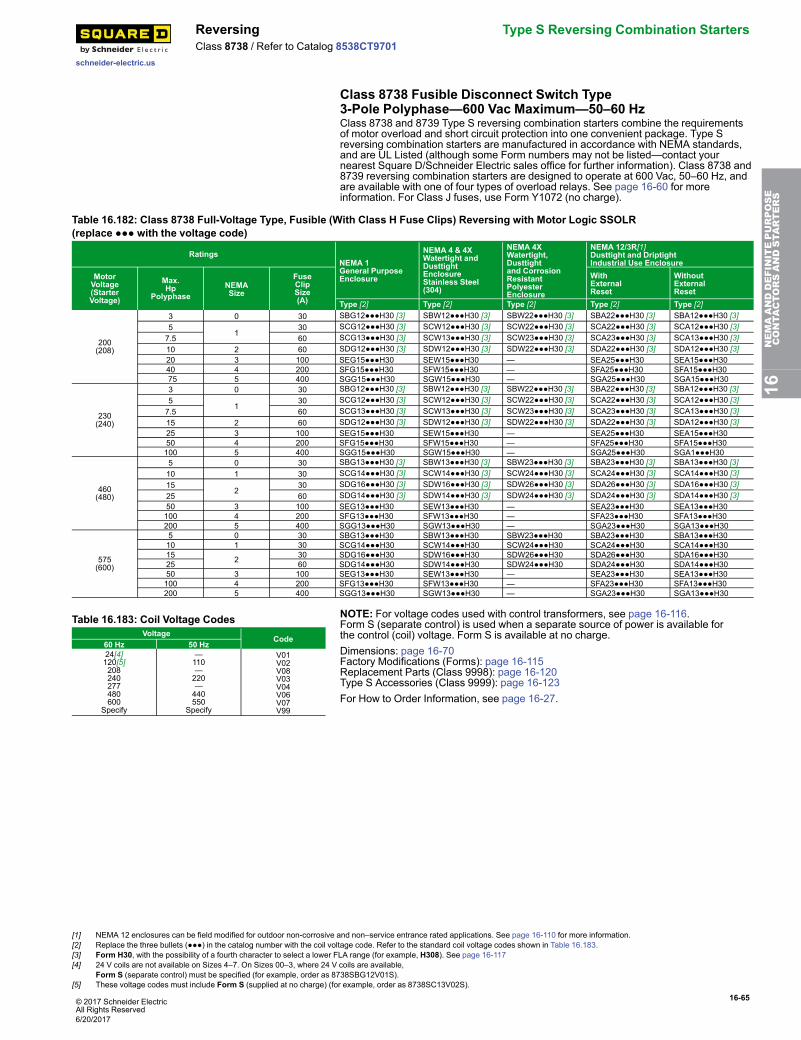
© 2017 Schneider ElectricAll Rights Reserved
16-65
schneider-electric.us
Reversing Type S Reversing Combination StartersClass 8738 / Refer to Catalog 8538CT9701
Class 8738 Fusible Disconnect Switch Type3-Pole Polyphase—600 Vac Maximum—50–60 HzClass 8738 and 8739 Type S reversing combination starters combine the requirementsof motor overload and short circuit protection into one convenient package. Type Sreversing combination starters are manufactured in accordance with NEMA standards,and are UL Listed (although some Form numbers may not be listed—contact yournearest Square D/Schneider Electric sales office for further information). Class 8738 and8739 reversing combination starters are designed to operate at 600 Vac, 50–60 Hz, andare available with one of four types of overload relays. See page 16-60 for moreinformation. For Class J fuses, use Form Y1072 (no charge).
Table 16.182: Class 8738 Full-Voltage Type, Fusible (With Class H Fuse Clips) Reversing with Motor Logic SSOLR(replace ●●● with the voltage code)
RatingsNEMA 1General PurposeEnclosure
NEMA 4 & 4XWatertight andDusttightEnclosureStainless Steel(304)
NEMA 4XWatertight,Dusttightand CorrosionResistantPolyesterEnclosure
NEMA 12/3R[1]Dusttight and DriptightIndustrial Use Enclosure
MotorVoltage(StarterVoltage)
Max.Hp
PolyphaseNEMASize
FuseClipSize(A)
WithExternalReset
WithoutExternalReset
Type [2] Type [2] Type [2] Type [2] Type [2]
200(208)
3 0 30 SBG12●●●H30 [3] SBW12●●●H30 [3] SBW22●●●H30 [3] SBA22●●●H30 [3] SBA12●●●H30 [3]5
130 SCG12●●●H30 [3] SCW12●●●H30 [3] SCW22●●●H30 [3] SCA22●●●H30 [3] SCA12●●●H30 [3]
7.5 60 SCG13●●●H30 [3] SCW13●●●H30 [3] SCW23●●●H30 [3] SCA23●●●H30 [3] SCA13●●●H30 [3]10 2 60 SDG12●●●H30 [3] SDW12●●●H30 [3] SDW22●●●H30 [3] SDA22●●●H30 [3] SDA12●●●H30 [3]20 3 100 SEG15●●●H30 SEW15●●●H30 — SEA25●●●H30 SEA15●●●H3040 4 200 SFG15●●●H30 SFW15●●●H30 — SFA25●●●H30 SFA15●●●H3075 5 400 SGG15●●●H30 SGW15●●●H30 — SGA25●●●H30 SGA15●●●H30
230(240)
3 0 30 SBG12●●●H30 [3] SBW12●●●H30 [3] SBW22●●●H30 [3] SBA22●●●H30 [3] SBA12●●●H30 [3]5
130 SCG12●●●H30 [3] SCW12●●●H30 [3] SCW22●●●H30 [3] SCA22●●●H30 [3] SCA12●●●H30 [3]
7.5 60 SCG13●●●H30 [3] SCW13●●●H30 [3] SCW23●●●H30 [3] SCA23●●●H30 [3] SCA13●●●H30 [3]15 2 60 SDG12●●●H30 [3] SDW12●●●H30 [3] SDW22●●●H30 [3] SDA22●●●H30 [3] SDA12●●●H30 [3]25 3 100 SEG15●●●H30 SEW15●●●H30 — SEA25●●●H30 SEA15●●●H3050 4 200 SFG15●●●H30 SFW15●●●H30 — SFA25●●●H30 SFA15●●●H30100 5 400 SGG15●●●H30 SGW15●●●H30 — SGA25●●●H30 SGA1●●●H30
460(480)
5 0 30 SBG13●●●H30 [3] SBW13●●●H30 [3] SBW23●●●H30 [3] SBA23●●●H30 [3] SBA13●●●H30 [3]10 1 30 SCG14●●●H30 [3] SCW14●●●H30 [3] SCW24●●●H30 [3] SCA24●●●H30 [3] SCA14●●●H30 [3]15
230 SDG16●●●H30 [3] SDW16●●●H30 [3] SDW26●●●H30 [3] SDA26●●●H30 [3] SDA16●●●H30 [3]
25 60 SDG14●●●H30 [3] SDW14●●●H30 [3] SDW24●●●H30 [3] SDA24●●●H30 [3] SDA14●●●H30 [3]50 3 100 SEG13●●●H30 SEW13●●●H30 — SEA23●●●H30 SEA13●●●H30100 4 200 SFG13●●●H30 SFW13●●●H30 — SFA23●●●H30 SFA13●●●H30200 5 400 SGG13●●●H30 SGW13●●●H30 — SGA23●●●H30 SGA13●●●H30
575(600)
5 0 30 SBG13●●●H30 SBW13●●●H30 SBW23●●●H30 SBA23●●●H30 SBA13●●●H3010 1 30 SCG14●●●H30 SCW14●●●H30 SCW24●●●H30 SCA24●●●H30 SCA14●●●H3015 2 30 SDG16●●●H30 SDW16●●●H30 SDW26●●●H30 SDA26●●●H30 SDA16●●●H3025 60 SDG14●●●H30 SDW14●●●H30 SDW24●●●H30 SDA24●●●H30 SDA14●●●H3050 3 100 SEG13●●●H30 SEW13●●●H30 — SEA23●●●H30 SEA13●●●H30100 4 200 SFG13●●●H30 SFW13●●●H30 — SFA23●●●H30 SFA13●●●H30200 5 400 SGG13●●●H30 SGW13●●●H30 — SGA23●●●H30 SGA13●●●H30
Table 16.183: Coil Voltage CodesVoltage
Code60 Hz 50 Hz24[4]120[5]208240277480600
Specify
—110—220—440550
Specify
V01V02V08V03V04V06V07V99
NOTE: For voltage codes used with control transformers, see page 16-116.Form S (separate control) is used when a separate source of power is available forthe control (coil) voltage. Form S is available at no charge.Dimensions: page 16-70Factory Modifications (Forms): page 16-115Replacement Parts (Class 9998): page 16-120Type S Accessories (Class 9999): page 16-123For How to Order Information, see page 16-27.
16NEMAANDDEFINITEPURPOSE
CONTA
CTORSANDSTA
RTERS
[1] NEMA 12 enclosures can be field modified for outdoor non-corrosive and non–service entrance rated applications. See page 16-110 for more information.[2] Replace the three bullets (●●●) in the catalog number with the coil voltage code. Refer to the standard coil voltage codes shown in Table 16.183.[3] Form H30, with the possibility of a fourth character to select a lower FLA range (for example, H308). See page 16-117[4] 24 V coils are not available on Sizes 4–7. On Sizes 00–3, where 24 V coils are available,
Form S (separate control) must be specified (for example, order as 8738SBG12V01S).[5] These voltage codes must include Form S (supplied at no charge) (for example, order as 8738SC13V02S).
6/20/2017
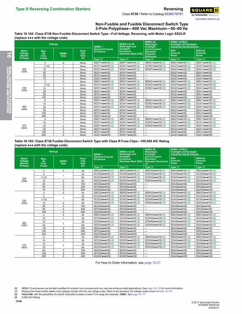
16-66 © 2017 Schneider ElectricAll Rights Reserved
Type S Reversing Combination Starters Reversing
schneider-electric.us
Class 8738 / Refer to Catalog 8538CT9701
Non-Fusible and Fusible Disconnect Switch Type3-Pole Polyphase—600 Vac Maximum—50–60 Hz
Table 16.184: Class 8738 Non-Fusible Disconnect Switch Type—Full-Voltage, Reversing, with Motor Logic SSOLR(replace ●●● with the voltage code)
RatingsNEMA 1General PurposeEnclosure
NEMA 4 & 4XWatertight andDusttightEnclosureStainless Steel (304)
NEMA 4XWatertight,Dusttightand CorrosionResistantPolyesterEnclosure
NEMA 12/3R[6]Dusttight and DriptightIndustrial Use Enclosure
MotorVoltage(StarterVoltage)
Max.HpPoly-Phase
NEMASize
FuseClipSize(A)
WithExternalReset
WithoutExternalReset
Type [7] Type [7] Type [7] Type [7] Type [7]
200(208)
3 0 None SBG11●●●H30 [8] SBW11●●●H30 [8] SBW21●●●H30 [8] SBA21●●●H30 [8] SBA11●●●H30 [8]7-1/2 1 None SCG11●●●H30 [8] SCW11●●●H30 [8] SCW21●●●H30 [8] SCA21●●●H30 [8] SCA11●●●H30 [8]10 2 None SDG11●●●H30 [8] SDW11●●●H30 [8] SDW21●●●H30 [8] SDA21●●●H30 [8] SDA11●●●H30 [8]25 3 None SEG11●●●H30 SEW11●●●H30 — SEA21●●●H30 SEA11●●●H3040 4 None SFG11●●●H30 SFW11●●●H30 — SFA21●●●H30 SFA11●●●H3075 5 None SGG11●●●H30 SGW11●●●H30 — SGA21●●●H30 SGA11●●●H30
230(240)
3 0 None SBG11●●●H30 [8] SBW11●●●H30 [8] SBW21●●●H30 [8] SBA21●●●H30 [8] SBA11●●●H30 [8]7-1/2 1 None SCG11●●●H30 [8] SCW11●●●H30 [8] SCW21●●●H30 [8] SCA21●●●H30 [8] SCA11●●●H30 [8]15 2 None SDG11●●●H30 [8] SDW11●●●H30 [8] SDW21●●●H30 [8] SDA21●●●H30 [8] SDA11●●●H30 [8]30 3 None SEG11●●●H30 SEW11●●●H30 — SEA21●●●H30 SEA11●●●H3050 4 None SFG11●●●H30 SFW11●●●H30 — SFA21●●●H30 SFA11●●●H30100 5 None SGG11●●●H30 SGW11●●●H30 — SGA21●●●H30 SGA11●●●H30
460(480)
5 0 None SBG11●●●H30 [8] SBW11●●●H30 [8] SBW21●●●H30 [8] SBA21●●●H30 [8] SBA11●●●H30 [8]10 1 None SCG11●●●H30 [8] SCW11●●●H30 [8] SCW21●●●H30 [8] SCA21●●●H30 [8] SCA11●●●H30 [8]25 2 None SDG11●●●H30 [8] SDW11●●●H30 [8] SDW21●●●H30 [8] SDA21●●●H30 [8] SDA11●●●H30 [8]50 3 None SEG11●●●H30 SEW11●●●H30 — SEA21●●●H30 SEA11●●●H30100 4 None SFG11●●●H30 SFW11●●●H30 — SFA21●●●H30 SFA11●●●H30200 5 None SGG11●●●H30 SGW11●●●H30 — SGA21●●●H30 SGA11●●●H30
575(600)
5 0 None SBG11●●●H30 [8] SBW11●●●H30 [8] SBW21●●●H30 [8] SBA21●●●H30 [8] SBA11●●●H30 [8]10 1 None SCG11●●●H30 [8] SCW11●●●H30 [8] SCW21●●●H30 [8] SCA21●●●H30 [8] SCA11●●●H30 [8]25 2 None SDG11●●●H30 [8] SDW11●●●H30 [8] SDW21●●●H30 [8] SDA21●●●H30 [8] SDA11●●●H30 [8]50 3 None SEG11●●●H30 SEW11●●●H30 — SEA21●●●H30 SEA11●●●H30100 4 None SFG11●●●H30 SFW11●●●H30 — SFA21●●●H30 SFA11●●●H30200 5 None SGG11●●●H30 SGW11●●●H30 — SGA21●●●H30 SGA11●●●H30
Table 16.185: Class 8738 Fusible Disconnect Switch Type with Class R Fuse Clips—100,000 AIC Rating(replace ●●● with the voltage code)
RatingsNEMA 1General PurposeEnclosure
NEMA 4 & 4XWatertight andDusttightEnclosureStainless Steel (304)
NEMA 4XWatertight,Dusttightand CorrosionResistantPolyester Enclosure[9]
NEMA 12/3R[6]Dusttight and DriptightIndustrial Use Enclosure
MotorVoltage(StarterVoltage)
Max.HpPoly-Phase
NEMASize
FuseClipSize(A)
WithExternalReset
WithoutExternalReset
Type [7] Type [7] Type [7] Type [7] Type [7]
200(208)
3 0 30 SBG32●●●H30 [8] SBW32●●●H30 [8] SBW42●●●H30 [8] SBA42●●●H30 [8] SBA32●●●H30 [8]5
130 SCG32●●●H30 [8] SCW32●●●H30 [8] SCW42●●●H30 [8] SCA42●●●H30 [8] SCA32●●●H30 [8]
7-1/2 60 SCG33●●●H30 [8] SCW33●●●H30 [8] SCW43●●●H30 [8] SCA43●●●H30 [8] SCA33●●●H30 [8]10 2 60 SDG32●●●H30 [8] SDW32●●●H30 [8] SDW42●●●H30 [8] SDA42●●●H30 [8] SDA32●●●H30 [8]20 3 100 SEG35●●●H30 SEW35●●●H30 — SEA45●●●H30 SEA35●●●H3040 4 200 SFG35●●●H30 SFW35●●●H30 — SFA45●●●H30 SFA35●●●H3075 5 400 SGG35●●●H30 SGW35●●●H30 — SGA45●●●H30 SGA35●●●H30
230(240)
3 0 30 SBG32●●●H30 [8] SBW32●●●H30 [8] SBW42●●●H30 [8] SBA42●●●H30 [8] SBA32●●●H30 [8]5
130 SCG32●●●H30 [8] SCW32●●●H30 [8] SCW42●●●H30 [8] SCA42●●●H30 [8] SCA32●●●H30 [8]
7-1/2 60 SCG33●●●H30 [8] SCW33●●●H30 [8] SCW43●●●H30 [8] SCA43●●●H30 [8] SCA33●●●H30 [8]15 2 60 SDG32●●●H30 [8] SDW32●●●H30 [8] SDW42●●●H30 [8] SDA42●●●H30 [8] SDA32●●●H30 [8]25 3 100 SEG35●●●H30 SEW35●●●H30 — SEA45●●●H30 SEA3●●●H3050 4 200 SFG35●●●H30 SFW35●●●H30 — SFA45●●●H30 SFA35●●●H30100 5 400 SGG35●●●H30 SGW35●●●H30 — SGA45●●●H30 SGA35●●●H30
460(480)
5 0 30 SBG33●●●H30 [8] SBW33●●●H30 [8] SBW43●●●H30 [8] SBA43●●●H30 [8] SBA33●●●H30 [8]10 1 30 SCG34●●●H30 [8] SCW34●●●H30 [8] SCW44●●●H30 [8] SCA44●●●H30 [8] SCA34●●●H30 [8]15
230 SDG36●●●H30 [8] SDW36●●●H30 [8] SDW46●●●H30 [8] SDA46●●●H30 [8] SDA36●●●H30 [8]
25 60 SDG34●●●H30 [8] SDW34●●●H30 [8] SDW44●●●H30 [8] SDA44●●●H30 [8] SDA34●●●H30 [8]50 3 100 SEG33●●●H30 SEW33●●●H30 — SEA43●●●H30 SEA33●●●H30100 4 200 SFG33●●●H30 SFW33●●●H30 — SFA43●●●H30 SFA33●●●H30200 5 400 SGG33●●●H30 SGW33●●●H30 — SGA43●●●H30 SGA33●●●H30
575(600)
5 0 30 SBG33●●●H30 [8] SBW33●●●H30 [8] SBW43●●●H30 [8] SBA43●●●H30 [8] SBA33●●●H30 [8]10 1 30 SCG34●●●H30 [8] SCW34●●●H30 [8] SCW44●●●H30 [8] SCA44●●●H30 [8] SCA34●●●H30 [8]15
230 SDG36●●●H30 [8] SDW36●●●H30 [8] SDW46●●●H30 [8] SDA46●●●H30 [8] SDA36●●●H30 [8]
25 60 SDG34●●●H30 [8] SDW34●●●H30 [8] SDW44●●●H30 [8] SDA44●●●H30 [8] SDA34●●●H30 [8]50 3 100 SEG33●●●H30 SEW33●●●H30 — SEA43●●●H30 SEA33●●●H30100 4 200 SFG33●●●H30 SFW33●●●H30 — SFA43●●●H30 SFA33●●●H30200 5 400 SGG33●●●H30 SGW33●●●H30 — SGA43●●●H30 SGA33●●●H30
For How to Order Information, see page 16-27.
16NEMAANDDEFINITEPURPOSE
CONTA
CTORSANDSTA
RTERS
[6] NEMA 12 enclosures can be field modified for outdoor non-corrosive and non–service entrance rated applications. See page 16-110 for more information.[7] Replace the three bullets (●●●) in the catalog number with the coil voltage code. Refer to the standard coil voltage codes shown inTable 16.187.[8] Form H30, with the possibility of a fourth character to select a lower FLA range (for example, H308). See page 16-117[9] 5,000 AIC Rating
6/20/2017
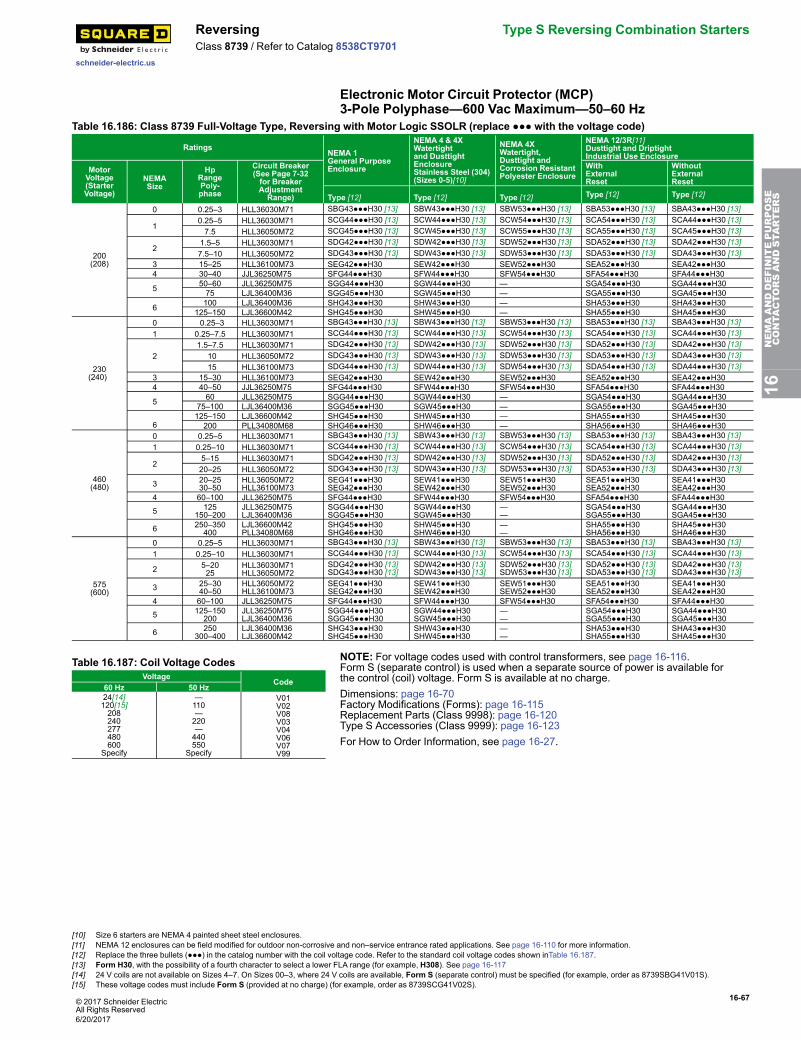
© 2017 Schneider ElectricAll Rights Reserved
16-67
schneider-electric.us
Reversing Type S Reversing Combination StartersClass 8739 / Refer to Catalog 8538CT9701
Electronic Motor Circuit Protector (MCP)3-Pole Polyphase—600 Vac Maximum—50–60 Hz
Table 16.186: Class 8739 Full-Voltage Type, Reversing with Motor Logic SSOLR (replace ●●● with the voltage code)
RatingsNEMA 1General PurposeEnclosure
NEMA 4 & 4XWatertightand DusttightEnclosureStainless Steel (304)(Sizes 0-5)[10]
NEMA 4XWatertight,Dusttight andCorrosion ResistantPolyester Enclosure
NEMA 12/3R[11]Dusttight and DriptightIndustrial Use Enclosure
MotorVoltage(StarterVoltage)
NEMASize
HpRangePoly-phase
Circuit Breaker(See Page 7-32for BreakerAdjustmentRange)
WithExternalReset
WithoutExternalReset
Type [12] Type [12] Type [12] Type [12] Type [12]
200(208)
0 0.25–3 HLL36030M71 SBG43●●●H30 [13] SBW43●●●H30 [13] SBW53●●●H30 [13] SBA53●●●H30 [13] SBA43●●●H30 [13]
10.25–5 HLL36030M71 SCG44●●●H30 [13] SCW44●●●H30 [13] SCW54●●●H30 [13] SCA54●●●H30 [13] SCA44●●●H30 [13]7.5 HLL36050M72 SCG45●●●H30 [13] SCW45●●●H30 [13] SCW55●●●H30 [13] SCA55●●●H30 [13] SCA45●●●H30 [13]
21.5–5 HLL36030M71 SDG42●●●H30 [13] SDW42●●●H30 [13] SDW52●●●H30 [13] SDA52●●●H30 [13] SDA42●●●H30 [13]7.5–10 HLL36050M72 SDG43●●●H30 [13] SDW43●●●H30 [13] SDW53●●●H30 [13] SDA53●●●H30 [13] SDA43●●●H30 [13]
3 15–25 HLL36100M73 SEG42●●●H30 SEW42●●●H30 SEW52●●●H30 SEA52●●●H30 SEA42●●●H304 30–40 JJL36250M75 SFG44●●●H30 SFW44●●●H30 SFW54●●●H30 SFA54●●●H30 SFA44●●●H30
5 50–60 JLL36250M75 SGG44●●●H30 SGW44●●●H30 — SGA54●●●H30 SGA44●●●H3075 LJL36400M36 SGG45●●●H30 SGW45●●●H30 — SGA55●●●H30 SGA45●●●H30
6 100 LJL36400M36 SHG43●●●H30 SHW43●●●H30 — SHA53●●●H30 SHA43●●●H30125–150 LJL36600M42 SHG45●●●H30 SHW45●●●H30 — SHA55●●●H30 SHA45●●●H30
230(240)
0 0.25–3 HLL36030M71 SBG43●●●H30 [13] SBW43●●●H30 [13] SBW53●●●H30 [13] SBA53●●●H30 [13] SBA43●●●H30 [13]1 0.25–7.5 HLL36030M71 SCG44●●●H30 [13] SCW44●●●H30 [13] SCW54●●●H30 [13] SCA54●●●H30 [13] SCA44●●●H30 [13]
21.5–7.5 HLL36030M71 SDG42●●●H30 [13] SDW42●●●H30 [13] SDW52●●●H30 [13] SDA52●●●H30 [13] SDA42●●●H30 [13]
10 HLL36050M72 SDG43●●●H30 [13] SDW43●●●H30 [13] SDW53●●●H30 [13] SDA53●●●H30 [13] SDA43●●●H30 [13]15 HLL36100M73 SDG44●●●H30 [13] SDW44●●●H30 [13] SDW54●●●H30 [13] SDA54●●●H30 [13] SDA44●●●H30 [13]
3 15–30 HLL36100M73 SEG42●●●H30 SEW42●●●H30 SEW52●●●H30 SEA52●●●H30 SEA42●●●H304 40–50 JJL36250M75 SFG44●●●H30 SFW44●●●H30 SFW54●●●H30 SFA54●●●H30 SFA44●●●H30
5 60 JLL36250M75 SGG44●●●H30 SGW44●●●H30 — SGA54●●●H30 SGA44●●●H3075–100 LJL36400M36 SGG45●●●H30 SGW45●●●H30 — SGA55●●●H30 SGA45●●●H30
6125–150 LJL36600M42 SHG45●●●H30 SHW45●●●H30 — SHA55●●●H30 SHA45●●●H30200 PLL34080M68 SHG46●●●H30 SHW46●●●H30 — SHA56●●●H30 SHA46●●●H30
460(480)
0 0.25–5 HLL36030M71 SBG43●●●H30 [13] SBW43●●●H30 [13] SBW53●●●H30 [13] SBA53●●●H30 [13] SBA43●●●H30 [13]1 0.25–10 HLL36030M71 SCG44●●●H30 [13] SCW44●●●H30 [13] SCW54●●●H30 [13] SCA54●●●H30 [13] SCA44●●●H30 [13]
25–15 HLL36030M71 SDG42●●●H30 [13] SDW42●●●H30 [13] SDW52●●●H30 [13] SDA52●●●H30 [13] SDA42●●●H30 [13]20–25 HLL36050M72 SDG43●●●H30 [13] SDW43●●●H30 [13] SDW53●●●H30 [13] SDA53●●●H30 [13] SDA43●●●H30 [13]
3 20–2530–50
HLL36050M72HLL36100M73
SEG41●●●H30SEG42●●●H30
SEW41●●●H30SEW42●●●H30
SEW51●●●H30SEW52●●●H30
SEA51●●●H30SEA52●●●H30
SEA41●●●H30SEA42●●●H30
4 60–100 JLL36250M75 SFG44●●●H30 SFW44●●●H30 SFW54●●●H30 SFA54●●●H30 SFA44●●●H30
5 125150–200
JLL36250M75LJL36400M36
SGG44●●●H30SGG45●●●H30
SGW44●●●H30SGW45●●●H30
——
SGA54●●●H30SGA55●●●H30
SGA44●●●H30SGA45●●●H30
6 250–350400
LJL36600M42PLL34080M68
SHG45●●●H30SHG46●●●H30
SHW45●●●H30SHW46●●●H30
——
SHA55●●●H30SHA56●●●H30
SHA45●●●H30SHA46●●●H30
575(600)
0 0.25–5 HLL36030M71 SBG43●●●H30 [13] SBW43●●●H30 [13] SBW53●●●H30 [13] SBA53●●●H30 [13] SBA43●●●H30 [13]1 0.25–10 HLL36030M71 SCG44●●●H30 [13] SCW44●●●H30 [13] SCW54●●●H30 [13] SCA54●●●H30 [13] SCA44●●●H30 [13]
2 5–2025
HLL36030M71HLL36050M72
SDG42●●●H30 [13]SDG43●●●H30 [13]
SDW42●●●H30 [13]SDW43●●●H30 [13]
SDW52●●●H30 [13]SDW53●●●H30 [13]
SDA52●●●H30 [13]SDA53●●●H30 [13]
SDA42●●●H30 [13]SDA43●●●H30 [13]
3 25–3040–50
HLL36050M72HLL36100M73
SEG41●●●H30SEG42●●●H30
SEW41●●●H30SEW42●●●H30
SEW51●●●H30SEW52●●●H30
SEA51●●●H30SEA52●●●H30
SEA41●●●H30SEA42●●●H30
4 60–100 JLL36250M75 SFG44●●●H30 SFW44●●●H30 SFW54●●●H30 SFA54●●●H30 SFA44●●●H30
5 125–150200
JLL36250M75LJL36400M36
SGG44●●●H30SGG45●●●H30
SGW44●●●H30SGW45●●●H30
——
SGA54●●●H30SGA55●●●H30
SGA44●●●H30SGA45●●●H30
6 250300–400
LJL36400M36LJL36600M42
SHG43●●●H30SHG45●●●H30
SHW43●●●H30SHW45●●●H30
——
SHA53●●●H30SHA55●●●H30
SHA43●●●H30SHA45●●●H30
Table 16.187: Coil Voltage CodesVoltage
Code60 Hz 50 Hz24[14]120[15]208240277480600
Specify
—110—220—440550
Specify
V01V02V08V03V04V06V07V99
NOTE: For voltage codes used with control transformers, see page 16-116.Form S (separate control) is used when a separate source of power is available forthe control (coil) voltage. Form S is available at no charge.Dimensions: page 16-70Factory Modifications (Forms): page 16-115Replacement Parts (Class 9998): page 16-120Type S Accessories (Class 9999): page 16-123For How to Order Information, see page 16-27.
16NEMAANDDEFINITEPURPOSE
CONTA
CTORSANDSTA
RTERS
[10] Size 6 starters are NEMA 4 painted sheet steel enclosures.[11] NEMA 12 enclosures can be field modified for outdoor non-corrosive and non–service entrance rated applications. See page 16-110 for more information.[12] Replace the three bullets (●●●) in the catalog number with the coil voltage code. Refer to the standard coil voltage codes shown inTable 16.187.[13] Form H30, with the possibility of a fourth character to select a lower FLA range (for example, H308). See page 16-117[14] 24 V coils are not available on Sizes 4–7. On Sizes 00–3, where 24 V coils are available, Form S (separate control) must be specified (for example, order as 8739SBG41V01S).[15] These voltage codes must include Form S (provided at no charge) (for example, order as 8739SCG41V02S).
6/20/2017
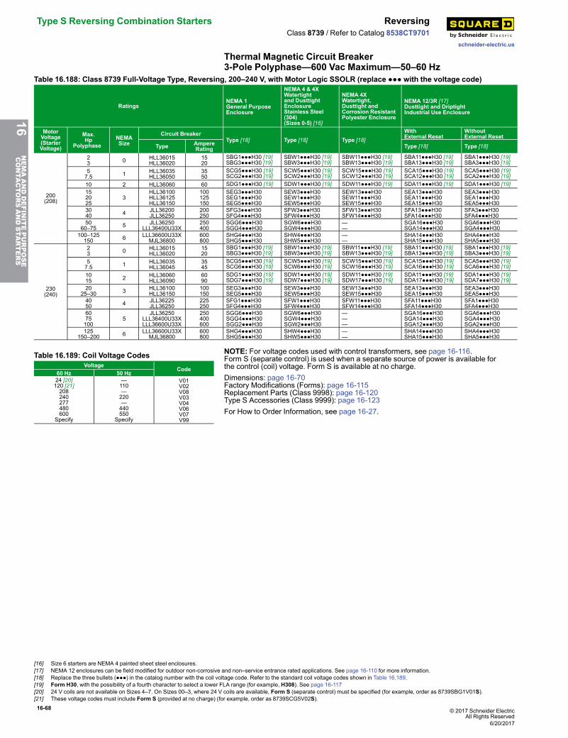
16-68 © 2017 Schneider ElectricAll Rights Reserved
Type S Reversing Combination Starters Reversing
schneider-electric.us
Class 8739 / Refer to Catalog 8538CT9701
Thermal Magnetic Circuit Breaker3-Pole Polyphase—600 Vac Maximum—50–60 Hz
Table 16.188: Class 8739 Full-Voltage Type, Reversing, 200–240 V, with Motor Logic SSOLR (replace ●●● with the voltage code)
RatingsNEMA 1General PurposeEnclosure
NEMA 4 & 4XWatertightand DusttightEnclosureStainless Steel(304)(Sizes 0-5) [16]
NEMA 4XWatertight,Dusttight andCorrosion ResistantPolyester Enclosure
NEMA 12/3R [17]Dusttight and DriptightIndustrial Use Enclosure
MotorVoltage(StarterVoltage)
Max.Hp
PolyphaseNEMASize
Circuit BreakerType [18] Type [18] Type [18]
WithExternal Reset
WithoutExternal Reset
Type AmpereRating Type [18] Type [18]
200(208)
23 0 HLL36015
HLL360201520
SBG1●●●H30 [19]SBG3●●●H30 [19]
SBW1●●●H30 [19]SBW3●●●H30 [19]
SBW11●●●H30 [19]SBW13●●●H30 [19]
SBA11●●●H30 [19]SBA13●●●H30 [19]
SBA1●●●H30 [19]SBA3●●●H30 [19]
57.5 1 HLL36035
HLL360503550
SCG5●●●H30 [19]SCG2●●●H30 [19]
SCW5●●●H30 [19]SCW2●●●H30 [19]
SCW15●●●H30 [19]SCW12●●●H30 [19]
SCA15●●●H30 [19]SCA12●●●H30 [19]
SCA5●●●H30 [19]SCA2●●●H30 [19]
10 2 HLL36060 60 SDG1●●●H30 [19] SDW1●●●H30 [19] SDW11●●●H30 [19] SDA11●●●H30 [19] SDA1●●●H30 [19]152025
3HLL36100HLL36125HLL36150
100125150
SEG3●●●H30SEG1●●●H30SEG5●●●H30
SEW3●●●H30SEW1●●●H30SEW5●●●H30
SEW13●●●H30SEW11●●●H30SEW15●●●H30
SEA13●●●H30SEA11●●●H30SEA15●●●H30
SEA3●●●H30SEA1●●●H30SEA5●●●H30
3040 4 JLL36200
JLL36250200250
SFG3●●●H30SFG4●●●H30
SFW3●●●H30SFW4●●●H30
SFW13●●●H30SFW14●●●H30
SFA13●●●H30SFA14●●●H30
SFA3●●●H30SFA4●●●H30
5060–75 5 JLL36250
LLL36400U33X250400
SGG6●●●H30SGG4●●●H30
SGW6●●●H30SGW4●●●H30
——
SGA16●●●H30SGA14●●●H30
SGA6●●●H30SGA4●●●H30
100–125150 6 LLL36600U33X
MJL36800600800
SHG4●●●H30SHG5●●●H30
SHW4●●●H30SHW5●●●H30
——
SHA14●●●H30SHA15●●●H30
SHA4●●●H30SHA5●●●H30
230(240)
23 0 HLL36015
HLL360201520
SBG1●●●H30 [19]SBG3●●●H30 [19]
SBW1●●●H30 [19]SBW3●●●H30 [19]
SBW11●●●H30 [19]SBW13●●●H30 [19]
SBA11●●●H30 [19]SBA13●●●H30 [19]
SBA1●●●H30 [19]SBA3●●●H30 [19]
57.5 1 HLL36035
HLL360453545
SCG5●●●H30 [19]SCG6●●●H30 [19]
SCW5●●●H30 [19]SCW6●●●H30 [19]
SCW15●●●H30 [19]SCW16●●●H30 [19]
SCA15●●●H30 [19]SCA16●●●H30 [19]
SCA5●●●H30 [19]SCA6●●●H30 [19]
1015 2 HLL36060
HLL360906090
SDG1●●●H30 [19]SDG7●●●H30 [19]
SDW1●●●H30 [19]SDW7●●●H30 [19]
SDW11●●●H30 [19]SDW17●●●H30 [19]
SDA11●●●H30 [19]SDA17●●●H30 [19]
SDA1●●●H30 [19]SDA7●●●H30 [19]
2025–30 3 HLL36100
HLL36150100150
SEG3●●●H30SEG5●●●H30
SEW3●●●H30SEW5●●●H30
SEW13●●●H30SEW15●●●H30
SEA13●●●H30SEA15●●●H30
SEA3●●●H30SEA5●●●H30
4050 4 JLL36225
JLL36250225250
SFG1●●●H30SFG4●●●H30
SFW1●●●H30SFW4●●●H30
SFW11●●●H30SFW14●●●H30
SFA11●●●H30SFA14●●●H30
SFA1●●●H30SFA4●●●H30
6075100
5JLL36250
LLL36400U33XLLL36600U33X
250400600
SGG6●●●H30SGG4●●●H30SGG2●●●H30
SGW6●●●H30SGW4●●●H30SGW2●●●H30
———
SGA16●●●H30SGA14●●●H30SGA12●●●H30
SGA6●●●H30SGA4●●●H30SGA2●●●H30
125150–200 6 LLL36600U33X
MJL36800600800
SHG4●●●H30SHG5●●●H30
SHW4●●●H30SHW5●●●H30
——
SHA14●●●H30SHA15●●●H30
SHA4●●●H30SHA5●●●H30
Table 16.189: Coil Voltage CodesVoltage
Code60 Hz 50 Hz24 [20]120 [21]208240277480600
Specify
—110—220—440550
Specify
V01V02V08V03V04V06V07V99
NOTE: For voltage codes used with control transformers, see page 16-116.Form S (separate control) is used when a separate source of power is available forthe control (coil) voltage. Form S is available at no charge.Dimensions: page 16-70Factory Modifications (Forms): page 16-115Replacement Parts (Class 9998): page 16-120Type S Accessories (Class 9999): page 16-123For How to Order Information, see page 16-27.
16NEMAANDDEFINITEPURPOSE
CONTA
CTORSANDSTA
RTERS
[16] Size 6 starters are NEMA 4 painted sheet steel enclosures.[17] NEMA 12 enclosures can be field modified for outdoor non-corrosive and non–service entrance rated applications. See page 16-110 for more information.[18] Replace the three bullets (●●●) in the catalog number with the coil voltage code. Refer to the standard coil voltage codes shown in Table 16.189.[19] Form H30, with the possibility of a fourth character to select a lower FLA range (for example, H308). See page 16-117[20] 24 V coils are not available on Sizes 4–7. On Sizes 00–3, where 24 V coils are available, Form S (separate control) must be specified (for example, order as 8739SBG1V01S).[21] These voltage codes must include Form S (provided at no charge) (for example, order as 8739SCG5V02S).
6/20/2017
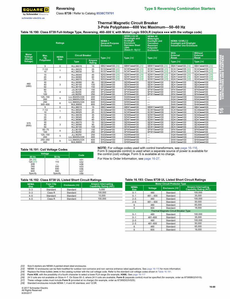
© 2017 Schneider ElectricAll Rights Reserved
16-69
schneider-electric.us
Reversing Type S Reversing Combination StartersClass 8739 / Refer to Catalog 8538CT9701
Thermal Magnetic Circuit Breaker3-Pole Polyphase—600 Vac Maximum—50–60 Hz
Table 16.190: Class 8739 Full-Voltage Type, Reversing, 460–600 V, with Motor Logic SSOLR (replace ●●● with the voltage code)
RatingsNEMA 1General PurposeEnclosure
NEMA 4 & 4XWatertight andDusttightEnclosureStainless Steel(304)(Sizes 0 - 5)[22]
NEMA 4XWatertight,Dusttight andCorrosionResistantPolyesterEnclosure
NEMA 12/3R[23]Dusttight and DriptightIndustrial Use Enclosure
MotorVoltage(StarterVoltage)
Max.Hp
PolyphaseNEMASize
Circuit BreakerType [24] Type [24] Type [24]
WithExternalReset
WithoutExternalReset
Type AmpereRating Type [24] Type [24]
460(480)
5 0 HLL36015 15 SBG1●●●H30 [25] SBW1●●●H30 [25] SBW11●●●H30 [25] SBA11●●●H30 [25] SBA1●●●H30 [25]7-1/210 1 HLL36025
HLL360302530
SCG3●●●H30 [25]SCG7●●●H30 [25]
SCW3●●●H30 [25]SCW7●●●H30 [25]
SCW13●●●H30 [25]SCW17●●●H30 [25]
SCA13●●●H30 [25]SCA17●●●H30 [25]
SCA3●●●H30 [25]SCA7●●●H30 [25]
152025
2HLL36045HLL36060HLL36070
456070
SDG3●●●H30 [25]SDG1●●●H30 [25]SDG5●●●H30 [25]
SDW3●●●H30 [25]SDW1●●●H30 [25]SDW5●●●H30 [25]
SDW13●●●H30 [25]SDW11●●●H30 [25]SDW15●●●H30 [25]
SDA13●●●H30 [25]SDA11●●●H30 [25]SDA15●●●H30 [25]
SDA3●●●H30 [25]SDA1●●●H30 [25]SDA5●●●H30 [25]
304050
3HLL36080HLL36100HLL36150
80100150
SEG6●●●H30SEG3●●●H30SEG5●●●H30
SEW6●●●H30SEW3●●●H30SEW5●●●H30
SEW16●●●H30SEW13●●●H30SEW15●●●H30
SEA16●●●H30SEA13●●●H30SEA15●●●H30
SEA6●●●H30SEA3●●●H30SEA5●●●H30
6075100
4JJL36105JJL36200JJL36250
150200250
SFG5●●●H30SFG3●●●H30SFG4●●●H30
SFW5●●●H30SFW3●●●H30SFW4●●●H30
SFW15●●●H30SFW13●●●H30SFW14●●●H30
SFA15●●●H30SFA13●●●H30SFA14●●●H30
SFA5●●●H30SFA3●●●H30SFA4●●●H30
125–150200 5 LLL36400U33X
LLL36600U33X400600
SGG4●●●H30SGG2●●●H30
SGW4●●●H30SGW2●●●H30
——
SGA14●●●H30SGA12●●●H30
SGA4●●●H30SGA2●●●H30
250300–400 6 LLL36600U33X
MJL36800600800
SHG4●●●H30SHG5●●●H30
SHW4●●●H30SHW5●●●H30
——
SHA14●●●H30SHA15●●●H30
SHA4●●●H30SHA5●●●H30
575(600)
5 0 HLL36015 15 SBG1●●●H30 SBW1●●●H30 SBW11●●●H30 SBA11●●●H30 SBA1●●●H307-1/210 1 HLL36020
HLL360252025
SCG8●●●H30SCG3●●●H30
SCW8●●●H30SCW3●●●H30
SCW18●●●H30SCW13●●●H30
SCA18●●●H30SCA13●●●H30
SCA8●●●H30SCA3●●●H30
152025
2HLL36035HLL36045HLL36060
354560
SDG8●●●H30SDG3●●●H30SDG1●●●H30
SDW8●●●H30SDW3●●●H30SDW1●●●H30
SDW18●●●H30SDW13●●●H30SDW11●●●H30
SDA18●●●H30SDA13●●●H30SDA12●●●H30
SDA8●●●H30SDA3●●●H30SDA1●●●H30
304050
3HLL36070HLL36090HLL36100
7090100
SEG4●●●H30SEG6●●●H30SEG3●●●H30
SEW4●●●H30SEW6●●●H30SEW3●●●H30
SEW14●●●H30SEW16●●●H30SEW13●●●H30
SEA14●●●H30SEA16●●●H30SEA13●●●H30
SEA4●●●H30SEA6●●●H30SEA3●●●H30
60–75100 4 JLL36150
JLL36250150250
SFG5●●●H30SFG4●●●H30
SFW5●●●H30SFW4●●●H30
SFW15●●●H30SFW14●●●H30
SFA15●●●H30SFA14●●●H30
SFA5●●●H30SFA4●●●H30
125–150200 5 JLL36250
LLL36400U33X250400
SGG6●●●H30SGG4●●●H30
SGW6●●●H30SGW4●●●H30
——
SGA16●●●H30SGA14●●●H30
SGA6●●●H30SGA4●●●H30
250–350400 6 LLL36600U33X
MJL36800600800
SHG4●●●H30SHG5●●●H30
SHW4●●●H30SHW5●●●H30
——
SHA14●●●H30SHA15●●●H30
SHA4●●●H30SHA5●●●H30
Table 16.191: Coil Voltage CodesVoltage
Code60 Hz 50 Hz24 [26]120 [27]208240480600
Specify
—110—220440550
Specify
V01V02V08V03V06V07V99
NOTE: For voltage codes used with control transformers, see page 16-116.Form S (separate control) is used when a separate source of power is available forthe control (coil) voltage. Form S is available at no charge.For How to Order Information, see page 16-27.
Table 16.192: Class 8738 UL Listed Short Circuit RatingsNEMASize
Fuse ClipType Enclosure [28] Ampere Interrupting
Capability Rating (AIC)0–3 Standard Standard 5,0000–3 Class R Standard 100,0004–5 Standard Standard 10,0004–5 Class R Standard 100,000
Table 16.193: Class 8739 UL Listed Short Circuit RatingsMotor Circuit Protector Type
NEMASize Voltage Enclosure [28] Ampere Interrupting
Capability Rating (AIC)0–1 480 Standard 100,0000–1 481 – 600 Standard 35,0002–5 480 Standard 100,0002–5 481 – 600 Standard 50,0006 480 Standard 65,0006 600 Standard 18,000
Thermal Magnetic Circuit Breaker Type0–1 480 Standard 100,0000–1 481–600 Standard 35,0002–5 480 Standard 100,0002–5 481–600 Standard 50,0006 480 Standard 65,0006 600 Standard 18,000
16NEMAANDDEFINITEPURPOSE
CONTA
CTORSANDSTA
RTERS
[22] Size 6 starters are NEMA 4 painted sheet steel enclosures.[23] NEMA 12 enclosures can be field modified for outdoor non-corrosive and non–service entrance rated applications. See page 16-110 for more information.[24] Replace the three bullets (●●●) in the catalog number with the coil voltage code. Refer to the standard coil voltage codes shown in Table 16.191.[25] Form H30, with the possibility of a fourth character to select a lower FLA range (for example, H308). See page 16-117[26] 24 V coils are not available on Sizes 4–7. On Sizes 00–3, where 24 V coils are available, Form S (separate control) must be specified (for example, order as 8739SBG2V01S).[27] These voltage codes must include Form S (provided at no charge) (for example, order as 8739SDG3V02S).[28] Standard enclosures include NEMA 1; 4 and 4X stainless; and 12/3R.
6/20/2017
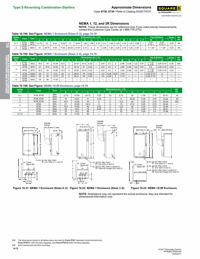
16-70 © 2017 Schneider ElectricAll Rights Reserved
Type S Reversing Combination Starters Approximate Dimensions
schneider-electric.us
Class 8738, 8739 / Refer to Catalog 8538CT9701
NEMA 1, 12, and 3R DimensionsNOTE: These dimensions are for reference only. If you need precise measurements,contact the Customer Care Center at 1-888-778-2733.
Table 16.194: See Figure: NEMA 1 Enclosure (Sizes 0–2), page 16-70NEMASize Class Type Dimensions (in. ) [29] Top & Bottom Sides Wt.
(lb)A B C D E F G H I J K L M N O P W X Y0–1 8738,
8739SBGSCG 13.75 23 8.34 10.63 21 18.91 1.88 1.88 3.75 2.31 1.06 3.25 2.19 1.25 0.88 — 0.25–
0.75–10.25–0.75–1 0.25 49
2 8738,8739 SDG 15 28.75 9.59 11.63 26.25 21.47 2.19 2 4 2.56 1.25 3.25 2.19 1.25 0.91 — 1–1.25 1–1.25 0.25 80
Table 16.195: See Figure: NEMA 1 Enclosure (Sizes 3–6), page 16-70NEMASize Class Type Dimensions (in.) [29] Top & Bottom Sides Wt.
(lb)A B C D E F G H I J K L M N O P W X Y3 8738,
8739 SEG 18.5 44 10.59 12.5 3 25.97 43.5 0.25 — 2.81 3.5 5 2.69 5.38 1.22 0.91 1–1.252–2.25 0.25–0.75 0.25 245
48738 SFG 21 51.5 10.53 15 3 30.72 51 0.25 — 2.81 3.5 5 2.69 5.38 1.22 0.91 2.5 0.25–0.75 0.25 —
8739 SFG 18.5 44 10.59 12.5 3 25.97 43.5 0.25 — 2.81 3.5 5 2.69 5.38 1.22 0.91 1–1.252–2.25 0.25–0.75 0.25 —
5 8738 SGG 30 77 15.5 22 4 39.41 76 0.25 — 3.5 6.28 9.25 3.19 — — — 0.25–0.75 3 — —8739 SGG 30 65 13.72 22 4 39.41 64 0.25 — 3.5 6.28 5 3.19 — — — 0.25–0.75 3 — —
6 8738,8739 SHG 36 90 17.03 — — — — — — — — — — — — — — — — —
Table 16.196: See Figure: NEMA 12/3R Enclosure, page 16-70NEMASize Class Type Dimensions (in.) [29] Wt.
(lb)A B C D E F G H I J0–1 8738, 8739 SBA
SCA 13.75 10.09 24.75 3.25 2.5 8.75 24 0.38 3.75 20.31 52
2 8738, 8739 SDA 15 10.97 31 3.25 3 9 30.25 0.38 3.75 23.44 953 8738, 8739 SEA 18.5 10.59 45 5 3 12.5 44 0.25 3.75 25.59 255
4 8738 SFA 21 10.59 52.5 5 3 15 51.5 0.25 3.75 30.34 —8739 SFA 18.5 10.59 45 3.25 3 12.5 44 0.25 3.75 25.59 —
5 8738 SGA 30 15.5 78 9.25 4 22 77 0.25 7.5 39.41 —8739 SGA 30 15.5 66 — 4 22 65 0.25 7.5 37.88 —
6 [30] 8739 SHA 36 17.03 90 — — — — — — — —
YO
N
C
E B
KM
D
A
Y
F
W X W
G
JH
I
L
HandleSwing
CoverOpen 90º
(4) .31 Dia. Mtg. Holes8 (For Sizes 0, 1, and 2)
Figure 16.21: NEMA 1 Enclosure (Sizes 0–2)
DA
E HL C
P
O
Y
BG
Y
J
NM
K
W X W
F
CoverOpen 90º
HandleSwing
(4) .44 Dia. Mtg. Holes11 (For Sizes 3 and 4)
(4) .56 Dia. Mtg. Holes Located on14 External Flanges (For Size 5)
Figure 16.22: NEMA 1 Enclosure (Sizes 3–6)
B
HandleSwing
C
F
A
J
I
DE
G
H
(4) .31 Dia. Mtg. Holes8 (For Sizes 0, 1, and 2)
(4) .44 Dia. Mtg. Holes11 (For Sizes 3 and 4)
(4) .56 Dia. Mtg. Holes Located on14 External Flanges (For Size 5)
CoverOpen 90º
Figure 16.23: NEMA 12/3R Enclosure
NOTE: Illustrations may not represent the actual enclosure; they are intended fordimensional information only.
16NEMAANDDEFINITEPURPOSE
CONTA
CTORSANDSTA
RTERS
[29] The dimensions shown in all tables above are also for Form FF4T (standard control transformer),Form FF4T11 (100 VA extra-capacity), and Form FF4T12 (200 VA extra-capacity).
[30] Size 6 enclosures are floor mounting.
6/20/2017
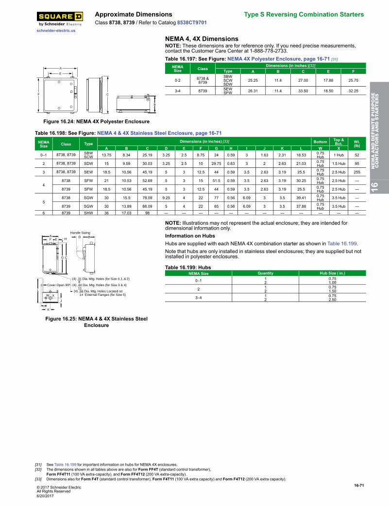
© 2017 Schneider ElectricAll Rights Reserved
16-71
schneider-electric.us
Approximate Dimensions Type S Reversing Combination StartersClass 8738, 8739 / Refer to Catalog 8538CT9701
NEMA 4, 4X DimensionsNOTE: These dimensions are for reference only. If you need precise measurements,contact the Customer Care Center at 1-888-778-2733.
A
E
F C
B
Figure 16.24: NEMA 4X Polyester Enclosure
Table 16.197: See Figure: NEMA 4X Polyester Enclosure, page 16-71 [31]
NEMASize Class
Dimensions (in inches )[32]Type A B C E F
0-2 8738 &8739
SBWSCWSDW
25.25 11.4 27.00 17.88 25.75
3-4 8739 SEWSFW 26.31 11.4 33.50 18.50 32.25
Table 16.198: See Figure: NEMA 4 & 4X Stainless Steel Enclosure, page 16-71NEMASize Class Type Dimensions (in inches) [33] Bottom Top &
Bot. Wt.(lb)
A B C D E F G H I J K L W X0–1 8738, 8739 SBW
SCW 13.75 8.34 25.19 3.25 2.5 8.75 24 0.59 3 1.63 2.31 18.53 0.75Hub 1 Hub 52
2 8738, 8739 SDW 15 9.59 30.03 3.25 2.5 10 29.75 0.63 3 2 2.63 21.03 0.75Hub 1.5 Hub 95
3 8738, 8739 SEW 18.5 10.56 45.19 5 3 12.5 44 0.59 3.5 2.63 3.19 25.5 0.75Hub 2.5 Hub 255
48738 SFW 21 10.53 52.69 5 3 15 51.5 0.59 3.5 2.63 3.19 30.25 0.75
Hub 2.5 Hub —
8739 SFW 18.5 10.56 45.19 5 3 12.5 44 0.59 3.5 2.63 3.19 25.5 0.75Hub 2.5 Hub —
58738 SGW 30 15.5 78.09 9.25 4 22 77 0.56 6.09 3 3.5 39.41 0.75
Hub 3.5 Hub —
8739 SGW 30 13.89 66.09 5 4 22 65 0.56 6.09 3 3.5 37.88 0.75Hub 3.5 Hub —
6 8739 SHW 36 17.03 98 — — — — — — — — — — — —
B
C
FA
(4) .31 Dia. Mtg. Holes (for Size 0, 1, & 2)8
(4) .44 Dia. Mtg. Holes (for Size 3 & 4)11
(4) .56 Dia. Mtg. Holes Located on14 External Flanges (for Size 5)
L
W X
I
Cover Open 90º
DE
K
J
G
H
Handle Swing
Figure 16.25: NEMA 4 & 4X Stainless SteelEnclosure
NOTE: Illustrations may not represent the actual enclosure; they are intended fordimensional information only.Information on HubsHubs are supplied with each NEMA 4X combination starter as shown in Table 16.199.Note that hubs are only installed in stainless steel enclosures; they are supplied but notinstalled in polyester enclosures.
Table 16.199: HubsNEMA Size Quantity Hub Size ( in.)
0–1 12
0.751.00
2 12
0.751.50
3–4 12
0.752.50
16NEMAANDDEFINITEPURPOSE
CONTA
CTORSANDSTA
RTERS
[31] See Table 16.199 for important information on hubs for NEMA 4X enclosures.[32] The dimensions shown in all tables above are also for Form FF4T (standard control transformer),
Form FF4T11 (100 VA extra-capacity), and Form FF4T12 (200 VA extra-capacity).[33] Dimensions also for Form F4T (standard control transformer), Form F4T11 (100 VA extra capacity) and Form F4T12 (200 VA extra capacity).
6/20/2017
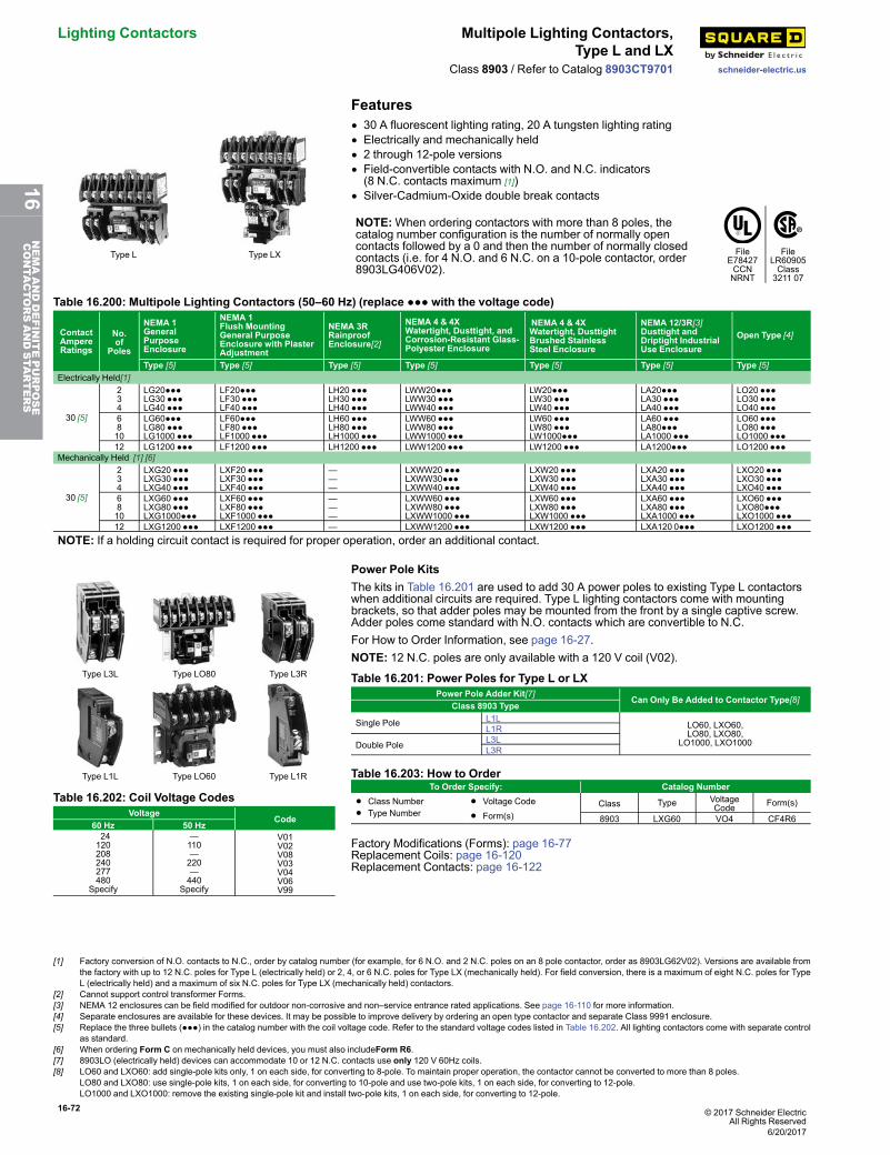
16-72 © 2017 Schneider ElectricAll Rights Reserved
Lighting Contactors Multipole Lighting Contactors,Type L and LX
schneider-electric.usClass 8903 / Refer to Catalog 8903CT9701
Features
Type L Type LX
• 30 A fluorescent lighting rating, 20 A tungsten lighting rating• Electrically and mechanically held• 2 through 12-pole versions• Field-convertible contacts with N.O. and N.C. indicators(8 N.C. contacts maximum [1])
• Silver-Cadmium-Oxide double break contacts
NOTE:When ordering contactors with more than 8 poles, thecatalog number configuration is the number of normally opencontacts followed by a 0 and then the number of normally closedcontacts (i.e. for 4 N.O. and 6 N.C. on a 10-pole contactor, order8903LG406V02).
FileE78427CCNNRNT
FileLR60905Class3211 07
Table 16.200: Multipole Lighting Contactors (50–60 Hz) (replace ●●● with the voltage code)
ContactAmpereRatings
No.of
Poles
NEMA 1GeneralPurposeEnclosure
NEMA 1Flush MountingGeneral PurposeEnclosure with PlasterAdjustment
NEMA 3RRainproofEnclosure[2]
NEMA 4 & 4XWatertight, Dusttight, andCorrosion-Resistant Glass-Polyester Enclosure
NEMA 4 & 4XWatertight, DusttightBrushed StainlessSteel Enclosure
NEMA 12/3R[3]Dusttight andDriptight IndustrialUse Enclosure
Open Type [4]
Type [5] Type [5] Type [5] Type [5] Type [5] Type [5] Type [5]Electrically Held[1]
30 [5]
234
LG20●●●LG30 ●●●LG40 ●●●
LF20●●●LF30 ●●●LF40 ●●●
LH20 ●●●LH30 ●●●LH40 ●●●
LWW20●●●LWW30 ●●●LWW40 ●●●
LW20●●●LW30 ●●●LW40 ●●●
LA20●●●LA30 ●●●LA40 ●●●
LO20 ●●●LO30 ●●●LO40 ●●●
6810
LG60●●●LG80 ●●●LG1000 ●●●
LF60●●●LF80 ●●●LF1000 ●●●
LH60 ●●●LH80 ●●●LH1000 ●●●
LWW60 ●●●LWW80 ●●●LWW1000 ●●●
LW60 ●●●LW80 ●●●LW1000●●●
LA60 ●●●LA80●●●LA1000 ●●●
LO60 ●●●LO80 ●●●LO1000 ●●●
12 LG1200 ●●● LF1200 ●●● LH1200 ●●● LWW1200 ●●● LW1200 ●●● LA1200●●● LO1200 ●●●Mechanically Held [1] [6]
30 [5]
234
LXG20 ●●●LXG30 ●●●LXG40 ●●●
LXF20 ●●●LXF30 ●●●LXF40 ●●●
———
LXWW20 ●●●LXWW30●●●LXWW40 ●●●
LXW20 ●●●LXW30 ●●●LXW40 ●●●
LXA20 ●●●LXA30 ●●●LXA40 ●●●
LXO20 ●●●LXO30 ●●●LXO40 ●●●
6810
LXG60 ●●●LXG80 ●●●LXG1000●●●
LXF60 ●●●LXF80 ●●●LXF1000 ●●●
———
LXWW60 ●●●LXWW80 ●●●LXWW1000 ●●●
LXW60 ●●●LXW80 ●●●LXW1000 ●●●
LXA60 ●●●LXA80 ●●●LXA1000 ●●●
LXO60 ●●●LXO80●●●LXO1000 ●●●
12 LXG1200 ●●● LXF1200 ●●● — LXWW1200 ●●● LXW1200 ●●● LXA120 0●●● LXO1200 ●●●NOTE: If a holding circuit contact is required for proper operation, order an additional contact.
Type L3L Type LO80 Type L3R
Type L1L Type LO60 Type L1R
Power Pole KitsThe kits in Table 16.201 are used to add 30 A power poles to existing Type L contactorswhen additional circuits are required. Type L lighting contactors come with mountingbrackets, so that adder poles may be mounted from the front by a single captive screw.Adder poles come standard with N.O. contacts which are convertible to N.C.For How to Order Information, see page 16-27.NOTE: 12 N.C. poles are only available with a 120 V coil (V02).
Table 16.201: Power Poles for Type L or LXPower Pole Adder Kit[7] Can Only Be Added to Contactor Type[8]
Class 8903 Type
Single Pole L1LLO60, LXO60,LO80, LXO80,
LO1000, LXO1000L1R
Double Pole L3LL3R
Table 16.202: Coil Voltage CodesVoltage
Code60 Hz 50 Hz24120208240277480
Specify
—110—220—440
Specify
V01V02V08V03V04V06V99
Table 16.203: How to OrderTo Order Specify: Catalog Number
• Class Number
• Type Number• Voltage Code
• Form(s)Class Type Voltage
Code Form(s)
8903 LXG60 VO4 CF4R6
Factory Modifications (Forms): page 16-77Replacement Coils: page 16-120Replacement Contacts: page 16-122
[1] Factory conversion of N.O. contacts to N.C., order by catalog number (for example, for 6 N.O. and 2 N.C. poles on an 8 pole contactor, order as 8903LG62V02). Versions are available fromthe factory with up to 12 N.C. poles for Type L (electrically held) or 2, 4, or 6 N.C. poles for Type LX (mechanically held). For field conversion, there is a maximum of eight N.C. poles for TypeL (electrically held) and a maximum of six N.C. poles for Type LX (mechanically held) contactors.
[2] Cannot support control transformer Forms.[3] NEMA 12 enclosures can be field modified for outdoor non-corrosive and non–service entrance rated applications. See page 16-110 for more information.[4] Separate enclosures are available for these devices. It may be possible to improve delivery by ordering an open type contactor and separate Class 9991 enclosure.[5] Replace the three bullets (●●●) in the catalog number with the coil voltage code. Refer to the standard voltage codes listed in Table 16.202. All lighting contactors come with separate control
as standard.[6] When ordering Form C on mechanically held devices, you must also includeForm R6.[7] 8903LO (electrically held) devices can accommodate 10 or 12 N.C. contacts use only 120 V 60Hz coils.[8] LO60 and LXO60: add single-pole kits only, 1 on each side, for converting to 8-pole. To maintain proper operation, the contactor cannot be converted to more than 8 poles.
LO80 and LXO80: use single-pole kits, 1 on each side, for converting to 10-pole and use two-pole kits, 1 on each side, for converting to 12-pole.LO1000 and LXO1000: remove the existing single-pole kit and install two-pole kits, 1 on each side, for converting to 12-pole.
6/20/2017
16NEMAANDDEFINITEPURPOSE
CONTA
CTORSANDSTA
RTERS
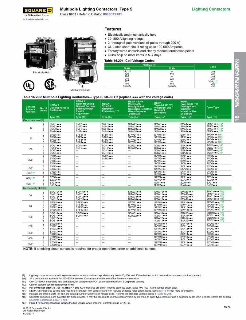
© 2017 Schneider ElectricAll Rights Reserved
16-73
schneider-electric.us
Multipole Lighting Contactors, Type S Lighting ContactorsClass 8903 / Refer to Catalog 8903CT9701
Features
Electrically Held
Mechanically Held
• Electrically and mechanically held• 30–800 A lighting ratings• 2- through 5-pole versions (5-poles through 200 A)• UL Listed short-circuit rating up to 100,000 Amperes• Factory wired controls and clearly marked termination points• Quick ship on most items in 5–7 days
Table 16.204: Coil Voltage CodesVoltage [9]
Code60 Hz 50 Hz24 [10]120208240277480
Specify
—110—220—440
Specify
V01V02V08V03
V04 [11]V06V99
Table 16.205: Multipole Lighting Contactors—Type S, 50–60 Hz (replace ●●● with the voltage code)
ContactAmpereRatings
No. ofPoles
NEMA 1General PurposeEnclosure
NEMA 1Flush MountingGeneral PurposeEnclosure withPlasterAdjustment
NEMAType 3RRainproofEnclosure [12]
NEMA 4 & 4XWatertight,Dusttight andCorrosion-ResistantGlass-PolyesterEnclosure
NEMAType 4 & 4X [13]Watertight andDusttightEnclosure
NEMAType 12/3R [14]Dusttight andDriptightIndustrial UseEnclosure
Open Type
Type [15] Type [15] Type [15] Type [15] Type [15] Type [15] Type [15]Electrically Held [9]
302345
SMG1●●●SMG2●●●SMG3●●●SMG4●●●
SMF1●●●SMF2●●●SMF3●●●SMF4●●●
SMH1●●●SMH2●●●SMH3●●●SMH4●●●
SMW21●●●SMW22●●●SMW23●●●SMW24●●●
SMW1●●●SMW2●●●SMW3●●●SMW4●●●
SMA1●●●SMA2●●●SMA3●●●SMA4●●●
SMO1●●● [16]SMO2●●● [16]SMO3●●● [16]SMO4●●● [16]
602345
SPG1●●●SPG2●●●SPG3●●●SPG4●●●
SPF1●●●SPF2●●●SPF3●●●SPF4●●●
SPH1●●●SPH2●●●SPH3●●●SPH4●●●
SPW21●●●SPW22●●●SPW23●●●SPW24●●●
SPW1●●●SPW2●●●SPW3●●●SPW4●●●
SPA1●●●SPA2●●●SPA3●●●SPA4●●●
SPO1●●● [16]SPO2●●● [16]SPO3●●● [16]SPO4●●● [16]
1002345
SQG1●●●SQG2●●●SQG3●●●SQG4●●●
SQF1●●●SQF2●●●——
SQH1●●●SQH2●●●SQH3●●●SQH4●●●
SQW21●●●SQW22●●●——
SQW1●●●SQW2●●●SQW3●●●SQW4●●●
SQA1●●●SQA2●●●SQA3●●●SQA4●●●
SQO1●●● [16]SQO2●●● [16]SQO3●●● [16]SQO4●●● [16]
2002345
SVG1●●●SVG2●●●SVG3●●●SVG4●●●
————
SVH1●●●SVH2●●●——
————
SVW1●●●SVW2●●●SVW3●●●SVW4●●●
SVA1●●●SVA2●●●SVA3●●●SVA4●●●
SVO1●●●SVO2●●●SVO3●●●SVO4●●●
300 23
SXG1●●●SXG2●●●
——
——
——
SXW1●●●SXW2●●●
SXA1●●●SXA2●●●
SXO1●●●SXO2●●●
400[17] 23
SYG1●●●SYG2●●●
——
——
——
SYW1●●●SYW2●●●
SYA1●●●SYA2●●●
SYO1●●●SYO2●●●
600[17] 23
SZG1●●●SZG2●●●
——
——
——
SZW1●●●SZW2●●●
SZA1●●●SZA2●●●
SZO1●●●SZO2●●●
800[17] 23
SJG1●●●SJG2●●●
——
——
——
SJW1●●●SJW2●●●
SJA1●●●SJA2●●●
SJO1●●●SJO2●●●
Mechanically Held[9]
302345
SMG10●●●SMG11●●●SMG12●●●SMG13●●●
SMF10●●●SMF11●●●SMF12●●●SMF13●●●
————
SMW31●●●SMW32●●●SMW33●●●SMW34●●●
SMW10●●●SMW11●●●SMW12●●●SMW13●●●
SMA10●●●SMA11●●●SMA12●●●SMA13●●●
SMO10●●● [16]SMO11●●● [16]SMO12●●● [16]SMO13●●● [16]
602345
SPG10●●●SPG11●●●SPG12●●●SPG13●●●
SPF10●●●SPF11●●●SPF12●●●SPF13●●●
————
SPW31●●●SPW32●●●SPW33●●●SPW34●●●
SPW10●●●SPW11●●●SPW12●●●SPW13●●●
SPA10●●●SPA11●●●SPA12●●●SPA13●●●
SPO10●●● [16]SPO11●●● [16]SPO12●●● [16]SPO13●●● [16]
1002345
SQG10●●●SQG11●●●SQG12●●●SQG13●●●
SQF10●●●SQF11●●●——
————
SQW31●●●SQW32●●●——
SQW10●●●SQW11●●●SQW12●●●SQW13●●●
SQA10●●●SQA11●●●SQA12●●●SQA13●●●
SQO10●●● [16]SQO11●●● [16]SQO12●●● [16]SQO13●●● [16]
200234
SVG10●●●SVG11●●●SVG12●●●
———
———
———
SVW10●●●SVW11●●●SVW12●●●
SVA10●●●SVA11●●●SVA12●●●
SVO10●●●SVO11●●●SVO12●●●
300 23
SXG13●●●SXG14●●●
——
——
——
SXW13●●●SXW14●●●
SXA13●●●SXA14●●●
SXO13●●●SXO14●●●
400 23
SYG16●●●SYG17●●●
——
——
——
SYW16●●●SYW17●●●
SYA16●●●SYA17●●●
SYO16●●●SYO17●●●
600 23
SZG18●●●SZG19●●●
——
——
——
SZW18●●●SZW19●●●
SZA18●●●SZA19●●●
SZO18●●●SZO19●●●
NOTE: If a holding circuit contact is required for proper operation, order an additional contact.
16NEMAANDDEFINITEPURPOSE
CONTA
CTORSANDSTA
RTERS
[9] Lighting contactors come with separate control as standard—except electrically held 400, 600, and 800 A devices, which come with common control as standard.[10] 24 V coils are not available for 200–800 A devices. Contact your local sales office for more information.[11] On 400–800 A electrically held contactors, for voltage code V04, you must select Form S (separate control).[12] Cannot support control transformer forms.[13] For contactor sizes 30–300 A, NEMA 4 and 4X enclosures are brush finished stainless steel. Sizes 400–800 A are painted sheet steel.[14] NEMA 12 enclosures can be field modified for outdoor non-corrosive and non–service entrance rated applications. See page 16-110 for more information.[15] Replace the three bullets (●●●) in the catalog number with the coil voltage code. Refer to the standard voltage codes in Table 16.204.[16] Separate enclosures are available for these devices. It may be possible to improve delivery time by ordering an open type contactor and a separate Class 9991 enclosure from the section,
Separate Enclosures, page 16-108.[17] Form FF4Tcomes standard; include the line voltage when ordering. Control voltage is 120–60.
6/20/2017
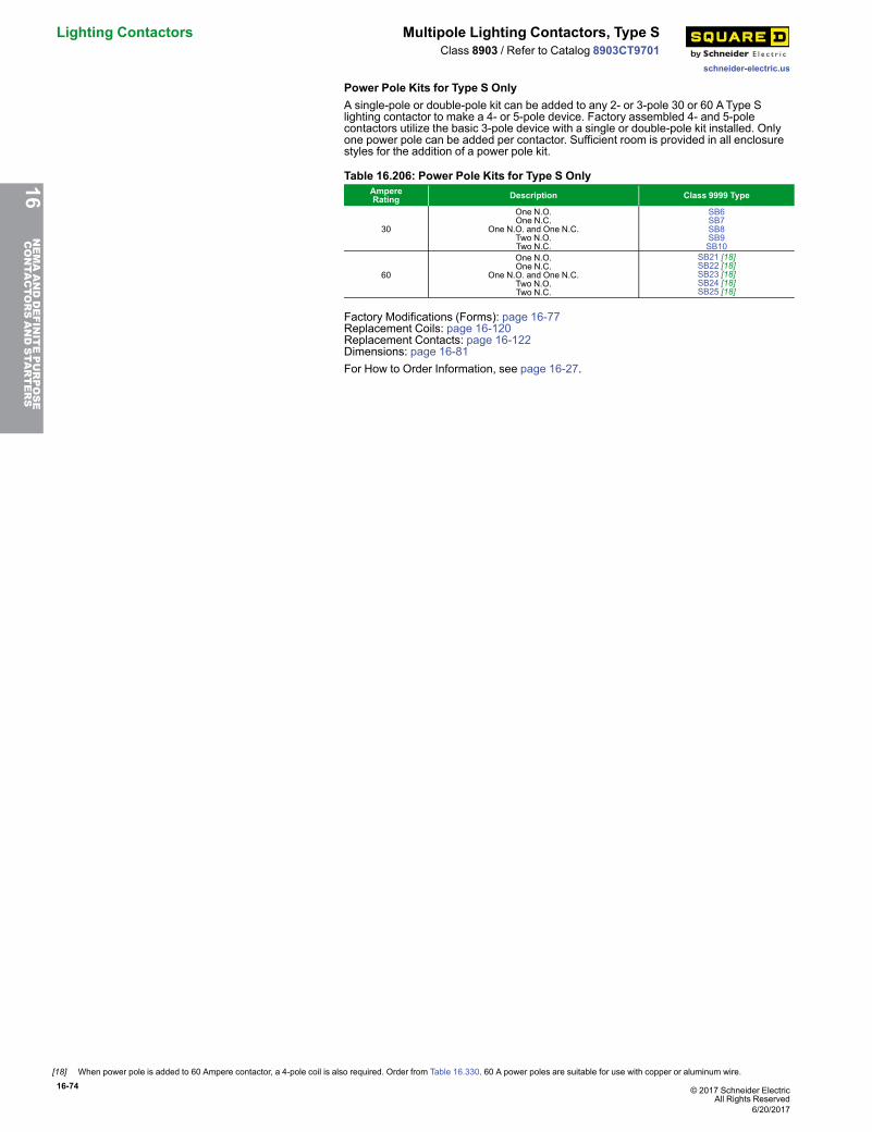
16-74 © 2017 Schneider ElectricAll Rights Reserved
Lighting Contactors Multipole Lighting Contactors, Type S
schneider-electric.us
Class 8903 / Refer to Catalog 8903CT9701
Power Pole Kits for Type S OnlyA single-pole or double-pole kit can be added to any 2- or 3-pole 30 or 60 AType Slighting contactor to make a 4- or 5-pole device. Factory assembled 4- and 5-polecontactors utilize the basic 3-pole device with a single or double-pole kit installed. Onlyone power pole can be added per contactor. Sufficient room is provided in all enclosurestyles for the addition of a power pole kit.
Table 16.206: Power Pole Kits for Type S OnlyAmpereRating Description Class 9999 Type
30
One N.O.One N.C.
One N.O. and One N.C.Two N.O.Two N.C.
SB6SB7SB8SB9SB10
60
One N.O.One N.C.
One N.O. and One N.C.Two N.O.Two N.C.
SB21 [18]SB22 [18]SB23 [18]SB24 [18]SB25 [18]
Factory Modifications (Forms): page 16-77Replacement Coils: page 16-120Replacement Contacts: page 16-122Dimensions: page 16-81For How to Order Information, see page 16-27.
16NEMAANDDEFINITEPURPOSE
CONTA
CTORSANDSTA
RTERS
[18] When power pole is added to 60 Ampere contactor, a 4-pole coil is also required. Order from Table 16.330. 60 A power poles are suitable for use with copper or aluminum wire.
6/20/2017
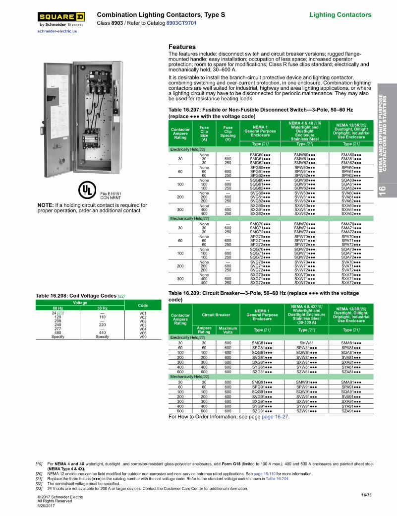
© 2017 Schneider ElectricAll Rights Reserved
16-75
schneider-electric.us
Combination Lighting Contactors, Type S Lighting ContactorsClass 8903 / Refer to Catalog 8903CT9701
Features
File E16151CCN NRNT
NOTE: If a holding circuit contact is required forproper operation, order an additional contact.
The features include: disconnect switch and circuit breaker versions; rugged flange-mounted handle; easy installation; occupation of less space; increased operatorprotection; room to spare for modifications; Class R fuse clips standard; electrically andmechanically held; 30–600 A.It is desirable to install the branch-circuit protective device and lighting contactor,combining switching and over-current protection, in one enclosure. Combination lightingcontactors are well suited for industrial, highway and area lighting applications, or wherea lighting circuit may have to be disconnected for periodic maintenance. They may alsobe used for resistance heating loads.
Table 16.207: Fusible or Non-Fusible Disconnect Switch—3-Pole, 50–60 Hz(replace ●●● with the voltage code)
ContactorAmpereRating
FuseClipSize(A)
FuseClip
Spacing(V)
NEMA 1General Purpose
Enclosure
NEMA 4 & 4X [19]Watertight and
DusttightEnclosure
Stainless Steel
NEMA 12/3R[20]Dusttight, OiltightDriptight, IndustrialUse Enclosure
Type [21] Type [21] Type [21]Electrically Held[22]
30None3030
—600250
SMG60●●●SMG61●●●SMG62●●●
SMW60●●●SMW61●●●SMW62●●●
SMA60●●●SMA61●●●SMA62●●●
60None6060
—600250
SPG60●●●SPG61●●●SPG62●●●
SPW60●●●SPW61●●●SPW62●●●
SPA60●●●SPA61●●●SPA62●●●
100None100100
—600250
SQG60●●●SQG61●●●SQG62●●●
SQW60●●●SQW61●●●SQW62●●●
SQA60●●●SQA61●●●SQA62●●●
200None200200
—600250
SVG60●●●SVG61●●●SVG62●●●
SVW60●●●SVW61●●●SVW62●●●
SVA60●●●SVA61●●●SVA62●●●
300None400400
—600250
SXG60●●●SXG61●●●SXG62●●●
SXW60●●●SXW61●●●SXW62●●●
SXA60●●●SXA61●●●SXA62●●●
Mechanically Held[22]
30None3030
—600250
SMG70●●●SMG71●●●SMG72●●●
SMW70●●●SMW71●●●SMW72●●●
SMA70●●●SMA71●●●SMA72●●●
60None6060
—600250
SPG70●●●SPG71●●●SPG72●●●
SPW70●●●SPW71●●●SPW72●●●
SPA70●●●SPA71●●●SPA72●●●
100None100100
—600250
SQG70●●●SQG71●●●SQG72●●●
SQW70●●●SQW71●●●SQW72●●●
SQA70●●●SQA71●●●SQA72●●●
200None200200
—600250
SVG70●●●SVG71●●●SVG72●●●
SVW70●●●SVW71●●●SVW72●●●
SVA70●●●SVA71●●●SVA72●●●
300None400400
—600250
SXG70●●●SXG71●●●SXG72●●●
SXW70●●●SXW71●●●SXW72●●●
SXA70●●●SXA71●●●SXA72●●●
Table 16.208: Coil Voltage Codes [22]Voltage
Code60 Hz 50 Hz24 [23]120208240277480
Specify
—110—220—440
Specify
V01V02V08V03V04V06V99
Table 16.209: Circuit Breaker—3-Pole, 50–60 Hz (replace ●●● with the voltagecode)
ContactorAmpereRating
Circuit BreakerNEMA 1
General PurposeEnclosure
NEMA 4 & 4X[19]Watertight and
Dusttight EnclosureStainless Steel(30-300 A)
NEMA 12/3R[20]Dusttight, Oiltight,Driptight, IndustrialUse Enclosure
AmpereRating
MaximumVolts Type [21] Type [21] Type [21]
Electrically Held[22]30 30 600 SMG81●●● SMW81 SMA81●●●60 60 600 SPG81●●● SPW81●●● SPA81●●●100 100 600 SQG81●●● SQW81●●● SQA81●●●200 200 600 SVG81●●● SVW81●●● SVA81●●●300 300 600 SXG81●●● SXW81●●● SXA81●●●400 400 600 SYG81●●● SYW81●●● SYA81●●●600 600 600 SZG81●●● SZW81●●● SZA81●●●
Mechanically Held[22]30 30 600 SMG91●●● SMW91●●● SMA91●●●60 60 600 SPG91●●● SPW91●●● SPA91●●●100 100 600 SQG91●●● SQW91●●● SQA91●●●200 200 600 SVG91●●● SVW91●●● SVA91●●●300 300 600 SXG91●●● SXW91●●● SXA91●●●400 400 600 SYG91●●● SYW91●●● SYA91●●●600 600 600 SZG91●●● SZW91●●● SZA91●●●
For How to Order Information, see page page 16-27.
16NEMAANDDEFINITEPURPOSE
CONTA
CTORSANDSTA
RTERS
[19] For NEMA 4 and 4X watertight, dusttight ,and corrosion-resistant glass-polyester enclosures, add Form G18 (limited to 100 A max.). 400 and 600 A enclosures are painted sheet steel(NEMAType 4 & 4X).
[20] NEMA 12 enclosures can be field modified for outdoor non-corrosive and non–service entrance rated applications. See page 16-110 for more information.[21] Replace the three bullets (●●●) in the catalog number with the coil voltage code. Refer to the standard voltage codes shown in Table 16.204.[22] The control/coil voltage must be specified.[23] 24 V coils are not available for 200 A or larger devices. Contact the Customer Care Center for additional information.
6/20/2017
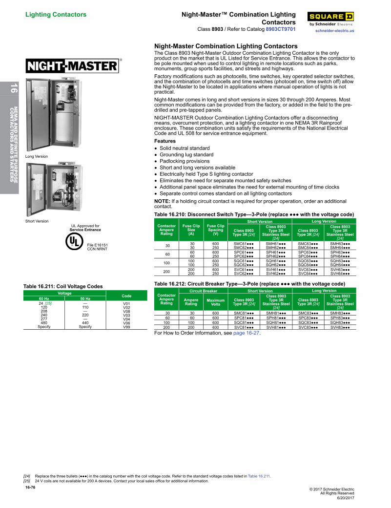
16-76 © 2017 Schneider ElectricAll Rights Reserved
Lighting Contactors Night-Master™ Combination LightingContactors
schneider-electric.usClass 8903 / Refer to Catalog 8903CT9701
Night-Master Combination Lighting Contactors
Long Version
Short VersionUL Approved forService Entrance
File E16151CCN NRNT
The Class 8903 Night-Master Outdoor Combination Lighting Contactor is the onlyproduct on the market that is UL Listed for Service Entrance. This allows the contactor tobe pole mounted when used to control lighting in remote locations such as parks,monuments, group sports facilities, and streets and highways.Factory modifications such as photocells, time switches, key operated selector switches,and the combination of photocells and time switches (photocell on, time switch off) allowthe Night-Master to be located in applications where manual operation of lights is notpractical.Night-Master comes in long and short versions in sizes 30 through 200 Amperes. Mostcommon modifications can be provided from the factory, or added in the field to the pre-drilled and pre-tapped panels.NIGHT-MASTER Outdoor Combination Lighting Contactors offer a disconnectingmeans, overcurrent protection, and a lighting contactor in one NEMA 3R Rainproofenclosure. These combination units satisfy the requirements of the National ElectricalCode and UL 508 for service entrance equipment.Features• Solid neutral standard• Grounding lug standard• Padlocking provisions• Short and long versions available• Electrically held Type S lighting contactor• Eliminates the need for separate mounted safety switches• Additional panel space eliminates the need for external mounting of time clocks• Separate control comes standard on all lighting contactorsNOTE: If a holding circuit contact is required for proper operation, order an additionalcontact.Table 16.210: Disconnect Switch Type—3-Pole (replace ●●● with the voltage code)
ContactorAmpereRating
Fuse ClipSize(A)
Fuse ClipSpacing
(V)
Short Version Long Version
Class 8903Type 3R [24]
Class 8903Type 3R
Stainless Steel[24]
Class 8903Type 3R [24]
Class 8903Type 3R
Stainless Steel[24]
30 30 30
600250
SMC61●●●SMC62●●●
SMH61●●●SMH62●●●
SMC63●●●SMC64●●●
SMH63●●●SMH64●●●
60 60 60
600250
SPC61●●●SPC62●●●
SPH61●●●SPH62●●●
SPC63●●●SPC64●●●
SPH63●●●SPH64●●●
100 100100
600250
SQC61●●●SQC62●●●
SQH61●●●SQH62●●●
SQC63●●●SQC64●●●
SQH63●●●SQH64●●●
200 200200
600250
SVC61●●●SVC62●●●
SVH61●●●SVH62●●●
SVC63●●●SVC64●●●
SVH63●●●SVH64●●●
Table 16.211: Coil Voltage CodesVoltage
Code60 Hz 50 Hz
24 [25]120208240277480
Specify
—110—220—440
Specify
V01V02V08V03V04V06V99
Table 16.212: Circuit Breaker Type—3-Pole (replace ●●● with the voltage code)
ContactorAmpereRating
Circuit Breaker Short Version Long Version
AmpereRating
MaximumVolts
Class 8903Type 3R [24]
Class 8903Type 3R
Stainless Steel[24]
Class 8903Type 3R [24]
Class 8903Type 3R
Stainless Steel[24]
30 30 600 SMC81●●● SMH81●●● SMC83●●● SMH83●●● 60 60 600 SPC81●●● SPH81●●● SPC83●●● SPH83●●●100 100 600 SQC81●●● SQH81●●● SQC83●●● SQH83●●●200 200 600 SVC81●●● SVH81●●● SVC83●●● SVH83●●●
For How to Order Information, see page 16-27.
[24] Replace the three bullets (●●●) in the catalog number with the coil voltage code. Refer to the standard voltage codes listed in Table 16.211.[25] 24 V coils are not available for 200 A devices. Contact your local sales office for additional information.
6/20/2017
16NEMAANDDEFINITEPURPOSE
CONTA
CTORSANDSTA
RTERS
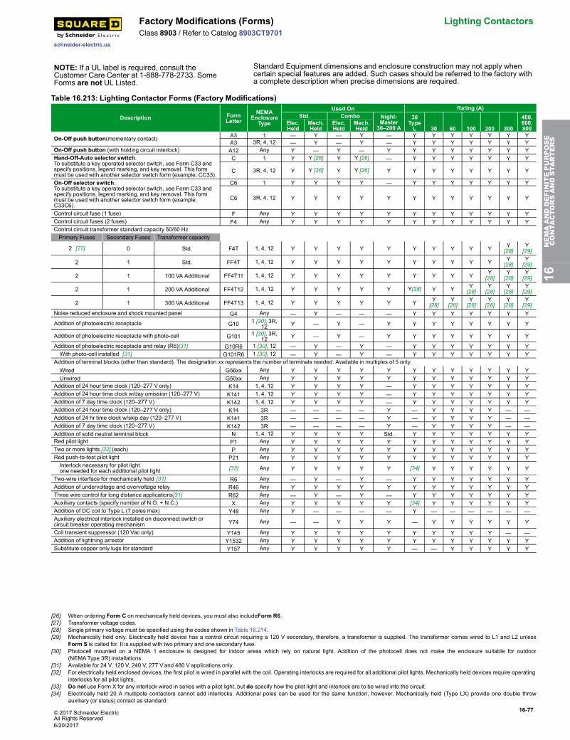
© 2017 Schneider ElectricAll Rights Reserved
16-77
schneider-electric.us
Factory Modifications (Forms) Lighting ContactorsClass 8903 / Refer to Catalog 8903CT9701
NOTE: If a UL label is required, consult theCustomer Care Center at 1-888-778-2733. SomeForms are not UL Listed.
Standard Equipment dimensions and enclosure construction may not apply whencertain special features are added. Such cases should be referred to the factory witha complete description when precise dimensions are required.
Table 16.213: Lighting Contactor Forms (Factory Modifications)
Description FormLetter
NEMAEnclosure
Type
Used On Rating (A)Std. Combo Night-
Master30–200 A
30TypeL 30 60 100 200 300
400,600,800
Elec.Held
Mech.Held
Elec.Held
Mech.Held
On-Off push button(momentary contact) A3 1 — Y — Y — Y Y Y Y Y Y YA3 3R, 4, 12 — Y — Y — Y Y Y Y Y Y Y
On-Off push button (with holding circuit interlock) A12 Any Y — Y — Y Y Y Y Y Y Y YHand-Off-Auto selector switch.To substitute a key operated selector switch, use Form C33 andspecify positions, legend marking, and key removal. This formmust be used with another selector switch form (example: CC33).
C 1 Y Y [26] Y Y [26] — Y Y Y Y Y Y Y
C 3R, 4, 12 Y Y [26] Y Y [26] Y Y Y Y Y Y Y Y
On-Off selector switch.To substitute a key operated selector switch, use Form C33 andspecify positions, legend marking, and key removal. This formmust be used with another selector switch form (example:C33C6).
C6 1 Y Y Y Y — Y Y Y Y Y Y Y
C6 3R, 4, 12 Y Y Y Y Y Y Y Y Y Y Y Y
Control circuit fuse (1 fuse) F Any Y Y Y Y Y Y Y Y Y Y Y YControl circuit fuses (2 fuses) F4 Any Y Y Y Y Y Y Y Y Y Y Y YControl circuit transformer standard capacity 50/60 HzPrimary Fuses Secondary Fuses Transformer capacity
2 [27] 0 Std. F4T 1, 4, 12 Y Y Y Y Y Y Y Y Y Y Y[28]
Y[29]
2 1 Std. FF4T 1, 4, 12 Y Y Y Y Y Y Y Y Y Y Y[28]
Y[29]
2 1 100 VA Additional FF4T11 1, 4, 12 Y Y Y Y Y Y Y Y Y Y[28]
Y[28]
Y[29]
2 1 200 VA Additional FF4T12 1, 4, 12 Y Y Y Y Y Y[28] Y Y Y[28]
Y[28]
Y[28]
Y[29]
2 1 300 VA Additional FF4T13 1, 4, 12 Y Y Y Y Y Y Y[28]
Y[28]
Y[28]
Y[28]
Y[28]
Y[29]
Noise reduced enclosure and shock mounted panel G4 Any — Y — — — Y Y Y Y Y Y Y
Addition of photoelectric receptacle G10 1 [30], 3R,12 Y — Y — Y Y Y Y Y Y Y Y
Addition of photoelectric receptacle with photo-cell G101 1 [30], 3R,12 Y — Y — Y Y Y Y Y Y Y Y
Addition of photoelectric receptacle and relay (R6)[31] G10R6 1 [30], 12 — Y — Y — Y Y Y Y Y Y YWith photo-cell installed [31] G101R6 1 [30], 12 — Y — Y — Y Y Y Y Y Y Y
Addition of terminal blocks (other than standard). The designation xx represents the number of terminals needed. Available in multiples of 5 only.Wired G56xx Any Y Y Y Y Y Y Y Y Y Y Y YUnwired G50xx Any Y Y Y Y Y Y Y Y Y Y Y Y
Addition of 24 hour time clock (120–277 V only) K14 1, 4, 12 Y Y Y Y — Y Y Y Y Y Y YAddition of 24 hour time clock w/day omission (120–277 V) K141 1, 4, 12 Y Y Y Y — Y Y Y Y Y Y YAddition of 7 day time clock (120–277 V) K142 1, 4, 12 Y Y Y Y — Y Y Y Y Y Y YAddition of 24 hour time clock (120–277 V only) K14 3R — — — — Y — Y Y Y Y — —Addition of 24 hr time clock w/skip day (120–277 V) K141 3R — — — — Y — Y Y Y Y — —Addition of 7 day time clock (120–277 V) K142 3R — — — — Y — Y Y Y Y — —Addition of solid neutral terminal block N 1, 4, 12 Y Y Y Y Std. Y Y Y Y Y Y YRed pilot light P1 Any Y Y Y Y Y Y Y Y Y Y Y YTwo or more lights [32] (each) P Any Y Y Y Y Y Y Y Y Y Y Y YRed push-to-test pilot light P21 Any Y Y Y Y Y Y Y Y Y Y Y YInterlock necessary for pilot lightone needed for each additional pilot light [33] Any Y Y Y Y Y [34] Y Y Y Y Y Y
Two-wire interface for mechanically held [31] R6 Any — Y — Y — Y Y Y Y Y Y YAddition of undervoltage and overvoltage relay R46 Any Y Y Y Y Y Y Y Y Y Y Y YThree wire control for long distance applications[31] R62 Any — Y — Y — Y Y Y Y Y Y YAuxiliary contacts (specify number of N.O. + N.C.) X Any Y Y Y Y Y [34] Y Y Y Y Y YAddition of DC coil to Type L (7 poles max) Y48 Any Y — — — — Y — — — — — —Auxiliary electrical interlock installed on disconnect switch orcircuit breaker operating mechanism Y74 Any — — Y Y Y — Y Y Y Y Y Y
Coil transient suppressor (120 Vac only) Y145 Any Y Y Y Y Y Y Y Y Y Y — —Addition of lightning arrestor Y1532 Any Y Y Y Y Y Y Y Y Y Y Y YSubstitute copper only lugs for standard Y157 Any Y Y Y Y Y — — Y Y Y Y Y
16NEMAANDDEFINITEPURPOSE
CONTA
CTORSANDSTA
RTERS
[26] When ordering Form C on mechanically held devices, you must also includeForm R6.[27] Transformer voltage codes.[28] Single primary voltage must be specified using the codes shown in Table 16.214.[29] Mechanically held only. Electrically held device has a control circuit requiring a 120 V secondary, therefore, a transformer is supplied. The transformer comes wired to L1 and L2 unless
Form S is called for. It is supplied with two primary and one secondary fuse.[30] Photocell mounted on a NEMA 1 enclosure is designed for indoor areas which rely on natural light. Addition of the photocell does not make the enclosure suitable for outdoor
(NEMAType 3R) installations.[31] Available for 24 V, 120 V, 240 V, 277 V and 480 V applications only.[32] For electrically held enclosed devices, the first pilot is wired in parallel with the coil. Operating interlocks are required for all additional pilot lights. Mechanically held devices require operating
interlocks for all pilot lights.[33] Do not use Form X for any interlock wired in series with a pilot light, but do specify how the pilot light and interlock are to be wired into the circuit.[34] Electrically held 20 A multipole contactors cannot add interlocks. Additional poles can be used for the same function, however. Mechanically held (Type LX) provide one double throw
auxiliary (or status) contact as standard.
6/20/2017
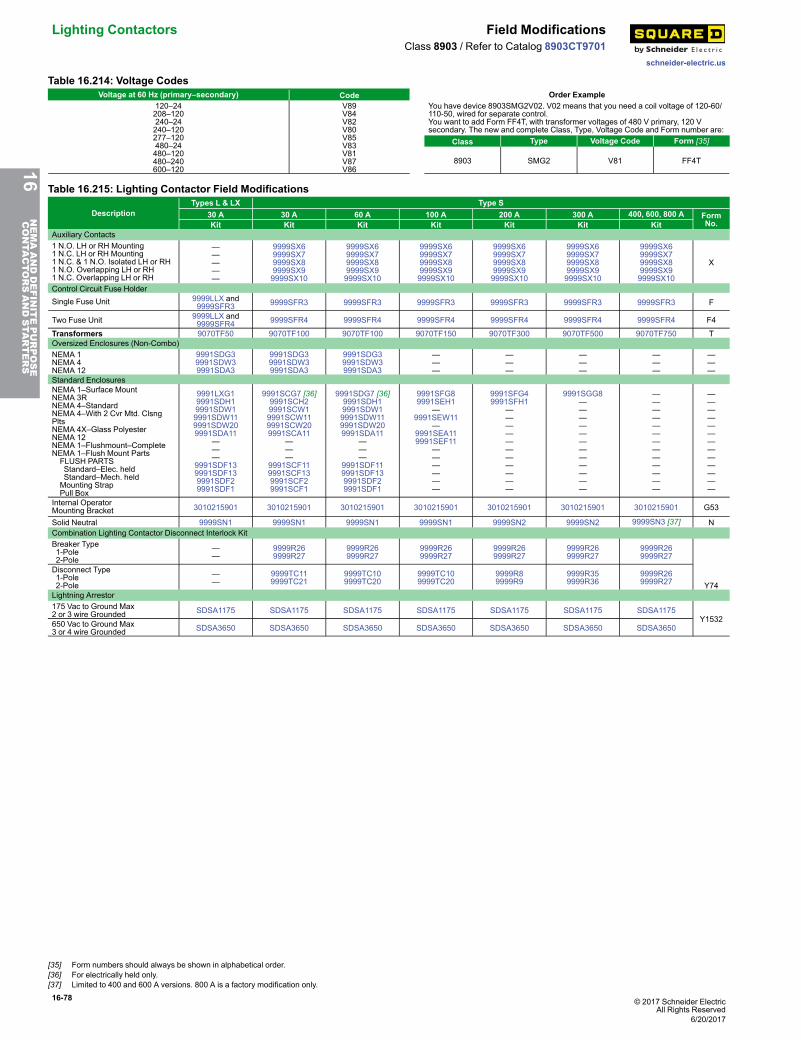
16-78 © 2017 Schneider ElectricAll Rights Reserved
Lighting Contactors Field Modifications
schneider-electric.us
Class 8903 / Refer to Catalog 8903CT9701
Table 16.214: Voltage CodesVoltage at 60 Hz (primary–secondary) Code Order Example
120–24208–120240–24240–120277–120480–24480–120480–240600–120
V89V84V82V80V85V83V81V87V86
You have device 8903SMG2V02. V02 means that you need a coil voltage of 120-60/110-50, wired for separate control.You want to add Form FF4T, with transformer voltages of 480 V primary, 120 Vsecondary. The new and complete Class, Type, Voltage Code and Form number are:
Class Type Voltage Code Form [35]
8903 SMG2 V81 FF4T
Table 16.215: Lighting Contactor Field Modifications
DescriptionTypes L & LX Type S
30 A 30 A 60 A 100 A 200 A 300 A 400, 600, 800 A FormNo.Kit Kit Kit Kit Kit Kit Kit
Auxiliary Contacts1 N.O. LH or RH Mounting1 N.C. LH or RH Mounting1 N.C. & 1 N.O. Isolated LH or RH1 N.O. Overlapping LH or RH1 N.C. Overlapping LH or RH
—————
9999SX69999SX79999SX89999SX99999SX10
9999SX69999SX79999SX89999SX99999SX10
9999SX69999SX79999SX89999SX99999SX10
9999SX69999SX79999SX89999SX99999SX10
9999SX69999SX79999SX89999SX99999SX10
9999SX69999SX79999SX89999SX99999SX10
X
Control Circuit Fuse HolderSingle Fuse Unit 9999LLX and
9999SFR3 9999SFR3 9999SFR3 9999SFR3 9999SFR3 9999SFR3 9999SFR3 F
Two Fuse Unit 9999LLX and9999SFR4 9999SFR4 9999SFR4 9999SFR4 9999SFR4 9999SFR4 9999SFR4 F4
Transformers 9070TF50 9070TF100 9070TF100 9070TF150 9070TF300 9070TF500 9070TF750 TOversized Enclosures (Non-Combo)NEMA 1NEMA 4NEMA 12
9991SDG39991SDW39991SDA3
9991SDG39991SDW39991SDA3
9991SDG39991SDW39991SDA3
———
———
———
———
———
Standard EnclosuresNEMA 1–Surface MountNEMA 3RNEMA 4–StandardNEMA 4–With 2 Cvr Mtd. ClsngPltsNEMA 4X–Glass PolyesterNEMA 12NEMA 1–Flushmount–CompleteNEMA 1–Flush Mount PartsFLUSH PARTSStandard–Elec. heldStandard–Mech. heldMounting StrapPull Box
9991LXG19991SDH19991SDW19991SDW119991SDW209991SDA11
———
9991SDF139991SDF139991SDF29991SDF1
9991SCG7 [36]9991SCH29991SCW19991SCW119991SCW209991SCA11
———
9991SCF119991SCF139991SCF29991SCF1
9991SDG7 [36]9991SDH19991SDW19991SDW119991SDW209991SDA11
———
9991SDF119991SDF139991SDF29991SDF1
9991SFG89991SEH1
—9991SEW11
—9991SEA119991SEF11
——————
9991SFG49991SFH1
———————————
9991SGG8————————————
—————————————
—————————————
Internal OperatorMounting Bracket 3010215901 3010215901 3010215901 3010215901 3010215901 3010215901 3010215901 G53
Solid Neutral 9999SN1 9999SN1 9999SN1 9999SN1 9999SN2 9999SN2 9999SN3 [37] NCombination Lighting Contactor Disconnect Interlock KitBreaker Type1-Pole2-Pole
——
9999R269999R27
9999R269999R27
9999R269999R27
9999R269999R27
9999R269999R27
9999R269999R27
Y74
Disconnect Type1-Pole2-Pole
——
9999TC119999TC21
9999TC109999TC20
9999TC109999TC20
9999R89999R9
9999R359999R36
9999R269999R27
Lightning Arrestor175 Vac to Ground Max2 or 3 wire Grounded SDSA1175 SDSA1175 SDSA1175 SDSA1175 SDSA1175 SDSA1175 SDSA1175
Y1532650 Vac to Ground Max3 or 4 wire Grounded SDSA3650 SDSA3650 SDSA3650 SDSA3650 SDSA3650 SDSA3650 SDSA3650
16NEMAANDDEFINITEPURPOSE
CONTA
CTORSANDSTA
RTERS
[35] Form numbers should always be shown in alphabetical order.[36] For electrically held only.[37] Limited to 400 and 600 A versions. 800 A is a factory modification only.
6/20/2017
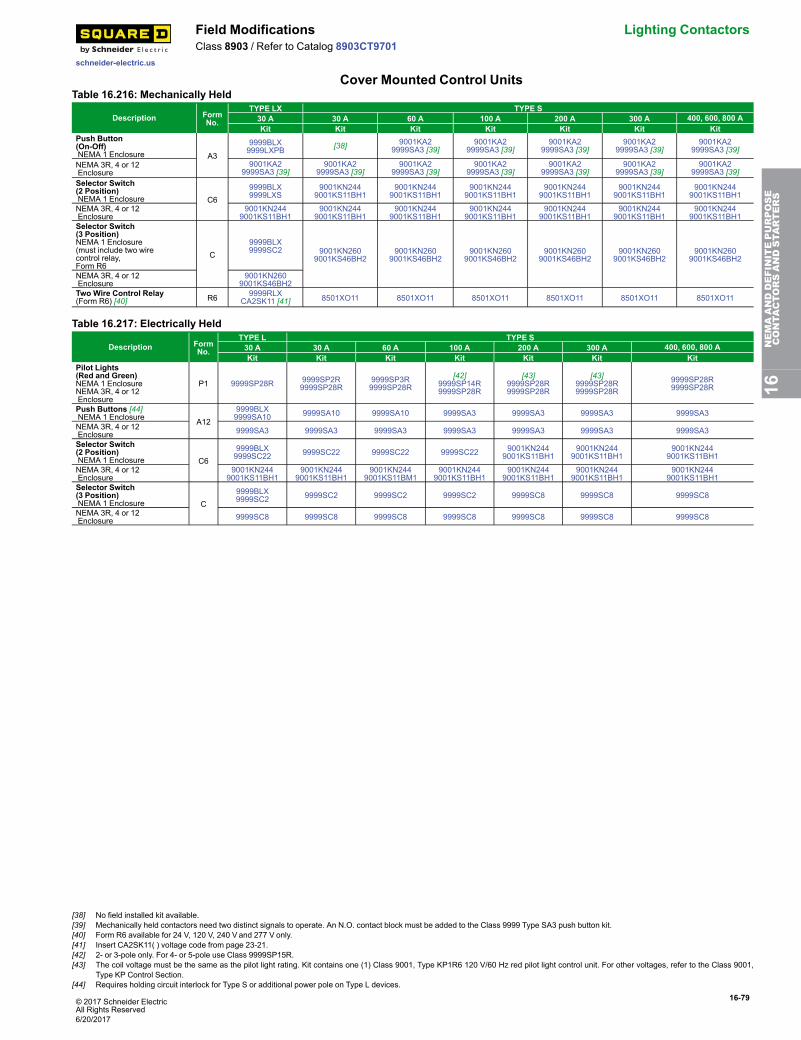
© 2017 Schneider ElectricAll Rights Reserved
16-79
schneider-electric.us
Field Modifications Lighting ContactorsClass 8903 / Refer to Catalog 8903CT9701
Cover Mounted Control UnitsTable 16.216: Mechanically Held
Description FormNo.
TYPE LX TYPE S30 A 30 A 60 A 100 A 200 A 300 A 400, 600, 800 AKit Kit Kit Kit Kit Kit Kit
Push Button(On-Off)NEMA 1 Enclosure A3
9999BLX9999LXPB [38] 9001KA2
9999SA3 [39]9001KA2
9999SA3 [39]9001KA2
9999SA3 [39]9001KA2
9999SA3 [39]9001KA2
9999SA3 [39]
NEMA 3R, 4 or 12Enclosure
9001KA29999SA3 [39]
9001KA29999SA3 [39]
9001KA29999SA3 [39]
9001KA29999SA3 [39]
9001KA29999SA3 [39]
9001KA29999SA3 [39]
9001KA29999SA3 [39]
Selector Switch(2 Position)NEMA 1 Enclosure C6
9999BLX9999LXS
9001KN2449001KS11BH1
9001KN2449001KS11BH1
9001KN2449001KS11BH1
9001KN2449001KS11BH1
9001KN2449001KS11BH1
9001KN2449001KS11BH1
NEMA 3R, 4 or 12Enclosure
9001KN2449001KS11BH1
9001KN2449001KS11BH1
9001KN2449001KS11BH1
9001KN2449001KS11BH1
9001KN2449001KS11BH1
9001KN2449001KS11BH1
9001KN2449001KS11BH1
Selector Switch(3 Position)NEMA 1 Enclosure(must include two wirecontrol relay,Form R6
C9999BLX9999SC2 9001KN260
9001KS46BH29001KN260
9001KS46BH29001KN260
9001KS46BH29001KN260
9001KS46BH29001KN260
9001KS46BH29001KN260
9001KS46BH2
NEMA 3R, 4 or 12Enclosure
9001KN2609001KS46BH2
Two Wire Control Relay(Form R6) [40] R6 9999RLX
CA2SK11 [41] 8501XO11 8501XO11 8501XO11 8501XO11 8501XO11 8501XO11
Table 16.217: Electrically Held
Description FormNo.
TYPE L TYPE S30 A 30 A 60 A 100 A 200 A 300 A 400, 600, 800 AKit Kit Kit Kit Kit Kit Kit
Pilot Lights(Red and Green)NEMA 1 EnclosureNEMA 3R, 4 or 12Enclosure
P1 9999SP28R 9999SP2R9999SP28R
9999SP3R9999SP28R
[42]9999SP14R9999SP28R
[43]9999SP28R9999SP28R
[43]9999SP28R9999SP28R
9999SP28R9999SP28R
Push Buttons [44]NEMA 1 Enclosure A12
9999BLX9999SA10 9999SA10 9999SA10 9999SA3 9999SA3 9999SA3 9999SA3
NEMA 3R, 4 or 12Enclosure 9999SA3 9999SA3 9999SA3 9999SA3 9999SA3 9999SA3 9999SA3
Selector Switch(2 Position)NEMA 1 Enclosure C6
9999BLX9999SC22 9999SC22 9999SC22 9999SC22 9001KN244
9001KS11BH19001KN244
9001KS11BH19001KN244
9001KS11BH1
NEMA 3R, 4 or 12Enclosure
9001KN2449001KS11BH1
9001KN2449001KS11BH1
9001KN2449001KS11BM1
9001KN2449001KS11BH1
9001KN2449001KS11BH1
9001KN2449001KS11BH1
9001KN2449001KS11BH1
Selector Switch(3 Position)NEMA 1 Enclosure C
9999BLX9999SC2 9999SC2 9999SC2 9999SC2 9999SC8 9999SC8 9999SC8
NEMA 3R, 4 or 12Enclosure 9999SC8 9999SC8 9999SC8 9999SC8 9999SC8 9999SC8 9999SC8
16NEMAANDDEFINITEPURPOSE
CONTA
CTORSANDSTA
RTERS
[38] No field installed kit available.[39] Mechanically held contactors need two distinct signals to operate. An N.O. contact block must be added to the Class 9999 Type SA3 push button kit.[40] Form R6 available for 24 V, 120 V, 240 V and 277 V only.[41] Insert CA2SK11( ) voltage code from page 23-21.[42] 2- or 3-pole only. For 4- or 5-pole use Class 9999SP15R.[43] The coil voltage must be the same as the pilot light rating. Kit contains one (1) Class 9001, Type KP1R6 120 V/60 Hz red pilot light control unit. For other voltages, refer to the Class 9001,
Type KP Control Section.[44] Requires holding circuit interlock for Type S or additional power pole on Type L devices.
6/20/2017
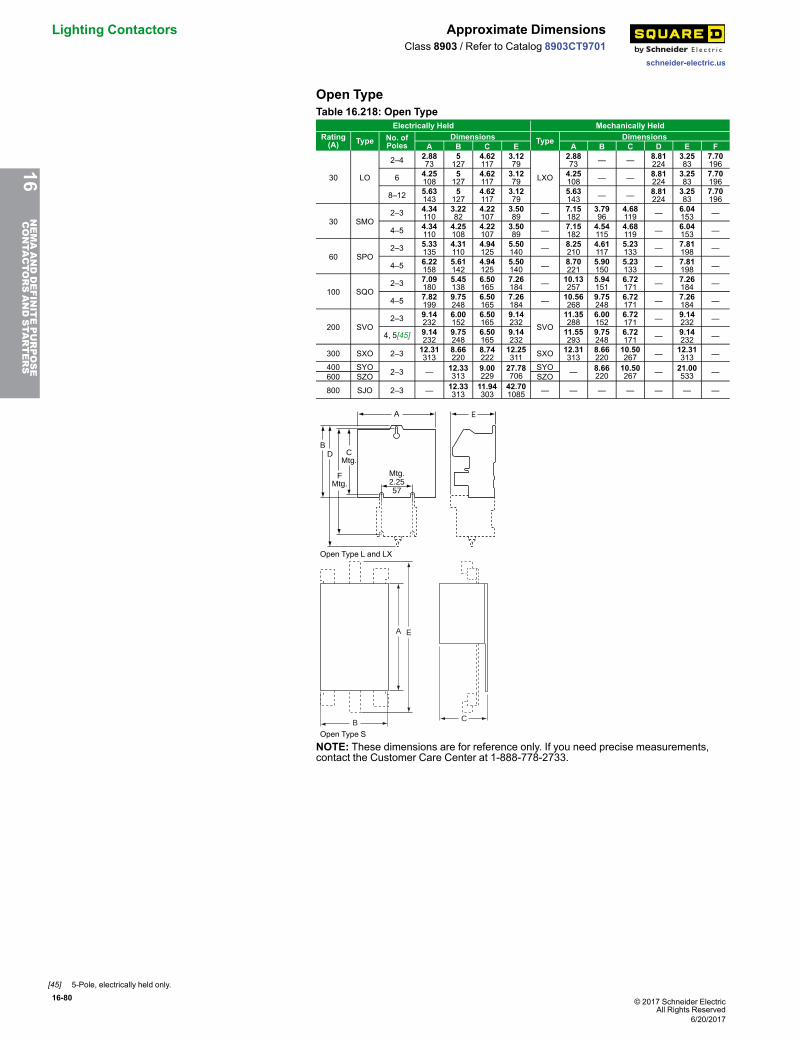
16-80 © 2017 Schneider ElectricAll Rights Reserved
Lighting Contactors Approximate Dimensions
schneider-electric.us
Class 8903 / Refer to Catalog 8903CT9701
Open TypeTable 16.218: Open Type
Electrically Held Mechanically HeldRating(A) Type No. of
PolesDimensions Type Dimensions
A B C E A B C D E F
30 LO
2–4 2.8873
5127
4.62117
3.1279
LXO
2.8873 — — 8.81
2243.2583
7.70196
6 4.25108
5127
4.62117
3.1279
4.25108 — — 8.81
2243.2583
7.70196
8–12 5.63143
5127
4.62117
3.1279
5.63143 — — 8.81
2243.2583
7.70196
30 SMO2–3 4.34
1103.2282
4.22107
3.5089 — 7.15
1823.7996
4.68119 — 6.04
153 —
4–5 4.34110
4.25108
4.22107
3.5089 — 7.15
1824.54115
4.68119 — 6.04
153 —
60 SPO2–3 5.33
1354.31110
4.94125
5.50140 — 8.25
2104.61117
5.23133 — 7.81
198 —
4–5 6.22158
5.61142
4.94125
5.50140 — 8.70
2215.90150
5.23133 — 7.81
198 —
100 SQO2–3 7.09
1805.45138
6.50165
7.26184 — 10.13
2575.94151
6.72171 — 7.26
184 —
4–5 7.82199
9.75248
6.50165
7.26184 — 10.56
2689.75248
6.72171 — 7.26
184 —
200 SVO2–3 9.14
2326.00152
6.50165
9.14232 SVO
11.35288
6.00152
6.72171 — 9.14
232 —
4, 5[45] 9.14232
9.75248
6.50165
9.14232
11.55293
9.75248
6.72171 — 9.14
232 —
300 SXO 2–3 12.31313
8.66220
8.74222
12.25311 SXO 12.31
3138.66220
10.50267 — 12.31
313 —
400 SYO 2–3 — 12.33313
9.00229
27.78706
SYO — 8.66220
10.50267 — 21.00
533 —600 SZO SZO
800 SJO 2–3 — 12.33313
11.94303
42.701085 — — — — — — —
A
Mtg.2.2557
B
FMtg.
CMtg.
D
E
Open Type L and LX
B
A E
C
Open Type S
NOTE: These dimensions are for reference only. If you need precise measurements,contact the Customer Care Center at 1-888-778-2733.
16NEMAANDDEFINITEPURPOSE
CONTA
CTORSANDSTA
RTERS
[45] 5-Pole, electrically held only.
6/20/2017
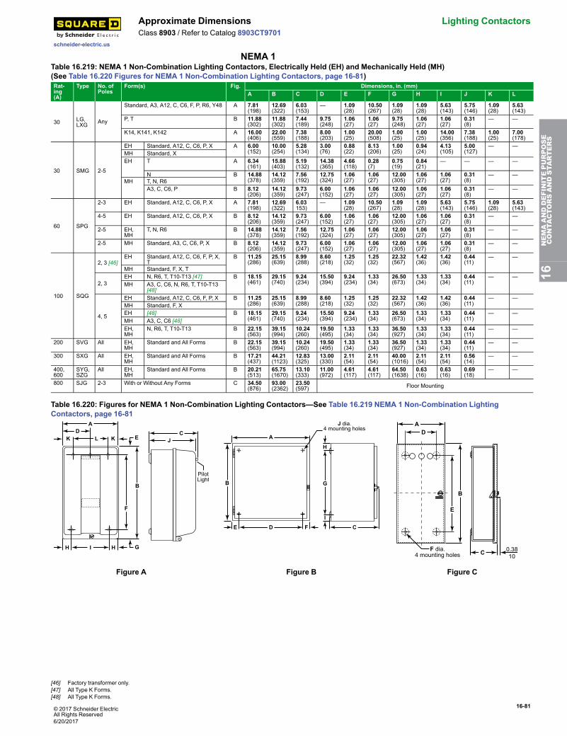
© 2017 Schneider ElectricAll Rights Reserved
16-81
schneider-electric.us
Approximate Dimensions Lighting ContactorsClass 8903 / Refer to Catalog 8903CT9701
NEMA 1Table 16.219: NEMA 1 Non-Combination Lighting Contactors, Electrically Held (EH) and Mechanically Held (MH)(See Table 16.220 Figures for NEMA 1 Non-Combination Lighting Contactors, page 16-81)Rat-ing(A)
Type No. ofPoles
Form(s) Fig. Dimensions, in. (mm)A B C D E F G H I J K L
30 LG,LXG Any
Standard, A3, A12, C, C6, F, P, R6, Y48 A 7.81(198)
12.69(322)
6.03(153)
— 1.09(28)
10.50(267)
1.09(28)
1.09(28)
5.63(143)
5.75(146)
1.09(28)
5.63(143)
P, T B 11.88(302)
11.88(302)
7.44(189)
9.75(248)
1.06(27)
1.06(27)
9.75(248)
1.06(27)
1.06(27)
0.31(8)
— —
K14, K141, K142 A 16.00(406)
22.00(559)
7.38(188)
8.00(203)
1.00(25)
20.00(508)
1.00(25)
1.00(25)
14.00(356)
7.38(188)
1.00(25)
7.00(178)
30 SMG 2-5
EH Standard, A12, C, C6, P, X A 6.00(152)
10.00(254)
5.28(134)
3.00(76)
0.88(22)
8.13(206)
1.00(25)
0.94(24)
4.13(105)
5.00(127)
— —MH Standard, XEH T A 6.34
(161)15.88(403)
5.19(132)
14.38(365)
4.66(118)
0.28(7)
0.75(19)
0.84(21)
— — — —
N B 14.88(378)
14.12(359)
7.56(192)
12.75(324)
1.06(27)
1.06(27)
12.00(305)
1.06(27)
1.06(27)
0.31(8)
— —MH T, N, R6
A3, C, C6, P B 8.12(206)
14.12(359)
9.73(247)
6.00(152)
1.06(27)
1.06(27)
12.00(305)
1.06(27)
1.06(27)
0.31(8)
— —
60 SPG
2-3 EH Standard, A12, C, C6, P, X A 7.81(198)
12.69(322)
6.03153)
— 1.09(28)
10.50(267)
1.09(28)
1.09(28)
5.63(143)
5.75(146)
1.09(28)
5.63(143)
4-5 EH Standard, A12, C, C6, P, X B 8.12(206)
14.12(359)
9.73(247)
6.00(152)
1.06(27)
1.06(27)
12.00(305)
1.06(27)
1.06(27)
0.31(8)
— —
2-5 EH,MH
T, N, R6 B 14.88(378)
14.12(359)
7.56(192)
12.75(324)
1.06(27)
1.06(27)
12.00(305)
1.06(27)
1.06(27)
0.31(8)
— —
2-5 MH Standard, A3, C, C6, P, X B 8.12(206)
14.12(359)
9.73(247)
6.00(152)
1.06(27)
1.06(27)
12.00(305)
1.06(27)
1.06(27)
0.31(8)
— —
100 SQG
2, 3 [46]EH Standard, A12, C, C6, F, P, X,
TB 11.25
(286)25.15(639)
8.99(288)
8.60(218)
1.25(32)
1.25(32)
22.32(567)
1.42(36)
1.42(36)
0.44(11)
— —
MH Standard, F, X, T
2, 3EH N, R6, T, T10-T13 [47] B 18.15
(461)29.15(740)
9.24(234)
15.50(394)
9.24(234)
1.33(34)
26.50(673)
1.33(34)
1.33(34)
0.44(11)
— —MH A3, C, C6, N, R6, T, T10-T13
[48]
4, 5
EH Standard, A12, C, C6, F, P, X B 11.25(286)
25.15(639)
8.99(288)
8.60(218)
1.25(32)
1.25(32)
22.32(567)
1.42(36)
1.42(36)
0.44(11)
— —MH Standard, F, XEH [48] B 18.15
(461)29.15(740)
9.24(234)
15.50(394)
9.24(234)
1.33(34)
26.50(673)
1.33(34)
1.33(34)
0.44(11)
— —MH A3, C, C6 [48]EH,MH
N, R6, T, T10-T13 B 22.15(563)
39.15(994)
10.24(260)
19.50(495)
1.33(34)
1.33(34)
36.50(927)
1.33(34)
1.33(34)
0.44(11)
— —
200 SVG All EH,MH
Standard and All Forms B 22.15(563)
39.15(994)
10.24(260)
19.50(495)
1.33(34)
1.33(34)
36.50(927)
1.33(34)
1.33(34)
0.44(11)
— —
300 SXG All EH,MH
Standard and All Forms B 17.21(437)
44.21(1123)
12.83(325)
13.00(330)
2.11(54)
2.11(54)
40.00(1016)
2.11(54)
2.11(54)
0.56(14)
— —
400,600
SYG,SZG
All EH,MH
Standard and All Forms B 20.21(513)
65.75(1670)
13.10(333)
11.00(972)
4.61(117)
4.61(117)
64.50(1638)
0.63(16)
0.63(16)
0.69(18)
— —
800 SJG 2-3 With or Without Any Forms C 34.50(876)
93.00(2362)
23.50(597) Floor Mounting
Table 16.220: Figures for NEMA 1 Non-Combination Lighting Contactors—See Table 16.219 NEMA 1 Non-Combination LightingContactors, page 16-81
C
A
IH H
DL KK J
PilotLight
F
B
E
G
A
D CE F
B G
H
J dia.4 mounting holes
I
AD
C 0.3810
F dia.4 mounting holes
B
E
Figure A Figure B Figure C
16NEMAANDDEFINITEPURPOSE
CONTA
CTORSANDSTA
RTERS
[46] Factory transformer only.[47] All Type K Forms.[48] All Type K Forms.
6/20/2017
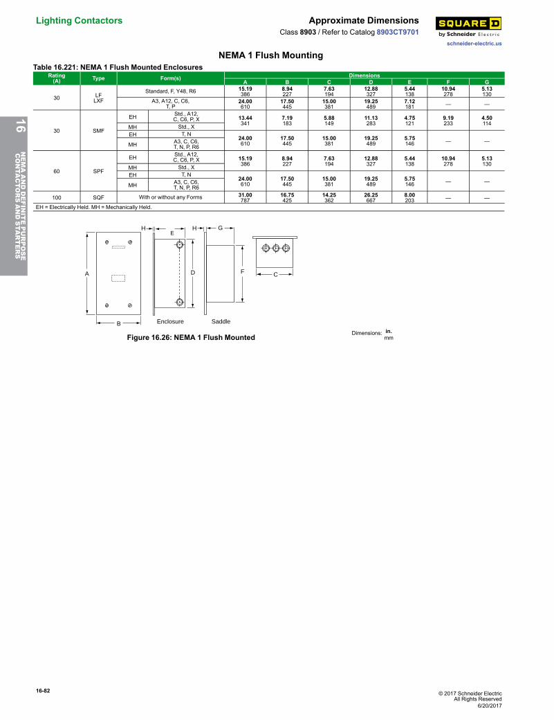
16-82 © 2017 Schneider ElectricAll Rights Reserved
Lighting Contactors Approximate Dimensions
schneider-electric.us
Class 8903 / Refer to Catalog 8903CT9701
NEMA 1 Flush MountingTable 16.221: NEMA 1 Flush Mounted Enclosures
Rating(A) Type Form(s) Dimensions
A B C D E F G
30 LFLXF
Standard, F, Y48, R6 15.19386
8.94227
7.63194
12.88327
5.44138
10.94278
5.13130
A3, A12, C, C6,T, P
24.00610
17.50445
15.00381
19.25489
7.12181 — —
30 SMF
EH Std., A12,C, C6, P, X 13.44
3417.19183
5.88149
11.13283
4.75121
9.19233
4.50114MH Std., X
EH T, N24.00610
17.50445
15.00381
19.25489
5.75146 — —
MH A3, C, C6,T, N, P, R6
60 SPF
EH Std., A12,C, C6, P, X 15.19
3868.94227
7.63194
12.88327
5.44138
10.94278
5.13130
MH Std., XEH T, N
24.00610
17.50445
15.00381
19.25489
5.75146 — —
MH A3, C, C6,T, N, P, R6
100 SQF With or without any Forms 31.00787
16.75425
14.25362
26.25667
8.00203 — —
EH = Electrically Held. MH = Mechanically Held.
A
B
HE
D
H G
F C
Enclosure Saddle
Figure 16.26: NEMA 1 Flush Mounted Dimensions: in.mm
16NEMAANDDEFINITEPURPOSE
CONTA
CTORSANDSTA
RTERS
6/20/2017
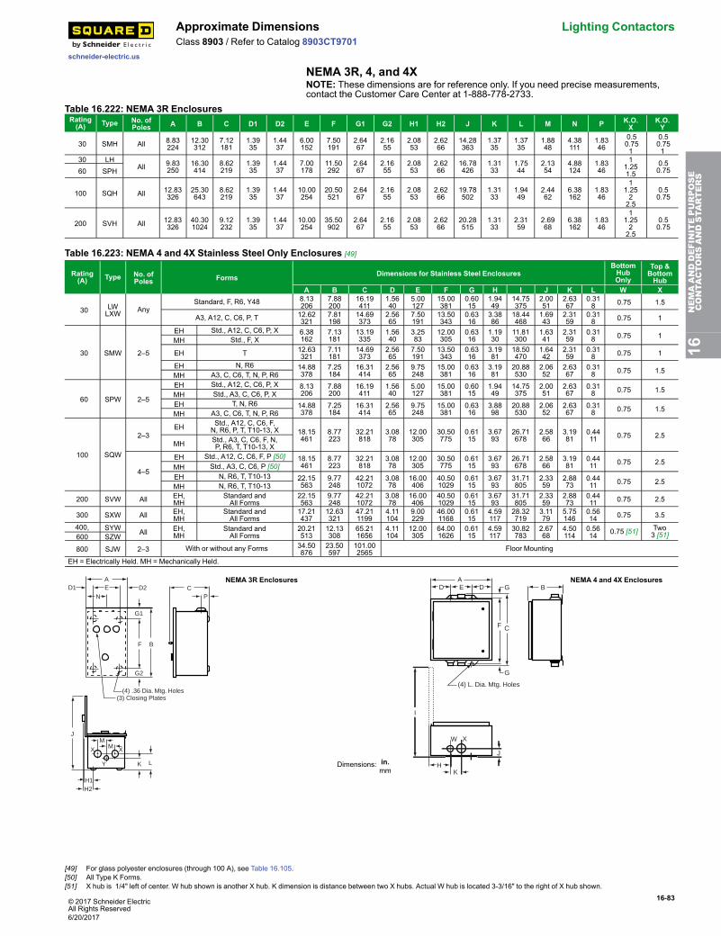
© 2017 Schneider ElectricAll Rights Reserved
16-83
schneider-electric.us
Approximate Dimensions Lighting ContactorsClass 8903 / Refer to Catalog 8903CT9701
NEMA 3R, 4, and 4XNOTE: These dimensions are for reference only. If you need precise measurements,contact the Customer Care Center at 1-888-778-2733.
Table 16.222: NEMA 3R EnclosuresRating(A) Type No. of
Poles A B C D1 D2 E F G1 G2 H1 H2 J K L M N P K.O.X
K.O.Y
30 SMH All 8.83224
12.30312
7.12181
1.3935
1.4437
6.00152
7.50191
2.6467
2.1655
2.0853
2.6266
14.28363
1.3735
1.3735
1.8848
4.38111
1.8346
0.50.751
0.50.751
30 LHAll 9.83
25016.30414
8.62219
1.3935
1.4437
7.00178
11.50292
2.6467
2.1655
2.0853
2.6266
16.78426
1.3133
1.7544
2.1354
4.88124
1.8346
11.251.5
0.50.7560 SPH
100 SQH All 12.83326
25.30643
8.62219
1.3935
1.4437
10.00254
20.50521
2.6467
2.1655
2.0853
2.6266
19.78502
1.3133
1.9449
2.4462
6.38162
1.8346
11.2522.5
0.50.75
200 SVH All 12.83326
40.301024
9.12232
1.3935
1.4437
10.00254
35.50902
2.6467
2.1655
2.0853
2.6266
20.28515
1.3133
2.3159
2.6968
6.38162
1.8346
11.2522.5
0.50.75
Table 16.223: NEMA 4 and 4X Stainless Steel Only Enclosures [49]
Rating(A) Type No. of
Poles Forms Dimensions for Stainless Steel EnclosuresBottomHubOnly
Top &BottomHub
A B C D E F G H I J K L W X
30 LWLXW Any
Standard, F, R6, Y48 8.13206
7.88200
16.19411
1.5640
5.00127
15.00381
0.6015
1.9449
14.75375
2.0051
2.6367
0.318 0.75 1.5
A3, A12, C, C6, P, T 12.62321
7.81198
14.69373
2.5665
7.50191
13.50343
0.6316
3.3886
18.44468
1.6943
2.3159
0.318 0.75 1
30 SMW 2–5
EH Std., A12, C, C6, P, X 6.38162
7.13181
13.19335
1.5640
3.2583
12.00305
0.6316
1.1930
11.81300
1.6341
2.3159
0.318 0.75 1
MH Std., F, X
EH T 12.63321
7.11181
14.69373
2.5665
7.50191
13.50343
0.6316
3.1981
18.50470
1.6442
2.3159
0.318 0.75 1
EH N, R6 14.88378
7.25184
16.31414
2.5665
9.75248
15.00381
0.6316
3.1981
20.88530
2.0652
2.6367
0.318 0.75 1.5
MH A3, C, C6, T, N, P, R6
60 SPW 2–5
EH Std., A12, C, C6, P, X 8.13206
7.88200
16.19411
1.5640
5.00127
15.00381
0.6015
1.9449
14.75375
2.0051
2.6367
0.318 0.75 1.5
MH Std., A3, C, C6, P, XEH T, N, R6 14.88
3787.25184
16.31414
2.5665
9.75248
15.00381
0.6316
3.8898
20.88530
2.0652
2.6367
0.318 0.75 1.5
MH A3, C, C6, T, N, P, R6
100 SQW
2–3EH Std., A12, C, C6, F,
N, R6, P, T, T10-13, X 18.15461
8.77223
32.21818
3.0878
12.00305
30.50775
0.6115
3.6793
26.71678
2.5866
3.1981
0.4411 0.75 2.5
MH Std., A3, C, C6, F, N,P, R6, T, T10-13, X
4–5
EH Std., A12, C, C6, F, P [50] 18.15461
8.77223
32.21818
3.0878
12.00305
30.50775
0.6115
3.6793
26.71678
2.5866
3.1981
0.4411 0.75 2.5
MH Std., A3, C, C6, P [50]EH N, R6, T, T10-13 22.15
5639.77248
42.211072
3.0878
16.00406
40.501029
0.6115
3.6793
31.71805
2.3359
2.8873
0.4411 0.75 2.5
MH N, R6, T, T10-13
200 SVW All EH,MH
Standard andAll Forms
22.15563
9.77248
42.211072
3.0878
16.00406
40.501029
0.6115
3.6793
31.71805
2.3359
2.8873
0.4411 0.75 2.5
300 SXW All EH,MH
Standard andAll Forms
17.21437
12.63321
47.211199
4.11104
9.00229
46.001168
0.6115
4.59117
28.32719
3.1179
5.75146
0.5614 0.75 3.5
400, SYW All EH,MH
Standard andAll Forms
20.21513
12.13308
65.211656
4.11104
12.00305
64.001626
0.6115
4.59117
30.82783
2.6768
4.50114
0.5614 0.75 [51] Two
3 [51]600 SZW
800 SJW 2–3 With or without any Forms 34.50876
23.50597
101.002565 Floor Mounting
EH = Electrically Held. MH = Mechanically Held.
AD2 C
P
G1
F
G2
B
EN
D1
D30060-118-D
(3) Closing Plates(4) .36 Dia. Mtg. Holes
K
MM XX
Y
J
H1H2
L
NEMA 3R Enclosures
Dimensions: in.mm
(4) L. Dia. Mtg. Holes
GDEDA
CF
B
C30054-260-A
J
HK
W X
I
G
NEMA 4 and 4X Enclosures
16NEMAANDDEFINITEPURPOSE
CONTA
CTORSANDSTA
RTERS
[49] For glass polyester enclosures (through 100 A), see Table 16.105.[50] All Type K Forms.[51] X hub is 1/4" left of center. W hub shown is another X hub. K dimension is distance between two X hubs. Actual W hub is located 3-3/16" to the right of X hub shown.
6/20/2017

16-84 © 2017 Schneider ElectricAll Rights Reserved
Lighting Contactors Approximate Dimensions
schneider-electric.us
Class 8903 / Refer to Catalog 8903CT9701
NEMA 12/3R and Night-Master™, NEMA 3RTable 16.224: See Figures: NEMA 12/3R (30–600 A) and NEMA 12/3R (800 A) (EH = Electrically Held; MH = Mechanically Held)AmpereRating Type Number
of Poles Form(s) DimensionsA B C D E F G H I J
30 LALXA Any
Standard, F, R6, Y48 8.13206
8.50216
15.75400
1.5640
5.00127
15.00381
0.318
2.1354
14.75375
0.318
A3, A12, C, C6, P, T 14.88378
7.88200
16.00406
2.5665
9.75248
15.00381
0.513
3.6693
21.25540
0.318
30 SMA 2-5
EH Std., A12, C, C6, P, X 6.38162
8.53217
12.75324
1.5640
3.2583
12.00305
0.3810
3.5690
12.50318
0.318MH Std., F, P, X
EH T 11.88302
7.75197
13.50343
2.5665
6.75171
12.75324
0.3810
3.6693
18.12460
0.318
EH N, R6 14.88378
7.88200
16.00406
2.5665
9.75248
15.00381
0.5013
3.6693
21.25540
0.318MH A3, C, C6, T, N, P, R6
60 SPA 2-5
EH Std., A12, C, C6, P, X 8.13206
9.28236
16.00406
1.5640
5.00127
15.00381
0.5013
3.6693
15.38391
0.318MH Std., A3, C, C6, P, X
EH T, N, R6 14.88378
7.88200
15.75400
2.5665
9.75248
15.00381
0.3810
3.6693
21.25540
0.318MH A3, C, C6, T, N, P, R6
100 SQA
2, 3 EH Std., A12, C, C6, F, N, R6, P, T, T10-13, X18.15461
9.24235
31.50800
3.0878
12.00305
30.50775
0.5013
3.6793
26.71678
0.4411
MH Std., A3, C, C6, F, N, P, R6, T, T10-13, X
4, 5
EH Std., A12, C, C6, F, N, P, [52]MH Std., A3, C, C6, P, [52]EH N, R6, T, T10-13, [52] 22.15
56310.24260
41.501054
3.0878
16.00406
40.501029
0.5013
3.6793
31.71805
0.4411MH N, R6, T, T10-13, [52]
200 SVA All EH andMH
Standard andAll Forms
22.15563
10.24260
41.501054
3.0878
16.00406
40.501029
0.5013
3.6793
31.71805
0.4411
300 SXA All EH andMH
Standard andAll Forms
17.21437
13.33339
47.001194
4.11104
9.00229
46.001168
0.5013
4.59117
28.32719
0.5614
400,600
SYA,SZA All EH and
MHStandard andAll Forms
20.21513
13.00330
65.001651
4.11104
12.00305
64.001626
0.5013
5.31135
30.87784
0.6918
800 SJA 2-3 With or without any Forms 93.002362
34.50876
23.50597 Floor Mounting
Table 16.225: Night-Master™ Outdoor Lighting Contactors (Short Version)—NEMA 3R Enclosures (see Figure: Night-Master Style)AmpereRating Description Type Number A B C D E F G H J
[53] K L M KnockoutsN P Q
30Disconnect Switch andCircuit Breaker Types
SMC61, 62, 81 23.50597
15.00381
8.42214
10.50267
19.00483
22.38568
7.00178
2.1855
1.5038
2.1354
2.1354
2.1354
0.50–0.75
1–1.251.50
0.50–0.7560 SPC61, 62, 81
100 SQC61, 62, 81 34.53877
20.00508
8.42214
10.50267
30.04763
33.41849
7.00178
2.1855
2.051
2.6868
2.6868
3.4487
0.50–0.75
1–1.252–2.50
1–1.251.5-2.0
200Disconnect Switch Type SVC61, 62 48.37
122919.00483
9.12232
10.53267
44.001118
47.251200
7.00178
2.1855
2.5064
2.6868
2.6868
3.4487
0.50–0.75
1–1.252–2.50
1–1.251.5–2.0Circuit Breaker Type SVC81
Table 16.226: Night-Master™ Outdoor Lighting Contactors (Long Version)—NEMA 3R Enclosures (see Figure: Night-Master Style)AmpereRating Description Type Number A B C D E F G H J
[53] K L M KnockoutsN P Q
30Disconnect Switch andCircuit Breaker Types
SMC63, 64, 83 38.88987
15.00381
8.42214
10.42265
34.38873
37.76959
7.00178
2.1855
1.5038
2.1354
2.1354
2.1354
0.50–0.75
1–1.251.50
0.50–0.7560 SPC63, 64, 83
100 SQC63, 64, 83 42.531080
20.00508
8.42214
10.42265
38.04966
41.411052
7.00178
2.1855
2.051
2.6868
2.6868
3.4487
0.50–0.75
1–1.252–2.50
1.–1.251.5–2.0
200Disconnect Switch Type SVC63, 64 56.37
143219.00483
9.12232
10.53267
52.001321
55.251403
7.00178
2.1855
2.5064
2.6868
2.6968
3.4487
0.50–0.75
1–1.252–2.50
1–1.251.5–2.0Circuit Breaker Type SVC83
NOTE: These dimensions are for reference only. If you need precise measurements, contact the Customer Care Center at 1-888-778-2733.
AD D
G
F C
E
G
I
H
(4) J Dia. Mtg. Holes
B
Figure 16.27: NEMA 12/3R (30–600 A)
B
A
C
Dimensions: in.mm
Figure 16.28: NEMA 12/3R (800 A)
B
FEA
G
(4) .44 Dia. Mtg. Holes 11
D
J
H
L MK
NP
Q
C
Figure 16.29: Night-Master Style
16NEMAANDDEFINITEPURPOSE
CONTA
CTORSANDSTA
RTERS
[52] All Type K Forms using Class 9001 Type K control units.[53] Conduit size.
6/20/2017
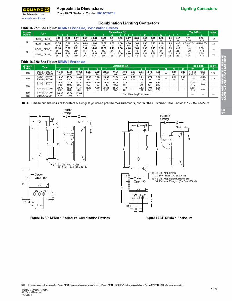
© 2017 Schneider ElectricAll Rights Reserved
16-85
schneider-electric.us
Approximate Dimensions Lighting ContactorsClass 8903 / Refer to Catalog 8903CT9701
Combination Lighting ContactorsTable 16.227: See Figure: NEMA 1 Enclosure, Combination DevicesAmpereRating Type Dimensions [54] Top & Bot. Sides
A B C D E F G H I J K L M N O W X Y
30SMG6_, SMG8_ 9.50
24122.50572
8.37213
6.38162
20.50521
14.68373
1.8146
1.6943
3.3786
3.3886
1.0627
3.2583
2.1855
1.2532
0.8722
0.50-0.75
0.50-0.75 .50
SMG7_, SMG9_ 13.75349
23.00584
8.36212
10.63270
21.00533
20.07510
1.8747
1.8848
3.7696
2.0652
1.0627
3.2583
2.1855
1.2532
0.8722
0.50-0.75-1.0
0.50-0.75-1.0 .50
60SPG6_, SPG8_ 10.50
26726.00660
9.62244
7.37187
24.00610
17.00432
2.1254
2.0051
4.00102
2.0652
1.0627
3.2583
2.1855
1.2532
0.8722
1.0-1.25
0.50-0.75 .50
SPG7_, SPG9_ 15.00381
28.75730
9.62244
11.62295
26.25667
21.50546
2.1855
2.0051
4.00102
2.5665
1.3133
3.2583
2.1855
1.2532
0.8722
1.0-1.25
0.50-0.75 .50
Table 16.228: See Figure: NEMA 1 EnclosureAmpereRating Type Dimensions [54] Top & Bot. Sides
A B C D E F G H I J K L M N O W X Y
100 SQG6_, SQG7_SQG81, SQG91
15.25387
39.501003
10.60269
9.25235
3.0076
22.68576
41.001041
2.6968
5.38137
2.8372
3.7495
5.00127 — 1.21
310.9023
1.-1.252.-2.50
0.50-0.75 0.50
200 SVG6_, SVG7_SVG81, SVG91
16.00406
50.001270
10.68271
10.00254
3.0076
23.68601
51.501308
2.6968
5.38137
2.8372
3.7495
5.00127 — 1.21
310.9023 2.50 0.50-
0.75 0.50
300SXG6_, SXG7_ 20.00
50875.001905
14.37365
12.00305
4.00102
29.43748
77.001956
3.1981 — 3.52
897.00178
9.25235 — — — 0.50-
0.75 3.00 —
SXG81, SXG91 20.00508
63.001600
14.37365
12.00305
4.00102
27.43697
65.001651
3.1981 — 3.52
897.00178
5.00127 — — — 0.50-
0.75 3.00 —
400 SYG81, SYG91 36.00914
90.002286
17.00432 Floor Mounting Enclosure — — —600 SZG81, SZG91
NOTE: These dimensions are for reference only. If you need precise measurements, contact the Customer Care Center at 1-888-778-2733.
YO
N
C
E B
K
MD
A
Y
F
W X W
G
JH
I
CoverOpen 90
L
(4) .31 Dia. Mtg. Holes 8 (For Sizes 30 & 60 A)
HandleSwing
Figure 16.30: NEMA 1 Enclosure, Combination Devices
YO
N
C
B
DA
Y
F
W X W
HI
CoverOpen 90
LE
K
J
G
(4) .44 Dia. Mtg. Holes 11 (For Sizes 100 & 200 A)(4) .56 Dia. Mtg. Holes Located on 14 External Flanges (For Size 300 A)
HandleSwing
Figure 16.31: NEMA 1 Enclosure
16NEMAANDDEFINITEPURPOSE
CONTA
CTORSANDSTA
RTERS
[54] Dimensions are the same for Form FF4T (standard control transformer), Form FF4T11 (100 VA extra capacity) and Form FF4T12 (200 VA extra capacity).
6/20/2017

16-86 © 2017 Schneider ElectricAll Rights Reserved
Lighting Contactors Approximate Dimensions
schneider-electric.us
Class 8903 / Refer to Catalog 8903CT9701
Table 16.229: See Figure: NEMA 4, 4X EnclosureAmpereRating Type Dimensions [55]
A B C D E F G H I J K L W X
30SMW6_, SMW8_ 9.50
2418.36212
24.76629
3.2583
2.5064
4.50114
23.50597
0.6316
3.0076
1.6241
2.3159
14.31363 0.75 Hub 1.0 Hub
SMW7_, SMW9_ 13.75349
8.36212
25.26642
3.2583
4.75121
4.25108
24.00610
0.6316
5.25133
1.6241
2.3159
20.14512 0.75 Hub 1.0 Hub
60SPW6_, SPW8_ 10.50
2679.61244
28.26718
3.2583
2.5064
5.50140
27.00686
0.6316
3.0076
2.0051
2.6367
16.56421 0.75 Hub 1.50 Hub
SPW7_, SPW9_ 15.00381
9.61244
31.01788
3.2583
5.38137
4.25108
29.75756
0.6316
5.88149
2.0051
2.6367
21.06535 0.75 Hub 1.50 Hub
100 SQW6_, SQW7_SQW81, SQW91
15.25387
10.60269
41.761061
5.00127
2.5064
10.25260
40.501029
0.6316
3.2482
2.6166
3.1981
22.18563 0.75 Hub 2.50 Hub
200 SVW6_, SVW7_SVW81, SVW91
16.00406
10.56268
52.261327
5.00127
2.5064
11.00279
51.001295
0.6316
3.2482
2.6166
3.1981
23.00584 0.75 Hub 2.50 Hub
300SXW6_, SXW7_ 20.00
50814.21361
78.121984
9.25235
4.00102
12.00305
77.001956
0.5614
4.77121
2.9675
3.5089
29.43748 0.75 Hub 3.50 Hub
SXW81, SXW91 20.00508
14.21361
66.121679
5.00127
4.00102
12.00305
65.001651
0.5614
4.77121
2.9675
3.5089
27.43697 0.75 Hub 3.50 Hub
400 SYW81, SYW91 36.00914
17.71450
98.002489 Floor Mounting Enclosure — —600 SZW81, SZW91
Table 16.230: See Figure: NEMA 12/3R EnclosureAmpereRating Type Dimensions [55]
A B C D E F G H I J
30SMA6_, SMA8_ 9.50
2418.36212
24.26616
3.2583
2.5064
4.50114
23.50597
0.3810
3.2583
14.31363
SMA7_, SMA9_ 13.75349
10.10257
24.76629
3.2583
4.75121
4.25108
24.00610
0.3810
5.50140
22.00559
60SPA6_, SPA8_ 10.50
2679.61244
27.76705
3.2583
2.5064
5.50140
27.00686
0.3810
3.2583
16.56421
SPA7_, SPA9_ 15.00381
10.98279
30.51775
3.2583
5.38137
4.25108
29.75756
0.3810
6.13156
23.43595
100 SQA6_, SQA7_SQA81, SQA91
15.25387
10.59269
42.001067
5.00127
3.0076
9.25235
41.001041
0.5013
3.7595
22.31567
200 SVA6_, SVA7_SVA81, SVA91
16.00406
10.52267
52.501334
5.00127
3.0076
10.00254
51.501308
0.5013
3.7595
23.00584
300SXA6_, SXA7_ 20.00
50814.21361
78.001981
9.25235
4.00102
12.00305
77.001956
0.5013
7.75197
29.43748
SXA81, SXA91 20.00508
14.21361
66.001676
5.00127
4.00102
12.00305
65.001651
0.5013
7.75197
27.43697
400 SYA81, SYA91 36.00914
17.71450
90.002286 Floor Mounting Enclosure
600 SZA81, SZA91
NOTE: These dimensions are for reference only. If you need precise measurements, contact the Customer Care Center at 1-888-778-2733.
B
Handle Swing
C
FA
L
W X
CoverOpen 90º
DE
KI
J
G
H
(4) .31 Dia. Mtg. Holes8 (For Sizes 30 & 60 A)
(4) .44 Dia. Mtg. Holes11 (For Sizes 100 & 200 A)
(4) .56 Dia. Mtg. Holes Located on14 External Flanges (For Size 300 A)
Figure 16.32: NEMA 4, 4X Enclosure
B
HandleSwing
C
FA
(4) .31 Dia. Mtg. Holes8 (For Sizes 30 & 60 A)
(4) .44 Dia. Mtg. Holes11 (For Sizes 100 & 200 A)
(4) .56 Dia. Mtg. Holes Located on14 External Flanges (For Size 300 A)
L
I
DE
G
H
CoverOpen 90°
Dimensions: in.
mm
Figure 16.33: NEMA 12/3R Enclosure
16NEMAANDDEFINITEPURPOSE
CONTA
CTORSANDSTA
RTERS
[55] Dimensions are the same for Form FF4T (standard control transformer), Form FF4T11 (100 VA extra capacity) and Form FF4T12 (200 VA extra capacity).
6/20/2017
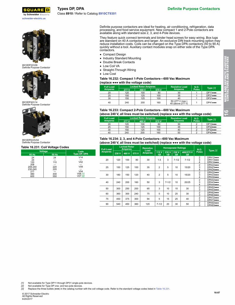
© 2017 Schneider ElectricAll Rights Reserved
16-87
schneider-electric.us
Types DP, DPA Definite Purpose ContactorsClass 8910 / Refer to Catalog 8910CT9301
8910DP22V09Definite Purpose Contactor
8910DP42V14Definite Purpose Contactor
8910DPA33V04Definite Purpose Contactor
Definite purpose contactors are ideal for heating, air conditioning, refrigeration, dataprocessing, and food service equipment. New compact 1 and 2-Pole contactors areavailable along with standard size 2, 3, and 4-Pole devices.They feature quick connect terminals and binder head screws for easy wiring. Box lugsare standard on 40 A contactors and larger. An exclusive DIN track mounting option mayreduce installation costs. Coils can be changed on the Type DPA contactors (50 to 90 A)quickly without a tool. Auxiliary contact modules snap on either side of the Type DPAcontactors.• Compact Design• Industry Standard Mounting• Double Break Contacts• Low Coil VA• Straight-Through Wiring• Low Cost
Table 16.231: Coil Voltage CodesVoltage Code
Type DP, DPA60 Hz 50 Hz2424120208
208-240230-240277480600
24—110—220220—440550
V14—V02—V09—V04
V06 [1]V07 [2]
Table 16.232: Compact 1-Pole Contactors—600 Vac Maximum(replace ●●● with the voltage code)
Full LoadAmperes
Locked Rotor Amperes Resistive LoadAmperes
N.O.Poles Type [3]
277 V 460 V 575 V20 120 100 80 30 1 DP11●●●25 150 125 100 35 1 DP21●●●30 150 125 100 40 1 DP31●●●
40 240 200 160 50 (277 V max.)40 (above 277 V) 1 DP41●●●
Table 16.233: Compact 2-Pole Contactors—600 Vac Maximum(above 240 V, all lines must be switched) (replace ●●● with the voltage code)
Full LoadAmperes
Locked Rotor Amperes Resistive LoadAmperes
N.O.Poles Type [3]
277 V 460 V 575 V20 120 100 80 30 2 DP12●●●25 150 125 100 35 2 DP22●●●30 150 125 100 40 2 DP32●●●40 240 200 160 50 2 DP42●●●
Table 16.234: 2, 3, and 4-Pole Contactors—600 Vac Maximum(above 240 V, all lines must be switched) (replace ●●● with the voltage code)
Full LoadAmperes
Locked RotorAmperes Resistive
LoadAmperes
Horsepower RatingsN.O.Poles Type [3]
230 V 460 V 575 V 115 V1Ø
230 V1Ø
230 V3Ø
460/575 V3Ø
20 120 100 80 30 1.5 3 7-1/2 7-1/2234
DPA12●●●DPA13●●●DPA14●●●
25 150 125 100 35 2 5 10 15/20234
DPA22●●●DPA23●●●DPA24●●●
30 180 150 120 40 2 5 10 15/20234
DPA32●●●DPA33●●●DPA34●●●
40 240 200 160 50 3 7-1/2 10 20/25234
DPA42●●●DPA43●●●DPA44●●●
50 300 250 200 65 3 10 15 30 23
DPA52●●●DPA53●●●
60 360 300 240 75 5 10 25 30 23
DPA62●●●DPA63●●●
75 450 375 300 94 5 15 25 40 23
DPA72●●●DPA73●●●
90 540 450 360 120 7-1/2 20 30 50 23
DPA92●●●DPA93●●●
16NEMAANDDEFINITEPURPOSE
CONTA
CTORSANDSTA
RTERS
[1] Not available for Type DP11 through DP31 single-pole devices.[2] Not available for Type DP one- and two-pole devices.[3] Replace the three bullets (●●●) in the catalog number with the coil voltage code. Refer to the standard voltage codes listed in Table 16.231.
6/20/2017
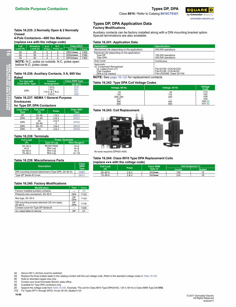
16-88 © 2017 Schneider ElectricAll Rights Reserved
Definite Purpose Contactors Types DP, DPA
schneider-electric.us
Class 8910 / Refer to Catalog 8910CT9301
Types DP, DPA Application DataTable 16.235: 2 Normally Open & 2 NormallyClosed4-Pole Contactors—600 Vac Maximum(replace ●●● with the voltage code)
FullLoad (A)
ResistiveLoad (A)
N.O.Poles
N.C.Poles [4]
Class 8910Type [5] Form
20 25 2 2 DPA14●●● Y39225 35 2 2 DPA24●●● Y39230 40 2 2 DPA34●●● Y392
NOTE: N.C. poles on outside. N.C. poles openbefore N.O. poles close.
Table 16.236: Auxiliary Contacts, 5 A, 600 VacRated
For Use withClass 8910, Type
ContactArrangement
Class 9999 Type20–90 A
DPA1 N.O.1 N.C.
1 N.O. & 1 N.C.2 N.O.
D10D01D11D20
Table 16.237: NEMA 1 General PurposeEnclosuresfor Type DP, DPA ContactorsClass 8910
TypeFull Load
(A) Poles Class 9991Type
DP 20–40 1 & 2 DPG1DPA 20–40 2 & 3 DPG1
DPA 5020–40
2 & 34 DPG2
DPA 60–75 2 & 3 DPG3DPA 90 2 & 3 DPG4
Table 16.238: TerminalsFull Load
(A)Power Terminals
Type of Lug Wire Range[6]20–30 A40 A
50–60 A75–90 A
Binder HeadBox LugBox LugBox Lug
14–814–614–214–1/0
Table 16.239: Miscellaneous Parts
DescriptionClass9999Type
DIN mounting bracket attachment (Type DPA, 20–60 A) DMB1Type DP Series B Cover DPC1
Factory ModificationsAuxiliary contacts can be factory installed along with a DIN mounting bracket option.Special terminations are also available.
Table 16.240: Factory ModificationsModification Type Form
Factory installed auxiliary contacts — [7]Pressure wire connectors, 20–30 A DPA Y122
Box lugs, 20–30 A DPDPA Y124
DIN mounting bracket attached (35 mm style),20–60 A
DPDPA Y135
Contact cover for Type DP Series B — Y248UL Listed label on device DP U1
Table 16.241: Application DataDescription SpecificationMechanical Life (depending on the application) 500,000 operationsElectrical Life (depending on the application)Type DPType DPA
100,000 operations200,000 operations
Duty Cycle ContinuousApprovals:UL Component RecognizedUL Listed (Form U1)CSA CertifiedDPA is CE marked
File E3190, CCN NLDX2File E3190, CCN NLDXFile LR25490, Class 321104
NOTE: See page 16-122 for replacement contacts.
Table 16.242: Type DPA Coil Voltage CodesVoltage, 60 Hz Voltage, 50 Hz Voltage
Code24120
208–240277480600
24110220—440550
V14V02V09V04
V06 [8]V07 [8]
Table 16.243: Coil Replacement
No tools required (DPA50–60A)
Table 16.244: Class 8910 Type DPA Replacement Coils(replace ●●● with the voltage code)
Full Load(A) Poles Class 9998
Type [9]Volt-Amperes[10]
Inrush Sealed50–60 A 2 & 3 DA2●●● 109 1075–90 A 2 & 3 DA3●●● 214 19
[4] Above 240 V, all lines must be switched.[5] Replace the three bullets (●●●) in the catalog number with the coil voltage code. Refer to the standard voltage codes in Table 16.242.[6] Solid or stranded copper wire only.[7] Contact your local Schneider Electric sales office.[8] Available for Type DPA contactors only.[9] Append the voltage code from Table 16.242. Example: The coil for Class 8910 Type DPA53V02, 120 V, 60 Hz is Class 9998 Type DA2V02.[10] For Types DP11 through DP32: Inrush 30 VA; Sealed 5 VA.
6/20/2017
16NEMAANDDEFINITEPURPOSE
CONTA
CTORSANDSTA
RTERS
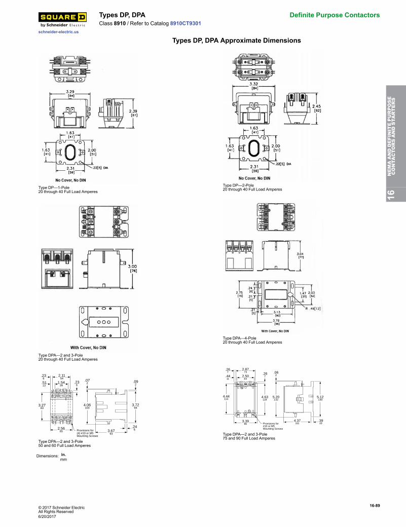
© 2017 Schneider ElectricAll Rights Reserved
16-89
schneider-electric.us
Types DP, DPA Definite Purpose ContactorsClass 8910 / Refer to Catalog 8910CT9301
Types DP, DPA Approximate Dimensions
Type DP—1-Pole20 through 40 Full Load Amperes
Type DP—2-Pole20 through 40 Full Load Amperes
Type DPA—2 and 3-Pole20 through 40 Full Load Amperes
Type DPA—4-Pole20 through 40 Full Load Amperes
.246
2.1154
1.5439
4.06103
3.2783
2.5665
.236
.236
.5113
Provisions for(4) #10 or M5Mounting Screws
.072 .09
2
3.7294
3.6793
Type DPA—2 and 3-Pole50 and 60 Full Load Amperes
2.8773
2.5064
Provisions for#10 or M5Mounting Screws
3.3986
4.44113
4.37111
.3910
4.63118
5.20132
.062
5.12130
.4411
.267 .26
7
Type DPA—2 and 3-Pole75 and 90 Full Load Amperes
Dimensions: in.mm
16NEMAANDDEFINITEPURPOSE
CONTA
CTORSANDSTA
RTERS
6/20/2017
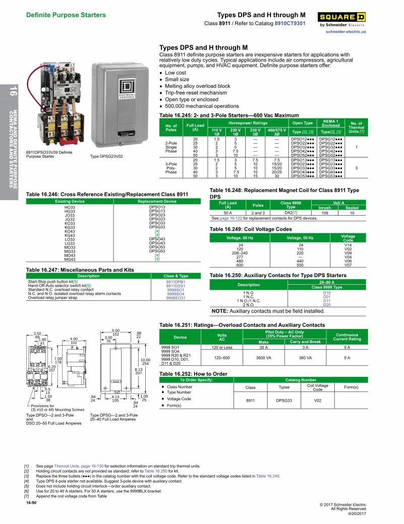
16-90 © 2017 Schneider ElectricAll Rights Reserved
Definite Purpose Starters Types DPS and H through M
schneider-electric.us
Class 8911 / Refer to Catalog 8910CT9301
Types DPS and H through M
8911DPSO33V09 DefinitePurpose Starter Type DPSG23V02
Class 8911 definite purpose starters are inexpensive starters for applications withrelatively low duty cycles. Typical applications include air compressors, agriculturalequipment, pumps, and HVAC equipment. Definite purpose starters offer:• Low cost• Small size• Melting alloy overload block• Trip-free reset mechanism• Open type or enclosed• 500,000 mechanical operations
Table 16.245: 2- and 3-Pole Starters—600 Vac Maximum
No. ofPoles
Full Load(A)
Horsepower Ratings Open Type NEMA 1Enclosed No. of
ThermalUnits [1]115 V
1Ø230 V1Ø
230 V3Ø
460/575 V3Ø Type [2], [3] Type[2], [3]
2-PoleSinglePhase
2025304050
1.52233
3557.510
—————
—————
DPSO12●●●DPSO22●●●DPSO32●●●DPSO42●●●DPSO52●●●
DPSG12●●●DPSG22●●●DPSG32●●●DPSG42●●●DPSG52●●●
1
3-PolePoly-Phase
2025304050
1.52233
3557.510
7.510101015
7.515/2015/2020/2530
DPSO13●●●DPSO23●●●DPSO33●●●DPSO43●●●DPSO53●●●
DPSG13●●●DPSG23●●●DPSG33●●●DPSG43●●●DPSG53●●●
3
Table 16.246: Cross Reference Existing/Replacement Class 8911Existing Device Replacement Device
HO33HG33JO33JG33KO33KG33KO43KG43LO33LG33MO33MG33MO43MG43
DPSO13DPSG13DPSO23DPSG23DPSO33DPSG33
[4][4]
DPSO43DPSG43DPSO53DPSG53
[4][4]
Table 16.247: Miscellaneous Parts and KitsDescription Class & Type
Start-Stop push button kit[5]Hand-Off-Auto selector switch kit[6]Standard N.C. overload relay contactN.C. and N.O. isolated overload relay alarm contactsOverload relay jumper strap
8911DPB18911DSS19998SO19999SO49998SO31
Table 16.248: Replacement Magnet Coil for Class 8911 TypeDPS
Full Load(A) Poles Class 9998
TypeVolt A
Inrush Sealed50 A 2 and 3 DA2[7] 109 10
See page 16-122 for replacement contacts for DPS devices.
Table 16.249: Coil Voltage CodesVoltage, 60 Hz Voltage, 50 Hz Voltage
Code24120
208–240277480600
24110220—440550
V14V02V09V04V06V07
Table 16.250: Auxiliary Contacts for Type DPS StartersDescription 20–90 A
Class 9999 Type1 N.O.1 N.C.
1 N.O./1 N.C.2 N.O.
D10D01D11D20
NOTE: Auxiliary contacts must be field installed.
Provisions for(3) #10 or M5 Mounting Screws
Reset
3.5089
1.6041
6.20157
7.00178
0.513
1.5038
4.00102
Reset
6.00152
10.00254
1.0025
4.13105
.9424
.9424
8.13207
3.0076
.8822
Type DPSO—2 and 3-PoleandDSO 20–50 Full Load Amperes
Type DPSG—2 and 3-Pole20–40 Full Load Amperes
Table 16.251: Ratings—Overload Contacts and Auxiliary Contacts
Device VoltsAC
Pilot Duty – AC Only(35% Power Factor) Continuous
Current RatingMake Carry and Break
9998 SO19999 SO49999 R20 & R219999 D10, D01,D11 & D20
120 or Less 30 A 3 A 5 A
120–600 3600 VA 360 VA 5 A
Table 16.252: How to OrderTo Order Specify: Catalog Number
• Class Number
• Type Number
• Voltage Code
• Form(s)
Class Typse Coil VoltageCode Form(s)
8911 DPSG33 V02
[1] See page Thermal Units, page 16-130 for selection information on standard trip thermal units.[2] Holding circuit contacts are not provided as standard; refer to Table 16.250 for kit.[3] Replace the three bullets (●●●) in the catalog number with the coil voltage code. Refer to the standard voltage codes listed in Table 16.249.[4] Type DPS 4-pole starter not available. Suggest 3-pole device with auxiliary contact.[5] Does not include holding circuit interlock—order auxiliary contact.[6] Use for 20 to 40 A starters. For 50 A starters, use the 9999BLX bracket.[7] Append the coil voltage code from Table
6/20/2017
16NEMAANDDEFINITEPURPOSE
CONTA
CTORSANDSTA
RTERS
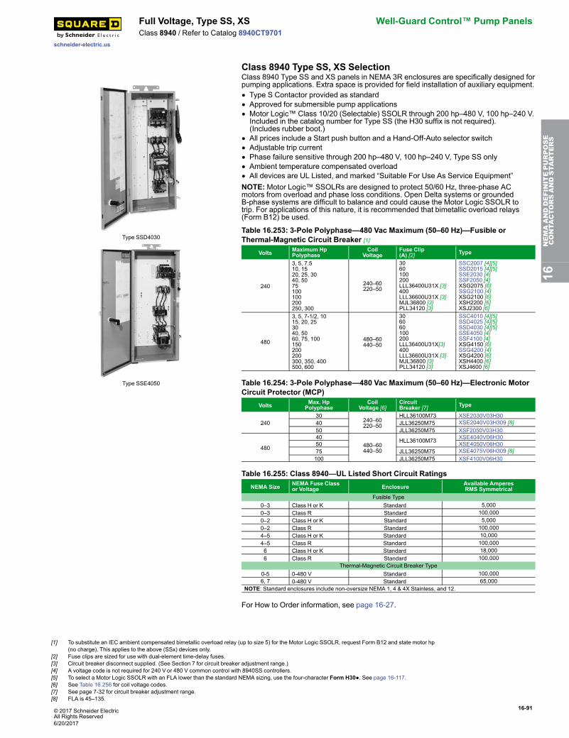
© 2017 Schneider ElectricAll Rights Reserved
16-91
schneider-electric.us
Full Voltage, Type SS, XS Well-Guard Control™ Pump PanelsClass 8940 / Refer to Catalog 8940CT9701
Class 8940 Type SS, XS Selection
Type SSD4030
Type SSE4050
Class 8940 Type SS and XS panels in NEMA 3R enclosures are specifically designed forpumping applications. Extra space is provided for field installation of auxiliary equipment.• Type S Contactor provided as standard• Approved for submersible pump applications• Motor Logic™ Class 10/20 (Selectable) SSOLR through 200 hp–480 V, 100 hp–240 V.Included in the catalog number for Type SS (the H30 suffix is not required).(Includes rubber boot.)
• All prices include a Start push button and a Hand-Off-Auto selector switch• Adjustable trip current• Phase failure sensitive through 200 hp–480 V, 100 hp–240 V, Type SS only• Ambient temperature compensated overload• All devices are UL Listed, and marked “Suitable For Use As Service Equipment”NOTE:Motor Logic™ SSOLRs are designed to protect 50/60 Hz, three-phase ACmotors from overload and phase loss conditions. Open Delta systems or groundedB-phase systems are difficult to balance and could cause the Motor Logic SSOLR totrip. For applications of this nature, it is recommended that bimetallic overload relays(Form B12) be used.
Table 16.253: 3-Pole Polyphase—480 Vac Maximum (50–60 Hz)—Fusible orThermal-Magnetic Circuit Breaker [1]
Volts Maximum HpPolyphase
CoilVoltage
Fuse Clip(A) [2] Type
240
3, 5, 7.510, 1520, 25, 3040, 5075100100200250, 300
240–60220–50
3060100200LLL36400U31X [3]400LLL36600U31X [3]MJL36800 [3]PLL34120 [3]
SSC2007 [4][5]SSD2015 [4][5]SSE2030 [4]SSF2050 [4]XSG2075 [6]SSG2100 [4]XSG2100 [6]XSH2200 [6]XSJ2300 [6]
480
3, 5, 7-1/2, 1015, 20, 253040, 5060, 75, 100150200200300, 350, 400500, 600
480–60440–50
306060100200LLL36400U31X[3]400LLL36600U31X [3]MJL36800 [3]PLL34120 [3]
SSC4010 [4][5]SSD4025 [4][5]SSD4030 [4][5]SSE4050 [4]SSF4100 [4]XSG4150 [6]SSG4200 [4]XSG4200 [6]XSH4400 [6]XSJ4600 [6]
Table 16.254: 3-Pole Polyphase—480 Vac Maximum (50–60 Hz)—Electronic MotorCircuit Protector (MCP)
Volts Max. HpPolyphase
CoilVoltage [6]
CircuitBreaker [7] Type
24030
240–60220–50
HLL36100M73 XSE2030V03H3040 JLL36250M75 XSE2040V03H309 [8]50 JLL36250M75 XSF2050V03H30
480
40480–60440–50
HLL36100M73 XSE4040V06H3050 XSE4050V06H3075 JLL36250M75 XSE4075V06H309 [8]100 JLL36250M75 XSF4100V06H30
Table 16.255: Class 8940—UL Listed Short Circuit RatingsNEMA Size NEMA Fuse Class
or Voltage Enclosure Available AmperesRMS Symmetrical
Fusible Type0–3 Class H or K Standard 5,0000–3 Class R Standard 100,0000–2 Class H or K Standard 5,0000–2 Class R Standard 100,0004–5 Class H or K Standard 10,0004–5 Class R Standard 100,0006 Class H or K Standard 18,0006 Class R Standard 100,000
Thermal-Magnetic Circuit Breaker Type0-5 0-480 V Standard 100,0006, 7 0-480 V Standard 65,000
NOTE: Standard enclosures include non-oversize NEMA 1, 4 & 4X Stainless, and 12.
For How to Order information, see page 16-27.
16NEMAANDDEFINITEPURPOSE
CONTA
CTORSANDSTA
RTERS
[1] To substitute an IEC ambient compensated bimetallic overload relay (up to size 5) for the Motor Logic SSOLR, request Form B12 and state motor hp(no charge). This applies to the above (SSx) devices only.
[2] Fuse clips are sized for use with dual-element time-delay fuses.[3] Circuit breaker disconnect supplied. (See Section 7 for circuit breaker adjustment range.)[4] A voltage code is not required for 240 V or 480 V common control with 8940SS controllers.[5] To select a Motor Logic SSOLR with an FLA lower than the standard NEMA sizing, use the four-character Form H30●. See page 16-117.[6] See Table 16.256 for coil voltage codes.[7] See page 7-32 for circuit breaker adjustment range.[8] FLA is 45–135.
6/20/2017
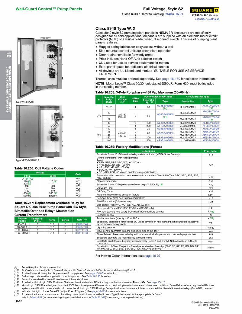
16-92 © 2017 Schneider ElectricAll Rights Reserved
Well-Guard Control™ Pump Panels Full Voltage, Style S2
schneider-electric.us
Class 8940 / Refer to Catalog 8940CT9701
Class 8940 Type W, X
Type WC3S2V06
Type XE3S2V02B12S
Table 16.256: Coil Voltage CodesVoltage
Code60 Hz 50 Hz
24 [9] [10]120 [9]208 [9]240—480
600 [9]Specify
—110 [9]—220380440
550 [9]Specify
V01V02V08V03V05V06V07V99
Table 16.257: Replacement Overload Relay forSquare D Class 8940 Pump Panel with IEC StyleBimetallic Overload Relays Mounted onCurrent Transformers
AmpereRange
Number ofPoles Form Series Type [11]
40–63 A 3 B12 B 9065TJF4063–100 A 3 B12 B 9065TJF63100–160 A 3 B12 B 9065TJF100160–250 A 3 B12 B 9065TJF160
Class 8940 style S2 pumping plant panels in NEMA 3R enclosures are specificallydesigned for oil field applications. All panels are supplied with an electonic motor circuitprotector (MCP) or a visible blade, fused, disconnect switch. This line of pumping plantpanels features:• Rugged spring latches for easy access without a tool• Side mounted control units for convenient operation• Door retainer available for windy areas• Price includes Hand-Off-Auto selector switch• UL Listed for use as service equipment for motors• Extra panel space for additional electrical controls• All devices are UL Listed, and marked “SUITABLE FOR USE AS SERVICEEQUIPMENT”
Thermal units must be ordered separately. See page 16-130 for selection information.NOTE:Motor Logic™ Class 20/30 (selectable) SSOLR, Form H30, must be includedin the catalog number.
Table 16.258: 3-Pole Polyphase—480 Vac Maximum (50–60 Hz)
VMax. HpPoly-phase
CoilVoltage[12]
NEMASize
Fusible Disconnect Type Circuit Breaker TypeFuse Clip(A) [13] Type Frame Size Type
240
7-1/2
240–60220–50
1 30 WC1S2V03H30[14] HLL36030M71 XC1S2V03H30
[14]
102 60 WD1S2V03H30
[14]HLL36050M72 XD1S2V03H30
[14]
15 HLL36100M73 XD2S2V03H30[14]
30 3 100 WE1S2V03H30 HLL36100M73 XE1S2V03H3050 4 200 WF1S2V03H30 JLL36250M75 XF2S2V03H30
480
10
480–60440–50
1 30 WC3S2V06H30 HLL36030M71 XC4S2V06H3015 2 60 WD3S2V06H30 HLL36030M71 XD3S2V06H3025 2 HLL36050M72 XD4S2V06H3050 3 100 WE3S2V06H30 HLL36100M73 XE3S2V06H30100 4 200 WF3S2V06H30 JLL36250M75 XF4S2V06H30
Table 16.259: Factory Modifications (Forms)Description Form Letter
Substitute Class 10 IEC overload relay – state motor hp (NEMA Sizes 0–4 only) B12Control transformer with fused primary:Types:● NPD, NPE, NPF, SSC, WC, XC (50 VA)● NPG, SSD, XD, WD (100 VA)● NPJ, SSE, XE, WE (150 VA)● SSF, XF, WF (300 VA)● SG, NSG, XSG (50 VA and an interposing control relay)
F4T
Factory-installed door wind latch assembly in a standard Class 8940 Type SSC, SSD, SSE, SSF,XSE, and XSF G45
Elapsed time meter G97Substitute Class 10/20 (selectable) Motor Logic™ SSOLR [15] H30On Delay Timer K25Off Delay Timer K26Program timer with day omission feature K141Backspin timer (time delay upon energization) K15Start Pushbutton (S2 panels only) A28Slim panel (Types WC, WD, WE, XC, XD, XE only) L8Short panel (Types SSE, SSF, XE-S2 and XF-S2 only) L9Pilot light (specify lens color). Does not include auxiliary contact. P [16]Separate control SAuxiliary contacts (specify N.O. or N.C.) X [17]Special UL panel label for modified UL Listed devices on non-standard panels (requires approvalby the manufacturing plant) Y1
Lightning arrestor Y1532Move control operators from the enclosure side to the door Y45Phase failure, phase reversal relay with time delay including under and over voltage protection R44Substitute standard trip melting alloy overload relays Y61Substitute quick-trip melting alloy overload relay (Sizes 1 and 2 only)–Not available on IEC stylecontactors Y611
Substitution of Class R rejection fuse clips for standard fuse clip. (8940 RD, RE, RF, RG, MD, ME,MF, MG, SSC, SSD, SSE, SSF, SSG, WC, WD, WE and WF) Y1071
For How to Order Information, see page 16-27.
[9] Form S required for separate control.[10] 24 V coils are not available on Size 4–7 starters. On Size 1–3 starters, 24 V coils are available using Form S.[11] A retro-fit reset kit is required for pre-series B pump panels. See page 16-107 for selection.[12] Coil voltage code must be supplied to order this product. See Table 16.256 for codes.[13] Fuse clips are sized for use with dual-element time-delay fuses.[14] To select a Motor Logic SSOLR with an FLA lower than the standard NEMA sizing, use the four-character Form H30●. See page 16-117.[15] Motor Logic SSOLR are designed to protect 50/60 hertz three-phase AC motors from overload, phase unbalance and phase loss conditions. Open Delta systems or grounded B-phase
systems are difficult to balance and could cause the Motor Logic SSOLR to trip. For applications of this nature, it is recommended that bi-metallic overload relays (Form B12) be used.[16] Indicate pilot light color as Form P1 (red) or Form P2 (green). See page 16-115 for more selections.[17] To determine the maximum number of auxiliary contacts which can be added to each Type S device and for the appropriate “X Form,”
refer to Table 16.84 (for non-reversing single-speed devices) or to Table 16.167(for reversing or two-speed devices)
6/20/2017
16NEMAANDDEFINITEPURPOSE
CONTA
CTORSANDSTA
RTERS
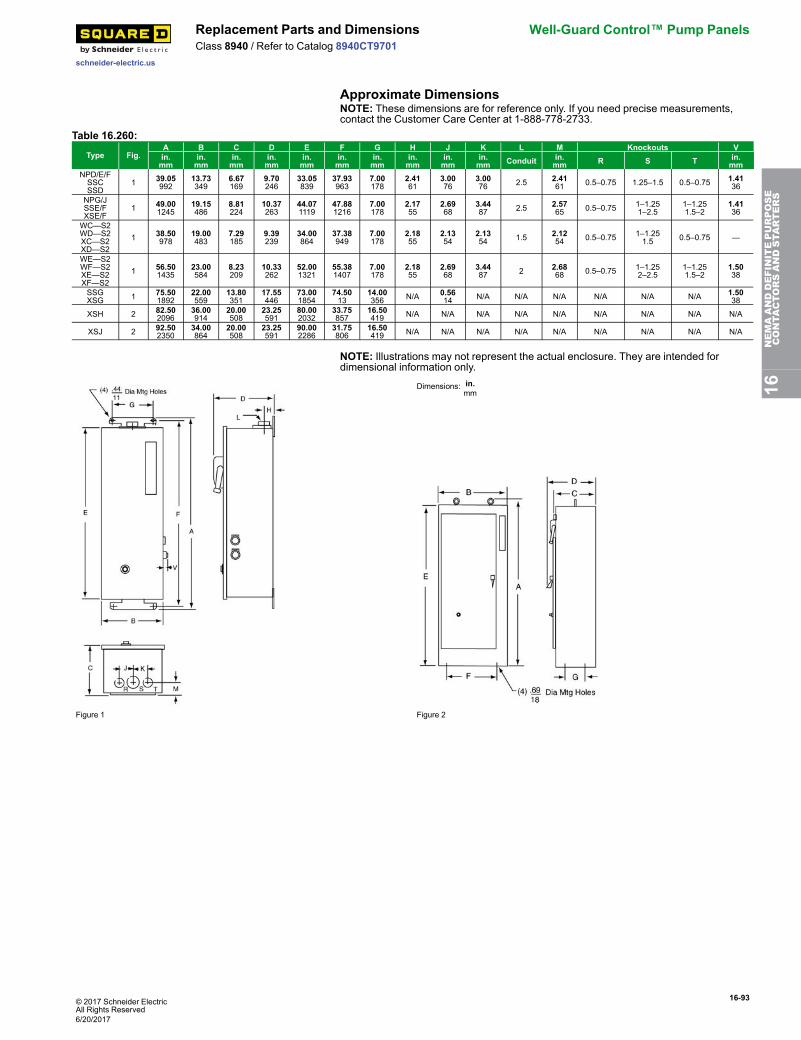
© 2017 Schneider ElectricAll Rights Reserved
16-93
schneider-electric.us
Replacement Parts and Dimensions Well-Guard Control™ Pump PanelsClass 8940 / Refer to Catalog 8940CT9701
Approximate DimensionsNOTE: These dimensions are for reference only. If you need precise measurements,contact the Customer Care Center at 1-888-778-2733.
Table 16.260:
Type Fig.A B C D E F G H J K L M Knockouts Vin.mm
in.mm
in.mm
in.mm
in.mm
in.mm
in.mm
in.mm
in.mm
in.mm Conduit in.
mm R S T in.mm
NPD/E/FSSCSSD
1 39.05992
13.73349
6.67169
9.70246
33.05839
37.93963
7.00178
2.4161
3.0076
3.0076 2.5 2.41
61 0.5–0.75 1.25–1.5 0.5–0.75 1.4136
NPG/JSSE/FXSE/F
1 49.001245
19.15486
8.81224
10.37263
44.071119
47.881216
7.00178
2.1755
2.6968
3.4487 2.5 2.57
65 0.5–0.75 1–1.251–2.5
1–1.251.5–2
1.4136
WC—S2WD—S2XC—S2XD—S2
1 38.50978
19.00483
7.29185
9.39239
34.00864
37.38949
7.00178
2.1855
2.1354
2.1354 1.5 2.12
54 0.5–0.75 1–1.251.5 0.5–0.75 —
WE—S2WF—S2XE—S2XF—S2
1 56.501435
23.00584
8.23209
10.33262
52.001321
55.381407
7.00178
2.1855
2.6968
3.4487 2 2.68
68 0.5–0.75 1–1.252–2.5
1–1.251.5–2
1.5038
SSGXSG 1 75.50
189222.00559
13.80351
17.55446
73.001854
74.5013
14.00356 N/A 0.56
14 N/A N/A N/A N/A N/A N/A 1.5038
XSH 2 82.502096
36.00914
20.00508
23.25591
80.002032
33.75857
16.50419 N/A N/A N/A N/A N/A N/A N/A N/A N/A
XSJ 2 92.502350
34.00864
20.00508
23.25591
90.002286
31.75806
16.50419 N/A N/A N/A N/A N/A N/A N/A N/A N/A
NOTE: Illustrations may not represent the actual enclosure. They are intended fordimensional information only.
Dimensions: in.mm
Figure 1 Figure 2
16NEMAANDDEFINITEPURPOSE
CONTA
CTORSANDSTA
RTERS
6/20/2017
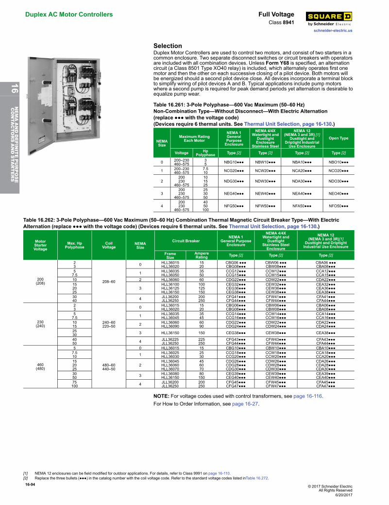
16-94 © 2017 Schneider ElectricAll Rights Reserved
Duplex AC Motor Controllers Full Voltage
schneider-electric.us
Class 8941
SelectionDuplex Motor Controllers are used to control two motors, and consist of two starters in acommon enclosure. Two separate disconnect switches or circuit breakers with operatorsare included with all combination devices. Unless Form Y68 is specified, an alternationcircuit (a Class 8501 Type XO40 relay) is included, which alternately operates first onemotor and then the other on each successive closing of a pilot device. Both motors willbe energized should a second pilot device close. All devices incorporate a terminal blockto simplify wiring of pilot devices A and B. Typical applications include pump motorswhere a second pump is required for peak demand periods yet alternation is desirable toequalize pump wear.
Table 16.261: 3-Pole Polyphase—600 Vac Maximum (50–60 Hz)Non-Combination Type—Without Disconnect—With Electric Alternation(replace ●●● with the voltage code)(Devices require 6 thermal units. See Thermal Unit Selection, page 16-130.)
NEMASize
Maximum RatingEach Motor
NEMA 1GeneralPurposeEnclosure
NEMA 4/4XWatertight and
DusttightEnclosure
Stainless Steel
NEMA 12(NEMA 3 and 3R) [1]
Dusttight andDriptight IndustrialUse Enclosure
Open Type
Voltage HpPolyphase Type [2] Type [2] Type [2] Type [2]
0 200–230460–575
35 NBG10●●● NBW10●●● NBA10●●● NBO10●●●
1 200–230460–575
7.510 NCG20●●● NCW20●●● NCA20●●● NCO20●●●
2200230
460–575
101525
NDG30●●● NDW30●●● NDA30●●● NDO30●●●
3200230
460–575
253050
NEG40●●● NEW40●●● NEA40●●● NEO40●●●
4200230
460–575
4050100
NFG50●●● NFW50●●● NFA50●●● NFO50●●●
Table 16.262: 3-Pole Polyphase—600 Vac Maximum (50–60 Hz) Combination Thermal Magnetic Circuit Breaker Type—With ElectricAlternation (replace ●●● with the voltage code) (Devices require 6 thermal units. See Thermal Unit Selection, page 16-130.)
MotorStarterVoltage
Max. HpPolyphase
CoilVoltage
NEMASize
Circuit BreakerNEMA 1
General PurposeEnclosure
NEMA 4/4XWatertight and
DusttightStainless SteelEnclosure
NEMA 12(NEMA 3 and 3R)[1]
Dusttight and DriptightIndustrial Use Enclosure
FrameSize
AmpereRating Type [2] Type [2] Type [2]
200(208)
23
208–60
0 HLL36015HLL36020
1520
CBG06 ●●●CBG08●●●
CBW06 ●●●CBW08●●●
CBA06 ●●●CBA08●●●
57.5 1 HLL36035
HLL360503550
CCG12●●●CCG15●●●
CCW12●●●CCW15●●●
CCA12●●●CCA15●●●
10 2 HLL36060 60 CDG22●●● CDW22●●● CDA22●●●152025
3HLL36100HLL36125HLL36150
100125150
CEG32●●●CEG36●●●CEG38●●●
CEW32●●●CEW36●●●CEW38●●●
CEA32●●●CEA36●●●CEA38●●●
3040 4 JLL36200
JLL36250200250
CFG41●●●CFG44●●●
CFW41●●●CFW44●●●
CFA41●●●CFA44●●●
230(240)
23
240–60220–50
0 HLL36015HLL36020
1520
CBG06●●●CBG08●●●
CBW06●●●CBW08●●●
CBA06●●●CBA08●●●
57.5 1 HLL36035
HLL360453545
CCG14●●●CCG16●●●
CCW14●●●CCW16●●●
CCA14●●●CCA16●●●
1015 2 HLL36060
HLL360906090
CDG22●●●CDG24●●●
CDW22●●●CDW24●●●
CDA22●●●CDA24●●●
2530 3 HLL36150 150 CEG38●●● CEW38●●● CEA38●●●
4050 4 JLL36225
JLL36250225250
CFG43●●●CFG44●●●
CFW43●●●CFW44●●●
CFA43●●●CFA44●●●
460(480)
5
480–60440–50
0 HLL36015 15 CBG10●●● CBW10●●● CBA10●●●7.510 1 HLL36025
HLL360302530
CCG18●●●CCG20●●●
CCW18●●●CCW20●●●
CCA18●●●CCA20●●●
152025
2HLL36045HLL36060HLL36070
456070
CDG26●●●CDG28●●●CDG30●●●
CDW26●●●CDW28●●●CDW30●●●
CDA26●●●CDA28●●●CDA30●●●
3050 3 HLL36080
HLL3615080150
CEG39●●●CEG40●●●
CEW39●●●CEW40●●●
CEA39●●●CEA40●●●
75100 4 JLL36200
JLL36250200250
CFG45●●●CFG47●●●
CFW45●●●CFW47●●●
CFA45●●●CFA47●●●
NOTE: For voltage codes used with control transformers, see page 16-116.For How to Order Information, see page 16-27.
[1] NEMA 12 enclosures can be field modified for outdoor applications. For details, refer to Class 9991 on page 16-110.[2] Replace the three bullets (●●●) in the catalog number with the coil voltage code. Refer to the standard voltage codes listed inTable 16.272.
6/20/2017
16NEMAANDDEFINITEPURPOSE
CONTA
CTORSANDSTA
RTERS
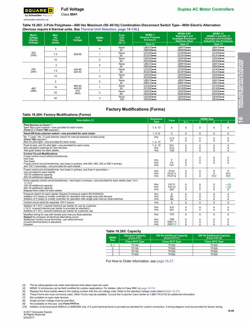
© 2017 Schneider ElectricAll Rights Reserved
16-95
schneider-electric.us
Full Voltage Duplex AC Motor ControllersClass 8941
Table 16.263: 3-Pole Polyphase—600 Vac Maximum (50–60 Hz) Combination Disconnect Switch Type—With Electric Alternation(Devices require 6 thermal units. See Thermal Unit Selection, page 16-130.)
MotorVoltage(StarterVoltage)
Max.HpPoly-phase
CoilVoltage
NEMASize
FuseClipSize(A) [3]
NEMA 1General Purpose
Enclosure
NEMA 4/4XWatertight and
Dusttight EnclosureStainless Steel
NEMA 12(NEMA 3 and 3R) [4]
Dusttight and DriptightIndustrial Use Enclosure
Type [5] Type [5] Type [5]
200(208)
3
208-60
0 None30
UBG10●●●DBG08●●●
UBW10●●●DBW08●●●
UBA10●●●DBA08●●●
7.5 1 None60
UCG20●●●DCG18●●●
UCW20●●●DCW18●●●
UCA20●●●DCA18●●●
10 2 None60
UDG30●●●DDG28●●●
UDW30●●●DDW28●●●
UDA30●●●DDA28●●●
230(240)
3
240-60220-50
0 None30
UBG10●●●DBG08●●●
UBW10●●●DBW08●●●
UBA10●●●DBA08●●●
7.5 1 None60
UCG20●●●DCG18●●●
UCW20●●●DCW18●●●
UCA20●●●DCA18●●●
15 2 None60
UDG30●●●DDG28●●●
UDW30●●●DDW28●●●
UDA30●●●DDA28●●●
460(480)
5
480-60440-50575(600)
0 None30
UBG10●●●DBG10●●●
UBW10●●●DBW10●●●
UBA10●●●DBA10●●●
10 1 None30
UCG20●●●DCG20●●●
UCW20●●●DCW20●●●
UCA20●●●DCA20●●●
25 2 None60
UDG30●●●DDG30●●●
UDW30●●●DDW30●●●
UDA30●●●DDA30●●●
50 3 None100
UEG40●●●DEG40●●●
UEW40●●●DEW40●●●
UEA40●●●DEA40●●●
Factory Modifications (Forms)Table 16.264: Factory Modifications (Forms)
Description [6] EnclosureType Form NEMA Size
0–1 2 3 4Pilot Devices in Cover[7]Start-Stop push buttons—one provided for each motor.(Form C or Form Y68 required.)
1, 4, 12 A X X X X
Hand-Off-Auto selector switch—one provided for each motor. 1, 4,12 C X X X XNo. 1 Lead—No. 2 Lead selector switch for manual selection of lead pump.(Form Y68 required.)Red On pilot light—one provided for each motor.
Any
1, 4, 12C13P1
XX
XX
XX
XX
Push-to-test, red On pilot light—one provided for each motor.Non-standard markings for pilot devices.Test push button for each starter.
1, 4, 12AnyAny
P21G12Y29
XXX
XXX
XXX
XXX
Control Circuit ModificationsFused control circuit without transformerOne fuseTwo fusesFused control circuit transformer, two fuses in primary, with 600, 480, 240 or 208 V primaryand 120 V secondary –one provided for each starter.
AnyAnyAny
FF4F4T
XXX
XXX
XXX
XXX
Fused control circuit transformer, two fuses in primary, one fuse in secondary—one provided for each starter.100 VA additional capacity200 VA additional capacity
AnyAnyAny
FF4TFF4T11FF4T12
XXX
XXX
XXX[8]
XX[8]X[8]
Extra capacity control circuit transformer—two fuses in primary—one provided for each starter (see Table16.265)100 VA additional capacity200 VA additional capacityElapsed time meter for each starter
AnyAnyAny
F4T11F4T12G97
XXX
XXX
XXX
—[9]—[9]X
Pressure switch for each starter (Square D pressure switch 9012GAW25)Addition of 2 relays to modify controller for operation with single pole pilot devicesAddition of 3 relays to modify controller for operation with single pole mercury float switches
AnyAnyAny
DR7R8
XXX
XXX
XXX
XXX
Control circuit wired for separate 120 V source Any S X X X XAddition of 1 N.O. unwired interlock per starter for use by customer(1 N.O. unwired interlock per starter is provided as standard.)Addition of 1 N.C. unwired interlock per starter for customer use
AnyAny
X10X01
XX
XX
XX
XX
Modified wiring for use with double pole mercury float switchesDeduct for omission of electrical alternating circuitAdditional Control circuit terminals—per wired terminal(5 point terminal block is standard)Unwired
Any
AnyAnyAny
Y24
Y68G56[10]G50[10]
X
XXX
X
XXX
X
XXX
X
XXX
Table 16.265: Capacity
NEMASize
Standard Capacity(Form F4T)
100 VA Additional Capacity(Form F4T11)
200 VA Additional Capacity(Form F4T12)
Class 9070 Type Class 9070 Type Class 9070 Type0, 1 TF100 TF200 TF3002 TF100 TF200 TF3003 TF150 TF300 TF5004 TF300 TF500 TF500
For How to Order Information, see page 16-27.
16NEMAANDDEFINITEPURPOSE
CONTA
CTORSANDSTA
RTERS
[3] The hp rating applies only when dual element time delay fuses are used.[4] NEMA 12 enclosures can be field modified for outdoor applications. For details, refer to Class 9991 on page 16-110.[5] Replace the three bullets (●●●) in the catalog number with the coil voltage code. Refer to the standard voltage codes listed inTable 16.272.[6] These Forms are most commonly used. Other Forms may be available. Consult the Customer Care Center at 1-888-778-2733 for additional information.[7] Not available on open style devices.[8] Single primary voltage must be specified.[9] Not available on this size. Use Form FF4T●●.[10] Addition of terminal block 9080CA or 9080GR6 only. A 5–point terminal block is provided as standard for custom connection. A wiring diagram must be provided for factory wiring.
6/20/2017
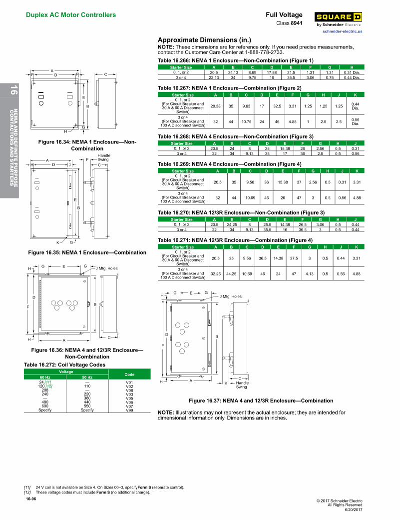
16-96 © 2017 Schneider ElectricAll Rights Reserved
Duplex AC Motor Controllers Full Voltage
schneider-electric.us
Class 8941
Approximate Dimensions (in.)NOTE: These dimensions are for reference only. If you need precise measurements,contact the Customer Care Center at 1-888-778-2733.
ADF F
E
B
GH
C
Figure 16.34: NEMA 1 Enclosure—Non-Combination
Table 16.266: NEMA 1 Enclosure—Non-Combination (Figure 1)Starter Size A B C D E F G H0, 1, or 2 20.5 24.13 8.69 17.88 21.5 1.31 1.31 0.31 Dia.3 or 4 22.13 34 9.75 16 35.5 3.06 0.75 0.44 Dia.
Table 16.267: NEMA 1 Enclosure—Combination (Figure 2)Starter Size A B C D E F G H J K0, 1, or 2
(For Circuit Breaker and30 A & 60 A Disconnect
Switch)20.38 35 9.63 17 32.5 3.31 1.25 1.25 1.25 0.44
Dia.
3 or 4(For Circuit Breaker and100 A Disconnect Switch)
32 44 10.75 24 46 4.88 1 2.5 2.5 0.56Dia.
ADH J
E
B
K G
FC
HandleSwing
Figure 16.35: NEMA 1 Enclosure—Combination
Table 16.268: NEMA 4 Enclosure—Non-Combination (Figure 3)Starter Size A B C D E F G H J0, 1, or 2 20.5 24 8 25 15.38 26 2.56 0.5 0.313 or 4 22 34 9.13 35 17 36 2.5 0.5 0.56
Table 16.269: NEMA 4 Enclosure—Combination (Figure 4)Starter Size A B C D E F G H J K0, 1, or 2
(For Circuit Breaker and30 A & 60 A Disconnect
Switch)20.5 35 9.56 36 15.38 37 2.56 0.5 0.31 3.31
3 or 4(For Circuit Breaker and100 A Disconnect Switch)
32 44 10.69 46 26 47 3 0.5 0.56 4.88
EGH
H
F
D
G
B
AC
J Mtg. Holes
Figure 16.36: NEMA 4 and 12/3R Enclosure—Non-Combination
Table 16.270: NEMA 12/3R Enclosure—Non-Combination (Figure 3)Starter Size A B C D E F G H J0, 1, or 2 20.5 24.25 8 25.5 14.38 26.5 3.06 0.5 0.443 or 4 22 34 9.13 35.5 16 36.5 3 0.5 0.44
Table 16.271: NEMA 12/3R Enclosure—Combination (Figure 4)Starter Size A B C D E F G H J K0, 1, or 2
(For Circuit Breaker and30 A & 60 A Disconnect
Switch)20.5 35 9.56 36.5 14.38 37.5 3 0.5 0.44 3.31
3 or 4(For Circuit Breaker and100 A Disconnect Switch)
32.25 44.25 10.69 46 24 47 4.13 0.5 0.56 4.88
Table 16.272: Coil Voltage CodesVoltage
Code60 Hz 50 Hz24 [11]120 [12]208240—480600
Specify
—110—220380440550
Specify
V01V02V08V03V05V06V07V99
GH
H
F
D
AK
C
B
GJ Mtg. Holes
HandleSwing
E
Figure 16.37: NEMA 4 and 12/3R Enclosure—Combination
NOTE: Illustrations may not represent the actual enclosure; they are intended fordimensional information only. Dimensions are in inches.
[11] 24 V coil is not available on Size 4. On Sizes 00–3, specifyForm S (separate control).[12] These voltage codes must include Form S (no additional charge).
6/20/2017
16NEMAANDDEFINITEPURPOSE
CONTA
CTORSANDSTA
RTERS
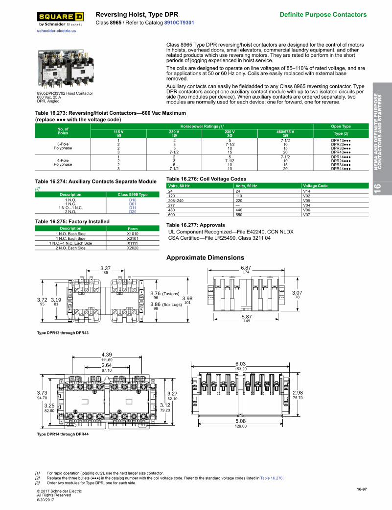
© 2017 Schneider ElectricAll Rights Reserved
16-97
schneider-electric.us
Reversing Hoist, Type DPR Definite Purpose ContactorsClass 8965 / Refer to Catalog 8910CT9301
8965DPR33V02 Hoist Contactor600 Vac, 25 ADPR, Angled
Class 8965 Type DPR reversing/hoist contactors are designed for the control of motorsin hoists, overhead doors, small elevators, commercial laundry equipment, and otherrelated products which use reversing motors. They are rated to perform in the shortperiods of jogging experienced in hoist service.The coils are designed to operate on line voltages of 85–110% of rated voltage, and arefor applications at 50 or 60 Hz only. Coils are easily replaced with external baseremoved.Auxiliary contacts can easily be fieldadded to any Class 8965 reversing contactor. TypeDPR contactors accept one auxiliary contact module with up to two isolated circuits perside (two modules per device). When auxiliary contacts are ordered separately, twomodules are normally used for each device; one for forward, one for reverse.
Table 16.273: Reversing/Hoist Contactors—600 Vac Maximum(replace ●●● with the voltage code)
No. ofPoles
Horsepower Ratings [1] Open Type115 V1Ø
230 V1Ø
230 V3Ø
460/575 V3Ø Type [2]
3-PolePolyphase
1223
235
7-1/2
57-1/21015
7-1/2101520
DPR13●●●DPR23●●●DPR33●●●DPR43●●●
4-PolePolyphase
1223
235
7-1/2
57-1/21010
7-1/2101520
DPR14●●●DPR24●●●DPR34●●●DPR44●●●
Table 16.274: Auxiliary Contacts Separate Module[3]
Description Class 9999 Type1 N.O.1 N.C.
1 N.O.–1 N.C.2 N.O.
D10D01D11D20
Table 16.275: Factory InstalledDescription Form
1 N.O. Each Side X10101 N.C. Each Side X0101
1 N.O.–1 N.C. Each Side X11112 N.O. Each Side X2020
Table 16.276: Coil Voltage CodesVolts, 60 Hz Volts, 50 Hz Voltage Code24 24 V14120 110 V02208–240 220 V09277 — V04480 440 V06600 550 V07
Table 16.277: ApprovalsUL Component Recognized—File E42240, CCN NLDXCSA Certified—File LR25490, Class 3211 04
Approximate Dimensions3.37
86
3.1981
3.07783.98
101
3.76 (Fastons) 96
3.86 (Box Lugs) 98
3.7295
6.87174
5.87149
Type DPR13 through DPR43
4.39111.60
2.6467.10
6.03153.20
2.9875.70
5.08129.00
3.7394.70
3.2582.60
3.1279.20
3.2782.10
Type DPR14 through DPR44
16NEMAANDDEFINITEPURPOSE
CONTA
CTORSANDSTA
RTERS
[1] For rapid operation (jogging duty), use the next larger size contactor.[2] Replace the three bullets (●●●) in the catalog number with the coil voltage code. Refer to the standard voltage codes listed in Table 16.276.[3] Order two modules for Type DPR, one for each side.
6/20/2017
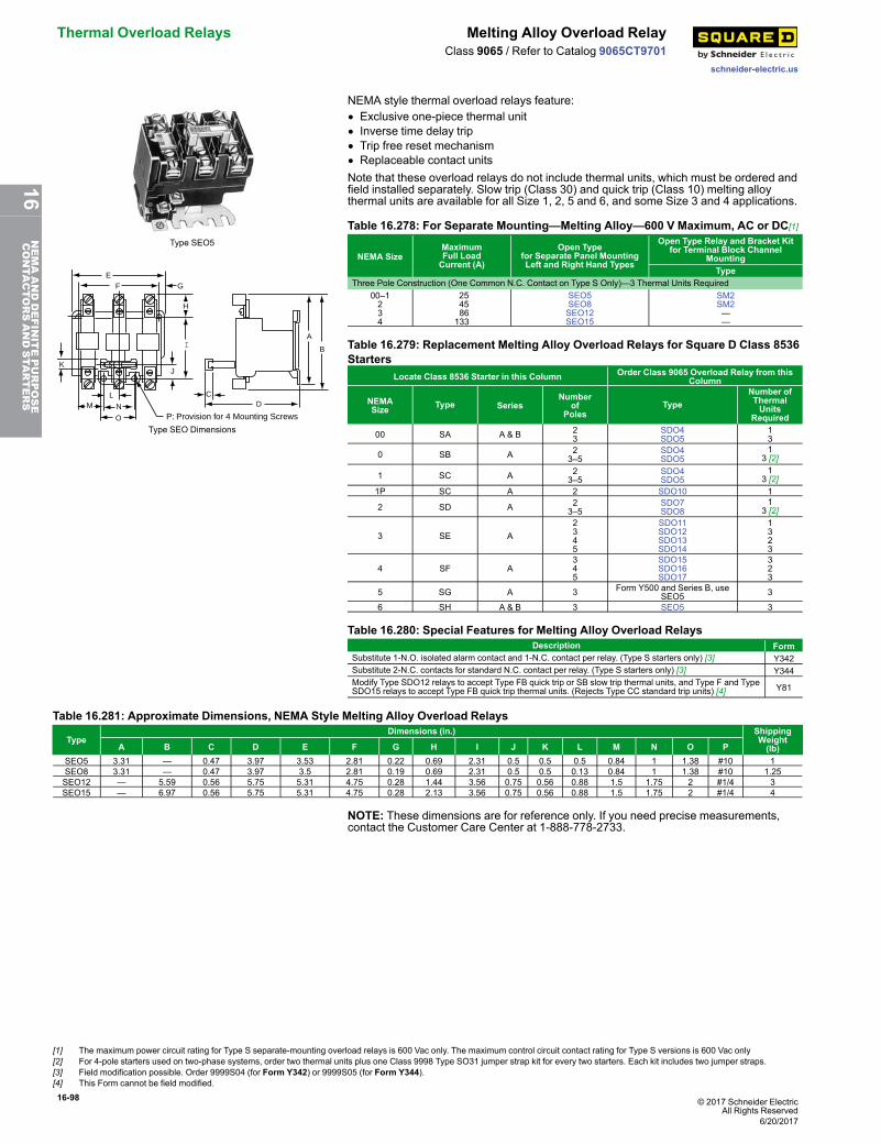
16-98 © 2017 Schneider ElectricAll Rights Reserved
Thermal Overload Relays Melting Alloy Overload Relay
schneider-electric.us
Class 9065 / Refer to Catalog 9065CT9701
Type SEO5
EF G
K
H
I
J
ML
N
O
CD
A
B
P: Provision for 4 Mounting Screws
Type SEO Dimensions
NEMA style thermal overload relays feature:• Exclusive one-piece thermal unit• Inverse time delay trip• Trip free reset mechanism• Replaceable contact unitsNote that these overload relays do not include thermal units, which must be ordered andfield installed separately. Slow trip (Class 30) and quick trip (Class 10) melting alloythermal units are available for all Size 1, 2, 5 and 6, and some Size 3 and 4 applications.
Table 16.278: For Separate Mounting—Melting Alloy—600 V Maximum, AC or DC[1]
NEMA SizeMaximumFull LoadCurrent (A)
Open Typefor Separate Panel MountingLeft and Right Hand Types
Open Type Relay and Bracket Kitfor Terminal Block Channel
MountingType
Three Pole Construction (One Common N.C. Contact on Type S Only)—3 Thermal Units Required00–1234
2545 86133
SEO5SEO8SEO12SEO15
SM2SM2——
Table 16.279: Replacement Melting Alloy Overload Relays for Square D Class 8536Starters
Locate Class 8536 Starter in this Column Order Class 9065 Overload Relay from thisColumn
NEMASize Type Series
Numberof
PolesType
Number ofThermalUnits
Required
00 SA A & B 23
SDO4SDO5
13
0 SB A 23–5
SDO4SDO5
13 [2]
1 SC A 23–5
SDO4SDO5
13 [2]
1P SC A 2 SDO10 1
2 SD A 23–5
SDO7SDO8
13 [2]
3 SE A2345
SDO11SDO12SDO13SDO14
1323
4 SF A345
SDO15SDO16SDO17
323
5 SG A 3 Form Y500 and Series B, useSEO5 3
6 SH A & B 3 SEO5 3
Table 16.280: Special Features for Melting Alloy Overload RelaysDescription Form
Substitute 1-N.O. isolated alarm contact and 1-N.C. contact per relay. (Type S starters only) [3] Y342Substitute 2-N.C. contacts for standard N.C. contact per relay. (Type S starters only) [3] Y344Modify Type SDO12 relays to accept Type FB quick trip or SB slow trip thermal units, and Type F and TypeSDO15 relays to accept Type FB quick trip thermal units. (Rejects Type CC standard trip units) [4] Y81
Table 16.281: Approximate Dimensions, NEMA Style Melting Alloy Overload Relays
TypeDimensions (in.) Shipping
Weight(lb)A B C D E F G H I J K L M N O P
SEO5 3.31 — 0.47 3.97 3.53 2.81 0.22 0.69 2.31 0.5 0.5 0.5 0.84 1 1.38 #10 1SEO8 3.31 — 0.47 3.97 3.5 2.81 0.19 0.69 2.31 0.5 0.5 0.13 0.84 1 1.38 #10 1.25SEO12 — 5.59 0.56 5.75 5.31 4.75 0.28 1.44 3.56 0.75 0.56 0.88 1.5 1.75 2 #1/4 3SEO15 — 6.97 0.56 5.75 5.31 4.75 0.28 2.13 3.56 0.75 0.56 0.88 1.5 1.75 2 #1/4 4
NOTE: These dimensions are for reference only. If you need precise measurements,contact the Customer Care Center at 1-888-778-2733.
[1] The maximum power circuit rating for Type S separate-mounting overload relays is 600 Vac only. The maximum control circuit contact rating for Type S versions is 600 Vac only[2] For 4-pole starters used on two-phase systems, order two thermal units plus one Class 9998 Type SO31 jumper strap kit for every two starters. Each kit includes two jumper straps.[3] Field modification possible. Order 9999S04 (for Form Y342) or 9999S05 (for Form Y344).[4] This Form cannot be field modified.
6/20/2017
16NEMAANDDEFINITEPURPOSE
CONTA
CTORSANDSTA
RTERS
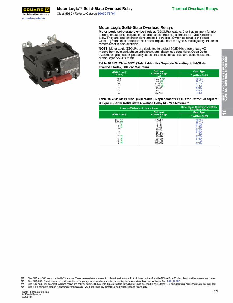
© 2017 Schneider ElectricAll Rights Reserved
16-99
schneider-electric.us
Motor Logic™ Solid-State Overload Relay Thermal Overload RelaysClass 9065 / Refer to Catalog 9065CT9701
Motor Logic Solid-State Overload RelaysMotor Logic solid-state overload relays (SSOLRs) feature: 3 to 1 adjustment for tripcurrent; phase loss and unbalance protection; direct replacement for Type S meltingalloy. They are ambient insensitive and self–powered. Switch selectable trip class;Class II ground fault detection; and direct replacement for Type S melting alloy. Electricalremote reset is also available.NOTE:Motor Logic SSOLRs are designed to protect 50/60 Hz, three-phase ACmotors from overload, phase unbalance, and phase loss conditions. Open Deltasystems or grounded B-phase systems are difficult to balance and could cause theMotor Logic SSOLR to trip.
Table 16.282: Class 10/20 (Selectable): For Separate Mounting Solid-StateOverload Relay, 600 Vac Maximum
NEMA Size[5](3-Pole)
Full LoadCurrent Range
(A)
Open TypeTrip Class 10/20
00B00C01234
1.5–4.5 [6]3–9 [6]6–18 [6]9–27 [6]15–4530–9045–135
SFB20SFC20SF020SF120SF220SF320SF420
Table 16.283: Class 10/20 (Selectable): Replacement SSOLR for Retrofit of SquareD Type S Starter Solid-State Overload Relay 600 Vac Maximum
Locate 8536 Starter in this column Order Class 9065 Overload Relayfrom this column
NEMA Size[5]Full Load
Current Range(A)
Open TypeTrip Class 10/20
00B [6]00C [6] 0 [6] 1 [6] 2 3 4
5 [7] 5 [8] 6 [7] 7 [7]
1.5–4.53–9 6–18 9–2715–4530–90 45–135 90–270 90–270180–540270–810
SFB20SFC20SF020SF120ST220ST320ST420ST520SF520ST620ST720
16NEMAANDDEFINITEPURPOSE
CONTA
CTORSANDSTA
RTERS
[5] Size 00B and 00C are not actual NEMA sizes. These designations are used to differentiate the lower FLA of these devices from the NEMA Size 00 Motor Logic solid-state overload relay.[6] Size 00B, 00C, 0, and 1 come without lugs. Lower amperage loads can be protected by looping the power wires. Lugs are available. See Table 16.357.[7] Size 5, 6, and 7 replacement overload relays are only for existing NEMA style Type S starters with a Motor Logic overload relay. External CTs and additional components are not included.[8] Size 5 is a complete drop-in replacement for Square D Type S melting alloy, bimetallic, and Y500 overload relays only.
6/20/2017
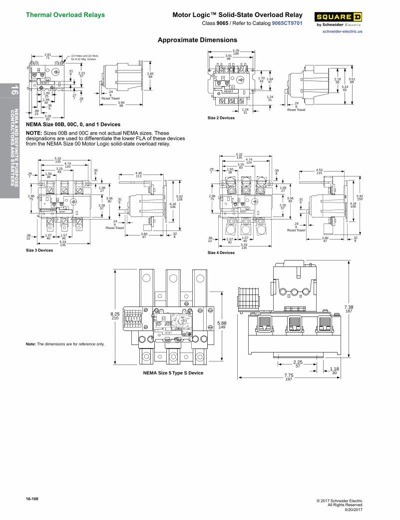
16-100 © 2017 Schneider ElectricAll Rights Reserved
Thermal Overload Relays Motor Logic™ Solid-State Overload Relay
schneider-electric.us
Class 9065 / Refer to Catalog 9065CT9701
Approximate Dimensions
RESET
(2) Holes and (2) Slotsfor 8-32 Mtg. Screws
.246
Reset Travel3.9099
2.6968
2.2357
1.0025
3.2683
1.5940
.369
.8923
.318
.277 .28
7
2.8171
NEMA Size 00B, 00C, 0, and 1 DevicesNOTE: Sizes 00B and 00C are not actual NEMA sizes. Thesedesignations are used to differentiate the lower FLA of these devicesfrom the NEMA Size 00 Motor Logic solid-state overload relay.
RESET
4.28109
1.7043
1.8447
2.1956
3.2482
3.5189
1.2431
1.2431
3.9199
.246
Reset Travel
Size 2 Devices
RESET
3.5690
2.2657
1.0827
.308
1.5740
1.5740
5.33135
.3810
2.9675
1.5038
.297
3.2583
4.74120
5.32135
.328
3.8097
4.16106
5.02128
4.45113
.318
.246
Reset Travel
Size 3 Devices
RESET
.328
3.8097
4.16106
5.92150
4.53115
.318
3.5690
2.2657
1.0827
.308
5.33135
1.5740
1.5740
.3810
2.9675
1.5038
.297
3.2583
4.74120
5.32135
.246
Reset Travel
Size 4 Devices
LISTEDIND.CONT.EQ.A159
TRIP=125%CLASS10
FLA
31161-184-51SERIES B
90
120150
180
A600P300
AC 3 Ph
50-60HZ
TRIP
PWR
210
270
MADE IN USA
SQUARE D COMPANY
8.25210
5.88149
7.38187
2.2557
1.1830
7.75197
NEMA Size 5 Type S Device
Note: The dimensions are for reference only.
6/20/2017
16NEMAANDDEFINITEPURPOSE
CONTA
CTORSANDSTA
RTERS
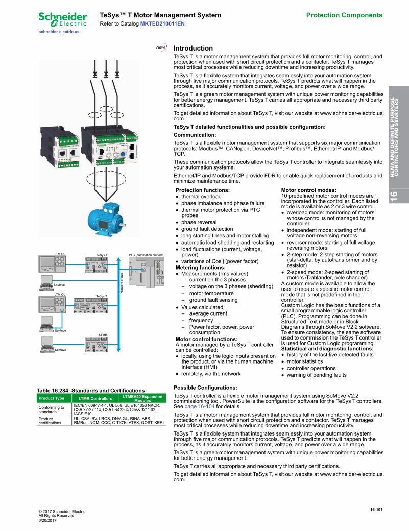
© 2017 Schneider ElectricAll Rights Reserved
16-101
schneider-electric.us
TeSys™ T Motor Management System Protection ComponentsRefer to Catalog MKTED210011EN
Introduction
LTM CU TeSys T
TeSys T
LTMR
SoMove
LTM CU
SoMove
SoMove
connector
PLC (automation platform)
Net
wor
k or
bus
TeSys T is a motor management system that provides full motor monitoring, control, andprotection when used with short circuit protection and a contactor. TeSys T managesmost critical processes while reducing downtime and increasing productivity.TeSys T is a flexible system that integrates seamlessly into your automation systemthrough five major communication protocols. TeSys T predicts what will happen in theprocess, as it accurately monitors current, voltage, and power over a wide range.TeSys T is a green motor management system with unique power monitoring capabilitiesfor better energy management. TeSys Tcarries all appropriate and necessary third partycertifications.To get detailed information about TeSys T, visit our website at www.schneider-electric.us.com.TeSys T detailed functionalities and possible configuration:Communication:TeSys T is a flexible motor management system that supports six major communicationprotocols: Modbus™, CANopen, DeviceNet™, Profibus™, Ethernet/IP, and Modbus/TCP.These communication protocols allow the TeSys Tcontroller to integrate seamlessly intoyour automation systems.Ethernet/IP and Modbus/TCP provide FDR to enable quick replacement of products andminimize maintenance time.
Protection functions:• thermal overload• phase imbalance and phase failure• thermal motor protection via PTCprobes
• phase reversal• ground fault detection• long starting times and motor stalling• automatic load shedding and restarting• load fluctuations (current, voltage,power)
• variations of Cos j (power factor)Metering functions:• Measurements (rms values):– current on the 3 phases– voltage on the 3 phases (shedding)– motor temperature– ground fault sensing
• Values calculated:– average current– frequency– Power factor, power, power
consumptionMotor control functions:A motor managed by a TeSys Tcontrollercan be controlled:• locally, using the logic inputs present onthe product, or via the human machineinterface (HMI)
• remotely, via the network
Motor control modes:10 predefined motor control modes areincorporated in the controller. Each listedmode is available as 2 or 3 wire control.• overload mode: monitoring of motorswhose control is not managed by thecontroller
• independent mode: starting of fullvoltage non-reversing motors
• reverser mode: starting of full voltagereversing motors
• 2-step mode: 2-step starting of motors(star-delta, by autotransformer and byresistor)
• 2-speed mode: 2-speed starting ofmotors (Dahlander, pole changer)
A custom mode is available to allow theuser to create a specific motor controlmode that is not predefined in thecontroller.Custom Logic has the basic functions of asmall programmable logic controller(PLC). Programming can be done inStructured Text mode or in BlockDiagrams through SoMove V2.2 software.To ensure consistency, the same softwareused to commission the TeSys Tcontrolleris used for Custom Logic programming.Statistical and diagnostic functions:• history of the last five detected faults• motor statistics• controller operations• warning of pending faults
Table 16.284: Standards and CertificationsProduct Type LTMR Controllers LTMEV40 Expansion
ModulesConforming tostandards
IEC/EN 60947-4-1, UL 508, UL E164353 NKCR,CSA 22-2 n°14, CSA LR43364 Class 3211 03,IACS E10
Productcertifications
UL, CSA, BV, LROS, DNV, GL, RINA, ABS,RMRos, NOM, CCC, C-TIC’K, ATEX, GOST, KERI
Possible Configurations:TeSys Tcontroller is a flexible motor management system using SoMove V2.2commissioning tool. PowerSuite is the configuration software for the TeSys Tcontrollers.See page 16-104 for details.TeSys T is a motor management system that provides full motor monitoring, control, andprotection when used with short circuit protection and a contactor. TeSys T managesmost critical processes while reducing downtime and increasing productivity.TeSys T is a flexible system that integrates seamlessly into your automation systemthrough five major communication protocols. TeSys T predicts what will happen in theprocess, as it accurately monitors current, voltage, and power over a wide range.TeSys T is a green motor management system with unique power monitoring capabilitiesfor better energy management.TeSys Tcarries all appropriate and necessary third party certifications.To get detailed information about TeSys T, visit our website at www.schneider-electric.us.com.
16NEMAANDDEFINITEPURPOSE
CONTA
CTORSANDSTA
RTERS
6/20/2017
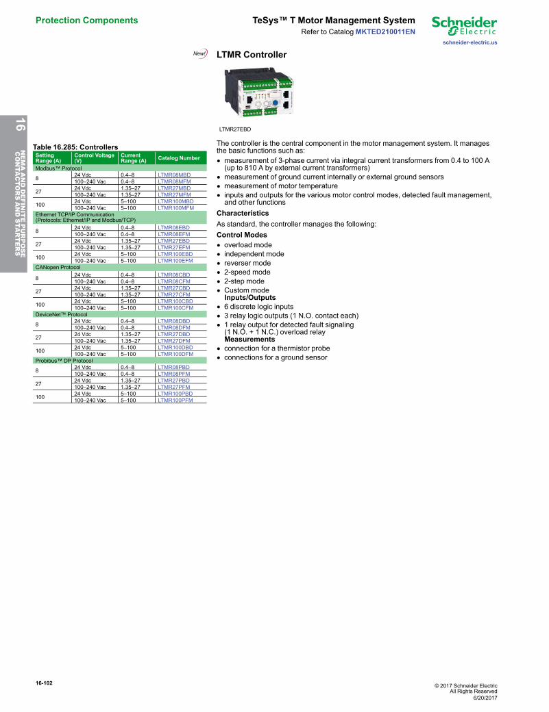
16-102 © 2017 Schneider ElectricAll Rights Reserved
Protection Components TeSys™ T Motor Management System
schneider-electric.us
Refer to CatalogMKTED210011EN
LTMR Controller
LTMR27EBD
Table 16.285: ControllersSettingRange (A)
Control Voltage(V)
CurrentRange (A) Catalog Number
Modbus™ Protocol
8 24 Vdc 0.4–8 LTMR08MBD100–240 Vac 0.4–8 LTMR08MFM
27 24 Vdc 1.35–27 LTMR27MBD100–240 Vac 1.35–27 LTMR27MFM
100 24 Vdc 5–100 LTMR100MBD100–240 Vac 5–100 LTMR100MFM
Ethernet TCP/IP Communication(Protocols: Ethernet/IP and Modbus/TCP)
8 24 Vdc 0.4–8 LTMR08EBD100–240 Vac 0.4–8 LTMR08EFM
27 24 Vdc 1.35–27 LTMR27EBD100–240 Vac 1.35–27 LTMR27EFM
100 24 Vdc 5–100 LTMR100EBD100–240 Vac 5–100 LTMR100EFM
CANopen Protocol
8 24 Vdc 0.4–8 LTMR08CBD100–240 Vac 0.4–8 LTMR08CFM
27 24 Vdc 1.35–27 LTMR27CBD100–240 Vac 1.35–27 LTMR27CFM
100 24 Vdc 5–100 LTMR100CBD100–240 Vac 5–100 LTMR100CFM
DeviceNet™ Protocol
8 24 Vdc 0.4–8 LTMR08DBD100–240 Vac 0.4–8 LTMR08DFM
27 24 Vdc 1.35–27 LTMR27DBD100–240 Vac 1.35–27 LTMR27DFM
100 24 Vdc 5–100 LTMR100DBD100–240 Vac 5–100 LTMR100DFM
Probibus™ DP Protocol
8 24 Vdc 0.4–8 LTMR08PBD100–240 Vac 0.4–8 LTMR08PFM
27 24 Vdc 1.35–27 LTMR27PBD100–240 Vac 1.35–27 LTMR27PFM
100 24 Vdc 5–100 LTMR100PBD100–240 Vac 5–100 LTMR100PFM
The controller is the central component in the motor management system. It managesthe basic functions such as:• measurement of 3-phase current via integral current transformers from 0.4 to 100 A(up to 810 A by external current transformers)
• measurement of ground current internally or external ground sensors• measurement of motor temperature• inputs and outputs for the various motor control modes, detected fault management,and other functions
CharacteristicsAs standard, the controller manages the following:Control Modes• overload mode• independent mode• reverser mode• 2-speed mode• 2-step mode• Custom modeInputs/Outputs
• 6 discrete logic inputs• 3 relay logic outputs (1 N.O. contact each)• 1 relay output for detected fault signaling(1 N.O. + 1 N.C.) overload relayMeasurements
• connection for a thermistor probe• connections for a ground sensor
16NEMAANDDEFINITEPURPOSE
CONTA
CTORSANDSTA
RTERS
6/20/2017
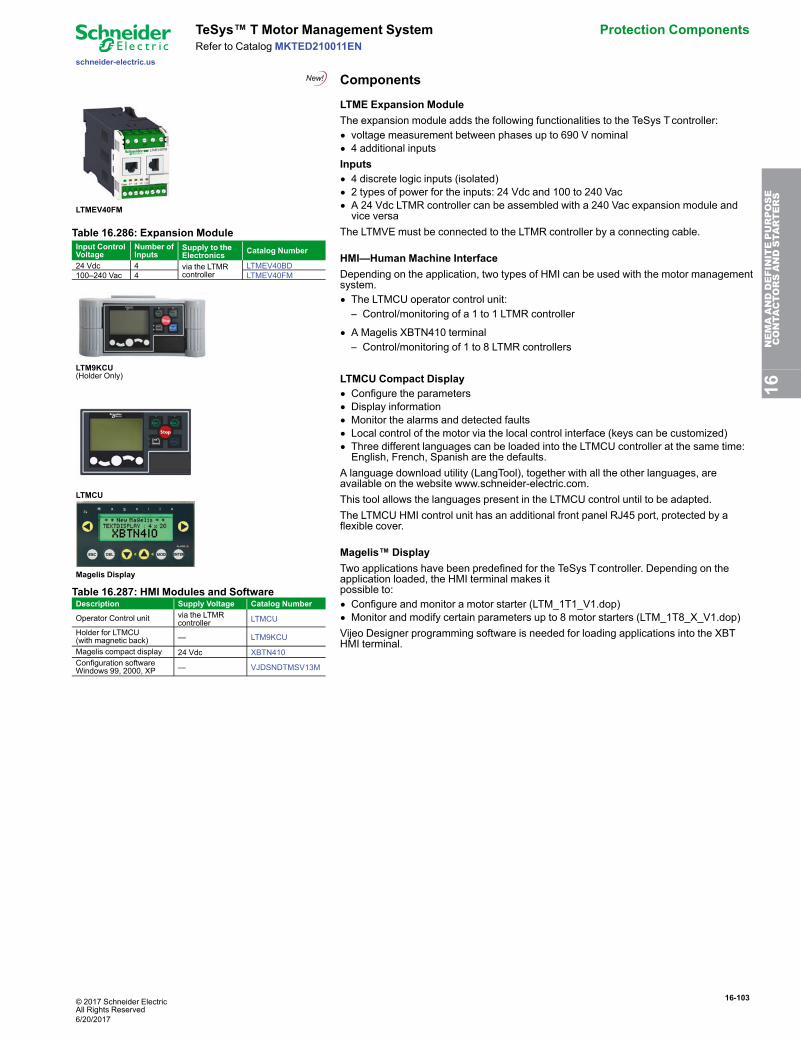
© 2017 Schneider ElectricAll Rights Reserved
16-103
schneider-electric.us
TeSys™ T Motor Management System Protection ComponentsRefer to Catalog MKTED210011EN
Components
LTMEV40FM
Table 16.286: Expansion ModuleInput ControlVoltage
Number ofInputs
Supply to theElectronics Catalog Number
24 Vdc 4 via the LTMRcontroller
LTMEV40BD100–240 Vac 4 LTMEV40FM
LTM9KCU(Holder Only)
LTMCU
Magelis Display
Table 16.287: HMI Modules and SoftwareDescription Supply Voltage Catalog Number
Operator Control unit via the LTMRcontroller LTMCU
Holder for LTMCU(with magnetic back) — LTM9KCU
Magelis compact display 24 Vdc XBTN410Configuration softwareWindows 99, 2000, XP — VJDSNDTMSV13M
LTME Expansion ModuleThe expansion module adds the following functionalities to the TeSys Tcontroller:• voltage measurement between phases up to 690 V nominal• 4 additional inputsInputs• 4 discrete logic inputs (isolated)• 2 types of power for the inputs: 24 Vdc and 100 to 240 Vac• A 24 Vdc LTMR controller can be assembled with a 240 Vac expansion module andvice versa
The LTMVE must be connected to the LTMR controller by a connecting cable.
HMI—Human Machine InterfaceDepending on the application, two types of HMI can be used with the motor managementsystem.• The LTMCU operator control unit:– Control/monitoring of a 1 to 1 LTMR controller
• A Magelis XBTN410 terminal– Control/monitoring of 1 to 8 LTMR controllers
LTMCU Compact Display• Configure the parameters• Display information• Monitor the alarms and detected faults• Local control of the motor via the local control interface (keys can be customized)• Three different languages can be loaded into the LTMCU controller at the same time:English, French, Spanish are the defaults.
A language download utility (LangTool), together with all the other languages, areavailable on the website www.schneider-electric.com.This tool allows the languages present in the LTMCU control until to be adapted.The LTMCU HMI control unit has an additional front panel RJ45 port, protected by aflexible cover.
Magelis™ DisplayTwo applications have been predefined for the TeSys Tcontroller. Depending on theapplication loaded, the HMI terminal makes itpossible to:• Configure and monitor a motor starter (LTM_1T1_V1.dop)• Monitor and modify certain parameters up to 8 motor starters (LTM_1T8_X_V1.dop)Vijeo Designer programming software is needed for loading applications into the XBTHMI terminal.
16NEMAANDDEFINITEPURPOSE
CONTA
CTORSANDSTA
RTERS
6/20/2017
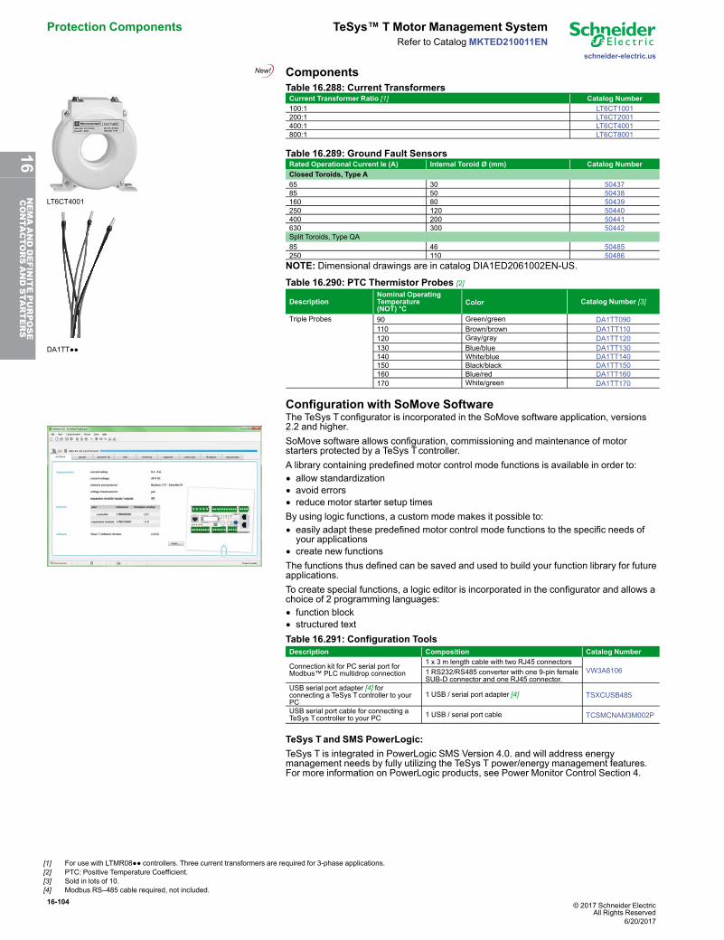
16-104 © 2017 Schneider ElectricAll Rights Reserved
Protection Components TeSys™ T Motor Management System
schneider-electric.us
Refer to CatalogMKTED210011EN
Components
LT6CT4001
DA1TT●●
Table 16.288: Current TransformersCurrent Transformer Ratio [1] Catalog Number100:1 LT6CT1001200:1 LT6CT2001400:1 LT6CT4001800:1 LT6CT8001
Table 16.289: Ground Fault SensorsRated Operational Current le (A) Internal Toroid Ø (mm) Catalog NumberClosed Toroids, Type A65 30 5043785 50 50438160 80 50439250 120 50440400 200 50441630 300 50442Split Toroids, Type QA85 46 50485250 110 50486NOTE: Dimensional drawings are in catalog DIA1ED2061002EN-US.
Table 16.290: PTC Thermistor Probes [2]
DescriptionNominal OperatingTemperature(NOT) °C
Color Catalog Number [3]
Triple Probes 90 Green/green DA1TT090110 Brown/brown DA1TT110120 Gray/gray DA1TT120130 Blue/blue DA1TT130140 White/blue DA1TT140150 Black/black DA1TT150160 Blue/red DA1TT160170 White/green DA1TT170
Configuration with SoMove SoftwareThe TeSys Tconfigurator is incorporated in the SoMove software application, versions2.2 and higher.SoMove software allows configuration, commissioning and maintenance of motorstarters protected by a TeSys Tcontroller.A library containing predefined motor control mode functions is available in order to:• allow standardization• avoid errors• reduce motor starter setup timesBy using logic functions, a custom mode makes it possible to:• easily adapt these predefined motor control mode functions to the specific needs ofyour applications
• create new functionsThe functions thus defined can be saved and used to build your function library for futureapplications.To create special functions, a logic editor is incorporated in the configurator and allows achoice of 2 programming languages:• function block• structured textTable 16.291: Configuration ToolsDescription Composition Catalog Number
Connection kit for PC serial port forModbus™ PLC multidrop connection
1 x 3 m length cable with two RJ45 connectorsVW3A81061 RS232/RS485 converter with one 9-pin female
SUB-D connector and one RJ45 connector.USB serial port adapter [4] forconnecting a TeSys Tcontroller to yourPC
1 USB / serial port adapter [4] TSXCUSB485
USB serial port cable for connecting aTeSys Tcontroller to your PC 1 USB / serial port cable TCSMCNAM3M002P
TeSys T and SMS PowerLogic:TeSys T is integrated in PowerLogic SMS Version 4.0. and will address energymanagement needs by fully utilizing the TeSys T power/energy management features.For more information on PowerLogic products, see Power Monitor Control Section 4.
[1] For use with LTMR08●● controllers. Three current transformers are required for 3-phase applications.[2] PTC: Positive Temperature Coefficient.[3] Sold in lots of 10.[4] Modbus RS–485 cable required, not included.
6/20/2017
16NEMAANDDEFINITEPURPOSE
CONTA
CTORSANDSTA
RTERS
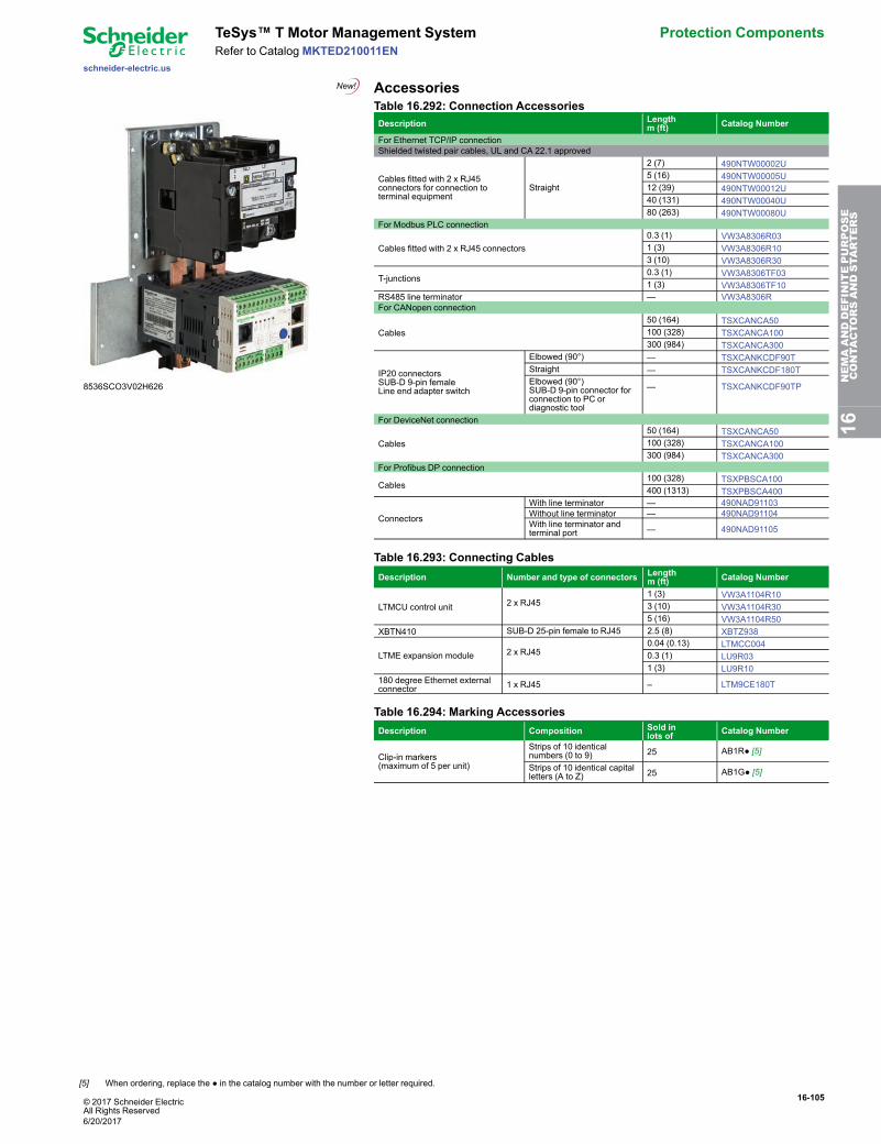
© 2017 Schneider ElectricAll Rights Reserved
16-105
schneider-electric.us
TeSys™ T Motor Management System Protection ComponentsRefer to Catalog MKTED210011EN
Accessories
8536SCO3V02H626
Table 16.292: Connection AccessoriesDescription Length
m (ft) Catalog Number
For Ethernet TCP/IP connectionShielded twisted pair cables, UL and CA 22.1 approved
Cables fitted with 2 x RJ45connectors for connection toterminal equipment
Straight
2 (7) 490NTW00002U5 (16) 490NTW00005U12 (39) 490NTW00012U40 (131) 490NTW00040U80 (263) 490NTW00080U
For Modbus PLC connection
Cables fitted with 2 x RJ45 connectors0.3 (1) VW3A8306R031 (3) VW3A8306R103 (10) VW3A8306R30
T-junctions0.3 (1) VW3A8306TF031 (3) VW3A8306TF10
RS485 line terminator — VW3A8306RFor CANopen connection
Cables50 (164) TSXCANCA50100 (328) TSXCANCA100300 (984) TSXCANCA300
IP20 connectorsSUB-D 9-pin femaleLine end adapter switch
Elbowed (90°) — TSXCANKCDF90TStraight — TSXCANKCDF180TElbowed (90°)SUB-D 9-pin connector forconnection to PC ordiagnostic tool
— TSXCANKCDF90TP
For DeviceNet connection
Cables50 (164) TSXCANCA50100 (328) TSXCANCA100300 (984) TSXCANCA300
For Profibus DP connection
Cables100 (328) TSXPBSCA100400 (1313) TSXPBSCA400
Connectors
With line terminator — 490NAD91103Without line terminator — 490NAD91104With line terminator andterminal port — 490NAD91105
Table 16.293: Connecting CablesDescription Number and type of connectors Length
m (ft) Catalog Number
LTMCU control unit 2 x RJ451 (3) VW3A1104R103 (10) VW3A1104R305 (16) VW3A1104R50
XBTN410 SUB-D 25-pin female to RJ45 2.5 (8) XBTZ938
LTME expansion module 2 x RJ450.04 (0.13) LTMCC0040.3 (1) LU9R031 (3) LU9R10
180 degree Ethernet externalconnector 1 x RJ45 – LTM9CE180T
Table 16.294: Marking AccessoriesDescription Composition Sold in
lots of Catalog Number
Clip-in markers(maximum of 5 per unit)
Strips of 10 identicalnumbers (0 to 9) 25 AB1R● [5]
Strips of 10 identical capitalletters (A to Z) 25 AB1G● [5]
16NEMAANDDEFINITEPURPOSE
CONTA
CTORSANDSTA
RTERS
[5] When ordering, replace the ● in the catalog number with the number or letter required.
6/20/2017
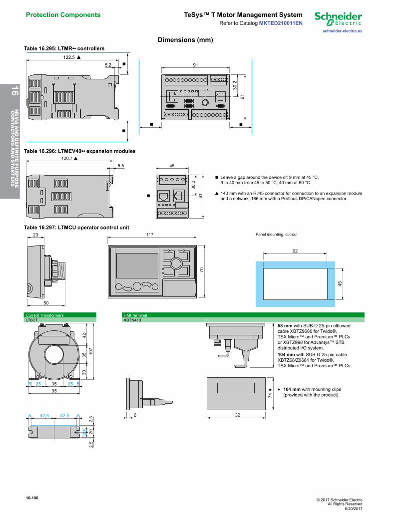
16-106 © 2017 Schneider ElectricAll Rights Reserved
Protection Components TeSys™ T Motor Management System
schneider-electric.us
Refer to CatalogMKTED210011EN
Dimensions (mm)Table 16.295: LTMR•• controllers
5.2 91
122.5 ▲
61
30.2
■■
■ ■
Table 16.296: LTMEV40•• expansion modules
5.5 45
120.7 s
61
30.2
▲
■
■
Leave a gap around the device of: 9 mm at 45 °C,9 to 40 mm from 45 to 50 °C, 40 mm at 60 °C.
140 mm with an RJ45 connector for connection to an expansion moduleand a network; 166 mm with a Profibus DP/CANopen connector.
Table 16.297: LTMCU operator control unit23
50
117
70
Panel mounting, cut-out
92
45
Current Transformers HMI TerminalLT6CT XBTN410
2,5
35255 525
95
35 107
3042
1010
2,5
20
42,5 42,55 5 132
74c
6
58 mm with SUB-D 25-pin elbowedcable XBTZ9680 for Twido®,TSX Micro™ and Premium™ PLCsor XBTZ998 for Advantys™ STBdistributed I/O system.
104 mm with SUB-D 25-pin cableXBTZ68/Z9681 for Twido®,TSX Micro™ and Premium™ PLCs
♦ 104 mm with mounting clips(provided with the product).
16NEMAANDDEFINITEPURPOSE
CONTA
CTORSANDSTA
RTERS
6/20/2017
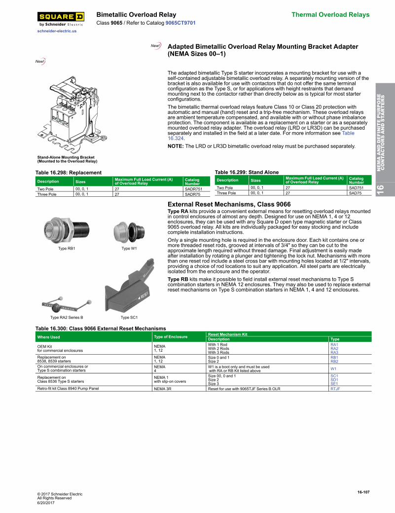
© 2017 Schneider ElectricAll Rights Reserved
16-107
schneider-electric.us
Bimetallic Overload Relay Thermal Overload RelaysClass 9065 / Refer to Catalog 9065CT9701
Adapted Bimetallic Overload Relay Mounting Bracket Adapter(NEMA Sizes 00–1)
RESETRESET
Stand-Alone Mounting Bracket(Mounted to the Overload Relay)
The adapted bimetallic Type S starter incorporates a mounting bracket for use with aself-contained adjustable bimetallic overload relay. A separately mounting version of thebracket is also available for use with contactors that do not offer the same terminalconfiguration as the Type S, or for applications with height restraints that demandmounting next to the contactor rather than directly below as is typical for most starterconfigurations.The bimetallic thermal overload relays feature Class 10 or Class 20 protection withautomatic and manual (hand) reset and a trip-free mechanism. These overload relaysare ambient temperature compensated, and available with or without phase imbalanceprotection. The component is available as a replacement on a starter or as a separatelymounted overload relay adapter. The overload relay (LRD or LR3D) can be purchasedseparately and installed in the field at a later date. For more information see Table16.324.NOTE: The LRD or LR3D bimetallic overload relay must be purchased separately.
Table 16.298: ReplacementDescription Sizes Maximum Full Load Current (A)
of Overload RelayCatalogNumber
Two Pole 00, 0, 1 27 SADR751Three Pole 00, 0, 1 27 SADR75
Table 16.299: Stand AloneDescription Sizes Maximum Full Load Current (A)
of Overload RelayCatalogNumber
Two Pole 00, 0, 1 27 SAD751Three Pole 00, 0, 1 27 SAD75
External Reset Mechanisms, Class 9066
Type RB1 Type W1
Type RA2 Series B Type SC1
Type RA kits provide a convenient external means for resetting overload relays mountedin control enclosures of almost any depth. Designed for use on NEMA 1, 4 or 12enclosures, they can be used with any Square D open type magnetic starter or Class9065 overload relay. All kits are individually packaged for easy stocking and includecomplete installation instructions.Only a single mounting hole is required in the enclosure door. Each kit contains one ormore threaded reset rods, grooved at intervals of 3/4" so they can be cut to theapproximate length required without thread damage. Final adjustment is easily madeafter installation by rotating a plunger and tightening the lock nut. Mechanisms with morethan one reset rod include a steel cross bar with mounting holes located at 1/2" intervals,providing a choice of rod locations to suit any application. All steel parts are electricallyisolated from the enclosure and the operator.Type RB kits make it possible to field install external reset mechanisms to Type Scombination starters in NEMA 12 enclosures. They may also be used to replace externalreset mechanisms on Type S combination starters in NEMA 1, 4 and 12 enclosures.
Table 16.300: Class 9066 External Reset MechanismsWhere Used Type of Enclosure Reset Mechanism Kit
Description Type
OEM Kitfor commercial enclosures
NEMA1, 12
With 1 RodWith 2 RodsWith 3 Rods
RA1RA2RA3
Replacement on8538, 8539 starters
NEMA1, 12
Size 0 and 1Size 2
RB1RB2
On commercial enclosures orType S combination starters
NEMA4
W1 is a boot only and must be usedwith RA or RB Kit listed above W1
Replacement onClass 8536 Type S starters
NEMA 1with slip-on covers
Size 00, 0 and 1Size 2Size 3
SC1SD1SE1
Retro-fit kit Class 8940 Pump Panel NEMA 3R Reset for use with 9065TJF Series B OLR RTJF
16NEMAANDDEFINITEPURPOSE
CONTA
CTORSANDSTA
RTERS
6/20/2017
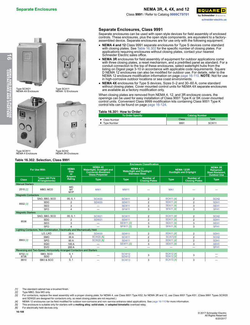
16-108 © 2017 Schneider ElectricAll Rights Reserved
Separate Enclosures NEMA 3R, 4, 4X, and 12
schneider-electric.us
Class 9991 / Refer to Catalog 9999CT9701
Separate Enclosures, Class 9991
Type SCW21NEMA 4X Enclosure
Type SCA11NEMA 12 Enclosure
Type SCW11NEMA 4 Enclosure
Type SCH2NEMA 3R Enclosure
Separate enclosures can be used with open style devices for field assembly of enclosedcontrols. These enclosures, plus the open style components, are equivalent to a factory-assembled device. Separate enclosures are for use only with the following equipment:• NEMA 4 and 12 Class 9991 separate enclosures for Type S devices come standardwith closing plates. See Table 16.302 for the specific number of closing plates. Forapplications requiring enclosures without closing plates, contact your nearestSchneider Electric sales office.
• NEMA 3R enclosures for field assembly of equipment for outdoor applications comewith three closing plates, a reset mechanism, and a predrilled panel as standard. For aconduit connection to the top of these enclosures, select watertight hubs from thelisting on Digest page 3-10 in accordance with applicable code requirements. SquareD NEMA 12 enclosures can also be modified for outdoor use. For details, refer to theNEMA 12 enclosure modification information on page page 16-110. NOTE: Not for usein high-corrosive outdoor locations or sea coast environments.
• NEMA 4X enclosures for Type S devices, Sizes 0–2 and 30–60 A, come standardwithout closing plates. Cover mounted control units for NEMA 4X separate enclosuresare available as a factory modification only.
When closing plates are removed from NEMA 4, 12, and 3R enclosure covers, theopenings can be used for easy installation of Class 9001 Type K or SK cover-mountedcontrol units. Convenient Class 9999 modification kits containing Class 9001 Type Kcontrol kits can be found on page page 16-124.
Table 16.301: How to OrderTo Order Specify: Catalog Number
• Class Number• Type Number
Class Type
9991 SCW11
Table 16.302: Selection, Class 9991
For Use With
Enclosure Classification
NEMASizeor
AmpereRating
NEMA 4XWatertight, Dusttight andCorrosion-ResistantGlass-Polyester
NEMA 4 [1]Watertight and Dusttight
Stainless SteelNEMA 12/3R
Dusttight and Driptight
NEMA 3RRainproof,
Sleet Resistant,Outdoor Use
Class Types (All PoleArrangements) Type Type Number of
Closing Plates Type Number ofClosing Plates Type
Manual Starters
2510 [2] MBO, MCOMOM1M1P
MW1 MW11 — MA1 — —
Magnetic Contactors
8502 [3]
SAO, SBO, SCO 00, 0, 1 SCW20 SCW11 2 SCA11 [4] 2 SCH2SDO 2 SDW20 SDW11 2 SDA11 [4] 2 SDH1SEO 3 — SEW11 3 SEA11 [4] 3 SEH1SFO 4 — SFW11 3 SFA11 [4] 3 SFH1
Magnetic Starters
8536
SAO, SBO, SCO 00, 0, 1 SCW21 SCW11 2 SCA11 [4] 2 SCH2SDO 2 SDW21 SDW11 2 SDA11 [4] 2 SDH1SEO 3 — SEW11 [5] 3 SEA11 [4] 3 SEH1SFO 4 — SFW11 [5] 3 SFA11 [4] 3 SFH1
Lighting Contactors, Non-Combination, Electrically and Mechanically Held
8903 [3]
LO, LXO 20 A SDW20 SDW11 2 SDA11 [4] 2 SDH1SMO 30 A SCW20 [6] SCW11 2 SCA11[4] 2 SCH2SPO 60 A SCW20 [6] SDW11 2 SDA11 [4] 2 SDH1SQO 100 A — SEW11 [5] 3 SEA11 [4] 3 SEH1SVO 200 A — — — — — SFH1
Reversing and Two-Speed, Horizontally Arranged Contactors and Starters8702 [3]8736
SBO, SCOSDO
0, 12 — SCW12
SDW12 3 SCA12 [4]SDA12 [4] 3 —
—8810 SBO & SCO 0, 1 — SCW13 3 SCA13 [4] 3 —
[1] The standard cabinet has a brushed finish.[2] Type MBO, Size MO only.[3] For contactors, replace the reset assembly with a proper closing plate: for NEMA 4, use Class 9001 Type K52; for NEMA 3R and 12, use Class 9001 Type K51. (Class 9991 Types SCW20
and SDW20 are designed for contactors only, so reset closing plates are not required.)[4] NEMA 12 enclosures can be field modified for outdoor non-corrosive and non–service entrance rated applications. See page 16-110 for more information.[5] This enclosure is suitable only for starters with amelting alloy, solid-state, or adapted bimetallic overload relay.[6] For electrically held devices only.
6/20/2017
16NEMAANDDEFINITEPURPOSE
CONTA
CTORSANDSTA
RTERS
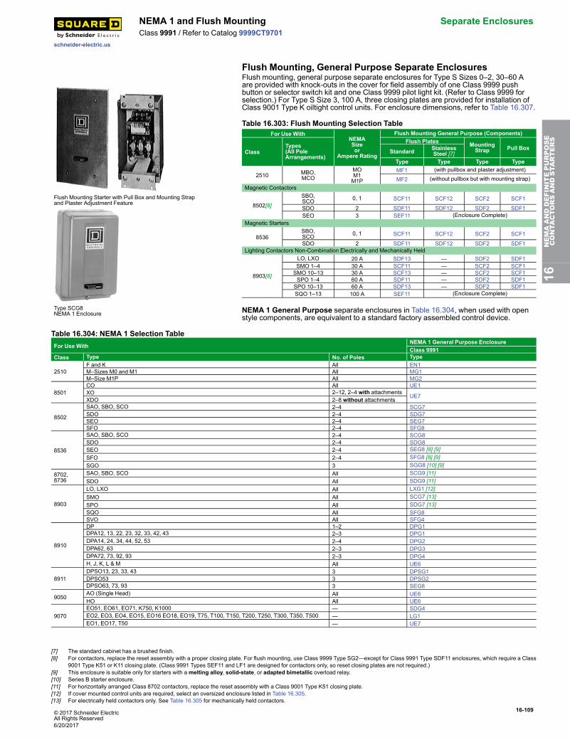
© 2017 Schneider ElectricAll Rights Reserved
16-109
schneider-electric.us
NEMA 1 and Flush Mounting Separate EnclosuresClass 9991 / Refer to Catalog 9999CT9701
Flush Mounting, General Purpose Separate Enclosures
Flush Mounting Starter with Pull Box and Mounting Strapand Plaster Adjustment Feature
Type SCG8NEMA 1 Enclosure
Flush mounting, general purpose separate enclosures for Type S Sizes 0–2, 30–60 Aare provided with knock-outs in the cover for field assembly of one Class 9999 pushbutton or selector switch kit and one Class 9999 pilot light kit. (Refer to Class 9999 forselection.) For Type S Size 3, 100 A, three closing plates are provided for installation ofClass 9001 Type K oiltight control units. For enclosure dimensions, refer to Table 16.307.
Table 16.303: Flush Mounting Selection TableFor Use With
NEMASizeor
Ampere Rating
Flush Mounting General Purpose (Components)
ClassTypes(All PoleArrangements)
Flush Plates MountingStrap Pull BoxStandard Stainless
Steel [7]Type Type Type Type
2510 MBO,MCO
MOM1M1P
MF1 (with pullbox and plaster adjustment)
MF2 (without pullbox but with mounting strap)Magnetic Contactors
8502[8]
SBO,SCO 0, 1 SCF11 SCF12 SCF2 SCF1
SDO 2 SDF11 SDF12 SDF2 SDF1SEO 3 SEF11 (Enclosure Complete)
Magnetic Starters
8536SBO,SCO 0, 1 SCF11 SCF12 SCF2 SCF1
SDO 2 SDF11 SDF12 SDF2 SDF1Lighting Contactors Non-Combination Electrically and Mechanically Held
8903[8]
LO, LXO 20 A SDF13 — SDF2 SDF1SMO 1–4 30 A SCF11 — SCF2 SCF1SMO 10–13 30 A SCF13 — SCF2 SCF1SPO 1–4 60 A SDF11 — SDF2 SDF1SPO 10–13 60 A SDF13 — SDF2 SDF1SQO 1–13 100 A SEF11 (Enclosure Complete)
NEMA 1 General Purpose separate enclosures in Table 16.304, when used with openstyle components, are equivalent to a standard factory assembled control device.
Table 16.304: NEMA 1 Selection TableFor Use With
NEMA 1 General Purpose EnclosureClass 9991
Class Type No. of Poles Type
2510F and K All EN1M–Sizes M0 and M1 All MG1M–Size M1P All MG2
8501CO All UE1XO 2–12, 2–4 with attachments
UE7XDO 2–8 without attachments
8502
SAO, SBO, SCO 2–4 SCG7SDO 2–4 SDG7SEO 2–4 SEG7SFO 2–4 SFG8
8536
SAO, SBO, SCO 2–4 SCG8SDO 2–4 SDG8SEO 2–4 SEG8 [8] [9]SFO 2–4 SFG8 [8] [9]SGO 3 SGG8 [10] [9]
8702,8736
SAO, SBO, SCO All SCG9 [11]SDO All SDG9 [11]
8903
LO, LXO All LXG1 [12]SMO All SCG7 [13]SPO All SDG7 [13]SQO All SFG8SVO All SFG4
8910
DP 1–2 DPG1DPA12, 13, 22, 23, 32, 33, 42, 43 2–3 DPG1DPA14, 24, 34, 44, 52, 53 2–4 DPG2DPA62, 63 2–3 DPG3DPA72, 73, 92, 93 2–3 DPG4H, J, K, L & M All UE6
8911DPSO13, 23, 33, 43 3 DPSG1DPSO53 3 DPSG2DPSO63, 73, 93 3 SEG8
9050AO (Single Head) All UE6HO All UE6
9070EO51, EO61, EO71, K750, K1000 — SDG4EO2, EO3, EO4, EO15, EO16 EO18, EO19, T75, T100, T150, T200, T250, T300, T350, T500 — LG1EO1, EO17, T50 — UE7
16NEMAANDDEFINITEPURPOSE
CONTA
CTORSANDSTA
RTERS
[7] The standard cabinet has a brushed finish.[8] For contactors, replace the reset assembly with a proper closing plate. For flush mounting, use Class 9999 Type SG2—except for Class 9991 Type SDF11 enclosures, which require a Class
9001 Type K51 or K11 closing plate. (Class 9991 Types SEF11 and LF1 are designed for contactors only, so reset closing plates are not required.)[9] This enclosure is suitable only for starters with amelting alloy, solid-state, or adapted bimetallic overload relay.[10] Series B starter enclosure.[11] For horizontally arranged Class 8702 contactors, replace the reset assembly with a Class 9001 Type K51 closing plate.[12] If cover mounted control units are required, select an oversized enclosure listed in Table 16.305.[13] For electrically held contactors only. See Table 16.305 for mechanically held contactors.
6/20/2017
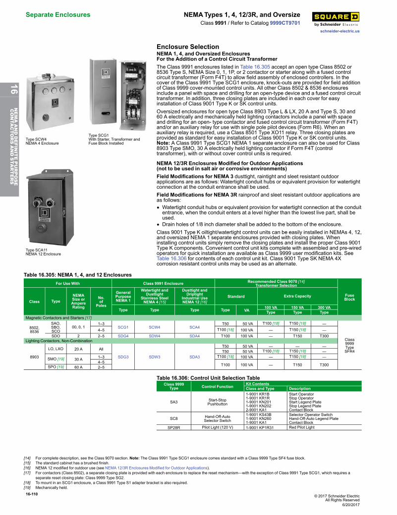
16-110 © 2017 Schneider ElectricAll Rights Reserved
Separate Enclosures NEMATypes 1, 4, 12/3R, and Oversize
schneider-electric.us
Class 9991 / Refer to Catalog 9999CT9701
Enclosure Selection
Type SCW4NEMA 4 Enclosure
Type SCG1With Starter, Transformer andFuse Block Installed
NEMA 1, 4, and Oversized EnclosuresFor the Addition of a Control Circuit TransformerThe Class 9991 enclosures listed in Table 16.305 accept an open type Class 8502 or8536 Type S, NEMA Size 0, 1, 1P, or 2 contactor or starter along with a fused controlcircuit transformer (Form F4T) to allow field assembly of enclosed controllers. In thecover of the Class 9991 Type SCG1 enclosure, knock-outs are provided for field additionof Class 9999 cover-mounted control units. All other Class 8502 & 8536 enclosuresinclude a panel with space and drilling for an open-type device and a fused control circuittransformer. In addition, three closing plates are included in each cover for easyinstallation of Class 9001 Type K or SK control units.Oversized enclosures for open type Class 8903 Type L & LX, 20 A and Type S, 30 and60 A electrically and mechanically held lighting contactors include a panel with spaceand drilling for an open- type contactor and fused control circuit transformer (Form F4T)and/or an auxiliary relay for use with single pole pilot devices (Form R6). When anauxiliary relay is required, use a Class 8501 Type XO11 relay. Three closing plates areprovided as standard for easy installation of Class 9001 Type K or SK control units.Note: A Class 9991 Type SCG1 NEMA 1 separate enclosure can also be used for Class8903 Type SMO, 30 A electrically held lighting contactor if Form F4T (controltransformer), with or without cover control units is required.
Type SCA11NEMA 12 Enclosure
NEMA 12/3R Enclosures Modified for Outdoor Applications(not to be used in salt air or corrosive environments)Field Modifications for NEMA 3 dusttight, raintight and sleet resistant outdoorapplications are as follows: Watertight conduit hubs or equivalent provision for watertightconnection at the conduit entrance shall be used.Field Modifications for NEMA 3R rainproof and sleet resistant outdoor applications areas follows:• Watertight conduit hubs or equivalent provision for watertight connection at the conduitentrance, when the conduit enters at a level higher than the lowest live part, shall beused.
• Drain holes of 1/8 inch diameter shall be added to the bottom of the enclosure.Class 9001 Type K oiltight/watertight control units can be easily installed in NEMAs 4, 12,and oversized NEMA 1 separate enclosures provided with closing plates. Wheninstalling control units simply remove the closing plates and install the proper Class 9001Type K components. Convenient control unit kits complete with assembled and pre-wiredoperators for quick installation are available as Class 9999 user modification kits. SeeTable 16.306 for contents of each control unit kit. Class 9001 Type SK NEMA 4Xcorrosion resistant control units may be used as an alternate.
Table 16.305: NEMA 1, 4, and 12 EnclosuresFor Use With Class 9991 Enclosure Recommended Class 9070 [14]
Transformer Selection
FuseBlockClass Type
NEMASize orAmpereRating
No.of
Poles
GeneralPurposeNEMA 1
Watertight andDusttight
Stainless SteelNEMA 4 [15]
Dusttight andDriptight
Industrial UseNEMA 12 [16]
Standard Extra Capacity
Type Type Type Type VA100 VA 150 VA 300 VAType Type Type
Magnetic Contactors and Starters [17]
8502,8536
SAO,SBO,SCO
00, 0, 11–3
SCG1 SCW4 SCA4T50 50 VA T100 [18] T150 [18] —
Class9999TypeSFR4
4–5 T100 [18] 100 VA — T150 [18] —SDO 2 2–5 SDG4 SDW4 SDA4 T100 100 VA — T150 T300
Lighting Contactors, Non-Combination
8903
LO, LXO 20 A All
SDG3 SDW3 SDA3
T50 50 VA — — —T50 50 VA T100 [18] T150 [18] —
SMO [19] 30 A 1–3 T100 [18] 100 VA — T150 [18] —4–5
T100 100 VA — T150 T300SPO [19] 60 A 2–5
Table 16.306: Control Unit Selection TableClass 9999
Type Control FunctionKit ContentsClass and Type Description
SA3 Start-StopPushbutton
1-9001 KR1B1-9001 KR1R1-9001 KN2011-9001 KN2022-9001 KA1
Start OperatorStop OperatorStart Legend PlateStop Legend PlateContact Block
SC8 Hand-Off-AutoSelector Switch
1-9001 KS43B1-9001 KN2601-9001 KA1
Selector Operator SwitchHand-Off-Auto Legend PlateContact Block
SP28R Pilot Light (120 V) 1-9001 KP1R31 Red Pilot Light
[14] For complete description, see the Class 9070 section. Note: The Class 9991 Type SCG1 enclosure comes standard with a Class 9999 Type SF4 fuse block.[15] The standard cabinet has a brushed finish.[16] NEMA 12 modified for outdoor use (see NEMA 12/3R Enclosures Modified for Outdoor Applications).[17] For contactors (Class 8502), a separate closing plate is provided with each enclosure to replace the reset mechanism—with the exception of Class 9991 Type SCG1, which requires a
separate reset closing plate: Class 9999 Type SG2.[18] To mount in an SCG1 enclosure, a Class 9991 Type S1 adapter bracket is also required.[19] Mechanically held.
6/20/2017
16NEMAANDDEFINITEPURPOSE
CONTA
CTORSANDSTA
RTERS
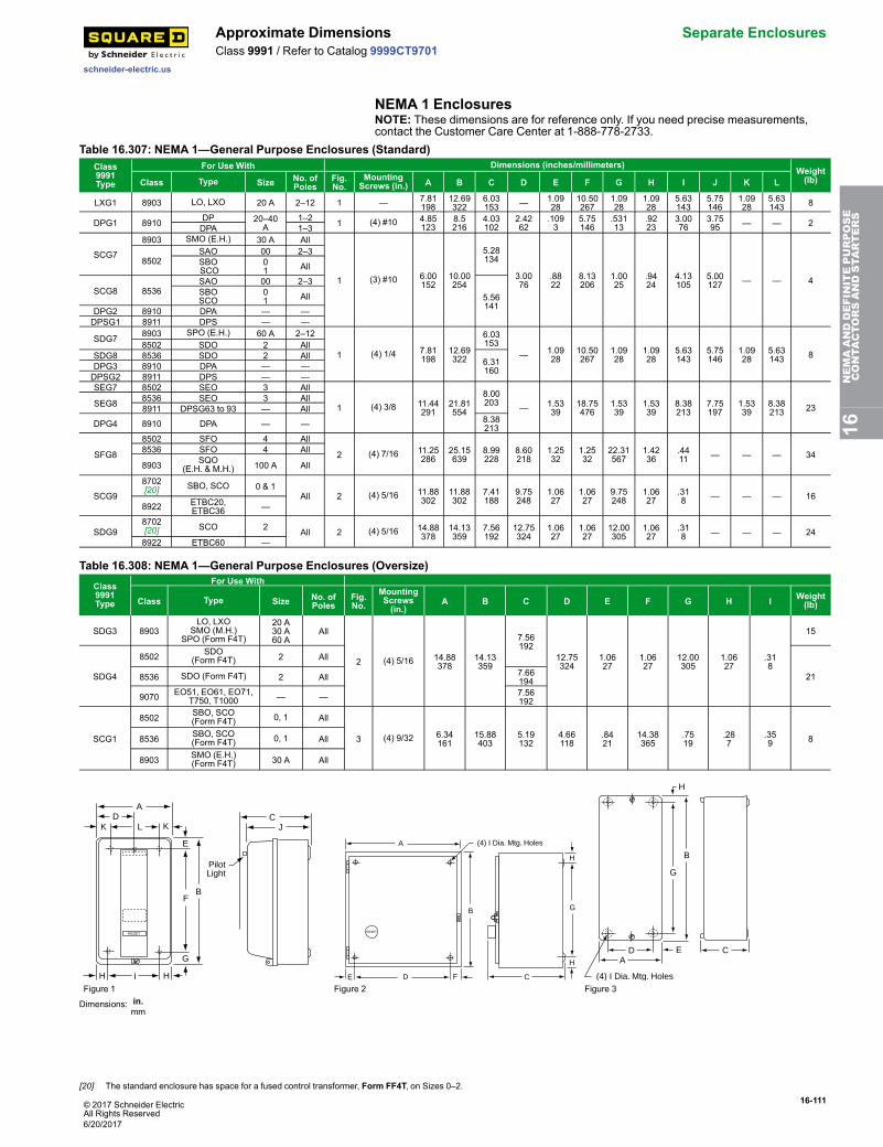
© 2017 Schneider ElectricAll Rights Reserved
16-111
schneider-electric.us
Approximate Dimensions Separate EnclosuresClass 9991 / Refer to Catalog 9999CT9701
NEMA 1 EnclosuresNOTE: These dimensions are for reference only. If you need precise measurements,contact the Customer Care Center at 1-888-778-2733.
Table 16.307: NEMA 1—General Purpose Enclosures (Standard)Class9991Type
For Use With Dimensions (inches/millimeters)Weight(lb)Class Type Size No. of
PolesFig.No.
MountingScrews (in.) A B C D E F G H I J K L
LXG1 8903 LO, LXO 20 A 2–12 1 — 7.81198
12.69322
6.03153 — 1.09
2810.50267
1.0928
1.0928
5.63143
5.75146
1.0928
5.63143 8
DPG1 8910 DP 20–40A
1–2 1 (4) #10 4.85123
8.5216
4.03102
2.4262
.1093
5.75146
.53113
.9223
3.0076
3.7595 — — 2DPA 1–3
SCG7
8903 SMO (E.H.) 30 A All
1 (3) #10 6.00152
10.00254
5.28134
3.0076
.8822
8.13206
1.0025
.9424
4.13105
5.00127 — — 4
8502SAO 00 2–3SBOSCO
01 All
SCG8 8536SAO 00 2–3
5.56141
SBOSCO
01 All
DPG2 8910 DPA — —DPSG1 8911 DPS — —
SDG7 8903 SPO (E.H.) 60 A 2–12
1 (4) 1/4 7.81198
12.69322
6.03153
— 1.0928
10.50267
1.0928
1.0928
5.63143
5.75146
1.0928
5.63143 8
8502 SDO 2 AllSDG8 8536 SDO 2 All
6.31160DPG3 8910 DPA — —
DPSG2 8911 DPS — —SEG7 8502 SEO 3 All
1 (4) 3/8 11.44291
21.81554
8.00203 — 1.53
3918.75476
1.5339
1.5339
8.38213
7.75197
1.5339
8.38213 23SEG8 8536 SEO 3 All
8911 DPSG63 to 93 — All
DPG4 8910 DPA — — 8.38213
SFG8
8502 SFO 4 All
2 (4) 7/16 11.25286
25.15639
8.99228
8.60218
1.2532
1.2532
22.31567
1.4236
.4411 — — — 348536 SFO 4 All
8903 SQO(E.H. & M.H.) 100 A All
SCG9
8702[20] SBO, SCO 0 & 1
All 2 (4) 5/16 11.88302
11.88302
7.41188
9.75248
1.0627
1.0627
9.75248
1.0627
.318 — — — 16
8922 ETBC20,ETBC36 —
SDG98702[20] SCO 2 All 2 (4) 5/16 14.88
37814.13359
7.56192
12.75324
1.0627
1.0627
12.00305
1.0627
.318 — — — 24
8922 ETBC60 —
Table 16.308: NEMA 1—General Purpose Enclosures (Oversize)Class9991Type
For Use With
Class Type Size No. ofPoles
Fig.No.
MountingScrews(in.)
A B C D E F G H I Weight(lb)
SDG3 8903LO, LXO
SMO (M.H.)SPO (Form F4T)
20 A30 A60 A
All
2 (4) 5/16 14.88378
14.13359
7.56192
12.75324
1.0627
1.0627
12.00305
1.0627
.318
15
SDG4
8502 SDO(Form F4T) 2 All
218536 SDO (Form F4T) 2 All 7.66194
9070 EO51, EO61, EO71,T750, T1000 — — 7.56
192
SCG1
8502 SBO, SCO(Form F4T) 0, 1 All
3 (4) 9/32 6.34161
15.88403
5.19132
4.66118
.8421
14.38365
.7519
.287
.359 88536 SBO, SCO
(Form F4T) 0, 1 All
8903 SMO (E.H.)(Form F4T) 30 A All
AD
K L K
E
BF
H I H
G
RESET
CJ
PilotLight
A
B
E D F
RESET
C
H
G
H
(4) I Dia. Mtg. Holes
H
B
G
CEDA
(4) I Dia. Mtg. HolesFigure 1 Figure 2 Figure 3
Dimensions: in.mm
16NEMAANDDEFINITEPURPOSE
CONTA
CTORSANDSTA
RTERS
[20] The standard enclosure has space for a fused control transformer, Form FF4T, on Sizes 0–2.
6/20/2017
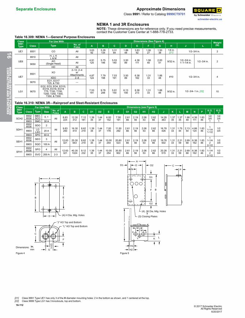
16-112 © 2017 Schneider ElectricAll Rights Reserved
Separate Enclosures Approximate Dimensions
schneider-electric.us
Class 9991 / Refer to Catalog 9999CT9701
NEMA 1 and 3R EnclosuresNOTE: These dimensions are for reference only. If you need precise measurements,contact the Customer Care Center at 1-888-778-2733.
Table 16.309: NEMA 1—General Purpose EnclosuresClass9991Type
For Use With Dimensions (See Figure 4) Weight(lb)Class Type No. of
Poles A B C D E F G H J L
UE1 8501 CO All 3.6392
5.28134
3.3184
1.8848
3.6392
1.0627
1.5038
1/4 in.[21] 1/2–3/4 in. 2
UE6
8910 H, J, KL & M All
4.91125
5.75146
5.53140
3.5089
4.38111
1.5640
2.0051 9/32 in. 1/2–3/4 in.
1–1-1/4 in. 1/2–3/4 in. 29050
AO(Single Head) All
HO All
UE78501 XO
2–12, 2–4w/
Attachments 4.87124
7.79198
7.53191
3.5089
6.38162
1.3133
1.8848 #10 1/2–3/4 in. 4XDO 2–8
9070 EO1, EO17T25, & T50 —
LG1 9070
EO2, EO3, EO4, EO15,EO16, EO18, EO19T75, T100, T150,T200, T250, T300,T350, & T500
— 7.53191
9.78248
5.91150
6.13156
8.38213
1.3133
1.8848 9/32 in. 1/2–3/4–1 in. [22] 10
Table 16.310: NEMA 3R—Rainproof and Sleet-Resistant EnclosuresClass9991Type
For Use With Dimensions (see Figure 5)
Class Type Size No. ofPoles A B C D1 D2 E F G1 G2 H1 H2 J K L M N P K.O.
XK.O.Y
SCH285028536
SBO,SCO 0, 1
All 8.83224
12.30312
7.12181
1.3935
1.4437
6.00152
7.50191
2.6166
2.1956
2.0853
2.6266
14.28363
1.3735
1.3735
1.8848
4.38111
1.8346
1/23/41
1/23/418903 SMO 30 A
SDH1
85028536 SDO 2
All 9.83250
16.30414
8.62219
1.3935
1.4437
7.00178
11.50292
2.6166
2.1956
2.0853
2.6266
16.78426
1.3133
1.7544
2.1354
4.88124
1.8346
11-1/41-1/2
1/23/48903 LO
LXO 20 A
8903 SPO 60 A
SEH185028536 SEO 3
All 12.63321
25.30643
8.62219
1.3935
1.4437
10.00254
20.60523
2.6166
2.1956
2.0853
2.6266
19.78502
1.3133
2.3159
2.6968
6.38162
1.8346
11-1/42
2-1/2
1/23/48903 SQO 100 A
SFH185028536 SFO 4 All 12.63
32140.301024
9.12232
1.3935
1.4437
10.00254
35.50902
2.6166
2.1956
2.0853
2.6266
20.28515
1.3133
2.3159
2.6968
6.38162
1.8346
11-1/42
2-1/2
1/23/48903 SVO 200 A 2-3
Dimensions: in.mm
A
EB
D
C
G2
G
F
(4) H Dia. Mtg. Holes
"J" KO Top and Bottom
"L" KO Top and Bottom
A
ED1 D2
N
G1
G2
F B
C
P
J
LK
H1
H2
MM
X X
Y
(4) .36 Dia. Mtg. Holes9
(3) Closing Plates
Figure 4 Figure 5
16NEMAANDDEFINITEPURPOSE
CONTA
CTORSANDSTA
RTERS
[21] Class 9991 Type UE1 has only 3 of the H diameter mounting holes: 2 in the bottom as shown, and 1 centered at the top.[22] Class 9999 Type LG1 has 3 knockouts, top and bottom.
6/20/2017
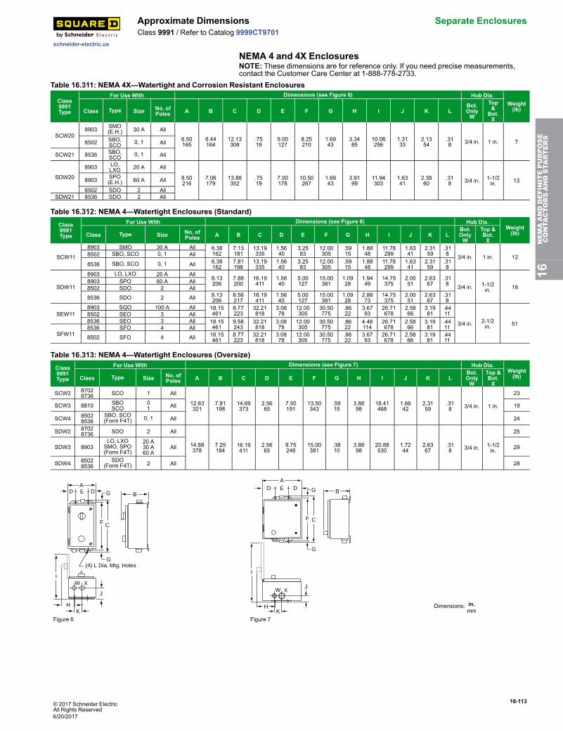
© 2017 Schneider ElectricAll Rights Reserved
16-113
schneider-electric.us
Approximate Dimensions Separate EnclosuresClass 9991 / Refer to Catalog 9999CT9701
NEMA 4 and 4X EnclosuresNOTE: These dimensions are for reference only. If you need precise measurements,contact the Customer Care Center at 1-888-778-2733.
Table 16.311: NEMA 4X—Watertight and Corrosion Resistant Enclosures
Class9991Type
For Use With Dimensions (see Figure 6) Hub Dia.Weight(lb)Class Type Size No. of
Poles A B C D E F G H I J K LBot.OnlyW
Top&
Bot.X
SCW208903 SMO
(E.H.) 30 A All
6.50165
6.44164
12.13308
.7519
5.00127
8.25210
1.6943
3.3485
10.06256
1.3133
2.1354
.318 3/4 in. 1 in. 78502 SBO,
SCO 0, 1 All
SCW21 8536 SBO,SCO 0, 1 All
SDW20
8903 LO,LXO 20 A All
8.50216
7.06179
13.88352
.7519
7.00178
10.50267
1.6943
3.9199
11.94303
1.6341
2.3860
.318 3/4 in. 1-1/2
in. 138903 SPO(E.H.) 60 A All
8502 SDO 2 AllSDW21 8536 SDO 2 All
Table 16.312: NEMA 4—Watertight Enclosures (Standard)Class9991Type
For Use With Dimensions (see Figure 6) Hub Dia.Weight(lb)Class Type Size No. of
Poles A B C D E F G H I J K LBot.OnlyW
Top &Bot.X
SCW11
8903 SMO 30 A All 6.38162
7.13181
13.19335
1.5640
3.2583
12.00305
.5915
1.8848
11.78299
1.6341
2.3159
.318 3/4 in. 1 in. 128502 SBO, SCO 0, 1 All
8536 SBO, SCO 0, 1 All 6.38162
7.81198
13.19335
1.5640
3.2583
12.00305
.5915
1.8848
11.78299
1.6341
2.3159
.318
SDW11
8903 LO, LXO 20 A All8.13206
7.88200
16.19411
1.5640
5.00127
15.00381
1.0928
1.9449
14.75375
2.0051
2.6367
.318 3/4 in. 1-1/2
in. 188903 SPO 60 A All8502 SDO 2 All
8536 SDO 2 All 8.13206
8.56217
16.19411
1.5640
5.00127
15.00381
1.0928
2.8873
14.75375
2.0051
2.6367
.318
SEW118903 SQO 100 A All 18.15
4618.77223
32.21818
3.0878
12.00305
30.50775
.8622
3.6793
26.71678
2.5866
3.1981
.4411
3/4 in. 2-1/2in. 51
8502 SEO 3 All8536 SEO 3 All 18.15
4619.58243
32.21818
3.0878
12.00305
30.50775
.8622
4.48114
26.71678
2.5866
3.1981
.4411
SFW118536 SFO 4 All
8502 SFO 4 All 18.15461
8.77223
32.21818
3.0878
12.00305
30.50775
.8622
3.6793
26.71678
2.5866
3.1981
.4411
Table 16.313: NEMA 4—Watertight Enclosures (Oversize)Class9991Type
For Use With Dimensions (see Figure 7) Hub Dia.Weight(lb)Class Type Size No. of
Poles A B C D E F G H I J K LBot.OnlyW
Top &Bot.X
SCW2 87028736 SCO 1 All
12.63321
7.81198
14.69373
2.5665
7.50191
13.50343
.5915
3.8898
18.41468
1.6642
2.3159
.318 3/4 in. 1 in.
23
SCW3 8810 SBOSCO
01 All 19
SCW4 85028536
SBO, SCO(Form F4T) 0, 1 All 24
SDW2 87028736 SDO 2 All
14.88378
7.25184
16.19411
2.5665
9.75248
15.00381
.3810
3.8898
20.88530
1.7244
2.6367
.318 3/4 in. 1-1/2
in.
25
SDW3 8903LO, LXOSMO, SPO(Form F4T)
20 A30 A60 A
All 29
SDW4 85028536
SDO(Form F4T) 2 All 28
AD E D G
G
B
CF
IW X
J
HK
(4) L Dia. Mtg. Holes
AD DE G
G
F C
J
KH
I
W X
B
Dimensions: in.mm
Figure 6 Figure 7
16NEMAANDDEFINITEPURPOSE
CONTA
CTORSANDSTA
RTERS
6/20/2017
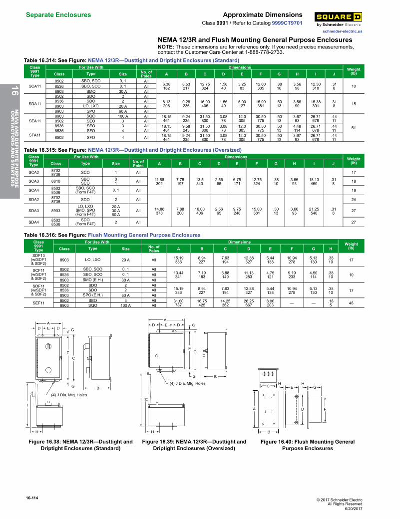
16-114 © 2017 Schneider ElectricAll Rights Reserved
Separate Enclosures Approximate Dimensions
schneider-electric.us
Class 9991 / Refer to Catalog 9999CT9701
NEMA 12/3R and Flush Mounting General Purpose EnclosuresNOTE: These dimensions are for reference only. If you need precise measurements,contact the Customer Care Center at 1-888-778-2733.
Table 16.314: See Figure: NEMA 12/3R—Dusttight and Driptight Enclosures (Standard)Class9991Type
For Use With Dimensions Weight(lb)Class Type Size No. of
Poles A B C D E F G H I J
SCA118502 SBO, SCO 0, 1 All
6.38162
8.53217
12.75324
1.5640
3.2583
12.00305
.3810
3.5690
12.50318
.318 108536 SBO, SCO 0, 1 All
8903 SMO 30 A All
SDA11
8502 SDO 2 All8.13206
9.28236
16.00406
1.5640
5.00127
15.00381
.5013
3.5690
15.38391
.318 15
8536 SDO 2 All8903 LO, LXO 20 A All8903 SPO 60 A All
SEA118903 SQO 100 A All 18.15
4619.24235
31.50800
3.0878
12.0305
30.50775
.5013
3.6793
26.71678
.4411
51
8502 SEO 3 All8536 SEO 3 All 18.15
4619.58243
31.50800
3.0878
12.0305
30.50775
.5013
4.48114
26.71678
.4411
SFA118536 SFO 4 All
8502 SFO 4 All 18.15461
9.24235
31.50800
3.0878
12.0305
30.50775
.5013
3.6793
26.71678
.4411
Table 16.315: See Figure: NEMA 12/3R—Dusttight and Driptight Enclosures (Oversized)Class9991Type
For Use With Dimensions Weight(lb)Class Type Size No. of
Poles A B C D E F G H I J
SCA2 87028736 SCO 1 All
11.88302
7.75197
13.5343
2.5665
6.75171
12.75324
.3810
3.6693
18.13460
.318
17
SCA3 8810 SBOSCO
01 All 18
SCA4 85028536
SBO, SCO(Form F4T) 0, 1 All 19
SDA2 87028736 SDO 2 All
14.88378
7.88200
16.00406
2.5665
9.75248
15.00381
.5013
3.6693
21.25540
.318
24
SDA3 8903LO, LXOSMO, SPO(Form F4T)
20 A30 A60 A
All 27
SDA4 85028536
SDO(Form F4T) 2 All 27
Table 16.316: See Figure: Flush Mounting General Purpose EnclosuresClass9991Type
For Use With Dimensions Weight(lb)Class Type Size No. of
Poles A B C D E F G HSDF13(w/SDF1& SDF2)
8903 LO, LXO 20 A All 15.19386
8.94227
7.63194
12.88327
5.44138
10.94278
5.13130
.3810 17
SCF11(w/SDF1& SDF2)
8502 SBO, SCO 0, 1 All13.44341
7.19183
5.88149
11.13283
4.75121
9.19233
4.50114
.3810 108536 SBO, SCO 0, 1 All
8903 SMO (E.H.) 30 A AllSDF11(w/SDF1& SDF2)
8502 SDO 2 All15.19386
8.94227
7.63194
12.88327
5.44138
10.94278
5.13130
.3810 178536 SDO 2 All
8903 SPO (E.H.) 60 A All
SEF11 8502 SEO 3 All 31.00787
16.75425
14.25362
26.25667
8.00203 — — .18
5 488903 SQO 100 A All
AD E D G
FC
G B
H
I
(4) J Dia. Mtg. Holes
Figure 16.38: NEMA 12/3R—Dusttight andDriptight Enclosures (Standard)
AE DD G
FC
G B
I
H
(4) J Dia. Mtg. Holes
Figure 16.39: NEMA 12/3R—Dusttight andDriptight Enclosures (Oversized)
C
A
B
H HE G
D F
Figure 16.40: Flush Mounting GeneralPurpose Enclosures
16NEMAANDDEFINITEPURPOSE
CONTA
CTORSANDSTA
RTERS
6/20/2017
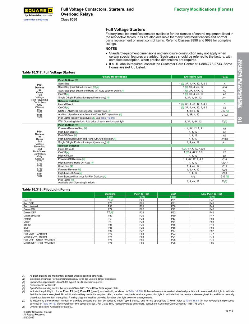
© 2017 Schneider ElectricAll Rights Reserved
16-115
schneider-electric.us
Full Voltage Contactors, Starters, andOverload Relays
Factory Modifications (Forms)
Class 8536
Full Voltage StartersFactory installed modifications are available for the classes of control equipment listed inthe respective tables. Kits are also available for many field modifications and normalparts replacement on most control items. Refer to Classes 9998 and 9999 for completelistings.NOTES• Standard equipment dimensions and enclosure construction may not apply whencertain special features are added. Such cases should be referred to the factory, withcomplete description, when precise dimensions are required.
• If a UL label is required, consult the Customer Care Center at 1-888-778-2733. SomeForms are not UL Listed.
Table 16.317: Full Voltage StartersFactory Modifications Enclosure Type Form
PilotDevices
inCoverFull
VoltageNon-ReversingControllers
OnlyClasses8502853685388539
Push Buttons [1]Start-Stop 1 [2], 3R, 4, 4X, 12, 7, & 9 AStart-Stop (maintained contact) [3] [4] 1 [2], 3R, 4, 4X, 12 A16Start-Stop push button and Hand-Off-Auto selector switch [4] 1 [2], 3R, 4, 4X, 12 ACOn-Off [4] 1 [2], 3R, 4, 4X, 12 A3Single Oiltight Pushbutton (specify marking) [4] 1, 3R, 4, 4X, 12 A11Selector SwitchesHand-Off-Auto 1 [2], 3R, 4, 4X, 12, 7, & 9 COn-Off [4] 1 [2], 3R, 4, 4X, 12, 7, & 9 C6NON-STANDARD markings for Pilot Devices [4] 1, 3R, 4, 12 G12 [5]Addition of padlock attachment to Class 9001 operators [4] 1, 3R, 4, 12 G122Pilot Lights (specify color/type) [6] See Table 16.318.With Operating Interlock: Add price of each interlock per light 1, 3R, 4, 4X, 12 X [7]
PilotDevices
inCoverFull
VoltageReversing
andMulti-SpeedControllers
OnlyClasses8702873687388739881088118812
Push Buttons [1]Forward-Reverse-Stop [4] 1, 4, 4X, 12, 7, 9 A1High-Low-Stop [4] 1, 4, 12 A2Fast-Off-Slow [4] 1, 4, 12 A9High-Low push button and Hand-Off-Auto selector [4] 1, 4, 12 A10CSingle Oiltight Pushbutton (specify marking) [4] 1, 4, 4X, 12 A11Selector SwitchesHand-Off-Auto 1 [2], 4, 4X, 12, 7, & 9 COn-Off [4] 1 [2], 4, 4X 7, & 9 C6High-Off-Low 1, 4, 12 C7Forward-Off-Reverse [4] 1, 4, 4X, 12, 7, & 9 C14High-Low and Hand-Off-Auto [4] 1, 4, 12 CC17Slow-Fast [4] 1, 4, 4X, 12 C19Forward-Reverse [4] 1, 4, 4X, 12 C20High-Low-Off-Auto [4] 1, 4, 12 C25Non-Standard Markings for Pilot Devices [4] Any G12 [5]Pilot Lights [6]Available with Operating Interlock 1, 4, 4X, 12 X [7]
Table 16.318: Pilot Light FormsStandard Push-to-Test LED LED-Push-to-TestForm Form Form Form
Red ON P1 [8] P21 P51 P42Red OFF P71 P81 P91 P43Red Unwired P38 P28 P58 P44Green ON P72 P82 P92 P45Green OFF P2 [8] P22 P52 P46Green Unwired P39 P29 P59 P47Amber P3 P23 P53 P63Clear P4 P24 P54 P64Yellow P35 P25 P55 P48Blue P36 P26 P56 P66White P37 P27 P57 P67Red LOW—Green HI P73 P83 P93 P77Green LOW—Red HI P74 P84 P94 P78Red OFF—Green FWD/REV P75 P85 P95 P79Green OFF—Red FWD/REV P76 P86 P96 P80
16NEMAANDDEFINITEPURPOSE
CONTA
CTORSANDSTA
RTERS
[1] All push buttons are momentary contact unless specified otherwise.[2] Selection of various Form combinations may force the use of a larger enclosure.[3] Specify the appropriate Class 9001 Type K or SK operator required.[4] Not available for Size 00.[5] Specify the marking and/or the required Class 9001 Type KN or SKN legend plate.[6] Indicate the pilot light color as Form P1 (red), Form P2 (green), and so forth, as shown in Table 16.318. Unless otherwise requested, standard practice is to wire a red pilot light to indicate
that the device is energized. No additional auxiliary contact is required. Also, standard practice is to wire a green pilot light to indicate that the device is de-energized. An additional normallyclosed auxiliary contact is supplied. A wiring diagram must be provided for other pilot light colors or arrangements.
[7] To determine the maximum number of auxiliary contacts that can be added to each Type S device, and for the appropriate X Form, refer to Table 16.84 (for non-reversing single-speeddevices) or Table 16.167 (for reversing or two-speed devices). For Class 8600 reduced voltage controllers, consult the Customer Care Center at 1-888-778-2733.
[8] Only for pilot light. Available for Size 00.
6/20/2017
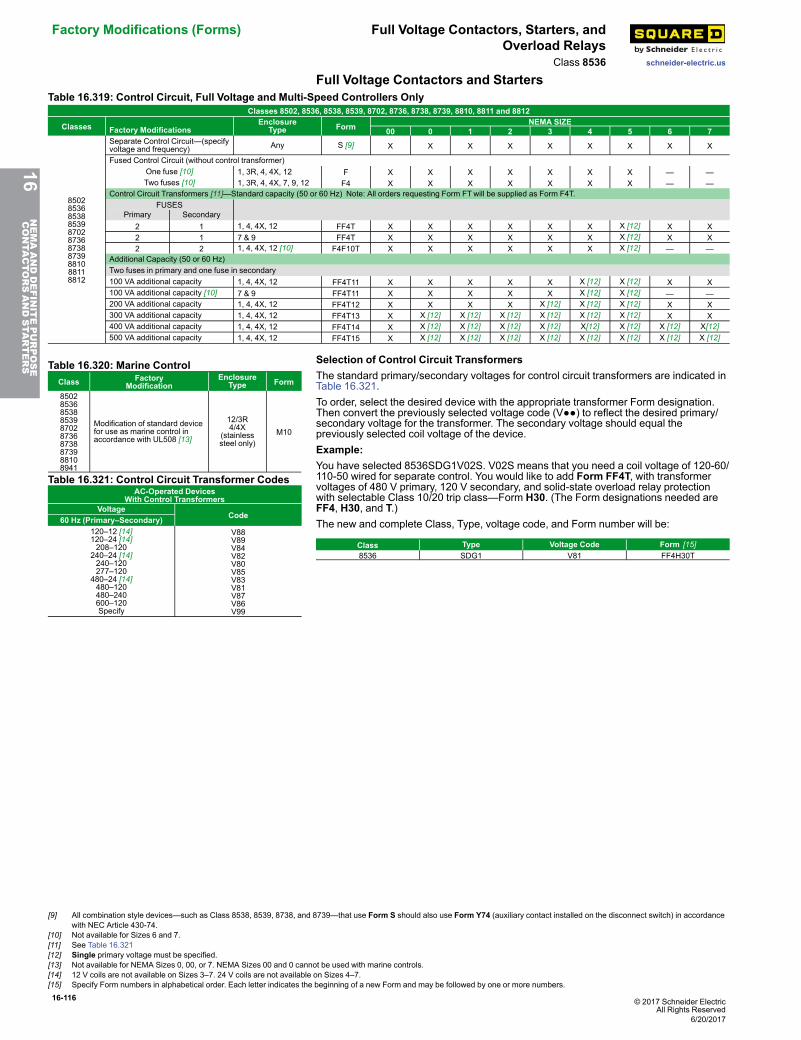
16-116 © 2017 Schneider ElectricAll Rights Reserved
Factory Modifications (Forms) Full Voltage Contactors, Starters, andOverload Relays
schneider-electric.usClass 8536Full Voltage Contactors and Starters
Table 16.319: Control Circuit, Full Voltage and Multi-Speed Controllers OnlyClasses 8502, 8536, 8538, 8539, 8702, 8736, 8738, 8739, 8810, 8811 and 8812
Classes Factory ModificationsEnclosure
Type Form NEMA SIZE00 0 1 2 3 4 5 6 7
85028536853885398702873687388739881088118812
Separate Control Circuit—(specifyvoltage and frequency) Any S [9] X X X X X X X X X
Fused Control Circuit (without control transformer)One fuse [10] 1, 3R, 4, 4X, 12 F X X X X X X X — —Two fuses [10] 1, 3R, 4, 4X, 7, 9, 12 F4 X X X X X X X — —
Control Circuit Transformers [11]—Standard capacity (50 or 60 Hz) Note: All orders requesting Form FTwill be supplied as Form F4T.FUSES
Primary Secondary2 1 1, 4, 4X, 12 FF4T X X X X X X X [12] X X2 1 7 & 9 FF4T X X X X X X X [12] X X2 2 1, 4, 4X, 12 [10] F4F10T X X X X X X X [12] — —
Additional Capacity (50 or 60 Hz)Two fuses in primary and one fuse in secondary100 VA additional capacity 1, 4, 4X, 12 FF4T11 X X X X X X [12] X [12] X X100 VA additional capacity [10] 7 & 9 FF4T11 X X X X X X [12] X [12] — —200 VA additional capacity 1, 4, 4X, 12 FF4T12 X X X X X [12] X [12] X [12] X X300 VA additional capacity 1, 4, 4X, 12 FF4T13 X X [12] X [12] X [12] X [12] X [12] X [12] X X400 VA additional capacity 1, 4, 4X, 12 FF4T14 X X [12] X [12] X [12] X [12] X[12] X [12] X [12] X[12]500 VA additional capacity 1, 4, 4X, 12 FF4T15 X X [12] X [12] X [12] X [12] X [12] X [12] X [12] X [12]
Table 16.320: Marine ControlClass Factory
ModificationEnclosure
Type Form
8502853685388539870287368738873988108941
Modification of standard devicefor use as marine control inaccordance with UL508 [13]
12/3R4/4X
(stainlesssteel only)
M10
Table 16.321: Control Circuit Transformer CodesAC-Operated Devices
With Control TransformersVoltage
Code60 Hz (Primary–Secondary)120–12 [14]120–24 [14]208–120
240–24 [14]240–120277–120
480–24 [14]480–120480–240600–120Specify
V88V89V84V82V80V85V83V81V87V86V99
Selection of Control Circuit TransformersThe standard primary/secondary voltages for control circuit transformers are indicated inTable 16.321.To order, select the desired device with the appropriate transformer Form designation.Then convert the previously selected voltage code (V●●) to reflect the desired primary/secondary voltage for the transformer. The secondary voltage should equal thepreviously selected coil voltage of the device.Example:You have selected 8536SDG1V02S. V02S means that you need a coil voltage of 120-60/110-50 wired for separate control. You would like to add Form FF4T, with transformervoltages of 480 V primary, 120 V secondary, and solid-state overload relay protectionwith selectable Class 10/20 trip class—Form H30. (The Form designations needed areFF4, H30, and T.)The new and complete Class, Type, voltage code, and Form number will be:
Class Type Voltage Code Form [15]8536 SDG1 V81 FF4H30T
16NEMAANDDEFINITEPURPOSE
CONTA
CTORSANDSTA
RTERS
[9] All combination style devices—such as Class 8538, 8539, 8738, and 8739—that use Form S should also use Form Y74 (auxiliary contact installed on the disconnect switch) in accordancewith NEC Article 430-74.
[10] Not available for Sizes 6 and 7.[11] See Table 16.321[12] Single primary voltage must be specified.[13] Not available for NEMA Sizes 0, 00, or 7. NEMA Sizes 00 and 0 cannot be used with marine controls.[14] 12 V coils are not available on Sizes 3–7. 24 V coils are not available on Sizes 4–7.[15] Specify Form numbers in alphabetical order. Each letter indicates the beginning of a new Form and may be followed by one or more numbers.
6/20/2017
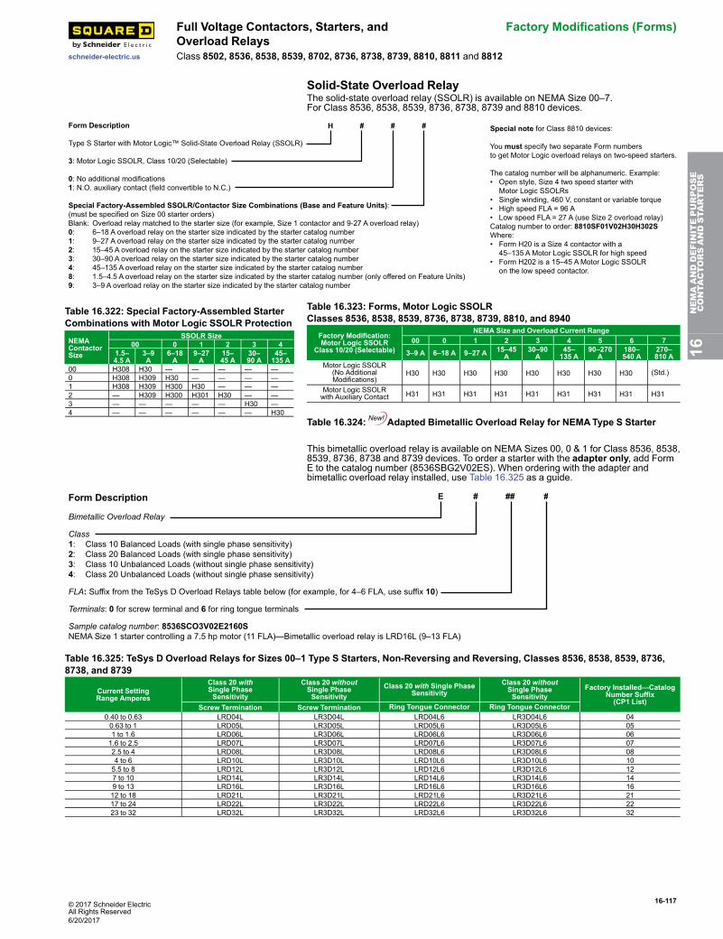
© 2017 Schneider ElectricAll Rights Reserved
16-117
schneider-electric.us
Full Voltage Contactors, Starters, andOverload Relays
Factory Modifications (Forms)
Class 8502, 8536, 8538, 8539, 8702, 8736, 8738, 8739, 8810, 8811 and 8812
Solid-State Overload RelayThe solid-state overload relay (SSOLR) is available on NEMA Size 00–7.For Class 8536, 8538, 8539, 8736, 8738, 8739 and 8810 devices.
Form Description
Type S Starter with Motor Logic™ Solid-State Overload Relay (SSOLR)
3: Motor Logic SSOLR, Class 10/20 (Selectable)
0: No additional modifications1: N.O. auxiliary contact (field convertible to N.C.)
Special Factory-Assembled SSOLR/Contactor Size Combinations (Base a nd Feature Units):(must be specified on Size 00 starter orders)Blank: Overload relay matched to the starter size (for example, Size 1 contactor and 9-27 A overload relay)0: 6–18 A overload relay on the starter size indicated by the starter catalog number1: 9–27 A overload relay on the starter size indicated by the starter catalog number2: 15–45 A overload relay on the starter size indicated by the starter catalog number3: 30–90 A overload relay on the starter size indicated by the starter catalog number4: 45–135 A overload relay on the starter size indicated by the starter catalog number8: 1.5–4.5 A overload relay on the starter size indicated by the starter catalog number (only offered on Feature Units)9: 3–9 A overload relay on the starter size indicated by the starter catalog number
H # # # Special note for Class 8810 devices:
You must specify two separate Form numbers to get Motor Logic overload relays on two-speed starters.
The catalog number will be alphanumeric. Example: • Open style, Size 4 two speed starter with Motor Logic SSOLRs • Single winding, 460 V, constant or variable torque• High speed FLA = 96 A• Low speed FLA = 27 A (use Size 2 overload relay)Catalog number to order: 8810SF01V02H30H302SWhere: • Form H20 is a Size 4 contactor with a 45–135 A Motor Logic SSOLR for high speed • Form H202 is a 15–45 A Motor Logic SSOLR on the low speed contactor.
Table 16.322: Special Factory-Assembled StarterCombinations with Motor Logic SSOLR Protection
NEMAContactorSize
SSOLR Size00 0 1 2 3 4
1.5–4.5 A
3–9A
6–18A
9–27A
15–45 A
30–90 A
45–135 A
00 H308 H30 — — — — —0 H308 H309 H30 — — — —1 H308 H309 H300 H30 — — —2 — H309 H300 H301 H30 — —3 — — — — — H30 —4 — — — — — — H30
Table 16.323: Forms, Motor Logic SSOLRClasses 8536, 8538, 8539, 8736, 8738, 8739, 8810, and 8940
Factory Modification:Motor Logic SSOLR
Class 10/20 (Selectable)
NEMA Size and Overload Current Range00 0 1 2 3 4 5 6 7
3–9 A 6–18 A 9–27 A 15–45A
30–90A
45–135 A
90–270A
180–540 A
270–810 A
Motor Logic SSOLR(No AdditionalModifications)
H30 H30 H30 H30 H30 H30 H30 H30 (Std.)
Motor Logic SSOLRwith Auxiliary Contact H31 H31 H31 H31 H31 H31 H31 H31 H31
Table 16.324: Adapted Bimetallic Overload Relay for NEMAType S Starter
This bimetallic overload relay is available on NEMA Sizes 00, 0 & 1 for Class 8536, 8538,8539, 8736, 8738 and 8739 devices. To order a starter with the adapter only, add FormE to the catalog number (8536SBG2V02ES). When ordering with the adapter andbimetallic overload relay installed, use Table 16.325 as a guide.
Form Description
Bimetallic Overload Relay
Class1: Class 10 Balanced Loads (with single phase sensitivity)2: Class 20 Balanced Loads (with single phase sensitivity)3: Class 10 Unbalanced Loads (without single phase sensitivity)4: Class 20 Unbalanced Loads (without single phase sensitivity)
FLA: Suffix from the TeSys D Overload Relays table below (for example, for 4–6 FLA, use suffix 10)
Terminals: 0 for screw terminal and 6 for ring tongue terminals
Sample catalog number: 8536SCO3V02E2160SNEMA Size 1 starter controlling a 7.5 hp motor (11 FLA)—Bimetallic overload relay is LRD16L (9–13 FLA)
E # ## #
Table 16.325: TeSys D Overload Relays for Sizes 00–1 Type S Starters, Non-Reversing and Reversing, Classes 8536, 8538, 8539, 8736,8738, and 8739
Current SettingRange Amperes
Class 20 withSingle PhaseSensitivity
Class 20 withoutSingle PhaseSensitivity
Class 20 with Single PhaseSensitivity
Class 20 withoutSingle PhaseSensitivity
Factory Installed—CatalogNumber Suffix(CP1 List)
Screw Termination Screw Termination Ring Tongue Connector Ring Tongue Connector0.40 to 0.63 LRD04L LR3D04L LRD04L6 LR3D04L6 040.63 to 1 LRD05L LR3D05L LRD05L6 LR3D05L6 051 to 1.6 LRD06L LR3D06L LRD06L6 LR3D06L6 061.6 to 2.5 LRD07L LR3D07L LRD07L6 LR3D07L6 072.5 to 4 LRD08L LR3D08L LRD08L6 LR3D08L6 084 to 6 LRD10L LR3D10L LRD10L6 LR3D10L6 105.5 to 8 LRD12L LR3D12L LRD12L6 LR3D12L6 127 to 10 LRD14L LR3D14L LRD14L6 LR3D14L6 149 to 13 LRD16L LR3D16L LRD16L6 LR3D16L6 1612 to 18 LRD21L LR3D21L LRD21L6 LR3D21L6 2117 to 24 LRD22L LR3D22L LRD22L6 LR3D22L6 2223 to 32 LRD32L LR3D32L LRD32L6 LR3D32L6 32
16NEMAANDDEFINITEPURPOSE
CONTA
CTORSANDSTA
RTERS
6/20/2017
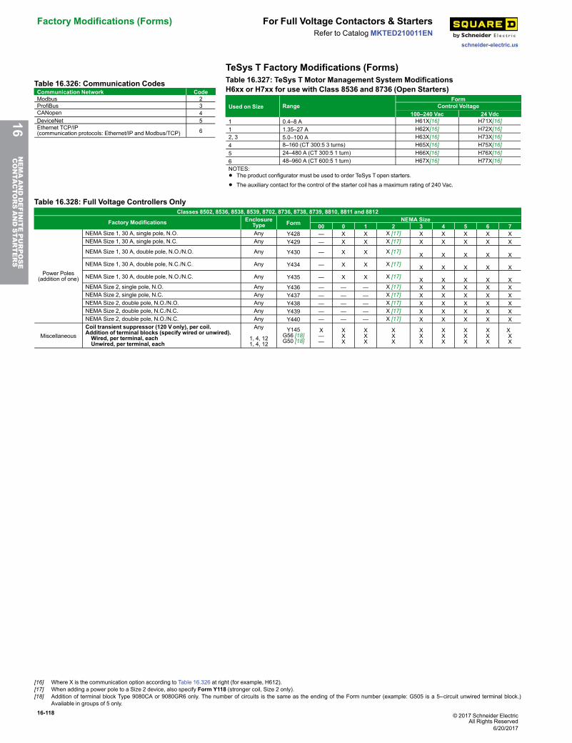
16-118 © 2017 Schneider ElectricAll Rights Reserved
Factory Modifications (Forms) For Full Voltage Contactors & Starters
schneider-electric.us
Refer to CatalogMKTED210011EN
TeSys T Factory Modifications (Forms)Table 16.326: Communication CodesCommunication Network CodeModbus 2ProfiBus 3CANopen 4DeviceNet 5Ethernet TCP/IP(communication protocols: Ethernet/IP and Modbus/TCP) 6
Table 16.327: TeSys T Motor Management System ModificationsH6xx or H7xx for use with Class 8536 and 8736 (Open Starters)
Used on Size RangeForm
Control Voltage100–240 Vac 24 Vdc
1 0.4–8 A H61X[16] H71X[16]1 1.35–27 A H62X[16] H72X[16]2, 3 5.0–100 A H63X[16] H73X[16]4 8–160 (CT 300:5 3 turns) H65X[16] H75X[16]5 24–480 A (CT 300:5 1 turn) H66X[16] H76X[16]6 48–960 A (CT 600:5 1 turn) H67X[16] H77X[16]NOTES:• The product configurator must be used to order TeSys Topen starters.
• The auxiliary contact for the control of the starter coil has a maximum rating of 240 Vac.
Table 16.328: Full Voltage Controllers OnlyClasses 8502, 8536, 8538, 8539, 8702, 8736, 8738, 8739, 8810, 8811 and 8812
Factory Modifications EnclosureType Form NEMA Size
00 0 1 2 3 4 5 6 7
Power Poles(addition of one)
NEMA Size 1, 30 A, single pole, N.O. Any Y428 — X X X [17] X X X X XNEMA Size 1, 30 A, single pole, N.C. Any Y429 — X X X [17] X X X X X
NEMA Size 1, 30 A, double pole, N.O./N.O. Any Y430 — X X X [17] X X X X XNEMA Size 1, 30 A, double pole, N.C./N.C. Any Y434 — X X X [17] X X X X XNEMA Size 1, 30 A, double pole, N.O./N.C. Any Y435 — X X X [17] X X X X XNEMA Size 2, single pole, N.O. Any Y436 — — — X [17] X X X X XNEMA Size 2, single pole, N.C. Any Y437 — — — X [17] X X X X XNEMA Size 2, double pole, N.O./N.O. Any Y438 — — — X [17] X X X X XNEMA Size 2, double pole, N.C./N.C. Any Y439 — — — X [17] X X X X XNEMA Size 2, double pole, N.O./N.C. Any Y440 — — — X [17] X X X X X
MiscellaneousCoil transient suppressor (120 Vonly), per coil.Addition of terminal blocks (specify wired or unwired).Wired, per terminal, eachUnwired, per terminal, each
Any
1, 4, 121, 4, 12
Y145G56 [18]G50 [18]
X——
XXX
XXX
XXX
XXX
XXX
XXX
XXX
X XX
16NEMAANDDEFINITEPURPOSE
CONTA
CTORSANDSTA
RTERS
[16] Where X is the communication option according to Table 16.326 at right (for example, H612).[17] When adding a power pole to a Size 2 device, also specify Form Y118 (stronger coil, Size 2 only).[18] Addition of terminal block Type 9080CA or 9080GR6 only. The number of circuits is the same as the ending of the Form number (example: G505 is a 5–circuit unwired terminal block.)
Available in groups of 5 only.
6/20/2017
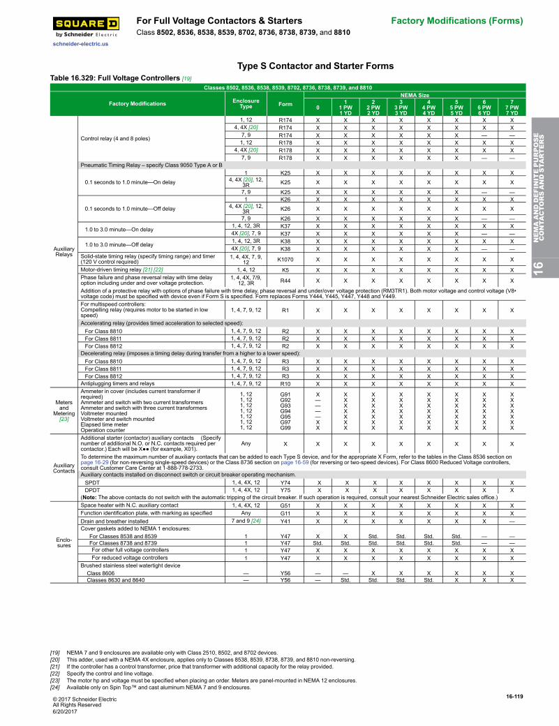
© 2017 Schneider ElectricAll Rights Reserved
16-119
schneider-electric.us
For Full Voltage Contactors & Starters Factory Modifications (Forms)Class 8502, 8536, 8538, 8539, 8702, 8736, 8738, 8739, and 8810
Type S Contactor and Starter FormsTable 16.329: Full Voltage Controllers [19]
Classes 8502, 8536, 8538, 8539, 8702, 8736, 8738, 8739, and 8810
Factory Modifications EnclosureType Form
NEMA Size
01
1 PW1 YD
22 PW2 YD
33 PW3 YD
44 PW4 YD
55 PW5 YD
66 PW6 YD
77 PW7 YD
AuxiliaryRelays
Control relay (4 and 8 poles)
1, 12 R174 X X X X X X X X4, 4X [20] R174 X X X X X X X X
7, 9 R174 X X X X X X — —1, 12 R178 X X X X X X X X
4, 4X [20] R178 X X X X X X X X7, 9 R178 X X X X X X — —
Pneumatic Timing Relay – specify Class 9050 Type A or B
0.1 seconds to 1.0 minute—On delay
1 K25 X X X X X X X X4, 4X [20], 12,
3R K25 X X X X X X X X
7, 9 K25 X X X X X X — —
0.1 seconds to 1.0 minute—Off delay
1 K26 X X X X X X X X4, 4X [20], 12,
3R K26 X X X X X X X X
7, 9 K26 X X X X X X — —
1.0 to 3.0 minute—On delay 1, 4, 12, 3R K37 X X X X X X X X4X [20], 7, 9 K37 X X X X X X — —
1.0 to 3.0 minute—Off delay 1, 4, 12, 3R K38 X X X X X X X X4X [20], 7, 9 K38 X X X X X X — —
Solid-state timing relay (specify timing range) and timer(120 V control required)
1, 4, 4X, 7, 9,12 K1070 X X X X X X X X
Motor-driven timing relay [21] [22] 1, 4, 12 K5 X X X X X X X XPhase failure and phase reversal relay with time delayoption including under and over voltage protection.
1, 4, 4X, 7/9,12, 3R R44 X X X X X X X X
Addition of a protective relay with options of phase failure with time delay, phase reversal and under/over voltage protection (RM3TR1). Both motor voltage and control voltage (V8•voltage code) must be specified with device even if Form S is specified. Form replaces Forms Y444, Y445, Y447, Y448 and Y449.For multispeed controllers:Compelling relay (requires motor to be started in lowspeed)
1, 4, 7, 9, 12 R1 X X X X X X X X
Accelerating relay (provides timed acceleration to selected speed):For Class 8810 1, 4, 7, 9, 12 R2 X X X X X X X XFor Class 8811 1, 4, 7, 9, 12 R2 X X X X X X X XFor Class 8812 1, 4, 7, 9, 12 R2 X X X X X X X X
Decelerating relay (imposes a timing delay during transfer from a higher to a lower speed):For Class 8810 1, 4, 7, 9, 12 R3 X X X X X X X XFor Class 8811 1, 4, 7, 9, 12 R3 X X X X X X X XFor Class 8812 1, 4, 7, 9, 12 R3 X X X X X X X X
Antiplugging timers and relays 1, 4, 7, 9, 12 R10 X X X X X X X X
Metersand
Metering[23]
Ammeter in cover (includes current transformer ifrequired)Ammeter and switch with two current transformersAmmeter and switch with three current transformersVoltmeter mountedVoltmeter and switch mountedElapsed time meterOperation counter
1, 121, 121, 121, 121, 121, 121, 12
G91G92G93G94G95G97G99
X————XX
XXXXXXX
XXXXXXX
XXXXXXX
XXXXXXX
XXXXXXX
XXXXXXX
XXXXXXX
AuxiliaryContacts
Additional starter (contactor) auxiliary contacts (Specifynumber of additional N.O. or N.C. contacts required percontactor.) Each will be X●● (for example, X01).
Any X X X X X X X X X
To determine the maximum number of auxiliary contacts that can be added to each Type S device, and for the appropriate X Form, refer to the tables in the Class 8536 section onpage 16-29 (for non-reversing single-speed devices) or the Class 8736 section on page 16-59 (for reversing or two-speed devices). For Class 8600 Reduced Voltage controllers,consult Customer Care Center at 1-888-778-2733.Auxiliary contacts installed on disconnect switch or circuit breaker operating mechanism.SPDT 1, 4, 4X, 12 Y74 X X X X X X X XDPDT 1, 4, 4X, 12 Y75 X X X X X X X X
(Note: The above contacts do not switch with the automatic tripping of the circuit breaker. If such operation is required, consult your nearest Schneider Electric sales office.)
Enclo-sures
Space heater with N.C. auxiliary contact 1, 4, 4X, 12 G51 X X X X X X X XFunction identification plate, with marking as specified Any G11 X X X X X X X XDrain and breather installed 7 and 9 [24] Y41 X X X X X X X —Cover gaskets added to NEMA 1 enclosures: For Classes 8538 and 8539 1 Y47 X X Std. Std. Std. Std. — — For Classes 8738 and 8739 1 Y47 Std. Std. Std. Std. Std. Std. — —For other full voltage controllers 1 Y47 X X X X X X X XFor reduced voltage controllers 1 Y47 X X X X X X X X
Brushed stainless steel watertight device Class 8606 — Y56 — — X X X X X X Classes 8630 and 8640 — Y56 — Std. Std. Std. Std. X X X
16NEMAANDDEFINITEPURPOSE
CONTA
CTORSANDSTA
RTERS
[19] NEMA 7 and 9 enclosures are available only with Class 2510, 8502, and 8702 devices.[20] This adder, used with a NEMA 4X enclosure, applies only to Classes 8538, 8539, 8738, 8739, and 8810 non-reversing.[21] If the controller has a control transformer, price that transformer with additional capacity for the relay provided.[22] Specify the control and line voltage.[23] The motor hp and voltage must be specified when placing an order. Meters are panel-mounted in NEMA 12 enclosures.[24] Available only on Spin Top™ and cast aluminum NEMA 7 and 9 enclosures.
6/20/2017
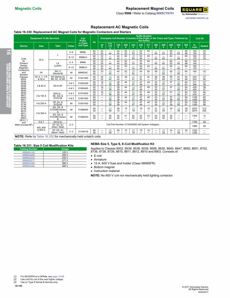
16-120 © 2017 Schneider ElectricAll Rights Reserved
Magnetic Coils Replacement Magnet Coils
schneider-electric.us
Class 9998 / Refer to Catalog 9065CT9701
Replacement AC Magnetic CoilsTable 16.330: Replacement AC Magnet Coils for Magnetic Contactors and Starters
Equipment To Be Serviced CoilPrefix,or Classand Type
Hz
Suffix Number(Complete Coil Number Consists of the Prefix or the Class and Type, Followed by
the Suffix)Coil VA
Device Size Type Poles 24V
110-115V
120V
208V
220V
240V
277V
380V
440V
480V
550V
600V
In-rush Sealed
Coilsfor
PresentDesignMagneticContactors
andStartersClasses8502,8536,8538,8539,8606,8630,8640,8647,8650,8651,8702,8736,8738,8739,8810,8811,8812,8903,8910 [1]and
8940 (except NP)
30 A
L2–6 9998L 60
502324
—44
4445
5052
[2]53
5354
55—
—60
—62
6263
—65
6566
150140
3030
8–12 9998LH 6050
2324
—44
4445
50—
[2]53
5354
55—
—60
—62
62—
—65
65—
180170
3535
LX(Latch)
2–4 9998L 6050
2324
—44
4445
5052
—53
5354
55—
—60
—62
6263
—65
6566
150140
——
6–12 9998LH 6050
2324
—44
4445
50—
—53
5354
55—
—60
—62
62—
—65
65—
180170
——
00 SA [3](Series B) All 9998SAC 60
5023—
[2]45
45—
52—
[2]54
54—
55—
59—
[2]62
62—
[2]65
65—
165—
33—
00, 0, 1, 1-P,& 30 A
SA (Series A)SB, SC, & SM All 31041400 60
502022
[2]42
4243
48—
[2]51
5153
52—
5657
5860
60[2]
6162
6264
245232
2726
2 & 60 A SD & SP2 & 3 31063409 60
501617
[2]38
3839
44—
[2]47
4748
49—
5354
[2]57
57—
[2]60
6061
311296
3736
4 & 5 31063400 6050
1617
[2]38
3839
44—
[2]47
4748
49—
5354
[2]57
57—
[2]60
6061
438429
3837
3 & 100 ADPA12_,SE, SQ, &SYD138
2 & 3 31074400 6050
1617
[2]38
3839
44—
[2]47
4748
49—
5354
[2]57
57—
[2]60
6061
700678
4647
4 & 5 31091400 6050
——
[2]38
3839
44—
[2]47
4748
49—
5354
[2]57
5758
[2]60
6061
11851260
8589
4 & 200 A SF, SV, &SYD230 All 31091400 60
50——
[2]38
3839
44—
[2]47
4748
49—
5354
[2]57
5758
[2]60
6061
11851260
8589
5 & 300 A
SG, SX, &SYD368 Series
AAll 31096400 60
50——
[2]09
0910
15—
[2]18
18—
19—
2122
[2]24
24—
[2]29
2930
29702970
212250
SG, SX, &SYD368 Series
BAll 31096320 60
50——
5050
5050
51—
5252
5252
53—
5454
5555
5555
——
——
1300—
14—
6 & 7 SH & SJ2–3 Coil Part Number 3110440050 (All System Voltages)
1780 48
400, 600& 800 A
SY, SZ, SJ(Elect. Held) 1960 59
SY, SZ, SJ(Mech. Held) 2–3 31104418 60
50——
[2]09
09—
15—
[2]18
18—
19—
——
[2]24
24—
[2]29
29—
15301250
——
NOTE: Refer to Table 16.332 for mechanically held unlatch coils.
Table 16.331: Size 5 Coil Modification KitsCatalog Number Volage
9998SG120 120 V9998SG208 208 V9998SG240 240 V9998SG277 277 V9998SG380 380 V9998SG480 480 V
NEMA Size 5, Type S, E-Coil Modification KitApplies to Classes 8502, 8536, 8538, 8539, 8606, 8630, 8640, 8647, 8650, 8651, 8702,8736, 8738, 8739, 8810, 8811, 8812, 8910 and 8903. Consists of:• E-coil• Armature• 15 A, 600 V fuse and holder (Class 9999SFR)• Bottom magnet• Instruction materialNOTE: No 600 V coil nor mechanically held lighting contactor.
16NEMAANDDEFINITEPURPOSE
CONTA
CTORSANDSTA
RTERS
[1] For 8910DPA1● to DPA9●, see page 16-88.[2] Use a 60 Hz coil of the next higher voltage.[3] Use on Type S Series B devices only.
6/20/2017
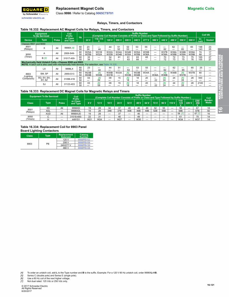
© 2017 Schneider ElectricAll Rights Reserved
16-121
schneider-electric.us
Replacement Magnet Coils Magnetic CoilsClass 9998 / Refer to Catalog 9065CT9701
Relays, Timers, and Contactors
Table 16.332: Replacement AC Magnet Coils for Relays, Timers, and ContactorsEquipment
To Be ServicedCoilPrefixor Classand Type
HzSuffix Number
(Complete Coil Number Consists of Prefix or Class and Type Followed by Suffix Number) Coil VA
Device Type Poles 24 V 110–115V 120 V 208 V 220 V 240 V 277 V 380 V 440 V 480 V 550 V 600 V In-
rush SealedClasses 8501 and 9050
8501(Relays) X All 9998X [4] 60
502324
—44
44—
5152
5253
53—
55—
——
—62
62—
—65
65—
148143
2325
9050(Timer)
A All 2959-S49- 6050
W25AW25B
W31BW32A
W32AW32B
W34AW34B
W34BW35A
W35AW35B
W35BW36A
——
W37BW38A
W38AW38B
W38BW39A
W39AW39B
7468
1717
B [5] All 31017-400- 6050
3334
——
5455
61—
6163
6364
65—
——
7072
7273
7375
7576
165155
2727
Mechanically Held Unlatch Coils—Classes 8508 and 8903NOTE: A latch coil is also used with mechanically held devices. For selection, see Table 16.330.
8903(Lighting
Contactors)
LX All 9998LX 6050
23—
—44
44—
51—
—53
53—
55—
——
—62
62—
—65
65—
25—
——
SM, SP All 2959-S13 6050
W23BW24B
[6]W30B
W30BW31B
W33A—
[6]W33B
W33BW34B
W34A—
—W36A
[6]W36B
W36B—
[6]W37B
W37B—
80—
——
SQ, SV, SX,SY, SZ All 31096-416 60
5003—
[6]09
09—
15—
[6]18
18—
20—
—22
[6]24
24—
[6]28
28—
550—
——
SJ All 31123-403 6050
03—
[6]09
09—
15—
[6]18
18—
20—
—22
[6]24
24—
[6]28
28—
2100—
——
Table 16.333: Replacement DC Magnet Coils for Magnetic Relays and TimersEquipment To Be Serviced Coil
Prefixor Classand Type
Suffix Number(Complete Coil Number Consists of Prefix or Class and Type Followed by Suffix Number.) Coil
BurdenWattsClass Type Poles 6 V 12 V 18 V 24 V 32 V 48 V 64 V 72 V 90 V 110 V
115/125V
220 V230/250V
8501(Relays)
XD All 9998XD 19 28 34 37 40 46 49 52 55 — 58 — 67 18XDL — 9998XDL 19 28 34B 37B 40B 46B 49B 52B 55B — 58B — 67B 50XUD All 9998XUD 19 28 — 37 — 46 — — — — 58 [7] — 67 [7] 16
9050(Timers)
C — 31018-400- 22 31 — 40 — 49 — — — — 61 — 70 14H — 4491S1 W21 W24 — W27 — W30 — — — — W34 — W37 14
Table 16.334: Replacement Coil for 8903 PanelBoard Lighting Contactors
Class Type ReplacementSolenoid
CatalogNumber
8903 PB
120 V 9998PBV02208 V 9998PBV08
240/277 V 9998PBV39480 V 9998PBV28
16NEMAANDDEFINITEPURPOSE
CONTA
CTORSANDSTA
RTERS
[4] To order an unlatch coil, add L to the Type number and B to the suffix. Example: For a 120 V 60 Hz unlatch coil, order 9998XL44B.[5] Series C (double pole) and Series E (single pole).[6] Use a 60 Hz coil of the next higher voltage.[7] Not dual rated. 125 Vdc or 250 Vdc only.
6/20/2017
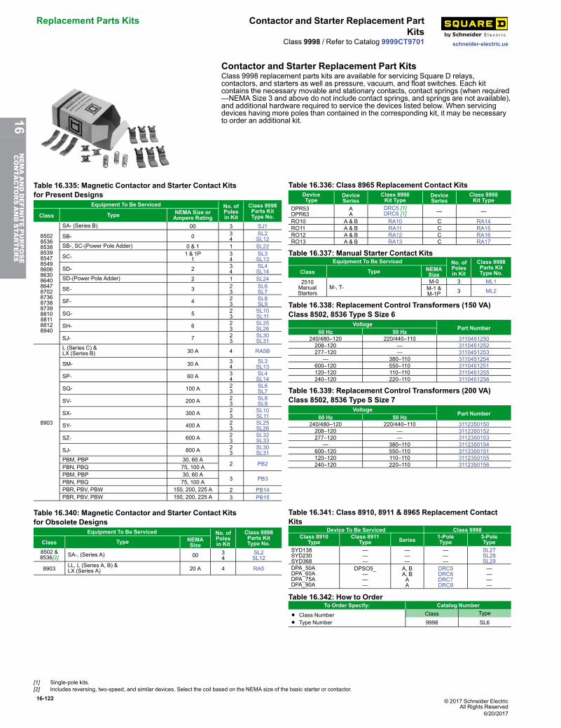
16-122 © 2017 Schneider ElectricAll Rights Reserved
Replacement Parts Kits Contactor and Starter Replacement PartKits
schneider-electric.usClass 9998 / Refer to Catalog 9999CT9701
Contactor and Starter Replacement Part KitsClass 9998 replacement parts kits are available for servicing Square D relays,contactors, and starters as well as pressure, vacuum, and float switches. Each kitcontains the necessary movable and stationary contacts, contact springs (when required—NEMA Size 3 and above do not include contact springs, and springs are not available),and additional hardware required to service the devices listed below. When servicingdevices having more poles than contained in the corresponding kit, it may be necessaryto order an additional kit.
Table 16.335: Magnetic Contactor and Starter Contact Kitsfor Present Designs
Equipment To Be Serviced No. ofPolesin Kit
Class 9998Parts KitType No.Class Type NEMA Size or
Ampere Rating
850285368538853985478549860686308640864787028736873887398810881188128940
SA- (Series B) 00 3 SJ1
SB- 0 34
SL2SL12
SB-, SC-(Power Pole Adder) 0 & 1 1 SL22
SC- 1 & 1P1
34
SL3SL13
SD- 2 34
SL4SL14
SD-(Power Pole Adder) 2 1 SL24
SE- 3 23
SL6SL7
SF- 4 23
SL8SL9
SG- 5 23
SL10SL11
SH- 6 23
SL25SL26
SJ- 7 23
SL30SL31
8903
L (Series C) &LX (Series B) 30 A 4 RA5B
SM- 30 A 34
SL3SL13
SP- 60 A 34
SL4SL14
SQ- 100 A 23
SL6SL7
SV- 200 A 23
SL8SL9
SX- 300 A 23
SL10SL11
SY- 400 A 23
SL25SL26
SZ- 600 A 23
SL32SL33
SJ- 800 A 23
SL30SL31
PBM, PBP 30, 60 A2 PB2PBN, PBQ 75, 100 A
PBM, PBP 30, 60 A3 PB3PBN, PBQ 75, 100 A
PBR, PBV, PBW 150, 200, 225 A 2 PB14PBR, PBV, PBW 150, 200, 225 A 3 PB15
Table 16.336: Class 8965 Replacement Contact KitsDeviceType
DeviceSeries
Class 9998Kit Type
DeviceSeries
Class 9998Kit Type
DPR53DPR63
AA
DRC5 [1]DRC6 [1] — —
RO10 A & B RA10 C RA14RO11 A & B RA11 C RA15RO12 A & B RA12 C RA16RO13 A & B RA13 C RA17
Table 16.337: Manual Starter Contact KitsEquipment To Be Serviced No. of
Polesin Kit
Class 9998Parts KitType No.Class Type NEMA
Size2510ManualStarters
M-, T-M-0 3 ML1M-1 &M-1P 3 ML2
Table 16.338: Replacement Control Transformers (150 VA)Class 8502, 8536 Type S Size 6
VoltagePart Number
60 Hz 50 Hz240/480–120 220/440–110 3110451250208–120 — 3110451252277–120 — 3110451253
— 380–110 3110451254600–120 550–110 3110451251120–120 110–110 3110451255240–120 220–110 3110451256
Table 16.339: Replacement Control Transformers (200 VA)Class 8502, 8536 Type S Size 7
VoltagePart Number
60 Hz 50 Hz240/480–120 220/440–110 3112350150208–120 — 3112350152277–120 — 3112350153
— 380–110 3112350154600–120 550–110 3112350151120–120 110–110 3112350155240–120 220–110 3112350156
Table 16.340: Magnetic Contactor and Starter Contact Kitsfor Obsolete Designs
Equipment To Be Serviced No. ofPolesin Kit
Class 9998Parts KitType No.Class Type NEMA
Size8502 &8536[2] SA-, (Series A) 00 3
4SL2SL12
8903 LL, L (Series A, B) &LX (Series A) 20 A 4 RA5
Table 16.341: Class 8910, 8911 & 8965 Replacement ContactKits
Device To Be Serviced Class 99981-PoleType
3-PoleType
Class 8910Type
Class 8911Type Series
SYD138SYD230SYD368
———
———
———
SL27SL28SL29
DPA_50ADPA_60ADPA_75ADPA_90A
DPSO5_———
A, BA, BAA
DRC5DRC6DRC7DRC9
————
Table 16.342: How to OrderTo Order Specify: Catalog Number
• Class Number• Type Number
Class Type
9998 SL6
[1] Single-pole kits.[2] Includes reversing, two-speed, and similar devices. Select the coil based on the NEMA size of the basic starter or contactor.
6/20/2017
16NEMAANDDEFINITEPURPOSE
CONTA
CTORSANDSTA
RTERS
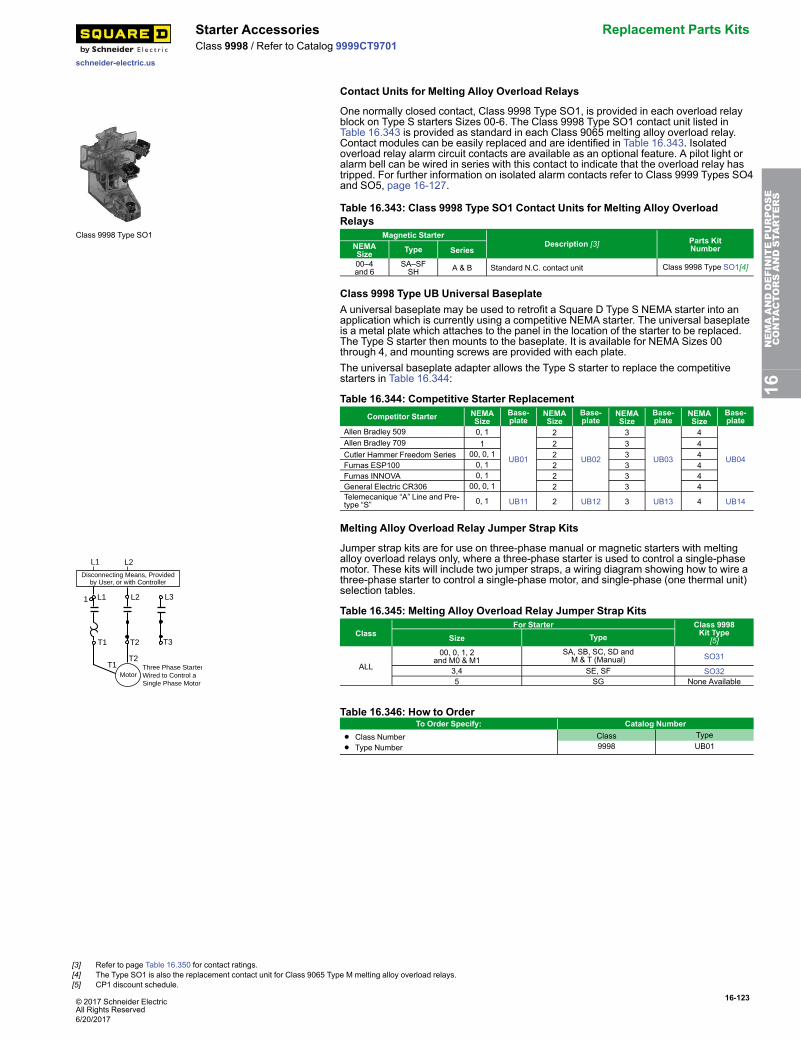
© 2017 Schneider ElectricAll Rights Reserved
16-123
schneider-electric.us
Starter Accessories Replacement Parts KitsClass 9998 / Refer to Catalog 9999CT9701
Contact Units for Melting Alloy Overload Relays
Class 9998 Type SO1
One normally closed contact, Class 9998 Type SO1, is provided in each overload relayblock on Type S starters Sizes 00-6. The Class 9998 Type SO1 contact unit listed inTable 16.343 is provided as standard in each Class 9065 melting alloy overload relay.Contact modules can be easily replaced and are identified in Table 16.343. Isolatedoverload relay alarm circuit contacts are available as an optional feature. A pilot light oralarm bell can be wired in series with this contact to indicate that the overload relay hastripped. For further information on isolated alarm contacts refer to Class 9999 Types SO4and SO5, page 16-127.
Table 16.343: Class 9998 Type SO1 Contact Units for Melting Alloy OverloadRelays
Magnetic StarterDescription [3] Parts Kit
NumberNEMASize Type Series00–4and 6
SA–SFSH A & B Standard N.C. contact unit Class 9998 Type SO1[4]
Class 9998 Type UB Universal BaseplateA universal baseplate may be used to retrofit a Square D Type S NEMA starter into anapplication which is currently using a competitive NEMA starter. The universal baseplateis a metal plate which attaches to the panel in the location of the starter to be replaced.The Type S starter then mounts to the baseplate. It is available for NEMA Sizes 00through 4, and mounting screws are provided with each plate.The universal baseplate adapter allows the Type S starter to replace the competitivestarters in Table 16.344:
Table 16.344: Competitive Starter ReplacementCompetitor Starter NEMA
SizeBase-plate
NEMASize
Base-plate
NEMASize
Base-plate
NEMASize
Base-plate
Allen Bradley 509 0, 1
UB01
2
UB02
3
UB03
4
UB04
Allen Bradley 709 1 2 3 4Cutler Hammer Freedom Series 00, 0, 1 2 3 4Furnas ESP100 0, 1 2 3 4Furnas INNOVA 0, 1 2 3 4General Electric CR306 00, 0, 1 2 3 4Telemecanique “A” Line and Pre-type “S” 0, 1 UB11 2 UB12 3 UB13 4 UB14
Melting Alloy Overload Relay Jumper Strap Kits
L1 L2
1 L1 L2 L3
T1
T1
T2
T2
T3
MotorThree Phase StarterWired to Control aSingle Phase Motor
Disconnecting Means, Providedby User, or with Controller
Jumper strap kits are for use on three-phase manual or magnetic starters with meltingalloy overload relays only, where a three-phase starter is used to control a single-phasemotor. These kits will include two jumper straps, a wiring diagram showing how to wire athree-phase starter to control a single-phase motor, and single-phase (one thermal unit)selection tables.
Table 16.345: Melting Alloy Overload Relay Jumper Strap Kits
ClassFor Starter Class 9998
Kit Type[5]Size Type
ALL
00, 0, 1, 2and M0 & M1
SA, SB, SC, SD andM & T (Manual) SO31
3,4 SE, SF SO325 SG None Available
Table 16.346: How to OrderTo Order Specify: Catalog Number
• Class Number
• Type NumberClass Type9998 UB01
16NEMAANDDEFINITEPURPOSE
CONTA
CTORSANDSTA
RTERS
[3] Refer to page Table 16.350 for contact ratings.[4] The Type SO1 is also the replacement contact unit for Class 9065 Type M melting alloy overload relays.[5] CP1 discount schedule.
6/20/2017
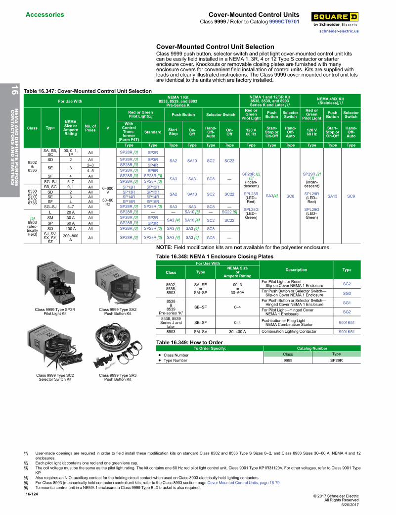
16-124 © 2017 Schneider ElectricAll Rights Reserved
Accessories Cover-Mounted Control Units
schneider-electric.us
Class 9999 / Refer to Catalog 9999CT9701
Cover-Mounted Control Unit SelectionClass 9999 push button, selector switch and pilot light cover-mounted control unit kitscan be easily field installed in a NEMA 1, 3R, 4 or 12 Type S contactor or starterenclosure cover. Knockouts or removable closing plates are furnished with manyenclosure covers for convenient field installation of control units. Kits are supplied withleads and clearly illustrated instructions. The Class 9999 cover mounted control unit kitsare identical to the units which are factory installed.
Table 16.347: Cover-Mounted Control Unit Selection
For Use WithNEMA 1 Kit
8538, 8539, and 8903Pre-Series K
NEMA 1 and 12/3R Kit8538, 8539, and 8903Series K and Later [1]
NEMA 4/4X Kit(Stainless)[1]
Class TypeNEMASize orAmpereRating
No. ofPoles V
Red or GreenPilot Light[2] Push Button Selector Switch
Red orGreen
Pilot LightPushButton
SelectorSwitch
Red orGreen
Pilot LightPushButton
SelectorSwitch
WithControlTrans-former
(Form F4T)
Standard Start-Stop
On-Off
Hand-Off-Auto
On-Off
120 V60 Hz
Start-Stop orOn-Off
Hand-Off-Auto
120 V60 Hz
Start-Stop orOn-Off
Hand-Off-Auto
Type Type Type Type Type Type Type Type Type Type Type Type
8502&
8536
SA, SB,SC
00, 0, 1,1P All
6–600V
50–60Hz
SP28R [3] SP2R
SA2 SA10 SC2 SC22
SP28R [2][3]
(incan-descent)
SPL28R(LED–Red)
SPL28G(LED–Green)
SA3[4] SC8
SP29R [2][3]
(incan-descent)
SPL29R(LED–Red)
SPL29G(LED–Green)
SA13 SC9
SD 2 All SP28R [3] SP3R
SE 32–3 SP28R [3] SP4R4–5 SP28R [3] SP5R
SF 4 All SP28R [3] SP28R [3]SA3 SA3 SC8 —
SG–SJ 5–7 All SP28R [3] SP28R [3]
8538853987028736
SB, SC 0, 1 All SP12R SP12R
SA2 SA10 SC2 SC22SD 2 All SP13R SP13RSE 3 All SP14R SP14RSF 4 All SP15R SP15R
SG–SJ 5–7 All SP28R [3] SP28R [3] SA3 SA3 SC8 —
[5]8903(Elec-tricallyHeld)
L 20 A All SP28R [3] — — SA10 [6] — SC22 [6]SM 30 A All SP28R [3] SP2R SA2 [4] SA10 [4] SC2 SC22SP 60 A All SP28R [3] SP3RSQ 100 A All SP28R [3] SP28R [3] SA3 [4] SA3 [4] SC8 —
SJ, SV,SX, SY,SZ
200–800A All SP28R [3] SP28R [3] SA3 [4] SA3 [4] SC8 —
NOTE: Field modification kits are not available for the polyester enclosures.
Class 9999 Type SP2RPilot Light Kit
Class 9999 Type SA2Push Button Kit
Class 9999 Type SC2Selector Switch Kit
Class 9999 Type SA3Push Button Kit
Table 16.348: NEMA 1 Enclosure Closing PlatesFor Use With
Description TypeClass TypeNEMA Size
orAmpere Rating
8502,8536,8903
SA–SEor
SM–SP
00–3or
30–60A
For Pilot Light or Reset—Slip-on Cover NEMA 1 Enclosure SG2
For Push Button or Selector Switch—Slip-on Cover NEMA 1 Enclosure SG3
8538&
8539Pre-series “K”
SB–SF 0–4
For Push Button or Selector Switch—Hinged Cover NEMA 1 Enclosure SG1
For Pilot Light—Hinged CoverNEMA 1 Enclosure SG2
8538, 8539Series J and
laterSB–SF 0–4 Pushbutton or Pilog Light
NEMA Combination Starter 9001K51
8903 SM–SV 30–400 A Combination Lighting Contactor 9001K51
Table 16.349: How to OrderTo Order Specify: Catalog Number
• Class Number
• Type NumberClass Type
9999 SP29R
16NEMAANDDEFINITEPURPOSE
CONTA
CTORSANDSTA
RTERS
[1] User-made openings are required in order to field install these modification kits on standard Class 8502 and 8536 Type S Sizes 0–2, and Class 8903 Sizes 30–60 A, NEMA 4 and 12enclosures.
[2] Each pilot light kit contains one red and one green lens cap.[3] The coil voltage must be the same as the pilot light rating. The kit contains one 60 Hz red pilot light control unit, Class 9001 Type KP1R31120V. For other voltages, refer to Class 9001 Type
KP.[4] Also requires an N.O. auxiliary contact for the holding circuit contact when used on Class 8903 electrically held lighting contactors.[5] For Class 8903 (mechanically held contactor) control unit kits, refer to the Class 8903 section, page Cover Mounted Control Units, page 16-79.[6] To mount a control unit in a NEMA 1 enclosure, a Class 9999 Type BLX bracket is also required.
6/20/2017
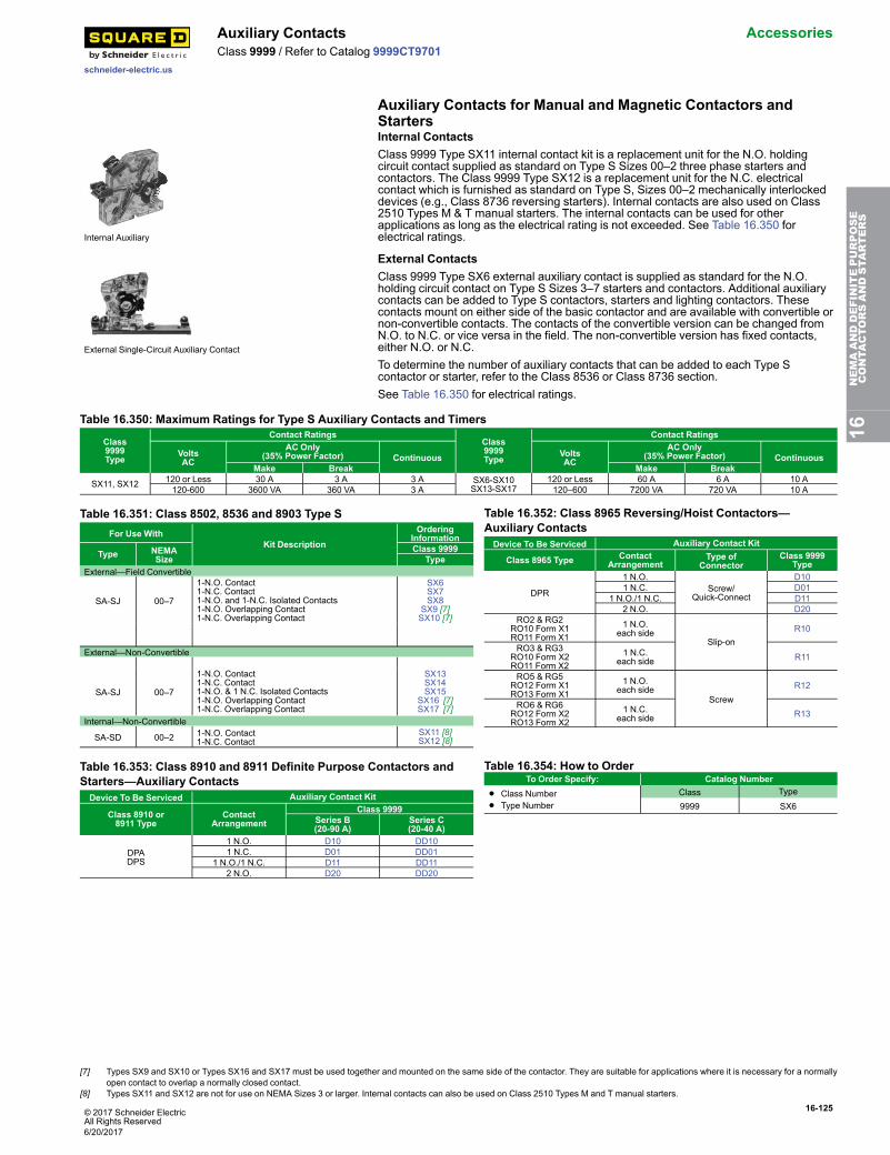
© 2017 Schneider ElectricAll Rights Reserved
16-125
schneider-electric.us
Auxiliary Contacts AccessoriesClass 9999 / Refer to Catalog 9999CT9701
Auxiliary Contacts for Manual and Magnetic Contactors andStarters
Internal Auxiliary
Internal ContactsClass 9999 Type SX11 internal contact kit is a replacement unit for the N.O. holdingcircuit contact supplied as standard on Type S Sizes 00–2 three phase starters andcontactors. The Class 9999 Type SX12 is a replacement unit for the N.C. electricalcontact which is furnished as standard on Type S, Sizes 00–2 mechanically interlockeddevices (e.g., Class 8736 reversing starters). Internal contacts are also used on Class2510 Types M & T manual starters. The internal contacts can be used for otherapplications as long as the electrical rating is not exceeded. See Table 16.350 forelectrical ratings.
External Single-Circuit Auxiliary Contact
External ContactsClass 9999 Type SX6 external auxiliary contact is supplied as standard for the N.O.holding circuit contact on Type S Sizes 3–7 starters and contactors. Additional auxiliarycontacts can be added to Type S contactors, starters and lighting contactors. Thesecontacts mount on either side of the basic contactor and are available with convertible ornon-convertible contacts. The contacts of the convertible version can be changed fromN.O. to N.C. or vice versa in the field. The non-convertible version has fixed contacts,either N.O. or N.C.To determine the number of auxiliary contacts that can be added to each Type Scontactor or starter, refer to the Class 8536 or Class 8736 section.See Table 16.350 for electrical ratings.
Table 16.350: Maximum Ratings for Type S Auxiliary Contacts and Timers
Class9999Type
Contact RatingsClass9999Type
Contact Ratings
VoltsAC
AC Only(35% Power Factor) Continuous Volts
ACAC Only
(35% Power Factor) ContinuousMake Break Make Break
SX11, SX12 120 or Less 30 A 3 A 3 A SX6-SX10SX13-SX17
120 or Less 60 A 6 A 10 A120-600 3600 VA 360 VA 3 A 120–600 7200 VA 720 VA 10 A
Table 16.351: Class 8502, 8536 and 8903 Type SFor Use With
Kit DescriptionOrdering
Information
Type NEMASize
Class 9999Type
External—Field Convertible
SA-SJ 00–7
1-N.O. Contact1-N.C. Contact1-N.O. and 1-N.C. Isolated Contacts1-N.O. Overlapping Contact1-N.C. Overlapping Contact
SX6SX7SX8
SX9 [7]SX10 [7]
External—Non-Convertible
SA-SJ 00–7
1-N.O. Contact1-N.C. Contact1-N.O. & 1 N.C. Isolated Contacts1-N.O. Overlapping Contact1-N.C. Overlapping Contact
SX13SX14SX15
SX16 [7]SX17 [7]
Internal—Non-Convertible
SA-SD 00–2 1-N.O. Contact1-N.C. Contact
SX11 [8]SX12 [8]
Table 16.352: Class 8965 Reversing/Hoist Contactors—Auxiliary ContactsDevice To Be Serviced Auxiliary Contact Kit
Class 8965 Type ContactArrangement
Type ofConnector
Class 9999Type
DPR
1 N.O.Screw/
Quick-Connect
D101 N.C. D01
1 N.O./1 N.C. D112 N.O. D20
RO2 & RG2RO10 Form X1RO11 Form X1
1 N.O.each side
Slip-onR10
RO3 & RG3RO10 Form X2RO11 Form X2
1 N.C.each side R11
RO5 & RG5RO12 Form X1RO13 Form X1
1 N.O.each side
ScrewR12
RO6 & RG6RO12 Form X2RO13 Form X2
1 N.C.each side R13
Table 16.353: Class 8910 and 8911 Definite Purpose Contactors andStarters—Auxiliary ContactsDevice To Be Serviced Auxiliary Contact Kit
Class 8910 or8911 Type
ContactArrangement
Class 9999Series B(20-90 A)
Series C(20-40 A)
DPADPS
1 N.O. D10 DD101 N.C. D01 DD01
1 N.O./1 N.C. D11 DD112 N.O. D20 DD20
Table 16.354: How to OrderTo Order Specify: Catalog Number
• Class Number
• Type NumberClass Type
9999 SX6
16NEMAANDDEFINITEPURPOSE
CONTA
CTORSANDSTA
RTERS
[7] Types SX9 and SX10 or Types SX16 and SX17 must be used together and mounted on the same side of the contactor. They are suitable for applications where it is necessary for a normallyopen contact to overlap a normally closed contact.
[8] Types SX11 and SX12 are not for use on NEMA Sizes 3 or larger. Internal contacts can also be used on Class 2510 Types M and T manual starters.
6/20/2017
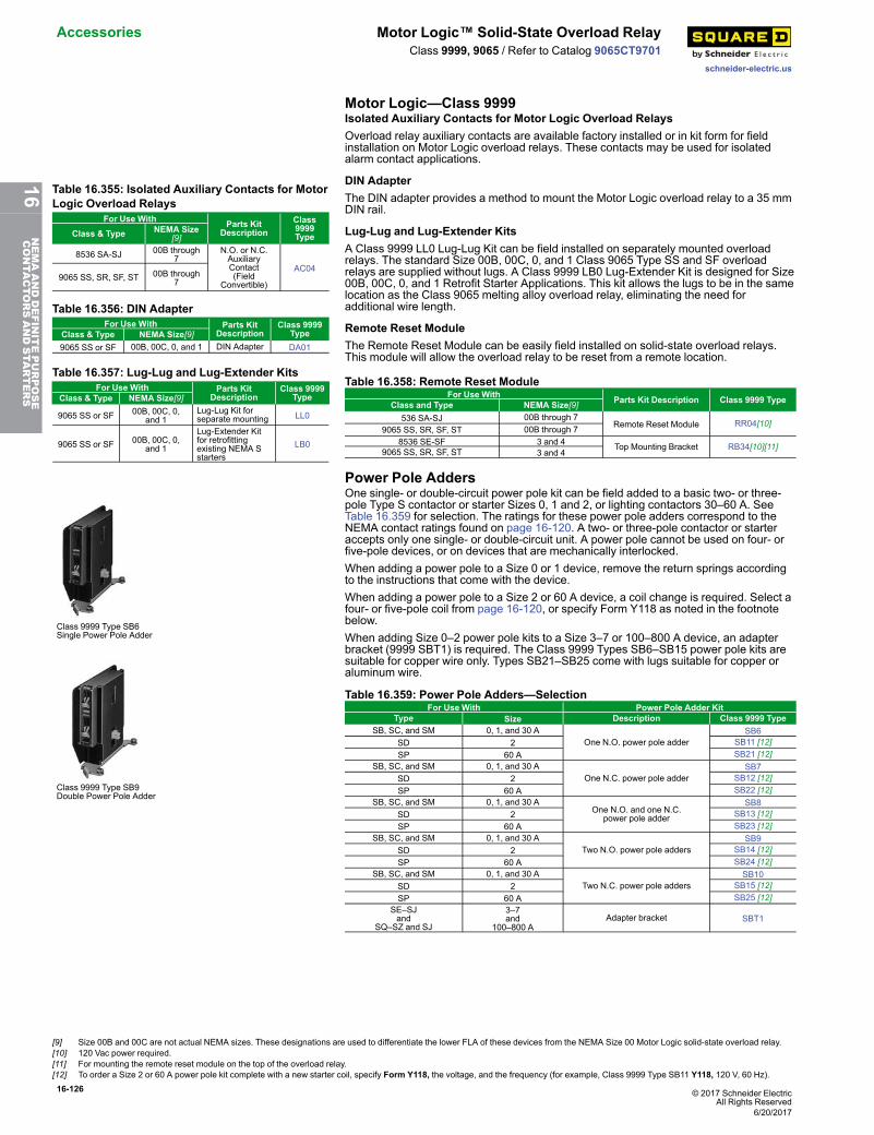
16-126 © 2017 Schneider ElectricAll Rights Reserved
Accessories Motor Logic™ Solid-State Overload Relay
schneider-electric.us
Class 9999, 9065 / Refer to Catalog 9065CT9701
Motor Logic—Class 9999Isolated Auxiliary Contacts for Motor Logic Overload RelaysOverload relay auxiliary contacts are available factory installed or in kit form for fieldinstallation on Motor Logic overload relays. These contacts may be used for isolatedalarm contact applications.
Table 16.355: Isolated Auxiliary Contacts for MotorLogic Overload Relays
For Use With Parts KitDescription
Class9999TypeClass & Type NEMA Size
[9]
8536 SA-SJ 00B through7
N.O. or N.C.AuxiliaryContact(Field
Convertible)
AC049065 SS, SR, SF, ST 00B through
7
DIN AdapterThe DIN adapter provides a method to mount the Motor Logic overload relay to a 35 mmDIN rail.
Table 16.356: DIN AdapterFor Use With Parts Kit
DescriptionClass 9999
TypeClass & Type NEMA Size[9]9065 SS or SF 00B, 00C, 0, and 1 DIN Adapter DA01
Lug-Lug and Lug-Extender KitsA Class 9999 LL0 Lug-Lug Kit can be field installed on separately mounted overloadrelays. The standard Size 00B, 00C, 0, and 1 Class 9065 Type SS and SF overloadrelays are supplied without lugs. A Class 9999 LB0 Lug-Extender Kit is designed for Size00B, 00C, 0, and 1 Retrofit Starter Applications. This kit allows the lugs to be in the samelocation as the Class 9065 melting alloy overload relay, eliminating the need foradditional wire length.
Table 16.357: Lug-Lug and Lug-Extender KitsFor Use With Parts Kit
DescriptionClass 9999
TypeClass & Type NEMA Size[9]
9065 SS or SF 00B, 00C, 0,and 1
Lug-Lug Kit forseparate mounting LL0
9065 SS or SF 00B, 00C, 0,and 1
Lug-Extender Kitfor retrofittingexisting NEMA Sstarters
LB0
Remote Reset ModuleThe Remote Reset Module can be easily field installed on solid-state overload relays.This module will allow the overload relay to be reset from a remote location.
Table 16.358: Remote Reset ModuleFor Use With Parts Kit Description Class 9999 TypeClass and Type NEMA Size[9]
536 SA-SJ 00B through 7Remote Reset Module RR04[10]
9065 SS, SR, SF, ST 00B through 78536 SE-SF 3 and 4 Top Mounting Bracket RB34[10][11]9065 SS, SR, SF, ST 3 and 4
Power Pole Adders
Class 9999 Type SB6Single Power Pole Adder
Class 9999 Type SB9Double Power Pole Adder
One single- or double-circuit power pole kit can be field added to a basic two- or three-pole Type S contactor or starter Sizes 0, 1 and 2, or lighting contactors 30–60 A. SeeTable 16.359 for selection. The ratings for these power pole adders correspond to theNEMA contact ratings found on page 16-120. A two- or three-pole contactor or starteraccepts only one single- or double-circuit unit. A power pole cannot be used on four- orfive-pole devices, or on devices that are mechanically interlocked.When adding a power pole to a Size 0 or 1 device, remove the return springs accordingto the instructions that come with the device.When adding a power pole to a Size 2 or 60 A device, a coil change is required. Select afour- or five-pole coil from page 16-120, or specify Form Y118 as noted in the footnotebelow.When adding Size 0–2 power pole kits to a Size 3–7 or 100–800 A device, an adapterbracket (9999 SBT1) is required. The Class 9999 Types SB6–SB15 power pole kits aresuitable for copper wire only. Types SB21–SB25 come with lugs suitable for copper oraluminum wire.
Table 16.359: Power Pole Adders—SelectionFor Use With Power Pole Adder Kit
Type Size Description Class 9999 TypeSB, SC, and SM 0, 1, and 30 A
One N.O. power pole adderSB6
SD 2 SB11 [12]SP 60 A SB21 [12]
SB, SC, and SM 0, 1, and 30 AOne N.C. power pole adder
SB7SD 2 SB12 [12]SP 60 A SB22 [12]
SB, SC, and SM 0, 1, and 30 AOne N.O. and one N.C.
power pole adder
SB8SD 2 SB13 [12]SP 60 A SB23 [12]
SB, SC, and SM 0, 1, and 30 ATwo N.O. power pole adders
SB9SD 2 SB14 [12]SP 60 A SB24 [12]
SB, SC, and SM 0, 1, and 30 ATwo N.C. power pole adders
SB10SD 2 SB15 [12]SP 60 A SB25 [12]
SE–SJand
SQ–SZ and SJ
3–7and
100–800 AAdapter bracket SBT1
[9] Size 00B and 00C are not actual NEMA sizes. These designations are used to differentiate the lower FLA of these devices from the NEMA Size 00 Motor Logic solid-state overload relay.[10] 120 Vac power required.[11] For mounting the remote reset module on the top of the overload relay.[12] To order a Size 2 or 60 A power pole kit complete with a new starter coil, specify Form Y118, the voltage, and the frequency (for example, Class 9999 Type SB11 Y118, 120 V, 60 Hz).
6/20/2017
16NEMAANDDEFINITEPURPOSE
CONTA
CTORSANDSTA
RTERS
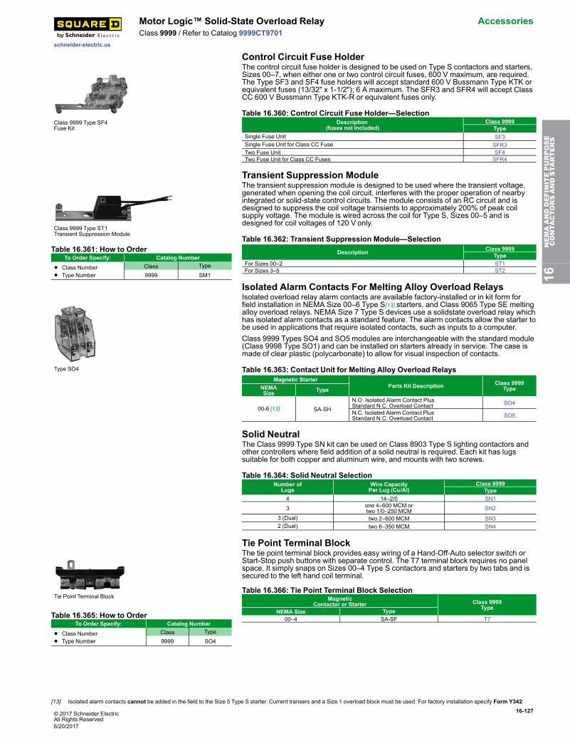
© 2017 Schneider ElectricAll Rights Reserved
16-127
schneider-electric.us
Motor Logic™ Solid-State Overload Relay AccessoriesClass 9999 / Refer to Catalog 9999CT9701
Control Circuit Fuse Holder
Class 9999 Type SF4Fuse Kit
The control circuit fuse holder is designed to be used on Type S contactors and starters,Sizes 00–7, when either one or two control circuit fuses, 600 V maximum, are required.The Type SF3 and SF4 fuse holders will accept standard 600 V Bussmann Type KTK orequivalent fuses (13/32" x 1-1/2"); 6 A maximum. The SFR3 and SFR4 will accept ClassCC 600 V Bussmann Type KTK-R or equivalent fuses only.
Table 16.360: Control Circuit Fuse Holder—SelectionDescription
(fuses not included)Class 9999
TypeSingle Fuse Unit SF3Single Fuse Unit for Class CC Fuse SFR3Two Fuse Unit SF4Two Fuse Unit for Class CC Fuses SFR4
Transient Suppression Module
Class 9999 Type ST1Transient Suppression Module
Table 16.361: How to OrderTo Order Specify: Catalog Number
• Class Number
• Type NumberClass Type
9999 SM1
The transient suppression module is designed to be used where the transient voltage,generated when opening the coil circuit, interferes with the proper operation of nearbyintegrated or solid-state control circuits. The module consists of an RC circuit and isdesigned to suppress the coil voltage transients to approximately 200% of peak coilsupply voltage. The module is wired across the coil for Type S, Sizes 00–5 and isdesigned for coil voltages of 120 V only.
Table 16.362: Transient Suppression Module—SelectionDescription Class 9999
TypeFor Sizes 00–2 ST1For Sizes 3–5 ST2
Isolated Alarm Contacts For Melting Alloy Overload Relays
Type SO4
Isolated overload relay alarm contacts are available factory-installed or in kit form forfield installation in NEMA Size 00–6 Type S[13] starters, and Class 9065 Type SE meltingalloy overload relays. NEMA Size 7 Type S devices use a solidstate overload relay whichhas isolated alarm contacts as a standard feature. The alarm contacts allow the starter tobe used in applications that require isolated contacts, such as inputs to a computer.Class 9999 Types SO4 and SO5 modules are interchangeable with the standard module(Class 9998 Type SO1) and can be installed on starters already in service. The case ismade of clear plastic (polycarbonate) to allow for visual inspection of contacts.
Table 16.363: Contact Unit for Melting Alloy Overload RelaysMagnetic Starter
Parts Kit Description Class 9999TypeNEMA
Size Type
00-6 [13] SA-SHN.O. Isolated Alarm Contact PlusStandard N.C. Overload Contact SO4
N.C. Isolated Alarm Contact PlusStandard N.C. Overload Contact SO5
Solid NeutralThe Class 9999 Type SN kit can be used on Class 8903 Type S lighting contactors andother controllers where field addition of a solid neutral is required. Each kit has lugssuitable for both copper and aluminum wire, and mounts with two screws.
Table 16.364: Solid Neutral SelectionNumber of
LugsWire CapacityPer Lug (Cu/Al)
Class 9999Type
4 14–2/0 SN1
3 one 4–600 MCM ortwo 1/0–250 MCM SN2
3 (Dual) two 2–600 MCM SN32 (Dual) two 6–350 MCM SN4
Tie Point Terminal Block
Tie Point Terminal Block
Table 16.365: How to OrderTo Order Specify: Catalog Number
• Class Number• Type Number
Class Type
9999 SO4
The tie point terminal block provides easy wiring of a Hand-Off-Auto selector switch orStart-Stop push buttons with separate control. The T7 terminal block requires no panelspace. It simply snaps on Sizes 00–4 Type S contactors and starters by two tabs and issecured to the left hand coil terminal.
Table 16.366: Tie Point Terminal Block SelectionMagnetic
Contactor or Starter Class 9999Type
NEMA Size Type00–4 SA-SF T7
16NEMAANDDEFINITEPURPOSE
CONTA
CTORSANDSTA
RTERS
[13] Isolated alarm contacts cannot be added in the field to the Size 5 Type S starter. Current transers and a Size 1 overload block must be used. For factory installation specify Form Y342.
6/20/2017
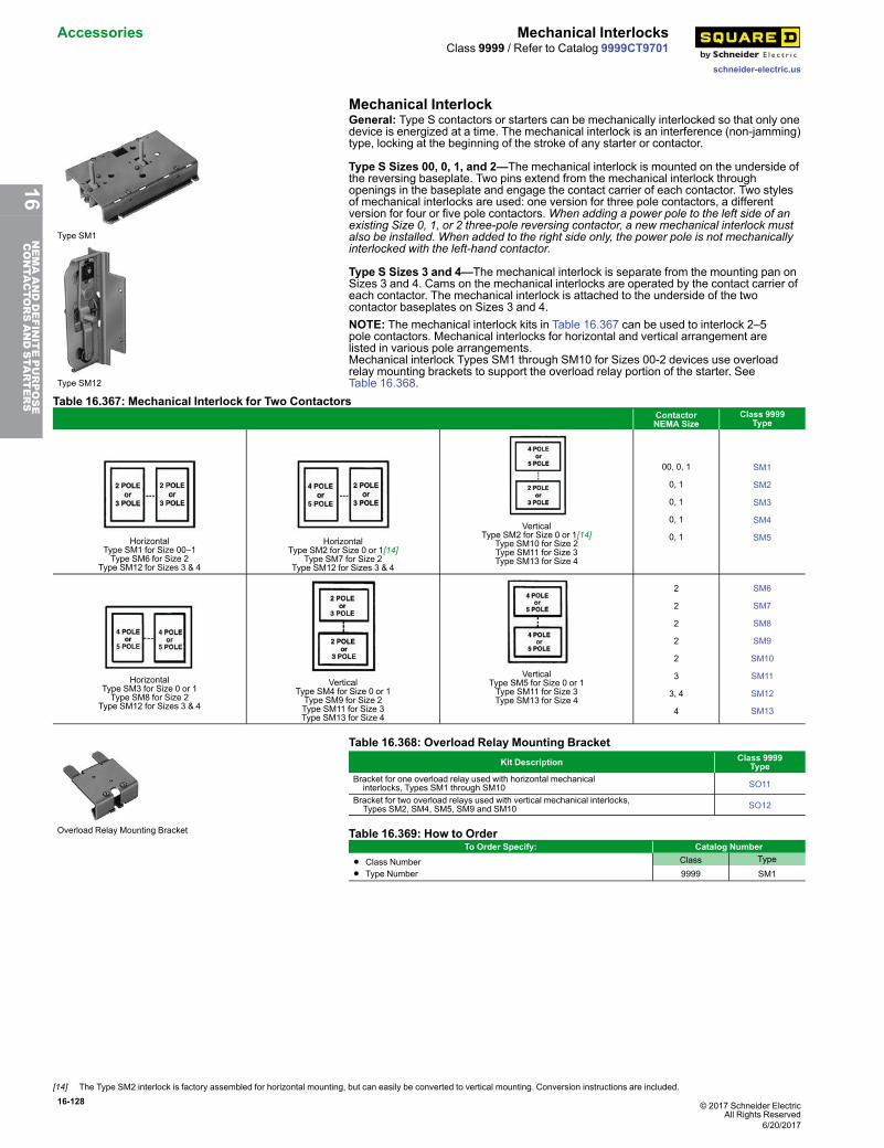
16-128 © 2017 Schneider ElectricAll Rights Reserved
Accessories Mechanical Interlocks
schneider-electric.us
Class 9999 / Refer to Catalog 9999CT9701
Mechanical Interlock
Type SM1
Type SM12
General: Type S contactors or starters can be mechanically interlocked so that only onedevice is energized at a time. The mechanical interlock is an interference (non-jamming)type, locking at the beginning of the stroke of any starter or contactor.
Type S Sizes 00, 0, 1, and 2—The mechanical interlock is mounted on the underside ofthe reversing baseplate. Two pins extend from the mechanical interlock throughopenings in the baseplate and engage the contact carrier of each contactor. Two stylesof mechanical interlocks are used: one version for three pole contactors, a differentversion for four or five pole contactors.When adding a power pole to the left side of anexisting Size 0, 1, or 2 three-pole reversing contactor, a new mechanical interlock mustalso be installed. When added to the right side only, the power pole is not mechanicallyinterlocked with the left-hand contactor.
Type S Sizes 3 and 4—The mechanical interlock is separate from the mounting pan onSizes 3 and 4. Cams on the mechanical interlocks are operated by the contact carrier ofeach contactor. The mechanical interlock is attached to the underside of the twocontactor baseplates on Sizes 3 and 4.NOTE: The mechanical interlock kits in Table 16.367 can be used to interlock 2–5pole contactors. Mechanical interlocks for horizontal and vertical arrangement arelisted in various pole arrangements.Mechanical interlock Types SM1 through SM10 for Sizes 00-2 devices use overloadrelay mounting brackets to support the overload relay portion of the starter. SeeTable 16.368.
Table 16.367: Mechanical Interlock for Two ContactorsContactorNEMA Size
Class 9999Type
HorizontalType SM1 for Size 00–1Type SM6 for Size 2
Type SM12 for Sizes 3 & 4
HorizontalType SM2 for Size 0 or 1[14]
Type SM7 for Size 2Type SM12 for Sizes 3 & 4
VerticalType SM2 for Size 0 or 1[14]
Type SM10 for Size 2Type SM11 for Size 3Type SM13 for Size 4
00, 0, 1
0, 1
0, 1
0, 1
0, 1
SM1
SM2
SM3
SM4
SM5
HorizontalType SM3 for Size 0 or 1Type SM8 for Size 2
Type SM12 for Sizes 3 & 4
VerticalType SM4 for Size 0 or 1Type SM9 for Size 2Type SM11 for Size 3Type SM13 for Size 4
VerticalType SM5 for Size 0 or 1Type SM11 for Size 3Type SM13 for Size 4
2
2
2
2
2
3
3, 4
4
SM6
SM7
SM8
SM9
SM10
SM11
SM12
SM13
Overload Relay Mounting Bracket
Table 16.368: Overload Relay Mounting BracketKit Description Class 9999
TypeBracket for one overload relay used with horizontal mechanical interlocks, Types SM1 through SM10 SO11
Bracket for two overload relays used with vertical mechanical interlocks, Types SM2, SM4, SM5, SM9 and SM10 SO12
Table 16.369: How to OrderTo Order Specify: Catalog Number
• Class Number
• Type NumberClass Type
9999 SM1
[14] The Type SM2 interlock is factory assembled for horizontal mounting, but can easily be converted to vertical mounting. Conversion instructions are included.
6/20/2017
16NEMAANDDEFINITEPURPOSE
CONTA
CTORSANDSTA
RTERS
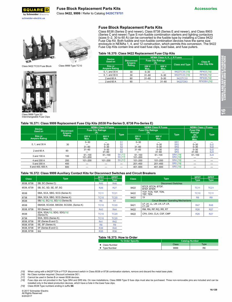
© 2017 Schneider ElectricAll Rights Reserved
16-129
schneider-electric.us
Fuse Block Replacement Parts Kits AccessoriesClass 9422, 9999 / Refer to Catalog 9420CT9701
Fuse Block Replacement Parts Kits
Class 9422 TC33 Fuse Block Class 9999 Type TC10
Class 9999 Type S2Interchangeable Fuse Clips
Class 8538 (Series D and newer), Class 8738 (Series E and newer), and Class 8903(Series C and newer) Type S non-fusible combination starters and lighting contactors(sizes 0–2, 30 to 60 A) can be converted to the fusible type by installing a Class 9422Fuse Clip Kit. Both fusible and non-fusible combination devices have the same sizeenclosure in NEMAs 1, 4, and 12 construction, which permits this conversion. The 9422Fuse Clip Kits contain line and load fuse clips, load base, and fuse pullers.
Table 16.370: Class 9422 Replacement Fuse Clip Kits
DeviceUsed on Disconnect
AmpereRating
NEMA Class H, K, J, R Fuses
Class RFuse Clip Kits
Fuse Clip Ratings(A)
Class and TypeSize or
Ampere Rating250 VMax.
600 VMax.
0, 1, and 30 A 30 0–30 — 9422TC30 [15] RFK03 [16]0, 1, and 30 A 30 31–60 0–30 9422TC33 [15] RFK06 [16]2 and 60 A 60 31–60 0–30 9422TC33 RFK06 [16]2 and 60 A 60 — 31–60 9422TD63 RFK06H [16]
Table 16.371: Class 9999 Replacement Fuse Clip Kits (8538 Pre-Series D, 8738 Pre-Series E)
DeviceUsed on Disconnect
AmpereRating
NEMA Class H Fuses NEMA Class R Fuses NEMA Class J FusesFuse Clip Ratings
(A)Type
Fuse Clip Ratings(A)
Type
Fuse ClipRatings(A)
600 VMax.
TypeSize or
Ampere Rating250 VMax.
600 VMax.
250 VMax.
600 VMax.
0, 1, and 30 A 300–30—
31–60
—0–300–30
S1S2S2
0–30—
31–60
—0–300–30
SR1SR2SR2
—0–300–30
—SJ2SJ2
2 and 60 A 60 31–60—
0–3031–60
S2S3
31–60—
0–3031–60
SR2SR3
0–3031–60
SJ2SJ3
3 and 100 A 100 61–100101–200
61–100—
S4 [17]S5 [17]
61–100101–200
61–100—
SR4 [18]SR4 [18]
61–100—
SJ4—
4 and 200 A 200 101–200 101–200 S5 [17] 101–200 101–200 SR4 [18] — —5 and 300 A 400 — — — 201–400 201–400 SR5 [18] — —
6 and 400, 600 A 600 — — — 401–600 401–600 SR5 [18] — —
Table 16.372: Class 9999 Auxiliary Contact Kits for Disconnect Switches and Circuit Breakers
Class Type SPDT DPDTClass Type SPDT DPDT
Type Type Type Type8538, 8738 SB, SC (Series C) R45 R46 Disconnect Switches
8539, 8739 SB, SC, SD, SE, SF, SG R26 R27 9422 BTCF, BTCN, BTDF,BTEF, BTEN TC11 TC21
8538 SBA, SCA, SBG, SCG (Series K) TC11 TC21 9422 TCF, TCN, TDF, TDN,TEF, TEN TC10 TC11
8738 SBA, SCA, SBG, SCG (Series K) TC10 TC20 9422 TF R8 R98538 SB[19], SC[19], SD[19] (Series B) R6 R7 Circuit Breaker Operating Mechanisms
8538 SBAS8, SCAS8, SBGS8, SCGS8, (Series K) TC10 TC20 9421 LF, LK, LL, LM, LN, LP, LR,LT, LW R47 R48
8538, 8738 SD (Series C) R43 R44 9422 RM, RN, RP, RQ, RR, RT R26 R27
8538 SDA, SDA[19], SDG, SDG[19](Series K) TC10 TC20 9422 CFA, CKA, CLA, CSF, CMP R26 R27
8738 SDA, SDG (Series K) TC10 TC208538, 8738 SE (Series B and C) R41 R428538, 8738 SE, SF (Series A) R8 R98538, 8738 SF (Series B and C) R39 R408538, 8738 SG R35 R36
Table 16.373: How to OrderTo Order Specify: Catalog Number
• Class Number• Type Number
Class Type
9999 R6
16NEMAANDDEFINITEPURPOSE
CONTA
CTORSANDSTA
RTERS
[15] When using with a 9422FTCN or FTCF disconnect switch in Class 8538 or 8738 combination starters, remove and discard the metal base plate.[16] No Class number required. Discount schedule DE1.[17] Cannot be used in Series B or newer 8538 devices.[18] Fuse clips are not provided in the Type SR4 and SR5 kits. On new installations, Class 9999 Type S fuse clips must also be purchased. Three non-removable pins are included and can be
installed only in the latest production devices, which have a hole in the lower fuse clips.[19] Class 8538 Type numbers ending in suffix S8.
6/20/2017
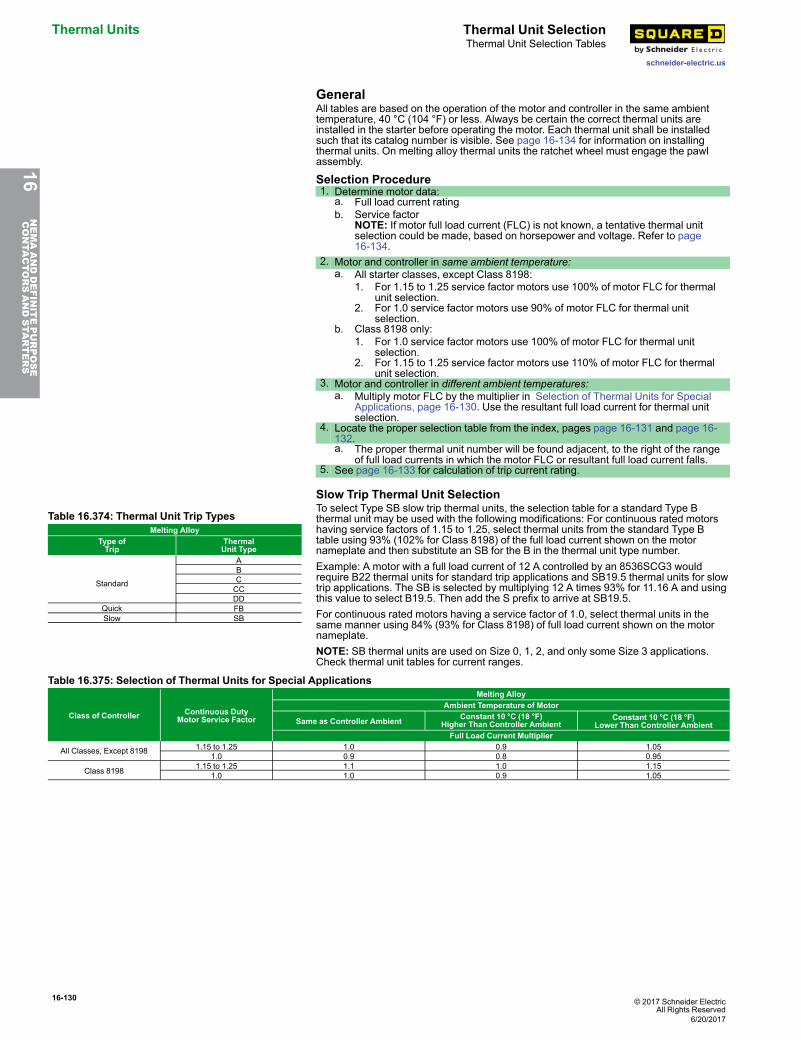
16-130 © 2017 Schneider ElectricAll Rights Reserved
Thermal Units Thermal Unit Selection
schneider-electric.us
Thermal Unit Selection Tables
GeneralAll tables are based on the operation of the motor and controller in the same ambienttemperature, 40 °C (104 °F) or less. Always be certain the correct thermal units areinstalled in the starter before operating the motor. Each thermal unit shall be installedsuch that its catalog number is visible. See page 16-134 for information on installingthermal units. On melting alloy thermal units the ratchet wheel must engage the pawlassembly.
Selection Procedure1. Determine motor data:
a. Full load current ratingb. Service factor
NOTE: If motor full load current (FLC) is not known, a tentative thermal unitselection could be made, based on horsepower and voltage. Refer to page16-134.
2. Motor and controller in same ambient temperature:a. All starter classes, except Class 8198:
1. For 1.15 to 1.25 service factor motors use 100% of motor FLC for thermalunit selection.
2. For 1.0 service factor motors use 90% of motor FLC for thermal unitselection.
b. Class 8198 only:1. For 1.0 service factor motors use 100% of motor FLC for thermal unit
selection.2. For 1.15 to 1.25 service factor motors use 110% of motor FLC for thermal
unit selection.3. Motor and controller in different ambient temperatures:
a. Multiply motor FLC by the multiplier in Selection of Thermal Units for SpecialApplications, page 16-130. Use the resultant full load current for thermal unitselection.
4. Locate the proper selection table from the index, pages page 16-131 and page 16-132.a. The proper thermal unit number will be found adjacent, to the right of the range
of full load currents in which the motor FLC or resultant full load current falls.5. See page 16-133 for calculation of trip current rating.
Slow Trip Thermal Unit Selection
Table 16.374: Thermal Unit Trip TypesMelting Alloy
Type ofTrip
ThermalUnit Type
Standard
ABCCCDD
Quick FBSlow SB
To select Type SB slow trip thermal units, the selection table for a standard Type Bthermal unit may be used with the following modifications: For continuous rated motorshaving service factors of 1.15 to 1.25, select thermal units from the standard Type Btable using 93% (102% for Class 8198) of the full load current shown on the motornameplate and then substitute an SB for the B in the thermal unit type number.Example: A motor with a full load current of 12 A controlled by an 8536SCG3 wouldrequire B22 thermal units for standard trip applications and SB19.5 thermal units for slowtrip applications. The SB is selected by multiplying 12 A times 93% for 11.16 A and usingthis value to select B19.5. Then add the S prefix to arrive at SB19.5.For continuous rated motors having a service factor of 1.0, select thermal units in thesame manner using 84% (93% for Class 8198) of full load current shown on the motornameplate.NOTE: SB thermal units are used on Size 0, 1, 2, and only some Size 3 applications.Check thermal unit tables for current ranges.
Table 16.375: Selection of Thermal Units for Special Applications
Class of Controller Continuous DutyMotor Service Factor
Melting AlloyAmbient Temperature of Motor
Same as Controller Ambient Constant 10 °C (18 °F)Higher Than Controller Ambient
Constant 10 °C (18 °F)Lower Than Controller Ambient
Full Load Current Multiplier
All Classes, Except 8198 1.15 to 1.25 1.0 0.9 1.051.0 0.9 0.8 0.95
Class 8198 1.15 to 1.25 1.1 1.0 1.151.0 1.0 0.9 1.05
16NEMAANDDEFINITEPURPOSE
CONTA
CTORSANDSTA
RTERS
6/20/2017
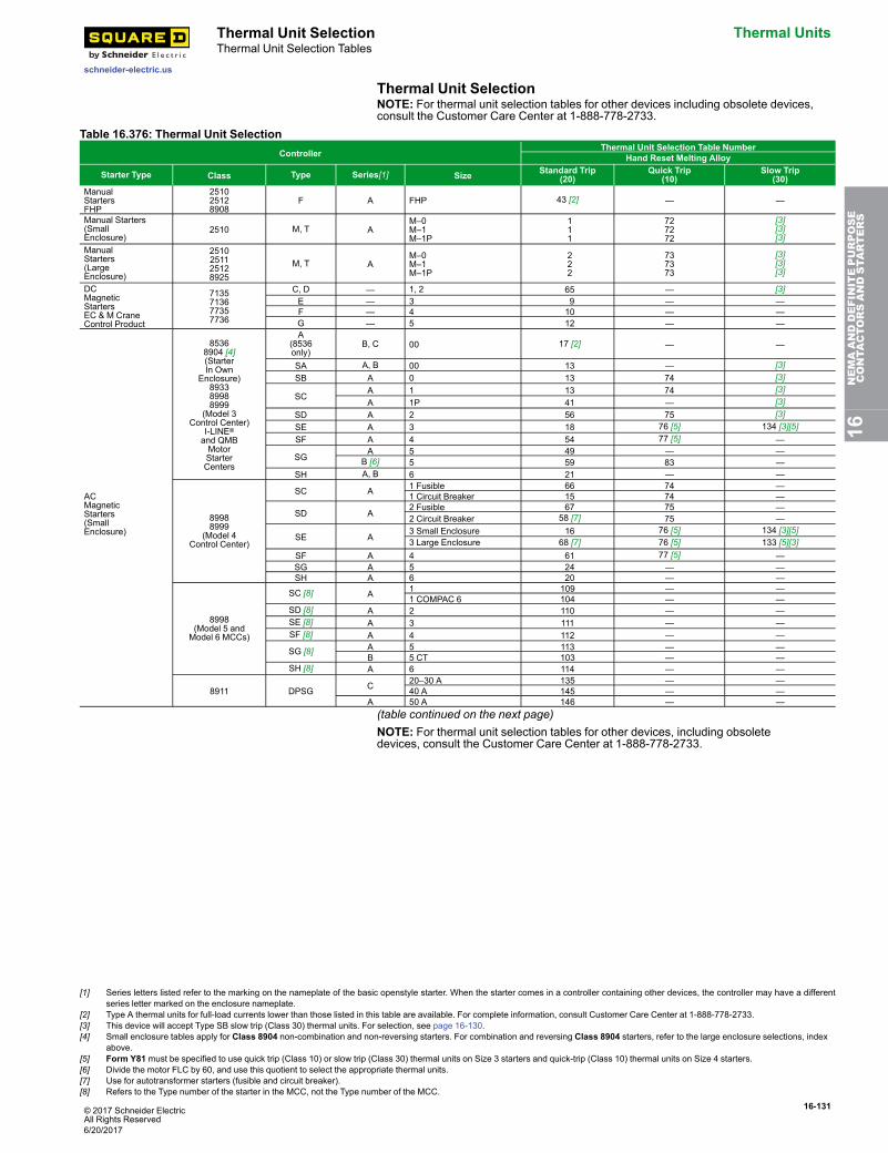
© 2017 Schneider ElectricAll Rights Reserved
16-131
schneider-electric.us
Thermal Unit Selection Thermal UnitsThermal Unit Selection Tables
Thermal Unit SelectionNOTE: For thermal unit selection tables for other devices including obsolete devices,consult the Customer Care Center at 1-888-778-2733.
Table 16.376: Thermal Unit SelectionController
Thermal Unit Selection Table NumberHand Reset Melting Alloy
Starter Type Class Type Series[1] Size Standard Trip(20)
Quick Trip(10)
Slow Trip(30)
ManualStartersFHP
251025128908
F A FHP 43 [2] — —
Manual Starters(SmallEnclosure)
2510 M, T AM–0M–1M–1P
111
727272
[3][3][3]
ManualStarters(LargeEnclosure)
2510251125128925
M, T AM–0M–1M–1P
222
737373
[3][3][3]
DCMagneticStartersEC & M CraneControl Product
7135713677357736
C, D — 1, 2 65 — [3]E — 3 9 — —F — 4 10 — —G — 5 12 — —
ACMagneticStarters(SmallEnclosure)
85368904 [4](StarterIn Own
Enclosure)893389988999
(Model 3Control Center)
I-LINE®
and QMBMotorStarterCenters
A(8536only)
B, C 00 17 [2] — —
SA A, B 00 13 — [3]SB A 0 13 74 [3]
SCA 1 13 74 [3]A 1P 41 — [3]
SD A 2 56 75 [3]SE A 3 18 76 [5] 134 [3][5]SF A 4 54 77 [5] —
SGA 5 49 — —
B [6] 5 59 83 —SH A, B 6 21 — —
89988999
(Model 4Control Center)
SC A 1 Fusible 66 74 —1 Circuit Breaker 15 74 —
SD A2 Fusible 67 75 —2 Circuit Breaker 58 [7] 75 —
SE A3 Small Enclosure 16 76 [5] 134 [3][5]3 Large Enclosure 68 [7] 76 [5] 133 [5][3]
SF A 4 61 77 [5] —SG A 5 24 — —SH A 6 20 — —
8998(Model 5 andModel 6 MCCs)
SC [8] A 1 109 — —1 COMPAC 6 104 — —
SD [8] A 2 110 — —SE [8] A 3 111 — —SF [8] A 4 112 — —
SG [8] A 5 113 — —B 5 CT 103 — —
SH [8] A 6 114 — —
8911 DPSG C 20–30 A 135 — —40 A 145 — —
A 50 A 146 — —(table continued on the next page)NOTE: For thermal unit selection tables for other devices, including obsoletedevices, consult the Customer Care Center at 1-888-778-2733.
16NEMAANDDEFINITEPURPOSE
CONTA
CTORSANDSTA
RTERS
[1] Series letters listed refer to the marking on the nameplate of the basic openstyle starter. When the starter comes in a controller containing other devices, the controller may have a differentseries letter marked on the enclosure nameplate.
[2] Type A thermal units for full-load currents lower than those listed in this table are available. For complete information, consult Customer Care Center at 1-888-778-2733.[3] This device will accept Type SB slow trip (Class 30) thermal units. For selection, see page 16-130.[4] Small enclosure tables apply for Class 8904 non-combination and non-reversing starters. For combination and reversing Class 8904 starters, refer to the large enclosure selections, index
above.[5] Form Y81 must be specified to use quick trip (Class 10) or slow trip (Class 30) thermal units on Size 3 starters and quick-trip (Class 10) thermal units on Size 4 starters.[6] Divide the motor FLC by 60, and use this quotient to select the appropriate thermal units.[7] Use for autotransformer starters (fusible and circuit breaker).[8] Refers to the Type number of the starter in the MCC, not the Type number of the MCC.
6/20/2017
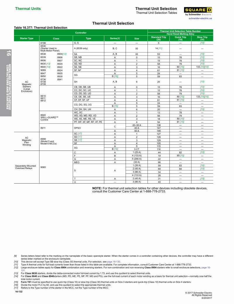
16-132 © 2017 Schneider ElectricAll Rights Reserved
Thermal Units Thermal Unit Selection
schneider-electric.us
Thermal Unit Selection Tables
Thermal Unit SelectionTable 16.377: Thermal Unit Selection
ControllerThermal Unit Selection Table Number
Hand Reset Melting Alloy
Starter Type Class Type Series[9] Size Standard Trip(20)
Quick Trip(10)
Slow Trip(30)
ACMagneticStarters(Large
Enclosure)
8198 G, S — — 5 — [10]8536(Starter Used inMulti-Motor Panel)
A (8536 only) B, C 00 14 [11] — —
8538 8904[12] SA A, B 00 53 — [10]8539 8906 SB, NB A 0 15 78 [10]8606 8907 SC, NC A 1 15 78 [10]8630 [13] 8920 SD, ND A 2 58 79 [10]8640 [14] 8922 SE, NE A 3 16 80 [15] 133 [15][10]9089 8924 SF, NF A 4 61 81 [15] —8647 8925
SGA 5 24 — —
8650 8930 B [16] 5 59 83 —873687388739
8941SH A, B 6 20 — [10]
881088118812
CB, DB, SB, UB A 0 15 78 [10]CC, DC, SC, UC A 1 15 78 [10]CD, DD, SD, UD A 2 58 79 [10]CE, DE, SE, UE A 3 16 80 [15] 133 [15][10]CF, DF, SF, UF A 4 61 81 [15] —
CG, DG, SG, UG A 5 24 — —B [16] 5 59 83 —
CH, DH, SH, UH A 6 20 — [10]
8940WELL-GUARD™Control
WC, XC A 1 13 78 —WD, XD, MD, RD, VD A 2 56 79 —WE, XE, ME, RE, VE A 3 18 80 [15] —PF, WF, XF, MF, RF, VF, PE A 4 54 81 [15] —
8911 DPSO C 20–30 A 136 — —40 A 147 — —
A 50 A 148 — —
ACMagneticPart-
Winding
8998(Model 5 andModel 6 MCCs)
SC [17] A 1 127 — —SD [17] A 2 128 — —SE [17] A 3 129 — —SF A 4 105 — —
SGA 5 115 — —
B [16] 5 CT 116 — —
Separately MountedOverload Relays 9065
C A 1 (25 A) 44 82 [10]F B 4 (133 A) 19 85 [15] —G A 5 (266 A) 22 — —MEO A (32 A) 86 — —
S A
1 (26 A) 59 83 [10]2 (45 A) 69 84 [10]3 (86 A) 34 — —4 (133 A) 28 — —
T A 2 (45 A) 31 — [10]U — 3 (86 A) 40 — —
NOTE: For thermal unit selection tables for other devices including obsolete devices,consult the Customer Care Center at 1-888-778-2733.
16NEMAANDDEFINITEPURPOSE
CONTA
CTORSANDSTA
RTERS
[9] Series letters listed refer to the marking on the nameplate of the basic openstyle starter. When the starter comes in a controller containing other devices, the controller may have a differentseries letter marked on the enclosure nameplate.
[10] This device will accept Type SB slow trip (Class 30) thermal units. For selection, see page 16-130.[11] Type A thermal units for full-load currents lower than those listed in this table are available. For complete information, consult Customer Care Center at 1-888-778-2733.[12] Large enclosure tables apply for Class 8904 combination and reversing starters. For non-combination and non-reversing Class 8904 starters refer to small enclosure selections, page 16-
131.[13] For Class 8630 starters, divide the delta-connected motor full-load current by 1.73, and use this quotient to select thermal units.[14] For Class 8640 and Class 8940starters (MD, PD, ME, PE, MF, PF, MG and PG), use the full-load current of each motor winding as a basis for thermal unit selection—normally one-half the
total motor current.[15] Form Y81 must be specified to use quick trip (Class 10) or slow trip (Class 30) thermal units on Size 3 starters and quick-trip (Class 10) thermal units on Size 4 starters.[16] Divide the motor FLC by 60, and use this quotient to select the appropriate thermal units.[17] Refers to the Type number of the starter in the MCC, not the Type number of the MCC.
6/20/2017
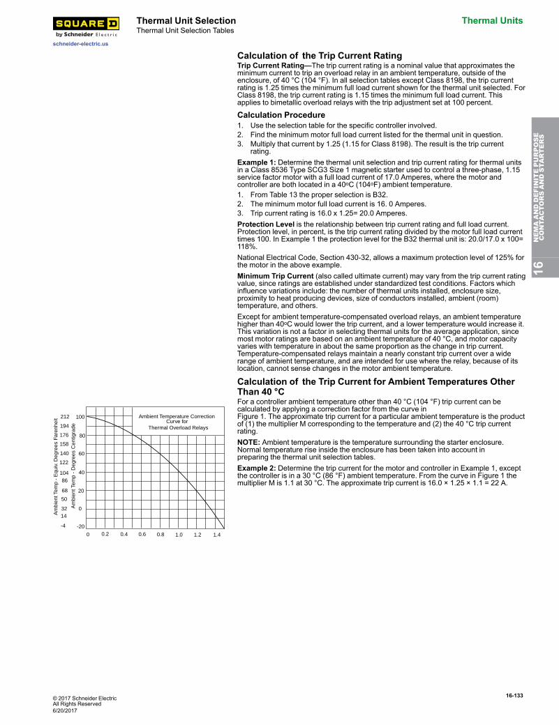
© 2017 Schneider ElectricAll Rights Reserved
16-133
schneider-electric.us
Thermal Unit Selection Thermal UnitsThermal Unit Selection Tables
Calculation of the Trip Current RatingTrip Current Rating—The trip current rating is a nominal value that approximates theminimum current to trip an overload relay in an ambient temperature, outside of theenclosure, of 40 °C (104 °F). In all selection tables except Class 8198, the trip currentrating is 1.25 times the minimum full load current shown for the thermal unit selected. ForClass 8198, the trip current rating is 1.15 times the minimum full load current. Thisapplies to bimetallic overload relays with the trip adjustment set at 100 percent.
Calculation Procedure1. Use the selection table for the specific controller involved.2. Find the minimum motor full load current listed for the thermal unit in question.3. Multiply that current by 1.25 (1.15 for Class 8198). The result is the trip current
rating.Example 1: Determine the thermal unit selection and trip current rating for thermal unitsin a Class 8536 Type SCG3 Size 1 magnetic starter used to control a three-phase, 1.15service factor motor with a full load current of 17.0 Amperes, where the motor andcontroller are both located in a 40oC (104oF) ambient temperature.1. From Table 13 the proper selection is B32.2. The minimum motor full load current is 16. 0 Amperes.3. Trip current rating is 16.0 x 1.25= 20.0 Amperes.Protection Level is the relationship between trip current rating and full load current.Protection level, in percent, is the trip current rating divided by the motor full load currenttimes 100. In Example 1 the protection level for the B32 thermal unit is: 20.0/17.0 x 100=118%.National Electrical Code, Section 430-32, allows a maximum protection level of 125% forthe motor in the above example.Minimum Trip Current (also called ultimate current) may vary from the trip current ratingvalue, since ratings are established under standardized test conditions. Factors whichinfluence variations include: the number of thermal units installed, enclosure size,proximity to heat producing devices, size of conductors installed, ambient (room)temperature, and others.Except for ambient temperature-compensated overload relays, an ambient temperaturehigher than 40oC would lower the trip current, and a lower temperature would increase it.This variation is not a factor in selecting thermal units for the average application, sincemost motor ratings are based on an ambient temperature of 40 °C, and motor capacityvaries with temperature in about the same proportion as the change in trip current.Temperature-compensated relays maintain a nearly constant trip current over a widerange of ambient temperature, and are intended for use where the relay, because of itslocation, cannot sense changes in the motor ambient temperature.
Calculation of the Trip Current for Ambient Temperatures OtherThan 40 °C
100
80
60
40
20
0
-20
212
194
176
158
140
122
10486
68
50
3214
-4
0 0.2 0.4 0.6 0.8 1.0 1.2 1.4
Ambient Temperature CorrectionCurve for
Thermal Overload Relays
Am
bien
t Tem
p -
Equ
iv. D
egre
es F
aren
heit
Am
bien
t Tem
p -
Deg
rees
Cen
tigra
de
For a controller ambient temperature other than 40 °C (104 °F) trip current can becalculated by applying a correction factor from the curve inFigure 1. The approximate trip current for a particular ambient temperature is the productof (1) the multiplier M corresponding to the temperature and (2) the 40 °C trip currentrating.NOTE: Ambient temperature is the temperature surrounding the starter enclosure.Normal temperature rise inside the enclosure has been taken into account inpreparing the thermal unit selection tables.Example 2: Determine the trip current for the motor and controller in Example 1, exceptthe controller is in a 30 °C (86 °F) ambient temperature. From the curve in Figure 1 themultiplier M is 1.1 at 30 °C. The approximate trip current is 16.0 × 1.25 × 1.1 = 22 A.
16NEMAANDDEFINITEPURPOSE
CONTA
CTORSANDSTA
RTERS
6/20/2017
16-134 © 2017 Schneider ElectricAll Rights Reserved
Thermal Units Thermal Unit Selection
schneider-electric.us
Thermal Unit Selection Tables
Approximate Thermal Unit Selection Based On Horsepower andVoltageGeneral—Thermal units selected using approximate full-load currents from Table 16.378will provide a trip current between 101% and 125% of full-load current for many 4-pole,single speed, normal torque, 60 Hz motors. Since full-load current rating of differentmakes and types of motors vary so widely, these selections may not be suitable.Thermal units should be selected on the basis of motor nameplate full-load current andservice factor. Thermal unit sizes originally selected on an approximate basis shouldalways be rechecked and corrected at the time of installation if required.How to use Table 16.378:• Locate the motor horsepower and voltage.• Determine the approximate full-load current fromTable 16.378.• Use the approximate full-load current in place of actual nameplate full-load current andfollow the Selection Procedure on page 16-130.
Table 16.378: Use This Table Only When the Motor Full-Load Current Is Not Known
MotorHorsepower
Motor Full-Load CurrentThree Ø Single Ø
200 V 230 V 460 V 575 V 115 V 230 V 1/6 — — — — 4.4 2.2 1/4 — — — — 5.8 2.9 1/3 — — — — 7.2 3.6 1/2 2.5 2.2 1.1 0.9 9.8 4.9 3/4 3.7 3.2 1.6 1.3 13.8 6.9 1 4.8 4.2 2.1 1.7 16 81-1/2 6.9 6.0 3.0 2.4 20 10
2 7.8 6.8 3.4 2.7 24 12 3 11.0 9.6 4.8 3.9 34 17 5 17.5 15.2 7.6 6.1 56 287-1/2 25.3 22 11 9 80 40
10 32.2 28 14 11 — 50 15 48.3 42 21 17 — — 20 62.1 54 27 22 — — 25 78.2 68 34 27 — — 30 92 80 40 32 — — 40 120 104 52 41 — — 50 150 130 65 52 — — 60 177 154 77 62 — — 75 221 192 96 77 — —100 285 248 124 99 — —125 359 312 156 125 — —150 414 360 180 144 — —200 552 480 240 192 — —
NOTE: These currents should not be used for selection of fuses, circuit breakers orwire sizes. See NEC tables 430-248 through 430-250. For motors rated 208-220volts, use 230 V column. For motors rated 440 to 550 volts, use 460 and 575 Vcolumns, respectively.
Mounting of the Thermal Units
Figure 1
Always be certain the correct thermal units are installed in the starter before operatingthe motor. Thermal units should always be mounted so that their type designation can beread from the front of the starter (see Figure 1). Melting alloy thermal units should bemounted so that the tooth of the pawl assembly can engage the teeth of the ratchetwheel when the reset button is pushed.Mounting surfaces of starter and thermal units should be clean and care should be takento insure that thermal unit mounting screws are fastened securely.
16NEMAANDDEFINITEPURPOSE
CONTA
CTORSANDSTA
RTERS
6/20/2017
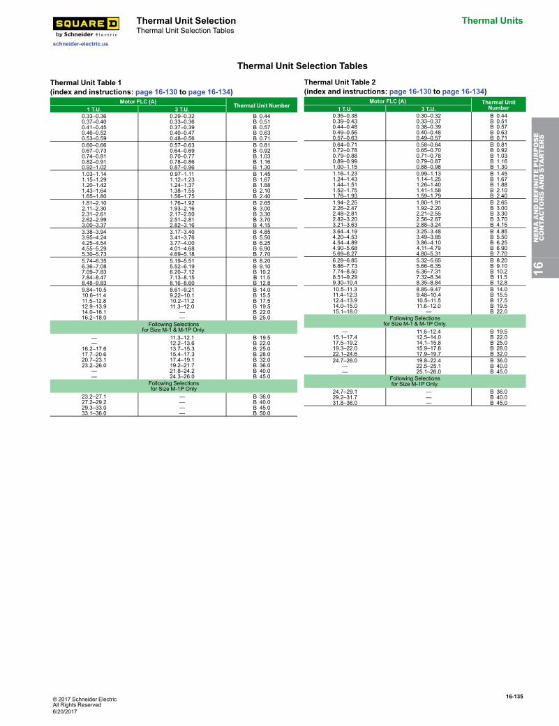
© 2017 Schneider ElectricAll Rights Reserved
16-135
schneider-electric.us
Thermal Unit Selection Thermal UnitsThermal Unit Selection Tables
Thermal Unit Selection Tables
Thermal Unit Table 1(index and instructions: page 16-130 to page 16-134)
Motor FLC (A)Thermal Unit Number
1 T.U. 3 T.U.0.33–0.360.37–0.400.41–0.450.46–0.520.53–0.59
0.29–0.320.33–0.360.37–0.390.40–0.470.48–0.56
B 0.44B 0.51B 0.57B 0.63B 0.71
0.60–0.660.67–0.730.74–0.810.82–0.910.92–1.02
0.57–0.630.64–0.690.70–0.770.78–0.860.87–0.96
B 0.81B 0.92B 1.03B 1.16B 1.30
1.03–1.141.15–1.291.20–1.421.43–1.641.65–1.80
0.97–1.111.12–1.231.24–1.371.38–1.551.56–1.75
B 1.45B 1.67B 1.88B 2.10B 2.40
1.81–2.102.11–2.302.31–2.612.62–2.993.00–3.37
1.76–1.921.93–2.162.17–2.502.51–2.812.82–3.16
B 2.65B 3.00B 3.30B 3.70B 4.15
3.38–3.943.95–4.244.25–4.544.55–5.295.30–5.73
3.17–3.403.41–3.763.77–4.004.01–4.684.69–5.18
B 4.85B 5.50B 6.25B 6.90B 7.70
5.74–6.356.36–7.087.09–7.837.84–8.478.48–9.83
5.19–5.515.52–6.196.20–7.127.13–8.158.16–8.60
B 8.20B 9.10B 10.2B 11.5B 12.8
9.84–10.510.6–11.411.5–12.812.9–13.914.0–16.116.2–18.0
8.61–9.219.22–10.110.2–11.211.3–12.0
——
B 14.0B 15.5B 17.5B 19.5B 22.0B 25.0
Following Selectionsfor Size M-1 & M-1P Only.
——
16.2–17.617.7–20.620.7–23.123.2–26.0
——
11.3–12.112.2–13.613.7–15.315.4–17.317.4–19.119.2–21.721.8–24.224.3–26.0
B 19.5B 22.0B 25.0B 28.0B 32.0B 36.0B 40.0B 45.0
Following Selectionsfor Size M-1P Only
23.2–27.127.2–29.229.3–33.033.1–36.0
————
B 36.0B 40.0B 45.0B 50.0
Thermal Unit Table 2(index and instructions: page 16-130 to page 16-134)
Motor FLC (A) Thermal UnitNumber1 T.U. 3 T.U.
0.35–0.380.39–0.430.44–0.480.49–0.560.57–0.63
0.30–0.320.33–0.370.38–0.390.40–0.480.49–0.57
B 0.44B 0.51B 0.57B 0.63B 0.71
0.64–0.710.72–0.780.79–0.880.89–0.991.00–1.15
0.58–0.640.65–0.700.71–0.780.79–0.870.88–0.98
B 0.81B 0.92B 1.03B 1.16B 1.30
1.16–1.231.24–1.431.44–1.511.52–1.751.76–1.93
0.99–1.131.14–1.251.26–1.401.41–1.581.59–1.79
B 1.45B 1.67B 1.88B 2.10B 2.40
1.94–2.252.26–2.472.48–2.812.82–3.203.21–3.63
1.80–1.911.92–2.202.21–2.552.56–2.872.88–3.24
B 2.65B 3.00B 3.30B 3.70B 4.15
3.64–4.194.20–4.534.54–4.894.90–5.685.69–6.27
3.25–3.483.49–3.853.86–4.104.11–4.794.80–5.31
B 4.85B 5.50B 6.25B 6.90B 7.70
6.28–6.856.86–7.737.74–8.508.51–9.299.30–10.4
5.32–5.655.66–6.356.36–7.317.32–8.348.35–8.84
B 8.20B 9.10B 10.2B 11.5B 12.8
10.5–11.311.4–12.312.4–13.914.0–15.015.1–18.0
8.85–9.479.48–10.410.5–11.511.6–12.0
—
B 14.0B 15.5B 17.5B 19.5B 22.0
Following Selectionsfor Size M-1 & M-1P Only.
—15.1–17.417.5–19.219.3–22.022.1–24.6
11.6–12.412.5–14.014.1–15.815.9–17.817.9–19.7
B 19.5B 22.0B 25.0B 28.0B 32.0
24.7–26.0——
19.8–22.422.5–25.125.1–26.0
B 36.0B 40.0B 45.0
Following Selectionsfor Size M-1P Only.
24.7–29.129.2–31.731.8–36.0
———
B 36.0B 40.0B 45.0
16NEMAANDDEFINITEPURPOSE
CONTA
CTORSANDSTA
RTERS
6/20/2017
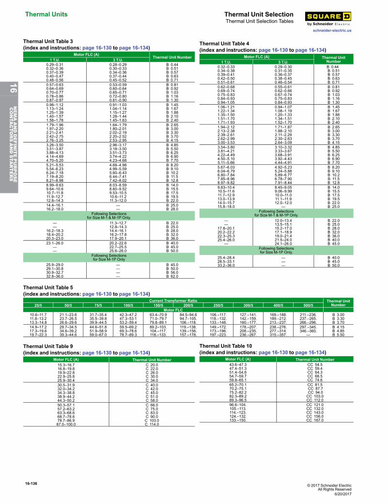
16-136 © 2017 Schneider ElectricAll Rights Reserved
Thermal Units Thermal Unit Selection
schneider-electric.us
Thermal Unit Selection Tables
Thermal Unit Table 3(index and instructions: page 16-130 to page 16-134)
Motor FLC (A)Thermal Unit Number
1 T.U. 3 T.U.0.29–0.310.32–0.360.37–0.390.40–0.470.48–0.56
0.28–0.290.30–0.330.34–0.360.37–0.440.45–0.52
B 0.44B 0.51B 0.57B 0.63B 0.71
0.57–0.630.64–0.690.70–0.770.78–0.860.87–0.97
0.53–0.590.60–0.640.65–0.710.72–0.800.81–0.90
B 0.81B 0.92B 1.03B 1.16B 1.30
0.98–1.121.13–1.241.25–1.391.40–1.571.58–1.78
0.91–1.031.04–1.141.15–1.271.28–1.441.45–1.63
B 1.45B 1.67B 1.88B 2.10B 2.40
1.79–1.961.97–2.202.21–2.412.42–2.752.76–3.25
1.64–1.791.80–2.012.02–2.192.20–2.522.53–2.95
B 2.65B 3.00B 3.30B 3.70B 4.15
3.26–3.503.51–3.873.88–4.134.14–4.694.70–5.20
2.96–3.173.18–3.503.51–3.733.74–4.224.23–4.68
B 4.85B 5.50B 6.25B 6.90B 7.70
5.21–5.535.54–6.236.24–7.187.19–8.208.21–8.98
4.69–4.984.99–5.595.60–6.436.44–7.417.42–8.02
B 8.20B 9.10B 10.2B 11.5B 12.8
8.99–9.639.64–10.610.7–11.811.9–12.712.8–14.3
8.03–8.598.60–9.529.53–10.510.6–11.211.3–12.0
B 14.0B 15.5B 17.5B 19.5B 22.0
14.4–16.116.2–18.0
——
B 25.0B 28.0
Following Selectionsfor Size M-1 & M-1P Only.
——
16.2–18.318.4–20.220.3–23.0
11.3–12.712.8–14.314.4–16.116.2–17.817.9–20.1
B 22.0B 25.0B 28.0B 32.0B 36.0
23.1–26.0——
20.2–22.622.7–25.525.6–26.0
B 40.0B 45.0B 50.0
Following Selectionsfor Size M-1P Only
25.9–29.029.1–30.830.9–32.732.8–36.0
————
B 45.0B 50.0B 56.0B 62.0
Thermal Unit Table 4(index and instructions: page 16-130 to page 16-134)
Motor FLC (A) Thermal UnitNumber1 T.U. 3 T.U.
0.32–0.330.34–0.380.39–0.410.42–0.500.51–0.61
0.29–0.300.31–0.350.36–0.370.38–0.450.46–0.54
B 0.44B 0.51B 0.57B 0.63B 0.71
0.62–0.680.69–0.740.75–0.830.84–0.930.94–1.05
0.55–0.610.62–0.660.67–0.740.75–0.830.84–0.93
B 0.81B 0.92B 1.03B 1.16B 1.30
1.06–1.211.22–1.341.35–1.501.51–1.701.71–1.93
0.94–1.071.08–1.191.20–1.331.34–1.511.52–1.70
B 1.45B 1.67B 1.88B 2.10B 2.40
1.94–2.122.13–2.382.39–2.612.62–2.993.00–3.53
1.71–1.871.88–2.102.11–2.292.30–2.632.64–3.09
B 2.65B 3.00B 3.30B 3.70B 4.15
3.54–3.803.81–4.214.22–4.494.50–5.105.11–5.66
3.10–3.323.33–3.673.68–3.913.92–4.434.44–4.91
B 4.85B 5.50B 6.25B 6.90B 7.70
5.67–6.036.04–6.796.80–7.847.85–8.968.97–9.82
4.92–5.235.24–5.885.89–6.776.78–7.907.91–8.44
B 8.20B 9.10B 10.2B 11.5B 12.8
9.83–10.410.5–11.611.7–12.913.0–13.914.0–15.715.8–18.0
8.45–9.059.06–9.9910.0–11.011.1–11.912.0–12.0
—
B 14.0B 15.5B 17.5B 19.5B 22.0B 25.0
Following Selectionsfor Size M-1 & M-1P Only.
——
17.8–20.120.2–22.222.3–25.325.4–26.0
—
12.0–13.413.5–15.115.2–17.017.1–18.919.0–21.421.5–24.024.1–26.0
B 22.0B 25.0B 28.0B 32.0B 36.0B 40.0B 45.0
Following Selectionsfor Size M-1P Only.
25.4–28.428.5–33.133.2–36.0
———
B 40.0B 45.0B 50.0
Thermal Unit Table 5(index and instructions: page 16-130 to page 16-134)
Current Transformer Ratio Thermal UnitNumber25/5 50/5 75/5 100/5 150/5 200/5 250/5 300/5 400/5 500/5
Motor FLC10.6–11.711.8–13.213.3–14.8
21.1–23.623.7–26.526.6–29.6
31.7–35.435.5–39.839.9–44.5
42.3–47.247.3–53.153.2–59.4
63.4–70.971.0–79.779.8–89.1
84.5–94.694.7–105.106.–118.
106.–117.118.–132.133.–148.
127.–141.142.–159.160.–177.
169.–188.189.–212.213.–237.
211.–236.237.–265.266.–296.
B 3.00B 3.30B 3.70
14.9–17.217.3–19.619.7–22.3
29.7–34.534.6–39.239.3–44.6
44.6–51.851.9–58.959.0–67.0
59.5–69.269.3–78.678.7–89.3
89.2–103.104.–117.118.–133.
119.–138.139.–156.157.–178.
149.–172.173.–196.197.–223.
178.–207.208.–235.236.–267.
238.–276.277.–314.315.–357.
297.–345.346.–360.
—
B 4.15B 4.85B 5.50
Thermal Unit Table 9(index and instructions: page 16-130 to page 16-134)
Motor FLC (A) Thermal Unit Number15.3–16.716.8–19.819.9–22.822.9–25.825.9–30.4
C 20.0C 22.0C 26.0C 30.0C 34.0
30.5–31.932.0–34.234.3–38.838.9–44.244.3–50.2
C 40.0C 42.0C 45.0C 51.0C 58.0
50.3–57.157.2–63.263.3–68.668.7–78.678.7–86.987.0–100.0
C 66.0C 75.0C 83.0C 90.0C 103.0C 114.0
Thermal Unit Table 10(index and instructions: page 16-130 to page 16-134)
Motor FLC (A) Thermal Unit Number43.6–47.347.4–51.351.4–54.654.7–59.759.8–65.1
CC 54.5CC 59.4CC 64.3CC 68.5CC 74.6
65.2–70.170.2–75.175.2–82.282.3–89.289.3–96.5
CC 81.5CC 87.7CC 94.0CC 103.0CC 112.0
96.6–104.105.–113.114.–123.124.–132.133.–150.
CC 121.0CC 132.0CC 143.0CC 156.0CC 167.0
6/20/2017
16NEMAANDDEFINITEPURPOSE
CONTA
CTORSANDSTA
RTERS
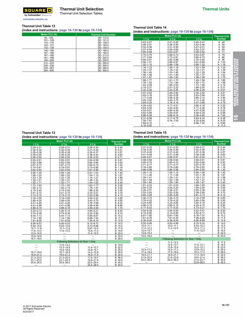
© 2017 Schneider ElectricAll Rights Reserved
16-137
schneider-electric.us
Thermal Unit Selection Thermal UnitsThermal Unit Selection Tables
Thermal Unit Table 12(index and instructions: page 16-130 to page 16-134)
Motor FLC (A) Thermal Unit Number92.–100.101.–109.110.–119.120.–131.132.–139.
DD 112.0DD 121.0DD 128.0DD 140.0DD 150.0
140.–156.157.–166.167.–180.181.–189.190.–209.
DD 160.0DD 185.0DD 213.0DD 220.0DD 230.0
210.–225.226.–238.239.–263.264.–300.
DD 250.0DD 265.0DD 280.0DD 300.0
Thermal Unit Table 14(index and instructions: page 16-130 to page 16-134)
Motor FLC (A) Thermal UnitNumber1.T.U. 2 T.U. 3 T.U.
0.43–0.470.48–0.510.52–0.560.57–0.640.65–0.69
0.41–0.450.46–0.500.51–0.550.56–0.620.63–0.67
0.40–0.410.42–0.460.47–0.510.52–0.570.58–0.62
A .49A .54A .59A .65A .71
0.70–0.760.77–0.840.85–0.910.92–1.011.02–1.15
0.68–0.720.73–0.810.82–0.880.89–0.970.98–1.08
0.63–0.670.68–0.750.76–0.800.81–0.890.90–1.02
A .78A .86A .95A 1.02A 1.16
1.16–1.231.24–1.371.38–1.451.46–1.561.57–1.67
1.09–1.181.19–1.321.33–1.401.41–1.481.49–1.60
1.03–1.091.10–1.211.22–1.291.30–1.371.38–1.48
A 1.25A 1.39A 1.54A 1.63A 1.75
1.68–1.771.78–1.921.93–2.092.10–2.312.32–2.56
1.61–1.721.73–1.841.85–2.002.01–2.222.23–2.45
1.49–1.581.59–1.721.73–1.851.86–2.052.06–2.29
A 1.86A 1.99A 2.15A 2.31A 2.57
2.57–2.922.93–3.163.17–3.483.49–3.833.84–4.24
2.46–2.822.83–3.083.09–3.393.40–3.753.76–4.16
2.30–2.622.63–2.842.85–3.103.11–3.463.47–3.85
A 2.81A 3.61A 3.95A 4.32A 4.79
4.25–4.624.63–4.924.93–5.615.62–5.855.86–6.36
4.17–4.514.52–4.834.84–5.495.50–5.675.68–6.16
3.86–4.164.17–4.464.47–5.085.09–5.355.36–5.82
A 5.30A 5.78A 6.20A 6.99A 7.65
6.37–6.997.00–7.677.68–8.158.16–9.00
6.17–6.756.76–7.00
——
5.83–6.346.35–6.956.96–7.00
—
A 8.38A 9.25A 9.85A 11.0
Thermal Unit Table 13(index and instructions: page 16-130 to page 16-134)
Motor FLC (A) Thermal UnitNumber1.T.U. 2 T.U. 3 T.U.
0.29–0.310.32–0.340.35–0.380.39–0.450.46–0.54
0.29–0.310.32–0.340.35–0.380.39–0.450.46–0.54
0.28–0.300.31–0.340.35–0.370.38–0.440.45–0.53
B 0.44B 0.51B 0.57B 0.63B 0.71
0.55–0.610.62–0.660.67–0.730.74–0.810.82–0.94
0.55–0.610.62–0.660.67–0.730.74–0.810.82–0.94
0.54–0.590.60–0.640.65–0.720.73–0.800.81–0.90
B 0.81B 0.92B 1.03B 1.16B 1.30
0.95–1.051.06–1.221.23–1.341.35–1.511.52–1.71
0.95–1.051.06–1.221.23–1.341.35–1.511.52–1.71
0.91–1.031.04–1.141.15–1.271.28–1.431.44–1.62
B 1.45B 1.67B 1.88B 2.10B 2.40
1.72–1.931.94–2.142.15–2.402.41–2.722.73–3.15
1.72–1.931.94–2.142.15–2.402.41–2.722.73–3.15
1.63–1.771.78–1.971.98–2.322.33–2.512.52–2.99
B 2.65B 3.00B 3.30B 3.70B 4.15
3.16–3.553.56–4.004.01–4.404.41–4.884.89–5.19
3.16–3.553.56–4.004.01–4.404.41–4.884.89–5.19
3.00–3.423.43–3.753.76–3.983.99–4.484.49–4.93
B 4.85B 5.50B 6.25B 6.90B 7.70
5.20–5.735.74–6.396.40–7.137.14–7.907.91–8.55
5.20–5.735.74–6.396.40–7.137.14–7.907.91–8.55
4.94–5.215.22–5.845.85–6.676.68–7.547.55–8.14
B 8.20B 9.10B 10.2B 11.5B 12.8
8.56–9.539.54–10.610.7–11.811.9–13.213.3–14.9
8.56–9.539.54–10.610.7–11.811.9–12.0
—
8.15–8.728.73–9.669.67–10.510.6–11.311.4–12.0
B 14.0B 15.5B 17.5B 19.5B 22.0
15.0–16.616.7–18.0
——
——
B 25.0B 28.0
Following Selections for Size 1 Only———
16.7–18.919.0–21.2
11.9–13.213.3–14.915.0–16.616.7–18.919.0–21.2
—11.4–12.712.8–14.114.2–15.916.0–17.5
B 19.5B 22.0B 25.0B 28.0B 32.0
21.3–23.023.1–25.525.6–26.0
—
21.3–23.023.1–25.525.6–26.0
—
17.6–19.719.8–21.922.0–24.424.5–26.0
B 36.0B 40.0B 45.0B 50.0
Thermal Unit Table 15(index and instructions: page 16-130 to page 16-134)
Motor FLC (A) Thermal UnitNumber1.T.U. 2 T.U. 3 T.U.
0.31–0.330.34–0.360.37–0.400.41–0.480.49–0.57
0.31–0.330.34–0.360.37–0.400.41–0.480.49–0.57
0.29–0.310.32–0.360.37–0.380.39–0.460.47–0.55
B 0.44B 0.51B 0.57B 0.63B 0.71
0.58–0.640.65–0.700.71–0.770.78–0.850.86–0.99
0.58–0.640.65–0.700.71–0.770.78–0.850.86–0.99
0.56–0.610.62–0.660.67–0.750.76–0.830.84–0.93
B 0.81B 0.92B 1.03B 1.16B 1.30
1.00–1.101.11–1.281.29–1.411.42–1.581.59–1.80
1.00–1.101.11–1.281.29–1.411.42–1.581.59–1.80
0.94–1.061.07–1.181.19–1.311.32–1.471.48–1.67
B 1.45B 1.67B 1.88B 2.10B 2.40
1.81–2.032.04–2.252.26–2.512.52–2.832.84–3.29
1.81–2.032.04–2.252.26–2.512.52–2.832.84–3.29
1.68–1.831.84–2.042.05–2.382.39–2.602.61–3.13
B 2.65B 3.00B 3.30B 3.70B 4.15
3.30–3.753.76–4.224.23–4.654.66–5.165.17–5.53
3.30–3.753.76–4.224.23–4.654.66–5.165.17–5.53
3.14–3.593.60–3.943.95–4.194.20–4.724.73–5.21
B 4.85B 5.50B 6.25B 6.90B 7.70
5.54–6.096.10–6.806.81–7.607.61–8.358.36–9.04
5.54–6.096.10–6.806.81–7.607.61–8.358.36–9.04
5.22–5.515.52–6.176.18–7.077.08–8.058.06–8.69
B 8.20B 9.10B 10.2B 11.5B 12.8
9.05–9.9910.0–11.111.2–12.312.4–13.713.8–15.4
9.05–9.9910.0–11.111.2–12.0
——
8.70–9.329.33–10.210.3–11.311.4–12.0
—
B 14.0B 15.5B 17.5B 19.5B 22.0
15.5–18.0 — — B 25.0Following Selections for Size 1 Only
———
15.5–17.217.3–19.4
11.2–12.312.4–13.713.8–15.415.5–17.217.3–19.4
—11.4–12.112.2–13.713.8–15.215.3–17.2
B 17.5B 19.5B 22.0B 25.0B 28.0
19.5–21.721.8–23.924.0–26.0
—
19.5–21.721.8–23.924.0–26.0
—
17.3–18.919.0–21.421.5–23.723.8–26.0
B 32.0B 36.0B 40.0B 45.0
16NEMAANDDEFINITEPURPOSE
CONTA
CTORSANDSTA
RTERS
6/20/2017
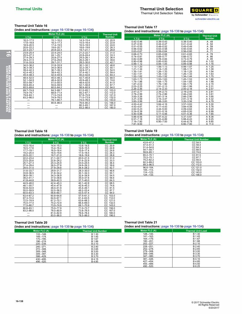
16-138 © 2017 Schneider ElectricAll Rights Reserved
Thermal Units Thermal Unit Selection
schneider-electric.us
Thermal Unit Selection Tables
Thermal Unit Table 16(index and instructions: page 16-130 to page 16-134)
Motor FLC (A) Thermal UnitNumber1.T.U. 2 T.U. 3 T.U.
16.2–17.517.6–18.818.9–20.520.6–22.222.3–23.7
15.1–16.216.3–17.317.4–19.519.6–20.720.8–22.3
14.3–15.415.5–16.416.5–18.518.6–19.619.7–21.1
CC 20.9CC 22.8CC 24.6CC 26.3CC 28.8
23.8–25.425.5–27.327.4–29.329.4–31.531.6–33.9
22.4–24.024.1–25.725.8–27.527.6–29.629.7–31.7
21.2–22.722.8–24.424.5–26.126.2–28.128.2–30.0
CC 31.0CC 33.3CC 36.4CC 39.6CC 42.7
34.0–36.236.3–39.339.4–42.342.4–45.345.4–48.3
31.8–33.934.0–36.636.7–39.339.4–42.342.4–44.9
30.1–32.132.2–34.734.8–37.337.4–40.140.2–42.6
CC 46.6CC 50.1CC 54.5CC 59.4CC 64.3
48.4–52.052.1–54.955.0–59.759.8–65.465.5–69.6
45.0–48.348.4–50.951.0–55.555.6–59.960.0–64.2
42.7–45.845.9–48.348.4–52.652.7–56.856.9–60.9
CC 68.5CC 74.6CC 81.5CC 87.7CC 94.0
69.7–74.874.9–79.779.8–83.183.2–86.0
—
64.3–68.768.8–71.471.5–74.874.9–78.078.1–80.7
61.0–65.165.2–67.767.8–70.971.0–73.974.0–76.5
CC 103.0CC 112.0CC 121.0CC 132.0CC 143.0
———
80.8–86.0——
76.6–80.280.3–83.183.2–86.0
CC 156.0CC 167.0CC 180.0
Thermal Unit Table 17(index and instructions: page 16-130 to page 16-134)
Motor FLC (A) Thermal UnitNumber1.T.U. 2 T.U. 3 T.U.
0.42–0.460.47–0.500.51–0.550.56–0.620.63–0.67
0.39–0.430.44–0.470.48–0.520.53–0.580.59–0.64
0.38–0.400.41–0.440.45–0.490.50–0.550.56–0.60
A .49A .54A .59A .65A .71
0.68–0.730.74–0.810.82–0.890.90–0.980.99–1.12
0.65–0.680.69–0.770.78–0.840.85–0.930.94–1.05
0.61–0.650.66–0.720.73–0.790.80–0.880.89–0.98
A .78A .86A .95A 1.02A 1.16
1.13–1.201.21–1.341.35–1.411.42–1.511.52–1.62
1.06–1.131.14–1.251.26–1.331.34–1.421.43–1.52
0.99–1.071.08–1.171.18–1.251.26–1.331.34–1.44
A 1.25A 1.39A 1.54A 1.63A 1.75
1.63–1.731.74–1.861.87–2.022.03–2.252.26–2.46
1.53–1.631.64–1.751.76–1.901.91–2.132.14–2.33
1.45–1.531.54–1.651.66–1.791.80–1.992.00–2.18
A 1.86A 1.99A 2.15A 2.31A 2.57
2.47–2.772.78–2.993.00–3.263.27–3.593.60–3.99
2.34–2.732.74–2.862.87–3.143.15–3.473.48–3.83
2.19–2.452.46–2.652.66–2.902.91–3.193.20–3.56
A 2.81A 3.61A 3.95A 4.32A 4.79
4.00–4.424.43–4.614.62–5.235.24–5.395.40–5.88
3.84–4.164.17–4.434.44–5.005.01–5.165.17–5.56
3.57–3.833.84–4.084.09–4.644.65–5.005.01–5.36
A 5.30A 5.78A 6.20A 6.99A 7.65
5.89–6.566.57–7.187.19–7.807.81–9.00
5.57–6.226.23–6.896.90–7.00
—
5.37–5.875.88–6.436.44–6.796.80–7.00
A 8.38A 9.25A 9.85A 11.0
Thermal Unit Table 18(index and instructions: page 16-130 to page 16-134)
Motor FLC (A) Thermal UnitNumber1.T.U. 2 T.U. 3 T.U.
15.5–16.416.5–17.617.7–19.119.2–20.420.5–22.1
14.4–15.315.4–16.416.5–18.418.5–19.619.7–21.0
13.6–14.514.6–15.515.6–17.417.5–18.518.6–19.9
CC 20.9CC 22.8CC 24.6CC 26.3CC 28.8
22.2–23.423.5–25.625.7–27.327.4–29.429.5–31.5
21.1–22.722.8–24.224.3–25.926.0–27.827.9–29.8
20.0–21.521.6–22.923.0–24.524.6–26.326.4–28.2
CC 31.0CC 33.3CC 36.4CC 39.6CC 42.7
31.6–33.733.8–36.536.6–39.139.2–41.741.8–44.8
29.9–31.731.8–34.234.3–36.937.0–39.839.9–42.3
28.3–30.030.1–32.332.4–34.935.0–37.637.7–40.0
CC 46.6CC 50.1CC 54.5CC 59.4CC 64.3
44.9–48.048.1–50.750.8–54.955.0–59.960.0–63.3
42.4–45.345.4–47.948.0–51.952.0–56.556.6–60.7
40.1–42.842.9–45.345.4–49.149.2–53.453.5–57.4
CC 68.5CC 74.6CC 81.5CC 87.7CC 94.0
63.4–67.267.3–72.472.5–74.975.0–77.477.5–80.7
60.8–64.864.9–67.167.2–70.170.2–72.973.0–74.9
57.5–61.361.4–63.563.6–66.366.4–69.069.1–70.9
CC 103.0CC 112.0CC 121.0CC 132.0CC 143.0
80.8–83.183.2–86.0
——
75.0–77.978.0–80.981.0–82.983.0–86.0
71.0–73.773.8–76.576.6–78.478.5–86.0
CC 156.0CC 167.0CC 180.0CC 196.0
Thermal Unit Table 19(index and instructions: page 16-130 to page 16-134)
Motor FLC (A) Thermal Unit Number43.6–47.347.4–51.351.4–54.654.7–59.759.8–65.1
CC 54.5CC 59.4CC 64.3CC 68.5CC 74.6
65.2–70.170.2–75.175.2–82.282.3–89.289.3–96.5
CC 81.5CC 87.7CC 94.0CC 103.0CC 112.0
96.6–104.105.–113.114.–123.124.–133.
CC 121.0CC 132.0CC 143.0CC 156.0
Thermal Unit Table 20(index and instructions: page 16-130 to page 16-134)
Motor FLC (A) Thermal Unit Number133.–148.149.–174.175.–195.196.–219.220.–239.
B 1.30B 1.45B 1.67B 1.88B 2.10
240.–271.272.–308.309.–348.349.–397.398.–429.
B 2.40B 2.65B 3.00B 3.30B 3.70
430.–495.496.–520.
B 4.15B 4.85
Thermal Unit Table 21(index and instructions: page 16-130 to page 16-134)
Motor FLC (A) Thermal Unit Load128.–140.141.–163.164.–179.180.–201.202.–227.
B 1.30B 1.45B 1.67B 1.88B 2.10
228.–251.252.–278.279.–308.309.–346.347.–380.
B 2.40B 2.65B 3.00B 3.30B 3.70
381.–426.427.–454.455.–489.490.–520.
B 4.15B 4.85B 5.50B 6.25
6/20/2017
16NEMAANDDEFINITEPURPOSE
CONTA
CTORSANDSTA
RTERS
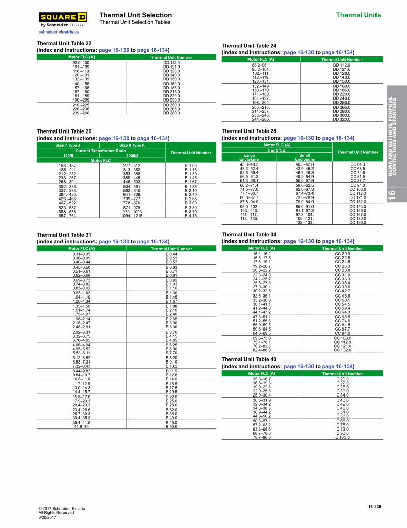
© 2017 Schneider ElectricAll Rights Reserved
16-139
schneider-electric.us
Thermal Unit Selection Thermal UnitsThermal Unit Selection Tables
Thermal Unit Table 22(index and instructions: page 16-130 to page 16-134)
Motor FLC (A) Thermal Unit Number92.0–100.101.–109.110.–119.120.–131.132.–139.
DD 112.0DD 121.0DD 128.0DD 140.0DD 150.0
140.–156.157.–166.167.–180.181.–189.190.–209.
DD 160.0DD 185.0DD 213.0DD 220.0DD 230.0
210.–225.226.–238.239.–266.
DD 250.0DD 265.0DD 280.0
Thermal Unit Table 24(index and instructions: page 16-130 to page 16-134)
Motor FLC (A) Thermal Unit Number88.2–95.195.2–101.102.–111.112.–119.120.–131.
DD 112.0DD 121.0DD 128.0DD 140.0DD 150.0
132.–149.150.–170.171.–180.181.–197.198.–204.
DD 160.0DD 185.0DD 220.0DD 240.0DD 250.0
205.–213.214.–237.238.–243.244.–266.
DD 265.0DD 280.0DD 300.0DD 320.0
Thermal Unit Table 26(index and instructions: page 16-130 to page 16-134)
Size 7 Type J Size 8 Type K
Thermal Unit NumberCurrent Transformer Ratio120/5 2000/5
Motor FLC166.–187.188.–211.212.–232.233.–267.268.–301.
277.–312.313.–352.353.–388.389.–445.446.–503.
B 1.03B 1.16B 1.30B 1.45B 1.67
302.–336.337.–383.384.–425.426.–466.467.–522.
504.–561.562.–640.641.–708.709.–777.778.–870.
B 1.88B 2.10B 2.40B 2.65B 3.00
523.–587.588.–656.657.–764.
871.–978.979.–1093.1094.–1215.
B 3.30B 3.70B 4.15
Thermal Unit Table 28(index and instructions: page 16-130 to page 16-134)
Motor FLC (A)
Thermal Unit Number2 or 3 T.U.Large
EnclosureSmall
Enclosure45.3–48.248.3–52.452.5–56.456.5–61.261.3–66.1
40.3–42.842.9–46.246.3–49.849.9–54.955.0–57.9
CC 64.3CC 68.5CC 74.6CC 81.5CC 87.7
66.2–71.471.5–77.077.1–80.780.8–87.787.8–94.9
58.0–62.562.6–67.367.4–73.473.5–78.979.0–84.9
CC 94.0CC 103.0CC 112.0CC 121.0CC 132.0
95.0–102.103.–110.111.–117.118.–133.
—
85.0–91.091.1–97.297.3–104.105.–121.122.–133.
CC 143.0CC 156.0CC 167.0CC 180.0CC 196.0
Thermal Unit Table 31(index and instructions: page 16-130 to page 16-134)
Motor FLC (A) Thermal Unit Number0.31–0.350.36–0.390.40–0.44
B 0.44B 0.51B 0.57
0.45–0.500.51–0.610.62–0.68
B 0.63B 0.71B 0.81
0.69–0.730.74–0.820.83–0.92
B 0.92B 1.03B 1.16
0.93–1.031.04–1.191.20–1.34
B 1.30B 1.45B 1.67
1.35–1.501.51–1.741.75–1.97
B 1.88B 2.10B 2.40
1.98–2.142.15–2.472.48–2.91
B 2.65B 3.00B 3.30
2.92–3.313.32–3.753.76–4.05
B 3.70B 4.15B 4.85
4.06–4.944.95–5.525.53–6.11
B 6.25B 6.90B 7.70
6.12–6.526.53–7.317.32–8.43
B 8.20B 9.10B 10.2
8.44–9.839.84–10.710.8–11.6
B 11.5B 12.8B 14.0
11.7–12.913.0–14.314.4–15.7
B 15.5B 17.5B 19.5
15.8–17.817.9–20.320.4–23.3
B 22.0B 25.0B 28.0
23.4–26.626.7–30.330.4–35.3
B 32.0B 36.0B 40.0
35.4–41.541.6–45
B 45.0B 50.0
Thermal Unit Table 34(index and instructions: page 16-130 to page 16-134)
Motor FLC (A) Thermal Unit Number15.1–16.216.3–17.517.6–19.119.2–20.720.8–22.2
CC 20.9CC 22.8CC 24.6CC 26.3CC 28.8
22.3–24.024.1–25.725.8–27.827.9–30.130.2–32.5
CC 31.0CC 33.3CC 36.4CC 39.6CC 42.7
32.6–35.135.2–38.038.1–41.141.2–44.044.1–47.2
CC 46.6CC 50.1CC 54.5CC 59.4CC 64.3
47.3–51.151.2–55.855.9–59.559.6–64.564.6–69.5
CC 68.5CC 74.6CC 81.5CC 87.7CC 94.0
69.6–75.075.1–78.178.2–82.382.4–86.0
CC 103.0CC 112.0CC 121.0CC 132.0
Thermal Unit Table 40(index and instructions: page 16-130 to page 16-134)
Motor FLC (A) Thermal Unit Number15.3–16.716.8–19.819.9–22.822.9–25.825.9–30.4
C 20.0C 22.0C 26.0C 30.0C 34.0
30.5–31.932.0–34.234.3–38.838.9–44.244.3–50.2
C 40.0C 42.0C 45.0C 51.0C 58.0
50.3–57.157.2–63.263.3–68.668.7–78.678.7–86.0
C 66.0C 75.0C 83.0C 90.0C 103.0
16NEMAANDDEFINITEPURPOSE
CONTA
CTORSANDSTA
RTERS
6/20/2017
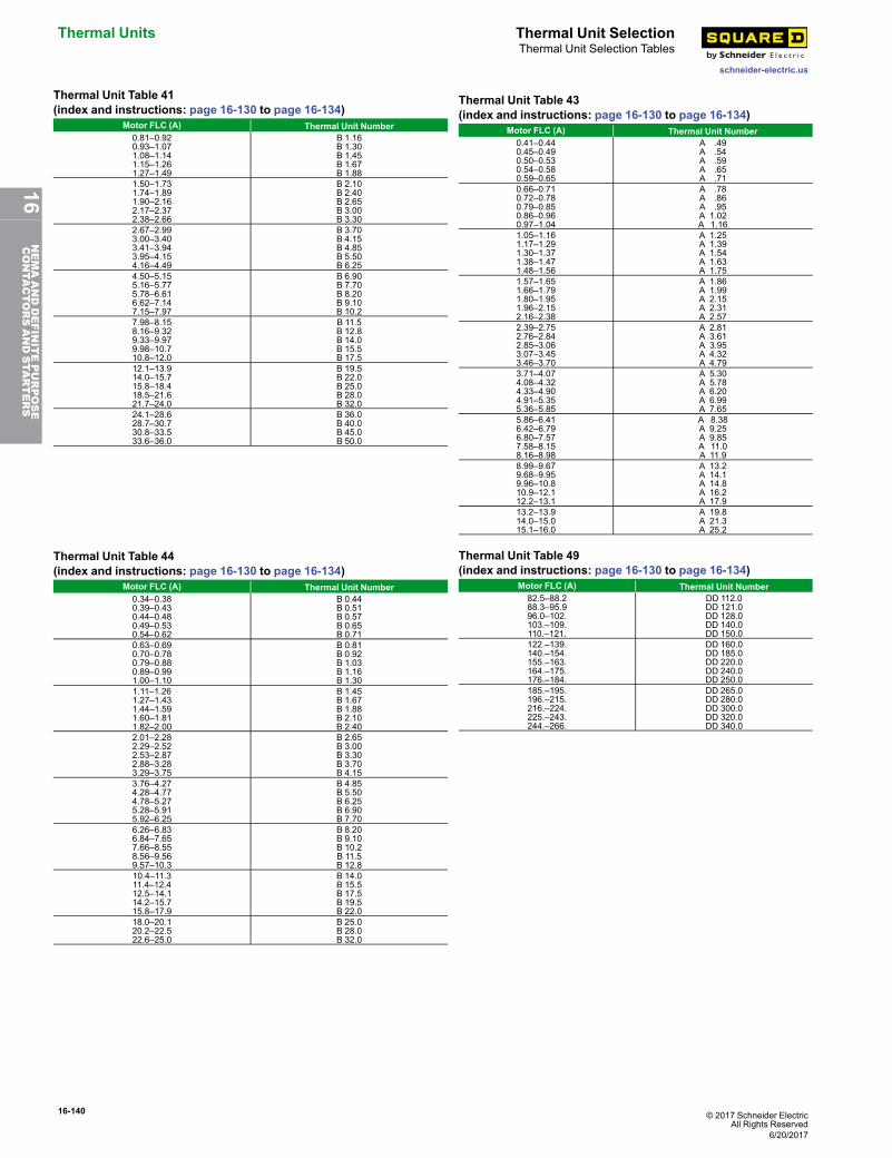
16-140 © 2017 Schneider ElectricAll Rights Reserved
Thermal Units Thermal Unit Selection
schneider-electric.us
Thermal Unit Selection Tables
Thermal Unit Table 41(index and instructions: page 16-130 to page 16-134)
Motor FLC (A) Thermal Unit Number0.81–0.920.93–1.071.08–1.141.15–1.261.27–1.49
B 1.16B 1.30B 1.45B 1.67B 1.88
1.50–1.731.74–1.891.90–2.162.17–2.372.38–2.66
B 2.10B 2.40B 2.65B 3.00B 3.30
2.67–2.993.00–3.403.41–3.943.95–4.154.16–4.49
B 3.70B 4.15B 4.85B 5.50B 6.25
4.50–5.155.16–5.775.78–6.616.62–7.147.15–7.97
B 6.90B 7.70B 8.20B 9.10B 10.2
7.98–8.158.16–9.329.33–9.979.98–10.710.8–12.0
B 11.5B 12.8B 14.0B 15.5B 17.5
12.1–13.914.0–15.715.8–18.418.5–21.621.7–24.0
B 19.5B 22.0B 25.0B 28.0B 32.0
24.1–28.628.7–30.730.8–33.533.6–36.0
B 36.0B 40.0B 45.0B 50.0
Thermal Unit Table 43(index and instructions: page 16-130 to page 16-134)
Motor FLC (A) Thermal Unit Number0.41–0.440.45–0.490.50–0.530.54–0.580.59–0.65
A .49A .54A .59A .65A .71
0.66–0.710.72–0.780.79–0.850.86–0.960.97–1.04
A .78A .86A .95A 1.02A 1.16
1.05–1.161.17–1.291.30–1.371.38–1.471.48–1.56
A 1.25A 1.39A 1.54A 1.63A 1.75
1.57–1.651.66–1.791.80–1.951.96–2.152.16–2.38
A 1.86A 1.99A 2.15A 2.31A 2.57
2.39–2.752.76–2.842.85–3.063.07–3.453.46–3.70
A 2.81A 3.61A 3.95A 4.32A 4.79
3.71–4.074.08–4.324.33–4.904.91–5.355.36–5.85
A 5.30A 5.78A 6.20A 6.99A 7.65
5.86–6.416.42–6.796.80–7.577.58–8.158.16–8.98
A 8.38A 9.25A 9.85A 11.0A 11.9
8.99–9.679.68–9.959.96–10.810.9–12.112.2–13.1
A 13.2A 14.1A 14.8A 16.2A 17.9
13.2–13.914.0–15.015.1–16.0
A 19.8A 21.3A 25.2
Thermal Unit Table 44(index and instructions: page 16-130 to page 16-134)
Motor FLC (A) Thermal Unit Number0.34–0.380.39–0.430.44–0.480.49–0.530.54–0.62
B 0.44B 0.51B 0.57B 0.65B 0.71
0.63–0.690.70–0.780.79–0.880.89–0.991.00–1.10
B 0.81B 0.92B 1.03B 1.16B 1.30
1.11–1.261.27–1.431.44–1.591.60–1.811.82–2.00
B 1.45B 1.67B 1.88B 2.10B 2.40
2.01–2.282.29–2.522.53–2.872.88–3.283.29–3.75
B 2.65B 3.00B 3.30B 3.70B 4.15
3.76–4.274.28–4.774.78–5.275.28–5.915.92–6.25
B 4.85B 5.50B 6.25B 6.90B 7.70
6.26–6.836.84–7.657.66–8.558.56–9.569.57–10.3
B 8.20B 9.10B 10.2B 11.5B 12.8
10.4–11.311.4–12.412.5–14.114.2–15.715.8–17.9
B 14.0B 15.5B 17.5B 19.5B 22.0
18.0–20.120.2–22.522.6–25.0
B 25.0B 28.0B 32.0
Thermal Unit Table 49(index and instructions: page 16-130 to page 16-134)
Motor FLC (A) Thermal Unit Number82.5–88.288.3–95.996.0–102.103.–109.110.–121.
DD 112.0DD 121.0DD 128.0DD 140.0DD 150.0
122.–139.140.–154.155.–163.164.–175.176.–184.
DD 160.0DD 185.0DD 220.0DD 240.0DD 250.0
185.–195.196.–215.216.–224.225.–243.244.–266.
DD 265.0DD 280.0DD 300.0DD 320.0DD 340.0
6/20/2017
16NEMAANDDEFINITEPURPOSE
CONTA
CTORSANDSTA
RTERS
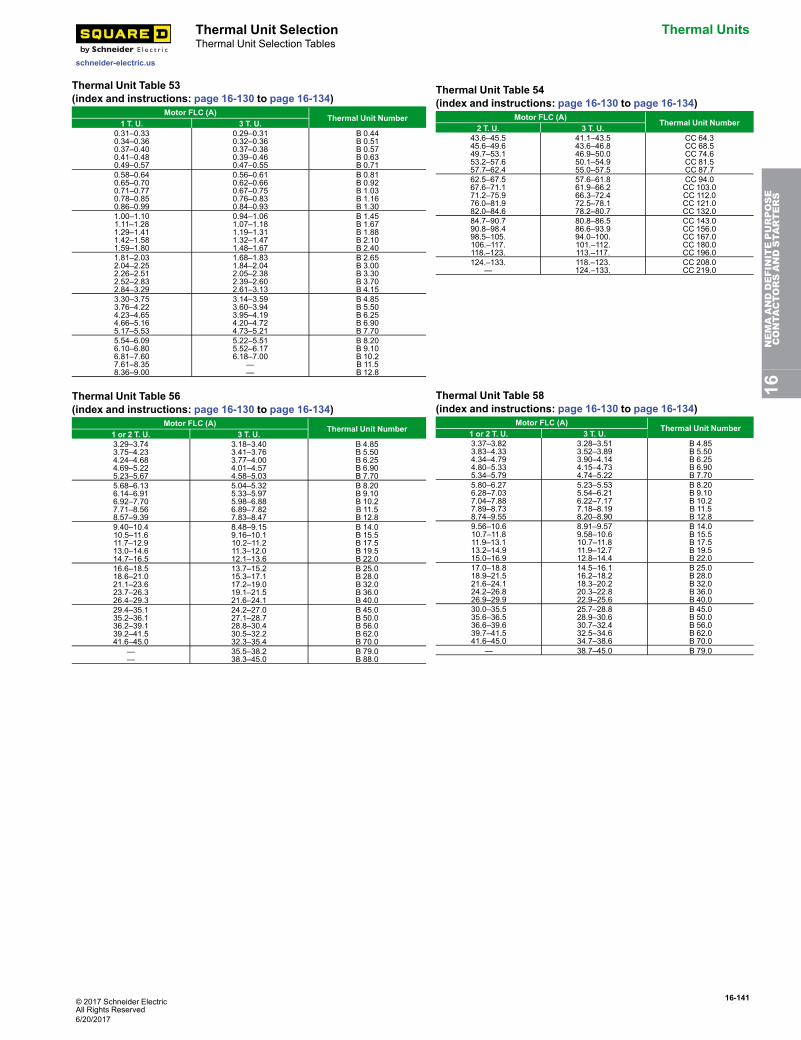
© 2017 Schneider ElectricAll Rights Reserved
16-141
schneider-electric.us
Thermal Unit Selection Thermal UnitsThermal Unit Selection Tables
Thermal Unit Table 53(index and instructions: page 16-130 to page 16-134)
Motor FLC (A)Thermal Unit Number
1 T. U. 3 T. U.0.31–0.330.34–0.360.37–0.400.41–0.480.49–0.57
0.29–0.310.32–0.360.37–0.380.39–0.460.47–0.55
B 0.44B 0.51B 0.57B 0.63B 0.71
0.58–0.640.65–0.700.71–0.770.78–0.850.86–0.99
0.56–0.610.62–0.660.67–0.750.76–0.830.84–0.93
B 0.81B 0.92B 1.03B 1.16B 1.30
1.00–1.101.11–1.281.29–1.411.42–1.581.59–1.80
0.94–1.061.07–1.181.19–1.311.32–1.471.48–1.67
B 1.45B 1.67B 1.88B 2.10B 2.40
1.81–2.032.04–2.252.26–2.512.52–2.832.84–3.29
1.68–1.831.84–2.042.05–2.382.39–2.602.61–3.13
B 2.65B 3.00B 3.30B 3.70B 4.15
3.30–3.753.76–4.224.23–4.654.66–5.165.17–5.53
3.14–3.593.60–3.943.95–4.194.20–4.724.73–5.21
B 4.85B 5.50B 6.25B 6.90B 7.70
5.54–6.096.10–6.806.81–7.607.61–8.358.36–9.00
5.22–5.515.52–6.176.18–7.00
——
B 8.20B 9.10B 10.2B 11.5B 12.8
Thermal Unit Table 54(index and instructions: page 16-130 to page 16-134)
Motor FLC (A)Thermal Unit Number
2 T. U. 3 T. U.43.6–45.545.6–49.649.7–53.153.2–57.657.7–62.4
41.1–43.543.6–46.846.9–50.050.1–54.955.0–57.5
CC 64.3CC 68.5CC 74.6CC 81.5CC 87.7
62.5–67.567.6–71.171.2–75.976.0–81.982.0–84.6
57.6–61.861.9–66.266.3–72.472.5–78.178.2–80.7
CC 94.0CC 103.0CC 112.0CC 121.0CC 132.0
84.7–90.790.8–98.498.5–105.106.–117.118.–123.
80.8–86.586.6–93.994.0–100.101.–112.113.–117.
CC 143.0CC 156.0CC 167.0CC 180.0CC 196.0
124.–133.—
118.–123.124.–133.
CC 208.0CC 219.0
Thermal Unit Table 56(index and instructions: page 16-130 to page 16-134)
Motor FLC (A)Thermal Unit Number
1 or 2 T. U. 3 T. U.3.29–3.743.75–4.234.24–4.684.69–5.225.23–5.67
3.18–3.403.41–3.763.77–4.004.01–4.574.58–5.03
B 4.85B 5.50B 6.25B 6.90B 7.70
5.68–6.136.14–6.916.92–7.707.71–8.568.57–9.39
5.04–5.325.33–5.975.98–6.886.89–7.827.83–8.47
B 8.20B 9.10B 10.2B 11.5B 12.8
9.40–10.410.5–11.611.7–12.913.0–14.614.7–16.5
8.48–9.159.16–10.110.2–11.211.3–12.012.1–13.6
B 14.0B 15.5B 17.5B 19.5B 22.0
16.6–18.518.6–21.021.1–23.623.7–26.326.4–29.3
13.7–15.215.3–17.117.2–19.019.1–21.521.6–24.1
B 25.0B 28.0B 32.0B 36.0B 40.0
29.4–35.135.2–36.136.2–39.139.2–41.541.6–45.0
24.2–27.027.1–28.728.8–30.430.5–32.232.3–35.4
B 45.0B 50.0B 56.0B 62.0B 70.0
——
35.5–38.238.3–45.0
B 79.0B 88.0
Thermal Unit Table 58(index and instructions: page 16-130 to page 16-134)
Motor FLC (A)Thermal Unit Number
1 or 2 T. U. 3 T. U.3.37–3.823.83–4.334.34–4.794.80–5.335.34–5.79
3.28–3.513.52–3.893.90–4.144.15–4.734.74–5.22
B 4.85B 5.50B 6.25B 6.90B 7.70
5.80–6.276.28–7.037.04–7.887.89–8.738.74–9.55
5.23–5.535.54–6.216.22–7.177.18–8.198.20–8.90
B 8.20B 9.10B 10.2B 11.5B 12.8
9.56–10.610.7–11.811.9–13.113.2–14.915.0–16.9
8.91–9.579.58–10.610.7–11.811.9–12.712.8–14.4
B 14.0B 15.5B 17.5B 19.5B 22.0
17.0–18.818.9–21.521.6–24.124.2–26.826.9–29.9
14.5–16.116.2–18.218.3–20.220.3–22.822.9–25.6
B 25.0B 28.0B 32.0B 36.0B 40.0
30.0–35.535.6–36.536.6–39.639.7–41.541.6–45.0
25.7–28.828.9–30.630.7–32.432.5–34.634.7–38.6
B 45.0B 50.0B 56.0B 62.0B 70.0
— 38.7–45.0 B 79.0
16NEMAANDDEFINITEPURPOSE
CONTA
CTORSANDSTA
RTERS
6/20/2017
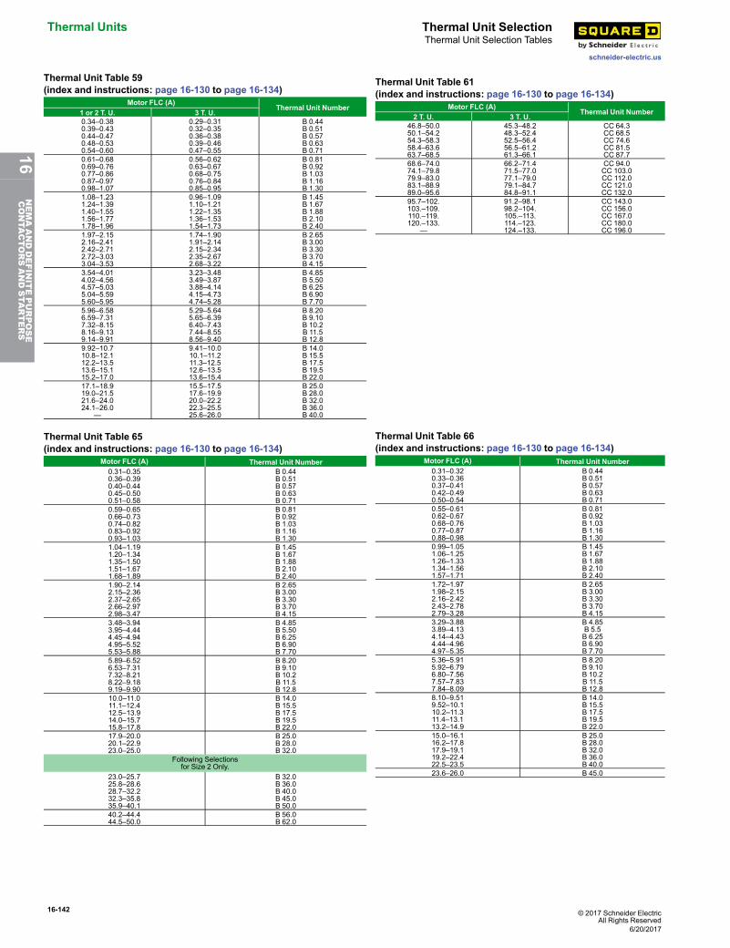
16-142 © 2017 Schneider ElectricAll Rights Reserved
Thermal Units Thermal Unit Selection
schneider-electric.us
Thermal Unit Selection Tables
Thermal Unit Table 59(index and instructions: page 16-130 to page 16-134)
Motor FLC (A)Thermal Unit Number
1 or 2 T. U. 3 T. U.0.34–0.380.39–0.430.44–0.470.48–0.530.54–0.60
0.29–0.310.32–0.350.36–0.380.39–0.460.47–0.55
B 0.44B 0.51B 0.57B 0.63B 0.71
0.61–0.680.69–0.760.77–0.860.87–0.970.98–1.07
0.56–0.620.63–0.670.68–0.750.76–0.840.85–0.95
B 0.81B 0.92B 1.03B 1.16B 1.30
1.08–1.231.24–1.391.40–1.551.56–1.771.78–1.96
0.96–1.091.10–1.211.22–1.351.36–1.531.54–1.73
B 1.45B 1.67B 1.88B 2.10B 2.40
1.97–2.152.16–2.412.42–2.712.72–3.033.04–3.53
1.74–1.901.91–2.142.15–2.342.35–2.672.68–3.22
B 2.65B 3.00B 3.30B 3.70B 4.15
3.54–4.014.02–4.564.57–5.035.04–5.595.60–5.95
3.23–3.483.49–3.873.88–4.144.15–4.734.74–5.28
B 4.85B 5.50B 6.25B 6.90B 7.70
5.96–6.586.59–7.317.32–8.158.16–9.139.14–9.91
5.29–5.645.65–6.396.40–7.437.44–8.558.56–9.40
B 8.20B 9.10B 10.2B 11.5B 12.8
9.92–10.710.8–12.112.2–13.513.6–15.115.2–17.0
9.41–10.010.1–11.211.3–12.512.6–13.513.6–15.4
B 14.0B 15.5B 17.5B 19.5B 22.0
17.1–18.919.0–21.521.6–24.024.1–26.0
—
15.5–17.517.6–19.920.0–22.222.3–25.525.6–26.0
B 25.0B 28.0B 32.0B 36.0B 40.0
Thermal Unit Table 61(index and instructions: page 16-130 to page 16-134)
Motor FLC (A)Thermal Unit Number
2 T. U. 3 T. U.46.8–50.050.1–54.254.3–58.358.4–63.663.7–68.5
45.3–48.248.3–52.452.5–56.456.5–61.261.3–66.1
CC 64.3CC 68.5CC 74.6CC 81.5CC 87.7
68.6–74.074.1–79.879.9–83.083.1–88.989.0–95.6
66.2–71.471.5–77.077.1–79.079.1–84.784.8–91.1
CC 94.0CC 103.0CC 112.0CC 121.0CC 132.0
95.7–102.103.–109.110.–119.120.–133.
—
91.2–98.198.2–104.105.–113.114.–123.124.–133.
CC 143.0CC 156.0CC 167.0CC 180.0CC 196.0
Thermal Unit Table 65(index and instructions: page 16-130 to page 16-134)
Motor FLC (A) Thermal Unit Number0.31–0.350.36–0.390.40–0.440.45–0.500.51–0.58
B 0.44B 0.51B 0.57B 0.63B 0.71
0.59–0.650.66–0.730.74–0.820.83–0.920.93–1.03
B 0.81B 0.92B 1.03B 1.16B 1.30
1.04–1.191.20–1.341.35–1.501.51–1.671.68–1.89
B 1.45B 1.67B 1.88B 2.10B 2.40
1.90–2.142.15–2.362.37–2.652.66–2.972.98–3.47
B 2.65B 3.00B 3.30B 3.70B 4.15
3.48–3.943.95–4.444.45–4.944.95–5.525.53–5.88
B 4.85B 5.50B 6.25B 6.90B 7.70
5.89–6.526.53–7.317.32–8.218.22–9.189.19–9.90
B 8.20B 9.10B 10.2B 11.5B 12.8
10.0–11.011.1–12.412.5–13.914.0–15.715.8–17.8
B 14.0B 15.5B 17.5B 19.5B 22.0
17.9–20.020.1–22.923.0–25.0
B 25.0B 28.0B 32.0
Following Selectionsfor Size 2 Only.
23.0–25.725.8–28.628.7–32.232.3–35.835.9–40.1
B 32.0B 36.0B 40.0B 45.0B 50.0
40.2–44.444.5–50.0
B 56.0B 62.0
Thermal Unit Table 66(index and instructions: page 16-130 to page 16-134)
Motor FLC (A) Thermal Unit Number0.31–0.320.33–0.360.37–0.410.42–0.490.50–0.54
B 0.44B 0.51B 0.57B 0.63B 0.71
0.55–0.610.62–0.670.68–0.760.77–0.870.88–0.98
B 0.81B 0.92B 1.03B 1.16B 1.30
0.99–1.051.06–1.251.26–1.331.34–1.561.57–1.71
B 1.45B 1.67B 1.88B 2.10B 2.40
1.72–1.971.98–2.152.16–2.422.43–2.782.79–3.28
B 2.65B 3.00B 3.30B 3.70B 4.15
3.29–3.883.89–4.134.14–4.434.44–4.964.97–5.35
B 4.85B 5.5B 6.25B 6.90B 7.70
5.36–5.915.92–6.796.80–7.567.57–7.837.84–8.09
B 8.20B 9.10B 10.2B 11.5B 12.8
8.10–9.519.52–10.110.2–11.311.4–13.113.2–14.9
B 14.0B 15.5B 17.5B 19.5B 22.0
15.0–16.116.2–17.817.9–19.119.2–22.422.5–23.5
B 25.0B 28.0B 32.0B 36.0B 40.0
23.6–26.0 B 45.0
6/20/2017
16NEMAANDDEFINITEPURPOSE
CONTA
CTORSANDSTA
RTERS
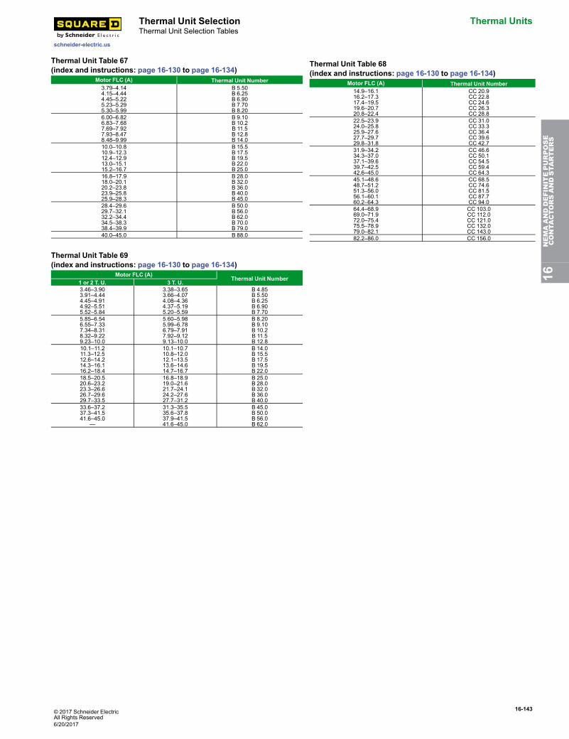
© 2017 Schneider ElectricAll Rights Reserved
16-143
schneider-electric.us
Thermal Unit Selection Thermal UnitsThermal Unit Selection Tables
Thermal Unit Table 67(index and instructions: page 16-130 to page 16-134)
Motor FLC (A) Thermal Unit Number3.79–4.144.15–4.444.45–5.225.23–5.295.30–5.99
B 5.50B 6.25B 6.90B 7.70B 8.20
6.00–6.826.83–7.687.69–7.927.93–8.478.48–9.99
B 9.10B 10.2B 11.5B 12.8B 14.0
10.0–10.810.9–12.312.4–12.913.0–15.115.2–16.7
B 15.5B 17.5B 19.5B 22.0B 25.0
16.8–17.918.0–20.120.2–23.823.9–25.825.9–28.3
B 28.0B 32.0B 36.0B 40.0B 45.0
28.4–29.629.7–32.132.2–34.434.5–38.338.4–39.9
B 50.0B 56.0B 62.0B 70.0B 79.0
40.0–45.0 B 88.0
Thermal Unit Table 68(index and instructions: page 16-130 to page 16-134)
Motor FLC (A) Thermal Unit Number14.9–16.116.2–17.317.4–19.519.6–20.720.8–22.4
CC 20.9CC 22.8CC 24.6CC 26.3CC 28.8
22.5–23.924.0–25.825.9–27.627.7–29.729.8–31.8
CC 31.0CC 33.3CC 36.4CC 39.6CC 42.7
31.9–34.234.3–37.037.1–39.639.7–42.542.6–45.0
CC 46.6CC 50.1CC 54.5CC 59.4CC 64.3
45.1–48.648.7–51.251.3–56.056.1–60.160.2–64.3
CC 68.5CC 74.6CC 81.5CC 87.7CC 94.0
64.4–68.969.0–71.972.0–75.475.5–78.979.0–82.1
CC 103.0CC 112.0CC 121.0CC 132.0CC 143.0
82.2–86.0 CC 156.0
Thermal Unit Table 69(index and instructions: page 16-130 to page 16-134)
Motor FLC (A)Thermal Unit Number
1 or 2 T. U. 3 T. U.3.46–3.903.91–4.444.45–4.914.92–5.515.52–5.84
3.38–3.653.66–4.074.08–4.364.37–5.195.20–5.59
B 4.85B 5.50B 6.25B 6.90B 7.70
5.85–6.546.55–7.337.34–8.318.32–9.229.23–10.0
5.60–5.985.99–6.786.79–7.917.92–9.129.13–10.0
B 8.20B 9.10B 10.2B 11.5B 12.8
10.1–11.211.3–12.512.6–14.214.3–16.116.2–18.4
10.1–10.710.8–12.012.1–13.513.6–14.614.7–16.7
B 14.0B 15.5B 17.5B 19.5B 22.0
18.5–20.520.6–23.223.3–26.626.7–29.629.7–33.5
16.8–18.919.0–21.621.7–24.124.2–27.627.7–31.2
B 25.0B 28.0B 32.0B 36.0B 40.0
33.6–37.237.3–41.541.6–45.0
—
31.3–35.535.6–37.837.9–41.541.6–45.0
B 45.0B 50.0B 56.0B 62.0
16NEMAANDDEFINITEPURPOSE
CONTA
CTORSANDSTA
RTERS
6/20/2017
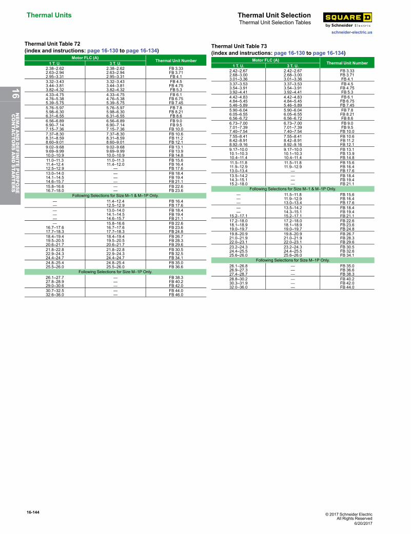
16-144 © 2017 Schneider ElectricAll Rights Reserved
Thermal Units Thermal Unit Selection
schneider-electric.us
Thermal Unit Selection Tables
Thermal Unit Table 72(index and instructions: page 16-130 to page 16-134)
Motor FLC (A)Thermal Unit Number
1 T. U. 3 T. U.2.38–2.622.63–2.942.95–3.31
2.38–2.622.63–2.942.95–3.31
FB 3.33FB 3.71FB 4.1
3.32–3.433.44–3.813.82–4.32
3.32–3.433.44–3.813.82–4.32
FB 4.5FB 4.75FB 5.3
4.33–4.754.76–5.385.39–5.75
4.33–4.754.76–5.385.39–5.75
FB 6.1FB 6.75FB 7.45
5.76–5.975.98–6.306.31–6.55
5.76–5.975.98–6.306.31–6.55
FB 7.8FB 8.21FB 8.6
6.56–6.896.90–7.147.15–7.36
6.56–6.896.90–7.147.15–7.36
FB 9.0FB 9.5FB 10.0
7.37–8.308.31–8.598.60–9.01
7.37–8.308.31–8.598.60–9.01
FB 10.6FB 11.2FB 12.1
9.02–9.689.69–9.9910.0–10.9
9.02–9.689.69–9.9910.0–10.9
FB 13.1FB 13.9FB 14.8
11.0–11.311.4–12.412.5–12.9
11.0–11.311.4–12.0
—
FB 15.6FB 16.4FB 17.6
13.0–14.014.1–14.514.6–15.7
———
FB 18.4FB 19.4FB 21.1
15.8–16.616.7–18.0
——
FB 22.6FB 23.6
Following Selections for Size M–1 & M–1P Only.——
11.4–12.412.5–12.9
FB 16.4FB 17.6
———
13.0–14.014.1–14.514.6–15.7
FB 18.4FB 19.4FB 21.1
—16.7–17.617.7–18.3
15.8–16.616.7–17.617.7–18.3
FB 22.6FB 23.6FB 24.8
18.4–19.419.5–20.520.6–21.7
18.4–19.419.5–20.520.6–21.7
FB 26.7FB 28.3FB 29.6
21.8–22.822.9–24.324.4–24.7
21.8–22.822.9–24.324.4–24.7
FB 30.5FB 32.5FB 34.1
24.8–25.425.5–26.0
24.8–25.425.5–26.0
FB 35.0FB 36.6
Following Selections for Size M–1P Only.26.1–27.727.8–28.929.0–30.6
———
FB 38.3FB 40.2FB 42.0
30.7–32.532.6–36.0
——
FB 44.0FB 46.0
Thermal Unit Table 73(index and instructions: page 16-130 to page 16-134)
Motor FLC (A)Thermal Unit Number
1 T. U. 3 T. U.2.42–2.672.68–3.003.01–3.36
2.42–2.672.68–3.003.01–3.36
FB 3.33FB 3.71FB 4.1
3.37–3.533.54–3.913.92–4.41
3.37–3.533.54–3.913.92–4.41
FB 4.5FB 4.75FB 5.3
4.42–4.834.84–5.455.46–5.89
4.42–4.834.84–5.455.46–5.89
FB 6.1FB 6.75FB 7.45
5.90–6.046.05–6.556.56–6.72
5.90–6.046.05–6.556.56–6.72
FB 7.8FB 8.21FB 8.6
6.73–7.007.01–7.397.40–7.54
6.73–7.007.01–7.397.40–7.54
FB 9.0FB 9.5FB 10.0
7.55–8.418.42–8.918.92–9.16
7.55–8.418.42–8.918.92–9.16
FB 10.6FB 11.2FB 12.1
9.17–10.010.1–10.310.4–11.4
9.17–10.010.1–10.310.4–11.4
FB 13.1FB 13.9FB 14.8
11.5–11.811.9–12.913.0–13.4
11.5–11.811.9–12.9
—
FB 15.6FB 16.4FB 17.6
13.5–14.214.3–15.115.2–18.0
———
FB 18.4FB 19.4FB 21.1
Following Selections for Size M–1 & M–1P Only.———
11.5–11.811.9–12.913.0–13.4
FB 15.6FB 16.4FB 17.6
——
15.2–17.1
13.5–14.214.3–15.115.2–17.1
FB 18.4FB 19.4FB 21.1
17.2–18.018.1–18.919.0–19.7
17.2–18.018.1–18.919.0–19.7
FB 22.6FB 23.6FB 24.8
19.8–20.921.0–21.922.0–23.1
19.8–20.921.0–21.922.0–23.1
FB 26.7FB 28.3FB 29.6
23.2–24.324.4–25.525.6–26.0
23.2–24.324.4–25.525.6–26.0
FB 30.5FB 32.6FB 34.1
Following Selections for Size M–1P Only.26.1–26.826.9–27.327.4–28.7
———
FB 35.0FB 36.6FB 38.3
28.8–30.230.3–31.932.0–36.0
———
FB 40.2FB 42.0FB 44.0
6/20/2017
16NEMAANDDEFINITEPURPOSE
CONTA
CTORSANDSTA
RTERS
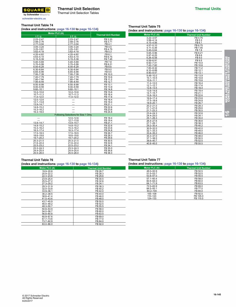
© 2017 Schneider ElectricAll Rights Reserved
16-145
schneider-electric.us
Thermal Unit Selection Thermal UnitsThermal Unit Selection Tables
Thermal Unit Table 74(index and instructions: page 16-130 to page 16-134)
Motor FLC (A)Thermal Unit Number
1 T. U. 3 T. U.2.23–2.472.48–2.762.77–3.04
2.23–2.472.48–2.762.77–3.04
FB 3.33FB 3.71FB 4.1
3.05–3.243.25–3.613.62–4.19
3.05–3.243.25–3.613.62–4.19
FB 4.5FB 4.75FB 5.3
4.20–4.624.63–5.145.15–5.39
4.20–4.624.63–5.145.15–5.39
FB 6.1FB 6.75FB 7.45
5.40–5.695.70–5.996.00–6.29
5.40–5.695.70–5.996.00–6.29
FB 7.8FB 8.21FB 8.6
6.30–6.646.65–6.997.00–7.39
6.30–6.646.65–6.997.00–7.39
FB 9.0FB 9.5FB 10.0
7.40–7.797.80–7.947.95–8.49
7.40–7.797.80–7.947.95–8.49
FB 10.6FB 11.2FB 12.1
8.50–8.999.00–9.599.60–10.1
8.50–8.999.00–9.599.60–10.1
FB 13.1FB 13.9FB 14.8
10.2–10.610.7–11.311.4–12.0
10.2–10.610.7–11.311.4–12.0
FB 15.6FB 16.4FB 17.6
12.0–12.612.7–13.813.9–14.7
———
FB 18.4FB 19.4FB 21.1
14.8–15.215.3–16.216.3–18.0
———
FB 22.6FB 23.6FB 24.8
Following Selections for Size 1 Only.——
13.9–14.7
12.0–12.612.7–13.813.9–14.7
FB 18.4FB 19.4FB 21.1
14.8–15.215.3–16.216.3–17.4
14.8–15.215.3–16.216.3–17.4
FB 22.6FB 23.6FB 24.8
17.5–18.518.6–19.619.7–20.2
17.5–18.518.6–19.619.7–20.2
FB 26.7FB 28.3FB 29.6
20.3–21.521.6–22.422.5–23.2
20.3–21.521.6–22.422.5–23.2
FB 30.5FB 32.6FB 34.1
23.3–24.324.4–25.425.5–26.0
23.3–24.324.4–25.425.5–26.0
FB 35.0FB 36.6FB 38.3
Thermal Unit Table 75(index and instructions: page 16-130 to page 16-134)
Motor FLC (A) Thermal Unit Number3.22–3.573.58–4.144.15–4.56
FB 4.75FB 5.3FB 6.1
4.57–5.105.11–5.395.40–5.64
FB 6.75FB 7.45FB 7.8
5.65–5.965.97–6.256.26–6.58
FB 8.21FB 8.6FB 9.0
6.59–6.916.92–7.417.42–7.82
FB 9.5FB 10.0FB 10.6
7.83–8.328.33–8.898.90–9.47
FB 11.2FB 12.1FB 13.1
9.48–10.010.1–10.510.6–11.1
FB 13.9FB 14.8FB 15.6
11.2–12.012.1–12.712.8–13.5
FB 16.4FB 17.6FB 18.4
13.6–14.614.7–15.715.8–16.5
FB 19.4FB 21.1FB 22.6
16.6–17.417.5–18.818.9–20.1
FB 23.6FB 24.8FB 26.7
20.2–21.021.1–21.621.7–23.3
FB 28.3FB 29.6FB 30.5
23.4–24.324.4–25.025.1–26.3
FB 32.6FB 34.1FB 35.0
26.4–27.627.7–29.129.2–30.4
FB 36.6FB 38.3FB 40.2
30.5–32.032.1–33.333.4–35.2
FB 42.0FB 44.0FB 46.0
35.3–37.037.1–38.538.6–40.7
FB 48.0FB 50.5FB 52.5
40.8–45.0 FB 55.5
Thermal Unit Table 76(index and instructions: page 16-130 to page 16-134)
Motor FLC (A) Thermal Unit Number19.9–20.820.9–22.222.3–23.8
FB 26.7FB 28.3FB 29.6
23.9–25.425.5–27.227.3–29.2
FB 30.5FB 32.6FB 34.1
29.3–31.932.0–33.833.9–36.1
FB 38.3FB 40.2FB 42.0
36.2–38.538.6–41.441.5–43.6
FB 44.0FB 46.0FB 48.0
43.7–45.946.0–48.248.3–50.7
FB 50.5FB 52.5FB 55.5
50.8–53.954.0–56.756.8–60.8
FB 58.0FB 60.0FB 63.5
60.9–67.667.7–73.673.7–82.9
FB 69.0FB 77.0FB 84.0
83.0–86.0 FB 92.0
Thermal Unit Table 77(index and instructions: page 16-130 to page 16-134)
Motor FLC (A) Thermal Unit Number48.0–50.951.0–53.753.8–57.0
FB 50.5FB 52.5FB 55.5
57.1–60.460.5–64.064.1–71.9
FB 58.0FB 60.0FB 63.5
72.0–83.984.0–93.193.2–104
FB 69.0FB 77.0FB 84.0
105–109110–123124–133
FB 92.0FB 105.0FB 115.0
16NEMAANDDEFINITEPURPOSE
CONTA
CTORSANDSTA
RTERS
6/20/2017
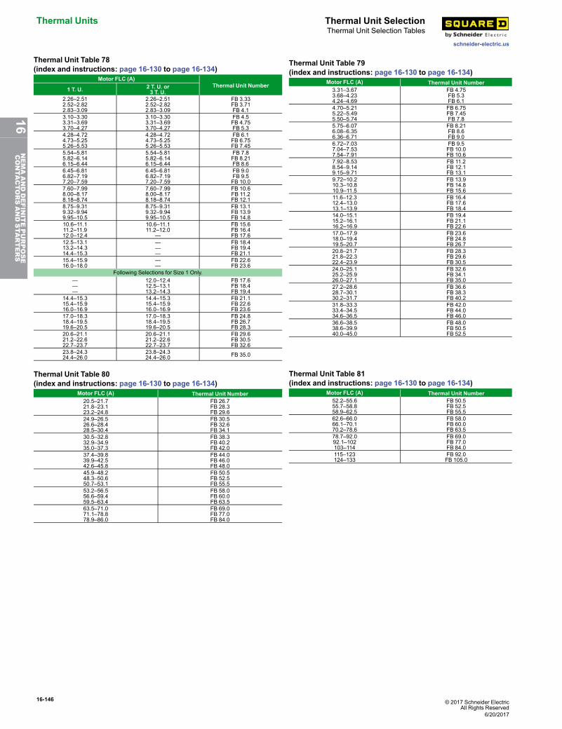
16-146 © 2017 Schneider ElectricAll Rights Reserved
Thermal Units Thermal Unit Selection
schneider-electric.us
Thermal Unit Selection Tables
Thermal Unit Table 78(index and instructions: page 16-130 to page 16-134)
Motor FLC (A)Thermal Unit Number
1 T. U. 2 T. U. or3 T. U.
2.26–2.512.52–2.822.83–3.09
2.26–2.512.52–2.822.83–3.09
FB 3.33FB 3.71FB 4.1
3.10–3.303.31–3.693.70–4.27
3.10–3.303.31–3.693.70–4.27
FB 4.5FB 4.75FB 5.3
4.28–4.724.73–5.255.26–5.53
4.28–4.724.73–5.255.26–5.53
FB 6.1FB 6.75FB 7.45
5.54–5.815.82–6.146.15–6.44
5.54–5.815.82–6.146.15–6.44
FB 7.8FB 8.21FB 8.6
6.45–6.816.82–7.197.20–7.59
6.45–6.816.82–7.197.20–7.59
FB 9.0FB 9.5FB 10.0
7.60–7.998.00–8.178.18–8.74
7.60–7.998.00–8.178.18–8.74
FB 10.6FB 11.2FB 12.1
8.75–9.319.32–9.949.95–10.5
8.75–9.319.32–9.949.95–10.5
FB 13.1FB 13.9FB 14.8
10.6–11.111.2–11.912.0–12.4
10.6–11.111.2–12.0
—
FB 15.6FB 16.4FB 17.6
12.5–13.113.2–14.314.4–15.3
———
FB 18.4FB 19.4FB 21.1
15.4–15.916.0–18.0
——
FB 22.6FB 23.6
Following Selections for Size 1 Only.———
12.0–12.412.5–13.113.2–14.3
FB 17.6FB 18.4FB 19.4
14.4–15.315.4–15.916.0–16.9
14.4–15.315.4–15.916.0–16.9
FB 21.1FB 22.6FB 23.6
17.0–18.318.4–19.519.6–20.5
17.0–18.318.4–19.519.6–20.5
FB 24.8FB 26.7FB 28.3
20.6–21.121.2–22.622.7–23.7
20.6–21.121.2–22.622.7–23.7
FB 29.6FB 30.5FB 32.6
23.8–24.324.4–26.0
23.8–24.324.4–26.0 FB 35.0
Thermal Unit Table 79(index and instructions: page 16-130 to page 16-134)
Motor FLC (A) Thermal Unit Number3.31–3.673.68–4.234.24–4.69
FB 4.75FB 5.3FB 6.1
4.70–5.215.22–5.495.50–5.74
FB 6.75FB 7.45FB 7.8
5.75–6.076.08–6.356.36–6.71
FB 8.21FB 8.6FB 9.0
6.72–7.037.04–7.537.54–7.91
FB 9.5FB 10.0FB 10.6
7.92–8.538.54–9.149.15–9.71
FB 11.2FB 12.1FB 13.1
9.72–10.210.3–10.810.9–11.5
FB 13.9FB 14.8FB 15.6
11.6–12.312.4–13.013.1–13.9
FB 16.4FB 17.6FB 18.4
14.0–15.115.2–16.116.2–16.9
FB 19.4FB 21.1FB 22.6
17.0–17.918.0–19.419.5–20.7
FB 23.6FB 24.8FB 26.7
20.8–21.721.8–22.322.4–23.9
FB 28.3FB 29.6FB 30.5
24.0–25.125.2–25.926.0–27.1
FB 32.6FB 34.1FB 35.0
27.2–28.628.7–30.130.2–31.7
FB 36.6FB 38.3FB 40.2
31.8–33.333.4–34.534.6–36.5
FB 42.0FB 44.0FB 46.0
36.6–38.538.6–39.940.0–45.0
FB 48.0FB 50.5FB 52.5
Thermal Unit Table 80(index and instructions: page 16-130 to page 16-134)
Motor FLC (A) Thermal Unit Number20.5–21.721.8–23.123.2–24.8
FB 26.7FB 28.3FB 29.6
24.9–26.526.6–28.428.5–30.4
FB 30.5FB 32.6FB 34.1
30.5–32.832.9–34.935.0–37.3
FB 38.3FB 40.2FB 42.0
37.4–39.839.9–42.542.6–45.8
FB 44.0FB 46.0FB 48.0
45.9–48.248.3–50.650.7–53.1
FB 50.5FB 52.5FB 55.5
53.2–56.556.6–59.459.5–63.4
FB 58.0FB 60.0FB 63.5
63.5–71.071.1–78.878.9–86.0
FB 69.0FB 77.0FB 84.0
Thermal Unit Table 81(index and instructions: page 16-130 to page 16-134)
Motor FLC (A) Thermal Unit Number52.2–55.655.7–58.858.9–62.5
FB 50.5FB 52.5FB 55.5
62.6–66.066.1–70.170.2–78.6
FB 58.0FB 60.0FB 63.5
78.7–92.092.1–102103–114
FB 69.0FB 77.0FB 84.0
115–123124–133
FB 92.0FB 105.0
6/20/2017
16NEMAANDDEFINITEPURPOSE
CONTA
CTORSANDSTA
RTERS
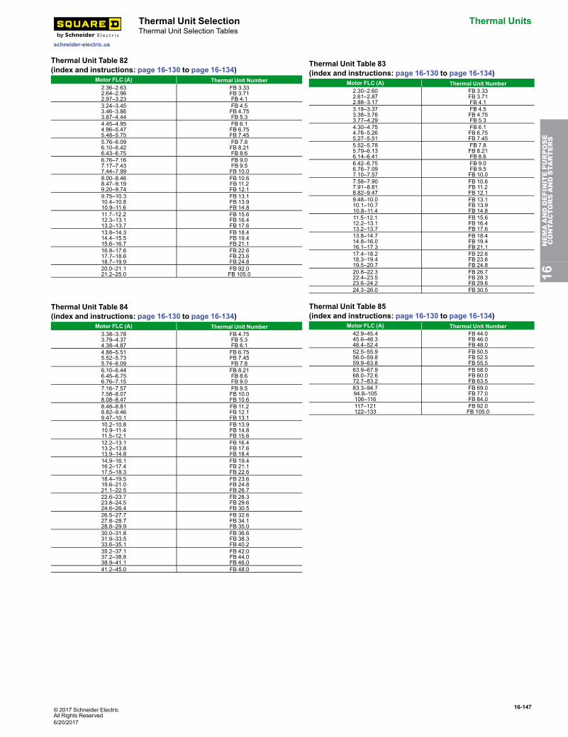
© 2017 Schneider ElectricAll Rights Reserved
16-147
schneider-electric.us
Thermal Unit Selection Thermal UnitsThermal Unit Selection Tables
Thermal Unit Table 82(index and instructions: page 16-130 to page 16-134)
Motor FLC (A) Thermal Unit Number2.36–2.632.64–2.962.97–3.23
FB 3.33FB 3.71FB 4.1
3.24–3.453.46–3.863.87–4.44
FB 4.5FB 4.75FB 5.3
4.45–4.954.96–5.475.48–5.75
FB 6.1FB 6.75FB 7.45
5.76–6.096.10–6.426.43–6.75
FB 7.8FB 8.21FB 8.6
6.76–7.167.17–7.437.44–7.99
FB 9.0FB 9.5FB 10.0
8.00–8.468.47–9.199.20–9.74
FB 10.6FB 11.2FB 12.1
9.75–10.310.4–10.810.9–11.6
FB 13.1FB 13.9FB 14.8
11.7–12.212.3–13.113.2–13.7
FB 15.6FB 16.4FB 17.6
13.8–14.314.4–15.515.6–16.7
FB 18.4FB 19.4FB 21.1
16.8–17.617.7–18.618.7–19.9
FB 22.6FB 23.6FB 24.8
20.0–21.121.2–25.0
FB 92.0FB 105.0
Thermal Unit Table 83(index and instructions: page 16-130 to page 16-134)
Motor FLC (A) Thermal Unit Number2.30–2.602.61–2.872.88–3.17
FB 3.33FB 3.71FB 4.1
3.18–3.373.38–3.763.77–4.29
FB 4.5FB 4.75FB 5.3
4.30–4.754.76–5.265.27–5.51
FB 6.1FB 6.75FB 7.45
5.52–5.785.79–6.136.14–6.41
FB 7.8FB 8.21FB 8.6
6.42–6.756.76–7.097.10–7.57
FB 9.0FB 9.5FB 10.0
7.58–7.907.91–8.818.82–9.47
FB 10.6FB 11.2FB 12.1
9.48–10.010.1–10.710.8–11.4
FB 13.1FB 13.9FB 14.8
11.5–12.112.2–13.113.2–13.7
FB 15.6FB 16.4FB 17.6
13.8–14.714.8–16.016.1–17.3
FB 18.4FB 19.4FB 21.1
17.4–18.218.3–19.419.5–20.7
FB 22.6FB 23.6FB 24.8
20.8–22.322.4–23.523.6–24.2
FB 26.7FB 28.3FB 29.6
24.3–26.0 FB 30.5
Thermal Unit Table 84(index and instructions: page 16-130 to page 16-134)
Motor FLC (A) Thermal Unit Number3.38–3.783.79–4.374.38–4.87
FB 4.75FB 5.3FB 6.1
4.88–5.515.52–5.735.74–6.09
FB 6.75FB 7.45FB 7.8
6.10–6.446.45–6.756.76–7.15
FB 8.21FB 8.6FB 9.0
7.16–7.577.58–8.078.08–8.47
FB 9.5FB 10.0FB 10.6
8.48–8.818.82–9.469.47–10.1
FB 11.2FB 12.1FB 13.1
10.2–10.810.9–11.411.5–12.1
FB 13.9FB 14.8FB 15.6
12.2–13.113.2–13.813.9–14.8
FB 16.4FB 17.6FB 18.4
14.9–16.116.2–17.417.5–18.3
FB 19.4FB 21.1FB 22.6
18.4–19.519.6–21.021.1–22.5
FB 23.6FB 24.8FB 26.7
22.6–23.723.8–24.524.6–26.4
FB 28.3FB 29.6FB 30.5
26.5–27.727.8–28.728.8–29.9
FB 32.6FB 34.1FB 35.0
30.0–31.831.9–33.533.6–35.1
FB 36.6FB 38.3FB 40.2
35.2–37.137.2–38.838.9–41.1
FB 42.0FB 44.0FB 46.0
41.2–45.0 FB 48.0
Thermal Unit Table 85(index and instructions: page 16-130 to page 16-134)
Motor FLC (A) Thermal Unit Number42.9–45.445.6–48.348.4–52.4
FB 44.0FB 46.0FB 48.0
52.5–55.956.0–59.859.9–63.8
FB 50.5FB 52.5FB 55.5
63.9–67.968.0–72.672.7–83.2
FB 58.0FB 60.0FB 63.5
83.3–94.794.8–105106–116
FB 69.0FB 77.0FB 84.0
117–121122–133
FB 92.0FB 105.0
16NEMAANDDEFINITEPURPOSE
CONTA
CTORSANDSTA
RTERS
6/20/2017
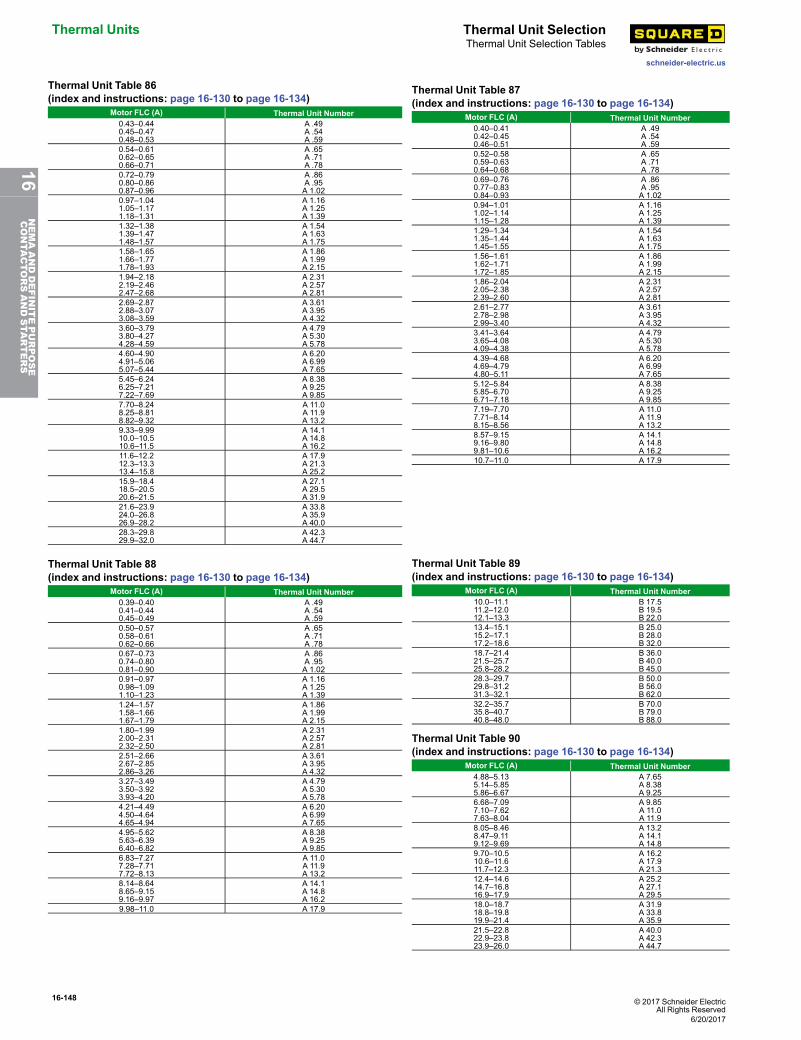
16-148 © 2017 Schneider ElectricAll Rights Reserved
Thermal Units Thermal Unit Selection
schneider-electric.us
Thermal Unit Selection Tables
Thermal Unit Table 86(index and instructions: page 16-130 to page 16-134)
Motor FLC (A) Thermal Unit Number0.43–0.440.45–0.470.48–0.53
A .49A .54A .59
0.54–0.610.62–0.650.66–0.71
A .65A .71A .78
0.72–0.790.80–0.860.87–0.96
A .86A .95A 1.02
0.97–1.041.05–1.171.18–1.31
A 1.16A 1.25A 1.39
1.32–1.381.39–1.471.48–1.57
A 1.54A 1.63A 1.75
1.58–1.651.66–1.771.78–1.93
A 1.86A 1.99A 2.15
1.94–2.182.19–2.462.47–2.68
A 2.31A 2.57A 2.81
2.69–2.872.88–3.073.08–3.59
A 3.61A 3.95A 4.32
3.60–3.793.80–4.274.28–4.59
A 4.79A 5.30A 5.78
4.60–4.904.91–5.065.07–5.44
A 6.20A 6.99A 7.65
5.45–6.246.25–7.217.22–7.69
A 8.38A 9.25A 9.85
7.70–8.248.25–8.818.82–9.32
A 11.0A 11.9A 13.2
9.33–9.9910.0–10.510.6–11.5
A 14.1A 14.8A 16.2
11.6–12.212.3–13.313.4–15.8
A 17.9A 21.3A 25.2
15.9–18.418.5–20.520.6–21.5
A 27.1A 29.5A 31.9
21.6–23.924.0–26.826.9–28.2
A 33.8A 35.9A 40.0
28.3–29.829.9–32.0
A 42.3A 44.7
Thermal Unit Table 87(index and instructions: page 16-130 to page 16-134)
Motor FLC (A) Thermal Unit Number0.40–0.410.42–0.450.46–0.51
A .49A .54A .59
0.52–0.580.59–0.630.64–0.68
A .65A .71A .78
0.69–0.760.77–0.830.84–0.93
A .86A .95A 1.02
0.94–1.011.02–1.141.15–1.28
A 1.16A 1.25A 1.39
1.29–1.341.35–1.441.45–1.55
A 1.54A 1.63A 1.75
1.56–1.611.62–1.711.72–1.85
A 1.86A 1.99A 2.15
1.86–2.042.05–2.382.39–2.60
A 2.31A 2.57A 2.81
2.61–2.772.78–2.982.99–3.40
A 3.61A 3.95A 4.32
3.41–3.643.65–4.084.09–4.38
A 4.79A 5.30A 5.78
4.39–4.684.69–4.794.80–5.11
A 6.20A 6.99A 7.65
5.12–5.845.85–6.706.71–7.18
A 8.38A 9.25A 9.85
7.19–7.707.71–8.148.15–8.56
A 11.0A 11.9A 13.2
8.57–9.159.16–9.809.81–10.6
A 14.1A 14.8A 16.2
10.7–11.0 A 17.9
Thermal Unit Table 88(index and instructions: page 16-130 to page 16-134)
Motor FLC (A) Thermal Unit Number0.39–0.400.41–0.440.45–0.49
A .49A .54A .59
0.50–0.570.58–0.610.62–0.66
A .65A .71A .78
0.67–0.730.74–0.800.81–0.90
A .86A .95A 1.02
0.91–0.970.98–1.091.10–1.23
A 1.16A 1.25A 1.39
1.24–1.571.58–1.661.67–1.79
A 1.86A 1.99A 2.15
1.80–1.992.00–2.312.32–2.50
A 2.31A 2.57A 2.81
2.51–2.662.67–2.852.86–3.26
A 3.61A 3.95A 4.32
3.27–3.493.50–3.923.93–4.20
A 4.79A 5.30A 5.78
4.21–4.494.50–4.644.65–4.94
A 6.20A 6.99A 7.65
4.95–5.625.63–6.396.40–6.82
A 8.38A 9.25A 9.85
6.83–7.277.28–7.717.72–8.13
A 11.0A 11.9A 13.2
8.14–8.648.65–9.159.16–9.97
A 14.1A 14.8A 16.2
9.98–11.0 A 17.9
Thermal Unit Table 89(index and instructions: page 16-130 to page 16-134)
Motor FLC (A) Thermal Unit Number10.0–11.111.2–12.012.1–13.3
B 17.5B 19.5B 22.0
13.4–15.115.2–17.117.2–18.6
B 25.0B 28.0B 32.0
18.7–21.421.5–25.725.8–28.2
B 36.0B 40.0B 45.0
28.3–29.729.8–31.231.3–32.1
B 50.0B 56.0B 62.0
32.2–35.735.8–40.740.8–48.0
B 70.0B 79.0B 88.0
Thermal Unit Table 90(index and instructions: page 16-130 to page 16-134)
Motor FLC (A) Thermal Unit Number4.88–5.135.14–5.855.86–6.67
A 7.65A 8.38A 9.25
6.68–7.097.10–7.627.63–8.04
A 9.85A 11.0A 11.9
8.05–8.468.47–9.119.12–9.69
A 13.2A 14.1A 14.8
9.70–10.510.6–11.611.7–12.3
A 16.2A 17.9A 21.3
12.4–14.614.7–16.816.9–17.9
A 25.2A 27.1A 29.5
18.0–18.718.8–19.819.9–21.4
A 31.9A 33.8A 35.9
21.5–22.822.9–23.823.9–26.0
A 40.0A 42.3A 44.7
6/20/2017
16NEMAANDDEFINITEPURPOSE
CONTA
CTORSANDSTA
RTERS
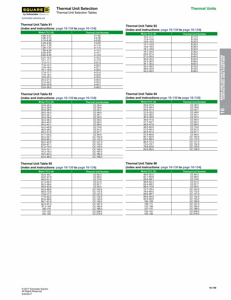
© 2017 Schneider ElectricAll Rights Reserved
16-149
schneider-electric.us
Thermal Unit Selection Thermal UnitsThermal Unit Selection Tables
Thermal Unit Table 91(index and instructions: page 16-130 to page 16-134)
Motor FLC (A) Thermal Unit Number4.80–5.075.08–5.735.74–6.48
A 7.65A 8.38A 9.25
6.49–6.906.91–7.257.26–7.81
A 9.85A 11.0A 11.9
7.82–8.298.30–8.818.82–9.40
A 13.2A 14.1A 14.8
9.41–10.010.1–11.111.2–11.7
A 16.2A 17.9A 21.3
11.8–13.713.8–16.016.1–16.9
A 25.2A 27.1A 29.5
17.0–17.717.8–18.718.8–20.2
A 31.9A 33.8A 35.9
20.3–21.421.5–22.522.6–23.8
A 40.0A 42.3A 44.7
23.9–26.0 A 48.0
Thermal Unit Table 92(index and instructions: page 16-130 to page 16-134)
Motor FLC (A) Thermal Unit Number10.5–11.711.8–12.512.6–14.0
B 17.5B 19.5B 22.0
14.1–15.815.9–18.018.1–19.6
B 25.0B 28.0B 32.0
19.7–23.523.6–27.427.5–30.5
B 36.0B 40.0B 45.0
30.6–32.232.3–34.034.1–35.2
B 50.0B 56.0B 62.0
35.3–39.539.6–43.944.0–48.0
B 70.0B 79.0B 88.0
Thermal Unit Table 93(index and instructions: page 16-130 to page 16-134)
Motor FLC (A) Thermal Unit Number23.8–25.225.3–26.826.9–28.4
CC 36.4CC 39.6CC 42.7
28.5–30.330.4–32.132.2–34.2
CC 46.6CC 50.1CC 54.5
34.3–36.336.4–40.240.3–43.1
CC 59.4CC 64.3CC 68.5
43.2–45.946.0–49.249.3–51.6
CC 74.6CC 81.5CC 87.7
51.7–54.254.3–55.755.8–60.3
CC 94.0CC 103.0CC 112.0
60.4–63.563.6–67.167.2–70.3
CC 121.0CC 132.0CC 143.0
70.4–74.174.2–78.378.4–83.3
CC 156.0CC 167.0CC 180.0
83.4–86.0 CC 196.0
Thermal Unit Table 94(index and instructions:page 16-130 to page 16-134)
Motor FLC (A) Thermal Unit Number25.8–27.527.6–29.429.5–31.4
CC 36.4CC 39.6CC 42.7
31.5–33.233.3–36.236.3–38.8
CC 46.6CC 50.1CC 54.5
38.9–41.641.7–44.744.8–47.9
CC 59.4CC 64.3CC 68.5
48.0–50.951.0–54.454.5–57.4
CC 74.6CC 81.5CC 87.7
57.5–60.660.7–63.964.0–68.4
CC 94.0CC 103.0CC 112.0
68.5–73.473.5–78.778.8–83.8
CC 121.0CC 132.0CC 143.0
83.9–86.0 CC 156.0
Thermal Unit Table 95(index and instructions: page 16-130 to page 16-134)
Motor FLC (A) Thermal Unit Number42.5–44.744.8–47.948.0–51.2
CC 64.3CC 68.5CC 74.6
51.3–55.255.3–59.459.5–63.8
CC 81.5CC 87.7CC 94.0
63.9–68.868.9–73.873.9–77.7
CC 103.0CC 112.0CC 121.0
77.8–82.582.6–86.686.7–91.9
CC 132.0CC 143.0CC 156.0
92.0–97.297.3–104105–114
CC 167.0CC 180.0CC 196.0
115–123124–150
CC 208.0CC 219.0
Thermal Unit Table 96(index and instructions: page 16-130 to page 16-134)
Motor FLC (A) Thermal Unit Number49.5–52.052.1–54.854.9–58.7
CC 64.3CC 68.5CC 74.6
58.8–63.363.4–68.368.4–73.6
CC 81.5CC 87.7CC 94.0
73.7–79.479.5–85.585.6–89.7
CC 103.0CC 112.0CC 121.0
89.8–94.894.9–99.9100–105
CC 132.0CC 143.0CC 156.0
106–111112–126127–131
CC 167.0CC 180.0CC 196.0
132–141142–150
CC 208.0CC 219.0
16NEMAANDDEFINITEPURPOSE
CONTA
CTORSANDSTA
RTERS
6/20/2017
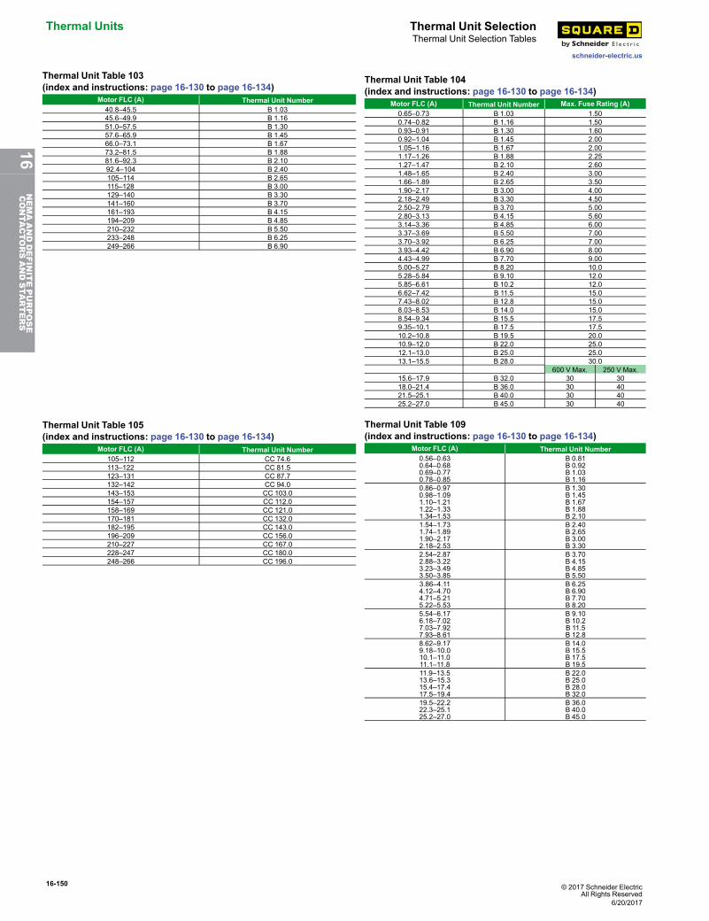
16-150 © 2017 Schneider ElectricAll Rights Reserved
Thermal Units Thermal Unit Selection
schneider-electric.us
Thermal Unit Selection Tables
Thermal Unit Table 103(index and instructions: page 16-130 to page 16-134)
Motor FLC (A) Thermal Unit Number40.8–45.5 B 1.0345.6–49.9 B 1.1651.0–57.5 B 1.3057.6–65.9 B 1.4566.0–73.1 B 1.6773.2–81.5 B 1.8881.6–92.3 B 2.1092.4–104 B 2.40105–114 B 2.65115–128 B 3.00129–140 B 3.30141–160 B 3.70161–193 B 4.15194–209 B 4.85210–232 B 5.50233–248 B 6.25249–266 B 6.90
Thermal Unit Table 104(index and instructions: page 16-130 to page 16-134)
Motor FLC (A) Thermal Unit Number Max. Fuse Rating (A)0.65–0.73 B 1.03 1.500.74–0.82 B 1.16 1.500.93–0.91 B 1.30 1.600.92–1.04 B 1.45 2.001.05–1.16 B 1.67 2.001.17–1.26 B 1.88 2.251.27–1.47 B 2.10 2.601.48–1.65 B 2.40 3.001.66–1.89 B 2.65 3.501.90–2.17 B 3.00 4.002.18–2.49 B 3.30 4.502.50–2.79 B 3.70 5.002.80–3.13 B 4.15 5.603.14–3.36 B 4.85 6.003.37–3.69 B 5.50 7.003.70–3.92 B 6.25 7.003.93–4.42 B 6.90 8.004.43–4.99 B 7.70 9.005.00–5.27 B 8.20 10.05.28–5.84 B 9.10 12.05.85–6.61 B 10.2 12.06.62–7.42 B 11.5 15.07.43–8.02 B 12.8 15.08.03–8.53 B 14.0 15.08.54–9.34 B 15.5 17.59.35–10.1 B 17.5 17.510.2–10.8 B 19.5 20.010.9–12.0 B 22.0 25.012.1–13.0 B 25.0 25.013.1–15.5 B 28.0 30.0
600 V Max. 250 V Max.15.6–17.9 B 32.0 30 3018.0–21.4 B 36.0 30 4021.5–25.1 B 40.0 30 4025.2–27.0 B 45.0 30 40
Thermal Unit Table 105(index and instructions: page 16-130 to page 16-134)
Motor FLC (A) Thermal Unit Number105–112 CC 74.6113–122 CC 81.5123–131 CC 87.7132–142 CC 94.0143–153 CC 103.0154–157 CC 112.0158–169 CC 121.0170–181 CC 132.0182–195 CC 143.0196–209 CC 156.0210–227 CC 167.0228–247 CC 180.0248–266 CC 196.0
Thermal Unit Table 109(index and instructions: page 16-130 to page 16-134)
Motor FLC (A) Thermal Unit Number0.56–0.630.64–0.680.69–0.770.78–0.85
B 0.81B 0.92B 1.03B 1.16
0.86–0.970.98–1.091.10–1.211.22–1.331.34–1.53
B 1.30B 1.45B 1.67B 1.88B 2.10
1.54–1.731.74–1.891.90–2.172.18–2.53
B 2.40B 2.65B 3.00B 3.30
2.54–2.872.88–3.223.23–3.493.50–3.85
B 3.70B 4.15B 4.85B 5.50
3.86–4.114.12–4.704.71–5.215.22–5.53
B 6.25B 6.90B 7.70B 8.20
5.54–6.176.18–7.027.03–7.927.93–8.61
B 9.10B 10.2B 11.5B 12.8
8.62–9.179.18–10.010.1–11.011.1–11.8
B 14.0B 15.5B 17.5B 19.5
11.9–13.513.6–15.315.4–17.417.5–19.4
B 22.0B 25.0B 28.0B 32.0
19.5–22.222.3–25.125.2–27.0
B 36.0B 40.0B 45.0
6/20/2017
16NEMAANDDEFINITEPURPOSE
CONTA
CTORSANDSTA
RTERS
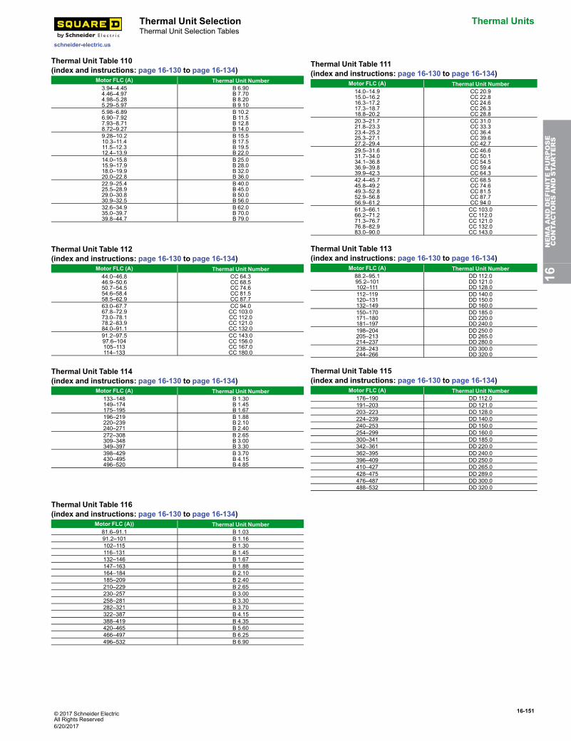
© 2017 Schneider ElectricAll Rights Reserved
16-151
schneider-electric.us
Thermal Unit Selection Thermal UnitsThermal Unit Selection Tables
Thermal Unit Table 110(index and instructions: page 16-130 to page 16-134)
Motor FLC (A) Thermal Unit Number3.94–4.454.46–4.974.98–5.285.29–5.97
B 6.90B 7.70B 8.20B 9.10
5.98–6.896.90–7.927.93–8.718.72–9.27
B 10.2B 11.5B 12.8B 14.0
9.28–10.210.3–11.411.5–12.312.4–13.9
B 15.5B 17.5B 19.5B 22.0
14.0–15.815.9–17.918.0–19.920.0–22.8
B 25.0B 28.0B 32.0B 36.0
22.9–25.425.5–28.929.0–30.830.9–32.5
B 40.0B 45.0B 50.0B 56.0
32.6–34.935.0–39.739.8–44.7
B 62.0B 70.0B 79.0
Thermal Unit Table 111(index and instructions: page 16-130 to page 16-134)
Motor FLC (A) Thermal Unit Number14.0–14.915.0–16.216.3–17.217.3–18.718.8–20.2
CC 20.9CC 22.8CC 24.6CC 26.3CC 28.8
20.3–21.721.8–23.323.4–25.225.3–27.127.2–29.4
CC 31.0CC 33.3CC 36.4CC 39.6CC 42.7
29.5–31.631.7–34.034.1–36.836.9–39.839.9–42.3
CC 46.6CC 50.1CC 54.5CC 59.4CC 64.3
42.4–45.745.8–49.249.3–52.852.9–56.856.9–61.2
CC 68.5CC 74.6CC 81.5CC 87.7CC 94.0
61.3–66.166.2–71.271.3–76.776.8–82.983.0–90.0
CC 103.0CC 112.0CC 121.0CC 132.0CC 143.0
Thermal Unit Table 112(index and instructions: page 16-130 to page 16-134)
Motor FLC (A) Thermal Unit Number44.0–46.846.9–50.650.7–54.554.6–58.458.5–62.9
CC 64.3CC 68.5CC 74.6CC 81.5CC 87.7
63.0–67.767.8–72.973.0–78.178.2–83.984.0–91.1
CC 94.0CC 103.0CC 112.0CC 121.0CC 132.0
91.2–97.597.6–104105–113114–133
CC 143.0CC 156.0CC 167.0CC 180.0
Thermal Unit Table 113(index and instructions: page 16-130 to page 16-134)
Motor FLC (A) Thermal Unit Number88.2–95.195.2–101102–111
DD 112.0DD 121.0DD 128.0
112–119120–131132–149
DD 140.0DD 150.0DD 160.0
150–170171–180181–197
DD 185.0DD 220.0DD 240.0
198–204205–213214–237
DD 250.0DD 265.0DD 280.0
238–243244–266
DD 300.0DD 320.0
Thermal Unit Table 114(index and instructions: page 16-130 to page 16-134)
Motor FLC (A) Thermal Unit Number133–148149–174175–195
B 1.30B 1.45B 1.67
196–219220–239240–271
B 1.88B 2.10B 2.40
272–308309–348349–397
B 2.65B 3.00B 3.30
398–429430–495496–520
B 3.70B 4.15B 4.85
Thermal Unit Table 115(index and instructions: page 16-130 to page 16-134)
Motor FLC (A) Thermal Unit Number176–190 DD 112.0191–203 DD 121.0203–223 DD 128.0224–239 DD 140.0240–253 DD 150.0254–299 DD 160.0300–341 DD 185.0342–361 DD 220.0362–395 DD 240.0396–409 DD 250.0410–427 DD 265.0428–475 DD 289.0476–487 DD 300.0488–532 DD 320.0
Thermal Unit Table 116(index and instructions: page 16-130 to page 16-134)
Motor FLC (A)) Thermal Unit Number81.6–91.1 B 1.0391.2–101 B 1.16102–115 B 1.30116–131 B 1.45132–146 B 1.67147–163 B 1.88164–184 B 2.10185–209 B 2.40210–229 B 2.65230–257 B 3.00258–281 B 3.30282–321 B 3.70322–387 B 4.15388–419 B 4.35420–465 B 5.60466–497 B 6.25496–532 B 6.90
16NEMAANDDEFINITEPURPOSE
CONTA
CTORSANDSTA
RTERS
6/20/2017
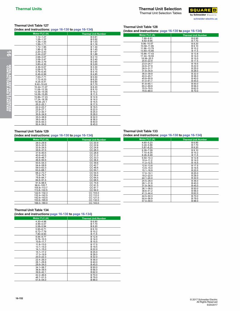
16-152 © 2017 Schneider ElectricAll Rights Reserved
Thermal Units Thermal Unit Selection
schneider-electric.us
Thermal Unit Selection Tables
Thermal Unit Table 127(index and instructions: page 16-130 to page 16-134)
Motor FLC (A) Thermal Unit Number1.12–1.271.28–1.371.38–1.551.56–1.71
B 0.81B 0.92B 1.03B 1.16
1.72–1.951.96–2.192.20–2.432.44–2.67
B 1.30B 1.45B 1.67B 1.88
2.68–3.073.08–3.473.48–3.793.80–4.35
B 2.10B 2.40B 2.65B 3.00
4.36–5.075.08–5.755.76–6.456.46–6.99
B 3.30B 3.70B 4.15B 4.85
7.00–7.717.72–8.238.24–9.419.42–10.43
B 5.50B 6.25B 6.90B 7.70
10.44–11.0711.08–12.3512.36–14.0514.06–15.85
B 8.20B 9.10B 10.2B 11.5
15.86–17.2317.24–18.3518.36–20.120.2–22.1
B 12.8B 14.0B 15.5B 17.5
22.2–23.723.8–27.127.2–30.730.8–34.9
B 19.5B 22.0B 25.0B 28.0
35.0–38.939.0–44.544.6–50.350.4–54.0
B 32.0B 36.0B 40.0B 45.0
Thermal Unit Table 128(index and instructions: page 16-130 to page 16-134)
Motor FLC (A) Thermal Unit Number7.88–8.918.92–9.95
B 6.90B 7.70
9.96–10.5710.58–11.9511.96–13.7913.80–15.85
B 8.20B 9.10B 10.2B 11.5
15.86–17.4317.44–18.5518.56–20.520.6–22.9
B 12.8B 14.0B 15.5B 17.5
23.0–24.724.8–27.928.0–31.731.8–35.9
B 19.5B 22.0B 25.0B 28.0
36.0–39.940.0–45.745.8–50.951.0–61.7
B 32.0B 36.0B 40.0B 45.0
61.8–65.165.2–69.970.0–79.579.6–89.4
B 50.0B 56.0B 62.0B 70.0
Thermal Unit Table 129(index and instructions: page 16-130 to page 16-134)
Motor FLC (A) Thermal Unit Number28.0–29.930.0–32.532.6–34.534.6–37.5
CC 20.9CC 22.8CC 24.6CC 26.3
37.6–40.540.6–43.543.6–46.746.8–50.5
CC 28.8CC 31.0CC 33.3CC 36.4
50.6–54.354.4–58.959.0–63.363.4–68.1
CC 39.6CC 42.7CC 46.6CC 50.1
68.2–73.773.8–79.779.8–84.784.8–91.5
CC 54.5CC 59.4CC 64.5CC 68.5
91.6–98.598.6–105.7105.8–113.7113.8–122.5
CC 74.6CC 81.5CC 87.7CC 94.0
122.6–132.3132.4–142.5142.6–153.5153.6–165.9
CC 103.0CC 112.0CC 121.0CC 132.0
166.0–180.0 CC 143.0
Thermal Unit Table 133(index and instructions: page 16-130 to page 16-134)
Motor FLC (A) Thermal Unit Number4.60–5.235.24–5.865.87–6.25
B 6.90B 7.70B 8.20
6.26–7.097.10–8.258.26–9.49
B 9.10B 10.2B 11.5
9.50–10.310.4–11.211.3–12.5
B 12.8B 14.0B 15.5
12.6–13.813.9–15.015.1–16.9
B 17.5B 19.5B 22.0
17.0–19.119.2–22.022.1–24.4
B 25.0B 28.0B 32.0
24.5–28.028.1–31.831.9–36.0
B 36.0B 40.0B 45.0
36.1–38.538.6–41.241.3–44.4
B 50.0B 56.0B 62.0
44.5–50.350.4–56.957.0–59.0
B 70.0B 79.0B 88.0
Thermal Unit Table 134(index and instructions:page 16-130 to page 16-134)
Motor FLC (A) Thermal Unit Number4.30–4.984.99–5.575.58–5.94
B 6.90B 7.70B 8.20
5.95–6.716.72–7.797.80–8.93
B 9.10B 10.2B 11.5
8.94–9.779.78–10.510.6–11.7
B 12.8B 14.0B 15.5
11.8–13.013.1–14.014.1–15.0
B 17.5B 19.5B 22.0
15.1–17.217.3–19.920.0–22.3
B 25.0B 28.0B 32.0
22.4–26.026.1–29.829.9–34.0
B 36.0B 40.0B 45.0
34.1–36.736.8–39.539.6–42.1
B 50.0B 56.0B 62.0
42.2–46.646.7–51.551.6–54.0
B 70.0B 79.0B 88.0
6/20/2017
16NEMAANDDEFINITEPURPOSE
CONTA
CTORSANDSTA
RTERS
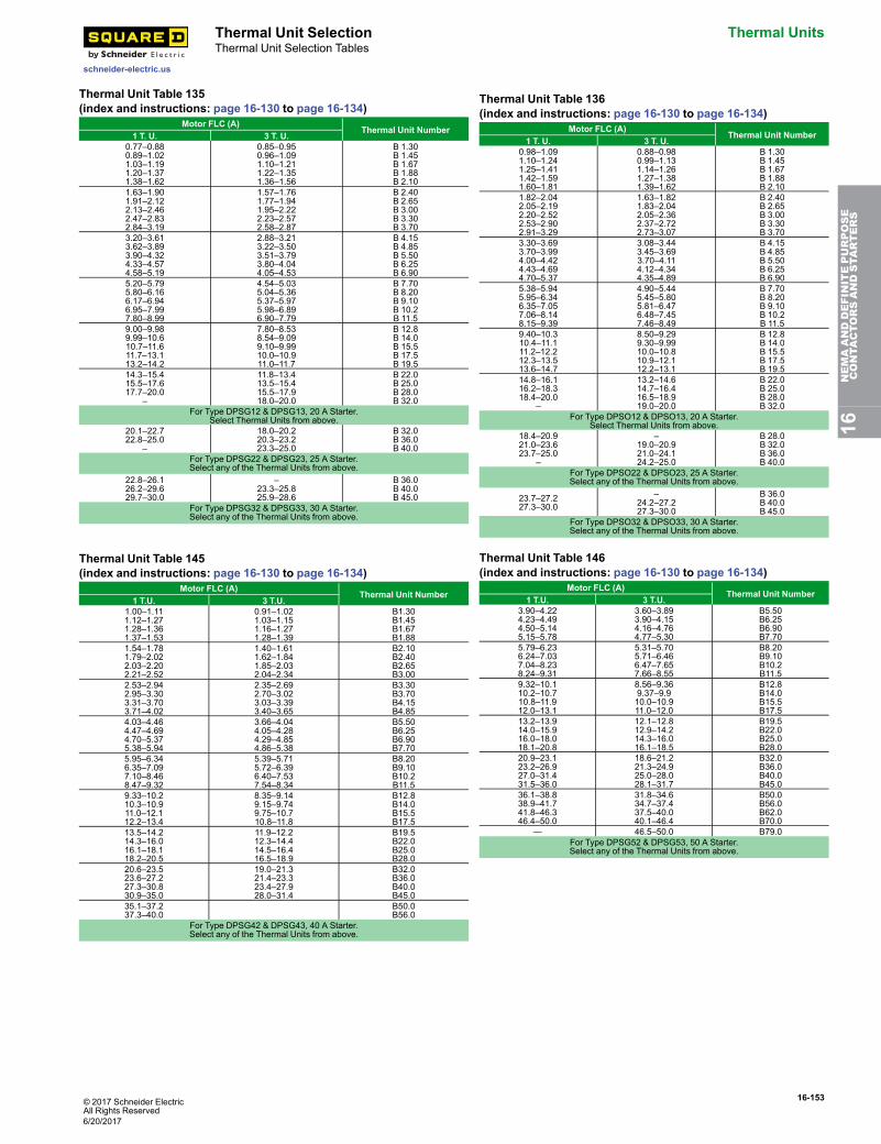
© 2017 Schneider ElectricAll Rights Reserved
16-153
schneider-electric.us
Thermal Unit Selection Thermal UnitsThermal Unit Selection Tables
Thermal Unit Table 135(index and instructions: page 16-130 to page 16-134)
Motor FLC (A)Thermal Unit Number
1 T. U. 3 T. U.0.77–0.880.89–1.021.03–1.191.20–1.371.38–1.62
0.85–0.950.96–1.091.10–1.211.22–1.351.36–1.56
B 1.30B 1.45B 1.67B 1.88B 2.10
1.63–1.901.91–2.122.13–2.462.47–2.832.84–3.19
1.57–1.761.77–1.941.95–2.222.23–2.572.58–2.87
B 2.40B 2.65B 3.00B 3.30B 3.70
3.20–3.613.62–3.893.90–4.324.33–4.574.58–5.19
2.88–3.213.22–3.503.51–3.793.80–4.044.05–4.53
B 4.15B 4.85B 5.50B 6.25B 6.90
5.20–5.795.80–6.166.17–6.946.95–7.997.80–8.99
4.54–5.035.04–5.365.37–5.975.98–6.896.90–7.79
B 7.70B 8.20B 9.10B 10.2B 11.5
9.00–9.989.99–10.610.7–11.611.7–13.113.2–14.2
7.80–8.538.54–9.099.10–9.9910.0–10.911.0–11.7
B 12.8B 14.0B 15.5B 17.5B 19.5
14.3–15.415.5–17.617.7–20.0
–
11.8–13.413.5–15.415.5–17.918.0–20.0
B 22.0B 25.0B 28.0B 32.0
For Type DPSG12 & DPSG13, 20 A Starter.Select Thermal Units from above.
20.1–22.722.8–25.0
–
18.0–20.220.3–23.223.3–25.0
B 32.0B 36.0B 40.0
For Type DPSG22 & DPSG23, 25 A Starter.Select any of the Thermal Units from above.
22.8–26.126.2–29.629.7–30.0
–23.3–25.825.9–28.6
B 36.0B 40.0B 45.0
For Type DPSG32 & DPSG33, 30 A Starter.Select any of the Thermal Units from above.
Thermal Unit Table 136(index and instructions: page 16-130 to page 16-134)
Motor FLC (A)Thermal Unit Number
1 T. U. 3 T. U.0.98–1.091.10–1.241.25–1.411.42–1.591.60–1.81
0.88–0.980.99–1.131.14–1.261.27–1.381.39–1.62
B 1.30B 1.45B 1.67B 1.88B 2.10
1.82–2.042.05–2.192.20–2.522.53–2.902.91–3.29
1.63–1.821.83–2.042.05–2.362.37–2.722.73–3.07
B 2.40B 2.65B 3.00B 3.30B 3.70
3.30–3.693.70–3.994.00–4.424.43–4.694.70–5.37
3.08–3.443.45–3.693.70–4.114.12–4.344.35–4.89
B 4.15B 4.85B 5.50B 6.25B 6.90
5.38–5.945.95–6.346.35–7.057.06–8.148.15–9.39
4.90–5.445.45–5.805.81–6.476.48–7.457.46–8.49
B 7.70B 8.20B 9.10B 10.2B 11.5
9.40–10.310.4–11.111.2–12.212.3–13.513.6–14.7
8.50–9.299.30–9.9910.0–10.810.9–12.112.2–13.1
B 12.8B 14.0B 15.5B 17.5B 19.5
14.8–16.116.2–18.318.4–20.0
–
13.2–14.614.7–16.416.5–18.919.0–20.0
B 22.0B 25.0B 28.0B 32.0
For Type DPSO12 & DPSO13, 20 A Starter.Select Thermal Units from above.
18.4–20.921.0–23.623.7–25.0
–
–19.0–20.921.0–24.124.2–25.0
B 28.0B 32.0B 36.0B 40.0
For Type DPSO22 & DPSO23, 25 A Starter.Select any of the Thermal Units from above.
23.7–27.227.3–30.0
–24.2–27.227.3–30.0
B 36.0B 40.0B 45.0
For Type DPSO32 & DPSO33, 30 A Starter.Select any of the Thermal Units from above.
Thermal Unit Table 145(index and instructions: page 16-130 to page 16-134)
Motor FLC (A)Thermal Unit Number
1 T.U. 3 T.U.1.00–1.111.12–1.271.28–1.361.37–1.53
0.91–1.021.03–1.151.16–1.271.28–1.39
B1.30B1.45B1.67B1.88
1.54–1.781.79–2.022.03–2.202.21–2.52
1.40–1.611.62–1.841.85–2.032.04–2.34
B2.10B2.40B2.65B3.00
2.53–2.942.95–3.303.31–3.703.71–4.02
2.35–2.692.70–3.023.03–3.393.40–3.65
B3.30B3.70B4.15B4.85
4.03–4.464.47–4.694.70–5.375.38–5.94
3.66–4.044.05–4.284.29–4.854.86–5.38
B5.50B6.25B6.90B7.70
5.95–6.346.35–7.097.10–8.468.47–9.32
5.39–5.715.72–6.396.40–7.537.54–8.34
B8.20B9.10B10.2B11.5
9.33–10.210.3–10.911.0–12.112.2–13.4
8.35–9.149.15–9.749.75–10.710.8–11.8
B12.8B14.0B15.5B17.5
13.5–14.214.3–16.016.1–18.118.2–20.5
11.9–12.212.3–14.414.5–16.416.5–18.9
B19.5B22.0B25.0B28.0
20.6–23.523.6–27.227.3–30.830.9–35.0
19.0–21.321.4–23.323.4–27.928.0–31.4
B32.0B36.0B40.0B45.0
35.1–37.237.3–40.0
B50.0B56.0
For Type DPSG42 & DPSG43, 40 A Starter.Select any of the Thermal Units from above.
Thermal Unit Table 146(index and instructions: page 16-130 to page 16-134)
Motor FLC (A)Thermal Unit Number
1 T.U. 3 T.U.3.90–4.224.23–4.494.50–5.145.15–5.78
3.60–3.893.90–4.154.16–4.764.77–5.30
B5.50B6.25B6.90B7.70
5.79–6.236.24–7.037.04–8.238.24–9.31
5.31–5.705.71–6.466.47–7.657.66–8.55
B8.20B9.10B10.2B11.5
9.32–10.110.2–10.710.8–11.912.0–13.1
8.56–9.369.37–9.910.0–10.911.0–12.0
B12.8B14.0B15.5B17.5
13.2–13.914.0–15.916.0–18.018.1–20.8
12.1–12.812.9–14.214.3–16.016.1–18.5
B19.5B22.0B25.0B28.0
20.9–23.123.2–26.927.0–31.431.5–36.0
18.6–21.221.3–24.925.0–28.028.1–31.7
B32.0B36.0B40.0B45.0
36.1–38.838.9–41.741.8–46.346.4–50.0
31.8–34.634.7–37.437.5–40.040.1–46.4
B50.0B56.0B62.0B70.0
— 46.5–50.0 B79.0For Type DPSG52 & DPSG53, 50 A Starter.Select any of the Thermal Units from above.
16NEMAANDDEFINITEPURPOSE
CONTA
CTORSANDSTA
RTERS
6/20/2017
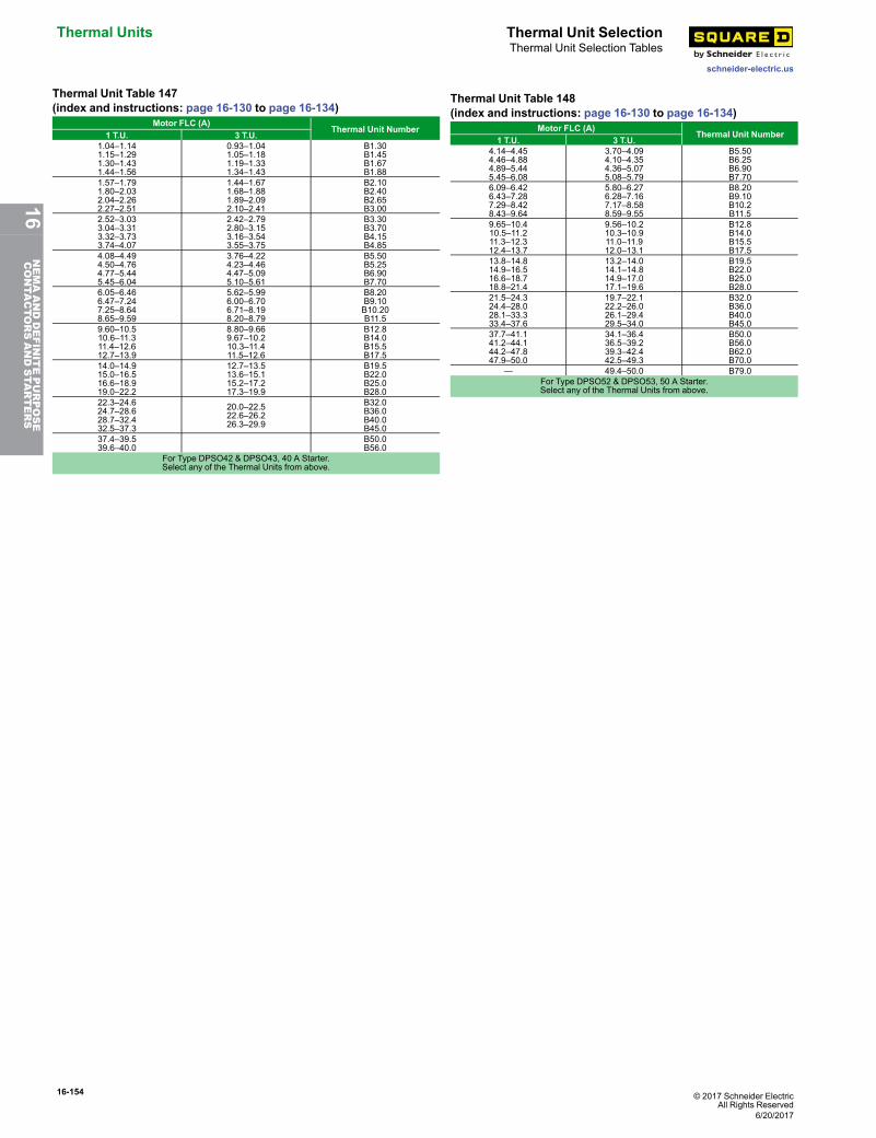
16-154 © 2017 Schneider ElectricAll Rights Reserved
Thermal Units Thermal Unit Selection
schneider-electric.us
Thermal Unit Selection Tables
Thermal Unit Table 147(index and instructions: page 16-130 to page 16-134)
Motor FLC (A)Thermal Unit Number
1 T.U. 3 T.U.1.04–1.141.15–1.291.30–1.431.44–1.56
0.93–1.041.05–1.181.19–1.331.34–1.43
B1.30B1.45B1.67B1.88
1.57–1.791.80–2.032.04–2.262.27–2.51
1.44–1.671.68–1.881.89–2.092.10–2.41
B2.10B2.40B2.65B3.00
2.52–3.033.04–3.313.32–3.733.74–4.07
2.42–2.792.80–3.153.16–3.543.55–3.75
B3.30B3.70B4.15B4.85
4.08–4.494.50–4.764.77–5.445.45–6.04
3.76–4.224.23–4.464.47–5.095.10–5.61
B5.50B5.25B6.90B7.70
6.05–6.466.47–7.247.25–8.648.65–9.59
5.62–5.996.00–6.706.71–8.198.20–8.79
B8.20B9.10B10.20B11.5
9.60–10.510.6–11.311.4–12.612.7–13.9
8.80–9.669.67–10.210.3–11.411.5–12.6
B12.8B14.0B15.5B17.5
14.0–14.915.0–16.516.6–18.919.0–22.2
12.7–13.513.6–15.115.2–17.217.3–19.9
B19.5B22.0B25.0B28.0
22.3–24.624.7–28.628.7–32.432.5–37.3
20.0–22.522.6–26.226.3–29.9
B32.0B36.0B40.0B45.0
37.4–39.539.6–40.0
B50.0B56.0
For Type DPSO42 & DPSO43, 40 A Starter.Select any of the Thermal Units from above.
Thermal Unit Table 148(index and instructions: page 16-130 to page 16-134)
Motor FLC (A)Thermal Unit Number
1 T.U. 3 T.U.4.14–4.454.46–4.884.89–5.445.45–6.08
3.70–4.094.10–4.354.36–5.075.08–5.79
B5.50B6.25B6.90B7.70
6.09–6.426.43–7.287.29–8.428.43–9.64
5.80–6.276.28–7.167.17–8.588.59–9.55
B8.20B9.10B10.2B11.5
9.65–10.410.5–11.211.3–12.312.4–13.7
9.56–10.210.3–10.911.0–11.912.0–13.1
B12.8B14.0B15.5B17.5
13.8–14.814.9–16.516.6–18.718.8–21.4
13.2–14.014.1–14.814.9–17.017.1–19.6
B19.5B22.0B25.0B28.0
21.5–24.324.4–28.028.1–33.333.4–37.6
19.7–22.122.2–26.026.1–29.429.5–34.0
B32.0B36.0B40.0B45.0
37.7–41.141.2–44.144.2–47.847.9–50.0
34.1–36.436.5–39.239.3–42.442.5–49.3
B50.0B56.0B62.0B70.0
— 49.4–50.0 B79.0For Type DPSO52 & DPSO53, 50 A Starter.Select any of the Thermal Units from above.
6/20/2017
16NEMAANDDEFINITEPURPOSE
CONTA
CTORSANDSTA
RTERS