Embed Size (px)
Citation preview

METHOD OF STATEMENT FOR CAPACITOR BANK SWITCH BOARD
Content:
1. Method for installation capacitor bank panel.
The condition of space at front, side and rear of panel.
The installation guide of capacitor and reactor inside
the panel.
The arrangements for capacitor banks panel without
reactor and with reactor.
The sample picture of actual capacitor banks panel.
2. Tightening torque for reference and follow.
3. Safety rule for loading and unloading
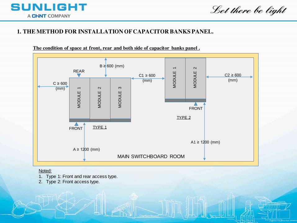
C1 ≥ 600
(mm)
C2 ≥ 600
(mm)
A1 ≥ 1200 (mm)
MO
DU
LE
1
FRONT
Noted:
1. Type 1: Front and rear access type.2. Type 2: Front access type.
MAIN SWITCHBOARD ROOM
1. THE METHOD FOR INSTALLATION OF CAPACITOR BANKS PANEL.
The condition of space at front, rear and both side of capacitor banks panel .
MO
DU
LE
2
MO
DU
LE
1
FRONT
MO
DU
LE
2
A ≥ 1200 (mm)
B ≥ 600 (mm)
REAR
C ≥ 600
(mm)
TYPE 1
TYPE 2 M
OD
ULE
3
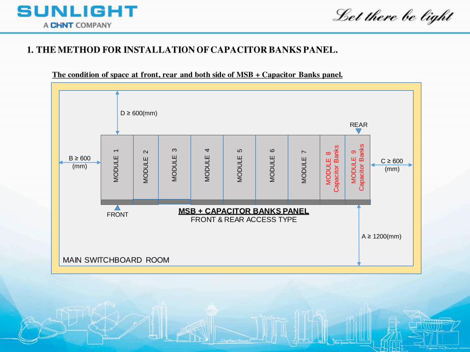
B ≥ 600
(mm)C ≥ 600
(mm)
A ≥ 1200(mm)
MO
DU
LE
1
FRONT MSB + CAPACITOR BANKS PANEL
FRONT & REAR ACCESS TYPE
MAIN SWITCHBOARD ROOM
REAR
D ≥ 600(mm)
MO
DU
LE
3
MO
DU
LE
4
MO
DU
LE
2
MO
DU
LE
5
MO
DU
LE
6
MO
DU
LE
7
MO
DU
LE
8
Capacitor
Banks
MO
DU
LE
9
Capacitor
Banks
The condition of space at front, rear and both side of MSB + Capacitor Banks panel.
1. THE METHOD FOR INSTALLATION OF CAPACITOR BANKS PANEL.
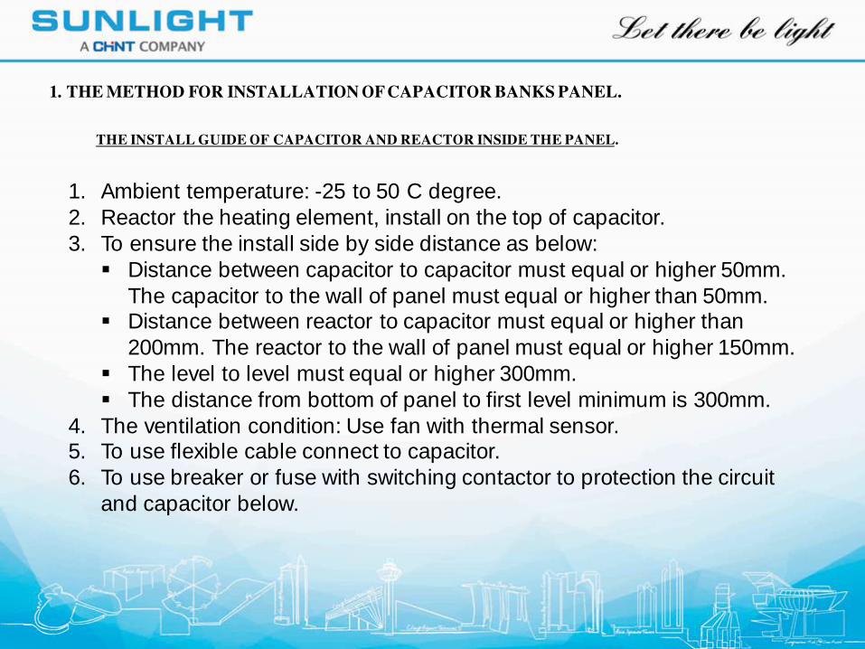
THE INSTALL GUIDE OF CAPACITOR AND REACTOR INSIDE THE PANEL.
1. Ambient temperature: -25 to 50 C degree.
2. Reactor the heating element, install on the top of capacitor.
3. To ensure the install side by side distance as below:
Distance between capacitor to capacitor must equal or higher 50mm.
The capacitor to the wall of panel must equal or higher than 50mm. Distance between reactor to capacitor must equal or higher than
200mm. The reactor to the wall of panel must equal or higher 150mm.
The level to level must equal or higher 300mm.
The distance from bottom of panel to first level minimum is 300mm.
4. The ventilation condition: Use fan with thermal sensor.5. To use flexible cable connect to capacitor.
6. To use breaker or fuse with switching contactor to protection the circuit
and capacitor below.
1. THE METHOD FOR INSTALLATION OF CAPACITOR BANKS PANEL.
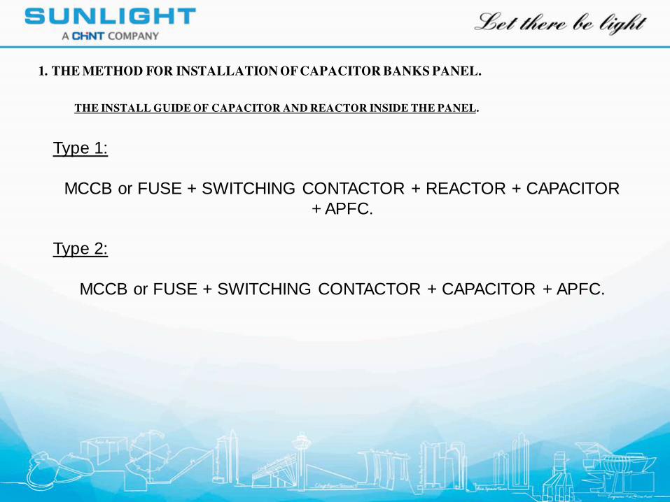
THE INSTALL GUIDE OF CAPACITOR AND REACTOR INSIDE THE PANEL.
Type 1:
MCCB or FUSE + SWITCHING CONTACTOR + REACTOR + CAPACITOR
+ APFC.
Type 2:
MCCB or FUSE + SWITCHING CONTACTOR + CAPACITOR + APFC.
1. THE METHOD FOR INSTALLATION OF CAPACITOR BANKS PANEL.
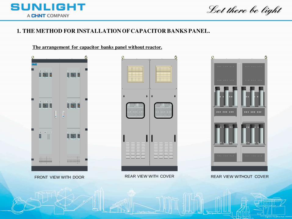
The arrangement for capacitor banks panel without reactor.
FRONT VIEW WITH DOOR REAR VIEW WITH COVER REAR VIEW WITHOUT COVER
1. THE METHOD FOR INSTALLATION OF CAPACITOR BANKS PANEL.
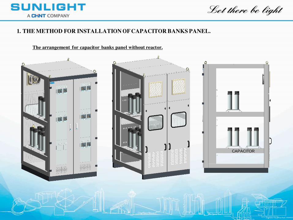
CAPACITOR
The arrangement for capacitor banks panel without reactor.
1. THE METHOD FOR INSTALLATION OF CAPACITOR BANKS PANEL.
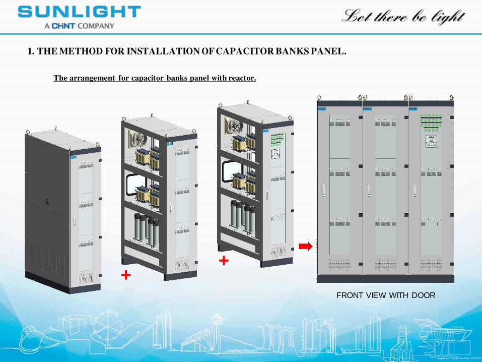
FRONT VIEW WITH DOOR
++
The arrangement for capacitor banks panel with reactor.
1. THE METHOD FOR INSTALLATION OF CAPACITOR BANKS PANEL.
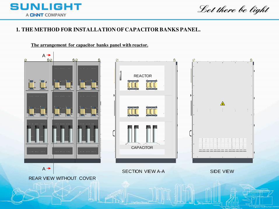
REAR VIEW WITHOUT COVER
SECTION VIEW A-A SIDE VIEWA
A
REACTOR
CAPACITOR
The arrangement for capacitor banks panel with reactor.
1. THE METHOD FOR INSTALLATION OF CAPACITOR BANKS PANEL.
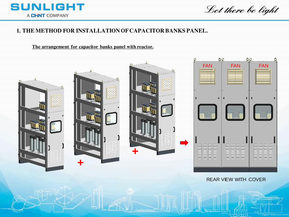
REAR VIEW WITH COVER
++
FAN FAN FAN
The arrangement for capacitor banks panel with reactor.
1. THE METHOD FOR INSTALLATION OF CAPACITOR BANKS PANEL.
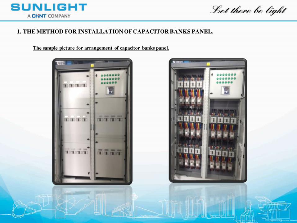
The sample picture for arrangement of capacitor banks panel.
1. THE METHOD FOR INSTALLATION OF CAPACITOR BANKS PANEL.
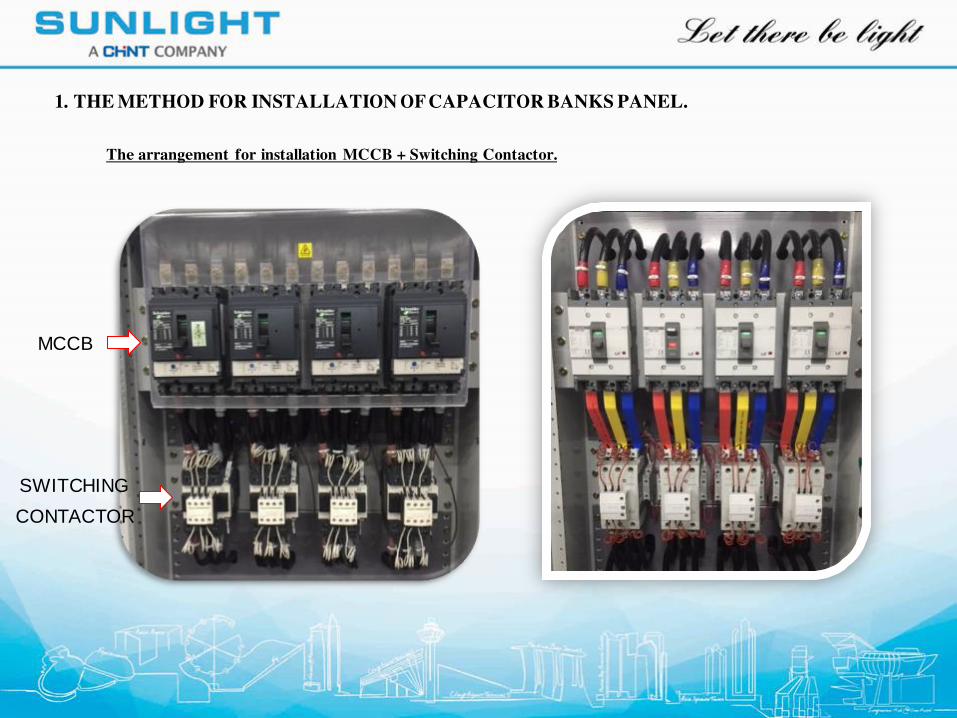
The arrangement for installation MCCB + Switching Contactor.
1. THE METHOD FOR INSTALLATION OF CAPACITOR BANKS PANEL.
MCCB
CONTACTOR
SWITCHING
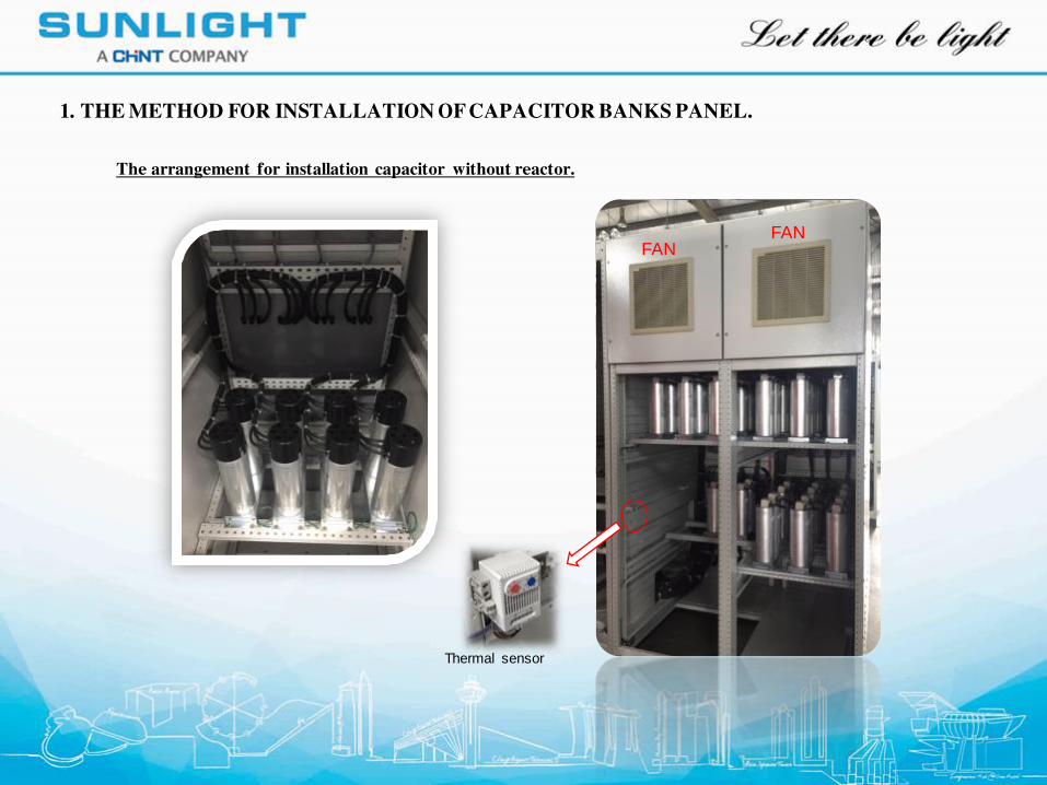
The arrangement for installation capacitor without reactor.
1. THE METHOD FOR INSTALLATION OF CAPACITOR BANKS PANEL.
FANFAN
Thermal sensor
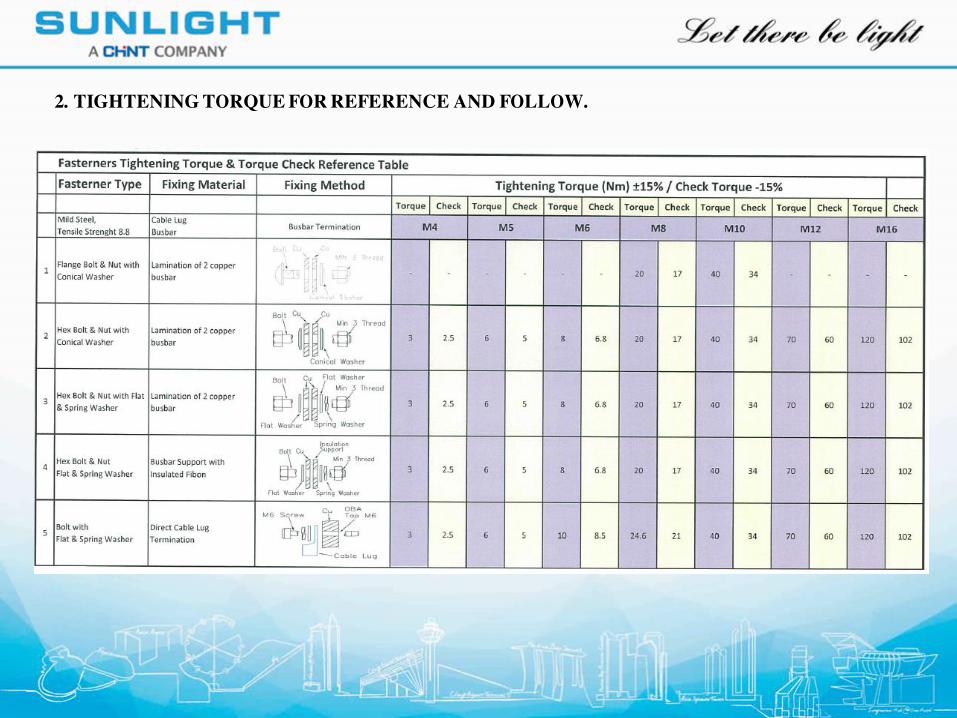
2. TIGHTENING TORQUE FOR REFERENCE AND FOLLOW.
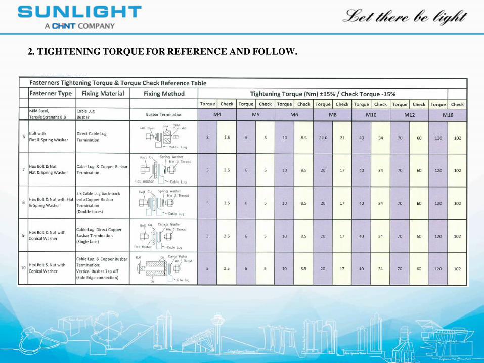
2. TIGHTENING TORQUE FOR REFERENCE AND FOLLOW.
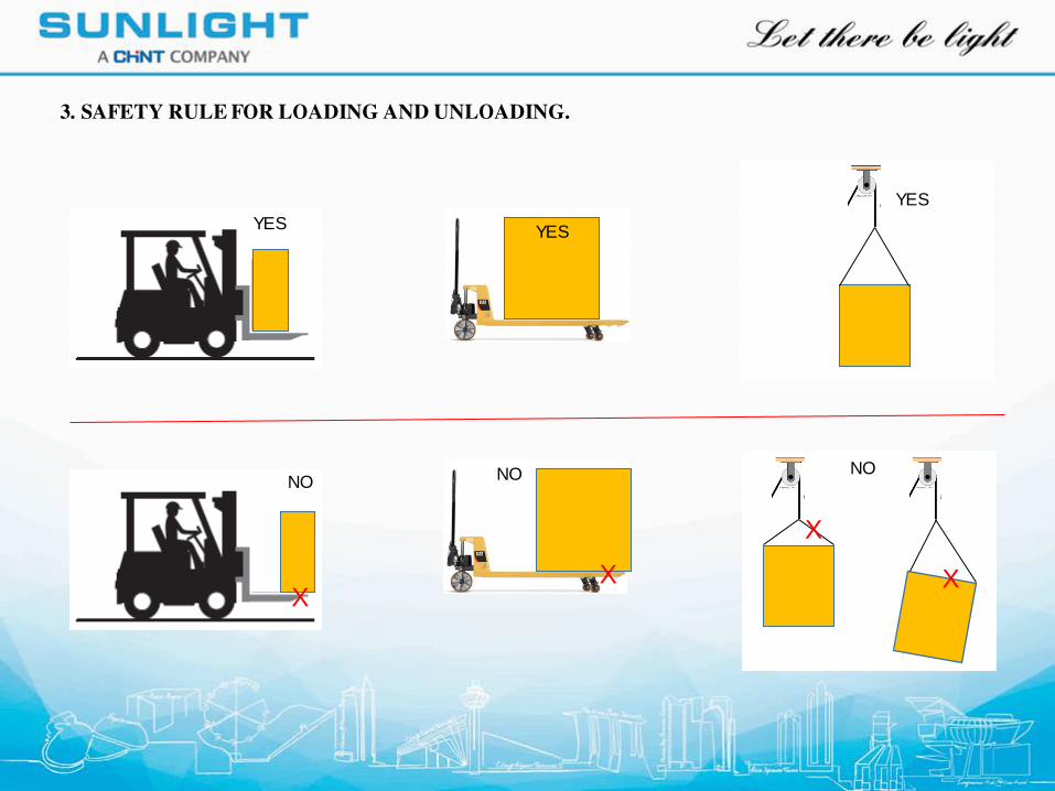
3. SAFETY RULE FOR LOADING AND UNLOADING.
YES
NO
YES
NO NO
YES
XX
X
X