Embed Size (px)
Citation preview
Mechanical properties of low-density polyethylene filled by graphite nanoplatelets
This article has been downloaded from IOPscience. Please scroll down to see the full text article.
2012 Nanotechnology 23 485705
(http://iopscience.iop.org/0957-4484/23/48/485705)
Download details:
IP Address: 87.18.141.162
The article was downloaded on 07/11/2012 at 08:40
Please note that terms and conditions apply.
View the table of contents for this issue, or go to the journal homepage for more
Home Search Collections Journals About Contact us My IOPscience
IOP PUBLISHING NANOTECHNOLOGY
Nanotechnology 23 (2012) 485705 (8pp) doi:10.1088/0957-4484/23/48/485705
Mechanical properties of low-densitypolyethylene filled by graphitenanoplateletsG Carotenuto1, S De Nicola2,3, M Palomba1, D Pullini4, A Horsewell5,T W Hansen6 and L Nicolais7
1 Institute for Composites and Biomedical Materials, National Research Council, Piazzale Tecchio, 80,I-80125 Napoli, Italy2 Istituto Nazionale di Ottica, Via Campi Flegrei 34, Pozzuoli, Italy3 INFN Sezione di Napoli, Italy4 Group Materials Labs, Fiat Research Centre Scpa, Strada Torino 50, I-10043 Orbassano, Italy5 Department of Mechanical Engineering and Center for Electron Nanoscopy, Technical University ofDenmark, DK-2800 Kongens-Lyngby, Denmark6 Center for Electron Nanoscopy, DK-2800 Kongens Lyngby, Denmark7 Department of Material Engineering and Production, University ‘Federico II’ of Naples,Piazzale Tecchio, 80, I-80125 Napoli, Italy
E-mail: [email protected]
Received 1 September 2012, in final form 2 October 2012Published 6 November 2012Online at stacks.iop.org/Nano/23/485705
AbstractThe mechanical properties of GNP/LDPE nanocomposites (graphite nanoplatelets/low densitypolyethylene) have been investigated, in order to establish the effect of nanoscalereinforcement within the polymer matrix. Results show that the presence of the filler does notinvolve a change in the microscopic structure of the polymer. However, on a macroscopicscale, GNPs limit the mobility of the polymer chains, resulting in an increase in stiffness forthe final composite. Orientation of GNPs within the LDPE matrix is also an important issuethat affects mechanical properties and it has been evaluated by testing nanocomposites madeby different manufacturing techniques (compression moulding and blown extrusion). Thecomparison between the experimental data and the Halpin–Tsai model shows that theorientation of GNPs due to the extrusion process leads to values of tensile modulus higherthan that obtained with the randomly oriented disposition resulting from the compressionmoulding technique.
(Some figures may appear in colour only in the online journal)
1. Introduction
There are different nanostructures which are based oncarbon in the Sp2 hybridization form [1]. Fullerenes, carbonnanotubes, graphene and graphene quantum dots are themost common nano-materials containing carbon in the Sp2
Content from this work may be used under the termsof the Creative Commons Attribution-NonCommercial-
ShareAlike 3.0 licence. Any further distribution of this work must maintainattribution to the author(s) and the title of the work, journal citation and DOI.
hybridization form, however also graphite nanoplatelets(GNP) and other nanostructures are based on the same kindof carbon. Graphite nanoplatelets are graphite crystals [2]with a thickness of only a few nanometres, whereas the othertwo dimensions are several hundred microns. These graphitenano-crystals contain only a few (usually less than ten)graphene layers. Graphite nanoplatelets have a semimetallicbehaviour, different from graphite which is a metallicmaterial [2] and graphene which is a semiconductor withzero bandgap. Graphene nanoplatelets are usually classifiedas quasi-bidimensional nanostructures (similarly multi-wall
10957-4484/12/485705+08$33.00 c© 2012 IOP Publishing Ltd Printed in the UK & the USA
Nanotechnology 23 (2012) 485705 G Carotenuto et al
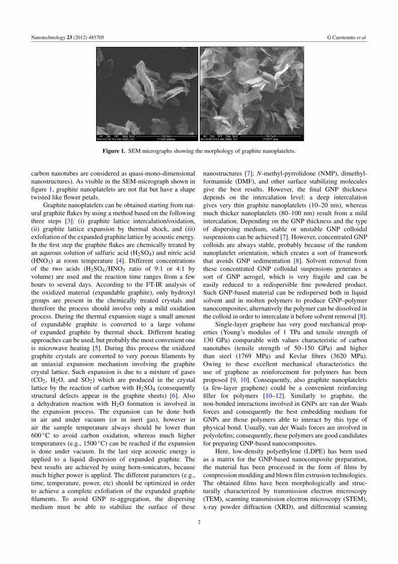
Figure 1. SEM micrographs showing the morphology of graphite nanoplatelets.
carbon nanotubes are considered as quasi-mono-dimensionalnanostructures). As visible in the SEM-micrograph shown infigure 1, graphite nanoplatelets are not flat but have a shapetwisted like flower petals.
Graphite nanoplatelets can be obtained starting from nat-ural graphite flakes by using a method based on the followingthree steps [3]: (i) graphite lattice intercalation/oxidation,(ii) graphite lattice expansion by thermal shock, and (iii)exfoliation of the expanded graphite lattice by acoustic energy.In the first step the graphite flakes are chemically treated byan aqueous solution of sulfuric acid (H2SO4) and nitric acid(HNO3) at room temperature [4]. Different concentrationsof the two acids (H2SO4/HNO3 ratio of 9:1 or 4:1 byvolume) are used and the reaction time ranges from a fewhours to several days. According to the FT-IR analysis ofthe oxidized material (expandable graphite), only hydroxylgroups are present in the chemically treated crystals andtherefore the process should involve only a mild oxidationprocess. During the thermal expansion stage a small amountof expandable graphite is converted to a large volumeof expanded graphite by thermal shock. Different heatingapproaches can be used, but probably the most convenient oneis microwave heating [5]. During this process the oxidizedgraphite crystals are converted to very porous filaments byan uniaxial expansion mechanism involving the graphitecrystal lattice. Such expansion is due to a mixture of gases(CO2, H2O, and SO2) which are produced in the crystallattice by the reaction of carbon with H2SO4 (consequentlystructural defects appear in the graphite sheets) [6]. Alsoa dehydration reaction with H2O formation is involved inthe expansion process. The expansion can be done bothin air and under vacuum (or in inert gas), however inair the sample temperature always should be lower than600 ◦C to avoid carbon oxidation, whereas much highertemperatures (e.g., 1500 ◦C) can be reached if the expansionis done under vacuum. In the last step acoustic energy isapplied to a liquid dispersion of expanded graphite. Thebest results are achieved by using horn-sonicators, becausemuch higher power is applied. The different parameters (e.g.,time, temperature, power, etc) should be optimized in orderto achieve a complete exfoliation of the expanded graphitefilaments. To avoid GNP re-aggregation, the dispersingmedium must be able to stabilize the surface of these
nanostructures [7]; N-methyl-pyrrolidone (NMP), dimethyl-formamide (DMF), and other surface stabilizing moleculesgive the best results. However, the final GNP thicknessdepends on the intercalation level: a deep intercalationgives very thin graphite nanoplatelets (10–20 nm), whereasmuch thicker nanoplatelets (80–100 nm) result from a mildintercalation. Depending on the GNP thickness and the typeof dispersing medium, stable or unstable GNP colloidalsuspensions can be achieved [7]. However, concentrated GNPcolloids are always stable, probably because of the randomnanoplatelet orientation, which creates a sort of frameworkthat avoids GNP sedimentation [8]. Solvent removal fromthese concentrated GNP colloidal suspensions generates asort of GNP aerogel, which is very fragile and can beeasily reduced to a redispersible fine powdered product.Such GNP-based material can be redispersed both in liquidsolvent and in molten polymers to produce GNP–polymernanocomposites; alternatively the polymer can be dissolved inthe colloid in order to intercalate it before solvent removal [8].
Single-layer graphene has very good mechanical prop-erties (Young’s modulus of 1 TPa and tensile strength of130 GPa) comparable with values characteristic of carbonnanotubes (tensile strength of 50–150 GPa) and higherthan steel (1769 MPa) and Kevlar fibres (3620 MPa).Owing to these excellent mechanical characteristics theuse of graphene as reinforcement for polymers has beenproposed [9, 10]. Consequently, also graphite nanoplatelets(a few-layer graphene) could be a convenient reinforcingfiller for polymers [10–12]. Similarly to graphite, thenon-bonded interactions involved in GNPs are van der Waalsforces and consequently the best embedding medium forGNPs are those polymers able to interact by this type ofphysical bond. Usually, van der Waals forces are involved inpolyolefins; consequently, these polymers are good candidatesfor preparing GNP-based nanocomposites.
Here, low-density polyethylene (LDPE) has been usedas a matrix for the GNP-based nanocomposite preparation,the material has been processed in the form of films bycompression moulding and blown film extrusion technologies.The obtained films have been morphologically and struc-turally characterized by transmission electron microscopy(TEM), scanning transmission electron microscopy (STEM),x-ray powder diffraction (XRD), and differential scanning
2
Nanotechnology 23 (2012) 485705 G Carotenuto et al
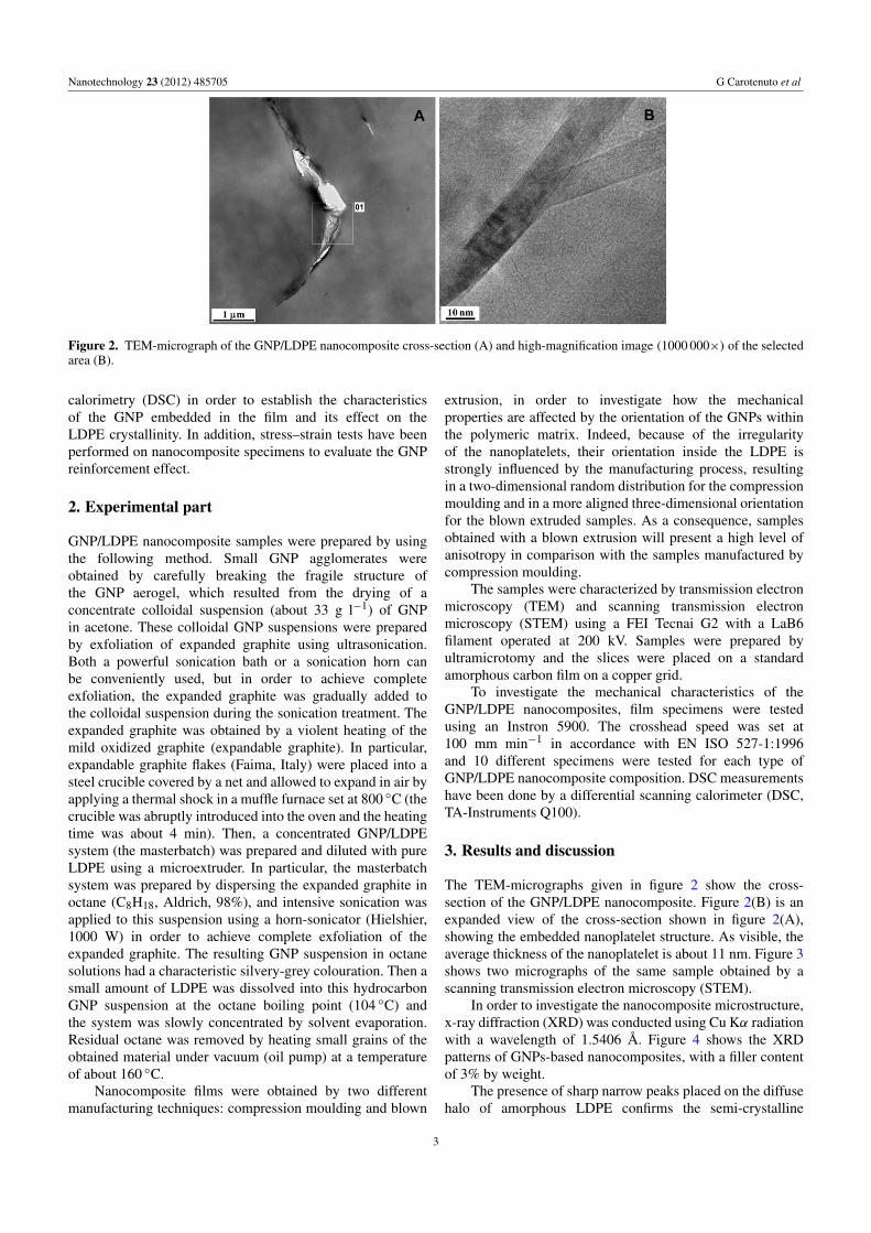
Figure 2. TEM-micrograph of the GNP/LDPE nanocomposite cross-section (A) and high-magnification image (1000 000×) of the selectedarea (B).
calorimetry (DSC) in order to establish the characteristicsof the GNP embedded in the film and its effect on theLDPE crystallinity. In addition, stress–strain tests have beenperformed on nanocomposite specimens to evaluate the GNPreinforcement effect.
2. Experimental part
GNP/LDPE nanocomposite samples were prepared by usingthe following method. Small GNP agglomerates wereobtained by carefully breaking the fragile structure ofthe GNP aerogel, which resulted from the drying of aconcentrate colloidal suspension (about 33 g l−1) of GNPin acetone. These colloidal GNP suspensions were preparedby exfoliation of expanded graphite using ultrasonication.Both a powerful sonication bath or a sonication horn canbe conveniently used, but in order to achieve completeexfoliation, the expanded graphite was gradually added tothe colloidal suspension during the sonication treatment. Theexpanded graphite was obtained by a violent heating of themild oxidized graphite (expandable graphite). In particular,expandable graphite flakes (Faima, Italy) were placed into asteel crucible covered by a net and allowed to expand in air byapplying a thermal shock in a muffle furnace set at 800 ◦C (thecrucible was abruptly introduced into the oven and the heatingtime was about 4 min). Then, a concentrated GNP/LDPEsystem (the masterbatch) was prepared and diluted with pureLDPE using a microextruder. In particular, the masterbatchsystem was prepared by dispersing the expanded graphite inoctane (C8H18, Aldrich, 98%), and intensive sonication wasapplied to this suspension using a horn-sonicator (Hielshier,1000 W) in order to achieve complete exfoliation of theexpanded graphite. The resulting GNP suspension in octanesolutions had a characteristic silvery-grey colouration. Then asmall amount of LDPE was dissolved into this hydrocarbonGNP suspension at the octane boiling point (104 ◦C) andthe system was slowly concentrated by solvent evaporation.Residual octane was removed by heating small grains of theobtained material under vacuum (oil pump) at a temperatureof about 160 ◦C.
Nanocomposite films were obtained by two differentmanufacturing techniques: compression moulding and blown
extrusion, in order to investigate how the mechanicalproperties are affected by the orientation of the GNPs withinthe polymeric matrix. Indeed, because of the irregularityof the nanoplatelets, their orientation inside the LDPE isstrongly influenced by the manufacturing process, resultingin a two-dimensional random distribution for the compressionmoulding and in a more aligned three-dimensional orientationfor the blown extruded samples. As a consequence, samplesobtained with a blown extrusion will present a high level ofanisotropy in comparison with the samples manufactured bycompression moulding.
The samples were characterized by transmission electronmicroscopy (TEM) and scanning transmission electronmicroscopy (STEM) using a FEI Tecnai G2 with a LaB6filament operated at 200 kV. Samples were prepared byultramicrotomy and the slices were placed on a standardamorphous carbon film on a copper grid.
To investigate the mechanical characteristics of theGNP/LDPE nanocomposites, film specimens were testedusing an Instron 5900. The crosshead speed was set at100 mm min−1 in accordance with EN ISO 527-1:1996and 10 different specimens were tested for each type ofGNP/LDPE nanocomposite composition. DSC measurementshave been done by a differential scanning calorimeter (DSC,TA-Instruments Q100).
3. Results and discussion
The TEM-micrographs given in figure 2 show the cross-section of the GNP/LDPE nanocomposite. Figure 2(B) is anexpanded view of the cross-section shown in figure 2(A),showing the embedded nanoplatelet structure. As visible, theaverage thickness of the nanoplatelet is about 11 nm. Figure 3shows two micrographs of the same sample obtained by ascanning transmission electron microscopy (STEM).
In order to investigate the nanocomposite microstructure,x-ray diffraction (XRD) was conducted using Cu Kα radiationwith a wavelength of 1.5406 A. Figure 4 shows the XRDpatterns of GNPs-based nanocomposites, with a filler contentof 3% by weight.
The presence of sharp narrow peaks placed on the diffusehalo of amorphous LDPE confirms the semi-crystalline
3
Nanotechnology 23 (2012) 485705 G Carotenuto et al
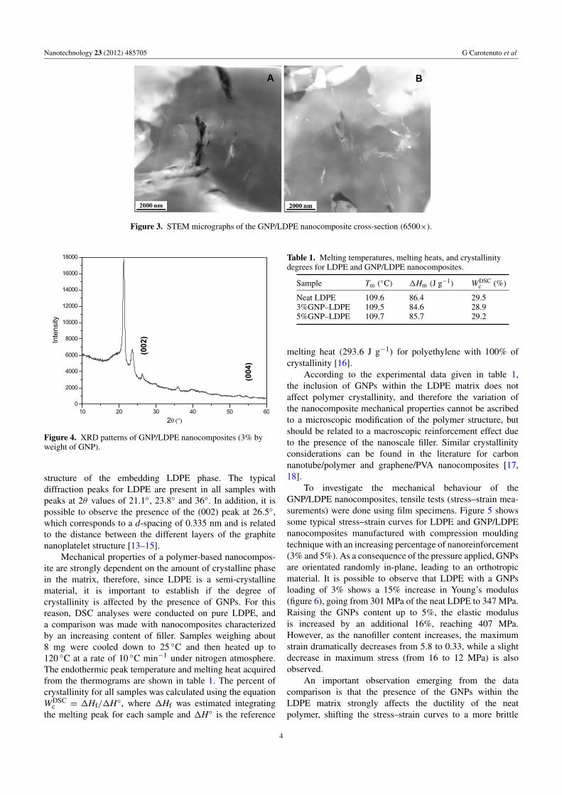
Figure 3. STEM micrographs of the GNP/LDPE nanocomposite cross-section (6500×).
Figure 4. XRD patterns of GNP/LDPE nanocomposites (3% byweight of GNP).
structure of the embedding LDPE phase. The typicaldiffraction peaks for LDPE are present in all samples withpeaks at 2θ values of 21.1◦, 23.8◦ and 36◦. In addition, it ispossible to observe the presence of the (002) peak at 26.5◦,which corresponds to a d-spacing of 0.335 nm and is relatedto the distance between the different layers of the graphitenanoplatelet structure [13–15].
Mechanical properties of a polymer-based nanocompos-ite are strongly dependent on the amount of crystalline phasein the matrix, therefore, since LDPE is a semi-crystallinematerial, it is important to establish if the degree ofcrystallinity is affected by the presence of GNPs. For thisreason, DSC analyses were conducted on pure LDPE, anda comparison was made with nanocomposites characterizedby an increasing content of filler. Samples weighing about8 mg were cooled down to 25 ◦C and then heated up to120 ◦C at a rate of 10 ◦C min−1 under nitrogen atmosphere.The endothermic peak temperature and melting heat acquiredfrom the thermograms are shown in table 1. The percent ofcrystallinity for all samples was calculated using the equationWDSC
c = 1Hf/1H◦, where 1Hf was estimated integratingthe melting peak for each sample and 1H◦ is the reference
Table 1. Melting temperatures, melting heats, and crystallinitydegrees for LDPE and GNP/LDPE nanocomposites.
Sample Tm (◦C) 1Hm (J g−1) WDSC
c (%)
Neat LDPE 109.6 86.4 29.53%GNP–LDPE 109.5 84.6 28.95%GNP–LDPE 109.7 85.7 29.2
melting heat (293.6 J g−1) for polyethylene with 100% ofcrystallinity [16].
According to the experimental data given in table 1,the inclusion of GNPs within the LDPE matrix does notaffect polymer crystallinity, and therefore the variation ofthe nanocomposite mechanical properties cannot be ascribedto a microscopic modification of the polymer structure, butshould be related to a macroscopic reinforcement effect dueto the presence of the nanoscale filler. Similar crystallinityconsiderations can be found in the literature for carbonnanotube/polymer and graphene/PVA nanocomposites [17,18].
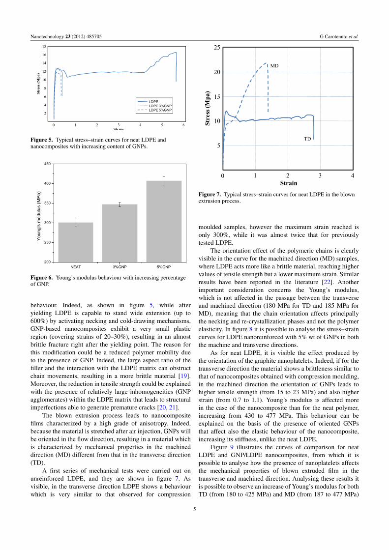
To investigate the mechanical behaviour of theGNP/LDPE nanocomposites, tensile tests (stress–strain mea-surements) were done using film specimens. Figure 5 showssome typical stress–strain curves for LDPE and GNP/LDPEnanocomposites manufactured with compression mouldingtechnique with an increasing percentage of nanoreinforcement(3% and 5%). As a consequence of the pressure applied, GNPsare orientated randomly in-plane, leading to an orthotropicmaterial. It is possible to observe that LDPE with a GNPsloading of 3% shows a 15% increase in Young’s modulus(figure 6), going from 301 MPa of the neat LDPE to 347 MPa.Raising the GNPs content up to 5%, the elastic modulusis increased by an additional 16%, reaching 407 MPa.However, as the nanofiller content increases, the maximumstrain dramatically decreases from 5.8 to 0.33, while a slightdecrease in maximum stress (from 16 to 12 MPa) is alsoobserved.
An important observation emerging from the datacomparison is that the presence of the GNPs within theLDPE matrix strongly affects the ductility of the neatpolymer, shifting the stress–strain curves to a more brittle
4
Nanotechnology 23 (2012) 485705 G Carotenuto et al
Figure 5. Typical stress–strain curves for neat LDPE andnanocomposites with increasing content of GNPs.
Figure 6. Young’s modulus behaviour with increasing percentageof GNP.
behaviour. Indeed, as shown in figure 5, while afteryielding LDPE is capable to stand wide extension (up to600%) by activating necking and cold-drawing mechanisms,GNP-based nanocomposites exhibit a very small plasticregion (covering strains of 20–30%), resulting in an almostbrittle fracture right after the yielding point. The reason forthis modification could be a reduced polymer mobility dueto the presence of GNP. Indeed, the large aspect ratio of thefiller and the interaction with the LDPE matrix can obstructchain movements, resulting in a more brittle material [19].Moreover, the reduction in tensile strength could be explainedwith the presence of relatively large inhomogeneities (GNPagglomerates) within the LDPE matrix that leads to structuralimperfections able to generate premature cracks [20, 21].
The blown extrusion process leads to nanocompositefilms characterized by a high grade of anisotropy. Indeed,because the material is stretched after air injection, GNPs willbe oriented in the flow direction, resulting in a material whichis characterized by mechanical properties in the machineddirection (MD) different from that in the transverse direction(TD).
A first series of mechanical tests were carried out onunreinforced LDPE, and they are shown in figure 7. Asvisible, in the transverse direction LDPE shows a behaviourwhich is very similar to that observed for compression
Figure 7. Typical stress–strain curves for neat LDPE in the blownextrusion process.
moulded samples, however the maximum strain reached isonly 300%, while it was almost twice that for previouslytested LDPE.
The orientation effect of the polymeric chains is clearlyvisible in the curve for the machined direction (MD) samples,where LDPE acts more like a brittle material, reaching highervalues of tensile strength but a lower maximum strain. Similarresults have been reported in the literature [22]. Anotherimportant consideration concerns the Young’s modulus,which is not affected in the passage between the transverseand machined direction (180 MPa for TD and 185 MPa forMD), meaning that the chain orientation affects principallythe necking and re-crystallization phases and not the polymerelasticity. In figure 8 it is possible to analyse the stress–straincurves for LDPE nanoreinforced with 5% wt of GNPs in boththe machine and transverse directions.
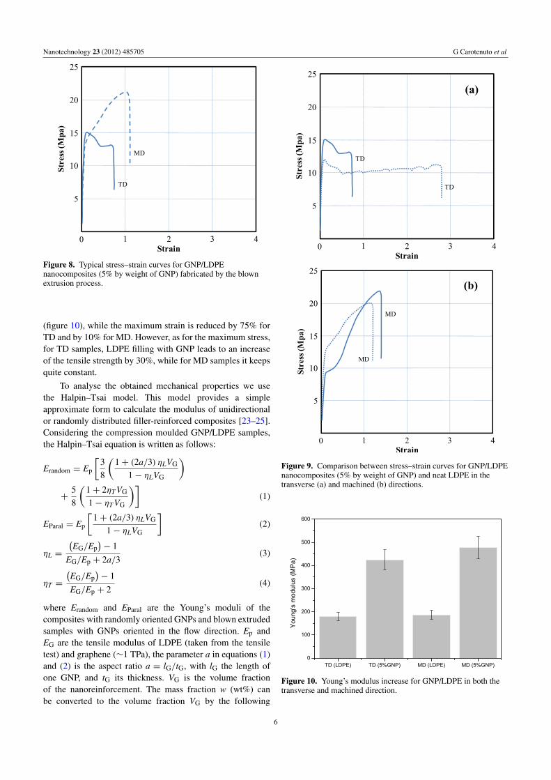
As for neat LDPE, it is visible the effect produced bythe orientation of the graphite nanoplatelets. Indeed, if for thetransverse direction the material shows a brittleness similar tothat of nanocomposites obtained with compression moulding,in the machined direction the orientation of GNPs leads tohigher tensile strength (from 15 to 23 MPa) and also higherstrain (from 0.7 to 1.1). Young’s modulus is affected morein the case of the nanocomposite than for the neat polymer,increasing from 430 to 477 MPa. This behaviour can beexplained on the basis of the presence of oriented GNPsthat affect also the elastic behaviour of the nanocomposite,increasing its stiffness, unlike the neat LDPE.
Figure 9 illustrates the curves of comparison for neatLDPE and GNP/LDPE nanocomposites, from which it ispossible to analyse how the presence of nanoplatelets affectsthe mechanical properties of blown extruded film in thetransverse and machined direction. Analysing these results itis possible to observe an increase of Young’s modulus for bothTD (from 180 to 425 MPa) and MD (from 187 to 477 MPa)
5
Nanotechnology 23 (2012) 485705 G Carotenuto et al
Figure 8. Typical stress–strain curves for GNP/LDPEnanocomposites (5% by weight of GNP) fabricated by the blownextrusion process.
(figure 10), while the maximum strain is reduced by 75% forTD and by 10% for MD. However, as for the maximum stress,for TD samples, LDPE filling with GNP leads to an increaseof the tensile strength by 30%, while for MD samples it keepsquite constant.
To analyse the obtained mechanical properties we usethe Halpin–Tsai model. This model provides a simpleapproximate form to calculate the modulus of unidirectionalor randomly distributed filler-reinforced composites [23–25].Considering the compression moulded GNP/LDPE samples,the Halpin–Tsai equation is written as follows:
Erandom = Ep
[38
(1+ (2a/3) ηLVG
1− ηLVG
)+
58
(1+ 2ηTVG
1− ηTVG
)](1)
EParal = Ep
[1+ (2a/3) ηLVG
1− ηLVG
](2)
ηL =
(EG/Ep
)− 1
EG/Ep + 2a/3(3)
ηT =
(EG/Ep
)− 1
EG/Ep + 2(4)
where Erandom and EParal are the Young’s moduli of thecomposites with randomly oriented GNPs and blown extrudedsamples with GNPs oriented in the flow direction. Ep andEG are the tensile modulus of LDPE (taken from the tensiletest) and graphene (∼1 TPa), the parameter a in equations (1)and (2) is the aspect ratio a = lG/tG, with lG the length ofone GNP, and tG its thickness. VG is the volume fractionof the nanoreinforcement. The mass fraction w (wt%) canbe converted to the volume fraction VG by the following
Figure 9. Comparison between stress–strain curves for GNP/LDPEnanocomposites (5% by weight of GNP) and neat LDPE in thetransverse (a) and machined (b) directions.
Figure 10. Young’s modulus increase for GNP/LDPE in both thetransverse and machined direction.
6
Nanotechnology 23 (2012) 485705 G Carotenuto et al
Figure 11. Comparison between the Halpin–Tsai modulusevaluation model and experimental data for compression mouldedGNP/LDPE nanocomposites: experimental data (red curve);Halpin–Tsai model of unidirectional distribution of GNPs (greencurve); Halpin–Tsai model of randomly orientated GNPs (bluecurve).
equation:
VG =wρp
wρp + (1− w) ρG. (5)
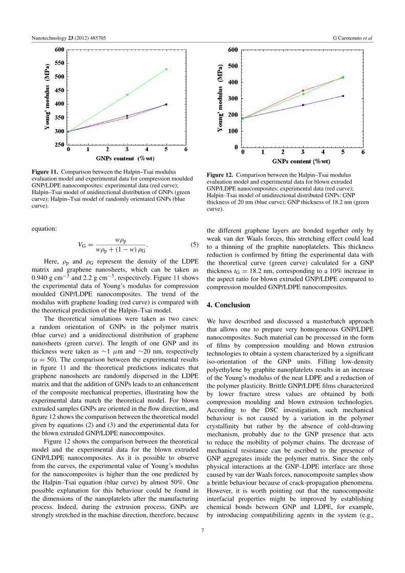
Here, ρp and ρG represent the density of the LDPEmatrix and graphene nanosheets, which can be taken as0.940 g cm−3 and 2.2 g cm−3, respectively. Figure 11 showsthe experimental data of Young’s modulus for compressionmoulded GNP/LDPE nanocomposites. The trend of themodulus with graphene loading (red curve) is compared withthe theoretical prediction of the Halpin–Tsai model.
The theoretical simulations were taken as two cases:a random orientation of GNPs in the polymer matrix(blue curve) and a unidirectional distribution of graphenenanosheets (green curve). The length of one GNP and itsthickness were taken as ∼1 µm and ∼20 nm, respectively(a = 50). The comparison between the experimental resultsin figure 11 and the theoretical predictions indicates thatgraphene nanosheets are randomly dispersed in the LDPEmatrix and that the addition of GNPs leads to an enhancementof the composite mechanical properties, illustrating how theexperimental data match the theoretical model. For blownextruded samples GNPs are oriented in the flow direction, andfigure 12 shows the comparison between the theoretical modelgiven by equations (2) and (3) and the experimental data forthe blown extruded GNP/LDPE nanocomposites.
Figure 12 shows the comparison between the theoreticalmodel and the experimental data for the blown extrudedGNP/LDPE nanocomposites. As it is possible to observefrom the curves, the experimental value of Young’s modulusfor the nanocomposites is higher than the one predicted bythe Halpin–Tsai equation (blue curve) by almost 50%. Onepossible explanation for this behaviour could be found inthe dimensions of the nanoplatelets after the manufacturingprocess. Indeed, during the extrusion process, GNPs arestrongly stretched in the machine direction, therefore, because
Figure 12. Comparison between the Halpin–Tsai modulusevaluation model and experimental data for blown extrudedGNP/LDPE nanocomposites: experimental data (red curve);Halpin–Tsai model of unidirectional distributed GNPs: GNPthickness of 20 nm (blue curve); GNP thickness of 18.2 nm (greencurve).
the different graphene layers are bonded together only byweak van der Waals forces, this stretching effect could leadto a thinning of the graphite nanoplatelets. This thicknessreduction is confirmed by fitting the experimental data withthe theoretical curve (green curve) calculated for a GNPthickness tG = 18.2 nm, corresponding to a 10% increase inthe aspect ratio for blown extruded GNP/LDPE compared tocompression moulded GNP/LDPE nanocomposites.
4. Conclusion
We have described and discussed a masterbatch approachthat allows one to prepare very homogeneous GNP/LDPEnanocomposites. Such material can be processed in the formof films by compression moulding and blown extrusiontechnologies to obtain a system characterized by a significantiso-orientation of the GNP units. Filling low-densitypolyethylene by graphite nanoplatelets results in an increaseof the Young’s modulus of the neat LDPE and a reduction ofthe polymer plasticity. Brittle GNP/LDPE films characterizedby lower fracture stress values are obtained by bothcompression moulding and blown extrusion technologies.According to the DSC investigation, such mechanicalbehaviour is not caused by a variation in the polymercrystallinity but rather by the absence of cold-drawingmechanism, probably due to the GNP presence that actsto reduce the mobility of polymer chains. The decrease ofmechanical resistance can be ascribed to the presence ofGNP aggregates inside the polymer matrix. Since the onlyphysical interactions at the GNP–LDPE interface are thosecaused by van der Waals forces, nanocomposite samples showa brittle behaviour because of crack-propagation phenomena.However, it is worth pointing out that the nanocompositeinterfacial properties might be improved by establishingchemical bonds between GNP and LDPE, for example,by introducing compatibilizing agents in the system (e.g.,
7
Nanotechnology 23 (2012) 485705 G Carotenuto et al
polyethylene grafting agents such as maleic anhydride). Infact, free radical addition to the carbon–carbon double bondsat graphite nano-crystal edges should be a very favouredchemical reaction.
Acknowledgments
The A P Møller and Chastine Mc-Kinney Møller Foundationis gratefully acknowledged for their contribution towards theestablishment of the Center for Electron Nanoscopy in theTechnical University of Denmark.
References
[1] Suarez-Martinez I, Grobert N and Ewels C P 2012 Carbon50 741
[2] Chung D D L 2002 J. Mater. Sci. 37 1475[3] Geng Y, Wang S J and Kim J-K 2009 J. Colloid Interface Sci.
336 592[4] Afanasov I M, Shornikova O N, Kirilenko D A, Vlasov I I,
Zhang L, Verbeeck J, Avdeev V V and Van Tendeloo G2010 Carbon 48 1858
[5] Kwon O Y, Choi S W, Park K and Kwon Y B 2003 J. Ind.Eng. Chem. 9 743
[6] Gui-Lei S, Xiao-Jie L and Hong-Hao Y 2007 New CarbonMater. 22 242
[7] Wei T, Fan Z, Luo G, Wang S and Song L 2009 Mater. Res.Bull. 44 977
[8] Lin C and Chung D D L 2009 Carbon 47 295[9] Li B and Zhong W-H 2011 J. Mater. Sci. 46 5595
[10] Delgado-Rangel J-A, Addiego F, Eddoumy F, Ahzi S,Patlazhan S, Toniazzo V and Ruch D 2012 J. Appl. Polym.Sci. 125 4316
[11] Li J, Kim J-K and Sham M L 2005 Scr. Mater. 53 235[12] Raza M A, Westwood A, Brown A, Hondow N and
Stirling C 2011 Carbon 49 4269[13] Lian P, Zhu X, Liang S, Li Z, Yang W and Wang H 2010
Electrochim. Acta 55 3909[14] Yang J, Zhang L Q, Shi J H, Quan Y N, Wang L L and
Tian M 2010 J. Appl. Polym. Sci. 116 2706[15] George J J, Bandyopadhyay A and Bhowmick A K 2008
J. Appl. Polym. Sci. 108 1603[16] Morawiec J, Pawlak A, Slouf M, Galeski A, Piorkowska E and
Krasnikowa N 2005 Eur. Polym. J. 41 1115[17] Liu L, Barber A H, Nuriel S and Wagner H D 2005 Adv.
Funct. Mater. 15 975[18] Liang J, Huang Y, Zhang L, Wang Y, Ma Y, Guo T and
Chen Y 2009 Adv. Funct. Mater. 19 2297[19] Kuilla T, Bhadra S, Yao D, Kim N H, Bose S and
Lee J H 2010 Prog. Polym. Sci. 35 1350[20] Zheng W, Lu X and Wong S-C 2004 J. Appl. Polym. Sci.
91 2781[21] Andrews R, Jacques D, Minot M and Rantell T 2002
Macromol. Mater. Eng. 287 395[22] Guichon O, Seguela R, David L and Vigier G 2003 J. Polym.
Sci. B 41 327[23] Zhou T, Chen F, Tang C, Bai H, Zhang Q, Deng H and
Fu Q 2011 Compos. Sci. Technol. 71 1266[24] Liang J, Huang Y, Zhang L, Wang Y, Ma Y, Guo T and
Chen Y 2009 Adv. Funct. Mater. 19 2297[25] Zhao X, Zhang Q, Chen D and Lu P 2010 Macromolecules
43 2357
8


