Embed Size (px)
Citation preview

International Scholarly Research NetworkISRN Renewable EnergyVolume 2012, Article ID 317982, 9 pagesdoi:10.5402/2012/317982
Research Article
MATLAB-Based Investigation of Multiphase InterleavedBuck-Boost Converter for PV System
Hardik P. Desai,1 Ranjan Maheshwari,2 and Shambhu N. Sharma3
1 Department of Electrical Engineering, Sarvajanik College of Engineering & Technology, Dr. R. K. Desai Marg, Athwalines,Surat 395001, India
2 Department of Electronics Engineering, Rajasthan Technical University, Kota 324022, India3 Department of Electrical Engineering, S. V. National Institute of Technology, Ichchhanath, Surat 395 007, India
Correspondence should be addressed to Hardik P. Desai, [email protected]
Received 30 September 2011; Accepted 9 November 2011
Academic Editor: S. Dai
Copyright © 2012 Hardik P. Desai et al. This is an open access article distributed under the Creative Commons AttributionLicense, which permits unrestricted use, distribution, and reproduction in any medium, provided the original work is properlycited.
A photovoltaic (PV) generator exhibits nonlinear voltage-current characteristics and its maximum power point varies with solarradiation. Analytical investigations of the new family of switching converters based on a parallel connection of N(=4) identicalbuck-boost converters employed in PV system are presented. The interleaving strategy ensures that all the converters operate atthe same switching frequency. Mathematical models developed using the state-space average technique are presented in this paper.Various steady-state performance expressions are also derived. The present converter system has the advantages of reduced size ofthe converter, and ripple in the total inductor current. The effectiveness of the four-phase interleaved dc-dc converter combinedwith PV system is demonstrated through simulations carried out in MATLAB environment.
1. Introduction
Generation of electrical energy from renewable sources hasgrowing interest globally. As Photovoltaic (PV) power gen-erator has advantages of no supply limitations, no pollution,and no noise, it can become the biggest contributor to elec-tricity generation among all renewable energy sources. PVsource is nonlinear power generator. Different techniquesto maximise PV power transfer to various loads havebeen reported in the literature [1], some techniques onlyapproximate the maximum power transfer of PV energybecause they are associated with specific atmospheric andload conditions. In order to draw its maximum power,it is possible to insert dc-dc power converters betweenthe PV and load. Power converters are required for manyfunctions. A dc-dc converter converts a dc input voltageinto a desired regulated dc output voltage [2, 3]. The dcinput may be an unregulated or regulated voltage. dc/dcconverters are widely used in photovoltaic generating systemsas an interface between the photovoltaic panel and theload, allowing the follow-up of the maximum power point(MPP). These converters are known as maximum power
point trackers (MPPTs). A maximum power point trackershould provide a maximum power to the load, even ifirradiation, load, and temperature vary [4–8]. The dc-dcconversion process implies in turn an associated effect ofimpedance transformation, that is, the input impedanceshows a dependence on a number of parameters such asload resistance, and duty cycle. Development of parallelconnected converters with interleaving control strategies iscoming up to increase the power processing capability andto improve the reliability of the power electronic system.In this paper, mathematical models are developed usingstate-space average technique for four-phase dc-dc converteremployed with PV. Also various steady-state performanceexpressions are derived. Simulations carried out in MATLABenvironment finds effectiveness of the four-phase interleaveddc-dc converter combined with PV system.
2. Multiphase InterleavedBuck-Boost Converter
Figure 1 shows the new family of switching converters basedon a parallel connection of N(=4) identical interleaved buck-

2 ISRN Renewable Energy
Iphoto Rs
SW1
SW2
SW3
SW4
RC
L1 L2 L3 L4
G
TVPV
+
IPV
D1
D2
D3
D4
−
Figure 1: 4-phase interleaved buck boost converter with PV generator.
1
0.5
0
(a) PWM pulses applied to SW1
1
0.5
0
(b) PWM pulses applied to SW2
1
0.5
0
(c) PWM pulses applied to SW3
1
0.5
0
(d) PWM pulses applied to SW4
0
IL1 IL2 IL3 IL4
t1 t2 t3 t4 t5 t6 t7 t8
(e) Inductor current
Figure 2: (a)–(d) PWM pulses applied to switches SW1–SW4, (e) current through inductor.
boost converters employed in PV system which is consideredfor an analytical investigations.
A PV module consists of a combination of many small PVcells that are connected in series and parallel configurationsto provide the desired voltage and current quantities. It isknown that a PV cell module shows a nonlinear characteristicbetween voltage and current quantities, which is dependenton the insolation and temperature. The equation [9] whichdescribe the I-V characteristics of the cell, is
IPV = IPHOTO − I0
(e(q(VPV+IPVRS)/nKT) − 1
), (1)
where IPHOTO is the cell photo current, RS is the seriesresistance of PV cell, K is Boltzmann’s constant, q is charge
on an electron, n is the diode quality factor, T is the celltemperature, and VPV is the output voltage of PV cell.Reorganization of the equation provides the output voltageof the PV generator as
VPV =(nKT
q
)ln
(I0 + IPHOTO − IPV)I0
− IPVRS, (2)
With N identical cells connected in series and M numberof series combinations connected in parallel, the resultantvoltage would be
VPV = N
(nKT
q
)ln
(I0 + IPHOTO − IPV)I0
− NIPVRS
M. (3)

ISRN Renewable Energy 3
Iphoto Rs
SW1
SW2
SW3
SW4
RC
L1 L2 L3 L4
G
TVPV
+
IPV
D1
D2
D3
D4
iL1 iL4 IL
−
Figure 3: Mode 1.
Iphoto Rs
SW1
SW2
SW3
SW4
RC
L1 L2 L3 L4
G
TVPV
+
IPV
D1
D2
D3
D4
iL1
−
IL
Figure 4: Mode 2.
Iphoto Rs
SW1
SW2
SW3
SW4
RC
L1 L2 L3 L4
G
TVPV
+
IPV
D1
D2
D3
D4
iL2iL1 IL
−
Figure 5: Mode 3.
To extract maximum power from the PV generator, MPPtracker is employed by connecting a dc-dc converter betweenthe PV generator and load. Protection circuits like stringcombiners, blocking diodes, bypass diodes; and fuses can alsobe used in the circuit. String combiners are the physical pointat which the leads from the PV generator circuits are joinedin parallel to create the main array output. Each converterconsists of a power MOSFET used as a controllable switch,an inductor L, a diode, a filter capacitor C, and a load resistorRL.
With the interleaving PWM method, pulses are appliedto the semiconductor switches such that SW1, SW2, SW3, and
Iphoto Rs
SW1
SW2
SW3
SW4
RC
L1 L2 L3L4
G
TVPV
+
IPV
D1
D2
D3
D4
iL2 IL
−
Figure 6: Mode 4.
Iphoto Rs
SW1
SW2
SW3
SW4
RC
L1 L2 L3 L4
G
TVPV
+
IPV
D1
D2
D3
D4
iL2 iL3 IL
−
Figure 7: Mode 5.
Iphoto Rs
SW1
SW2
SW3
SW4
RC
L1 L2 L3 L4
G
TVPV
+
IPV
D1
D2
D3
D4
iL3 IL
−
Figure 8: Mode 6.
SW4 are on and off in interleaving fashion as shown in Figure2. Here, conduction period for the switches may be the samedepending on the duty cycle of PWM pulses and t1 + t2 + t3 +t4 + t5 + t6 + t7 + t8 = T , where T is the total time period forswitching with the on duty ratio d = ton/T , where ton is thetime interval when the switch is on.

4 ISRN Renewable Energy
Iphoto Rs
SW1
SW2
SW3
SW4
RC
L1 L2 L3 L4
G
TVPV
+
IPV
D1
D2
D3
D4
iL3 iL4 IL
−
Figure 9: Mode 7.
Iphoto Rs
SW1
SW2
SW3
SW4
RC
L1 L2 L3 L4
G
TVPV
+
IPV
D1
D2
D3
D4
iL4 IL
−
Figure 10: Mode 8.
Different modes of operation are as follows.
(i) Mode 1 (0 ≤ t ≤ t1). In this mode, SW1, and D4 are onand SW2, SW3, SW4, D1, D2, and D3 are off.
The state space equations for Figure 3 are
˙iL1 = VPV
L1− rL1
L1iL1,
˙iL2 = 0,
˙iL3 = 0,
˙iL4 = VL
L4− rL4
L4iL4,
VL = − iL4
C− VL
RLC.
(4)
(ii) Mode 2 (t1 < t ≤ t2). In this mode; SW1 is on and SW2,SW3, SW4, D1, D2, D3, D4 are off.
The state space equations for Figure 4 are
˙iL1 = VPV
L1− rL1
L1iL1,
˙iL2 = 0,
˙iL3 = 0,
˙iL4 = 0,
VL = − VL
RLC.
(5)
(iii) Mode 3 (t2 < t ≤ t3). In this mode, SW2, and D1 are onand SW1, SW3, SW4, D2, D3, and D4 are off.
The state space equations for Figure 5 are
˙iL1 = VL
L1− rL1
L1iL1,
˙iL2 = VPV
L2− rL2
L2iL2,
˙iL3 = 0,
˙iL4 = 0,
VL = − iL1
C− VL
RLC.
(6)
(iv) Mode 4 (t3 < t ≤ t4). In this mode, SW2 is on and SW1,SW3, SW4, D1, D2, D3, and D4 are off.
The state space equations for Figure 6 are
˙iL1 = 0
˙iL2 = VPV
L2− rL2
L2iL2
˙iL3 = 0
˙iL4 = 0
VL = − VL
RLC.
(7)
(v) Mode 5 (t4 < t ≤ t5). In this mode, SW3 and D2 are onand SW1, SW2, SW4, D1, D3, and D4 are off.
The state space equations for Figure 7 are
˙iL1 = 0,
˙iL2 = VL
L2− rL2
L2iL2,
˙iL3 = VPV
L3− rL3
L3iL3,
˙iL4 = 0,
VL = − iL2
C− VL
RLC.
(8)
(vi) Mode 6 (t5 < t ≤ t6). In this mode, SW3 is on and SW1,SW2, SW4, D1, D2, D3, and D4 are off.
The state space equations for Figure 8 are
˙iL1 = 0,
˙iL2 = 0,
˙iL3 = VPV
L3− rL3
L3iL3,
˙iL4 = 0,
VL = − VL
RLC.
(9)

ISRN Renewable Energy 5
100
50
00 0.05 0.1 0.15 0.2 0.25 0.3 0.35 0.4
PP
V(W
)
Time (S)
(a)
20
10
00 0.05 0.1 0.15 0.2 0.25 0.3 0.35 0.4
VP
V(V
)
Time (S)
(b)
4
2
00 0.05 0.1 0.15 0.2 0.25 0.3 0.35 0.4
I PV
(A)
Time (S)
(c)
Figure 11: PV output (a) power, (b) voltage, and (c) current at MPP.
0
−5−10
0 0.05 0.1 0.15 0.2 0.25 0.3 0.35 0.4Time (S)
I L1
(A)
(a)
0
−5−10
0 0.05 0.1 0.15 0.2 0.25 0.3 0.35 0.4
Time (S)
I L2
(A)
(b)
0
−5−10
0 0.05 0.1 0.15 0.2 0.25 0.3 0.35 0.4
Time (S)
I L3
(A)
(c)
0
−5
−100 0.05 0.1 0.15 0.2 0.25 0.3 0.35 0.4
Time (S)
I L4
(A)
(d)
Figure 12: Current through inductors (a) L1, (b) L2, (c) L3, and (d) L4.
(vii) Mode 7 (t6 < t ≤ t7). In this mode, SW4 and D3 are onand SW1, SW2, SW3, D1, D2, and D4 are off.
The state-space equations for Figure 9 are
˙iL1 = 0,
˙iL2 = 0,
˙iL3 = VL
L3− rL3
L3iL3,
˙iL4 = VPV
L4− rL4
L4iL4,
VL = − iL3
C− VL
RLC.
(10)
(viii) Mode 8 (t7 < t ≤ t8). In this mode, SW4 is on and SW1,SW2, SW3, D1, D2, D3, and D4 are off.
The state-space equations for Figure 10 are
˙iL1 = 0,
˙iL2 = 0,
˙iL3 = 0,
˙iL4 = VPV
L4− rL4
L4iL4,
VL = − VL
RLC.
(11)

6 ISRN Renewable Energy
From, the above equations,
˙iL1 = (d1 + d2)VPV
L1− (d1 + d2 + d3)
rL1
L1iL1 + d3
VL
L1,
˙iL2 = (d3 + d4)VPV
L2− (d3 + d4 + d5)
rL2
L2iL2 + d5
VL
L2,
˙iL3 = (d5 + d6)VPV
L3− (d5 + d6 + d7)
rL3
L3iL3 + d7
VL
L3,
˙iL4 = d1VL
L4+ (d7 + d8)
VPV
L4− (d1 + d7 + d8)
rL4
L4iL4,
VL = − iL1d3 + iL2d5 + iL3d7 + iL4d1
C− dVL
RLC,
(12)
where d = d1 + d2 + d3 + d4 + d5 + d6 + d7 + d8.Further simplifying the above equations,
⎡⎢⎢⎢⎢⎢⎣
˙iL1˙iL2˙iL3˙iL4
VL
⎤⎥⎥⎥⎥⎥⎦=
⎡⎢⎢⎢⎢⎢⎢⎢⎢⎢⎢⎢⎢⎢⎢⎢⎣
− (d1 + d2 + d3)rL1
L10 0 0
d3
L1
0 − (d3 + d4 + d5)rL2
L20 0
d5
L2
0 0 − (d5 + d6 + d7)rL3
L30
d7
L3
0 0 0 − (d1 + d7 + d8)rL4
L4
d1
L4
−d3
C−d5
C−d7
C−d1
C− d
RLC
⎤⎥⎥⎥⎥⎥⎥⎥⎥⎥⎥⎥⎥⎥⎥⎥⎦
⎡⎢⎢⎢⎢⎢⎣
iL1
iL2
iL3
iL4
VL
⎤⎥⎥⎥⎥⎥⎦
+ VPV
⎡⎢⎢⎢⎢⎢⎢⎢⎢⎢⎢⎢⎢⎢⎣
(d1 + d2)L1
(d3 + d4)L2
(d5 + d6)L3
(d7 + d8)L40
⎤⎥⎥⎥⎥⎥⎥⎥⎥⎥⎥⎥⎥⎥⎦
,
(13)
where, iLn: is the inductor current of nth phase converter, Ln:is the inductance of phase n.
Considering the operation of converter 1, d1 + d2 = dand d3 = d′, converter 2, d3 + d4 = d and d5 = d′, and so on,r1 = r2 = r3 = r4 = r and L1 = L2 = L3 = L4 = L, outputvoltage is given by
VL = −dVPV
d′, (14)
where d′ is the duty cycle when the converter is supplied toload and after that inductor current becomes zero.
The previous equation describes the output voltagefunction of dc-dc converter. Input voltage of the converter(VPV) can be adjusted to maximum power point by adjustingthe duty cycle. The maximum switch and diode peak currentsare given by
ISNM = IDNM =(VPVT(dN + dN+1)
2LN
), (15)
Where M tends for maximum values.For multiphase interleaved dc-dc converter, losses occur
in MOSFETs, diodes, inductor, output capacitor, and soforth.
Losses that occurred in switches
=N∑
i=1
rswiI2swir + f Cswi(VPV + VL)2,
(16)
where Iswir = ΔiL√
(di + di+1)/3.
Losses that occured in diodes
=N∑
i=1
rdiI2dir + VFiIdi,
(17)
where Idir = ΔiL√
(di + di+1)/3.
Inductor conduction losses
=N∑
i=1
rLiI2Lri,
(18)
where ILri = ΔiL√
(d2i−1 + d2i + d2i+2)/3.
Losses that occurred in output capacitor
= rcI2rc,
(19)
Total losses
=N∑
i=1
[ rswiI2rswi + f Cswi(VPV + VL)2
+ rdiI2rdi + VFiIdi + rLiI
2Lri ] + rcI
2rc,
(20)
where rswi and rdi are switch resistance diode resistance,respectively; VF is the forward voltage of diode, and suffix
ISRN Renewable Energy 7
0.3 0.3 0.3 0.3001 0.3001 0.3001 0.3001 0.3001 0.3002 0.3002 0.3002
Time (S)
0
−5
−10
I L1
(A)
(a)
0.3 0.3 0.3 0.3001 0.3001 0.3001 0.3001 0.3001 0.3002 0.3002 0.3002
Time (S)
0
−5
−10
I L2
(A)
(b)
0.3 0.3 0.3 0.3001 0.3001 0.3001 0.3001 0.3001 0.3002 0.3002 0.3002
Time (S)
0
−5
−10
I L3
(A)
(c)
0.3 0.3 0.3 0.3001 0.3001 0.3001 0.3001 0.3001 0.3002 0.3002 0.3002
Time (S)
0
−5
−10
I L4
(A)
(d)
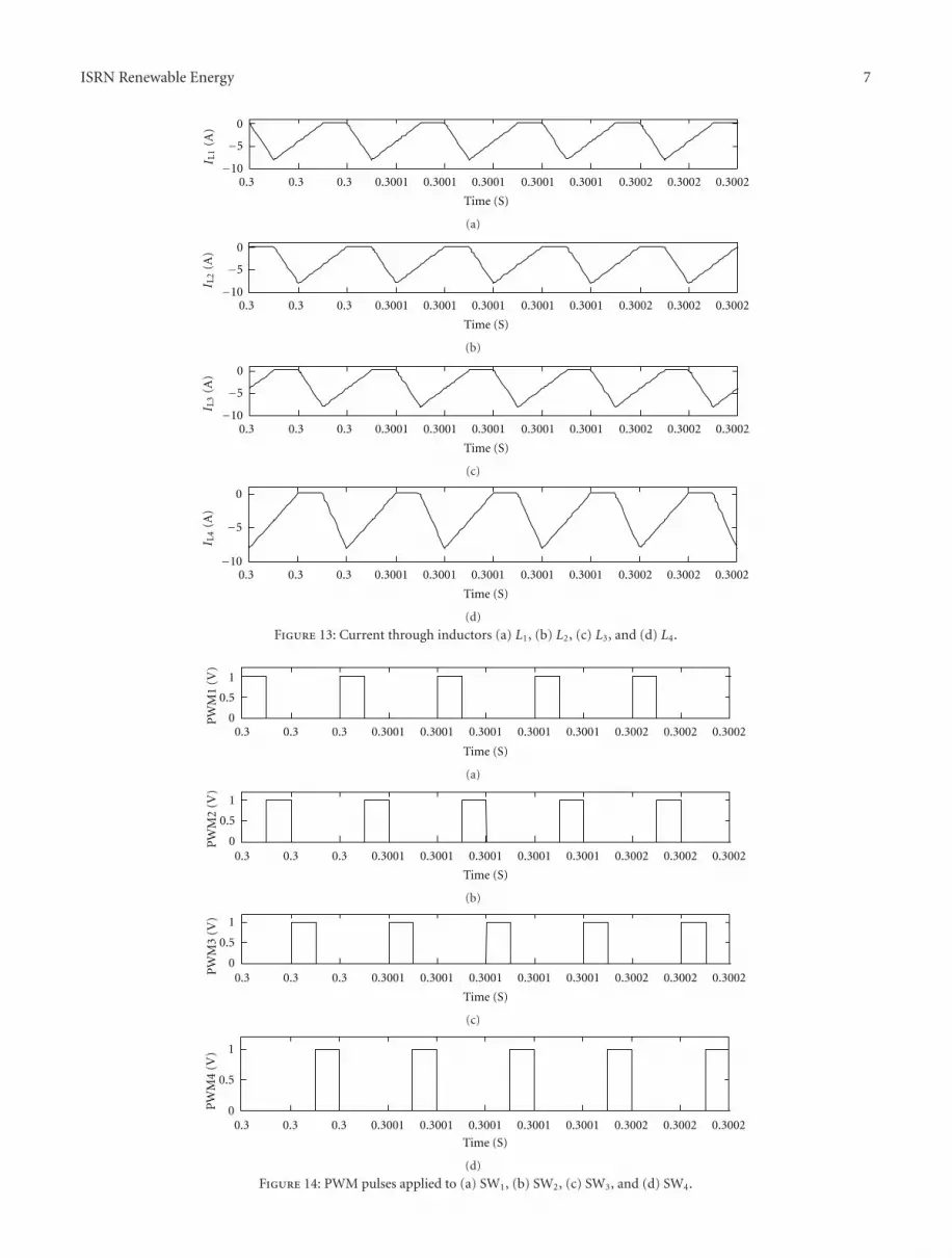
Figure 13: Current through inductors (a) L1, (b) L2, (c) L3, and (d) L4.
0.3 0.3 0.3 0.3001 0.3001 0.3001 0.3001 0.3001 0.3002 0.3002 0.30020
0.5
1
Time (S)
PW
M1
(V)
(a)
0.3 0.3 0.3 0.3001 0.3001 0.3001 0.3001 0.3001 0.3002 0.3002 0.30020
0.5
1
Time (S)
PW
M2
(V)
(b)
0.3 0.3 0.3 0.3001 0.3001 0.3001 0.3001 0.3001 0.3002 0.3002 0.30020
0.5
1
Time (S)
PW
M3
(V)
(c)
0.3 0.3 0.3 0.3001 0.3001 0.3001 0.3001 0.3001 0.3002 0.3002 0.30020
0.5
1
Time (S)
PW
M4
(V)
(d)
Figure 14: PWM pulses applied to (a) SW1, (b) SW2, (c) SW3, and (d) SW4.

8 ISRN Renewable Energy
14
12
10
8
6
4
2
0
−20 0.05 0.1 0.15 0.2 0.25 0.3 0.35 0.4
Time (S)
I LT
OT
(A)
Figure 15: Total inductor current.
0 0.05 0.1 0.15 0.2 0.25 0.3 0.35 0.40
40
80
Time (S)
Pow
er (
W)
(a)
0 0.05 0.1 0.15 0.2 0.25 0.3 0.35 0.4
0
10
Time (S)
Vol
tage
(V
)
−10
(b)
0 0.05 0.1 0.15 0.2 0.25 0.3 0.35 0.4
0
5
Time (S)
Cu
rren
t (A
)
(c)
−10
−5
(c)
Figure 16: Converter output (a) power, (b) voltage and (c) current at MPP.
r tends to rms value. Thus, the converter efficiency is givenby,
η = PLPL + Total Losses
. (21)
3. Simulation Results
The following parameters are used for simulation. PVgenerator parameters [10]: open circuit voltage: 21.8 V; shortcircuit current: 4.7 A; power at MPP = 75 W; converterparameters: switching frequency = 25 kHz; rL1 = rL2 = rL3 =rL4 = 0.01Ω, L1 = L2 = L3 = L4 = 20μH, C = 1000 μF, VF =0.1 V; rC = 0.06Ω.
It was found that maximum power is extracted from PVgenerator with 4-phase interleaved dc-dc converter as shownin Figure 11 in which PV power (a) voltage (b) and current(c) at MPP is shown. At MPP, power of 74.3 W is extractedwith voltage of 18.1 V and current of 4.1 A from PV. Figure12 shows the current through inductors L1 to L4. Current
through inductors for time duration of 0.3 to 0.3002 s areshown in Figure 13.
Figure 14 shows the pulse pattern applied to SW1 to SW4.It can be seen that one out of four converters is in operationwith PV at a time. As shown in Figure 15, which shows totalinductor current continuous in nature, the ripple currentreduced significantly. Figure 16 shows the converter outputpower (a), voltage (b), and current (c) for the given MPPcondition. At MPP, power of 65.1 W with voltage of 8.07 Vand current of 8.07 A is available at load.
4. Conclusion
By using the state-space averaging technique, mathematicalmodels are developed for parallel connected 4 identical buck-boost converters employed in PV system. The interleavingstrategy employed for PWM pulses ensures that all theconverters operate at the same switching frequency. Varioussteady-state performance expressions were derived. Thepresent converter system has the advantages of reduced size

ISRN Renewable Energy 9
of the converter as inductor size is reduced; total inductorcurrent is continuous although individual inductor currentis discontinuous. The maximum power tracking effectivenessof the four-phase interleaved dc-dc converter combined withPV system is demonstrated through simulations carried outin MATLAB environment.
References
[1] H. K. Patel and H. P. Desai, “Maximum power point algorithmin PV generation: an overview,” in Proceedings of the 7th Inter-national Conference on Power Electronics and Drive Systems(PEDS ’07), pp. 624–630, Bangkok, Thailand, November 2007.
[2] B. Kazimierczuk and M. K. Bryant, “Derivation of the buck-boost PWM DC-DC converter circuit topology,” in Proceed-ings of the International Symposium on Circuits and Systems,pp. 841–844, May 2002.
[3] T. M. Undeland, W. P. Robbins, and N. Mohan, Power Electro-nics: Converters, Applications, and Design, John Wiley & Sons,2nd edition, 1996.
[4] K. H. Hussein, I. Muta, T. Hoshino, and M. Osakada, “Maxi-mum photovoltaic power tracking: an algorithm for rapidlychanging atmospheric conditions,” IEE Proceedings: Genera-tion, Transmission and Distribution, vol. 142, no. 1, pp. 59–64,1995.
[5] E. Duran, M. Sidrach-de-Cardona, J. M. Andujar, and J. M.Enrique, “Theoretical assessment of the maximum powerpoint tracking efficiency of photovoltaic facilities with differ-ent converter topologies,” Solar Energy, vol. 81, no. 1, pp. 31–38, 2007.
[6] R. D. Middlebrook and S. Cuk, “A general unified approach tomodelling switching converter power stages,” in Proceedings ofthe Power Electronics Specialists Conference, pp. 18–34, Cleve-land, Ohio, USA, June 1976.
[7] A. Gherlitz, Y. Berkovich, A. Ioinovici, and O. Abutbul, “Step-up switching-mode converter with high voltage gain using aswitched-capacitor circuit,” IEEE Transactions on Circuits andSystems I, vol. 50, no. 8, pp. 1098–1102, 2003.
[8] H. Dehbonei, E. F. Fuchs, and M. A. S. Masoum, “Theoret-ical and experimental analyses of photovoltaic systems withvoltage- and current-based maximum power-point tracking,”IEEE Transactions on Energy Conversion, vol. 17, no. 4, pp.514–522, 2002.
[9] G. Walker, “Evaluating MPPT converter topologies using aMATLAB PV model,” Journal of Electrical and Electronics Engi-neering, vol. 21, no. 1, pp. 49–55, 2001.
[10] Solar Data Sheets, http://www.bpsunoasis.com.

Submit your manuscripts athttp://www.hindawi.com
Hindawi Publishing Corporationhttp://www.hindawi.com Volume 2014
StructuresJournal of
International Journal of
RotatingMachinery
Hindawi Publishing Corporationhttp://www.hindawi.com Volume 2014
Industrial EngineeringJournal of
Hindawi Publishing Corporationhttp://www.hindawi.com Volume 2014
TribologyAdvances in
Hindawi Publishing Corporationhttp://www.hindawi.com Volume 2014
EnergyJournal of
Hindawi Publishing Corporationhttp://www.hindawi.com Volume 2014
Hindawi Publishing Corporation http://www.hindawi.com
Journal ofEngineeringVolume 2014
Hindawi Publishing Corporation http://www.hindawi.com Volume 2014
International Journal ofPhotoenergy
Hindawi Publishing Corporationhttp://www.hindawi.com Volume 2014
Nuclear InstallationsScience and Technology of
Hindawi Publishing Corporationhttp://www.hindawi.com Volume 2014
Solar EnergyJournal of
Hindawi Publishing Corporationhttp://www.hindawi.com Volume 2014
Wind EnergyJournal of
Power ElectronicsHindawi Publishing Corporationhttp://www.hindawi.com Volume 2014
Advances in
FuelsJournal of
Hindawi Publishing Corporationhttp://www.hindawi.com Volume 2014
Hindawi Publishing Corporationhttp://www.hindawi.com Volume 2014
Nuclear EnergyInternational Journal of
Hindawi Publishing Corporationhttp://www.hindawi.com Volume 2014
High Energy PhysicsAdvances in
Hindawi Publishing Corporationhttp://www.hindawi.com Volume 2014
Mechanical Engineering
Advances in
Journal ofPetroleum Engineering
Hindawi Publishing Corporationhttp://www.hindawi.com Volume 2014
The Scientific World JournalHindawi Publishing Corporation http://www.hindawi.com Volume 2014
Journal of
Hindawi Publishing Corporationhttp://www.hindawi.com Volume 2014
Renewable Energy
CombustionJournal of
Hindawi Publishing Corporationhttp://www.hindawi.com Volume 2014