Embed Size (px)
Citation preview
Chelan County PUD
Transmission & Distribution
Material Stock
Catalog

T &D Standards Administration 0000.01
New Material Evaluation Procedures
Originator: DSmith Date: 5/10/2007
Approval: R Phillips Date: 4/25/2012 Page1 of 4
Revision: Updated contact info STD Committee: 4/25/2012
0000.01 New Material Evaluation Procedures
1. New Material Evaluation
1.1. Recognizing that new materials may provide improvement in design, construction, and maintenance for more cost effective construction, the District will evaluate such materials so that their use can be properly implemented and determined if they meet District Standards.
2. Scope
2.1. The Material Evaluation procedures outlined herein are applicable to all new materials submitted for consideration to the District for use in T&D construction and maintenance projects.
2.2. New materials are those, which have never been used or have been used on a limited basis without sufficient documentation or performance evaluation, except those specified on special contract documents.
3. Standards Committee
3.1. The Standards Engineer is responsible for administering this policy through the T&D Standards Committee. The Standards Committee is comprised of representative of the following areas. o Engineering Standards o Customer Service Engineering o T&D Warehousing o Purchasing District o Electric Shop o T&D Operations Supervisors o T&D Journeyman Linemen o Transmission, Substation or Distribution Engineers
4. Procedure
4.1. The Standards Department has been charged with the responsibility of coordinating the evaluations of new materials. The request for evaluation may be made by contractors, manufacturers, suppliers, consultants or District personnel, hereinafter referred to as the vendor.
4.2. The vendor is required to supply requisite information demonstrating the properties and performance of the material. At a minimum, the submission shall include the following:

T &D Standards Administration 0000.01
New Material Evaluation Procedures
Originator: DSmith Date: 5/10/2007
Approval: R Phillips Date: 4/25/2012 Page2 of 4
Revision: Updated contact info STD Committee: 4/25/2012
0000.01 New Material Evaluation Procedures
4.2.1. One copy of the completed form "T & D Material Evaluation" located on the last page of this document.
4.2.2. Pertinent technical data and test results which support use of the material and a statement identifying the uses and the cost benefit versus alternate materials.
4.2.3. If there are safety considerations or other restrictions or limitations on the use of the material, they should be stated and supplied also.
4.2.4. Additionally, if the material is a material developed through engineering design, the engineering calculations should be submitted.
4.2.5. Any additional information, material brochures, testing reports, etc., that you feel is pertinent to the evaluation of your material/procedure
4.2.6. Please do not submit any samples at this time. Should field or laboratory testing be needed you will be contacted and the samples requested.
4.3. Initial Evaluation
4.3.1. The submission will be reviewed by the T & D Standards Engineer. Materials not considered acceptable for further evaluation will be rejected at this point without further evaluation and the vendor so notified. Materials with questionable benefit or limited application by the District will be put on hold and the vendor so notified. Some materials require field-testing to fully understand their benefits. Should this be the case, the material/procedure will be moved to a "Long Range Evaluation Process" and its progress monitored.
4.3.2. All chemical products must be accompanied by a MSDS.
4.3.3. Our evaluation may include a review of technical and test data, visual inspection of the item, discussion in Standards Committee(s), field evaluation by electrical workers, inquiries to other utilities, and laboratory testing.
4.3.4. Some items require approval by our Environmental or Safety departments. The process may take several months.
4.3.5. Vendors will be informed of our decision at the end of the process.
T &D Standards Administration 0000.01
New Material Evaluation Procedures
Originator: DSmith Date: 5/10/2007
Approval: R Phillips Date: 4/25/2012 Page3 of 4
Revision: Updated contact info STD Committee: 4/25/2012
0000.01 New Material Evaluation Procedures
4.3.6. Materials with potential benefit and application will have the findings and recommendations presented to the T & D Standards Committee for action.
4.4. Standards Committee Evaluation
4.4.1. The Committee shall further evaluate the information furnished and determine if any additional information, reference, sample material or material, testing or clarification is needed.
4.4.2. With complete information, the Committee shall evaluate and make recommendations as follows:
APPROVED NOT APPROVED MATERIAL MEETS CURRENT SPECIFICATIONS NON - INTEREST or LIMITED USE ITEM
4.5. The vendor will be notified of the recommendation.
4.6. Acceptance of a material is in no way to be construed as a commitment to purchase, recommend, or specify a particular material.
5. Implementation
5.1. Upon request of the design personnel, the Standards Engineer will add the appropriate mfg part numbers to the existing Material Catalog Sheet or develop a new Material Catalog Sheet.
5.2. If appropriate, the Districts estimating system will be modified to allow inclusion of this material into T & D projects.
5.3. The use of the material is the responsibility of the project engineers. 6. Updating / Re-evaluating
6.1. As do several other area electric utilities, we generally do not re-evaluate items that have failed testing or have otherwise been rejected or removed from approval until a period of three (3) years has elapsed. Any exceptions to this policy are at our sole discretion.
6.2. The most current copies of all material specifications or catalog sheets are available on our web site.
6.3. You may always phone or e-mail to ask questions. The Standards Department tries to be helpful and fair, and we endeavor to approve as many qualified suppliers of products as is practical.

T &D Standards Administration 0000.01
New Material Evaluation Procedures
Originator: DSmith Date: 5/10/2007
Approval: R Phillips Date: 4/25/2012 Page4 of 4
Revision: Updated contact info STD Committee: 4/25/2012
Standards Office: Standards Mailing Address: E-mail: 327 N Wenatchee Ave PO Box 1231 mailto:[email protected] Wenatchee, WA 98801 Wenatchee, WA 98807 Telephone: (509) 661-4257 Fax: 509-661-8148
T & D Material Evaluation Form
Manufacturer ______________________ Mfr’s. Cat. No. _____________________________
Chelan County PUD Stock Number (if known) __________________
Material Specification / Catalog Number (if known) __________________
Applicable Industry Standards (ANSI, IEEE, NEMA, etc) ____________________________________
Description of item/application: _____________________________________________________________________
Current Users: (Attach additional sheets if necessary)
1. Contact Name__________________________________ Phone Number:__________ Utility: ________________
2. Contact Name__________________________________ Phone Number:__________ Utility: ________________
Material Safety Data Sheet Required and Attached _____________________ Estimated price $_________ per _____ Usual delivery time ___________________________ Manufacturer’s Representative: Name ____________________________________________ (You may attach business card) Firm ____________________________________________
Address: ____________________________________________
Tel _______________________
Fax _______________________
e-mail ______________________________________ This portion for Chelan County PUD use only
Approved? Yes ___ No ___ by Standards.
Additional comments/reason if not approved _________________________________________________
___________________________________________________ Date mfr’s. rep. notified: ____________
Date Received _________________ Date to field reviewer _________________
Comments ___________________________________________________________________________
_____________________________________________________________________________________
Date review completed ______________ Reviewer Initials: ______________
T &D STANDARDS Administration 0000.02
Originator:
DSmith Date: 5/30/2007
“OR EQUAL” DEFINITION
Approval:
DSmith Date: 5/30/2007 Page1 of 1
Revision: NEW STD Committee: 5/30/2007
0000.02 OR_EQUAL_DEFINITION.doc
Application: This document defines the Approved Manufactures Part Numbers and “OR EQUAL” relationship. Definition of "Or Equal":
1. OR EQUAL - Contractor-proposed substitution of specific materials or processes that are deemed by the District, in its sole discretion, to be equal in every material respect.
2. Offers of substitution for items described in the Contract Documents as "Or Equal" will be
considered only upon the written request of the Contractor, and no requests for substitutions will be acknowledged or considered from suppliers, distributors, manufacturers, or Subcontractors or any other source. Requests for approval of substitution shall be made by following District Standards #0000.01 “New Material Evaluation Procedure”.
3. NO PURCHASE SHALL BE MADE OR INSTALLATION PERFORMED BY CONTRACTOR
WITHOUT APPROVAL OF THE DISTRICTS STANDARDS DEPARTMENT.
T &D Standards Administration 0000.03
Originator: DSmith Date: 7/6/2007
INSTRUCTIONS
How to Use The Material Catalog
Approval: DSmith Date: 7/6/2007 Page1 of 1Revision: NEW Approved
0000.03 INSTRUCTIONS.doc
1. Introduction
1.1. The Material Catalog lists all items that District regularly stocks in warehouses and includes product descriptions organized by product categories and approved manufactures catalog numbers.
1.2. This information is updated on a daily basis and is used for Purchase Requisitions. 2. Adobe Portable Document Format (PDF)
The web site documents are published in the Adobe® Portable Document Format (PDF). You will need to download and install a free copy of Adobe Acrobat Reader to view the documents. Go to http://www.adobe.com/products/acrobat/readstep2.html if you have not already installed Acrobat Reader.
3. Document Features:
3.1. Bookmark On the left side of the page is a section entitled “Bookmarks”. These bookmarks allow you to jump to a particular section or page easily.
3.2. Search You can access the search function by mouse clicking on the binocular icon. Using this function, you can search for:
• Maximo Stock Number • Manufactures Name • Manufactures Catalog Number • Any text or number
3.3. Printing: You can print all two hundred pages or any single page. The default is printing all pages so be careful.
- Material Catalog - CONNECTORS 1000
Originator: DSmith Date:7/9/2007
CONNECTORS
Approval: DSmith Date: 7/9/2007 Page 1 of 1
Revision: NEW Stds Committee Approval: Approved
1000 CONNECTORS.DOC
CONNECTORS
- Material Catalog - Connectors 1010.03
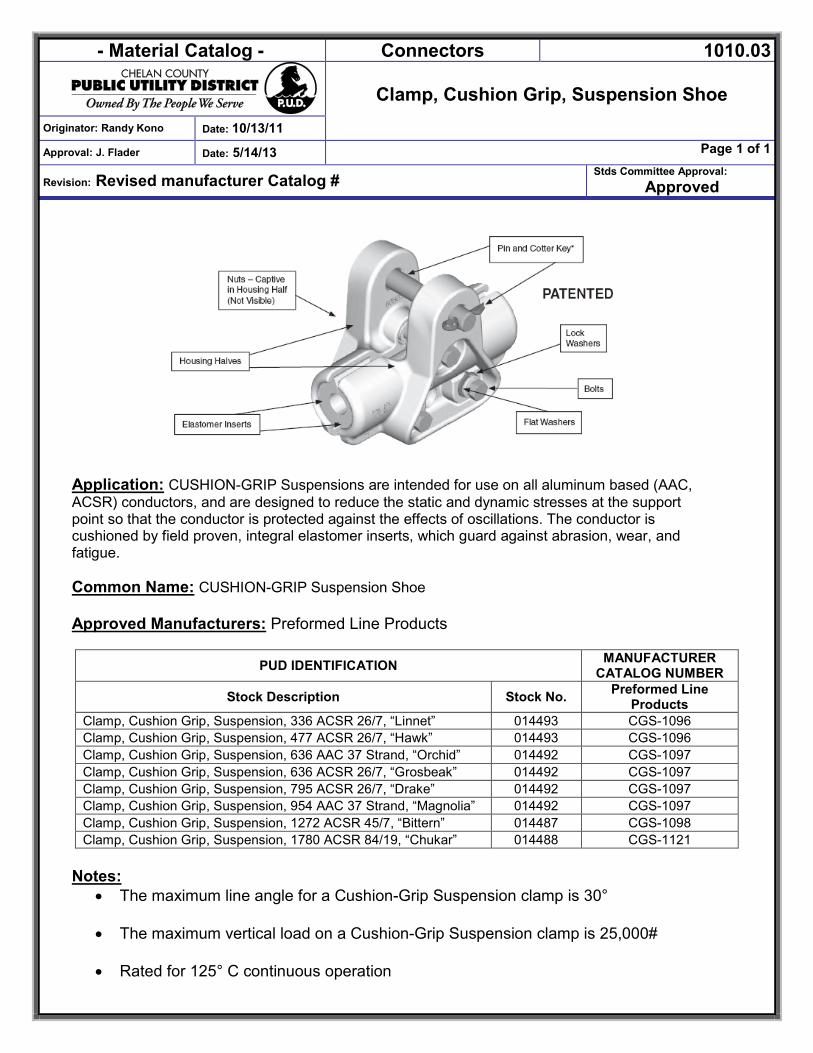
Clamp, Cushion Grip, Suspension Shoe
Originator: Randy Kono Date: 10/13/11
Approval: J. Flader Date: 5/14/13 Page 1 of 1
Revision: Revised manufacturer Catalog # Stds Committee Approval:
Approved
Application: CUSHION-GRIP Suspensions are intended for use on all aluminum based (AAC, ACSR) conductors, and are designed to reduce the static and dynamic stresses at the support point so that the conductor is protected against the effects of oscillations. The conductor is cushioned by field proven, integral elastomer inserts, which guard against abrasion, wear, and fatigue. Common Name: CUSHION-GRIP Suspension Shoe
Approved Manufacturers: Preformed Line Products
PUD IDENTIFICATION MANUFACTURER CATALOG NUMBER
Stock Description Stock No. Preformed Line Products
Clamp, Cushion Grip, Suspension, 336 ACSR 26/7, “Linnet” 014493 CGS-1096 Clamp, Cushion Grip, Suspension, 477 ACSR 26/7, “Hawk” 014493 CGS-1096 Clamp, Cushion Grip, Suspension, 636 AAC 37 Strand, “Orchid” 014492 CGS-1097 Clamp, Cushion Grip, Suspension, 636 ACSR 26/7, “Grosbeak” 014492 CGS-1097 Clamp, Cushion Grip, Suspension, 795 ACSR 26/7, “Drake” 014492 CGS-1097 Clamp, Cushion Grip, Suspension, 954 AAC 37 Strand, “Magnolia” 014492 CGS-1097 Clamp, Cushion Grip, Suspension, 1272 ACSR 45/7, “Bittern” 014487 CGS-1098 Clamp, Cushion Grip, Suspension, 1780 ACSR 84/19, “Chukar” 014488 CGS-1121
Notes:
• The maximum line angle for a Cushion-Grip Suspension clamp is 30°
• The maximum vertical load on a Cushion-Grip Suspension clamp is 25,000#
• Rated for 125° C continuous operation
- Material Catalog - Connectors 1010.04
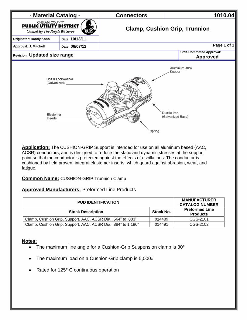
Clamp, Cushion Grip, Trunnion
Originator: Randy Kono Date: 10/13/11
Approval: J. Mitchell Date: 06/07/12 Page 1 of 1
Revision: Updated size range Stds Committee Approval:
Approved
Application: The CUSHION-GRIP Support is intended for use on all aluminum based (AAC, ACSR) conductors, and is designed to reduce the static and dynamic stresses at the support point so that the conductor is protected against the effects of oscillations. The conductor is cushioned by field proven, integral elastomer inserts, which guard against abrasion, wear, and fatigue. Common Name: CUSHION-GRIP Trunnion Clamp
Approved Manufacturers: Preformed Line Products
PUD IDENTIFICATION MANUFACTURER CATALOG NUMBER
Stock Description Stock No. Preformed Line Products
Clamp, Cushion Grip, Support, AAC, ACSR Dia. .564” to .883” 014489 CGS-2101 Clamp, Cushion Grip, Support, AAC, ACSR Dia. .884” to 1.196” 014491 CGS-2102
Notes: The maximum line angle for a Cushion-Grip Suspension clamp is 30°
The maximum load on a Cushion-Grip clamp is 5,000#
Rated for 125° C continuous operation
- Material Catalog - CONNECTORS 1010.11
Originator: DSmith Date: 7/7/2006
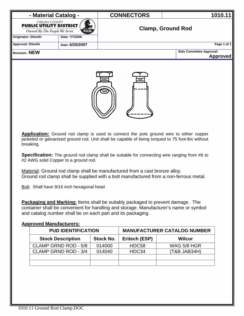
Clamp, Ground Rod
Approval: DSmith Date: 6/20/2007 Page 1 of 1
Revision: NEW Stds Committee Approval: Approved
1010.11 Ground Rod Clamp.DOC
Application: Ground rod clamp is used to connect the pole ground wire to either copper jacketed or galvanized ground rod. Unit shall be capable of being torqued to 75 foot-lbs without breaking.
Specification: The ground rod clamp shall be suitable for connecting wire ranging from #6 to #2 AWG solid Copper to a ground rod. Material: Ground rod clamp shall be manufactured from a cast bronze alloy. Ground rod clamp shall be supplied with a bolt manufactured from a non-ferrous metal. Bolt: Shall have 9/16 inch hexagonal head Packaging and Marking: Items shall be suitably packaged to prevent damage. The container shall be convenient for handling and storage. Manufacturer’s name or symbol and catalog number shall be on each part and its packaging. Approved Manufacturers:
PUD IDENTIFICATION MANUFACTURER CATALOG NUMBER Stock Description Stock No. Eritech (ESP) Wilcor
CLAMP GRND ROD - 5/8 014000 HDC58 WAG 5/8 HGR CLAMP GRND ROD - 3/4 014040 HDC34 (T&B JAB34H)
- Material Catalog - CONNECTORS 1010.13
Originator: DSmith Date: 7/7/06
STIRRUPS, COMPRESSION HOTLINE
Approval: DSmith Date:6/20/2007 Page 1 of 1
Revision: NEW Stds Committee Approval: Approved
1010.13 Stirrup, Compression.Doc
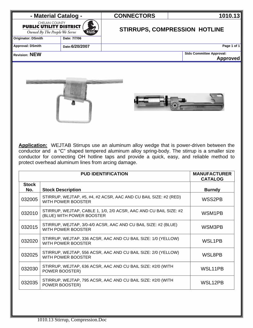
Application: WEJTAB Stirrups use an aluminum alloy wedge that is power-driven between the conductor and a “C” shaped tempered aluminum alloy spring-body. The stirrup is a smaller size conductor for connecting OH hotline taps and provide a quick, easy, and reliable method to protect overhead aluminum lines from arcing damage.
PUD IDENTIFICATION MANUFACTURER
CATALOG Stock
No. Stock Description Burndy
032005 STIRRUP, WEJTAP, #5, #4, #2 ACSR, AAC AND CU BAIL SIZE: #2 (RED) WITH POWER BOOSTER WSS2PB
032010 STIRRUP, WEJTAP, CABLE 1, 1/0, 2/0 ACSR, AAC AND CU BAIL SIZE: #2 (BLUE) WITH POWER BOOSTER WSM1PB
032015 STIRRUP, WEJTAP, 3/0-4/0 ACSR, AAC AND CU BAIL SIZE: #2 (BLUE) WITH POWER BOOSTER WSM3PB
032020 STIRRUP, WEJTAP, 336 ACSR, AAC AND CU BAIL SIZE: 1/0 (YELLOW) WITH POWER BOOSTER WSL1PB
032025 STIRRUP, WEJTAP, 556 ACSR, AAC AND CU BAIL SIZE: 2/0 (YELLOW) WITH POWER BOOSTER WSL8PB
032030 STIRRUP, WEJTAP, 636 ACSR, AAC AND CU BAIL SIZE: #2/0 (WITH POWER BOOSTER) WSL11PB
032035 STIRRUP, WEJTAP, 795 ACSR, AAC AND CU BAIL SIZE: #2/0 (WITH POWER BOOSTER) WSL12PB
- Material Catalog - CONNECTORS 1010.14
Originator: DSmith Date: 7/7/06
HOTLINE TAP-OFF CLAMP, BRONZE
Approval: DSmith Date:6/20/2007 Page 1 of 1
Revision: NEW Stds Committee Approval: Approved
1010.14 Hotline Clamp Bronze.DOC
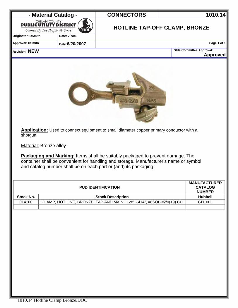
Application: Used to connect equipment to small diameter copper primary conductor with a shotgun.
Material: Bronze alloy Packaging and Marking: Items shall be suitably packaged to prevent damage. The container shall be convenient for handling and storage. Manufacturer’s name or symbol and catalog number shall be on each part or (and) its packaging.
PUD IDENTIFICATION MANUFACTURER
CATALOG NUMBER
Stock No. Stock Description Hubbell 014100 CLAMP, HOT LINE, BRONZE, TAP AND MAIN: .128" -.414", #8SOL-#2/0(19) CU GH100L
- Material Catalog - CONNECTORS 1010.15
Originator: DSmith Date: 7/20/2006
CLAMPS, HOTLINE
TAP & STIRRUPS, ALUMINUM Approval: DSmith Date: 1/17/2008 Page 1 of 2
Revision: Revised Main & Tap Sizes Stds Committee Approval: Approved
1010.15 Hotline Clamp Al.DOC
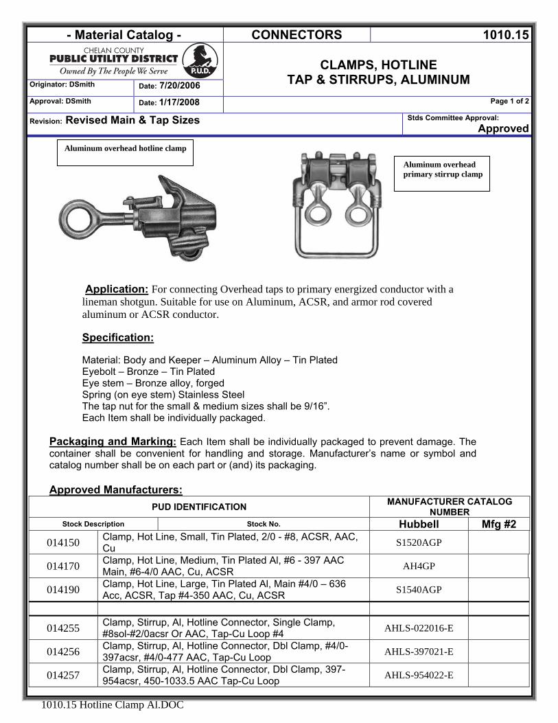
Application: For connecting Overhead taps to primary energized conductor with a lineman shotgun. Suitable for use on Aluminum, ACSR, and armor rod covered aluminum or ACSR conductor. Specification: Material: Body and Keeper – Aluminum Alloy – Tin Plated Eyebolt – Bronze – Tin Plated Eye stem – Bronze alloy, forged Spring (on eye stem) Stainless Steel The tap nut for the small & medium sizes shall be 9/16”. Each Item shall be individually packaged.
Packaging and Marking: Each Item shall be individually packaged to prevent damage. The container shall be convenient for handling and storage. Manufacturer’s name or symbol and catalog number shall be on each part or (and) its packaging. Approved Manufacturers:
PUD IDENTIFICATION MANUFACTURER CATALOG NUMBER
Stock Description Stock No. Hubbell Mfg #2 014150 Clamp, Hot Line, Small, Tin Plated, 2/0 - #8, ACSR, AAC,
Cu S1520AGP
014170 Clamp, Hot Line, Medium, Tin Plated Al, #6 - 397 AAC Main, #6-4/0 AAC, Cu, ACSR AH4GP
014190 Clamp, Hot Line, Large, Tin Plated Al, Main #4/0 – 636 Acc, ACSR, Tap #4-350 AAC, Cu, ACSR S1540AGP
014255 Clamp, Stirrup, Al, Hotline Connector, Single Clamp, #8sol-#2/0acsr Or AAC, Tap-Cu Loop #4 AHLS-022016-E
014256 Clamp, Stirrup, Al, Hotline Connector, Dbl Clamp, #4/0-397acsr, #4/0-477 AAC, Tap-Cu Loop AHLS-397021-E
014257 Clamp, Stirrup, Al, Hotline Connector, Dbl Clamp, 397-954acsr, 450-1033.5 AAC Tap-Cu Loop AHLS-954022-E
Aluminum overhead primary stirrup clamp
Aluminum overhead hotline clamp
- Material Catalog - CONNECTORS 1010.19
Originator: DSmith Date: 7/7/06
SPLIT BOLT
Approval: DSmith Date: 6/20/2007 Page 1 of 1
Revision: NEW Stds Committee Approval: Approved
1010.19 Split Bolt.DOC
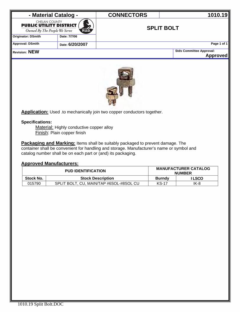
Application: Used .to mechanically join two copper conductors together. Specifications:
Material: Highly conductive copper alloy Finish: Plain copper finish
Packaging and Marking: Items shall be suitably packaged to prevent damage. The container shall be convenient for handling and storage. Manufacturer’s name or symbol and catalog number shall be on each part or (and) its packaging. Approved Manufacturers:
PUD IDENTIFICATION MANUFACTURER CATALOG NUMBER
Stock No. Stock Description Burndy ILSCO 015790 SPLIT BOLT, CU, MAIN/TAP #6SOL-#8SOL CU KS-17 IK-8
- Material Catalog - CONNECTORS 1010.22
DEADEND CLAMPS,
Bolted Straight-Line Spring-Loaded Side Opening Originator: D. Smith Date:8/29/06
Reviewed: D. Smith Date: 8/11/2008 Page 1 of 1
Revisions: Changed Small Unit to accommodate 266ACSR, Removed Tin Plated Requirement due to sole source conflict.
Stds Committee Approval: 9/20/06
1010.22 Deadend Clamps.DOC
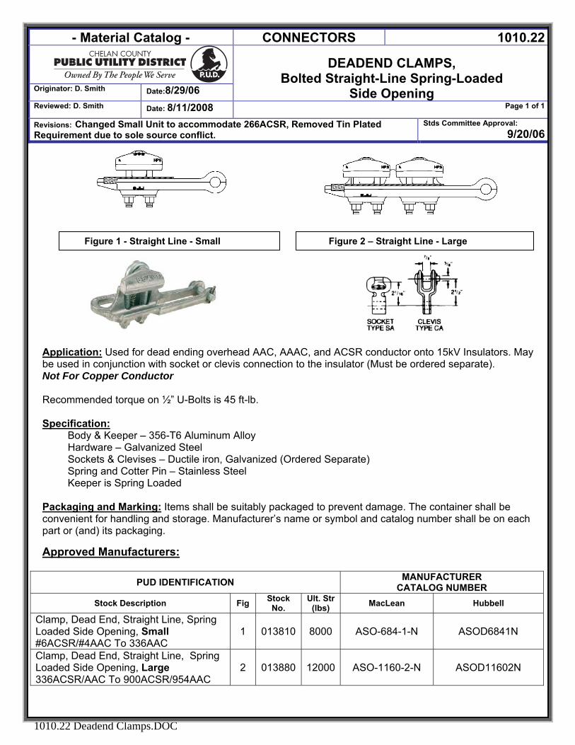
Application: Used for dead ending overhead AAC, AAAC, and ACSR conductor onto 15kV Insulators. May be used in conjunction with socket or clevis connection to the insulator (Must be ordered separate). Not For Copper Conductor Recommended torque on ½” U-Bolts is 45 ft-lb. Specification:
Body & Keeper – 356-T6 Aluminum Alloy Hardware – Galvanized Steel Sockets & Clevises – Ductile iron, Galvanized (Ordered Separate) Spring and Cotter Pin – Stainless Steel Keeper is Spring Loaded
Packaging and Marking: Items shall be suitably packaged to prevent damage. The container shall be convenient for handling and storage. Manufacturer’s name or symbol and catalog number shall be on each part or (and) its packaging.
Approved Manufacturers:
PUD IDENTIFICATION MANUFACTURER CATALOG NUMBER
Stock Description Fig Stock No.
Ult. Str (lbs) MacLean Hubbell
Clamp, Dead End, Straight Line, Spring Loaded Side Opening, Small #6ACSR/#4AAC To 336AAC
1 013810 8000 ASO-684-1-N ASOD6841N
Clamp, Dead End, Straight Line, Spring Loaded Side Opening, Large 336ACSR/AAC To 900ACSR/954AAC
2 013880 12000 ASO-1160-2-N ASOD11602N
Figure 1 - Straight Line - Small Figure 2 – Straight Line - Large
- Material Catalog - CONNECTORS 1010.23
Originator: DSmith Date: 6/20/2007
DEADEND CLAMPS,
Bolted Quadrant Style - Iron
Approval: DSmith Date:6/20/2007 Page 1 of 1
Revision: NEW Stds Committee Approval: Approved
1010.23 Deadend Clamps Iron.DOC
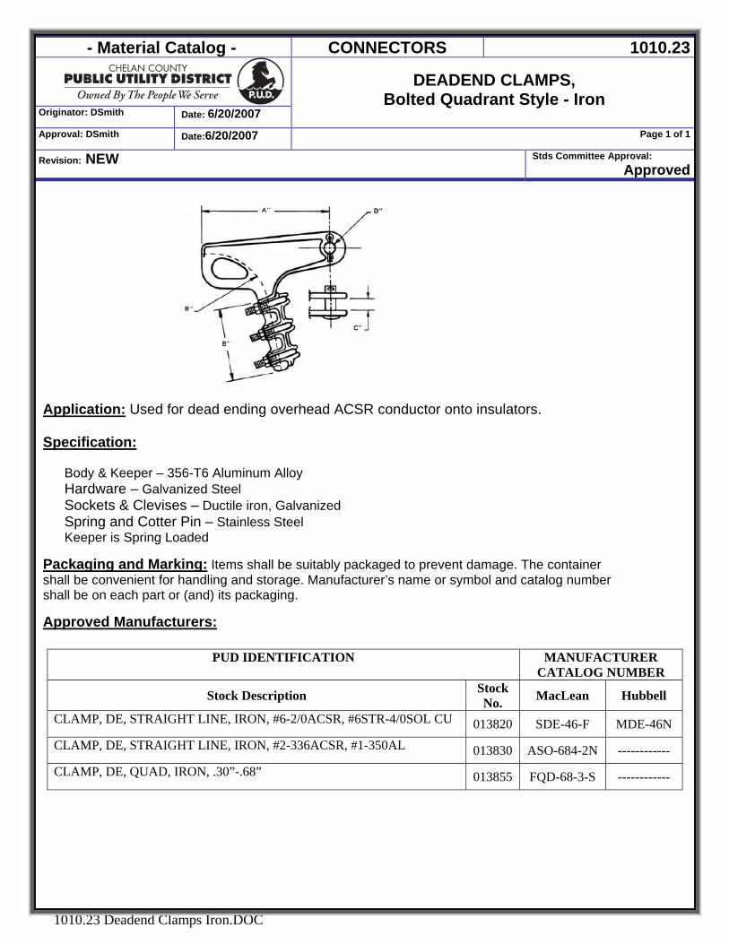
Application: Used for dead ending overhead ACSR conductor onto insulators. Specification: Body & Keeper – 356-T6 Aluminum Alloy Hardware – Galvanized Steel Sockets & Clevises – Ductile iron, Galvanized Spring and Cotter Pin – Stainless Steel Keeper is Spring Loaded
Packaging and Marking: Items shall be suitably packaged to prevent damage. The container shall be convenient for handling and storage. Manufacturer’s name or symbol and catalog number shall be on each part or (and) its packaging.
Approved Manufacturers:
PUD IDENTIFICATION MANUFACTURER
CATALOG NUMBER
Stock Description Stock No. MacLean Hubbell
CLAMP, DE, STRAIGHT LINE, IRON, #6-2/0ACSR, #6STR-4/0SOL CU 013820 SDE-46-F MDE-46N CLAMP, DE, STRAIGHT LINE, IRON, #2-336ACSR, #1-350AL 013830 ASO-684-2N ------------ CLAMP, DE, QUAD, IRON, .30”-.68” 013855 FQD-68-3-S ------------
- Material Catalog - CONNECTORS 1010.26
Originator: DSmith Date: 7/20/2006
OVERHEAD SECONDARY SETSCREW BAR
WITH STUD. Approval: DSmith Date: 1/4/2008
Page 1 of 1
Revision: NEW Stds Committee Approval: 9/22/06
1010.26 OVERHEAD SECONDARY SETSCREW BAR WITH STUD.DOC
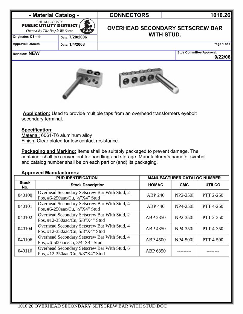
Application: Used to provide multiple taps from an overhead transformers eyebolt secondary terminal. Specification: Material: 6061-T6 aluminum alloy Finish: Clear plated for low contact resistance Packaging and Marking: Items shall be suitably packaged to prevent damage. The container shall be convenient for handling and storage. Manufacturer’s name or symbol and catalog number shall be on each part or (and) its packaging. Approved Manufacturers:
PUD IDENTIFICATION MANUFACTURER CATALOG NUMBER Stock
No. Stock Description HOMAC CMC UTILCO
040100 Overhead Secondary Setscrew Bar With Stud, 2 Pos, #6-250aac/Cu, ½”X4” Stud ABP 240 NP2-250I PTT 2-250
040101 Overhead Secondary Setscrew Bar With Stud, 4 Pos, #6-250aac/Cu, ½”X4” Stud ABP 440 NP4-250I PTT 4-250
040102 Overhead Secondary Setscrew Bar With Stud, 2 Pos, #12-350aac/Cu, 5/8”X4” Stud ABP 2350 NP2-350I PTT 2-350
040104 Overhead Secondary Setscrew Bar With Stud, 4 Pos, #12-350aac/Cu, 5/8”X4” Stud ABP 4350 NP4-350I PTT 4-350
040106 Overhead Secondary Setscrew Bar With Stud, 4 Pos, #6-500aac/Cu, 3/4”X4” Stud ABP 4500 NP4-500I PTT 4-500
040110 Overhead Secondary Setscrew Bar With Stud, 6 Pos, #12-350aac/Cu, 5/8”X4” Stud ABP 6350 --------- --------
- Material Catalog - CONNECTORS 1010.27
Originator: DSmith Date: 1/4/2008
SET SCREW AL BAR, ABOVE GRADE, FOR CU OR AL SECONDARY CABLE
Approval: DSmith Date: 1/4/2008 Page 1 of 1
Revision: Moved slip fit connectors to 1019.08 Stds Committee Approval: Approved
1010.27 Connectors, SET SCREW AL BAR, ABOVE GRADE.DOC
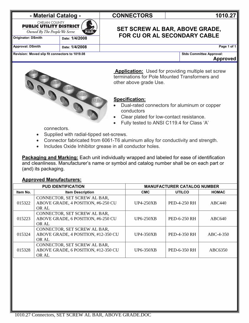
Application: Used for providing multiple set screw terminations for Pole Mounted Transformers and other above grade Use. Specification: • Dual-rated connectors for aluminum or copper
conductors • Clear plated for low-contact resistance. • Fully tested to ANSI C119.4 for Class ‘A’
connectors. • Supplied with radial-tipped set-screws. • Connector fabricated from 6061-T6 aluminum alloy for conductivity and strength. • Includes Oxide Inhibitor grease in all conductor holes.
Packaging and Marking: Each unit individually wrapped and labeled for ease of identification and cleanliness. Manufacturer’s name or symbol and catalog number shall be on each part or (and) its packaging. Approved Manufacturers:
PUD IDENTIFICATION MANUFACTURER CATALOG NUMBER Item No. Item Description CMC UTILCO HOMAC
015322 CONNECTOR, SET SCREW AL BAR, ABOVE GRADE, 4 POSITION, #6-250 CU OR AL
UP4-250XB PED-4-250 RH ABC440
015223 CONNECTOR, SET SCREW AL BAR, ABOVE GRADE, 6 POSITION, #6-250 CU OR AL
UP6-250XB PED-6-250 RH ABC640
015324 CONNECTOR, SET SCREW AL BAR, ABOVE GRADE, 4 POSITION, #12-350 CU OR AL
UP4-350XB PED-4-350 RH ABC-4-350
015328 CONNECTOR, SET SCREW AL BAR, ABOVE GRADE, 6 POSITION, #12-350 CU OR AL
UP6-350XB PED-6-350 RH ABC6350
- Material Catalog - CONNECTORS 1010.30
Originator: DSmith Date: 7/20/2006
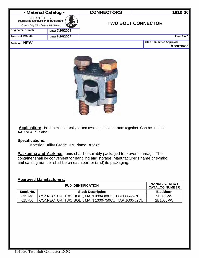
TWO BOLT CONNECTOR
Approval: DSmith Date: 6/20/2007 Page 1 of 1
Revision: NEW Stds Committee Approval: Approved
1010.30 Two Bolt Connector.DOC
Application: Used to mechanically fasten two copper conductors together. Can be used on AAC or ACSR also. Specifications:
Material: Utility Grade TIN Plated Bronze Packaging and Marking: Items shall be suitably packaged to prevent damage. The container shall be convenient for handling and storage. Manufacturer’s name or symbol and catalog number shall be on each part or (and) its packaging. Approved Manufacturers:
PUD IDENTIFICATION MANUFACTURER CATALOG NUMBER
Stock No. Stock Description Blackburn 015740 CONNECTOR, TWO BOLT, MAIN 800-600CU, TAP 800-#2CU 2B800PW 015750 CONNECTOR, TWO BOLT, MAIN 1000-750CU, TAP 1000-#2CU 2B1000PW
- Material Catalog - CONNECTORS 1010.31
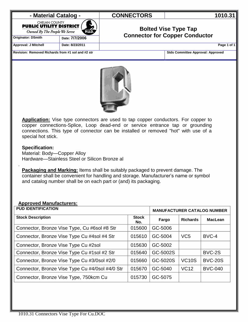
Bolted Vise Type Tap
Connector for Copper Conductor Originator: DSmith Date: 7/7/2006
Approval: J Mitchell Date: 8/23/2011 Page 1 of 1
Revision: Removed Richards from #1 sol and #2 str Stds Committee Approval: Approved
1010.31 Connectors Vise Type For Cu.DOC
Application: Vise type connectors are used to tap copper conductors. For copper to copper connections-Splice, Loop dead-end or service entrance tap or grounding connections. This type of connector can be installed or removed "hot" with use of a special hot stick. Specification: Material: Body—Copper Alloy Hardware—Stainless Steel or Silicon Bronze al
. Packaging and Marking: Items shall be suitably packaged to prevent damage. The container shall be convenient for handling and storage. Manufacturer’s name or symbol and catalog number shall be on each part or (and) its packaging.
Approved Manufacturers:
PUD IDENTIFICATION MANUFACTURER CATALOG NUMBER Stock Description Stock
No. Fargo Richards MacLean
Connector, Bronze Vise Type, Cu #6sol #8 Str 015600 GC-5006
Connector, Bronze Vise Type Cu #4sol #4 Str 015610 GC-5004 VC5 BVC-4
Connector, Bronze Vise Type Cu #2sol 015630 GC-5002 Connector, Bronze Vise Type Cu #1sol #2 Str 015640 GC-5002S BVC-2S Connector, Bronze Vise Type Cu #3/0sol #2/0 015660 GC-5020S VC10S BVC-20S
Connector, Bronze Vise Type Cu #4/0sol #4/0 Str 015670 GC-5040 VC12 BVC-040
Connector, Bronze Vise Type, 750kcm Cu 015730 GC-5075
- Material Catalog - CONNECTORS 1010.32
Originator: DSmith Date:7/13/2006
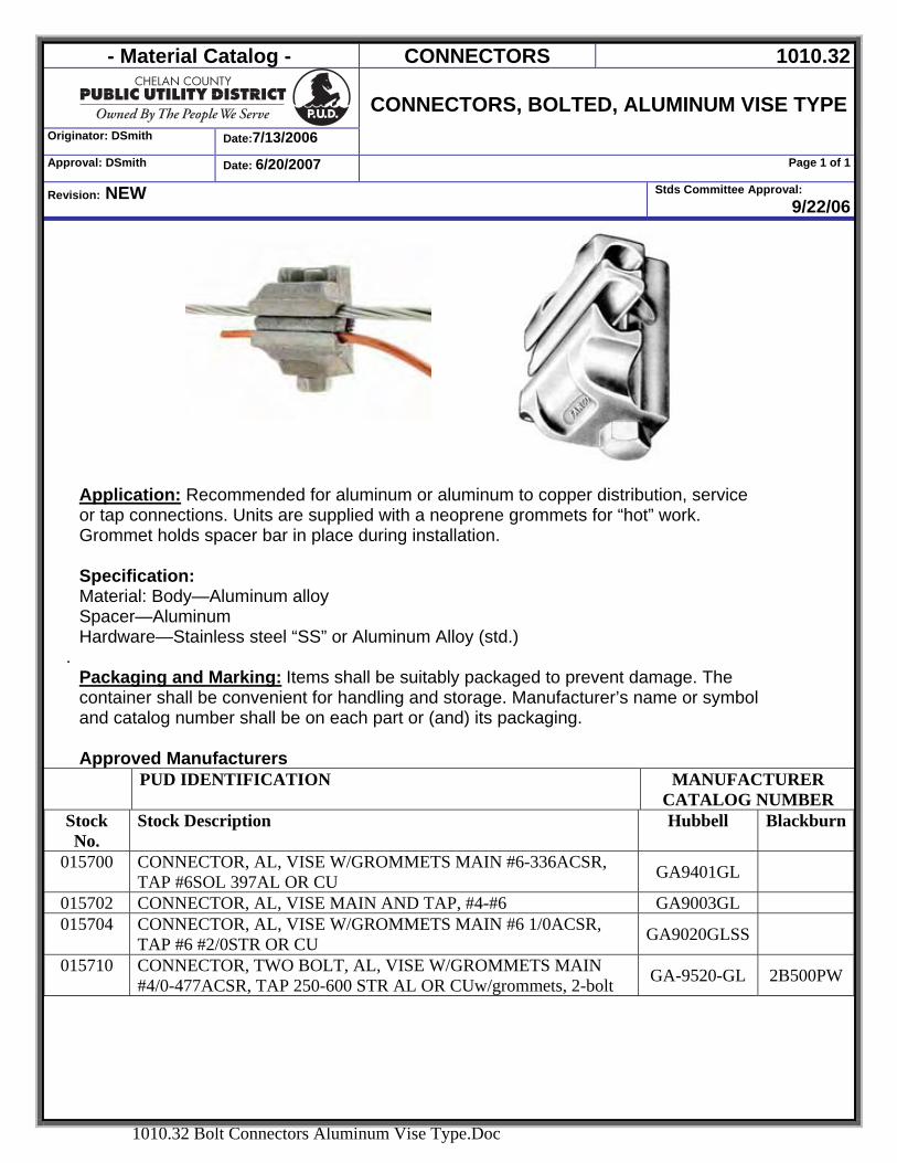
CONNECTORS, BOLTED, ALUMINUM VISE TYPE
Approval: DSmith Date: 6/20/2007 Page 1 of 1
Revision: NEW Stds Committee Approval: 9/22/06
1010.32 Bolt Connectors Aluminum Vise Type.Doc
Application: Recommended for aluminum or aluminum to copper distribution, service or tap connections. Units are supplied with a neoprene grommets for “hot” work. Grommet holds spacer bar in place during installation. Specification: Material: Body—Aluminum alloy Spacer—Aluminum Hardware—Stainless steel “SS” or Aluminum Alloy (std.)
. Packaging and Marking: Items shall be suitably packaged to prevent damage. The container shall be convenient for handling and storage. Manufacturer’s name or symbol and catalog number shall be on each part or (and) its packaging. Approved Manufacturers
PUD IDENTIFICATION MANUFACTURER CATALOG NUMBER
Stock No.
Stock Description Hubbell Blackburn
015700 CONNECTOR, AL, VISE W/GROMMETS MAIN #6-336ACSR, TAP #6SOL 397AL OR CU GA9401GL
015702 CONNECTOR, AL, VISE MAIN AND TAP, #4-#6 GA9003GL 015704 CONNECTOR, AL, VISE W/GROMMETS MAIN #6 1/0ACSR,
TAP #6 #2/0STR OR CU GA9020GLSS
015710 CONNECTOR, TWO BOLT, AL, VISE W/GROMMETS MAIN #4/0-477ACSR, TAP 250-600 STR AL OR CUw/grommets, 2-bolt GA-9520-GL 2B500PW
- Material Catalog - CONNECTORS 1010.33
Originator: DSmith Date: 7/7/06
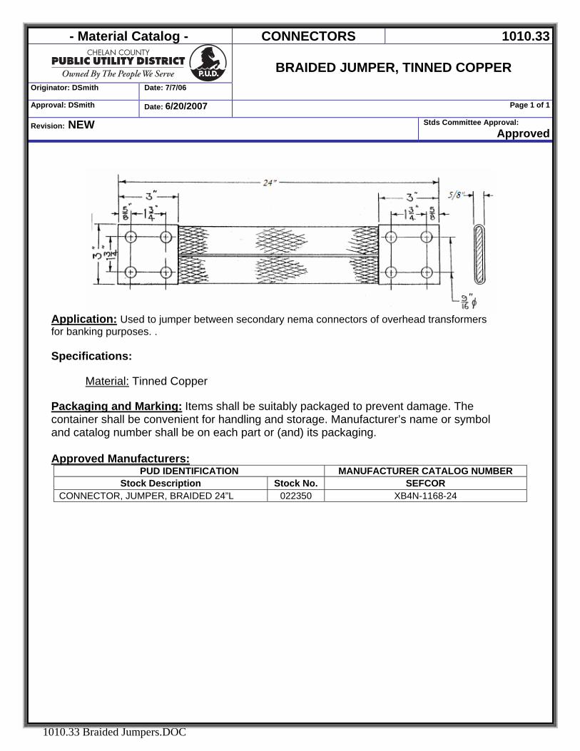
BRAIDED JUMPER, TINNED COPPER
Approval: DSmith Date: 6/20/2007 Page 1 of 1
Revision: NEW Stds Committee Approval: Approved
1010.33 Braided Jumpers.DOC
Application: Used to jumper between secondary nema connectors of overhead transformers for banking purposes. . Specifications:
Material: Tinned Copper Packaging and Marking: Items shall be suitably packaged to prevent damage. The container shall be convenient for handling and storage. Manufacturer’s name or symbol and catalog number shall be on each part or (and) its packaging. Approved Manufacturers:
PUD IDENTIFICATION MANUFACTURER CATALOG NUMBER Stock Description Stock No. SEFCOR
CONNECTOR, JUMPER, BRAIDED 24”L 022350 XB4N-1168-24
- Material Catalog - CONNECTORS 1010.34
Originator: DSmith Date: 7/7/06
BUSHING, OVERHEAD POLE-MOUNT
TRANSFORMER Approval: DSmith Date: 7/7/06 Page 1 of 1
Revision: NEW Stds Committee Approval: Approved
1010.34 Ovrhd Xfmr Bushing.DOC
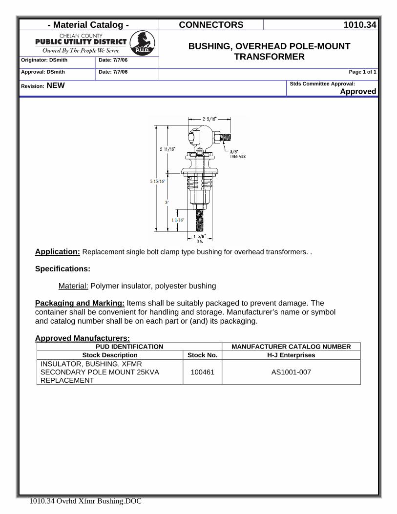
Application: Replacement single bolt clamp type bushing for overhead transformers. . Specifications:
Material: Polymer insulator, polyester bushing Packaging and Marking: Items shall be suitably packaged to prevent damage. The container shall be convenient for handling and storage. Manufacturer’s name or symbol and catalog number shall be on each part or (and) its packaging. Approved Manufacturers:
PUD IDENTIFICATION MANUFACTURER CATALOG NUMBER Stock Description Stock No. H-J Enterprises
INSULATOR, BUSHING, XFMR SECONDARY POLE MOUNT 25KVA REPLACEMENT
100461 AS1001-007
- Material Catalog - CONNECTORS 1011.01
Originator: DSmith Date: 7/21/2006
SLEEVES, NICOPRESS
Approval: DSmith Date: 6/20/2007 Page 1 of 1
Revision: NEW Stds Committee Approval: Approved
1011.01 Nicopress Sleeves.DOC
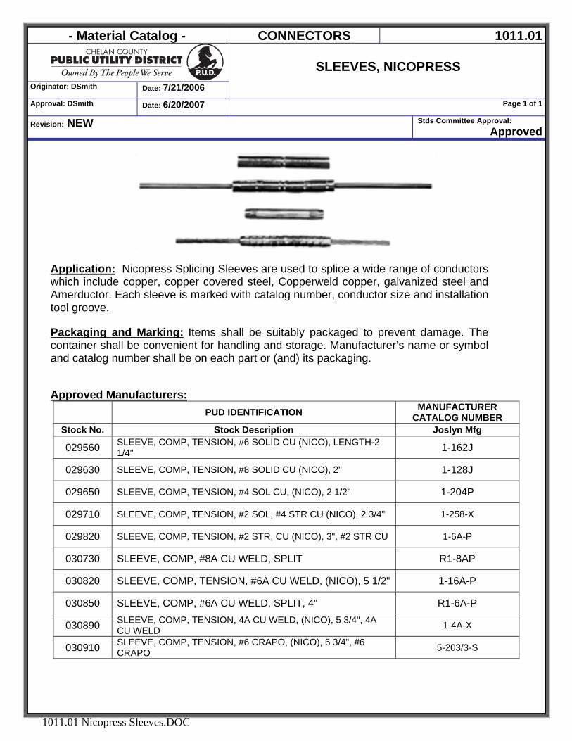
Application: Nicopress Splicing Sleeves are used to splice a wide range of conductors which include copper, copper covered steel, Copperweld copper, galvanized steel and Amerductor. Each sleeve is marked with catalog number, conductor size and installation tool groove. Packaging and Marking: Items shall be suitably packaged to prevent damage. The container shall be convenient for handling and storage. Manufacturer’s name or symbol and catalog number shall be on each part or (and) its packaging. Approved Manufacturers:
PUD IDENTIFICATION MANUFACTURER CATALOG NUMBER
Stock No. Stock Description Joslyn Mfg
029560 SLEEVE, COMP, TENSION, #6 SOLID CU (NICO), LENGTH-2 1/4" 1-162J
029630 SLEEVE, COMP, TENSION, #8 SOLID CU (NICO), 2" 1-128J
029650 SLEEVE, COMP, TENSION, #4 SOL CU, (NICO), 2 1/2" 1-204P
029710 SLEEVE, COMP, TENSION, #2 SOL, #4 STR CU (NICO), 2 3/4" 1-258-X
029820 SLEEVE, COMP, TENSION, #2 STR, CU (NICO), 3", #2 STR CU 1-6A-P
030730 SLEEVE, COMP, #8A CU WELD, SPLIT R1-8AP
030820 SLEEVE, COMP, TENSION, #6A CU WELD, (NICO), 5 1/2" 1-16A-P
030850 SLEEVE, COMP, #6A CU WELD, SPLIT, 4" R1-6A-P
030890 SLEEVE, COMP, TENSION, 4A CU WELD, (NICO), 5 3/4", 4A CU WELD 1-4A-X
030910 SLEEVE, COMP, TENSION, #6 CRAPO, (NICO), 6 3/4", #6 CRAPO 5-203/3-S
- Material Catalog - CONNECTORS 1011.02
SLEEVES, COMPRESSION
FULL TENSION Originator: DSmith Date: 7/7/06
Approval: DSmith Date: 7/7/06 Page 1 of 1
Revision: NEW Spelling error
Stds Committee Approval: Approved
1011.02 Jumpers Compression.DOC
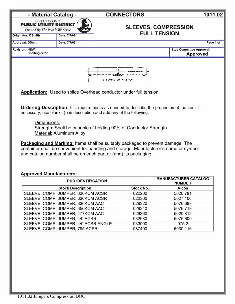
Application: Used to splice Overhead conductor under full tension.
Ordering Description: List requirements as needed to describe the properties of the item. If necessary, use blanks ( ) in description and add any of the following.
Dimensions: Strength: Shall be capable of holding 90% of Conductor Strength Material: Aluminum Alloy
Packaging and Marking: Items shall be suitably packaged to prevent damage. The container shall be convenient for handling and storage. Manufacturer’s name or symbol and catalog number shall be on each part or (and) its packaging. Approved Manufacturers:
PUD IDENTIFICATION MANUFACTURER CATALOG NUMBER
Stock Description Stock No. Alcoa SLEEVE, COMP, JUMPER, 336KCM ACSR 022200 5020.781 SLEEVE, COMP, JUMPER, 636KCM ACSR 022300 5027.106 SLEEVE, COMP, JUMPER, 336KCM AAC 029320 5076.688 SLEEVE, COMP, JUMPER, 350KCM AAC 029340 5076.719 SLEEVE, COMP, JUMPER, 477KCM AAC 029360 5020.812 SLEEVE, COMP, JUMPER, 4/0 ACSR 032980 5075.609 SLEEVE, COMP, JUMPER, 4/0 ACSR ANGLE 033000 975.2 SLEEVE, COMP, JUMPER, 795 ACSR 087400 5030.116
- Material Catalog - CONNECTORS 1011.03
SLEEVES, ACSR
FULL TENSION COMPRESSION One Piece
Originator: DSmith Date: 11/13/06
Approval: DSmith Date: 11/17/2010 Page 1 of 1
Revision: NEW Stds Committee Approval: Approved
1011.03 Sleeves Comp ACSR Full Tension Onepiece.DOC
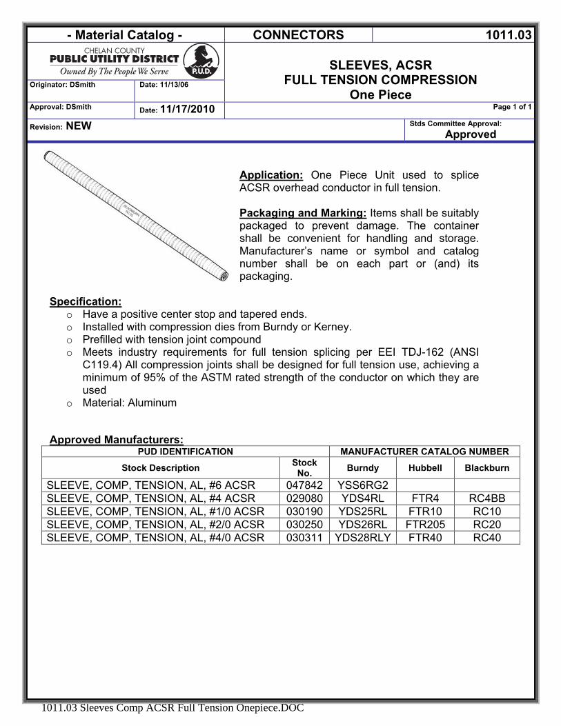
Application: One Piece Unit used to splice ACSR overhead conductor in full tension. Packaging and Marking: Items shall be suitably packaged to prevent damage. The container shall be convenient for handling and storage. Manufacturer’s name or symbol and catalog number shall be on each part or (and) its packaging.
Specification: o Have a positive center stop and tapered ends. o Installed with compression dies from Burndy or Kerney. o Prefilled with tension joint compound o Meets industry requirements for full tension splicing per EEI TDJ-162 (ANSI
C119.4) All compression joints shall be designed for full tension use, achieving a minimum of 95% of the ASTM rated strength of the conductor on which they are used
o Material: Aluminum Approved Manufacturers:
PUD IDENTIFICATION MANUFACTURER CATALOG NUMBER
Stock Description Stock No. Burndy Hubbell Blackburn
SLEEVE, COMP, TENSION, AL, #6 ACSR 047842 YSS6RG2 SLEEVE, COMP, TENSION, AL, #4 ACSR 029080 YDS4RL FTR4 RC4BB SLEEVE, COMP, TENSION, AL, #1/0 ACSR 030190 YDS25RL FTR10 RC10 SLEEVE, COMP, TENSION, AL, #2/0 ACSR 030250 YDS26RL FTR205 RC20 SLEEVE, COMP, TENSION, AL, #4/0 ACSR 030311 YDS28RLY FTR40 RC40
- Material Catalog - CONNECTORS 1011.04
SLEEVES, SERVICE WIRE NEUTRAL SPLICE
PARTIAL TENSION COMPRESSION ONE PIECE
Originator: DSmith Date: 11/13/06
Approval: DSmith Date: 12/2/2008 Page 1 of 1
Revision: Moved 030160 to 1019.11 category Stds Committee Approval: Approved
1011.04 Sleeves Comp Service Wire Neutral Splice Partial Tension.doc
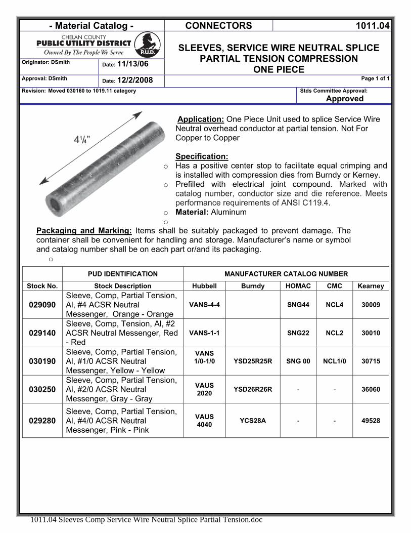
Application: One Piece Unit used to splice Service Wire Neutral overhead conductor at partial tension. Not For Copper to Copper Specification:
o Has a positive center stop to facilitate equal crimping and is installed with compression dies from Burndy or Kerney.
o Prefilled with electrical joint compound. Marked with catalog number, conductor size and die reference. Meets performance requirements of ANSI C119.4.
o Material: Aluminum o
Packaging and Marking: Items shall be suitably packaged to prevent damage. The container shall be convenient for handling and storage. Manufacturer’s name or symbol and catalog number shall be on each part or/and its packaging.
o
PUD IDENTIFICATION MANUFACTURER CATALOG NUMBER
Stock No. Stock Description Hubbell Burndy HOMAC CMC Kearney
029090 Sleeve, Comp, Partial Tension, Al, #4 ACSR Neutral Messenger, Orange - Orange
VANS-4-4 SNG44 NCL4 30009
029140 Sleeve, Comp, Tension, Al, #2 ACSR Neutral Messenger, Red - Red
VANS-1-1 SNG22 NCL2 30010
030190 Sleeve, Comp, Partial Tension, Al, #1/0 ACSR Neutral Messenger, Yellow - Yellow
VANS 1/0-1/0
YSD25R25R SNG 00 NCL1/0 30715
030250 Sleeve, Comp, Partial Tension, Al, #2/0 ACSR Neutral Messenger, Gray - Gray
VAUS 2020 YSD26R26R - - 36060
029280 Sleeve, Comp, Partial Tension, Al, #4/0 ACSR Neutral Messenger, Pink - Pink
VAUS 4040 YCS28A - - 49528

- Material Standards - Connector, Compression 1011.05
Originator: dsmith Date: 7/17/2006
Sleeve, Insulated Nontension Service
“Firecrackers” Approval: dsmith Date: 7/25/2007 Page 1 of 1
Revision: Revised – Added new items. Stds Committee Approval: Approved
1011.05 Sleeves, Service Entrance Insulated.Doc
Application Service entrance sleeves are for any combination of copper, aluminum, ACSR, compressed and compact conductors, in non-tension use. Pre-filled with PENETROX joint compound and capped. Sleeves shall have a center divider to prevent migration of moisture from the service to the service entrance conductors. Common Name: Firecrackers
Details: Stk # Color Code A-B Conductor Range A Conductor Range B Die
047840 Blue - Blue 6 ACSR, 6 STR, 4 Solid 6 ACSR, 6 STR, 4 Solid 5/8 047850 Orange-Orange 4 ACSR, 4 STR., 2 Sol. 4 ACSR, 4 STR., 2 Sol. 5/8 047860 Red-Red 2 ACSR, 1-2 STR. 2 ACSR, 1-2 STR. 5/8 047880 Red-Orange 2 ACSR, 1-2 STR. 4 ACSR, 3-4 STR., 2 SOL. 5/8 047885 Red-Yellow 2 ACSR, 1-2 STR. 1/0 ASCR, 2/0 STR., 1/0 STR. 5/8 047875 Yellow-Yellow 1/0 ASCR, 2/0 STR., 1/0 STR. 1/0 ASCR, 2/0 STR., 1/0 STR. 840 047870 Grey-Grey 2/0 ASCR, 2/0 STR., 3/0 STR. 2/0 ASCR, 2/0 STR., 3/0 STR. 840 047890 Pink-Gray 4/0 ACSR , 4/0 STR. 2/0 ASCR, 2/0 STR., 3/0 STR. 840 047895 Pink-Pink 4/0 ACSR , 4/0 STR. 4/0 ACSR , 4/0 STR. 840
Approved Manufacturers:
Stock No.
Manufacturer Catalog Number
Maximo Description
Blackburn Burndy Homac
047840 Sleeve, Insulated Nontension Service, #6ACSR, #6STR, #4Sol Blue – Blue ICS64-1 ES4W4W UBB66
047850 Sleeve, Insulated Nontension Service, #4ACSR, #4STR, #2Solid, Orange - Orange ICS68-1 ES2W2W UOO44
047860 Sleeve, Insulated Nontension Service, #2ACSR, #2STR Red – Red ICS73-1 ES2R2R URR22
047880 Sleeve, Insulated Nontension Service, #2ACSR To #4ACSR, Red-Orange ICS72-1 ES2R2W U1N24
047885 Sleeve, Insulated Nontension Service, #2ACSR To 1/0ACSR, Red-Yellow ICS77-1 ES25R2R U1N102
047875 Sleeve, Insulated Nontension Service,1/0ACSR, 1/0STR Yellow - Yellow IKL36 ES25R25R U1N1010
047870 Sleeve, Insulated Nontension Service, #2/0ACSR, #2/0 STR Grey – Gray IKL54 NONE X1N2020
047890 Sleeve, Insulated Nontension Service, #4/0ACSR To #2/0ACSR, Pink-Grey IKL67 NONE X1N4020
047895 Sleeve, Insulated Nontension Service, #4/0ACSR, #4/0STR Pink-Pink IKL69 NONE X1N4040
- Material Catalog - CONNECTORS 1011.06
Conductors, Compression,
Tap, H-Type Wide Range for AL/AL or AL/CU
Originator: DSmith Date: 6/21/2007
Approval: DSmith Date: 10/1/2008 Page 1 of 1
Revision: added Burndy YHN600 for #015550 & Changed description of 015560 Stds Committee: Approved
1011.06 Comp Crimit HTAP.DOC
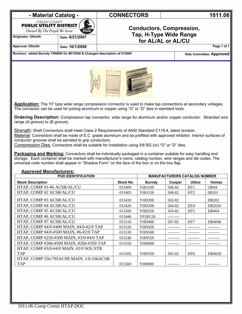
Application: The “H” type wide range compression connector is used to make tap connections at secondary voltages. The connector can be used for joining aluminum or copper using “O” or “D” dies in standard tools. Ordering Description: Compression tap connector, wide range for aluminum and/or copper conductor. Stranded wire range (A groove) to (B groove). Strength: Shall Connectors shall meet Class 2 Requirements of ANSI Standard C119.4, latest revision. Material: Connectors shall be made of E.C. grade aluminum and be prefilled with approved inhibitor. Interior surfaces of conductor grooves shall be serrated to grip conductors. Compression Dies: Connectors shall be suitable for installation using 5/8 BG (or) “O” or “D” dies. Packaging and Marking: Connectors shall be individually packaged in a container suitable for easy handling and storage. Each container shall be marked with manufacturer’s name, catalog number, wire ranges and die codes. The universal code number shall appear in “Shadow Form” on the face of the box or on the box flap.
Approved Manufacturers:
PUD IDENTIFICATION MANUFACTURERS CATALOG NUMBERStock Description Stock No Burndy Cooper Utilco Homac HTAP, COMP #1-#6 ACSR/AL/CU 015400 YHO100 506-82 HT1 OB44 HTAP, COMP #2 ACSR/AL/CU 015405 YHO150 508-82 HT2 0B101
HTAP, COMP #3 ACSR/AL/CU 015410 YHD200 502-82 DB202 HTAP, COMP #4 ACSR/AL/CU 015420 YHD300 504-82 HT4 DB2020 HTAP, COMP #5 ACSR/AL/CU 015500 YHD250 503-82 HT5 DB404 HTAP, COMP #6 ACSR/AL/CU 015440 YP28U26 --------- HTAP, COMP #7 ACSR/AL/CU 015510 YHD400 507-82 HT7 DB4040 HTAP, COMP #4/0-#400 MAIN, #4/0-#2/0 TAP 015520 YHN450 --------- --------- --------- HTAP, COMP #4/0-#500 MAIN, #6-#2/0 TAP 015530 YHN500 --------- --------- --------- HTAP, COMP #250-#500 MAIN, #3/0-#4/0 TAP 015540 YHN550 --------- --------- --------- HTAP, COMP #266-#500 MAIN, #266-#350 TAP 015550 YHN600 --------- --------- --------- HTAP, COMP #3/0-#4/0 MAIN, #2/0 SOL/STR TAP 015505 YHD350 505-82 HT6 DB4020 HTAP, COMP 556-795ACSR MAIN, 1/0-336ACSR TAP 015560 YHR800 --------- --------- ---------
- Material Catalog - CONNECTORS 1011.07
Originator: DSmith Date: 10/8/2007
CRIMPIT, COMPRESSION
COPPER “C-TAPS” FOR COPPER
Approval: DSmith Date: 10/8/2007 Page 1 of 1
Revision: Stds Committee: Approved
1011.07 Crimit_Compression_Copper_C.DOC
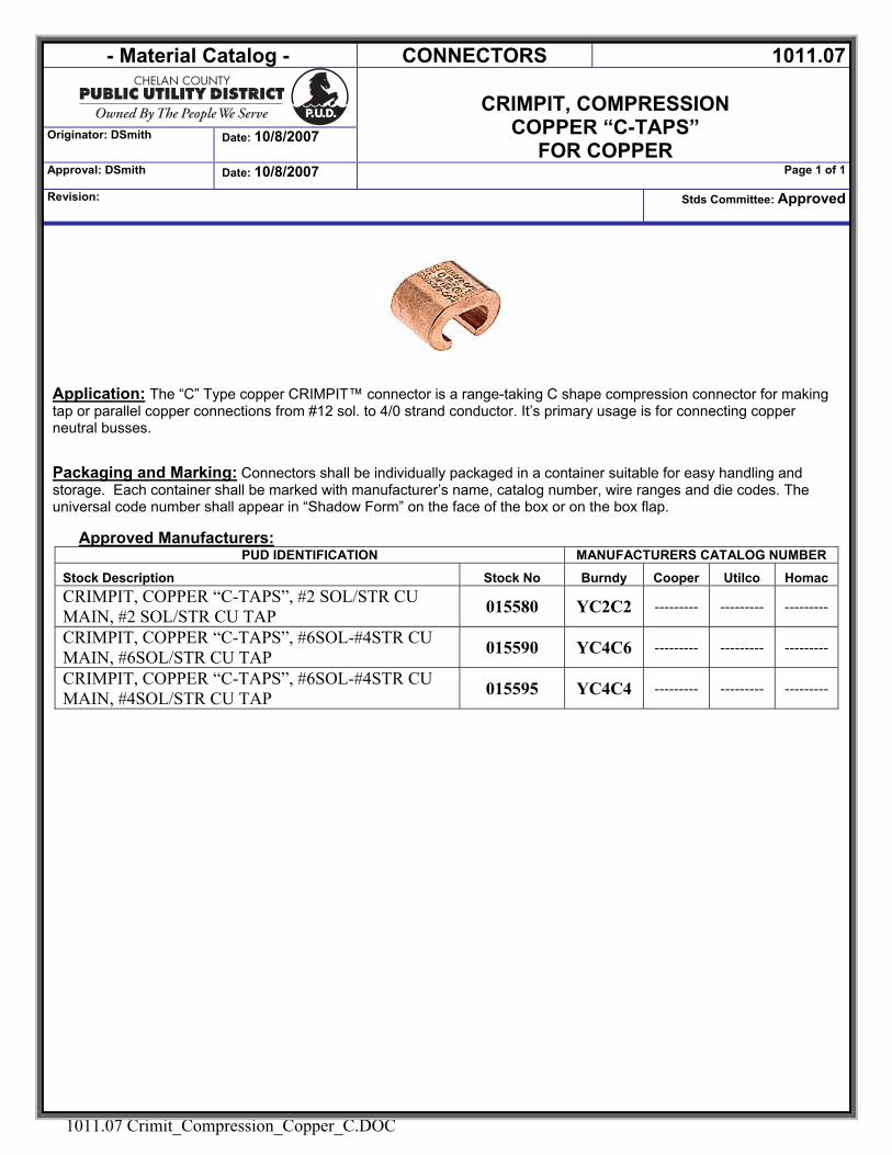
Application: The “C” Type copper CRIMPIT™ connector is a range-taking C shape compression connector for making tap or parallel copper connections from #12 sol. to 4/0 strand conductor. It’s primary usage is for connecting copper neutral busses. Packaging and Marking: Connectors shall be individually packaged in a container suitable for easy handling and storage. Each container shall be marked with manufacturer’s name, catalog number, wire ranges and die codes. The universal code number shall appear in “Shadow Form” on the face of the box or on the box flap.
Approved Manufacturers:
PUD IDENTIFICATION MANUFACTURERS CATALOG NUMBER
Stock Description Stock No Burndy Cooper Utilco Homac CRIMPIT, COPPER “C-TAPS”, #2 SOL/STR CU MAIN, #2 SOL/STR CU TAP 015580 YC2C2 --------- --------- ---------
CRIMPIT, COPPER “C-TAPS”, #6SOL-#4STR CU MAIN, #6SOL/STR CU TAP 015590 YC4C6 --------- --------- ---------
CRIMPIT, COPPER “C-TAPS”, #6SOL-#4STR CU MAIN, #4SOL/STR CU TAP 015595 YC4C4 --------- --------- ---------
- Material Catalog - CONNECTORS 1011.08
Originator: DSmith Date: 7/7/2006
TAP, TEE, CABLE TO 4 HOLE PAD
Transmission Approval: DSmith Date: 6/22/2007 Page 1 of 1
Revision: NEW Stds Committee Approval: Approved
1011.08 Hitemp Tee Tap TLINE.DOC
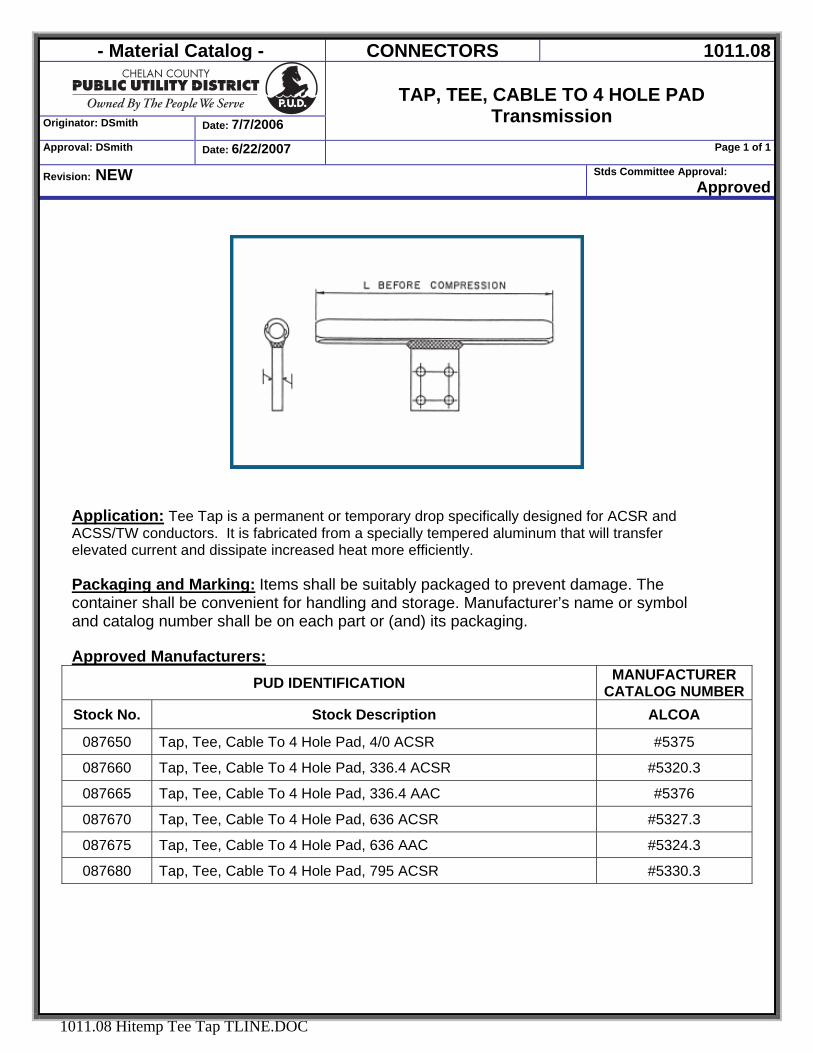
Application: Tee Tap is a permanent or temporary drop specifically designed for ACSR and ACSS/TW conductors. It is fabricated from a specially tempered aluminum that will transfer elevated current and dissipate increased heat more efficiently.
Packaging and Marking: Items shall be suitably packaged to prevent damage. The container shall be convenient for handling and storage. Manufacturer’s name or symbol and catalog number shall be on each part or (and) its packaging. Approved Manufacturers:
PUD IDENTIFICATION MANUFACTURER CATALOG NUMBER
Stock No. Stock Description ALCOA
087650 Tap, Tee, Cable To 4 Hole Pad, 4/0 ACSR #5375
087660 Tap, Tee, Cable To 4 Hole Pad, 336.4 ACSR #5320.3
087665 Tap, Tee, Cable To 4 Hole Pad, 336.4 AAC #5376
087670 Tap, Tee, Cable To 4 Hole Pad, 636 ACSR #5327.3
087675 Tap, Tee, Cable To 4 Hole Pad, 636 AAC #5324.3
087680 Tap, Tee, Cable To 4 Hole Pad, 795 ACSR #5330.3
- Material Catalog - CONNECTORS 1011.09
Originator: DSmith Date: 11/13/06
SPLICE OH, ACSR
FULL TENSION PREFORMED
Approval: DSmith Date: 8/29/2007 Page 1 of 1
Revision: NEW Stds Committee Approval: Approved
1011.09 SPLICE, OH, ACSR Fulltension Preformed.DOC
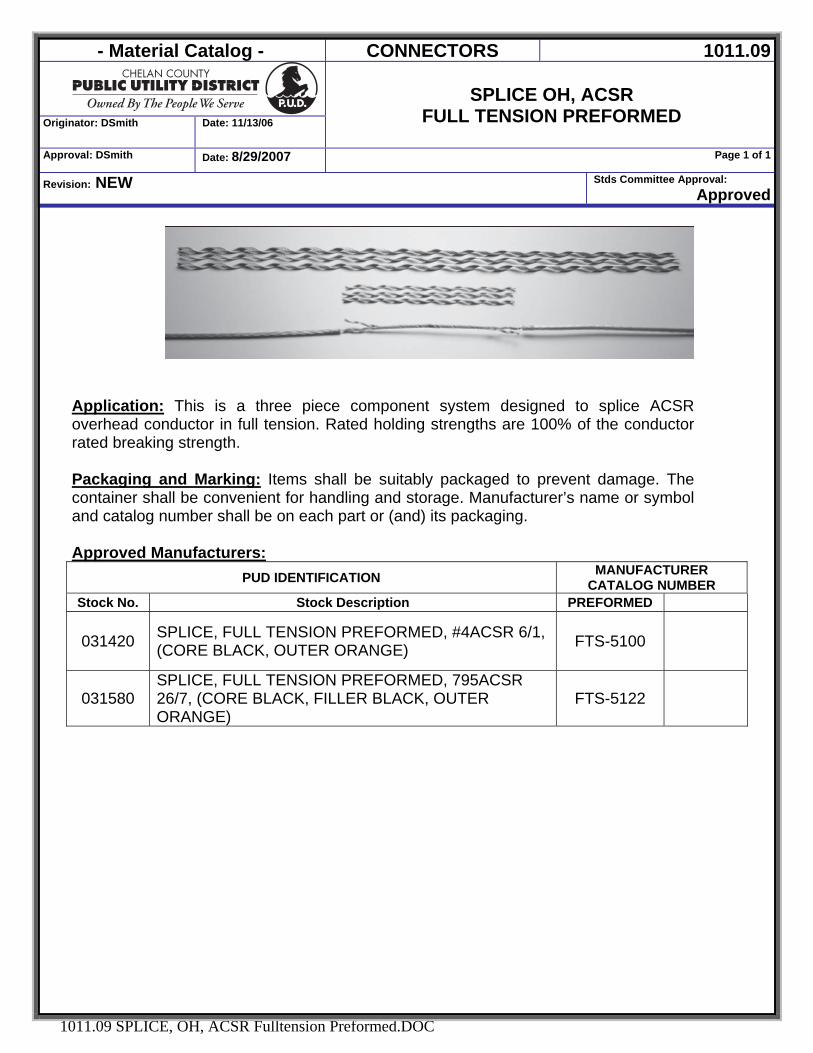
Application: This is a three piece component system designed to splice ACSR overhead conductor in full tension. Rated holding strengths are 100% of the conductor rated breaking strength. Packaging and Marking: Items shall be suitably packaged to prevent damage. The container shall be convenient for handling and storage. Manufacturer’s name or symbol and catalog number shall be on each part or (and) its packaging. Approved Manufacturers:
PUD IDENTIFICATION MANUFACTURER CATALOG NUMBER
Stock No. Stock Description PREFORMED
031420 SPLICE, FULL TENSION PREFORMED, #4ACSR 6/1, (CORE BLACK, OUTER ORANGE) FTS-5100
031580 SPLICE, FULL TENSION PREFORMED, 795ACSR 26/7, (CORE BLACK, FILLER BLACK, OUTER ORANGE)
FTS-5122
- Material Catalog - CONNECTORS 1011.14
Originator: DSmith Date: 7/21/2006
SLEEVES, SPLIT REPAIR, ACSR
Transmission Approval: DSmith Date: 6/22/2007 Page 1 of 1
Revision: NEW Stds Committee Approval: Approved
1011.14 Sleeve Split Repair ACSR TLINE.DOC
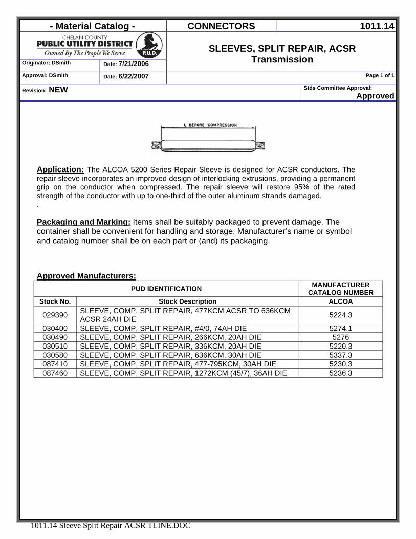
Application: The ALCOA 5200 Series Repair Sleeve is designed for ACSR conductors. The repair sleeve incorporates an improved design of interlocking extrusions, providing a permanent grip on the conductor when compressed. The repair sleeve will restore 95% of the rated strength of the conductor with up to one-third of the outer aluminum strands damaged. . Packaging and Marking: Items shall be suitably packaged to prevent damage. The container shall be convenient for handling and storage. Manufacturer’s name or symbol and catalog number shall be on each part or (and) its packaging. Approved Manufacturers:
PUD IDENTIFICATION MANUFACTURER CATALOG NUMBER
Stock No. Stock Description ALCOA
029390 SLEEVE, COMP, SPLIT REPAIR, 477KCM ACSR TO 636KCM ACSR 24AH DIE 5224.3
030400 SLEEVE, COMP, SPLIT REPAIR, #4/0, 74AH DIE 5274.1 030490 SLEEVE, COMP, SPLIT REPAIR, 266KCM, 20AH DIE 5276 030510 SLEEVE, COMP, SPLIT REPAIR, 336KCM, 20AH DIE 5220.3 030580 SLEEVE, COMP, SPLIT REPAIR, 636KCM, 30AH DIE 5337.3 087410 SLEEVE, COMP, SPLIT REPAIR, 477-795KCM, 30AH DIE 5230.3 087460 SLEEVE, COMP, SPLIT REPAIR, 1272KCM (45/7), 36AH DIE 5236.3
- Material Catalog - CONNECTORS 1011.16
Originator: DSmith Date: 7/7/06
SLEEVE, COMPRESSION/TENSION, AAC
Transmission Approval: DSmith Date:6/22/2007 Page 1 of 1
Revision: NEW Stds Committee Approval: Approved
1011.16 Sleeve Comp AAC TLINE.DOC
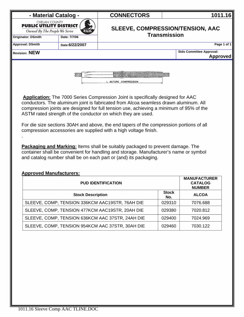
Application: The 7000 Series Compression Joint is specifically designed for AAC conductors. The aluminum joint is fabricated from Alcoa seamless drawn aluminum. All compression joints are designed for full tension use, achieving a minimum of 95% of the ASTM rated strength of the conductor on which they are used. For die size sections 30AH and above, the end tapers of the compression portions of all compression accessories are supplied with a high voltage finish. . Packaging and Marking: Items shall be suitably packaged to prevent damage. The container shall be convenient for handling and storage. Manufacturer’s name or symbol and catalog number shall be on each part or (and) its packaging. Approved Manufacturers:
PUD IDENTIFICATION MANUFACTURER
CATALOG NUMBER
Stock Description Stock No. ALCOA
SLEEVE, COMP, TENSION 336KCM AAC19STR, 76AH DIE 029310 7076.688
SLEEVE, COMP, TENSION 477KCM AAC19STR, 20AH DIE 029380 7020.812
SLEEVE, COMP, TENSION 636KCM AAC 37STR, 24AH DIE 029400 7024.969
SLEEVE, COMP, TENSION 954KCM AAC 37STR, 30AH DIE 029460 7030.122
- Material Catalog - CONNECTORS 1011.17
SLEEVES, ACSR
ALCOA FULL TENSION Transmission
Originator: DSmith Date: 3/13/2007
Approval: DSmith Date: 10/22/2014 Page 1 of 1
Revision: NEW Stds Committee Approval: Approved
1011.17 Sleeves Comp ACSR Alcoa Two Piece TLINE.DOC
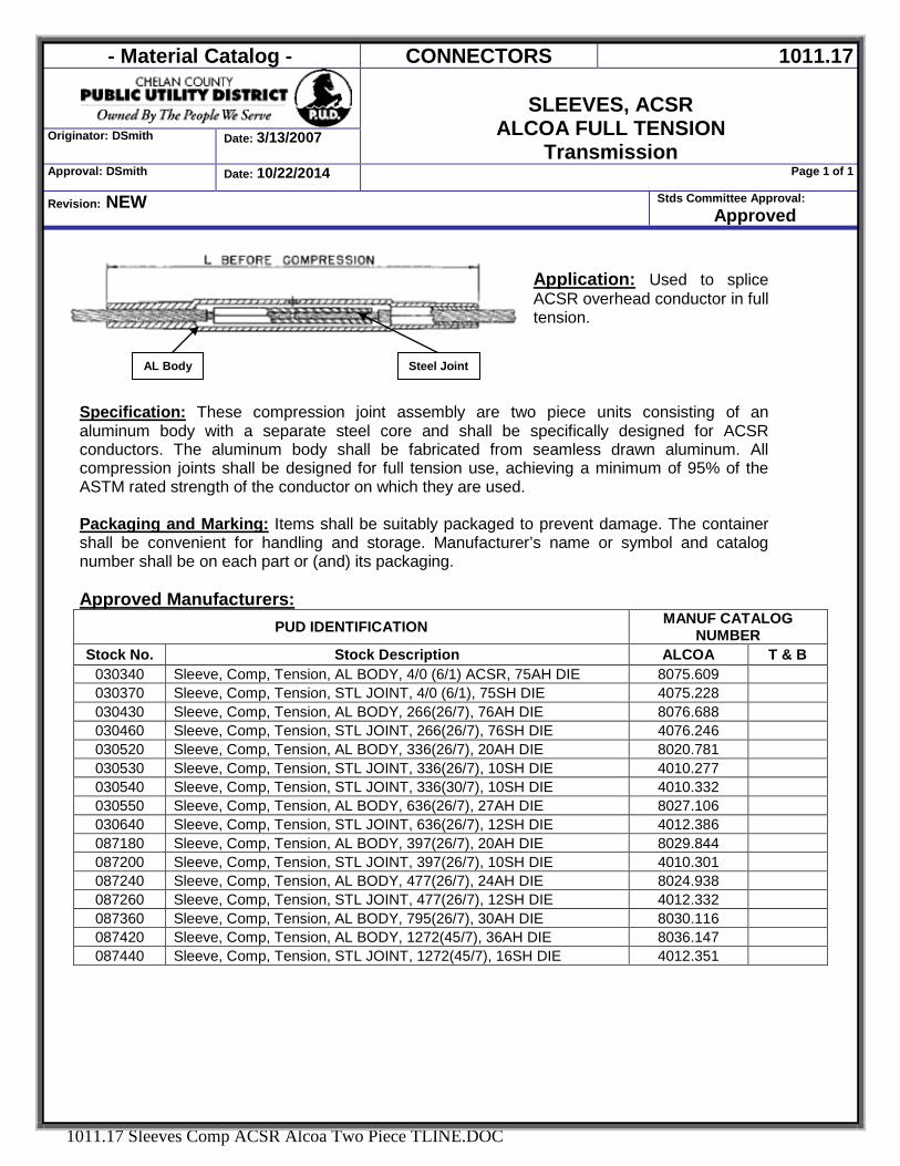
AL Body Steel Joint
Application: Used to splice ACSR overhead conductor in full tension.
Specification: These compression joint assembly are two piece units consisting of an aluminum body with a separate steel core and shall be specifically designed for ACSR conductors. The aluminum body shall be fabricated from seamless drawn aluminum. All compression joints shall be designed for full tension use, achieving a minimum of 95% of the ASTM rated strength of the conductor on which they are used. Packaging and Marking: Items shall be suitably packaged to prevent damage. The container shall be convenient for handling and storage. Manufacturer’s name or symbol and catalog number shall be on each part or (and) its packaging. Approved Manufacturers:
PUD IDENTIFICATION MANUF CATALOG NUMBER
Stock No. Stock Description ALCOA T & B 030340 Sleeve, Comp, Tension, AL BODY, 4/0 (6/1) ACSR, 75AH DIE 8075.609 030370 Sleeve, Comp, Tension, STL JOINT, 4/0 (6/1), 75SH DIE 4075.228 030430 Sleeve, Comp, Tension, AL BODY, 266(26/7), 76AH DIE 8076.688 030460 Sleeve, Comp, Tension, STL JOINT, 266(26/7), 76SH DIE 4076.246 030520 Sleeve, Comp, Tension, AL BODY, 336(26/7), 20AH DIE 8020.781 030530 Sleeve, Comp, Tension, STL JOINT, 336(26/7), 10SH DIE 4010.277 030540 Sleeve, Comp, Tension, STL JOINT, 336(30/7), 10SH DIE 4010.332 030550 Sleeve, Comp, Tension, AL BODY, 636(26/7), 27AH DIE 8027.106 030640 Sleeve, Comp, Tension, STL JOINT, 636(26/7), 12SH DIE 4012.386 087180 Sleeve, Comp, Tension, AL BODY, 397(26/7), 20AH DIE 8029.844 087200 Sleeve, Comp, Tension, STL JOINT, 397(26/7), 10SH DIE 4010.301 087240 Sleeve, Comp, Tension, AL BODY, 477(26/7), 24AH DIE 8024.938 087260 Sleeve, Comp, Tension, STL JOINT, 477(26/7), 12SH DIE 4012.332 087360 Sleeve, Comp, Tension, AL BODY, 795(26/7), 30AH DIE 8030.116 087420 Sleeve, Comp, Tension, AL BODY, 1272(45/7), 36AH DIE 8036.147 087440 Sleeve, Comp, Tension, STL JOINT, 1272(45/7), 16SH DIE 4012.351
- Material Catalog - CONNECTORS 1011.18
TERMINAL PAD, COMPRESSION
Originator: DSmith Date:6/21/2007
Approval: DSmith Date:10/22/2008 Page 1 of 2
Revision: Updated Mfg Part Number Stds Committee Approval: Approved
1011.18 Terminal Pads, Compression.DOC
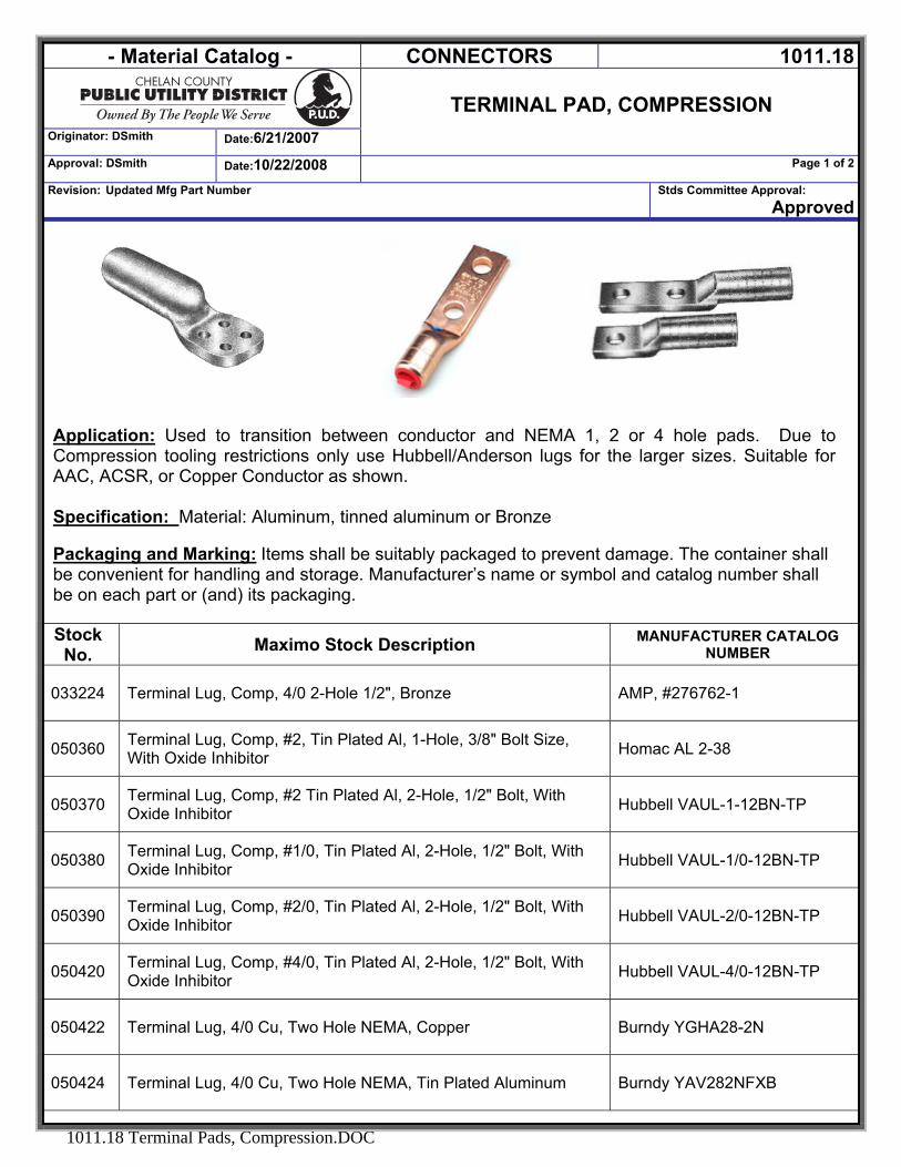
Application: Used to transition between conductor and NEMA 1, 2 or 4 hole pads. Due to Compression tooling restrictions only use Hubbell/Anderson lugs for the larger sizes. Suitable for AAC, ACSR, or Copper Conductor as shown. Specification: Material: Aluminum, tinned aluminum or Bronze Packaging and Marking: Items shall be suitably packaged to prevent damage. The container shall be convenient for handling and storage. Manufacturer’s name or symbol and catalog number shall be on each part or (and) its packaging.
Stock No. Maximo Stock Description MANUFACTURER CATALOG
NUMBER
033224 Terminal Lug, Comp, 4/0 2-Hole 1/2", Bronze AMP, #276762-1
050360 Terminal Lug, Comp, #2, Tin Plated Al, 1-Hole, 3/8" Bolt Size, With Oxide Inhibitor Homac AL 2-38
050370 Terminal Lug, Comp, #2 Tin Plated Al, 2-Hole, 1/2" Bolt, With Oxide Inhibitor Hubbell VAUL-1-12BN-TP
050380 Terminal Lug, Comp, #1/0, Tin Plated Al, 2-Hole, 1/2" Bolt, With Oxide Inhibitor Hubbell VAUL-1/0-12BN-TP
050390 Terminal Lug, Comp, #2/0, Tin Plated Al, 2-Hole, 1/2" Bolt, With Oxide Inhibitor Hubbell VAUL-2/0-12BN-TP
050420 Terminal Lug, Comp, #4/0, Tin Plated Al, 2-Hole, 1/2" Bolt, With Oxide Inhibitor Hubbell VAUL-4/0-12BN-TP
050422 Terminal Lug, 4/0 Cu, Two Hole NEMA, Copper Burndy YGHA28-2N
050424 Terminal Lug, 4/0 Cu, Two Hole NEMA, Tin Plated Aluminum Burndy YAV282NFXB
- Material Catalog - CONNECTORS 1011.18
TERMINAL PAD, COMPRESSION
Originator: DSmith Date:6/27/2014
Approval: J. Mitchell Date:6/27/2014 Page 2 of 2
Revision: Updated description for 050460r Stds Committee Approval: Approved
1011.18 Terminal Pads, Compression.docx
Stock No. Maximo Stock Description MANUFACTURER CATALOG
NUMBER
050440 Terminal Lug, Comp, 336kcm, Tin Plated Al, 2-Hole, 1/2" Bolt, With Oxide Inhibitor Hubbell VAUL-350-12BN-TP
050445 Terminal Lug, Comp, 336.4 ACSR, Tin Plated Al, 2-Hole, All Purpose PENN-UNION #KVL-RO33D1
050450 Terminal Lug, Comp, 500kcm, Tin Plated Al, 2-Hole, 1/2" Bolt, With Oxide Inhibitor Hubbell VAUL-500-12BN-TP
050451 Terminal Lug, Comp, 500kcm, Tin Plated Al, 2-Hole Burndy #YAK34A2G2
050452 Terminal Lug, Comp, 500kcm, Tin Plated Al, 2-Hole Burndy #YAK34A2G1
050460 Terminal Lug, Comp, 750kcm, Tin Plated Al, 2-Hole Hubbell VAUL-750-12BN-TP
050480 Terminal Lug, Comp, 750, Tin Plated Al, 2-Hole Homac 750 NTN
050485 Terminal Lug, Comp, 750, Tin Plated Al, 2-Hole Hubbell ALCF-800B
050490 Terminal Lug, Comp, 750kcm To 1000kcm, Tin Plated Al, 2-Hole, 1/2" Bolt, With Oxide Inhibitor Hubbell VAUL-1000-12BN-TP
050495 Terminal Lug, Comp, 750kcm to 1000kcm Tin Plated Al, 4-Hole, Short Barrel, 1/2" Bolt, With Oxide Inhibitor CCLS-1216C
- Material Catalog - Connectors 1011.19
Deadend, Compression, Jumper Terminals, 15°,
ACSR & AAC Conductors Originator: Jennifer Smith Date: 10/17/2008
Approval: Jennifer Smith Date: 10/17/2008 Page 1 of 1
Revision: NEW Stds Committee Approval:
Approved
1011.19 Terminal Pads, Compression, Deadend 15degree.DOC
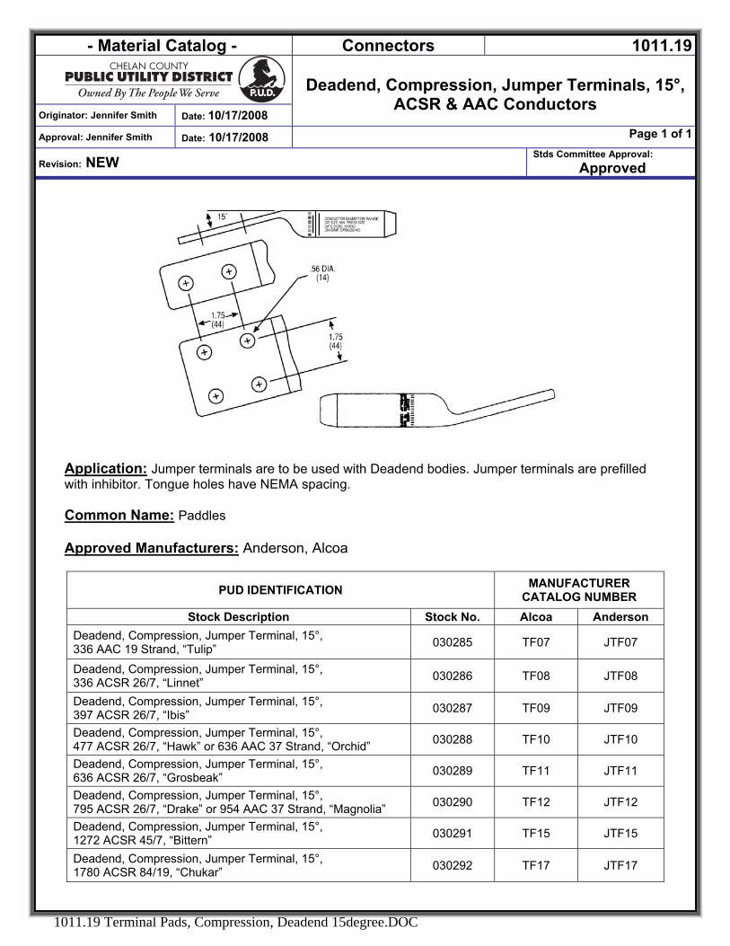
Application: Jumper terminals are to be used with Deadend bodies. Jumper terminals are prefilled with inhibitor. Tongue holes have NEMA spacing. Common Name: Paddles
Approved Manufacturers: Anderson, Alcoa
PUD IDENTIFICATION MANUFACTURER CATALOG NUMBER
Stock Description Stock No. Alcoa Anderson Deadend, Compression, Jumper Terminal, 15°, 336 AAC 19 Strand, “Tulip” 030285 TF07 JTF07
Deadend, Compression, Jumper Terminal, 15°, 336 ACSR 26/7, “Linnet” 030286 TF08 JTF08
Deadend, Compression, Jumper Terminal, 15°, 397 ACSR 26/7, “Ibis” 030287 TF09 JTF09
Deadend, Compression, Jumper Terminal, 15°, 477 ACSR 26/7, “Hawk” or 636 AAC 37 Strand, “Orchid” 030288 TF10 JTF10
Deadend, Compression, Jumper Terminal, 15°, 636 ACSR 26/7, “Grosbeak” 030289 TF11 JTF11
Deadend, Compression, Jumper Terminal, 15°, 795 ACSR 26/7, “Drake” or 954 AAC 37 Strand, “Magnolia” 030290 TF12 JTF12
Deadend, Compression, Jumper Terminal, 15°, 1272 ACSR 45/7, “Bittern” 030291 TF15 JTF15
Deadend, Compression, Jumper Terminal, 15°, 1780 ACSR 84/19, “Chukar” 030292 TF17 JTF17
- Material Catalog - CONNECTORS 1011.20
TERMINAL PADS, BOLT-ON, BRONZE
Originator: DSmith Date: 6/21/2007
Approval: J Mitchell Date: 1/11/2013 Page 1 of 1
Revision: Revised verbage. Stds Committee Approval: Approved
1011.20 Terminal pad, Bolt-On Bronze
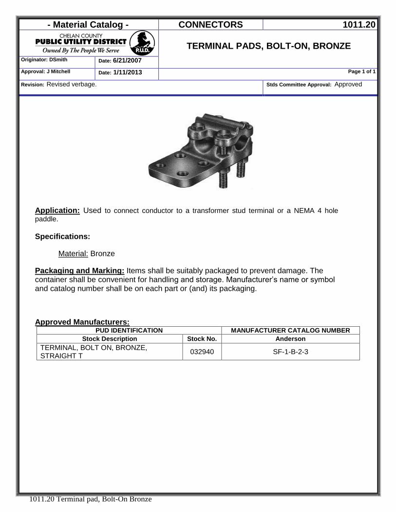
Application: Used to connect conductor to a transformer stud terminal or a NEMA 4 hole paddle.
Specifications:
Material: Bronze
Packaging and Marking: Items shall be suitably packaged to prevent damage. The container shall be convenient for handling and storage. Manufacturer’s name or symbol and catalog number shall be on each part or (and) its packaging. Approved Manufacturers:
PUD IDENTIFICATION MANUFACTURER CATALOG NUMBER Stock Description Stock No. Anderson
TERMINAL, BOLT ON, BRONZE, STRAIGHT T 032940 SF-1-B-2-3
- Material Catalog - CONNECTORS 1011.21
Originator: DSmith Date: 6/21/2007
TERMINAL PADS, WEJTAP, 2-HOLE PADDLE
Approval: DSmith Date:10/8/2007 Page 1 of 1
Revision: NEW Stds Committee Approval: Approved
1011.21 Termial Pad, WEJTAP, 2 Hole Paddle.DOC
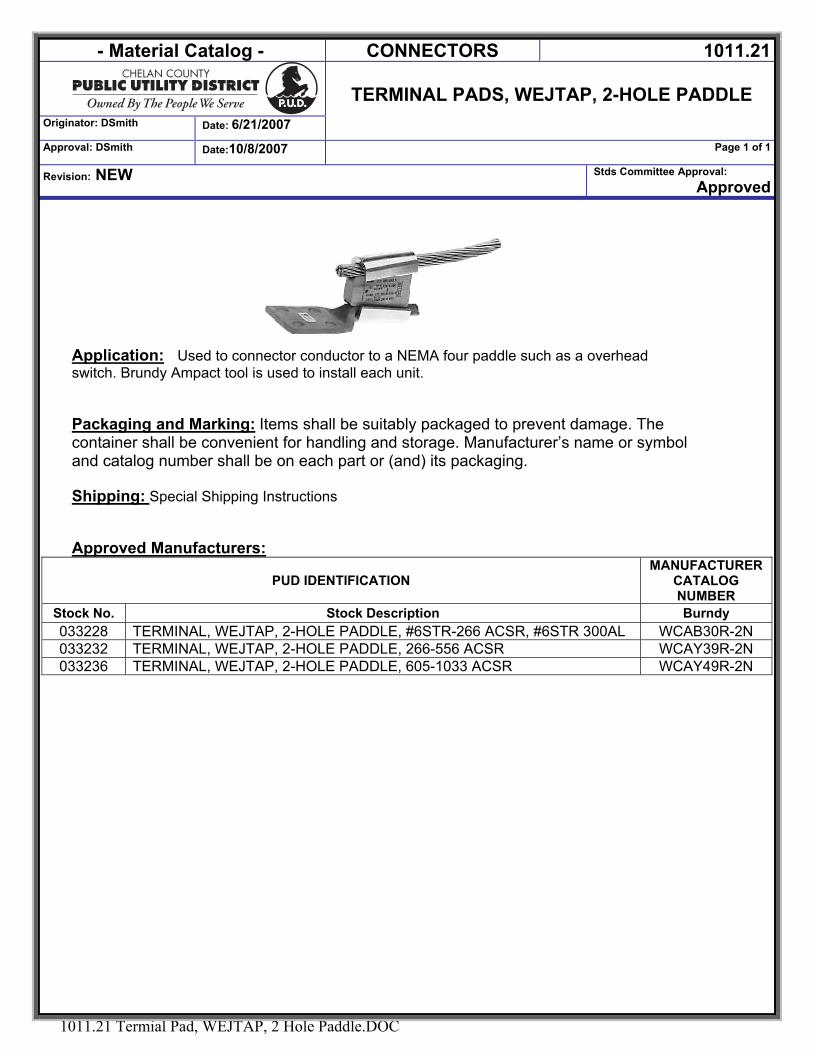
Application: Used to connector conductor to a NEMA four paddle such as a overhead switch. Brundy Ampact tool is used to install each unit. Packaging and Marking: Items shall be suitably packaged to prevent damage. The container shall be convenient for handling and storage. Manufacturer’s name or symbol and catalog number shall be on each part or (and) its packaging. Shipping: Special Shipping Instructions Approved Manufacturers:
PUD IDENTIFICATION MANUFACTURER
CATALOG NUMBER
Stock No. Stock Description Burndy 033228 TERMINAL, WEJTAP, 2-HOLE PADDLE, #6STR-266 ACSR, #6STR 300AL WCAB30R-2N 033232 TERMINAL, WEJTAP, 2-HOLE PADDLE, 266-556 ACSR WCAY39R-2N 033236 TERMINAL, WEJTAP, 2-HOLE PADDLE, 605-1033 ACSR WCAY49R-2N
- Material Catalog - CONNECTORS 1011.22
TAPS, COMPRESSION, WEJTAP AND POWER
BOOSTER Originator: DSmith Date: 2/13/2015
Approval: J. Mitchell Date: 2/17/2015 Page 1 of 2
Revision: Removed STK# 032635
Stds Committee Approval: 9/22/06
1011.22 Tap Wejtap.docx
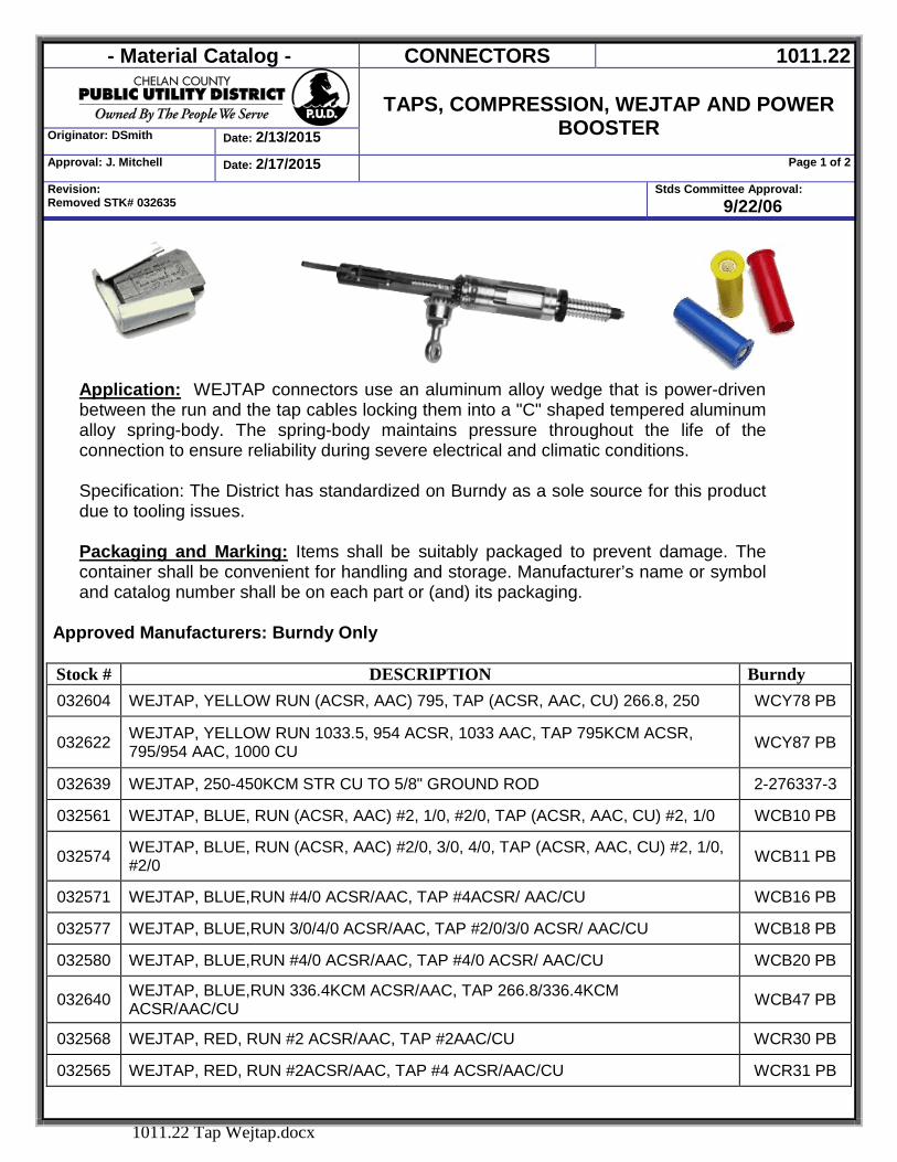
Application: WEJTAP connectors use an aluminum alloy wedge that is power-driven between the run and the tap cables locking them into a "C" shaped tempered aluminum alloy spring-body. The spring-body maintains pressure throughout the life of the connection to ensure reliability during severe electrical and climatic conditions. Specification: The District has standardized on Burndy as a sole source for this product due to tooling issues. Packaging and Marking: Items shall be suitably packaged to prevent damage. The container shall be convenient for handling and storage. Manufacturer’s name or symbol and catalog number shall be on each part or (and) its packaging.
Approved Manufacturers: Burndy Only Stock # DESCRIPTION Burndy 032604 WEJTAP, YELLOW RUN (ACSR, AAC) 795, TAP (ACSR, AAC, CU) 266.8, 250 WCY78 PB
032622 WEJTAP, YELLOW RUN 1033.5, 954 ACSR, 1033 AAC, TAP 795KCM ACSR, 795/954 AAC, 1000 CU WCY87 PB
032639 WEJTAP, 250-450KCM STR CU TO 5/8" GROUND ROD 2-276337-3
032561 WEJTAP, BLUE, RUN (ACSR, AAC) #2, 1/0, #2/0, TAP (ACSR, AAC, CU) #2, 1/0 WCB10 PB
032574 WEJTAP, BLUE, RUN (ACSR, AAC) #2/0, 3/0, 4/0, TAP (ACSR, AAC, CU) #2, 1/0, #2/0 WCB11 PB
032571 WEJTAP, BLUE,RUN #4/0 ACSR/AAC, TAP #4ACSR/ AAC/CU WCB16 PB
032577 WEJTAP, BLUE,RUN 3/0/4/0 ACSR/AAC, TAP #2/0/3/0 ACSR/ AAC/CU WCB18 PB
032580 WEJTAP, BLUE,RUN #4/0 ACSR/AAC, TAP #4/0 ACSR/ AAC/CU WCB20 PB
032640 WEJTAP, BLUE,RUN 336.4KCM ACSR/AAC, TAP 266.8/336.4KCM ACSR/AAC/CU WCB47 PB
032568 WEJTAP, RED, RUN #2 ACSR/AAC, TAP #2AAC/CU WCR30 PB
032565 WEJTAP, RED, RUN #2ACSR/AAC, TAP #4 ACSR/AAC/CU WCR31 PB
- Material Catalog - CONNECTORS 1011.22
TAPS, COMPRESSION, WEJTAP AND POWER
BOOSTER Originator: DSmith Date: 2/13/2015
Approval: J. Mitchell Date: 2/13/2015 Page 2 of 2
Revision: Removed STK# 032635
Stds Committee Approval: 9/22/06
1011.22 Tap Wejtap.docx
032562 WEJTAP, RED, RUN, #6, #4 ACSR/AAC, TAP #6 ACSR/AAC/CU WCR33 PB
032619 WEJTAP, YELLOW, RUN 954/1033.5KCM ACSR/AAC, TAP #2 ACSR/AAC/CU WCY100 PB
032625 WEJTAP, YELLOW, RUN 397.5KCM AAC, TAP #2AAC/CU WCY50 PB
032583 WEJTAP, YELLOW, RUN 397.5KCMAAC, TAP 1/0AAC/CU WCY51 PB
032586 WEJTAP, YELLOW, RUN 397.5KCM AAC, TAP #4/0AAC/CU WCY54 PB
032584 WEJTAP, YELLOW, RUN 397.5KCM AAC, TAP 336.4/397.5KCM AAC, 350 CU WCY56 PB
032598 WEJTAP, YELLOW, RUN 556.5KCM ACSR/AAC, TAP 556.5KCM ACSR/AAC WCY60 PB
032592 WEJTAP, YELLOW, RUN 397.5/556.5KCM ACSR/AAC, TAP 266.8/336.4/397.5KCM ACSR/AAC/CU WCY62 PB
032587 WEJTAP, YELLOW, RUN 397.5KCM/477KCM/556.5KCM ACSR/AAC, TAP #4/0/266.8KCM ACSR/AAC/CU WCY63 PB
032616 WEJTAP, YELLOW, DIAMTERS: RUN: 1.133-0.907, TAP 1.142-0.907 WCY73 PB
032607 WEJTAP, YELLOW, RUN 795KCM ACSR, TAP 556.5KCM ACSR WCY74 PB
032613 WEJTAP, YELLOW, RUN 795KCM ACSR/AAC, TAP 477KCM ACSR, 556.5KCM AAC, 500CU WCY75 PB
032610 WEJTAP, YELLOW, RUN 795KCM ACSR/AAC, TAP 336.4/397.5KCM ACSR/AAC/CU WCY77 PB
032601 WEJTAP, YELLOW, RUN 795KCM ACSR/CU, TAP 3/0/4/0 ACSR, #4/0 AAC/CU WCY79 PB
032589 WEJTAP, YELLOW, RUN 795KCM ACSR/AAC, TAP 1/0/2/0 ACSR/AAC/CU WCY81 PB
028620 SHELL,WEJTAP POWER BOOSTER, RED WPBR-BOX25
028615 SHELL,WEJTAP POWER BOOSTER, BLUE WPBB-BOX25
028630 SHELL,WEJTAP POWER BOOSTER, WHITE WPBW-BOX25
028625 SHELL,WEJTAP POWER BOOSTER, YELLOW WPBY-BOX25
- Material Catalog - Connectors 1012.01
Originator: DSmith Date:7/7/2006
Sleeves, Automatic
Tension, Copper
Approval: J.Mitchell Date: 8/13/2014 Page 1 of 1
Revision: CORRECTED ITEM # Stds Committee Approval: Approved
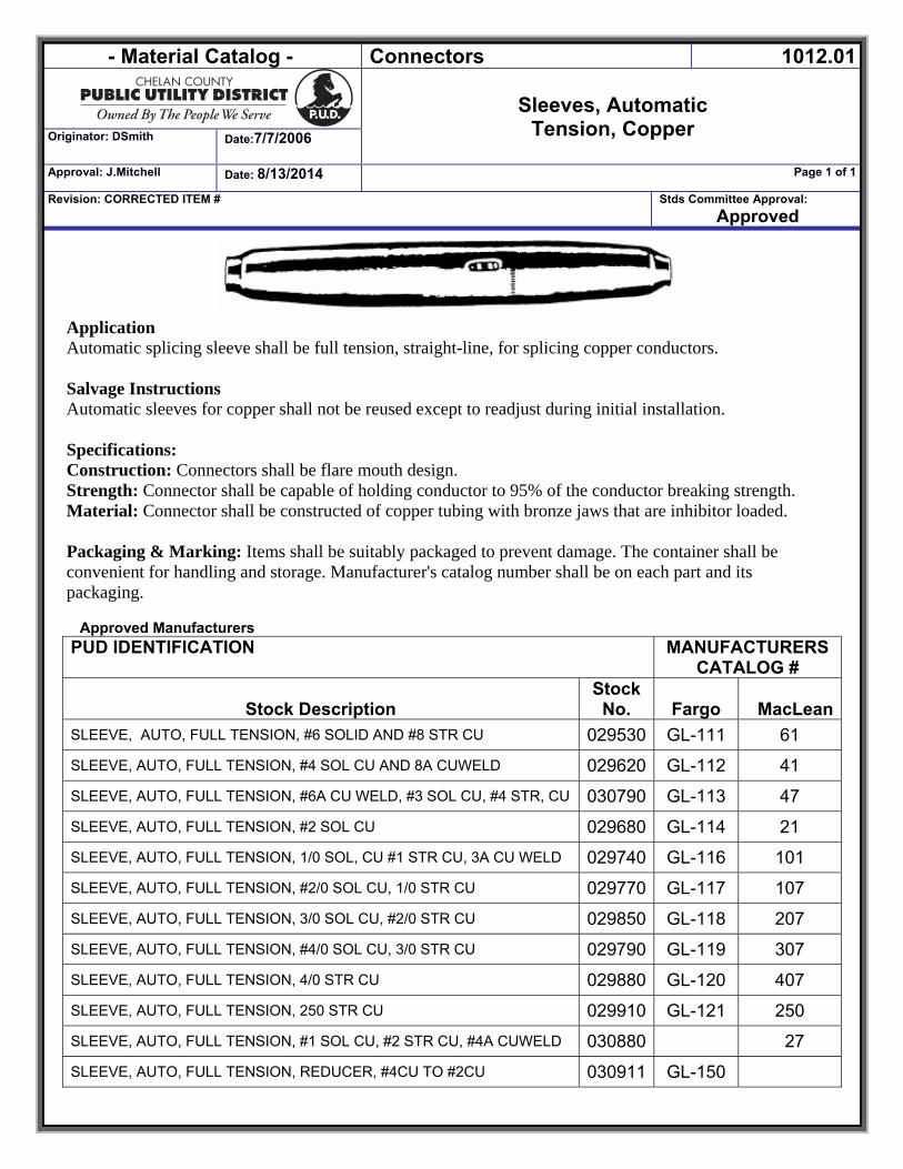
Application Automatic splicing sleeve shall be full tension, straight-line, for splicing copper conductors. Salvage Instructions Automatic sleeves for copper shall not be reused except to readjust during initial installation. Specifications: Construction: Connectors shall be flare mouth design. Strength: Connector shall be capable of holding conductor to 95% of the conductor breaking strength. Material: Connector shall be constructed of copper tubing with bronze jaws that are inhibitor loaded. Packaging & Marking: Items shall be suitably packaged to prevent damage. The container shall be convenient for handling and storage. Manufacturer's catalog number shall be on each part and its packaging.
Approved Manufacturers
PUD IDENTIFICATION MANUFACTURERS CATALOG #
Stock Description Stock No. Fargo MacLean
SLEEVE, AUTO, FULL TENSION, #6 SOLID AND #8 STR CU 029530 GL-111 61
SLEEVE, AUTO, FULL TENSION, #4 SOL CU AND 8A CUWELD 029620 GL-112 41
SLEEVE, AUTO, FULL TENSION, #6A CU WELD, #3 SOL CU, #4 STR, CU 030790 GL-113 47
SLEEVE, AUTO, FULL TENSION, #2 SOL CU 029680 GL-114 21
SLEEVE, AUTO, FULL TENSION, 1/0 SOL, CU #1 STR CU, 3A CU WELD 029740 GL-116 101
SLEEVE, AUTO, FULL TENSION, #2/0 SOL CU, 1/0 STR CU 029770 GL-117 107
SLEEVE, AUTO, FULL TENSION, 3/0 SOL CU, #2/0 STR CU 029850 GL-118 207
SLEEVE, AUTO, FULL TENSION, #4/0 SOL CU, 3/0 STR CU 029790 GL-119 307
SLEEVE, AUTO, FULL TENSION, 4/0 STR CU 029880 GL-120 407
SLEEVE, AUTO, FULL TENSION, 250 STR CU 029910 GL-121 250
SLEEVE, AUTO, FULL TENSION, #1 SOL CU, #2 STR CU, #4A CUWELD 030880 27
SLEEVE, AUTO, FULL TENSION, REDUCER, #4CU TO #2CU 030911 GL-150
- Material Catalog - CONNECTORS 1012.02
SLEEVE, AUTOMATIC
For ACSR/AAC/AAAC Conductor Originator: DSmith Date: 11/17/2010
Approval: DSmith Date: 11/17/2010 Page 1 of 1
Revision: NEW Stds Committee Approval: Approved
1012.02 Auto Sleeve.DOC
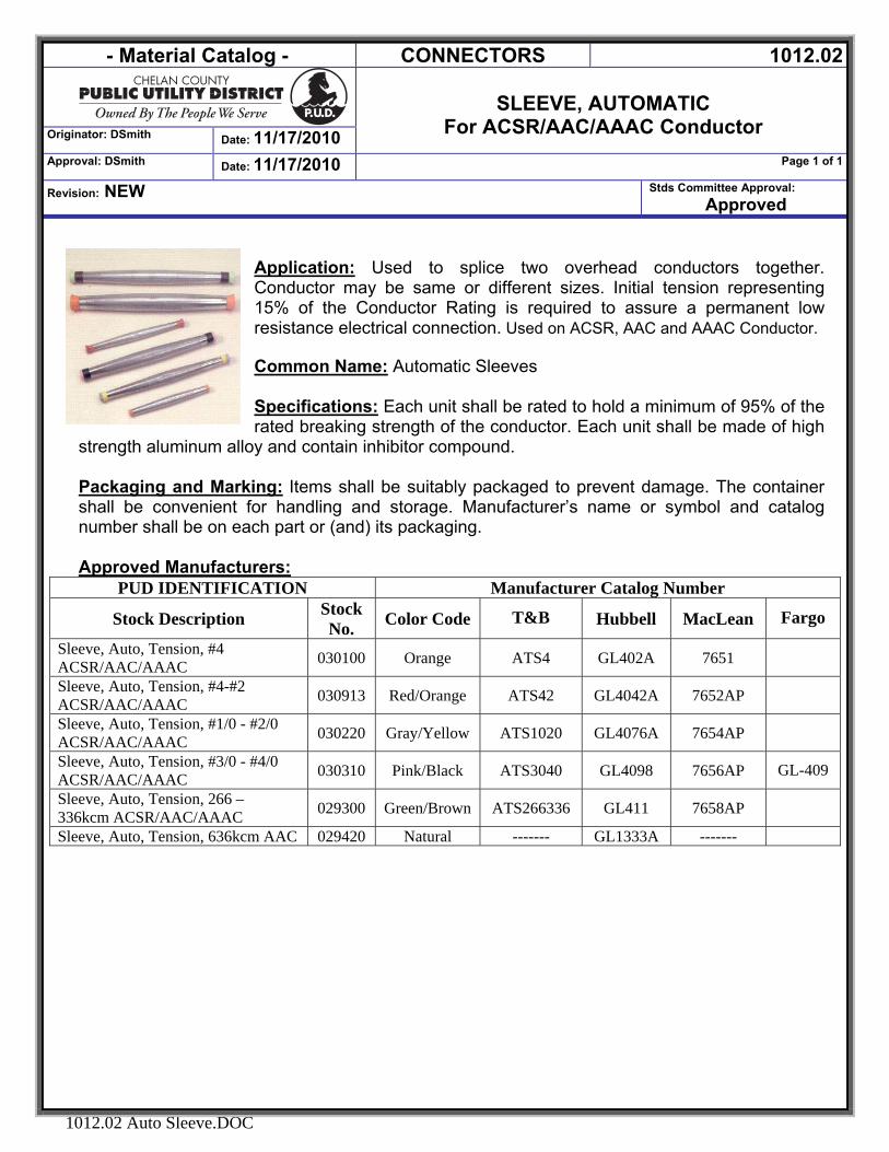
Application: Used to splice two overhead conductors together. Conductor may be same or different sizes. Initial tension representing 15% of the Conductor Rating is required to assure a permanent low resistance electrical connection. Used on ACSR, AAC and AAAC Conductor. Common Name: Automatic Sleeves Specifications: Each unit shall be rated to hold a minimum of 95% of the rated breaking strength of the conductor. Each unit shall be made of high
strength aluminum alloy and contain inhibitor compound.
Packaging and Marking: Items shall be suitably packaged to prevent damage. The container shall be convenient for handling and storage. Manufacturer’s name or symbol and catalog number shall be on each part or (and) its packaging. Approved Manufacturers:
PUD IDENTIFICATION Manufacturer Catalog Number
Stock Description Stock No. Color Code T&B Hubbell MacLean Fargo
Sleeve, Auto, Tension, #4 ACSR/AAC/AAAC 030100 Orange ATS4 GL402A 7651
Sleeve, Auto, Tension, #4-#2 ACSR/AAC/AAAC 030913 Red/Orange ATS42 GL4042A 7652AP
Sleeve, Auto, Tension, #1/0 - #2/0 ACSR/AAC/AAAC 030220 Gray/Yellow ATS1020 GL4076A 7654AP
Sleeve, Auto, Tension, #3/0 - #4/0 ACSR/AAC/AAAC 030310 Pink/Black ATS3040 GL4098 7656AP GL-409
Sleeve, Auto, Tension, 266 – 336kcm ACSR/AAC/AAAC 029300 Green/Brown ATS266336 GL411 7658AP
Sleeve, Auto, Tension, 636kcm AAC 029420 Natural ------- GL1333A -------
- Material Catalog - CONNECTORS 1012.04
STRANDVISE
Originator: Jeff Flader Date: 1/25/2012
Approval: Jeff Mitchell Date: 1/25/2012 Page 1 of 1
Revision: NEW Stds Committee Approval:
Strandvise.docx
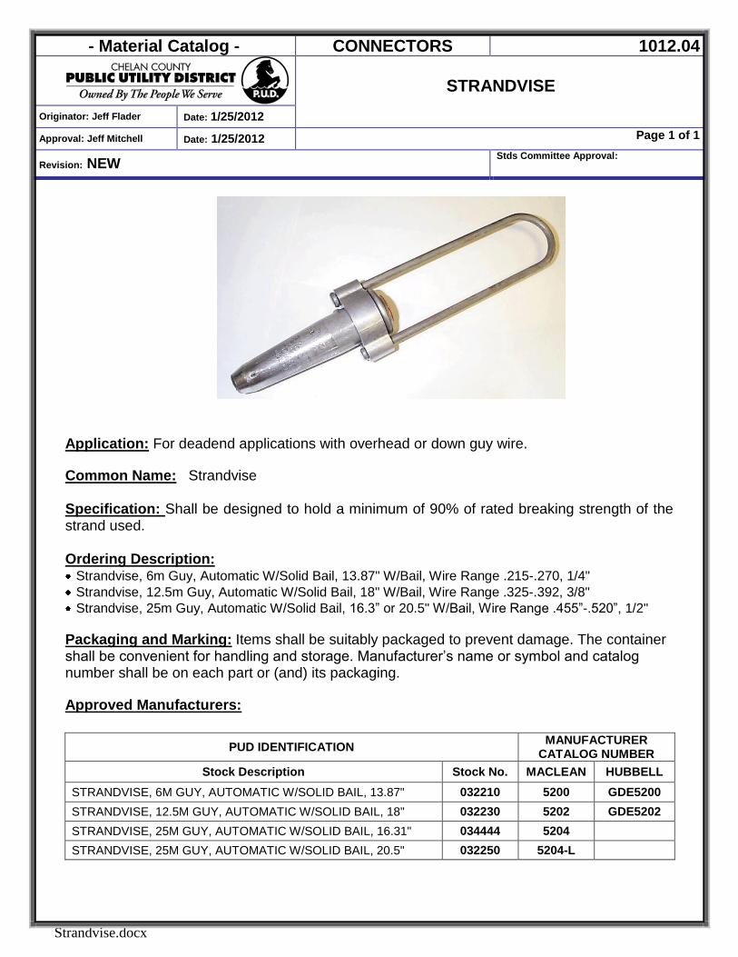
Application: For deadend applications with overhead or down guy wire. Common Name: Strandvise
Specification: Shall be designed to hold a minimum of 90% of rated breaking strength of the strand used. Ordering Description: Strandvise, 6m Guy, Automatic W/Solid Bail, 13.87" W/Bail, Wire Range .215-.270, 1/4" Strandvise, 12.5m Guy, Automatic W/Solid Bail, 18" W/Bail, Wire Range .325-.392, 3/8" Strandvise, 25m Guy, Automatic W/Solid Bail, 16.3” or 20.5" W/Bail, Wire Range .455”-.520”, 1/2"
Packaging and Marking: Items shall be suitably packaged to prevent damage. The container shall be convenient for handling and storage. Manufacturer’s name or symbol and catalog number shall be on each part or (and) its packaging. Approved Manufacturers:
PUD IDENTIFICATION MANUFACTURER CATALOG NUMBER
Stock Description Stock No. MACLEAN HUBBELL STRANDVISE, 6M GUY, AUTOMATIC W/SOLID BAIL, 13.87" 032210 5200 GDE5200 STRANDVISE, 12.5M GUY, AUTOMATIC W/SOLID BAIL, 18" 032230 5202 GDE5202 STRANDVISE, 25M GUY, AUTOMATIC W/SOLID BAIL, 16.31" 034444 5204 STRANDVISE, 25M GUY, AUTOMATIC W/SOLID BAIL, 20.5" 032250 5204-L
- Material Catalog - CONNECTORS 1012.05
STRANDLINK
Originator: DSmith Date: 7/7/06
Approval: J Mitchell Date: 1/25/20121/25/2012
Page 1 of 1
Revision: Updated Description Stds Committee Approval: Approved
1012.05 Strandlink.DOC
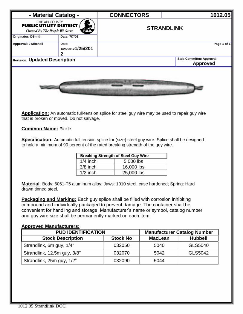
Application: An automatic full-tension splice for steel guy wire may be used to repair guy wire that is broken or moved. Do not salvage. Common Name: Pickle Specification: Automatic full tension splice for (size) steel guy wire. Splice shall be designed to hold a minimum of 90 percent of the rated breaking strength of the guy wire.
Breaking Strength of Steel Guy Wire 1/4 inch 5,000 lbs 3/8 inch 16,000 lbs 1/2 inch 25,000 lbs
Material: Body: 6061-T6 aluminum alloy; Jaws: 1010 steel, case hardened; Spring: Hard drawn tinned steel. Packaging and Marking: Each guy splice shall be filled with corrosion inhibiting compound and individually packaged to prevent damage. The container shall be convenient for handling and storage. Manufacturer’s name or symbol, catalog number and guy wire size shall be permanently marked on each item.
Approved Manufacturers:
PUD IDENTIFICATION Manufacturer Catalog Number Stock Description Stock No MacLean Hubbell
Strandlink, 6m guy, 1/4" 032050 5040 GLS5040 Strandlink, 12.5m guy, 3/8" 032070 5042 GLS5042 Strandlink, 25m guy, 1/2” 032090 5044
- Material Catalog - CONNECTORS 1014.07
Originator: DSmith Date: 7/7/06
CONNECTOR, BOLTED STATION BUS, STUD
NEMA 4 HOLE PAD Approval: DSmith Date: 6/27/2007 Page 1 of 1
Revision: NEW Stds Committee Approval: Approved
1014.07 Bolted Station Bus Stud.DOC
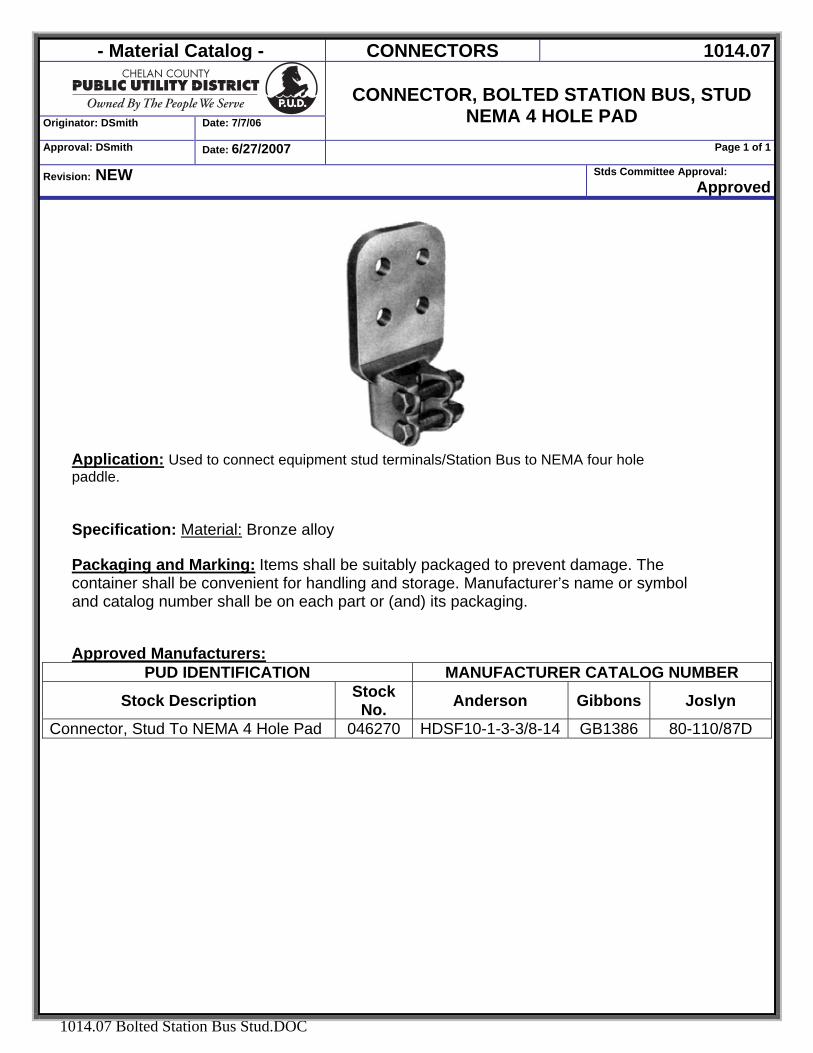
Application: Used to connect equipment stud terminals/Station Bus to NEMA four hole paddle.
Specification: Material: Bronze alloy Packaging and Marking: Items shall be suitably packaged to prevent damage. The container shall be convenient for handling and storage. Manufacturer’s name or symbol and catalog number shall be on each part or (and) its packaging. Approved Manufacturers:
PUD IDENTIFICATION MANUFACTURER CATALOG NUMBER
Stock Description Stock No. Anderson Gibbons Joslyn
Connector, Stud To NEMA 4 Hole Pad 046270 HDSF10-1-3-3/8-14 GB1386 80-110/87D
- Material Catalog - CONNECTORS 1016.01
Originator: DSmith Date:5/10/2005
Connections, Ground - Exothermic
Approval: DSmith Date: 7/9/2007 Page 1 of 1
Revision: Added Figure Identifier Stds Committee Approval: 5/14/05
1016.01 Connector, Ground, Exothermic.DOC
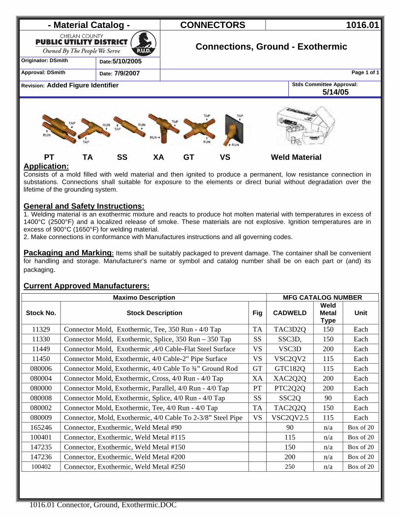
PT TA SS XA GT VS Weld Material
Application: Consists of a mold filled with weld material and then ignited to produce a permanent, low resistance connection in substations. Connections shall suitable for exposure to the elements or direct burial without degradation over the lifetime of the grounding system.
General and Safety Instructions: 1. Welding material is an exothermic mixture and reacts to produce hot molten material with temperatures in excess of 1400°C (2500°F) and a localized release of smoke. These materials are not explosive. Ignition temperatures are in excess of 900°C (1650°F) for welding material. 2. Make connections in conformance with Manufactures instructions and all governing codes.
Packaging and Marking: Items shall be suitably packaged to prevent damage. The container shall be convenient for handling and storage. Manufacturer’s name or symbol and catalog number shall be on each part or (and) its packaging.
Current Approved Manufacturers:
Maximo Description MFG CATALOG NUMBER
Stock No. Stock Description Fig CADWELD Weld Metal Type
Unit
11329 Connector Mold, Exothermic, Tee, 350 Run - 4/0 Tap TA TAC3D2Q 150 Each 11330 Connector Mold, Exothermic, Splice, 350 Run – 350 Tap SS SSC3D, 150 Each 11449 Connector Mold, Exothermic ,4/0 Cable-Flat Steel Surface VS VSC3D 200 Each 11450 Connector Mold, Exothermic, 4/0 Cable-2" Pipe Surface VS VSC2QV2 115 Each
080006 Connector Mold, Exothermic, 4/0 Cable To ¾” Ground Rod GT GTC182Q 115 Each 080004 Connector Mold, Exothermic, Cross, 4/0 Run - 4/0 Tap XA XAC2Q2Q 200 Each 080000 Connector Mold, Exothermic, Parallel, 4/0 Run - 4/0 Tap PT PTC2Q2Q 200 Each 080008 Connector Mold, Exothermic, Splice, 4/0 Run - 4/0 Tap SS SSC2Q 90 Each 080002 Connector Mold, Exothermic, Tee, 4/0 Run - 4/0 Tap TA TAC2Q2Q 150 Each 080009 Connector, Mold, Exothermic, 4/0 Cable To 2-3/8” Steel Pipe VS VSC2QV2.5 115 Each 165246 Connector, Exothermic, Weld Metal #90 90 n/a Box of 20 100401 Connector, Exothermic, Weld Metal #115 115 n/a Box of 20 147235 Connector, Exothermic, Weld Metal #150 150 n/a Box of 20 147236 Connector, Exothermic, Weld Metal #200 200 n/a Box of 20 100402 Connector, Exothermic, Weld Metal #250 250 n/a Box of 20
- Material Catalog - CONNECTORS 1019
Originator: DSmith Date:7/11/2007
CONNECTORS Underground
Approval: DSmith Date: 7/11/2007 Page 1 of 1
Revision: NEW Stds Committee Approval: Approved
1019 CONNECTORS UG.DOC
CONNECTORS Underground
- Material Catalog - HARDWARE, LINE 1019.01
Terminations, UG 15kV Cable,
COLD SHRINK Originator: DSmith Date: 7/2/2007
Approval: DSmith Date: 10/8/2008 Page 1 of 1
Revision: Changed 9” to 6” stinger Stds Committee Approval: Approved
1019.01 Terminations, UG 15kV Cable, Cold Shrink.DOC
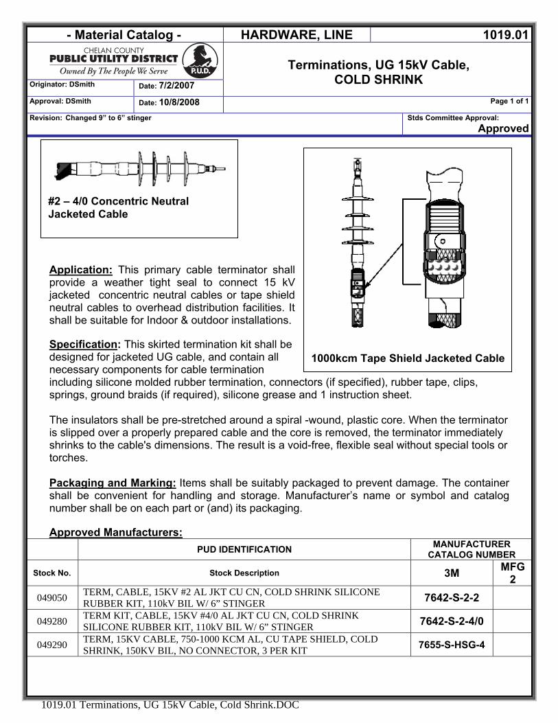
#2 – 4/0 Concentric Neutral Jacketed Cable
1000kcm Tape Shield Jacketed Cable
Application: This primary cable terminator shall provide a weather tight seal to connect 15 kV jacketed concentric neutral cables or tape shield neutral cables to overhead distribution facilities. It shall be suitable for Indoor & outdoor installations. Specification: This skirted termination kit shall be designed for jacketed UG cable, and contain all necessary components for cable termination including silicone molded rubber termination, connectors (if specified), rubber tape, clips, springs, ground braids (if required), silicone grease and 1 instruction sheet. The insulators shall be pre-stretched around a spiral -wound, plastic core. When the terminator is slipped over a properly prepared cable and the core is removed, the terminator immediately shrinks to the cable's dimensions. The result is a void-free, flexible seal without special tools or torches. Packaging and Marking: Items shall be suitably packaged to prevent damage. The container shall be convenient for handling and storage. Manufacturer’s name or symbol and catalog number shall be on each part or (and) its packaging. Approved Manufacturers: PUD IDENTIFICATION MANUFACTURER
CATALOG NUMBER
Stock No. Stock Description 3M MFG 2
049050 TERM, CABLE, 15KV #2 AL JKT CU CN, COLD SHRINK SILICONE RUBBER KIT, 110kV BIL W/ 6” STINGER 7642-S-2-2
049280 TERM KIT, CABLE, 15KV #4/0 AL JKT CU CN, COLD SHRINK SILICONE RUBBER KIT, 110kV BIL W/ 6” STINGER 7642-S-2-4/0
049290 TERM, 15KV CABLE, 750-1000 KCM AL, CU TAPE SHIELD, COLD SHRINK, 150KV BIL, NO CONNECTOR, 3 PER KIT 7655-S-HSG-4
- Material Catalog - CONNECTORS 1019.02
SLEEVES/SPLICES, UG 15Kv CABLE
Originator: DSmith Date: 7/7/06
Approval: DSmith Date: 8/7/2008 Page 1 of 1
Revision: Moved 600V splices to 1019.11 Stds Committee Approval: Approved
1019.02 UG Sleeves And Splices, 15kV.DOC
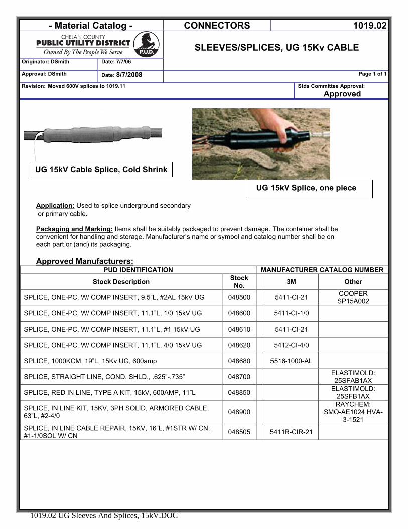
Application: Used to splice underground secondary or primary cable. Packaging and Marking: Items shall be suitably packaged to prevent damage. The container shall be convenient for handling and storage. Manufacturer’s name or symbol and catalog number shall be on each part or (and) its packaging. Approved Manufacturers:
PUD IDENTIFICATION MANUFACTURER CATALOG NUMBER
Stock Description Stock No. 3M Other
SPLICE, ONE-PC. W/ COMP INSERT, 9.5”L, #2AL 15kV UG 048500 5411-CI-21 COOPER SP15A002
SPLICE, ONE-PC. W/ COMP INSERT, 11.1”L, 1/0 15kV UG 048600 5411-CI-1/0
SPLICE, ONE-PC. W/ COMP INSERT, 11.1”L, #1 15kV UG 048610 5411-CI-21
SPLICE, ONE-PC. W/ COMP INSERT, 11.1”L, 4/0 15kV UG 048620 5412-CI-4/0
SPLICE, 1000KCM, 19”L, 15Kv UG, 600amp 048680 5516-1000-AL
SPLICE, STRAIGHT LINE, COND. SHLD., .625”-.735” 048700 ELASTIMOLD: 25SFAB1AX
SPLICE, RED IN LINE, TYPE A KIT, 15kV, 600AMP, 11”L 048850 ELASTIMOLD: 25SFB1AX
SPLICE, IN LINE KIT, 15KV, 3PH SOLID, ARMORED CABLE, 63”L, #2-4/0 048900
RAYCHEM: SMO-AE1024 HVA-
3-1521 SPLICE, IN LINE CABLE REPAIR, 15KV, 16”L, #1STR W/ CN, #1-1/0SOL W/ CN 048505 5411R-CIR-21
UG 15kV Cable Splice, Cold Shrink
UG 15kV Splice, one piece
- Material Catalog - CONNECTORS 1019.03
Originator: DSmith Date: 7/25/2006
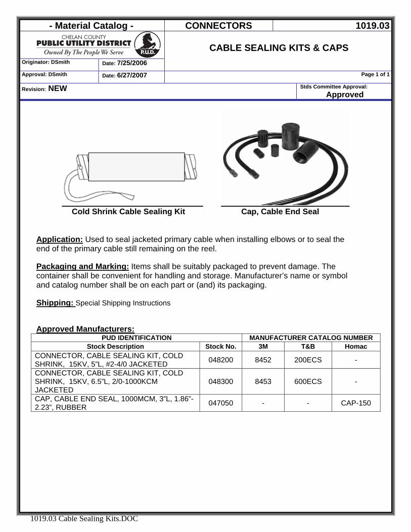
CABLE SEALING KITS & CAPS
Approval: DSmith Date: 6/27/2007 Page 1 of 1
Revision: NEW Stds Committee Approval: Approved
1019.03 Cable Sealing Kits.DOC
Cold Shrink Cable Sealing Kit Cap, Cable End Seal
Application: Used to seal jacketed primary cable when installing elbows or to seal the end of the primary cable still remaining on the reel. Packaging and Marking: Items shall be suitably packaged to prevent damage. The container shall be convenient for handling and storage. Manufacturer’s name or symbol and catalog number shall be on each part or (and) its packaging. Shipping: Special Shipping Instructions Approved Manufacturers:
PUD IDENTIFICATION MANUFACTURER CATALOG NUMBER Stock Description Stock No. 3M T&B Homac
CONNECTOR, CABLE SEALING KIT, COLD SHRINK, 15KV, 5”L, #2-4/0 JACKETED 048200 8452 200ECS -
CONNECTOR, CABLE SEALING KIT, COLD SHRINK, 15KV, 6.5”L, 2/0-1000KCM JACKETED
048300 8453 600ECS -
CAP, CABLE END SEAL, 1000MCM, 3”L, 1.86”-2.23”, RUBBER 047050 - - CAP-150
- Material Catalog - Connectors - Cable 1019.04
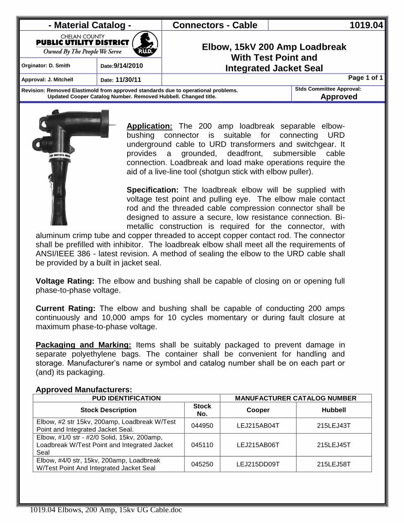
Elbow, 15kV 200 Amp Loadbreak
With Test Point and Integrated Jacket Seal Orginator: D. Smith Date:9/14/2010
Approval: J. Mitchell Date: 11/30/11 Page 1 of 1
Revision: Removed Elastimold from approved standards due to operational problems. Updated Cooper Catalog Number. Removed Hubbell. Changed title.
Stds Committee Approval: Approved
1019.04 Elbows, 200 Amp, 15kv UG Cable.doc
Application: The 200 amp loadbreak separable elbow-bushing connector is suitable for connecting URD underground cable to URD transformers and switchgear. It provides a grounded, deadfront, submersible cable connection. Loadbreak and load make operations require the aid of a live-line tool (shotgun stick with elbow puller). Specification: The loadbreak elbow will be supplied with voltage test point and pulling eye. The elbow male contact rod and the threaded cable compression connector shall be designed to assure a secure, low resistance connection. Bi-metallic construction is required for the connector, with
aluminum crimp tube and copper threaded to accept copper contact rod. The connector shall be prefilled with inhibitor. The loadbreak elbow shall meet all the requirements of ANSI/IEEE 386 - latest revision. A method of sealing the elbow to the URD cable shall be provided by a built in jacket seal. Voltage Rating: The elbow and bushing shall be capable of closing on or opening full phase-to-phase voltage. Current Rating: The elbow and bushing shall be capable of conducting 200 amps continuously and 10,000 amps for 10 cycles momentary or during fault closure at maximum phase-to-phase voltage. Packaging and Marking: Items shall be suitably packaged to prevent damage in separate polyethylene bags. The container shall be convenient for handling and storage. Manufacturer’s name or symbol and catalog number shall be on each part or (and) its packaging. Approved Manufacturers:
PUD IDENTIFICATION MANUFACTURER CATALOG NUMBER
Stock Description Stock No. Cooper Hubbell
Elbow, #2 str 15kv, 200amp, Loadbreak W/Test Point and Integrated Jacket Seal. 044950 LEJ215AB04T 215LEJ43T
Elbow, #1/0 str - #2/0 Solid, 15kv, 200amp, Loadbreak W/Test Point and Integrated Jacket Seal
045110 LEJ215AB06T 215LEJ45T
Elbow, #4/0 str, 15kv, 200amp, Loadbreak W/Test Point And Integrated Jacket Seal 045250 LEJ215DD09T 215LEJ58T
- Material Catalog - CONNECTORS - UG 1019.05
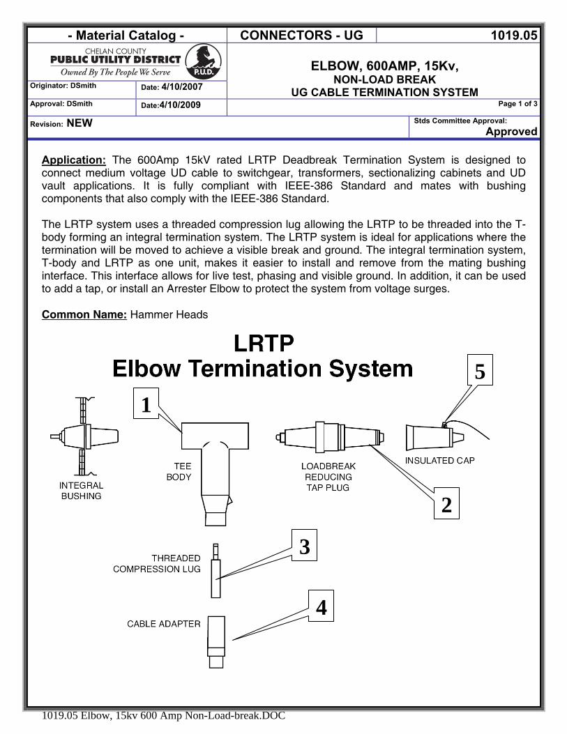
ELBOW, 600AMP, 15Kv,
NON-LOAD BREAK UG CABLE TERMINATION SYSTEM
Originator: DSmith Date: 4/10/2007
Approval: DSmith Date:4/10/2009 Page 1 of 3
Revision: NEW Stds Committee Approval: Approved
1019.05 Elbow, 15kv 600 Amp Non-Load-break.DOC
Application: The 600Amp 15kV rated LRTP Deadbreak Termination System is designed to connect medium voltage UD cable to switchgear, transformers, sectionalizing cabinets and UD vault applications. It is fully compliant with IEEE-386 Standard and mates with bushing components that also comply with the IEEE-386 Standard. The LRTP system uses a threaded compression lug allowing the LRTP to be threaded into the T-body forming an integral termination system. The LRTP system is ideal for applications where the termination will be moved to achieve a visible break and ground. The integral termination system, T-body and LRTP as one unit, makes it easier to install and remove from the mating bushing interface. This interface allows for live test, phasing and visible ground. In addition, it can be used to add a tap, or install an Arrester Elbow to protect the system from voltage surges. Common Name: Hammer Heads
4
3
1
2
5

- Material Catalog - CONNECTORS - UG 1019.05
ELBOW, 600AMP, 15Kv,
NON-LOAD BREAK UG CABLE TERMINATION SYSTEM
Originator: DSmith Date: 4/10/2007
Approval: DSmith Date:4/10/2009 Page 2 of 3
Revision: NEW Stds Committee Approval: Approved
1019.05 Elbow, 15kv 600 Amp Non-Load-break.DOC
Item # Application
1
T-Body - The Deadbreak Elbow is designed to terminate power cables with copper or aluminum conductors ranging in sizes from #2 AWG to 1250MCM. It may be installed on any 600 amp rated (aluminum) or 900 amp rated (copper) deadbreak apparatus bushing that meets IEEE Standard 386 latest revision for Separable Insulated Connectors.
2 LRTP - The 600/900 amp LRTP is designed to tap a 200 amp loadbreak interface device to an existing 600/900 amp deadbreak using a bolted connection. A common application is for grounding and isolating 600/900 amp systems. The LRTP is fault-close rated to 10,000 amps and complies with IEEE 386.
3 Connector Compression, Copper Top Threaded This is a bimetal compression connector that is thread with a 15/16 hole.
4 Cable Adapters accommodate power cable insulation diameters from 0.530 to 1.935 inches
5 Insulating Protective Cap - The insulating cap isolates unused 600 amp interfaces.
6 Connecting Plug is required exclusively for applications involving the joining or connecting of two or more molded 600 elbows. Wrench holes are provided to tighten the Connecting Plug into a 600 or 900 amp Deadbreak Elbow by using a standard spanner wrench.
7 Basic Insulating Plug with Cap - The Basic Insulating Plug is required to secure the molded rubber 600 amp elbow in place.
8 The Torque Tool is required to check the torque of a 15 kV Class T-OP II deadbreak connector or bushing adapter when it is installed on a 600 A bushing interface. It is precision calibrated and shotgun stick operable.
9 T-WRENCH, The T-Wrench is used to install the Loadbreak Reducing Tap Plug into the Bushing Extender.
10 SHIELD ADAPTERS/SEALING AND GROUNDING KIT Used for cold shrink sealing and grounding tape shielded cables.
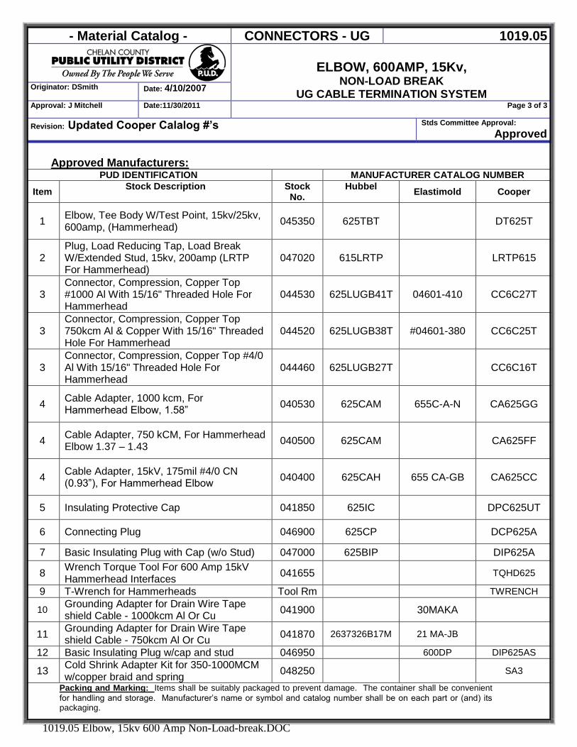
- Material Catalog - CONNECTORS - UG 1019.05
ELBOW, 600AMP, 15Kv,
NON-LOAD BREAK UG CABLE TERMINATION SYSTEM
Originator: DSmith Date: 4/10/2007
Approval: J Mitchell Date:11/30/2011 Page 3 of 3
Revision: Updated Cooper Calalog #’s Stds Committee Approval: Approved
1019.05 Elbow, 15kv 600 Amp Non-Load-break.DOC
Approved Manufacturers: PUD IDENTIFICATION MANUFACTURER CATALOG NUMBER
Item Stock Description Stock No.
Hubbel Elastimold Cooper
1 Elbow, Tee Body W/Test Point, 15kv/25kv, 600amp, (Hammerhead) 045350 625TBT DT625T
2 Plug, Load Reducing Tap, Load Break W/Extended Stud, 15kv, 200amp (LRTP For Hammerhead)
047020 615LRTP LRTP615
3 Connector, Compression, Copper Top #1000 Al With 15/16" Threaded Hole For Hammerhead
044530 625LUGB41T 04601-410 CC6C27T
3 Connector, Compression, Copper Top 750kcm Al & Copper With 15/16" Threaded Hole For Hammerhead
044520 625LUGB38T #04601-380 CC6C25T
3 Connector, Compression, Copper Top #4/0 Al With 15/16" Threaded Hole For Hammerhead
044460 625LUGB27T CC6C16T
4 Cable Adapter, 1000 kcm, For Hammerhead Elbow, 1.58” 040530 625CAM 655C-A-N CA625GG
4 Cable Adapter, 750 kCM, For Hammerhead Elbow 1.37 – 1.43 040500 625CAM CA625FF
4 Cable Adapter, 15kV, 175mil #4/0 CN (0.93”), For Hammerhead Elbow 040400 625CAH 655 CA-GB CA625CC
5 Insulating Protective Cap 041850 625IC DPC625UT
6 Connecting Plug 046900 625CP DCP625A
7 Basic Insulating Plug with Cap (w/o Stud) 047000 625BIP DIP625A
8 Wrench Torque Tool For 600 Amp 15kV Hammerhead Interfaces 041655 TQHD625
9 T-Wrench for Hammerheads Tool Rm TWRENCH
10 Grounding Adapter for Drain Wire Tape shield Cable - 1000kcm Al Or Cu 041900 30MAKA
11 Grounding Adapter for Drain Wire Tape shield Cable - 750kcm Al Or Cu 041870 2637326B17M 21 MA-JB
12 Basic Insulating Plug w/cap and stud 046950 600DP DIP625AS
13 Cold Shrink Adapter Kit for 350-1000MCM w/copper braid and spring 048250 SA3
Packing and Marking: Items shall be suitably packaged to prevent damage. The container shall be convenient for handling and storage. Manufacturer’s name or symbol and catalog number shall be on each part or (and) its packaging.
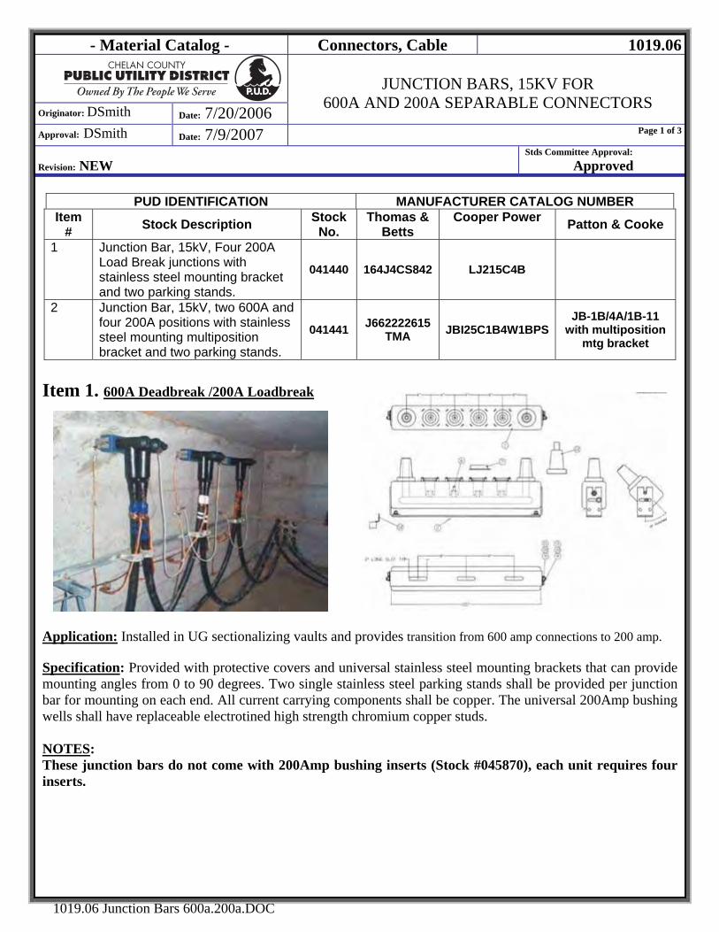
- Material Catalog - Connectors, Cable 1019.06
Originator: DSmith Date: 7/20/2006
JUNCTION BARS, 15KV FOR
600A AND 200A SEPARABLE CONNECTORS
Approval: DSmith Date: 7/9/2007 Page 1 of 3
Revision: NEW
Stds Committee Approval: Approved
1019.06 Junction Bars 600a.200a.DOC
PUD IDENTIFICATION MANUFACTURER CATALOG NUMBER Item
# Stock Description Stock No.
Thomas & Betts
Cooper Power Patton & Cooke
1 Junction Bar, 15kV, Four 200A Load Break junctions with stainless steel mounting bracket and two parking stands.
041440 164J4CS842 LJ215C4B
2 Junction Bar, 15kV, two 600A and four 200A positions with stainless steel mounting multiposition bracket and two parking stands.
041441 J662222615TMA JBI25C1B4W1BPS
JB-1B/4A/1B-11 with multiposition
mtg bracket
Item 1. 600A Deadbreak /200A Loadbreak
Application: Installed in UG sectionalizing vaults and provides transition from 600 amp connections to 200 amp.
Specification: Provided with protective covers and universal stainless steel mounting brackets that can provide mounting angles from 0 to 90 degrees. Two single stainless steel parking stands shall be provided per junction bar for mounting on each end. All current carrying components shall be copper. The universal 200Amp bushing wells shall have replaceable electrotined high strength chromium copper studs. NOTES: These junction bars do not come with 200Amp bushing inserts (Stock #045870), each unit requires four inserts.

- Material Catalog - Connectors, Cable 1019.06
Originator: DSmith Date: 7/20/2006
JUNCTION BARS, 15KV FOR
600A AND 200A SEPARABLE CONNECTORS
Approval: DSmith Date: 7/9/2007 Page 2 of 3
Revision: NEW
Stds Committee Approval: Approved
1019.06 Junction Bars 600a.200a.DOC
Item 2. 200A Load Break
Application: Installed in sectionalizing vaults and cabinets to terminate 200 Amp 15kV UG cable. Specification: Multiposition junction bar with 200A bushings. Each unit is provided with protective covers and universal stainless steel mounting brackets that can provide mounting angles from 0 to 90 degrees. All current carrying components shall be copper. Two single stainless steel parking stands shall be provided per junction bar and are mounting on each end. Two drain wire clamps shall be provided. Each shall accommodate two wires up to 1/0 stranded (3/8" diameter). Each bushing shall include a bright yellow latch indicator ring, located on the circumference of the interface collar for determining if the elbow is properly installed.
3. GENERAL:
Class 200 Amp 600 Amp Operating Voltage (Max continuous line-to ground, 100% insulation system) 8.3kv 8.3kv
BIL 95 BIL 125 BIL Current @ 90oC Continuous Operating Temperature 200 Amp 600 Amp Current – Short-Time 10kA sym. 10 cycles 25kA sym. 10 cycles
Applicable Standards: All separable connectors shall be designed and manufactured to ANSI/IEEE Standard 386 and tested in accordance with IEEE #48. Packaging and Marking: Items shall be suitably packaged to prevent damage. The container shall be convenient for handling and storage. Manufacturer’s name or symbol and catalog number shall be on each part or (and) its packaging.
Note: District requires four junctions:
- Material Catalog - Connectors, Cable 1019.06
Originator: DSmith Date: 7/20/2006
JUNCTION BARS, 15KV FOR
600A AND 200A SEPARABLE CONNECTORS
Approval: DSmith Date: 7/9/2007 Page 3 of 3
Revision: NEW
Stds Committee Approval: Approved
1019.06 Junction Bars 600a.200a.DOC
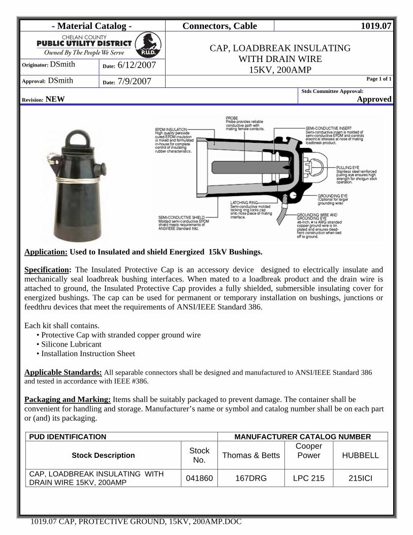
- Material Catalog - Connectors, Cable 1019.07
Originator: DSmith Date: 6/12/2007
CAP, LOADBREAK INSULATING
WITH DRAIN WIRE 15KV, 200AMP
Approval: DSmith Date: 7/9/2007 Page 1 of 1
Revision: NEW
Stds Committee Approval: Approved
1019.07 CAP, PROTECTIVE GROUND, 15KV, 200AMP.DOC
Application: Used to Insulated and shield Energized 15kV Bushings.
Specification: The Insulated Protective Cap is an accessory device designed to electrically insulate and mechanically seal loadbreak bushing interfaces. When mated to a loadbreak product and the drain wire is attached to ground, the Insulated Protective Cap provides a fully shielded, submersible insulating cover for energized bushings. The cap can be used for permanent or temporary installation on bushings, junctions or feedthru devices that meet the requirements of ANSI/IEEE Standard 386. Each kit shall contains. • Protective Cap with stranded copper ground wire • Silicone Lubricant • Installation Instruction Sheet Applicable Standards: All separable connectors shall be designed and manufactured to ANSI/IEEE Standard 386 and tested in accordance with IEEE #386. Packaging and Marking: Items shall be suitably packaged to prevent damage. The container shall be convenient for handling and storage. Manufacturer’s name or symbol and catalog number shall be on each part or (and) its packaging.
PUD IDENTIFICATION MANUFACTURER CATALOG NUMBER
Stock Description Stock No. Thomas & Betts
Cooper Power
HUBBELL
CAP, LOADBREAK INSULATING WITH DRAIN WIRE 15KV, 200AMP 041860 167DRG LPC 215 215ICI

- Material Catalog - CONNECTORS 1019.08
Originator: DSmith Date: 10/16/2007
CONNECTOR, BAR, SLIP FIT
FOR PADMOUNT TRANSFORMER
Approval: DSmith Date: 1/4/2008 Page 1 of 1
Revision: NEW SHEET – MOVED ITEMS FROM 1010.27 Stds Committee Approval: Approved
1019.08 CONNECTOR, BAR, SLIP FIT.DOC
Application: Used for providing multiple set screw terminations for padmounted transformers. Designed to slip on the transformer stud and then tightened with two set screws which facilitate changing out the transformer without having to remove all secondary services. Specification:
• Dual-rated connectors for aluminum or copper conductors
• Clear plated for low-contact resistance. • Fully tested to ANSI C119.4 for Class ‘A’ connectors. • Supplied with radial-tipped set-screws. • Connector fabricated from 6061-T6 aluminum alloy for conductivity and strength. • Includes Oxide Inhibitor grease.
Packaging and Marking: Items shall be suitably packaged to prevent damage. The container shall be convenient for handling and storage. Manufacturer’s name or symbol and catalog number shall be on each part or (and) its packaging. Approved Manufacturers:
PUD IDENTIFICATION MANUFACTURER CATALOG NUMBER Item No. Item Description CMC UTILCO HOMAC T&B
040140 CONNECTOR, BAR, AL, 4 POS., #12-350 AAC/CU 5/8”-11 SLIP FIT NSSM 350-4I PTF4350J CSW4350 TSB4359D58
040160 CONNECTOR, BAR, AL, 6 POS., #12-350 AAC/CU 5/8”-11 SLIP FIT NSSM 350-6I PTF6350J CSW6350 TSB6359D58
040165 CONNECTOR, BAR, AL, 6 POS., #2-500 AAC/CU 5/8”-11 SLIP FIT NSSM 500-6IA NONE CSW6500-58 TSB6559D58
040170 CONNECTOR, BAR, AL, 6 POS., #2-500 AAC/CU 1”-14 SLIP FIT NSSM 500-6I PTF6500J CSW 6500 TSB6559D51
A
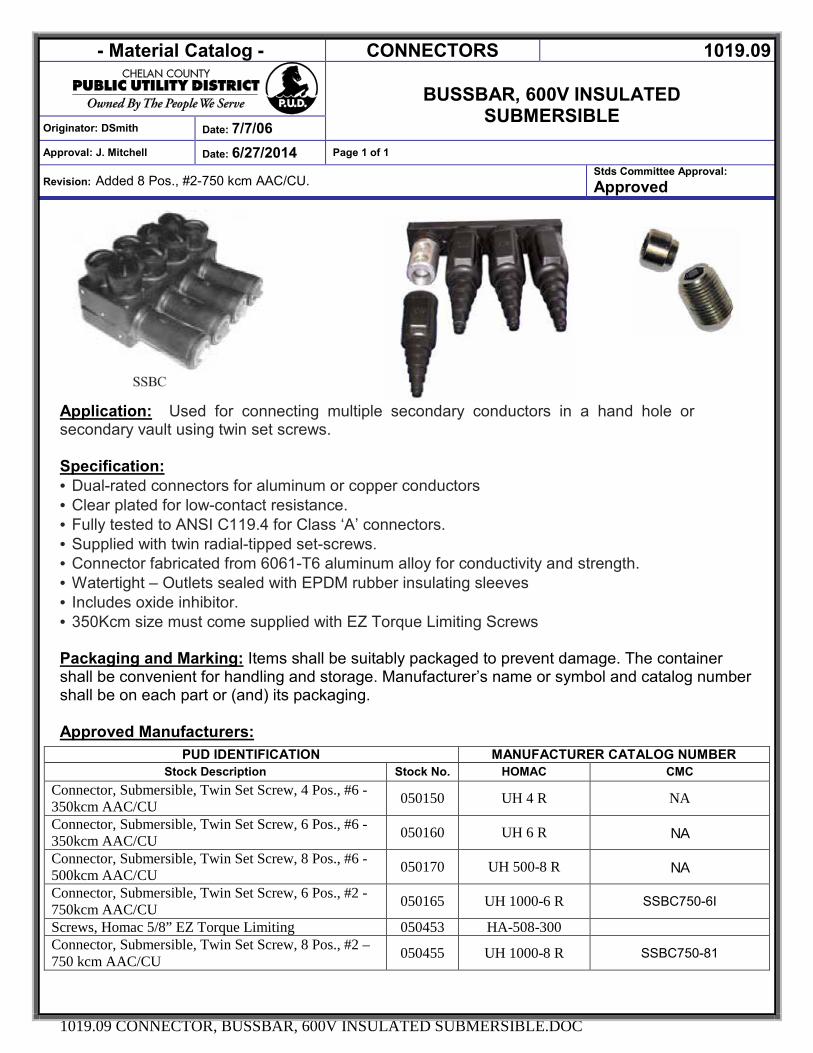
- Material Catalog - CONNECTORS 1019.09
BUSSBAR, 600V INSULATED
SUBMERSIBLE Originator: DSmith Date: 7/7/06
Approval: J. Mitchell Date: 6/27/2014 Page 1 of 1
Revision: Added 8 Pos., #2-750 kcm AAC/CU. Stds Committee Approval: Approved
1019.09 CONNECTOR, BUSSBAR, 600V INSULATED SUBMERSIBLE.DOC
Application: Used for connecting multiple secondary conductors in a hand hole or secondary vault using twin set screws.
Specification: · Dual-rated connectors for aluminum or copper conductors · Clear plated for low-contact resistance. · Fully tested to ANSI C119.4 for Class ‘A’ connectors. · Supplied with twin radial-tipped set-screws. · Connector fabricated from 6061-T6 aluminum alloy for conductivity and strength. · Watertight – Outlets sealed with EPDM rubber insulating sleeves · Includes oxide inhibitor. · 350Kcm size must come supplied with EZ Torque Limiting Screws
Packaging and Marking: Items shall be suitably packaged to prevent damage. The container shall be convenient for handling and storage. Manufacturer’s name or symbol and catalog number shall be on each part or (and) its packaging.
Approved Manufacturers:
PUD IDENTIFICATION MANUFACTURER CATALOG NUMBER Stock Description Stock No. HOMAC CMC
Connector, Submersible, Twin Set Screw, 4 Pos., #6 - 350kcm AAC/CU 050150 UH 4 R NA
Connector, Submersible, Twin Set Screw, 6 Pos., #6 - 350kcm AAC/CU 050160 UH 6 R NA
Connector, Submersible, Twin Set Screw, 8 Pos., #6 - 500kcm AAC/CU 050170 UH 500-8 R NA
Connector, Submersible, Twin Set Screw, 6 Pos., #2 - 750kcm AAC/CU 050165 UH 1000-6 R SSBC750-6I
Screws, Homac 5/8” EZ Torque Limiting 050453 HA-508-300 Connector, Submersible, Twin Set Screw, 8 Pos., #2 – 750 kcm AAC/CU 050455 UH 1000-8 R SSBC750-81
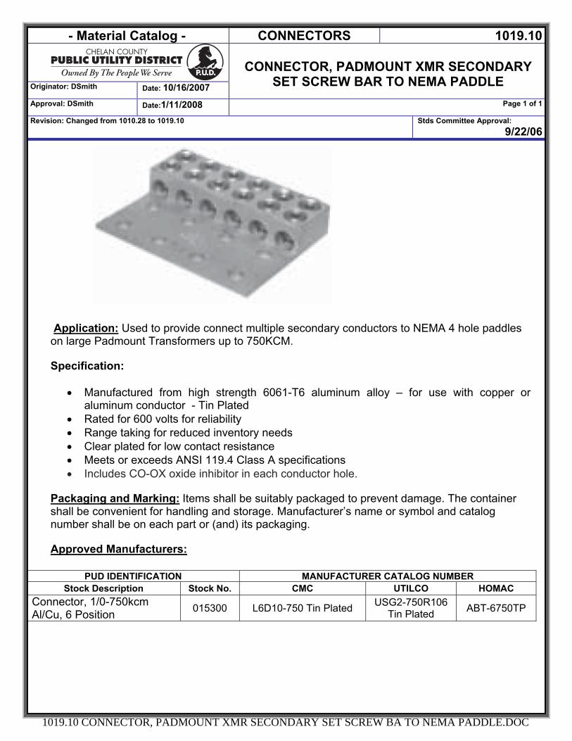
- Material Catalog - CONNECTORS 1019.10
Originator: DSmith Date: 10/16/2007
CONNECTOR, PADMOUNT XMR SECONDARY
SET SCREW BAR TO NEMA PADDLE Approval: DSmith Date:1/11/2008 Page 1 of 1
Revision: Changed from 1010.28 to 1019.10 Stds Committee Approval: 9/22/06
1019.10 CONNECTOR, PADMOUNT XMR SECONDARY SET SCREW BA TO NEMA PADDLE.DOC
Application: Used to provide connect multiple secondary conductors to NEMA 4 hole paddles on large Padmount Transformers up to 750KCM. Specification:
• Manufactured from high strength 6061-T6 aluminum alloy – for use with copper or aluminum conductor - Tin Plated
• Rated for 600 volts for reliability • Range taking for reduced inventory needs • Clear plated for low contact resistance • Meets or exceeds ANSI 119.4 Class A specifications • Includes CO-OX oxide inhibitor in each conductor hole.
Packaging and Marking: Items shall be suitably packaged to prevent damage. The container shall be convenient for handling and storage. Manufacturer’s name or symbol and catalog number shall be on each part or (and) its packaging. Approved Manufacturers:
PUD IDENTIFICATION MANUFACTURER CATALOG NUMBER Stock Description Stock No. CMC UTILCO HOMAC
Connector, 1/0-750kcm Al/Cu, 6 Position 015300 L6D10-750 Tin Plated USG2-750R106
Tin Plated ABT-6750TP
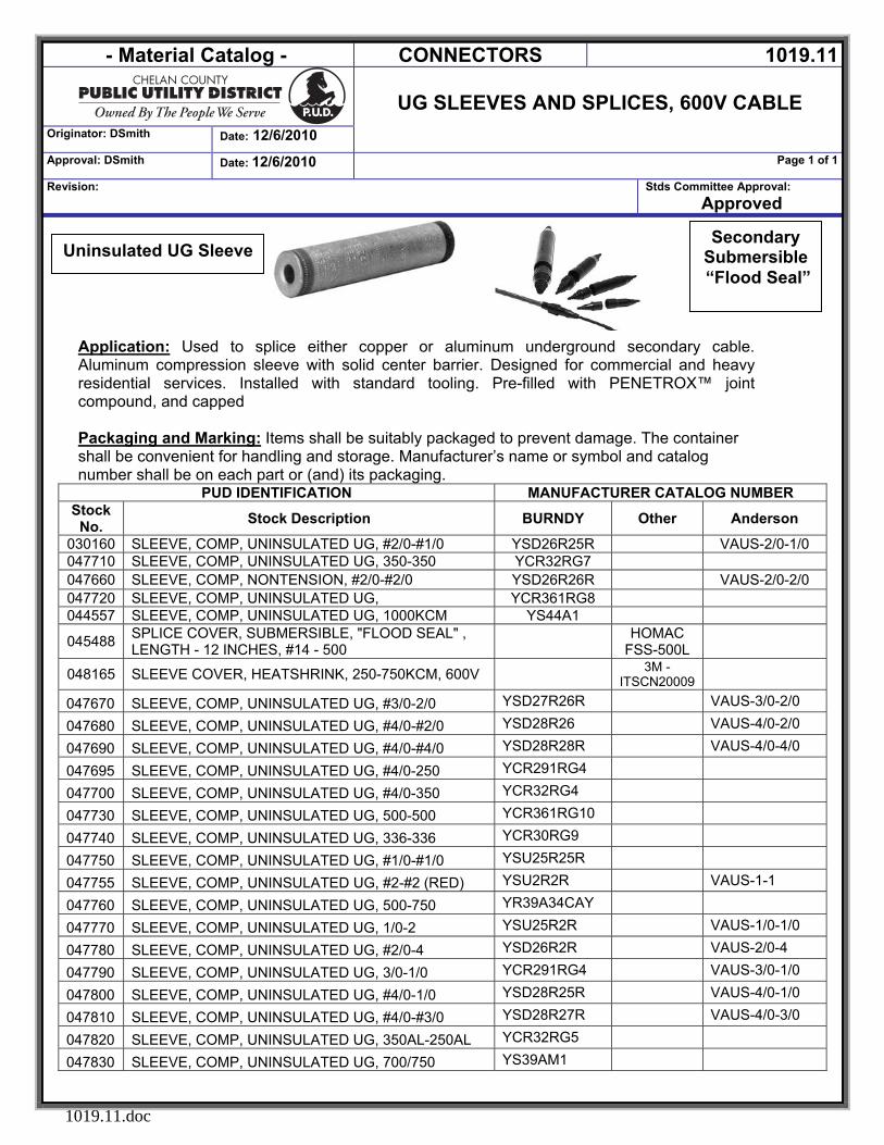
- Material Catalog - CONNECTORS 1019.11
UG SLEEVES AND SPLICES, 600V CABLE
Originator: DSmith Date: 12/6/2010 Approval: DSmith Date: 12/6/2010 Page 1 of 1
Revision: Stds Committee Approval: Approved
1019.11.doc
Application: Used to splice either copper or aluminum underground secondary cable. Aluminum compression sleeve with solid center barrier. Designed for commercial and heavy residential services. Installed with standard tooling. Pre-filled with PENETROX™ joint compound, and capped Packaging and Marking: Items shall be suitably packaged to prevent damage. The container shall be convenient for handling and storage. Manufacturer’s name or symbol and catalog number shall be on each part or (and) its packaging.
PUD IDENTIFICATION MANUFACTURER CATALOG NUMBER Stock
No. Stock Description BURNDY Other Anderson
030160 SLEEVE, COMP, UNINSULATED UG, #2/0-#1/0 YSD26R25R VAUS-2/0-1/0 047710 SLEEVE, COMP, UNINSULATED UG, 350-350 YCR32RG7 047660 SLEEVE, COMP, NONTENSION, #2/0-#2/0 YSD26R26R VAUS-2/0-2/0 047720 SLEEVE, COMP, UNINSULATED UG, YCR361RG8 044557 SLEEVE, COMP, UNINSULATED UG, 1000KCM YS44A1
045488 SPLICE COVER, SUBMERSIBLE, "FLOOD SEAL" , LENGTH - 12 INCHES, #14 - 500 HOMAC
FSS-500L
048165 SLEEVE COVER, HEATSHRINK, 250-750KCM, 600V 3M -ITSCN20009
047670 SLEEVE, COMP, UNINSULATED UG, #3/0-2/0 YSD27R26R VAUS-3/0-2/0
047680 SLEEVE, COMP, UNINSULATED UG, #4/0-#2/0 YSD28R26 VAUS-4/0-2/0
047690 SLEEVE, COMP, UNINSULATED UG, #4/0-#4/0 YSD28R28R VAUS-4/0-4/0
047695 SLEEVE, COMP, UNINSULATED UG, #4/0-250 YCR291RG4
047700 SLEEVE, COMP, UNINSULATED UG, #4/0-350 YCR32RG4
047730 SLEEVE, COMP, UNINSULATED UG, 500-500 YCR361RG10
047740 SLEEVE, COMP, UNINSULATED UG, 336-336 YCR30RG9
047750 SLEEVE, COMP, UNINSULATED UG, #1/0-#1/0 YSU25R25R
047755 SLEEVE, COMP, UNINSULATED UG, #2-#2 (RED) YSU2R2R VAUS-1-1
047760 SLEEVE, COMP, UNINSULATED UG, 500-750 YR39A34CAY
047770 SLEEVE, COMP, UNINSULATED UG, 1/0-2 YSU25R2R VAUS-1/0-1/0
047780 SLEEVE, COMP, UNINSULATED UG, #2/0-4 YSD26R2R VAUS-2/0-4
047790 SLEEVE, COMP, UNINSULATED UG, 3/0-1/0 YCR291RG4 VAUS-3/0-1/0
047800 SLEEVE, COMP, UNINSULATED UG, #4/0-1/0 YSD28R25R VAUS-4/0-1/0
047810 SLEEVE, COMP, UNINSULATED UG, #4/0-#3/0 YSD28R27R VAUS-4/0-3/0
047820 SLEEVE, COMP, UNINSULATED UG, 350AL-250AL YCR32RG5
047830 SLEEVE, COMP, UNINSULATED UG, 700/750 YS39AM1
Secondary Submersible “Flood Seal”
Uninsulated UG Sleeve
- Material Catalog - LINE EQUIPMENT 1200
Originator: DSmith Date:7/9/2007
LINE EQUIPMENT
Approval: DSmith Date: 7/9/2007 Page 1 of 1
Revision: NEW Stds Committee Approval: Approved
1200 LINE EQUIPMENT.DOC
SECTION 1200 LINE EQUIPMENT
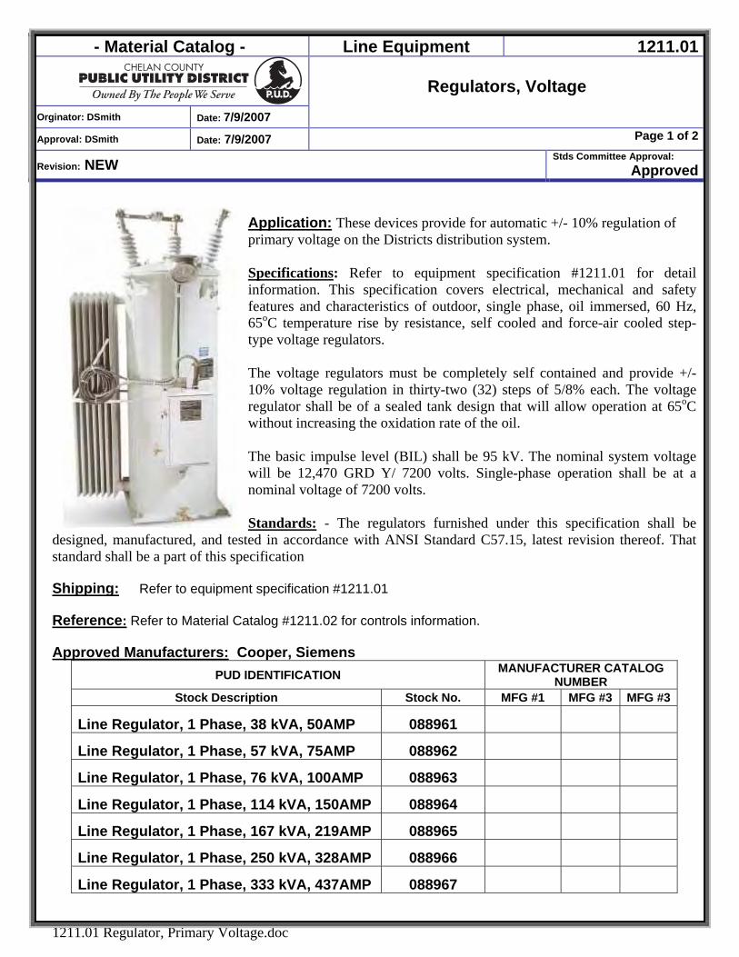
- Material Catalog - Line Equipment 1211.01
Orginator: DSmith Date: 7/9/2007
Regulators, Voltage
Approval: DSmith Date: 7/9/2007 Page 1 of 2
Revision: NEW Stds Committee Approval:
Approved
1211.01 Regulator, Primary Voltage.doc
Application: These devices provide for automatic +/- 10% regulation of primary voltage on the Districts distribution system. Specifications: Refer to equipment specification #1211.01 for detail information. This specification covers electrical, mechanical and safety features and characteristics of outdoor, single phase, oil immersed, 60 Hz, 65oC temperature rise by resistance, self cooled and force-air cooled step-type voltage regulators. The voltage regulators must be completely self contained and provide +/- 10% voltage regulation in thirty-two (32) steps of 5/8% each. The voltage regulator shall be of a sealed tank design that will allow operation at 65oC without increasing the oxidation rate of the oil. The basic impulse level (BIL) shall be 95 kV. The nominal system voltage will be 12,470 GRD Y/ 7200 volts. Single-phase operation shall be at a nominal voltage of 7200 volts. Standards: - The regulators furnished under this specification shall be
designed, manufactured, and tested in accordance with ANSI Standard C57.15, latest revision thereof. That standard shall be a part of this specification Shipping: Refer to equipment specification #1211.01 Reference: Refer to Material Catalog #1211.02 for controls information. Approved Manufacturers: Cooper, Siemens
PUD IDENTIFICATION MANUFACTURER CATALOG NUMBER
Stock Description Stock No. MFG #1 MFG #3 MFG #3
Line Regulator, 1 Phase, 38 kVA, 50AMP 088961
Line Regulator, 1 Phase, 57 kVA, 75AMP 088962
Line Regulator, 1 Phase, 76 kVA, 100AMP 088963
Line Regulator, 1 Phase, 114 kVA, 150AMP 088964
Line Regulator, 1 Phase, 167 kVA, 219AMP 088965
Line Regulator, 1 Phase, 250 kVA, 328AMP 088966
Line Regulator, 1 Phase, 333 kVA, 437AMP 088967
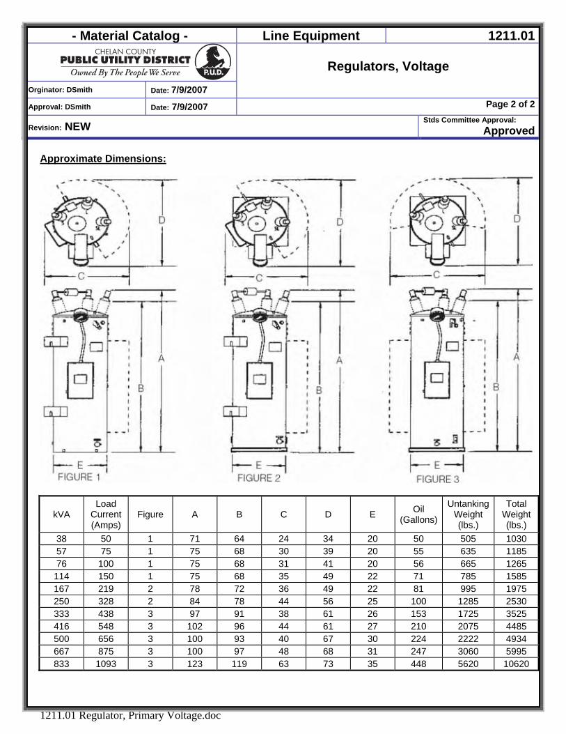
- Material Catalog - Line Equipment 1211.01
Orginator: DSmith Date: 7/9/2007
Regulators, Voltage
Approval: DSmith Date: 7/9/2007 Page 2 of 2
Revision: NEW Stds Committee Approval:
Approved
1211.01 Regulator, Primary Voltage.doc
Approximate Dimensions:
kVA Load
Current (Amps)
Figure A B C D E Oil (Gallons)
Untanking Weight (lbs.)
Total Weight (lbs.)
38 50 1 71 64 24 34 20 50 505 1030 57 75 1 75 68 30 39 20 55 635 1185 76 100 1 75 68 31 41 20 56 665 1265
114 150 1 75 68 35 49 22 71 785 1585 167 219 2 78 72 36 49 22 81 995 1975 250 328 2 84 78 44 56 25 100 1285 2530 333 438 3 97 91 38 61 26 153 1725 3525 416 548 3 102 96 44 61 27 210 2075 4485 500 656 3 100 93 40 67 30 224 2222 4934 667 875 3 100 97 48 68 31 247 3060 5995 833 1093 3 123 119 63 73 35 448 5620 10620
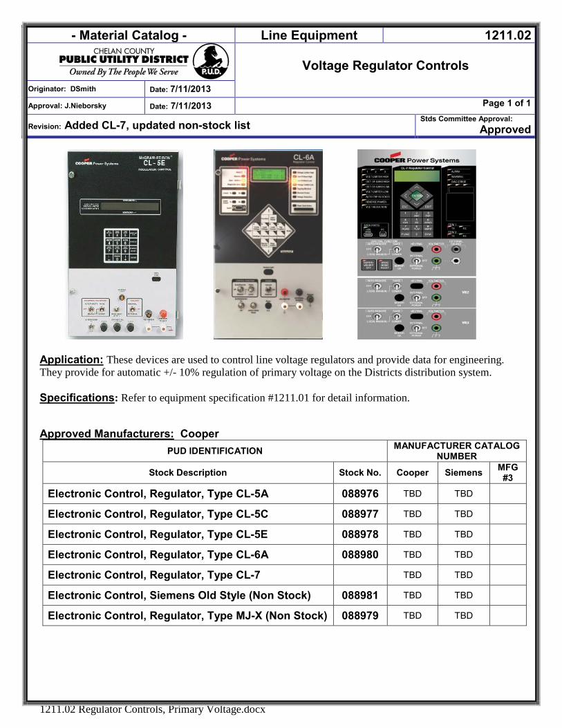
- Material Catalog - Line Equipment 1211.02
Voltage Regulator Controls
Originator: DSmith Date: 7/11/2013
Approval: J.Nieborsky Date: 7/11/2013 Page 1 of 1
Revision: Added CL-7, updated non-stock list Stds Committee Approval:
Approved
1211.02 Regulator Controls, Primary Voltage.docx
Application: These devices are used to control line voltage regulators and provide data for engineering. They provide for automatic +/- 10% regulation of primary voltage on the Districts distribution system. Specifications: Refer to equipment specification #1211.01 for detail information. Approved Manufacturers: Cooper
PUD IDENTIFICATION MANUFACTURER CATALOG NUMBER
Stock Description Stock No. Cooper Siemens MFG #3
Electronic Control, Regulator, Type CL-5A 088976 TBD TBD
Electronic Control, Regulator, Type CL-5C 088977 TBD TBD
Electronic Control, Regulator, Type CL-5E 088978 TBD TBD
Electronic Control, Regulator, Type CL-6A 088980 TBD TBD
Electronic Control, Regulator, Type CL-7 TBD TBD
Electronic Control, Siemens Old Style (Non Stock) 088981 TBD TBD
Electronic Control, Regulator, Type MJ-X (Non Stock) 088979 TBD TBD
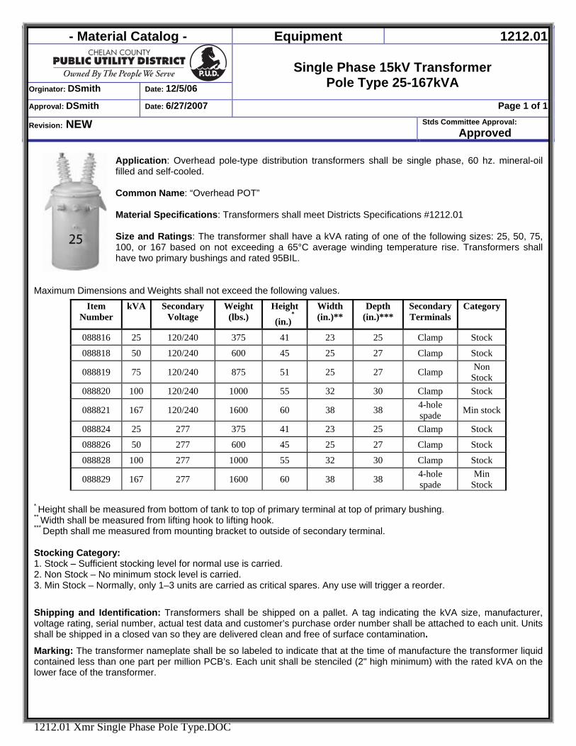
- Material Catalog - Equipment 1212.01
Orginator: DSmith Date: 12/5/06
Single Phase 15kV Transformer
Pole Type 25-167kVA Approval: DSmith Date: 6/27/2007 Page 1 of 1
Revision: NEW Stds Committee Approval: Approved
1212.01 Xmr Single Phase Pole Type.DOC
Application: Overhead pole-type distribution transformers shall be single phase, 60 hz. mineral-oil filled and self-cooled. Common Name: “Overhead POT” Material Specifications: Transformers shall meet Districts Specifications #1212.01 Size and Ratings: The transformer shall have a kVA rating of one of the following sizes: 25, 50, 75, 100, or 167 based on not exceeding a 65°C average winding temperature rise. Transformers shall have two primary bushings and rated 95BIL.
Maximum Dimensions and Weights shall not exceed the following values.
* Height shall be measured from bottom of tank to top of primary terminal at top of primary bushing. ** Width shall be measured from lifting hook to lifting hook. *** Depth shall me measured from mounting bracket to outside of secondary terminal. Stocking Category: 1. Stock – Sufficient stocking level for normal use is carried. 2. Non Stock – No minimum stock level is carried. 3. Min Stock – Normally, only 1–3 units are carried as critical spares. Any use will trigger a reorder.
Shipping and Identification: Transformers shall be shipped on a pallet. A tag indicating the kVA size, manufacturer, voltage rating, serial number, actual test data and customer’s purchase order number shall be attached to each unit. Units shall be shipped in a closed van so they are delivered clean and free of surface contamination.
Marking: The transformer nameplate shall be so labeled to indicate that at the time of manufacture the transformer liquid contained less than one part per million PCB’s. Each unit shall be stenciled (2" high minimum) with the rated kVA on the lower face of the transformer.
Item Number
kVA Secondary Voltage
Weight (lbs.)
Height
(in.)*
Width (in.)**
Depth (in.)***
Secondary Terminals
Category
088816 25 120/240 375 41 23 25 Clamp Stock
088818 50 120/240 600 45 25 27 Clamp Stock
088819 75 120/240 875 51 25 27 Clamp Non Stock
088820 100 120/240 1000 55 32 30 Clamp Stock
088821 167 120/240 1600 60 38 38 4-hole spade Min stock
088824 25 277 375 41 23 25 Clamp Stock
088826 50 277 600 45 25 27 Clamp Stock
088828 100 277 1000 55 32 30 Clamp Stock
088829 167 277 1600 60 38 38 4-hole spade
Min Stock
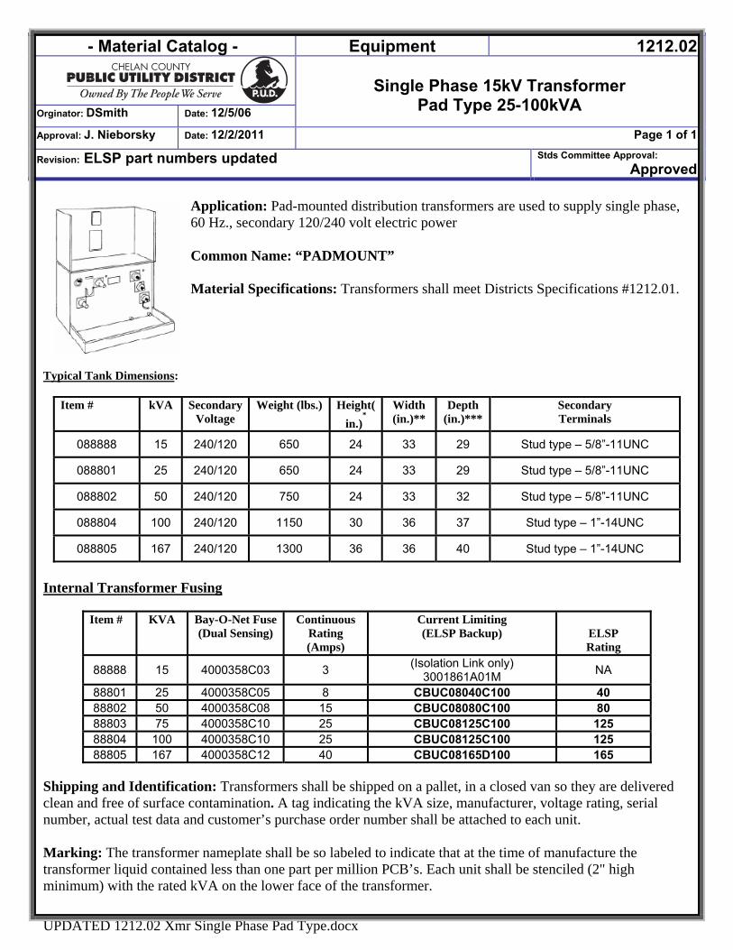
- Material Catalog - Equipment 1212.02
Single Phase 15kV Transformer
Pad Type 25-100kVA Orginator: DSmith Date: 12/5/06
Approval: J. Nieborsky Date: 12/2/2011 Page 1 of 1
Revision: ELSP part numbers updated Stds Committee Approval: Approved
UPDATED 1212.02 Xmr Single Phase Pad Type.docx
Application: Pad-mounted distribution transformers are used to supply single phase, 60 Hz., secondary 120/240 volt electric power Common Name: “PADMOUNT” Material Specifications: Transformers shall meet Districts Specifications #1212.01.
Typical Tank Dimensions:
Item # kVA Secondary Voltage
Weight (lbs.) Height(in.)
*Width (in.)**
Depth (in.)***
Secondary Terminals
088888 15 240/120 650 24 33 29 Stud type – 5/8”-11UNC
088801 25 240/120 650 24 33 29 Stud type – 5/8”-11UNC
088802 50 240/120 750 24 33 32 Stud type – 5/8”-11UNC
088804 100 240/120 1150 30 36 37 Stud type – 1”-14UNC
088805 167 240/120 1300 36 36 40 Stud type – 1”-14UNC
Internal Transformer Fusing Shipping and Identification: Transformers shall be shipped on a pallet, in a closed van so they are delivered clean and free of surface contamination. A tag indicating the kVA size, manufacturer, voltage rating, serial number, actual test data and customer’s purchase order number shall be attached to each unit. Marking: The transformer nameplate shall be so labeled to indicate that at the time of manufacture the transformer liquid contained less than one part per million PCB’s. Each unit shall be stenciled (2" high minimum) with the rated kVA on the lower face of the transformer.
Item # KVA
Bay-O-Net Fuse (Dual Sensing)
Continuous Rating (Amps)
Current Limiting (ELSP Backup)
ELSP Rating
88888 15 4000358C03 3 (Isolation Link only) 3001861A01M NA
88801 25 4000358C05 8 CBUC08040C100 40 88802 50 4000358C08 15 CBUC08080C100 80 88803 75 4000358C10 25 CBUC08125C100 125 88804 100 4000358C10 25 CBUC08125C100 125 88805 167 4000358C12 40 CBUC08165D100 165
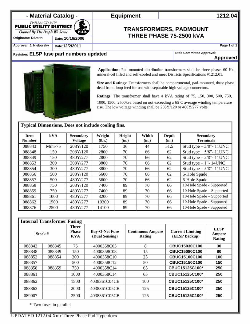
- Material Catalog - Equipment 1212.04
TRANSFORMERS, PADMOUNT
THREE PHASE 75-2500 kVA Originator: DSmith Date: 10/16/2006
Approval: J. Nieborsky Date:12/2/2011 Page 1 of 1
Revision: ELSP fuse part numbers updated Stds Committee Approval: Approved
UPDATED 1212.04 Xmr Three Phase Pad Type.docx
Application: Pad-mounted distribution transformers shall be three phase, 60 Hz.,
mineral-oil filled and self-cooled and meet Districts Specifications #1212.01.
Size and Ratings: Transformers shall be compartmental, pad-mounted, three phase,
dead front, loop feed for use with separable high voltage connectors.
Ratings: The transformer shall have a kVA rating of 75, 150, 300, 500, 750,
1000, 1500, 2500kva based on not exceeding a 65o
C average winding temperature
rise. The low voltage winding shall be 208Y/120 or 480Y/277 volts.
Typical Dimensions, Does not include cooling fins.
Item
Number
kVA Secondary
Voltage
Weight
(lbs.)
Height
(in.)
Width
(in.)
Depth
(in.)
Secondary
Terminals
088843 Mini-75 208Y/120 1750 36 44 51.5 Stud type – 5/8”- 11UNC
088848 150 208Y/120 2800 70 66 62 Stud type – 5/8”- 11UNC
088849 150 480Y/277 2800 70 66 62 Stud type – 5/8”- 11UNC
088853 300 208Y/277 3800 70 66 62 Stud type – 1”- 14UNC
088854 300 480Y/277 3800 70 66 62 Stud type – 5/8”- 11UNC
088856 500 208Y/120 5600 70 66 62 6-Hole Spade
088857 500 480Y/277 5600 70 66 62 6-Hole Spade
088858 750 208Y/120 7400 89 70 66 10-Hole Spade - Supported
088859 750 480Y/277 7400 89 70 66 10-Hole Spade – Supported
088861 1000 480Y/277 8200 89 70 66 10-Hole Spade – Supported
088862 1500 480Y/277 10300 89 70 66 10-Hole Spade - Supported
088876 2500 480Y/277 14100 89 70 66 10-Hole Spade - Supported
* Two fuses in parallel
Internal Transformer Fusing
Stock #
Three
Phase
KVA
Bay-O-Net Fuse
(Dual Sensing)
Continuous Ampere
Rating
Current Limiting
(ELSP Backup)
ELSP
Ampere
Rating
088843 088845 75 4000358C05 8 CBUC15030C100 30 088848 088849 150 4000358C08 15 CBUC15080C100 80 088853 088854 300 4000358C10 25 CBUC15100C100 100 088857 500 4000358C12 50 CBUC15150D100 150 088858 088859 750 4000358C14 65 CBUC15125C100* 250 088861 1000 4000358C14 65 CBUC15125C100* 250
088862 1500 4038361C04CB 100 CBUC15125C100* 250
088863 2000 4038361C05CB 125 CBUC15125C100* 250
089007 2500 4038361C05CB 125 CBUC15125C100* 250
- Material Catalog - UG MATERIAL 1300
Originator: DSmith Date:1/23/2007
UG MATERIAL
Approval: DSmith Date: 1/23/2007 Page 1 of 1
Revision: NEW Stds Committee Approval: Approved
1300 UG MATERIAL.DOC
UNDERGROUND
MATERIAL
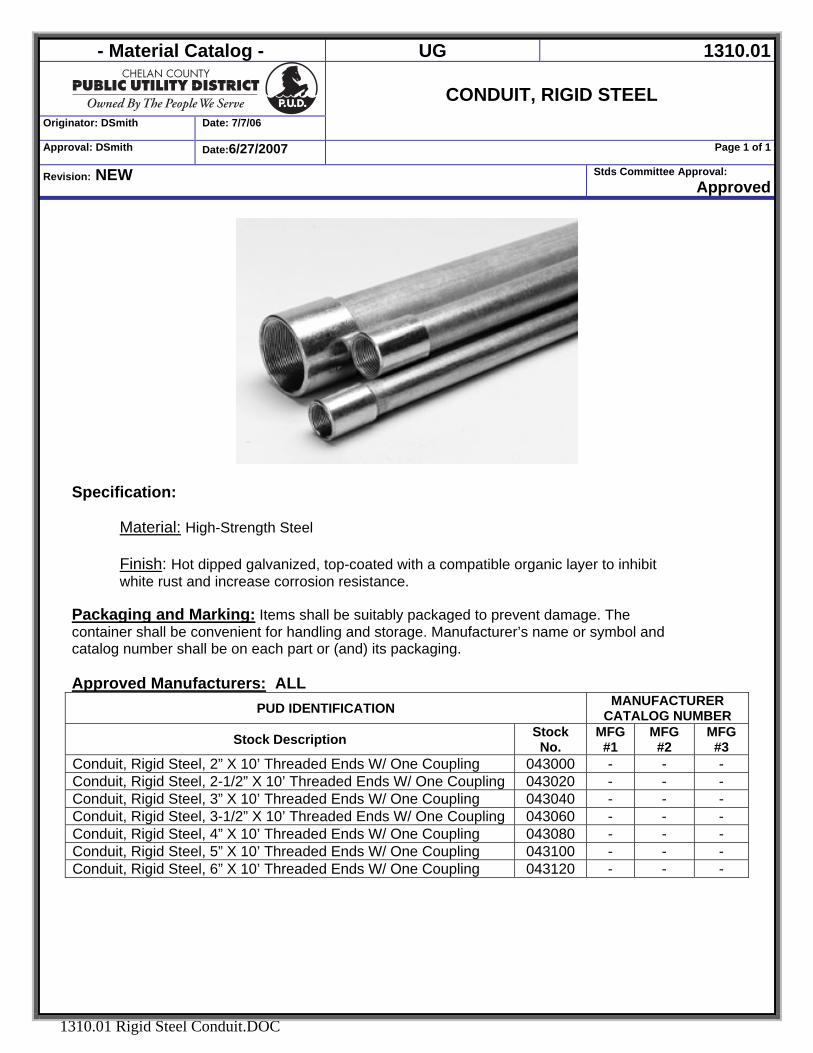
- Material Catalog - UG 1310.01
Originator: DSmith Date: 7/7/06
CONDUIT, RIGID STEEL
Approval: DSmith Date:6/27/2007 Page 1 of 1
Revision: NEW Stds Committee Approval: Approved
1310.01 Rigid Steel Conduit.DOC
Specification:
Material: High-Strength Steel Finish: Hot dipped galvanized, top-coated with a compatible organic layer to inhibit white rust and increase corrosion resistance.
Packaging and Marking: Items shall be suitably packaged to prevent damage. The container shall be convenient for handling and storage. Manufacturer’s name or symbol and catalog number shall be on each part or (and) its packaging. Approved Manufacturers: ALL
PUD IDENTIFICATION MANUFACTURER CATALOG NUMBER
Stock Description Stock No.
MFG #1
MFG #2
MFG #3
Conduit, Rigid Steel, 2” X 10’ Threaded Ends W/ One Coupling 043000 - - - Conduit, Rigid Steel, 2-1/2” X 10’ Threaded Ends W/ One Coupling 043020 - - - Conduit, Rigid Steel, 3” X 10’ Threaded Ends W/ One Coupling 043040 - - - Conduit, Rigid Steel, 3-1/2” X 10’ Threaded Ends W/ One Coupling 043060 - - - Conduit, Rigid Steel, 4” X 10’ Threaded Ends W/ One Coupling 043080 - - - Conduit, Rigid Steel, 5” X 10’ Threaded Ends W/ One Coupling 043100 - - - Conduit, Rigid Steel, 6” X 10’ Threaded Ends W/ One Coupling 043120 - - -
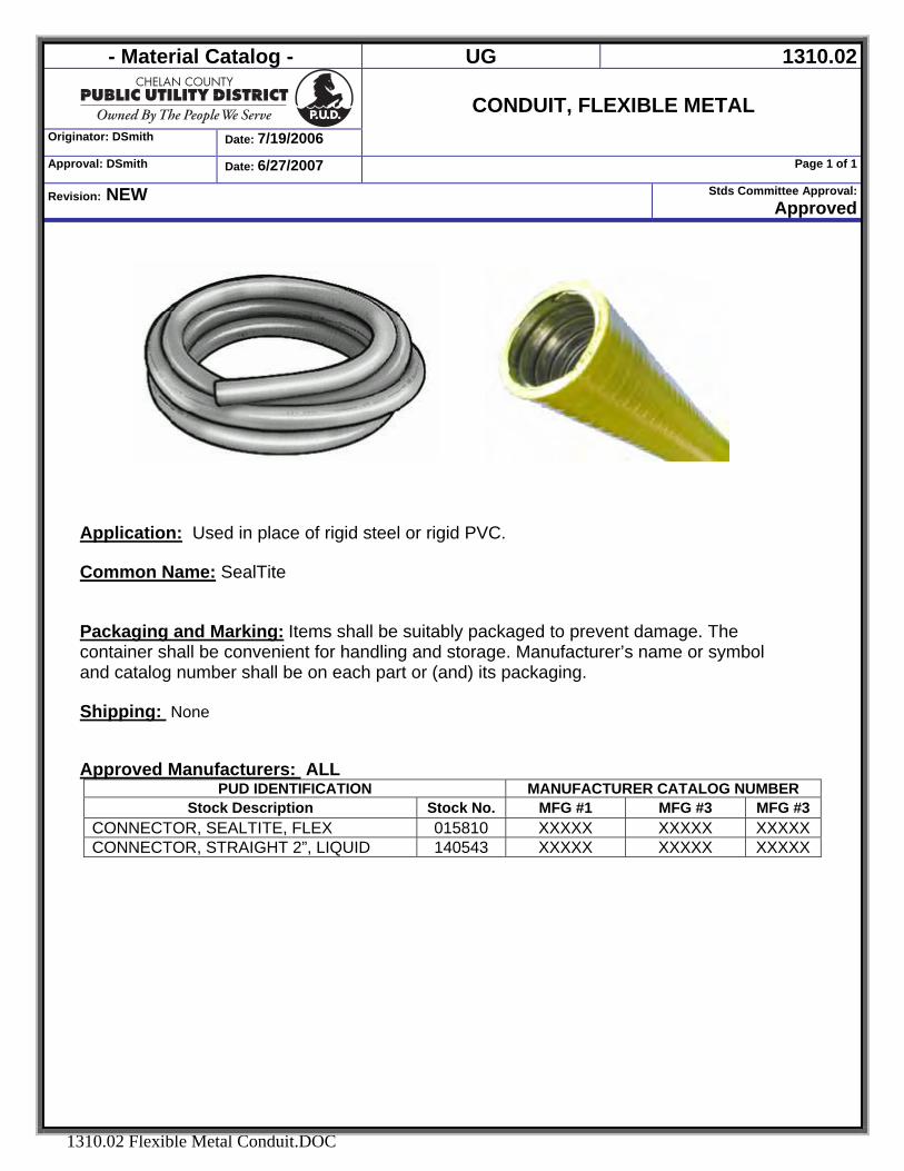
- Material Catalog - UG 1310.02
Originator: DSmith Date: 7/19/2006
CONDUIT, FLEXIBLE METAL
Approval: DSmith Date: 6/27/2007 Page 1 of 1
Revision: NEW Stds Committee Approval:Approved
1310.02 Flexible Metal Conduit.DOC
Application: Used in place of rigid steel or rigid PVC. Common Name: SealTite
Packaging and Marking: Items shall be suitably packaged to prevent damage. The container shall be convenient for handling and storage. Manufacturer’s name or symbol and catalog number shall be on each part or (and) its packaging. Shipping: None Approved Manufacturers: ALL
PUD IDENTIFICATION MANUFACTURER CATALOG NUMBER Stock Description Stock No. MFG #1 MFG #3 MFG #3
CONNECTOR, SEALTITE, FLEX 015810 XXXXX XXXXX XXXXX CONNECTOR, STRAIGHT 2”, LIQUID 140543 XXXXX XXXXX XXXXX
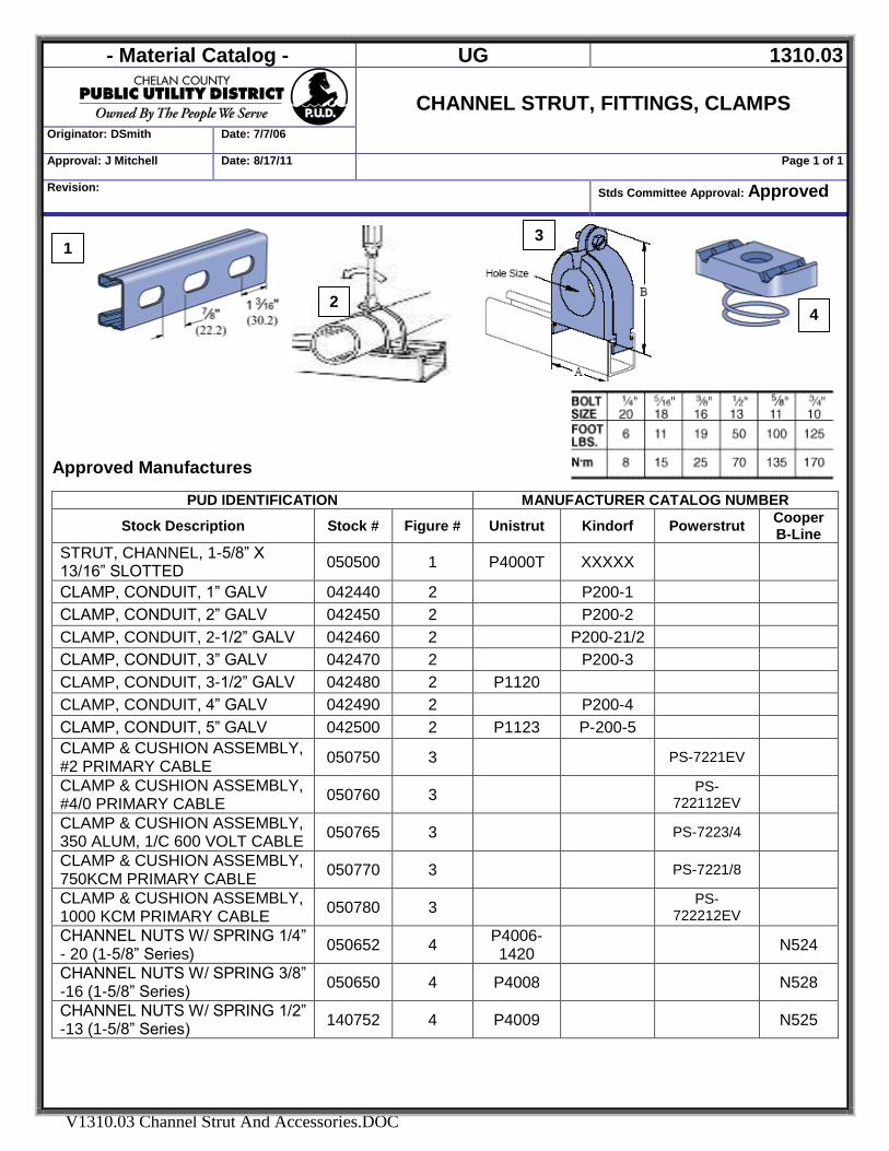
- Material Catalog - UG 1310.03
CHANNEL STRUT, FITTINGS, CLAMPS
Originator: DSmith Date: 7/7/06
Approval: J Mitchell Date: 8/17/11 Page 1 of 1
Revision: Stds Committee Approval: Approved
V1310.03 Channel Strut And Accessories.DOC
2
3
4
1
Approved Manufactures
PUD IDENTIFICATION MANUFACTURER CATALOG NUMBER
Stock Description Stock # Figure # Unistrut Kindorf Powerstrut Cooper B-Line
STRUT, CHANNEL, 1-5/8” X 13/16” SLOTTED 050500 1 P4000T XXXXX
CLAMP, CONDUIT, 1” GALV 042440 2 P200-1 CLAMP, CONDUIT, 2” GALV 042450 2 P200-2 CLAMP, CONDUIT, 2-1/2” GALV 042460 2 P200-21/2 CLAMP, CONDUIT, 3” GALV 042470 2 P200-3 CLAMP, CONDUIT, 3-1/2” GALV 042480 2 P1120 CLAMP, CONDUIT, 4” GALV 042490 2 P200-4 CLAMP, CONDUIT, 5” GALV 042500 2 P1123 P-200-5 CLAMP & CUSHION ASSEMBLY, #2 PRIMARY CABLE 050750 3 PS-7221EV
CLAMP & CUSHION ASSEMBLY, #4/0 PRIMARY CABLE 050760 3 PS-
722112EV
CLAMP & CUSHION ASSEMBLY, 350 ALUM, 1/C 600 VOLT CABLE 050765 3 PS-7223/4
CLAMP & CUSHION ASSEMBLY, 750KCM PRIMARY CABLE 050770 3 PS-7221/8
CLAMP & CUSHION ASSEMBLY, 1000 KCM PRIMARY CABLE 050780 3 PS-
722212EV
CHANNEL NUTS W/ SPRING 1/4” - 20 (1-5/8” Series) 050652 4 P4006-
1420 N524
CHANNEL NUTS W/ SPRING 3/8” -16 (1-5/8” Series) 050650 4 P4008 N528
CHANNEL NUTS W/ SPRING 1/2” -13 (1-5/8” Series) 140752 4 P4009 N525
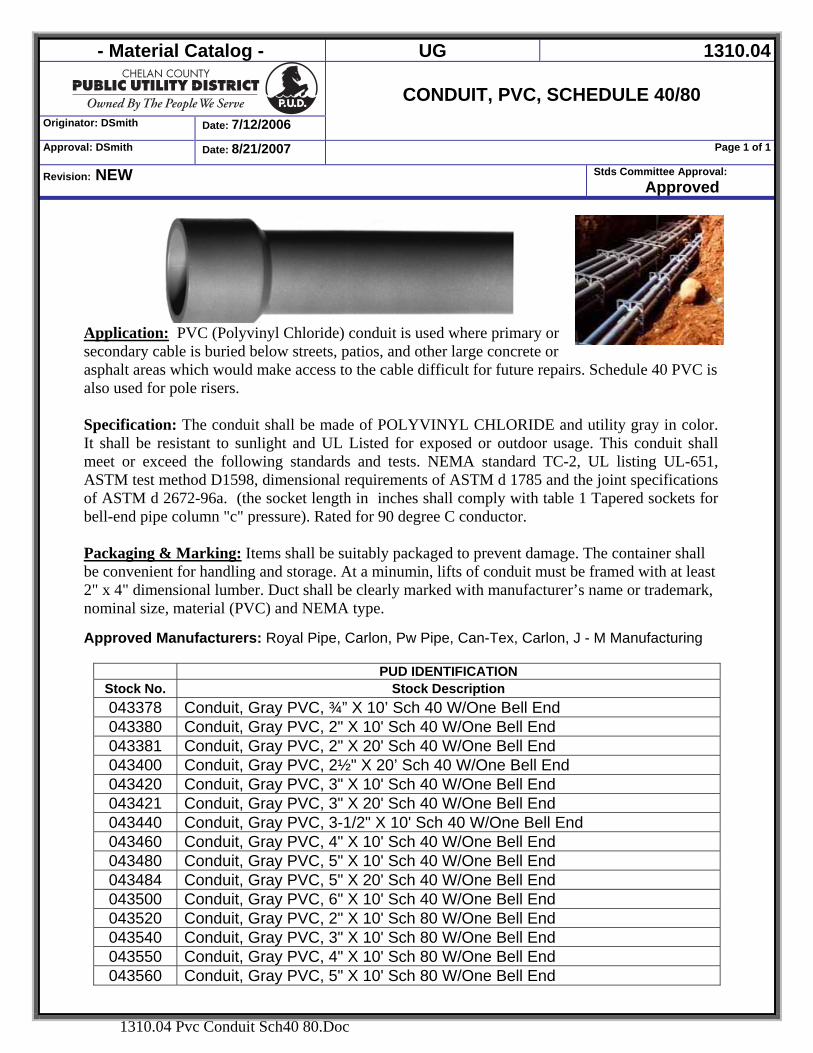
- Material Catalog - UG 1310.04
Originator: DSmith Date: 7/12/2006
CONDUIT, PVC, SCHEDULE 40/80
Approval: DSmith Date: 8/21/2007 Page 1 of 1
Revision: NEW Stds Committee Approval: Approved
1310.04 Pvc Conduit Sch40 80.Doc
Application: PVC (Polyvinyl Chloride) conduit is used where primary or secondary cable is buried below streets, patios, and other large concrete or asphalt areas which would make access to the cable difficult for future repairs. Schedule 40 PVC is also used for pole risers. Specification: The conduit shall be made of POLYVINYL CHLORIDE and utility gray in color. It shall be resistant to sunlight and UL Listed for exposed or outdoor usage. This conduit shall meet or exceed the following standards and tests. NEMA standard TC-2, UL listing UL-651, ASTM test method D1598, dimensional requirements of ASTM d 1785 and the joint specifications of ASTM d 2672-96a. (the socket length in inches shall comply with table 1 Tapered sockets for bell-end pipe column "c" pressure). Rated for 90 degree C conductor. Packaging & Marking: Items shall be suitably packaged to prevent damage. The container shall be convenient for handling and storage. At a minumin, lifts of conduit must be framed with at least 2" x 4" dimensional lumber. Duct shall be clearly marked with manufacturer’s name or trademark, nominal size, material (PVC) and NEMA type.
Approved Manufacturers: Royal Pipe, Carlon, Pw Pipe, Can-Tex, Carlon, J - M Manufacturing
PUD IDENTIFICATION Stock No. Stock Description 043378 Conduit, Gray PVC, ¾” X 10’ Sch 40 W/One Bell End 043380 Conduit, Gray PVC, 2" X 10' Sch 40 W/One Bell End 043381 Conduit, Gray PVC, 2" X 20' Sch 40 W/One Bell End 043400 Conduit, Gray PVC, 2½" X 20’ Sch 40 W/One Bell End 043420 Conduit, Gray PVC, 3" X 10' Sch 40 W/One Bell End 043421 Conduit, Gray PVC, 3" X 20' Sch 40 W/One Bell End 043440 Conduit, Gray PVC, 3-1/2" X 10' Sch 40 W/One Bell End 043460 Conduit, Gray PVC, 4" X 10' Sch 40 W/One Bell End 043480 Conduit, Gray PVC, 5" X 10' Sch 40 W/One Bell End 043484 Conduit, Gray PVC, 5" X 20' Sch 40 W/One Bell End 043500 Conduit, Gray PVC, 6" X 10' Sch 40 W/One Bell End 043520 Conduit, Gray PVC, 2" X 10' Sch 80 W/One Bell End 043540 Conduit, Gray PVC, 3" X 10' Sch 80 W/One Bell End 043550 Conduit, Gray PVC, 4" X 10' Sch 80 W/One Bell End 043560 Conduit, Gray PVC, 5" X 10' Sch 80 W/One Bell End
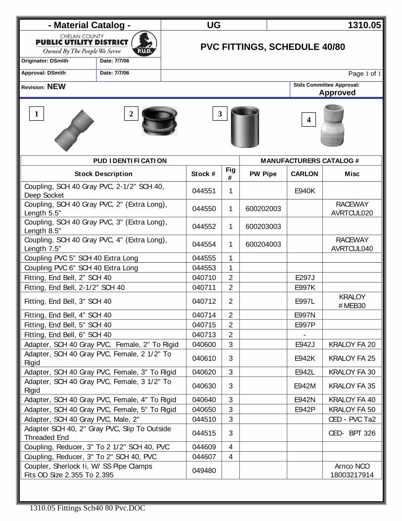
- Material Catalog - UG 1310.05
Originator: DSmith Date: 7/7/06
PVC FITTINGS, SCHEDULE 40/80
Approval: DSmith Date: 7/7/06 Page 1 of 1
Revision: NEW Stds Committee Approval: Approved
1310.05 Fittings Sch40 80 Pvc.DOC
1 2 34
PUD IDENTIFICATION MANUFACTURERS CATALOG #
Stock Description Stock # Fig# PW Pipe CARLON Misc
Coupling, SCH 40 Gray PVC, 2-1/2" SCH 40, Deep Socket 044551 1 E940K
Coupling, SCH 40 Gray PVC, 2" (Extra Long), Length 5.5" 044550 1 600202003 RACEWAY
AVRTCUL020 Coupling, SCH 40 Gray PVC, 3" (Extra Long), Length 8.5" 044552 1 600203003
Coupling, SCH 40 Gray PVC, 4" (Extra Long), Length 7.5" 044554 1 600204003 RACEWAY
AVRTCUL040 Coupling PVC 5" SCH 40 Extra Long 044555 1 Coupling PVC 6" SCH 40 Extra Long 044553 1 Fitting, End Bell, 2” SCH 40 040710 2 E297J Fitting, End Bell, 2-1/2” SCH 40 040711 2 E997K
Fitting, End Bell, 3” SCH 40 040712 2 E997L KRALOY #MEB30
Fitting, End Bell, 4” SCH 40 040714 2 E997N Fitting, End Bell, 5” SCH 40 040715 2 E997P Fitting, End Bell, 6” SCH 40 040713 2 - Adapter, SCH 40 Gray PVC, Female, 2" To Rigid 040600 3 E942J KRALOY FA 20 Adapter, SCH 40 Gray PVC, Female, 2 1/2" To Rigid 040610 3 E942K KRALOY FA 25
Adapter, SCH 40 Gray PVC, Female, 3" To Rigid 040620 3 E942L KRALOY FA 30 Adapter, SCH 40 Gray PVC, Female, 3 1/2" To Rigid 040630 3 E942M KRALOY FA 35
Adapter, SCH 40 Gray PVC, Female, 4" To Rigid 040640 3 E942N KRALOY FA 40 Adapter, SCH 40 Gray PVC, Female, 5" To Rigid 040650 3 E942P KRALOY FA 50 Adapter, SCH 40 Gray PVC, Male, 2" 044510 3 CED - PVC Ta2 Adapter SCH 40, 2" Gray PVC, Slip To Outside Threaded End 044515 3 CED- BPT 326
Coupling, Reducer, 3" To 2 1/2" SCH 40, PVC 044609 4 Coupling, Reducer, 3" To 2" SCH 40, PVC 044607 4 Coupler, Sherlock Ii, W/ SS Pipe Clamps Fits OD Size 2.355 To 2.395 049480 Arnco NCO
18003217914
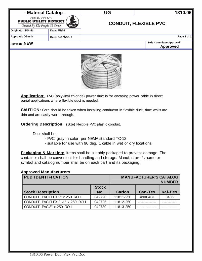
- Material Catalog - UG 1310.06
Originator: DSmith Date: 7/7/06
CONDUIT, FLEXIBLE PVC
Approval: DSmith Date: 6/27/2007 Page 1 of 1
Revision: NEW Stds Committee Approval: Approved
1310.06 Power Duct Flex Pvc.Doc
Application: PVC (polyvinyl chloride) power duct is for encasing power cable in direct burial applications where flexible duct is needed. CAUTION: Care should be taken when installing conductor in flexible duct, duct walls are thin and are easily worn through. Ordering Description: (Size) Flexible PVC plastic conduit.
Duct shall be: - PVC, gray in color, per NEMA standard TC-12 - suitable for use with 90 deg. C cable in wet or dry locations.
Packaging & Marking: Items shall be suitably packaged to prevent damage. The container shall be convenient for handling and storage. Manufacturer’s name or symbol and catalog number shall be on each part and its packaging. Approved Manufacturers
PUD IDENTIFICATION MANUFACTURER’S CATALOG NUMBER
Stock Description Stock No. Carlon Can-Tex Kaf-flex
CONDUIT, PVC FLEX 2" x 250' ROLL 042720 11811-250 A90CAG1 8436 CONDUIT, PVC FLEX 2 ½" x 250' ROLL 042725 11812-250 -------------- ----------- CONDUIT, PVC 3" x 250’ ROLL 042730 11813-250 -------------- -----------
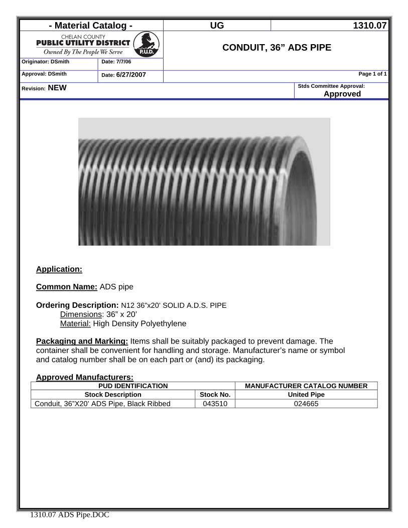
- Material Catalog - UG 1310.07
Originator: DSmith Date: 7/7/06
CONDUIT, 36” ADS PIPE
Approval: DSmith Date: 6/27/2007 Page 1 of 1
Revision: NEW Stds Committee Approval: Approved
1310.07 ADS Pipe.DOC
Application: Common Name: ADS pipe
Ordering Description: N12 36”x20’ SOLID A.D.S. PIPE
Dimensions: 36” x 20’ Material: High Density Polyethylene
Packaging and Marking: Items shall be suitably packaged to prevent damage. The container shall be convenient for handling and storage. Manufacturer’s name or symbol and catalog number shall be on each part or (and) its packaging.
Approved Manufacturers:
PUD IDENTIFICATION MANUFACTURER CATALOG NUMBER Stock Description Stock No. United Pipe
Conduit, 36”X20’ ADS Pipe, Black Ribbed 043510 024665
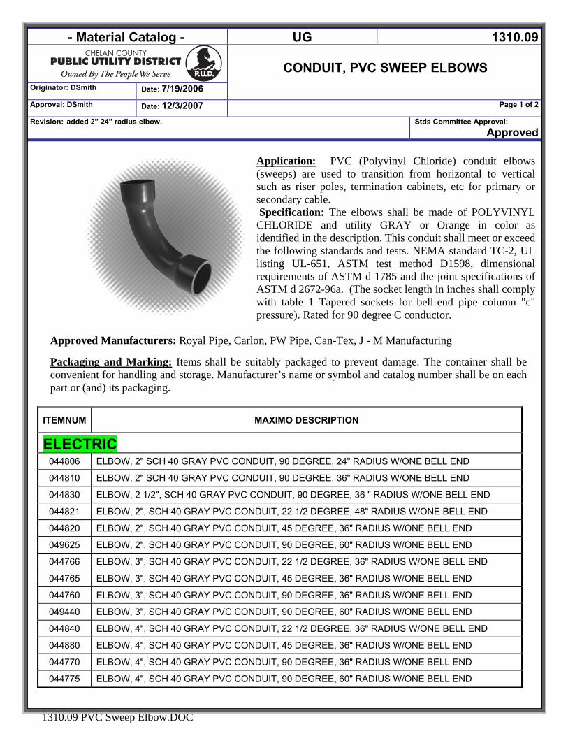
- Material Catalog - UG 1310.09
Originator: DSmith Date: 7/19/2006
CONDUIT, PVC SWEEP ELBOWS
Approval: DSmith Date: 12/3/2007 Page 1 of 2
Revision: added 2” 24” radius elbow. Stds Committee Approval: Approved
1310.09 PVC Sweep Elbow.DOC
Application: PVC (Polyvinyl Chloride) conduit elbows (sweeps) are used to transition from horizontal to vertical such as riser poles, termination cabinets, etc for primary or secondary cable. Specification: The elbows shall be made of POLYVINYL CHLORIDE and utility GRAY or Orange in color as identified in the description. This conduit shall meet or exceed the following standards and tests. NEMA standard TC-2, UL listing UL-651, ASTM test method D1598, dimensional requirements of ASTM d 1785 and the joint specifications of ASTM d 2672-96a. (The socket length in inches shall comply with table 1 Tapered sockets for bell-end pipe column "c" pressure). Rated for 90 degree C conductor.
Approved Manufacturers: Royal Pipe, Carlon, PW Pipe, Can-Tex, J - M Manufacturing Packaging and Marking: Items shall be suitably packaged to prevent damage. The container shall be convenient for handling and storage. Manufacturer’s name or symbol and catalog number shall be on each part or (and) its packaging.
ITEMNUM MAXIMO DESCRIPTION
ELECTRIC 044806 ELBOW, 2" SCH 40 GRAY PVC CONDUIT, 90 DEGREE, 24" RADIUS W/ONE BELL END
044810 ELBOW, 2" SCH 40 GRAY PVC CONDUIT, 90 DEGREE, 36" RADIUS W/ONE BELL END
044830 ELBOW, 2 1/2", SCH 40 GRAY PVC CONDUIT, 90 DEGREE, 36 " RADIUS W/ONE BELL END
044821 ELBOW, 2", SCH 40 GRAY PVC CONDUIT, 22 1/2 DEGREE, 48" RADIUS W/ONE BELL END
044820 ELBOW, 2", SCH 40 GRAY PVC CONDUIT, 45 DEGREE, 36" RADIUS W/ONE BELL END
049625 ELBOW, 2", SCH 40 GRAY PVC CONDUIT, 90 DEGREE, 60" RADIUS W/ONE BELL END
044766 ELBOW, 3", SCH 40 GRAY PVC CONDUIT, 22 1/2 DEGREE, 36" RADIUS W/ONE BELL END
044765 ELBOW, 3", SCH 40 GRAY PVC CONDUIT, 45 DEGREE, 36" RADIUS W/ONE BELL END
044760 ELBOW, 3", SCH 40 GRAY PVC CONDUIT, 90 DEGREE, 36" RADIUS W/ONE BELL END
049440 ELBOW, 3", SCH 40 GRAY PVC CONDUIT, 90 DEGREE, 60" RADIUS W/ONE BELL END
044840 ELBOW, 4", SCH 40 GRAY PVC CONDUIT, 22 1/2 DEGREE, 36" RADIUS W/ONE BELL END
044880 ELBOW, 4", SCH 40 GRAY PVC CONDUIT, 45 DEGREE, 36" RADIUS W/ONE BELL END
044770 ELBOW, 4", SCH 40 GRAY PVC CONDUIT, 90 DEGREE, 36" RADIUS W/ONE BELL END
044775 ELBOW, 4", SCH 40 GRAY PVC CONDUIT, 90 DEGREE, 60" RADIUS W/ONE BELL END
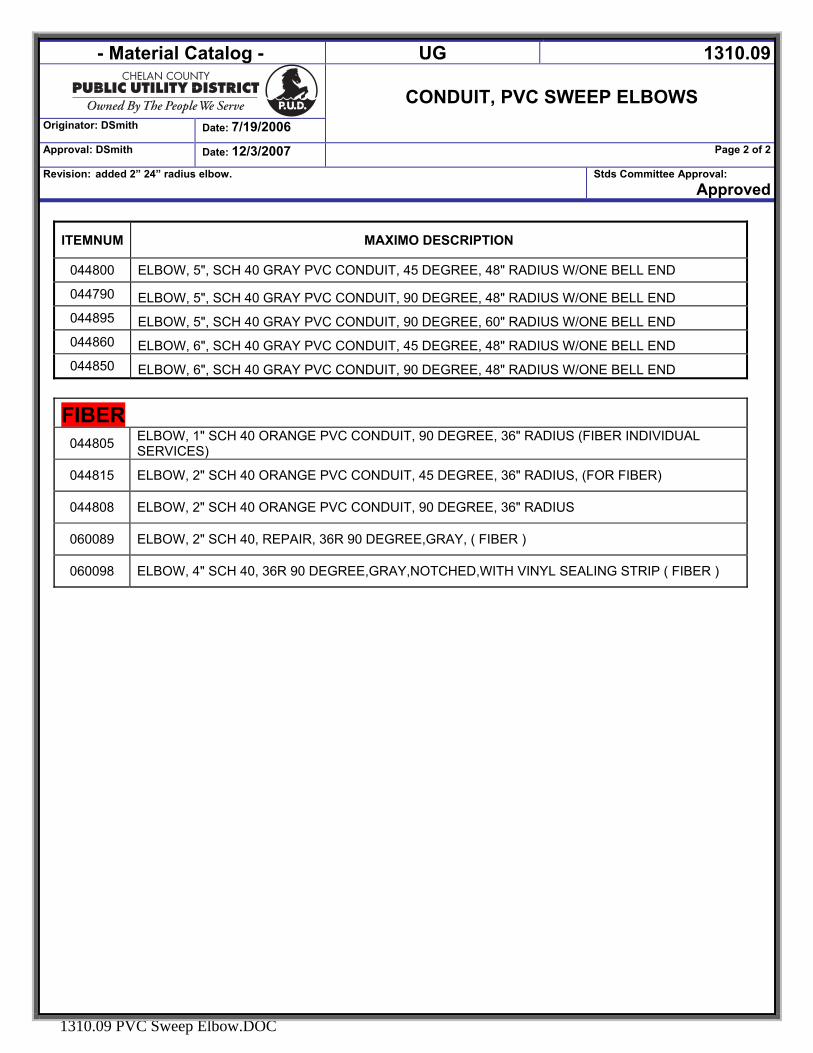
- Material Catalog - UG 1310.09
Originator: DSmith Date: 7/19/2006
CONDUIT, PVC SWEEP ELBOWS
Approval: DSmith Date: 12/3/2007 Page 2 of 2
Revision: added 2” 24” radius elbow. Stds Committee Approval: Approved
1310.09 PVC Sweep Elbow.DOC
ITEMNUM MAXIMO DESCRIPTION
044800 ELBOW, 5", SCH 40 GRAY PVC CONDUIT, 45 DEGREE, 48" RADIUS W/ONE BELL END
044790 ELBOW, 5", SCH 40 GRAY PVC CONDUIT, 90 DEGREE, 48" RADIUS W/ONE BELL END 044895 ELBOW, 5", SCH 40 GRAY PVC CONDUIT, 90 DEGREE, 60" RADIUS W/ONE BELL END 044860 ELBOW, 6", SCH 40 GRAY PVC CONDUIT, 45 DEGREE, 48" RADIUS W/ONE BELL END 044850 ELBOW, 6", SCH 40 GRAY PVC CONDUIT, 90 DEGREE, 48" RADIUS W/ONE BELL END
FIBER 044805 ELBOW, 1" SCH 40 ORANGE PVC CONDUIT, 90 DEGREE, 36" RADIUS (FIBER INDIVIDUAL
SERVICES)
044815 ELBOW, 2" SCH 40 ORANGE PVC CONDUIT, 45 DEGREE, 36" RADIUS, (FOR FIBER)
044808 ELBOW, 2" SCH 40 ORANGE PVC CONDUIT, 90 DEGREE, 36" RADIUS
060089 ELBOW, 2" SCH 40, REPAIR, 36R 90 DEGREE,GRAY, ( FIBER )
060098 ELBOW, 4" SCH 40, 36R 90 DEGREE,GRAY,NOTCHED,WITH VINYL SEALING STRIP ( FIBER )
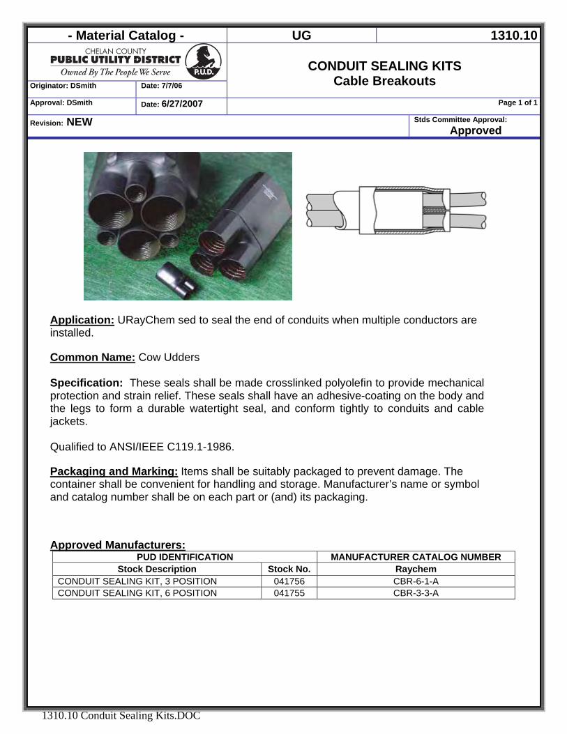
- Material Catalog - UG 1310.10
Originator: DSmith Date: 7/7/06
CONDUIT SEALING KITS
Cable Breakouts Approval: DSmith Date: 6/27/2007 Page 1 of 1
Revision: NEW Stds Committee Approval: Approved
1310.10 Conduit Sealing Kits.DOC
Application: URayChem sed to seal the end of conduits when multiple conductors are installed. Common Name: Cow Udders
Specification: These seals shall be made crosslinked polyolefin to provide mechanical protection and strain relief. These seals shall have an adhesive-coating on the body and the legs to form a durable watertight seal, and conform tightly to conduits and cable jackets. Qualified to ANSI/IEEE C119.1-1986. Packaging and Marking: Items shall be suitably packaged to prevent damage. The container shall be convenient for handling and storage. Manufacturer’s name or symbol and catalog number shall be on each part or (and) its packaging. Approved Manufacturers:
PUD IDENTIFICATION MANUFACTURER CATALOG NUMBER Stock Description Stock No. Raychem
CONDUIT SEALING KIT, 3 POSITION 041756 CBR-6-1-A CONDUIT SEALING KIT, 6 POSITION 041755 CBR-3-3-A
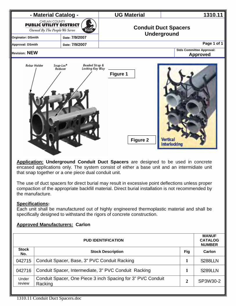
- Material Catalog - UG Material 1310.11
Orginator: DSmith Date: 7/9/2007
Conduit Duct Spacers
Underground
Approval: DSmith Date: 7/9/2007 Page 1 of 1
Revision: NEW Stds Committee Approval:
Approved
1310.11 Conduit Duct Spacers.doc
Application: Underground Conduit Duct Spacers are designed to be used in concrete encased applications only. The system consist of either a base unit and an intermidiate unit that snap together or a one piece dual conduit unit. The use of duct spacers for direct burial may result in excessive point deflections unless proper compaction of the appropriate backfill material. Direct burial installation is not recommended by the manufacture. Specifications: Each unit shall be manufactured out of highly engineered thermoplastic material and shall be specifically designed to withstand the rigors of concrete construction. Approved Manufacturers: Carlon
PUD IDENTIFICATION MANUF
CATALOG NUMBER
Stock No. Stock Description Fig Carlon
042715 Conduit Spacer, Base, 3" PVC Conduit Racking 1 S288LLN
042716 Conduit Spacer, Intermediate, 3" PVC Conduit Racking 1 S289LLN
Under review
Conduit Spacer, One Piece 3 inch Spacing for 3” PVC Conduit Racking 2 SP3W30-2
Figure 2
Figure 1
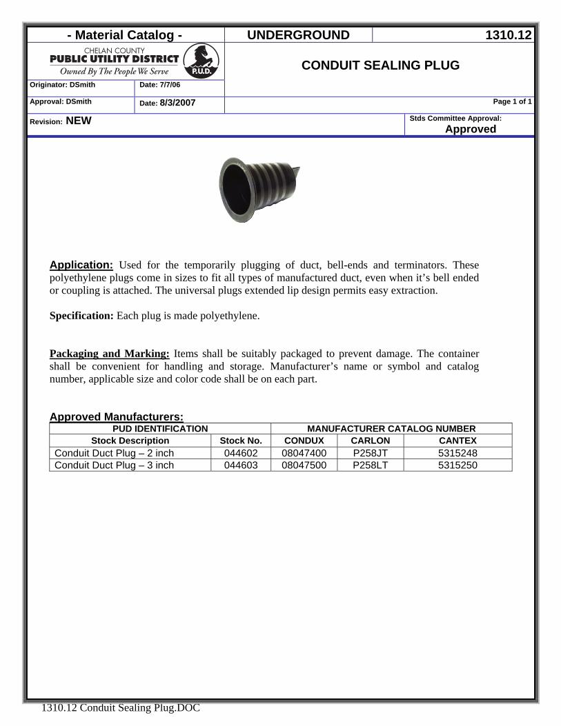
- Material Catalog - UNDERGROUND 1310.12
Originator: DSmith Date: 7/7/06
CONDUIT SEALING PLUG
Approval: DSmith Date: 8/3/2007 Page 1 of 1
Revision: NEW Stds Committee Approval: Approved
1310.12 Conduit Sealing Plug.DOC
Application: Used for the temporarily plugging of duct, bell-ends and terminators. These polyethylene plugs come in sizes to fit all types of manufactured duct, even when it’s bell ended or coupling is attached. The universal plugs extended lip design permits easy extraction. Specification: Each plug is made polyethylene. Packaging and Marking: Items shall be suitably packaged to prevent damage. The container shall be convenient for handling and storage. Manufacturer’s name or symbol and catalog number, applicable size and color code shall be on each part. Approved Manufacturers:
PUD IDENTIFICATION MANUFACTURER CATALOG NUMBER Stock Description Stock No. CONDUX CARLON CANTEX
Conduit Duct Plug – 2 inch 044602 08047400 P258JT 5315248 Conduit Duct Plug – 3 inch 044603 08047500 P258LT 5315250
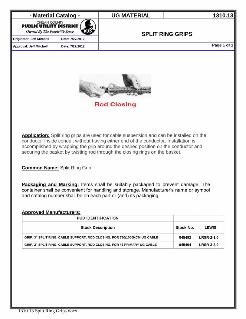
- Material Catalog - UG MATERIAL 1310.13
SPLIT RING GRIPS
Originator: Jeff Mitchell Date: 7/27/2012
Approval: Jeff Mitchell Date: 7/27/2012 Page 1 of 1
1310.13 Split Ring Grips.docx
Application: Split ring grips are used for cable suspension and can be installed on the conductor inside conduit without having either end of the conductor. Installation is accomplished by wrapping the grip around the desired position on the conductor and securing the basket by twisting rod through the closing rings on the basket. Common Name: Split Ring Grip
Packaging and Marking: Items shall be suitably packaged to prevent damage. The container shall be convenient for handling and storage. Manufacturer’s name or symbol and catalog number shall be on each part or (and) its packaging. Approved Manufacturers:
PUD IDENTIFICATION
Stock Description Stock No.
LEWIS
GRIP, 3” SPLIT RING, CABLE SUPPORT, ROD CLOSING, FOR 750/1000KCM UG CABLE 045492 LRSR-2-1.0
GRIP, 2” SPLIT RING, CABLE SUPPORT, ROD CLOSING, FOR #2 PRIMARY UG CABLE 045494 LRSR-3-2.0
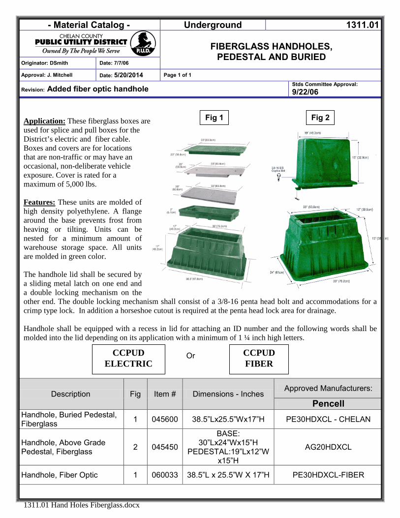
- Material Catalog - Underground 1311.01
FIBERGLASS HANDHOLES,
PEDESTAL AND BURIED Originator: DSmith Date: 7/7/06
Approval: J. Mitchell Date: 5/20/2014 Page 1 of 1
Revision: Added fiber optic handhole Stds Committee Approval: 9/22/06
1311.01 Hand Holes Fiberglass.docx
Fig 1 Fig 2
Application: These fiberglass boxes are used for splice and pull boxes for the District’s electric and fiber cable. Boxes and covers are for locations that are non-traffic or may have an occasional, non-deliberate vehicle exposure. Cover is rated for a maximum of 5,000 lbs. Features: These units are molded of high density polyethylene. A flange around the base prevents frost from heaving or tilting. Units can be nested for a minimum amount of warehouse storage space. All units are molded in green color. The handhole lid shall be secured by a sliding metal latch on one end and a double locking mechanism on the other end. The double locking mechanism shall consist of a 3/8-16 penta head bolt and accommodations for a crimp type lock. In addition a horseshoe cutout is required at the penta head lock area for drainage. Handhole shall be equipped with a recess in lid for attaching an ID number and the following words shall be molded into the lid depending on its application with a minimum of 1 ¼ inch high letters.
Or
Description Fig Item # Dimensions - Inches Approved Manufacturers:
Pencell Handhole, Buried Pedestal, Fiberglass 1 045600 38.5”Lx25.5”Wx17”H PE30HDXCL - CHELAN
Handhole, Above Grade Pedestal, Fiberglass 2 045450
BASE: 30”Lx24”Wx15”H
PEDESTAL:19”Lx12”Wx15”H
AG20HDXCL
Handhole, Fiber Optic 1 060033 38.5”L x 25.5”W X 17”H PE30HDXCL-FIBER
CCPUD FIBER
CCPUD ELECTRIC
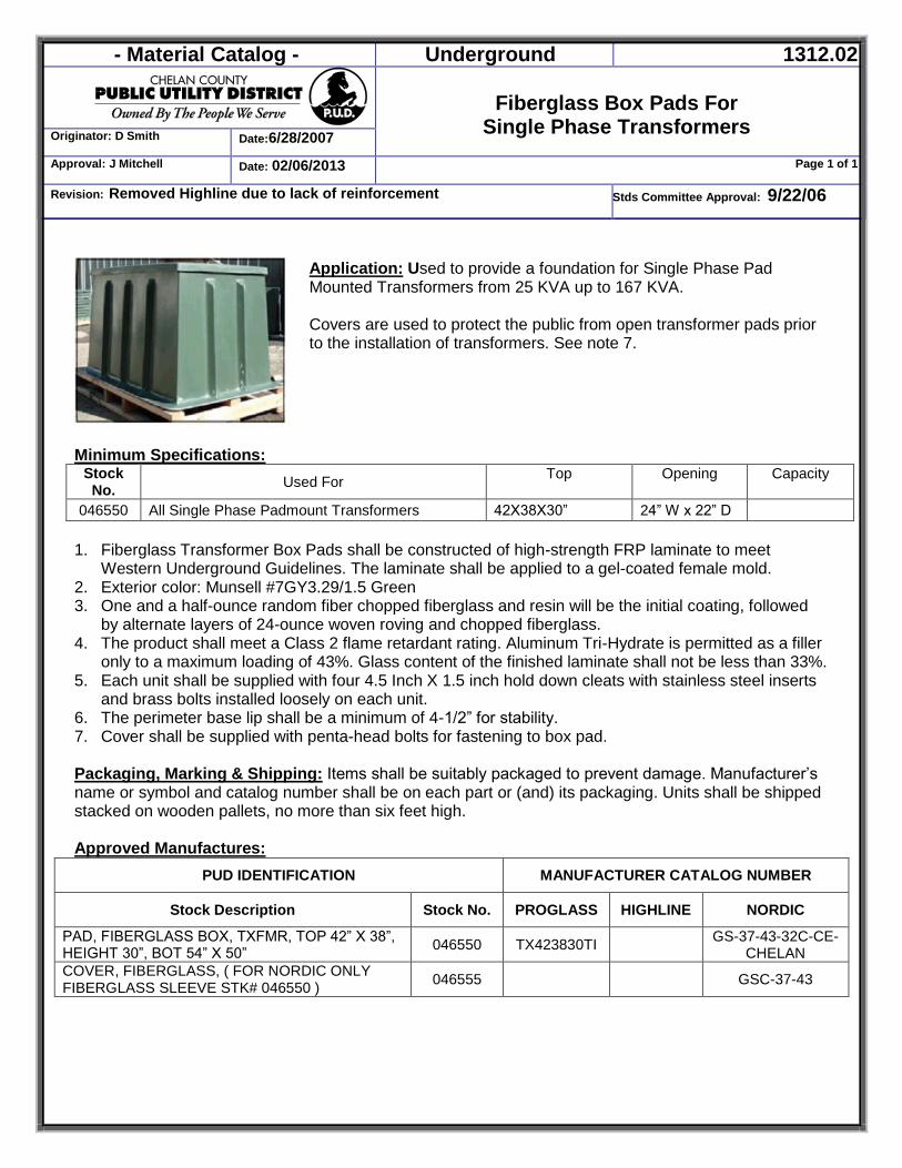
- Material Catalog - Underground 1312.02
Fiberglass Box Pads For
Single Phase Transformers Originator: D Smith Date:6/28/2007
Approval: J Mitchell Date: 02/06/2013 Page 1 of 1
Revision: Removed Highline due to lack of reinforcement Stds Committee Approval: 9/22/06
Application: Used to provide a foundation for Single Phase Pad Mounted Transformers from 25 KVA up to 167 KVA. Covers are used to protect the public from open transformer pads prior to the installation of transformers. See note 7.
Minimum Specifications: Stock No. Used For Top Opening Capacity
046550 All Single Phase Padmount Transformers 42X38X30” 24” W x 22” D
1. Fiberglass Transformer Box Pads shall be constructed of high-strength FRP laminate to meet Western Underground Guidelines. The laminate shall be applied to a gel-coated female mold.
2. Exterior color: Munsell #7GY3.29/1.5 Green 3. One and a half-ounce random fiber chopped fiberglass and resin will be the initial coating, followed
by alternate layers of 24-ounce woven roving and chopped fiberglass. 4. The product shall meet a Class 2 flame retardant rating. Aluminum Tri-Hydrate is permitted as a filler
only to a maximum loading of 43%. Glass content of the finished laminate shall not be less than 33%. 5. Each unit shall be supplied with four 4.5 Inch X 1.5 inch hold down cleats with stainless steel inserts
and brass bolts installed loosely on each unit. 6. The perimeter base lip shall be a minimum of 4-1/2” for stability. 7. Cover shall be supplied with penta-head bolts for fastening to box pad.
Packaging, Marking & Shipping: Items shall be suitably packaged to prevent damage. Manufacturer’s name or symbol and catalog number shall be on each part or (and) its packaging. Units shall be shipped stacked on wooden pallets, no more than six feet high. Approved Manufactures:
PUD IDENTIFICATION MANUFACTURER CATALOG NUMBER
Stock Description Stock No. PROGLASS HIGHLINE NORDIC
PAD, FIBERGLASS BOX, TXFMR, TOP 42” X 38”, HEIGHT 30”, BOT 54” X 50” 046550 TX423830TI GS-37-43-32C-CE-
CHELAN COVER, FIBERGLASS, ( FOR NORDIC ONLY FIBERGLASS SLEEVE STK# 046550 ) 046555 GSC-37-43
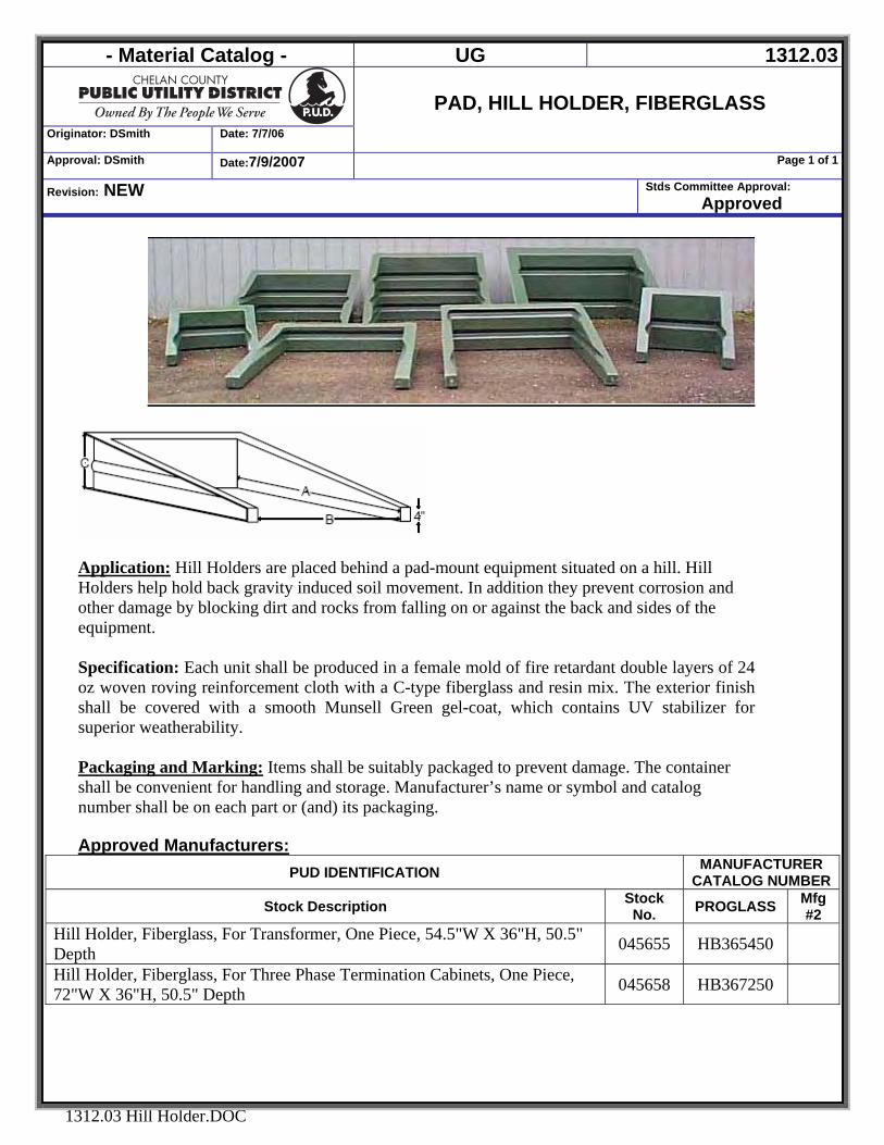
- Material Catalog - UG 1312.03
Originator: DSmith Date: 7/7/06
PAD, HILL HOLDER, FIBERGLASS
Approval: DSmith Date:7/9/2007 Page 1 of 1
Revision: NEW Stds Committee Approval: Approved
1312.03 Hill Holder.DOC
Application: Hill Holders are placed behind a pad-mount equipment situated on a hill. Hill Holders help hold back gravity induced soil movement. In addition they prevent corrosion and other damage by blocking dirt and rocks from falling on or against the back and sides of the equipment. Specification: Each unit shall be produced in a female mold of fire retardant double layers of 24 oz woven roving reinforcement cloth with a C-type fiberglass and resin mix. The exterior finish shall be covered with a smooth Munsell Green gel-coat, which contains UV stabilizer for superior weatherability. Packaging and Marking: Items shall be suitably packaged to prevent damage. The container shall be convenient for handling and storage. Manufacturer’s name or symbol and catalog number shall be on each part or (and) its packaging. Approved Manufacturers:
PUD IDENTIFICATION MANUFACTURER CATALOG NUMBER
Stock Description Stock No. PROGLASS Mfg
#2 Hill Holder, Fiberglass, For Transformer, One Piece, 54.5"W X 36"H, 50.5" Depth 045655 HB365450
Hill Holder, Fiberglass, For Three Phase Termination Cabinets, One Piece, 72"W X 36"H, 50.5" Depth 045658 HB367250
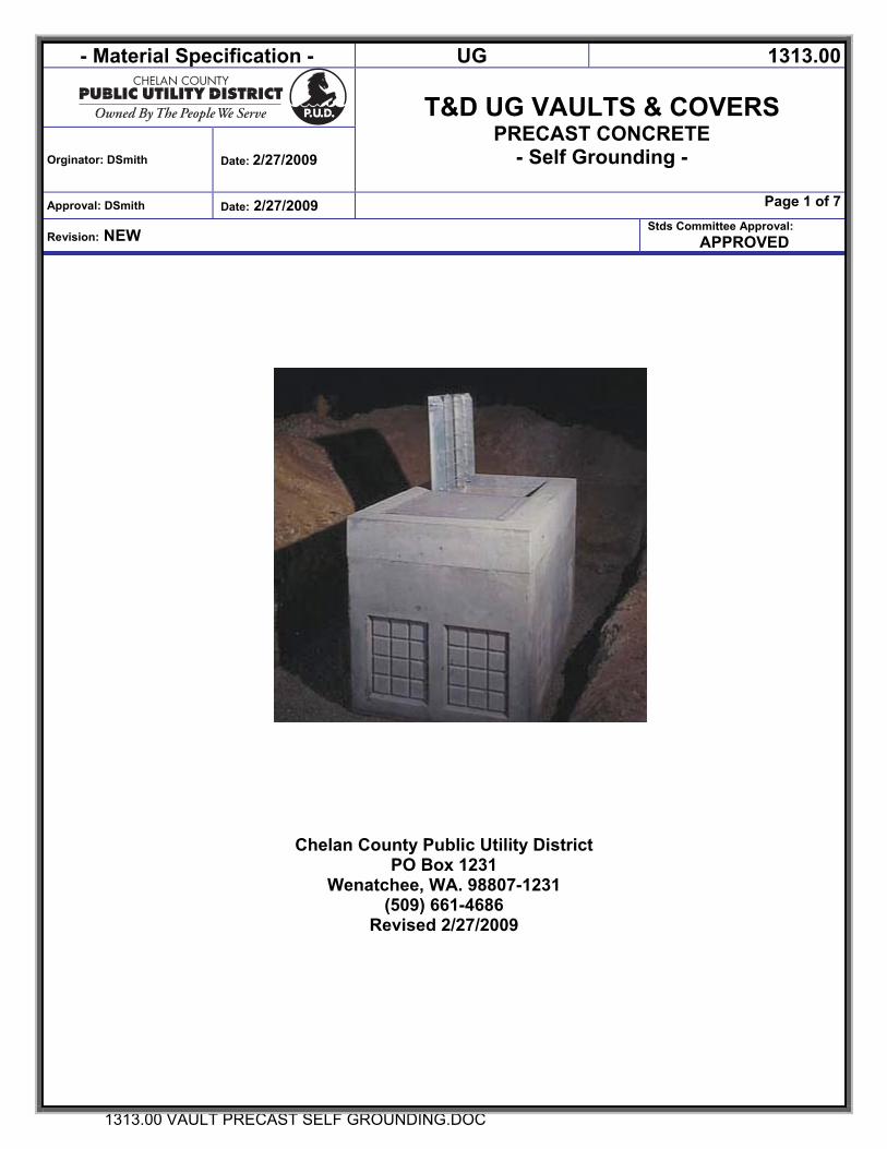
- Material Specification - UG 1313.00
T&D UG VAULTS & COVERS
PRECAST CONCRETE - Self Grounding -
Orginator: DSmith Date: 2/27/2009
Approval: DSmith Date: 2/27/2009 Page 1 of 7
Revision: NEW Stds Committee Approval:
APPROVED
1313.00 VAULT PRECAST SELF GROUNDING.DOC
Chelan County Public Utility District PO Box 1231
Wenatchee, WA. 98807-1231 (509) 661-4686
Revised 2/27/2009
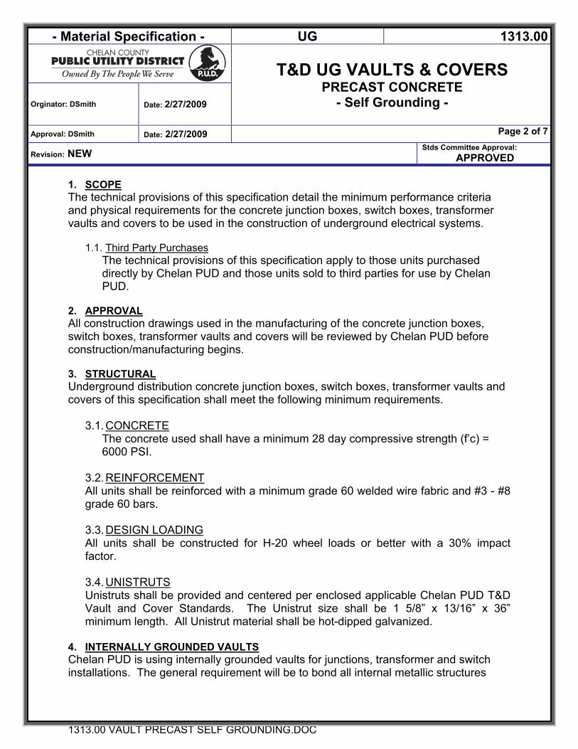
- Material Specification - UG 1313.00
T&D UG VAULTS & COVERS
PRECAST CONCRETE - Self Grounding -
Orginator: DSmith Date: 2/27/2009
Approval: DSmith Date: 2/27/2009 Page 2 of 7
Revision: NEW Stds Committee Approval:
APPROVED
1313.00 VAULT PRECAST SELF GROUNDING.DOC
1. SCOPE The technical provisions of this specification detail the minimum performance criteria and physical requirements for the concrete junction boxes, switch boxes, transformer vaults and covers to be used in the construction of underground electrical systems.
1.1. Third Party Purchases The technical provisions of this specification apply to those units purchased directly by Chelan PUD and those units sold to third parties for use by Chelan PUD.
2. APPROVAL All construction drawings used in the manufacturing of the concrete junction boxes, switch boxes, transformer vaults and covers will be reviewed by Chelan PUD before construction/manufacturing begins. 3. STRUCTURAL Underground distribution concrete junction boxes, switch boxes, transformer vaults and covers of this specification shall meet the following minimum requirements.
3.1. CONCRETE
The concrete used shall have a minimum 28 day compressive strength (f’c) = 6000 PSI.
3.2. REINFORCEMENT All units shall be reinforced with a minimum grade 60 welded wire fabric and #3 - #8 grade 60 bars.
3.3. DESIGN LOADING All units shall be constructed for H-20 wheel loads or better with a 30% impact factor.
3.4. UNISTRUTS Unistruts shall be provided and centered per enclosed applicable Chelan PUD T&D Vault and Cover Standards. The Unistrut size shall be 1 5/8” x 13/16” x 36” minimum length. All Unistrut material shall be hot-dipped galvanized.
4. INTERNALLY GROUNDED VAULTS Chelan PUD is using internally grounded vaults for junctions, transformer and switch installations. The general requirement will be to bond all internal metallic structures
- Material Specification - UG 1313.00
T&D UG VAULTS & COVERS
PRECAST CONCRETE - Self Grounding -
Orginator: DSmith Date: 2/27/2009
Approval: DSmith Date: 2/27/2009 Page 3 of 7
Revision: NEW Stds Committee Approval:
APPROVED
1313.00 VAULT PRECAST SELF GROUNDING.DOC
together to a bronze insert. This grounding procedure shall meet the provisions of NESC Rule 94B6
4.1. ELECTRODES Grounding electrodes shall be as shown on attached drawings and:
SPECIFICATION REBAR
Minimum length 22 feet
Minimum size # 3 - 3/8”
4.1.1. Installation • The Electrodes shall be installed as straight as possible. • The Electrodes shall be encased with a minimum of 1½“ of radial concrete. • The Electrodes shall be a minimum of 2.5’ below the top of the vault or
junction box.
4.1.2. Ground Insert Connector Each bronze insert will be tapped for 1/2”-13 bolt, and located 2 inches below the Unistrut and in the middle of two opposite side walls (two inserts per wall, one faces inside the vault the other faces outside the vault) as shown in the attached Standard Drawings. A 3/8-inch steel rod, or similar sized metallic conductor, shall be used to bond the inserts to the structural steel in the concrete. The inserts shall be plugged to prevent contamination from entering. On multi-sectioned vaults, the inserts shall be vertically aligned. Only the middle section will have the inserts that face inside the vault and outside the vault, all other inserts in these vaults will be placed as shown in the attached standard for that type vault.
4.1.2.1- Bonding to rebar and Wire Mesh Ground insert connectors shall be electrically bonded to rebar and wire mesh by welded connections in a minimum of two locations
- Material Specification - UG 1313.00
T&D UG VAULTS & COVERS
PRECAST CONCRETE - Self Grounding -
Orginator: DSmith Date: 2/27/2009
Approval: DSmith Date: 2/27/2009 Page 4 of 7
Revision: NEW Stds Committee Approval:
APPROVED
1313.00 VAULT PRECAST SELF GROUNDING.DOC
4.1.2.2 – Labeling of Inserts Inserts shall be labeled / identified in Green Paint as follows:
Section Label Base (Section that includes the minimum of 22 ft. of #3 Rebar bonded to insert) GRND
Cover BOND
Mid-Section BOND
The labeling shall be adjacent to the insert. When inserts on covers are oriented downward the label shall be painted on the access opening side closest to the insert location.
5. COVERS
5.1. GROUNDING INSERTS All covers shall have grounding inserts installed per manufacturer’s and Chelan PUD’s specification. Each insert shall be bonded to the wire mesh used as reinforcement in the cover. The location is shown on the drawings, for each unit, included with this specification.
5.2. METALLIC COVERS The 36” x 36” cover(s) shall be designed for AASHTO H20 loading, as specified, and shall have two 180-degree flush hinges, lifting handle(s), and concealed locking device(s). A Penta head bolt in a recessed, non-rotating cup is to be part of the required locking device. (See Figure 1, ANSI C57.12.28.1988, for typical installation). The lid shall be manufactured from a skid resistant surface, hot-dipped galvanized steel and be provided with spring-assisted opening and closing requiring a 55-pound maximum effort to open and close it. As an alternate, an aluminum lid may be supplied subject to Chelan PUD‘s approval. If supplied, it must meet all the applicable requirements above.
5.3. COVER, TRANSFORMER VAULT The transformer vault lids shall have blockouts as described in the attached material standard for each type vault.
5.3.1. LOGO “CHELAN PUD” All covers shall have the logo “CHELAN PUD” cast into the concrete structure using minimum two-inch-high letters. The logo is to be legible after 20 years

- Material Specification - UG 1313.00
T&D UG VAULTS & COVERS
PRECAST CONCRETE - Self Grounding -
Orginator: DSmith Date: 2/27/2009
Approval: DSmith Date: 2/27/2009 Page 5 of 7
Revision: NEW Stds Committee Approval:
APPROVED
1313.00 VAULT PRECAST SELF GROUNDING.DOC
exposure and placement such as to be easily noticed by a lay person casually inspecting the structure.
6. LIFTING METHOD Lifting provisions shall be installed per manufacturer’s and Chelan PUD’s requirements.
6.1. COVERS
6.1.1. Burke Fittings All vault covers supplied shall have a Burke fitting placed in each corner of the top according to manufacturer’s standards.
6.1.2. Strap Lifting Notch 554 And 575 Vaults Only All 554 and 575 covers supplied shall have a “Strap Lifting Notch” cast in the vault side of the cover in each corner. The triangular notch shall have three (3) inch sides and be ¼ inch high. 6.1.3. LOWER UNIT
6.1.3.1. 554 And 575 Units These units shall have two (2) ton Rigging/Lifting fittings placed in each corner per manufacturer’s specifications and approved by Chelan PUD.
6.1.3.2. 612 And 810 Units These units shall have four (4) ton Rigging/Lifting fittings placed in each corner per manufacturer’s specifications and approved by Chelan County PUD.
7. ACCESSORIES Items to be included with each type vault.
7.1. SUMP A sump shall be provided in the bottom of each vault. The size and placement of the sump shall be as shown in the manufacturer’s catalog and approved by Chelan PUD. The bottom of the sump shall be designed such that it can be knocked out if desired.
7.2. KNOCKOUTS
- Material Specification - UG 1313.00
T&D UG VAULTS & COVERS
PRECAST CONCRETE - Self Grounding -
Orginator: DSmith Date: 2/27/2009
Approval: DSmith Date: 2/27/2009 Page 6 of 7
Revision: NEW Stds Committee Approval:
APPROVED
1313.00 VAULT PRECAST SELF GROUNDING.DOC
All units shall have cable knockouts located in each corner of the lower portion according to the manufacturer’s standard and Chelan PUD’s requirements.
7.3. CABLE PULLING DEVICES In addition to the Burke Lifting devices, cable pulling irons shall be mounted in each corner and be suitable as anchors for cable pulling operations. Location in each type unit shall be as shown on specification drawings.
- Material Specification - UG 1313.00
T&D UG VAULTS & COVERS
PRECAST CONCRETE - Self Grounding -
Orginator: DSmith Date: 2/27/2009
Approval: DSmith Date: 2/27/2009 Page 7 of 7
Revision: NEW Stds Committee Approval:
APPROVED
1313.00 VAULT PRECAST SELF GROUNDING.DOC
8. APPROVED MANUFACTURES
Utility Vault P.O. Box 588 Auburn, WA 98071
H2 Precast 4919 Contractors Drive East Wenatchee, WA. 98802
Phone: (800) 892-1538 (253) 839-3500 Fax: (253) 735-4201
Phone: (509) 884-6644
Email: [email protected] Email: [email protected] 9. RELATED STANDARDS & DIMESIONS Please refer to the T&D Material Stock Catalog for this items detail specifications on the district’s web site listed below: HTTP://WWW.CHELANPUD.ORG/DISTRICT-STANDARDS.HTML These catalog pages are updated when a change is made to the specifications. Vendors shall utilize these specifications when responding to a request for quote.
• Material Catalog #1313.01 – 554 Vaults, Concrete, Self Grounding
• Material Catalog #1313.02 – 575 Vaults, Concrete, Self Grounding
• Material Catalog #1313.03 – 612 Vaults, Concrete, Self Grounding
• Material Catalog #1313.04 – 810 Vaults, Concrete, Self Grounding
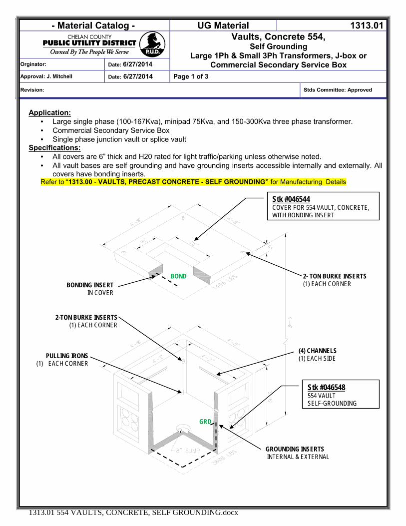
- Material Catalog - UG Material 1313.01
Vaults, Concrete 554, Self Grounding
Large 1Ph & Small 3Ph Transformers, J-box or Commercial Secondary Service Box Orginator: Date: 6/27/2014
Approval: J. Mitchell Date: 6/27/2014 Page 1 of 3
Revision: Stds Committee: Approved
1313.01 554 VAULTS, CONCRETE, SELF GROUNDING.docx
Application: · Large single phase (100-167Kva), minipad 75Kva, and 150-300Kva three phase transformer. · Commercial Secondary Service Box · Single phase junction vault or splice vault
Specifications: · All covers are 6” thick and H20 rated for light traffic/parking unless otherwise noted. · All vault bases are self grounding and have grounding inserts accessible internally and externally. All
covers have bonding inserts. Refer to “1313.00 - VAULTS, PRECAST CONCRETE - SELF GROUNDING” for Manufacturing Details
Stk #046544 COVER FOR 554 VAULT, CONCRETE, WITH BONDING INSERT
(4) CHANNELS (1) EACH SIDE
BONDING INSERT IN COVER
2-TON BURKE INSERTS (1) EACH CORNER
PULLING IRONS (1) EACH CORNER
GROUNDING INSERTS INTERNAL & EXTERNAL
BOND
GRD
Stk #046548 554 VAULT SELF-GROUNDING
2- TON BURKE INSERTS (1) EACH CORNER
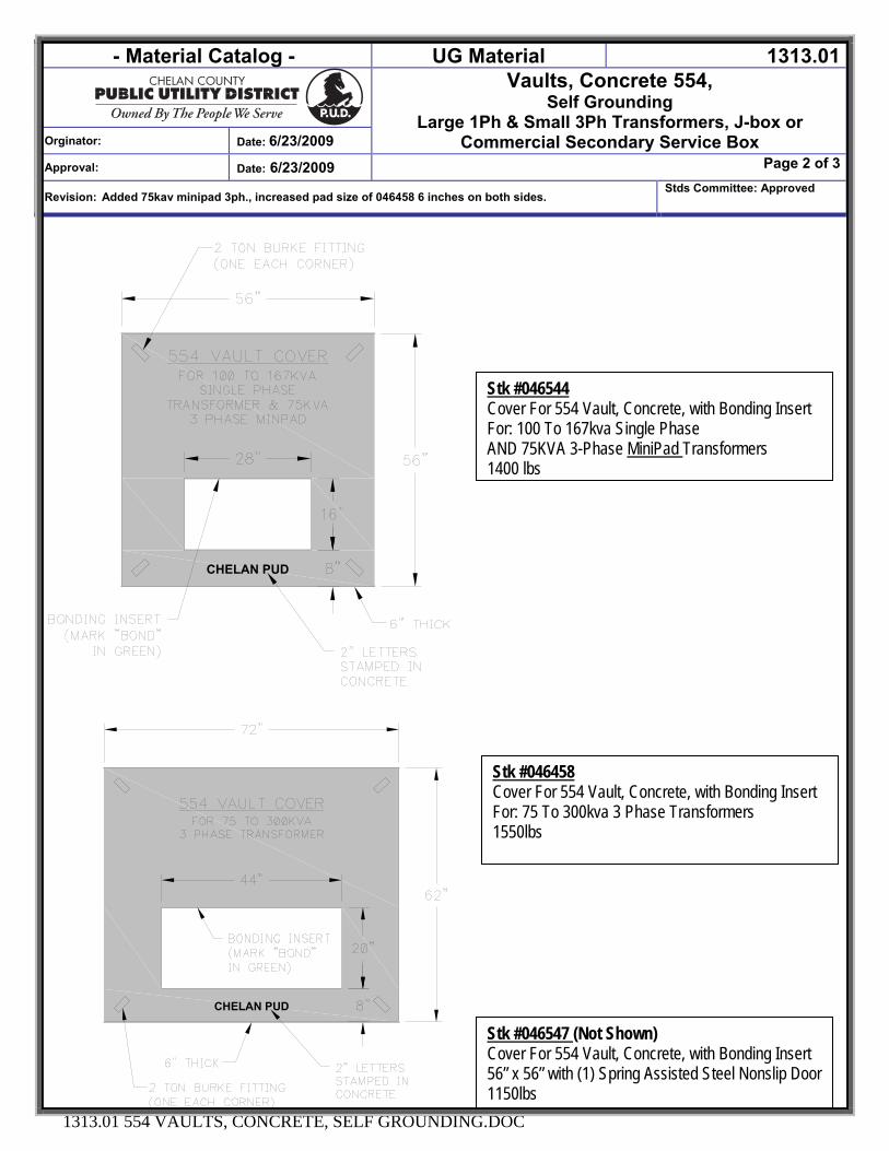
- Material Catalog - UG Material 1313.01Vaults, Concrete 554,
Self Grounding Large 1Ph & Small 3Ph Transformers, J-box or
Commercial Secondary Service Box Orginator: Date: 6/23/2009
Approval: Date: 6/23/2009 Page 2 of 3
Revision: Added 75kav minipad 3ph., increased pad size of 046458 6 inches on both sides. Stds Committee: Approved
1313.01 554 VAULTS, CONCRETE, SELF GROUNDING.DOC
CHELAN PUD
CHELAN PUD
Stk #046544 Cover For 554 Vault, Concrete, with Bonding Insert For: 100 To 167kva Single Phase AND 75KVA 3-Phase MiniPad Transformers 1400 lbs
Stk #046458 Cover For 554 Vault, Concrete, with Bonding Insert For: 75 To 300kva 3 Phase Transformers 1550lbs
Stk #046547 (Not Shown) Cover For 554 Vault, Concrete, with Bonding Insert 56” x 56” with (1) Spring Assisted Steel Nonslip Door 1150lbs
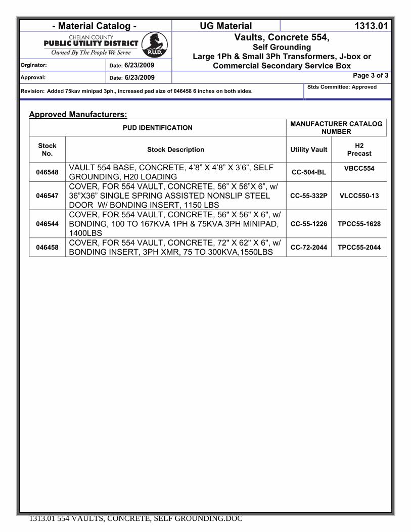
- Material Catalog - UG Material 1313.01Vaults, Concrete 554,
Self Grounding Large 1Ph & Small 3Ph Transformers, J-box or
Commercial Secondary Service Box Orginator: Date: 6/23/2009
Approval: Date: 6/23/2009 Page 3 of 3
Revision: Added 75kav minipad 3ph., increased pad size of 046458 6 inches on both sides. Stds Committee: Approved
1313.01 554 VAULTS, CONCRETE, SELF GROUNDING.DOC
Approved Manufacturers: PUD IDENTIFICATION MANUFACTURER CATALOG
NUMBER
Stock No. Stock Description Utility Vault H2
Precast
046548 VAULT 554 BASE, CONCRETE, 4’8” X 4’8” X 3’6”, SELF GROUNDING, H20 LOADING CC-504-BL VBCC554
046547 COVER, FOR 554 VAULT, CONCRETE, 56” X 56”X 6”, w/ 36”X36” SINGLE SPRING ASSISTED NONSLIP STEEL DOOR W/ BONDING INSERT, 1150 LBS
CC-55-332P VLCC550-13
046544 COVER, FOR 554 VAULT, CONCRETE, 56" X 56" X 6", w/ BONDING, 100 TO 167KVA 1PH & 75KVA 3PH MINIPAD, 1400LBS
CC-55-1226 TPCC55-1628
046458 COVER, FOR 554 VAULT, CONCRETE, 72" X 62" X 6", w/ BONDING INSERT, 3PH XMR, 75 TO 300KVA,1550LBS CC-72-2044 TPCC55-2044
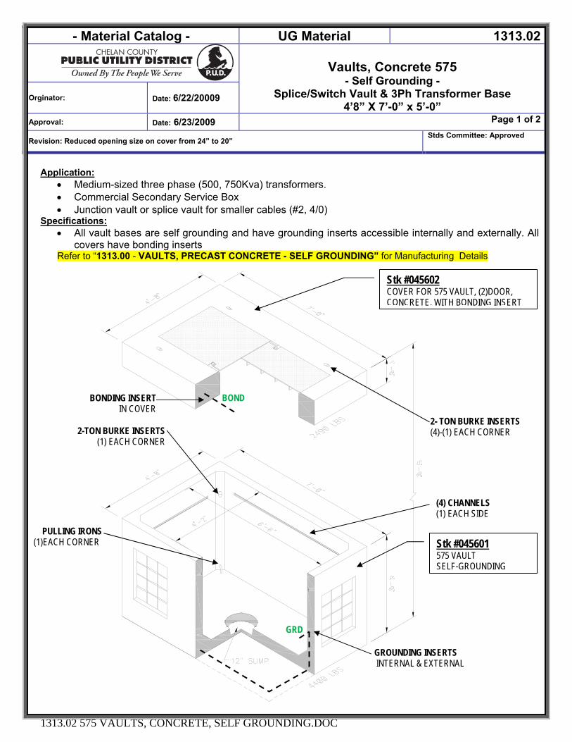
- Material Catalog - UG Material 1313.02
Vaults, Concrete 575 - Self Grounding -
Splice/Switch Vault & 3Ph Transformer Base 4’8” X 7’-0” x 5’-0”
Orginator: Date: 6/22/20009
Approval: Date: 6/23/2009 Page 1 of 2
Revision: Reduced opening size on cover from 24” to 20” Stds Committee: Approved
1313.02 575 VAULTS, CONCRETE, SELF GROUNDING.DOC
Application: • Medium-sized three phase (500, 750Kva) transformers. • Commercial Secondary Service Box • Junction vault or splice vault for smaller cables (#2, 4/0)
Specifications: • All vault bases are self grounding and have grounding inserts accessible internally and externally. All
covers have bonding inserts Refer to “1313.00 - VAULTS, PRECAST CONCRETE - SELF GROUNDING” for Manufacturing Details
Stk #045602 COVER FOR 575 VAULT, (2)DOOR, CONCRETE, WITH BONDING INSERT
Stk #045601 575 VAULT SELF-GROUNDING
2- TON BURKE INSERTS (4)-(1) EACH CORNER
(4) CHANNELS (1) EACH SIDE
BONDING INSERT IN COVER
2-TON BURKE INSERTS (1) EACH CORNER
PULLING IRONS (1)EACH CORNER
GROUNDING INSERTS INTERNAL & EXTERNAL
BOND
GRD
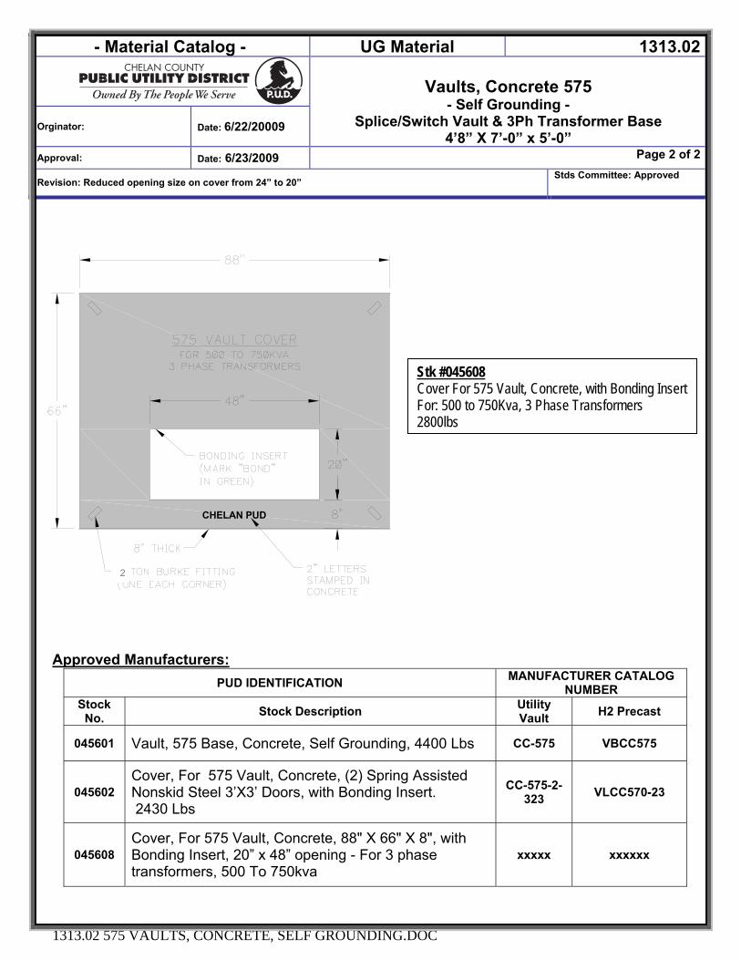
- Material Catalog - UG Material 1313.02
Vaults, Concrete 575 - Self Grounding -
Splice/Switch Vault & 3Ph Transformer Base 4’8” X 7’-0” x 5’-0”
Orginator: Date: 6/22/20009
Approval: Date: 6/23/2009 Page 2 of 2
Revision: Reduced opening size on cover from 24” to 20” Stds Committee: Approved
1313.02 575 VAULTS, CONCRETE, SELF GROUNDING.DOC
CHELAN PUD
Approved Manufacturers:
PUD IDENTIFICATION MANUFACTURER CATALOG NUMBER
Stock No. Stock Description Utility
Vault H2 Precast
045601 Vault, 575 Base, Concrete, Self Grounding, 4400 Lbs CC-575 VBCC575
045602 Cover, For 575 Vault, Concrete, (2) Spring Assisted Nonskid Steel 3’X3’ Doors, with Bonding Insert. 2430 Lbs
CC-575-2-323 VLCC570-23
045608 Cover, For 575 Vault, Concrete, 88" X 66" X 8", with Bonding Insert, 20” x 48” opening - For 3 phase transformers, 500 To 750kva
xxxxx xxxxxx
Stk #045608 Cover For 575 Vault, Concrete, with Bonding Insert For: 500 to 750Kva, 3 Phase Transformers 2800lbs
2
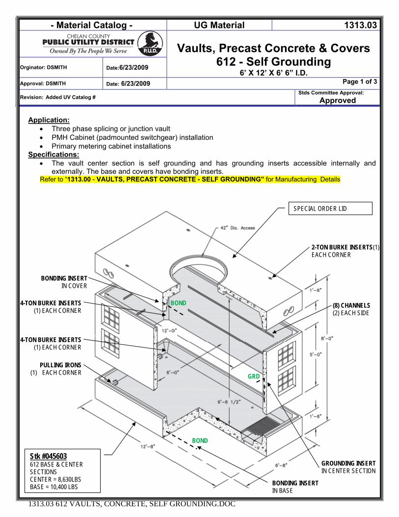
- Material Catalog - UG Material 1313.03
Vaults, Precast Concrete & Covers 612 - Self Grounding
6’ X 12’ X 6’ 6” I.D. Orginator: DSMITH Date:6/23/2009
Approval: DSMITH Date: 6/23/2009 Page 1 of 3
Revision: Added UV Catalog # Stds Committee Approval:
Approved
1313.03 612 VAULTS, CONCRETE, SELF GROUNDING.DOC
Application: • Three phase splicing or junction vault • PMH Cabinet (padmounted switchgear) installation • Primary metering cabinet installations
Specifications: • The vault center section is self grounding and has grounding inserts accessible internally and
externally. The base and covers have bonding inserts. Refer to “1313.00 - VAULTS, PRECAST CONCRETE - SELF GROUNDING” for Manufacturing Details
SPECIAL ORDER LID
(8) CHANNELS (2) EACH SIDE
BONDING INSERT IN COVER
4-TON BURKE INSERTS (1) EACH CORNER
PULLING IRONS (1) EACH CORNER
BONDING INSERT IN BASE
BOND
GRD
Stk #045603 612 BASE & CENTER SECTIONS CENTER = 8,630LBS BASE = 10,400 LBS
2-TON BURKE INSERTS(1) EACH CORNER
BOND
4-TON BURKE INSERTS (1) EACH CORNER
GROUNDING INSERT IN CENTER SECTION
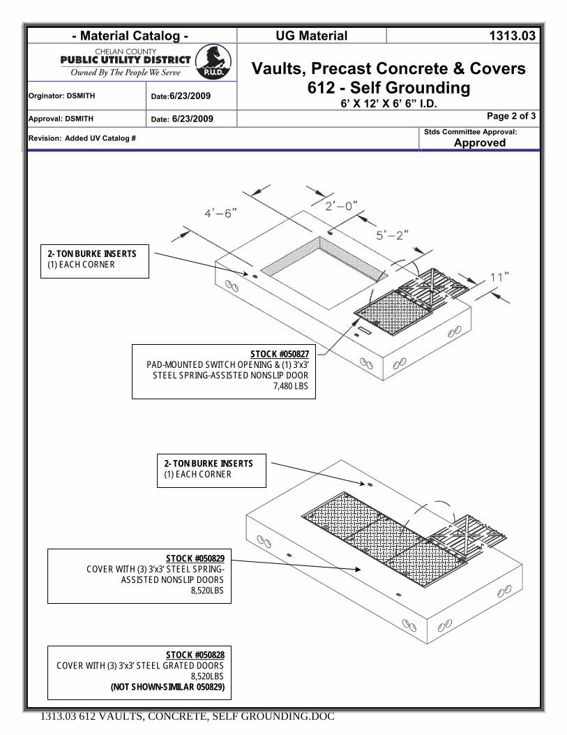
- Material Catalog - UG Material 1313.03
Vaults, Precast Concrete & Covers 612 - Self Grounding
6’ X 12’ X 6’ 6” I.D. Orginator: DSMITH Date:6/23/2009
Approval: DSMITH Date: 6/23/2009 Page 2 of 3
Revision: Added UV Catalog # Stds Committee Approval:
Approved
1313.03 612 VAULTS, CONCRETE, SELF GROUNDING.DOC
STOCK #050827 PAD-MOUNTED SWITCH OPENING & (1) 3’x3’
STEEL SPRING-ASSISTED NONSLIP DOOR 7,480 LBS
2- TON BURKE INSERTS (1) EACH CORNER
STOCK #050829 COVER WITH (3) 3’x3’ STEEL SPRING-
ASSISTED NONSLIP DOORS 8,520LBS
2- TON BURKE INSERTS (1) EACH CORNER
STOCK #050828 COVER WITH (3) 3’x3’ STEEL GRATED DOORS
8,520LBS (NOT SHOWN-SIMILAR 050829)
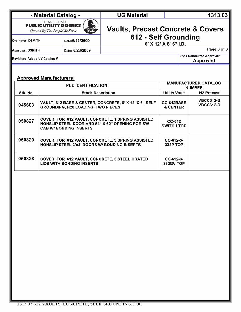
- Material Catalog - UG Material 1313.03
Vaults, Precast Concrete & Covers 612 - Self Grounding
6’ X 12’ X 6’ 6” I.D. Orginator: DSMITH Date:6/23/2009
Approval: DSMITH Date: 6/23/2009 Page 3 of 3
Revision: Added UV Catalog # Stds Committee Approval:
Approved
1313.03 612 VAULTS, CONCRETE, SELF GROUNDING.DOC
Approved Manufacturers:
PUD IDENTIFICATION MANUFACTURER CATALOG NUMBER
Stk. No. Stock Description Utility Vault H2 Precast
045603 VAULT, 612 BASE & CENTER, CONCRETE, 6’ X 12’ X 6’, SELF GROUNDING, H20 LOADING, TWO PIECES
CC-612BASE & CENTER
VBCC612-B VBCC612-D
050827
COVER, FOR 612 VAULT, CONCRETE, 1 SPRING ASSISTED NONSLIP STEEL DOOR AND 54” X 62” OPENING FOR SW CAB W/ BONDING INSERTS
CC-612 SWITCH TOP
050829
COVER, FOR 612 VAULT, CONCRETE, 3 SPRING ASSISTED NONSLIP STEEL 3’x3’ DOORS W/ BONDING INSERTS
CC-612-3-332P TOP
050828
COVER, FOR 612 VAULT, CONCRETE, 3 STEEL GRATED LIDS WITH BONDING INSERTS
CC-612-3-332GV TOP
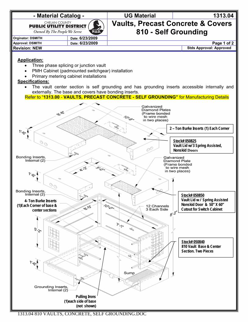
- Material Catalog - UG Material 1313.04Vaults, Precast Concrete & Covers
810 - Self Grounding Orginator: DSMITH Date: 6/23/2009 Approval: DSMITH Date: 6/23/2009 Page 1 of 2 Revision: NEW Stds Approval: Approved
1313.04 810 VAULTS, CONCRETE, SELF GROUNDING.DOC
Application: • Three phase splicing or junction vault • PMH Cabinet (padmounted switchgear) installation • Primary metering cabinet installations
Specifications: • The vault center section is self grounding and has grounding inserts accessible internally and
externally. The base and covers have bonding inserts. Refer to “1313.00 - VAULTS, PRECAST CONCRETE - SELF GROUNDING” for Manufacturing Details
Stock# 050825 Vault Lid w/ 3 Spring Assisted, Nonskid Doors
Stock# 050850 Vault Lid w / Spring Assisted Nonskid Door & 50” X 60” Cutout for Switch Cabinet
Stock# 050840 810 Vault Base & Center Section. Two Pieces
2 – Ton Burke Inserts (1) Each Corner
4- Ton Burke Inserts (1)Each Corner of base &
center sections
Pulling Irons (1)each side of base
(not shown)
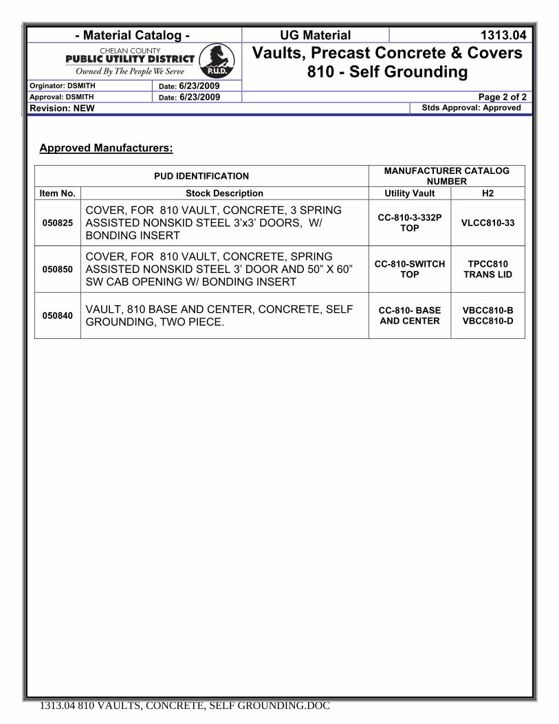
- Material Catalog - UG Material 1313.04Vaults, Precast Concrete & Covers
810 - Self Grounding Orginator: DSMITH Date: 6/23/2009 Approval: DSMITH Date: 6/23/2009 Page 2 of 2 Revision: NEW Stds Approval: Approved
1313.04 810 VAULTS, CONCRETE, SELF GROUNDING.DOC
Approved Manufacturers:
PUD IDENTIFICATION MANUFACTURER CATALOG NUMBER
Item No. Stock Description Utility Vault H2
050825 COVER, FOR 810 VAULT, CONCRETE, 3 SPRING ASSISTED NONSKID STEEL 3’x3’ DOORS, W/ BONDING INSERT
CC-810-3-332P TOP VLCC810-33
050850 COVER, FOR 810 VAULT, CONCRETE, SPRING ASSISTED NONSKID STEEL 3’ DOOR AND 50” X 60” SW CAB OPENING W/ BONDING INSERT
CC-810-SWITCH TOP
TPCC810 TRANS LID
050840 VAULT, 810 BASE AND CENTER, CONCRETE, SELF GROUNDING, TWO PIECE.
CC-810- BASE AND CENTER
VBCC810-B VBCC810-D
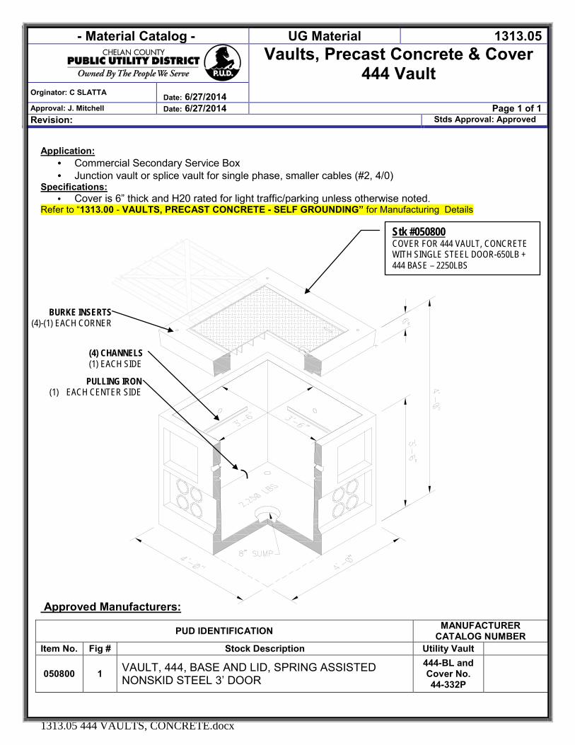
- Material Catalog - UG Material 1313.05
Vaults, Precast Concrete & Cover 444 Vault
Orginator: C SLATTA Date: 6/27/2014
Approval: J. Mitchell Date: 6/27/2014 Page 1 of 1 Revision: Stds Approval: Approved
1313.05 444 VAULTS, CONCRETE.docx
Application: · Commercial Secondary Service Box · Junction vault or splice vault for single phase, smaller cables (#2, 4/0)
Specifications: · Cover is 6” thick and H20 rated for light traffic/parking unless otherwise noted.
Refer to “1313.00 - VAULTS, PRECAST CONCRETE - SELF GROUNDING” for Manufacturing Details
Approved Manufacturers:
PUD IDENTIFICATION MANUFACTURER CATALOG NUMBER
Item No. Fig # Stock Description Utility Vault
050800 1 VAULT, 444, BASE AND LID, SPRING ASSISTED NONSKID STEEL 3’ DOOR
444-BL and Cover No. 44-332P
BURKE INSERTS (4)-(1) EACH CORNER
(4) CHANNELS (1) EACH SIDE
PULLING IRON (1) EACH CENTER SIDE
Stk #050800 COVER FOR 444 VAULT, CONCRETE WITH SINGLE STEEL DOOR-650LB + 444 BASE – 2250LBS
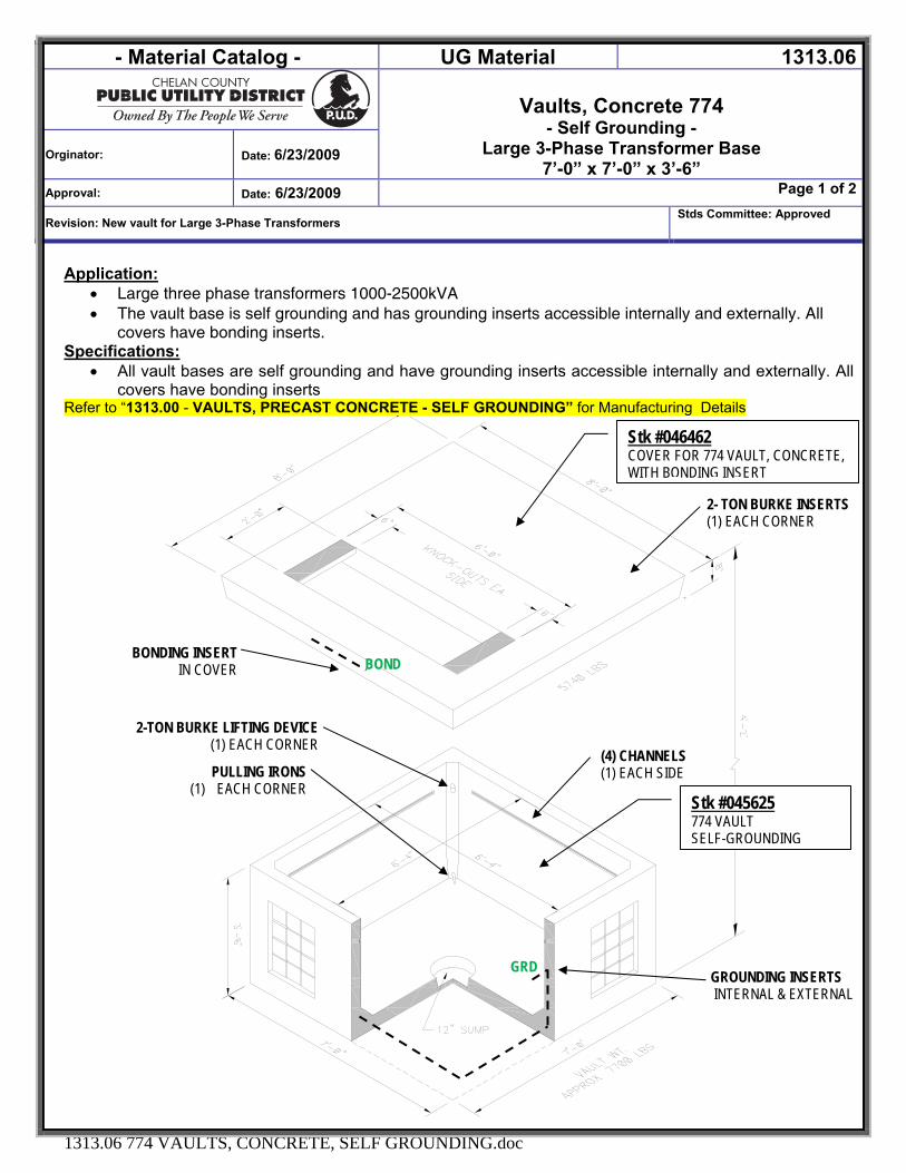
- Material Catalog - UG Material 1313.06
Vaults, Concrete 774 - Self Grounding -
Large 3-Phase Transformer Base 7’-0” x 7’-0” x 3’-6”
Orginator: Date: 6/23/2009
Approval: Date: 6/23/2009 Page 1 of 2
Revision: New vault for Large 3-Phase Transformers Stds Committee: Approved
1313.06 774 VAULTS, CONCRETE, SELF GROUNDING.doc
Application: • Large three phase transformers 1000-2500kVA • The vault base is self grounding and has grounding inserts accessible internally and externally. All
covers have bonding inserts. Specifications:
• All vault bases are self grounding and have grounding inserts accessible internally and externally. All covers have bonding inserts
Refer to “1313.00 - VAULTS, PRECAST CONCRETE - SELF GROUNDING” for Manufacturing Details
Stk #046462 COVER FOR 774 VAULT, CONCRETE, WITH BONDING INSERT
Stk #045625 774 VAULT SELF-GROUNDING
2- TON BURKE INSERTS (1) EACH CORNER
(4) CHANNELS (1) EACH SIDE
BONDING INSERT IN COVER
2-TON BURKE LIFTING DEVICE (1) EACH CORNER
PULLING IRONS (1) EACH CORNER
GROUNDING INSERTS INTERNAL & EXTERNAL
BOND
GRD

- Material Catalog - UG Material 1313.06
Vaults, Concrete 774 - Self Grounding -
Large 3-Phase Transformer Base 7’-0” x 7’-0” x 3’-6”
Orginator: Date: 6/23/2009
Approval: Date: 6/23/2009 Page 2 of 2
Revision: New vault for Large 3-Phase Transformers Stds Committee: Approved
1313.06 774 VAULTS, CONCRETE, SELF GROUNDING.doc
CHELAN PUD
PUD IDENTIFICATION MANUFACTURER CATALOG NUMBER
Stock No. Stock Description Utility Vault H2 Precast 045625 Vault, 774 Base, Concrete, Self Grounding, 4400 Lbs XXXX XXXX
046462
Cover, For 774 Vault, Concrete, 96" X 96" X 8", with Bonding Insert, 24” x 60” opening with (2) - 6” knockouts. For 3PH transformers, 1000 to 2500kva. 5740lbs
CC-88-2460 TPCC88-2460
Stk #046462 Cover For 774 Vault, Concrete, with Bonding Insert For: 1000 to 2500kVA, 3 Phase Transformers 5740lbs
2
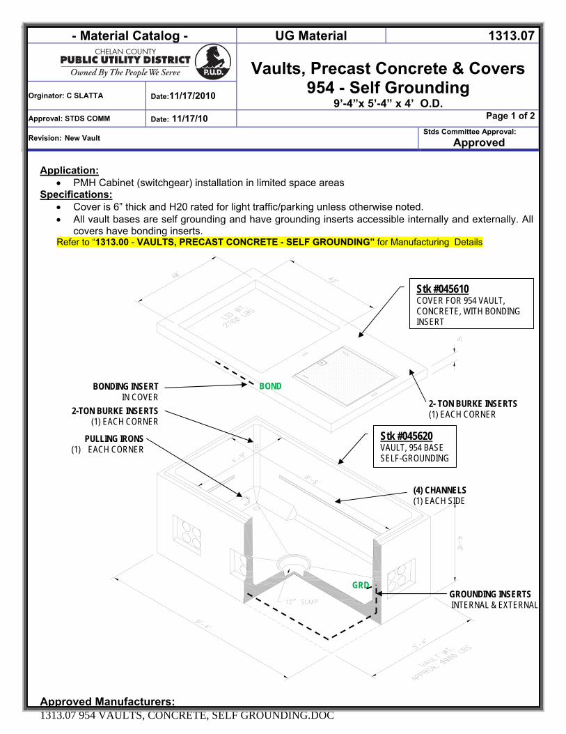
- Material Catalog - UG Material 1313.07
Vaults, Precast Concrete & Covers 954 - Self Grounding
9’-4”x 5’-4” x 4’ O.D. Orginator: C SLATTA Date:11/17/2010
Approval: STDS COMM Date: 11/17/10 Page 1 of 2
Revision: New Vault Stds Committee Approval:
Approved
1313.07 954 VAULTS, CONCRETE, SELF GROUNDING.DOC
Application: • PMH Cabinet (switchgear) installation in limited space areas
Specifications: • Cover is 6” thick and H20 rated for light traffic/parking unless otherwise noted. • All vault bases are self grounding and have grounding inserts accessible internally and externally. All
covers have bonding inserts. Refer to “1313.00 - VAULTS, PRECAST CONCRETE - SELF GROUNDING” for Manufacturing Details
Approved Manufacturers:
Stk #045610 COVER FOR 954 VAULT, CONCRETE, WITH BONDING INSERT
(4) CHANNELS (1) EACH SIDE
BONDING INSERT IN COVER
2-TON BURKE INSERTS (1) EACH CORNER
PULLING IRONS (1) EACH CORNER
GROUNDING INSERTS INTERNAL & EXTERNAL
BOND
GRD
2- TON BURKE INSERTS (1) EACH CORNER
Stk #045620 VAULT, 954 BASE SELF-GROUNDING

- Material Catalog - UG Material 1313.07
Vaults, Precast Concrete & Covers 954 - Self Grounding
9’-4”x 5’-4” x 4’ O.D. Orginator: C SLATTA Date:11/17/2010
Approval: STDS COMM Date: 11/17/10 Page 2 of 2
Revision: New Vault Stds Committee Approval:
Approved
1313.07 954 VAULTS, CONCRETE, SELF GROUNDING.DOC
Approved Manufacturers:
PUD IDENTIFICATION MANUFACTURER CATALOG NUMBER
Figure Stock No. Stock Description Utility Vault H2
Precast
1 045610 COVER, FOR PMH CABINET WITH 42” X 48” OPENING AND 36” X 36” SPRING ASSISTED STEEL DOOR
2 045620
VAULT, 954 BASE, CONCRETE, 9’-4” x 5’-4” x 4’, SELF GROUNDING. SPECIAL COVER: WITH 42” x 48” OPENING AND 36” X36” SPRING ASSISTED, NON-SKID STEEL DOOR
XXXX
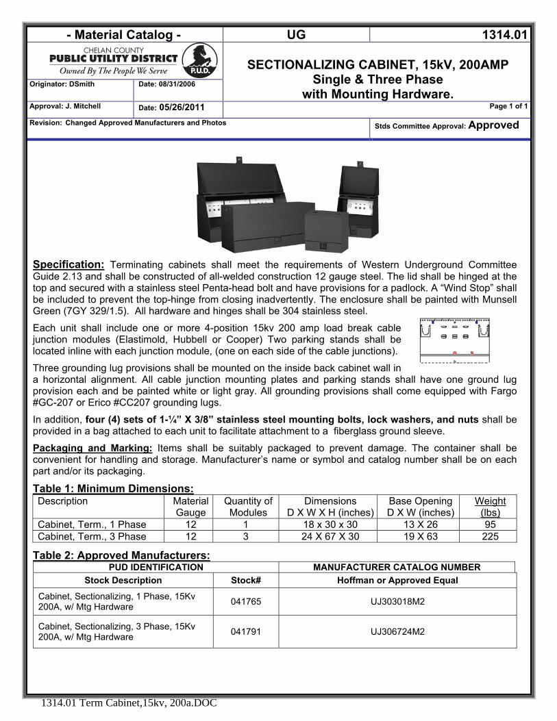
- Material Catalog - UG 1314.01
SECTIONALIZING CABINET, 15kV, 200AMP
Single & Three Phase with Mounting Hardware.
Originator: DSmith Date: 08/31/2006
Approval: J. Mitchell Date: 05/26/2011 Page 1 of 1
Revision: Changed Approved Manufacturers and Photos Stds Committee Approval: Approved
1314.01 Term Cabinet,15kv, 200a.DOC
Specification: Terminating cabinets shall meet the requirements of Western Underground Committee Guide 2.13 and shall be constructed of all-welded construction 12 gauge steel. The lid shall be hinged at the top and secured with a stainless steel Penta-head bolt and have provisions for a padlock. A “Wind Stop” shall be included to prevent the top-hinge from closing inadvertently. The enclosure shall be painted with Munsell Green (7GY 329/1.5). All hardware and hinges shall be 304 stainless steel.
Each unit shall include one or more 4-position 15kv 200 amp load break cable junction modules (Elastimold, Hubbell or Cooper) Two parking stands shall be located inline with each junction module, (one on each side of the cable junctions).
Three grounding lug provisions shall be mounted on the inside back cabinet wall in a horizontal alignment. All cable junction mounting plates and parking stands shall have one ground lug provision each and be painted white or light gray. All grounding provisions shall come equipped with Fargo #GC-207 or Erico #CC207 grounding lugs.
In addition, four (4) sets of 1-¼” X 3/8” stainless steel mounting bolts, lock washers, and nuts shall be provided in a bag attached to each unit to facilitate attachment to a fiberglass ground sleeve.
Packaging and Marking: Items shall be suitably packaged to prevent damage. The container shall be convenient for handling and storage. Manufacturer’s name or symbol and catalog number shall be on each part and/or its packaging.
Table 1: Minimum Dimensions: Description Material
Gauge Quantity of Modules
Dimensions D X W X H (inches)
Base Opening D X W (inches)
Weight (lbs)
Cabinet, Term., 1 Phase 12 1 18 x 30 x 30 13 X 26 95 Cabinet, Term., 3 Phase 12 3 24 X 67 X 30 19 X 63 225
Table 2: Approved Manufacturers: PUD IDENTIFICATION MANUFACTURER CATALOG NUMBER
Stock Description Stock# Hoffman or Approved Equal
Cabinet, Sectionalizing, 1 Phase, 15Kv 200A, w/ Mtg Hardware 041765 UJ303018M2
Cabinet, Sectionalizing, 3 Phase, 15Kv 200A, w/ Mtg Hardware 041791 UJ306724M2
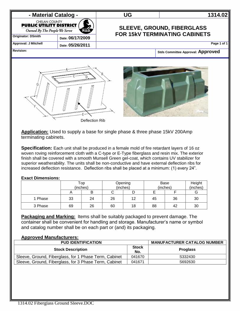
- Material Catalog - UG 1314.02
SLEEVE, GROUND, FIBERGLASS
FOR 15kV TERMINATING CABINETS Originator: DSmith Date: 06/17/2009 Approval: J Mitchell Date: 05/26/2011 Page 1 of 1
Revision: Stds Committee Approval: Approved
1314.02 Fiberglass Ground Sleeve.DOC
Application: Used to supply a base for single phase & three phase 15kV 200Amp terminating cabinets.
Specification: Each unit shall be produced in a female mold of fire retardant layers of 16 oz woven roving reinforcement cloth with a C-type or E-Type fiberglass and resin mix. The exterior finish shall be covered with a smooth Munsell Green gel-coat, which contains UV stabilizer for superior weatherability. The units shall be non-conductive and have external deflection ribs for increased deflection resistance. Deflection ribs shall be placed at a minimum: (1) every 24”. Exact Dimensions:
Top
(inches) Opening (inches)
Base (inches)
Height (inches)
A B C D E F G 1 Phase 33 24 26 12 45 36 30
3 Phase 69 26 60 18 88 42 30 Packaging and Marking: Items shall be suitably packaged to prevent damage. The container shall be convenient for handling and storage. Manufacturer’s name or symbol and catalog number shall be on each part or (and) its packaging. Approved Manufacturers:
PUD IDENTIFICATION MANUFACTURER CATALOG NUMBER
Stock Description Stock No. Proglass
Sleeve, Ground, Fiberglass, for 1 Phase Term, Cabinet 041670 S332430 Sleeve, Ground, Fiberglass, for 3 Phase Term, Cabinet 041671 S692630
Deflection Rib
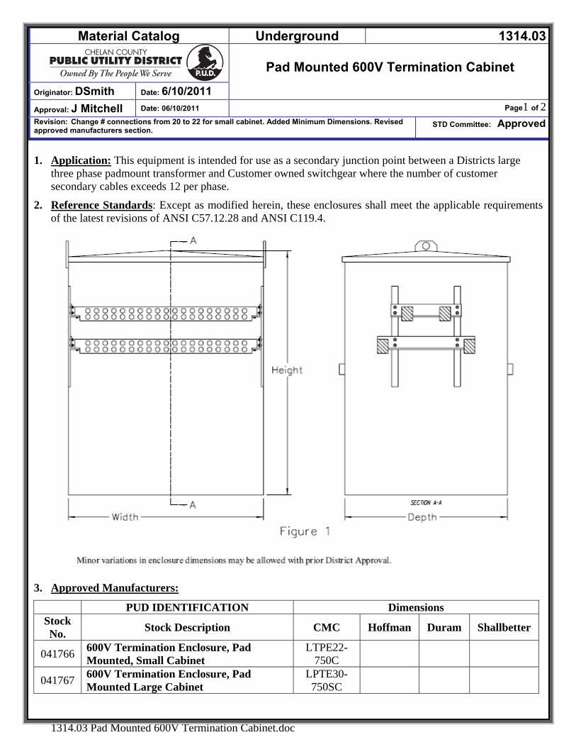
Material Catalog Underground 1314.03
Pad Mounted 600V Termination Cabinet
Originator: DSmith Date: 6/10/2011
Approval: J Mitchell Date: 06/10/2011 Page1 of 2Revision: Change # connections from 20 to 22 for small cabinet. Added Minimum Dimensions. Revised approved manufacturers section.
STD Committee: Approved
1314.03 Pad Mounted 600V Termination Cabinet.doc
1. Application: This equipment is intended for use as a secondary junction point between a Districts large three phase padmount transformer and Customer owned switchgear where the number of customer secondary cables exceeds 12 per phase.
2. Reference Standards: Except as modified herein, these enclosures shall meet the applicable requirements of the latest revisions of ANSI C57.12.28 and ANSI C119.4.
3. Approved Manufacturers:
PUD IDENTIFICATION Dimensions Stock No. Stock Description CMC Hoffman Duram Shallbetter
041766 600V Termination Enclosure, Pad Mounted, Small Cabinet
LTPE22-750C
041767 600V Termination Enclosure, Pad Mounted Large Cabinet
LPTE30-750SC
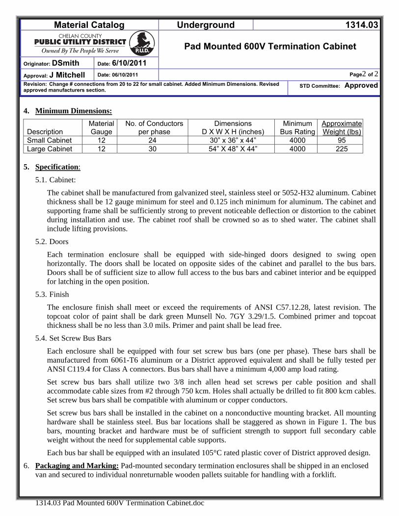
Material Catalog Underground 1314.03
Pad Mounted 600V Termination Cabinet
Originator: DSmith Date: 6/10/2011
Approval: J Mitchell Date: 06/10/2011 Page2 of 2Revision: Change # connections from 20 to 22 for small cabinet. Added Minimum Dimensions. Revised approved manufacturers section.
STD Committee: Approved
1314.03 Pad Mounted 600V Termination Cabinet.doc
4. Minimum Dimensions:
Description Material Gauge
No. of Conductors per phase
Dimensions D X W X H (inches)
Minimum Bus Rating
ApproximateWeight (lbs)
Small Cabinet 12 24 30” x 36” x 44” 4000 95 Large Cabinet 12 30 54” X 48” X 44” 4000 225
5. Specification:
5.1. Cabinet:
The cabinet shall be manufactured from galvanized steel, stainless steel or 5052-H32 aluminum. Cabinet thickness shall be 12 gauge minimum for steel and 0.125 inch minimum for aluminum. The cabinet and supporting frame shall be sufficiently strong to prevent noticeable deflection or distortion to the cabinet during installation and use. The cabinet roof shall be crowned so as to shed water. The cabinet shall include lifting provisions.
5.2. Doors
Each termination enclosure shall be equipped with side-hinged doors designed to swing open horizontally. The doors shall be located on opposite sides of the cabinet and parallel to the bus bars. Doors shall be of sufficient size to allow full access to the bus bars and cabinet interior and be equipped for latching in the open position.
5.3. Finish
The enclosure finish shall meet or exceed the requirements of ANSI C57.12.28, latest revision. The topcoat color of paint shall be dark green Munsell No. 7GY 3.29/1.5. Combined primer and topcoat thickness shall be no less than 3.0 mils. Primer and paint shall be lead free.
5.4. Set Screw Bus Bars
Each enclosure shall be equipped with four set screw bus bars (one per phase). These bars shall be manufactured from 6061-T6 aluminum or a District approved equivalent and shall be fully tested per ANSI C119.4 for Class A connectors. Bus bars shall have a minimum 4,000 amp load rating.
Set screw bus bars shall utilize two 3/8 inch allen head set screws per cable position and shall accommodate cable sizes from #2 through 750 kcm. Holes shall actually be drilled to fit 800 kcm cables. Set screw bus bars shall be compatible with aluminum or copper conductors.
Set screw bus bars shall be installed in the cabinet on a nonconductive mounting bracket. All mounting hardware shall be stainless steel. Bus bar locations shall be staggered as shown in Figure 1. The bus bars, mounting bracket and hardware must be of sufficient strength to support full secondary cable weight without the need for supplemental cable supports.
Each bus bar shall be equipped with an insulated 105°C rated plastic cover of District approved design.
6. Packaging and Marking: Pad-mounted secondary termination enclosures shall be shipped in an enclosed van and secured to individual nonreturnable wooden pallets suitable for handling with a forklift.
- Material Catalog - Fuses & Arrestors 1400
Originator: DSmith Date:7/9/2007
Fuses & Arresters
Approval: DSmith Date: 7/9/2007 Page 1 of 1
Revision: NEW Stds Committee Approval: Approved
1400.00 FUSES & ARRESTERS.DOC
FUSES & ARRESTERS
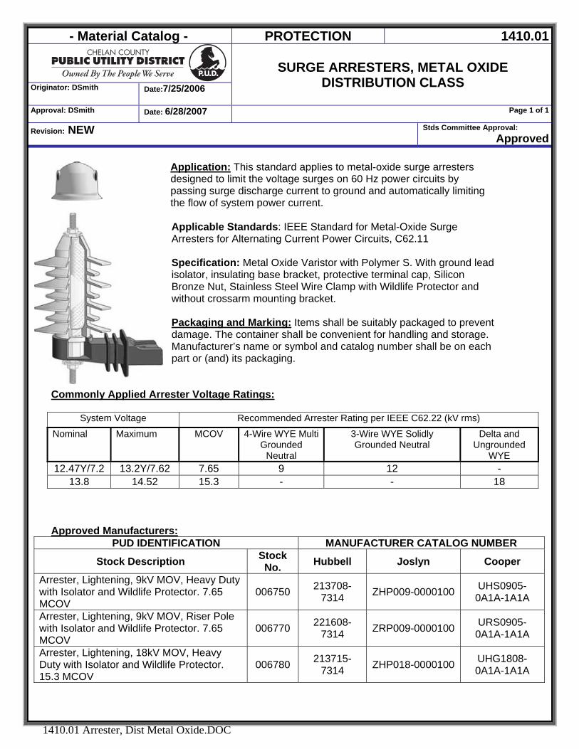
- Material Catalog - PROTECTION 1410.01
Originator: DSmith Date:7/25/2006
SURGE ARRESTERS, METAL OXIDE
DISTRIBUTION CLASS
Approval: DSmith Date: 6/28/2007 Page 1 of 1
Revision: NEW Stds Committee Approval: Approved
1410.01 Arrester, Dist Metal Oxide.DOC
Application: This standard applies to metal-oxide surge arresters designed to limit the voltage surges on 60 Hz power circuits by passing surge discharge current to ground and automatically limiting the flow of system power current. Applicable Standards: IEEE Standard for Metal-Oxide Surge Arresters for Alternating Current Power Circuits, C62.11 Specification: Metal Oxide Varistor with Polymer S. With ground lead isolator, insulating base bracket, protective terminal cap, Silicon Bronze Nut, Stainless Steel Wire Clamp with Wildlife Protector and without crossarm mounting bracket. Packaging and Marking: Items shall be suitably packaged to prevent damage. The container shall be convenient for handling and storage. Manufacturer’s name or symbol and catalog number shall be on each part or (and) its packaging.
Commonly Applied Arrester Voltage Ratings:
System Voltage Recommended Arrester Rating per IEEE C62.22 (kV rms)
Nominal Maximum MCOV 4-Wire WYE Multi Grounded
Neutral
3-Wire WYE Solidly Grounded Neutral
Delta and Ungrounded
WYE 12.47Y/7.2 13.2Y/7.62 7.65 9 12 -
13.8 14.52 15.3 - - 18
Approved Manufacturers:
PUD IDENTIFICATION MANUFACTURER CATALOG NUMBER
Stock Description Stock No. Hubbell Joslyn Cooper
Arrester, Lightening, 9kV MOV, Heavy Duty with Isolator and Wildlife Protector. 7.65 MCOV
006750 213708-7314 ZHP009-0000100 UHS0905-
0A1A-1A1A
Arrester, Lightening, 9kV MOV, Riser Pole with Isolator and Wildlife Protector. 7.65 MCOV
006770 221608-7314 ZRP009-0000100 URS0905-
0A1A-1A1A
Arrester, Lightening, 18kV MOV, Heavy Duty with Isolator and Wildlife Protector. 15.3 MCOV
006780 213715-7314 ZHP018-0000100 UHG1808-
0A1A-1A1A
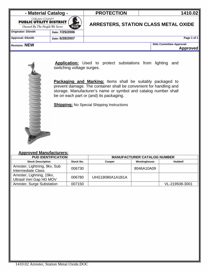
- Material Catalog - PROTECTION 1410.02
Originator: DSmith Date: 7/25/2006
ARRESTERS, STATION CLASS METAL OXIDE
Approval: DSmith Date: 6/28/2007 Page 1 of 1
Revision: NEW Stds Committee Approval: Approved
1410.02 Arrester, Station Metal Oxide.DOC
Application: Used to protect substations from lighting and switching voltage surges. Packaging and Marking: Items shall be suitably packaged to prevent damage. The container shall be convenient for handling and storage. Manufacturer’s name or symbol and catalog number shall be on each part or (and) its packaging. Shipping: No Special Shipping Instructions
Approved Manufacturers:
PUD IDENTIFICATION MANUFACTURER CATALOG NUMBER Stock Description Stock No. Cooper Westinghouse Hubbell
Arrester, Lightning, 9kv, Sub Intermediate Class 006730 8046A10A09
Arrester, Lighning, 19kv, Ultrasil Veri Gap HD MOV 006780 UHG18080A1A1B1A
Arrester, Surge Substation 007150 VL-219508-3001
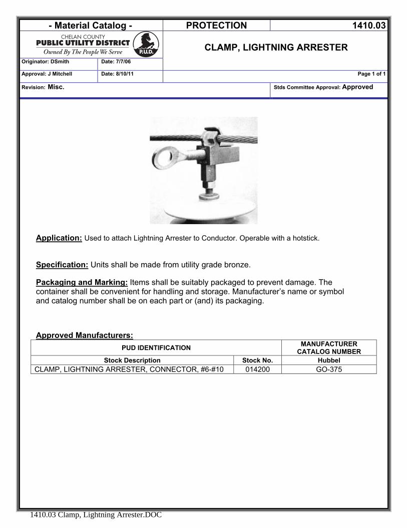
- Material Catalog - PROTECTION 1410.03
CLAMP, LIGHTNING ARRESTER
Originator: DSmith Date: 7/7/06
Approval: J Mitchell Date: 8/10/11 Page 1 of 1
Revision: Misc. Stds Committee Approval: Approved
1410.03 Clamp, Lightning Arrester.DOC
Application: Used to attach Lightning Arrester to Conductor. Operable with a hotstick.
Specification: Units shall be made from utility grade bronze. Packaging and Marking: Items shall be suitably packaged to prevent damage. The container shall be convenient for handling and storage. Manufacturer’s name or symbol and catalog number shall be on each part or (and) its packaging. Approved Manufacturers:
PUD IDENTIFICATION MANUFACTURER CATALOG NUMBER
Stock Description Stock No. Hubbel CLAMP, LIGHTNING ARRESTER, CONNECTOR, #6-#10 014200 GO-375
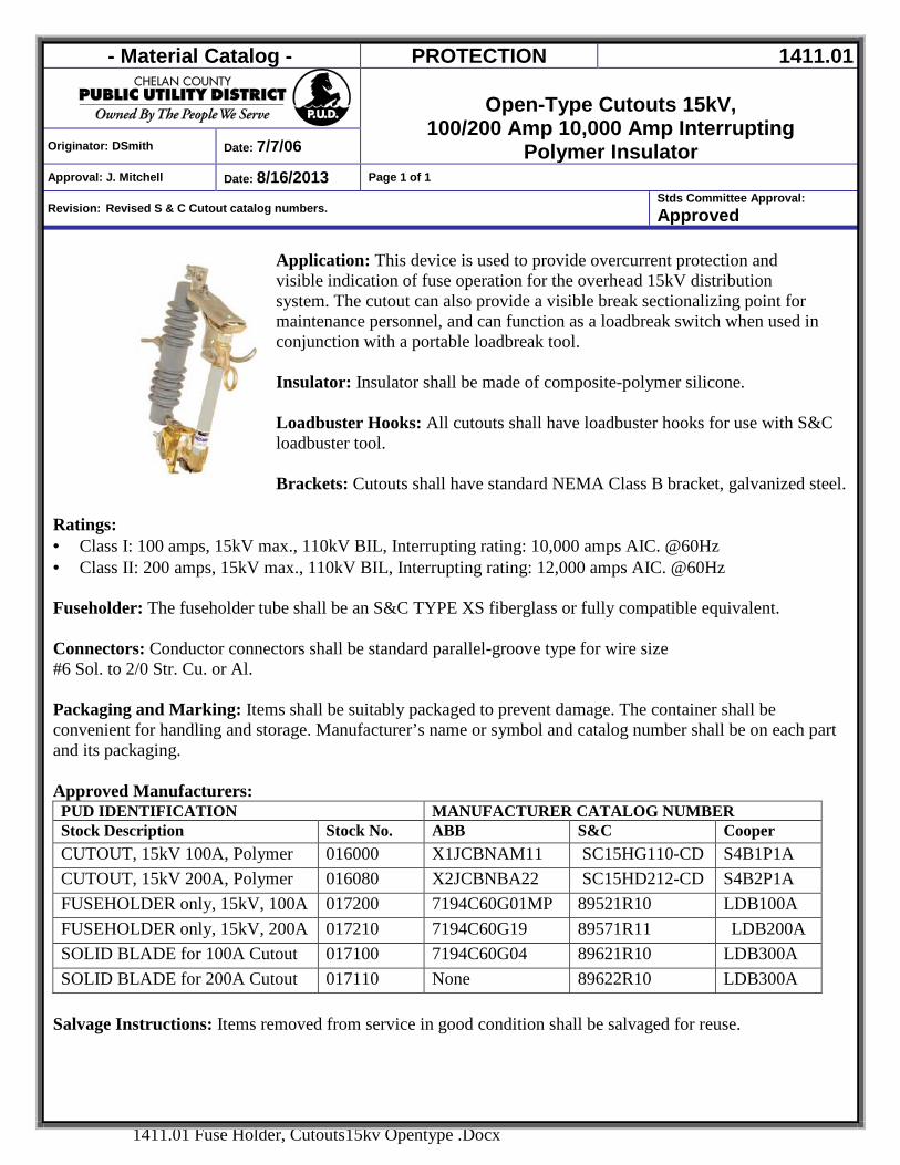
- Material Catalog - PROTECTION 1411.01
Open-Type Cutouts 15kV,
100/200 Amp 10,000 Amp Interrupting Polymer Insulator Originator: DSmith Date: 7/7/06
Approval: J. Mitchell Date: 8/16/2013 Page 1 of 1
Revision: Revised S & C Cutout catalog numbers. Stds Committee Approval: Approved
1411.01 Fuse Holder, Cutouts15kv Opentype .Docx
Application: This device is used to provide overcurrent protection and visible indication of fuse operation for the overhead 15kV distribution system. The cutout can also provide a visible break sectionalizing point for maintenance personnel, and can function as a loadbreak switch when used in conjunction with a portable loadbreak tool. Insulator: Insulator shall be made of composite-polymer silicone. Loadbuster Hooks: All cutouts shall have loadbuster hooks for use with S&C loadbuster tool. Brackets: Cutouts shall have standard NEMA Class B bracket, galvanized steel.
Ratings: · Class I: 100 amps, 15kV max., 110kV BIL, Interrupting rating: 10,000 amps AIC. @60Hz · Class II: 200 amps, 15kV max., 110kV BIL, Interrupting rating: 12,000 amps AIC. @60Hz Fuseholder: The fuseholder tube shall be an S&C TYPE XS fiberglass or fully compatible equivalent. Connectors: Conductor connectors shall be standard parallel-groove type for wire size #6 Sol. to 2/0 Str. Cu. or Al. Packaging and Marking: Items shall be suitably packaged to prevent damage. The container shall be convenient for handling and storage. Manufacturer’s name or symbol and catalog number shall be on each part and its packaging.
Approved Manufacturers: PUD IDENTIFICATION MANUFACTURER CATALOG NUMBER Stock Description Stock No. ABB S&C Cooper CUTOUT, 15kV 100A, Polymer 016000 X1JCBNAM11 SC15HG110-CD S4B1P1A CUTOUT, 15kV 200A, Polymer 016080 X2JCBNBA22 SC15HD212-CD S4B2P1A FUSEHOLDER only, 15kV, 100A 017200 7194C60G01MP 89521R10 LDB100A FUSEHOLDER only, 15kV, 200A 017210 7194C60G19 89571R11 LDB200A SOLID BLADE for 100A Cutout 017100 7194C60G04 89621R10 LDB300A SOLID BLADE for 200A Cutout 017110 None 89622R10 LDB300A
Salvage Instructions: Items removed from service in good condition shall be salvaged for reuse.
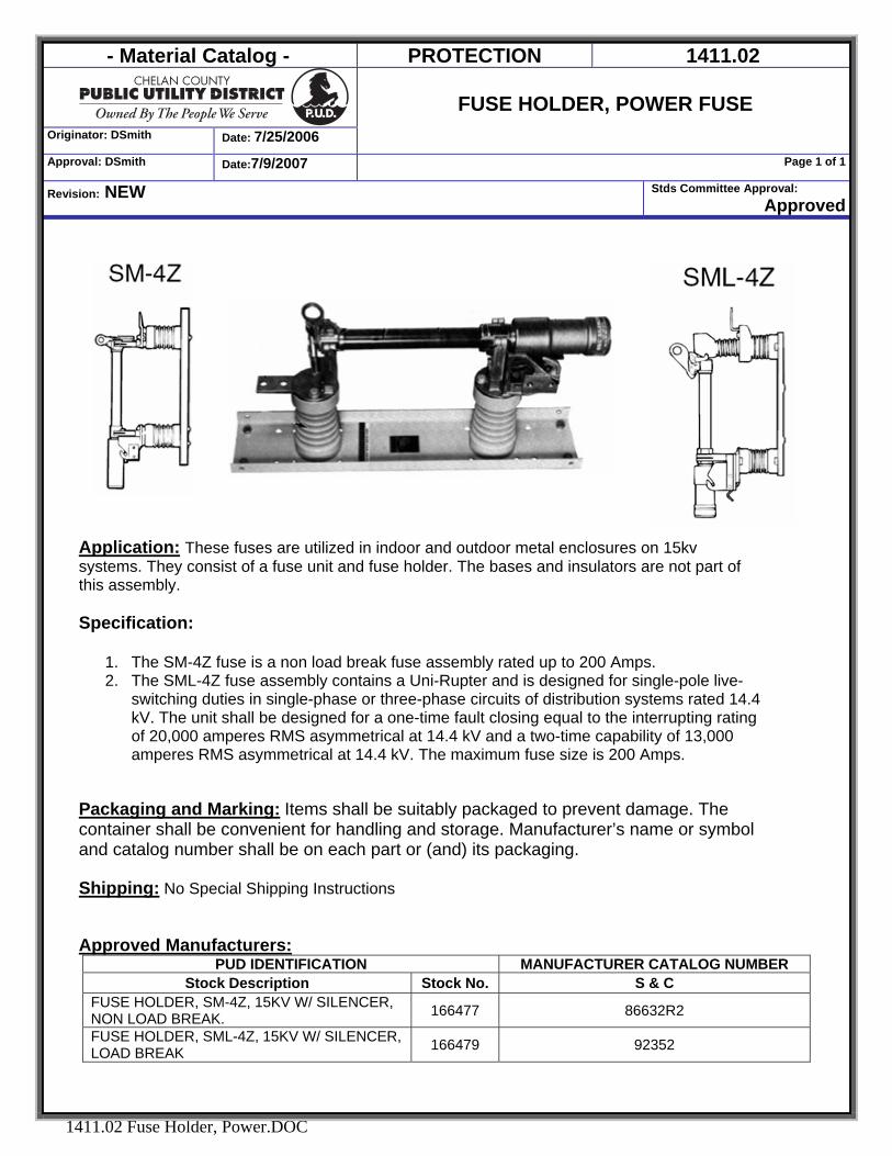
- Material Catalog - PROTECTION 1411.02
Originator: DSmith Date: 7/25/2006
FUSE HOLDER, POWER FUSE
Approval: DSmith Date:7/9/2007 Page 1 of 1
Revision: NEW Stds Committee Approval: Approved
1411.02 Fuse Holder, Power.DOC
Application: These fuses are utilized in indoor and outdoor metal enclosures on 15kv systems. They consist of a fuse unit and fuse holder. The bases and insulators are not part of this assembly. Specification:
1. The SM-4Z fuse is a non load break fuse assembly rated up to 200 Amps. 2. The SML-4Z fuse assembly contains a Uni-Rupter and is designed for single-pole live-
switching duties in single-phase or three-phase circuits of distribution systems rated 14.4 kV. The unit shall be designed for a one-time fault closing equal to the interrupting rating of 20,000 amperes RMS asymmetrical at 14.4 kV and a two-time capability of 13,000 amperes RMS asymmetrical at 14.4 kV. The maximum fuse size is 200 Amps.
Packaging and Marking: Items shall be suitably packaged to prevent damage. The container shall be convenient for handling and storage. Manufacturer’s name or symbol and catalog number shall be on each part or (and) its packaging. Shipping: No Special Shipping Instructions Approved Manufacturers:
PUD IDENTIFICATION MANUFACTURER CATALOG NUMBER Stock Description Stock No. S & C
FUSE HOLDER, SM-4Z, 15KV W/ SILENCER, NON LOAD BREAK. 166477 86632R2
FUSE HOLDER, SML-4Z, 15KV W/ SILENCER, LOAD BREAK 166479 92352
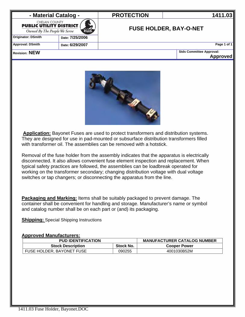
- Material Catalog - PROTECTION 1411.03
Originator: DSmith Date: 7/25/2006
FUSE HOLDER, BAY-O-NET
Approval: DSmith Date: 6/29/2007 Page 1 of 1
Revision: NEW Stds Committee Approval: Approved
1411.03 Fuse Holder, Bayonet.DOC
Application: Bayonet Fuses are used to protect transformers and distribution systems. They are designed for use in pad-mounted or subsurface distribution transformers filled with transformer oil. The assemblies can be removed with a hotstick. Removal of the fuse holder from the assembly indicates that the apparatus is electrically disconnected. It also allows convenient fuse element inspection and replacement. When typical safety practices are followed, the assemblies can be loadbreak operated for working on the transformer secondary; changing distribution voltage with dual voltage switches or tap changers; or disconnecting the apparatus from the line. Packaging and Marking: Items shall be suitably packaged to prevent damage. The container shall be convenient for handling and storage. Manufacturer’s name or symbol and catalog number shall be on each part or (and) its packaging. Shipping: Special Shipping Instructions Approved Manufacturers:
PUD IDENTIFICATION MANUFACTURER CATALOG NUMBER Stock Description Stock No. Cooper Power
FUSE HOLDER, BAYONET FUSE 090255 4001030B52M
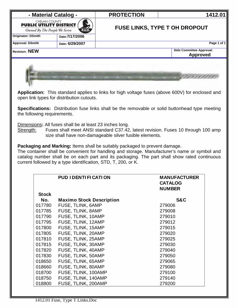
- Material Catalog - PROTECTION 1412.01
Originator: DSmith Date:7/17/2006
FUSE LINKS, TYPE T OH DROPOUT
Approval: DSmith Date: 6/29/2007 Page 1 of 1
Revision: NEW Stds Committee Approval: Approved
1412.01 Fuse, Type T Links.Doc
Application: This standard applies to links for high voltage fuses (above 600V) for enclosed and open link types for distribution cutouts. Specifications: Distribution fuse links shall be the removable or solid buttonhead type meeting the following requirements. Dimensions: All fuses shall be at least 23 inches long. Strength: Fuses shall meet ANSI standard C37.42, latest revision. Fuses 10 through 100 amp
size shall have non-damageable silver fusible elements. Packaging and Marking: Items shall be suitably packaged to prevent damage. The container shall be convenient for handling and storage. Manufacturer’s name or symbol and catalog number shall be on each part and its packaging. The part shall show rated continuous current followed by a type identification, STD, T, 200, or K.
PUD IDENTIFICATION MANUFACTURER CATALOG NUMBER
Stock No. Maximo Stock Description S&C
017780 FUSE, TLINK, 6AMP 279006 017785 FUSE, TLINK, 8AMP 279008 017790 FUSE, TLINK, 10AMP 279010 017795 FUSE, TLINK, 12AMP 279012 017800 FUSE, TLINK, 15AMP 279015 017805 FUSE, TLINK, 20AMP 279020 017810 FUSE, TLINK, 25AMP 279025 017815 FUSE, TLINK, 30AMP 279030 017820 FUSE, TLINK, 40AMP 279040 017830 FUSE, TLINK, 50AMP 279050 018650 FUSE, TLINK, 65AMP 279065 018660 FUSE, TLINK, 80AMP 279080 018700 FUSE, TLINK, 100AMP 279100 018750 FUSE, TLINK, 140AMP 279140 018800 FUSE, TLINK, 200AMP 279200
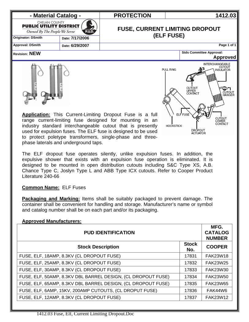
- Material Catalog - PROTECTION 1412.03
Originator: DSmith Date: 7/17/2006
FUSE, CURRENT LIMITING DROPOUT
(ELF FUSE) Approval: DSmith Date: 6/29/2007 Page 1 of 1
Revision: NEW Stds Committee Approval: Approved
1412.03 Fuse, Elf, Current Limiting Dropout.Doc
Application: This Current-Limiting Dropout Fuse is a full range current-limiting fuse designed for mounting in an industry standard interchangeable cutout that is presently used for expulsion fuses. The ELF fuse is designed to be used to protect poletype transformers, single-phase and three-phase laterals and underground taps. The ELF dropout fuse operates silently, unlike expulsion fuses. In addition, the expulsive shower that exists with an expulsion fuse operation is eliminated. It is designed to be mounted in open distribution cutouts including S&C Type XS, A.B. Chance Type C, Joslyn Type L and ABB Type ICX cutouts. Refer to Cooper Product Literature 240-66 Common Name: ELF Fuses
Packaging and Marking: Items shall be suitably packaged to prevent damage. The container shall be convenient for handling and storage. Manufacturer’s name or symbol and catalog number shall be on each part and/or its packaging. Approved Manufacturers:
PUD IDENTIFICATION MFG.
CATALOG NUMBER
Stock Description Stock No. COOPER
FUSE, ELF, 18AMP, 8.3KV (CL DROPOUT FUSE) 17831 FAK23W18 FUSE, ELF, 25AMP, 8.3KV (CL DROPOUT FUSE) 17832 FAK23W25 FUSE, ELF, 30AMP, 8.3KV (CL DROPOUT FUSE) 17833 FAK23W30 FUSE, ELF, 50AMP, 8.3KV DBL BARREL DESIGN, (CL DROPOUT FUSE) 17834 FAK23W50 FUSE, ELF, 65AMP, 8.3KV DBL BARREL DESIGN, (CL DROPOUT FUSE) 17835 FAK23W65 FUSE, ELF, 6AMP, 15KV, 200AMP CUTOUTS, (CL DROPUT FUSE) 17836 FAK44W6 FUSE, ELF, 12AMP, 8.3KV (CL DROPOUT FUSE) 17837 FAK23W12
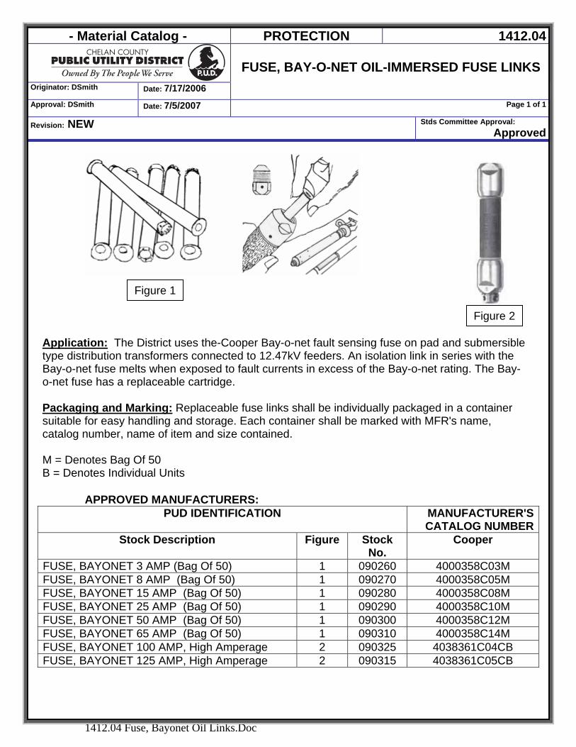
- Material Catalog - PROTECTION 1412.04
Originator: DSmith Date: 7/17/2006
FUSE, BAY-O-NET OIL-IMMERSED FUSE LINKS
Approval: DSmith Date: 7/5/2007 Page 1 of 1
Revision: NEW Stds Committee Approval: Approved
1412.04 Fuse, Bayonet Oil Links.Doc
Figure 1
Figure 2
Application: The District uses the-Cooper Bay-o-net fault sensing fuse on pad and submersible type distribution transformers connected to 12.47kV feeders. An isolation link in series with the Bay-o-net fuse melts when exposed to fault currents in excess of the Bay-o-net rating. The Bay-o-net fuse has a replaceable cartridge. Packaging and Marking: Replaceable fuse links shall be individually packaged in a container suitable for easy handling and storage. Each container shall be marked with MFR's name, catalog number, name of item and size contained. M = Denotes Bag Of 50 B = Denotes Individual Units
APPROVED MANUFACTURERS:
PUD IDENTIFICATION MANUFACTURER'S CATALOG NUMBER
Stock Description Figure Stock No.
Cooper
FUSE, BAYONET 3 AMP (Bag Of 50) 1 090260 4000358C03M FUSE, BAYONET 8 AMP (Bag Of 50) 1 090270 4000358C05M FUSE, BAYONET 15 AMP (Bag Of 50) 1 090280 4000358C08M FUSE, BAYONET 25 AMP (Bag Of 50) 1 090290 4000358C10M FUSE, BAYONET 50 AMP (Bag Of 50) 1 090300 4000358C12M FUSE, BAYONET 65 AMP (Bag Of 50) 1 090310 4000358C14M FUSE, BAYONET 100 AMP, High Amperage 2 090325 4038361C04CB FUSE, BAYONET 125 AMP, High Amperage 2 090315 4038361C05CB
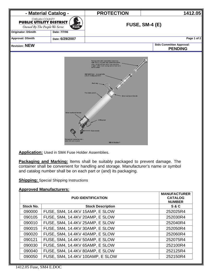
- Material Catalog - PROTECTION 1412.05
Originator: DSmith Date: 7/7/06
FUSE, SM-4 (E)
Approval: DSmith Date: 6/29/2007 Page 1 of 2
Revision: NEW Stds Committee Approval: PENDING
1412.05 Fuse, SM4 E.DOC
Application: Used in SM4 Fuse Holder Assemblies. Packaging and Marking: Items shall be suitably packaged to prevent damage. The container shall be convenient for handling and storage. Manufacturer’s name or symbol and catalog number shall be on each part or (and) its packaging. Shipping: Special Shipping Instructions Approved Manufacturers:
PUD IDENTIFICATION MANUFACTURER
CATALOG NUMBER
Stock No. Stock Description S & C 090000 FUSE, SM4, 14.4KV 15AMP, E SLOW 252025R4 090105 FUSE, SM4, 14.4KV 20AMP, E SLOW 252030R4 090010 FUSE, SM4, 14.4KV 25AMP, E SLOW 252040R4 090015 FUSE, SM4, 14.4KV 30AMP, E SLOW 252050R4 090020 FUSE, SM4, 14.4KV 40AMP, E SLOW 252060R4 090121 FUSE, SM4, 14.4KV 50AMP, E SLOW 252075R4 090030 FUSE, SM4, 14.4KV 65AMP, E SLOW 252100R4 090040 FUSE, SM4, 14.4KV 80AMP, E SLOW 252125R4 090050 FUSE, SM4, 14.4KV 100AMP, E SLOW 252150R4
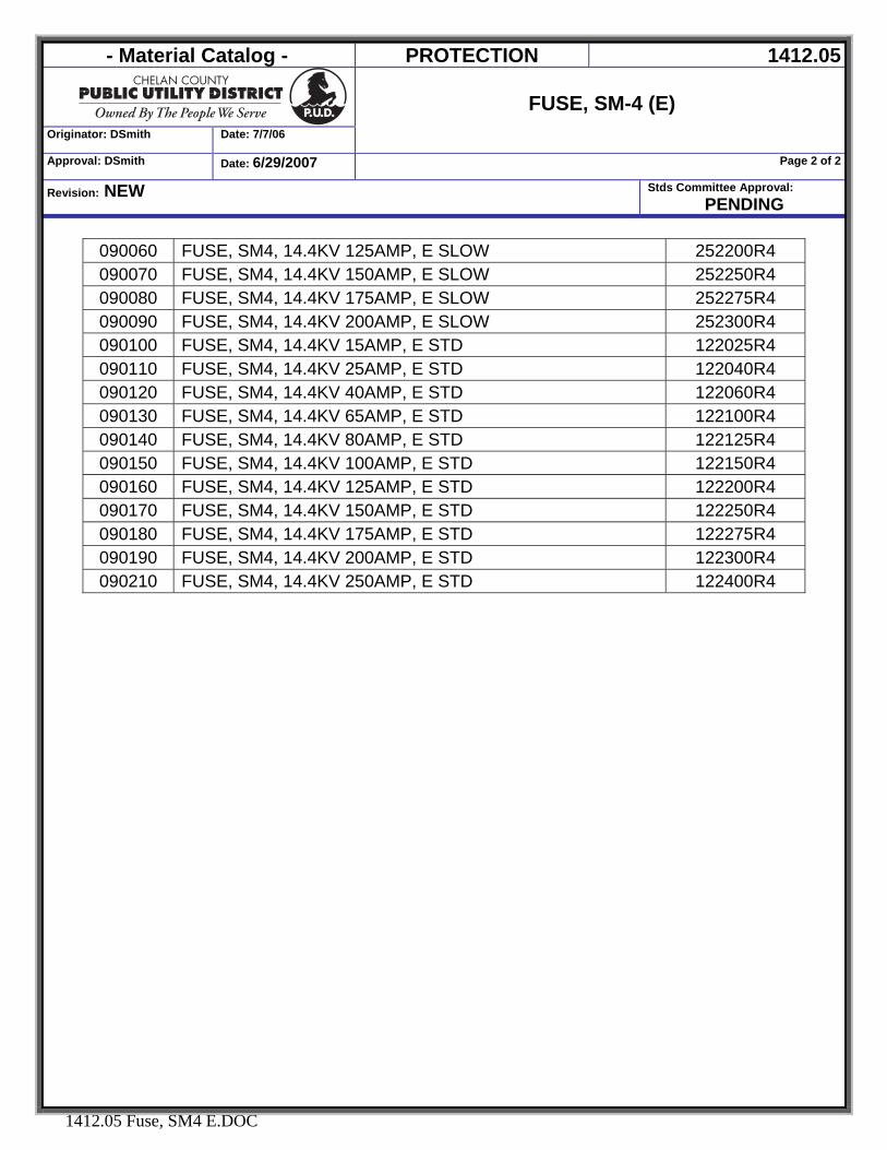
- Material Catalog - PROTECTION 1412.05
Originator: DSmith Date: 7/7/06
FUSE, SM-4 (E)
Approval: DSmith Date: 6/29/2007 Page 2 of 2
Revision: NEW Stds Committee Approval: PENDING
1412.05 Fuse, SM4 E.DOC
090060 FUSE, SM4, 14.4KV 125AMP, E SLOW 252200R4 090070 FUSE, SM4, 14.4KV 150AMP, E SLOW 252250R4 090080 FUSE, SM4, 14.4KV 175AMP, E SLOW 252275R4 090090 FUSE, SM4, 14.4KV 200AMP, E SLOW 252300R4 090100 FUSE, SM4, 14.4KV 15AMP, E STD 122025R4 090110 FUSE, SM4, 14.4KV 25AMP, E STD 122040R4 090120 FUSE, SM4, 14.4KV 40AMP, E STD 122060R4 090130 FUSE, SM4, 14.4KV 65AMP, E STD 122100R4 090140 FUSE, SM4, 14.4KV 80AMP, E STD 122125R4 090150 FUSE, SM4, 14.4KV 100AMP, E STD 122150R4 090160 FUSE, SM4, 14.4KV 125AMP, E STD 122200R4 090170 FUSE, SM4, 14.4KV 150AMP, E STD 122250R4 090180 FUSE, SM4, 14.4KV 175AMP, E STD 122275R4 090190 FUSE, SM4, 14.4KV 200AMP, E STD 122300R4 090210 FUSE, SM4, 14.4KV 250AMP, E STD 122400R4
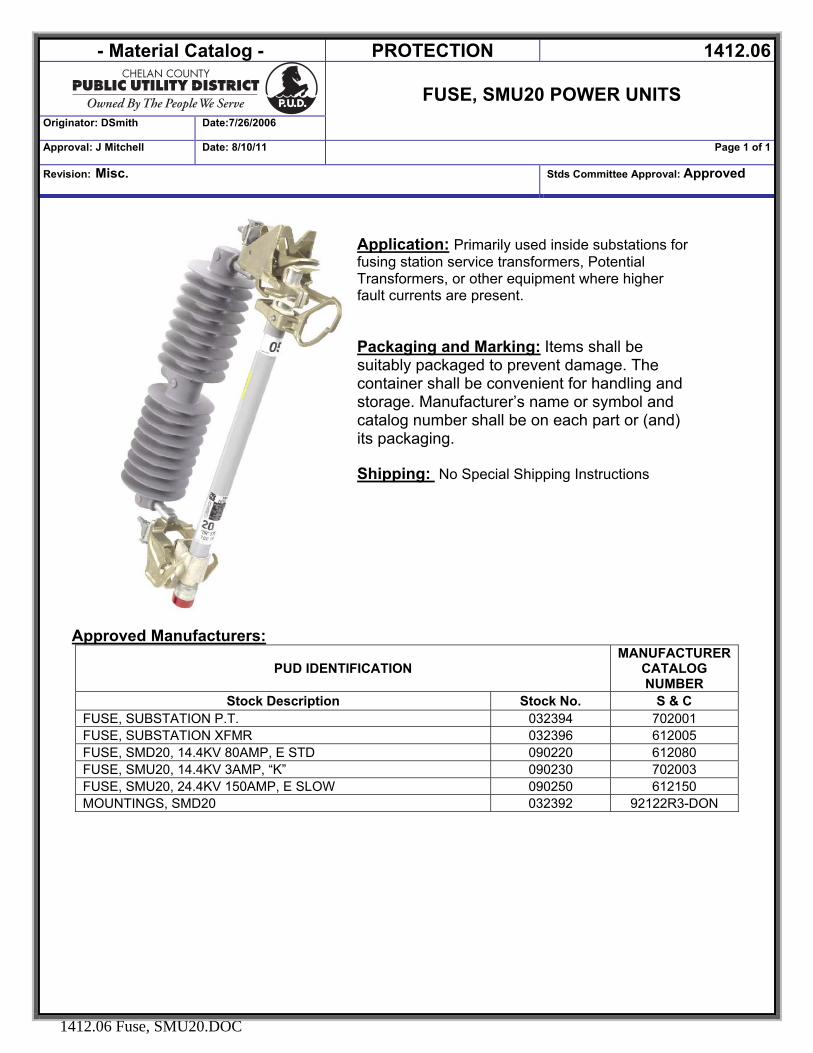
- Material Catalog - PROTECTION 1412.06
FUSE, SMU20 POWER UNITS
Originator: DSmith Date:7/26/2006
Approval: J Mitchell Date: 8/10/11 Page 1 of 1
Revision: Misc. Stds Committee Approval: Approved
1412.06 Fuse, SMU20.DOC
Application: Primarily used inside substations for fusing station service transformers, Potential Transformers, or other equipment where higher fault currents are present. Packaging and Marking: Items shall be suitably packaged to prevent damage. The container shall be convenient for handling and storage. Manufacturer’s name or symbol and catalog number shall be on each part or (and) its packaging. Shipping: No Special Shipping Instructions
Approved Manufacturers: PUD IDENTIFICATION
MANUFACTURER CATALOG NUMBER
Stock Description Stock No. S & C FUSE, SUBSTATION P.T. 032394 702001 FUSE, SUBSTATION XFMR 032396 612005 FUSE, SMD20, 14.4KV 80AMP, E STD 090220 612080 FUSE, SMU20, 14.4KV 3AMP, “K” 090230 702003 FUSE, SMU20, 24.4KV 150AMP, E SLOW 090250 612150 MOUNTINGS, SMD20 032392 92122R3-DON
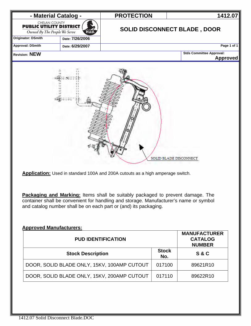
- Material Catalog - PROTECTION 1412.07
Originator: DSmith Date: 7/26/2006
SOLID DISCONNECT BLADE , DOOR
Approval: DSmith Date: 6/29/2007 Page 1 of 1
Revision: NEW Stds Committee Approval: Approved
1412.07 Solid Disconnect Blade.DOC
Application: Used in standard 100A and 200A cutouts as a high amperage switch.
Packaging and Marking: Items shall be suitably packaged to prevent damage. The container shall be convenient for handling and storage. Manufacturer’s name or symbol and catalog number shall be on each part or (and) its packaging. Approved Manufacturers:
PUD IDENTIFICATION MANUFACTURER
CATALOG NUMBER
Stock Description Stock No. S & C
DOOR, SOLID BLADE ONLY, 15KV, 100AMP CUTOUT 017100 89621R10
DOOR, SOLID BLADE ONLY, 15KV, 200AMP CUTOUT 017110 89622R10
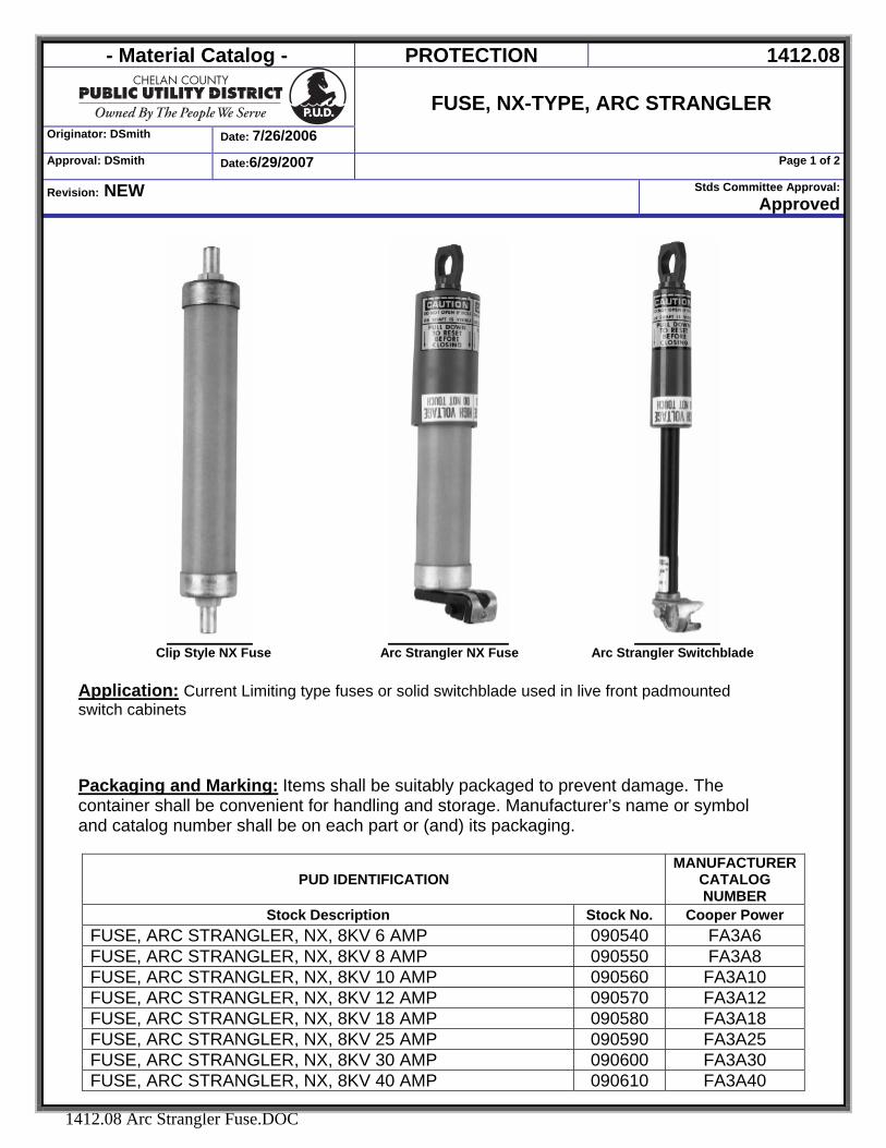
- Material Catalog - PROTECTION 1412.08
Originator: DSmith Date: 7/26/2006
FUSE, NX-TYPE, ARC STRANGLER
Approval: DSmith Date:6/29/2007 Page 1 of 2
Revision: NEW Stds Committee Approval:Approved
1412.08 Arc Strangler Fuse.DOC
Clip Style NX Fuse Arc Strangler NX Fuse Arc Strangler Switchblade
Application: Current Limiting type fuses or solid switchblade used in live front padmounted switch cabinets
Packaging and Marking: Items shall be suitably packaged to prevent damage. The container shall be convenient for handling and storage. Manufacturer’s name or symbol and catalog number shall be on each part or (and) its packaging.
PUD IDENTIFICATION MANUFACTURER
CATALOG NUMBER
Stock Description Stock No. Cooper Power FUSE, ARC STRANGLER, NX, 8KV 6 AMP 090540 FA3A6 FUSE, ARC STRANGLER, NX, 8KV 8 AMP 090550 FA3A8 FUSE, ARC STRANGLER, NX, 8KV 10 AMP 090560 FA3A10 FUSE, ARC STRANGLER, NX, 8KV 12 AMP 090570 FA3A12 FUSE, ARC STRANGLER, NX, 8KV 18 AMP 090580 FA3A18 FUSE, ARC STRANGLER, NX, 8KV 25 AMP 090590 FA3A25 FUSE, ARC STRANGLER, NX, 8KV 30 AMP 090600 FA3A30 FUSE, ARC STRANGLER, NX, 8KV 40 AMP 090610 FA3A40
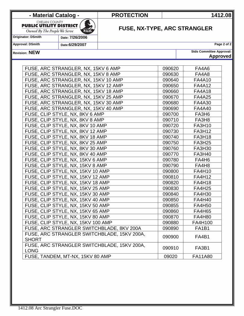
- Material Catalog - PROTECTION 1412.08
Originator: DSmith Date: 7/26/2006
FUSE, NX-TYPE, ARC STRANGLER
Approval: DSmith Date:6/29/2007 Page 2 of 2
Revision: NEW Stds Committee Approval:Approved
1412.08 Arc Strangler Fuse.DOC
FUSE, ARC STRANGLER, NX, 15KV 6 AMP 090620 FA4A6 FUSE, ARC STRANGLER, NX, 15KV 8 AMP 090630 FA4A8 FUSE, ARC STRANGLER, NX, 15KV 10 AMP 090640 FA4A10 FUSE, ARC STRANGLER, NX, 15KV 12 AMP 090650 FA4A12 FUSE, ARC STRANGLER, NX, 15KV 18 AMP 090660 FA4A18 FUSE, ARC STRANGLER, NX, 15KV 25 AMP 090670 FA4A25 FUSE, ARC STRANGLER, NX, 15KV 30 AMP 090680 FA4A30 FUSE, ARC STRANGLER, NX, 15KV 40 AMP 090690 FA4A40 FUSE, CLIP STYLE, NX, 8KV 6 AMP 090700 FA3H6 FUSE, CLIP STYLE, NX, 8KV 8 AMP 090710 FA3H8 FUSE, CLIP STYLE, NX, 8KV 10 AMP 090720 FA3H10 FUSE, CLIP STYLE, NX, 8KV 12 AMP 090730 FA3H12 FUSE, CLIP STYLE, NX, 8KV 18 AMP 090740 FA3H18 FUSE, CLIP STYLE, NX, 8KV 25 AMP 090750 FA3H25 FUSE, CLIP STYLE, NX, 8KV 30 AMP 090760 FA3H30 FUSE, CLIP STYLE, NX, 8KV 40 AMP 090770 FA3H40 FUSE, CLIP STYLE, NX, 15KV 6 AMP 090780 FA4H6 FUSE, CLIP STYLE, NX, 15KV 8 AMP 090790 FA4H8 FUSE, CLIP STYLE, NX, 15KV 10 AMP 090800 FA4H10 FUSE, CLIP STYLE, NX, 15KV 12 AMP 090810 FA4H12 FUSE, CLIP STYLE, NX, 15KV 18 AMP 090820 FA4H18 FUSE, CLIP STYLE, NX, 15KV 25 AMP 090830 FA4H25 FUSE, CLIP STYLE, NX, 15KV 30 AMP 090840 FA4H30 FUSE, CLIP STYLE, NX, 15KV 40 AMP 090850 FA4H40 FUSE, CLIP STYLE, NX, 15KV 50 AMP 090855 FA4H50 FUSE, CLIP STYLE, NX, 15KV 65 AMP 090860 FA4H65 FUSE, CLIP STYLE, NX, 15KV 80 AMP 090870 FA4H80 FUSE, CLIP STYLE, NX, 15KV 100 AMP 090880 FA4H100 FUSE, ARC STRANGLER SWITCHBLADE, 8KV 200A 090890 FA1B1 FUSE, ARC STRANGLER SWITCHBLADE, 15KV 200A, SHORT 090900 FA4B1
FUSE, ARC STRANGLER SWITCHBLADE, 15KV 200A, LONG 090910 FA3B1
FUSE, TANDEM, MT-NX, 15KV 80 AMP 09020 FA11A80
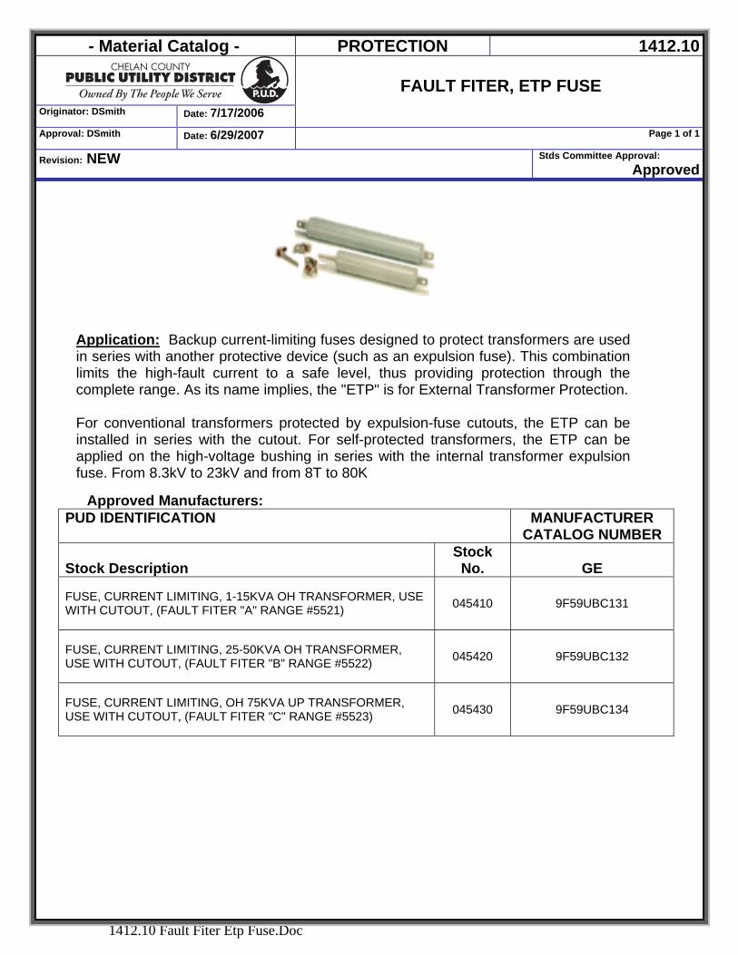
- Material Catalog - PROTECTION 1412.10
Originator: DSmith Date: 7/17/2006
FAULT FITER, ETP FUSE
Approval: DSmith Date: 6/29/2007 Page 1 of 1
Revision: NEW Stds Committee Approval: Approved
1412.10 Fault Fiter Etp Fuse.Doc
Application: Backup current-limiting fuses designed to protect transformers are used in series with another protective device (such as an expulsion fuse). This combination limits the high-fault current to a safe level, thus providing protection through the complete range. As its name implies, the "ETP" is for External Transformer Protection. For conventional transformers protected by expulsion-fuse cutouts, the ETP can be installed in series with the cutout. For self-protected transformers, the ETP can be applied on the high-voltage bushing in series with the internal transformer expulsion fuse. From 8.3kV to 23kV and from 8T to 80K
Approved Manufacturers:
PUD IDENTIFICATION MANUFACTURER CATALOG NUMBER
Stock Description Stock No. GE
FUSE, CURRENT LIMITING, 1-15KVA OH TRANSFORMER, USE WITH CUTOUT, (FAULT FITER "A" RANGE #5521) 045410 9F59UBC131
FUSE, CURRENT LIMITING, 25-50KVA OH TRANSFORMER, USE WITH CUTOUT, (FAULT FITER "B" RANGE #5522) 045420 9F59UBC132
FUSE, CURRENT LIMITING, OH 75KVA UP TRANSFORMER, USE WITH CUTOUT, (FAULT FITER "C" RANGE #5523) 045430 9F59UBC134
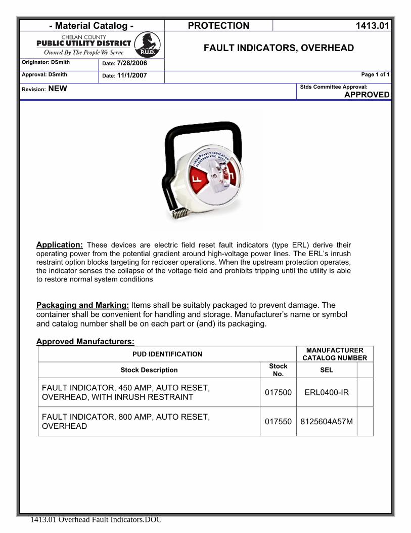
- Material Catalog - PROTECTION 1413.01
Originator: DSmith
FAULT INDICATORS, OVERHEAD
Date: 7/28/2006
Approval: DSmith Page 1 of 1Date: 11/1/2007
Revision: NEW Stds Committee Approval: APPROVED
1413.01 Overhead Fault Indicators.DOC
Application: These devices are electric field reset fault indicators (type ERL) derive their operating power from the potential gradient around high-voltage power lines. The ERL’s inrush restraint option blocks targeting for recloser operations. When the upstream protection operates, the indicator senses the collapse of the voltage field and prohibits tripping until the utility is able to restore normal system conditions Packaging and Marking: Items shall be suitably packaged to prevent damage. The container shall be convenient for handling and storage. Manufacturer’s name or symbol and catalog number shall be on each part or (and) its packaging. Approved Manufacturers:
PUD IDENTIFICATION MANUFACTURER CATALOG NUMBER
Stock Description Stock No. SEL
FAULT INDICATOR, 450 AMP, AUTO RESET, OVERHEAD, WITH INRUSH RESTRAINT 017500 ERL0400-IR
FAULT INDICATOR, 800 AMP, AUTO RESET, OVERHEAD 017550 8125604A57M

- Material Catalog - PROTECTION 1413.02
Originator: DSmith Date:6/29/2007
FAULT INDICATOR
15kV URD Elbow Test Point Voltage Reset
Approval: DSmith Date: 6/29/2007 Page 1 of 1
Revision: NEW Stds Committee Approval: Approved
1413.03 Fault Indicators, Elbow Test Point.DOC
Application: These units are used on 200 and 600 A class underground distribution systems whose terminators have test points. The unit requires a 5 kV phase-to-ground minimum voltage to reset and remain ready to trip. Its target, built into the sensor housing itself, automatically resets when system voltage returns to normal. The conductive, EPDM rubber housing maintains the separable connector system's ground shielding. The unit operates independently of load current. The unit’s inrush restraint feature blocks tripping that might result from reclosing operations. When the breaker or recloser opens, the unit senses a loss of voltage on the test point. The unit blocks the display from targeting if the subsequent inrush current exceeds the trip value. It is ready to trip a few minutes after reenergization. Packaging and Marking: Items shall be suitably packaged to prevent damage. The container shall be convenient for handling and storage. Manufacturer’s name or symbol and catalog number shall be on each part or (and) its packaging. Approved Manufacturers:
PUD IDENTIFICATION MANUFACTURER CATALOG NUMBER
Stock Description Stock No.
Schweitzer Engineering Laboratories
FAULT IND, ELBOW TEST PT, 15KV, 200AMP VOLTAGE RESET 045470 1TPRI0200J
FAULT IND, ELBOW TEST PT, 15KV, 450AMP VOLTAGE RESET 045480 ITPRI0450J
FAULT IND, ELBOW TEST PT, 15KV, 800AMP VOLTAGE RESET 045481 1TPRI-0800J
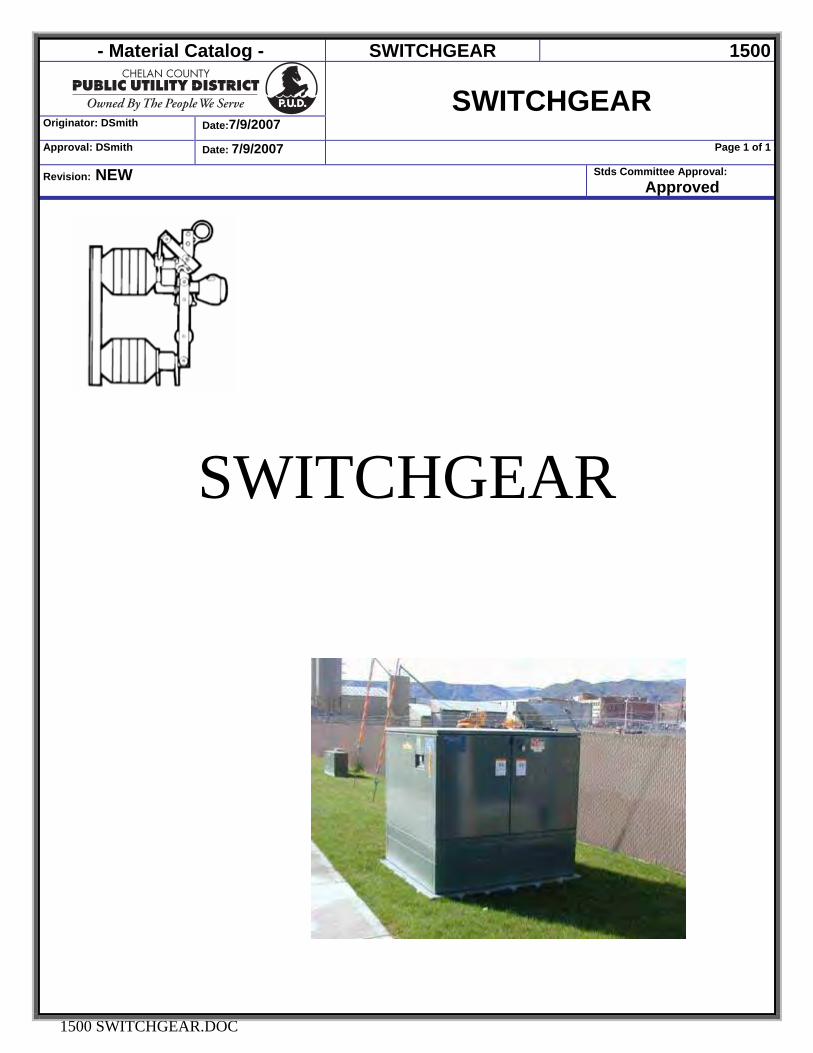
- Material Catalog - SWITCHGEAR 1500
Originator: DSmith Date:7/9/2007
SWITCHGEAR
Approval: DSmith Date: 7/9/2007 Page 1 of 1
Revision: NEW Stds Committee Approval: Approved
1500 SWITCHGEAR.DOC
SWITCHGEAR

- Material Catalog - SWITCHGEAR 1511.02
SWITCH, DISCONNECT SPST
Crossarm Mounted 15kV, 600 Amp
Originator: DSmith Date: 7/9/2013
Approval: J. NIeborsky Date: 7/9/2013 Page 1 of 1
Revision: Added Cooper Catalog Number Stds Committee Approval: Approved
1511.02 SWITCH, DISCONNECT 600A 15KV, SPST.Docx
Application: Loadbuster Disconnects are designed for use with Loadbuster, S&C’s portable loadbreak tool, which has an interrupting rating of 600 amperes nominal, 900 amperes maximum. When used with Loadbuster, the disconnects are suitable for these single-phase live-switching duties on single-phase or three-phase circuits of overhead distribution systems: They can be mounted either vertically or horizontally. Specification: Each switch shall have the following ratings: Equipped: With Loadbuster hooks for operation with an S & C Loadbuster tool. Electrical Rating: Switch shall be capable of conducting 600 amps continuous, 30,000 amps momentary in the bypass position. Insulators: Shall be NEMA standard posts non porcelain suitable for outdoor operation. Terminal Pads: Shall be NEMA standard with two 9/16 inch diameter holes on 1-3/4 inch centers. Base: Shall Be Structural Steel Channel Approximately 5 Inches Wide Carriage Bolt Slots And A Backing Plate Suitable For Mounting Either Vertically Or Horizontally. Base Shall Be Hot-Dipped Galvanized After Fabrication Per Latest Revision Of Astm A-153. Packaging and Marking: Items shall be suitably packaged to prevent damage. The container shall be convenient for handling and storage. Manufacturer’s name or symbol and catalog number shall be on each part or it packaging. Accepted Manufacturers: S&C, Cooper Power Systems
Stock Description Stock No. S&C Cooper
SWITCH, DISCONNECT 600A 15KV, SPST 016150 4922R9-E D73P16S0
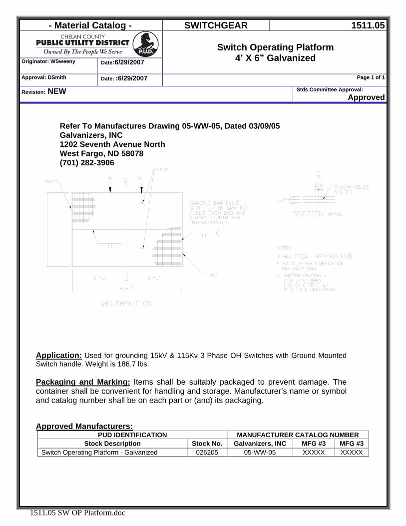
- Material Catalog - SWITCHGEAR 1511.05
Originator: WSweeny Date:6/29/2007
Switch Operating Platform
4’ X 6” Galvanized
Approval: DSmith Date: :6/29/2007 Page 1 of 1
Revision: NEW Stds Committee Approval: Approved
1511.05 SW OP Platform.doc
Refer To Manufactures Drawing 05-WW-05, Dated 03/09/05 Galvanizers, INC 1202 Seventh Avenue North West Fargo, ND 58078 (701) 282-3906
Application: Used for grounding 15kV & 115Kv 3 Phase OH Switches with Ground Mounted Switch handle. Weight is 186.7 lbs.
Packaging and Marking: Items shall be suitably packaged to prevent damage. The container shall be convenient for handling and storage. Manufacturer’s name or symbol and catalog number shall be on each part or (and) its packaging. Approved Manufacturers:
PUD IDENTIFICATION MANUFACTURER CATALOG NUMBER Stock Description Stock No. Galvanizers, INC MFG #3 MFG #3
Switch Operating Platform - Galvanized 026205 05-WW-05 XXXXX XXXXX
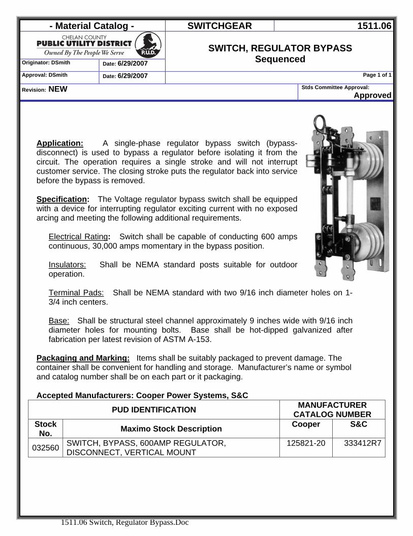
- Material Catalog - SWITCHGEAR 1511.06
Originator: DSmith Date: 6/29/2007
SWITCH, REGULATOR BYPASS
Sequenced Approval: DSmith Date: 6/29/2007 Page 1 of 1
Revision: NEW Stds Committee Approval: Approved
1511.06 Switch, Regulator Bypass.Doc
Application: A single-phase regulator bypass switch (bypass-disconnect) is used to bypass a regulator before isolating it from the circuit. The operation requires a single stroke and will not interrupt customer service. The closing stroke puts the regulator back into service before the bypass is removed. Specification: The Voltage regulator bypass switch shall be equipped with a device for interrupting regulator exciting current with no exposed arcing and meeting the following additional requirements.
Electrical Rating: Switch shall be capable of conducting 600 amps continuous, 30,000 amps momentary in the bypass position. Insulators: Shall be NEMA standard posts suitable for outdoor operation. Terminal Pads: Shall be NEMA standard with two 9/16 inch diameter holes on 1-3/4 inch centers.
Base: Shall be structural steel channel approximately 9 inches wide with 9/16 inch diameter holes for mounting bolts. Base shall be hot-dipped galvanized after fabrication per latest revision of ASTM A-153.
Packaging and Marking: Items shall be suitably packaged to prevent damage. The container shall be convenient for handling and storage. Manufacturer’s name or symbol and catalog number shall be on each part or it packaging.
Accepted Manufacturers: Cooper Power Systems, S&C
PUD IDENTIFICATION MANUFACTURER CATALOG NUMBER
Stock No. Maximo Stock Description Cooper S&C
032560 SWITCH, BYPASS, 600AMP REGULATOR, DISCONNECT, VERTICAL MOUNT
125821-20 333412R7
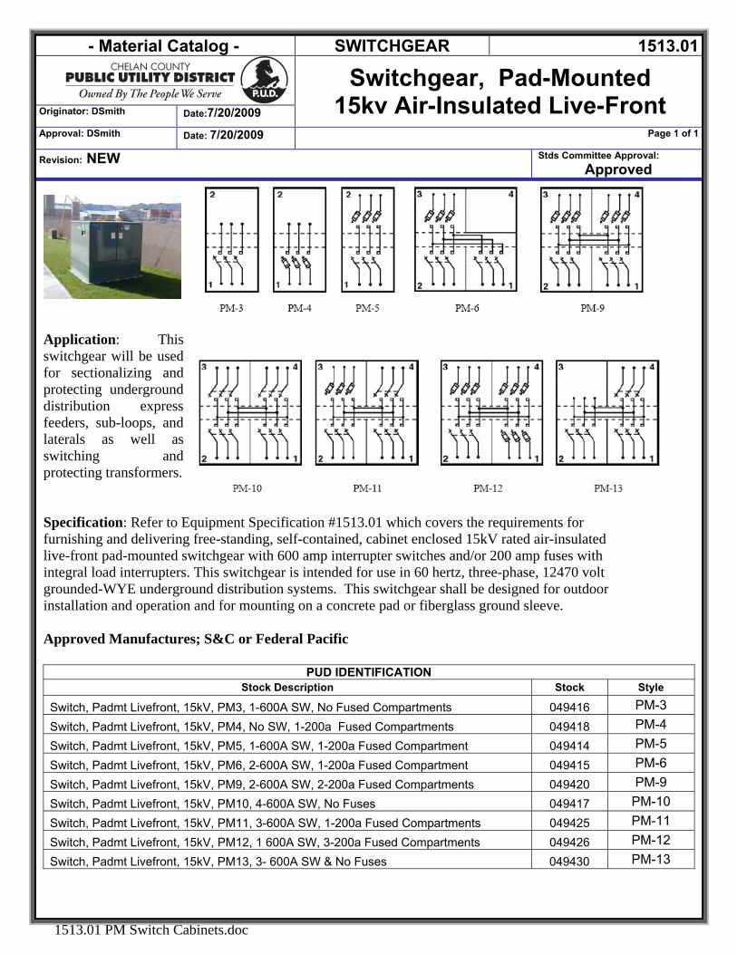
- Material Catalog - SWITCHGEAR 1513.01
Switchgear, Pad-Mounted
15kv Air-Insulated Live-Front Originator: DSmith Date:7/20/2009 Approval: DSmith Date: 7/20/2009 Page 1 of 1
Revision: NEW Stds Committee Approval: Approved
1513.01 PM Switch Cabinets.doc
Application: This switchgear will be used for sectionalizing and protecting underground distribution express feeders, sub-loops, and laterals as well as switching and protecting transformers. Specification: Refer to Equipment Specification #1513.01 which covers the requirements for furnishing and delivering free-standing, self-contained, cabinet enclosed 15kV rated air-insulated live-front pad-mounted switchgear with 600 amp interrupter switches and/or 200 amp fuses with integral load interrupters. This switchgear is intended for use in 60 hertz, three-phase, 12470 volt grounded-WYE underground distribution systems. This switchgear shall be designed for outdoor installation and operation and for mounting on a concrete pad or fiberglass ground sleeve. Approved Manufactures; S&C or Federal Pacific
PUD IDENTIFICATION Stock Description Stock Style
Switch, Padmt Livefront, 15kV, PM3, 1-600A SW, No Fused Compartments 049416 PM-3 Switch, Padmt Livefront, 15kV, PM4, No SW, 1-200a Fused Compartments 049418 PM-4 Switch, Padmt Livefront, 15kV, PM5, 1-600A SW, 1-200a Fused Compartment 049414 PM-5 Switch, Padmt Livefront, 15kV, PM6, 2-600A SW, 1-200a Fused Compartment 049415 PM-6 Switch, Padmt Livefront, 15kV, PM9, 2-600A SW, 2-200a Fused Compartments 049420 PM-9 Switch, Padmt Livefront, 15kV, PM10, 4-600A SW, No Fuses 049417 PM-10 Switch, Padmt Livefront, 15kV, PM11, 3-600A SW, 1-200a Fused Compartments 049425 PM-11 Switch, Padmt Livefront, 15kV, PM12, 1 600A SW, 3-200a Fused Compartments 049426 PM-12 Switch, Padmt Livefront, 15kV, PM13, 3- 600A SW & No Fuses 049430 PM-13
- Material Catalog - LINE HARDWARE 1600
Originator: DSmith Date:1/24/2007
LINE HARDWARE
Approval: DSmith Date: 1/24/2007 Page 1 of 1
Revision: NEW Stds Committee Approval: Approved
1600 LINE HARDWARE.DOC
SECTION 1600 LINE HARDWARE
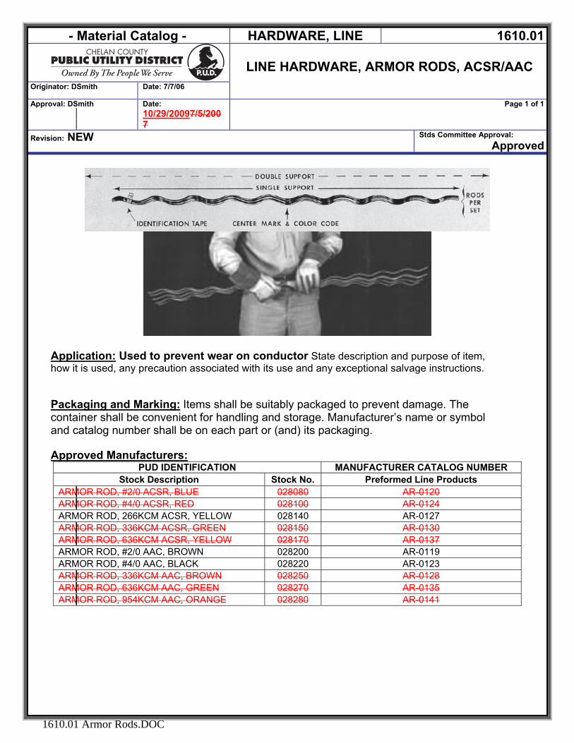
- Material Catalog - HARDWARE, LINE 1610.01
LINE HARDWARE, ARMOR RODS, ACSR/AAC
Originator: DSmith Date: 7/7/06
Approval: DSmith Date: 10/29/20097/5/2007
Page 1 of 1
Revision: NEW Stds Committee Approval: Approved
1610.01 Armor Rods.DOC
Application: Used to prevent wear on conductor State description and purpose of item, how it is used, any precaution associated with its use and any exceptional salvage instructions. Packaging and Marking: Items shall be suitably packaged to prevent damage. The container shall be convenient for handling and storage. Manufacturer’s name or symbol and catalog number shall be on each part or (and) its packaging. Approved Manufacturers:
PUD IDENTIFICATION MANUFACTURER CATALOG NUMBER Stock Description Stock No. Preformed Line Products
ARMOR ROD, #2/0 ACSR, BLUE 028080 AR-0120 ARMOR ROD, #4/0 ACSR, RED 028100 AR-0124 ARMOR ROD, 266KCM ACSR, YELLOW 028140 AR-0127 ARMOR ROD, 336KCM ACSR, GREEN 028150 AR-0130 ARMOR ROD, 636KCM ACSR, YELLOW 028170 AR-0137 ARMOR ROD, #2/0 AAC, BROWN 028200 AR-0119 ARMOR ROD, #4/0 AAC, BLACK 028220 AR-0123 ARMOR ROD, 336KCM AAC, BROWN 028250 AR-0128 ARMOR ROD, 636KCM AAC, GREEN 028270 AR-0135 ARMOR ROD, 954KCM AAC, ORANGE 028280 AR-0141
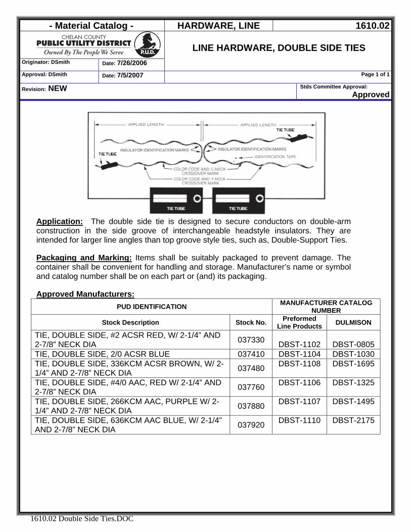
- Material Catalog - HARDWARE, LINE 1610.02
Originator: DSmith Date: 7/26/2006
LINE HARDWARE, DOUBLE SIDE TIES
Approval: DSmith Date: 7/5/2007 Page 1 of 1
Revision: NEW Stds Committee Approval: Approved
1610.02 Double Side Ties.DOC
Application: The double side tie is designed to secure conductors on double-arm construction in the side groove of interchangeable headstyle insulators. They are intended for larger line angles than top groove style ties, such as, Double-Support Ties. Packaging and Marking: Items shall be suitably packaged to prevent damage. The container shall be convenient for handling and storage. Manufacturer’s name or symbol and catalog number shall be on each part or (and) its packaging. Approved Manufacturers:
PUD IDENTIFICATION MANUFACTURER CATALOG NUMBER
Stock Description Stock No. Preformed Line Products DULMISON
TIE, DOUBLE SIDE, #2 ACSR RED, W/ 2-1/4” AND 2-7/8” NECK DIA 037330
DBST-1102
DBST-0805 TIE, DOUBLE SIDE, 2/0 ACSR BLUE 037410 DBST-1104 DBST-1030 TIE, DOUBLE SIDE, 336KCM ACSR BROWN, W/ 2-1/4” AND 2-7/8” NECK DIA 037480 DBST-1108 DBST-1695
TIE, DOUBLE SIDE, #4/0 AAC, RED W/ 2-1/4” AND 2-7/8” NECK DIA 037760 DBST-1106 DBST-1325
TIE, DOUBLE SIDE, 266KCM AAC, PURPLE W/ 2-1/4” AND 2-7/8” NECK DIA 037880 DBST-1107 DBST-1495
TIE, DOUBLE SIDE, 636KCM AAC BLUE, W/ 2-1/4” AND 2-7/8” NECK DIA 037920 DBST-1110 DBST-2175
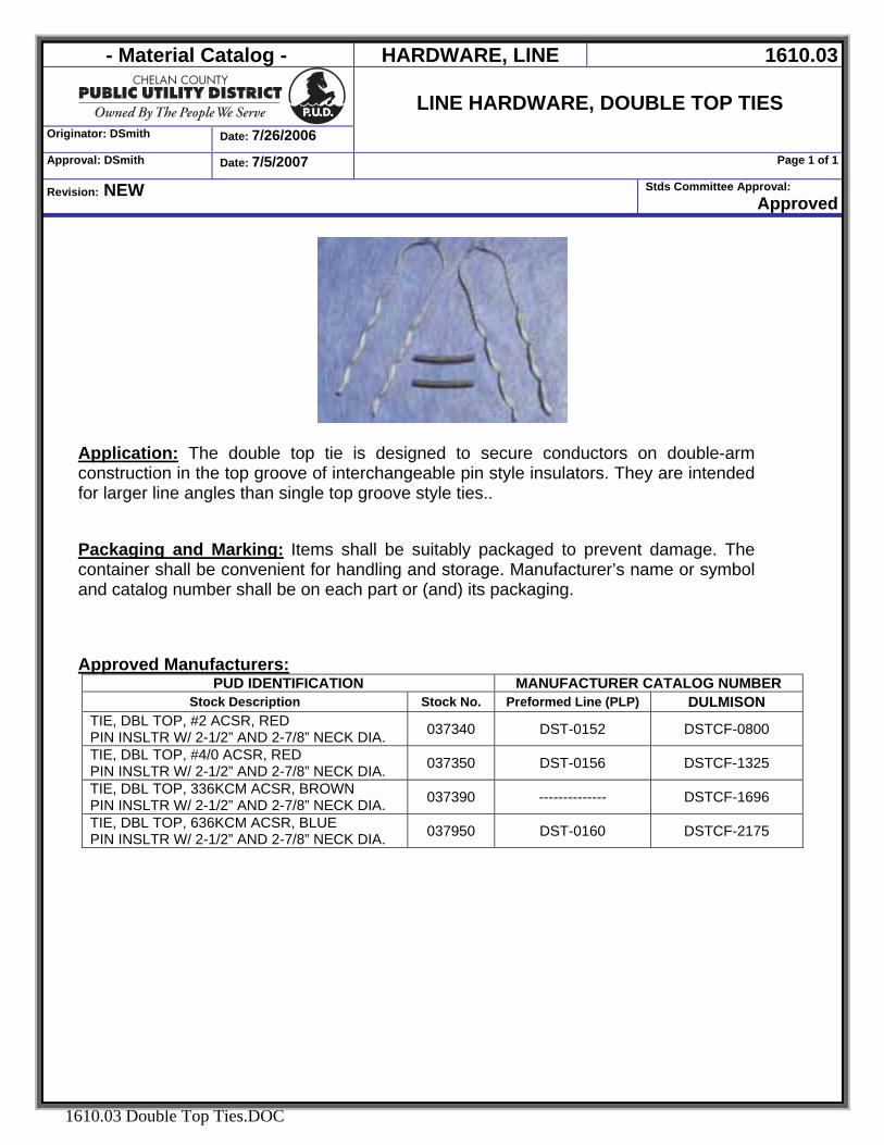
- Material Catalog - HARDWARE, LINE 1610.03
Originator: DSmith Date: 7/26/2006
LINE HARDWARE, DOUBLE TOP TIES
Approval: DSmith Date: 7/5/2007 Page 1 of 1
Revision: NEW Stds Committee Approval: Approved
1610.03 Double Top Ties.DOC
Application: The double top tie is designed to secure conductors on double-arm construction in the top groove of interchangeable pin style insulators. They are intended for larger line angles than single top groove style ties.. Packaging and Marking: Items shall be suitably packaged to prevent damage. The container shall be convenient for handling and storage. Manufacturer’s name or symbol and catalog number shall be on each part or (and) its packaging. Approved Manufacturers:
PUD IDENTIFICATION MANUFACTURER CATALOG NUMBER Stock Description Stock No. Preformed Line (PLP) DULMISON
TIE, DBL TOP, #2 ACSR, RED PIN INSLTR W/ 2-1/2” AND 2-7/8” NECK DIA. 037340 DST-0152 DSTCF-0800
TIE, DBL TOP, #4/0 ACSR, RED PIN INSLTR W/ 2-1/2” AND 2-7/8” NECK DIA. 037350 DST-0156 DSTCF-1325
TIE, DBL TOP, 336KCM ACSR, BROWN PIN INSLTR W/ 2-1/2” AND 2-7/8” NECK DIA. 037390 -------------- DSTCF-1696
TIE, DBL TOP, 636KCM ACSR, BLUE PIN INSLTR W/ 2-1/2” AND 2-7/8” NECK DIA. 037950 DST-0160 DSTCF-2175
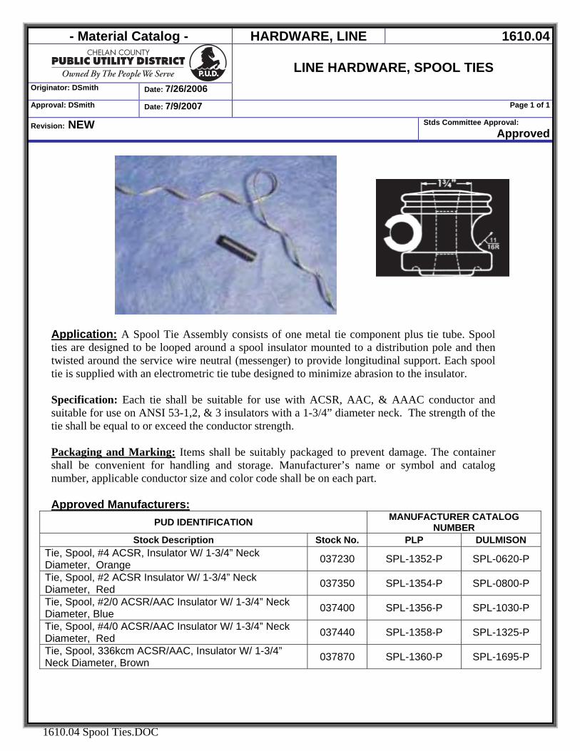
- Material Catalog - HARDWARE, LINE 1610.04
Originator: DSmith Date: 7/26/2006
LINE HARDWARE, SPOOL TIES
Approval: DSmith Date: 7/9/2007 Page 1 of 1
Revision: NEW Stds Committee Approval: Approved
1610.04 Spool Ties.DOC
Application: A Spool Tie Assembly consists of one metal tie component plus tie tube. Spool ties are designed to be looped around a spool insulator mounted to a distribution pole and then twisted around the service wire neutral (messenger) to provide longitudinal support. Each spool tie is supplied with an electrometric tie tube designed to minimize abrasion to the insulator. Specification: Each tie shall be suitable for use with ACSR, AAC, & AAAC conductor and suitable for use on ANSI 53-1,2, & 3 insulators with a 1-3/4” diameter neck. The strength of the tie shall be equal to or exceed the conductor strength. Packaging and Marking: Items shall be suitably packaged to prevent damage. The container shall be convenient for handling and storage. Manufacturer’s name or symbol and catalog number, applicable conductor size and color code shall be on each part. Approved Manufacturers:
PUD IDENTIFICATION MANUFACTURER CATALOG NUMBER
Stock Description Stock No. PLP DULMISON Tie, Spool, #4 ACSR, Insulator W/ 1-3/4” Neck Diameter, Orange 037230 SPL-1352-P SPL-0620-P
Tie, Spool, #2 ACSR Insulator W/ 1-3/4” Neck Diameter, Red 037350 SPL-1354-P SPL-0800-P
Tie, Spool, #2/0 ACSR/AAC Insulator W/ 1-3/4” Neck Diameter, Blue 037400 SPL-1356-P SPL-1030-P
Tie, Spool, #4/0 ACSR/AAC Insulator W/ 1-3/4” Neck Diameter, Red 037440 SPL-1358-P SPL-1325-P
Tie, Spool, 336kcm ACSR/AAC, Insulator W/ 1-3/4” Neck Diameter, Brown 037870 SPL-1360-P SPL-1695-P
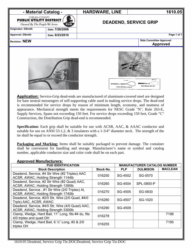
- Material Catalog - HARDWARE, LINE 1610.05
DEADEND, SERVICE GRIP
Originator: DSmith Date: 7/26/2006
Approval: DSmith Date: 6/23/2010 Page 1 of 1
Revision: NEW Stds Committee Approval: Approved
1610.05 Deadend, Service Grip Tie.DOCDeadend, Service Grip Tie.DOC
Application: Service-Grip dead-ends are manufactured of aluminum-covered steel are designed for bare neutral messengers of self-supporting cable used in making service drops. The dead-end is recommended for service drops by reason of minimum length, economy, and neatness of appearance. Mechanical strength meets the requirements for NESC Grade "N", Rule 263-E, Supply Services, Spans not exceeding 150 feet. For service drops exceeding 150 feet, Grade "C" Construction, the Distribution Grip dead-end is recommended. Specification: Each grip shall be suitable for use with ACSR, AAC, & AAAC conductor and suitable for use on ANSI 53-1,2, & 3 insulators with a 1-3/4” diameter neck. The strength of the tie shall be equal to or exceed the conductor strength. Packaging and Marking: Items shall be suitably packaged to prevent damage. The container shall be convenient for handling and storage. Manufacturer’s name or symbol and catalog number, applicable conductor size and color code shall be on each part. Approved Manufacturers:
PUD IDENTIFICATION MANUFACTURER CATALOG NUMBER Stock Description Stock No. PLP DULMISON MACLEAN
Deadend, Service, #4 Str Wire (#2 Triplex) AAC ACSR, AWAC, Holding Strength 1144lb 016250 SG-4502 SG-0570
Deadend, Service, #2 Str Wire (#2 Quad) AAC, ACSR, AWAC, Holding Strength 1395lb 016260 SG-4504 SPL-0800-P
Deadend, Service , #1 Str Wire (2/0 Triplex) Al, ACSR, AWAC, Holding Strength 1740lb 016270 SG-4505 SG-0830
Deadend, Service, #2/0 Str, Wire (2/0 Quad, #4/0 Trplx) AAC, ACSR, AWAC 016280 SG-4507 SG-1020
Deadend, Service, #4/0 Str, Wire (4/0 Quad) AAC, ACSR, AWAC, Holding Strength 3300lb 016290 SG-4509
Clamp, Wedge, Hard Bail, 11” Long, fits #4 du, fits 4/0 triplex and quad OH 016278 7198
Clamp, Wedge, Hard Bail, 6 ½” Long, #2 & 2/0 triplex OH 016255 7195
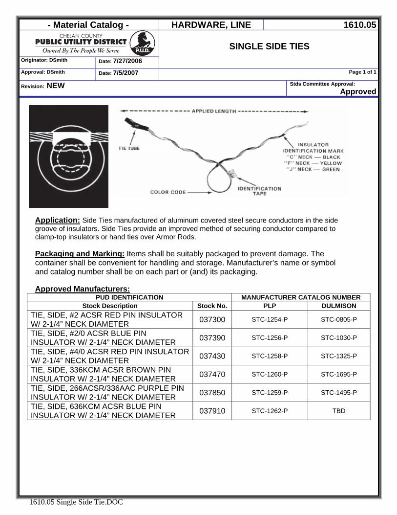
- Material Catalog - HARDWARE, LINE 1610.05
Originator: DSmith Date: 7/27/2006
SINGLE SIDE TIES
Approval: DSmith Date: 7/5/2007 Page 1 of 1
Revision: NEW Stds Committee Approval: Approved
1610.05 Single Side Tie.DOC
Application: Side Ties manufactured of aluminum covered steel secure conductors in the side groove of insulators. Side Ties provide an improved method of securing conductor compared to clamp-top insulators or hand ties over Armor Rods. Packaging and Marking: Items shall be suitably packaged to prevent damage. The container shall be convenient for handling and storage. Manufacturer’s name or symbol and catalog number shall be on each part or (and) its packaging. Approved Manufacturers:
PUD IDENTIFICATION MANUFACTURER CATALOG NUMBER Stock Description Stock No. PLP DULMISON
TIE, SIDE, #2 ACSR RED PIN INSULATOR W/ 2-1/4” NECK DIAMETER 037300 STC-1254-P STC-0805-P
TIE, SIDE, #2/0 ACSR BLUE PIN INSULATOR W/ 2-1/4” NECK DIAMETER 037390 STC-1256-P STC-1030-P
TIE, SIDE, #4/0 ACSR RED PIN INSULATOR W/ 2-1/4” NECK DIAMETER 037430 STC-1258-P STC-1325-P
TIE, SIDE, 336KCM ACSR BROWN PIN INSULATOR W/ 2-1/4” NECK DIAMETER 037470 STC-1260-P STC-1695-P
TIE, SIDE, 266ACSR/336AAC PURPLE PIN INSULATOR W/ 2-1/4” NECK DIAMETER 037850 STC-1259-P STC-1495-P
TIE, SIDE, 636KCM ACSR BLUE PIN INSULATOR W/ 2-1/4” NECK DIAMETER 037910 STC-1262-P TBD
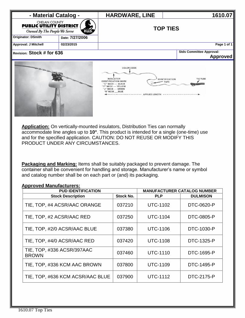
- Material Catalog - HARDWARE, LINE 1610.07
TOP TIES
Originator: DSmith Date: 7/27/2006
Approval: J Mitchell 02/23/2015 Page 1 of 1
Revision: Stock # for 636 Stds Committee Approval: Approved
1610.07 Top Ties
Application: On vertically-mounted insulators, Distribution Ties can normally accommodate line angles up to 10°. This product is intended for a single (one-time) use and for the specified application. CAUTION: DO NOT REUSE OR MODIFY THIS PRODUCT UNDER ANY CIRCUMSTANCES. Packaging and Marking: Items shall be suitably packaged to prevent damage. The container shall be convenient for handling and storage. Manufacturer’s name or symbol and catalog number shall be on each part or (and) its packaging. Approved Manufacturers:
PUD IDENTIFICATION MANUFACTURER CATALOG NUMBER Stock Description Stock No. PLP DULMISON
TIE, TOP, #4 ACSR/AAC ORANGE 037210 UTC-1102 DTC-0620-P
TIE, TOP, #2 ACSR/AAC RED 037250 UTC-1104 DTC-0805-P
TIE, TOP, #2/0 ACSR/AAC BLUE 037380 UTC-1106 DTC-1030-P
TIE, TOP, #4/0 ACSR/AAC RED 037420 UTC-1108 DTC-1325-P
TIE, TOP, #336 ACSR/397AAC BROWN 037460 UTC-1110 DTC-1695-P
TIE, TOP, #336 KCM AAC BROWN 037800 UTC-1109 DTC-1495-P
TIE, TOP, #636 KCM ACSR/AAC BLUE 037900 UTC-1112 DTC-2175-P
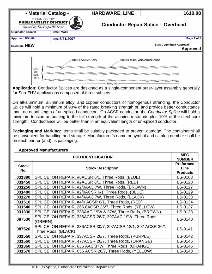
- Material Catalog - HARDWARE, LINE 1610.08
Originator: DSmith Date: 7/7/06
Conductor Repair Splice – Overhead
Approval: DSmith Date:8/31/2007 Page 1 of 1
Revision: NEW Stds Committee Approval: Approved
1610.08 Splice, Conductor Preformed Repair.Doc
Application: Conductor Splices are designed as a single-component outer-layer assembly generally for Sub-EHV applications composed of three subsets. On all-aluminum, aluminum alloy, and copper conductors of homogenous stranding, the Conductor Splice will hold a minimum of 90% of the rated breaking strength of, and provide better conductance than, an equal length of un-spliced conductor. On ACSR conductor, the Conductor Splice will hold a minimum tension amounting to the full strength of the aluminum strands plus 10% of the steel core strength. Conductance will be better than in an equivalent length of un-spliced conductor. Packaging and Marking: Items shall be suitably packaged to prevent damage. The container shall be convenient for handling and storage. Manufacturer’s name or symbol and catalog number shall be on each part or (and) its packaging.
Approved Manufacturers
PUD IDENTIFICATION MFG NUMBER
Stock No. Stock Description
Preformed Line
Products 031390 SPLICE, OH REPAIR, #6ACSR 6/1, Three Rods, (BLUE) LS-0108 031450 SPLICE, OH REPAIR, #2ACSR 6/1, Three Rods, (RED) LS-0120 031250 SPLICE, OH REPAIR, #2/0AAC 7W, Three Rods, (BROWN) LS-0127 031480 SPLICE, OH REPAIR, #2/0ACSR 6/1, Three Rods, (BLUE) LS-0129 031270 SPLICE, OH REPAIR, #4/0AAC 7W, Three Rods, (BLACK) LS-0133 031510 SPLICE, OH REPAIR, #4/0 ACSR 6/1, Three Rods, (RED) LS-0134 031540 SPLICE, OH REPAIR, 266.8ACSR 26/7, Three Rods, (YELLOW) LS-0137 031330 SPLICE, OH REPAIR, 336AAC 19W & 37W, Three Rods, (BROWN) LS-0138
087530 SPLICE, OH REPAIR, 336ACSR 26/7, 397AAC 19W, Three Rods, (GREEN) LS-0140
087520 SPLICE, OH REPAIR, 336ACSR 30/7, 397ACSR 18/1, 397 ACSR 36/1 Three Rods, (BLACK) LS-0141
031550 SPLICE, OH REPAIR, 397ACSR 26/7, Three Rods, (PURPLE) LS-0142 031560 SPLICE, OH REPAIR, 477ACSR 26/7, Three Rods, (ORANGE) LS-0145 031360 SPLICE, OH REPAIR, 636 AAC 37W, Three Rods, (ORANGE) LS-0146 031570 SPLICE, OH REPAIR, 636 ACSR 26/7, Three Rods, (YELLOW) LS-0148
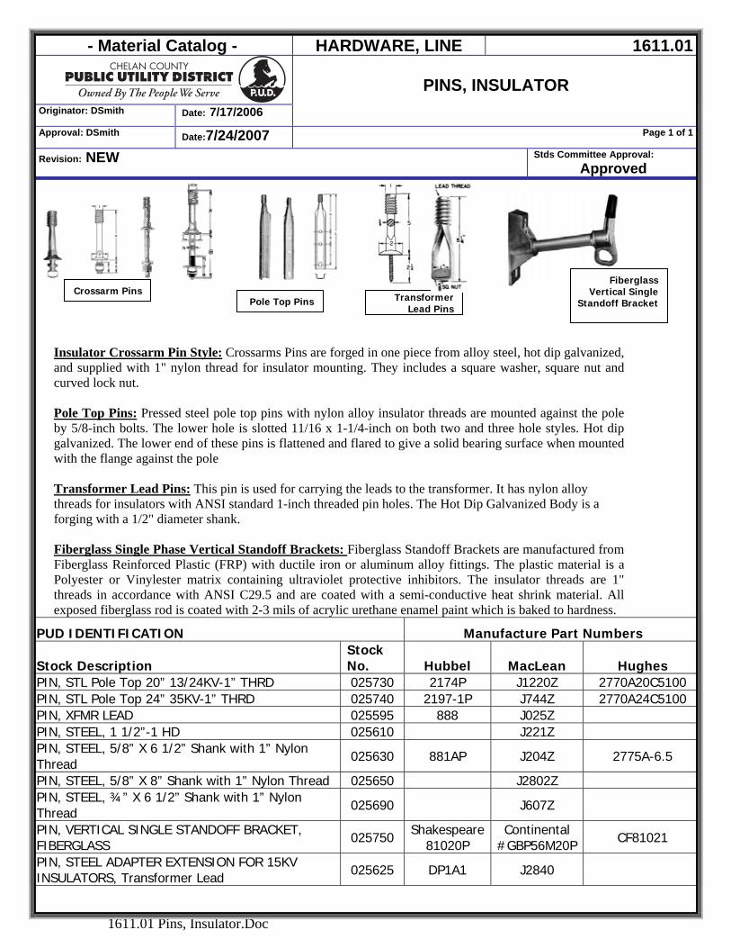
- Material Catalog - HARDWARE, LINE 1611.01
Originator: DSmith Date: 7/17/2006
PINS, INSULATOR
Approval: DSmith Date:7/24/2007 Page 1 of 1
Revision: NEW Stds Committee Approval: Approved
1611.01 Pins, Insulator.Doc
TransformerLead Pins
Fiberglass Vertical Single
Standoff BracketPole Top PinsCrossarm Pins
Insulator Crossarm Pin Style: Crossarms Pins are forged in one piece from alloy steel, hot dip galvanized, and supplied with 1" nylon thread for insulator mounting. They includes a square washer, square nut and curved lock nut.
Pole Top Pins: Pressed steel pole top pins with nylon alloy insulator threads are mounted against the pole by 5/8-inch bolts. The lower hole is slotted 11/16 x 1-1/4-inch on both two and three hole styles. Hot dip galvanized. The lower end of these pins is flattened and flared to give a solid bearing surface when mounted with the flange against the pole Transformer Lead Pins: This pin is used for carrying the leads to the transformer. It has nylon alloy threads for insulators with ANSI standard 1-inch threaded pin holes. The Hot Dip Galvanized Body is a forging with a 1/2" diameter shank. Fiberglass Single Phase Vertical Standoff Brackets: Fiberglass Standoff Brackets are manufactured from Fiberglass Reinforced Plastic (FRP) with ductile iron or aluminum alloy fittings. The plastic material is a Polyester or Vinylester matrix containing ultraviolet protective inhibitors. The insulator threads are 1" threads in accordance with ANSI C29.5 and are coated with a semi-conductive heat shrink material. All exposed fiberglass rod is coated with 2-3 mils of acrylic urethane enamel paint which is baked to hardness.
PUD IDENTIFICATION Manufacture Part Numbers
Stock Description Stock No. Hubbel MacLean Hughes
PIN, STL Pole Top 20” 13/24KV-1” THRD 025730 2174P J1220Z 2770A20C5100 PIN, STL Pole Top 24” 35KV-1” THRD 025740 2197-1P J744Z 2770A24C5100 PIN, XFMR LEAD 025595 888 J025Z PIN, STEEL, 1 1/2”-1 HD 025610 J221Z PIN, STEEL, 5/8” X 6 1/2” Shank with 1” Nylon Thread 025630 881AP J204Z 2775A-6.5
PIN, STEEL, 5/8” X 8” Shank with 1” Nylon Thread 025650 J2802Z PIN, STEEL, ¾” X 6 1/2” Shank with 1” Nylon Thread 025690 J607Z
PIN, VERTICAL SINGLE STANDOFF BRACKET, FIBERGLASS 025750 Shakespeare
81020P Continental
#GBP56M20P CF81021
PIN, STEEL ADAPTER EXTENSION FOR 15KV INSULATORS, Transformer Lead 025625 DP1A1 J2840
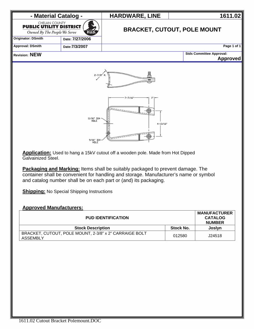
- Material Catalog - HARDWARE, LINE 1611.02
Originator: DSmith Date: 7/27/2006
BRACKET, CUTOUT, POLE MOUNT
Approval: DSmith Date:7/3/2007 Page 1 of 1
Revision: NEW Stds Committee Approval: Approved
1611.02 Cutout Bracket Polemount.DOC
Application: Used to hang a 15kV cutout off a wooden pole. Made from Hot Dipped Galvainized Steel. Packaging and Marking: Items shall be suitably packaged to prevent damage. The container shall be convenient for handling and storage. Manufacturer’s name or symbol and catalog number shall be on each part or (and) its packaging. Shipping: No Special Shipping Instructions Approved Manufacturers:
PUD IDENTIFICATION MANUFACTURER
CATALOG NUMBER
Stock Description Stock No. Joslyn BRACKET, CUTOUT, POLE MOUNT, 2-3/8” x 2” CARRAIGE BOLT ASSEMBLY 012580 J24518
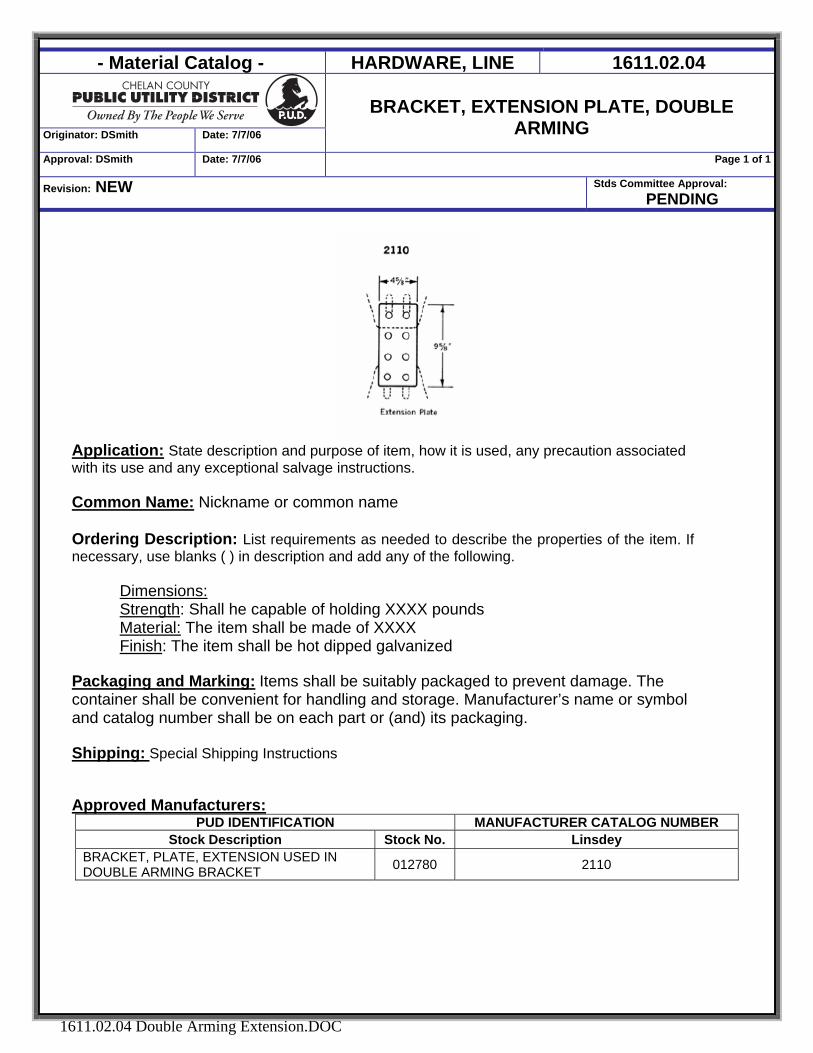
- Material Catalog - HARDWARE, LINE 1611.02.04
Originator: DSmith Date: 7/7/06
BRACKET, EXTENSION PLATE, DOUBLE
ARMING Approval: DSmith Date: 7/7/06 Page 1 of 1
Revision: NEW Stds Committee Approval: PENDING
1611.02.04 Double Arming Extension.DOC
Application: State description and purpose of item, how it is used, any precaution associated with its use and any exceptional salvage instructions. Common Name: Nickname or common name
Ordering Description: List requirements as needed to describe the properties of the item. If necessary, use blanks ( ) in description and add any of the following.
Dimensions: Strength: Shall he capable of holding XXXX pounds Material: The item shall be made of XXXX Finish: The item shall be hot dipped galvanized
Packaging and Marking: Items shall be suitably packaged to prevent damage. The container shall be convenient for handling and storage. Manufacturer’s name or symbol and catalog number shall be on each part or (and) its packaging. Shipping: Special Shipping Instructions Approved Manufacturers:
PUD IDENTIFICATION MANUFACTURER CATALOG NUMBER Stock Description Stock No. Linsdey
BRACKET, PLATE, EXTENSION USED IN DOUBLE ARMING BRACKET 012780 2110
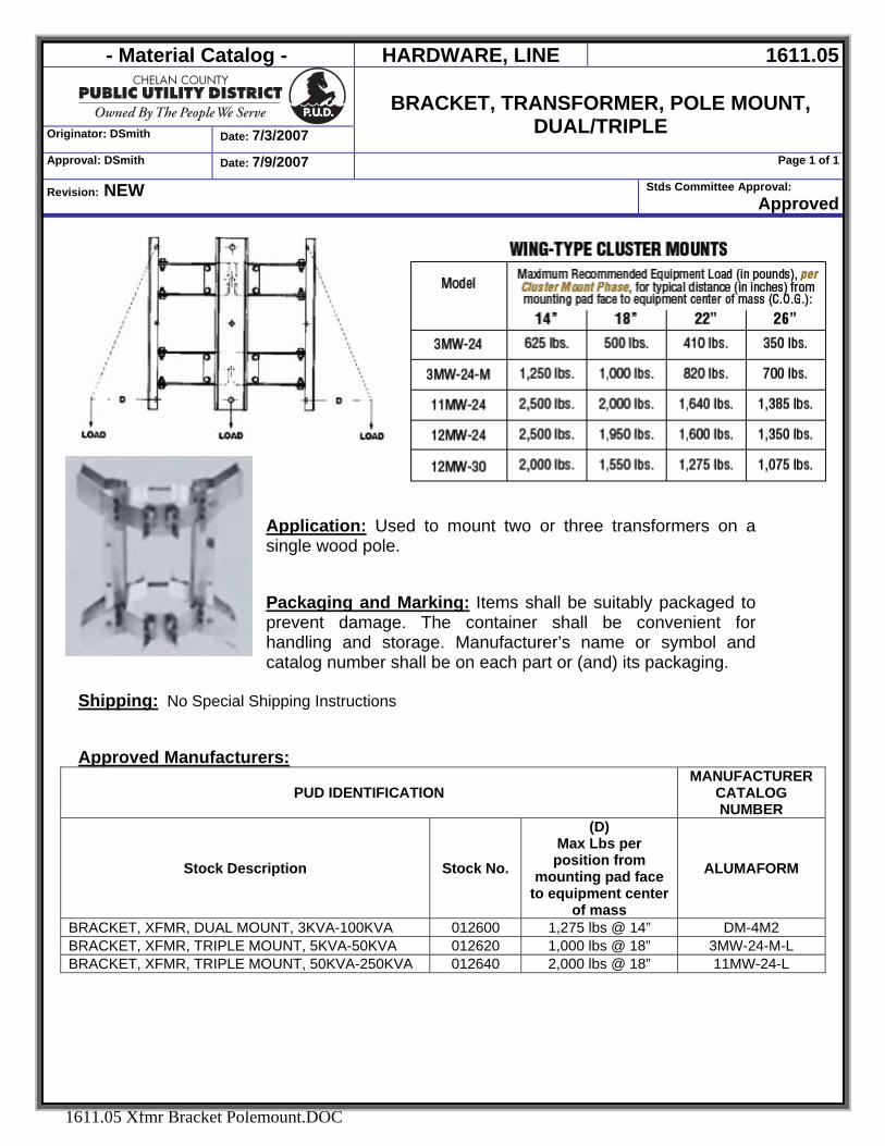
- Material Catalog - HARDWARE, LINE 1611.05
Originator: DSmith Date: 7/3/2007
BRACKET, TRANSFORMER, POLE MOUNT,
DUAL/TRIPLE Approval: DSmith Date: 7/9/2007 Page 1 of 1
Revision: NEW Stds Committee Approval: Approved
1611.05 Xfmr Bracket Polemount.DOC
Application: Used to mount two or three transformers on a single wood pole. Packaging and Marking: Items shall be suitably packaged to prevent damage. The container shall be convenient for handling and storage. Manufacturer’s name or symbol and catalog number shall be on each part or (and) its packaging.
Shipping: No Special Shipping Instructions Approved Manufacturers:
PUD IDENTIFICATION MANUFACTURER
CATALOG NUMBER
Stock Description Stock No.
(D) Max Lbs per position from
mounting pad face to equipment center
of mass
ALUMAFORM
BRACKET, XFMR, DUAL MOUNT, 3KVA-100KVA 012600 1,275 lbs @ 14” DM-4M2 BRACKET, XFMR, TRIPLE MOUNT, 5KVA-50KVA 012620 1,000 lbs @ 18” 3MW-24-M-L BRACKET, XFMR, TRIPLE MOUNT, 50KVA-250KVA 012640 2,000 lbs @ 18” 11MW-24-L
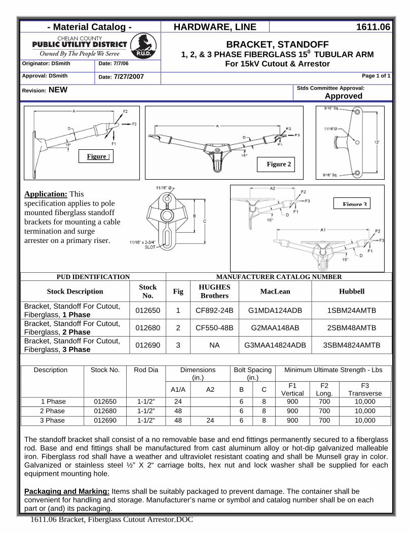
- Material Catalog - HARDWARE, LINE 1611.06
Originator: DSmith Date: 7/7/06
BRACKET, STANDOFF 1, 2, & 3 PHASE FIBERGLASS 150 TUBULAR ARM
For 15kV Cutout & Arrestor Approval: DSmith Date: 7/27/2007 Page 1 of 1
Revision: NEW Stds Committee Approval: Approved
1611.06 Bracket, Fiberglass Cutout Arrestor.DOC
Figure 3
Figure 1
Application: This specification applies to pole mounted fiberglass standoff brackets for mounting a cable termination and surge arrester on a primary riser.
PUD IDENTIFICATION MANUFACTURER CATALOG NUMBER
Stock Description Stock No. Fig HUGHES
Brothers MacLean Hubbell
Bracket, Standoff For Cutout, Fiberglass, 1 Phase 012650 1 CF892-24B G1MDA124ADB 1SBM24AMTB
Bracket, Standoff For Cutout, Fiberglass, 2 Phase 012680 2 CF550-48B G2MAA148AB 2SBM48AMTB
Bracket, Standoff For Cutout, Fiberglass, 3 Phase 012690 3 NA G3MAA14824ADB 3SBM4824AMTB
The standoff bracket shall consist of a no removable base and end fittings permanently secured to a fiberglass rod. Base and end fittings shall be manufactured from cast aluminum alloy or hot-dip galvanized malleable iron. Fiberglass rod shall have a weather and ultraviolet resistant coating and shall be Munsell gray in color. Galvanized or stainless steel ½” X 2“ carriage bolts, hex nut and lock washer shall be supplied for each equipment mounting hole.
Packaging and Marking: Items shall be suitably packaged to prevent damage. The container shall be convenient for handling and storage. Manufacturer’s name or symbol and catalog number shall be on each part or (and) its packaging.
Dimensions (in.)
Bolt Spacing(in.)
Minimum Ultimate Strength - Lbs Description Stock No. Rod Dia
A1/A A2 B C F1 Vertical
F2 Long.
F3 Transverse
1 Phase 012650 1-1/2” 24 6 8 900 700 10,000 2 Phase 012680 1-1/2” 48 6 8 900 700 10,000 3 Phase 012690 1-1/2” 48 24 6 8 900 700 10,000
Figure 2
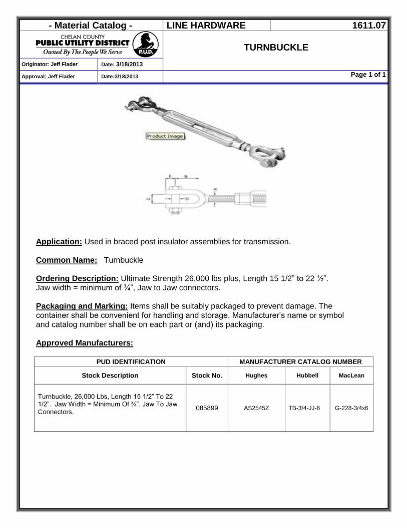
- Material Catalog - LINE HARDWARE 1611.07
TURNBUCKLE
Originator: Jeff Flader Date: 3/18/2013
Approval: Jeff Flader Date:3/18/2013 Page 1 of 1
Application: Used in braced post insulator assemblies for transmission. Common Name: Turnbuckle
Ordering Description: Ultimate Strength 26,000 lbs plus, Length 15 1/2” to 22 ½”. Jaw width = minimum of ¾”, Jaw to Jaw connectors. Packaging and Marking: Items shall be suitably packaged to prevent damage. The container shall be convenient for handling and storage. Manufacturer’s name or symbol and catalog number shall be on each part or (and) its packaging. Approved Manufacturers:
PUD IDENTIFICATION MANUFACTURER CATALOG NUMBER
Stock Description Stock No. Hughes Hubbell MacLean
Turnbuckle, 26,000 Lbs, Length 15 1/2” To 22 1/2”. Jaw Width = Minimum Of ¾”. Jaw To Jaw Connectors.
085899 AS2545Z TB-3/4-JJ-6 G-228-3/4x6

- Material Catalog - LINE HARDWARE 1612.01
DEADEND, CLEVIS, Y BALL - HOTLINE
Originator: Jeff Flader Date: 1/25/2012
Approval: Jeff Mitchell Date: 1/25/2012 Page 1 of 1
Revision: NEW Stds Committee Approval:
Pending
1612.01 Deadend, Clevis, Y Ball-Hotline.doc
Application: Installed between transmission conductor dead ends and 115 kv insulators Common Name: Deadend, Clevis, Y Ball - Hotline
Ordering Description: Deadend, Clevis, Y Ball, Hotline, Hd Galv, 9" To 10" Long, 3/4" Pin, 30,000 Lb Rating. Packaging and Marking: Items shall be suitably packaged to prevent damage. The container shall be convenient for handling and storage. Manufacturer’s name or symbol and catalog number shall be on each part or (and) its packaging. Approved Manufacturers:
PUD IDENTIFICATION MANUFACTURER CATALOG NUMBER Stock Description Stock No. Hubbell Anderson Preformed Maclean
DEADEND, CLEVIS, Y BALL - HOTLINE 085700 HYBC-30 HYBC-30 BYCL-30 YCBHL-65A
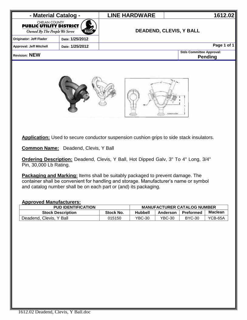
- Material Catalog - LINE HARDWARE 1612.02
DEADEND, CLEVIS, Y BALL
Originator: Jeff Flader Date: 1/25/2012
Approval: Jeff Mitchell Date: 1/25/2012 Page 1 of 1
Revision: NEW Stds Committee Approval:
Pending
1612.02 Deadend, Clevis, Y Ball.doc
Application: Used to secure conductor suspension cushion grips to side stack insulators. Common Name: Deadend, Clevis, Y Ball
Ordering Description: Deadend, Clevis, Y Ball, Hot Dipped Galv, 3" To 4" Long, 3/4" Pin, 30,000 Lb Rating. Packaging and Marking: Items shall be suitably packaged to prevent damage. The container shall be convenient for handling and storage. Manufacturer’s name or symbol and catalog number shall be on each part or (and) its packaging. Approved Manufacturers:
PUD IDENTIFICATION MANUFACTURER CATALOG NUMBER Stock Description Stock No. Hubbell Anderson Preformed Maclean
Deadend, Clevis, Y Ball 015150 YBC-30 YBC-30 BYC-30 YCB-65A
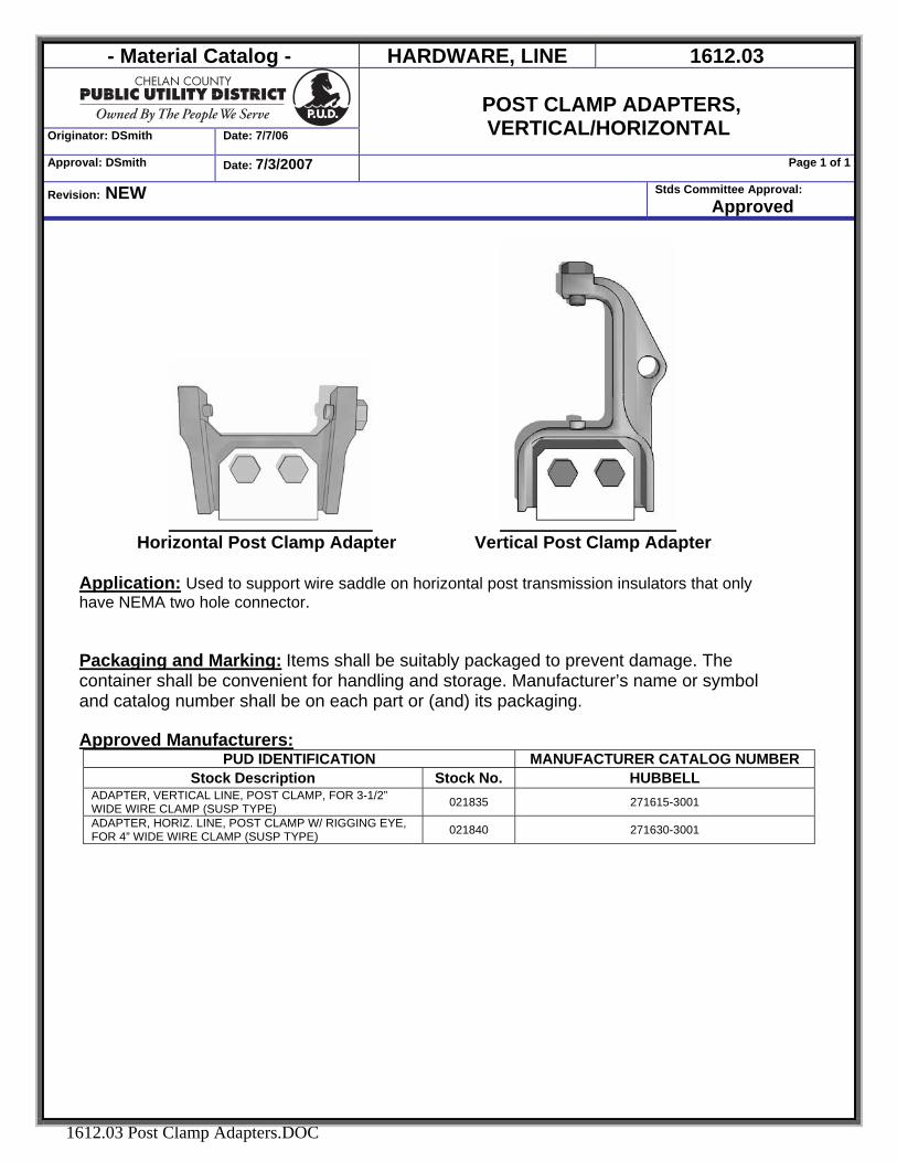
- Material Catalog - HARDWARE, LINE 1612.03
Originator: DSmith Date: 7/7/06
POST CLAMP ADAPTERS, VERTICAL/HORIZONTAL
Approval: DSmith Date: 7/3/2007 Page 1 of 1
Revision: NEW Stds Committee Approval: Approved
1612.03 Post Clamp Adapters.DOC
Horizontal Post Clamp Adapter Vertical Post Clamp Adapter
Application: Used to support wire saddle on horizontal post transmission insulators that only have NEMA two hole connector.
Packaging and Marking: Items shall be suitably packaged to prevent damage. The container shall be convenient for handling and storage. Manufacturer’s name or symbol and catalog number shall be on each part or (and) its packaging. Approved Manufacturers:
PUD IDENTIFICATION MANUFACTURER CATALOG NUMBER Stock Description Stock No. HUBBELL
ADAPTER, VERTICAL LINE, POST CLAMP, FOR 3-1/2” WIDE WIRE CLAMP (SUSP TYPE) 021835 271615-3001
ADAPTER, HORIZ. LINE, POST CLAMP W/ RIGGING EYE, FOR 4” WIDE WIRE CLAMP (SUSP TYPE) 021840 271630-3001
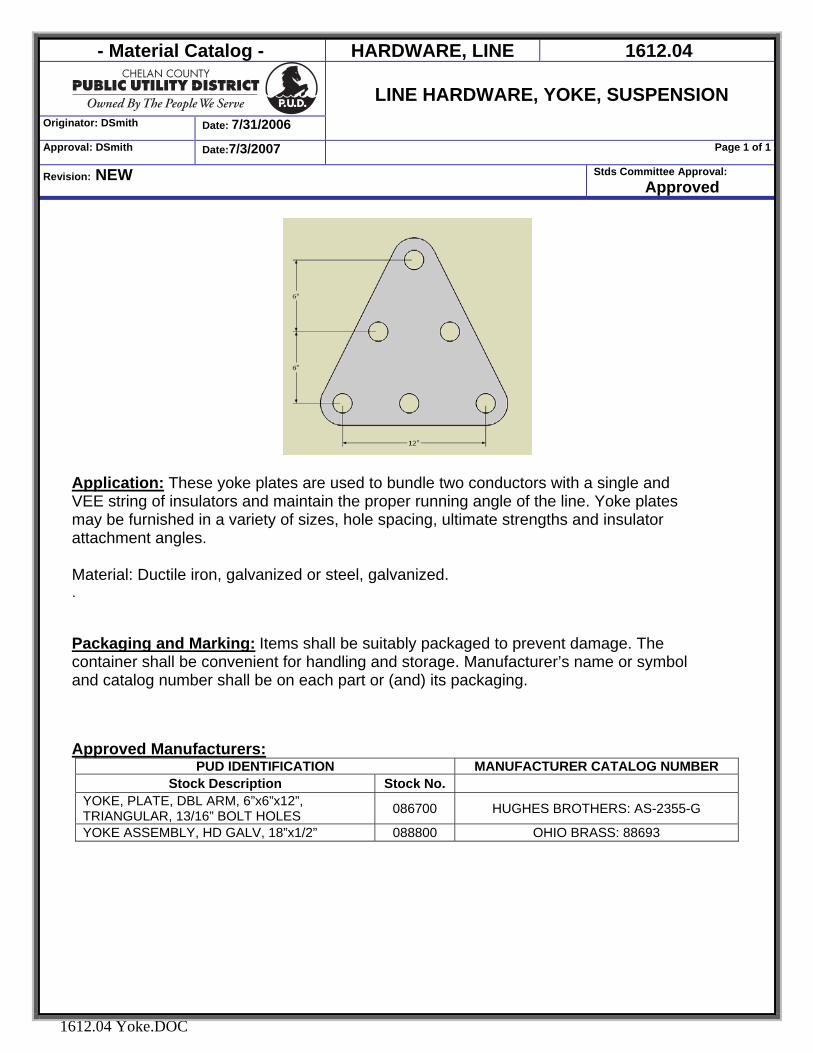
- Material Catalog - HARDWARE, LINE 1612.04
Originator: DSmith Date: 7/31/2006
LINE HARDWARE, YOKE, SUSPENSION
Approval: DSmith Date:7/3/2007 Page 1 of 1
Revision: NEW Stds Committee Approval: Approved
1612.04 Yoke.DOC
Application: These yoke plates are used to bundle two conductors with a single and VEE string of insulators and maintain the proper running angle of the line. Yoke plates may be furnished in a variety of sizes, hole spacing, ultimate strengths and insulator attachment angles. Material: Ductile iron, galvanized or steel, galvanized. . Packaging and Marking: Items shall be suitably packaged to prevent damage. The container shall be convenient for handling and storage. Manufacturer’s name or symbol and catalog number shall be on each part or (and) its packaging. Approved Manufacturers:
PUD IDENTIFICATION MANUFACTURER CATALOG NUMBER Stock Description Stock No.
YOKE, PLATE, DBL ARM, 6”x6”x12”, TRIANGULAR, 13/16” BOLT HOLES 086700 HUGHES BROTHERS: AS-2355-G
YOKE ASSEMBLY, HD GALV, 18”x1/2” 088800 OHIO BRASS: 88693
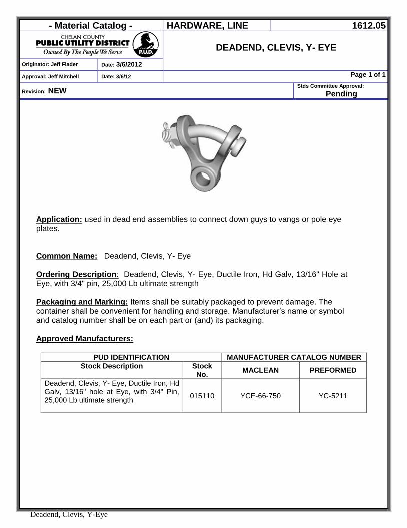
- Material Catalog - HARDWARE, LINE 1612.05
DEADEND, CLEVIS, Y- EYE
Originator: Jeff Flader Date: 3/6/2012
Approval: Jeff Mitchell Date: 3/6/12 Page 1 of 1
Revision: NEW Stds Committee Approval:
Pending
Deadend, Clevis, Y-Eye
Application: used in dead end assemblies to connect down guys to vangs or pole eye plates. Common Name: Deadend, Clevis, Y- Eye Ordering Description: Deadend, Clevis, Y- Eye, Ductile Iron, Hd Galv, 13/16" Hole at Eye, with 3/4" pin, 25,000 Lb ultimate strength Packaging and Marking: Items shall be suitably packaged to prevent damage. The container shall be convenient for handling and storage. Manufacturer’s name or symbol and catalog number shall be on each part or (and) its packaging. Approved Manufacturers:
PUD IDENTIFICATION MANUFACTURER CATALOG NUMBER Stock Description
Stock No. MACLEAN PREFORMED
Deadend, Clevis, Y- Eye, Ductile Iron, Hd Galv, 13/16" hole at Eye, with 3/4" Pin, 25,000 Lb ultimate strength
015110 YCE-66-750 YC-5211

- Material Catalog - Hardware, Line 1612.06
Deadend, Compression, Vertical Eye Type,
Single Tongue, ACSR Conductors Originator: Jennifer Smith Date: 10/17/2008
Approval: Jennifer Smith Date: 10/17/2008 Page 1 of 1
Revision: NEW Stds Committee Approval:
Approved
1612.06 Deadend Eye Single ACSR.DOC
Application: A deadend assembly for Aluminum Conductor Steel Reinforced (ACSR) conductors consists of a pre-filled aluminum deadend body precompressed onto a steel eye, a prefilled 15° jumper terminal, mounting hardware and core gripping unit. Terminal and tongue have NEMA hole spacing. Common Name: Deadend Bodies
Approved Manufacturers: Anderson, Alcoa
PUD IDENTIFICATION MANUFACTURER CATALOG NUMBER
Stock Description Stock No. Alcoa Anderson Deadend, Compression, Vertical Eye Type, Single Tongue, 336 ACSR 26/7, “Linnet” 030303 VES086 A0108131
Deadend, Compression, Vertical Eye Type, Single Tongue, 397 ACSR 26/7, “Ibis” 030304 VES096
Deadend, Compression, Vertical Eye Type, Single Tongue, 477 ACSR 26/7, “Hawk” 030305 VES105 A0110211
Deadend, Compression, Vertical Eye Type, Single Tongue, 636 ACSR 26/7, “Grosbeak” 030306 VES116
Deadend, Compression, Vertical Eye Type, Single Tongue, 795 ACSR 26/7, “Drake” 030307 VES126 A0112451
Deadend, Compression, Vertical Eye Type, Single Tongue, 1272 ACSR 45/7, “Bittern” 030308 VES153 A0115591
Deadend, Compression, Vertical Eye Type, Single Tongue, 1780 ACSR 84/19, “Chukar” 030309 VES174

- Material Catalog - Hardware, Line 1612.07
Deadends, Compression, Vertical Eye Type,
Double Tongue, ACSR Conductors Originator: Jennifer Smith Date: 10/17/2008
Approval: Jennifer Smith Date: 10/17/2008 Page 1 of 1
Revision: NEW Stds Committee Approval:
Approved
1612.07 Deadend Eye Double ACSR.doc
Application: A deadend assembly for Aluminum Conductor Steel Reinforced (ACSR) conductors consists of a pre-filled aluminum deadend body precompressed onto a steel eye, two prefilled 15° jumper terminals, mounting hardware and core gripping unit. Terminal and tongue have NEMA hole spacing. Common Name: Deadend Bodies
Approved Manufacturers: Alcoa
PUD IDENTIFICATION MANUFACTURER CATALOG NUMBER
Stock Description Stock No. Alcoa Deadend, Compression, Vertical Eye Type, Double Tongue, 336 ACSR 26/7, “Linnet” 030283 VED086
Deadend, Compression, Vertical Eye Type, Double Tongue, 636 ACSR 26/7, “Grosbeak” 030284 VED116
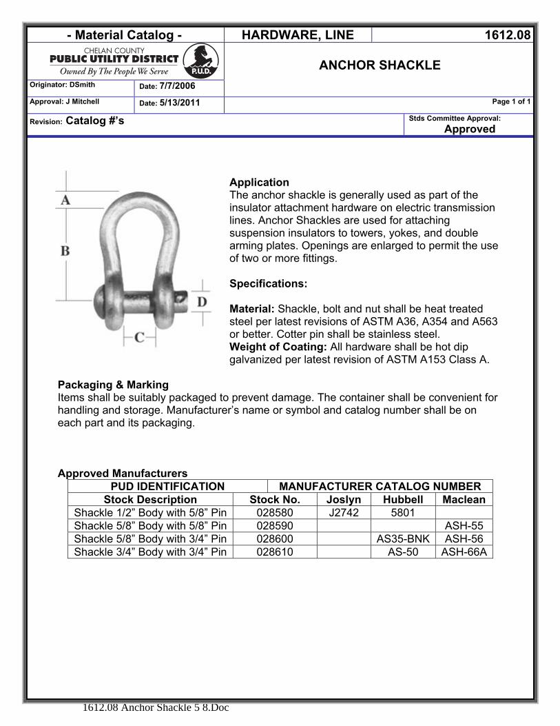
- Material Catalog - HARDWARE, LINE 1612.08
ANCHOR SHACKLE
Originator: DSmith Date: 7/7/2006
Approval: J Mitchell Date: 5/13/2011 Page 1 of 1
Revision: Catalog #’s Stds Committee Approval: Approved
1612.08 Anchor Shackle 5 8.Doc
Application The anchor shackle is generally used as part of the insulator attachment hardware on electric transmission lines. Anchor Shackles are used for attaching suspension insulators to towers, yokes, and double arming plates. Openings are enlarged to permit the use of two or more fittings. Specifications: Material: Shackle, bolt and nut shall be heat treated steel per latest revisions of ASTM A36, A354 and A563 or better. Cotter pin shall be stainless steel. Weight of Coating: All hardware shall be hot dip galvanized per latest revision of ASTM A153 Class A.
Packaging & Marking Items shall be suitably packaged to prevent damage. The container shall be convenient for handling and storage. Manufacturer’s name or symbol and catalog number shall be on each part and its packaging.
Approved Manufacturers
PUD IDENTIFICATION MANUFACTURER CATALOG NUMBER Stock Description Stock No. Joslyn Hubbell Maclean
Shackle 1/2” Body with 5/8” Pin 028580 J2742 5801 Shackle 5/8” Body with 5/8” Pin 028590 ASH-55 Shackle 5/8” Body with 3/4” Pin 028600 AS35-BNK ASH-56 Shackle 3/4” Body with 3/4” Pin 028610 AS-50 ASH-66A
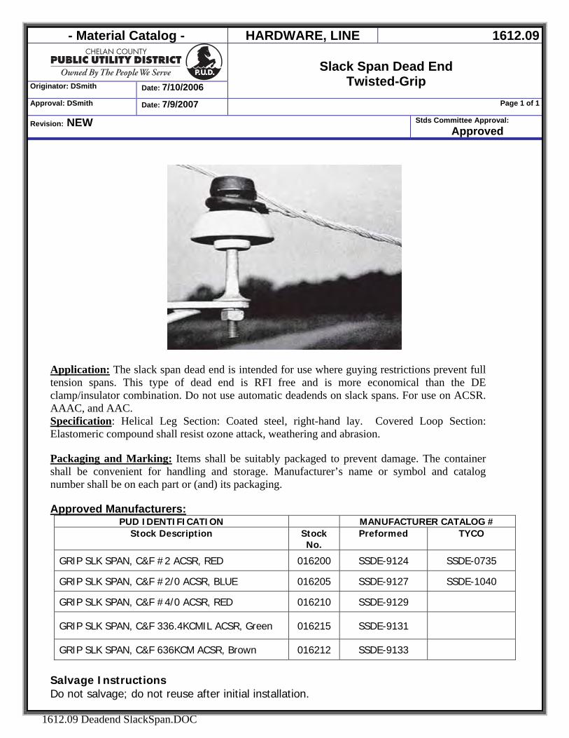
- Material Catalog - HARDWARE, LINE 1612.09
Originator: DSmith Date: 7/10/2006
Slack Span Dead End
Twisted-Grip Approval: DSmith Date: 7/9/2007 Page 1 of 1
Revision: NEW Stds Committee Approval: Approved
1612.09 Deadend SlackSpan.DOC
Application: The slack span dead end is intended for use where guying restrictions prevent full tension spans. This type of dead end is RFI free and is more economical than the DE clamp/insulator combination. Do not use automatic deadends on slack spans. For use on ACSR. AAAC, and AAC. Specification: Helical Leg Section: Coated steel, right-hand lay. Covered Loop Section: Elastomeric compound shall resist ozone attack, weathering and abrasion. Packaging and Marking: Items shall be suitably packaged to prevent damage. The container shall be convenient for handling and storage. Manufacturer’s name or symbol and catalog number shall be on each part or (and) its packaging. Approved Manufacturers:
PUD IDENTIFICATION MANUFACTURER CATALOG # Stock Description Stock
No. Preformed TYCO
GRIP SLK SPAN, C&F #2 ACSR, RED 016200 SSDE-9124 SSDE-0735
GRIP SLK SPAN, C&F #2/0 ACSR, BLUE 016205 SSDE-9127 SSDE-1040
GRIP SLK SPAN, C&F #4/0 ACSR, RED 016210 SSDE-9129
GRIP SLK SPAN, C&F 336.4KCMIL ACSR, Green 016215 SSDE-9131
GRIP SLK SPAN, C&F 636KCM ACSR, Brown 016212 SSDE-9133
Salvage Instructions Do not salvage; do not reuse after initial installation.
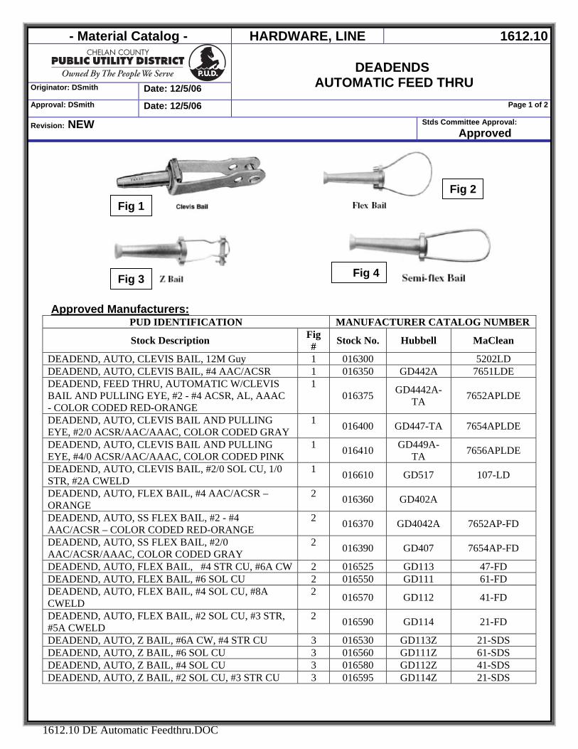
- Material Catalog - HARDWARE, LINE 1612.10
Originator: DSmith Date: 12/5/06
DEADENDS
AUTOMATIC FEED THRU Approval: DSmith Date: 12/5/06 Page 1 of 2
Revision: NEW Stds Committee Approval: Approved
1612.10 DE Automatic Feedthru.DOC
Fig 4
Approved Manufacturers:
PUD IDENTIFICATION MANUFACTURER CATALOG NUMBER
Stock Description Fig # Stock No. Hubbell MaClean
DEADEND, AUTO, CLEVIS BAIL, 12M Guy 1 016300 5202LD DEADEND, AUTO, CLEVIS BAIL, #4 AAC/ACSR 1 016350 GD442A 7651LDE DEADEND, FEED THRU, AUTOMATIC W/CLEVIS BAIL AND PULLING EYE, #2 - #4 ACSR, AL, AAAC - COLOR CODED RED-ORANGE
1 016375 GD4442A-
TA 7652APLDE
DEADEND, AUTO, CLEVIS BAIL AND PULLING EYE, #2/0 ACSR/AAC/AAAC, COLOR CODED GRAY
1 016400 GD447-TA 7654APLDE
DEADEND, AUTO, CLEVIS BAIL AND PULLING EYE, #4/0 ACSR/AAC/AAAC, COLOR CODED PINK
1 016410 GD449A-TA 7656APLDE
DEADEND, AUTO, CLEVIS BAIL, #2/0 SOL CU, 1/0 STR, #2A CWELD
1 016610 GD517 107-LD
DEADEND, AUTO, FLEX BAIL, #4 AAC/ACSR – ORANGE
2 016360 GD402A
DEADEND, AUTO, SS FLEX BAIL, #2 - #4 AAC/ACSR – COLOR CODED RED-ORANGE
2 016370 GD4042A 7652AP-FD
DEADEND, AUTO, SS FLEX BAIL, #2/0 AAC/ACSR/AAAC, COLOR CODED GRAY
2 016390 GD407 7654AP-FD
DEADEND, AUTO, FLEX BAIL, #4 STR CU, #6A CW 2 016525 GD113 47-FD DEADEND, AUTO, FLEX BAIL, #6 SOL CU 2 016550 GD111 61-FD DEADEND, AUTO, FLEX BAIL, #4 SOL CU, #8A CWELD
2 016570 GD112 41-FD
DEADEND, AUTO, FLEX BAIL, #2 SOL CU, #3 STR, #5A CWELD
2 016590 GD114 21-FD
DEADEND, AUTO, Z BAIL, #6A CW, #4 STR CU 3 016530 GD113Z 21-SDS DEADEND, AUTO, Z BAIL, #6 SOL CU 3 016560 GD111Z 61-SDS DEADEND, AUTO, Z BAIL, #4 SOL CU 3 016580 GD112Z 41-SDS DEADEND, AUTO, Z BAIL, #2 SOL CU, #3 STR CU 3 016595 GD114Z 21-SDS
Fig 1
Fig 3
Fig 2
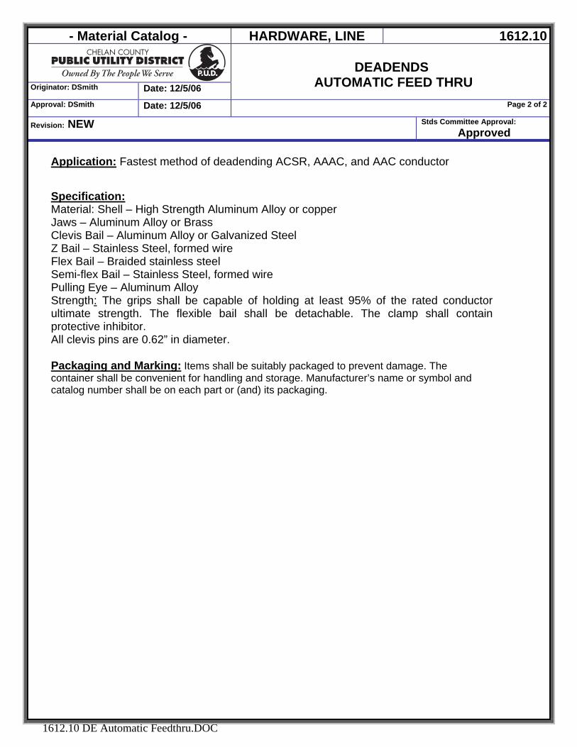
- Material Catalog - HARDWARE, LINE 1612.10
Originator: DSmith Date: 12/5/06
DEADENDS
AUTOMATIC FEED THRU Approval: DSmith Date: 12/5/06 Page 2 of 2
Revision: NEW Stds Committee Approval: Approved
1612.10 DE Automatic Feedthru.DOC
Application: Fastest method of deadending ACSR, AAAC, and AAC conductor Specification: Material: Shell – High Strength Aluminum Alloy or copper Jaws – Aluminum Alloy or Brass Clevis Bail – Aluminum Alloy or Galvanized Steel Z Bail – Stainless Steel, formed wire Flex Bail – Braided stainless steel Semi-flex Bail – Stainless Steel, formed wire Pulling Eye – Aluminum Alloy Strength: The grips shall be capable of holding at least 95% of the rated conductor ultimate strength. The flexible bail shall be detachable. The clamp shall contain protective inhibitor. All clevis pins are 0.62” in diameter. Packaging and Marking: Items shall be suitably packaged to prevent damage. The container shall be convenient for handling and storage. Manufacturer’s name or symbol and catalog number shall be on each part or (and) its packaging.
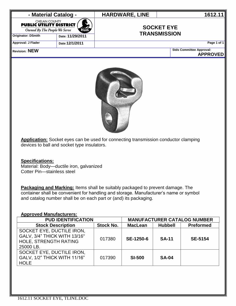
- Material Catalog - HARDWARE, LINE 1612.11
SOCKET EYE
TRANSMISSION Originator: DSmith Date: 11/29/2011
Approval: J Flader Date:12/1/2011 Page 1 of 1
Revision: NEW Stds Committee Approval: APPROVED
1612.11 SOCKET EYE, TLINE.DOC
Application: Socket eyes can be used for connecting transmission conductor clamping devices to ball and socket type insulators. Specifications: Material: Body—ductile iron, galvanized Cotter Pin—stainless steel
Packaging and Marking: Items shall be suitably packaged to prevent damage. The container shall be convenient for handling and storage. Manufacturer’s name or symbol and catalog number shall be on each part or (and) its packaging. Approved Manufacturers:
PUD IDENTIFICATION MANUFACTURER CATALOG NUMBER Stock Description Stock No. MacLean Hubbell Preformed
SOCKET EYE, DUCTILE IRON, GALV, 3/4” THICK WITH 13/16" HOLE, STRENGTH RATING 25000 LB.
017380 SE-1250-6 SA-11 SE-5154
SOCKET EYE, DUCTILE IRON, GALV, 1/2” THICK WITH 11/16” HOLE
017390 SI-500 SA-04
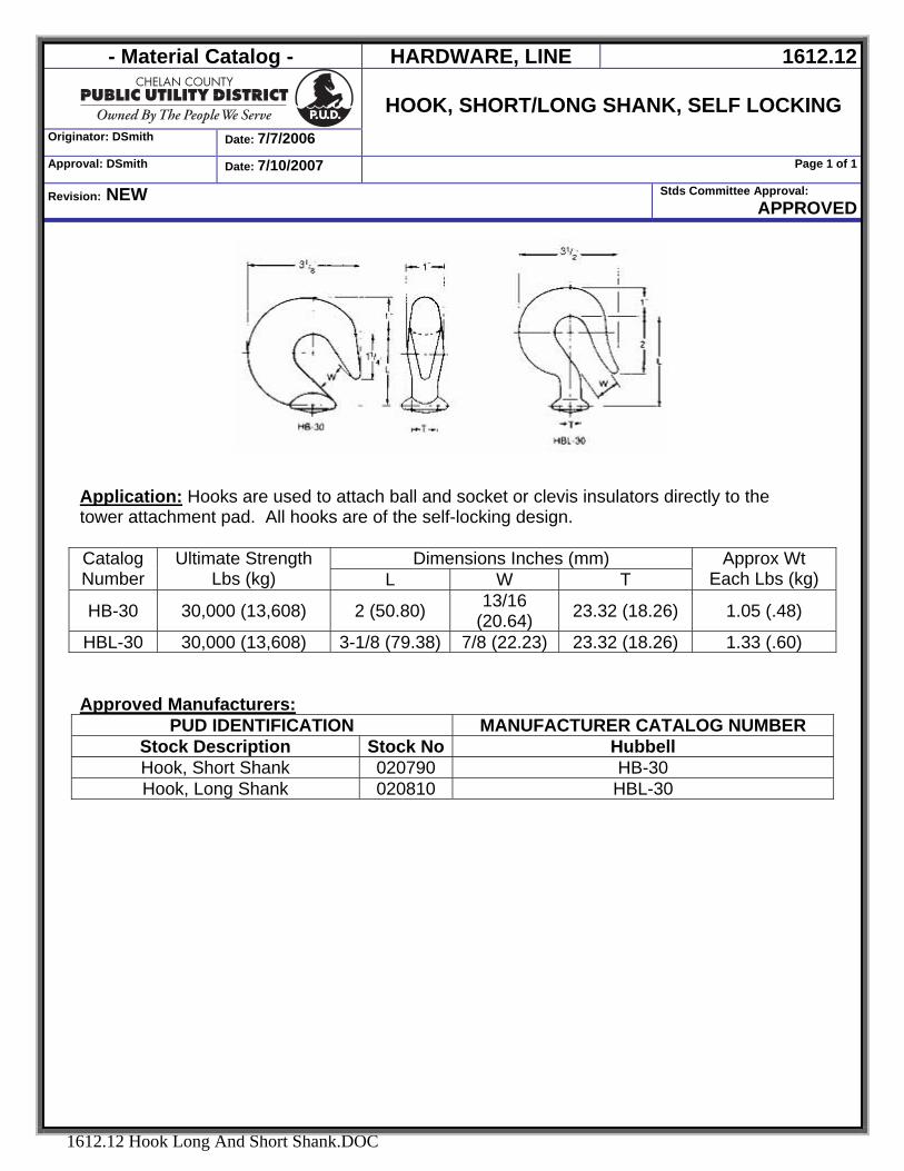
- Material Catalog - HARDWARE, LINE 1612.12
Originator: DSmith Date: 7/7/2006
HOOK, SHORT/LONG SHANK, SELF LOCKING
Approval: DSmith Date: 7/10/2007 Page 1 of 1
Revision: NEW Stds Committee Approval: APPROVED
1612.12 Hook Long And Short Shank.DOC
Application: Hooks are used to attach ball and socket or clevis insulators directly to the tower attachment pad. All hooks are of the self-locking design.
Dimensions Inches (mm) Catalog Number
Ultimate Strength Lbs (kg) L W T
Approx Wt Each Lbs (kg)
HB-30 30,000 (13,608) 2 (50.80) 13/16 (20.64) 23.32 (18.26) 1.05 (.48)
HBL-30 30,000 (13,608) 3-1/8 (79.38) 7/8 (22.23) 23.32 (18.26) 1.33 (.60) Approved Manufacturers:
PUD IDENTIFICATION MANUFACTURER CATALOG NUMBER Stock Description Stock No Hubbell Hook, Short Shank 020790 HB-30 Hook, Long Shank 020810 HBL-30

- Material Catalog - LINE HARDWARE 1612.13
CLEVIS, SOCKET, HOTLINE
Originator: Flader, Jeff Date: 1/25/2012
Approval: Flader, Jeff Date: 1/25/2012 Page 1 of 1
Revision: NEW Stds Committee Approval:
Pending
1612.13 CLEVIS, SOCKET, HOTLINE.doc
Application: used at dead end assemblies to secure transmission conductor. Common Name: Clevis, Socket, Hotline
Ordering Description: Clevis, Socket, Hotline, Hd Galv, 10", Clevis Width 1" With 5/8" Pin & Cotter Key, 30k Lb Ultimate Strength. Packaging and Marking: Items shall be suitably packaged to prevent damage. The container shall be convenient for handling and storage. Manufacturer’s name or symbol and catalog number shall be on each part or (and) its packaging. Approved Manufacturers:
PUD IDENTIFICATION MANUFACTURER CATALOG NUMBER Stock Description Stock No. Hubbell Anderson Maclean
Clevis, Socket, Hotline, Hd Galv, 10" 085500 HSC-100 HSC-100 HCHL-55A
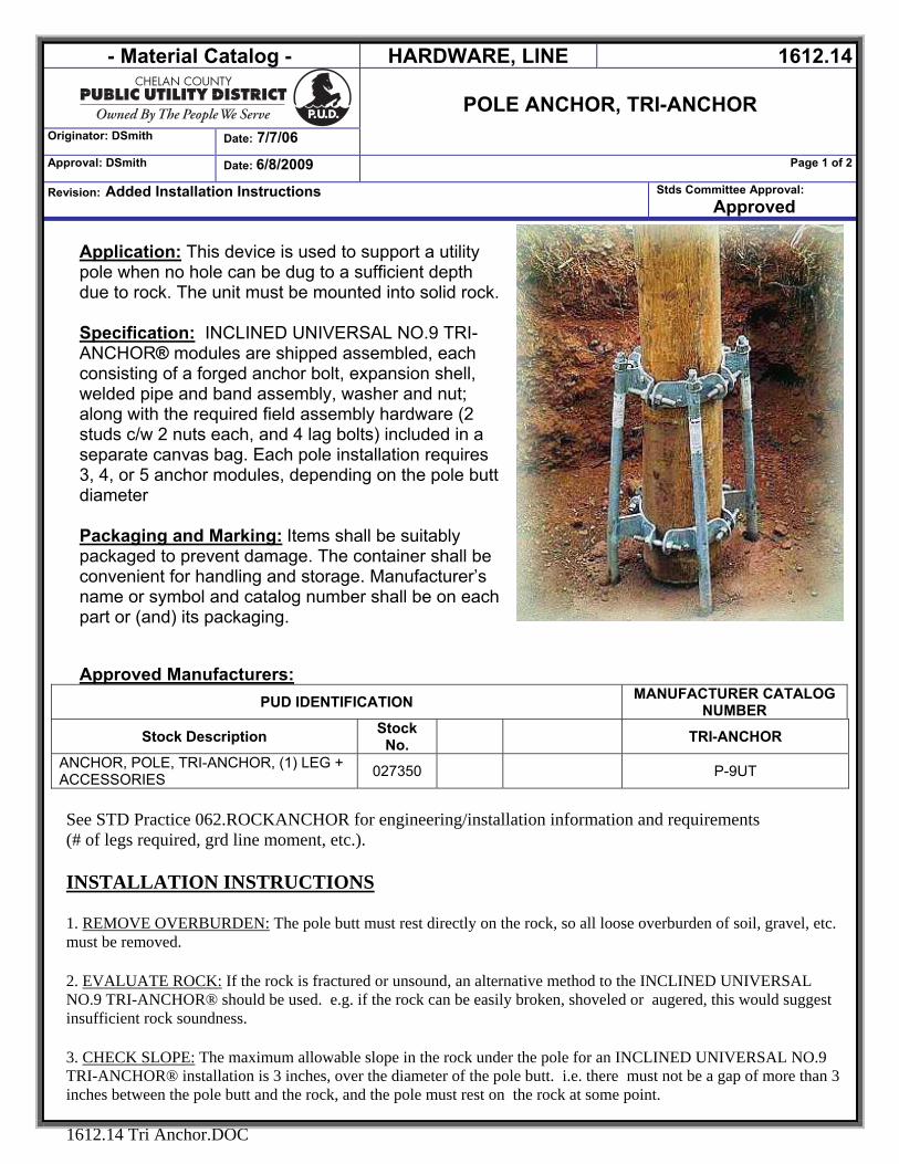
- Material Catalog - HARDWARE, LINE 1612.14
POLE ANCHOR, TRI-ANCHOR
Originator: DSmith Date: 7/7/06
Approval: DSmith Date: 6/8/2009 Page 1 of 2
Revision: Added Installation Instructions Stds Committee Approval: Approved
1612.14 Tri Anchor.DOC
Application: This device is used to support a utility pole when no hole can be dug to a sufficient depth due to rock. The unit must be mounted into solid rock. Specification: INCLINED UNIVERSAL NO.9 TRI-ANCHOR® modules are shipped assembled, each consisting of a forged anchor bolt, expansion shell, welded pipe and band assembly, washer and nut; along with the required field assembly hardware (2 studs c/w 2 nuts each, and 4 lag bolts) included in a separate canvas bag. Each pole installation requires 3, 4, or 5 anchor modules, depending on the pole butt diameter Packaging and Marking: Items shall be suitably packaged to prevent damage. The container shall be convenient for handling and storage. Manufacturer’s name or symbol and catalog number shall be on each part or (and) its packaging. Approved Manufacturers:
PUD IDENTIFICATION MANUFACTURER CATALOG NUMBER
Stock Description Stock No. TRI-ANCHOR
ANCHOR, POLE, TRI-ANCHOR, (1) LEG + ACCESSORIES 027350 P-9UT
See STD Practice 062.ROCKANCHOR for engineering/installation information and requirements (# of legs required, grd line moment, etc.).
INSTALLATION INSTRUCTIONS
1. REMOVE OVERBURDEN: The pole butt must rest directly on the rock, so all loose overburden of soil, gravel, etc. must be removed.
2. EVALUATE ROCK: If the rock is fractured or unsound, an alternative method to the INCLINED UNIVERSAL NO.9 TRI-ANCHOR® should be used. e.g. if the rock can be easily broken, shoveled or augered, this would suggest insufficient rock soundness.
3. CHECK SLOPE: The maximum allowable slope in the rock under the pole for an INCLINED UNIVERSAL NO.9 TRI-ANCHOR® installation is 3 inches, over the diameter of the pole butt. i.e. there must not be a gap of more than 3 inches between the pole butt and the rock, and the pole must rest on the rock at some point.
- Material Catalog - HARDWARE, LINE 1612.14
POLE ANCHOR, TRI-ANCHOR
Originator: DSmith Date: 7/7/06
Approval: DSmith Date: 6/8/2009 Page 2 of 2
Revision: Added Installation Instructions Stds Committee Approval: Approved
1612.14 Tri Anchor.DOC
4. DECIDE ON NUMBER OF MODULES: Consult the Selection Chart to decide on the required number of modules for the installation, which varies with the pole butt diameter. Where the ranges overlap, the required ground line moments will help determine the number of modules to be used.
5. ASSEMBLE ROCK DRILLING TEMPLATE: Choose the appropriate template core for the configuration chosen (i.e. 3, 4 or 5 modules). Insert the sleeves into the template core.
6. ADJUST TEMPLATE: Fit the assembled template to the pole butt, adjusting it for the pole size. Place the template right side up on the rock so that the holes to be drilled point OUTWARD from the pole center. The proper slope is given by the inclined drilling sleeve. On sloped rock, use the leveling bolts to ensure that the template is level before drilling.
7. DRILL HOLES: Begin at the highest point of the rock and drill a 2" diameter hole through the template to a depth of 24 inches. Continue drilling the remaining holes through the template to the same depth, when measured from a horizontal line. All rock dust should be cleaned out.
8. INSERT THE ANCHORS: With all holes drilled, remove the template and drop the anchors into the holes. Loosely connect the bands with the studs.
9. ERECT POLE AND TIGHTEN BANDS: Lift and hold the pole in place vertically. Tighten all the studs to grip the pole within the bands. Ensure that all nuts are firmly tightened. 10. TIGHTEN ANCHOR BOLTS: Tighten the nuts of the anchor bolts firmly. In sound rock a positive anchor will develop from the expansion of the expansion shell. In poor rock you will run out of thread before developing an adequate bond, and an alternate location or method must be used.
11. INSTALL LAG BOLTS: Install all lag bolts with a wrench. Pre-drilling holes in the pole and using an impact wrench or socket wrench are recommended. Release the pole.
12. FINAL STEPS: Grouting of the holes is optional if ice is a concern. Backfill any removed overburden if desired. 13. MAINTENANCE: Incorporate the INCLINED UNIVERSAL NO.9 TRI-ANCHOR® system into the regular pole and line maintenance schedule and procedures. At each inspection ensure that all nuts and lags are in place and tight.
Manufacture Contact Information: TRI-STEEL USA 1535 CABOT ST. # 201 MONTREAL, CANADA H4E 1C8 TOLL FREE: 1-888-ON-ROCK-8 1-888-667-6258 Fax: 514-766-6111 E-MAIL: [email protected]
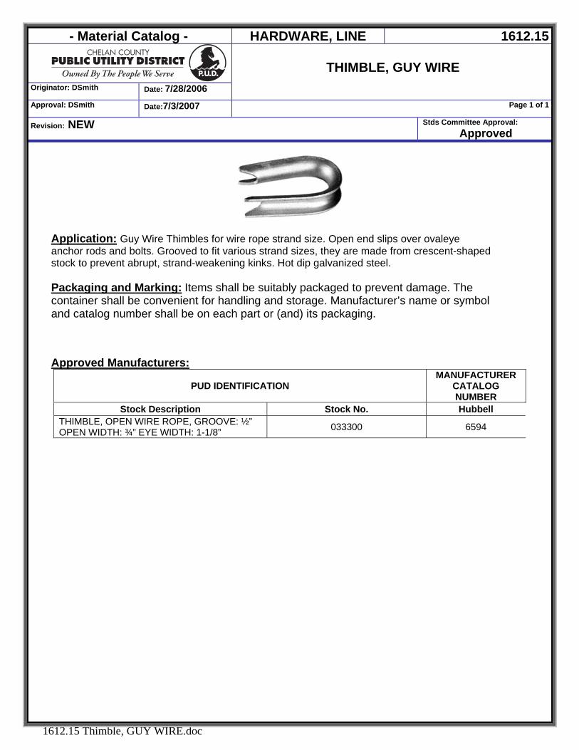
- Material Catalog - HARDWARE, LINE 1612.15
Originator: DSmith Date: 7/28/2006
THIMBLE, GUY WIRE
Approval: DSmith Date:7/3/2007 Page 1 of 1
Revision: NEW Stds Committee Approval: Approved
1612.15 Thimble, GUY WIRE.doc
Application: Guy Wire Thimbles for wire rope strand size. Open end slips over ovaleye anchor rods and bolts. Grooved to fit various strand sizes, they are made from crescent-shaped stock to prevent abrupt, strand-weakening kinks. Hot dip galvanized steel. Packaging and Marking: Items shall be suitably packaged to prevent damage. The container shall be convenient for handling and storage. Manufacturer’s name or symbol and catalog number shall be on each part or (and) its packaging. Approved Manufacturers:
PUD IDENTIFICATION MANUFACTURER
CATALOG NUMBER
Stock Description Stock No. Hubbell THIMBLE, OPEN WIRE ROPE, GROOVE: ½” OPEN WIDTH: ¾” EYE WIDTH: 1-1/8” 033300 6594
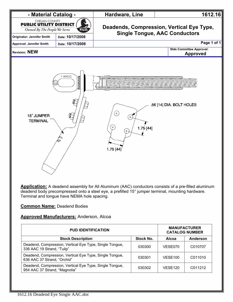
- Material Catalog - Hardware, Line 1612.16
Deadends, Compression, Vertical Eye Type,
Single Tongue, AAC Conductors Originator: Jennifer Smith Date: 10/17/2008
Approval: Jennifer Smith Date: 10/17/2008 Page 1 of 1
Revision: NEW Stds Committee Approval:
Approved
1612.16 Deadend Eye Single AAC.doc
Application: A deadend assembly for All Aluminum (AAC) conductors consists of a pre-filled aluminum deadend body precompressed onto a steel eye, a prefilled 15° jumper terminal, mounting hardware. Terminal and tongue have NEMA hole spacing. Common Name: Deadend Bodies
Approved Manufacturers: Anderson, Alcoa
PUD IDENTIFICATION MANUFACTURER CATALOG NUMBER
Stock Description Stock No. Alcoa Anderson Deadend, Compression, Vertical Eye Type, Single Tongue, 336 AAC 19 Strand, “Tulip” 030300 VESE070 C010707
Deadend, Compression, Vertical Eye Type, Single Tongue, 636 AAC 37 Strand, “Orchid” 030301 VESE100 C011010
Deadend, Compression, Vertical Eye Type, Single Tongue, 954 AAC 37 Strand, “Magnolia” 030302 VESE120 C011212
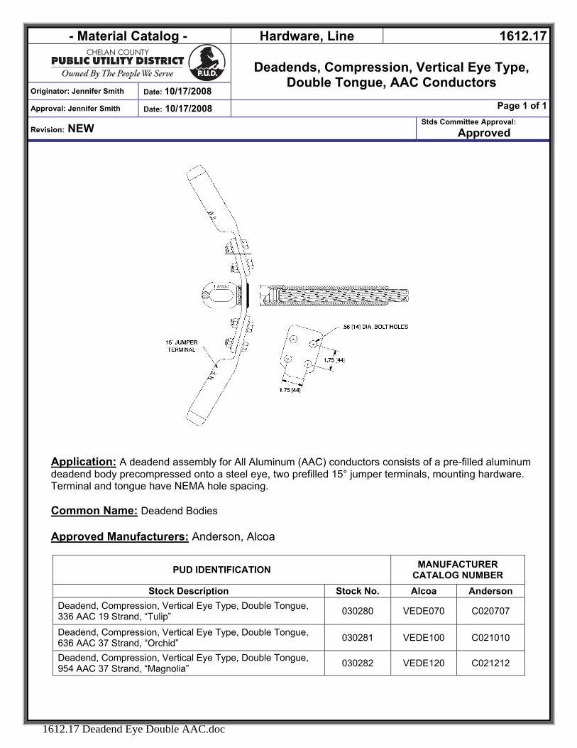
- Material Catalog - Hardware, Line 1612.17
Deadends, Compression, Vertical Eye Type,
Double Tongue, AAC Conductors Originator: Jennifer Smith Date: 10/17/2008
Approval: Jennifer Smith Date: 10/17/2008 Page 1 of 1
Revision: NEW Stds Committee Approval:
Approved
1612.17 Deadend Eye Double AAC.doc
Application: A deadend assembly for All Aluminum (AAC) conductors consists of a pre-filled aluminum deadend body precompressed onto a steel eye, two prefilled 15° jumper terminals, mounting hardware. Terminal and tongue have NEMA hole spacing. Common Name: Deadend Bodies
Approved Manufacturers: Anderson, Alcoa
PUD IDENTIFICATION MANUFACTURER CATALOG NUMBER
Stock Description Stock No. Alcoa Anderson Deadend, Compression, Vertical Eye Type, Double Tongue, 336 AAC 19 Strand, “Tulip” 030280 VEDE070 C020707
Deadend, Compression, Vertical Eye Type, Double Tongue, 636 AAC 37 Strand, “Orchid” 030281 VEDE100 C021010
Deadend, Compression, Vertical Eye Type, Double Tongue, 954 AAC 37 Strand, “Magnolia” 030282 VEDE120 C021212
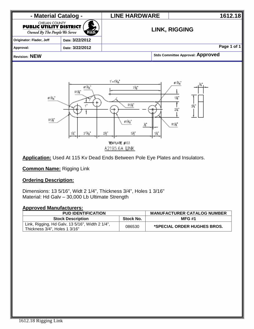
- Material Catalog - LINE HARDWARE 1612.18
LINK, RIGGING
Originator: Flader, Jeff Date: 3/22/2012
Approval: Date: 3/22/2012 Page 1 of 1
Revision: NEW Stds Committee Approval: Approved
1612.18 Rigging Link
Application: Used At 115 Kv Dead Ends Between Pole Eye Plates and Insulators. Common Name: Rigging Link
Ordering Description: Dimensions: 13 5/16", Widt 2 1/4", Thickness 3/4", Holes 1 3/16" Material: Hd Galv – 30,000 Lb Ultimate Strength Approved Manufacturers:
PUD IDENTIFICATION MANUFACTURER CATALOG NUMBER Stock Description Stock No. MFG #1
Link, Rigging, Hd Galv, 13 5/16", Width 2 1/4", Thickness 3/4", Holes 1 3/16" 086530 *SPECIAL ORDER HUGHES BROS.
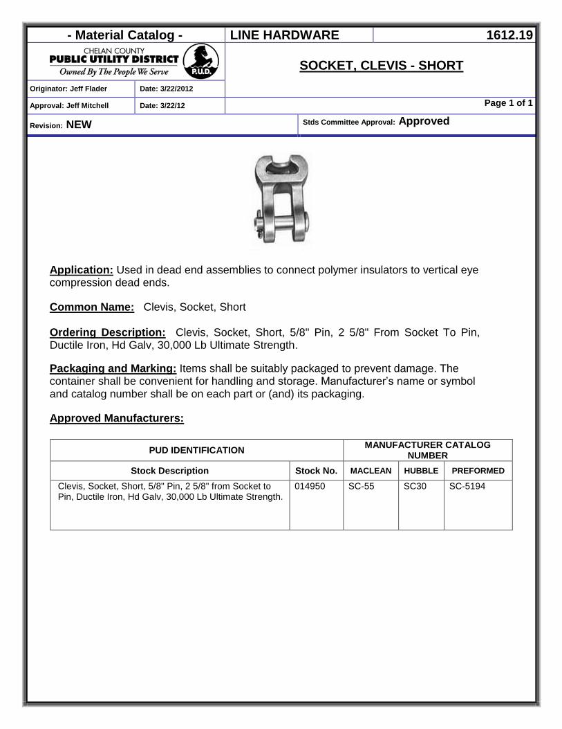
- Material Catalog - LINE HARDWARE 1612.19
SOCKET, CLEVIS - SHORT
Originator: Jeff Flader Date: 3/22/2012
Approval: Jeff Mitchell Date: 3/22/12 Page 1 of 1
Revision: NEW Stds Committee Approval: Approved
Application: Used in dead end assemblies to connect polymer insulators to vertical eye compression dead ends. Common Name: Clevis, Socket, Short
Ordering Description: Clevis, Socket, Short, 5/8" Pin, 2 5/8" From Socket To Pin, Ductile Iron, Hd Galv, 30,000 Lb Ultimate Strength.
Packaging and Marking: Items shall be suitably packaged to prevent damage. The container shall be convenient for handling and storage. Manufacturer’s name or symbol and catalog number shall be on each part or (and) its packaging. Approved Manufacturers:
PUD IDENTIFICATION MANUFACTURER CATALOG NUMBER
Stock Description Stock No. MACLEAN HUBBLE PREFORMED
Clevis, Socket, Short, 5/8" Pin, 2 5/8" from Socket to Pin, Ductile Iron, Hd Galv, 30,000 Lb Ultimate Strength.
014950 SC-55 SC30 SC-5194

- Material Catalog - HARDWARE, LINE 1613.01
Originator: DSmith Date:7/28/2006
GUYING ANCHOR, CROSS PLATE
Approval: DSmith Date: 7/3/2007 Page 1 of 1
Revision: NEW Stds Committee Approval: Approved
1613.01 Guying Anchor Cross Plate.DOC
Application: The Cross-Plate anchor is made for installation in holes drilled by power diggers. Because the size of the hole does not affect holding capacity, the hole can be dug by the same auger that is used to dig the pole holes on transmission projects. Cross-Plate anchors are installed in a diagonal bored hole which is undercut so the anchor is at right angles to the guy. A rod trench is either cut with a trenching tool or drilled with a small power auger. Both anchor and rod trench should be refilled and tamped. Packaging and Marking: Items shall be suitably packaged to prevent damage. The container shall be convenient for handling and storage. Manufacturer’s name or symbol and catalog number shall be on each part or (and) its packaging. Approved Manufacturers:
PUD IDENTIFICATION MANUFACTURER CATALOG NUMBER
Stock Description Stock No. Chance
ANCHOR, 24” CROSS PLATE 005255 X24
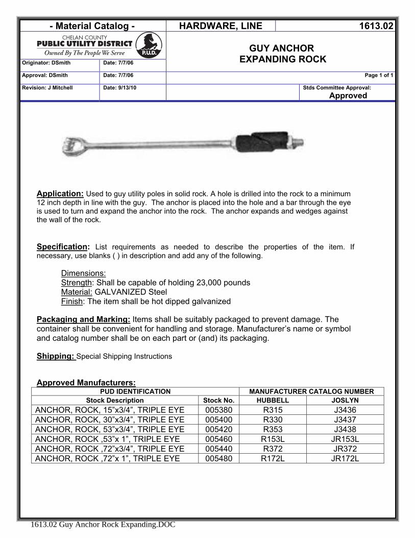
- Material Catalog - HARDWARE, LINE 1613.02
GUY ANCHOR
EXPANDING ROCK Originator: DSmith Date: 7/7/06
Approval: DSmith Date: 7/7/06 Page 1 of 1
Revision: J Mitchell Date: 9/13/10 Stds Committee Approval: Approved
1613.02 Guy Anchor Rock Expanding.DOC
Application: Used to guy utility poles in solid rock. A hole is drilled into the rock to a minimum 12 inch depth in line with the guy. The anchor is placed into the hole and a bar through the eye is used to turn and expand the anchor into the rock. The anchor expands and wedges against the wall of the rock.
Specification: List requirements as needed to describe the properties of the item. If necessary, use blanks ( ) in description and add any of the following.
Dimensions: Strength: Shall be capable of holding 23,000 pounds Material: GALVANIZED Steel Finish: The item shall be hot dipped galvanized
Packaging and Marking: Items shall be suitably packaged to prevent damage. The container shall be convenient for handling and storage. Manufacturer’s name or symbol and catalog number shall be on each part or (and) its packaging. Shipping: Special Shipping Instructions Approved Manufacturers:
PUD IDENTIFICATION MANUFACTURER CATALOG NUMBER Stock Description Stock No. HUBBELL JOSLYN
ANCHOR, ROCK, 15”x3/4”, TRIPLE EYE 005380 R315 J3436 ANCHOR, ROCK, 30”x3/4”, TRIPLE EYE 005400 R330 J3437 ANCHOR, ROCK, 53”x3/4”, TRIPLE EYE 005420 R353 J3438 ANCHOR, ROCK ,53”x 1”, TRIPLE EYE 005460 R153L JR153L ANCHOR, ROCK ,72”x3/4”, TRIPLE EYE 005440 R372 JR372 ANCHOR, ROCK ,72”x 1”, TRIPLE EYE 005480 R172L JR172L
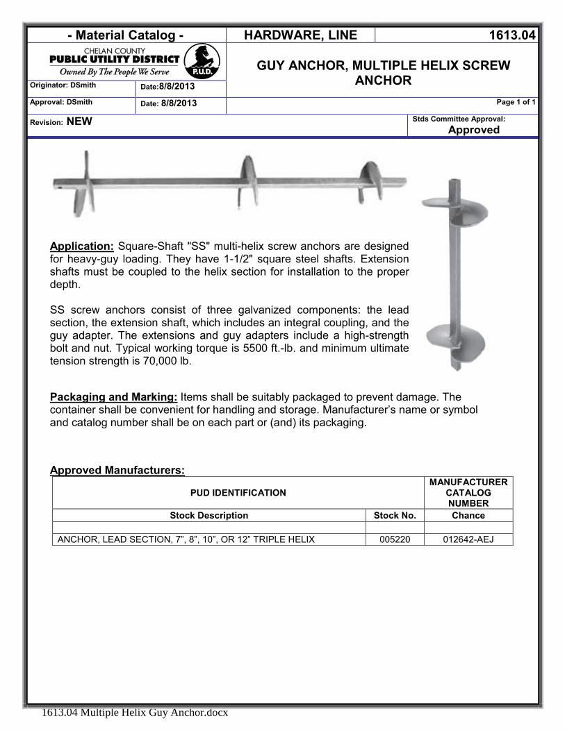
- Material Catalog - HARDWARE, LINE 1613.04
GUY ANCHOR, MULTIPLE HELIX SCREW
ANCHOR Originator: DSmith Date:8/8/2013
Approval: DSmith Date: 8/8/2013 Page 1 of 1
Revision: NEW Stds Committee Approval: Approved
1613.04 Multiple Helix Guy Anchor.docx
Application: Square-Shaft "SS" multi-helix screw anchors are designed for heavy-guy loading. They have 1-1/2" square steel shafts. Extension shafts must be coupled to the helix section for installation to the proper depth. SS screw anchors consist of three galvanized components: the lead section, the extension shaft, which includes an integral coupling, and the guy adapter. The extensions and guy adapters include a high-strength bolt and nut. Typical working torque is 5500 ft.-lb. and minimum ultimate tension strength is 70,000 lb.
Packaging and Marking: Items shall be suitably packaged to prevent damage. The container shall be convenient for handling and storage. Manufacturer’s name or symbol and catalog number shall be on each part or (and) its packaging. Approved Manufacturers:
PUD IDENTIFICATION MANUFACTURER
CATALOG NUMBER
Stock Description Stock No. Chance ANCHOR, LEAD SECTION, 7”, 8”, 10”, OR 12” TRIPLE HELIX 005220 012642-AEJ
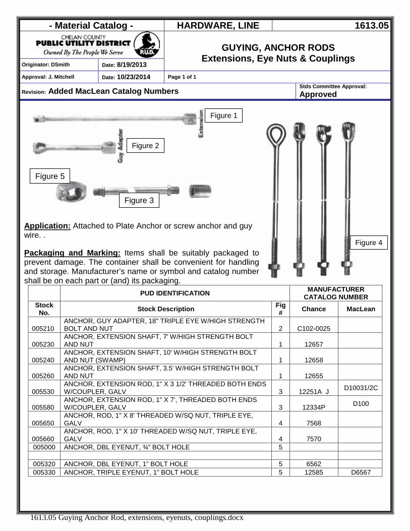
- Material Catalog - HARDWARE, LINE 1613.05
GUYING, ANCHOR RODS
Extensions, Eye Nuts & Couplings Originator: DSmith Date: 8/19/2013
Approval: J. Mitchell Date: 10/23/2014 Page 1 of 1
Revision: Added MacLean Catalog Numbers Stds Committee Approval: Approved
1613.05 Guying Anchor Rod, extensions, eyenuts, couplings.docx
Figure 4
Application: Attached to Plate Anchor or screw anchor and guy wire. .
Packaging and Marking: Items shall be suitably packaged to prevent damage. The container shall be convenient for handling and storage. Manufacturer’s name or symbol and catalog number shall be on each part or (and) its packaging.
PUD IDENTIFICATION MANUFACTURER CATALOG NUMBER
Stock No. Stock Description Fig
# Chance MacLean
005210 ANCHOR, GUY ADAPTER, 18" TRIPLE EYE W/HIGH STRENGTH BOLT AND NUT 2 C102-0025
005230 ANCHOR, EXTENSION SHAFT, 7' W/HIGH STRENGTH BOLT AND NUT 1 12657
005240 ANCHOR, EXTENSION SHAFT, 10' W/HIGH STRENGTH BOLT AND NUT (SWAMP) 1 12658
005260 ANCHOR, EXTENSION SHAFT, 3.5' W/HIGH STRENGTH BOLT AND NUT 1 12655
005530 ANCHOR, EXTENSION ROD, 1" X 3 1/2' THREADED BOTH ENDS W/COUPLER, GALV 3 12251A J D10031/2C
005580 ANCHOR, EXTENSION ROD, 1" X 7', THREADED BOTH ENDS W/COUPLER, GALV 3 12334P D100
005650 ANCHOR, ROD, 1" X 8' THREADED W/SQ NUT, TRIPLE EYE, GALV 4 7568
005660 ANCHOR, ROD, 1" X 10' THREADED W/SQ NUT, TRIPLE EYE, GALV 4 7570
005000 ANCHOR, DBL EYENUT, ¾” BOLT HOLE 5
005320 ANCHOR, DBL EYENUT, 1” BOLT HOLE 5 6562 005330 ANCHOR, TRIPLE EYENUT, 1” BOLT HOLE 5 12585 D6567
Figure 1
Figure 2
Figure 3
Figure 5
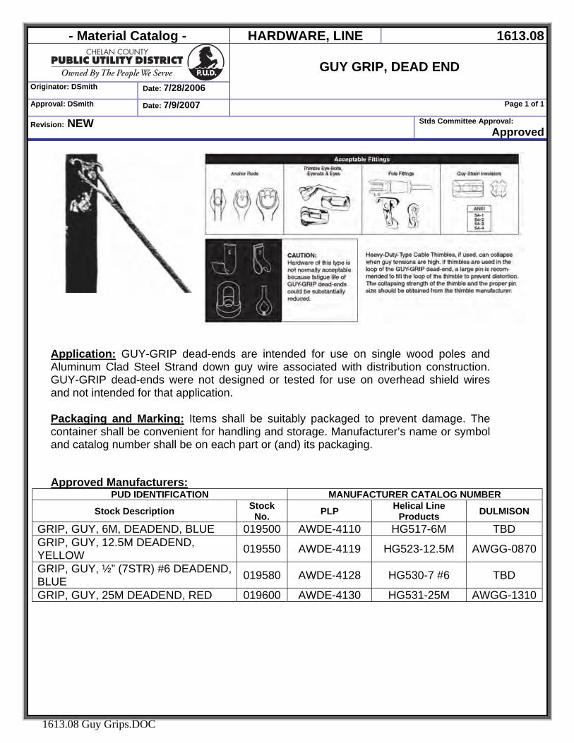
- Material Catalog - HARDWARE, LINE 1613.08
Originator: DSmith Date: 7/28/2006
GUY GRIP, DEAD END
Approval: DSmith Date: 7/9/2007 Page 1 of 1
Revision: NEW Stds Committee Approval: Approved
1613.08 Guy Grips.DOC
Application: GUY-GRIP dead-ends are intended for use on single wood poles and Aluminum Clad Steel Strand down guy wire associated with distribution construction. GUY-GRIP dead-ends were not designed or tested for use on overhead shield wires and not intended for that application. Packaging and Marking: Items shall be suitably packaged to prevent damage. The container shall be convenient for handling and storage. Manufacturer’s name or symbol and catalog number shall be on each part or (and) its packaging. Approved Manufacturers:
PUD IDENTIFICATION MANUFACTURER CATALOG NUMBER
Stock Description Stock No. PLP Helical Line
Products DULMISON
GRIP, GUY, 6M, DEADEND, BLUE 019500 AWDE-4110 HG517-6M TBD GRIP, GUY, 12.5M DEADEND, YELLOW 019550 AWDE-4119 HG523-12.5M AWGG-0870
GRIP, GUY, ½” (7STR) #6 DEADEND, BLUE 019580 AWDE-4128 HG530-7 #6 TBD
GRIP, GUY, 25M DEADEND, RED 019600 AWDE-4130 HG531-25M AWGG-1310

- Material Catalog - HARDWARE, LINE 1613.09
Originator: DSmith Date: 12/19/2006
GUY GUARDS
Approval: DSmith Date: 7/9/2007 Page 1 of 1
Revision: NEW Stds Committee Approval: 12/19/06
1613.09 Guy Guards.DOC
Application: Guy Guards are designed to identify Down Guys or other wire and cable installations where anchoring devices are exposed to pedestrian and/or vehicular traffic.
Specification: Each 8’ long unit shall be made of 1-1/2” OD bright yellow round polyethylene that is UV resistant with a slotted top end. Each unit shall an integral helix grip (pigtail) and locking strap that prevents the unit from sliding after initial installation Packaging and Marking: Items shall be suitably packaged to prevent damage. The container shall be convenient for handling and storage. Manufacturer’s name or symbol and catalog number shall be on each part or (and) its packaging. Approved Manufacturers:
PUD IDENTIFICATION MANUFACTURER CATALOG NUMBER
Stock Description Stock No. PLP GUARD, GUY, 1-1/2" O.D. YELLOW - ROUND, 8' LONG, UV RESISTANT POLYETHYLENE 027500 PG-5718
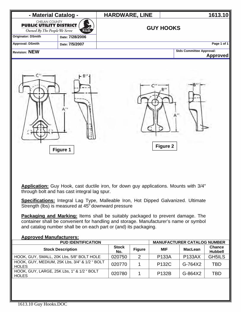
- Material Catalog - HARDWARE, LINE 1613.10
Originator: DSmith Date: 7/28/2006
GUY HOOKS
Approval: DSmith Date: 7/5/2007 Page 1 of 1
Revision: NEW Stds Committee Approval: Approved
1613.10 Guy Hooks.DOC
Application: Guy Hook, cast ductile iron, for down guy applications. Mounts with 3/4" through bolt and has cast integral lag spur.
Specifications: Integral Lag Type, Malleable Iron, Hot Dipped Galvanized. Ultimate Strength (lbs) is measured at 45o downward pressure
Packaging and Marking: Items shall be suitably packaged to prevent damage. The container shall be convenient for handling and storage. Manufacturer’s name or symbol and catalog number shall be on each part or (and) its packaging. Approved Manufacturers:
PUD IDENTIFICATION MANUFACTURER CATALOG NUMBER
Stock Description Stock No. Figure MIF MacLean Chance
Hubbell HOOK, GUY, SMALL, 20K Lbs, 5/8” BOLT HOLE 020750 2 P133A P133AX GH5ILS HOOK, GUY, MEDIUM, 25K Lbs, 3/4” & 1/2 “ BOLT HOLES 020770 1 P132C G-764X2 TBD HOOK, GUY, LARGE, 25K Lbs, 1” & 1/2 “ BOLT HOLES 020780 1 P132B G-864X2 TBD
Figure 1 Figure 2
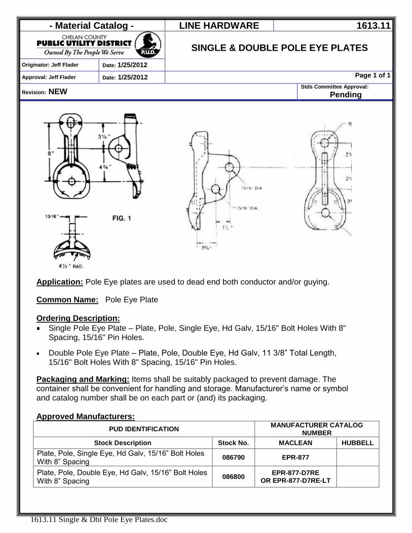
- Material Catalog - LINE HARDWARE 1613.11
SINGLE & DOUBLE POLE EYE PLATES
Originator: Jeff Flader Date: 1/25/2012
Approval: Jeff Flader Date: 1/25/2012 Page 1 of 1
Revision: NEW Stds Committee Approval:
Pending
1613.11 Single & Dbl Pole Eye Plates.doc
Application: Pole Eye plates are used to dead end both conductor and/or guying. Common Name: Pole Eye Plate
Ordering Description: Single Pole Eye Plate – Plate, Pole, Single Eye, Hd Galv, 15/16" Bolt Holes With 8"
Spacing, 15/16" Pin Holes. Double Pole Eye Plate – Plate, Pole, Double Eye, Hd Galv, 11 3/8” Total Length,
15/16" Bolt Holes With 8" Spacing, 15/16" Pin Holes.
Packaging and Marking: Items shall be suitably packaged to prevent damage. The container shall be convenient for handling and storage. Manufacturer’s name or symbol and catalog number shall be on each part or (and) its packaging.
Approved Manufacturers:
PUD IDENTIFICATION MANUFACTURER CATALOG NUMBER
Stock Description Stock No. MACLEAN HUBBELL Plate, Pole, Single Eye, Hd Galv, 15/16” Bolt Holes With 8” Spacing 086790 EPR-877
Plate, Pole, Double Eye, Hd Galv, 15/16” Bolt Holes With 8” Spacing 086800 EPR-877-D7RE
OR EPR-877-D7RE-LT
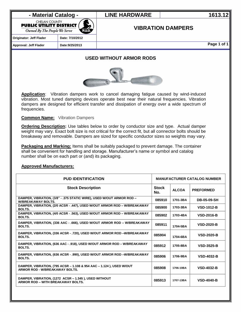
- Material Catalog - LINE HARDWARE 1613.12
VIBRATION DAMPERS
Originator: Jeff Flader Date: 7/10/2012
Approval: Jeff Flader Date:9/25/2013 Page 1 of 1
USED WITHOUT ARMOR RODS
Application: Vibration dampers work to cancel damaging fatigue caused by wind-induced vibration. Most tuned damping devices operate best near their natural frequencies. Vibration dampers are designed for efficient transfer and dissipation of energy over a wide spectrum of frequencies. Common Name: Vibration Dampers
Ordering Description: Use tables below to order by conductor size and type. Actual damper weight may vary. Exact bolt size is not critical for the correct fit, but all connector bolts should be breakaway and removable. Dampers are sized for specific conductor sizes so weights may vary. Packaging and Marking: Items shall be suitably packaged to prevent damage. The container shall be convenient for handling and storage. Manufacturer’s name or symbol and catalog number shall be on each part or (and) its packaging. Approved Manufacturers:
PUD IDENTIFICATION MANUFACTURER CATALOG NUMBER
Stock Description
Stock No.
ALCOA
PREFORMED
DAMPER, VIBRATION, (3/8” - .375 STATIC WIRE), USED W/OUT ARMOR ROD – W/BREAKAWAY BOLTS. 085910 1701-3BA DB-05-09-SH DAMPER, VIBRATION, (2/0 ACSR - .447), USED W/OUT ARMOR ROD – W/BREAKAWAY BOLTS. 085900 1703-3BA VSD-1012-B DAMPER, VIBRATION, (4/0 ACSR - .563), USED W/OUT ARMOR ROD – W/BREAKAWAY BOLTS. 085902 1703-4BA VSD-2016-B
DAMPER, VIBRATION, (336 AAC - .666), USED W/OUT ARMOR ROD – W/BREAKAWAY BOLTS. 085911
1704-5BA VSD-2020-B
DAMPER, VIBRATION, (336 ACSR - .720), USED W/OUT ARMOR ROD –W/BREAKAWAY BOLTS. 085904
1704-6BA VSD-2020-B
DAMPER, VIBRATION, (636 AAC - .918), USED W/OUT ARMOR ROD – W/BREAKAWAY BOLTS. 085912 1705-8BA VSD-3525-B
DAMPER, VIBRATION, (636 ACSR - .990), USED W/OUT ARMOR ROD –W/BREAKAWAY BOLTS. 085906 1706-9BA VSD-4032-B
DAMPER, VIBRATION, (795 ACSR – 1.108 & 954 AAC – 1.124 ), USED W/OUT ARMOR ROD - W/BREAKAWAY BOLTS. 085908 1706-10BA VSD-4032-B
DAMPER, VIBRATION, (1272 ACSR – 1.345 ), USED WITHOUT ARMOR ROD – WITH BREAKAWAY BOLTS. 085913 1707-13BA VSD-4040-B
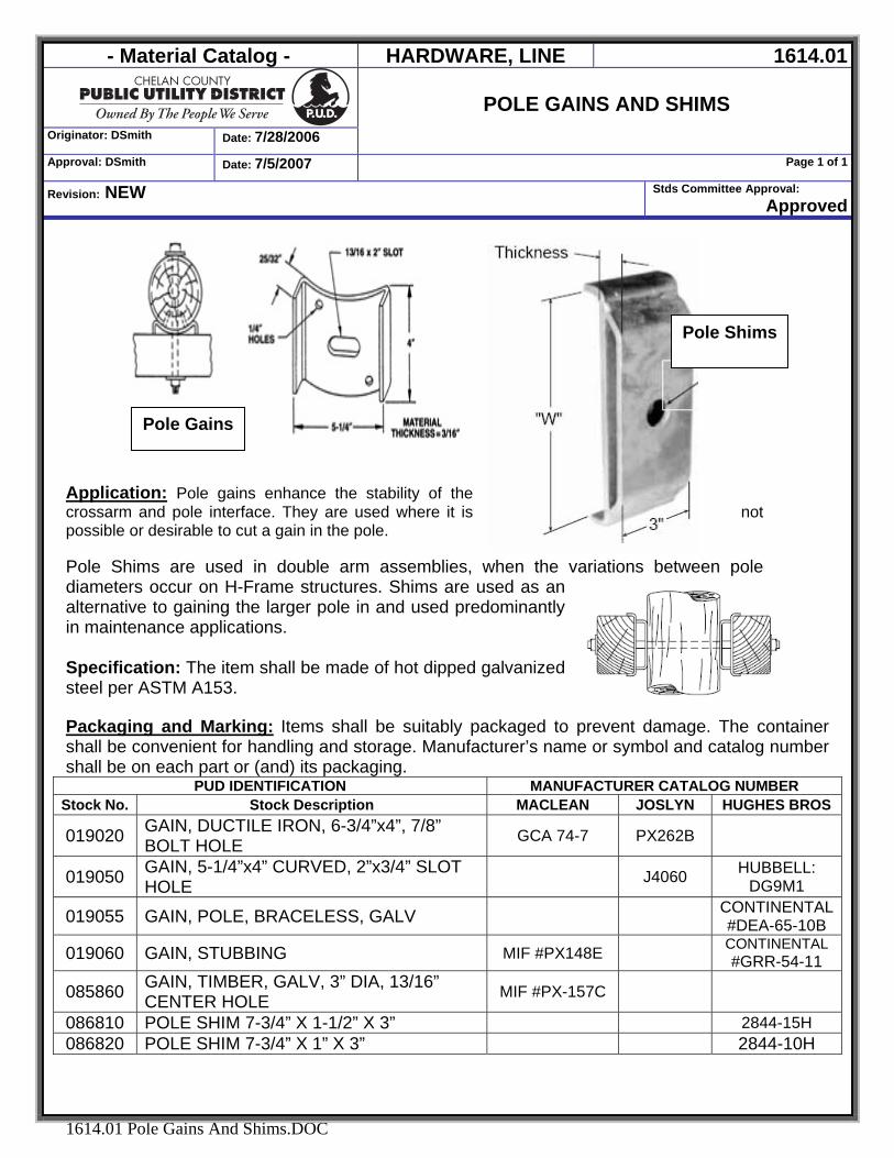
- Material Catalog - HARDWARE, LINE 1614.01
Originator: DSmith Date: 7/28/2006
POLE GAINS AND SHIMS
Approval: DSmith Date: 7/5/2007 Page 1 of 1
Revision: NEW Stds Committee Approval: Approved
1614.01 Pole Gains And Shims.DOC
Application: Pole gains enhance the stability of the crossarm and pole interface. They are used where it is not possible or desirable to cut a gain in the pole. Pole Shims are used in double arm assemblies, when the variations between pole diameters occur on H-Frame structures. Shims are used as an alternative to gaining the larger pole in and used predominantly in maintenance applications. Specification: The item shall be made of hot dipped galvanized steel per ASTM A153.
Packaging and Marking: Items shall be suitably packaged to prevent damage. The container shall be convenient for handling and storage. Manufacturer’s name or symbol and catalog number shall be on each part or (and) its packaging.
PUD IDENTIFICATION MANUFACTURER CATALOG NUMBER Stock No. Stock Description MACLEAN JOSLYN HUGHES BROS
019020 GAIN, DUCTILE IRON, 6-3/4”x4”, 7/8” BOLT HOLE GCA 74-7 PX262B
019050 GAIN, 5-1/4”x4” CURVED, 2”x3/4” SLOT HOLE J4060 HUBBELL:
DG9M1
019055 GAIN, POLE, BRACELESS, GALV CONTINENTAL #DEA-65-10B
019060 GAIN, STUBBING MIF #PX148E CONTINENTAL #GRR-54-11
085860 GAIN, TIMBER, GALV, 3” DIA, 13/16” CENTER HOLE MIF #PX-157C
086810 POLE SHIM 7-3/4” X 1-1/2” X 3” 2844-15H 086820 POLE SHIM 7-3/4” X 1” X 3” 2844-10H
Pole Gains
Pole Shims
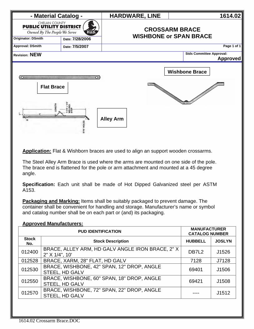
- Material Catalog - HARDWARE, LINE 1614.02
Originator: DSmith Date: 7/28/2006
CROSSARM BRACE
WISHBONE or SPAN BRACE Approval: DSmith Date: 7/5/2007 Page 1 of 1
Revision: NEW Stds Committee Approval: Approved
1614.02 Crossarm Brace.DOC
Application: Flat & Wishborn braces are used to align an support wooden crossarms.
The Steel Alley Arm Brace is used where the arms are mounted on one side of the pole. The brace end is flattened for the pole or arm attachment and mounted at a 45 degree angle. Specification: Each unit shall be made of Hot Dipped Galvanized steel per ASTM A153. Packaging and Marking: Items shall be suitably packaged to prevent damage. The container shall be convenient for handling and storage. Manufacturer’s name or symbol and catalog number shall be on each part or (and) its packaging. Approved Manufacturers:
PUD IDENTIFICATION MANUFACTURER CATALOG NUMBER
Stock No. Stock Description HUBBELL JOSLYN
012400 BRACE, ALLEY ARM, HD GALV ANGLE IRON BRACE, 2" X 2" X 1/4", 10' DB7L2 J1526
012528 BRACE, XARM, 28" FLAT, HD GALV 7128 J7128
012530 BRACE, WISHBONE, 42" SPAN, 12" DROP, ANGLE STEEL, HD GALV 69401 J1506
012550 BRACE, WISHBONE, 60" SPAN, 18" DROP, ANGLE STEEL, HD GALV 69421 J1508
012570 BRACE, WISHBONE, 72" SPAN, 22" DROP, ANGLE STEEL, HD GALV ---- J1512
Wishbone Brace
Flat Brace
Alley Arm
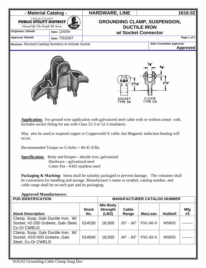
- Material Catalog - HARDWARE, LINE 1616.02
Originator: DSmith Date: 12/6/06
GROUNDING CLAMP, SUSPENSION, DUCTILE IRON
w/ Socket Connector Approval: DSmith Date: 7/5/2007 Page 1 of 1
Revision: Revised Catalog Numbers to Include Socket Stds Committee Approval: Approved
1616.02 Grounding Cable Clamp Susp.Doc
Application: For ground wire application with galvanized steel cable with or without armor rods. Includes socket fitting for use with Class 52-3 or 52-3 insulators. May also be used to suspend copper or Copperweld ® cable, but Magnetic induction heating will occur. Recommended Torque on U-bolts = 40-45 ft/lbs Specification: Body and Keeper—ductile iron, galvanized
Hardware—galvanized steel Cotter Pin—#302 stainless steel
Packaging & Marking: Items shall be suitably packaged to prevent damage. The container shall be convenient for handling and storage. Manufacturer’s name or symbol, catalog number, and cable range shall be on each part and its packaging. Approved Manufacturers:
PUD IDENTIFICATION MANUFACTURER CATALOG NUMBER
Stock Description Stock
No.
Min Body Strength
(LBS) Cable Range MacLean Hubbell
Mfg #3
Clamp, Susp, Galv Ductile Iron, W/ Socket, #2-250 Grdwire, Galv Steel, Cu Or CWELD
014530 16,000 .20” - .60” FSC-60-S MS60S --------
Clamp, Susp, Galv Ductile Iron, W/ Socket, #2/0-500 Grdwire, Galv Steel, Cu Or CWELD
014540 18,000 .40” - .83” FSC-83-S MS83S --------
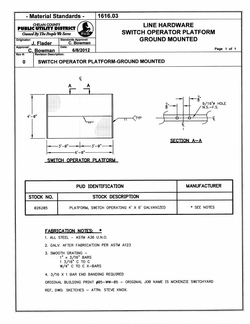
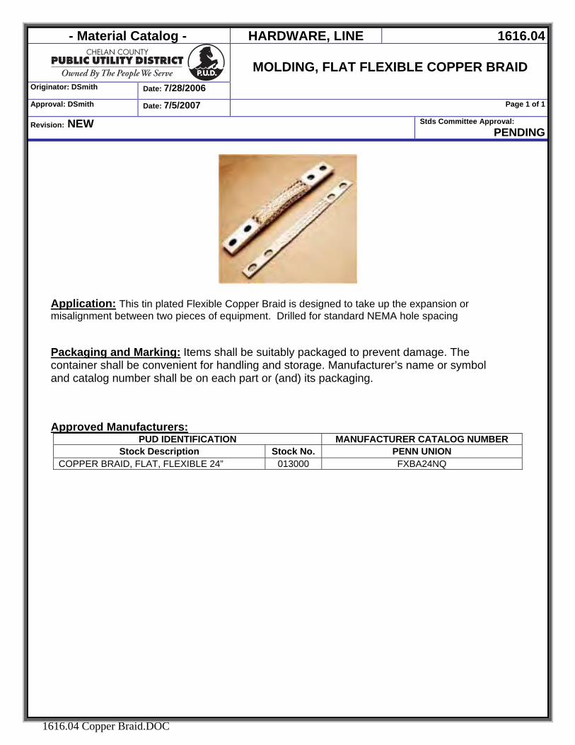
- Material Catalog - HARDWARE, LINE 1616.04
Originator: DSmith Date: 7/28/2006
MOLDING, FLAT FLEXIBLE COPPER BRAID
Approval: DSmith Date: 7/5/2007 Page 1 of 1
Revision: NEW Stds Committee Approval: PENDING
1616.04 Copper Braid.DOC
Application: This tin plated Flexible Copper Braid is designed to take up the expansion or misalignment between two pieces of equipment. Drilled for standard NEMA hole spacing Packaging and Marking: Items shall be suitably packaged to prevent damage. The container shall be convenient for handling and storage. Manufacturer’s name or symbol and catalog number shall be on each part or (and) its packaging. Approved Manufacturers:
PUD IDENTIFICATION MANUFACTURER CATALOG NUMBER Stock Description Stock No. PENN UNION
COPPER BRAID, FLAT, FLEXIBLE 24” 013000 FXBA24NQ
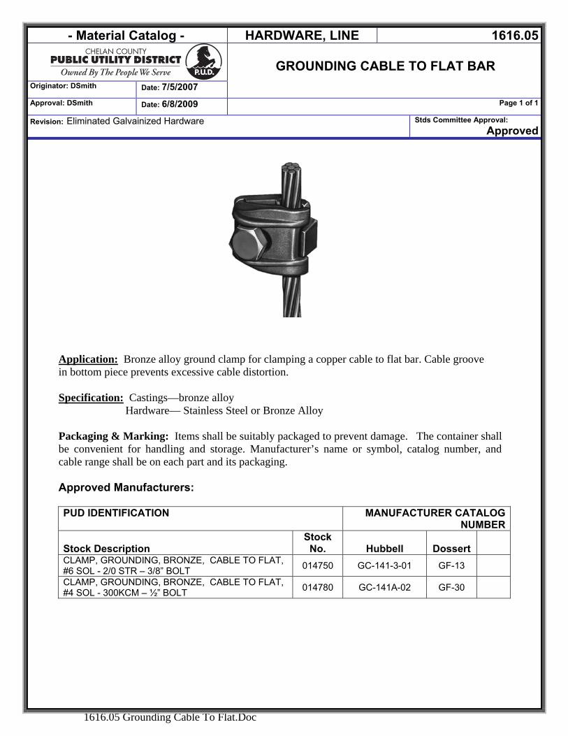
- Material Catalog - HARDWARE, LINE 1616.05
GROUNDING CABLE TO FLAT BAR
Originator: DSmith Date: 7/5/2007
Approval: DSmith Date: 6/8/2009 Page 1 of 1
Revision: Eliminated Galvainized Hardware Stds Committee Approval: Approved
1616.05 Grounding Cable To Flat.Doc
Application: Bronze alloy ground clamp for clamping a copper cable to flat bar. Cable groove in bottom piece prevents excessive cable distortion. Specification: Castings—bronze alloy
Hardware— Stainless Steel or Bronze Alloy
Packaging & Marking: Items shall be suitably packaged to prevent damage. The container shall be convenient for handling and storage. Manufacturer’s name or symbol, catalog number, and cable range shall be on each part and its packaging. Approved Manufacturers:
PUD IDENTIFICATION MANUFACTURER CATALOG
NUMBER
Stock Description Stock
No. Hubbell Dossert CLAMP, GROUNDING, BRONZE, CABLE TO FLAT, #6 SOL - 2/0 STR – 3/8” BOLT 014750 GC-141-3-01 GF-13
CLAMP, GROUNDING, BRONZE, CABLE TO FLAT, #4 SOL - 300KCM – ½” BOLT 014780 GC-141A-02 GF-30
- Material Catalog - INSULATORS 1700
Originator: DSmith Date:1/24/2007
INSULATORS
Approval: DSmith Date: 2/8/2007 Page 1 of 1
Revision: NEW Stds Committee Approval: Approved
1700 INSULATORS.DOC
SECTION 1700 INSULATORS
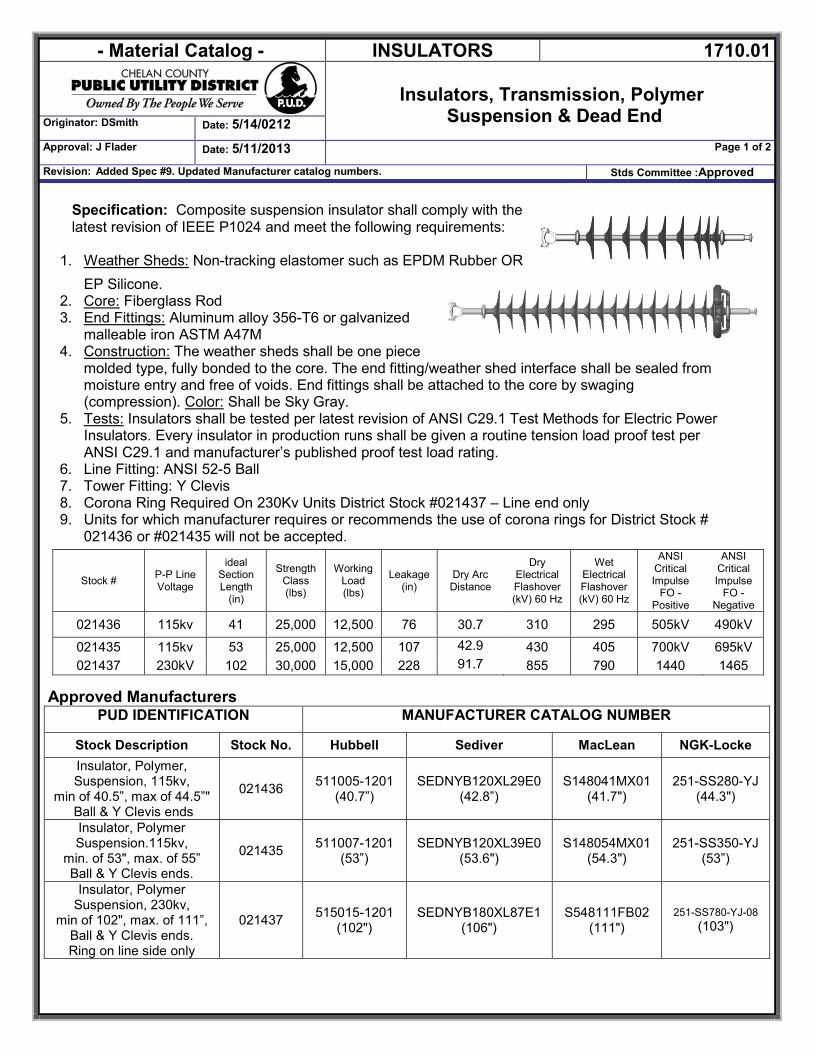
- Material Catalog - INSULATORS 1710.01
Insulators, Transmission, Polymer
Suspension & Dead End Originator: DSmith Date: 5/14/0212
Approval: J Flader Date: 5/11/2013 Page 1 of 2
Revision: Added Spec #9. Updated Manufacturer catalog numbers. Stds Committee :Approved
Specification: Composite suspension insulator shall comply with the latest revision of IEEE P1024 and meet the following requirements:
1. Weather Sheds: Non-tracking elastomer such as EPDM Rubber OR EP Silicone.
2. Core: Fiberglass Rod 3. End Fittings: Aluminum alloy 356-T6 or galvanized
malleable iron ASTM A47M 4. Construction: The weather sheds shall be one piece
molded type, fully bonded to the core. The end fitting/weather shed interface shall be sealed from moisture entry and free of voids. End fittings shall be attached to the core by swaging (compression). Color: Shall be Sky Gray.
5. Tests: Insulators shall be tested per latest revision of ANSI C29.1 Test Methods for Electric Power Insulators. Every insulator in production runs shall be given a routine tension load proof test per ANSI C29.1 and manufacturer’s published proof test load rating.
6. Line Fitting: ANSI 52-5 Ball 7. Tower Fitting: Y Clevis 8. Corona Ring Required On 230Kv Units District Stock #021437 – Line end only 9. Units for which manufacturer requires or recommends the use of corona rings for District Stock #
021436 or #021435 will not be accepted.
Approved Manufacturers
PUD IDENTIFICATION MANUFACTURER CATALOG NUMBER
Stock Description Stock No. Hubbell Sediver MacLean NGK-Locke Insulator, Polymer, Suspension, 115kv,
min of 40.5”, max of 44.5”" Ball & Y Clevis ends
021436 511005-1201 (40.7”)
SEDNYB120XL29E0 (42.8”)
S148041MX01 (41.7")
251-SS280-YJ (44.3")
Insulator, Polymer Suspension.115kv,
min. of 53", max. of 55” Ball & Y Clevis ends.
021435 511007-1201 (53”)
SEDNYB120XL39E0 (53.6")
S148054MX01 (54.3")
251-SS350-YJ (53”)
Insulator, Polymer Suspension, 230kv,
min of 102", max. of 111”, Ball & Y Clevis ends. Ring on line side only
021437 515015-1201 (102")
SEDNYB180XL87E1 (106")
S548111FB02 (111")
251-SS780-YJ-08 (103")
Stock # P-P Line Voltage
ideal Section Length
(in)
Strength Class (lbs)
Working Load (lbs)
Leakage (in)
Dry Arc Distance
Dry Electrical Flashover (kV) 60 Hz
Wet Electrical Flashover (kV) 60 Hz
ANSI Critical Impulse
FO - Positive
ANSI Critical Impulse
FO - Negative
021436 115kv 41 25,000 12,500 76 30.7 310 295 505kV 490kV
021435 115kv 53 25,000 12,500 107 42.9 430 405 700kV 695kV 021437 230kV 102 30,000 15,000 228 91.7 855 790 1440 1465
- Material Catalog - INSULATORS 1710.01
Insulators, Transmission, Polymer
Suspension & Dead End Originator: DSmith Date: 5/14/0212
Approval: J Flader Date: 5/11/2013 Page 2 of 2
Revision: Added Spec #9. Updated Manufacturer catalog numbers. Stds Committee :Approved
Packaging & Marking: Items shall be suitably packaged to prevent damage. The container shall be convenient for handling and storage. Manufacturer’s name or symbol, catalog number, strength rating and date code shall be permanently marked on each part and its packaging.
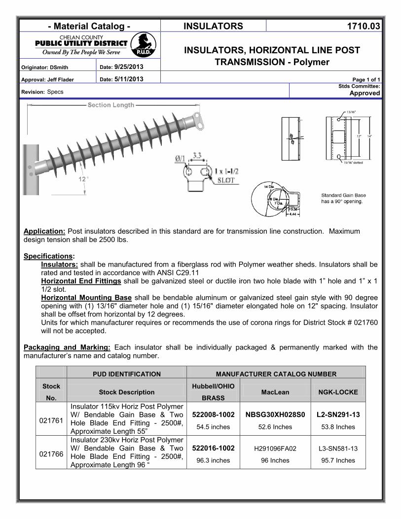
- Material Catalog - INSULATORS 1710.03
INSULATORS, HORIZONTAL LINE POST
TRANSMISSION - Polymer Originator: DSmith Date: 9/25/2013
Approval: Jeff Flader Date: 5/11/2013 Page 1 of 1
Revision: Specs Stds Committee:
Approved
Application: Post insulators described in this standard are for transmission line construction. Maximum design tension shall be 2500 lbs. Specifications:
Insulators: shall be manufactured from a fiberglass rod with Polymer weather sheds. Insulators shall be rated and tested in accordance with ANSI C29.11 Horizontal End Fittings shall be galvanized steel or ductile iron two hole blade with 1” hole and 1” x 1 1/2 slot. Horizontal Mounting Base shall be bendable aluminum or galvanized steel gain style with 90 degree
opening with (1) 13/16" diameter hole and (1) 15/16" diameter elongated hole on 12" spacing. Insulator shall be offset from horizontal by 12 degrees. Units for which manufacturer requires or recommends the use of corona rings for District Stock # 021760 will not be accepted.
Packaging and Marking: Each insulator shall be individually packaged & permanently marked with the manufacturer’s name and catalog number.
PUD IDENTIFICATION MANUFACTURER CATALOG NUMBER
Stock
No. Stock Description
Hubbell/OHIO
BRASS MacLean NGK-LOCKE
021761
Insulator 115kv Horiz Post Polymer W/ Bendable Gain Base & Two Hole Blade End Fitting - 2500#, Approximate Length 55”
522008-1002 54.5 inches
NBSG30XH028S0 52.6 Inches
L2-SN291-13 53.8 Inches
021766
Insulator 230kv Horiz Post Polymer W/ Bendable Gain Base & Two Hole Blade End Fitting - 2500#, Approximate Length 96 “
522016-1002 96.3 inches
H291096FA02
96 Inches
L3-SN581-13
95.7 Inches
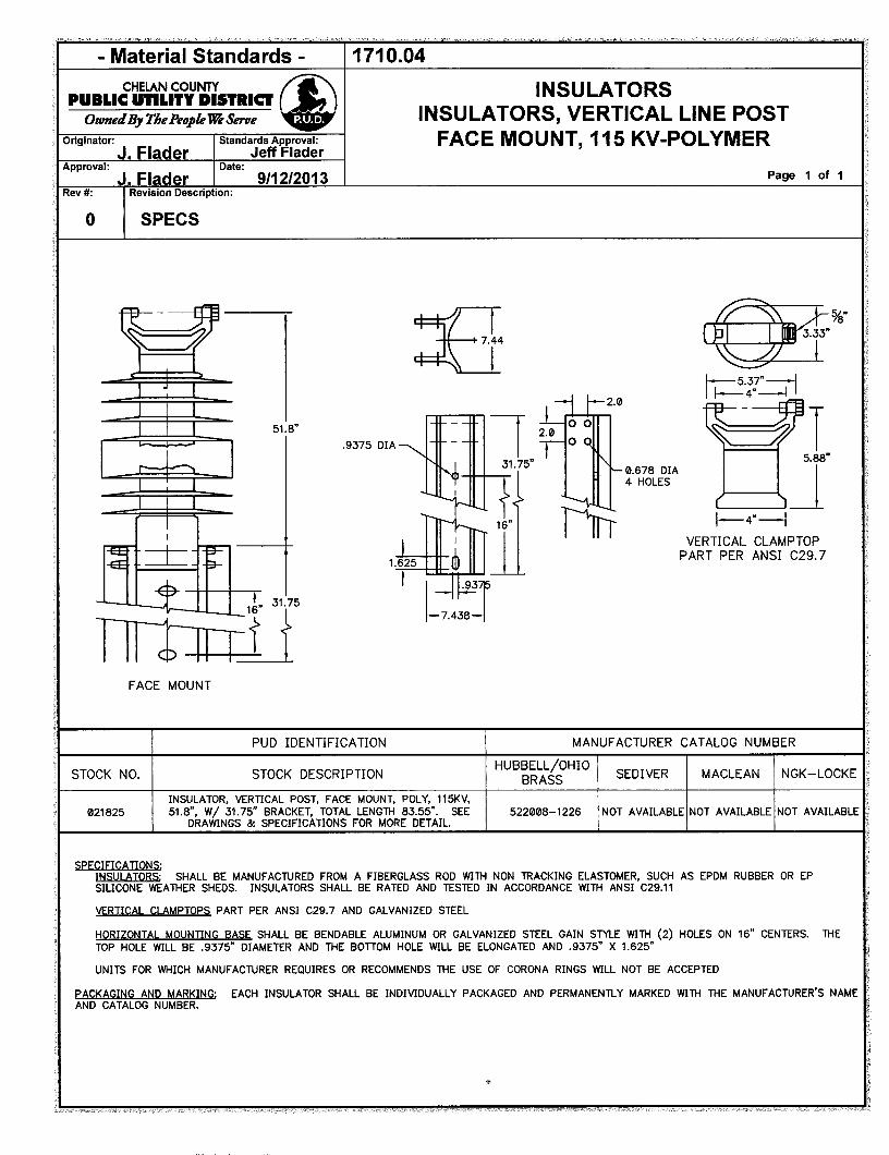
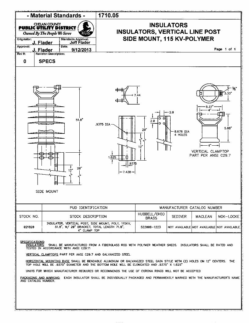
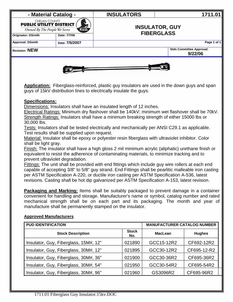
- Material Catalog - INSULATORS 1711.01
Originator: DSmith Date: 7/7/06
INSULATOR, GUY
FIBERGLASS Approval: DSmith Date: 7/5/2007 Page 1 of 1
Revision: NEW Stds Committee Approval: 9/22/06
1711.01 Fiberglass Guy Insulator.15kv.DOC
Application: Fiberglass-reinforced, plastic guy insulators are used in the down guys and span guys of 15kV distribution lines to electrically insulate the guys. Specifications: Dimensions: Insulators shall have an insulated length of 12 inches. Electrical Ratings: Minimum dry flashover shall be 140kV; minimum wet flashover shall be 70kV. Strength Ratings: Insulators shall have a minimum breaking strength of either 15000 lbs or 30,000 lbs. Tests: Insulators shall be tested electrically and mechanically per ANSI C29.1 as applicable. Test results shall be supplied upon request. Material: Insulator shall be epoxy or polyester resin fiberglass with ultraviolet inhibitor. Color shall be light gray. Finish: The insulator shall have a high gloss 2 mil minimum acrylic (aliphatic) urethane finish or equivalent to resist the adherence of contaminating materials, to minimize tracking and to prevent ultraviolet degradation. Fittings: The unit shall be provided with end fittings which include guy wire rollers at each end capable of accepting 3/8" to 5/8" guy strand. End Fittings shall be pearlitic malleable iron casting per ASTM Specification A-220, or ductile iron casting per ASTM Specification A-536, latest revisions. Casting shall be hot dip galvanized per ASTM Specification A-153, latest revision. Packaging and Marking: Items shall be suitably packaged to prevent damage in a container convenient for handling and storage. Manufacturer's name or symbol, catalog number and rated mechanical strength shall be on each part and its packaging. The month and year of manufacture shall be permanently stamped on the insulator. Approved Manufacturers
PUD IDENTIFICATION MANUFACTURER CATALOG NUMBER
Stock Description Stock No. MacLean Hughes
Insulator, Guy, Fiberglass, 15M#, 12” 021890 GCC15-12R2 CF692-12R2 Insulator, Guy, Fiberglass, 30M#, 12” 021895 GCC30-12R2 CF695-12-R2 Insulator, Guy, Fiberglass, 30M#, 36” 021900 GCC30-36R2 CF695-36R2 Insulator, Guy, Fiberglass, 30M#, 54” 021950 GCC30-54R2 CF695-54R2 Insulator, Guy, Fiberglass, 30M#, 96” 021960 GS3096R2 CF695-96R2
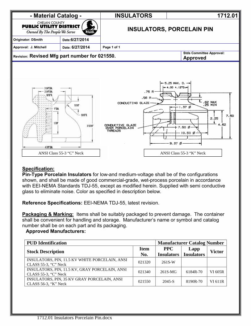
- Material Catalog - INSULATORS 1712.01
INSULATORS, PORCELAIN PIN
Originator: DSmith Date:6/27/2014
Approval: J. Mitchell Date: 6/27/2014 Page 1 of 1
Revision: Revised Mfg part number for 021550. Stds Committee Approval: Approved
1712.01 Insulators Porcelain Pin.docx
Specification: Pin-Type Porcelain Insulators for low-and medium-voltage shall be of the configurations shown, and shall be made of good commercial-grade, wet-process porcelain in accordance with EEI-NEMA Standards TDJ-55, except as modified herein. Supplied with semi conductive glass to eliminate noise. Color as specified in description below. Reference Specifications: EEI-NEMA TDJ-55, latest revision.
Packaging & Marking: Items shall be suitably packaged to prevent damage. The container shall be convenient for handling and storage. Manufacturer’s name or symbol and catalog number shall be on each part and its packaging.
Approved Manufacturers:
PUD Identification Manufacturer Catalog Number
Stock Description Item No.
PPC Insulators
Lapp Insulators Victor
INSULATORS, PIN, 11.5 KV WHITE PORCELAIN, ANSI CLASS 55-3, “C” Neck 021320 261S-W
INSULATORS, PIN, 11.5 KV, GRAY PORCELAIN, ANSI CLASS 55-3, “C” Neck 021340 261S-MG 6184R-70 VI 605R
INSULATORS, PIN, 35 KV GRAY PORCELAIN, ANSI CLASS 56-3, “K” Neck 021550 2045-S 8190R-70 VI 611R
ANSI Class 55-3 “K” Neck ANSI Class 55-3 “C” Neck
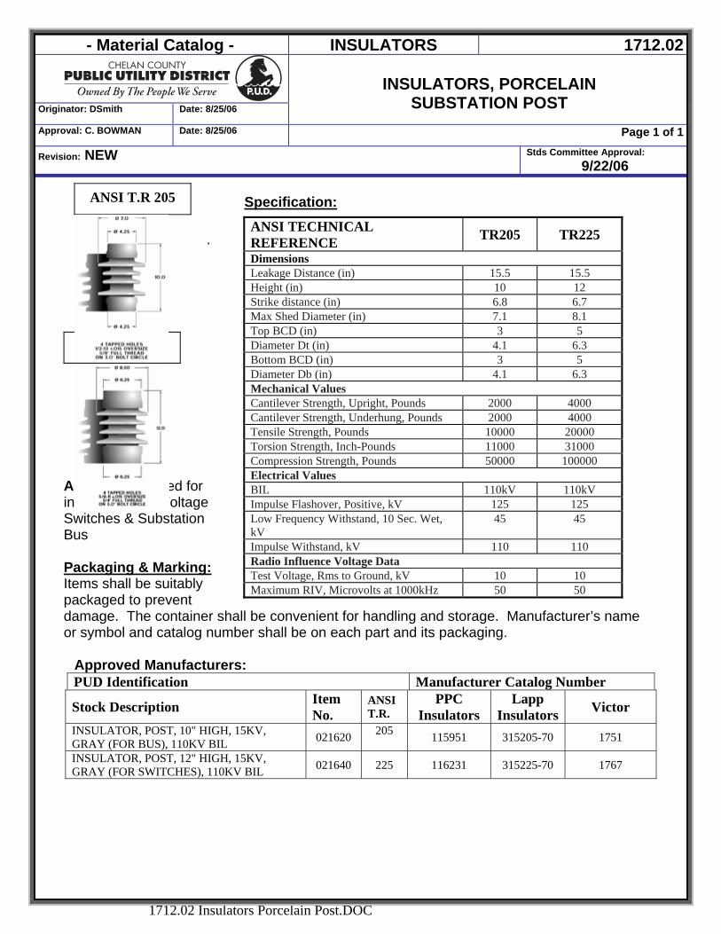
- Material Catalog - INSULATORS 1712.02
Originator: DSmith Date: 8/25/06
INSULATORS, PORCELAIN
SUBSTATION POST Approval: C. BOWMAN Date: 8/25/06 Page 1 of 1
Revision: NEW Stds Committee Approval: 9/22/06
1712.02 Insulators Porcelain Post.DOC
Specification: .
Application: Used for insulating High Voltage Switches & Substation Bus Packaging & Marking: Items shall be suitably packaged to prevent damage. The container shall be convenient for handling and storage. Manufacturer’s name or symbol and catalog number shall be on each part and its packaging.
Approved Manufacturers: PUD Identification Manufacturer Catalog Number
Stock Description Item No.
ANSI T.R.
PPC Insulators
Lapp Insulators Victor
INSULATOR, POST, 10" HIGH, 15KV, GRAY (FOR BUS), 110KV BIL 021620 205 115951 315205-70 1751
INSULATOR, POST, 12" HIGH, 15KV, GRAY (FOR SWITCHES), 110KV BIL 021640 225 116231 315225-70 1767
ANSI T.R 205
ANSI TECHNICAL REFERENCE TR205 TR225 Dimensions Leakage Distance (in) 15.5 15.5 Height (in) 10 12 Strike distance (in) 6.8 6.7 Max Shed Diameter (in) 7.1 8.1 Top BCD (in) 3 5 Diameter Dt (in) 4.1 6.3 Bottom BCD (in) 3 5 Diameter Db (in) 4.1 6.3 Mechanical Values Cantilever Strength, Upright, Pounds 2000 4000 Cantilever Strength, Underhung, Pounds 2000 4000 Tensile Strength, Pounds 10000 20000 Torsion Strength, Inch-Pounds 11000 31000 Compression Strength, Pounds 50000 100000 Electrical Values BIL 110kV 110kV Impulse Flashover, Positive, kV 125 125 Low Frequency Withstand, 10 Sec. Wet, kV
45 45
Impulse Withstand, kV 110 110 Radio Influence Voltage Data Test Voltage, Rms to Ground, kV 10 10 Maximum RIV, Microvolts at 1000kHz 50 50
ANSI T.R. 225
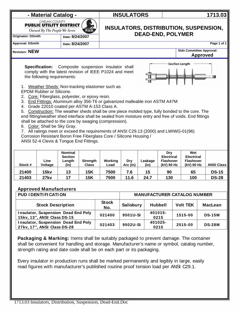
- Material Catalog - INSULATORS 1713.03
Originator: DSmith Date: 8/24/2007
INSULATORS, DISTRIBUTION, SUSPENSION,
DEAD-END, POLYMER Approval: DSmith Date: 8/24/2007 Page 1 of 1
Revision: NEW Stds Committee Approval: Approved
1713.03 Insulators, Distribution, Suspension, Dead-End.Doc
Specification: Composite suspension insulator shall comply with the latest revision of IEEE P1024 and meet the following requirements:
1. Weather Sheds: Non-tracking elastomer such as EPDM Rubber or Silicone. 2. Core: Fiberglass, polyester, or epoxy resin. 3. End Fittings: Aluminum alloy 356-T6 or galvanized malleable iron ASTM A47M 4. Grade 22010 coated per ASTM A-153 Class A. 5. Construction: The weather sheds shall be one piece molded type, fully bonded to the core. The end fitting/weather shed interface shall be sealed from moisture entry and free of voids. End fittings shall be attached to the core by swaging (compression). 6. Color: Shall be Sky Gray. 7. All ratings meet or exceed the requirements of ANSI C29.13 (2000) and LWIWG-01(96) Corrosion Resistant Boron Free Fiberglass Core / Silicone Housing / ANSI 52-4 Clevis & Tongue End Fittings.
Approved Manufacturers PUD IDENTIFICATION MANUFACTURER CATALOG NUMBER
Stock Description Stock No. Salisbury Hubbell Volt TEK MacLean
Insulator, Suspension Dead End Poly 15kv, 13”, ANSI Class DS-15 021400 9501U-SI 401015-
0215 1515-00 DS-15M
Insulator, Suspension Dead End Poly 27kv, 17”, ANSI Class DS-28 021403 9502U-SI 401025-
0215 2515-00 DS-28M
Packaging & Marking: Items shall be suitably packaged to prevent damage. The container shall be convenient for handling and storage. Manufacturer’s name or symbol, catalog number, strength rating and date code shall be on each part or its packaging. Every insulator in production runs shall be marked permanently and legibly in large, easily read figures with manufacturer’s published routine proof tension load per ANSI C29.1.
Stock # Line
Voltage
Nominal Section Length
(in) Strength
Class Working
Load Dry
Arc (in) Leakage
(in)
Dry Electrical Flashover (kV) 60 Hz
Wet Electrical Flashover (kV) 60 Hz ANSI Class
21400 15kv 13 15K 7500 7.6 15 90 65 DS-15 21403 27kv 17 15K 7500 11.6 24.7 130 100 DS-28
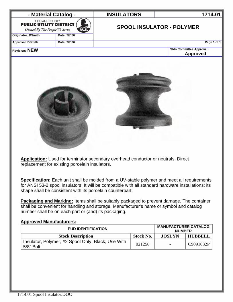
- Material Catalog - INSULATORS 1714.01
Originator: DSmith Date: 7/7/06
SPOOL INSULATOR - POLYMER
Approval: DSmith Date: 7/7/06 Page 1 of 1
Revision: NEW Stds Committee Approval: Approved
1714.01 Spool Insulator.DOC
Application: Used for terminator secondary overhead conductor or neutrals. Direct replacement for existing porcelain insulators.
Specification: Each unit shall be molded from a UV-stable polymer and meet all requirements for ANSI 53-2 spool insulators. It will be compatible with all standard hardware installations; its shape shall be consistent with its porcelain counterpart. Packaging and Marking: Items shall be suitably packaged to prevent damage. The container shall be convenient for handling and storage. Manufacturer’s name or symbol and catalog number shall be on each part or (and) its packaging. Approved Manufacturers:
PUD IDENTIFICATION MANUFACTURER CATALOG NUMBER
Stock Description Stock No. JOSLYN HUBBELLInsulator, Polymer, #2 Spool Only, Black, Use With 5/8” Bolt 021250 - C9091032P
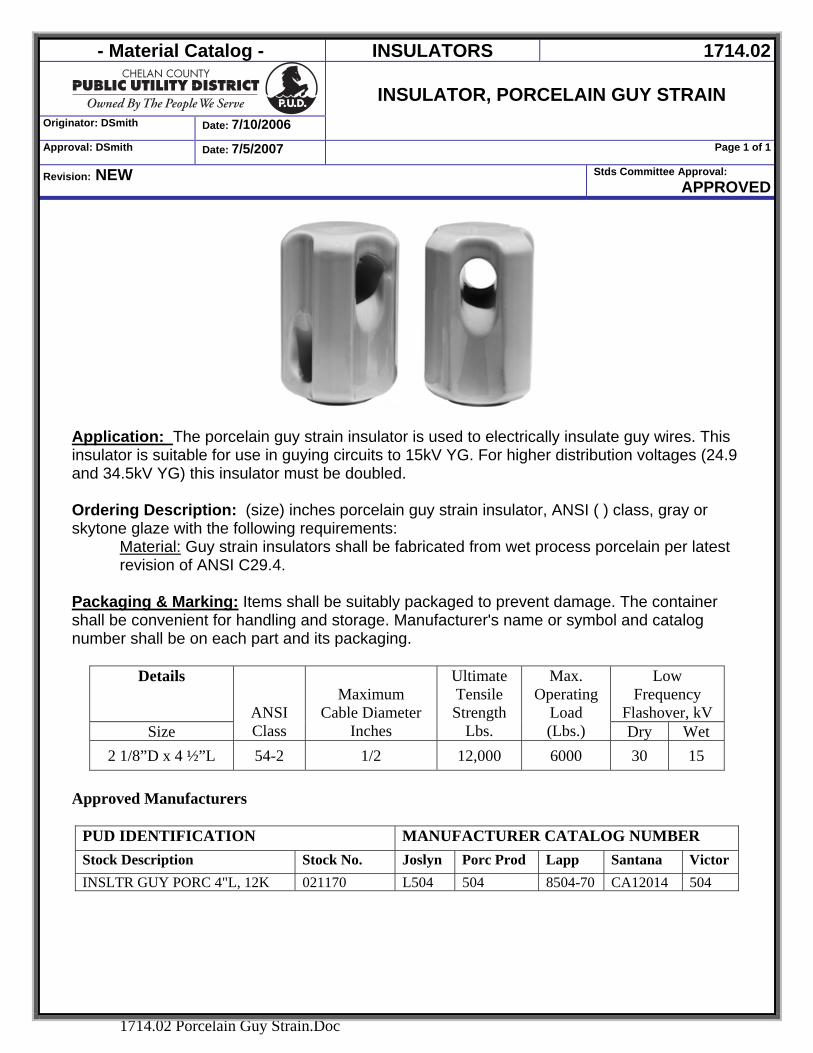
- Material Catalog - INSULATORS 1714.02
Originator: DSmith Date: 7/10/2006
INSULATOR, PORCELAIN GUY STRAIN
Approval: DSmith Date: 7/5/2007 Page 1 of 1
Revision: NEW Stds Committee Approval: APPROVED
1714.02 Porcelain Guy Strain.Doc
Application: The porcelain guy strain insulator is used to electrically insulate guy wires. This insulator is suitable for use in guying circuits to 15kV YG. For higher distribution voltages (24.9 and 34.5kV YG) this insulator must be doubled. Ordering Description: (size) inches porcelain guy strain insulator, ANSI ( ) class, gray or skytone glaze with the following requirements:
Material: Guy strain insulators shall be fabricated from wet process porcelain per latest revision of ANSI C29.4.
Packaging & Marking: Items shall be suitably packaged to prevent damage. The container shall be convenient for handling and storage. Manufacturer's name or symbol and catalog number shall be on each part and its packaging.
Details
Low Frequency
Flashover, kV Size
ANSI Class
Maximum Cable Diameter
Inches
Ultimate Tensile Strength
Lbs.
Max. Operating
Load (Lbs.) Dry Wet
2 1/8”D x 4 ½”L 54-2 1/2 12,000 6000 30 15
Approved Manufacturers
PUD IDENTIFICATION MANUFACTURER CATALOG NUMBER Stock Description Stock No. Joslyn Porc Prod Lapp Santana Victor INSLTR GUY PORC 4"L, 12K 021170 L504 504 8504-70 CA12014 504
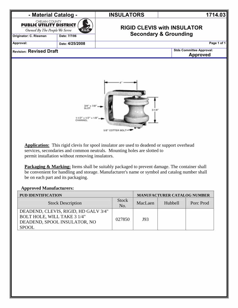
- Material Catalog - INSULATORS 1714.03
Originator: C. Rissman Date: 7/7/06
RIGID CLEVIS with INSULATOR
Secondary & Grounding Approval: Date: 4/25/2008 Page 1 of 1
Revision: Revised Draft Stds Committee Approval: Approved
Application: This rigid clevis for spool insulator are used to deadend or support overhead services, secondaries and common neutrals. Mounting holes are slotted to permit installation without removing insulators. Packaging & Marking: Items shall be suitably packaged to prevent damage. The container shall be convenient for handling and storage. Manufacturer's name or symbol and catalog number shall be on each part and its packaging.
Approved Manufacturers: PUD IDENTIFICATION MANUFACTURER CATALOG NUMBER
Stock Description Stock No. MacLaen Hubbell Porc Prod
DEADEND, CLEVIS, RIGID, HD GALV 3/4" BOLT HOLE, WILL TAKE 3 1/4" DEADEND, SPOOL INSULATOR, NO SPOOL
027850 J93
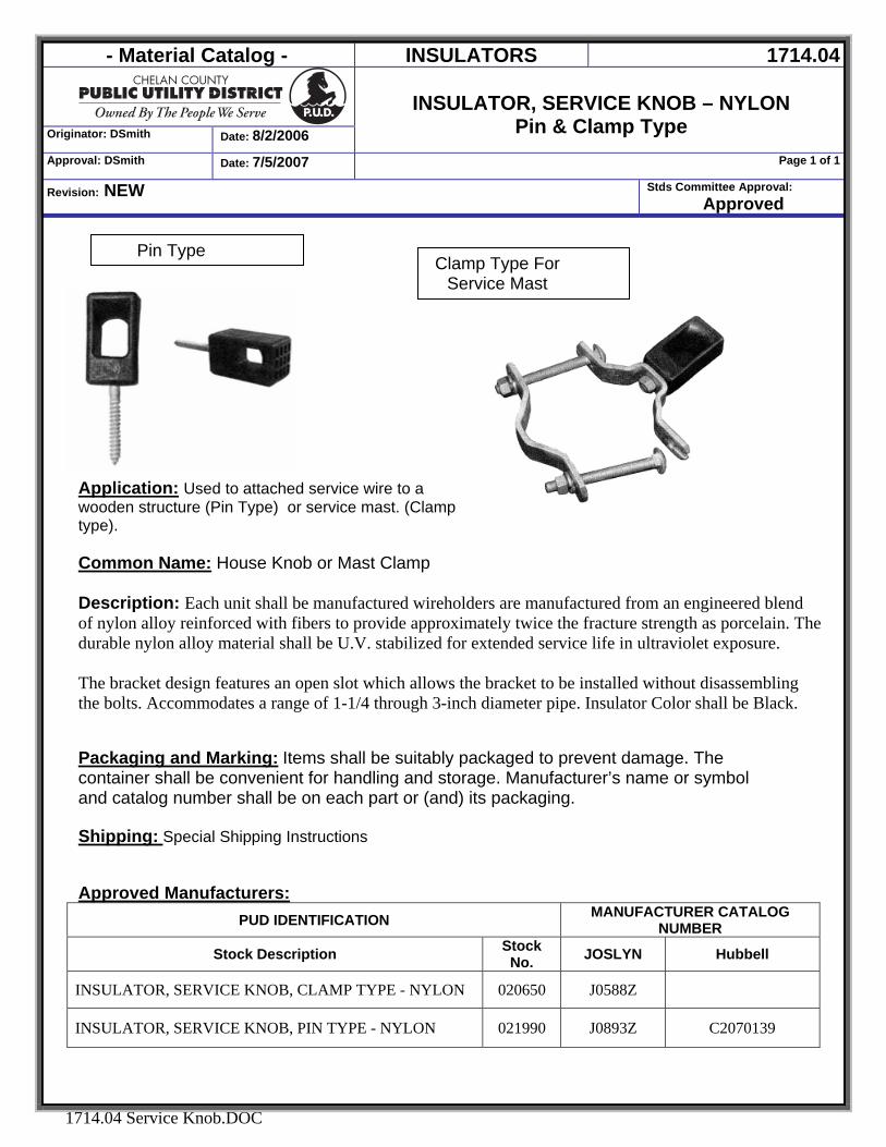
- Material Catalog - INSULATORS 1714.04
Originator: DSmith Date: 8/2/2006
INSULATOR, SERVICE KNOB – NYLON
Pin & Clamp Type Approval: DSmith Date: 7/5/2007 Page 1 of 1
Revision: NEW Stds Committee Approval: Approved
1714.04 Service Knob.DOC
Application: Used to attached service wire to a wooden structure (Pin Type) or service mast. (Clamp type). Common Name: House Knob or Mast Clamp
Description: Each unit shall be manufactured wireholders are manufactured from an engineered blend of nylon alloy reinforced with fibers to provide approximately twice the fracture strength as porcelain. The durable nylon alloy material shall be U.V. stabilized for extended service life in ultraviolet exposure. The bracket design features an open slot which allows the bracket to be installed without disassembling the bolts. Accommodates a range of 1-1/4 through 3-inch diameter pipe. Insulator Color shall be Black.
Packaging and Marking: Items shall be suitably packaged to prevent damage. The container shall be convenient for handling and storage. Manufacturer’s name or symbol and catalog number shall be on each part or (and) its packaging. Shipping: Special Shipping Instructions Approved Manufacturers:
PUD IDENTIFICATION MANUFACTURER CATALOG NUMBER
Stock Description Stock No. JOSLYN Hubbell
INSULATOR, SERVICE KNOB, CLAMP TYPE - NYLON 020650 J0588Z
INSULATOR, SERVICE KNOB, PIN TYPE - NYLON 021990 J0893Z C2070139
Clamp Type For Service Mast
Pin Type
- Material Catalog - FASTENERS 5000
Originator: DSmith Date:2/8/2007
FASTENERS
Approval: DSmith Date: 2/8/2007 Page 1 of 1
Revision: NEW Stds Committee Approval: Approved
5000 FASTENERS.DOC
FASTENERS
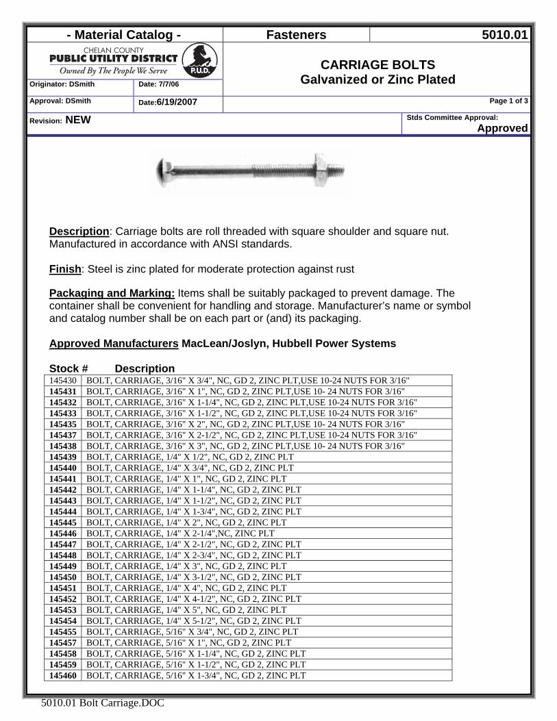
- Material Catalog - Fasteners 5010.01
Originator: DSmith Date: 7/7/06
CARRIAGE BOLTS
Galvanized or Zinc Plated Approval: DSmith Date:6/19/2007 Page 1 of 3
Revision: NEW Stds Committee Approval: Approved
5010.01 Bolt Carriage.DOC
Description: Carriage bolts are roll threaded with square shoulder and square nut. Manufactured in accordance with ANSI standards. Finish: Steel is zinc plated for moderate protection against rust Packaging and Marking: Items shall be suitably packaged to prevent damage. The container shall be convenient for handling and storage. Manufacturer’s name or symbol and catalog number shall be on each part or (and) its packaging.
Approved Manufacturers MacLean/Joslyn, Hubbell Power Systems Stock # Description 145430 BOLT, CARRIAGE, 3/16" X 3/4", NC, GD 2, ZINC PLT,USE 10-24 NUTS FOR 3/16" 145431 BOLT, CARRIAGE, 3/16" X 1", NC, GD 2, ZINC PLT,USE 10- 24 NUTS FOR 3/16" 145432 BOLT, CARRIAGE, 3/16" X 1-1/4", NC, GD 2, ZINC PLT,USE 10-24 NUTS FOR 3/16" 145433 BOLT, CARRIAGE, 3/16" X 1-1/2", NC, GD 2, ZINC PLT,USE 10-24 NUTS FOR 3/16" 145435 BOLT, CARRIAGE, 3/16" X 2", NC, GD 2, ZINC PLT,USE 10- 24 NUTS FOR 3/16" 145437 BOLT, CARRIAGE, 3/16" X 2-1/2", NC, GD 2, ZINC PLT,USE 10-24 NUTS FOR 3/16" 145438 BOLT, CARRIAGE, 3/16" X 3", NC, GD 2, ZINC PLT,USE 10- 24 NUTS FOR 3/16" 145439 BOLT, CARRIAGE, 1/4" X 1/2", NC, GD 2, ZINC PLT 145440 BOLT, CARRIAGE, 1/4" X 3/4", NC, GD 2, ZINC PLT 145441 BOLT, CARRIAGE, 1/4" X 1", NC, GD 2, ZINC PLT 145442 BOLT, CARRIAGE, 1/4" X 1-1/4", NC, GD 2, ZINC PLT 145443 BOLT, CARRIAGE, 1/4" X 1-1/2", NC, GD 2, ZINC PLT 145444 BOLT, CARRIAGE, 1/4" X 1-3/4", NC, GD 2, ZINC PLT 145445 BOLT, CARRIAGE, 1/4" X 2", NC, GD 2, ZINC PLT 145446 BOLT, CARRIAGE, 1/4" X 2-1/4",NC, ZINC PLT 145447 BOLT, CARRIAGE, 1/4" X 2-1/2", NC, GD 2, ZINC PLT 145448 BOLT, CARRIAGE, 1/4" X 2-3/4", NC, GD 2, ZINC PLT 145449 BOLT, CARRIAGE, 1/4" X 3", NC, GD 2, ZINC PLT 145450 BOLT, CARRIAGE, 1/4" X 3-1/2", NC, GD 2, ZINC PLT 145451 BOLT, CARRIAGE, 1/4" X 4", NC, GD 2, ZINC PLT 145452 BOLT, CARRIAGE, 1/4" X 4-1/2", NC, GD 2, ZINC PLT 145453 BOLT, CARRIAGE, 1/4" X 5", NC, GD 2, ZINC PLT 145454 BOLT, CARRIAGE, 1/4" X 5-1/2", NC, GD 2, ZINC PLT 145455 BOLT, CARRIAGE, 5/16" X 3/4", NC, GD 2, ZINC PLT 145457 BOLT, CARRIAGE, 5/16" X 1", NC, GD 2, ZINC PLT 145458 BOLT, CARRIAGE, 5/16" X 1-1/4", NC, GD 2, ZINC PLT 145459 BOLT, CARRIAGE, 5/16" X 1-1/2", NC, GD 2, ZINC PLT 145460 BOLT, CARRIAGE, 5/16" X 1-3/4", NC, GD 2, ZINC PLT
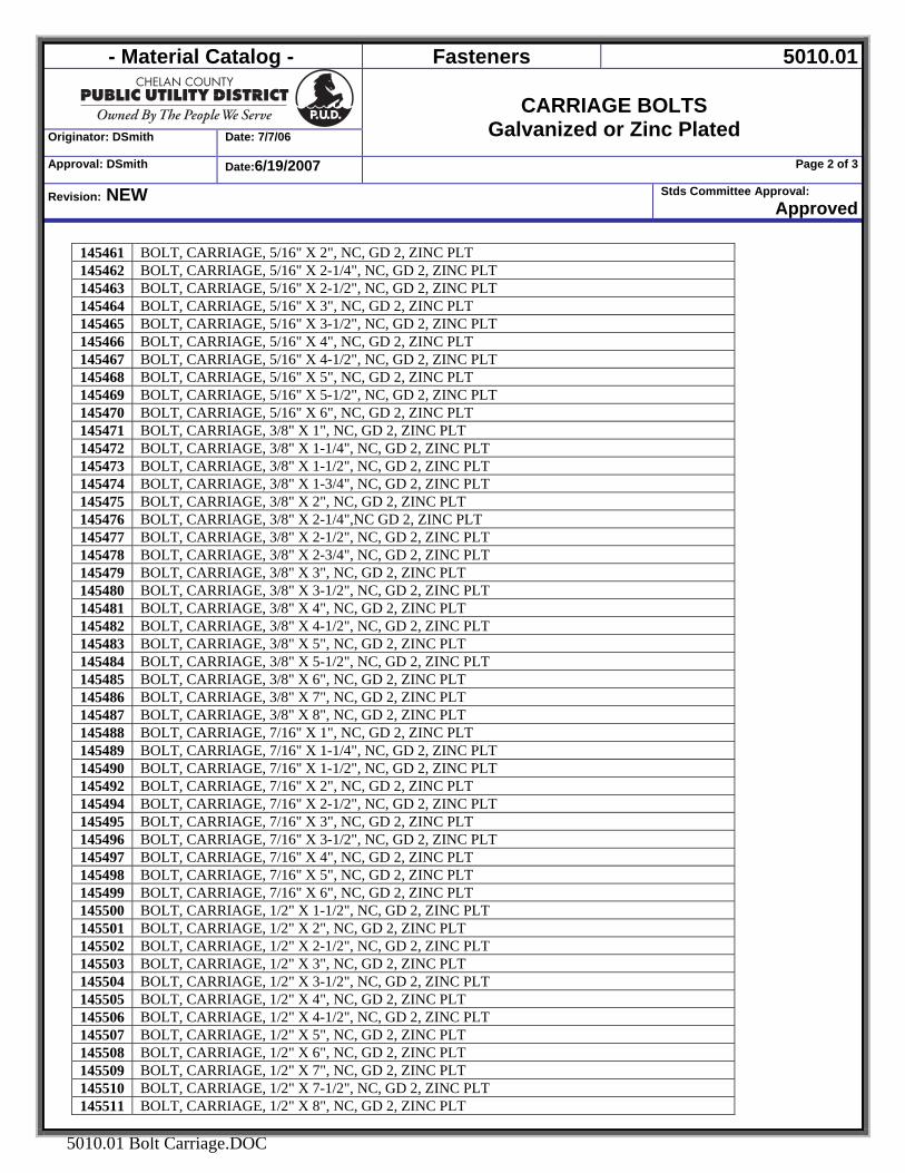
- Material Catalog - Fasteners 5010.01
Originator: DSmith Date: 7/7/06
CARRIAGE BOLTS
Galvanized or Zinc Plated Approval: DSmith Date:6/19/2007 Page 2 of 3
Revision: NEW Stds Committee Approval: Approved
5010.01 Bolt Carriage.DOC
145461 BOLT, CARRIAGE, 5/16" X 2", NC, GD 2, ZINC PLT 145462 BOLT, CARRIAGE, 5/16" X 2-1/4", NC, GD 2, ZINC PLT 145463 BOLT, CARRIAGE, 5/16" X 2-1/2", NC, GD 2, ZINC PLT 145464 BOLT, CARRIAGE, 5/16" X 3", NC, GD 2, ZINC PLT 145465 BOLT, CARRIAGE, 5/16" X 3-1/2", NC, GD 2, ZINC PLT 145466 BOLT, CARRIAGE, 5/16" X 4", NC, GD 2, ZINC PLT 145467 BOLT, CARRIAGE, 5/16" X 4-1/2", NC, GD 2, ZINC PLT 145468 BOLT, CARRIAGE, 5/16" X 5", NC, GD 2, ZINC PLT 145469 BOLT, CARRIAGE, 5/16" X 5-1/2", NC, GD 2, ZINC PLT 145470 BOLT, CARRIAGE, 5/16" X 6", NC, GD 2, ZINC PLT 145471 BOLT, CARRIAGE, 3/8" X 1", NC, GD 2, ZINC PLT 145472 BOLT, CARRIAGE, 3/8" X 1-1/4", NC, GD 2, ZINC PLT 145473 BOLT, CARRIAGE, 3/8" X 1-1/2", NC, GD 2, ZINC PLT 145474 BOLT, CARRIAGE, 3/8" X 1-3/4", NC, GD 2, ZINC PLT 145475 BOLT, CARRIAGE, 3/8" X 2", NC, GD 2, ZINC PLT 145476 BOLT, CARRIAGE, 3/8" X 2-1/4",NC GD 2, ZINC PLT 145477 BOLT, CARRIAGE, 3/8" X 2-1/2", NC, GD 2, ZINC PLT 145478 BOLT, CARRIAGE, 3/8" X 2-3/4", NC, GD 2, ZINC PLT 145479 BOLT, CARRIAGE, 3/8" X 3", NC, GD 2, ZINC PLT 145480 BOLT, CARRIAGE, 3/8" X 3-1/2", NC, GD 2, ZINC PLT 145481 BOLT, CARRIAGE, 3/8" X 4", NC, GD 2, ZINC PLT 145482 BOLT, CARRIAGE, 3/8" X 4-1/2", NC, GD 2, ZINC PLT 145483 BOLT, CARRIAGE, 3/8" X 5", NC, GD 2, ZINC PLT 145484 BOLT, CARRIAGE, 3/8" X 5-1/2", NC, GD 2, ZINC PLT 145485 BOLT, CARRIAGE, 3/8" X 6", NC, GD 2, ZINC PLT 145486 BOLT, CARRIAGE, 3/8" X 7", NC, GD 2, ZINC PLT 145487 BOLT, CARRIAGE, 3/8" X 8", NC, GD 2, ZINC PLT 145488 BOLT, CARRIAGE, 7/16" X 1", NC, GD 2, ZINC PLT 145489 BOLT, CARRIAGE, 7/16" X 1-1/4", NC, GD 2, ZINC PLT 145490 BOLT, CARRIAGE, 7/16" X 1-1/2", NC, GD 2, ZINC PLT 145492 BOLT, CARRIAGE, 7/16" X 2", NC, GD 2, ZINC PLT 145494 BOLT, CARRIAGE, 7/16" X 2-1/2", NC, GD 2, ZINC PLT 145495 BOLT, CARRIAGE, 7/16" X 3", NC, GD 2, ZINC PLT 145496 BOLT, CARRIAGE, 7/16" X 3-1/2", NC, GD 2, ZINC PLT 145497 BOLT, CARRIAGE, 7/16" X 4", NC, GD 2, ZINC PLT 145498 BOLT, CARRIAGE, 7/16" X 5", NC, GD 2, ZINC PLT 145499 BOLT, CARRIAGE, 7/16" X 6", NC, GD 2, ZINC PLT 145500 BOLT, CARRIAGE, 1/2" X 1-1/2", NC, GD 2, ZINC PLT 145501 BOLT, CARRIAGE, 1/2" X 2", NC, GD 2, ZINC PLT 145502 BOLT, CARRIAGE, 1/2" X 2-1/2", NC, GD 2, ZINC PLT 145503 BOLT, CARRIAGE, 1/2" X 3", NC, GD 2, ZINC PLT 145504 BOLT, CARRIAGE, 1/2" X 3-1/2", NC, GD 2, ZINC PLT 145505 BOLT, CARRIAGE, 1/2" X 4", NC, GD 2, ZINC PLT 145506 BOLT, CARRIAGE, 1/2" X 4-1/2", NC, GD 2, ZINC PLT 145507 BOLT, CARRIAGE, 1/2" X 5", NC, GD 2, ZINC PLT 145508 BOLT, CARRIAGE, 1/2" X 6", NC, GD 2, ZINC PLT 145509 BOLT, CARRIAGE, 1/2" X 7", NC, GD 2, ZINC PLT 145510 BOLT, CARRIAGE, 1/2" X 7-1/2", NC, GD 2, ZINC PLT 145511 BOLT, CARRIAGE, 1/2" X 8", NC, GD 2, ZINC PLT
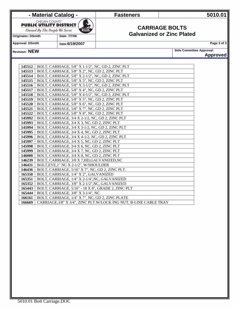
- Material Catalog - Fasteners 5010.01
Originator: DSmith Date: 7/7/06
CARRIAGE BOLTS
Galvanized or Zinc Plated Approval: DSmith Date:6/19/2007 Page 3 of 3
Revision: NEW Stds Committee Approval: Approved
5010.01 Bolt Carriage.DOC
145512 BOLT, CARRIAGE, 5/8" X 1-1/2", NC, GD 2, ZINC PLT 145513 BOLT, CARRIAGE, 5/8" X 2", NC, GD 2, ZINC PLT 145514 BOLT, CARRIAGE, 5/8" X 2-1/2", NC, GD 2, ZINC PLT 145515 BOLT, CARRIAGE, 5/8" X 3", NC, GD 2, ZINC PLT 145516 BOLT, CARRIAGE, 5/8" X 3-1/2", NC, GD 2, ZINC PLT 145517 BOLT, CARRIAGE, 5/8" X 4", NC, GD 2, ZINC PLT 145518 BOLT, CARRIAGE, 5/8" X 4-1/2", NC, GD 2, ZINC PLT 145519 BOLT, CARRIAGE, 5/8" X 5", NC, GD 2, ZINC PLT 145520 BOLT, CARRIAGE, 5/8" X 6", NC, GD 2, ZINC PLT 145521 BOLT, CARRIAGE, 5/8" X 7", NC, GD 2, ZINC PLT 145522 BOLT, CARRIAGE, 5/8" X 8", NC, GD 2, ZINC PLT 145992 BOLT, CARRIAGE, 3/4 X 2-1/2, NC, GD 2, ZINC PLT 145993 BOLT, CARRIAGE, 3/4 X 3, NC, GD 2, ZINC PLT 145994 BOLT, CARRIAGE, 3/4 X 3-1/2, NC, GD 2, ZINC PLT 145995 BOLT, CARRIAGE, 3/4 X 4, NC, GD 2, ZINC PLT 145996 BOLT, CARRIAGE, 3/4 X 4-1/2, NC, GD 2, ZINC PLT 145997 BOLT, CARRIAGE, 3/4 X 5, NC, GD 2, ZINC PLT 145998 BOLT, CARRIAGE, 3/4 X 6, NC, GD 2, ZINC PLT 145999 BOLT, CARRIAGE, 3/4 X 7, NC, GD 2, ZINC PLT 146000 BOLT, CARRIAGE, 3/4 X 8, NC, GD 2, ZINC PLT 146239 BOLT, CARRIAGE, 3/8 X 7,HD,GALVANIZED,NC 146431 BOLT,EYE,1" NC X 2-1/2", W/SHOULDER 146436 BOLT, CARRIAGE, 5/16" X 7", NC, GD 2, ZINC PLT. 165350 BOLT, CARRIAGE, 1/4" X 2", GALVANIZED 165351 BOLT, CARRIAGE, 1/4" X 2-1/4",NC, GALVANIZED 165352 BOLT, CARRIAGE, 3/8" X 2-1/2",NC, GALVANIZED 165443 BOLT, CARRIAGE, 5/16" - 18 X 8", GRADE 2, ZINC PLT 165444 BOLT, CARRIAGE, 3/8" X 3-1/4", NC 166161 BOLT, CARRIAGE, 1/4" X 7", NC, GD 2, ZINC PLATE 166669 CARRIAGE,3/8" X 3/4", ZINC PLT.W/LOCK ING NUT, B-LINE CABLE TRAY
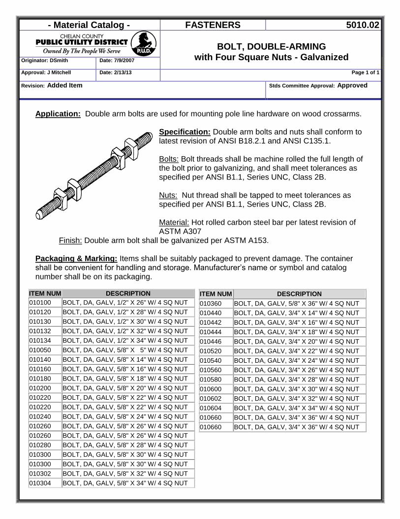
- Material Catalog - FASTENERS 5010.02
BOLT, DOUBLE-ARMING
with Four Square Nuts - Galvanized Originator: DSmith Date: 7/9/2007
Approval: J Mitchell Date: 2/13/13 Page 1 of 1
Revision: Added Item Stds Committee Approval: Approved
Application: Double arm bolts are used for mounting pole line hardware on wood crossarms.
Specification: Double arm bolts and nuts shall conform to latest revision of ANSI B18.2.1 and ANSI C135.1. Bolts: Bolt threads shall be machine rolled the full length of the bolt prior to galvanizing, and shall meet tolerances as specified per ANSI B1.1, Series UNC, Class 2B. Nuts: Nut thread shall be tapped to meet tolerances as specified per ANSI B1.1, Series UNC, Class 2B. Material: Hot rolled carbon steel bar per latest revision of ASTM A307
Finish: Double arm bolt shall be galvanized per ASTM A153. Packaging & Marking: Items shall be suitably packaged to prevent damage. The container shall be convenient for handling and storage. Manufacturer’s name or symbol and catalog number shall be on its packaging.
ITEM NUM DESCRIPTION 010100 BOLT, DA, GALV, 1/2" X 26" W/ 4 SQ NUT 010120 BOLT, DA, GALV, 1/2" X 28" W/ 4 SQ NUT 010130 BOLT, DA, GALV, 1/2" X 30" W/ 4 SQ NUT 010132 BOLT, DA, GALV, 1/2" X 32" W/ 4 SQ NUT 010134 BOLT, DA, GALV, 1/2" X 34" W/ 4 SQ NUT 010050 BOLT, DA, GALV, 5/8" X 5" W/ 4 SQ NUT 010140 BOLT, DA, GALV, 5/8" X 14" W/ 4 SQ NUT 010160 BOLT, DA, GALV, 5/8" X 16" W/ 4 SQ NUT 010180 BOLT, DA, GALV, 5/8" X 18" W/ 4 SQ NUT 010200 BOLT, DA, GALV, 5/8" X 20" W/ 4 SQ NUT 010220 BOLT, DA, GALV, 5/8" X 22" W/ 4 SQ NUT 010220 BOLT, DA, GALV, 5/8" X 22" W/ 4 SQ NUT 010240 BOLT, DA, GALV, 5/8" X 24" W/ 4 SQ NUT 010260 BOLT, DA, GALV, 5/8" X 26" W/ 4 SQ NUT 010260 BOLT, DA, GALV, 5/8" X 26" W/ 4 SQ NUT 010280 BOLT, DA, GALV, 5/8" X 28" W/ 4 SQ NUT 010300 BOLT, DA, GALV, 5/8" X 30" W/ 4 SQ NUT 010300 BOLT, DA, GALV, 5/8" X 30" W/ 4 SQ NUT 010302 BOLT, DA, GALV, 5/8" X 32" W/ 4 SQ NUT 010304 BOLT, DA, GALV, 5/8" X 34" W/ 4 SQ NUT
ITEM NUM DESCRIPTION 010360 BOLT, DA, GALV, 5/8" X 36" W/ 4 SQ NUT 010440 BOLT, DA, GALV, 3/4" X 14" W/ 4 SQ NUT 010442 BOLT, DA, GALV, 3/4" X 16" W/ 4 SQ NUT 010444 BOLT, DA, GALV, 3/4" X 18" W/ 4 SQ NUT 010446 BOLT, DA, GALV, 3/4" X 20" W/ 4 SQ NUT 010520 BOLT, DA, GALV, 3/4" X 22" W/ 4 SQ NUT 010540 BOLT, DA, GALV, 3/4" X 24" W/ 4 SQ NUT 010560 BOLT, DA, GALV, 3/4" X 26" W/ 4 SQ NUT 010580 BOLT, DA, GALV, 3/4" X 28" W/ 4 SQ NUT 010600 BOLT, DA, GALV, 3/4" X 30" W/ 4 SQ NUT 010602 BOLT, DA, GALV, 3/4" X 32" W/ 4 SQ NUT 010604 BOLT, DA, GALV, 3/4" X 34" W/ 4 SQ NUT 010660 BOLT, DA, GALV, 3/4" X 36" W/ 4 SQ NUT 010660 BOLT, DA, GALV, 3/4" X 36" W/ 4 SQ NUT
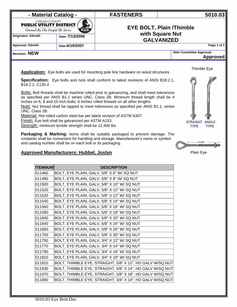
- Material Catalog - FASTENERS 5010.03
Originator: DSmith Date: 7/13/2006
EYE BOLT, Plain /Thimble
with Square Nut GALVANIZED
Approval: DSmith Date:6/19/2007 Page 1 of 1
Revision: NEW Stds Committee Approval: Approved
5010.03 Eye Bolt.Doc
Application: Eye bolts are used for mounting pole line hardware on wood structures. Specification: Eye bolts and nuts shall conform to latest revisions of ANSI B18.2.1, B18.2.2, C135.4 Bolts: Bolt threads shall be machine rolled prior to galvanizing, and shall meet tolerances as specified per ANSI B1.1 series UNC, Class 2B. Minimum thread length shall be 4 inches on 6, 8 and 10 inch bolts, 6 inches rolled threads on all other lengths. Nuts: Nut thread shall be tapped to meet tolerances as specified per ANSI B1.1, series UNC, Class 2B. Material: Hot rolled carbon steel bar per latest revision of ASTM A307. Finish: Eye bolt shall be galvanized per ASTM A153. Strength: minimum tensile strength shall be 12,400 lbs.
Packaging & Marking: Items shall be suitably packaged to prevent damage. The container shall be convenient for handling and storage. Manufacturer’s name or symbol and catalog number shall be on each bolt or its packaging. Approved Manufacturers: Hubbel, Joslyn
ITEMNUM DESCRIPTION 011460 BOLT, EYE PLAIN, GALV, 5/8" X 6" W/ SQ NUT 011480 BOLT, EYE PLAIN, GALV, 5/8" X 8" W/ SQ NUT 011500 BOLT, EYE PLAIN, GALV, 5/8" X 10" W/ SQ NUT 011520 BOLT, EYE PLAIN, GALV, 5/8" X 12" W/ SQ NUT 011520 BOLT, EYE PLAIN, GALV, 5/8" X 12" W/ SQ NUT 011540 BOLT, EYE PLAIN, GALV, 5/8" X 14" W/ SQ NUT 011560 BOLT, EYE PLAIN, GALV, 5/8" X 16" W/ SQ NUT 011580 BOLT, EYE PLAIN, GALV, 5/8" X 18" W/ SQ NUT 011600 BOLT, EYE PLAIN, GALV, 5/8" X 20" W/ SQ NUT 011640 BOLT, EYE PLAIN, GALV, 5/8" X 24" W/ SQ NUT 011660 BOLT, EYE PLAIN, GALV, 5/8" X 26" W/ SQ NUT 011700 BOLT, EYE PLAIN, GALV, 5/8" X 30" W/ SQ NUT 011750 BOLT, EYE PLAIN, GALV, 3/4" X 12" W/ SQ NUT 011770 BOLT, EYE PLAIN, GALV, 3/4" X 14" W/ SQ NUT 011790 BOLT, EYE PLAIN, GALV, 3/4" X 16" W/ SQ NUT 011810 BOLT, EYE PLAIN, GALV, 3/4" X 18" W/ SQ NUT 011910 BOLT, THIMBLE EYE, STRAIGHT, 5/8" X 12", HD GALV W/SQ NUT 011930 BOLT, THIMBLE EYE, STRAIGHT, 5/8" X 14", HD GALV W/SQ NUT 011970 BOLT, THIMBLE EYE, STRAIGHT, 5/8" X 18", HD GALV W/SQ NUT 011990 BOLT, THIMBLE EYE, STRAIGHT, 3/4" X 14", HD GALV W/SQ NUT
Thimble Eye
Plain Eye
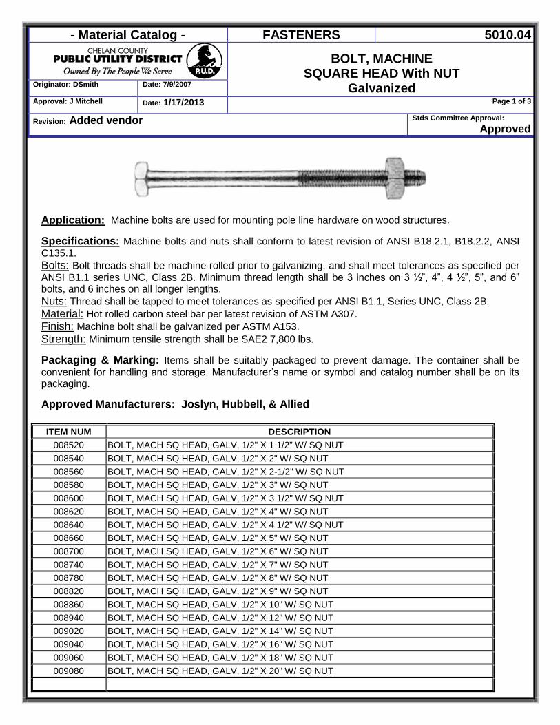
- Material Catalog - FASTENERS 5010.04
BOLT, MACHINE SQUARE HEAD With NUT
Galvanized Originator: DSmith Date: 7/9/2007
Approval: J Mitchell Date: 1/17/2013 Page 1 of 3
Revision: Added vendor Stds Committee Approval: Approved
Application: Machine bolts are used for mounting pole line hardware on wood structures. Specifications: Machine bolts and nuts shall conform to latest revision of ANSI B18.2.1, B18.2.2, ANSI C135.1. Bolts: Bolt threads shall be machine rolled prior to galvanizing, and shall meet tolerances as specified per ANSI B1.1 series UNC, Class 2B. Minimum thread length shall be 3 inches on 3 ½”, 4”, 4 ½”, 5”, and 6” bolts, and 6 inches on all longer lengths. Nuts: Thread shall be tapped to meet tolerances as specified per ANSI B1.1, Series UNC, Class 2B. Material: Hot rolled carbon steel bar per latest revision of ASTM A307. Finish: Machine bolt shall be galvanized per ASTM A153. Strength: Minimum tensile strength shall be SAE2 7,800 lbs.
Packaging & Marking: Items shall be suitably packaged to prevent damage. The container shall be convenient for handling and storage. Manufacturer’s name or symbol and catalog number shall be on its packaging. Approved Manufacturers: Joslyn, Hubbell, & Allied
ITEM NUM DESCRIPTION
008520 BOLT, MACH SQ HEAD, GALV, 1/2" X 1 1/2" W/ SQ NUT 008540 BOLT, MACH SQ HEAD, GALV, 1/2" X 2" W/ SQ NUT
008560 BOLT, MACH SQ HEAD, GALV, 1/2" X 2-1/2" W/ SQ NUT
008580 BOLT, MACH SQ HEAD, GALV, 1/2" X 3" W/ SQ NUT
008600 BOLT, MACH SQ HEAD, GALV, 1/2" X 3 1/2" W/ SQ NUT
008620 BOLT, MACH SQ HEAD, GALV, 1/2" X 4" W/ SQ NUT
008640 BOLT, MACH SQ HEAD, GALV, 1/2" X 4 1/2" W/ SQ NUT
008660 BOLT, MACH SQ HEAD, GALV, 1/2" X 5" W/ SQ NUT
008700 BOLT, MACH SQ HEAD, GALV, 1/2" X 6" W/ SQ NUT
008740 BOLT, MACH SQ HEAD, GALV, 1/2" X 7" W/ SQ NUT
008780 BOLT, MACH SQ HEAD, GALV, 1/2" X 8" W/ SQ NUT
008820 BOLT, MACH SQ HEAD, GALV, 1/2" X 9" W/ SQ NUT
008860 BOLT, MACH SQ HEAD, GALV, 1/2" X 10" W/ SQ NUT
008940 BOLT, MACH SQ HEAD, GALV, 1/2" X 12" W/ SQ NUT
009020 BOLT, MACH SQ HEAD, GALV, 1/2" X 14" W/ SQ NUT
009040 BOLT, MACH SQ HEAD, GALV, 1/2" X 16" W/ SQ NUT
009060 BOLT, MACH SQ HEAD, GALV, 1/2" X 18" W/ SQ NUT
009080 BOLT, MACH SQ HEAD, GALV, 1/2" X 20" W/ SQ NUT
- Material Catalog - FASTENERS 5010.04
BOLT, MACHINE SQUARE HEAD With NUT
Galvanized Originator: DSmith Date: 7/9/2007
Approval: J Mitchell Date: 1/17/2013 Page 2 of 3
Revision: Added vendor Stds Committee Approval: Approved
ITEM NUM DESCRIPTION
009270 BOLT, MACH SQ HEAD, GALV, 5/8" X 1 1/2" W/ SQ NUT
009290 BOLT, MACH SQ HEAD, GALV, 5/8" X 2" W/ SQ NUT
009350 BOLT, MACH SQ HEAD, GALV, 5/8" X 5" W/ SQ NUT
009360 BOLT, MACH SQ HEAD, GALV, 5/8" X 6" W/ SQ NUT
009370 BOLT, MACH SQ HEAD, GALV, 5/8" X 7" W/ SQ NUT
009380 BOLT, MACH SQ HEAD, GALV, 5/8" X 8" W/ SQ NUT
009400 BOLT, MACH SQ HEAD, GALV, 5/8" X 10" W/ SQ NUT
009420 BOLT, MACH SQ HEAD, GALV, 5/8" X 12" W/ SQ NUT
009440 BOLT, MACH SQ HEAD, GALV, 5/8" X 14" W/ SQ NUT
009460 BOLT, MACH SQ HEAD, GALV, 5/8" X 16" W/ SQ NUT
009480 BOLT, MACH SQ HEAD, GALV, 5/8" X 18" W/ SQ NUT
009500 BOLT, MACH SQ HEAD, GALV, 5/8" X 20" W/ SQ NUT
009500 BOLT, MACH SQ HEAD, GALV, 5/8" X 20" W/ SQ NUT
009520 BOLT, MACH SQ HEAD, GALV, 5/8" X 22" W/ SQ NUT
009540 BOLT, MACH SQ HEAD, GALV, 5/8" X 24" W/ SQ NUT
009540 BOLT, MACH SQ HEAD, GALV, 5/8" X 24" W/ SQ NUT
009560 BOLT, MACH SQ HEAD, GALV, 5/8" X 26" W/ SQ NUT
009580 BOLT, MACH SQ HEAD, GALV, 5/8" X 28" W/ SQ NUT
009600 BOLT, MACH SQ HEAD, GALV, 5/8" X 30" W/ SQ NUT
009620 BOLT, MACH SQ HEAD, GALV, 5/8" X 32" W/ SQ NUT
009640 BOLT, MACH SQ HEAD, GALV, 5/8" X 34" W/ SQ NUT
009660 BOLT, MACH SQ HEAD, GALV, 5/8" X 36" W/ SQ NUT
009700 BOLT, MACH SQ HEAD, GALV, 3/4" X 10" W/ SQ NUT
009720 BOLT, MACH SQ HEAD, GALV, 3/4" X 12" W/ SQ NUT
009740 BOLT, MACH SQ HEAD, GALV, 3/4" X 14" W/ SQ NUT
009760 BOLT, MACH SQ HEAD, GALV, 3/4" X 16" W/ SQ NUT
009780 BOLT, MACH SQ HEAD, GALV, 3/4" X 18" W/ SQ NUT
009800 BOLT, MACH SQ HEAD, GALV, 3/4" X 20" W/ SQ NUT
009820 BOLT, MACH SQ HEAD, GALV, 3/4" X 22" W/ SQ NUT
009840 BOLT, MACH SQ HEAD, GALV, 3/4" X 24" W/ SQ NUT
009840 BOLT, MACH SQ HEAD, GALV, 3/4" X 24" W/ SQ NUT
009860 BOLT, MACH SQ HEAD, GALV, 3/4" X 26" W/ SQ NUT
009880 BOLT, MACH SQ HEAD, GALV, 3/4" X 28" W/ SQ NUT
009900 BOLT, MACH SQ HEAD, GALV, 3/4" X 30" W/ SQ NUT
082420 BOLT, MACH SQ HEAD, GALV, 7/8" X 2" W/ SQ NUT
082420 BOLT, MACH SQ HEAD, GALV, 7/8" X 2" W/ SQ NUT
082440 BOLT, MACH SQ HEAD, GALV, 7/8" X 4" W/ SQ NUT
- Material Catalog - FASTENERS 5010.04
BOLT, MACHINE SQUARE HEAD With NUT
Galvanized Originator: DSmith Date: 7/9/2007
Approval: J Mitchell Date: 1/17/2013 Page 3 of 3
Revision: Added vendor Stds Committee Approval: Approved
ITEM NUM DESCRIPTION
082450 BOLT, MACH SQ HEAD, GALV, 7/8" X 10" W/ SQ NUT
082520 BOLT, MACH SQ HEAD, GALV, 7/8" X 12" W/ SQ NUT
082540 BOLT, MACH SQ HEAD, GALV, 7/8" X 14" W/ SQ NUT
082560 BOLT, MACH SQ HEAD, GALV, 7/8" X 16" W/ SQ NUT
082560 BOLT, MACH SQ HEAD, GALV, 7/8" X 16" W/ SQ NUT
082580 BOLT, MACH SQ HEAD, GALV, 7/8" X 18" W/ SQ NUT
082600 BOLT, MACH SQ HEAD, GALV, 7/8" X 20" W/ SQ NUT
082620 BOLT, MACH SQ HEAD, GALV, 7/8" X 22" W/ SQ NUT
082640 BOLT, MACH SQ HEAD, GALV, 7/8" X 24" W/ SQ NUT
082640 BOLT, MACH SQ HEAD, GALV, 7/8" X 24" W/ SQ NUT
082660 BOLT, MACH SQ HEAD, GALV, 7/8" X 26" W/ SQ NUT
082680 BOLT, MACH SQ HEAD, GALV, 7/8" X 28" W/ SQ NUT
082700 BOLT, MACH SQ HEAD, GALV, 7/8" X 30" W/ SQ NUT
082702 BOLT, MACH SQ HEAD, GALV, 7/8" X 32” W/ SQ NUT
082704 BOLT, MACH SQ HEAD, GALV, 7/8" X 34" W/ SQ NUT
082706 BOLT, MACH SQ HEAD, GALV, 7/8" X 36" W/ SQ NUT
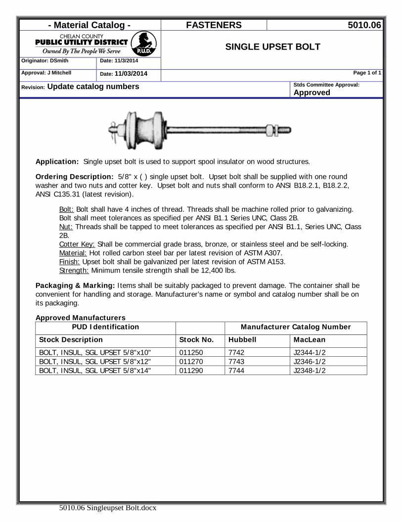
- Material Catalog - FASTENERS 5010.06
SINGLE UPSET BOLT
Originator: DSmith Date: 11/3/2014
Approval: J Mitchell Date: 11/03/2014 Page 1 of 1
Revision: Update catalog numbers Stds Committee Approval: Approved
5010.06 Singleupset Bolt.docx
Application: Single upset bolt is used to support spool insulator on wood structures. Ordering Description: 5/8" x ( ) single upset bolt. Upset bolt shall be supplied with one round washer and two nuts and cotter key. Upset bolt and nuts shall conform to ANSI B18.2.1, B18.2.2, ANSI C135.31 (latest revision).
Bolt: Bolt shall have 4 inches of thread. Threads shall be machine rolled prior to galvanizing. Bolt shall meet tolerances as specified per ANSI B1.1 Series UNC, Class 2B. Nut: Threads shall be tapped to meet tolerances as specified per ANSI B1.1, Series UNC, Class 2B. Cotter Key: Shall be commercial grade brass, bronze, or stainless steel and be self-locking. Material: Hot rolled carbon steel bar per latest revision of ASTM A307. Finish: Upset bolt shall be galvanized per latest revision of ASTM A153. Strength: Minimum tensile strength shall be 12,400 lbs.
Packaging & Marking: Items shall be suitably packaged to prevent damage. The container shall be convenient for handling and storage. Manufacturer’s name or symbol and catalog number shall be on its packaging.
Approved Manufacturers
PUD Identification Manufacturer Catalog Number
Stock Description Stock No. Hubbell MacLean
BOLT, INSUL, SGL UPSET 5/8"x10" 011250 7742 J2344-1/2 BOLT, INSUL, SGL UPSET 5/8"x12" 011270 7743 J2346-1/2 BOLT, INSUL, SGL UPSET 5/8"x14" 011290 7744 J2348-1/2
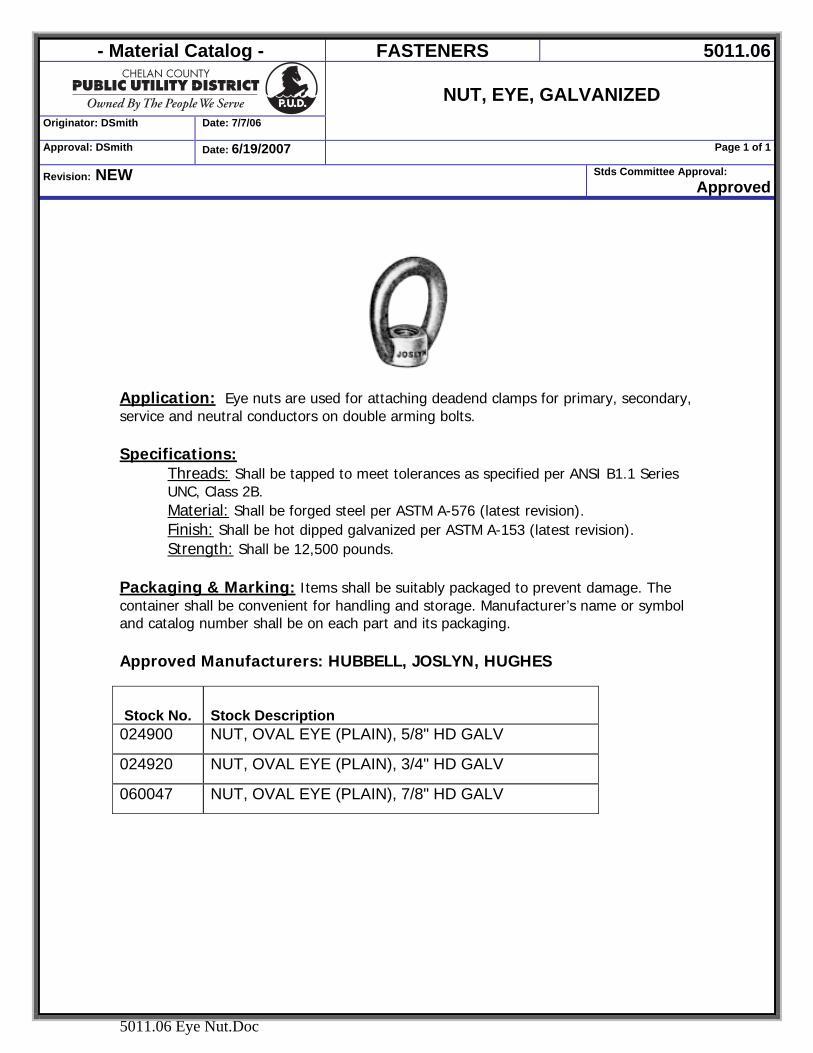
- Material Catalog - FASTENERS 5011.06
Originator: DSmith Date: 7/7/06
NUT, EYE, GALVANIZED
Approval: DSmith Date: 6/19/2007 Page 1 of 1
Revision: NEW Stds Committee Approval: Approved
5011.06 Eye Nut.Doc
Application: Eye nuts are used for attaching deadend clamps for primary, secondary, service and neutral conductors on double arming bolts. Specifications:
Threads: Shall be tapped to meet tolerances as specified per ANSI B1.1 Series UNC, Class 2B. Material: Shall be forged steel per ASTM A-576 (latest revision). Finish: Shall be hot dipped galvanized per ASTM A-153 (latest revision). Strength: Shall be 12,500 pounds.
Packaging & Marking: Items shall be suitably packaged to prevent damage. The container shall be convenient for handling and storage. Manufacturer’s name or symbol and catalog number shall be on each part and its packaging. Approved Manufacturers: HUBBELL, JOSLYN, HUGHES
Stock No. Stock Description 024900 NUT, OVAL EYE (PLAIN), 5/8" HD GALV
024920 NUT, OVAL EYE (PLAIN), 3/4" HD GALV
060047 NUT, OVAL EYE (PLAIN), 7/8" HD GALV
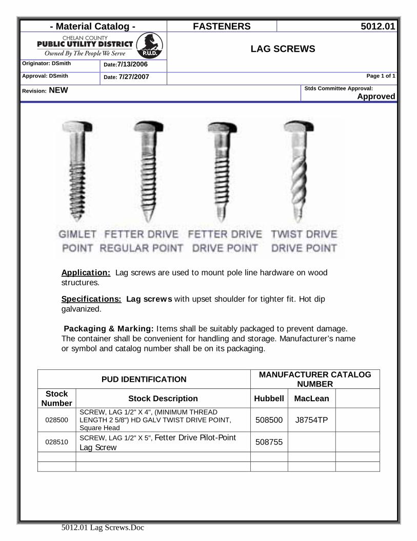
- Material Catalog - FASTENERS 5012.01
Originator: DSmith Date:7/13/2006
LAG SCREWS
Approval: DSmith Date: 7/27/2007 Page 1 of 1
Revision: NEW Stds Committee Approval: Approved
5012.01 Lag Screws.Doc
Application: Lag screws are used to mount pole line hardware on wood structures.
Specifications: Lag screws with upset shoulder for tighter fit. Hot dip galvanized. Packaging & Marking: Items shall be suitably packaged to prevent damage. The container shall be convenient for handling and storage. Manufacturer’s name or symbol and catalog number shall be on its packaging.
PUD IDENTIFICATION MANUFACTURER CATALOG NUMBER
Stock Number Stock Description Hubbell MacLean
028500 SCREW, LAG 1/2" X 4", (MINIMUM THREAD LENGTH 2 5/8") HD GALV TWIST DRIVE POINT, Square Head
508500 J8754TP
028510 SCREW, LAG 1/2" X 5", Fetter Drive Pilot-Point Lag Screw
508755
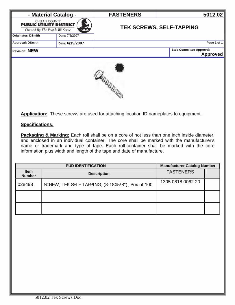
- Material Catalog - FASTENERS 5012.02
Originator: DSmith Date: 7/9/2007
TEK SCREWS, SELF-TAPPING
Approval: DSmith Date: 6/19/2007 Page 1 of 1
Revision: NEW Stds Committee Approval: Approved
5012.02 Tek Screws.Doc
Application: These screws are used for attaching location ID nameplates to equipment. Specifications: Packaging & Marking: Each roll shall be on a core of not less than one inch inside diameter, and enclosed in an individual container. The core shall be marked with the manufacturer's name or trademark and type of tape. Each roll-container shall be marked with the core information plus width and length of the tape and date of manufacture.
PUD IDENTIFICATION Manufacturer Catalog Number Item
Number Description FASTENERS
028498 SCREW, TEK SELF TAPPING, (8-18X5/8"), Box of 100 1305.0818.0062.20
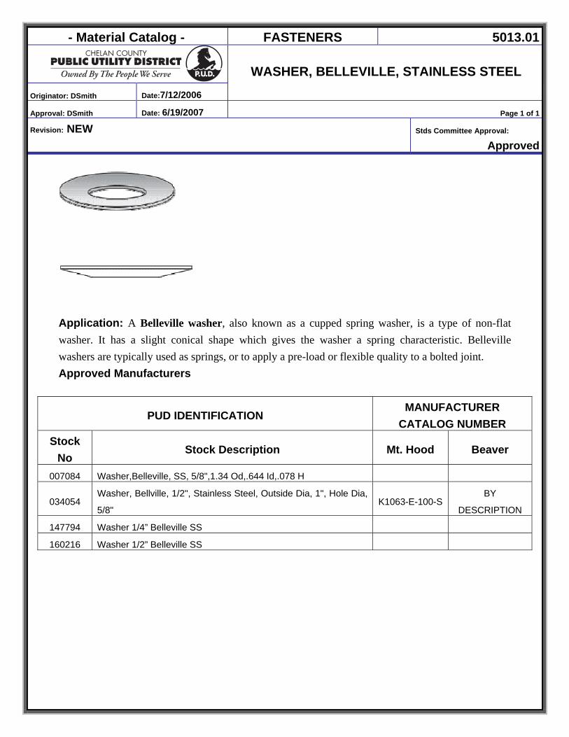
- Material Catalog - FASTENERS 5013.01
Originator: DSmith Date:7/12/2006
WASHER, BELLEVILLE, STAINLESS STEEL
Approval: DSmith Date: 6/19/2007 Page 1 of 1
Revision: NEW Stds Committee Approval:
Approved
Application: A Belleville washer, also known as a cupped spring washer, is a type of non-flat washer. It has a slight conical shape which gives the washer a spring characteristic. Belleville washers are typically used as springs, or to apply a pre-load or flexible quality to a bolted joint. Approved Manufacturers
PUD IDENTIFICATION MANUFACTURER
CATALOG NUMBER Stock
No Stock Description Mt. Hood Beaver
007084 Washer,Belleville, SS, 5/8",1.34 Od,.644 Id,.078 H
034054 Washer, Bellville, 1/2", Stainless Steel, Outside Dia, 1", Hole Dia,
5/8" K1063-E-100-S
BY
DESCRIPTION
147794 Washer 1/4” Belleville SS
160216 Washer 1/2” Belleville SS
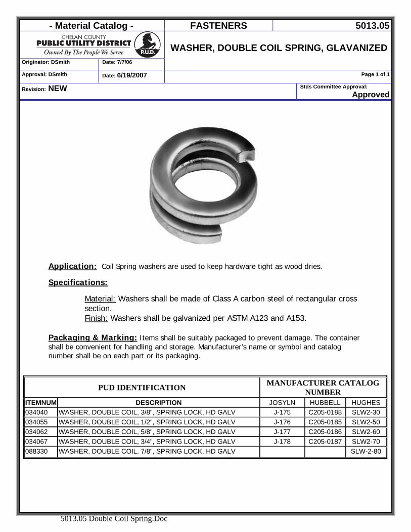
- Material Catalog - FASTENERS 5013.05
Originator: DSmith Date: 7/7/06
WASHER, DOUBLE COIL SPRING, GLAVANIZED
Approval: DSmith Date: 6/19/2007 Page 1 of 1
Revision: NEW Stds Committee Approval: Approved
5013.05 Double Coil Spring.Doc
Application: Coil Spring washers are used to keep hardware tight as wood dries.
Specifications:
Material: Washers shall be made of Class A carbon steel of rectangular cross section. Finish: Washers shall be galvanized per ASTM A123 and A153.
Packaging & Marking: Items shall be suitably packaged to prevent damage. The container shall be convenient for handling and storage. Manufacturer’s name or symbol and catalog number shall be on each part or its packaging.
PUD IDENTIFICATION MANUFACTURER CATALOG NUMBER
ITEMNUM DESCRIPTION JOSYLN HUBBELL HUGHES 034040 WASHER, DOUBLE COIL, 3/8", SPRING LOCK, HD GALV J-175 C205-0188 SLW2-30 034055 WASHER, DOUBLE COIL, 1/2", SPRING LOCK, HD GALV J-176 C205-0185 SLW2-50 034062 WASHER, DOUBLE COIL, 5/8", SPRING LOCK, HD GALV J-177 C205-0186 SLW2-60 034067 WASHER, DOUBLE COIL, 3/4", SPRING LOCK, HD GALV J-178 C205-0187 SLW2-70 088330 WASHER, DOUBLE COIL, 7/8", SPRING LOCK, HD GALV SLW-2-80
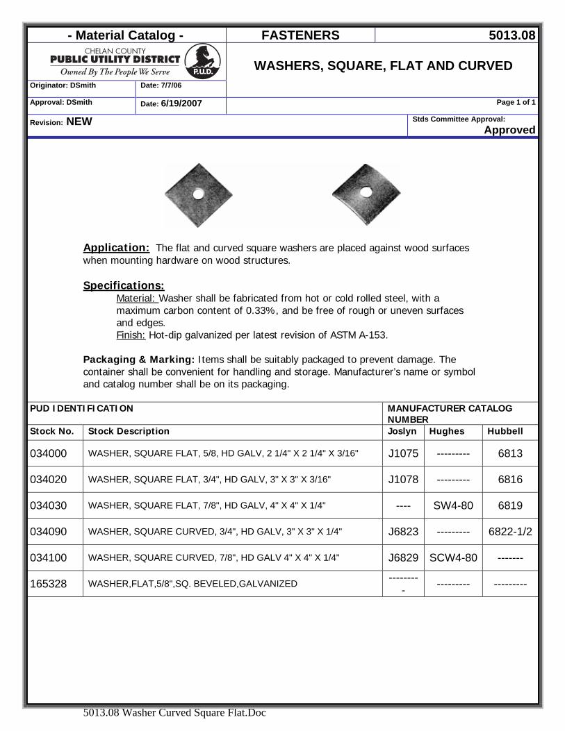
- Material Catalog - FASTENERS 5013.08
Originator: DSmith Date: 7/7/06
WASHERS, SQUARE, FLAT AND CURVED
Approval: DSmith Date: 6/19/2007 Page 1 of 1
Revision: NEW Stds Committee Approval: Approved
5013.08 Washer Curved Square Flat.Doc
Application: The flat and curved square washers are placed against wood surfaces when mounting hardware on wood structures. Specifications:
Material: Washer shall be fabricated from hot or cold rolled steel, with a maximum carbon content of 0.33%, and be free of rough or uneven surfaces and edges. Finish: Hot-dip galvanized per latest revision of ASTM A-153.
Packaging & Marking: Items shall be suitably packaged to prevent damage. The container shall be convenient for handling and storage. Manufacturer’s name or symbol and catalog number shall be on its packaging.
PUD IDENTIFICATION MANUFACTURER CATALOG NUMBER
Stock No. Stock Description Joslyn Hughes Hubbell
034000 WASHER, SQUARE FLAT, 5/8, HD GALV, 2 1/4" X 2 1/4" X 3/16" J1075 --------- 6813
034020 WASHER, SQUARE FLAT, 3/4", HD GALV, 3" X 3" X 3/16" J1078 --------- 6816
034030 WASHER, SQUARE FLAT, 7/8", HD GALV, 4" X 4" X 1/4" ---- SW4-80 6819
034090 WASHER, SQUARE CURVED, 3/4", HD GALV, 3" X 3" X 1/4" J6823 --------- 6822-1/2
034100 WASHER, SQUARE CURVED, 7/8", HD GALV 4" X 4" X 1/4" J6829 SCW4-80 -------
165328 WASHER,FLAT,5/8",SQ. BEVELED,GALVANIZED --------- --------- ---------

- Material Catalog - FASTENERS 5016.01
Originator: DSmith Date:6/19/2007
Staples, Wire
Approval: DSmith Date: :6/19/2007 Page 1 of 1
Revision: NEW Stds Committee Approval: Approved
5016.01 Staples, Wire.doc
Application Wire staples are used to attach ground wire to wooden poles. Specifications: All staples and finishes must meet or exceed the following Standards.
• Federal Specifications FF-N-105A, type 111, style 1 • ANSI standards for rolled or Slashed points • EEI-NEMA standards for rolled or slashed points with serrated edge
Packaging & Marking: Items shall be suitably packaged to prevent damage. The container shall be convenient for handling and storage. Manufacturer’s name or symbol and catalog number shall be on its packaging.
PUD IDENTIFICATION Manufacturer Catalog Number
Item Number Description L & J
Industrial Staples
031900 STAPLE,GALV, 1 3/4"X3/8"X 0.148" - SERRATED POINT J7487HDG
031905 STAPLE, WIRE, GALV, (2 1/2" WIDE X 4" LONG)
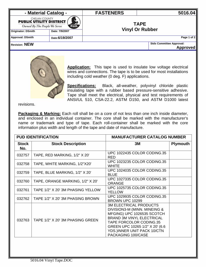
- Material Catalog - FASTENERS 5016.04
Originator: DSmith Date: 7/9/2007
TAPE
Vinyl Or Rubber Approval: DSmith Date:6/19/2007 Page 1 of 2
Revision: NEW Stds Committee Approval: Approved
5016.04 Vinyl Tape.DOC
Application: This tape is used to insulate low voltage electrical wires and connections. The tape is to be used for most installations including cold weather (0 deg. F) applications. Specifications: Black, all-weather, polyvinyl chloride plastic insulating tape with a rubber based pressure-sensitive adhesive. Tape shall meet the electrical, physical and test requirements of ANSI/UL 510, CSA-22.2, ASTM D150, and ASTM D1000 latest
revisions. Packaging & Marking: Each roll shall be on a core of not less than one inch inside diameter, and enclosed in an individual container. The core shall be marked with the manufacturer's name or trademark and type of tape. Each roll-container shall be marked with the core information plus width and length of the tape and date of manufacture.
PUD IDENTIFICATION MANUFACTURER CATALOG NUMBER Stock No.
Stock Description 3M Plymouth
032757 TAPE, RED MARKING, 1/2" X 20' UPC 1022435 COLOR CODING.35 RED
032758 TAPE, WHITE MARKING, 1/2"X20' UPC 1023235 COLOR CODING.35 WHITE
032759 TAPE, BLUE MARKING, 1/2" X 20' UPC 1024035 COLOR CODING.35 BLUE
032760 TAPE, ORANGE MARKING, 1/2" X 20' UPC 1027335 COLOR CODING.35 ORANGE
032761 TAPE 1/2" X 20' 3M PHASING YELLOW UPC 1025735 COLOR CODING.35 YELLOW
032762 TAPE 1/2" X 20' 3M PHASING BROWN UPC 1029935 COLOR CODING.35 BROWN UPC 10299
032763 TAPE 1/2" X 20' 3M PHASING GREEN
3M ELECTRICAL PRODUCTS DIVISION3-M (MINN. MINEING & MFGING) UPC 1026535 SCOTCH BRAND 3M VINYL ELECTRICAL TAPE FORCOLOR CODING.35 GREEN UPC 10265 1/2" X 20' (6.6 YDS.)INNER UNIT PACK 10/CTN PACKAGING 100/CASE
- Material Catalog - FASTENERS 5016.04
Originator: DSmith Date: 7/9/2007
TAPE
Vinyl Or Rubber Approval: DSmith Date:6/19/2007 Page 2 of 2
Revision: NEW Stds Committee Approval: Approved
5016.04 Vinyl Tape.DOC
Stock No.
Stock Description 3M Plymouth
032764 TAPE, GRAY MARKING, 1/2" X 20'
3M ELECTRICAL PRODUCTS DIVISION3-M (MINN. MINEING & MFGING) UPC 1028135 SCOTCH BRAND 3M VINYL ELECTRICAL TAPE FORCOLOR CODING.35 GRAY UPC 10281 1/2" X 20' (6.6 YDS.)INNER UNIT PACK 10/CTN PACKAGING 100/CASE
032800 TAPE, BLACK VINYL, PREMIUM 85CW, 1.5" CORE, 3/4" X 66' 37 4243
032820 TAPE, 1 1/2" VINYL, PREMIUM 85CW, 1.5 CORE, 108' LONG 37 4273
032830 TAPE BUS BAR INSULATING SUB. RAYCHEM #HVBT-2-R 049520 TAPE CU SHIELDING 3M24 G.E. #3M-24
049620
TAPE, WARNING (4 MILS) 6" WIDE- 1000' LONG- RED WITH BLACK - INSCRIBED WITH "CHELAN COUNTY POWER" AND TELEPHONE(509) 663-8121. MUST BE IN DISPENSER BOXES.
TERRATAPE (REEF INDUSTRIES, HOUSTON, TX ALLEN SYSTEMS THOR ENTERPRISES, INC.(TAPE ITEM NUMBER 22002 AND DISPENSER NUMBER 49005)
143002 TAPE,DUCT,SILVER,2" X 60 YDS. P
143002 TAPE,DUCT,SILVER,2" X 60 YDS.
NASHUA 357 SURE TAPE PC622 UNITED TAPE COMPANY #110-2 3M "SCOTCH" BRAND 50254 3-M (MINN. MINEING & MFGING) 50254
148863 TAPE,SPLICING,RUBBER,LINERLESS,1" X 30'
3-M (MINN. MINEING & MFGING) 130C
160312 TAPE, FLAGGING, ENGINEER, 1 3/16" X 150 FEET, GLOW ORANGE,SURVEY
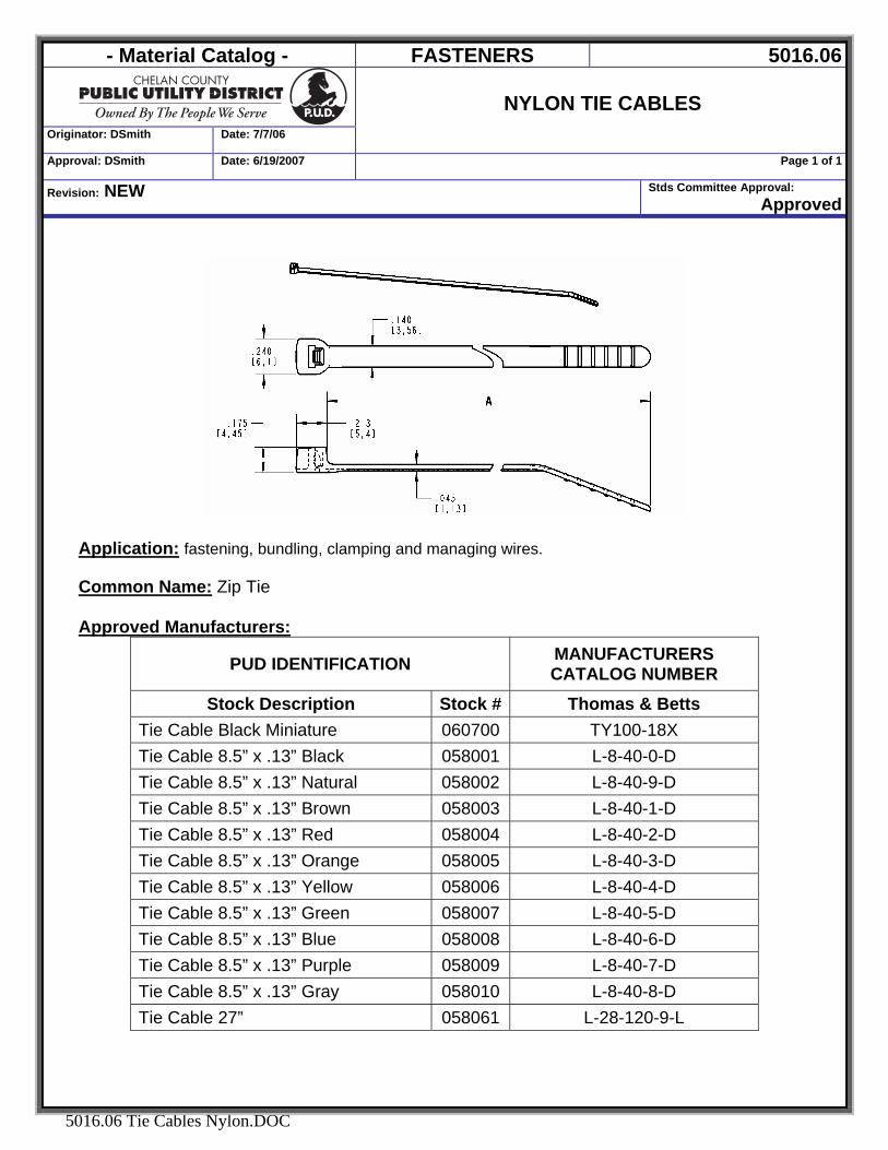
- Material Catalog - FASTENERS 5016.06
Originator: DSmith Date: 7/7/06
NYLON TIE CABLES
Approval: DSmith Date: 6/19/2007 Page 1 of 1
Revision: NEW Stds Committee Approval: Approved
5016.06 Tie Cables Nylon.DOC
Application: fastening, bundling, clamping and managing wires. Common Name: Zip Tie
Approved Manufacturers:
PUD IDENTIFICATION MANUFACTURERS CATALOG NUMBER
Stock Description Stock # Thomas & Betts Tie Cable Black Miniature 060700 TY100-18X Tie Cable 8.5” x .13” Black 058001 L-8-40-0-D Tie Cable 8.5” x .13” Natural 058002 L-8-40-9-D Tie Cable 8.5” x .13” Brown 058003 L-8-40-1-D Tie Cable 8.5” x .13” Red 058004 L-8-40-2-D Tie Cable 8.5” x .13” Orange 058005 L-8-40-3-D Tie Cable 8.5” x .13” Yellow 058006 L-8-40-4-D Tie Cable 8.5” x .13” Green 058007 L-8-40-5-D Tie Cable 8.5” x .13” Blue 058008 L-8-40-6-D Tie Cable 8.5” x .13” Purple 058009 L-8-40-7-D Tie Cable 8.5” x .13” Gray 058010 L-8-40-8-D Tie Cable 27” 058061 L-28-120-9-L
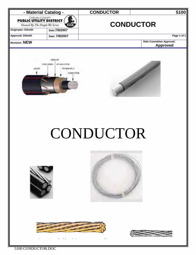
- Material Catalog - CONDUCTOR 5100
Originator: DSmith Date:7/9/2007
CONDUCTOR
Approval: DSmith Date: 7/9/2007 Page 1 of 1
Revision: NEW Stds Committee Approval: Approved
5100 CONDUCTOR.DOC
CONDUCTOR
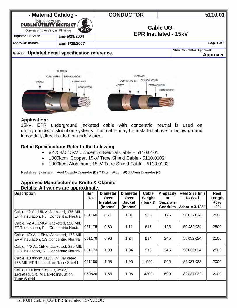
- Material Catalog - CONDUCTOR 5110.01
Originator: DSmith Date 5/28/2004
Cable UG,
EPR Insulated - 15kV Approval: DSmith Date: 6/28/2007 Page 1 of 1
Revision: Updated detail specification reference. Stds Committee Approval:
Approved
5110.01 Cable, UG EPR Insulated 15kV.DOC
Application: 15kV, EPR underground jacketed cable with concentric neutral is used on multigrounded distribution systems. This cable may be installed above or below ground in conduit, direct buried, or underwater. Detail Specification: Refer to the following
• #2 & 4/0 15kV Concentric Neutral Cable – 5110.0101 • 1000kcm Copper, 15kV Tape Shield Cable - 5110.0102 • 1000kcm Aluminum, 15kV Tape Shield Cable - 5110.0103
Reel dimensions are = Reel Outside Diameter (D) X Drum Width (W) X Drum Diameter (d) Approved Manufacturers: Kerite & Okonite Details: All values are approximate.
Description Item No.
Diameter Over
Insulation(Inches)
Diameter Over
Jacket (Inches)
Cable Weight(lbs/kft)
Ampacity In
Separate Conduits
Reel Size (in.)DxWxd
Arbor = 3.125”
Reel Length
+5% - 0%
Cable, #2 AL,15KV, Jacketed, 175 MIL EPR Insulation, Full Concentric Neutral 051160 0.71 1.01 536 125 50X32X24 2500
Cable, #2 AL,15KV, Jacketed, 220 MIL EPR Insulation, Full Concentric Neutral 051175 0.80 1.11 617 125 50X32X24 2500
Cable, 4/0 AL,15KV, Jacketed, 175 MIL EPR Insulation, 1/3 Concentric Neutral 051170 0.93 1.24 814 245 58X32X24 2500
Cable, 4/0 AL,15KV, Jacketed, 220 MIL EPR Insulation, 1/3 Concentric Neutral 051173 1.03 1.34 913 245 58X32X24 2500
Cable, 1000kcm AL,15KV, Jacketed, 175 MIL EPR Insulation, Tape Shield 051180 1.58 1.96 1990 565 82X37X32 2000
Cable 1000kcm Copper, 15kV, Jacketed, 175 MIL EPR Insulation, Tape Shield
050826 1.58 1.96 4309 690 82X37X32 2000
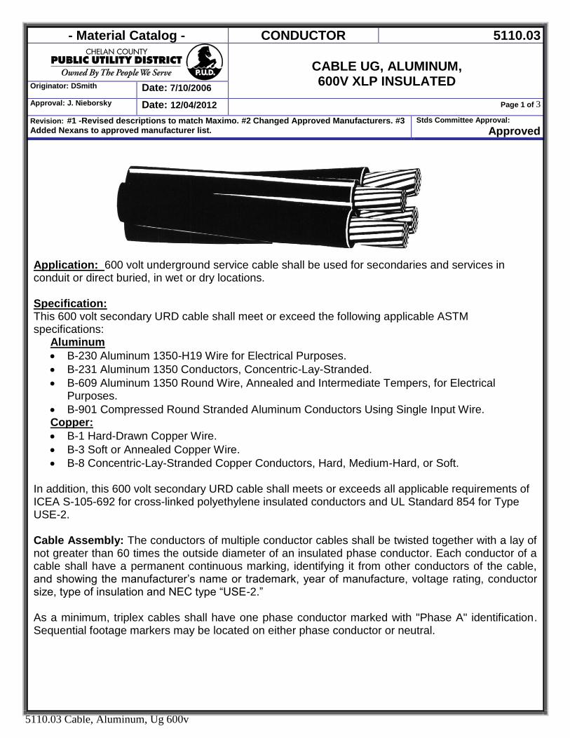
- Material Catalog - CONDUCTOR 5110.03
CABLE UG, ALUMINUM, 600V XLP INSULATED Originator: DSmith Date: 7/10/2006
Approval: J. Nieborsky Date: 12/04/2012 Page 1 of 3
Revision: #1 -Revised descriptions to match Maximo. #2 Changed Approved Manufacturers. #3 Added Nexans to approved manufacturer list.
Stds Committee Approval: Approved
5110.03 Cable, Aluminum, Ug 600v
Application: 600 volt underground service cable shall be used for secondaries and services in conduit or direct buried, in wet or dry locations. Specification: This 600 volt secondary URD cable shall meet or exceed the following applicable ASTM specifications: Aluminum
B-230 Aluminum 1350-H19 Wire for Electrical Purposes. B-231 Aluminum 1350 Conductors, Concentric-Lay-Stranded. B-609 Aluminum 1350 Round Wire, Annealed and Intermediate Tempers, for Electrical
Purposes. B-901 Compressed Round Stranded Aluminum Conductors Using Single Input Wire.
Copper: B-1 Hard-Drawn Copper Wire. B-3 Soft or Annealed Copper Wire. B-8 Concentric-Lay-Stranded Copper Conductors, Hard, Medium-Hard, or Soft.
In addition, this 600 volt secondary URD cable shall meets or exceeds all applicable requirements of ICEA S-105-692 for cross-linked polyethylene insulated conductors and UL Standard 854 for Type USE-2. Cable Assembly: The conductors of multiple conductor cables shall be twisted together with a lay of not greater than 60 times the outside diameter of an insulated phase conductor. Each conductor of a cable shall have a permanent continuous marking, identifying it from other conductors of the cable, and showing the manufacturer’s name or trademark, year of manufacture, voltage rating, conductor size, type of insulation and NEC type “USE-2.” As a minimum, triplex cables shall have one phase conductor marked with "Phase A" identification. Sequential footage markers may be located on either phase conductor or neutral.
- Material Catalog - CONDUCTOR 5110.03
CABLE UG, ALUMINUM, 600V XLP INSULATED Originator: DSmith Date: 7/10/2006
Approval: J. Nieborsky Date: 12/04/2012 Page 2 of 3
Revision: #1 -Revised descriptions to match Maximo. #2 Changed Approved Manufacturers. #3 Added Nexans to approved manufacturer list.
Stds Committee Approval: Approved
5110.03 Cable, Aluminum, Ug 600v
As a minimum, quadraplex cables shall have one phase conductor marked with "Phase A" identification, a second phase conductor marked with "Phase B" identification. Sequential footage markers may be located on any phase conductor or the neutral. Packaging and Marking: Cable shall be shipped on nonreturnable reels of NEMA WC26 dimensions with in either “cut to order” or standard lengths as specified. Conductor shall be level wound on reel. Both ends of the wire shall be fastened to the reel. Conductor shall be protected by heavy wrapping, either heavy fiberboard or 10 mil. plastic. The net weight, length, conductor size and kind, stranding, voltage class, purchaser’s order number, and manufacturer’s name, address, starting footage of the cable (at the hub), and serial number shall be marked on a durable label or tag and securely fastened to the outside of the reel. Reels shall be free of foreign objects (nails, etc.) that could damage the conductor during transit or while dispensing. Reel size shall be a minimum of 1-1/2” larger than wound conductor. Reels shall not exceed maximum flange diameter of 66 inches nor a maximum outside width of 32-1/2 inches. The arbor hole shall have a diameter of 2-1/2 inches. Shipping: All cable shall be shipped on an open flatbed truck. Reel flanges shall be vertical and positioned to be unloaded from the side. The cable shall be protected by heavy wrapping, either heavy fiberboard or 10 mil plastic. All cable ends shall be sealed with approved end caps to prevent the entrance of moisture during shipping and storage. Tests: The cable shall be tested in accordance with the applicable requirements of ICEA Publication No. S-105-692 (latest revision) except "sparking testing" shall not be permitted. Results of these tests shall be supplied to the Standards Engineer prior to shipping if requested. Inspection: Inspection may be made at the manufacturer’s plant or upon receipt, at the option of the purchaser. Failure to meet any of the requirements of this specification will be cause for rejection.
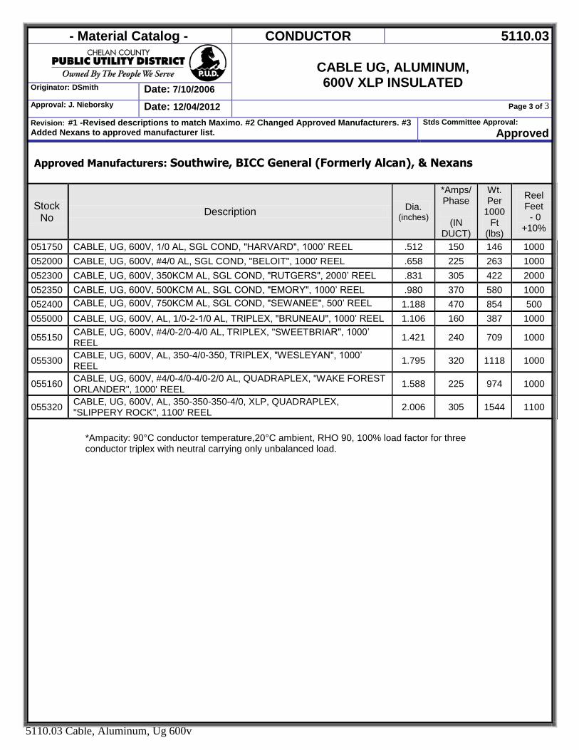
- Material Catalog - CONDUCTOR 5110.03
CABLE UG, ALUMINUM, 600V XLP INSULATED Originator: DSmith Date: 7/10/2006
Approval: J. Nieborsky Date: 12/04/2012 Page 3 of 3
Revision: #1 -Revised descriptions to match Maximo. #2 Changed Approved Manufacturers. #3 Added Nexans to approved manufacturer list.
Stds Committee Approval: Approved
5110.03 Cable, Aluminum, Ug 600v
Approved Manufacturers: Southwire, BICC General (Formerly Alcan), & Nexans
Stock No Description Dia.
(inches)
*Amps/Phase
(IN
DUCT)
Wt. Per
1000 Ft
(lbs)
Reel Feet - 0
+10%
051750 CABLE, UG, 600V, 1/0 AL, SGL COND, "HARVARD", 1000’ REEL .512 150 146 1000 052000 CABLE, UG, 600V, #4/0 AL, SGL COND, "BELOIT", 1000' REEL .658 225 263 1000 052300 CABLE, UG, 600V, 350KCM AL, SGL COND, "RUTGERS", 2000’ REEL .831 305 422 2000 052350 CABLE, UG, 600V, 500KCM AL, SGL COND, "EMORY", 1000’ REEL .980 370 580 1000 052400 CABLE, UG, 600V, 750KCM AL, SGL COND, "SEWANEE", 500’ REEL 1.188 470 854 500 055000 CABLE, UG, 600V, AL, 1/0-2-1/0 AL, TRIPLEX, "BRUNEAU", 1000’ REEL 1.106 160 387 1000
055150 CABLE, UG, 600V, #4/0-2/0-4/0 AL, TRIPLEX, "SWEETBRIAR", 1000’ REEL 1.421 240 709 1000
055300 CABLE, UG, 600V, AL, 350-4/0-350, TRIPLEX, "WESLEYAN", 1000’ REEL
1.795 320 1118 1000
055160 CABLE, UG, 600V, #4/0-4/0-4/0-2/0 AL, QUADRAPLEX, "WAKE FOREST ORLANDER", 1000' REEL
1.588 225 974 1000
055320 CABLE, UG, 600V, AL, 350-350-350-4/0, XLP, QUADRAPLEX, "SLIPPERY ROCK", 1100' REEL 2.006 305 1544 1100
*Ampacity: 90°C conductor temperature,20°C ambient, RHO 90, 100% load factor for three conductor triplex with neutral carrying only unbalanced load.
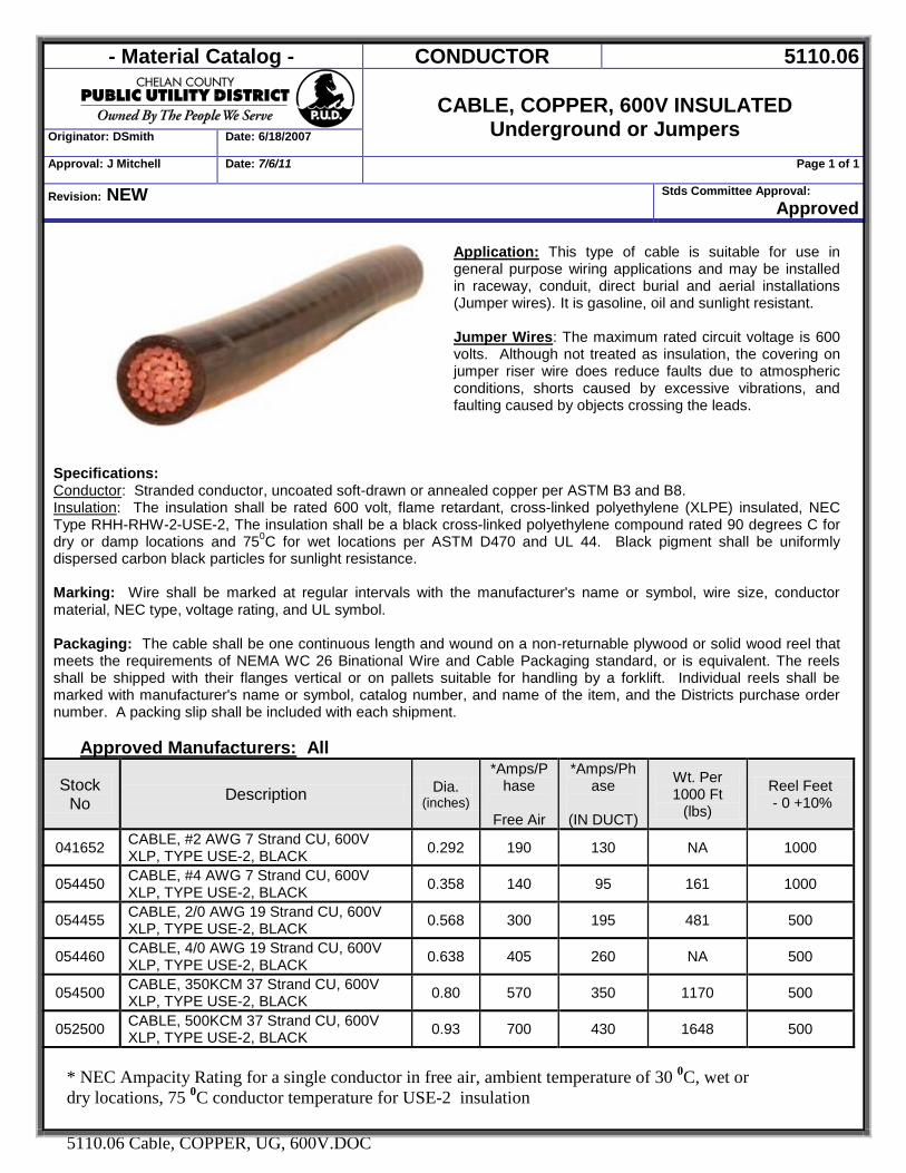
- Material Catalog - CONDUCTOR 5110.06
CABLE, COPPER, 600V INSULATED
Underground or Jumpers Originator: DSmith Date: 6/18/2007
Approval: J Mitchell Date: 7/6/11 Page 1 of 1
Revision: NEW Stds Committee Approval: Approved
5110.06 Cable, COPPER, UG, 600V.DOC
Application: This type of cable is suitable for use in general purpose wiring applications and may be installed in raceway, conduit, direct burial and aerial installations (Jumper wires). It is gasoline, oil and sunlight resistant. Jumper Wires: The maximum rated circuit voltage is 600 volts. Although not treated as insulation, the covering on jumper riser wire does reduce faults due to atmospheric conditions, shorts caused by excessive vibrations, and faulting caused by objects crossing the leads.
Specifications: Conductor: Stranded conductor, uncoated soft-drawn or annealed copper per ASTM B3 and B8. Insulation: The insulation shall be rated 600 volt, flame retardant, cross-linked polyethylene (XLPE) insulated, NEC Type RHH-RHW-2-USE-2, The insulation shall be a black cross-linked polyethylene compound rated 90 degrees C for dry or damp locations and 750C for wet locations per ASTM D470 and UL 44. Black pigment shall be uniformly dispersed carbon black particles for sunlight resistance. Marking: Wire shall be marked at regular intervals with the manufacturer's name or symbol, wire size, conductor material, NEC type, voltage rating, and UL symbol. Packaging: The cable shall be one continuous length and wound on a non-returnable plywood or solid wood reel that meets the requirements of NEMA WC 26 Binational Wire and Cable Packaging standard, or is equivalent. The reels shall be shipped with their flanges vertical or on pallets suitable for handling by a forklift. Individual reels shall be marked with manufacturer's name or symbol, catalog number, and name of the item, and the Districts purchase order number. A packing slip shall be included with each shipment.
Approved Manufacturers: All
Stock No Description Dia.
(inches)
*Amps/Phase
Free Air
*Amps/Phase
(IN DUCT)
Wt. Per 1000 Ft
(lbs)
Reel Feet - 0 +10%
041652 CABLE, #2 AWG 7 Strand CU, 600V XLP, TYPE USE-2, BLACK 0.292 190 130 NA 1000
054450 CABLE, #4 AWG 7 Strand CU, 600V XLP, TYPE USE-2, BLACK 0.358 140 95 161 1000
054455 CABLE, 2/0 AWG 19 Strand CU, 600V XLP, TYPE USE-2, BLACK 0.568 300 195 481 500
054460 CABLE, 4/0 AWG 19 Strand CU, 600V XLP, TYPE USE-2, BLACK 0.638 405 260 NA 500
054500 CABLE, 350KCM 37 Strand CU, 600V XLP, TYPE USE-2, BLACK 0.80 570 350 1170 500
052500 CABLE, 500KCM 37 Strand CU, 600V XLP, TYPE USE-2, BLACK 0.93 700 430 1648 500
* NEC Ampacity Rating for a single conductor in free air, ambient temperature of 30
0C, wet or
dry locations, 75 0C conductor temperature for USE-2 insulation
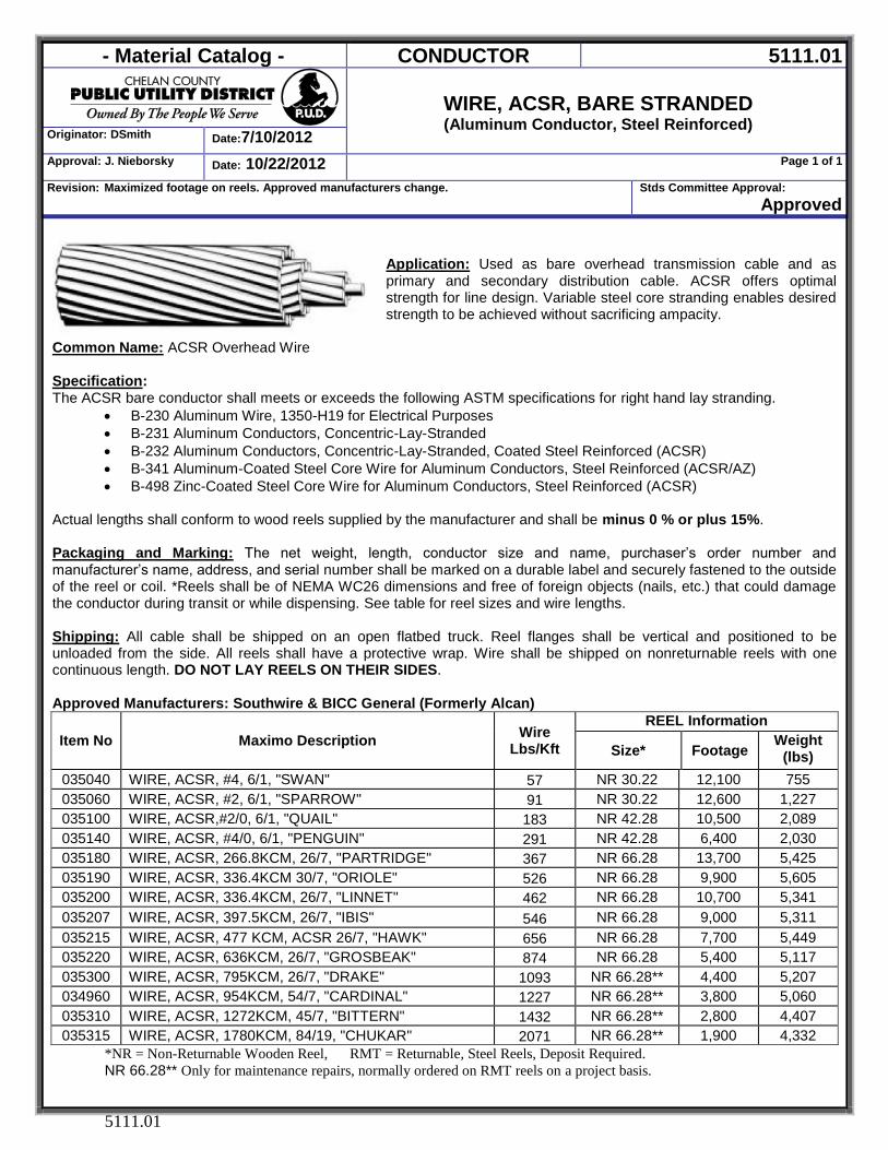
- Material Catalog - CONDUCTOR 5111.01
WIRE, ACSR, BARE STRANDED (Aluminum Conductor, Steel Reinforced)
Originator: DSmith Date:7/10/2012
Approval: J. Nieborsky Date: 10/22/2012 Page 1 of 1
Revision: Maximized footage on reels. Approved manufacturers change. Stds Committee Approval: Approved
5111.01
Application: Used as bare overhead transmission cable and as primary and secondary distribution cable. ACSR offers optimal strength for line design. Variable steel core stranding enables desired strength to be achieved without sacrificing ampacity.
Common Name: ACSR Overhead Wire Specification: The ACSR bare conductor shall meets or exceeds the following ASTM specifications for right hand lay stranding.
B-230 Aluminum Wire, 1350-H19 for Electrical Purposes B-231 Aluminum Conductors, Concentric-Lay-Stranded B-232 Aluminum Conductors, Concentric-Lay-Stranded, Coated Steel Reinforced (ACSR) B-341 Aluminum-Coated Steel Core Wire for Aluminum Conductors, Steel Reinforced (ACSR/AZ) B-498 Zinc-Coated Steel Core Wire for Aluminum Conductors, Steel Reinforced (ACSR)
Actual lengths shall conform to wood reels supplied by the manufacturer and shall be minus 0 % or plus 15%. Packaging and Marking: The net weight, length, conductor size and name, purchaser’s order number and manufacturer’s name, address, and serial number shall be marked on a durable label and securely fastened to the outside of the reel or coil. *Reels shall be of NEMA WC26 dimensions and free of foreign objects (nails, etc.) that could damage the conductor during transit or while dispensing. See table for reel sizes and wire lengths. Shipping: All cable shall be shipped on an open flatbed truck. Reel flanges shall be vertical and positioned to be unloaded from the side. All reels shall have a protective wrap. Wire shall be shipped on nonreturnable reels with one continuous length. DO NOT LAY REELS ON THEIR SIDES. Approved Manufacturers: Southwire & BICC General (Formerly Alcan)
Item No Maximo Description Wire Lbs/Kft
REEL Information
Size* Footage Weight
(lbs) 035040 WIRE, ACSR, #4, 6/1, "SWAN" 57 NR 30.22 12,100 755 035060 WIRE, ACSR, #2, 6/1, "SPARROW" 91 NR 30.22 12,600 1,227 035100 WIRE, ACSR,#2/0, 6/1, "QUAIL" 183 NR 42.28 10,500 2,089 035140 WIRE, ACSR, #4/0, 6/1, "PENGUIN" 291 NR 42.28 6,400 2,030 035180 WIRE, ACSR, 266.8KCM, 26/7, "PARTRIDGE" 367 NR 66.28 13,700 5,425 035190 WIRE, ACSR, 336.4KCM 30/7, "ORIOLE" 526 NR 66.28 9,900 5,605 035200 WIRE, ACSR, 336.4KCM, 26/7, "LINNET" 462 NR 66.28 10,700 5,341 035207 WIRE, ACSR, 397.5KCM, 26/7, "IBIS" 546 NR 66.28 9,000 5,311 035215 WIRE, ACSR, 477 KCM, ACSR 26/7, "HAWK" 656 NR 66.28 7,700 5,449 035220 WIRE, ACSR, 636KCM, 26/7, "GROSBEAK" 874 NR 66.28 5,400 5,117 035300 WIRE, ACSR, 795KCM, 26/7, "DRAKE" 1093 NR 66.28** 4,400 5,207 034960 WIRE, ACSR, 954KCM, 54/7, "CARDINAL" 1227 NR 66.28** 3,800 5,060 035310 WIRE, ACSR, 1272KCM, 45/7, "BITTERN" 1432 NR 66.28** 2,800 4,407 035315 WIRE, ACSR, 1780KCM, 84/19, "CHUKAR" 2071 NR 66.28** 1,900 4,332
*NR = Non-Returnable Wooden Reel, RMT = Returnable, Steel Reels, Deposit Required.
NR 66.28** Only for maintenance repairs, normally ordered on RMT reels on a project basis.
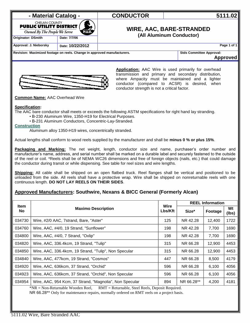
- Material Catalog - CONDUCTOR 5111.02
WIRE, AAC, BARE-STRANDED
(All Aluminum Conductor) Originator: DSmith Date: 7/7/06
Approval: J. Nieborsky Date: 10/22/2012 Page 1 of 1
Revision: Maximized footage on reels. Change in approved manufacturers. Stds Committee Approval: Approved
5111.02 Wire, Bare Stranded AAC
Application: AAC Wire is used primarily for overhead transmission and primary and secondary distribution, where Ampacity must be maintained and a lighter conductor (compared to ACSR) is desired, when conductor strength is not a critical factor.
Common Name: AAC Overhead Wire Specification: The AAC bare conductor shall meets or exceeds the following ASTM specifications for right hand lay stranding.
• B-230 Aluminum Wire, 1350-H19 for Electrical Purposes. • B-231 Aluminum Conductors, Concentric-Lay-Stranded.
Construction Aluminum alloy 1350-H19 wires, concentrically stranded.
Actual lengths shall conform to wood reels supplied by the manufacturer and shall be minus 0 % or plus 15%. Packaging and Marking: The net weight, length, conductor size and name, purchaser’s order number and manufacturer’s name, address, and serial number shall be marked on a durable label and securely fastened to the outside of the reel or coil. *Reels shall be of NEMA WC26 dimensions and free of foreign objects (nails, etc.) that could damage the conductor during transit or while dispensing. See table for reel sizes and wire lengths. Shipping: All cable shall be shipped on an open flatbed truck. Reel flanges shall be vertical and positioned to be unloaded from the side. All reels shall have a protective wrap. Wire shall be shipped on nonreturnable reels with one continuous length. DO NOT LAY REELS ON THEIR SIDES. Approved Manufacturers: Southwire, Nexans & BICC General (Formerly Alcan)
Item No Maximo Description Wire
Lbs/Kft
REEL Information
Size* Footage Wt
(lbs)
034730 Wire, #2/0 AAC, 7strand, Bare, "Aster" 125 NR 42.28 12,400 1722
034760 Wire, AAC, #4/0, 19 Strand, "Sunflower" 198 NR 42.28 7,700 1690
034800 Wire, AAC, #4/0, 7 Strand, "Oxlip" 198 NR 42.28 7,700 1690
034820 Wire, AAC, 336.4kcm, 19 Strand, "Tulip" 315 NR 66.28 12,900 4453
034850 Wire, AAC, 336.4kcm, 19 Strand, "Tulip", Non Specular 315 NR 66.28 12,900 4453
034840 Wire, AAC, 477kcm, 19 Strand, "Cosmos" 447 NR 66.28 8,500 4179
034920 Wire, AAC, 636kcm, 37 Strand, "Orchid" 596 NR 66.28 6,100 4056
034923 Wire, AAC, 636kcm, 37 Strand, "Orchid", Non Specular 596 NR 66.28 6,100 4056
034954 Wire, AAC, 954 Kcm, 37 Strand, "Magnolia", Non Specular 894 NR 66.28** 4,200 4181 *NR = Non-Returnable Wooden Reel, RMT = Returnable, Steel Reels, Deposit Required.
NR 66.28** Only for maintenance repairs, normally ordered on RMT reels on a project basis.
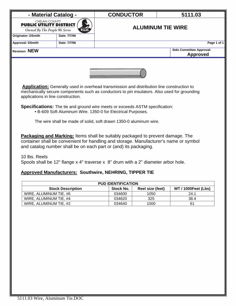
- Material Catalog - CONDUCTOR 5111.03
Originator: DSmith Date: 7/7/06
ALUMINUM TIE WIRE
Approval: DSmith Date: 7/7/06 Page 1 of 1
Revision: NEW Stds Committee Approval: Approved
5111.03 Wire, Aluminum Tie.DOC
Application: Generally used in overhead transmission and distribution line construction to mechanically secure components such as conductors to pin insulators. Also used for grounding applications in line construction. Specifications: The tie and ground wire meets or exceeds ASTM specification:
• B-609 Soft Aluminum Wire. 1350-0 for Electrical Purposes. The wire shall be made of solid, soft drawn 1350-0 aluminum wire.
Packaging and Marking: Items shall be suitably packaged to prevent damage. The container shall be convenient for handling and storage. Manufacturer’s name or symbol and catalog number shall be on each part or (and) its packaging. 10 lbs. Reels Spools shall be 12" flange x 4" traverse x 8" drum with a 2" diameter arbor hole. Approved Manufacturers: Southwire, NEHRING, TIPPER TIE
PUD IDENTIFICATION Stock Description Stock No. Reel size (feet) WT / 1000Feet (Lbs)
WIRE, ALUMINUM TIE, #6 034600 1050 24.1 WIRE, ALUMINUM TIE, #4 034620 325 38.4 WIRE, ALUMINUM TIE, #2 034640 1000 61
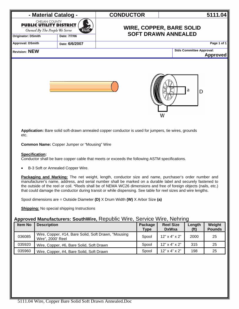
- Material Catalog - CONDUCTOR 5111.04
Originator: DSmith Date: 7/7/06
WIRE, COPPER, BARE SOLID
SOFT DRAWN ANNEALED Approval: DSmith Date: 6/6/2007 Page 1 of 1
Revision: NEW Stds Committee Approval: Approved
5111.04 Wire, Copper Bare Solid Soft Drawn Annealed.Doc
Application: Bare solid soft-drawn annealed copper conductor is used for jumpers, tie wires, grounds etc. Common Name: Copper Jumper or “Mousing” Wire Specification: Conductor shall be bare copper cable that meets or exceeds the following ASTM specifications.
• B-3 Soft or Annealed Copper Wire.
Packaging and Marking: The net weight, length, conductor size and name, purchaser’s order number and manufacturer’s name, address, and serial number shall be marked on a durable label and securely fastened to the outside of the reel or coil. *Reels shall be of NEMA WC26 dimensions and free of foreign objects (nails, etc.) that could damage the conductor during transit or while dispensing. See table for reel sizes and wire lengths. Spool dimensions are = Outside Diameter (D) X Drum Width (W) X Arbor Size (a) Shipping: No special shipping Instructions
Approved Manufacturers: SouthWire, Republic Wire, Service Wire, Nehring Item No Description Package
Type Reel Size DxWxa
Length (ft)
Weight Pounds
036085 Wire, Copper, #14, Bare Solid, Soft Drawn, "Mousing Wire", 2000' Reel Spool 12” x 4” x 2” 2000 25
035920 Wire, Copper, #6, Bare Solid, Soft Drawn Spool 12” x 4” x 2” 315 25 035960 Wire, Copper, #4, Bare Soild, Soft Drawn Spool 12” x 4” x 2” 198 25
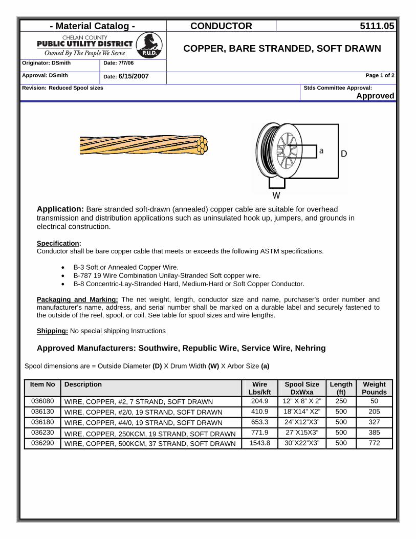
- Material Catalog - CONDUCTOR 5111.05
Originator: DSmith Date: 7/7/06
COPPER, BARE STRANDED, SOFT DRAWN
Approval: DSmith Date: 6/15/2007 Page 1 of 2
Revision: Reduced Spool sizes Stds Committee Approval: Approved
Application: Bare stranded soft-drawn (annealed) copper cable are suitable for overhead transmission and distribution applications such as uninsulated hook up, jumpers, and grounds in electrical construction. Specification: Conductor shall be bare copper cable that meets or exceeds the following ASTM specifications.
• B-3 Soft or Annealed Copper Wire. • B-787 19 Wire Combination Unilay-Stranded Soft copper wire. • B-8 Concentric-Lay-Stranded Hard, Medium-Hard or Soft Copper Conductor.
Packaging and Marking: The net weight, length, conductor size and name, purchaser’s order number and manufacturer’s name, address, and serial number shall be marked on a durable label and securely fastened to the outside of the reel, spool, or coil. See table for spool sizes and wire lengths. Shipping: No special shipping Instructions Approved Manufacturers: Southwire, Republic Wire, Service Wire, Nehring
Spool dimensions are = Outside Diameter (D) X Drum Width (W) X Arbor Size (a)
Item No Description Wire
Lbs/kft Spool Size
DxWxa Length
(ft) Weight Pounds
036080 WIRE, COPPER, #2, 7 STRAND, SOFT DRAWN 204.9 12” X 8” X 2” 250 50 036130 WIRE, COPPER, #2/0, 19 STRAND, SOFT DRAWN 410.9 18”X14” X2” 500 205 036180 WIRE, COPPER, #4/0, 19 STRAND, SOFT DRAWN 653.3 24”X12”X3” 500 327 036230 WIRE, COPPER, 250KCM, 19 STRAND, SOFT DRAWN 771.9 27”X15X3” 500 385 036290 WIRE, COPPER, 500KCM, 37 STRAND, SOFT DRAWN 1543.8 30”X22”X3” 500 772
- Material Catalog - CONDUCTOR 5111.05
Originator: DSmith Date: 7/7/06
COPPER, BARE STRANDED, SOFT DRAWN
Approval: DSmith Date: 6/15/2007 Page 2 of 2
Revision: Reduced Spool sizes Stds Committee Approval: Approved
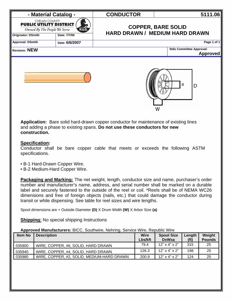
- Material Catalog - CONDUCTOR 5111.06
Originator: DSmith Date: 7/7/06
COPPER, BARE SOLID
HARD DRAWN / MEDIUM HARD DRAWN Approval: DSmith Date: 6/6/2007 Page 1 of 1
Revision: NEW Stds Committee Approval: Approved
Application: Bare solid hard-drawn copper conductor for maintenance of existing lines and adding a phase to existing spans. Do not use these conductors for new construction. Specification: Conductor shall be bare copper cable that meets or exceeds the following ASTM specifications.
• B-1 Hard-Drawn Copper Wire. • B-2 Medium-Hard Copper Wire.
Packaging and Marking: The net weight, length, conductor size and name, purchaser’s order number and manufacturer’s name, address, and serial number shall be marked on a durable label and securely fastened to the outside of the reel or coil. *Reels shall be of NEMA WC26 dimensions and free of foreign objects (nails, etc.) that could damage the conductor during transit or while dispensing. See table for reel sizes and wire lengths. Spool dimensions are = Outside Diameter (D) X Drum Width (W) X Arbor Size (a) Shipping: No special shipping Instructions
Approved Manufacturers: BICC, Southwire, Nehring, Service Wire, Republic Wire
Item No Description Wire Lbs/kft
Spool Size DxWxa
Length (ft)
Weight Pounds
035900 WIRE, COPPER, #6, SOLID, HARD DRAWN 79.4 12” x 4” x 2” 315 25
035940 WIRE, COPPER, #4, SOLID, HARD DRAWN 126.3 12” x 4” x 2” 198 25 035980 WIRE, COPPER, #2, SOLID, MEDIUM-HARD DRAWN 200.9 12” x 4” x 2” 124 25
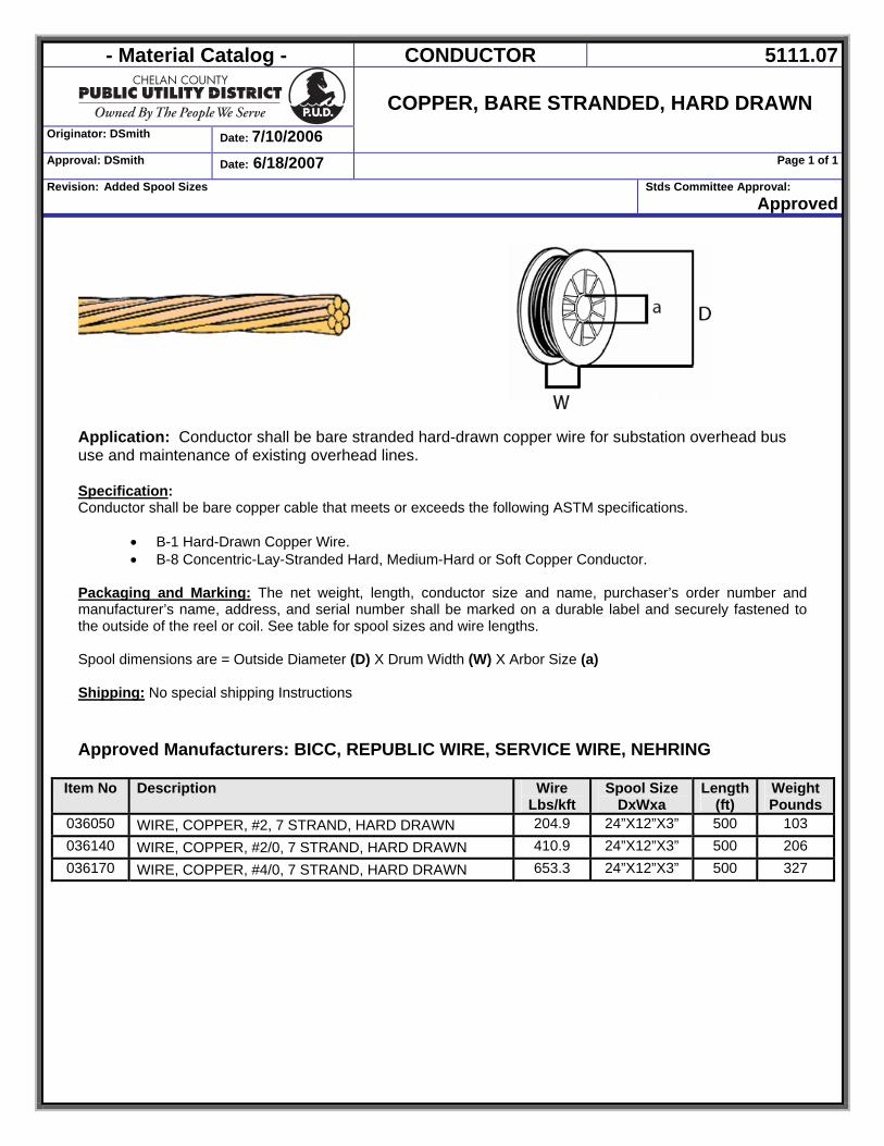
- Material Catalog - CONDUCTOR 5111.07
Originator: DSmith Date: 7/10/2006
COPPER, BARE STRANDED, HARD DRAWN
Approval: DSmith Date: 6/18/2007 Page 1 of 1
Revision: Added Spool Sizes Stds Committee Approval: Approved
Application: Conductor shall be bare stranded hard-drawn copper wire for substation overhead bus use and maintenance of existing overhead lines. Specification: Conductor shall be bare copper cable that meets or exceeds the following ASTM specifications.
• B-1 Hard-Drawn Copper Wire. • B-8 Concentric-Lay-Stranded Hard, Medium-Hard or Soft Copper Conductor.
Packaging and Marking: The net weight, length, conductor size and name, purchaser’s order number and manufacturer’s name, address, and serial number shall be marked on a durable label and securely fastened to the outside of the reel or coil. See table for spool sizes and wire lengths. Spool dimensions are = Outside Diameter (D) X Drum Width (W) X Arbor Size (a) Shipping: No special shipping Instructions Approved Manufacturers: BICC, REPUBLIC WIRE, SERVICE WIRE, NEHRING
Item No Description Wire Lbs/kft
Spool Size DxWxa
Length (ft)
Weight Pounds
036050 WIRE, COPPER, #2, 7 STRAND, HARD DRAWN 204.9 24”X12”X3” 500 103 036140 WIRE, COPPER, #2/0, 7 STRAND, HARD DRAWN 410.9 24”X12”X3” 500 206 036170 WIRE, COPPER, #4/0, 7 STRAND, HARD DRAWN 653.3 24”X12”X3” 500 327
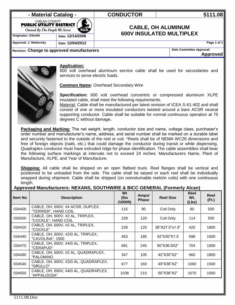
- Material Catalog - CONDUCTOR 5111.08
CABLE, OH ALUMINUM
600V INSULATED MULTIPLEX Originator: DSmith Date: 12/14/2006
Approval: J. Nieborsky Date: 12/04/2012 Page 1 of 1
Revision: Change to approved manufacturers Stds Committee Approval: Approved
5111.08.Doc
Application: 600 volt overhead aluminum service cable shall be used for secondaries and services to serve electric loads. Common Name: Overhead Secondary Wire Specification: 600 volt overhead concentric or compressed aluminum XLPE insulated cable, shall meet the following requirements. Material: Cable shall be manufactured per latest revision of ICEA S-61-402 and shall consist of one or more insulated conductors twisted around a bare ACSR neutral supporting conductor. Cable shall be suitable for normal continuous operation at 75 degrees C without damage.
Packaging and Marking: The net weight, length, conductor size and name, voltage class, purchaser’s order number and manufacturer’s name, address, and serial number shall be marked on a durable label and securely fastened to the outside of the reel or coil. *Reels shall be of NEMA WC26 dimensions and free of foreign objects (nails, etc.) that could damage the conductor during transit or while dispensing. Quadraplex conductor must have extruded ridge for phase identification. The cable assemblies shall bear the following surface markings at intervals not to exceed 24 inches: Manufacturers Name, Plant of Manufacture, XLPE, and Year of Manufacture. Shipping: All cable shall be shipped on an open flatbed truck. Reel flanges shall be vertical and positioned to be unloaded from the side. The cable shall be tarped or each reel shall be individually wrapped during shipment. Cable shall be shipped (on nonreturnable reels/in coils) with one continuous length.
Approved Manufacturers: NEXANS, SOUTHWIRE & BICC GENERAL (Formerly Alcan)
Item No Description Wt (lbs
/1000ft)
Amps/Phase Reel Size
Reel Wt.
(Lbs)
Reel (Ft.)
034400 CABLE, OH, 600V, #4 ACSR, DUPLEX, "TERRIER", HAND COIL 115 90 Coil Only 60 500
034500 CABLE, OH, 600V, #2 AL, TRIPLEX, "COCKLE", HAND COIL 228 120 Coil Only 114 500
034420 CABLE, OH, 600V, #2 AL, TRIPLEX, "COCKLE" 228 120 36”X27.5”x1.5” 420 1800
034440 CABLE, OH, 600V, #2/0 AL, TRIPLEX, "CAVOLINA", 1500 453 185 42”X30”X1.5 698 1500
034470 CABLE, OH, 600V, #4/0 AL, TRIPLEX, "CERAPUD" 681 245 50”X36.5X2” 704 1000
034490 CABLE, OH, 600V, #2 AL, QUADRAPLEX, "PALOMINO 347 105 42”X30”X2” 660 1800
034540 CABLE, OH, 600V, #2/0 AL, QUADRAPLEX, "GRULLO” 677 160 49”X36”X2” 1060 1500
034550 CABLE, OH, 600V, #4/0 AL, QUADRAPLEX, "APPALOOSA" 1038 210 50”X36”X2” 1070 1000
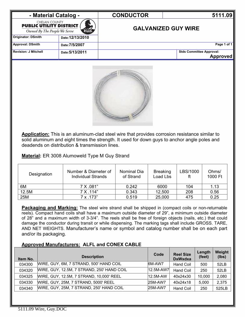
- Material Catalog - CONDUCTOR 5111.09
GALVANIZED GUY WIRE
Originator: DSmith Date:12/13/2010
Approval: DSmith Date:7/5/2007 Page 1 of 1
Revision: J Mitchell Date:5/13/2011 Stds Committee Approval: Approved
5111.09 Wire, Guy.DOC
Application: This is an aluminum-clad steel wire that provides corrosion resistance similar to solid aluminum and eight times the strength. It used for down guys to anchor angle poles and deadends on distribution & transmission lines. Material: ER 3008 Alumoweld Type M Guy Strand
Designation Number & Diameter of Individual Strands
Nominal Dia of Strand
Breaking Load Lbs
LBS/1000 ft
Ohms/ 1000 Ft
6M 7 X .081” 0.242 6000 104 1.13 12.5M 7 X .114” 0.343 12,500 208 0.56 25M 7 x .173” 0.519 25,000 475 0.25 Packaging and Marking: The steel wire strand shall be shipped in (compact coils or non-returnable reels). Compact hand coils shall have a maximum outside diameter of 29”, a minimum outside diameter of 28” and a maximum width of 3-3/4”. The reels shall be free of foreign objects (nails, etc.) that could damage the conductor during transit or while dispensing. The marking tags shall include GROSS. TARE, AND NET WEIGHTS. Manufacturer’s name or symbol and catalog number shall be on each part and/or its packaging. Approved Manufacturers: ALFL and CONEX CABLE
Item No.
Description Code
Reel Size DxWxdxa
Length (feet)
Weight (lbs)
034300 WIRE, GUY, 6M, 7 STRAND, 500' HAND COIL 6M-AW7 Hand Coil 500 52LB 034320 WIRE, GUY, 12.5M, 7 STRAND, 250' HAND COIL 12.5M-AW7 Hand Coil 250 52LB 034325 WIRE, GUY, 12.5M, 7 STRAND, 10,000' REEL 12.5M-AW 40x24x30 10,000 2,080 034330 WIRE, GUY, 25M, 7 STRAND, 5000' REEL 25M-AW7 40x24x18 5,000 2,375 034340 WIRE, GUY, 25M, 7 STRAND, 250' HAND COIL 25M-AW7 Hand Coil 250 525LB
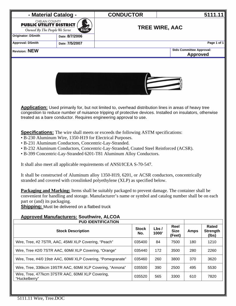
- Material Catalog - CONDUCTOR 5111.11
Originator: DSmith Date: 8/7/2006
TREE WIRE, AAC
Approval: DSmith Date: 7/5/2007 Page 1 of 1
Revision: NEW Stds Committee Approval: Approved
5111.11 Wire, Tree.DOC
Application: Used primarily for, but not limited to, overhead distribution lines in areas of heavy tree congestion to reduce number of nuisance tripping of protective devices. Installed on insulators, otherwise treated as a bare conductor. Requires engineering approval to use. Specifications: The wire shall meets or exceeds the following ASTM specifications: • B-230 Aluminum Wire, 1350-H19 for Electrical Purposes. • B-231 Aluminum Conductors, Concentric-Lay-Stranded. • B-232 Aluminum Conductors, Concentric-Lay-Stranded, Coated Steel Reinforced (ACSR). • B-399 Concentric-Lay-Stranded 6201-T81 Aluminum Alloy Conductors. It shall also meet all applicable requirements of ANSI/ICEA S-70-547. It shall be constructed of Aluminum alloy 1350-H19, 6201, or ACSR conductors, concentrically stranded and covered with crosslinked polyethylene (XLP) as specified below. Packaging and Marking: Items shall be suitably packaged to prevent damage. The container shall be convenient for handling and storage. Manufacturer’s name or symbol and catalog number shall be on each part or (and) its packaging. Shipping: Must be delivered on a flatbed truck Approved Manufacturers: Southwire, ALCOA
PUD IDENTIFICATION
Stock Description Stock No.
Lbs / 1000’
Reel Size
(Feet) Amps
Rated Strength
(lbs) Wire, Tree, #2 7STR, AAC, 45Mil XLP Covering, “Peach” 035400 84 7500 180 1210
Wire, Tree #2/0 7STR AAC, 60Mil XLP Covering, “Orange” 035440 172 3500 280 2260
Wire, Tree, #4/0 19str AAC, 60Mil XLP Covering, “Pomegranate” 035460 260 3800 370 3620
Wire, Tree, 336kcm 19STR AAC, 60Mil XLP Covering, “Annona” 035500 390 2500 495 5530
Wire, Tree, 477kcm 37STR AAC, 60Mil XLP Covering, “Huckelberry” 035520 565 3300 610 7820
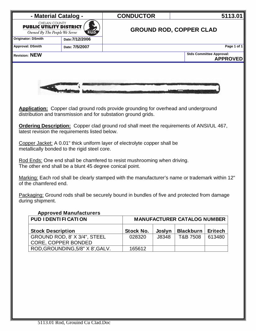
- Material Catalog - CONDUCTOR 5113.01
Originator: DSmith Date:7/12/2006
GROUND ROD, COPPER CLAD
Approval: DSmith Date: 7/5/2007 Page 1 of 1
Revision: NEW Stds Committee Approval: APPROVED
5113.01 Rod, Grouind Cu Clad.Doc
Application: Copper clad ground rods provide grounding for overhead and underground distribution and transmission and for substation ground grids.
Ordering Description: Copper clad ground rod shall meet the requirements of ANSI/UL 467, latest revision the requirements listed below. Copper Jacket: A 0.01" thick uniform layer of electrolyte copper shall be metallically bonded to the rigid steel core. Rod Ends: One end shall be chamfered to resist mushrooming when driving. The other end shall be a blunt 45 degree conical point. Marking: Each rod shall be clearly stamped with the manufacturer’s name or trademark within 12" of the chamfered end. Packaging: Ground rods shall be securely bound in bundles of five and protected from damage during shipment.
Approved Manufacturers
PUD IDENTIFICATION MANUFACTURER CATALOG NUMBER
Stock Description Stock No. Joslyn Blackburn Eritech GROUND ROD, 8' X 3/4", STEEL CORE, COPPER BONDED
028320 J8348 T&B 7508 613480
ROD,GROUNDING,5/8" X 8',GALV. 165612
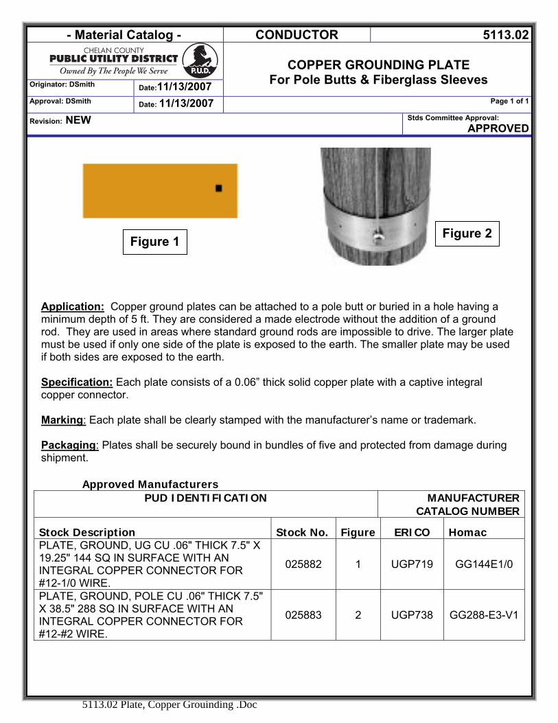
- Material Catalog - CONDUCTOR 5113.02
Originator: DSmith Date:11/13/2007
COPPER GROUNDING PLATE
For Pole Butts & Fiberglass Sleeves Approval: DSmith Date: 11/13/2007 Page 1 of 1
Revision: NEW Stds Committee Approval: APPROVED
5113.02 Plate, Copper Grouinding .Doc
Application: Copper ground plates can be attached to a pole butt or buried in a hole having a minimum depth of 5 ft. They are considered a made electrode without the addition of a ground rod. They are used in areas where standard ground rods are impossible to drive. The larger plate must be used if only one side of the plate is exposed to the earth. The smaller plate may be used if both sides are exposed to the earth.
Specification: Each plate consists of a 0.06” thick solid copper plate with a captive integral copper connector. Marking: Each plate shall be clearly stamped with the manufacturer’s name or trademark. Packaging: Plates shall be securely bound in bundles of five and protected from damage during shipment.
Approved Manufacturers
PUD IDENTIFICATION MANUFACTURER CATALOG NUMBER
Stock Description Stock No. Figure ERICO Homac PLATE, GROUND, UG CU .06" THICK 7.5" X 19.25" 144 SQ IN SURFACE WITH AN INTEGRAL COPPER CONNECTOR FOR #12-1/0 WIRE.
025882 1 UGP719 GG144E1/0
PLATE, GROUND, POLE CU .06" THICK 7.5" X 38.5" 288 SQ IN SURFACE WITH AN INTEGRAL COPPER CONNECTOR FOR #12-#2 WIRE.
025883 2 UGP738 GG288-E3-V1
Figure 2Figure 1
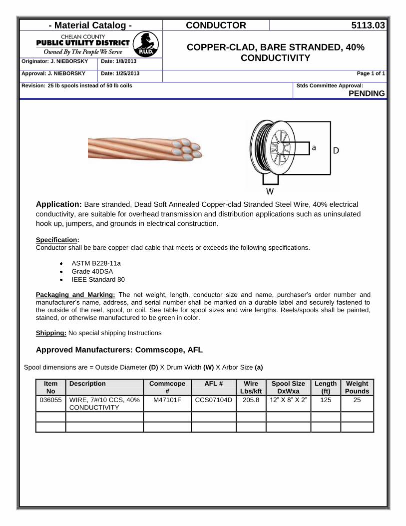
- Material Catalog - CONDUCTOR 5113.03
COPPER-CLAD, BARE STRANDED, 40%
CONDUCTIVITY Originator: J. NIEBORSKY Date: 1/8/2013
Approval: J. NIEBORSKY Date: 1/25/2013 Page 1 of 1
Revision: 25 lb spools instead of 50 lb coils Stds Committee Approval: PENDING
Application: Bare stranded, Dead Soft Annealed Copper-clad Stranded Steel Wire, 40% electrical conductivity, are suitable for overhead transmission and distribution applications such as uninsulated hook up, jumpers, and grounds in electrical construction. Specification: Conductor shall be bare copper-clad cable that meets or exceeds the following specifications.
ASTM B228-11a Grade 40DSA IEEE Standard 80
Packaging and Marking: The net weight, length, conductor size and name, purchaser’s order number and manufacturer’s name, address, and serial number shall be marked on a durable label and securely fastened to the outside of the reel, spool, or coil. See table for spool sizes and wire lengths. Reels/spools shall be painted, stained, or otherwise manufactured to be green in color. Shipping: No special shipping Instructions Approved Manufacturers: Commscope, AFL
Spool dimensions are = Outside Diameter (D) X Drum Width (W) X Arbor Size (a)
Item No
Description Commcope #
AFL # Wire Lbs/kft
Spool Size DxWxa
Length (ft)
Weight Pounds
036055 WIRE, 7#/10 CCS, 40% CONDUCTIVITY
M47101F CCS07104D 205.8 12” X 8” X 2” 125 25
- Material Catalog - LABELS & SIGNS 5200
Originator: DSmith Date:2/8/2007
LABELS & SIGNS
Approval: DSmith Date: 2/8/2007 Page 1 of 1
Revision: NEW Stds Committee Approval: Approved
5200 LABELS AND SIGNS.DOC
LABELS & SIGNS
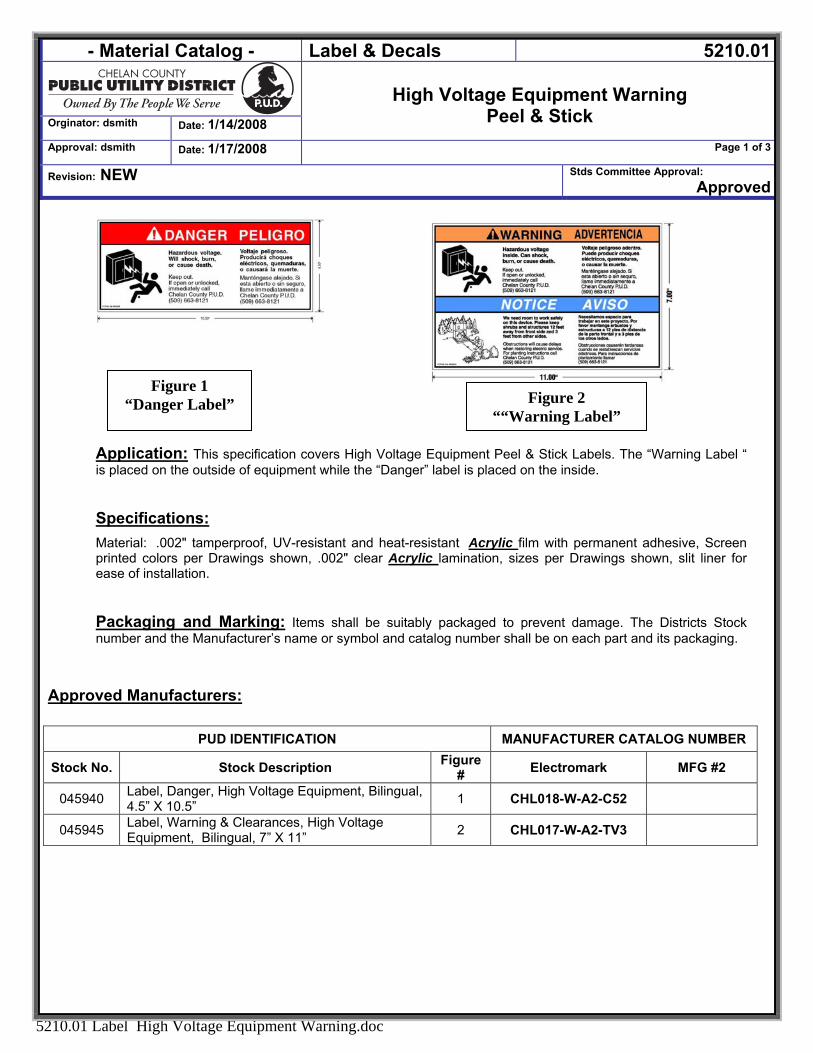
- Material Catalog - Label & Decals 5210.01
Orginator: dsmith Date: 1/14/2008
High Voltage Equipment Warning
Peel & Stick Approval: dsmith Date: 1/17/2008 Page 1 of 3
Revision: NEW Stds Committee Approval: Approved
5210.01 Label High Voltage Equipment Warning.doc
Application: This specification covers High Voltage Equipment Peel & Stick Labels. The “Warning Label “ is placed on the outside of equipment while the “Danger” label is placed on the inside.
Specifications: Material: .002" tamperproof, UV-resistant and heat-resistant Acrylic film with permanent adhesive, Screen printed colors per Drawings shown, .002" clear Acrylic lamination, sizes per Drawings shown, slit liner for ease of installation.
Packaging and Marking: Items shall be suitably packaged to prevent damage. The Districts Stock number and the Manufacturer’s name or symbol and catalog number shall be on each part and its packaging.
Approved Manufacturers:
PUD IDENTIFICATION MANUFACTURER CATALOG NUMBER
Stock No. Stock Description Figure # Electromark MFG #2
045940 Label, Danger, High Voltage Equipment, Bilingual, 4.5” X 10.5” 1 CHL018-W-A2-C52
045945 Label, Warning & Clearances, High Voltage Equipment, Bilingual, 7” X 11” 2 CHL017-W-A2-TV3
Figure 1 “Danger Label” Figure 2
““Warning Label”
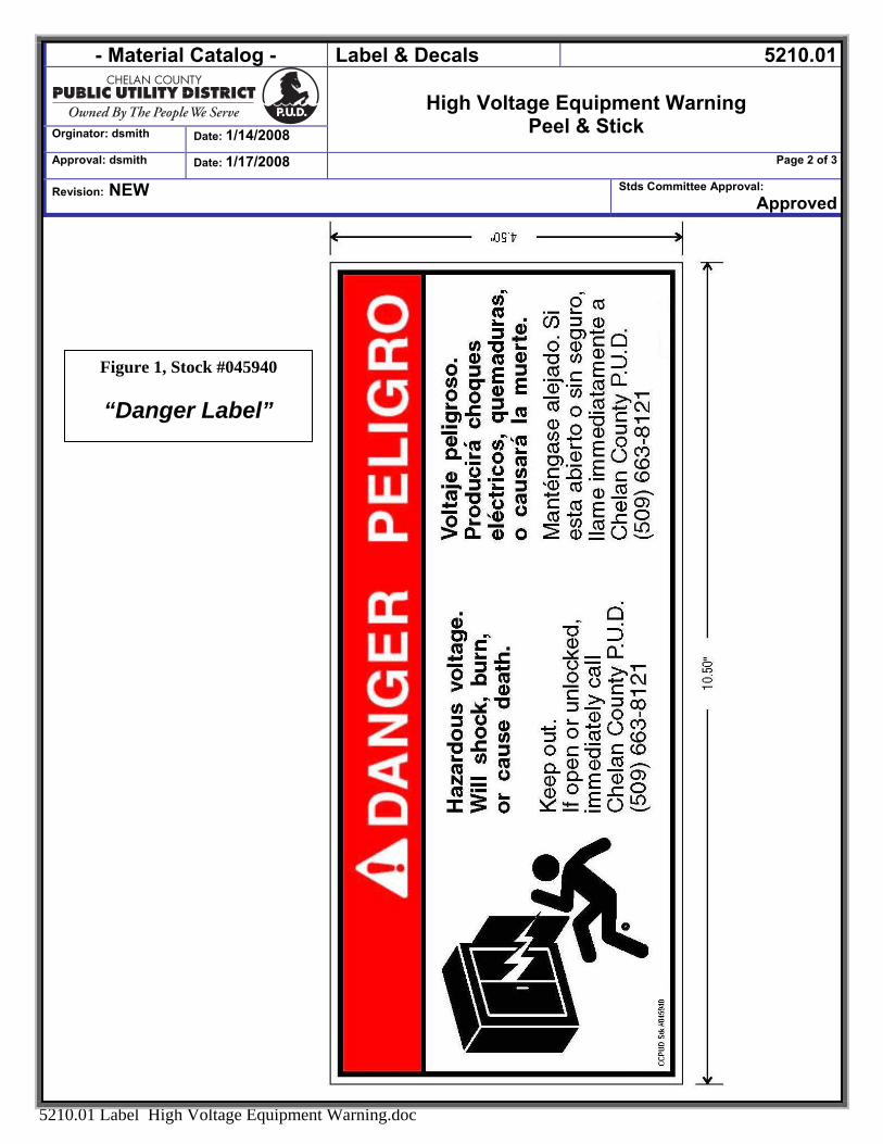
- Material Catalog - 5210.01Label & Decals
High Voltage Equipment Warning
Peel & Stick Orginator: dsmith Date: 1/14/2008
Approval: dsmith Date: 1/17/2008 Page 2 of 3
Revision: NEW oval: Approved
Stds Committee Appr
5210.01 Label High Voltage Equipment Warning.doc
Figure 1, Stock #045940
“Danger Label”
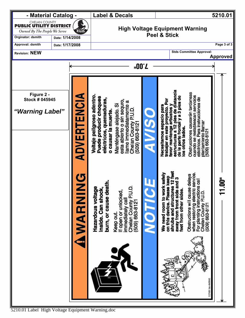
- Material Catalog - Label & Decals 5210.01
1/14/2008
High Voltage Equipment Warning
Peel & Stick Orginator: dsmith Date:
Approval: dsmith Date: 1/17/2008 Page 3 of 3
Revision: NEW Stds Committee Approval: Approved
5210.01 Label High Voltage Equipment Warning.doc
Figure 2 - Stock # 045945
“Warning Label”
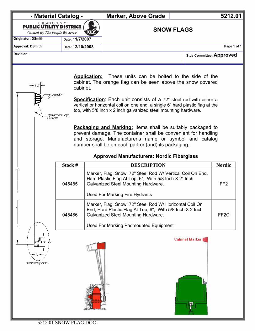
- Material Catalog - Marker, Above Grade 5212.01
SNOW FLAGS
Originator: DSmith Date: 11/7/2007
Approval: DSmith Date: 12/10/2008 Page 1 of 1
Revision: Stds Committee: Approved
5212.01 SNOW FLAG.DOC
Application: These units can be bolted to the side of the cabinet. The orange flag can be seen above the snow covered cabinet. Specification: Each unit consists of a 72" steel rod with either a vertical or horizontal coil on one end, a single 6” hard plastic flag at the top, with 5/8 inch x 2 inch galvanized steel mounting hardware. Packaging and Marking: Items shall be suitably packaged to prevent damage. The container shall be convenient for handling and storage. Manufacturer’s name or symbol and catalog number shall be on each part or (and) its packaging.
Approved Manufacturers: Nordic Fiberglass
Stock # DESCRIPTION Nordic
045485
Marker, Flag, Snow, 72" Steel Rod W/ Vertical Coil On End, Hard Plastic Flag At Top, 6", With 5/8 Inch X 2” Inch Galvanized Steel Mounting Hardware. Used For Marking Fire Hydrants
FF2
045486
Marker, Flag, Snow, 72" Steel Rod W/ Horizontal Coil On End, Hard Plastic Flag At Top, 6", With 5/8 Inch X 2 Inch Galvanized Steel Mounting Hardware. Used For Marking Padmounted Equipment
FF2C
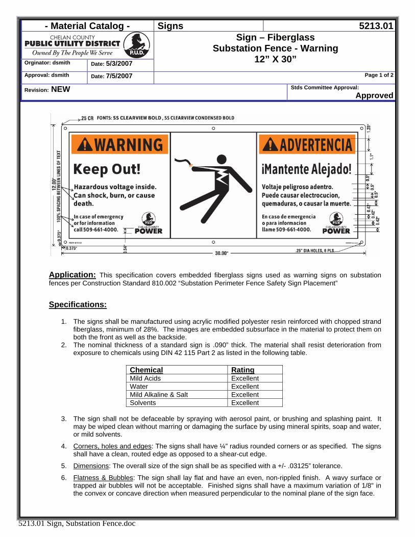
- Material Catalog - Signs 5213.01
Orginator: dsmith Date: 5/3/2007
Sign – Fiberglass Substation Fence - Warning
12” X 30” Approval: dsmith Date: 7/5/2007 Page 1 of 2
Revision: NEW Stds Committee Approval: Approved
5213.01 Sign, Substation Fence.doc
Application: This specification covers embedded fiberglass signs used as warning signs on substation fences per Construction Standard 810.002 “Substation Perimeter Fence Safety Sign Placement”
Specifications:
1. The signs shall be manufactured using acrylic modified polyester resin reinforced with chopped strand fiberglass, minimum of 28%. The images are embedded subsurface in the material to protect them on both the front as well as the backside.
2. The nominal thickness of a standard sign is .090” thick. The material shall resist deterioration from exposure to chemicals using DIN 42 115 Part 2 as listed in the following table.
Chemical Rating Mild Acids Excellent Water Excellent Mild Alkaline & Salt Excellent Solvents Excellent
3. The sign shall not be defaceable by spraying with aerosol paint, or brushing and splashing paint. It
may be wiped clean without marring or damaging the surface by using mineral spirits, soap and water, or mild solvents.
4. Corners, holes and edges: The signs shall have ¼” radius rounded corners or as specified. The signs shall have a clean, routed edge as opposed to a shear-cut edge.
5. Dimensions: The overall size of the sign shall be as specified with a +/- .03125” tolerance.
6. Flatness & Bubbles: The sign shall lay flat and have an even, non-rippled finish. A wavy surface or trapped air bubbles will not be acceptable. Finished signs shall have a maximum variation of 1/8" in the convex or concave direction when measured perpendicular to the nominal plane of the sign face.
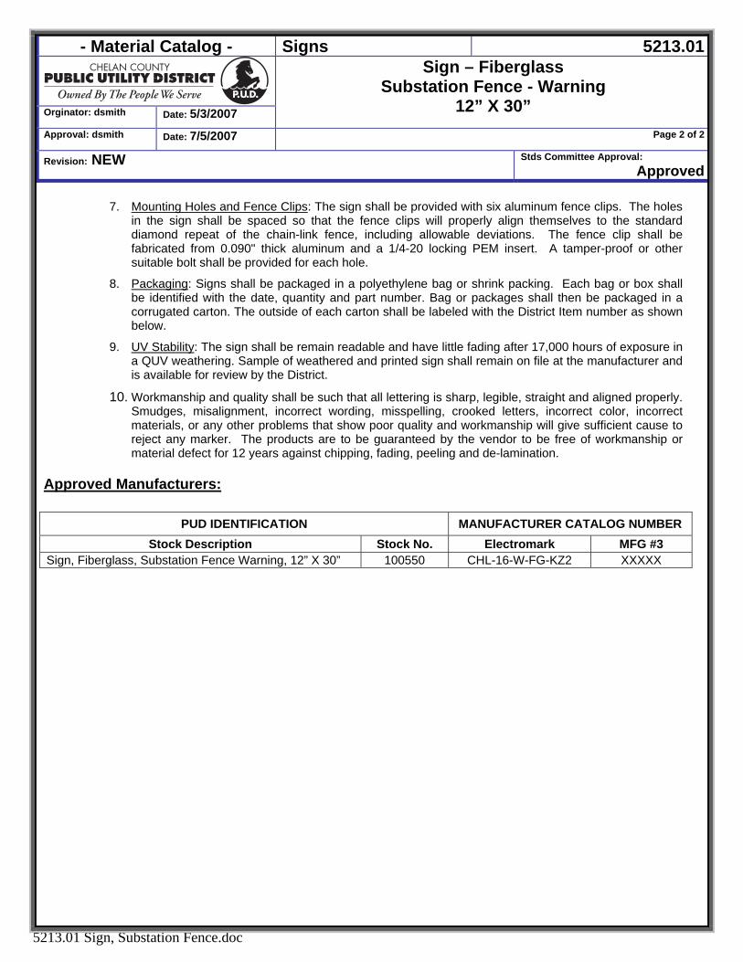
- Material Catalog - Signs 5213.01
Orginator: dsmith Date: 5/3/2007
Sign – Fiberglass Substation Fence - Warning
12” X 30” Approval: dsmith Date: 7/5/2007 Page 2 of 2
Revision: NEW Stds Committee Approval: Approved
5213.01 Sign, Substation Fence.doc
7. Mounting Holes and Fence Clips: The sign shall be provided with six aluminum fence clips. The holes in the sign shall be spaced so that the fence clips will properly align themselves to the standard diamond repeat of the chain-link fence, including allowable deviations. The fence clip shall be fabricated from 0.090" thick aluminum and a 1/4-20 locking PEM insert. A tamper-proof or other suitable bolt shall be provided for each hole.
8. Packaging: Signs shall be packaged in a polyethylene bag or shrink packing. Each bag or box shall be identified with the date, quantity and part number. Bag or packages shall then be packaged in a corrugated carton. The outside of each carton shall be labeled with the District Item number as shown below.
9. UV Stability: The sign shall be remain readable and have little fading after 17,000 hours of exposure in a QUV weathering. Sample of weathered and printed sign shall remain on file at the manufacturer and is available for review by the District.
10. Workmanship and quality shall be such that all lettering is sharp, legible, straight and aligned properly. Smudges, misalignment, incorrect wording, misspelling, crooked letters, incorrect color, incorrect materials, or any other problems that show poor quality and workmanship will give sufficient cause to reject any marker. The products are to be guaranteed by the vendor to be free of workmanship or material defect for 12 years against chipping, fading, peeling and de-lamination.
Approved Manufacturers:
PUD IDENTIFICATION MANUFACTURER CATALOG NUMBER Stock Description Stock No. Electromark MFG #3
Sign, Fiberglass, Substation Fence Warning, 12” X 30” 100550 CHL-16-W-FG-KZ2 XXXXX
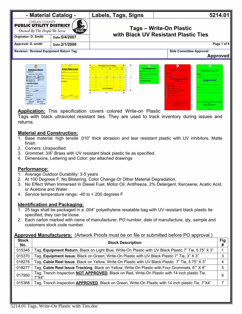
- Material Catalog - Labels, Tags, Signs 5214.01
Orginator: D. Smith Date:5/4/2007
Tags – Write-On Plastic
with Black UV Resistant Plastic Ties Approval: D. smith Date:2/1/2008 Page 1 of 6
Revision: Revised Equipment Return Tag Stds Committee Approval: Approved
5214.01 Tags, Write-On Plastic with Ties.doc
Application: This specification covers colored Write-on Plastic Tags with black ultraviolet resistant ties. They are used to track inventory during issues and returns.
DO NOT REMOVE
Material and Construction: 1. Base material: high tensile .010” thick abrasion and tear resistant plastic with UV inhibitors, Matte
finish. 2. Corners: Unspecified 3. Grommet: 3/8” Brass with UV resistant black plastic tie as specified. 4. Dimensions, Lettering and Color: per attached drawings Performance: 1. Average Outdoor Durability: 3-5 years 2. At 100 Degrees F, No Blistering, Color Change Or Other Material Degradation. 3. No Effect When Immersed In Diesel Fuel, Motor Oil, Antifreeze, 2% Detergent, Kerosene, Acetic Acid,
or Acetone and Water. 4. Service temperature range: -40 to + 200 degrees F Identification and Packaging: 1. 25 tags shall be packaged in a .004” polyethylene resalable bag with UV resistant black plastic tie
specified, they can be loose. 2. Each carton marked with name of manufacturer, PO number, date of manufacture, qty, sample and
customers stock code number.
Approved Manufacturers: (Artwork Proofs must be on file or submitted before PO approval.) Stock
No. Stock Description Fig #
015346 Tag, Equipment Return, Black on Light Blue, Write-On Plastic with UV Black Plastic 7” Tie, 5.75” X 3” 1 015370 Tag, Equipment Issue, Black on Green, Write-On Plastic with UV Black Plastic 7” Tie, 3” X 3” 3 018276 Tag, Cable Reel Issue, Black on Yellow, Write-On Plastic with UV Black Plastic 7” Tie, 5.75” X 3” 4 018277 Tag, Cable Reel Issue Tracking, Black on Yellow, Write-On Plastic with Four Grommets, 6”” X 8” 5
017950 Tag, Trench Inspection NOT APPROVED, Black on Red, Write-On Plastic with 14 inch plastic Tie, 7”X4” 6
015368 Tag, Trench Inspection APPROVED, Black on Green, Write-On Plastic with 14 inch plastic Tie, 7”X4” 7
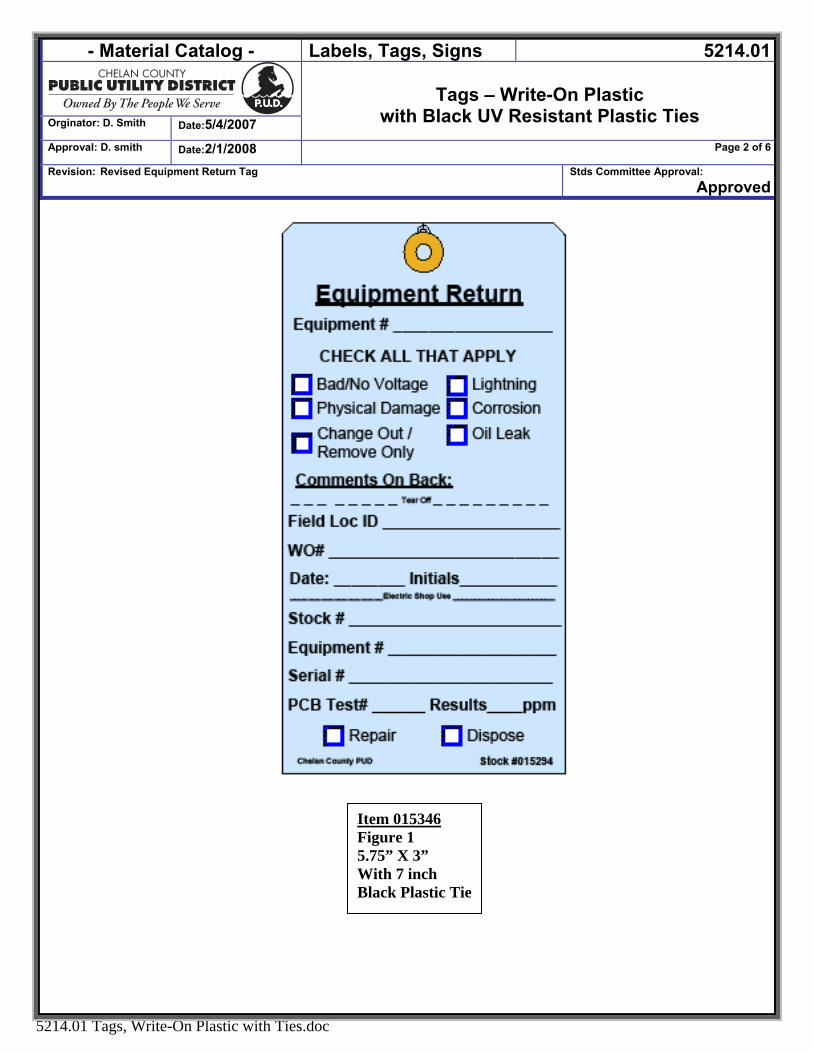
- Material Catalog - Labels, Tags, Signs 5214.01
Orginator: D. Smith Date:5/4/2007
Tags – Write-On Plastic
with Black UV Resistant Plastic Ties Approval: D. smith Date:2/1/2008 Page 2 of 6
Revision: Revised Equipment Return Tag Stds Committee Approval: Approved
5214.01 Tags, Write-On Plastic with Ties.doc
Item 015346 Figure 1 5.75” X 3” With 7 inch Black Plastic Tie
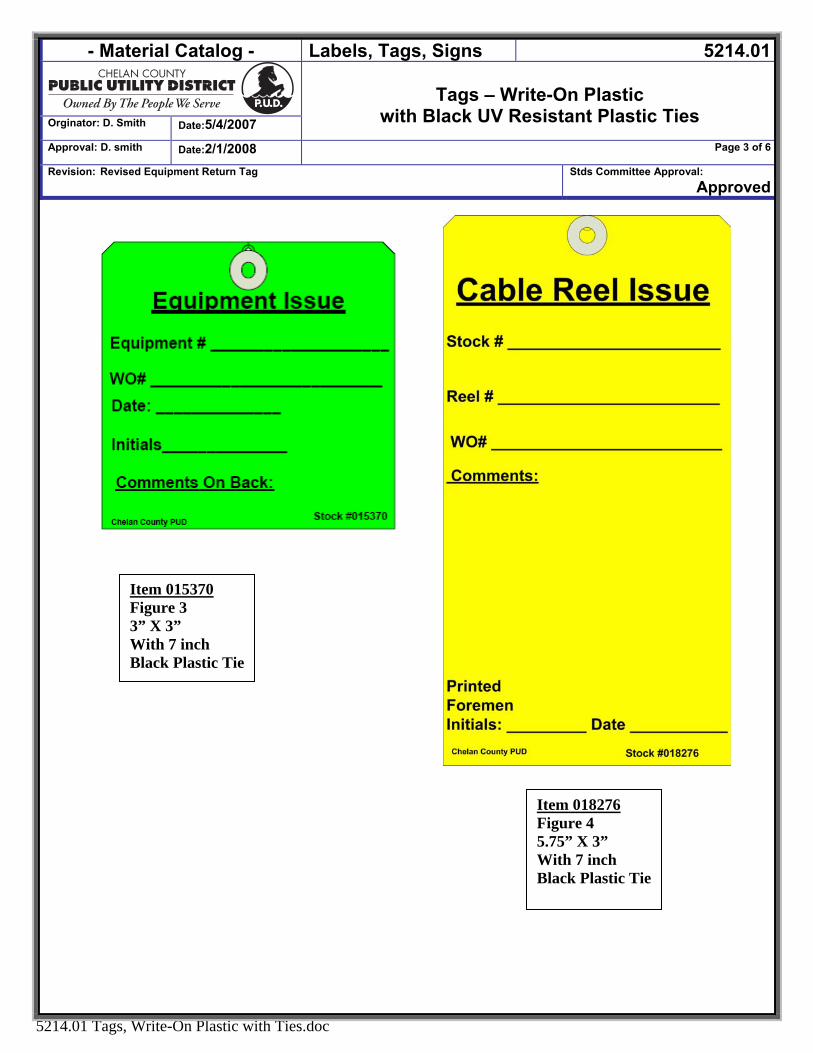
- Material Catalog - Labels, Tags, Signs 5214.01
Orginator: D. Smith Date:5/4/2007
Tags – Write-On Plastic
with Black UV Resistant Plastic Ties Approval: D. smith Date:2/1/2008 Page 3 of 6
Revision: Revised Equipment Return Tag Stds Committee Approval: Approved
5214.01 Tags, Write-On Plastic with Ties.doc
Item 015370 Figure 3 3” X 3” With 7 inch Black Plastic Tie
Item 018276 Figure 4 5.75” X 3” With 7 inch Black Plastic Tie
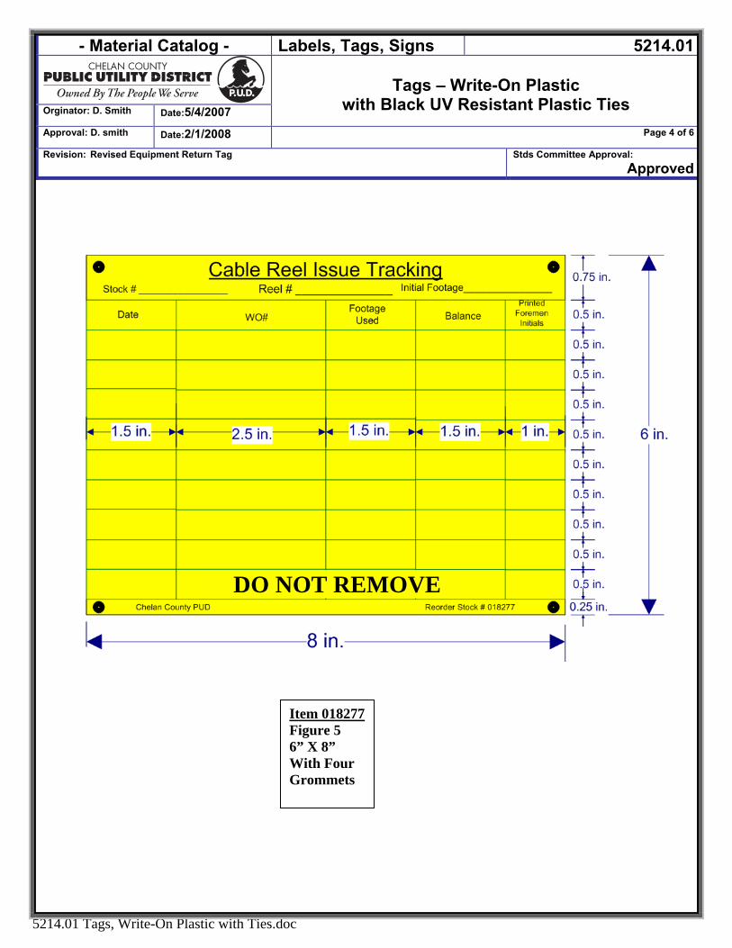
- Material Catalog - Labels, Tags, Signs 5214.01
Orginator: D. Smith Date:5/4/2007
Tags – Write-On Plastic
with Black UV Resistant Plastic Ties Approval: D. smith Date:2/1/2008 Page 4 of 6
Revision: Revised Equipment Return Tag Stds Committee Approval: Approved
5214.01 Tags, Write-On Plastic with Ties.doc
Item 018277Figure 5 6” X 8” With Four Grommets
DO NOT REMOVE
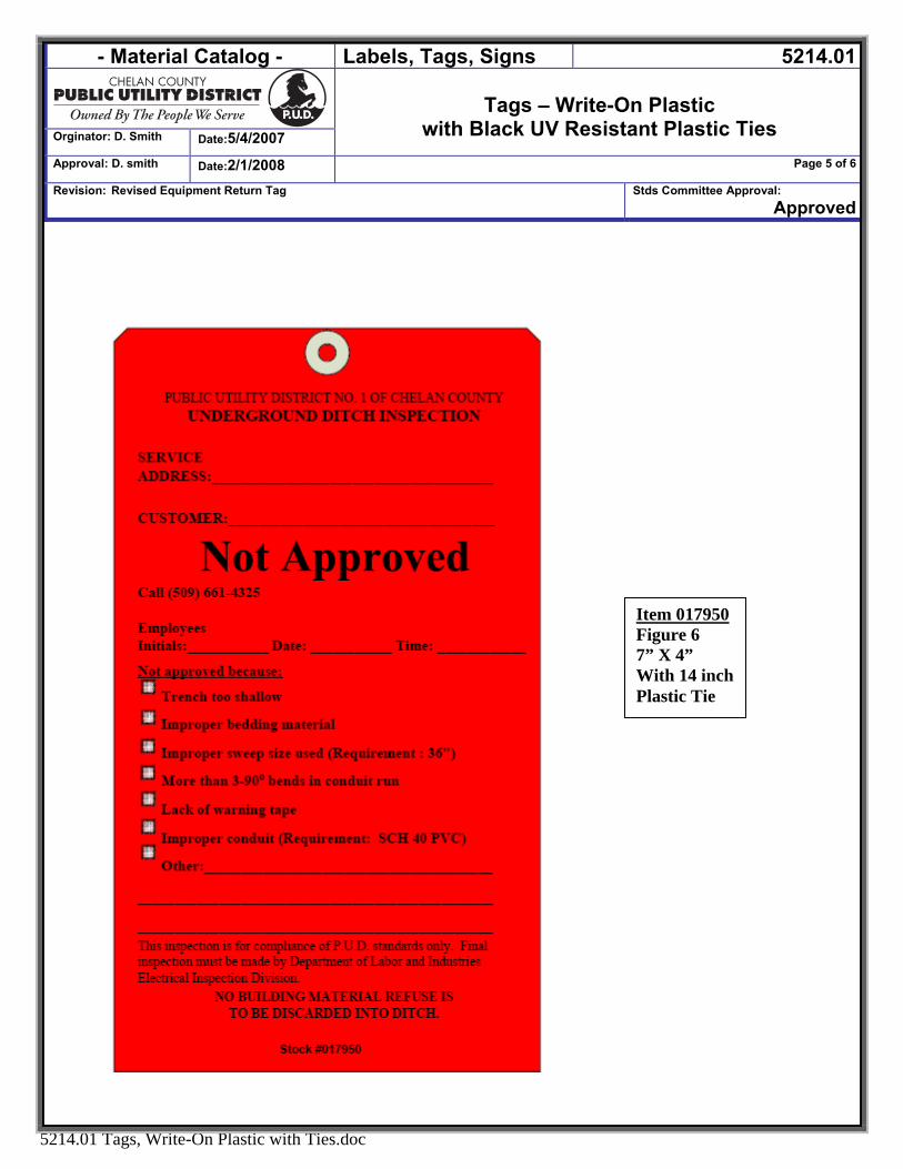
- Material Catalog - Labels, Tags, Signs 5214.01
Orginator: D. Smith Date:5/4/2007
Tags – Write-On Plastic
with Black UV Resistant Plastic Ties Approval: D. smith Date:2/1/2008 Page 5 of 6
Revision: Revised Equipment Return Tag Stds Committee Approval: Approved
5214.01 Tags, Write-On Plastic with Ties.doc
Item 017950Figure 6 7” X 4” With 14 inch Plastic Tie
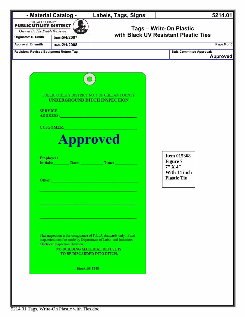
- Material Catalog - Labels, Tags, Signs 5214.01
Orginator: D. Smith Date:5/4/2007
Tags – Write-On Plastic
with Black UV Resistant Plastic Ties Approval: D. smith Date:2/1/2008 Page 6 of 6
Revision: Revised Equipment Return Tag Stds Committee Approval: Approved
5214.01 Tags, Write-On Plastic with Ties.doc
Item 015368 Figure 7 7” X 4” With 14 inch Plastic Tie

- Material Catalog - CHEMICALS 5300
Originator: DSmith Date:7/9/2007
CHEMICALS
Approval: DSmith Date: 7/9/2007 Page 1 of 1
Revision: NEW Stds Committee Approval: Approved
5300 CHEMICALS.DOC
CHEMICALS
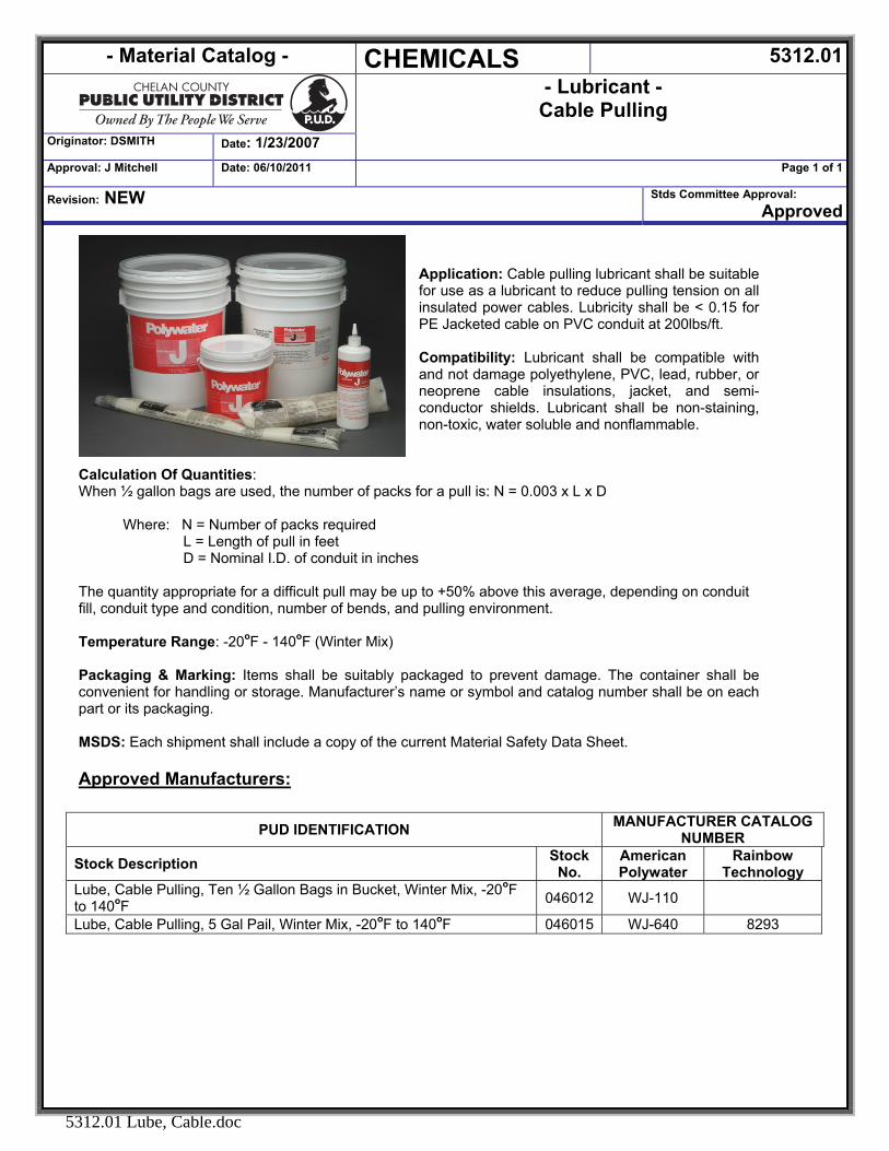
- Material Catalog - CHEMICALS 5312.01
- Lubricant - Cable Pulling
Originator: DSMITH Date: 1/23/2007 Approval: J Mitchell Date: 06/10/2011 Page 1 of 1
Revision: NEW Stds Committee Approval: Approved
Application: Cable pulling lubricant shall be suitable for use as a lubricant to reduce pulling tension on all insulated power cables. Lubricity shall be < 0.15 for PE Jacketed cable on PVC conduit at 200lbs/ft. Compatibility: Lubricant shall be compatible with and not damage polyethylene, PVC, lead, rubber, or neoprene cable insulations, jacket, and semi-conductor shields. Lubricant shall be non-staining, non-toxic, water soluble and nonflammable.
Calculation Of Quantities: When ½ gallon bags are used, the number of packs for a pull is: N = 0.003 x L x D Where: N = Number of packs required
L = Length of pull in feet D = Nominal I.D. of conduit in inches The quantity appropriate for a difficult pull may be up to +50% above this average, depending on conduit fill, conduit type and condition, number of bends, and pulling environment. Temperature Range: -20oF - 140oF (Winter Mix) Packaging & Marking: Items shall be suitably packaged to prevent damage. The container shall be convenient for handling or storage. Manufacturer’s name or symbol and catalog number shall be on each part or its packaging. MSDS: Each shipment shall include a copy of the current Material Safety Data Sheet.
Approved Manufacturers:
PUD IDENTIFICATION MANUFACTURER CATALOG NUMBER
Stock Description Stock No.
American Polywater
Rainbow Technology
Lube, Cable Pulling, Ten ½ Gallon Bags in Bucket, Winter Mix, -20oF to 140oF 046012 WJ-110
Lube, Cable Pulling, 5 Gal Pail, Winter Mix, -20oF to 140oF 046015 WJ-640 8293
5312.01 Lube, Cable.doc
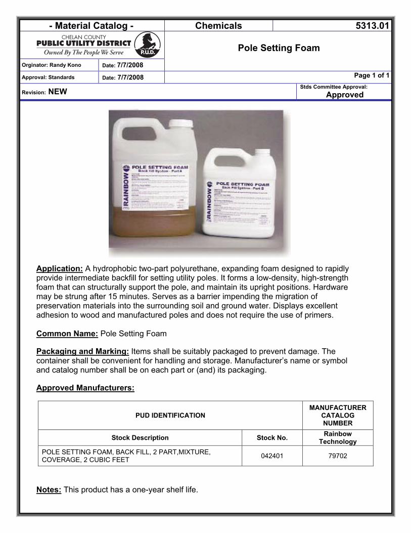
- Material Catalog - Chemicals 5313.01
Orginator: Randy Kono Date: 7/7/2008
Pole Setting Foam
Approval: Standards Date: 7/7/2008 Page 1 of 1
Revision: NEW Stds Committee Approval:
Approved
Application: A hydrophobic two-part polyurethane, expanding foam designed to rapidly provide intermediate backfill for setting utility poles. It forms a low-density, high-strength foam that can structurally support the pole, and maintain its upright positions. Hardware may be strung after 15 minutes. Serves as a barrier impending the migration of preservation materials into the surrounding soil and ground water. Displays excellent adhesion to wood and manufactured poles and does not require the use of primers. Common Name: Pole Setting Foam Packaging and Marking: Items shall be suitably packaged to prevent damage. The container shall be convenient for handling and storage. Manufacturer’s name or symbol and catalog number shall be on each part or (and) its packaging. Approved Manufacturers:
PUD IDENTIFICATION MANUFACTURER
CATALOG NUMBER
Stock Description Stock No. Rainbow Technology
POLE SETTING FOAM, BACK FILL, 2 PART,MIXTURE, COVERAGE, 2 CUBIC FEET 042401 79702
Notes: This product has a one-year shelf life.
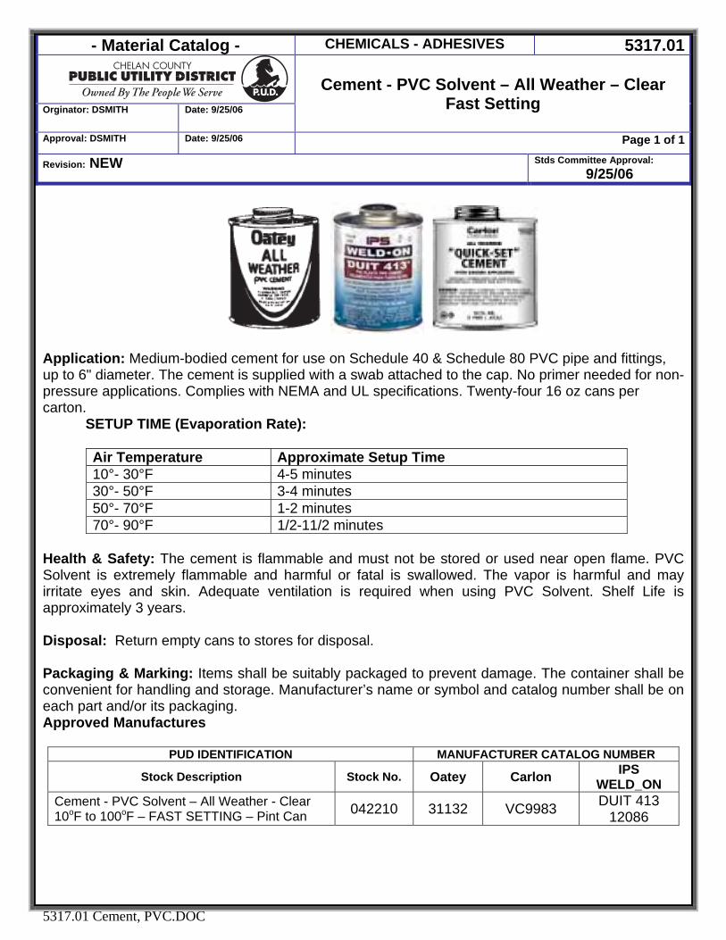
- Material Catalog - CHEMICALS - ADHESIVES 5317.01
Orginator: DSMITH Date: 9/25/06
Cement - PVC Solvent – All Weather – Clear
Fast Setting
Approval: DSMITH Date: 9/25/06 Page 1 of 1
Revision: NEW Stds Committee Approval: 9/25/06
5317.01 Cement, PVC.DOC
Application: Medium-bodied cement for use on Schedule 40 & Schedule 80 PVC pipe and fittings, up to 6" diameter. The cement is supplied with a swab attached to the cap. No primer needed for non-pressure applications. Complies with NEMA and UL specifications. Twenty-four 16 oz cans per carton.
SETUP TIME (Evaporation Rate): Air Temperature Approximate Setup Time 10°- 30°F 4-5 minutes 30°- 50°F 3-4 minutes 50°- 70°F 1-2 minutes 70°- 90°F 1/2-11/2 minutes
Health & Safety: The cement is flammable and must not be stored or used near open flame. PVC Solvent is extremely flammable and harmful or fatal is swallowed. The vapor is harmful and may irritate eyes and skin. Adequate ventilation is required when using PVC Solvent. Shelf Life is approximately 3 years. Disposal: Return empty cans to stores for disposal. Packaging & Marking: Items shall be suitably packaged to prevent damage. The container shall be convenient for handling and storage. Manufacturer’s name or symbol and catalog number shall be on each part and/or its packaging. Approved Manufactures
PUD IDENTIFICATION MANUFACTURER CATALOG NUMBER
Stock Description Stock No. Oatey Carlon IPS WELD_ON
Cement - PVC Solvent – All Weather - Clear 10oF to 100oF – FAST SETTING – Pint Can 042210 31132 VC9983 DUIT 413
12086


