Embed Size (px)
Citation preview

LG TRAINING MANUALSpring 2009 Washer TrainingLG TRAINING MANUAL
WM3001HRA

TRAINING MANUAL WM3001H*A
WM3001H*A Page 1 Washer
IMPORTANT SAFETY NOTICE
The information in this training manual is intended for use by persons possessing an adequate background in electrical equipment, electronic devices, and mechanical systems. In any attempt to repair a major appliance, personal injury and property damage can result. The manufacturer or seller maintains no liability for the interpretation of this information, nor can it assume any liability in conjunction with its use. When servicing this product, under no circumstances should the original design be modified or altered without permission from LG Electronics. Unauthorized modifications will not only void the warranty, but may lead to property damage or user injury. If wires, screws, clips, straps, nuts, or washers used to complete a ground path are removed for service, they must be returned to their original positions and properly fastened.
CAUTION
To avoid personal injury, disconnect the power before servicing this product. If electrical power is required for diagnosis or test purposes, disconnect the power immediately after performing the necessary checks. Also be aware that many household appliances present a weight hazard. At least two people should be involved in the installation or servicing of such devices. Failure to consider the weight of an appliance could result in physical injury.
ESD NOTICE
Some of the electronic components in appliances are electrostatic discharge (ESD) sensitive. ESD can weaken or damage the electronics in these appliances in a manner that renders them inoperative or reduces the time until their next failure. Connect an ESD wrist strap to a ground connection point or unpainted metal in the appliance. Alternatively, you can touch your finger repeatedly to a ground connection point or unpainted metal in the appliance. Before removing a replacement part from its package, touch the anti-static bag to a ground connection point or unpainted metal in the appliance. Handle the electronic control assembly by its edges only. When repackaging a failed electronic control assembly in an anti-static bag, observe these same precautions.
REGULATORY INFORMATION
This equipment has been tested and found to comply with the limits for a Class B digital device, pursuant to Part 15 of the FCC Rules. These limits are designed to provide reasonable protection against harmful interference when the equipment is operated in a residential installation. This equipment generates, uses, and can radiate radio frequency energy, and, if not installed and used in accordance with the instruction manual, may cause harmful interference to radio communications. However, there is no guarantee that interference will not occur in a particular installation. If this equipment does cause harmful interference to radio or television reception, which can be determined by turning the equipment off and on, the user is encouraged to try to correct the interference by one or more of the following measures: Reorient or relocate the receiving antenna; Increase the separation between the equipment and the receiver; Connect the equipment to an outlet on a different circuit than that to which the receiver is connected; or consult the dealer or an experienced radio/TV technician for help.
DISCLAIMER
The information in this training manual was accurate at the time of publication. Every effort has been made to ensure accuracy. Updates, changes, etc. are available via GCSC and LGCSacademy. The information in this manual is intended for persons with adequate backgrounds in electronics, mechanical, and electronic servicing. The manufacturer and seller are not to be held responsible for any liability incurred from its use.
COMPLIANCE
The responsible party for this device’s compliance is LG Electronics Alabama, Inc.; 201 James Record Road, Huntsville, AL, 35813.
TRAINING MANUAL WM3001H*A
WM3001H*A Page 2 Washer
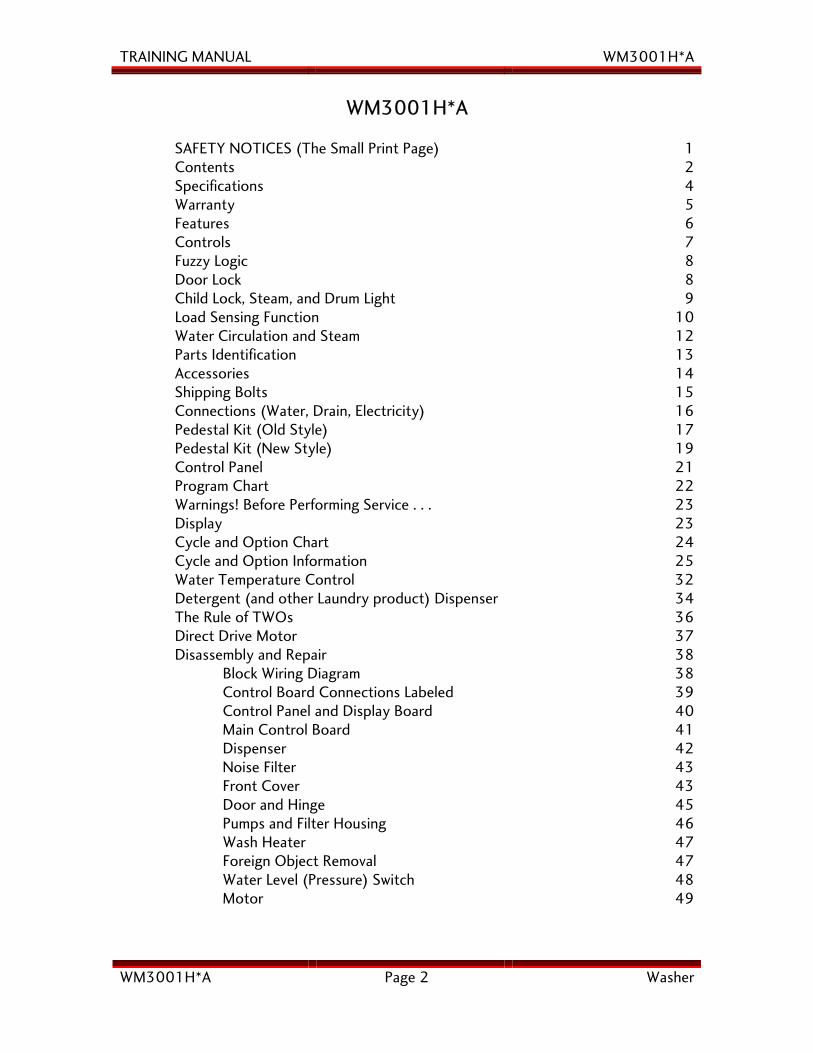
WM3001H*A SAFETY NOTICES (The Small Print Page) 1 Contents 2 Specifications 4 Warranty 5 Features 6 Controls 7 Fuzzy Logic 8 Door Lock 8 Child Lock, Steam, and Drum Light 9 Load Sensing Function 10 Water Circulation and Steam 12 Parts Identification 13 Accessories 14 Shipping Bolts 15 Connections (Water, Drain, Electricity) 16 Pedestal Kit (Old Style) 17 Pedestal Kit (New Style) 19 Control Panel 21 Program Chart 22 Warnings! Before Performing Service . . . 23 Display 23 Cycle and Option Chart 24 Cycle and Option Information 25 Water Temperature Control 32 Detergent (and other Laundry product) Dispenser 34 The Rule of TWOs 36 Direct Drive Motor 37 Disassembly and Repair 38 Block Wiring Diagram 38 Control Board Connections Labeled 39 Control Panel and Display Board 40 Main Control Board 41 Dispenser 42 Noise Filter 43 Front Cover 43 Door and Hinge 45 Pumps and Filter Housing 46 Wash Heater 47 Foreign Object Removal 47 Water Level (Pressure) Switch 48 Motor 49
TRAINING MANUAL WM3001H*A
WM3001H*A Page 3 Washer
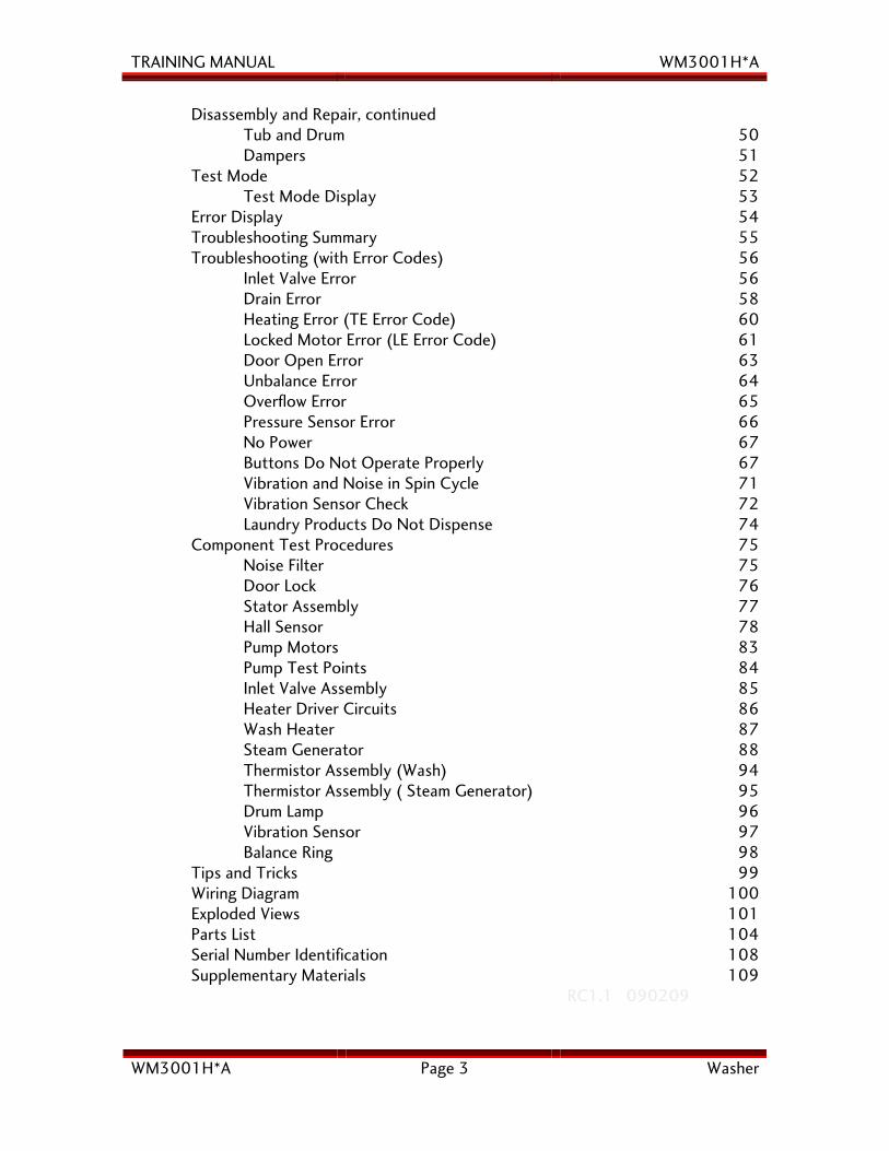
Disassembly and Repair, continued Tub and Drum 50 Dampers 51 Test Mode 52 Test Mode Display 53 Error Display 54 Troubleshooting Summary 55 Troubleshooting (with Error Codes) 56 Inlet Valve Error 56 Drain Error 58 Heating Error (TE Error Code) 60 Locked Motor Error (LE Error Code) 61 Door Open Error 63 Unbalance Error 64 Overflow Error 65 Pressure Sensor Error 66 No Power 67 Buttons Do Not Operate Properly 67 Vibration and Noise in Spin Cycle 71 Vibration Sensor Check 72 Laundry Products Do Not Dispense 74 Component Test Procedures 75 Noise Filter 75 Door Lock 76 Stator Assembly 77 Hall Sensor 78 Pump Motors 83 Pump Test Points 84 Inlet Valve Assembly 85 Heater Driver Circuits 86 Wash Heater 87 Steam Generator 88 Thermistor Assembly (Wash) 94 Thermistor Assembly ( Steam Generator) 95 Drum Lamp 96 Vibration Sensor 97 Balance Ring 98 Tips and Tricks 99 Wiring Diagram 100 Exploded Views 101 Parts List 104 Serial Number Identification 108 Supplementary Materials 109 RC1.1 090209
TRAINING MANUAL WM3001H*A
WM3001H*A Page 4 Washer
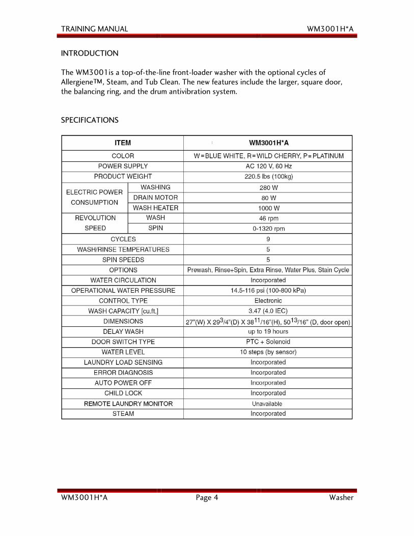
INTRODUCTION The WM3001is a top-of-the-line front-loader washer with the optional cycles of Allergiene™, Steam, and Tub Clean. The new features include the larger, square door, the balancing ring, and the drum antivibration system. SPECIFICATIONS
TRAINING MANUAL WM3001H*A
WM3001H*A Page 5 Washer
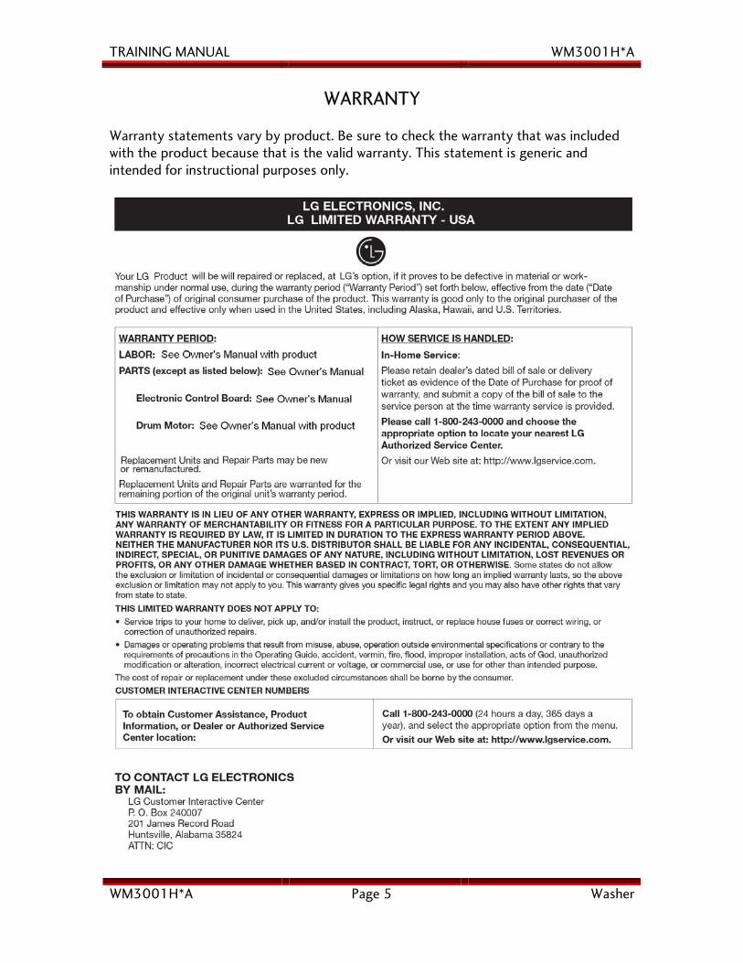
WARRANTY
Warranty statements vary by product. Be sure to check the warranty that was included with the product because that is the valid warranty. This statement is generic and intended for instructional purposes only.
TRAINING MANUAL WM3001H*A
WM3001H*A Page 6 Washer
FEATURES
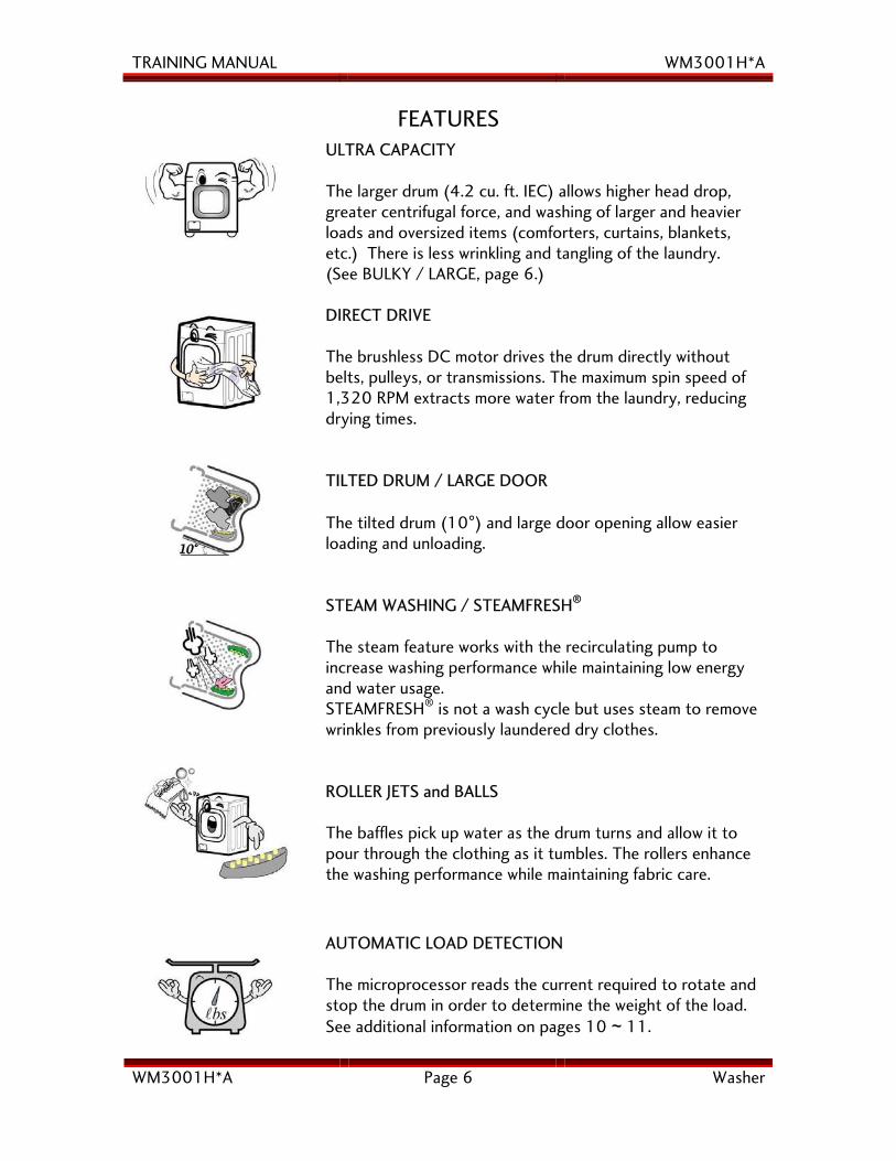
ULTRA CAPACITY The larger drum (4.2 cu. ft. IEC) allows higher head drop, greater centrifugal force, and washing of larger and heavier loads and oversized items (comforters, curtains, blankets, etc.) There is less wrinkling and tangling of the laundry. (See BULKY / LARGE, page 6.) DIRECT DRIVE The brushless DC motor drives the drum directly without belts, pulleys, or transmissions. The maximum spin speed of 1,320 RPM extracts more water from the laundry, reducing drying times. TILTED DRUM / LARGE DOOR The tilted drum (10°) and large door opening allow easier loading and unloading. STEAM WASHING / STEAMFRESH®
The steam feature works with the recirculating pump to increase washing performance while maintaining low energy and water usage. STEAMFRESH® is not a wash cycle but uses steam to remove wrinkles from previously laundered dry clothes. ROLLER JETS and BALLS The baffles pick up water as the drum turns and allow it to pour through the clothing as it tumbles. The rollers enhance the washing performance while maintaining fabric care.
AUTOMATIC LOAD DETECTION The microprocessor reads the current required to rotate and stop the drum in order to determine the weight of the load. See additional information on pages 10 ~ 11.
TRAINING MANUAL WM3001H*A
WM3001H*A Page 7 Washer
FEATURES, continued
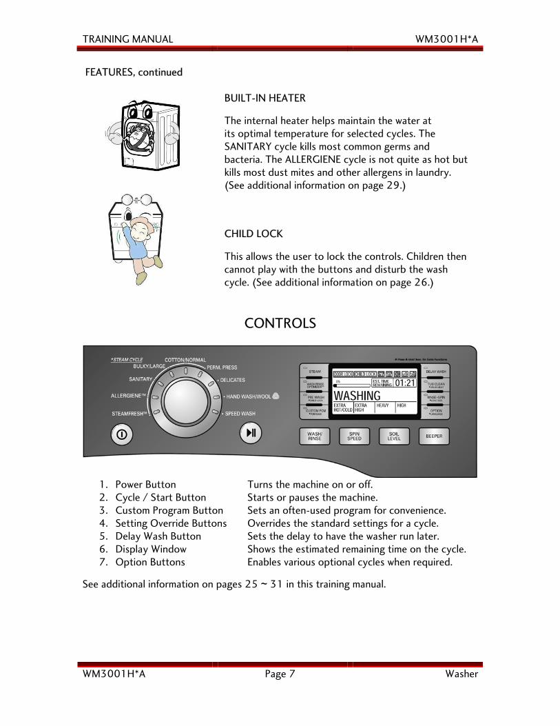
BUILT-IN HEATER The internal heater helps maintain the water at its optimal temperature for selected cycles. The SANITARY cycle kills most common germs and bacteria. The ALLERGIENE cycle is not quite as hot but kills most dust mites and other allergens in laundry. (See additional information on page 29.) CHILD LOCK
This allows the user to lock the controls. Children then cannot play with the buttons and disturb the wash cycle. (See additional information on page 26.)
CONTROLS
1. Power Button Turns the machine on or off. 2. Cycle / Start Button Starts or pauses the machine. 3. Custom Program Button Sets an often-used program for convenience. 4. Setting Override Buttons Overrides the standard settings for a cycle. 5. Delay Wash Button Sets the delay to have the washer run later. 6. Display Window Shows the estimated remaining time on the cycle. 7. Option Buttons Enables various optional cycles when required.
See additional information on pages 25 ~ 31 in this training manual.
TRAINING MANUAL WM3001H*A
WM3001H*A Page 8 Washer
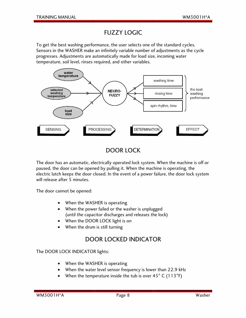
FUZZY LOGIC To get the best washing performance, the user selects one of the standard cycles. Sensors in the WASHER make an infinitely variable number of adjustments as the cycle progresses. Adjustments are automatically made for load size, incoming water temperature, soil level, rinses required, and other variables.
DOOR LOCK
The door has an automatic, electrically operated lock system. When the machine is off or paused, the door can be opened by pulling it. When the machine is operating, the electric latch keeps the door closed. In the event of a power failure, the door lock system will release after 5 minutes. The door cannot be opened:
• When the WASHER is operating • When the power failed or the washer is unplugged
(until the capacitor discharges and releases the lock) • When the DOOR LOCK light is on • When the drum is still turning
DOOR LOCKED INDICATOR The DOOR LOCK INDICATOR lights:
• When the WASHER is operating • When the water level sensor frequency is lower than 22.9 kHz • When the temperature inside the tub is over 45° C (113°F)
TRAINING MANUAL WM3001H*A
WM3001H*A Page 9 Washer
CHILD LOCK The CHILD LOCK feature prevents unwanted use of the washer. Press and hold the PRE-WASH button for three seconds to lock or unlock the control panel. When the CHILD LOCK is set, all controls except the CHILD LOCK button are disabled.
STEAM The STEAM feature offers enhanced washing performance with lower water and energy consumption. It is especially useful for highly soiled or stained clothing, baby clothes, and sick room linens.
DRUM LIGHT The LED drum light turns on when the POWER button is pressed. It remains off when the door is locked, but can be turned on at any time during the cycle by pressing and holding the RINSE+SPIN button. It will turn off automatically four minutes later.
TRAINING MANUAL WM3001H*A
WM3001H*A Page 10 Washer
LOAD SENSING FUNCTION
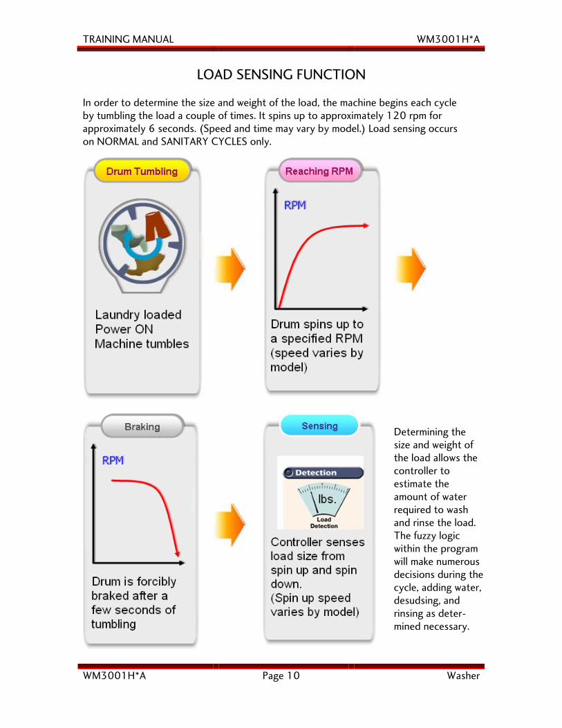
In order to determine the size and weight of the load, the machine begins each cycle by tumbling the load a couple of times. It spins up to approximately 120 rpm for approximately 6 seconds. (Speed and time may vary by model.) Load sensing occurs on NORMAL and SANITARY CYCLES only.
Determining the size and weight of the load allows the controller to estimate the amount of water required to wash and rinse the load. The fuzzy logic within the program will make numerous decisions during the cycle, adding water, desudsing, and rinsing as deter-mined necessary.
TRAINING MANUAL WM3001H*A
WM3001H*A Page 11 Washer
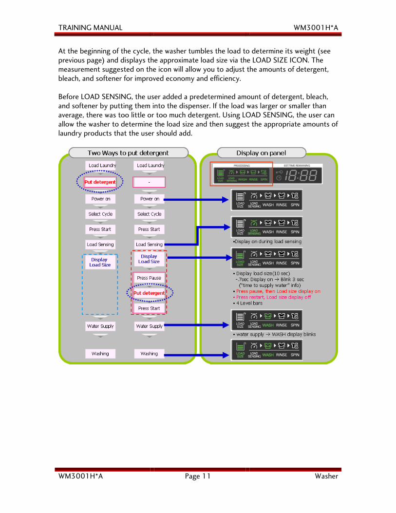
At the beginning of the cycle, the washer tumbles the load to determine its weight (see previous page) and displays the approximate load size via the LOAD SIZE ICON. The measurement suggested on the icon will allow you to adjust the amounts of detergent, bleach, and softener for improved economy and efficiency. Before LOAD SENSING, the user added a predetermined amount of detergent, bleach, and softener by putting them into the dispenser. If the load was larger or smaller than average, there was too little or too much detergent. Using LOAD SENSING, the user can allow the washer to determine the load size and then suggest the appropriate amounts of laundry products that the user should add.
TRAINING MANUAL WM3001H*A
WM3001H*A Page 12 Washer
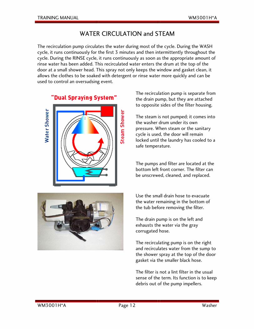
WATER CIRCULATION and STEAM The recirculation pump circulates the water during most of the cycle. During the WASH cycle, it runs continuously for the first 3 minutes and then intermittently throughout the cycle. During the RINSE cycle, it runs continuously as soon as the appropriate amount of rinse water has been added. This recirculated water enters the drum at the top of the door at a small shower head. This spray not only keeps the window and gasket clean, it allows the clothes to be soaked with detergent or rinse water more quickly and can be used to control an oversudsing event.
The recirculation pump is separate from the drain pump, but they are attached to opposite sides of the filter housing. The steam is not pumped; it comes into the washer drum under its own pressure. When steam or the sanitary cycle is used, the door will remain locked until the laundry has cooled to a safe temperature. The pumps and filter are located at the bottom left front corner. The filter can be unscrewed, cleaned, and replaced.
Use the small drain hose to evacuate the water remaining in the bottom of the tub before removing the filter. The drain pump is on the left and exhausts the water via the gray corrugated hose. The recirculating pump is on the right and recirculates water from the sump to the shower spray at the top of the door gasket via the smaller black hose. The filter is not a lint filter in the usual sense of the term. Its function is to keep debris out of the pump impellers.
TRAINING MANUAL WM3001H*A
WM3001H*A Page 13 Washer
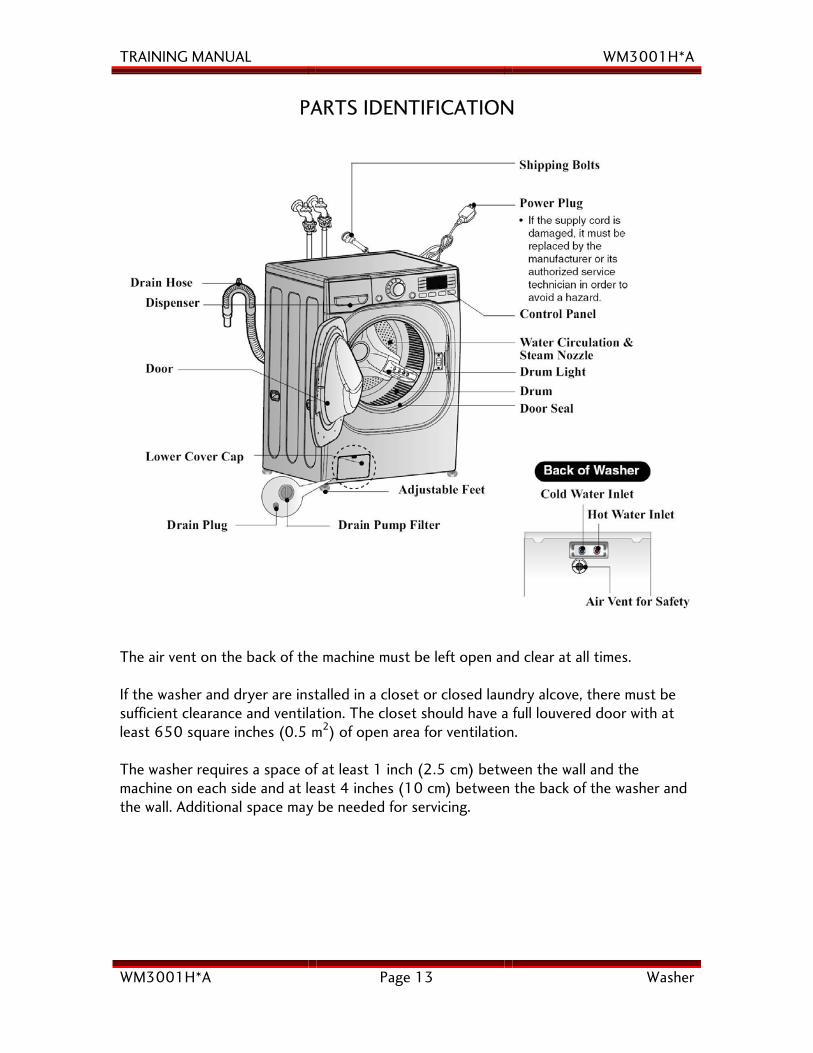
PARTS IDENTIFICATION
The air vent on the back of the machine must be left open and clear at all times. If the washer and dryer are installed in a closet or closed laundry alcove, there must be sufficient clearance and ventilation. The closet should have a full louvered door with at least 650 square inches (0.5 m2) of open area for ventilation. The washer requires a space of at least 1 inch (2.5 cm) between the wall and the machine on each side and at least 4 inches (10 cm) between the back of the washer and the wall. Additional space may be needed for servicing.
TRAINING MANUAL WM3001H*A
WM3001H*A Page 14 Washer
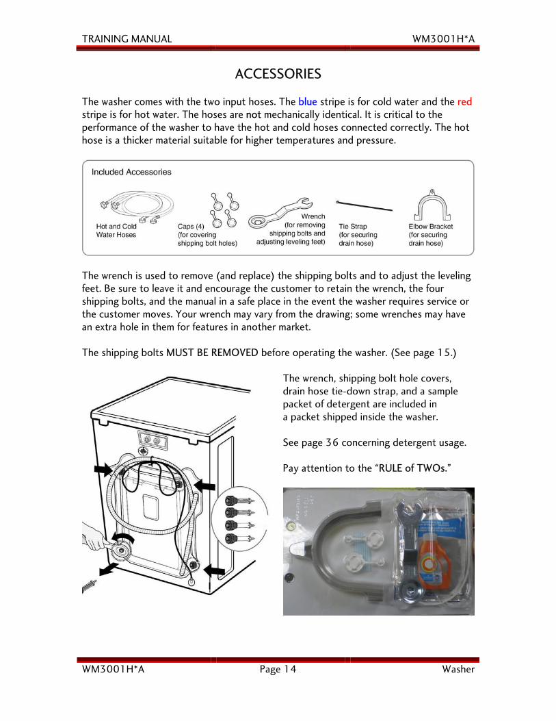
ACCESSORIES The washer comes with the two input hoses. The blue stripe is for cold water and the red stripe is for hot water. The hoses are not mechanically identical. It is critical to the performance of the washer to have the hot and cold hoses connected correctly. The hot hose is a thicker material suitable for higher temperatures and pressure.
The wrench is used to remove (and replace) the shipping bolts and to adjust the leveling feet. Be sure to leave it and encourage the customer to retain the wrench, the four shipping bolts, and the manual in a safe place in the event the washer requires service or the customer moves. Your wrench may vary from the drawing; some wrenches may have an extra hole in them for features in another market. The shipping bolts MUST BE REMOVED before operating the washer. (See page 15.)
The wrench, shipping bolt hole covers, drain hose tie-down strap, and a sample packet of detergent are included in a packet shipped inside the washer. See page 36 concerning detergent usage. Pay attention to the “RULE of TWOs.”
TRAINING MANUAL WM3001H*A
WM3001H*A Page 15 Washer
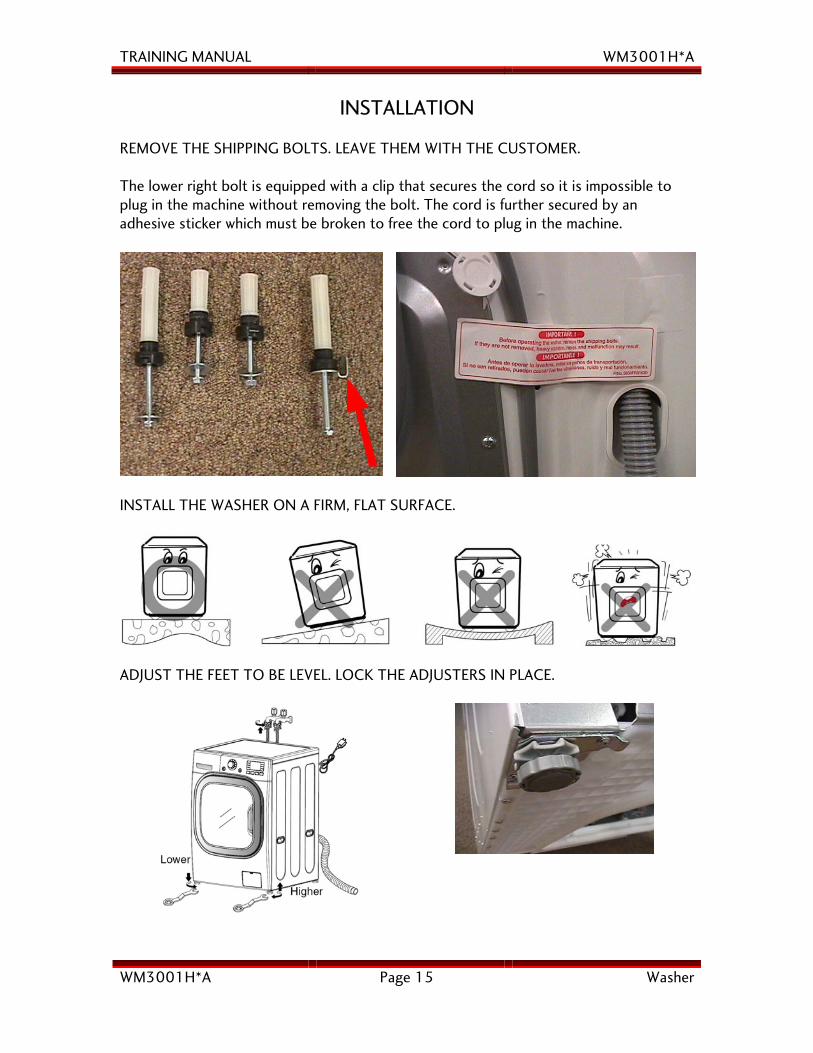
INSTALLATION REMOVE THE SHIPPING BOLTS. LEAVE THEM WITH THE CUSTOMER. The lower right bolt is equipped with a clip that secures the cord so it is impossible to plug in the machine without removing the bolt. The cord is further secured by an adhesive sticker which must be broken to free the cord to plug in the machine.
INSTALL THE WASHER ON A FIRM, FLAT SURFACE.
ADJUST THE FEET TO BE LEVEL. LOCK THE ADJUSTERS IN PLACE.
TRAINING MANUAL WM3001H*A
WM3001H*A Page 16 Washer
CONNECTIONS
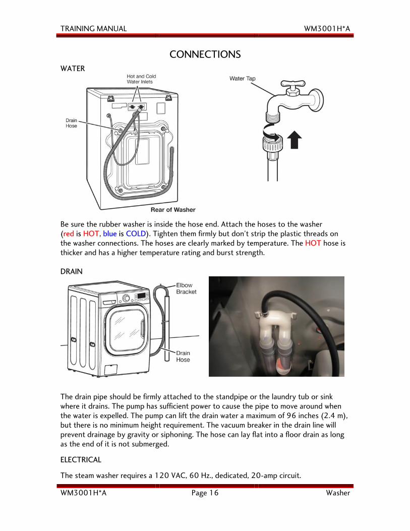
WATER
Be sure the rubber washer is inside the hose end. Attach the hoses to the washer (red is HOT, blue is COLD). Tighten them firmly but don’t strip the plastic threads on the washer connections. The hoses are clearly marked by temperature. The HOT hose is thicker and has a higher temperature rating and burst strength. DRAIN
The drain pipe should be firmly attached to the standpipe or the laundry tub or sink where it drains. The pump has sufficient power to cause the pipe to move around when the water is expelled. The pump can lift the drain water a maximum of 96 inches (2.4 m), but there is no minimum height requirement. The vacuum breaker in the drain line will prevent drainage by gravity or siphoning. The hose can lay flat into a floor drain as long as the end of it is not submerged.
ELECTRICAL
The steam washer requires a 120 VAC, 60 Hz., dedicated, 20-amp circuit.
TRAINING MANUAL WM3001H*A
WM3001H*A Page 17 Washer
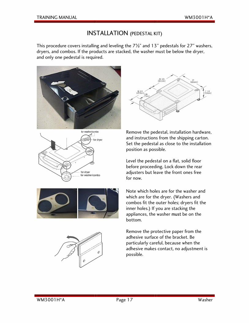
INSTALLATION (PEDESTAL KIT) This procedure covers installing and leveling the 7½” and 13” pedestals for 27” washers, dryers, and combos. If the products are stacked, the washer must be below the dryer, and only one pedestal is required.
Remove the pedestal, installation hardware, and instructions from the shipping carton. Set the pedestal as close to the installation position as possible. Level the pedestal on a flat, solid floor before proceeding. Lock down the rear adjusters but leave the front ones free for now.
Note which holes are for the washer and which are for the dryer. (Washers and combos fit the outer holes; dryers fit the inner holes.) If you are stacking the appliances, the washer must be on the bottom.
Remove the protective paper from the adhesive surface of the bracket. Be particularly careful, because when the adhesive makes contact, no adjustment is possible.
TRAINING MANUAL WM3001H*A
WM3001H*A Page 18 Washer
PEDESTAL, continued
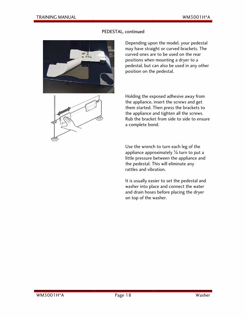
Depending upon the model, your pedestal may have straight or curved brackets. The curved ones are to be used on the rear positions when mounting a dryer to a pedestal, but can also be used in any other position on the pedestal.
Holding the exposed adhesive away from the appliance, insert the screws and get them started. Then press the brackets to the appliance and tighten all the screws. Rub the bracket from side to side to ensure a complete bond.
Use the wrench to turn each leg of the appliance approximately ¼ turn to put a little pressure between the appliance and the pedestal. This will eliminate any rattles and vibration.
It is usually easier to set the pedestal and washer into place and connect the water and drain hoses before placing the dryer on top of the washer.
TRAINING MANUAL WM3001H*A
WM3001H*A Page 19 Washer
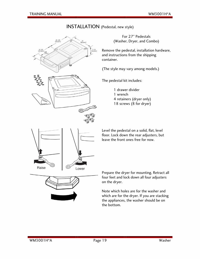
INSTALLATION (Pedestal, new style)
For 27” Pedestals (Washer, Dryer, and Combo)
Remove the pedestal, installation hardware, and instructions from the shipping container. (The style may vary among models.)
The pedestal kit includes: 1 drawer divider 1 wrench 4 retainers (dryer only) 18 screws (8 for dryer)
Level the pedestal on a solid, flat, level floor. Lock down the rear adjusters, but leave the front ones free for now.
Prepare the dryer for mounting. Retract all four feet and lock down all four adjusters on the dryer. Note which holes are for the washer and which are for the dryer. If you are stacking the appliances, the washer should be on the bottom.
TRAINING MANUAL WM3001H*A
WM3001H*A Page 20 Washer
INSTALLATION (Pedestal, new style, continued)
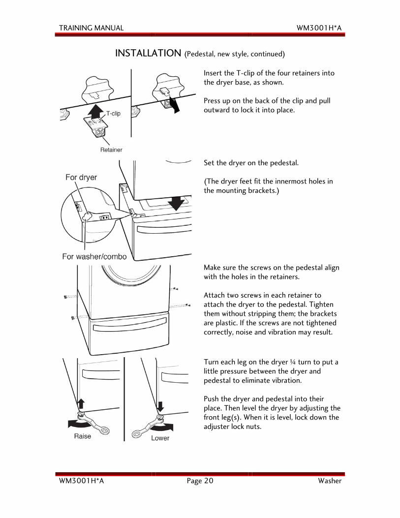
Insert the T-clip of the four retainers into the dryer base, as shown. Press up on the back of the clip and pull outward to lock it into place.
Set the dryer on the pedestal. (The dryer feet fit the innermost holes in the mounting brackets.)
Make sure the screws on the pedestal align with the holes in the retainers. Attach two screws in each retainer to attach the dryer to the pedestal. Tighten them without stripping them; the brackets are plastic. If the screws are not tightened correctly, noise and vibration may result.
Turn each leg on the dryer ¼ turn to put a little pressure between the dryer and pedestal to eliminate vibration. Push the dryer and pedestal into their place. Then level the dryer by adjusting the front leg(s). When it is level, lock down the adjuster lock nuts.
TRAINING MANUAL WM3001H*A
WM3001H*A Page 21 Washer
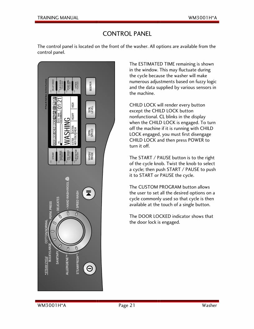
CONTROL PANEL
The control panel is located on the front of the washer. All options are available from the control panel.
The ESTIMATED TIME remaining is shown in the window. This may fluctuate during the cycle because the washer will make numerous adjustments based on fuzzy logic and the data supplied by various sensors in the machine. CHILD LOCK will render every button except the CHILD LOCK button nonfunctional. CL blinks in the display when the CHILD LOCK is engaged. To turn off the machine if it is running with CHILD LOCK engaged, you must first disengage CHILD LOCK and then press POWER to turn it off. The START / PAUSE button is to the right of the cycle knob. Twist the knob to select a cycle; then push START / PAUSE to push it to START or PAUSE the cycle. The CUSTOM PROGRAM button allows the user to set all the desired options on a cycle commonly used so that cycle is then available at the touch of a single button. The DOOR LOCKED indicator shows that the door lock is engaged.
TRAINING MANUAL WM3001H*A
WM3001H*A Page 22 Washer
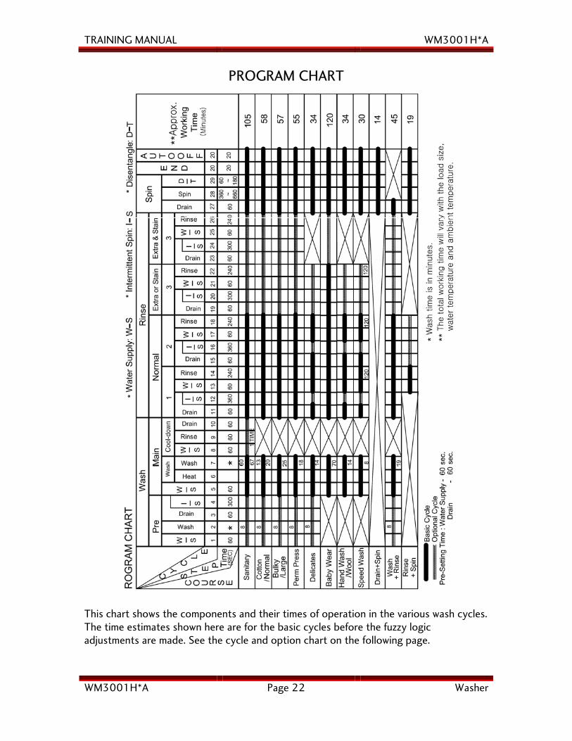
PROGRAM CHART
This chart shows the components and their times of operation in the various wash cycles. The time estimates shown here are for the basic cycles before the fuzzy logic adjustments are made. See the cycle and option chart on the following page.
TRAINING MANUAL WM3001H*A
WM3001H*A Page 23 Washer
BEFORE PERFORMING SERVICE
• Always unplug the washer to work on it.
• Be careful to avoid electric shock when disconnecting parts for troubleshooting.
• Some terminals in the steam washer have 120 Volts AC or DC on them, sometimes even when the washer is off. The motor operates on 310 Volts DC.
• The main board powers down a few minutes after any cycle is completed. The red LED will go out when the board powers down.
• The steam generator operates at a high temperature. Be careful when servicing it. It can be drained in place by removing the drain cap, but have a hose or a big towel ready to soak up the spillage. It is simplest to cool before servicing and then drain it after removing it from the washer.
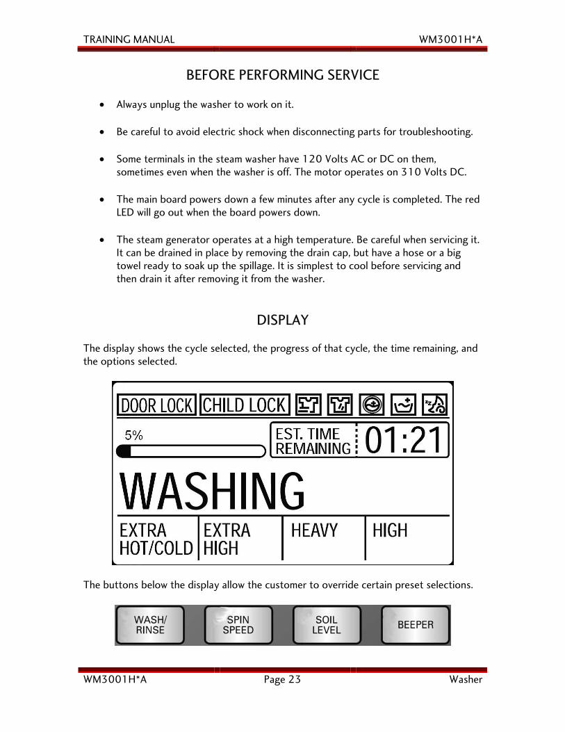
DISPLAY
The display shows the cycle selected, the progress of that cycle, the time remaining, and the options selected.
The buttons below the display allow the customer to override certain preset selections.
TRAINING MANUAL WM3001H*A
WM3001H*A Page 24 Washer
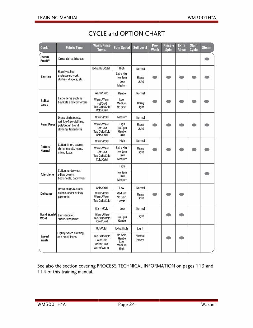
CYCLE and OPTION CHART
See also the section covering PROCESS TECHNICAL INFORMATION on pages 113 and 114 of this training manual.
TRAINING MANUAL WM3001H*A
WM3001H*A Page 25 Washer
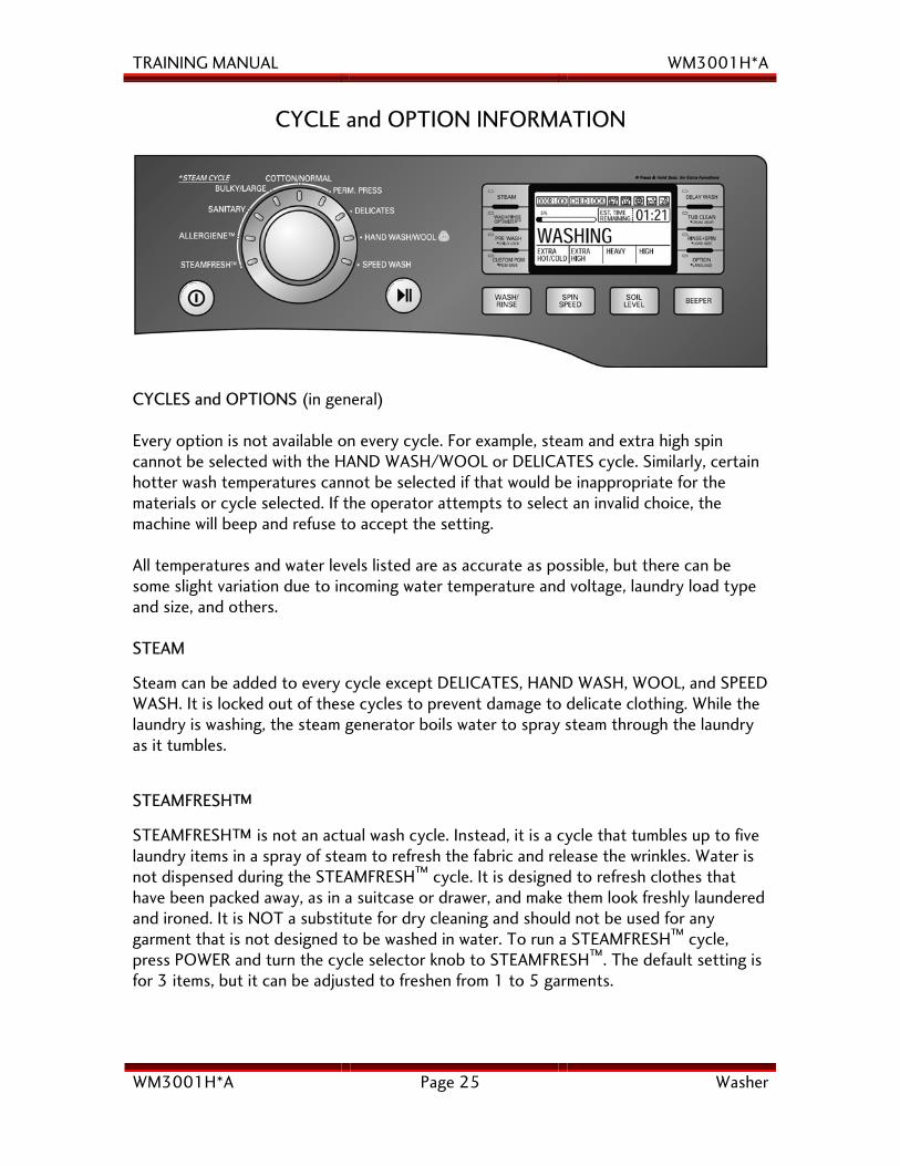
CYCLE and OPTION INFORMATION
CYCLES and OPTIONS (in general) Every option is not available on every cycle. For example, steam and extra high spin cannot be selected with the HAND WASH/WOOL or DELICATES cycle. Similarly, certain hotter wash temperatures cannot be selected if that would be inappropriate for the materials or cycle selected. If the operator attempts to select an invalid choice, the machine will beep and refuse to accept the setting. All temperatures and water levels listed are as accurate as possible, but there can be some slight variation due to incoming water temperature and voltage, laundry load type and size, and others. STEAM
Steam can be added to every cycle except DELICATES, HAND WASH, WOOL, and SPEED WASH. It is locked out of these cycles to prevent damage to delicate clothing. While the laundry is washing, the steam generator boils water to spray steam through the laundry as it tumbles.
STEAMFRESH™
STEAMFRESH™ is not an actual wash cycle. Instead, it is a cycle that tumbles up to five laundry items in a spray of steam to refresh the fabric and release the wrinkles. Water is not dispensed during the STEAMFRESH™ cycle. It is designed to refresh clothes that have been packed away, as in a suitcase or drawer, and make them look freshly laundered and ironed. It is NOT a substitute for dry cleaning and should not be used for any garment that is not designed to be washed in water. To run a STEAMFRESH™ cycle, press POWER and turn the cycle selector knob to STEAMFRESH™. The default setting is for 3 items, but it can be adjusted to freshen from 1 to 5 garments.
TRAINING MANUAL WM3001H*A
WM3001H*A Page 26 Washer
ALLERGIENE™ The Allergiene™ cycle is designed to use hotter wash water (140° F or 60° C) than the regular HOT wash (112° F or 50° C) but not as hot as the SANITARY cycle (158° F or 70° C). Its purpose is to remove all allergens, such as dust mites and their eggs and droppings, as well as lint and dead skin cells. This machine is certified allergy and asthma friendly by the Allergy and Asthma Foundation of America as removing 95% of harmful allergens. When the Allergiene™ cycle is operating, the display shows 1:50 at the beginning, the water level defaults to approximately 242 and spin defaults to HIGH. The steam generator operates as does the wash water heater in the bottom of the tub. SANITARY The sanitary cycle is used to reduce 99.9% bacteria and germs, as in baby clothes and sick room linens. The wash water temperature defaults to 158° F (70° C) and cannot be adjusted. BULKY / LARGE The BULKY / LARGE cycle is designed to launder large items like tablecloths and bed covers. It is NOT intended as an opportunity to overload the machine. Just because an item can be forced into the tub is not evidence it can be successfully laundered there. In every case, the laundry must be able to tumble to be cleaned effectively. If you push a king-sized comforter into the tub, but it is so compressed it cannot tumble, it cannot be washed or rinsed effectively. Further, it will be unable to distribute itself within the drum for the spin cycle, and will cause the machine to have difficulty in the spin cycle because it cannot redistribute the load. Such large items should be taken to a commercial self-service laundry where oversized machines are available. In the BULKY / LARGE cycle, the cycle time is preset. The default selections can be overridden for wash temperature, spin speed, and soil level. If a selection is not permissible with the cycle, the machine will beep and refuse to accept the setting. COTTON / NORMAL The COTTON / NORMAL cycle is the most often used cycle. It defaults to a 0:53 minute cycle time, but this may vary as the fuzzy logic makes numerous adjustments throughout the cycle. It is the only cycle that genuinely senses the load before displaying the approximate wash time. The water level defaults to approximately 239. The default selections can be overridden for wash temperature, spin speed, and soil level.
TRAINING MANUAL WM3001H*A
WM3001H*A Page 27 Washer
PERM. PRESS The permanent press cycle defaults to a 0:57 cycle time. The default selections can be overridden for wash temperature, spin speed, and soil level. Water level defaults to approximately 234, which is more water than a normal cycle. DELICATES The delicate cycle defaults to a 0:42 minute cycle. The water level defaults to approximately 230. The default selections can be overridden for wash temperature, spin speed, and soil level, but certain options cannot be selected, such as steam, very hot water, and high speed spin. If a selection is not permissible with the cycle, the machine will beep and refuse to accept the setting. HAND WASH / WOOL This cycle is designed for woolen articles and other garments that are suitable to be washed in water but must be treated very delicately. The HAND WASH / WOOL cycle defaults to a 0:55 minute cycle. Water level defaults to 230. The drum tumbles very gently, making slightly less than one complete revolution per tumble, which is just enough to turn the load over in the water.
SPEED WASH SPEED WASH is the quickest cycle that provides a complete wash and rinse. It defaults to a 0:35 minute cycle. The default selections can be overridden for wash temperature, spin speed, and soil level, very hot water, and high speed spin, but certain options cannot be selected. If a selection is not permissible with the cycle, the machine will beep and refuse to accept the setting. SPEED WASH defaults to a HOT wash, but most people find that overriding it to select WARM gives a better wash and less wrinkling.
OPTIONS
When a cycle is selected, options like water temperature, spin speed, are preset for that cycle, but they can be overridden by selecting one of the option buttons on the control panel. For example, selecting a COTTON/NORMAL cycle will automatically default to a WARM wash, COLD rinse, HIGH spin speed, and NORMAL soil level. Any of these settings may be overridden by changing the options at the control panel before the wash cycle is started.
Not every option is available for every cycle. As mentioned above, the DELICATE cycle will lock out selections HOT WASH water, HIGH spin speed, and STEAM in the cycle.
TRAINING MANUAL WM3001H*A
WM3001H*A Page 28 Washer
OPTIONS
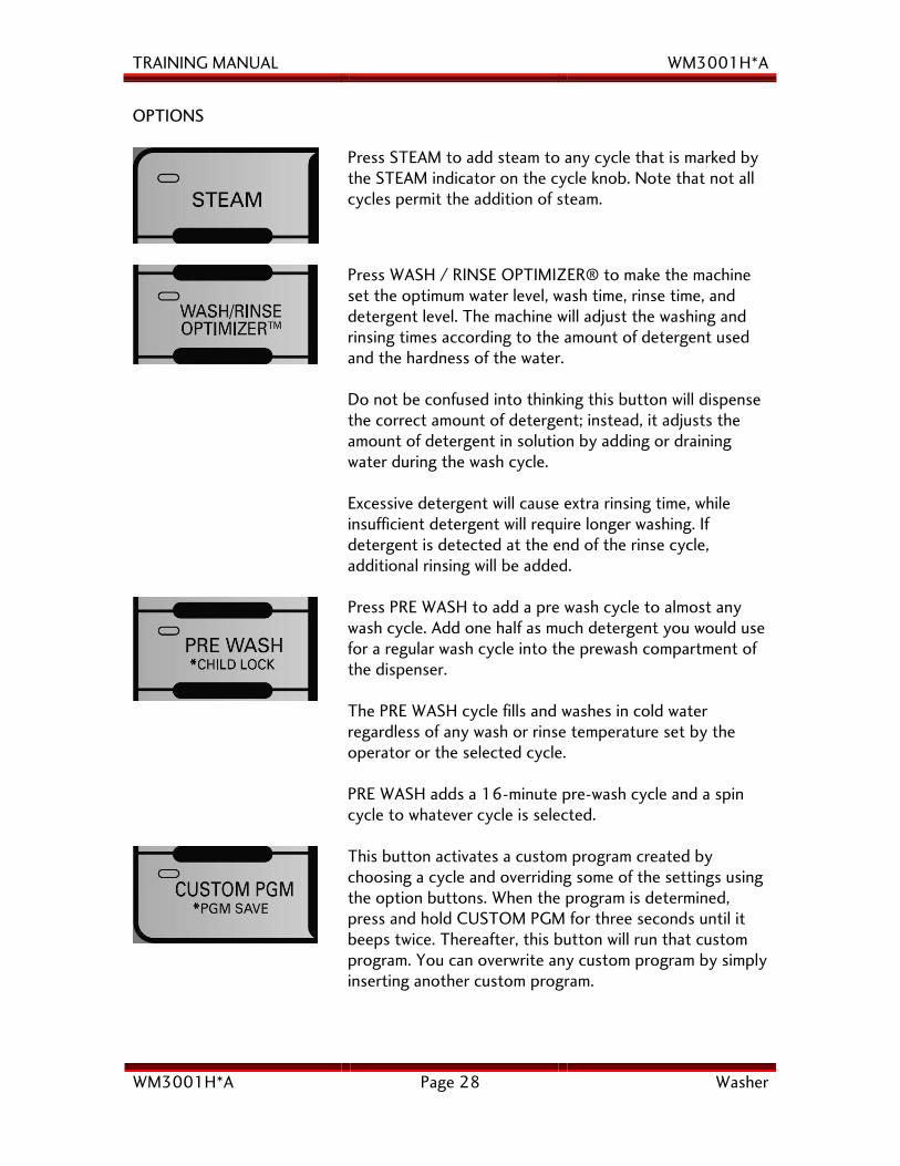
Press STEAM to add steam to any cycle that is marked by the STEAM indicator on the cycle knob. Note that not all cycles permit the addition of steam.
Press WASH / RINSE OPTIMIZER® to make the machine set the optimum water level, wash time, rinse time, and detergent level. The machine will adjust the washing and rinsing times according to the amount of detergent used and the hardness of the water. Do not be confused into thinking this button will dispense the correct amount of detergent; instead, it adjusts the amount of detergent in solution by adding or draining water during the wash cycle. Excessive detergent will cause extra rinsing time, while insufficient detergent will require longer washing. If detergent is detected at the end of the rinse cycle, additional rinsing will be added.
Press PRE WASH to add a pre wash cycle to almost any wash cycle. Add one half as much detergent you would use for a regular wash cycle into the prewash compartment of the dispenser. The PRE WASH cycle fills and washes in cold water regardless of any wash or rinse temperature set by the operator or the selected cycle. PRE WASH adds a 16-minute pre-wash cycle and a spin cycle to whatever cycle is selected.
This button activates a custom program created by choosing a cycle and overriding some of the settings using the option buttons. When the program is determined, press and hold CUSTOM PGM for three seconds until it beeps twice. Thereafter, this button will run that custom program. You can overwrite any custom program by simply inserting another custom program.
TRAINING MANUAL WM3001H*A
WM3001H*A Page 29 Washer
OPTIONS, continued
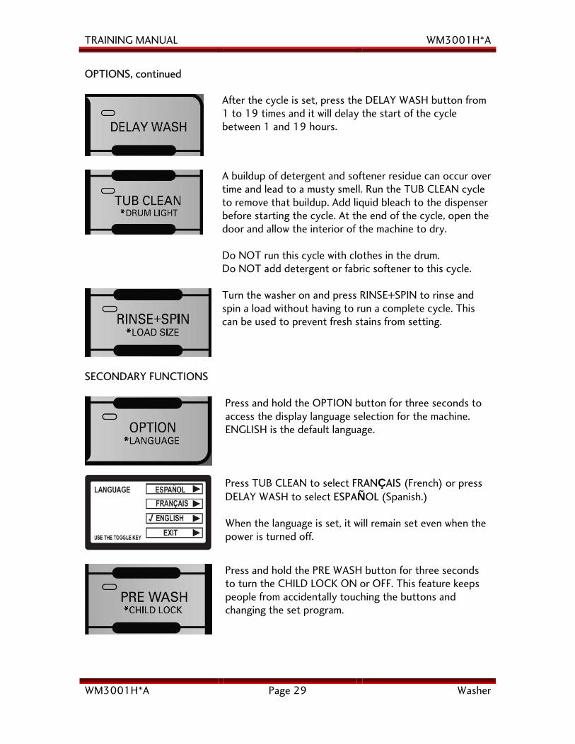
After the cycle is set, press the DELAY WASH button from 1 to 19 times and it will delay the start of the cycle between 1 and 19 hours.
A buildup of detergent and softener residue can occur over time and lead to a musty smell. Run the TUB CLEAN cycle to remove that buildup. Add liquid bleach to the dispenser before starting the cycle. At the end of the cycle, open the door and allow the interior of the machine to dry. Do NOT run this cycle with clothes in the drum. Do NOT add detergent or fabric softener to this cycle.
Turn the washer on and press RINSE+SPIN to rinse and spin a load without having to run a complete cycle. This can be used to prevent fresh stains from setting.
SECONDARY FUNCTIONS
Press and hold the OPTION button for three seconds to access the display language selection for the machine. ENGLISH is the default language. Press TUB CLEAN to select FRANÇAIS (French) or press DELAY WASH to select ESPAÑOL (Spanish.) When the language is set, it will remain set even when the power is turned off.
Press and hold the PRE WASH button for three seconds to turn the CHILD LOCK ON or OFF. This feature keeps people from accidentally touching the buttons and changing the set program.
TRAINING MANUAL WM3001H*A
WM3001H*A Page 30 Washer
SECONDARY FUNCTIONS, continued
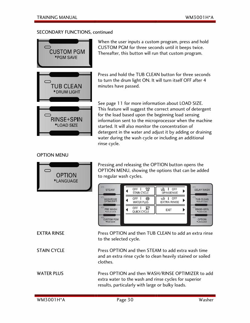
When the user inputs a custom program, press and hold CUSTOM PGM for three seconds until it beeps twice. Thereafter, this button will run that custom program.
Press and hold the TUB CLEAN button for three seconds to turn the drum light ON. It will turn itself OFF after 4 minutes have passed. See page 11 for more information about LOAD SIZE.
This feature will suggest the correct amount of detergent for the load based upon the beginning load sensing information sent to the microprocessor when the machine started. It will also monitor the concentration of detergent in the water and adjust it by adding or draining water during the wash cycle or including an additional rinse cycle.
OPTION MENU
Pressing and releasing the OPTION button opens the OPTION MENU, showing the options that can be added to regular wash cycles.
EXTRA RINSE Press OPTION and then TUB CLEAN to add an extra rinse to the selected cycle.
STAIN CYCLE Press OPTION and then STEAM to add extra wash time and an extra rinse cycle to clean heavily stained or soiled clothes.
WATER PLUS Press OPTION and then WASH/RINSE OPTIMIZER to add extra water to the wash and rinse cycles for superior results, particularly with large or bulky loads.
TRAINING MANUAL WM3001H*A
WM3001H*A Page 31 Washer
OPTION MENU, continued QUICK CYCLE Press OPTION and then PRE WASH to abbreviate the
normal wash cycle.
SPINSENSE™ SPINSENSE™ is used to help reduce or eliminate vibration, especially on wood floor installations. The SPINSENSE™ indicator remains lit while the washer is running to show that it is active. It is a non-volatile toggle, meaning that it remains set in whatever position it is set, even if there is a power failure.
Only woolen items designated as machine washable should be washed in the washing machine, and then on the HAND WASH / WOOL cycle only. Wash only small loads (less than 8 pounds) for optimum fabric care. Use only a neutral, wool-safe detergent. Only a small amount of detergent is necessary due to the small load size and low water volume. The HAND WASH / WOOL cycle uses a gentle tumble action and low speed spin.
NSF International certifies that the SANITARY cycle reduces 99.9% of the bacteria on laundry, and that none of the bacteria will carry over to the subsequent laundry load.

TRAINING MANUAL WM3001H*A
WM3001H*A Page 32 Washer
WATER TEMPERATURE CONTROL
PREWASH CYCLE Cold water is supplied via the dispenser when the prewash valve opens. If COLD WASH / COLD RINSE is selected, the heater is not activated. If another WASH / RINSE temper-ature is selected, the heater still is not activated during the PREWASH unless the water temperature is lower than 85° F (29° C). MAIN WASH and RINSE CYCLE At the beginning of the prewash cycle, COLD water is supplied via the dispenser when the prewash valve opens. Then HOT or COLD water is applied as required to create a wash of the programmed temperature, as shown in the table below. EXTRA
HOT HOT WARM COLD
Set Point 158° F 122° F 104° F 86° F Range (Wash) 158~167° F 122~131° F 104~113° F 50~86° F Range (Rinse) 68~77° F 68~77° F 68~77° F Tap As used in the chart, the set point is the specified temperature setting (hot, warm, and cold) as recommend by clothing manufacturers. In times past, HOT was whatever came out of the hot water faucet, COLD was whatever came out of the cold water faucet, and WARM was what happened with both valves opened. The washing machine uses a thermistor and computer to regulate the water input, adding hot or cold water as needed to adjust the temperature. If the washer cannot achieve the desired temperature with the addition of hot water to the tub, the heater will be activated and continue to operate until the desired temperature is achieved. When the desired setting is reached, the heater is turned off, and it will not come on again unless the temperature of the water in the tub decreases by 36°F (20° C.) For example, in the case of a HOT wash, when the water is heated to 122°F (50° C.) In example 1, on the next page, HOT / COLD temperatures are chosen for a NORMAL cycle. The prewash valve is opened and cold water is supplied briefly, then the hot valve is opened and water fills the tub until it reaches 131° F. As 131°F is hotter than the set point for HOT washing (122°F), the cold valve is opened to regulate the temperature to 122°F and the heater is never energized because the water temperature meets the target.
continued on next page
TRAINING MANUAL WM3001H*A
WM3001H*A Page 33 Washer
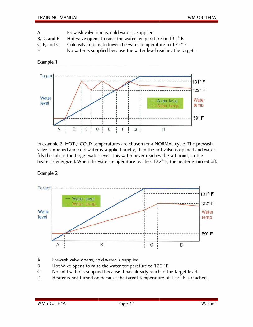
A Prewash valve opens, cold water is supplied. B, D, and F Hot valve opens to raise the water temperature to 131° F. C, E, and G Cold valve opens to lower the water temperature to 122° F. H No water is supplied because the water level reaches the target. Example 1
In example 2, HOT / COLD temperatures are chosen for a NORMAL cycle. The prewash valve is opened and cold water is supplied briefly, then the hot valve is opened and water fills the tub to the target water level. This water never reaches the set point, so the heater is energized. When the water temperature reaches 122° F, the heater is turned off. Example 2
A Prewash valve opens, cold water is supplied. B Hot valve opens to raise the water temperature to 122° F. C No cold water is supplied because it has already reached the target level. D Heater is not turned on because the target temperature of 122° F is reached.
TRAINING MANUAL WM3001H*A
WM3001H*A Page 34 Washer
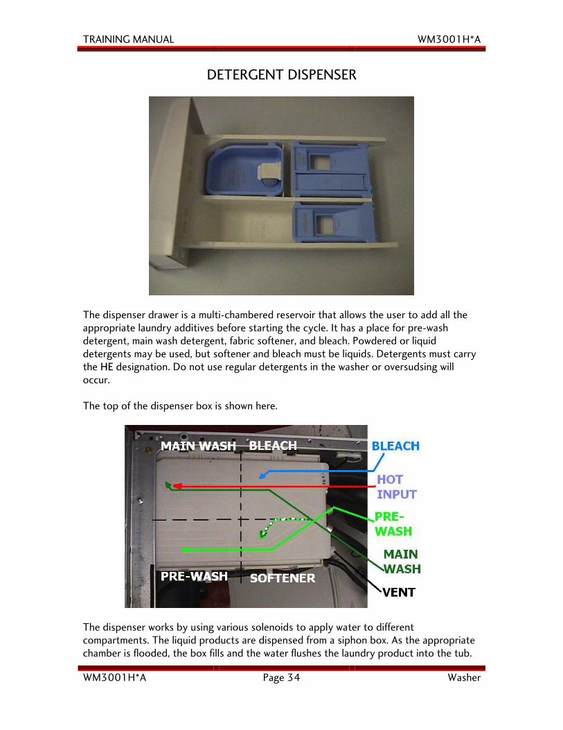
DETERGENT DISPENSER
The dispenser drawer is a multi-chambered reservoir that allows the user to add all the appropriate laundry additives before starting the cycle. It has a place for pre-wash detergent, main wash detergent, fabric softener, and bleach. Powdered or liquid detergents may be used, but softener and bleach must be liquids. Detergents must carry the HE designation. Do not use regular detergents in the washer or oversudsing will occur. The top of the dispenser box is shown here.
The dispenser works by using various solenoids to apply water to different compartments. The liquid products are dispensed from a siphon box. As the appropriate chamber is flooded, the box fills and the water flushes the laundry product into the tub.
TRAINING MANUAL WM3001H*A
WM3001H*A Page 35 Washer
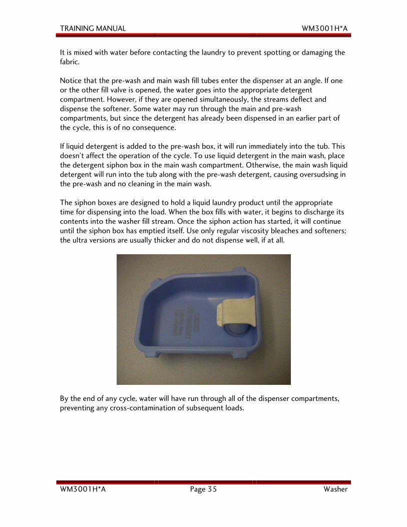
It is mixed with water before contacting the laundry to prevent spotting or damaging the fabric. Notice that the pre-wash and main wash fill tubes enter the dispenser at an angle. If one or the other fill valve is opened, the water goes into the appropriate detergent compartment. However, if they are opened simultaneously, the streams deflect and dispense the softener. Some water may run through the main and pre-wash compartments, but since the detergent has already been dispensed in an earlier part of the cycle, this is of no consequence. If liquid detergent is added to the pre-wash box, it will run immediately into the tub. This doesn’t affect the operation of the cycle. To use liquid detergent in the main wash, place the detergent siphon box in the main wash compartment. Otherwise, the main wash liquid detergent will run into the tub along with the pre-wash detergent, causing oversudsing in the pre-wash and no cleaning in the main wash. The siphon boxes are designed to hold a liquid laundry product until the appropriate time for dispensing into the load. When the box fills with water, it begins to discharge its contents into the washer fill stream. Once the siphon action has started, it will continue until the siphon box has emptied itself. Use only regular viscosity bleaches and softeners; the ultra versions are usually thicker and do not dispense well, if at all.
By the end of any cycle, water will have run through all of the dispenser compartments, preventing any cross-contamination of subsequent loads.
TRAINING MANUAL WM3001H*A
WM3001H*A Page 36 Washer
THE RULE OF TWOs We recommend the RULE OF TWOS concerning the usage of laundry products. Use no more than TWO TABLESPOONS of detergent in either the pre-wash or the main wash cycles. Use no more than TWO TEASPOONS of softener or bleach. While some HE laundry detergents suggest the use of as much as 4 ounces per load, this is entirely too much detergent for the LG machines. It will leave detergent film on your clothes, causing them to be dull and dingy. Over time, using too much detergent and softener will cause a thick film to build up on the inner surface of the tub. This buildup may become so thick it causes friction when the drum rotates, which will cause a malfunction of the machine. It may also generate a foul odor. While the use of a cleaning agent, like one designed to remove the soap scum from a whirlpool bath, will sometimes help, the best way to resolve this issue is to disassemble the machine, separate the tub halves, and use a pressure washer to remove the build up. This is costly, and we recommend using the appropriate amounts of detergent and other laundry additives to prevent such an occurrence. Due to the design of the machine, we do not recommend using it to soak or dye clothing, nor do we recommend the use of various laundry additives such as enzyme pre-soaks, detergent boosters, borax additives, bluing, and others.
TRAINING MANUAL WM3001H*A
WM3001H*A Page 37 Washer
DIRECT DRIVE MOTOR
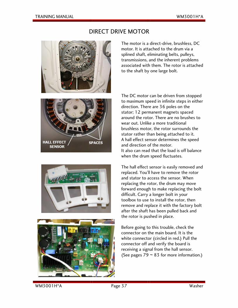
The motor is a direct-drive, brushless, DC motor. It is attached to the drum via a splined shaft, eliminating belts, pulleys, transmissions, and the inherent problems associated with them. The rotor is attached to the shaft by one large bolt.
The DC motor can be driven from stopped to maximum speed in infinite steps in either direction. There are 36 poles on the stator; 12 permanent magnets spaced around the rotor. There are no brushes to wear out. Unlike a more traditional brushless motor, the rotor surrounds the stator rather than being attached to it. A hall effect sensor determines the speed and direction of the motor. It also can read that the load is off balance when the drum speed fluctuates.
The hall effect sensor is easily removed and replaced. You’ll have to remove the rotor and stator to access the sensor. When replacing the rotor, the drum may move forward enough to make replacing the bolt difficult. Carry a longer bolt in your toolbox to use to install the rotor, then remove and replace it with the factory bolt after the shaft has been pulled back and the rotor is pushed in place.
Before going to this trouble, check the connector on the main board. It is the white connector (circled in red.) Pull the connector off and verify the board is receiving a signal from the hall sensor. (See pages 79 ~ 83 for more information.)
TRAINING MANUAL WM3001H*A
WM3001H*A Page 38 Washer
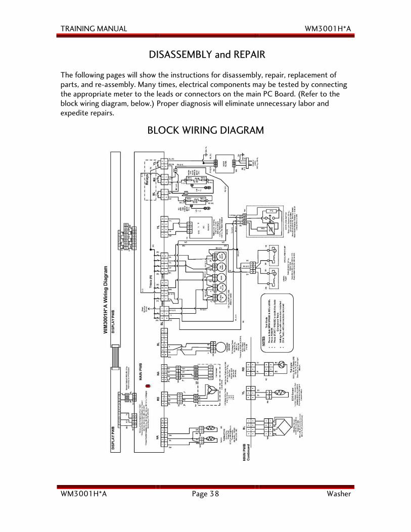
DISASSEMBLY and REPAIR
The following pages will show the instructions for disassembly, repair, replacement of parts, and re-assembly. Many times, electrical components may be tested by connecting the appropriate meter to the leads or connectors on the main PC Board. (Refer to the block wiring diagram, below.) Proper diagnosis will eliminate unnecessary labor and expedite repairs.
BLOCK WIRING DIAGRAM
TRAINING MANUAL WM3001H*A
WM3001H*A Page 39 Washer
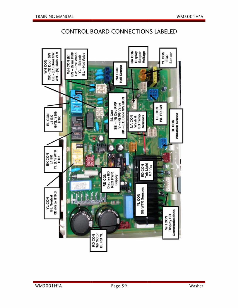
CONTROL BOARD CONNECTIONS LABELED
TRAINING MANUAL WM3001H*A
WM3001H*A Page 40 Washer
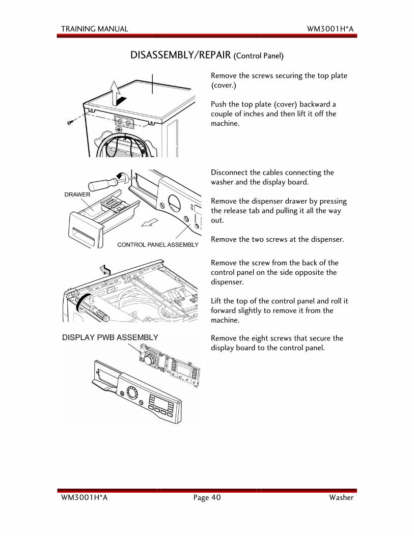
DISASSEMBLY/REPAIR (Control Panel)
Remove the screws securing the top plate (cover.) Push the top plate (cover) backward a couple of inches and then lift it off the machine.
Disconnect the cables connecting the washer and the display board. Remove the dispenser drawer by pressing the release tab and pulling it all the way out. Remove the two screws at the dispenser.
Remove the screw from the back of the control panel on the side opposite the dispenser. Lift the top of the control panel and roll it forward slightly to remove it from the machine.
Remove the eight screws that secure the display board to the control panel.
TRAINING MANUAL WM3001H*A
WM3001H*A Page 41 Washer
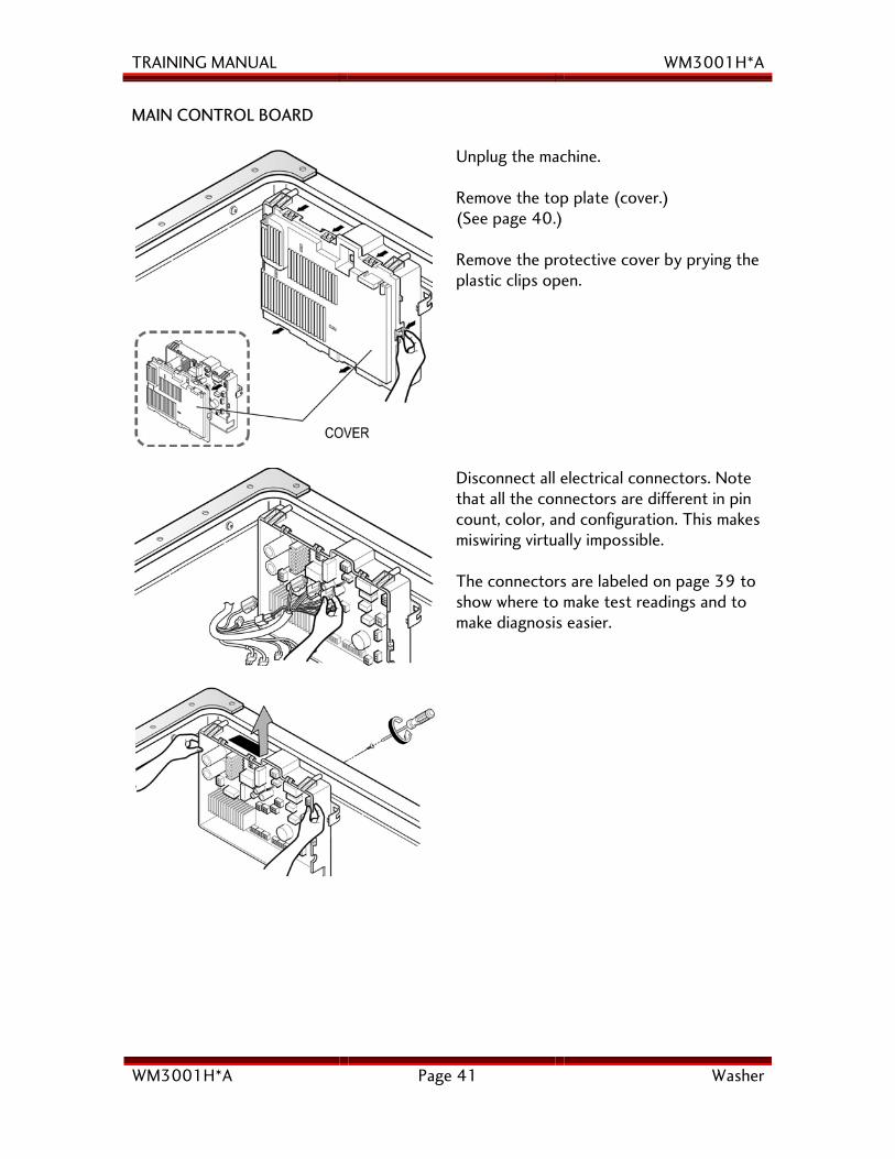
MAIN CONTROL BOARD
Unplug the machine. Remove the top plate (cover.) (See page 40.) Remove the protective cover by prying the plastic clips open.
Disconnect all electrical connectors. Note that all the connectors are different in pin count, color, and configuration. This makes miswiring virtually impossible. The connectors are labeled on page 39 to show where to make test readings and to make diagnosis easier.
TRAINING MANUAL WM3001H*A
WM3001H*A Page 42 Washer
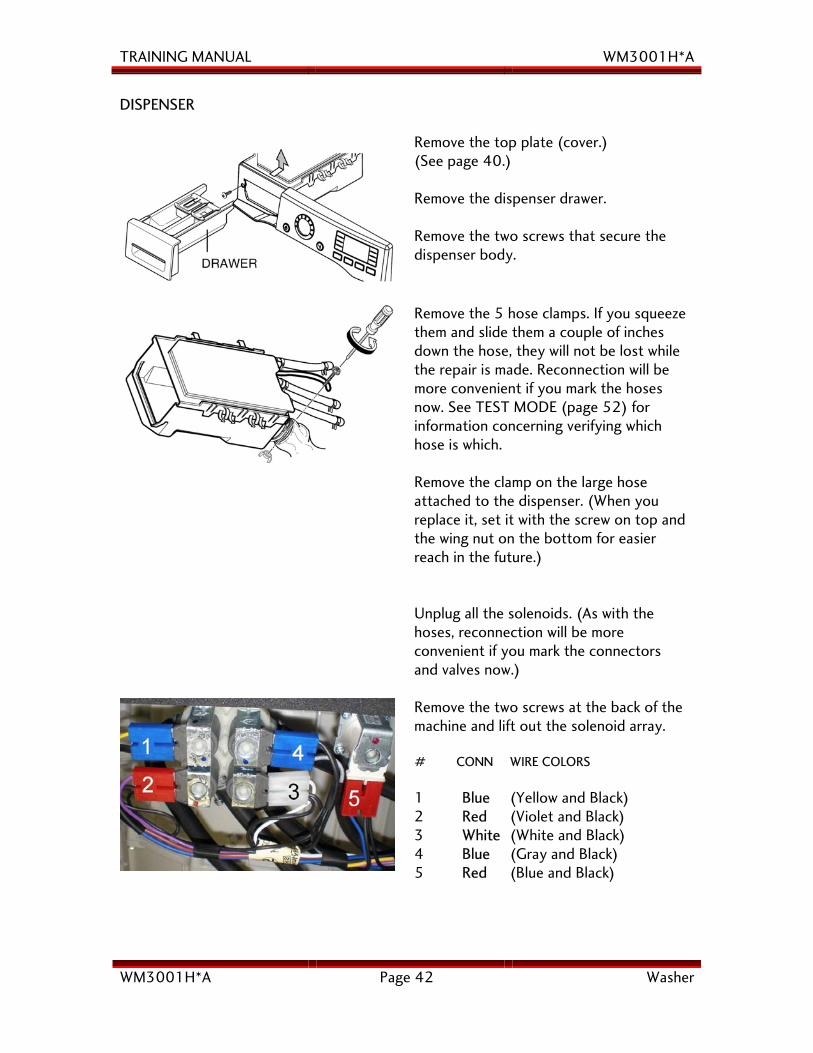
DISPENSER
Remove the top plate (cover.) (See page 40.) Remove the dispenser drawer. Remove the two screws that secure the dispenser body.
Remove the 5 hose clamps. If you squeeze them and slide them a couple of inches down the hose, they will not be lost while the repair is made. Reconnection will be more convenient if you mark the hoses now. See TEST MODE (page 52) for information concerning verifying which hose is which. Remove the clamp on the large hose attached to the dispenser. (When you replace it, set it with the screw on top and the wing nut on the bottom for easier reach in the future.)
Unplug all the solenoids. (As with the hoses, reconnection will be more convenient if you mark the connectors and valves now.) Remove the two screws at the back of the machine and lift out the solenoid array. # CONN WIRE COLORS 1 Blue (Yellow and Black) 2 Red (Violet and Black) 3 White (White and Black) 4 Blue (Gray and Black) 5 Red (Blue and Black)
TRAINING MANUAL WM3001H*A
WM3001H*A Page 43 Washer
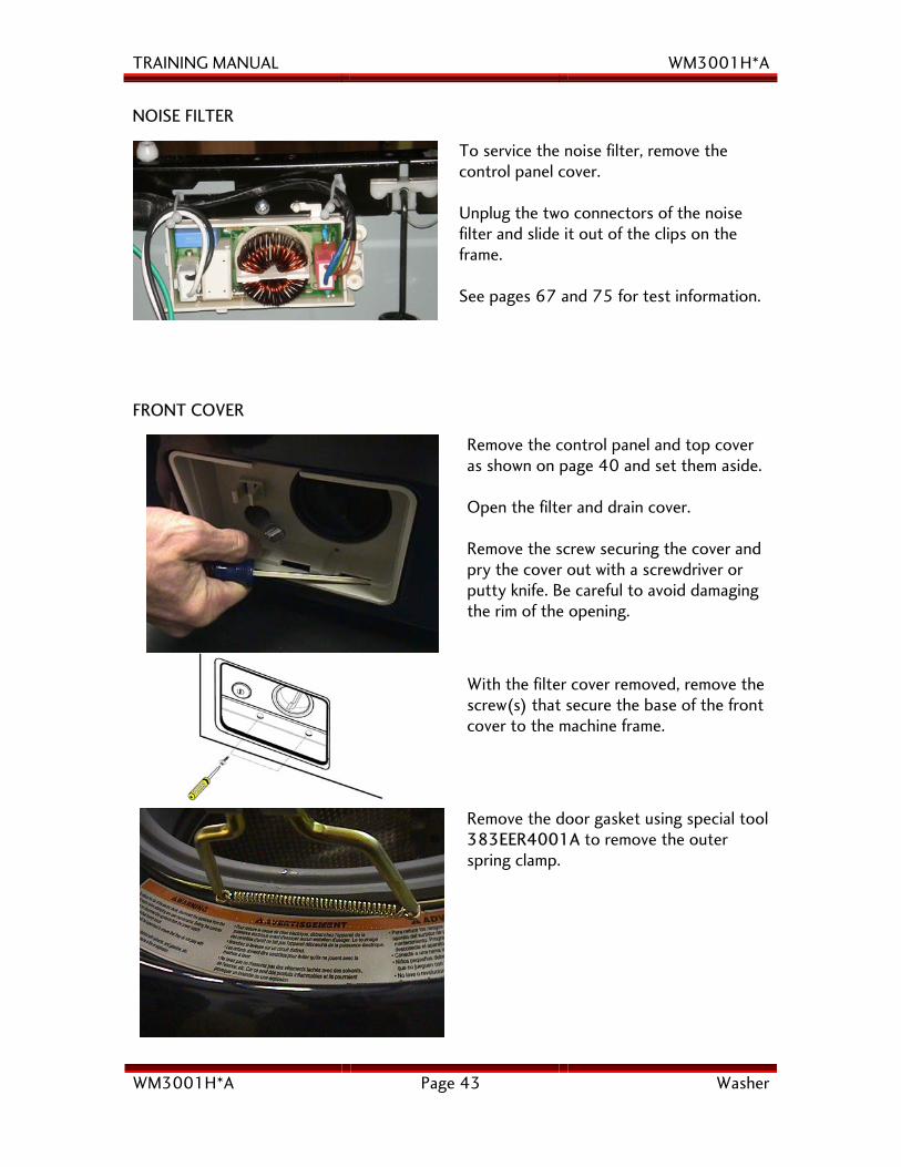
NOISE FILTER
To service the noise filter, remove the control panel cover. Unplug the two connectors of the noise filter and slide it out of the clips on the frame. See pages 67 and 75 for test information.
FRONT COVER
Remove the control panel and top cover as shown on page 40 and set them aside. Open the filter and drain cover. Remove the screw securing the cover and pry the cover out with a screwdriver or putty knife. Be careful to avoid damaging the rim of the opening.
With the filter cover removed, remove the screw(s) that secure the base of the front cover to the machine frame.
Remove the door gasket using special tool 383EER4001A to remove the outer spring clamp.
TRAINING MANUAL WM3001H*A
WM3001H*A Page 44 Washer
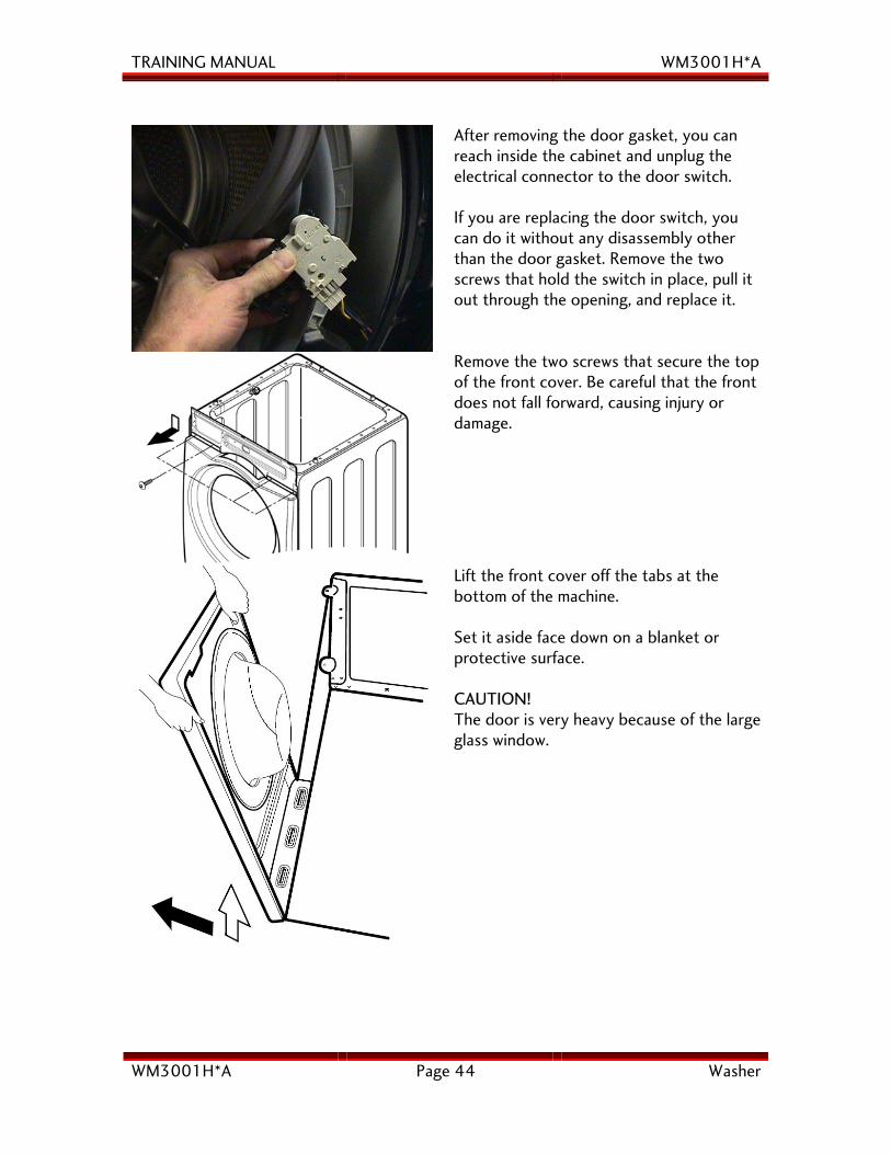
After removing the door gasket, you can reach inside the cabinet and unplug the electrical connector to the door switch. If you are replacing the door switch, you can do it without any disassembly other than the door gasket. Remove the two screws that hold the switch in place, pull it out through the opening, and replace it.
Remove the two screws that secure the top of the front cover. Be careful that the front does not fall forward, causing injury or damage.
Lift the front cover off the tabs at the bottom of the machine. Set it aside face down on a blanket or protective surface. CAUTION! The door is very heavy because of the large glass window.
TRAINING MANUAL WM3001H*A
WM3001H*A Page 45 Washer
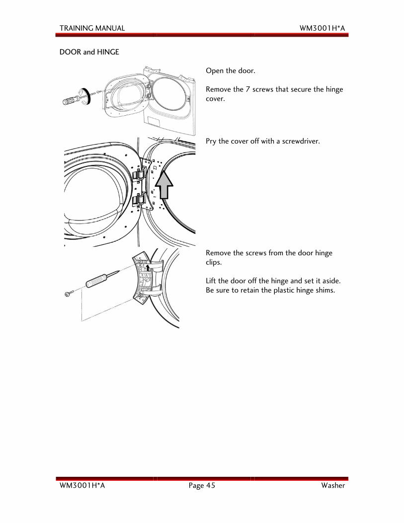
DOOR and HINGE
Open the door. Remove the 7 screws that secure the hinge cover.
Pry the cover off with a screwdriver.
Remove the screws from the door hinge clips. Lift the door off the hinge and set it aside. Be sure to retain the plastic hinge shims.
TRAINING MANUAL WM3001H*A
WM3001H*A Page 46 Washer
PUMPS and FILTER HOUSING
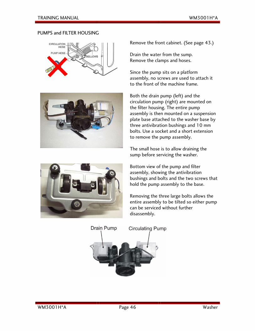
Remove the front cabinet. (See page 43.) Drain the water from the sump. Remove the clamps and hoses. Since the pump sits on a platform assembly, no screws are used to attach it to the front of the machine frame.
Both the drain pump (left) and the circulation pump (right) are mounted on the filter housing. The entire pump assembly is then mounted on a suspension plate base attached to the washer base by three antivibration bushings and 10 mm bolts. Use a socket and a short extension to remove the pump assembly. The small hose is to allow draining the sump before servicing the washer.
Bottom view of the pump and filter assembly, showing the antivibration bushings and bolts and the two screws that hold the pump assembly to the base. Removing the three large bolts allows the entire assembly to be tilted so either pump can be serviced without further disassembly.
TRAINING MANUAL WM3001H*A
WM3001H*A Page 47 Washer
DRAIN PUMP, continued The drain pump and the circulating pump are attached to either side of the filter housing. The drain pump is used to exhaust the water from the washer. The recirculating pump serves three purposes: it sprays water from the tub onto the laundry, creating a better saturation of detergent and better rinsing, it keeps the window clean, and it allows the customer to see water in the tub. The filter between the pumps is not a lint filter in the traditional since. It serves to trap larger objects (keys, coins, buttons, etc.) that may find their way into the washer and protects the pumps from physical damage. WASH HEATER
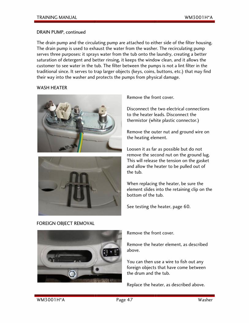
Remove the front cover. Disconnect the two electrical connections to the heater leads. Disconnect the thermistor (white plastic connector.) Remove the outer nut and ground wire on the heating element. Loosen it as far as possible but do not remove the second nut on the ground lug. This will release the tension on the gasket and allow the heater to be pulled out of the tub. When replacing the heater, be sure the element slides into the retaining clip on the bottom of the tub. See testing the heater, page 60.
FOREIGN OBJECT REMOVAL
Remove the front cover. Remove the heater element, as described above. You can then use a wire to fish out any foreign objects that have come between the drum and the tub. Replace the heater, as described above.
TRAINING MANUAL WM3001H*A
WM3001H*A Page 48 Washer
DISASSEMBLY and REPAIR, continued WATER LEVEL SWITCH
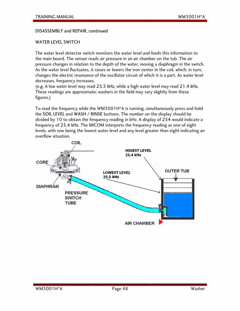
The water level detector switch monitors the water level and feeds this information to the main board. The sensor reads air pressure in an air chamber on the tub. The air pressure changes in relation to the depth of the water, moving a diaphragm in the switch. As the water level fluctuates, it raises or lowers the iron center in the coil, which, in turn, changes the electric resonance of the oscillator circuit of which it is a part. As water level decreases, frequency increases. (e.g. A low water level may read 25.5 kHz, while a high water level may read 21.4 kHz. These readings are approximate; washers in the field may vary slightly from these figures.) To read the frequency while the WM3001H*A is running, simultaneously press and hold the SOIL LEVEL and WASH / RINSE buttons. The number on the display should be divided by 10 to obtain the frequency reading in kHz. A display of 254 would indicate a frequency of 25.4 kHz. The MICOM interprets the frequency reading as one of eight levels, with one being the lowest water level and any level greater than eight indicating an overflow situation.
TRAINING MANUAL WM3001H*A
WM3001H*A Page 49 Washer
DISASSEMBLY and REPAIR, continued MOTOR
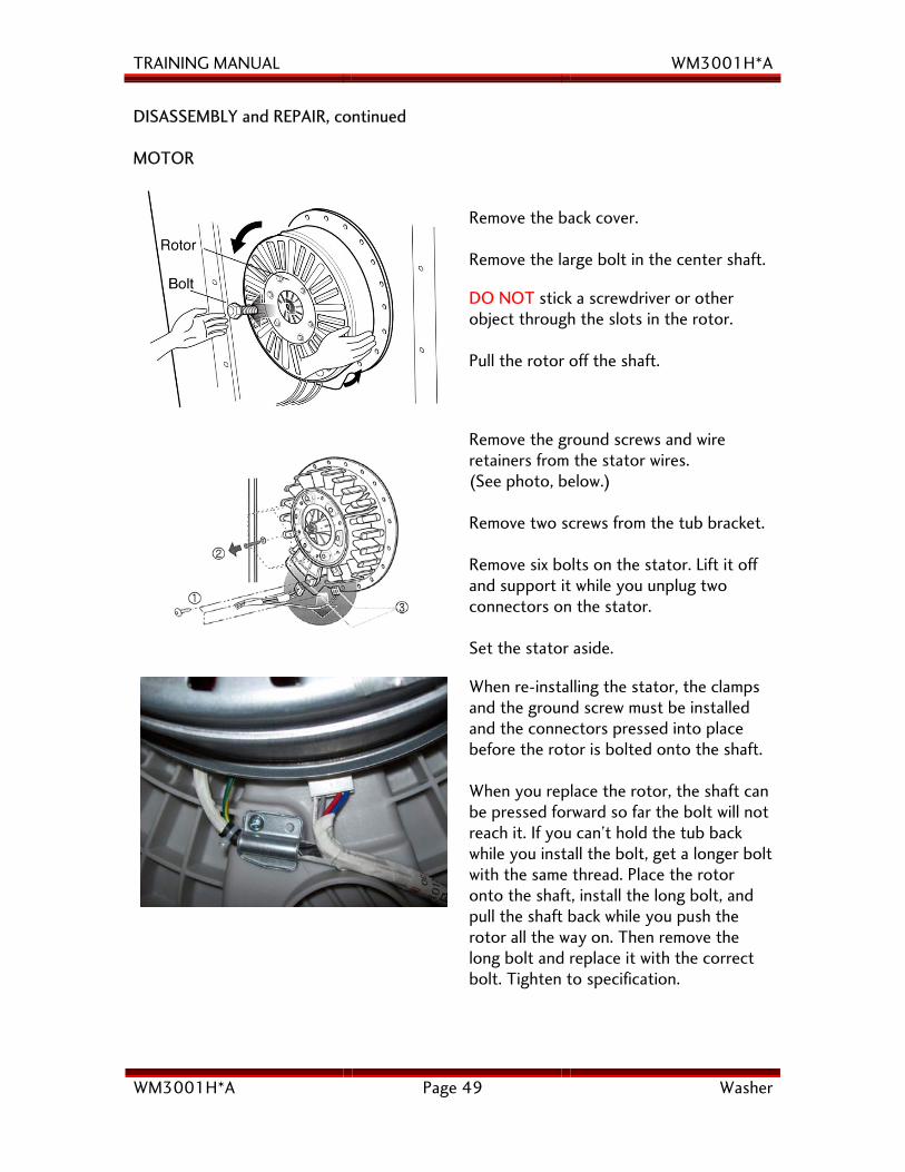
Remove the back cover. Remove the large bolt in the center shaft.
DO NOT stick a screwdriver or other object through the slots in the rotor. Pull the rotor off the shaft.
Remove the ground screws and wire retainers from the stator wires. (See photo, below.) Remove two screws from the tub bracket. Remove six bolts on the stator. Lift it off and support it while you unplug two connectors on the stator. Set the stator aside.
When re-installing the stator, the clamps and the ground screw must be installed and the connectors pressed into place before the rotor is bolted onto the shaft. When you replace the rotor, the shaft can be pressed forward so far the bolt will not reach it. If you can’t hold the tub back while you install the bolt, get a longer bolt with the same thread. Place the rotor onto the shaft, install the long bolt, and pull the shaft back while you push the rotor all the way on. Then remove the long bolt and replace it with the correct bolt. Tighten to specification.
TRAINING MANUAL WM3001H*A
WM3001H*A Page 50 Washer
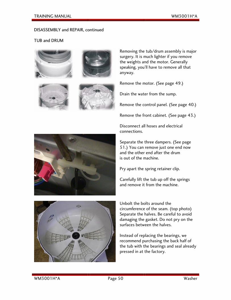
DISASSEMBLY and REPAIR, continued TUB and DRUM
Removing the tub/drum assembly is major surgery. It is much lighter if you remove the weights and the motor. Generally speaking, you’ll have to remove all that anyway. Remove the motor. (See page 49.) Drain the water from the sump. Remove the control panel. (See page 40.) Remove the front cabinet. (See page 43.) Disconnect all hoses and electrical connections.
Separate the three dampers. (See page 51.) You can remove just one end now and the other end after the drum is out of the machine. Pry apart the spring retainer clip. Carefully lift the tub up off the springs and remove it from the machine.
Unbolt the bolts around the circumference of the seam. (top photo) Separate the halves. Be careful to avoid damaging the gasket. Do not pry on the surfaces between the halves. Instead of replacing the bearings, we recommend purchasing the back half of the tub with the bearings and seal already pressed in at the factory.
TRAINING MANUAL WM3001H*A
WM3001H*A Page 51 Washer
DISASSEMBLY and REPAIR, continued DAMPERS
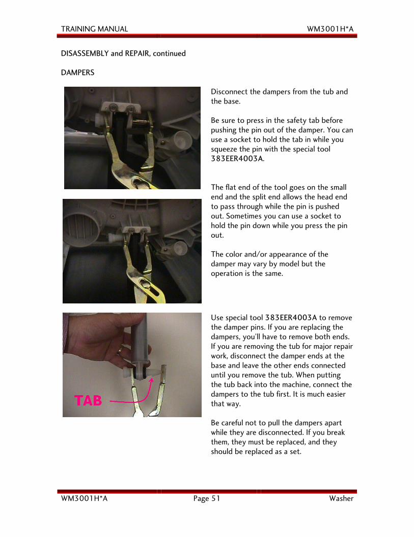
Disconnect the dampers from the tub and the base. Be sure to press in the safety tab before pushing the pin out of the damper. You can use a socket to hold the tab in while you squeeze the pin with the special tool 383EER4003A. The flat end of the tool goes on the small end and the split end allows the head end to pass through while the pin is pushed out. Sometimes you can use a socket to hold the pin down while you press the pin out. The color and/or appearance of the damper may vary by model but the operation is the same.
Use special tool 383EER4003A to remove the damper pins. If you are replacing the dampers, you’ll have to remove both ends. If you are removing the tub for major repair work, disconnect the damper ends at the base and leave the other ends connected until you remove the tub. When putting the tub back into the machine, connect the dampers to the tub first. It is much easier that way. Be careful not to pull the dampers apart while they are disconnected. If you break them, they must be replaced, and they should be replaced as a set.
TRAINING MANUAL WM3001H*A
WM3001H*A Page 52 Washer
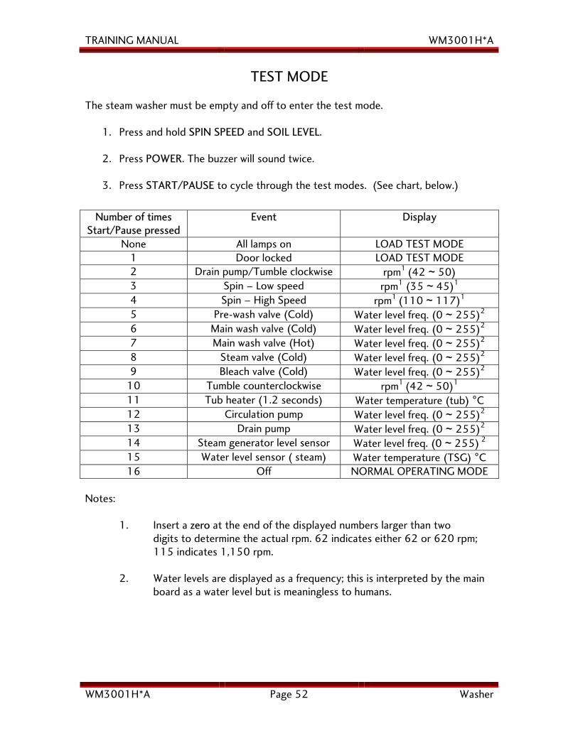
TEST MODE
The steam washer must be empty and off to enter the test mode.
1. Press and hold SPIN SPEED and SOIL LEVEL.
2. Press POWER. The buzzer will sound twice.
3. Press START/PAUSE to cycle through the test modes. (See chart, below.)
Number of times
Start/Pause pressed Event Display
None All lamps on LOAD TEST MODE 1 Door locked LOAD TEST MODE 2 Drain pump/Tumble clockwise rpm1 (42 ~ 50) 3 Spin – Low speed rpm1 (35 ~ 45)1 4 Spin – High Speed rpm1 (110 ~ 117)1 5 Pre-wash valve (Cold) Water level freq. (0 ~ 255)2 6 Main wash valve (Cold) Water level freq. (0 ~ 255)2 7 Main wash valve (Hot) Water level freq. (0 ~ 255)2 8 Steam valve (Cold) Water level freq. (0 ~ 255)2 9 Bleach valve (Cold) Water level freq. (0 ~ 255)2
10 Tumble counterclockwise rpm1 (42 ~ 50)1 11 Tub heater (1.2 seconds) Water temperature (tub) °C 12 Circulation pump Water level freq. (0 ~ 255)2 13 Drain pump Water level freq. (0 ~ 255)2 14 Steam generator level sensor Water level freq. (0 ~ 255) 2 15 Water level sensor ( steam) Water temperature (TSG) °C 16 Off NORMAL OPERATING MODE
Notes: 1. Insert a zero at the end of the displayed numbers larger than two digits to determine the actual rpm. 62 indicates either 62 or 620 rpm; 115 indicates 1,150 rpm. 2. Water levels are displayed as a frequency; this is interpreted by the main board as a water level but is meaningless to humans.
TRAINING MANUAL WM3001H*A
WM3001H*A Page 53 Washer
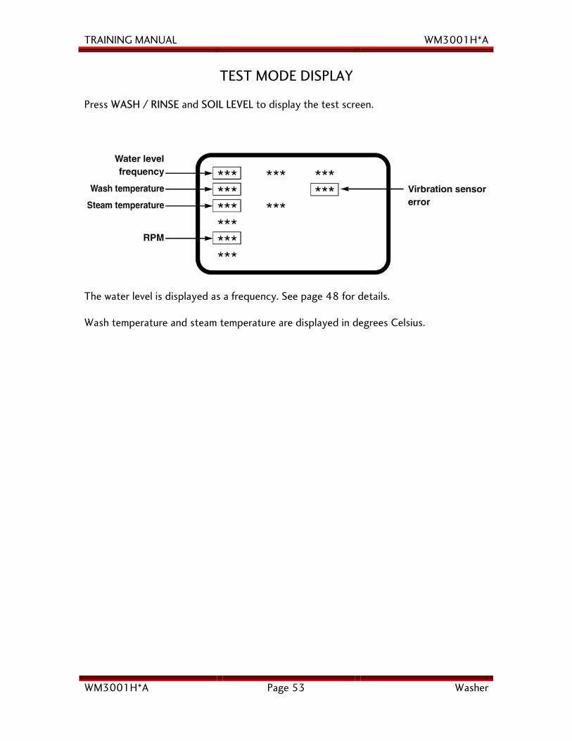
TEST MODE DISPLAY
Press WASH / RINSE and SOIL LEVEL to display the test screen.
The water level is displayed as a frequency. See page 48 for details. Wash temperature and steam temperature are displayed in degrees Celsius.
TRAINING MANUAL WM3001H*A
WM3001H*A Page 54 Washer
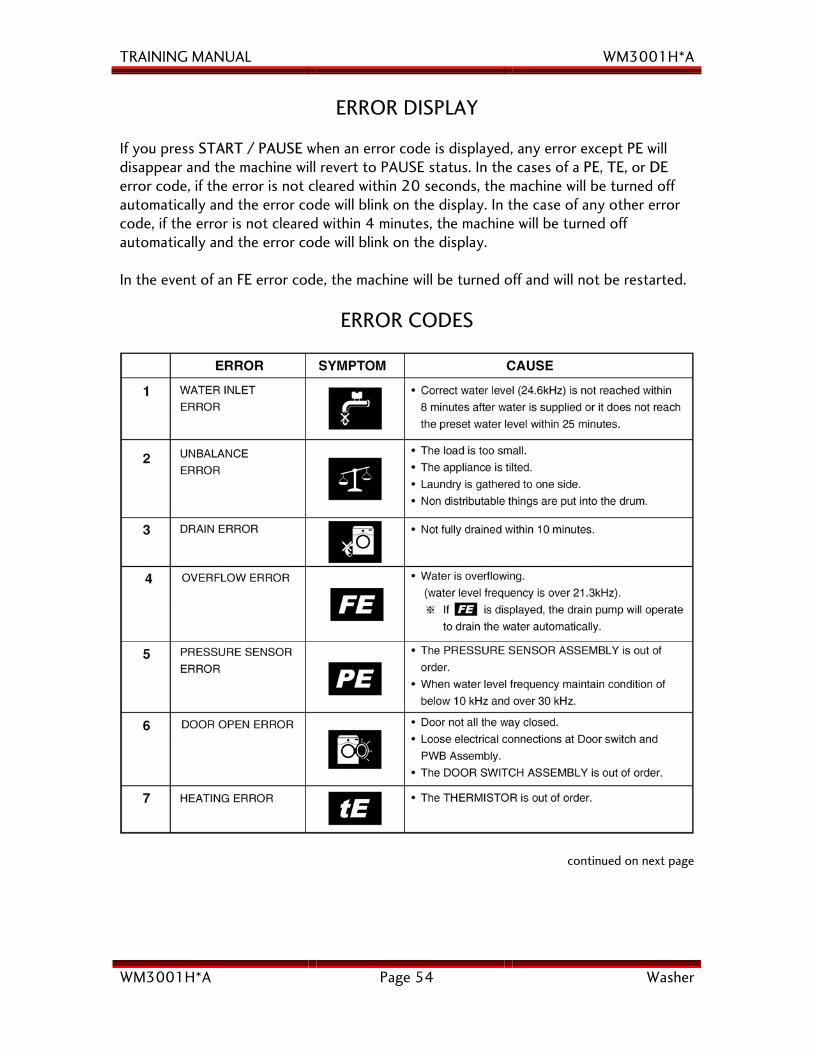
ERROR DISPLAY If you press START / PAUSE when an error code is displayed, any error except PE will disappear and the machine will revert to PAUSE status. In the cases of a PE, TE, or DE error code, if the error is not cleared within 20 seconds, the machine will be turned off automatically and the error code will blink on the display. In the case of any other error code, if the error is not cleared within 4 minutes, the machine will be turned off automatically and the error code will blink on the display. In the event of an FE error code, the machine will be turned off and will not be restarted.
ERROR CODES
continued on next page
TRAINING MANUAL WM3001H*A
WM3001H*A Page 55 Washer
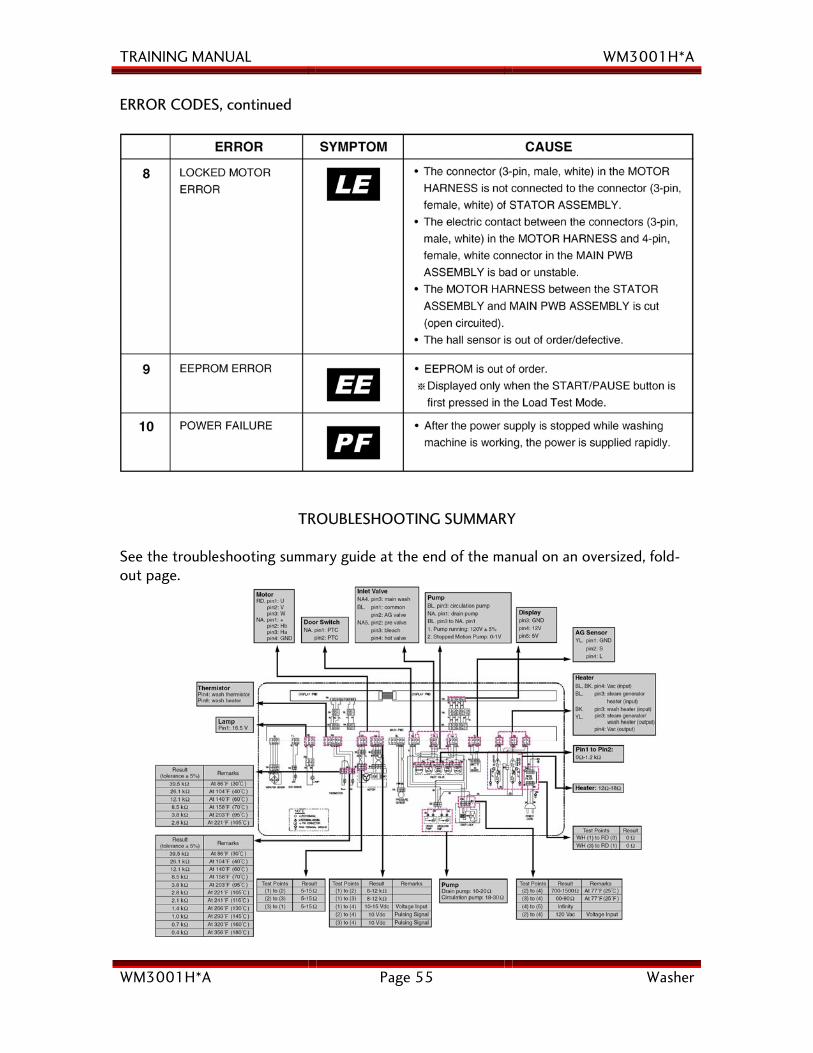
ERROR CODES, continued
TROUBLESHOOTING SUMMARY
See the troubleshooting summary guide at the end of the manual on an oversized, fold-out page.
TRAINING MANUAL WM3001H*A
WM3001H*A Page 56 Washer
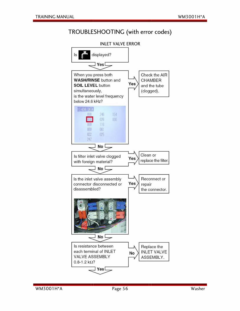
TROUBLESHOOTING (with error codes)
INLET VALVE ERROR
TRAINING MANUAL WM3001H*A
WM3001H*A Page 57 Washer
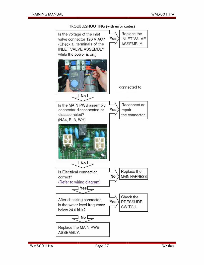
TROUBLESHOOTING (with error codes)
TRAINING MANUAL WM3001H*A
WM3001H*A Page 58 Washer
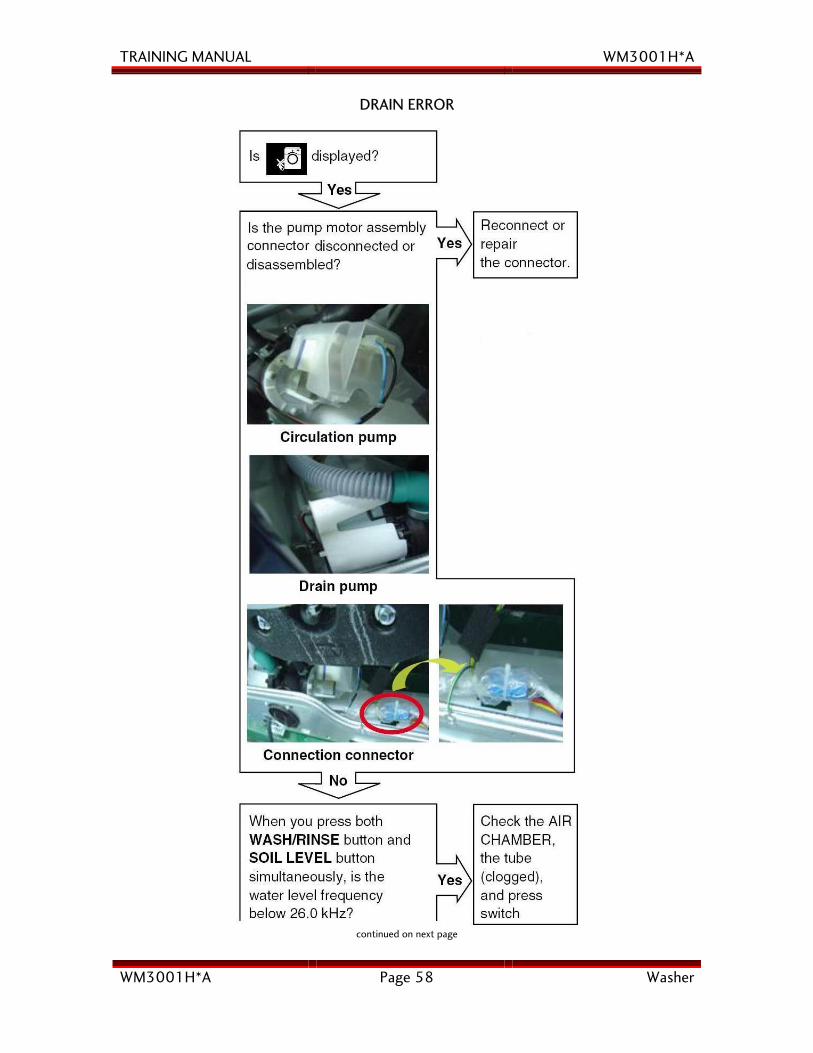
DRAIN ERROR
continued on next page
TRAINING MANUAL WM3001H*A
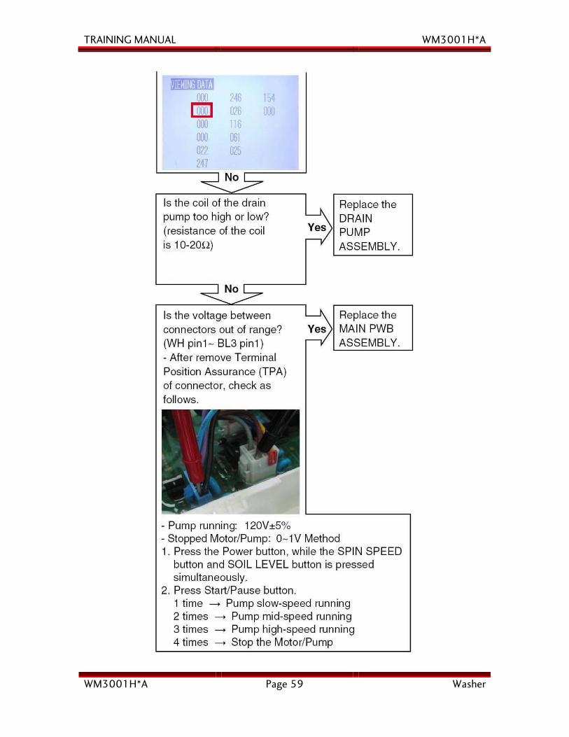
WM3001H*A Page 59 Washer
TRAINING MANUAL WM3001H*A
WM3001H*A Page 60 Washer
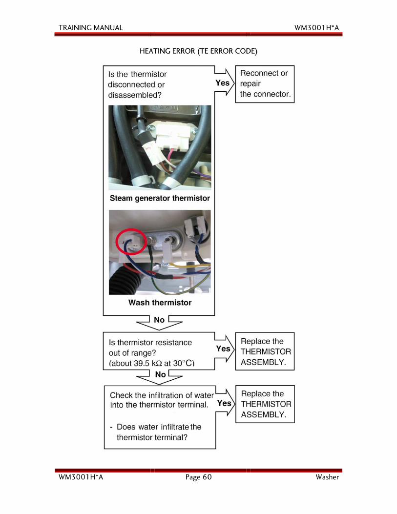
HEATING ERROR (TE ERROR CODE)
TRAINING MANUAL WM3001H*A
WM3001H*A Page 61 Washer
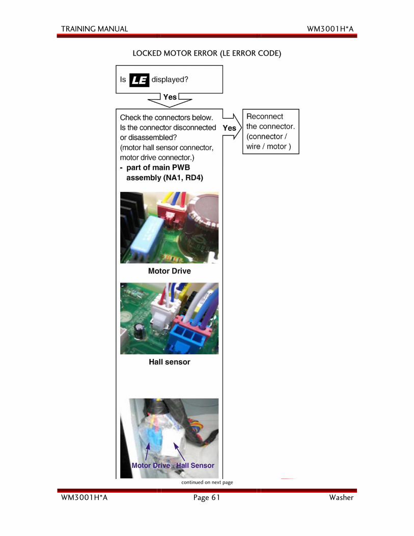
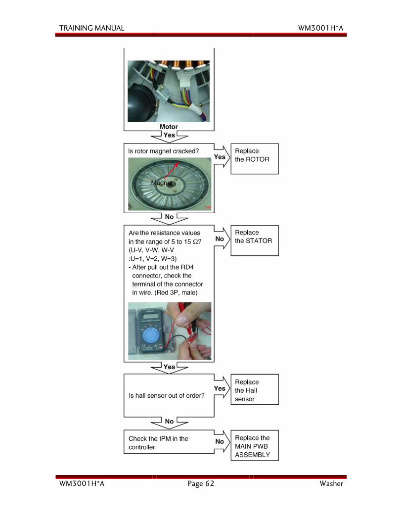
LOCKED MOTOR ERROR (LE ERROR CODE)
continued on next page
TRAINING MANUAL WM3001H*A
WM3001H*A Page 62 Washer
TRAINING MANUAL WM3001H*A
WM3001H*A Page 63 Washer
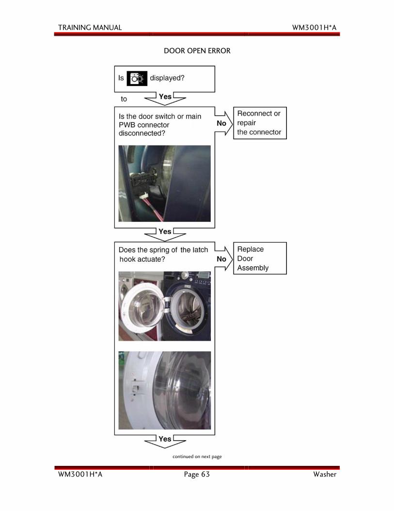
DOOR OPEN ERROR
continued on next page
TRAINING MANUAL WM3001H*A
WM3001H*A Page 64 Washer
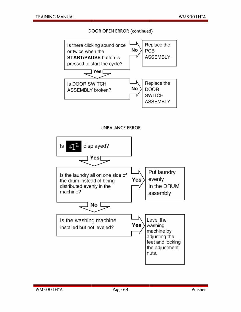
DOOR OPEN ERROR (continued)
UNBALANCE ERROR
TRAINING MANUAL WM3001H*A
WM3001H*A Page 65 Washer
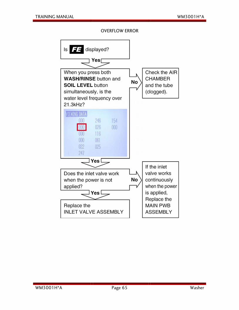
OVERFLOW ERROR
TRAINING MANUAL WM3001H*A
WM3001H*A Page 66 Washer
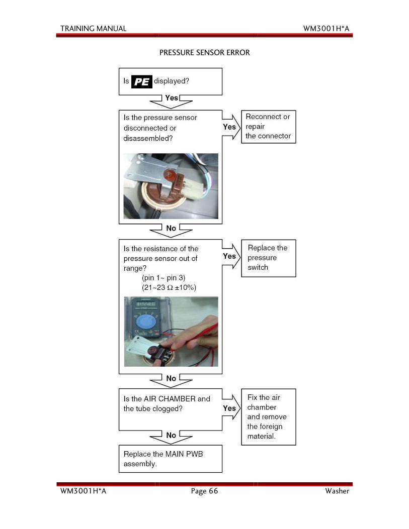
PRESSURE SENSOR ERROR
TRAINING MANUAL WM3001H*A
WM3001H*A Page 67 Washer
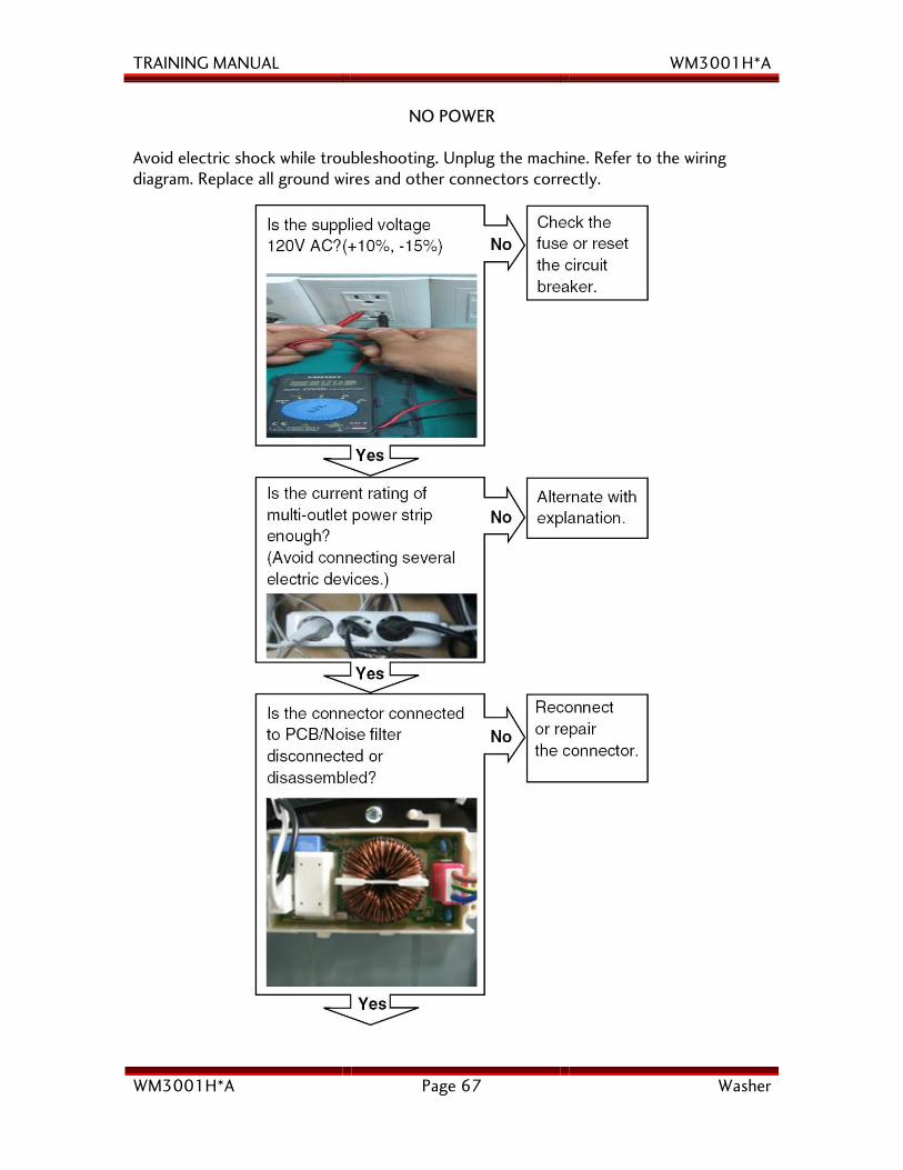
NO POWER
Avoid electric shock while troubleshooting. Unplug the machine. Refer to the wiring diagram. Replace all ground wires and other connectors correctly.
TRAINING MANUAL WM3001H*A
WM3001H*A Page 68 Washer
TRAINING MANUAL WM3001H*A
WM3001H*A Page 69 Washer
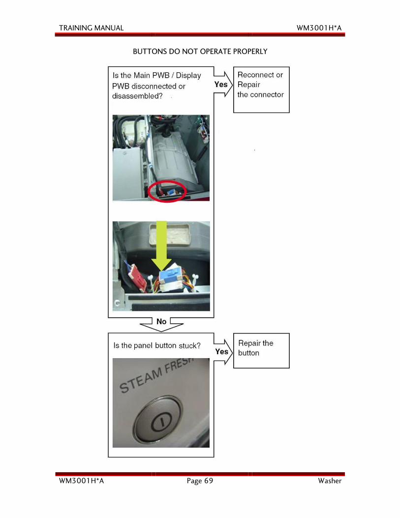
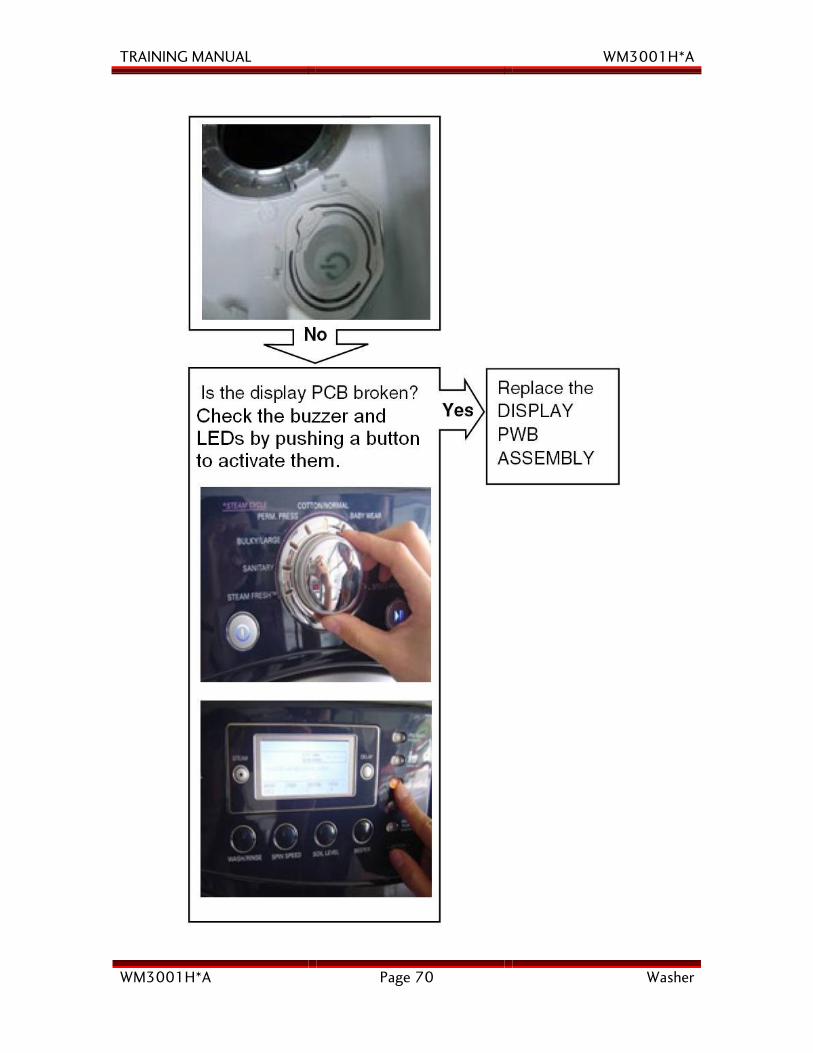
BUTTONS DO NOT OPERATE PROPERLY
TRAINING MANUAL WM3001H*A
WM3001H*A Page 70 Washer
TRAINING MANUAL WM3001H*A
WM3001H*A Page 71 Washer
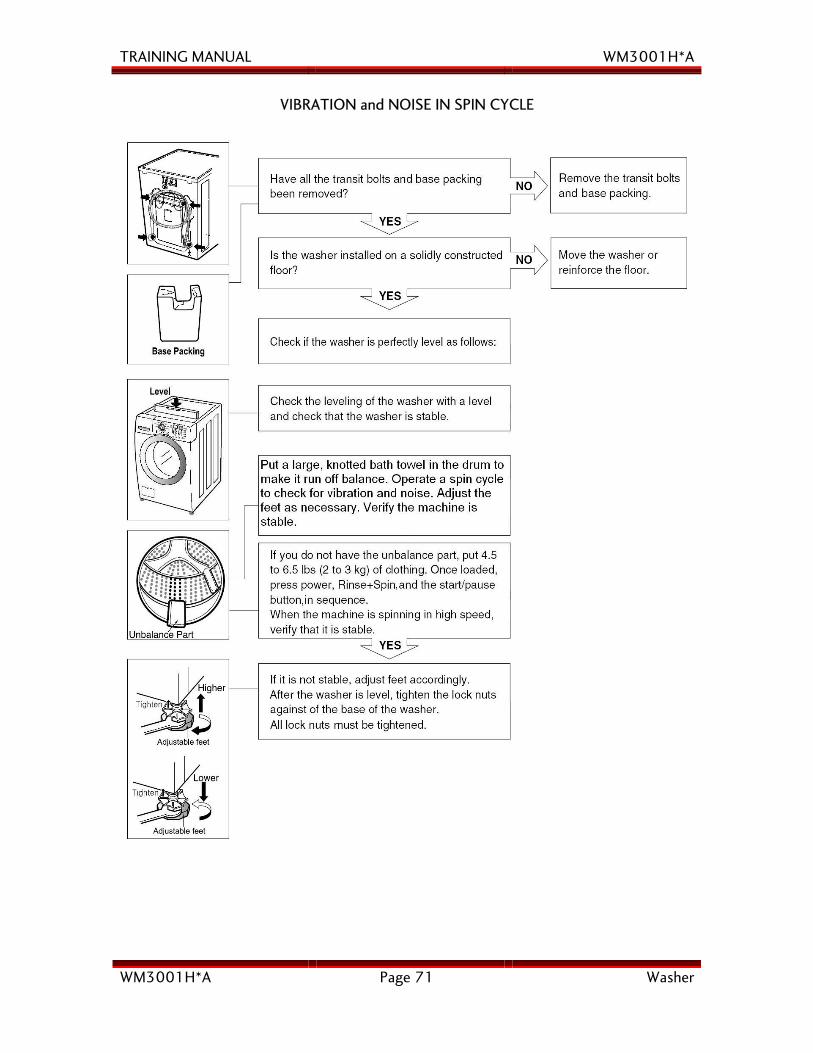
VIBRATION and NOISE IN SPIN CYCLE
TRAINING MANUAL WM3001H*A
WM3001H*A Page 72 Washer
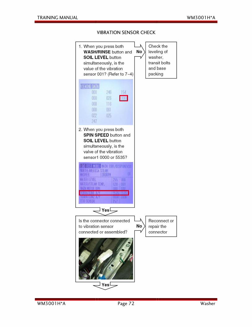
VIBRATION SENSOR CHECK
TRAINING MANUAL WM3001H*A
WM3001H*A Page 73 Washer
TRAINING MANUAL WM3001H*A
WM3001H*A Page 74 Washer
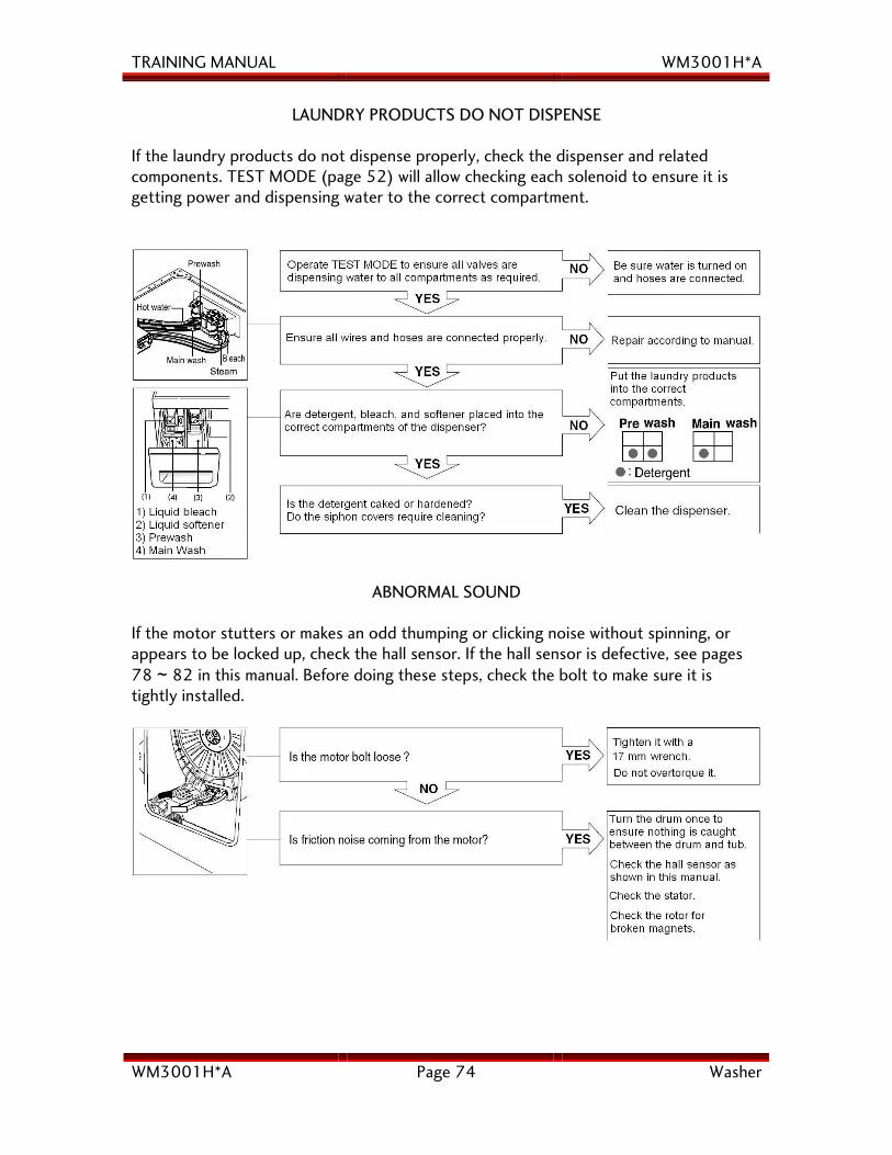
LAUNDRY PRODUCTS DO NOT DISPENSE
If the laundry products do not dispense properly, check the dispenser and related components. TEST MODE (page 52) will allow checking each solenoid to ensure it is getting power and dispensing water to the correct compartment.
ABNORMAL SOUND
If the motor stutters or makes an odd thumping or clicking noise without spinning, or appears to be locked up, check the hall sensor. If the hall sensor is defective, see pages 78 ~ 82 in this manual. Before doing these steps, check the bolt to make sure it is tightly installed.
TRAINING MANUAL WM3001H*A
WM3001H*A Page 75 Washer
COMPONENT TEST PROCEDURES
Several components of the machine can be tested before removing or exchanging them. Some test procedures can be completed without major disassembly other than to disconnect the component from its circuit; others may be tested from their connector on the control panel. Often, the only equipment required is a multimeter.
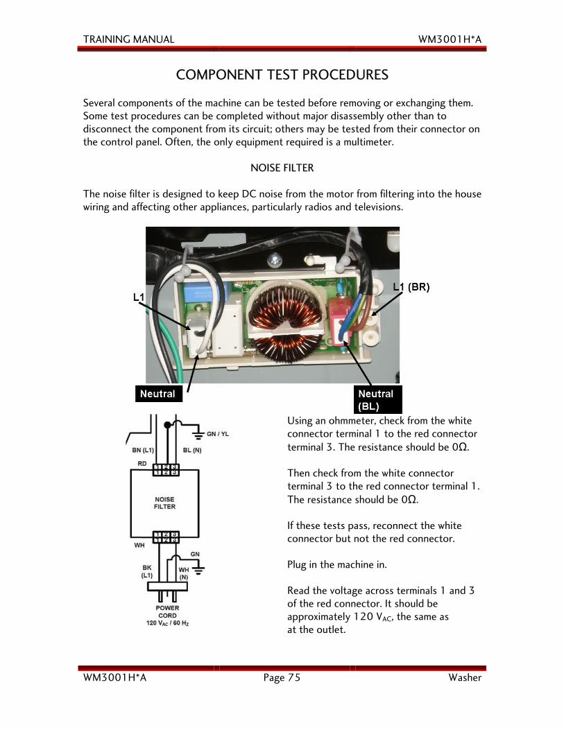
NOISE FILTER
The noise filter is designed to keep DC noise from the motor from filtering into the house wiring and affecting other appliances, particularly radios and televisions.
Using an ohmmeter, check from the white connector terminal 1 to the red connector terminal 3. The resistance should be 0Ω. Then check from the white connector terminal 3 to the red connector terminal 1. The resistance should be 0Ω. If these tests pass, reconnect the white connector but not the red connector. Plug in the machine in. Read the voltage across terminals 1 and 3 of the red connector. It should be approximately 120 VAC, the same as at the outlet.
TRAINING MANUAL WM3001H*A
WM3001H*A Page 76 Washer
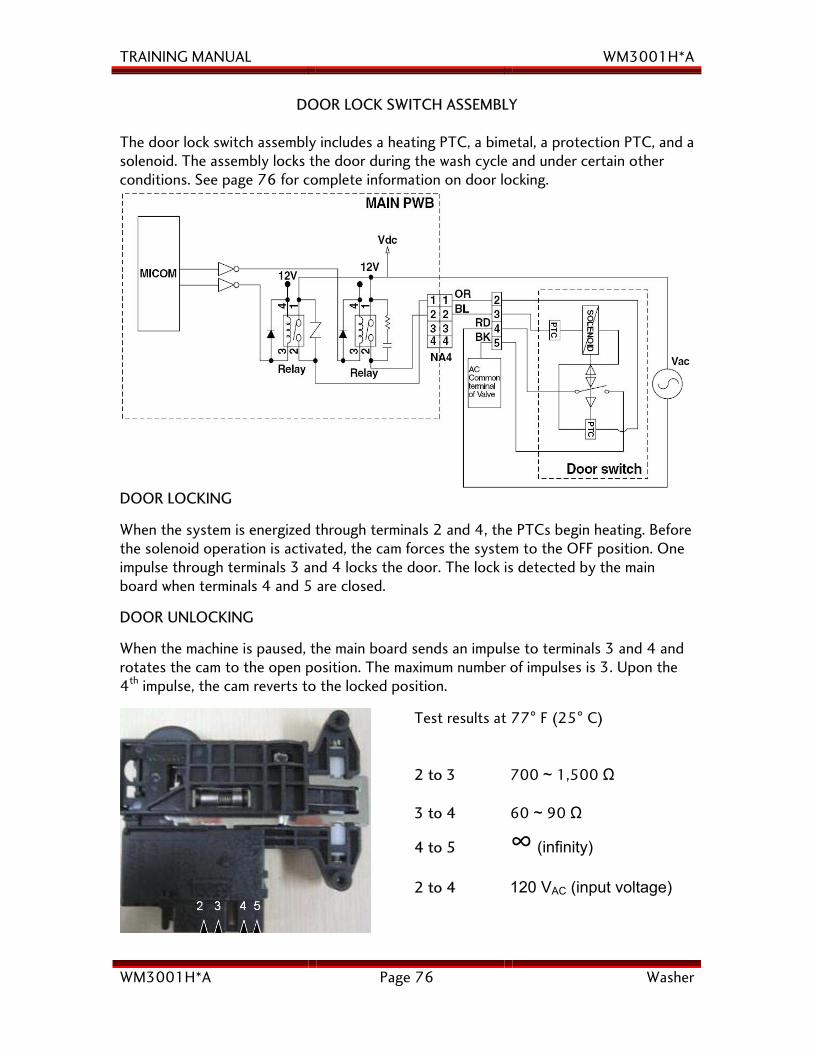
DOOR LOCK SWITCH ASSEMBLY
The door lock switch assembly includes a heating PTC, a bimetal, a protection PTC, and a solenoid. The assembly locks the door during the wash cycle and under certain other conditions. See page 76 for complete information on door locking.
DOOR LOCKING
When the system is energized through terminals 2 and 4, the PTCs begin heating. Before the solenoid operation is activated, the cam forces the system to the OFF position. One impulse through terminals 3 and 4 locks the door. The lock is detected by the main board when terminals 4 and 5 are closed.
DOOR UNLOCKING
When the machine is paused, the main board sends an impulse to terminals 3 and 4 and rotates the cam to the open position. The maximum number of impulses is 3. Upon the 4th impulse, the cam reverts to the locked position.
Test results at 77° F (25° C) 2 to 3 700 ~ 1,500 Ω 3 to 4 60 ~ 90 Ω
4 to 5 ∞ (infinity) 2 to 4 120 VAC (input voltage)
TRAINING MANUAL WM3001H*A
WM3001H*A Page 77 Washer
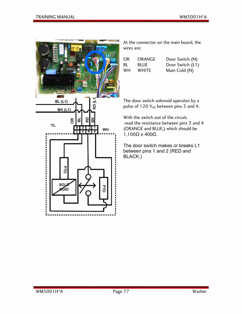
At the connector on the main board, the wires are: OR ORANGE Door Switch (N) BL BLUE Door Switch (L1) WH WHITE Main Cold (N)
The door switch solenoid operates by a pulse of 120 VAC between pins 3 and 4. With the switch out of the circuit, read the resistance between pins 3 and 4 (ORANGE and BLUE,) which should be 1,100Ω ± 400Ω. The door switch makes or breaks L1 between pins 1 and 2 (RED and BLACK.)
TRAINING MANUAL WM3001H*A
WM3001H*A Page 78 Washer
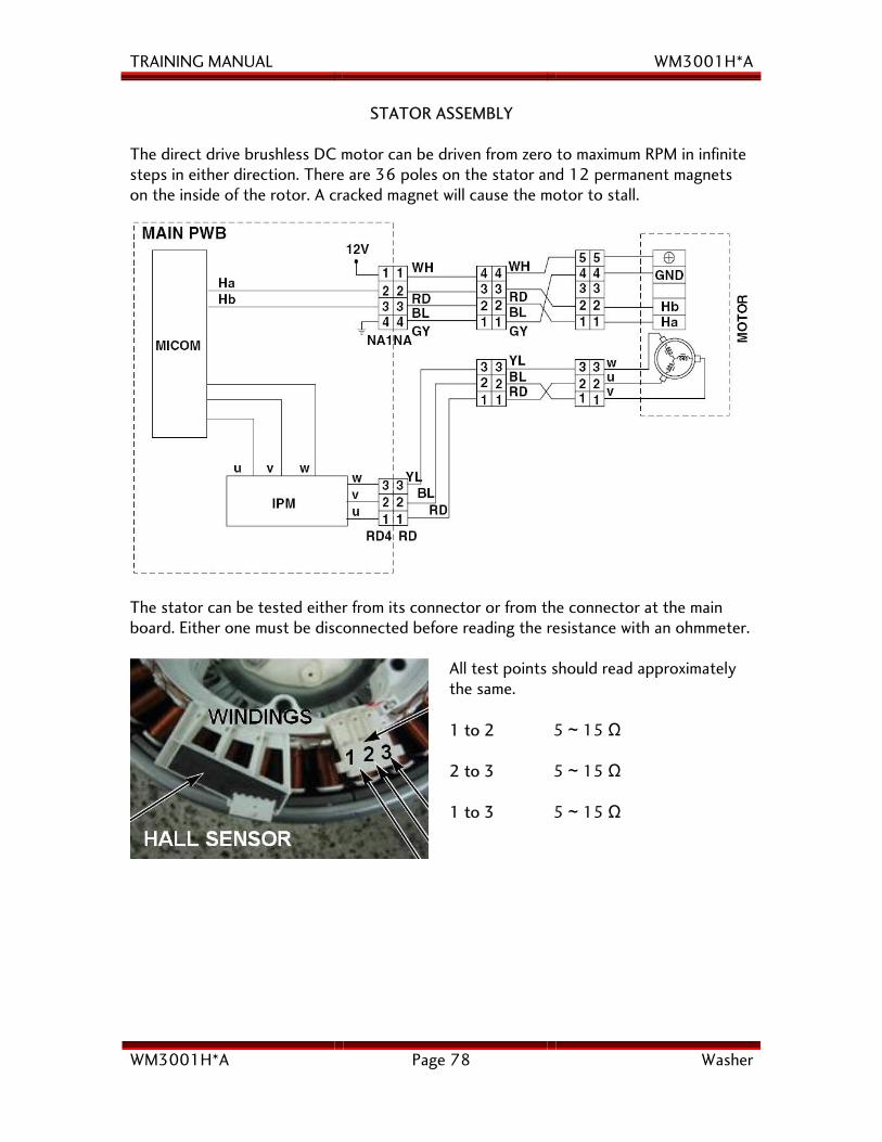
STATOR ASSEMBLY
The direct drive brushless DC motor can be driven from zero to maximum RPM in infinite steps in either direction. There are 36 poles on the stator and 12 permanent magnets on the inside of the rotor. A cracked magnet will cause the motor to stall.
The stator can be tested either from its connector or from the connector at the main board. Either one must be disconnected before reading the resistance with an ohmmeter.
All test points should read approximately the same. 1 to 2 5 ~ 15 Ω 2 to 3 5 ~ 15 Ω 1 to 3 5 ~ 15 Ω
TRAINING MANUAL WM3001H*A
WM3001H*A Page 79 Washer
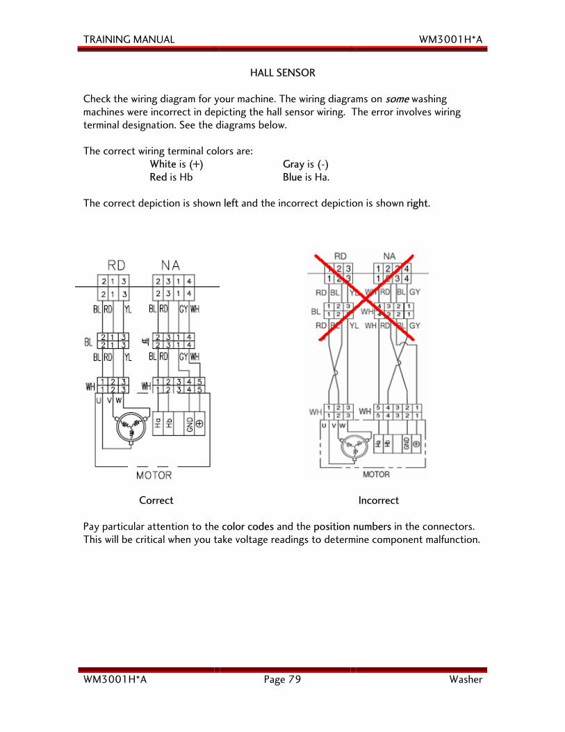
HALL SENSOR Check the wiring diagram for your machine. The wiring diagrams on some washing machines were incorrect in depicting the hall sensor wiring. The error involves wiring terminal designation. See the diagrams below. The correct wiring terminal colors are: White is (+) Gray is (-) Red is Hb Blue is Ha. The correct depiction is shown left and the incorrect depiction is shown right.
Correct Incorrect Pay particular attention to the color codes and the position numbers in the connectors. This will be critical when you take voltage readings to determine component malfunction.
TRAINING MANUAL WM3001H*A
WM3001H*A Page 80 Washer
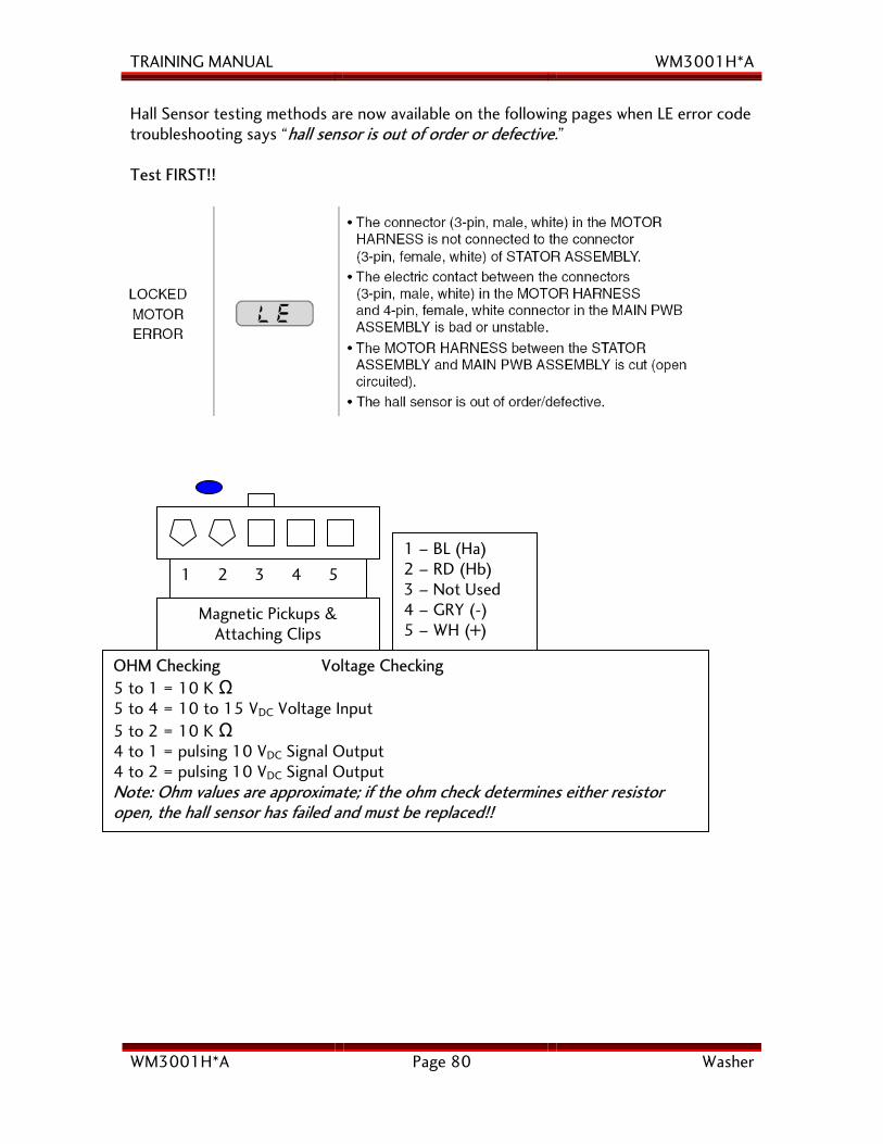
Magnetic Pickups & Attaching Clips
1 2 3 4 5
OHM Checking Voltage Checking5 to 1 = 10 K Ω
5 to 4 = 10 to 15 VDC Voltage Input 5 to 2 = 10 K Ω 4 to 1 = pulsing 10 VDC Signal Output 4 to 2 = pulsing 10 VDC Signal Output Note: Ohm values are approximate; if the ohm check determines either resistor open, the hall sensor has failed and must be replaced!!
1 – BL (Ha)2 – RD (Hb) 3 – Not Used 4 – GRY (-) 5 – WH (+)
Hall Sensor testing methods are now available on the following pages when LE error code troubleshooting says “hall sensor is out of order or defective.” Test FIRST!!
TRAINING MANUAL WM3001H*A
WM3001H*A Page 81 Washer
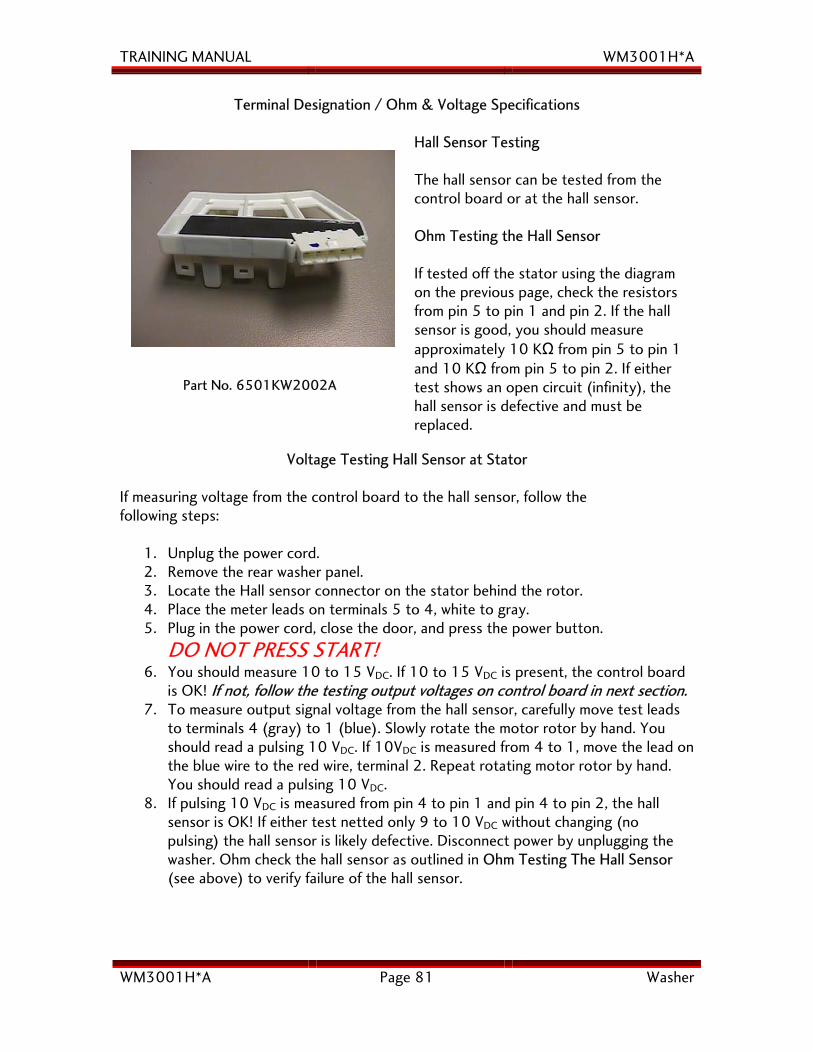
Terminal Designation / Ohm & Voltage Specifications
Part No. 6501KW2002A
Hall Sensor Testing The hall sensor can be tested from the control board or at the hall sensor. Ohm Testing the Hall Sensor If tested off the stator using the diagram on the previous page, check the resistors from pin 5 to pin 1 and pin 2. If the hall sensor is good, you should measure approximately 10 KΩ from pin 5 to pin 1 and 10 KΩ from pin 5 to pin 2. If either test shows an open circuit (infinity), the hall sensor is defective and must be replaced.
Voltage Testing Hall Sensor at Stator If measuring voltage from the control board to the hall sensor, follow the following steps:
1. Unplug the power cord. 2. Remove the rear washer panel. 3. Locate the Hall sensor connector on the stator behind the rotor. 4. Place the meter leads on terminals 5 to 4, white to gray. 5. Plug in the power cord, close the door, and press the power button.
DO NOT PRESS START! 6. You should measure 10 to 15 VDC. If 10 to 15 VDC is present, the control board
is OK! If not, follow the testing output voltages on control board in next section. 7. To measure output signal voltage from the hall sensor, carefully move test leads
to terminals 4 (gray) to 1 (blue). Slowly rotate the motor rotor by hand. You should read a pulsing 10 VDC. If 10VDC is measured from 4 to 1, move the lead on the blue wire to the red wire, terminal 2. Repeat rotating motor rotor by hand. You should read a pulsing 10 VDC.
8. If pulsing 10 VDC is measured from pin 4 to pin 1 and pin 4 to pin 2, the hall sensor is OK! If either test netted only 9 to 10 VDC without changing (no pulsing) the hall sensor is likely defective. Disconnect power by unplugging the washer. Ohm check the hall sensor as outlined in Ohm Testing The Hall Sensor (see above) to verify failure of the hall sensor.
TRAINING MANUAL WM3001H*A
WM3001H*A Page 82 Washer
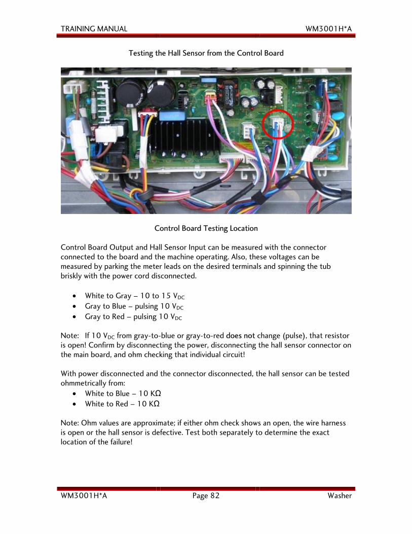
Testing the Hall Sensor from the Control Board
Control Board Testing Location Control Board Output and Hall Sensor Input can be measured with the connector connected to the board and the machine operating. Also, these voltages can be measured by parking the meter leads on the desired terminals and spinning the tub briskly with the power cord disconnected.
• White to Gray – 10 to 15 VDC • Gray to Blue – pulsing 10 VDC • Gray to Red – pulsing 10 VDC
Note: If 10 VDC from gray-to-blue or gray-to-red does not change (pulse), that resistor is open! Confirm by disconnecting the power, disconnecting the hall sensor connector on the main board, and ohm checking that individual circuit!
With power disconnected and the connector disconnected, the hall sensor can be tested ohmmetrically from:
• White to Blue – 10 KΩ • White to Red – 10 KΩ
Note: Ohm values are approximate; if either ohm check shows an open, the wire harness is open or the hall sensor is defective. Test both separately to determine the exact location of the failure!
TRAINING MANUAL WM3001H*A
WM3001H*A Page 83 Washer
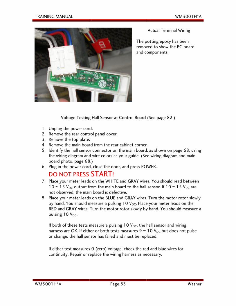
Actual Terminal Wiring
The potting epoxy has been removed to show the PC board and components.
Voltage Testing Hall Sensor at Control Board (See page 82.)
1. Unplug the power cord. 2. Remove the rear control panel cover. 3. Remove the top plate. 4. Remove the main board from the rear cabinet corner. 5. Identify the hall sensor connector on the main board, as shown on page 68, using
the wiring diagram and wire colors as your guide. (See wiring diagram and main board photo, page 68.)
6. Plug in the power cord, close the door, and press POWER.
DO NOT PRESS START! 7. Place your meter leads on the WHITE and GRAY wires. You should read between
10 ~ 15 VDC output from the main board to the hall sensor. If 10 ~ 15 VDC are not observed, the main board is defective.
8. Place your meter leads on the BLUE and GRAY wires. Turn the motor rotor slowly by hand. You should measure a pulsing 10 VDC. Place your meter leads on the RED and GRAY wires. Turn the motor rotor slowly by hand. You should measure a pulsing 10 VDC. If both of these tests measure a pulsing 10 VDC, the hall sensor and wiring harness are OK. If either or both tests measures 9 ~ 10 VDC but does not pulse or change, the hall sensor has failed and must be replaced.
If either test measures 0 (zero) voltage, check the red and blue wires for continuity. Repair or replace the wiring harness as necessary.
TRAINING MANUAL WM3001H*A
WM3001H*A Page 84 Washer
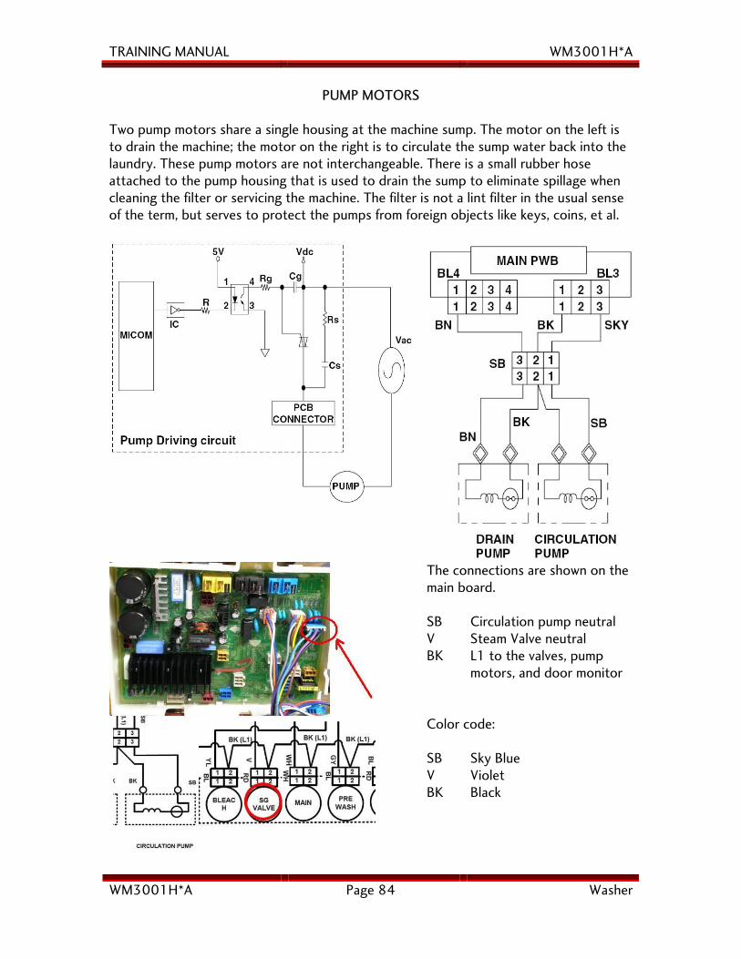
PUMP MOTORS
Two pump motors share a single housing at the machine sump. The motor on the left is to drain the machine; the motor on the right is to circulate the sump water back into the laundry. These pump motors are not interchangeable. There is a small rubber hose attached to the pump housing that is used to drain the sump to eliminate spillage when cleaning the filter or servicing the machine. The filter is not a lint filter in the usual sense of the term, but serves to protect the pumps from foreign objects like keys, coins, et al.
The connections are shown on the main board. SB Circulation pump neutral V Steam Valve neutral BK L1 to the valves, pump motors, and door monitor Color code: SB Sky Blue V Violet BK Black
TRAINING MANUAL WM3001H*A
WM3001H*A Page 85 Washer
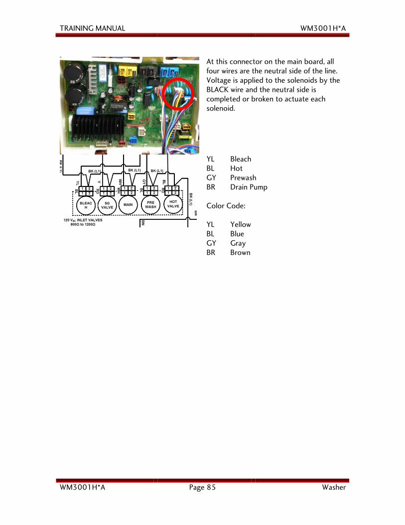
At this connector on the main board, all four wires are the neutral side of the line. Voltage is applied to the solenoids by the BLACK wire and the neutral side is completed or broken to actuate each solenoid.
YL Bleach BL Hot GY Prewash BR Drain Pump Color Code: YL Yellow BL Blue GY Gray BR Brown
TRAINING MANUAL WM3001H*A
WM3001H*A Page 86 Washer
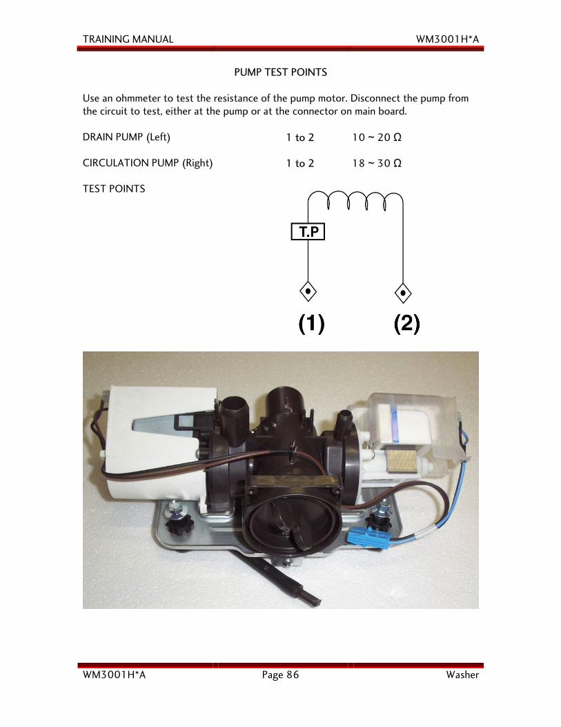
PUMP TEST POINTS Use an ohmmeter to test the resistance of the pump motor. Disconnect the pump from the circuit to test, either at the pump or at the connector on main board. DRAIN PUMP (Left)
1 to 2 10 ~ 20 Ω
CIRCULATION PUMP (Right)
1 to 2 18 ~ 30 Ω
TEST POINTS
TRAINING MANUAL WM3001H*A
WM3001H*A Page 87 Washer
INLET VALVE ASSEMBLY
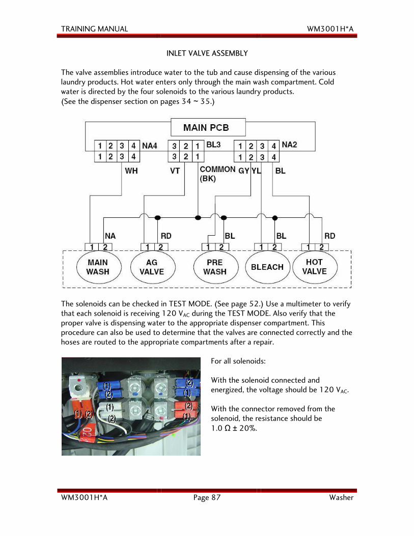
The valve assemblies introduce water to the tub and cause dispensing of the various laundry products. Hot water enters only through the main wash compartment. Cold water is directed by the four solenoids to the various laundry products. (See the dispenser section on pages 34 ~ 35.)
The solenoids can be checked in TEST MODE. (See page 52.) Use a multimeter to verify that each solenoid is receiving 120 VAC during the TEST MODE. Also verify that the proper valve is dispensing water to the appropriate dispenser compartment. This procedure can also be used to determine that the valves are connected correctly and the hoses are routed to the appropriate compartments after a repair.
For all solenoids: With the solenoid connected and energized, the voltage should be 120 VAC. With the connector removed from the solenoid, the resistance should be 1.0 Ω ± 20%.
TRAINING MANUAL WM3001H*A
WM3001H*A Page 88 Washer
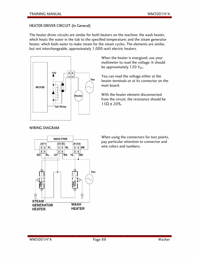
HEATER DRIVER CIRCUIT (In General) The heater driver circuits are similar for both heaters on the machine: the wash heater, which heats the water in the tub to the specified temperature; and the steam generator heater, which boils water to make steam for the steam cycles. The elements are similar, but not interchangeable, approximately 1,000-watt electric heaters.
When the heater is energized, use your multimeter to read the voltage. It should be approximately 120 VAC. You can read the voltage either at the heater terminals or at its connector on the main board. With the heater element disconnected from the circuit, the resistance should be 15Ω ± 20%.
WIRING DIAGRAM
When using the connectors for test points, pay particular attention to connector and wire colors and numbers.
TRAINING MANUAL WM3001H*A
WM3001H*A Page 89 Washer
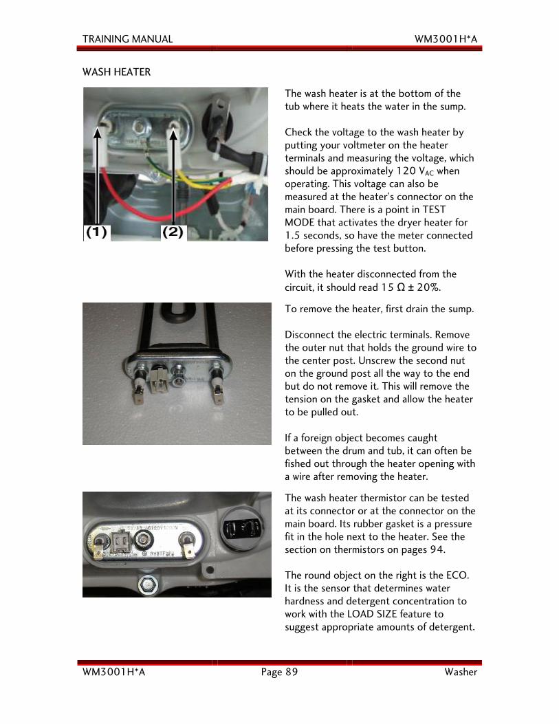
WASH HEATER
The wash heater is at the bottom of the tub where it heats the water in the sump. Check the voltage to the wash heater by putting your voltmeter on the heater terminals and measuring the voltage, which should be approximately 120 VAC when operating. This voltage can also be measured at the heater’s connector on the main board. There is a point in TEST MODE that activates the dryer heater for 1.5 seconds, so have the meter connected before pressing the test button. With the heater disconnected from the circuit, it should read 15 Ω ± 20%.
To remove the heater, first drain the sump. Disconnect the electric terminals. Remove the outer nut that holds the ground wire to the center post. Unscrew the second nut on the ground post all the way to the end but do not remove it. This will remove the tension on the gasket and allow the heater to be pulled out. If a foreign object becomes caught between the drum and tub, it can often be fished out through the heater opening with a wire after removing the heater.
The wash heater thermistor can be tested at its connector or at the connector on the main board. Its rubber gasket is a pressure fit in the hole next to the heater. See the section on thermistors on pages 94. The round object on the right is the ECO. It is the sensor that determines water hardness and detergent concentration to work with the LOAD SIZE feature to suggest appropriate amounts of detergent.
TRAINING MANUAL WM3001H*A
WM3001H*A Page 90 Washer
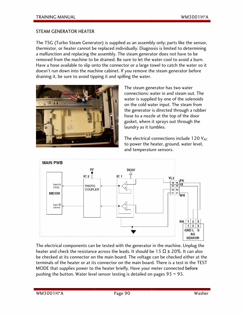
STEAM GENERATOR HEATER The TSG (Turbo Steam Generator) is supplied as an assembly only; parts like the sensor, thermistor, or heater cannot be replaced individually. Diagnosis is limited to determining a malfunction and replacing the assembly. The steam generator does not have to be removed from the machine to be drained. Be sure to let the water cool to avoid a burn. Have a hose available to slip onto the connector or a large towel to catch the water so it doesn’t run down into the machine cabinet. If you remove the steam generator before draining it, be sure to avoid tipping it and spilling the water.
The steam generator has two water connections: water in and steam out. The water is supplied by one of the solenoids on the cold water input. The steam from the generator is directed through a rubber hose to a nozzle at the top of the door gasket, where it sprays out through the laundry as it tumbles. The electrical connections include 120 VAC to power the heater, ground, water level, and temperature sensors.
The electrical components can be tested with the generator in the machine. Unplug the heater and check the resistance across the leads. It should be 15 Ω ± 20%. It can also be checked at its connector on the main board. The voltage can be checked either at the terminals of the heater or at its connector on the main board. There is a test in the TEST MODE that supplies power to the heater briefly. Have your meter connected before pushing the button. Water level sensor testing is detailed on pages 93 ~ 95.
TRAINING MANUAL WM3001H*A
WM3001H*A Page 91 Washer
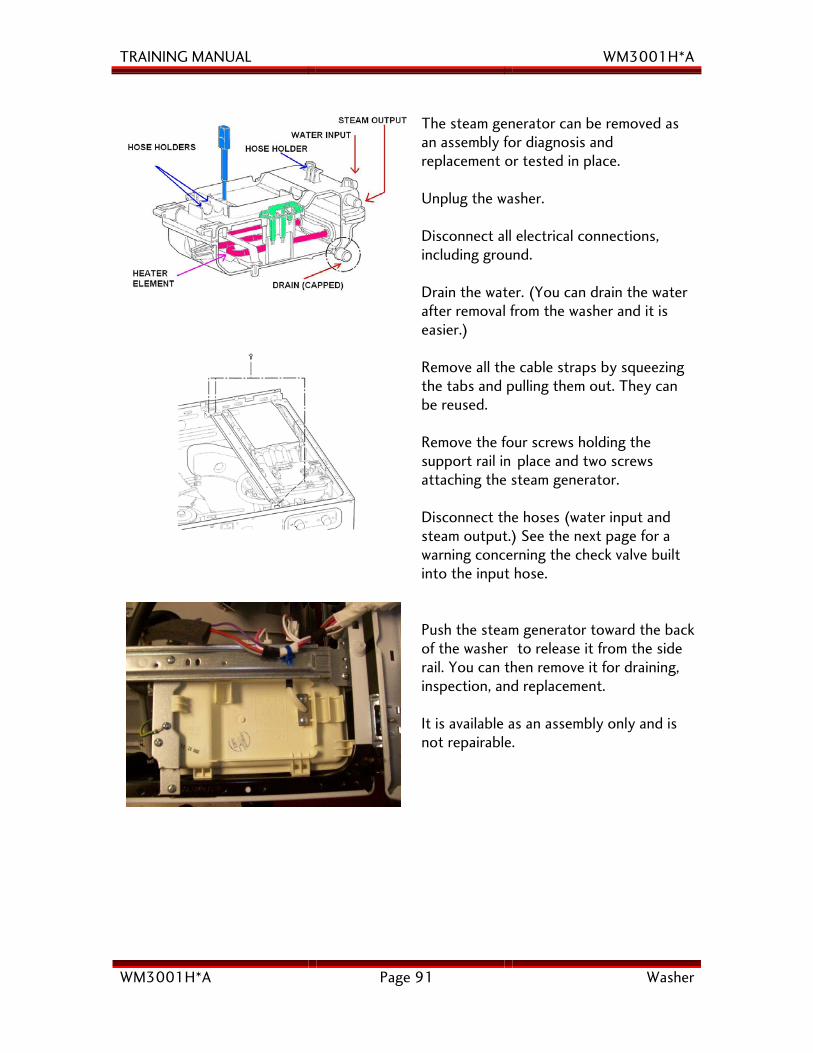
The steam generator can be removed as an assembly for diagnosis and replacement or tested in place. Unplug the washer. Disconnect all electrical connections, including ground. Drain the water. (You can drain the water after removal from the washer and it is easier.)
Remove all the cable straps by squeezing the tabs and pulling them out. They can be reused. Remove the four screws holding the support rail in place and two screws attaching the steam generator. Disconnect the hoses (water input and steam output.) See the next page for a warning concerning the check valve built into the input hose.
Push the steam generator toward the back of the washer to release it from the side rail. You can then remove it for draining, inspection, and replacement. It is available as an assembly only and is not repairable.
TRAINING MANUAL WM3001H*A
WM3001H*A Page 92 Washer
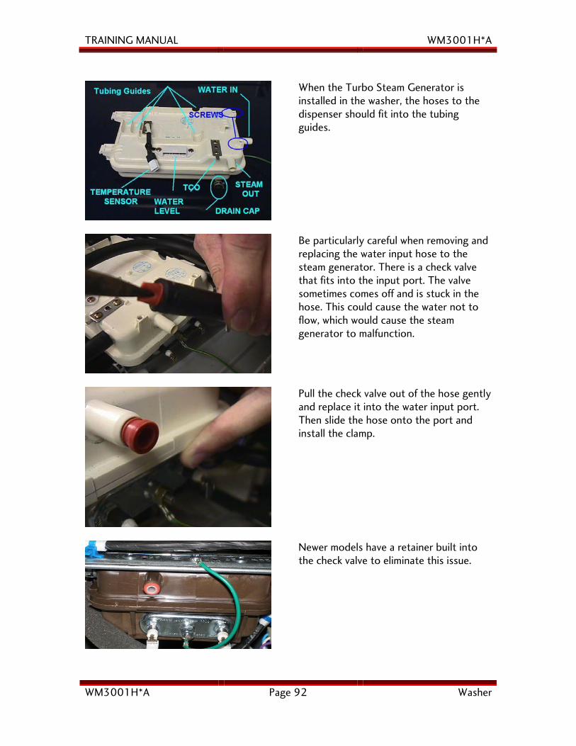
When the Turbo Steam Generator is installed in the washer, the hoses to the dispenser should fit into the tubing guides.
Be particularly careful when removing and replacing the water input hose to the steam generator. There is a check valve that fits into the input port. The valve sometimes comes off and is stuck in the hose. This could cause the water not to flow, which would cause the steam generator to malfunction.
Pull the check valve out of the hose gently and replace it into the water input port. Then slide the hose onto the port and install the clamp.
Newer models have a retainer built into the check valve to eliminate this issue.
TRAINING MANUAL WM3001H*A
WM3001H*A Page 93 Washer
Sensor Wiring Diagram Steam Generator
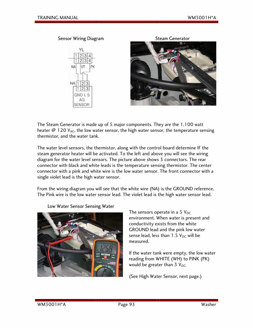
The Steam Generator is made up of 5 major components. They are the 1,100 watt heater @ 120 VAC, the low water sensor, the high water sensor, the temperature sensing thermistor, and the water tank. The water level sensors, the thermistor, along with the control board determine IF the steam generator heater will be activated. To the left and above you will see the wiring diagram for the water level sensors. The picture above shows 3 connectors. The rear connector with black and white leads is the temperature sensing thermistor. The center connector with a pink and white wire is the low water sensor. The front connector with a single violet lead is the high water sensor. From the wiring diagram you will see that the white wire (NA) is the GROUND reference. The Pink wire is the low water sensor lead. The violet lead is the high water sensor lead.
Low Water Sensor Sensing Water
The sensors operate in a 5 VDC
environment. When water is present and conductivity exists from the white GROUND lead and the pink low water sense lead, less than 1.5 VDC will be measured. If the water tank were empty, the low water reading from WHITE (WH) to PINK (PK) would be greater than 3 VDC.
(See High Water Sensor, next page.)
TRAINING MANUAL WM3001H*A
WM3001H*A Page 94 Washer
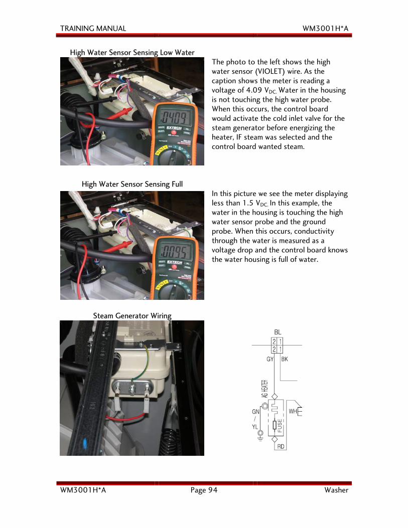
High Water Sensor Sensing Low Water
The photo to the left shows the high water sensor (VIOLET) wire. As the caption shows the meter is reading a voltage of 4.09 VDC. Water in the housing is not touching the high water probe. When this occurs, the control board would activate the cold inlet valve for the steam generator before energizing the heater, IF steam was selected and the control board wanted steam.
High Water Sensor Sensing Full
In this picture we see the meter displaying less than 1.5 VDC. In this example, the water in the housing is touching the high water sensor probe and the ground probe. When this occurs, conductivity through the water is measured as a voltage drop and the control board knows the water housing is full of water.
Steam Generator Wiring
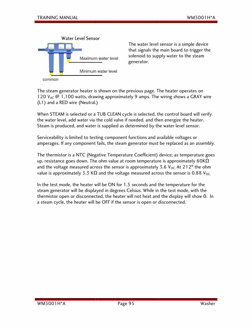
TRAINING MANUAL WM3001H*A
WM3001H*A Page 95 Washer
Water Level Sensor
The water level sensor is a simple device that signals the main board to trigger the solenoid to supply water to the steam generator.
The steam generator heater is shown on the previous page. The heater operates on 120 VAC @ 1,100 watts, drawing approximately 9 amps. The wiring shows a GRAY wire (L1) and a RED wire (Neutral.) When STEAM is selected or a TUB CLEAN cycle is selected, the control board will verify the water level, add water via the cold valve if needed, and then energize the heater. Steam is produced, and water is supplied as determined by the water level sensor. Serviceability is limited to testing component functions and available voltages or amperages. If any component fails, the steam generator must be replaced as an assembly. The thermistor is a NTC (Negative Temperature Coefficient) device; as temperature goes up, resistance goes down. The ohm value at room temperature is approximately 60KΩ and the voltage measured across the sensor is approximately 3.6 VDC. At 212º the ohm value is approximately 3.3 KΩ and the voltage measured across the sensor is 0.88 VDC.
In the test mode, the heater will be ON for 1.5 seconds and the temperature for the steam generator will be displayed in degrees Celsius. While in the test mode, with the thermistor open or disconnected, the heater will not heat and the display will show 0. In a steam cycle, the heater will be OFF if the sensor is open or disconnected.
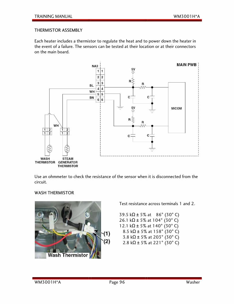
TRAINING MANUAL WM3001H*A
WM3001H*A Page 96 Washer
THERMISTOR ASSEMBLY Each heater includes a thermistor to regulate the heat and to power down the heater in the event of a failure. The sensors can be tested at their location or at their connectors on the main board.
Use an ohmmeter to check the resistance of the sensor when it is disconnected from the circuit. WASH THERMISTOR
Test resistance across terminals 1 and 2. 39.5 kΩ ± 5% at 86° (30° C) 26.1 kΩ ± 5% at 104° (30° C) 12.1 kΩ ± 5% at 140° (30° C) 8.5 kΩ ± 5% at 158° (30° C) 3.8 kΩ ± 5% at 203° (30° C) 2.8 kΩ ± 5% at 221° (30° C)
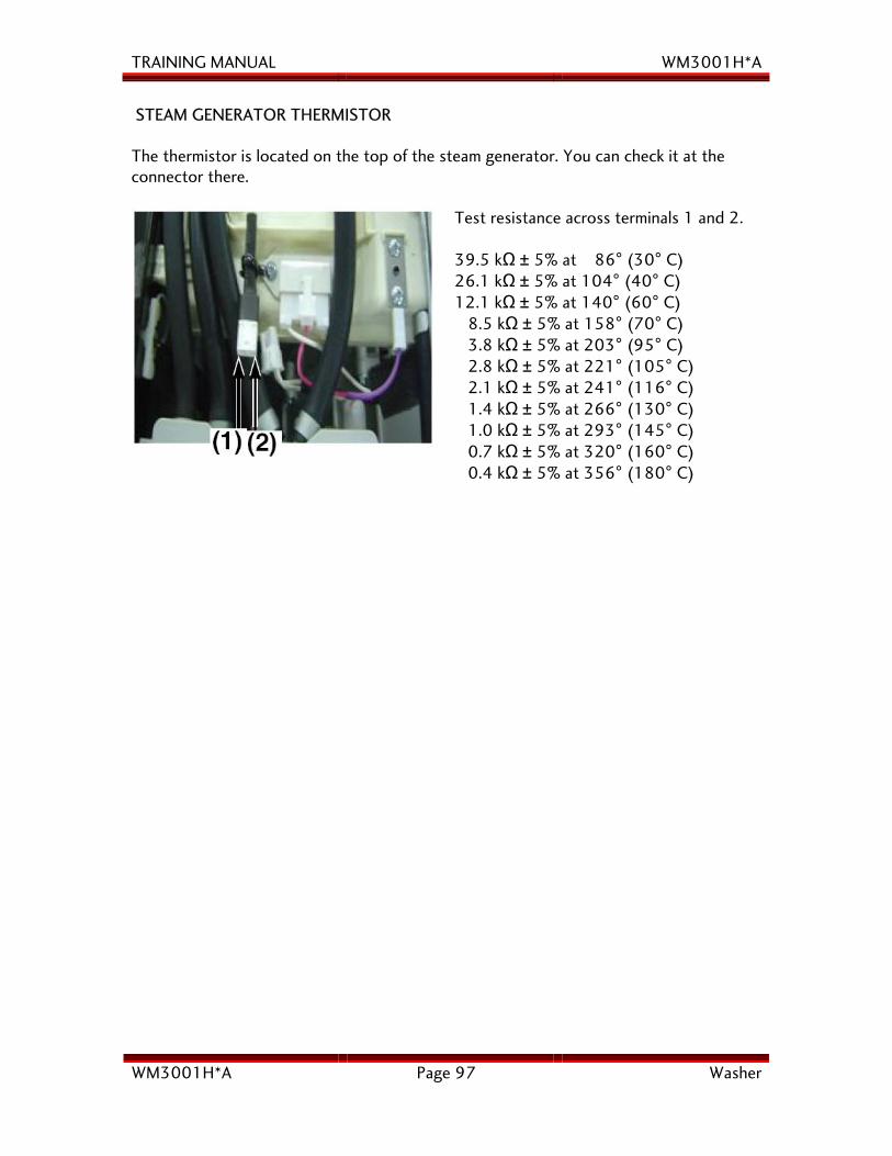
TRAINING MANUAL WM3001H*A
WM3001H*A Page 97 Washer
STEAM GENERATOR THERMISTOR The thermistor is located on the top of the steam generator. You can check it at the connector there.
Test resistance across terminals 1 and 2. 39.5 kΩ ± 5% at 86° (30° C) 26.1 kΩ ± 5% at 104° (40° C) 12.1 kΩ ± 5% at 140° (60° C) 8.5 kΩ ± 5% at 158° (70° C) 3.8 kΩ ± 5% at 203° (95° C) 2.8 kΩ ± 5% at 221° (105° C) 2.1 kΩ ± 5% at 241° (116° C) 1.4 kΩ ± 5% at 266° (130° C) 1.0 kΩ ± 5% at 293° (145° C) 0.7 kΩ ± 5% at 320° (160° C) 0.4 kΩ ± 5% at 356° (180° C)
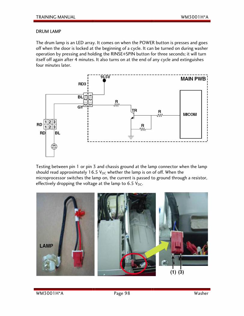
TRAINING MANUAL WM3001H*A
WM3001H*A Page 98 Washer
DRUM LAMP The drum lamp is an LED array. It comes on when the POWER button is presses and goes off when the door is locked at the beginning of a cycle. It can be turned on during washer operation by pressing and holding the RINSE+SPIN button for three seconds; it will turn itself off again after 4 minutes. It also turns on at the end of any cycle and extinguishes four minutes later.
Testing between pin 1 or pin 3 and chassis ground at the lamp connector when the lamp should read approximately 16.5 VDC whether the lamp is on of off. When the microprocessor switches the lamp on, the current is passed to ground through a resistor, effectively dropping the voltage at the lamp to 6.5 VDC.
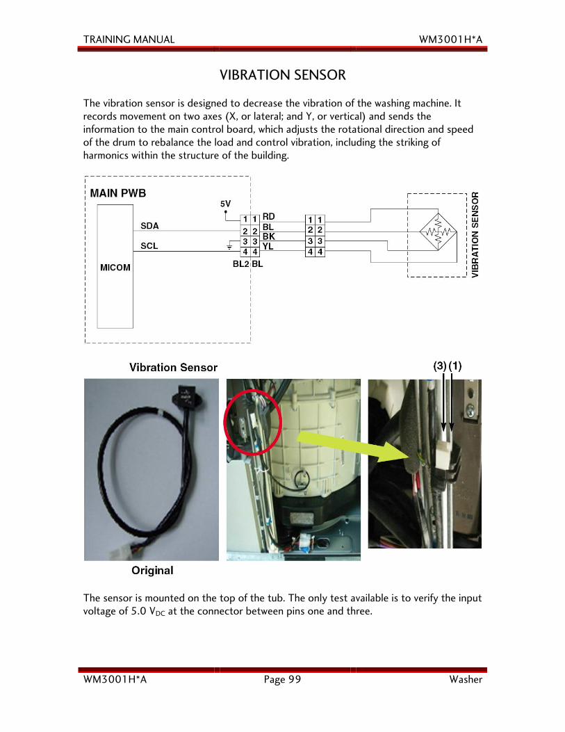
TRAINING MANUAL WM3001H*A
WM3001H*A Page 99 Washer
VIBRATION SENSOR The vibration sensor is designed to decrease the vibration of the washing machine. It records movement on two axes (X, or lateral; and Y, or vertical) and sends the information to the main control board, which adjusts the rotational direction and speed of the drum to rebalance the load and control vibration, including the striking of harmonics within the structure of the building.
The sensor is mounted on the top of the tub. The only test available is to verify the input voltage of 5.0 VDC at the connector between pins one and three.
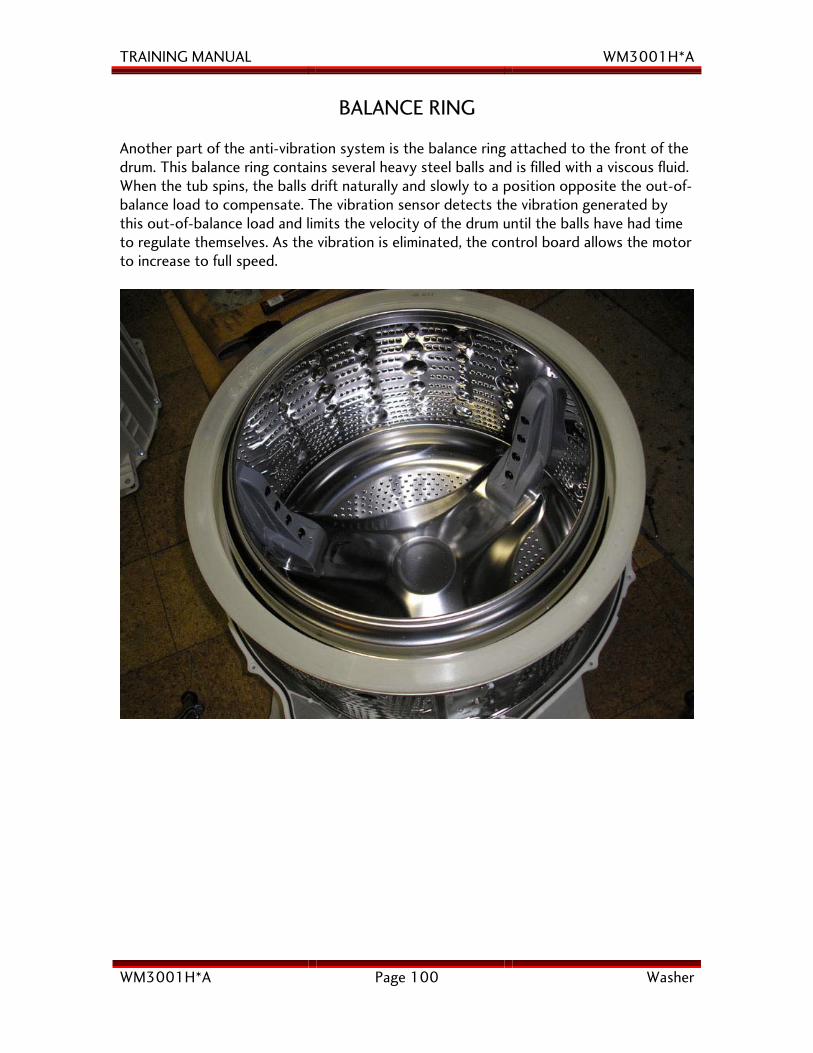
TRAINING MANUAL WM3001H*A
WM3001H*A Page 100 Washer
BALANCE RING
Another part of the anti-vibration system is the balance ring attached to the front of the drum. This balance ring contains several heavy steel balls and is filled with a viscous fluid. When the tub spins, the balls drift naturally and slowly to a position opposite the out-of-balance load to compensate. The vibration sensor detects the vibration generated by this out-of-balance load and limits the velocity of the drum until the balls have had time to regulate themselves. As the vibration is eliminated, the control board allows the motor to increase to full speed.
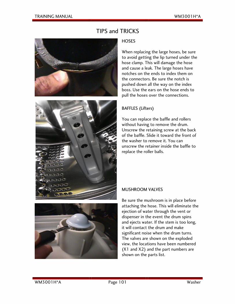
TRAINING MANUAL WM3001H*A
WM3001H*A Page 101 Washer
TIPS and TRICKS
HOSES When replacing the large hoses, be sure to avoid getting the lip turned under the hose clamp. This will damage the hose and cause a leak. The large hoses have notches on the ends to index them on the connectors. Be sure the notch is pushed down all the way on the index boss. Use the ears on the hose ends to pull the hoses over the connections.
BAFFLES (Lifters) You can replace the baffle and rollers without having to remove the drum. Unscrew the retaining screw at the back of the baffle. Slide it toward the front of the washer to remove it. You can unscrew the retainer inside the baffle to replace the roller balls. MUSHROOM VALVES Be sure the mushroom is in place before
attaching the hose. This will eliminate the ejection of water through the vent or dispenser in the event the drum spins and ejects water. If the stem is too long, it will contact the drum and make significant noise when the drum turns. The valves are shown on the exploded view, the locations have been numbered (X1 and X2) and the part numbers are shown on the parts list.
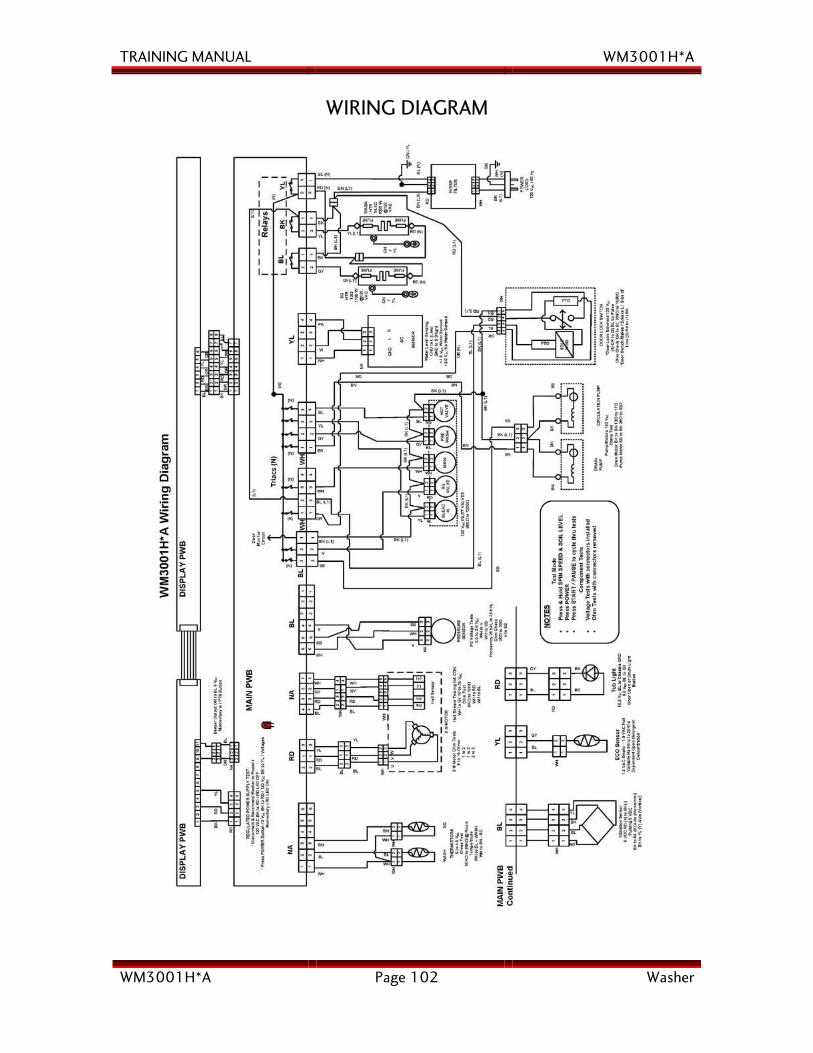
TRAINING MANUAL WM3001H*A
WM3001H*A Page 102 Washer
WIRING DIAGRAM
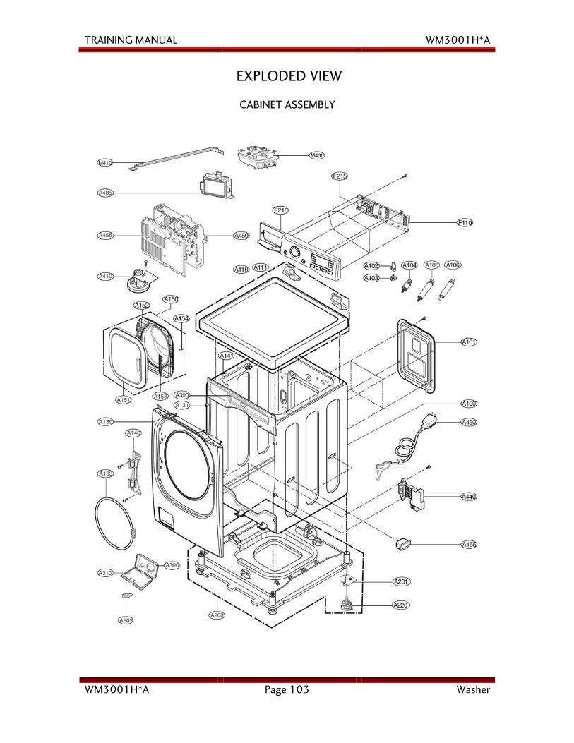
TRAINING MANUAL WM3001H*A
WM3001H*A Page 103 Washer
EXPLODED VIEW
CABINET ASSEMBLY

TRAINING MANUAL WM3001H*A
WM3001H*A Page 104 Washer
DRUM and TUB ASSEMBLY
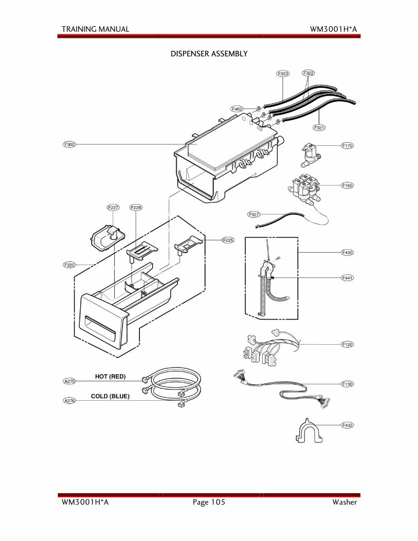
TRAINING MANUAL WM3001H*A
WM3001H*A Page 105 Washer
DISPENSER ASSEMBLY
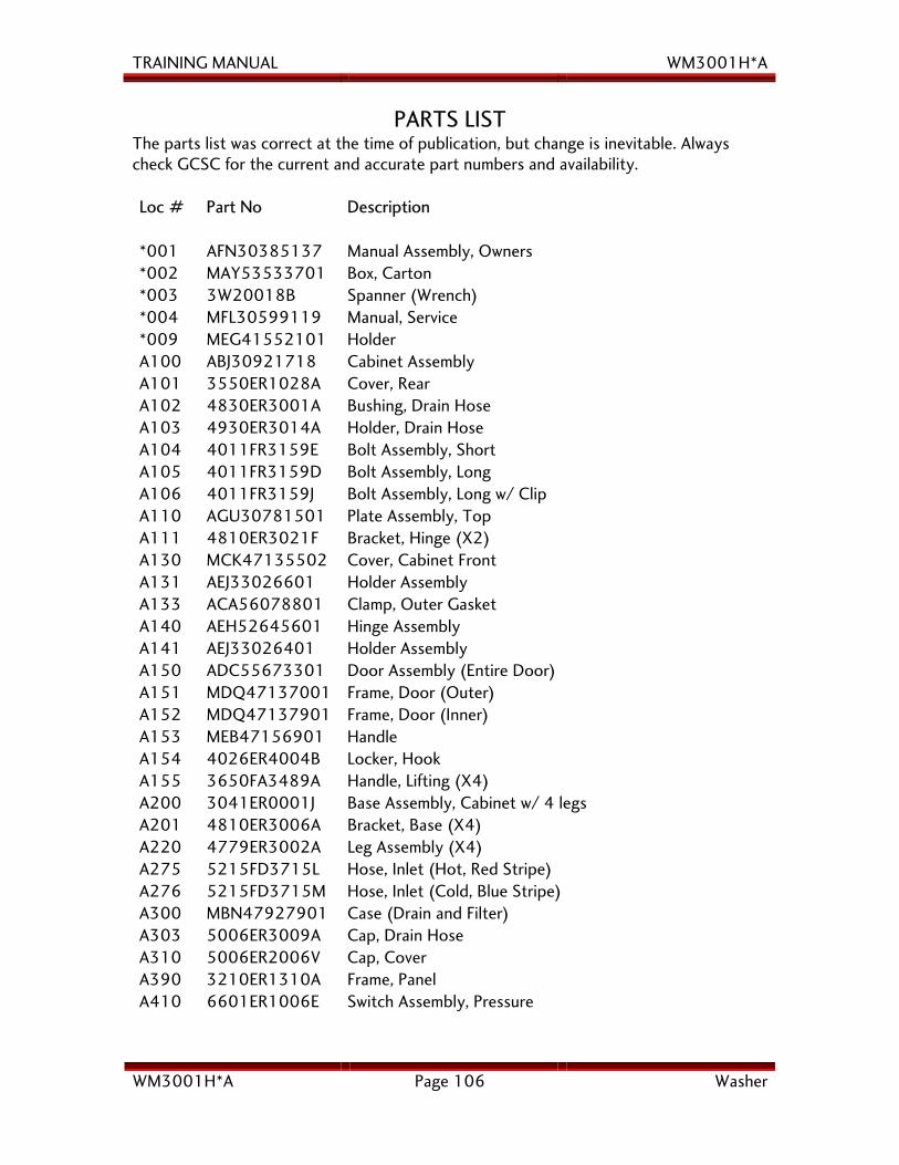
TRAINING MANUAL WM3001H*A
WM3001H*A Page 106 Washer
PARTS LIST The parts list was correct at the time of publication, but change is inevitable. Always check GCSC for the current and accurate part numbers and availability. Loc # Part No Description *001 AFN30385137 Manual Assembly, Owners *002 MAY53533701 Box, Carton *003 3W20018B Spanner (Wrench) *004 MFL30599119 Manual, Service *009 MEG41552101 Holder A100 ABJ30921718 Cabinet Assembly A101 3550ER1028A Cover, Rear A102 4830ER3001A Bushing, Drain Hose A103 4930ER3014A Holder, Drain Hose A104 4011FR3159E Bolt Assembly, Short A105 4011FR3159D Bolt Assembly, Long A106 4011FR3159J Bolt Assembly, Long w/ Clip A110 AGU30781501 Plate Assembly, Top A111 4810ER3021F Bracket, Hinge (X2) A130 MCK47135502 Cover, Cabinet Front A131 AEJ33026601 Holder Assembly A133 ACA56078801 Clamp, Outer Gasket A140 AEH52645601 Hinge Assembly A141 AEJ33026401 Holder Assembly A150 ADC55673301 Door Assembly (Entire Door) A151 MDQ47137001 Frame, Door (Outer) A152 MDQ47137901 Frame, Door (Inner) A153 MEB47156901 Handle A154 4026ER4004B Locker, Hook A155 3650FA3489A Handle, Lifting (X4) A200 3041ER0001J Base Assembly, Cabinet w/ 4 legs A201 4810ER3006A Bracket, Base (X4) A220 4779ER3002A Leg Assembly (X4) A275 5215FD3715L Hose, Inlet (Hot, Red Stripe) A276 5215FD3715M Hose, Inlet (Cold, Blue Stripe) A300 MBN47927901 Case (Drain and Filter) A303 5006ER3009A Cap, Drain Hose A310 5006ER2006V Cap, Cover A390 3210ER1310A Frame, Panel A410 6601ER1006E Switch Assembly, Pressure
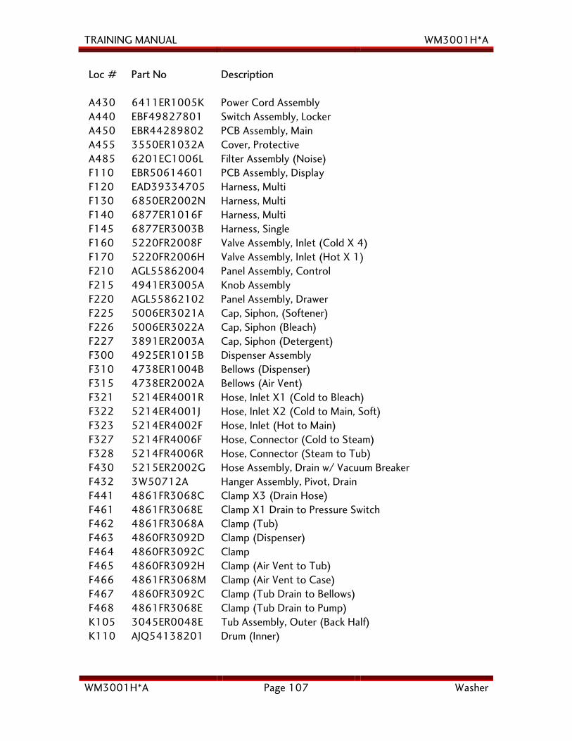
TRAINING MANUAL WM3001H*A
WM3001H*A Page 107 Washer
Loc # Part No Description A430 6411ER1005K Power Cord Assembly A440 EBF49827801 Switch Assembly, Locker A450 EBR44289802 PCB Assembly, Main A455 3550ER1032A Cover, Protective A485 6201EC1006L Filter Assembly (Noise) F110 EBR50614601 PCB Assembly, Display F120 EAD39334705 Harness, Multi F130 6850ER2002N Harness, Multi F140 6877ER1016F Harness, Multi F145 6877ER3003B Harness, Single F160 5220FR2008F Valve Assembly, Inlet (Cold X 4) F170 5220FR2006H Valve Assembly, Inlet (Hot X 1) F210 AGL55862004 Panel Assembly, Control F215 4941ER3005A Knob Assembly F220 AGL55862102 Panel Assembly, Drawer F225 5006ER3021A Cap, Siphon, (Softener) F226 5006ER3022A Cap, Siphon (Bleach) F227 3891ER2003A Cap, Siphon (Detergent) F300 4925ER1015B Dispenser Assembly F310 4738ER1004B Bellows (Dispenser) F315 4738ER2002A Bellows (Air Vent) F321 5214ER4001R Hose, Inlet X1 (Cold to Bleach) F322 5214ER4001J Hose, Inlet X2 (Cold to Main, Soft) F323 5214ER4002F Hose, Inlet (Hot to Main) F327 5214FR4006F Hose, Connector (Cold to Steam) F328 5214FR4006R Hose, Connector (Steam to Tub) F430 5215ER2002G Hose Assembly, Drain w/ Vacuum Breaker F432 3W50712A Hanger Assembly, Pivot, Drain F441 4861FR3068C Clamp X3 (Drain Hose) F461 4861FR3068E Clamp X1 Drain to Pressure Switch F462 4861FR3068A Clamp (Tub) F463 4860FR3092D Clamp (Dispenser) F464 4860FR3092C Clamp F465 4860FR3092H Clamp (Air Vent to Tub) F466 4861FR3068M Clamp (Air Vent to Case) F467 4860FR3092C Clamp (Tub Drain to Bellows) F468 4861FR3068E Clamp (Tub Drain to Pump) K105 3045ER0048E Tub Assembly, Outer (Back Half) K110 AJQ54138201 Drum (Inner)
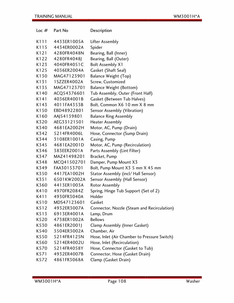
TRAINING MANUAL WM3001H*A
WM3001H*A Page 108 Washer
Loc # Part No Description K111 4433ER1005A Lifter Assembly K115 4434ER0002A Spider K121 4280FR4048N Bearing, Ball (Inner) K122 4280FR4048J Bearing, Ball (Outer) K123 4040FR4051C Bolt Assembly X1 K125 4036ER2004A Gasket (Shaft Seal) K130 MAG47123901 Balance Weight (Top) K131 1SZZER4002A Screw, Customized K135 MAG47123701 Balance Weight (Bottom) K140 ACQ54376601 Tub Assembly, Outer (Front Half) K141 4036ER4001B Gasket (Between Tub Halves) K143 4011FA4353B Bolt, Common X6 10 mm X 8 mm K150 EBD48922801 Sensor Assembly (Vibration) K160 AAJ54139801 Balance Ring Assembly K320 AEG33121501 Heater Assembly K340 4681EA2002H Motor, AC, Pump (Drain) K342 5214FR4006L Hose, Connector (Sump Drain) K344 3108ER1001A Casing, Pump K345 4681EA2001D Motor, AC, Pump (Recirculation) K346 383EER2001A Parts Assembly (Lint Filter) K347 MAZ41498201 Bracket, Pump K348 MCQ41502701 Damper, Pump Mount X3 K349 FAA30153701 Bolt, Pump Mount X3 5 mm X 45 mm K350 4417EA1002H Stator Assembly (incl/ Hall Sensor) K351 6501KW2002A Sensor Assembly (Hall Sensor) K360 4413ER1003A Rotor Assembly K410 4970FR2084Z Spring, Hinge Tub Support (Set of 2) K411 4930FR3040A Holder K510 MDS47123601 Gasket K512 4932ER3007A Connector, Nozzle (Steam and Recirculation) K513 6913ER4001A Lamp, Drum K520 4738ER1002A Bellows K530 4861ER2001J Clamp Assembly (Inner Gasket) K540 3504ER3002A Chamber, Air K550 5214FR4125N Hose, Inlet (Air Chamber to Pressure Switch) K560 5214ER4002U Hose, Inlet (Recirculation) K570 5214FR4058Y Hose, Connector (Gasket to Tub) K571 4932ER4007B Connector, Hose (Gasket Drain) K572 4861FR3068A Clamp (Gasket Drain)
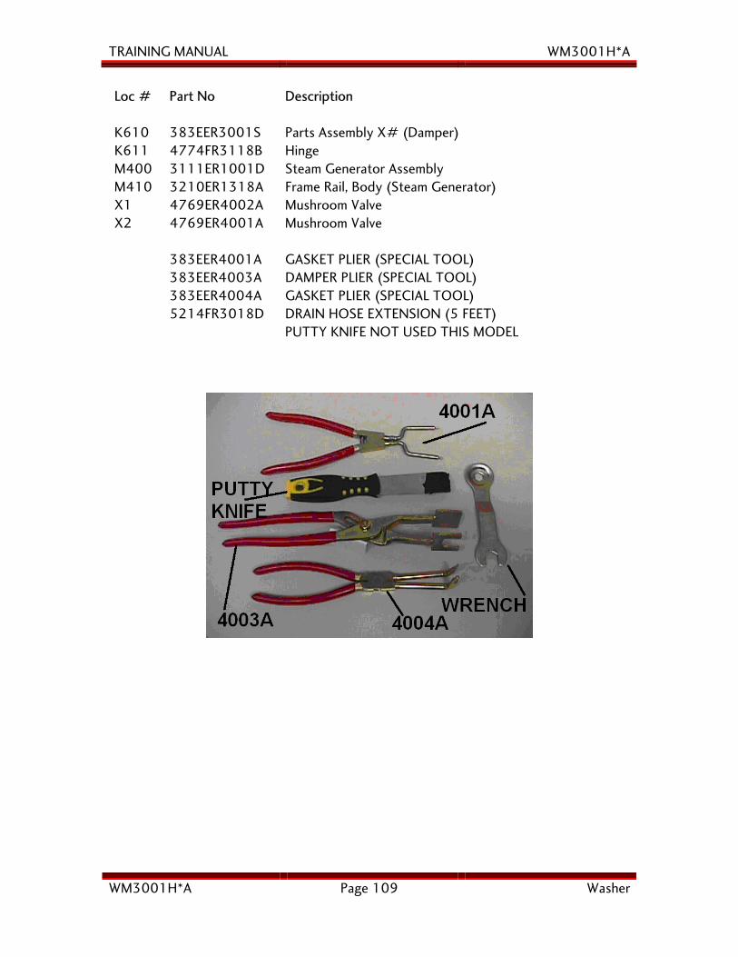
TRAINING MANUAL WM3001H*A
WM3001H*A Page 109 Washer
Loc # Part No Description K610 383EER3001S Parts Assembly X# (Damper) K611 4774FR3118B Hinge M400 3111ER1001D Steam Generator Assembly M410 3210ER1318A Frame Rail, Body (Steam Generator) X1 4769ER4002A Mushroom Valve X2 4769ER4001A Mushroom Valve 383EER4001A GASKET PLIER (SPECIAL TOOL) 383EER4003A DAMPER PLIER (SPECIAL TOOL) 383EER4004A GASKET PLIER (SPECIAL TOOL) 5214FR3018D DRAIN HOSE EXTENSION (5 FEET) PUTTY KNIFE NOT USED THIS MODEL
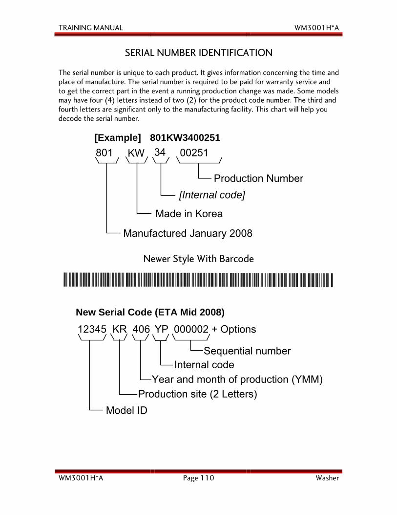
TRAINING MANUAL WM3001H*A
WM3001H*A Page 110 Washer
SERIAL NUMBER IDENTIFICATION The serial number is unique to each product. It gives information concerning the time and place of manufacture. The serial number is required to be paid for warranty service and to get the correct part in the event a running production change was made. Some models may have four (4) letters instead of two (2) for the product code number. The third and fourth letters are significant only to the manufacturing facility. This chart will help you decode the serial number.
[Example] 801KW3400251801 KW 00251
Production Number[Internal code]
Manufactured January 2008
34
Made in Korea
Newer Style With Barcode
Sequential numberInternal code
Model IDProduction site (2 Letters)
12345 KR 406 YP 000002 + OptionsNew Serial Code (ETA Mid 2008)
Year and month of production (YMM)
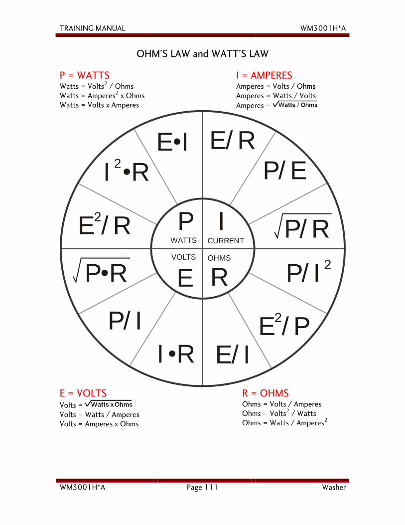
TRAINING MANUAL WM3001H*A
WM3001H*A Page 111 Washer
OHM’S LAW and WATT’S LAW
P = WATTS Watts = Volts2 / Ohms Watts = Amperes2 x Ohms Watts = Volts x Amperes
I = AMPERES Amperes = Volts / Ohms Amperes = Watts / Volts Amperes =
I R2•
E /R2
P R•
P/I
E I• E/RP/E
P/R
P/I2
E /P2
P
E/II R•
I
E R
WATTS CURRENT
VOLTS OHMS
E = VOLTS Volts = Volts = Watts / Amperes Volts = Amperes x Ohms
R = OHMS Ohms = Volts / Amperes Ohms = Volts2 / Watts Ohms = Watts / Amperes2
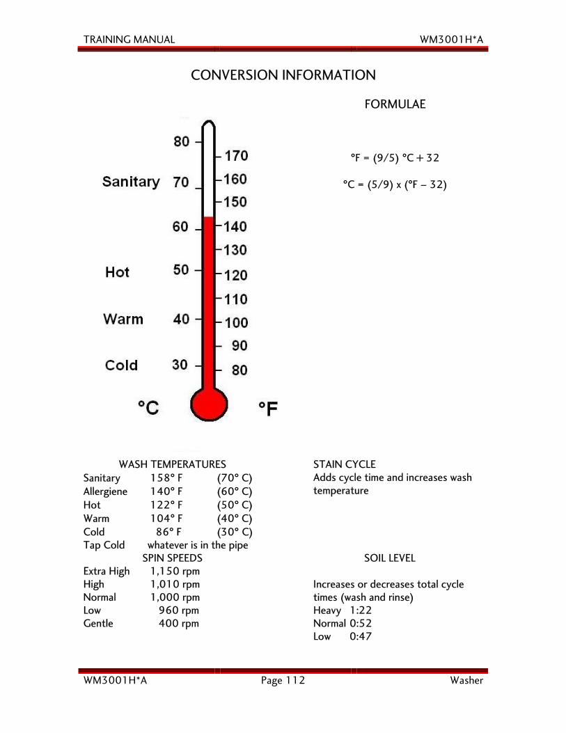
TRAINING MANUAL WM3001H*A
WM3001H*A Page 112 Washer
CONVERSION INFORMATION
FORMULAE
°F = (9/5) °C + 32
°C = (5/9) x (°F – 32)
WASH TEMPERATURES Sanitary 158° F (70° C) Allergiene 140° F (60° C) Hot 122° F (50° C) Warm 104° F (40° C) Cold 86° F (30° C) Tap Cold whatever is in the pipe
STAIN CYCLE Adds cycle time and increases wash temperature
SPIN SPEEDS Extra High 1,150 rpm High 1,010 rpm Normal 1,000 rpm Low 960 rpm Gentle 400 rpm
SOIL LEVEL Increases or decreases total cycle times (wash and rinse) Heavy 1:22 Normal 0:52 Low 0:47
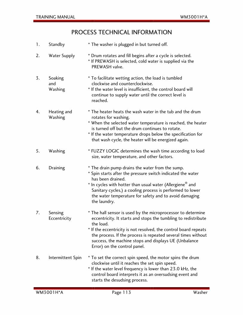
TRAINING MANUAL WM3001H*A
WM3001H*A Page 113 Washer
PROCESS TECHNICAL INFORMATION 1. Standby * The washer is plugged in but turned off.
2. Water Supply * Drum rotates and fill begins after a cycle is selected.
* If PREWASH is selected, cold water is supplied via the PREWASH valve.
3. Soaking and Washing
* To facilitate wetting action, the load is tumbled clockwise and counterclockwise. * If the water level is insufficient, the control board will continue to supply water until the correct level is reached.
4. Heating and Washing
* The heater heats the wash water in the tub and the drum rotates for washing. * When the selected water temperature is reached, the heater is turned off but the drum continues to rotate. * If the water temperature drops below the specification for that wash cycle, the heater will be energized again.
5. Washing * FUZZY LOGIC determines the wash time according to load size, water temperature, and other factors.
6. Draining * The drain pump drains the water from the sump. * Spin starts after the pressure switch indicated the water has been drained. * In cycles with hotter than usual water (Allergiene® and Sanitary cycles,) a cooling process is performed to lower the water temperature for safety and to avoid damaging the laundry.
7. Sensing Eccentricity
* The hall sensor is used by the microprocessor to determine eccentricity. It starts and stops the tumbling to redistribute the load. * If the eccentricity is not resolved, the control board repeats the process. If the process is repeated several times without success, the machine stops and displays UE (Unbalance Error) on the control panel.
8. Intermittent Spin * To set the correct spin speed, the motor spins the drum clockwise until it reaches the set spin speed. * If the water level frequency is lower than 23.0 kHz, the control board interprets it as an oversudsing event and starts the desudsing process.
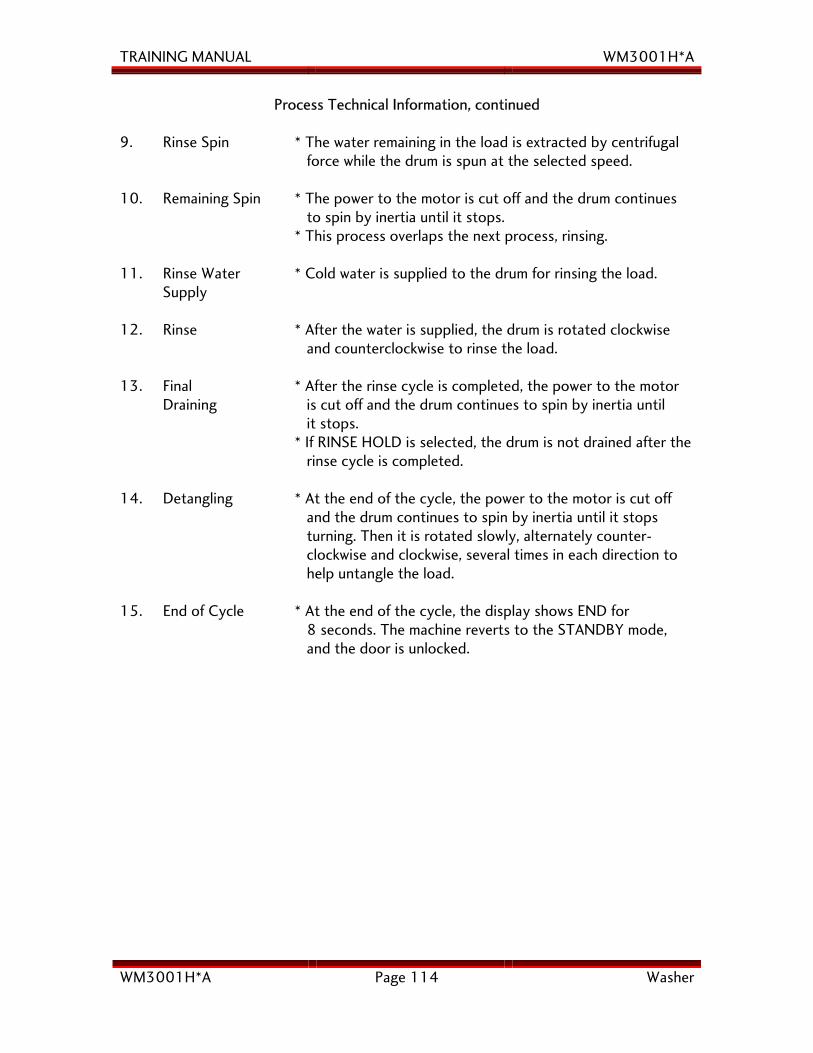
TRAINING MANUAL WM3001H*A
WM3001H*A Page 114 Washer
Process Technical Information, continued 9. Rinse Spin * The water remaining in the load is extracted by centrifugal
force while the drum is spun at the selected speed.
10. Remaining Spin * The power to the motor is cut off and the drum continues to spin by inertia until it stops. * This process overlaps the next process, rinsing.
11. Rinse Water Supply
* Cold water is supplied to the drum for rinsing the load.
12. Rinse * After the water is supplied, the drum is rotated clockwise and counterclockwise to rinse the load.
13. Final Draining
* After the rinse cycle is completed, the power to the motor is cut off and the drum continues to spin by inertia until it stops. * If RINSE HOLD is selected, the drum is not drained after the rinse cycle is completed.
14. Detangling * At the end of the cycle, the power to the motor is cut off and the drum continues to spin by inertia until it stops turning. Then it is rotated slowly, alternately counter- clockwise and clockwise, several times in each direction to help untangle the load.
15. End of Cycle * At the end of the cycle, the display shows END for 8 seconds. The machine reverts to the STANDBY mode, and the door is unlocked.