Embed Size (px)
Citation preview
SERVICE TRAINING
MANUAL FOR
LM600A
LM800A
LM1000A
1
Contents
Overview ....................................................................................................................................................2
Features ......................................................................................................................................................3
Specifications..............................................................................................................................................4
Rail table ....................................................................................................................................................5
Installation ..................................................................................................................................................6
Opener logic (design) ..............................................................................................................................7-8
Receiver/Control module............................................................................................................................9
LiftMaster “Smart” receiver ....................................................................................................................10
Remote control features ............................................................................................................................11
Remote control models ............................................................................................................................11
Programming your receiver on to the remote control ..............................................................................12
Programming the keyless entry system ....................................................................................................13
Multi-function wall-mounted door control panel................................................................................14-15
Connections ..............................................................................................................................................16
Automatic setting of the limits ................................................................................................................17
Manual setting of the limits ......................................................................................................................18
Travel setting ............................................................................................................................................19
Setting the force........................................................................................................................................20
Automatic reverse system (safety) ..........................................................................................................21
The Protector System™ (Infrared Sensor) ..............................................................................................22
Troubleshooting – The Protector System™ (Infrared Sensor) ................................................................23
Setting the tension ....................................................................................................................................23
Remote control tester device M18E ........................................................................................................24
Motors and transmissions ........................................................................................................................25
Installation/Removal of motor (motor replacement) ................................................................................26
Troubleshooting/Fault correction ........................................................................................................27-30
LiftMaster service ....................................................................................................................................31
2
Overview
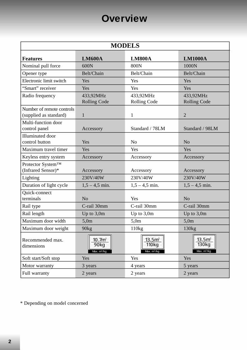
* Depending on model concerned
MODELS
Features LM600A LM800A LM1000ANominal pull force 600N 800N 1000N
Opener type Belt/Chain Belt/Chain Belt/Chain
Electronic limit switch Yes Yes Yes
“Smart” receiver Yes Yes Yes
Radio frequency 433,92MHz 433,92MHz 433,92MHzRolling Code Rolling Code Rolling Code
Number of remote controls(supplied as standard) 1 1 2
Multi-function door control panel Accessory Standard / 78LM Standard / 98LM
Illuminated door control button Yes No No
Maximum travel timer Yes Yes Yes
Keyless entry system Accessory Accessory Accessory
Protector System™(Infrared Sensor)* Accessory Accessory Accessory
Lighting 230V/40W 230V/40W 230V/40W
Duration of light cycle 1,5 – 4,5 min. 1,5 – 4,5 min. 1,5 – 4,5 min.
Quick-connect terminals No Yes No
Rail type C-rail 30mm C-rail 30mm C-rail 30mm
Rail length Up to 3,0m Up to 3,0m Up to 3,0m
Maximum door width 5,0m 5,0m 5,0m
Maximum door weight 90kg 110kg 130kg
Soft start/Soft stop Yes Yes Yes
Motor warranty 3 years 4 years 5 years
Full warranty 2 years 2 years 2 years
Recommended max.dimensions
10.7m2
90kgMax. m2/kg
13.5m2
110kgMax. m2/kg
13.5m2
130kgMax. m2/kg
3
Features
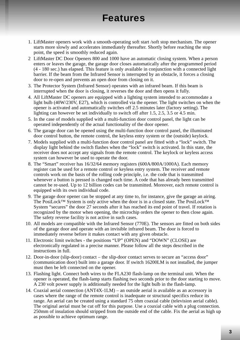
1. LiftMaster openers work with a smooth-operating soft start /soft stop mechanism. The openerstarts more slowly and accelerates immediately thereafter. Shortly before reaching the stoppoint, the speed is smoothly reduced again.
2 LiftMaster DC Door Openers 800 and 1000 have an automatic closing system. When a personenters or leaves the garage, the garage door closes automatically after the programmed period(4 - 180 sec.) has elapsed. This feature is only available in conjunction with a connected lightbarrier. If the beam from the Infrared Sensor is interrupted by an obstacle, it forces a closingdoor to re-open and prevents an open door from closing on it.
3. The Protector System (Infrared Sensor) operates with an infrared beam. If this beam isinterrupted when the door is closing, it reverses the door and then opens it fully.
4. All LiftMaster DC openers are equipped with a lighting system intended to accommodate alight bulb (40W/230V, E27), which is controlled via the opener. The light switches on when theopener is activated and automatically switches off 2.5 minutes later (factory setting). Thelighting can however be set individually to switch off after 1.5, 2.5, 3.5 or 4.5 min.
5. In the case of models supplied with a multi-function door control panel, the light can beoperated independently of the actual functionality of the door opener.
6. The garage door can be opened using the multi-function door control panel, the illuminateddoor control button, the remote control, the keyless entry system or the (outside) keylock.
7. Models supplied with a multi-function door control panel are fitted with a “lock” switch. Thedisplay light behind the switch flashes when the “lock” switch is activated. In this state, thereceiver does not accept any signals from the remote control. The keylock or keyless accesssystem can however be used to operate the door.
8. The “Smart” receiver has 16/32/64 memory registers (600A/800A/1000A). Each memoryregister can be used for a remote control or keyless entry system. The receiver and remotecontrols work on the basis of the rolling code principle, i.e. the code that is transmittedwhenever a button is pressed is changed each time. A code that has already been transmittedcannot be re-used. Up to 12 billion codes can be transmitted. Moreover, each remote control isequipped with its own individual code.
9. The garage door opener can be stopped at any time to, for instance, give the garage an airing.The PosiLock™ System is only active when the door is in a closed state. The PosiLock™System “secures” the door 27 seconds after it has reached its end point of travel. If rotation isrecognized by the motor when opening, the microchip orders the opener to then close again.The safety reverse facility is not active in such cases.
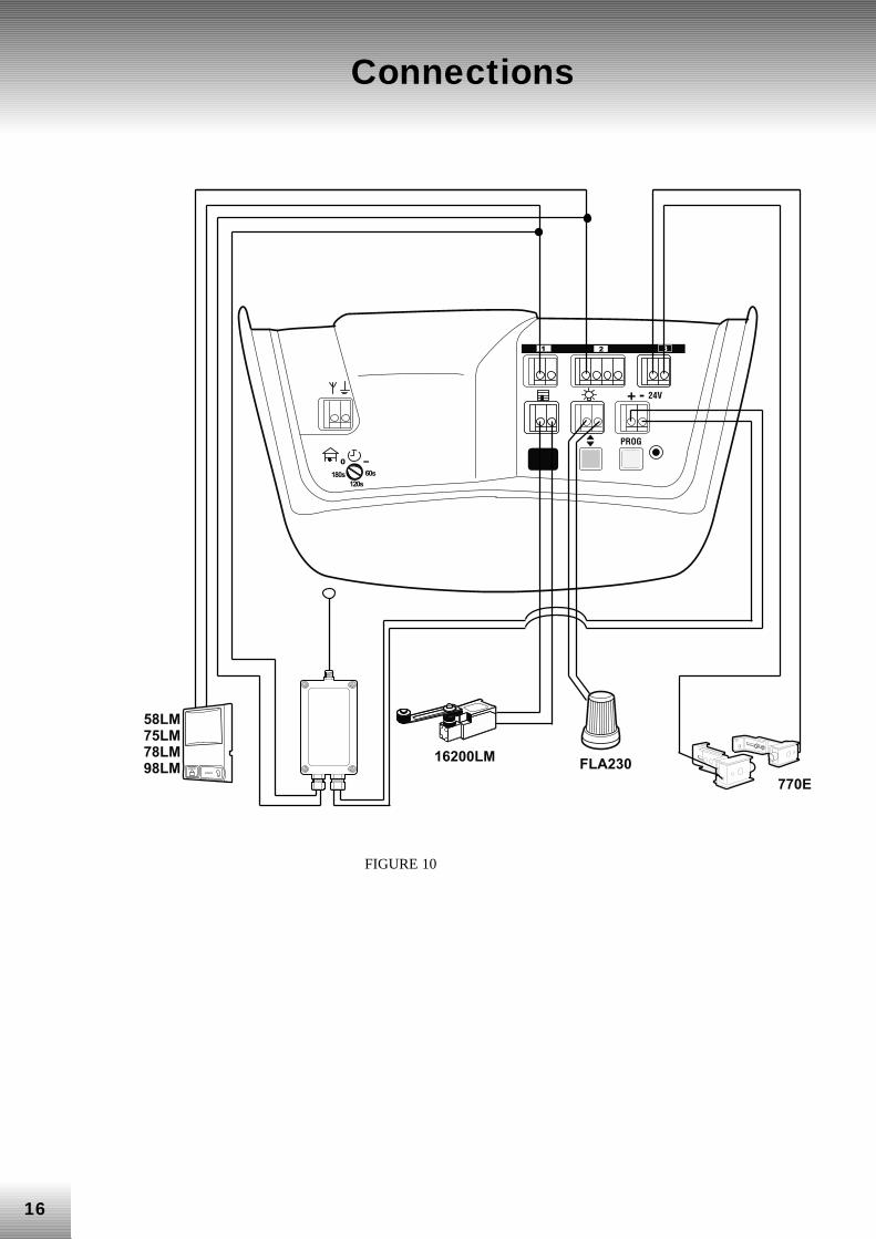
10. All models are compatible with the Infrared Sensor (770E). The sensors are fitted on both sidesof the garage door and operate with an invisible infrared beam. The door is forced toimmediately reverse before it makes contact with any given obstacle.
11. Electronic limit switches - the positions “UP” (OPEN) and “DOWN” (CLOSE) areelectronically regulated in a precise manner. Please follow all the steps described in theinstructions in full.
12. Door-in-door (slip-door) contact – the slip-door contact serves to secure an “access door”(communication door) built into a garage door. If switch 16200LM is not installed, the jumpermust then be left connected on the opener.
13. Flashing light. Connect both wires to the FLA230 flash-lamp on the terminal unit. When theopener is operated, the flash-lamp starts flashing two seconds prior to the door starting to move.A 230 volt power supply is additionally needed for the light bulb in the flash-lamp.
14. Coaxial aerial connection (ANT4X-1LM) – an outside aerial is available as an accessory incases where the range of the remote control is inadequate or structural specifics reduce itsrange. An aerial can be created using a standard 75 ohm coaxial cable (television aerial cable).The original aerial must be cut off for this purpose. Use a coaxial cable with a plug connection.250mm of insulation should stripped from the outside end of the cable. Fix the aerial as high upas possible to achieve optimum range.
4
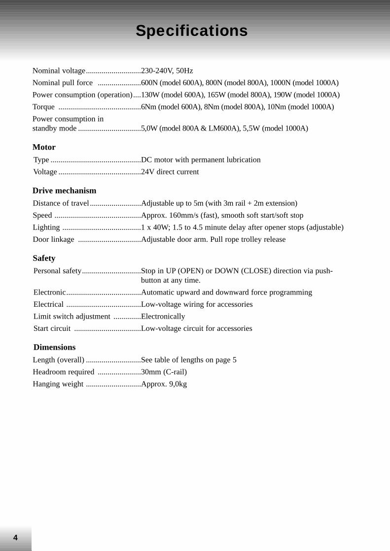
Specifications
Nominal voltage............................230-240V, 50Hz
Nominal pull force ......................600N (model 600A), 800N (model 800A), 1000N (model 1000A)
Power consumption (operation)....130W (model 600A), 165W (model 800A), 190W (model 1000A)
Torque ..........................................6Nm (model 600A), 8Nm (model 800A), 10Nm (model 1000A)
Power consumption in standby mode ................................5,0W (model 800A & LM600A), 5,5W (model 1000A)
Motor
Type ..............................................DC motor with permanent lubrication
Voltage ..........................................24V direct current
Drive mechanism
Distance of travel ..........................Adjustable up to 5m (with 3m rail + 2m extension)
Speed ............................................Approx. 160mm/s (fast), smooth soft start/soft stop
Lighting ........................................1 x 40W; 1.5 to 4.5 minute delay after opener stops (adjustable)
Door linkage ................................Adjustable door arm. Pull rope trolley release
Safety
Personal safety..............................Stop in UP (OPEN) or DOWN (CLOSE) direction via push-button at any time.
Electronic......................................Automatic upward and downward force programming
Electrical ......................................Low-voltage wiring for accessories
Limit switch adjustment ..............Electronically
Start circuit ..................................Low-voltage circuit for accessories
Dimensions
Length (overall) ............................See table of lengths on page 5
Headroom required ......................30mm (C-rail)
Hanging weight ............................Approx. 9,0kg
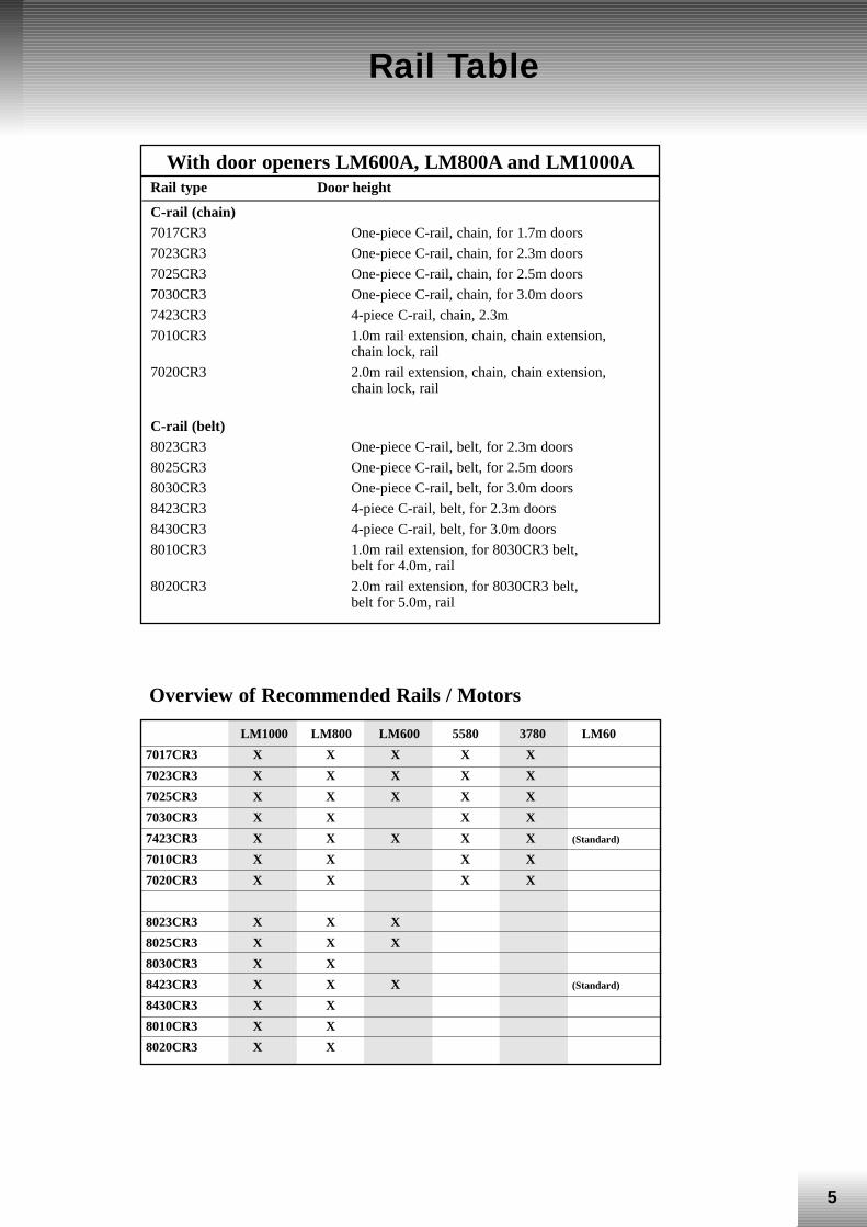
LM1000 LM800 LM600 5580 3780 LM60
7017CR3 X X X X X
7023CR3 X X X X X
7025CR3 X X X X X
7030CR3 X X X X
7423CR3 X X X X X (Standard)
7010CR3 X X X X
7020CR3 X X X X
8023CR3 X X X
8025CR3 X X X
8030CR3 X X
8423CR3 X X X (Standard)
8430CR3 X X
8010CR3 X X
8020CR3 X X
5
Rail Table
With door openers LM600A, LM800A and LM1000ARail type Door height
C-rail (chain) 7017CR3 One-piece C-rail, chain, for 1.7m doors
7023CR3 One-piece C-rail, chain, for 2.3m doors
7025CR3 One-piece C-rail, chain, for 2.5m doors
7030CR3 One-piece C-rail, chain, for 3.0m doors
7423CR3 4-piece C-rail, chain, 2.3m
7010CR3 1.0m rail extension, chain, chain extension, chain lock, rail
7020CR3 2.0m rail extension, chain, chain extension, chain lock, rail
C-rail (belt)8023CR3 One-piece C-rail, belt, for 2.3m doors
8025CR3 One-piece C-rail, belt, for 2.5m doors
8030CR3 One-piece C-rail, belt, for 3.0m doors
8423CR3 4-piece C-rail, belt, for 2.3m doors
8430CR3 4-piece C-rail, belt, for 3.0m doors
8010CR3 1.0m rail extension, for 8030CR3 belt, belt for 4.0m, rail
8020CR3 2.0m rail extension, for 8030CR3 belt, belt for 5.0m, rail
Overview of Recommended Rails / Motors
6
Installation
Check the garage door and the assembly accessories prior to installing the door opener.
• Ensure that there is sufficient headroom, there aren’t any worn rollers on the door, the cables /ropes are not chafed, the door is balanced and the rollers have been lubricated.
• Only connect the opener to a mains supply that has been EARTHED in accordance with thestandards and regulations applying locally.
• The door should close fully.
• To avoid serious personal injury, remove all the ropes and wires connected to the garage doorprior to installing the garage door opener.
• Disengage all the garage door locks to avoid damage to the garage door.
• Read the LiftMaster installation instructions carefully and then pass them on to the customer.
InstallationOnce you have determined which garage door the opener should be installed on, please note thefollowing instructions.
• Ensure that the trolley bracket is firmly attached to the garage. If it is incorrectly installed, thesafety reverse system may not function properly.
• Follow the instructions given by the door manufacturer as to whether the door needsreinforcing so that it does not bend or become deformed.
• The installation and electric wiring must be installed in accordance with the relevantregulations.
• The garage door must reverse on contact with an obstacle at least 50mm high laid flat on thefloor. Failure to carry out the safety reverse system test may result in serious personal injury.
• The door control button and switch should not be mounted in the immediate vicinity of thedoor while its moving parts should be located at a minimum height of 1.5m (out of the reachof children).
• Permanently fasten the caution label to the wall near the door control button as a reminder ofsafe operating procedures.
• Instruct the customers as to the functioning and operating of the garage door opener, how thesafety reverse system works, the nature of routine maintenance work, etc.
7
Opener Logic (Design)
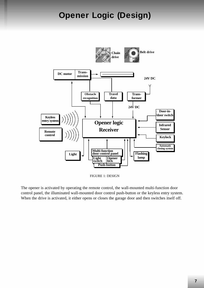
FIGURE 1: DESIGN
The opener is activated by operating the remote control, the wall-mounted multi-function doorcontrol panel, the illuminated wall-mounted door control push-button or the keyless entry system.When the drive is activated, it either opens or closes the garage door and then switches itself off.
Chaindrive
Belt drive
Trans-mission
Obstaclerecognition
Opener logic Receiver
Flashinglamp
Light Multi-functiondoor control panel Lightswitch
Openerlock
Push-button
Door-in-door switch
InfraredSensor
Keylock
Automaticclosing system
DC motor
Keylessentry system
Remotecontrol
24V DC
24V DC
Trans-former
Traveldata
8
Opener Logic (Design) (contd.)
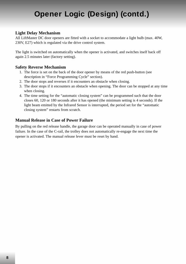
Light Delay Mechanism All LiftMaster DC door openers are fitted with a socket to accommodate a light bulb (max. 40W,230V, E27) which is regulated via the drive control system.
The light is switched on automatically when the opener is activated, and switches itself back offagain 2.5 minutes later (factory setting).
Safety Reverse Mechanism 1. The force is set on the back of the door opener by means of the red push-button (see
description in “Force Programming Cycle” section). 2. The door stops and reverses if it encounters an obstacle when closing. 3. The door stops if it encounters an obstacle when opening. The door can be stopped at any time
when closing. 4. The time setting for the “automatic closing system” can be programmed such that the door
closes 60, 120 or 180 seconds after it has opened (the minimum setting is 4 seconds). If thelight beam emitted by the Infrared Sensor is interrupted, the period set for the “automaticclosing system” restarts from scratch.
Manual Release in Case of Power Failure By pulling on the red release handle, the garage door can be operated manually in case of powerfailure. In the case of the C-rail, the trolley does not automatically re-engage the next time theopener is activated. The manual release lever must be reset by hand.
9
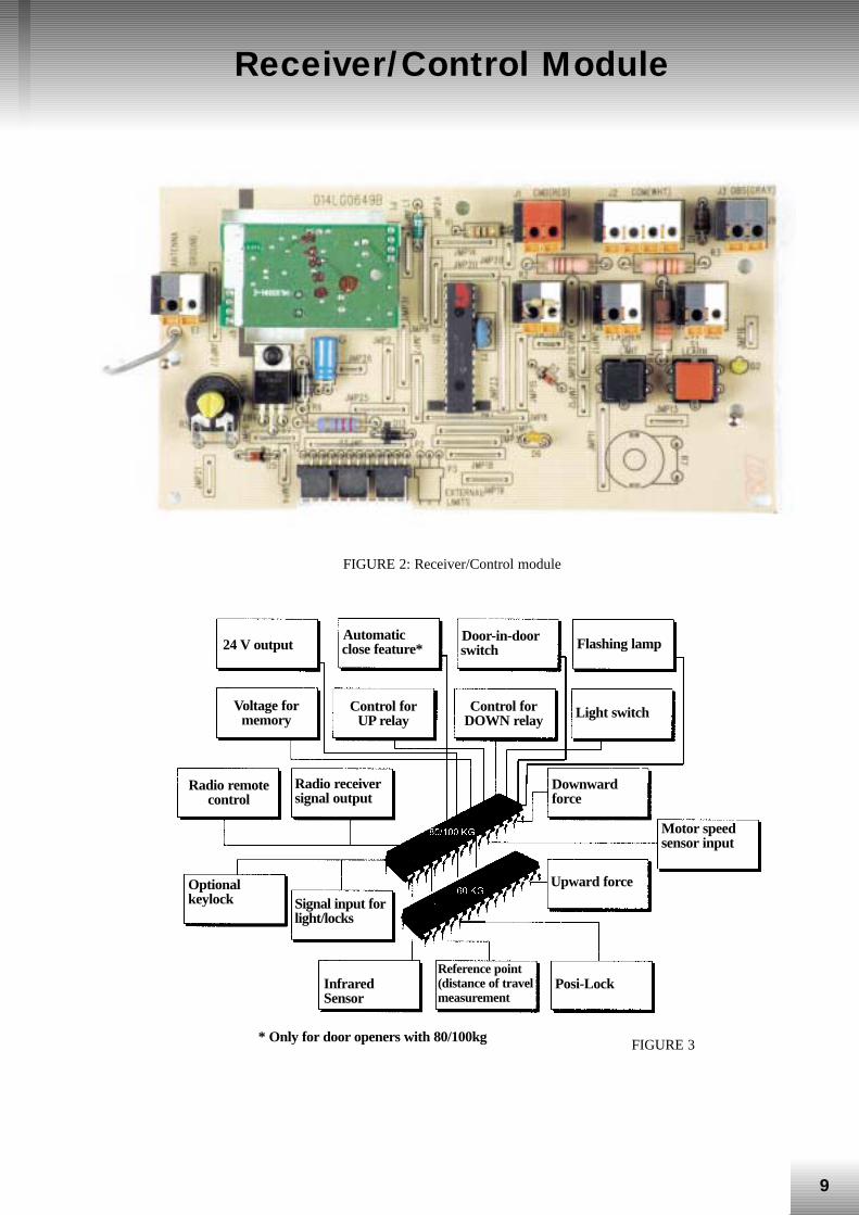
Receiver/Control Module
FIGURE 2: Receiver/Control module
FIGURE 3
24 V output Automaticclose feature*
Door-in-doorswitch Flashing lamp
Voltage formemory
Control forDOWN relay
Control forUP relay Light switch
Radio remotecontrol
Radio receiversignal output
Optionalkeylock Signal input for
light/locks
InfraredSensor
Reference point(distance of travelmeasurement
Posi-Lock
Upward force
Downwardforce
Motor speedsensor input
* Only for door openers with 80/100kg
10
LiftMaster “Smart” Receiver
R1
R1
R1
R15
R31
R63
R16
R32
R64
"Smart" Receiver
LM600A
LM800A
LM1000A
1 2 3
4 5 6
7 8 9
0
ENTER
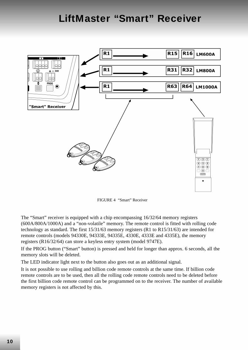
FIGURE 4 “Smart” Receiver
The “Smart” receiver is equipped with a chip encompassing 16/32/64 memory registers(600A/800A/1000A) and a “non-volatile” memory. The remote control is fitted with rolling codetechnology as standard. The first 15/31/63 memory registers (R1 to R15/31/63) are intended forremote controls (models 94330E, 94333E, 94335E, 4330E, 4333E and 4335E), the memoryregisters (R16/32/64) can store a keyless entry system (model 9747E).
If the PROG button (“Smart” button) is pressed and held for longer than approx. 6 seconds, all thememory slots will be deleted.
The LED indicator light next to the button also goes out as an additional signal.
It is not possible to use rolling and billion code remote controls at the same time. If billion coderemote controls are to be used, then all the rolling code remote controls need to be deleted beforethe first billion code remote control can be programmed on to the receiver. The number of availablememory registers is not affected by this.
11
Remote Control Features
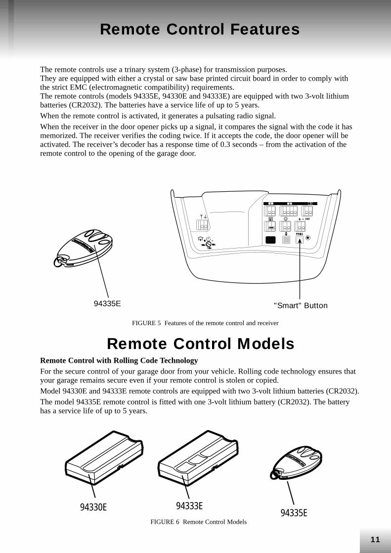
The remote controls use a trinary system (3-phase) for transmission purposes. They are equipped with either a crystal or saw base printed circuit board in order to comply withthe strict EMC (electromagnetic compatibility) requirements. The remote controls (models 94335E, 94330E and 94333E) are equipped with two 3-volt lithiumbatteries (CR2032). The batteries have a service life of up to 5 years. When the remote control is activated, it generates a pulsating radio signal. When the receiver in the door opener picks up a signal, it compares the signal with the code it hasmemorized. The receiver verifies the coding twice. If it accepts the code, the door opener will beactivated. The receiver’s decoder has a response time of 0.3 seconds – from the activation of theremote control to the opening of the garage door.
94335E "Smart" Button
FIGURE 5 Features of the remote control and receiver
Remote Control Models Remote Control with Rolling Code Technology For the secure control of your garage door from your vehicle. Rolling code technology ensures thatyour garage remains secure even if your remote control is stolen or copied. Model 94330E and 94333E remote controls are equipped with two 3-volt lithium batteries (CR2032). The model 94335E remote control is fitted with one 3-volt lithium battery (CR2032). The batteryhas a service life of up to 5 years.
94335E94333E94330E
FIGURE 6 Remote Control Models
12
Programming the Receiver on to the Remote Control
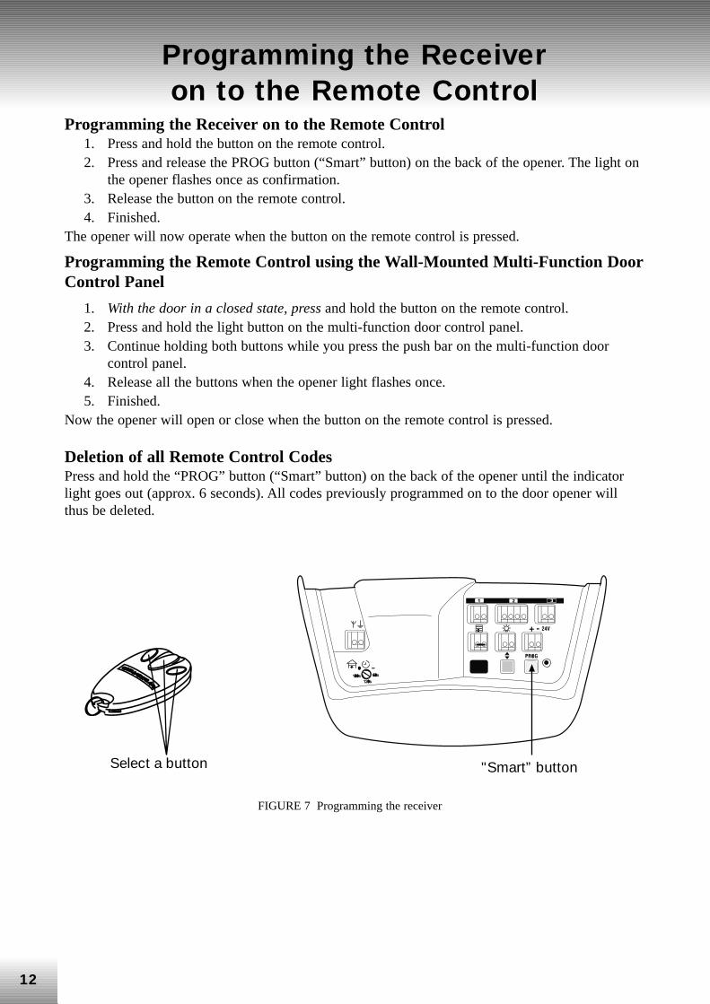
Programming the Receiver on to the Remote Control 1. Press and hold the button on the remote control. 2. Press and release the PROG button (“Smart” button) on the back of the opener. The light on
the opener flashes once as confirmation. 3. Release the button on the remote control. 4. Finished.
The opener will now operate when the button on the remote control is pressed.
Programming the Remote Control using the Wall-Mounted Multi-Function DoorControl Panel
1. With the door in a closed state, press and hold the button on the remote control. 2. Press and hold the light button on the multi-function door control panel. 3. Continue holding both buttons while you press the push bar on the multi-function door
control panel. 4. Release all the buttons when the opener light flashes once. 5. Finished.
Now the opener will open or close when the button on the remote control is pressed.
Deletion of all Remote Control Codes Press and hold the “PROG” button (“Smart” button) on the back of the opener until the indicatorlight goes out (approx. 6 seconds). All codes previously programmed on to the door opener willthus be deleted.
Select a button "Smart” button
FIGURE 7 Programming the receiver
13
Programming the Keyless Entry System (Model 9747E)
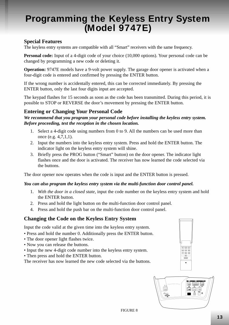
Special Features The keyless entry systems are compatible with all “Smart” receivers with the same frequency.
Personal code: Input of a 4-digit code of your choice (10,000 options). Your personal code can bechanged by programming a new code or deleting it.
Operation: 9747E models have a 9-volt power supply. The garage door opener is activated when afour-digit code is entered and confirmed by pressing the ENTER button.
If the wrong number is accidentally entered, this can be corrected immediately. By pressing theENTER button, only the last four digits input are accepted.
The keypad flashes for 15 seconds as soon as the code has been transmitted. During this period, it ispossible to STOP or REVERSE the door’s movement by pressing the ENTER button.
Entering or Changing Your Personal Code We recommend that you program your personal code before installing the keyless entry system.Before proceeding, test the reception in the chosen location.
1. Select a 4-digit code using numbers from 0 to 9. All the numbers can be used more thanonce (e.g. 4,7,1,1).
2. Input the numbers into the keyless entry system. Press and hold the ENTER button. Theindicator light on the keyless entry system will shine.
3. Briefly press the PROG button (“Smart” button) on the door opener. The indicator lightflashes once and the door is activated. The receiver has now learned the code selected viathe buttons.
The door opener now operates when the code is input and the ENTER button is pressed.
You can also program the keyless entry system via the multi-function door control panel.
1. With the door in a closed state, input the code number on the keyless entry system and holdthe ENTER button.
2. Press and hold the light button on the multi-function door control panel. 4. Press and hold the push bar on the multi-function door control panel.
Changing the Code on the Keyless Entry System
Input the code valid at the given time into the keyless entry system. • Press and hold the number 0. Additionally press the ENTER button. • The door opener light flashes twice. • Now you can release the buttons. • Input the new 4-digit code number into the keyless entry system. • Then press and hold the ENTER button. The receiver has now learned the new code selected via the buttons.
FIGURE 8
� � �
� � �
� �
�� ��
14
Multi-Function Door Control Panel
The multi-function door control panel is intended to open and close the garage door from inside.
Further special features are described here in brief: Lock/Safety Switch Remote operation can be prevented at the push of a button – the receiver then accepts no furthersignals emitted by the remote control. The garage door can however be activated via the multi-function door control panel, the outside keylock or keyless entry system. The flashing LEDindicator light behind the “Start” button shows that the “Lock/Safety” switch has been activated.
Light Switch The light switch can be used to switch the light on and off without activating the door opener. Thelight can be switched off by pressing the light switch again or by opening or closing the garage door.
If the garage door is activated, the light switches off automatically after 1.5, 2.5, 3.5 or 4.5minutes depending on the given setting.
Programming the Remote Control/Keyless Entry System via the Multi-Function Door Control Panel
1. Remote control – press and hold the button on the remote control while the door is in aclosed state.
Keyless access system – input the 4-digit code number via the keypad and hold the ENTERbutton.
2. Press and hold the light button on the multi-function door control panel. Press the button onthe remote control or the ENTER button on the keyless entry system. Press and hold thepush bar on the multi-function door control panel.
3. Release all the buttons when the door opener light starts flashing. The new code has beenprogrammed.
NOTE: Consult pages 13-14 for further information on programming the remote control and thekeyless entry system.
Operation of door opener light Press the LIGHT button to turn the opener light on or off. This button will not control the opener lightwhen the door is opening or closing. If you turn the light on and then activate the door opener, the lightwill remain on for 1.5 – 4.5 minutes. Press again to turn it off sooner. The standard 2.5 minute intervalcan be changed to 1.5, 3.5 or 4.5 minutes as follows: Press and hold the LOCK button until the light on the door opener starts flashing (about 10 seconds). Asingle flash indicates that the timer has been reset to 1.5 minutes. Repeat the procedure and the lightwill flash twice, resetting the timer to 2.5 minutes. Repeat again for a 3.5 minute interval and a furthertime for the maximum possible interval of 4.5 minutes.
15
Multi-Function Door Control Panel(contd.)
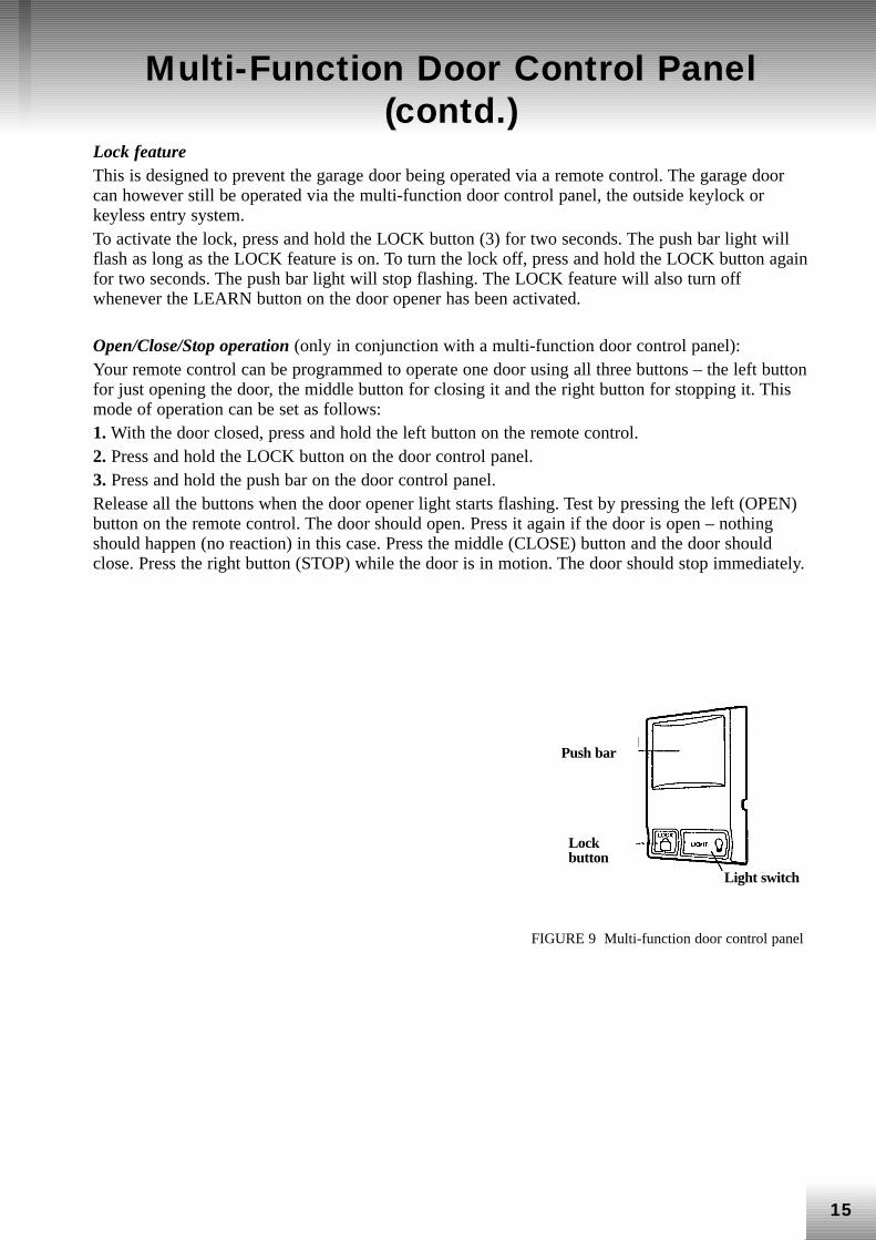
Lock feature This is designed to prevent the garage door being operated via a remote control. The garage doorcan however still be operated via the multi-function door control panel, the outside keylock orkeyless entry system. To activate the lock, press and hold the LOCK button (3) for two seconds. The push bar light willflash as long as the LOCK feature is on. To turn the lock off, press and hold the LOCK button againfor two seconds. The push bar light will stop flashing. The LOCK feature will also turn offwhenever the LEARN button on the door opener has been activated.
Open/Close/Stop operation (only in conjunction with a multi-function door control panel): Your remote control can be programmed to operate one door using all three buttons – the left buttonfor just opening the door, the middle button for closing it and the right button for stopping it. Thismode of operation can be set as follows: 1. With the door closed, press and hold the left button on the remote control. 2. Press and hold the LOCK button on the door control panel. 3. Press and hold the push bar on the door control panel. Release all the buttons when the door opener light starts flashing. Test by pressing the left (OPEN)button on the remote control. The door should open. Press it again if the door is open – nothingshould happen (no reaction) in this case. Press the middle (CLOSE) button and the door shouldclose. Press the right button (STOP) while the door is in motion. The door should stop immediately.
FIGURE 9 Multi-function door control panel
Lockbutton
Push bar
Light switch
16
Connections
��������
�����
����������������
����� �� ���
FIGURE 10
17
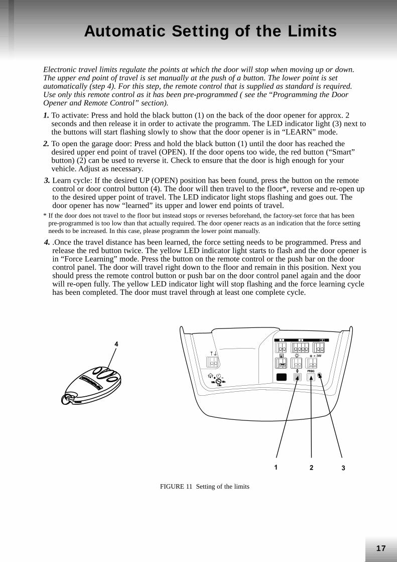
Electronic travel limits regulate the points at which the door will stop when moving up or down.The upper end point of travel is set manually at the push of a button. The lower point is setautomatically (step 4). For this step, the remote control that is supplied as standard is required.Use only this remote control as it has been pre-programmed ( see the “Programming the DoorOpener and Remote Control” section).
1. To activate: Press and hold the black button (1) on the back of the door opener for approx. 2seconds and then release it in order to activate the programm. The LED indicator light (3) next tothe buttons will start flashing slowly to show that the door opener is in “LEARN” mode.
2. To open the garage door: Press and hold the black button (1) until the door has reached thedesired upper end point of travel (OPEN). If the door opens too wide, the red button (“Smart”button) (2) can be used to reverse it. Check to ensure that the door is high enough for yourvehicle. Adjust as necessary.
3. Learn cycle: If the desired UP (OPEN) position has been found, press the button on the remotecontrol or door control button (4). The door will then travel to the floor*, reverse and re-open upto the desired upper point of travel. The LED indicator light stops flashing and goes out. Thedoor opener has now “learned” its upper and lower end points of travel.
* If the door does not travel to the floor but instead stops or reverses beforehand, the factory-set force that has beenpre-programmed is too low than that actually required. The door opener reacts as an indication that the force settingneeds to be increased. In this case, please programm the lower point manually.
4. .Once the travel distance has been learned, the force setting needs to be programmed. Press andrelease the red button twice. The yellow LED indicator light starts to flash and the door opener isin “Force Learning” mode. Press the button on the remote control or the push bar on the doorcontrol panel. The door will travel right down to the floor and remain in this position. Next youshould press the remote control button or push bar on the door control panel again and the doorwill re-open fully. The yellow LED indicator light will stop flashing and the force learning cyclehas been completed. The door must travel through at least one complete cycle.
� � �
�
Automatic Setting of the Limits
FIGURE 11 Setting of the limits
18
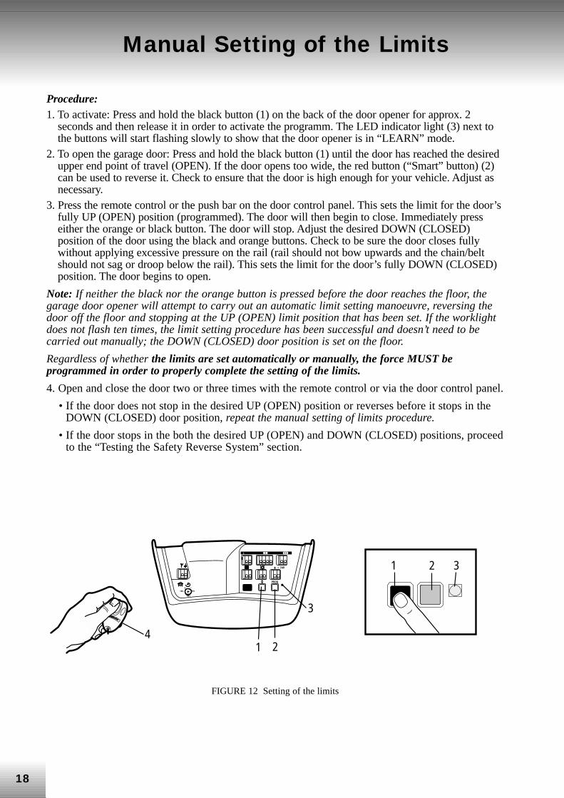
Procedure:1. To activate: Press and hold the black button (1) on the back of the door opener for approx. 2
seconds and then release it in order to activate the programm. The LED indicator light (3) next tothe buttons will start flashing slowly to show that the door opener is in “LEARN” mode.
2. To open the garage door: Press and hold the black button (1) until the door has reached the desiredupper end point of travel (OPEN). If the door opens too wide, the red button (“Smart” button) (2)can be used to reverse it. Check to ensure that the door is high enough for your vehicle. Adjust asnecessary.
3. Press the remote control or the push bar on the door control panel. This sets the limit for the door’sfully UP (OPEN) position (programmed). The door will then begin to close. Immediately presseither the orange or black button. The door will stop. Adjust the desired DOWN (CLOSED)position of the door using the black and orange buttons. Check to be sure the door closes fullywithout applying excessive pressure on the rail (rail should not bow upwards and the chain/beltshould not sag or droop below the rail). This sets the limit for the door’s fully DOWN (CLOSED)position. The door begins to open.
Note: If neither the black nor the orange button is pressed before the door reaches the floor, thegarage door opener will attempt to carry out an automatic limit setting manoeuvre, reversing thedoor off the floor and stopping at the UP (OPEN) limit position that has been set. If the worklightdoes not flash ten times, the limit setting procedure has been successful and doesn’t need to becarried out manually; the DOWN (CLOSED) door position is set on the floor.
Regardless of whether the limits are set automatically or manually, the force MUST beprogrammed in order to properly complete the setting of the limits.
4. Open and close the door two or three times with the remote control or via the door control panel.
• If the door does not stop in the desired UP (OPEN) position or reverses before it stops in theDOWN (CLOSED) door position, repeat the manual setting of limits procedure.
• If the door stops in the both the desired UP (OPEN) and DOWN (CLOSED) positions, proceedto the “Testing the Safety Reverse System” section.
Manual Setting of the Limits
4
LiftMaster
2
3
1
1 32
60 s
120 s
180 s
O –
1 2 3
FIGURE 12 Setting of the limits
19
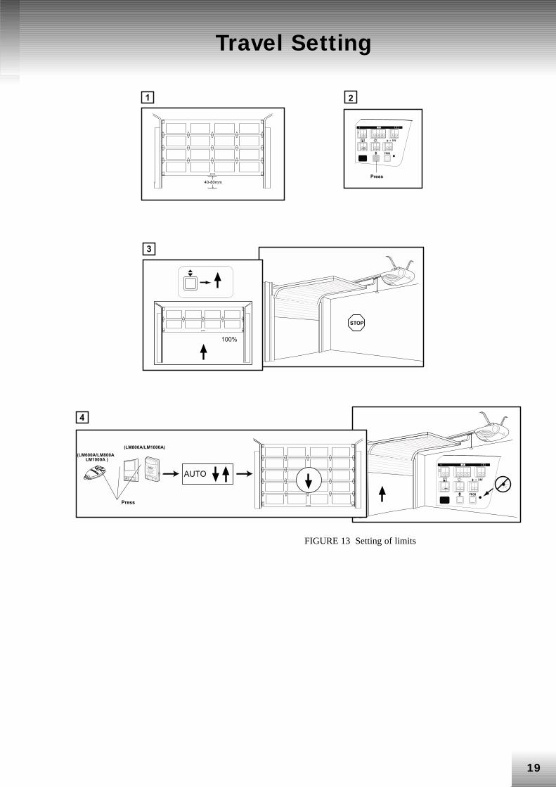
FIGURE 13 Setting of limits
�
�
� ���
�
� ��
�
����
�������
���
����
�����������������������
����������������
����
�
����
� ��
���
Travel Setting
�
�
FIGURE 14 Setting the force
20
Setting the Force
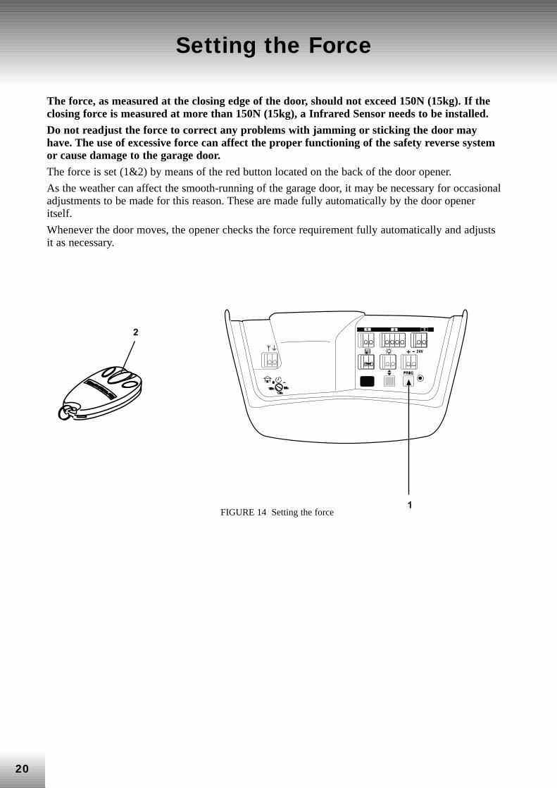
The force, as measured at the closing edge of the door, should not exceed 150N (15kg). If theclosing force is measured at more than 150N (15kg), a Infrared Sensor needs to be installed.
Do not readjust the force to correct any problems with jamming or sticking the door mayhave. The use of excessive force can affect the proper functioning of the safety reverse systemor cause damage to the garage door.
The force is set (1&2) by means of the red button located on the back of the door opener.
As the weather can affect the smooth-running of the garage door, it may be necessary for occasionaladjustments to be made for this reason. These are made fully automatically by the door openeritself.
Whenever the door moves, the opener checks the force requirement fully automatically and adjustsit as necessary.
21
Automatic Reverse System
Test the safety reverse system after1. each time the limits and force are set
2. each time the garage door is repaired or adjusted (including springs or other bracketelements)
3. each time the garage floor is repaired or modified
4 each time the garage door opener is repaired or adjusted.
CONSULT THE INSTALLATION INSTRUCTIONS FOR FURTHER INFORMATION ON THE50MM TEST.
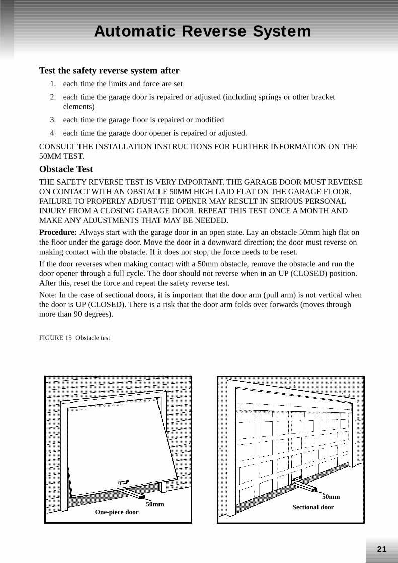
Obstacle Test THE SAFETY REVERSE TEST IS VERY IMPORTANT. THE GARAGE DOOR MUST REVERSEON CONTACT WITH AN OBSTACLE 50MM HIGH LAID FLAT ON THE GARAGE FLOOR.FAILURE TO PROPERLY ADJUST THE OPENER MAY RESULT IN SERIOUS PERSONALINJURY FROM A CLOSING GARAGE DOOR. REPEAT THIS TEST ONCE A MONTH ANDMAKE ANY ADJUSTMENTS THAT MAY BE NEEDED.
Procedure: Always start with the garage door in an open state. Lay an obstacle 50mm high flat onthe floor under the garage door. Move the door in a downward direction; the door must reverse onmaking contact with the obstacle. If it does not stop, the force needs to be reset.
If the door reverses when making contact with a 50mm obstacle, remove the obstacle and run thedoor opener through a full cycle. The door should not reverse when in an UP (CLOSED) position.After this, reset the force and repeat the safety reverse test.
Note: In the case of sectional doors, it is important that the door arm (pull arm) is not vertical whenthe door is UP (CLOSED). There is a risk that the door arm folds over forwards (moves throughmore than 90 degrees).
FIGURE 15 Obstacle test
One-piece doorSectional door50mm
50mm
22
The Protector System™Infrared Sensor
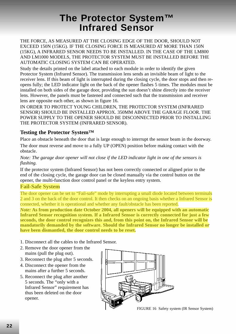
THE FORCE, AS MEASURED AT THE CLOSING EDGE OF THE DOOR, SHOULD NOTEXCEED 150N (15KG). IF THE CLOSING FORCE IS MEASURED AT MORE THAN 150N(15KG), A INFRARED SENSOR NEEDS TO BE INSTALLED. IN THE CASE OF THE LM800AND LM1000 MODELS, THE PROTECTOR SYSTEM MUST BE INSTALLED BEFORE THEAUTOMATIC CLOSING SYSTEM CAN BE OPERATED. Study the details printed on the label attached to each module in order to identify the givenProtector System (Infrared Sensor). The transmission lens sends an invisible beam of light to thereceiver lens. If this beam of light is interrupted during the closing cycle, the door stops and then re-opens fully; the LED indicator light on the back of the opener flashes 5 times. The modules must beinstalled on both sides of the garage door, providing the sun doesn’t shine directly into the receiverlens. However, the panels must be fastened and connected such that the transmission and receiverlens are opposite each other, as shown in figure 16. IN ORDER TO PROTECT YOUNG CHILDREN, THE PROTECTOR SYSTEM (INFRAREDSENSOR) SHOULD BE INSTALLED APPROX. 350MM ABOVE THE GARAGE FLOOR. THEPOWER SUPPLY TO THE OPENER SHOULD BE DISCONNECTED PRIOR TO INSTALLINGTHE PROTECTOR SYSTEM (INFRARED SENSOR).
Testing the Protector System™Place an obstacle beneath the door that is large enough to interrupt the sensor beam in the doorway. The door must reverse and move to a fully UP (OPEN) position before making contact with theobstacle. Note: The garage door opener will not close if the LED indicator light in one of the sensors isflashing. If the protector system (Infrared Sensor) has not been correctly connected or aligned prior to theend of the closing cycle, the garage door can be closed manually via the control button on theopener, the multi-function door control panel or the keyless entry system. Fail-Safe System The door opener can be set to “Fail-safe” mode by interrupting a small diode located between terminals2 and 3 on the back of the door control. It then checks on an ongoing basis whether a Infrared Sensor isconnected, whether it is operational and whether any fault/obstacle has been reported. Note: As from production date October 2004, all openers will be equipped with an automaticInfrared Sensor recognition system. If a Infrared Sensor is correctly connected for just a fewseconds, the door control recognizes this and, from this point on, the Infrared Sensor will bemandatorily demanded by the software. Should the Infrared Sensor no longer be installed orhave been dismantled, the door control needs to be reset.
1. Disconnect all the cables to the Infrared Sensor.2. Remove the door opener from the
mains (pull the plug out).3. Reconnect the plug after 5 seconds.4. Disconnect the opener from the
mains after a further 5 seconds.5. Reconnect the plug after another
5 seconds. The “only with aInfrared Sensor” requirement hasthus been deleted on the dooropener.
FIGURE 16 Safety system (IR Sensor System)
23
Troubleshooting Infrared Sensor
1. In the event of the receiver LED indicator light not coming on after installation, check thefollowing:• Power supply to the door opener. • Short circuit in the black/white wire. This can occur under the cable terminals or
connection terminals.• Incorrect wiring between the sensor and the door opener. • Interruption of power circuit (broken circuit).
2. If the transmitter LED indicator light shines steadily but the receiver LED indicator light doesnot, you must:• See if an obstacle is in the way.• Check the alignment. • Check the connections.
(NOTE: CONSULT PAGES 28-30 FOR FURTHER INFORMATION ON INFRARED SENSORFAULT ANALYSIS).
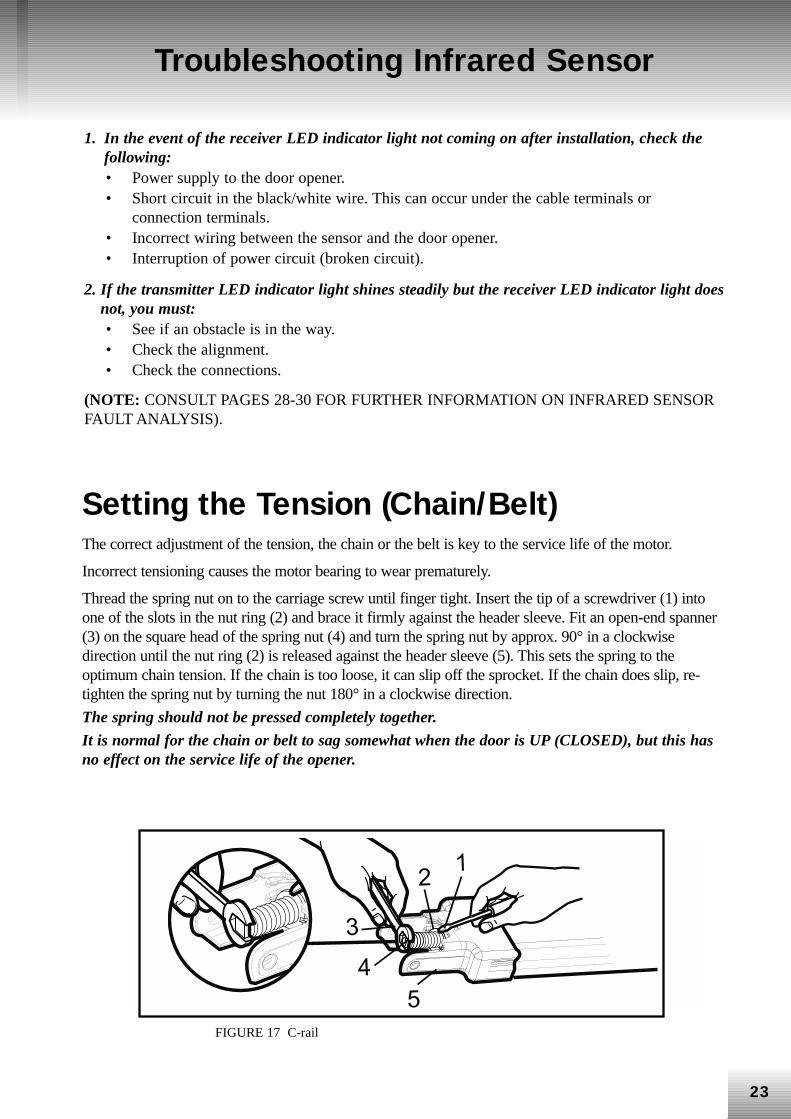
Setting the Tension (Chain/Belt) The correct adjustment of the tension, the chain or the belt is key to the service life of the motor.
Incorrect tensioning causes the motor bearing to wear prematurely.
Thread the spring nut on to the carriage screw until finger tight. Insert the tip of a screwdriver (1) intoone of the slots in the nut ring (2) and brace it firmly against the header sleeve. Fit an open-end spanner(3) on the square head of the spring nut (4) and turn the spring nut by approx. 90° in a clockwisedirection until the nut ring (2) is released against the header sleeve (5). This sets the spring to theoptimum chain tension. If the chain is too loose, it can slip off the sprocket. If the chain does slip, re-tighten the spring nut by turning the nut 180° in a clockwise direction.
The spring should not be pressed completely together.
It is normal for the chain or belt to sag somewhat when the door is UP (CLOSED), but this hasno effect on the service life of the opener.
��
�
��
FIGURE 17 C-rail
24
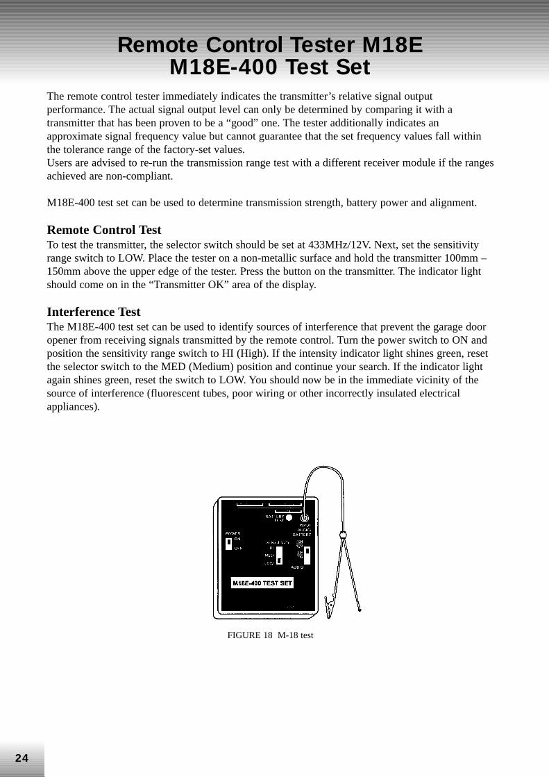
Remote Control Tester M18E M18E-400 Test Set
The remote control tester immediately indicates the transmitter’s relative signal outputperformance. The actual signal output level can only be determined by comparing it with atransmitter that has been proven to be a “good” one. The tester additionally indicates anapproximate signal frequency value but cannot guarantee that the set frequency values fall withinthe tolerance range of the factory-set values. Users are advised to re-run the transmission range test with a different receiver module if the rangesachieved are non-compliant.
M18E-400 test set can be used to determine transmission strength, battery power and alignment.
Remote Control Test To test the transmitter, the selector switch should be set at 433MHz/12V. Next, set the sensitivityrange switch to LOW. Place the tester on a non-metallic surface and hold the transmitter 100mm –150mm above the upper edge of the tester. Press the button on the transmitter. The indicator lightshould come on in the “Transmitter OK” area of the display.
Interference Test The M18E-400 test set can be used to identify sources of interference that prevent the garage dooropener from receiving signals transmitted by the remote control. Turn the power switch to ON andposition the sensitivity range switch to HI (High). If the intensity indicator light shines green, resetthe selector switch to the MED (Medium) position and continue your search. If the indicator lightagain shines green, reset the switch to LOW. You should now be in the immediate vicinity of thesource of interference (fluorescent tubes, poor wiring or other incorrectly insulated electricalappliances).
FIGURE 18 M-18 test
25
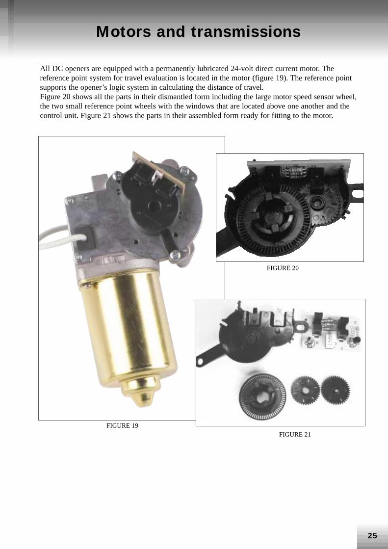
Motors and transmissions
All DC openers are equipped with a permanently lubricated 24-volt direct current motor. Thereference point system for travel evaluation is located in the motor (figure 19). The reference pointsupports the opener’s logic system in calculating the distance of travel. Figure 20 shows all the parts in their dismantled form including the large motor speed sensor wheel,the two small reference point wheels with the windows that are located above one another and thecontrol unit. Figure 21 shows the parts in their assembled form ready for fitting to the motor.
FIGURE 19FIGURE 21
FIGURE 20
26
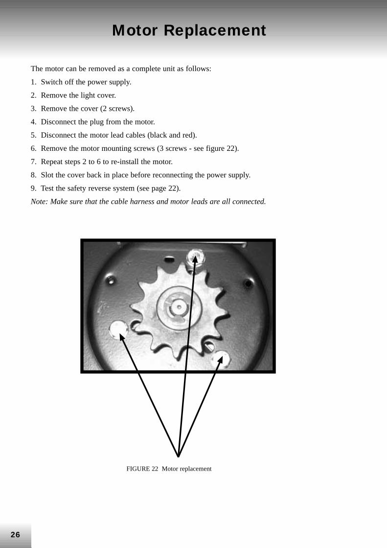
Motor Replacement
The motor can be removed as a complete unit as follows:
1. Switch off the power supply.
2. Remove the light cover.
3. Remove the cover (2 screws).
4. Disconnect the plug from the motor.
5. Disconnect the motor lead cables (black and red).
6. Remove the motor mounting screws (3 screws - see figure 22).
7. Repeat steps 2 to 6 to re-install the motor.
8. Slot the cover back in place before reconnecting the power supply.
9. Test the safety reverse system (see page 22).
Note: Make sure that the cable harness and motor leads are all connected.
FIGURE 22 Motor replacement
27
Troubleshooting
General troubleshooting When servicing the garage door opener, the most important thing is to identify the cause of thefault. The technician must decide whether the problem has been caused by the:
• Installation• Drive mechanism • Remote control • Radio receiver/Circuit board
InstallationThe garage door opener should be installed such that a minimum amount of force is needed tomove the door.
• If the door “jumps” during its initial movement, check whether the opener and the brackethave been fitted at the correct angle to the door.
• Disengage the door from the rail by pulling down on the red release handle and open itmanually to ensure that the door is balanced. If the spring is too weak, the garage dooropener carries the weight of the garage door. The garage door opener is capable of doingthis, but an important feature is thereby lost – its safety. All repairs to the garage doorshould be carried out prior to the installation.
• Try moving the door from the position in which the opener ‘bites’. In this way, parts thatstick or jam can be easily identified.
OpenerRemove any additional devices that may be connected. Bridge terminals 1+ 2. The opener ought tofunction if there is no problem. If the opener doesn’t function, consult the Troubleshooting table.
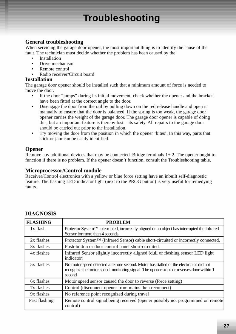
Microprocessor/Control module Receiver/Control electronics with a yellow or blue force setting have an inbuilt self-diagnosticfeature. The flashing LED indicator light (next to the PROG button) is very useful for remedyingfaults.
FLASHING PROBLEM1x flash Protector System™ interrupted, incorrectly aligned or an object has interrupted the Infrared
Sensor for more than 4 seconds 2x flashes Protector System™ (Infrared Sensor) cable short-circuited or incorrectly connected.3x flashes Push-button or door control panel short-circuited 4x flashes Infrared Sensor slightly incorrectly aligned (dull or flashing sensor LED light
indicator) 5x flashes No motor speed detected after one second. Motor has stalled or the electronics did not
recognize the motor speed monitoring signal. The opener stops or reverses door within 1second
6x flashes Motor speed sensor caused the door to reverse (force setting) 7x flashes Control (disconnect opener from mains then reconnect) 9x flashes No reference point recognized during travel
Fast flashing Remote control signal being received (opener possibly not programmed on remotecontrol)
DIAGNOSIS
28
Troubleshooting (contd.)
1. The opener doesn’t operate from either the door control panel or the remote control:• Does the opener have electric power? Plug a lamp into the socket. If it doesn’t light up, check the
fuse box or the circuit breaker. • Have you disengaged all the door locks? Re-read the installation instruction warnings on page 1. • Is there a build-up of ice or snow under the door? The door may be frozen to the ground. Remove
any obstacles. • The garage door spring may have broken. Have it replaced by persons qualified to do so. 2. The opener operates from the remote control but not from the door control panel:• Is the door control panel button lit? If not, remove the bell wire from the opener terminals. Short
the red and white terminals by touching both terminals at the same time with a piece of wire. If theopener runs, check for a faulty wire connection to the door control panel, a short under the staplesor a broken wire.
• Are all the wire connections in order? Re-read page 4 of the installation instructions.3. The opener operates from the door control panel but not from the remote control:• Replace the battery if necessary. • If you have two or more remote controls and only one operates, repeat the routines detailed in the
“Programming the Opener and Remote Control” and “Programming the Keyless Entry System”sections.
• Is the door control button flashing? Then the lock feature on the opener has been activated. If youhave a multi-function door control panel, press and hold the lock button for 2 seconds. The doorcontrol button will stop flashing.
4. The remote control has a short range:• Has a battery been fitted? • Change the location of the remote control in your car. • Metal garage doors, foil-backed insulation or metal sidings will reduce the transmission range. 5. The door reverses for no apparent reason and the opener light doesn’t flash:• Is something obstructing the door? Pull the release handle. Operate the door manually. If it is
unbalanced or jams, have it repaired by persons qualified to so. • Clear any ice or snow from the garage floor area where the garage door closes. • Repeat the routines detailed in the “Setting the Limits” and “Setting the Force” sections in the
instructions. Repeat the safety reverse test after any necessary adjustments have been made. 6. The door reverses for no apparent reason and the opener light flashes for 5 seconds afterreversing:Check the Protector System™ (Infrared Sensor) (if you have installed this accessory). Correct thealignment if the LED indicator light is flashing.
29
Troubleshooting (contd.)
7. The noise made by the opener is disturbing for fellow occupants of the house:If the operational noise is a problem because of the proximity of the opener to living quarters, it is advisableto install the Vibration Isolator Kit 89LM. This kit was designed to reduce the “sounding board” effect and iseasy to install. 8. The garage door opens and closes by itself:Make sure the push-button on the remote control is not stuck in the “on” position. 9. The door stops, but doesn’t close completely:Repeat the routine detailed in the “Setting the Limits” section. Repeat the safety reverse test after any adjustment of door arm length, closing force or DOWN(CLOSED) limit. 10. The door opens but won’t close:• Check the Protector System™ (Infrared Sensor) (if you have installed this accessory). Correct the
alignment if the LED indicator light is flashing. • If the opener light does not flash and the installation is a new one, repeat the routines detailed in
the “Setting the Limits” and “Setting the Force” sections of the instructions. Repeat the safety reverse test after any necessary adjustments have been made. 11. The opener light does not turn on:Replace the light bulb (max. 24V/21W). Replace any defective light bulbs with rough-service ones. 12. The opener creaks:The door may be unbalanced or springs broken. Close the door and use the manual release rope andhandle to disconnect the trolley. Open and close the door manually. A properly balanced door will stayat any point of travel and be supported entirely by its springs. If this is not the case, have the problemremedied by persons qualified to do so. 13. The opener motor hums briefly, then won’t work:• The garage door springs are possibly broken. SEE ABOVE. • If the problem occurs during the initial operation of the opener, the door is locked. Disengage the
door lock. Repeat the safety reverse test after any necessary adjustments have been made. 14. The opener won’t activate due to power failure:• Pull the manual release rope on the handle down and back to disconnect the trolley. The door can
now be opened and closed manually. When then power has been restored, pull the release handlestraight down. The next time the opener is activated, the trolley will automatically reconnect.
• The outside quick release, which is available as an accessory, disconnects the trolley from outsidethe garage in case of power failure.
30
15. Setting the limits manually:To program the limits manually: 1. Press and hold the black button until the yellow LED indicator light starts flashing slowly and
then release. 2. Adjust the position of the door by using the black and orange buttons. The black button moves
the door UP (OPEN) and the orange one moves the door DOWN (CLOSE). Check to be sure thedoor opens high enough for your vehicle.
3. Press the remote control or door control panel. This sets the limit for the door’s UP (OPEN)position. The door then begins to close. Immediately press the orange or black button. Thedoor will stop.
4. Adjust the desired DOWN (CLOSED) position using the black and orange buttons. Check to besure the door closes fully without applying excessive pressure to the rail (rail should not bowupwards nor should the chain/ belt sag or droop below the rail). Press the remote control or doorcontrol panel. This sets the limit for the door’s DOWN (CLOSED) position. The door thenbegins to open.
Note: If neither the black nor the orange button is pressed before the door reaches the floor, thegarage door opener will attempt to carry out an automatic limit setting manoeuvre, reversing thedoor off the floor and stopping at the UP (OPEN) limit position that has been set. If the worklightdoes not flash ten times, the limit setting procedure has been successful and doesn’t need to becarried out manually; the DOWN (CLOSED) door position is set on the floor. Regardless ofwhether the limits are set automatically or manually, the force MUST be programmed in order toproperly complete the setting of the limits. See the “Setting the Force” section. 4. Open and close the door two or three times with the remote control or via the door control panel.
• If the door does not stop in the desired UP (OPEN) position or reverses before it stops in theDOWN (CLOSED) door position, repeat the manual setting of limits procedure.
• If the door stops in the both the desired UP (OPEN) and DOWN (CLOSED) positions, proceedto the “Testing the Safety Reverse System” section.
Troubleshooting (contd.)
The LiftMaster hotline is there to help you
Don’t hesitate to call the LiftMaster hotline on
+49 (0) 6838-907-172
Monday - Friday 08:00 - 17:00
HOW TO ORDER SPARE PARTSSpare parts can be supplied in accordance with our spare parts price lists minus the discount you havebeen granted.
PLEASE PROVIDE THE FOLLOWING INFORMATIONWHENEVER ORDERING SPARE PARTS:
1. CUSTOMER NUMBER
2. ITEM NUMBER
3. ITEM DESCRIPTION
4. MODEL NUMBER OF GARAGE DOOR OPENER (UNDER THE LIGHT COVER)
PLEASE SEND YOUR ORDERS TO:
Chamberlain GmbHService DepartmentAlfred-Nobel Str. 4
D66793 SaarwellingenFax: +49 (0) 6838-907-179
© Chamberlain GmbH, 2004 95902-1


