Embed Size (px)
Citation preview
TECHNICAL REPORT
ISA-TR18.2.6-2012 Alarm Systems for Batch and Discrete Processes
Approved 31 May 2012
Copyright International Society of Automation Provided by IHS under license with ISA
Order Number: 01993985Sold to:FAA WJH TECH CNTR (TDX DA) [001457] - [email protected], Not for Resale,2014-01-27 21:26:54 UTCNo reproduction or networking permitted without license from IHS
--````,,``,``,`,,,,,,,`-`-``,```,,,`---

ISA-TR18.2.6-2012
Copyright 2012 ISA. All rights reserved.
2
ISA-TR18.2.6-2012, Alarm Systems for Batch and Discrete Processes
ISBN: 978-1-937560-18-8
Copyright © 2012 by the International Society of Automation. All rights reserved. Printed in the United States of America. No part of this publication may be reproduced, stored in a retrieval system, or transmitted in any form or by any means (electronic, mechanical, photocopying, recording, or otherwise) without the prior written permission of the publisher.
ISA 67 Alexander Drive P.O. Box 12277 Research Triangle Park, North Carolina 27709, USA
E-mail: [email protected]
Copyright International Society of Automation Provided by IHS under license with ISA
Order Number: 01993985Sold to:FAA WJH TECH CNTR (TDX DA) [001457] - [email protected], Not for Resale,2014-01-27 21:26:54 UTCNo reproduction or networking permitted without license from IHS
--````,,``,``,`,,,,,,,`-`-``,```,,,`---
ISA-TR18.2.6-2012
Copyright 2012 ISA. All rights reserved.
3
Preface
This preface is included for information purposes only and is not part of ISA-TR18.2.6-2012.
This technical report has been prepared as part of the service of ISA, the International Society of Automation, toward a goal of helping in the understanding and use of ANSI/ISA-18.2-2009 as applied to batch and discrete processes. To be of real value, this document should not be static but should be subject to periodic review. Toward this end, the Society welcomes all comments and criticisms and asks that they be addressed to the Secretary, Standards and Practices Board; ISA, 67 Alexander Drive; P.O. Box 12277; Research Triangle Park, NC 27709, USA; Telephone (919) 549-8411; Fax (919) 549-8288; E-mail: [email protected].
The ISA Standards and Practices Department is aware of the growing need for attention to the metric system of units in general, and the International System of Units (SI) in particular, in the preparation of instrumentation standards, recommended practices, and technical reports. The Department is further aware of the benefits to USA users of ISA standards of incorporating suitable references to the SI (and the metric system) in their business and professional dealings with other countries. Toward this end, the Department will endeavor to introduce SI and acceptable metric units in all new and revised standards to the greatest extent possible. The Metric Practice Guide, which has been published by the Institute of Electrical and Electronics Engineers (IEEE) as ANSI/IEEE Std. 268-1992, and future revisions, will be the reference guide for definitions, symbols, abbreviations, and conversion factors.
It is the policy of ISA to encourage and welcome the participation of all concerned individuals and interests in the development of ISA standards. Participation in the ISA standards-making process by an individual in no way constitutes endorsement by the employer of that individual, of ISA, or of any of the standards, recommended practices, and technical reports that ISA develops.
This technical report is structured to follow the ISA Style Guide.
THE USER OF THIS DOCUMENT SHOULD BE AWARE THAT THIS DOCUMENT MAY BE IMPACTED BY ELECTRONIC SECURITY ISSUES. THE COMMITTEE HAS NOT YET ADDRESSED THE POTENTIAL ISSUES IN THIS VERSION.
The following served as members of ISA18 Work Group 6 (WG6) to develop this technical report: NAME COMPANY Joseph Alford Consultant John Bogdan J. Bogdan Consulting LLC Bridget Fitzpatrick Mustang Engineering Tejas Ghiya Genentech Bill Hollifield PAS Douglas Metzger DPM Consulting Graham Nasby Eramosa Engineering Inc. Alan Phipps Eli Lilly Gregory Ruklic Consultant Henry Salomons Dow Chemical Nicholas Sands DuPont Ruth Schiedermayer Object Technologies CEM, Inc. Marcus Tennant Yokogawa Bob Weibel TiPS, Inc.
Copyright International Society of Automation Provided by IHS under license with ISA
Order Number: 01993985Sold to:FAA WJH TECH CNTR (TDX DA) [001457] - [email protected], Not for Resale,2014-01-27 21:26:54 UTCNo reproduction or networking permitted without license from IHS
--````,,``,``,`,,,,,,,`-`-``,```,,,`---

ISA-TR18.2.6-2012
Copyright 2012 ISA. All rights reserved.
4
The following people acted as voting members of ISA18 in approving publication of this technical report: NAME COMPANY Donald Dunn, Co-Chair Aramco Services Co. Nicholas Sands, Co-Chair DuPont Erwin Icayan ACES Inc. Joseph Alford Joseph S. Alford LLC Stephen Apple IntelaTrac-Wonderware Mobile Solutions Joe Bingham AES Global Inc. Alex Boquiren Bechtel Corp. Alan Bryant Oxy Inc. John Campbell Consultant Bridget Fitzpatrick Mustang Engineering Max Hanson MCC Control Systems Bill Hollifield PAS Alan Hugo Capstone Technology Lokesh Kalra Chevron Edward Marszal Kenexis Michael Marvan Shell Canada Douglas Metzger DPM Consulting Ian Nimmo User Centered Design Services LLC Patrick O’Donnell BP Douglas Rothenberg D. Roth Inc. Todd Stauffer Exida Co. David Strobhar Beville Engineering Inc. Angela Summers SIS-TECH Solutions LP Beth Vail URS SMS Bob Weibel TiPs Inc. This technical report was approved for publication by the ISA Standards and Practices Board on 31 May 2012. NAME COMPANY D. Dunn, Vice President Aramco Services Co. E. Cosman, Vice President-Elect The Dow Chemical Co. D. Bartusiak ExxonMobil Chemical Company P. Brett Honeywell Inc. J. Campbell Consultant M. Coppler Det Norske Veritas Certification Inc.. B. Dumortier Schneider Electric J. Federlein Federlein & Assoc. Inc. J. Gilsinn U.S. NIST E. Icayan ACES Inc. J. Jamison EnCana Corporation Ltd. K. Lindner Endress+Hauser Process Solutions AG V. Maggioli Feltronics Corp. T. McAvinew Instrumentation & Control Engineering LLC R. Reimer Rockwell Automation S. Russell Valero Energy Corp. N. Sands DuPont H. Sasajima Azbil Corp. T. Schnaare Rosemount Inc. J. Tatera Tatera & Associates Inc.
Copyright International Society of Automation Provided by IHS under license with ISA
Order Number: 01993985Sold to:FAA WJH TECH CNTR (TDX DA) [001457] - [email protected], Not for Resale,2014-01-27 21:26:54 UTCNo reproduction or networking permitted without license from IHS
--````,,``,``,`,,,,,,,`-`-``,```,,,`---

ISA-TR18.2.6-2012
Copyright 2012 ISA. All rights reserved.
5
I. Verhappen Yokogawa Canada Inc. W. Weidman WCW Consulting J. Weiss Applied Control Solutions LLC M. Wilkins Yokogawa IA Global Marketing USMK D. Zetterberg Chevron Energy Technology Company
Copyright International Society of Automation Provided by IHS under license with ISA
Order Number: 01993985Sold to:FAA WJH TECH CNTR (TDX DA) [001457] - [email protected], Not for Resale,2014-01-27 21:26:54 UTCNo reproduction or networking permitted without license from IHS
--````,,``,``,`,,,,,,,`-`-``,```,,,`---

ISA-TR18.2.6-2012
Copyright 2012 ISA. All rights reserved.
6
Copyright International Society of Automation Provided by IHS under license with ISA
Order Number: 01993985Sold to:FAA WJH TECH CNTR (TDX DA) [001457] - [email protected], Not for Resale,2014-01-27 21:26:54 UTCNo reproduction or networking permitted without license from IHS
--````,,``,``,`,,,,,,,`-`-``,```,,,`---
ISA-TR18.2.6-2012
Copyright 2012 ISA. All rights reserved.
7
Contents
Foreword ............................................................................................................................... 11
Purpose................................................................................................................................. 12
1 Scope ............................................................................................................................. 13
1.1 General applicability .................................................................................................... 13
1.2 The alarm system ....................................................................................................... 13
2 Normative references ....................................................................................................... 14
3 Definitions of terms and acronyms ...................................................................................... 14
3.1 Definitions .................................................................................................................. 14
3.2 Acronyms................................................................................................................... 17
4 Continuous, batch, and discrete processes.......................................................................... 18
4.1 General discussion ..................................................................................................... 18
4.2 The forms of production ............................................................................................... 20
4.3 Control system integration factors ................................................................................. 23
5 Alarm system models ....................................................................................................... 23
5.1 Alarm systems ............................................................................................................ 23
5.2 Alarm management lifecycle ........................................................................................ 23
5.3 Process condition model .............................................................................................. 24
5.4 Alarm state model ....................................................................................................... 26
5.5 Alarm response timeline model ..................................................................................... 28
6 Philosophy ...................................................................................................................... 30
6.1 Purpose ..................................................................................................................... 30
6.2 Applicability to batch and discrete processes .................................................................. 30
7 Alarm system requirements specification ............................................................................. 31
7.1 Purpose ..................................................................................................................... 31
7.2 Applicability to batch processes .................................................................................... 31
7.3 Applicability to discrete processes ................................................................................. 32
8 Identification .................................................................................................................... 33
8.1 Purpose ..................................................................................................................... 33
8.2 Providing alarms that track operational state .................................................................. 33
8.3 Examples ................................................................................................................... 33
9 Rationalization ................................................................................................................. 39
9.1 Purpose ..................................................................................................................... 39
9.2 Alarm rationalization activities....................................................................................... 39
9.3 Alarm rationalization team members ............................................................................. 40
9.4 Assembling data for use in rationalization ...................................................................... 40
9.5 Alarms for critical process parameters ........................................................................... 40
9.6 Batch examples .......................................................................................................... 41
9.7 Examples of special importance to regulated industries ................................................... 42
10 Basic alarm design ........................................................................................................... 44
10.1 Purpose ................................................................................................................... 44
10.2 Applicability to batch and discrete processes ................................................................ 44
Copyright International Society of Automation Provided by IHS under license with ISA
Order Number: 01993985Sold to:FAA WJH TECH CNTR (TDX DA) [001457] - [email protected], Not for Resale,2014-01-27 21:26:54 UTCNo reproduction or networking permitted without license from IHS
--````,,``,``,`,,,,,,,`-`-``,```,,,`---
ISA-TR18.2.6-2012
Copyright 2012 ISA. All rights reserved.
8
10.3 Batch alarms in an ISA-88 structured system ................................................................ 45
11 HMI design ...................................................................................................................... 46
11.1 Purpose ................................................................................................................... 46
11.2 Applicability to batch and discrete processes ................................................................ 47
11.3 Basic HMI information and display requirements ........................................................... 47
11.4 Additional contextual HMI information .......................................................................... 48
11.5 HMI functional requirements and recommendations ...................................................... 48
11.6 Special considerations for semi-automated processes ................................................... 48
11.7 Example: PV trend plot with golden-batch-driven alarms ................................................ 49
12 Enhanced/Advanced alarming ........................................................................................... 50
12.1 Purpose ................................................................................................................... 50
12.2 Applicability to batch and discrete processes ................................................................ 50
12.3 Methods in linking alarm records to batch lot identifiers .................................................. 51
13 Implementation ................................................................................................................ 52
13.1 Purpose ................................................................................................................. 52
13.2 Initial operator training ............................................................................................. 52
13.3 Testing challenges in batch processes ....................................................................... 52
13.4 Alarm system implementation in highly regulated industries ......................................... 53
14 Operations ...................................................................................................................... 55
14.1 Purpose ................................................................................................................... 55
14.2 Effects of process types (continuous, batch, discrete) on alarm response procedures ....... 55
14.3 Alarm response and resolution ................................................................................... 57
15 Maintenance .................................................................................................................... 58
15.1 Purpose ................................................................................................................... 58
15.2 Applicability to batch and discrete processes ................................................................ 58
15.3 Examples ................................................................................................................. 59
16 Monitoring and assessment ............................................................................................... 61
16.1 Purpose ................................................................................................................... 61
16.2 Setting appropriate alarm KPIs ................................................................................... 61
16.3 Alarm rate and other operating station metrics .............................................................. 64
16.4 Correlated alarms ..................................................................................................... 65
16.5 Use of metrics for operational improvements ................................................................ 66
17 Management of change (MOC) .......................................................................................... 66
17.1 Purpose ................................................................................................................... 66
17.2 Applicability to batch and discrete processes ................................................................ 66
17.3 Applicability to alarm classes of regulatory interest ........................................................ 66
17.4 Automated audit trails ................................................................................................ 67
18 Audit ............................................................................................................................... 67
18.1 Purpose ................................................................................................................... 67
18.2 Applicability to batch and discrete processes ................................................................ 67
18.3 Validation documentation considerations ..................................................................... 68
19 References ...................................................................................................................... 69
20 Bibliography .................................................................................................................... 69
Copyright International Society of Automation Provided by IHS under license with ISA
Order Number: 01993985Sold to:FAA WJH TECH CNTR (TDX DA) [001457] - [email protected], Not for Resale,2014-01-27 21:26:54 UTCNo reproduction or networking permitted without license from IHS
--````,,``,``,`,,,,,,,`-`-``,```,,,`---
ISA-TR18.2.6-2012
Copyright 2012 ISA. All rights reserved.
9
Figures
Figure 1 – Alarm system dataflow (from ISA-18.2) ................................................................................ 13 Figure 2 – Alarm management lifecycle (from ISA-18.2) ....................................................................... 24 Figure 3 – Process condition model (from ISA-18.2) ............................................................................. 25 Figure 4 – Modified Figure 3 for batch processes .................................................................................. 26 Figure 5 – Modified Figure 3 for discrete processes .............................................................................. 26 Figure 6 – Alarm state transition diagram (from ISA-18.2) .................................................................... 27 Figure 7 – Alarm timeline (from ISA-18.2) .............................................................................................. 29 Figure 8 – Logic diagram of alarm to prevent pump damage due to cavitation ..................................... 34 Figure 9 – Recirculating Hot Water-For-Injection system ...................................................................... 34 Figure 10 – Pipeline product transition ................................................................................................... 36 Figure 11 – Setting alarm setpoints (limits) for critical process parameters .......................................... 43 Figure 12 – Product quality design space .............................................................................................. 44 Figure 13 – ISA-88 software architecture ............................................................................................... 45 Figure 14 – Possible ISA-88 data paths for alarm attribute data ........................................................... 46 Figure 15 – Trend plot of DO2 (time varying), in relative time, showing golden-batch-driven alarms ... 49
Copyright International Society of Automation Provided by IHS under license with ISA
Order Number: 01993985Sold to:FAA WJH TECH CNTR (TDX DA) [001457] - [email protected], Not for Resale,2014-01-27 21:26:54 UTCNo reproduction or networking permitted without license from IHS
--````,,``,``,`,,,,,,,`-`-``,```,,,`---

ISA-TR18.2.6-2012
Copyright 2012 ISA. All rights reserved.
10
Copyright International Society of Automation Provided by IHS under license with ISA
Order Number: 01993985Sold to:FAA WJH TECH CNTR (TDX DA) [001457] - [email protected], Not for Resale,2014-01-27 21:26:54 UTCNo reproduction or networking permitted without license from IHS
--````,,``,``,`,,,,,,,`-`-``,```,,,`---
ISA-TR18.2.6-2012
Copyright 2012 ISA. All rights reserved.
11
Foreword
In 2003, the ISA Standards and Practices Board reactivated its ISA18 Committee (which had produced a standard in 1979 on Annunciator Sequences and Specifications – ISA-18.1-1979) to create standards for computer-based alarm systems for the process industries. In June of 2009, the ANSI/ISA approval process was completed for the standard, the result being ANSI/ISA-18.2-2009, Management of Alarm Systems for the Process Industries, commonly referred to as ISA-18.2. Starting in mid-2009, the ISA18 committee established working groups to produce technical reports, designed to augment the standard with additional rationale, usage guidelines, and examples in different areas of alarm management. Six technical reports are being created by these working groups:
a) WG1 – Alarm Philosophy
b) WG2 – Alarm Identification and Rationalization
c) WG3 – Basic Alarm Design
d) WG4 – Enhanced and Advanced Alarm Methods
e) WG5 – Alarm System Monitoring, Assessment, and Auditing
f) WG6 – Alarm Systems for Batch and Discrete Processes
This technical report, produced by Working Group 6, is designed to provide guidance, rationale, and examples for those with a need for understanding and application of ISA-18.2 to batch and discrete processes.
The guidance as presented in this document is general in nature and should be applied to each system as appropriate by personnel knowledgeable in the manufacturing process and control systems to which it is being applied. The guidance includes suggestions on appropriate techniques that are generally applicable; however, selection of activities and practices for a given system is the responsibility of the system’s designers, users, and/or support staff.
It is intended that this guidance will be updated over time as experience is gained. As such, while the general format of this guidance is expected to remain relatively stable, the specifics of its application and specific solutions are expected to evolve.
Copyright International Society of Automation Provided by IHS under license with ISA
Order Number: 01993985Sold to:FAA WJH TECH CNTR (TDX DA) [001457] - [email protected], Not for Resale,2014-01-27 21:26:54 UTCNo reproduction or networking permitted without license from IHS
--````,,``,``,`,,,,,,,`-`-``,```,,,`---
ISA-TR18.2.6-2012
Copyright 2012 ISA. All rights reserved.
12
Introduction
This technical report (TR) is one of several TRs developed to provide examples and discuss how to implement the requirements and best practices contained in ISA-18.2, Management of Alarm Systems for the Process Industries. This TR provides guidance to manufacturers, vendors, consultants, and practitioners at end-user companies in describing how the standard applies to batch and discrete processes. Relevant techniques and examples are included.
The technical report is organized into two parts. The first part is introductory in nature (Clauses 1-5). The second part, which is the main body of the technical report (Clauses 6-18), presents information and examples on how each of the alarm management lifecycle activities described in the standard, ISA-18.2, applies to batch and discrete processes. In order to facilitate use of this technical report as an extension of the standard, Clauses 6-18 refer to the same lifecycle activities in both documents. Clause 6 in the TR, for example, corresponds to Clause 6 in ISA-18.2.
Following the recommended guidance in this technical report will not necessarily ensure that alarm management problems will be avoided. It will, however, help to identify and address alarm specification, design, implementation, and management opportunities that are important to batch and discrete processes. It can also help minimize the generation of nuisance alarms that could complicate and frustrate operators’ awareness, understanding, and response to abnormal situations.
The guidance as presented in this document is general in nature and should be applied to each system, as appropriate, by personnel knowledgeable in the manufacturing process and control systems to which it is being applied. The guidance includes suggestions on appropriate applications that are generally applicable; however, selection of activities and practices for a given system is the responsibility of the system’s designers, users, and/or support staff.
It is intended that this guidance will be updated over time with future revisions to this TR as experience is gained in dealing with the nuances of batch and discrete process alarms. As such, while the general format of this guidance is expected to remain relatively stable, the specifics of its application and specific solutions are expected to evolve.
Purpose
This technical report addresses the specification, design, implementation, and management of alarms and alarm systems for batch and discrete processes. It explains how ISA-18.2 applies to batch and discrete processes and contains several examples.
This technical report was written to provide guidance for the use of ISA-18.2 for batch and discrete processes with due consideration of other guidance documents that have been developed throughout industry.
Alarms for batch and discrete processes are often associated with additional design, implementation, and management considerations compared to those for continuous processes. This technical report is intended to include these additional considerations.
Copyright International Society of Automation Provided by IHS under license with ISA
Order Number: 01993985Sold to:FAA WJH TECH CNTR (TDX DA) [001457] - [email protected], Not for Resale,2014-01-27 21:26:54 UTCNo reproduction or networking permitted without license from IHS
--````,,``,``,`,,,,,,,`-`-``,```,,,`---
ISA-TR18.2.6-2012
Copyright 2012 ISA. All rights reserved.
13
1 Scope
1.1 General applicability
This technical report covers the application of alarm management principles in ISA-18.2 to batch and discrete processes. The general principles and techniques described in this technical report are intended for use in the lifecycle management of an alarm system based on programmable electronic controller and computer-based human machine interface (HMI) technology. Use of this technical report should consider batch and discrete process alarms from all systems presented to the operator, which may include basic process control systems, annunciator panels, safety instrumented systems, fire and gas systems, and emergency response systems.
1.2 The alarm system
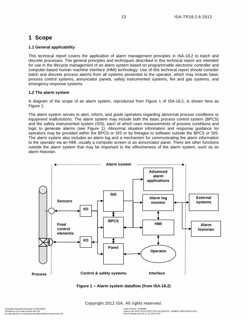
A diagram of the scope of an alarm system, reproduced from Figure 1 of ISA-18.2, is shown here as Figure 1.
The alarm system serves to alert, inform, and guide operators regarding abnormal process conditions or equipment malfunctions. The alarm system may include both the basic process control system (BPCS) and the safety instrumented system (SIS), each of which uses measurements of process conditions and logic to generate alarms (see Figure 1). Abnormal situation information and response guidance for operators may be provided within the BPCS or SIS or by linkages to software outside the BPCS or SIS. The alarm system also includes an alarm log and a mechanism for communicating the alarm information to the operator via an HMI, usually a computer screen or an annunciator panel. There are other functions outside the alarm system that may be important to the effectiveness of the alarm system, such as an alarm historian.
Figure 1 – Alarm system dataflow (from ISA-18.2)
Process
Sensors
Final control elements
BPCS
I/O
I/O
SIS
Panel
Alarm log
monitor
HMI
Interface
Alarm system
Operator
Control & safety systems
External systems
Alarm
historian
Advanced alarm
applications
Copyright International Society of Automation Provided by IHS under license with ISA
Order Number: 01993985Sold to:FAA WJH TECH CNTR (TDX DA) [001457] - [email protected], Not for Resale,2014-01-27 21:26:54 UTCNo reproduction or networking permitted without license from IHS
--````,,``,``,`,,,,,,,`-`-``,```,,,`---
ISA-TR18.2.6-2012
Copyright 2012 ISA. All rights reserved.
14
Components and work processes associated with control systems that are considered exclusions to the alarm system as shown in Figure 1 (e.g., sensors and final control elements, annunciator panels, fire detection and suppression systems, security systems, etc.) are described in ISA-18.2.
2 Normative references
ANSI/ISA-18.2-2009, Management of Alarm Systems for the Process Industries (referred to in this
document as ISA-18.2).
ANSI/ISA-84.00.01-2004 Parts 1-3 (IEC 61511-1, -2, and -3 Mod) Functional Safety: Safety Instrumented Systems for the Process Industry Sector (referred to in this document as ISA-84)
ANSI/ISA-88.00.01-2010 Batch Control Part 1: Models and Terminology (referred to in this
document as ISA-88)
ANSI/ISA-95.00.01-2010 (IEC 62264-1 Mod) Enterprise-Control System Integration - Part 1: Models and Terminology (referred to in this document as ISA-95)
3 Definitions of terms and acronyms
3.1 Definitions
Defined terms used in this technical report are listed below. Synonymous terms, which are not used in this technical report, are listed in parentheses.
Note 1 Most definitions listed here are copied from ISA-18.2. Those that are not from ISA-18.2 are shown in italics.
Note 2 Some alarm terms that are frequently used in industry are not defined or used in ISA-18.2 or this technical report because they have multiple meanings and interpretations by different BPCS vendors. Examples include alarm enable, alarm disable, and alarm inhibit.
3.1.1 activate the process of enabling an alarm function within the alarm system 3.1.2 advanced alarming a collection of techniques (e.g., state-based alarming and dynamic prioritization) that can help manage alarm rates in specific situations 3.1.3 alarm an audible and/or visible means of indicating to the operator an equipment malfunction, process deviation, or abnormal condition requiring a response 3.1.4 alarm attributes (alarm parameters) the settings for an alarm within the process control system (e.g., alarm setpoint, alarm priority) 3.1.5 alarm class a group of alarms with common alarm management requirements (e.g., testing, training, monitoring, and audit requirements) 3.1.6 alarm deadband the range through which an input is varied from the alarm setpoint necessary to clear the alarm 3.1.7 alarm flood (alarm shower) a condition during which the alarm rate is greater than the operator can effectively manage (e.g., more than 1 alarm per minute)
Copyright International Society of Automation Provided by IHS under license with ISA
Order Number: 01993985Sold to:FAA WJH TECH CNTR (TDX DA) [001457] - [email protected], Not for Resale,2014-01-27 21:26:54 UTCNo reproduction or networking permitted without license from IHS
--````,,``,``,`,,,,,,,`-`-``,```,,,`---
ISA-TR18.2.6-2012
Copyright 2012 ISA. All rights reserved.
15
3.1.8 alarm historian the long-term repository for alarm records 3.1.9 alarm log the short-term repository for alarm records 3.1.10 alarm management (alarm system management) the processes and practices for determining, documenting, designing, operating, monitoring, and maintaining alarm systems 3.1.11 alarm message a text string displayed with the alarm indication that provides additional information to the operator (e.g., operator action) 3.1.12 alarm philosophy a document that establishes the basic definitions, principles, and processes to design, implement, and maintain an alarm system 3.1.13 alarm priority the importance assigned to an alarm within the alarm system to indicate the urgency of response (e.g., seriousness of consequences and allowable response time) 3.1.14 alarm setpoint (alarm limit, alarm trip point) the threshold value of a process variable or discrete state that triggers the alarm indication 3.1.15 alarm system requirements specification the document that specifies the details of the alarm system design that are used in selecting components of an alarm system 3.1.16 alarm type (alarm condition) the alarm on a process measurement (e.g., low process variable alarm, high process variable alarm, or discrepancy alarm) 3.1.17 alert an audible and/or visible means of indicating to the operator an equipment or process condition that requires awareness, that is indicated separately from alarm indications, and that does not meet the criteria for an alarm 3.1.18 batch process (from ISA-88) a process that leads to the production of finite quantities of material by subjecting quantities of input materials to an ordered set of processing activities over a finite period of time, using one or more pieces of equipment 3.1.19 chattering alarm an alarm that repeatedly transitions between the alarm state and the normal state in a short period of time 3.1.20 classification the process of separating alarms into classes based on common requirements (e.g., testing, training, monitoring, and auditing requirements). See also alarm class. 3.1.21 continuous process a method used to manufacture a weight or volume of product without interruption
Copyright International Society of Automation Provided by IHS under license with ISA
Order Number: 01993985Sold to:FAA WJH TECH CNTR (TDX DA) [001457] - [email protected], Not for Resale,2014-01-27 21:26:54 UTCNo reproduction or networking permitted without license from IHS
--````,,``,``,`,,,,,,,`-`-``,```,,,`---
ISA-TR18.2.6-2012
Copyright 2012 ISA. All rights reserved.
16
3.1.22 critical process parameter an operational variable that must be controlled within predetermined criteria to ensure that the product meets its specification 3.1.23 discrete process the assembly and/or packaging of individual product units, each of which is identifiable 3.1.24 dynamic alarming The automatic modification of alarms based on process state or conditions 3.1.25 highly managed alarm an alarm belonging to a class with more requirements than general alarms (e.g., a safety alarm) 3.1.26 implementation the transition stage between design and operation during which the alarm is initially put into service 3.1.27 lean methodology a production practice that strives to prevent waste by eliminating any activities or materials that do not provide value 3.1.28 master alarm database the authorized list of rationalized alarms and associated attributes 3.1.29 measurement uncertainty the possible difference between the actual value of a process parameter and the displayed/recorded value due to the cumulative tolerances of all components involved in generating the displayed/recorded value 3.1.30 nuisance alarm an alarm that annunciates excessively, unnecessarily, or does not return to normal after the correct response is taken (e.g., chattering, fleeting, or stale alarms) 3.1.31 OPC a set of specifications for the exchange of information in a process control environment 3.1.32 operator the person who initiates and monitors the operation of a process 3.1.33 out-of-service the state of an alarm during which the alarm indication is suppressed, typically manually, for reasons such as maintenance 3.1.34 plant state (plant mode) a defined state of operation of a process plant (e.g., shutdown, startup, operating) 3.1.35 prioritization the process of assigning to an alarm a level of importance that can be implemented within the alarm system 3.1.36 process manufacturing the combination of continuous, batch, and/or discrete operations utilized in order to manufacture and package a product 3.1.37 process type the characterization of a process as predominately continuous, batch, or discrete
Copyright International Society of Automation Provided by IHS under license with ISA
Order Number: 01993985Sold to:FAA WJH TECH CNTR (TDX DA) [001457] - [email protected], Not for Resale,2014-01-27 21:26:54 UTCNo reproduction or networking permitted without license from IHS
--````,,``,``,`,,,,,,,`-`-``,```,,,`---
ISA-TR18.2.6-2012
Copyright 2012 ISA. All rights reserved.
17
3.1.38 proven acceptable range the boundaries of process parameters within which the manufacture of product of acceptable quality has been demonstrated 3.1.39 rationalization the process to review a potential alarm against the principles of the alarm philosophy to establish and document the rationale and design requirements for the alarm 3.1.40 remote alarm an alarm from a remotely operated facility or a remote interface 3.1.41 re-alarming alarm (re-triggering alarm) an alarm that is automatically re-annunciated to the operator under certain conditions 3.1.42 shelve a mechanism, typically initiated by the operator, to temporarily suppress an alarm 3.1.43 state-based alarm (mode-based alarm) an alarm that is automatically modified or suppressed based on process state or conditions 3.1.44 statistical alarm an alarm generated based on statistical processing of a process variable or variables 3.1.45 suppress any mechanism to prevent the indication of the alarm to the operator when the base alarm condition is present (i.e., shelving, designed suppression, out-of-service) 3.1.46 tag (point) the unique identifier assigned to a process measurement, calculation, or device within the control system
3.2 Acronyms
Note Most acronyms listed here are copied from ISA-18.2. Those that are not from ISA-18.2 are shown in italics.
3.2.1 Ack: Acknowledge or Acknowledged 3.2.2 ASRS: Alarm System Requirements Specification 3.2.3 BPCS: Basic Process Control System 3.2.4 CPP: Critical Process Parameter 3.2.5 cGMP: current Good Manufacturing Practice (e.g., from US Government FDA) 3.2.6 CM: Control Module 3.2.7 EEMUA: Engineering Equipment and Materials Users’ Association 3.2.8 EM: Equipment Module 3.2.9 EMI: Electromagnetic Interference 3.2.10 EPA: Environmental Protection Agency (US Government) 3.2.11 ERP: Enterprise Resource Planning 3.2.12 ESD: Emergency Shutdown System 3.2.13 FDA: Food and Drug Administration (US government) 3.2.14 FMEA: Failure Modes and Effects Analysis 3.2.15 HMA: Highly Managed Alarm 3.2.16 HMI: Human Machine Interface 3.2.17 HAZOP: Hazard and Operability Study 3.2.18 KPI: Key Performance Indicator 3.2.19 MES: Manufacturing Execution System (see ISA-95) 3.2.20 MOC: Management of Change 3.2.21 MTBF: Mean Time Between Failures 3.2.22 OEE: Operational Equipment Effectiveness
Copyright International Society of Automation Provided by IHS under license with ISA
Order Number: 01993985Sold to:FAA WJH TECH CNTR (TDX DA) [001457] - [email protected], Not for Resale,2014-01-27 21:26:54 UTCNo reproduction or networking permitted without license from IHS
--````,,``,``,`,,,,,,,`-`-``,```,,,`---
ISA-TR18.2.6-2012
Copyright 2012 ISA. All rights reserved.
18
3.2.23 OPC: OLE for Process Control Systems, where OLE is Object Linking and Embedding (see OPC Overview in Bibliography) 3.2.24 OSHA: Occupational Safety and Health Administration (US government) 3.2.25 P&ID: Piping (or Process) and Instrumentation Diagram 3.2.26 PAR: Proven Acceptable Range 3.2.27 PHA: Process Hazards Analysis 3.2.28 RFI: Radio Frequency Interference 3.2.29 RFID: Radio Frequency Identification 3.2.30 RPN: Risk Priority Number 3.2.31 RTN: Return to Normal 3.2.32 SIF: Safety Instrumented Function 3.2.33 SIL: Safety Integrity Level 3.2.34 SIS: Safety Instrumented System 3.2.35 SRS: Safety Requirements Specification 3.2.36 SOP: Standard Operating Procedure 3.2.37 Unack: Unacknowledged
4 Continuous, batch, and discrete processes
4.1 General discussion
Production manufacturing is generally comprised of processes that create output either by transforming raw materials into a new material or by generating discrete physical items. Chemical, biological, physical, or other methods can be used to convert, separate, or blend materials to produce an intermediate or final product, typically measured by weight or volume. Discrete manufacturing creates components, subassemblies, or final product measured by part count.
Manufacturing processes can utilize batch or continuous methodology to achieve results. Batch signifies that materials or subassemblies are held or batched at one or more stages during manufacturing for hold or transfer, while continuous signifies that there are no interruptions until the final product is output.
The impact of applying analysis-based process improvement may result in a reduction in batching and an increase in application of continuous methods to reduce or remove non-value-added production time. However, specific product requirements, including use of high-value, unstable, or other sensitive materials and process steps, may dictate the use of batch methodologies to achieve consistent control and desired product quality. Batching commonly creates intermediate inventory, which can require more complex inventory tracking systems. It is important to note that batch processes can have parts (sub-processes) that are continuous in nature, and continuous processes can have sub-processes that are batch in nature. These are often referred to as semi-continuous or semi-batch, depending on the dominant method of operations. The material flow path may be fixed, or in continuous process cases, such as petroleum or chemical separation, it may provide separate pathways for each grade or composition output by the process.
This clause introduces some of the differences and commonalities of the different manufacturing methodologies affecting alarm systems. While the scope of ISA-18.2 covers all process types, this technical report provides specific guidance for batch and discrete processes. However, since continuous production is a common manufacturing paradigm, and portions of some batch and discrete processes operate in a continuous fashion, some aspects of continuous processes are included in this report to provide appropriate context.
4.1.1 Production tracking identifiers
Identifiers, such as batch number or lot number, are typically defined in requirements for processes to provide tracking of raw materials, intermediate, and final products. Each of the production methodologies described in this report has varying requirements for managing alarms and the respective impact on products. For instance, the output of continuous processes may be divided into batches based on time, and alarms typically will be traced to records for specific batches.
Copyright International Society of Automation Provided by IHS under license with ISA
Order Number: 01993985Sold to:FAA WJH TECH CNTR (TDX DA) [001457] - [email protected], Not for Resale,2014-01-27 21:26:54 UTCNo reproduction or networking permitted without license from IHS
--````,,``,``,`,,,,,,,`-`-``,```,,,`---
ISA-TR18.2.6-2012
Copyright 2012 ISA. All rights reserved.
19
While most final products routinely have batch identification assigned for customer tracking, justification for use of batch identifiers for materials and intermediate products within a process is dependent on the need to track, report, and analyze process data and abnormal event records. Either batch or continuous methods may track individual material containers, lots, or units when more oversight is required, such as in the production or use of controlled substances.
4.1.2 Production state and step transitions
In addition to production activities, batch and continuous methods typically employ various setup or preparatory operations, as well as process-end or shutdown activities, in addition to production activities. It is more common that discrete production operations may be stopped for planned or unplanned intervals, leaving product or components in the system or production line without adverse effect. This may not be the case for many continuous manufacturing operations. However, for continuous operations designed to accommodate planned interruptions or shutdowns, alarms and instruments should be designed to function without nuisances during these events.
In some batch operations, a steady-state production phase similar to continuous processes may exist for a period of time. However, batch operations typically have many more steps, as well as state or control-point transitions, and the preparatory and shutdown operations are a higher percentage of total process activities. Batch steady-state operations, if any, typically operate for a shorter time than is common in continuous processes. Where processes contain non-automated operations or steps, the HMI or other control interfaces physically closer to the process systems and equipment are utilized to facilitate efficient workflow responses to alarms and notifications.
The examination of a target process is recommended to determine where steady-state operations exist, if any, within phases and operations. Alarm management within the steady-state region for either continuous or batch processes may be handled in a similar fashion as described in this report. Non-steady-state operations, such as preparatory or shutdown activities, or transitions between steady-state operations, typically have conditions requiring activation, suppression, alarm setpoint setting/changing, timing, and other attributes of specific alerts and alarms within each operation or step. These attributes are defined to meet manufacturing requirements while eliminating nuisance alarms or otherwise unnecessary notifications. Advanced alarming techniques, though not significantly different from those used in continuous processes, generally have a higher frequency of use in batch processes.
Alarm suppression in configurable systems may include methods to temporarily prevent or limit alarms by time or number of occurrences or may allow other special controls or logic to inactivate one or more alarms for all or part of a production run.
4.1.3 Time calculation and recording
Recording of time and date/time stamps for data and event records in computer systems are ideally based on two paradigms: calendar time/date and relative time. Relative time is typically the elapsed time for a given batch or for a given unit of product. Many systems employ a hybrid approach, with parallel functions or systems, using relative time for data and calendar time for events. Some standard, vendor-supplied control systems may not provide relative time functionality, possibly necessitating the need for additional software development. The alarm management program should employ a simple and reliable methodology of ensuring that the recording of time in manufacturing records is accurate and supportive of integrated systems reporting functionality.
4.1.4 Alarm management
One principle is that an alarm is sent directly to the individual or group responsible for responding to it. Continuous operations are more likely to utilize centralized control-room-based oversight and fewer personnel in the immediate areas of manufacturing. If the targeted recipient of an alarm is not the control-room operator, it may still be appropriate to send information to the control room, depending on the situation.
Copyright International Society of Automation Provided by IHS under license with ISA
Order Number: 01993985Sold to:FAA WJH TECH CNTR (TDX DA) [001457] - [email protected], Not for Resale,2014-01-27 21:26:54 UTCNo reproduction or networking permitted without license from IHS
--````,,``,``,`,,,,,,,`-`-``,```,,,`---
ISA-TR18.2.6-2012
Copyright 2012 ISA. All rights reserved.
20
Good alarm design for systems takes into account the role of alerts, process pauses, and human-machine interactive alarm responses, impacting product quality, yield, or throughput. A common paradigm in batch processes is that recipients of alarms include groups or individuals, in addition to control-room operators, designated to respond directly to alarms as experts ready to correct problems. Also, the nature of some processes, especially batch, can place highly variable loadings on plant utilities, so it is not unusual for utilities to be the root cause of an abnormal situation. Therefore, especially for continuous operations, it is possible that alarms may need to be directly sent to groups managing plant steam, compressed air, nitrogen, sterile water, cooling water, or other utilities.
4.2 The forms of production
The practice of how alarm generation, response, and resolution are configured and executed for the continuous, batch, and discrete types of production is affected by many variables.
The effects of each process type and alarm-handling methodology need to be evaluated for each scenario. Decisions must be made at the local level to determine how various circumstances should be factored into the overall approach when configuring alarms.
Alarm management design and implementation must address any regulatory requirements, such as in pharmaceutical or medical-device production. Examples of these requirements include operator identification and audit trail, and creation/management of official production records.
4.2.1 Continuous production
Continuous production is characterized by a steady outflow of final product. Raw materials may be fed to the process in steady stream(s), or, alternatively, added from batches that are supplied as needed to support operations. The materials flow path typically remains unchanged during production operations. Control and oversight of operations are often managed from a centralized control location with dedicated inside and outside operators. Manufacturing typically takes place 24 hours a day until production targets are met.
Production interruptions vary from slight reduction in processing throughout to an extended shutdown. Interruptions tend to be more disruptive to downstream process steps and may require line clearing/cleaning and/or restart operations. Both the activities of shutting down and restarting continuous production are typically major operational activities and may take many hours or even days to execute.
4.2.1.1 Continuous process product identification
While not a necessity, an identifier, such as batch number, may be given to a complete production run from start-up to shutdown. There are cases in which it is necessary to capture continuous process output into pre-determined volumes or weights, each given a batch ID to facilitate practical tracking, shipping, and consumption of products. It may be necessary to track raw materials through production to final product shipments.
4.2.1.2 Continuous process time calculation and recording
For continuous processes, calendar time may be more useful than relative time, as any batch identification assigned to portions of production for tracking can be based on time and date to provide the context of production. However, there may be time-based control progression that is more appropriately based on relative time, such as when control algorithms increase or decrease process step time based on actual conditions.
Alarm configuration for continuous processes in some cases may be a function of time or process step sequence. Alarm attributes, such as alarm setpoints, alarm suppressed-by-design periods, or allowable operator shelving time may need to change during process execution as per the process design. It is more common that a lengthy continuous processing steady-state period exists that utilizes a fixed set of alarm attributes. Preparatory and shutdown-state transitions may be utilized as in batch processes, and the
Copyright International Society of Automation Provided by IHS under license with ISA
Order Number: 01993985Sold to:FAA WJH TECH CNTR (TDX DA) [001457] - [email protected], Not for Resale,2014-01-27 21:26:54 UTCNo reproduction or networking permitted without license from IHS
--````,,``,``,`,,,,,,,`-`-``,```,,,`---
ISA-TR18.2.6-2012
Copyright 2012 ISA. All rights reserved.
21
function transition between steps can be modeled, as in the ISA-88 batch standard. Alarm attributes are typically automatically changed when a process transitions to another state or is paused/aborted if that is an option for the process. States may be manually initiated and thus may be less automated or optimized.
4.2.1.3 Continuous process alarm management
In continuous operations, alarms are designed to be as predictive as possible, providing timely notification to operators before conditions degrade to where manufacturing upsets occur, safety is compromised, product is affected, or the process must be shut down. Continuous manufacturing, especially for transformative processes, can require a lengthy cleaning/preparation and restart process. There may be fewer changes to alarm setpoints or other parameters during a continuous production phase of operations than in batch or discrete processes. Model-based alarming can be used to provide modification of acceptable process or control ranges by time or other dynamic parameters to more closely monitor critical process parameters.
4.2.2 Batch production
Batch production is characterized by utilization of planned quantities of raw materials and intermediates to create a pre-determined quantity of final product. The flow path can vary, depending upon product, and systems can be designed to be rapidly reconfigurable to desired specifications of product families without major software/hardware changes.
Controlling operations may be managed from one or more control centers, which may be decentralized to support startup, shutdown, and restart activities occurring more frequently than in continuous processes.
Batch production can be more agile than continuous production in the ability to go to a safe state or hold, and therefore, an alarm may have a corresponding action that puts the process into a hold state while the alarm condition is being attended. Any interruptions usually only affect the current batch and may be more isolated to specific process steps than in continuous manufacturing, although processes creating intermediates or sub-assemblies can be time-dependent and interlocked to subsequent process steps.
4.2.2.1 Batch process product identification
Batch identifiers are used to plan and track predetermined weights or volumes of production. Batch identifiers are often reference codes but may be a date or date code of manufacture. In some identification practices, lots comprise multiple batches.
4.2.2.2 Batch process time recording
For batch processes, relative time (i.e., the time since the beginning of the batch or process step) can be more relevant than calendar time in helping provide the context and importance of process information.
4.2.2.3 Batch process alarm management
Since batch processes typically are characterized by a larger number of states in which alarms play a role, the capability to programmatically change the configuration of an alarm so that it is active for certain batch steps but not others is important. Additionally, it can be important to programmatically change the priority of alarms as a function of process step/phase. For example, the pH of the contents in a chemical reactor might be low priority during media make-up yet high priority once the reactor has heated up, and the chemical reaction is occurring.
Configuration as a function of batch state selection, including the transition between states, is defined by the ISA-88 batch standard. For example, alarm attributes, such as alarm setpoints, alarm suppressed-by-design period, or allowable operator shelving time, may need to be automatically changed when a process state transitions to another state or is paused or aborted.
Various process parameters may be time-varying for a batch process, i.e., not only from state to state (step to step), but within a state (step). For example, fed-batch reactors are often characterized by an
Copyright International Society of Automation Provided by IHS under license with ISA
Order Number: 01993985Sold to:FAA WJH TECH CNTR (TDX DA) [001457] - [email protected], Not for Resale,2014-01-27 21:26:54 UTCNo reproduction or networking permitted without license from IHS
--````,,``,``,`,,,,,,,`-`-``,```,,,`---
ISA-TR18.2.6-2012
Copyright 2012 ISA. All rights reserved.
22
incoming material for which the feed rate (and, therefore, alarm setpoints) may change frequently during the batch step in which a chemical reaction is taking place. Therefore, numerous automated and/or manual alarm setpoint adjustments may be needed as a batch progresses. Additionally, automated changes could be based on process-relative time, or other state or conditional logic necessary to execute the process.
Batch plant processes are often associated with many manual operations in preparing equipment needed for upcoming process steps and in transferring process material. There may also be manual operations performed in association with a production phase. Therefore, significant operator time may be spent away from the control room.
Facility departments responsible for maintaining utilities directly supporting production are essential to the management of the often changing conditions of batch processes. Such groups are not normally located in a plant’s central control room or on the plant floor but are located remotely. Therefore, batch processes especially tend to require automation systems to have the capability to send alarms, pages, emails, text messages, and/or other information to remote areas and to accommodate alarm acknowledgements from remote areas.
As in continuous production, alarm management methods within systems are typically designed to notify operators of conditions prior to the onset of consequences for conditions, such as those that may affect product quality, personnel safety, the environment within or outside of facilities, or business-critical operations.
4.2.3 Discrete production
Discrete production is characterized by utilization of individual parts, components, or assemblies to create individual or unit products. The flow path is generally fixed, however, some pre-defined steps in fixed equipment and systems may be skipped or activated as necessary for a current production configuration. Discrete packaging operations may be part of the overall manufacturing paradigm for continuous production processes as well. Discrete processes typically may be stopped for periods of time to address problems or facilitate packaging or other configuration changes, except in cases where a product may be sensitive to conditions, such as temperature or moisture. These short stoppages generally have little or no impact on subsequent process steps, other than a delay in production.
Controlling operations are often managed from one or more decentralized control centers, small consoles, custom controls, or portable/handheld devices.
Operations can typically be readily started and stopped. Manufacturing operations are typically specialized in nature and, therefore, unique, except within product families.
4.2.3.1 Discrete process product identification
Discrete manufacturing may utilize serial numbers or other assigned identifiers to track or trace individual units.
Optionally, numbers or identifiers may be assigned and used to track a group of output units from discrete processes into batches or lots. Identification of products is typically by serial number, although low-cost items may only be traceable via production-run number/ID, date/time, or date code. It may be necessary to track production-run numbers associated with certain builds of components that make up a larger item. The production-run numbers or codes should be associated with the various alarms experienced during the stage of manufacturing where the alarm occurred.
4.2.3.2 Discrete process time calculation and recording:
For discrete processes, calendar time can be more useful than relative time, as any batch or lot identification assigned to portions of production are often based on time and date to provide the context and importance of process information.
Copyright International Society of Automation Provided by IHS under license with ISA
Order Number: 01993985Sold to:FAA WJH TECH CNTR (TDX DA) [001457] - [email protected], Not for Resale,2014-01-27 21:26:54 UTCNo reproduction or networking permitted without license from IHS
--````,,``,``,`,,,,,,,`-`-``,```,,,`---
ISA-TR18.2.6-2012
Copyright 2012 ISA. All rights reserved.
23
Alarm configuration for discrete processes is typically similar to that of a steady-state period, utilizing a fixed set of alarm attributes.
4.2.3.3 Discrete process alarm management
Discrete process alarms are often accompanied by a process pause until the underlying cause is corrected by an operator. In some cases, the very act of the machine pausing demands the operator’s attention, thus rendering a procedural acknowledgement of the alarm at the HMI superfluous. In these cases, self-acknowledging alarms (i.e., alarms in which the control system automatically acknowledges the alarm within a specified period of time and/or when the process condition returns to normal) may be appropriate. Personnel may not need to respond if the condition originally causing the alarm returns to normal, and the alarm acknowledges and clears within an acceptable time span. Conversely, when the process itself has not paused, the operator may be allowed to manage other aspects of the process concurrently with the alarm. The act of acknowledgement by the operator at the HMI in these cases is appropriate, as it indicates that he or she has seen the alarm condition, accepts ownership of the situation, and is ready to work on addressing the specific situation.
4.3 Control system integration factors
As the number of suppliers or types of equipment increases, the look and feel of alarms, as well as the selection, classification, terminology and definition of alarms, may become highly variable (or even incompatible) across the facility. The alarm philosophy can be very different for continuous, batch, and discrete manufacturing. Continuous operations typically have personnel trained and skilled in addressing issues from beginning to end through the process, thus any differing look and feel of alarms across unit operations can negatively impact alarm responses. Batch and discrete process steps may have less impact from differing unit operations since personnel are often dedicated to those specific operations and associated alarms. However, it is advantageous to adhere as much as possible to a consistent set of standards and approaches developed during the requirements and design project phases.
Synchronizing time measurement among the various control systems in the overall system architecture can be complex and difficult to achieve. Operations may rely on time-based coordination of system functionality across the architecture. Batch and discrete operations typically have more differences in equipment types throughout the process than in continuous production, and may require extra effort to ensure accurate production-record time and date recording. These conditions have additional impact when the process must comply with regulations, such as safety or good manufacturing practices. The creation, maintenance, and reporting of an accurate record of alarms and human interaction with the system may be critical to compliance with regulations, such as safety or good manufacturing practices. This may include international or multi-time-zone requirements for system time management where companies utilize enterprise systems for record-keeping or production planning and control for manufacturing operations.
5 Alarm system models
5.1 Alarm systems
Alarm systems are used to communicate indications of abnormal process conditions or equipment malfunctions to the operators, the personnel monitoring, operating, and controlling the process. To be effective, alarm systems must be well designed, implemented, operated, and maintained. Alarm management is the set of practices and processes that ensures an effective alarm system. ISA-18.2 is based on a series of alarm system models, including the alarm management lifecycle, the process condition model, and the alarm state transition diagram.
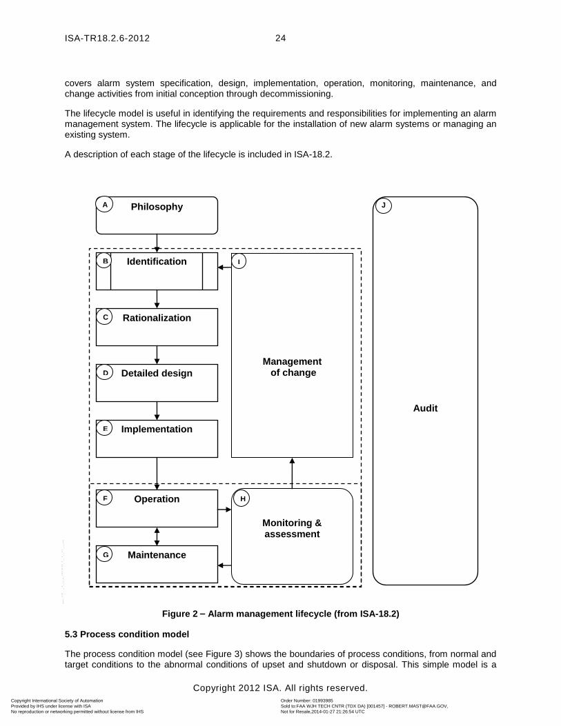
5.2 Alarm management lifecycle
The alarm management lifecycle consists of multiple stages. Figure 2 illustrates the relationship between the stages of the alarm management lifecycle described in ISA-18.2. The alarm management lifecycle
Copyright International Society of Automation Provided by IHS under license with ISA
Order Number: 01993985Sold to:FAA WJH TECH CNTR (TDX DA) [001457] - [email protected], Not for Resale,2014-01-27 21:26:54 UTCNo reproduction or networking permitted without license from IHS
--````,,``,``,`,,,,,,,`-`-``,```,,,`---
ISA-TR18.2.6-2012
Copyright 2012 ISA. All rights reserved.
24
covers alarm system specification, design, implementation, operation, monitoring, maintenance, and change activities from initial conception through decommissioning.
The lifecycle model is useful in identifying the requirements and responsibilities for implementing an alarm management system. The lifecycle is applicable for the installation of new alarm systems or managing an existing system.
A description of each stage of the lifecycle is included in ISA-18.2.
Figure 2 – Alarm management lifecycle (from ISA-18.2)
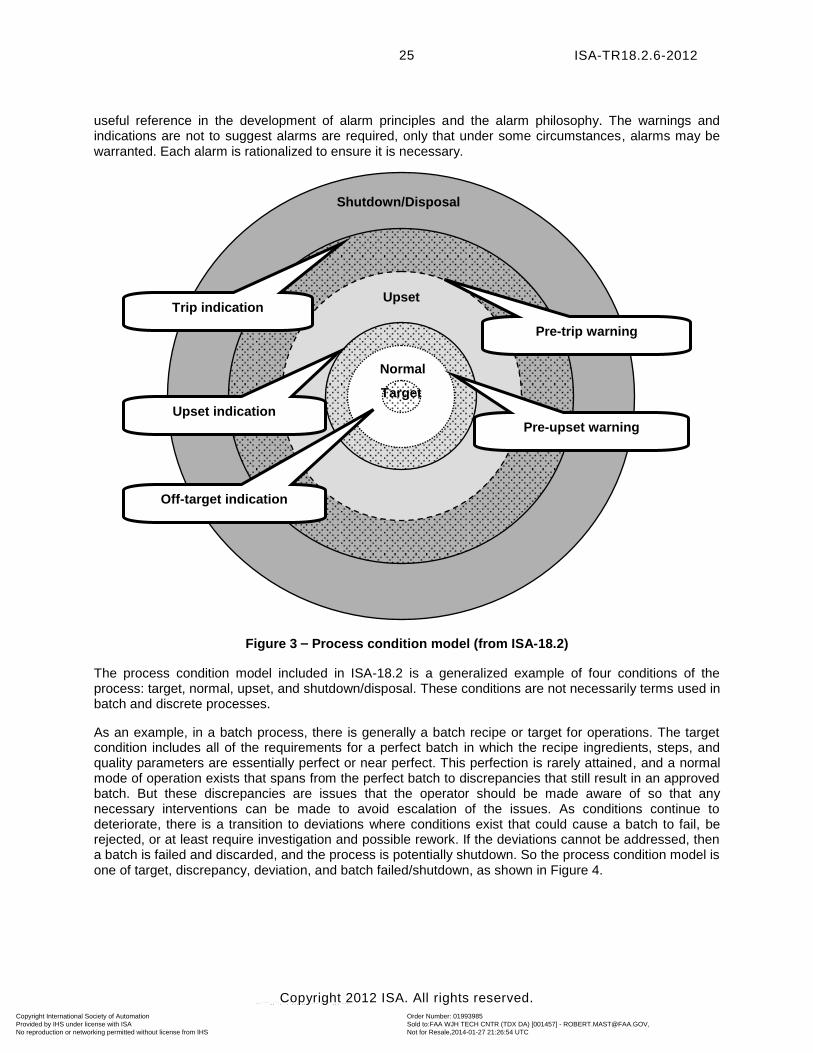
5.3 Process condition model
The process condition model (see Figure 3) shows the boundaries of process conditions, from normal and target conditions to the abnormal conditions of upset and shutdown or disposal. This simple model is a
Monitoring & assessment
Philosophy
Audit
Rationalization
Identification
Detailed design
Implementation
Maintenance
Operation
Management of change
D
C
E
A A A A A A A A
J
B
G
H
F
I
Copyright International Society of Automation Provided by IHS under license with ISA
Order Number: 01993985Sold to:FAA WJH TECH CNTR (TDX DA) [001457] - [email protected], Not for Resale,2014-01-27 21:26:54 UTCNo reproduction or networking permitted without license from IHS
--````,,``,``,`,,,,,,,`-`-``,```,,,`---
ISA-TR18.2.6-2012
Copyright 2012 ISA. All rights reserved.
25
useful reference in the development of alarm principles and the alarm philosophy. The warnings and indications are not to suggest alarms are required, only that under some circumstances, alarms may be warranted. Each alarm is rationalized to ensure it is necessary.
Figure 3 – Process condition model (from ISA-18.2)
The process condition model included in ISA-18.2 is a generalized example of four conditions of the process: target, normal, upset, and shutdown/disposal. These conditions are not necessarily terms used in batch and discrete processes.
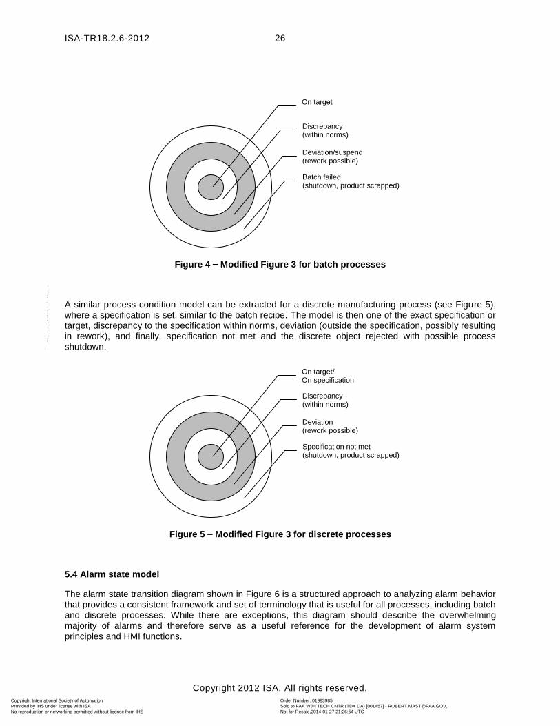
As an example, in a batch process, there is generally a batch recipe or target for operations. The target condition includes all of the requirements for a perfect batch in which the recipe ingredients, steps, and quality parameters are essentially perfect or near perfect. This perfection is rarely attained, and a normal mode of operation exists that spans from the perfect batch to discrepancies that still result in an approved batch. But these discrepancies are issues that the operator should be made aware of so that any necessary interventions can be made to avoid escalation of the issues. As conditions continue to deteriorate, there is a transition to deviations where conditions exist that could cause a batch to fail, be rejected, or at least require investigation and possible rework. If the deviations cannot be addressed, then a batch is failed and discarded, and the process is potentially shutdown. So the process condition model is one of target, discrepancy, deviation, and batch failed/shutdown, as shown in Figure 4.
Pre-upset warning
Pre-trip warning
Trip indication
Upset indication
Off-target indication
Upset
Shutdown/Disposal
Normal
Target
Copyright International Society of Automation Provided by IHS under license with ISA
Order Number: 01993985Sold to:FAA WJH TECH CNTR (TDX DA) [001457] - [email protected], Not for Resale,2014-01-27 21:26:54 UTCNo reproduction or networking permitted without license from IHS
--````,,``,``,`,,,,,,,`-`-``,```,,,`---
ISA-TR18.2.6-2012
Copyright 2012 ISA. All rights reserved.
26
Figure 4 – Modified Figure 3 for batch processes
A similar process condition model can be extracted for a discrete manufacturing process (see Figure 5), where a specification is set, similar to the batch recipe. The model is then one of the exact specification or target, discrepancy to the specification within norms, deviation (outside the specification, possibly resulting in rework), and finally, specification not met and the discrete object rejected with possible process shutdown.
Figure 5 – Modified Figure 3 for discrete processes
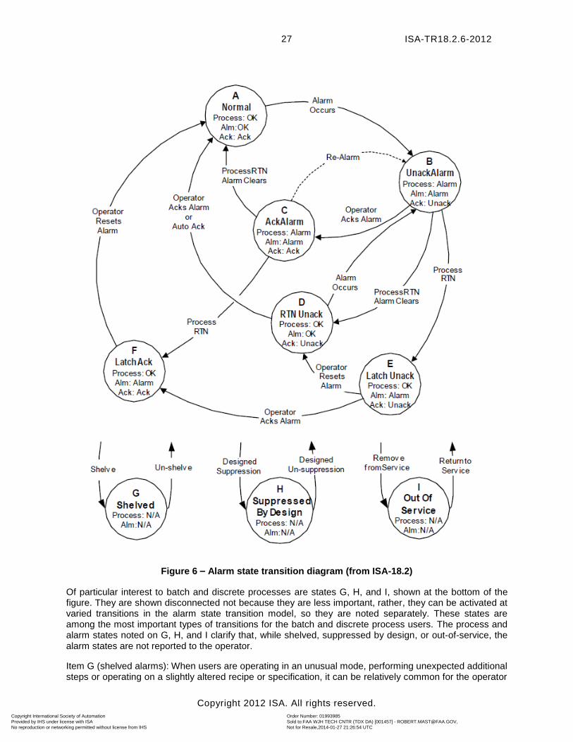
5.4 Alarm state model
The alarm state transition diagram shown in Figure 6 is a structured approach to analyzing alarm behavior that provides a consistent framework and set of terminology that is useful for all processes, including batch and discrete processes. While there are exceptions, this diagram should describe the overwhelming majority of alarms and therefore serve as a useful reference for the development of alarm system principles and HMI functions.
Discrepancy (within norms)
On target
Batch failed (shutdown, product scrapped)
Deviation/suspend (rework possible)
Discrepancy (within norms)
On target/ On specification
Specification not met (shutdown, product scrapped)
Deviation (rework possible)
Copyright International Society of Automation Provided by IHS under license with ISA
Order Number: 01993985Sold to:FAA WJH TECH CNTR (TDX DA) [001457] - [email protected], Not for Resale,2014-01-27 21:26:54 UTCNo reproduction or networking permitted without license from IHS
--````,,``,``,`,,,,,,,`-`-``,```,,,`---
ISA-TR18.2.6-2012
Copyright 2012 ISA. All rights reserved.
27
Figure 6 – Alarm state transition diagram (from ISA-18.2)
Of particular interest to batch and discrete processes are states G, H, and I, shown at the bottom of the figure. They are shown disconnected not because they are less important, rather, they can be activated at varied transitions in the alarm state transition model, so they are noted separately. These states are among the most important types of transitions for the batch and discrete process users. The process and alarm states noted on G, H, and I clarify that, while shelved, suppressed by design, or out-of-service, the alarm states are not reported to the operator.
Item G (shelved alarms): When users are operating in an unusual mode, performing unexpected additional steps or operating on a slightly altered recipe or specification, it can be relatively common for the operator
Copyright International Society of Automation Provided by IHS under license with ISA
Order Number: 01993985Sold to:FAA WJH TECH CNTR (TDX DA) [001457] - [email protected], Not for Resale,2014-01-27 21:26:54 UTCNo reproduction or networking permitted without license from IHS
--````,,``,``,`,,,,,,,`-`-``,```,,,`---

ISA-TR18.2.6-2012
Copyright 2012 ISA. All rights reserved.
28
to temporarily shelve an alarm that is causing distraction and is not required for a temporary period. Depending on the flexibility of the control system, it may be quite common for recipe or specification modifications to be performed in real time without extensive engineering support that might be required to reprogram the alarm system. The shelved state is used when an alarm is temporarily suppressed, using a controlled methodology. An alarm in the shelved state is under the control of the operator. The shelving system may automatically unshelve alarms.
Item H (designed suppression): Alarms may be automatically modified based on batch phase or operation. The suppressed-by-design state is used to suppress alarms based on operating conditions or plant states. An alarm in the suppressed-by-design state is under the control of logic that determines the relevance of the alarm. Batch and discrete processes commonly consider the phase or mode of operation as part of the logic that defines the alarm function, making designed suppression a frequently used technique. Alarm suppression can be accomplished by varied means, such as by change to alarm setpoints or by altering the parameters governing an individual alarm’s suppression status.
Item I (out-of-service): The out-of-service alarm state is used to manually suppress alarms (e.g., use control system functionality to remove alarms from service) when they are removed from service, typically for maintenance. An alarm in the out-of-service state is under the control of maintenance. It is important to recognize that this basic functionality is important in an effective alarm system. Procedurally, it is important when an alarm has been marked out-of-service that other alternative methods/procedures to monitor the process be put in place while the alarm is not available.
Items E and F (latching alarms): Latching alarms also have some special considerations for batch and discrete processes. Of particular interest is the treatment of manual operator reset functions. In batch and discrete processes, it is possible that an alarm may be active and then never return to normal before the end of the batch or discrete run. Once the batch or run is complete, the alarm often becomes irrelevant. One desired latching alarm in batch or discrete processes is that of an exception or deviation that should be investigated, resolved, and documented. The value in pursuing the investigation during the batch run is that the result may be important in deciding whether to forward process the batch to the next process step. If the operator is unable to complete this process during the applicable phase, it may be necessary for other support personnel to complete the investigation. This type of investigation is often done as part of the exception/deviation resolution process, where all unresolved items are flagged for investigation after the end of the batch.
If the alarm is not latched, then it returns to normal as the process is prepared for the next run. If it is latched, once the process returns to normal, the operator needs to acknowledge the process is in a cleared state and is ready for a return to service, effectively rearming the alarm. Some of the complexity of this alarm reset is not shown, though the transition states can still be seen to apply.
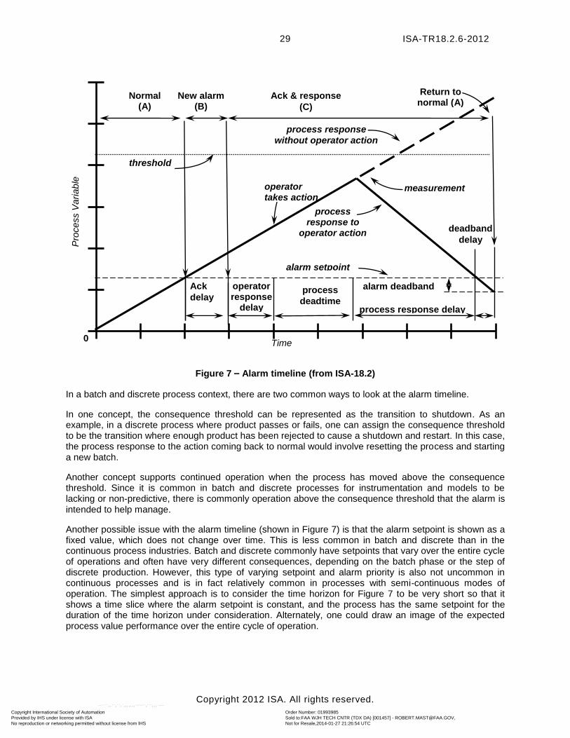
5.5 Alarm response timeline model
Figure 7 represents a process measurement that increases from a normal condition to an abnormal condition and the two possible scenarios based on whether the operator takes corrective action or not. Using Figure 7, it is possible to map some of the alarm-specific states to this timeline to clarify the definition of terms related to time.
Copyright International Society of Automation Provided by IHS under license with ISA
Order Number: 01993985Sold to:FAA WJH TECH CNTR (TDX DA) [001457] - [email protected], Not for Resale,2014-01-27 21:26:54 UTCNo reproduction or networking permitted without license from IHS
--````,,``,``,`,,,,,,,`-`-``,```,,,`---
ISA-TR18.2.6-2012
Copyright 2012 ISA. All rights reserved.
29
Figure 7 – Alarm timeline (from ISA-18.2)
In a batch and discrete process context, there are two common ways to look at the alarm timeline.
In one concept, the consequence threshold can be represented as the transition to shutdown. As an example, in a discrete process where product passes or fails, one can assign the consequence threshold to be the transition where enough product has been rejected to cause a shutdown and restart. In this case, the process response to the action coming back to normal would involve resetting the process and starting a new batch.
Another concept supports continued operation when the process has moved above the consequence threshold. Since it is common in batch and discrete processes for instrumentation and models to be lacking or non-predictive, there is commonly operation above the consequence threshold that the alarm is intended to help manage.
Another possible issue with the alarm timeline (shown in Figure 7) is that the alarm setpoint is shown as a fixed value, which does not change over time. This is less common in batch and discrete than in the continuous process industries. Batch and discrete commonly have setpoints that vary over the entire cycle of operations and often have very different consequences, depending on the batch phase or the step of discrete production. However, this type of varying setpoint and alarm priority is also not uncommon in continuous processes and is in fact relatively common in processes with semi-continuous modes of operation. The simplest approach is to consider the time horizon for Figure 7 to be very short so that it shows a time slice where the alarm setpoint is constant, and the process has the same setpoint for the duration of the time horizon under consideration. Alternately, one could draw an image of the expected process value performance over the entire cycle of operation.
0
Pro
cess V
ari
ab
le
Time
process response
without operator action
Normal (A)
operator response
delay
measurement
New alarm (B)
Ack & response
(C)
process
deadtime process response delay
deadband
delay
process response to
operator action
threshold
alarm setpoint
alarm deadband Ack
delay
Return to normal (A)
operator takes action
Copyright International Society of Automation Provided by IHS under license with ISA
Order Number: 01993985Sold to:FAA WJH TECH CNTR (TDX DA) [001457] - [email protected], Not for Resale,2014-01-27 21:26:54 UTCNo reproduction or networking permitted without license from IHS
--````,,``,``,`,,,,,,,`-`-``,```,,,`---
ISA-TR18.2.6-2012
Copyright 2012 ISA. All rights reserved.
30
6 Philosophy
6.1 Purpose
The alarm philosophy serves as the design framework for the alarm system. It establishes the criteria, definitions, and principles for the alarm lifecycle stages by specifying the methods for alarm identification, rationalization, design, classification, prioritization, monitoring, management of change, and audit to be followed. Refer to the ISA-18.2 standard and draft technical report, ISA-dTR18.2.1 (dTR1), Alarm Philosophy, for detailed guidance regarding the philosophy lifecycle activity.
6.2 Applicability to batch and discrete processes
In general, the principles involved in creating an alarm philosophy are similar for continuous, batch, and discrete processes.
6.2.1 Batch and discrete process considerations
If a company utilizes batch and/or discrete processes, it is useful to keep in mind the typical characteristics of these kinds of processes when creating the alarm philosophy.
The objectives of an alarm philosophy document, according to ISA-18.2, include ensuring that facilities can achieve
a) consistency across process equipment
b) design and management of the alarm system that supports an effective operator response to alarms
These objectives can be challenging to achieve for all three types of processes (continuous, batch, and discrete). Batch and discrete processes, in particular, can present special challenges, as they traditionally utilize many different vendors in supplying various unit operations equipment with many of the unit operations commonly employing an equipment vendor-supplied embedded proprietary PLC-based control system for monitoring, control, and alarming. It can sometimes be difficult to convince equipment vendors to modify their automation code to help customers achieve their philosophy objectives and/or meet requirements documented in the Alarm System Requirements Specification (ASRS). Continuous processes may also make use of a large number of equipment vendors, although process equipment generally interfaces to a single control system and a common user interface. As much as possible, independent systems should be made to have a common look and feel for the operator.
6.2.2. Alarm philosophy topics of special importance to batch/discrete processes
Some of the recommended topics in an alarm philosophy that may be impacted by the existence of batch/discrete processes are (ref. ISA-18.2)
a) design b) classification c) MOC d) HMI guidance e) approved advanced alarm management techniques
Alarm design could be impacted by the need to programmatically change certain alarm attributes in real time (a frequent need for batch processes) or implement certain alarm record tag/header information (e.g., batch lot number) when sending alarm records to a historian.
There may be consideration for designating critical process parameter (CPP) alarms (common in heavily regulated batch/discrete process industries, such as pharmaceutical, biotech, and medical devices) as a separate class of alarms since alarm management activities above those for general alarms are expected. Such classes of alarms may need more rigorous MOC, especially for formally validated systems.
Copyright International Society of Automation Provided by IHS under license with ISA
Order Number: 01993985Sold to:FAA WJH TECH CNTR (TDX DA) [001457] - [email protected], Not for Resale,2014-01-27 21:26:54 UTCNo reproduction or networking permitted without license from IHS
--````,,``,``,`,,,,,,,`-`-``,```,,,`---
ISA-TR18.2.6-2012
Copyright 2012 ISA. All rights reserved.
31
For batch and discrete processes, it is often necessary to utilize advanced alarming techniques, i.e., additional layers of logic, programming, or modeling beyond the basic alarming methods, to modify alarming behavior or improve operator guidance. Examples might include use of state-based alarming, adaptive alarming, lot number identifiers, and relative time. It is important to identify the use of such techniques in the alarm philosophy. For more information on advanced/enhanced alarming techniques, refer to the ISA-18.2 standard and TR4.
7 Alarm system requirements specification (ASRS)
7.1 Purpose
The ASRS documents the alarm functionality expected of the control system. It is often created as a subset of the overall functional requirements for a process automation system. The ASRS is used to help evaluate systems being considered for a plant, guide the detailed system design, help determine if any system customization and/or use of third-party products are necessary, and serve as the primary basis of alarm system functional testing during implementation. The ASRS specifies what functionality the alarm system needs to provide. This, in turn, will be helpful when rationalizing, designing, implementing, visualizing, and recording individual alarms and in analyzing alarm records.
When creating an ASRS, care should be taken when choosing the words should vs. shall when writing individual requirements. Written requirements that use the word should can sometimes be interpreted as being nice to have, but not really needed. It is important to make clear which features are must-haves and which ones are nice-to-haves.
7.2 Applicability to batch processes
Many commercial automation systems were first developed to meet the needs of continuous processes. While some of these systems have been updated to accommodate certain frequently needed requirements of batch processes, functionality gaps exist in other systems. Therefore, it should not be assumed that a modern commercial automation system will be able to meet all the specific needs of batch processes, including alarm management. Any special alarm requirements associated with batch processes should be identified in the ASRS portion of the functional/user requirements and then checked against the functionality of the automation system being considered. This will then allow time and opportunity to ensure specific batch process requirements can be met. Examples of alarm functionality important to batch processes include use of batch lot numbers, relative time, time and state-based alarm attributes, state-based and conditional alarm suppression, and alarm redirection.
7.2.1 Sample ASRS items for a batch process
The following list includes example items that could be included in an ASRS for a batch process. These examples are not intended to imply requirements or best practices for all alarm systems. They are items that a company may require for specific plants or a specific system:
a) The system should be capable of programmatically changing alarm attributes (e.g., setpoints, priority) based on batch relative time and/or conditional logic.
b) An alarm should be configurable as a function of the process step(s) and/or phase(s) for which it is relevant. This includes alarm suppression as a function of process state.
c) An alarm record (alarm, alarm acknowledge, and alarm clear) sent to the historian should contain sufficient information to allow the record to be recovered, knowing only the batch lot number and batch step/phase.
d) The historian should contain record query and sorting ability, including the ability to sort on data/alarm descriptors, such as batch lot number, batch step/phase, priority, and/or type. The historian should then be able to generate a batch report, utilizing the sorted information.
Copyright International Society of Automation Provided by IHS under license with ISA
Order Number: 01993985Sold to:FAA WJH TECH CNTR (TDX DA) [001457] - [email protected], Not for Resale,2014-01-27 21:26:54 UTCNo reproduction or networking permitted without license from IHS
--````,,``,``,`,,,,,,,`-`-``,```,,,`---
ISA-TR18.2.6-2012
Copyright 2012 ISA. All rights reserved.
32
e) The system should be able to convert calendar time to relative time to enable the display and analysis of alarm records relative to the beginning of a batch step/phase.
f) The system should be compliant with the U.S. Government Code of Federal Regulations 21 CFR Part 11 (i.e., electronic records and electronic signatures) since certain alarm and alarm acknowledge records are covered by this CFR for validated computer systems in industries regulated by the FDA. Further, electronic manufacturing tickets, SOPs, and process recipes, which may contain information and/or logic regarding alarms, are covered by this CFR. The need to comply with this CFR implies that audit trail functionality exists in the control system.
Note Audit trail functionality refers to the automatic generation of electronic records when changes (e.g., alarm setpoints) are made online to an operating computer system.
Further, the control system should contain appropriate security to prevent unauthorized access or change to electronic records (e.g., databases, recipes, SOPs, and real-time executing process control code).
g) The alarm system should be able to send text messages (or pages) to personnel not located in the control room or plant floor (i.e., located in remote areas). Further, the system should be able to receive and record alarm acknowledgements from personnel in remote areas.
7.3 Applicability to discrete processes
As with batch processes, automated discrete processes have grown in importance in recent decades. Such processes interface to a variety of specialty field devices, e.g., vision systems, robotics, and barcode/RFID readers. In addition, such processes often deal with manufacturing and inspecting a large number of items per unit of time, so systems may require interrupt capability of exceptionally short time increments (e.g., milliseconds). Also, many discrete processes are associated with specialized equipment in which equipment automation exists as vendor-provided, hard-coded, embedded PLCs. Some of these PLCs do not conform to industrial communication standards, e.g., OPC. This can create special challenges when abnormal events for which alarms are generated in equipment embedded PLCs need to be communicated to a BPCS HMI and/or plant historian.
Any special alarm requirements associated with discrete processes should be identified in the ASRS portion of the functional/user requirements. This will then allow time and opportunity to ensure specific discrete process functional/user requirements can be met.
7.3.1 Sample ASRS items for a discrete process
The following list includes example items that could be included in an ASRS for a discrete process. These examples are not intended to imply requirements or best practices for all alarm systems. They are items that a company may require for specific plants or a specific system:
a) The alarm system should be able to individually monitor and respond to detected abnormal situations for up to 240 widgets per minute on an assembly line.
b) The system should be capable of online calculation of statistical moving averages of discrete events for use, as appropriate, to trigger alarms and/or alerts.
c) The system should be capable of interfacing to all anticipated field devices, including any vision and robotic systems. Interfaces should include the ability to obtain any field device diagnostic information in real time so as to facilitate appropriate alarms and/or alerts.
d) The system should be capable of reading information from both active and passive radio frequency identification (RFID) devices implanted in product packaging and using this information, as appropriate, to trigger alarms and/or alerts.
Copyright International Society of Automation Provided by IHS under license with ISA
Order Number: 01993985Sold to:FAA WJH TECH CNTR (TDX DA) [001457] - [email protected], Not for Resale,2014-01-27 21:26:54 UTCNo reproduction or networking permitted without license from IHS
--````,,``,``,`,,,,,,,`-`-``,```,,,`---
ISA-TR18.2.6-2012
Copyright 2012 ISA. All rights reserved.
33
e) Any equipment vendor-supplied embedded PLCs providing equipment automation must be able to electronically communicate process and abnormal event data to a plant basic process control system (e.g., DCS) and plant historian.
Means should exist (e.g., via alarm record tags or historian utility) to associate alarm records with their corresponding production batch/lot number.
8 Identification
8.1 Purpose
This clause provides guidance on alarm identification for batch/discrete processes, with a specific focus on providing examples. For further information, see Clause 8 of the standard, ISA-18.2, which contains recommendations regarding alarm identification. The draft technical report, ISA-dTR18.2.2 (dTR2), contains further detailed explanations and examples of how to pursue alarm identification in the context of all types of process systems.
Identification is a general term for the different methods that can be used to determine the possible need for an alarm or a change to an alarm. Identification can be considered as a collection point for possible alarms to be rationalized.
8.2 Providing alarms that track operational state
All of the alarm identification methods listed in ISA-18.2, Clause 8, are useful and applicable to batch and discrete systems. The emphasis is on the identification of undesirable situations, and the alarm logic should be designed to unambiguously detect these situations. One of the distinguishing features of batch and discrete processes is the role of transitions. In a continuous process, there are transitions (e.g., start-up to normal, rate changes, normal to shutdown, starting and stopping of equipment), but they occur less frequently than in batch or discrete processes. In batch and discrete processes, transitions are integral to the process. Abnormal or undesirable situations can occur during a transition or between transitions; they can also transcend transitions or be global in scope. Identification of the abnormal situation in batch and discrete processes must take into account the conditions that exist in the various states of the process and the transitions between them.
In addition, the batch standard, ISA-88, includes defined states, such as Idle, Hold, and Pause, so alarm identification needs to consider alarms specific to these kinds of states.
8.3 Examples
The following are several examples of identifying alarms in a batch or discrete process. These examples provide details related to alarm identification and, in some cases, alarm considerations from other stages in the lifecycle, such as rationalization and design.
8.3.1 Example: Alarms requiring special logic: pump damage due to cavitation
Description: The level of a tank is being lowered as part of a batch operation. Both the pressure and the liquid level in the tank are measured and can vary significantly.
Problem: (Abnormal/undesirable situation): Cavitation will cause pump damage.
Potential alarm identification: During the discussion of this undesirable situation, it was realized that either low tank level or low tank pressure could cause low pump suction pressure, leading to cavitation. It was also realized that below a certain level, regardless of the pressure, vapor could be sucked into the pump suction, causing cavitation. Finally, the pump cannot cavitate if it is not running. The final alarm logic is depicted in Figure 8. An alarm will only be generated if the pump is running, and either the level is low or the sum of tank pressure plus the tank level times the density is low.
Copyright International Society of Automation Provided by IHS under license with ISA
Order Number: 01993985Sold to:FAA WJH TECH CNTR (TDX DA) [001457] - [email protected], Not for Resale,2014-01-27 21:26:54 UTCNo reproduction or networking permitted without license from IHS
--````,,``,``,`,,,,,,,`-`-``,```,,,`---
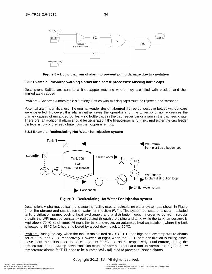
ISA-TR18.2.6-2012
Copyright 2012 ISA. All rights reserved.
34
OrAndPressure +
(Density * Level)
≤ X
≤ Y
Tank Pressure
Tank Level
Pump Running
Alarm
Figure 8 – Logic diagram of alarm to prevent pump damage due to cavitation
8.3.2 Example: Providing warning alarms for discrete processes: Missing bottle caps
Description: Bottles are sent to a filler/capper machine where they are filled with product and then immediately capped.
Problem: (Abnormal/undesirable situation): Bottles with missing caps must be rejected and scrapped.
Potential alarm identification: The original vendor design alarmed if three consecutive bottles without caps were detected. However, this alarm neither gives the operator any time to respond, nor addresses the primary causes of uncapped bottles -- no bottle caps in the cap feeder bin or a jam in the cap feed chute. Therefore, an additional alarm should be generated if the filler/capper is running, and either the cap feeder bin level is low or the feed chute from the hopper is empty.
8.3.3 Example: Recirculating Hot Water-for-Injection system
Figure 9 – Recirculating Hot Water-For-Injection system
Description: A pharmaceutical manufacturing facility uses a recirculating water system, as shown in Figure 9, for the storage and distribution of water for injection (WFI). The system consists of a steam jacketed tank, distribution pump, cooling heat exchanger, and a distribution loop. In order to control microbial growth, the WFI must be constantly recirculated through the piping and tank, while the tank temperature is kept above 70 ºC at all times. At night the tank undergoes an automatic heat sanitization, where the tank is heated to 85 ºC for 2 hours, followed by a cool-down back to 70 ºC.
Problem: During the day, when the tank is maintained at 70 ºC, TIT1 has high and low temperature alarms set at 65 ºC and 75 ºC respectively. However, at night, when the 85 ºC heat sanitization is taking place, these alarm setpoints need to be changed to 80 ºC and 95 ºC respectively. Furthermore, during the temperature ramp-up/ramp-down transition states of normal-to-sani and sani-to-normal, the high and low temperature alarms for TIT1 need to be automatically adjusted to prevent nuisance alarms.
Chiller water return
Chiller water
WFI supply to plant distribution loop
Tank 100
Hot Water For Injection
WFI return from plant distribution loop
TIT2
TIC
TIT1 TIC
Steam
Tank fill
Condensate
Copyright International Society of Automation Provided by IHS under license with ISA
Order Number: 01993985Sold to:FAA WJH TECH CNTR (TDX DA) [001457] - [email protected], Not for Resale,2014-01-27 21:26:54 UTCNo reproduction or networking permitted without license from IHS
--````,,``,``,`,,,,,,,`-`-``,```,,,`---
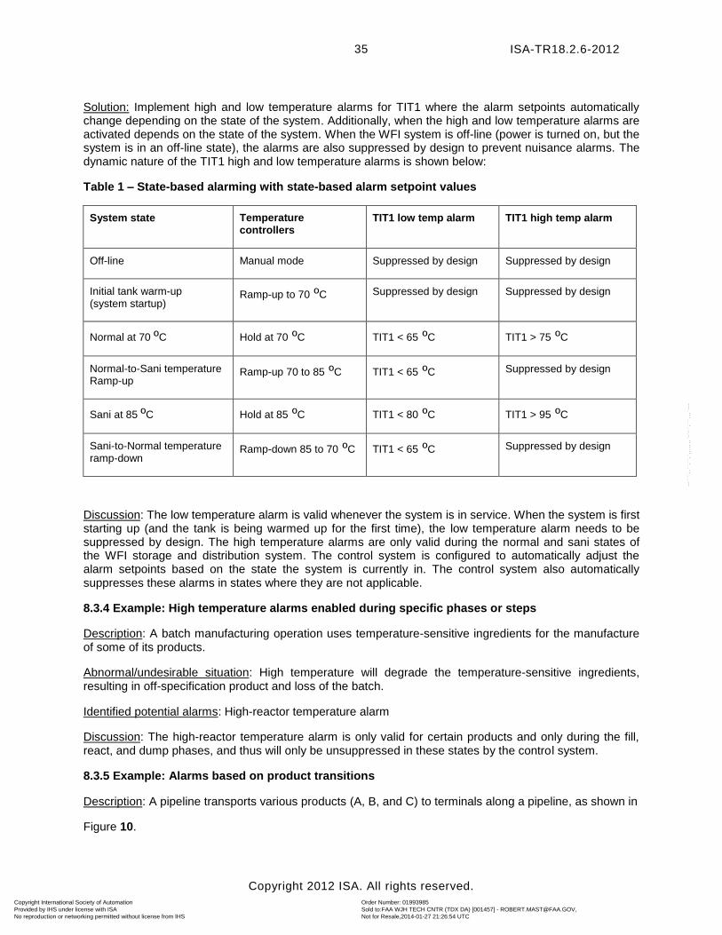
ISA-TR18.2.6-2012
Copyright 2012 ISA. All rights reserved.
35
Solution: Implement high and low temperature alarms for TIT1 where the alarm setpoints automatically change depending on the state of the system. Additionally, when the high and low temperature alarms are activated depends on the state of the system. When the WFI system is off-line (power is turned on, but the system is in an off-line state), the alarms are also suppressed by design to prevent nuisance alarms. The dynamic nature of the TIT1 high and low temperature alarms is shown below:
Table 1 – State-based alarming with state-based alarm setpoint values
System state Temperature controllers
TIT1 low temp alarm TIT1 high temp alarm
Off-line Manual mode Suppressed by design Suppressed by design
Initial tank warm-up (system startup)
Ramp-up to 70 ºC Suppressed by design Suppressed by design
Normal at 70 ºC Hold at 70 ºC TIT1 < 65 ºC TIT1 > 75 ºC
Normal-to-Sani temperature Ramp-up
Ramp-up 70 to 85 ºC TIT1 < 65 ºC Suppressed by design
Sani at 85 ºC Hold at 85 ºC TIT1 < 80 ºC TIT1 > 95 ºC
Sani-to-Normal temperature ramp-down
Ramp-down 85 to 70 ºC TIT1 < 65 ºC Suppressed by design
Discussion: The low temperature alarm is valid whenever the system is in service. When the system is first starting up (and the tank is being warmed up for the first time), the low temperature alarm needs to be suppressed by design. The high temperature alarms are only valid during the normal and sani states of the WFI storage and distribution system. The control system is configured to automatically adjust the alarm setpoints based on the state the system is currently in. The control system also automatically suppresses these alarms in states where they are not applicable.
8.3.4 Example: High temperature alarms enabled during specific phases or steps
Description: A batch manufacturing operation uses temperature-sensitive ingredients for the manufacture of some of its products.
Abnormal/undesirable situation: High temperature will degrade the temperature-sensitive ingredients, resulting in off-specification product and loss of the batch.
Identified potential alarms: High-reactor temperature alarm
Discussion: The high-reactor temperature alarm is only valid for certain products and only during the fill, react, and dump phases, and thus will only be unsuppressed in these states by the control system.
8.3.5 Example: Alarms based on product transitions
Description: A pipeline transports various products (A, B, and C) to terminals along a pipeline, as shown in
Figure 10.
Copyright International Society of Automation Provided by IHS under license with ISA
Order Number: 01993985Sold to:FAA WJH TECH CNTR (TDX DA) [001457] - [email protected], Not for Resale,2014-01-27 21:26:54 UTCNo reproduction or networking permitted without license from IHS
--````,,``,``,`,,,,,,,`-`-``,```,,,`---
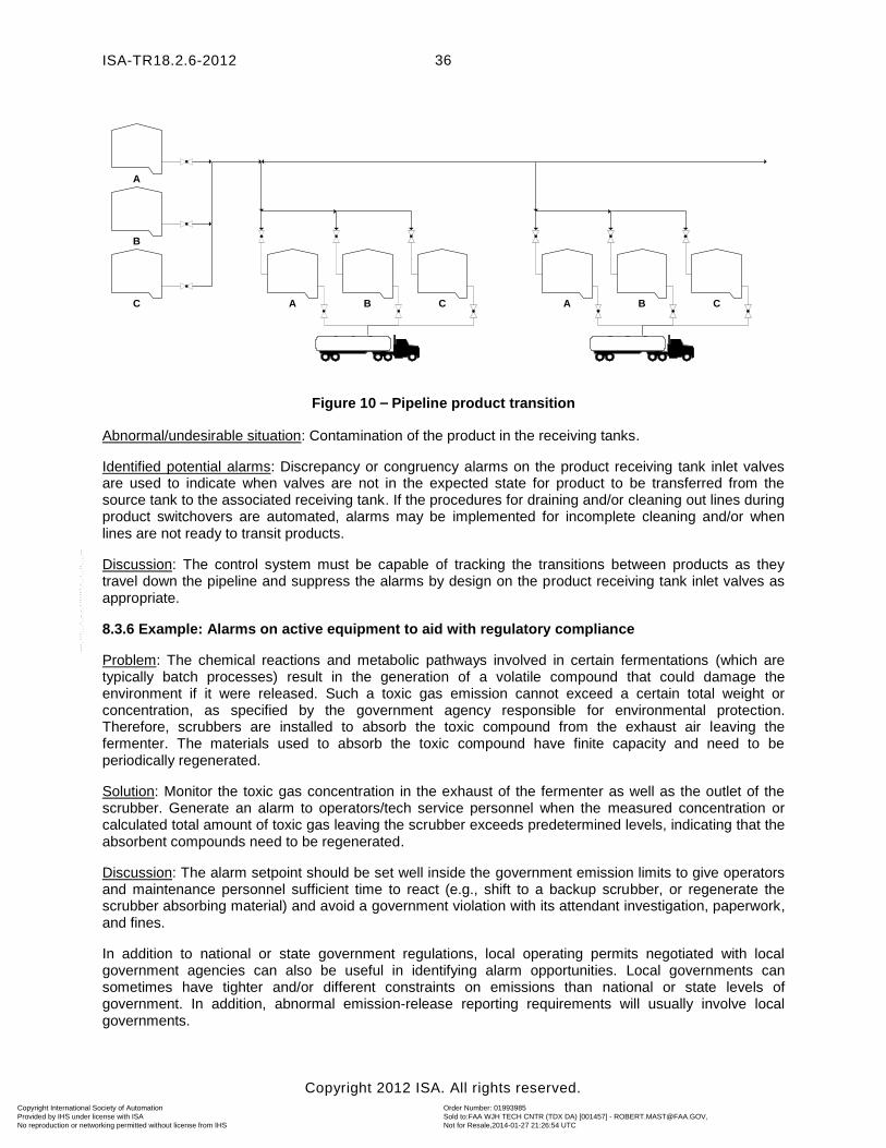
ISA-TR18.2.6-2012
Copyright 2012 ISA. All rights reserved.
36
A
B
C A B C A B C
Figure 10 – Pipeline product transition
Abnormal/undesirable situation: Contamination of the product in the receiving tanks.
Identified potential alarms: Discrepancy or congruency alarms on the product receiving tank inlet valves are used to indicate when valves are not in the expected state for product to be transferred from the source tank to the associated receiving tank. If the procedures for draining and/or cleaning out lines during product switchovers are automated, alarms may be implemented for incomplete cleaning and/or when lines are not ready to transit products.
Discussion: The control system must be capable of tracking the transitions between products as they travel down the pipeline and suppress the alarms by design on the product receiving tank inlet valves as appropriate.
8.3.6 Example: Alarms on active equipment to aid with regulatory compliance
Problem: The chemical reactions and metabolic pathways involved in certain fermentations (which are typically batch processes) result in the generation of a volatile compound that could damage the environment if it were released. Such a toxic gas emission cannot exceed a certain total weight or concentration, as specified by the government agency responsible for environmental protection. Therefore, scrubbers are installed to absorb the toxic compound from the exhaust air leaving the fermenter. The materials used to absorb the toxic compound have finite capacity and need to be periodically regenerated.
Solution: Monitor the toxic gas concentration in the exhaust of the fermenter as well as the outlet of the scrubber. Generate an alarm to operators/tech service personnel when the measured concentration or calculated total amount of toxic gas leaving the scrubber exceeds predetermined levels, indicating that the absorbent compounds need to be regenerated.
Discussion: The alarm setpoint should be set well inside the government emission limits to give operators and maintenance personnel sufficient time to react (e.g., shift to a backup scrubber, or regenerate the scrubber absorbing material) and avoid a government violation with its attendant investigation, paperwork, and fines.
In addition to national or state government regulations, local operating permits negotiated with local government agencies can also be useful in identifying alarm opportunities. Local governments can sometimes have tighter and/or different constraints on emissions than national or state levels of government. In addition, abnormal emission-release reporting requirements will usually involve local governments.
Copyright International Society of Automation Provided by IHS under license with ISA
Order Number: 01993985Sold to:FAA WJH TECH CNTR (TDX DA) [001457] - [email protected], Not for Resale,2014-01-27 21:26:54 UTCNo reproduction or networking permitted without license from IHS
--````,,``,``,`,,,,,,,`-`-``,```,,,`---
ISA-TR18.2.6-2012
Copyright 2012 ISA. All rights reserved.
37
8.3.7 Example: Use of FMEA to identify possible abnormal situations
Description: A failure modes and effects analysis (FMEA) typically lists all the possible failure modes of a product, piece of equipment, or operation, then it scores each possible failure mode in each of the following areas: 1) severity of consequences, 2) frequency/probability of occurrence, and 3) timely detection. The result of multiplying the above three scores together gives the risk priority number (RPN). The failure modes with the highest RPNs are targeted for focused process, product, or operation modifications with the intent to reduce the RPN. Appropriately configured alarms are a major technique used to help minimize failure mode RPNs, as they can help operators reduce abnormal event consequences (via prompt annunciation to the operator) and improve detectability. The severity of consequences and detectability metrics, identified during the development of RPNs, can also be useful in determining the priority of an alarm during rationalization since they are collectively an indicator of risk level.
Problem: An FMEA analysis of a discrete process reveals a high RPN if a problem develops with an automated vision system that inspects widgets. The limited online diagnostic functionality that is provided by the vendor-provided control system to quickly detect such a problem is a significant factor in the high value of the RPN.
Solution: Add appropriate logic and alarms to periodically direct the vision system to view one or more standard prepared widgets with known flaws. Incorrect automated analysis of such known unacceptable widgets, coupled with an appropriate alarm, can result in earlier detection of a vision system problem. The new alarm(s) significantly improves the RPN detectability score, thereby reducing risk probability for the process.
8.3.8 Example: Transitioning between Operational and Hold/Idle/Pause states
Problem: A process is in the Operational state in which the conditions of low recirculation flow and stoppage of the agitator are alarmed. An unrelated process condition is encountered that puts the process in a Hold state. In the Hold state, both the recirculation flow and the agitator are intentionally stopped. Therefore, the alarmed conditions of the Operational state are inappropriate.
Solution: The state-based alarm management automatically changes the alarm attributes so that the no-flow and agitator-stopped conditions do not cause alarms. Instead, a high-recirculation flow alarm, set at a very low setpoint, is placed in effect, as is an agitator-is-running alarm. These alarms would indicate failure to achieve the desired process conditions appropriate to the Hold state.
Discussion: In defining process states, the batch standard, ISA-88, includes states such as Hold, Idle, Pause, Run, and Abort. A batch recipe may not include all of these possibilities but will usually include some of them. Certain configured alarms specific to one or more of these states will usually not be appropriate for others.
8.3.9 Example: Communications failure alarms
Problem: A batch processing plant uses several pieces of equipment from different manufacturers that had been added over time. Each piece of equipment has its own control system, and the plant also has a large recipe-based control system that communicates with all pieces of equipment. Some communications are over high-speed fiber-optic links, but others are over older less reliable communications. If two pieces of equipment that interact with each other cannot read the status from each other, there could be a process upset.
Solution: Create an alarm to indicate loss of communication by implementing communication watchdog alarms on all communication links. In a watchdog alarm, a memory register with a constantly changing value is monitored over a communication link; if the read in value does not change after a certain period of time (due to a communications disruption), an alarm is triggered. If communications between equipment are disrupted, equipment can then automatically go into safe standby/shutdown states, and operators can be notified.
Copyright International Society of Automation Provided by IHS under license with ISA
Order Number: 01993985Sold to:FAA WJH TECH CNTR (TDX DA) [001457] - [email protected], Not for Resale,2014-01-27 21:26:54 UTCNo reproduction or networking permitted without license from IHS
--````,,``,``,`,,,,,,,`-`-``,```,,,`---
ISA-TR18.2.6-2012
Copyright 2012 ISA. All rights reserved.
38
Discussion: Complex distributed control systems that must constantly communicate with each other in order to function correctly often exist in batch plants with control systems from different vendors.
8.3.10 Example: Resistance to robotic arm movement
Problem: Many discrete processes include robotic arm devices that move through three-dimensional space while performing their duties. The robotic arm devices may experience increasing mechanical resistance in performing their tasks due to a variety of possible causes, e.g., insufficient lubrication of joints.
Solution: Measure online the electrical current draw of the robotic device, and generate an alarm if the current exceeds a predetermined value in order to draw attention to the situation before it results in a failure. This is based on the principle that the robotic device will increase its current draw as it encounters increasing resistance.
Discussion: Alarming an increased current draw (representing increased resistance) may permit some time for visual checks and response by operators that could, in some cases, prevent a production line shutdown. In other cases, it may be appropriate to put the production line in Pause, Hold, or Idle status while robotic arm joint maintenance is performed.
8.3.11 Example: Alarm identification for a vision system
Description: A discrete manufacturing operation uses a vision system for inspecting manufactured widgets. The process measurement is not a single finite number, as is the case with most process measurements, but a complex two-dimensional pictorial image.
Abnormal/undesirable situation: Missed widget defects and/or false positives caused by a degraded image.
Identified potential alarms: Potential alarms may be associated with analysis of the vision-system image itself, and/or with some of the environmental parameters known to influence image quality. For example, image quality is known to be a function of the cleanliness of the camera lens (e.g., presence of oil vapors and dust) and local environmental factors (e.g., lighting, heat, vibration, static electricity, and RFI/EMI electrical noise). Some of the causes of image problems are directly measureable. For example, lighting intensity can be monitored and an alarm configured when the light intensity drops below a required threshold; this type of alarm can be important since many fluorescent lights are known to become dimmer as they age. Further, light intensity is key to providing appropriate contrast between widget parts and background, with some vision system applications monitoring the size and location of shadows in addition to the widget itself.
The practice of beginning a production run with a few widget samples of known quality (both good and defective) is another technique that is sometimes used to help identify and alarm a defective vision system.
Discussion: There are many potential causes of an abnormal situation in obtaining and analyzing a vision-system image. Automated monitoring of the diagnostic software provided by the vision system vendor, as well as selected environmental parameters, can often be helpful for problem determination. In the case of a system malfunction, a well-designed set of alarms and diagnostic measurements can aid the operator by suggesting the cause of incorrect results, or at least narrowing down the list of possibilities.
Some potential abnormal situations may not be programmed into the vision system vendor’s embedded data processor/controller. The alarm identification effort, therefore, should note what abnormal situations the vendor’s embedded system does identify, and then determine if additional measurements are needed to monitor additional potential causes of faulty vision-system results.
There may be challenges in pursuing other alarm management activities, e.g., alarm design, HMI, and/or implementation, especially if the vision system vendor is unwilling to modify his or her system to
Copyright International Society of Automation Provided by IHS under license with ISA
Order Number: 01993985Sold to:FAA WJH TECH CNTR (TDX DA) [001457] - [email protected], Not for Resale,2014-01-27 21:26:54 UTCNo reproduction or networking permitted without license from IHS
--````,,``,``,`,,,,,,,`-`-``,```,,,`---
ISA-TR18.2.6-2012
Copyright 2012 ISA. All rights reserved.
39
accommodate requested modifications. Additional alarm logic might need to be distributed to other available systems (e.g., process control).
It is important with any vendor-provided packaged control system, such as those that are often provided with vision systems, to ensure that the interface for the operators, record-keeping, and alarm management contains the features that are needed for the particular process application. Splitting controls, meaning having to implement missing functionality with add-on control system components, should be avoided, as it makes the system hard to use for operators and support personnel.
9 Rationalization
9.1 Purpose
This part of the technical report provides supplementary information for rationalization of alarms for batch and discrete processes. For background information, refer to Clause 9 of the standard, ISA-18.2, which contains general requirements and recommendations regarding the alarm rationalization activity. The draft technical report, ISA-dTR-18.2.2 (dTR2), Alarm Identification and Rationalization, contains more detailed explanations and examples of rationalization for a wide variety of process types. The following clause of this report provides specific guidance for batch/discrete processes:
The purpose of alarm rationalization and documentation is to ensure that each alarm or alarm system change
a) meets the criteria set forth in the alarm philosophy
b) is correctly prioritized
c) has the proper activation point or logical condition
d) has an action identified
e) is properly documented
In addition, as part of the rationalization activity, any detailed process design information that will be needed for the following basic design and advanced alarming design stages of the alarm system development cycle should be captured and placed in a master alarm database. This is also the stage to identify individual situations in which advanced/enhanced alarming techniques may be needed.
9.2 Alarm rationalization activities
Fundamentally, alarm rationalization for batch, discrete, and continuous processes are similar. In each case, the goal is to ensure that alarms are valid and meaningful for every process state, mode, and/or condition. Some differences between batch and discrete processes versus continuous processes that will affect alarm rationalization include the following:
a) The number and variety of products produced are typically higher in batch and discrete processes.
b) Batch and discrete processes are often more flexible in the arrangement and use of the process equipment.
c) Mode or state changes are more frequent in batch or discrete processes.
d) Process modes or states are usually better defined and more readily known in batch and discrete processes than in continuous processes.
The implications of these differences are that the causes of an alarm, the consequences of failing to manage an alarm, as well as the setpoint, priority, suppressed/unsuppressed status, etc., of an alarm, which can be functions of the process state, mode, or condition, can also change more frequently in batch
Copyright International Society of Automation Provided by IHS under license with ISA
Order Number: 01993985Sold to:FAA WJH TECH CNTR (TDX DA) [001457] - [email protected], Not for Resale,2014-01-27 21:26:54 UTCNo reproduction or networking permitted without license from IHS
--````,,``,``,`,,,,,,,`-`-``,```,,,`---
ISA-TR18.2.6-2012
Copyright 2012 ISA. All rights reserved.
40
and discrete processes than in continuous processes. In batch processes, alarms should be rationalized for each mode or state.
Since alarms in batch and discrete systems can have this additional complexity, it is helpful to have these intricacies documented in the alarm system itself. It is advisable that for each alarm, the details about its cause, the exact mode/state/condition in which it occurred, the consequences of the alarm in each instance, and the recommended operator actions be documented so that operators have easy access to this information. Incorporating this information into a master alarm database is one such way to accomplish this.
9.3 Alarm rationalization team members
The need to have qualified and experienced rationalization team members is the same for batch, discrete, and continuous processes. Because batch and discrete processes are more flexible in the arrangement and use of the process equipment, selecting a small group of related equipment to perform rationalization can make the selection of team members easier. This is a good way to partition the work into manageable segments. This partitioning of the rationalization process will also permit the selection of the most appropriate personnel, including quality control/assurance participation, when appropriate.
When partitioning the work, care must be given to ensure that there is sufficient continuity of guidance and direction between the various working teams. Doing so will encourage the work to progress more smoothly and the results to be more consistent.
9.4 Assembling data for use in rationalization
All of the sources of information that are useful for rationalization of alarms in a continuous process are also useful for batch and discrete processes. In addition, the batch logic and equipment models are necessary so that the rationalization team can determine: the process states and/or mode as they apply to the alarm; the consequences of failing to manage the alarm; and the appropriate setpoint, priority, and other attributes. In this context, each alarm can be considered in terms of its applicability to and validity in each process state and/or mode. The potential for increased complexity of the rationalization process, particularly for batch processes, may mean the amount of work required is larger. The complexity of process phase and state review can make the alarm database much larger as well.
9.5 Alarms for critical process parameters
Alarms for critical process parameters (CPPs) are those alarms associated with conditions potentially negatively impacting product quality during specific process states or phases.
The rigor to which CPPs are monitored and analyzed is very industry and process specific. In certain regulated industries (e.g., pharmaceutical and medical-device manufacturing) the term CPP also implies a very specialized set of formalized procedures and documentation that must be executed each time an alarm associated with a CPP is triggered.
CPP alarms in regulated industries are of high significance for lot disposition. If alarms occur on critical process parameters, then the abnormal situation must be further examined by quality control personnel to determine if the material can be forward processed or reworked, or if they need to be dumped.
It is important during rationalization to identify the steps and phases of a process in which an alarm is associated with a CPP and to include this information in the master alarm database.
As part of the alarm philosophy, CPP alarms should be described with regard to their severity of consequence. Typically, for plants regulated by the FDA, a product quality consequence category (i.e., class) is defined, and a CPP alarm will have a high priority.
Copyright International Society of Automation Provided by IHS under license with ISA
Order Number: 01993985Sold to:FAA WJH TECH CNTR (TDX DA) [001457] - [email protected], Not for Resale,2014-01-27 21:26:54 UTCNo reproduction or networking permitted without license from IHS
--````,,``,``,`,,,,,,,`-`-``,```,,,`---
ISA-TR18.2.6-2012
Copyright 2012 ISA. All rights reserved.
41
9.6 Batch examples
9.6.1 Example: Filter plugging in a pipe path
Description: A batch process measures flow in a recirculation loop used to filter product. The recirculation loop is only used during certain points in the batch process.
Problem: When the recirculation loop is in use, a low flow alarm can indicate a plugged filter and require operator action. At other times, when flow through this pipe path is not used, a low flow alarm is a nuisance alarm.
Solution: Documenting the need to have this alarm suppressed by design should be included in the rationalization activities.
Discussion: Rationalization will help determine if an alarm is needed for a particular flow. If the alarm is needed, it will also be necessary to document its priority, setpoint, class, cause, consequence, and corrective action as well as states/modes when the alarm should be suppressed by design.
9.6.2 Example: Differential pressure alarm in a pasteurization unit
Description: Dairy products are often pasteurized using high temperature. A positive differential pressure between the product and the raw milk must be maintained at all times so that in the event these two streams get cross-connected (either through operator error or due to equipment malfunction), the pasteurized milk will leak into the raw milk and not the other way around.
Solution: The control system will monitor the pressure differential between the pasteurized and raw milk lines and trigger a shutdown alarm if the pressure differential drops below an alarm threshold. In addition to alarming the problem to the operator, the alarm will also activate automated interlocks in the control system to change the flow path to a safe configuration. The details of the alarm and how the interlocks would work will be developed during the rationalization step. However, if the process is such that the pasteurization unit is not always used during the batch processing, then the pressure differential alarm may need to be suppressed by design at appropriate times during the batch.
Discussion: Rationalization of potential alarms associated with pasteurization will need to take into account when the pasteurization steps are active in the batch processing. Suppressing alarms by design based on batch processing steps would also need to be included in the rationalization decisions.
9.6.3 Example: Need for separate configured alarms for CPPs
Description: The following example describes how critical process parameters (CPPs) are used in food and pharmaceutical industries to identify those measurements that can significantly impact the quality of batch material being produced (see measurement uncertainty example in 9.7.1). A rationale for which measurements should be considered as critical process parameter(s) will have been used by quality and other production personnel during the selection. The measurement values identified as CPPs may only need to be in effect during specific steps of the batch process. These alarms may need to be suppressed by design by the control system during other batch steps.
Problem: A large steam-jacketed processing tank has two possible high temperature alarms. The first high temperature alarm is used when the tank is being used in production to ensure that the tank does not overheat the product it contains. A second high temperature alarm, using a much higher alarm setpoint, is used when the tank is being steam sanitized to ensure that a plastic material used in the tank’s valves does not melt. The first high temperature alarm is considered a CPP alarm due to its product contact and the sensitivity of the product to temperature. The second alarm is not considered a CPP alarm because it does not directly impact product quality being manufactured.
Solution: In practice, an alarm rationalization can direct the configuration of two separate maximum temperature alarms with different alarm setpoint, consequence, and operation action for each.
Copyright International Society of Automation Provided by IHS under license with ISA
Order Number: 01993985Sold to:FAA WJH TECH CNTR (TDX DA) [001457] - [email protected], Not for Resale,2014-01-27 21:26:54 UTCNo reproduction or networking permitted without license from IHS
--````,,``,``,`,,,,,,,`-`-``,```,,,`---
ISA-TR18.2.6-2012
Copyright 2012 ISA. All rights reserved.
42
Discussion: During rationalization, it may be necessary to specify separate alarms for CPP vs. non-CPP based again upon the overall alarm philosophy. This has the added advantage of being able to track CPP alarms separately from other process alarms.
9.7 Examples of special importance to regulated industries
The following are examples describing aspects of alarm rationalization of special importance to some regulatory agencies.
9.7.1 Example: Measurement uncertainty and alarm setpoints
Description: The following example illustrates the use of measurement uncertainty to help determine valid alarm setpoint values. The principle of measurement uncertainty was first developed and quantified for use in the nuclear power industry and has subsequently found application in several of the process industries. ISA publications exist that document this principle and define quantitative algorithms for calculating cumulative measurement uncertainty. Measurement uncertainty information is sometimes needed by the rationalization team when dealing with CPPs.
Problem: In the pharmaceutical and biotech industries (which typically make extensive use of batch processes), the concept of proven acceptable range (PAR) is used to establish the range of values of critical process parameters for which product of acceptable quality has been proven to exist. A natural inclination is to specify alarm setpoints at the ends of the PAR since such alarms automatically trigger quality control (QC) deviation investigations. However, due to the existence of measurement uncertainty, it is possible that a real abnormal event (occurring just outside the PAR) will be missed (due to the measurement being within the PAR values). As a result, measurement uncertainty must be considered in determining alarm setpoints for pharmaceutical critical process parameters. A further concern is that alarming at or near PAR values does not give operators sufficient time to try to avoid the deviation.
Solution: The measurement of a process parameter can differ from the real value for several reasons, most due to uncertainty regarding the several components in a measurement train, going from sensor to computer. These components include the sensor, transmitter, and analog-to-digital (A/D) converter and may include other items, such as transducers. For example, the accuracy of some sensors is stated as 1% of the instrument’s span. The accuracy can also be a function of Preventive Maintenance (PM) frequency, as some sensor specs include a drifting specification (% drift per specified time interval). The cumulative effect of all sources of measurement uncertainty should be quantified and a determination made for how far (if at all) to set alarm setpoints inside the PAR values (see Fig. 11.)
Discussion: Missing recognition of an excursion outside of PAR on a critical process parameter in the pharmaceutical industry is a violation of federal cGMPs. Each excursion (i.e., abnormal event) outside the PAR (commonly known as a process deviation) must be identified and investigated in order to determine if the product associated with that lot is fit for human consumption and/or forward processing. Therefore, it is unacceptable to alarm a critical process parameter at the PAR value if enough measurement uncertainty exists that a measurement within PAR values could exist when the real parameter value is outside the PAR values.
An important goal of abnormal situation management is to try to avoid process deviations. Alarming at the PAR values +/- an adjustment for measurement uncertainty is very useful for support groups who must investigate actual deviations. However, it is useful to rationalize setpoints for operators at values within deviation limits to allow them some time to respond and avoid an actual deviation. Real-time alarms (vs. post-batch run analysis of batch records) are often appropriate to direct to plant TS/QC personnel, as deviations can result in decisions to rework, recycle, or discard the batch. Real-time alarms allow these decisions to be made as soon as practical once the existence of a deviation becomes known.
Copyright International Society of Automation Provided by IHS under license with ISA
Order Number: 01993985Sold to:FAA WJH TECH CNTR (TDX DA) [001457] - [email protected], Not for Resale,2014-01-27 21:26:54 UTCNo reproduction or networking permitted without license from IHS
--````,,``,``,`,,,,,,,`-`-``,```,,,`---
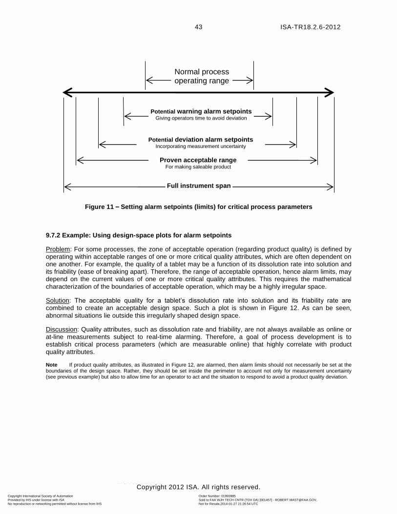
ISA-TR18.2.6-2012
Copyright 2012 ISA. All rights reserved.
43
Figure 11 – Setting alarm setpoints (limits) for critical process parameters
9.7.2 Example: Using design-space plots for alarm setpoints
Problem: For some processes, the zone of acceptable operation (regarding product quality) is defined by operating within acceptable ranges of one or more critical quality attributes, which are often dependent on one another. For example, the quality of a tablet may be a function of its dissolution rate into solution and its friability (ease of breaking apart). Therefore, the range of acceptable operation, hence alarm limits, may depend on the current values of one or more critical quality attributes. This requires the mathematical characterization of the boundaries of acceptable operation, which may be a highly irregular space.
Solution: The acceptable quality for a tablet’s dissolution rate into solution and its friability rate are combined to create an acceptable design space. Such a plot is shown in Figure 12. As can be seen, abnormal situations lie outside this irregularly shaped design space.
Discussion: Quality attributes, such as dissolution rate and friability, are not always available as online or at-line measurements subject to real-time alarming. Therefore, a goal of process development is to establish critical process parameters (which are measurable online) that highly correlate with product quality attributes.
Note If product quality attributes, as illustrated in Figure 12, are alarmed, then alarm limits should not necessarily be set at the boundaries of the design space. Rather, they should be set inside the perimeter to account not only for measurement uncertainty (see previous example) but also to allow time for an operator to act and the situation to respond to avoid a product quality deviation.
Full instrument span
Proven acceptable range For making saleable product
Potential deviation alarm setpoints Incorporating measurement uncertainty
Potential warning alarm setpoints Giving operators time to avoid deviation
Normal process operating range
Copyright International Society of Automation Provided by IHS under license with ISA
Order Number: 01993985Sold to:FAA WJH TECH CNTR (TDX DA) [001457] - [email protected], Not for Resale,2014-01-27 21:26:54 UTCNo reproduction or networking permitted without license from IHS
--````,,``,``,`,,,,,,,`-`-``,```,,,`---
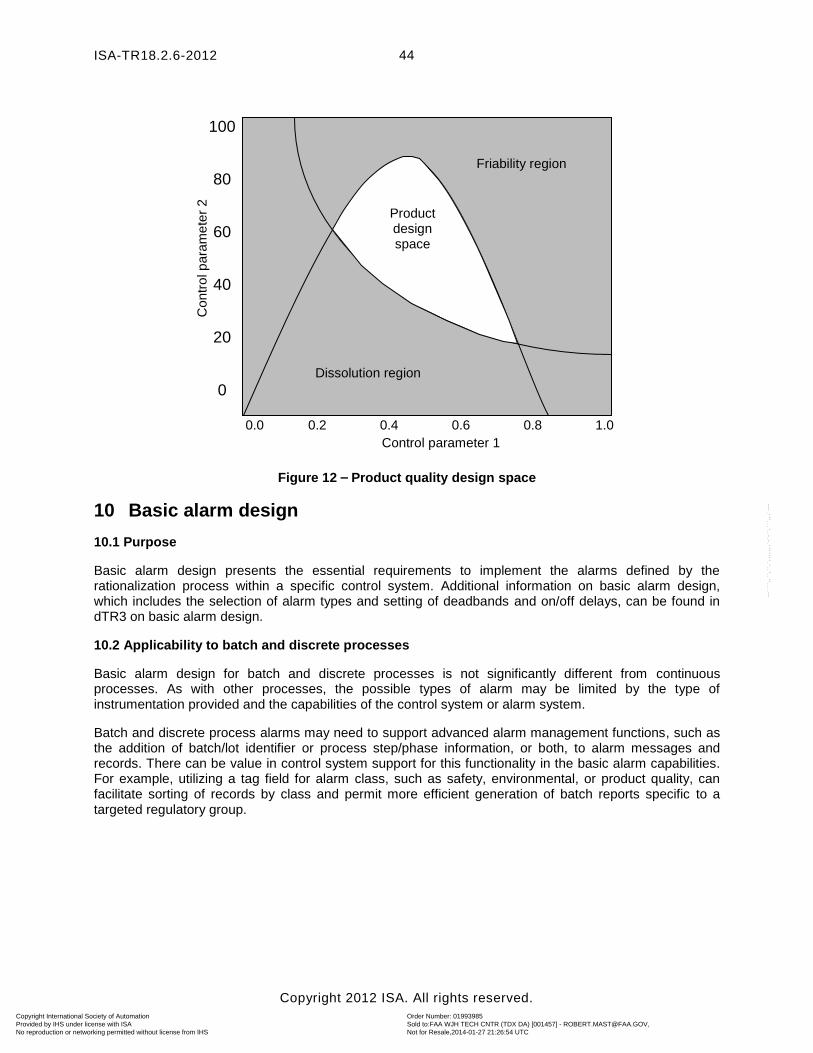
ISA-TR18.2.6-2012
Copyright 2012 ISA. All rights reserved.
44
Figure 12 – Product quality design space
10 Basic alarm design
10.1 Purpose
Basic alarm design presents the essential requirements to implement the alarms defined by the rationalization process within a specific control system. Additional information on basic alarm design, which includes the selection of alarm types and setting of deadbands and on/off delays, can be found in dTR3 on basic alarm design.
10.2 Applicability to batch and discrete processes
Basic alarm design for batch and discrete processes is not significantly different from continuous processes. As with other processes, the possible types of alarm may be limited by the type of instrumentation provided and the capabilities of the control system or alarm system.
Batch and discrete process alarms may need to support advanced alarm management functions, such as the addition of batch/lot identifier or process step/phase information, or both, to alarm messages and records. There can be value in control system support for this functionality in the basic alarm capabilities. For example, utilizing a tag field for alarm class, such as safety, environmental, or product quality, can facilitate sorting of records by class and permit more efficient generation of batch reports specific to a targeted regulatory group.
0.0 0.2 0.4 0.6 0.8 1.0
100
80
60
40
20
0 Dissolution region
Friability region
Product design space
Control parameter 1
Contr
ol p
ara
me
ter
2
Copyright International Society of Automation Provided by IHS under license with ISA
Order Number: 01993985Sold to:FAA WJH TECH CNTR (TDX DA) [001457] - [email protected], Not for Resale,2014-01-27 21:26:54 UTCNo reproduction or networking permitted without license from IHS
--````,,``,``,`,,,,,,,`-`-``,```,,,`---
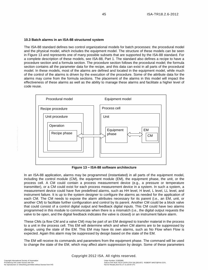
ISA-TR18.2.6-2012
Copyright 2012 ISA. All rights reserved.
45
10.3 Batch alarms in an ISA-88 structured system
The ISA-88 standard defines two control organizational models for batch processes: the procedural model and the physical model, which includes the equipment model. The structure of these models can be seen in Figure 13 and represents one of many possible subsets that are supported by the ISA-88 standard. For a complete description of these models, see ISA-88, Part 1. The standard also defines a recipe to have a procedure section and a formula section. The procedure section follows the procedural model; the formula section contains all the parameter data for the recipe, and this data can exist in all parts of the procedural model. In these models, most of the alarms are defined and located in the equipment model, while much of the control of the alarms is driven by the execution of the procedure. Some of the attribute data for the alarms may come from the formula sections. The placement of the alarms in this model will impact the effectiveness of these alarms as well as the ability to manage these alarms and facilitate a higher level of code reuse.
Figure 13 – ISA-88 software architecture
In an ISA-88 application, alarms may be programmed (instantiated) in all parts of the equipment model, including the control module (CM), the equipment module (EM), the equipment phase, the unit, or the process cell. A CM could contain a process measurement device (e.g., a pressure or temperature transmitter), or a CM could exist for each process measurement device in a system. In such a system, a measurement device could have five predefined alarms, such as HH level, H level, L level, LL level, and instrument failure. It is up to the system designer to configure the alarms as needed for the application of each CM. The CM needs to expose the alarm attributes necessary for its parent (i.e., an EM, unit, or another CM) to facilitate further configuration and control by its parent. Another CM could be a block valve that could consist of a control digital output and feedback digital inputs. This CM could have two alarms programmed in this module to communicate when there is a mismatch (i.e., the digital output requests the valve to be open, and the digital feedback indicates the valve is closed) or an instrument failure alarm.
These CMs (a flow CM and a valve CM) may be part of an EM designed to transfer material in the process to a unit in the process cell. This EM will determine which and when CM alarms are to be suppressed by design, using the state of the EM. This EM may have its own alarms, such as No Flow when Flow is expected. Again this alarm may be suppressed by design based on the state of the EM.
The EM will receive its commands and parameters from the equipment phase. The command will be used to change the state of the EM, which may affect alarm suppression by design. Some of these parameters
Process cell
EM
CM Equipment phase
Unit procedure
Operation
Recipe phase
Unit
Procedural model Equipment model
Recipe procedure
Copyright International Society of Automation Provided by IHS under license with ISA
Order Number: 01993985Sold to:FAA WJH TECH CNTR (TDX DA) [001457] - [email protected], Not for Resale,2014-01-27 21:26:54 UTCNo reproduction or networking permitted without license from IHS
--````,,``,``,`,,,,,,,`-`-``,```,,,`---
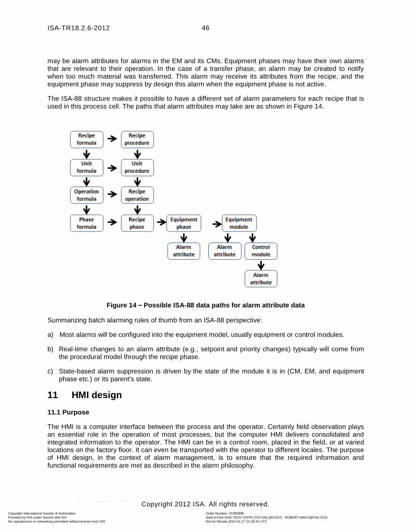
ISA-TR18.2.6-2012
Copyright 2012 ISA. All rights reserved.
46
may be alarm attributes for alarms in the EM and its CMs. Equipment phases may have their own alarms that are relevant to their operation. In the case of a transfer phase, an alarm may be created to notify when too much material was transferred. This alarm may receive its attributes from the recipe, and the equipment phase may suppress by design this alarm when the equipment phase is not active.
The ISA-88 structure makes it possible to have a different set of alarm parameters for each recipe that is used in this process cell. The paths that alarm attributes may take are as shown in Figure 14.
Figure 14 – Possible ISA-88 data paths for alarm attribute data
Summarizing batch alarming rules of thumb from an ISA-88 perspective:
a) Most alarms will be configured into the equipment model, usually equipment or control modules.
b) Real-time changes to an alarm attribute (e.g., setpoint and priority changes) typically will come from the procedural model through the recipe phase.
c) State-based alarm suppression is driven by the state of the module it is in (CM, EM, and equipment phase etc.) or its parent's state.
11 HMI design
11.1 Purpose
The HMI is a computer interface between the process and the operator. Certainly field observation plays an essential role in the operation of most processes, but the computer HMI delivers consolidated and integrated information to the operator. The HMI can be in a control room, placed in the field, or at varied locations on the factory floor. It can even be transported with the operator to different locales. The purpose of HMI design, in the context of alarm management, is to ensure that the required information and functional requirements are met as described in the alarm philosophy.
Copyright International Society of Automation Provided by IHS under license with ISA
Order Number: 01993985Sold to:FAA WJH TECH CNTR (TDX DA) [001457] - [email protected], Not for Resale,2014-01-27 21:26:54 UTCNo reproduction or networking permitted without license from IHS
--````,,``,``,`,,,,,,,`-`-``,```,,,`---
ISA-TR18.2.6-2012
Copyright 2012 ISA. All rights reserved.
47
11.2 Applicability to batch and discrete processes
Most of the principles involved in HMI design for alarm management are similar for continuous, batch, and discrete processes. In fact, many of the key principles are derived from interaction design experience outside of the process industries. The similarities and differences between continuous and batch or discrete processes, are summarized in Clause 4 of this document. Many of the differences are in the magnitude and frequency of certain aspects of alarm management.
The use of relative time or the elapsed time since a specific past event or time marker in a process (e.g. the start of a batch/lot) is a good example. In continuous manufacturing, a relative time concept is sometimes used to manage certain activities, e.g., catalyst performance. As a new catalyst charge is made, it may take x time to become active, remain at varying activity levels over time, and then be scheduled for replacement based on degrading performance. The time since the last charge is a key variable in managing this. The charge data may be stored in the BPCS, (using traditional calendar time) and a relative time calculated and displayed to the operator. If a catalyst activation is complex and time-consuming, it is a common best practice for this activation to include information on key variables and operator activity as a relative time roadmap for the operating team.
In batch manufacturing, current relative-time monitoring is highly desirable. In batch, product release for sale is generally not done as a check on a small number of end-result quality parameters. Instead, a batch process has performance specifications throughout the production process that must be met. These specifications may not be at every phase of the process, so some parts of the batch may be monitored more rigorously than others. However, when there are critical process parameters, deviations from these specifications can result in the rejection of a batch, even if end-run quality parameters are met. The key operator intervention steps are often a result of monitoring these specifications over the life of the batch. As the batch process moves through the phases of its cycle, the alarm limits on virtually any of the critical parameters may change or become irrelevant. To manage this, the HMI may have to show a relative time comparison of the target specification compared to actual. Continuous processes seldom have the need to display relative time.
So, the notion of relative time is clearly present in continuous processes and batch manufacturing. However, if the alarm limits relative to the continuous catalyst example were not set in a relative time frame, the likelihood that a product would fail to be approved for release is often relatively minor. A batch process that does not manage production to specifications has a higher likelihood for batch failure with off-spec product.
11.3 Basic HMI information and display requirements
ISA-18.2 details requirements and recommendations for the display of alarm information throughout the HMI from the alarm summary and history presentation reports to point details and display of information on process displays and overviews. This provides a framework for the HMI design relative to alarm management.
ISA-18.2 provides recommendations for the following types of displays:
a) alarm summary display;
b) alarm status display
c) alarm log display
d) overview display
e) process display
f) tag detail display
g) first-out display
Copyright International Society of Automation Provided by IHS under license with ISA
Order Number: 01993985Sold to:FAA WJH TECH CNTR (TDX DA) [001457] - [email protected], Not for Resale,2014-01-27 21:26:54 UTCNo reproduction or networking permitted without license from IHS
--````,,``,``,`,,,,,,,`-`-``,```,,,`---
ISA-TR18.2.6-2012
Copyright 2012 ISA. All rights reserved.
48
h) shelved alarm display
i) out-of-service alarm display
j) suppressed-by-design alarm display
11.4 Additional contextual HMI information
From a batch and discrete manufacturing perspective, the operator focuses on ensuring that the batch or the discrete item is made according to specifications. These specifications, often called recipes, provide a detailed instruction set that must be followed from moment to moment.
For example, a given pressure might be expected to be held tightly over the entire cycle of the manufacturing process. But the target setpoint might change several times. Or the pressure might only need to be monitored for a small subset of the entire cycle at one or several different setpoints. Depending on the complexity of the process, the system (capabilities and process control design decisions) may manage these changing alarm requirements automatically. Overall, the operator must understand the state of the process and the instruction set specifications. Whether this is done automatically or manually is a decision for the operating company.
In order to help the operator understand the state of the process, it is recommended that the following information be provided, either on the control system HMI or some other means of communication:
a) batch relative time
b) batch sequence stage (e.g., the current step in the instruction set)
c) order number, lot number, or batch ID
It is recommended that these items be directly integrated into the control system if the complexity of the process supports the effort. In complex systems, consideration should be given to provide the means to view all of the above alarm display types with the ability to sort by phase/step of the process and by order number, lot number, or batch ID.
11.5 HMI functional requirements and recommendations
ISA-18.2 details the basic requirements and optional recommendations for the HMI functional requirements. This provides a solid framework for the HMI functional design relative to alarm management, including the functional design for alarm shelving and designed suppression.
Depending on the process control design, alarm shelving and/or designed suppression are often part of day-to-day operation in batch and discrete manufacturing. The process control system may track or determine the current system mode/state in enough detail that designed suppression manages all alarm information dynamically, or it may be required that the operator interact with the alarm system more manually. More detailed alarm system requirements may be useful to manage these functional requirements.
11.6 Special considerations for semi-automated processes
In many batch and discrete operations, it is not uncommon for parts of the process to be completely manual. In batch, the operator may provide more direct process intervention than is common in continuous manufacturing. In discrete manufacturing, it is not uncommon to have only parts of the process automated. As such, it is quite common for the HMI location to be outside of a central control room, either in the field, on the production line, or to be carried with the operator.
Additionally, for less hazardous processes, it is not uncommon for alarm communication to be accomplished via remote methods, including text messages, e-mail, voicemail, and/or phone calls. The fidelity, security, and robustness of these methods must be factored into their design.
Copyright International Society of Automation Provided by IHS under license with ISA
Order Number: 01993985Sold to:FAA WJH TECH CNTR (TDX DA) [001457] - [email protected], Not for Resale,2014-01-27 21:26:54 UTCNo reproduction or networking permitted without license from IHS
--````,,``,``,`,,,,,,,`-`-``,```,,,`---
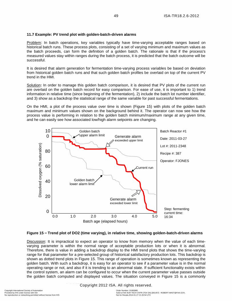
ISA-TR18.2.6-2012
Copyright 2012 ISA. All rights reserved.
49
11.7 Example: PV trend plot with golden-batch-driven alarms
Problem: In batch operations, key variables typically have time-varying acceptable ranges based on historical batch runs. These process plots, consisting of a set of varying minimum and maximum values as the batch proceeds, can form the definition of a golden batch. The rationale is that if the process's measured values stay within ranges during the batch process, it is predicted that the batch outcome will be successful.
It is desired that alarm generation for fermentation time-varying process variables be based on deviation from historical golden batch runs and that such golden batch profiles be overlaid on top of the current PV trend in the HMI.
Solution: In order to manage this golden batch comparison, it is desired that PV plots of the current run are overlaid on the golden batch record for easy comparison. For ease of use, it is important to 1) trend information in relative time (since beginning of the fermentation), 2) include the batch lot number identifier, and 3) show as a backdrop the statistical range of the same variable for past successful fermentations.
On the HMI, a plot of the process value over time is shown (Figure 15) with plots of the golden batch maximum and minimum values shown on the background behind it. The operator can now see how the process value is performing in relation to the golden batch minimum/maximum range at any given time, and he can easily see how associated low/high alarm setpoints are changing.
Figure 15 – Trend plot of DO2 (time varying), in relative time, showing golden-batch-driven alarms
Discussion: It is impractical to expect an operator to know from memory when the value of each time-varying parameter is within the normal range of acceptable production lots or when it is abnormal. Therefore, there is value in adding a backdrop display to the HMI trend plots that shows the time-varying range for that parameter for a pre-selected group of historical satisfactory production lots. This backdrop is shown as dotted trend plots in Figure 15. This range of operation is sometimes known as representing the golden batch. With such a backdrop, it is easy for an operator to see if a parameter value is in the normal operating range or not, and also if it is trending to an abnormal state. If sufficient functionality exists within the control system, an alarm can be configured to occur when the current parameter value passes outside the golden batch computed and displayed values. The situation conveyed in Figure 15 is a commonly
0.0 1.0 2.0 3.0 4.0 5.0
100
80
60
40
20
0
Batch age (elapsed hours)
Dis
solv
ed o
xygen (
% s
atu
ratio
n)
Generate alarm exceeded upper limit
Generate alarm exceeded lower limit
Golden batch lower alarm limit
Golden batch upper alarm limit
Current run
Batch Reactor #1
Date: 2011-03-27
Lot #: 2011-2348
Recipe #: 387
Operator: FJONES
Step: fermenting current time: 16:34
Copyright International Society of Automation Provided by IHS under license with ISA
Order Number: 01993985Sold to:FAA WJH TECH CNTR (TDX DA) [001457] - [email protected], Not for Resale,2014-01-27 21:26:54 UTCNo reproduction or networking permitted without license from IHS
--````,,``,``,`,,,,,,,`-`-``,```,,,`---
ISA-TR18.2.6-2012
Copyright 2012 ISA. All rights reserved.
50
occurring one in fermentation processes, in which abnormal contamination events (noticeable, e.g., at about 4.25 hours in Figure 15) significantly alter the normal dissolved oxygen trend. Thus, the monitoring and alarming of dissolved oxygen, as depicted in Figure 15, can be very effective in the early detection of a contaminated fermentor.
The x or horizontal axis in Figure 15 is shown as relative time (i.e., time since the beginning of the fermentation) rather than calendar time. This provides appropriate context in which operators and technical service personnel can interpret the plot and any generated alarm(s) since the interpretation of the plot and alarms shown are specific to the fermentation step. Any dissolved oxygen data records for any other fermentor step (e.g., pre-inoculation, sterilizing, harvesting) would be interpreted differently.
The labels on the trend plot include the batch lot number. This is because information for pharmaceutical processes is usually collected, searched, analyzed, and reported as a function of batch lot number. For example, if a company’s Quality Assurance group or the FDA does an audit of a plant, they often ask to see the records for particular batch lot numbers. Therefore, it is useful to show the batch lot numbers on process trend displays and to include batch lot numbers in data and alarm records.
Note If this plot were a historical plot, it could have been displayed by typing in only the lot number, step name (e.g., fermentation), and process variable name (e.g., dissolved oxygen). No calendar time or vessel identifier information would be needed.
12 Enhanced/Advanced alarming
12.1 Purpose
The purpose of enhanced/advanced alarming is to provide methods, techniques, and functionality for satisfying alarm system requirements that are over and above those that can be satisfied with basic alarming. Some advanced or enhanced alarming techniques may be necessary to consider from the beginning in automating batch processes, while their applicability may be less frequent and less necessary in continuous processes. The need for enhanced/advanced alarm functionality, whether implemented initially or later, should be anticipated early in the life of a system and included in the ASRS (Clause 7). ISA-18.2, Clause 12, discusses enhanced/advanced alarming, and ISA-TR18.2.4-2012 (TR4) contains detailed explanations and examples of enhanced/advanced alarming. Both documents also summarize some of the cost, support, complexity, HMI, and MOC implications of using enhanced/advanced alarming.
12.2 Applicability to batch and discrete processes
Enhanced/advanced alarming techniques can be applicable to all kinds of processes (continuous, batch, and discrete). They can be especially important to batch processes due to the high frequency, for example, of state changes and flexible plant reconfigurations. Also, some batch process alarm requirements regarding display, analysis, and potential redirection may not be easily satisfied with commercial off-the-shelf products.
Examples of possible user requirements, necessitating advanced/enhanced techniques for some automation systems (which are common to many batch processes but which also apply to some continuous and discrete processes) include:
a) Suppress/unsuppress alarms as a function of process step/phase or plant state.
b) Programmatically (or manually online) change alarm attributes (e.g., setpoint, priority) as a function of process step/phase, plant state, other conditional logic or specific product being produced; i.e., operating regimes can change (within the same equipment) as the process proceeds from step to step.
c) Display, query, sort, and analyze alarm records by lot/batch number and process step/phase.
d) Display alarm events in relative time.
Copyright International Society of Automation Provided by IHS under license with ISA
Order Number: 01993985Sold to:FAA WJH TECH CNTR (TDX DA) [001457] - [email protected], Not for Resale,2014-01-27 21:26:54 UTCNo reproduction or networking permitted without license from IHS
--````,,``,``,`,,,,,,,`-`-``,```,,,`---
ISA-TR18.2.6-2012
Copyright 2012 ISA. All rights reserved.
51
e) Configure alarm logic so that different equipment can be linked to the same process recipe (i.e., sometimes equipment is not predetermined but is assigned, e.g., before a batch starts based on what equipment is available).
f) Dynamically direct generated alarms to different personnel and/or support groups for which a response is expected (e.g., plant operators, technical service, plant utility operations).
g) Add appropriate system features (e.g., data security, audit trails) for processes in highly regulated industries.
12.3 Methods in linking alarm records to batch lot identifiers
There are different methods in which alarm records can be associated with their manufacturing process unique batch lot identifier.
12.3.1 Start/End (time) record method
This approach is based on capturing the batch and/or batch step start time and end time, associating this information with the equipment in which the batch/step was run, and then associating any alarms that occurred in that time interval with that batch. One way of capturing these times is to have the control system generate the start/terminate records as the batch recipe automatically sequences through the batch steps and/or as the result of operator interaction with the control system HMI, indicating that the process has advanced to the next step. There are a couple of considerations with this approach.
First, it certainly needs to be granular to be useful. The time synchronization of the control system and the process historian and the event historians can make this a challenge.
Second, there is often more than one batch on a production line at a time. For example, batch A is at unit operation 1 while batch B is at unit operation 2, and so forth. So it is not merely capturing the start and end time of the entire batch but the start and end time that a batch enters each unit operation (or whatever level of detail is required for analysis). The task of associating alarms with a batch then evolves into associating alarms with a batch for each unit operation. So the queries become: for given batch A, identify the start and end times for each unit operation, then find all alarms associated with that unit operation between those start and end times.
This method also allows for environmental alarms that span multiple unit operations (suites) to be considered. This is a common approach to the issue. Still to be considered is how to filter (i.e., ignore) alarms that occurred in a unit operation that are not needed for the batch report. A bulk of the effort to implement this system is at the database reporting level. The automation system does not necessarily have to know the batch identifier, but it can be useful if it does so as to include the batch identifier in the start/stop record header.
12.3.2 Record tag association method
This pre-processing approach is based on associating the batch identifier with alarms prior to or as they occur. As a batch enters a unit operation, the alarm system associates the batch identifier with the alarms for that unit operation. This requires the automation system to know the batch identifier and the alarm logging system to be able to associate that identifier with the alarm as it is logged. Some vendors have constructed their alarm tag database with spare text fields called alarm extension fields. When a batch starts, the batch identifier can be written to one of the alarm extension fields for all of the alarms in that unit operation. So whenever an alarm occurs and is logged to the alarm database, that field is also stored. Other vendors allow the batch unit name to be added to an alarm and event alarm-class field (multiple units can be added with a comma delimiter, which addresses environmental alarms that affect multiple suites). Some vendors offer custom record-tagging capability.
Regardless of the vendor solution, this pre-processing method allows all alarms associated with a batch to be retrieved by a simple query of the alarm database for all alarms where the alarm field equals the
Copyright International Society of Automation Provided by IHS under license with ISA
Order Number: 01993985Sold to:FAA WJH TECH CNTR (TDX DA) [001457] - [email protected], Not for Resale,2014-01-27 21:26:54 UTCNo reproduction or networking permitted without license from IHS
--````,,``,``,`,,,,,,,`-`-``,```,,,`---
ISA-TR18.2.6-2012
Copyright 2012 ISA. All rights reserved.
52
desired batch identifier. A bulk of the engineering effort is in the automation system, which must be aware of the batch identifier and populate that field of all alarms when the batch enters that unit operation. Depending on the vendor and system architecture, this approach may not easily deal with certain classes of alarms (e.g., environmental) that may affect multiple suites, which may be processing multiple batches.
12.3.3 Use of manufacturing execution systems (MES)
Some companies make batch lot number assignments from IT Level 3 or 4 systems, as defined by ISA-95. A Level 3 MES is often used to assign batch lot numbers since this helps ensure a unique identifier for each lot generated by a corporation and also helps with batch lot tracking (also an MES function). This implies downloading of the batch lot number to the BPCS system and/or its historian.
MES systems, if used by a company, also typically generate the official batch report, as well as deviation reports, so it is important that data sent to the MES system, including alarm records with possible regulatory implications, be identified with a batch lot number.
13 Implementation
13.1 Purpose
The implementation stage of the alarm lifecycle covers general requirements to install an alarm or alarm system or to implement a modification to an existing alarm or alarm system and bring it to operational status. Implementation is the transition from design to operation.
Managing alarms in a regulated industry requires careful implementation of any software application used to make decisions about the process or product. Therefore, additional consideration should be given to the implementation of an alarm system in regulated industries (e.g., pharmaceutical, biotech, medical devices), which are heavy users of batch/discrete processes.
13.2 Initial operator training
The general principles regarding alarm system initial operator training are similar for continuous, batch, and discrete processes. Whatever differences exist are usually due to differences in plant hazardous conditions, regulatory agency requirements, and other factors.
13.3 Testing challenges in batch processes
Batch processes can have special challenges to consider when testing alarm systems. These challenges are the result of the dynamic nature of the process, with its multiple time-varying steps and transitions. The following subclauses will address common items in an ASRS associated with batch processes, (see 7.2.1).
13.3.1 Frequent transitions
Batch processes (reference ISA-88) typically have states titled: Hold, Idle, Pause, Abort, etc. Batch control recipes normally include some of these states. Transitioning between these states normally involves suppressing and/or enabling specific alarms. Alarm attribute changes associated with transitions should be tested during implementation.
Methods to test alarm systems with frequent batch transitions can vary and may depend on variables, such as cost, safety, environmental, or product quality. Depending on the type of process measurement, test or water batches can be used to test the change in alarm attributes. While most alarm attribute changes are associated with alarm suppression, some processes may also need adjustment of alarm setpoints on analog points or changes to the priority of the alarm.
Some cases may exist where testing of alarms during the batch transitions is of value by running small batches and purposely generating abnormal events.
Copyright International Society of Automation Provided by IHS under license with ISA
Order Number: 01993985Sold to:FAA WJH TECH CNTR (TDX DA) [001457] - [email protected], Not for Resale,2014-01-27 21:26:54 UTCNo reproduction or networking permitted without license from IHS
--````,,``,``,`,,,,,,,`-`-``,```,,,`---
ISA-TR18.2.6-2012
Copyright 2012 ISA. All rights reserved.
53
Process simulators can also be a valuable alternative to test the alarms during batch transitions. High fidelity simulators, which can model processes with accurate time-varying process variables, can be useful to test abnormal situations that would not be practical to test in an actual production system. Concerns such as cost, safety, environmental, or product quality can be factors to consider when implementing process simulators to test alarm systems.
In all cases, reliable alarm logging and data historian applications are very important to document these test cases.
13.3.2 Variable alarm attributes
Basic configuration of a control system will usually include default or initial alarm attributes or settings. The source of many alarm attribute settings can be a batch recipe formula, which is usually loaded into the control system, using a recipe manager. These alarm attributes may change during a state as opposed to alarm attribute changes at state transitions. Fed-batch reactors, for example, are often characterized by an incoming feed for which a feed rate and its associated alarm setpoints may change frequently during a chemical reaction batch step. Therefore, numerous automated or manual alarm setpoint adjustments may be needed as a batch progresses.
Depending on the frequency of alarm attribute changes, a process data historian can be beneficial to identify process variables changing over time and help test the associated dynamic alarm attributes. Other testing techniques, such as running smaller throw-away batches, water batching, or use of process simulators can also assist in alarm-system testing.
13.3.3 Alarm record relationship to batch record
Not only is it important to test the alarm changes, it is also important to verify a specific alarm is associated with the correct batch lot number. Many processes have concurrent multiple phases with multiple batches. The alarm system should be able to associate a specific alarm to a batch, both in real time and historical process databases. Process simulators can be valuable tools to simulate a batch and test the alarms associated with a recipe and batch lot number.
13.3.4 Alarm routing
Some batch operations may not have a conventional central control room. Also, some alarms need to be sent to personnel other than the primary operator. It is important to test if the alarm is sent to the appropriate individual. The robustness of the communication media should also be considered. For example, if an alarm system is configured to send a message via short message service (SMS), such as mobile-phone text messages, then consider the possibility the message is not sent as requested or not received due to equipment failure. Depending on the criticality of the situation, the alarm may be escalated to another individual, or another media may be selected. The alarm may also require remote acknowledgement to stop the escalation process. All communication pathways for the alarm routing should be documented and tested.
13.4 Alarm system implementation in highly regulated industries
Specific requirements exist for some aspects of implementation, including testing and training, in highly regulated industries.
13.4.1 Initial operator training in cGMP environments
Basic principles of cGMPs include proper training of personnel directly impacting the process. Since the alarm system is designed to guide and inform the operator, specific training requirements should be considered.
A prerequisite to operator training is to receive GMP training. Operator training specifically for alarm handling and management should be done under the guidance of an expert per the GMP guidelines. This is to provide inexperienced operators with an awareness of government expectations regarding the
Copyright International Society of Automation Provided by IHS under license with ISA
Order Number: 01993985Sold to:FAA WJH TECH CNTR (TDX DA) [001457] - [email protected], Not for Resale,2014-01-27 21:26:54 UTCNo reproduction or networking permitted without license from IHS
--````,,``,``,`,,,,,,,`-`-``,```,,,`---
ISA-TR18.2.6-2012
Copyright 2012 ISA. All rights reserved.
54
manufacture of regulated products. The master alarm database can be a training tool for operators to obtain insight to the rationale behind the alarm occurrence and provide recommendations to remedy the situation.
Alarms specific to CPPs usually require detailed alarm-response procedures and may have extensive training associated with this alarm class. This may include additional sampling, inspections, tests, and checks to be carried out or initiated, as appropriate, to cover initial alarm response, planned changes, and deviations. In some companies, alarms associated with CPPs may be elevated and classified as highly managed alarms.
13.4.2 Testing expectations in regulated industries (e.g., pharmaceutical)
The alarm system should be part of the validation scope in a regulated environment, such as processes under the jurisdiction of the US Food and Drug Administration. The validation plan should include a detailed plan of how the alarm system will be tested and documented. This validation process includes three major testing components: the installation qualification, the operational qualification, and the performance qualification. These will be discussed in the clauses below.
Prior to commencing validation in a regulated industry, initial commissioning testing is usually undertaken with the alarm system to check functionality before formal validation testing begins. Commissioning testing often has less formal requirements (e.g., documentation) than formal validation and therefore provides an opportunity to more easily and quickly correct any problems that may appear.
The testing of alarm responses and the ability of operators to follow response procedures is typically performed in an environment subject to cGMPs. A process simulator can be valuable to test some alarms, especially for those abnormal situations that may be impractical to set up on a production system. This type of testing can increase the cost of commissioning but has been shown to reduce process upsets and quality problems.
13.4.3 Installation qualification
The installation qualification (IQ) generally concerns hardware but may include some installation aspects of software. It is a set of activities intended to provide documented evidence that equipment and its ancillary systems and subsystems have been installed in accordance with specifications. Specifically, IQ helps ensure that installation aspects of hardware and software, including, e.g., alarm annunciators, have been identified; agree with specifications identified in purchase orders; and adhere to company equipment installation guidelines, manufacturer’s installation recommendations, and industry standards (e.g., the National Electrical Code).
Key topics, such as communication links from alarm providers to alarm consumers (e.g., alarm historians), computer and network hardware installation specifications, and configuration data related to hardware functions may be found in IQ documentation.
13.4.4 Operational qualification
Specific to the alarm system, the operational qualification (OQ) is intended to provide evidence that the alarm system functions according to the system specifications, as defined in functional requirements, including the ASRS, and to any business process, functional design, plant infrastructure, and regulatory requirements. OQ typically involves tests of software operating in installed qualified hardware in an environment not involving the plant making actual product.
A series of test cases (sometimes called test scripts) are usually defined with the objective of demonstrating that the alarm system meets the specified requirements. These tests are based on business scenarios that reflect the intended use of the system. The cases should be capable of providing a high degree of confidence that the system is functioning as specified. In addition to addressing functional requirements, tests should be defined to confirm that the alarm system meets non-functional requirements; including
Copyright International Society of Automation Provided by IHS under license with ISA
Order Number: 01993985Sold to:FAA WJH TECH CNTR (TDX DA) [001457] - [email protected], Not for Resale,2014-01-27 21:26:54 UTCNo reproduction or networking permitted without license from IHS
--````,,``,``,`,,,,,,,`-`-``,```,,,`---
ISA-TR18.2.6-2012
Copyright 2012 ISA. All rights reserved.
55
a) system component failure (including power loss)
b) back-up and recovery
c) performance and resilience under load
13.4.5 Performance qualification
The performance qualification (PQ) provides documented evidence that the process or system is reproducible and stable and that it meets requirements for the expected range of plant operating conditions. Usually, a minimum of three tests (i.e., production runs) is expected. In this testing environment, the plant may be making actual product (although usually not for sale), and tests include ones focusing on worst-case scenarios, e.g., maximum loading.
13.4.6 Validation documentation
Following the completion of IQ, OQ, and PQ, a validation documentation set is assembled. This will comprise the key documentation that has been generated during the control system development and implementation, including the alarm system. The validation documentation pertaining to the alarm system can include such items as a validation plan, user and functional requirement specifications, qualification reports, and a traceability matrix. Refer to ISPE’s Good Automated Manufacturing Practices (GAMP) for more details.
14 Operations
14.1 Purpose
The operations stage of the alarm lifecycle covers requirements for alarms to remain in and return to the operational state. This clause also describes appropriate use of tools for alarm handling within the operational state.
14.2 Effects of process types (continuous, batch, discrete) on alarm response procedures
The concepts covered in the standard, ISA-18.2, regarding alarm response procedures are universal to all process types without exception, and there is a great deal of overlap in the application of these concepts between each process type. The following clauses in this technical report capture additional ideas and concepts, which may provide additional guidance based on specific process-type considerations.
14.2.1 Effects of process type on operator alarm response procedure documentation
The availability of documentation may be limited by the geography of different types of operations. While the traditional control room is often a mainstay of many continuous and some batch operations, it may be less prevalent in discrete and batch operations where there is a high degree of physical operator involvement with the process area. In those situations, the availability of procedures may be limited to the HMI located on the plant floor. If the HMI has limited or locked functionality, the issue may be further complicated. Other factors that may affect availability of documentation are related to regulated environments in which policy strictly limits the type and form of documentation allowed in control rooms and/or via HMI displays. These operational obstacles must be considered and alternatives evaluated in order to provide greatest access of documentation to operators.
14.2.2 Effects of process mode on alarm suppression/unsuppression
The use of alarm suppression in phase-driven batch operations may offer some additional challenges. Batch operations-phase management often requires that alarm configurations be active and inactive at different times throughout the course of the batch, with changing setpoints, priority settings, and other dynamic alarm attributes (i.e., state-based alarm changes). The actual implementation is very dependent on the control system capabilities and approach to managing alarms as well as the control system’s
Copyright International Society of Automation Provided by IHS under license with ISA
Order Number: 01993985Sold to:FAA WJH TECH CNTR (TDX DA) [001457] - [email protected], Not for Resale,2014-01-27 21:26:54 UTCNo reproduction or networking permitted without license from IHS
--````,,``,``,`,,,,,,,`-`-``,```,,,`---
ISA-TR18.2.6-2012
Copyright 2012 ISA. All rights reserved.
56
capability for alarm configuration manipulation in real-time situations. Regardless of the use of alarm shelving, alarm suppression, or other technique in the alarm design to manipulate the real-time alarm configuration, batch operations will almost certainly involve the manual or programmatic action of changing the alarm to either annunciate or not annunciate.
Suppression may be done either manually or programmatically as a part of batch operations as the process transitions through various programming states. The effort may be further complicated, as some alarms are shelved in the native state and are only unshelved during specific parts of the recipe.
When the process of alarm suppression is handled manually (i.e., shelved) as a matter of recipe or procedure in a batch process, there must be particular attention paid to the status of alarms and a means to check that the status is valid for the particular operations that are currently underway. The review of shelved alarm status required at the start of each shift in ISA-18.2 may not be sufficient in this case, as the status of an alarm may change several times in a single day. Additional requirements in regulated industries may require an audit trail of all manual intervention and actions taken during the course of the batch. Where the control system technology is inadequate to provide acceptable audit trail details, the effort of tracking manual actions must be clearly proceduralized. The impact of undisciplined handling and tracking manual intervention with alarm suppression may result in alarm conditions being missed along with the corresponding consequences.
Where suppression of alarms occurs programmatically (i.e., designed suppression), there must be robust testing and verification that the alarm state will be appropriate for the particular operation. For example, phases must be robust enough to verify the current state of alarm settings when beginning a phase and to release alarms to their default state when completing a phase. In cases where alarm conditions are not checked and returned to the default state, the resulting condition may result in nuisance alarms.
Other issues may exist when batch processes are associated with changing setpoints and changing priority levels. For example, if a medium priority high temperature alarm is unsuppressed to protect a piece of equipment, a particular phase may require that alarm to be reset to a lower value at a higher priority in order to guard against a potential environmental concern. Once that particular phase is complete, the alarm needs to reset back to the original condition or a completely different state. The management overhead of handling this, either programmatically or procedurally, is not trivial.
Discrete and continuous operations may face similar challenges, depending on the nature of the operation and the complexity of the control system. However, the number of transitions and the changing states of the process within these particular operations are not as prevalent as in many batch-type operations.
14.2.2.1 Risks associated with operator-initiated alarm changes
Where practical, the manual suppression/unsuppression and manipulation of alarm settings should be avoided. Naturally, this is highly dependent on the sophistication of the control system, the sophistication of the batch/recipe manager associated with the equipment and process, and the variation of processes that may be run in the equipment.
In cases where operator manipulation of alarm settings is unavoidable, clear procedures are necessary to establish boundaries and rules for adjustment. Adjustments should only be made based on recipe or batch requirements and never to suit operator preference. A means of auditing the current state vs. anticipated state is recommended. Changes driven by recipe or batch states should be reviewed frequently to assure the manual adjustment to an alarm setting continues to meet the stated objective of the alarm. It is important to track and audit all such changes to ensure that they are properly done, appropriately communicated, and responsibly managed.
14.2.3 Effects of process type on training
In situations where there is limited availability of alarm response documentation, the degree and intensity of both initial and refresher training may be affected. A careful review of the process type and expectations
Copyright International Society of Automation Provided by IHS under license with ISA
Order Number: 01993985Sold to:FAA WJH TECH CNTR (TDX DA) [001457] - [email protected], Not for Resale,2014-01-27 21:26:54 UTCNo reproduction or networking permitted without license from IHS
--````,,``,``,`,,,,,,,`-`-``,```,,,`---
ISA-TR18.2.6-2012
Copyright 2012 ISA. All rights reserved.
57
will help the user determine additional training expectations that may be required. Several examples are given below.
In situations where the documentation will be limited for the operator, based on operational geography or technological limitations, a more robust training effort may be required to educate operators and to assure they are maintaining their capabilities related to alarm response.
In operations where the operator will be required to suppress alarms as part of a batch, special training may be necessary to execute those efforts and how to monitor the current state of the alarm system to assure that alarm settings are correct. When the batch recipe is updated or changed, or when the product being processed is changed, specific operator training may be required to assure that new or changed alarm expectations are clear and responses are unambiguous.
Certain regulatory environments may also drive the need for frequent refresher training. For example, FDA requirements for operator training are very specific and require strict attention to content and timing of refresher training.
Certain regulatory environments may also drive the need for different behaviors and practices when determining frequency and the nature of refresher training. For example, the FDA, via cGMPS, requires that operators have, maintain, and have documented all relevant qualifications that are associated with their jobs. Periodic refresher training can be an important part of establishing the continuing qualification of operators. Also, cGMPs are living requirements, occasionally revised and updated, which in turn could prompt refresher training for operators. A company's interpretation of cGMPs might also change over time, prompting operator refresher training. Periodic operator refresher training can be valuable in reviewing recent changes to the automation system (including alarm functions), and also in reviewing regulatory requirements regarding online changes they might make to an operating system (e.g., documenting manual alarm setpoint changes made during a process not prompted by the manufacturing ticket or documenting an alarm an operator might have suppressed or shelved).
14.3 Alarm response and resolution
The practice of how alarm response and resolution is configured and executed is affected by many variables, including the type of control system, the local site practices and policies regarding operational expectations for handling alarms, and the particular mode of operation. For the purposes of the technical report, only the last variable will be considered.
A comprehensive and holistic understanding of operational behaviors and duties are, in no small part, affected by the process type (continuous, batch, discrete) and should factor into alarm response procedures for each operational area.
The effects of process type and alarm handling behavior need to be evaluated specific to the operation and take into consideration operational subtleties that may be unique for the area. Procedures should capture the behaviors and determine how unconventional circumstances should be handled.
14.3.1 Alarm acknowledgement
As a matter of practice, all alarms should receive a response. Acknowledgement is typically a part of the response.
The function of alarm acknowledgement has a variety of implementations on different control systems, and its use may also be related to process type and/or plant operational philosophy. In general, when an alarm is acknowledged, a time-stamped record is produced, and certain HMI behaviors associated with the alarm are changed, such as blinking and sound. Typical alarm system capabilities might include alarm group acknowledge and acknowledge all alarms. Use of these capabilities makes it difficult to make accurate inferences about the operator’s recognition and response to any particular alarm.
Copyright International Society of Automation Provided by IHS under license with ISA
Order Number: 01993985Sold to:FAA WJH TECH CNTR (TDX DA) [001457] - [email protected], Not for Resale,2014-01-27 21:26:54 UTCNo reproduction or networking permitted without license from IHS
--````,,``,``,`,,,,,,,`-`-``,```,,,`---
ISA-TR18.2.6-2012
Copyright 2012 ISA. All rights reserved.
58
Some find it desirable to require operator consistency in the act of alarm acknowledgement so that acknowledgement records have consistent meaning relating to the operator’s interaction with the alarm. If such consistency exists, then analysis of alarm acknowledgement records can provide useful information, particularly relating to operator response during abnormal situations. Written practices or procedures that detail proper and improper use of alarm system acknowledgement capabilities are sometimes used to encourage or require consistency.
In batch operations, alarm acknowledgement practices may be similar to those of continuous plants. However, with the operator frequently located near process equipment and unable to necessarily directly acknowledge an alarm prior to taking action, the practices related to and action of alarm acknowledgement need to account for the overall operator responsibilities. Someone not directly responsible for taking action may have authority to acknowledge an alarm and inform the responsible operator in the field to address the situation. Remote acknowledgement in the field may necessitate an additional action for the operator when he returns to the control system to assure that all active alarm conditions are attended to, not just the one that he thought he was attending.
In discrete operations, the alarm may also correspond to a plant operation stoppage, with the resulting operator action of first addressing the alarm condition and then acknowledging it as an indication that the condition has cleared. Particularly where the stoppage of one part of the process has a cascading effect to other parts of the operations, causing cascading alarms for each stoppage, the need for the operator to acknowledge each cascading alarm as it occurs is not reasonable or necessary.
The use of self-acknowledging alarms is a practice that may be dangerous, regardless of mode, and should drive a question regarding whether the situation is an alarm or an event that does not meet all criteria for being an alarm (e.g., alert or message).
15 Maintenance
15.1 Purpose
Maintenance, a separate stage of the alarm lifecycle, covers requirements for alarm system testing, replacement-in-kind, and repair. Maintenance involves the transition of alarms out of the operational state and returning to the operational state. When alarms are in the stage of maintenance, they no longer function according to their designed purpose.
15.2 Applicability to batch and discrete processes
The alarm maintenance clause of ISA-18.2 (Clause 15) is applicable to all types of processes, including batch and discrete.
Due to the sequential nature of batch and discrete manufacturing, recipe or procedural-driven alarms need to be considered carefully when developing, scheduling, performing, and documenting maintenance activities around alarms.
Recipe or procedural-driven alarms are alarms that are activated and deactivated during different steps in a process sequence, often by a batch execution engine or fixed sequencing logic embedded in the controller.
For any required periodic testing, unique identifiers of the procedure used, such as master recipe or procedure name and version number, should be documented.
If a highly managed alarm has a sequence condition as part of its requirement, the sequence should be documented as part of the records for out-of-service conditions and periodic maintenance and returning the alarms to service.
Copyright International Society of Automation Provided by IHS under license with ISA
Order Number: 01993985Sold to:FAA WJH TECH CNTR (TDX DA) [001457] - [email protected], Not for Resale,2014-01-27 21:26:54 UTCNo reproduction or networking permitted without license from IHS
--````,,``,``,`,,,,,,,`-`-``,```,,,`---
ISA-TR18.2.6-2012
Copyright 2012 ISA. All rights reserved.
59
Batch and discrete processes often have an advantage for scheduling for alarm maintenance with opportunity for periodic downtime of production due to the shorter cycle time of a batch process or discontinuous production runs for discrete, as compared to a continuous operation.
Many batch plants are based in the life-science industries; for many of these processes it is necessary to follow FDA’s cGMPs regarding alarm maintenance schedules for critical process parameters. Failure to meet these schedules can trigger regulatory action against the manufacturer.
Some batch processes in the chemical industry are covered under OSHA’s regulation of process safety management of highly hazardous chemicals. Often, in a PHA analysis of a process, it is assumed that alarm systems will be checked according to established maintenance schedules, and it is determined that the established maintenance schedules will reduce the risk of an abnormal situation. Many companies require that any alarms associated with process safety operations be tested during relevant maintenance operations.
15.3 Examples
The following examples illustrate alarm maintenance activities:
15.3.1 Example: Replacement-in-kind equipment: Instrument configuration for gas monitors
In vacuum packaging of food products, it is important to make certain that the sealing equipment is performing a consistent sealing of packages. To test the sealing of the packages, the food industry often uses monitors that test the gas composition. If the residual gas is, for one reason or another, not at a composition within user-defined levels, it is an indication of an improperly sealed package; an alarm will be activated, and the packaging machine will stop, or an alarm light will flash.
Problem: Replace a gas monitor in a vacuum packaging system that has an analog output and alarm output settings. Make sure that when the monitor is replaced, the correct make/model is installed; also ensure that the monitor is configured to the correct alarm outputs before it is put into service.
Solution: Document both the necessary alarm configuration settings and the make/model of the gas monitor. In the testing procedure, verify the physical equipment is configured, calibrated, and documented.
15.3.2 Example: Replacement of like equipment: Dissolved oxygen probes
There are different types of dissolved oxygen probes used in industry. Calibration and measurement dynamic responses can be different with the various types.
Problem: Replace one type of dissolved oxygen probe in fermentors with another type.
Solution: Take dissolved oxygen alarms out of service until appropriate tests can be run on the new probes and alarm attributes adjusted if necessary.
Discussion: The differences in probe types can result in different recommended values for alarm on/off limits and/or deadbands. Therefore, as part of the alarm system maintenance process, the dissolved oxygen probe alarms should be taken out of service and the operators appropriately notified. After appropriate testing is completed and any alarm attributes adjusted, the dissolved oxygen alarms can be put back in service. This replacement-in-kind activity should also be controlled and documented via a plant’s MOC procedures.
15.3.3 Example: Periodic maintenance requirements for online analytical systems
Problem: Analytical systems (such as gas chromatography (GC), high performance liquid chromatography (HPLC), mass spectrometry (MS), and near-infrared (NIR) systems) are sometimes used in monitoring and/or controlling certain critical process parameters in batch pharmaceutical process manufacturing. Loss of calibration of the analytical system may affect validity of operational alarms, making use of analytical system information.
Copyright International Society of Automation Provided by IHS under license with ISA
Order Number: 01993985Sold to:FAA WJH TECH CNTR (TDX DA) [001457] - [email protected], Not for Resale,2014-01-27 21:26:54 UTCNo reproduction or networking permitted without license from IHS
--````,,``,``,`,,,,,,,`-`-``,```,,,`---
ISA-TR18.2.6-2012
Copyright 2012 ISA. All rights reserved.
60
Solution: Perform appropriate maintenance, including calibration checks, on the analytical system and its associated alarms at periodic intervals. Conduct periodic refresher training for operators.
Discussion: Parameters being monitored by analytical systems in pharmaceutical manufacturing are often critical process parameters and therefore associated with product quality. Consequently, CPPs are a candidate for a separate alarm class designation, requiring management activities over and above those of general alarms, e.g., maintenance activities, such as periodic testing and periodic refresher training for operators. It is appropriate to periodically check the validity of the analytical system calibration and associated system alarms. As with other examples of batch processes, the short cycle time usually provides ample opportunity between batches to pursue maintenance. However, some problems may surface while a batch process is in progress. Since some batch steps may not need the online analytical system, it may be possible to perform some maintenance activities during a batch run. Otherwise, it may be possible to put the process in a HOLD state while servicing the analytical system. Regardless of how pursued, it may be appropriate to take alarms out of service while the analytical system is being serviced, appropriate testing is being completed, and any alarm attributes adjusted.
15.3.4 Example: Replacement of resin in a chromatography separation column
Description: Chromatography columns are frequently used in industry to separate compounds in a mixture (a common unit operation for batch pharmaceutical product recovery and purification operations). Compound separations occurring within the column trigger valve changes, resulting in the collection of different column output fractions.
Problem: The material (e.g., resin) used to separate compounds in the analytical chromatograph has a finite life and needs to be replaced periodically. The replacement resin will likely have slightly different physical characteristics (e.g., density, void volume, porosity) than the original resin, resulting in different operating characteristics of the column.
Solution: Take the chromatography column output alarms out of service while maintenance (i.e., resin replacement) is occurring. Notify operators as appropriate. Test new column operation to determine if any alarm attributes need to be changed. Put the alarms back in service when maintenance and associated testing are completed.
15.3.5 Example: Barcodes
Problem: A discrete process packaging line requires that a barcode label be added to each package and then automatically read, with read information then stored in a database. Attempts to read barcodes can be unsuccessful for several reasons, including improper placement of the barcode label on the package, crimping of the label, solvent smears on the label, and problems with the barcode reader, such as a weak light-beam source. Unsuccessful barcode reading events need to be alarmed.
Solution: Incorporate regularly scheduled preventive/predictive maintenance for barcode readers and periodic testing of alarms associated with barcode reading. Since barcode alarms may be associated with product identity for regulated products, periodic refresher training for operators and maintenance personnel may also be needed. If a barcode system is upgraded, which can occur from time to time due to continual improvements of the technology, alarms may need to be taken out of service while new systems are installed and tested.
Discussion: Barcode reading can be an important indicator of the identity of a manufactured item, package, product container, or raw material. Identity is one of several formal attributes of product quality. Justification for periodic testing of barcode reading equipment and alarms also exists in that the reliability of barcode reading is a time-varying function of many variables, including the strength of the barcode reader energy source, cleanliness of optical portions of the reader, and wear and tear on the mechanical motion aspects of applying a barcode label. Since abnormal situations on discrete processes often result in shutdown of the production line, it is especially important to conduct periodic maintenance activities as appropriate to help minimize the incidence of such shutdowns.
Copyright International Society of Automation Provided by IHS under license with ISA
Order Number: 01993985Sold to:FAA WJH TECH CNTR (TDX DA) [001457] - [email protected], Not for Resale,2014-01-27 21:26:54 UTCNo reproduction or networking permitted without license from IHS
--````,,``,``,`,,,,,,,`-`-``,```,,,`---
ISA-TR18.2.6-2012
Copyright 2012 ISA. All rights reserved.
61
Note In some plants and for some products, radio frequency identification (RFID) systems are being implemented, in some cases replacing the previous use of barcoding systems. RFID systems involve microchips installed on, e.g., product containers or packages that can be read remotely. The principles of alarm management for RFID systems are similar to those of barcode systems.
16 Monitoring and assessment
16.1 Purpose
The monitoring and assessment stage of the alarm lifecycle verifies that design, implementation, rationalization, operation, and maintenance are satisfactory. Problems identified via alarm system monitoring can be resolved in several different parts of the lifecycle (e.g., design, maintenance, or management-of-change) depending upon the nature of the problem.
References regarding monitoring and assessment include ISA-18.2 (Clause 16) and ISA-TR18.2.5 (TR5).
16.1.1 Monitoring and assessment in the context of process type
The use and interpretation of monitoring and assessment may be different based on the process type that exists in the plant as well as limitations and capabilities of the process control technology used in the plant. There is significant overlap between the three most common process types (continuous, batch, and discrete), as the general principles of alarm management transcend the process type. However, there are also many elements of the process type that set them apart from each other.
For example, while many of the metrics that plant users may choose to measure will be similar between the process types, the interpretation of the data and the measures of acceptable performance may be different.
Some examples include:
a) the effects on and interpretation of alarm frequency between batch and continuous operations (e.g., the effects of frequent state transitions, multiple recipes, and variable equipment-use frequency in a batch operation vs. the steady-state operations in a continuous operation)
b) the direct measure of equipment effectiveness or utilization metrics often used in discrete operations and the correlation of such measurements to alarm activations. In developing such measures, it is important for the operation to understand the relationship of terminology used, such as the potential interchangeability of fault and alert with the traditional definition of alarm as defined in ISA-18.2.
c) use of chattering and fleeting alarm conditions in batch operations to identify poorly designed dynamic alarm attributes based on phase or recipe operation
The exact metrics that are to be used for monitoring and assessment will be specific to each facility and process type. With batch/discrete processes, the use of many different states and operating modes may result in more detailed metrics, provided the control system provides adequate capability to capture sufficient data. Additional metrics may allow, among other things, for batch-to-batch/lot-to-lot comparisons as well as identification of times when the process is stressing the equipment and control system.
16.2 Setting appropriate alarm KPIs
The challenge with using key performance indicators (KPIs) is to select the most appropriate ones for each process. Clause 16 in the ISA-18.2 standard, TR5, and EEMUA-191 provide guidance and discuss the power and usefulness of appropriate metrics and KPIs in measuring the performance and operational capability of an alarm system. The KPIs provide
a) context for the current state of the alarm system
b) a measure of improvements to the overall system performance and operational improvements driven by alarm data
Copyright International Society of Automation Provided by IHS under license with ISA
Order Number: 01993985Sold to:FAA WJH TECH CNTR (TDX DA) [001457] - [email protected], Not for Resale,2014-01-27 21:26:54 UTCNo reproduction or networking permitted without license from IHS
--````,,``,``,`,,,,,,,`-`-``,```,,,`---
ISA-TR18.2.6-2012
Copyright 2012 ISA. All rights reserved.
62
c) an indication of how a plant is running. KPIs may help identify equipment that needs to be replaced, processes that need to be improved, and operational behaviors that need to be modified.
These standards and publications also have provided some baseline guides for how to measure performance across specific KPIs, such as alarm rate, alarm floods, and chattering alarms. For example, the alarm rate will, among other things, determine if the operator can reasonably be expected to respond to the alarms that occur. If operators are overwhelmed by too many alarms in a short period of time, they simply will be unable to adequately respond to all alarm conditions. Figure 14 in ISA-18.2 (Alarm Performance Metric Summary) includes the recommended average annunciated alarm rate per operating position, not to exceed an average of six alarms per hour. Any more than an average of six alarms per hour has been generally accepted to be a rate beyond what is reasonable for an operator to handle for extended periods of time. Handling six alarms does not represent a goal to achieve but is simply an indicator of the operator’s ability to manage the job. Obviously the goal for every operating environment would be no alarms per operator. For additional information, refer to TR5, which discusses the concept of how averages may be misleading.
However, this and other widely used KPIs are given as a starting point for each plant. The actual measure of acceptability at any given manufacturing area must reflect the operational reality, and KPIs should be set to reflect those realities. Many of these situations exist more frequently in certain process types than others.
Also for batch processes in particular, 16.2.1 through 16.2.6 illustrate the value in generating alarm records, which can either contain or be linked with product-lot identifier, specific equipment, and process step/phase. Such information can be of great value in facilitating alarm record sorts and queries in pursuing alarm system monitoring and assessment activities, including calculation of KPI metrics.
16.2.1 Availability of the operator
In any operation, there are times when the operator may not always be present at the control system HMI. Operations management must evaluate the availability of operators when determining how many alarms they may be able to handle. In all operations, job sharing, training, and increasing responsibility given to fewer people will impact their ability to tend to alarm conditions. In batch operations, operators are often required to tend to specific manual and semi-automatic steps associated with the batch, which take them away from the control room and to the equipment on the plant floor. Although the plant may provide remote annunciation to alert the operator that an alarm requires attention, it may be several minutes before the operator has time to respond while he completes the batch step requiring attention. In some continuous and batch processes, the plant may be unmanned during night shifts and rely on paging to notify appropriate personnel of alarm occurrences, which may delay the operator response by minutes or even hours.
In a discrete process, the operator is often not located in a control room, but rather works directly in the manufacturing environment, interacting directly with the equipment. As a result, the operator is usually immediately available when an alarm annunciates but is also likely burdened with multiple tasks concurrently. At the time an alarm annunciates, the operator’s attention is often on a different task, and he must redirect his attention to the alarm condition while not ignoring the relative importance of the original task at hand. Compared to an operator monitoring a board in a control room, the discrete operator’s ability to attend to alarms and stay on top of the rest of his job assignments can quickly become overwhelming while on the plant floor.
Another consideration for discrete operations is that many alarms indicate equipment conditions that have paused or stopped the process. From the point of view of the operator, his job function changes until the condition is corrected. Operator availability essentially becomes a non-factor, but the effect on the other tasks the operator is working on is negatively impacted by the alarm. In effect, in discrete operations, the operator is infinitely available, and yet the tolerance of the system for the operator to be dealing with the alarm condition is zero. The operator no longer needs to worry about the other tasks at hand because nothing happens until the condition causing the alarm is cleared.
Copyright International Society of Automation Provided by IHS under license with ISA
Order Number: 01993985Sold to:FAA WJH TECH CNTR (TDX DA) [001457] - [email protected], Not for Resale,2014-01-27 21:26:54 UTCNo reproduction or networking permitted without license from IHS
--````,,``,``,`,,,,,,,`-`-``,```,,,`---
ISA-TR18.2.6-2012
Copyright 2012 ISA. All rights reserved.
63
16.2.2 Time in operation
TR5 includes discussion related to how the use of averages in alarm metrics can be misleading if no accounting is made for equipment utilization. Below is an expansion on those ideas.
Most batch and discrete operations have periods of time where all or part of the equipment is idled and other times when non-production activities, such as cleaning or line set-up, are occupying the equipment time. If idle time and other non-production activities are not accounted for in reporting alarm rate, the rate may be unnecessarily skewed to show fewer alarms per reporting period than actually exist. If an equipment type is only active 40% of the time, then it is appropriate to normalize the alarm rate based on the time the equipment is actually in use and the type of use (e.g., cleaning versus production).
For example, in a given month, an operating station may have 750 alarms for a month with approximately 750 hours, or 1 alarm per hour. As a performance measure, this is a very manageable rate. However, if the equipment was only operational 150 hours, the alarm rate suddenly jumps to 5 alarms per hour, which is on the very edge of what may be deemed manageable. Furthermore additional investigation shows that only 75 hours actually had alarms, with a resulting rate of 10 alarms per hour. For the purposes of this example, the hours in operation have a challenging alarm rate, and the actual hours with alarms are averaging a rate that is simply unmanageable. Once the alarm system has been remedied, this continues to be a useful metric. If a particular month has average alarm activations in excess of 10 per hour, then the investigation of those hours becomes highly informative as indicators of improvement opportunities for the equipment, process, or operation. Careful study of times of high alarm activations, correlated with the phase or process that is concurrent at the time, may point to specific issues that may otherwise be overlooked.
The increased sophistication in alarm-rate calculations is applicable to any process type but becomes more essential for batch and discrete operations, where the equipment may have a high degree of idle time. Furthermore, as the operation of the alarm system is improved over time, the additional granularity of these KPIs allow for targeted investigations when alarms do activate.
16.2.3 Multiple phases
In batch operations, there are often many phases or steps that are run. To a limited degree, this also may be true for discrete and continuous operations, but transitions are generally not as frequent or dramatic in those particular operations, with the possible exception of specific start-up or shutdown phases in continuous plants.
For the purposes of gathering meaningful KPIs for multiphase batch operations, it is often useful to measure alarm-system performance and operational metrics based on phases. In doing so, certain trends may become apparent, such as a common operation resulting in more alarms during one phase than another. This may be attributed to either the alarm configuration or an operational limitation.
As an example, a bioreactor operation typically consists of about eight steps/phases. Alarm metrics covering the entire several-day, cycle-time operation (e.g., average alarms per hour) may indicate no reason for concern, even when excluding idle time, while an analysis stratifying alarms by process step may show consistently high alarm rates for a particular step (e.g., sterilization). Such an analysis can be helpful in directing support personnel to those operational steps needing the most attention.
16.2.4 Multiple products
In many discrete plants, the equipment is designed to run an operation for multiple products or product sizes. Many batch plants are also designed to run campaigns of different products. The alarm data from one product size or equipment configuration may prove to be very different from another, leading the engineer to discover opportunities for operational improvement and increased throughput. The frequent changeover of products and the variety of equipment configurations may also contribute to fluctuating alarm rates. The area may be able to identify frequent issues that occur during product changeover and improve training and procedures as a result.
Copyright International Society of Automation Provided by IHS under license with ISA
Order Number: 01993985Sold to:FAA WJH TECH CNTR (TDX DA) [001457] - [email protected], Not for Resale,2014-01-27 21:26:54 UTCNo reproduction or networking permitted without license from IHS
--````,,``,``,`,,,,,,,`-`-``,```,,,`---
ISA-TR18.2.6-2012
Copyright 2012 ISA. All rights reserved.
64
16.2.5 Equipment-specific control system challenges to collecting alarm KPIs
Some control systems designed before current alarm management principles were developed may not allow easy suppression of alarms while the unit (as defined in the ISA-88 standard) is not active and not acquired. Perhaps other process control systems have suppression capabilities but still log the alarm condition as though they were active.
TR5 identifies these as non-annunciated alarms and, without special attention, may negatively impact the metrics. While the unit is idle, equipment maintenance may be ongoing and potentially generate alarms without an operator response. When determining metrics for the system, only annunciated alarms should be included.
These examples may generate non-annunciated alarms and provide inaccurate metrics, as these alarm activations do not require an operator response while the unit is not running. It is possible to provide logic in a third-party, alarm-logging application or process historian to account for non-annunciated alarms and provide more accurate KPI metrics and reports. A solution is possible by applying the metrics only for the time the batch recipe acquired the unit and not the total time in the metric window, as is done in continuous processes.
16.2.6 Alarm acknowledgement
Evaluation of alarm acknowledgement records, beyond a simple confirmation of operator awareness of an abnormal situation, may have special uses based on the type of process. In particular, where a batch/lot is being considered for release for sale after a review of the manufacturing records, there is often specific attention paid to the investigation, understanding, and resolution of abnormal events.
Note This is a requirement for CPPs in some industries.
Investigators, for example, will often want to reconstruct the sequence of events associated with an abnormal situation with the detailed timeline, including when and if alarm acknowledgements occurred. A complete record of events is crucial for these investigations as well as specific operational procedures for acknowledging and clearing alarm conditions.
Alarm acknowledgement data may also be useful in determining the behavior of both the operator and the equipment during abnormal situations, resulting in a process pause and in helping improve the overall design of the alarm logic during a process-pause event. Sometimes, a single event may generate multiple alarms. Reviewing the timing of the acknowledgement of those alarms may help to determine their relative usefulness for a particular event.
If alarm acknowledgement data is to be useful, operating-area personnel must have a clear understanding of how alarm acknowledgement is to be implemented as part of the alarm response activity. If acknowledgement is undefined, or practices such as acknowledge all are used, there is very little useful information that will be available for review from the alarm data. Alternatively, if alarm acknowledgement is part of the response process and represents a true acknowledgement by the operator that the alarm has been noted and is being addressed, the importance of this metric becomes very useful in understanding the chain of events that occurred for a given abnormal situation.
Refer to TR5 for a more detailed discussion on different ways alarm acknowledgement may be implemented.
16.3 Alarm rate and other operating station metrics
Plant management’s definition of an operating station may affect metrics as well as the staffing model of an area. In many batch operations, operators may have several stations for which they are responsible. They may also physically move with the process, causing an overlap of operators in the same station. Additionally, the core function of an operating position may fundamentally change based on the step or process that is being run, thus making the metrics highly dependent on changing conditions. In many
Copyright International Society of Automation Provided by IHS under license with ISA
Order Number: 01993985Sold to:FAA WJH TECH CNTR (TDX DA) [001457] - [email protected], Not for Resale,2014-01-27 21:26:54 UTCNo reproduction or networking permitted without license from IHS
--````,,``,``,`,,,,,,,`-`-``,```,,,`---
ISA-TR18.2.6-2012
Copyright 2012 ISA. All rights reserved.
65
cases an average number of operators in a process area may need to be predefined for the KPI metric to be relevant. Furthermore, this number may vary, depending on process, state of the process, and shift.
When setting alarm-rate metrics in batch operations, it is important to have a consistent and meaningful means by which to track the alarm load for the area. Preferably, while it may require extra care to determine, it is desired to track the alarm load for each physical operator, regardless of shifting responsibilities and station location responsibilities. If tracking the load on a particular operator is simply not reasonable, the area may factor the load for a given operating station based on the particular recipe, phase, and operator intensity of the operation at the time. Irrespective of the final approach, in order for these metrics to be meaningful, a consistent and equitable approach must be determined and applied.
In a discrete operation, the operator may also have multiple stations to which he attends, and the staffing model may also include job rotation. As each lot may vary in terms of the size, speed, and function of the equipment, the alarm metrics may be impacted significantly on a lot-to-lot basis. Engineering tradeoffs are determined when certain production changes result in an increased alarm rate, or they may lead to certain alarm conditions being missed by the control system (e.g., increased line speed causing the vision system to miss defective labels). Resulting problems with alarm rate or detection may be due to equipment limitations, process control limitations, operator availability, or production limitations. Management, operations, and engineering will need to weigh these factors and the potential for added down time due to alarms or increased product defects due to missed alarms.
Tracking alarm metrics related to specific physical operating stations will facilitate recognition of potential equipment-related problems. Additionally, the impact of alarm activations at one operating station and the corresponding potential for other alarm activations or other process-pause conditions, either upstream or downstream of the subject operating station, will provide context for operations and management regarding the impact of each operating station as it affects the overall operation.
Summarizing, an individual operator can only do so much, so operator overload, as measured by relevant KPIs, needs to be managed.
16.4 Correlated alarms
Because of the multiple paths and steps that a single piece of equipment in a batch operation may be required to accommodate, there may be a higher tolerance by plant personnel for correlated and redundant alarming in these operations. The complexity of accounting for every possible path and outcome to which the equipment is capable may not make complete elimination of correlated/redundant alarms practical or cost effective.
For all types of production, the cascade of alarms may be directly related to the level of sophistication of the control system and how many additional faults are temporarily created in addressing the original fault. The situation is not limited by the process type but may be more prevalent in manufacturing situations where control system integration is done by multiple vendors and without a unified approach or system integration. This is most likely to be seen in many discrete manufacturing environments.
For example, to clear a jam in a production line, which was annunciated by an equipment fault alarm, the operator may need to remove several safety guards, each of which will result in an additional equipment fault alarm, even though the machine is already stopped. A sophisticated and elegant control solution would recognize the initial fault condition and suppress by design the remaining fault alarms. However, the equipment is often purchased with the control system as a complete package, and the vendor is unable or unwilling to provide that level of sophistication. If the standard control system does not include this level of sophistication, the incremental cost to include it is often rejected in favor of handling such alarm conditions procedurally.
Multiple vendors supplying equipment would be another example. One vendor may stop equipment for a fault, causing the individual units to back up to the upstream equipment. If there is no integration between the different equipment (and there often is not), the upstream equipment will stop and often annunciate its own alarm or fault.
Copyright International Society of Automation Provided by IHS under license with ISA
Order Number: 01993985Sold to:FAA WJH TECH CNTR (TDX DA) [001457] - [email protected], Not for Resale,2014-01-27 21:26:54 UTCNo reproduction or networking permitted without license from IHS
--````,,``,``,`,,,,,,,`-`-``,```,,,`---
ISA-TR18.2.6-2012
Copyright 2012 ISA. All rights reserved.
66
It should be noted that this sort of situation might significantly add to the alarm rate and provide a very misleading picture as to the state of the alarm system and the equipment. As a best practice, the equipment customer must weigh the immediate cost of accepting the vendor package with the ongoing costs of managing a poorly designed alarm system.
16.5 Use of metrics for operational improvements
The implementation and use of monitoring and assessment tools are predicated on the idea that alarms can and should add business value in the plant. The intention of the ISA-18.2 clause on monitoring and assessment is to provide tools necessary to determine the relative performance of an existing alarm design, identify opportunities for improvement to plant operations through investigation of existing alarm activations, and transform underperforming alarm systems into vital tools for operation.
There are two questions that a site should consider as it takes a look at the topic of monitoring and assessment: 1) What is the business value of alarms? and 2) What is the impact of a poorly performing alarm system in the plant? Monitoring and assessment becomes a vital process for answering both of those questions.
Through the use of thoughtful monitoring and assessment techniques, which align with the operational philosophy of the area and are designed to capture the nuances of the manufacturing process type, an area can use the resulting data to drive positive improvement to the overall alarm design and ultimately transform the alarm system into a tool for the overall plant operation, which brings value and improved reliability to the plant.
17 Management of change (MOC)
17.1 Purpose
The purpose of management of change is to ensure that changes to the alarm system are authorized and subjected to the evaluation and documentation criteria described in the alarm philosophy. Refer to ISA-18.2 for guidance regarding the management of change lifecycle activity.
17.2 Applicability to batch and discrete processes
The principles of managing changes to alarm systems are similar for continuous, batch, and discrete processes.
There may be increased challenges in managing changes to alarm systems for batch and discrete processes due to the greater use of equipment vendor-provided embedded PLCs that monitor and control individual unit operations. Changes to the software in embedded PLCs, including changes in alarm functionality, often require contract agreements to have the equipment vendor make the desired changes. Some changes may involve multiple companies (e.g., vendor, engineering design firm, and customer). Changes involving multiple companies are typically more costly and time-consuming than those pursued only by a plant’s in-house support group.
Summarizing, from an MOC perspective, alarm system programming changes requiring equipment-vendor involvement probably need to be managed differently than changes to alarm attribute settings, which can normally be accomplished by the end user. Different work processes, personnel, and procedures will likely be involved.
17.3 Applicability to alarm classes of regulatory interest
MOC may be a more rigorous process for certain classes of alarms (e.g., CPPs, safety) if so identified and documented in the alarm philosophy. This is generally due to the severe potential consequences of mismanaged changes to such classes of alarms, including possible reporting requirements to regulatory agencies.
Copyright International Society of Automation Provided by IHS under license with ISA
Order Number: 01993985Sold to:FAA WJH TECH CNTR (TDX DA) [001457] - [email protected], Not for Resale,2014-01-27 21:26:54 UTCNo reproduction or networking permitted without license from IHS
--````,,``,``,`,,,,,,,`-`-``,```,,,`---
ISA-TR18.2.6-2012
Copyright 2012 ISA. All rights reserved.
67
In fact, FDA inspections often include review of how companies manage change to their manufacturing processes in general and to their CPPs in particular. Some companies subject to cGMPs choose to designate CPPs as highly managed alarms (HMAs, a particular ISA-18.2 alarm classification with many administrative requirements), although ISA-18.2 contains no requirement that any alarm be specifically designated as an HMA.
17.4 Automated audit trails
One of the MOC techniques that is often encouraged by regulatory agencies when validated systems are required is incorporation of automated audit trails in the automation system. Audit trails provide, e.g., automatic generation of records when manual online changes are made to a control system. This includes manual operator changes to alarm setpoints. The additional records available in a historian as a result of automated audit trails can be very helpful in investigating process deviations, as are required for some regulated industries (e.g., those covered by cGMPs).
Use of automated audit trails is also considered an automation system best practice. Automated logging of changes to the alarm system and its settings can be a powerful tool for tracking system performance and overall process stability. If an alarm setting is frequently being changed by operators (a common occurrence with some batch processes), it could indicate a problem with the alarm, a training issue, or a common situation in the process that needs to be investigated.
When operator changes to alarm setpoints are justified, such cases should be anticipated during alarm rationalization so that they are documented with the adjustability criteria, conditions, and allowable ranges defined (ref. API-RP-1167). Audit-trail information can then be used to verify that actual changes are in accordance with information in the master alarm database.
18 Audit
18.1 Purpose
Audit is a separate stage of the lifecycle that is conducted periodically to maintain the integrity of the alarm system and alarm management processes. An audit is concerned with the managerial and work practices associated with the alarm system.
Clause 18 in the ISA-18.2 standard outlines the scope of what should be covered as part of the audit stage of the alarm system lifecycle. TR5 contains specific guidance on how to undertake an alarm system audit.
Alarm system auditing can be undertaken as a standalone activity, or it can be part of a larger work process at a plant. It is common for some plants (e.g., pharmaceutical plants) to include the alarm audit as a subset of a plant’s computer automation system’s formal periodic review. Such formal periodic reviews are a requirement of validated systems used in processes subject to cGMPs.
18.2 Applicability to batch and discrete processes
The general principles involved in auditing alarm systems are similar for continuous, batch, and discrete processes. However, some audit details may be specific to the type of process. For example, in batch and discrete systems, additional KPIs should be considered when evaluating alarm system performance, such as metrics based on batches, lots, and/or batch state. Further, special work processes/procedures may be involved in tagging, filtering, sorting, and analyzing logged alarm records with respect to batch/lot number and/or batch state. Therefore, while specific alarm record analysis may be the domain of alarm monitoring and assessment activities, the expectation for such analysis, the metrics to be used, and the work processes and procedures involved are expected content within the philosophy and are, therefore, appropriate for review in an audit.
Copyright International Society of Automation Provided by IHS under license with ISA
Order Number: 01993985Sold to:FAA WJH TECH CNTR (TDX DA) [001457] - [email protected], Not for Resale,2014-01-27 21:26:54 UTCNo reproduction or networking permitted without license from IHS
--````,,``,``,`,,,,,,,`-`-``,```,,,`---

ISA-TR18.2.6-2012
Copyright 2012 ISA. All rights reserved.
68
18.3 Validation documentation considerations
Audits in regulated industries (e.g., pharmaceutical) that include validated alarm systems should ensure that appropriate documentation exists that verifies systems are operating in accordance with requirements and that they can be expected to continue doing so in the future. This implies the existence of procedures affecting alarms (e.g., MOC), and evidence that the procedures are being followed. Audits should also review documentation, verifying operators are trained to do their jobs and that alarm incidents involving CPPs are formally investigated.
Copyright International Society of Automation Provided by IHS under license with ISA
Order Number: 01993985Sold to:FAA WJH TECH CNTR (TDX DA) [001457] - [email protected], Not for Resale,2014-01-27 21:26:54 UTCNo reproduction or networking permitted without license from IHS
--````,,``,``,`,,,,,,,`-`-``,```,,,`---
ISA-TR18.2.6-2012
Copyright 2012 ISA. All rights reserved.
69
19 References
The following referenced documents may be useful for the application of this technical report.
API-RP-1167, Pipeline SCADA Alarm Management, 1st Edition, American Petroleum Institute, Dec. 2010.
Engineering Equipment Materials Users’ Association, Alarm Systems -- A Guide to Design, Management and Procurement, EEMUA Publication No. 191, 2
nd Edition (London: EEMUA, 2007).
GAMP (Good Automation Manufacturing Practices), Guide for Validation of Automated Systems in Pharmaceutical Manufacture, ISPE (International Society for Pharmaceutical Engineering), Jan. 2008.
ISA-dTR18.2.1-2012, Alarm Philosophy (also known as dTR1)
ISA-dTR18.2.2-2012, Alarm Identification and Rationalization (also known as dTR2)
ISA-dTR18.2.3-2012, Basic Alarm Design (also known as dTR3)
ISA-TR18.2.4-2012, Enhanced and Advanced Alarm Methods (also known as TR4)
ISA-TR18.2.5-2012, Alarm System Monitoring, Assessment, and Auditing (also known as TR5)
20 Bibliography
Alford, J., Cairney, C., Higgs, R., Honsowetz, M., Huynh, V., Jines, A., Keates, D., Skelton, C., “Real Rewards From Artificial Intelligence,” InTech, April 1999.
Alford, J., Cairney, C., Higgs, R., Honsowetz, M., Huynh, V., Jines, A., Keates, D., Skelton, C., “Online Expert System Applications: Use in Fermentation Plants,” InTech, July 1999.
Bastiaan, H.K., Production Information Management, World Batch Forum, April 2000.
Hawkins, W.M., Fisher, T., Batch Control Systems Design, Application, and Implementation, 2nd
Edition,
ISA (Research Triangle Park, NC, International Society of Automation, 2006).
Hollifield, B.R., Habibi, E., Alarm Management: A Comprehensive Guide, Second Edition, ISA, (Research
Triangle Park, NC, International Society of Automation, 2011).
Morse, C., S88: Case Study for Improved Production Flexibility, Safety, and Environment, World Batch
Forum, Oct. 2000.
OPC Overview, V 1.0, OPC Foundation, Oct. 1998
http://www.opcfoundation.org/DownloadFile.aspx/General/OPC Overview 1.00.pdf?RI=1
Rothenberg, D.H., Alarm Management for Process Control - A Best-Practice Guide for Design,
Implementation, and Use of Industrial Alarm Systems (New Jersey: Momentum Press, 2009).
Copyright International Society of Automation Provided by IHS under license with ISA
Order Number: 01993985Sold to:FAA WJH TECH CNTR (TDX DA) [001457] - [email protected], Not for Resale,2014-01-27 21:26:54 UTCNo reproduction or networking permitted without license from IHS
--````,,``,``,`,,,,,,,`-`-``,```,,,`---

ISA-TR18.2.6-2012
Copyright 2012 ISA. All rights reserved.
70
Copyright International Society of Automation Provided by IHS under license with ISA
Order Number: 01993985Sold to:FAA WJH TECH CNTR (TDX DA) [001457] - [email protected], Not for Resale,2014-01-27 21:26:54 UTCNo reproduction or networking permitted without license from IHS
--````,,``,``,`,,,,,,,`-`-``,```,,,`---

Developing and promulgating sound consensus standards, recommended practices, and technical reports is one of ISA’s primary goals. To achieve this goal, the Standards and Practices Department relies on the technical expertise and efforts of volunteer committee members, chairmen, and reviewers.
ISA is an American National Standards Institute (ANSI) accredited organization. ISA administers United States Technical Advisory Groups (USTAGs) and provides secretariat support for International Electrotechnical Commission (IEC) and International Organization for Standardization (ISO) committees that develop process measurement and control standards. To obtain additional information on the Society’s standards program, please write:
ISA Attn: Standards Department 67 Alexander Drive P.O. Box 12277 Research Triangle Park, NC 27709
ISBN: 978-1-937560-18-8
Copyright International Society of Automation Provided by IHS under license with ISA
Order Number: 01993985Sold to:FAA WJH TECH CNTR (TDX DA) [001457] - [email protected], Not for Resale,2014-01-27 21:26:54 UTCNo reproduction or networking permitted without license from IHS
--````,,``,``,`,,,,,,,`-`-``,```,,,`---


