Embed Size (px)
Citation preview
4630 Northgate Blvd #160, Sacramento, CA 95834877-730-0700 916-515-9701 observant.net
O B S E R V A N T S O L U T I O N D ATA S H E E T
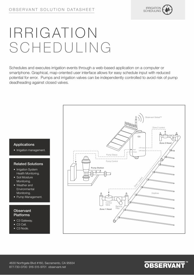
Schedules and executes irrigation events through a web-based application on a computer or smartphone. Graphical, map-oriented user interface allows for easy schedule input with reduced potential for error. Pumps and irrigation valves can be independently controlled to avoid risk of pump deadheading against closed valves.
Applications• Irrigation management.
Related Solutions• Irrigation System
Health Monitoring.• Soil Moisture
Monitoring.• Weather and
Environmental Monitoring.
• Pump Management.
Observant Platforms• C3 Gateway.• C3 Cell.• C3 Node.
I R R I G AT I O N SCH EDU L I N G
Zone 2 control
Pump Status
Pump Control
Zone 2 Head
Zone 1 Head
Driplines
Pump Station
Observant Global™
C3Zo
ne 1
con
trol
LSR Output
LSR OutputOutput
Input
Control Valve
Backup Filter
4630 Northgate Blvd #160, Sacramento, CA 95834877-730-0700 916-515-9701 observant.net
O B S E R V A N T S O L U T I O N D ATA S H E E T
I/O Type and ConnectionObservant LSR Card: The LSR Card is necessary to interface latching solenoid valves to a C3 telemetry platform. Connect the LSR Card signal inputs to C3 Dual-Mode Outputs 1, 2 and 3. Connect the LSR Card power inputs to the C3 Power output. These connections can be easily made using the cables supplied with the LSR Card. See OBS-USR-TN001 C3 Latching Solenoid Driver Card. An LSR Card is not required when interfacing with a Solo.
Latching Solenoid Valve: If a C3 telemetry unit is used, connect up to four 2-wire 12V DC latching solenoid valves to the LSR Card outputs. See OBS-USR-TN001 C3 Latching Solenoid Driver Card. If a Solo telemetry unit is used, connect up to two 2-wire 12 V DC latching solenoid valves directly to Outputs 1 and 2 of the Output Port using Observant cable P/N OUT-S.
Electric Pump: Interface to an electric pump using one or two 12 VDC coil, normally-open relays as described in Note: OBS-USR-TN004 Tech Note: Electric Pump Control. The pump control relay(s) are connected to digital outputs on the C3. Interfacing a C3 or other telemetry platform with an electric motor should be performed by a qualified electrician.
Output Limitations: One C3 telemetry unit can control up to four valves and one pump fitted with a Run-Off-Auto switch. Controlling more than four valves and one pump or controlling a pump with dual relay (latching start/stop) control will require more than one C3.
CapabilitiesTime-Based Irrigation Scheduling: Use the Observant Global™ platform to program and implement time-based irrigation schedules using a map-based user interface on a computer or smartphone. One C3 telemetry unit is required per each four zones.
Manual Irrigation Control: Manually turn pumps and valves on and off using a computer or mobile device.
Record History of Irrigation Events: Record irrigation history to correlate irrigation activity with crop and weather conditions. Combine with the Flow and Line Pressure Monitoring solution to also record the volume of water used per irrigation event.
Pump Delay: Schedule a pump start delay after the opening of the first valve in an irrigation schedule to avoid the possibility of deadheading. Also, schedule a delay of the closing of the last valve in the schedule until after the pump has shut off.
Integrate with Other Observant Solutions: Use Flow and Line Pressure Monitoring in conjunction with Irrigation Scheduling to verify proper execution of scheduled commands and alerts on any problems.
Graphical, Map Based User Interface: User friendly interface within Observant Global simplifies the creation and monitoring of irrigation schedules and eliminates errors.
Supported Devices• Observant LSR 4 channel latching relay driver.• DC latching solenoid controlled valves.
OBS-MKT-BR025-R1

4630 Northgate Blvd #160, Sacramento, CA 95834877-730-0700 916-515-9701 observant.net
O B S E R V A N T S O L U T I O N D ATA S H E E T
Monitors the status of an irrigation zone or system to confirm proper operation and predict potential problems or required maintenance. Measurements from pressure gauges, flow meters and other devices are recorded, showing trends and alerting the user when high or low values indicate problems.
Automated text-message alerts draw immediate attention to equipment failures and other status changes. Flow and Line Pressure Monitoring can be combined with other Observant solutions for comprehensive farm water management.
Mai
nlin
e flo
w
Bac
kflus
h S
tatu
s
Mainline pressure
Zone 2 pressure
Zone 2 Head
Zone 1 Head
Driplines
Filter Station
Observant Global™
C3
Zone
1 p
ress
ure
InputInput
4-20 mA
4-20 mA
4-20 mA
Pressure Sensor
Control Valve
Backflush controller
Flow meter
Backup Filter
Applications
• Drip irrigation.• Mechanized (Pivot) Irrigation.• Solid Set Sprinkler Irrigation.• Microspray/Microsprinkler
Irrigation.• Furrow Irrigation.
Related Solutions
• Pump Management.• Irrigation Scheduling.• Soil Moisture Monitoring.• Weather & Environmental
Monitoring.
Observant Platforms
• C3 Gateway.• C3 Cell.• C3 Node.• Solo.
FLOW A N D L I N E PR ESSU R E M O N I TO R I N G
4630 Northgate Blvd #160, Sacramento, CA 95834877-730-0700 916-515-9701 observant.net
O B S E R V A N T S O L U T I O N D ATA S H E E T
Capability: Flow Rate and Totalized Flow MonitoringI/O Type and ConnectionDigital Input, pulse train. Connect to C3™ or Solo™ Dual Purpose Digital/Analog Inputs (Inputs 1 –4). See the Observant Technical Note: Pulse Flow Meters and Pulse Energy Meters.
Physical InterpretationEach digital pulse represents one unit of volume passing through the device, calibrated per device. Flow rate is proportional to pulse frequency. Totalized flow over time is proportional to the number of pulses counted over time. Raw pulses are converted and displayed in engineering units (gallons, gallons per minute, liters or liters per minute as appropriate) by the Observant Global™ software.
Input Source• Flow meter at head of irrigation system, such as pump or filter station output.• Flow meter at head of individual irrigation zone.
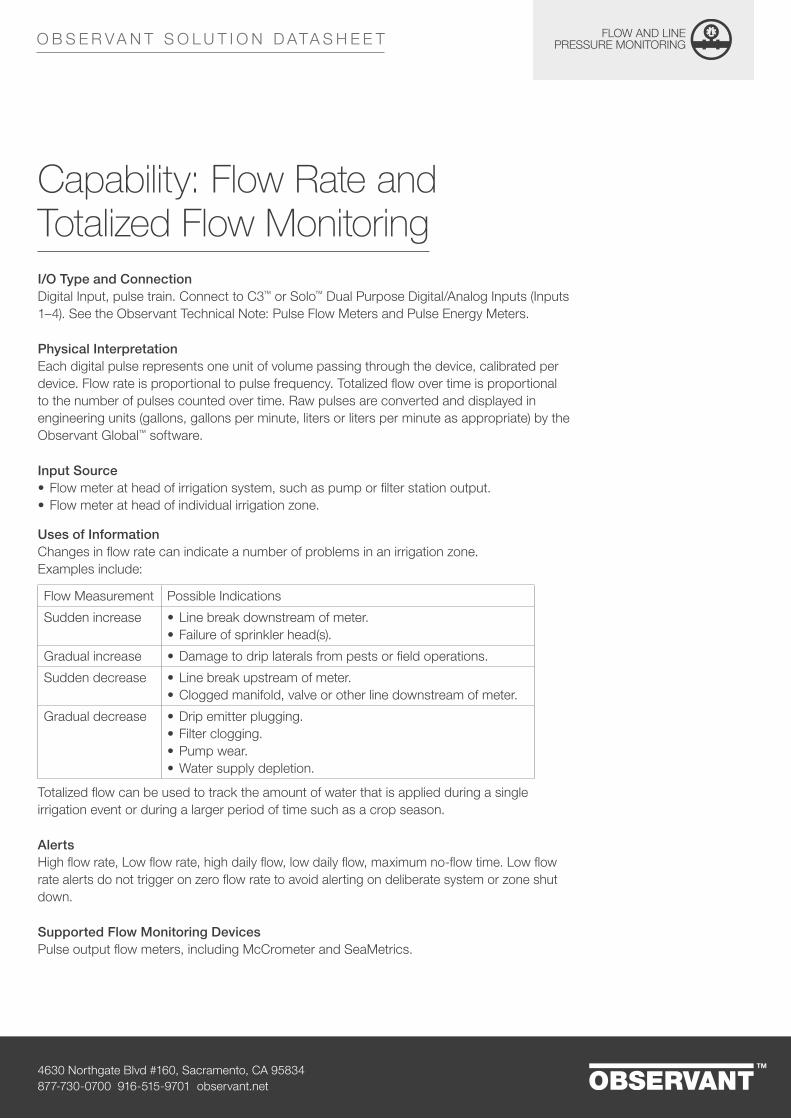
Uses of InformationChanges in flow rate can indicate a number of problems in an irrigation zone. Examples include:
Flow Measurement Possible Indications
Sudden increase • Line break downstream of meter.• Failure of sprinkler head(s).
Gradual increase • Damage to drip laterals from pests or field operations.
Sudden decrease • Line break upstream of meter.• Clogged manifold, valve or other line downstream of meter.
Gradual decrease • Drip emitter plugging.• Filter clogging.• Pump wear.• Water supply depletion.
Totalized flow can be used to track the amount of water that is applied during a single irrigation event or during a larger period of time such as a crop season.
AlertsHigh flow rate, Low flow rate, high daily flow, low daily flow, maximum no-flow time. Low flow rate alerts do not trigger on zero flow rate to avoid alerting on deliberate system or zone shut down.
Supported Flow Monitoring DevicesPulse output flow meters, including McCrometer and SeaMetrics.

4630 Northgate Blvd #160, Sacramento, CA 95834877-730-0700 916-515-9701 observant.net
O B S E R V A N T S O L U T I O N D ATA S H E E T
Capability: Pressure MonitoringI/O Type and Connections:Analog Input, 4–20 mA. Connect to Dual Purpose Switched Outputs (with C3 Telemetry Units) or to the Sensor Input using an appropriate connector (with Solo Telemetry Units).
Physical Interpretation:Analog signal is proportional to water pressure at the measurement point. Supported devices are automatically calibrated to provide measurements in engineering units (PSI or Bar).
Input Source(s):• Pressure sensor at entrance to irrigation zone.• Pressure sensor immediately downstream of filter or filter station.• Pressure sensor immediately upstream of filter or filter station.• Pressure sensors at other critical points.
Uses of Information
Pressure Measurement Location Possible Indications
Increase Head of zone • Drip emitter plugging if zone is not pressure regulated.
Decrease Head of zone • Line break downstream of sensor.• Damage to sprinkler head(s).• Damage to drip laterals by pests or field operations.
Increase Tail of drip zone (flush manifold) • Drip emitter plugging.
Decrease Filter output • Filter clogging, backflush required*.
Sudden increase Filter output • Filter element failure*.
* Use this measurement for small supplemental or backup filters. The main filter station should use a dedicated, backflush controller.
AlertsHigh Pressure.
Supported Pressure Monitoring DeviceSchneider OsiSense P/N XMLK100P2D23 Pressure Sensor, 4 20 mA output, 100 PSI.
4630 Northgate Blvd #160, Sacramento, CA 95834877-730-0700 916-515-9701 observant.net
O B S E R V A N T S O L U T I O N D ATA S H E E T
Capability: Backflush MonitoringI/O Type and Connections:Normally Open relay output of backflush controller indicating backflush status. Connect to C3 or Solo Dual Purpose Digital/Analog Inputs (Inputs 1 –4). See Observant Health Desk article, “Switched Input to Monitor Equipment State.”
Physical Interpretation:A digital input is connected to a backflush controller status output or to a pressure switch mounted on a filter-station, backflush line. An “active” value indicates the filter is being backflushed. An “inactive” value indicates the filter is in normal operating mode.
Input Sources:• Status output of backflush controller, relay, or digital output.• Pressure switch on backflush line of filter station’s relay output.
Uses of Information:Filter stations under independent backflush control will typically backflush when the pressure drop across the station reaches a preset value. In normal operation, a filter station will backflush at regular intervals, which depend on flow rate, water quality, and media type. An increase in backflush frequency can indicate a problem with the water source, which must be addressed before it causes problems with the filters or the irrigation system. Algae or bacterial blooms in surface water or an increase in scale or sand in well water are two of the many water supply problems that can be detected by monitoring backflush frequency. A sudden drop in backflush frequency can also indicate problems such as filter-media failure.
Supported Pressure Monitoring DeviceNormally Open electrical contact (relay) devices.
Supported Devices• Pulse output flow meters including McCrometer and SeaMetrics.• Schneider OsiSense P/N XMLK100P2D23 Pressure Sensor, 4–20 mA output 100 PSI.• Flow Switch, normally-open relay output.
OBS-MKT-BR026-R1

4630 Northgate Blvd #160, Sacramento, CA 95834877-730-0700 916-515-9701 observant.net
O B S E R V A N T S O L U T I O N D ATA S H E E T
Optimizes plant growth by monitoring the root zone environment including soil moisture vs. depth profile, salinity (EC) and temperature. Use Soil Moisture Monitoring in irrigated farms to maximize irrigation performance and better manage the application of expensive nutrients. Use in any farm to plan and execute operations on the right fields at the right times.
Applications• Irrigation management.• Nutrient management.• Timing of field
operations.• Runoff/percolation
management.
Related Solutions• Irrigation System
Health Monitoring.• Irrigation Scheduling.• Weather &
Environmental Monitoring.
Observant Platforms• C3 Gateway.• C3 Cell.• C3 Node.• Solo Cell.
SO I L M O IST U R E M O N I TO R I N G
C3
RS232/SDI input
C3
RS232/SDI input
C3 with Multi-depth Probe
C3 with Multiple Single-Point Probes

4630 Northgate Blvd #160, Sacramento, CA 95834877-730-0700 916-515-9701 observant.net
O B S E R V A N T S O L U T I O N D ATA S H E E T
I/O Type and ConnectionAll communication between Observant telemetry platforms and soil moisture probes is through the SDI-12 serial port. Multiple probes can be connected to a single C3 or Solo in a daisy chain configuration. When multiple SDI-12 devices are interfaced with a single C3, it is critical that each device be programmed with a unique address. See the following Observant Technical Note: OBS-USR-TN002 EnviroPro Soil Moisture Probe with C3.
Capabilities: Soil Moisture MeasurementSingle vs. Multi-Depth (“Profile”) Probes
Single-position soil moisture can be measured using a single-point capacitance probe, such as the Decagon GS3 or the Stephens HydroProbe II. Moisture can be measured at several positions (depths) in the root zone using a multi-depth probe, such as the Envirotek EnviroPro probe or the AquaCheck Subsurface probe. To measure at multiple depths using a single-point probe, multiple probes must be used.
Moisture Probe Locations
Divide the farming operation into logical Management Units, where each management unit covers an area of uniform soil type, crop, climate and irrigation method. Examples could be a single block in a drip irrigated field, or a single circle in a center pivot irrigated field. Each management unit should contain a soil moisture probe in the crop root zone at a location that is representative of the entire unit.
Root Summary
At each moisture probe location, multiple readings can be obtained indicating soil moisture at multiple depths within the root zone profile. To make irrigation decisions, the multiple readings must be mathematically combined into a single number, which represents root zone water content at that location. This is accomplished by calculating a weighted average of readings at each depth, referred to as the “Root Summary”. Weights are specified to produce a Root Summary reading that is appropriate for the geometry of the root zone. Weights can be changed throughout the season as the size of the root zone increases. The Observant platform automatically calculates and plots the Root Summary at each location based on weights that have been input by the user. If no weights are specified, sensor readings at all depths are weighted equally.
4630 Northgate Blvd #160, Sacramento, CA 95834877-730-0700 916-515-9701 observant.net
O B S E R V A N T S O L U T I O N D ATA S H E E T
Using Soil Moisture to Plan Irrigation
Soil Moisture is used to plan irrigation through the following process:
1. Determine the Root Summary value for a single probe that corresponds to “Field Capacity.” This can be accomplished by irrigating the root zone to saturation, then recording the Root Summary reading after allowing excess water to drain.
2. Set the upper management boundary (top end of light blue “Full” band) in the Crop Manager screen within Observant Global to the value measured in (1) by clicking on the upper left hand corner of the Root Zone Average graph.
3. Determine the Root Summary value which corresponds to the onset of stress. This is the lowest soil moisture value which supports healthy growing conditions, and soil moisture below this level causes plant stress. Determining this value must be done by observing when the soil has become dry enough to be ready for another irrigation cycle, and may require digging into the root zone.
4. Set the lower management boundary (bottom of the light red “Refill” band) in the Crop Manager screen within Observant Global to the value measured in (3) by clicking on the upper left hand corner of the Root Zone Average graph.
5. Set the management lines corresponding to the top and bottom of the green “Normal” band by selecting values slightly below the Full line set in (2) and slightly above the Stress Onset line set in (4) respectively.
6. Monitor Root Summary vs. time for each management unit via the Crop Manager. For each irrigation event, initiate irrigation when moisture approaches the bottom of the green Normal band and run irrigation long enough to bring moisture close to the top of the band.
7. As irrigation data is collected it can be used by the Observant platform to predict the next time irrigation should be initiated and how much runtime will be required.
Other Uses for Soil Moisture
In addition to planning irrigation, soil moisture data has many other uses, including:
• Managing deficit irrigation. • Monitoring soil moisture below the root zone to manage or document percolation/
leaching.• Monitoring soil moisture at the field perimeter to manage or document runoff.• Ensuring field conditions can support mechanical operations such as planting,
spraying and harvest.

4630 Northgate Blvd #160, Sacramento, CA 95834877-730-0700 916-515-9701 observant.net
O B S E R V A N T S O L U T I O N D ATA S H E E T
Capabilities: Soil EC MeasurementMany capacitive soil moisture probes also measure soil EC (salinity), and this information can be accessed by the Observant Global platform through the same SDI-12 connection as soil moisture. EC information can be valuable when growing salt-sensitive crops, especially when using drip irrigation in dry climates where root zone salinity must be actively managed.
EC measurements can also be useful when applying nutrients and other chemicals throughout the season, as most fertilizers directly impact soil salinity. EC measurements can help avoid overuse of fertilizers and damage to salt-sensitive crops by overapplication of chemicals such as sodium hypochlorite.
See Supported Devices below for supported probes that support EC Measurement.
Capabilities: Soil Temperature MeasurementAs with EC, many capacitive soil moisture probes also measure soil temperature. Soil temperature can be an important factor in planning germination time and nutrient applications.
Supported Devices• EnviroPro Multi-Depth Capacitance Probe.• EnviroPro Multi-Depth Capacitance Probe upgraded for EC.• Aquacheck Multi-Depth Capacitance Probe.• Decagon GS3 Single-Point Capacitance Probe.• Stephens HydraProbe II Single-Point SMS. Includes EC capability.
OBS-MKT-BR027-R1

4630 Northgate Blvd #160, Sacramento, CA 95834877-730-0700 916-515-9701 observant.net
O B S E R V A N T S O L U T I O N D ATA S H E E T
Monitors and controls pumps remotely. The Pump Management solution allows you to be aware of the status of your pump systems and to start and stop them remotely. Remote monitoring and control reduces labor, improves maintenance and enhances your ability to react to changing conditions. Monitor and control an on/off electric pump or, through an Observant-supported interface, monitor and control a diesel-engine driven pump. Combine with other Observant solutions to maintain reservoir water-levels or schedule and supply an irrigation system.
Applications• Irrigation management.• Reservoir management.• Fertigation.• Energy management.
Related Solutions• Flow and Line Pressure
Monitoring.• Irrigation Scheduling.• Water Level Monitoring.• Diesel Engine Management.• Energy Monitoring.
Observant Platforms• C3 Gateway.• C3 Cell.• C3 Node.• Solo Cell.• Pico.
PU M P M A N AG EM EN T
Pump
Local User Interface
Diesel Pump Monitoring / Control
Inlet
C3
Observant Global™
Discharge Pressure Switch
SuctionPressure Switch
RS485
InputInput
Discharge
MPC-20
Diesel Motor
Contactor
Electric Motor
Electric Pump Monitoring / Control
Inlet
C3
Observant Global™
COM
Output
Input
Relay
3Ø AC Power
On/Off/Auto SW
Input
Discharge
Pump
Discharge Pressure Switch
SuctionPressure Switch
RUNOFF
AUTO
RUNOFF
AUTO

4630 Northgate Blvd #160, Sacramento, CA 95834877-730-0700 916-515-9701 observant.net
O B S E R V A N T S O L U T I O N D ATA S H E E T
I/O Type and ConnectionElectric Pumps
Electric pumps interface with an Observant Telemetry platform using one or two DC coil relays depending on configuration. In most implementations one or two normally open DC coil relays are used to control an appropriately rated high voltage contactor which can establish or interrupt the power supply to the pump motor. Connect the 12 volt relay coils to the Dual Purpose Switched Outputs 1-4 on the C3 or the two High Current Outputs of the Solo. Interfacing a Telemetry Unit with an electric pump should only be performed by a qualified electrician. For more information see Observant Technical Note OBS-USR-TN004: Electric Pump Control.
Diesel Pumps
Certain diesel engine powered pumps which utilize the Enovation Controls Murphy MPC-20 Diesel Engine Controller can be interfaced with the RS485 port on a C3 Telemetry Unit. Interfacing a Telemetry Unit with a Murphy MPC-20 controller requires custom modifications to the controller setup which should only be performed by the pump manufacturer or a highly qualified integrator.
Relay Inputs
On an electric pump, a SPST relay with a mains-rated coil can be installed to indicate when the motor contactor is activated. This is recommended for pumps that can be started either remotely by Observant Global or locally by a switch. Relay closure tells Observant Global that the pump has been turned on locally. Wire the relay coil in parallel with the contactor contactor coil and wire the NO SPST relay terminals to a Dual Purpose Digital/Analog Input (Inputs 1-4) on the C3.
Flow Switches, Pressure Switches
Connect flow switches and pressure switches to the C3 or Solo Dual Purpose Digital/Analog Inputs (Inputs 1-4).
4630 Northgate Blvd #160, Sacramento, CA 95834877-730-0700 916-515-9701 observant.net
O B S E R V A N T S O L U T I O N D ATA S H E E T
CapabilitiesRemotely Start and Stop Pump
Start and stop your pump using Observant Global™ on your desktop computer or smartphone.
Automatically Start and Stop Pump
when used in conjunction with the Irrigation Scheduling or Water Level Monitoring solutions, pumps can be automatically run to execute a pre-programmed irrigation schedule or maintain a water level. Pump start and stop can be timed with valve actions to avoid dangerous deadhead conditions.
Monitor Pump Run Status
Know when your pump is running. This information can be used directly, or as an input to other Observant solutions such as Irrigation Scheduling. Receive alerts if the pump shuts down due to an alarm or failure.
Monitor and Track Run Time
Keep track of pump runtime and use this information to schedule maintenance and other operations.
Monitor Pump Input/Output
Monitor pump intake and output through flow and/or pressure switches to confirm proper operation. Text message alerts can be issued if low flow conditions indicate problems.
Monitor Pump Alarms (Diesel / MPC-20 applications)
Remotely monitor pump alarm status. Alerts can be issued on the occurrence of any alarms reported by the engine controller including low oil pressure, high temperature, low fuel and many others. See Murphy MPC-20 Operation Manual for a complete list of alarm conditions.
Integrate With Other Observant Solutions
Use Pump Management as a key component of Irrigation Scheduling, Water Level Control and Energy Management.
4630 Northgate Blvd #160, Sacramento, CA 95834877-730-0700 916-515-9701 observant.net
O B S E R V A N T S O L U T I O N D ATA S H E E T
AlertsThe following alerts are supported in this Solution:
• Unexpected pump shutdown• Pump does not start, as sensed by pressure switch or contactor relay,
when “Start” command is given• Pump starts, as sensed by pressure switch or contactor relay,
when no “Start” command is given. This can occur if pump is controlled locally.
Supported Devices• DC Motor Pump controlled with relay closure (Observant Tech Note OBS-USR-
TN004).*• AC Induction Motor Pump controlled with relay closure (Observant Tech Note OBS-
USR-TN004).*• Pressure Switch, Normally Open Relay Output.• Flow Switch, Normally Open Relay Output.• Diesel engines enabled by Enovation Controls Murphy MPC-20 Diesel Engine
Control.**
* On-site installation including starter (if applicable), drive (if applicable), contactor, emergency stop and appropriate fail-safe circuits not provided by Observant. Observant C3 will interface with 12VDC relay coil for on-off control. See Observant Technical Note OBS-USR-TN004: Electric Pump Control.
** Pumps not integrated with an Observant telemetry package as-supplied must be controlled by the Enovations Controls Murphy MPC-20 and must be custom integrated by the pump/engine supplier or a qualified integrator.
SAFETY DISCLAIMER
Pump must be installed by a qualified electrician and/or mechanic. Fail-safe circuits must be included that are appropriate for remote operation. Remote monitoring and/or control through the Observant platform does not constitute or replace hard-wired safety shutoffs.
OBS-MKT-BR028-R1
4630 Northgate Blvd #160, Sacramento, CA 95834877-730-0700 916-515-9701 observant.net
O B S E R V A N T S O L U T I O N D ATA S H E E T
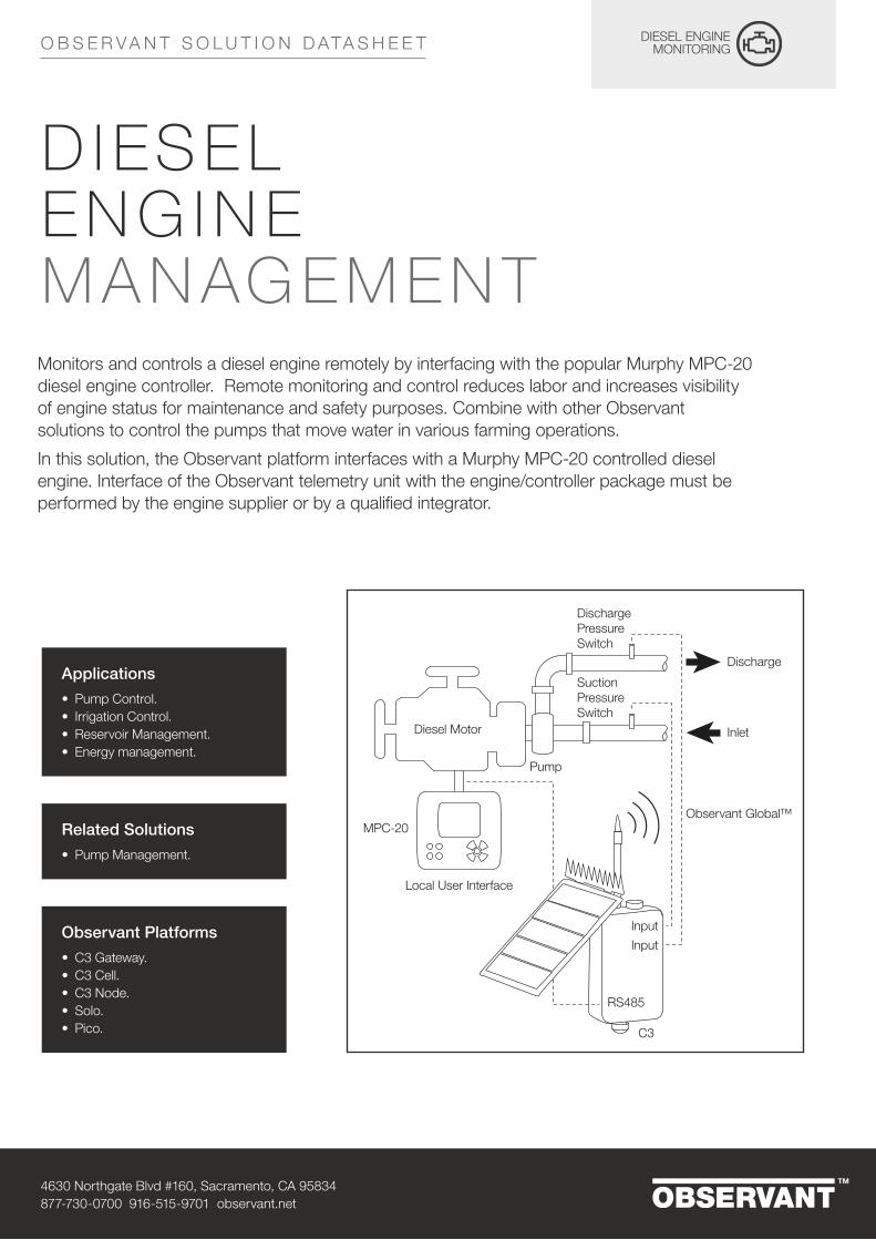
Monitors and controls a diesel engine remotely by interfacing with the popular Murphy MPC-20 diesel engine controller. Remote monitoring and control reduces labor and increases visibility of engine status for maintenance and safety purposes. Combine with other Observant solutions to control the pumps that move water in various farming operations.
In this solution, the Observant platform interfaces with a Murphy MPC-20 controlled diesel engine. Interface of the Observant telemetry unit with the engine/controller package must be performed by the engine supplier or by a qualified integrator.
Applications• Pump Control.• Irrigation Control.• Reservoir Management.• Energy management.
Related Solutions• Pump Management.
Observant Platforms• C3 Gateway.• C3 Cell.• C3 Node.• Solo.• Pico.
D I ES EL EN G I N E M A N AG EM EN T
Pump
Local User Interface
Diesel Pump Monitoring / Control
Inlet
C3
Observant Global™
Discharge Pressure Switch
SuctionPressure Switch
RS485
InputInput
Discharge
MPC-20
Diesel Motor

4630 Northgate Blvd #160, Sacramento, CA 95834877-730-0700 916-515-9701 observant.net
O B S E R V A N T S O L U T I O N D ATA S H E E T
I/O Type and ConnectionCertain diesel engine powered pumps which utilize the Enovation Murphy MPC-20 Diesel Engine Controller can be interfaced with the RS485 input on a C3 or Solo Telemetry Unit. Interfacing a Telemetry Unit with a Murphy MPC-20 controller requires custom modifications to the controller setup, which should only be performed by the pump manufacturer or a highly qualified integrator. Specific manufacturers who can provide this feature are shown in the “Supported Devices” section of this document.
Capabilities: ControlStart/stop engine. Start and stop engine remotely, either manually or according to a time-based schedule.
Capabilities: Monitor• Monitor and Record Engine Speed (RPM). Monitor and record engine speed over
time. Alert on high or low engine speed.• Monitor and Record Oil Pressure. Alert on high or low value.• Monitor and Record Engine Temperature. Alert on high or low value..• Monitor fuel level. Monitor fuel level if engine is equipped with a fuel level sensor.
Alert on low fuel level.• Track engine runtime. Keep track of cumulative engine runtime and use this
information to schedule maintenance and other activities.
Capabilities: Engine AlertsMonitor engine status. Monitor the numerous alarm and status conditions available on MPC-20 controller and alert using text messaging when engine goes into an alarm condition. A listing of all alarm and status conditions available on MPC-20 enabled engines is provided below. Availability of specific alarms and status conditions depends on the configuration of the engine and controller.

4630 Northgate Blvd #160, Sacramento, CA 95834877-730-0700 916-515-9701 observant.net
O B S E R V A N T S O L U T I O N D ATA S H E E T
MPC-20 ALARMSLow fuel Low oil pressure
Fuel leak High engine temperature
Fuel filter restriction High discharge pressure (application)
Low lube level Low discharge pressure (application)
Low coolant level High suction (application)
Water in fuel Low suction (application)
No flow High level (application)
High oil temperature Low level (application)
High flow (application) Oil filter restriction
Low flow (application) Low engine temperature
High pump oil temp (application) High engine oil pressure
High pump housing temp (application) Battery charger failure
Low gearbox pressure (application) Run to destruct
High gearbox pressure (application) High battery
Air dampener closed Low battery
Air filter restriction Amber lamp
MPC-20 SERVICE REMINDERSAir filter life Fuel filter life remaining
Air filter life remaining Oil filter life
Battery life Oil filter life remaining
Battery life remaining Oil life
Belt life Oil life remaining
Belt life remaining Overhaul life
Fuel filter life Overhaul life remaining
Supported DevicesDiesel engine enabled with Enovation Controls Murphy MPC-20 Diesel Engine Controller. Engine package must be integrated with an Observant telemetry platform as delivered by the supplier, or must be integrated by a qualified technician.
SAFETY DISCLAIMER
Engine must be installed by a qualified mechanic. Automatic shutdowns and other fail-safe features of the Murphy MPC-20 Engine Controller must be properly set and remain in place for safe operation. Remote monitoring and/or control through the Observant platform does not constitute or replace local safety shutoffs.
OBS-MKT-BR029-R1
4630 Northgate Blvd #160, Sacramento, CA 95834877-730-0700 916-515-9701 observant.net
O B S E R V A N T S O L U T I O N D ATA S H E E T
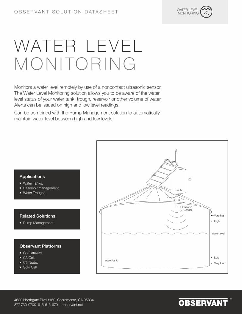
Monitors a water level remotely by use of a noncontact ultrasonic sensor. The Water Level Monitoring solution allows you to be aware of the water level status of your water tank, trough, reservoir or other volume of water. Alerts can be issued on high and low level readings.
Can be combined with the Pump Management solution to automatically maintain water level between high and low levels.
Applications• Water Tanks.• Reservoir management.• Water Troughs.
Observant Platforms• C3 Gateway.• C3 Cell.• C3 Node.• Solo Cell.
WAT ER L E V EL M O N I TO R I N G
Very high
High
Water level
Low
Very lowWater tank
C3
UltrasonicSensor
Observant Global™
RS485
Related Solutions• Pump Management.
4630 Northgate Blvd #160, Sacramento, CA 95834877-730-0700 916-515-9701 observant.net
O B S E R V A N T S O L U T I O N D ATA S H E E T
Kits and Add-on Packs• Tank Monitoring Kit C3, Standard – Complete tank water level monitoring kit based on C3
platform for tanks up to 13 feet/4 m from base to sensor, including cables and mounting hardware.
• Tank Monitoring Kit Solo, Standard – Complete tank water level monitoring kit based on Solo platform for tanks up to 13 feet/4 m from base to sensor, including cables and mounting hardware.
• Add-on Pack, Senix Standard C3 – Senix 13 feet/4 m ultrasonic sensor and cable for C3.• Add-on Pack, Senix Standard Solo – Senix 13 feet/4 m ultrasonic sensor and cable for Solo.• Add-on Pack, Senix Tall C3 – Senix 50 feet/15 m ultrasonic sensor and cable for C3.• Add-on Pack, Senix Tall Solo – Senix 50 feet/15 m ultrasonic sensor and cable for Solo.
I/O Type and ConnectionSenix Ultrasonic Sensor. Connect the ultrasonic sensor to C3 RS485 port or Solo Sensor Port using cables provided with the Observant kit.
Capabilities• Remotely monitor and record water level. • Alert on low, high, very low and very high water levels.
Supported Devices• Senix ToughSonic 14 Ultrasonic Level Sensor.• Senix ToughSonic 50 Ultrasonic Level Sensor.
OBS-MKT-BR038-R1
OUTPUT21
INPUT21
B
A
M
OL
L3
M ASTART
E-STOP
START / STOPCONTROLCIRCUIT
MOTOR
CONTACT
FUSE
DISCONNECT
OVERLOAD
M
OL OL OL B
12VDC
12VDC
M M
L2L1
OUTPUT21
INPUT21
A
M
L3
ARUN
OFFAUTO
RUN-OFF-AUTOCONTROLCIRCUIT
MOTOR
CONTACT
FUSE
DISCONNECT
OVERLOAD
M
OL OL OL
OL
12VDC
M M
L2L1
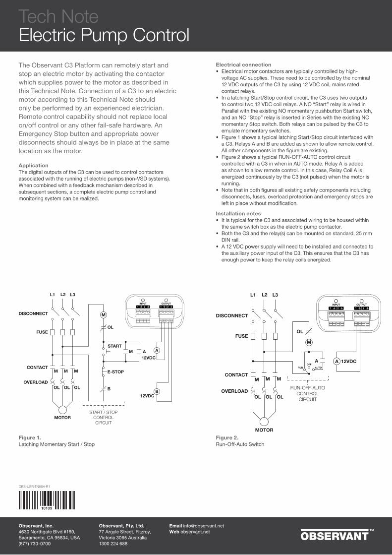
The Observant C3 Platform can remotely start and stop an electric motor by activating the contactor which supplies power to the motor as described in this Technical Note. Connection of a C3 to an electric motor according to this Technical Note should only be performed by an experienced electrician. Remote control capability should not replace local on/off control or any other fail-safe hardware. An Emergency Stop button and appropriate power disconnects should always be in place at the same location as the motor.
ApplicationThe digital outputs of the C3 can be used to control contactors associated with the running of electric pumps (non-VSD systems). When combined with a feedback mechanism described in subsequent sections, a complete electric pump control and monitoring system can be realized.
Figure 1.Latching Momentary Start / Stop
Figure 2.Run-Off-Auto Switch
Electrical connection• Electrical motor contactors are typically controlled by high-
voltage AC supplies. These need to be controlled by the nominal 12 VDC outputs of the C3 by using 12 VDC coil, mains rated contact relays.
• In a latching Start/Stop control circuit, the C3 uses two outputs to control two 12 VDC coil relays. A NO “Start” relay is wired in Parallel with the existing NO momentary pushbutton Start switch, and an NC “Stop” relay is inserted in Series with the existing NC momentary Stop switch. Both relays can be pulsed by the C3 to emulate momentary switches.
• Figure 1 shows a typical latching Start/Stop circuit interfaced with a C3. Relays A and B are added as shown to allow remote control. All other components in the figure are existing.
• Figure 2 shows a typical RUN-OFF-AUTO control circuit controlled with a C3 in when in AUTO mode. Relay A is added as shown to allow remote control. In this case, Relay Coil A is energized continuously by the C3 (not pulsed) when the motor is running.
• Note that in both figures all existing safety components including disconnects, fuses, overload protection and emergency stops are left in place without modification.
Installation notes• It is typical for the C3 and associated wiring to be housed within
the same switch box as the electric pump contactor.• Both the C3 and the relay(s) can be mounted on standard, 25 mm
DIN rail.• A 12 VDC power supply will need to be installed and connected to
the auxiliary power input of the C3. This ensures that the C3 has enough power to keep the relay coils energized.
Tech NoteElectric Pump Control
10109
OBS-USR-TN004-R1
Email [email protected] observant.net
Observant, Pty. Ltd.77 Argyle Street, Fitzroy, Victoria 3065 Australia1300 224 688
Observant, Inc.4630 Northgate Blvd #160, Sacramento, CA 95834, USA(877) 730-0700
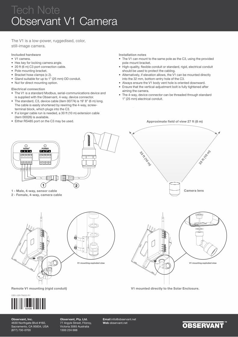
The V1 is a low-power, ruggedised, color, still-image camera.
Included hardware• V1 camera.• Hex key for locking camera angle.• 20 ft (6 m) C3 port connection cable.• Pole mounting bracket.• Bracket hose clamps (x 2).• Gland suitable for up to 1” (25 mm) OD conduit.• Nut for direct mounting option.
Electrical connection• The V1 is a standard Modbus, serial-communications device and
is supplied with the Observant, 4-way, device connector.• The standard, C3, device cable (item 00774) is 19’ 8” (6 m) long.
The cable is easily shortened by rewiring the 4-way, screw-terminal block, which plugs into the C3.
• If a longer cable run is needed, a 30 ft (10 m) extension cable (item 00026) is available.
• Either RS485 port on the C3 may be used.
Red
Blue
Yellow
Green
A BRS4851 POWER
1 2
1 21 - Male, 4-way, sensor cable 2 - Female, 4-way, camera cable
Remote V1 mounting (rigid conduit) V1 mounted directly to the Solar Enclosure.
Tech NoteObservant V1 Camera
Approximate field of view 27 ft (8 m)
Camera lens
33 ft (10 m) 33
ft (1
0 m
)
Installation notes• The V1 can mount to the same pole as the C3, using the provided
pole-mount bracket.• High-quality, flexible conduit or standard, rigid, electrical conduit
should be used to protect the cabling.• Alternatively, if elevation allows, the V1 can be mounted directly
into the 32 mm, bottom-entry hole of the C3.• Always ensure the V1 body vent hole is oriented downward.• Ensure that the vertical-adjustment bolt is fully tightened after
aiming the camera.• The 4-way, device connector can be threaded through standard
1” (25 mm) electrical conduit.
V1 mounting exploded viewV1 mounting exploded view
10108
OBS-USR-TN003-R1
Observant, Inc.4630 Northgate Blvd #160, Sacramento, CA 95834, USA(877) 730-0700
Email [email protected] observant.net
Observant, Pty. Ltd.77 Argyle Street, Fitzroy, Victoria 3065 Australia1300 224 688

The EnviroPro Soil Moisture Probe measures soil moisture, temperature, and optionally, electrical conductivity (EC) along its length in increments of 4” (10 cm). This Tech Note highlights various EnviroPro features and provides guidance on the probe’s installation.
ApplicationThe EnviroPro Soil Moisture Probe is suitable for a wide range of perennial and annual crops. Used in combination with Observant Global, it allows agronomists and growers to identify and manage the water delivered to the plant’s primary root zone during each growth stage. Measurements at 4” (10 cm) intervals allow observation of water infiltration into the soil profile and active uptake during active growth. EC measurements can be used to infer salinity or the concentration of some fertilizers. The probe is fully sealed, mechanically robust, and features a 5-year manufacturer’s warranty.
OrderingAll probes come with a 30 ft (10 m) cable. An optional Cable Junction Accessory Pack containing a cable junction and two conduit stoppers allows this length to be extended using suitable cable.Product code Imperial Metric Description01282 16” 40 cm 4 sensor moisture/temperature probe01238 32” 80 cm 8 sensor moisture/temperature probe01285 48” 120 cm 12 sensor moisture/temperature probe01286 64” 160 cm 16 sensor moisture/temperature probe01550 16” 40 cm Upgrade pack to enable EC on 40 cm probe01525 32” 80 cm Upgrade pack to enable EC on probes 80 cm and longer
The components above may not have all the tools and consumables necessary for installation (such as conduit and associated fittings).
Recommended procedureThis section provides an overview of the installation process. Refer to the EnviroPro manual for a detailed guide.• Select the probe position. Consideration should be given to the root zone of the
crop and the location of any nearby drip-irrigation emitters.• Drill a 1.5” (36–38mm) hole for the probe. Retain the removed site soil if you don’t
intend to use a bentonite/sand slurry.• Test the probe placement within the hole. It should be below the surface, typically by
no more than 4” (10 cm).• Create a slurry to seal the probe within the hole. If using site soil, mix it with just
enough water to create a smooth, soup-like consistency. Alternatively, combine 3.5 oz (100 g) of Bentonite with 32 oz (900 g) of fine sand, add 0.25 gallon (1 L) of water, and allow 30 minutes for the bentonite to absorb the water and swell. Probes installed with the bentonite/sand slurry are often easier to remove.
• Pour the slurry into the hole until it is about half full. Insert the probe until it is no more than 4” (10 cm) below ground level. If the slurry does not reach the surface, remove the probe and add more. Avoid excessive force; if you experience more than 30 lb (15 kg) of resistance, the slurry mixture may need more water. Add up to 5% extra and repeat.
• Connect the probe to the C3 unit as per the wiring diagram.• Protect all cabling that would otherwise be exposed to weather. Cover the ground
level cabling and probe with soil. We recommend rigid plastic or steel conduit and direct-burial, UV stable cable.
• If possible, log into Observant Global prior to leaving the site, and verify that the sensor is operating correctly.
Optional accessoriesProduct code Description10125 Cable Junction Accessory Pack01150 Removal Clamp01149 Installation Kit
Tech NoteEnviroPro Soil Moisture Probe for C3
OBS-USR-TN002-R1
Example Installation
Conduit stoppersOptional connection for cable extension
Hard plastic or steel conduit
Electrical connection
10102
Observant, Inc.4630 Northgate Blvd #160, Sacramento, CA 95834, USA(877) 730-0700
Email [email protected] observant.net
Observant, Pty. Ltd.77 Argyle Street, Fitzroy, Victoria 3065 Australia1300 224 688
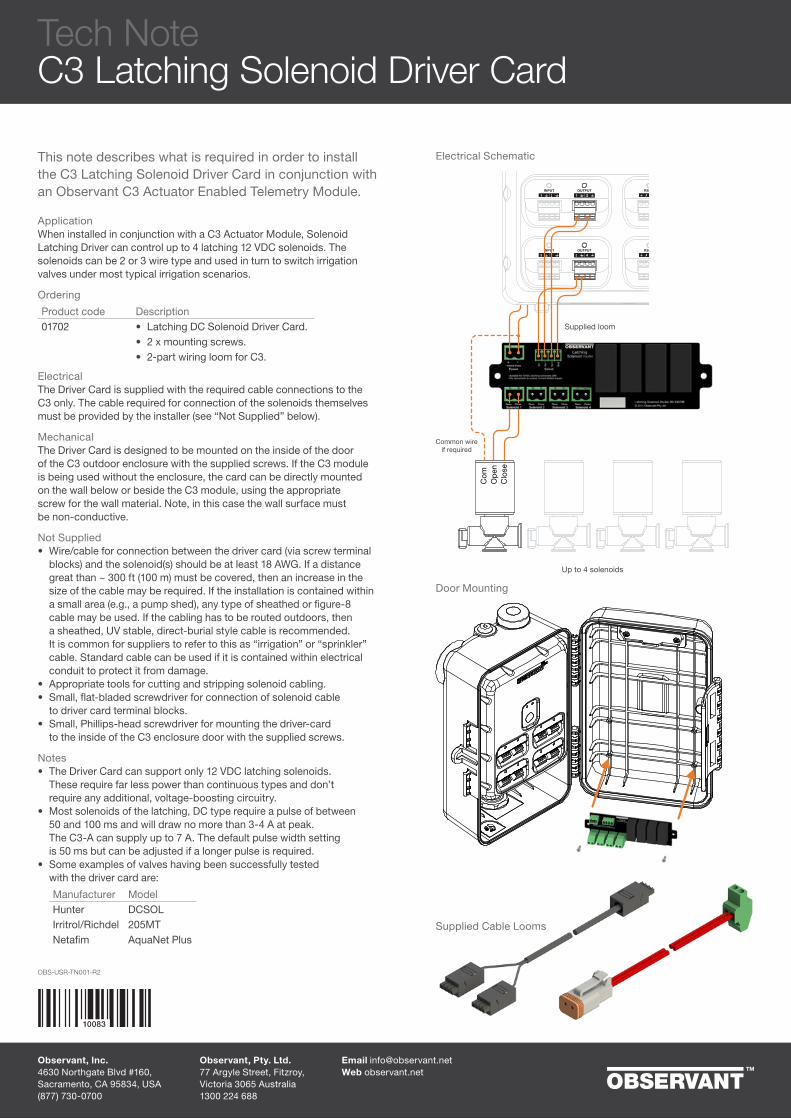
This note describes what is required in order to install the C3 Latching Solenoid Driver Card in conjunction with an Observant C3 Actuator Enabled Telemetry Module.
ApplicationWhen installed in conjunction with a C3 Actuator Module, Solenoid Latching Driver can control up to 4 latching 12 VDC solenoids. The solenoids can be 2 or 3 wire type and used in turn to switch irrigation valves under most typical irrigation scenarios.
Ordering
Product code Description01702 • Latching DC Solenoid Driver Card.
• 2 x mounting screws.• 2-part wiring loom for C3.
ElectricalThe Driver Card is supplied with the required cable connections to the C3 only. The cable required for connection of the solenoids themselves must be provided by the installer (see “Not Supplied” below).
MechanicalThe Driver Card is designed to be mounted on the inside of the door of the C3 outdoor enclosure with the supplied screws. If the C3 module is being used without the enclosure, the card can be directly mounted on the wall below or beside the C3 module, using the appropriate screw for the wall material. Note, in this case the wall surface must be non-conductive.
Not Supplied• Wire/cable for connection between the driver card (via screw terminal
blocks) and the solenoid(s) should be at least 18 AWG. If a distance great than ~ 300 ft (100 m) must be covered, then an increase in the size of the cable may be required. If the installation is contained within a small area (e.g., a pump shed), any type of sheathed or figure-8 cable may be used. If the cabling has to be routed outdoors, then a sheathed, UV stable, direct-burial style cable is recommended. It is common for suppliers to refer to this as “irrigation” or “sprinkler” cable. Standard cable can be used if it is contained within electrical conduit to protect it from damage.
• Appropriate tools for cutting and stripping solenoid cabling.• Small, flat-bladed screwdriver for connection of solenoid cable
to driver card terminal blocks.• Small, Phillips-head screwdriver for mounting the driver-card
to the inside of the C3 enclosure door with the supplied screws.
Notes• The Driver Card can support only 12 VDC latching solenoids.
These require far less power than continuous types and don’t require any additional, voltage-boosting circuitry.
• Most solenoids of the latching, DC type require a pulse of between 50 and 100 ms and will draw no more than 3-4 A at peak. The C3-A can supply up to 7 A. The default pulse width setting is 50 ms but can be adjusted if a longer pulse is required.
• Some examples of valves having been successfully tested with the driver card are:
Manufacturer ModelHunter DCSOLIrritrol/Richdel 205MTNetafim AquaNet Plus
ARS485INPUT
AINPUT RS485
21
3 4
OUTPUT
OUTPUT
2
43
1
Supplied loom
Up to 4 solenoids
Clo
seO
pen
Com
Common wireif required
Supplied Cable Looms
Door Mounting
Electrical Schematic
Tech NoteC3 Latching Solenoid Driver Card
10083
Observant, Inc.4630 Northgate Blvd #160, Sacramento, CA 95834, USA(877) 730-0700
Email [email protected] observant.net
Observant, Pty. Ltd.77 Argyle Street, Fitzroy, Victoria 3065 Australia1300 224 688
OBS-USR-TN001-R2

OBS-USR-TN005-R1
Cable junction(cable length can be shortened as needed)
Function Solo EnviroProPower Brown RedSDI-12 Blue BlueGround Black Black
The EnviroPro Soil Moisture Probe measures soil moisture, temperature, and optionally, electrical conductivity (EC) along its length in increments of 4” (10 cm). This Tech Note highlights various EnviroPro features and provides guidance on the probe’s installation.
ApplicationThe EnviroPro Soil Moisture Probe is suitable for a wide range of perennial and annual crops. Used in combination with Observant Global, it allows agronomists and growers to identify and manage the water delivered to the plant’s primary root zone during each growth stage. Measurements at 4” (10 cm) intervals allow observation of water infiltration into the soil profile and active uptake during active growth. EC measurements can be used to infer salinity or the concentration of some fertilizers. The probe is fully sealed, mechanically robust, and features a 5-year manufacturer’s warranty.
OrderingAll probes come with a 30 ft (10 m) cable. The Solo SFOTPS Accessory Pack is required to connect the probe to the Solo and contains a 15 ft (5 m) cable and a junction for joining the two cables. The overall cable length can be shortened from 45 ft (15 m) by cutting the probe cable to a more suitable length.Product code Imperial Metric Description10124 Solo Sensor Accessory Pack01282 16” 40 cm 4 sensor moisture/temperature probe
01238 32” 80 cm 8 sensor moisture/temperature probe01285 48” 120 cm 12 sensor moisture/temperature probe01286 64” 160 cm 16 sensor moisture/temperature probe01550 16” 40 cm Upgrade pack to enable EC on 40 cm probe01525 32” 80 cm Upgrade pack to enable EC on probes 80 cm and longer
The components above may not have all the tools and consumables necessary for installation (such as conduit and associated fittings).
Recommended procedureThis section provides an overview of the installation process. Refer to the EnviroPro manual for a detailed guide.• Select the probe position. Consideration should be given to the root zone of the
crop and the location of any nearby drip-irrigation emitters.• Drill a 1.5” (36–38mm) hole for the probe. Retain the removed site soil if you don’t
intend to use a bentonite/sand slurry.• Test the probe placement within the hole. It should be below the surface, typically by
no more than 4” (10 cm).• Create a slurry to seal the probe within the hole. If using site soil, mix it with just
enough water to create a smooth, soup-like consistency. Alternatively, combine 3.5 oz (100 g) of Bentonite with 32 oz (900 g) of fine sand, add 0.25 gallon (1 L) of water, and allow 30 minutes for the bentonite to absorb the water and swell. Probes installed with the bentonite/sand slurry are often easier to remove.
• Pour the slurry into the hole until it is about half full. Insert the probe until it is nomore than 4” (10 cm) below ground level. If the slurry does not reach the surface, remove the probe and add more. Avoid excessive force; if you experience more than 30 lb (15 kg) of resistance, the slurry mixture may need more water. Add up to 5% extra and repeat.
• Connect the probe to the Solo unit as per the wiring diagram.• Protect all cabling that would otherwise be exposed to weather. Cover the ground
level cabling and probe with soil. We recommend rigid plastic or steel conduit anddirect-burial, UV stable cable.
• If possible, log into Observant Global prior to leaving the site, and verify that thesensor is operating correctly.
Optional accessoriesProduct code Description01150 Removal Clamp01149 Installation Kit
Example Installation
Electrical connection
Tech NoteEnviroPro Soil Moisture Probe for Solo
10106
Solo Sensor Port
Observant, Inc.4630 Northgate Blvd #160, Sacramento, CA 95834, USA(877) 730-0700
Email [email protected] observant.net
Observant, Pty. Ltd.77 Argyle Street, Fitzroy, Victoria 3065 Australia1300 224 688

The hardware provided in the C3 solar panel split mount kit allows any C3 enclosure with attached solar panel to be converted to a sealed enclosure and separately mountable solar panel.
Where to UseUse this kit anywhere the solar panel needs to be mounted at a height that allows it to receive adequate sunlight but prohibits easy access to the C3 module. For example, the solar panel can be mounted atop a high pole, above the tree canopy, with the C3 module and enclosure remaining at ground level.
Included Hardware• Enclosure blanking cap, seal, and fastener.• Aluminium solar panel mounting bracket with 2” hose clamps
and fasteners.• 30 ft (10 m), 2-core, power cable with gel filled joiners
and cable gland.• Hex key to suit both blanking cap and solar mount.
Required• Large pliers to crimp electrical connections.• Large, flat-bladed screw driver for hose clamps.• Small, flat-bladed screw driver for C3 terminal block connections.• 1/2” (12 mm), 5/8” (16 mm) bits and drill, routing the cable within the
mounting pole as shown.• Cable cutting and stripping tools.
Figure AC3 enclosure dis-assembly
Figure BBlanking cap assembly
Figure CSolar panel assembly
Figure DPower cable extension
Figure EGeneral installation
Tech NoteC3 Solar Panel Split Mount
Cabling routing
Power cable joiners
C3 power connection
Installation• Disassemble the C3 solar enclosure as shown in Figure A.• Assemble the blanking cap as shown in Figure B.• Drill a 5/8” hole in the enclosure as shown in Figure B
and install cable gland.• Cut the remaining solar panel power cable to 4” (100 mm)
and strip 2” (50 mm) of outer sheath.• Assemble the solar panel and mounting bracket as shown in Figure C.• Connect the power cable extension to the solar panel power cable using
the supplied crimps as shown in Figure D.• Drill a 1/2” hole in the mounting post at the point you wish to mount
the solar panel.• Thread the power cable through this hole.• Affix solar panel assembly to the pole with supplied hose clamps ensuring
that it will face the sun at local noon. The power connection is housed within the mount.
• Install the C3 enclosure mount onto the post.• Drill a 5/8” or larger hole through the mount and the post using the bottom
pilot mark.• Use a stiff piece of hooked wire to draw the power cable through
this hole.• Push the power cable through the cable gland and install the
enclosure on the mount.• Shorten the power cable if desired; some excess cable can be stored
inside the C3 enclosure.• Connect the power cable to the C3 terminal block as shown in Figure E.
Part numbers
Product code Description10165 C3 Solar Enclosure Split Mount Kit
Mounting Post
1/2” hole
5/8” hole
5/8” hole
BR
OBS-USR-TN006-R2Jain Irrigation, USA.2851 East Florence Ave Fresno, CA 93721, USA(559) 485-7171 Email [email protected]
Jain Irrigation, AU.77 Argyle Street, Fitzroy, Victoria 3065 Australia1300 224 688
10116
This tech note outlines some important concepts to consider when mounting antennas for telemetry systems and provides information on best-practice methods for locating and installing antennas for use with Observant products.
Locating AntennasMaximize Communication Effectiveness• Antennas for 900MHz ISM radios (and cellular
modems) need “line of sight” to perform their best. Be sure it is possible to see the antenna at the other end of the link without any intervening obstructions.
• Do not forget that crops themselves can grow to heights that could mask radio signals.
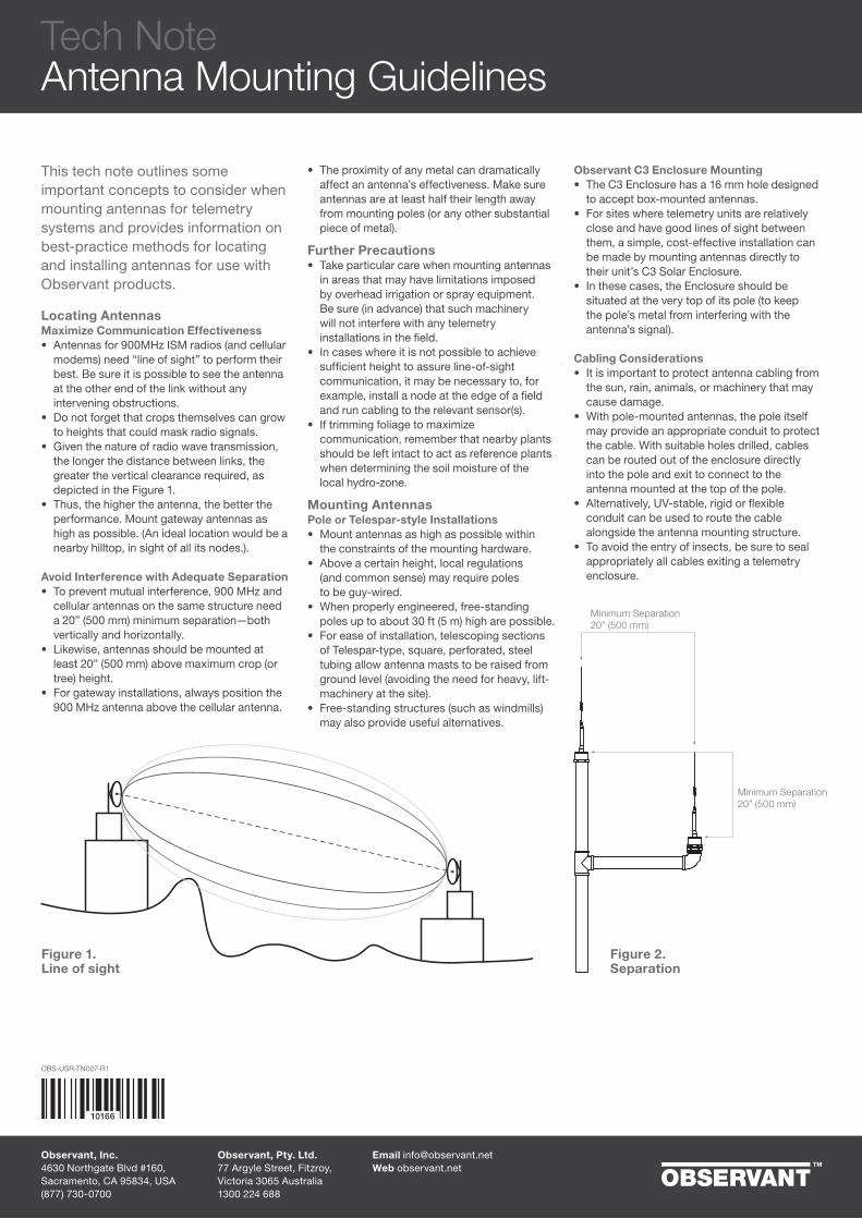
• Given the nature of radio wave transmission, the longer the distance between links, the greater the vertical clearance required, as depicted in the Figure 1.
• Thus, the higher the antenna, the better the performance. Mount gateway antennas as high as possible. (An ideal location would be a nearby hilltop, in sight of all its nodes.).
Avoid Interference with Adequate Separation• To prevent mutual interference, 900 MHz and
cellular antennas on the same structure need a 20” (500 mm) minimum separation—both vertically and horizontally.
• Likewise, antennas should be mounted at least 20” (500 mm) above maximum crop (or tree) height.
• For gateway installations, always position the 900 MHz antenna above the cellular antenna.
• The proximity of any metal can dramatically affect an antenna’s effectiveness. Make sure antennas are at least half their length away from mounting poles (or any other substantial piece of metal).
Further Precautions• Take particular care when mounting antennas
in areas that may have limitations imposed by overhead irrigation or spray equipment. Be sure (in advance) that such machinery will not interfere with any telemetry installations in the field.
• In cases where it is not possible to achieve sufficient height to assure line-of-sight communication, it may be necessary to, for example, install a node at the edge of a field and run cabling to the relevant sensor(s).
• If trimming foliage to maximize communication, remember that nearby plants should be left intact to act as reference plants when determining the soil moisture of the local hydro-zone.
Mounting AntennasPole or Telespar-style Installations• Mount antennas as high as possible within
the constraints of the mounting hardware.• Above a certain height, local regulations
(and common sense) may require poles to be guy-wired.
• When properly engineered, free-standing poles up to about 30 ft (5 m) high are possible.
• For ease of installation, telescoping sections of Telespar-type, square, perforated, steel tubing allow antenna masts to be raised from ground level (avoiding the need for heavy, lift-machinery at the site).
• Free-standing structures (such as windmills) may also provide useful alternatives.
Observant C3 Enclosure Mounting• The C3 Enclosure has a 16 mm hole designed
to accept box-mounted antennas.• For sites where telemetry units are relatively
close and have good lines of sight between them, a simple, cost-effective installation can be made by mounting antennas directly to their unit’s C3 Solar Enclosure.
• In these cases, the Enclosure should be situated at the very top of its pole (to keep the pole’s metal from interfering with the antenna’s signal).
Cabling Considerations• It is important to protect antenna cabling from
the sun, rain, animals, or machinery that may cause damage.
• With pole-mounted antennas, the pole itself may provide an appropriate conduit to protect the cable. With suitable holes drilled, cables can be routed out of the enclosure directly into the pole and exit to connect to the antenna mounted at the top of the pole.
• Alternatively, UV-stable, rigid or flexible conduit can be used to route the cable alongside the antenna mounting structure.
• To avoid the entry of insects, be sure to seal appropriately all cables exiting a telemetry enclosure.
Minimum Separation 20” (500 mm)
Minimum Separation20” (500 mm)
Figure 1.Line of sight
Figure 2.Separation
Tech NoteAntenna Mounting Guidelines
Observant, Inc.4630 Northgate Blvd #160, Sacramento, CA 95834, USA(877) 730-0700
Email [email protected] observant.net
Observant, Pty. Ltd.77 Argyle Street, Fitzroy, Victoria 3065 Australia1300 224 688
10166
OBS-USR-TN007-R1
OBS-USR-TN008-R2
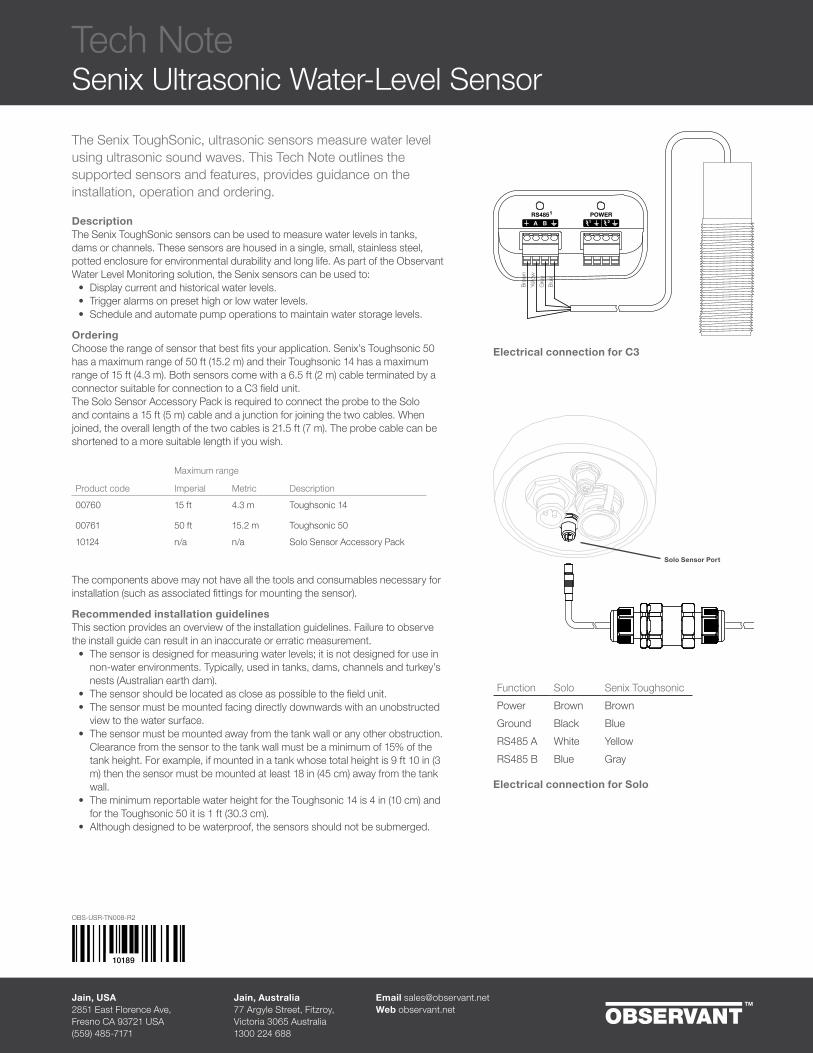
The Senix ToughSonic, ultrasonic sensors measure water level
using ultrasonic sound waves. This Tech Note outlines the
supported sensors and features, provides guidance on the
installation, operation and ordering.
DescriptionThe Senix ToughSonic sensors can be used to measure water levels in tanks,
dams or channels. These sensors are housed in a single, small, stainless steel,
potted enclosure for environmental durability and long life. As part of the Observant
Water Level Monitoring solution, the Senix sensors can be used to:
• Display current and historical water levels.
• Trigger alarms on preset high or low water levels.
• Schedule and automate pump operations to maintain water storage levels.
OrderingChoose the range of sensor that best fits your application. Senix’s Toughsonic 50 has a maximum range of 50 ft (15.2 m) and their Toughsonic 14 has a maximum range of 15 ft (4.3 m). Both sensors come with a 6.5 ft (2 m) cable terminated by a connector suitable for connection to a C3 field unit. The Solo Sensor Accessory Pack is required to connect the probe to the Solo
and contains a 15 ft (5 m) cable and a junction for joining the two cables. When joined, the overall length of the two cables is 21.5 ft (7 m). The probe cable can be shortened to a more suitable length if you wish.
Maximum range
Product code Imperial Metric Description
00760 15 ft 4.3 m Toughsonic 14
00761 50 ft 15.2 m Toughsonic 5010124 n/a n/a Solo Sensor Accessory Pack
The components above may not have all the tools and consumables necessary for
installation (such as associated fittings for mounting the sensor).
Recommended installation guidelinesThis section provides an overview of the installation guidelines. Failure to observe
the install guide can result in an inaccurate or erratic measurement.
• The sensor is designed for measuring water levels; it is not designed for use in
non-water environments. Typically, used in tanks, dams, channels and turkey’s nests (Australian earth dam).
• The sensor should be located as close as possible to the field unit.• The sensor must be mounted facing directly downwards with an unobstructed
view to the water surface.
• The sensor must be mounted away from the tank wall or any other obstruction.
Clearance from the sensor to the tank wall must be a minimum of 15% of the tank height. For example, if mounted in a tank whose total height is 9 ft 10 in (3 m) then the sensor must be mounted at least 18 in (45 cm) away from the tank wall.
• The minimum reportable water height for the Toughsonic 14 is 4 in (10 cm) and for the Toughsonic 50 it is 1 ft (30.3 cm).
• Although designed to be waterproof, the sensors should not be submerged.
Tech Note
Senix Ultrasonic Water-Level Sensor
10189
Jain, USA2851 East Florence Ave, Fresno CA 93721 USA(559) 485-7171
Email [email protected]
Web observant.net
Jain, Australia77 Argyle Street, Fitzroy, Victoria 3065 Australia1300 224 688
Electrical connection for C3
Function Solo Senix Toughsonic
Power Brown Brown
Ground Black Blue
RS485 A White Yellow
RS485 B Blue Gray
Electrical connection for Solo
Solo Sensor Port

Tech Note
Solo Soil Moisture Probe and Pressure Sensor
10196
Cable Junction(Sensor cables may be
shortened if appropriate.)
Solo sensor port
OsiSense4–20 mA
OsiSense
Item #10194 — Harness
Item #10194 — Junction FittingsTwo junction fittings are
included with the harness.
EnviroPro
Solo output
port
EnviroProSDI-12
ApplicationThis cable harness allows a Solo field unit to be easily connected to both an EnviroPro soil moisture sensor and a 4–20 mA, analog line-pressure sensor. With this combination, irrigation events can easily be correlated to soil moisture profiles via Observant Global. See additional information in the EnviroPro Soil Moisture Probe for Solo tech note. This cable harness is compatible with Observant-supplied EnviroPro probes and OsiSense pressure sensors.
OrderingItem # Description
10194 Solo to Line Pressure & Soil Moisture Kit
01282 400 mm EnviroPro probe
01238 800 mm EnviroPro probe
01285 1200 mm EnviroPro probe
01286 1600 mm EnviroPro probe
01473 OsiSense Pressure sensor with 2m/6.5ft cable
01474 OsiSense Pressure Sensor with 5m/16.4 cable
Function Harness OsiSenseSupply Red BrownReturn Green Blue
Function Harness EnviroProPower Red RedSDI-12 Blue BlueGround Green Black
The EnviroPro Soil Moisture Probe and a 0–100 PSI line
pressure sensor can be connected to a single Solo unit
using this cable harness.
InstallationThe cable harness includes two connectors designed to mate with the appropriate ports on the Solo to support both sensors. At the other end the harness splits into two bare-ended cables — one connecting to the OsiSense, the other connecting to the EnviroPro. Connections to both sensors can be made using the weatherproof inline junction boxes with either the gel-filled wire splice connectors or a 3-way terminal block.The overall length of the harness is 30 ft (10 m). If a shorter cable run is appropriate for your installation, the sensor cables can be shortened as required. Ensure all junction hardware is tightened sufficiently to prevent water ingress. Protect all cabling that would otherwise be exposed to weather by burial or within appropriate conduit. Please note that the default software configuration of the EnviroPro in Observant Global must be changed to select high-power output 1 for the supply output in order for the combination to operate correctly.
Option 13-way termination block
Option 2Gel-filled wire joiners
OBS-USR-TN009-R3
Jain Irrigation, USA.2851 East Florence Ave
Fresno, CA 93721, USA
(559) 485-7171 Email [email protected]
Jain Irrigation, AU.77 Argyle Street, Fitzroy,
Victoria 3065 Australia
1300 224 688
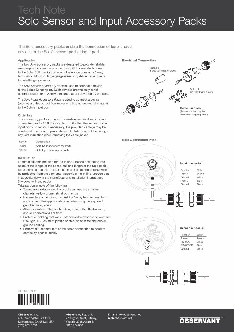
ApplicationThe two Solo accessory packs are designed to provide reliable, weatherproof connections of devices with bare-ended cables to the Solo. Both packs come with the option of using a 3-way termination block for large gauge wires, or gel-filled wire joiners for smaller gauge wires.
The Solo Sensor Accessory Pack is used to connect a device to the Solo’s Sensor port. Such devices are typically serial-communication or 4–20 mA sensors that are powered by the Solo.
The Solo Input Accessory Pack is used to connect a device (such as a pulse output flow meter or a tipping bucket rain gauge) to the Solo’s Input port.
OrderingThe accessory packs come with an in-line junction box, 4 crimp connectors and a 15 ft (5 m) cable to suit either the sensor port or input port connector. If necessary, the provided cable(s) may be shortened to a more appropriate length. Take care not to damage any wire insulation when removing the cable jacket.
Item # Description10124 Solo Sensor Accessory Pack10204 Solo Input Accessory Pack
InstallationLocate a suitable position for the in-line junction box taking into account the length of the sensor tail and length of the Solo cable. It’s preferable that the in-line junction box be buried or otherwise be protected from the elements. Assemble the in-line junction box in accordance with the manufacturer’s installation instructions (included with the pack). Take particular note of the following:
• To ensure a reliable weatherproof seal, use the smallest diameter yellow grommets at both ends.
• For smaller gauge wires, discard the 3-way termination block and connect the appropriate wire pairs using the supplied gel-filled wire joiners.
• After assembly of the junction box, ensure that the housing, and all connections are tight.
• Protect all cabling that would otherwise be exposed to weather. Use rigid, UV-resistant plastic or steel conduit for any above-ground cabling.
• Perform a functional test of the cable connection to confirm continuity prior to burial.
The Solo accessory packs enable the connection of bare-ended devices to the Solo’s sensor port or input port.
Sensor connector
Input connector
Cable Junction(Sensor cables may be shortened if appropriate.)
Option 13-way termination block
Option 2Gel-filled wire joiners
Function ColorInput 1 BrownGround WhiteInput 2 BlueGround Black
Function ColorPower BrownRS485A WhiteRS485B/SDI BlueGround Black
Electrical Connection
Solo Connection Panel
Tech NoteSolo Sensor and Input Accessory Packs
Observant, Inc.4630 Northgate Blvd #160, Sacramento, CA 95834, USA(877) 730-0700
Email [email protected] observant.net
Observant, Pty. Ltd.77 Argyle Street, Fitzroy, Victoria 3065 Australia1300 224 688
OBS-USR-TN010-R1
10206
OBS-USR-TN012-R1
10234
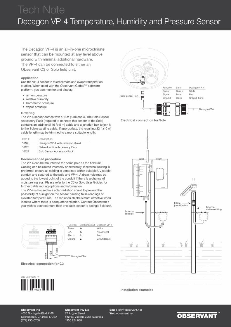
The Decagon VP-4 is an all-in-one microclimate sensor that can be mounted at any level above ground with minimal additional hardware. The VP-4 can be connected to either an Observant C3 or Solo field unit.
ApplicationUse the VP-4 sensor in microclimate and evapotranspiration studies. When used with the Observant Global™ software platform, you can monitor and display:
• air temperature• relative humidity• barometric pressure• vapor pressure
OrderingThe VP-4 sensor comes with a 16 ft (5 m) cable. The Solo Sensor Accessory Pack (required to connect this sensor to the Solo) contains an additional 16 ft (5 m) cable and a junction box to join it to the Solo’s existing cable. If appropriate, the resulting 32 ft (10 m) cable length may be trimmed to a more suitable length.
Item # Description10183 Decagon VP-4 with radiation shield10125 Cable Junction Accessory Pack10124 Solo Sensor Accessory Pack
Recommended procedureThe VP-4 can be mounted to the same pole as the field unit. Cabling can be routed internally or externally. If external routing is preferred, ensure all cabling is contained within suitable UV stable conduit and secured to the pole and VP-4. A drain hole may be added to the lowest point of the conduit if there is a chance of moisture ingress. Please refer to the C3 or Solo User Guides for further cable routing options and information.The VP-4 is housed in a solar radiation shield to prevent the possibility of sunlight on the sensor causing false readings of elevated temperatures. The radiation shield is most effective when located where there is adequate ventilation. Contact Observant if you wish to connect more than one such sensor to a single field unit.
Function C3 RS232/SDI Decagon VP-4Power White
N/A Tx No connectSDI-12 Rx RedGround Ground (bare)
Function Solo Decagon VP-4Power Brown WhiteSignal Blue RedGround Black Ground (bare)
Electrical connection for C3
Electrical connection for Solo
Whi
te
Decagon VP-4
Solo Sensor Port
Red B
are
Installation examples
Inline junction box
External conduit
Internal cable routing
Decagon VP-4
Observant Inc4630 Northgate Blvd #160Sacramento, CA 95834, USA(877) 730-0700
Email [email protected] observant.net
Observant Pty Ltd77 Argyle Street Fitzroy, Victoria 3065 Australia1300 224 688
Tech NoteDecagon VP-4 Temperature, Humidity and Pressure Sensor
Tech NoteObservant Seametrics Pulse Output Flow Meter Bundle
10245
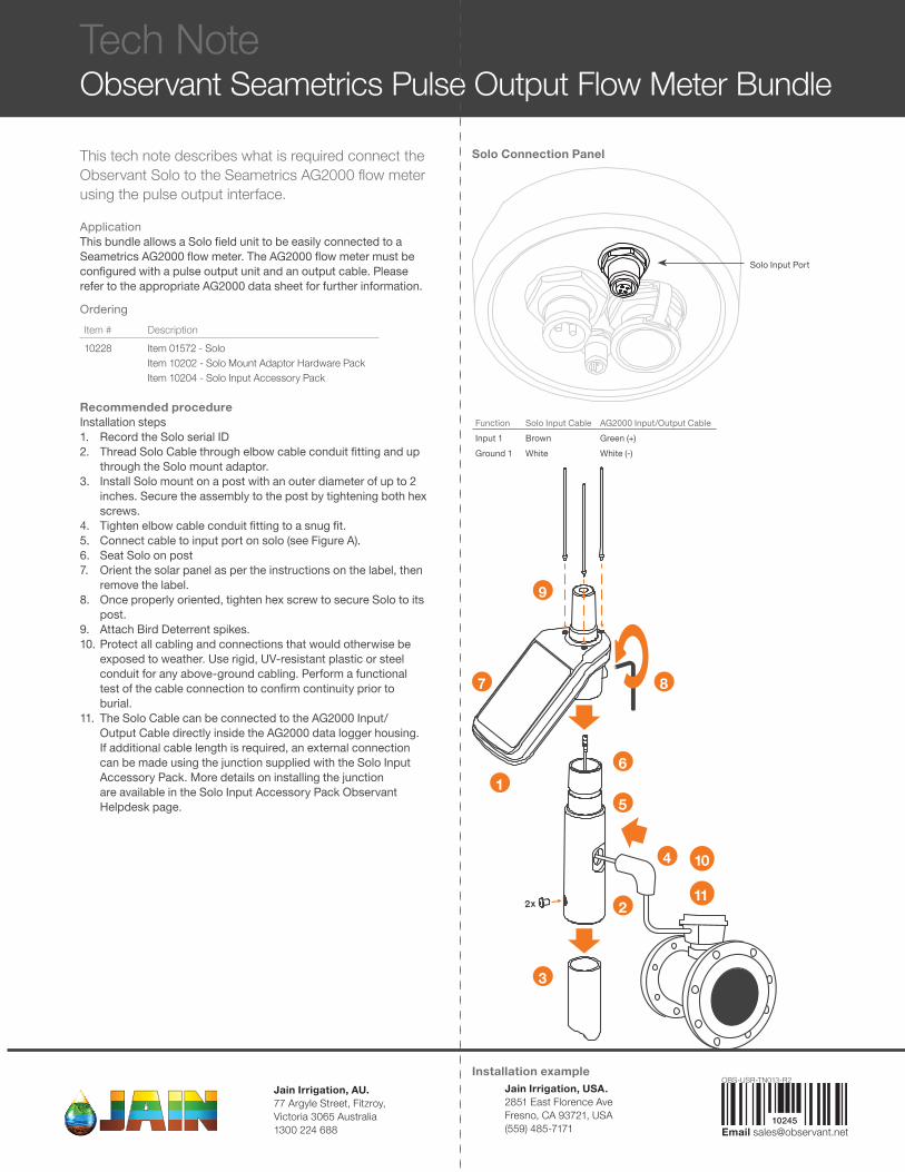
This tech note describes what is required connect the Observant Solo to the Seametrics AG2000 flow meter using the pulse output interface.
ApplicationThis bundle allows a Solo field unit to be easily connected to a Seametrics AG2000 flow meter. The AG2000 flow meter must be configured with a pulse output unit and an output cable. Please refer to the appropriate AG2000 data sheet for further information.
OrderingItem # Description10228 Item 01572 - Solo
Item 10202 - Solo Mount Adaptor Hardware PackItem 10204 - Solo Input Accessory Pack
Recommended procedureInstallation steps1. Record the Solo serial ID2. Thread Solo Cable through elbow cable conduit fitting and up
through the Solo mount adaptor.3. Install Solo mount on a post with an outer diameter of up to 2
inches. Secure the assembly to the post by tightening both hex screws.
4. Tighten elbow cable conduit fitting to a snug fit.5. Connect cable to input port on solo (see Figure A).6. Seat Solo on post7. Orient the solar panel as per the instructions on the label, then
remove the label.8. Once properly oriented, tighten hex screw to secure Solo to its
post.9. Attach Bird Deterrent spikes.10. Protect all cabling and connections that would otherwise be
exposed to weather. Use rigid, UV-resistant plastic or steel conduit for any above-ground cabling. Perform a functional test of the cable connection to confirm continuity prior to burial.
11. The Solo Cable can be connected to the AG2000 Input/Output Cable directly inside the AG2000 data logger housing. If additional cable length is required, an external connection can be made using the junction supplied with the Solo Input Accessory Pack. More details on installing the junction are available in the Solo Input Accessory Pack Observant Helpdesk page.
Function Solo Input Cable AG2000 Input/Output CableInput 1 Brown Green (+)Ground 1 White White (-)
Installation example
Solo Connection Panel
Solo Input Port
2x
8
9
7
16
4 10
11
5
3
2
OBS-USR-TN013-R2Jain Irrigation, USA.2851 East Florence Ave Fresno, CA 93721, USA(559) 485-7171 Email [email protected]
Jain Irrigation, AU.77 Argyle Street, Fitzroy, Victoria 3065 Australia1300 224 688

Price List
OBS-SLS-BR014 Jain Australia July 2018 Price List
Jain Australia July 2018
Contents PageHow to use the Price List 2How to Order 4Prices 5Limited Product Warranty 8C3 Device Cabling 10Solo Device Cabling 11Connector Identification 12Third Party Products 13
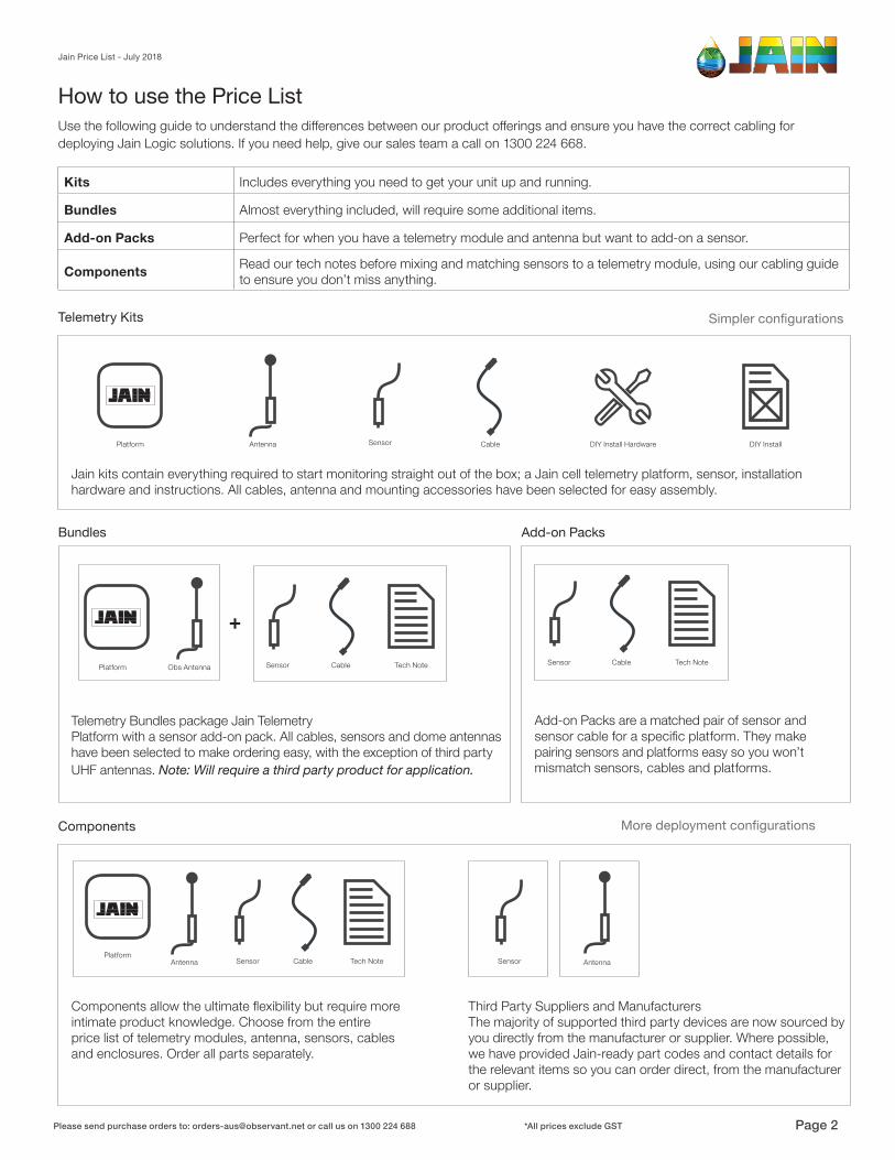
Jain kits contain everything required to start monitoring straight out of the box; a Jain cell telemetry platform, sensor, installation hardware and instructions. All cables, antenna and mounting accessories have been selected for easy assembly.
How to use the Price List
Sensor DIY InstallDIY Install HardwareCablePlatform Antenna
PlatformAntenna
Telemetry Bundles package Jain TelemetryPlatform with a sensor add-on pack. All cables, sensors and dome antennas have been selected to make ordering easy, with the exception of third party UHF antennas. Note: Will require a third party product for application.
Tech Note
Tech Note
Sensor
Sensor Sensor
Cable
Cable
Components allow the ultimate flexibility but require more intimate product knowledge. Choose from the entire price list of telemetry modules, antenna, sensors, cables and enclosures. Order all parts separately.
Third Party Suppliers and ManufacturersThe majority of supported third party devices are now sourced by you directly from the manufacturer or supplier. Where possible, we have provided Jain-ready part codes and contact details for the relevant items so you can order direct, from the manufacturer or supplier.
Simpler configurations
More deployment configurationsComponents
Bundles
Telemetry Kits
Add-on Packs are a matched pair of sensor and sensor cable for a specific platform. They make pairing sensors and platforms easy so you won’t mismatch sensors, cables and platforms.
Tech NoteSensor Cable
Add-on Packs
Platform Obs Antenna
Use the following guide to understand the differences between our product offerings and ensure you have the correct cabling for deploying Jain Logic solutions. If you need help, give our sales team a call on 1300 224 668. Kits Includes everything you need to get your unit up and running.
Bundles Almost everything included, will require some additional items.
Add-on Packs Perfect for when you have a telemetry module and antenna but want to add-on a sensor.
Components Read our tech notes before mixing and matching sensors to a telemetry module, using our cabling guide to ensure you don’t miss anything.
Antenna
Jain Price List - July 2018
Please send purchase orders to: [email protected] or call us on 1300 224 688 Page 2*All prices exclude GST
Cell Tower Stand Alone
Monitoring and Control Device(s)
Cell Tower Gateway Node
Monitoring and Control Device(s)
Monitoring and Control Device(s)
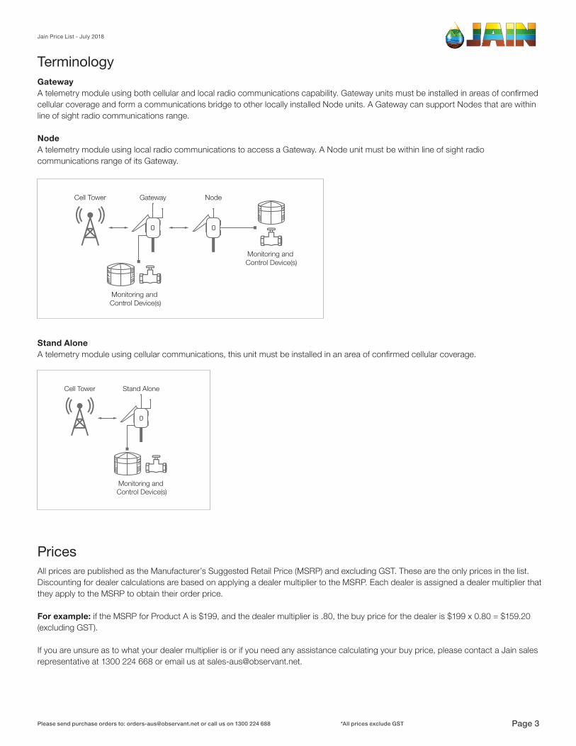
TerminologyGatewayA telemetry module using both cellular and local radio communications capability. Gateway units must be installed in areas of confirmed cellular coverage and form a communications bridge to other locally installed Node units. A Gateway can support Nodes that are within line of sight radio communications range.
NodeA telemetry module using local radio communications to access a Gateway. A Node unit must be within line of sight radio communications range of its Gateway.
Stand AloneA telemetry module using cellular communications, this unit must be installed in an area of confirmed cellular coverage.
All prices are published as the Manufacturer’s Suggested Retail Price (MSRP) and excluding GST. These are the only prices in the list. Discounting for dealer calculations are based on applying a dealer multiplier to the MSRP. Each dealer is assigned a dealer multiplier that they apply to the MSRP to obtain their order price.
For example: if the MSRP for Product A is $199, and the dealer multiplier is .80, the buy price for the dealer is $199 x 0.80 = $159.20 (excluding GST).
If you are unsure as to what your dealer multiplier is or if you need any assistance calculating your buy price, please contact a Jain sales representative at 1300 224 668 or email us at [email protected].
Prices
Jain Price List - July 2018
Please send purchase orders to: [email protected] or call us on 1300 224 688 Page 3*All prices exclude GST
How to OrderAll orders should be sent to Jain via email, to [email protected]. Orders must include the following information;
• Purchase Order Number or Reference Number• Ship To Address with Post Code (no PO Boxes); • Company Name & Contact Name • Contact Number of Purchaser• Jain Part Numbers & Jain Product Names
If applicable, please include or reference the Jain Quote number used to build your order. Do not hesitate to discuss your order in advance with your Jain representative – we’re here to help! Prices in this Price List are subject to change without prior notice. Please consult us for help building a quote, or to confirm prices in advance of your order.
Dispatch & ShippingOrders will be processed within the next business day. You will receive an Order Confirmation that will include the shipping costs, please review the Order Confirmation immediately and contact us if anything is incorrect.
Once your order is packed and dispatched, you will recieve a tracking number from our warehouse. Orders that do not include the relevant information required to process your order may be subject to delays. If you have not received an Order Confirmation within 24hours, please contact us.
Technical AssistanceWe are here to help! Jain offers Technical Support via our highly trained staff during normal business hours, and online 24/7 via our HelpDesk on Jain Logic. Call our Toll Free number 1300 224 688 or contact your representative to coordinate technical assistance.
Subscription FeesJain Logic is a subscription based service. It’s important to understand that all Jain Solutions sold will have ongoing Subscription Fees that needs to be communicated to end-users. Ongoing use of Jain Logic and the ability for Jain equipment to communicate with the Jain Logic software platform requires the payment of these recurring charges. To learn more about Subscription Fees visit the Help Desk.
Jain Price List - July 2018
Please send purchase orders to: [email protected] or call us on 1300 224 688 Page 4*All prices exclude GST
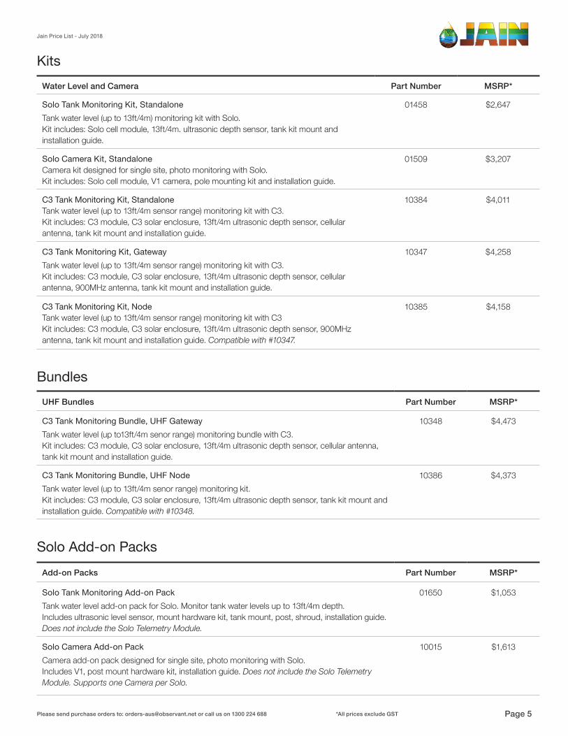
KitsWater Level and Camera Part Number MSRP*
Solo Tank Monitoring Kit, Standalone 01458 $2,647Tank water level (up to 13ft/4m) monitoring kit with Solo. Kit includes: Solo cell module, 13ft/4m. ultrasonic depth sensor, tank kit mount and installation guide.
Solo Camera Kit, StandaloneCamera kit designed for single site, photo monitoring with Solo.Kit includes: Solo cell module, V1 camera, pole mounting kit and installation guide.
01509 $3,207
C3 Tank Monitoring Kit, Standalone Tank water level (up to 13ft/4m sensor range) monitoring kit with C3. Kit includes: C3 module, C3 solar enclosure, 13ft/4m ultrasonic depth sensor, cellular antenna, tank kit mount and installation guide.
10384 $4,011
C3 Tank Monitoring Kit, Gateway 10347 $4,258Tank water level (up to 13ft/4m sensor range) monitoring kit with C3.Kit includes: C3 module, C3 solar enclosure, 13ft/4m ultrasonic depth sensor, cellular antenna, 900MHz antenna, tank kit mount and installation guide.
C3 Tank Monitoring Kit, Node Tank water level (up to 13ft/4m sensor range) monitoring kit with C3Kit includes: C3 module, C3 solar enclosure, 13ft/4m ultrasonic depth sensor, 900MHz antenna, tank kit mount and installation guide. Compatible with #10347.
10385 $4,158
BundlesUHF Bundles Part Number MSRP*
C3 Tank Monitoring Bundle, UHF Gateway 10348 $4,473Tank water level (up to13ft/4m senor range) monitoring bundle with C3. Kit includes: C3 module, C3 solar enclosure, 13ft/4m ultrasonic depth sensor, cellular antenna, tank kit mount and installation guide.
C3 Tank Monitoring Bundle, UHF Node 10386 $4,373Tank water level (up to 13ft/4m senor range) monitoring kit. Kit includes: C3 module, C3 solar enclosure, 13ft/4m ultrasonic depth sensor, tank kit mount and installation guide. Compatible with #10348.
Solo Add-on PacksAdd-on Packs Part Number MSRP*
Solo Tank Monitoring Add-on Pack 01650 $1,053Tank water level add-on pack for Solo. Monitor tank water levels up to 13ft/4m depth. Includes ultrasonic level sensor, mount hardware kit, tank mount, post, shroud, installation guide.Does not include the Solo Telemetry Module.
Solo Camera Add-on Pack 10015 $1,613Camera add-on pack designed for single site, photo monitoring with Solo. Includes V1, post mount hardware kit, installation guide. Does not include the Solo Telemetry Module. Supports one Camera per Solo.
Jain Price List - July 2018
Please send purchase orders to: [email protected] or call us on 1300 224 688 Page 5*All prices exclude GST
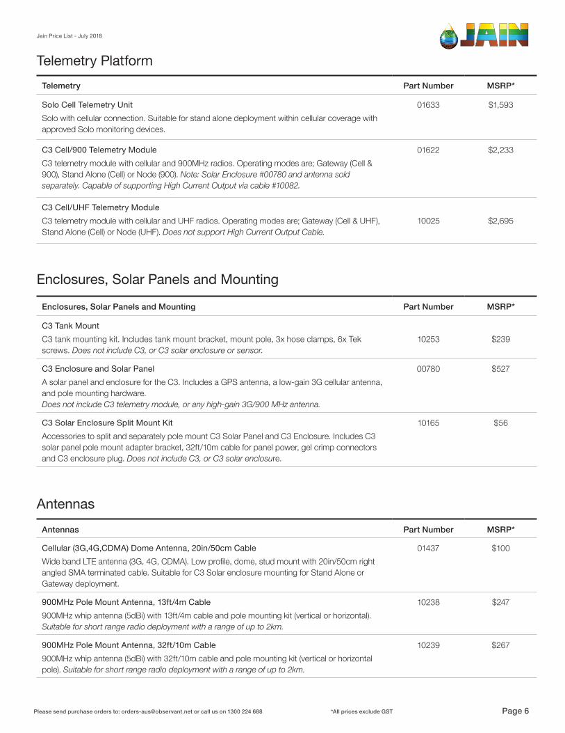
Antennas Part Number MSRP*
Cellular (3G,4G,CDMA) Dome Antenna, 20in/50cm Cable 01437 $100Wide band LTE antenna (3G, 4G, CDMA). Low profile, dome, stud mount with 20in/50cm rightangled SMA terminated cable. Suitable for C3 Solar enclosure mounting for Stand Alone orGateway deployment.
900MHz Pole Mount Antenna, 13ft/4m Cable 10238 $247900MHz whip antenna (5dBi) with 13ft/4m cable and pole mounting kit (vertical or horizontal).Suitable for short range radio deployment with a range of up to 2km.
900MHz Pole Mount Antenna, 32ft/10m Cable 10239 $267900MHz whip antenna (5dBi) with 32ft/10m cable and pole mounting kit (vertical or horizontal pole). Suitable for short range radio deployment with a range of up to 2km.
Antennas
Enclosures, Solar Panels and Mounting
Enclosures, Solar Panels and Mounting Part Number MSRP*
C3 Tank MountC3 tank mounting kit. Includes tank mount bracket, mount pole, 3x hose clamps, 6x Tek screws. Does not include C3, or C3 solar enclosure or sensor.
10253 $239
C3 Enclosure and Solar Panel 00780 $527A solar panel and enclosure for the C3. Includes a GPS antenna, a low-gain 3G cellular antenna, and pole mounting hardware. Does not include C3 telemetry module, or any high-gain 3G/900 MHz antenna.
C3 Solar Enclosure Split Mount Kit 10165 $56Accessories to split and separately pole mount C3 Solar Panel and C3 Enclosure. Includes C3 solar panel pole mount adapter bracket, 32ft/10m cable for panel power, gel crimp connectors and C3 enclosure plug. Does not include C3, or C3 solar enclosure.
Telemetry PlatformTelemetry Part Number MSRP*
Solo Cell Telemetry Unit 01633 $1,593Solo with cellular connection. Suitable for stand alone deployment within cellular coverage with approved Solo monitoring devices.
C3 Cell/900 Telemetry Module 01622 $2,233C3 telemetry module with cellular and 900MHz radios. Operating modes are; Gateway (Cell &900), Stand Alone (Cell) or Node (900). Note: Solar Enclosure #00780 and antenna sold separately. Capable of supporting High Current Output via cable #10082.
C3 Cell/UHF Telemetry ModuleC3 telemetry module with cellular and UHF radios. Operating modes are; Gateway (Cell & UHF),Stand Alone (Cell) or Node (UHF). Does not support High Current Output Cable.
10025 $2,695
Jain Price List - July 2018
Please send purchase orders to: [email protected] or call us on 1300 224 688 Page 6*All prices exclude GST

Imaging Part Number MSRP*
V1 Digital Still Image Camera 01488 $1,367Jain’s V1 camera comes with a 2ft/60cm cable terminated with a female, Switchcraft EN3 connector plus all associated pole-mounting hardware. Includes pole mount bracket and clamps.
Imaging
Cables and Connectors
Cables and Connectors Part Number MSRP*
Solo Input Accessory Pack 10204 $127Connect bare ended 2 wire sensors to the Solo digital input port. Includes: Solo input cable to bare ends 5m, IP rated 3-terminal in-line junction box and 4 gel crimp connectors.
Parts and ServicesParts and Services Part Number MSRP*
DIN Rail Clip 00609 $10A 4” DIN rail clip and screws to mount the C3 module on a DIN rail (DIN rail not included).
C3 Door Seal 00669 $5A replacement O-ring used on the C3 Solar Enclosure as a door seal.
Plug-Seal for C3 Enclosure 00764 $20When using an external antenna with the C3, this hole plug, with its associated hardware, neatly seals the unused, antenna-mounting hole in the C3 Enclosure.
100-240 V AC power AUS 00012 $85This power adaptor allows any C3 or Solo Telemetry Module to have its battery charge maintained by local AC power (instead of a solar panel).
Level Sensor Part Number MSRP*
Senix 13ft/4m Ultrasonic Level Sensor with 2m Bare Ends 00760 $912Senix ultrasonic level sensor with 13ft/4m range. Sensor comes with bracket and shroud. Suitable for a C3 or a Solo but will require a Solo sensor accessory pack #10124.
Senix 13ft/4m Ultrasonic Level Sensor for C3 Tank Kit 01463 $931Senix ultrasonic level sensor with 13ft/4m range. Sensor comes with 25cm cable to C3 connector for C3 Tank Monitoring Kit.
Water Level
Jain Price List - July 2018
Please send purchase orders to: [email protected] or call us on 1300 224 688 Page 7*All prices exclude GST
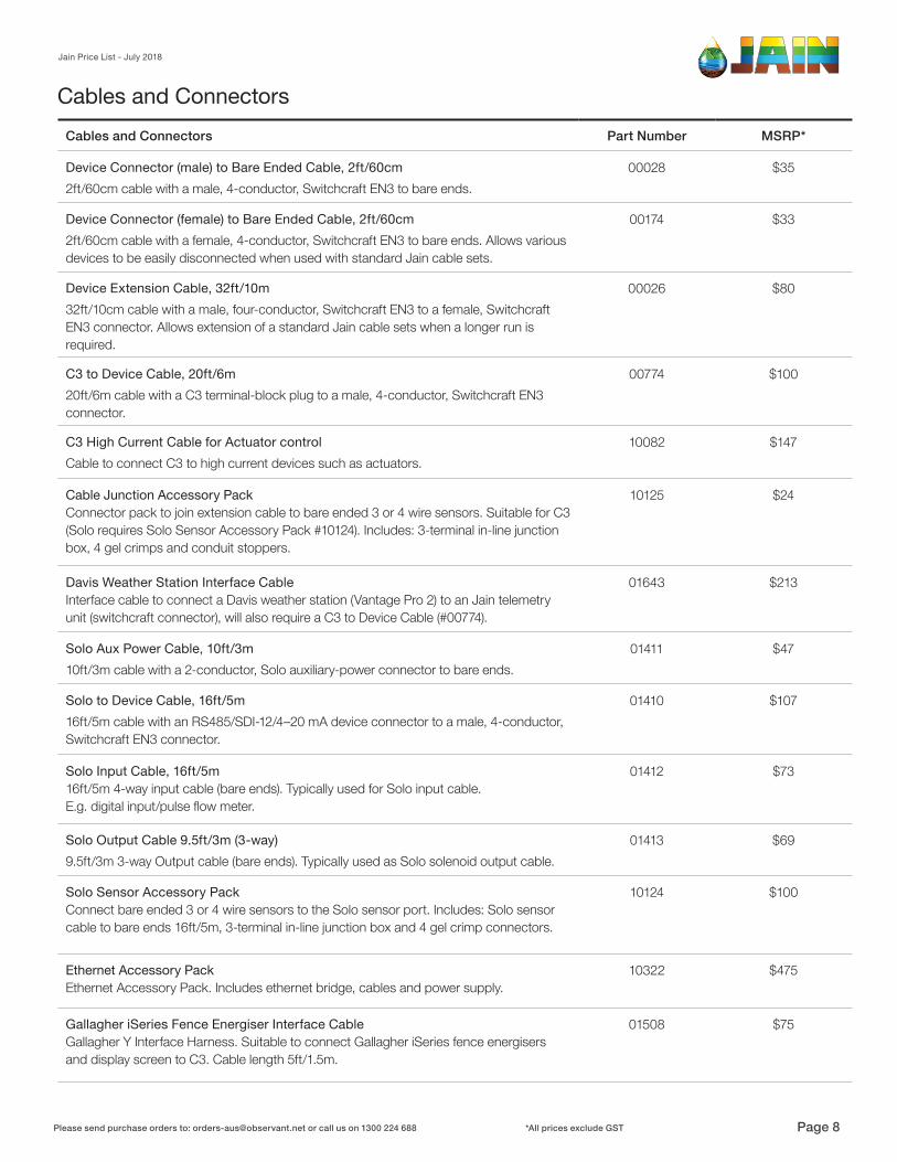
Cables and Connectors Part Number MSRP*
Device Connector (male) to Bare Ended Cable, 2ft/60cm 00028 $352ft/60cm cable with a male, 4-conductor, Switchcraft EN3 to bare ends.
Device Connector (female) to Bare Ended Cable, 2ft/60cm 00174 $332ft/60cm cable with a female, 4-conductor, Switchcraft EN3 to bare ends. Allows various devices to be easily disconnected when used with standard Jain cable sets.
Device Extension Cable, 32ft/10m 00026 $8032ft/10cm cable with a male, four-conductor, Switchcraft EN3 to a female, Switchcraft EN3 connector. Allows extension of a standard Jain cable sets when a longer run is required.
C3 to Device Cable, 20ft/6m 00774 $10020ft/6m cable with a C3 terminal-block plug to a male, 4-conductor, Switchcraft EN3 connector.
C3 High Current Cable for Actuator control 10082 $147Cable to connect C3 to high current devices such as actuators.
Cable Junction Accessory PackConnector pack to join extension cable to bare ended 3 or 4 wire sensors. Suitable for C3 (Solo requires Solo Sensor Accessory Pack #10124). Includes: 3-terminal in-line junction box, 4 gel crimps and conduit stoppers.
10125 $24
Davis Weather Station Interface CableInterface cable to connect a Davis weather station (Vantage Pro 2) to an Jain telemetry unit (switchcraft connector), will also require a C3 to Device Cable (#00774).
01643 $213
Solo Aux Power Cable, 10ft/3m 01411 $4710ft/3m cable with a 2-conductor, Solo auxiliary-power connector to bare ends.
Solo to Device Cable, 16ft/5m 01410 $10716ft/5m cable with an RS485/SDI-12/4–20 mA device connector to a male, 4-conductor, Switchcraft EN3 connector.
Solo Input Cable, 16ft/5m 16ft/5m 4-way input cable (bare ends). Typically used for Solo input cable. E.g. digital input/pulse flow meter.
01412 $73
Solo Output Cable 9.5ft/3m (3-way) 01413 $699.5ft/3m 3-way Output cable (bare ends). Typically used as Solo solenoid output cable.
Solo Sensor Accessory PackConnect bare ended 3 or 4 wire sensors to the Solo sensor port. Includes: Solo sensor cable to bare ends 16ft/5m, 3-terminal in-line junction box and 4 gel crimp connectors.
10124 $100
Ethernet Accessory PackEthernet Accessory Pack. Includes ethernet bridge, cables and power supply.
10322 $475
Gallagher iSeries Fence Energiser Interface CableGallagher Y Interface Harness. Suitable to connect Gallagher iSeries fence energisers and display screen to C3. Cable length 5ft/1.5m.
01508 $75
Cables and Connectors
Jain Price List - July 2018
Please send purchase orders to: [email protected] or call us on 1300 224 688 Page 8*All prices exclude GST

Jain Price List - July 2018
Please send purchase orders to: [email protected] or call us on 1300 224 688 Page 9*All prices exclude GST
Jain Limited Product Warranty
LIMITED PRODUCT WARRANTYFor the purposes of this Warranty, the terms We, Us, or Our means the relevant Jain entity as set out at the foot of this document.
Except as provided below, We warrant that (i) for a period of three (3) years from the date of sale to a customer (“You”), Our C3 Products shall be free from defects in material and workmanship and (ii) for a period of one (1) year from the date of sale to You, Our Solo and V1 Products shall be free from defects in material and workmanship. Equipment from third party manufacturers or suppliers is covered by their applicable warranties.
In the event any Products are found to be defective during the applicable warranty period, You must contact the place of purchase (“Dealer”) and the Dealer must immediately contact Us, and the Dealer will work with Us to address the defect. You must contact the Dealer before the expiration of the applicable warranty period to make a warranty claim and follow the process set out at http://observant.net/support/warranty. If the Products are determined to be defective by Us, We will issue a return merchandise authorization number (“RMA”). You or the Dealer, as appropriate, shall return the Product(s) to Us with the RMA clearly a xed to the Product and postage prepaid at the address set out below or other address and method as specified with the RMA documentation.
We will, at Our sole option, either repair or resupply the defective Product(s). Any repair or resupply hereunder may contain newly manufactured or reconditioned used parts which are functionally equivalent to new.
The foregoing limited warranty shall become void and will not apply if: (a) the Product(s) has/have been tampered with in any way, or attempts to repair it/them have been made by any person other than Our authorized Jain employee or authorized Dealer technician; or (b) third party supplied parts/products used in conjunction with the Product have damaged the Product; or (c) damage which occurred in shipping is apparent or subsequently proved; or (d) the Product(s) is/are damaged by catastrophe, fault, or negligence of any person or entity other than Us; or (e) the Product(s) is/are damaged by installation, use, or maintenance of such Product(s) other than as instructed by Us, or for purposes other than that for which is it specifically designed.
This limited warranty is subject to change by Us from time to time as notified on our website at observant.net.
Any action for breach of this warranty shall be brought within three (3) months of the expiration of the applicable warranty period.
OUR OBLIGATION UNDER THIS LIMITED WARRANTY IS LIMITED TO THE REPAIR OR REPLACEMENT OF THE DEFECTIVE PRODUCT AT OUR SOLE DISCRETION. ANY AND ALL COSTS OF REMOVAL, INSTALLATION AND/OR REINSTALLATION, AND FREIGHT CHARGES ARE EXPRESSLY EXCLUDED FROM THIS WARRANTY. EXCEPT AS SET FORTH HEREIN, THERE ARE NO OTHER EXPRESS OR IMPLIED PRODUCT WARRANTIES, AND OBSERVANT HEREBY DISCLAIMS ANY AND ALL OTHER WARRANTIES, WHETHER EXPRESS OR IMPLIED, INCLUDING, WITHOUT LIMITATION, ALL WARRANTIES OF MERCHANTABILITY OR FITNESS FOR A PARTICULAR PURPOSE.
WE DO NOT WARRANT THAT PRODUCTS WILL MEET OR CONTINUE TO MEET DEALER’S OR DEALER’S CUSTOMER SPECIFICATIONS OR THAT ANY OR ALL ERRORS, MALFUNCTIONS, AND DEFECTS CAN OR WILL BE CORRECTED. WE DO NOT WARRANT THAT THE OPERATION OF THE PRODUCTS WILL BE UNINTERRUPTED OR ERROR FREE.
LIMITATION OF LIABILITYIN NO EVENT SHALL WE BE LIABLE TO DEALER, CUSTOMER, OR ANY THIRD PARTY FOR ANY LOST BUSINESS PROFITS, OR LOST DATA, OR LOSS OF SAVINGS OR REVENUE, OR LOSS OF USE OF THE PRODUCT OR ASSOCIATED EQUIPMENT OR DOWNTIME, OR THE COST OF SUBSTITUTE EQUIPMENT, OR ANY INCIDENTAL, CONSEQUENTIAL, SPECIAL, OR INDIRECT DAMAGES, EVEN IF WE HAVE BEEN ADVISED OF THE POSSIBILITY THEREOF. IN NO EVENT SHALL OUR LIABILITY TO YOU, DEALER, OR ANY OTHER PARTY EXCEED THE PURCHASE PRICE PAID BY DEALER TO US FOR THE PRODUCTS CONNECTED WITH ANY CLAIM, WHETHER SUCH CLAIM IS IN CONTRACT, TORT, OR OTHERWISE INCLUDING, WITHOUT LIMITATION, ANY INDEMNIFICATION CLAIMS.
Who You are contracting with under this Warranty, who You should direct Notices to, the law that will apply to the Agreement and the courts having jurisdiction depend on where you are domiciled as set out below:
Where you are domiciled Relevant Entity Notices should be sent to Governing law
North America Jain Irrigation USA Jain Irrigation 2851 East Florence Ave Fresno, CA 93721 USA
California, USA
Australia and Rest of World
Jain Agriculture Services Australia Jain Agriculture Services Australia 77 Argyle St Fitzroy, Victoria, 3065 Australia
Victoria, Australia
10074
SAMP
LE
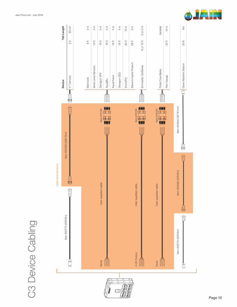
Jain Price List - July 2018
Please send purchase orders to: [email protected] or call us on 1300 224 688 Page 10*All prices exclude GSTC3 D
evice
Cab
ling
Seria
lUs
er s
uppl
ied
cabl
eIte
m #
1012
5
4–20
Out
put
User
sup
plie
d ca
ble
Item
#10
125
Inpu
tUs
er s
uppl
ied
cabl
eIte
m #
1012
5
Item
#00
026
(32f
t/10m
)Ite
m #
0077
4 (2
0ft/6
m)
Opt
iona
l Ext
ensio
ns
Schn
eide
r OsiS
ense
6 or
16
ft2
or 5
m
Pulse
Flo
w M
eter
Varia
ble
Rain
Gau
ge32
ft10
m
Dev
ice
Tail
Leng
th
V1 C
amer
a2
ft60
cm
Elek
troni
k6
ft2
m
Seni
x Le
vel S
enso
rs13
ft4
m
Deca
gon
VP4
16 ft
5 m
Aqua
Blu
16 ft
5 m
Aqua
Che
ck16
ft5
m
Deca
gon
GS3
16 ft
5 m
Envir
oPro
32 ft
10 m
Stev
ens
Hyd
ra P
robe
II26
ft8
m
Davis
Wea
ther
Sta
tion
20 ft
6m
Item
#00
774
(20f
t/6m
)Ite
m #
0164
3 (3
2”/8
1cm
)Ite
m #
0002
6 (2
0ft/6
m)
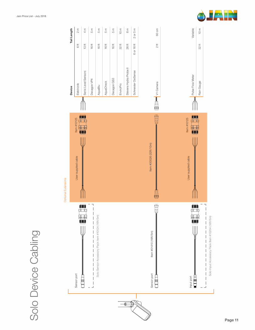
Jain Price List - July 2018
Please send purchase orders to: [email protected] or call us on 1300 224 688 Page 11*All prices exclude GST
Opt
iona
l Ext
ensio
ns
Solo
Inpu
t Acc
esso
ry P
ack
Item
#10
204
(16f
t/5m
)
Solo
Sen
sor A
cces
sory
Pac
k Ite
m #
1012
4 (1
6ft/5
m)
User
sup
plie
d ca
ble
Item
#00
026
(32f
t/10m
)Ite
m #
0141
0 (1
6ft/5
m)
Item
#10
125
Item
#10
125
Sens
or p
ort
Inpu
t por
t
Sens
or p
ort
Solo
Dev
ice C
ablin
g
Pulse
Flo
w M
eter
Varia
ble
Rain
Gau
ge32
ft10
m
V1 C
amer
a2
ft60
cm
Dev
ice
Tail
Leng
th
Elek
troni
k6
ft2
m
Seni
x Le
vel S
enso
rs13
ft4
m
Deca
gon
VP4
16 ft
5 m
Aqua
Blu
16 ft
5 m
Aqua
Che
ck16
ft5
m
Deca
gon
GS3
16 ft
5 m
Envir
oPro
32 ft
10 m
Stev
ens
Hyd
ra P
robe
II26
ft8
m
Schn
eide
r OsiS
ense
6 or
16
ft2
or 5
m
User
sup
plie
d ca
ble
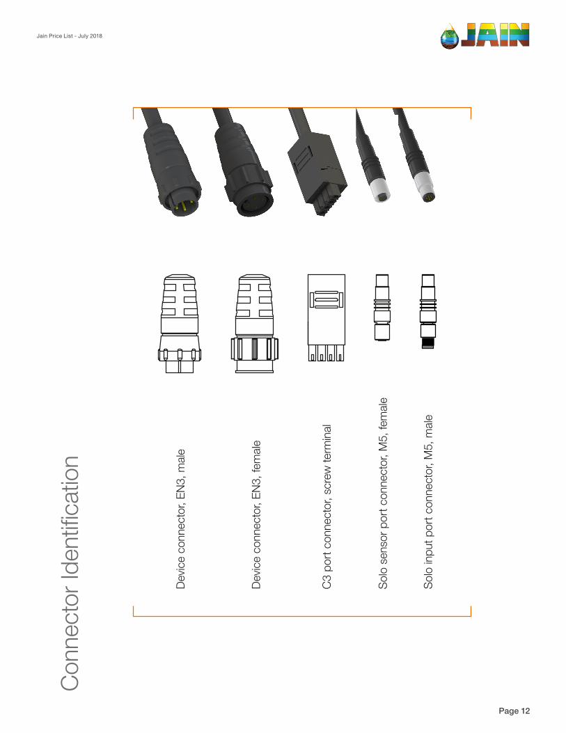
Jain Price List - July 2018
Please send purchase orders to: [email protected] or call us on 1300 224 688 Page 12*All prices exclude GST
Con
nect
or Id
entifi
catio
n
Dev
ice
conn
ecto
r, EN
3, m
ale
Dev
ice
conn
ecto
r, EN
3, fe
mal
e
C3
port
con
nect
or, s
crew
term
inal
Sol
o se
nsor
por
t con
nect
or, M
5, fe
mal
e
Sol
o in
put p
ort c
onne
ctor
, M5,
mal
e
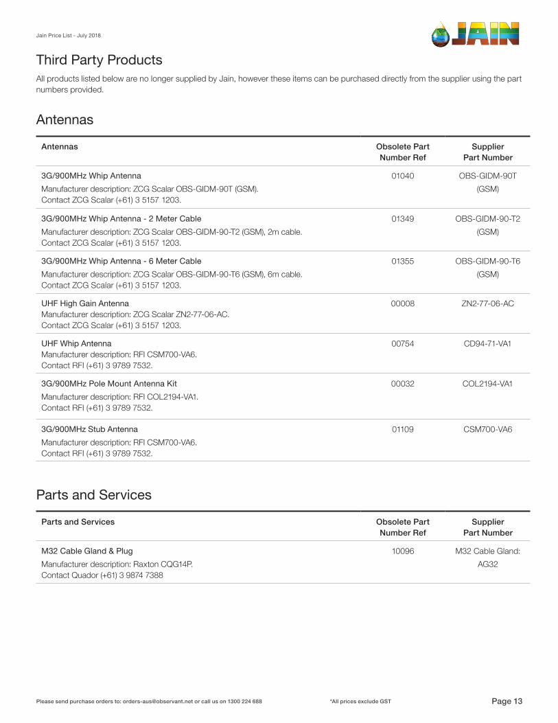
Parts and Services Obsolete Part Number Ref
SupplierPart Number
M32 Cable Gland & Plug 10096 M32 Cable Gland: Manufacturer description: Raxton CQG14P. Contact Quador (+61) 3 9874 7388
AG32
Parts and Services
Antennas Obsolete Part Number Ref
SupplierPart Number
3G/900MHz Whip Antenna 01040 OBS-GIDM-90TManufacturer description: ZCG Scalar OBS-GIDM-90T (GSM).Contact ZCG Scalar (+61) 3 5157 1203.
(GSM)
3G/900MHz Whip Antenna - 2 Meter Cable 01349 OBS-GIDM-90-T2Manufacturer description: ZCG Scalar OBS-GIDM-90-T2 (GSM), 2m cable.Contact ZCG Scalar (+61) 3 5157 1203.
(GSM)
3G/900MHz Whip Antenna - 6 Meter Cable 01355 OBS-GIDM-90-T6Manufacturer description: ZCG Scalar OBS-GIDM-90-T6 (GSM), 6m cable.Contact ZCG Scalar (+61) 3 5157 1203.
(GSM)
UHF High Gain Antenna Manufacturer description: ZCG Scalar ZN2-77-06-AC. Contact ZCG Scalar (+61) 3 5157 1203.
00008 ZN2-77-06-AC
UHF Whip AntennaManufacturer description: RFI CSM700-VA6. Contact RFI (+61) 3 9789 7532.
00754 CD94-71-VA1
3G/900MHz Pole Mount Antenna Kit 00032 COL2194-VA1Manufacturer description: RFI COL2194-VA1. Contact RFI (+61) 3 9789 7532.
3G/900MHz Stub Antenna 01109 CSM700-VA6Manufacturer description: RFI CSM700-VA6. Contact RFI (+61) 3 9789 7532.
Antennas
All products listed below are no longer supplied by Jain, however these items can be purchased directly from the supplier using the part numbers provided.
Third Party Products
Jain Price List - July 2018
Please send purchase orders to: [email protected] or call us on 1300 224 688 Page 13*All prices exclude GST
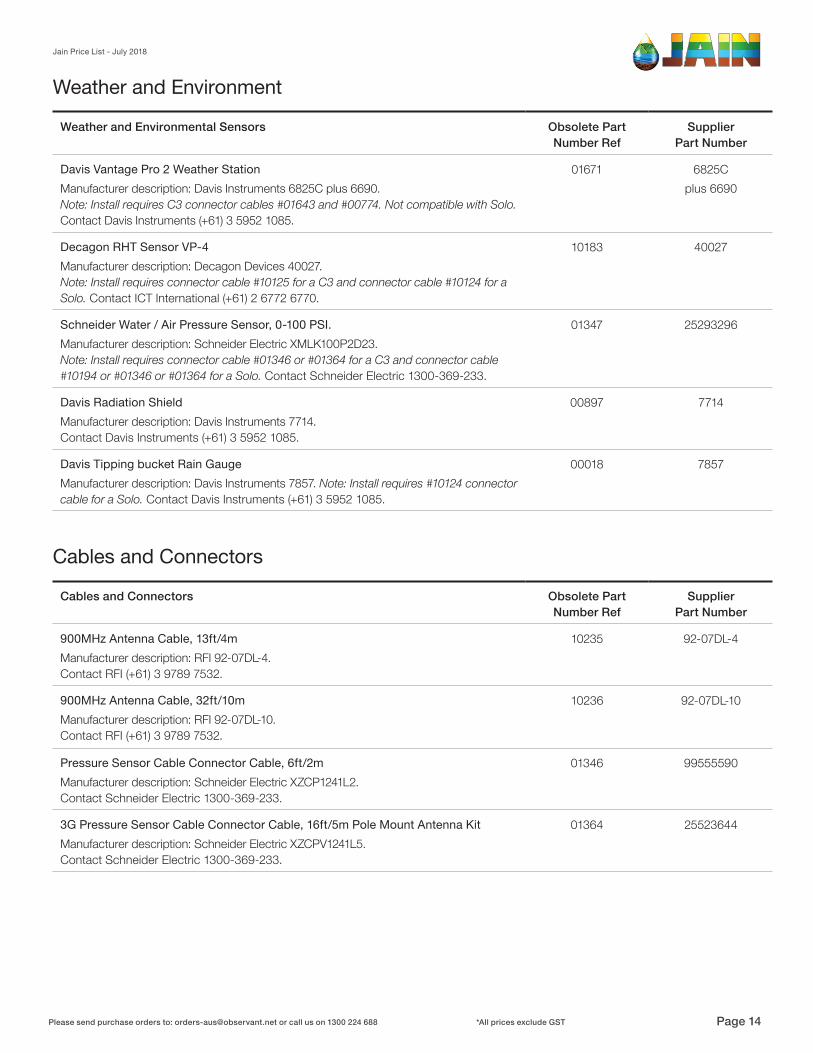
Weather and Environmental Sensors Obsolete Part Number Ref
SupplierPart Number
Davis Vantage Pro 2 Weather Station 01671 6825C Manufacturer description: Davis Instruments 6825C plus 6690. Note: Install requires C3 connector cables #01643 and #00774. Not compatible with Solo. Contact Davis Instruments (+61) 3 5952 1085.
plus 6690
Decagon RHT Sensor VP-4 10183 40027Manufacturer description: Decagon Devices 40027.Note: Install requires connector cable #10125 for a C3 and connector cable #10124 for a Solo. Contact ICT International (+61) 2 6772 6770.
Schneider Water / Air Pressure Sensor, 0-100 PSI. 01347 25293296Manufacturer description: Schneider Electric XMLK100P2D23.Note: Install requires connector cable #01346 or #01364 for a C3 and connector cable #10194 or #01346 or #01364 for a Solo. Contact Schneider Electric 1300-369-233.
Davis Radiation Shield 00897 7714Manufacturer description: Davis Instruments 7714. Contact Davis Instruments (+61) 3 5952 1085.
Davis Tipping bucket Rain Gauge 00018 7857Manufacturer description: Davis Instruments 7857. Note: Install requires #10124 connector cable for a Solo. Contact Davis Instruments (+61) 3 5952 1085.
Weather and Environment
Cables and Connectors Obsolete Part Number Ref
SupplierPart Number
900MHz Antenna Cable, 13ft/4m 10235 92-07DL-4 Manufacturer description: RFI 92-07DL-4. Contact RFI (+61) 3 9789 7532.
900MHz Antenna Cable, 32ft/10m 10236 92-07DL-10Manufacturer description: RFI 92-07DL-10. Contact RFI (+61) 3 9789 7532.
Pressure Sensor Cable Connector Cable, 6ft/2m 01346 99555590Manufacturer description: Schneider Electric XZCP1241L2.Contact Schneider Electric 1300-369-233.
3G Pressure Sensor Cable Connector Cable, 16ft/5m Pole Mount Antenna Kit 01364 25523644Manufacturer description: Schneider Electric XZCPV1241L5.Contact Schneider Electric 1300-369-233.
Cables and Connectors
Jain Price List - July 2018
Please send purchase orders to: [email protected] or call us on 1300 224 688 Page 14*All prices exclude GST

Soil Moisture Probes and Sensors Obsolete Part Number Ref
SupplierPart Number
Aquacheck Classic SDI-12 Probe, 32” 01663 150-085Manufacturer description: Aquacheck 150-085. Note: Install requires connector cable #10125 for a C3 and connector cable #10124 or #10194 for a Solo.Contact AquaCheck AUS (+61) 428 938 986.
EnviroPro 16”/400mm 4 Sensor Soil Moisture, Temperature ProbeManufacturer description: Entelechy Pty Ltd EP100GL-04-OB10. Note: Install requires connector cable #10125 for a C3 and connector cable #10124 or #10194 for a Solo.Contact Entelechy Pty Ltd (+61) 8 8251 7559.
01282 EP100GL-04-OB10
EnviroPro 48”/1200mm 12 Sensor Soil Moisture, Temperature Probe 01285 EP100GL-12-OB10Manufacturer description: Entelechy Pty Ltd EP100GL-12-OB10. Note: Install requires connector cable #10125 for a C3 and connector cable #10124 or #10194 for a Solo.Contact Entelechy Pty Ltd (+61) 8 8251 7559.
EnviroPro 64”/1600mm 16 Sensor Soil Moisture, Temperature ProbeManufacturer description: Entelechy Pty Ltd EP100GL-16-OB10. Note: Install requires connector cable #10125 for a C3 and connector cable #10124 or #10194 for a Solo.Contact Entelechy Pty Ltd (+61) 8 8251 7559.
01286 EP100GL-16-OB10
EnviroPro 32”/800mm 8 Sensor Soil Moisture, Temperature Probe 01238 EP100GL-08-OB10Manufacturer description: Entelechy Pty Ltd EP100GL-08-OB10. Note: Install requires connector cable #10125 for a C3 and connector cable #10124 or #10194 for a Solo.Contact Entelechy Pty Ltd (+61) 8 8251 7559.
Upgrade Enviropro 16”/400mm to ECManufacturer description: Entelechy Pty Ltd EP-UPG-04.Contact Entelechy Pty Ltd (+61) 8 8251 7559.
01550 EP-UPG-04
Upgrade Enviropro 32”/800mm + Lengths to ECManufacturer description: Entelechy Pty Ltd EP-UPG-08.Contact Entelechy Pty Ltd (+61) 8 8251 7559.
01525 EP-UPG-08
EnviroPro Removal ClampManufacturer description: Entelechy Pty Ltd EP-CLAMP. Contact Entelechy Pty Ltd (+61) 8 8251 7559.
01150 EP-CLAMP
EnviroPro Dummy probe 16”/400mmManufacturer description: Entelechy Pty Ltd EP-DUMMY. Contact Entelechy Pty Ltd (+61) 8 8251 7559.
01152 EP-DUMMY
EnviroPro Installation Kit 01149 EP-INST-KITManufacturer description: Entelechy Pty Ltd EP-INST-KIT. Contact Entelechy Pty Ltd (+61) 8 8251 7559.
Soil Moisture
Jain Price List - July 2018
Please send purchase orders to: [email protected] or call us on 1300 224 688 Page 15*All prices exclude GST