Embed Size (px)
Citation preview
BULLETIN N( D. O. 180
..."evIsed)
JANUARY' ., , 1951
I rrig ation Structu res
And Equipment:
Extension ServiceMontana State CollegeBozeman, Mon*:ana
CONTENTS
Dams . . .. . . .. --------. -- -- - 7
Headgates, Drops and Checks 12
Turnouts and Siphons ... ._._. ._. ,__ .._._ 20
Soil Auger
Leveling
Ditchers
Dikes and Dikers c ._._. ..•.• ••• ------ _
Furrowers and Corrugatol's
24
25
32
33
36
Turnouts and Spiles ._._.. " __. .. 36
Levels and Surveying Equipment . __ 40
Portable Dams .____. . ._... .. _ ..._. __ 45
Soil Moisture Prober _. ..._.. _. __.. _.__ ._...._ 47
Montanu Extensioll Se·rvice in. Agriculture and Home Economicti, R. B. Tootell, Director.;Montana State College and United' States Department of Agriculture Cooperating.
pistrihuted in fUl'tl1"l'fi!we of Acts of Congress. May 8 and June 30, 1914.
~-M (U!i&t~?~CP 1Mn 1
'"I r.. ,"";
IRRIGATION STRUCTURESAND EQUIPMENT
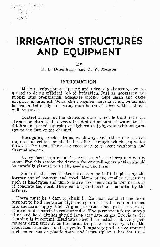
ByH. L. Dusenberry and O. W. Monson
INTRODUCTION
Modern irrigation equipment and adequate structure are required to do an efficient job of irrigation. Just as necessary areproper land preparation, adequate ditches kept clean and dikesproperly maintained. When these requirements are met, water canbe controlled easily and many man hours of labor with a shovelwill be saved.
Control begins at the diversion dam which is built into thestream or channel. It diverts the desired amount of water to theditches and permits surplus or high water to by-pass without damage to the dam or the channel.
Headgates, checks, drops, wastewayg and other devices arerequired at critical points in the ditch through which the waterflows to the farm. These are necessary to prevent washouts andchannel erosion.
Every farm requires a different set of structures and equipment. For this reason the devices fat controlling irrigation shouldbe earefully planned to fit the needs of the farm.
Some of the needed structures can be built in place by thefarmer' out of concrete and wood. Many of the smaller structuressuch as headgates and turnouts are now being made commerciallyof concrete and steel. These can be pmchased and installed by thefarmer.
There must be a dam or check in the main l:Hnal at the farmturnout to hold the water high enough so tile water can lJp 1:urIwc1into the farm supply ditch. A good permanent headgHtl~, preferablyof steel and concrete is recommended. The permanent farm supplyditch and head ditches should have adequate banks. Provision forcleaning is important. Headgates should be installed at every permanent ditch turnout on the farm. Drops are necessary when theditch must run down a steep grade. Temporary portable equipmentsuch as canvas or plastic dams anc1large siphon tubes fo1' tU1'I1-
4 MONTANA EXTENSION SERVICE
outs will give excellent control under certain conditions, such asfor contour or border ditches or border dikes. They also reducethe cost of turnout structures and leave the ditch open for mechanIcal cleaning.
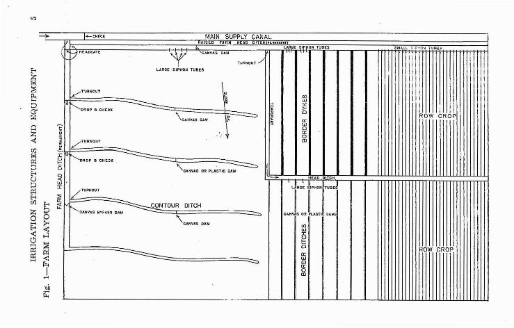
The purpose of this bulletin is to provide information on theconstruction of irrigation devices and equipment which can bemade on the farm. The use of commercial equipment will also bediscussed and illustrated. While every farm has different requirements for structures, an illustration of the ones which might beneeded for some common methods of irrigation are shown in Fig. 1.
Several methods are shown for illustration purposes. It is unlikely that a farm would be adapted to this many different methods. Ordinarily one or two methods are used on each farm. On flatland where the slope is less than 3 percent the border ditch or border dyke method will likely be best adapted. On steeper lands thecontour ditch will be used. Row crops require irrigation by furrows. On steep, uneven or extremely flat land, or when the watersupply is short, the corrugation method will be most efficient.
In each case the method requires certain equipment. Firstthere is the implements needed to level the land. Then the equipment to construct the ditc~es, dikes and furrows.
Controls are needed at every turnout in the ditch. They may bepermanent or temporary. Usually the structures such as checks,headgates and turnouts should be permanent when placed in thehead ditches. Temporary controls, such as canvas dams, are usedin the field where the ditches are also temporary.
In Figure I the drop checks mayor may not be needed, depending on whether or not the soil washes. If the erosion is not
. a. problem, only the check will be needed. If this is true the checkcan be permanent or temporary. The concrete check has the advantage of requiring very little upkeep after it is once installed.If ditch maintenance is a problem, requiring annual use of theditcher, it may be more practical to use temporary checks such ascanvas or steel dams.
Where large syphon tubes are indicated in Figure I, perman(mt checks and turnouts could be substituted. The permanentstructures would require a much greater initial investment butwould be more convenient for the irrigator to use. The large tubesare portable and thus can be moved with the water. The irrigatoruses only enough tubes to take care of the amount of water heis using. Where Figure I shows small syphon tubes, wooden lathspiles or straight stepl tubes installed in the bank could be used.Here again it is a question of the faJ'mer's preference and adaptingthe equipment to the farm.
-II">
E-iZ
~Il."'"::>CJIl:il
QZ<t:(/)
l:il
~E-i()
~(/)
a~
~;
E-i
8~H
~p:;,rl
oil~
J:gc.o<0:WJ:
::;;;0:;:;::
I+-CHECK MAIN SUPPLY CANAL.eol EO FARM HEAD DITCHIPI:".......l"TI
LARGE SIP ON TUBES SMALL :; I?~ON TU BESt1 HEADGATE
YCANV.e.S DAM
I !iTURNOUT ./
LARGE ·SIPHO,1 TUSES
.........-TURNOUT
~ I'i en IwI~OROP a CHEC'«
.. ~ :.: IA >-~ I
\CANVAS DAM
0 ROW CROP,'. r--e;>
~ a:~ w
0a:0
/TURNOUT CD
F..........OROP 8 CHECK
l'CANVAS DR PLA&TIC DAM ---.::::::::>HEAD DITCH
L!RGE 3'PHOH fuul/TURNOUT
CA.vt OR tASTIC O'MS""CANVAS BYPASS DAM
CONTOUR DITCH
\CANVAS DAM
-..0>
enWJ:
~0 ROW CROPa::w
~ 0a::0CD
:;r':J/tl~x:,~W;'t",,~:;'~"o;~::::'teltj r~,==to-,-~-'--~_~-'~',_M~,"_' . .--v== J(Oboutj5<~O:~dO~~~\ '~I~, /' ~,~ &b \ \.1 I \ (
1 \" ~O' ~~~ ,~f I #=> II \ f7J \ "> I~ \ ~ I I 'I I qg \\"~/ I !-~~~dll=:'1L 1 '/ l' PI-AN >10:....
~ ~~':,CTNe:, oI!P//
-Ioj', I
~f1I- I I TQpordcYn, I ~-,n~ ,
If) -C,.e:J"f . l t-'. - '~AubbltJl'nOao-v'Y !Jlittll,or. . _, ,
- --=-' ' I';;:;::;,~:":;::.:.. ' ', : \ 0'8 I
COY>'>pl.t. oi<ie. Iv;fh rja-o"" , • " , \
~ COb' , , , , , ,:\ '.I ~;.. I '\ ~ / 1;;:- I : \\----------.----.,--....::~ I
~ . --l~-~-----~- --~--.-- ..': , Il. 3"'~,'.-:...:...-.- _
DOlI'VNlJTRCAM E"L..Cv....rjON
RUBBLI:::. MASONRY' SPILLWAY FOR AN EARTH DAM
Fig. 2
=>
~oz~~
~ti!zrn
~~~....()t:r.1
IHRIGATION STRUCTURES AND EQUIPMENT
DAMS
7
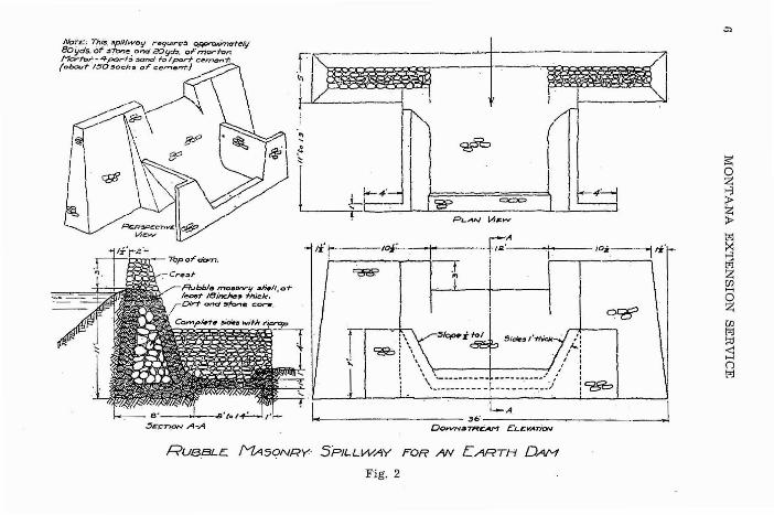
a. Masonry.-Fig. 2 shows the general plan and proportionsof a rock masonry dam which, with minor changes, can be adaptedto a wide variety of conditions. It is of the overflow type and thecenter section of the dam serves for a spillway for flood waterswhenever the flow in the creek exceeds the capacity of the diversioncanal. This type of dam is recommended wherever rock and boulders are accessible within convenient reach of the dam site. Thedimensions given for the dam provide for a minimum use of cementin order to cut down cash outlay. To offset this saving on cement,a liberal use of rock is recommended in order to give strength andstability to the structure.
For the shell of the dam, use clean stone laid in cement mortar. The mortar should be fairly rich. Not over 6 gallons of watershould be used per sack of cement, with only enough sand to makea good mortar. If the sand is wet, cut the'amount of water to 51A~
gallons per sack. 'sand must be clean and sharp. Even small amountsof vegetable matter and dirt will reduce the strength of the mortar.
The downstream sides and wing walls should also be laidup in mortar with a thickness of not less than 12 inches. The flooror apron should be increased to 18 inches if the drop exceeds 4feet. The length of the apron should be about twice the amount ofdrop, with a mi:oimum of 8 feet. For the structure illustrated inFig. 2, having a drop of 8 feet, the apron should be 16 feet longand 18 inches thick. Note also that a check wall at the lower endprovides for a water cushion, and the water discharges at slightlybelow the grade level in the creek.
The capacity of the spillway is 10.5 cuhic feet per secondper foot of crest when the depth on the crest is 2.5 feet.
Concrete Dam
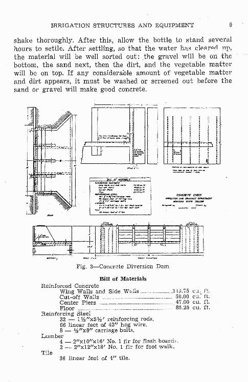
Fig. 3 shows a design for a reinforced concrete diversion checkclam with 4 bays.
When building concrete structures for wHter control, it ishighly important that attention be given to the selec1iol1 of ;·wndand gravel used and to the proportioning of the cOl\cl'de mixturt;.
8 MONTANA EXTENSION SERVICE
Only clean sand and gravel, free from vegetable matter and dirt,should be used. A small amount of dirt will neutralize a considerable amount of cement.
It is important also to use a rich mixture. To skimp on theamount of cement used is really a waste, because the resultingstructure will not stand up under the erosive action of water andweather. A 1 :2%:5 mixture that is, 1 part cement, 21;2 parts sandand 5 parts gravel, represents a good proportion of cement andaggregate. The most reliable basis for designating a mixture, however, is the so called cement-water ratio. By this is meant limiting the amount of water used per sack of cement. For the structure shown in Fig. 3, it is recommended that not more than 6gallons of water be used per sack of cement, using only enoughsand and gravel to make a. good workable mixture.
Reinforcing by steel strengthens the structure. Steel is placedon the side of the wall subject to tensile stresses. The rods shouldbe imbedded in the concrete 1 inch deep. Side walls and floors alsoneed a small amount of reinforcing to protect against excessiveerosion. This can be supplied in the form of hog wire fencingembedded in the concreete 1 inch deep.
Other important features in the construction of a concretediversion dam, as shown in Fig. 3, are the cut-off walls. The upstream wall in particular, should extend down into solid materialfrom 2 to 3 feet. The downstream cut-off wall should extenddeeply enough to prevent backwash under the floor. If the structure is to be built upon a porous formation, such as sand orgravel, drainage must be provided to carry away water whichpercolates under the structure tending to caUSe uplift when theflash boards are in place. This is carried away by means of a4-inch tile laid under the floor with an outlet branch as shownin Fig. 3.
Concrete structures are expensive, but there is no justification for skimping in the materials used; since this usually resultsin failure and a waste of the entire structure rather than in anynet saving.
A simple test to c1<c!termine the iluitability of sand or gravelfor use in concrete is to fill a bottle, such as a fruit jar, one-halffull of sand or gravel; then fill it completely with water and
IHRIGATION STRUCTURES AND EQUIPMENT 9
shake thoroughly. After this, allow the bottle to stand severalhours to settle; After settling, so that the water has c:10AfPrl 1111,
the material will be well sorted out: the gravel will be on thebottom, the sand next, then the dirt, and the vegetable matterwill be on top. If any considerable amount of vegetable matterand dirt appears, it must be washed or screened out before the8and or gravel will make good concrete.
1----< , _.-. - ...---------J
11 I
I
CM<:R£rc <HEr:X~1'1OI'I'.AND IJltAlHAlU fJDWfT'WOlT
~'ANA !roAr'I' COI.l.CQC
(M,~ ~ __ MU""'wn.o:v
...,.~n~...vrr~=:_"";;'''''''' ....,., ".I,~_'rI:;:-- ~:z~~rrrL
M~.J·""i,.;.,n-w" __"JJ'-- """1*/-
Lu:~~·#~·~ ..~.•_"·"ID-It~·"_1",.. """ __
nd·,#· '1·1I4 · ..... , ............ """"-
". _,"'.'o!Olo
Fig. 3-Concrete Diversion Dam
Bill of MaterialsReinfor·ced Concrete
Wing Walls and Side W"lls____ J 1,;.75 Cll. n.Cut-off Walls ._.. 50.00 cu: ft.Center Piers . . 47.00 cu. ft.Floor 85.25 cu. n.
Reinforcing Steel32 - 1%"x5%' reinforcing rods.66 linear feet of 42" hog wire.8 - %"x8" carria,ge bolts.
Lumber4 - 2"xlO"x16' No.1 fir for flash board;..2 - 2"x12"x18' No.1 fir for foot 'walk.
Tile36 linear feet of 4" tile.
10 MONTANA EXTENSION SERVICE
5£.C'TION A· A
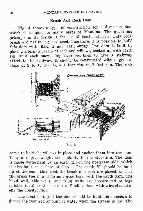
Brush And Rock Dam
Fig. 4 shows a type of construction for a diversion damwhich is adapted to many parts of Montana. The governingprinciple in its design is the use of local materials. Only rock,brush and native logs are used. Therefore, it is possible to buildthis dam with little, if any, cash outlay. The dam is built byplacing alternate layers of rock and willows, backed up with earthfill, with each succeeding layer set back to give a stairwayeffect to the spillway. It should be' constructed with a generalslope of 2 to 1; that is, a 1 foot rise to 2 feet run. The rock
f---u--- t" '-:-1'---- '.._, _.~~1"-1---- --- ">,.. ,t! .' l .;.
_A~r~ F' .... ! I"u,.... .,,,.e..._ ..' 0_0. ALrC;~NATC LAYC". D"
WIL"'OW If'flfl.RJH AtJD Ror:::..:WALL:II 4!Jv/l.T or "~Tl\l 8"LOOS
Fig. 4
serve to hold the willows in place and anchor them into the dam.They also give weight and :->tabi)ity to the structure. The damis made watertight by an earth fill on the upstream side, whichis also built on a slope of 2 to 1. The earth fill should be builtup at the same time that the brush and rock are placed, so thatthe brush ties in and forms a good bond with the earth dam. Thehead wall, side walls, and wing walls are constructed of logsnotched together at the co)'neI'S_ Binding them with wire strengthens the construction.
The crest or top of the dam should be built high enough todivert the required amount of water when the stream is low. The
r'RRIGATION STRUCTURES AND EQUIPM.ENT 11
diversion channel -illust .be protected with a headgate so tha.Lthe amount of diverted water may be controlled, especially duringhigh water. A double wall and double wing headgate is better thana single wall structure. At the lower end of the spillway thechannel should be heavily riprapped the full width for a distanceof 4 to 6 feet. This riprapping should be placed below the gradeline of the channel so that the water will be discharged belowthe grade, and thereby prevent erosion or backwash.
This type of structure is to be recommended wherever brush,rock and logs are available convenient to the dam site. If carefully constructed, such a structure should be safe for conditionswhere the height or fall does not exceed 10 feet. Since thematerials used are cheap, these should be used in liberal proportions.
Temporary Low Cost Diversi()D Dams
Where a small ditch of water is to be taken from some of thesmaller rivers, it is often necessary to build a diversion dam thatwill be inexpensive and be within a reasonable cost-benefit ratio.Where the stream bed is rock and gravel, a dam can be made witha bulldozer by pushing a thick layer of rocks and gravel across theptream bed to hold the water up against the diversion gate.The surplus water spills over the rock dam and goes on down thestream. A dam of this kind may require some maintenance fromyear to year, but the original cost and the maintenance are nothigh on streams where the channel is fairly stable and the seasonalflow does not fluctuate excessively.
Where a ditch is taken from a stream the ditch should betaken out at a level lower than the bottom of the stream bea ifpossible. If this is done a diversion dam may not be needed.
Rock piers are sometimes built at 10 or 15 feet intervalsacross the stream. During the irrigation season, poles are suspendedbetween these piers. If the poles do not divert enough water,boards are placed in front of the poles. This may be supplementedwith straw or manure to form a still tighter di\'ersioll. The J!olesand boards are removed in the fall after the irrigation season is(IVer, leaving only the piers in the channel over winter. On streams
12 MONTANA EXTENSION SERVICE
where heavy flooding occurs and lots 'of debris is carried, thepiers are likely to be lost and may have to be replaced.
A rock basket dam can be made by laying woven wire on thestream bed, covering it with rock. Place the loose ends of the wireon top and tie to the wire beneath. The wire holds the rock, in place.
Whenever benefits will justify cost, a good concrete diversionstructure should be designed and installed to save annual maintenance and provide a permanent structure.
HEADGA'l'ES
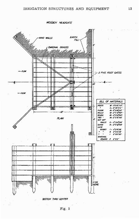
Fig. 5 shows the general plan for a wooden headgate capableof handling a large flow of water. It has two 5-foot gates andshould have a capacity of about 100 cubic feet per second. It isrecommended that 2-inch material be used throughout and, toadd to the durability of the structure, this lumber should becreosoted before nailing in place. The posts used may be of anynative wood, instead of the sawed 6x6's illustrated in Fig. 5.These posts also should be creosoted to preserve them againstdecay. Heavy cross bracing is necessary to keep the walls fromwarping and being pushed inward.
An important feature is the setting of the posts to a depthof at least 3 feet to hold the structure firmly in place. It is alsoimportant to build cut-off .walls and wing walls down into thebed of the canal sufficient to prevent washing under the structure.Unless the posts are deeply set, firmly tamped and anchored inplace, the whole structure is liable to be raised by the watergetting under the floor and uplifting or floating it away.
An added feature to the design shown in Fig. 5 would be theuse of a wheel and screw stem on each of the gates to facilitateopening and closing them. It may also be necessary to protectthe downstream end by l'iprapping- with stone to prevent backwash and undercutting. The floo]' of the structure should be setlevel with or even slightly below the bottom of the channel. Thistends to reduce the danger of undercutting and erosion aroundthe structure.
IRRIGATION STRUCTURES AND EQUIPMENT 13
It. a-x,'xl2'-</ .. ~·n~x~···"
IQ- rX""1? q~rX~/2';
II. rx/2"XIZ"U- 2"'X6'X/o'
f_ .,.)(~)(,.
6 2 4 Jt400x"I I·Xa·)(4'·
1- r)(/~XIO'
'.2·)(~1/Y
FLOORWALLS,WINGS1/6-'ClJTOfT
WAlLS....InGATE
GUtDCS
BILL OF MATERIALS
WlM:J HI4l.LS
1-------1R'-------1I
It-'-tr---+-It-tf'"~---+ffi----+Hf I72 FIVE FOOT GATES-npw
~-_---- -1+-tt---+-fI:-lf----:'JeIl--~4I--#-1-1O'--<C_-
1t!+---H--i-+-----HHI+It----+-t1
H-i-!--'-------~l3'C!R
LlFig_ 5
14 MONTANA EXTENSION SERVICE
Concrete Headgate
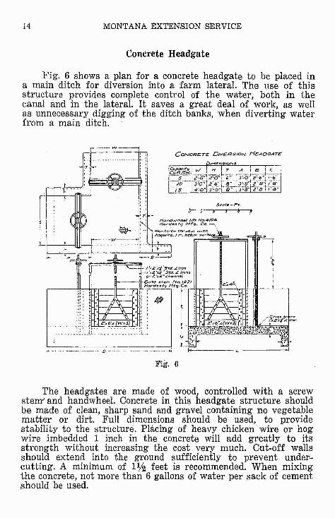
Fig. 6 shows a plan for a concrete headgate to be placed ina main ditch for diversion into a farm lateral. The use of thisstructure provides complete control of the water, both in thecanal and in the lateral. It saves a great deal of work, as wellas unnecessary digging of the ditch banks, when diverting waterfrom a main ditch.
r-- YV---,
J;~:----~-~'CONCR.cT~ DIVERSION HCADOATE
$c"JI:-Ft.
5---7-J: j !
The headgates are made of wood, controlled with a screwstem" and handwheel. Concrete in this headgate structure shouldbe made of clean, sharp sand and gravel containing no vegetablematter or dirt. Full dimensions should be used, to providestability to the structure. Placing of heavy chicken wire or hogwire imbedded 1 inch in the concrete will add greatly to itsstrength without increasing the cost very much. Cut-off wallsshould extend into the ground sufficiently to prevent under;.cutting. A minimum of 11/2 feet is recommended. When mixingthe concrete, not more than 6 gallons of water per sack of cementshould be used.
IRRIGATION STRUCTURES AND EQUIPMENT 15
Concrete Checks and Drops
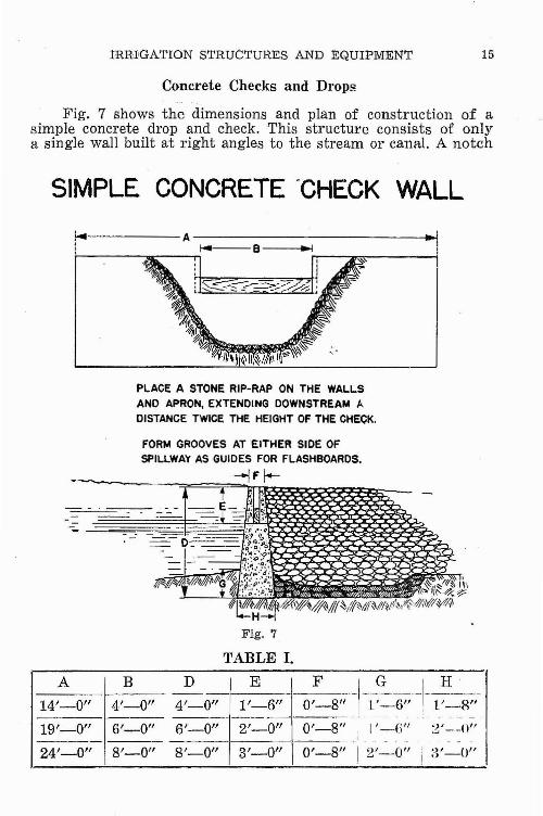
Fig. 7 shows the dimensions and plan of construction of asimple concrete drop and check. This structure consists of onlya single wall built at right angles to the stream or canal. A notch
SIMPLE CONCRETE -CHECK WALL
PLACE A STONE RIP-RAP ON THE WALLSAND APRON. EXTENDING DOWNSTREAM ADISTANCE TWICE THE HEIGHT OF THE CHECK,
FORM GROOVES AT EITHER SIDE OFSPILLWAY AS GUIDES FOR FLASHBOARDS.
-IF I-
TABLE L
A B
14'--0" 4'-0"
19'-0" 6'-0"
24'-0" 8'-0"
~o;;--t-=-6'10: 8" -h~/011~-g;;6'-0" _ 2'-0" O'-8"~, I'-(i" 2'~~()"
8'-0" 3'-0" 0'-8" I 2'-0" :~'-O"!
16 MONTANA EXTENSION SERVICE
through the center provides a passage for the water when not inuse. Grooves in the wall, into which flash boards can be fitted,provide for checking or raising the water surface when desiredfor diversion. Since this check does not have the bracing effectof side walls, it must be rather wide and thick in order to bestable. To protect the channel against erosion, a heavy riprapping of rocks should be placed on the lower side. This mayslope up to the crest of the check, or simply be placed in thebottom of the channel onto which the water will fall. It isimportant that the water should be discharged at grade levelto prevent eddies and undercutting.
In building concrete structures, the farmer is. cautionedagainst undue economy in the use of cement. Either sufficientcement should be used to make a durable Rtrueture, or else its use
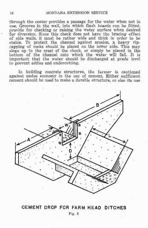
CEMENT DROP FOR FARM HEAD DITCHESFig. 8
IRRIGATION STRUCTURES AND EQUIPMEN1.' 17
TABLE II.
Capacity of Width ('If (A) (B)ditch in opening" (E) & (F)
c.r.s. eW) ft. (H) in. (C) in. ft.
2 1 12 6 2
6 2 12 6 2
8 2% 15 6 2
10 3 18 8 2L()/-
14 3lj2 18 8 3
DROP LENGTH OF APRON(D) Feet (I.) Feet
1 2%1% 3
2 4
3 6 -
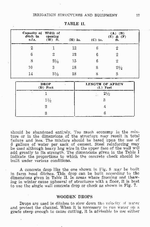
should be abandoned entirely. Too much economy in the mixture or in the dimensions. of the structure may result in totalfailure and 108s. The mixture should be based upon the use of6 gallons of water per sack of cement. Steel reinforcing maybe used although heavy hog wire in the upper face of the wall willadd greatly to its strength. The dimensions given in the Table Iindicate the proportions to which the concrete check should bebuilt under various conditions.
A concrete drop like the one shown in Fig. 8 may be bu\ltin farm head ditches. This drop can be built according' to thedimensions given in Table II. In areas where freezing and thawing in winter cause upheaval of structures with a floor, it is bestto use the single wall concrete drop or check as shown in Fig. 7.
WOODEN DROPS
Drops are used in ditches to slow down the velocity e)f waterand protect the channel. When it is necessary to run water un agrade steep enough to cause cutting, it is advisable to use either
18 MONTANA EXTENSION SERVICE
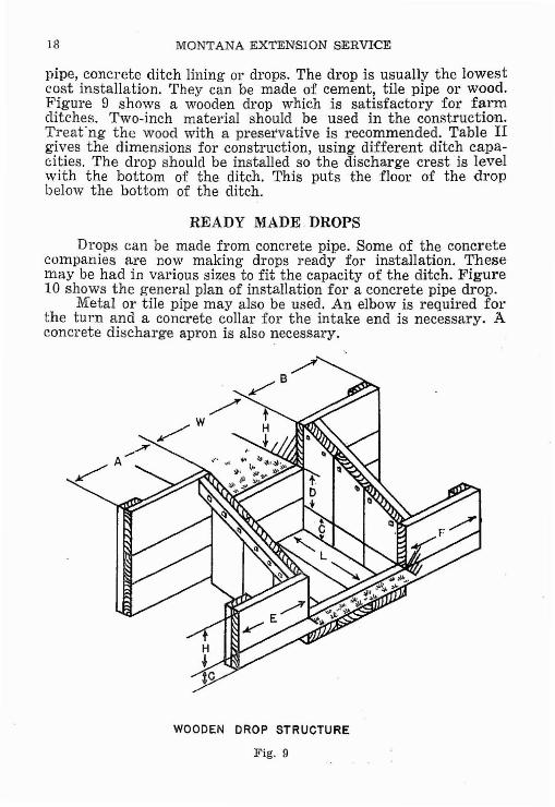
pipe, concrete ditch lining or drops. The drop is usually the lowestcost installation. They can be made of cement, tile pipe or wood.Figure 9 shows a wooden drop which is satisfactory for farmditches. Two-inch material should be used in the construction.Treat'ng the wood with a preservative is recommended. Table IIgives the dimensions for construction, using different ditch capacities. The drop should be installed so the discharge crest is levelwith the bottom of the ditch. This puts the floor of the dropbelow the bottom of the ditch.
READY MADE DROPSDrops can be made from concrete pipe. Some of the concrete
companies are now making drops ready for installation. Thesemay be had in various sizes to fit the capacity of the ditch. Figure10 shows the general plan of installation for a concrete pipe drop.
M'etal or tile pipe may also be used. An elbow is required forthe turn and a concrete collar for the intake end is necessary. Aconcrete discharge apron is also necessary.
WOODEN DROP STRUCTURE
Fig. 9
IIRRIGATION STRUCTURES AND EQUIPMENT 19
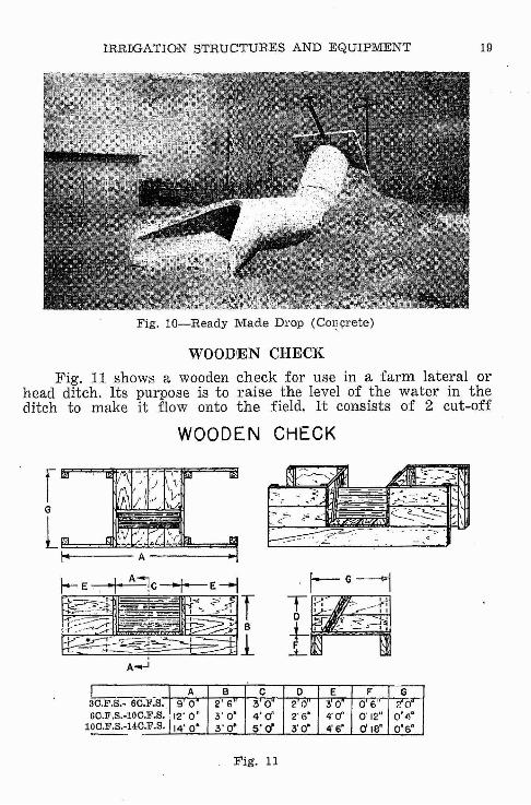
Fig, lO-Ready Made Drop (Co12l;rete)
WOODEN CHECK
Fig. 11 shows a wooden check for use in a farm lateral orhead ditch. Its purpose is to raise the level of the water in theditch to make it flow onto the field. It consists of 2 cut-off
WOODEN CHECK
~-,____ I A. B C 0 E F GC.F.S.- 6C.F.S., 9 0 2 6 :3 0 20 30 0'6" ~'
C.F,S.-lOC.F.S., 112' 0" 3' 0' 4'0' 2' 6" 4'0' 0'12" 0'40
~14~.F.S. 14' 0' 3' O· 5' d' 3'0' 4' 6' d la' 0'6"
36
1
Fig. 11
20 MONTANA EXTENSION SERVICE
walls extending into the banks and bottom of the ditch, securelyimbedded to prevent the water from cutting around.. The waterlevel is controlled by placing flash boards in the grooves of theside walls. These grooves are built on a slant. This prevents theflash boards from floating out when put in place, since thepressure of the water will hold them down.
It is highly important that the cut-off wall be set deepenough into the bottom of the ditch to prevent undercutting. For
. g'umbo soils a minimum of 12 inches is recommended for the Fdimension, and for large structures 18 inches is justified as givenin Fig. 11. For the construction of this check, 2-inch lumberf'hould be used; as lighter material would rot out very quickly.Treating of the lumber with creosote before nailing in placeis desirable.
TURNOUTSTurnouts are needed to provide a quick and easy means of
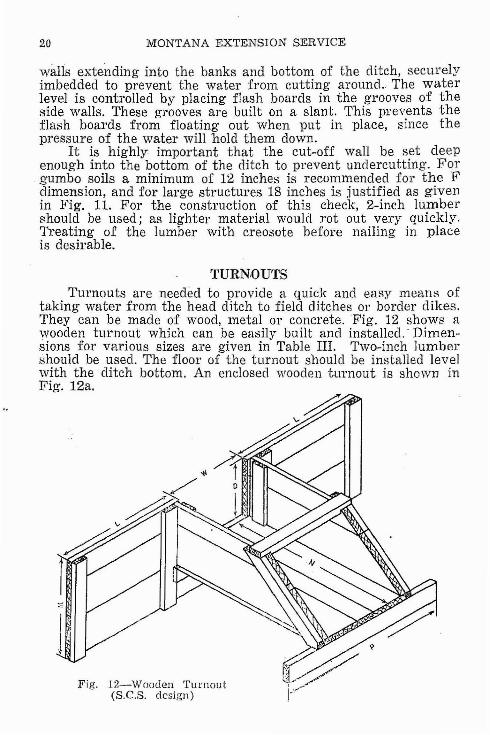
taking water from the head ditch to field ditches or border dikes.They can be made of wood, metal or concrete. Fig. 12 shows awooden turnout which can be easily built and installed.' Dimensions for various sizes are given in Table III. Two-inch lumbershould be used. The floor of the turnout should be installed levelwith the ditch bottom. An enclosed "vooden uwnout is shown inFig. 12a.
IrFig. 12-Wooden Turnout
(S.C.S. desi.gn)
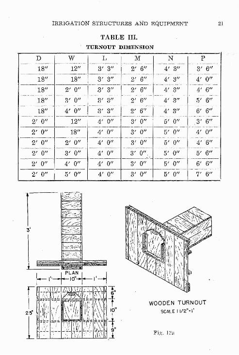
IRRIGATION STRUCTURES AND EQUIPMEN'l' 21
TABLE III.
TURNOUT DIMENSION
2' 0" 3' 3" 2' 6"... ......•. . .. ._..-- .
3' 0" 3' 3" 2' 6"
p
3' 6"
6' 6"
4' 0"
'1' 6"
5' 6"
4' 0"
4'6"
5' 6"
.3' 6"
4' 3"
5' 0"
5' 0"
4' 3"
4' 3"
5' 0"
5' 0"
Fig. l~n
WOODEN TURNOUT
SCALE I 1/2"; I'
3' 0"
3' 0"
3' 0"
2' 6"
3' 0",
4' 0"
4' 0"
4' 0"
·1' 0"
.3' 3"
2' 0"
3' 0"
4' 0"12"
18"
~~-=-I
~~1V;::/';:-.I~~~:~~~J
L=.=..~·SI.:;::::-__/-;-.1
18"
18"
18"
2' 0"
2' 0"
2' 0"
2' 0"2' 0"
2' 0"
1';3'
22 MONTANA EXTENSION SERVICE
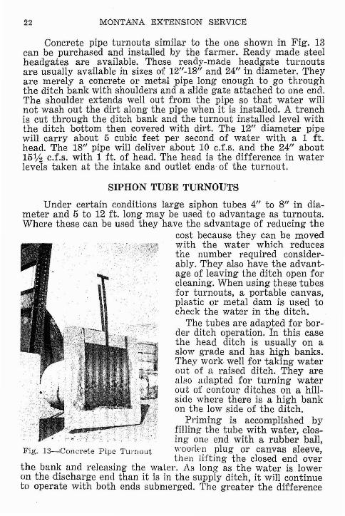
Concrete pipe turnouts similar to the one shown in Fig. 13can be purchased and installed by the farmer. Ready made steelheadgates are available. These ready-made headgate turnoutsare usually available in sizes of 1211-18" and 24" in diameter. Theyare merely a concrete or metal pipe long enough to go throughthe ditch bank with shoulders and a slide gate attached to one end.The shoulder extends well out from the pipe so that water willnot wash out the dirt along the pipe when it is installed. A trenchis cut through the ditch bank and the turnout installed level withthe ditch bottom then covered with dirt. The 12" diameter pipewill carry about 5 cubic feet per second of water with a 1 ft.head. The 18" pipe will deliver about 10 c.t.s. and the 24" about15% c.f.s. with 1 ft. of head. The head is the difference in waterlevels taken at the intake and outlet ends of the turnout.
SIPHON TUBE TURNOUTS
Under certain conditions large siphon tubes 4" to 8" in diameter and 5 to 12 ft. long may be used to advantage as turnouts.Where these can be used they have the advantage of reducing the
cost because they can be movedwith the water which reducesthe number required considerably. They also have the advantage of leaving the ditch open forcleaning. When using these tubesfor turnouts, a portable canvas,plastic or metal dam is used tocheck the water in the ditch.
The tubes are adapted for border ditch operation. In this casethe head ditch is usually on aslow grade and has high banks.They work wen for taking waterout of a raised ditch. They arealso adapted for turning waterout of contour ditches on a hillside where there is a high bankon the low side of the ditch.
Priming is accomplished byfilling the tube with water, closing one end with a rubber ball,
Fig. 1:3-'Concrete Pipe TUl"Dout woodE'TI plug or canvas sleeve,then lifting the closed end over
the bank and releasing the water. As long as the water is loweron the discharge end than it is in the supply ditch, it will continueto operate with both ends submerged. The greater the difference
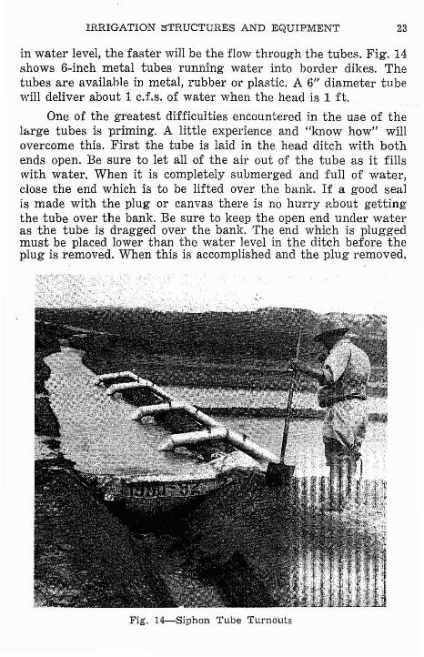
IRRIGATION STRUCTURES AND EQUIPMENT 23
in water level, the faster will be the flow through the tubes. Fig. 14shows 6-inch metal tubes running water into border dikes. Thetubes are availahle in metal, rubber or plastic. A 6" diameter tubewill deliver about 1 c.f.s. of water when the head is 1 ft.
One of the greatest difficulties encountered in the use of thelarge tubes is priming. A little experience and "know how" willovercome this. First the tube is laid in the head ditch with bothends open. Be sure to let all of the air out of the tube as it fillswith water. When it is completely submerged and full of water,close the end which is to be lifted over the bank. If a good sealis made with the plug or canvas there is no hurry about gettingthe tube over the bank. Be sure to keep the open end under wateras the tube is dragged over the bank. The end which is pluggedmust be placed lowe·r than the water level in the ditch before theplug is removed. When this is accomplished and the plug removed,
Fig. 14--'Siphon Tube Turnouts
24 MONTANA EXTENSION SERVICE
Fig, 15
lIN. P,PE:
SL£e:V£
COUPLING
11 INCARPCNTII:/tf'S
BIT
SOil.. .AUC5£R
the water will start running and continue as long as the water remains higher in the ditch.
One of the difficulties which is apt to happen is air getting'into the tube from the discharge end after the water starts. Thismay be overcome by digging a small notch in the dirt for the end ofthe tube to lay in. If this is done before priming is attempted thewater will come up around the discharge end and fOl'm a perfectseal to prevent air from entering;he tube.
Frequently a small amount ofair will get into the tube duringthe priming process but thewater will continue to flow. Whenthis happens, the flo w is re-stricted. It is therefor advisableto reprime the tube if you sus-pect this may have happened.With plastic tubes you can seethe air bubble but with steel orrubber tubes you cannot be surewhether or not you have an airbubble. If you think the flowshould be greater, it is best to reprime the tube.
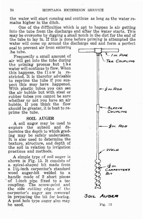
SOIL AUGERA soil auger may be used to
explore the subsoil and determine the depth to which grading may be safely undertaken.It is also used to determine thetexture, structure, and depth ofthe soil in relation to irrigationpractices and methods.
A simple type of soil auger isshown in Fig. 15. It consists ofa spiral-shaped bit made froma I1f2-inch carpenter's standardwood auger-bit welded to ahandle made of 2 short pieces
. of I-inch pipe fixed to a teecoupling. The screw-point andthe side cutting edges of th,.,carpenter's auger are removedin preparing the bit for boring',A post hole type auger alB,o maybe used.
I'RRTGATrON STRUCTURES AND EQUIPMENT
LEVELING
25
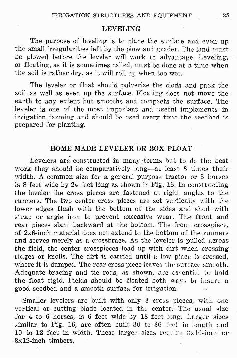
The purpose of leveling is to plane the surface and even upthe small irregularities left by the plow and grader. The land mu~t
be plowed before the leveler will work to advantage. Leveling,or floating, as it is sometimes called, must be done at a time whenthe soil is rather dry, as it will roll up when too wet.
The leveler or float should pulverize the clods and pack thesoil as well as even up the surface. Floating does not move theearth to any extent but smooths and compacts the surface. Theleveler is one of the most important and useful implements inirrigation farming and should be used every time the seedbed isprepared for planting.
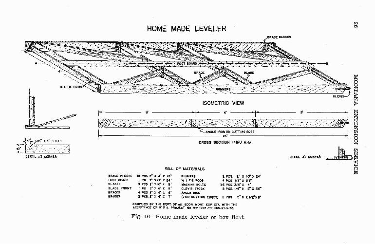
HOME MADE LEVELER OR BOX FLOAT
Levelers are constructed in many.>forms but to do the bestwork they should be comparatively long-at least 3 times theirwidth. A common size for a general purpose tradal' or 8 horsesis 8 feet wide by 24 feet long as shown in Fig. 16. In constructingthe leveler the cross pieces are fastened at right angles to therunners. The two center cross pieces are set vertically with thelower edges flush with the bottom of the sides and shod withstrap or angle iron to prevent excessive wear. The front andrear pieces slant backward at the bottom. The front crosspiece,of 2x6-inch material does not extend to the bottom of the runnersand serves merely as a crossbrace. As the leveler is pulled acrossthe field, the center crosspieces load up with dirt when crossingridges or knolls. The dirt is carried until a low place is crossed,where it is dumped. The rear cross piece leaves the surface smooth,Adequate bracing and tie rods, as shown, are es:-;<:.~ntiaJ to holdthe float rigid. Fields should be floated both wa,vs to insure agood seedbed and a smooth surface for irrigation.
Smaller levelers are built with only 3 cross pieces, with onevertical or cutting blade located in the center. The usual sizefor 4 to 6 horses, is 6 feet wide by 18 feet long, Larg'~}I' :-;izessimilar to Fig. 16, are often built 30 to 36 fllet in length and10 to 12 feet in width. These larger sizes require ::xlO-il1l'h ClI'
3x12-inch timbers.
HOME MADE LEVELERt-:la>
8ftACE 8I.OCKS
f
.J s--k 3/8" x 4" SOLTS
-.;;- tt,.".;· /1O~, > -,'f]....I..-....- • •• < /' // ~~
DETAIL J..7 CORNER
~g~>
;~ ~~~
~
s'
DETAIL AT CORNER
T
2"K 21n'X"
s'
2. pes. 2" x 10"' X 2.4·4 pes 112" x.llft'
36 pes. 3/8- x .-2. pes, 1/4" x 2" X 3d'
ISOMETRIC VIEW
CROSS SECTION THRU A-a
T
RUNNERSW. I TIE RODSMACHJNE BOLTSCLEVis STOe)(ANGLE IRON(FOR CUTTING EDGES) 2 pcs,
BILL OF MATERIALS
s'
18 pes. 2" x 4" X 10'·I PC 2" x It' X 24'3 pes 2" 'lC 10" X '8'I PC 2")1 ft x st
4 pes 2" x 6" X 8°2 Pes. 2" x ft' X 7·
BRACE BLOCKSFOOT BOARD
BLADHBLADf-. FRONTBRACESBRACES
1-
ri~~;~~::--~~- ~;~~J--~~~~--~~~-~S~:~'~;~SI:(~k;:~" /_ :__ ~~:~: ..JI <- ANGLE (ROO ON CUTTING EDGE t
III 24' •
t.
COMPILED BY THE DEPT. OF AG. ECON. MONT. EX? STA. WITH THEASSISTA!'\1CE OF W. P. A. PROJECT NO. WP 190!5 _np 465-91~3-75.
Fig. 16-Home made leveler or box float.
IRRIGATION STRUCTURES AND EQUIPMENT 27
SIDNEY LAND LEVELER
=F===--:tu' LEVER
$Tf.E1.. PIPE BRACING·'
... ANGLE IIIOIt_
BLADE ASSEhlllLT
Fig. 17-Sidney adjustable blade leveler
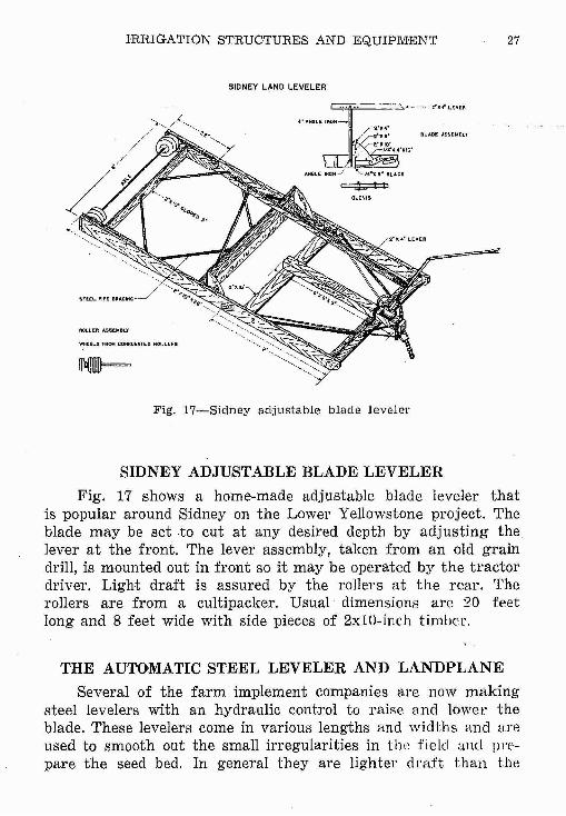
SIDNEY ADJUSTABLE BLADE LEVELER
Fig. 17 shows a home-made adjustable blade leveler thatis popular around Sidney on the Lower Yellowstone project. Theblade may be set to cut at any desired depth by adjusting thelever at the front. The lever assembly, taken from an old graindrill, is mounted out in front so it may be operated by the tractordriver. Light draft is assured by the rollers at the rear. Therollers are from a cultipacker. Usual dimensions are 20 feetlong and 8 feet wide with side pieces of 2x10-inch timher.
THE AU110MATIC STEEL LEVELER AND LANDPLANE
Several of the farm implement companies are now makingsteel levelers with an hydraulic control to raise and lower theblade. These levelers come in various lengths and widths and Hreused to smooth out the small irregularities in the fielcl and prepare the seed bed. In general they are lighter draft than the
28 MONTANA EXTENSION SERVICE
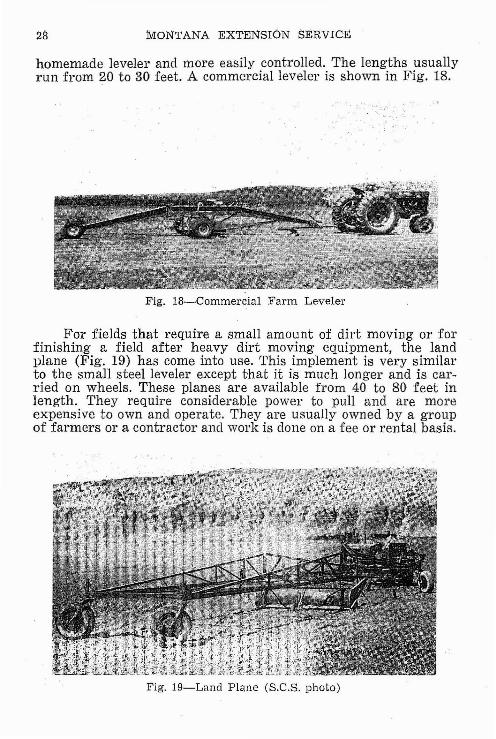
homemade leveler and more easily controlled. The lengths usuallyrun from 20 to 30 feet. A commercial leveler is shown in Fig. 18.
Fig. l8---Commercial Farm Leveler
For fields that require a small amount of dirt moving or forfinishing a field after heavy dirt moving equipment, the landplane (Fig. 19) has come into use. rfhis implement is very similarto the small steel leveler except that it is much longer and is carried on wheels. These planes are available from 40 to 80 feet inlength. They require considerable power to pull and are moreexpensive to own and operate. They are usually owned by a groupof farmers or a contractor and work is done on a fee or rental basis.
Fig. 19-Land Plane (S.C.S. photo)
IRRIGATION STRUCTURES AND EQUIPMENT
HEAVY GRADING AND LEVELING EQUIPMENT
29
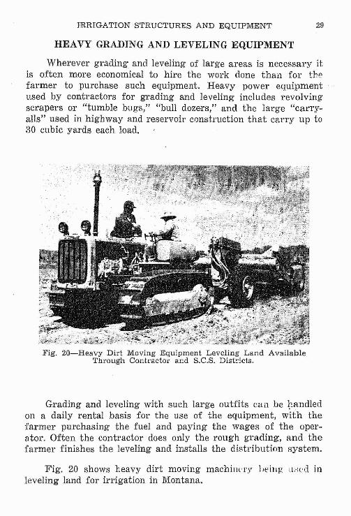
Wherever gTading and leveling of large areas is necessary itis often more economical to hire the work done than for thefarmer to purchase such equipment. Heavy power equipmentused by contractors for grading and leveling includes revolvingscrapers or "tumble bugs," "bull dozers," and the large "carryalls" used in highway and reservoir construction that carry up to30 cubic yards each load.
Fig. 20-Heavy Dirt Moving Equipment Leveling Land AvailableThrough Contractor and S.C.S. Districts.
Grading and leveling with such large outfits cun be ~andled
on a daily rental basis for the use of the equipment, with thefarmer purchasing the fuel and paying the wages of the operator. Often the contractor does only the rough grading, and thefarmer finishes the leveling and installs the distribution system.
Fig. 20 shows heavy dirt moving machilH'l'Y }Jeing lIsed inleveling land for irrigation in Montana.
30 MONTANA EXTENSION SERVICE
HOMEMADE DITCHER\ 1'12',,'.'14 ' ST~ ANOLE IRONS
~• _ DRILL 5 KOI.ES FOR 5/." PIN.X 2" CENTERS'." I" SHAFT. _ 36"0 PLOW WHEEl.
-f PIN JOINT~ ~ /' .' _.
• A T <.... -: ._~"~12"~'i~ '~;3~~ : ~ST~P IRON EDGE • '" . e:~~~==~~::=:§::§§
REAR VIEW
TOP VIEW
FRAME ASSEMBLY
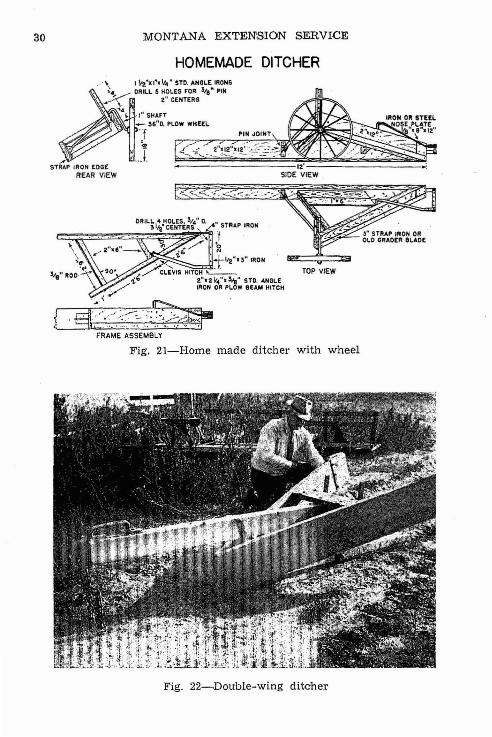
Fig. 21-Home made ditchel' with wheel
Fig. 22~DoU'ble-wing diteher
DOUBLE WING TYPE DITCHER
......~
~......o>>-3
oZen>-3~~()>-3~;>Z"--r~ 2"~ 18' stmp wHh tWist h109(S beam to brocc stl"l1fl t::J
, tl:j
od......"d
~Z>-3
.. Plate for no."
r bolt th.u both sIdes of plah and L--r~~i"L with point on
bottom end
·l""zf",28'L~,-".4= eol! lhru both sides and both strnf'
. ~I~/~ ~2 "Z8 Br.." stra.p riuitcd thtu L
. 'finlida--.., I' Z -~'- " .. ~ it il til '-2- in.ide.••.. ~ (I t~1
. lr- if$trap iron hit~h
SIDE ELEVATION
."'4"·4'6" S"..",
.--""f ....· F"lat ir• ., onMit_ of. 4"'."
-til;.,
"f " ",':.'." t ' II Ma"'. bolt
9'"
j .... R""r .kid ."'2"'tfL. 'Z~"from an"....'Mach.b.1U~ 6"'6"-8Te"..", i'·ll"~.r ..ar '
Z-.f21!a.5 1 Plank ~. . "_ C II 'C ~ _ l; i iCovered with to '1<1., '101, iron
f""Z":'Z' L iron 'harpen~an outcr edge.
DETAIL OF ADJUSTMENTBARS
..-z:Strap;.;
1'-6" Mach. bolt/t:!"·'.: ...~
t·hoIC$-2·c~"+e:"'3:in strap iron /
for adju.stmc:nt
VIEW LOOKING AT ~OTTOM
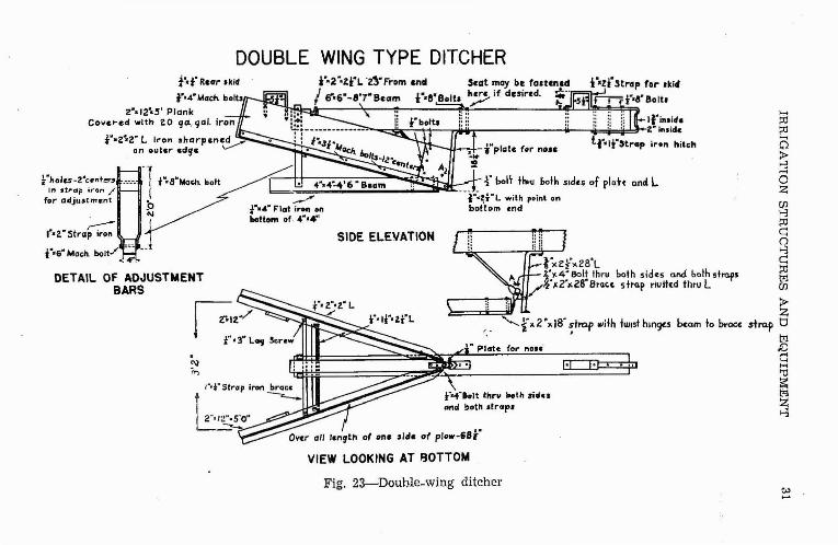
Fig. 23-Double-wing ditchert.>.....
32 MONTANA EXTENSION SERVICE
DITCHERS
Most of the ditchers in use are commercial machines made ofsteel. For those who may want to make their own, Figs. 21 and 23are included to show construction details for the "homemadeditcher with wheel" and "the double wing ditcher." These ditchersmay be used for cleaning an old ditch or shaping up a ditch madeby plowing a single plow furrow.
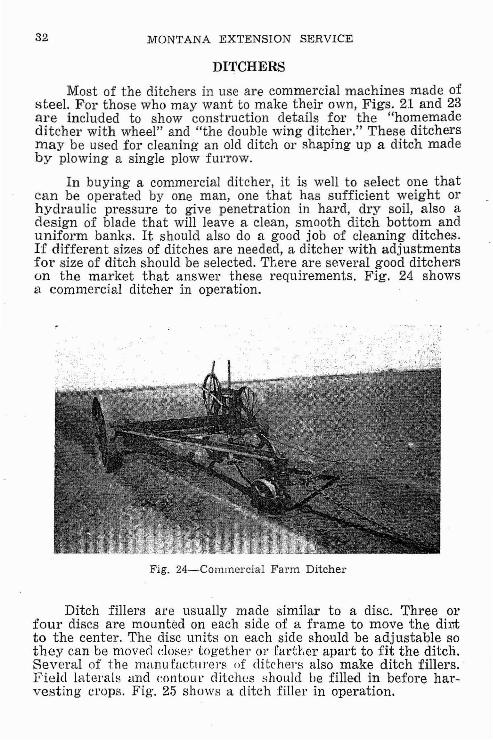
In buying a commercial ditcher, it is well to select one thatcan be operated by one man, one that has sufficient weight orhydraulic pressure to give penetration in hard, dry soil, also adesign of blade that will leave a clean, smooth ditch bottom anduniform banks. It should also do a good job of cleaning ditches.If different sizes of ditches are needed, a ditcher with adjustmentsfor size of ditch should be selected. There are several good ditcherson the market that answer these requirements. Fig. 24 showsa. commercial ditcher in operation.
Fig. 24-Commercial Farm Ditcher
Ditch fillers are usually made similar to a disc. Three orfour discs are mounted on each side of a frame to move the dir,tto the center. The disc units on each side should be adjustable sothey can be moved closer together or farther apart to fit the ditch.Several of the manu factmel's of ditchel's also make ditch fillers.Field latel'als and rontou l' ditches f-ihould be filled in before harvesting crops. Fig. 25 shows a ditch filler in operation.
IHRIGATION STRUCTURES AND EQUlPMENT
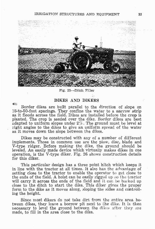
Fig. 25~Ditch Filler
DIKES AND DIKERS
33
Border dikes are built parallel to the direction of slope on15:.to-50-foot spacings. They confine the water to a narrow stripas it floods across the field. Dikes are installed before the crop isplanted. The crop is seeded over the dike. Border dikes are beRtadapted to uniform slopes under 2%. The ground must be level atright angles to the dikes to give an uniform spread of the wateras it moves down the slope between the dikes.
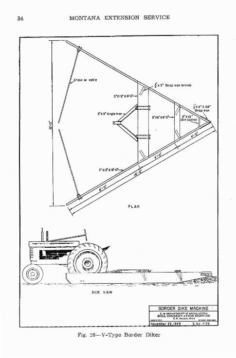
Dikes may be constructed with any of a number of differentimplements. Those in common use are the plow, disc, blade andV-type ridger. Before making the dike, the ground should beleveled. An easily made device which virtually makes dikes in oneoperation, is the V-type dikeI'. Fig. 26 shows construction detailsfor this dikeI'.
This particular design has a three point hitch which keeps itin line with the tractor at all times. It also has the ailvantage ofsetting close to the tractor to enable the operator to get dose tothe ends of the field. A hoist can be easily rigged ll}J so 1he tn1ctorwill carry it across the ends of the- field and it can be backed upclose to the ditch to start the dike. This diker gives the properform to the dike as it moves along, sloping the sides and controlling the height.
Since most dikers do not take dirt from the entire area between dikes, they leave a borrow pit next to the dike. It is thennecessary to level the ground between the dik(~s aHer they aremade, to fill in the area close to the dike.
34 MONTANA EXTENSION SIDRVICE
SIDE VIEW
BORDER DIKE MACHINE .U. s. P1WAR'rM,,:!"T OF' AOItICLJI:ruu.,;
SOILCON9'EHV.\TION SERVIGRII. II. 1l~,,,,.Il. '~hJ~1
November 22 1949
Fig. :.l6-V-Ty.pe Border DikeI'
!'RRIGATION STRUCTURES AND EQUIPMENT 35
Another means of making dikes, is by installing a long bladeon a regular grader. By making two or three rounds to form eachdike a thin layer of dirt can be taken from the entire area betwe'O'TIdikes. '
Some machine companies are now building hydraulically controlled blades which will pull dirt at right angles to the dikes. Thistype of equipment is operated cross-wise of the field dumping thedirt on the dike with the hydraulic lift. It works something likeraking hay with the old fashioned dump rake.
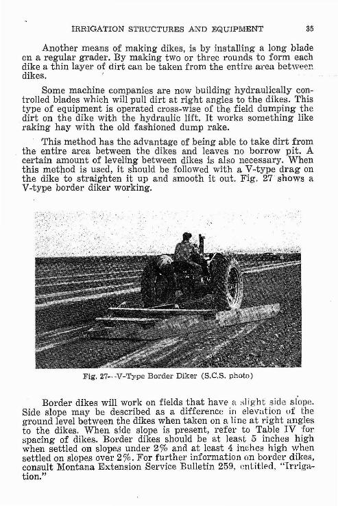
This method has the advantage of being able to take dirt fromthe entire area between the dikes and leaves no borrow pit. Acertain amount of leveling between dikes is also necessary. 'Whenthis method is used, it should be followed with a V-type drag onthe dike to straighten it up and smooth it out. Fig. 27 shows aV-type border diker working.
F,ig. 27-V-Type Border Diker (S.C,S. photo)
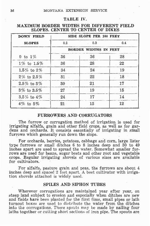
Border dikes will work on fields that have H :-llight side slope.Side slope may be described as a difference in elevation uf theground level between the dikes when taken on a line at right anglesto the dikes. When side slope is present, refer to Table IV forspacing of dikes. Border dikes should be at least 5 inches highwhen settled on slopes under 2% and at least 4 inches high whensettled on slopes over 2%. For further information on border dikes,consult Montana Extension Service Bulletin 259, entitled, "Irrigation."
MONTANA EXTENSION SERVICE
TABLE IV.
MAXIMUM BORDER WIDfTHS FOR DIFFERENT FIELDSLOPES. CENTER TO CENTER OF DIKES
DOWN FIELD SIDE SLOPE PER 100 FEET--------_.__.
SLOPES 0.2 0.3 0.4--
BORDER WIDTHS IN FEET~
0 to 1% 36 36 28
1% to 1.5% 36 28 22-_..._....-._ .._.~------
1.5% to 2% 34 24 19
2% to 2.5% 31 22 18
2.5% to 3% 30 21 17----
3% to 3.5% 27 19 15- -- --------
3.5(}{, to 4% 24 17 14.__...._.._...- --------- ---------
4% to 5% 21 15 12
FURROWERS AND CORRUGATORS
The furrow or corrugation method of irrigation is· used forirrigating alfalfa, grain and other field crops, as well as for gardens and orchards. It consists essentially of irrigating in smallfurrows which generally run down the slope.
-For orchards, berries, potatoes, cabbage and corn, large listertype furrows or small ditches 6 to 8 inches deep and' 30 to 49inches apart are used to spread the water. Somewhat smaller furrows are used for beans,sugar beets and other root and vegetablecrops. Regular irrigating shbvels of various sizes are availablefor cultivatol's. - -
For alfalfa, pasture grain and peas, the furrows are about 4inches deep and spaced 2 feet apart. A beet cultivator with irrigation shovels attached is widely used.
SPILES AND SIPHON TUBES
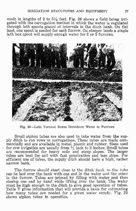
Wherever corrugations are maintained year after year, onsteep land subj ect to erosion and especially when ditches are newand fields have been planted for the first time, small pipes or lathturnout boxes are used to distribute the water from the ditchesinto the corrugations. These spouts may be made by nailing fourlaths together or cutting shol't sections of iron pipe. The spouts ·are
IHRrGATION STRUCTURES AND EQUIPMENT 3'1
made in lengths of 2 to 31;2 feet. Fig. 28 shows a field being irrigated with the corrugation method in which the water is regulatedthrough lath spouts placed at intervals in the ditch bank. On flatland, one spout is needed for each furrow. On steeper lands a singlelath box SPOLlt will supply enough water for 2 or 3 furrows.
Fig. 28-Lath Turnout Boxes Distribute Water to Furrows
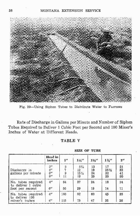
Small siphon tubes are also used to take water from the supply ditch to run rows or corrugations. These tubes are made commercially and are available in metal, plastic and rubber. Sizes usedfor row irrigation are usually from i!/t. inch to 2 inches. Small tubesare recommended for heavy soils and steep slopes. The largertubes are best for soil with fast penetration and less slope. Forefficient use of tubes, the supply ditch should have a high, rathernarrow bank.
The furrow should start close to the ditch bank ~w the tubecan be laid over the bank with one end in the water and the otherin the furrow. Tubes are primed by filling with water and thenclos,ing one end by hand while lifting over the bank. The watermust be high enough in the ditch to give good operation of tubes.Table V gives information that will provide a basis for estimatinghow many tubes are needed for a given water supply. Fig'. 29shows siphon tubes in operation.
38 MONTANA EXTENSION SERVICE
Fig. 29-Using SiJphon Tubes to DistriJbute Water to Furrows
Rate of Discharge in Gallons per Minute and Number of SiphonTubes Required to Deliver 1 Cubic Foot per Second and 100 Miner'sInches of Water at Different Heads.
TABLE V
SIZE OF TUBE
Head ininches 1/1 1%,/1 1~/I 1%" 2/1
--- f---------- -
2" 5 BlIi 13 17 21Discharge in 4" 7 12 19 25 1h 32gallons per minute 6" 9 15% 24 32 41
9" 11 19 29 39 50_..- -- -----No. tllibes required 4/1 64 37 24 18 14to deliver 1 -cubicfoot per second 6" 50 29 19 14 11
No. tubes required! 4" 160 92 60 4.5 35to deliver 100miner's inches ti" 1:l5 '73 47 35 28
'-----.
IRRIGATION STRUCTURES AND EQUI,PMENT 39
GATED PIPE
Gated pipe gives better control of the water Ht the row turn;8. This pipe is made in various sizes usually from 4 to 8 incheSdiameter. Slide gates are set in the pipe at the same spacingsthe rows. The pipe is used in place of a head ditch across the
I side of the field with the gates between the rows or over theTOWS. Water is run into the pipe by gravity and the slide gatemings provide a means of giving complete control of the amountswater for each furrow. Gated pipe gives good control of waterslopes too steep for effective use and distribution from an
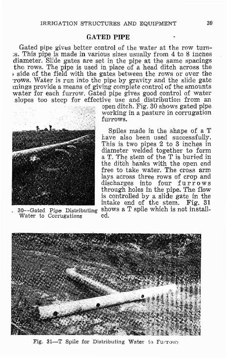
open ditch. Fig. 30 shows gated pipeworking in a pasture in corrugationfurrows.
Spiles made in the shape of a Thave also been used successfully.This is two pipes 2 to 3 inches indiameter welded together to forma T. The stem of the T is buried inthe ditch banks with the open endfree to take water. The cross armlays across three rows of crop anddischarges into four fur row sthrough holes in the pipe. The flowis controlled by a slide gate in theintake end of the stem. Fig. 31
30-Gated Pipe Distributing shows a T spile which is not install-Water to Corrugations ed.
Fig. 31-'T Spile for Distributing Water to FUITow,'
40 MONTANA EXTENSION SERVICE
LEVELS AND SURVEYING EQUIPMENT
To apply the irrigation water with the least trouble and expenditure of time,. the ditches should be run to the proper grade;and weirs, headgates, checks, turnouts, and other devices should.be properly installed before the water is ready for the ditches.To accomplish this requires the use of levels.
HOME MADE "CRICKET" LEVEL
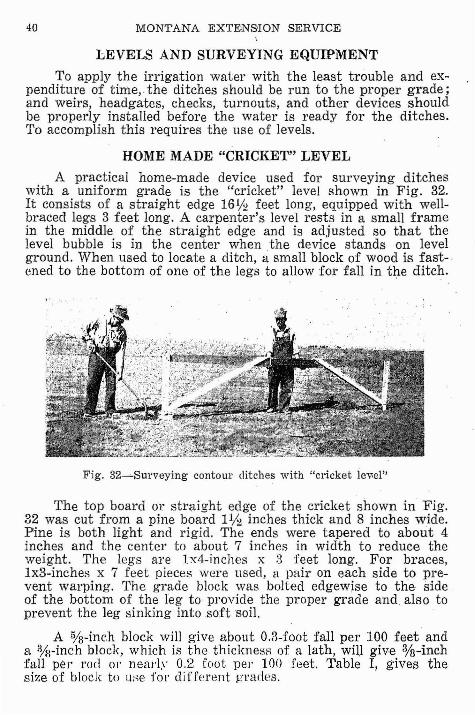
A practical home-made device used for surveying ditcheswith a uniform grade is the "cricket" level shown in Fig. 32.It consists of a straight edge 161j2 feet long, equipped with wellbraced legs 3 feet long. A carpenter's level rests in a small framein the middle of the straight edge and is adjusted so that thelevel bubble is in the center when the device stands on levelground. When used to locate a ditch, a small block of wood is fast-·cned to the bottom of one of the legs to allow for fall in the ditch.
Fig. 32~Surveying contour ditches with "cricket iev.el"
The top board or straight edge of the cricket shown in Fig.32 was cut from a pine board 1% inches thick and 8 inches wide.Pine is both light and rigid. The ends were tapered to about 4inches and the center to about 7 inches in width to reduce the'.'feight. The legs are Ix4-inches x 3 feet long. For braces,lx3-inches x 7 feet pieces were used, a pair on each side to prevent warping. The grade block was bolted edgewise to the sideof the bottom of the leg to provide the proper grade and. also toprevent the leg sinking into soft soil.
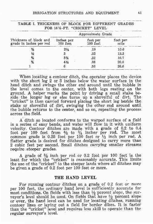
A %-inch block will give about 0.3-foot fall per 100 feet anda %-inch block, which is the thickness of a lath, will giv,e %-inchfall per rod or nea]'l~' 0.2 foot pel' IOO feet. Table I, gives thesize of block to UKe for diffEl1'ent g'l'alles.
1'RRIGATION STRUCTURES AND EQUIPMENT
TAJBLE 1. 1'HIICKNEIS'S OoF BLOCK FOR DIFFERENT GRAUEISFOR 16lh-FT. "CRICK'ET" LEVEL
------._----,-_._-Approximate Grade
Thickness of block and inches per feet per feet pergrade in inches per rod 100 feet 100 feet mile
%%%~
1
.19
.25
.32
.38
.50
10.013.316.720.026.6
When locating a contour ditch, the operator places the devicewith the short leg 2 or 3 inches below the water surface in thehead ditch and swings the other end around until the bu1;>ble inthe level' comel; to the center, with both leg I; resting on theground. A helper marks the point by driving a small stake beside the longer leg or else turns up a shovelful of dirt. The"cricket" is then carried forward plach).g the short leg beside thestake or shovelful of dirt, swinging the other end around untilthe bubble returns to the center, and so on, repeating the processacross the field.
A' ditch so located conforms to the warped surface of a fieldin a series of easy bends, and water will flow in it with uniformvelocity. Contour ditches are made with a grade of 0.2 to 0.4foot per 100 feet from % to % incher per rod. The mostcommon grade is 0.25 foot per 100 feet or 112 inch per rod. Aflatter grade is desired for ditches designed to carry more than2 cubic feet per second. Small ditches carrying smaller streamsrequire. steeper grades.
A grade of % inch per rod or 0.2 foot per 100 feet is theleast for which the "cricket" is reasonably accurate. This limitsthe use of the "cricket" to the steeper lands where all ditches maybe given a grade of 0.2 foot per 100 feet or more.
THE HAND LEVEL
For running contour ditches on a grade of 0.2 feet or mOl'e
per 100 feet, the ordinary hand level is sufficiently accurate fol'most conditions. On fields with less than % percent slope, the surveyor's level should be used. On fields that have 1/2 percent slopeor over, the hand level can be used for locating ditches, runningcontour lines or laying out afield for border dikes. It is fasterthan the "cricket" level and requires less skill to operate than theregular surveyor's level.
42 MONTANA EXTENSION SIDRVlGE
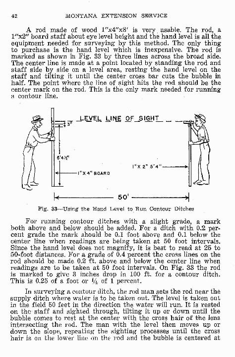
A rod made of wood 1"x4"x8' is very usable. The rod, al/1x2" board staff about eye level height and the hand level is all theequipment needed for surveying by this method. The only thingto purchase is the hand level which is inexpensive. The rod ismarked as shown in Fig. 33 by three lines across the broad side.'fhe center line is made at a point located by standing the rod andstaff side by side on a level area, resting the hand level on thestaff and tilting it until the center cross bar cuts the bubble inhalf. The point where the line of sight hits the rod should be thecenter mark on the rod. This is the only mark needed for runninga contour line.
~14Ytl
+-'OX4" '0'"I"X 2" 5'4"---+1
50' -----~)I
Fig. 33-Using the Hand Level to Run Contour Ditches
For running contour ditches with a slight grade, a markboth above and below should be added. For a ditch with 0.2 percent grade the mark should be 0.1 foot above and 0.1 below thecenter line when readings are being taken at 50 foot intervals.Since the hand level does not magnify, it is best to read at 25 to50-foot distances. For a grade of 0.4 percent the cross lines on therod should be made 0.2 ft. above and below the center line whenreadings are to be taken at 50 foot intervals. On Fig. 33 the rodis marked to give 3 inches drop in 100 ft. for a contour ditch.This is 0.25 of a foot orYt. of 1 percent.
In surveying a contonr ditch, the rod man sets the rod near thesupply ditch where water is to be taken out. The level is taken outin the field 50 feet in the direction the water will run. It is restedon the staff and sighted through, tilting it up or down until thebubble comes to rest at the center with the cross hair of the lensintersecting the rod. The man with the level then moves up ordown the slope, repeating the sighting processes until the crosshair is on the lower line on the rod and the bubble is centerEjd at
IRRIGATION STRUCTURES AND EQUIPMENT 43
the same time. When this point is found, the staff is held on thisspot and the rod man moves on across the field in the directionthe water will run, 50 feet past the man with the level.
This time the rod man moves the rod up or down the slope untilthe level line of the sight is hitting the top mark on the rod. Therod man then marks this spot and holds the rod on it while theman with the level goes past him 50 ft. and locates a new pointwhere he is reading the lower mark. The two go around each otheralternately, always 50 feet and the man in the lead always movesup or down the slope to find the new point. The man with thelevel should remember to read the top mark on the rod whensighting in the direction the water is to run and the bottom markwhen sighting in the opposite direction. Points should be markedeither by a shovelful of dirt or a stake. If a third man and ditcherequipment is available, it can follow along through the points asthey are located and no marking is necessary. .
For running contour lines, the same procedure is followed,except that the center mark on the rod is the only one used.
USE OF 'l'HE SURVEYOR'S,. LEVEL
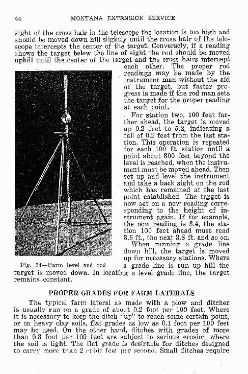
Running a contour ditch grade with a surveyor's level requires two persons, the instrument man and the rod man. Thelevel is set up about 300 feet out from the head ditch down theside of the field and a little above the elevation where the firstcontour ditch is to be taken out, so that when leveled, the telescope or line of sight is 4 or 5 feet above the proposed turnout.When using a small farm level the length of sight should belimited to 200 feet each way from the instrument. Fig. 34 showsa farm level and a surveyor's rod often used in laying out farmditches.
The rodman places the lower end of the rod 2 or 3 inches belowthe water surface in the head ditch or turnout box, care beingtaken to hold the rod vertically. The levelman sights through thetelescope and reads the figure on the level rod intercepted bythe horizontal cross-hair. For example, assume that the crosshair intercepts the figure 4.8 feet. Then the target is set at thatfigure which is the initial reading. (Surveyors' level rods areusually marked off in feet and tenths of a foot, being easiet· toread and calculate than one marked in feet and inche:-;), A stakeis placed or a shovelful of dirt turned uP. to mark the, place ofbeginning. The rodman then paces approximately 100 feet fromthe starting point in the direction of the ditch is expected to go andsets the target at 5.0 feet which allows 0.2 foot fall if the grade isto be 0.2 per hundred ft. The rod is then held up by the rodm'an..for a reading. If the target center is above the horizontal line of
44 MONTANA EXTENSION SERVICE
sight of the cross hair in the telescope the location is too high andshould be moved down hill slightly until the cross hair of the telescope intercepts the center of the target. Conversely, if a readingshows the target below the line of sight the rod should be moveduphill until the center of the target and the cross hairs intercept
each other. The proper rodreadings may be made by theinstrument man without the aidof the target, but faster progress is made if the rod man setsthe target for the proper readingat each point.
For station two, 100 feet farther ahead, the target is movedup 0.2 feet to 5.2, indicating afall of 0.2 feet from the last station. This operation is repeatedfor each 100 ft. station until apoint about 300 feet beyond thelevel is reached, when the instrument must be moved ahead. Thenset up and level the instrumentand take a back sight on the rodwhich has remained at the lastpoint established. The ta]Jget isnow set on a new reading carre··sponding to the height of instrument again. If for example,the new reading is 3.4, the station 100 feet ahead must read3.6 ft., the next 3.8 ft. and so on.
When running a. grade linedown hill, the target is movedup for necessary stations. Where
Fig. 34-Farm level and rod a grade line is run up hill thetarget is moved down. In locating a level grade line, the targetremains constant.
PROPER GRADES FOR FARM LATERALSThe typical fal'ill lateral as made with a plow and ditcher
is usually run on a grade of about 0.2 foot per 100 feet. Whereit is necessary to keep the ditch "up" to reach some certain point,or on heavy clay soils, flat grades as low as 0.1 foot per 100 feetmay be used. On the other hand, ditches with grades of morethan 0.3 foot per 100 feet are subject to serious erosion wherethe soil is light. The flat grade is desirable for ditches designedto cany more than 2 cubic feei per seeond. Small ditches require
l'RRIOA'fION STRUCTURES AND EQUIPMENT 45
steeper grades. Table VI on this page gives the carrying capacityof farm ditches at varying depths at grades of 0.1 and 0.2 footper 100 feet. Ordinary V-type ditches carry considerably lesswater than these--sizes.
TABLE Vr~CARRYINGCAp:AOITY OF r<'ARM DITCHES
Dept ,Crossin section
incrue,s -sq. ft.
9 2.0612 3.0015 4.0618 5.2521 6.5624 8.00
9 2.8112 4.0015 5.3118 6.7521 8.3124 10.00
Velocity-feet per second
Grade .001 Grade .002or .1 ft/100 or .2 it/lOO
Bottom width of ditch 2 feet.80 1.15.96 1.38
1.10 1.571.24 1.751.35 1.921.46 2.03
Bottom width of ditch 3 feet.88 1.24
1.06 1.471.20 1.701.34 1.901.44 2.041.58 2.26
Discharge incubic feet per second--_._--".~-
Grade .001 Grade .002
1.65 2.362.88 4.144.46 6.386.50 9.208.85 12.60
11.70 16.20
2.47 3.484.25 5.886.36 9.029.0'5 12.82
11.98 16.9215.80 22.60
------ ------------- ._-----_._-----
PORTABLE DAMS
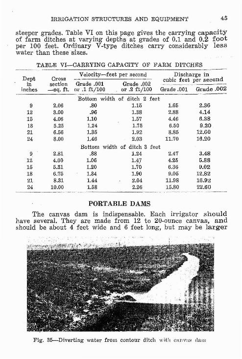
The canvas dam is indispensable. Each irrigator shouldhave several. They are made from 12 to 20-ounce canvas, andshould be about 4 feet wide and 6 feet long, but may be larger
Fig. 35-Diverting water from contour ditch with Cill1'lal' dam
46 MONTANA EXTENSION SERVICE
for larger ditches. The 6-foot side is fastened to a lO-foot 2x2,a 2x4, or a pole, either by nails through a lath, or by sewing alarge hem through which the stick or pole may be inserted. Thismakes it possible to withdraw the pole and fold the canvas whennot in use. Heavy burlap will also make a satisfactory dam.
Fig. 35 shows a canvas dam used to divert water from acontour ditch to the land. The dam is usually put in place beforethe water reaches the point of diversion and is laid in the ditchwith the canvas extending up stream and the pole spanning theditch and resting on each bank. Some earth should be thrownon the edges of the canvas to hold it in place. With two damson each lateral, one may be placed while the water is spreadingfrom the one above. Canvas dams will last much longer if cleaned,dried and placed under cover after each irrigation.
.Plastic dams are coming into common use. They serve thesame purpose and are used in the same manner as the canvasdam. They are somewhat more expensive, but are reported to havea longer life than the canvas dam. These dams will tear underrough use but can be vulcanized. They do not accumulate muchweight when wet and only a small amount of mud sticks to themwhen they are removed from the ditch.
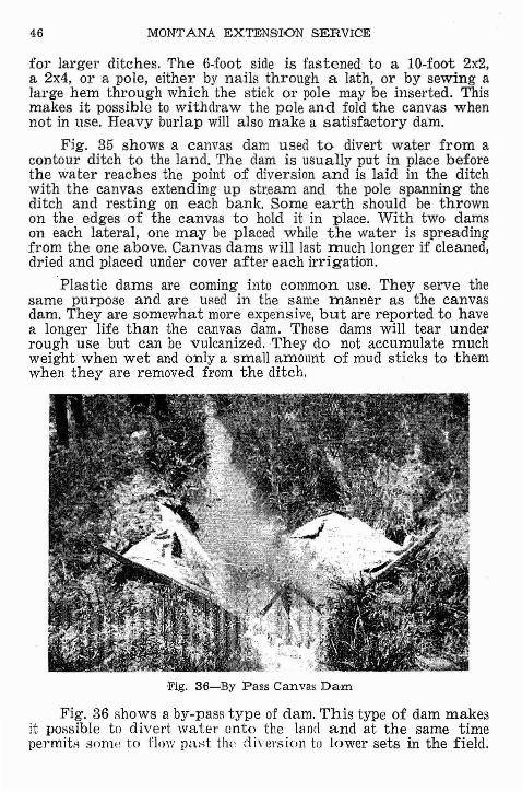
'Fig. 36----'By Pass Canvas Dam
Fig. 36 shows a by-pass type of clam. This type of dam makesit possible to divert water onto the land and at the same timepermitH snnw to flow past tlw d ivel'gjol1 to lower sets in the field.
I'RRIGATION STRUCTURES AND EQUIPMENT 47
It is particularly suited to the irrigation of row crops where siphontubes or spiles are used as turnouts and the water level in theditch must be held ata uniform level to operate them.
Portable metal dams are used successfully for small ditchesin soBs that do not erode readily. They consist of a half circle ortriangle-shaped piece of heavy gage galvanized iron or steel, re~
inforced across the top and usually with a single metal peg throughthe center that sticks into the bottom of the ditch.
Fig. 37-Soil moisture prober
MOI!!lrUfllflt:. PROIAC.R(COVRT£.SY BuR£.AU (J~ R~CLAMArJON)
HANDLE.j"". __ I.e ,,.,.
FIN,Roo.31'"'T. LONG
0,...,.:JOIL.
w,---j r-.l"N.
Y'}\\\...V
E:NLAR'GItD
V,EW OF eND
., '.," ..... \
" ."", '.
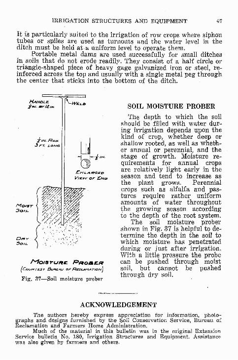
SOIL MOISTURE PROBER
The depth to which the soilshould be filled with water during irrigation depends upon thekind of crop, whether deep orshallow rooted, as well as whether annual or perennial, and thestage of growth. Moisture requirements for annual cropsare relatively light early in theseason and tend to increase asthe plant grows. Perennialcrops such as alfalfa and pas~
tures require rather uniformamounts of water throughoutthe growing season accordingto the depth of the root system.
The soil moisture probershown in Fig. 37 is helpful to determine the depth in the soil towhich moisture has penetratedduring or just after irrigation.With a little pressure' the probecan be pushed through moistsoil, but cannot be pushedthrough dry soil.
ACKNOWLEDGEMENTThe authors hereby express appreciation for information, photo
gr8Jphs and designs furnished by the Soil Conservation Service, Bureau ofReclamation and Farmers Home Administration.
Much of the material in this bulletin was in the original ExtensionService bulletin No. 180, Irrigation Structures and Equipment. Assistancewas also given by farmers and others.