Embed Size (px)
Citation preview
Guidelines for Planning and Design
of
MICRO IRRIGATION SYSTEM
CHIEF ENGINEER (DESIGN) DR. RAM MANOHAR LOHIA PARIKALP BHAWAN
TELIBAGH, LUCKNOW, 226029
IRRIGATION AND WATER RESOURCES DEPARTMENT
UTTAR PRADESH
Guidelines for Planning and Design of
Micro Irrigation System
First Edition: March, 2022
Issued By: Chief Engineer (Design), Dr. Ram Manohar Lohia
Parikalp Bhawan, Telibagh, Lucknow, 226029
Department: Irrigation and Water Resources Department, U. P.

Er. Vinod Kumar Niranjan
Engineer in Chief and Head of Department
Irrigation and Water Resources Department
Uttar Pradesh, Lucknow
FOREWORD
Development is a continuous process and in that process development of technology helps in the
optimum use of resources to meet the need of ever growing demand. Water is a vital resource which is required to sustain life on earth. Growing population, industrialization, upgradation of standard of living put huge pressure on water as a resource.
Irrigation sector consumes 92 % of water; hence, increasing efficiency in water application in irrigation sector will immensely save water. Micro irrigation is most efficient form of water
application method. Therefore, micro irrigation is the future vital area to be explored and practiced in U ttar Pradesh.
The future revolution in agriculture will come from precision farming. Micro-irrigation can, indeed, be the stepping stone for achieving the goal of making farming sustainable, profitable and productive.
To implement the micro irrigation system 'Guidelines for Planning and Design of Micro Irrigation System" has been prepared by Central Design Directorate, Lucknow. These guidelines will be helpful in providing the opportunity to new users who require technical knowhow in design and establishment of
the system. It will also be helpful in maintaining the uniformity of quality.
These guidelines have been prepared by the Central Design Directorate under the leadership of Er. AK Jain, Level - I (D & R). It is hoped that the guidelines will be helpful for designers and field engineers.
Er. Ashok Kumar Singh
Engineer in Chief (D & P)
Irrigation and Water Resources Department
Uttar Pradesh, Lucknow
FOREWORD
UP state has 161. 70 BCM of surface water and 72 BCM exploitable ground water. Because of
increasing demand for various purposes namely irrigation, drinking and domestic, power, industrial and other uses, its scarcity is becoming apparent which shall get more pronounced with increasing population. The indiscriminate use of ground water has resulted in depletion of groundwater storage and lowering of water levels in certain areas on one hand,on other hand, the surface water canals, in areas having shallow water level, have resulted in water logging and soil salinisation. With continual diminishing per capita water availability coupled with groundwater exploitation, it has become imperative to switch to efficient water saving technologies and alternative methods of irrigation.
Flood irrigation has been predominantly used for field crops, where water losses from evaporation and leaching are very high. As a result of the water saving campaign in recent years, the development of micro irrigation system has been recognised. Micro irrigation system can be of immense help in reducing a bit of the burden. This system is effective in saving water and increasing water use efficiency as compared to the conventional surface irrigation methods. Additionally, it also helps in minimizing soil erosion.
To implement the micro irrigation system "Guidelines for Planning and Design of Micro Irrigation System" has been prepared by Central Design Directorate, Lucknow under the leadership of Er. A K Jain, Level - I (D & R). These guidelines not only give the methodology but also provide the specification of various elements of design & equipment, to our designer and field engineer.
I hope this manual will be of great use for the department & it will help in optimizing the scarce resource i.e. water.
~1-0~
(Ashok Kumar Singh)
Er. Mushtaq Ahmad
Engineer in Chief (Project)
Irrigation and Water Resources Department
Uttar Pradesh, Lucknow
FOREWORD
Water is essential for sustainable development of human beings specially for drinking, agriculture, health, sanitation, construction etc. Around 92 % available water resources are being utilized in agricultural irrigation sector. Conventional canal systems tubewells, tanks are widely used to carry water from naturally occurring sources, to farmer's field. There is huge wastage of water in traditional irrigation methods like flood irrigation etc. So, it is required to develop technology which can help in optimal utilization of water and its transportation from source to field. For this, we need to change conventional system to piped network system.
Micro irrigation system can be of immense help in reducing a bit of the burden. This system is effective in saving water and increasing water use efficiency as compared to the conventional surface irrigation methods. Additionally, it also helps in prevention of growth of unwanted weeds and soil eros10n.
To implement the micro rrngation system "Guidelines for Planning and Design of Micro Irrigation System" has been prepared by Central Design Directorate, Lucknow. These guidelines will be helpful in providing the opportunity to new users who require technical knowhow in design and establishment of the system. It will also be helpful in maintaining the uniformity of quality.
These guidelines for planning and design of Micro Irrigation System have been prepared by the Central Design Directorate under the leadership of Er. A K Jain, Level - I (D & R). It is hoped that the guidelines will be helpful for designers and field engineers.
PREFACE
U P has a vast network of canals, tubewells and tanks which are used for inigation purpose. Canal system and Guls (water course) are essential components of this system which are used to carry irrigation water from source to field. Farmers broadly use flood irrigation system to irrigate their fields. This process leads to wastage of water in the form of conveyance loss, percolation loss, evaporation loss, loss due to breach and loss due to negligence. Excessive use of water is not only harmful for the yield of plants but also invites the danger of water logging where water table is high.
Micro inigation system is useful in optimising the yield of crops Uustify the slogan 'Per Drop More Crop') and minimise the losses which are inevitable in conventional system. Micro irrigation is the slow application of continuous drips, bubbler, subsurface or sprays of water above or below the soil surface. This system is most suitable for water scarce areas and in hilly terrains where ground is uneven and undulating. Besides, it helps reduce water consumption, growth of unwanted plants (weeds), soil erosion and cost of cultivation.
Until now, there was no formal guideline available for the U P Irrigation Department for micro irrigation systems. Officers of Central Design Directorate, Lucknow have prepared a comprehensive guidelines for planning and design of micro irrigation system. Er. Anil Kumar Niranjan, S.E., Er. Kamnesh Kumar and Er. Alok Kumar (Executive Engineers) and Er. Alok Kumar and Er. Varsha Bisht (Assistant Engineers) have made valuable contributions in preparing these guidelines.
These guidelines cover introduction, objectives, types, benefits and limitations of Micro Irrigation Systems. It also covers planning and designing, running and maintenance of Drip and Sprinkler Irrigation and its components under Micro Irrigation System. These guidelines also include indicative bill of quantities for drip and sprinkler irrigation systems for reference alongwith crop specific design examples as annexures. Various IS Codes and other government sources have been referred for preparation of these guidelines.
It is hoped that these guidelines will be helpful for both design and field engineers in designing and execution of micro inigation system related projects.
. 0~
~~~~ (Er.~Ibk Ku:nar Jain)
Chief Engineer, Level T (D & R)
Irrigation and Water Resources Department
Uttar Pradesh, Lucknow
CORE TEAM ASSOCIATED WITH THE PREPARATION OF GUIDELINES
~=:;--_
Er. Karunesh Kumar
Executive Engineer
~ Er. Alok Kumar ·
Assistant Engineer
,./ ..J''V
-\- ~0~' Er. Alo~ mar Ja~
Chief Engineer, Level I (D & R)
Superintendent Engineer
~ Er. Alok Kumar
Executive Engineer
Assistant Engineer
i
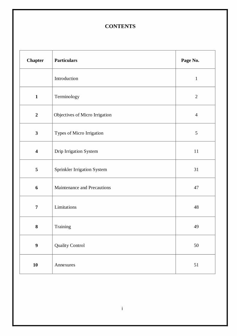
CONTENTS
Chapter Particulars Page No.
Introduction 1
1 Terminology 2
2 Objectives of Micro Irrigation 4
3 Types of Micro Irrigation 5
4 Drip Irrigation System 11
5 Sprinkler Irrigation System 31
6 Maintenance and Precautions 47
7 Limitations 48
8 Training 49
9 Quality Control 50
10 Annexures 51
ii
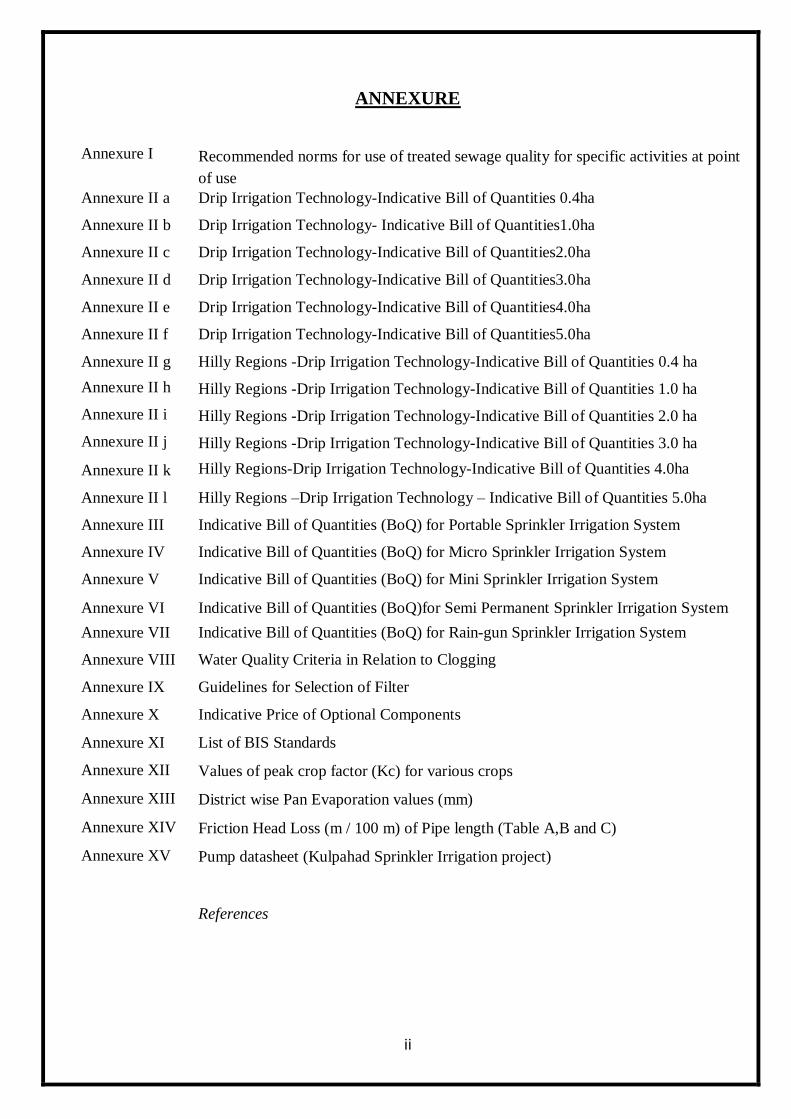
ANNEXURE
Annexure I Recommended norms for use of treated sewage quality for specific activities at point
of use
Annexure II a Drip Irrigation Technology-Indicative Bill of Quantities 0.4ha
Annexure II b Drip Irrigation Technology- Indicative Bill of Quantities1.0ha
Annexure II c Drip Irrigation Technology-Indicative Bill of Quantities2.0ha
Annexure II d Drip Irrigation Technology-Indicative Bill of Quantities3.0ha
Annexure II e Drip Irrigation Technology-Indicative Bill of Quantities4.0ha
Annexure II f Drip Irrigation Technology-Indicative Bill of Quantities5.0ha
Annexure II g Hilly Regions -Drip Irrigation Technology-Indicative Bill of Quantities 0.4 ha
Annexure II h Hilly Regions -Drip Irrigation Technology-Indicative Bill of Quantities 1.0 ha
Annexure II i Hilly Regions -Drip Irrigation Technology-Indicative Bill of Quantities 2.0 ha
Annexure II j Hilly Regions -Drip Irrigation Technology-Indicative Bill of Quantities 3.0 ha
Annexure II k Hilly Regions-Drip Irrigation Technology-Indicative Bill of Quantities 4.0ha
Annexure II l Hilly Regions –Drip Irrigation Technology – Indicative Bill of Quantities 5.0ha
Annexure III Indicative Bill of Quantities (BoQ) for Portable Sprinkler Irrigation System
Annexure IV Indicative Bill of Quantities (BoQ) for Micro Sprinkler Irrigation System
Annexure V Indicative Bill of Quantities (BoQ) for Mini Sprinkler Irrigation System
Annexure VI Indicative Bill of Quantities (BoQ)for Semi Permanent Sprinkler Irrigation System
Annexure VII Indicative Bill of Quantities (BoQ) for Rain-gun Sprinkler Irrigation System
Annexure VIII Water Quality Criteria in Relation to Clogging
Annexure IX Guidelines for Selection of Filter
Annexure X Indicative Price of Optional Components
Annexure XI List of BIS Standards
Annexure XII Values of peak crop factor (Kc) for various crops
Annexure XIII District wise Pan Evaporation values (mm)
Annexure XIV Friction Head Loss (m / 100 m) of Pipe length (Table A,B and C)
Annexure XV Pump datasheet (Kulpahad Sprinkler Irrigation project)
References
1
INTRODUCTION
In 2015, Government of India launched Pradhan Mantri Krishi Sinchayee Yojana
(PMKSY). The scheme aims at creating protective irrigation by harnessing rain water at micro level
through ‗Jal Sanchay‘ and ‗Jal Sinchan‘. Micro irrigation is an integral component of the scheme to
maximise water use efficiency at farm level.
State of Uttar Pradesh has bounty of water resources, but not all water resources are
utilizable. Rainfall is mainly limited to monsoon season. Due to plain topography of the state, large
storage of water is not feasible. We do divert certain amount of water coming from upper riparian
states but that does not suffice the demand. Due to excess abstraction, ground water is depleting very
fast and many regions have already gone into dark zone resulting rivers going dry in lean season.
Because of all these physical and topographical constraints there is little scope of augmentation of
water resources and supply side management of water resources.
So, demand side management is only option left now. Demand side scenario of the State is
such that almost 92 percent water consumption is in agriculture sector. Further within agriculture
sector, 85 percent water is consumed by only three crops that are wheat, paddy and sugarcane. All of
these crops are water guzzling crops. However, farmers produce these crops because of remunerative
prices and ready market is available for these crops. Food security and farmers‘ income are twin
objectives of any state agricultural policy but sustainability of resources is also imperative keeping in
mind requirements of future generations. So, we have to take immediate steps to reduce water
consumption in agriculture sector ensuring sustainability without compromising food security or
farmers‘ income.
To reduce water demand we need to shift to less water intensive crops along with
promoting micro-irrigation. However, judicious use of micro irrigation is imperative to draw real
benefits from this technology. While sprinkler irrigation is suitable for any type of crop in undulating
terrains such as Bundelkhand, its use in plains in wheat crop may not help any net water saving
because saving in seepage part is tantamount to reducing recharge of ground water by same amount.
Further, evaporation losses are rather more in sprinklers so there is no saving on that part too.
However, other benefits of micro-irrigation including sprinkler do entail use of these systems in large
scale in the state of Uttar Pradesh. Heavily silted canal water may not be best option for micro-
irrigation but there are thousands of state and private tube-wells and also lift canals where these
systems can be used extensively.
2
3
Chapter 1
TERMINOLOGY
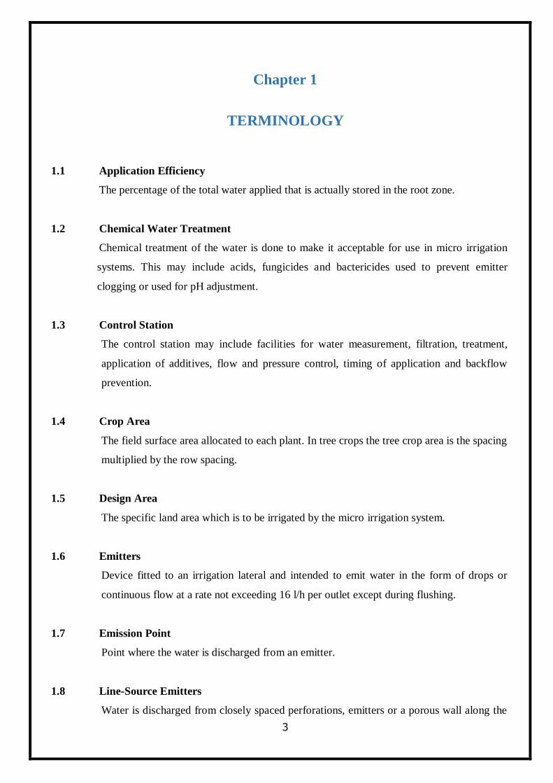
1.1 Application Efficiency
The percentage of the total water applied that is actually stored in the root zone.
1.2 Chemical Water Treatment
Chemical treatment of the water is done to make it acceptable for use in micro irrigation
systems. This may include acids, fungicides and bactericides used to prevent emitter
clogging or used for pH adjustment.
1.3 Control Station
The control station may include facilities for water measurement, filtration, treatment,
application of additives, flow and pressure control, timing of application and backflow
prevention.
1.4 Crop Area
The field surface area allocated to each plant. In tree crops the tree crop area is the spacing
multiplied by the row spacing.
1.5 Design Area
The specific land area which is to be irrigated by the micro irrigation system.
1.6 Emitters
Device fitted to an irrigation lateral and intended to emit water in the form of drops or
continuous flow at a rate not exceeding 16 l/h per outlet except during flushing.
1.7 Emission Point
Point where the water is discharged from an emitter.
1.8 Line-Source Emitters
Water is discharged from closely spaced perforations, emitters or a porous wall along the
4
lateral line.
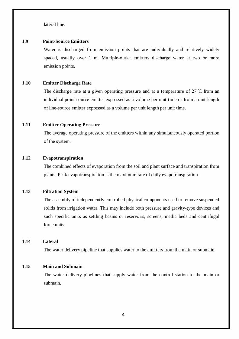
1.9 Point-Source Emitters
Water is discharged from emission points that are individually and relatively widely
spaced, usually over 1 m. Multiple-outlet emitters discharge water at two or more
emission points.
1.10 Emitter Discharge Rate
The discharge rate at a given operating pressure and at a temperature of 27 ֯C from an
individual point-source emitter expressed as a volume per unit time or from a unit length
of line-source emitter expressed as a volume per unit length per unit time.
1.11 Emitter Operating Pressure
The average operating pressure of the emitters within any simultaneously operated portion
of the system.
1.12 Evapotranspiration
The combined effects of evaporation from the soil and plant surface and transpiration from
plants. Peak evapotranspiration is the maximum rate of daily evapotranspiration.
1.13 Filtration System
The assembly of independently controlled physical components used to remove suspended
solids from irrigation water. This may include both pressure and gravity-type devices and
such specific units as settling basins or reservoirs, screens, media beds and centrifugal
force units.
1.14 Lateral
The water delivery pipeline that supplies water to the emitters from the main or submain.
1.15 Main and Submain
The water delivery pipelines that supply water from the control station to the main or
submain.
5
Chapter 2
OBJECTIVES OF MICRO-IRRIGATION
The main objectives of Micro-Irrigation are as under:
o Increase the area under micro irrigation technologies to enhance water use efficiency
in irrigation sector.
o Increase productivity of crops and income of farmers through precision water
management.
o Promote micro irrigation technologies in water intensive/consuming crops like
sugarcane, banana, cotton etc. and give adequate focus to extend coverage of field
crops under micro irrigation technologies.
o Make potential use of micro irrigation systems for promoting fertigation and
chemigation.
o Promote micro irrigation technologies in water scarce, water stressed and critical
ground water blocks/districts.
o Link tube-well / river-lift irrigation projects with micro irrigation technologies for best
use of energy both for lifting and pressurised irrigation as far as possible.
o Promote, develop and disseminate micro irrigation technology for agriculture and
horticulture development with modern scientific knowledge.
6
Chapter 3
TYPES OF MICROIRRIGATION
Micro irrigation is the frequent application of small quantities of water on or below the soil
surface as drops, tiny streams or miniature spray through emitters or applicators placed along a water
delivery line. Micro irrigation encompasses a number of methods or concepts such as bubbler, drip,
trickle, mist or spray and subsurface irrigation.
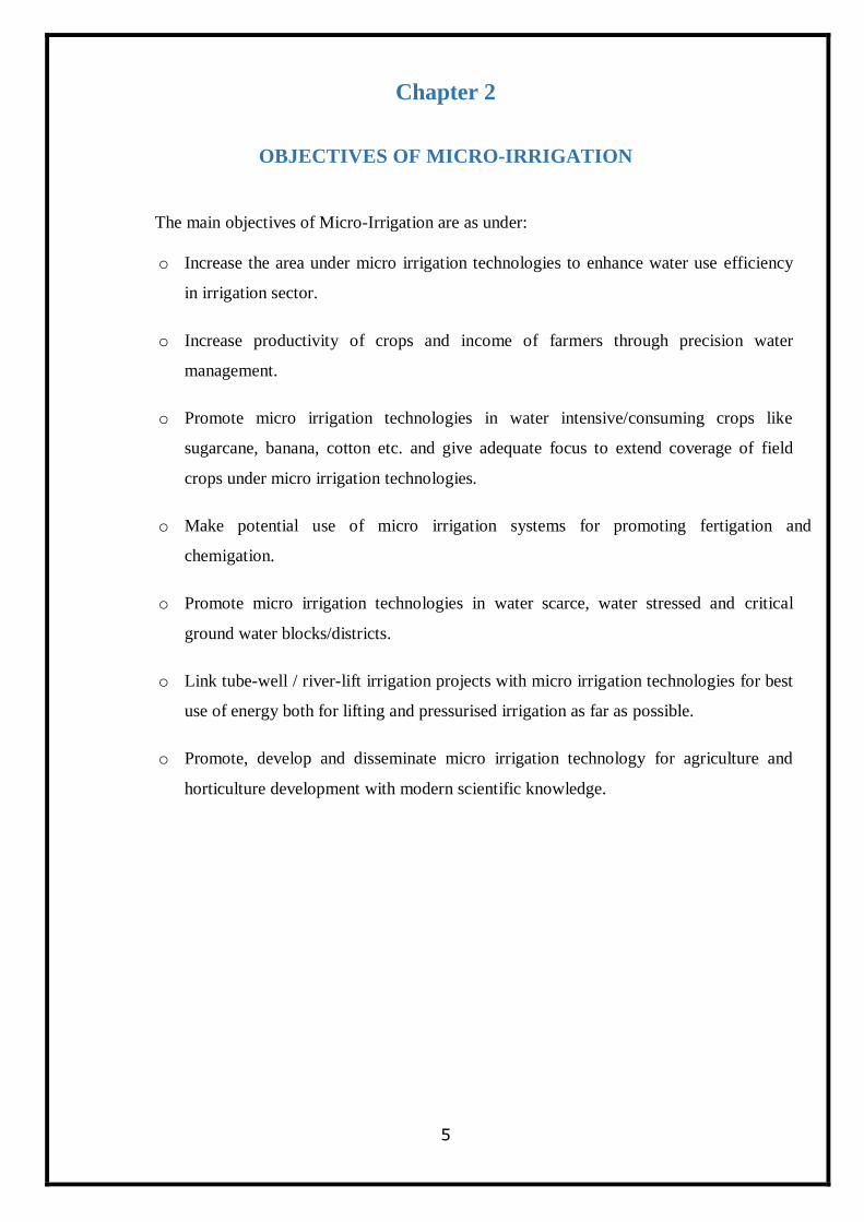
1. Bubbler Irrigation
The application of water to the soil surface as a small stream or fountain, where the
discharge rates for point source bubblers, emitters are greater than for drip or sub surface
emitters but generally less than 225 lit/hr. Because the emitter discharge rate normally
exceeds the infiltration rate of soil, a small basin is usually required to contain or control
the water.
Bubbler Irrigation
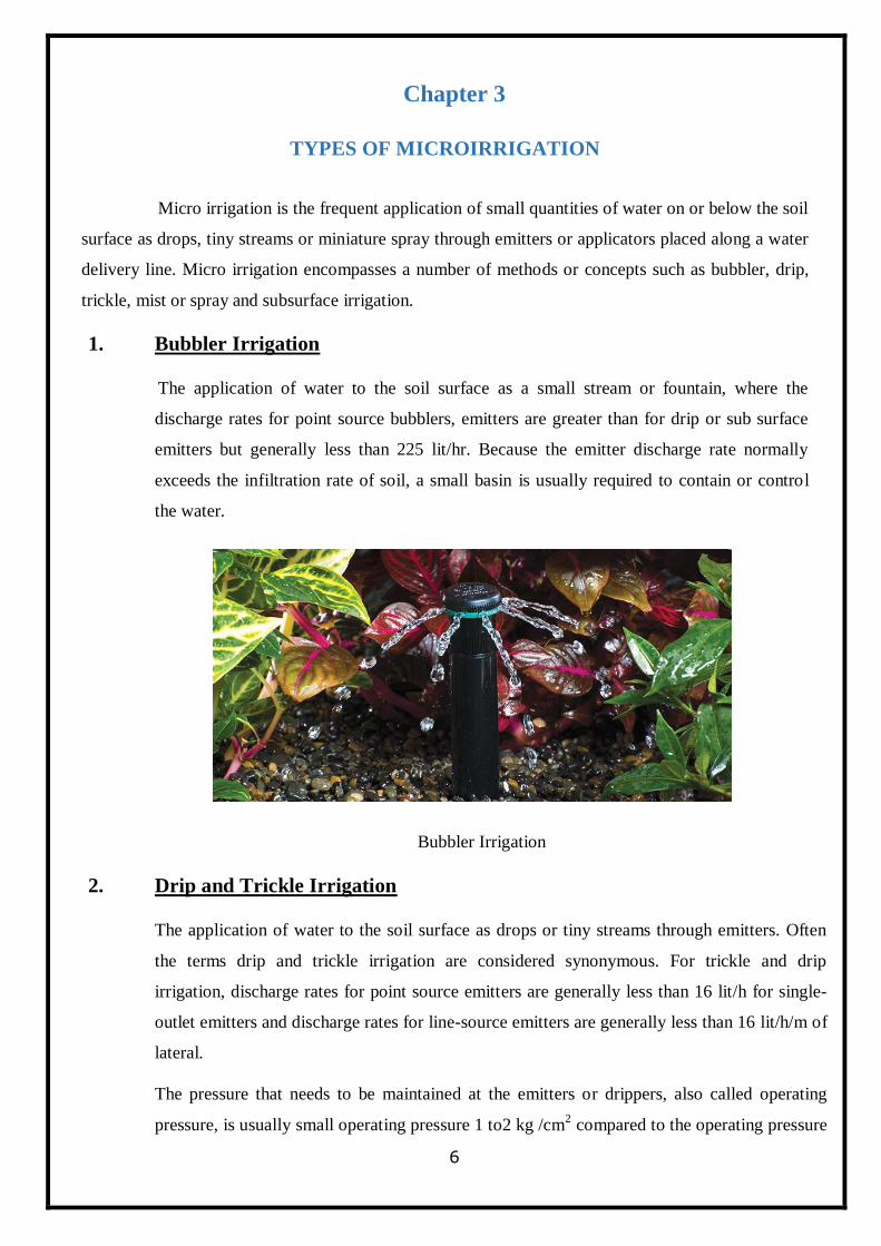
2. Drip and Trickle Irrigation
The application of water to the soil surface as drops or tiny streams through emitters. Often
the terms drip and trickle irrigation are considered synonymous. For trickle and drip
irrigation, discharge rates for point source emitters are generally less than 16 lit/h for single-
outlet emitters and discharge rates for line-source emitters are generally less than 16 lit/h/m of
lateral.
The pressure that needs to be maintained at the emitters or drippers, also called operating
pressure, is usually small operating pressure 1 to2 kg /cm2 compared to the operating pressure
7
at nozzle of the sprinkler irrigation system.
Drip Irrigation (Surface)
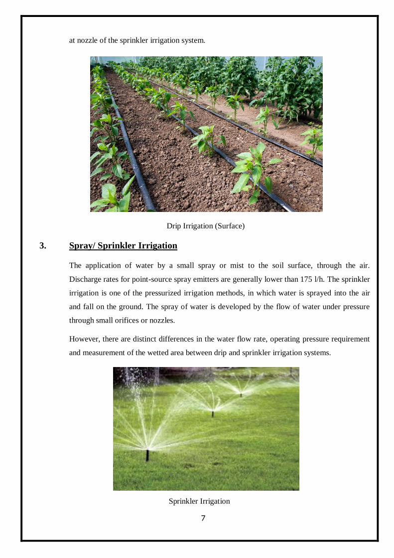
3. Spray/ Sprinkler Irrigation
The application of water by a small spray or mist to the soil surface, through the air.
Discharge rates for point-source spray emitters are generally lower than 175 l/h. The sprinkler
irrigation is one of the pressurized irrigation methods, in which water is sprayed into the air
and fall on the ground. The spray of water is developed by the flow of water under pressure
through small orifices or nozzles.
However, there are distinct differences in the water flow rate, operating pressure requirement
and measurement of the wetted area between drip and sprinkler irrigation systems.
Sprinkler Irrigation
8
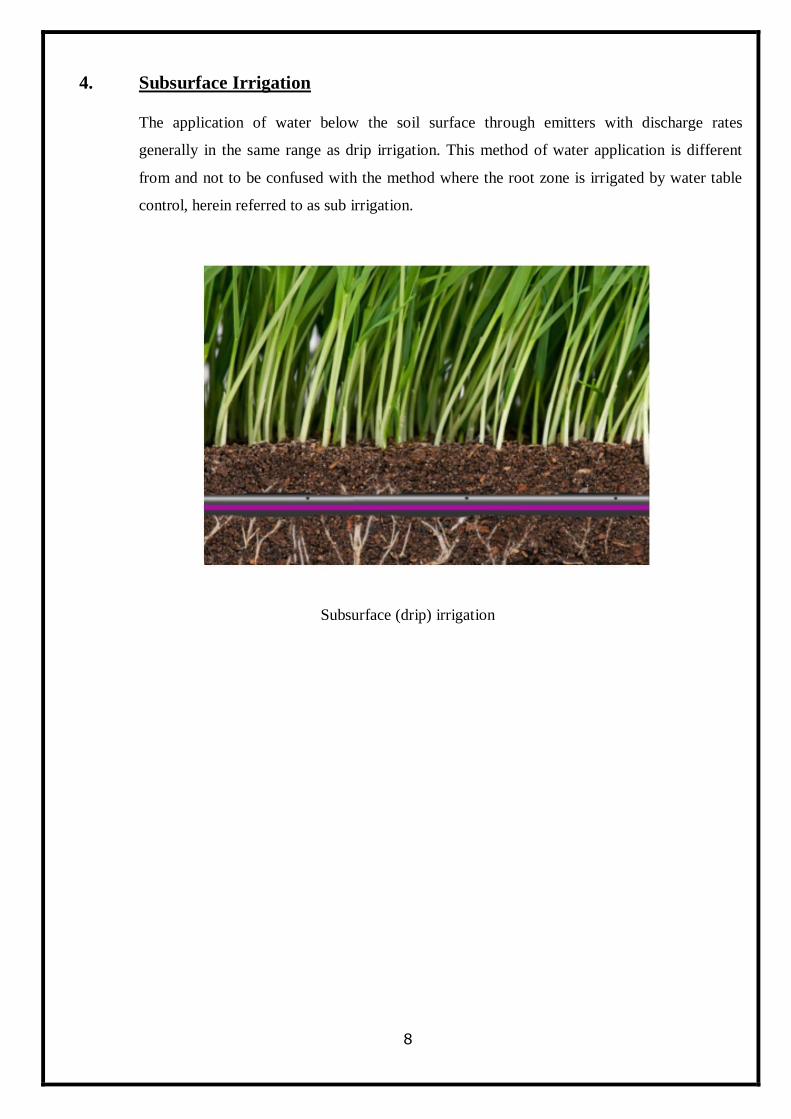
4. Subsurface Irrigation
The application of water below the soil surface through emitters with discharge rates
generally in the same range as drip irrigation. This method of water application is different
from and not to be confused with the method where the root zone is irrigated by water table
control, herein referred to as sub irrigation.
Subsurface (drip) irrigation
9
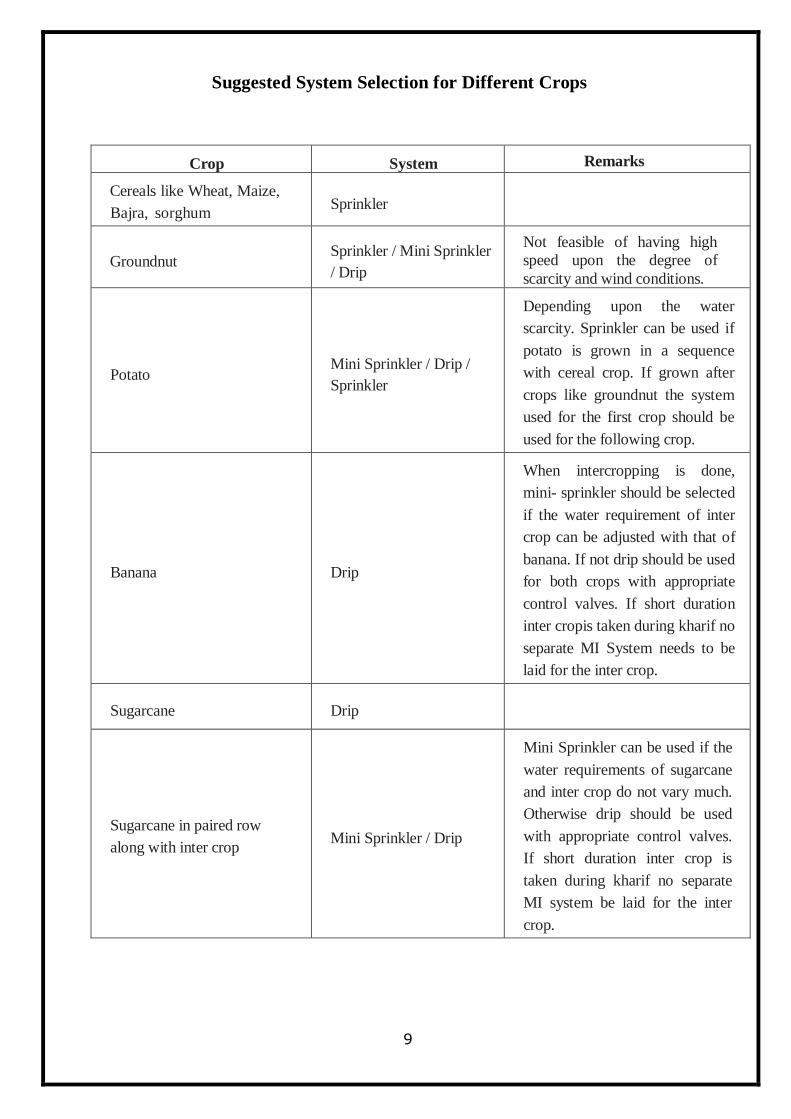
Suggested System Selection for Different Crops
Crop System Remarks
Cereals like Wheat, Maize,
Bajra, sorghum Sprinkler
Groundnut Sprinkler / Mini Sprinkler
/ Drip
Not feasible of having high
speed upon the degree of
scarcity and wind conditions.
Potato Mini Sprinkler / Drip /
Sprinkler
Depending upon the water
scarcity. Sprinkler can be used if
potato is grown in a sequence
with cereal crop. If grown after
crops like groundnut the system
used for the first crop should be
used for the following crop.
Banana Drip
When intercropping is done,
mini- sprinkler should be selected
if the water requirement of inter
crop can be adjusted with that of
banana. If not drip should be used
for both crops with appropriate
control valves. If short duration
inter cropis taken during kharif no
separate MI System needs to be
laid for the inter crop.
Sugarcane Drip
Sugarcane in paired row
along with inter crop Mini Sprinkler / Drip
Mini Sprinkler can be used if the
water requirements of sugarcane
and inter crop do not vary much.
Otherwise drip should be used
with appropriate control valves.
If short duration inter crop is
taken during kharif no separate
MI system be laid for the inter
crop.
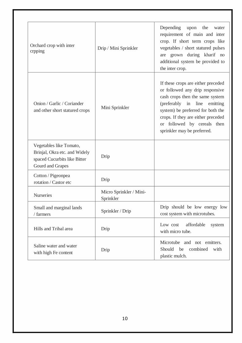
10
Orchard crop with inter
crpping Drip / Mini Sprinkler
Depending upon the water
requirement of main and inter
crop. If short term crops like
vegetables / short statured pulses
are grown during kharif no
additional system be provided to
the inter crop.
Onion / Garlic / Coriander
and other short statured crops Mini Sprinkler
If these crops are either preceded
or followed any drip responsive
cash crops then the same system
(preferably in line emitting
system) be preferred for both the
crops. If they are either preceded
or followed by cereals then
sprinkler may be preferred.
Vegetables like Tomato,
Brinjal, Okra etc. and Widely
spaced Cucurbits like Bitter
Gourd and Grapes
Drip
Cotton / Pigeonpea
rotation / Castor etc Drip
Nurseries Micro Sprinkler / Mini-
Sprinkler
Small and marginal lands
/ farmers Sprinkler / Drip
Drip should be low energy low
cost system with microtubes.
Hills and Tribal area Drip Low cost affordable system
with micro tube.
Saline water and water
with high Fe content Drip
Microtube and not emitters.
Should be combined with
plastic mulch.
11
DRIP IRRIGATION
SYSTEM
12
CHAPTER 4
DRIP IRRIGATION SYSTEM
Drip Irrigation system is the latest method of Irrigation. It is an efficient method of
application of water at the plant bottom at a rate nearly equal to the consumptive use rate of plant.
Thereby minimising the conventional water losses like percolation , runoff and evaporation from
soil. This method has been found to be highly successful in distant crops like mango, grape, papaya,
orchard, etc.
Drip irrigation system can be classified into the following:
(i) Surface drip irrigation
(ii) Sub-surface drip irrigation
(iii) Family drip
(iv) Online drip
(v) In-line drip
Surface drip irrigation
Surface drip irrigation is used to irrigate perennial crops (plants that live for more than two
years) and annual crops (plants that germinate, produce seeds, flower and die in one year).
Sub-surface drip irrigation
Sub-surface drip irrigation is a method of irrigating crops through buried plastic tubes,
containing embedded emitters located at regular spacing. A subsurface drip irrigation system has a
similar design as surface drip irrigation system. But in this case, the drip tubes are typically located 1
– 2 m apart and 15 – 25 cm below the soil surface. In sub-surface drip irrigation, evaporation is
minimized and water is used more efficiently as compared to surface irrigation. In sub-surface
irrigation, the effects of surface infiltration, water losses via evaporation and surface run-off are
eliminated. Water is applied directly to the root zone of a crop as opposed to surface irrigation, in
which most weed seeds hibernate. Water application is efficient and uniform in this system.
Family drip or gravity fed drip irrigation
Family drip or ‗gravity fed drip irrigation‘ system is a low-cost system developed for small
family plots. It is suitable for house gardening and peri - urban agriculture. It can also be used to
demonstrate the working of drip irrigation system. Family drip system is designed for areas
13
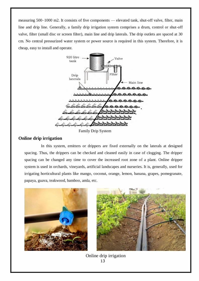
measuring 500–1000 m2. It consists of five components — elevated tank, shut-off valve, filter, main
line and drip line. Generally, a family drip irrigation system comprises a drum, control or shut-off
valve, filter (small disc or screen filter), main line and drip laterals. The drip outlets are spaced at 30
cm. No central pressurized water system or power source is required in this system. Therefore, it is
cheap, easy to install and operate.
Family Drip System
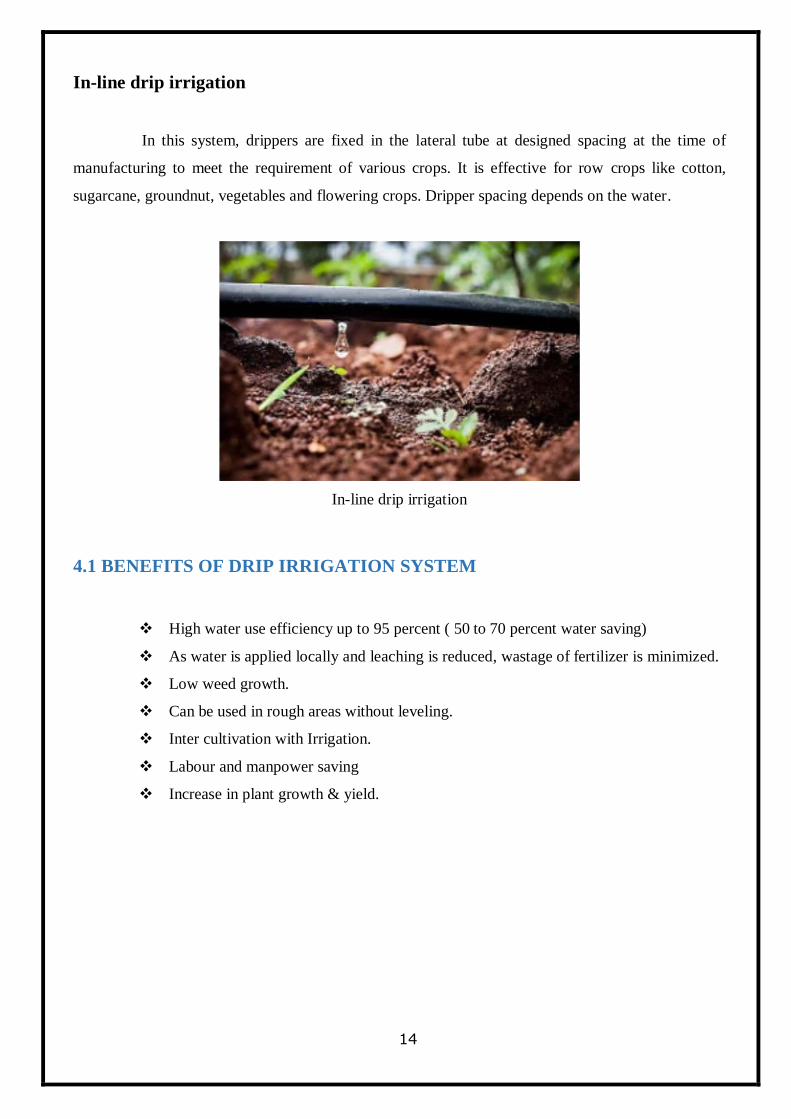
Online drip irrigation
In this system, emitters or drippers are fixed externally on the laterals at designed
spacing. Thus, the drippers can be checked and cleaned easily in case of clogging. The dripper
spacing can be changed any time to cover the increased root zone of a plant. Online dripper
system is used in orchards, vineyards, artificial landscapes and nurseries. It is, generally, used for
irrigating horticultural plants like mango, coconut, orange, lemon, banana, grapes, pomegranate,
papaya, guava, teakwood, bamboo, amla, etc.
Online drip irrigation
14
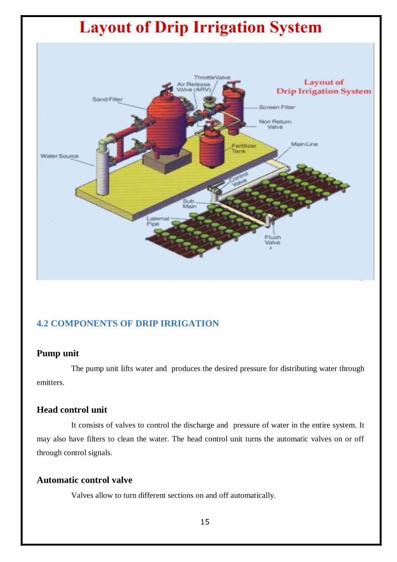
In-line drip irrigation
In this system, drippers are fixed in the lateral tube at designed spacing at the time of
manufacturing to meet the requirement of various crops. It is effective for row crops like cotton,
sugarcane, groundnut, vegetables and flowering crops. Dripper spacing depends on the water.
In-line drip irrigation
4.1 BENEFITS OF DRIP IRRIGATION SYSTEM
High water use efficiency up to 95 percent ( 50 to 70 percent water saving)
As water is applied locally and leaching is reduced, wastage of fertilizer is minimized.
Low weed growth.
Can be used in rough areas without leveling.
Inter cultivation with Irrigation.
Labour and manpower saving
Increase in plant growth & yield.
15
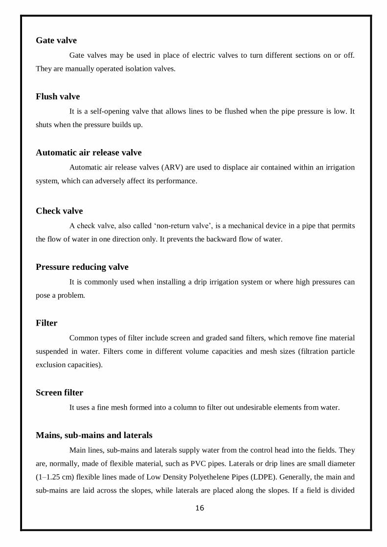
4.2 COMPONENTS OF DRIP IRRIGATION
Pump unit
The pump unit lifts water and produces the desired pressure for distributing water through
emitters.
Head control unit
It consists of valves to control the discharge and pressure of water in the entire system. It
may also have filters to clean the water. The head control unit turns the automatic valves on or off
through control signals.
Automatic control valve
Valves allow to turn different sections on and off automatically.
16
Gate valve
Gate valves may be used in place of electric valves to turn different sections on or off.
They are manually operated isolation valves.
Flush valve
It is a self-opening valve that allows lines to be flushed when the pipe pressure is low. It
shuts when the pressure builds up.
Automatic air release valve
Automatic air release valves (ARV) are used to displace air contained within an irrigation
system, which can adversely affect its performance.
Check valve
A check valve, also called ‗non-return valve‘, is a mechanical device in a pipe that permits
the flow of water in one direction only. It prevents the backward flow of water.
Pressure reducing valve
It is commonly used when installing a drip irrigation system or where high pressures can
pose a problem.
Filter
Common types of filter include screen and graded sand filters, which remove fine material
suspended in water. Filters come in different volume capacities and mesh sizes (filtration particle
exclusion capacities).
Screen filter
It uses a fine mesh formed into a column to filter out undesirable elements from water.
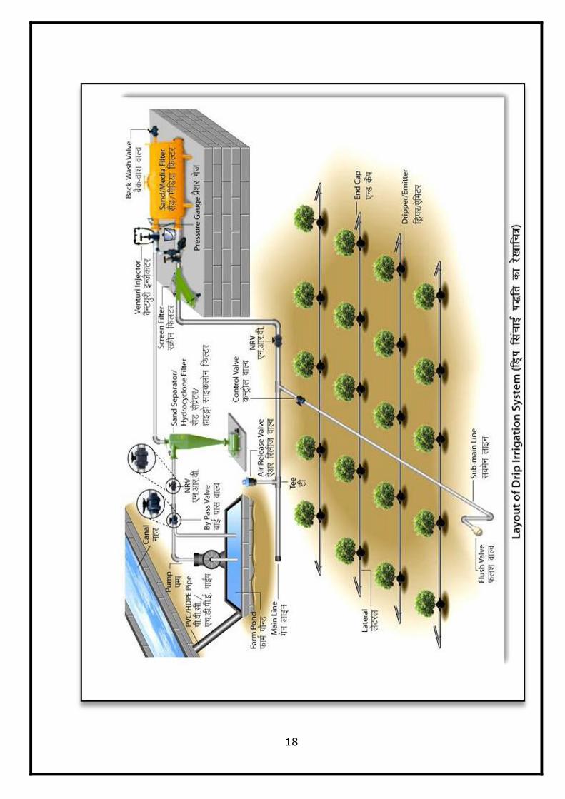
Mains, sub-mains and laterals
Main lines, sub-mains and laterals supply water from the control head into the fields. They
are, normally, made of flexible material, such as PVC pipes. Laterals or drip lines are small diameter
(1–1.25 cm) flexible lines made of Low Density Polyethelene Pipes (LDPE). Generally, the main and
sub-mains are laid across the slopes, while laterals are placed along the slopes. If a field is divided
17
into sub-block, each block is provided with one sub-main and a control valve. Based on the available
data of water capacity, water requirement of a plant and pressure required at the lateral layout,
designs for the micro irrigation system are made. Laterals are, normally, laid parallel to each other.
There is, usually, one lateral line for each crop row.
Emitters or drippers
These are fixed at regular intervals in the laterals. They are, usually, spaced more than 1 m
apart. For row crops, more closely spaced emitters may be used to wet a strip of soil. They supply
specified quantity of water to plants in a field. Water is delivered at or near the root zones of plants,
drop-by-drop. The PVC valves allow water to flow at a slow rate (2–16 litre per hour) and in various
shapes and designs. Emitters are selected on the basis of soil texture and crop root zone system. To
measure the anticipated variations in the discharge of water in emitters, a pressure gauge is used.
18
19
4.3 PLANNING AND DESIGN OF DRIP IRRIGATION SYSTEM
The planning and design of drip irrigation system is essential to supply the required
quantity of irrigation water to the crop at a desired uniformity. The main purpose of the design of drip
irrigation system is to decide the dimensions of various components of the system such that the
system provides the require quantity of water at the desired uniformity in application while keeping
the cost of the system to minimum. To apply the desired amount of water at nearly uniform rate to all
the plants in the field, it is essential to design the irrigation system that maintains a desired hydraulic
pressure in the pipe network and provide the desired operating pressure at the emitter. The design of
drip irrigation system consists of selection of emission devices, size of laterals, manifolds, sub main,
main pipeline, filter and pump. The system design depends on many factors, but the design will be
constrained by several economics factors such as feasibility, initial investment, labour, return on
investment and performance parameters such as the rated flow rate and desired emission uniformity.
The steps to be followed for designing the drip irrigation system are given below:
1. Inventory of the resources and data collection.
2. Computation of peak crop water requirement
3. Deciding the appropriate layout of the drip irrigation system
4. Selection of emitters
5. Hydraulic design of the system in terms of lateral, sub main and main
6. Horse power requirement of pump
1. Inventory of the Resources and Data Collection
The resources involved include:
Water resources: Quantity (stream size, volume and duration for which the supply is
available) and quality of water, the type of water resources i.e. bore/tube well; open dug
well, reservoir/pond/tank or river and location of the water resource.
Land resources: The size and shape of the area to be irrigated with the consent of WUAs
(Water User Associations), soil type for its texture and irrigation properties (field capacity,
wilting point, bulk density, allowable depletion level) including infiltration rate, and
topography of the land.
20
Climate: The climatic data required for the computation of crop water requirement.
Crop: Crop type, sowing/planting and harvesting period, crop coefficient, fertilizer
requirements, crop geometry. In general following guidelines can be used to ensure
adequate quantity of available water for supply of irrigation water to the wide spaced
(orchard) and close spaced (vegetable etc.) crops. However the area to be irrigated can be
decided on the basis of the water availability and the crop water demand.
2. Peak Crop Water Requirement:
The design of drip irrigation system needs the information on the peak water requirement,
however while the system is in operation, the water requirement during the specified
irrigation interval is required. Crop water requirement is calculated for each plant and the
water requirement of the whole area is estimated based on the water requirement per plant
and total number of plants.
3. Layout of the Drip Irrigation System:
It is possible to apply water to the whole field by drip irrigation method at the same time.
However this may result in the requirement of high discharge which may not be available,
further large diameter of mains and sub main which could make the system more
expensive and the high capacities of the fertigation and filtration units. Hence the whole
field needs to be divided in to the convenient number of subunits. Each subunit is then
designed separately and operated separately by having valve at the head of the subunit.
The layout of the micro irrigation system i.e. arrangement of main, sub mains and laterals
is done considering the shape, size and slope of the field. As for as possible, the sub main
should run along the slope of the field and lateral should be laid across the slope or along
the contour lines of the field.
4. Selection of Emitters:
The emitters are to be selected for its discharge, operating pressure, online/inline, pressure
compensating/non pressure compensating, point source/line source, single exit/multi exit
21
and surface/subsurface. The selection of particular type of emitter depends on the soil,
crop, topography, desired emission uniformity, available discharge and electricity/other
sources for operation of the system, water quality, water use efficiency and the cost.
5. Hydraulic Design of Pipe Network:
The pipe network in drip irrigation system consists of laterals, sub main and main. Water
under pressure flows through these pipes and as a result the pressure in the pipes reduces
creating the variation in pressure or pressure difference between any two points. The
emitter discharge depends on the operating pressure available in the pipe at emitter
connection and reduces with reducing pressure. Therefore there is variation in discharge
obtained by the emitters in system; affecting the emission uniformity.
The procedure of hydraulic design consists of:
1. Know the operating pressure of emitters
2. Find out the allowable head loss in lateral and sub main
3. Find out the lateral and sub main discharge
4. Find out the diameter and length of the lateral such that the head loss in the lateral is
within allowable limits for the given layout. For this purpose find out the head loss by
Hazen William or Darcy-Wesibach formula for different combinations of diameter and
length and select the suitable combination by trial and error method
5. Repeat the procedure for the sub main
6. Find out the diameter of main so that the velocity is within the allowable limit or find
out the head loss in main for the specified diameter of the main. The length of the main is
the distance of the field from the water source.
4.4 ESTIMATION OF WATER AND POWER REQUIREMENT FOR
INSTALLATION OF MICRO IRRIGATION SYSTEM
A. Estimation of Quantity of Water
To irrigate an area by drip / sprinkler irrigation system sufficient amount of water
should be made available at the place where the system needs to be installed. To
estimate the minimum quantity of water for meeting the irrigation water requirement
22
of any area, the following steps are required.
Collection of General Information
Information on type of water source, crops to be grown, topographic conditions,
type and texture of soil and climatological data are essential for designing the drip /
sprinkle irrigation system.
Layout of the Field
The design layout of the field / plot by giving appropriate specifications of the
lengths of main line, sub main line, lateral lines, distance of water source from
Pump station in meters to connect water source with the existing/planned crop in the
area must be worked out., discharge of the emitting device used (lph/ lps), Number
of Control Valves used as per the design layout of the proposed field/plot with
area(ha).
Crop Water Requirement
Water requirement of crops (WR) is a function of plants, surface area covered by
plants, evapo-transpiration rate. Irrigation water requirement has to be calculated
for each plant and thereafter for the whole plot based on plant population, for
different seasons. The maximum discharge required during any one of the three
seasons is adopted for system design. The daily water requirement for fully grown
plants can be calculated as under:
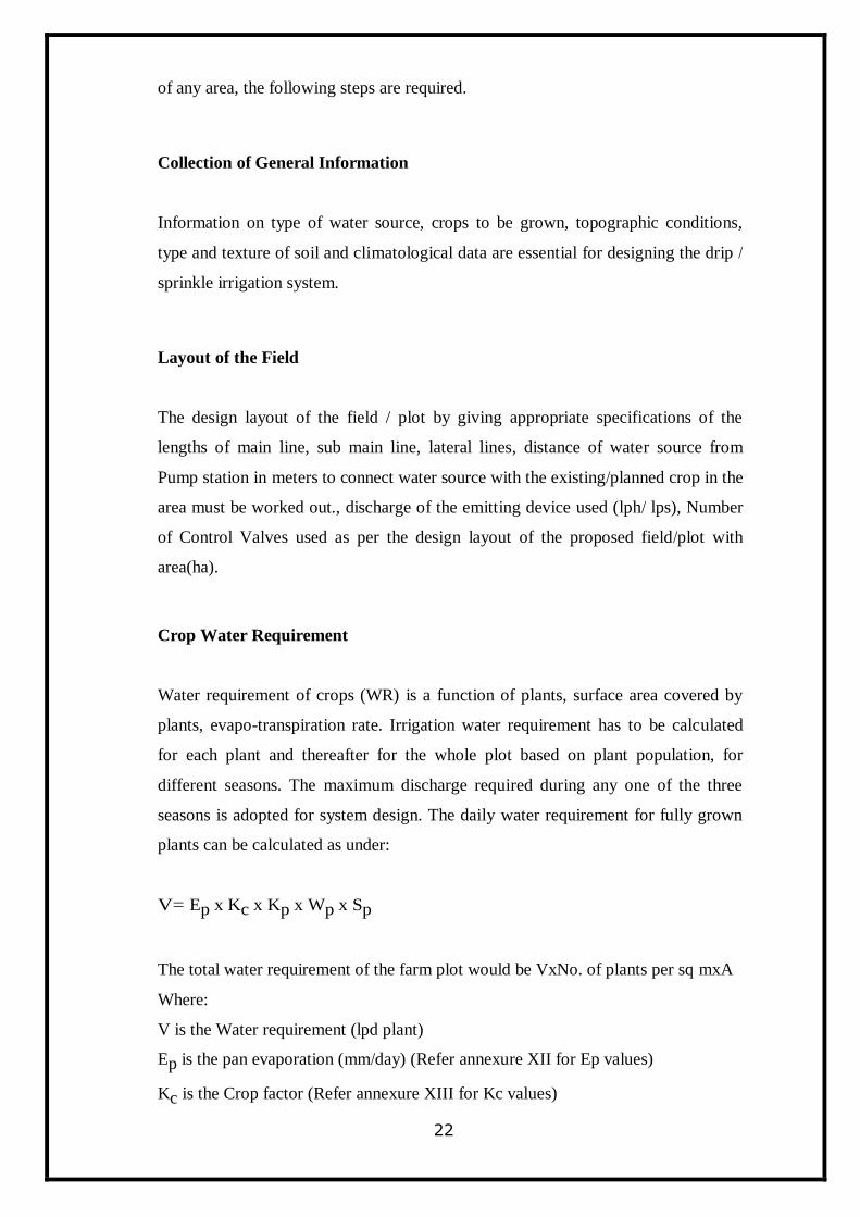
V= Ep x Kc x Kp x Wp x Sp
The total water requirement of the farm plot would be VxNo. of plants per sq mxA
Where:
V is the Water requirement (lpd plant)
Ep is the pan evaporation (mm/day) (Refer annexure XII for Ep values)
Kc is the Crop factor (Refer annexure XIII for Kc values)
23
Kp is the pan factor (For the Class A evaporation pan, the average K pan varies
between 0.7 and 0.8)
Wp is the wetted area (0.3for wide spaced crops and 0.9 for close spaced crops)
Sp is the spacing of crops/plant (m2)
B. Estimation of Horse power (HP) of Pumping Unit
Power required to pump the required irrigation water from the source and to develop sufficient
pressure to operate the drippers effectively.
The ideal drip irrigation system is one in which all drippers / emitters (or orifices) deliver
equal / uniform volume of water in a given irrigation time. The dripper / emitter flow variation
caused by water pressure can be controlled by hydraulic design.
Flow carried by each lateral line (de) = dripper discharge x No. of drippers per plant x No.
of plants along each lateral.
Flow carried by each sub-main line (ds) = de x No. of lateral line per sub main line Flow
carried by each mainline (dm) = ds x No. of sub-mains
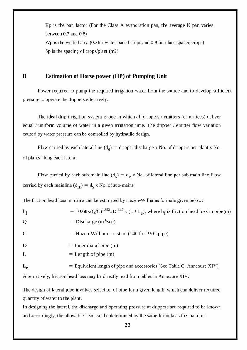
The friction head loss in mains can be estimated by Hazen-Williams formula given below:
hf = 10.68x(Q/C)1.852
xD-4.87
x (L+Le), where hf is friction head loss in pipe(m)
Q = Discharge (m3/sec)
C = Hazen-William constant (140 for PVC pipe)
D = Inner dia of pipe (m)
L = Length of pipe (m)
Le = Equivalent length of pipe and accessories (See Table C, Annexure XIV)
Alternatively, friction head loss may be directly read from tables in Annexure XIV.
The design of lateral pipe involves selection of pipe for a given length, which can deliver required
quantity of water to the plant.
In designing the lateral, the discharge and operating pressure at drippers are required to be known
and accordingly, the allowable head can be determined by the same formula as the mainline.
24
Design Criteria
1. It should be ensured that the head loss in the lateral length between the first and last
emitter is within 10 percent of the head available at the first emitter.
2. The friction head loss in the mainline should not exceed 1 m / 100 m length of the
mainline. Friction head loss for various discharges is given in Table B (Annexure XIV) and
equivalent lengths of straight pipe in (m) giving equivalent resistance to flow in pipe fittings in
Table C (Annexure XIV).
After finalization of dimensions of main, sub-mains and laterals the selection of pump consists
of the following steps.
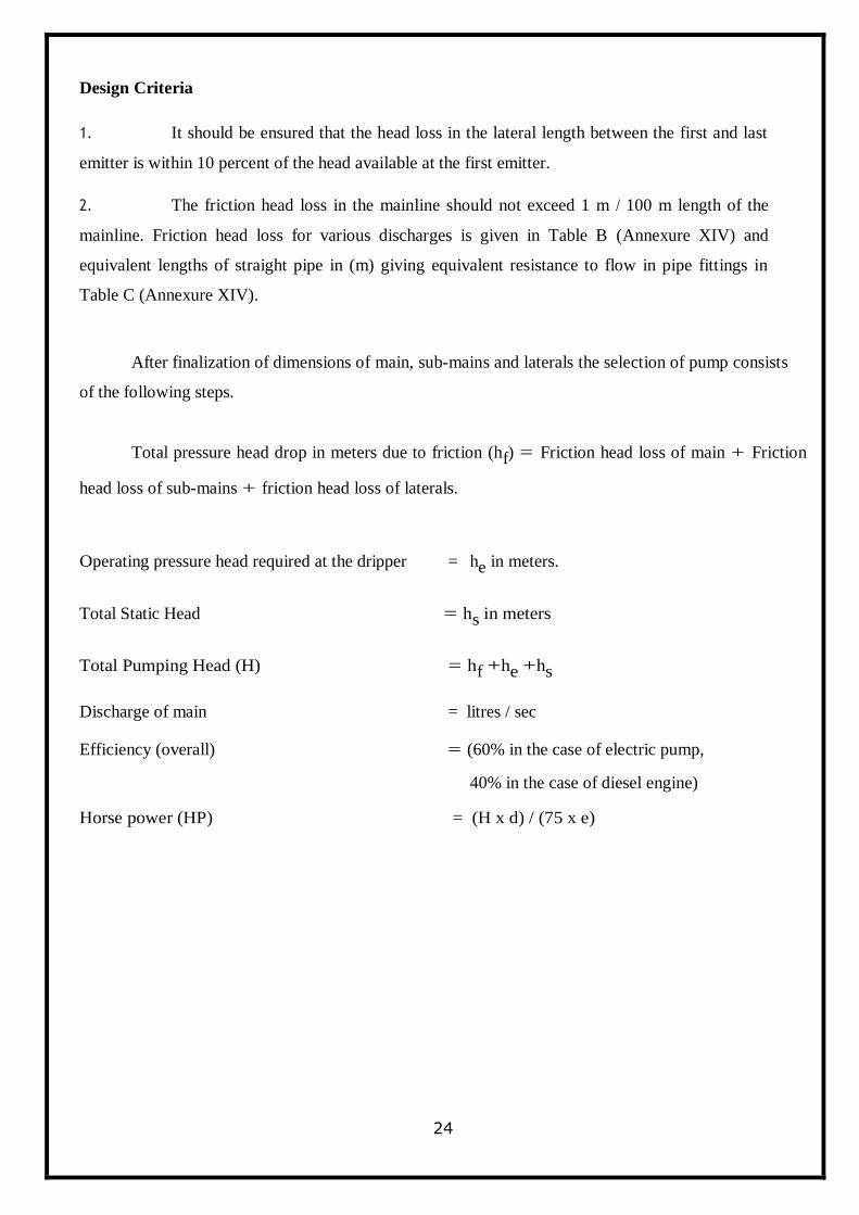
Total pressure head drop in meters due to friction (hf) = Friction head loss of main + Friction
head loss of sub-mains + friction head loss of laterals.
Operating pressure head required at the dripper = he in meters.
Total Static Head = hs in meters
Total Pumping Head (H) = hf +he +hs
Discharge of main = litres / sec
Efficiency (overall) = (60% in the case of electric pump,
40% in the case of diesel engine)
Horse power (HP) = (H x d) / (75 x e)

25
4.5 DESIGN EXAMPLE OF DRIP IRRIGATION SYSTEM
To install drip irrigation system for a new citrus plantation on one ha plots.
Basic Data Analysis
1. No. of Plants
Area (1 ha approx.) = 104 m x 96 m
Spacing (m) = 6 m x6 m
No of plants along the width of the field = 96/6 = 16 nos
No. of plats along the length of the field = 104/6 = 17 nos
Total no of plants = 16x17 = 272 nos
2. Estimation of Water Requirement
Kc = 0.9
Kp = 0.78
Wp = 0.3
Sp = 36
The irrigation water requirement is determined using Indian Meteorological Department
(IMD) pan evaporation data. The average monthly pan evaporation data for the area is given
below:
Normal Monthly Pan Evaporation Data
Month mm Month mm
January 099.2 July 145.6
February 119.6 August 134.6
March 176.3 September 134.6
April 210.2 October 144.6
May 245.4 November 112.2
June 198.8 December 94.4
26
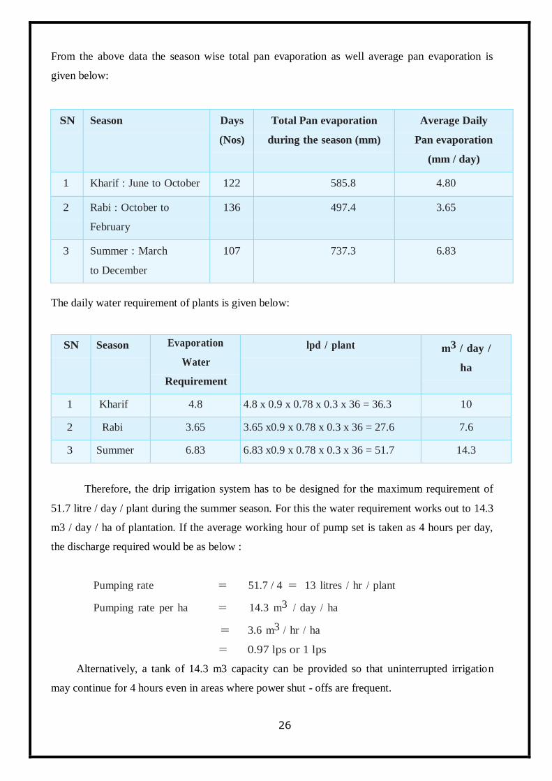
From the above data the season wise total pan evaporation as well average pan evaporation is
given below:
The daily water requirement of plants is given below:
SN Season Evaporation
Water
Requirement
lpd / plant m3 / day /
ha
1 Kharif 4.8 4.8 x 0.9 x 0.78 x 0.3 x 36 = 36.3 10
2 Rabi 3.65 3.65 x0.9 x 0.78 x 0.3 x 36 = 27.6 7.6
3 Summer 6.83 6.83 x0.9 x 0.78 x 0.3 x 36 = 51.7 14.3
Therefore, the drip irrigation system has to be designed for the maximum requirement of
51.7 litre / day / plant during the summer season. For this the water requirement works out to 14.3
m3 / day / ha of plantation. If the average working hour of pump set is taken as 4 hours per day,
the discharge required would be as below :
Pumping rate = 51.7 / 4 = 13 litres / hr / plant
Pumping rate per ha = 14.3 m3 / day / ha
= 3.6 m3 / hr / ha
= 0.97 lps or 1 lps
Alternatively, a tank of 14.3 m3 capacity can be provided so that uninterrupted irrigation
may continue for 4 hours even in areas where power shut - offs are frequent.
SN Season Days
(Nos)
Total Pan evaporation
during the season (mm)
Average Daily
Pan evaporation
(mm / day)
1 Kharif : June to October 122 585.8 4.80
2 Rabi : October to
February
136 497.4 3.65
3 Summer : March
to December
107 737.3 6.83
27
3. Selection of Drippers
Number of Drippers:
Depending upon the type of dripper and discharge required their number can be estimated.
For a pressure head of 10 m and discharge at 4 litres / hour the number of drippers required are:
No. of drippers / plant = Rate of pumping / hour / plant
Avg. discharge of one dripper
= 13 / 4 or 3.25 say 3
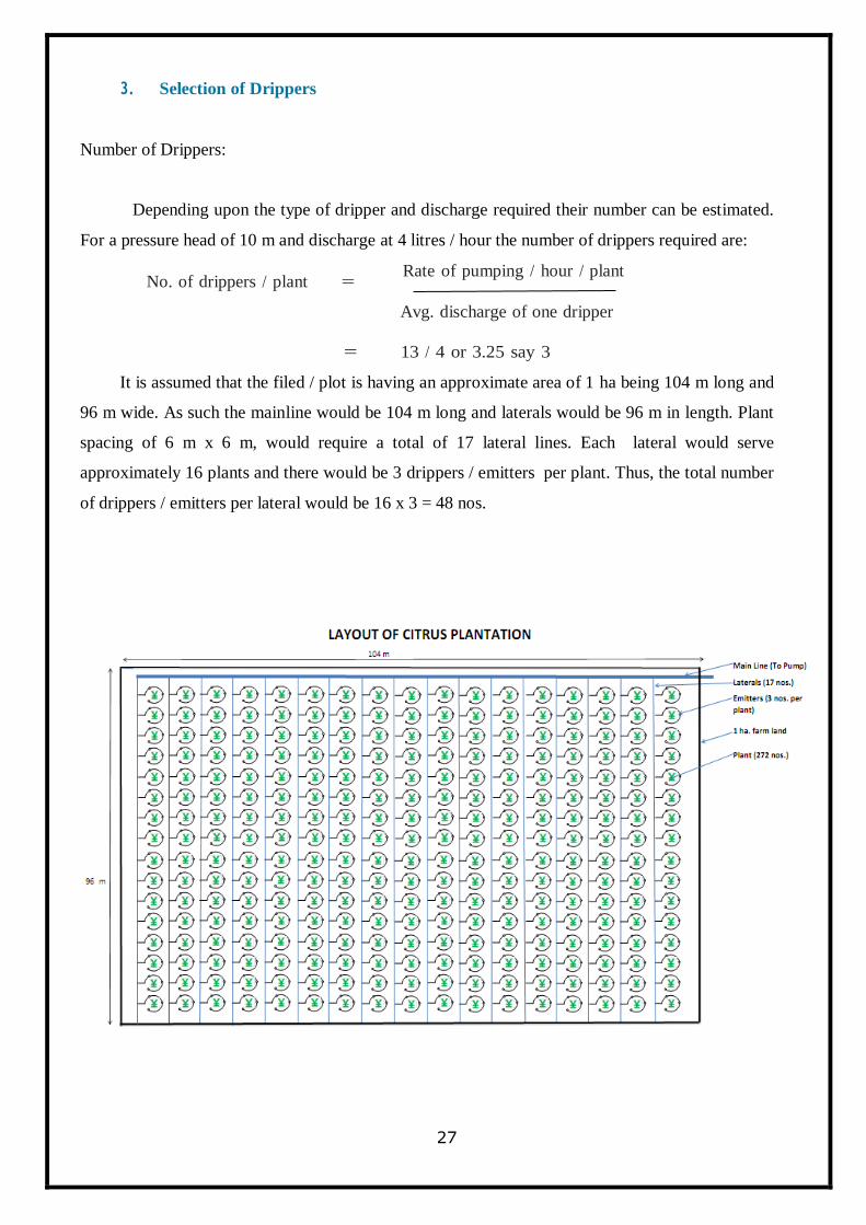
It is assumed that the filed / plot is having an approximate area of 1 ha being 104 m long and
96 m wide. As such the mainline would be 104 m long and laterals would be 96 m in length. Plant
spacing of 6 m x 6 m, would require a total of 17 lateral lines. Each lateral would serve
approximately 16 plants and there would be 3 drippers / emitters per plant. Thus, the total number
of drippers / emitters per lateral would be 16 x 3 = 48 nos.
28
4. Main Line and Laterals
Main Line
The main line is designed to carry the maximum discharge required for total number of plants in
the farm field / plot.
Maximum discharge required = No. of plants x peak discharge per plant
= 272 x 13
= 3536 lph or 1 lps
Friction head loss in pipes (m)
Total length of main line = 104.0 m
Equivalent length of 17 straight = 8.5 m
Connection
Equivalent length of tee bends, etc = 6.0 m
TOTAL = 118.5 or say 120 m
From Table B it would be seen that for discharge of 1 lps through a pipe of say 40 mm diameter,
the friction loss would be 2 m per 100 m length of 2.3 m for 120 m equivalent length.
As the proposed system uses multiple openings, the friction loss is taken as 1 / 3 of the total
friction loss i.e. 2.3 / 3 i.e. 0.77 m. Thus the loss in mains is within 1.0 m / 100 m and a pipe of 40
mm diameter will be ideal in the layout.
Laterals
A lateral is so selected that the pressure difference from the proximate end to the last
dripper does not exceed 10 per cent of the normal operating head which in the present case is 10 x
10 / 100 = 1.0 for lateral of 100 m length. The land slope is 0.5 m / 100 m. Thus the total friction
loss allowable is 1 + 0.5 = 1.5 m.
In addition to 100 m length of laterals there is additional loss due to connectors. This is
29
generally taken as 0.1 to 1 m (on an average 0.5) of the equivalent length of a dripper. The
equivalent length of 48 drippers would this be 16 x 0.5 = 8 m. Thus, total equivalent length for
calculation of friction loss in laterals would be 8 m. The total flow in each lateral is 192 lph. i.e. 4
x 3 x 16. A perusal of Table A shows that for 200 lph flow the friction loss in 13.9 mm inner
diameter pipe would be 1.7 m per 100 m length. Therefore, in 104 m length it would be 1.77 m.
It is a general practice that friction losses are taken at 1 / 3 of the total equivalent length of pipes
with multiple dripper / connections. Thus the friction loss works out to 1 / 3 x 1.77 = 0.59 m which
is within the maximum permissible limit of 1.0 m. Therefore, 14 mm (OD) lateral pipe of 96 m
length is suggested in this scheme.
5. Horsepower of Pumpset
The HP of pumpset required is based upon design discharge and total operating head. The
total head is the sum of total static head and friction losses in the system.
Static Head
i) The total static head is the sum total of the following :
a. Depth to water 15 m
b. Drawdown 3 m
c. Outlet level above ground level 1 m
d. Friction loss in pipes, bends, 2 m
foot valves etc.
Total 21 m
ii) The friction loss in the drip unit is as under :
a Friction loss in main pipe 0.77 (m)
b Friction loss in laterals 0.59
(m)
c Minimum head required over drippers 10.00
(m)
11.36 (m)
Total Head = Static Head + Friction Head Loss
30
= 21.00 + 11.36
= 32.36 or say 33 m
HP of pump set = (Q x H) / (75 x e)
Where Q = Discharge (lps)
H = Head (m)
e = Pumping Efficiency (0.7)
HP = (1 x 33) / (75 x 0.70)
= 0.63 or say 1 HP
31
SPRINKLER
IRRIGATION
SYSTEM
32
CHAPTER 5
SPRINKLER IRRIGATION SYSTEM
In sprinkler irrigation, water under pressure is discharged in the air which falls back to
earth‘s surface as artificial rainfall. A set of nozzles are used to discharge under pressure. Nozzles
are attached to a network of High Density Polyethylene (HDPE) pipes for simulating the rainfall.
Pumps are used to discharge water under pressure. This type of irrigation is best switch for sandy
soils, undulated and hilly terrain. Sprinkler Irrigation can be used in following crops - Wheat,
Cotton, Groundnut, Tabaco, Potato, Onion, Ginger, Peas, etc.
In addition to above, sprinkler irrigation can also be used for irrigation leafy vegetables,
nurseries, hardening of seeds, landscaping, etc.
Types of sprinkler irrigation system
Micro-sprinklers
Micro-sprinklers are emitters, commonly, known as sprinkler or spray heads. They operate by
spreading water through air, usually, in predetermined patterns. Depending on the water throw
patterns, micro-sprinklers are referred to as ‗mini-sprays‘, ‗micro-sprays‘, ‗jets‘ or ‗spinners‘. The
sprinkler heads are external emitters individually connected to lateral pipes, typically, using what
can be called ‗micro-tubes‘ or a small diameter tubing. The sprinkler heads can be mounted on a
support stake of 50-150 cm height, connected to the supply pipe. Micro - sprinkler system
requires less energy, and generally, operates at a pressure range of 1–3 kg/cm2 and a discharge
range of 40–75 lph. Micro-sprinklers are desirable because fewer sprinkler heads are required to
cover a large area. The system is suited for crops with shallow rooting pattern like garlic, onion,
etc.
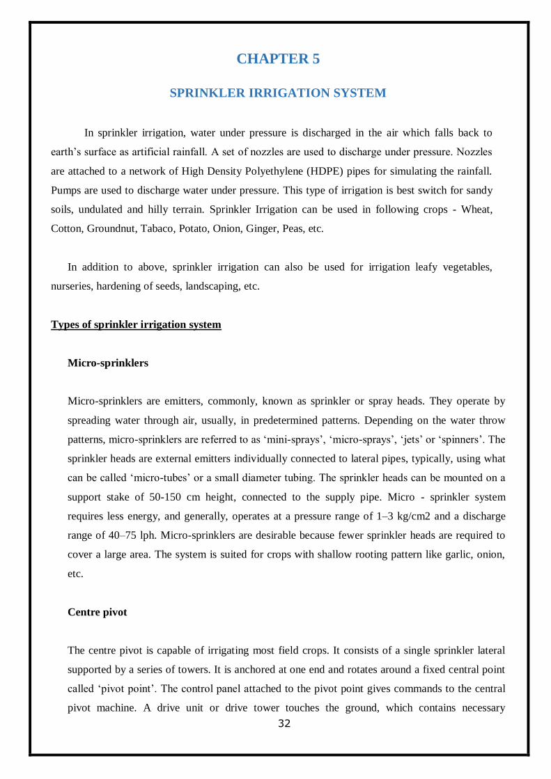
Centre pivot
The centre pivot is capable of irrigating most field crops. It consists of a single sprinkler lateral
supported by a series of towers. It is anchored at one end and rotates around a fixed central point
called ‗pivot point‘. The control panel attached to the pivot point gives commands to the central
pivot machine. A drive unit or drive tower touches the ground, which contains necessary
33
components for the machine to move. It consists of a base beam, drive train, wheels and other
structural support equipment. The towers are self-propelled so that the lateral rotates around the
pivot point installed in the center of the irrigated area. The long pipes between the drive units are
called ‗spans‘.
Centre Pivot
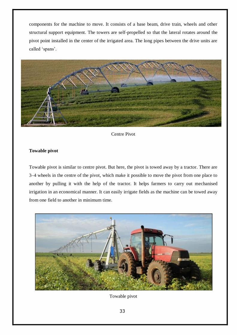
Towable pivot
Towable pivot is similar to centre pivot. But here, the pivot is towed away by a tractor. There are
3–4 wheels in the centre of the pivot, which make it possible to move the pivot from one place to
another by pulling it with the help of the tractor. It helps farmers to carry out mechanised
irrigation in an economical manner. It can easily irrigate fields as the machine can be towed away
from one field to another in minimum time.
Towable pivot
34
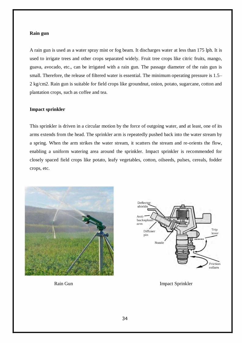
Rain gun
A rain gun is used as a water spray mist or fog beam. It discharges water at less than 175 lph. It is
used to irrigate trees and other crops separated widely. Fruit tree crops like citric fruits, mango,
guava, avocado, etc., can be irrigated with a rain gun. The passage diameter of the rain gun is
small. Therefore, the release of filtered water is essential. The minimum operating pressure is 1.5–
2 kg/cm2. Rain gun is suitable for field crops like groundnut, onion, potato, sugarcane, cotton and
plantation crops, such as coffee and tea.
Impact sprinkler
This sprinkler is driven in a circular motion by the force of outgoing water, and at least, one of its
arms extends from the head. The sprinkler arm is repeatedly pushed back into the water stream by
a spring. When the arm strikes the water stream, it scatters the stream and re-orients the flow,
enabling a uniform watering area around the sprinkler. Impact sprinkler is recommended for
closely spaced field crops like potato, leafy vegetables, cotton, oilseeds, pulses, cereals, fodder
crops, etc.
Rain Gun Impact Sprinkler
35
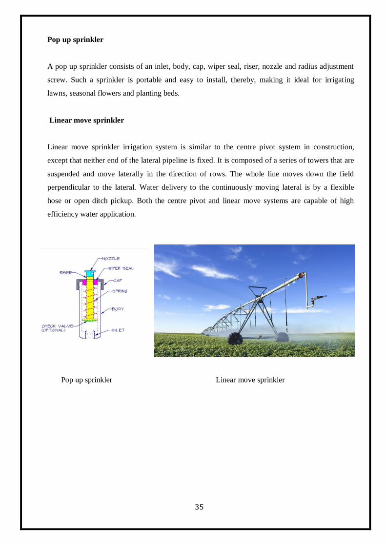
Pop up sprinkler
A pop up sprinkler consists of an inlet, body, cap, wiper seal, riser, nozzle and radius adjustment
screw. Such a sprinkler is portable and easy to install, thereby, making it ideal for irrigating
lawns, seasonal flowers and planting beds.
Linear move sprinkler
Linear move sprinkler irrigation system is similar to the centre pivot system in construction,
except that neither end of the lateral pipeline is fixed. It is composed of a series of towers that are
suspended and move laterally in the direction of rows. The whole line moves down the field
perpendicular to the lateral. Water delivery to the continuously moving lateral is by a flexible
hose or open ditch pickup. Both the centre pivot and linear move systems are capable of high
efficiency water application.
Pop up sprinkler Linear move sprinkler
36
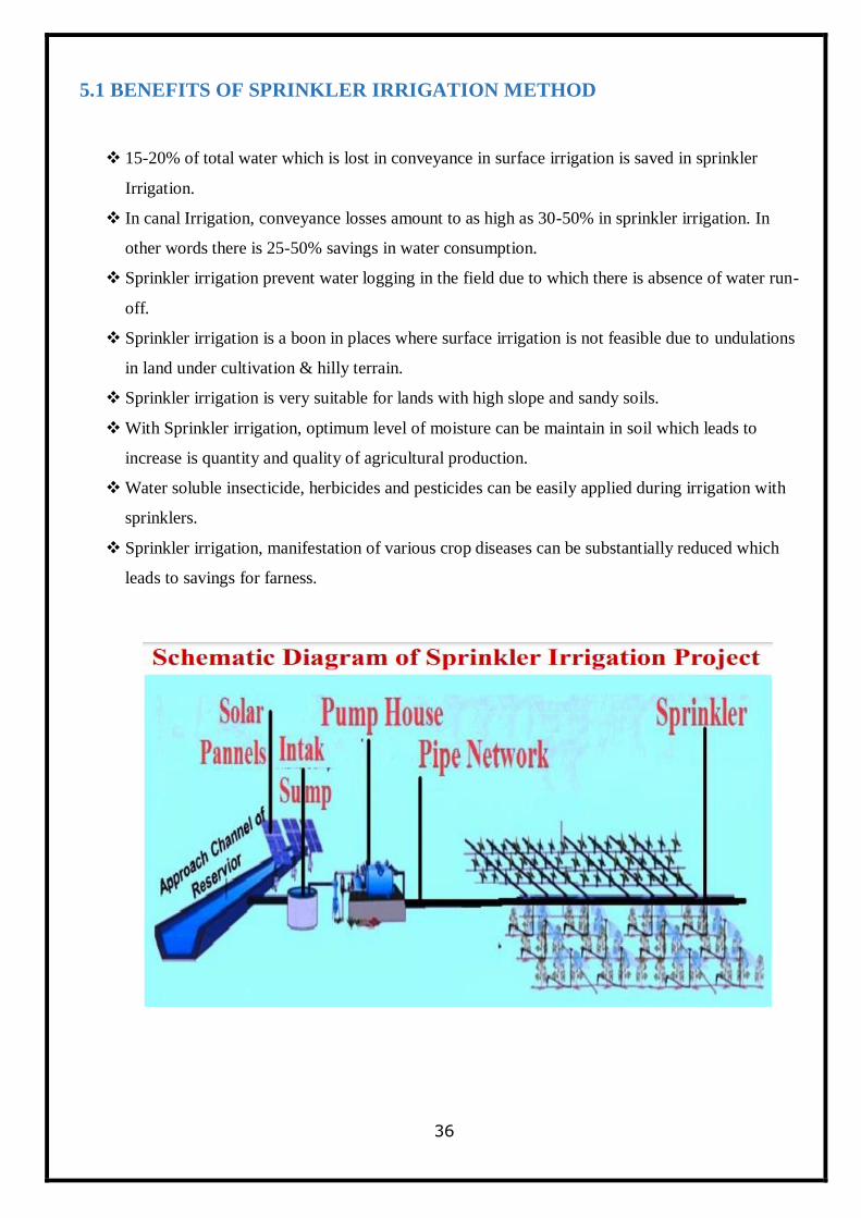
5.1 BENEFITS OF SPRINKLER IRRIGATION METHOD
15-20% of total water which is lost in conveyance in surface irrigation is saved in sprinkler
Irrigation.
In canal Irrigation, conveyance losses amount to as high as 30-50% in sprinkler irrigation. In
other words there is 25-50% savings in water consumption.
Sprinkler irrigation prevent water logging in the field due to which there is absence of water run-
off.
Sprinkler irrigation is a boon in places where surface irrigation is not feasible due to undulations
in land under cultivation & hilly terrain.
Sprinkler irrigation is very suitable for lands with high slope and sandy soils.
With Sprinkler irrigation, optimum level of moisture can be maintain in soil which leads to
increase is quantity and quality of agricultural production.
Water soluble insecticide, herbicides and pesticides can be easily applied during irrigation with
sprinklers.
Sprinkler irrigation, manifestation of various crop diseases can be substantially reduced which
leads to savings for farness.
37
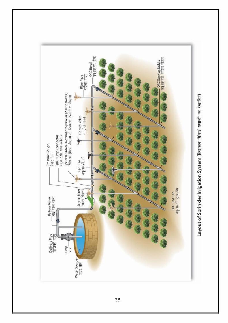
5.2 COMPONENTS OF SPRINKLER IRRIGATION METHOD
Pump unit and valves
A pump is used for developing the required pressure. It can be used under the following
conditions.
• The land is undulating for leveling (the leveling work will be cost-intensive).
• The soil is porous, erodible and impermeable (which makes it difficult to irrigate it by any
other method).
• The flow rate is too less for employing surface irrigation method.
Filtration unit
Filtration unit is required to remove the impurities present in the irrigation water. Hydro-
cyclone, media and screen are the different types of filter. The choice of filter depends on the
quality of water. If the quality of water is poor, then a filter of higher mesh size is used.
Pipeline
The layout of mains, sub-mains and laterals depends on local conditions like topography, soil
characteristics and source of water. The main line must be laid along the slope and the laterals
across the slope or nearly on the contours. In portable system, the laterals need to be of the same
size so that they can be changed easily.
Sprinklers
The selection of sprinkler depends on its nozzle size and the pressure with which it discharges
water. It must also be ensured that the water discharged does not cause run-off or damage to the
crops. Besides, it must supply water to the crops sown in a field uniformly under the prevailing
wind conditions. It must meet the irrigation water requirement of a crop and the irrigation
frequency.
38
39
5.3 PLANNING AND DESIGN OF SPRINKLER IRRIGATION SYSTEM
A sprinkler irrigation system needs to be laid and designed properly to suit the conditions
of a particular site to achieve high efficiencies. The choice of sprinkler system depends on i) land
topography that cannot be properly leveled owing to the subsoil being exposed and cost involved
in land leveling ii) soil texture, particularly infiltration rate of the soil so that the application or
precipitation rate of the system is less than the infiltration rate of the soil iii) available water
resources and eventually matching the capacity of sprinkler system with the water requirement of
the crops and, the system with high water application efficiency, and iv) cost effective from the
point of crop production economics.
1. Inventory of the Land and Water Resources
The inventory of resources includes following:
i) Topographical map of the Area:
The topographical map of the field needs to be prepared. The map should include the field
boundaries and the locations of the bunds with the consent of WUAs or landholder, farm roads
building and location of water resources. The map should also include the contour map of the
area. The contour map enables to determine the slope of the field, if any, in both the direction.
The slope is required to decide the layout and placement of the pipe network (main, sub main
and laterals) and computation of the elevation difference which is required for the design of
pipes in terms of its diameter and length.
ii) Water Resources:
The information on quantity and quality of available water resources is required for design of
sprinkler system. The quantity of the water resources in terms of the seasonal availability of the
water; and discharge available for irrigating the field and duration for which it is available per
day are required to match with the crop water requirement.
40
iii) Crops to be Irrigated:
The information on crops, its root zone depth, crop coefficient, and allowable depletion level is
required for computing the water requirement of the crops and irrigation frequency. The
climatic and soil parameters are required to determine crop water requirement.
iv) Soils:
The soil parameters such as field capacity, wilting point, bulk density and infiltration rate are
used for irrigation system design. Field capacity, wilting point, bulk density are required for
estimating the available soil water in the root zone The information on infiltration rate is used in
selecting the nozzle size, type of nozzle and lateral spacing.
v) Climate:
The weather parameters such as pan evaporation, rainfall, temperature, relative humidity, wind
speed and sunshine hours are required to compute the water requirement of the crops. The peak
water requirement estimation requires peak summer weather parameters such as solar radiation,
temperature, humidity etc.
vi) Availability of Power Source:
The type of source of power can be electricity or diesel or both. Irrigation system can be
planned and designed based on the assured timings of availability of power supply.
2. Hydraulic Design of Pipe Network
The pipe network in the sprinkler irrigation system consists of the lateral, sub main and
main pipeline. The sprinkle nozzles are mounted on the laterals; laterals are connected to the sub
main and sub main to the main. Main pipe line takes water from the source through the pump. It is
desired to design the pipe network appropriately for uniform water application and economical
system cost. As the sprinkler system requires pressure to operate, both uniformity water
application and system economy are affected by the frictional head loss through the pipes. Large
variation in friction head loss in the lateral or sub main reduces the uniformity in water application
on the other hand too small variation results in high uniformity, which requires larger pipe size
41
makes system more expensive. Hence it requires optimal combination of hydraulic and economic
consideration. Hazen-Williams equation is commonly adopted for estimating frictional head loss
through sprinkler pipes.
Flow Velocity in Pipe
Normally flow velocities in pipes should not exceed 3m s-1 .For permanent systems with
polyvinyl chloride (PVC) plastic pipe, and asbestos cement (AC) pipe used for water supply,
water flow velocity should not exceed 2.25 m s-1 and most manufactures caution against using
water flow velocity in excess of 1.6 ms-1.
Allowable Head Loss in Sprinkler Pipe
Pressure loss occurs due to friction and joints. This should not exceed practical value. Normally
it should be between 15 and 20 per cent of the total head. The recommended practice to design
the sprinkler lateral is not to exceed the pressure variation more than 20% of the higher
pressure. The difference in elevation head is considered while determining the variation in
pressure. This may be paying of laterals in upward slope or down slope. While the lateral is laid
on up slope direction, the less pressure is available at the nozzle while lateral laid on down slope
direction, the additional pressure is available at the sprinkler nozzle due to gain in energy.
Pipe with Multi Outlet
When there are no outlets along the length of the lateral or sub main (usually called as closed
pipe line or blind pipe), the head loss due to friction can be computed by Hazen-William
formula However, in sprinkler lateral or sub main, outlets along the length of the pipe are given
as sprinkler heads or sprinkler laterals as the case may be. Flow of water through the closed or
blind pipe of a given diameter causes more frictional head loss compared to that of a pipe with
number of outlets along the length of the pipe which is due to the fact that the flow rate
decreases with every passing outlet. To accurately compute friction loss in the lateral with multi
outlet, start at the last outlet on the pipe line and work back to the head of the pipeline,
computing the friction head loss between each outlet for the flow rate between two outlets. In
case of multiple outlets the frictional head loss through the blind pipe is computed for the given
flow rate and then multiply with reduction factor (F) due to reducing flow rate. The reduction
factor depends on the number of equally spaced outlets on the lateral.
42
Pumps and Power Units
The suitable size of pump is selected considering the maximum total head against which the
pump expected to operate and deliver the required discharge. This is be determined by:
Ht = Hn + Hm ± Hj + Hs
where,
Ht = total design head against which the pump is working, m
Hn = maximum head required at the main to operate the sprinklers on the lateral at the required
average pressure, including the riser height, m
Hm = maximum friction loss in the main and in the suction line, m
Hj = elevation difference between the pump and the junction of the lateral and the main, m, and
Hs = elevation difference between the pump and the source of water after drawdown, m
5.4 ESTIMATION OF WATER AND POWER REQUIREMENT FOR
INSTALLATION OF SPRINKLER IRRIGATION SYSTEM
A. Estimation of Quantity of Water
To irrigate an area by drip / sprinkler irrigation system sufficient amount of water
should be made available at the place where the system needs to be installed. To
estimate the minimum quantity of water for meeting the irrigation water requirement
of any area, the following steps are required.
Collection of General Information
Information on type of water source, crops to be grown, topographic conditions,
type and texture of soil and climatological data are essential for designing the drip /
sprinkle irrigation system.
43
Layout of the Field
The design layout of the field / plot by giving appropriate specifications of the
lengths of main line, sub main line, lateral lines, distance of water source from
Pump station in meters to connect water source with the existing/planned crop in the
area must be worked out., discharge of the emitting device used (lph/ lps), Number
of Control Valves used as per the design layout of the proposed field/plot with
area(ha).
Crop Water Requirement
The water application requirement for fully grown plants can be calculated as
under:
V= Ep x Kc x Kp
Where:
V is the Peak evaporation rate (mm/day)
Ep is the pan evaporation (mm/day) (Refer annexure XII for Ep values)
Kc is the Crop factor (Refer annexure XIII for Kc values)
Kp is the pan factor (For the Class A evaporation pan, the average K pan varies
between 0.7 and 0.8)
Discharge requirement = Area of the plot x Peak Evaporation Rate
Discharge of nozzles depends on radius of area required & selection of nozzles.
B. Estimation of Horse power (HP) of Pumping Unit
Power is required to pump the required irrigation water from the source and to develop sufficient pressure
to operate the nozzles effectively.
The ideal sprinkler irrigation system is one in which all nozzles deliver equal / uniform volume of
water in a given irrigation time. The nozzle flow variation caused by water pressure can be
44
controlled by hydraulic design.
Flow carried by each lateral line (de) = Nozzle discharge x No. of nozzles in each lateral.
Flow carried by each sub-main line (ds) = No. of lateral line per sub main line x de
Flow carried by each mainline (dm) = ds x No. of sub-mains
The friction head loss in mains can be estimated by Hazen-Williams formula given below:
hf = 10.68x(Q/C)1.852
xD-4.87
x (L+Le), where hf is friction head loss in pipe(m)
Q = Discharge (m3/sec)
C = Hazen-William constant (140 for PVC pipe)
D = Inner dia of pipe (m)
L = Length of pipe (m)
Le = Equivalent length of pipe and accessories (See Table C, Annexure XIV)
Alternatively, friction head loss may be directly read from tables in Annexure XIV.
Design Criteria
1. It should be ensured that the head loss in the lateral length between the first and last
emitter is within 10 percent of the head available at the first emitter.
2. The friction head loss in the mainline should not exceed 1 m / 100 m length of the
mainline. Friction head loss for various discharges is given in Table B (Annexure
XIV) and equivalent lengths of straight pipe in (m) giving equivalent resistance to
flow in pipe fittings in Table C (Annexure XIV).
After finalization of dimensions of main, sub-mains and laterals the selection of pump consists of the
following steps.
Total pressure head drop in meters due to friction (hf) = Friction head loss of main + Friction head loss
of sub-mains + friction head loss of laterals.
Operating pressure head required at the dripper = he in meters.
45
Total Static Head = hs in meters
Total Pumping Head (H) = hf +he +hs
Discharge of main = litres / sec
Efficiency (overall) = (60% in the case of electric pump,
40% in the case of diesel engine)
HP of pump set = (Q x H) / (75 x e)
5.5 DESIGN EXAMPLE OF SPRINKLER IRRIGATION SYSTEM
(Kulpahad Sprinkler Irrigation Project)
Design of Sprinkler irrigation depends upon :
i) Region
ii) Types of crops
iii) Types of using sprinkler
iv) Duration of irrigation
1- Area assumed - 20 ha.
2- Type of crop - Wheat
3- Peak evaporation rate-
Total pan evaporation during the season=138 mm (Source: IMD on the basis of region )
Daily evapotranspiration = 138/30 =4.6 mm/day
Peak evaporation rate = Ep x Kc x Kp
= 4.6 x 1.15 x 0.7
= 3.72mm/day ( depends on the region)
4- Irrigation interval = 12 days
5- Water application requirement (or depth) = 12 x 3.72
= 44.64 mm
= 4.46 cm
6- Discharge of nozzles : depends on area required & selection of nozzles
For example
12m radius 5035 SDLP nozzle discharge
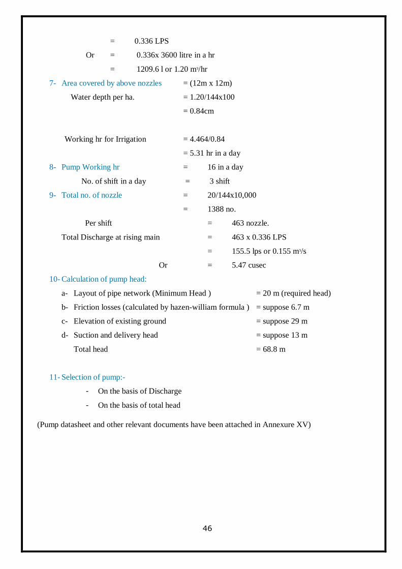
46
= 0.336 LPS
Or = 0.336x 3600 litre in a hr
= 1209.6 l or 1.20 mᵌ/hr
7- Area covered by above nozzles = (12m x 12m)
Water depth per ha. = 1.20/144x100
= 0.84cm
Working hr for Irrigation = 4.464/0.84
= 5.31 hr in a day
8- Pump Working hr = 16 in a day
No. of shift in a day = 3 shift
9- Total no. of nozzle = 20/144x10,000
= 1388 no.
Per shift = 463 nozzle.
Total Discharge at rising main = 463 x 0.336 LPS
= 155.5 lps or 0.155 mᵌ/s
Or = 5.47 cusec
10- Calculation of pump head:
a- Layout of pipe network (Minimum Head ) = 20 m (required head)
b- Friction losses (calculated by hazen-william formula ) = suppose 6.7 m
c- Elevation of existing ground = suppose 29 m
d- Suction and delivery head = suppose 13 m
Total head = 68.8 m
11- Selection of pump:-
- On the basis of Discharge
- On the basis of total head
(Pump datasheet and other relevant documents have been attached in Annexure XV)
47
Chapter 6
MAINTENANCE AND PRECAUTIONS
Drip Irrigation System
There are no moving parts in drip irrigation so if the system is used properly, it only requires
maintenance of pump, and the following points should be kept in mind for the operation and
maintenance of drip irrigation system:
1- The place where the system is installed, there should be a restriction on the movement of animals
otherwise the system may be damaged.
2- Normally the system is run for half an hour or an hour per day. In case of extreme change in
weather, operational changes become necessary.
3- In order to make the drip irrigation unit more useful, it is necessary that along with the
installation of the system, suitable crop combination shall be considered like pomegranates
plants can be planted with the garden of sweet lime. Sweet lime plants will give fruits in four
years and pomegranate plants will start giving fruits in 1.5 years.
4- In the use of drip irrigation, the main problem is that the pipes and drippers can get clogged, for
this it is necessary to have an effective filteration along with backwashing facility.
Sprinkler Irrigation System
Following precautions shall be taken during sprinkler irrigation:-
a) All equipment and fittings shall be properly inspected before and after use.
b) Clean water devoid of sand shall be used for sprinkler irrigation.
c) After use of insecticides or pesticides all equipment shall be thoroughly washed with clean
water.
d) Washers, rubber seals and other fittings shall be inspected on regular basis and if needed shall be
replaced at the earliest.
48
Chapter 7
LIMITATIONS
Drip Irrigation System
High Initial cost.
Clogging of Emitters.
Technical Knowledge is required for design, installation & maintenance.
Sprinkler Irrigation System
Water distribution from sprinklers is non-uniform when speed of winds is high in the area.
Ripe fruits are affected adversely by sprinkler irrigation.
Regular source of water is necessary for effectiveness of this technique.
Water should be free from sand, floating materials and shall not be saline.
Energy requirements for this technique are very high.
This technique is not suitable for clayey soils and in dry areas.
Grooves and furrows are not required in sprinkler irrigation. This leads to saving of land
which can be utilised for increasing crop area.
Farmers need to be made aware and educated regarding sprinkler irrigation.
This technique depends on type of crop under cultivation.
In this technique, multiple types of components are used leading to high maintenance cost.
49
Chapter 8
TRAINING FOR SYSTEM OPERATION
Human resource development is an important component of any new scheme. Under the
programme training of farmers, WUA or land holders and entrepreneur etc , micro irrigation
technician and farm pond lining technician and trainers‘ training may be taken up.
Operation and Maintenance of the system requires adequate training of users for system
operation etc. The manufacturers should provide detailed operational and maintenance manual in
the local vernacular language at the time of installation of the system.
Service centres and / or offices of drip / sprinkler system manufacturers /authorised distributors
may be hired to provide technical guidance on system maintenance schedules, supply spare parts
and ensure satisfactory performance of the system during the warranty period.
50
Chapter 9
QUALITY CONTROL
Crucial aspect of supply of micro irrigation systems is the quality of hardware which is used by
the farmer. It needs to been ensured that quality components having BIS marking (wherever
applicable) are installed in the field. Poor quality has an adverse impact on performance of the
system which may affect yield of the crop, quantity of water applied, quantity of fertilizer
delivered to the plant etc. It may also increase energy consumption. In fact, sub-standard system
will not only adversely impact performance, but could also reduce the durability and the life of
the components and/or system.
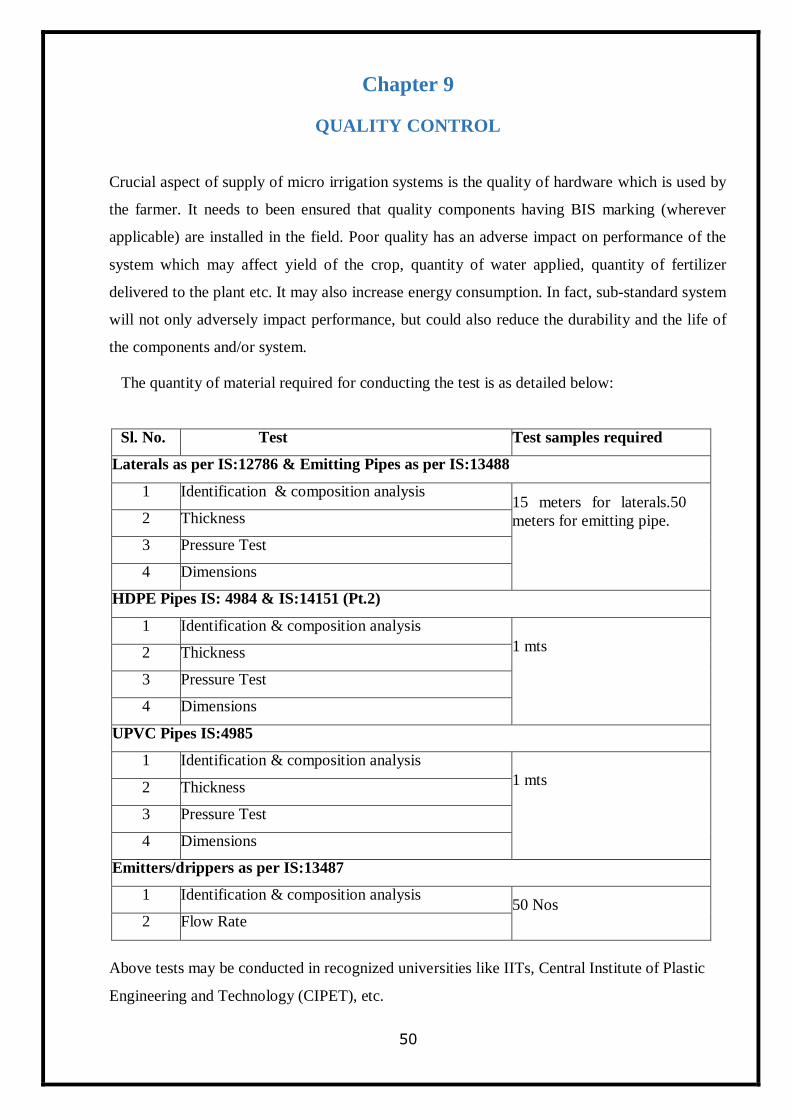
The quantity of material required for conducting the test is as detailed below:
Sl. No. Test Test samples required
Laterals as per IS:12786 & Emitting Pipes as per IS:13488
1 Identification & composition analysis 15 meters for laterals.50
meters for emitting pipe. 2 Thickness
3 Pressure Test
4 Dimensions
HDPE Pipes IS: 4984 & IS:14151 (Pt.2)
1 Identification & composition analysis
1 mts 2 Thickness
3 Pressure Test
4 Dimensions
UPVC Pipes IS:4985
1 Identification & composition analysis
1 mts 2 Thickness
3 Pressure Test
4 Dimensions
Emitters/drippers as per IS:13487
1 Identification & composition analysis 50 Nos
2 Flow Rate
Above tests may be conducted in recognized universities like IITs, Central Institute of Plastic
Engineering and Technology (CIPET), etc.
51
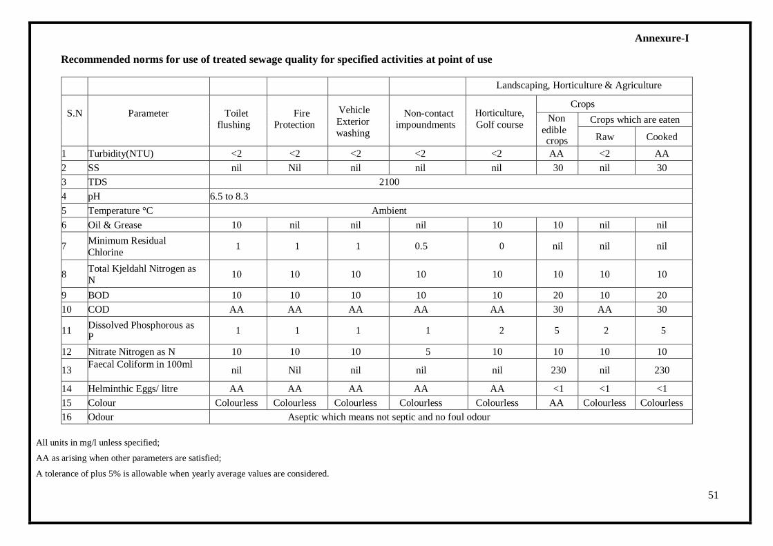
Annexure-I
Recommended norms for use of treated sewage quality for specified activities at point of use
Landscaping, Horticulture & Agriculture
S.N
Parameter
Toilet flushing
Fire Protection
Vehicle
Exterior washing
Non-contact impoundments
Horticulture,
Golf course
Crops
Non
edible crops
Crops which are eaten
Raw Cooked
1 Turbidity(NTU) <2 <2 <2 <2 <2 AA <2 AA
2 SS nil Nil nil nil nil 30 nil 30
3 TDS 2100
4 pH 6.5 to 8.3
5 Temperature °C Ambient
6 Oil & Grease 10 nil nil nil 10 10 nil nil
7 Minimum Residual
Chlorine 1 1 1 0.5 0 nil nil nil
8 Total Kjeldahl Nitrogen as N
10 10 10 10 10 10 10 10
9 BOD 10 10 10 10 10 20 10 20
10 COD AA AA AA AA AA 30 AA 30
11 Dissolved Phosphorous as P
1 1 1 1 2 5 2 5
12 Nitrate Nitrogen as N 10 10 10 5 10 10 10 10
13 Faecal Coliform in 100ml
nil Nil nil nil nil 230 nil 230
14 Helminthic Eggs/ litre AA AA AA AA AA <1 <1 <1
15 Colour Colourless Colourless Colourless Colourless Colourless AA Colourless Colourless
16 Odour Aseptic which means not septic and no foul odour
All units in mg/l unless specified;
AA as arising when other parameters are satisfied;
A tolerance of plus 5% is allowable when yearly average values are considered.
52
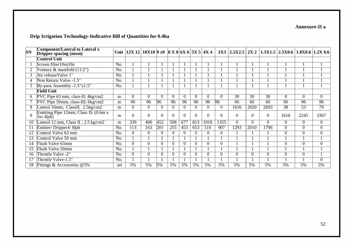
Annexure-II a
Drip Irrigation Technology-Indicative Bill of Quantities for 0.4ha
SN Component/Lateral to Lateral x Dripper spacing (mxm) Unit 12X 12 10X10 9 x9 8 X 8 6X 6 5X 5 4X 4 3X3 2.5X2.5 2X 2 1.5X1.5 2.5X0.6 1.8X0.6 1.2X 0.6
Control Unit 1 Screen filter10m3/hr No. 1 1 1 1 1 1 1 1 1 1 1 1 1 1
2 Ventury & manifold (11/2") No. 1 1 1 1 1 1 1 1 1 1 1 1 1 1
3 Air releaseValve 1" No. 1 1 1 1 1 1 1 1 1 1 1 1 1 1
4 Non Return Valve -1.5" No. 1 1 1 1 1 1 1 1 1 1 1 1 1 1
5 By-pass Assembly -1.5"x1.5" No. 1 1 1 1 1 1 1 1 1 1 1 1 1 1
Field Unit 6 PVC Pipe 63 mm, class-II; 4kg/cm2 m 0 0 0 0 0 0 0 0 30 30 30 0 0 0
7 PVC Pipe 50mm, class-III; 6kg/cm2 m 96 96 96 96 96 96 96 96 66 66 66 96 96 96
8 Lateral 16mm, ClassII; 2.5kg/cm2 m 0 0 0 0 0 0 0 0 1616 2020 2693 38 53 79
9 Emitting Pipe 12mm; Class II: (0.6m x 1to 4lph) m 0 0 0 0 0 0 0 0 0 0 0 1616 2245 3367
10 Lateral 12 mm, Class II ; 2.5 kg/cm2 m 339 406 452 508 677 813 1016 1355 0 0 0 0 0 0
11 Emitter/ Dripper4/ 8lph No. 113 163 201 255 453 653 510 907 1293 2010 1796 0 0 0
12 Control Valve 63 mm No. 0 0 0 0 0 0 0 0 1 1 1 0 0 0
13 Control Valve 50 mm No. 1 1 1 1 1 1 1 1 1 1 1 1 1 1
14 Flush Valve 63mm No. 0 0 0 0 0 0 0 0 1 1 1 0 0 0
15 Flush Valve 50mm No. 1 1 1 1 1 1 1 1 1 1 1 1 1 1
16 Throttle Valve -2" No. 0 0 0 0 0 0 0 0 0 0 0 0 0 1
17 Throttle Valve-1.5" No. 1 1 1 1 1 1 1 1 1 1 1 1 1 0
18 Fittings & Accessories @5% set 5% 5% 5% 5% 5% 5% 5% 5% 5% 5% 5% 5% 5% 5%
53
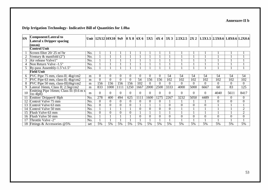
Annexure-II b
Drip Irrigation Technology- Indicative Bill of Quantities for 1.0ha
SN Component/Lateral to
Lateral x Dripper spacing
(mxm)
Unit 12X12 10X10 9x9 8 X 8 6X 6 5X5 4X 4 3X 3 2.5X2.5 2X 2 1.5X1.5 2.5X0.6 1.8X0.6 1.2X0.6
Control Unit
1 Screen filter 20/ 25 m3/hr No. 1 1 1 1 1 1 1 1 1 1 1 1 1 1
2 Ventury & manifold (2") No. 1 1 1 1 1 1 1 1 1 1 1 1 1 1 3 Air release Valve1" No. 1 1 1 1 1 1 1 1 1 1 1 1 1 1 4 Non Return Valve -1.5" No. 1 1 1 1 1 1 1 1 1 1 1 1 1 1 5 By-pass Assembly-1.5"x1.5" No. 1 1 1 1 1 1 1 1 1 1 1 1 1 1
Field Unit
6 PVC Pipe 75 mm, class-II; 4kg/cm2 m 0 0 0 0 0 0 0 54 54 54 54 54 54 54 7 PVC Pipe 63 mm, class-II; 4kg/cm2 m 0 0 0 0 54 156 156 102 102 102 102 102 102 102 8 PVC Pipe 50 mm, class-III;6kg/cm2 m 156 156 156 156 102 0 0 0 0 0 0 0 0 0 9 Lateral 16mm, Class II; 2.5kg/cm2 m 833 1000 1111 1250 1667 2000 2500 3333 4000 5000 6667 60 83 125
10 Emitting Pipe 16mm; Class II: (0.6 m x 1to 4lph) m 0 0 0 0 0 0 0 0 0 0 0 4040 5611 8417
11 Emitter/ Dripper4/ 8lph No. 278 400 494 625 1111 1600 1275 2267 3232 5050 4489 0 0 0 12 Control Valve 75 mm No. 0 0 0 0 0 0 0 1 1 1 1 0 0 0 13 Control Valve 63 mm No. 0 0 0 0 1 1 1 0 0 0 0 1 1 1 14 Control Valve 50 mm No. 1 1 1 1 0 0 0 0 1 1 1 1 1 2 15 Flush Valve 63 mm No. 0 0 0 0 1 1 1 1 1 1 1 1 1 2 16 Flush Valve 50 mm No. 1 1 1 1 0 0 0 0 0 0 0 0 0 0 17 Throttle Valve -2" No. 1 1 1 1 1 1 1 1 1 1 1 1 1 1 18 Fittings & Accessories @5% set 5% 5% 5% 5% 5% 5% 5% 5% 5% 5% 5% 5% 5% 5%
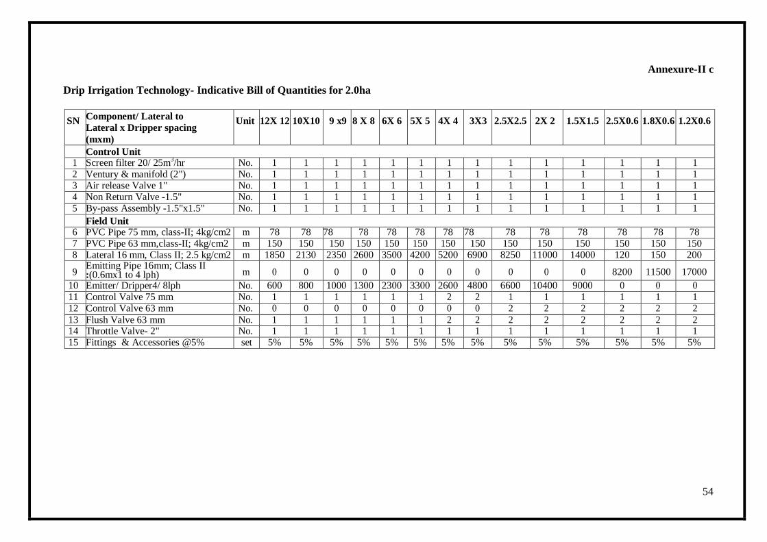
54
Annexure-II c
Drip Irrigation Technology- Indicative Bill of Quantities for 2.0ha
SN Component/ Lateral to
Lateral x Dripper spacing
(mxm)
Unit 12X 12 10X10 9 x9 8 X 8 6X 6 5X 5 4X 4 3X3 2.5X2.5 2X 2 1.5X1.5 2.5X0.6 1.8X0.6 1.2X0.6
Control Unit 1 Screen filter 20/ 25m
3/hr No. 1 1 1 1 1 1 1 1 1 1 1 1 1 1
2 Ventury & manifold (2") No. 1 1 1 1 1 1 1 1 1 1 1 1 1 1 3 Air release Valve 1" No. 1 1 1 1 1 1 1 1 1 1 1 1 1 1 4 Non Return Valve -1.5" No. 1 1 1 1 1 1 1 1 1 1 1 1 1 1 5 By-pass Assembly -1.5"x1.5" No. 1 1 1 1 1 1 1 1 1 1 1 1 1 1
Field Unit 6 PVC Pipe 75 mm, class-II; 4kg/cm2 m 78 78 78 78 78 78 78 78 78 78 78 78 78 78 7 PVC Pipe 63 mm,class-II; 4kg/cm2 m 150 150 150 150 150 150 150 150 150 150 150 150 150 150 8 Lateral 16 mm, Class II; 2.5 kg/cm2 m 1850 2130 2350 2600 3500 4200 5200 6900 8250 11000 14000 120 150 200
9 Emitting Pipe 16mm; Class II :(0.6mx1 to 4 lph) m 0 0 0 0 0 0 0 0 0 0 0 8200 11500 17000
10 Emitter/ Dripper4/ 8lph No. 600 800 1000 1300 2300 3300 2600 4800 6600 10400 9000 0 0 0 11 Control Valve 75 mm No. 1 1 1 1 1 1 2 2 1 1 1 1 1 1 12 Control Valve 63 mm No. 0 0 0 0 0 0 0 0 2 2 2 2 2 2
13 Flush Valve 63 mm No. 1 1 1 1 1 1 2 2 2 2 2 2 2 2 14 Throttle Valve- 2" No. 1 1 1 1 1 1 1 1 1 1 1 1 1 1 15 Fittings & Accessories @5% set 5% 5% 5% 5% 5% 5% 5% 5% 5% 5% 5% 5% 5% 5%
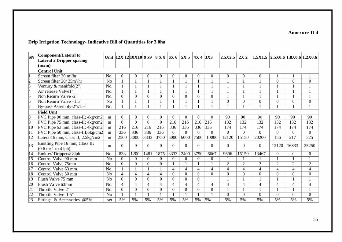
55
Annexure-II d
Drip Irrigation Technology- Indicative Bill of Quantities for 3.0ha
SN Component/Lateral to
Lateral x Dripper spacing
(mxm)
Unit 12X 12 10X10 9 x9 8 X 8 6X 6 5X 5 4X 4 3X3 2.5X2.5 2X 2 1.5X1.5 2.5X0.6 1.8X0.6 1.2X0.6
Control Unit 1 Screen filter 30 m
3/hr No. 0 0 0 0 0 0 0 0 0 0 0 1 1 1
2 Screen filter 20/ 25m3/hr No 1 1 1 1 1 1 1 1 1 1 1 0 0 0
3 Ventury & manifold(2") No. 1 1 1 1 1 1 1 1 1 1 1 1 1 1
4 Air release Valve1" No. 1 1 1 1 1 1 1 1 1 1 1 1 1 1 5 Non Return Valve -2" No. 0 0 0 0 0 0 0 0 1 1 1 1 1 1 6 Non Return Valve –1.5" No 1 1 1 1 1 1 1 1 0 0 0 0 0 0 7 By-pass Assembly-2"x1.5" No. 1 1 1 1 1 1 1 1 1 1 1 1 1 1
Field Unit 8 PVC Pipe 90 mm, class-II; 4kg/cm2 m 0 0 0 0 0 0 0 0 90 90 90 90 90 90 9 PVC Pipe 75 mm, class-II; 4kg/cm2 m 0 0 0 0 216 216 216 216 132 132 132 132 132 132 10 PVC Pipe 63 mm, class-II; 4kg/cm2 m 216 216 216 216 336 336 336 336 174 174 174 174 174 174 11 PVC Pipe 50 mm, class-III;6kg/cm2 m 336 336 336 336 0 0 0 0 0 0 0 0 0 0 12 Lateral16 mm, Class II; 2.5kg/cm2 m 2500 3000 3333 3750 5000 6000 7500 10000 12120 15150 20200 156 217 325
13 Emitting Pipe 16 mm; Class II:
(0.6 mx1 to 4 lph) m 0 0 0 0 0 0 0 0 0 0 0 12120 16833 25250
14 Emitter/ Dripper4/ 8lph No. 833 1200 1481 1875 3333 2400 3750 6667 9696 15150 13467 0 0 0 15 Control Valve 90 mm No 0 0 0 0 0 0 0 0 1 1 1 1 1 1 16 Control Valve 75mm No. 0 0 0 0 1 1 1 1 2 2 2 2 2 2
17 Control Valve 63 mm No. 1 1 1 1 4 4 4 4 4 4 4 4 4 4 18 Control Valve 50 mm No 4 4 4 4 0 0 0 0 0 0 0 0 0 0 19 Flush Valve 75 mm No 0 0 0 0 0 0 0 1 1 1 1 1 1
20 Flush Valve 63mm No. 4 4 4 4 4 4 4 4 4 4 4 4 4 4 21 Throttle Valve-2" No. 0 0 0 0 0 0 0 0 1 1 1 1 1 1 22 Throttle Valve–1.5" No 1 1 1 1 1 1 1 1 0 0 0 0 0 0
23 Fittings & Accessories @5% set 5% 5% 5% 5% 5% 5% 5% 5% 5% 5% 5% 5% 5% 5%
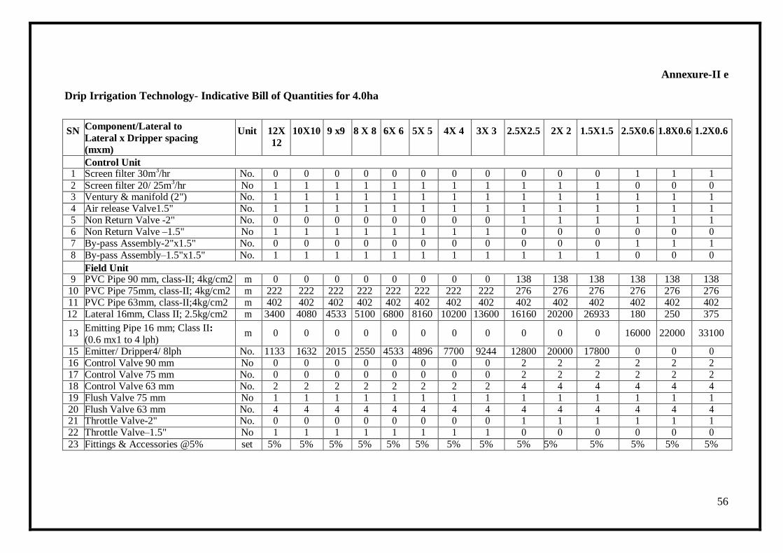
56
Annexure-II e
Drip Irrigation Technology- Indicative Bill of Quantities for 4.0ha
SN Component/Lateral to
Lateral x Dripper spacing
(mxm)
Unit 12X
12
10X10 9 x9 8 X 8 6X 6 5X 5 4X 4 3X 3 2.5X2.5 2X 2 1.5X1.5 2.5X0.6 1.8X0.6 1.2X0.6
Control Unit 1 Screen filter 30m
3/hr No. 0 0 0 0 0 0 0 0 0 0 0 1 1 1
2 Screen filter 20/ 25m3/hr No 1 1 1 1 1 1 1 1 1 1 1 0 0 0
3 Ventury & manifold (2") No. 1 1 1 1 1 1 1 1 1 1 1 1 1 1 4 Air release Valve1.5" No. 1 1 1 1 1 1 1 1 1 1 1 1 1 1 5 Non Return Valve -2" No. 0 0 0 0 0 0 0 0 1 1 1 1 1 1 6 Non Return Valve –1.5" No 1 1 1 1 1 1 1 1 0 0 0 0 0 0 7 By-pass Assembly-2"x1.5" No. 0 0 0 0 0 0 0 0 0 0 0 1 1 1
8 By-pass Assembly–1.5"x1.5" No. 1 1 1 1 1 1 1 1 1 1 1 0 0 0
Field Unit 9 PVC Pipe 90 mm, class-II; 4kg/cm2 m 0 0 0 0 0 0 0 0 138 138 138 138 138 138
10 PVC Pipe 75mm, class-II; 4kg/cm2 m 222 222 222 222 222 222 222 222 276 276 276 276 276 276 11 PVC Pipe 63mm, class-II;4kg/cm2 m 402 402 402 402 402 402 402 402 402 402 402 402 402 402 12 Lateral 16mm, Class II; 2.5kg/cm2 m 3400 4080 4533 5100 6800 8160 10200 13600 16160 20200 26933 180 250 375
13 Emitting Pipe 16 mm; Class II:
(0.6 mx1 to 4 lph) m 0 0 0 0 0 0 0 0 0 0 0 16000 22000 33100
15 Emitter/ Dripper4/ 8lph No. 1133 1632 2015 2550 4533 4896 7700 9244 12800 20000 17800 0 0 0 16 Control Valve 90 mm No 0 0 0 0 0 0 0 0 2 2 2 2 2 2 17 Control Valve 75 mm No. 0 0 0 0 0 0 0 0 2 2 2 2 2 2 18 Control Valve 63 mm No. 2 2 2 2 2 2 2 2 4 4 4 4 4 4 19 Flush Valve 75 mm No 1 1 1 1 1 1 1 1 1 1 1 1 1 1 20 Flush Valve 63 mm No. 4 4 4 4 4 4 4 4 4 4 4 4 4 4 21 Throttle Valve-2" No. 0 0 0 0 0 0 0 0 1 1 1 1 1 1 22 Throttle Valve–1.5" No 1 1 1 1 1 1 1 1 0 0 0 0 0 0
23 Fittings & Accessories @5% set 5% 5% 5% 5% 5% 5% 5% 5% 5% 5% 5% 5% 5% 5%
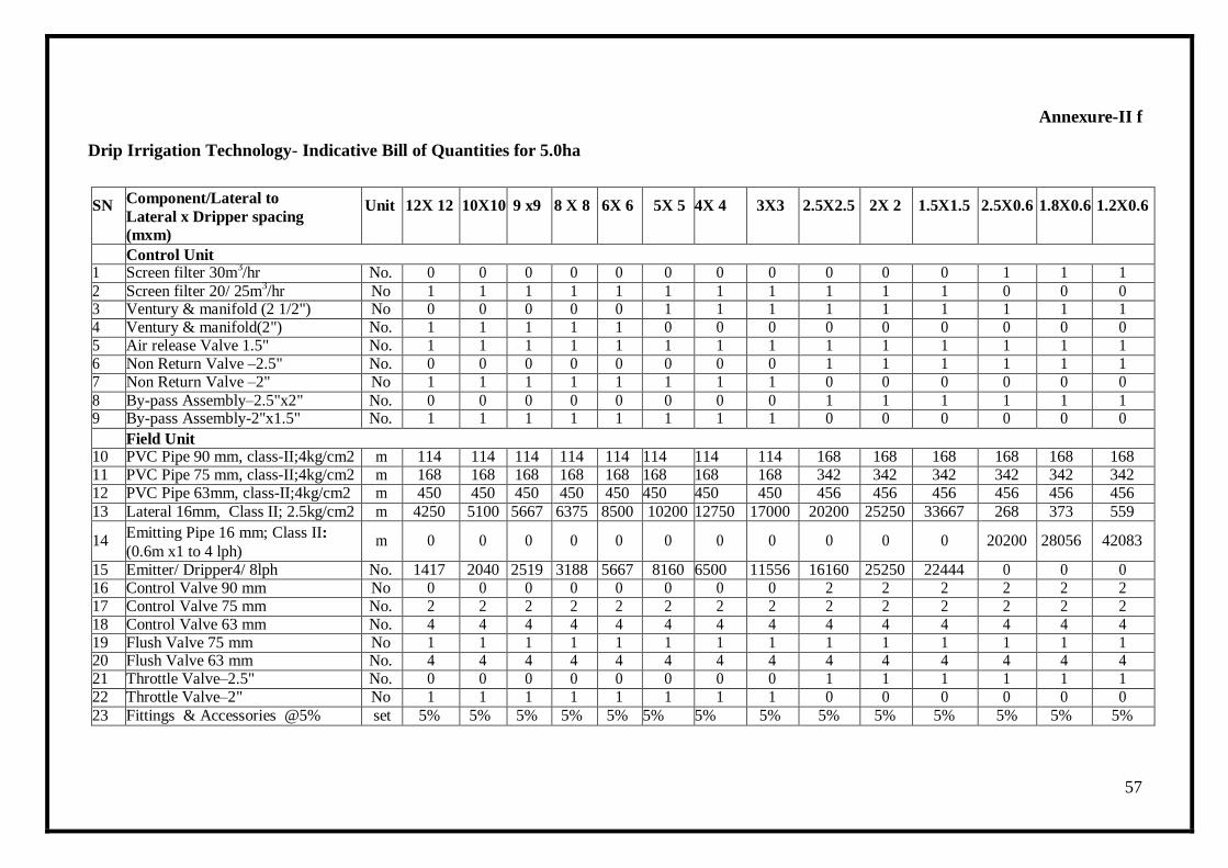
57
Annexure-II f
Drip Irrigation Technology- Indicative Bill of Quantities for 5.0ha
SN Component/Lateral to
Lateral x Dripper spacing
(mxm)
Unit 12X 12 10X10 9 x9 8 X 8 6X 6 5X 5 4X 4 3X3 2.5X2.5 2X 2 1.5X1.5 2.5X0.6 1.8X0.6 1.2X0.6
Control Unit 1 Screen filter 30m
3/hr No. 0 0 0 0 0 0 0 0 0 0 0 1 1 1
2 Screen filter 20/ 25m3/hr No 1 1 1 1 1 1 1 1 1 1 1 0 0 0
3 Ventury & manifold (2 1/2") No 0 0 0 0 0 1 1 1 1 1 1 1 1 1 4 Ventury & manifold(2") No. 1 1 1 1 1 0 0 0 0 0 0 0 0 0 5 Air release Valve 1.5" No. 1 1 1 1 1 1 1 1 1 1 1 1 1 1 6 Non Return Valve –2.5" No. 0 0 0 0 0 0 0 0 1 1 1 1 1 1 7 Non Return Valve –2" No 1 1 1 1 1 1 1 1 0 0 0 0 0 0
8 By-pass Assembly–2.5"x2" No. 0 0 0 0 0 0 0 0 1 1 1 1 1 1 9 By-pass Assembly-2"x1.5" No. 1 1 1 1 1 1 1 1 0 0 0 0 0 0
Field Unit 10 PVC Pipe 90 mm, class-II;4kg/cm2 m 114 114 114 114 114 114 114 114 168 168 168 168 168 168 11 PVC Pipe 75 mm, class-II;4kg/cm2 m 168 168 168 168 168 168 168 168 342 342 342 342 342 342 12 PVC Pipe 63mm, class-II;4kg/cm2 m 450 450 450 450 450 450 450 450 456 456 456 456 456 456
13 Lateral 16mm, Class II; 2.5kg/cm2 m 4250 5100 5667 6375 8500 10200 12750 17000 20200 25250 33667 268 373 559
14 Emitting Pipe 16 mm; Class II:
(0.6m x1 to 4 lph) m 0 0 0 0 0 0 0 0 0 0 0 20200 28056 42083
15 Emitter/ Dripper4/ 8lph No. 1417 2040 2519 3188 5667 8160 6500 11556 16160 25250 22444 0 0 0 16 Control Valve 90 mm No 0 0 0 0 0 0 0 0 2 2 2 2 2 2 17 Control Valve 75 mm No. 2 2 2 2 2 2 2 2 2 2 2 2 2 2 18 Control Valve 63 mm No. 4 4 4 4 4 4 4 4 4 4 4 4 4 4 19 Flush Valve 75 mm No 1 1 1 1 1 1 1 1 1 1 1 1 1 1 20 Flush Valve 63 mm No. 4 4 4 4 4 4 4 4 4 4 4 4 4 4 21 Throttle Valve–2.5" No. 0 0 0 0 0 0 0 0 1 1 1 1 1 1 22 Throttle Valve–2" No 1 1 1 1 1 1 1 1 0 0 0 0 0 0
23 Fittings & Accessories @5% set 5% 5% 5% 5% 5% 5% 5% 5% 5% 5% 5% 5% 5% 5%
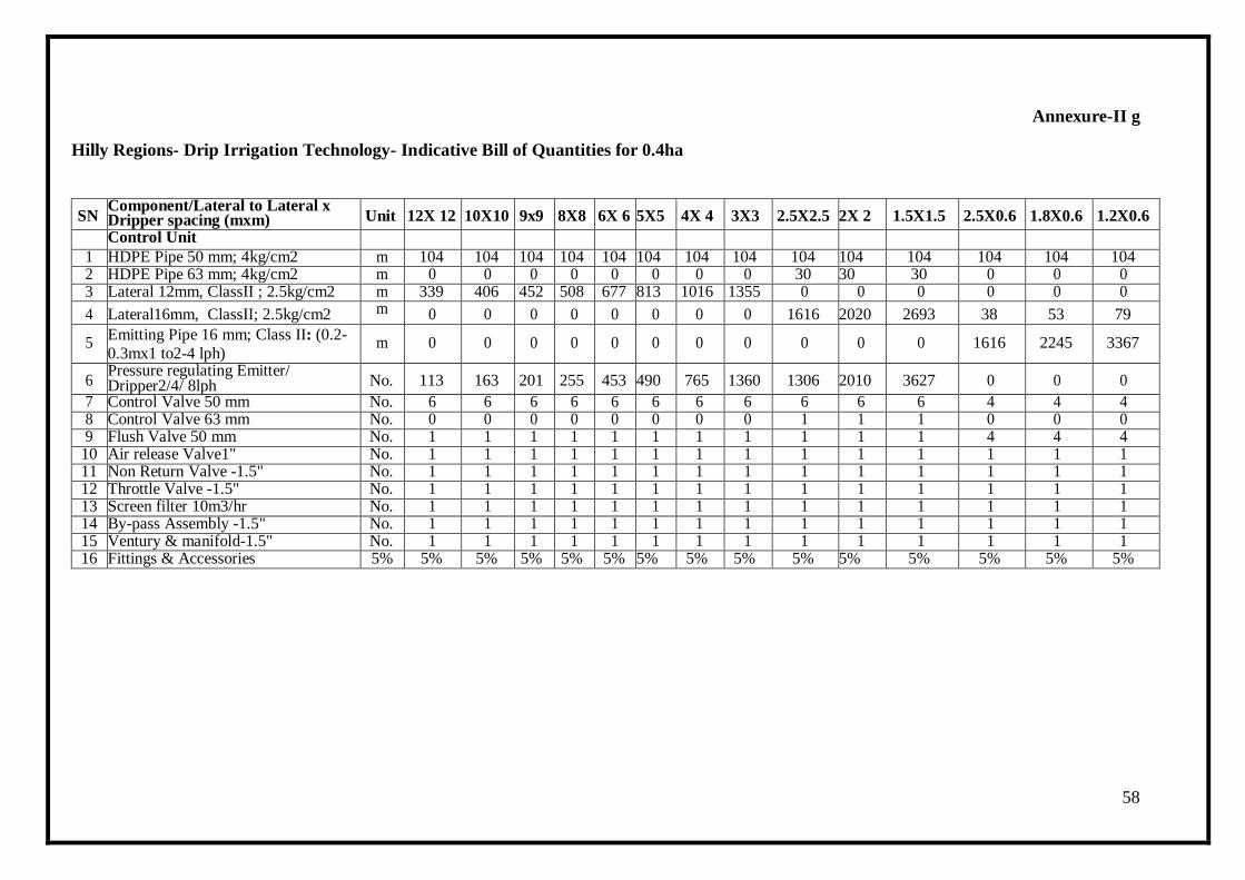
58
Annexure-II g
Hilly Regions- Drip Irrigation Technology- Indicative Bill of Quantities for 0.4ha
SN Component/Lateral to Lateral x Dripper spacing (mxm) Unit 12X 12 10X10 9x9 8X8 6X 6 5X5 4X 4 3X3 2.5X2.5 2X 2 1.5X1.5 2.5X0.6 1.8X0.6 1.2X0.6
Control Unit 1 HDPE Pipe 50 mm; 4kg/cm2 m 104 104 104 104 104 104 104 104 104 104 104 104 104 104 2 HDPE Pipe 63 mm; 4kg/cm2 m 0 0 0 0 0 0 0 0 30 30 30 0 0 0 3 Lateral 12mm, ClassII ; 2.5kg/cm2 m 339 406 452 508 677 813 1016 1355 0 0 0 0 0 0
4 Lateral16mm, ClassII; 2.5kg/cm2 m 0 0 0 0 0 0 0 0 1616 2020 2693 38 53 79
5 Emitting Pipe 16 mm; Class II: (0.2-
0.3mx1 to2-4 lph) m 0 0 0 0 0 0 0 0 0 0 0 1616 2245 3367
6 Pressure regulating Emitter/ Dripper2/4/ 8lph No. 113 163 201 255 453 490 765 1360 1306 2010 3627 0 0 0
7 Control Valve 50 mm No. 6 6 6 6 6 6 6 6 6 6 6 4 4 4 8 Control Valve 63 mm No. 0 0 0 0 0 0 0 0 1 1 1 0 0 0 9 Flush Valve 50 mm No. 1 1 1 1 1 1 1 1 1 1 1 4 4 4
10 Air release Valve1" No. 1 1 1 1 1 1 1 1 1 1 1 1 1 1 11 Non Return Valve -1.5" No. 1 1 1 1 1 1 1 1 1 1 1 1 1 1 12 Throttle Valve -1.5" No. 1 1 1 1 1 1 1 1 1 1 1 1 1 1 13 Screen filter 10m3/hr No. 1 1 1 1 1 1 1 1 1 1 1 1 1 1 14 By-pass Assembly -1.5" No. 1 1 1 1 1 1 1 1 1 1 1 1 1 1 15 Ventury & manifold-1.5" No. 1 1 1 1 1 1 1 1 1 1 1 1 1 1 16 Fittings & Accessories 5% 5% 5% 5% 5% 5% 5% 5% 5% 5% 5% 5% 5% 5% 5%
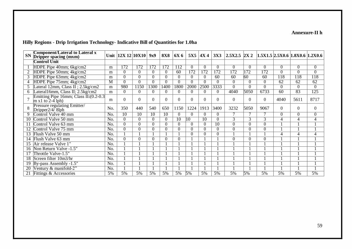
59
Annexure-II h
Hilly Regions - Drip Irrigation Technology- Indicative Bill of Quantities for 1.0ha
SN Component/Lateral to Lateral x Dripper spacing (mxm) Unit 12X 12 10X10 9x9 8X8 6X 6 5X5 4X 4 3X3 2.5X2.5 2X 2 1.5X1.5 2.5X0.6 1.8X0.6 1.2X0.6
Control Unit 1 HDPE Pipe 40mm; 6kg/cm2 m 172 172 172 172 112 0 0 0 0 0 0 0 0 0 2 HDPE Pipe 50mm; 4kg/cm2 m 0 0 0 0 60 172 172 172 172 172 172 0 0 0 3 HDPE Pipe 63mm; 4kg/cm2 m 0 0 0 0 0 0 0 60 60 60 60 118 118 118 4 HDPE Pipe 75mm; 4kg/cm2 M 0 0 0 0 0 0 0 0 0 0 0 62 62 62 5 Lateral 12mm, Class II ; 2.5kg/cm2 m 980 1150 1300 1400 1800 2000 2500 3333 0 0 0 0 0 0 6 Lateral16mm, Class II; 2.5kg/cm2 m 0 0 0 0 0 0 0 0 4040 5050 6733 60 83 125
7 Emitting Pipe 16mm; Class II:(0.2-0.3 m x1 to 2-4 lph) m 0 0 0 0 0 0 0 0 0 0 0 4040 5611 8717
8 Pressure regulating Emitter/ Dripper2/4/ 8lph No. 350 440 540 650 1150 1224 1913 3400 3232 5050 9067 0 0 0
9 Control Valve 40 mm No. 10 10 10 10 0 0 0 0 7 7 7 0 0 0 10 Control Valve 50 mm No. 0 0 0 0 10 10 10 0 3 3 3 4 4 4 11 Control Valve 63 mm No. 0 0 0 0 0 0 0 10 0 0 0 1 1 1 12 Control Valve 75 mm No. 0 0 0 0 0 0 0 0 0 0 0 1 1 1 13 Flush Valve 50 mm No. 1 1 1 1 1 0 0 0 1 1 1 4 4 4 14 Flush Valve 63 mm No. 0 0 0 0 0 1 1 1 0 0 0 1 1 1 15 Air release Valve 1" No. 1 1 1 1 1 1 1 1 1 1 1 1 1 1 16 Non Return Valve -1.5" No. 1 1 1 1 1 1 1 1 1 1 1 1 1 1 17 Throttle Valve-1.5" No. 1 1 1 1 1 1 1 1 1 1 1 1 1 1 18 Screen filter 10m3/hr No. 1 1 1 1 1 1 1 1 1 1 1 1 1 1 19 By-pass Assembly -1.5" No. 1 1 1 1 1 1 1 1 1 1 1 1 1 1 20 Ventury & manifold-2‖ No. 1 1 1 1 1 1 1 1 1 1 1 1 1 1 21 Fittings & Accessories 5% 5% 5% 5% 5% 5% 5% 5% 5% 5% 5% 5% 5% 5% 5%
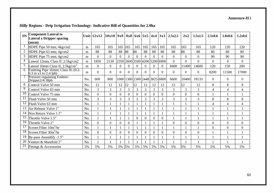
60
Annexure-II i
Hilly Regions - Drip Irrigation Technology- Indicative Bill of Quantities for 2.0ha
SN Component Lateral to
Lateral x Dripper spacing
(mxm)
Unit 12x12 10x10 9x9 8x8 6x6 5x5 4x4 3x3 2.5x2.5 2x2 1.5x1.5 2.5x0.6 1.8x0.6 1.2x0.6
1 HDPE Pipe 50 mm; 4kg/cm2 m 165 165 165 165 165 165 165 165 165 165 165 120 120 120
2 HDPE Pipe 63 mm; 4g/cm2 m 88 88 88 88 88 88 88 88 88 88 88 80 80 80
3 HDPE Pipe 75 mm; 4g/cm2 m 0 0 0 0 0 0 0 0 0 0 0 90 90 90 4 Lateral 12mm, Class II ;2.5kg/cm2 m 1850 2130 2350 2600 3500 4200 5200 6900 0 0 0 0 0 0 5 Lateral 16mm Class II, 2.5kg/cm
2 m 0 0 0 0 0 0 0 0 8400 11400 14600 120 150 200
6 Emitting Pipe 16mm; Class II: (0.2-0.3 m x1 to 2-4 lph) m 0 0 0 0 0 0 0 0 0 0 0 8200 11500 17000
7 Pressure regulating Emitter/ Dripper2/4/ 8lph No. 600 800 1000 1300 2300 2448 3825 6800 6600 10400 18133 0 0 0
8 Control Valve 50 mm No. 12 12 12 12 12 12 12 12 12 12 12 8 8 8 9 Control Valve 63 mm No. 3 3 3 3 3 3 3 3 3 3 3 4 4 4 10 Control Valve 75 mm No. 0 0 0 0 0 0 0 0 0 0 0 1 1 1 11 Flush Valve 50 mm No. 3 3 3 3 3 3 3 3 3 3 3 8 8 8 12 Flush Valve 63 mm No. 1 1 1 1 1 1 1 1 1 1 1 4 4 4
13 Air Release Valve 1‖ No. 1 1 1 1 1 1 1 1 1 1 1 1 1 1
14 Non Return Valve 1.5‖ No. 1 1 1 1 1 1 1 1 1 1 1 1 1 1 15 Throttle Valve 1.5" No. 1 1 1 1 0 0 0 0 1 1 1 1 1 1 16 Throttle Valve 2" No. 0 0 0 0 1 1 1 1 0 0 0 0 0 0 17 Screen Filter 10m
3/hr No. 1 1 1 1 1 1 1 1 1 1 1 0 0 0
18 Screen Filter 30m3/hr No. 0 0 0 0 0 0 0 0 0 0 0 1 1 1
19 By-pass Assembly -1.5‖ No. 1 1 1 1 1 1 1 1 1 1 1 1 1 1
20 Venturi & Manifold 2‖ No. 1 1 1 1 1 1 1 1 1 1 1 1 1 1 21 Fittings & Accessories 5% 5% 5% 5% 5% 5% 5% 5% 5% 5% 5% 5% 5% 5% 5%

61
Annexure-II j
Hilly Regions- Drip Irrigation Technology- Indicative Bill of Quantities for 3.0ha
SN
Component Lateral to Lateral x
Dripper spacing (mxm) Uni
t
12x12 10x10 9x9 8x8 6x6 5x5 4x4 3x3 2.5x2.5 2x2 1.5x1.5 2.5x0.6 1.8x0.6 1.2x0.6
1 HDPE Pipe 90 mm; 4kg/cm2 m 0 0 0 0 0 0 0 0 105 105 105 0 0 0
2 HDPE Pipe 75 mm; 4kg/cm2 m 0 0 0 0 240 240 240 240 144 144 144 105 105 105
3 HDPE Pipe 63 mm; 4kg/cm2 m 240 240 240 240 380 380 380 380 190 190 190 150 150 150
4 HDPE Pipe 50mm; 4kg/cm2 m 380 380 380 380 0 0 0 0 0 0 0 200 200 200
5 Lateral 16mm Class II, 2.5kg/cm2 m 0 0 0 0 0 0 0 0 12120 15150 20200 156 217 325
6 Lateral12mm, Class II;2.5kg/cm2 m 2500 3000 3333 3750 5000 6000 7500 10000 0 0 0 0 0 0
7 Emitting Pipe 16 mm; Class II: (0.2-0.3 mx1 to 2-4 lph)
m 0 0 0 0 0 0 0 0 0 0 0 12120 16833 25250
8 Pressure regulating Emitter/ Dripper2/4/ 8lph No. 833 1200 1481 1875 3333 3672 5738 10200 9696 15150 26933 0 0 0
9 Control Valve 90 mm No 0 0 0 0 0 0 0 0 1 1 1 0 0 0
10 Control Valve 75 mm No 3 3 3 3 3 3 3 3 5 5 5 1 1 1
11 Control Valve 63 mm No. 8 8 8 8 8 8 8 8 8 8 8 2 2 2
12 Control Valve 50 mm No. 0 0 0 0 0 0 0 0 0 0 0 8 8 8
13 Flush Valve 75 mm No. 3 3 3 3 3 3 3 3 5 5 5 0 0 0
14 Flush Valve 63 mm No. 8 8 8 8 8 8 8 8 8 8 8 1 1 1
15 Flush Valve 50 mm No. 0 0 0 0 0 0 0 0 0 0 0 4 4 4
16 Air Release Valve 1‖ No. 1 1 1 1 1 1 1 1 1 1 1 1 1 1
17 Non Return Valve 1.5‖ No. 1 1 1 1 1 1 1 1 0 0 0 0 0 0
18 Non Return Valve 2‖ No. 0 0 0 0 0 0 0 0 1 1 1 1 1 1
19 Throttle Valve 1.5‖ No. 1 1 1 1 1 1 1 1 0 0 0 0 0 0
20 Throttle Valve 2‖ No. 0 0 0 0 0 0 0 0 1 1 1 1 1 1
21 Screen Filter 30 m3/hr No. 0 0 0 0 0 0 0 0 0 0 0 1 1 1
22 Screen Filter 20/25m3/hr No. 0 0 0 0 0 1 1 1 0 0 0 0 0 0
23 Screen Filter 10m3/hr No. 1 1 1 1 1 0 0 0 1 1 1 0 0 0
24 By-pass Assembly-2‖ No. 1 1 1 1 1 1 1 1 1 1 1 1 1 1
25 Venturi & Manifold2 ― No. 1 1 1 1 1 1 1 1 1 1 1 1 1 1
26 Fittings & Accessories 5% 5% 5% 5% 5% 5% 5% 5% 5% 5% 5% 5% 5% 5% 5%
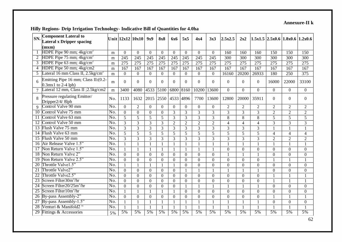
62
Annexure-II k
Hilly Regions- Drip Irrigation Technology- Indicative Bill of Quantities for 4.0ha
SN.
Component Lateral to
Lateral x Dripper spacing
(mxm)
Unit 12x12 10x10 9x9 8x8 6x6 5x5 4x4 3x3 2.5x2.5 2x2 1.5x1.5 2.5x0.6 1.8x0.6 1.2x0.6
1 HDPE Pipe 90 mm; 4kg/cm2 m 0 0 0 0 0 0 0 0 160 160 160 150 150 150
2 HDPE Pipe 75 mm; 4kg/cm2 m 245 245 245 245 245 245 245 245 300 300 300 300 300 300
3 HDPE Pipe 63 mm; 4kg/cm2 m 275 275 275 275 275 275 275 275 275 275 275 275 275 275
4 HDPE Pipe 50 mm; 4kg/cm2 m 167 167 167 167 167 167 167 167 167 167 167 167 167 167 5 Lateral 16 mm Class II, 2.5kg/cm
2 m 0 0 0 0 0 0 0 0 16160 20200 26933 180 250 375
6 Emitting Pipe 16 mm; Class II:(0.2-
0.3mx1 to 2-4 lph) m 0 0 0 0 0 0 0 0 0 0 0 16000 22000 33100
7 Lateral 12 mm, Class II ;2.5kg/cm2 m 3400 4080 4533 5100 6800 8160 10200 13600 0 0 0 0 0 0
8 Pressure regulating Emitter/
Dripper2/4/ 8lph No. 1133 1632 2015 2550 4533 4896 7700 13600 12800 20000 35911 0 0 0
9 Control Valve 90 mm No. 0 2 0 0 0 0 0 0 2 2 2 2 2 2
10 Control Valve 75 mm No. 0 0 0 0 3 3 3 3 3 3 3 2 2 2 11 Control Valve 63 mm No. 5 5 5 5 3 3 3 3 8 8 8 5 5 5 12 Control Valve 50 mm No. 3 3 3 3 2 2 2 2 4 4 4 3 3 3 13 Flush Valve 75 mm No. 3 3 3 3 3 3 3 3 3 3 3 1 1 1 14 Flush Valve 63 mm No. 5 5 5 5 5 5 5 5 5 5 5 4 4 4 15 Flush Valve 50 mm No. 3 3 3 3 3 3 3 3 3 3 3 2 2 2 16 Air Release Valve 1.5‖ No. 1 1 1 1 1 1 1 1 1 1 1 1 1 1 17 Non Return Valve 1.5‖ No. 1 1 1 1 1 1 1 1 0 0 0 0 0 0 18 Non Return Valve 2‖ No. 0 0 0 0 0 0 0 0 1 1 1 0 0 0 19 Non Return Valve 2.5‖ No. 0 0 0 0 0 0 0 0 0 0 0 1 1 1 20 Throttle Valve1.5‖ No. 1 1 1 1 1 0 0 0 0 0 0 0 0 0 21 Throttle Valve2‖ No. 0 0 0 0 0 1 1 1 1 1 1 0 0 0 22 Throttle Valve2.5‖ No. 0 0 0 0 0 0 0 0 0 0 0 1 1 1 23 Screen Filter30m
3/hr No. 0 0 0 0 0 0 0 0 0 0 0 1 1 1
24 Screen Filter20/25m3/hr No. 0 0 0 0 0 1 1 1 1 1 1 0 0 0
25 Screen Filter10m3/hr No. 1 1 1 1 1 0 0 0 0 0 0 0 0 0
26 By-pass Assembly-2‖ No. 0 0 0 0 0 0 0 0 0 0 0 1 1 1 27 By-pass Assembly-1.5‖ No. 1 1 1 1 1 1 1 1 1 1 1 0 0 0 28 Venturi & Manifold2 ― No. 1 1 1 1 1 1 1 1 1 1 1 1 1 1 29 Fittings & Accessories 5% 5% 5% 5% 5% 5% 5% 5% 5% 5% 5% 5% 5% 5% 5%
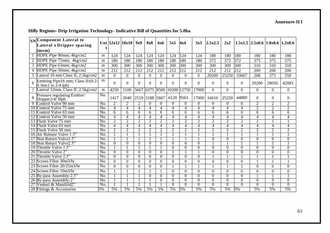
63
Annexure-II l
Hilly Regions- Drip Irrigation Technology- Indicative Bill of Quantities for 5.0ha
SN Component Lateral to
Lateral x Dripper spacing
(mxm)
Uni
t
12x12 10x10 9x9 8x8 6x6 5x5 4x4 3x3 2.5x2.5 2x2 1.5x1.5 2.5x0.6 1.8x0.6 1.2x0.6
1 HDPE Pipe 90mm; 4kg/cm2 m 124 124 124 124 124 124 124 124 180 180 180 180 180 180 2 HDPE Pipe 75mm; 4kg/cm2 m 180 180 180 180 180 180 180 180 372 372 372 375 375 375 3 HDPE Pipe 63mm; 4kg/cm2 m 300 300 300 300 300 300 300 300 300 300 300 310 310 310 4 HDPE Pipe 50mm; 4kg/cm2 m 212 212 212 212 212 212 212 212 212 212 212 200 200 200 5 Lateral 16 mm Class II, 2.5kg/cm2 m 0 0 0 0 0 0 0 0 20200 25250 33667 268 373 559
6 Emitting Pipe16 mm; Class II:(0.2- 0.3mx1 to 2-4 lph)
m 0 0 0 0 0 0 0 0 0 0 0 20200 28056 42083
7 Lateral 12mm, Class II ;2.5kg/cm2 m 4250 5100 5667 6375 8500 10200 12750 17000 0 0 0 0 0 0
8 Pressure regulating Emitter/ Dripper2/4/ 8lph
No. 1417 2040 2519 3188 5667 6120 9563 17000 16610 25250 44889 0 0 0
9 Control Valve 90 mm No. 2 2 2 0 0 0 0 0 0 0 0 2 2 2 10 Control Valve 75 mm No. 4 4 4 4 4 4 4 4 4 4 4 2 2 2 11 Control Valve 63 mm No. 6 6 6 6 6 6 6 6 6 6 6 6 6 6 12 Control Valve 50 mm No. 4 4 4 4 4 4 4 4 4 4 4 4 4 4 13 Flush Valve 75 mm No. 2 2 2 2 2 2 2 2 2 2 2 1 1 1 14 Flush Valve 63 mm No. 4 4 4 4 4 4 4 4 4 4 4 4 4 4 15 Flush Valve 50 mm No. 2 2 2 2 2 2 2 2 2 2 2 2 2 2 16 Air Release Valve 1.5‖ No. 1 1 1 1 1 1 1 1 1 1 1 1 1 1 17 Non Return Valve1.5‖ No. 1 1 1 1 1 1 1 1 0 0 0 0 0 0 18 Non Return Valve2.5‖ No. 0 0 0 0 0 0 0 0 1 1 1 1 1 1 19 Throttle Valve 1.5‖ No. 1 1 1 1 1 0 0 0 0 0 0 0 0 0 20 Throttle Valve 2‖ No. 0 0 0 0 0 1 1 1 0 0 0 0 0 0 21 Throttle Valve 2.5‖ No. 0 0 0 0 0 0 0 0 1 1 1 1 1 1 22 Screen Filter 30m3/hr No. 0 0 0 0 0 0 0 0 0 0 0 1 1 1 23 Screen Filter 20/25m3/hr No. 0 0 0 0 0 1 1 1 1 1 1 0 0 0 24 Screen Filter 10m3/hr No. 1 1 1 1 1 0 0 0 0 0 0 0 0 0 25 By-pass Assembly-2.5‖ No. 1 1 1 0 0 0 0 0 0 0 0 1 1 1 26 By-pass Assembly-2‖ No. 1 1 1 1 0 0 0 0 0 0 0 0 0 0 27 Venturi & Manifold2― No. 1 1 1 1 1 0 0 0 0 0 0 0 0 0 28 Fittings & Accessories 5% 5% 5% 5% 5% 5% 5% 5% 5% 5% 5% 5% 5% 5% 5%
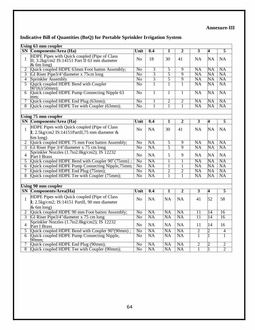
64
Annexure-III
Indicative Bill of Quantities (BoQ) for Portable Sprinkler Irrigation System
Using 63 mm coupler SN Components/Area (Ha) Unit 0.4 1 2 3 4 5
1 HDPE Pipes with Quick coupled (Pipe of Class II; 3.2kg/cm2 IS:14151 Part II 63 mm diameter & 6m long)
No 18 30 41 NA NA NA
2 Quick coupled HDPE 63mm Foot batten Assembly; No 3 5 9 NA NA NA 3 GI Riser Pipe3/4"diameter x 75cm long No 3 5 9 NA NA NA 4 Sprinkler Assembly No 3 5 9 NA NA NA 5 Quick coupled HDPE Bend with Coupler
900(63/50mm);
No 1 1 1 NA NA NA
6 Quick coupled HDPE Pump Connecting Nipple 63 mm;
No 1 1 1 NA NA NA
7 Quick coupled HDPE End Plug (63mm); No 1 2 2 NA NA NA 8 Quick coupled HDPE Tee with Coupler (63mm); No 1 1 1 NA NA NA
Using 75 mm coupler SN Components/Area (Ha) Unit 0.4 1 2 3 4 5
1 HDPE Pipes with Quick coupled (Pipe of Class
I; 2.5kg/cm2 IS:14151PartII,75 mm diameter &
6m long)
No NA 30 41 NA NA NA
2 Quick coupled HDPE 75 mm Foot batten Assembly; No NA 5 9 NA NA NA 3 GI Riser Pipe 3/4"diameter x 75 cm long No NA 5 9 NA NA NA
4 Sprinkler Nozzles (1.7to2.8kg/cm2); IS 12232 Part I Brass No NA 5 9 NA NA NA
5 Quick coupled HDPE Bend with Coupler 900 (75mm) ; No NA 1 1 NA NA NA
6 Quick coupled HDPE Pump Connecting Nipple,75mm; No NA 1 1 NA NA NA 7 Quick coupled HDPE End Plug (75mm); No NA 2 2 NA NA NA 8 Quick coupled HDPE Tee with Coupler (75mm); No NA 1 1 NA NA NA
Using 90 mm coupler SN Components/Area(Ha) Unit 0.4 1 2 3 4 5
1 HDPE Pipes with Quick coupled (Pipe of Class
I; 2.5kg/cm2; IS:14151 PartII, 90 mm diameter & 6m long)
No NA NA NA 41 52 58
2 Quick coupled HDPE 90 mm Foot batten Assembly; No NA NA NA 11 14 16 3 GI Riser Pipe3/4"diameter x 75 cm long No NA NA NA 11 14 16
4 Sprinkler Nozzles (1.7to2.8kg/cm2); IS 12232 Part I Brass No NA NA NA 11 14 16
5 Quick coupled HDPE Bend with Coupler 900(90mm) ; No NA NA NA 2 2 4
6 Quick coupled HDPE Pump Connecting Nipple, 90mm;
No NA NA NA 1 1 1
7 Quick coupled HDPE End Plug (90mm); No NA NA NA 2 2 2 8 Quick coupled HDPE Tee with Coupler (90mm); No NA NA NA 1 1 2
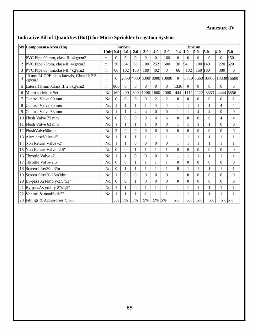
65
Annexure-IV
Indicative Bill of Quantities (BoQ) for Micro Sprinkler Irrigation System
SN Components/Area (Ha) 5mx5m 3mx3m
Unit 0.4 1.0 2.0 3.0 4.0 5.0 0.4 1.0 2.0 3.0 4.0 5.0
1 PVC Pipe 90 mm, class-II; 4kg/cm2 m 0 0 0 0 0 160 0 0 0 0 0 150
2 PVC Pipe 75mm, class-II; 4kg/cm2 m 30 54 80 100 252 600 30 54 100 140 220 520
3 PVC Pipe 63 mm,class-II;4kg/cm2 m 66 102 150 180 402 0 66 102 150 180 380 0
4 20 mm LLDPE plain laterals, Class II; 2.5 kg/cm2 m 0 2000 4000 6000 8000 10000 0 3350 6660 10000 13330 16600
5 Lateral16 mm ,Class II; 2.5kg/cm2 m 800 0 0 0 0 0 1336 0 0 0 0 0
6 Micro sprinkler Set No. 160 400 800 1200 1600 2000 444 1111 2222 3333 4444 5556
7 Control Valve 90 mm No. 0 0 0 0 2 2 0 0 0 0 0 1
8 Control Valve 75 mm No. 1 1 1 1 4 4 1 1 1 1 4 4
9 Control Valve 63 mm No. 1 1 4 4 0 0 1 1 4 4 0 0
10 Flush Valve 75 mm No. 0 0 0 0 4 6 0 0 0 0 4 4
11 Flush Valve 63 mm No. 1 1 1 1 0 0 1 1 1 1 0 0
12 FlushValve50mm No. 2 0 0 0 0 0 0 0 0 0 0 0
13 AirreleaseValve-1" No. 1 1 1 1 1 1 1 1 1 1 1 1
14 Non Return Valve -2" No. 1 1 0 0 0 0 1 1 1 1 1 1
15 Non Return Valve -2.5" No. 0 0 1 1 1 1 0 0 0 0 0 0
16 Throttle Valve -2" No. 1 1 0 0 0 0 1 1 1 1 1 1
17 Throttle Valve-2.5" No. 0 0 1 1 1 1 0 0 0 0 0 0
18 Screen filter30m3/hr No. 0 1 1 1 1 1 0 1 1 1 1 1
19 Screen filter20/25m3/hr No. 1 0 0 0 0 0 1 0 0 0 0 0
20 By-pass Assembly-2.5"x2" No. 0 0 1 0 0 0 0 0 0 0 0 0
21 By-passAssembly-2"x1,5" No. 1 1 0 1 1 1 1 1 1 1 1 1
22 Venturi & manifold-2" No. 1 1 1 1 1 1 1 1 1 1 1 1
23 Fittings & Accessories @5% 5% 5% 5% 5% 5% 5% 5% 5% 5% 5% 5% 5%
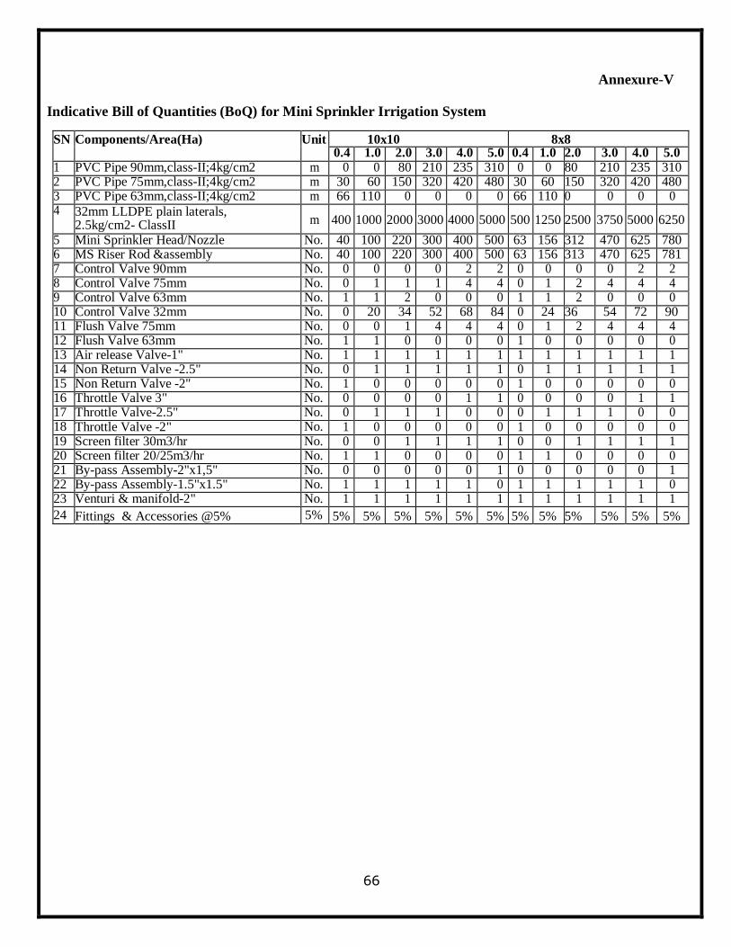
66
Annexure-V
Indicative Bill of Quantities (BoQ) for Mini Sprinkler Irrigation System
SN Components/Area(Ha) Unit 10x10 8x8 0.4 1.0 2.0 3.0 4.0 5.0 0.4 1.0 2.0 3.0 4.0 5.0
1 PVC Pipe 90mm,class-II;4kg/cm2 m 0 0 80 210 235 310 0 0 80 210 235 310 2 PVC Pipe 75mm,class-II;4kg/cm2 m 30 60 150 320 420 480 30 60 150 320 420 480 3 PVC Pipe 63mm,class-II;4kg/cm2 m 66 110 0 0 0 0 66 110 0 0 0 0 4 32mm LLDPE plain laterals,
2.5kg/cm2- ClassII m 400 1000 2000 3000 4000 5000 500 1250 2500 3750 5000 6250
5 Mini Sprinkler Head/Nozzle No. 40 100 220 300 400 500 63 156 312 470 625 780 6 MS Riser Rod &assembly No. 40 100 220 300 400 500 63 156 313 470 625 781 7 Control Valve 90mm No. 0 0 0 0 2 2 0 0 0 0 2 2 8 Control Valve 75mm No. 0 1 1 1 4 4 0 1 2 4 4 4 9 Control Valve 63mm No. 1 1 2 0 0 0 1 1 2 0 0 0 10 Control Valve 32mm No. 0 20 34 52 68 84 0 24 36 54 72 90 11 Flush Valve 75mm No. 0 0 1 4 4 4 0 1 2 4 4 4 12 Flush Valve 63mm No. 1 1 0 0 0 0 1 0 0 0 0 0 13 Air release Valve-1" No. 1 1 1 1 1 1 1 1 1 1 1 1 14 Non Return Valve -2.5" No. 0 1 1 1 1 1 0 1 1 1 1 1 15 Non Return Valve -2" No. 1 0 0 0 0 0 1 0 0 0 0 0 16 Throttle Valve 3" No. 0 0 0 0 1 1 0 0 0 0 1 1 17 Throttle Valve-2.5" No. 0 1 1 1 0 0 0 1 1 1 0 0 18 Throttle Valve -2" No. 1 0 0 0 0 0 1 0 0 0 0 0 19 Screen filter 30m3/hr No. 0 0 1 1 1 1 0 0 1 1 1 1 20 Screen filter 20/25m3/hr No. 1 1 0 0 0 0 1 1 0 0 0 0 21 By-pass Assembly-2"x1,5" No. 0 0 0 0 0 1 0 0 0 0 0 1 22 By-pass Assembly-1.5"x1.5" No. 1 1 1 1 1 0 1 1 1 1 1 0 23 Venturi & manifold-2" No. 1 1 1 1 1 1 1 1 1 1 1 1
24 Fittings & Accessories @5% 5% 5% 5% 5% 5% 5% 5% 5% 5% 5% 5% 5% 5%
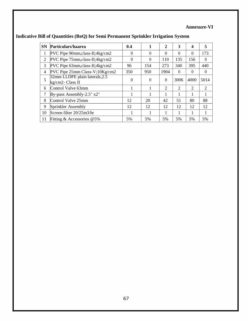
67
Annexure-VI
Indicative Bill of Quantities (BoQ) for Semi Permanent Sprinkler Irrigation System
SN Particulars/haarea 0.4 1 2 3 4 5
1 PVC Pipe 90mm,class-II;4kg/cm2 0 0 0 0 0 173
2 PVC Pipe 75mm,class-II;4kg/cm2 0 0 110 135 156 0
3 PVC Pipe 63mm,class-II;4kg/cm2 96 154 273 340 395 440
4 PVC Pipe 25mm Class-V;10Kg/cm2 350 950 1904 0 0 0
5 32mm LLDPE plain laterals,2.5
kg/cm2- Class II 0 0 0 3006 4000 5014
6 Control Valve 63mm 1 1 2 2 2 2
7 By-pass Assembly-2.5" x2" 1 1 1 1 1 1
8 Control Valve 25mm 12 20 42 51 80 88
9 Sprinkler Assembly 12 12 12 12 12 12
10 Screen filter 20/25m3/hr 1 1 1 1 1 1
11 Fitting & Accessories @5% 5% 5% 5% 5% 5% 5%
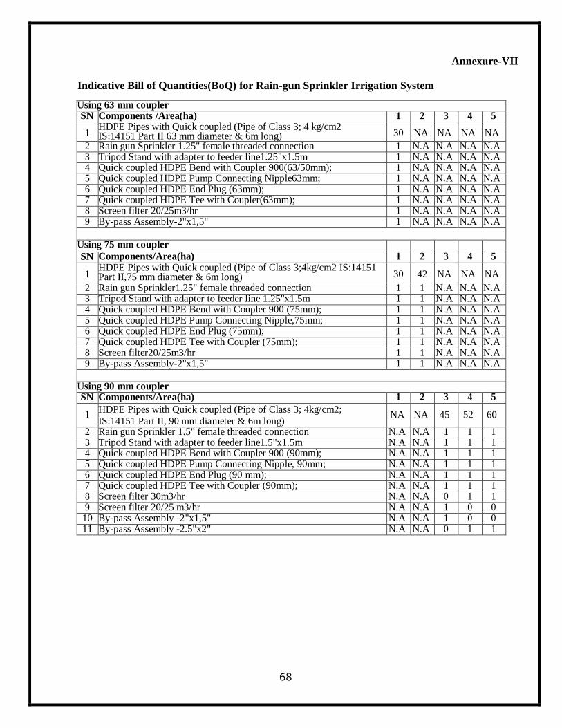
68
Annexure-VII
Indicative Bill of Quantities(BoQ) for Rain-gun Sprinkler Irrigation System
Using 63 mm coupler SN Components /Area(ha) 1 2 3 4 5
1 HDPE Pipes with Quick coupled (Pipe of Class 3; 4 kg/cm2 IS:14151 Part II 63 mm diameter & 6m long) 30 NA NA NA NA
2 Rain gun Sprinkler 1.25" female threaded connection 1 N.A N.A N.A N.A 3 Tripod Stand with adapter to feeder line1.25"x1.5m 1 N.A N.A N.A N.A 4 Quick coupled HDPE Bend with Coupler 900(63/50mm); 1 N.A N.A N.A N.A 5 Quick coupled HDPE Pump Connecting Nipple63mm; 1 N.A N.A N.A N.A 6 Quick coupled HDPE End Plug (63mm); 1 N.A N.A N.A N.A 7 Quick coupled HDPE Tee with Coupler(63mm); 1 N.A N.A N.A N.A 8 Screen filter 20/25m3/hr 1 N.A N.A N.A N.A 9 By-pass Assembly-2"x1,5" 1 N.A N.A N.A N.A
Using 75 mm coupler SN Components/Area(ha) 1 2 3 4 5
1 HDPE Pipes with Quick coupled (Pipe of Class 3;4kg/cm2 IS:14151 Part II,75 mm diameter & 6m long) 30 42 NA NA NA
2 Rain gun Sprinkler1.25" female threaded connection 1 1 N.A N.A N.A 3 Tripod Stand with adapter to feeder line 1.25"x1.5m 1 1 N.A N.A N.A 4 Quick coupled HDPE Bend with Coupler 900 (75mm); 1 1 N.A N.A N.A 5 Quick coupled HDPE Pump Connecting Nipple,75mm; 1 1 N.A N.A N.A 6 Quick coupled HDPE End Plug (75mm); 1 1 N.A N.A N.A 7 Quick coupled HDPE Tee with Coupler (75mm); 1 1 N.A N.A N.A 8 Screen filter20/25m3/hr 1 1 N.A N.A N.A 9 By-pass Assembly-2"x1,5" 1 1 N.A N.A N.A
Using 90 mm coupler SN Components/Area(ha) 1 2 3 4 5
1 HDPE Pipes with Quick coupled (Pipe of Class 3; 4kg/cm2;
IS:14151 Part II, 90 mm diameter & 6m long) NA NA 45 52 60
2 Rain gun Sprinkler 1.5" female threaded connection N.A N.A 1 1 1 3 Tripod Stand with adapter to feeder line1.5"x1.5m N.A N.A 1 1 1 4 Quick coupled HDPE Bend with Coupler 900 (90mm); N.A N.A 1 1 1 5 Quick coupled HDPE Pump Connecting Nipple, 90mm; N.A N.A 1 1 1 6 Quick coupled HDPE End Plug (90 mm); N.A N.A 1 1 1 7 Quick coupled HDPE Tee with Coupler (90mm); N.A N.A 1 1 1 8 Screen filter 30m3/hr N.A N.A 0 1 1 9 Screen filter 20/25 m3/hr N.A N.A 1 0 0
10 By-pass Assembly -2"x1,5" N.A N.A 1 0 0 11 By-pass Assembly -2.5"x2" N.A N.A 0 1 1
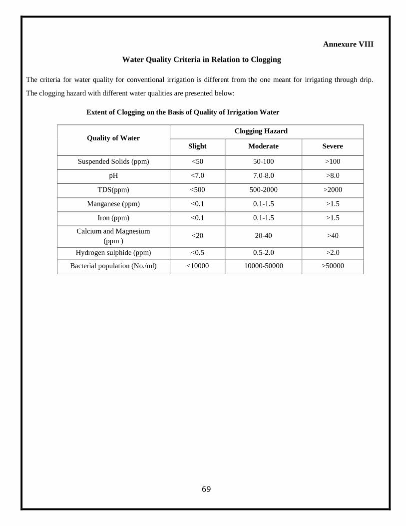
69
Annexure VIII
Water Quality Criteria in Relation to Clogging
The criteria for water quality for conventional irrigation is different from the one meant for irrigating through drip.
The clogging hazard with different water qualities are presented below:
Extent of Clogging on the Basis of Quality of Irrigation Water
Quality of Water Clogging Hazard
Slight Moderate Severe
Suspended Solids (ppm) <50 50-100 >100
pH <7.0 7.0-8.0 >8.0
TDS(ppm) <500 500-2000 >2000
Manganese (ppm) <0.1 0.1-1.5 >1.5
Iron (ppm) <0.1 0.1-1.5 >1.5
Calcium and Magnesium
(ppm ) <20 20-40 >40
Hydrogen sulphide (ppm) <0.5 0.5-2.0 >2.0
Bacterial population (No./ml) <10000 10000-50000 >50000
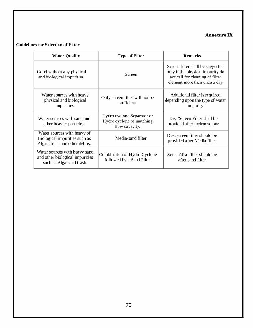
70
Annexure IX
Guidelines for Selection of Filter
Water Quality Type of Filter Remarks
Good without any physical
and biological impurities. Screen
Screen filter shall be suggested
only if the physical impurity do
not call for cleaning of filter
element more than once a day
Water sources with heavy
physical and biological
impurities.
Only screen filter will not be
sufficient
Additional filter is required
depending upon the type of water
impurity
Water sources with sand and
other heavier particles.
Hydro cyclone Separator or
Hydro cyclone of matching
flow capacity.
Disc/Screen Filter shall be
provided after hydrocyclone
Water sources with heavy of
Biological impurities such as Algae, trash and other debris.
Media/sand filter Disc/screen filter should be
provided after Media filter
Water sources with heavy sand and other biological impurities
such as Algae and trash.
Combination of Hydro Cyclone
followed by a Sand Filter Screen/disc filter should be
after sand filter
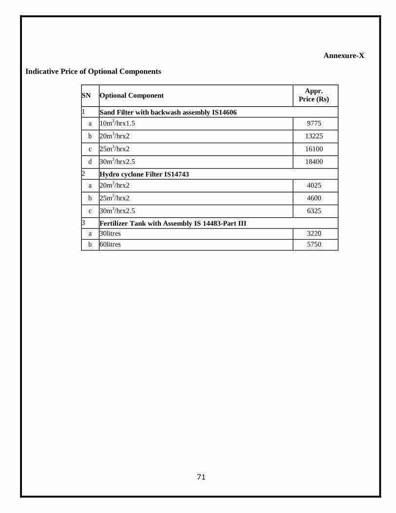
71
Annexure-X
Indicative Price of Optional Components
SN Optional Component Appr.
Price (Rs)
1 Sand Filter with backwash assembly IS14606
a 10m3/hrx1.5 9775
b 20m3/hrx2 13225
c 25m3/hrx2 16100
d 30m3/hrx2.5 18400
2 Hydro cyclone Filter IS14743
a 20m3/hrx2 4025
b 25m3/hrx2 4600
c 30m3/hrx2.5 6325
3 Fertilizer Tank with Assembly IS 14483-Part III
a 30litres 3220
b 60litres 5750
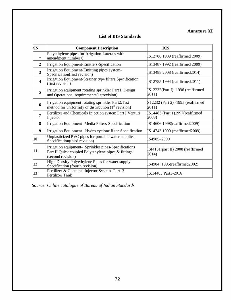
72
Annexure XI
List of BIS Standards
SN Component Description BIS
1 Polyethylene pipes for Irrigation-Laterals with amendment number 6
IS12786:1989 (reaffirmed 2009)
2 Irrigation Equipment-Emitters-Specification IS13487:1992 (reaffirmed 2009)
3 Irrigation Equipment-Emitting pipes system-Specification(first revision)
IS13488:2008 (reaffirmed2014)
4 Irrigation Equipment-Strainer type filters Specification (first revision)
IS12785:1994 (reaffirmed2011)
5 Irrigation equipment rotating sprinkler Part I, Design
and Operational requirements(1strevision)
IS12232(Part I) -1996 (reaffirmed 2011)
6 Irrigation equipment rotating sprinkler Part2,Test
method for uniformity of distribution (1st revision)
S12232 (Part 2) -1995 (reaffirmed
2011)
7 Fertilizer and Chemicals Injection system Part I Venturi Injector
IS14483 (Part 1)1997(reaffirmed 2009)
8 Irrigation Equipment- Media Filters-Specification IS14606:1998(reaffirmed2009)
9 Irrigation Equipment –Hydro cyclone filter-Specification IS14743:1999 (reaffirmed2009)
10 Unplasticized PVC pipes for portable water supplies-Specification(third revision) IS4985–2000
11 Irrigation equipment- Sprinkler pipes-Specifications
Part II Quick coupled Polyethylene pipes & fittings (second revision)
ISI4151(part II) 2008 (reaffirmed
2014)
12 High Density Polyethylene Pipes for water supply-Specification (fourth revision) IS4984 :1995(reaffirmed2002)
13 Fertilizer & Chemical Injector System- Part 3 Fertilizer Tank
IS:14483 Part3-2016
Source: Online catalogue of Bureau of Indian Standards
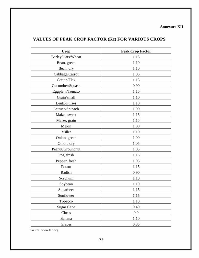
73
Annexure XII
VALUES OF PEAK CROP FACTOR (Kc) FOR VARIOUS CROPS
Crop Peak Crop Factor
Barley/Oats/Wheat 1.15
Bean, green 1.10
Bean, dry 1.10
Cabbage/Carrot 1.05
Cotton/Flax 1.15
Cucumber/Squash 0.90
Eggplant/Tomato 1.15
Grain/small 1.10
Lentil/Pulses 1.10
Lettuce/Spinach 1.00
Maize, sweet 1.15
Maize, grain 1.15
Melon 1.00
Millet 1.10
Onion, green 1.00
Onion, dry 1.05
Peanut/Groundnut 1.05
Pea, fresh 1.15
Pepper, fresh 1.05
Potato 1.15
Radish 0.90
Sorghum 1.10
Soybean 1.10
Sugarbeet 1.15
Sunflower 1.15
Tobacco 1.10
Sugar Cane 0.40
Citrus 0.9
Banana 1.10
Grapes 0.85
Source: www.fao.org
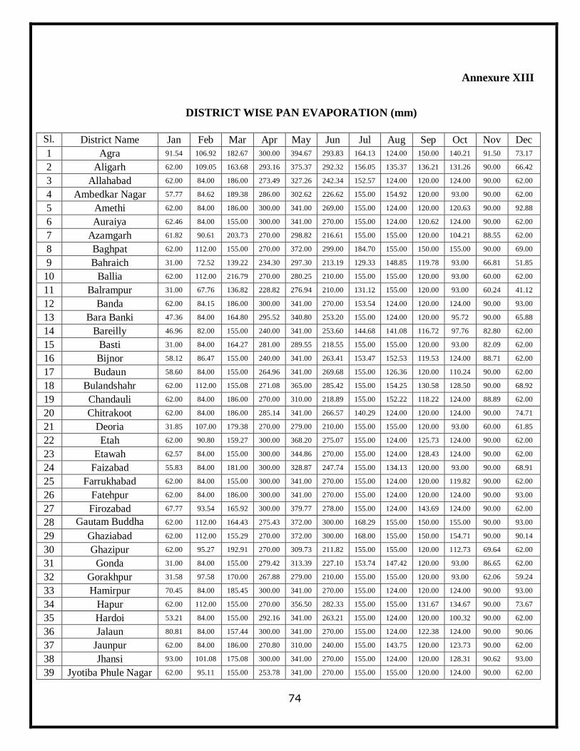
74
Annexure XIII
DISTRICT WISE PAN EVAPORATION (mm)
Sl.
No. District Name Jan Feb Mar Apr May Jun Jul Aug Sep Oct Nov Dec
1 Agra 91.54 106.92 182.67 300.00 394.67 293.83 164.13 124.00 150.00 140.21 91.50 73.17
2 Aligarh 62.00 109.05 163.68 293.16 375.37 292.32 156.05 135.37 136.21 131.26 90.00 66.42
3 Allahabad 62.00 84.00 186.00 273.49 327.26 242.34 152.57 124.00 120.00 124.00 90.00 62.00
4 Ambedkar Nagar 57.77 84.62 189.38 286.00 302.62 226.62 155.00 154.92 120.00 93.00 90.00 62.00
5 Amethi 62.00 84.00 186.00 300.00 341.00 269.00 155.00 124.00 120.00 120.63 90.00 92.88
6 Auraiya 62.46 84.00 155.00 300.00 341.00 270.00 155.00 124.00 120.62 124.00 90.00 62.00
7 Azamgarh 61.82 90.61 203.73 270.00 298.82 216.61 155.00 155.00 120.00 104.21 88.55 62.00
8 Baghpat 62.00 112.00 155.00 270.00 372.00 299.00 184.70 155.00 150.00 155.00 90.00 69.00
9 Bahraich 31.00 72.52 139.22 234.30 297.30 213.19 129.33 148.85 119.78 93.00 66.81 51.85
10 Ballia 62.00 112.00 216.79 270.00 280.25 210.00 155.00 155.00 120.00 93.00 60.00 62.00
11 Balrampur 31.00 67.76 136.82 228.82 276.94 210.00 131.12 155.00 120.00 93.00 60.24 41.12
12 Banda 62.00 84.15 186.00 300.00 341.00 270.00 153.54 124.00 120.00 124.00 90.00 93.00
13 Bara Banki 47.36 84.00 164.80 295.52 340.80 253.20 155.00 124.00 120.00 95.72 90.00 65.88
14 Bareilly 46.96 82.00 155.00 240.00 341.00 253.60 144.68 141.08 116.72 97.76 82.80 62.00
15 Basti 31.00 84.00 164.27 281.00 289.55 218.55 155.00 155.00 120.00 93.00 82.09 62.00
16 Bijnor 58.12 86.47 155.00 240.00 341.00 263.41 153.47 152.53 119.53 124.00 88.71 62.00
17 Budaun 58.60 84.00 155.00 264.96 341.00 269.68 155.00 126.36 120.00 110.24 90.00 62.00
18 Bulandshahr 62.00 112.00 155.08 271.08 365.00 285.42 155.00 154.25 130.58 128.50 90.00 68.92
19 Chandauli 62.00 84.00 186.00 270.00 310.00 218.89 155.00 152.22 118.22 124.00 88.89 62.00
20 Chitrakoot 62.00 84.00 186.00 285.14 341.00 266.57 140.29 124.00 120.00 124.00 90.00 74.71
21 Deoria 31.85 107.00 179.38 270.00 279.00 210.00 155.00 155.00 120.00 93.00 60.00 61.85
22 Etah 62.00 90.80 159.27 300.00 368.20 275.07 155.00 124.00 125.73 124.00 90.00 62.00
23 Etawah 62.57 84.00 155.00 300.00 344.86 270.00 155.00 124.00 128.43 124.00 90.00 62.00
24 Faizabad 55.83 84.00 181.00 300.00 328.87 247.74 155.00 134.13 120.00 93.00 90.00 68.91
25 Farrukhabad 62.00 84.00 155.00 300.00 341.00 270.00 155.00 124.00 120.00 119.82 90.00 62.00
26 Fatehpur 62.00 84.00 186.00 300.00 341.00 270.00 155.00 124.00 120.00 124.00 90.00 93.00
27 Firozabad 67.77 93.54 165.92 300.00 379.77 278.00 155.00 124.00 143.69 124.00 90.00 62.00
28 Gautam Buddha
Nagar
62.00 112.00 164.43 275.43 372.00 300.00 168.29 155.00 150.00 155.00 90.00 93.00
29 Ghaziabad 62.00 112.00 155.29 270.00 372.00 300.00 168.00 155.00 150.00 154.71 90.00 90.14
30 Ghazipur 62.00 95.27 192.91 270.00 309.73 211.82 155.00 155.00 120.00 112.73 69.64 62.00
31 Gonda 31.00 84.00 155.00 279.42 313.39 227.10 153.74 147.42 120.00 93.00 86.65 62.00
32 Gorakhpur 31.58 97.58 170.00 267.88 279.00 210.00 155.00 155.00 120.00 93.00 62.06 59.24
33 Hamirpur 70.45 84.00 185.45 300.00 341.00 270.00 155.00 124.00 120.00 124.00 90.00 93.00
34 Hapur 62.00 112.00 155.00 270.00 356.50 282.33 155.00 155.00 131.67 134.67 90.00 73.67
35 Hardoi 53.21 84.00 155.00 292.16 341.00 263.21 155.00 124.00 120.00 100.32 90.00 62.00
36 Jalaun 80.81 84.00 157.44 300.00 341.00 270.00 155.00 124.00 122.38 124.00 90.00 90.06
37 Jaunpur 62.00 84.00 186.00 270.80 310.00 240.00 155.00 143.75 120.00 123.73 90.00 62.00
38 Jhansi 93.00 101.08 175.08 300.00 341.00 270.00 155.00 124.00 120.00 128.31 90.62 93.00
39 Jyotiba Phule Nagar 62.00 95.11 155.00 253.78 341.00 270.00 155.00 155.00 120.00 124.00 90.00 62.00
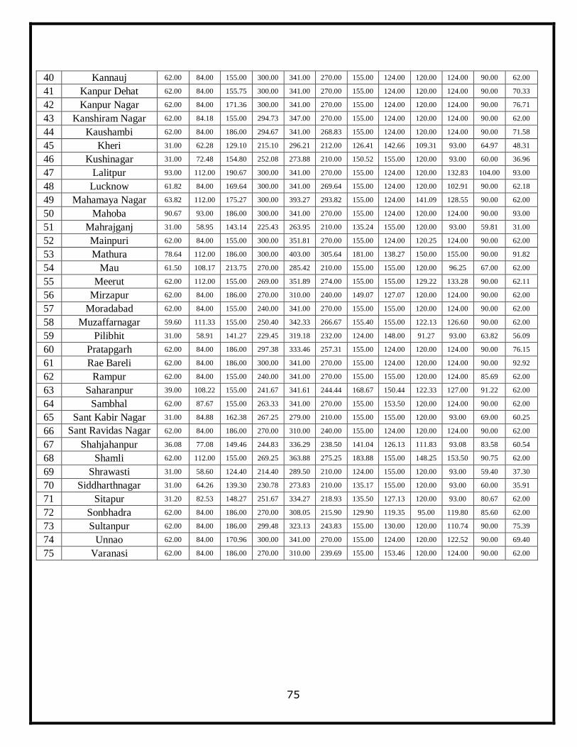
75
40 Kannauj 62.00 84.00 155.00 300.00 341.00 270.00 155.00 124.00 120.00 124.00 90.00 62.00
41 Kanpur Dehat 62.00 84.00 155.75 300.00 341.00 270.00 155.00 124.00 120.00 124.00 90.00 70.33
42 Kanpur Nagar 62.00 84.00 171.36 300.00 341.00 270.00 155.00 124.00 120.00 124.00 90.00 76.71
43 Kanshiram Nagar 62.00 84.18 155.00 294.73 347.00 270.00 155.00 124.00 120.00 124.00 90.00 62.00
44 Kaushambi 62.00 84.00 186.00 294.67 341.00 268.83 155.00 124.00 120.00 124.00 90.00 71.58
45 Kheri 31.00 62.28 129.10 215.10 296.21 212.00 126.41 142.66 109.31 93.00 64.97 48.31
46 Kushinagar 31.00 72.48 154.80 252.08 273.88 210.00 150.52 155.00 120.00 93.00 60.00 36.96
47 Lalitpur 93.00 112.00 190.67 300.00 341.00 270.00 155.00 124.00 120.00 132.83 104.00 93.00
48 Lucknow 61.82 84.00 169.64 300.00 341.00 269.64 155.00 124.00 120.00 102.91 90.00 62.18
49 Mahamaya Nagar 63.82 112.00 175.27 300.00 393.27 293.82 155.00 124.00 141.09 128.55 90.00 62.00
50 Mahoba 90.67 93.00 186.00 300.00 341.00 270.00 155.00 124.00 120.00 124.00 90.00 93.00
51 Mahrajganj 31.00 58.95 143.14 225.43 263.95 210.00 135.24 155.00 120.00 93.00 59.81 31.00
52 Mainpuri 62.00 84.00 155.00 300.00 351.81 270.00 155.00 124.00 120.25 124.00 90.00 62.00
53 Mathura 78.64 112.00 186.00 300.00 403.00 305.64 181.00 138.27 150.00 155.00 90.00 91.82
54 Mau 61.50 108.17 213.75 270.00 285.42 210.00 155.00 155.00 120.00 96.25 67.00 62.00
55 Meerut 62.00 112.00 155.00 269.00 351.89 274.00 155.00 155.00 129.22 133.28 90.00 62.11
56 Mirzapur 62.00 84.00 186.00 270.00 310.00 240.00 149.07 127.07 120.00 124.00 90.00 62.00
57 Moradabad 62.00 84.00 155.00 240.00 341.00 270.00 155.00 155.00 120.00 124.00 90.00 62.00
58 Muzaffarnagar 59.60 111.33 155.00 250.40 342.33 266.67 155.40 155.00 122.13 126.60 90.00 62.00
59 Pilibhit 31.00 58.91 141.27 229.45 319.18 232.00 124.00 148.00 91.27 93.00 63.82 56.09
60 Pratapgarh 62.00 84.00 186.00 297.38 333.46 257.31 155.00 124.00 120.00 124.00 90.00 76.15
61 Rae Bareli 62.00 84.00 186.00 300.00 341.00 270.00 155.00 124.00 120.00 124.00 90.00 92.92
62 Rampur 62.00 84.00 155.00 240.00 341.00 270.00 155.00 155.00 120.00 124.00 85.69 62.00
63 Saharanpur 39.00 108.22 155.00 241.67 341.61 244.44 168.67 150.44 122.33 127.00 91.22 62.00
64 Sambhal 62.00 87.67 155.00 263.33 341.00 270.00 155.00 153.50 120.00 124.00 90.00 62.00
65 Sant Kabir Nagar 31.00 84.88 162.38 267.25 279.00 210.00 155.00 155.00 120.00 93.00 69.00 60.25
66 Sant Ravidas Nagar (Bhadohi)
62.00 84.00 186.00 270.00 310.00 240.00 155.00 124.00 120.00 124.00 90.00 62.00
67 Shahjahanpur 36.08 77.08 149.46 244.83 336.29 238.50 141.04 126.13 111.83 93.08 83.58 60.54
68 Shamli 62.00 112.00 155.00 269.25 363.88 275.25 183.88 155.00 148.25 153.50 90.75 62.00
69 Shrawasti 31.00 58.60 124.40 214.40 289.50 210.00 124.00 155.00 120.00 93.00 59.40 37.30
70 Siddharthnagar 31.00 64.26 139.30 230.78 273.83 210.00 135.17 155.00 120.00 93.00 60.00 35.91
71 Sitapur 31.20 82.53 148.27 251.67 334.27 218.93 135.50 127.13 120.00 93.00 80.67 62.00
72 Sonbhadra 62.00 84.00 186.00 270.00 308.05 215.90 129.90 119.35 95.00 119.80 85.60 62.00
73 Sultanpur 62.00 84.00 186.00 299.48 323.13 243.83 155.00 130.00 120.00 110.74 90.00 75.39
74 Unnao 62.00 84.00 170.96 300.00 341.00 270.00 155.00 124.00 120.00 122.52 90.00 69.40
75 Varanasi 62.00 84.00 186.00 270.00 310.00 239.69 155.00 153.46 120.00 124.00 90.00 62.00
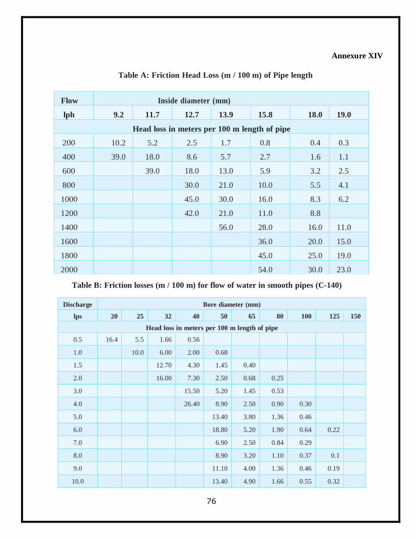
76
Annexure XIV
Table A: Friction Head Loss (m / 100 m) of Pipe length
Table B: Friction losses (m / 100 m) for flow of water in smooth pipes (C-140)
Discharge Bore diameter (mm)
lps 20 25 32 40 50 65 80 100 125 150
Head loss in meters per 100 m length of pipe
0.5 16.4 5.5 1.66 0.56
1.0 10.0 6.00 2.00 0.68
1.5 12.70 4.30 1.45 0.40
2.0 16.00 7.30 2.50 0.68 0.25
3.0 15.50 5.20 1.45 0.53
4.0 26.40 8.90 2.50 0.90 0.30
5.0 13.40 3.80 1.36 0.46
6.0 18.80 5.20 1.90 0.64 0.22
7.0 6.90 2.50 0.84 0.29
8.0 8.90 3.20 1.10 0.37 0.1
9.0 11.10 4.00 1.36 0.46 0.19
10.0 13.40 4.90 1.66 0.55 0.32
Flow Inside diameter (mm)
lph 9.2 11.7 12.7 13.9 15.8 18.0 19.0
Head loss in meters per 100 m length of pipe
200 10.2 5.2 2.5 1.7 0.8 0.4 0.3
400 39.0 18.0 8.6 5.7 2.7 1.6 1.1
600
39.0 18.0 13.0 5.9 3.2 2.5
800
30.0 21.0 10.0 5.5 4.1
1000
45.0 30.0 16.0 8.3 6.2
1200
42.0 21.0 11.0 8.8
1400
56.0 28.0 16.0 11.0
1600
36.0 20.0 15.0
1800
45.0 25.0 19.0
2000
54.0 30.0 23.0
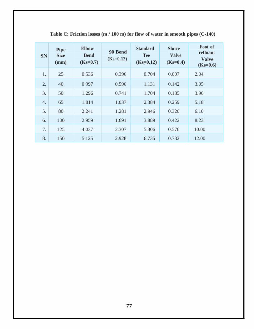
77
Table C: Friction losses (m / 100 m) for flow of water in smooth pipes (C-140)
SN
Pipe
Size
(mm)
Elbow
Bend
(Ks=0.7)
90 Bend
(Ks=0.12)
Standard
Tee
(Ks=0.12)
Sluice
Valve
(Ks=0.4)
Foot of
refluant
Valve
(Ks=0.6)
1. 25 0.536 0.396 0.704 0.007 2.04
2. 40 0.997 0.596 1.131 0.142 3.05
3. 50 1.296 0.741 1.704 0.185 3.96
4. 65 1.814 1.037 2.384 0.259 5.18
5. 80 2.241 1.281 2.946 0.320 6.10
6. 100 2.959 1.691 3.889 0.422 8.23
7. 125 4.037 2.307 5.306 0.576 10.00
8. 150 5.125 2.928 6.735 0.732 12.00
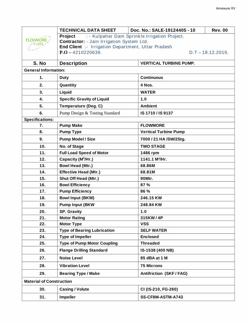
TECHNICAL DATA SHEET Doc. No.: SALE-19124405 - 10 Rev. 00
Project : - Kulpahar Dam Sprinkle Irrigation Project. Contractor: - Jain Irrigation System Ltd. End Client :- Irrigation Department, Uttar Pradesh P.O – 4210220639. D.T – 18.12.2019.
S. No Description VERTICAL TURBINE PUMP. General Information:
1. Duty Continuous
2. Quantity 4 Nos.
3. Liquid WATER
4. Specific Gravity of Liquid 1.0
5. Temperature (Deg. C) Ambient
6. Pump Design & Testing Standard IS 1710 / IS 9137
Specifications: 7. Pump Make FLOWMORE
8. Pump Type Vertical Turbine Pump
9. Pump Model / Size 7000 / 21 HA /SW/2Stg.
10. No. of Stage TWO STAGE
11. Full Load Speed of Motor 1486 rpm
12. Capacity (M3/Hr.) 1141.1 M³/Hr.
13. Bowl Head (Mtr.) 68.86M
14. Effective Head (Mtr.) 68.81M
15. Shut Off Head (Mtr.) 90Mtr.
16. Bowl Efficiency 87 %
17. Pump Efficiency 86 %
18. Bowl Input (BKW) 246.15 KW
19. Pump Input (BKW 248.84 KW
20. SP. Gravity 1.0
21. Motor Rating 315KW / 4P
22. Motor Type VSS
23. Type of Bearing Lubrication SELF WATER
24. Type of Impeller Enclosed
25. Type of Pump Motor Coupling Threaded
26. Flange Drilling Standard IS-1538 (400 NB)
27. Noise Level 85 dBA at 1 M
28. Vibration Level 75 Microns
29. Bearing Type / Make Antifriction (SKF / FAG)
Material of Construction
30. Casing / Volute CI (IS-210, FG-260)
31. Impeller SS-CF8M-ASTM-A743
Annexure XV
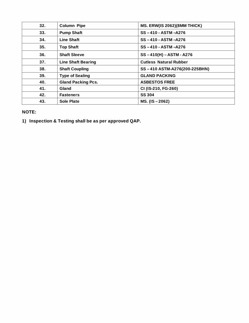
32. Column Pipe MS. ERW(IS 2062)(8MM THICK)
33. Pump Shaft SS – 410 - ASTM –A276
34. Line Shaft SS – 410 - ASTM –A276
35. Top Shaft SS – 410 - ASTM –A276
36. Shaft Sleeve SS – 410(H) – ASTM - A276
37. Line Shaft Bearing Cutless Natural Rubber
38. Shaft Coupling SS – 410 ASTM-A276(200-225BHN)
39. Type of Sealing GLAND PACKING
40. Gland Packing Pcs. ASBESTOS FREE
41. Gland CI (IS-210, FG-260)
42. Fasteners SS 304
43. Sole Plate MS. (IS – 2062)
NOTE:
1) Inspection & Testing shall be as per approved QAP.
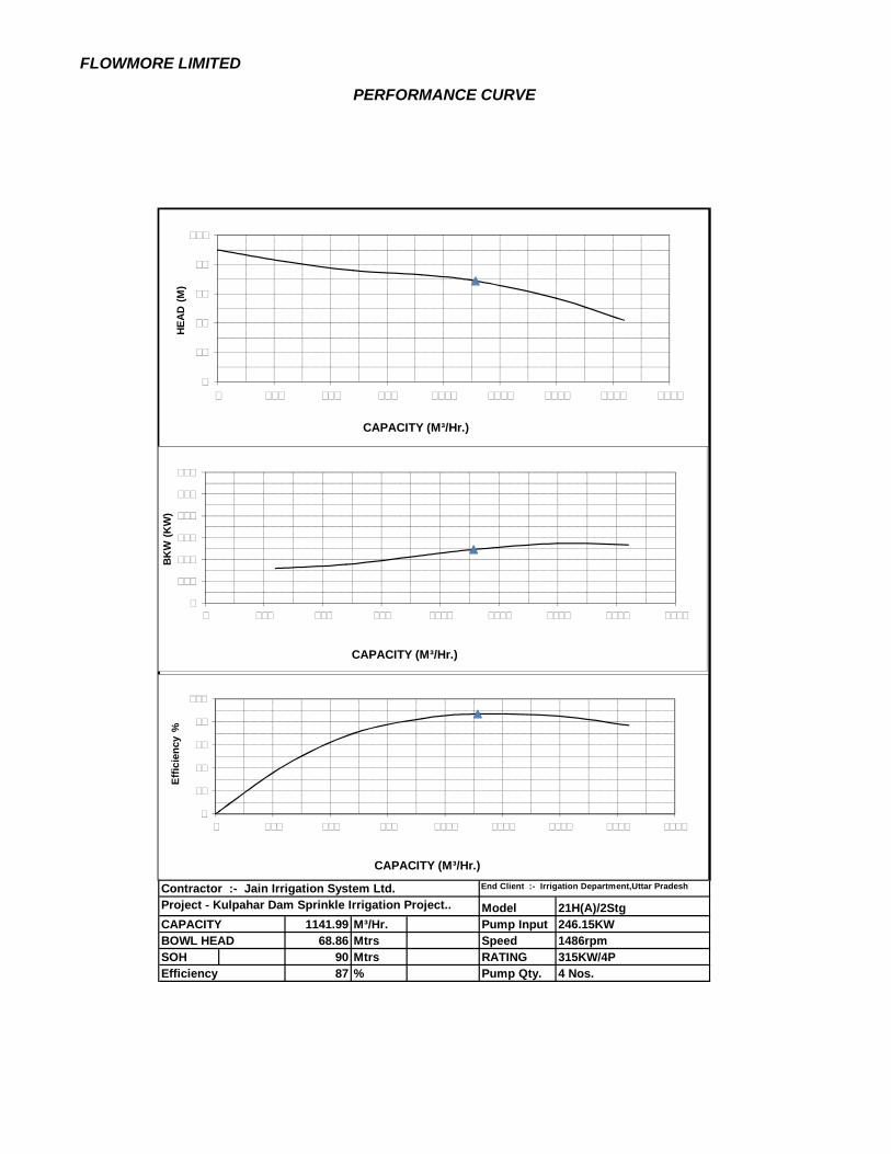
FLOWMORE LIMITED
PERFORMANCE CURVE
ModelCAPACITY 1141.99 M³/Hr. Pump Input
68.86 Mtrs Speed 1486rpmSOH 90 Mtrs RATING 315KW/4P
87 % Pump Qty. 4 Nos.Efficiency
Contractor :- Jain Irrigation System Ltd. End Client :- Irrigation Department,Uttar Pradesh
Project - Kulpahar Dam Sprinkle Irrigation Project.. 21H(A)/2Stg246.15KW
BOWL HEAD
0
20
40
60
80
100
0 250 500 750 1000 1250 1500 1750 2000
0
100
200
300
400
500
600
0 250 500 750 1000 1250 1500 1750 2000
0
20
40
60
80
100
0 250 500 750 1000 1250 1500 1750 2000
Effic
ienc
y %
BKW
(KW
)HE
AD (
M)
CAPACITY (M³/Hr.)
CAPACITY (M³/Hr.)
CAPACITY (M³/Hr.)
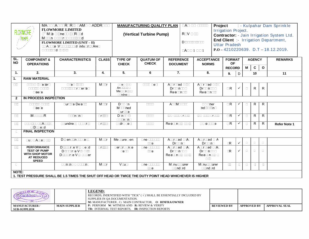
MANUFACTURER’S NAME & ADDRESS FLOWMORE LIMITED 9th Mile Stone, G.T. Road Mohan Nagar, Ghaziabad
MANUFACTURING QUALITY PLAN
(Vertical Turbine Pump)
QAP NO - 4405 REV – 00 Dt. 03.01.2020 PAGE 1 OF 1
Project : - Kulpahar Dam Sprinkle Irrigation Project. Contractor: - Jain Irrigation System Ltd. End Client :- Irrigation Department, Uttar Pradesh P.O – 4210220639. D.T – 18.12.2019.
FLOWMORE LIMITED (UNIT – II) 28 A, Site IV, Sahibabad Industrial Area Ghaziabad (U.P.)
LEGEND: RECORDS, INDENTIFIED WITH “TICK” ( ) SHALL BE ESSENTIALLY INCLUDED BY SUPPLIER IN QA DOCUMENTATION. M: MANUFACTURER , C: MAIN CONTRACTOR, O: RINFRA/OWNER P: PERFORM W: WITNESS AND R: REVIEW & VERIFY TR: INTERNAL TEST REPORTS, IR: INSPECTION REPORTS
MANUFACTURER / SUB-SUPPLIER
MAIN-SUPPLIER REVIEWED BY APPROVED BY APPROVAL SEAL
SL. NO
COMPONENT & OPERATIONS
CHARACTERISTICS
CLASS
TYPE OF CHECK
QUATUM OF CHECK
REFERENCE DOCUMENT
ACCEPTANCE NORMS
FORMAT OF
RECORD
AGENCY REMARKS
M C O 1. 2. 3. 4. 5. 6 7. 8. 9. D 10 11
1. RAW MATERIAL
1.1
Bowl, Impeller, Shaft & Shaft
Sleeve
Chemical & Physical Properties
Major
Chemical Analysis & Mechanical Hardness
Each Heat Approved C.S. Drawings & Relevant IS
Approved C.S. Drawings & Relevant IS
T R
P
R
R
2 IN PROCESS INSPECTION 2.1
Shaft & Shaft
Sleeve Surface Defects
Major
DPT on Machined Surface
100% ASTME-165
No Liner Indications
T R
P
R
R
2.2
IMPELLER Balancing Critical
Dynamic Balancing
100% ISO 1940 Gr. 6.3 ISO 1940 Gr. 6.3 T R
P
R
R
2.3 Bowls, Col. Assly., S.D. Head
Soundness of Parts Critical Hydro Test 100% Relevant IS / HIS No leakage T R
P R
R
Refer Note 1
3 FINAL INSPECTION
3.1 Pump Assembly Dimensional Check Major Measurement One of Each type
Approved G.A. Drawing
Approved G A Drawing
I R
P
W
W
3.2 PERFORMANCE TEST OF PUMP
WITH SHOP MOTOR AT REDUCED
SPEED
Discharge V/S Head Discharge V/S Eff.
Discharge V/S Power
Critical Performance Test
One of Each type
Approved G.A. Drawings &
Relevant IS / HIS
Approved G.A. Drawings &
Relevant IS / HIS
I R
P
W
W
5 Painting & Packing Major Visual One of Each type
Manufacturer Standard
Manufacturer Standard
--- -- P -- --
NOTE: 1. TEST PRESSURE SHALL BE 1.5 TIMES THE SHUT OFF HEAD OR TWICE THE DUTY POINT HEAD WHICHEVER IS HIGHER
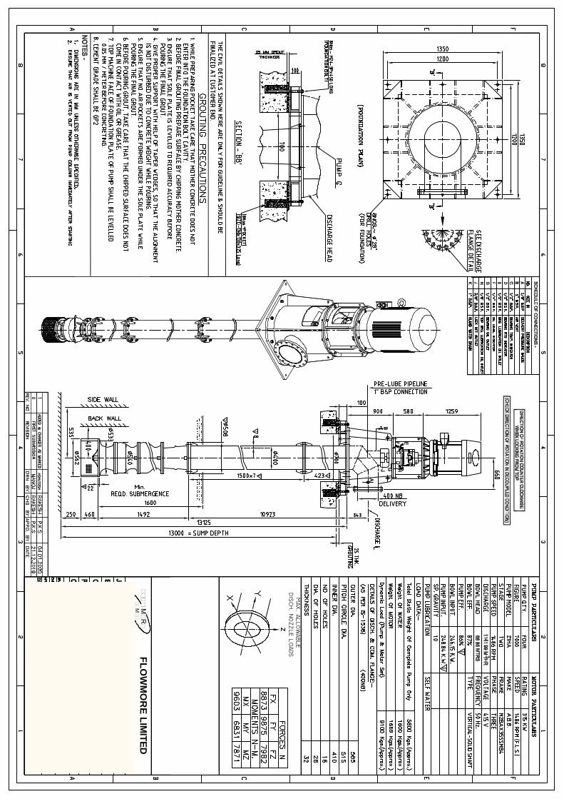
NEW
DELH
IFLO
WM
OR
E LIMITED
FLOW
MO
RE
PU
MPS
78
REFERENCES
https://minorirrigation.uk.gov.in/
Operational Guidelines of Per Drop More Crop (Micro Irrigation), GoI
Drip and Sprinkler irrigation by Ranjit Kumar Biswas
www.iasri.res.in (Indian Agricultural Statics Research Institute)
https://www.fao.org
IS 10799 : 1999 (Reaffirmed 2021)


