Embed Size (px)
Citation preview
HAL Id: hal-02163437https://hal.archives-ouvertes.fr/hal-02163437
Submitted on 9 Mar 2021
HAL is a multi-disciplinary open accessarchive for the deposit and dissemination of sci-entific research documents, whether they are pub-lished or not. The documents may come fromteaching and research institutions in France orabroad, or from public or private research centers.
L’archive ouverte pluridisciplinaire HAL, estdestinée au dépôt et à la diffusion de documentsscientifiques de niveau recherche, publiés ou non,émanant des établissements d’enseignement et derecherche français ou étrangers, des laboratoirespublics ou privés.
Aqueous stabilisation of carbon-encapsulatedsuperparamagnetic α-iron nanoparticles for biomedical
applicationsNoemí Aguiló-Aguayo, Lionel Maurizi, Sandra Galmarini, Marie GabrielleOllivier-Beuzelin, Géraldine Coullerez, Enric Bertran, Heinrich Hofmann
To cite this version:Noemí Aguiló-Aguayo, Lionel Maurizi, Sandra Galmarini, Marie Gabrielle Ollivier-Beuzelin, GéraldineCoullerez, et al.. Aqueous stabilisation of carbon-encapsulated superparamagnetic α-iron nanoparti-cles for biomedical applications. Dalton Transactions, Royal Society of Chemistry, 2014, 43 (36),pp.13764-13775. �10.1039/C4DT00085D�. �hal-02163437�
Aqueous stabilisation of carbon-encapsulated superparamagneticα-iron nanoparticles for biomedical applications
Noemı Aguilo-Aguayo,∗a‡¶ Lionel Maurizi,b¶ Sandra Galmarini,b Marie Gabrielle Ollivier-Beuzelin,bGeraldine Coullerez,b Enric Bertrana and Heinrich Hofmannb
Received Xth XXXXXXXXXX 20XX, Accepted Xth XXXXXXXXX 20XXFirst published on the web Xth XXXXXXXXXX 200XDOI: 10.1039/b000000x
Carbon-based nanomaterials, such as carbon-encapsulated magnetic nanoparticles (CEMNP, core@shell), present a wide rangeof desirable properties for applications in the biomedical field (clinical MRI, hyperthermia), for energy production and storage(hydrogen storage), for the improvement of electronic components and for environmental applications (water-treatment). How-ever this kind of nanoparticles tends to aggregate in water suspensions. This often hampers the processability of the suspensionsand presents an obstacle for their application in many fields. Here the stabilisation of core-shell Fe-C nanoparticles by surfaceadsorbed polyvinyl-alcohol (PVA) is presented. Different PVA/CEMNP mass ratios (9, 36, 144 and 576 w/w) were studied.Several characterisation techniques were used in order to determine the size distribution of the particles and to optimize thePVA/CEMNP ratio. A good colloidal stability was obtained for spherical nanoparticles of about 50 nm in diameter containingseveral superparamagnetic Fe cores. The nanoparticles were found to be isolated and well dispersed in solution. The use of PVAfor coating carbon-encapsulated Fe nanoparticles does not only result in a good colloidal stability in aqueous suspensions, but theresulting particles also show low cytotoxicity and an interesting cell internalization behaviour. The simple stabilization methoddeveloped here can likely be extended to other core@shell nanoparticle systems as well as other carbon-based nanomaterials inthe future.
1 Introduction
Carbon-encapsulated superparamagnetic iron nanoparticles(core-shell Fe-C NPs) are very interesting for a wide rangeof applications from the biomedical field1–6, (hyperthermia,local therapy, magnetic resonance imaging, biosensing), to en-ergy storage and production7–10 (hydrogen storage, improvedelectrodes in batteries or supercapacitors), environmental is-sues (soil remediation,11,12 water treatment,13,14 waste-watertreatment15) and electronic applications16 (spintronics). Forseveral of the above mentioned applications, superparamag-netic rather than ferromagnetic behaviour of the Fe cores isrequired for instance to avoid the aggregation of nanoparticlesdue to magnetic forces upon the removal of an external mag-netic field (previously applied to e.g. provide a controllable
aFEMAN group, IN2UB, Department of Applied Physics and Optics, Univer-sitat de Barcelona, Martı i Franques 1, 08028 Barcelona, Catalonia, Spain.Fax: +34 934039219; Tel: +34 934037092; E-mail: [email protected],[email protected] Laboratoire de Technologie de Poudres (LTP), EPFL-STI-IMX-LTP Station12, MX Ecublens, CH-1025, Lausanne, Switzerland.‡ Present address: Research Institute of Textile Chemistry and Physics, Uni-versity of Innsbruck, Hoechsterstrasse 73, 6850 Dornbirn, Austria.¶ These authors contributed equally to this work.† Electronic Supplementary Information (ESI) available: TEM image,EELS spectrum and EDX analysis of the Fe-C nanoparticles. See DOI:10.1039/b000000x/
local heating) or for a better control of the response to an exter-nal field (non hysteresis loop). The carbon encapsulation playsan important role in the nanoparticle structure, since it pro-tects the magnetic core against oxidation, thermal or tempo-rary degradation. Additionally the carbon coating adds somespecial characteristics to the nanoparticles, such as good elec-trocatalytic activity and other interesting electrical propertiesas well as the possibility of chemical functionalisation. How-ever, the coated NPs are often obtained in aggregated state(due to hydrophobic surfaces) and thus the synthesis of well-dispersed and stable carbon-coated magnetic NPs with narrowsize distributions in aqueous media is still a challenge.17 Thecontrol of the size distribution and the avoidance of nanoparti-cle agglomeration in aqueous solutions (i.e. the colloidal sta-bility) are crucial for the mentioned applications.
In the literature several methods for the stabilisation of NPswere reported, but these usually affect the magnetic proper-ties of the nanoparticles or modify the morphology and struc-tural properties of the final product. To improve the disper-sion of carbon-based nanomaterials (single, multiple carbonnanotubes or graphene), some treatments such as aggressivechemical functionalisation (the use of acid at high tempera-tures) or mechanical dispersion methods (ultrasonic or highshear mixing), are commonly used.18–20 However, these meth-ods present drawbacks, since they can introduce structural de-
1–14 | 1
fects and may damage the electrical or mechanical propertiesof the carbon nanostructures.
In order to favour the colloidal stability of NPs, the use ofpolymers or surfactants is widespread.21 Some of the mostcommon natural or synthetic polymers in this context are dex-tran, chitosan, poly(ethylene glycol) (PEG), poly(vinyl alco-hol) (PVA).22–24 Among those the PVA polymer is one of themost widely accepted in the biomedicine field, due to its non-toxicity, biocompatibility, water solubility and biodegradabil-ity.25
In the present work, we were able to produce nearlymonodisperse core-shell Fe-C superparamagnetic NPs whichwere stable in aqueous solution. The colloidal stability wasachieved with the help of PVA adsorption and was studied indetails by different characterisation methods. This allowed usnot only to assess the colloidal stability of the nanoparticlesand to determine the optimal amount of PVA. In addition thecellular toxicity and internalization of the PVA-functionalisednanoparticles was estimated. The results of the last two meth-ods are promising with respect to the future use of the pro-duced NPs for biomedical applications. In summary this workpresents a further step towards the use of Fe-C particles innanomedicine.
2 Experimental Details
2.1 Synthesis of superparamagnetic core-shell Fe-Cnanoparticles (Fe-C NPs)
Superparamagnetic core-shell Fe-C NPs were produced bymeans of a modified arc-discharge plasma method (mADP),developed in the FEMAN group.26,27 The technique was mod-ified to achieve better control of the core size distribution,which is essential for the superparamagnetic properties of thenanoparticles. The synthesis was carried out at atmosphericpressure under a He flow rate of 1.6 L/min. The applied cur-rent used was 30 A. The iron source came from an iron pre-cursor based on a solution of ferrocene diluted in isooctane(0.5 wt.%) and the carbon source was provided by the elec-trodes, which were made of pure graphite (99.99 % purity).NPs were collected from the walls of the reactor and magnet-ically separated in order to only obtain the magnetic productonly. Samples were stored in absolute ethanol for clean andeasy nanoparticle manipulation at a total NP concentration of70 µg/mL.
2.2 Coating and characterisation of Fe-C@PVA andFe-C@A-PVAFITC
It was reported previously that the surface charge has an im-portant effect on cellular internalisation; negatively chargedNPs are not as easily internalised as positively charged ones.28
Consequently, to be able to use the particles for cell internal-isation studies they needed to be coated. In addition a judi-ciously chosen coating can provide a better colloidal stabilitydue to steric repulsion. Thus the particles were coated withpolyvinyl-alcohol (PVA), which has been used previously forthe stabilisation of different nanoparticles.29–31 For the coat-ing, PVA (Mowiol R© 3-85) with a hydrolysis degree of 85 % to89 % and average molecular weight of 14000 g/mol, suppliedby courtesy of Kuraray, was used.
PVA-coated Fe-C nanoparticles (Fe-C@PVA) were pre-pared using different PVA to total NP mass ratios: 9, 36, 144and 576 w/w. The PVA polymer was first diluted in water.Then it was added to the Fe-C NP suspensions at the differ-ent PVA to NP ratios and mixed in an ultrasound bath for10 min. The final Fe-C@PVA suspensions were obtained witha NP concentration of 37 µg/mL in a water/ethanol mixture(50:50 v/v). The particles were then fully characterized by dif-ferent methods, which were applied a week after the prepara-tion, to ensure that equilibrium was reached.
Scanning electron microscope observations were carriedout using a Hitachi H-4100FE instrument operating at an ac-celerating voltage of 20 kV. Transmission electron microscopeobservations were done using a JEOL JEM 2100 operated at200 kV. Nanoparticles were analysed by STEM-EDX using aJEOL JEM 2100 operating at 200 kV equipped with a OxfordINCAx-sight Si(Li) detector for EDX. EELS was done usinga Jeol 2010F FEG operating at 200kV equipped with a GatanImage Filter (GIF). Magnetic properties were studied using asuperconducting-quantum-interference device (SQUID) mag-netometer at temperatures from 5 to 300 K and using fields upto 5.5 T.
Zeta-potential measurements were performed using aBrookhaven ZetaPALS instrument, equipped with a 661 nmlaser illumination. The detector position was set to 90◦. Moredetails are described elsewhere32. PVA-coated NPs were di-luted in pure water at a NP concentration of 2 µg/mL for theZeta-potential measurements. At this NP concentration themeasurements were well reproducible. The measurementswere treated using the Smoluchowski model. Measurementswere repeated 4 times.
Particle size measurement (number and volume weighteddistributions) with an analytical disc centrifuge were carriedout with a CPS Instruments Europe at 17633 rpm. A densityof 2.2 g/mL, an absorption coefficient of K = 0.7 and the theo-retical refractive index of carbon (n = 2.67) were used for thecalculations. For each measurement a volume of 200 µl of theFe-C@PVA at a total NP concentration of 37 µg/mL was used.Measurements were repeated 5 times. The volume weighteddistributions obtained were fitted and when two populationswere found, the mean diameter value of each population ob-tained (DV 50) were given with the volume percentages of thispopulation. Each DV 50 was given with its geometrical stan-
2 | 1–14

dard deviation (σg).The mean diameter standard deviation ofthe number weighted distribution was obtained from the CPSsoftware.
As the initial PVA coating results in neutral particles, theFe-C@PVA samples were additionally functionalised using ansmall amount of amino-PVA (A-PVA) with an average molec-ular weight of 80000 to 140000 g/mol and an amine contentMNH2/MPVA of 2.3-2.6, supplied by courtesy of ERKOL R©
(M12). A week after their preparation, Fe-C@PVA suspen-sions (37 µg nanoparticle / mL) were mixed with A-PVA, pre-viously diluted in water, using an A-PVA quantity leading toa final A-PVA/PVA mass ratio of 2 %.
In order to detect the Fe-C@A-PVA NPs, they were func-tionalised with A-PVA labelled with Fluoresceine isothio-cyanate (FITC) by using a protocol described previously bythe LTP group.33 Briefly, 200 mg of A-PVA were dissolvedin 10 mL Borate buffer solution at pH 10 and 12.5 mM andheated at 80 ◦C for one hour. The final solution had an A-PVAconcentration of 20 mgA−PVA/mL. 0.05 mmol of FITC weredissolved in 2 mL of Dimethylsulfoxide solution (DMSO).The A-PVA and FITC solutions were mixed under magneticstirring for 24 hours, protected from light. After the reac-tion, the solution was dialysed three times against 800 mLdistilled water with 12 hours between each water change.The 3 dialysed solutions were then analysed in UV-visible at490 nm. The estimated yield of FITC grafting is 0.045 mmolof FITC, which reacted with the 200 mg of A-PVA. The finalA-PVAFITC solution had a concentration of 4.76 mg of poly-mer/mL and 0.0011 mmolFITC/mL.
For all the Fe-C@A-PVA samples with polymer/NP ratiosof 9, 36, 144 and 576 w/w, 8 µg A-PVAFITC/mL were added.The labelled samples will be referred to as Fe-C@A-PVAFITC.
The amount of additional PVA added by the A-PVA and A-PVAFITC was so small (2% mass or 0.2% molar of the totalamount of PVA in the coating) that it was considered to benegligible for the particle size.
2.3 Cell culture, cytotoxicity and cellular internalisationstudies
As a first approach to estimate the usability of the particles forthe biomedical applications, Fe-C@A-PVAFITC were used forcellular incubation experiments. These were done at least 24hours after the sample preparation to ensure equilibration. Thebiological behaviour, such as cytotoxicity and internalisation,was studied on cervix adenocarcinoma cells (HeLa). The con-centration of Fe-C@A-PVAFITC / cells was kept constant forall experiments.
Cytotoxicity was evaluated using MTS assays. HeLa cellswere plated at a density of 20000 cells/well in a 96 well plateat 37 ◦C in 5 % CO2 atmosphere. 100 µL of 25 times di-luted Fe-C@A-PVAFITC suspensions and pure PVA solutions
(mixture of PVA-OH and A-PVAFITC, to estimate the poten-tial influence of fluorescence on this test), at the same con-centrations as the corresponding Fe-C@A-PVAFITC suspen-sions, were prepared. For each condition, triplicate experi-ments were performed. After 1, 3, 6 and 24h of incubation,the medium was removed and 100 µL of MTS reagent, previ-ously diluted 6 times, were added. After two hours of incu-bation, the absorbance at 490 nm was recorded using a platereader Infinite M200 from TECAN. The cell viability (%) wascalculated relatively to control wells, where only medium wasadded to the cells. A statistical analysis of the measured cellviability was done using standard least squares multiple linearregression. Initially a set of 7 predictor variables was consid-ered: time t, PVA/NP mass ratio rPVA , presence of particles pP
and repetition number of the experiments s, as well as t · rPVA ,t · pP and t · s, due to the possibility that any effect on the vi-ability might change over time. The significance of each pre-dictor was then estimated using the t-test statistics and the setof predictor variables was reduced to the maximum set con-taining only predictors with a p-value of < 0.005. In additionto the full set of data, two subsets containing only viabilitytest up to three hours and only measurements for rPVA up to144 were analysed as well. The validity of the linear regres-sion was checked with the Tuckey-Anscombe as well as witha QQ-plot. All statistical analyses were done with the R Envi-ronment for Statistical Computing.34
For internalisation observations, cervix HeLa cells weregrown on 24/24 mm coverslips in the bottom of 6 wells plateswith DMEM (GIBCO, #41966-052) completed with 10 %FBS (GIBCO, #10270-106, heat inactivated) and 1 % Pen-Strep-Ampho. The initial cell concentration (50000 cellsper well) was chosen to reach 80 % confluence after 4 days.When 80 % confluence was reached, 1 mL of 10 times di-luted Fe-C@A-PVAFITC or 1 mL of 10 times diluted Fe-C wasadded to the well. Each experiment was done in duplicate. Ascontrol, duplicates were loaded with DMEM.
After 24 hours incubation at 37 ◦C under 5 % CO2, HeLacells were washed 3 times with PBS 1X and 1 mL of freshmedium was added. 1 µL of DAPI (1 mg/mL) was injectedto each well and incubate 10 minutes at the same conditions.After DAPI removal and 3 washings of 1 mL PBS, cells werefixed with 5 mL of Paraformaldehyde (PFA at 40 mg/mL) for15 minutes at 37◦C and 5 % CO2. The excess was washedby the same method as previously described. Coverslips werethen placed on slides using prolongold (Invitrogen). The poly-merisation was carried out for at least 16 hours in darkness.Finally slides and coverslips were sealed together with nail-polished.
Slides were then observed on an inverted confocal micro-scope (Carl Zeiss LSM 700 Invert, software: Zen 2009) witha laser at 405 nm for DAPI detection (550 nm beam splitter)and laser at 488 nm for FITC detection (600 nm beam split-
1–14 | 3
ter). The magnification was set at 63X on oil immersion.To correlate with the confocal experiments, TEM imag-
ing of HeLa cell internalisation was also done. HeLa cellswere seeded in 12-well plates 225000 cells per well; 1.3 mLper well. Cells were incubated for 24h at 37 ◦C under 5 %CO2. After 24h incubation, the medium was replaced byDMEM, naked particles or coated NPs at a PVA/NP mass ra-tio of 9, 36, 144 and 576 w/w or with a mixture of PVA ata different PVA/NP ratios (9, 36, 144 and 576 w/w). Cellswere again incubated for 24h at 37 ◦C under 5 % CO2. Aftertreatment the cells were washed once with PBS1x (GBICO,#10010-015). Cells were covered with 1.8 mL Glutaralde-hyde 0.15 M Hepes buffer and store at 4 ◦C until further treat-ment. Cells were washed twice in 0.15 M Hepes buffer andleft overnight in it. Then the cells were rinsed three timesin 0.05 M maleate, NaOH buffer before contrasting the sam-ples for an hour using 0.5 % Uranylacetate, 0.05 M Maleate,NaOH buffer. Cells were washed again in 0.05 M Maleate,NaOH buffer and then progressively dehydrated in increasingconcentrations of ethanol (70 %, 80 %, 96 % and 100 %). Thesamples were then embedded in Epon for few days. Sectionsof 80 nm thickness were made for each condition. Contrast,embedment, sectioning and TEM analysis were made on aPhilips/FEI CM12 in the Institute of Anatomy at the Univer-sity of Bern.
3 Results and Discussion
3.1 Characterisation of Fe-C NPs
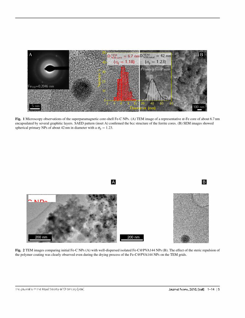
Superparamagnetic core-shell Fe-C NPs were charac-terised by high-resolution, transmission electron microscopy(HRTEM, TEM) and scanning electron microscope observa-tions (SEM) (Fig. 1). The primary size of the Fe-C particlesand the diameter of the Fe cores (Ferets diameters) were cal-culated by counting NPs from TEM (220 counts) and SEM(514 counts) images and fitting the corresponding histogramsto the commonly used lognormal distribution.
The fitting was done via the median diameter DN50 of thelognormal distribution, which corresponds to the geometricaverage of the measured diameters (equal to the median valuein a lognormal distribution) and via the geometric standarddeviation σg. The particle counting and diameter calculations(Ferets diameter) from microscopy observations were done us-ing ImageJ.35
TEM observations show that the crystalline Fe cores pre-sented nearly monodisperse diameters of 6.7 nm with σg =1.18. HRTEM image (Fig. 1A) showed a representative Fecore coated by several graphitic layers. SAED pattern (in-set Fig. 1A) confirmed the bcc α-Fe phase of the iron cores.The Fe cores were well protected against oxidation by thegraphitic shell. XRD and EELS analyses also confirmed this
(see supplementary information). On SEM images (Fig. 1B)one can see that the coated Fe-C NPs have spherical shapewith a measured primary diameter of 42 nm with a narrowsize distribution (σg = 1.23). Elemental analysis was per-formed by means of a controlled combustion at high tempera-tures (around 1800 ◦C) in a pure oxygen stream using a CHNanalyser. The weight percentage of carbon found in the NPswas around 70 % (C 71.48 %, H 2.35 %, N 1.56 %).
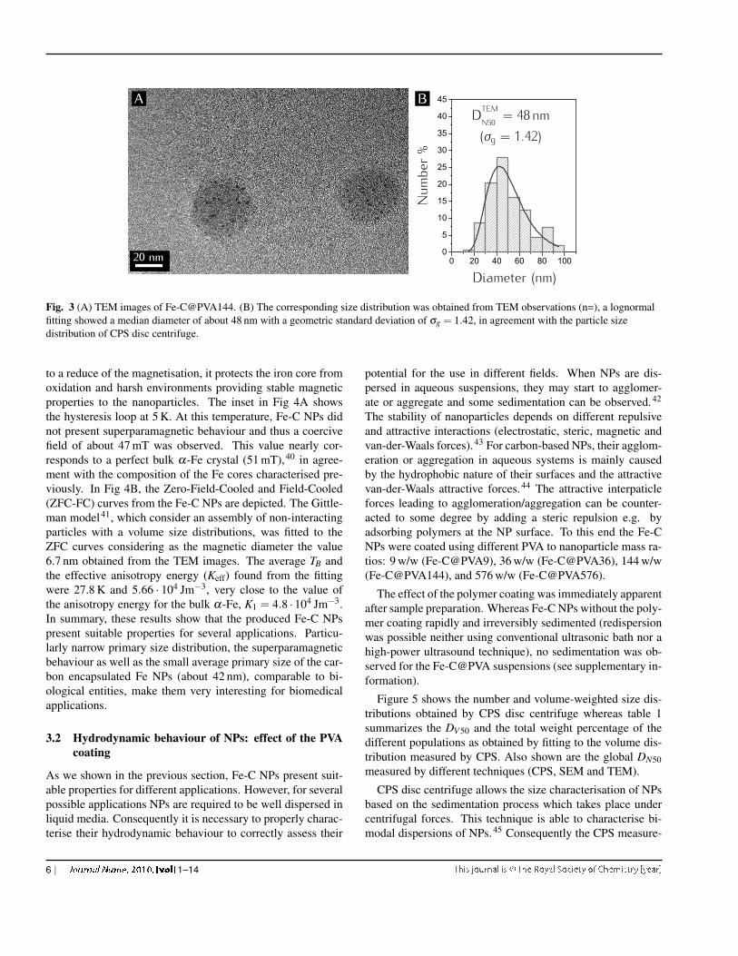
The morphology of the naked and coated Fe-C NPs can beseen in figures 2 and 3. The naked Fe-C NPs appear as ag-glomerates of vaguely spherical carbon particles with up to∼ 3 iron cores inside. The coated NPs on the other hand aremore dispersed, and seem to contain more (several tens of)iron cores per particle. The iron cores seem to be uniformlydistributed throughout the particles. The change in morphol-ogy is surprising. It is possible that the interaction between theFe-C particles and the PVA exceeds simple surface adsorption.There are several possible scenarios for this. One explanationwould be that the PVA partially or completely dissolves andreplaces the carbon coating. However it is difficult to imaginethat a simple PVA coating in itself could prevent the iron coresfrom oxidizing, yet the unchanging size and morphology ofthe Fe core would indicate that they are not oxidized. Conse-quently other explanations seem more likely. It is also possiblethat the interaction with PVA changes the structure of the car-bon coating. For instance the interaction with the PVA couldlead to a partial amorphization of the carbon coating, with thePVA absorbing in the pores of the amorphous carbon, thusleading to a PVA-carbon coating. Similar mechanisms havebeen observed before.36 Another scenario would be that onlythe amorphous part of the Fe-C particles is dissolved upon theaddition of PVA whereas the graphitic shell remains. On theseparticles the PVA could then form a semi-crystalline coating,similar to what is observed for carbon nanotubes.37 The ob-served particles would then be semi-crystalline PVA particlescontaining several Fe-C cores. It is clear that the exact struc-ture of the produced Fe-C@PVA particles will warrant furtherstudy in future, however such a study was outside the scopeof this article, whose aim it was only to study the colloidalstability and the possible applicability of the particles in thebiomedical field. However we added a discussion of the struc-ture of the Fe-C@PVA particles and the possible scenarios inthe manuscript.
The magnetic properties of the superparamagnetic NPswere also studied. In Fig 4 the magnetic response from thehysteresis loop at room temperature is depicted. Experimentaldata fitted the typical Langevin function38 corresponding toa superparamagnetic behaviour with a magnetic moment perα-Fe core of µ = 7.5 ·10−20 Am2, which corresponds to a sat-uration magnetisation of about 60 Am2/kg, smaller than thebulk α-Fe (220 Am2/kg) due to the interaction of the carboncoating with the iron core.39 Although carbon coating can lead
4 | 1–14
Fe110=0.2046 nm
2 4 6 8 10 20 40 60 800
10
20
30
40
50
Numb
er%
Diameter (nm)
D TEMN50�core = 6.7 nm(σg = 1�18)
D SEMN50�total = 42 nm(σg = 1�23)
Primary total size
A B
5 nm 100 nm
Fig. 1 Microscopy observations of the superparamagnetic core-shell Fe-C NPs. (A) TEM image of a representative α-Fe core of about 6.7 nmencapsulated by several graphitic layers. SAED pattern (inset A) confirmed the bcc structure of the ferrite cores. (B) SEM images showedspherical primary NPs of about 42 nm in diameter with a σg = 1.23.
A B
200 nm 200 nm
Fig. 2 TEM images comparing initial Fe-C NPs (A) with well-dispersed isolated Fe-C@PVA144 NPs (B). The effect of the steric repulsion ofthe polymer coating was clearly observed even during the drying process of the Fe-C@PVA144 NPs on the TEM grids.
1–14 | 5
0 20 40 60 80 1000
5
10
15
20
25
30
35
40
45A B
20 nmDiameter (nm)
Numb
er%
DTEMN50 = 48 nm(σg = 1�42)
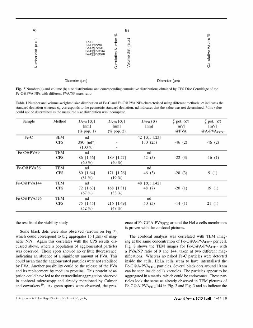
Fig. 3 (A) TEM images of Fe-C@PVA144. (B) The corresponding size distribution was obtained from TEM observations (n=), a lognormalfitting showed a median diameter of about 48 nm with a geometric standard deviation of σg = 1.42, in agreement with the particle sizedistribution of CPS disc centrifuge.
to a reduce of the magnetisation, it protects the iron core fromoxidation and harsh environments providing stable magneticproperties to the nanoparticles. The inset in Fig 4A showsthe hysteresis loop at 5 K. At this temperature, Fe-C NPs didnot present superparamagnetic behaviour and thus a coercivefield of about 47 mT was observed. This value nearly cor-responds to a perfect bulk α-Fe crystal (51 mT),40 in agree-ment with the composition of the Fe cores characterised pre-viously. In Fig 4B, the Zero-Field-Cooled and Field-Cooled(ZFC-FC) curves from the Fe-C NPs are depicted. The Gittle-man model41, which consider an assembly of non-interactingparticles with a volume size distributions, was fitted to theZFC curves considering as the magnetic diameter the value6.7 nm obtained from the TEM images. The average TB andthe effective anisotropy energy (Keff) found from the fittingwere 27.8 K and 5.66 · 104 Jm−3, very close to the value ofthe anisotropy energy for the bulk α-Fe, K1 = 4.8 ·104 Jm−3.In summary, these results show that the produced Fe-C NPspresent suitable properties for several applications. Particu-larly narrow primary size distribution, the superparamagneticbehaviour as well as the small average primary size of the car-bon encapsulated Fe NPs (about 42 nm), comparable to bi-ological entities, make them very interesting for biomedicalapplications.
3.2 Hydrodynamic behaviour of NPs: effect of the PVAcoating
As we shown in the previous section, Fe-C NPs present suit-able properties for different applications. However, for severalpossible applications NPs are required to be well dispersed inliquid media. Consequently it is necessary to properly charac-terise their hydrodynamic behaviour to correctly assess their
potential for the use in different fields. When NPs are dis-persed in aqueous suspensions, they may start to agglomer-ate or aggregate and some sedimentation can be observed.42
The stability of nanoparticles depends on different repulsiveand attractive interactions (electrostatic, steric, magnetic andvan-der-Waals forces).43 For carbon-based NPs, their agglom-eration or aggregation in aqueous systems is mainly causedby the hydrophobic nature of their surfaces and the attractivevan-der-Waals attractive forces.44 The attractive interpaticleforces leading to agglomeration/aggregation can be counter-acted to some degree by adding a steric repulsion e.g. byadsorbing polymers at the NP surface. To this end the Fe-CNPs were coated using different PVA to nanoparticle mass ra-tios: 9 w/w (Fe-C@PVA9), 36 w/w (Fe-C@PVA36), 144 w/w(Fe-C@PVA144), and 576 w/w (Fe-C@PVA576).
The effect of the polymer coating was immediately apparentafter sample preparation. Whereas Fe-C NPs without the poly-mer coating rapidly and irreversibly sedimented (redispersionwas possible neither using conventional ultrasonic bath nor ahigh-power ultrasound technique), no sedimentation was ob-served for the Fe-C@PVA suspensions (see supplementary in-formation).
Figure 5 shows the number and volume-weighted size dis-tributions obtained by CPS disc centrifuge whereas table 1summarizes the DV 50 and the total weight percentage of thedifferent populations as obtained by fitting to the volume dis-tribution measured by CPS. Also shown are the global DN50measured by different techniques (CPS, SEM and TEM).
CPS disc centrifuge allows the size characterisation of NPsbased on the sedimentation process which takes place undercentrifugal forces. This technique is able to characterise bi-modal dispersions of NPs.45 Consequently the CPS measure-
6 | 1–14

0 2 4 6 8 1 0 1 2 1 4 1 6 1 8 2 00 . 0
0 . 2
0 . 4
0 . 6
0 . 8
1 . 0
- 5 0 - 2 5 0 2 5 5 0- 0 . 5
0 . 0
0 . 5
1 . 0
0 5 0 1 0 0 1 5 0 2 0 0 2 5 0 3 0 0
A) B)
M/M
S
µ0H (mT)
T = 5 Kµ0HC = 47 mT
M/M
S
µ0H/T (mT/K)
Langevin curve fittingExperimental data at room temperature
χ(a
.u.)
T (K)
ZFC curveFC curve
µ0H = 10 mT
ZFC fitting Gittleman’s modelKeff = 5.66 · 104 J/m3
TB = 27.8 K
Fig. 4 Magnetic properties of the Fe-C NPs were depicted. (A) Hysteresis response at room temperature (300 K) followed a Langevinfunction corresponding to superparamagnetic behaviour. The hysteresis response at 5 K lower than TB (inset graph) showed a coercive field ofabout 47 mT in agreement with bulk α-Fe. (B) ZFC-FC curves confirmed TB lower than room temperature and α-Fe composition of thenanoparticles (Keff close to the K1 α-Fe bulk value).
ments clearly show the effect of the PVA (figure 5). Withoutany coating, the DV 50 of the Fe-C particles was much higherthan for PVA coated Fe-C (table 1). For naked Fe-C onlyone population, extending the measured size range of up to1 µm, was observed . On the contrary, for PVA/Fe-C mass ra-tios between 9 and 576, two populations of particle diameterswere observed: one around 70-90 nm and another one, proba-bly corresponding to agglomerated particles, around 170-220nm. The mean volume weighted diameter of the first popu-lation seems to initially decrease with increasing PVA ratiosfrom Fe-C@PVA9 to Fe-C@PVA144 and increased again forhigher PVA contents (table 1). Moreover simultaneously tothe initial decrease of the DV 50, the proportion of the smallestpopulation increased, up to a PVA/NP ratio of 36 above whichthe relative amount of small particles decreased again. Con-trary to what one would expect, there is no substantial increasein the hydrodynamic diameter of the population of dispersedparticles due to the polymer coating. This could indicate that,even if the PVA can be expected to increase the monolayersize, it might disperse preferentially smaller particles and thusdecreases the mean diameter of the dispersed Fe-C particles.In addition, as we have discussed before, it is possible thatthe addition of PVA has a more pronounced effect than sim-ple surface adsorption, which might lead to a more complexdependence of the particle size on the amount of PVA.
These results indicate, that best dispersion of the particles,meaning with the smallest DV 50 and the highest proportionof small particles, can be obtained for an optimal PVA/Fe-C mass ratio should be between 36 and 144. Moreover, in
number-weighted size distribution measurements, contrary tothe naked Fe-C NPs (DN50: 130 nm) the median diame-ter of the number-weighted size distribution (DN50) of allPVA coated Fe-C@PVA NPs were around 50 nm (table 1) ingood agreement with the primary NP size calculated from mi-croscopy observations (Fig. 1-B). This shows the effect of thepolymer coating on the NP dispersion in aqueous suspension.
The TEM observations of the Fe-C@PVA NPs also givesome indication of the stabilization of the NPs by the PVA.The effect of the polymer coating is clearly visible, espe-cially for sample Fe-C@PVA144 (fig. 2). For this samplethe polymer was able to inhibit the agglomeration of the NPseven during the drying process after deposition of NPs ontoholey carbon-coated TEM grids (hydrophobic surfaces). Weshould underline that samples were stable and TEM gridslooked the same even 12 months after preparation. How-ever, NPs with a lower amount of polymer (Fe-C@PVA9, Fe-C@PVA36) were agglomerated during the drying process andfor Fe-C@PVA576 NPs, the amount of polymer on the gridsmade their observation by TEM very difficult (the electronbeam was partially transmitted through the grid).
The number-weighted size distribution of Fe-C@PVA144from TEM images (248 counts) is represented in fig. 3. Themedian TEM diameter was about 48 nm, in excellent agree-ment with CPS results, pointing out the reliability of the CPSmethod for the characterization of the present samples and theeffect of the polymer coating.
In summary we can say that for several applications,carbon-coated magnetic NPs are very interesting due to their
1–14 | 7

stable characteristics under harsh conditions (e.g. under acidicor basic conditions, reactive atmospheres or high tempera-tures). However, their poor colloidal stability can make theiruse for some applications difficult. Using PVA to coat the Fe-C particles at different NPVA/NP mass ratios (9; 36; 144 and576) allowed a better colloidal stability, with an optimal PVAto NP ratio between 36 and 144.
3.3 Zeta (ζ ) potential of nanoparticles: effect of the PVAcoating
The Zeta potentials of the Fe-C and Fe-C@PVA NPs were alsoinvestigated (table 1). As a general rule a higher absolute valueof the zeta potential helps stabilize the particles in solution46.
The measured Zeta potential of naked Fe-C NPs dispersedin water is about -46 mV. The negative Zeta potential is mostlikely due to charges determined by the surface chemistry ofthe carbon shell, such as the presence of surface carboxylgroups due to some carbon defects, and depends on the surfaceoxygen content.47 For increasing polymer concentrations, theabsolute value of the Zeta potential tends towards a lower ab-solute value. This is indicative of the presence of polymerson the surface of the NPs, increasing the size of the electri-cal double layer. Clearly the electrostatic repulsions betweenthe naked NPs were not enough to stabilise them in aqueoussuspensions. Upon addition of the polymer, the Zeta poten-tial strength decreases and hence the electrostatic interactionsare expected to become weaker as well. Consequently it isthe steric repulsion coming from the polymer coating which isresponsible for the previously discussed colloidal stabilisationof PVA-coated NPs dispersed in water.
The Zeta potential measurements (table 1) forFe-C@A-PVAFITC showed higher values than Fe-C@PVANPs. Initially the zeta potential increased continuously withthe ratio of PVA and for ratios greater than 36 w/w, the Zetavalues became positive. However at PVA ratios > 144 w/w,the zeta potential appears to reach a constant value of about 20mV. This indicates that the PVA is either completely maskingthe particles and thus dominating the surface properties orthat the additional PVA is no longer adsorbed at the particlesurfaces.
3.4 First approach to biomedical applications: cytoxicityand cellular internalisation
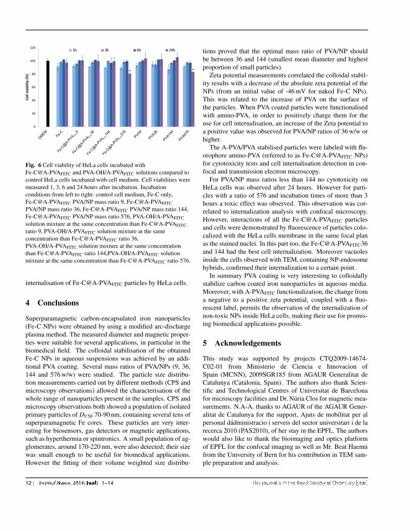
The cytotoxicity and cellular internalisation were examinedby incubating amino-functionalised PVA-coated nanoparticlesand HeLa cells. The influence of the Fe-C@A-PVAFITC withdifferent PVA/NPs mass ratios on the viability of incubatedHeLa cells was measured after 1, 3, 6 and 24 hours by MTS.The results can be seen in figure 6 and the results of the statis-tical analysis in table 2. First of all, the analysis revealed sta-
tistically significant variations between the repetitions of themeasurements, which increased over time. Since the effect ofthe repetitions of the measurements is probably not linear wemight be at the limit of the applicability of the linear modelused, however the Tukey-Anscombe and the QQ-plot did notreveal any significant model violations, apart from a coupleof outliers. Consequently we assume that the results of theanalysis are valid.
The statistical analysis of the results did not reveal any tox-icity effect of the Fe-C NPs on HeLa cells. However the addi-tion of PVA and A-PVA appears to have a slightly toxic effect.The effect becomes only statistically significant if the resultsfor higher PVA/NP ratios than 144 w/w and incubation timeslonger than 3 hours are included (see additional results in thesupplementary information). Consequently the toxicity seemsto be due to the higher amount of A-PVA coated on these NPsand longer incubation times. The observed toxicity is likely tobe caused by the increasing surface charge with the increasingquantity of A-PVA. In fact it has been reported previously,that highly positively charged particles decrease cell viabil-ity48. As observed in paragraph 3.3, it is possible that for thehighest ratio (576 w/w), part of the PVA is not adsorbed at theparticle surface but is present as freely floating polymers insolution. Thus the observed toxicity might be due to the freePVA rather than the coated particles.
Table 2 Results of the statistical analysis of the viability results:estimated parameters β est with their standard error ∆ and theirp-value as well as the estimated standard deviation of the randomfluctuations σ est, the estimated mean squared error of thepredictions and the global p-value of the model.
β est ∆ p-valuet ∗ rPVA [h] −1.4 ·103 0.2 ·10−3 5.4 ·10−15
t ∗ s [h] 1.7 ·10−1 0.2 ·10−1 4.4 ·10−11
σ est R2 p-valueglobal 4.8 0.5 4.8 ·10−16
The uptake of the NPs by HeLa cells was investigated byconfocal fluorescence microscopy and TEM imaging. Theconfocal microscopy images (Fig. 7) show that the labelledparticles (Fe-C@A-PVAFITC: apple-green spots) can be foundprincipally surrounding HeLa cells and in the same focal planof the cell nuclei stained with DAPI (blue colour). This is in-dicative of the colocalisation of the Fe-C@A-PVAFITC and theHeLa cell membranes, meaning that only few particles couldpass this membrane. For the 36 and 144 mass ratios parti-cles, more cells and flourescent particles were observed thanon the Fe-C@A-PVAFITC9 and 576. It could seem that par-ticles with PVA/NP ratio of 9 interacted less with the cellsbecause of their initial surface charges still negative. For theFe-C@A-PVAFITC576, fewer cells were observed, correlating
8 | 1–14
Num
ber
dist
. (a.
u.)
Cum
ulat
ive
Num
ber
%
Diameter (µm)
Fe-CFe-C@PVA9Fe-C@PVA36Fe-C@PVA144Fe-C@PVA576
A)
Cum
ulat
ive
Volu
me
%
Diameter (µm)
Vol
ume
dist
. (a.
u.)
B)
Fig. 5 Number (a) and volume (b) size distributions and corresponding cumulative distributions obtained by CPS Disc Centrifuge of theFe-C@PVA NPs with different PVA/NP mass ratio.
Table 1 Number and volume-weighted size distribution of Fe-C and Fe-C@PVA NPs characterised using different methods. σ indicates thestandard deviation whereas σg corresponds to the geometric standard deviation. nd indicates that the value was not determined. *this valuecould not be determined as the measured size distribution was incomplete.
Sample Method DV50 [σg] DV50 [σg] DN50 (σ ) ζ pot. (σ ) ζ pot. (σ )[nm] [nm] [nm] [mV] [mV]
(% pop. 1) (% pop. 2) @PVA @A-PVAFITC
Fe-C SEM nd 42 [σg: 1.23]CPS 380 [nd*] - 130 (25) -46 (2) -46 (2)
(100 %) -Fe-C@PVA9 TEM nd nd
CPS 86 [1.56] 189 [1.27] 52 (5) -22 (3) -16 (1)(60 %) (40 %)
Fe-C@PVA36 TEM nd ndCPS 80 [1.64] 171 [1.26] 46 (3) -28 (3) 9 (1)
(81 %) (19 %)Fe-C@PVA144 TEM nd 48 [σg: 1.42]
CPS 72 [1.63] 168 [1.31] 48 (7) -20 (1) 19 (1)(67 %) (33 %)
Fe-C@PVA576 TEM nd ndCPS 75 [1.45] 216 [1.49] 50 (5) -14 (1) 21 (1)
(52 %) (48 %)
the results of the viability study.
Some black dots were also observed (arrows on Fig 7),which could correspond to big aggregates (>1 µm) of mag-netic NPs. Again this correlates with the CPS results dis-cussed above, where a population of agglomerated particleswas observed. Those spots showed no or little fluorescence,indicating an absence of a significant amount of PVA. Thiscould mean that the agglomerated particles were not stabilisedby PVA. Another possibility could be the release of the PVAand its replacement by medium proteins. This protein adso-prtion could have led to the extracellular aggregation observedin confocal microscopy and already mentioned by Calmonand coworkers49. As green sports were observed, the pres-
ence of Fe-C@A-PVAFITC around the HeLa cells membranesis proven with the confocal pictures.
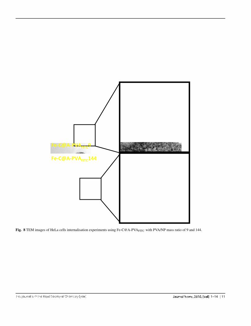
The confocal analysis was correlated with TEM imag-ing at the same concentration of Fe-C@A-PVAFITC per cell.Fig. 8 shows the TEM images for Fe-C@A-PVAFITC witha PVA/NP ratio of 9 and 144, taken at two different mag-nifications. Whereas no naked Fe-C particles were detectedinside the cells, HeLa cells seem to have internalised theFe-C@A-PVAFITC particles. Several black dots around 10 nmcan be seen inside cell’s vacuoles. The particles appear to beaggregated in a matrix, which could be endozomes. These par-ticles look the same as already observed in TEM pictures ofFe-C@A-PVAFITC144 in Fig. 2 and Fig. 3 and so indicate the
1–14 | 9
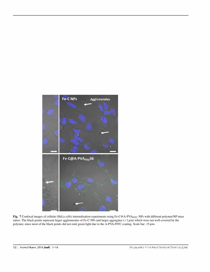
Fig. 7 Confocal images of cellular (HeLa cells) internalisation experiments using Fe-C@A-PVAFITC NPs with different polymer/NP massratios. The black points represent larger agglomerates of Fe-C NPs and larger aggregates (>1 µm) which were not well-covered by thepolymer, since most of the black points did not emit green light due to the A-PVA-FITC coating. Scale bar: 15 µm.
10 | 1–14
Fe‐C@A‐PVAFITC9
Fe‐C@A‐PVAFITC144
Fig. 8 TEM images of HeLa cells internalisation experiments using Fe-C@A-PVAFITC with PVA/NP mass ratio of 9 and 144.
1–14 | 11
Fe-C@A-PVA FITC9
0
20
40
60
80
100
120
Ce
ll vi
abili
ty (
%)
1h 3h 6h 24h
Fe-C
DMEM
Fe-C@A-PVA FITC36
Fe-C@A-PVA FITC144
Fe-C@A-PVA FITC576
PVA9
PVA36
PVA144
PVA576
* *
Fig. 6 Cell viability of HeLa cells incubated withFe-C@A-PVAFITC and PVA-OH/A-PVAFITC solutions compared tocontrol HeLa cells incubated with cell medium. Cell viabilities weremeasured 1, 3, 6 and 24 hours after incubation. Incubationconditions from left to right: control cell medium, Fe-C only,Fe-C@A-PVAFITC PVA/NP mass ratio 9, Fe-C@A-PVAFITCPVA/NP mass ratio 36, Fe-C@A-PVAFITC PVA/NP mass ratio 144,Fe-C@A-PVAFITC PVA/NP mass ratio 576, PVA-OH/A-PVAFITCsolution mixture at the same concentration than Fe-C@A-PVAFITCratio 9, PVA-OH/A-PVAFITC solution mixture at the sameconcentration than Fe-C@A-PVAFITC ratio 36,PVA-OH/A-PVAFITC solution mixture at the same concentrationthan Fe-C@A-PVAFITC ratio 144,PVA-OH/A-PVAFITC solutionmixture at the same concentration than Fe-C@A-PVAFITC ratio 576.
internalisation of Fe-C@A-PVAFITC particles by HeLa cells.
4 Conclusions
Superparamagnetic carbon-encapsulated iron nanoparticles(Fe-C NPs) were obtained by using a modified arc-dischargeplasma method. The measured diameter and magnetic proper-ties were suitable for several applications, in particular in thebiomedical field. The colloidal stabilisation of the obtainedFe-C NPs in aqueous suspensions was achieved by an addi-tional PVA coating. Several mass ratios of PVA/NPs (9, 36,144 and 576 w/w) were studied. The particle size distribu-tion measurements carried out by different methods (CPS andmicroscopy observations) allowed the characterisation of thewhole range of nanoparticles present in the samples. CPS andmicroscopy observations both showed a population of isolatedprimary particles of DV 50 70-90 nm, containing several tens ofsuperparamagnetic Fe cores. These particles are very inter-esting for biosensors, gas detectors or magnetic applications,such as hyperthermia or spintronics. A small population of ag-glomerates, around 170-220 nm, were also detected; their sizewas small enough to be useful for biomedical applications.However the fitting of their volume weighted size distribu-
tions proved that the optimal mass ratio of PVA/NP shouldbe between 36 and 144 (smallest mean diameter and highestproportion of small particles).
Zeta potential measurements correlated the colloidal stabil-ity results with a decrease of the absolute zeta potential of theNPs (from an initial value of -46 mV for naked Fe-C NPs).This was related to the increase of PVA on the surface ofthe particles. When PVA coated particles were functionalisedwith amino-PVA, in order to positively charge them for theuse for cell internalisation, an increase of the Zeta potential toa positive value was observed for PVA/NP ratios of 36 w/w orhigher.
The A-PVA/PVA stabilised particles were labeled with flu-orophore amino-PVA (referred to as Fe-C@A-PVAFITC NPs)for cytotoxicity tests and cell internalisation detection in con-focal and transmission electron microscopy.
For PVA/NP mass ratios less than 144 no cytotoxicity onHeLa cells was observed after 24 hours. However for parti-cles with a ratio of 576 and incubation times of more than 3hours a toxic effect was observed. This observation was cor-related to internalization analysis with confocal microscopy.However, interactions of all the Fe-C@A-PVAFITC particlesand cells were demonstrated by fluorescence of particles colo-calized with the HeLa cells membrane in the same focal planas the stained nuclei. In this part too, the Fe-C@A-PVAFITC36and 144 had the best cell internalization. Moreover vacuolesinside the cells observed with TEM, containing NP-endosomehybrids, confirmed their internalization to a certain point.
In summary PVA coating is very interesting to colloidallystabilize carbon coated iron nanoparticles in aqueous media.Moreover, with A-PVAFITC functionalization, the change froma negative to a positive zeta potential, coupled with a fluo-rescent label, permits the observation of the internalization ofnon-toxic NPs inside HeLa cells, making their use for promis-ing biomedical applications possible.
5 Acknowledgements
This study was supported by projects CTQ2009-14674-C02-01 from Ministerio de Ciencia e Innovacion ofSpain (MCNN), 2009SGR185 from AGAUR Generalitat deCatalunya (Catalonia, Spain). The authors also thank Scien-tific and Technological Centres of Universitat de Barcelonafor microscopy facilities and Dr. Nuria Clos for magnetic mea-surements. N.A-A. thanks to AGAUR of the AGAUR Gener-alitat de Catalunya for the support, Ajuts de mobilitat per alpersonal dadministracio i serveis del sector universitari i de larecerca 2010 (PAS2010), of her stay in the EPFL. The authorswould also like to thank the bioimaging and optics platformof EPFL for the confocal imaging as well as Mr. Beat Haennifrom the University of Bern for his contribution in TEM sam-ple preparation and analysis.
12 | 1–14
References
1 W. S. Seo, J. H. Lee, X. Sun, Y. Suzuki, D. Mann, Z. Liu,M. Terashima, P. C. Yang, M. V. McConnell, D. G. Nishimura,and H. Dai, “Feco/graphitic-shell nanocrystals as advanced magnetic-resonance-imaging and near-infrared agents,” Nature Materials, vol. 5,pp. 971–976, 2006.
2 R. Grass, E. Athanassiou, and W. Stark, “Covalently functionalized cobaltnanoparticles as a platform for magnetic separations in organic synthe-sis,” Angewandte Chemie International Edition, vol. 46, no. 26, pp. 4909–4912, 2007.
3 F.-r. Li, W.-h. Yan, Y.-h. Guo, H. Qi, and H.-x. Zhou, “Preparationof carboplatin-fe@c-loaded chitosan nanoparticles and study on hyper-thermia combined with pharmacotherapy for liver cancer.,” InternationalJournal of Hyperthermia, vol. 25, no. 5, pp. 383–91, 2009.
4 H. A. Schreiber, J. Prechl, H. Jiang, A. Zozulya, Z. Fabry, F. Denes, andM. Sandor, “Using carbon magnetic nanoparticles to target, track, andmanipulate dendritic cells,” Journal of Immunological Methods, vol. 356,no. 1-2, pp. 47 – 59, 2010.
5 H. Liu, M. Y. Hua, H. W. Yang, C. Y. Huang, P. C. Chu, J. S. Wu, I. C.Tseng, J. J. Wang, T. C. Yen, P. Y. Chen, and K. C. Wei, “Magnetic reso-nance monitoring of focused ultrasound/magnetic nanoparticle targetingdelivery of therapeutic agents to the brain,” Proceedings of the NationalAcademy of Sciences of the United States of America, vol. 107, pp. 15205–10, 2010.
6 Y. Xu, M. Mahmood, and A. Fejleh, “Carbon-covered magnetic nanoma-terials and their application for the thermolysis of cancer cells,” Interna-tional Journal of Nanomedicine, vol. 5, pp. 167–176, 2010.
7 A. Pandolfo and A. Hollenkamp, “Carbon properties and their role in su-percapacitors,” Journal of Power Sources, vol. 157, no. 1, pp. 11 – 27,2006.
8 H. T. Yang, D. Hasegawa, M. Takahashi, and T. Ogawa, “Achieving anoninteracting magnetic nanoparticle system through direct control of in-terparticle spacing,” Applied Physics Letters, vol. 94, no. 1, pp. 013103–013103–3, 2009.
9 W. Li, Q. Xin, and Y. Yan, “Nanostructured ptfe/c cathode catalysts for di-rect methanol fuel cell: The effect of catalyst composition,” InternationalJournal of Hydrogen Energy, vol. 35, no. 6, pp. 2530 – 2538, 2010.
10 Y. Zhang and D. Book, “Hydrogen storage properties of ball-milledgraphite with 0.5wt.% fe,” International Journal of Energy Research,pp. 720–725, 2011.
11 X.-W. Wei, G.-X. Zhu, C.-J. Xia, and Y. Ye, “A solution phase fabrica-tion of magnetic nanoparticles encapsulated in carbon,” Nanotechnology,vol. 17, no. 17, p. 4307, 2006.
12 D. Zhang, S. Wei, C. Kaila, X. Su, J. Wu, A. B. Karki, D. P. Young, andZ. Guo, “Carbon-stabilized iron nanoparticles for environmental remedi-ation,” Nanoscale, vol. 2, pp. 917–919, 2010.
13 H. Wang, Y.-F. Yu, Q.-W. Chen, and K. Cheng, “Carboxyl-functionalizednanoparticles with magnetic core and mesopore carbon shell as adsor-bents for the removal of heavy metal ions from aqueous solution,” DaltonTransactions, vol. 40, pp. 559–563, 2011.
14 K. Cheng, Y.-M. Zhou, Z.-Y. Sun, H.-B. Hu, H. Zhong, X.-K. Kong, andQ.-W. Chen, “Synthesis of carbon-coated, porous and water-dispersivefe3o4 nanocapsules and their excellent performance for heavy metal re-moval applications,” Dalton Transactions, vol. 41, pp. 5854–5861, 2012.
15 Y. Zhang, S. Xu, Y. Luo, S. Pan, H. Ding, and G. Li, “Synthesis of meso-porous carbon capsules encapsulated with magnetite nanoparticles andtheir application in wastewater treatment,” Journal of Matererials Chem-istry, vol. 21, pp. 3664–3671, 2011.
16 J. Bonard, A. Sallin, and J. Wegrowe, “Giant magnetoresistance from a cowire incorporating carbon-encapsulated magnetic nanoparticles,” in Elec-tronic properties of novel materials-molecular nanostructures (H. Kuz-many, J. Fink, M. Mehring, and S. Roth, eds.), vol. 544 of AIP confer-ence proceedings, pp. 508–511, Aldrich; ATOS GmbH; Aventis Res &
Technol; AVL List GmbH; Bruker Analyt Messtechnik GmbH; CRED-ITANSTALT BANKVEREIN, AMER INST PHYSICS, 2000. 14th In-ternational Winter School on Electronic Properties on Novel Materials,KIRCHBERG, AUSTRIA, MAR 04-11, 2000.
17 A.-H. Lu, E. Salabas, and F. Schth, “Magnetic nanoparticles: Synthesis,protection, functionalization, and application,” Angewandte Chemie In-ternational Edition, vol. 46, no. 8, pp. 1222–1244, 2007.
18 L. Vaisman, H. D. Wagner, and G. Marom, “The role of surfactants in dis-persion of carbon nanotubes,” Advances in Colloid and Interface Science,vol. 128-130, pp. 37–46, 2006.
19 J. Nishijo, C. Okabe, O. Oishi, and N. Nishi, “Synthesis, structures andmagnetic properties of carbon-encapsulated nanoparticles via thermal de-composition of metal acetylide,” Carbon, vol. 44, no. 14, pp. 2943–2949,2006.
20 A. Taylor, Y. Krupskaya, S. Costa, S. Oswald, K. Krmer, S. Fssel, R. Klin-geler, B. Bchner, E. Borowiak-Palen, and M. Wirth, “Functionalizationof carbon encapsulated iron nanoparticles,” Journal of Nanoparticle Re-search, vol. 12, no. 2, pp. 513–519, 2010.
21 P. Tartaj, M. del Puerto Morales, S. Veintemillas-Verdaguer, T. Gonzalez-Carreno, and C. J. Serna, “The preparation of magnetic nanoparticlesfor applications in biomedicine,” Journal of Physics D: Applied Physics,vol. 36, no. 13, p. R182, 2003.
22 A. Taylor, Y. Krupskaya, K. Krmer, S. Fssel, R. Klingeler, B. Bchner,and M. P. Wirth, “Cisplatin-loaded carbon-encapsulated iron nanoparti-cles and their in vitro effects in magnetic fluid hyperthermia,” Carbon,vol. 48, no. 8, pp. 2327–2334, 2010.
23 M. Poplawska, G. Zukowska, S. Cudzilo, and M. Bystrzejewski, “Chem-ical functionalization of carbon-encapsulated magnetic nanoparticles by1,3-dipolar cycloaddition of nitrile oxide,” Carbon, vol. 48, no. 4,pp. 1318 – 1320, 2010.
24 M. Zeltner, R. N. Grass, A. Schaetz, S. B. Bubenhofer, N. A. Luechinger,and W. J. Stark, “Stable dispersions of ferromagnetic carbon-coated metalnanoparticles: preparation via surface initiated atom transfer radical poly-merization,” Journal of Materials Chemistry, vol. 22, pp. 12064–12071,2012.
25 G. Paradossi, F. Cavalieri, E. Chiessi, C. Spagnoli, and M. Cowman,“Poly(vinyl alcohol) as versatile biomaterial for potential biomedical ap-plications,” Journal of Materials Science: Materials in Medicine, vol. 14,no. 8, pp. 687–691, 2003.
26 E. Bertran-Serra, N. Aguilo-Aguayo, and M. J. Inestrosa-Izurieta,“Method and reactor for the production of carbon-coated nanoparticles.”Patent, March 2012. WO/2012/025652.
27 N. Aguil-Aguayo, Z. Liu, E. Bertran, and J. Yang, “Thermal-inducedstructural evolution of carbon-encapsulated iron nanoparticles generatedby two different methods,” The Journal of Physical Chemistry C, vol. 117,pp. 19167–19174, Sept. 2013.
28 S. E. A. Gratton, P. A. Ropp, P. D. Pohlhaus, J. C. Luft, V. J. Madden,M. E. Napier, and J. M. DeSimone, “The effect of particle design on cel-lular internalization pathways,” Proceedings of the National Academy ofSciences, vol. 105, no. 33, pp. 11613–11618, 2008.
29 L. Maurizi, U. Sakulkhu, L. A. Crowe, V. M. Dao, N. Leclaire, J.-P.Valle, and H. Hofmann, “Syntheses of cross-linked polymeric superpara-magnetic beads with tunable properties,” RSC Advances, vol. 4, no. 22,p. 11142, 2014.
30 M. Chastellain, A. Petri, and H. Hofmann, “Particle size investigationsof a multistep synthesis of pva coated superparamagnetic nanoparticles,”Journal of Colloid and Interface Science, vol. 278, no. 2, pp. 353 – 360,2004.
31 U. Sakulkhu, M. Mahmoudi, L. Maurizi, J. Salaklang, and H. Hofmann,“Protein corona composition of superparamagnetic iron oxide nanopar-ticles with various physico-chemical properties and coatings,” ScientificReports, vol. 4, May 2014.
32 P. Bowen, “Particle size distribution measurement from millimeters tonanometers and from rods to platelets,” Journal of Dispersion Science
1–14 | 13
and Technology, vol. 23, no. 5, pp. 631–662, 2002.33 B. Steitz, J. Salaklang, A. Finka, C. O’Neil, H. Hofmann, and A. Petri-
Fink, “Fixed bed reactor for solid-phase surface derivatization of su-perparamagnetic nanoparticles,” Bioconjugate Chemistry, vol. 18, no. 5,pp. 1684–1690, 2007.
34 R. D. C. Team, R: A Language and Environment for Statistical Comput-ing. 2010. ISBN 3-900051-07-0.
35 M. D. Abramoff, P. J. Magelhaes, and S. J. Ram, “Image processing withImageJ,” Biophotonics Int, vol. 11, no. 7, pp. 36–42, 2004.
36 F.-m. Zhang, J. Chang, and B. Eberhard, “Dissolution of poly(vinylalcohol)-modified carbon nanotubes in a buffer solution,” New CarbonMaterials, vol. 25, pp. 241–247, June 2010.
37 K. G. Dassios and C. Galiotis, “Polymernanotube interaction inMWCNT/poly(vinyl alcohol) composite mats,” Carbon, vol. 50,pp. 4291–4294, Sept. 2012.
38 C. P. Bean and J. D. Livingston, “Superparamagnetism,” Journal of Ap-plied Physics, vol. 30, no. 4, pp. S120–S129, 1959.
39 D. M. Duffy and J. A. Blackman, “Magnetism of 3d transition-metaladatoms and dimers on graphite,” Phys. Rev. B, vol. 58, pp. 7443–7449,Sep 1998.
40 B. Cullity and C. Graham, Introduction to Magnetic Materials. John Wi-ley & Sons, 2009.
41 J. I. Gittleman, B. Abeles, and S. Bozowski, “Superparamagnetism andrelaxation effects in granular ni-sio2 and ni-al2o3 films,” Phys. Rev. B,vol. 9, pp. 3891–3897, May 1974.
42 J. Jiang, G. Oberdrster, and P. Biswas, “Characterization of size, surfacecharge, and agglomeration state of nanoparticle dispersions for toxico-logical studies,” Journal of Nanoparticle Research, vol. 11, pp. 77–89,2009.
43 E. Verwey and J. Overbeek, Theory of the Stability of Lyophobic Colloids.Dover Books on Chemistry Series, Dover Publications, 1999.
44 E. Bottani and J. Tascon, Adsorption By Carbons. Chemical, Petrochem-ical & Process, Elsevier, 2008.
45 D. Mahl, J. Diendorf, W. Meyer-Zaika, and M. Epple, “Possibilities andlimitations of different analytical methods for the size determination of abimodal dispersion of metallic nanoparticles,” Colloids and Surfaces A:Physicochemical and Engineering Aspects, vol. 377, no. 1-3, pp. 386–392, 2011.
46 U. Aschauer, O. Burgos-Montes, R. Moreno, and P. Bowen, “Hamaker2: A toolkit for the calculation of particle interactions and suspensionstability and its application to mullite synthesis by colloidal methods,”Journal of Dispersion Science and Technology, vol. 32, no. 4, p. 470,2011.
47 C. Moreno-Castilla, “Adsorption of organic molecules from aqueous so-lutions on carbon materials,” Carbon, vol. 42, no. 1, pp. 83 – 94, 2004.
48 S. Bhattacharjee, L. H. de Haan, N. M. Evers, X. Jiang, A. T. Marcelis,H. Zuilhof, I. M. Rietjens, and G. M. Alink, “Role of surface chargeand oxidative stress in cytotoxicity of organic monolayer-coated siliconnanoparticles towards macrophage NR8383 cells,” Particle and fibre tox-icology, vol. 7, no. 1, p. 25, 2010.
49 M. F. Calmon, A. T. de Souza, N. M. Candido, M. I. B. Raposo, S. Taboga,P. Rahal, and J. G. Nery, “A systematic study of transfection efficiencyand cytotoxicity in HeLa cells using iron oxide nanoparticles preparedwith organic and inorganic bases,” Colloids and Surfaces B: Biointer-faces, vol. 100, pp. 177–184, Dec. 2012.
14 | 1–14


