Embed Size (px)
Citation preview
Investigating WirelessHART coexistence issues through a specifically designed simulator
C.M. De Dominicis,P. Ferrari,A. Flammini, E. Sisinni Dept. of Electronics for Automation
University of Brescia Via Branze, 38 – 25123 – Brescia, Italy
M. Bertocco,G. Giorgi,C. Narduzzi,F. Tramarin Dept. of Information Engineering
University of Padova via G. Gradenigo, 6/B – 35131 – Padova, Italy
Abstract—In this paper, the WirelessHART communication scheme is investigated. The protocol is at first described, in order to underline the key aspects of its design; then, a simulation tool is presented: it enables analysis that accounts for both protocol and physical layers issues. In particular, interference effects on protocol choices can be easily analyzed. The experimental results, obtained from simulations, highlight improvements of WirelessHART with respect to IEEE 802.15.4 standard, concerning the Packet Error Ratio (PER) degradation of interfering networks.
Keywords - WirelessHART, coexistence, wireless sensor network, simulation, wireless fieldbus
I. INTRODUCTION One of the main innovation in the industrial automation and
process control world is the use of wireless transmission systems. At higher levels, wireless networks are based on the well established and mature IEEE802.11 family of standards; they are used in mobile Human to Machine Interfaces (HMIs) and in supervisory systems. On the contrary, at the sensor and actuator level there are several proprietary wireless solutions based on different and not compatible technologies [1]. Obviously, this situation greatly slows down the adoption of such systems. In order to overcome this limit, the specifications of the first commercial available wireless fieldbus have been released in September 2007. It is part of HART specifications and for this reason it is called WirelessHART (WH) [2]. Commercial devices are still in the pre-release phase and no information at all are available on their performances.
Obviously, the adoption of a wireless link for data communication provides appealing opportunities for industrial systems, but in order to make control applications reliable (i.e. closing the loop over wireless), further researches are needed. It is well known that wireless networking is affected by varying time-delays and packet losses (see e.g. [3]). However, we need not only to develop new theory to deal with integrated wireless communications and control, but we are also obliged to develop simulation platforms for testing and verifying the theories before implementing them on real industrial systems.
In particular, severe coexistence problems will surely raise for the presence of other wireless systems in the same industrial area. It will not be easy to realize experimental testbeds made up of a huge number of different networks, each
one made up of several nodes and based on different technologies. Communication systems nowadays available treat interfering signals just as “noise”, without any knowledge about their origin. Within a densely populated environment, uncoordinated fighting to obtain transmission rights leads to poorer performances, since each node simply “talks more often and louder” than others, with the only effect of increasing the noise and reduce the bandwidth. Available protocols are intrinsically selfish, i.e. they have not efficient mechanisms that allow effective discovery and coexistence with devices using different solutions. For this reason, new protocol stacks taking into account coexistence issues must be developed and new integrated cross-layer simulation frameworks are necessary to predict their behavior in a crowded scenario.
In this work authors present a newly designed simulator for the WH standard, based on the open source environment OMNeT++ [4,5]. The tool is able to simulate a whole WH network, and also the effects of interference from co-located Low Rate Wireless Personal Area Networks (LR-WPANs) or Wireless Local Area Networks (WLANs), operating in the same frequency range.
The paper is structured as follows: after a brief resume of the WH standard, some details of the realized simulation software are provided. Subsequently, some experimental results are resumed; in particular, the Packet Error Ratio (PER) of a WH network in presence of a WLAN link is estimated and compared with performances of traditional IEEE802.15.4 solutions. Finally some concluding remarks are reported.
II. THE WIRELESS HART PROTOCOL
Starting from the release 7.0 of HART specifications, the well known mixed signaling of analog and digital information has been enforced by a new physical layer that provides a low cost, low speed (e.g., compared to WLAN applications) wireless connection to HART-enabled devices.
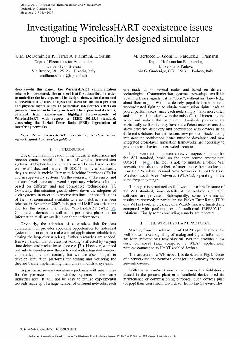
The structure of a WH network is depicted in Fig.1. Nodes of a network are: the Network Manager; the Gateway and some network devices.
With the term network device we mean both a field device placed in the process plant or a handheld device used for maintenance or commissioning purposes. Such devices push (or pop) their data stream towards (or from) the Gateway. The
I2MTC 2009 - International Instrumentation and Measurement Technology Conference Singapore, 5-7 May 2009
978-1-4244-3353-7/09/$25.00 ©2009 IEEE
Authorized licensed use limited to: Univ of Calif Berkeley. Downloaded on January 17, 2010 at 20:36 from IEEE Xplore. Restrictions apply.
Field device(s)
Gateway
Handheld device
Host Plant
Network Manager Security Manager
Figure 1. Architecture of a WH network.
latter is made up of several access points deployed within the plant which effectively collect packets on the air but can be accessed as a traditional HART device by the Host Plant (i.e. it is able to react to HART commands). On the contrary, network setup and maintenance is a task of a (unique) Network Manager, i.e. the WH network has a centralized operation architecture.The Network Manager is extended by the Security Manager that ensures security handling cryptographic session for each data transaction. It generates keys, joint keys and network key, which are further propagated to the field devices by the Network Manager. Multiple networks can be connected to one Security Manager.
The standard has been loosely designed around the ISO/OSI open architecture model, as better described in the following.
A. The MAC and PHY layer
Thanks to similarities with requirements of LR-WPANs, the IEEE802.15.4-2006 has been chosen as the physical layer. This ensures low cost, high availability and a multi vendor offer. It operates in the 2.4GHz free licensed ISM band and offers a gross transfer rate of 250 kbps. The available bandwidth is divided into 16 channels (even if WH uses only 15 of them), each one 2MHz wide and 5MHz apart from the other. With regards to the modulation schema, the original Direct Sequence Spread Spectrum (DSSS) modulation is enforced by the adoption of a frequency agility mechanism (slow frequency hopping, i.e. the channel used for communicating is changed on a packet by packet basis). In addition, if needed, some channels can be blacklisted. This choice allows for a better stationary or narrow band interference rejection, as a simultaneous WLAN transmission or multipath fading. Another difference from the LR-WPAN standard is the adoption of a ±10ppm clock accuracy (and not ±40ppm).
Referring to the Medium Access Control layer (a sublayer of the Data Link), an hybrid policy based on Time Division Medium Access (TDMA) and Carrier Sense Multiple Access (CSMA) has been adopted. For each packet and its acknowledge, a 10 ms wide slot is used. The slot duration has been chosen as a trade off between the maximum slot occupation (133 data byte @250kbps = 4.256ms, followed by a 26 byte acknowledge @250kbps = 832μs) and the achievable synchronization accuracy. Time slots are grouped into a repetitive pattern called superframe; each node must be able to support several concurrent superframes. Data transfer occurs in a cyclic way with the source and the sink node paired by a link. Links are allocated to a superframe by the Network Manager.
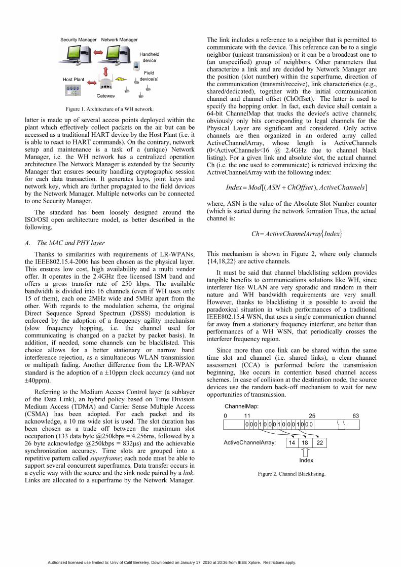
The link includes a reference to a neighbor that is permitted to communicate with the device. This reference can be to a single neighbor (unicast transmission) or it can be a broadcast one to (an unspecified) group of neighbors. Other parameters that characterize a link and are decided by Network Manager are the position (slot number) within the superframe, direction of the communication (transmit/receive), link characteristics (e.g., shared/dedicated), together with the initial communication channel and channel offset (ChOffset). The latter is used to specify the hopping order. In fact, each device shall contain a 64-bit ChannelMap that tracks the device's active channels; obviously only bits corresponding to legal channels for the Physical Layer are significant and considered. Only active channels are then organized in an ordered array called ActiveChannelArray, whose length is ActiveChannels (0<ActiveChannels<16 @ 2.4GHz due to channel black listing). For a given link and absolute slot, the actual channel Ch (i.e. the one used to communicate) is retrieved indexing the ActiveChannelArray with the following index:
]),[( nelsActiveChanChOffsetASNModIndex +=
where, ASN is the value of the Absolute Slot Number counter (which is started during the network formation Thus, the actual channel is:
{ }IndexnelArrayActiveChanCh=
This mechanism is shown in Figure 2, where only channels {14,18,22} are active channels.
It must be said that channel blacklisting seldom provides tangible benefits to communications solutions like WH, since interferer like WLAN are very sporadic and random in their nature and WH bandwidth requirements are very small. However, thanks to blacklisting it is possible to avoid the paradoxical situation in which performances of a traditional IEEE802.15.4 WSN, that uses a single communication channel far away from a stationary frequency interferer, are better than performances of a WH WSN, that periodically crosses the interferer frequency region.
Since more than one link can be shared within the same time slot and channel (i.e. shared links), a clear channel assessment (CCA) is performed before the transmission beginning, like occurs in contention based channel access schemes. In case of collision at the destination node, the source devices use the random back-off mechanism to wait for new opportunities of transmission.
0 63 11 25 0 0 0 1 0 0 1 0 0 0 0 0 0 0 1
14 18 22
ChannelMap:
ActiveChannelArray:
Index
Figure 2. Channel Blacklisting.
Authorized licensed use limited to: Univ of Calif Berkeley. Downloaded on January 17, 2010 at 20:36 from IEEE Xplore. Restrictions apply.
B. The NWK layer When the network is set up for the first time, it receives a
NetworkID (and authentication keys from the Security Manager). All these operations are under the control of the Network Manager, which maintains a complete list of all devices. It has full knowledge of the network topology, and decides how packets must be forwarded among nodes. Starting from neighbor lists compiled by each node, it is possible to construct the so called routing graphs, i.e. the collection of all vectors that join source and sink of each link. Every data packet is forwarded along one of this graph (the graph ID is within the NWK layer header). Alternatively, the Network Manager can also decide to use traditional address routing, but this feature is used primarily in the commissioning phase for testing and troubleshooting of network path.
Another important Network Manager responsibility is link scheduling. Nodes need to know either where (by means of graph routing), and when the packets should be sent (by means of link scheduling). The Network Manager must create a network wide link table, where, for each link, it is specified the corresponding superframe and time slot (together with other ancillary information like link type, function - transmit, receive or shared, neighbor information and ChOffset). Obviously, time synchronization is a crucial point, since both the source and the sink of a link must have a common sense of time. This allows for an efficient use of resources; in fact, WH implements a full mesh topology and every node must be also a router, but low duty cycle operations can be still implemented thanks to a priori known link scheduling.
In order to dynamically react to environment changes, the Network Manager is also responsible to monitor the system wellness. Diagnostic information are used to pursue this goal.
Finally, one should note that, in the current release, the standard do not clearly indicate how Network Manager tasks shall be performed, i.e. what kind of algorithm should be implemented for routing, link scheduling and network monitoring.
C. Upper layers They are the same of traditional HART protocol. In
particular, it is possible to set up a connection oriented communication link between the host application and the field device. More in general, both TCP/IP like transfer with acknowledgement (used for alarm/event notification) and UDP like without acknowledgements (used for sending real time process data) are supported.
III. THE SIMULATOR The WH standard supposes that only one network exists in
the same area. It is not clearly stated how different Network Managers should collaborate. In particular, interfering networks are treated just as noise. For this reason, we have realized a simulator able to predict what is the behavior of a WH network when other WH, IEEE802.15.4 or IEEE802.11 networks are in the same radio coverage area.
A. OMNeT++ and Mobility Framework This project is developed starting from results presented in
[6], where a tool able to simulate interference coexistence issues between an IEEE802.15.4 wireless sensor networks (WSNs) and an IEEE802.11b WLAN was discussed. The core of the simulator is OMNeT++, an open source simulation environment based on a discrete event approach. Together with the Mobility Framework [7], it allows the simulation of WSNs in a very simple way. The latter is a public framework developed at the Technische Universitat of Berlin; it includes an almost complete implementation of the IEEE802.11b standard and, in the development version, a rather complete implementation of the IEEE802.15.4 standard.
B. Simulator architecture The architecture of the proposed simulator is summarized
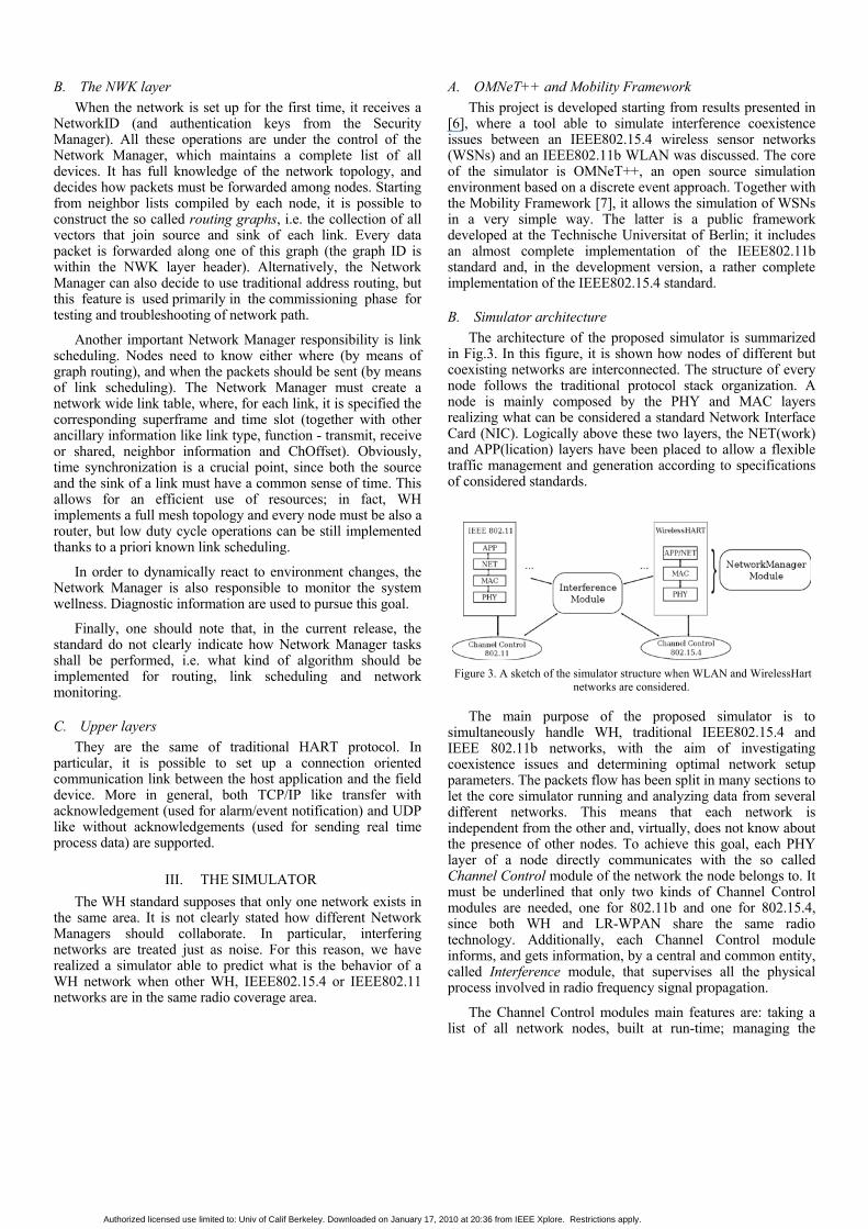
in Fig.3. In this figure, it is shown how nodes of different but coexisting networks are interconnected. The structure of every node follows the traditional protocol stack organization. A node is mainly composed by the PHY and MAC layers realizing what can be considered a standard Network Interface Card (NIC). Logically above these two layers, the NET(work) and APP(lication) layers have been placed to allow a flexible traffic management and generation according to specifications of considered standards.
Figure 3. A sketch of the simulator structure when WLAN and WirelessHart
networks are considered.
The main purpose of the proposed simulator is to simultaneously handle WH, traditional IEEE802.15.4 and IEEE 802.11b networks, with the aim of investigating coexistence issues and determining optimal network setup parameters. The packets flow has been split in many sections to let the core simulator running and analyzing data from several different networks. This means that each network is independent from the other and, virtually, does not know about the presence of other nodes. To achieve this goal, each PHY layer of a node directly communicates with the so called Channel Control module of the network the node belongs to. It must be underlined that only two kinds of Channel Control modules are needed, one for 802.11b and one for 802.15.4, since both WH and LR-WPAN share the same radio technology. Additionally, each Channel Control module informs, and gets information, by a central and common entity, called Interference module, that supervises all the physical process involved in radio frequency signal propagation.
The Channel Control modules main features are: taking a list of all network nodes, built at run-time; managing the
Authorized licensed use limited to: Univ of Calif Berkeley. Downloaded on January 17, 2010 at 20:36 from IEEE Xplore. Restrictions apply.
connections between nodes, deciding if a node can be, or not, connected to another on the basis of the maximum receivable power; recalculating connections every time a node changes its position; embedding the wireless channel module, through which multiple propagation models can be implemented; isolating a network from others, accepting and registering only nodes of the same type; interfacing with the Interference module. These functions allow communications among nodes free from interferers from other networks’ transmissions, virtualizing the wireless channel.
The simulator models physical wireless communications implementing two channel models: a simple path loss model that considers Friis free space propagation, and a two-slope path loss channel model. In fact, in accordance to [8], the Friis propagation model is not so accurate for the typical environment in which considered networks generally operate, for the presence of obstacles and reflections. The two-slope path loss channel model predicts in a more accurate fashion the power attenuation of the medium, following free space propagation model till 8m, assuming a path loss exponent of 3.3 after that threshold.
The abovementioned Interference module is the link between each virtual channel in a simulation. The channel control modules inform it of each transmission on their channels (remember that all the considered standards do not change the channel during the transmission), and this module stores this information in a container for each network. In this way, every time a packet is received, the PHY layer has to ask to this central entity if the packet can be correctly received or if it undergoes a collision. In the context of the simulator, collision is meant as a temporal coincidence of the packet received with one or more packets of the other networks. Since the frequency hopping functionality of WH are considered, it must be also checked that packets also coexist on the same frequency band. This also means that adjacent channels do not interfere, an assumption that can be false if the two transmissions are characterized by very different received power. Assuming that a collision is arisen, the Signal to Interference Ratio (SIR) is evaluated and, as exposed in [6], the Packet Error Ratio (PER) is estimated so that a Bernoulli trial returns if the packet has to be rejected or accepted.
IV. RESULTS Based on previous experimental papers, [8,9], the testbed
adopted for simulations is sketched in Fig.4.
Figure 4. The environmental set-up reproduced in the simulation.
The environment is composed of a WH network that
interferes with a WLAN network composed of two nodes.
These nodes reproduce an up-link transmission between a STation (ST) and an Access Point (AP), exchanging 600Bytes-long packets. The WH network is composed of three nodes exchanging data each other; for the sake of easiness, in these exchanges the gateway is never considered. This network is placed around the WLAN receiver node (ST), covering an area of 2m of radius. The APP layer of each field device generates new data every 30ms alternating the other two devices as the recipient; for this reason, it has been implemented a superframe made up of six 10ms-wide timeslots, as shown in Fig. 5a. All exchanged packets have a length of 127Bytes.
Figure 5. Channel allocations in a) WH and b) LR-WPAN.
Simulation runs presented here consider these variables: the duty cycle λWLAN of the IEEE 802.11b transmission (varying in the range 35%-100% of the available bandwidth) and the transmission power (set to 1mW-0dBm or 1.5mW-1.8dBm for WH nodes, 30mW-15dBm for the WLAN). Some general parameters, valid among all simulation runs, are: the gross bit-rate of considered networks (IEEE 802.11b: 11Mb/s; WH: 250kb/s, due to the adoption of IEEE802.15.4-PHY) and the path loss model (two-slope model). This configuration has been compared with an equivalent LR-WPAN. The IEEE802.15.4 interferer is made up of a Full Function Devices (FFDs), which acts as the coordinator, and receives data from three Reduced Function Devices (RFDs), with a polling time of 10ms (it must be remembered that channel access is randomized by the backoff time). In this case the channel is chosen to overlap the WLAN transmission, as depicted in Fig. 5b .
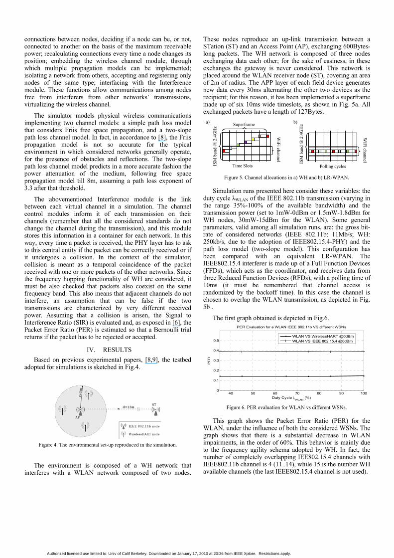
The first graph obtained is depicted in Fig.6.
40 50 60 70 80 90 1000
0.1
0.2
0.3
0.4
0.5
Duty Cycle λWLAN (%)
PER
PER Evaluation for a WLAN IEEE 802.11b VS different WSNs
WLAN VS WirelessHART @0dBmWLAN VS IEEE 802.15.4 @0dBm
Figure 6. PER evaluation for WLAN vs different WSNs.
This graph shows the Packet Error Ratio (PER) for the WLAN, under the influence of both the considered WSNs. The graph shows that there is a substantial decrease in WLAN impairments, in the order of 60%. This behavior is mainly due to the frequency agility schema adopted by WH. In fact, the number of completely overlapping IEE802.15.4 channels with IEEE802.11b channel is 4 (11..14), while 15 is the number WH available channels (the last IEEE802.15.4 channel is not used).
ISM
ban
d @
2.4
GH
z
Polling cycles ISM
ban
d @
2.4
GH
z
Time Slots
WiFi channel
WiFi channel
Superframe a) b)
Authorized licensed use limited to: Univ of Calif Berkeley. Downloaded on January 17, 2010 at 20:36 from IEEE Xplore. Restrictions apply.
Information collected in simulation also return data to compute the PER for the two WSNs. Even if it is possible to estimate the PER for each node, for ease of evaluation it has been furnished an average value obtained as the ratio between the mean of all collisions occurred and the mean of packets sent. Results are shown in Fig.7. As WH allows a transmission power up to 10mW-10dBm, two different power levels have been used to simulate the WH network to describe advantages deriving from stronger signals. For an exact comparison with IEEE 802.15.4, we have adopted the LR-WPAN nominal value, 0dBm-1mW, and an higher 1.8dBm-1.5mW.
The graph shows a substantial decrease in WSN packet collisions if the WH standard is employed, and this is again due to the Frequency Hopping algorithm implemented in WH. It is also shown that a small increase in the transmission power of nodes allows a strong reduction of packets collisions. If the transmission power is increased from 3dBm up to 10dBm, with this testbed the PER for the WH network assumes a value of zero, for all the WLAN duty-cycles.
40 50 60 70 80 90 1000
0.02
0.04
0.06
0.08
0.1
0.12
0.14
0.16
Duty cycle λWLAN (%)
Pac
ket E
rror
Rat
io (P
ER)
PER evaluation of IEEE802.15.4 and WirelessHART networks VS a WLAN network
WirelessHART @0dBmIEEE 802.15.4 @0dBmWirelessHART @1.8dBm
Figure 7. PER of LR-WPAN and WH communications vs WLAN.
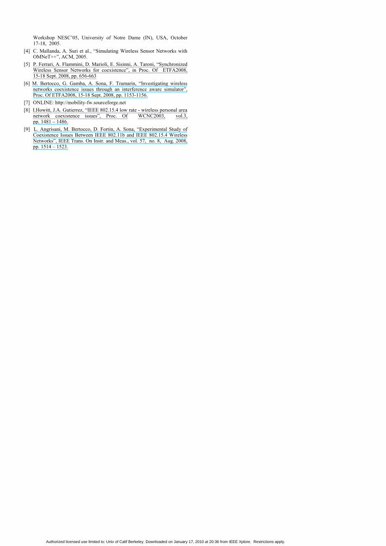
Some additional simulations have been performed on the channel blacklisting mechanism, considering the same scenario depicted in Figure 4, with the same parameters taken into account. WLAN transmits on channel 1 (centered around 2412 MHz), while IEEE 802.15.4-PHY overlapping channels [11..14] (2405-2420 MHz) are inactivated in the ChannelMap, as described in section II. Results are reported in Figure 8.
40 50 60 70 80 90 1000
0.05
0.1
0.15
0.2
0.25
Duty cyclie λWLAN (%)
Pac
ket E
rror
Rat
io (P
ER
)
Effect of Black Listing on impairments (PER) of a WLAN network and a WH network
WLAN VS WirelessHART @0dBmWLAN VS WirelessHART @0dBm - with Black ListingWirelessHART @0dBm - with Black ListingWirelessHART @0dBm
Figure 8. Effect of blacklisting on impairments of a WLAN and a WH network.
However, considering typical data delivery of WLAN traffic, improvements are higher for IEEE802.11
communications. In particular, supposing a centralized system supervisioning the plant, it is reasonable to dynamically turn on and off blacklisting during WLAN bursts. Following simulation results proof that channel blacklisting can be profitably used to make improve coexistence.
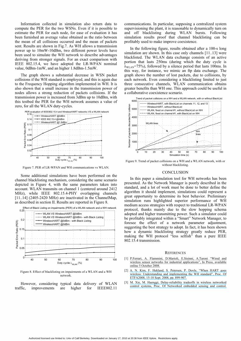
In the following figure, results obtained after a 100-s long simulation are shown. In this case only channels [11..13] were blacklisted. The WLAN data exchange consists of an active portion that lasts 250ms (during which the duty cycle is λWLAN=75%), followed by a silence period that lasts 100ms. In this way, for instance, we mimic an ftp data exchange. The graph shows the number of lost packets, due to collisions, by each network. Even considering a blacklisting limited to just three consecutive channels, WLAN communication obtains greater benefits than WH one. This approach could be useful in a collaborative coexistence scenario.
0 10 20 30 40 50 60 70 80 90 1000
1000
2000
3000
4000
5000
6000
Simulation time (s)
Num
ber o
f pac
kets
dis
card
ed fo
r col
lisio
n
Trend of packet collisions on a WH and a WLAN network, with or without BlackList
WirelessHART, with BlackList on channels 11, 12, and 13WirelessHART, without BlackListWLAN, fixed on channel #1, without BlackList on WHWLAN, fixed on channel #1, with BlackList on WH
WH lines
WLAN lines
Figure 9. Trend of packet collisions on a WH and a WLAN network, with or
without blacklisting.
CONCLUSION In this paper a simulation tool for WH networks has been
presented. As the Network Manager is poorly described in the standard, and a lot of work must be done to better define the algorithm it should implement, simulations could represent a great opportunity to determine its best behavior. Preliminary simulation runs highlighted superior performance of WH medium access strategies with respect to traditional LR-WPAN protocol, thanks mainly due to the slow hopping schema adopted and higher transmitting power. Such a simulator could be profitably integrated within a “Smart” Network Manager, to foresee the effect of a network parameter adjustment, suggesting the best strategy to adopt. In fact, it has been shown how a dynamic blacklisting strategy greatly reduce PER, making the WH protocol “less selfish” than a pure IEEE 802.15.4 transmission.
REFERENCES [1] P.Ferrari, A. Flammini, D.Marioli, E.Sisinni, A.Taroni “Wired and
wireless sensor networks for industrial applications”, In Press, available online 5 October 2008.
[2] A. N. Kim, F. Hekland, S. Petersen, P. Doyle, “When HART goes wireless: Understanding and implementing the WH standard”, Proc. Of ETFA2008, 15-18 Sept. 2008, pp. 899-907.
[3] M. Xie, M. Haenggi, Delay-reliability tradeoffs in wireless networked control systems, Proc. Of Networked embedded sensing and control.
Authorized licensed use limited to: Univ of Calif Berkeley. Downloaded on January 17, 2010 at 20:36 from IEEE Xplore. Restrictions apply.
Workshop NESC’05, University of Notre Dame (IN), USA, October 17-18, 2005.
[4] C. Mallanda, A. Suri et al., “Simulating Wireless Sensor Networks with OMNeT++”, ACM, 2005.
[5] P. Ferrari, A. Flammini, D. Marioli, E. Sisinni, A. Taroni, “Synchronized Wireless Sensor Networks for coexistence”, in Proc. Of ETFA2008, 15-18 Sept. 2008, pp. 656-663
[6] M. Bertocco, G. Gamba, A. Sona, F. Tramarin, “Investigating wireless networks coexistence issues through an interference aware simulator”, Proc. Of ETFA2008, 15-18 Sept. 2008, pp. 1153-1156.
[7] ONLINE: http://mobility-fw.sourceforge.net [8] I.Howitt, J.A. Gutierrez, “IEEE 802.15.4 low rate - wireless personal area
network coexistence issues”, Proc. Of WCNC2003, vol.3, pp. 1481 – 1486.
[9] L. Angrisani, M. Bertocco, D. Fortin, A. Sona, “Experimental Study of Coexistence Issues Between IEEE 802.11b and IEEE 802.15.4 Wireless Networks”, IEEE Trans. On Instr. and Meas., vol. 57, no. 8, Aug. 2008, pp. 1514 – 1523.
Authorized licensed use limited to: Univ of Calif Berkeley. Downloaded on January 17, 2010 at 20:36 from IEEE Xplore. Restrictions apply.


