Embed Size (px)
Citation preview
Electrochimica Acta 53 (2008) 6366–6371
Contents lists available at ScienceDirect
Electrochimica Acta
journa l homepage: www.e lsev ier .com/ locate /e lec tac ta
Insights into the electrochemical activity of nanosized �-LiFeO2
J. Moralesa, J. Santos-Penaa,∗, R. Trocoli a, S. Frangerb, E. Rodrıguez-Castellonc
pus de5, Fra
os, Un
, J. Salectr
tudieenomrmeimpe
t rathpresewas tties uernat
a Departamento de Quımica Inorganica e Ingenierıa Quımica, Edificio Marie Curie, Camb Laboratoire de Physico-Chimie de l’Etat Solide, ICMMO, Universite Paris XI, Orsay 9140c Departamento de Quımica Inorganica, Cristalografıa y Mineralogıa, Campus de Teatin
a r t i c l e i n f o
Article history:Received 12 November 2007Received in revised form 16 April 2008Accepted 18 April 2008Available online 29 April 2008
Keywords:�-LiFeO2
Lithium ion batteries positive electrodeX-ray photoelectron spectroscopyMossbauer spectroscopyDifferential scanning calorimetryElectrochemical impedance spectroscopy
a b s t r a c t
In recent work [J. Morales�-LiFeO2 with increased emorphs. In this work, we saccurate picture of the ph(XPS) measurements conficess. The electrochemicalduring the first charge, butests revealed that Fe(IV)species. Finally, �-LiFeO2
regimes. Stabilised capacitherefore an attractive alt
1. Introduction
Progress with lithium ion battery technology is still limited
by the high cost of the electrodes. The discovery of the excel-lent properties of LiCoO2 as positive electrode material for thistype of energy storage device [1–3] has been followed by exten-sive research on alternative, more inexpensive, thermally safe,environmentally friendly systems. In this context, the studiesof Goodenough and co-workers [4,5] on LiFePO4 have consider-ably expanded this research field and facilitated the commercialavailability of LiFePO4-based electrodes. However, the pursuit ofa LiFePO4 material suitable for electrochemical purposes is stillmeeting with the complications raised by this compound havingelectronic insulating properties [6–9]. Five different polymorphs oflithium ferrite, LiFeO2, have been studied as potential alternativesto Li–Co–O positive electrodes [10–18]. One major drawback of fer-rites as electrode materials results from their low cycling efficiencyand also low operating voltage [10–17]. However, Li–Fe–O systemscan provide similar capacities to those of LiCoO2 and LiFePO4. This,together with the low cost and easy preparation of a number ofthese materials, are attractive advantages for their use as electrodematerials.∗ Corresponding author. Tel.: +34 957 218620; fax: +34 957 218621.E-mail address: [email protected] (J. Santos-Pena).
0013-4686/$ – see front matter © 2008 Elsevier Ltd. All rights reserved.doi:10.1016/j.electacta.2008.04.057
Rabanales, Universidad de Cordoba, Cordoba 14071, Spainnceiversidad de Malaga, Malaga 29071, Spain
ntos-Pena, Electrochem. Commun. 9 (2007) 2116], we prepared nanosizedochemical activity in lithium cells relative to various lithium ferrite poly-d the previous electrodes in different charge states in order to obtain a more
ena occurring during cycling. Ex situ X-ray photoelectron spectroscopyd the oxidation/reduction of iron atoms during the charge/discharge pro-dance spectroscopy results suggested that the electrolyte is not oxidiseder than a solid electrolyte interface is formed after one cycle. Also, thermalnt in the electrodes reacted with the electrolyte to form oxidised carbonested as a positive electrode material in a lithium battery under differentp to 150 mAh g−1 were obtained under a C/4 regime. This lithium ferrite isive to LiCoO2.
© 2008 Elsevier Ltd. All rights reserved.
In recent work [18], we examined the electrochemical propertiesin lithium batteries of pure nanosized �-LiFeO2, which exhibited along cycle life and capacities up to 150 mAh g−1 over at least 50cycles. These values are several times higher than those reportedfor various other polymorphs or even the alpha form itself [16,17].The reaction taking place in the electrode during the charge process
is believed to be as follows:LiFeO2 → xLi+ + xe− + Li1−xFe1−xIIIFex
IVO2 (1)
Charged electrodes should contain iron in a mixed oxidationstate (III and IV). A preliminary study of the material showedthat, during charge/discharge cycles, Li+ ions (as well as Fe4+ ionsformed in the oxidation reaction) migrate from octahedral 4a sitesto tetrahedral 8c sites. In this work, we use various characterizationtechniques to examine in greater depth the phenomena occurringin this electrode during cycling. Based on the results, the electrolyteis not electrochemically degraded by charging but reacts with Fe(IV)present in the electrode. These phenomena scarcely detract fromthe good electrochemical performance of the cell.
2. Experimental
The lithium ferrite was obtained from �-FeOOH (goethite) asiron source. LiNO3 was obtained from Panreac in 98% purity andLiOH from Merck, 98% in purity. The surface area was determinedwith a Micromeritics ASAP 2020 instrument and found to be144 m2 g−1. X-ray diffraction (XRD) patterns were recorded on a
mica Acta 53 (2008) 6366–6371 6367
J. Morales et al. / ElectrochiSiemens D5000 X-ray diffractometer, using Cu K� radiation anda graphite monochromator. The electrodes were subjected to X-ray photoelectron spectroscopy (XPS) in various charge/dischargestates. Spectra were obtained on a Physical Electronics PHI 5700spectrometer, using non-monochromatic Mg K� radiation (300 W,15 kV, 1253.6 eV) and a multi-channel detector. Spectra wererecorded in the constant pass energy mode at 29.35 eV, using a720 �m diameter analysis area. Binding energy (BE) values werereferred to the C 1s peak (284.8 eV) from the adventitious contam-ination layer during data processing of the XPS spectra. All spectrawere fitted to Gauss–Lorentz curves in order to more accuratelydetermine the binding energy of the different element core levels.The error in BE was estimated to be ca. ±0.1 eV. For recording ofXPS spectra, the containers were opened in the air and the samplesrapidly transferred to the preparation chamber of the XPS spec-trometer. In this way, exposure of the samples to air was minimized.
The samples were transferred to plastic sample holders andexamined by standard transmission Mossbauer effect spectroscopy(MS), using a 50 mCi 57Co/Rh source as described elsewhere [19].The spectrometer was calibrated using 10 mg cm−2 �-Fe foil at rt.All isomer shifts are referred to the centroid of the calibrationspectrum. The thermal variation with time was continuously mon-itored by using the software Daswin, developed by Glaberson andBrettschneider [20]. The temperature uncertainties over the dataacquisition intervals were estimated to be ±0.1 K.
The electrode was prepared from a mixture of active material,carbon black and Teflon in a 75:17:8 weight proportion. Electro-chemical measurements were made in a two-electrode cell, usinglithium as counter-electrode. The electrolyte used was Merck bat-tery electrolyte LP 40, which consists of 1 M LiPF6 in ethylenecarbonate (EC) and dimethyl carbonate (DMC) in a 1:1 (w/w) ratio.XPS, XRD and MS measurements were made from electrodes testedin swagelock-type cells that were galvanostatically charged anddischarged over the 1.5–4.5 V range under a C/10 regime, C rep-resenting one Li+ ion exchanged in 1 h. A coin cell configurationwas used for extensive cycling. Electrochemical measurementswere controlled via a MacPile II or Arbin potentiostat–galvanostat.A three-electrode cell was used for electrochemical impedancespectroscopy (EIS) measurements, spectra being recorded with apotentiostat EGG PAR 273 A coupled to a 1255 Schlumberger Fre-quency Response Analyzer. Measurements were made over therange 84 kHz–3.4 mHz. The excitation signal was 10 mV peak topeak. The equilibrium potential was assumed to be reached whenthe drift in open-circuit voltage fell below 1 mV h−1. Impedance
diagrams were fitted with the software Zplot®, from Scribner Asso-ciates.Thermal measurements were made on a DSC-4 PerkinElmercalorimeter. Electrodes were charged at 4.5 V under a C/8 regime.Cells were dissembled in a glove box to remove the charged cath-ode. Approximately, 12 mg of the charged electrodes was sealedin an aluminium sample pan and heated at 10 K min−1 from roomtemperature to 573 K. The specific heat flow was referred to thecathode weight.
3. Results and discussion
3.1. First cycles in ˛-LiFeO2 in swagelock cells
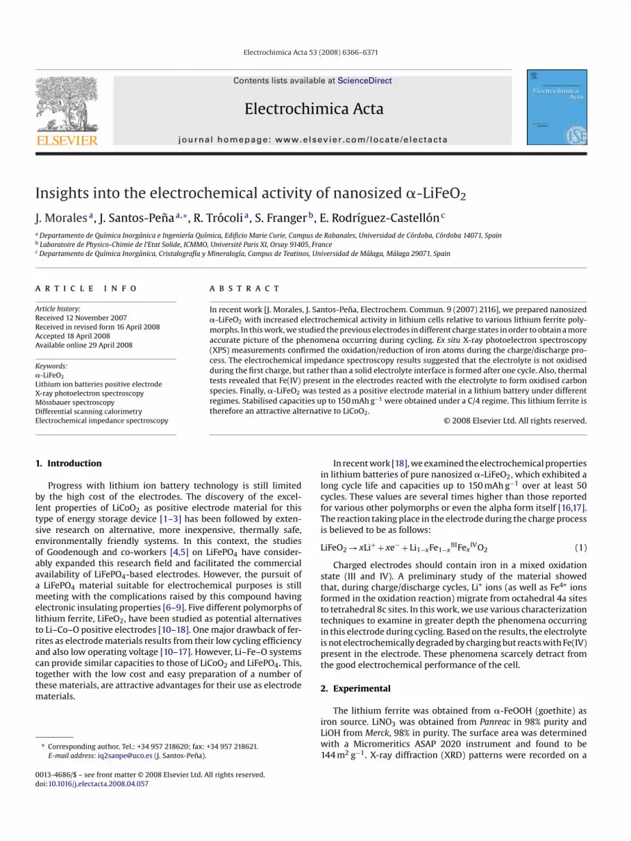
Fig. 1 shows the first galvanostatic curves for the Li/�-LiFeO2cell as obtained by using a swagelock configuration. The profilesare somewhat different from that obtained for the coin cell con-figuration [18]. On charging, the cell exhibited a pseudo-plateaucorresponding to the removal of 0.2 Li ions up to 4.5 V and pro-viding a specific capacity of 55 mAh g−1. The formal composition
Fig. 1. First three charge/discharge cycles for the Li/LiPF6(EC,DMC)/�-LiFeO2 elec-trode cycled under a C/8 regime.
of the charged electrode, as calculated from the measured totalamount of charge transferred, was Li0.8FeIII,IVO2. The discharge pro-cess featured a pronounced drop in voltage at the beginning. At3.0 V, the slope changed and a pseudo-plateau that extending toca. 1.7 V was observed. The estimated limit composition at 1.5 Vwas Li1.4FeII,IIIO2, the electrode providing 160 mAh g−1. Subsequentcharge/discharge curves were s-shaped, similarly to iron oxideswith various structures including �-LiFeO2 [16–18], corrugatedlayer LiFeO2 [11–13], goethite-type LiFeO2 [14] and spinel-typeLiFe5O8 [21]. In this respect, unusual FeIV ions generated duringcharging may play an important role in the development of voltagehysteresis in these systems [14,16].
In an earlier work, ex situ XRD patterns (not shown therein)for the reaction products obtained in the charged (4.5 V) and dis-charged (1.5 V) states confirmed that lithium ferrite crystallinity isdegraded on cycling, even though the peaks retain their position[18]. However, the variation of the I(2 2 0)/I(2 0 0) ratio with the stateof charge was suggestive of structural rearrangement upon lithiumremoval. Similar results were reported for a Li4/3Ti2/3O2–LiFeO2solid solution prepared by Tabuchi et al. [22]. Based on this evi-dence, we proposed that FeIV atoms formed during reaction (1) aredisplaced from octahedral 4a sites to tetrahedral 8c positions, andalso that lithium ions must use the 8c sites as a conduction pathway
[23]. Therefore, Fe(IV) must hinder lithium diffusion during charge,which accounts for the disparate profiles of the charge–dischargecurves. Furthermore, the discharged electrode of nominal formulaLi1.3FeO2 can be the result of empty, 8c tetrahedral positions beingoccupied by excess lithium.Some authors believe that no clear free spaces exist for lithiumdiffusion in the �-LiFeO2 structure [16] and have questioned theactual process taking place in these electrodes. Moreover, thecapacities provided by our �-LiFeO2 electrode were higher thanthose reported for other �-forms and other polymorphs. Con-sequently, one can question whether some contribution to thecapacity exists from the oxidation of the electrolyte up to 4.5 V.In order to shed some light on this issue, we obtained various typesof measurements (XPS, EIS, MS and DSC included).
3.2. XPS study of the ˛-LiFeO2 electrodes
The chemical environment of iron was examined from XPS spec-tra. Fig. 2 shows the Fe 2p spectra obtained for three electrodes atdifferent states of charge (viz. at open-cell voltage (OCV), chargedat 4.5 V and discharged at 1.5 V). The shape and position of the
6368 J. Morales et al. / Electrochimica A
batteries [Li0.3NiO2, LiMO2 (M Ni, Co)] can react with the commonelectrolytes over the 473–573 K range by virtue of the oxygen lossoccurring at such temperatures [27,28]. The enthalpy of the processhas been calculated to be: 600, 460–1300 and 210 J g−1 for Li0.3NiO2[29], LixMO2 (M Ni, Co) [30] and SiOx-coated LiNi0.8Co0.2O2 [28],respectively. In our material, Fe(IV) present seemingly reacts in adirect manner with the electrolyte at lower temperatures, whichprecludes its use up to 373 K. However, this reaction is much lessexothermic that in commonly untreated lithium ion electrodes,which is a clear advantage.
3.4. Electrochemical impedance spectroscopy
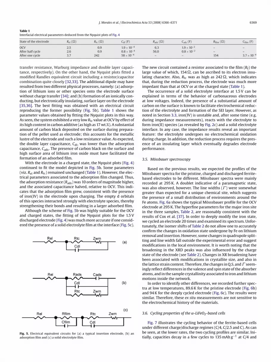
Gold and lithium were used as counter and reference electrode,respectively. Fig. 4 shows the Nyquist plots obtained at three dif-ferent states of charge (OCV, charged at 4.5 V and after one cycle,discharged at 1.5 V) of the Li/LiPF6(EC,DMC)/LiFeO2 cells. The plotsfailed to fit a classic Randles model [31] (Fig. 5a) where Rel (the elec-trolyte resistance) was placed in series with the equivalent circuitfor an insertion electrode (Rtc, WO and Cdl are the interfacial charge
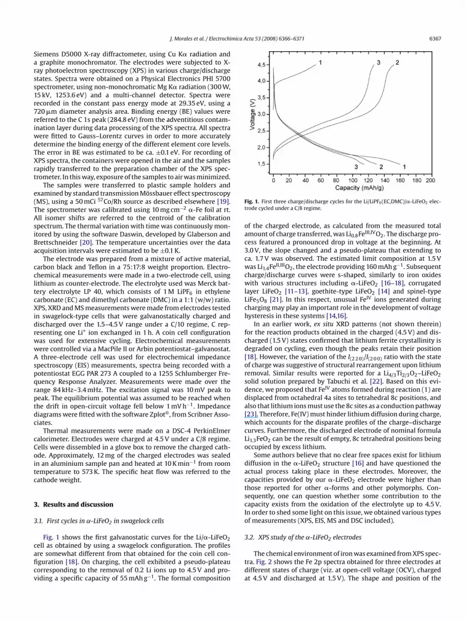
Fig. 2. XPS profiles for Fe 2p for the �-LiFeO2-based electrodes: at OCV (a), after halfcycle at 4.5 V (b), and after one cycle at 1.5 V (c).
emission peaks for the pristine electrode (Fig. 2a) are consistentwith those for Fe2O3 [24] and transition metal ferrites [25], theFe 2p3/2 and 2p1/2 peaks being accompanied by typical satellitepeaks. The BE values for Fe(III) containing oxides are usually inthe 710.8–711.1 eV range, which is close to the value for our fer-rite. However, such a value is lower than that reported by Allen etal. [26] for a form of LiFeO2. In any case, these results confirm thepresence of Fe(III) in the electrode, which is consistent with thenominal composition.
Upon charging (Fig. 2b), BE was slightly shifted (from 711.1 to711.4 eV); however, the shape and peak set changed very little. This
means that the Fe environment is scarcely altered, consistent withthe limited Li removal. The small increase in BE observed could beassigned to the small fraction of oxidized Fe present. On the otherhand, discharging (Fig. 2c) caused more pronounced changes in theprofile (especially, a decrease in BE for the Fe 2p peak by 1.1 eV).This change reveals a marked alteration of the Fe oxidation stateand may be consistent with its reduction to Fe(II).3.3. Differential scanning calorimetry
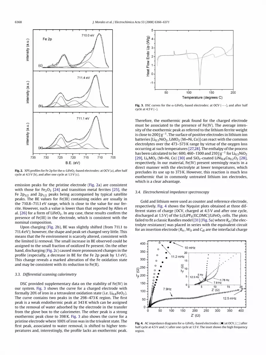
DSC provided supplementary data on the stability of Fe(IV) inour system. Fig. 3 shows the curve for a charged electrode withformally 20% of iron in a tetravalent oxidation state (i.e. Li0.8FeO2).The curve contains two peaks in the 298–473 K region. The firstpeak is a weak endothermic peak at 343 K which can be assignedto the removal of water adsorbed by the electrode in the transferfrom the glove box to the calorimeter. The other peak is a strongexothermic peak close to 398 K. Fig. 3 also shows the curve for apristine electrode where 100% of iron was in the trivalent state. Thefirst peak, associated to water removal, is shifted to higher tem-peratures and, interestingly, the profile lacks an exothermic peak.
cta 53 (2008) 6366–6371
Fig. 3. DSC curves for the �-LiFeO2-based electrodes: at OCV (- - -), and after halfcycle at 4.5 V (–).
Therefore, the exothermic peak found for the charged electrodemust be associated to the presence of Fe(IV). The average inten-sity of the exothermic peak as referred to the lithium ferrite weightis close to 200 J g−1. The surface of positive electrodes in lithium ion
Fig. 4. AC impedance diagrams for �-LiFeO2-based electrodes: (�) at OCV, (©) afterhalf cycle at 4.5 V and (+) after one cycle at 1.5 V. The inset shows the high frequencyregion.
mica A
J. Morales et al. / ElectrochiTable 1Interfacial electrical parameters deduced from the Nyquist plots of Fig. 4
State of the electrode Rel (�) Rtc (�) Cdl (F)
OCV 2.5 0.9 1.9 × 10⁻⁴
After half cycle 2.6 0.9 0.8 × 10⁻⁴
After one cycle 3.7 242 58 × 10−4
transfer resistance, Warburg impedance and double layer capaci-tance, respectively). On the other hand, the Nyquist plots fitted amodified Randles equivalent circuit including a resistor/capacitorcombination quite closely [32,33]. The additional dipole may haveresulted from two different physical processes, namely: (a) adsorp-tion of lithium ions or other species onto the electrode surfacewithout charge transfer [34]; and (b) formation of an ionically con-ducting, but electronically insulating, surface layer on the electrode[35,36]. The best fitting was obtained with an electrical circuitreproducing the former possibility (Fig. 5b). Table 1 shows theparameter values obtained by fitting the Nyquist plots in this way.As seen, the system exhibited a very low Rtc value at OCV by effect ofits high content in carbon additive (as high as 17 wt.%). A substantial
amount of carbon black deposited on the surface during prepara-tion of the pellet used as electrode; this accounts for the metalliclustre of the electrode and such a low resistance value. As expected,the double layer capacitance, Cdl, was lower than the adsorptioncapacitance, Cads. The presence of carbon black on the surface andhigh surface area of lithium iron oxide must have facilitated theformation of an adsorbed film.With the electrode in a charged state, the Nyquist plots (Fig. 4)continued to fit the model depicted in Fig. 5b. Some parameters(viz. Rel and Rtc) remained unchanged (Table 1). However, the elec-trical parameters associated to the adsorption film changed. Thus,the adsorption resistance (Rads) was 10 orders of magnitude higher,and the associated capacitance halved, relative to OCV. This indi-cates that the adsorption film grew, consistent with the presenceof iron(IV) in the electrode upon charging. The empty d orbitalsof this species interacted strongly with electrolyte species, therebystrengthening their bonds and resulting in a larger adsorbed film.
Although the scheme of Fig. 5b was highly suitable for the OCVand charged states, the fitting of the Nyquist plots for the 1.5 Vdischarged electrode (Fig. 4) was much more accurate if one consid-ered the presence of a solid electrolyte film at the interface (Fig. 5c).
Fig. 5. Electrical equivalent circuits for (a) a typical insertion electrode, (b) anadsorption film and (c) a solid electrolyte film.
cta 53 (2008) 6366–6371 6369
Rads (�) Cads (F) Rfilm (�) Cfilm (F)
6.3 1.9 × 10⁻² – –56.0 0.8 × 10⁻² – –
– – 154 3.7 × 10⁻⁴
The new circuit contained a resistor associated to the film (Rf) thelarge value of which, 154 �, can be ascribed to its electron insu-lating character. Also, Rtc was as high as 242 �, which indicatesthat, during the reduction process, the electrode was much moreimpedant than that at OCV or at the charged state (Table 1).
The occurrence of a solid electrolyte interface at 1.5 V can beexplained in terms of the behavior of carbonaceous electrodesat low voltages. Indeed, the presence of a substantial amount ofcarbon on the surface is known to facilitate electrochemical reduc-tion of the electrolyte and formation of the SEI layer. However, asnoted in Section 3.3, iron(IV) is unstable and, after some time (e.g.during impedance measurements), reacts with the electrolyte toform iron(II) species (as revealed by Fig. 2c) and a solid electrolyteinterface. In any case, the impedance results reveal an importantfeature: the electrolyte undergoes no electrochemical oxidationduring charge. In addition, the reduction process requires the pres-ence of an insulating layer which eventually degrades electrodeperformance.
3.5. Mossbauer spectroscopy
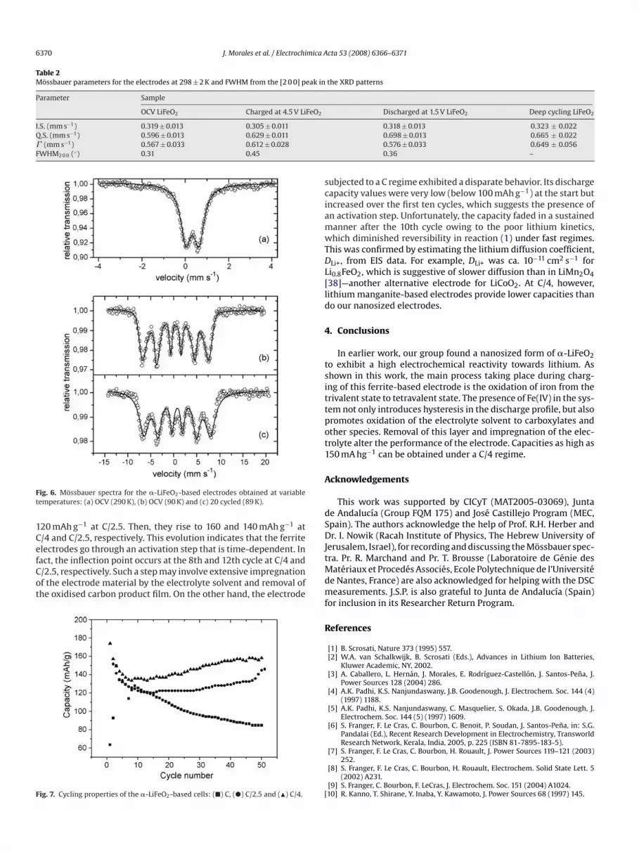
Based on the previous results, we expected the profiles of theMossbauer spectra for the pristine, charged and discharged ferrite-based electrodes to be different. Mossbauer spectra were mainlyrecorded at 295 K. A doublet indicative of a paramagnetic state,was also observed, however. The line widths (� ) were somewhatgreater than expected for a unique chemical site, which suggeststhe presence of a small distribution of environments around theFe atoms. Fig. 6a shows the typical Mosssbauer profile for the OCVelectrode at 295 K. The hyperfine parameters for the major iron sitein the three samples, Table 2, are reasonably consistent with theresults of Cox et al. [37]. In order to deeply modify the iron state,we cycled an electrode 20 times and examined its spectrum. Unfor-tunately, the isomer shifts of Table 2 do not allow one to accuratelyconfirm the changes in oxidation state undergone by Fe on lithiumremoval and insertion. However, some changes in quadrupole split-
ting and line width fall outside the experimental error and suggestmodifications in the local environment. It is worth noting that thebroadening in the XRD peaks was also influenced by the chargestate of the electrode (see Table 2). Changes in XR broadening havebeen associated with modifications in crystallite size, and also inthe lattice strain content. Therefore, the changes in Q.S. and � seem-ingly reflect differences in the valence and spin state of the absorberatoms, and in the sample crystallinity associated to iron and lithiummotions inside the network.In order to identify other differences, we recorded further spec-tra at low temperatures, 89.6 K for the pristine electrode (Fig. 6b)and 94 K for the deeply cycled electrode (Fig. 6c). The results weresimilar. Therefore, these ex situ measurements are not sensitive tothe electrochemical history of the materials.
3.6. Cycling properties of the ˛-LiFeO2-based cells
Fig. 7 illustrates the cycling behavior of the ferrite-based cellsunder different charge/discharge regimes (C/4, C/2.5 and C). As canbe seen, at the lower rates, the two cycling profiles are similar. Ini-tially, capacities decay in a few cycles to 135 mAh g−1 at C/4 and
6370 J. Morales et al. / Electrochimica A
Table 2Mossbauer parameters for the electrodes at 298 ± 2 K and FWHM from the [2 0 0] peak in
Parameter Sample
OCV LiFeO2 Charged at 4.5 V LiFeO2
I.S. (mm s−1) 0.319 ± 0.013 0.305 ± 0.011Q.S. (mm s−1) 0.596 ± 0.013 0.629 ± 0.011� (mm s−1) 0.567 ± 0.033 0.612 ± 0.028FWHM2 0 0 (◦) 0.31 0.45
Fig. 6. Mossbauer spectra for the �-LiFeO2-based electrodes obtained at variabletemperatures: (a) OCV (290 K), (b) OCV (90 K) and (c) 20 cycled (89 K).
120 mAh g−1 at C/2.5. Then, they rise to 160 and 140 mAh g−1 atC/4 and C/2.5, respectively. This evolution indicates that the ferriteelectrodes go through an activation step that is time-dependent. Infact, the inflection point occurs at the 8th and 12th cycle at C/4 andC/2.5, respectively. Such a step may involve extensive impregnationof the electrode material by the electrolyte solvent and removal ofthe oxidised carbon product film. On the other hand, the electrode
Fig. 7. Cycling properties of the �-LiFeO2-based cells: (�) C, (�) C/2.5 and (�) C/4.
cta 53 (2008) 6366–6371
the XRD patterns
Discharged at 1.5 V LiFeO2 Deep cycling LiFeO2
0.318 ± 0.013 0.323 ± 0.0220.698 ± 0.013 0.665 ± 0.0220.576 ± 0.033 0.649 ± 0.0560.36 –
subjected to a C regime exhibited a disparate behavior. Its dischargecapacity values were very low (below 100 mAh g−1) at the start butincreased over the first ten cycles, which suggests the presence ofan activation step. Unfortunately, the capacity faded in a sustainedmanner after the 10th cycle owing to the poor lithium kinetics,which diminished reversibility in reaction (1) under fast regimes.This was confirmed by estimating the lithium diffusion coefficient,DLi+, from EIS data. For example, DLi+ was ca. 10−11 cm2 s−1 forLi0.8FeO2, which is suggestive of slower diffusion than in LiMn2O4[38]—another alternative electrode for LiCoO2. At C/4, however,lithium manganite-based electrodes provide lower capacities thando our nanosized electrodes.
4. Conclusions
In earlier work, our group found a nanosized form of �-LiFeO2to exhibit a high electrochemical reactivity towards lithium. Asshown in this work, the main process taking place during charg-ing of this ferrite-based electrode is the oxidation of iron from thetrivalent state to tetravalent state. The presence of Fe(IV) in the sys-tem not only introduces hysteresis in the discharge profile, but alsopromotes oxidation of the electrolyte solvent to carboxylates andother species. Removal of this layer and impregnation of the elec-trolyte alter the performance of the electrode. Capacities as high as150 mA hg−1 can be obtained under a C/4 regime.
Acknowledgements
This work was supported by CICyT (MAT2005-03069), Juntade Andalucıa (Group FQM 175) and Jose Castillejo Program (MEC,Spain). The authors acknowledge the help of Prof. R.H. Herber andDr. I. Nowik (Racah Institute of Physics, The Hebrew University ofJerusalem, Israel), for recording and discussing the Mossbauer spec-tra. Pr. R. Marchand and Pr. T. Brousse (Laboratoire de Genie des
Materiaux et Procedes Associes, Ecole Polytechnique de l’Universitede Nantes, France) are also acknowledged for helping with the DSCmeasurements. J.S.P. is also grateful to Junta de Andalucıa (Spain)for inclusion in its Researcher Return Program.References
[1] B. Scrosati, Nature 373 (1995) 557.[2] W.A. van Schalkwijk, B. Scrosati (Eds.), Advances in Lithium Ion Batteries,
Kluwer Academic, NY, 2002.[3] A. Caballero, L. Hernan, J. Morales, E. Rodrıguez-Castellon, J. Santos-Pena, J.
Power Sources 128 (2004) 286.[4] A.K. Padhi, K.S. Nanjundaswany, J.B. Goodenough, J. Electrochem. Soc. 144 (4)
(1997) 1188.[5] A.K. Padhi, K.S. Nanjundaswany, C. Masquelier, S. Okada, J.B. Goodenough, J.
Electrochem. Soc. 144 (5) (1997) 1609.[6] S. Franger, F. Le Cras, C. Bourbon, C. Benoit, P. Soudan, J. Santos-Pena, in: S.G.
Pandalai (Ed.), Recent Research Development in Electrochemistry, TransworldResearch Network, Kerala, India, 2005, p. 225 (ISBN 81-7895-183-5).
[7] S. Franger, F. Le Cras, C. Bourbon, H. Rouault, J. Power Sources 119–121 (2003)252.
[8] S. Franger, F. Le Cras, C. Bourbon, H. Rouault, Electrochem. Solid State Lett. 5(2002) A231.
[9] S. Franger, C. Bourbon, F. LeCras, J. Electrochem. Soc. 151 (2004) A1024.[10] R. Kanno, T. Shirane, Y. Inaba, Y. Kawamoto, J. Power Sources 68 (1997) 145.

[
[
[[
[
[[
[[[
[
[
J. Morales et al. / Electrochimica A
[11] Y.S. Lee, C.S. Yoon, Y.K. Sun, K. Kobayakawa, Y. Sato, Electrochem. Commun. 4(2002) 727.
12] Y.S. Lee, S. Sato, M. Tabuchi, C.S. Yoon, Y.K. Sun, K. Kobayakawa, Y. Sato, Elec-trochem. Commun. 5 (2003) 549.
13] Y.S. Lee, S. Sato, Y.K. Sun, K. Kobayakawa, Y. Sato, J. Power Sources 119–121(2003) 285.
14] Y. Sakurai, H. Arai, S. Okada, J. Yamaki, J. Power Sources 68 (1997) 711.15] T. Matsumura, R. Kanno, Y. Inaba, Y. Kawamoto, M. Takano, J. Electrochem. Soc.
149 (2002) A1509.16] Y. Sakurai, H. Arai, J. Yamaki, Solid State Ionics 113–115 (1998) 29.
[17] X. Wang, L. Gao, F. Zhou, Z. Zhang, M. Ji, C. Tang, T. Shen, H. Zheng, J. CrystalGrowth 265 (2004) 220.
18] J. Morales, J. Santos-Pena, Electrochem. Commun. 9 (2007) 2116.19] R.H. Herber, I. Nowik, D.A. Loginov, Z.A. Starikova, A.R. Kudinov, Eur. J. Inorg.
Chem. (2004) 3476 (and references therein).20] W. Glaberson, M. Brettschneider; see: www.phys.huji.ac.il/∼glabersn.21] J. Kim, A. Manthiram, J. Electrochem. Soc. 146 (1999) 4371.22] M. Tabuchi, A. Nakashima, H. Shigemura, K. Ado, H. Kobayashi, H. Sakaebe, K.
Tatsumi, H. Kageyama, T. Nakamura, R. Kanno, J. Mater. Chem. 13 (2003) 1747.23] A.R. West, Basic Solid State Chemistry, second ed., John Wiley & Sons, NY, 1999,
p. 324.24] E. Paparazzo, J. Phys. D 20 (1987) 1091.
[[
[
[
[
[
[[
[
[[[[
[
cta 53 (2008) 6366–6371 6371
25] G.C. Allen, S.J. Harris, J.A. Hutson, J.M. Dyke, App. Surf. Sci. 37 (1989) 111.26] G.C. Allen, M.T. Curtis, A.J. Hooper, P.M. Tucker, J. Chem. Soc. Dalton Trans. 1525.
(1974).27] J.R. Dahn, E.W. Fuller, M. Obrovac, V. von Sacken, Solid State Ionics 69 (1994)
265.28] H. Omanda, T. Brousse, C. Marhic, D.M. Schleich, J. Electrochem. Soc. 151 (6)
(2004) A933.29] Ph. Biensan, B. Simon, J.P. Peres, A. de Guibert, M. Broussely, J.M. bidet, F. Perton,
J. Power Sources 81–82 (1999) 906.30] H. Sup Lim, H.-J. Kweon, G.B. Kim, The Second Hawaii Battery Conference,
Abstract, vol. 305, 1999.31] C. Ho, I.D. Raistrick, R.A. Huggins, J. Electrochem. Soc. 127 (1980) 343.32] M.G.S.R. Thomas, P.G. Bruce, J.B. Goodenough, J. Electrochem. Soc. 132 (1985)
1521.33] S. Franger, S. Bach, J. Farcy, J.-P. Pereira-Ramos, N. Baffier, Electrochim. Acta 48
(2003) 891.34] J.E. Bauerle, J. Phys. Chem. Solids 30 (1969) 2657.35] C.A.C. Sequeira, A. Hooper, Solid State Ionics 9–10 (1983) 1131.36] D. Fauteux, Solid State Ionics 17 (1985) 133.37] D.E. Cox, G. Shirane, P.A. Flinn, S.L. Ruby, W.J. Takei, Phys. Rev. 132 (1963)
1547.38] D. Guyomard, J.-M. Tarascon, J. Electrochem. Soc. 139 (1992) 937.


![( S )-α-Benzylprolinium cis -[( S )-α-benzylprolinato]dichloridopalladium(II)](https://img.dokumen.tips/doc/110x75/6348b49609e11fdd740ae7fe/-s-benzylprolinium-cis-s-benzylprolinatodichloridopalladiumii.jpg)


