Embed Size (px)
Citation preview
Nanosized Ce–Zn substituted microwave absorber material forX-band applications
Imran Sadiq a,n, Irshad Ali a, Evgeny Rebrov b, Shahzad Naseem c,M. Naeem Ashiq d, M.U. Rana a
a Department of Physics, Bahauddin Zakariya University, Multan 60800, Pakistanb School of Chemistry and Chemical Engineering, Queen's University Belfast, UKc Center for Solid State Physics, University of the Punjab, Lahore, Pakistand Institute of Chemical Sciences, Bahauddin Zakariya University, Multan 60800, Pakistan
a r t i c l e i n f o
Article history:Received 23 February 2014Received in revised form11 June 2014Available online 24 June 2014
Keywords:Sol–gel synthesisX-ray diffractionElectrical propertyMagnetic structureMicrowave absorption property
a b s t r a c t
The sol–gel autocombustion method has been used to synthesize the Ce–Zn substituted with composi-tion Sr2�xCexNi2Fe28�yZnyO46 (x¼0.02, 0.04, 0.06, 0.08, 0.010 and y¼0.1, 0.2, 0.3, 0.4, 0.5) X-typehexagonal ferrites. The XRD analysis confirms the single phase of the material. The variation in latticeparameters can be observed with addition of Ce–Zn dopant. The ferrites substituted with Ce–Zn contentshave low value of grain size than the unsubstituted ferrites. The crystallite size measured from TEM andHRTEM analysis was found in the range of 40–45 nm which is in good agreement with the theoreticallymeasured by Scherer formula. The room temperature electrical resistivity lies in the range of �109 Ω-cm,so the investigated sample can be considered good material for reducing the eddy current losses.The enhancement in magnetic properties (saturation magnetization, retentivity and coercivity) has beenobserved with the substitution of Ce–Zn contents in pure ferrites. The increment in resistivity andmagnetic properties with the substitution of Ce–Zn dopant makes it important candidate to be used inthe formation of multilayer chip inductors (MLCIs). The maximum reflection loss of �23.4 dB at12.858 GHz is obtained by Ce–Zn doped ferrites and attenuation constant agrees well with the reflectionloss. The microwave absorption properties of this substituted material reflect its applications in superhigh frequency (SHF) devices.
& 2014 Elsevier B.V. All rights reserved.
1. Introduction
With the expanding usage of high frequency operating circuitdevices and wireless devices in gigahertz range in our daily life,the electromagnetic interference EMI and electromagnetic radia-tions EMR are becoming a serious problem [1–3]. The miniatur-ization of electronic gadgets has directed the scientific researchtowards the fabrication of new materials that are suitable for thehigh frequency applications as well as cope up with the EMI/EMRproblems [4]. Many researchers studied the microwave absorptionproperties of various materials to make them suitable for highfrequency applications [5,6]. Recently, many materials have beenused as microwave absorbing materials (MAMs) such as ZnOcomposites, carbon nanotubes, metal alloys, and hexaferrites[7–10]. The basic requirement for microwave absorber is that thematerial should hold light weight, low cost, easy to synthesize,
strong absorption, thin thickness, excellent chemical stability andwide wave band [11–14]. Hexagonal ferrites with excellent che-mical stability, high saturation magnetization, suitable coercivityand high anisotropic field are considered good material for micro-wave absorption properties [15]. Among the hexagonal ferrites,X-type hexagonal ferrites with low coercivity and high saturationmagnetization can be important filler for microwave absorptionproperties [16]. It is noticed that the structural, magnetic andmicrowave absorption properties of ferrites materials can be tunedwith the substitution of rare earth elements [17]. There are severaltechniques to prepare the hexagonal ferrites e.g. co-precipitation,dry and wet-milling, oxidation and reduction, sol–gel autocombus-tion methods, etc. Among all these methods, the sol gel autocombus-tion method has attracted the more interest due to the advantage ofcheap precursors and simple preparations. It is effective in obtainingthe desired monophasic products with greater homogeneity andfiner particle size at low temperature [18].
Many researchers have investigated the microwave absorptionproperties of ferrites materials. U-type hexagonal ferrites wereprepared by using solid state reaction method by Shannigrahi et al.[19]. The Co-doped sample with 98% absorption was found
Contents lists available at ScienceDirect
journal homepage: www.elsevier.com/locate/jmmm
Journal of Magnetism and Magnetic Materials
http://dx.doi.org/10.1016/j.jmmm.2014.06.0450304-8853/& 2014 Elsevier B.V. All rights reserved.
n Corresponding author. Tel.: þ92 619210199; fax: þ92 619210068.E-mail addresses: [email protected] (I. Sadiq),
[email protected] (M.U. Rana).
Journal of Magnetism and Magnetic Materials 370 (2014) 25–31
appropriate to reduce the microwave interference. Tadjarodiet al. [20] synthesized the conducting and magnetic polyanilineBa0.69Sr0.17Cd0.07Zn0.07Fe12O19 nanocomposites by the in situpolymerization method. The maximum absorption of �16 dB inX-band region makes it important material to be used as micro-wave absorber. However, microwave absorption properties of Ce3þ
substituted X-type hexagonal ferrites have never been reportedbefore, so we selected following material for investigation.
The aim of this work is to synthesize the hexagonal nanofer-rites by the sol–gel autocombustion method and understand theinfluence of Ce–Zn substitution on structural, infrared, electrical,magnetic and microwave absorption properties of Sr2�xCexNi2-Fe28�yZnyO46 (x¼0.02, 0.04, 0.06, 0.08, 0.010 and y¼0.1, 0.2, 0.3,0.4, 0.5) X-type hexagonal ferrites.
2. Experimental procedures
The polycrystalline samples with composition Sr2�xCexNi2-Fe28�yZnyO46 (x¼0.02, 0.04, 0.06, 0.08, 0.010 and y¼0.1, 0.2, 0.3,0.4, 0.5) were prepared by the Sol gel autocombustion method.The stoichiometric ratios of raw materials (Sr(No3)2, Co(No3)2,NiCl2 � 6H2O, Ce (No3)3, Fe(No3)3 �9H2o, Citric Acid) were mixed indeionized water. The gel was attained by stirring the solution at80 1C. The gel was burnt at 400 1C for 1 h and then sintered at1250 1C in air for 6 h to attain the required phase. The powder wasthen pressed into pellets at a pressure of (�30 KN) using Paul-OttoWeber hydraulic press by using polyvinyl alcohol (PVA) as binder.
The thermal analysis to conform the temperature at whichrequired phase can be obtained was carried out by the MettlerToledo TGA/DSC 1 STARe system equipped with Nitrogen gas. Thecrystalline phase after heat treatment was identified by SchimadzuX-Ray diffractometer equipped with Cu-Kα radiations (λ¼1.5406 Å).The FTIR Spectra has been recorded by C91020 PerkinelmerFTIR Spectrometer in the near infrared region over the range of4000–450 cm�1. The surface morphology and particle size wasexamined by JEOL JSM-6500F field emission scanning electronmicroscopy and TECNAI F20 Phillips High Resolution TransmissionElectron Microscopy. The electrical properties were measured by twoprobe method, using source meter model Keithly 2400. The magneticproperties at room temperature were measured by vibrating samplemagnetometer, LakeShore.
Complex permittivity and permeability measurements were car-ried out through Agilent E8361A PNA Network Analyzer by using thecavity Perturbation Method [21]. The cavity was made up of X-bandwaveguide with dimensions reported earlier [22]. The samples wereprepared by properly mixing of 20% Paraffin wax and 80% of theferrite material to insert into the slot of the waveguide. The reflectedand transmitted parameter (S11, S21) were measured through NetworkAnalyzer. The complex permittivity and permeability were measuredby using following relations:
ε0 �1¼ ½Vc=Vs�½ðf c� f sÞ=2f s� ð1Þ
ε″¼ ½Vc=4Vs�½1=Qs–1=Qc� ð2Þ
m0 �1¼ ½Vc=kVs�½ðf c� f sÞ=f s� ð3Þ
m″¼ ½Vc=2kVs�½1=Qs–1=Qc� ð4Þ
where Vc and Vs are the volumes of the empty cavity and the sample,fc and fs are the resonance frequencies of the empty cavity and thesample, Qc and Qs are the quality factor for the empty cavity andperturbed case, k¼2a2/(a2þ l2) is the geometrical parameter, where ‘l’is the length and ‘a’ is the breadth of the cavity.
3. Results and discussion
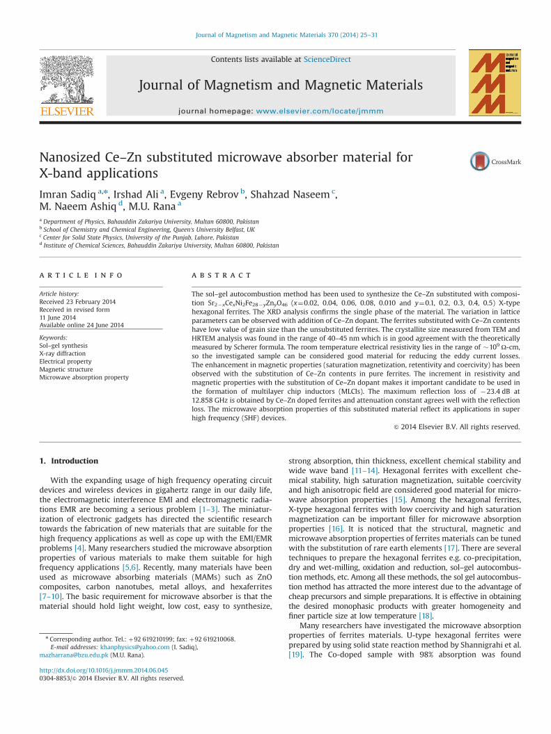
Fig. 1 shows the thermo-gravimetric analysis and differentialscanning calorimetry analysis from room temperature to 1000 1Cand 500 1C respectively of pre-sintered precursor (burnt gel).The TGA curve can be divided into two endothermic peaks inthe temperature ranges from 50 to 350 1C and 450 to 750 1C. Thefirst endothermic peak at 146.3 1C in temperature range of50–350 1C shows the weight loss of 3.32% which may be due tothe loss of water absorbed by the pre-sintered precursor andthe other endothermic peak at 601.8 1C in temperature rangeof 450–750 1C shows the weight loss of 7.94% which may beattributed to the decomposition of hydroxides to oxides of thevarious materials. The wide exothermic peak in the end of theTGA curve may show the formation of hexagonal phase. Theendothermic peaks in DSC analysis indicate the removal of waterabsorbed by the pre-sintered precursor. Neither exothermic norendothermic peak is observed after 350 1C which shows that theremoval of organic substituents and oxidation of organic com-pounds is happened after 500 1C as indicated in TGA curve.
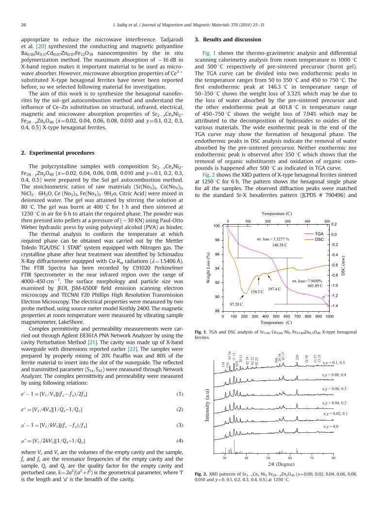
Fig. 2 shows the XRD pattern of X-type hexagonal ferrites sinteredat 1250 1C for 6 h. The pattern shows the hexagonal single phasefor all the samples. The observed diffraction peaks were matchedto the standard Sr-X hexaferrites pattern (JCPDS # 790496) and
0 100 200 300 400 500 600 700 800 900 100088
90
92
94
96
98
1000 100 200 300 400 500
-1.4
-1.2
-1.0
-0.8
-0.6
-0.4
-0.2
0.0
0.2
TGA
Wei
ght L
oss (
%)
Temperature (C)
wt. loss = 3.3277 %
wt. loss= 7.9450%
146.38 C
601.89 C
Temperature (C)
DSC
(mw
)
DSC
87.20 C
154.5 C197.4 C
Fig. 1. TGA and DSC analysis of Sr1.96 Ce0.04 Ni2 Fe27.80Zn0.2O46 X-type hexagonalferrites.
30 40 50 60 70 80
2 θ (Degree)
x,y = 0,0
Inte
nsity
(a.u
)
x,y = 0.02, 0.1
x,y = 0.04, 0.2
x,y = 0.06, 0.3
220
x,y = 0.08, 0.4
x,y = 0.1, 0.5
110
116
01 2
611
15
024 20
11
02 1
902
22
02 2
5
300 20 3
803
15
10 5
8
11 5
713
25
Fig. 2. XRD patterns of Sr2�xCex Ni2 Fe28�yZnyO46 (x¼0.00, 0.02, 0.04, 0.06, 0.08,0.010 and y¼0, 0.1, 0.2, 0.3, 0.4, 0.5) at 1250 1C.
I. Sadiq et al. / Journal of Magnetism and Magnetic Materials 370 (2014) 25–3126
found thereby no extra peak of secondary phase due to unreactedconstituents or impurities. However, two extra peaks, belong to X-Type hexaferrites crystal structure, have been detected in last Ce–Znconcentration (x,y¼0.1,0.5) at 2θ angles 33.09 and 38.31 respectively.The lattice parameters a (Å) and c (Å) were calculated by using theformula
1=d2hkl ¼ 4ðh2þhkþk2Þ=3a2þ l2=c2 ð5Þwhere dhkl is the d-spacing of the lines in the XRD pattern and h, kand l are the corresponding Miller indices.
The values of lattice constants a (Å), c (Å) and cell volume arelisted in Table 1. The variation of lattice parameters can be explainedon the basis of site occupation by different ions. Ben-xi et al. [23]reported that the rare earth trivalent ions rather prefer to occupy theoctahedral Fe sites instead of Sr sites in R block. Ben et al. [24]reported that the divalent ions Ni2þ and Zn2þ lies essentially in theoctahedral and tetrahedral sites of spinel S block. So in presentinvestigation, the rare earth Ce3þ with ionic radii (1.034 Å) entersinto the octahedral sites of Fe3þ with ionic radii (0.645 Å) in R blockwhich may produce the variation in lattice parameter. Ben et al. [25]reported that about all the Fe3þ ions occupy the octahedral sites in Sblock. Hence the substitution of Fe3þ by Zn2þ with ionic radii(0.74 Å) also contributes in the variation of lattice parameter.
The crystallite size was measured by well known DebyeScherrer formula S¼kλ/B cos θ.
Where ‘S’ is the crystallite size, k is constant whose value is0.94, λ is wavelength and equal to 1.5406 Å, B is the line width athalf maximum height and θ is the angle. The crystallite size of thepresented investigated ferrites lies in the range of 34–49 nm. Khanet al. [26] reported that the ferrites material with grain size lessthan 50 nm is found to be suitable to obtain the signal to noiseratio in high density recording media, so these materials can beused in high density recording media.
The unit cell volume was calculated by using following formula:
V ¼ a2c sin 120˚ ð6Þwhere “a” and “c” are lattice constants.
The unit cell volume of Ce–Zn substituted ferrites is greaterthan the pure ferrite.
X ray density was measured by the following equation.
Dx ¼ 3M=NV ð7Þwhere M is the molar mass, N is the Avogadro's number and V isthe volume of the unit cell,
The bulk density was measured by following relation.
D¼m=πr2h ð8Þwhere m is mass, r is the radius and h is the thickness of pellet.
The porosity was measured by using formula
P ¼ 1�D=Dx ð9Þwhere D and Dx are the bulk and X-rays densities respectively.
The values of bulk and X-rays densities and porosity are givenin Table 1. It can be observed that the value of porosity for Ce–Znsubstituted ferrites is smaller than the pure ferrite which may bedue to the negative microstrain which produces the compressivestress in the lattice [27].
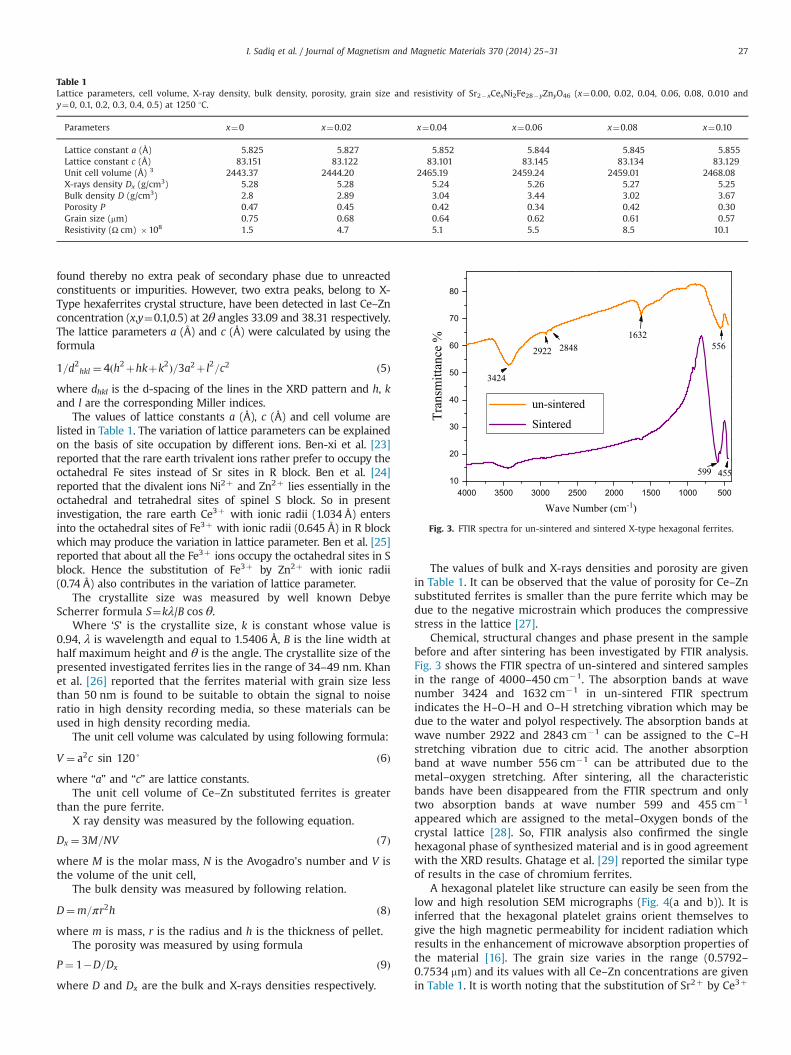
Chemical, structural changes and phase present in the samplebefore and after sintering has been investigated by FTIR analysis.Fig. 3 shows the FTIR spectra of un-sintered and sintered samplesin the range of 4000–450 cm�1. The absorption bands at wavenumber 3424 and 1632 cm�1 in un-sintered FTIR spectrumindicates the H–O–H and O–H stretching vibration which may bedue to the water and polyol respectively. The absorption bands atwave number 2922 and 2843 cm�1 can be assigned to the C–Hstretching vibration due to citric acid. The another absorptionband at wave number 556 cm�1 can be attributed due to themetal–oxygen stretching. After sintering, all the characteristicbands have been disappeared from the FTIR spectrum and onlytwo absorption bands at wave number 599 and 455 cm�1
appeared which are assigned to the metal–Oxygen bonds of thecrystal lattice [28]. So, FTIR analysis also confirmed the singlehexagonal phase of synthesized material and is in good agreementwith the XRD results. Ghatage et al. [29] reported the similar typeof results in the case of chromium ferrites.
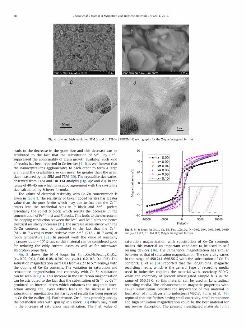
A hexagonal platelet like structure can easily be seen from thelow and high resolution SEM micrographs (Fig. 4(a and b)). It isinferred that the hexagonal platelet grains orient themselves togive the high magnetic permeability for incident radiation whichresults in the enhancement of microwave absorption properties ofthe material [16]. The grain size varies in the range (0.5792–0.7534 mm) and its values with all Ce–Zn concentrations are givenin Table 1. It is worth noting that the substitution of Sr2þ by Ce3þ
Table 1Lattice parameters, cell volume, X-ray density, bulk density, porosity, grain size and resistivity of Sr2�xCexNi2Fe28�yZnyO46 (x¼0.00, 0.02, 0.04, 0.06, 0.08, 0.010 andy¼0, 0.1, 0.2, 0.3, 0.4, 0.5) at 1250 1C.
Parameters x¼0 x¼0.02 x¼0.04 x¼0.06 x¼0.08 x¼0.10
Lattice constant a (Å) 5.825 5.827 5.852 5.844 5.845 5.855Lattice constant c (Å) 83.151 83.122 83.101 83.145 83.134 83.129Unit cell volume (Å) 3 2443.37 2444.20 2465.19 2459.24 2459.01 2468.08X-rays density Dx (g/cm3) 5.28 5.28 5.24 5.26 5.27 5.25Bulk density D (g/cm3) 2.8 2.89 3.04 3.44 3.02 3.67Porosity P 0.47 0.45 0.42 0.34 0.42 0.30Grain size (mm) 0.75 0.68 0.64 0.62 0.61 0.57Resistivity (Ω cm) �108 1.5 4.7 5.1 5.5 8.5 10.1
4000 3500 3000 2500 2000 1500 1000 50010
20
30
40
50
60
70
80
Tran
smitt
ance
%
Wave Number (cm-1)
un-sintered
Sintered
3424
2922 28481632
556
599 455
Fig. 3. FTIR spectra for un-sintered and sintered X-type hexagonal ferrites.
I. Sadiq et al. / Journal of Magnetism and Magnetic Materials 370 (2014) 25–31 27
leads to the decrease in the grain size and this decrease can beattributed to the fact that the substitution of Sr2þ by Ce3þ
suppressed the abnormality of grain growth availably. Such kindof results has been reported in Ce-ferrites [4]. It is well known thatthe nanocrystallites agglomerates to each other to form a largegrain and the crystallite size can never be greater than the grainsize measured by the SEM and TEM [30]. The crystallite size varies,observed from TEM and HRTEM analysis (Fig. 4(c and d)), in therange of 40–45 nmwhich is in good agreement with the crystallitesize calculated by Scherer formula.
The values of electrical resistivity with Ce–Zn concentration isgiven in Table 1. The resistivity of Ce–Zn doped ferrites has greatervalue than the pure ferrite which may due to fact that the Ce3þ
enters into the octahedral sites in R block and Zn2þ prefersessentially the spinel S block which results the decrease in theconcentration of Fe3þ in S and R blocks. This leads to the decrease inthe hopping conduction between the Fe2þ and Fe3þ sites and henceelectrical resistivity increases [31]. The increase in resistivity with theCe–Zn contents may be attributed to the fact that the Ce3þ
(81�10�6 Ω cm) is more resistive than Sr2þ (21.5�10�6 Ωcm) atroom temperature [32]. In present work the value of resistivityincreases upto �109 Ω-cm, so this material can be considered goodfor reducing the eddy current losses as well as for microwaveabsorption properties.
Fig. 5 shows the M–H loops for Sr2�xCexNi2Fe28�yZnyO46
(x¼0.02, 0.04, 0.06, 0.08, 0.010 and y¼0.1, 0.2, 0.3, 0.4, 0.5). Thesaturation magnetization increases from 42.27 to 57.93emu/g withthe doping of Ce–Zn contents. The variation in saturation andremanence magnetization and coercivity with Ce–Zn substationcan be seen in Fig. 6. This increase in the saturation magnetizationcan be attributed to the fact that the substitution of Sr2þ by Ce3þ
produced an internal stress which enhances the magnetic inter-action among the layers which leads to the increase in thesaturation magnetization. Similar type of results has been reportedin Ce-ferrite earlier [4]. Furthermore, Zn2þ ions probably occupythe octahedral sites with spin up in S Block [33] which may resultin the increase of saturation magnetization. The high value of
saturation magnetization with substitution of Ce–Zn contentsmakes this material an important candidate to be used in selfbiasing devices [16]. The remanence magnetization has similarbehavior as that of saturation magnetization. The coercivity variesin the range of 450.214–656.56 G with the substitution of Ce–Zncontents. Li et al. [34] reported that the longitudinal magneticrecording media, which is the general type of recording mediaused in industries requires the material with coercivity 600 G,while the coercivity of present investigated sample falls in therange of 656.59 G, so this material can be used in Longitudinalrecording media. The enhancement in magnetic properties withCe–Zn substitution indicates the importance of this material information of multilayer chip inductors (MLCIs). Pullar et al. [16]reported that the ferrites having small coercivity, small remanenceand high saturation magnetization could be the best material formicrowave absorption. The present investigated materials fulfill
Fig. 4. Low and high resolution SEM (a and b), TEM (c), HRTEM (d) micrographs for the X-type hexagonal ferrites.
-10000 -5000 0 5000 10000-60
-40
-20
0
20
40
60
Mag
netiz
atio
n (e
mu/
g)
Field(G)
x= 0.00 x= 0.02 x= 0.04 x= 0.06 x= 0.08 x= 0.10
Fig. 5. M–H loops for Sr2�x Cex Ni2 Fe28�yZnyO46 (x¼0.02, 0.04, 0.06, 0.08, 0.010and y¼0.1, 0.2, 0.3, 0.4, 0.5) X-type hexagonal ferrites.
I. Sadiq et al. / Journal of Magnetism and Magnetic Materials 370 (2014) 25–3128
the conditions so Ce–Zn doped ferrites could be applicable for themicrowave absorption.
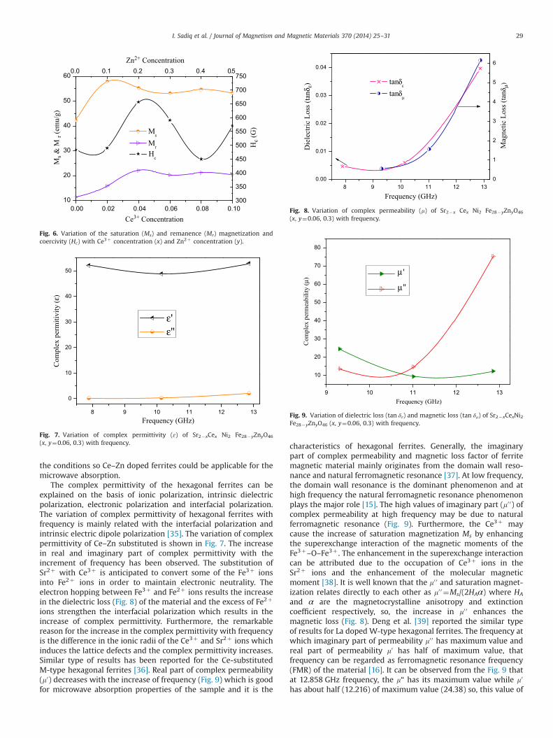
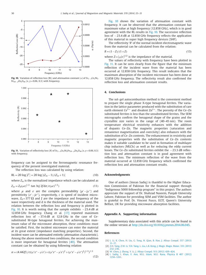
The complex permittivity of the hexagonal ferrites can beexplained on the basis of ionic polarization, intrinsic dielectricpolarization, electronic polarization and interfacial polarization.The variation of complex permittivity of hexagonal ferrites withfrequency is mainly related with the interfacial polarization andintrinsic electric dipole polarization [35]. The variation of complexpermittivity of Ce–Zn substituted is shown in Fig. 7. The increasein real and imaginary part of complex permittivity with theincrement of frequency has been observed. The substitution ofSr2þ with Ce3þ is anticipated to convert some of the Fe3þ ionsinto Fe2þ ions in order to maintain electronic neutrality. Theelectron hopping between Fe3þ and Fe2þ ions results the increasein the dielectric loss (Fig. 8) of the material and the excess of Fe2þ
ions strengthen the interfacial polarization which results in theincrease of complex permittivity. Furthermore, the remarkablereason for the increase in the complex permittivity with frequencyis the difference in the ionic radii of the Ce3þ and Sr2þ ions whichinduces the lattice defects and the complex permittivity increases.Similar type of results has been reported for the Ce-substitutedM-type hexagonal ferrites [36]. Real part of complex permeability(m0) decreases with the increase of frequency (Fig. 9) which is goodfor microwave absorption properties of the sample and it is the
characteristics of hexagonal ferrites. Generally, the imaginarypart of complex permeability and magnetic loss factor of ferritemagnetic material mainly originates from the domain wall reso-nance and natural ferromagnetic resonance [37]. At low frequency,the domain wall resonance is the dominant phenomenon and athigh frequency the natural ferromagnetic resonance phenomenonplays the major role [15]. The high values of imaginary part (m0 0) ofcomplex permeability at high frequency may be due to naturalferromagnetic resonance (Fig. 9). Furthermore, the Ce3þ maycause the increase of saturation magnetization Ms by enhancingthe superexchange interaction of the magnetic moments of theFe3þ–O–Fe3þ . The enhancement in the superexchange interactioncan be attributed due to the occupation of Ce3þ ions in theSr2þ ions and the enhancement of the molecular magneticmoment [38]. It is well known that the m0 0 and saturation magnet-ization relates directly to each other as m0 0 ¼Ms/(2HAα) where HA
and α are the magnetocrystalline anisotropy and extinctioncoefficient respectively, so, the increase in m0 0 enhances themagnetic loss (Fig. 8). Deng et al. [39] reported the similar typeof results for La doped W-type hexagonal ferrites. The frequency atwhich imaginary part of permeability m0 0 has maximum value andreal part of permeability m0 has half of maximum value, thatfrequency can be regarded as ferromagnetic resonance frequency(FMR) of the material [16]. It can be observed from the Fig. 9 thatat 12.858 GHz frequency, the m“ has its maximum value while m0
has about half (12.216) of maximum value (24.38) so, this value of
10
20
30
40
50
60
0.00 0.02 0.04 0.06 0.08 0.10
0.0 0.1 0.2 0.3 0.4 0.5
300
350
400
450
500
550
600
650
700
750
Ms
Mr
Ms &
M r
(em
u/g)
Ce3+ Concentration
Zn2+ Concentration
Hc (
G)
Hc
Fig. 6. Variation of the saturation (Ms) and remanence (Mr) magnetization andcoercivity (Hc) with Ce3þ concentration (x) and Zn2þ concentration (y).
8 9 10 11 12 13
0
10
20
30
40
50
Com
plex
per
miti
vity
(ε)
Frequency (GHz)
ε'ε''
Fig. 7. Variation of complex permittivity (ɛ) of Sr2�xCex Ni2 Fe28�yZnyO46
(x, y¼0.06, 0.3) with frequency.
8 9 10 11 12 130.00
0.01
0.02
0.03
0.04
0
1
2
3
4
5
6
tanδε
Die
lect
ric L
oss (
tanδ
ε)
Frequency (GHz)
tanδμ
Mag
netic
Los
s (ta
nδμ)
Fig. 8. Variation of complex permeability (m) of Sr2�x Cex Ni2 Fe28�yZnyO46
(x, y¼0.06, 0.3) with frequency.
9 10 11 12 13
10
20
30
40
50
60
70
80
Com
plex
per
mea
bilit
y (μ
)
Frequency (GHz)
μ '
μ ''
Fig. 9. Variation of dielectric loss (tan δɛ) and magnetic loss (tan δm) of Sr2�xCexNi2Fe28�yZnyO46 (x, y¼0.06, 0.3) with frequency.
I. Sadiq et al. / Journal of Magnetism and Magnetic Materials 370 (2014) 25–31 29
frequency can be assigned to the ferromagnetic resonance fre-quency of the present investigated material.
The reflection loss was calculated by using relation:
RL¼ 20 log Г��
��¼ 20 log ðZin�1Þ=ðZinþ1Þ
��
�� ð10Þ
where Zin is the normalized impedance which can be calculated as
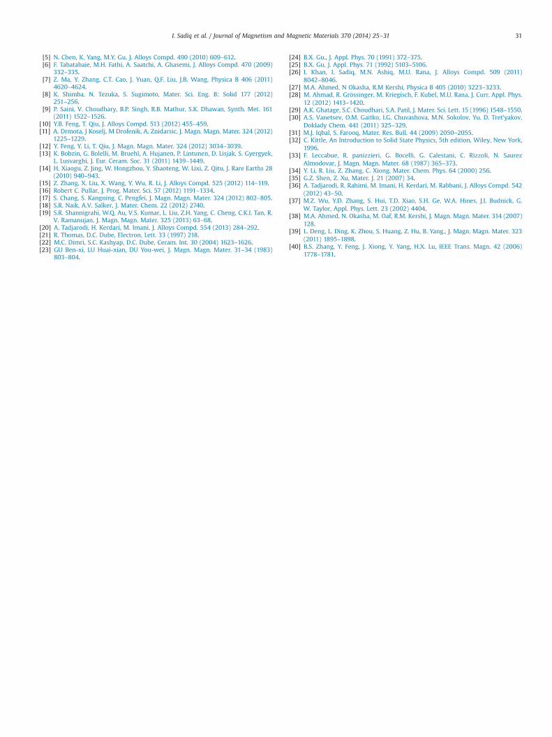
Zin ¼ Z0ðmεÞ1=2 tan hðj 2f dπ=cðmεÞ1=2Þ ð11Þwhere μ and ε are the complex permeability (μ0 � jm0 0) andpermittivity (ε0 � jε0 0), respectively, c is speed of incident micro-wave, Z0¼377Ω and ƒ are the impedance and frequency of thewave respectively and d is the thickness of the material used. Therelation between the reflection loss and frequency is plotted inFig. 10. It is worth noting that the sample exhibits �23.4 dB at12.858 GHz frequency. Chang et al. [17] reported maximumreflection loss of �37.4 dB at 12.8 GHz in the case of Ce-substituted M-type hexagonal ferrites. For achieving the max-imum value of the microwave absorption, these conditions mustbe satisfied. First, the incident microwave can enter the materialat its great extent (impedance matching properties). Second, theincident wave can be attenuated entirely (attenuation characteristic).Among the above mentioned two conditions, the second conditionis more important for hexagonal ferrites [40]. The attenuationconstant can be obtained by using following relation
α¼ ð4:442f Þ=cððm″ε″�m0ε0Þþððm″ε″�m0ε0Þ2þðm″ε0 �m0ε″Þ2Þ1=2Þ1=2ð12Þ
Fig. 10 shows the variation of attenuation constant withfrequency. It can be observed that the attenuation constant hasmaximum value at high frequency (12.858 GHz), which is in goodagreement with the RL results in Fig. 10. The successive reflectionloss of �23.4 dB at 12.858 GHz frequency reflects the applicationof this material in super high frequency devices (SHF).
The reflectivity ‘R’ of the normal incident electromagnetic wavefrom the material can be calculated from the relation:
R¼ ð1�ZÞ=ð1þZÞ ð13Þwhere Z¼(m/ε)1/2 is the impedance of the material.
The values of reflectivity with frequency have been plotted inFig. 11. It can be seen clearly from the figure that the minimumreflection of the incident wave from the material has beenoccurred at 12.858 GHz frequency. This result indicates that themaximum absorption of the incident microwave has been done at12.858 GHz frequency. The reflectivity result also confirmed thereflection loss and attenuation constant results.
4. Conclusions
The sol–gel autocombustion method is the convenient methodto prepare the single phase X-type hexagonal ferrites. The varia-tion in the lattice parameter produced with the substitution of rareearth element Ce3þ and divalent Zn2þ . The porosity of the Ce–Znsubstituted ferrites is less than the unsubstituted ferrites. The SEMmicrographs confirm the hexagonal shape of the grains and thecrystallite size varies in the range of (40–45 nm). The roomtemperature electrical resistivity enhances with the additionof dopants Ce–Zn. The magnetic properties (saturation andremanence magnetization and coercivity) also enhances with thesubstitution of Ce–Zn contents. The enhancement in resistivity andmagnetic properties with the substitution of Ce–Zn contentsmakes it suitable candidate to be used in formation of multilayerchip inductors (MLCIs) as well as for reducing the eddy currentlosses. The Ce–Zn substituted ferrites exhibit the �23.3 dB reflec-tion loss and attenuation constant is in good agreement withreflection loss. The minimum reflection of the wave from thematerial occurred at 12.858 GHz frequency which confirmed thereflection loss and attenuation constant results.
Acknowledgments
One of authors (Imran Sadiq) is thankful to the Higher Educa-tion Commission of Pakistan for the financial support through“Indigenous 5000 fellowship program” in this project. The authorsappreciate the support of Dr. Shahzad Naseem, Punjab UniversityLahore, Pakistan for providing SEM and VSM facilities. The authoris grateful to Prof. Dr. Vincent Fusco, ECIT, Queen's UniversityBelfast, UK for providing microwave absorption facilities.
Appendix A. Supporting information
Supplementary data associated with this article can be found inthe online version at http://dx.doi.org/10.1016/j.jmmm.2014.06.045.
References
[1] L. Li, K. Chen, H. Liu, G. Tong, H. Qian, B. Hao, J. Alloys Compd. 557 (2013)11–17.
[2] Z.H. Yang, Z.W. Li, Y.H. Yang, L. Liu, L.B. Kong, J. Magn. Magn. Mater. 331 (2013)232–236.
[3] W. Chen, J. Zheng, Y. Li, J. Alloys Compd. 513 (2012) 420–424.[4] I. Sadiq, I. Khan, F. Aen, M.U. Islam, M.U. Rana, Physica B 407 (2012)
1256–1261.
8 9 10 11 12 13
-25
-20
-15
-10
-5
0
0.0000
0.0003
0.0006
0.0009
0.0012
Ref
lect
ion
Loss
(dB
)
Frequency (GHz)
α(N
p/m
)
Fig. 10. Variation of reflection loss (RL) and attenuation constant (α) of Sr2�xCexNi2Fe28�yZnyO46 (x, y¼0.06, 0.3) with frequency.
7 8 9 10 11 12 130.980
0.984
0.988
0.992
0.996
1.000
Ref
lect
ivity
(R)
Frequency f (GHz)
Fig. 11. Variation of reflectivity loss (R) of Sr2�xCexNi2Fe28�yZnyO46 (x, y¼0.06, 0.3)with frequency.
I. Sadiq et al. / Journal of Magnetism and Magnetic Materials 370 (2014) 25–3130
[5] N. Chen, K. Yang, M.Y. Gu, J. Alloys Compd. 490 (2010) 609–612.[6] F. Tabatabaie, M.H. Fathi, A. Saatchi, A. Ghasemi, J. Alloys Compd. 470 (2009)
332–335.[7] Z. Ma, Y. Zhang, C.T. Cao, J. Yuan, Q.F. Liu, J.B. Wang, Physica B 406 (2011)
4620–4624.[8] K. Shimba, N. Tezuka, S. Sugimoto, Mater. Sci. Eng. B: Solid 177 (2012)
251–256.[9] P. Saini, V. Choudhary, B.P. Singh, R.B. Mathur, S.K. Dhawan, Synth. Met. 161
(2011) 1522–1526.[10] Y.B. Feng, T. Qiu, J. Alloys Compd. 513 (2012) 455–459.[11] A. Drmota, J Koselj, M Drofenik, A. Znidarsic, J. Magn. Magn. Mater. 324 (2012)
1225–1229.[12] Y. Feng, Y. Li, T. Qiu, J. Magn. Magn. Mater. 324 (2012) 3034–3039.[13] K. Bobzin, G. Bolelli, M. Bruehl, A. Hujanen, P. Lintunen, D. Lisjak, S. Gyergyek,
L. Lusvarghi, J. Eur. Ceram. Soc. 31 (2011) 1439–1449.[14] H. Xiaogu, Z. Jing, W. Hongzhou, Y. Shaoteng, W. Lixi, Z. Qitu, J. Rare Earths 28
(2010) 940–943.[15] Z. Zhang, X. Liu, X. Wang, Y. Wu, R. Li, J. Alloys Compd. 525 (2012) 114–119.[16] Robert C. Pullar, J. Prog. Mater. Sci. 57 (2012) 1191–1334.[17] S. Chang, S. Kangning, C. Pengfei, J. Magn. Magn. Mater. 324 (2012) 802–805.[18] S.R. Naik, A.V. Salker, J. Mater. Chem. 22 (2012) 2740.[19] S.R. Shannigrahi, W.Q. Au, V.S. Kumar, L. Liu, Z.H. Yang, C. Cheng, C.K.I. Tan, R.
V. Ramanujan, J. Magn. Magn. Mater. 325 (2013) 63–68.[20] A. Tadjarodi, H. Kerdari, M. Imani, J. Alloys Compd. 554 (2013) 284–292.[21] R. Thomas, D.C. Dube, Electron, Lett. 33 (1997) 218.[22] M.C. Dimri, S.C. Kashyap, D.C. Dube, Ceram. Int. 30 (2004) 1623–1626.[23] GU Ben-xi, LU Huai-xian, DU You-wei, J. Magn. Magn. Mater. 31–34 (1983)
803–804.
[24] B.X. Gu., J. Appl. Phys. 70 (1991) 372–375.[25] B.X. Gu, J. Appl. Phys. 71 (1992) 5103–5106.[26] I. Khan, I. Sadiq, M.N. Ashiq, M.U. Rana, J. Alloys Compd. 509 (2011)
8042–8046.[27] M.A. Ahmed, N Okasha, R.M Kershi, Physica B 405 (2010) 3223–3233.[28] M. Ahmad, R. Grössinger, M. Kriegisch, F. Kubel, M.U. Rana, J. Curr. Appl. Phys.
12 (2012) 1413–1420.[29] A.K. Ghatage, S.C. Choudhari, S.A. Patil, J. Mater. Sci. Lett. 15 (1996) 1548–1550.[30] A.S. Vanetsev, O.M. Gaitko, I.G. Chuvashova, M.N. Sokolov, Yu. D. Tret'yakov,
Doklady Chem. 441 (2011) 325–329.[31] M.J. Iqbal, S. Farooq, Mater. Res. Bull. 44 (2009) 2050–2055.[32] C. Kittle, An Introduction to Solid State Physics, 5th edition, Wiley, New York,
1996.[33] F. Leccabue, R. panizzieri, G. Bocelli, G. Calestani, C. Rizzoli, N. Saurez
Almodovar, J. Magn. Magn. Mater. 68 (1987) 365–373.[34] Y. Li, R. Liu, Z. Zhang, C. Xiong, Mater. Chem. Phys. 64 (2000) 256.[35] G.Z. Shen, Z. Xu, Mater. J. 21 (2007) 34.[36] A. Tadjarodi, R. Rahimi, M. Imani, H. Kerdari, M. Rabbani, J. Alloys Compd. 542
(2012) 43–50.[37] M.Z. Wu, Y.D. Zhang, S. Hui, T.D. Xiao, S.H. Ge, W.A. Hines, J.I. Budnick, G.
W. Taylor, Appl. Phys. Lett. 23 (2002) 4404.[38] M.A. Ahmed, N. Okasha, M. Oaf, R.M. Kershi, J. Magn. Magn. Mater. 314 (2007)
128.[39] L. Deng, L. Ding, K. Zhou, S. Huang, Z. Hu, B. Yang., J. Magn. Magn. Mater. 323
(2011) 1895–1898.[40] B.S. Zhang, Y. Feng, J. Xiong, Y. Yang, H.X. Lu, IEEE Trans. Magn. 42 (2006)
1778–1781.
I. Sadiq et al. / Journal of Magnetism and Magnetic Materials 370 (2014) 25–31 31


