Embed Size (px)
Citation preview
arX
iv:0
712.
3204
v2 [
cond
-mat
.mes
-hal
l] 2
1 M
ar 2
008
Influence of photon-assisted tunneling on heat flow in a normal metal–
superconductor tunnel junction
Nikolai B. Kopnin,1, 2, ∗ Fabio Taddei,3 Jukka P. Pekola,1 and Francesco Giazotto3, †
1Low Temperature Laboratory, Helsinki University of Technology, P.O. Box 2200, 02015 TKK, Finland2L. D. Landau Institute for Theoretical Physics, 117940 Moscow, Russia3NEST CNR-INFM and Scuola Normale Superiore, I-56126 Pisa, Italy
We have investigated theoretically the influence of an AC drive on heat transport in a hybridnormal metal - superconductor tunnel junction in the photon-assisted tunneling regime. We findthat the useful heat flux out from the normal metal is always reduced as compared to its magnitudeunder the static and quasi-static drive conditions. Our results are useful to predict the operativeconditions of AC driven superconducting electron refrigerators.
PACS numbers: 74.50.+r,73.23.-b,73.50.Lw
I. INTRODUCTION
Photon-assisted tunneling (PAT) has been dis-cussed in literature for almost half a century bynow1,2,3,4,5,6,7,8,9,10,11,12,13,14,15,16,17,18. This phe-nomenon arises when a relatively high frequency fieldis applied across a tunnel junction whose DC current-voltage characteristics are highly non-linear. Theradiation field is, however, slow enough to guaranteeadiabatic evolution of the energy levels of the electrons.A typical system to observe PAT is a SIS tunnel junction,with superconducting (S) leads and a tunnel barrier (I) inbetween. Even though the system as such is a Josephsonjunction for Cooper pairs, PAT deals with the influenceof the radiation on quasiparticle tunneling. Our systemof interest here is a NIS tunnel junction, where one ofthe conductors is a normal metal (N). Such junctionsexhibit highly nonlinear current-voltage characteristicsat low temperatures, and normally the current is dueto quasiparticles only. NIS-junctions are known to havepeculiar heat transport properties under the applica-tion of a DC bias voltage19,20,21,22,23,24,25,26,27,28,29, or(”quasi-static”) AC radiation of relatively low frequencyin form of either periodic or stochastic drive30,31,32.Specifically, it is possible to find operation regimes wherethe normal metal is refrigerated and the superconductoris overheated, and in some special situations the oppositecan occur as well. The question remains whether andunder what conditions the relatively high frequencyradiation responsible for PAT would either enhanceor suppress the thermal transport in the NIS-system.In this paper we show that the influence of PAT, ascompared to static and quasi-static AC drive conditions,is to decrease the refrigeration of the normal conductor,and also to change, usually to increase, the magnitude ofheat dissipation in the superconductor. Although theseresults are somewhat unfortunate for high-frequencyapplications of NIS-junctions, they are, however, usefulin finding operating conditions, for instance, for ACdriven electronic refrigerators30,31.
The paper is organized as follows. In Sec. II we de-scribe the theoretical framework together with the dis-
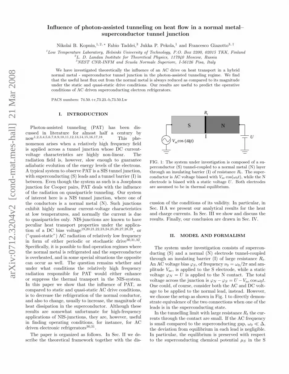
S N
Rt
IVaccos (ω0t)
U
FIG. 1: The system under investigation is composed of a su-perconductor (S) tunnel-coupled to a normal metal (N) layerthrough an insulating barrier (I) of resistance Rt. The super-conductor is AC voltage biased with Vac cos(ω0t), while the Nelectrode is biased with a static voltage U . Both electrodesare assumed to be in thermal equilibrium.
cussion of the conditions of its validity. In particular, inSec. II A we present our analytical results for the heatand charge currents. In Sec. III we show and discuss theresults. Finally, our conclusion are drawn in Sec. IV.
II. MODEL AND FORMALISM
The system under investigation consists of supercon-ducting (S) and a normal (N) electrode tunnel-coupledthrough an insulating barrier (I) of large resistance Rt.An AC voltage bias ϕS , of frequency ν0 = ω0/2π and am-plitude Vac, is applied to the S electrode, while a staticvoltage ϕN = U is applied to the N contact. The totalvoltage across the junction is ϕN −ϕS = U −Vac cosω0t.One could, of course, consider both the AC and DC volt-age to be applied to the normal lead, instead. However,we choose the setup as shown in Fig. 1 to directly demon-strate equivalence of the two connections when one of theleads is in the superconducting state.
In the tunnelling limit with large resistance Rt the cur-rents through the contact are small. If the AC frequencyis small compared to the superconducting gap, ω0 ≪ ∆,the deviation from equilibrium in each lead is negligible.In particular, the equilibrium is preserved with respectto the superconducting chemical potential µS in the S
2
electrode (which has dimensions much bigger than thebranch-imbalance relaxation length). This leads to thestandard assumption14,15,16
~
2
∂χ
∂t≡ µS = −eϕS . (1)
where χ is the order parameter phase.In the case of equilibrium described by Eq. (1), the
order parameter has the form
∆(r, t) = ∆0(r) exp
(
2i
~
∫ t
0
µs dt′)
. (2)
It is convenient to start with the Bogoliubov–de Gennesequation (BdGE) for the eigen-functions of the system,
i~∂u
∂t= (H0 + eϕS)u + ∆v ,
i~∂v
∂t= −(H∗
0 + eϕS)v + ∆∗u ,
where H0 is the normal-state Hamiltonian. Solutions tothe BdGE have the form
u(r, t) = u0(r)e−iEt/~+(i/~)
R
t µs dt′ , (3)
v(r, t) = v0(r)e−iEt/~−(i/~)
R
t µs dt′ , (4)
where u0(r) and v0(r) satisfy the BdGE in the absenceof the applied potential (ϕS = 0)
Eu0 = H0u0 + ∆(r)v0 ,
Ev0 = −H∗0v0 + ∆∗(r)u0 .
Using the standard approach we define the retarded(R) and advanced (A) Green function, which can be writ-ten as a matrix in Nambu space:
GR(A) =
(
GR(A) FR(A)
−FR(A)† GR(A)
)
,
where FR(A) refer to the anomalous Gorkov function.Since these functions are statistical averages of the par-ticle field operators which can be decomposed into thewave functions Eqs. (3) and (4), the retarded and ad-vanced Green functions with help of Eqs. (3) and (4)take the form
GR(A)(t1, t2) = GR(A),0(t1, t2) ei/~(R
t1 µs dt′−R
t2 µs dt′) ,
GR(A)(t1, t2) = GR(A),0(t1, t2) e−i/~(R
t1 µs dt′+R
t2 µs dt′),
FR(A)(t1, t2) = FR(A),0(t1, t2) ei/~(R
t1 µs dt′+R
t2 µs dt′) ,
where GR(A),0, FR(A),0 refer to ϕS = 0.If the AC voltage is applied to the superconductor
µs = −eVac cosω0t . (5)
Using the identity
e−i
~
R
t
0eVac cos ω0t′ dt′ =
n=+∞∑
n=−∞
Jn(α)e−inω0t (6)
where α = eVac/~ω0, and Jn is the nth order Besselfunction. The Green functions in the frequency repre-sentation take the form
GR(A)ǫ,ǫ−~ω =
∑
n,m
Jn(α)Jm(α)GR(A),0ǫ−n~ω0,ǫ−~ω−m~ω0
.
If ϕS = 0, there is no time-dependence and G(0)ǫ1,ǫ2 =
2π~δ(ǫ1−ǫ2)Gǫ1 . Here and in what follows one frequencysubscript refers to the static Green function.
The semi-classical Green functions are defined as theGreen functions in the momentum representation inte-grated over the energy variable ξp = p2/2m− EF ,
gǫ1,ǫ2 =
∫ +∞
−∞
Gǫ1,ǫ2(p,p − k)dξp
πi.
Under the AC drive we thus have
gR(A)ǫ,ǫ−~ω =
∑
n,k
2πδ(ω − kω0)Jn(α)Jn−k(α)gR(A)ǫ−n~ω0
, (7)
fR(A)ǫ,ǫ−~ω =
∑
n,m
2πδ(ω − kω0)Jn(α)Jk−n(α)fR(A)ǫ−n~ω0
. (8)
For the Keldysh functions we use the standardrepresentation33,34 in terms of f1 and f2 which are thecomponents of the distribution function respectively oddand even in (ǫ,p). In Nambu space,
gKǫ1,ǫ2 =
∫ +∞
−∞
dǫ′
2π~
[
gRǫ1,ǫ′ (f1,ǫ′,ǫ2 + τ3f2,ǫ′,ǫ2)
− (f1,ǫ1,ǫ′, + τ3f2,ǫ1,ǫ′,) gAǫ′,ǫ2
]
where
τ3 =
(
1 00 −1
)
.
In what follows we omit the integration limits if the in-tegration is extended over the infinite range. With Eqs.(7), (8) the Keldysh Green functions take the form
gKǫ,ǫ−~ω =
∑
n,k
2πδ(ω − kω0)Jn(α)Jn−k(α)
×[gRǫ−n~ω0
− gAǫ−n~ω0
]
× [f1(ǫ − n~ω0) + f2(ǫ − n~ω0)] ,
fKǫ,ǫ−~ω =
∑
n,m
2πδ(ω − kω0)Jn(α)Jk−n(α)
×[
fRǫ−n~ω0
(f1,ǫ−n~ω0− f2,ǫ−n~ω0
)
−(f1,ǫ−n~ω0+ f2,ǫ−n~ω0
)fAǫ−n~ω0
]
, (9)
where the distributions f1 and f2 in the superconductorrefer to the state with ϕS = 0. Equations for gR(A) andgK are obtained from the corresponding equations forgR(A) and gK by substituting g → g, ω0 → −ω0, andf2 → −f2.
These solutions describe a quasi-equilibrium state witha time-dependent chemical potential Eq. (5). In the limit
3
ω0 → 0, using Eq. (10), we have gR(A,K)ǫ → g
R(A,K)ǫ+µS
,
gR(A,K)ǫ → g
R(A,K)ǫ−µS
which agrees with the constant-
voltage limit35.Here we need an obvious remark. It can be shown (see
Appendix A) that for µs satisfying Eq. (5)
∑
n,k
2πδ(ω − kω0)Jn(α)Jn−k(α)Φ(ǫ − n~ω0)
=
∫
Φ(ǫ + µs(t))eiωt dt (10)
for any function Φ(ǫ) which has no singularities. For afunction with singularities (or large higher-order deriva-tives) at certain ǫ, Eq. (10) holds only in the limit ω0 → 0.
If the density of states gR(A)ǫ , f
R(A)ǫ , and the distribution
function were smooth functions, the quasi-static limitwould hold for any ω0; in this case all the quantitieswould simply adiabatically depend on the AC potentialVac. However, due to a strong singularity at ǫ = ∆ of thedensity of states and/or a sharp dependence of the dis-tribution function for low temperatures, the quasi-staticpicture breaks down for a finite ω0, determined by thesmallest scale of the non-linearity. As a result both thetunnel current and the heat flux for a finite frequency de-viate strongly from the quasi-static behavior. In practice,the reservoirs are not perfect. In particular relaxation inthe superconductor is still an open issue. This is a ques-tion that needs to be addressed separately. The presenttreatment gives the answers in the case of ideal reservoirs.
Consider the self-consistency equation for the order pa-rameter. Since f2 = 0 for ϕS = 0, the self-consistencyequation ∆(ω) = (λ/4)
∫
fKǫ,ǫ−~ω dǫ takes the form
∆(ω) = ∆0
∑
k
Jk(2α)2πδ(ω − kω0) (11)
which is the Fourier transform of Eq. (2) where
∆0(r) = (λ/4)
∫
dǫ[
fRǫ − fA
ǫ
]
f1(ǫ)
with f1(ǫ) = tanh(ǫ/2T ) is the order parameter for zeroAC field. This implies that the Eqs. (1)–(4) are consis-tent. In obtaining Eq. (11) we use
n=+∞∑
n=−∞
Jk+n(t)Jn(z) = Jk(t − z) . (12)
A. Charge and energy currents
For two tunnel-coupled electrodes, the charge currentthat flows into the electrode i is given by35
I(i) = −ieπ~νiΩi
2Tr
[
τ3IK(i; t, t′)
]
t=t′. (13)
whereas the heat current flowing into the electrode i is
Q(i) =π~
2νiΩi
4Tr
[
∂
∂t−
∂
∂t′+
2ieϕi
~τ3
]
IK(i; t, t′)
t=t′.
(14)Here νi is the normal-state density of states in the elec-trode i, Ωi and ϕi are its volume and electric potential.The collision integral IK(i) in the electrode that appearsin Eqs. (13), (14) contains contribution due to tunnellingfrom neighboring electrode and the electron-phonon con-tribution, IK = IK
t + IKe−ph. The electron-electron in-
teractions drop out from the energy current because ofthe energy conservation. The energy flow into the elec-trode can thus be separated into two parts. One partcontaining IK
e−ph is the energy exchange with the heat
bath (phonons). The other part contains the tunnel con-tribution IK
t and is the energy current into the electrodethrough the tunnel contact. The tunnel collision integralfor the electrode 1 in contact with an electrode 2 has theform35
IKt (1) = iη1
[
gR(2) gK(1) − gR(1) gK(2)
+gK(2) gA(1) − gK(1) gA(2)]
. (15)
Here the arguments i = 1 or 2 refer to the electrodes Sor N. The symbol is the convolution over the internalvariables
A(1) B(2) =
∫
A(1; t1, t′)B(2; t′, t2)dt′ .
The factor
ηi = [4νiΩie2Rt]
−1
parameterizes the tunnelling strength between the elec-trodes, Rt being the tunnel resistance. Since in the nor-mal state
gR(A)N (ǫ; t1, t2) = ±τ3δ(t1 − t2) ,
gKN (ǫ; t1, t2) = 2[fN
1 (ǫ)τ3 + fN2 (ǫ)]δ(t1 − t2) ,
the collision integral in the superconductor is
IKt (S) = iηS
τ3gKS + gK
S τ3
+2[τ3fN1 + fN
2 ]gAS − 2gR
S [fN1 τ3 + fN
2 ]
.(16)
The even and odd components of the distribution func-tion correspond to the absence of the AC potential. Theyare, respectively,
fN2 (ǫ) = −nǫ + (1 − n−ǫ)
= nN (ǫ + eU) − nN (ǫ − eU) , (17)
fN1 (ǫ) = −nǫ + n−ǫ
= 1 − nN (ǫ + eU) − nN (ǫ − eU) , (18)
for the normal lead, and
fS2 (ǫ) = −nǫ + (1 − n−ǫ) = 0 , (19)
fS1 (ǫ) = −nǫ + n−ǫ = 1 − 2nS(ǫ) = tanh
ǫ
2TS,(20)
4
for the superconducting lead. Here nN(ǫ) and nS(ǫ) arethe Fermi functions with temperatures TN and TS , re-spectively. The distributions in the superconductor thuscorrespond to the zero-potential state.
As far as the NIS junction is concerned, consider firstthe charge current into the superconductor defined by Eq.(13). The tunnel current in the frequency representationbecomes
IS(ω) =1
4eRt
∫
dǫ gǫ
∑
n,k
Jn(α)Jn−k(α)
2πδ(ω − kω0)[fS1 (ǫ) + fS
2 (ǫ) − fN1 (ǫ + n~ω0) − fN
2 (ǫ + n~ω0)]
−2πδ(ω + kω0)[fS1 (ǫ) − fS
2 (ǫ) − fN1 (ǫ − n~ω0) + fN
2 (ǫ − n~ω0)]
=1
2eRt
∫
dǫ gǫ
∑
n,k
Jn(α)Jn−k(α)
×2πδ(ω − kω0)[nN (ǫ − eU + n~ω0) − nS(ǫ)] + 2πδ(ω + kω0)[nN (ǫ − eU − n~ω0) − nS(ǫ)] . (21)
In Eq. (21) we use the relation gR(A)ǫ = −g
R(A)ǫ for static functions, and denote gǫ ≡ (gR
ǫ − gAǫ )/2 the ratio of the
superconducting density of states to that in the normal state, gǫ = NS(ǫ)/NN . The ω0 component of the current is
IS ω0(t) =
cos(ω0t)
eRt
∫
dǫ gǫ
∑
n
Jn(α)Jn−1(α)[
fS1 (ǫ) − fN
1 (ǫ + n~ω0)]
=cos(ω0t)
eRt
∫
dǫ gǫ
∑
n
Jn(α)Jn−1(α) [nN (ǫ + eU + n~ω0) + nN(ǫ − eU + n~ω0) − 2nS(ǫ)] . (22)
The time averaged current takes the form
IS =1
2eRt
∫
dǫ gǫ
∑
n
J2n(α)
[
fS2 (ǫ) − fN
2 (ǫ + n~ω0)]
=1
2eRt
∫
dǫ gǫ
∑
n
J2n(α)
×[nN (ǫ − eU + n~ω0) − nN (ǫ + eU + n~ω0)]. (23)
The terms with f2 drop out of Eq. (22) due to the prop-erty of the Bessel functions
J−n = (−1)nJn . (24)
Note that if we set ω0 = 0 the average current assumesthe zero-ac-voltage form
I(0)S =
1
2eRt
∫
dǫ gǫ[nN (ǫ − eU) − nN(ǫ + eU)] .
Indeed, when taking the limit ω0 → 0 one should keep inmind that the sum
∑
n J2n(α) = 1 [which is a consequence
of a more general relation Eq. (12)] converges at n ∼α = eVac/~ω0. Therefore, ~nω0 ∼ eVac in Eq. (21); thusone has to put eVac → 0 to neglect n~ω0. However, thetrue static expression is defined for ω0 = 0 but Vac 6= 0.According to Eq. (10), it has the energy-shifted densityof states gǫ±eVac
and the distribution functions fS1 (ǫ ±
eVac), fS2 (ǫ ± eVac). This static limit (i.e., ω0 = 0 and
Vac 6= 0) is indeed obtained from Eq. (21) using Eq. (10).Making shifts of the integration variable we find
IstaticS =
1
2eRt
∫
dǫ gǫ[fS2 (ǫ) − fN static
2 (ǫ)] (25)
where fS2 = 0 and
fN2 = nN(ǫ + eU − eVac) − nN (ǫ − eU + eVac)
which corresponds to the total voltage U−Vac, accordingto Eq. (17).
The heat current that flows into the superconductinglead can be calculated with help of Eqs. (3) and (4). Wefind in the frequency representation
−~
[(
∂
∂t−
∂
∂t′+
2ieϕS
~
)
gR(A)(t, t′)
]
ǫ,ǫ−~ω
(26)
= 4πi∑
n,k
δ(ω − kω0)Jn(α)Jn−k(α)(ǫ − n~ω0)gR(A)ǫ−n~ω0
,
−~
[(
∂
∂t−
∂
∂t′+
2ieϕS
~
)
gK(t, t′)
]
ǫ,ǫ−~ω
(27)
= 4πi∑
n,k
δ(ω − kω0)Jn(α)Jn−k(α)(ǫ − n~ω0)
×[gRǫ−n~ω0
− gAǫ−n~ω0
] [f1(ǫ − n~ω0) + f2(ǫ − n~ω0)] ,
and similarly for g with the substitutions g → g, ϕS →−ϕS , ω0 → −ω0, and f2 → −f2. Here the distributionfunctions again correspond to zero AC potential.
Shifting the energy variable under the integral, the av-erage heat current into the superconductor becomes
QS =1
2e2Rt
∫
ǫgǫ
∑
n
J2n(α)
×[
fS1 (ǫ) − fN
1 (ǫ + n~ω0)]
dǫ . (28)
5
The heat current Eq. (28) is even in ω0. For ω0 = 0Eq. (28) formally goes over into
Q(0)S =
1
2e2Rt
∫
ǫgǫ
[
fS1 (ǫ) − fN
1 (ǫ)]
dǫ
with fN1 and fS
1 from Eqs. (18), (20). This is the zero-
ac-voltage result.
The static expression is obtained from Eqs. (10), (26),and (27)
QstaticS =
1
2e2Rt
∫
ǫgǫ
[
fS1 (ǫ) − fN static
1 (ǫ)]
dǫ (29)
where fNstatic1 (ǫ) corresponds to the total voltage U−Vac,
fN static1 (ǫ) = 1−nN (ǫ+eU −eVac)−nN (ǫ−eU +eVac) .
This should be compared to Eq. (18).
It is also interesting to define the quasi-static regime,which is obtained by averaging the static heat flux Qstatic
Sover the sinusoidal voltage cycle with Vac → Vac cosω0t.It does not coincide with the static expression due to thevoltage oscillations. This quasi-static regime correspondsto the classical limit occurring at small frequencies, forwhich the photon energy ~ω0 is much smaller than theenergy scale over which the non-linearity of the I-V curveoccurs15,16. In the system under investigation such en-ergy scale is set by the temperature or by the width of thesuperconducting DOS peak near the gap energy, whichsmear the sudden current onset occurring at the super-conductor gap. As it will be confirmed in Sec. III, thequasi-static regime occurs for ~ω0 ≪ kBT .
We now consider the heat current flowing out of thenormal electrode:
QoutN = QS − (ϕN − ϕS)IS , (30)
where IS is the tunnel charge current reported in Eq.(21). Note that the heat extracted from the normal elec-trode and the heat entering the superconducting lead dif-fer by the energy absorbed at the NIS interface where thepotential drops by ϕN −ϕS . The time-average heat cur-rent is
Qout
N = QS − UIS − Pac (31)
where Pac = Vac cos(ω0t)IS ω0(t) is the average AC power
absorbed at the NIS contact,
Pac = −Vac
2eRt
∫
gǫ
∑
n
Jn(α)Jn−1(α)
×[
fS1 (ǫ) − fN
1 (ǫ + nω0)]
dǫ . (32)
Note that Pac is finite both in the static case (ω0 ≡ 0)and in the quasi-static regime (small but finite ω0).
III. RESULTS AND DISCUSSION
We shall now discuss how the heat current depends onthe various parameters of the system. This can be doneby numerically evaluating the expressions given in theprevious section. In the following we shall assume param-eters typical of aluminum (Al) as S material, with criticaltemperature Tc=1.19 K. We assume the superconduct-ing gap to follow the BCS relation ∆0 = 1.764kBTc andchoose
NS(ǫ) = |Re[(ǫ + iΓ)/√
(ǫ + iΓ)2 − ∆2]| ,
where Γ is a smearing parameter which accounts forquasiparticle states within the gap35,36,37. We will useΓ = 10−4∆0, as experimentally verified in Ref. 37. Fi-nally, we shall always assume the N and S electrodes tobe at the same temperature, i.e., TS = TN ≡ T .
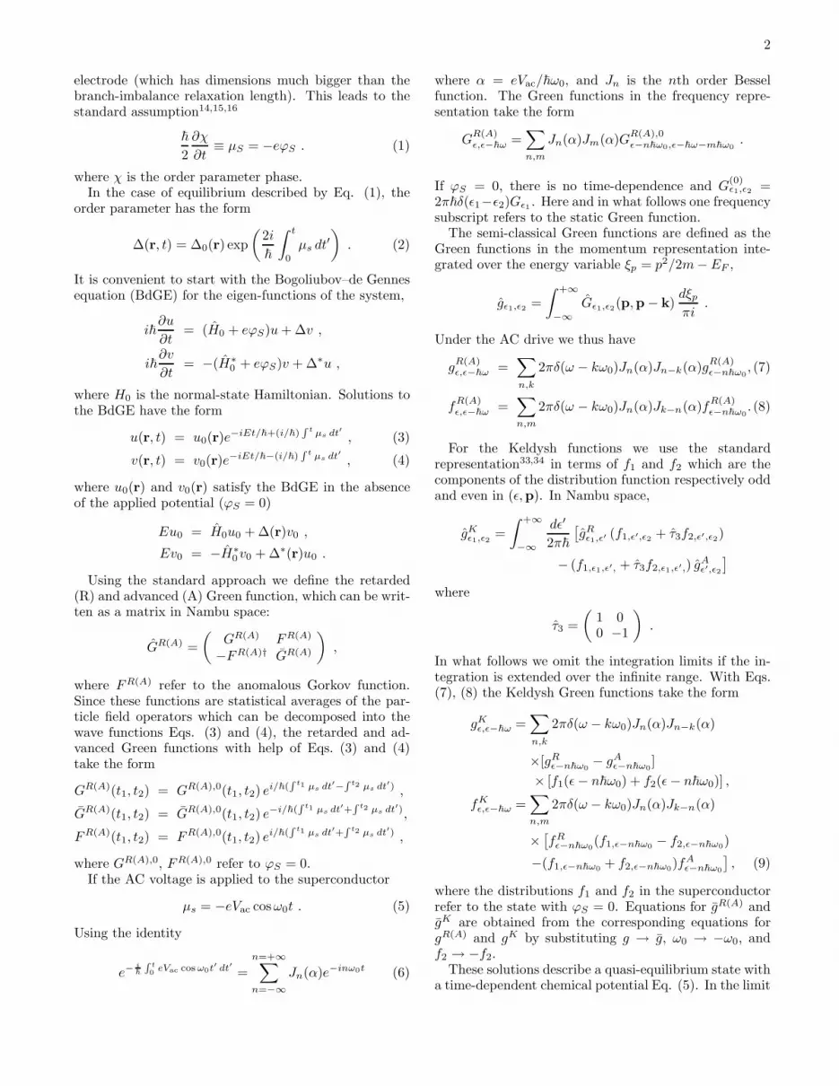
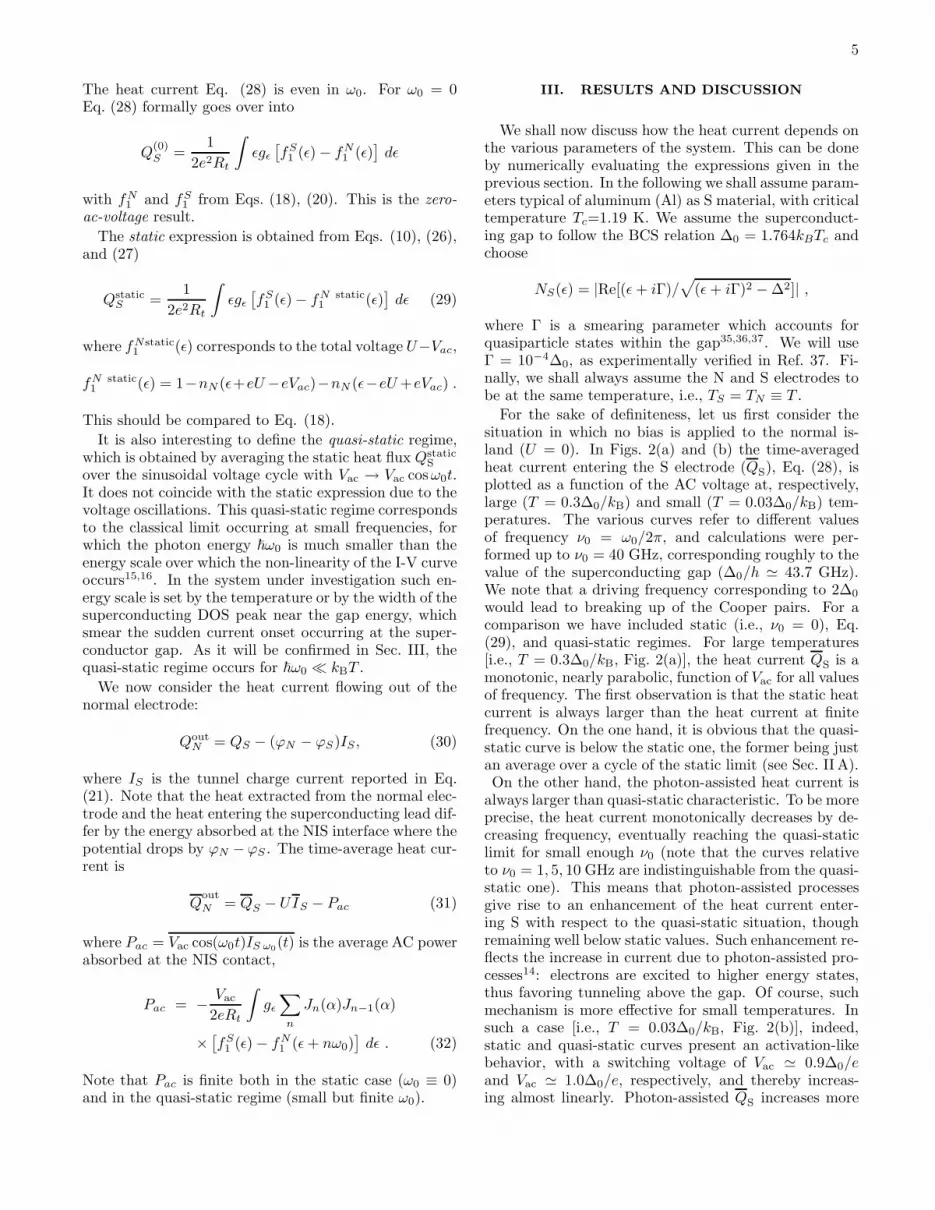
For the sake of definiteness, let us first consider thesituation in which no bias is applied to the normal is-land (U = 0). In Figs. 2(a) and (b) the time-averagedheat current entering the S electrode (QS), Eq. (28), isplotted as a function of the AC voltage at, respectively,large (T = 0.3∆0/kB) and small (T = 0.03∆0/kB) tem-peratures. The various curves refer to different valuesof frequency ν0 = ω0/2π, and calculations were per-formed up to ν0 = 40 GHz, corresponding roughly to thevalue of the superconducting gap (∆0/h ≃ 43.7 GHz).We note that a driving frequency corresponding to 2∆0
would lead to breaking up of the Cooper pairs. For acomparison we have included static (i.e., ν0 = 0), Eq.(29), and quasi-static regimes. For large temperatures[i.e., T = 0.3∆0/kB, Fig. 2(a)], the heat current QS is amonotonic, nearly parabolic, function of Vac for all valuesof frequency. The first observation is that the static heatcurrent is always larger than the heat current at finitefrequency. On the one hand, it is obvious that the quasi-static curve is below the static one, the former being justan average over a cycle of the static limit (see Sec. II A).On the other hand, the photon-assisted heat current is
always larger than quasi-static characteristic. To be moreprecise, the heat current monotonically decreases by de-creasing frequency, eventually reaching the quasi-staticlimit for small enough ν0 (note that the curves relativeto ν0 = 1, 5, 10 GHz are indistinguishable from the quasi-static one). This means that photon-assisted processesgive rise to an enhancement of the heat current enter-ing S with respect to the quasi-static situation, thoughremaining well below static values. Such enhancement re-flects the increase in current due to photon-assisted pro-cesses14: electrons are excited to higher energy states,thus favoring tunneling above the gap. Of course, suchmechanism is more effective for small temperatures. Insuch a case [i.e., T = 0.03∆0/kB, Fig. 2(b)], indeed,static and quasi-static curves present an activation-likebehavior, with a switching voltage of Vac ≃ 0.9∆0/eand Vac ≃ 1.0∆0/e, respectively, and thereby increas-ing almost linearly. Photon-assisted QS increases more
6
0.0 0.2 0.4 0.6 0.8 1.0 1.2 1.4
0.0
0.1
0.2
0.3
0.4
e2 RtQ
S/∆
2 0
eVac /∆0
1 5 10 20 40 static quasi-static
TS = T
N = 0.3∆
0/k
B
U = 0
ν0(GHz)
(a)
0.0 0.2 0.4 0.6 0.8 1.0 1.2 1.4
0.0
0.1
0.2
0.3
0.4
e2 RtQ
S/∆
2 0
eVac /∆0
1 5 10 20 40 static quasi-static
TS = T
N = 0.03∆
0/k
B
U = 0
ν0(GHz)
(b)
FIG. 2: (color online) Normalized time-average heat currentinto the S electrode QS as a function of the amplitude ofthe AC voltage Vac for different values of ν0 at (a) high(T = 0.3∆0/kB) and (b) low (T = 0.03∆0/kB) temperature.The static case and the quasi-static limit are plotted for com-parison. Note that in (a) the curves relative to ν0 =10, 5 and1 GHz coincide with the quasi-static one.
smoothly as compared with the quasi-static case, whichis approached by decreasing ν0.
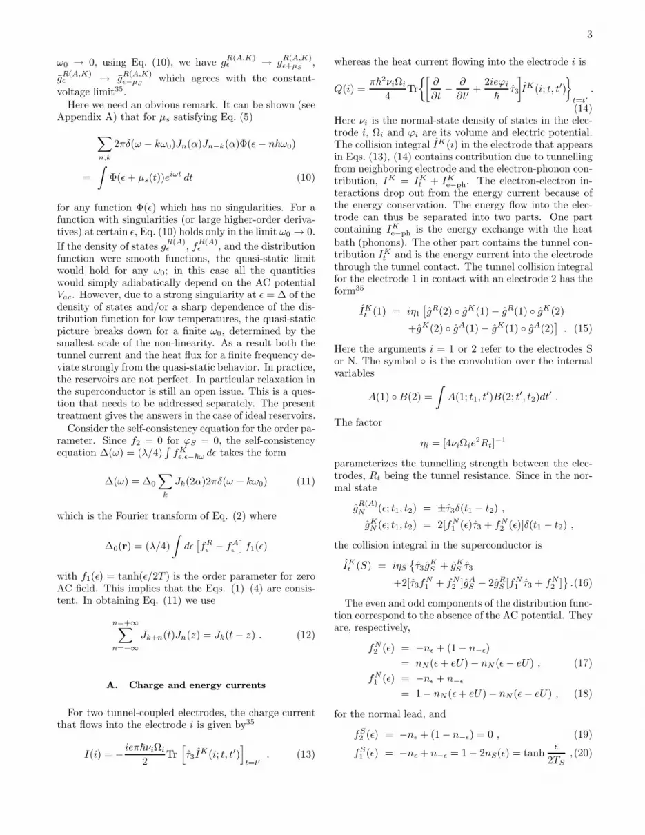
We now consider the heat current extracted from theN electrode Q
out
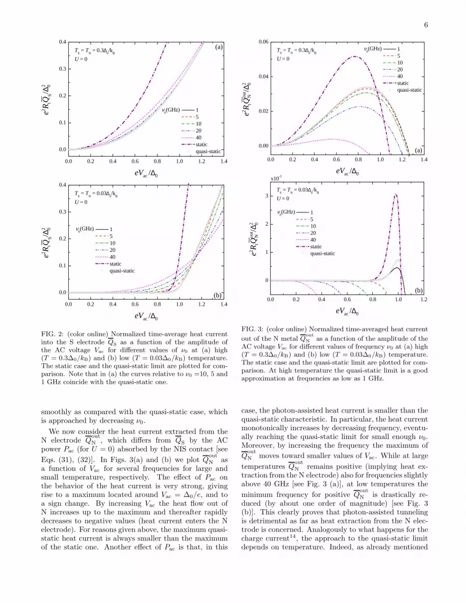
N , which differs from QS by the ACpower Pac (for U = 0) absorbed by the NIS contact [see
Eqs. (31), (32)]. In Figs. 3(a) and (b) we plot Qout
N asa function of Vac for several frequencies for large andsmall temperature, respectively. The effect of Pac onthe behavior of the heat current is very strong, givingrise to a maximum located around Vac = ∆0/e, and toa sign change. By increasing Vac the heat flow out ofN increases up to the maximum and thereafter rapidlydecreases to negative values (heat current enters the Nelectrode). For reasons given above, the maximum quasi-static heat current is always smaller than the maximumof the static one. Another effect of Pac is that, in this
0.0 0.2 0.4 0.6 0.8 1.0 1.2 1.4
0.00
0.02
0.04
0.06
e2 RtQ
out
N/∆
2 0
eVac /∆0
1 5 10 20 40 static quasi-static
TS = T
N = 0.3∆
0/k
B
U = 0
ν0(GHz)
(a)
0.0 0.2 0.4 0.6 0.8 1.0 1.2
0
1
2
3
e2 RtQ
out
N/∆
2 0
eVac /∆0
1 5 10 20 40 static quasi-static
TS = T
N = 0.03∆
0/k
B
U = 0
ν0(GHz)
(b)
x10-3
FIG. 3: (color online) Normalized time-averaged heat current
out of the N metal Qout
N as a function of the amplitude of theAC voltage Vac for different values of frequency ν0 at (a) high(T = 0.3∆0/kB) and (b) low (T = 0.03∆0/kB) temperature.The static case and the quasi-static limit are plotted for com-parison. At high temperature the quasi-static limit is a goodapproximation at frequencies as low as 1 GHz.
case, the photon-assisted heat current is smaller than thequasi-static characteristic. In particular, the heat currentmonotonically increases by decreasing frequency, eventu-ally reaching the quasi-static limit for small enough ν0.Moreover, by increasing the frequency the maximum of
Qout
N moves toward smaller values of Vac. While at large
temperatures Qout
N remains positive (implying heat ex-traction from the N electrode) also for frequencies slightlyabove 40 GHz [see Fig. 3 (a)], at low temperatures the
minimum frequency for positive Qout
N is drastically re-duced (by about one order of magnitude) [see Fig. 3(b)]. This clearly proves that photon-assisted tunnelingis detrimental as far as heat extraction from the N elec-trode is concerned. Analogously to what happens for thecharge current14, the approach to the quasi-static limitdepends on temperature. Indeed, as already mentioned
7
0.5 0.6 0.7 0.8 0.9 1.0 1.1
0
2
4
6
8
e2 R
tQou
tN
/∆2 0
eVac /∆0
0.1 0.3 0.5 0.8 1.0 2.0 3.0 quasi-static
TS = T
N = 0.03∆
0/k
B
U = 0
ν0(GHz)
x10-4
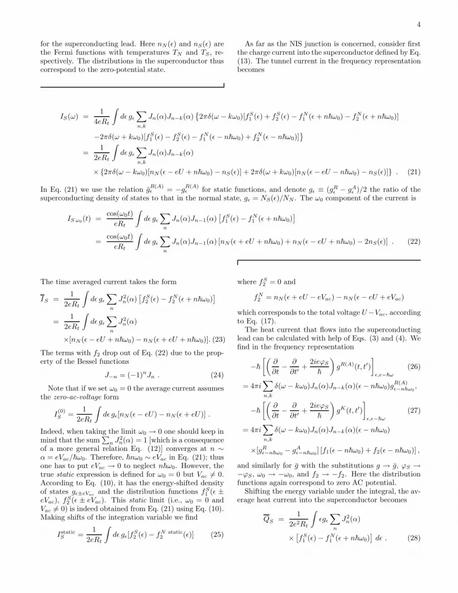
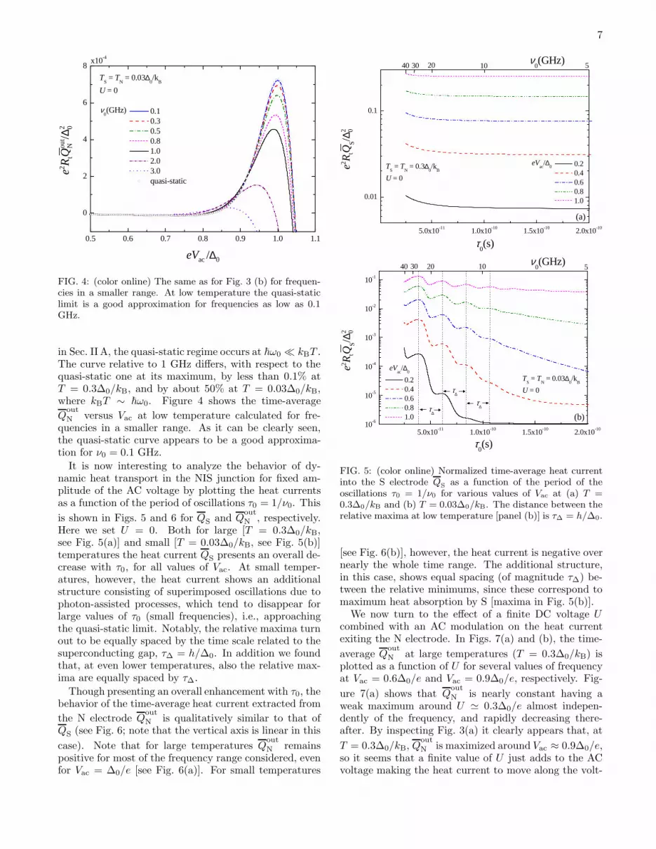
FIG. 4: (color online) The same as for Fig. 3 (b) for frequen-cies in a smaller range. At low temperature the quasi-staticlimit is a good approximation for frequencies as low as 0.1GHz.
in Sec. II A, the quasi-static regime occurs at ~ω0 ≪ kBT .The curve relative to 1 GHz differs, with respect to thequasi-static one at its maximum, by less than 0.1% atT = 0.3∆0/kB, and by about 50% at T = 0.03∆0/kB,where kBT ∼ ~ω0. Figure 4 shows the time-average
Qout
N versus Vac at low temperature calculated for fre-quencies in a smaller range. As it can be clearly seen,the quasi-static curve appears to be a good approxima-tion for ν0 = 0.1 GHz.
It is now interesting to analyze the behavior of dy-namic heat transport in the NIS junction for fixed am-plitude of the AC voltage by plotting the heat currentsas a function of the period of oscillations τ0 = 1/ν0. This
is shown in Figs. 5 and 6 for QS and Qout
N , respectively.Here we set U = 0. Both for large [T = 0.3∆0/kB,see Fig. 5(a)] and small [T = 0.03∆0/kB, see Fig. 5(b)]temperatures the heat current QS presents an overall de-crease with τ0, for all values of Vac. At small temper-atures, however, the heat current shows an additionalstructure consisting of superimposed oscillations due tophoton-assisted processes, which tend to disappear forlarge values of τ0 (small frequencies), i.e., approachingthe quasi-static limit. Notably, the relative maxima turnout to be equally spaced by the time scale related to thesuperconducting gap, τ∆ = h/∆0. In addition we foundthat, at even lower temperatures, also the relative max-ima are equally spaced by τ∆.
Though presenting an overall enhancement with τ0, thebehavior of the time-average heat current extracted from
the N electrode Qout
N is qualitatively similar to that ofQS (see Fig. 6; note that the vertical axis is linear in this
case). Note that for large temperatures Qout
N remainspositive for most of the frequency range considered, evenfor Vac = ∆0/e [see Fig. 6(a)]. For small temperatures
5.0x10⁻¹¹ 1.0x10⁻¹⁰ 1.5x10⁻¹⁰ 2.0x10⁻¹⁰
0.01
0.1
(a)
e2 RtQ
S/∆
2 0
τ0(s)
0.2 0.4 0.6 0.8 1.0
TS = T
N = 0.3∆
0/k
B
U = 0
eVac
/∆0
40 30 20 10 5 ν0(GHz)
5.0x10⁻¹¹ 1.0x10⁻¹⁰ 1.5x10⁻¹⁰ 2.0x10-1010-6
10-5
10-4
10-3
10-2
10-1
τ∆
τ∆
(b)
e2 RtQ
S/∆
2 0
τ0(s)
0.2 0.4 0.6 0.8 1.0
TS = T
N = 0.03∆
0/k
B
U = 0
eVac
/∆0
τ∆
40 30 20 5 ν
0(GHz)10
FIG. 5: (color online) Normalized time-average heat currentinto the S electrode Q
Sas a function of the period of the
oscillations τ0 = 1/ν0 for various values of Vac at (a) T =0.3∆0/kB and (b) T = 0.03∆0/kB. The distance between therelative maxima at low temperature [panel (b)] is τ∆ = h/∆0.
[see Fig. 6(b)], however, the heat current is negative overnearly the whole time range. The additional structure,in this case, shows equal spacing (of magnitude τ∆) be-tween the relative minimums, since these correspond tomaximum heat absorption by S [maxima in Fig. 5(b)].
We now turn to the effect of a finite DC voltage Ucombined with an AC modulation on the heat currentexiting the N electrode. In Figs. 7(a) and (b), the time-
average Qout
N at large temperatures (T = 0.3∆0/kB) isplotted as a function of U for several values of frequencyat Vac = 0.6∆0/e and Vac = 0.9∆0/e, respectively. Fig-
ure 7(a) shows that Qout
N is nearly constant having aweak maximum around U ≃ 0.3∆0/e almost indepen-dently of the frequency, and rapidly decreasing there-after. By inspecting Fig. 3(a) it clearly appears that, at
T = 0.3∆0/kB, Qout
N is maximized around Vac ≈ 0.9∆0/e,so it seems that a finite value of U just adds to the ACvoltage making the heat current to move along the volt-
8
5.0x10⁻¹¹ 1.0x10⁻¹⁰ 1.5x10⁻¹⁰ 2.0x10⁻¹⁰-0.02
-0.01
0.00
0.01
0.02
0.03
0.0410
(a)
e2 RtQ
out
N/∆
2 0
τ0(s)
0.2 0.4 0.6 0.8 1.0
TS = T
N = 0.3∆
0/k
B
U = 0
eVac
/∆0
ν0(GHz)40 30 20 5
5.0x10⁻¹¹ 1.0x10⁻¹⁰ 1.5x10⁻¹⁰ 2.0x10⁻¹⁰
-0.03
-0.02
-0.01
0.00 5102030
(b)
e2 RtQ
out
N/∆
2 0
τ0(s)
0.2 0.4 0.6 0.8 1.0
TS = T
N = 0.03∆
0/k
B
U = 0
eVac
/∆0
ν0(GHz)
40
τ∆
τ∆
τ∆
FIG. 6: (color online) Normalized time-average heat currentout of the N electrode Qout
N as a function of the period ofthe oscillations τ0 = 1/ν0 for several values of Vac at (a) T =0.3∆0/kB and (b) T = 0.03∆0/kB. At low temperature [panel(b)] the distance between relative minimums turn out to beτ∆ = h/∆0. In (b) the curve relative to Vac = 0.2∆0/e isconsistent, in the scale of the figure, with zero.
age characteristic similarly to the pure AC case. Further-more, we note that the addition of a static DC potentialto an AC modulation is not able to recover the maxi-mum value the heat current can achieve with only theAC voltage biasing. A confirmation of this is given inthe plots displayed in Fig. 7(b) which are relative to avalue of Vac = 0.9∆0/e. For such an AC voltage biasing
Qout
N does not present a constant part, and the additionof U turns out to only suppress the time-average heatcurrent. Moreover, an increase of frequency ν0 causes a
reduction of Qout
N , even to negative values.
We finally plot in Fig. 8 the maximum value of Qout
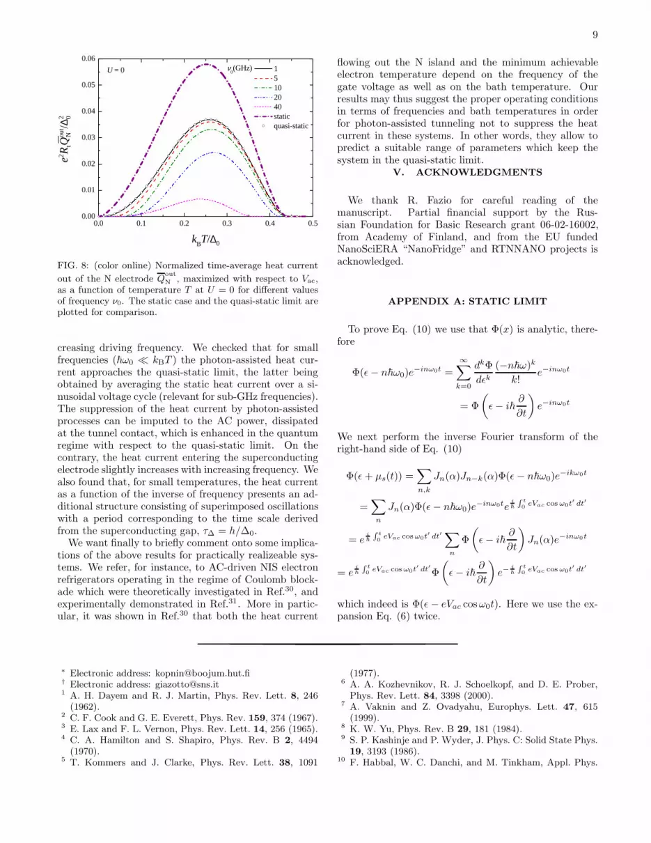
N ,obtained by spanning over Vac, as a function of T for sev-eral values of frequency. For every ν0 the time-average
Qout
N is a bell-shaped function presenting a maximumaround T ≃ 0.25∆0/kB (similarly to what happens in
0.0 0.1 0.2 0.3 0.4 0.5 0.6 0.7-0.01
0.00
0.01
0.02
0.03
0.04
e2 RtQ
out
N/∆
2 0
eU/∆0
1 5 10 20 40
TS = T
N = 0.3∆
0/k
B
eVac
= 0.9∆0
ν0(GHz)
(b)
0.0 0.1 0.2 0.3 0.4 0.5 0.6 0.70.00
0.01
0.02
0.03
e2 RtQ
out
N/∆
2 0
eU/∆0
1 5 10 20 40
TS = T
N = 0.3∆
0/k
B
eVac
= 0.6∆0
ν0(GHz)
(a)
FIG. 7: (color online) Normalized time-average heat current
exiting the N electrode Qout
Nas a function of the DC voltage
U for various values of ν0 at (a) Vac = 0.6∆0/e and (b) Vac =0.9∆0/e. In (a) and (b) the calculations were performed bysetting the temperature at T = 0.3∆0/kB.
the static19 as well as in the quasi-static limit), whichis gradually suppressed upon enhancing the frequency.By increasing the frequency the curves slightly shrink,thus reducing the temperature interval of positive heatcurrent. Moreover, the position of the maxima tends tomove to higher temperatures for intermediate frequencies(i.e., for ν0 below ≃ 20 GHZ), while they tend to moveto lower temperatures in the higher range of frequencies(see for example the curve corresponding to ν0 = 40 GHzin Fig. 8).
IV. CONCLUSIONS
In this paper we have calculated the heat currentsin a normal/superconductor tunnel junction driven byan oscillating bias voltage in the photon-assisted tun-neling regime. We have found that the maximum heatextracted from the normal electrode decreases with in-
9
0.0 0.1 0.2 0.3 0.4 0.50.00
0.01
0.02
0.03
0.04
0.05
0.06
e2 RtQ
out
N/∆
2 0
kBT/∆0
1 5 10 20 40 static quasi-static
U = 0 ν0(GHz)
FIG. 8: (color online) Normalized time-average heat current
out of the N electrode Qout
N, maximized with respect to Vac,
as a function of temperature T at U = 0 for different valuesof frequency ν0. The static case and the quasi-static limit areplotted for comparison.
creasing driving frequency. We checked that for smallfrequencies (~ω0 ≪ kBT ) the photon-assisted heat cur-rent approaches the quasi-static limit, the latter beingobtained by averaging the static heat current over a si-nusoidal voltage cycle (relevant for sub-GHz frequencies).The suppression of the heat current by photon-assistedprocesses can be imputed to the AC power, dissipatedat the tunnel contact, which is enhanced in the quantumregime with respect to the quasi-static limit. On thecontrary, the heat current entering the superconductingelectrode slightly increases with increasing frequency. Wealso found that, for small temperatures, the heat currentas a function of the inverse of frequency presents an ad-ditional structure consisting of superimposed oscillationswith a period corresponding to the time scale derivedfrom the superconducting gap, τ∆ = h/∆0.
We want finally to briefly comment onto some implica-tions of the above results for practically realizeable sys-tems. We refer, for instance, to AC-driven NIS electronrefrigerators operating in the regime of Coulomb block-ade which were theoretically investigated in Ref.30, andexperimentally demonstrated in Ref.31. More in partic-ular, it was shown in Ref.30 that both the heat current
flowing out the N island and the minimum achievableelectron temperature depend on the frequency of thegate voltage as well as on the bath temperature. Ourresults may thus suggest the proper operating conditionsin terms of frequencies and bath temperatures in orderfor photon-assisted tunneling not to suppress the heatcurrent in these systems. In other words, they allow topredict a suitable range of parameters which keep thesystem in the quasi-static limit.
V. ACKNOWLEDGMENTS
We thank R. Fazio for careful reading of themanuscript. Partial financial support by the Rus-sian Foundation for Basic Research grant 06-02-16002,from Academy of Finland, and from the EU fundedNanoSciERA “NanoFridge” and RTNNANO projects isacknowledged.
APPENDIX A: STATIC LIMIT
To prove Eq. (10) we use that Φ(x) is analytic, there-fore
Φ(ǫ − n~ω0)e−inω0t =
∞∑
k=0
dkΦ
dǫk
(−n~ω)k
k!e−inω0t
= Φ
(
ǫ − i~∂
∂t
)
e−inω0t
We next perform the inverse Fourier transform of theright-hand side of Eq. (10)
Φ(ǫ + µs(t)) =∑
n,k
Jn(α)Jn−k(α)Φ(ǫ − n~ω0)e−ikω0t
=∑
n
Jn(α)Φ(ǫ − n~ω0)e−inω0te
i
~
R
t
0eVac cos ω0t′ dt′
= ei
~
R
t
0eVac cos ω0t′ dt′
∑
n
Φ
(
ǫ − i~∂
∂t
)
Jn(α)e−inω0t
= ei
~
R
t
0eVac cos ω0t′ dt′Φ
(
ǫ − i~∂
∂t
)
e−i
~
R
t
0eVac cos ω0t′ dt′
which indeed is Φ(ǫ − eVac cosω0t). Here we use the ex-pansion Eq. (6) twice.
∗ Electronic address: [email protected]† Electronic address: [email protected] A. H. Dayem and R. J. Martin, Phys. Rev. Lett. 8, 246
(1962).2 C. F. Cook and G. E. Everett, Phys. Rev. 159, 374 (1967).3 E. Lax and F. L. Vernon, Phys. Rev. Lett. 14, 256 (1965).4 C. A. Hamilton and S. Shapiro, Phys. Rev. B 2, 4494
(1970).5 T. Kommers and J. Clarke, Phys. Rev. Lett. 38, 1091
(1977).6 A. A. Kozhevnikov, R. J. Schoelkopf, and D. E. Prober,
Phys. Rev. Lett. 84, 3398 (2000).7 A. Vaknin and Z. Ovadyahu, Europhys. Lett. 47, 615
(1999).8 K. W. Yu, Phys. Rev. B 29, 181 (1984).9 S. P. Kashinje and P. Wyder, J. Phys. C: Solid State Phys.
19, 3193 (1986).10 F. Habbal, W. C. Danchi, and M. Tinkham, Appl. Phys.
10
Lett. 42, 296 (1983).11 J. E. Mooij and T. M. Klapwijk, Phys. Rev. B 27, 3054
(1983).12 B. Leone, J. R. Gao, T. M. Klapwijk, B. D. Jackson, W.
M. Laauwen, and G. de Lange, Appl. Phys. Lett. 78, 1616(2001).
13 Y. Uzawa and Z. Wang, Phys. Rev. Lett. 95, 017002(2005).
14 P. K. Tien, and J. P. Gordon, Phys. Rev. 129, 647 (1963).15 J. R. Tucker and M. J. Feldman, Rev. Mod. Phys. 57, 1055
(1985).16 J. R. Tucker, IEEE J. Quantum Electron. 15, 1234 (1979).17 J. N. Sweet and G. I. Rochlin, Phys. Rev. B 2, 656 (1970).18 U. Zimmermann and K. Kreck, Z. Phys. B 101, 555 (1996).19 See F. Giazotto, T. T. Heikkila, A. Luukanen, A. M. Savin,
and J. P. Pekola, Rev. Mod. Phys. 78, 217 (2006), andreferences therein.
20 A. Bardas and D. Averin, Phys. Rev. B 52, 12873 (1995).21 M. M. Leivo, J. P. Pekola, and D. V. Averin, Appl. Phys.
Lett. 68, 1996 (1996).22 M. Nahum, T. M. Eiles, and J. M. Martinis, Appl. Phys.
Lett. 65, 3123 (1994).23 A. M. Clark, A. Williams, S. T. Ruggiero, M. L. van den
Berg, and J. N. Ullom, Appl. Phys. Lett. 84, 625 (2004).24 A. M. Clark, N. A. Miller, A. Williams, S. T. Ruggiero, G.
C. Hilton, L. R. Vale, J. A. Beall, K. D. Irwin, and J. N.Ullom, Appl. Phys. Lett. 86, 173508 (2005).
25 A. M. Savin, M. Prunnila, P. P. Kivinen, J. P. Pekola, J.Ahopelto, and A. J. Manninen, Appl. Phys. Lett. 79, 1471
(2001).26 R. Leoni, G. Arena, M. G. Castellano, and G. Torrioli, J.
Appl. Phys. 85, 3877 (1999).27 F. Giazotto, F. Taddei, R. Fazio, and F. Beltram, Appl.
Phys. Lett. 80, 3784 (2002).28 F. Giazotto, F. Taddei, M. Governale, C. Castellana, R.
Fazio, and F. Beltram, Phys. Rev. Lett. 97, 197001 (2006).29 F. Giazotto, F. Taddei, P. D’Amico, R. Fazio, and F. Bel-
tram, Phys. Rev. B 76, 184518 (2007).30 J. P. Pekola, F. Giazotto, and O.-P. Saira, Phys. Rev. Lett.
98, 037201 (2007).31 O.-P.Saira, M. Meschke, F. Giazotto, A. M. Savin, M.
Mottonen, and J. P. Pekola, Phys. Rev. Lett. 99, 027203(2007).
32 J. P. Pekola and F. W. J. Hekking, Phys. Rev. Lett. 98,210604 (2007).
33 A. I. Larkin and Yu. N. Ovchinnikov, Zh. Eksp. Teor. Fiz.73, 299 (1977) [Sov. Phys. JETP 46, 155 (1977)].
34 N. B.Kopnin, Theory of Nonequilibrium Superconductivity
(Clarendon, Oxford, 2001).35 J. Voutilainen, T. T. Heikkila, and N.B. Kopnin, Phys.
Rev. B 72, 054505 (2005).36 R. C. Dynes, J. P. Garno, G. B. Hertel, and T. P. Orlando,
Phys. Rev. Lett. 53, 2437 (1984).37 J. P. Pekola, T. T. Heikkila, A. M. Savin, J. T. Flyktman,
F. Giazotto, and F. W. J. Hekking, Phys. Rev. Lett. 92,056804 (2004).


