Embed Size (px)
Citation preview

Released: 05/01/2007
FOR-A Co., Ltd. VPS-700OU
Important Note On USB Memory Do not power on VPS-700OU with a USB flash memory inserted in the USB port of
VPS-700OU.
If VPS-700OU is powered on with a USB memory inserted by mistake, VPS-700OU cannot
start up properly, displaying such messages as "Now Initializing..." on the menu display.
In this case, make sure there is no memory access (access lamp is not flashing.) and
remove the USB memory from the USB port. And then power off, then on VPS-700OU.

VPS-700 MU Video Production System
VPS-700RPS MU Video Production System
VPS-700OU Operation Unit
5th Edition
OPERATION MANUAL
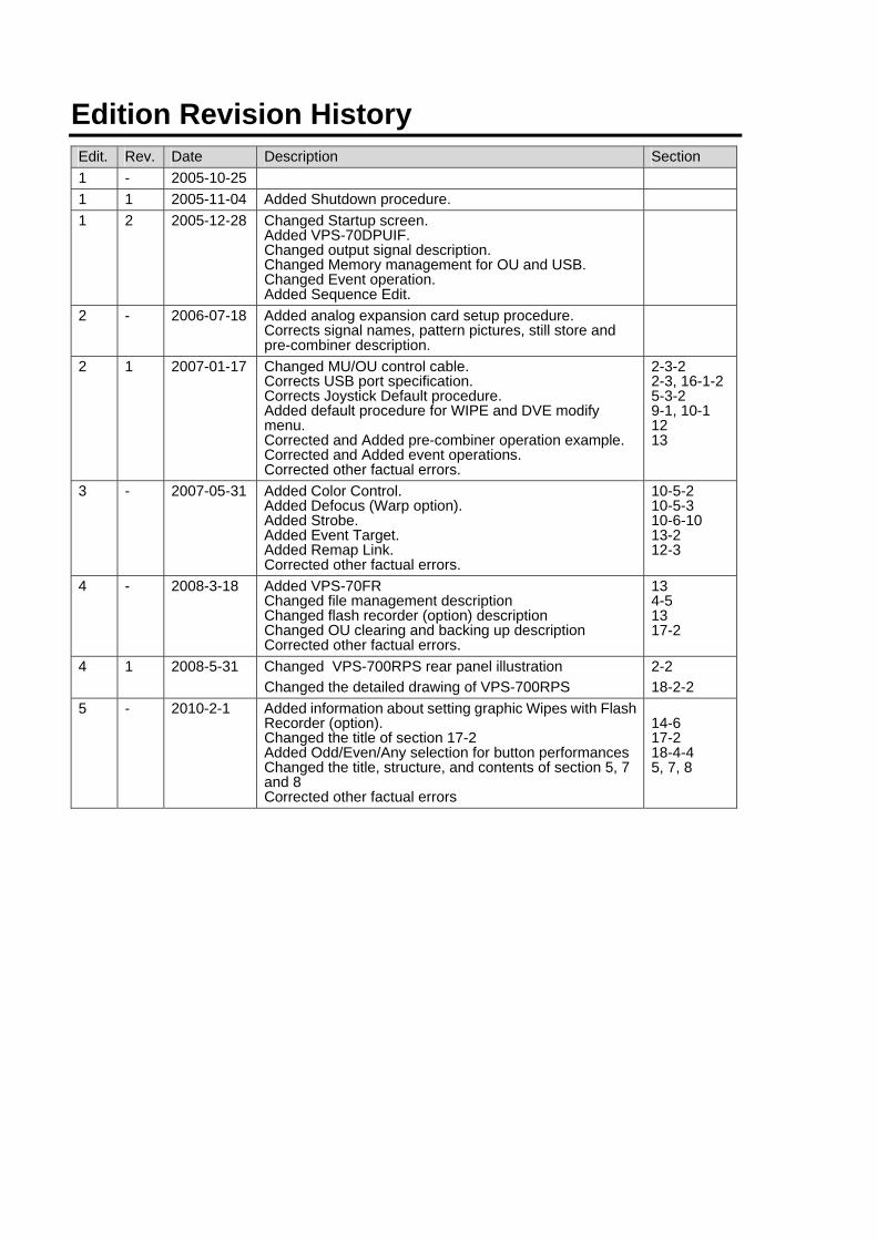
Edition Revision History Edit. Rev. Date Description Section 1 - 2005-10-25 1 1 2005-11-04 Added Shutdown procedure. 1 2 2005-12-28 Changed Startup screen.
Added VPS-70DPUIF. Changed output signal description. Changed Memory management for OU and USB. Changed Event operation. Added Sequence Edit.
2 - 2006-07-18 Added analog expansion card setup procedure. Corrects signal names, pattern pictures, still store and pre-combiner description.
2 1 2007-01-17 Changed MU/OU control cable. Corrects USB port specification. Corrects Joystick Default procedure. Added default procedure for WIPE and DVE modify menu. Corrected and Added pre-combiner operation example. Corrected and Added event operations. Corrected other factual errors.
2-3-2 2-3, 16-1-2 5-3-2 9-1, 10-1 12 13
3 - 2007-05-31 Added Color Control. Added Defocus (Warp option). Added Strobe. Added Event Target. Added Remap Link. Corrected other factual errors.
10-5-2 10-5-3 10-6-10 13-2 12-3
4 - 2008-3-18 Added VPS-70FR Changed file management description Changed flash recorder (option) description Changed OU clearing and backing up description Corrected other factual errors.
13 4-5 13 17-2
4 1 2008-5-31 Changed VPS-700RPS rear panel illustration Changed the detailed drawing of VPS-700RPS
2-2 18-2-2
5 - 2010-2-1 Added information about setting graphic Wipes with Flash Recorder (option). Changed the title of section 17-2 Added Odd/Even/Any selection for button performances Changed the title, structure, and contents of section 5, 7 and 8 Corrected other factual errors
14-6 17-2 18-4-4 5, 7, 8
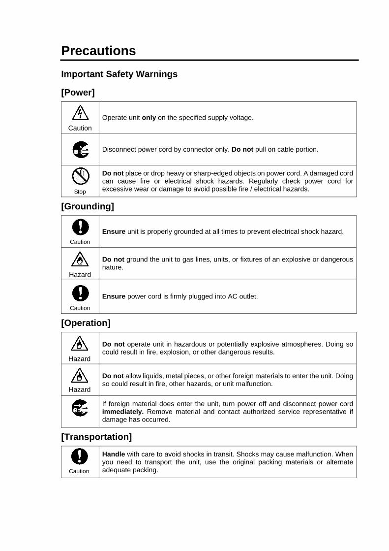
Precautions Important Safety Warnings
[Power]
Operate unit only on the specified supply voltage.
Disconnect power cord by connector only. Do not pull on cable portion.
Do not place or drop heavy or sharp-edged objects on power cord. A damaged cord can cause fire or electrical shock hazards. Regularly check power cord for excessive wear or damage to avoid possible fire / electrical hazards.
[Grounding]
Ensure unit is properly grounded at all times to prevent electrical shock hazard.
Do not ground the unit to gas lines, units, or fixtures of an explosive or dangerous nature.
Ensure power cord is firmly plugged into AC outlet.
[Operation]
Do not operate unit in hazardous or potentially explosive atmospheres. Doing so could result in fire, explosion, or other dangerous results.
Do not allow liquids, metal pieces, or other foreign materials to enter the unit. Doing so could result in fire, other hazards, or unit malfunction.
If foreign material does enter the unit, turn power off and disconnect power cord immediately. Remove material and contact authorized service representative if damage has occurred.
[Transportation]
Handle with care to avoid shocks in transit. Shocks may cause malfunction. When you need to transport the unit, use the original packing materials or alternate adequate packing.
Stop
Caution
Hazard
Hazard
Caution
Hazard
Caution
Caution
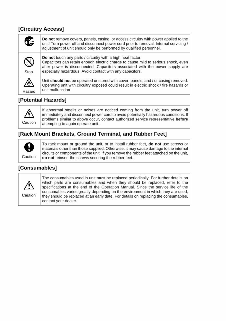
[Circuitry Access]
Do not remove covers, panels, casing, or access circuitry with power applied to the unit! Turn power off and disconnect power cord prior to removal. Internal servicing / adjustment of unit should only be performed by qualified personnel.
Do not touch any parts / circuitry with a high heat factor. Capacitors can retain enough electric charge to cause mild to serious shock, even after power is disconnected. Capacitors associated with the power supply are especially hazardous. Avoid contact with any capacitors.
Unit should not be operated or stored with cover, panels, and / or casing removed. Operating unit with circuitry exposed could result in electric shock / fire hazards or unit malfunction.
[Potential Hazards]
If abnormal smells or noises are noticed coming from the unit, turn power off immediately and disconnect power cord to avoid potentially hazardous conditions. If problems similar to above occur, contact authorized service representative before attempting to again operate unit.
[Rack Mount Brackets, Ground Terminal, and Rubber Feet]
To rack mount or ground the unit, or to install rubber feet, do not use screws or materials other than those supplied. Otherwise, it may cause damage to the internal circuits or components of the unit. If you remove the rubber feet attached on the unit, do not reinsert the screws securing the rubber feet.
[Consumables]
The consumables used in unit must be replaced periodically. For further details on which parts are consumables and when they should be replaced, refer to the specifications at the end of the Operation Manual. Since the service life of the consumables varies greatly depending on the environment in which they are used, they should be replaced at an early date. For details on replacing the consumables, contact your dealer.
Caution
Hazard
Stop
Caution
Caution
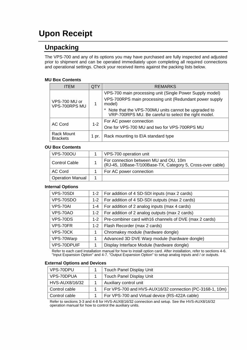
Upon Receipt Unpacking The VPS-700 and any of its options you may have purchased are fully inspected and adjusted prior to shipment and can be operated immediately upon completing all required connections and operational settings. Check your received items against the packing lists below.
MU Box Contents ITEM QTY REMARKS
VPS-700 MU or VPS-700RPS MU 1
VPS-700 main processing unit (Single Power Supply model) VPS-700RPS main processing unit (Redundant power supply model) * Note that the VPS-700MU units cannot be upgraded to
VRP-700RPS MU. Be careful to select the right model.
AC Cord 1-2 For AC power connection One for VPS-700 MU and two for VPS-700RPS MU
Rack Mount Brackets 1 pr. Rack mounting to EIA standard type
OU Box Contents VPS-700OU 1 VPS-700 operation unit
Control Cable 1 For connection between MU and OU, 10m (RJ-45, 10Base-T/100Base-TX, Category 5, Cross-over cable)
AC Cord 1 For AC power connection Operation Manual 1
Internal Options VPS-70SDI 1-2 For addition of 4 SD-SDI inputs (max 2 cards) VPS-70SDO 1-2 For addition of 4 SD-SDI outputs (max 2 cards) VPS-70AI 1-4 For addition of 2 analog inputs (max 4 cards) VPS-70AO 1-2 For addition of 2 analog outputs (max 2 cards) VPS-70DS 1-2 Pre-combiner card with16 channels of DVE (max 2 cards) VPS-70FR 1-2 Flash Recorder (max 2 cards) VPS-70CK 1 Chromakey module (hardware dongle) VPS-70Warp 1 Advanced 3D DVE Warp module (hardware dongle) VPS-70DPUIF 1 Display Interface Module (hardware dongle) Refer to each card installation manual for how to install option card. After installation, refer to sections 4-6. "Input Expansion Option" and 4-7. "Output Expansion Option" to setup analog inputs and / or outputs.
External Options and Devices VPS-70DPU 1 Touch Panel Display Unit VPS-70DPUA 1 Touch Panel Display Unit HVS-AUX8/16/32 1 Auxiliary control unit Control cable 1 For VPS-700 and HVS-AUX16/32 connection (PC-3168-1, 10m) Control cable 1 For VPS-700 and Virtual device (RS-422A cable) Refer to sections 3-3 and 4-8 for HVS-AUX8/16/32 connection and setup. See the HVS-AUX8/16/32 operation manual for how to control the auxiliary units.

Check Check to ensure no damage has occurred during shipment. If damage has occurred, or items are missing, inform your supplier immediately. Rack Mounting The VPS-700 can be mounted to EIA standard rack units. When rack mounting a unit, use the accessory rack mount brackets (rack ears).
Table of Contents
1. Prior to Starting ...........................................................................................................................1 1-1. Welcome.............................................................................................................................1 1-2. VPS-700 Overview..............................................................................................................1 1-3. About This Manual ..............................................................................................................2 1-4. Basic Switcher Operations..................................................................................................3
1-4-1. Background Transitions ..............................................................................................3 1-4-2. Key Transitions ...........................................................................................................4 1-4-3. DVE Pictures ..............................................................................................................5 1-4-4. Sequence Operation ...................................................................................................6
2. Panel Description........................................................................................................................7 2-1. VPS-700 MU (Single PS Model) .........................................................................................7 2-2. VPS-700RPS MU (Redundant PS Model) ..........................................................................8 2-3. Operation Unit.....................................................................................................................9
2-3-1. Control Panel ..............................................................................................................9 2-3-2. Rear Panel................................................................................................................10
2-4. Interfaces ..........................................................................................................................11 2-5. MU Rear Panel Cards.......................................................................................................14
3. Connection and Setup ..............................................................................................................15 3-1. Basic Connection ..............................................................................................................15 3-2. Optional Configuration ......................................................................................................16 3-3. Connection for Aux Output Control (Option) .....................................................................17
4. Setup ........................................................................................................................................18 4-1. Power ON .........................................................................................................................18 4-2. Selecting System Signal Format .......................................................................................19 4-3. Power OFF .......................................................................................................................20 4-4. Quick Reference for Menu Setting ....................................................................................21 4-5. File Management ..............................................................................................................22 4-6. Input Expansion Option.....................................................................................................24
4-6-1. Available Combinations of Card Installations ............................................................24 4-6-2. Adjustments on CPU Card ........................................................................................25 4-6-3. Settings for Optional Inputs.......................................................................................26
4-7. Output Expansion Option..................................................................................................27 4-7-1. Available combinations of card installations ..............................................................27 4-7-2. Settings for Optional Analog Outputs ........................................................................28
4-8. Connection Settings for Aux Output Control .....................................................................29 4-9. Easy Virtual Connection Setting........................................................................................30
5. Menu Description ......................................................................................................................31
5-1. Menu Overview ................................................................................................................ 31 5-2. Menu Display.................................................................................................................... 33 5-3. How to Access Menus ...................................................................................................... 34
5-3-1. How to Use Menus ................................................................................................... 36 5-3-2. Keypad Input ............................................................................................................ 37 5-3-3. Joystick Input............................................................................................................ 38
5-4. Returning to Default ......................................................................................................... 39 5-4-1. Using Menu Controls................................................................................................ 39 5-4-2. Using Buttons in Joystick Section............................................................................. 39
6. Touch Panel Operations (Option) ............................................................................................. 40
7. Signal Setting Workflow............................................................................................................ 41 7-1. Input Signal ...................................................................................................................... 41
7-1-1. Signal Name............................................................................................................. 41 7-1-2. Changing Signal Name ............................................................................................ 41 7-1-3. Selecting Signals for Background............................................................................. 43 7-1-4. Assigning Signals to M/E Bus................................................................................... 44 7-1-5. Input Signal and Frame Synchronizer Modes .......................................................... 45 7-1-6. Input Signal Adjustments (Proc Amp) ....................................................................... 46 7-1-7. Selecting Signals for Keys and DSKs....................................................................... 46
7-2. Output Signals.................................................................................................................. 47 7-2-1. Assigning Signals to Auxiliary Outputs ..................................................................... 47 7-2-2. Selecting Signals for PREV and CLEAN Outputs..................................................... 48 7-2-3. Selecting Preview Output ......................................................................................... 49
8. Transition Operations ............................................................................................................... 50 8-1. About Transitions.............................................................................................................. 50
8-1-1. Transition Rate ......................................................................................................... 51 8-2. Background Transitions.................................................................................................... 52
8-2-1. Cut............................................................................................................................ 52 8-2-2. Mix............................................................................................................................ 53 8-2-3. WIPE and DVE......................................................................................................... 54 8-2-4. Fader Limit ............................................................................................................... 55
8-3. Key and DSK Transitions ................................................................................................. 56 8-3-1. DSK Transitions and Changing Priority Orders ........................................................ 56 8-3-2. Key Cut Transitions .................................................................................................. 57 8-3-3. Mix Transitions for Keys ........................................................................................... 57 8-3-4. Wipe Transitions for Keys......................................................................................... 58 8-3-5. DVE Transitions for Keys ......................................................................................... 59 8-3-6. Priority Order Change of Keys.................................................................................. 59
8-4. BLACK Transitions ........................................................................................................... 60
9. Keyer / DSK Setup ................................................................................................................... 61
9-1. Keyer /DSK Setup Menu...................................................................................................61 9-2. Mask .................................................................................................................................63 9-3. Edge and Shadow.............................................................................................................64 9-4. Making and Adjusting Chromakeys (Option).....................................................................66
9-4-1. Auto Key ...................................................................................................................66 9-4-2. Adjusting Chromakey ................................................................................................67
9-5. Assigning DVEs to Keyers ................................................................................................69 9-5-1. About DVE Channels ................................................................................................69 9-5-2. Opening DVE Menus and Assigning DVE.................................................................69
10. Wipe Modify ............................................................................................................................70 10-1. Returning Wipe Modify Setting to Default .......................................................................71 10-2. Wipe Modify Example .....................................................................................................71
11. DVE Modify .............................................................................................................................72 11-1. Returning DVE Modify Setting to Default ........................................................................72 11-2. DVE Modify Example ......................................................................................................73 11-3. Basic ...............................................................................................................................75
11-3-1. Position and Rotation ..............................................................................................75 11-3-2. Aspect .....................................................................................................................76 11-3-3. Setup.......................................................................................................................76
11-4. Border .............................................................................................................................77 11-5. Sub Effect........................................................................................................................79
11-5-1. Trail .........................................................................................................................79 11-5-2. Chroma Control.......................................................................................................80 11-5-3. Strobe......................................................................................................................80
11-6. Warp (Option)..................................................................................................................81 11-6-1. Ripple......................................................................................................................81 11-6-2. Swirl ........................................................................................................................82 11-6-3. Mosaic.....................................................................................................................82 11-6-4. Slats ........................................................................................................................82 11-6-5. Lens ........................................................................................................................83 11-6-6. Page Turn................................................................................................................84 11-6-7. Page Peel................................................................................................................85 11-6-8. Splits .......................................................................................................................85 11-6-9. Mirror.......................................................................................................................86 11-6-10. Defocus.................................................................................................................86
11-7. Light (Option) ..................................................................................................................87 11-7-1. Type ........................................................................................................................87 11-7-2. Light 1-2 ..................................................................................................................87
12. Internally Generated Signals...................................................................................................88 12-1. Bus Mattes......................................................................................................................88 12-2. Still Store.........................................................................................................................88
12-2-1. Downloading Still Images from USB....................................................................... 89 12-2-2. Capturing Program Out and Saving Still ................................................................. 90 12-2-3. Assigning Stills to Video Sources ........................................................................... 90 12-2-4. Exporting Stills to USB Flash Memory Drive .......................................................... 91 12-2-5. Deleting Still File..................................................................................................... 91 12-2-6. 32-bit TGA Images ................................................................................................. 92
13. Pre-combiner (Option)............................................................................................................ 93 13-1. Setting Up Pre-combined Images................................................................................... 93 13-2. Editing Pre-combined Images ........................................................................................ 95 13-3. Merging Input Mapping................................................................................................... 96 13-4. Pre-combined Image Setting Example ........................................................................... 96
13-4-1. Setting Up Image A ................................................................................................ 97 13-4-2. Setting Up Image B ................................................................................................ 99 13-4-3. Making Transition ................................................................................................. 100
14. Flash Recorder (Option)....................................................................................................... 101 14-1. Managing Frame Memory ............................................................................................ 101 14-2. Initializing ..................................................................................................................... 102 14-3. Recording in Tracks...................................................................................................... 103 14-4. Editing Clips ................................................................................................................. 104 14-5. Clip Playback................................................................................................................ 105 14-6. Deleting Clips ............................................................................................................... 107
15. Event Memory ...................................................................................................................... 109 15-1. Storing Events .............................................................................................................. 109 15-2. Recalling Events............................................................................................................110 15-3. Clearing Events .............................................................................................................112 15-4. Backing up Events to OU or USB Memory....................................................................112
16. Sequence Operations............................................................................................................113 16-1. Storing Sequence to Memory ........................................................................................113 16-2. Recalling Sequence ......................................................................................................114 16-3. Playing Sequence .........................................................................................................114 16-4. Editing Sequence ..........................................................................................................115
17. Interface Settings ..................................................................................................................117 17-1. RS422 Interfaces...........................................................................................................117 17-2. GPI Inputs .....................................................................................................................118 17-3. Tally Outputs..................................................................................................................119
18. System Setup....................................................................................................................... 120 18-1. Signal Format and System Delay ................................................................................. 120 18-2. Clearing and Backing Up OU ....................................................................................... 121
18-2-1. Clearing Data ....................................................................................................... 121
18-2-2. Backing Up OU Data.............................................................................................123 18-3. Update ..........................................................................................................................125 18-4. Status............................................................................................................................126
18-4-1. Option Boards .......................................................................................................126 18-4-2. Alarm.....................................................................................................................127 18-4-3. CPU Version .........................................................................................................127 18-4-4. Field Selection for Switchover...............................................................................128
19. Specifications and Dimensions .............................................................................................129 19-1. Unit Specifications.........................................................................................................129
19-1-1. VPS-700 ...............................................................................................................129 19-1-2. VPS-700OU ..........................................................................................................130 19-1-3. VPS-70AI ..............................................................................................................130 19-1-4. VPS-70AO ............................................................................................................131
19-2. External Dimensions .....................................................................................................132 19-2-1. VPS-700 MU.........................................................................................................132 19-2-2. VPS-700RPS MU..................................................................................................133 19-2-3. VPS-700OU ..........................................................................................................134
Appendix 1. Menu List ................................................................................................................135 1-1. M/E menu .......................................................................................................................135 1-2. Keyer / DSK menu ..........................................................................................................136 1-3. Pre-Combiner menu........................................................................................................138 1-4. Flash Recorder menu .....................................................................................................139 1-5. Still Store menu...............................................................................................................139 1-6. Sequence and Event menu.............................................................................................140 1-7. Setup (Matte, Input, Aux) menu ......................................................................................141 1-8. Setup (System, Serial, GPIO/Tally, Data Backup, Update) menu................................142 1-9. Status menu....................................................................................................................143 1-10. DVE Modify (Basic, Border) menu ................................................................................143 1-11. DVE Modify (Sub Effects) menu....................................................................................144 1-12. DVE Modify (Warp) menu (Option) ...............................................................................145 1-13. DVE Modify (Light) menu (Option) ................................................................................146
Appendix 2. GUI menu................................................................................................................147 2-1. M/E menu .......................................................................................................................147 2-2. Keyer / DSK menu ..........................................................................................................151 2-3. Pre-Combiner menu........................................................................................................155 2-4. Flash Recorder Menu .....................................................................................................158 2-5. Still Store menu...............................................................................................................162 2-6. Sequence, Event menu...................................................................................................163 2-7. Setup (Matte, Input, Output) menu..................................................................................165 2-8. Setup (System, Serial, GPIO/Tally, Data Backup, Update) menu................................168 2-9. Status menu....................................................................................................................173

Appendix 3. Pattern List ............................................................................................................. 175 3-1. WIPE Pattern List ........................................................................................................... 175 3-2. 2.5D (2D & Basic 3D) DVE Pattern List.......................................................................... 176 3-3. 3D DVE (VPS-700Warp Option) Pattern List.................................................................. 177
Index .......................................................................................................................................... 180
1
1. Prior to Starting
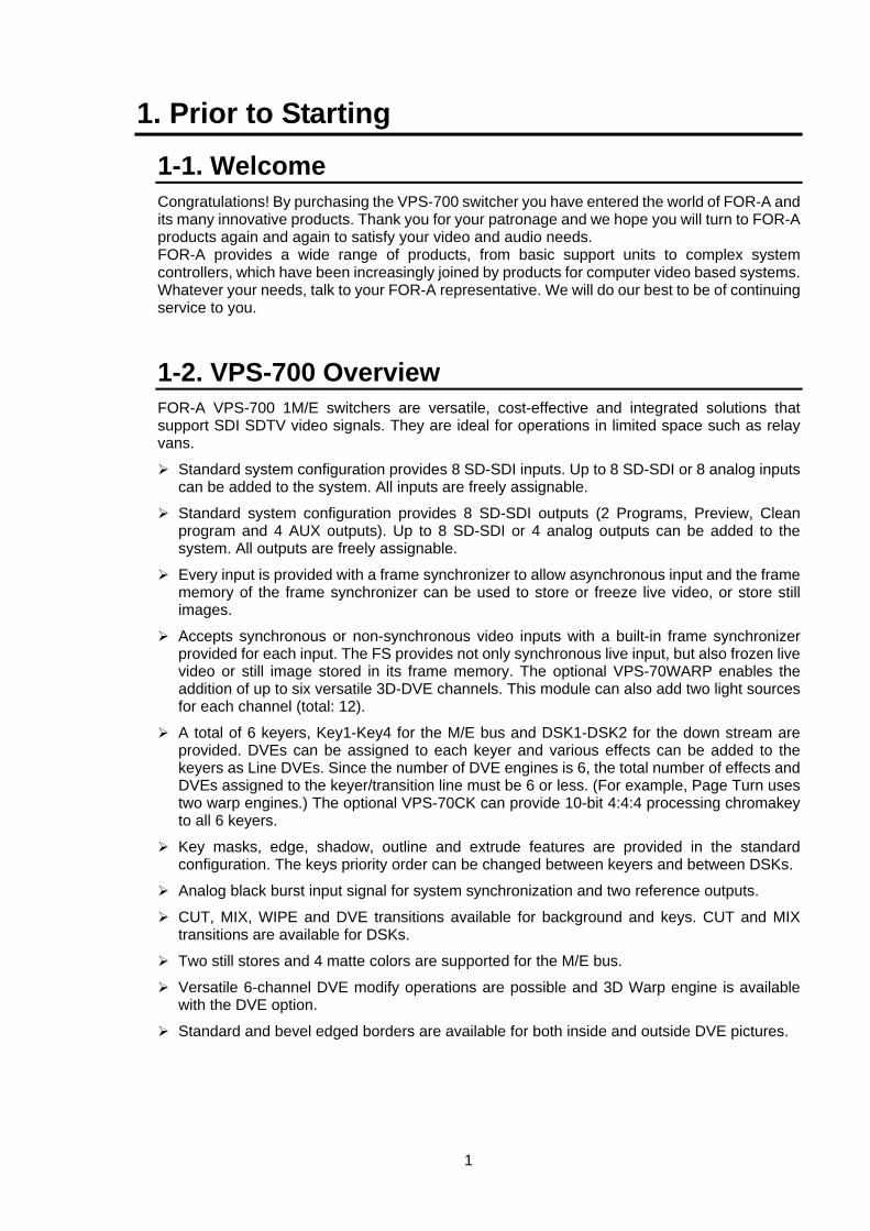
1-1. Welcome Congratulations! By purchasing the VPS-700 switcher you have entered the world of FOR-A and its many innovative products. Thank you for your patronage and we hope you will turn to FOR-A products again and again to satisfy your video and audio needs. FOR-A provides a wide range of products, from basic support units to complex system controllers, which have been increasingly joined by products for computer video based systems. Whatever your needs, talk to your FOR-A representative. We will do our best to be of continuing service to you.
1-2. VPS-700 Overview FOR-A VPS-700 1M/E switchers are versatile, cost-effective and integrated solutions that support SDI SDTV video signals. They are ideal for operations in limited space such as relay vans.
Standard system configuration provides 8 SD-SDI inputs. Up to 8 SD-SDI or 8 analog inputs can be added to the system. All inputs are freely assignable.
Standard system configuration provides 8 SD-SDI outputs (2 Programs, Preview, Clean program and 4 AUX outputs). Up to 8 SD-SDI or 4 analog outputs can be added to the system. All outputs are freely assignable.
Every input is provided with a frame synchronizer to allow asynchronous input and the frame memory of the frame synchronizer can be used to store or freeze live video, or store still images.
Accepts synchronous or non-synchronous video inputs with a built-in frame synchronizer provided for each input. The FS provides not only synchronous live input, but also frozen live video or still image stored in its frame memory. The optional VPS-70WARP enables the addition of up to six versatile 3D-DVE channels. This module can also add two light sources for each channel (total: 12).
A total of 6 keyers, Key1-Key4 for the M/E bus and DSK1-DSK2 for the down stream are provided. DVEs can be assigned to each keyer and various effects can be added to the keyers as Line DVEs. Since the number of DVE engines is 6, the total number of effects and DVEs assigned to the keyer/transition line must be 6 or less. (For example, Page Turn uses two warp engines.) The optional VPS-70CK can provide 10-bit 4:4:4 processing chromakey to all 6 keyers.
Key masks, edge, shadow, outline and extrude features are provided in the standard configuration. The keys priority order can be changed between keyers and between DSKs.
Analog black burst input signal for system synchronization and two reference outputs.
CUT, MIX, WIPE and DVE transitions available for background and keys. CUT and MIX transitions are available for DSKs.
Two still stores and 4 matte colors are supported for the M/E bus.
Versatile 6-channel DVE modify operations are possible and 3D Warp engine is available with the DVE option.
Standard and bevel edged borders are available for both inside and outside DVE pictures.
2
By installing an optional DVE Input Card, Basic 2.5D-DVEs (position, size, rotation, border) can be added to each input, and two precombiners can be added. The precombined video signals can be assigned as primary signals or materials for keyers. One DVE input card has 16 lines of DVEs. Since up to 2 cards can be installed, DVE can be assigned to all Combiner A/B inputs even at the most number of inputs.
Up to 8 configurable signal layers, including PGM, PST, 4 Keys and 2 DSKs, are supported in the standard system. The optional pre-combiners enable to create the pre-combined image with up to17 layers and the program output with up to 25 layers.
Optional Flash Recorder card is available. Up to a total of two Flash Recorder cards and DVE cards are installable into two shared slots. One flash recorder card can store approximately 120 seconds of D1 uncompressed images in non-volatile memory and also supports simultaneous playback of up to two channels with a key. Playback is available in different modes such as loop play mode, and trigger play mode.
The internal event memory for saving and reading 96 events (setting data).
100 sequences with up to 31 keyframes each can be saved.
Built-in USB ports for flash drive for uploading and downloading setting files and image sources.
Standard system includes three RS-422 ports and 8 GPI inputs and 24 tally outputs capabilities (Remote connector) for various remote controls.
An optional SVGA (800 x 600) Touch Panel LCD display is available for the intuitive menu operation using GUI.
VPS-700 unit is housed in a compact EIA 2RU standard size. VPS-700RPS is EIA 3RU.
Redundant power supply (VPS-700RPS only).
1-3. About This Manual This manual is intended to help users easily operate the VPS-700 and make full use of its functions during operations. Before connecting or operating your unit, read this operation manual thoroughly to ensure you understand the product. After reading, it is important to keep this manual in a safe place and available for reference. Font Conventions The following conventions are used through out this manual:
Circled text (such as AUTO) is used for buttons.
Text in square brackets (such as [SYSTEM] - [GPI]) is used for menu and submenu titles.
Shaded text (such as ON) is used for the setting items and values in the menus.
3
1-4. Basic Switcher Operations This chapter explains important information that you need to know before using the VPS-700. This includes points related to transition, key setup, DVE key and sequence operations.
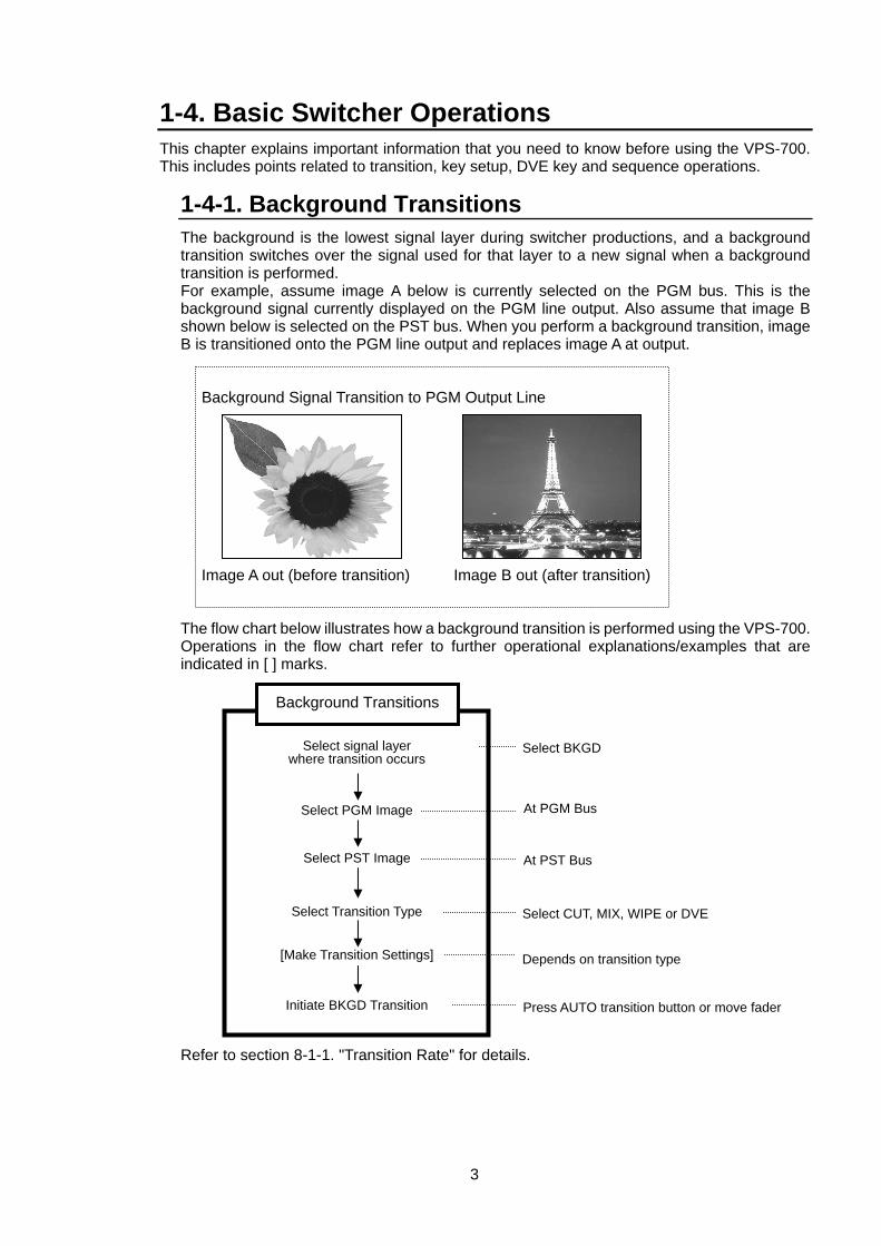
1-4-1. Background Transitions The background is the lowest signal layer during switcher productions, and a background transition switches over the signal used for that layer to a new signal when a background transition is performed. For example, assume image A below is currently selected on the PGM bus. This is the background signal currently displayed on the PGM line output. Also assume that image B shown below is selected on the PST bus. When you perform a background transition, image B is transitioned onto the PGM line output and replaces image A at output. Background Signal Transition to PGM Output Line Image A out (before transition) Image B out (after transition) The flow chart below illustrates how a background transition is performed using the VPS-700. Operations in the flow chart refer to further operational explanations/examples that are indicated in [ ] marks. Refer to section 8-1-1. "Transition Rate" for details.
Background Transitions
Initiate BKGD Transition Press AUTO transition button or move fader
Select PST Image At PST Bus
Select PGM Image At PGM Bus
Select signal layer where transition occurs
Select BKGD
Select Transition Type Select CUT, MIX, WIPE or DVE
[Make Transition Settings] Depends on transition type
4
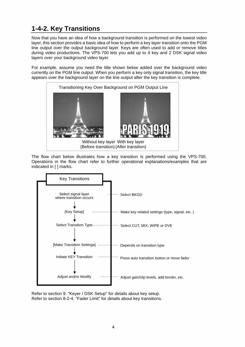
1-4-2. Key Transitions Now that you have an idea of how a background transition is performed on the lowest video layer, this section provides a basic idea of how to perform a key layer transition onto the PGM line output over the output background layer. Keys are often used to add or remove titles during video productions. The VPS-700 lets you add up to 4 key and 2 DSK signal video layers over your background video layer. For example, assume you need the title shown below added over the background video currently on the PGM line output. When you perform a key only signal transition, the key title appears over the background layer on the line output after the key transition is complete.
Transitioning Key Over Background on PGM Output Line
Without key layer With key layer (Before transition) (After transition)
The flow chart below illustrates how a key transition is performed using the VPS-700. Operations in the flow chart refer to further operational explanations/examples that are indicated in [ ] marks.
Refer to section 9. "Keyer / DSK Setup" for details about key setup. Refer to section 8-2-4. "Fader Limit” for details about key transitions.
Key Transitions
Adjust and/or Modify Adjust gain/clip levels, add border, etc.
Select Transition Type Select CUT, MIX, WIPE or DVE
[Key Setup] Make key related settings (type, signal, etc. )
Select signal layer where transition occurs
Select BKGD
[Make Transition Settings] Depends on transition type
Initiate KEY Transition Press auto transition button or move fader
5
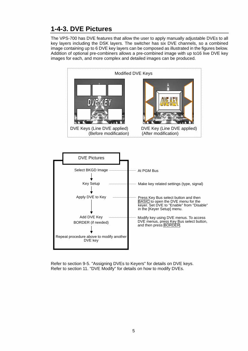
1-4-3. DVE Pictures The VPS-700 has DVE features that allow the user to apply manually adjustable DVEs to all key layers including the DSK layers. The switcher has six DVE channels, so a combined image containing up to 6 DVE key layers can be composed as illustrated in the figures below. Addition of optional pre-combiners allows a pre-combined image with up to16 live DVE key images for each, and more complex and detailed images can be produced.
Modified DVE Keys
DVE Keys (Line DVE applied) DVE Key (Line DVE applied) (Before modification) (After modification)
Refer to section 9-5. "Assigning DVEs to Keyers" for details on DVE keys. Refer to section 11. "DVE Modify" for details on how to modify DVEs.
DVE Pictures
Apply DVE to Key Press Key Bus select button and then BASIC to open the DVE menu for the keyer. Set DVE to "Enable" from "Disable" in the [Keyer Setup] menu.
Key Setup Make key related settings (type, signal)
Select BKGD Image At PGM Bus
Add DVE Key BORDER (if needed)
Modify key using DVE menus. To access DVE menus, press Key Bus select button, and then press BORDER.
Repeat procedure above to modify anotherDVE key
6
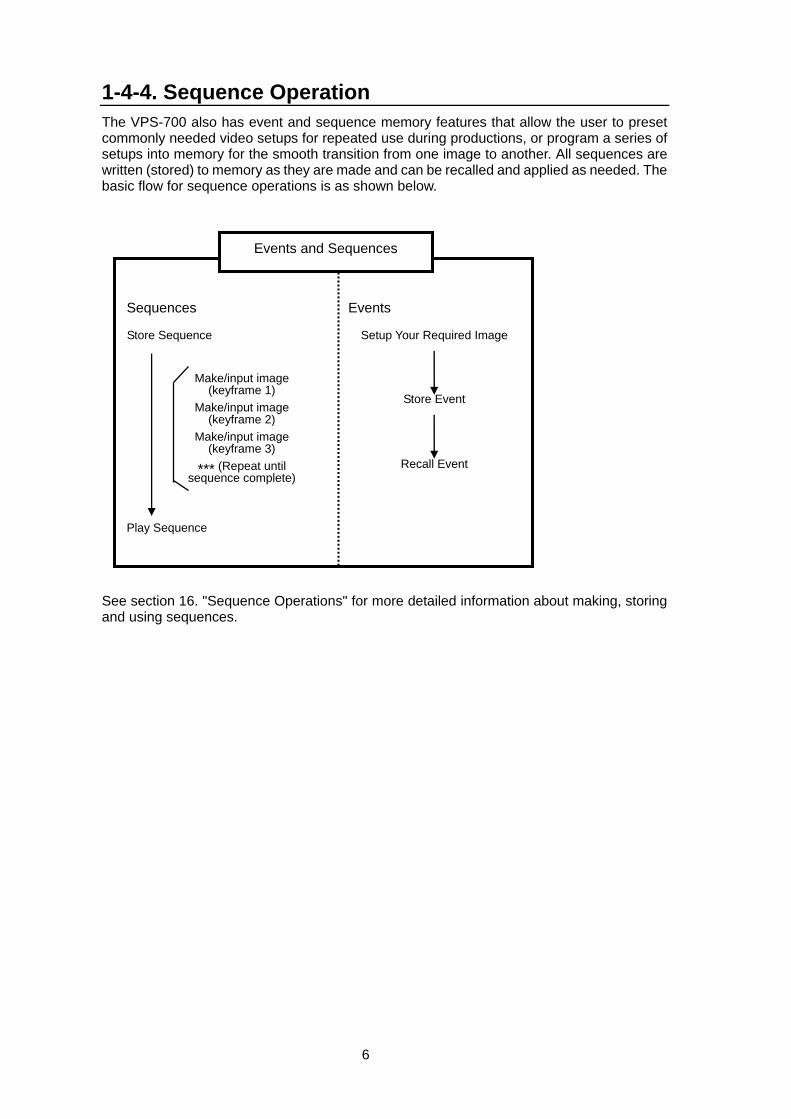
1-4-4. Sequence Operation The VPS-700 also has event and sequence memory features that allow the user to preset commonly needed video setups for repeated use during productions, or program a series of setups into memory for the smooth transition from one image to another. All sequences are written (stored) to memory as they are made and can be recalled and applied as needed. The basic flow for sequence operations is as shown below.
See section 16. "Sequence Operations" for more detailed information about making, storing and using sequences.
Events and Sequences
Setup Your Required Image
Store Event
Recall Event
Store Sequence
Play Sequence
Make/input image (keyframe 1)
Make/input image (keyframe 2)
Make/input image (keyframe 3)
*** (Repeat until sequence complete)
Sequences Events
7
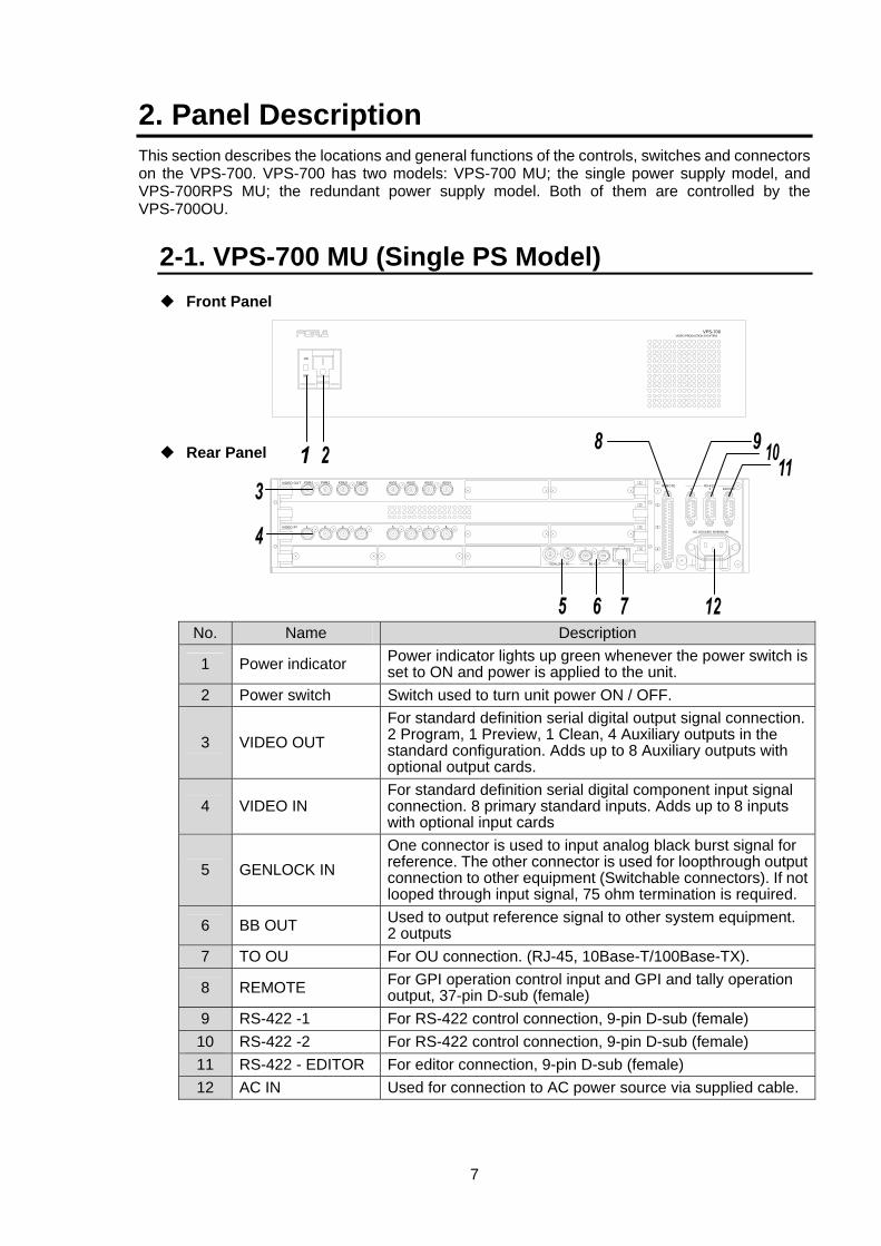
2. Panel Description This section describes the locations and general functions of the controls, switches and connectors on the VPS-700. VPS-700 has two models: VPS-700 MU; the single power supply model, and VPS-700RPS MU; the redundant power supply model. Both of them are controlled by the VPS-700OU.
2-1. VPS-700 MU (Single PS Model) Front Panel
Rear Panel
No. Name Description
1 Power indicator Power indicator lights up green whenever the power switch is set to ON and power is applied to the unit.
2 Power switch Switch used to turn unit power ON / OFF.
3 VIDEO OUT For standard definition serial digital output signal connection.2 Program, 1 Preview, 1 Clean, 4 Auxiliary outputs in the standard configuration. Adds up to 8 Auxiliary outputs with optional output cards.
4 VIDEO IN For standard definition serial digital component input signal connection. 8 primary standard inputs. Adds up to 8 inputs with optional input cards
5 GENLOCK IN One connector is used to input analog black burst signal for reference. The other connector is used for loopthrough output connection to other equipment (Switchable connectors). If not looped through input signal, 75 ohm termination is required.
6 BB OUT Used to output reference signal to other system equipment. 2 outputs
7 TO OU For OU connection. (RJ-45, 10Base-T/100Base-TX).
8 REMOTE For GPI operation control input and GPI and tally operation output, 37-pin D-sub (female)
9 RS-422 -1 For RS-422 control connection, 9-pin D-sub (female) 10 RS-422 -2 For RS-422 control connection, 9-pin D-sub (female) 11 RS-422 - EDITOR For editor connection, 9-pin D-sub (female) 12 AC IN Used for connection to AC power source via supplied cable.
ON
OFF
VPS-700VIDEO PRODUCTION SYSYTEM
1
4
3
2
1
2
1
TO OU
2
GENLOCK IN BB OUT
4
3 41 862 5 7 3VIDEO IN
VIDEO OUTREMOTE
EDITOR2RS-422
1
AC 100-240V 50/60Hz IN
PGM1 PGM2 PREV CLEAN AUX1 AUX2 AUX3 AUX4
8
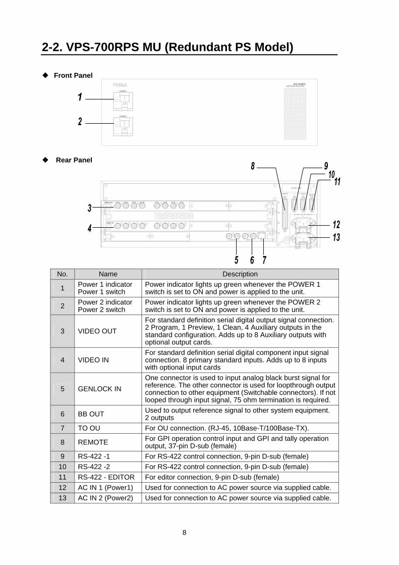
2-2. VPS-700RPS MU (Redundant PS Model)
Front Panel
Rear Panel
No. Name Description
1 Power 1 indicator Power 1 switch
Power indicator lights up green whenever the POWER 1 switch is set to ON and power is applied to the unit.
2 Power 2 indicator Power 2 switch
Power indicator lights up green whenever the POWER 2 switch is set to ON and power is applied to the unit.
3 VIDEO OUT For standard definition serial digital output signal connection.2 Program, 1 Preview, 1 Clean, 4 Auxiliary outputs in the standard configuration. Adds up to 8 Auxiliary outputs with optional output cards.
4 VIDEO IN For standard definition serial digital component input signal connection. 8 primary standard inputs. Adds up to 8 inputs with optional input cards
5 GENLOCK IN One connector is used to input analog black burst signal for reference. The other connector is used for loopthrough output connection to other equipment (Switchable connectors). If not looped through input signal, 75 ohm termination is required.
6 BB OUT Used to output reference signal to other system equipment. 2 outputs
7 TO OU For OU connection. (RJ-45, 10Base-T/100Base-TX).
8 REMOTE For GPI operation control input and GPI and tally operation output, 37-pin D-sub (female)
9 RS-422 -1 For RS-422 control connection, 9-pin D-sub (female) 10 RS-422 -2 For RS-422 control connection, 9-pin D-sub (female) 11 RS-422 - EDITOR For editor connection, 9-pin D-sub (female) 12 AC IN 1 (Power1) Used for connection to AC power source via supplied cable. 13 AC IN 2 (Power2) Used for connection to AC power source via supplied cable.
ON
OFF
ON
OFF
POWER 1
POWER 2
VPS-700RPSVIDEO PRODUCTION SYSTEM
1
2
3
4
752 6 81 43
21 4
3
2
1 2
1VIDEO OUT
GE NLOCK IN BB OUT TO OU
VIDEO IN
PGM 1 PGM 2 PR EV AUX1 AUX2 AU X3CLE AN AU X4
AC 100 - 240 V 50 / 60 Hz IN
R ATING LABEL
REM OTE R S-422EDITOR
1
2
9
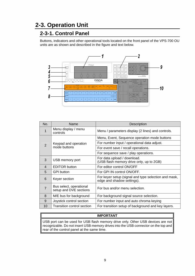
2-3. Operation Unit 2-3-1. Control Panel Buttons, indicators and other operational tools located on the front panel of the VPS-700 OU units are as shown and described in the figure and text below.
No. Name Description
1 Menu display / menu controls Menu / parameters display (2 lines) and controls.
Menu, Event, Sequence operation mode buttons For number input / operational data adjust. For event save / recall operations.
2 Keypad and operation mode buttons
For sequence save / play operations.
3 USB memory port For data upload / download. (USB flash memory drive only, up to 2GB)
4 EDITOR button For editor control ON/OFF 5 GPI button For GPI IN control ON/OFF.
6 Keyer section For keyer setup (signal and type selection and mask, edge and shadow settings).
7 Bus select, operational setup and DVE sections For bus and/or menu selection.
8 M/E bus for background For background signal source selection. 9 Joystick control section For number input and auto chroma keying
10 Transition control section For transition setup of background and key layers.
IMPORTANT
USB port can be used for USB flash memory drive only. Other USB devices are not recognizable. Do not insert USB memory drives into the USB connector on the top and rear of the control panel at the same time.
1
TRANSITION
PRIORITY1 OVER 2
21
2
4
3 4
321
LOW1 2 3 4
4321
HIGH
KEY STATUSKEY LAYER
Z
Y
X
DSK
FADER DIRECTION
JOYSTICK
VPS-700VIDEO PRODUCTION SYSTEM
F3 F4F2F1
DEFAULT FINE
DVE ROT
WIPE POS
DVE POS
AUTO CK
SEQ LINK FADER LIMIT NOR/REV REVERSE PREV TRANS
DSK1
DSK2
DSKCUT
BLACKTRANS
DSKMIX
KEY2
KEY4
DVE(NAM)
KEY1
KEY3
WIPE(FAM)
BKGD
MIX
AUTO
TRANSITION TYPE
CUT
DVE
KEYER
SHIFT
SHIFT
SHIFT
COMBINER SETUP
12
12
11
11
10
10
9
9
BORDERBASIC
8
8
EVENTCOMB B
7
7
SEQCOMB A
6
6
DSK2STILL
5
5
DSK1STATUS
4
4
3
3
KEY4
SETUP
BUS SELECT
KEY3AUX
2
2
KEY2
1
1
KEY1MATTE
BLACK
PROGRAM
BLACK
PRESET
KEY ON
GPI
EXT SELF CK EDGE SHADOWMASKVIDEO PRODUCTION SYSTEM
MULTI LAYERINGGINGA
EDITOR
USB MEMORY
EVENT
-
RECALL
2 3
8 97
MENU
SEQ
1
STORE
65
LOOP DIR
4
INSERT
ENTER
DELETE
CANCEL
NEW
.0
INPUT SYSTEM
SUB EFF WARP LIGHT
10
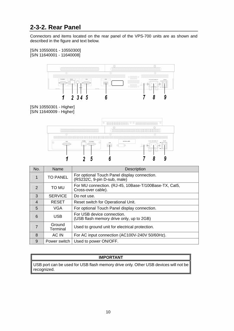
2-3-2. Rear Panel Connectors and items located on the rear panel of the VPS-700 units are as shown and described in the figure and text below.
[S/N 10550001 - 10550300] [S/N 11640001 - 11640008] [S/N 10550301 - Higher] [S/N 11640009 - Higher]
No. Name Description
1 TO PANEL For optional Touch Panel display connection. (RS232C, 9-pin D-sub, male)
2 TO MU For MU connection. (RJ-45, 10Base-T/100Base-TX, Cat5, Cross-over cable).
3 SERVICE Do not use. 4 RESET Reset switch for Operational Unit. 5 VGA For optional Touch Panel display connection.
6 USB For USB device connection. (USB flash memory drive only, up to 2GB)
7 Ground Terminal Used to ground unit for electrical protection.
8 AC IN For AC input connection (AC100V-240V 50/60Hz). 9 Power switch Used to power ON/OFF.
IMPORTANT
USB port can be used for USB flash memory drive only. Other USB devices will not be recognized.
ON
TO PANEL VGA
RESET
TO MU USB AC 100-240V 50/60Hz IN
OFF
POWER
OFF
ONON
OFF
USBVGA TO MU TO PANEL RATING LABEL AC100 - 200V 50/60Hz IN POW ER

11
2-4. Interfaces EDITOR Connector
Pin Assignment Table (9-pin D-sub female) Pin No. Signal Name Description
1 FG Frame ground 2 T- Transmit data (-) 3 R+ Receive data (+) 4 SG Signal ground 5 - Not used 6 SG Signal ground 7 T+ Transmit data (+) 8 R- Receive data (-) 9 FG Frame ground
Cable Connectors 9-pin D-sub connector (male) with inch security lock screws.
RS-422 (1) (2) Connector
Pin Assignment Table (9-pin D-sub female) Pin No. Signal Name Description
1 FG Frame ground 2 R- Receive data (-) 3 T+ Transmit data (+) 4 SG Signal ground 5 - Not used 6 SG Signal ground 7 R+ Receive data (+) 8 T- Transmit data (-) 9 FG Frame ground
Cable Connectors 9-pin D-sub connector (male) with inch security lock screws.
12
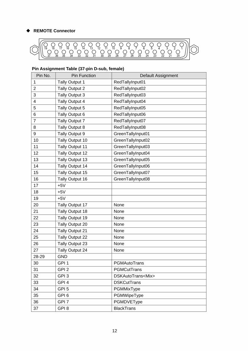
REMOTE Connector
Pin Assignment Table (37-pin D-sub, female) Pin No. Pin Function Default Assignment
1 Tally Output 1 RedTallyInput01 2 Tally Output 2 RedTallyInput02 3 Tally Output 3 RedTallyInput03 4 Tally Output 4 RedTallyInput04 5 Tally Output 5 RedTallyInput05 6 Tally Output 6 RedTallyInput06 7 Tally Output 7 RedTallyInput07 8 Tally Output 8 RedTallyInput08 9 Tally Output 9 GreenTallyInput01 10 Tally Output 10 GreenTallyInput02 11 Tally Output 11 GreenTallyInput03 12 Tally Output 12 GreenTallyInput04 13 Tally Output 13 GreenTallyInput05 14 Tally Output 14 GreenTallyInput06 15 Tally Output 15 GreenTallyInput07 16 Tally Output 16 GreenTallyInput08 17 +5V 18 +5V 19 +5V 20 Tally Output 17 None 21 Tally Output 18 None 22 Tally Output 19 None 23 Tally Output 20 None 24 Tally Output 21 None 25 Tally Output 22 None 26 Tally Output 23 None 27 Tally Output 24 None 28-29 GND 30 GPI 1 PGMAutoTrans 31 GPI 2 PGMCutTrans 32 GPI 3 DSKAutoTrans<Mix> 33 GPI 4 DSKCutTrans 34 GPI 5 PGMMixType 35 GPI 6 PGMWipeType 36 GPI 7 PGMDVEType 37 GPI 8 BlackTrans
13
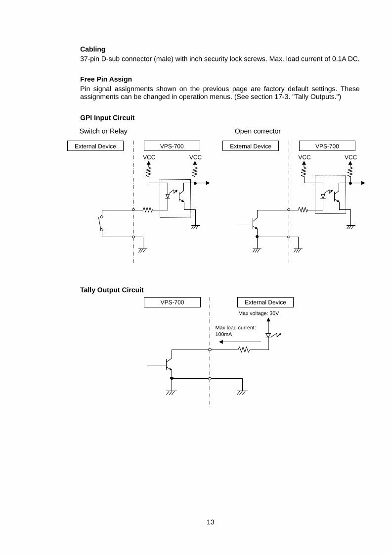
Cabling 37-pin D-sub connector (male) with inch security lock screws. Max. load current of 0.1A DC.
Free Pin Assign Pin signal assignments shown on the previous page are factory default settings. These assignments can be changed in operation menus. (See section 17-3. "Tally Outputs.")
GPI Input Circuit
Tally Output Circuit
VPS-700
VCCVCC
External Device
Open corrector
VPS-700
VCCVCC
External Device
Switch or Relay
External Device
Max voltage: 30V
VPS-700
Max load current: 100mA
14
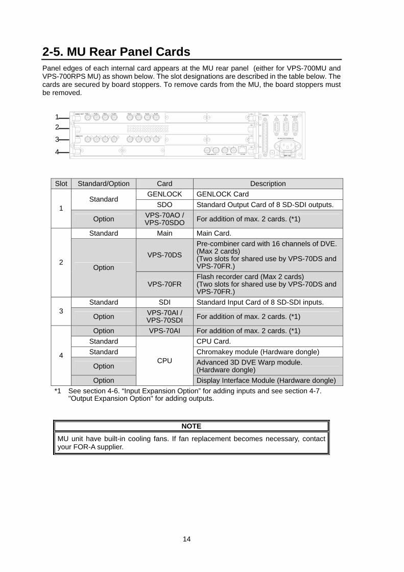
2-5. MU Rear Panel Cards Panel edges of each internal card appears at the MU rear panel (either for VPS-700MU and VPS-700RPS MU) as shown below. The slot designations are described in the table below. The cards are secured by board stoppers. To remove cards from the MU, the board stoppers must be removed.
Slot Standard/Option Card Description
GENLOCK GENLOCK Card Standard
SDO Standard Output Card of 8 SD-SDI outputs. 1 Option VPS-70AO /
VPS-70SDO For addition of max. 2 cards. (*1)
Standard Main Main Card.
VPS-70DS Pre-combiner card with 16 channels of DVE.(Max 2 cards) (Two slots for shared use by VPS-70DS and VPS-70FR.) 2
Option
VPS-70FR Flash recorder card (Max 2 cards) (Two slots for shared use by VPS-70DS and VPS-70FR.)
Standard SDI Standard Input Card of 8 SD-SDI inputs. 3
Option VPS-70AI / VPS-70SDI For addition of max. 2 cards. (*1)
Option VPS-70AI For addition of max. 2 cards. (*1) Standard CPU Card. Standard Chromakey module (Hardware dongle)
Option Advanced 3D DVE Warp module. (Hardware dongle)
4
Option
CPU
Display Interface Module (Hardware dongle) *1 See section 4-6. “Input Expansion Option” for adding inputs and see section 4-7.
"Output Expansion Option" for adding outputs.
NOTE
MU unit have built-in cooling fans. If fan replacement becomes necessary, contact your FOR-A supplier.
3 41 862 5 7VIDEO IN
PGM 1 AUX2PGM 2 AUX1CLEAN AUX4PREV AUX3VIDEO OUT
4
3
2
1
2
1
TO OU
2
GENLOCK IN BB OUT
4
3
REMOTE1
SER.NO.
1 EDITOR2RS-422
AC100-240V 50/60Hz IN
1 2
3
4
15
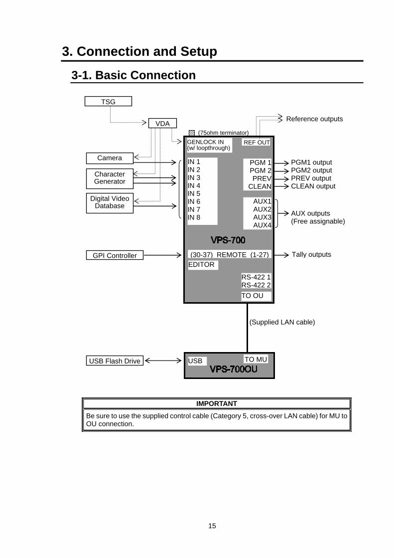
3. Connection and Setup
3-1. Basic Connection
IMPORTANT
Be sure to use the supplied control cable (Category 5, cross-over LAN cable) for MU to OU connection.
REF OUT
1
GENLOCK IN (w/ loopthrough)
IN 1 IN 2 IN 3 IN 4 IN 5 IN 6 IN 7 IN 8
PGM1 outputPGM2 outputPREV outputCLEAN output
Reference outputs
GPI Controller
TO OU
RS-422 1RS-422 2
REF OUT
VDA
TSG
Character Generator
Camera PGM 1PGM 2PREV
CLEAN
(30-37) REMOTE (1-27) Tally outputs
Digital Video Database
TO MU
(75ohm terminator)
AUX1AUX2AUX3AUX4
AUX outputs (Free assignable)
EDITOR
USBUSB Flash Drive
(Supplied LAN cable)
16
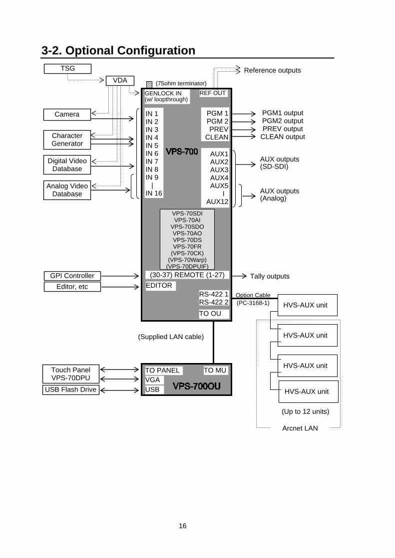
3-2. Optional Configuration
REF OUT
1
IN 1 IN 2 IN 3 IN 4 IN 5 IN 6 IN 7 IN 8 IN 9 | IN 16
PGM1 output PGM2 output PREV output
CLEAN output
GPI Controller
TO OU
RS-422 1RS-422 2
TSG
Character Generator
Camera PGM 1PGM 2PREV
CLEAN
(30-37) REMOTE (1-27) Tally outputs
Digital Video Database
TO MU
AUX1AUX2AUX3AUX4AUX5
I AUX12
AUX outputs (SD-SDI)
EDITOR
GENLOCK IN (w/ loopthrough)
Reference outputs
REF OUT(75ohm terminator)
VGA
Editor, etc
USB
Touch Panel VPS-70DPU
USB Flash Drive
TO PANEL
(Supplied LAN cable)
VPS-70SDIVPS-70AI
VPS-70SDO VPS-70AO VPS-70DS VPS-70FR
(VPS-70CK) (VPS-70Warp)
(VPS-70DPUIF)
HVS-AUX unit
HVS-AUX unit
HVS-AUX unit
Arcnet LAN
Option Cable(PC-3168-1)
(Up to 12 units)
Analog Video Database
VDA
AUX outputs (Analog)
HVS-AUX unit
17
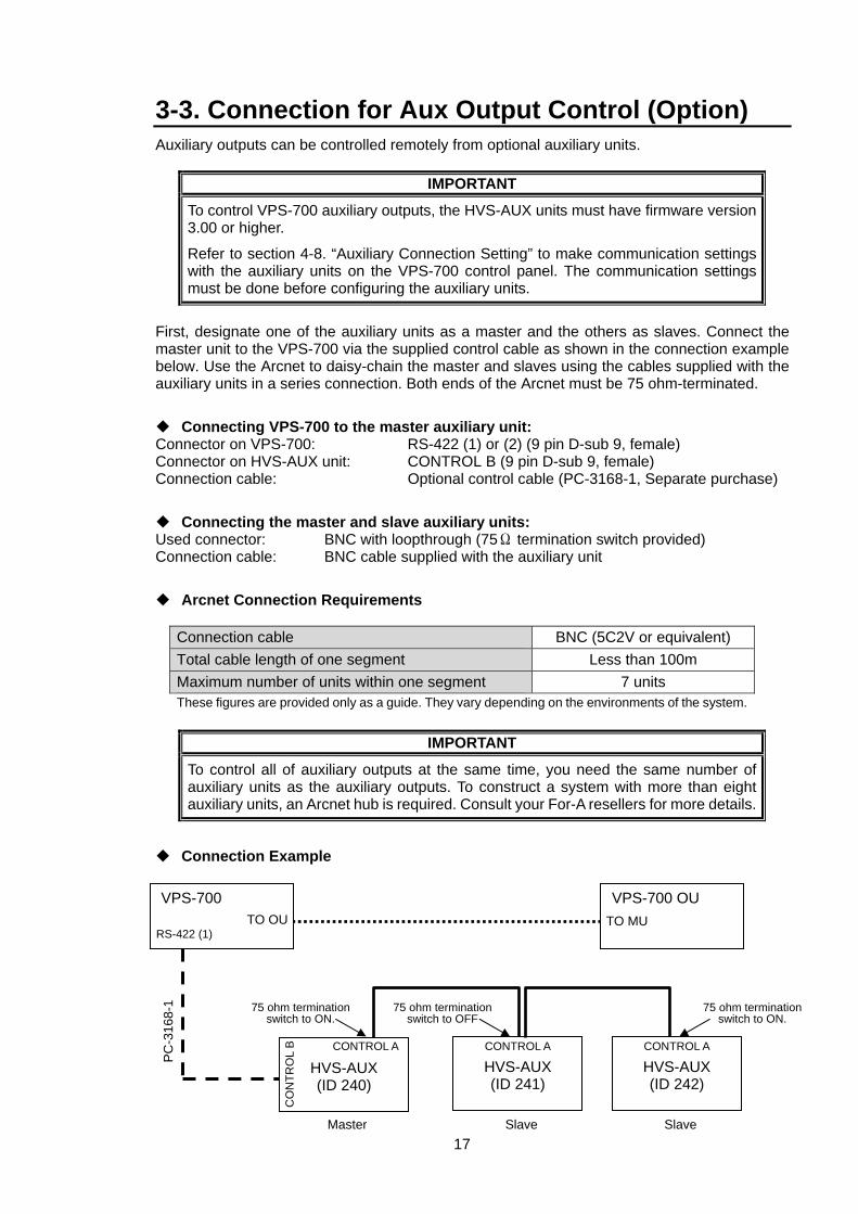
3-3. Connection for Aux Output Control (Option) Auxiliary outputs can be controlled remotely from optional auxiliary units.
IMPORTANT
To control VPS-700 auxiliary outputs, the HVS-AUX units must have firmware version 3.00 or higher.
Refer to section 4-8. “Auxiliary Connection Setting” to make communication settings with the auxiliary units on the VPS-700 control panel. The communication settings must be done before configuring the auxiliary units.
First, designate one of the auxiliary units as a master and the others as slaves. Connect the master unit to the VPS-700 via the supplied control cable as shown in the connection example below. Use the Arcnet to daisy-chain the master and slaves using the cables supplied with the auxiliary units in a series connection. Both ends of the Arcnet must be 75 ohm-terminated.
Connecting VPS-700 to the master auxiliary unit: Connector on VPS-700: RS-422 (1) or (2) (9 pin D-sub 9, female) Connector on HVS-AUX unit: CONTROL B (9 pin D-sub 9, female) Connection cable: Optional control cable (PC-3168-1, Separate purchase)
Connecting the master and slave auxiliary units: Used connector: BNC with loopthrough (75Ω termination switch provided) Connection cable: BNC cable supplied with the auxiliary unit
Arcnet Connection Requirements
Connection cable BNC (5C2V or equivalent) Total cable length of one segment Less than 100m Maximum number of units within one segment 7 units These figures are provided only as a guide. They vary depending on the environments of the system.
IMPORTANT
To control all of auxiliary outputs at the same time, you need the same number of auxiliary units as the auxiliary outputs. To construct a system with more than eight auxiliary units, an Arcnet hub is required. Consult your For-A resellers for more details.
Connection Example
75 ohm termination switch to ON.
HVS-AUX (ID 240)
HVS-AUX (ID 241)
75 ohm termination switch to OFF
Master
CO
NTR
OL
B
Slave Slave
CONTROL A CONTROL A
HVS-AUX (ID 242)
CONTROL A
75 ohm termination switch to ON.
PC-3
168-
1
VPS-700 OU VPS-700
RS-422 (1) TO OU TO MU
18
4. Setup
4-1. Power ON Before powering ON the VPS-700, verify that all cabling connections are secure and power supplies are properly connected.
Turn all units in the system ON.
Set the power switch on the VPS-700 front panel to ON. The power indicator lights up green when power is supplied to the unit.
Set the power switch on the VPS-700OU rear panel to ON to start up the operation unit.
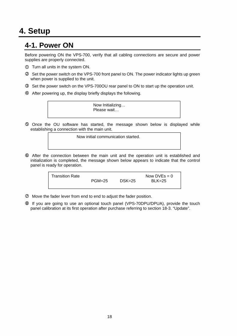
After powering up, the display briefly displays the following.
Once the OU software has started, the message shown below is displayed while establishing a connection with the main unit.
After the connection between the main unit and the operation unit is established and initialization is completed, the message shown below appears to indicate that the control panel is ready for operation.
Move the fader lever from end to end to adjust the fader position.
If you are going to use an optional touch panel (VPS-70DPU/DPUA), provide the touch panel calibration at its first operation after purchase referring to section 18-3. “Update”.
Now Initializing… Please wait…
Transition Rate Now DVEs = 0 PGM=25 DSK=25 BLK=25
Now initial communication started.
19
4-2. Selecting System Signal Format Before using your switcher, select a signal format for your system.
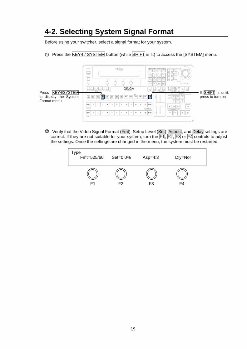
Press the KEY4 / SYSTEM button (while SHIFT is lit) to access the [SYSTEM] menu.
Verify that the Video Signal Format (Fmt), Setup Level (Set), Aspect, and Delay settings are correct. If they are not suitable for your system, turn the F1, F2, F3 or F4 controls to adjust the settings. Once the settings are changed in the menu, the system must be restarted.
F1 F2 F3 F4
Type Fmt=525/60 Set=0.0% Asp=4:3 Dly=Nor
1
TRANSITION
PRIORITY1 OVER 2
21
2
4
3 4
321
LOW1 2 3 4
4321
HIGH
KEY STATUSKEY LAYER
Z
Y
X
DSK
FADER DIRECTION
JOYSTICK
VPS-700VIDEO PRODUCTION SYSTEM
F3 F4F2F1
DEFAULT FINE
DVE ROT
WIPE POS
DVE POS
AUTO CK
SEQ LINK FADER LIMIT NOR/REV REVERSE PREV TRANS
DSK1
DSK2
DSKCUT
BLACKTRANS
DSKMIX
KEY2
KEY4
DVE(NAM)
KEY1
KEY3
WIPE(FAM)
BKGD
MIX
AUTO
TRANSITION TYPE
CUT
DVE
KEYER
SHIFT
SHIFT
SHIFT
COMBINER SETUP
12
12
11
11
10
10
9
9
BORDERBASIC
8
8
EVENTCOMB B
7
7
SEQCOMB A
6
6
DSK2STILL
5
5
DSK1STATUS
4
4
3
3
KEY4
SETUP
BUS SELECT
KEY3AUX
2
2
KEY2
1
1
KEY1MATTE
BLACK
PROGRAM
BLACK
PRESET
KEY ON
GPI
EXT SELF CK EDGE SHADOWMASKVIDEO PRODUCTION SYSTEM
MULTI LAYERINGGINGA
EDITOR
USB MEMORY
EVENT
-
RECALL
2 3
8 97
MENU
SEQ
1
STORE
65
LOOP DIR
4
INSERT
ENTER
DELETE
CANCEL
NEW
.0
INPUT SYSTEM
SUB EFF WARP LIGHT
If SHIFT is unlit, press to turn on
Press KEY4/SYSTEMto display the System Format menu
20
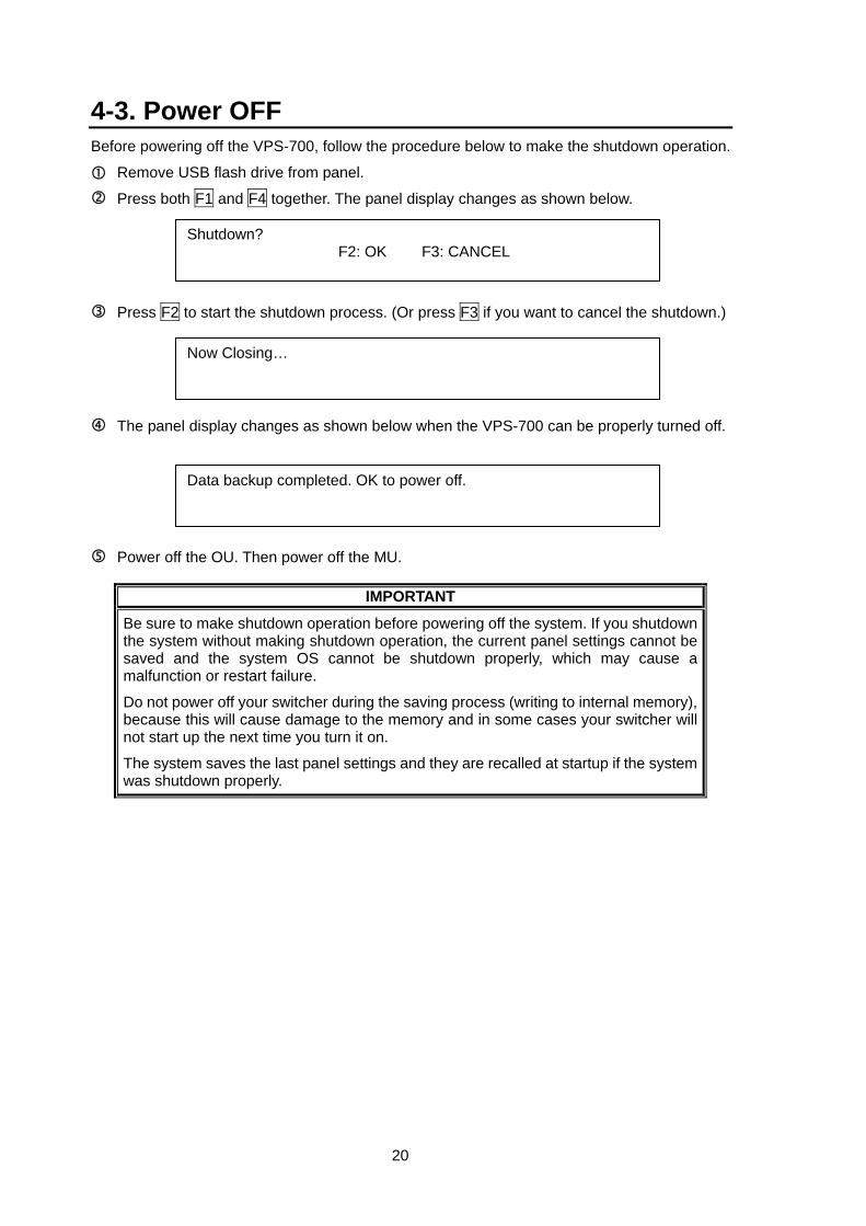
4-3. Power OFF Before powering off the VPS-700, follow the procedure below to make the shutdown operation.
Remove USB flash drive from panel.
Press both F1 and F4 together. The panel display changes as shown below.
Press F2 to start the shutdown process. (Or press F3 if you want to cancel the shutdown.)
The panel display changes as shown below when the VPS-700 can be properly turned off.
Power off the OU. Then power off the MU.
IMPORTANT
Be sure to make shutdown operation before powering off the system. If you shutdown the system without making shutdown operation, the current panel settings cannot be saved and the system OS cannot be shutdown properly, which may cause a malfunction or restart failure.
Do not power off your switcher during the saving process (writing to internal memory), because this will cause damage to the memory and in some cases your switcher will not start up the next time you turn it on.
The system saves the last panel settings and they are recalled at startup if the system was shutdown properly.
Shutdown? F2: OK F3: CANCEL
Data backup completed. OK to power off.
Now Closing…
21
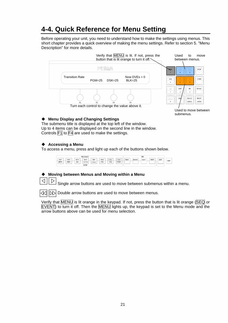
4-4. Quick Reference for Menu Setting Before operating your unit, you need to understand how to make the settings using menus. This short chapter provides a quick overview of making the menu settings. Refer to section 5. "Menu Description" for more details.
Menu Display and Changing Settings The submenu title is displayed at the top left of the window. Up to 4 items can be displayed on the second line in the window. Controls F1 to F4 are used to make the settings.
Accessing a Menu To access a menu, press and light up each of the buttons shown below.
Moving between Menus and Moving within a Menu Single arrow buttons are used to move between submenus within a menu.
Double arrow buttons are used to move between menus.
Verify that MENU is lit orange in the keypad. If not, press the button that is lit orange (SEQ or EVENT) to turn it off. Then the MENU lights up, the keypad is set to the Menu mode and the arrow buttons above can be used for menu selection.
DVE
SHIFTBORDERBASIC
EVENTCOMB B
SEQCOMB ADSK2
STILLDSK1
STATUS
KEY4
SETUP
BUS SELECTKEY3AUX
KEY2KEY1MATTE INPUT SYSTEM
SUB EFF WARP LIGHT
Transition Rate Now DVEs = 0 PGM=25 DSK=25 BLK=25
F3 F4F2F1
EVENT
-
RECALL
2 3
8 97
MENU
SEQ
1
STORE
65
LOOP DIR
4
INSERT
ENTER
DELETE
CANCEL
NEW
.0
Used to move between menus.
Used to move between submenus.
Verify that MENU is lit. If not, press the button that is lit orange to turn it off.
Turn each control to change the value above it.
22
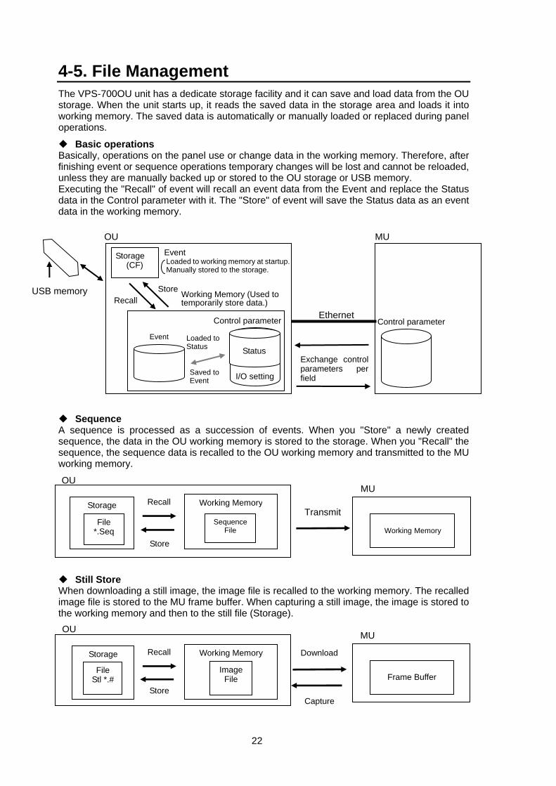
4-5. File Management The VPS-700OU unit has a dedicate storage facility and it can save and load data from the OU storage. When the unit starts up, it reads the saved data in the storage area and loads it into working memory. The saved data is automatically or manually loaded or replaced during panel operations.
Basic operations Basically, operations on the panel use or change data in the working memory. Therefore, after finishing event or sequence operations temporary changes will be lost and cannot be reloaded, unless they are manually backed up or stored to the OU storage or USB memory. Executing the "Recall" of event will recall an event data from the Event and replace the Status data in the Control parameter with it. The "Store" of event will save the Status data as an event data in the working memory.
Sequence A sequence is processed as a succession of events. When you "Store" a newly created sequence, the data in the OU working memory is stored to the storage. When you "Recall" the sequence, the sequence data is recalled to the OU working memory and transmitted to the MU working memory.
Still Store When downloading a still image, the image file is recalled to the working memory. The recalled image file is stored to the MU frame buffer. When capturing a still image, the image is stored to the working memory and then to the still file (Storage).
Transmit
Working Memory
MU
Storage
File *.Seq
Working Memory
SequenceFile
Store
Recall
OU
Storage
File Stl *.#
Download
Capture
Working Memory
ImageFile
Store
Recall
Frame Buffer
MUOU
USB memory
Exchange control parameters per field
MU
Control parameter
OU
Storage (CF)
Control parameter
Event
Recall
Ethernet
Loaded to Status
Store Working Memory (Used to temporarily store data.)
Status
I/O setting
Event Loaded to working memory at startup. Manually stored to the storage.
Saved to Event
23
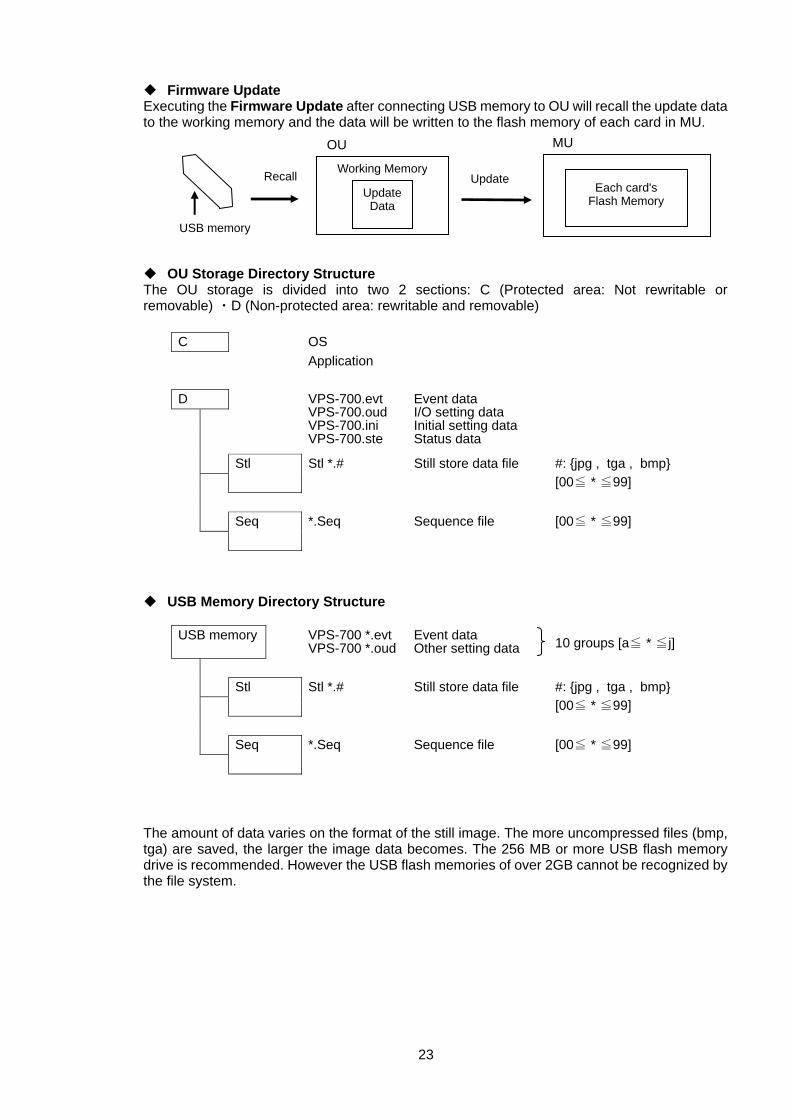
Firmware Update Executing the Firmware Update after connecting USB memory to OU will recall the update data to the working memory and the data will be written to the flash memory of each card in MU.
OU Storage Directory Structure The OU storage is divided into two 2 sections: C (Protected area: Not rewritable or removable) ・D (Non-protected area: rewritable and removable)
C OS Application D
VPS-700.evt VPS-700.oud VPS-700.ini VPS-700.ste
Event data I/O setting data Initial setting data Status data
Stl Stl *.# Still store data file
#: {jpg , tga , bmp} [00≦ * ≦99]
Seq *.Seq Sequence file
[00≦ * ≦99]
USB Memory Directory Structure
USB memory VPS-700 *.evt VPS-700 *.oud
Event data Other setting data
10 groups [a≦ * ≦j]
Stl
Stl *.# Still store data file #: {jpg , tga , bmp} [00≦ * ≦99]
[00≦ * ≦99]
Seq *.Seq
Sequence file
The amount of data varies on the format of the still image. The more uncompressed files (bmp, tga) are saved, the larger the image data becomes. The 256 MB or more USB flash memory drive is recommended. However the USB flash memories of over 2GB cannot be recognized by the file system.
Working Memory
UpdateData
Each card'sFlash Memory
MU
USB memory
UpdateRecall
OU
24
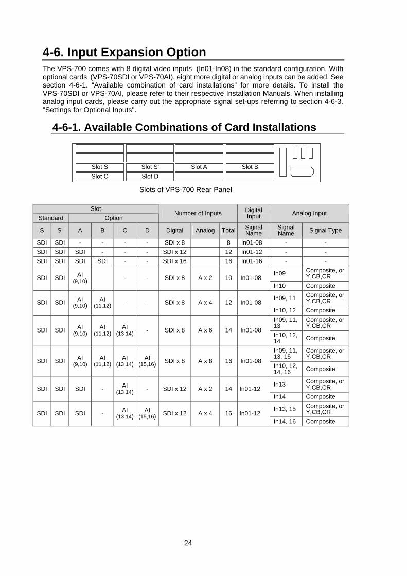
4-6. Input Expansion Option The VPS-700 comes with 8 digital video inputs (In01-In08) in the standard configuration. With optional cards (VPS-70SDI or VPS-70AI), eight more digital or analog inputs can be added. See section 4-6-1. “Available combination of card installations” for more details. To install the VPS-70SDI or VPS-70AI, please refer to their respective Installation Manuals. When installing analog input cards, please carry out the appropriate signal set-ups referring to section 4-6-3. "Settings for Optional Inputs".
4-6-1. Available Combinations of Card Installations
Slot Standard Option
Number of Inputs Digital Input Analog Input
S S' A B C D Digital Analog Total Signal Name
Signal Name Signal Type
SDI SDI - - - - SDI x 8 8 In01-08 - - SDI SDI SDI - - - SDI x 12 12 In01-12 - - SDI SDI SDI SDI - - SDI x 16 16 In01-16 - -
In09 Composite, or Y,CB,CR SDI SDI AI
(9,10) - - SDI x 8 A x 2 10 In01-08 In10 Composite
In09, 11 Composite, or Y,CB,CR SDI SDI AI
(9,10) AI
(11,12) - - SDI x 8 A x 4 12 In01-08 In10, 12 Composite In09, 11, 13
Composite, or Y,CB,CR
SDI SDI AI (9,10)
AI (11,12)
AI (13,14) - SDI x 8 A x 6 14 In01-08
In10, 12, 14 Composite
In09, 11, 13, 15
Composite, or Y,CB,CR
SDI SDI AI (9,10)
AI (11,12)
AI (13,14)
AI (15,16) SDI x 8 A x 8 16 In01-08
In10, 12, 14, 16 Composite
In13 Composite, or Y,CB,CR SDI SDI SDI - AI
(13,14) - SDI x 12 A x 2 14 In01-12 In14 Composite
In13, 15 Composite, or Y,CB,CR SDI SDI SDI - AI
(13,14) AI
(15,16) SDI x 12 A x 4 16 In01-12 In14, 16 Composite
Slot S Slot C
Slot S' Slot D
Slot A Slot B
Slots of VPS-700 Rear Panel
25
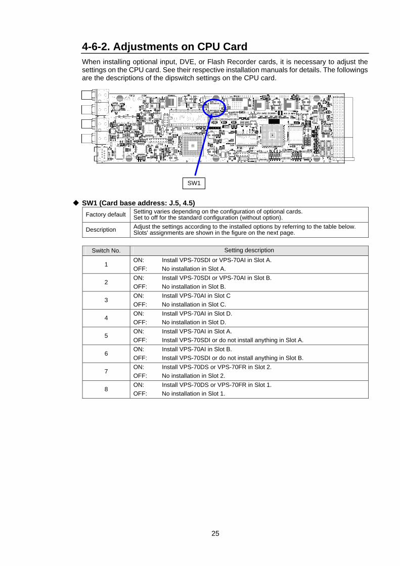
4-6-2. Adjustments on CPU Card When installing optional input, DVE, or Flash Recorder cards, it is necessary to adjust the settings on the CPU card. See their respective installation manuals for details. The followings are the descriptions of the dipswitch settings on the CPU card.
SW1 (Card base address: J.5, 4.5) Factory default Setting varies depending on the configuration of optional cards.
Set to off for the standard configuration (without option).
Description Adjust the settings according to the installed options by referring to the table below. Slots' assignments are shown in the figure on the next page.
Switch No. Setting description
1 ON: Install VPS-70SDI or VPS-70AI in Slot A. OFF: No installation in Slot A.
2 ON: Install VPS-70SDI or VPS-70AI in Slot B. OFF: No installation in Slot B.
3 ON: Install VPS-70AI in Slot C OFF: No installation in Slot C.
4 ON: Install VPS-70AI in Slot D. OFF: No installation in Slot D.
5 ON: Install VPS-70AI in Slot A. OFF: Install VPS-70SDI or do not install anything in Slot A.
6 ON: Install VPS-70AI in Slot B. OFF: Install VPS-70SDI or do not install anything in Slot B.
7 ON: Install VPS-70DS or VPS-70FR in Slot 2. OFF: No installation in Slot 2.
8 ON: Install VPS-70DS or VPS-70FR in Slot 1. OFF: No installation in Slot 1.
SW1
26
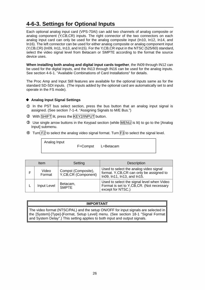
4-6-3. Settings for Optional Inputs Each optional analog input card (VPS-70AI) can add two channels of analog composite or analog component (Y,CB,CR) inputs. The right connector of the two connectors on each analog input card can only be used for the analog composite input (In10, In12, In14, and In16). The left connector can be used for either analog composite or analog component input (Y,CB,CR) (In09, In11, In13, and In15). For the Y,CB,CR input in the NTSC (525/60) standard, select the video signal level from Betacam or SMPTE according to the format the source device uses. When installing both analog and digital input cards together, the IN09 through IN12 can be used for the digital inputs, and the IN13 through IN16 can be used for the analog inputs. See section 4-6-1. "Available Combinations of Card Installations" for details. The Proc Amp and Input Still features are available for the optional inputs same as for the standard SD-SDI inputs. (The inputs added by the optional card are automatically set to and operate in the FS mode).
Analog Input Signal Settings
In the PST bus select section, press the bus button that an analog input signal is assigned. (See section 7-1-4. “Assigning Signals to M/E Bus.”)
With SHIFT lit, press the KEY2/INPUT button.
Use single arrow buttons in the Keypad section (while MENU is lit) to go to the [Analog Input] submenu.
Turn F2 to select the analog video signal format. Turn F3 to select the signal level.
Item Setting Description
F Video Format
Compst (Composite), Y,CB,CR (Component)
Used to select the analog video signal format. Y,CB,CR can only be assigned to In09, In11, In13, and In15.
L Input Level Betacam, SMPTE
Used to select the signal level when Video Format is set to Y,CB,CR. (Not necessary except for NTSC.)
IMPORTANT
The video format (NTSC/PAL) and the setup ON/OFF for input signals are selected in the [System]-[Type]-[Format, Setup Level] menu. (See section 18-1 "Signal Format and System Delay".) This setting applies to both input and output signals.
Analog Input F=Compst L=Betacam
27
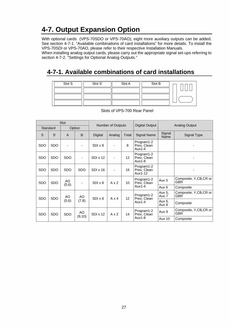
4-7. Output Expansion Option With optional cards (VPS-70SDO or VPS-70AO), eight more auxiliary outputs can be added. See section 4-7-1. “Available combinations of card installations” for more details. To install the VPS-70SDI or VPS-70AO, please refer to their respective Installation Manuals. When installing analog output cards, please carry out the appropriate signal set-ups referring to section 4-7-2. "Settings for Optional Analog Outputs."
4-7-1. Available combinations of card installations
Slot Standard Option
Number of Outputs Digital Output Analog Output
S S' A B Digital Analog Total Signal Name Signal Name Signal Type
SDO SDO - - SDI x 8 - 8 Program1-2 Prev, Clean Aux1-4
-
SDO SDO SDO - SDI x 12 - 12 Program1-2 Prev, Clean Aux1-8
-
SDO SDO SDO SDO SDI x 16 - 16 Program1-2 Prev, Clean Aux1-12
-
Aux 5 Composite, Y,CB,CR or GBR SDO SDO AO
(5,6) - SDI x 8 A x 2 10 Program1-2 Prev, Clean Aux1-4 Aux 6 Composite
Aux 5, Aux 7
Composite, Y,CB,CR or GBR
SDO SDO AO (5,6)
AO (7,8) SDI x 8 A x 4 12
Program1-2 Prev, Clean Aux1-4 Aux 6,
Aux 8 Composite
Aux 9 Composite, Y,CB,CR or GBR SDO SDO SDO AO
(9,10) SDI x 12 A x 2 14 Program1-2 Prev, Clean Aux1-8 Aux 10 Composite
Slot S
Slot S'
Slot A
Slot B
Slots of VPS-700 Rear Panel
28
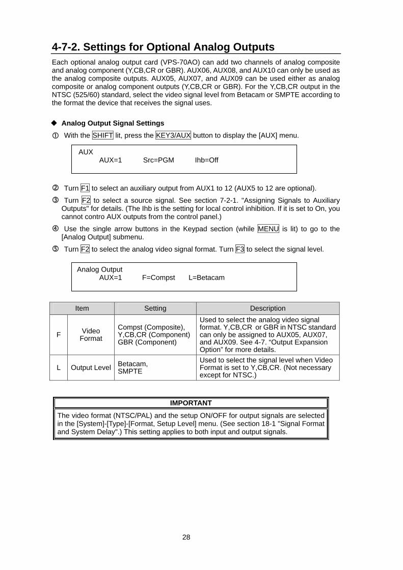
4-7-2. Settings for Optional Analog Outputs Each optional analog output card (VPS-70AO) can add two channels of analog composite and analog component (Y,CB,CR or GBR). AUX06, AUX08, and AUX10 can only be used as the analog composite outputs. AUX05, AUX07, and AUX09 can be used either as analog composite or analog component outputs (Y,CB,CR or GBR). For the Y,CB,CR output in the NTSC (525/60) standard, select the video signal level from Betacam or SMPTE according to the format the device that receives the signal uses.
Analog Output Signal Settings
With the SHIFT lit, press the KEY3/AUX button to display the [AUX] menu.
Turn F1 to select an auxiliary output from AUX1 to 12 (AUX5 to 12 are optional).
Turn F2 to select a source signal. See section 7-2-1. "Assigning Signals to Auxiliary Outputs" for details. (The Ihb is the setting for local control inhibition. If it is set to On, you cannot contro AUX outputs from the control panel.)
Use the single arrow buttons in the Keypad section (while MENU is lit) to go to the [Analog Output] submenu.
Turn F2 to select the analog video signal format. Turn F3 to select the signal level.
Item Setting Description
F Video Format
Compst (Composite), Y,CB,CR (Component)GBR (Component)
Used to select the analog video signal format. Y,CB,CR or GBR in NTSC standard can only be assigned to AUX05, AUX07, and AUX09. See 4-7. “Output Expansion Option” for more details.
L Output Level Betacam, SMPTE
Used to select the signal level when Video Format is set to Y,CB,CR. (Not necessary except for NTSC.)
IMPORTANT
The video format (NTSC/PAL) and the setup ON/OFF for output signals are selected in the [System]-[Type]-[Format, Setup Level] menu. (See section 18-1 "Signal Format and System Delay".) This setting applies to both input and output signals.
Analog Output AUX=1 F=Compst L=Betacam
AUX AUX=1 Src=PGM Ihb=Off
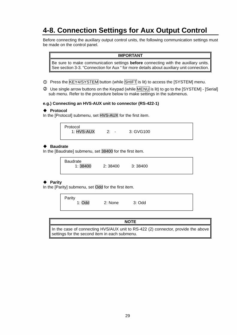
29
4-8. Connection Settings for Aux Output Control Before connecting the auxiliary output control units, the following communication settings must be made on the control panel.
IMPORTANT
Be sure to make communication settings before connecting with the auxiliary units. See section 3-3. “Connection for Aux “ for more details about auxiliary unit connection.
Press the KEY4/SYSTEM button (while SHIFT is lit) to access the [SYSTEM] menu.
Use single arrow buttons on the Keypad (while MENU is lit) to go to the [SYSTEM] - [Serial] sub menu. Refer to the procedure below to make settings in the submenus.
e.g.) Connecting an HVS-AUX unit to connector (RS-422-1)
Protocol In the [Protocol] submenu, set HVS-AUX for the first item.
Baudrate In the [Baudrate] submenu, set 38400 for the first item.
Parity In the [Parity] submenu, set Odd for the first item.
NOTE
In the case of connecting HVS/AUX unit to RS-422 (2) connector, provide the above settings for the second item in each submenu.
Protocol 1: HVS-AUX 2: - 3: GVG100
Parity 1: Odd 2: None 3: Odd
Baudrate 1: 38400 2: 38400 3: 38400
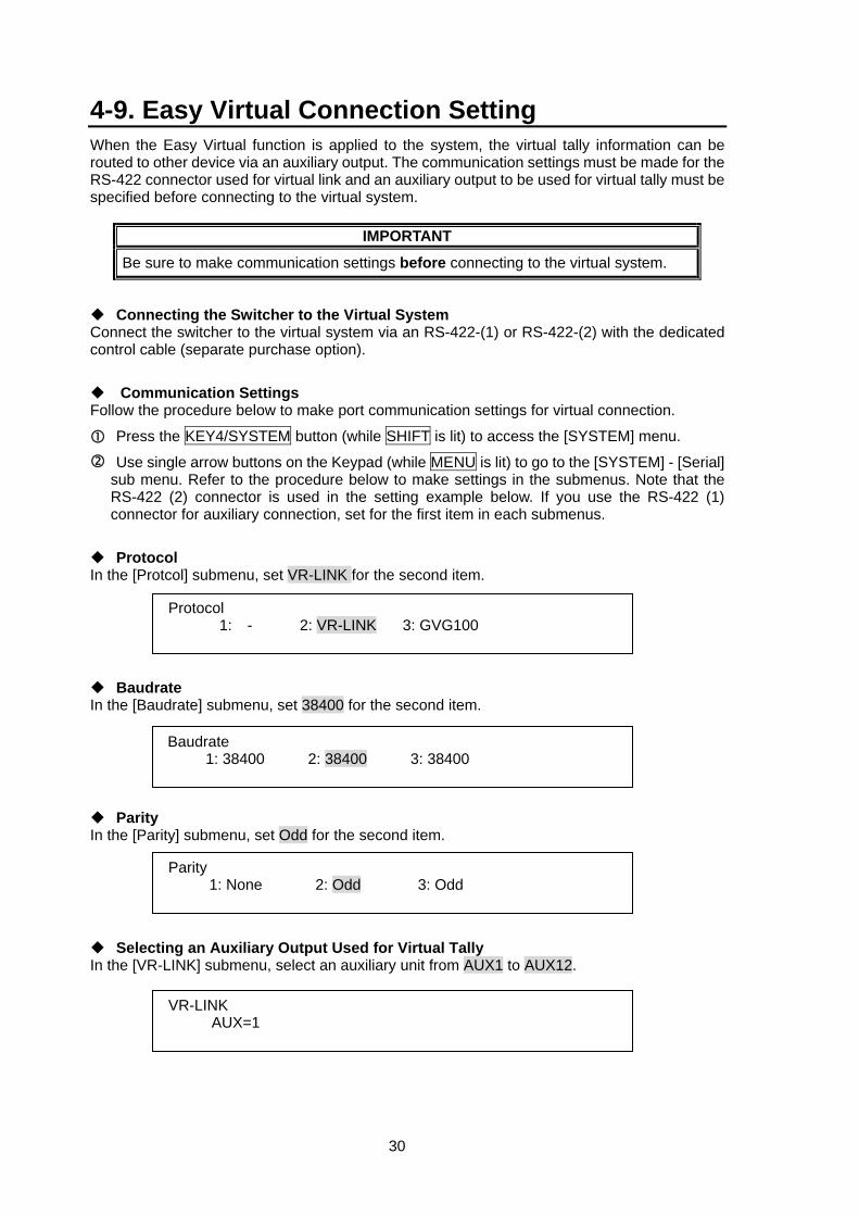
30
4-9. Easy Virtual Connection Setting When the Easy Virtual function is applied to the system, the virtual tally information can be routed to other device via an auxiliary output. The communication settings must be made for the RS-422 connector used for virtual link and an auxiliary output to be used for virtual tally must be specified before connecting to the virtual system.
IMPORTANT
Be sure to make communication settings before connecting to the virtual system.
Connecting the Switcher to the Virtual System Connect the switcher to the virtual system via an RS-422-(1) or RS-422-(2) with the dedicated control cable (separate purchase option).
Communication Settings Follow the procedure below to make port communication settings for virtual connection.
Press the KEY4/SYSTEM button (while SHIFT is lit) to access the [SYSTEM] menu.
Use single arrow buttons on the Keypad (while MENU is lit) to go to the [SYSTEM] - [Serial] sub menu. Refer to the procedure below to make settings in the submenus. Note that the RS-422 (2) connector is used in the setting example below. If you use the RS-422 (1) connector for auxiliary connection, set for the first item in each submenus.
Protocol In the [Protcol] submenu, set VR-LINK for the second item.
Baudrate In the [Baudrate] submenu, set 38400 for the second item.
Parity In the [Parity] submenu, set Odd for the second item.
Selecting an Auxiliary Output Used for Virtual Tally In the [VR-LINK] submenu, select an auxiliary unit from AUX1 to AUX12.
Protocol 1: - 2: VR-LINK 3: GVG100
Parity 1: None 2: Odd 3: Odd
Baudrate 1: 38400 2: 38400 3: 38400
VR-LINK AUX=1
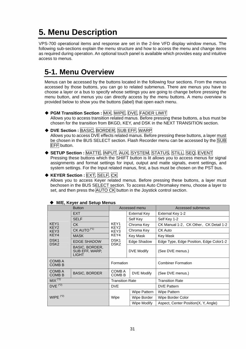
31
5. Menu Description VPS-700 operational items and response are set in the 2-line VFD display window menus. The following sub-sections explain the menu structure and how to access the menu and change items as required during operation. An optional touch panel is available which provides easy and intuitive access to menus.
5-1. Menu Overview Menus can be accessed by the buttons located in the following four sections. From the menus accessed by those buttons, you can go to related submenus. There are menus you have to choose a layer or a bus to specify whose settings you are going to change before pressing the menu button, and menus you can directly access by the menu buttons. A menu overview is provided below to show you the buttons (label) that open each menu.
PGM Transition Section : MIX, WIPE, DVE, FADER LIMIT Allows you to access transition related manus. Before pressing these buttons, a bus must be chosen for the transition from BKGD, KEY, and DSK in the NEXT TRANSITION section.
DVE Section : BASIC, BORDER, SUB EFF, WARP Allows you to access DVE effects related manus. Before pressing these buttons, a layer must be chosen in the BUS SELECT section. Flash Recorder menu can be accessed by the SUB EFF button.
SETUP Section : MATTE, INPUT, AUX, SYSTEM, STATUS, STILL, SEQ, EVENT Pressing these buttons which the SHIFT button is lit allows you to access menus for signal assignments and format settings for input, output and matte signals, event settings, and system settings. For the Input related manus, first, a bus must be chosen on the PST bus.
KEYER Section : EXT, SELF, CK Allows you to access Keyer related menus. Before pressing these buttons, a layer must bechosen in the BUS SELECT section. To access Auto Chromakey menu, choose a layer to set, and then press the AUTO CK button in the Joystick control section.
M/E, Keyer and Setup Menus Button Accessed menu Accessed submenus EXT External Key External Key 1-2 SELF Self Key Self Key 1-2 CK Chroma Key CK Manual 1-2、CK Other、CK Detail 1-2CK AUTO (*1) Chroma Key CK Auto MASK Key Mask Key Mask EDGE SHADOW Edge Shadow Edge Type, Edge Position, Edge Color1-2
KEY1 KEY2 KEY3 KEY4 DSK1 DSK2
BASIC, BORDER, SUB EFF, WARP, LIGHT
KEY1 KEY2 KEY3 KEY4 DSK1 DSK2
DVE Modify (See DVE menus.)
COMB A COMB B Formation Combiner Formation
COMB A COMB B BASIC, BORDER COMB A
COMB B DVE Modify (See DVE menus.)
MIX (*2) Transition Rate Transition Rate DVE (*2) DVE DVE Pattern
Wipe Pattern Wipe Pattern Wipe Border Wipe Border Color WIPE (*2) Wipe Wipe Modify Aspect, Center Position(X, Y, Angle)
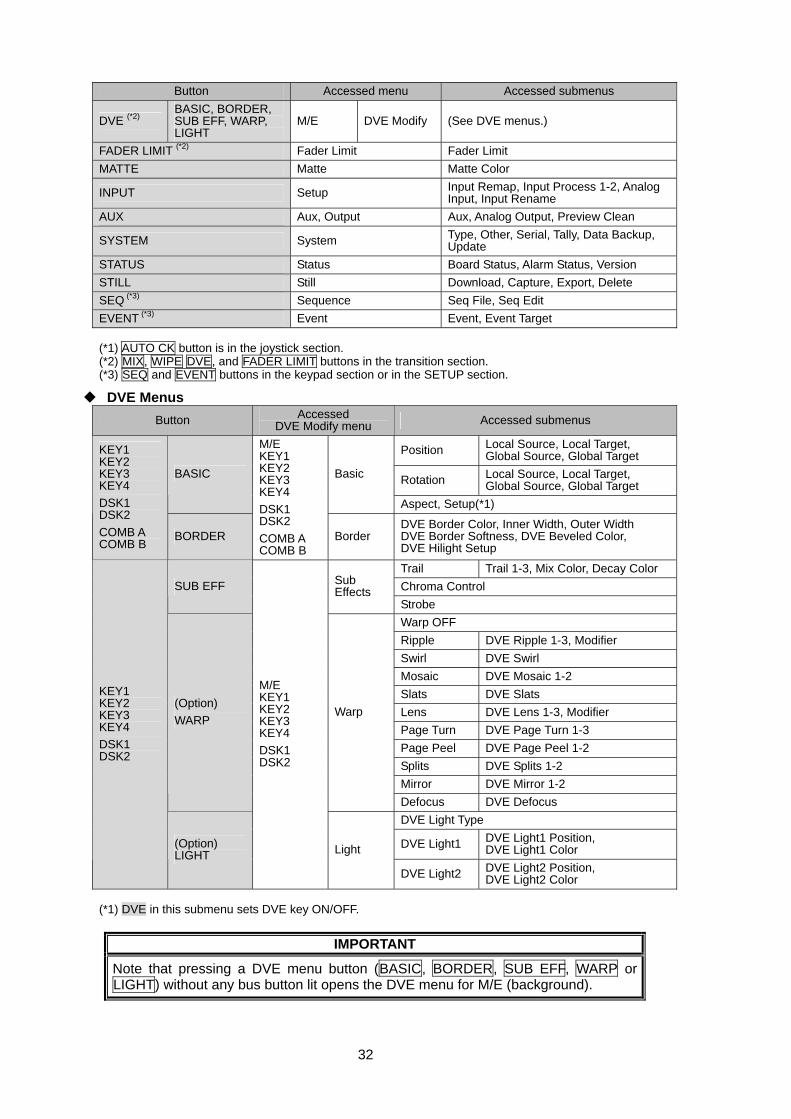
32
Button Accessed menu Accessed submenus
DVE (*2) BASIC, BORDER, SUB EFF, WARP, LIGHT
M/E DVE Modify (See DVE menus.)
FADER LIMIT (*2) Fader Limit Fader Limit MATTE Matte Matte Color
INPUT Setup Input Remap, Input Process 1-2, Analog Input, Input Rename
AUX Aux, Output Aux, Analog Output, Preview Clean
SYSTEM System Type, Other, Serial, Tally, Data Backup, Update
STATUS Status Board Status, Alarm Status, Version STILL Still Download, Capture, Export, Delete SEQ (*3) Sequence Seq File, Seq Edit EVENT (*3) Event Event, Event Target (*1) AUTO CK button is in the joystick section. (*2) MIX, WIPE DVE, and FADER LIMIT buttons in the transition section. (*3) SEQ and EVENT buttons in the keypad section or in the SETUP section.
DVE Menus Button Accessed
DVE Modify menu Accessed submenus
Position Local Source, Local Target, Global Source, Global Target
Rotation Local Source, Local Target, Global Source, Global Target
BASIC Basic
Aspect, Setup(*1)
KEY1 KEY2 KEY3 KEY4 DSK1 DSK2 COMB A COMB B
BORDER
M/E KEY1 KEY2 KEY3 KEY4 DSK1 DSK2 COMB A COMB B
Border DVE Border Color, Inner Width, Outer Width DVE Border Softness, DVE Beveled Color, DVE Hilight Setup
Trail Trail 1-3, Mix Color, Decay Color Chroma Control SUB EFF Sub
Effects Strobe Warp OFF Ripple DVE Ripple 1-3, Modifier Swirl DVE Swirl Mosaic DVE Mosaic 1-2 Slats DVE Slats Lens DVE Lens 1-3, Modifier Page Turn DVE Page Turn 1-3 Page Peel DVE Page Peel 1-2 Splits DVE Splits 1-2 Mirror DVE Mirror 1-2
(Option) WARP
Warp
Defocus DVE Defocus DVE Light Type
DVE Light1 DVE Light1 Position, DVE Light1 Color
KEY1 KEY2 KEY3 KEY4 DSK1 DSK2
(Option) LIGHT
M/E KEY1 KEY2 KEY3 KEY4 DSK1 DSK2
Light
DVE Light2 DVE Light2 Position, DVE Light2 Color
(*1) DVE in this submenu sets DVE key ON/OFF.
IMPORTANT
Note that pressing a DVE menu button (BASIC, BORDER, SUB EFF, WARP or LIGHT) without any bus button lit opens the DVE menu for M/E (background).
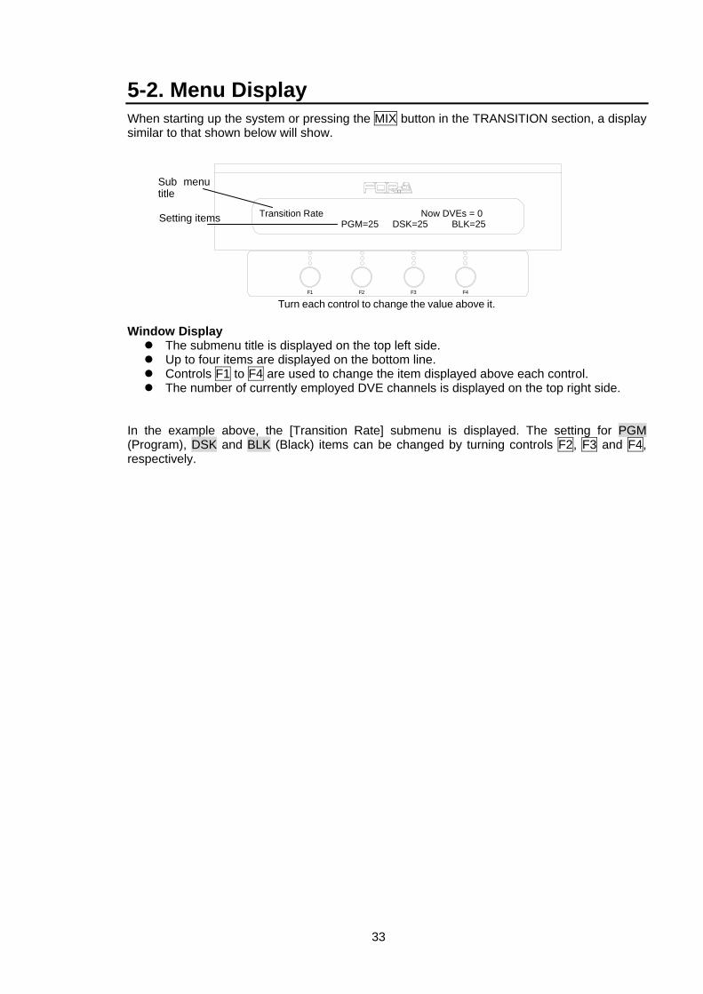
33
5-2. Menu Display When starting up the system or pressing the MIX button in the TRANSITION section, a display similar to that shown below will show. Window Display
The submenu title is displayed on the top left side. Up to four items are displayed on the bottom line. Controls F1 to F4 are used to change the item displayed above each control. The number of currently employed DVE channels is displayed on the top right side.
In the example above, the [Transition Rate] submenu is displayed. The setting for PGM (Program), DSK and BLK (Black) items can be changed by turning controls F2, F3 and F4, respectively.
Transition Rate Now DVEs = 0 PGM=25 DSK=25 BLK=25
F3 F4F2F1
Turn each control to change the value above it.
Sub menu title
Setting items
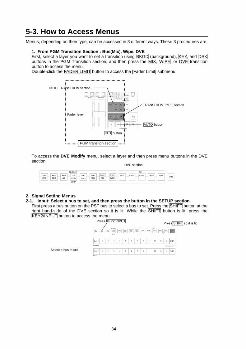
34
5-3. How to Access Menus Menus, depending on their type, can be accessed in 3 different ways. These 3 procedures are:
1. From PGM Transition Section : Bus(Mix), Wipe, DVE First, select a layer you want to set a transition using BKGD (background), KEY, and DSK buttons in the PGM Transition section, and then press the MIX, WIPE, or DVE transition button to access the menu. Double-click the FADER LIMIT button to access the [Fader Limit] submenu.
To access the DVE Modify menu, select a layer and then press menu buttons in the DVE
section.
2. Signal Setting Menus 2-1. Input: Select a bus to set, and then press the button in the SETUP section.
First press a bus button on the PST bus to select a bus to set. Press the SHIFT button at the right hand-side of the DVE section so it is lit. While the SHIFT button is lit, press the KEY2/INPUT button to access the menu.
1
TRANSITION
PRIORITY1 OVER 2
21
24
3 4321
LOW1 2 3 4
4321
HIGH
KEY STATUSKEY LAYER DSK
FADER DIRECTIONSEQ LINK FADER LIMIT NOR/REV REVERSE PREV TRANS
DSK1
DSK2
DSKCUT
BLACKTRANS
DSKMIX
KEY2
KEY4
DVE(NAM)
KEY1
KEY3
WIPE(FAM)
BKGD
MIX
AUTO
TRANSITION TYPE
CUT
NEXT TRANSITION section
TRANSITION TYPE section
AUTO button
Fader lever
CUT button
PGM transiton section
DVE section
DVE
SHIFTBORDERBASIC
EVENTCOMB B
SEQCOMB ADSK2
STILLDSK1
STATUS
KEY4
SETUP
BUS SELECTKEY3AUX
KEY2KEY1MATTE INPUT SYSTEM
SUB EFF WARP LIGHT
Press KEY2/INPUT
Select a bus to set
SHIFT
SHIFT
COMBINER SETUP
12
12
11
11
10
10
9
9
8
8
7
7
6
6
5
5
4
4
3
3
2
2
1
1
BLACK
PROGRAM
BLACK
PRESET
Press SHIFT so it is lit. DVE
SHIFTBORDERBASIC
EVENTCOMB B
SEQCOMB ADSK2
STILLDSK1
STATUS
KEY4
SETUP
BUS SELECTKEY3AUX
KEY2KEY1MATTE INPUT SYSTEM
SUB EFF WARP LIGHT
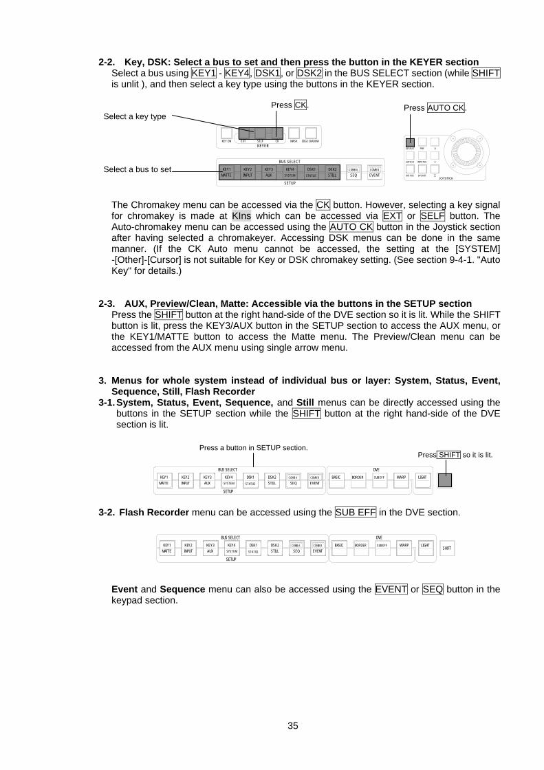
35
2-2. Key, DSK: Select a bus to set and then press the button in the KEYER section Select a bus using KEY1 - KEY4, DSK1, or DSK2 in the BUS SELECT section (while SHIFT is unlit ), and then select a key type using the buttons in the KEYER section.
The Chromakey menu can be accessed via the CK button. However, selecting a key signal
for chromakey is made at KIns which can be accessed via EXT or SELF button. The Auto-chromakey menu can be accessed using the AUTO CK button in the Joystick section after having selected a chromakeyer. Accessing DSK menus can be done in the same manner. (If the CK Auto menu cannot be accessed, the setting at the [SYSTEM] -[Other]-[Cursor] is not suitable for Key or DSK chromakey setting. (See section 9-4-1. "Auto Key" for details.)
2-3. AUX, Preview/Clean, Matte: Accessible via the buttons in the SETUP section
Press the SHIFT button at the right hand-side of the DVE section so it is lit. While the SHIFT button is lit, press the KEY3/AUX button in the SETUP section to access the AUX menu, or the KEY1/MATTE button to access the Matte menu. The Preview/Clean menu can be accessed from the AUX menu using single arrow menu.
3. Menus for whole system instead of individual bus or layer: System, Status, Event,
Sequence, Still, Flash Recorder 3-1. System, Status, Event, Sequence, and Still menus can be directly accessed using the
buttons in the SETUP section while the SHIFT button at the right hand-side of the DVE section is lit.
3-2. Flash Recorder menu can be accessed using the SUB EFF in the DVE section.
Event and Sequence menu can also be accessed using the EVENT or SEQ button in the keypad section.
Select a key type
Select a bus to set
Press CK.
KEYER
EVENTCOMB B
SEQCOMB ADSK2
STILLDSK1
STATUS
KEY4
SETUP
BUS SELECT
KEY3AUX
KEY2KEY1MATTE
KEY ON EXT SELF CK EDGE SHADOWMASK
INPUT SYSTEM
Press AUTO CK.
Z
Y
X
JOYSTICK
DEFAULT FINE
DVE ROT
WIPE POS
DVE POS
AUTO CK
DVE
SHIFTBORDERBASIC
EVENTCOMB B
SEQCOMB ADSK2
STILLDSK1
STATUS
KEY4
SETUP
BUS SELECTKEY3AUX
KEY2KEY1MATTE INPUT SYSTEM
SUB EFF WARP LIGHT
DVE
SHIFTBORDERBASIC
EVENTCOMB B
SEQCOMB ADSK2
STILLDSK1
STATUS
KEY4
SETUP
BUS SELECTKEY3AUX
KEY2KEY1MATTE INPUT SYSTEM
SUB EFF WARP LIGHT
Press a button in SETUP section. Press SHIFT so it is lit.
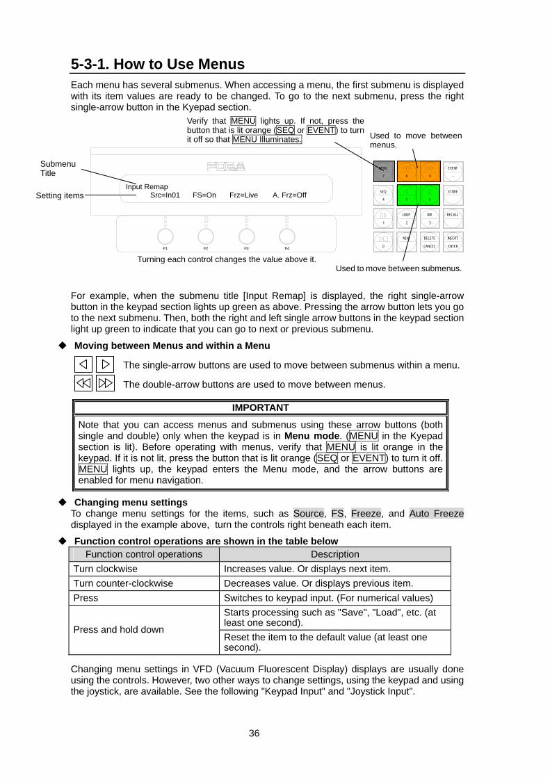
36
5-3-1. How to Use Menus Each menu has several submenus. When accessing a menu, the first submenu is displayed with its item values are ready to be changed. To go to the next submenu, press the right single-arrow button in the Kyepad section.
For example, when the submenu title [Input Remap] is displayed, the right single-arrow button in the keypad section lights up green as above. Pressing the arrow button lets you go to the next submenu. Then, both the right and left single arrow buttons in the keypad section light up green to indicate that you can go to next or previous submenu.
Moving between Menus and within a Menu
The single-arrow buttons are used to move between submenus within a menu.
The double-arrow buttons are used to move between menus.
IMPORTANT
Note that you can access menus and submenus using these arrow buttons (both single and double) only when the keypad is in Menu mode. (MENU in the Kyepad section is lit). Before operating with menus, verify that MENU is lit orange in the keypad. If it is not lit, press the button that is lit orange (SEQ or EVENT) to turn it off. MENU lights up, the keypad enters the Menu mode, and the arrow buttons are enabled for menu navigation.
Changing menu settings To change menu settings for the items, such as Source, FS, Freeze, and Auto Freeze displayed in the example above, turn the controls right beneath each item.
Function control operations are shown in the table below Function control operations Description
Turn clockwise Increases value. Or displays next item. Turn counter-clockwise Decreases value. Or displays previous item. Press Switches to keypad input. (For numerical values)
Starts processing such as "Save", "Load", etc. (at least one second).
Press and hold down Reset the item to the default value (at least one second).
Changing menu settings in VFD (Vacuum Fluorescent Display) displays are usually done using the controls. However, two other ways to change settings, using the keypad and using the joystick, are available. See the following "Keypad Input" and "Joystick Input".
Input Remap Src=In01 FS=On Frz=Live A. Frz=Off
F3 F4F2F1
EVENT
-
RECALL
2 3
8 97
MENU
SEQ
1
STORE
65
LOOP DIR
4
INSERT
ENTER
DELETE
CANCEL
NEW
.0
Used to move between menus.
Used to move between submenus.
Verify that MENU lights up. If not, press the button that is lit orange (SEQ or EVENT) to turn it off so that MENU Illuminates.
Turning each control changes the value above it.
Submenu Title
Setting items
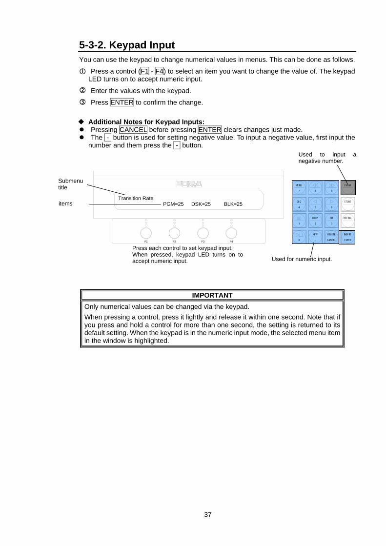
37
5-3-2. Keypad Input You can use the keypad to change numerical values in menus. This can be done as follows.
Press a control (F1 - F4) to select an item you want to change the value of. The keypad LED turns on to accept numeric input.
Enter the values with the keypad.
Press ENTER to confirm the change.
Additional Notes for Keypad Inputs: Pressing CANCEL before pressing ENTER clears changes just made. The - button is used for setting negative value. To input a negative value, first input the
number and them press the - button.
IMPORTANT Only numerical values can be changed via the keypad. When pressing a control, press it lightly and release it within one second. Note that if you press and hold a control for more than one second, the setting is returned to its default setting. When the keypad is in the numeric input mode, the selected menu item in the window is highlighted.
Transition Rate PGM=25 DSK=25 BLK=25
Used for numeric input.
Submenu title
items
Used to input a negative number.
F3 F4F2F1
EVENT
-
RECALL
2 3
8 97
MENU
SEQ
1
STORE
65
LOOP DIR
4
INSERT
ENTER
DELETE
CANCEL
NEW
.0
Press each control to set keypad input.When pressed, keypad LED turns on toaccept numeric input.
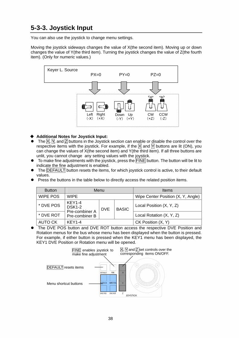
38
5-3-3. Joystick Input You can also use the joystick to change menu settings. Moving the joystick sideways changes the value of X(the second item). Moving up or down changes the value of Y(the third item). Turning the joystick changes the value of Z(the fourth item). (Only for numeric values.)
Additional Notes for Joystick Input: The X, Y, and Z buttons in the Joystick section can enable or disable the control over the
respective items with the joystick. For example, if the X and Y buttons are lit (ON), you can change the values of X(the second item) and Y(the third item). If all three buttons are unlit, you cannot change any setting values with the joystick.
To make fine adjustments with the joystick, press the FINE button. The button will be lit to indicate the fine adjustment is enabled.
The DEFAULT button resets the items, for which joystick control is active, to their default values.
Press the buttons in the table below to directly access the related position items.
Button Menu Items WIPE POS WIPE Wipe Center Position (X, Y, Angle)
* DVE POS Local Position (X, Y, Z)
* DVE ROT
KEY1-4 DSK1-2 Pre-combiner A Pre-combiner B
DVE BASIC Local Rotation (X, Y, Z)
AUTO CK KEY1-4 CK Position (X, Y) The DVE POS button and DVE ROT button access the respective DVE Position and
Rotation menus for the bus whose menu has been displayed when the button is pressed. For example, if either button is pressed when the KEY1 menu has been displayed, the KEY1 DVE Position or Rotation menu will be opened.
Left (-X)
Right(+X)
Down(-Y)
Up(+Y)
CW(+Z)
CCW(-Z)
Keyer L. Source PX=0 PY=0 PZ=0
Z
Y
X
JOYSTICK
DEFAULT FINE
DVE ROT
WIPE POS
DVE POS
AUTO CKMenu shortcut buttons
X, Y and Z set controls over the corresponding items ON/OFF.
FINE enables joystick tomake fine adjustment
DEFAULT resets items
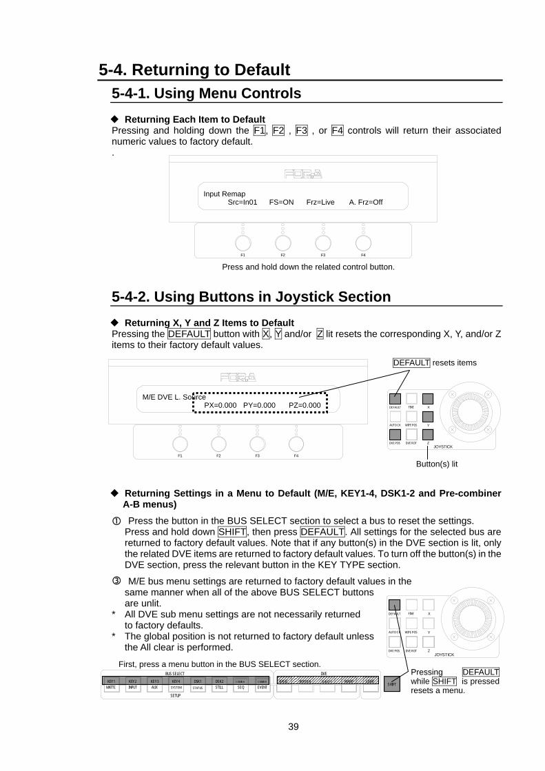
39
5-4. Returning to Default 5-4-1. Using Menu Controls
Returning Each Item to Default Pressing and holding down the F1, F2 , F3 , or F4 controls will return their associated numeric values to factory default. . 5-4-2. Using Buttons in Joystick Section
Returning X, Y and Z Items to Default Pressing the DEFAULT button with X, Y and/or Z lit resets the corresponding X, Y, and/or Z items to their factory default values.
Returning Settings in a Menu to Default (M/E, KEY1-4, DSK1-2 and Pre-combiner A-B menus)
Press the button in the BUS SELECT section to select a bus to reset the settings. Press and hold down SHIFT, then press DEFAULT. All settings for the selected bus are returned to factory default values. Note that if any button(s) in the DVE section is lit, only the related DVE items are returned to factory default values. To turn off the button(s) in the DVE section, press the relevant button in the KEY TYPE section.
M/E bus menu settings are returned to factory default values in the same manner when all of the above BUS SELECT buttons are unlit.
* All DVE sub menu settings are not necessarily returned to factory defaults. * The global position is not returned to factory default unless the All clear is performed.
Input Remap Src=In01 FS=ON Frz=Live A. Frz=Off
F3 F4F2F1
Press and hold down the related control button.
F3 F4F2F1
M/E DVE L. Source PX=0.000 PY=0.000 PZ=0.000
Z
Y
X
JOYSTICK
DEFAULT FINE
DVE ROT
WIPE POS
DVE POS
AUTO CK
DEFAULT resets items
Button(s) lit
Pressing DEFAULTwhile SHIFT is pressed resets a menu.
First, press a menu button in the BUS SELECT section.DVE
SHIFTBORDERBASIC
EVENTCOMB B
SEQCOMB ADSK2
STILLDSK1
STATUS
KEY4
SETUP
BUS SELECTKEY3AUX
KEY2KEY1MATTE INPUT SYSTEM
SUB EFF WARP LIGHT
Z
Y
X
JOYSTICK
DEFAULT FINE
DVE ROT
WIPE POS
DVE POS
AUTO CK

40
6. Touch Panel Operations (Option) The optional touch panel can be used to enable intuitive and easy menu operation. Also, with the optional display unit interface module (VPS-70DPUIF) you can connect and use a commercially available display such as CRT or LCD for menu display. When starting up the Operation Unit, perform a touch panel calibration refering to section 18-3. “Update”. See “Appendix 2. GUI menu” for each menu screen.
Status Display: At the top right of the screen, the VPS-700 GUI version, the number of currently employed DVE channels, and the transition rates for M/E, PGM, DSK and BLK transitions are always displayed.
Menu Folders: On the touch panel, the menus are displayed in a folder format. Touching a folder displays the components of the folder. VPS-700 has six menus, that are displayed in the top left of screen, for the top category. Each top menu is divided into several submenus, and some of these submenus are further subdivided into sub-submenus. Dog eared tabs (right corner is folded) indicate they do not have any submenus inside.
Sub menus and items: Menus are several level deep. The depth varies depending on the menu. When the menu folder at the lowest level is pressed, the menu items are displayed at the bottom of the screen. These items are also displayed on the control panel at the same time.
NOTE
Changes to the setting values can only be made on the control panel, not on the touch panel. To change values, turn a control under the value you want to change.
Menu Folders
Selected submenu
Items in the selected submenu(Display only)
Status Display
Error Display
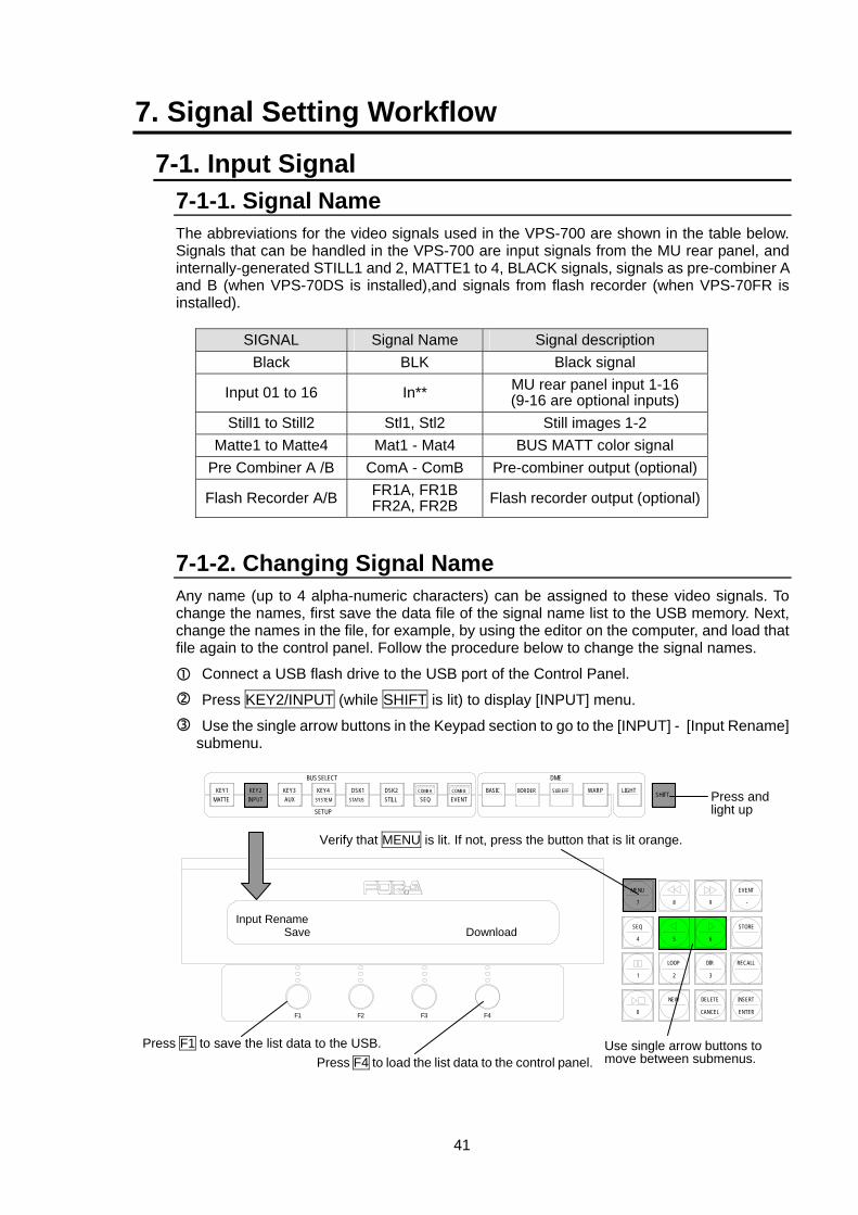
41
7. Signal Setting Workflow
7-1. Input Signal 7-1-1. Signal Name The abbreviations for the video signals used in the VPS-700 are shown in the table below. Signals that can be handled in the VPS-700 are input signals from the MU rear panel, and internally-generated STILL1 and 2, MATTE1 to 4, BLACK signals, signals as pre-combiner A and B (when VPS-70DS is installed),and signals from flash recorder (when VPS-70FR is installed).
SIGNAL Signal Name Signal description Black BLK Black signal
Input 01 to 16 In** MU rear panel input 1-16 (9-16 are optional inputs)
Still1 to Still2 Stl1, Stl2 Still images 1-2 Matte1 to Matte4 Mat1 - Mat4 BUS MATT color signal
Pre Combiner A /B ComA - ComB Pre-combiner output (optional)
Flash Recorder A/B FR1A, FR1B FR2A, FR2B Flash recorder output (optional)
7-1-2. Changing Signal Name Any name (up to 4 alpha-numeric characters) can be assigned to these video signals. To change the names, first save the data file of the signal name list to the USB memory. Next, change the names in the file, for example, by using the editor on the computer, and load that file again to the control panel. Follow the procedure below to change the signal names.
Connect a USB flash drive to the USB port of the Control Panel.
Press KEY2/INPUT (while SHIFT is lit) to display [INPUT] menu.
Use the single arrow buttons in the Keypad section to go to the [INPUT] - [Input Rename] submenu.
SHIFTBORDERBASICEVENTCOMB B
SEQCOMB ADSK2
STILLDSK1
STATUS
KEY4
SETUP
BUS SELECT
KEY3AUX
KEY2KEY1MATTE INPUT SYSTEM
SUB EFF WARP LIGHT
DME
Input Rename Save Download
F3 F4F2F1
EVENT
-
RECALL
2 3
8 97
MENU
SEQ
1
STORE
65
LOOP DIR
4
INSERT
ENTER
DELETE
CANCEL
NEW
.0
Use single arrow buttons to move between submenus.
Verify that MENU is lit. If not, press the button that is lit orange.
Press F1 to save the list data to the USB.
Press and light up
Press F4 to load the list data to the control panel.
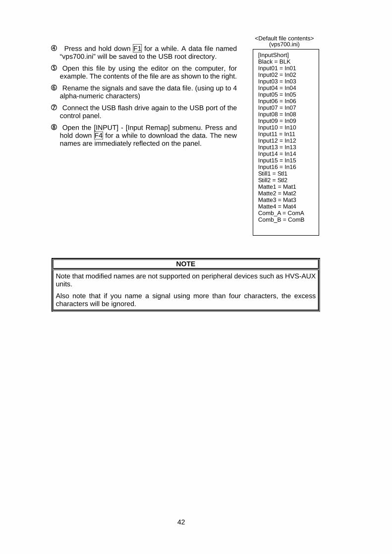
42
Press and hold down F1 for a while. A data file named “vps700.ini” will be saved to the USB root directory.
Open this file by using the editor on the computer, for example. The contents of the file are as shown to the right.
Rename the signals and save the data file. (using up to 4 alpha-numeric characters)
Connect the USB flash drive again to the USB port of the control panel.
Open the [INPUT] - [Input Remap] submenu. Press and hold down F4 for a while to download the data. The new names are immediately reflected on the panel.
NOTE
Note that modified names are not supported on peripheral devices such as HVS-AUX units.
Also note that if you name a signal using more than four characters, the excess characters will be ignored.
[InputShort] Black = BLK Input01 = In01 Input02 = In02 Input03 = In03 Input04 = In04 Input05 = In05 Input06 = In06 Input07 = In07 Input08 = In08 Input09 = In09 Input10 = In10 Input11 = In11 Input12 = In12 Input13 = In13 Input14 = In14 Input15 = In15 Input16 = In16 Still1 = Stl1 Still2 = Stl2 Matte1 = Mat1 Matte2 = Mat2 Matte3 = Mat3 Matte4 = Mat4 Comb_A = ComA Comb_B = ComB
<Default file contents> (vps700.ini)
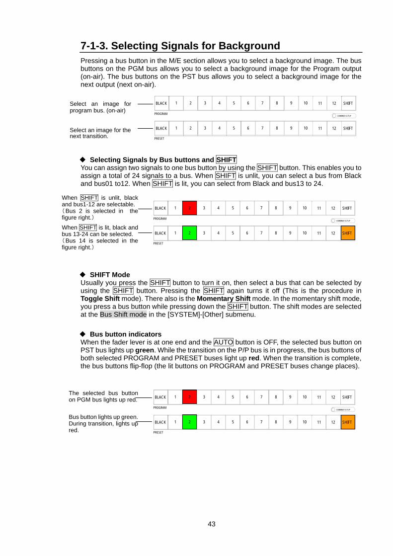
43
7-1-3. Selecting Signals for Background Pressing a bus button in the M/E section allows you to select a background image. The bus buttons on the PGM bus allows you to select a background image for the Program output (on-air). The bus buttons on the PST bus allows you to select a background image for the next output (next on-air).
Selecting Signals by Bus buttons and SHIFT You can assign two signals to one bus button by using the SHIFT button. This enables you to assign a total of 24 signals to a bus. When SHIFT is unlit, you can select a bus from Black and bus01 to12. When SHIFT is lit, you can select from Black and bus13 to 24.
SHIFT Mode Usually you press the SHIFT button to turn it on, then select a bus that can be selected by using the SHIFT button. Pressing the SHIFT again turns it off (This is the procedure in Toggle Shift mode). There also is the Momentary Shift mode. In the momentary shift mode, you press a bus button while pressing down the SHIFT button. The shift modes are selected at the Bus Shift mode in the [SYSTEM]-[Other] submenu.
Bus button indicators When the fader lever is at one end and the AUTO button is OFF, the selected bus button on PST bus lights up green. While the transition on the P/P bus is in progress, the bus buttons of both selected PROGRAM and PRESET buses light up red. When the transition is complete, the bus buttons flip-flop (the lit buttons on PROGRAM and PRESET buses change places).
SHIFT
SHIFT
COMBINER SETUP
12
12
11
11
10
10
9
9
8
8
7
7
6
6
5
5
4
4
3
3
2
2
1
1
BLACK
PROGRAM
BLACK
PRESET
Select an image forprogram bus. (on-air)
Select an image for the next transition.
SHIFT
SHIFT
COMBINER SETUP
12
12
11
11
10
10
9
9
8
8
7
7
6
6
5
5
4
4
3
3
2
2
1
1
BLACK
PROGRAM
BLACK
PRESET
When SHIFT is unlit, black and bus1-12 are selectable. (Bus 2 is selected in thefigure right.)
When SHIFT is lit, black andbus 13-24 can be selected. (Bus 14 is selected in thefigure right.)
SHIFT
SHIFT
COMBINER SETUP
12
12
11
11
10
10
9
9
8
8
7
7
6
6
5
5
4
4
3
3
2
2
1
1
BLACK
PROGRAM
BLACK
PRESET
The selected bus buttonon PGM bus lights up red.
Bus button lights up green.During transition, lights upred.
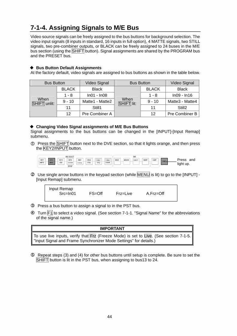
44
7-1-4. Assigning Signals to M/E Bus Video source signals can be freely assigned to the bus buttons for background selection. The video input signals (8 inputs in standard, 16 inputs in full option), 4 MATTE signals, two STILL signals, two pre-combiner outputs, or BLACK can be freely assigned to 24 buses in the M/E bus section (using the SHIFT button). Signal assignments are shared by the PROGRAM bus and the PRESET bus.
Bus Button Default Assignments At the factory default, video signals are assigned to bus buttons as shown in the table below.
Bus Button Video Signal Bus Button Video Signal BLACK Black BLACK Black
1 - 8 In01 - In08 1 - 8 In09 - In16 9 - 10 Matte1 - Matte2 9 - 10 Matte3 - Matte4
11 Still1 11 Still2
When SHIFT unlit:
12 Pre Combiner A
When SHIFT lit:
12 Pre Combiner B
Changing Video Signal assignments of M/E Bus Buttons Signal assignments to the bus buttons can be changed in the [INPUT]-[Input Remap] submenu.
Press the SHIFT button next to the DVE section, so that it lights orange, and then press the KEY2/INPUT button.
Use single arrow buttons in the keypad section (while MENU is lit) to go to the [INPUT] - [Input Remap] submenu.
Press a bus button to assign a signal to in the PST bus.
Turn F1 to select a video signal. (See section 7-1-1. "Signal Name" for the abbreviations of the signal name.)
IMPORTANT
To use live inputs, verify that Frz (Freeze Mode) is set to Live. (See section 7-1-5. "Input Signal and Frame Synchronizer Mode Settings" for details.)
Repeat steps (3) and (4) for other bus buttons until setup is complete. Be sure to set the SHIFT button is lit in the PST bus, when assigning to bus13 to 24.
Input Remap Src=In01 FS=Off Frz=Live A.Frz=Off
DVE
SHIFTBORDERBASIC
EVENTCOMB B
SEQCOMB ADSK2
STILLDSK1
STATUS
KEY4
SETUP
BUS SELECTKEY3AUX
KEY2KEY1MATTE INPUT SYSTEM
SUB EFF WARP LIGHT Press and light up.
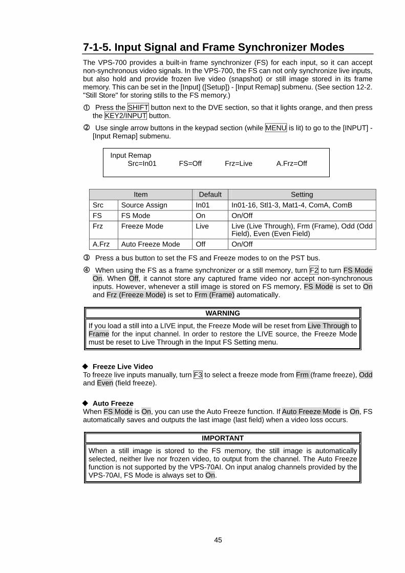
45
7-1-5. Input Signal and Frame Synchronizer Modes The VPS-700 provides a built-in frame synchronizer (FS) for each input, so it can accept non-synchronous video signals. In the VPS-700, the FS can not only synchronize live inputs, but also hold and provide frozen live video (snapshot) or still image stored in its frame memory. This can be set in the [Input] ([Setup]) - [Input Remap] submenu. (See section 12-2. "Still Store" for storing stills to the FS memory.)
Press the SHIFT button next to the DVE section, so that it lights orange, and then press the KEY2/INPUT button.
Use single arrow buttons in the keypad section (while MENU is lit) to go to the [INPUT] - [Input Remap] submenu.
Item Default Setting Src Source Assign In01 In01-16, Stl1-3, Mat1-4, ComA, ComB FS FS Mode On On/Off Frz Freeze Mode Live Live (Live Through), Frm (Frame), Odd (Odd
Field), Even (Even Field) A.Frz Auto Freeze Mode Off On/Off
Press a bus button to set the FS and Freeze modes to on the PST bus.
When using the FS as a frame synchronizer or a still memory, turn F2 to turn FS Mode On. When Off, it cannot store any captured frame video nor accept non-synchronous inputs. However, whenever a still image is stored on FS memory, FS Mode is set to On and Frz (Freeze Mode) is set to Frm (Frame) automatically.
WARNING
If you load a still into a LIVE input, the Freeze Mode will be reset from Live Through to Frame for the input channel. In order to restore the LIVE source, the Freeze Mode must be reset to Live Through in the Input FS Setting menu.
Freeze Live Video To freeze live inputs manually, turn F3 to select a freeze mode from Frm (frame freeze), Odd and Even (field freeze).
Auto Freeze When FS Mode is On, you can use the Auto Freeze function. If Auto Freeze Mode is On, FS automatically saves and outputs the last image (last field) when a video loss occurs.
IMPORTANT
When a still image is stored to the FS memory, the still image is automatically selected, neither live nor frozen video, to output from the channel. The Auto Freeze function is not supported by the VPS-70AI. On input analog channels provided by the VPS-70AI, FS Mode is always set to On.
Input Remap Src=In01 FS=Off Frz=Live A.Frz=Off
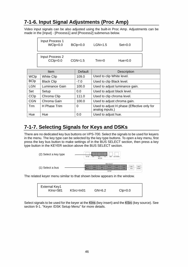
46
7-1-6. Input Signal Adjustments (Proc Amp) Video input signals can be also adjusted using the built-in Proc Amp. Adjustments can be made in the [Input] - [Process1] and [Process2] submenus below.
Item Default Description WClp White Clip 109.0 Used to clip White level. BClp Black Clip -7.0 Used to clip Black level. LGN Luminance Gain 100.0 Used to adjust luminance gain. Set Setup 0.0 Used to adjust black level. CClp Chroma Clip 111.0 Used to clip chroma level. CGN Chroma Gain 100.0 Used to adjust chroma gain. Trm H Phase Trim 0 Used to adjust H phase (Effective only for
analog inputs.) Hue Hue 0.0 Used to adjust hue.
7-1-7. Selecting Signals for Keys and DSKs There are no dedicated key bus buttons on VPS-700. Select the signals to be used for keyers in the menu. The key type can be selected by the key type buttons. To open a key menu, first press the key bus button to make settings of in the BUS SELECT section, then press a key type button in the KEYER section above the BUS SELECT section. The related keyer menu similar to that shown below appears in the window. Select signals to be used for the keyer at the KIns (key insert) and the KSrc (key source). See section 9-1. "Keyer /DSK Setup Menu" for more details.
Input Process 1 WClp=0.0 BClp=0.0 LGN=1.5 Set=0.0
Input Process 2 CClp=0.0 CGN=1.5 Trm=0 Hue=0.0
External Key1 KIns=Stl1 KSrc=In01 GN=6.2 Clp=0.0
KEYER
EVENTCOMB B
SEQCOMB ADSK2
STILLDSK1
STATUS
KEY4
SETUP
BUS SELECT
KEY3AUX
KEY2KEY1MATTE
KEY ON EXT SELF CK EDGE SHADOWMASK
INPUT SYSTEM
(2) Select a key type
(1) Select a bus
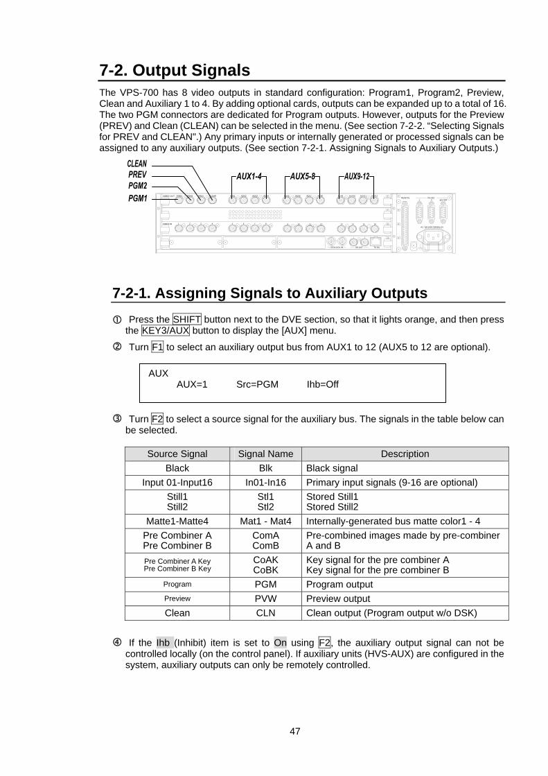
47
7-2. Output Signals The VPS-700 has 8 video outputs in standard configuration: Program1, Program2, Preview, Clean and Auxiliary 1 to 4. By adding optional cards, outputs can be expanded up to a total of 16. The two PGM connectors are dedicated for Program outputs. However, outputs for the Preview (PREV) and Clean (CLEAN) can be selected in the menu. (See section 7-2-2. “Selecting Signals for PREV and CLEAN".) Any primary inputs or internally generated or processed signals can be assigned to any auxiliary outputs. (See section 7-2-1. Assigning Signals to Auxiliary Outputs.)
7-2-1. Assigning Signals to Auxiliary Outputs Press the SHIFT button next to the DVE section, so that it lights orange, and then press the KEY3/AUX button to display the [AUX] menu.
Turn F1 to select an auxiliary output bus from AUX1 to 12 (AUX5 to 12 are optional).
Turn F2 to select a source signal for the auxiliary bus. The signals in the table below can be selected.
Source Signal Signal Name Description
Black Blk Black signal Input 01-Input16 In01-In16 Primary input signals (9-16 are optional)
Still1 Still2
Stl1 Stl2
Stored Still1 Stored Still2
Matte1-Matte4 Mat1 - Mat4 Internally-generated bus matte color1 - 4 Pre Combiner A Pre Combiner B
ComA ComB
Pre-combined images made by pre-combiner A and B
Pre Combiner A Key Pre Combiner B Key
CoAK CoBK
Key signal for the pre combiner A Key signal for the pre combiner B
Program PGM Program output Preview PVW Preview output Clean CLN Clean output (Program output w/o DSK)
If the Ihb (Inhibit) item is set to On using F2, the auxiliary output signal can not be controlled locally (on the control panel). If auxiliary units (HVS-AUX) are configured in the system, auxiliary outputs can only be remotely controlled.
1
4
3
2
1
2
1
TO OU
2
GENLOCK IN BB OUT
4
3 41 862 5 7 3VIDEO IN
VIDEO OUTREMOTE
EDITOR2RS-422
1
AC 100-240V 50/60Hz IN
PGM1 PGM2 PREV CLEAN AUX1 AUX2 AUX3 AUX4
9 10 11
AUX6 AUX7 AUX8 AUX9 AUX10 AUX11 AUX12AUX5
12 13 14 15 16
AUX AUX=1 Src=PGM Ihb=Off
48
7-2-2. Selecting Signals for PREV and CLEAN Outputs The output assignments for the PREV connector on the VPS-700 rear panel can be changed. Use the following procedure to change the assignments.
Press the KEY3/AUX button (while SHIFT is lit) to display the [AUX] menu.
Use single arrow buttons in the keypad (while MENU is lit) to go to the [Preview/Clean]] submenu as shown below. Turn F1 to select a signal for the PREV output. (See the table below.) Turn F2 to select for the CLEAN output. (See the table below.).
Available Output Options
Item Options Description
w/D_PV PGM PV + DSK PV (Background, key and DSK signals for next transition)
woDSK PGM PV(Background and key signals for next transition)PV
KeyOut PGM key + Key1-4 key + DSK1, 2 key (Key signals on PGM output (on air))
woDSK PGM+key (Backgound and key signals on PGM output (on air))
CL KeyOut PGM key + Key1-4 key + DSK1, 2 key
(Key signals on PGM output (on air)) * Key signals are displayed corresponding to the key transition, but in a manner of cut transitions. However DVE transitions are displayed the same as actual transitions.
Preview/Clean PV=w/D_PV CL=woDSK
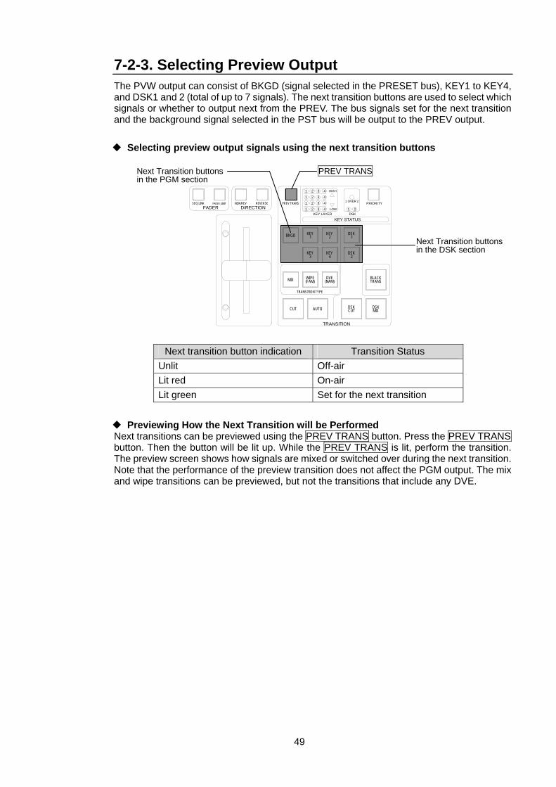
49
7-2-3. Selecting Preview Output The PVW output can consist of BKGD (signal selected in the PRESET bus), KEY1 to KEY4, and DSK1 and 2 (total of up to 7 signals). The next transition buttons are used to select which signals or whether to output next from the PREV. The bus signals set for the next transition and the background signal selected in the PST bus will be output to the PREV output.
Selecting preview output signals using the next transition buttons
Next transition button indication Transition Status Unlit Off-air Lit red On-air Lit green Set for the next transition
Previewing How the Next Transition will be Performed Next transitions can be previewed using the PREV TRANS button. Press the PREV TRANS button. Then the button will be lit up. While the PREV TRANS is lit, perform the transition. The preview screen shows how signals are mixed or switched over during the next transition. Note that the performance of the preview transition does not affect the PGM output. The mix and wipe transitions can be previewed, but not the transitions that include any DVE.
1
TRANSITION
PRIORITY1 OVER 2
21
24
3 4321
LOW1 2 3 44321
HIGH
KEY STATUSKEY LAYER DSK
FADER DIRECTIONSEQ LINK FADER LIMIT NOR/REV REVERSE PREV TRANS
DSK1
DSK2
DSKCUT
BLACKTRANS
DSKMIX
KEY2
KEY4
DVE(NAM)
KEY1
KEY3
WIPE(FAM)
BKGD
MIX
AUTO
TRANSITION TYPE
CUT
Next Transition buttons in the PGM section
Next Transition buttons in the DSK section
PREV TRANS
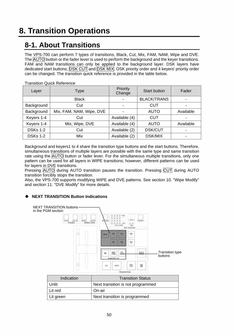
50
8. Transition Operations
8-1. About Transitions The VPS-700 can perform 7 types of transitions, Black, Cut, Mix, FAM, NAM, Wipe and DVE. The AUTO button or the fader lever is used to perform the background and the keyer transitions. FAM and NAM transitions can only be applied to the background layer. DSK layers have dedicated start buttons; DSK CUT and DSK MIX. DSK priority order and 4 keyers' priority order can be changed. The transition quick reference is provided in the table below. Transition Quick Reference
Layer Type Priority Change Start button Fader
Black - BLACK/TRANS - Background Cut - CUT - Background Mix, FAM, NAM, Wipe, DVE - AUTO Available Keyers 1-4 Cut Available (4) CUT - Keyers 1-4 Mix, Wipe, DVE Available (4) AUTO Available DSKs 1-2 Cut Available (2) DSK/CUT - DSKs 1-2 Mix Available (2) DSK/MIX -
Background and keyers1 to 4 share the transition type buttons and the start buttons. Therefore, simultaneous transitions of multiple layers are possible with the same type and same transition rate using the AUTO button or fader lever. For the simultaneous multiple transitions, only one pattern can be used for all layers in WIPE transitions; however, different patterns can be used for layers in DVE transitions. Pressing AUTO during AUTO transition pauses the transition. Pressing CUT during AUTO transition forcibly stops the transition. Also, the VPS-700 supports modifying WIPE and DVE patterns. See section 10. "Wipe Modify" and section 11. "DVE Modify" for more details.
NEXT TRANSITION Button Indications
Indication Transition Status Unlit Next transition is not programmed Lit red On-air Lit green Next transition is programmed
1
TRANSITION
PRIORITY1 OVER 2
21
24
3 4321
LOW1 2 3 44321
HIGH
KEY STATUSKEY LAYER DSK
FADER DIRECTIONSEQ LINK FADER LIMIT NOR/REV REVERSE PREV TRANS
DSK1
DSK2
DSKCUT
BLACKTRANS
DSKMIX
KEY2
KEY4
DVE(NAM)
KEY1
KEY3
WIPE(FAM)
BKGD
MIX
AUTO
TRANSITION TYPE
CUT
NEXT TRANSITION buttons in the PGM section
Transition type buttons
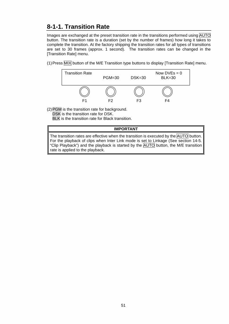
51
8-1-1. Transition Rate Images are exchanged at the preset transition rate in the transitions performed using AUTO button. The transition rate is a duration (set by the number of frames) how long it takes to complete the transition. At the factory shipping the transition rates for all types of transitions are set to 30 frames (approx. 1 second). The transition rates can be changed in the [Transition Rate] menu.
(1) Press MIX button of the M/E Transition type buttons to display [Transition Rate] menu.
(2) PGM is the transition rate for background. DSK is the transition rate for DSK. BLK is the transition rate for Black transition.
IMPORTANT
The transition rates are effective when the transition is executed by the AUTO button. For the playback of clips when Inter Link mode is set to Linkage (See section 14-5. “Clip Playback”) and the playback is started by the AUTO button, the M/E transition rate is applied to the playback.
F1 F2 F3 F4
Transition Rate Now DVEs = 0 PGM=30 DSK=30 BLK=30
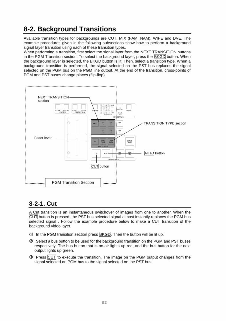
52
8-2. Background Transitions Available transition types for backgrounds are CUT, MIX (FAM, NAM), WIPE and DVE. The example procedures given in the following subsections show how to perform a background signal layer transition using each of these transition types. When performing a transition, first select the signal layer from the NEXT TRANSITION buttons in the PGM Transition section. To select the background layer, press the BKGD button. When the background layer is selected, the BKGD button is lit. Then, select a transition type. When a background transition is performed, the signal selected on the PST bus replaces the signal selected on the PGM bus on the PGM line output. At the end of the transition, cross-points of PGM and PST buses change places (flip-flop).
8-2-1. Cut A Cut transition is an instantaneous switchover of images from one to another. When the CUT button is pressed, the PST bus selected signal almost instantly replaces the PGM bus selected signal . Follow the example procedure below to make a CUT transition of the background video layer.
In the PGM transition section press BKGD. Then the button will be lit up.
Select a bus button to be used for the background transition on the PGM and PST buses respectively. The bus button that is on-air lights up red, and the bus button for the next output lights up green.
Press CUT to execute the transition. The image on the PGM output changes from the signal selected on PGM bus to the signal selected on the PST bus.
1
TRANSITION
PRIORITY1 OVER 2
21
24
3 4321
LOW1 2 3 44321
HIGH
KEY STATUSKEY LAYER DSK
FADER DIRECTIONSEQ LINK FADER LIMIT NOR/REV REVERSE PREV TRANS
DSK1
DSK2
DSKCUT
BLACKTRANS
DSKMIX
KEY2
KEY4
DVE(NAM)
KEY1
KEY3
WIPE(FAM)
BKGD
MIX
AUTO
TRANSITION TYPE
CUT
NEXT TRANSITION section
TRANSITION TYPE section
AUTO button
Fader lever
CUT button
PGM Transition Section
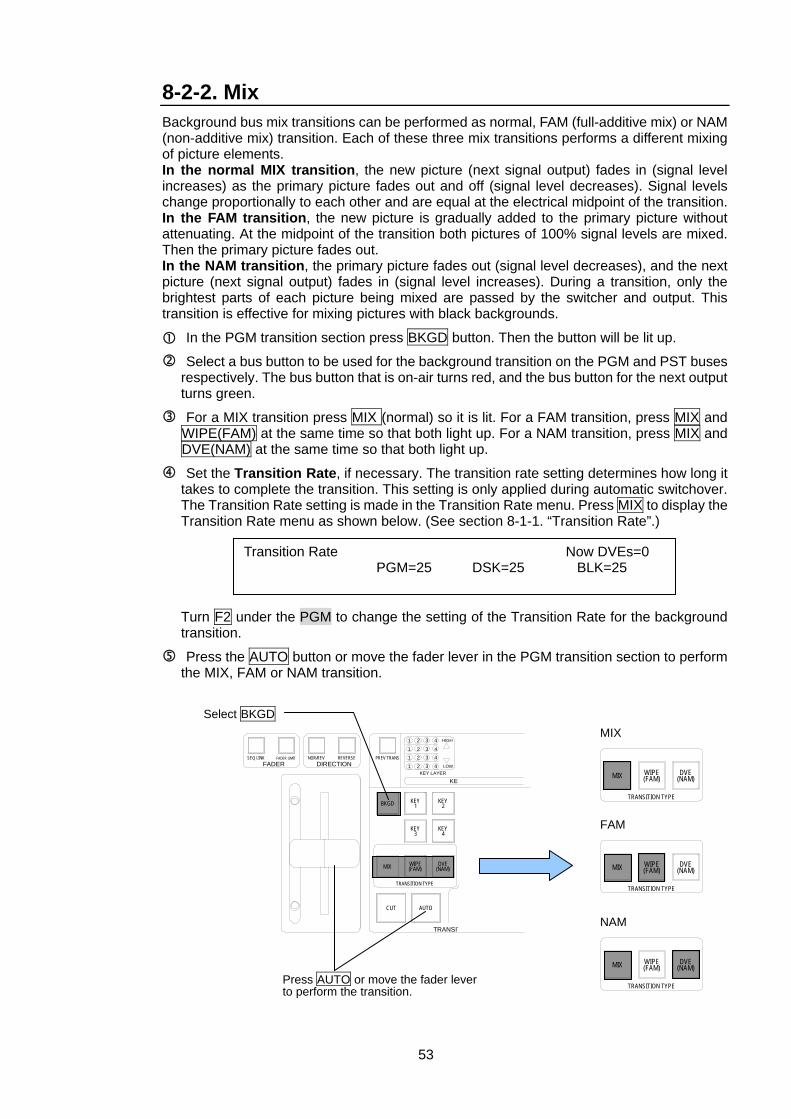
53
8-2-2. Mix Background bus mix transitions can be performed as normal, FAM (full-additive mix) or NAM (non-additive mix) transition. Each of these three mix transitions performs a different mixing of picture elements. In the normal MIX transition, the new picture (next signal output) fades in (signal level increases) as the primary picture fades out and off (signal level decreases). Signal levels change proportionally to each other and are equal at the electrical midpoint of the transition. In the FAM transition, the new picture is gradually added to the primary picture without attenuating. At the midpoint of the transition both pictures of 100% signal levels are mixed. Then the primary picture fades out. In the NAM transition, the primary picture fades out (signal level decreases), and the next picture (next signal output) fades in (signal level increases). During a transition, only the brightest parts of each picture being mixed are passed by the switcher and output. This transition is effective for mixing pictures with black backgrounds.
In the PGM transition section press BKGD button. Then the button will be lit up.
Select a bus button to be used for the background transition on the PGM and PST buses respectively. The bus button that is on-air turns red, and the bus button for the next output turns green.
For a MIX transition press MIX (normal) so it is lit. For a FAM transition, press MIX and WIPE(FAM) at the same time so that both light up. For a NAM transition, press MIX and DVE(NAM) at the same time so that both light up.
Set the Transition Rate, if necessary. The transition rate setting determines how long it takes to complete the transition. This setting is only applied during automatic switchover. The Transition Rate setting is made in the Transition Rate menu. Press MIX to display the Transition Rate menu as shown below. (See section 8-1-1. “Transition Rate”.) Turn F2 under the PGM to change the setting of the Transition Rate for the background transition.
Press the AUTO button or move the fader lever in the PGM transition section to perform the MIX, FAM or NAM transition.
Transition Rate Now DVEs=0 PGM=25 DSK=25 BLK=25
1
TRANSIT
24
3 4321
LOW1 2 3 44321
HIGH
KEYKEY LAYER
FADER DIRECTIONSEQ LINK FADER LIMIT NOR/REV REVERSE PREV TRANS
KEY2
KEY4
DVE(NAM)
KEY1
KEY3
WIPE(FAM)
BKGD
MIX
AUTO
TRANSITION TYPE
CUT
Select BKGD MIX
FAM
NAM
DVE(NAM)
WIPE(FAM)MIX
TRANSITION TYPE
DVE(NAM)
WIPE(FAM)MIX
TRANSITION TYPE
DVE(NAM)
WIPE(FAM)MIX
TRANSITION TYPEPress AUTO or move the fader lever to perform the transition.
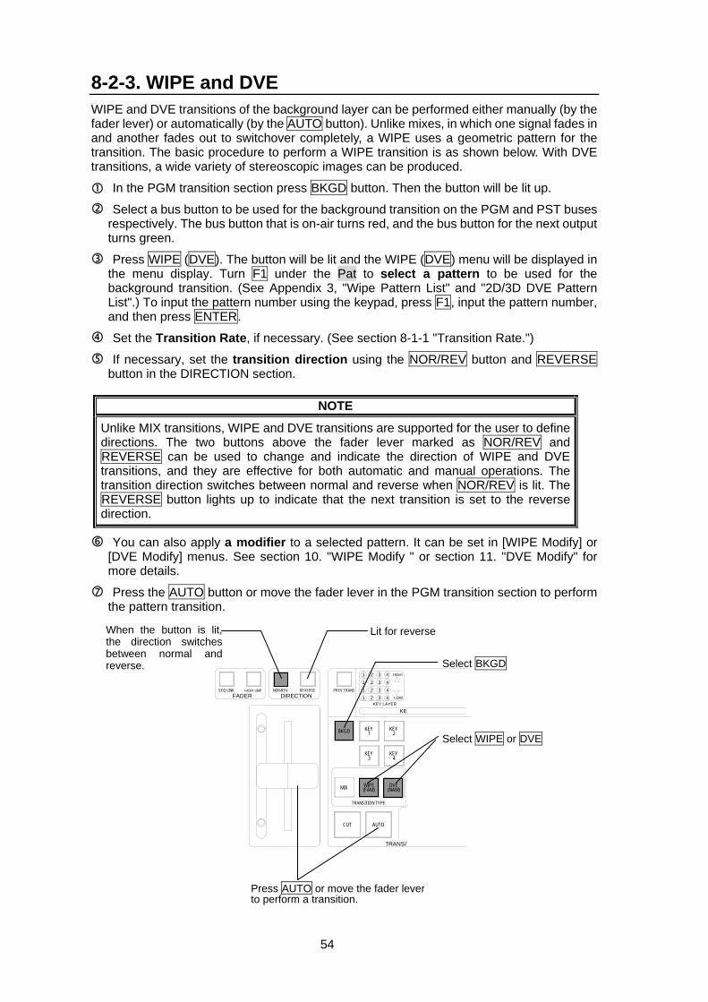
54
8-2-3. WIPE and DVE WIPE and DVE transitions of the background layer can be performed either manually (by the fader lever) or automatically (by the AUTO button). Unlike mixes, in which one signal fades in and another fades out to switchover completely, a WIPE uses a geometric pattern for the transition. The basic procedure to perform a WIPE transition is as shown below. With DVE transitions, a wide variety of stereoscopic images can be produced.
In the PGM transition section press BKGD button. Then the button will be lit up.
Select a bus button to be used for the background transition on the PGM and PST buses respectively. The bus button that is on-air turns red, and the bus button for the next output turns green.
Press WIPE (DVE). The button will be lit and the WIPE (DVE) menu will be displayed in the menu display. Turn F1 under the Pat to select a pattern to be used for the background transition. (See Appendix 3, "Wipe Pattern List" and "2D/3D DVE Pattern List".) To input the pattern number using the keypad, press F1, input the pattern number, and then press ENTER.
Set the Transition Rate, if necessary. (See section 8-1-1 "Transition Rate.")
If necessary, set the transition direction using the NOR/REV button and REVERSE button in the DIRECTION section.
NOTE
Unlike MIX transitions, WIPE and DVE transitions are supported for the user to define directions. The two buttons above the fader lever marked as NOR/REV and REVERSE can be used to change and indicate the direction of WIPE and DVE transitions, and they are effective for both automatic and manual operations. The transition direction switches between normal and reverse when NOR/REV is lit. The REVERSE button lights up to indicate that the next transition is set to the reverse direction.
You can also apply a modifier to a selected pattern. It can be set in [WIPE Modify] or [DVE Modify] menus. See section 10. "WIPE Modify " or section 11. "DVE Modify" for more details.
Press the AUTO button or move the fader lever in the PGM transition section to perform the pattern transition.
1
TRANSIT
24
3 4321
LOW1 2 3 44321
HIGH
KEYKEY LAYER
FADER DIRECTIONSEQ LINK FADER LIMIT NOR/REV REVERSE PREV TRANS
KEY2
KEY4
DVE(NAM)
KEY1
KEY3
WIPE(FAM)
BKGD
MIX
AUTO
TRANSITION TYPE
CUT
Select BKGD
Press AUTO or move the fader lever to perform a transition.
Select WIPE or DVE
Lit for reverse When the button is lit,the direction switchesbetween normal andreverse.
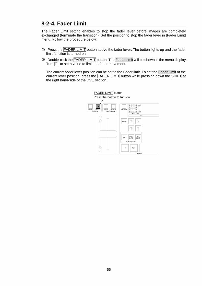
55
8-2-4. Fader Limit The Fader Limit setting enables to stop the fader lever before images are completely exchanged (terminate the transition). Set the position to stop the fader lever in [Fader Limit] menu. Follow the procedure below.
Press the FADER LIMIT button above the fader lever. The button lights up and the fader limit function is turned on.
Double-click the FADER LIMIT button. The Fader Limit will be shown in the menu display. Turn F1 to set a value to limit the fader movement. The current fader lever position can be set to the Fader limit. To set the Fader Limit at the current lever position, press the FADER LIMIT button while pressing down the SHIFT at the right hand-side of the DVE section.
1
TRANSIT
24
3 4321
LOW1 2 3 44321
HIGH
KEYKEY LAYER
FADER DIRECTIONSEQ LINK FADER LIMIT NOR/REV REVERSE PREV TRANS
KEY2
KEY4
DVE(NAM)
KEY1
KEY3
WIPE(FAM)
BKGD
MIX
AUTO
TRANSITION TYPE
CUT
FADER LIMIT button Press the button to turn on.
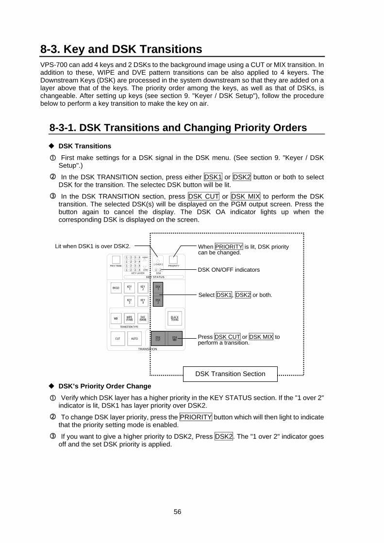
56
8-3. Key and DSK Transitions VPS-700 can add 4 keys and 2 DSKs to the background image using a CUT or MIX transition. In addition to these, WIPE and DVE pattern transitions can be also applied to 4 keyers. The Downstream Keys (DSK) are processed in the system downstream so that they are added on a layer above that of the keys. The priority order among the keys, as well as that of DSKs, is changeable. After setting up keys (see section 9. "Keyer / DSK Setup"), follow the procedure below to perform a key transition to make the key on air.
8-3-1. DSK Transitions and Changing Priority Orders DSK Transitions
First make settings for a DSK signal in the DSK menu. (See section 9. "Keyer / DSK Setup".)
In the DSK TRANSITION section, press either DSK1 or DSK2 button or both to select DSK for the transition. The selectec DSK button will be lit.
In the DSK TRANSITION section, press DSK CUT or DSK MIX to perform the DSK transition. The selected DSK(s) will be displayed on the PGM output screen. Press the button again to cancel the display. The DSK OA indicator lights up when the corresponding DSK is displayed on the screen.
DSK’s Priority Order Change
Verify which DSK layer has a higher priority in the KEY STATUS section. If the "1 over 2" indicator is lit, DSK1 has layer priority over DSK2.
To change DSK layer priority, press the PRIORITY button which will then light to indicate that the priority setting mode is enabled.
If you want to give a higher priority to DSK2, Press DSK2. The "1 over 2" indicator goes off and the set DSK priority is applied.
1
TRANSITION
PRIORITY1 OVER 2
21
24
3 4321
LOW1 2 3 44321
HIGH
KEY STATUSKEY LAYER DSK
PREV TRANS
DSK1
DSK2
DSKCUT
BLACKTRANS
DSKMIX
KEY2
KEY4
DVE(NAM)
KEY1
KEY3
WIPE(FAM)
BKGD
MIX
AUTO
TRANSITION TYPE
CUT Press DSK CUT or DSK MIX to perform a transition.
When PRIORITY is lit, DSK priority can be changed.
Select DSK1, DSK2 or both.
Lit when DSK1 is over DSK2.
DSK ON/OFF indicators
DSK Transition Section
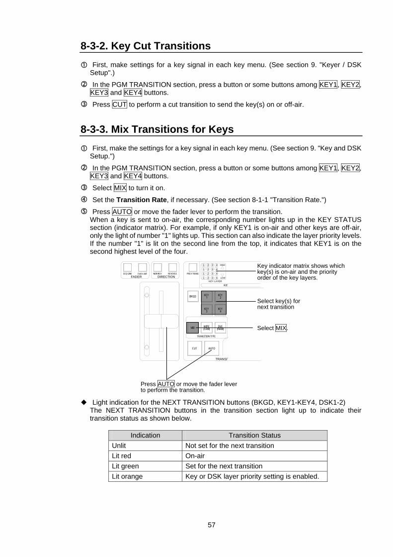
57
8-3-2. Key Cut Transitions First, make settings for a key signal in each key menu. (See section 9. "Keyer / DSK Setup".)
In the PGM TRANSITION section, press a button or some buttons among KEY1, KEY2, KEY3 and KEY4 buttons.
Press CUT to perform a cut transition to send the key(s) on or off-air. 8-3-3. Mix Transitions for Keys
First, make the settings for a key signal in each key menu. (See section 9. "Key and DSK Setup.")
In the PGM TRANSITION section, press a button or some buttons among KEY1, KEY2, KEY3 and KEY4 buttons.
Select MIX to turn it on.
Set the Transition Rate, if necessary. (See section 8-1-1 "Transition Rate.")
Press AUTO or move the fader lever to perform the transition. When a key is sent to on-air, the corresponding number lights up in the KEY STATUS section (indicator matrix). For example, if only KEY1 is on-air and other keys are off-air, only the light of number "1" lights up. This section can also indicate the layer priority levels. If the number "1" is lit on the second line from the top, it indicates that KEY1 is on the second highest level of the four.
Light indication for the NEXT TRANSITION buttons (BKGD, KEY1-KEY4, DSK1-2) The NEXT TRANSITION buttons in the transition section light up to indicate their transition status as shown below.
Indication Transition Status Unlit Not set for the next transition Lit red On-air Lit green Set for the next transition Lit orange Key or DSK layer priority setting is enabled.
1
TRANSIT
24
3 4321
LOW1 2 3 44321
HIGH
KEYKEY LAYER
FADER DIRECTIONSEQ LINK FADER LIMIT NOR/REV REVERSE PREV TRANS
KEY2
KEY4
DVE(NAM)
KEY1
KEY3
WIPE(FAM)
BKGD
MIX
AUTO
TRANSITION TYPE
CUT
Press AUTO or move the fader lever to perform the transition.
Key indicator matrix shows which key(s) is on-air and the priority order of the key layers.
Select key(s) for next transition
Select MIX.
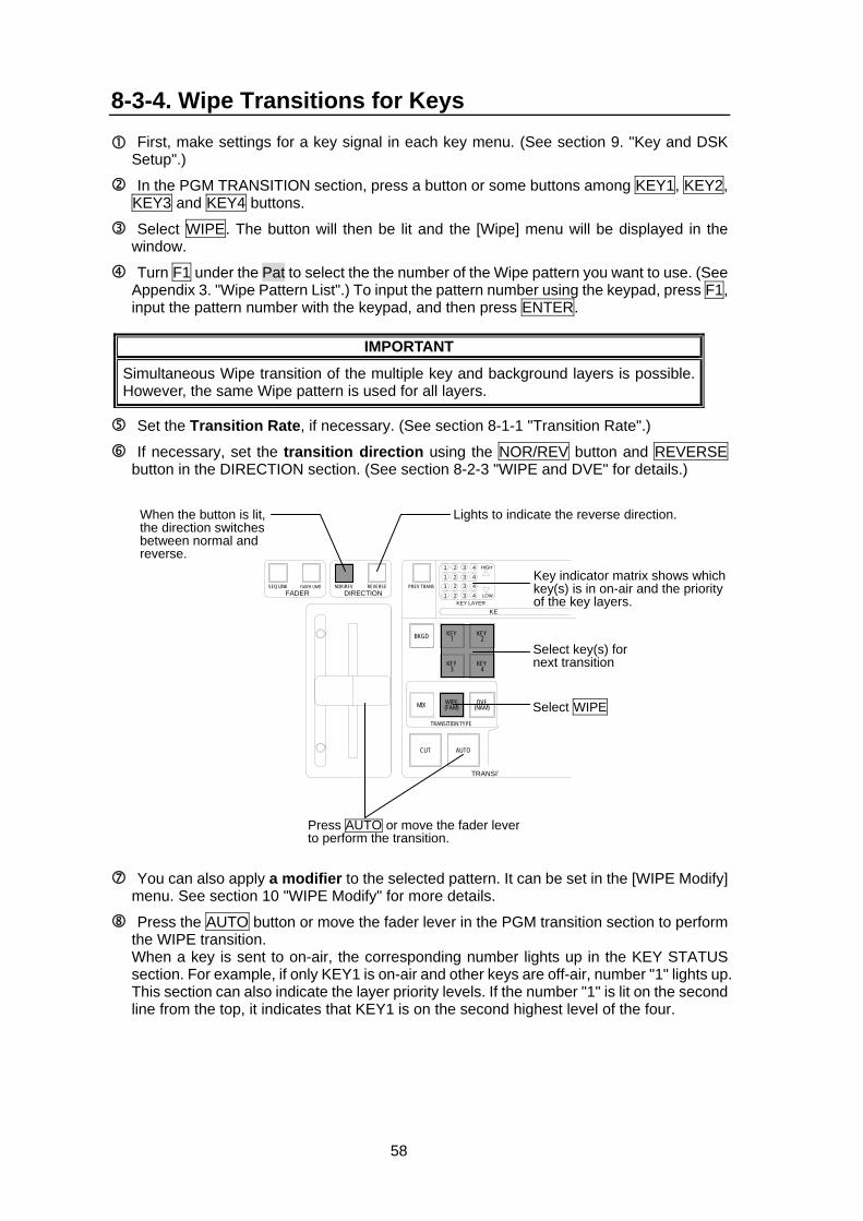
58
8-3-4. Wipe Transitions for Keys First, make settings for a key signal in each key menu. (See section 9. "Key and DSK Setup".)
In the PGM TRANSITION section, press a button or some buttons among KEY1, KEY2, KEY3 and KEY4 buttons.
Select WIPE. The button will then be lit and the [Wipe] menu will be displayed in the window.
Turn F1 under the Pat to select the the number of the Wipe pattern you want to use. (See Appendix 3. "Wipe Pattern List".) To input the pattern number using the keypad, press F1, input the pattern number with the keypad, and then press ENTER.
IMPORTANT
Simultaneous Wipe transition of the multiple key and background layers is possible. However, the same Wipe pattern is used for all layers.
Set the Transition Rate, if necessary. (See section 8-1-1 "Transition Rate".)
If necessary, set the transition direction using the NOR/REV button and REVERSE button in the DIRECTION section. (See section 8-2-3 "WIPE and DVE" for details.)
You can also apply a modifier to the selected pattern. It can be set in the [WIPE Modify] menu. See section 10 "WIPE Modify" for more details.
Press the AUTO button or move the fader lever in the PGM transition section to perform the WIPE transition. When a key is sent to on-air, the corresponding number lights up in the KEY STATUS section. For example, if only KEY1 is on-air and other keys are off-air, number "1" lights up. This section can also indicate the layer priority levels. If the number "1" is lit on the second line from the top, it indicates that KEY1 is on the second highest level of the four.
1
TRANSIT
24
3 4321
LOW1 2 3 44321
HIGH
KEYKEY LAYER
FADER DIRECTIONSEQ LINK FADER LIMIT NOR/REV REVERSE PREV TRANS
KEY2
KEY4
DVE(NAM)
KEY1
KEY3
WIPE(FAM)
BKGD
MIX
AUTO
TRANSITION TYPE
CUT
Press AUTO or move the fader lever to perform the transition.
Select WIPE
Lights to indicate the reverse direction. When the button is lit, the direction switches between normal and reverse.
Key indicator matrix shows which key(s) is in on-air and the priority of the key layers.
Select key(s) for next transition
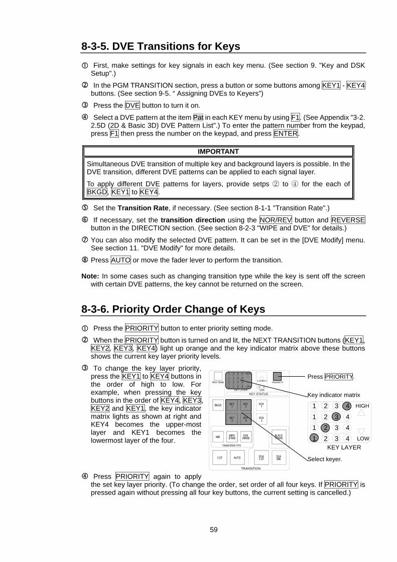
59
8-3-5. DVE Transitions for Keys First, make settings for key signals in each key menu. (See section 9. "Key and DSK Setup".)
In the PGM TRANSITION section, press a button or some buttons among KEY1 - KEY4 buttons. (See section 9-5. “ Assigning DVEs to Keyers”)
Press the DVE button to turn it on.
Select a DVE pattern at the item Pat in each KEY menu by using F1. (See Appendix "3-2. 2.5D (2D & Basic 3D) DVE Pattern List".) To enter the pattern number from the keypad, press F1 then press the number on the keypad, and press ENTER.
IMPORTANT
Simultaneous DVE transition of multiple key and background layers is possible. In the DVE transition, different DVE patterns can be applied to each signal layer.
To apply different DVE patterns for layers, provide setps ② to ④ for the each of BKGD, KEY1 to KEY4.
Set the Transition Rate, if necessary. (See section 8-1-1 "Transition Rate".)
If necessary, set the transition direction using the NOR/REV button and REVERSE button in the DIRECTION section. (See section 8-2-3 "WIPE and DVE" for details.)
You can also modify the selected DVE pattern. It can be set in the [DVE Modify] menu. See section 11. "DVE Modify" for more details.
Press AUTO or move the fader lever to perform the transition.
Note: In some cases such as changing transition type while the key is sent off the screen with certain DVE patterns, the key cannot be returned on the screen.
8-3-6. Priority Order Change of Keys Press the PRIORITY button to enter priority setting mode.
When the PRIORITY button is turned on and lit, the NEXT TRANSITION buttons (KEY1, KEY2, KEY3, KEY4) light up orange and the key indicator matrix above these buttons shows the current key layer priority levels.
To change the key layer priority, press the KEY1 to KEY4 buttons in the order of high to low. For example, when pressing the key buttons in the order of KEY4, KEY3, KEY2 and KEY1, the key indicator matrix lights as shown at right and KEY4 becomes the upper-most layer and KEY1 becomes the lowermost layer of the four.
Press PRIORITY again to apply the set key layer priority. (To change the order, set order of all four keys. If PRIORITY is pressed again without pressing all four key buttons, the current setting is cancelled.)
1
TRANSITION
PRIORITY1 OVER 2
21
24
3 4321
LOW1 2 3 44321
HIGH
KEY STATUSKEY LAYER DSK
PREV TRANS
DSK1
DSK2
DSKCUT
BLACKTRANS
DSKMIX
KEY2
KEY4
DVE(NAM)
KEY1
KEY3
WIPE(FAM)
BKGD
MIX
AUTO
TRANSITION TYPE
CUT Select keyer.
Key indicator matrix
Press PRIORITY.
1 24
3 4321
LOW1 2 3 44321
HIGH
KEY LAYER
60
8-4. BLACK Transitions Pressing BLACK TRANS in the NEXT TRANSITION section initiates a fade to (or fade from) black of whatever signal layers are currently on the program line (background and keys). Pressing the BLACK TRANS button again during the transition instantaneously returns the initial image on the program line. This means that the program line video changes from black to the initial image if it was in the process of fading to black, and vice versa, changes from the image to black if it was in the process of fading to the image.
IMPORTANT
BLACK transitions have the highest priority among all auto transitions. BLACK transition takes place whenever the BLACK TRANS button is pressed, even if DSK or PGM transition is in progress. BLACK TRANS button lights up red during transition, lights up orange when black is on-air, and then goes off when the initial image is returned.
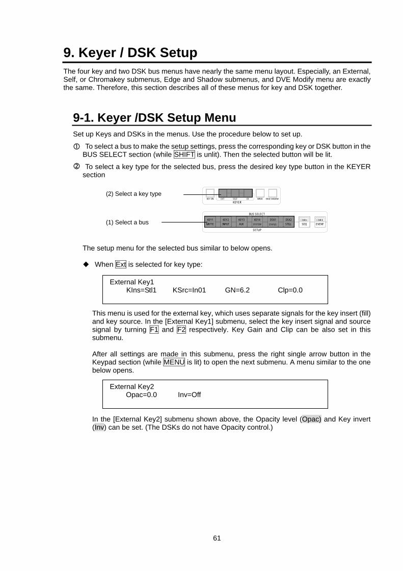
61
9. Keyer / DSK Setup The four key and two DSK bus menus have nearly the same menu layout. Especially, an External, Self, or Chromakey submenus, Edge and Shadow submenus, and DVE Modify menu are exactly the same. Therefore, this section describes all of these menus for key and DSK together.
9-1. Keyer /DSK Setup Menu Set up Keys and DSKs in the menus. Use the procedure below to set up.
To select a bus to make the setup settings, press the corresponding key or DSK button in the BUS SELECT section (while SHIFT is unlit). Then the selected button will be lit.
To select a key type for the selected bus, press the desired key type button in the KEYER section The setup menu for the selected bus similar to below opens.
When Ext is selected for key type: This menu is used for the external key, which uses separate signals for the key insert (fill) and key source. In the [External Key1] submenu, select the key insert signal and source signal by turning F1 and F2 respectively. Key Gain and Clip can be also set in this submenu. After all settings are made in this submenu, press the right single arrow button in the Keypad section (while MENU is lit) to open the next submenu. A menu similar to the one below opens. In the [External Key2] submenu shown above, the Opacity level (Opac) and Key invert (Inv) can be set. (The DSKs do not have Opacity control.)
KEYER
EVENTCOMB B
SEQCOMB ADSK2
STILLDSK1
STATUS
KEY4
SETUP
BUS SELECT
KEY3AUX
KEY2KEY1MATTE
KEY ON EXT SELF CK EDGE SHADOWMASK
INPUT SYSTEM
(2) Select a key type
(1) Select a bus
External Key1 KIns=Stl1 KSrc=In01 GN=6.2 Clp=0.0
External Key2 Opac=0.0 Inv=Off
62
When Self is selected for key type: This menu is used for the self key, which uses the same signal for key source and key insert (fill). In the [Self Key1] submenu, select key insert signal by turning F1. Key Gain and Clip can be also set in this submenu. After all settings are made in this submenu, press the right single arrow button in the Keypad section (while MENU is lit) to open the next submenu. A menu similar to that shown below opens. In the [Self Key2] submenu shown above, the Opacity level (Opac) and Key invert (Inv) can be set. (The DSKs do not have Opacity control.)
When CK is selected for type: This menu is used for the Chroma key, which has a very different setup procedure from other key types. See section 9-4 "Making and Adjusting Chromakey" for more details.
KEY ON Button The KEY ON button to the left of the KEYER section is used to select keyer DVE On / Off. Pressing the unlit button sets DVE to On (Enable-no Key) for the currently selected keyer. Pressing the button again sets DVE to On (Enable-with Key). And pressing it again turns off the light and sets DVE to Off (Disable). (See section 9-5-2. "Opening DVE Menus and Assigning DVE.")
Both key insert and key source can be selected from Black, IN01 to IN16, Still 1 and 2, Matte 1 to 4, ComA, and ComB for any type of keys.
Self Key1 KIns=Stl1 GN=6.2 Clp=0.0
Self Key2 Opac=0.0 Inv=Off
CK Manual1 Ang=1.7 KAc=4.2 GN=6.2 Clp=0.0
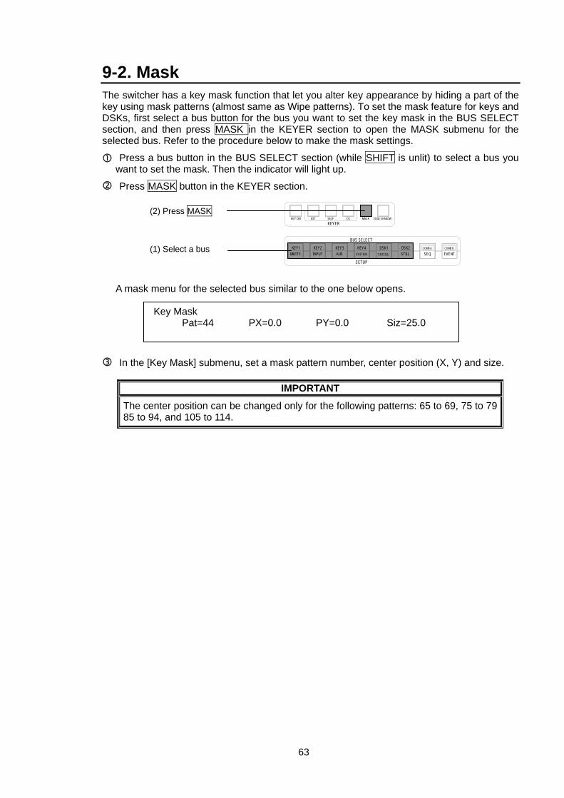
63
9-2. Mask The switcher has a key mask function that let you alter key appearance by hiding a part of the key using mask patterns (almost same as Wipe patterns). To set the mask feature for keys and DSKs, first select a bus button for the bus you want to set the key mask in the BUS SELECT section, and then press MASK in the KEYER section to open the MASK submenu for the selected bus. Refer to the procedure below to make the mask settings.
Press a bus button in the BUS SELECT section (while SHIFT is unlit) to select a bus you want to set the mask. Then the indicator will light up.
Press MASK button in the KEYER section. A mask menu for the selected bus similar to the one below opens.
In the [Key Mask] submenu, set a mask pattern number, center position (X, Y) and size.
IMPORTANT
The center position can be changed only for the following patterns: 65 to 69, 75 to 79 85 to 94, and 105 to 114.
KEYER
EVENTCOMB B
SEQCOMB ADSK2
STILLDSK1
STATUS
KEY4
SETUP
BUS SELECT
KEY3AUX
KEY2KEY1MATTE
KEY ON EXT SELF CK EDGE SHADOWMASK
INPUT SYSTEM
(2) Press MASK
(1) Select a bus
Key Mask Pat=44 PX=0.0 PY=0.0 Siz=25.0
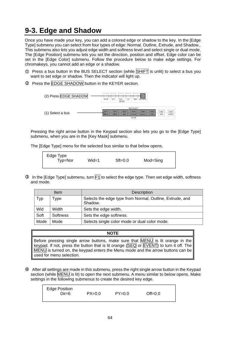
64
9-3. Edge and Shadow Once you have made your key, you can add a colored edge or shadow to the key. In the [Edge Type] submenu you can select from four types of edge: Normal. Outline, Extrude, and Shadow,. This submenu also lets you adjust edge width and softness level and select single or dual mode. The [Edge Position] submenu lets you set the direction, position and offset. Edge color can be set in the [Edge Color] submenu. Follow the procedure below to make edge settings. For chromakeys, you cannot add an edge or a shadow.
Press a bus button in the BUS SELECT section (while SHIFT is unlit) to select a bus you want to set edge or shadow. Then the indicator will light up.
Press the EDGE SHADOW button in the KEYER section. Pressing the right arrow button in the Keypad section also lets you go to the [Edge Type] submenu, when you are in the [Key Mask] submenu. The [Edge Type] menu for the selected bus similar to that below opens.
In the [Edge Type] submenu, turn F1 to select the edge type. Then set edge width, softness and mode.
Item Description Typ Type Selects the edge type from Normal, Outline, Extrude, and
Shadow. Wid Width Sets the edge width. Soft Softness Sets the edge softness. Mode Mode Selects single color mode or dual color mode.
NOTE
Before pressing single arrow buttons, make sure that MENU is lit orange in the keypad. If not, press the button that is lit orange (SEQ or EVENT) to turn it off. The MENU is turned on, the keypad enters the Menu mode and the arrow buttons can be used for menu selection.
After all settings are made in this submenu, press the right single arrow button in the Keypad section (while MENU is lit) to open the next submenu. A menu similar to below opens. Make settings in the following submenus to create the desired key edge.
Edge Position Dir=6 PX=0.0 PY=0.0 Off=0.0
KEYER
EVENTCOMB B
SEQCOMB ADSK2
STILLDSK1
STATUS
KEY4
SETUP
BUS SELECT
KEY3AUX
KEY2KEY1MATTE
KEY ON EXT SELF CK EDGE SHADOWMASK
INPUT SYSTEM
(2) Press EDGE SHADOW
(1) Select a bus
Edge Type Typ=Nor Wid=1 Sft=0.0 Mod=Sing
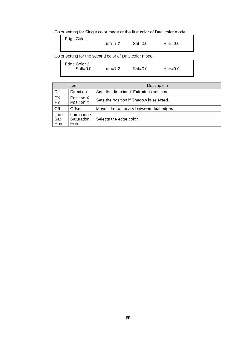
65
Color setting for Single color mode or the first color of Dual color mode: Color setting for the second color of Dual color mode:
Item Description Dir Direction Sets the direction if Extrude is selected. PX PY
Position X Position Y Sets the position if Shadow is selected.
Off Offset Moves the boundary between dual edges. Lum Sat Hue
Luminance Saturation Hue
Selects the edge color.
Edge Color 1 Lum=7.2 Sat=0.0 Hue=0.0
Edge Color 2 Soft=0.0 Lum=7.2 Sat=0.0 Hue=0.0
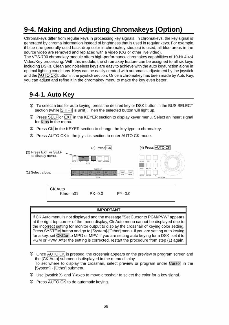
66
9-4. Making and Adjusting Chromakeys (Option) Chromakeys differ from regular keys in processing key signals. In chromakeys, the key signal is generated by chroma information instead of brightness that is used in regular keys. For example, if blue (the generally used back-drop color in chromakey studios) is used, all blue areas in the source video are removed and replaced with a video (CG or other live video). The VPS-700 chromakey module offers high-performance chromakey capabilities of 10-bit 4:4:4 Video/Key processing. With this module, the chromakey feature can be assigned to all six keys including DSKs. Clean and noiseless keys are easy to achieve with the auto keyfunction alone in optimal lighting conditions. Keys can be easily created with automatic adjustment by the joystick and the AUTO CK button in the joystick section. Once a chromakey has been made by Auto Key, you can adjust and refine it in the chromakey menu to make the key even better.
9-4-1. Auto Key To select a bus for auto keying, press the desired key or DSK button in the BUS SELECT section (while SHIFT is unlit). Then the selected button will light up.
Press SELF or EXT in the KEYER section to display keyer menu. Select an insert signal for KIns in the menu.
Press CK in the KEYER section to change the key type to chromakey.
Press AUTO CK in the joystick section to enter AUTO CK mode.
IMPORTANT
If CK Auto menu is not displayed and the message "Set Cursor to PGM/PVW" appears at the right top corner of the menu display, Ck Auto menu cannot be displayed due to the incorrect setting for monitor output to display the crosshair of keying color setting. Press SYSTEM button and go to [System]-[Other] menu. If you are setting auto keying for a key, set CKCur to MPG or MPV. If you are setting auto keying for a DSK, set it to PGM or PVW. After the setting is corrected, restart the procedure from step (1) again.
Once AUTO CK is pressed, the crosshair appears on the preview or program screen and the [CK Auto] submenu is displayed in the menu display. To set where to display the crosshair, select preview or program under Cursor in the [System] - [Other] submenu.
Use joystick X- and Y-axes to move crosshair to select the color for a key signal.
Press AUTO CK to do automatic keying.
Z
Y
X
JOYSTICK
DEFAULT FINE
DVE ROT
WIPE POS
DVE POS
AUTO CK
(4) Press AUTO CK.
KEYER
EVENTCOMB B
SEQCOMB ADSK2
STILLDSK1
STATUS
KEY4
SETUP
BUS SELECT
KEY3AUX
KEY2KEY1MATTE
KEY ON EXT SELF CK EDGE SHADOWMASK
INPUT SYSTEM
(2) Press EXT or SELF to display menu.
(1) Select a bus.
(3) Press CK.
CK Auto KIns=In01 PX=0.0 PY=0.0
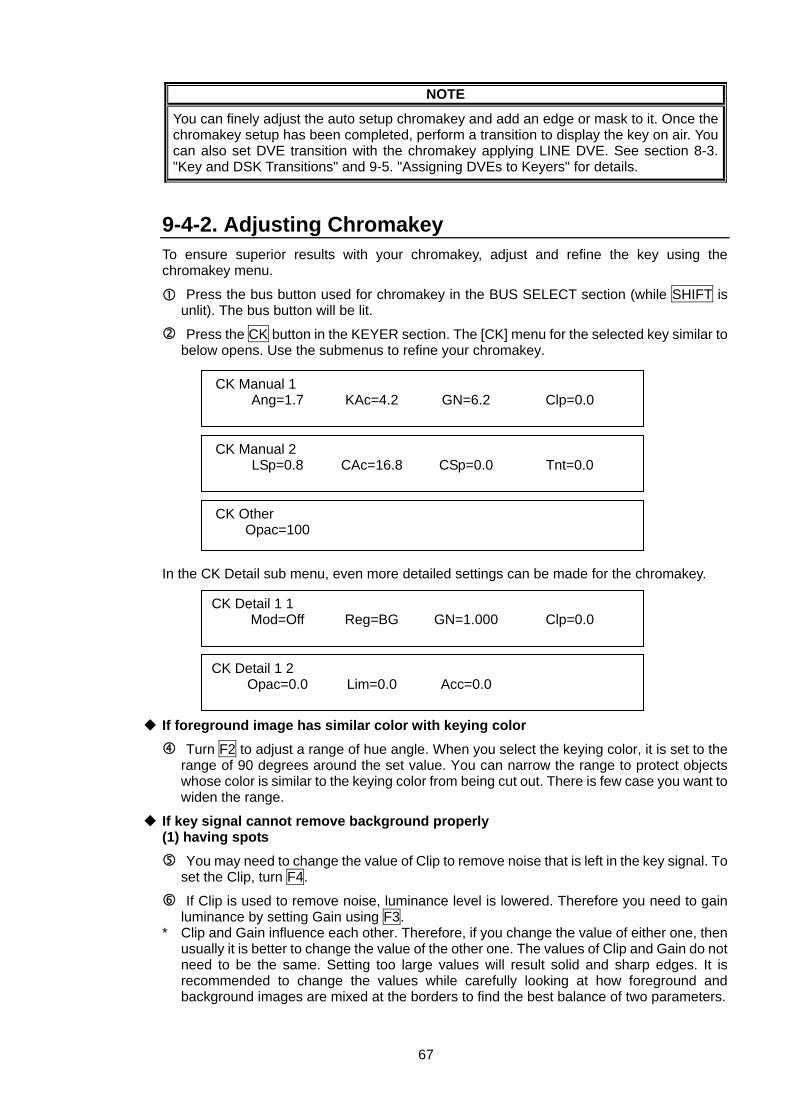
67
NOTE
You can finely adjust the auto setup chromakey and add an edge or mask to it. Once the chromakey setup has been completed, perform a transition to display the key on air. You can also set DVE transition with the chromakey applying LINE DVE. See section 8-3. "Key and DSK Transitions" and 9-5. "Assigning DVEs to Keyers" for details.
9-4-2. Adjusting Chromakey To ensure superior results with your chromakey, adjust and refine the key using the chromakey menu.
Press the bus button used for chromakey in the BUS SELECT section (while SHIFT is unlit). The bus button will be lit.
Press the CK button in the KEYER section. The [CK] menu for the selected key similar to below opens. Use the submenus to refine your chromakey.
In the CK Detail sub menu, even more detailed settings can be made for the chromakey.
If foreground image has similar color with keying color Turn F2 to adjust a range of hue angle. When you select the keying color, it is set to the range of 90 degrees around the set value. You can narrow the range to protect objects whose color is similar to the keying color from being cut out. There is few case you want to widen the range.
If key signal cannot remove background properly (1) having spots
You may need to change the value of Clip to remove noise that is left in the key signal. To set the Clip, turn F4.
If Clip is used to remove noise, luminance level is lowered. Therefore you need to gain luminance by setting Gain using F3.
* Clip and Gain influence each other. Therefore, if you change the value of either one, then usually it is better to change the value of the other one. The values of Clip and Gain do not need to be the same. Setting too large values will result solid and sharp edges. It is recommended to change the values while carefully looking at how foreground and background images are mixed at the borders to find the best balance of two parameters.
CK Manual 1 Ang=1.7 KAc=4.2 GN=6.2 Clp=0.0
CK Manual 2 LSp=0.8 CAc=16.8 CSp=0.0 Tnt=0.0
CK Other Opac=100
CK Detail 1 1 Mod=Off Reg=BG GN=1.000 Clp=0.0
CK Detail 1 2 Opac=0.0 Lim=0.0 Acc=0.0
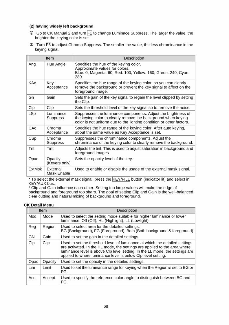
68
(2) having widely left background Go to CK Manual 2 and turn F1 to change Luminace Suppress. The larger the value, the brighter the keying color is set.
Turn F3 to adjust Chroma Suppress. The smaller the value, the less chrominance in the keying signal.
Item Description
Ang Hue Angle Specifies the hue of the keying color. Approximate values for colors. Blue: 0, Magenta: 60, Red: 100, Yellow: 160, Green: 240, Cyan: 280
KAc Key Acceptance
Specifies the hue range of the keying color, so you can clearly remove the background or prevent the key signal to affect on the foreground image.
Gn Gain Sets the gain of the key signal to regain the level clipped by setting the Clip.
Clp Clip Sets the threshold level of the key signal so to remove the noise. LSp Luminance
Suppress Suppresses the luminance components. Adjust the brightness of the keying color to clearly remove the background when keying color is not uniform due to the lighting condition or other factors.
CAc Chroma Acceptance
Specifies the hue range of the keying color. After auto keying, about the same value as Key Acceptance is set.
CSp Chroma Suppress
Suppresses the chrominance components. Adjust the chrominance of the keying color to clearly remove the background.
Tnt Tint Adjusts the tint. This is used to adjust saturation in background and foreground images.
Opac Opacity (Keyers only)
Sets the opacity level of the key.
ExtMsk External Mask Enable
Used to enable or disable the usage of the external mask signal.
* To select the external mask signal, press the KEY/FILL button (indicator lit) and select in KEY/AUX bus. * Clip and Gain influence each other. Setting too large values will make the edge of background and foreground too sharp. The goal of setting Clip and Gain is the well-balanced clear cutting and natural mixing of background and foreground.
CK Detail Menu
Item Description Mod Mode Used to select the setting mode suitable for higher luminance or lower
luminance. Off (Off), HL (Highlight), LL (Lowlight) Reg Region Used to select area for the detailed settings.
BG (Background), FG (Foreground), Both (Both background & foreground)GN Gain Used to set the gain in the detailed settings. Clp Clip Used to set the threshold level of luminance at which the detailed settings
are activated. In the HL mode, the settings are applied to the area where luminance level is above Clp level setting. In the LL mode, the settings are applied to where luminance level is below Clp level setting.
Opac Opacity Used to set the opacity in the detailed settings. Lim Limit Used to set the luminance range for keying when the Region is set to BG or
FG. Acc Accept Used to specify the reference color angle to distinguish between BG and
FG.
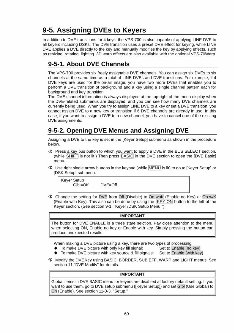
69
9-5. Assigning DVEs to Keyers In addition to DVE transitions for 4 keys, the VPS-700 is also capable of applying LINE DVE to all keyers including DSKs. The DVE transition uses a preset DVE effect for keying, while LINE DVE applies a DVE directly to the key and manually modifies the key by applying effects, such as resizing, rotating, lighting. 3D warp effects are also available with the optional VPS-70Warp.
9-5-1. About DVE Channels The VPS-700 provides six freely assignable DVE channels. You can assign six DVEs to six channels at the same time as a total of LINE DVEs and DVE transitions. For example, if 4 DVE keys are used for the on-air image, you have two more DVEs that enables you to perform a DVE transition of background and a key using a single channel pattern each for background and key transition. The DVE channel information is always displayed at the top right of the menu display when the DVE-related submenus are displayed, and you can see how many DVE channels are currently being used. When you try to assign LINE DVE to a key or set a DVE transition, you cannot assign DVE to a new key or transition if 6 DVE channels are already in use. In this case, if you want to assign a DVE to a new channel, you have to cancel one of the existing DVE assignments. 9-5-2. Opening DVE Menus and Assigning DVE Assigning a DVE to the key is set in the [Keyer Setup] submenu as shown in the procedure below.
Press a key bus button to which you want to apply a DVE in the BUS SELECT section. (while SHIFT is not lit.) Then press BASIC in the DVE section to open the [DVE Basic] menu.
Use right single arrow buttons in the keypad (while MENU is lit) to go to [Keyer Setup] or [DSK Setup] submenu.
Change the setting for DVE from Off (Disable) to On-woK (Enable-no Key) or On-w/K (Enable-with Key). This also can be done by using the KEY ON button to the left of the Keyer section. (See section 9-1. "Keyer /DSK Setup Menu.")
IMPORTANT
The button for DVE ENABLE is a three stare selction. Pay close attention to the menu when selecting ON, Enable no key or Enable with key. Simply pressing the button can produce unexpected results.
When making a DVE picture using a key, there are two types of processing:
To make DVE picture with only key fill signal: Set to Enable (no key) To make DVE picture with key source & fill signals: Set to Enable (with key)
Modify the DVE key using BASIC, BORDER, SUB EFF, WARP and LIGHT menus. See section 11 "DVE Modify" for details.
IMPORTANT
Global items in DVE BASIC menu for keyers are disabled at factory default setting. If you want to use them, go to DVE setup submenu ([Keyer Setup]) and set Glbl (Use Global) to On (Enable). See section 11-3-3. "Setup."
Keyer Setup Glbl=Off DVE=Off
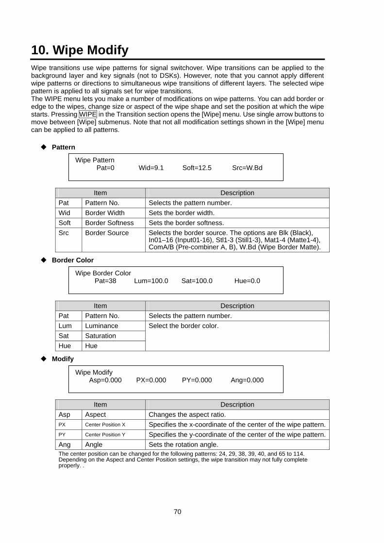
70
10. Wipe Modify Wipe transitions use wipe patterns for signal switchover. Wipe transitions can be applied to the background layer and key signals (not to DSKs). However, note that you cannot apply different wipe patterns or directions to simultaneous wipe transitions of different layers. The selected wipe pattern is applied to all signals set for wipe transitions. The WIPE menu lets you make a number of modifications on wipe patterns. You can add border or edge to the wipes, change size or aspect of the wipe shape and set the position at which the wipe starts. Pressing WIPE in the Transition section opens the [Wipe] menu. Use single arrow buttons to move between [Wipe] submenus. Note that not all modification settings shown in the [Wipe] menu can be applied to all patterns.
Pattern
Item Description
Pat Pattern No. Selects the pattern number. Wid Border Width Sets the border width. Soft Border Softness Sets the border softness. Src Border Source Selects the border source. The options are Blk (Black),
In01–16 (Input01-16), Stl1-3 (Still1-3), Mat1-4 (Matte1-4), ComA/B (Pre-combiner A, B), W.Bd (Wipe Border Matte).
Border Color
Item Description
Pat Pattern No. Selects the pattern number. Lum Luminance Sat Saturation Hue Hue
Select the border color.
Modify
Item Description
Asp Aspect Changes the aspect ratio. PX Center Position X Specifies the x-coordinate of the center of the wipe pattern.PY Center Position Y Specifies the y-coordinate of the center of the wipe pattern.Ang Angle Sets the rotation angle. The center position can be changed for the following patterns: 24, 29, 38, 39, 40, and 65 to 114. Depending on the Aspect and Center Position settings, the wipe transition may not fully complete properly. .
Wipe Pattern Pat=0 Wid=9.1 Soft=12.5 Src=W.Bd
Wipe Border Color Pat=38 Lum=100.0 Sat=100.0 Hue=0.0
Wipe Modify Asp=0.000 PX=0.000 PY=0.000 Ang=0.000
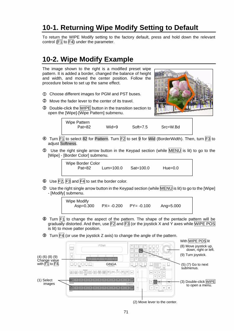
71
10-1. Returning Wipe Modify Setting to Default To return the WIPE Modify setting to the factory default, press and hold down the relevant control (F1 to F4) under the parameter.
10-2. Wipe Modify Example The image shown to the right is a modified preset wipe pattern. It is added a border, changed the balance of height and width, and moved the center position. Follow the procedure below to set up the same effect.
Choose different images for PGM and PST buses.
Move the fader lever to the center of its travel.
Double-click the WIPE button in the transition section to open the [Wipe]-[Wipe Pattern] submenu.
Turn F1 to select 82 for Pattern. Turn F2 to set 9 for Wid (BorderWidth). Then, turn F3 to adjust Softness.
Use the right single arrow button in the Keypad section (while MENU is lit) to go to the [Wipe] - [Border Color] submenu.
Use F2, F3 and F4 to set the border color.
Use the right single arrow button in the Keypad section (while MENU is lit) to go to the [Wipe] - [Modify] submenu.
Turn F1 to change the aspect of the pattern. The shape of the pentacle pattern will be gradually distorted. And then, use F2 and F3 (or the joystick X and Y axes while WIPE POS is lit) to move patter position.
Turn F4 (or use the joystick Z axis) to change the angle of the pattern.
Wipe Pattern Pat=82 Wid=9 Soft=7.5 Src=W.Bd
Wipe Border Color Pat=82 Lum=100.0 Sat=100.0 Hue=0.0
Wipe Modify Asp=0.300 PX= -0.200 PY= -0.100 Ang=5.000
(5) (7) Go to next submenus.
(1) Select images
(2) Move lever to the center.
(3) Double-click WIPE to open a menu.
With WIPE POS lit (8) Move joystick up,
down, right or left.(9) Turn joystick. (4) (6) (8) (9)
Change value with F1 to F4. 1
TRANSITION
PRIORITY1 OVER 2
21
2
4
3 4
321
LOW1 2 3 4
4321
HIGH
KEY STATUSKEY LAYER
Z
Y
X
DSK
FADER DIRECTION
JOYSTICK
VPS-700VIDEO PRODUCTION SYSTEM
F3 F4F2F1
DEFAULT FINE
DVE ROT
WIPE POS
DVE POS
AUTO CK
SEQ LINK FADER LIMIT NOR/REV REVERSE PREV TRANS
DSK1
DSK2
DSKCUT
BLACKTRANS
DSKMIX
KEY2
KEY4
DVE(NAM)
KEY1
KEY3
WIPE(FAM)
BKGD
MIX
AUTO
TRANSITION TYPE
CUT
DVE
KEYER
SHIFT
SHIFT
SHIFT
COMBINER SETUP
12
12
11
11
10
10
9
9
BORDERBASIC
8
8
EVENTCOMB B
7
7
SEQCOMB A
6
6
DSK2STILL
5
5
DSK1STATUS
4
4
3
3
KEY4
SETUP
BUS SELECT
KEY3AUX
2
2
KEY2
1
1
KEY1MATTE
BLACK
PROGRAM
BLACK
PRESET
KEY ON
GPI
EXT SELF CK EDGE SHADOWMASKVIDEO PRODUCTION SYSTEM
MULTI LAYERINGGINGA
EDITOR
USB MEMORY
EVENT
-
RECALL
2 3
8 97
MENU
SEQ
1
STORE
65
LOOP DIR
4
INSERT
ENTER
DELETE
CANCEL
NEW
.0
INPUT SYSTEM
SUB EFF WARP LIGHT
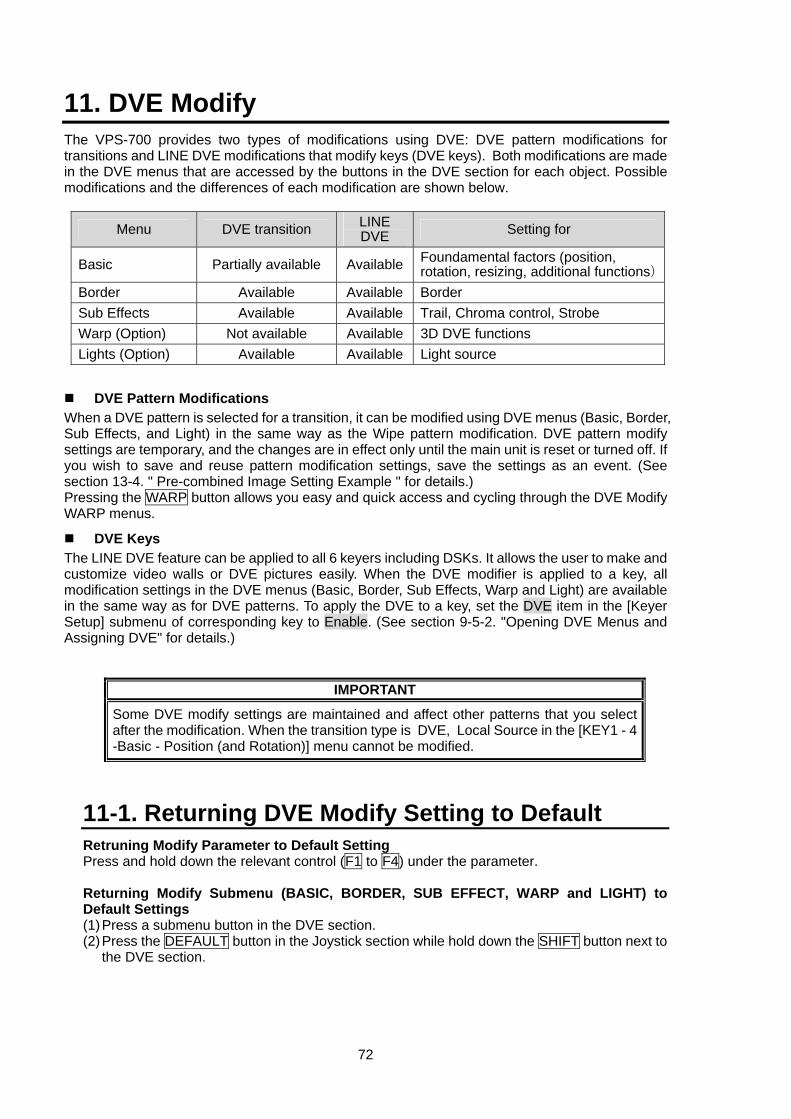
72
11. DVE Modify The VPS-700 provides two types of modifications using DVE: DVE pattern modifications for transitions and LINE DVE modifications that modify keys (DVE keys). Both modifications are made in the DVE menus that are accessed by the buttons in the DVE section for each object. Possible modifications and the differences of each modification are shown below.
Menu DVE transition LINE DVE Setting for
Basic Partially available Available Foundamental factors (position, rotation, resizing, additional functions)
Border Available Available Border Sub Effects Available Available Trail, Chroma control, Strobe Warp (Option) Not available Available 3D DVE functions Lights (Option) Available Available Light source
DVE Pattern Modifications When a DVE pattern is selected for a transition, it can be modified using DVE menus (Basic, Border, Sub Effects, and Light) in the same way as the Wipe pattern modification. DVE pattern modify settings are temporary, and the changes are in effect only until the main unit is reset or turned off. If you wish to save and reuse pattern modification settings, save the settings as an event. (See section 13-4. " Pre-combined Image Setting Example " for details.) Pressing the WARP button allows you easy and quick access and cycling through the DVE Modify WARP menus.
DVE Keys The LINE DVE feature can be applied to all 6 keyers including DSKs. It allows the user to make and customize video walls or DVE pictures easily. When the DVE modifier is applied to a key, all modification settings in the DVE menus (Basic, Border, Sub Effects, Warp and Light) are available in the same way as for DVE patterns. To apply the DVE to a key, set the DVE item in the [Keyer Setup] submenu of corresponding key to Enable. (See section 9-5-2. "Opening DVE Menus and Assigning DVE" for details.)
IMPORTANT
Some DVE modify settings are maintained and affect other patterns that you select after the modification. When the transition type is DVE, Local Source in the [KEY1 - 4 -Basic - Position (and Rotation)] menu cannot be modified.
11-1. Returning DVE Modify Setting to Default Retruning Modify Parameter to Default Setting Press and hold down the relevant control (F1 to F4) under the parameter.
Returning Modify Submenu (BASIC, BORDER, SUB EFFECT, WARP and LIGHT) to Default Settings (1) Press a submenu button in the DVE section. (2) Press the DEFAULT button in the Joystick section while hold down the SHIFT button next to
the DVE section.
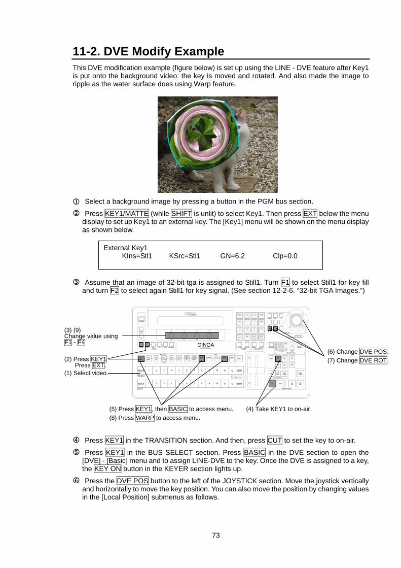
73
11-2. DVE Modify Example This DVE modification example (figure below) is set up using the LINE - DVE feature after Key1 is put onto the background video: the key is moved and rotated. And also made the image to ripple as the water surface does using Warp feature.
Select a background image by pressing a button in the PGM bus section.
Press KEY1/MATTE (while SHIFT is unlit) to select Key1. Then press EXT below the menu display to set up Key1 to an external key. The [Key1] menu will be shown on the menu display as shown below.
Assume that an image of 32-bit tga is assigned to Still1. Turn F1 to select Still1 for key fill and turn F2 to select again Still1 for key signal. (See section 12-2-6. “32-bit TGA Images.”)
Press KEY1 in the TRANSITION section. And then, press CUT to set the key to on-air.
Press KEY1 in the BUS SELECT section. Press BASIC in the DVE section to open the [DVE] - [Basic] menu and to assign LINE-DVE to the key. Once the DVE is assigned to a key, the KEY ON button in the KEYER section lights up.
Press the DVE POS button to the left of the JOYSTICK section. Move the joystick vertically and horizontally to move the key position. You can also move the position by changing values in the [Local Position] submenus as follows.
External Key1 KIns=Stl1 KSrc=Stl1 GN=6.2 Clp=0.0
(6) Change DVE POS.(7) Change DVE ROT.
(1) Select video.
(4) Take KEY1 to on-air.
(3) (9) Change value using F1 - F4
(2) Press KEY1 Press EXT.
(5) Press KEY1, then BASIC to access menu.(8) Press WARP to access menu.
1
TRANSITION
PRIORITY1 OVER 2
21
24
3 4321
LOW1 2 3 44321
HIGH
KEY STATUSKEY LAYER
Z
Y
X
DSK
FADER DIRECTION
JOYSTICK
VPS-700VIDEO PRODUCTION SYSTEM
F3 F4F2F1
DEFAULT FINE
DVE ROT
WIPE POS
DVE POS
AUTO CK
SEQ LINK FADER LIMIT NOR/REV REVERSE PREV TRANS
DSK1
DSK2
DSKCUT
BLACKTRANS
DSKMIX
KEY2
KEY4
DVE(NAM)
KEY1
KEY3
WIPE(FAM)
BKGD
MIX
AUTO
TRANSITION TYPE
CUT
DVE
KEYER
SHIFT
SHIFT
SHIFT
COMBINER SETUP
12
12
11
11
10
10
9
9
BORDERBASIC
8
8
EVENTCOMB B
7
7
SEQCOMB A
6
6
DSK2STILL
5
5
DSK1STATUS
4
4
3
3
KEY4
SETUP
BUS SELECT
KEY3AUX
2
2
KEY2
1
1
KEY1MATTE
BLACK
PROGRAM
BLACK
PRESET
KEY ON
GPI
EXT SELF CK EDGE SHADOWMASKVIDEO PRODUCTION SYSTEM
MULTI LAYERINGGINGA
EDITOR
USB MEMORY
EVENT
-
RECALL
2 3
8 97
MENU
SEQ
1
STORE
65
LOOP DIR
4
INSERT
ENTER
DELETE
CANCEL
NEW
.0
INPUT SYSTEM
SUB EFF WARP LIGHT
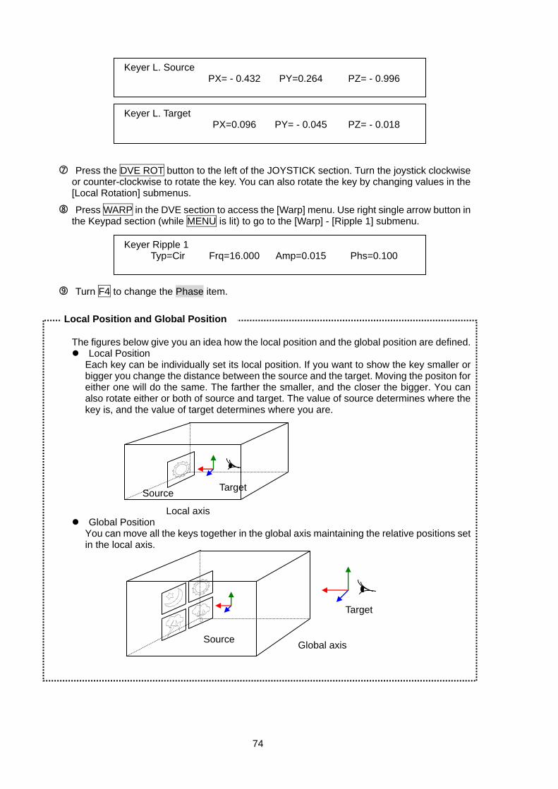
74
Press the DVE ROT button to the left of the JOYSTICK section. Turn the joystick clockwise or counter-clockwise to rotate the key. You can also rotate the key by changing values in the [Local Rotation] submenus.
Press WARP in the DVE section to access the [Warp] menu. Use right single arrow button in the Keypad section (while MENU is lit) to go to the [Warp] - [Ripple 1] submenu.
Turn F4 to change the Phase item.
The figures below give you an idea how the local position and the global position are defined. Local Position
Each key can be individually set its local position. If you want to show the key smaller or bigger you change the distance between the source and the target. Moving the positon for either one will do the same. The farther the smaller, and the closer the bigger. You can also rotate either or both of source and target. The value of source determines where the key is, and the value of target determines where you are.
Global Position You can move all the keys together in the global axis maintaining the relative positions set in the local axis.
Keyer L. Source PX= - 0.432 PY=0.264 PZ= - 0.996
Keyer L. Target PX=0.096 PY= - 0.045 PZ= - 0.018
Keyer Ripple 1 Typ=Cir Frq=16.000 Amp=0.015 Phs=0.100
Global axisSource
Target
Source Target
Local axis
Local Position and Global Position
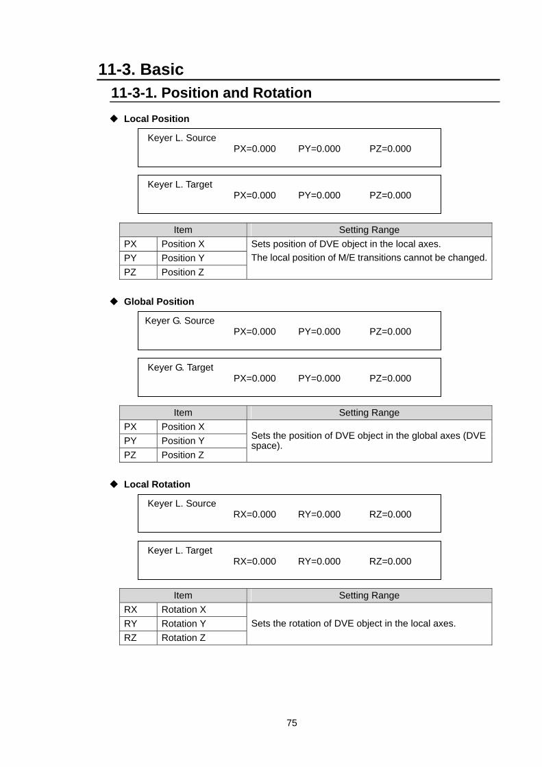
75
11-3. Basic 11-3-1. Position and Rotation
Local Position
Item Setting Range PX Position X PY Position Y PZ Position Z
Sets position of DVE object in the local axes. The local position of M/E transitions cannot be changed.
Global Position
Item Setting Range PX Position X PY Position Y PZ Position Z
Sets the position of DVE object in the global axes (DVE space).
Local Rotation
Item Setting Range RX Rotation X RY Rotation Y RZ Rotation Z
Sets the rotation of DVE object in the local axes.
Keyer L. Source PX=0.000 PY=0.000 PZ=0.000
Keyer L. Target PX=0.000 PY=0.000 PZ=0.000
Keyer G. Source PX=0.000 PY=0.000 PZ=0.000
Keyer G. Target PX=0.000 PY=0.000 PZ=0.000
Keyer L. Source RX=0.000 RY=0.000 RZ=0.000
Keyer L. Target RX=0.000 RY=0.000 RZ=0.000
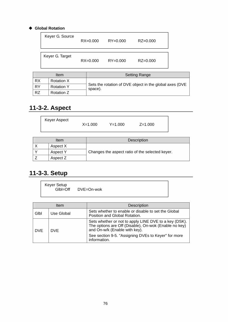
76
Global Rotation
Item Setting Range RX Rotation X RY Rotation Y RZ Rotation Z
Sets the rotation of DVE object in the global axes (DVE space).
11-3-2. Aspect
Item Description X Aspect X Y Aspect Y Z Aspect Z
Changes the aspect ratio of the selected keyer.
11-3-3. Setup
Item Description
Glbl Use Global Sets whether to enable or disable to set the Global Position and Global Rotation.
DVE DVE
Sets whether or not to apply LINE DVE to a key (DSK). The options are Off (Disable), On-wok (Enable no key) and On-w/k (Enable with key). See section 9-5. "Assigning DVEs to Keyer" for more information.
Keyer G. Source RX=0.000 RY=0.000 RZ=0.000
Keyer G. Target RX=0.000 RY=0.000 RZ=0.000
Keyer Aspect X=1.000 Y=1.000 Z=1.000
Keyer Setup Glbl=Off DVE=On-wok
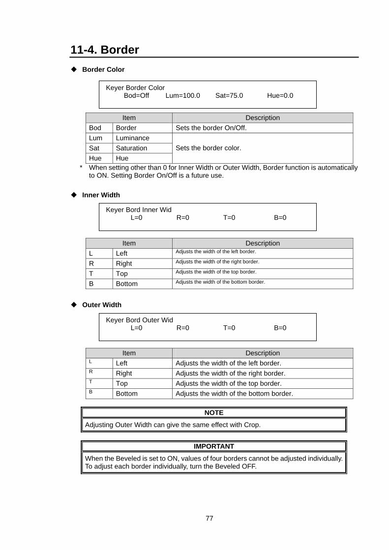
77
11-4. Border Border Color
Item Description Bod Border Sets the border On/Off. Lum Luminance Sat Saturation Hue Hue
Sets the border color.
* When setting other than 0 for Inner Width or Outer Width, Border function is automatically to ON. Setting Border On/Off is a future use.
Inner Width
Item Description L Left Adjusts the width of the left border.
R Right Adjusts the width of the right border.
T Top Adjusts the width of the top border.
B Bottom Adjusts the width of the bottom border.
Outer Width
Item Description L Left Adjusts the width of the left border. R Right Adjusts the width of the right border. T Top Adjusts the width of the top border. B Bottom Adjusts the width of the bottom border.
NOTE
Adjusting Outer Width can give the same effect with Crop.
IMPORTANT
When the Beveled is set to ON, values of four borders cannot be adjusted individually. To adjust each border individually, turn the Beveled OFF.
Keyer Border Color Bod=Off Lum=100.0 Sat=75.0 Hue=0.0
Keyer Bord Inner Wid L=0 R=0 T=0 B=0
Keyer Bord Outer Wid L=0 R=0 T=0 B=0
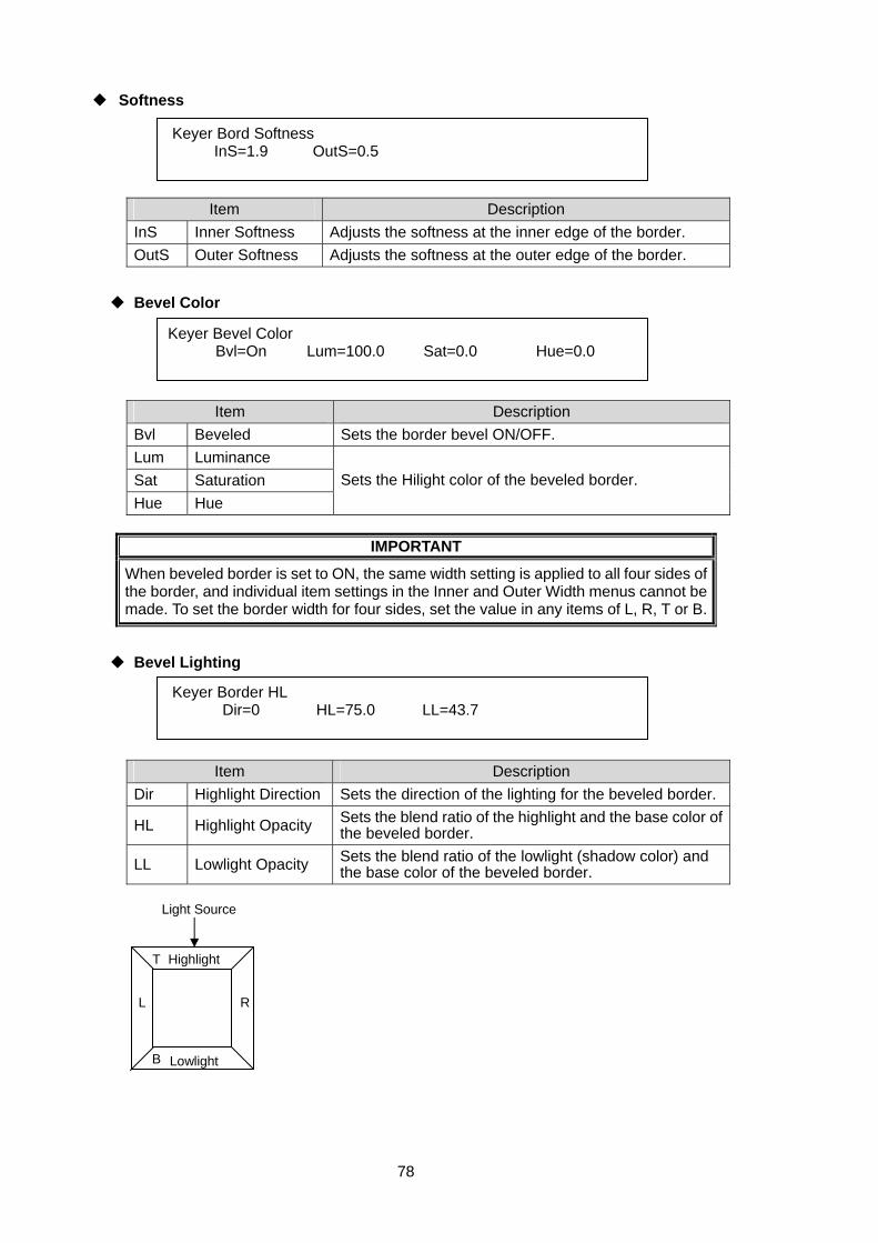
78
Softness
Item Description InS Inner Softness Adjusts the softness at the inner edge of the border. OutS Outer Softness Adjusts the softness at the outer edge of the border.
Bevel Color
Item Description Bvl Beveled Sets the border bevel ON/OFF. Lum Luminance Sat Saturation Hue Hue
Sets the Hilight color of the beveled border.
IMPORTANT
When beveled border is set to ON, the same width setting is applied to all four sides of the border, and individual item settings in the Inner and Outer Width menus cannot be made. To set the border width for four sides, set the value in any items of L, R, T or B.
Bevel Lighting
Item Description Dir Highlight Direction Sets the direction of the lighting for the beveled border.
HL Highlight Opacity Sets the blend ratio of the highlight and the base color of the beveled border.
LL Lowlight Opacity Sets the blend ratio of the lowlight (shadow color) and the base color of the beveled border.
Keyer Bord Softness InS=1.9 OutS=0.5
Keyer Bevel Color Bvl=On Lum=100.0 Sat=0.0 Hue=0.0
Keyer Border HL Dir=0 HL=75.0 LL=43.7
Light Source
Highlight
Lowlight
R L
T
B
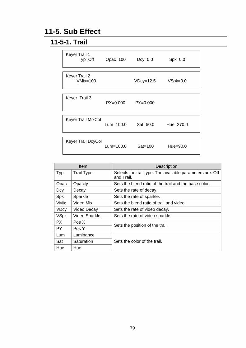
79
11-5. Sub Effect 11-5-1. Trail
Item Description Typ Trail Type Selects the trail type. The available parameters are: Off
and Trail. Opac Opacity Sets the blend ratio of the trail and the base color. Dcy Decay Sets the rate of decay. Spk Sparkle Sets the rate of sparkle. VMix Video Mix Sets the blend ratio of trail and video. VDcy Video Decay Sets the rate of video decay. VSpk Video Sparkle Sets the rate of video sparkle. PX Pos X PY Pos Y
Sets the position of the trail.
Lum Luminance Sat Saturation Hue Hue
Sets the color of the trail.
Keyer Trail 1 Typ=Off Opac=100 Dcy=0.0 Spk=0.0
Keyer Trail 2 VMix=100 VDcy=12.5 VSpk=0.0
Keyer Trail 3 PX=0.000 PY=0.000
Keyer Trail MixCol Lum=100.0 Sat=50.0 Hue=270.0
Keyer Trail DcyCol Lum=100.0 Sat=100 Hue=90.0
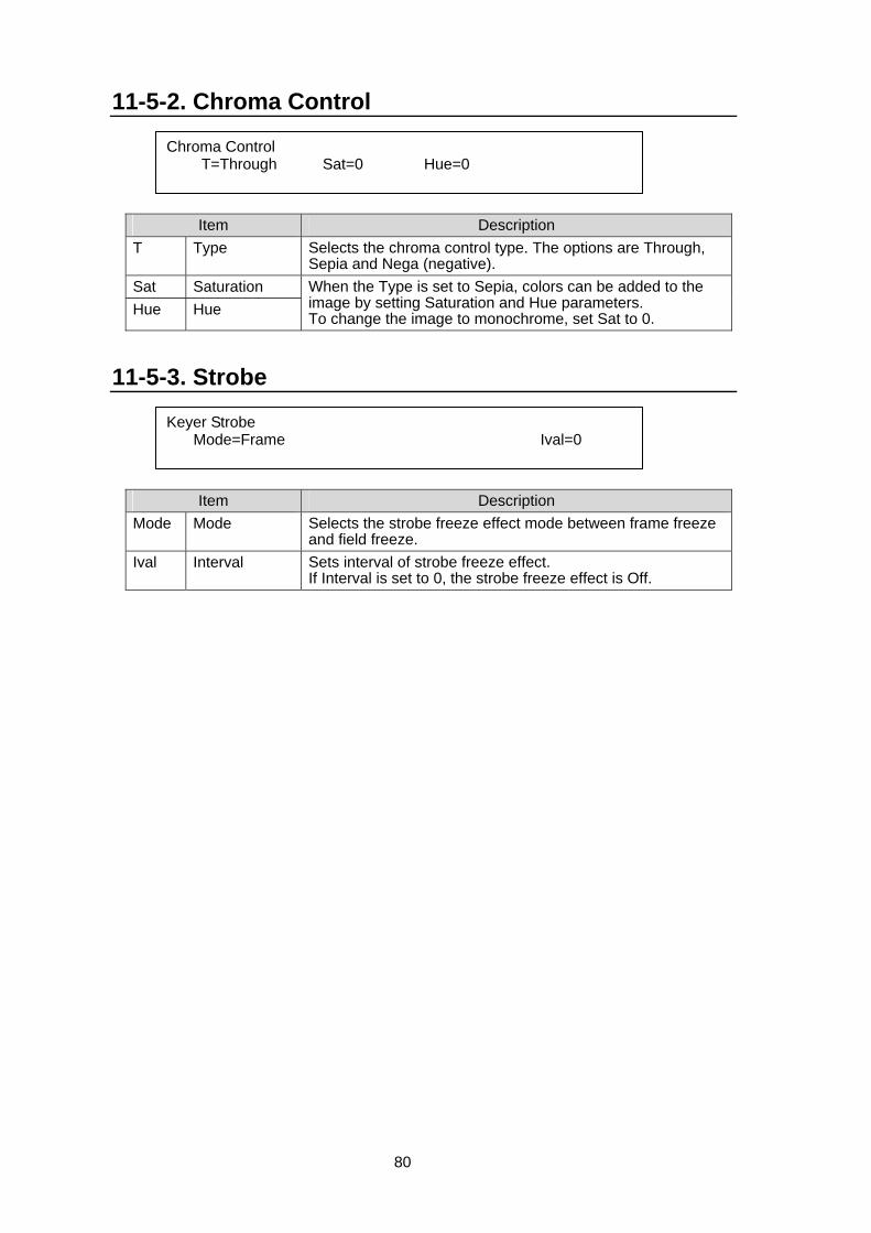
80
11-5-2. Chroma Control
Item Description T Type Selects the chroma control type. The options are Through,
Sepia and Nega (negative). Sat Saturation Hue Hue
When the Type is set to Sepia, colors can be added to the image by setting Saturation and Hue parameters. To change the image to monochrome, set Sat to 0.
11-5-3. Strobe
Item Description Mode Mode Selects the strobe freeze effect mode between frame freeze
and field freeze. Ival Interval Sets interval of strobe freeze effect.
If Interval is set to 0, the strobe freeze effect is Off.
Chroma Control T=Through Sat=0 Hue=0
Keyer Strobe Mode=Frame Ival=0
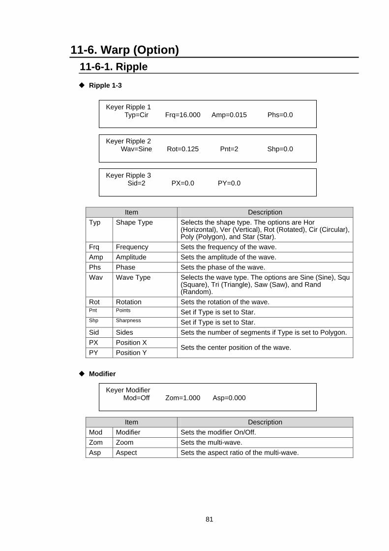
81
11-6. Warp (Option) 11-6-1. Ripple
Ripple 1-3
Item Description Typ Shape Type Selects the shape type. The options are Hor
(Horizontal), Ver (Vertical), Rot (Rotated), Cir (Circular), Poly (Polygon), and Star (Star).
Frq Frequency Sets the frequency of the wave. Amp Amplitude Sets the amplitude of the wave. Phs Phase Sets the phase of the wave. Wav Wave Type Selects the wave type. The options are Sine (Sine), Squ
(Square), Tri (Triangle), Saw (Saw), and Rand (Random).
Rot Rotation Sets the rotation of the wave. Pnt Points Set if Type is set to Star. Shp Sharpness Set if Type is set to Star. Sid Sides Sets the number of segments if Type is set to Polygon. PX Position X PY Position Y
Sets the center position of the wave.
Modifier
Item Description Mod Modifier Sets the modifier On/Off. Zom Zoom Sets the multi-wave. Asp Aspect Sets the aspect ratio of the multi-wave.
Keyer Ripple 1 Typ=Cir Frq=16.000 Amp=0.015 Phs=0.0
Keyer Ripple 2 Wav=Sine Rot=0.125 Pnt=2 Shp=0.0
Keyer Ripple 3 Sid=2 PX=0.0 PY=0.0
Keyer Modifier Mod=Off Zom=1.000 Asp=0.000
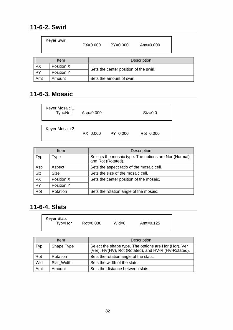
82
11-6-2. Swirl
Item Description PX Position X PY Position Y
Sets the center position of the swirl.
Amt Amount Sets the amount of swirl.
11-6-3. Mosaic
Item Description Typ Type Selects the mosaic type. The options are Nor (Normal)
and Rot (Rotated). Asp Aspect Sets the aspect ratio of the mosaic cell. Siz Size Sets the size of the mosaic cell. PX Position X PY Position Y
Sets the center position of the mosaic.
Rot Rotation Sets the rotation angle of the mosaic. 11-6-4. Slats
Item Description Typ Shape Type Select the shape type. The options are Hor (Hor), Ver
(Ver), HV(HV), Rot (Rotated), and HV-R (HV-Rotated). Rot Rotation Sets the rotation angle of the slats. Wid Slat_Width Sets the width of the slats. Amt Amount Sets the distance between slats.
Keyer Swirl PX=0.000 PY=0.000 Amt=0.000
Keyer Mosaic 1 Typ=Nor Asp=0.000 Siz=0.0
Keyer Mosaic 2 PX=0.000 PY=0.000 Rot=0.000
Keyer Slats Typ=Hor Rot=0.000 Wid=8 Amt=0.125

83
11-6-5. Lens Lens 1-3
Item Description Typ Shape Type Selects the shape type. The options are Cir (Circular),
Poly (Polygon), and Star (Star). Rot Rotation Sets the rotation angle of the lens Pnt Points Sets the number of lens if Type is set to Polygon or Star.Amt Amount Sets the focal length of the lens. Typ Pattern Type Selects the pattern type. The options are Rnd (Round),
Lin (Linear), and Mul (Multi). PX Position X PY Position Y
Sets the position of the lens.
Siz Size Sets the size of the lens. Tlt Tilt Sets the amount of tilt of the lens.
Modifier
Item Description Mod Modifier Set the modifier On/Off. Zom Zoom Sets the multi-lens. Asp Aspect Sets the aspect ratio of the multi-lens.
Keyer Lens 1 Typ=Cir Rot=0.000 Pnt=8 Amt=0.125
Keyer Lens 2 Typ=Rnd PX=0.000 PY=0.000 Siz=0.500
Keyer Lens 3 Tlt=0.000
Keyer Modifier Mod=Off Zom=1.000 Asp=0.000
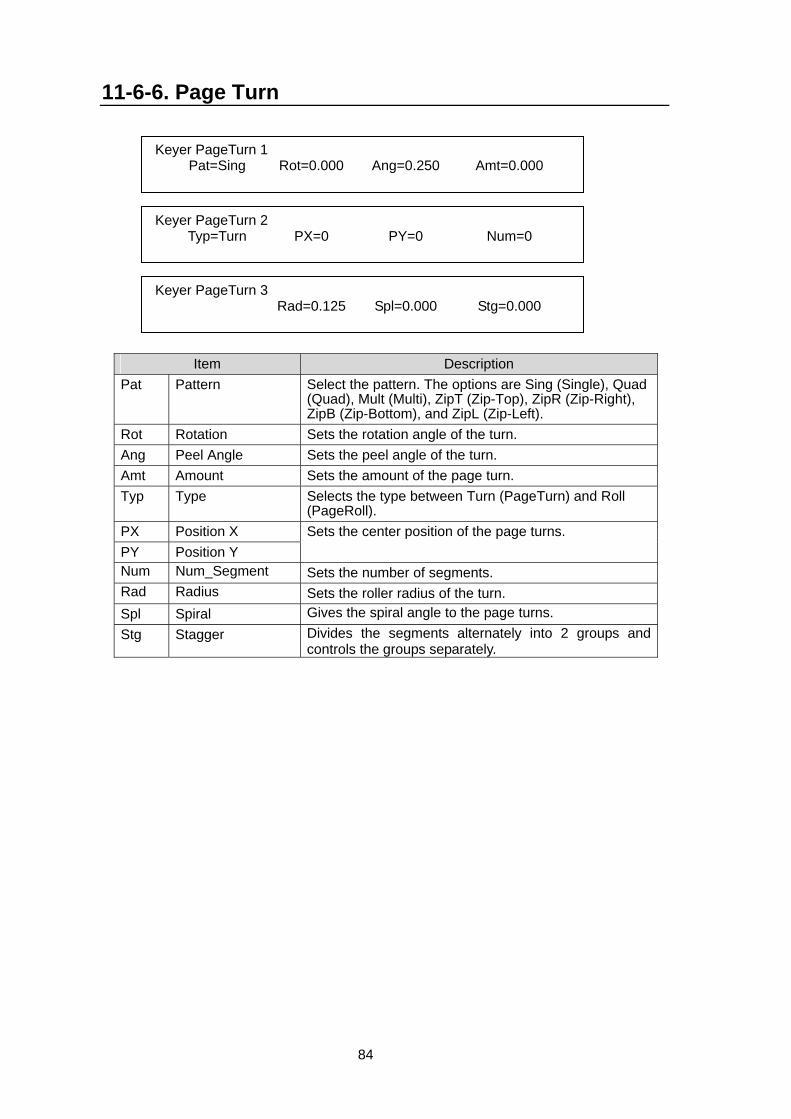
84
11-6-6. Page Turn
Item Description Pat Pattern Select the pattern. The options are Sing (Single), Quad
(Quad), Mult (Multi), ZipT (Zip-Top), ZipR (Zip-Right), ZipB (Zip-Bottom), and ZipL (Zip-Left).
Rot Rotation Sets the rotation angle of the turn. Ang Peel Angle Sets the peel angle of the turn. Amt Amount Sets the amount of the page turn. Typ Type Selects the type between Turn (PageTurn) and Roll
(PageRoll). PX Position X PY Position Y
Sets the center position of the page turns.
Num Num_Segment Sets the number of segments. Rad Radius Sets the roller radius of the turn. Spl Spiral Gives the spiral angle to the page turns. Stg Stagger Divides the segments alternately into 2 groups and
controls the groups separately.
Keyer PageTurn 1 Pat=Sing Rot=0.000 Ang=0.250 Amt=0.000
Keyer PageTurn 2 Typ=Turn PX=0 PY=0 Num=0
Keyer PageTurn 3 Rad=0.125 Spl=0.000 Stg=0.000
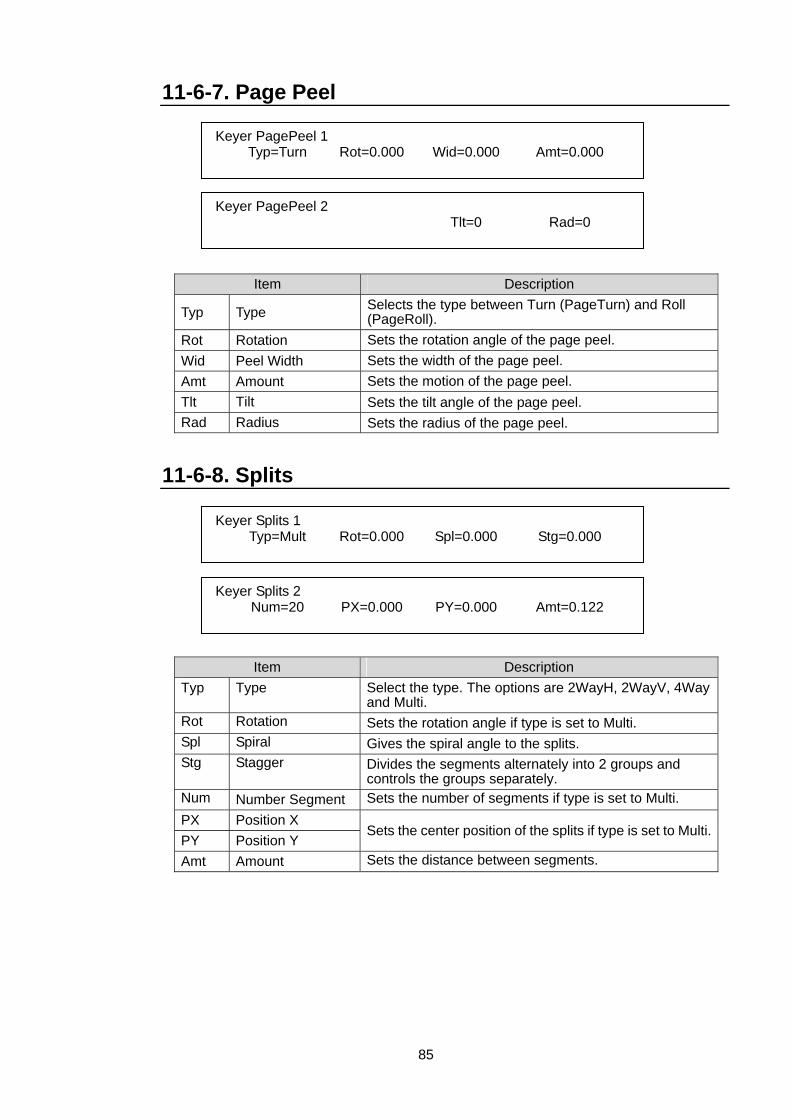
85
11-6-7. Page Peel
Item Description
Typ Type Selects the type between Turn (PageTurn) and Roll (PageRoll).
Rot Rotation Sets the rotation angle of the page peel. Wid Peel Width Sets the width of the page peel. Amt Amount Sets the motion of the page peel. Tlt Tilt Sets the tilt angle of the page peel. Rad Radius Sets the radius of the page peel.
11-6-8. Splits
Item Description Typ Type Select the type. The options are 2WayH, 2WayV, 4Way
and Multi. Rot Rotation Sets the rotation angle if type is set to Multi. Spl Spiral Gives the spiral angle to the splits. Stg Stagger Divides the segments alternately into 2 groups and
controls the groups separately. Num Number Segment Sets the number of segments if type is set to Multi. PX Position X PY Position Y
Sets the center position of the splits if type is set to Multi.
Amt Amount Sets the distance between segments.
Keyer PagePeel 1 Typ=Turn Rot=0.000 Wid=0.000 Amt=0.000
Keyer PagePeel 2 Tlt=0 Rad=0
Keyer Splits 1 Typ=Mult Rot=0.000 Spl=0.000 Stg=0.000
Keyer Splits 2 Num=20 PX=0.000 PY=0.000 Amt=0.122
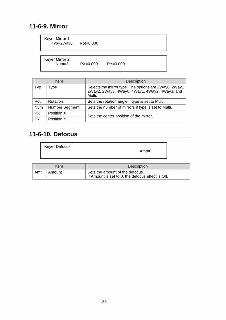
86
11-6-9. Mirror
Item Description Typ Type Selects the mirror type. The options are 2Way0, 2Way1
2Way2, 2Way3, 4Way0, 4Way1, 4Way2, 4Way3, and Multi.
Rot Rotation Sets the rotation angle if type is set to Multi. Num Number Segment Sets the number of mirrors if type is set to Multi. PX Position X PY Position Y
Sets the center position of the mirror.
11-6-10. Defocus
Item Description Amt Amount Sets the amount of the defocus.
If Amount is set to 0, the defocus effect is Off.
Keyer Mirror 1 Typ=2Way0 Rot=0.000
Keyer Mirror 2 Num=3 PX=0.000 PY=0.000
Keyer Defocus Amt=0
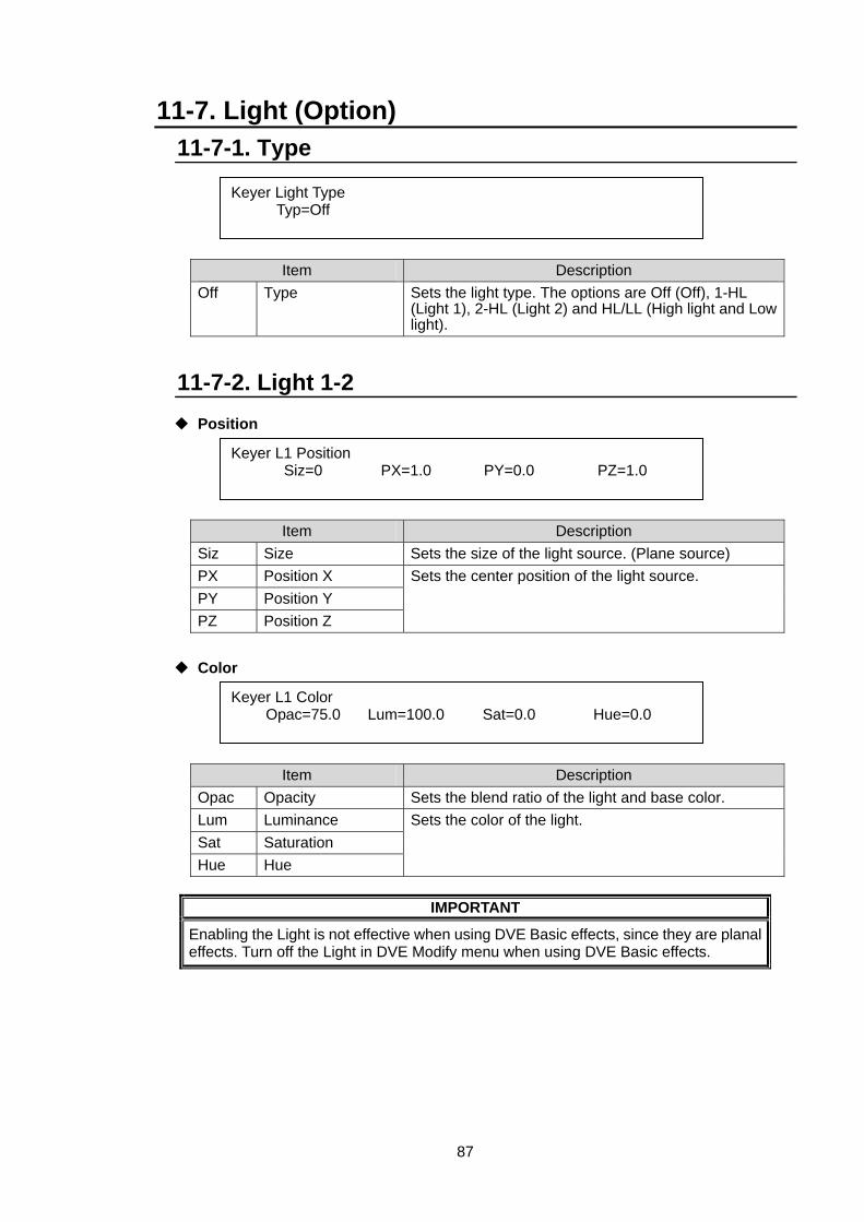
87
11-7. Light (Option) 11-7-1. Type
Item Description Off Type Sets the light type. The options are Off (Off), 1-HL
(Light 1), 2-HL (Light 2) and HL/LL (High light and Low light).
11-7-2. Light 1-2
Position
Item Description Siz Size Sets the size of the light source. (Plane source) PX Position X PY Position Y PZ Position Z
Sets the center position of the light source.
Color
Item Description Opac Opacity Sets the blend ratio of the light and base color. Lum Luminance Sat Saturation Hue Hue
Sets the color of the light.
IMPORTANT
Enabling the Light is not effective when using DVE Basic effects, since they are planal effects. Turn off the Light in DVE Modify menu when using DVE Basic effects.
Keyer Light Type Typ=Off
Keyer L1 Position Siz=0 PX=1.0 PY=0.0 PZ=1.0
Keyer L1 Color Opac=75.0 Lum=100.0 Sat=0.0 Hue=0.0
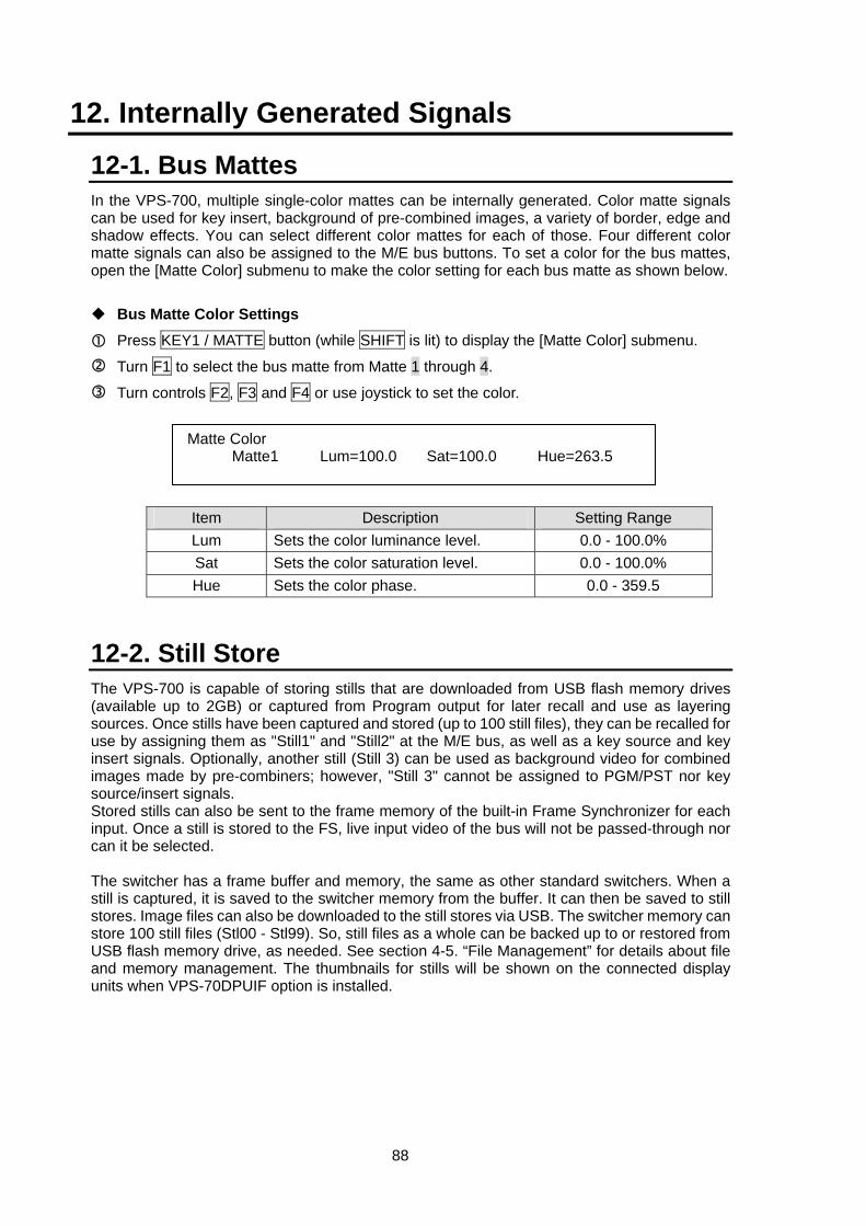
88
12. Internally Generated Signals
12-1. Bus Mattes In the VPS-700, multiple single-color mattes can be internally generated. Color matte signals can be used for key insert, background of pre-combined images, a variety of border, edge and shadow effects. You can select different color mattes for each of those. Four different color matte signals can also be assigned to the M/E bus buttons. To set a color for the bus mattes, open the [Matte Color] submenu to make the color setting for each bus matte as shown below.
Bus Matte Color Settings
Press KEY1 / MATTE button (while SHIFT is lit) to display the [Matte Color] submenu.
Turn F1 to select the bus matte from Matte 1 through 4.
Turn controls F2, F3 and F4 or use joystick to set the color.
Item Description Setting Range Lum Sets the color luminance level. 0.0 - 100.0% Sat Sets the color saturation level. 0.0 - 100.0% Hue Sets the color phase. 0.0 - 359.5
12-2. Still Store The VPS-700 is capable of storing stills that are downloaded from USB flash memory drives (available up to 2GB) or captured from Program output for later recall and use as layering sources. Once stills have been captured and stored (up to 100 still files), they can be recalled for use by assigning them as "Still1" and "Still2" at the M/E bus, as well as a key source and key insert signals. Optionally, another still (Still 3) can be used as background video for combined images made by pre-combiners; however, "Still 3" cannot be assigned to PGM/PST nor key source/insert signals. Stored stills can also be sent to the frame memory of the built-in Frame Synchronizer for each input. Once a still is stored to the FS, live input video of the bus will not be passed-through nor can it be selected. The switcher has a frame buffer and memory, the same as other standard switchers. When a still is captured, it is saved to the switcher memory from the buffer. It can then be saved to still stores. Image files can also be downloaded to the still stores via USB. The switcher memory can store 100 still files (Stl00 - Stl99). So, still files as a whole can be backed up to or restored from USB flash memory drive, as needed. See section 4-5. “File Management” for details about file and memory management. The thumbnails for stills will be shown on the connected display units when VPS-70DPUIF option is installed.
Matte Color Matte1 Lum=100.0 Sat=100.0 Hue=263.5
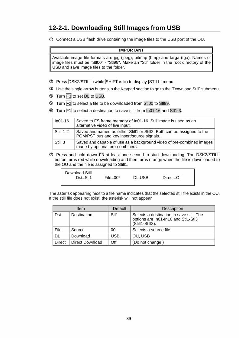
89
12-2-1. Downloading Still Images from USB Connect a USB flash drive containing the image files to the USB port of the OU.
IMPORTANT
Available image file formats are jpg (jpeg), bitmap (bmp) and targa (tga). Names of image files must be "Stl00" - "Stl99". Make an "Stl" folder in the root directory of the USB and save image files to the folder.
Press DSK2/STILL (while SHIFT is lit) to display [STILL] menu.
Use the single arrow buttons in the Keypad section to go to the [Download Still] submenu.
Turn F3 to set DL to USB.
Turn F2 to select a file to be downloaded from Stl00 to Stl99.
Turn F1 to select a destination to save still from In01-16 and Stl1-3.
In01-16 Saved to FS frame memory of In01-16. Still image is used as an alternative video of live input.
Still 1-2 Saved and named as either Still1 or Still2. Both can be assigned to the PGM/PST bus and key insert/source signals.
Still 3 Saved and capable of use as a background video of pre-combined images made by optional pre-combiners.
Press and hold down F3 at least one second to start downloading. The DSK2/STILL button turns red while downloading and then turns orange when the file is downloaded to the OU and the file is assigned to Still1.
The asterisk appearing next to a file name indicates that the selected still file exists in the OU. If the still file does not exist, the asterisk will not appear.
Item Default Description Dst Destination Stl1 Selects a destination to save still. The
options are In01-In16 and Stl1-Stl3 (Still1-Still3).
File Source 00 Selects a source file. DL Download USB OU, USB Direct Direct Download Off (Do not change.)
Download Still Dst=Stl1 File=00* DL:USB Direct=Off
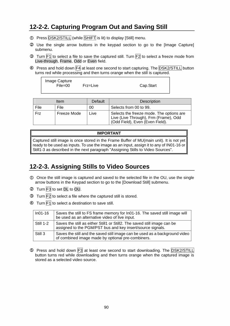
90
12-2-2. Capturing Program Out and Saving Still Press DSK2/STILL (while SHIFT is lit) to display [Still] menu.
Use the single arrow buttons in the keypad section to go to the [Image Capture] submenu.
Turn F1 to select a file to save the captured still. Turn F2 to select a freeze mode from Live-through, Frame, Odd or Even field.
Press and hold down F4 at least one second to start capturing. The DSK2/STILL button turns red while processing and then turns orange when the still is captured.
Item Default Description File File 00 Selects from 00 to 99. Frz Freeze Mode Live Selects the freeze mode. The options are
Live (Live Through), Frm (Frame), Odd (Odd Field), Even (Even Field).
IMPORTANT
Captured still image is once stored in the Frame Buffer of MU(main unit). It is not yet ready to be used as inputs. To use the image as an input, assign it to any of IN01-16 or Still1-3 as described in the next paragraph "Assigning Stills to Video Sources".
12-2-3. Assigning Stills to Video Sources
Once the still image is captured and saved to the selected file in the OU, use the single arrow buttons in the Keypad section to go to the [Download Still] submenu.
Turn F3 to set DL to OU.
Turn F2 to select a file where the captured still is stored.
Turn F1 to select a destination to save still.
In01-16 Saves the still to FS frame memory for In01-16. The saved still image will be used as an alternative video of live input.
Still 1-2 Saves the still as either Still1 or Still2. The saved still image can be assigned to the PGM/PST bus and key insert/source signals.
Still 3 Saves the still and the saved still image can be used as a background video of combined image made by optional pre-combiners.
Press and hold down F3 at least one second to start downloading. The DSK2/STILL button turns red while downloading and then turns orange when the captured image is stored as a selected video source.
Image Capture File=00 Frz=Live Cap.Start
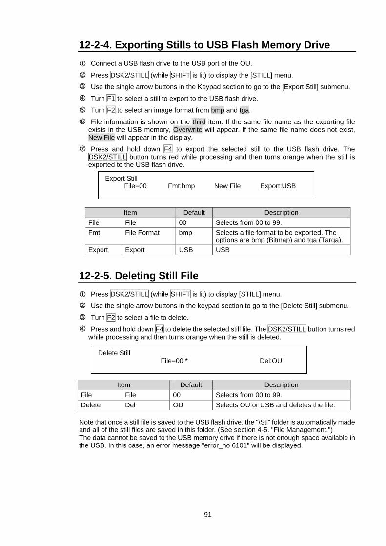
91
12-2-4. Exporting Stills to USB Flash Memory Drive Connect a USB flash drive to the USB port of the OU.
Press DSK2/STILL (while SHIFT is lit) to display the [STILL] menu.
Use the single arrow buttons in the Keypad section to go to the [Export Still] submenu.
Turn F1 to select a still to export to the USB flash drive.
Turn F2 to select an image format from bmp and tga.
File information is shown on the third item. If the same file name as the exporting file exists in the USB memory, Overwrite will appear. If the same file name does not exist, New File will appear in the display.
Press and hold down F4 to export the selected still to the USB flash drive. The DSK2/STILL button turns red while processing and then turns orange when the still is exported to the USB flash drive.
Item Default Description File File 00 Selects from 00 to 99. Fmt File Format bmp Selects a file format to be exported. The
options are bmp (Bitmap) and tga (Targa). Export Export USB USB
12-2-5. Deleting Still File Press DSK2/STILL (while SHIFT is lit) to display [STILL] menu.
Use the single arrow buttons in the keypad section to go to the [Delete Still] submenu.
Turn F2 to select a file to delete.
Press and hold down F4 to delete the selected still file. The DSK2/STILL button turns red while processing and then turns orange when the still is deleted.
Item Default Description File File 00 Selects from 00 to 99. Delete Del OU Selects OU or USB and deletes the file. Note that once a still file is saved to the USB flash drive, the "\Stl" folder is automatically made and all of the still files are saved in this folder. (See section 4-5. "File Management.") The data cannot be saved to the USB memory drive if there is not enough space available in the USB. In this case, an error message "error_no 6101" will be displayed.
Export Still File=00 Fmt:bmp New File Export:USB
Delete Still File=00 * Del:OU
92
12-2-6. 32-bit TGA Images Stills 1 and 2 can load 32-bit tga files. While the image files such as bitmap or jpeg are 24-bit RGB files and do not have alpha channel (key data), 32-bit tga is a 32-bit image with alpha channel. You can load both key and fill data as a 32-bit tga file to the one bus (Still1 or Still2). Storing two data in one bus allows you to use less buses, and so it makes your still data management easy. Follow the procedure below to load the image to the Still and set up a keyer.
Refer to section 12-2-1. “Downloading Still Images from USB” to download 32-bit tga file to Still1 (or Still2).
Select a Keyer or a DSK (from KEY1-4 or DSK1-2) and press the EXT button to set it as an External key.
Select Stl1 (or Stll2) for both KIns (Key Insert) and KSrc (Key Source) items in the Keyer (or DSK) menu.
NOTE
Only Still1 and Still2 support 32-bit tga files.
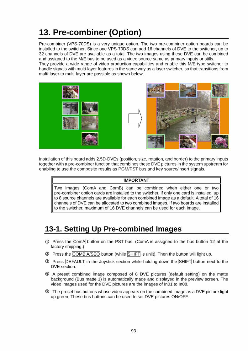
93
13. Pre-combiner (Option) Pre-combiner (VPS-70DS) is a very unique option. The two pre-combiner option boards can be installed to the switcher. Since one VPS-70DS can add 16 channels of DVE to the switcher, up to 32 channels of DVE are available as a total. The two images using these DVE can be combined and assigned to the M/E bus to be used as a video source same as primary inputs or stills. They provide a wide range of video production capabilities and enable this M/E-type switcher to handle signals with multi-layer features in the same way as a layer switcher, so that transitions from multi-layer to multi-layer are possible as shown below. Installation of this board adds 2.5D-DVEs (position, size, rotation, and border) to the primary inputs together with a pre-combiner function that combines these DVE pictures in the system upstream for enabling to use the composite results as PGM/PST bus and key source/insert signals.
IMPORTANT
Two images (ComA and ComB) can be combined when either one or two pre-combiner option cards are installed to the switcher. If only one card is installed, up to 8 source channels are available for each combined image as a default. A total of 16 channels of DVE can be allocated to two combined images. If two boards are installed to the switcher, maximum of 16 DVE channels can be used for each image.
13-1. Setting Up Pre-combined Images Press the ComA button on the PST bus. (ComA is assigned to the bus button 12 at the factory shipping.)
Press the COMB A/SEQ button (while SHIFT is unlit). Then the button will light up.
Press DEFAULT in the Joystick section while holding down the SHIFT button next to the DVE section.
A preset combined image composed of 8 DVE pictures (default setting) on the matte background (Bus matte 1) is automatically made and displayed in the preview screen. The video images used for the DVE pictures are the images of In01 to In08.
The preset bus buttons whose video appears on the combined image as a DVE picture light up green. These bus buttons can be used to set DVE pictures ON/OFF.
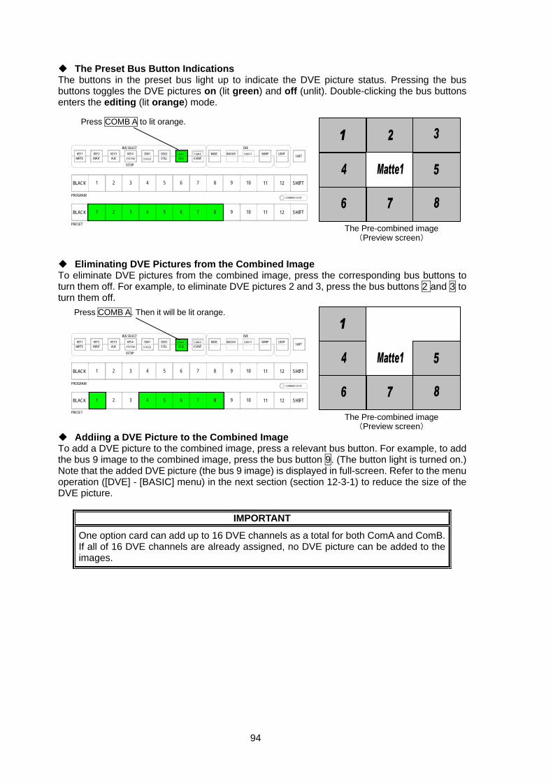
94
The Preset Bus Button Indications The buttons in the preset bus light up to indicate the DVE picture status. Pressing the bus buttons toggles the DVE pictures on (lit green) and off (unlit). Double-clicking the bus buttons enters the editing (lit orange) mode.
Eliminating DVE Pictures from the Combined Image To eliminate DVE pictures from the combined image, press the corresponding bus buttons to turn them off. For example, to eliminate DVE pictures 2 and 3, press the bus buttons 2 and 3 to turn them off.
Addiing a DVE Picture to the Combined Image To add a DVE picture to the combined image, press a relevant bus button. For example, to add the bus 9 image to the combined image, press the bus button 9. (The button light is turned on.) Note that the added DVE picture (the bus 9 image) is displayed in full-screen. Refer to the menu operation ([DVE] - [BASIC] menu) in the next section (section 12-3-1) to reduce the size of the DVE picture.
IMPORTANT
One option card can add up to 16 DVE channels as a total for both ComA and ComB. If all of 16 DVE channels are already assigned, no DVE picture can be added to the images.
Press COMB A to lit orange.
DVE
SHIFT
SHIFT
SHIFT
COMBINER SETUP
12
12
11
11
10
10
9
9
BORDERBASIC
8
8
EVENTCOMB B
7
7
SEQCOMB A
6
6
DSK2STILL
5
5
DSK1STATUS
4
4
3
3
KEY4
SETUP
BUS SELECTKEY3AUX
2
2
KEY2
1
1
KEY1MATTE
BLACK
PROGRAM
BLACK
PRESET
INPUT SYSTEM
SUB EFF WARP LIGHT
The Pre-combined image (Preview screen)
DVE
SHIFT
SHIFT
SHIFT
COMBINER SETUP
12
12
11
11
10
10
9
9
BORDERBASIC
8
8
EVENTCOMB B
7
7
SEQCOMB A
6
6
DSK2STILL
5
5
DSK1STATUS
4
4
3
3
KEY4
SETUP
BUS SELECTKEY3AUX
2
2
KEY2
1
1
KEY1MATTE
BLACK
PROGRAM
BLACK
PRESET
INPUT SYSTEM
SUB EFF WARP LIGHT
Press COMB A. Then it will be lit orange.
The Pre-combined image (Preview screen)
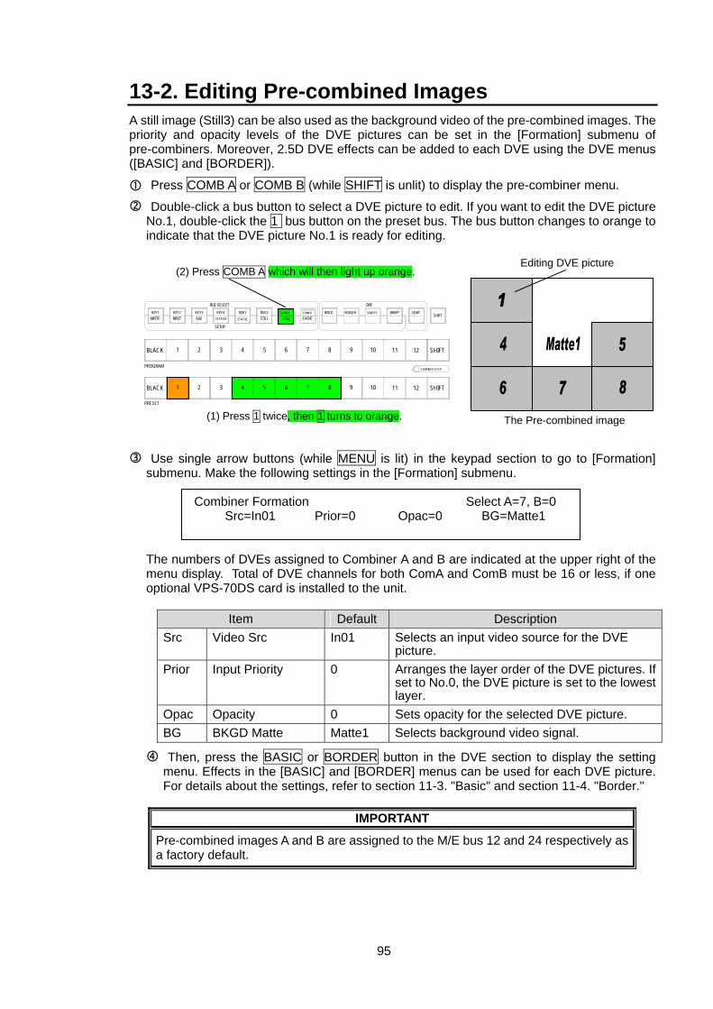
95
13-2. Editing Pre-combined Images A still image (Still3) can be also used as the background video of the pre-combined images. The priority and opacity levels of the DVE pictures can be set in the [Formation] submenu of pre-combiners. Moreover, 2.5D DVE effects can be added to each DVE using the DVE menus ([BASIC] and [BORDER]).
Press COMB A or COMB B (while SHIFT is unlit) to display the pre-combiner menu.
Double-click a bus button to select a DVE picture to edit. If you want to edit the DVE picture No.1, double-click the 1 bus button on the preset bus. The bus button changes to orange to indicate that the DVE picture No.1 is ready for editing.
Use single arrow buttons (while MENU is lit) in the keypad section to go to [Formation] submenu. Make the following settings in the [Formation] submenu.
The numbers of DVEs assigned to Combiner A and B are indicated at the upper right of the menu display. Total of DVE channels for both ComA and ComB must be 16 or less, if one optional VPS-70DS card is installed to the unit.
Item Default Description
Src Video Src In01 Selects an input video source for the DVE picture.
Prior Input Priority 0 Arranges the layer order of the DVE pictures. If set to No.0, the DVE picture is set to the lowest layer.
Opac Opacity 0 Sets opacity for the selected DVE picture. BG BKGD Matte Matte1 Selects background video signal.
Then, press the BASIC or BORDER button in the DVE section to display the setting menu. Effects in the [BASIC] and [BORDER] menus can be used for each DVE picture. For details about the settings, refer to section 11-3. "Basic" and section 11-4. "Border."
IMPORTANT
Pre-combined images A and B are assigned to the M/E bus 12 and 24 respectively as a factory default.
Combiner Formation Select A=7, B=0 Src=In01 Prior=0 Opac=0 BG=Matte1
DVE
SHIFT
SHIFT
SHIFT
COMBINER SETUP
12
12
11
11
10
10
9
9
BORDERBASIC
8
8
EVENTCOMB B
7
7
SEQCOMB A
6
6
DSK2STILL
5
5
DSK1STATUS
4
4
3
3
KEY4
SETUP
BUS SELECTKEY3AUX
2
2
KEY2
1
1
KEY1MATTE
BLACK
PROGRAM
BLACK
PRESET
INPUT SYSTEM
SUB EFF WARP LIGHT
(1) Press 1 twice, then 1 turns to orange.
(2) Press COMB A which will then light up orange.Editing DVE picture
The Pre-combined image
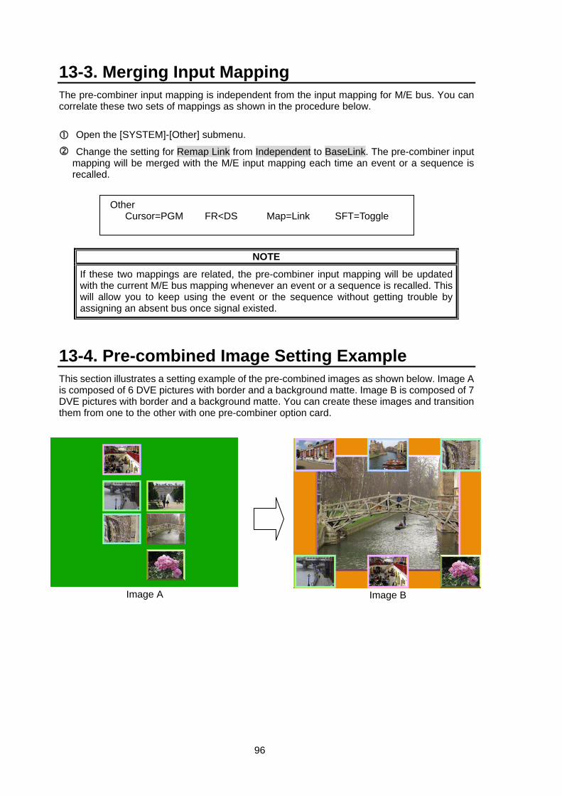
96
13-3. Merging Input Mapping The pre-combiner input mapping is independent from the input mapping for M/E bus. You can correlate these two sets of mappings as shown in the procedure below.
Open the [SYSTEM]-[Other] submenu.
Change the setting for Remap Link from Independent to BaseLink. The pre-combiner input mapping will be merged with the M/E input mapping each time an event or a sequence is recalled.
NOTE
If these two mappings are related, the pre-combiner input mapping will be updated with the current M/E bus mapping whenever an event or a sequence is recalled. This will allow you to keep using the event or the sequence without getting trouble by assigning an absent bus once signal existed.
13-4. Pre-combined Image Setting Example This section illustrates a setting example of the pre-combined images as shown below. Image A is composed of 6 DVE pictures with border and a background matte. Image B is composed of 7 DVE pictures with border and a background matte. You can create these images and transition them from one to the other with one pre-combiner option card.
Image A Image B
Other Cursor=PGM FR<DS Map=Link SFT=Toggle
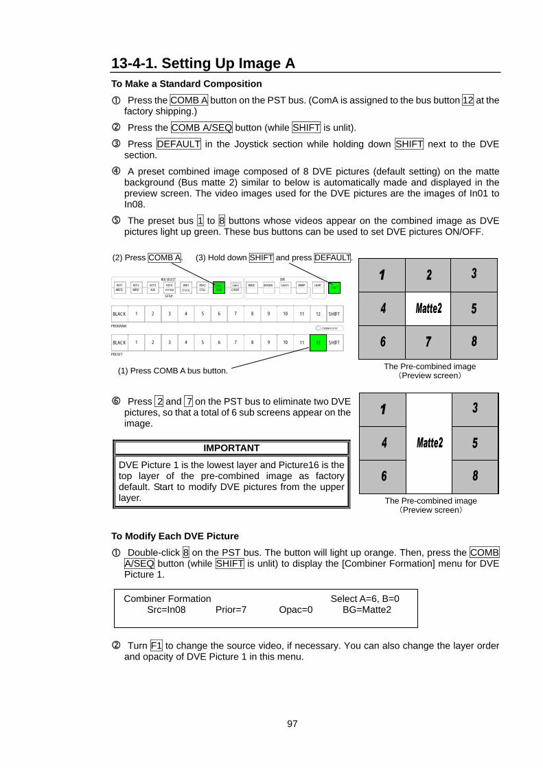
97
13-4-1. Setting Up Image A To Make a Standard Composition
Press the COMB A button on the PST bus. (ComA is assigned to the bus button 12 at the factory shipping.)
Press the COMB A/SEQ button (while SHIFT is unlit).
Press DEFAULT in the Joystick section while holding down SHIFT next to the DVE section.
A preset combined image composed of 8 DVE pictures (default setting) on the matte background (Bus matte 2) similar to below is automatically made and displayed in the preview screen. The video images used for the DVE pictures are the images of In01 to In08.
The preset bus 1 to 8 buttons whose videos appear on the combined image as DVE pictures light up green. These bus buttons can be used to set DVE pictures ON/OFF.
Press 2 and 7 on the PST bus to eliminate two DVE pictures, so that a total of 6 sub screens appear on the image.
IMPORTANT
DVE Picture 1 is the lowest layer and Picture16 is the top layer of the pre-combined image as factory default. Start to modify DVE pictures from the upper layer.
To Modify Each DVE Picture
Double-click 8 on the PST bus. The button will light up orange. Then, press the COMB A/SEQ button (while SHIFT is unlit) to display the [Combiner Formation] menu for DVE Picture 1.
Turn F1 to change the source video, if necessary. You can also change the layer order and opacity of DVE Picture 1 in this menu.
The Pre-combined image(Preview screen)
(2) Press COMB A.
(1) Press COMB A bus button.
(3) Hold down SHIFT and press DEFAULT.
DVE
SHIFT
SHIFT
SHIFT
COMBINER SETUP
12
12
11
11
10
10
9
9
BORDERBASIC
8
8
EVENTCOMB B
7
7
SEQCOMB A
6
6
DSK2STILL
5
5
DSK1STATUS
4
4
3
3
KEY4
SETUP
BUS SELECTKEY3AUX
2
2
KEY2
1
1
KEY1MATTE
BLACK
PROGRAM
BLACK
PRESET
INPUT SYSTEM
SUB EFF WARP LIGHT
The Pre-combined image(Preview screen)
Combiner Formation Select A=6, B=0 Src=In08 Prior=7 Opac=0 BG=Matte2
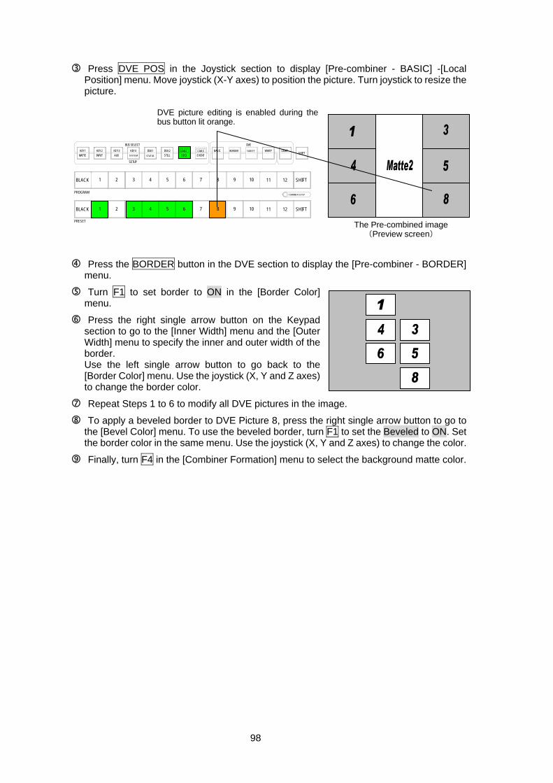
98
Press DVE POS in the Joystick section to display [Pre-combiner - BASIC] -[Local Position] menu. Move joystick (X-Y axes) to position the picture. Turn joystick to resize the picture.
Press the BORDER button in the DVE section to display the [Pre-combiner - BORDER] menu.
Turn F1 to set border to ON in the [Border Color] menu.
Press the right single arrow button on the Keypad section to go to the [Inner Width] menu and the [Outer Width] menu to specify the inner and outer width of the border. Use the left single arrow button to go back to the [Border Color] menu. Use the joystick (X, Y and Z axes) to change the border color.
Repeat Steps 1 to 6 to modify all DVE pictures in the image.
To apply a beveled border to DVE Picture 8, press the right single arrow button to go to the [Bevel Color] menu. To use the beveled border, turn F1 to set the Beveled to ON. Set the border color in the same menu. Use the joystick (X, Y and Z axes) to change the color.
Finally, turn F4 in the [Combiner Formation] menu to select the background matte color.
DVE picture editing is enabled during thebus button lit orange.
DVE
SHIFT
SHIFT
SHIFT
COMBINER SETUP
12
12
11
11
10
10
9
9
BORDERBASIC
8
8
EVENTCOMB B
7
7
SEQCOMB A
6
6
DSK2STILL
5
5
DSK1STATUS
4
4
3
3
KEY4
SETUP
BUS SELECTKEY3AUX
2
2
KEY2
1
1
KEY1MATTE
BLACK
PROGRAM
BLACK
PRESET
INPUT SYSTEM
SUB EFF WARP LIGHT
The Pre-combined image (Preview screen)
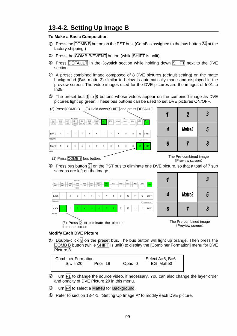
99
13-4-2. Setting Up Image B To Make a Basic Composition
Press the COMB B button on the PST bus. (ComB is assigned to the bus button 24 at the factory shipping.)
Press the COMB B/EVENT button (while SHIFT is unlit).
Press DEFAULT in the Joystick section while holding down SHIFT next to the DVE section.
A preset combined image composed of 8 DVE pictures (default setting) on the matte background (Bus matte 3) similar to below is automatically made and displayed in the preview screen. The video images used for the DVE pictures are the images of In01 to In08.
The preset bus 1 to 8 buttons whose videos appear on the combined image as DVE pictures light up green. These bus buttons can be used to set DVE pictures ON/OFF.
Press bus button 2 on the PST bus to eliminate one DVE picture, so that a total of 7 sub screens are left on the image.
Modify Each DVE Picture
Double-click 8 on the preset bus. The bus button will light up orange. Then press the COMB B button (while SHIFT is unlit) to display the [Combiner Formation] menu for DVE Picture 8.
Turn F1 to change the source video, if necessary. You can also change the layer order and opacity of DVE Picture 20 in this menu.
Turn F4 to select a Matte3 for Background.
Refer to section 13-4-1. "Setting Up Image A" to modify each DVE picture.
Combiner Formation Select A=6, B=6 Src=In20 Prior=19 Opac=0 BG=Matte3
The Pre-combined image(Preview screen)
(2) Press COMB B.
(1) Press COMB B bus button.
(3) Hold down SHIFT and press DEFAULT.
DVE
SHIFT
SHIFT
SHIFT
COMBINER SETUP
12
12
11
11
10
10
9
9
BORDERBASIC
8
8
EVENTCOMB B
7
7
SEQCOMB A
6
6
DSK2STILL
5
5
DSK1STATUS
4
4
3
3
KEY4
SETUP
BUS SELECTKEY3AUX
2
2
KEY2
1
1
KEY1MATTE
BLACK
PROGRAM
BLACK
PRESET
INPUT SYSTEM
SUB EFF WARP LIGHT
(6) Press 2 to eliminate the picture from the screen.
The Pre-combined image(Preview screen)
DVE
SHIFT
SHIFT
SHIFT
COMBINER SETUP
12
12
11
11
10
10
9
9
BORDERBASIC
8
8
EVENTCOMB B
7
7
SEQCOMB A
6
6
DSK2STILL
5
5
DSK1STATUS
4
4
3
3
KEY4
SETUP
BUS SELECTKEY3AUX
2
2
KEY2
1
1
KEY1MATTE
BLACK
PROGRAM
BLACK
PRESET
INPUT SYSTEM
SUB EFF WARP LIGHT
100
13-4-3. Making Transition To Assign Pre-combiner Images to Bus At a factory shipping, The Pre-combiner A image is assigned to Bus 12 (unshifted) and the Pre-combiner B image is assigned to Bus 12 (shifted). If you want to change these bus assignments, see 7-1-4 "Assigning Signals to M/E Bus." To Make Transition from Pre-combiner A to Pre-combiner B Using WIPE or DVE
In the PGM transition section press the BKGD button. Then the button will be lit up.
Press 12 on the PGM bus (while SHIFT is unlit). The button will turn on red.
Press 12 on the PST bus (while SHIFT is lit). The bus button will turn on green.
Press WIPE (DVE). The button will then be lit. When WIPE (DVE) is pressed, the WIPE (DVE) menu is automatically displayed in the window. Turn F1 under the Pat item to select a pattern to be used for the background transition. (See Appendix 3, "Wipe Pattern List" and "2D/3D DVE Pattern List".) To input the number using the keypad, press F1, input the pattern number with the keypad, and then press ENTER.
Set the Transition Rate, if necessary. (See section 8-2-2 "Mix".)
If necessary, set the transition direction using the NOR/REV button and REVERSE button in the DIRECTION section.
You can also apply a modifier to a selected pattern. It can be set in the WIPE or DVE Modify menu. See section 10. "WIPE Modify " or section 11. "DVE Modify" for more details.
Press the AUTO button or move the fader lever in the PGM transition section to perform the pattern transition.
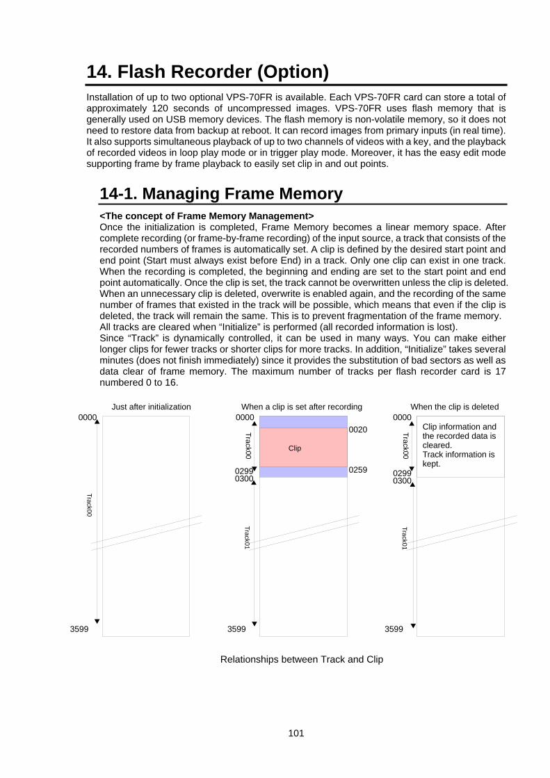
101
14. Flash Recorder (Option) Installation of up to two optional VPS-70FR is available. Each VPS-70FR card can store a total of approximately 120 seconds of uncompressed images. VPS-70FR uses flash memory that is generally used on USB memory devices. The flash memory is non-volatile memory, so it does not need to restore data from backup at reboot. It can record images from primary inputs (in real time). It also supports simultaneous playback of up to two channels of videos with a key, and the playback of recorded videos in loop play mode or in trigger play mode. Moreover, it has the easy edit mode supporting frame by frame playback to easily set clip in and out points.
14-1. Managing Frame Memory <The concept of Frame Memory Management> Once the initialization is completed, Frame Memory becomes a linear memory space. After complete recording (or frame-by-frame recording) of the input source, a track that consists of the recorded numbers of frames is automatically set. A clip is defined by the desired start point and end point (Start must always exist before End) in a track. Only one clip can exist in one track. When the recording is completed, the beginning and ending are set to the start point and end point automatically. Once the clip is set, the track cannot be overwritten unless the clip is deleted. When an unnecessary clip is deleted, overwrite is enabled again, and the recording of the same number of frames that existed in the track will be possible, which means that even if the clip is deleted, the track will remain the same. This is to prevent fragmentation of the frame memory. All tracks are cleared when “Initialize” is performed (all recorded information is lost). Since “Track” is dynamically controlled, it can be used in many ways. You can make either longer clips for fewer tracks or shorter clips for more tracks. In addition, “Initialize” takes several minutes (does not finish immediately) since it provides the substitution of bad sectors as well as data clear of frame memory. The maximum number of tracks per flash recorder card is 17 numbered 0 to 16.
Track01
Track01
Track00
0000
3599
Just after initialization
0000
3599
0000
3599
When the clip is deleted
0299 0259
0020Track00
Track00Clip
Clip information and the recorded data is cleared. Track information is kept.
When a clip is set after recording
Relationships between Track and Clip
0300 02990300
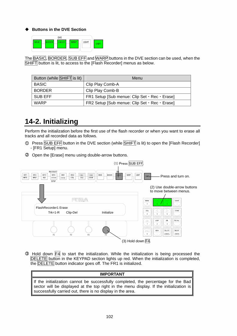
102
DVE
SHIFTBORDERBASIC SUB EFF WARP LIGHT
Buttons in the DVE Section The BASIC, BORDER, SUB EFF and WARP buttons in the DVE section can be used, when the SHIFT button is lit, to access to the [Flash Recorder] menus as below.
Button (while SHIFT is lit) Menu BASIC Clip Play Comb-A BORDER Clip Play Comb-B SUB EFF FR1 Setup [Sub menue: Clip Set・Rec・Erase] WARP FR2 Setup [Sub menue: Clip Set・Rec・Erase]
14-2. Initializing Perform the initialization before the first use of the flash recorder or when you want to erase all tracks and all recorded data as follows.
Press SUB EFF button in the DVE section (while SHIFT is lit) to open the [Flash Recorder] - [FR1 Setup] menu.
Open the [Erase] menu using double-arrow buttons.
Hold down F4 to start the initialization. While the initialization is being processed the DELETE button in the KEYPAD section lights up red. When the initialization is completed, the DELETE button indicator goes off. The FR1 is initialized.
IMPORTANT
If the initialization cannot be successfully completed, the percentage for the Bad sector will be displayed at the top right in the menu display. If the initialization is successfully carried out, there is no display in the area.
F3 F4F2F1
EVENT
-
RECALL
2 3
8 97
MENU
SEQ
1
STORE
65
LOOP DIR
4
INSERT
ENTER
DELETE
CANCEL
NEW
.0
FlashRecorder1 Erase Trk=1-R Clip-Del Initialize
(2) Use double-arrow buttons to move between menus.
DVE
SHIFTBORDERBASIC
EVENTCOMB B
SEQCOMB ADSK2
STILLDSK1
STATUS
KEY4
SETUP
BUS SELECTKEY3AUX
KEY2KEY1MATTE INPUT SYSTEM
SUB EFF WARP LIGHT Press and turn on.
(3) Hold down F4.
(1) Press SUB EFF.
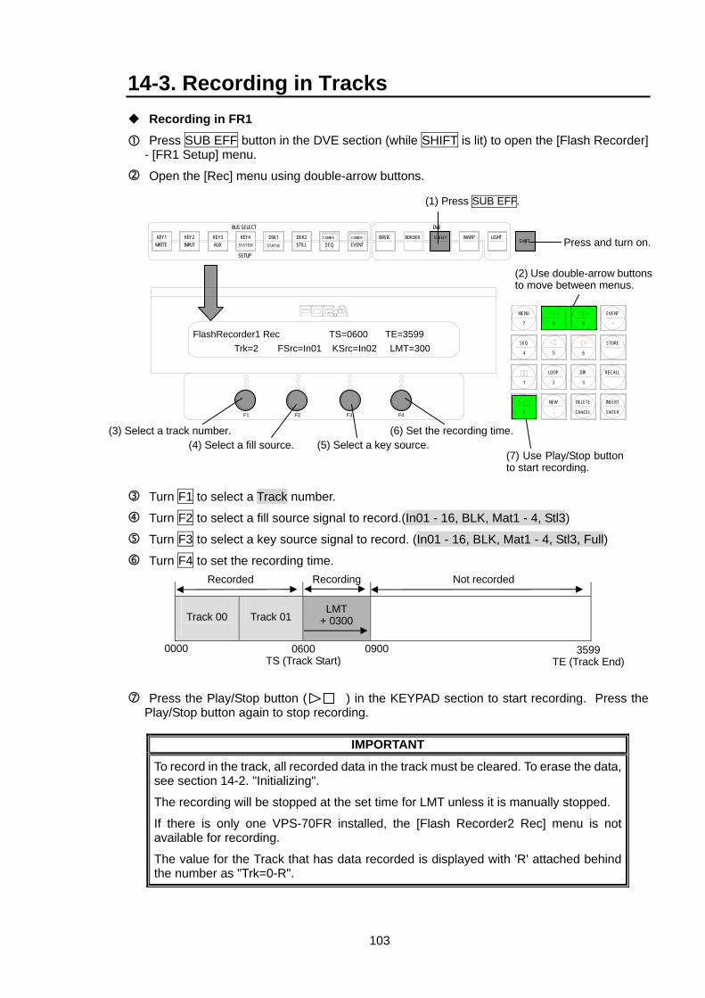
103
14-3. Recording in Tracks Recording in FR1
Press SUB EFF button in the DVE section (while SHIFT is lit) to open the [Flash Recorder] - [FR1 Setup] menu.
Open the [Rec] menu using double-arrow buttons.
Turn F1 to select a Track number.
Turn F2 to select a fill source signal to record.(In01 - 16, BLK, Mat1 - 4, Stl3)
Turn F3 to select a key source signal to record. (In01 - 16, BLK, Mat1 - 4, Stl3, Full)
Turn F4 to set the recording time.
Track 00
Track 01
Press the Play/Stop button ( ) in the KEYPAD section to start recording. Press the Play/Stop button again to stop recording.
IMPORTANT
To record in the track, all recorded data in the track must be cleared. To erase the data, see section 14-2. "Initializing".
The recording will be stopped at the set time for LMT unless it is manually stopped.
If there is only one VPS-70FR installed, the [Flash Recorder2 Rec] menu is not available for recording.
The value for the Track that has data recorded is displayed with 'R' attached behind the number as "Trk=0-R".
Recorded
0000
Not recorded
3599TE (Track End)
0600TS (Track Start)
LMT + 0300
0900
Recording
(2) Use double-arrow buttons to move between menus.
(3) Select a track number.
DVE
SHIFTBORDERBASIC
EVENTCOMB B
SEQCOMB ADSK2
STILLDSK1
STATUS
KEY4
SETUP
BUS SELECTKEY3AUX
KEY2KEY1MATTE INPUT SYSTEM
SUB EFF WARP LIGHT Press and turn on.
(6) Set the recording time. (4) Select a fill source. (5) Select a key source.
(1) Press SUB EFF.
(7) Use Play/Stop button to start recording.
F3 F4F2F1
EVENT
-
RECALL
2 3
8 97
MENU
SEQ
1
STORE
65
LOOP DIR
4
INSERT
ENTER
DELETE
CANCEL
NEW
.0
FlashRecorder1 Rec TS=0600 TE=3599 Trk=2 FSrc=In01 KSrc=In02 LMT=300
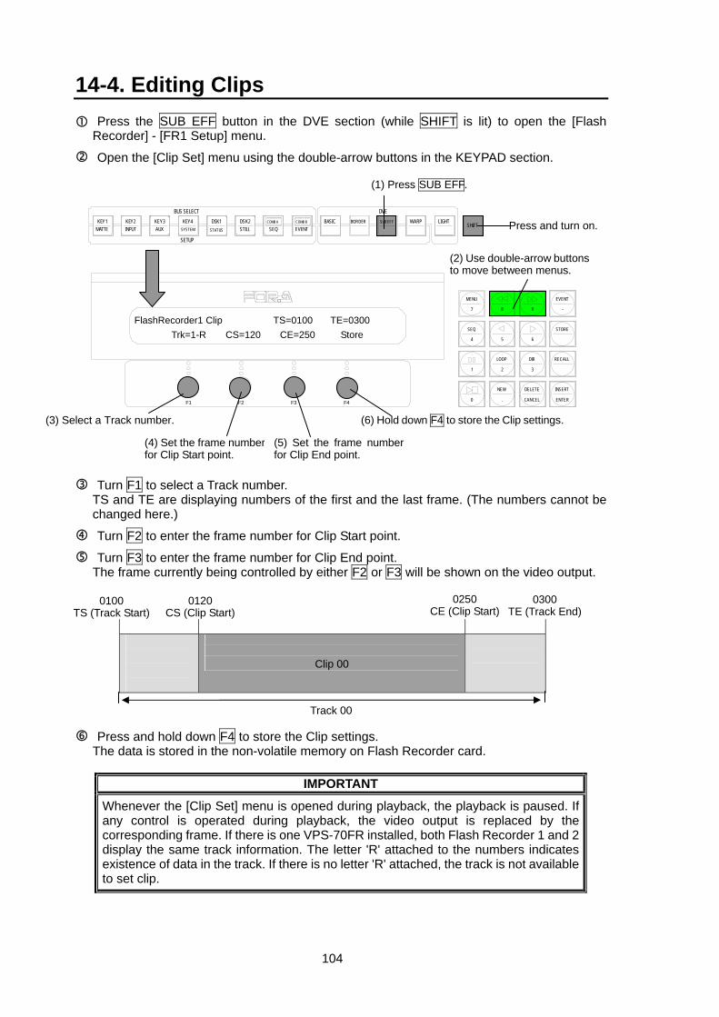
104
14-4. Editing Clips Press the SUB EFF button in the DVE section (while SHIFT is lit) to open the [Flash Recorder] - [FR1 Setup] menu.
Open the [Clip Set] menu using the double-arrow buttons in the KEYPAD section.
Turn F1 to select a Track number. TS and TE are displaying numbers of the first and the last frame. (The numbers cannot be changed here.)
Turn F2 to enter the frame number for Clip Start point.
Turn F3 to enter the frame number for Clip End point. The frame currently being controlled by either F2 or F3 will be shown on the video output.
Clip 00
Press and hold down F4 to store the Clip settings. The data is stored in the non-volatile memory on Flash Recorder card.
IMPORTANT
Whenever the [Clip Set] menu is opened during playback, the playback is paused. If any control is operated during playback, the video output is replaced by the corresponding frame. If there is one VPS-70FR installed, both Flash Recorder 1 and 2 display the same track information. The letter 'R' attached to the numbers indicates existence of data in the track. If there is no letter 'R' attached, the track is not available to set clip.
F3 F4F2F1
EVENT
-
RECALL
2 3
8 97
MENU
SEQ
1
STORE
65
LOOP DIR
4
INSERT
ENTER
DELETE
CANCEL
NEW
.0
FlashRecorder1 Clip TS=0100 TE=0300 Trk=1-R CS=120 CE=250 Store
(2) Use double-arrow buttons to move between menus.
(3) Select a Track number.
DVE
SHIFTBORDERBASIC
EVENTCOMB B
SEQCOMB ADSK2
STILLDSK1
STATUS
KEY4
SETUP
BUS SELECTKEY3AUX
KEY2KEY1MATTE INPUT SYSTEM
SUB EFF WARP LIGHT Press and turn on.
(6) Hold down F4 to store the Clip settings.
(4) Set the frame numberfor Clip Start point.
(5) Set the frame number for Clip End point.
(1) Press SUB EFF.
0100 TS (Track Start)
0300 TE (Track End)
0120CS (Clip Start)
0250CE (Clip Start)
Track 00
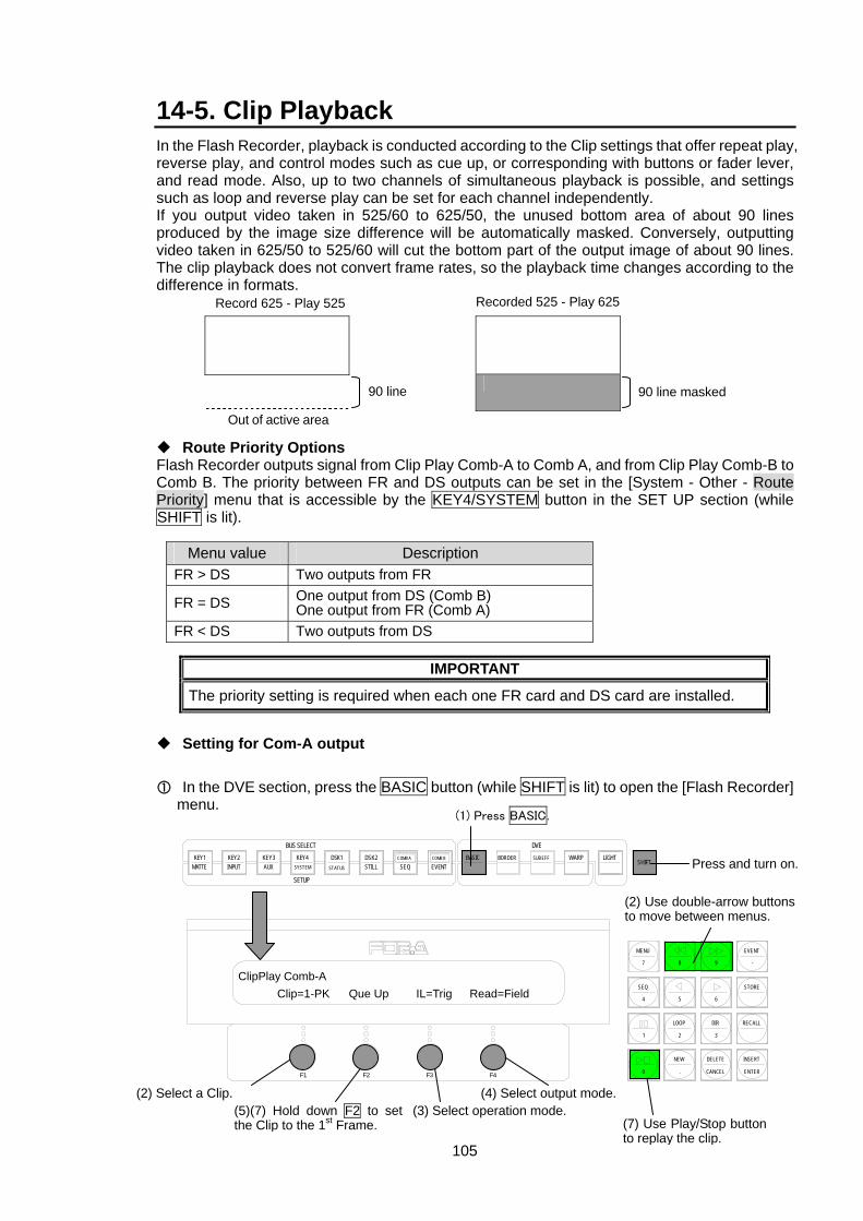
105
14-5. Clip Playback In the Flash Recorder, playback is conducted according to the Clip settings that offer repeat play, reverse play, and control modes such as cue up, or corresponding with buttons or fader lever, and read mode. Also, up to two channels of simultaneous playback is possible, and settings such as loop and reverse play can be set for each channel independently. If you output video taken in 525/60 to 625/50, the unused bottom area of about 90 lines produced by the image size difference will be automatically masked. Conversely, outputting video taken in 625/50 to 525/60 will cut the bottom part of the output image of about 90 lines. The clip playback does not convert frame rates, so the playback time changes according to the difference in formats.
Route Priority Options Flash Recorder outputs signal from Clip Play Comb-A to Comb A, and from Clip Play Comb-B to Comb B. The priority between FR and DS outputs can be set in the [System - Other - Route Priority] menu that is accessible by the KEY4/SYSTEM button in the SET UP section (while SHIFT is lit).
Menu value Description
FR > DS Two outputs from FR
FR = DS One output from DS (Comb B) One output from FR (Comb A)
FR < DS Two outputs from DS
IMPORTANT
The priority setting is required when each one FR card and DS card are installed.
Setting for Com-A output
In the DVE section, press the BASIC button (while SHIFT is lit) to open the [Flash Recorder] menu.
(2) Select a Clip. (4) Select output mode. (5)(7) Hold down F2 to set the Clip to the 1st Frame.
(3) Select operation mode.(7) Use Play/Stop button to replay the clip.
(1) Press BASIC.
DVE
SHIFTBORDERBASIC
EVENTCOMB B
SEQCOMB ADSK2
STILLDSK1
STATUS
KEY4
SETUP
BUS SELECTKEY3AUX
KEY2KEY1MATTE INPUT SYSTEM
SUB EFF WARP LIGHT
F3 F4F2F1
EVENT
-
RECALL
2 3
8 97
MENU
SEQ
1
STORE
65
LOOP DIR
4
INSERT
ENTER
DELETE
CANCEL
NEW
.0
ClipPlay Comb-A Clip=1-PK Que Up IL=Trig Read=Field
(2) Use double-arrow buttons to move between menus.
Press and turn on.
Recorded 525 - Play 625
90 line masked
Record 625 - Play 525
90 line
Out of active area

106
Open the [Clip Play Comb-A] menu using the double-arrow buttons in the keypad section.
Turn F1 to select a Clip to be output. When one VPS-70FR is installed: Comb-A and Comb-B display the clips in FR1. When two VPS-70FR are installed: Comb-A displays the clips in FR1, and Comb-B displays the clips in FR2.
Turn F3 to select the operation mode from Off, Trigger, or Linkage. Off: Operated by Play/Stop and Pause/Restart buttons Trigger: Playback triggered by AUTO button, and the duration of playback is the same as the duration of recording. Linkage: By AUTO button: Playback processed at the set transition rate By Fader lever: Playback processed in conjunction with fader lever operation
Turn F4 to select the output mode from Frame, or Field.
Press and hold down F2 to set the clip to the first frame.
Press Play/Stop button in KEYPAD to start playback of the clip (Play/Stop button lit red). To pause playback, press the Play/Stop button again.
After completing the playback, it stops at the last frame of the clip. To restart playback of the clip, press and hold down F2 to set the clip to the first frame, then press Play/Stop button.
Play/Stop button
Pressing the button starts playback of a clip. Pressing again pauses the playback.
LOOP LOOP button Sets the playback mode to loop playback (continuous playback). Lights up red when it is on.
DIR DIR button Reverses the playback while it lights up red.
Pause/Restart button
Pressing the button during playback pauses the playback. Pressing again restarts the playback.
IMPORTANT
Although recording will take place if recording is started during playback, playback cannot be initiated during recording.
Keypad LEDs are controlled by the currently displayed menu.
The priority between DS and FR changes according to various factors such as the number of installed FR cards, presence of DS card and various settings. Basically FR1 has the priority over FR2 when two FR cards are installed.
"N" or "P" attached at the end of Clip number indicates formats, "K" indicates the Clip is with a Key, and "D" indicates there is no recorded data.
Pause/Restart
LOOP Play/Stop DIR
EVENT
-
RECALL
2 3
8 97
MENU
SEQ
1
STORE
65
LOOP DIR
4
INSERT
ENTER
DELETE
CANCEL
NEW
.0
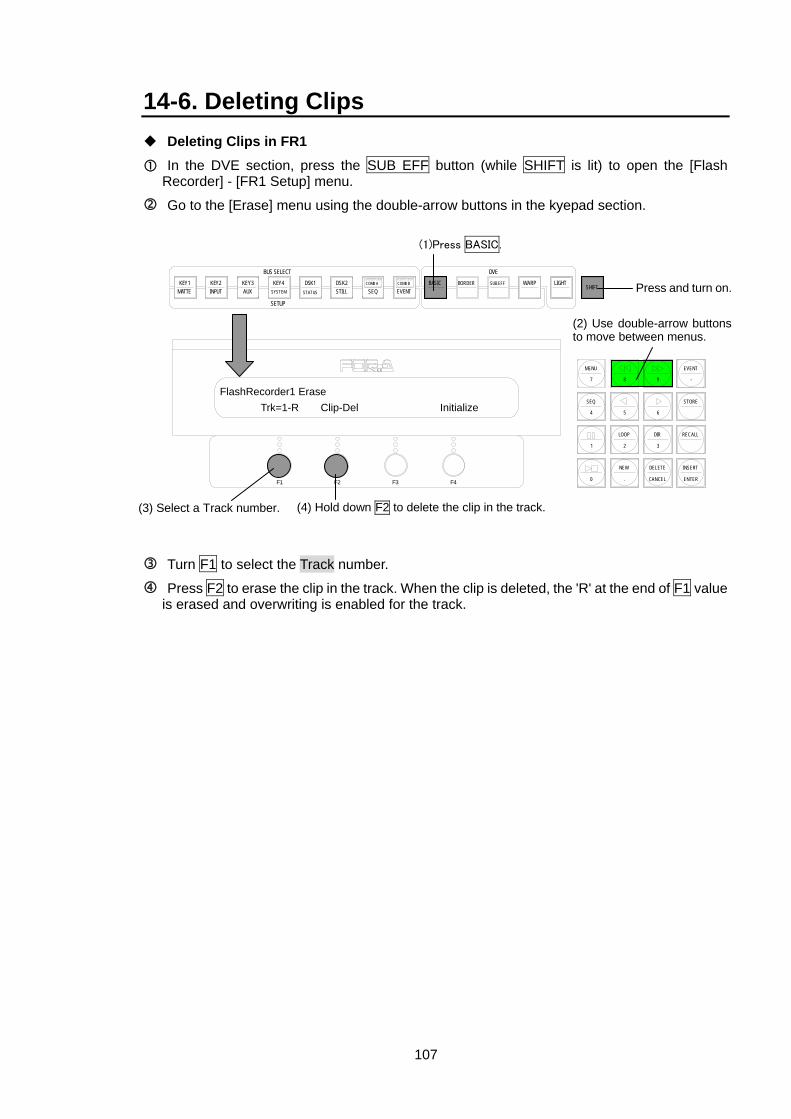
107
14-6. Deleting Clips Deleting Clips in FR1
In the DVE section, press the SUB EFF button (while SHIFT is lit) to open the [Flash Recorder] - [FR1 Setup] menu.
Go to the [Erase] menu using the double-arrow buttons in the kyepad section.
Turn F1 to select the Track number.
Press F2 to erase the clip in the track. When the clip is deleted, the 'R' at the end of F1 value is erased and overwriting is enabled for the track.
(1)Press BASIC.
DVE
SHIFTBORDERBASIC
EVENTCOMB B
SEQCOMB ADSK2
STILLDSK1
STATUS
KEY4
SETUP
BUS SELECTKEY3AUX
KEY2KEY1MATTE INPUT SYSTEM
SUB EFF WARP LIGHT
F3 F4F2F1
EVENT
-
RECALL
2 3
8 97
MENU
SEQ
1
STORE
65
LOOP DIR
4
INSERT
ENTER
DELETE
CANCEL
NEW
.0
FlashRecorder1 Erase Trk=1-R Clip-Del Initialize
(2) Use double-arrow buttons to move between menus.
(3) Select a Track number.
Press and turn on.
(4) Hold down F2 to delete the clip in the track.
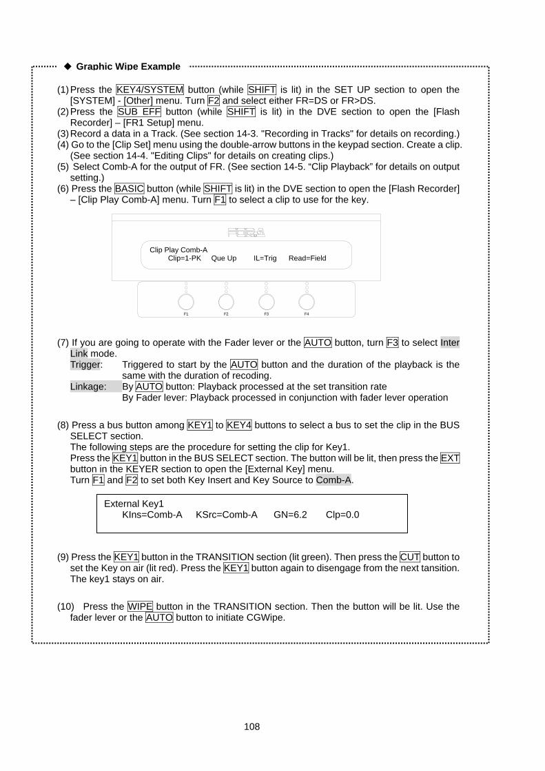
108
(1) Press the KEY4/SYSTEM button (while SHIFT is lit) in the SET UP section to open the
[SYSTEM] - [Other] menu. Turn F2 and select either FR=DS or FR>DS. (2) Press the SUB EFF button (while SHIFT is lit) in the DVE section to open the [Flash
Recorder] – [FR1 Setup] menu. (3) Record a data in a Track. (See section 14-3. "Recording in Tracks" for details on recording.) (4) Go to the [Clip Set] menu using the double-arrow buttons in the keypad section. Create a clip.
(See section 14-4. "Editing Clips" for details on creating clips.) (5) Select Comb-A for the output of FR. (See section 14-5. “Clip Playback” for details on output
setting.) (6) Press the BASIC button (while SHIFT is lit) in the DVE section to open the [Flash Recorder]
– [Clip Play Comb-A] menu. Turn F1 to select a clip to use for the key.
(7) If you are going to operate with the Fader lever or the AUTO button, turn F3 to select Inter
Link mode. Trigger: Triggered to start by the AUTO button and the duration of the playback is the same with the duration of recoding. Linkage: By AUTO button: Playback processed at the set transition rate By Fader lever: Playback processed in conjunction with fader lever operation
(8) Press a bus button among KEY1 to KEY4 buttons to select a bus to set the clip in the BUS
SELECT section. The following steps are the procedure for setting the clip for Key1. Press the KEY1 button in the BUS SELECT section. The button will be lit, then press the EXT button in the KEYER section to open the [External Key] menu. Turn F1 and F2 to set both Key Insert and Key Source to Comb-A.
(9) Press the KEY1 button in the TRANSITION section (lit green). Then press the CUT button to
set the Key on air (lit red). Press the KEY1 button again to disengage from the next tansition. The key1 stays on air.
(10) Press the WIPE button in the TRANSITION section. Then the button will be lit. Use the
fader lever or the AUTO button to initiate CGWipe.
External Key1 KIns=Comb-A KSrc=Comb-A GN=6.2 Clp=0.0
Graphic Wipe Example
F3 F4F2F1
Clip Play Comb-A Clip=1-PK Que Up IL=Trig Read=Field
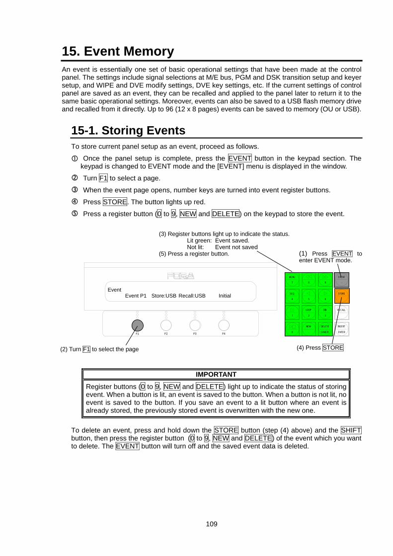
109
15. Event Memory An event is essentially one set of basic operational settings that have been made at the control panel. The settings include signal selections at M/E bus, PGM and DSK transition setup and keyer setup, and WIPE and DVE modify settings, DVE key settings, etc. If the current settings of control panel are saved as an event, they can be recalled and applied to the panel later to return it to the same basic operational settings. Moreover, events can also be saved to a USB flash memory drive and recalled from it directly. Up to 96 (12 x 8 pages) events can be saved to memory (OU or USB).
15-1. Storing Events To store current panel setup as an event, proceed as follows.
Once the panel setup is complete, press the EVENT button in the keypad section. The keypad is changed to EVENT mode and the [EVENT] menu is displayed in the window.
Turn F1 to select a page.
When the event page opens, number keys are turned into event register buttons.
Press STORE. The button lights up red.
Press a register button (0 to 9, NEW and DELETE) on the keypad to store the event.
IMPORTANT
Register buttons (0 to 9, NEW and DELETE) light up to indicate the status of storing event. When a button is lit, an event is saved to the button. When a button is not lit, no event is saved to the button. If you save an event to a lit button where an event is already stored, the previously stored event is overwritten with the new one.
To delete an event, press and hold down the STORE button (step (4) above) and the SHIFT button, then press the register button (0 to 9, NEW and DELETE) of the event which you want to delete. The EVENT button will turn off and the saved event data is deleted.
(2) Turn F1 to select the page
Event Event P1 Store:USB Recall:USB Initial
(1) Press EVENT toenter EVENT mode.
F3 F4F2F1
EVENT
-
RECALL
2 3
8 97
MENU
SEQ
1
STORE
65
LOOP DIR
4
INSERT
ENTER
DELETE
CANCEL
NEW
.0
(4) Press STORE
(3) Register buttons light up to indicate the status. Lit green: Event saved. Not lit: Event not saved
(5) Press a register button.
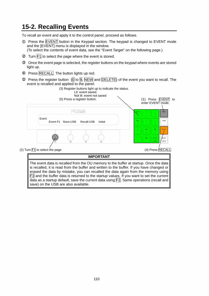
110
15-2. Recalling Events To recall an event and apply it to the control panel, proceed as follows.
Press the EVENT button in the Keypad section. The keypad is changed to EVENT mode and the [EVENT] menu is displayed in the window. (To select the contents of event data, see the "Event Target" on the following page.)
Turn F1 to select the page where the event is stored.
Once the event page is selected, the register buttons on the keypad where events are stored light up.
Press RECALL. The button lights up red.
Press the register button (0 to 9, NEW and DELETE) of the event you want to recall. The event is recalled and applied to the panel.
IMPORTANT
The event data is recalled from the OU memory to the buffer at startup. Once the data is recalled, it is read from the buffer and written to the buffer. If you have changed or erased the data by mistake, you can recalled the data again from the memory using F3 and the buffer data is returned to the startup values. If you want to set the current data as a startup default, save the current data using F2. Same operations (recall and save) on the USB are also available.
Event Event P1 Store:USB Recall:USB Initial
(1) Press EVENT to enter EVENT mode.
F3 F4F2F1
EVENT
-
RECALL
2 3
8 97
MENU
SEQ
1
STORE
65
LOOP DIR
4
INSERT
ENTER
DELETE
CANCEL
NEW
.0
(2) Turn F1 to select the page (4) Press RECALL
(3) Register buttons light up to indicate the status.Lit: event saved. Not lit: event not saved
(5) Press a register button.
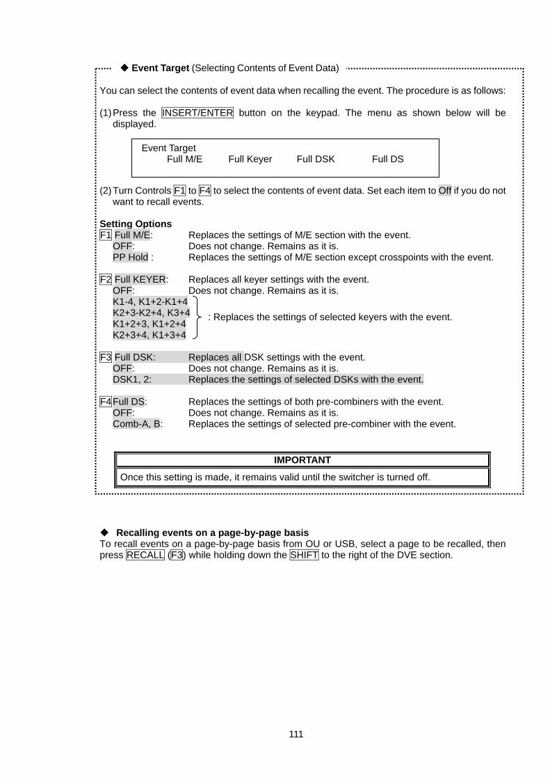
111
You can select the contents of event data when recalling the event. The procedure is as follows: (1) Press the INSERT/ENTER button on the keypad. The menu as shown below will be
displayed. (2) Turn Controls F1 to F4 to select the contents of event data. Set each item to Off if you do not
want to recall events. Setting Options F1 Full M/E: Replaces the settings of M/E section with the event.
OFF: Does not change. Remains as it is. PP Hold : Replaces the settings of M/E section except crosspoints with the event.
F2 Full KEYER: Replaces all keyer settings with the event.
OFF: Does not change. Remains as it is. K1-4, K1+2-K1+4 K2+3-K2+4, K3+4 K1+2+3, K1+2+4 K2+3+4, K1+3+4
F3 Full DSK: Replaces all DSK settings with the event.
OFF: Does not change. Remains as it is. DSK1, 2: Replaces the settings of selected DSKs with the event.
F4 Full DS: Replaces the settings of both pre-combiners with the event.
OFF: Does not change. Remains as it is. Comb-A, B: Replaces the settings of selected pre-combiner with the event.
IMPORTANT
Once this setting is made, it remains valid until the switcher is turned off.
Recalling events on a page-by-page basis To recall events on a page-by-page basis from OU or USB, select a page to be recalled, then press RECALL (F3) while holding down the SHIFT to the right of the DVE section.
Event Target Full M/E Full Keyer Full DSK Full DS
: Replaces the settings of selected keyers with the event.
◆ Event Target (Selecting Contents of Event Data)
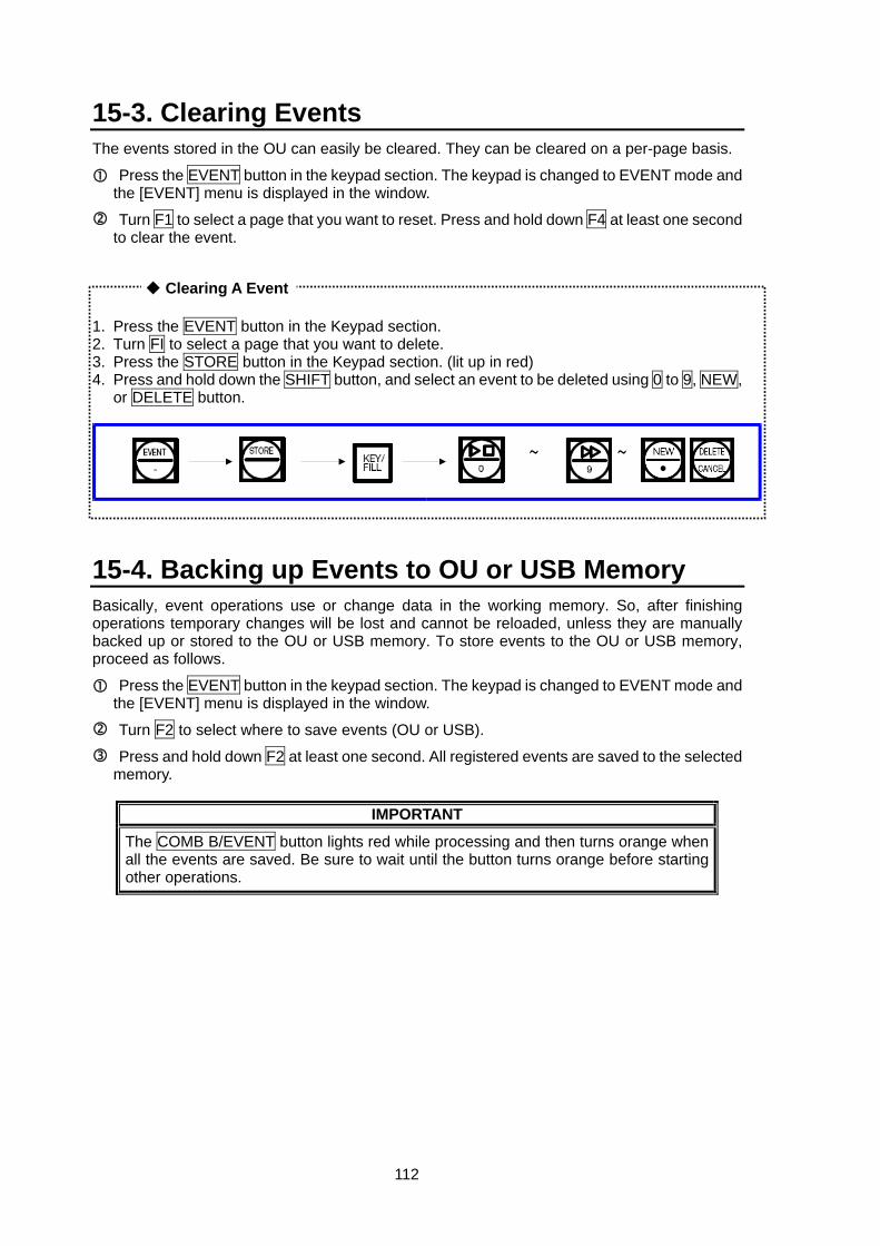
112
15-3. Clearing Events The events stored in the OU can easily be cleared. They can be cleared on a per-page basis.
Press the EVENT button in the keypad section. The keypad is changed to EVENT mode and the [EVENT] menu is displayed in the window.
Turn F1 to select a page that you want to reset. Press and hold down F4 at least one second to clear the event.
1. Press the EVENT button in the Keypad section. 2. Turn FI to select a page that you want to delete. 3. Press the STORE button in the Keypad section. (lit up in red) 4. Press and hold down the SHIFT button, and select an event to be deleted using 0 to 9, NEW,
or DELETE button.
15-4. Backing up Events to OU or USB Memory Basically, event operations use or change data in the working memory. So, after finishing operations temporary changes will be lost and cannot be reloaded, unless they are manually backed up or stored to the OU or USB memory. To store events to the OU or USB memory, proceed as follows.
Press the EVENT button in the keypad section. The keypad is changed to EVENT mode and the [EVENT] menu is displayed in the window.
Turn F2 to select where to save events (OU or USB).
Press and hold down F2 at least one second. All registered events are saved to the selected memory.
IMPORTANT
The COMB B/EVENT button lights red while processing and then turns orange when all the events are saved. Be sure to wait until the button turns orange before starting other operations.
◆ Clearing A Event
~ ~
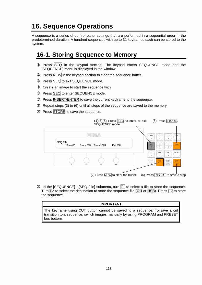
113
16. Sequence Operations A sequence is a series of control panel settings that are performed in a sequential order in the predetermined duration. A hundred sequences with up to 31 keyframes each can be stored to the system.
16-1. Storing Sequence to Memory Press SEQ in the keypad section. The keypad enters SEQUENCE mode and the [SEQUENCE] menu is displayed in the window.
Press NEW in the keypad section to clear the sequence buffer.
Press SEQ to exit SEQUENCE mode.
Create an image to start the sequence with.
Press SEQ to enter SEQUENCE mode.
Press INSERT/ENTER to save the current keyframe to the sequence.
Repeat steps (3) to (6) until all steps of the sequence are saved to the memory.
Press STORE to save the sequence.
In the [SEQUENCE] - [SEQ File] submenu, turn F1 to select a file to store the sequence. Turn F2 to select the destination to store the sequence file (OU or USB). Press F2 to store the sequence.
IMPORTANT
The keyframe using CUT button cannot be saved to a sequence. To save a cut transition to a sequence, switch images manually by using PROGRAM and PRESET bus bottons.
(1)(3)(5) Press SEQ to enter or exit SEQUENCE mode.
F3 F4F2F1
EVENT
-
RECALL
2 3
8 97
MENU
SEQ
1
STORE
65
LOOP DIR
4
INSERT
ENTER
DELETE
CANCEL
NEW
.0
(6) Press INSERT to save a step
SEQ File File=00 Store:OU Recall:OU Del:OU
(8) Press STORE.
(2) Press NEW to clear the buffer.
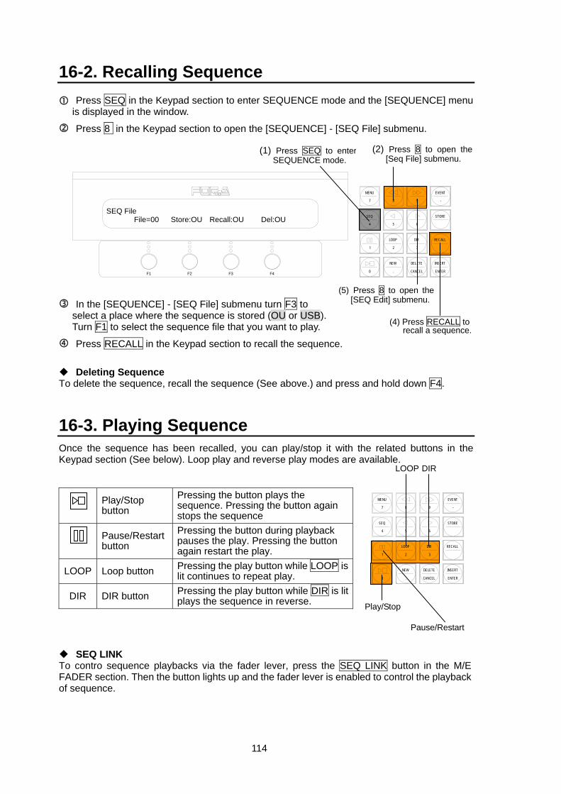
114
16-2. Recalling Sequence Press SEQ in the Keypad section to enter SEQUENCE mode and the [SEQUENCE] menu is displayed in the window.
Press 8 in the Keypad section to open the [SEQUENCE] - [SEQ File] submenu.
In the [SEQUENCE] - [SEQ File] submenu turn F3 to select a place where the sequence is stored (OU or USB). Turn F1 to select the sequence file that you want to play.
Press RECALL in the Keypad section to recall the sequence.
Deleting Sequence To delete the sequence, recall the sequence (See above.) and press and hold down F4.
16-3. Playing Sequence Once the sequence has been recalled, you can play/stop it with the related buttons in the Keypad section (See below). Loop play and reverse play modes are available.
Play/Stop button
Pressing the button plays the sequence. Pressing the button again stops the sequence
Pause/Restart button
Pressing the button during playback pauses the play. Pressing the button again restart the play.
LOOP Loop button Pressing the play button while LOOP is lit continues to repeat play.
DIR DIR button Pressing the play button while DIR is lit plays the sequence in reverse.
SEQ LINK To contro sequence playbacks via the fader lever, press the SEQ LINK button in the M/E FADER section. Then the button lights up and the fader lever is enabled to control the playback of sequence.
F3 F4F2F1
EVENT
-
RECALL
2 3
8 97
MENU
SEQ
1
STORE
65
LOOP DIR
4
INSERT
ENTER
DELETE
CANCEL
NEW
.0
(5) Press 8 to open the [SEQ Edit] submenu.
SEQ File File=00 Store:OU Recall:OU Del:OU
(2) Press 8 to open the [Seq File] submenu.
(1) Press SEQ to enter SEQUENCE mode.
(4) Press RECALL to recall a sequence.
EVENT
-
RECALL
2 3
8 97
MENU
SEQ
1
STORE
65
LOOP DIR
4
INSERT
ENTER
DELETE
CANCEL
NEW
.0
LOOP
Pause/Restart
Play/Stop
DIR
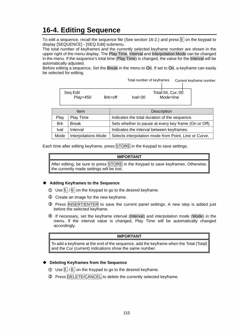
115
16-4. Editing Sequence To edit a sequence, recall the sequence file (See section 16-2.) and press 9 on the keypad to display [SEQUENCE] - [SEQ Edit] submenu. The total number of keyframes and the currently selected keyframe number are shown in the upper right of the menu display. The Play Time, Interval and Interpolation Mode can be changed in the menu. If the sequence’s total time (Play Time) is changed, the value for the Interval will be automatically adjusted. Before editing a sequence, Set the Break in the menu to On. If set to On, a keyframe can easily be selected for editing.
Item Description Play Play Time Indicates the total duration of the sequence. Brk Break Sets whether to pause at every key frame (On or Off).Ival Interval Indicates the interval between keyframes.
Mode Interpolations Mode Selects interpolation mode from Point, Line or Curve. Each time after editing keyframe, press STORE in the Keypad to save settings.
IMPORTANT
After editing, be sure to press STORE in the Keypad to save keyframes. Otherwise, the currently made settings will be lost.
Adding Keyframes to the Sequence
Use 5 / 6 on the Keypad to go to the desired keyframe.
Create an image for the new keyframe.
Press INSERT/ENTER to save the current panel settings. A new step is added just before the selected keyframe.
If necessary, set the keyframe interval (Interval) and interpolation mode (Mode) in the menu. If the interval value is changed, Play Time will be automatically changed accordingly.
IMPORTANT
To add a keyframe at the end of the sequence, add the keyframe when the Total (Total) and the Cur (current) indications show the same number.
Deleting Keyframes from the Sequence
Use 5 / 6 on the Keypad to go to the desired keyframe.
Press DELETE/CANCEL to delete the currently selected keyframe.
Seq Edit Total:04, Cur.:00 Play=450 Brk=off Ival=30 Mode=line
Total number of keyframes Current keyframe number
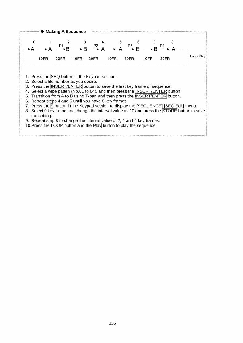
116
1. Press the SEQ button in the Keypad section. 2. Select a file number as you desire. 3. Press the INSERT/ENTER button to save the first key frame of sequence. 4. Select a wipe patten (No.01 to 04), and then press the INSERT/ENTER button. 5. Transition from A to B using T-bar, and then press the INSERT/ENTER button. 6. Repeat steps 4 and 5 untill you have 8 key frames. 7. Press the 9 button in the Keypad section to display the [SECUENCE]-[SEQ Edit] menu. 8. Select 0 key frame and change the interval value as 10 and press the STORE button to save
the setting. 9. Repeat step 8 to change the interval value of 2, 4 and 6 key frames. 10.Press the LOOP button and the Play button to play the sequence.
A A B B A A B B A
0 1 2 3 4 5 6 7 8
10FR 30FR 10FR 30FR 10FR 30FR 10FR 30FR
P1 P2 P3 P4
Loop Play
◆ Making A Sequence
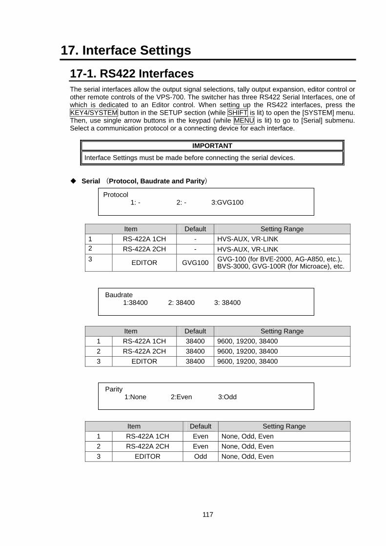
117
17. Interface Settings
17-1. RS422 Interfaces The serial interfaces allow the output signal selections, tally output expansion, editor control or other remote controls of the VPS-700. The switcher has three RS422 Serial Interfaces, one of which is dedicated to an Editor control. When setting up the RS422 interfaces, press the KEY4/SYSTEM button in the SETUP section (while SHIFT is lit) to open the [SYSTEM] menu. Then, use single arrow buttons in the keypad (while MENU is lit) to go to [Serial] submenu. Select a communication protocol or a connecting device for each interface.
IMPORTANT
Interface Settings must be made before connecting the serial devices.
Serial (Protocol, Baudrate and Parity)
Item Default Setting Range 1 RS-422A 1CH - HVS-AUX, VR-LINK 2 RS-422A 2CH - HVS-AUX, VR-LINK 3 EDITOR GVG100 GVG-100 (for BVE-2000, AG-A850, etc.),
BVS-3000, GVG-100R (for Microace), etc.
Item Default Setting Range 1 RS-422A 1CH 38400 9600, 19200, 38400 2 RS-422A 2CH 38400 9600, 19200, 38400 3 EDITOR 38400 9600, 19200, 38400
Item Default Setting Range 1 RS-422A 1CH Even None, Odd, Even 2 RS-422A 2CH Even None, Odd, Even 3 EDITOR Odd None, Odd, Even
Protocol 1: - 2: - 3:GVG100
Parity 1:None 2:Even 3:Odd
Baudrate 1:38400 2: 38400 3: 38400
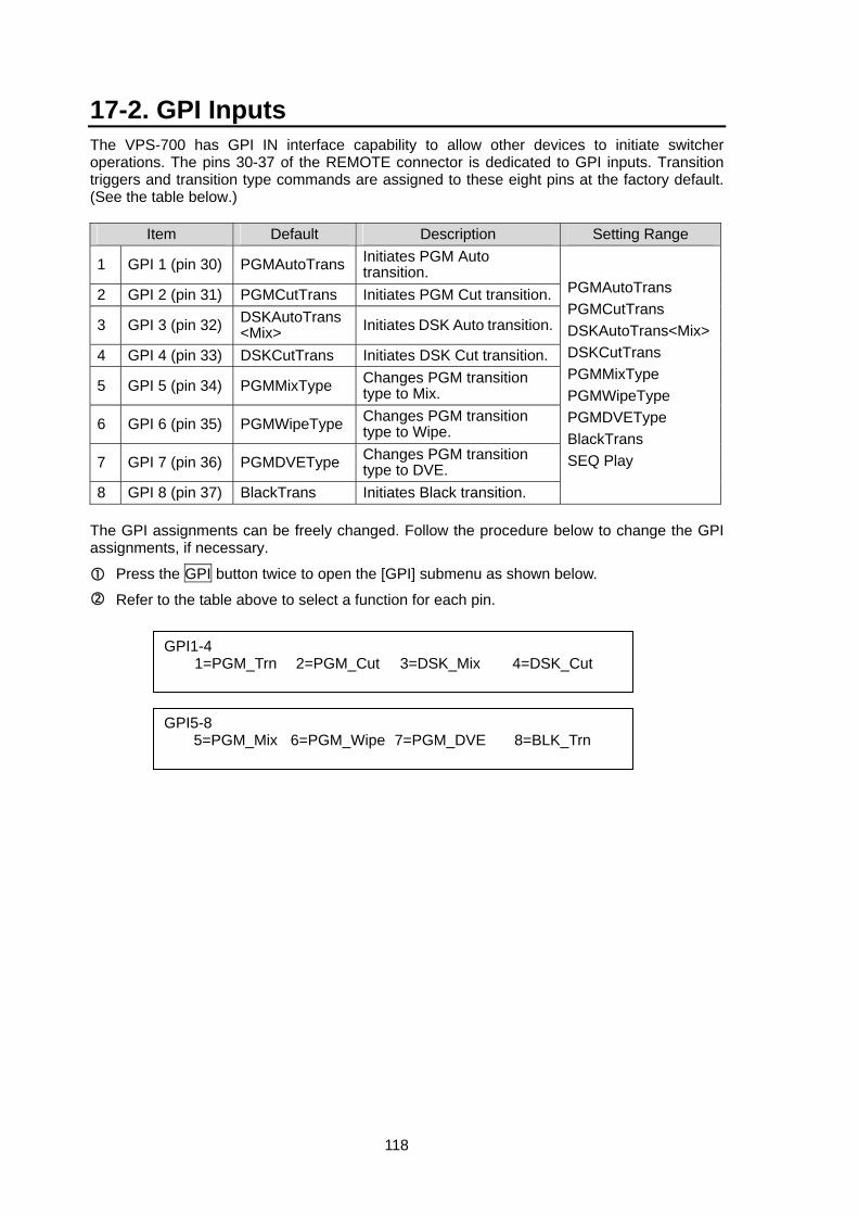
118
17-2. GPI Inputs The VPS-700 has GPI IN interface capability to allow other devices to initiate switcher operations. The pins 30-37 of the REMOTE connector is dedicated to GPI inputs. Transition triggers and transition type commands are assigned to these eight pins at the factory default. (See the table below.)
Item Default Description Setting Range
1 GPI 1 (pin 30) PGMAutoTrans Initiates PGM Auto transition.
2 GPI 2 (pin 31) PGMCutTrans Initiates PGM Cut transition.
3 GPI 3 (pin 32) DSKAutoTrans<Mix> Initiates DSK Auto transition.
4 GPI 4 (pin 33) DSKCutTrans Initiates DSK Cut transition.
5 GPI 5 (pin 34) PGMMixType Changes PGM transition type to Mix.
6 GPI 6 (pin 35) PGMWipeType Changes PGM transition type to Wipe.
7 GPI 7 (pin 36) PGMDVEType Changes PGM transition type to DVE.
8 GPI 8 (pin 37) BlackTrans Initiates Black transition.
PGMAutoTrans PGMCutTrans DSKAutoTrans<Mix>DSKCutTrans PGMMixType PGMWipeType PGMDVEType BlackTrans SEQ Play
The GPI assignments can be freely changed. Follow the procedure below to change the GPI assignments, if necessary.
Press the GPI button twice to open the [GPI] submenu as shown below.
Refer to the table above to select a function for each pin.
GPI1-4 1=PGM_Trn 2=PGM_Cut 3=DSK_Mix 4=DSK_Cut
GPI5-8 5=PGM_Mix 6=PGM_Wipe 7=PGM_DVE 8=BLK_Trn
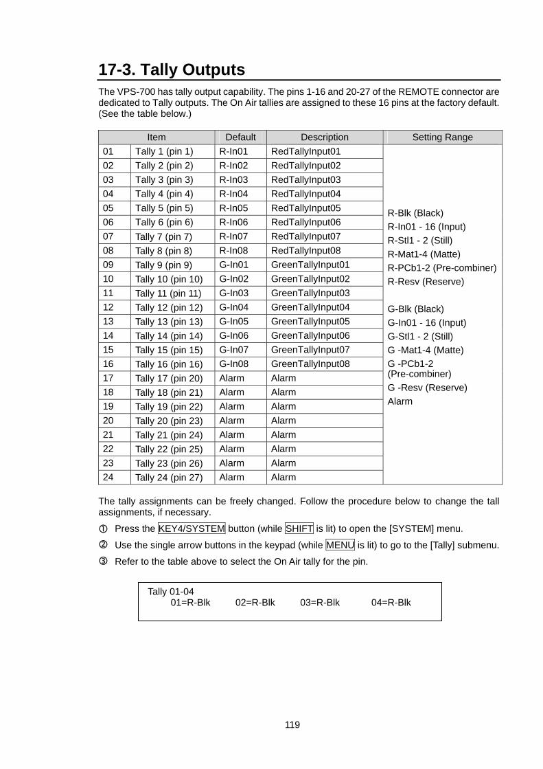
119
17-3. Tally Outputs The VPS-700 has tally output capability. The pins 1-16 and 20-27 of the REMOTE connector are dedicated to Tally outputs. The On Air tallies are assigned to these 16 pins at the factory default. (See the table below.)
Item Default Description Setting Range 01 Tally 1 (pin 1) R-In01 RedTallyInput01 02 Tally 2 (pin 2) R-In02 RedTallyInput02 03 Tally 3 (pin 3) R-In03 RedTallyInput03 04 Tally 4 (pin 4) R-In04 RedTallyInput04 05 Tally 5 (pin 5) R-In05 RedTallyInput05 06 Tally 6 (pin 6) R-In06 RedTallyInput06 07 Tally 7 (pin 7) R-In07 RedTallyInput07 08 Tally 8 (pin 8) R-In08 RedTallyInput08 09 Tally 9 (pin 9) G-In01 GreenTallyInput01 10 Tally 10 (pin 10) G-In02 GreenTallyInput02 11 Tally 11 (pin 11) G-In03 GreenTallyInput03 12 Tally 12 (pin 12) G-In04 GreenTallyInput04 13 Tally 13 (pin 13) G-In05 GreenTallyInput05 14 Tally 14 (pin 14) G-In06 GreenTallyInput06 15 Tally 15 (pin 15) G-In07 GreenTallyInput07 16 Tally 16 (pin 16) G-In08 GreenTallyInput08 17 Tally 17 (pin 20) Alarm Alarm 18 Tally 18 (pin 21) Alarm Alarm 19 Tally 19 (pin 22) Alarm Alarm 20 Tally 20 (pin 23) Alarm Alarm 21 Tally 21 (pin 24) Alarm Alarm 22 Tally 22 (pin 25) Alarm Alarm 23 Tally 23 (pin 26) Alarm Alarm 24 Tally 24 (pin 27) Alarm Alarm
R-Blk (Black) R-In01 - 16 (Input) R-Stl1 - 2 (Still) R-Mat1-4 (Matte) R-PCb1-2 (Pre-combiner)R-Resv (Reserve) G-Blk (Black) G-In01 - 16 (Input) G-Stl1 - 2 (Still) G -Mat1-4 (Matte) G -PCb1-2 (Pre-combiner) G -Resv (Reserve) Alarm
The tally assignments can be freely changed. Follow the procedure below to change the tall assignments, if necessary.
Press the KEY4/SYSTEM button (while SHIFT is lit) to open the [SYSTEM] menu.
Use the single arrow buttons in the keypad (while MENU is lit) to go to the [Tally] submenu.
Refer to the table above to select the On Air tally for the pin.
Tally 01-04 01=R-Blk 02=R-Blk 03=R-Blk 04=R-Blk
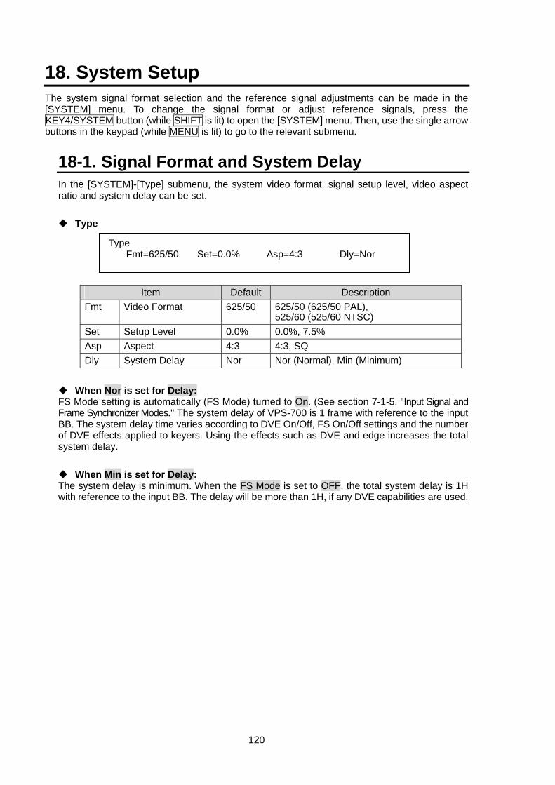
120
18. System Setup The system signal format selection and the reference signal adjustments can be made in the [SYSTEM] menu. To change the signal format or adjust reference signals, press the KEY4/SYSTEM button (while SHIFT is lit) to open the [SYSTEM] menu. Then, use the single arrow buttons in the keypad (while MENU is lit) to go to the relevant submenu.
18-1. Signal Format and System Delay In the [SYSTEM]-[Type] submenu, the system video format, signal setup level, video aspect ratio and system delay can be set.
Type
Item Default Description Fmt Video Format 625/50 625/50 (625/50 PAL),
525/60 (525/60 NTSC) Set Setup Level 0.0% 0.0%, 7.5% Asp Aspect 4:3 4:3, SQ Dly System Delay Nor Nor (Normal), Min (Minimum)
When Nor is set for Delay: FS Mode setting is automatically (FS Mode) turned to On. (See section 7-1-5. "Input Signal and Frame Synchronizer Modes." The system delay of VPS-700 is 1 frame with reference to the input BB. The system delay time varies according to DVE On/Off, FS On/Off settings and the number of DVE effects applied to keyers. Using the effects such as DVE and edge increases the total system delay.
When Min is set for Delay: The system delay is minimum. When the FS Mode is set to OFF, the total system delay is 1H with reference to the input BB. The delay will be more than 1H, if any DVE capabilities are used.
Type Fmt=625/50 Set=0.0% Asp=4:3 Dly=Nor
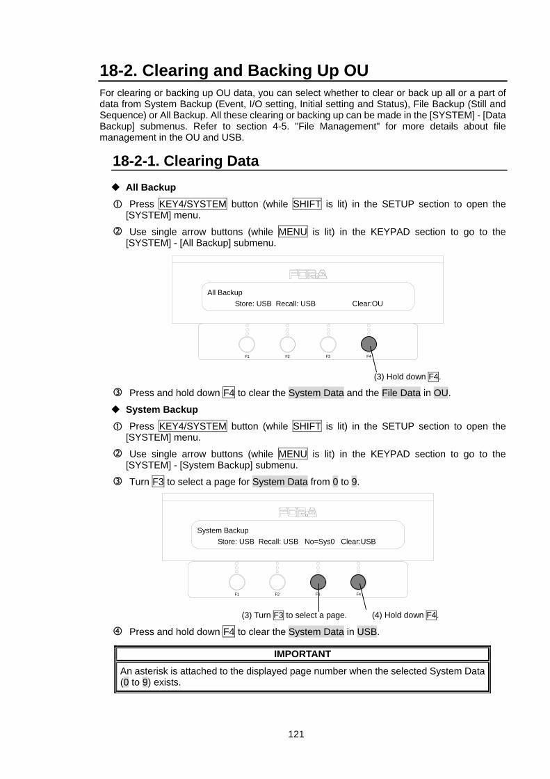
121
18-2. Clearing and Backing Up OU For clearing or backing up OU data, you can select whether to clear or back up all or a part of data from System Backup (Event, I/O setting, Initial setting and Status), File Backup (Still and Sequence) or All Backup. All these clearing or backing up can be made in the [SYSTEM] - [Data Backup] submenus. Refer to section 4-5. "File Management" for more details about file management in the OU and USB.
18-2-1. Clearing Data All Backup
Press KEY4/SYSTEM button (while SHIFT is lit) in the SETUP section to open the [SYSTEM] menu.
Use single arrow buttons (while MENU is lit) in the KEYPAD section to go to the [SYSTEM] - [All Backup] submenu.
Press and hold down F4 to clear the System Data and the File Data in OU.
System Backup
Press KEY4/SYSTEM button (while SHIFT is lit) in the SETUP section to open the [SYSTEM] menu.
Use single arrow buttons (while MENU is lit) in the KEYPAD section to go to the [SYSTEM] - [System Backup] submenu.
Turn F3 to select a page for System Data from 0 to 9.
Press and hold down F4 to clear the System Data in USB.
IMPORTANT
An asterisk is attached to the displayed page number when the selected System Data (0 to 9) exists.
F3 F4F2F1
System Backup Store: USB Recall: USB No=Sys0 Clear:USB
(3) Turn F3 to select a page. (4) Hold down F4.
F3 F4F2F1
All Backup Store: USB Recall: USB Clear:OU
(3) Hold down F4.
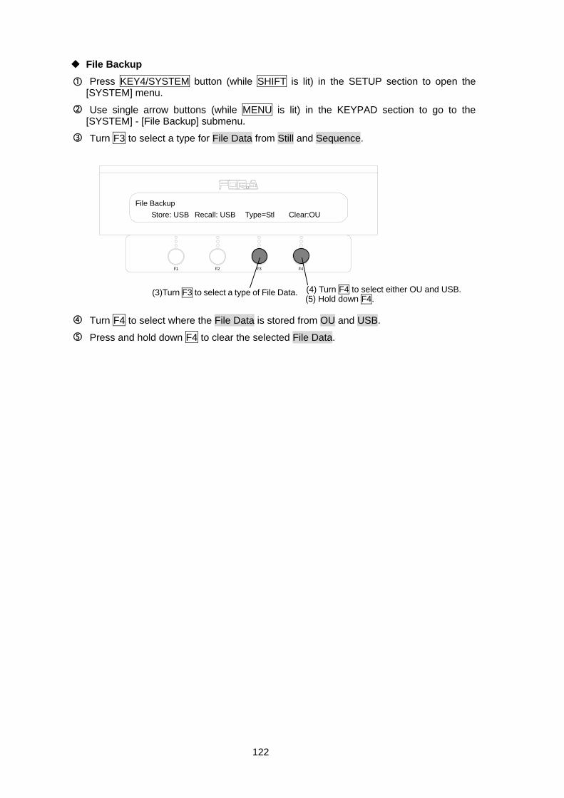
122
File Backup
Press KEY4/SYSTEM button (while SHIFT is lit) in the SETUP section to open the [SYSTEM] menu.
Use single arrow buttons (while MENU is lit) in the KEYPAD section to go to the [SYSTEM] - [File Backup] submenu.
Turn F3 to select a type for File Data from Still and Sequence.
Turn F4 to select where the File Data is stored from OU and USB.
Press and hold down F4 to clear the selected File Data.
F3 F4F2F1
File Backup Store: USB Recall: USB Type=Stl Clear:OU
(3)Turn F3 to select a type of File Data. (4) Turn F4 to select either OU and USB. (5) Hold down F4.
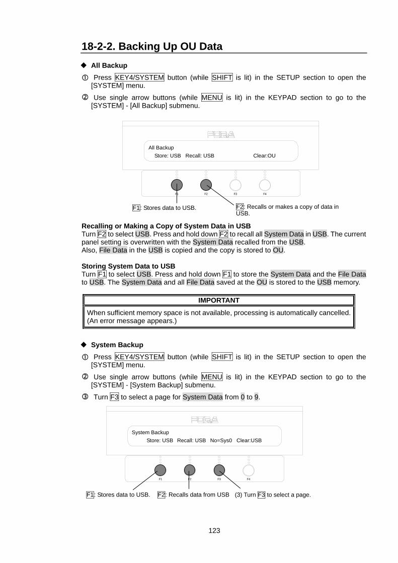
123
18-2-2. Backing Up OU Data All Backup
Press KEY4/SYSTEM button (while SHIFT is lit) in the SETUP section to open the [SYSTEM] menu.
Use single arrow buttons (while MENU is lit) in the KEYPAD section to go to the [SYSTEM] - [All Backup] submenu.
Recalling or Making a Copy of System Data in USB Turn F2 to select USB. Press and hold down F2 to recall all System Data in USB. The current panel setting is overwritten with the System Data recalled from the USB. Also, File Data in the USB is copied and the copy is stored to OU. Storing System Data to USB Turn F1 to select USB. Press and hold down F1 to store the System Data and the File Data to USB. The System Data and all File Data saved at the OU is stored to the USB memory.
IMPORTANT
When sufficient memory space is not available, processing is automatically cancelled. (An error message appears.)
System Backup
Press KEY4/SYSTEM button (while SHIFT is lit) in the SETUP section to open the [SYSTEM] menu.
Use single arrow buttons (while MENU is lit) in the KEYPAD section to go to the [SYSTEM] - [System Backup] submenu.
Turn F3 to select a page for System Data from 0 to 9.
System Backup Store: USB Recall: USB No=Sys0 Clear:USB
F3 F4F2F1
(3) Turn F3 to select a page. F1: Stores data to USB. F2: Recalls data from USB
F3 F4F2F1
All Backup Store: USB Recall: USB Clear:OU
F2: Recalls or makes a copy of data in USB.
F1: Stores data to USB.
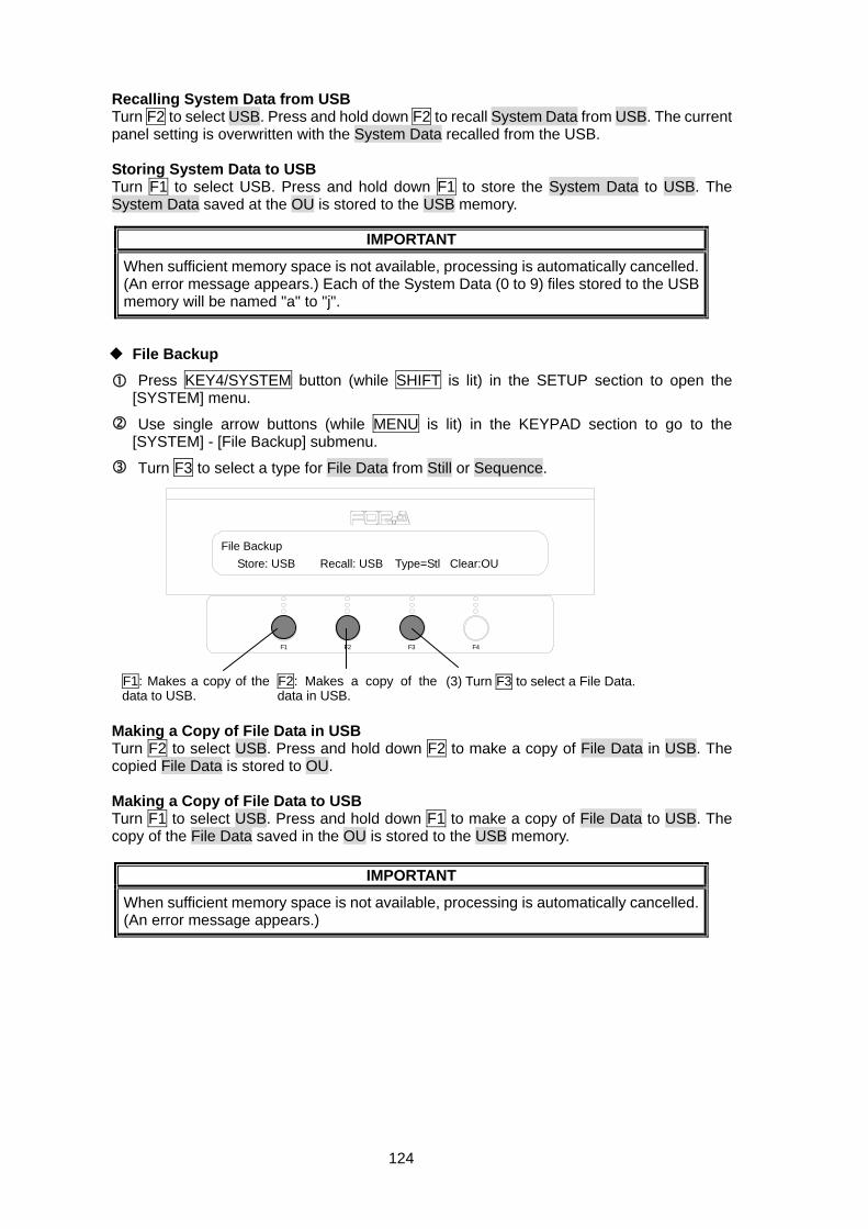
124
Recalling System Data from USB Turn F2 to select USB. Press and hold down F2 to recall System Data from USB. The current panel setting is overwritten with the System Data recalled from the USB. Storing System Data to USB Turn F1 to select USB. Press and hold down F1 to store the System Data to USB. The System Data saved at the OU is stored to the USB memory.
IMPORTANT
When sufficient memory space is not available, processing is automatically cancelled. (An error message appears.) Each of the System Data (0 to 9) files stored to the USB memory will be named "a" to "j".
File Backup
Press KEY4/SYSTEM button (while SHIFT is lit) in the SETUP section to open the [SYSTEM] menu.
Use single arrow buttons (while MENU is lit) in the KEYPAD section to go to the [SYSTEM] - [File Backup] submenu.
Turn F3 to select a type for File Data from Still or Sequence.
Making a Copy of File Data in USB Turn F2 to select USB. Press and hold down F2 to make a copy of File Data in USB. The copied File Data is stored to OU. Making a Copy of File Data to USB Turn F1 to select USB. Press and hold down F1 to make a copy of File Data to USB. The copy of the File Data saved in the OU is stored to the USB memory.
IMPORTANT
When sufficient memory space is not available, processing is automatically cancelled. (An error message appears.)
F3 F4F2F1
File Backup Store: USB Recall: USB Type=Stl Clear:OU
(3) Turn F3 to select a File Data. F1: Makes a copy of the data to USB.
F2: Makes a copy of the data in USB.
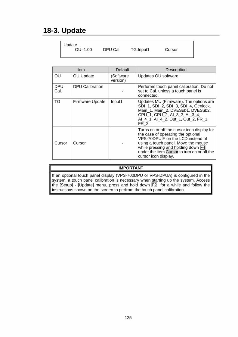
125
18-3. Update
Item Default Description OU OU Update (Software
version) Updates OU software.
DPU Cal.
DPU Calibration -
Performs touch panel calibration. Do not set to Cal. unless a touch panel is connected.
TG Firmware Update Input1 Updates MU (Firmware). The options are SDI_1, SDI_2, SDI_3, SDI_4, Genlock, Main_1, Main_2, DVESub1, DVESub2, CPU_1, CPU_2, AI_3_3, AI_3_4, AI_4_1, AI_4_2, Out_1, Out_2, FR_1, FR_2.
Cursor Cursor -
Turns on or off the cursor icon display for the case of operating the optional VPS-70DPUIF on the LCD instead of using a touch panel. Move the mouse while pressing and holding down F4 under the item Cursor to turn on or off the cursor icon display.
IMPORTANT
If an optional touch panel display (VPS-700DPU or VPS-DPUA) is configured in the system, a touch panel calibration is necessary when starting up the system. Access the [Setup] - [Update] menu, press and hold down F2 for a while and follow the instructions shown on the screen to perfrom the touch panel calibration.
Update OU=1.00 DPU Cal. TG:Input1 Cursor
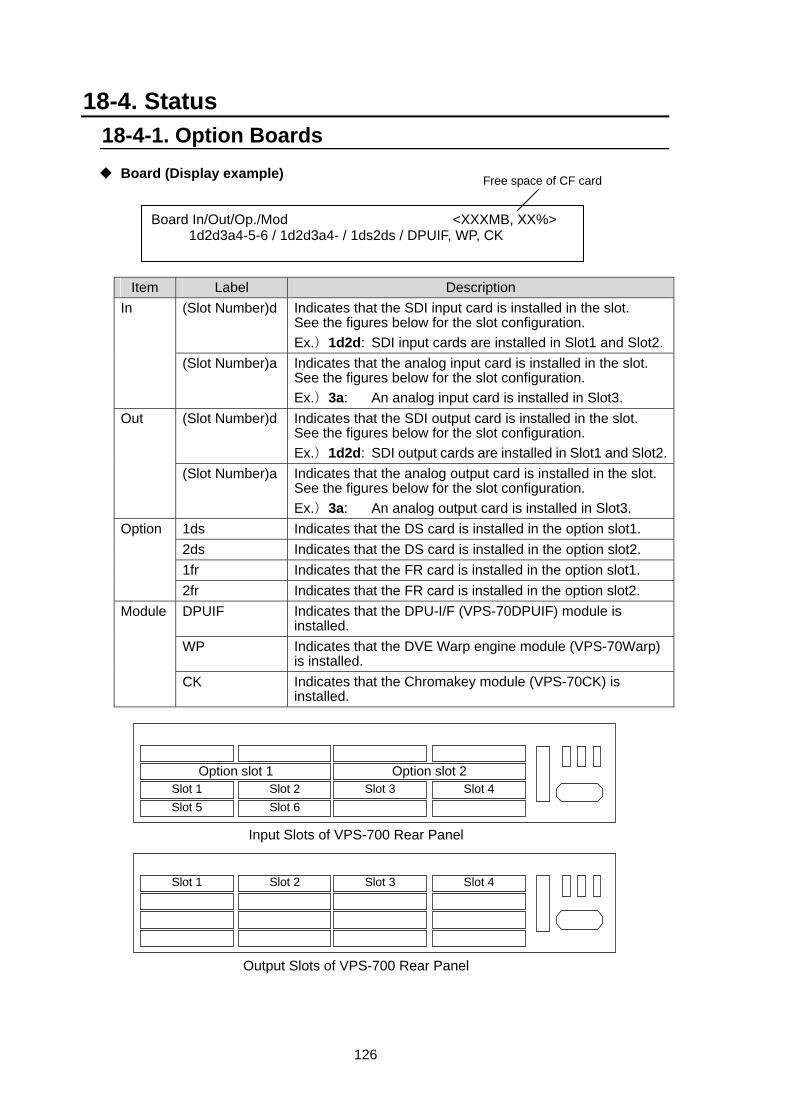
126
18-4. Status 18-4-1. Option Boards
Board (Display example)
Item Label Description (Slot Number)d Indicates that the SDI input card is installed in the slot.
See the figures below for the slot configuration. Ex.)1d2d: SDI input cards are installed in Slot1 and Slot2.
In
(Slot Number)a Indicates that the analog input card is installed in the slot. See the figures below for the slot configuration. Ex.)3a: An analog input card is installed in Slot3.
(Slot Number)d Indicates that the SDI output card is installed in the slot. See the figures below for the slot configuration. Ex.)1d2d: SDI output cards are installed in Slot1 and Slot2.
Out
(Slot Number)a Indicates that the analog output card is installed in the slot. See the figures below for the slot configuration. Ex.)3a: An analog output card is installed in Slot3.
1ds Indicates that the DS card is installed in the option slot1. 2ds Indicates that the DS card is installed in the option slot2. 1fr Indicates that the FR card is installed in the option slot1.
Option
2fr Indicates that the FR card is installed in the option slot2. DPUIF Indicates that the DPU-I/F (VPS-70DPUIF) module is
installed. WP Indicates that the DVE Warp engine module (VPS-70Warp)
is installed.
Module
CK Indicates that the Chromakey module (VPS-70CK) is installed.
Board In/Out/Op./Mod <XXXMB, XX%> 1d2d3a4-5-6 / 1d2d3a4- / 1ds2ds / DPUIF, WP, CK
Free space of CF card
Option slot 2Option slot 1
Input Slots of VPS-700 Rear Panel
Output Slots of VPS-700 Rear Panel
Slot 1 Slot 5
Slot 2 Slot 6
Slot 3 Slot 4
Slot 1
Slot 2
Slot 3 Slot 4
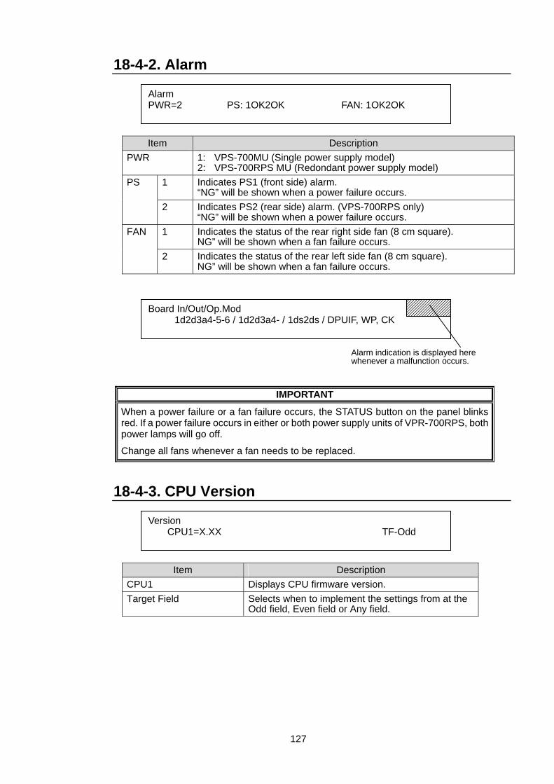
127
18-4-2. Alarm
Item Description PWR 1: VPS-700MU (Single power supply model)
2: VPS-700RPS MU (Redondant power supply model) 1 Indicates PS1 (front side) alarm.
“NG” will be shown when a power failure occurs. PS
2 Indicates PS2 (rear side) alarm. (VPS-700RPS only) “NG” will be shown when a power failure occurs.
1 Indicates the status of the rear right side fan (8 cm square). NG” will be shown when a fan failure occurs.
FAN
2 Indicates the status of the rear left side fan (8 cm square). NG” will be shown when a fan failure occurs.
IMPORTANT
When a power failure or a fan failure occurs, the STATUS button on the panel blinks red. If a power failure occurs in either or both power supply units of VPR-700RPS, both power lamps will go off.
Change all fans whenever a fan needs to be replaced.
18-4-3. CPU Version
Item Description CPU1 Displays CPU firmware version. Target Field Selects when to implement the settings from at the
Odd field, Even field or Any field.
Alarm PWR=2 PS: 1OK2OK FAN: 1OK2OK
Board In/Out/Op.Mod 1d2d3a4-5-6 / 1d2d3a4- / 1ds2ds / DPUIF, WP, CK
Alarm indication is displayed here whenever a malfunction occurs.
Version CPU1=X.XX TF-Odd
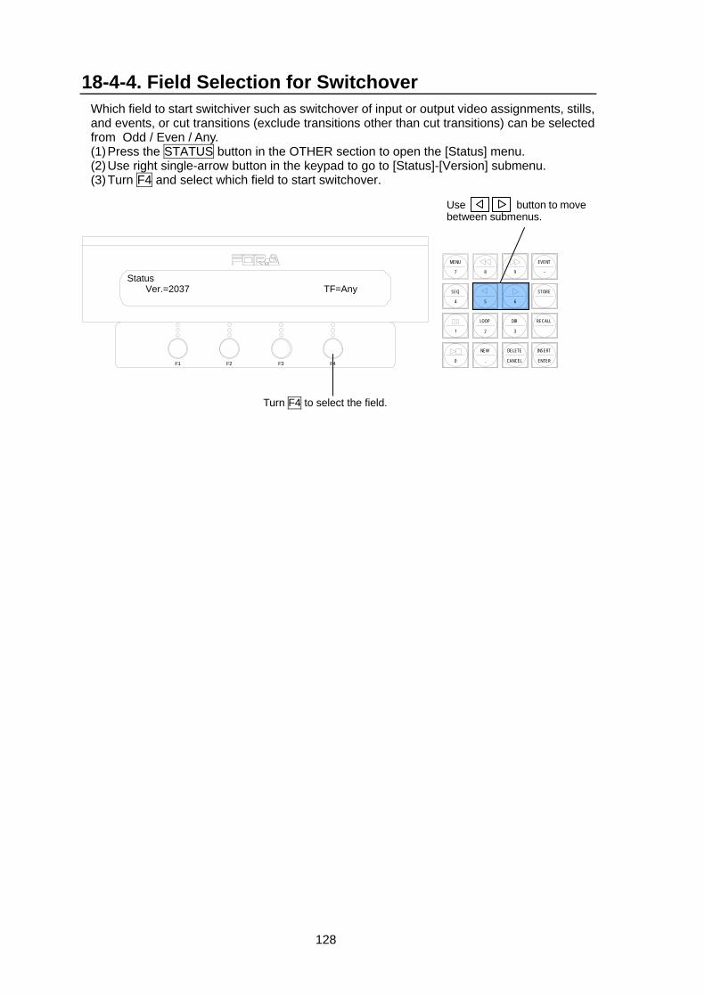
128
18-4-4. Field Selection for Switchover Which field to start switchiver such as switchover of input or output video assignments, stills, and events, or cut transitions (exclude transitions other than cut transitions) can be selected from Odd / Even / Any. (1) Press the STATUS button in the OTHER section to open the [Status] menu. (2) Use right single-arrow button in the keypad to go to [Status]-[Version] submenu. (3) Turn F4 and select which field to start switchover.
Use button to move between submenus.
Status Ver.=2037 TF=Any
Turn F4 to select the field.
F3 F4F2F1
EVENT
-
RECALL
2 3
8 97
MENU
SEQ
1
STORE
65
LOOP DIR
4
INSERT
ENTER
DELETE
CANCEL
NEW
.0
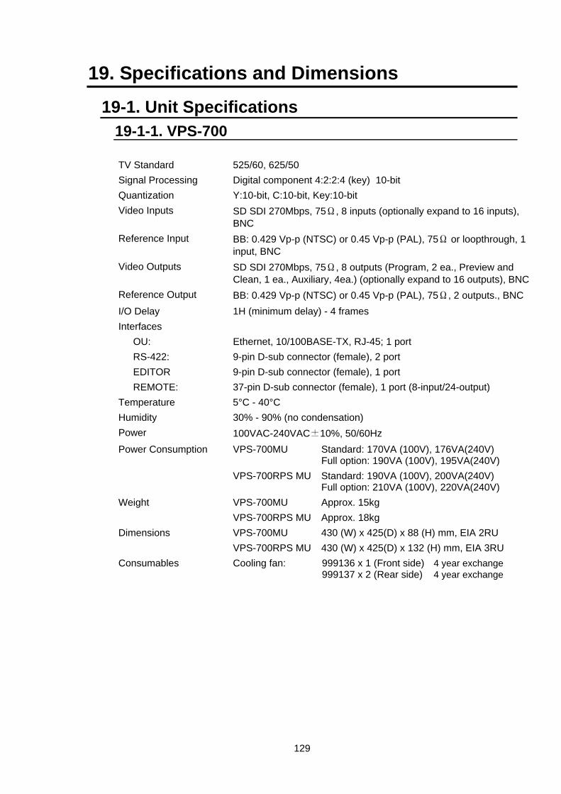
129
19. Specifications and Dimensions
19-1. Unit Specifications 19-1-1. VPS-700 TV Standard 525/60, 625/50 Signal Processing Digital component 4:2:2:4 (key) 10-bit Quantization Y:10-bit, C:10-bit, Key:10-bit Video Inputs SD SDI 270Mbps, 75Ω, 8 inputs (optionally expand to 16 inputs),
BNC Reference Input BB: 0.429 Vp-p (NTSC) or 0.45 Vp-p (PAL), 75Ω or loopthrough, 1
input, BNC Video Outputs SD SDI 270Mbps, 75Ω, 8 outputs (Program, 2 ea., Preview and
Clean, 1 ea., Auxiliary, 4ea.) (optionally expand to 16 outputs), BNCReference Output BB: 0.429 Vp-p (NTSC) or 0.45 Vp-p (PAL), 75Ω, 2 outputs., BNC I/O Delay 1H (minimum delay) - 4 frames Interfaces OU: Ethernet, 10/100BASE-TX, RJ-45; 1 port RS-422: 9-pin D-sub connector (female), 2 port EDITOR 9-pin D-sub connector (female), 1 port REMOTE: 37-pin D-sub connector (female), 1 port (8-input/24-output) Temperature 5°C - 40°C Humidity 30% - 90% (no condensation) Power 100VAC-240VAC±10%, 50/60Hz Power Consumption VPS-700MU Standard: 170VA (100V), 176VA(240V)
Full option: 190VA (100V), 195VA(240V) VPS-700RPS MU Standard: 190VA (100V), 200VA(240V)
Full option: 210VA (100V), 220VA(240V) Weight VPS-700MU Approx. 15kg VPS-700RPS MU Approx. 18kg Dimensions VPS-700MU 430 (W) x 425(D) x 88 (H) mm, EIA 2RU VPS-700RPS MU 430 (W) x 425(D) x 132 (H) mm, EIA 3RU Consumables Cooling fan: 999136 x 1 (Front side) 4 year exchange
999137 x 2 (Rear side) 4 year exchange
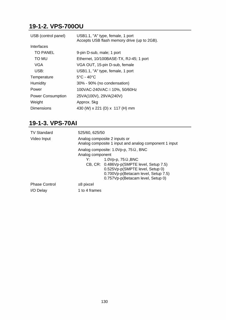
130
19-1-2. VPS-700OU USB (control panel) USB1.1, "A" type, female, 1 port
Accepts USB flash memory drive (up to 2GB). Interfaces TO PANEL 9-pin D-sub, male; 1 port TO MU Ethernet, 10/100BASE-TX, RJ-45; 1 port VGA VGA OUT, 15-pin D-sub, female USB: USB1.1, "A" type, female, 1 port Temperature 5°C - 40°C Humidity 30% - 90% (no condensation) Power 100VAC-240VAC±10%, 50/60Hz Power Consumption 25VA(100V), 29VA(240V) Weight Approx. 5kg Dimensions 430 (W) x 221 (D) x 117 (H) mm
19-1-3. VPS-70AI TV Standard 525/60, 625/50 Video Input Analog composite 2 inputs or
Analog composite 1 input and analog component 1 input Analog composite: 1.0Vp-p, 75Ω, BNC
Analog component Y: 1.0Vp-p, 75Ω,BNC CB, CR: 0.486Vp-p(SMPTE level, Setup 7.5) 0.525Vp-p(SMPTE level, Setup 0) 0.700Vp-p(Betacam level, Setup 7.5) 0.757Vp-p(Betacam level, Setup 0)
Phase Control ±8 pixcel I/O Delay 1 to 4 frames
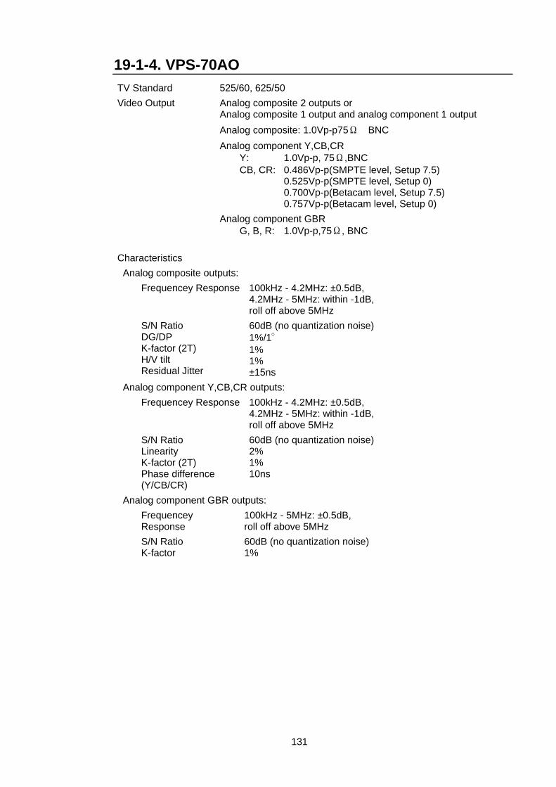
131
19-1-4. VPS-70AO TV Standard 525/60, 625/50 Video Output Analog composite 2 outputs or
Analog composite 1 output and analog component 1 output Analog composite: 1.0Vp-p75Ω BNC
Analog component Y,CB,CR Y: 1.0Vp-p, 75Ω,BNC CB, CR: 0.486Vp-p(SMPTE level, Setup 7.5) 0.525Vp-p(SMPTE level, Setup 0) 0.700Vp-p(Betacam level, Setup 7.5) 0.757Vp-p(Betacam level, Setup 0) Analog component GBR G, B, R: 1.0Vp-p,75Ω, BNC
Characteristics Analog composite outputs: Frequencey Response 100kHz - 4.2MHz: ±0.5dB,
4.2MHz - 5MHz: within -1dB, roll off above 5MHz
S/N Ratio DG/DP K-factor (2T) H/V tilt Residual Jitter
60dB (no quantization noise) 1%/1° 1% 1% ±15ns
Analog component Y,CB,CR outputs: Frequencey Response 100kHz - 4.2MHz: ±0.5dB,
4.2MHz - 5MHz: within -1dB, roll off above 5MHz
S/N Ratio Linearity K-factor (2T) Phase difference (Y/CB/CR)
60dB (no quantization noise) 2% 1% 10ns
Analog component GBR outputs: Frequencey
Response 100kHz - 5MHz: ±0.5dB, roll off above 5MHz
S/N Ratio K-factor
60dB (no quantization noise) 1%
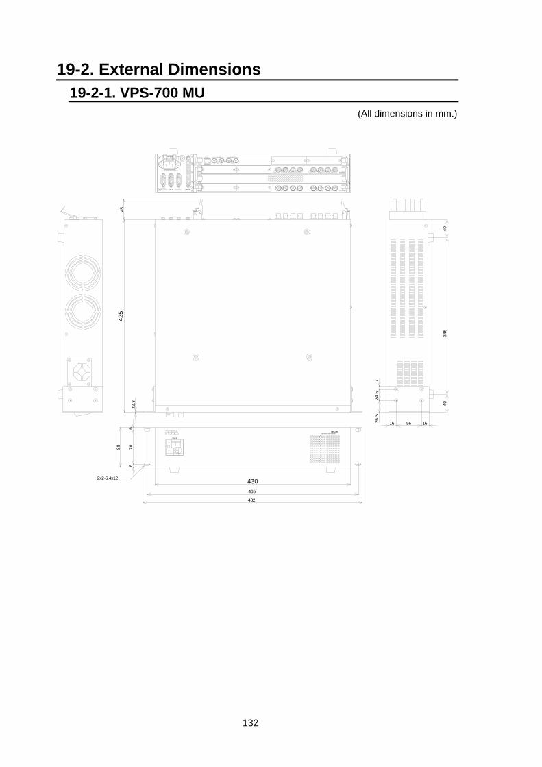
132
19-2. External Dimensions 19-2-1. VPS-700 MU
(All dimensions in mm.)
POWER
ON
OFF
2x2-6.4x12
676
6t2
.3
425
430465
482
16 56 1626.5
24.5
7
4034
540
8845
VPS-700VIDEO PRODUCTION SYSYTEM
VIDEO IN
PGM 1AUX2 PGM 2AUX1 CLEANAUX4 PREVAUX3 VIDEO OUT
4
3
2
1
2
1
TO OU
2
GENLOCK INBB OUT
4
3
REMOTE1
SER.NO.
1EDITOR 2RS-422
AC100-240V 50/60Hz IN
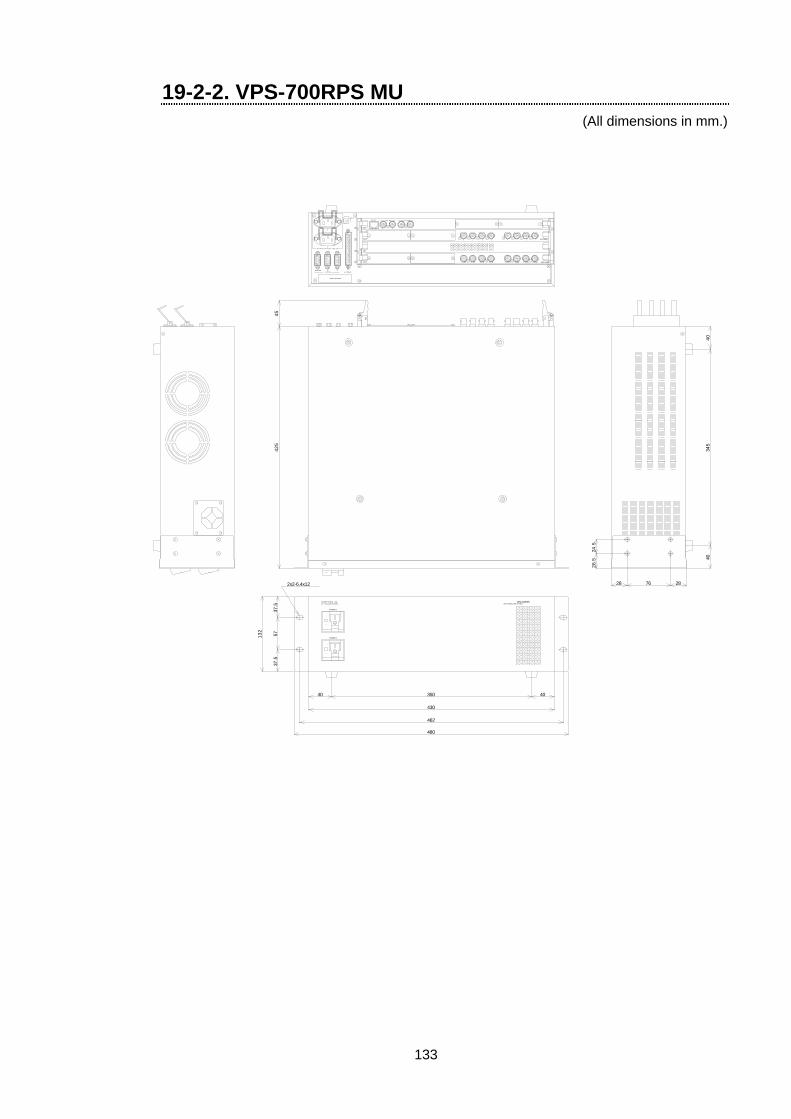
133
19-2-2. VPS-700RPS MU (All dimensions in mm.)
2x2-6.4x12
ON
OFF
ON
OFF
40 350 40
430
462
480
37.5
5737
.5
132
28 76 28
26.5
24.5
425
4034
540
45
VPS-700RPSVIDEO PRODUCTION SYSTEM
POWER 1
POWER 2
VIDEO OUT
12345678
1
GENLOCK INBB OUTTO OU
VIDEO IN
PGM 1PGM 2PREVAUX1AUX2AUX3 CLEANAUX4
24
3
2
3
4
2
1 1
AC 100 - 240 V 50 / 60 Hz IN
RATING LABEL
REMOTERS-422EDITOR
2
12
1
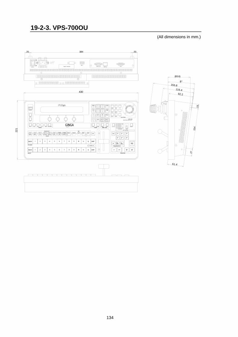
134
19-2-3. VPS-700OU (All dimensions in mm.)
OFF
ONON
OFF
USBVGATO MUTO PANEL
VIDEO PRODUCTION SYSTEMVPS-700
JOYSTICK
DSK
X
Y
Z
KEY LAYER
KEY STATUS
HIGH
1 2 3 44321 LOW
1 2 3434
2
1 2
1 OVER 2 PRIORITY
1
RATING LABEL
430
221
61.4
92.2
116.4
155.8
(83.6)
20 384 20
1515
427
8°
AC100 - 200V 50/60Hz INPOWER
AUTO CK
DVE POS
WIPE POS
DVE ROT
FINEDEFAULT
STORESEQ
MENU
LOOP RECALL2 3
DIR
4 5 6
7 8
0
9 -
EVENT
.NEW
1
KEY2
KEY1
AUTO
BLACKTRANS
BKGD
CUT
DVE(NAM)
WIPE(FAM)MIX
KEY3
KEY4
DSK2
DSK1
DSKMIX
DSKCUT
TRANSITION TYPE
TRANSITION
PREV TRANS
DIRECTIONFADERREVERSESEQ LINK NOR/REVFADER LIMIT
INSERT
ENTER
DELETE
CANCEL
SETUP
BORDERBASICEVENT
BUS SELECT
STATUS
F1 F2 F4F3
SYSTEMKEY1
SHIFTCOMB B
SEQCOMB A
MATTEDSK2STILL
DSK1KEY4AUX
KEY3
109876542 123
3 5BLACK 1 112 8
SHIFT
124 109 SHIFT76
BLACK 1 11
KEYER
USB MEMORY
EDGE SHADOW
GPI
EDITOR
COMBINER SETUP
KEY ON EXT SELF MASKCK
PROGRAM
PRESET
DVE
INPUTSUB EFF LIGHTWARPKEY2
GINGAMULTI LAYERING
VIDEO PRODUCTION SYSTEM
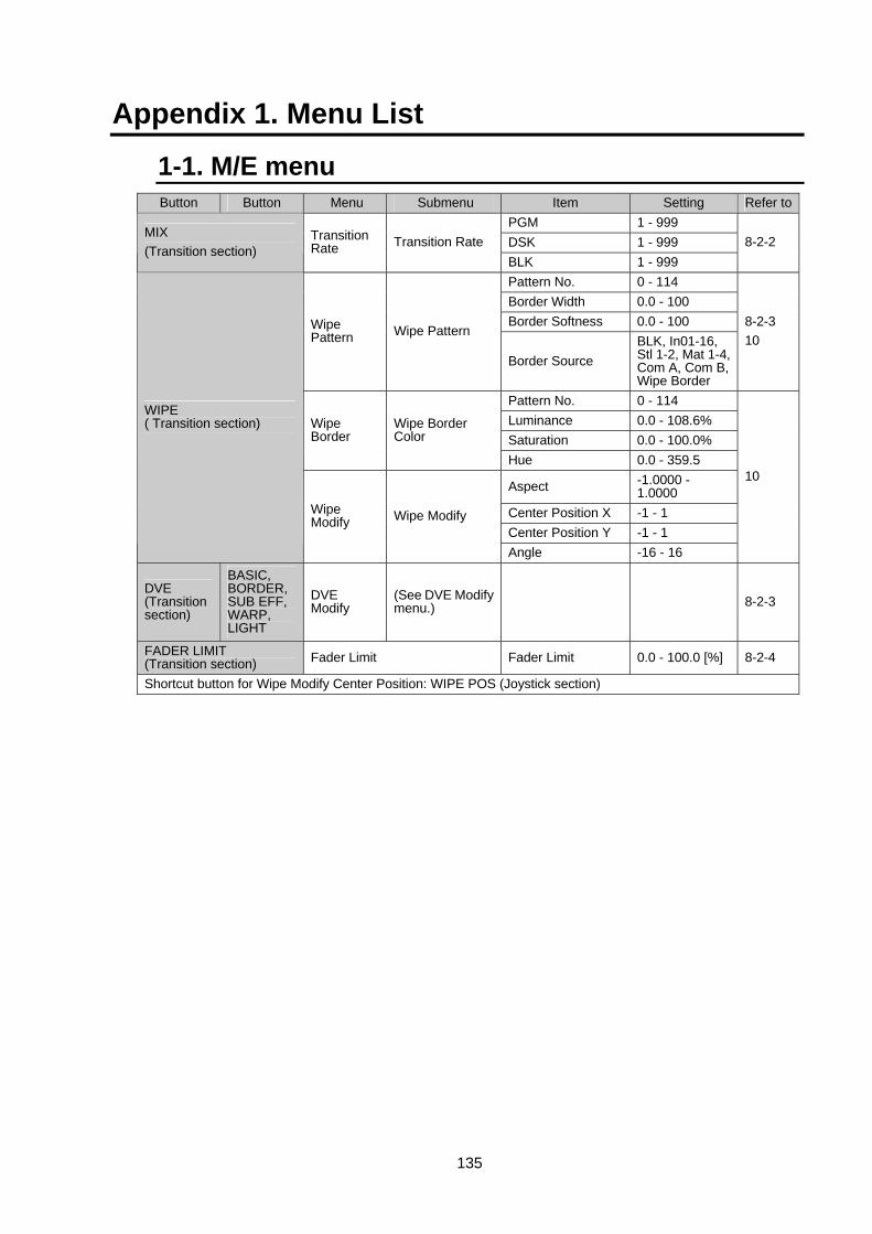
135
Appendix 1. Menu List
1-1. M/E menu Button Button Menu Submenu Item Setting Refer to
PGM 1 - 999 DSK 1 - 999
MIX (Transition section)
Transition Rate Transition Rate
BLK 1 - 999 8-2-2
Pattern No. 0 - 114 Border Width 0.0 - 100 Border Softness 0.0 - 100 Wipe
Pattern Wipe Pattern
Border Source BLK, In01-16, Stl 1-2, Mat 1-4, Com A, Com B, Wipe Border
8-2-3 10
Pattern No. 0 - 114 Luminance 0.0 - 108.6% Saturation 0.0 - 100.0%
Wipe Border
Wipe Border Color
Hue 0.0 - 359.5
Aspect -1.0000 - 1.0000
Center Position X -1 - 1 Center Position Y -1 - 1
WIPE ( Transition section)
Wipe Modify Wipe Modify
Angle -16 - 16
10
DVE (Transition section)
BASIC, BORDER, SUB EFF, WARP, LIGHT
DVE Modify
(See DVE Modify menu.) 8-2-3
FADER LIMIT (Transition section) Fader Limit Fader Limit 0.0 - 100.0 [%] 8-2-4
Shortcut button for Wipe Modify Center Position: WIPE POS (Joystick section)
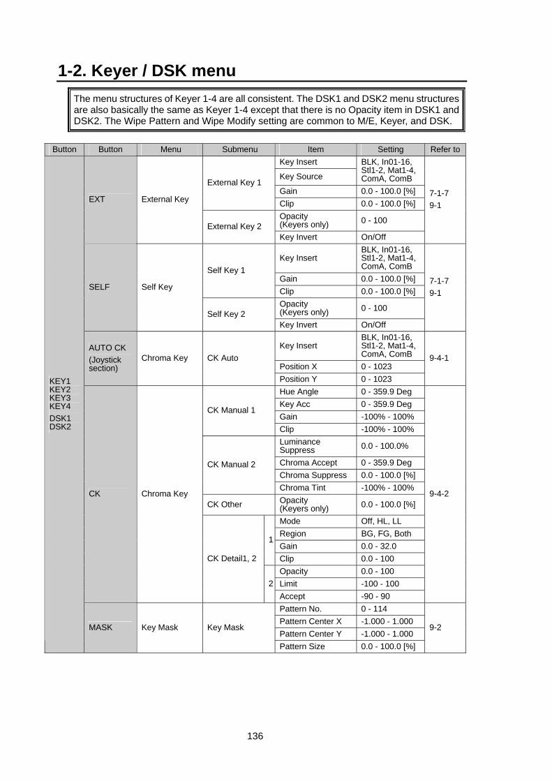
136
1-2. Keyer / DSK menu The menu structures of Keyer 1-4 are all consistent. The DSK1 and DSK2 menu structures are also basically the same as Keyer 1-4 except that there is no Opacity item in DSK1 and DSK2. The Wipe Pattern and Wipe Modify setting are common to M/E, Keyer, and DSK.
Button Button Menu Submenu Item Setting Refer to
Key Insert
Key Source
BLK, In01-16, Stl1-2, Mat1-4, ComA, ComB
Gain 0.0 - 100.0 [%] External Key 1
Clip 0.0 - 100.0 [%] Opacity (Keyers only) 0 - 100
EXT External Key
External Key 2 Key Invert On/Off
7-1-7 9-1
Key Insert BLK, In01-16, Stl1-2, Mat1-4, ComA, ComB
Gain 0.0 - 100.0 [%] Self Key 1
Clip 0.0 - 100.0 [%] Opacity (Keyers only) 0 - 100
SELF Self Key
Self Key 2 Key Invert On/Off
7-1-7 9-1
Key Insert BLK, In01-16, Stl1-2, Mat1-4, ComA, ComB
Position X 0 - 1023
AUTO CK (Joystick section)
Chroma Key CK Auto
Position Y 0 - 1023
9-4-1
Hue Angle 0 - 359.9 Deg Key Acc 0 - 359.9 Deg Gain -100% - 100%
CK Manual 1
Clip -100% - 100% Luminance Suppress 0.0 - 100.0%
Chroma Accept 0 - 359.9 Deg Chroma Suppress 0.0 - 100.0 [%]
CK Manual 2
Chroma Tint -100% - 100%
CK Other Opacity (Keyers only) 0.0 - 100.0 [%]
Mode Off, HL, LL Region BG, FG, Both Gain 0.0 - 32.0
1
Clip 0.0 - 100 Opacity 0.0 - 100 Limit -100 - 100
CK Chroma Key
CK Detail1, 2
2Accept -90 - 90
9-4-2
Pattern No. 0 - 114 Pattern Center X -1.000 - 1.000 Pattern Center Y -1.000 - 1.000
KEY1 KEY2 KEY3 KEY4 DSK1 DSK2
MASK Key Mask Key Mask
Pattern Size 0.0 - 100.0 [%]
9-2
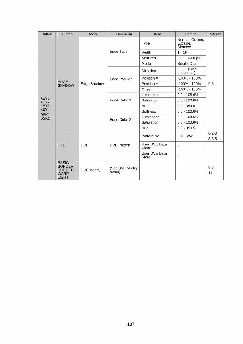
137
Button Button Menu Submenu Item Setting Refer to
Type Normal, Outline, Extrude, Shadow
Width 1 - 15 Softness 0.0 - 100.0 [%]
Edge Type
Mode Single, Dual
Direction 0 - 11 (Clock directions )
Position X -100% - 100% Position Y -100% - 100%
Edge Position
Offset -100% - 100% Luminance 0.0 - 108.6% Saturation 0.0 - 100.0% Edge Color 1 Hue 0.0 - 359.5 Softness 0.0 - 100.0% Luminance 0.0 - 108.6% Saturation 0.0 - 100.0%
EDGE SHADOW Edge Shadow
Edge Color 2
Hue 0.0 - 359.5
9-3
Pattern No. 000 - 252 8-2-3 8-3-5
User DVE Data Clear - DVE DVE DVE Pattern
User DVE Data Store -
KEY1 KEY2 KEY3 KEY4 DSK1 DSK2
BASIC, BORDER, SUB EFF, WARP, LIGHT
DVE Modify (See DVE Modify menu)
9-5 11
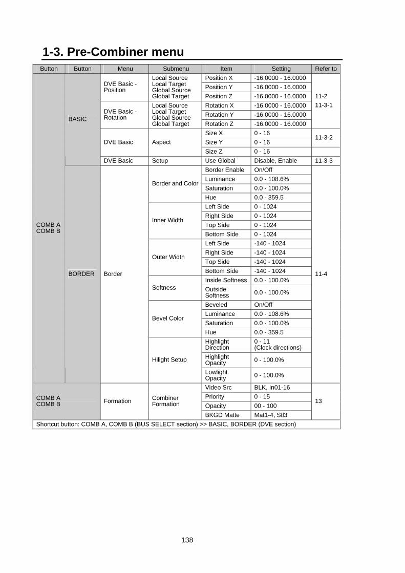
138
1-3. Pre-Combiner menu Button Button Menu Submenu Item Setting Refer to
Position X -16.0000 - 16.0000 Position Y -16.0000 - 16.0000 DVE Basic -
Position
Local Source Local Target Global Source Global Target Position Z -16.0000 - 16.0000
Rotation X -16.0000 - 16.0000 Rotation Y -16.0000 - 16.0000 DVE Basic -
Rotation
Local Source Local Target Global Source Global Target Rotation Z -16.0000 - 16.0000
11-2 11-3-1
Size X 0 - 16 Size Y 0 - 16
11-3-2 DVE Basic Aspect
Size Z 0 - 16
BASIC
DVE Basic Setup Use Global Disable, Enable 11-3-3 Border Enable On/Off Luminance 0.0 - 108.6% Saturation 0.0 - 100.0%
Border and Color
Hue 0.0 - 359.5 Left Side 0 - 1024 Right Side 0 - 1024 Top Side 0 - 1024
Inner Width
Bottom Side 0 - 1024 Left Side -140 - 1024 Right Side -140 - 1024 Top Side -140 - 1024
Outer Width
Bottom Side -140 - 1024 Inside Softness 0.0 - 100.0%
Softness Outside Softness 0.0 - 100.0%
Beveled On/Off Luminance 0.0 - 108.6% Saturation 0.0 - 100.0%
Bevel Color
Hue 0.0 - 359.5 Highlight Direction
0 - 11 (Clock directions)
Highlight Opacity 0 - 100.0%
COMB A COMB B
BORDER Border
Hilight Setup
Lowlight Opacity 0 - 100.0%
11-4
Video Src BLK, In01-16 Priority 0 - 15 Opacity 00 - 100
COMB A COMB B Formation Combiner
Formation
BKGD Matte Mat1-4, Stl3
13
Shortcut button: COMB A, COMB B (BUS SELECT section) >> BASIC, BORDER (DVE section)
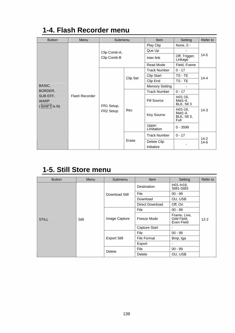
139
1-4. Flash Recorder menu Button Menu Submenu Item Setting Refer to
Play Clip None, 0 - Que Up -
Inter link Off, Trigger, Linkage
Clip Comb-A, Clip Comb-B
Read Mode Field, Frame
14-5
Track Number 0 - 17 Clip Start TS - TE Clip End TS - TE
Clip Set
Memory Setting -
14-4
Track Number 0 - 17
Fill Source In01-16, Mat1-4, BLK, Stl 3
Key Source In01-16, Mat1-4, BLK, Stl 3, Full
Rec
Upper Limitation 0 - 3599
14-3
Track Number 0 - 17
BASIC, BORDER, SUB EFF, WARP ( SHIFT is lit)
Flash Recorder
FR1 Setup, FR2 Setup
Erase Delete Clip Initialize
- 14-2 14-6
1-5. Still Store menu Button Menu Submenu Item Setting Refer to
Destination In01-In16, Still1-Still3
File 00 - 99 Download OU, USB
Download Still
Direct Download Off, On File 00 - 99
Freeze Mode Frame, Live, Odd Field, Even Field
Image Capture
Capture Start - File 00 - 99 File Format Bmp, tga Export Still Export - File 00 - 99
STILL Still
Delete Delete OU, USB
12-2
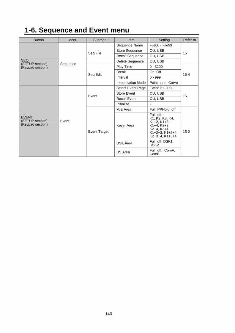
140
1-6. Sequence and Event menu Button Menu Submenu Item Setting Refer to
Sequence Name File00 - File99 Store Sequence OU, USB Recall Sequence OU, USB
Seq File
Delete Sequence OU, USB
16
Play Time 0 - 3200 Break On, Off Interval 0 - 999
SEQ (SETUP section) (Keypad section)
Sequence
Seq Edit
Interpolation Mode Point, Line, Curve
16-4
Select Event Page Event P1 - P8 Store Event OU, USB Recall Event OU, USB
Event
Initialize -
15
M/E Area Full, PPHold, off
Keyer Area
Full, off, K1, K2, K3, K4, K1+2, K1+3, K1+4, K2+3, K2+4, K3+4, K1+2+3, K1+2+4, K2+3+4, K1+3+4
DSK Area Full, off, DSK1, DSK2
EVENT (SETUP section) (Keypad section)
Event
Event Target
DS Area Full, off, ComA, ComB
15-2
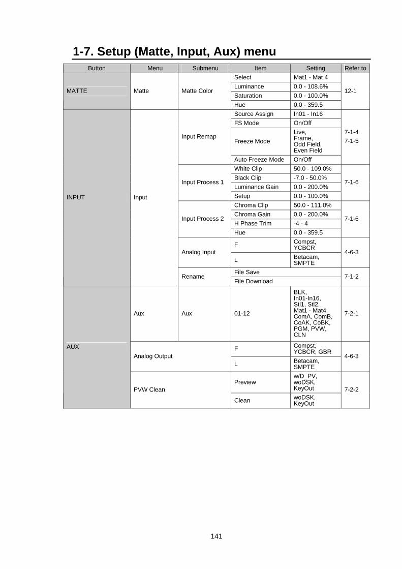
141
1-7. Setup (Matte, Input, Aux) menu Button Menu Submenu Item Setting Refer to
Select Mat1 - Mat 4 Luminance 0.0 - 108.6% Saturation 0.0 - 100.0%
MATTE Matte Matte Color
Hue 0.0 - 359.5
12-1
Source Assign In01 - In16 FS Mode On/Off
Freeze Mode Live, Frame, Odd Field, Even Field
Input Remap
Auto Freeze Mode On/Off
7-1-4 7-1-5
White Clip 50.0 - 109.0% Black Clip -7.0 - 50.0% Luminance Gain 0.0 - 200.0%
Input Process 1
Setup 0.0 - 100.0%
7-1-6
Chroma Clip 50.0 - 111.0% Chroma Gain 0.0 - 200.0% H Phase Trim -4 - 4
Input Process 2
Hue 0.0 - 359.5
7-1-6
F Compst, YCBCR
Analog Input L Betacam,
SMPTE
4-6-3
File Save
INPUT Input
Rename File Download
7-1-2
Aux Aux 01-12
BLK, In01-In16, Stl1, Stl2, Mat1 - Mat4, ComA, ComB, CoAK, CoBK, PGM, PVW, CLN
7-2-1
F Compst, YCBCR, GBR
Analog Output L Betacam,
SMPTE
4-6-3
Preview w/D_PV, woDSK, KeyOut
AUX
PVW Clean
Clean woDSK, KeyOut
7-2-2
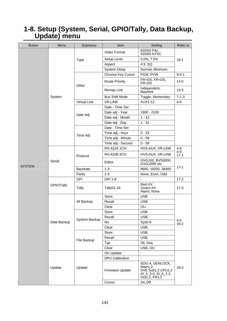
142
1-8. Setup (System, Serial, GPIO/Tally, Data Backup, Update) menu
Button Menu Submenu Item Setting Refer to
Video Format 625/50 PAL, 525/60 NTSC
Setup Level 0.0%, 7.5% Aspect 4:3, SQ
Type
System Delay Normal, Minimum
18-1
Chroma Key Cursor PGM, PVW 9-4-1
Route Priority FR>DS, FR=DS, FR<DS 14-5
Remap Link Independent, Baselink 13-3
Other
Bus Shift Mode Toggle, Momentary 7-1-3 Virtual Link VR-LINK AUX1-12 4-9
Date - Time Set - Date adj - Year 1900 - 2100 Date adj - Month 1 - 12
Date Adj
Date adj - Day 1 - 31 Date - Time Set - Time adj - Hour 0 - 23 Time adj - Minute 0 - 59
System
Time Adj
Time adj - Second 0 - 59 RS-422A 1CH HVS-AUX, VR-LINK
RS-422B 2CH HVS-AUX, VR-LINK
4-8 4-9 17-1 Protocol
Editor GVG100, BVS3000, GVG100R etc
Baudrate 1-3 9600, 19200, 38400
Serial
Parity 1-3 None, Even, Odd
17-1
GPI GPI 1-8 - 17-2
GPIO/Tally Tally Tally01-24
Red-XX Green-XX Alarm, None
17-3
Store USB Recall USB All Backup Clear OU Store USB Recall USB No. Sys0-9
System Backup
Clear USB Store USB Recall USB Typ Stl, Seq
Data Backup
File Backup
Clear USB, OU
4-5 18-2
OU Update - DPU Calibration -
Firmware Update
SDI1-4, GENLOCK, Main1,2, DVE Sub1,2 CPU1,2 AI_3_3-4, AI_4_1-2, Out1,2, FR1,2
SYSTEM
Update Update
Cursor On,Off
18-3
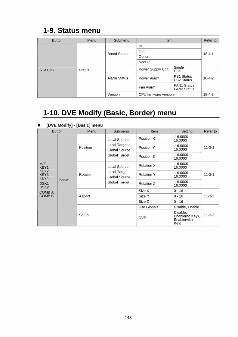
143
1-9. Status menu Button Menu Submenu Item Refer to
In Out Option
Board Status
Module
18-4-1
Power Supply Unit Single Dual
Power Alarm PS1 Status PS2 Status Alarm Status
Fan Alarm FAN1 Status FAN2 Status
18-4-2
STATUS Status
Version CPU firmware version- 18-4-3
1-10. DVE Modify (Basic, Border) menu [DVE Modify] - [Basic] menu
Button Menu Submenu Item Setting Refer to
Position X -16.0000 - 16.0000
Position Y -16.0000 - 16.0000 Position
Local Source Local Target Global Source Global Target Position Z -16.0000 -
16.0000
11-3-1
Rotation X -16.0000 - 16.0000
Rotation Y -16.0000 - 16.0000 Rotation
Local Source Local Target Global Source Global Target Rotation Z -16.0000 -
16.0000
11-3-1
Size X 0 - 16 Size Y 0 - 16 Aspect Size Z 0 - 16
11-3-2
Use Globals Disable, Enable
M/E KEY1 KEY2 KEY3 KEY4 DSK1 DSK2 COMB A COMB B
Basic
Setup DVE
Disable, Enable(no Key),Enable(with Key)
11-3-3
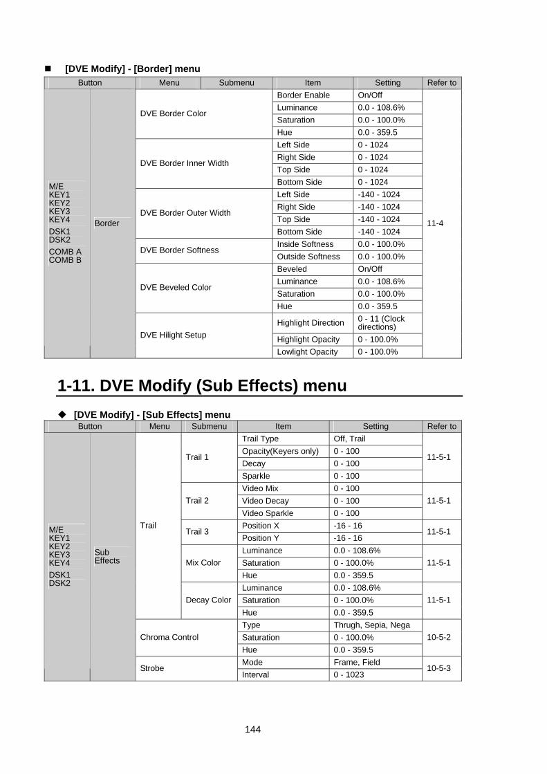
144
[DVE Modify] - [Border] menu Button Menu Submenu Item Setting Refer to
Border Enable On/Off Luminance 0.0 - 108.6% Saturation 0.0 - 100.0%
DVE Border Color
Hue 0.0 - 359.5 Left Side 0 - 1024 Right Side 0 - 1024 Top Side 0 - 1024
DVE Border Inner Width
Bottom Side 0 - 1024 Left Side -140 - 1024 Right Side -140 - 1024 Top Side -140 - 1024
DVE Border Outer Width
Bottom Side -140 - 1024 Inside Softness 0.0 - 100.0%
DVE Border Softness Outside Softness 0.0 - 100.0% Beveled On/Off Luminance 0.0 - 108.6% Saturation 0.0 - 100.0%
DVE Beveled Color
Hue 0.0 - 359.5
Highlight Direction 0 - 11 (Clock directions)
Highlight Opacity 0 - 100.0%
M/E KEY1 KEY2 KEY3 KEY4 DSK1 DSK2 COMB A COMB B
Border
DVE Hilight Setup
Lowlight Opacity 0 - 100.0%
11-4
1-11. DVE Modify (Sub Effects) menu [DVE Modify] - [Sub Effects] menu
Button Menu Submenu Item Setting Refer toTrail Type Off, Trail Opacity(Keyers only) 0 - 100 Decay 0 - 100
Trail 1
Sparkle 0 - 100
11-5-1
Video Mix 0 - 100 Video Decay 0 - 100 Trail 2 Video Sparkle 0 - 100
11-5-1
Position X -16 - 16 Trail 3
Position Y -16 - 16 11-5-1
Luminance 0.0 - 108.6% Saturation 0 - 100.0% Mix Color Hue 0.0 - 359.5
11-5-1
Luminance 0.0 - 108.6% Saturation 0 - 100.0%
Trail
Decay ColorHue 0.0 - 359.5
11-5-1
Type Thrugh, Sepia, Nega Saturation 0 - 100.0% Chroma Control Hue 0.0 - 359.5
10-5-2
Mode Frame, Field
M/E KEY1 KEY2 KEY3 KEY4 DSK1 DSK2
Sub Effects
Strobe Interval 0 - 1023
10-5-3
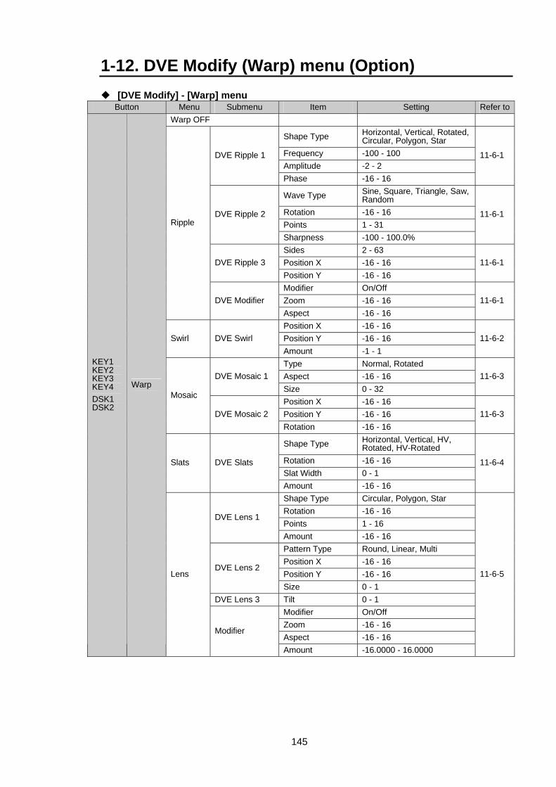
145
1-12. DVE Modify (Warp) menu (Option) [DVE Modify] - [Warp] menu Button Menu Submenu Item Setting Refer to
Warp OFF
Shape Type Horizontal, Vertical, Rotated, Circular, Polygon, Star
Frequency -100 - 100 Amplitude -2 - 2
DVE Ripple 1
Phase -16 - 16
11-6-1
Wave Type Sine, Square, Triangle, Saw, Random
Rotation -16 - 16 Points 1 - 31
DVE Ripple 2
Sharpness -100 - 100.0%
11-6-1
Sides 2 - 63 Position X -16 - 16 DVE Ripple 3 Position Y -16 - 16
11-6-1
Modifier On/Off Zoom -16 - 16
Ripple
DVE Modifier Aspect -16 - 16
11-6-1
Position X -16 - 16 Position Y -16 - 16 Swirl DVE Swirl Amount -1 - 1
11-6-2
Type Normal, Rotated Aspect -16 - 16 DVE Mosaic 1 Size 0 - 32
11-6-3
Position X -16 - 16 Position Y -16 - 16
Mosaic
DVE Mosaic 2 Rotation -16 - 16
11-6-3
Shape Type Horizontal, Vertical, HV, Rotated, HV-Rotated
Rotation -16 - 16 Slat Width 0 - 1
Slats DVE Slats
Amount -16 - 16
11-6-4
Shape Type Circular, Polygon, Star Rotation -16 - 16 Points 1 - 16
DVE Lens 1
Amount -16 - 16 Pattern Type Round, Linear, Multi Position X -16 - 16 Position Y -16 - 16
DVE Lens 2
Size 0 - 1 DVE Lens 3 Tilt 0 - 1
Modifier On/Off Zoom -16 - 16 Aspect -16 - 16
KEY1 KEY2 KEY3 KEY4 DSK1 DSK2
Warp
Lens
Modifier
Amount -16.0000 - 16.0000
11-6-5
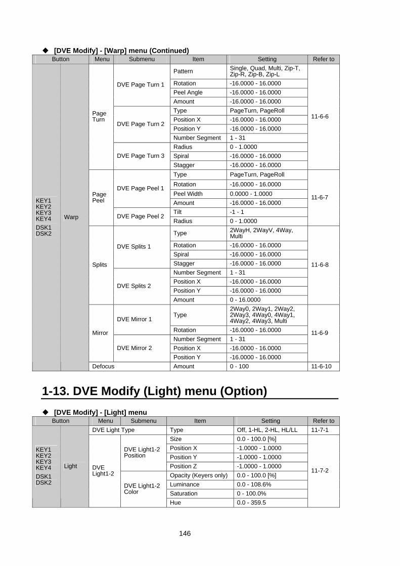
146
[DVE Modify] - [Warp] menu (Continued) Button Menu Submenu Item Setting Refer to
Pattern Single, Quad, Multi, Zip-T, Zip-R, Zip-B, Zip-L
Rotation -16.0000 - 16.0000 Peel Angle -16.0000 - 16.0000
DVE Page Turn 1
Amount -16.0000 - 16.0000 Type PageTurn, PageRoll Position X -16.0000 - 16.0000 Position Y -16.0000 - 16.0000
DVE Page Turn 2
Number Segment 1 - 31 Radius 0 - 1.0000 Spiral -16.0000 - 16.0000
Page Turn
DVE Page Turn 3 Stagger -16.0000 - 16.0000
11-6-6
Type PageTurn, PageRoll Rotation -16.0000 - 16.0000 Peel Width 0.0000 - 1.0000
DVE Page Peel 1
Amount -16.0000 - 16.0000 Tilt -1 - 1
Page Peel
DVE Page Peel 2 Radius 0 - 1.0000
11-6-7
Type 2WayH, 2WayV, 4Way, Multi
Rotation -16.0000 - 16.0000 Spiral -16.0000 - 16.0000
DVE Splits 1
Stagger -16.0000 - 16.0000 Number Segment 1 - 31 Position X -16.0000 - 16.0000 Position Y -16.0000 - 16.0000
Splits
DVE Splits 2
Amount 0 - 16.0000
11-6-8
Type 2Way0, 2Way1, 2Way2, 2Way3, 4Way0, 4Way1, 4Way2, 4Way3, Multi DVE Mirror 1
Rotation -16.0000 - 16.0000 Number Segment 1 - 31 Position X -16.0000 - 16.0000
Mirror
DVE Mirror 2 Position Y -16.0000 - 16.0000
11-6-9
KEY1 KEY2 KEY3 KEY4 DSK1 DSK2
Warp
Defocus Amount 0 - 100 11-6-10
1-13. DVE Modify (Light) menu (Option) [DVE Modify] - [Light] menu Button Menu Submenu Item Setting Refer to
DVE Light Type Type Off, 1-HL, 2-HL, HL/LL 11-7-1 Size 0.0 - 100.0 [%] Position X -1.0000 - 1.0000 Position Y -1.0000 - 1.0000
DVE Light1-2 Position
Position Z -1.0000 - 1.0000 Opacity (Keyers only) 0.0 - 100.0 [%] Luminance 0.0 - 108.6% Saturation 0 - 100.0%
KEY1 KEY2 KEY3 KEY4 DSK1 DSK2
Light DVE Light1-2
DVE Light1-2 Color
Hue 0.0 - 359.5
11-7-2
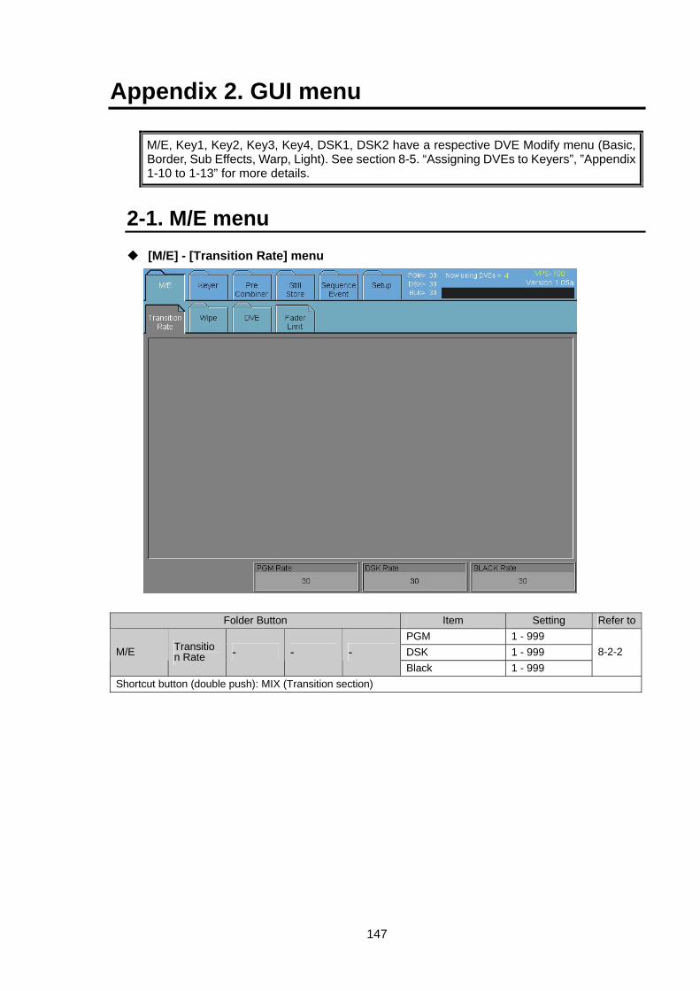
147
Appendix 2. GUI menu
M/E, Key1, Key2, Key3, Key4, DSK1, DSK2 have a respective DVE Modify menu (Basic, Border, Sub Effects, Warp, Light). See section 8-5. “Assigning DVEs to Keyers”, ”Appendix 1-10 to 1-13” for more details.
2-1. M/E menu [M/E] - [Transition Rate] menu
Folder Button Item Setting Refer toPGM 1 - 999 DSK 1 - 999 M/E Transitio
n Rate - - - Black 1 - 999
8-2-2
Shortcut button (double push): MIX (Transition section)
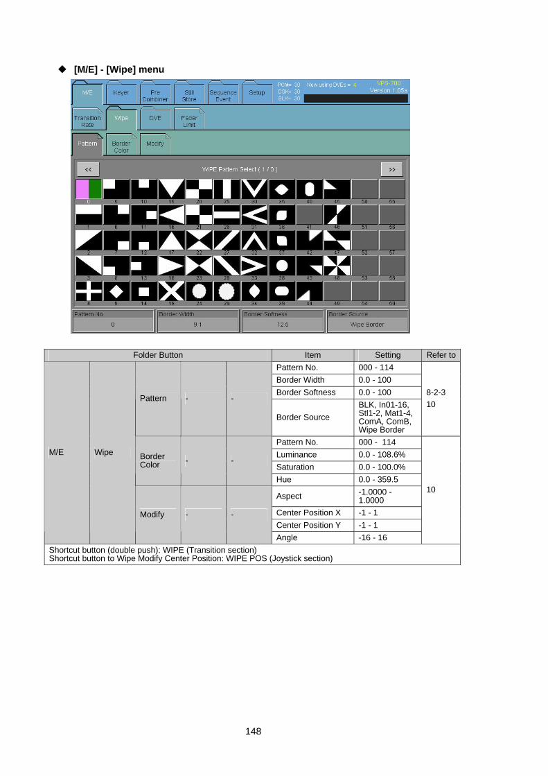
148
[M/E] - [Wipe] menu
Folder Button Item Setting Refer toPattern No. 000 - 114 Border Width 0.0 - 100 Border Softness 0.0 - 100
Pattern - -
Border Source BLK, In01-16, Stl1-2, Mat1-4, ComA, ComB, Wipe Border
8-2-3 10
Pattern No. 000 - 114 Luminance 0.0 - 108.6% Saturation 0.0 - 100.0%
Border Color - -
Hue 0.0 - 359.5
Aspect -1.0000 - 1.0000
Center Position X -1 - 1 Center Position Y -1 - 1
M/E Wipe
Modify - -
Angle -16 - 16
10
Shortcut button (double push): WIPE (Transition section) Shortcut button to Wipe Modify Center Position: WIPE POS (Joystick section)
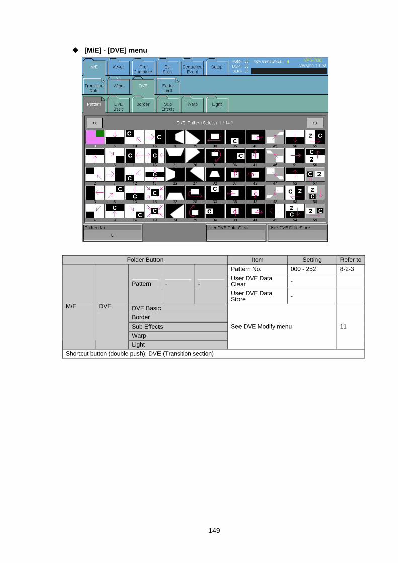
149
[M/E] - [DVE] menu
Folder Button Item Setting Refer toPattern No. 000 - 252 8-2-3 User DVE Data Clear - Pattern - - User DVE Data Store -
DVE Basic Border Sub Effects Warp
M/E DVE
Light
See DVE Modify menu 11
Shortcut button (double push): DVE (Transition section)
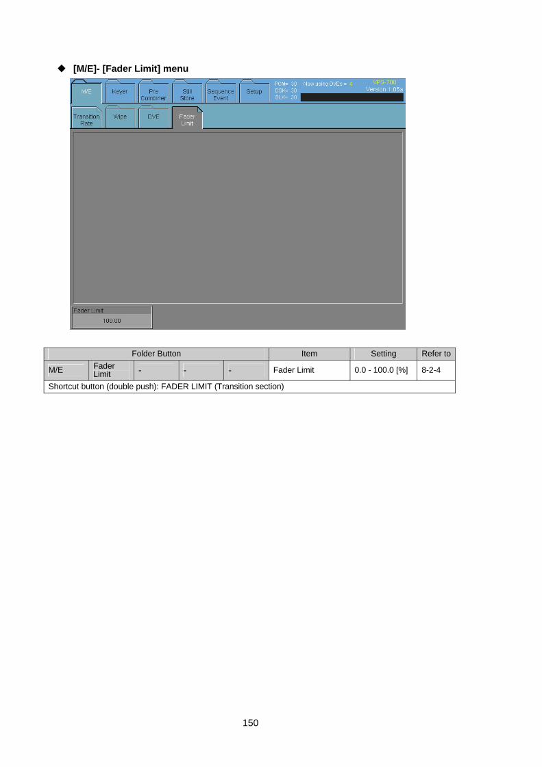
150
[M/E]- [Fader Limit] menu
Folder Button Item Setting Refer to
M/E Fader Limit - - - Fader Limit 0.0 - 100.0 [%] 8-2-4
Shortcut button (double push): FADER LIMIT (Transition section)
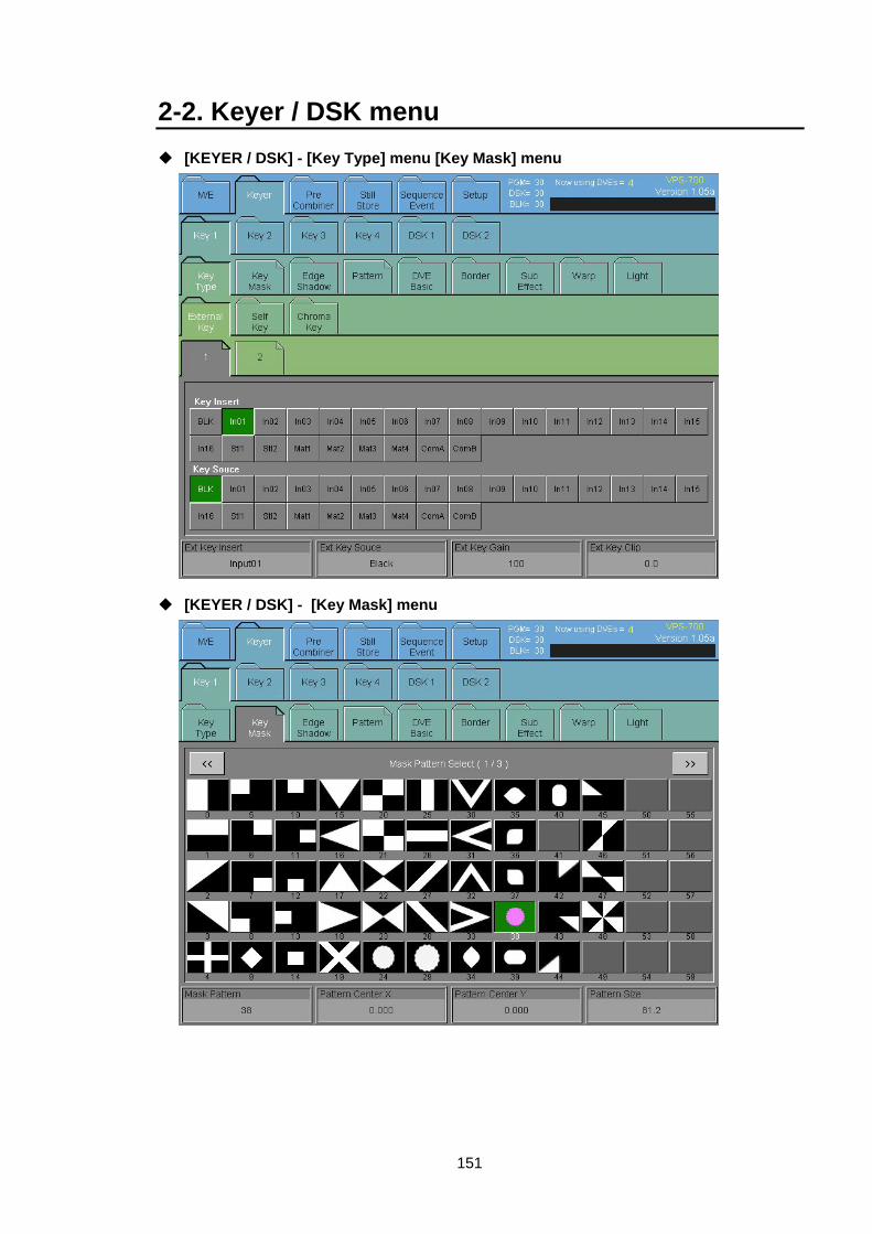
151
2-2. Keyer / DSK menu [KEYER / DSK] - [Key Type] menu [Key Mask] menu
[KEYER / DSK] - [Key Mask] menu
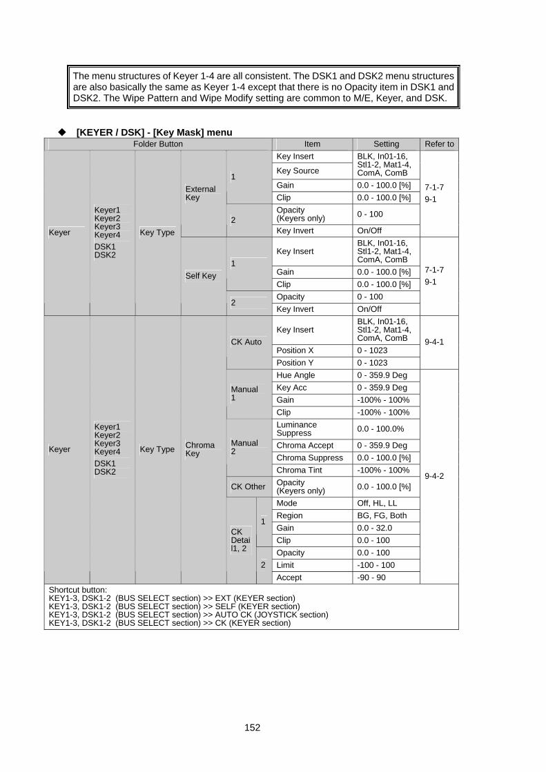
152
The menu structures of Keyer 1-4 are all consistent. The DSK1 and DSK2 menu structures are also basically the same as Keyer 1-4 except that there is no Opacity item in DSK1 and DSK2. The Wipe Pattern and Wipe Modify setting are common to M/E, Keyer, and DSK.
[KEYER / DSK] - [Key Mask] menu Folder Button Item Setting Refer to
Key Insert
Key Source
BLK, In01-16, Stl1-2, Mat1-4, ComA, ComB
Gain 0.0 - 100.0 [%] 1
Clip 0.0 - 100.0 [%] Opacity (Keyers only) 0 - 100
External Key
2 Key Invert On/Off
7-1-7 9-1
Key Insert BLK, In01-16, Stl1-2, Mat1-4, ComA, ComB
Gain 0.0 - 100.0 [%] 1
Clip 0.0 - 100.0 [%] Opacity 0 - 100
Keyer
Keyer1 Keyer2 Keyer3 Keyer4 DSK1 DSK2
Key Type
Self Key
2 Key Invert On/Off
7-1-7 9-1
Key Insert BLK, In01-16, Stl1-2, Mat1-4, ComA, ComB
Position X 0 - 1023 CK Auto
Position Y 0 - 1023
9-4-1
Hue Angle 0 - 359.9 Deg Key Acc 0 - 359.9 Deg Gain -100% - 100%
Manual 1
Clip -100% - 100% Luminance Suppress 0.0 - 100.0%
Chroma Accept 0 - 359.9 Deg Chroma Suppress 0.0 - 100.0 [%]
Manual 2
Chroma Tint -100% - 100%
CK Other Opacity (Keyers only) 0.0 - 100.0 [%]
Mode Off, HL, LL Region BG, FG, Both Gain 0.0 - 32.0
1
Clip 0.0 - 100 Opacity 0.0 - 100 Limit -100 - 100
Keyer
Keyer1 Keyer2 Keyer3 Keyer4 DSK1 DSK2
Key Type Chroma Key
CK Detail1, 2
2Accept -90 - 90
9-4-2
Shortcut button: KEY1-3, DSK1-2 (BUS SELECT section) >> EXT (KEYER section) KEY1-3, DSK1-2 (BUS SELECT section) >> SELF (KEYER section) KEY1-3, DSK1-2 (BUS SELECT section) >> AUTO CK (JOYSTICK section) KEY1-3, DSK1-2 (BUS SELECT section) >> CK (KEYER section)
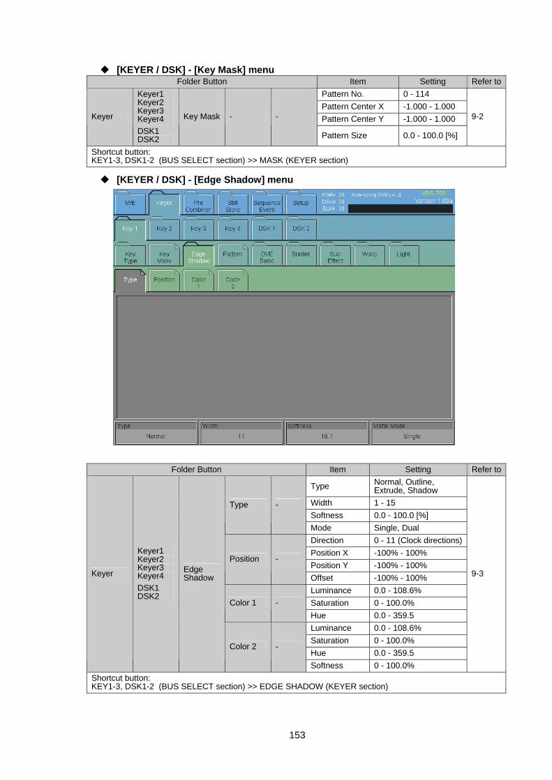
153
[KEYER / DSK] - [Key Mask] menu Folder Button Item Setting Refer to
Pattern No. 0 - 114 Pattern Center X -1.000 - 1.000 Pattern Center Y -1.000 - 1.000 Keyer
Keyer1 Keyer2 Keyer3 Keyer4 DSK1 DSK2
Key Mask - -
Pattern Size 0.0 - 100.0 [%]
9-2
Shortcut button: KEY1-3, DSK1-2 (BUS SELECT section) >> MASK (KEYER section)
[KEYER / DSK] - [Edge Shadow] menu
Folder Button Item Setting Refer to
Type Normal, Outline, Extrude, Shadow
Width 1 - 15 Softness 0.0 - 100.0 [%]
Type -
Mode Single, Dual Direction 0 - 11 (Clock directions)Position X -100% - 100% Position Y -100% - 100%
Position -
Offset -100% - 100% Luminance 0.0 - 108.6% Saturation 0 - 100.0% Color 1 - Hue 0.0 - 359.5 Luminance 0.0 - 108.6% Saturation 0 - 100.0% Hue 0.0 - 359.5
Keyer
Keyer1 Keyer2 Keyer3 Keyer4 DSK1 DSK2
Edge Shadow
Color 2 -
Softness 0 - 100.0%
9-3
Shortcut button: KEY1-3, DSK1-2 (BUS SELECT section) >> EDGE SHADOW (KEYER section)
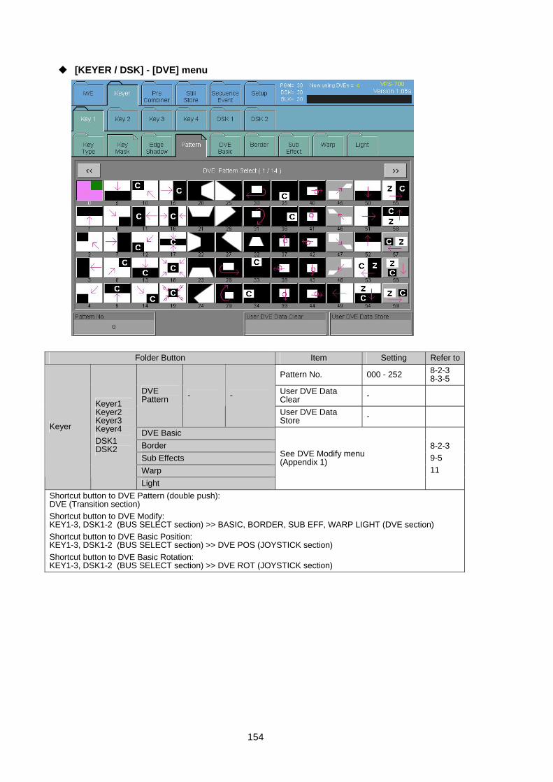
154
[KEYER / DSK] - [DVE] menu
Folder Button Item Setting Refer to
Pattern No. 000 - 252 8-2-3 8-3-5
User DVE Data Clear - DVE
Pattern - -
User DVE Data Store -
DVE Basic Border Sub Effects Warp
Keyer
Keyer1 Keyer2 Keyer3 Keyer4 DSK1 DSK2
Light
See DVE Modify menu (Appendix 1)
8-2-3 9-5 11
Shortcut button to DVE Pattern (double push): DVE (Transition section) Shortcut button to DVE Modify: KEY1-3, DSK1-2 (BUS SELECT section) >> BASIC, BORDER, SUB EFF, WARP LIGHT (DVE section) Shortcut button to DVE Basic Position: KEY1-3, DSK1-2 (BUS SELECT section) >> DVE POS (JOYSTICK section) Shortcut button to DVE Basic Rotation: KEY1-3, DSK1-2 (BUS SELECT section) >> DVE ROT (JOYSTICK section)
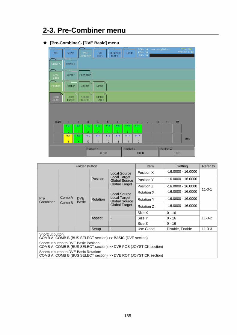
155
2-3. Pre-Combiner menu [Pre-Combiner]- [DVE Basic] menu
Folder Button Item Setting Refer to
Position X -16.0000 - 16.0000
Position Y -16.0000 - 16.0000Position Local Source Local Target Global SourceGlobal Target Position Z -16.0000 - 16.0000
Rotation X -16.0000 - 16.0000
Rotation Y -16.0000 - 16.0000RotationLocal Source Local Target Global SourceGlobal Target Rotation Z -16.0000 - 16.0000
11-3-1
Size X 0 - 16 Size Y 0 - 16 Aspect - Size Z 0 - 16
11-3-2
Pre Combiner
Comb AComb B
DVE Basic
Setup - Use Global Disable, Enable 11-3-3 Shortcut button: COMB A, COMB B (BUS SELECT section) >> BASIC (DVE section) Shortcut button to DVE Basic Position: COMB A, COMB B (BUS SELECT section) >> DVE POS (JOYSTICK section) Shortcut button to DVE Basic Rotation: COMB A, COMB B (BUS SELECT section) >> DVE ROT (JOYSTICK section)
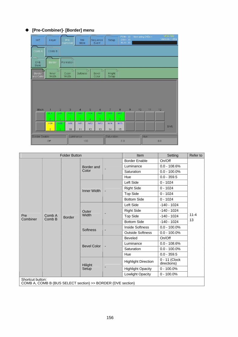
156
[Pre-Combiner]- [Border] menu
Folder Button Item Setting Refer toBorder Enable On/Off Luminance 0.0 - 108.6% Saturation 0.0 - 100.0%
Border and Color -
Hue 0.0 - 359.5 Left Side 0 - 1024 Right Side 0 - 1024 Top Side 0 - 1024
Inner Width -
Bottom Side 0 - 1024 Left Side -140 - 1024 Right Side -140 - 1024 Top Side -140 - 1024
Outer Width -
Bottom Side -140 - 1024 Inside Softness 0.0 - 100.0%
Softness - Outside Softness 0.0 - 100.0% Beveled On/Off Luminance 0.0 - 108.6% Saturation 0.0 - 100.0%
Bevel Color -
Hue 0.0 - 359.5
Highlight Direction 0 - 11 (Clock directions)
Highlight Opacity 0 - 100.0%
Pre Combiner
Comb A Comb B Border
Hilight Setup -
Lowlight Opacity 0 - 100.0%
11-4 13
Shortcut button: COMB A, COMB B (BUS SELECT section) >> BORDER (DVE section)
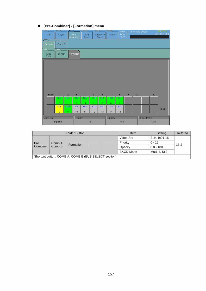
157
[Pre-Combiner] - [Formation] menu
Folder Button Item Setting Refer toVideo Src BLK, In01-16 Priority 0 - 15 Opacity 0.0 - 100.0
Pre Combiner
Comb A Comb B Formation - -
BKGD Matte Mat1-4, Stl3
13-2
Shortcut button: COMB A, COMB B (BUS SELECT section)
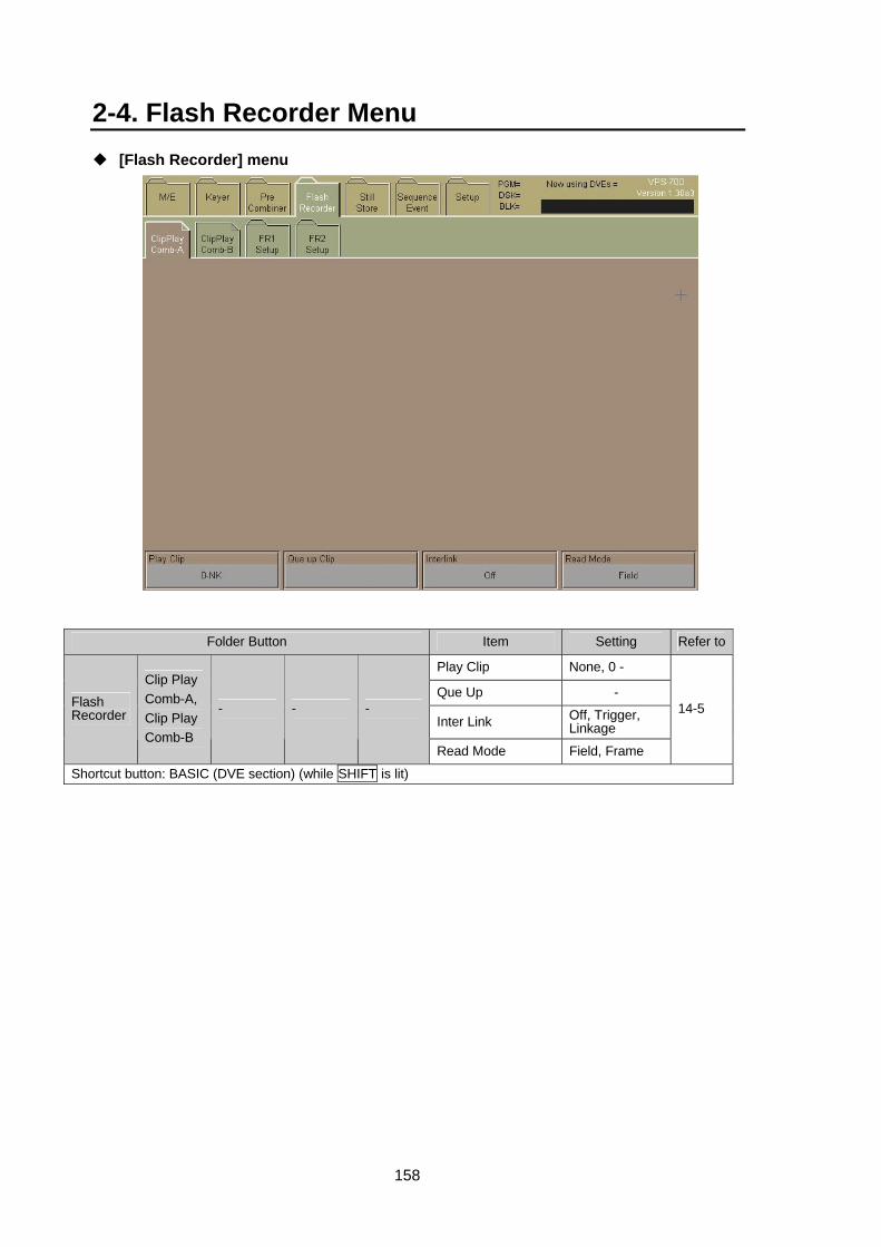
158
2-4. Flash Recorder Menu [Flash Recorder] menu
Folder Button Item Setting Refer to
Play Clip None, 0 -
Que Up -
Inter Link Off, Trigger, Linkage
Flash Recorder
Clip Play Comb-A, Clip Play Comb-B
- - -
Read Mode Field, Frame
14-5
Shortcut button: BASIC (DVE section) (while SHIFT is lit)
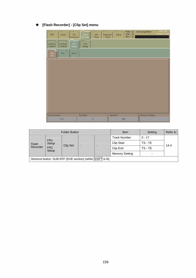
159
[Flash Recorder] - [Clip Set] menu
Folder Button Item Setting Refer to
Track Number 0 - 17
Clip Start TS - TE
Clip End TS - TE Flash Recorder
FR1 Setup FR2 Setup
Clip Set - -
Memory Setting -
14-4
Shortcut button: SUB EFF (DVE section) (while SHIFT is lit)
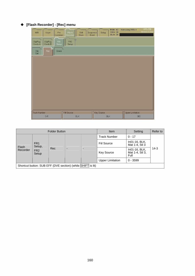
160
[Flash Recorder] - [Rec] menu
Folder Button Item Setting Refer to
Track Number 0 - 17
Fiil Source In01-16, BLK, Mat 1-4, Stl 3
Key Source In01-16, BLK, Mat 1-4, Stl 3, Full
Flash Recorder
FR1 Setup, FR2 Setup
Rec - -
Upper Limitation 0 - 3599
14-3
Shortcut button: SUB EFF (DVE section) (while SHIFT is lit)
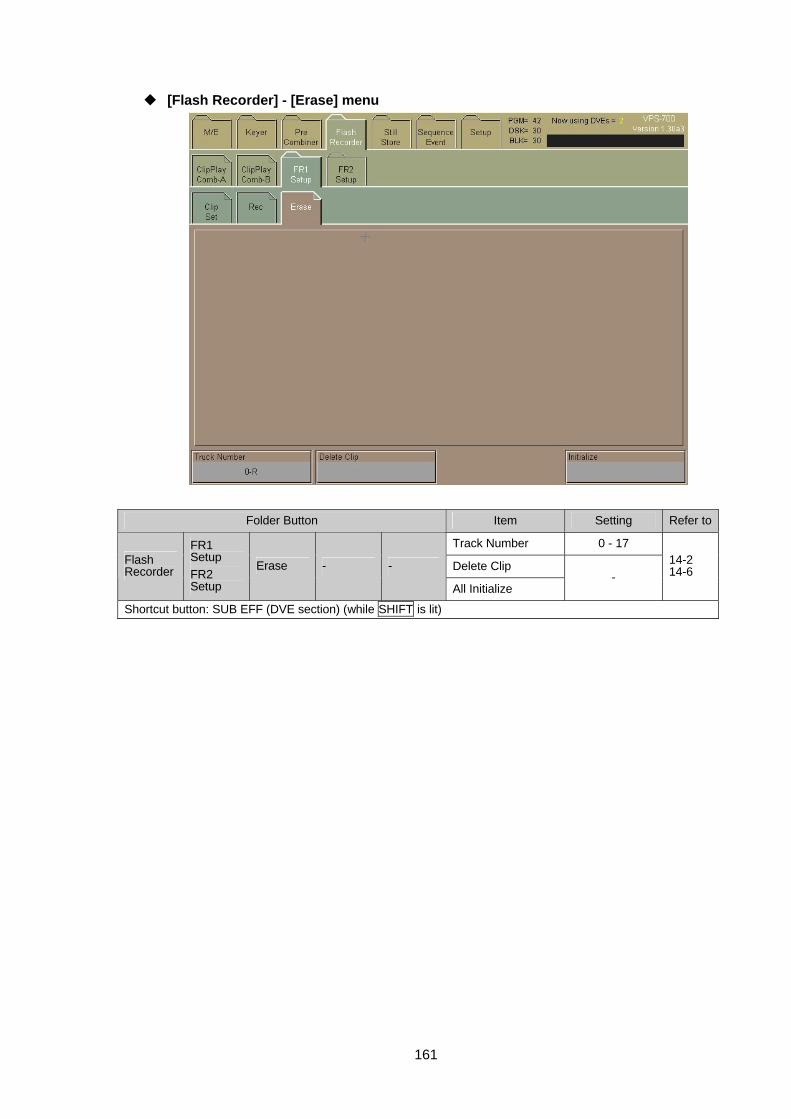
161
[Flash Recorder] - [Erase] menu
Folder Button Item Setting Refer to
Track Number 0 - 17
Delete Clip Flash Recorder
FR1 Setup FR2 Setup
Erase - -
All Initialize -
14-2 14-6
Shortcut button: SUB EFF (DVE section) (while SHIFT is lit)
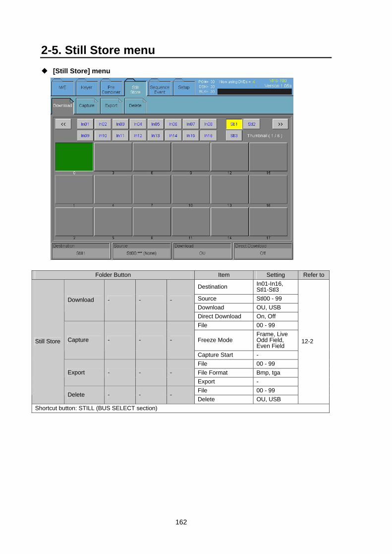
162
2-5. Still Store menu [Still Store] menu
Folder Button Item Setting Refer to
Destination In01-In16, Stl1-Stl3
Source Stl00 - 99 Download OU, USB
Download - - -
Direct Download On, Off File 00 - 99
Freeze Mode Frame, Live Odd Field, Even Field
Capture - - -
Capture Start - File 00 - 99 File Format Bmp, tga Export - - - Export - File 00 - 99
Still Store
Delete - - - Delete OU, USB
12-2
Shortcut button: STILL (BUS SELECT section)
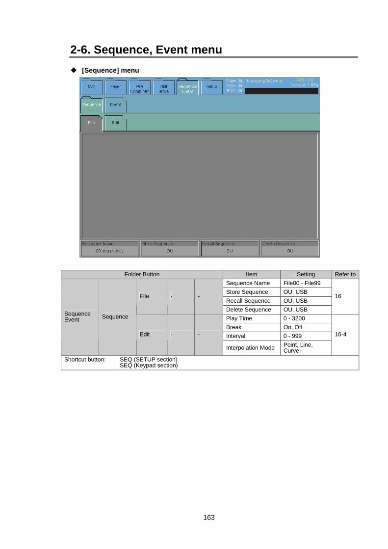
163
2-6. Sequence, Event menu [Sequence] menu
Folder Button Item Setting Refer toSequence Name File00 - File99 Store Sequence OU, USB Recall Sequence OU, USB
File - -
Delete Sequence OU, USB
16
Play Time 0 - 3200 Break On, Off Interval 0 - 999
Sequence Event Sequence
Edit - -
Interpolation Mode Point, Line, Curve
16-4
Shortcut button: SEQ (SETUP section) SEQ (Keypad section)
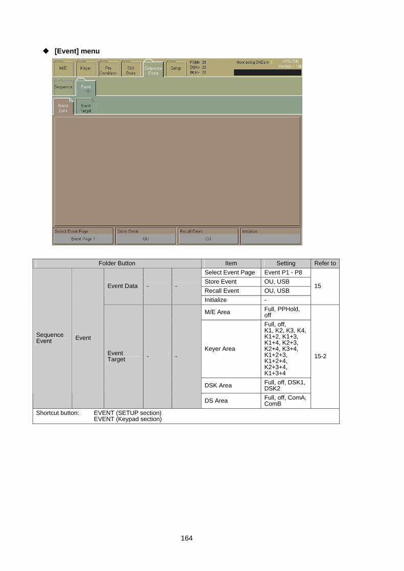
164
[Event] menu
Folder Button Item Setting Refer toSelect Event Page Event P1 - P8 Store Event OU, USB Recall Event OU, USB
Event Data - -
Initialize -
15
M/E Area Full, PPHold, off
Keyer Area
Full, off, K1, K2, K3, K4, K1+2, K1+3, K1+4, K2+3, K2+4, K3+4, K1+2+3, K1+2+4, K2+3+4, K1+3+4
DSK Area Full, off, DSK1, DSK2
Sequence Event Event
Event Target - -
DS Area Full, off, ComA, ComB
15-2
Shortcut button: EVENT (SETUP section) EVENT (Keypad section)
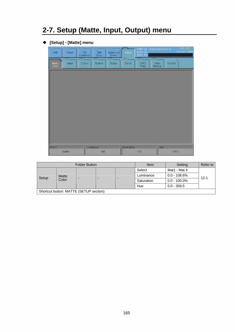
165
2-7. Setup (Matte, Input, Output) menu [Setup] - [Matte] menu
Folder Button Item Setting Refer toSelect Mat1 - Mat 4 Luminance 0.0 - 108.6% Saturation 0.0 - 100.0%
Setup Matte Color - - -
Hue 0.0 - 359.5
12-1
Shortcut button: MATTE (SETUP section)

166
[Setup] - [Input] menu
Folder Button Item Setting Refer toSource Assign In01 - In16 FS Mode On, Off
Freeze Mode Live Frame, Odd Field, Even Field
Remap - -
Auto Freeze Mode On, Off
7-1-4 7-1-5
White Clip 50.0 - 109.0% Black Clip -7.0 - 50.0% Luminance Gain 0.0 - 200.0%
Input Process 1 - -
Setup 0 - 100.0%
7-1-6
Chroma Clip 50.0 - 111.0% Chroma Gain 0.0 - 200.0% H Phase Trim -4 - 4
Input Process 2 - -
Hue 0.0 - 359.5
7-1-6
F Compst, YCBCR Analog
Input - - L Betacam,
SMPTE
4-6-2
File Save
Setup Input
Rename - - File Download
7-1-2
Shortcut button: INPUT (SETUP section)
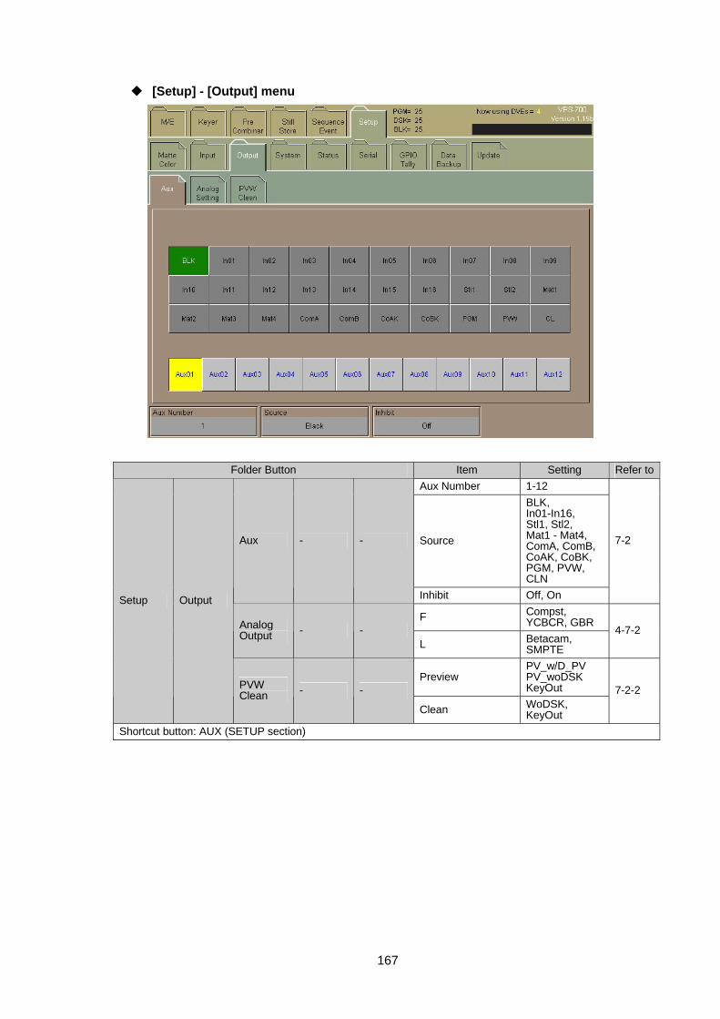
167
[Setup] - [Output] menu
Folder Button Item Setting Refer toAux Number 1-12
Source
BLK, In01-In16, Stl1, Stl2, Mat1 - Mat4, ComA, ComB, CoAK, CoBK, PGM, PVW, CLN
Aux - -
Inhibit Off, On
7-2
F Compst, YCBCR, GBR Analog
Output - - L Betacam,
SMPTE
4-7-2
Preview PV_w/D_PV PV_woDSK KeyOut
Setup Output
PVW Clean - -
Clean WoDSK, KeyOut
7-2-2
Shortcut button: AUX (SETUP section)
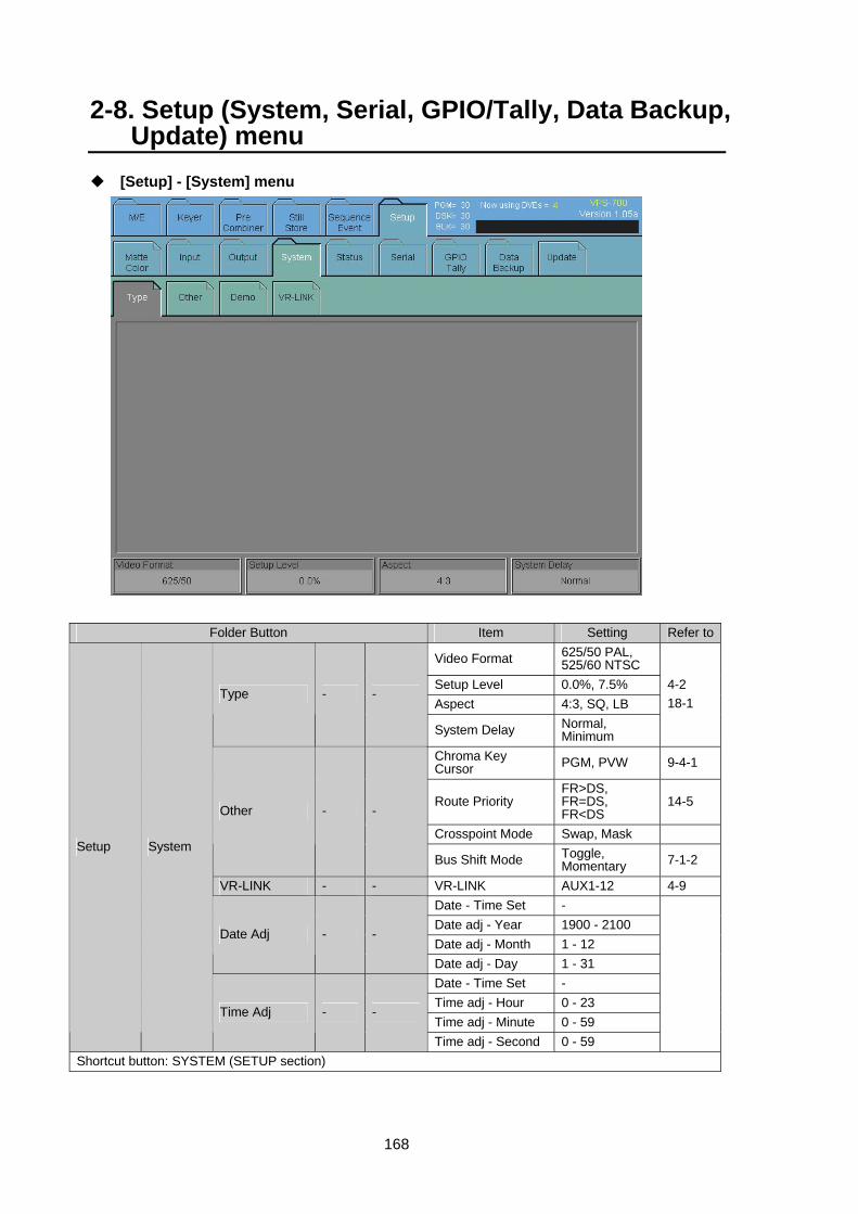
168
2-8. Setup (System, Serial, GPIO/Tally, Data Backup, Update) menu
[Setup] - [System] menu
Folder Button Item Setting Refer to
Video Format 625/50 PAL, 525/60 NTSC
Setup Level 0.0%, 7.5% Aspect 4:3, SQ, LB
Type - -
System Delay Normal, Minimum
4-2 18-1
Chroma Key Cursor PGM, PVW 9-4-1
Route Priority FR>DS, FR=DS, FR<DS
14-5
Crosspoint Mode Swap, Mask
Other - -
Bus Shift Mode Toggle, Momentary 7-1-2
VR-LINK - - VR-LINK AUX1-12 4-9 Date - Time Set - Date adj - Year 1900 - 2100 Date adj - Month 1 - 12
Date Adj - -
Date adj - Day 1 - 31 Date - Time Set - Time adj - Hour 0 - 23 Time adj - Minute 0 - 59
Setup System
Time Adj - -
Time adj - Second 0 - 59
Shortcut button: SYSTEM (SETUP section)
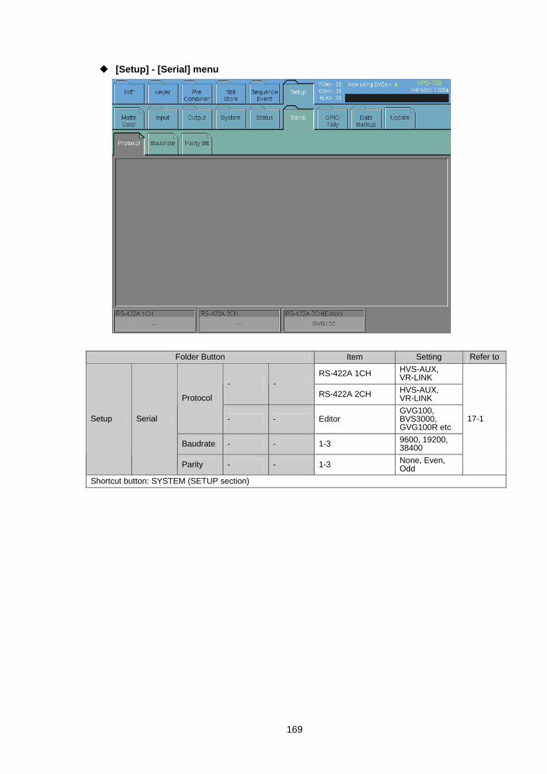
169
[Setup] - [Serial] menu
Folder Button Item Setting Refer to
RS-422A 1CH HVS-AUX, VR-LINK
- - RS-422A 2CH HVS-AUX,
VR-LINK Protocol
- - Editor GVG100, BVS3000, GVG100R etc
Baudrate - - 1-3 9600, 19200, 38400
Setup Serial
Parity - - 1-3 None, Even, Odd
17-1
Shortcut button: SYSTEM (SETUP section)
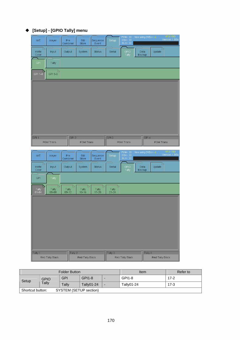
170
[Setup] - [GPIO Tally] menu
Folder Button Item Refer to
GPI GPI1-8 - GPI1-8 17-2 Setup GPIO
Tally Tally Tally01-24 - Tally01-24 17-3 Shortcut button: SYSTEM (SETUP section)
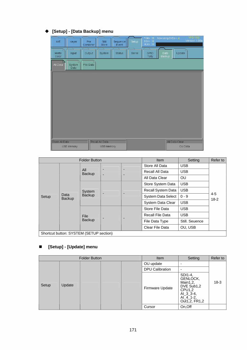
171
[Setup] - [Data Backup] menu
Folder Button Item Setting Refer toStore All Data USB Recall All Data USB All
Backup - -
- -
All Data Clear OU Store System Data USB Recall System Data USB System Data Select 0 - 9
System Backup - -
System Data Clear USB Store File Data USB Recall File Data USB File Data Type Still. Seuence
Setup Data Backup
File Backup - -
Clear File Data OU, USB
4-5 18-2
Shortcut button: SYSTEM (SETUP section)
[Setup] - [Update] menu
Folder Button Item Setting Refer toOU update - DPU Calibration -
Firmware Update
SDI1-4, GENLOCK, Main1,2, DVE Sub1,2 CPU1,2 AI_3_3-4, AI_4_1-2, Out1,2, FR1,2
18-3 Setup Update
Cursor On,Off

172
Folder Button Item Setting Refer toOU update - DPU Calibration -
Firmware Update
SDI1-4, GENLOCK, Main1,2, DVE Sub1,2 CPU1,2 AI_3_3-4, AI_4_1-2, Out1,2, FR1,2
18-3 Setup Update
Cursor On,Off Shortcut button: SYSTEM (SETUP section)
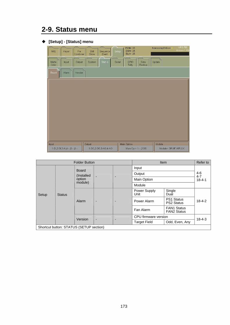
173
2-9. Status menu [Setup] - [Status] menu
Folder Button Item Refer toInput Output Main Option
Board (Installed option module)
- -
Module
4-6 4-7 18-4-1
Power Supply Unit
Single Dual
Power Alarm PS1 Status PS2 Status Alarm - -
Fan Alarm FAN1 Status FAN2 Status
18-4-2
CPU firmware version
Setup Status
Version - - Target Field Odd, Even, Any
18-4-3
Shortcut button: STATUS (SETUP section)

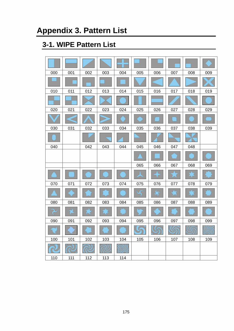
175
Appendix 3. Pattern List
3-1. WIPE Pattern List
000 001 002 003 004 005 006 007 008 009
010 011 012 013 014 015 016 017 018 019
020 021 022 023 024 025 026 027 028 029
030 031 032 033 034 035 036 037 038 039
040 042 043 044 045 046 047 048
065 066 067 068 069
070 071 072 073 074 075 076 077 078 079
080 081 082 083 084 085 086 087 088 089
090 091 092 093 094 095 096 097 098 099
100 101 102 103 104 105 106 107 108 109
110 111 112 113 114
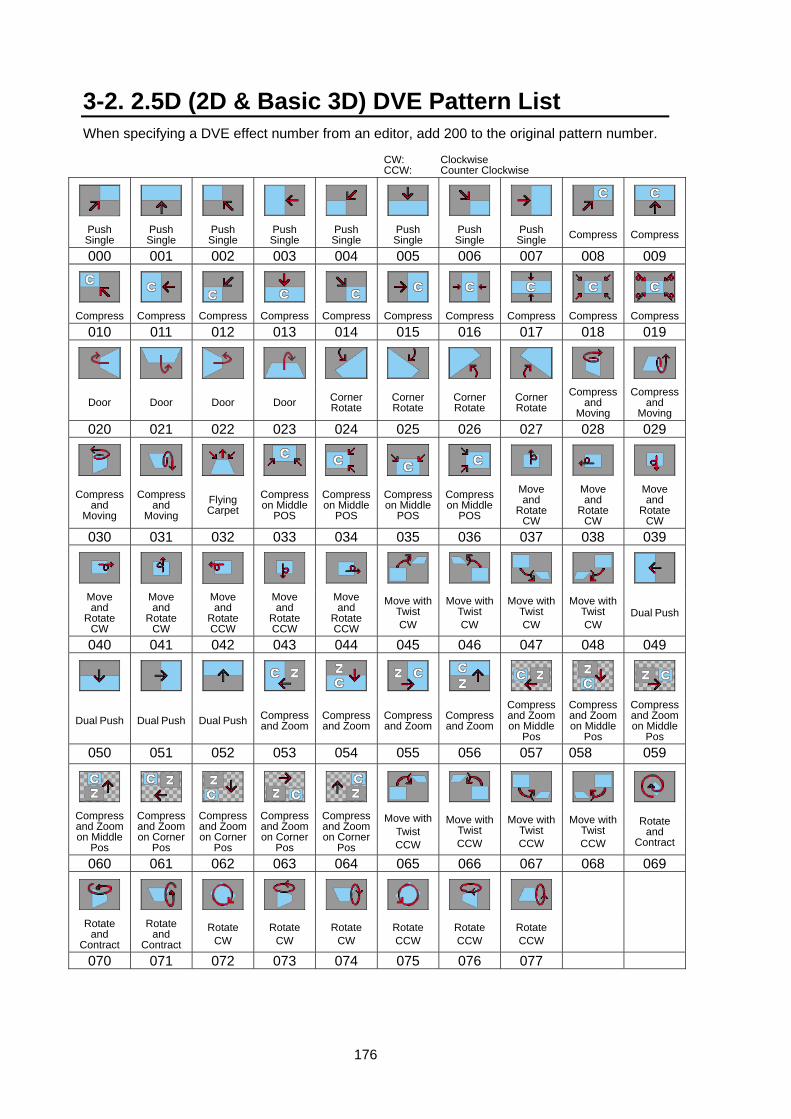
176
3-2. 2.5D (2D & Basic 3D) DVE Pattern List When specifying a DVE effect number from an editor, add 200 to the original pattern number.
CW: Clockwise
CCW: Counter Clockwise
Push Single
Push Single
Push Single
Push Single
Push Single
Push Single
Push Single
Push Single Compress Compress
000 001 002 003 004 005 006 007 008 009
Compress Compress Compress Compress Compress Compress Compress Compress Compress Compress
010 011 012 013 014 015 016 017 018 019
Door Door Door Door Corner Rotate
Corner Rotate
Corner Rotate
Corner Rotate
Compress and
Moving
Compress and
Moving 020 021 022 023 024 025 026 027 028 029
Compress
and Moving
Compress and
Moving Flying Carpet
Compress on Middle
POS
Compress on Middle
POS
Compress on Middle
POS
Compress on Middle
POS
Move and
Rotate CW
Move and
Rotate CW
Move and
Rotate CW
030 031 032 033 034 035 036 037 038 039
Move and
Rotate CW
Move and
Rotate CW
Move and
Rotate CCW
Move and
Rotate CCW
Move and
Rotate CCW
Move with Twist CW
Move with Twist CW
Move with Twist CW
Move with Twist CW
Dual Push
040 041 042 043 044 045 046 047 048 049
Dual Push Dual Push Dual Push Compress and Zoom
Compress and Zoom
Compress and Zoom
Compress and Zoom
Compress and Zoom on Middle
Pos
Compress and Zoom on Middle
Pos
Compress and Zoom on Middle
Pos 050 051 052 053 054 055 056 057 058 059
Compress and Zoom on Middle
Pos
Compress and Zoom on Corner
Pos
Compress and Zoom on Corner
Pos
Compress and Zoom on Corner
Pos
Compress and Zoom on Corner
Pos
Move withTwist CCW
Move with Twist CCW
Move with Twist CCW
Move with Twist CCW
Rotate and
Contract
060 061 062 063 064 065 066 067 068 069
Rotate and
Contract
Rotate and
Contract Rotate
CW Rotate
CW Rotate
CW Rotate CCW
Rotate CCW
Rotate CCW
070 071 072 073 074 075 076 077
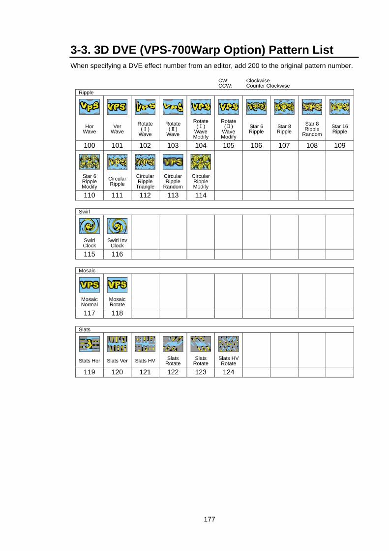
177
3-3. 3D DVE (VPS-700Warp Option) Pattern List When specifying a DVE effect number from an editor, add 200 to the original pattern number.
CW: Clockwise CCW: Counter Clockwise
Ripple
Hor Wave
Ver Wave
Rotate (Ⅰ)
Wave
Rotate (Ⅱ)
Wave
Rotate (Ⅰ)
Wave Modify
Rotate (Ⅱ)
Wave Modify
Star 6 Ripple
Star 8 Ripple
Star 8 Ripple
RandomStar 16 Ripple
100 101 102 103 104 105 106 107 108 109
Star 6 Ripple Modify
Circular Ripple
Circular Ripple
Triangle
Circular Ripple
Random
Circular Ripple Modify
110 111 112 113 114
Swirl
Swirl Clock
Swirl Inv Clock
115 116
Mosaic
Mosaic Normal
Mosaic Rotate
117 118
Slats
Stats Hor Slats Ver Slats HV Slats Rotate
Slats Rotate
Slats HV Rotate
119 120 121 122 123 124
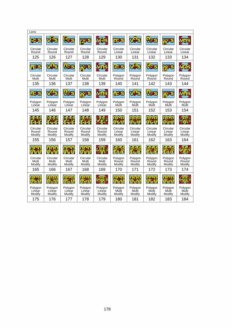
178
Lens
Circular Round
Circular Round
Circular Round
Circular Round
Circular Round
Circular Linear
Circular Linear
Circular Linear
Circular Linear
Circular Linear
125 126 127 128 129 130 131 132 133 134
Circular
Multi Circular
Multi Circular
Multi Circular
Multi Circular
Multi Polygon Round
Polygon Round
Polygon Round
Polygon Round
Polygon Round
135 136 137 138 139 140 141 142 143 144
Polygon Linear
Polygon Linear
Polygon Linear
Polygon Linear
Polygon Linear
Polygon Multi
Polygon Multi
Polygon Multi
Polygon Multi
Polygon Multi
145 146 147 148 149 150 151 152 153 154
Circular Round Modify
Circular Round Modify
Circular Round Modify
Circular Round Modify
Circular Round Modify
Circular Linear Modify
Circular Linear Modify
Circular Linear Modify
Circular Linear Modify
Circular Linear Modify
155 156 157 158 159 160 161 162 163 164
Circular
Multi Modify
Circular Multi
Modify
Circular Multi
Modify
Circular Multi
Modify
Circular Multi
Modify
Polygon Round Modify
Polygon Round Modify
Polygon Round Modify
Polygon Round Modify
Polygon Round Modify
165 166 167 168 169 170 171 172 173 174
Polygon Linear Modify
Polygon Linear Modify
Polygon Linear Modify
Polygon Linear Modify
Polygon Linear Modify
Polygon Multi
Modify
Polygon Multi
Modify
Polygon Multi
Modify
Polygon Multi
Modify
Polygon Multi
Modify
175 176 177 178 179 180 181 182 183 184
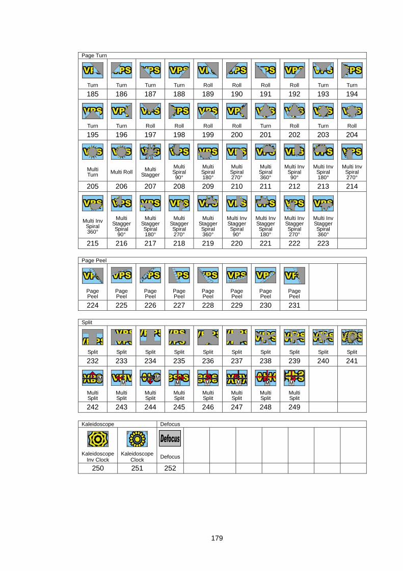
179
Page Turn
Turn Turn Turn Turn Roll Roll Roll Roll Turn Turn
185 186 187 188 189 190 191 192 193 194
Turn Turn Roll Roll Roll Roll Turn Roll Turn Roll
195 196 197 198 199 200 201 202 203 204
Multi Turn Multi Roll Multi
Stagger Multi Spiral 90°
Multi Spiral 180°
Multi Spiral 270°
Multi Spiral 360°
Multi Inv Spiral 90°
Multi Inv Spiral 180°
Multi Inv Spiral 270°
205 206 207 208 209 210 211 212 213 214
Multi Inv Spiral 360°
Multi Stagger Spiral 90°
Multi Stagger Spiral 180°
Multi Stagger Spiral 270°
Multi Stagger Spiral 360°
Multi Inv Stagger Spiral 90°
Multi Inv Stagger Spiral 180°
Multi Inv Stagger Spiral 270°
Multi Inv Stagger Spiral 360°
215 216 217 218 219 220 221 222 223
Page Peel
Page Peel
Page Peel
Page Peel
Page Peel
Page Peel
Page Peel
Page Peel
Page Peel
224 225 226 227 228 229 230 231
Split
Split Split Split Split Split Split Split Split Split Split
232 233 234 235 236 237 238 239 240 241
Multi Split
Multi Split
Multi Split
Multi Split
Multi Split
Multi Split
Multi Split
Multi Split
242 243 244 245 246 247 248 249
Kaleidoscope Defocus
Kaleidoscope Inv Clock
Kaleidoscope Clock Defocus
250 251 252
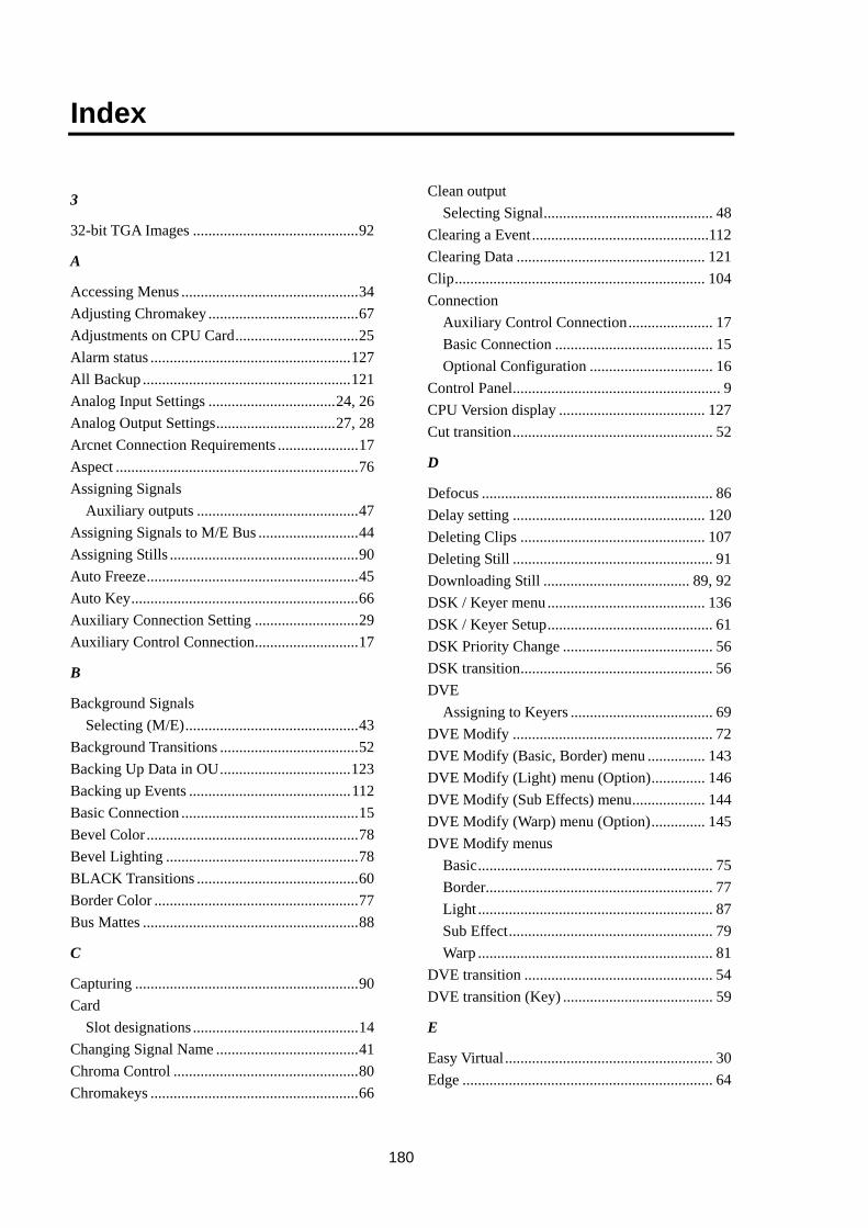
180
Index
3
32-bit TGA Images ...........................................92
A
Accessing Menus ..............................................34 Adjusting Chromakey .......................................67 Adjustments on CPU Card................................25 Alarm status ....................................................127 All Backup ......................................................121 Analog Input Settings .................................24, 26 Analog Output Settings...............................27, 28 Arcnet Connection Requirements .....................17 Aspect ...............................................................76 Assigning Signals
Auxiliary outputs ..........................................47 Assigning Signals to M/E Bus ..........................44 Assigning Stills .................................................90 Auto Freeze.......................................................45 Auto Key...........................................................66 Auxiliary Connection Setting ...........................29 Auxiliary Control Connection...........................17
B
Background Signals Selecting (M/E).............................................43
Background Transitions ....................................52 Backing Up Data in OU..................................123 Backing up Events ..........................................112 Basic Connection ..............................................15 Bevel Color .......................................................78 Bevel Lighting ..................................................78 BLACK Transitions ..........................................60 Border Color .....................................................77 Bus Mattes ........................................................88
C
Capturing ..........................................................90 Card
Slot designations ...........................................14 Changing Signal Name .....................................41 Chroma Control ................................................80 Chromakeys ......................................................66
Clean output Selecting Signal............................................ 48
Clearing a Event..............................................112 Clearing Data ................................................. 121 Clip................................................................. 104 Connection
Auxiliary Control Connection...................... 17 Basic Connection ......................................... 15 Optional Configuration ................................ 16
Control Panel...................................................... 9 CPU Version display ...................................... 127 Cut transition.................................................... 52
D
Defocus ............................................................ 86 Delay setting .................................................. 120 Deleting Clips ................................................ 107 Deleting Still .................................................... 91 Downloading Still ...................................... 89, 92 DSK / Keyer menu ......................................... 136 DSK / Keyer Setup........................................... 61 DSK Priority Change ....................................... 56 DSK transition.................................................. 56 DVE
Assigning to Keyers ..................................... 69 DVE Modify .................................................... 72 DVE Modify (Basic, Border) menu ............... 143 DVE Modify (Light) menu (Option).............. 146 DVE Modify (Sub Effects) menu................... 144 DVE Modify (Warp) menu (Option).............. 145 DVE Modify menus
Basic............................................................. 75 Border........................................................... 77 Light ............................................................. 87 Sub Effect..................................................... 79 Warp ............................................................. 81
DVE transition ................................................. 54 DVE transition (Key) ....................................... 59
E
Easy Virtual...................................................... 30 Edge ................................................................. 64
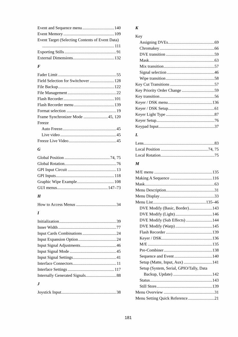
181
Event and Sequence menu ..............................140 Event Memory ................................................109 Event Target (Selecting Contents of Event Data)
.................................................................... 111 Exporting Stills .................................................91 External Dimensions.......................................132
F
Fader Limit .......................................................55 Field Selection for Switchover .......................128 File Backup.....................................................122 File Management ..............................................22 Flash Recorder................................................101 Flash Recorder menu ......................................139 Format selection ...............................................19 Frame Synchronizer Mode .......................45, 120 Freeze
Auto Freeze...................................................45 Live video .....................................................45
Freeze Live Video.............................................45
G
Global Position ...........................................74, 75 Global Rotation.................................................76 GPI Input Circuit ..............................................13 GPI Inputs....................................................... 118 Graphic Wipe Example...................................108 GUI menus................................................147–73
H
How to Access Menus ......................................34
I
Initialization......................................................39 Inner Width .......................................................77 Input Cards Combinations ................................24 Input Expansion Option....................................24 Input Signal Adjustments..................................46 Input Signal Mode ............................................45 Input Signal Settings.........................................41 Interface Connectors......................................... 11 Interface Settings ............................................ 117 Internally Generated Signals.............................88
J
Joystick Input....................................................38
K
Key Assigning DVEs............................................69 Chromakey....................................................66 DVE transition ..............................................59 Mask..............................................................63 Mix transition................................................57 Signal selection .............................................46 Wipe transition ..............................................58
Key Cut Transitions ..........................................57 Key Priority Order Change ...............................59 Key transition....................................................56 Keyer / DSK menu..........................................136 Keyer / DSK Setup............................................61 Keyer Light Type ..............................................87 Keyer Setup.......................................................76 Keypad Input.....................................................37
L
Lens...................................................................83 Local Position .............................................74, 75 Local Rotation...................................................75
M
M/E menu .......................................................135 Making A Sequence ........................................116 Mask..................................................................63 Menu Description..............................................31 Menu Display....................................................33 Menu List ..................................................135–46
DVE Modify (Basic, Border)......................143 DVE Modify (Light) ...................................146 DVE Modify (Sub Effects) .........................144 DVE Modify (Warp) ...................................145 Flash Recorder ............................................139 Keyer / DSK................................................136 M/E .............................................................135 Pre-Combiner..............................................138 Sequence and Event ....................................140 Setup (Matte, Input, Aux) ...........................141 Setup (System, Serial, GPIO/Tally, Data
Backup, Update) .....................................142 Status...........................................................143 Still Store.....................................................139
Menu Overview ................................................31 Menu Setting Quick Reference .........................21
182
Menus How to use ....................................................36
Merging Input Mapping....................................96 Mirror................................................................86 Mix transition....................................................53 Mix transitions (Key)........................................57 Mosaic...............................................................82
O
Option Boards status.......................................126 Optional Configuration .....................................16 Optional Inputs .................................................26 Optional Outputs...............................................28 Outer Width ......................................................77 Output Card Combinations ...............................27 Output Expansion Option .................................27 Output Signal Settings ......................................47
P
Page Peel...........................................................85 Page Turn ..........................................................84 Panel Description
Control Panel ..................................................9 Control unit rear panel ..................................10 VPS-700 MU ..................................................7 VPS-700RPS MU ...........................................8
Pattern List................................................175–79 Playback (Flash recorder) ...............................105 Power OFF........................................................20 Power ON .........................................................18 Pre-combiner.....................................................93 Pre-Combiner menu........................................138 Previe output
Selecting Signal ............................................48 Priority Change .................................................56 Proc Amp ..........................................................46
R
Recalling Events .............................................110 Returning to Default .........................................39 Ripple................................................................81 RS422 Interface setting...................................117
S
Saving Still........................................................90 Selecting Signals
Background...................................................43
Keys and DSKs ............................................ 46 PREV and CLEAN ...................................... 48
Selecting System Signal Format ...................... 19 Sequence .........................................................113 Sequence and Event menu ............................. 140 Setup ................................................................ 18 Setup (Matte, Input, Aux) menu..................... 141 Setup (System, Serial, GPIO/Tally, Data Backup,
Update) menu............................................. 142 Shadow............................................................. 64 Signal Adjustments........................................... 46 Signal assignment
Auxiliary output ........................................... 47 Signal Assignment
M/E Bus ....................................................... 44 Signal Format Selection ................................... 19 Signal Format setting ..................................... 120 Signal Name..................................................... 41 Signal Routing.................................................. 41 Slats.................................................................. 82 Slot designations .............................................. 14 Softness ............................................................ 78 Specifications ................................................. 129 Splits ................................................................ 85 Status display ................................................. 126 Status menu .................................................... 143 Still Store.......................................................... 88 Still Store menu.............................................. 139 Storing Events ................................................ 109 Strobe ............................................................... 80 Swirl ................................................................. 82 System Backup............................................... 121 System Delay setting...................................... 120 System Setup.................................................. 120 System Signal Format ...................................... 19
T
Tally Output Circuit ......................................... 13 Tally Outputs...................................................119 TGA Images (32-bit) ........................................ 92 Touch Panel Operations ................................... 40 Track .............................................................. 103 Trail .................................................................. 79 Transition Rate ................................................. 51 Transitions........................................................ 50
Background transition .................................. 52
183
Black transition.............................................60 Cut transition ................................................52 Key and DSK transition................................56 Key Cut transition.........................................57 Mix transition ...............................................53 WIPE and DVE transition ............................54
U
Update.............................................................125 Using Menus.....................................................36
V
Virtual Connection Setting................................30 Virtual tally .......................................................30
W
Wipe Modify .....................................................70 Wipe transition..................................................54 Wipe transition (Key)........................................58


Warning This equipment has been tested and found to comply with the limits for a Class A digital device, pursuant to Part 15 of FCC Rules. These limits are designed to provide reasonable protection against harmful interference when the equipment is operated in a commercial environment. This equipment generates, uses, and can radiate radio frequency energy and, if not installed and used in accordance with the instruction manual, may cause harmful interference to radio communications. Operation of this equipment in a residential area is likely to cause harmful interference, in which case the user will be required to correct the interference at his own expense.
02/01/2010 Printed in Japan
FOR-A COMPANY LIMITED Head Office : 3-8-1 Ebisu, Shibuya-ku, Tokyo 150-0013, Japan Overseas Division Phone: +81 (0)3-3446-3936, Fax: +81 (0)3-3446-1470 Japan Branch Offices : Osaka/Okinawa/Fukuoka/Hiroshima/Nagoya/Sendai/Sapporo R&D/Production : Sakura Center/Sapporo Center
FOR-A America Corporate Office 11125 Knott Ave., Suite #A, Cypress, CA 90630, USA Phone: +1 714-894-3311 Fax: +1 714-894-5399
FOR-A America East Coast Office Two Executive Drive, Suite 670, Fort Lee Executive Park, Fort Lee NJ 07024, USA Phone: +1 (201) 944-1120 Fax : +1 (201) 944-1132
FOR-A America Distribution & Service Center 2400 N.E. Waldo Road, Gainesville, FL 32609, USA Phone: +1 352-371-1505 Fax: +1 352-378-5320
FOR-A Corporation of Canada 346A Queen Street West, Toronto, Ontario M5V 2A2, Canada Phone: +1 416-977-0343 Fax: +1 416-977-0657
FOR-A Latin America & the Caribbean
5200 Blue lagoon Drive, Suite 760, Miami, FL 33126, USA Phone: +1-305-931-1700 Fax: +1-305-264-7890
FOR-A UK Limited UNIT C71, Barwell Business Park, Leatherhead Road, Chessington Surrey, KT9 2NY, UK Phone: +44 (0)20-8391-7979 Fax: +44 (0)20-8391-7978
FOR-A Italia S.r.l.
Viale Europa 50 20093, Cologno Monzese (MI), Milan, Italy Phone: +39 02-254-3635/6 Fax: +39 02-254-0477
FOR-A Corporation of Korea 801 Dangsan Bld., 53-1 Dangsan-Dong, Youngdeungpo-Gu, Seoul 150-800, Korea Phone: +82 (0)2-2637-0761 Fax: +82 (0)2-2637-0760
FOR-A China Limited 708B Huateng Building, No. 302, 3 District, Jinsong, Chaoyang, Beijing 100021, China Phone: +86 (0)10-8721-6023 Fax: +86 (0)10-8721-6033
*The contents of this manual are subject to change without notice.


