Embed Size (px)
Citation preview

EN Operating InstructionsGuillotines
www.ideal.de
IDEAL 4315
IDEAL 4350

- 2 -
Table of Contents
Safety precautions 3Intended use 4Installation 10Startup 12Operation 14Operating elements 19Blade and cutting stick replacement 22Maintenance and cleaning 31Annual inspection / Safety test 31Possible malfunctions 33Accessories 37Technical data 38EC-declaration of conformity 41
- 3 -
Safety precautions
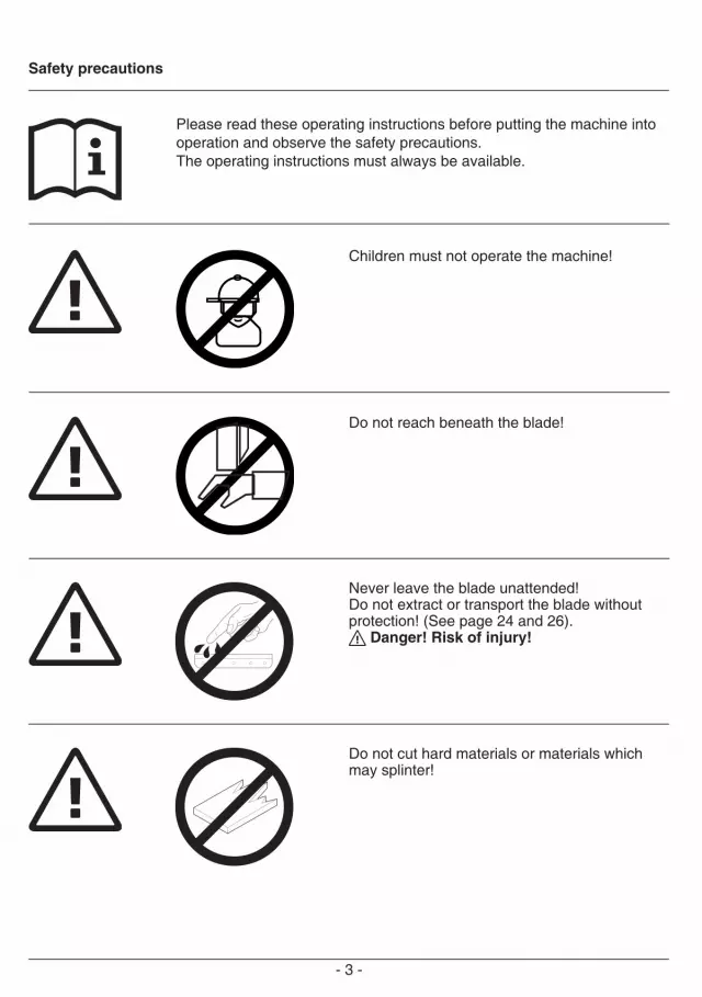
Please read these operating instructions before putting the machine into operation and observe the safety precautions. The operating instructions must always be available.
Children must not operate the machine!
Do not reach beneath the blade!
Never leave the blade unattended!Do not extract or transport the blade without protection! (See page 24 and 26).
Danger! Risk of injury!
Do not cut hard materials or materials which may splinter!

- 4 -
Intended use
The machine is designed for cutting stacks ofpaper to a specified size. This machine is constructed for "one-manoperation" only!
Warning! Clips or similar damage thecutting blade.
Safety precautions / Intended use
Do not use any spray cans with flammable content near to the cutting machine!
Do not use any flammable cleaning agents.

- 5 -
Disconnect from the mains before starting anyservice work or before removing the panels!
Replacement of blade and cutting stick maybe performed only when the main switch isswitched off!
Safety precautions

- 6 -
A
AA
B
CAC
All components which could endanger theoperator are covered by a guard!
Operating the machine without safety device is forbidden! • Movable front safety guard (A)• rear screwed safety guard (B) • and cover (C)
Safety precautions

- 7 -
B
CA
The dangerous cutting movement issafeguarded by a movable guard (A), rear screwed safety guard (B) and a safetytwo-handed control system! (C)
Before working with the machine and afterevery blade replacement the automatic cut-offfunction of safety guard (A),(correct if distancebetween cover and table is < 15 mm) mainswitch (B) and control panel (C) must bechecked.
Safety precautions

- 8 -
230 V / 10A min120 V / 15A min
Protect mains cable against heat, oil andsharp edges!
Connect the power cord to a single phasesocket.
Ensure free access to mains
Safety precautions

- 9 -
When not in use for a longer period switchoff (Main switch to "0").
Clamping BladeOK
OK
Danger! Do not turn main switch to position "0" whilst blade is moving upwards ordownwards! Risk of injury!
Danger! Blade must always be covered by the pressing bar.
Safety precautions

- 10 -
B
A
A
B
Unpack the cabinet (A), (accessories) orstand (B), (accessories) and assemble according to the enclosed separate instructions.
2 strong people are required to lift themachine onto the cabinet. Beware of fingers!Do not hold onto the actuators (B) when lifting the machine out of the packaging!The operating side of the machine must align with the cabinet (A)!
Risk of injury!
Installation

- 11 -
Assembly of stand: 2 strong people are required to lift themachine out of the packaging. • Lay the machine on the floor side wards (1.).• Remove the lower cover (2.)• Place the cutter correctly onto the machine stand. Fit the 4 washers and tighten the 4 hexagon nuts with a spanner (3.). • Screw on the lower cover (4.)• Install the machine.
Installation

- 12 -
Startup
Plug into socket.
Screw on the backgauge crank (A).Screw on the handle (B) (only 4315)found in the tool set (C).
Installation / Startup

- 13 -
BB
A
AA
It is forbidden to operate the machine if the operating and safety instructions have not been understood. Please check the safety devices are functioning and complete before use.• All covers have to be mounted (A).• The release for cutting is allowed only if the cover is closed and the two-hand safety device is operated at the same time (B).• The front cover should not close by itself. Tighten the hexagonal recess screw right (C). We recommend you keep a record of your test results.
Startup

- 14 -
BA
C
Position the main switch "I" (A) Insert the key the control system and moveit to the right (B). Open the safety guard (C).The machine is now ready for use.
Operation

- 15 -
A
B
C
D
E
The measurement is set with the backgaugecrank.(A) The symbol – rotary direction –
moves to the right on the display (B)(see picture C). The rotary direction of the backgauge crank (A) is indicated on the right.Keep turning the backgauge crank to the right until a measurement appears (see picture E). The reference position is reached.The cutting size can now be set with thehandle (A).If the backgauge is right at the front the symbol – rotary direction – will move to theleft (see picture D). Turn the backgauge crankto the left until the rotary direction appears onthe right in the display (see picture C).Afterwards turn the backgauge crank to the right until a measurements appears (see picture E). The reference position is reached.The cutting size can now be set with thehandle (A). Proceed to position from therear.
Measurement is shown on the display in inches or cm (B).
Information:When the machine is only switched off by the Key switch G (main switch E is still ON) it is not necessary to advance to the reference point when a new measurement is inserted.
Operation

- 16 -
Optical cutting red line (A). Blade cuts on the front edge (B) of the light beam. (Only use when no exact cut is required).
Pull out the handle to avoid the measurementbeing wrongly adjusted.
Operation
- 17 -
B C
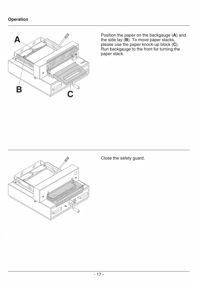
A Position the paper on the backgauge (A) andthe side lay (B). To move paper stacks, please use the paper knock-up block (C).Run backgauge to the front for turning the paper stack.
Close the safety guard.
Operation

- 18 -
A
A
Cutting activation: Press both buttons of the two-handed control system (A) simultaneously and keep them pressed until the paper is completely cut.
To interrupt or stop cutting: To interrupt or stop cutting, release both buttons (A) of the two-hand control.
4315 Before every cut the lever must be moved tothe left and tightened with light pressure.
4350The clamp moves automatically when cuttingis activated.
Operation

- 19 -
Operating elements
A - Front safety guard
B - Safety two-handed control system
C - Overload switch blade drive
D - Clamping
E - Main switch
F - Crank handle for backgauge setting
G - Key switch
H - Backgauge
I - Side lay left
J - Display cutting size (cm or inch)
K - Changeover cm/inch
L - Measuring unit (cm or inch)
Operation / Operating elements

- 20 -
A
B
C
D
E
Start machine• Main switch E to position "I", insert the key
G for the control panel and turn it to the right. Open the front safety guard A. Warning! Before cutting a measurement please check if
the correct scale (cm or inch) is set. Display in cm or inch• Press q K Display changes between cm
and inch. For information on how to store see page 19, picture below left.
• The measurement is set with the backgauge crank.(A) The symbol – rotary direction – moves to the right on the display (B) (see
picture C). The rotary direction of the backgauge crank (A) is indicated on the right. Keep turning the backgauge crank to the right until a measurement appears (see picture E). The reference position is reached. The cutting size can now be set with the
handle (A). If the backgauge is right at the front the symbol – rotary direction – will move to the left (see picture D). Turn the backgauge crank to the left until the rotary direction ap-
pears on the right in the display (see picture C). Afterwards turn the backgauge crank to the right until a measurements appears (see picture E). The reference position is reached. The cutting size can now
be set with the handle (A). Proceed to position from the rear. The measurement scale in cm or inch has a
LED display L. For information on how to store see page 19, picture below left.
Operation

- 21 -
A
Cutting to specified dimensions • The cutting size can now be set with the handle F. • Insert paper and move by means of the stacking angle to the backgauge H and side lay on the left I.• Move the pressing lever D to the left by a slight swing (only 4315).• Close the front safety guard A. • Release the cut.
Cut according to markings• Adjust the backgauge with the crank handle F to the back.• Insert paper and move by means of the stacking angle to the backgauge H and side lay on the left I.• Turn crank handle F to the right until the marking on the paper to be cut is below the cutting line indicator. • Move the pressing lever D to the left by a slight swing (only 4315).• Close the safety guard A. • Release the cut.
Cutting activation Warning!
• The front safety guard must be opened completely before every cut (A).• Run backgauge to the front for turning the paper stack.• Do not interrupt the upward movement of the blade by performing switching procedures.• Close the front safety guard A.• Blade must always be at the top and be covered by the clamp. Do not touch the blade - risk of injury! (see security information on page 30).
Operation

- 22 -
If the cutting quality decreases:• Check the cutting depth (see page 30).• Check the cutting stick (see page 23).• Replace or grind the blade (see page 22 - 30). The blade cannot be ground if the blade height is less than 35 mm/1,38 inches. A new blade must be used. Purchase the new blade from Krug & Priester, D -72336 Balingen only. The blade may only be ground by a qualified workshop or from the manufacturer Krug & Priester, D -72336 Balingen.
Danger! Risk of injury!The blade is extremely sharp. Do not extract or transport the blade without protection. Changing the blade may only be performed by trained staff.
Blade and cutting stick replacement

- 23 -
Turn the blade depth adjustment screw to theleft until it stops (screwdriver found in tool set (A).
Cutting stick replacement :• Lift the cutting stick by hand and pull it out.(1.).• If needed the cutting stick can be turned or exchanged. (The cutting stick can be used eight times). (2.).
Warning! The machine may only be operated when the cutting sticks are inserted!
After exchanging the cutting stick close the clamp by moving the clamp lever to the left (3) (only 4315).
Blade and cutting stick replacement

- 24 -
Remove the remaining 3 screws (1.). Push the blade and blade changing tool (A) to the right and lower to remove (2.) Place the blade into the blade carrier (B) and screw it into place (3.).
Position the main switch to "0" (1.) Open the safety guard (2.). Remove the 2 blade screws on the elongated holes (3.). Then put the blade changing tool (R) into place and fasten it to the blade (4.).
Blade and cutting stick replacement

- 25 -
Take the exchange blade carefully out of the blade box and screw it to the blade changing tool (A)• blade must be covered! (B).
Danger! Risk of injury!
Blade and cutting stick replacement

- 26 -
Place the blade to be exchanged, using the blade changing tool, into the blade carrierand push to the top and to the left.(1.)(see picture A) while doing so push bothsprings back. It is only necessary to push back the springs ifa polished blade is to be exchanged.(see picture B).
Blade and cutting stick replacement
- 27 -
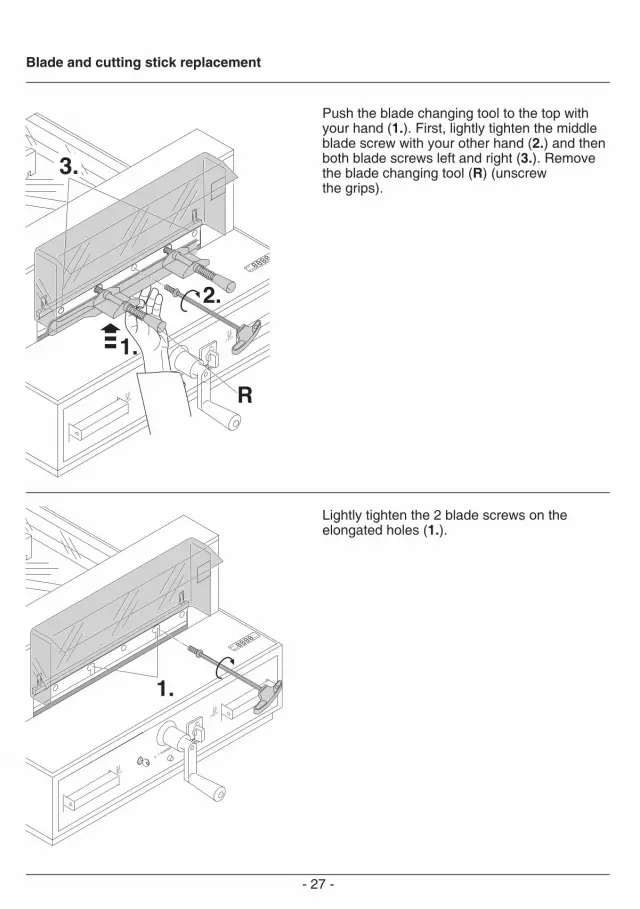
Push the blade changing tool to the top withyour hand (1.). First, lightly tighten the middleblade screw with your other hand (2.) and thenboth blade screws left and right (3.). Remove the blade changing tool (R) (unscrew the grips).
Lightly tighten the 2 blade screws on the elongated holes (1.).
Blade and cutting stick replacement

- 28 -
3.2.
1. Close the clamp by moving the clamp lever tothe left (1.) Close the safety guard (2.) Lowerthe blade by pressing both cutting buttons (3.) If the last sheet of paper is not completely cut, gradually turn the knob for blade-depth adjustment (A) ¼ turn to the right until the paper is cut along the entire length.(1 turn = 1,5 mm)
Open the clamp by moving the clamp lever tothe right (1.). Remove all tools and distributepaper along the entire cutting length (2.).Turn main switch to position "I" (3.).
Blade and cutting stick replacement

- 29 -
Tighten all 5 blade screws with a torque of 10Nm.
Blade and cutting stick replacement

- 30 -
Paper cutting test. If the last sheet or several sheets are not completely cut, gradually turn the knob for blade depth adjustment (A) ¼ turn to the right until the paper is cut along the entire length. Do not set too low as blade will become blunt sooner.
Danger! Do not turn main switch to position "0" whilst blade is movingupwards or downwards! Risk of injury!
Danger! Blade must always be covered by the pressing bar (see picture below onthe left).
Clamping BladeOK
OK
Blade and cutting stick replacement

- 31 -
2027
Next Maintenance
Krug & Priester GmbH & Co. KG72336 Balingen - Germany
Parts & Service HOTLINE
Germany: +49 7433 2690France: +33 3 8820 5435North America: +1 843 552 2700All other countries: Please contactyour local distributorwww.krug-priester.com
2023
Maintenance work may only be performed bytrained staff.
Danger! Disconnect the mains beforestarting any service work or beforeremoving the cover.
Safety testThe safety regulations are according to the regulations of the country where the cutting machine is operated. The manufacturer recommends a safety check is made every 5 years by an authorised service team.
Annual inspectionTo maintain the operational safety and to prevent premature wear, we recommend an annual inspection and maintenance of the machine by a qualified service technician.
Maintenance and cleaning
- 32 -
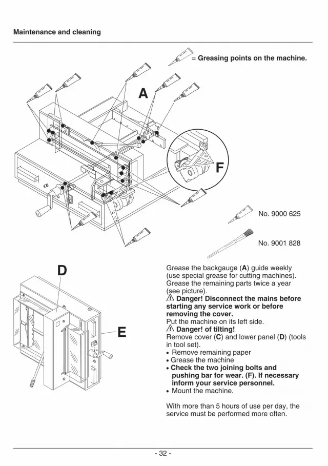
No. 9000 625
No. 9001 828
A
F
Grease the backgauge (A) guide weekly (use special grease for cutting machines).Grease the remaining parts twice a year (see picture).
Danger! Disconnect the mains beforestarting any service work or beforeremoving the cover. Put the machine on its left side. Danger! of tilting! Remove cover (C) and lower panel (D) (tools in tool set).• Remove remaining paper• Grease the machine• Check the two joining bolts and
pushing bar for wear. (F). If necessary inform your service personnel.
• Mount the machine.
With more than 5 hours of use per day, the service must be performed more often.
= Greasing points on the machine.
Maintenance and cleaning

- 33 -
Machine does not function!
Is the machine plugged in?
Main switch to position "I"? (A) Control system activated? (B)(Turn key to the right) Release a cut see page 18.
Possible malfunctions

- 34 -
Machine turns off:• Machine overloaded Safety button (A) ejects. Allow 1 minute cooling time and reset the safety button (A). • Machine blocked• Blade is blunt Eliminate the cause, and push the safety button (A).
Possible malfunctions

- 35 -
Does not cut through the last sheet:• Turn or turn around the cutting stick (A), readjust the blade by means of the blade adjusting knob (B). (See page 30).
Poor cutting quality or blade stays in thepaper stack.• change the blade (C) (see page 22 - 30).
Possible malfunctions

- 36 -
Service
Cut cannot be made.• If cover is open: close it.• If cover is closed: open and re-close it. (Security check).
Motor runs but blade does not movedownwards.• Security brake has been activated! Inform the service team!
Did none of the specified solutions help you with your problem? Contact: Service • www.krug-priester.com • [email protected]
Possible malfunctions

- 37 -
Recommended Accessories:
Blade No. 9000 121
Cutting stick (6 pieces) No. 9000 221
Paper knock-up block No. 9000 520 1
Blade changing tool No. 9000 522 1
Cabinet No. 4215 1100
Stand No. 4205 1100
1 Included in delivery.
Accessories
Grease tube No. 9000 625 1
Brush No. 9001 828

- 38 -
Technical data:• Power supply: 230V/50Hz/0,45KW,
120V/60Hz/0,45KW• Sound level: EN 13023: < 70 dB (A)• Leakage current < 3,5mA• Power cord gauge min. 1,5mm2 (230V)• Power cord gauge AWG 18 (15A) (120V)• Cutting height: 40 mm• Cutting length: 430 mm• Table depth: 435 mm• Height/Weight: 1085 mm/91 kg with stand (4315) 1080 mm/113 kg with cabinet (4315) 1085 mm/96 kg with stand (4350) 1080 mm/118 kg with cabinet (4350) The exact technical specifications can be found on the technical specifications sticker (A) on the machine. A wiring diagram is found in the electrical switch box.To claim under guarantee, the machine must still carry its original identification label.
Required space for operation, servicing andmaintenance.appr. 1200 mm x 1300 mm x 1400 mm.(W x D x H)
Technical data

- 39 -
This machine is approved by independent safety laboratories and is in compliance with the EC-regulations 2006/42/EG, and 2014/30/EU.
Sound level information: The sound level is < 70 db (A) as defined by EN 13023.
Subject to alteration without notice.
Technical data

- 40 -
The company Krug + Priester has the following certifications:• Quality management system according to DIN EN ISO 9001:2015• Environmental management system according to DIN EN ISO 14001:2015• Energy management system according to DIN EN ISO 50001:2018
Technical data

- 41 -
GS- IDENT. No. UL- IDENT. No. 4315 11431501 104315014350 11435001 10431501
EC-declaration of conformity
EC-declaration of conformity
- Herewith we declare that
- complies with the following provisons applying to it
2006/42/EG: EC Machinery directive
2014/30/EG: EMV Electromagnetic compatibility directive
2011/65/EU, 2015/863/EURoHS directive
- Applied harmonised standards in particular
EN 60204-1; EN 1010-1; EN 1010-3; EN 55014-1; EN 55014-2; EN 61000-3-2; EN 61000-3-3; EN ISO 12100; EN ISO 13857; EN ISO 11204; EN 13023; EN ISO 13849-1;BS EN 60204-1; BS EN 1010-1; BS EN 1010-3; BS EN 55014-1; BS EN 55014-2; BS EN 61000-3-2; BS EN 61000-3-3; BS EN ISO 12100; BS EN ISO 13857; BS EN ISO 11204; BS EN 13023; BS EN ISO 13849-1
Authorized representative for technical documentation Krug & Priester GmbH & Co. KGSimon-Schweitzer-Str. 34D-72336 Balingen (Germany)
10.02.2022Date
- Managing Director -

- 42 -
Remarks:

- 43 -
Remarks:

Krug & Priester GmbH & Co. KGSimon-Schweitzer-Str. 34D-72336 Balingen (Germany)www.krug-priester.com 01-2020 10.02.2022 zm
• Document Shredders •
• Trimmers and Guillotines •
9700193 9700136
IDEAL • Made in Germany


