Embed Size (px)
Citation preview
Journal of Natural Gas Science and Engineering 101 (2022) 104547
Available online 28 March 20221875-5100/Published by Elsevier B.V.
Hydrogen-induced cracking and blistering in steels: A review
May L. Martin a,*, Petros Sofronis b,c
a Applied Chemicals and Materials Division, Materials Measurement Laboratory, National Institute of Standards and Technology, Boulder, CO, 80305, USA b Department of Mechanical Science and Engineering, University of Illinois at Urbana-Champaign, Urbana-Champaign, IL, 61801, USA c International Institute for Carbon Neutral Energy Research (WPI-I2CNER), Kyushu University, 744 Moto-oka, Nishi-ku, Fukuoka, 819-0395, Japan
A R T I C L E I N F O
Keywords: Hydrogen-induced cracking Corrosion Hydrogen sulfide environment Blistering
A B S T R A C T
This paper presents a review of the current state of scientific understanding of the corrosion phenomenon known as Hydrogen-Induced Cracking (HIC). HIC is defined as cracking in low-to medium-strength steels where cracking is driven by the precipitation of gaseous hydrogen molecules within the crack, which typically occurs in sour (H2S containing) environments. It is a complicated phenomenon, encompassing a surface reaction for hydrogen uptake, hydrogen diffusion to vulnerable microstructural sites, hydrogen gas precipitation creating an incipient crack, and crack growth driven by hydrogen gas pressure within the crack. While HIC has been studied for decades, understanding of the critical factors controlling each step of the phenomenon has been elusive. The maturation of many characterization techniques gives hope that a full mechanistic understanding may occur in the near future.
Credit author statement
May L. Martin – Investigation, Writing, Petros Sofronis – Conceptu-alization, Supervision.
1. Introduction
A 2002 study initiated by the National Association of Corrosion Engineers (NACE) found that the direct costs of corrosion in the US, at the time, was $276 billion dollars, or 3.1% of the country’s GDP (Koch et al., 2002). Of that, oil and gas exploration and production saw corrosion costs of $1.4 billion, while petroleum refining saw $3.7 billion. For natural gas and liquid crude pipelines, the estimated annual cost was $7 billion, suggesting it is one of the largest affected areas in the industry. The report’s authors estimated that 25–30% of the costs could be saved through proper corrosion management procedures. The 2016 NACE IMPACT report estimated that the cost in 2013 had grown to nearly $450 billion dollars in the US, or 2.7% of the GDP, and $2.5 trillion worldwide, and still suggested that 15–35% cost savings could be achieved worldwide with proper mitigation practices (Koch et al., 2016). And it is important to note that these numbers do not account for losses due to leaks causing environmental damage (and corresponding tourism activity losses), clean-up costs of these spills and leaks, facility shutdown and corrosion prevention costs, or loss of life (Sotoodeh and
Sotoodeh, 2021). In particular, as sour conditions become increasingly the norm for
petrochemical exploration, H2S influenced corrosion processes will continue to plague the industry. (Sour service is when the oil/gas environment has a partial pressure of H2S sufficient to cause cracking, which was previously defined as greater than 0.3 kPa (Milliams, 2016).) And, even with a potential reduction in petrochemical processes, H2S is still common in several other industries, such as mining and paper processing, as well as being naturally produced by anaerobic bacteria in processes common in sewage (OSHA). While the presence of hydrogen sulfide gas can have multiple effects on the performance of structural metals, such as pitting, mass loss from corrosion, or stress-corrosion cracking, one common form of corrosion from H2S is hydrogen-induced cracking (HIC) (ANSI/NACE, 2016). While there are no recent infamous catastrophes associated with this phenomenon, as the above numbers suggest, any prominent corrosion phenomenon has an enormous financial impact on industry and infrastructure, and the potential for causing loss of life.
As with many problems facing industry, particularly corrosion-based problems, a great deal of research into HIC has occurred, but it has primarily been comprised of individual specific use studies with a scattering of fundamental science-focused studies, with no large-scale systematic studies which would provide the guidance needed for ma-terials design/selection against this phenomenon. This review focuses
* Corresponding author. E-mail address: [email protected] (M.L. Martin).
Contents lists available at ScienceDirect
Journal of Natural Gas Science and Engineering
journal homepage: www.elsevier.com/locate/jngse
https://doi.org/10.1016/j.jngse.2022.104547 Received 16 December 2021; Received in revised form 22 March 2022; Accepted 24 March 2022
Journal of Natural Gas Science and Engineering 101 (2022) 104547
2
on an overview of the phenomenon of HIC in low-to medium-strength steels, with an emphasis on recent results which give insight into the fundamental mechanism of the phenomenon.
2. Definition
2.1. ASM and literature definition
Hydrogen-induced cracking or HIC, as described by the ASM Hand-book, is the cracking in low-to medium-strength steels in the absence of applied stress where the driving force for crack propagation is molecular hydrogen pressure build-up within the crack (Timmins, 1996). NACE specifically states that the term hydrogen-induced cracking covers the now-obsolete terms of stepwise cracking, hydrogen-induced step-wise cracking, blister cracking, and hydrogen pressure cracking (ANSI/-NACE, 2016). This hydrogen gas precipitates when the hydrogen solu-bility limit of the material is reached (Liu, 2011). These cracks are typically parallel to the steel surface, and are usually associated with microstructural features such as inclusions or other planar defects in the longitudinal direction (often associated with rolling processes) (Elboujdaini and Revie, 2011). HIC is particularly associated with wet conditions where H2S (sour corrosion) is present (Sotoodeh and Sotoo-deh, 2021; Timmins, 1996), though it can also be induced by aggressive electrochemical charging (Perez Escobar et al., 2011). HIC manifests itself in forms commonly referred to as stepwise cracking or blistering, where the latter creates clear defects on the metal surface. Catastrophic failure can occur, particularly from step-wise cracking, when there is sufficient reduction to the effective thickness of the part (Elboujdaini and Revie, 2011; Kane, 1985a). Other materials can also display cracking and blistering under aggressive electrochemical charging (Chen et al., 2009; Panagopoulos et al., 1998; Rozenak, 2005, 2007; Shan et al., 2005; Takano et al., 2021), though this review will concentrate on the ASM-defined HIC phenomenon in steels.
2.2. Hydrogen-induced cracking vs. hydrogen embrittlement
There are multiple environmental degradation phenomena in which hydrogen plays an important role. While clearly defined by the ASM Handbook to refer to cracking driven by hydrogen pressure build-up, there are unfortunately cases in the literature where HIC is used to refer to different phenomena, especially hydrogen embrittlement (often abbreviated as HE). A lack of consistent terminology means that cracking or failure due to hydrogen embrittlement has been referred to by terms such as hydrogen-enhanced cracking, hydrogen environment- assisted cracking, or hydrogen-assisted cracking, and in some cases, as hydrogen-induced cracking. This can be a source of confusion and it is important to differentiate the phenomena. Hydrogen embrittlement is traditionally defined as the loss of ductility that many metals exhibit due to the presence of hydrogen atoms within the metal lattice (Martin et al., 2020). It generally requires an applied force and does not generally have hydrogen gas precipitation within the material. Also, as mentioned, hydrogen embrittlement is a problem that plagues many classes of metals, while HIC is primarily a concern in non-austenitic steels, though, as mentioned, blistering has been observed in other materials under aggressive electrochemical charging (Chen et al., 2009; Panagopoulos et al., 1998; Rozenak, 2005, 2007; Shan et al., 2005). Another clear difference is that hydrogen embrittlement is generally reversible, with the material regaining its ductility once the hydrogen is removed from the material, while HIC causes irreversible damage within the material. HIC is generally found under aqueous conditions, often involving elec-trochemical charging or the presence of hydrogen sulfide, while hydrogen embrittlement can occur under a variety of conditions, including much milder conditions, or in dry hydrogen gas environments. This discussion is meant not just to more clearly define the phenomena, but also as a call for greater consistency in naming conventions.
After clarifying the difference between the phenomena, it is worth
noting that it is likely that hydrogen embrittlement plays a crucial role in the HIC process. The large amount of interstitial hydrogen present in the material when hydrogen gas precipitates out into cracks suggests that it likely affects the material response around the cracks. It may also have an impact on crack initiation. These aspects will be discussed later in this review.
3. Mechanisms of HIC
HIC occurs through a series of steps, which will be discussed in the sections below. Hydrogen from the environment enters the material. Hydrogen diffuses through the material, collecting at inhomogeneities until the solubility limit is locally met. Molecular hydrogen precipitates out at initiation sites, most commonly elongated MnS inclusions. Cracks propagate due to the hydrogen pressure in the crack.
3.1. Hydrogen uptake and trapping
While hydrogen is ubiquitous, and is known to enter materials under favorable conditions, for HIC, a relatively large amount must enter the steel throughout the process. This can occur under sour service envi-ronments. The severity of hydrogen uptake will depend upon various environmental conditions, including temperature, pH, chemistry of the aqueous solution, and the partial pressures of H2S, CO2, and H2, though not necessarily total pressure of the system (Moore and McIntyre, 1998; Elboujdaini et al., 2006).
3.1.1. Surface reaction In sour service environments, several different corrosion processes
can occur with iron and steels. But the effect which is of most concern to HIC is the uptake of atomic hydrogen. The anodic dissolution of iron allows for the reduction of hydrogen ions to atomic hydrogen, which can enter the steel or iron matrix (Kim and Kim, 2014). While atomic hydrogen is thermodynamically unstable, the hydrogen sulfide impedes the recombination to hydrogen gas, allowing the atomic hydrogen to be adsorbed onto the steel surface (Kim and Kim, 2014; Findley et al., 2015). Hydrogen sulfide is then thought to have two effects, being the source of the hydrogen atoms, and preventing recombination of hydrogen atoms into stable H2 (g) molecules.
As with many corrosion processes, there are a variety of surface re-actions occurring under the conditions at which HIC occurs. Many studies have looked at the effect of H2S on the corrosion of steels and iron, as well as nickel and chromium (Castaneda et al., 2009; Cheng et al., 1999; Zhao et al., 2011). For iron and steels, the consensus has been that a FeS1-X compound, usually identified as mackinawite, is formed during H2S exposure (Shoesmith et al., 1980; Tang et al., 2010), which leads to acidification and an increase in hydrogen ions that the metal can uptake (Cheng et al., 1999; Hoffmeister, 2006; Fatah et al., 2011). The overall reaction is generally considered to be Fe + H2S(aq) → FeS + H2 (Shoesmith et al., 1980; Lucio-Garcia et al., 2009; Ma et al., 2000). However, depending upon the H2S concentration, different films of iron-sulfur compounds, such as ferrous sulfide, troilite, or pyrite, can form on the iron surface that could impede corrosion processes (Ma et al., 2000; Hernandez-Espejel et al., 2010). Further study is needed to understand which properties of the surface corrosion products and environment, such as variations with pH or propensity to not adhere to underlying metal, determine the nature of the film and whether the film is deleterious or protective. This may also determine which corrosion processes (HIC, pitting, stress corrosion cracking, etc.) are dominant.
In addition to the concentration of H2S, other environmental factors like pH also play an important role in hydrogen charging. In general, lower pH (more acidic environments) tends to increase hydrogen transport, with low pH and high H2S concentration resulting in the largest amount of diffusible hydrogen entering the material (Kim et al., 2008). It has been proposed that corrosive products are more likely to be soluble at lower pH, and hydrogen can more easily enter clean surfaces
M.L. Martin and P. Sofronis
Journal of Natural Gas Science and Engineering 101 (2022) 104547
3
(Skei et al., 1953). However, in alkaline environments, hydrogen transport has been observed to increase with increasing pH (Schuyler, 1979).
The effect of pH is important to note as the NACE standard for HIC testing (ANSI/NACE, 2016) has three different testing solution options. The first is an acidified brine solution with a pH of 2.7–3.3 after H2S saturation. The second is synthetic seawater with an initial pH of 4.8–5.4 after H2S saturation. And the third is a buffered brine solution where the tester is able to define the pH.
It is worth noting that H2S is a poisonous gas that is a greater hazard than many labs are prepared to deal with. As such, hydrogen entry is often facilitated by electrochemical charging instead. Some authors will refer to testing methods as following a “modified NACE standard TM0284” (Mohtadi-Bonab et al., 2014; Zhang et al., 2018) when they follow the standard apart from using electrochemical charging in the place of H2S exposure. Hydrogen uptake is controlled by current density and charging time. Longer charging times and higher current densities result in higher amounts of hydrogen in the material, and therefore greater amounts of cracking (Dong et al., 2009a; Mohtadi-Bonab et al., 2015; Tiegel et al., 2016). Measured hydrogen amounts have been observed to plateau after certain times or certain current densities (Mohtadi-Bonab et al., 2015; Tiegel et al., 2016), which has been asso-ciated with solution exhaustion or loss of hydrogen from the sample due to cracks encountering the surface. Electrochemical charging is often done with an acidic solution, such as sulfuric acid, coupled with a “recombination poison”, such as ammonium thiocyanate (Mohtadi-Bo-nab et al., 2015), sodium arsenite (Hejazi et al., 2012) or thiourea (Perez Escobar et al., 2011). There does not appear to be clear translation from electrochemical charging conditions to H2S conditions that would allow direct comparison between results under the two conditions. And, as mentioned, a wide variety of solutions are used, possibly making direct comparison between different studies difficult. This is part of why Findley et al. makes a comment that since in-service H2S corrosion is not properly captured by the Devanathan-Stachurski cell electrochemical permeation experiments, those results should primarily be used for qualitative rankings of materials rather than quantitative performance (Findley et al., 2015). Because of these differences, qualification of materials for HIC service needs to be done under the NACE TM0284 standard, using H2S gas exposure, which has been shown to reasonably predict real-life performance (Moore and McIntyre, 1998).
3.1.2. Hydrogen diffusion and trapping Many studies have been conducted on hydrogen diffusion in metals,
so only a brief summary will be covered here. Once hydrogen enters the iron lattice, it is assumed to move according to Fick’s diffusion laws (Volkl et al., 1975) through interstitial sites, generally the tetrahedral site in body-centered cubic iron (Fukai, 1984). In an ideal crystal, the hydrogen would diffuse from the entry surface (high concentration) through the sample, forming a predictable distribution, and not accu-mulating in high enough concentrations to precipitate into hydrogen gas pockets, except perhaps near the entry surface. However, trapping of the diffusing hydrogen by various microstructural features in the material changes the distribution profile of the hydrogen in the steel.
Traps can be characterized in several different ways depending upon structural character or the energy of the trap (how difficult it is for hydrogen to escape) (Pressouyre, 1979, 1980). Generally, traps are divided into reversible and irreversible traps, with dislocations and grain boundaries usually considered reversible traps, and incoherent precipitates usually considered irreversible. With respect to HIC, traps can have two influences: on the diffusion and distribution of hydrogen, and on hydrogen accumulation and crack initiation.
The effect of trapping on the diffusion of hydrogen can be significant. For example, the addition of 1 wt% carbon into steel can result in a two order of magnitude lower diffusivity due to increased trapping by microstructural features created by the addition of carbon (Verbeken et al., 2012). The morphology of secondary phases created by the
addition of carbon can affect the trapping characteristics of the pre-cipitates. Spheroidised cementite in ferrite was found to result in higher diffusivity than when there was the dispersion of fine coherent Fe3C precipitates which constitutes pearlite, likely due to increased trapping by the fine precipitates (Bott et al., 1993; Johnson et al., 1987).
Trapping can also change the solubility of the material: the amount of hydrogen that a material can contain. In the case of the spheroidised cementite vs pearlite, higher solubilities were measured in the pearlitic systems, likely due to the increased amount of traps sites due to higher surface areas associated with the finer precipitates (Bott et al., 1993; Johnson et al., 1987). Dislocations are also trapping sites, and increased hydrogen concentrations were measured in quenched martensite compared to quenched and tempered martensite, due to the higher number of dislocation traps in the quenched material (Johnson et al., 1987).
Irreversible traps remove diffusible hydrogen from the system, increasing the total amount of hydrogen needed to reach critical con-centrations. This has been the rationale for adding fine precipitates such as titanium/niobium carbonitrides to steels to improve cracking resis-tance (Zhao et al., 2002). However, it should be noted that this may be a short-term effect, as once these deep traps are saturated and cannot remove more hydrogen from the system, they no longer impact the diffusion (Dadfarnia et al., 2011). Several studies have shown that nanosized Ti and Nb carbonitrides do not affect the resistance of some pipeline steels to HIC (Huang et al., 2011; Zhao et al., 2003).
An important aspect that needs to be considered is that many of the steels of concern are rolled and consist of multiple different steel mi-crostructures, including pearlite, bainite, and martensite, often resulting in banded microstructures. Having bands of potential trap sites will have different effects than randomly distributed sites throughout a ferrite matrix. Permeation studies, which measure the kinetics of hydrogen diffusing through a membrane of material, of pearlitic steels have shown distinct differences in diffusion when the pearlite bands are aligned in the permeation direction (in parallel) versus perpendicular to the permeation direction (in series) (Lee and Chan, 1991; Tau and Chan, 1996). As hydrogen is slowed by each layer, it accumulates, affecting the overall distribution of the hydrogen, potentially resulting in crack initiation.
At certain trap sites, hydrogen can accumulate to sufficient concen-trations that the precipitation of H2 gas is favorable. Precipitation of molecular hydrogen will occur when the atomic hydrogen concentration is greater than the solubility limit of the material (Liu, 2011). Reaching this critical concentration of hydrogen is thought to be a requirement for cracking (Liou et al., 1993; Lukito and Szklarska-Smialowska, 1997). Based upon the discussion above, it is evident that this is more likely to occur at trapping sites as the atomic hydrogen accumulates at these locations. However, as molecular hydrogen is larger than atomic hydrogen, it cannot easily fit in the same volume. Certain traps, such as microvoids or inclusion interfaces, may include more space, or be more prone to opening up space creating a weak point from which cracks can initiate.
As the diffusion and trapping of hydrogen is critical to the estab-lishment of conditions favorable to cracking, there have been many at-tempts to relate permeation tests to susceptibility to HIC. Several studies have found that HIC susceptibility increases as apparent diffusivity de-creases and apparent solubility increases (Huang et al., 2010, 2011). The suggested reason is that increased trapping at irreversible traps, such as inclusions, leads to the decreased diffusivity, and is related to favorable conditions for crack initiation. However, those trends are not universal, as in some cases higher diffusivities were measured for materials which exhibited HIC than for those that did not (Kim et al., 2008). In these cases, it was suggested that, when irreversible trapping sites are not crack nucleation sites, the amount of diffusible hydrogen is the impor-tant factor (Kim et al., 2008; Huang et al., 2011; Arafin and Szpunar, 2011). This suggests that permeation studies may not be useful for comparing different steel classes, where the microstructural factors
M.L. Martin and P. Sofronis
Journal of Natural Gas Science and Engineering 101 (2022) 104547
4
affecting cracking are very different. It is also important to note that permeation studies usually introduce the hydrogen electrochemically, which does not represent the in-service sour conditions which usually results in HIC. As such, they may not be useful for comparing the quantitative performance of these materials (Findley et al., 2015).
3.2. Step-wise cracking
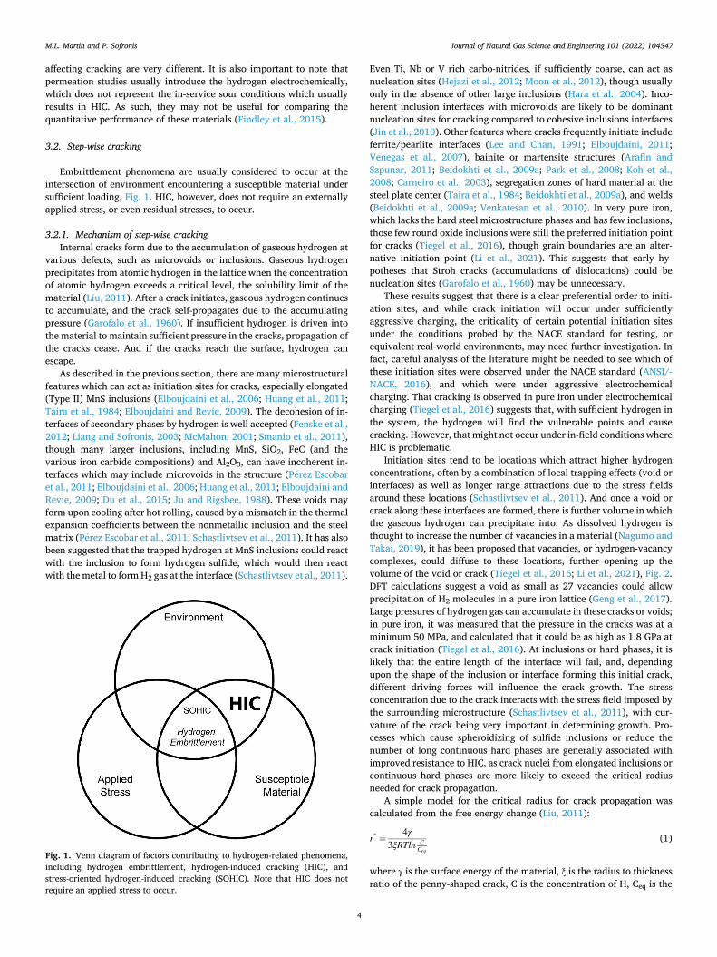
Embrittlement phenomena are usually considered to occur at the intersection of environment encountering a susceptible material under sufficient loading, Fig. 1. HIC, however, does not require an externally applied stress, or even residual stresses, to occur.
3.2.1. Mechanism of step-wise cracking Internal cracks form due to the accumulation of gaseous hydrogen at
various defects, such as microvoids or inclusions. Gaseous hydrogen precipitates from atomic hydrogen in the lattice when the concentration of atomic hydrogen exceeds a critical level, the solubility limit of the material (Liu, 2011). After a crack initiates, gaseous hydrogen continues to accumulate, and the crack self-propagates due to the accumulating pressure (Garofalo et al., 1960). If insufficient hydrogen is driven into the material to maintain sufficient pressure in the cracks, propagation of the cracks cease. And if the cracks reach the surface, hydrogen can escape.
As described in the previous section, there are many microstructural features which can act as initiation sites for cracks, especially elongated (Type II) MnS inclusions (Elboujdaini et al., 2006; Huang et al., 2011; Taira et al., 1984; Elboujdaini and Revie, 2009). The decohesion of in-terfaces of secondary phases by hydrogen is well accepted (Fenske et al., 2012; Liang and Sofronis, 2003; McMahon, 2001; Smanio et al., 2011), though many larger inclusions, including MnS, SiO2, FeC (and the various iron carbide compositions) and Al2O3, can have incoherent in-terfaces which may include microvoids in the structure (Perez Escobar et al., 2011; Elboujdaini et al., 2006; Huang et al., 2011; Elboujdaini and Revie, 2009; Du et al., 2015; Ju and Rigsbee, 1988). These voids may form upon cooling after hot rolling, caused by a mismatch in the thermal expansion coefficients between the nonmetallic inclusion and the steel matrix (Perez Escobar et al., 2011; Schastlivtsev et al., 2011). It has also been suggested that the trapped hydrogen at MnS inclusions could react with the inclusion to form hydrogen sulfide, which would then react with the metal to form H2 gas at the interface (Schastlivtsev et al., 2011).
Even Ti, Nb or V rich carbo-nitrides, if sufficiently coarse, can act as nucleation sites (Hejazi et al., 2012; Moon et al., 2012), though usually only in the absence of other large inclusions (Hara et al., 2004). Inco-herent inclusion interfaces with microvoids are likely to be dominant nucleation sites for cracking compared to cohesive inclusions interfaces (Jin et al., 2010). Other features where cracks frequently initiate include ferrite/pearlite interfaces (Lee and Chan, 1991; Elboujdaini, 2011; Venegas et al., 2007), bainite or martensite structures (Arafin and Szpunar, 2011; Beidokhti et al., 2009a; Park et al., 2008; Koh et al., 2008; Carneiro et al., 2003), segregation zones of hard material at the steel plate center (Taira et al., 1984; Beidokhti et al., 2009a), and welds (Beidokhti et al., 2009a; Venkatesan et al., 2010). In very pure iron, which lacks the hard steel microstructure phases and has few inclusions, those few round oxide inclusions were still the preferred initiation point for cracks (Tiegel et al., 2016), though grain boundaries are an alter-native initiation point (Li et al., 2021). This suggests that early hy-potheses that Stroh cracks (accumulations of dislocations) could be nucleation sites (Garofalo et al., 1960) may be unnecessary.
These results suggest that there is a clear preferential order to initi-ation sites, and while crack initiation will occur under sufficiently aggressive charging, the criticality of certain potential initiation sites under the conditions probed by the NACE standard for testing, or equivalent real-world environments, may need further investigation. In fact, careful analysis of the literature might be needed to see which of these initiation sites were observed under the NACE standard (ANSI/-NACE, 2016), and which were under aggressive electrochemical charging. That cracking is observed in pure iron under electrochemical charging (Tiegel et al., 2016) suggests that, with sufficient hydrogen in the system, the hydrogen will find the vulnerable points and cause cracking. However, that might not occur under in-field conditions where HIC is problematic.
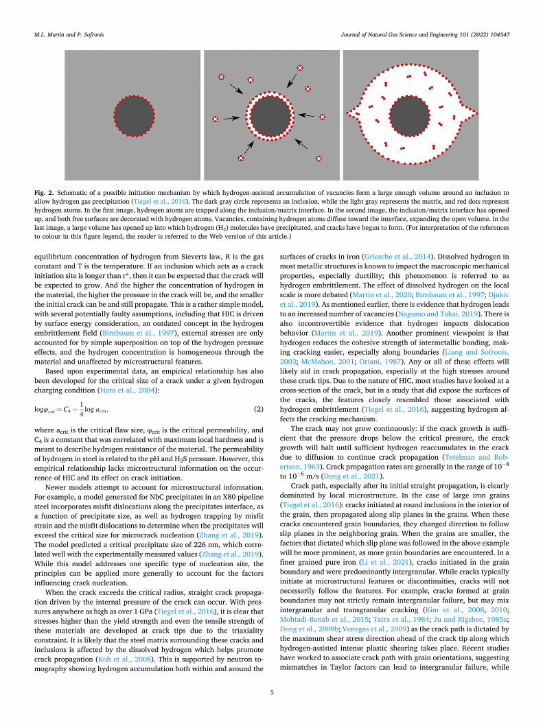
Initiation sites tend to be locations which attract higher hydrogen concentrations, often by a combination of local trapping effects (void or interfaces) as well as longer range attractions due to the stress fields around these locations (Schastlivtsev et al., 2011). And once a void or crack along these interfaces are formed, there is further volume in which the gaseous hydrogen can precipitate into. As dissolved hydrogen is thought to increase the number of vacancies in a material (Nagumo and Takai, 2019), it has been proposed that vacancies, or hydrogen-vacancy complexes, could diffuse to these locations, further opening up the volume of the void or crack (Tiegel et al., 2016; Li et al., 2021), Fig. 2. DFT calculations suggest a void as small as 27 vacancies could allow precipitation of H2 molecules in a pure iron lattice (Geng et al., 2017). Large pressures of hydrogen gas can accumulate in these cracks or voids; in pure iron, it was measured that the pressure in the cracks was at a minimum 50 MPa, and calculated that it could be as high as 1.8 GPa at crack initiation (Tiegel et al., 2016). At inclusions or hard phases, it is likely that the entire length of the interface will fail, and, depending upon the shape of the inclusion or interface forming this initial crack, different driving forces will influence the crack growth. The stress concentration due to the crack interacts with the stress field imposed by the surrounding microstructure (Schastlivtsev et al., 2011), with cur-vature of the crack being very important in determining growth. Pro-cesses which cause spheroidizing of sulfide inclusions or reduce the number of long continuous hard phases are generally associated with improved resistance to HIC, as crack nuclei from elongated inclusions or continuous hard phases are more likely to exceed the critical radius needed for crack propagation.
A simple model for the critical radius for crack propagation was calculated from the free energy change (Liu, 2011):
r* =4γ
3ξRTln CCeq
(1)
where γ is the surface energy of the material, ξ is the radius to thickness ratio of the penny-shaped crack, C is the concentration of H, Ceq is the
Fig. 1. Venn diagram of factors contributing to hydrogen-related phenomena, including hydrogen embrittlement, hydrogen-induced cracking (HIC), and stress-oriented hydrogen-induced cracking (SOHIC). Note that HIC does not require an applied stress to occur.
M.L. Martin and P. Sofronis
Journal of Natural Gas Science and Engineering 101 (2022) 104547
5
equilibrium concentration of hydrogen from Sieverts law, R is the gas constant and T is the temperature. If an inclusion which acts as a crack initiation site is longer than r*, then it can be expected that the crack will be expected to grow. And the higher the concentration of hydrogen in the material, the higher the pressure in the crack will be, and the smaller the initial crack can be and still propagate. This is a rather simple model, with several potentially faulty assumptions, including that HIC is driven by surface energy consideration, an outdated concept in the hydrogen embrittlement field (Birnbaum et al., 1997), external stresses are only accounted for by simple superposition on top of the hydrogen pressure effects, and the hydrogen concentration is homogeneous through the material and unaffected by microstructural features.
Based upon experimental data, an empirical relationship has also been developed for the critical size of a crack under a given hydrogen charging condition (Hara et al., 2004):
logφcrit =C4 −14
log acrit, (2)
where acrit is the critical flaw size, φcrit is the critical permeability, and C4 is a constant that was correlated with maximum local hardness and is meant to describe hydrogen resistance of the material. The permeability of hydrogen in steel is related to the pH and H2S pressure. However, this empirical relationship lacks microstructural information on the occur-rence of HIC and its effect on crack initiation.
Newer models attempt to account for microstructural information. For example, a model generated for NbC precipitates in an X80 pipeline steel incorporates misfit dislocations along the precipitates interface, as a function of precipitate size, as well as hydrogen trapping by misfit strain and the misfit dislocations to determine when the precipitates will exceed the critical size for microcrack nucleation (Zhang et al., 2019). The model predicted a critical precipitate size of 226 nm, which corre-lated well with the experimentally measured values (Zhang et al., 2019). While this model addresses one specific type of nucleation site, the principles can be applied more generally to account for the factors influencing crack nucleation.
When the crack exceeds the critical radius, straight crack propaga-tion driven by the internal pressure of the crack can occur. With pres-sures anywhere as high as over 1 GPa (Tiegel et al., 2016), it is clear that stresses higher than the yield strength and even the tensile strength of these materials are developed at crack tips due to the triaxiality constraint. It is likely that the steel matrix surrounding these cracks and inclusions is affected by the dissolved hydrogen which helps promote crack propagation (Koh et al., 2008). This is supported by neutron to-mography showing hydrogen accumulation both within and around the
surfaces of cracks in iron (Griesche et al., 2014). Dissolved hydrogen in most metallic structures is known to impact the macroscopic mechanical properties, especially ductility; this phenomenon is referred to as hydrogen embrittlement. The effect of dissolved hydrogen on the local scale is more debated (Martin et al., 2020; Birnbaum et al., 1997; Djukic et al., 2019). As mentioned earlier, there is evidence that hydrogen leads to an increased number of vacancies (Nagumo and Takai, 2019). There is also incontrovertible evidence that hydrogen impacts dislocation behavior (Martin et al., 2019). Another prominent viewpoint is that hydrogen reduces the cohesive strength of intermetallic bonding, mak-ing cracking easier, especially along boundaries (Liang and Sofronis, 2003; McMahon, 2001; Oriani, 1987). Any or all of these effects will likely aid in crack propagation, especially at the high stresses around these crack tips. Due to the nature of HIC, most studies have looked at a cross-section of the crack, but in a study that did expose the surfaces of the cracks, the features closely resembled those associated with hydrogen embrittlement (Tiegel et al., 2016), suggesting hydrogen af-fects the cracking mechanism.
The crack may not grow continuously: if the crack growth is suffi-cient that the pressure drops below the critical pressure, the crack growth will halt until sufficient hydrogen reaccumulates in the crack due to diffusion to continue crack propagation (Tetelman and Rob-ertson, 1963). Crack propagation rates are generally in the range of 10− 8
to 10− 6 m/s (Dong et al., 2021). Crack path, especially after its initial straight propagation, is clearly
dominated by local microstructure. In the case of large iron grains (Tiegel et al., 2016): cracks initiated at round inclusions in the interior of the grain, then propagated along slip planes in the grains. When these cracks encountered grain boundaries, they changed direction to follow slip planes in the neighboring grain. When the grains are smaller, the factors that dictated which slip plane was followed in the above example will be more prominent, as more grain boundaries are encountered. In a finer grained pure iron (Li et al., 2021), cracks initiated in the grain boundary and were predominantly intergranular. While cracks typically initiate at microstructural features or discontinuities, cracks will not necessarily follow the features. For example, cracks formed at grain boundaries may not strictly remain intergranular failure, but may mix intergranular and transgranular cracking (Kim et al., 2008, 2010; Mohtadi-Bonab et al., 2015; Taira et al., 1984; Ju and Rigsbee, 1985a; Dong et al., 2009b; Venegas et al., 2009) as the crack path is dictated by the maximum shear stress direction ahead of the crack tip along which hydrogen-assisted intense plastic shearing takes place. Recent studies have worked to associate crack path with grain orientations, suggesting mismatches in Taylor factors can lead to intergranular failure, while
Fig. 2. Schematic of a possible initiation mechanism by which hydrogen-assisted accumulation of vacancies form a large enough volume around an inclusion to allow hydrogen gas precipitation (Tiegel et al., 2016). The dark gray circle represents an inclusion, while the light gray represents the matrix, and red dots represent hydrogen atoms. In the first image, hydrogen atoms are trapped along the inclusion/matrix interface. In the second image, the inclusion/matrix interface has opened up, and both free surfaces are decorated with hydrogen atoms. Vacancies, containing hydrogen atoms diffuse toward the interface, expanding the open volume. In the last image, a large volume has opened up into which hydrogen (H2) molecules have precipitated, and cracks have begun to form. (For interpretation of the references to colour in this figure legend, the reader is referred to the Web version of this article.)
M.L. Martin and P. Sofronis
Journal of Natural Gas Science and Engineering 101 (2022) 104547
6
high Taylor factors may lead to transgranular failure (Mohtadi-Bonab et al., 2015). In a rolled microstructure, it is simple to imagine cracks propagating along the elongated hard microstructures such as sulfide stringers. Similarly, cracks could propagate along pearlite/ferrite in-terfaces (Lee and Chan, 1991; Du et al., 2015).
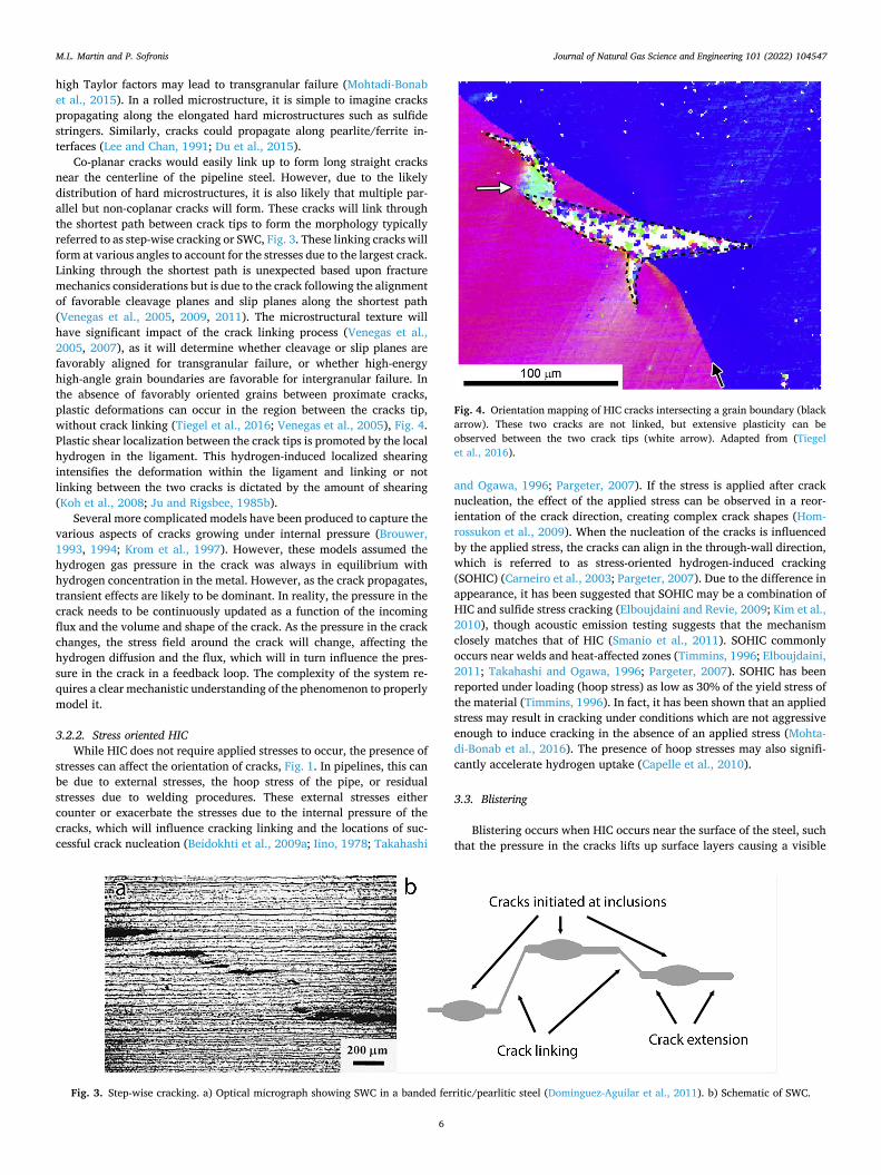
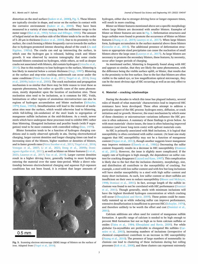
Co-planar cracks would easily link up to form long straight cracks near the centerline of the pipeline steel. However, due to the likely distribution of hard microstructures, it is also likely that multiple par-allel but non-coplanar cracks will form. These cracks will link through the shortest path between crack tips to form the morphology typically referred to as step-wise cracking or SWC, Fig. 3. These linking cracks will form at various angles to account for the stresses due to the largest crack. Linking through the shortest path is unexpected based upon fracture mechanics considerations but is due to the crack following the alignment of favorable cleavage planes and slip planes along the shortest path (Venegas et al., 2005, 2009, 2011). The microstructural texture will have significant impact of the crack linking process (Venegas et al., 2005, 2007), as it will determine whether cleavage or slip planes are favorably aligned for transgranular failure, or whether high-energy high-angle grain boundaries are favorable for intergranular failure. In the absence of favorably oriented grains between proximate cracks, plastic deformations can occur in the region between the cracks tip, without crack linking (Tiegel et al., 2016; Venegas et al., 2005), Fig. 4. Plastic shear localization between the crack tips is promoted by the local hydrogen in the ligament. This hydrogen-induced localized shearing intensifies the deformation within the ligament and linking or not linking between the two cracks is dictated by the amount of shearing (Koh et al., 2008; Ju and Rigsbee, 1985b).
Several more complicated models have been produced to capture the various aspects of cracks growing under internal pressure (Brouwer, 1993, 1994; Krom et al., 1997). However, these models assumed the hydrogen gas pressure in the crack was always in equilibrium with hydrogen concentration in the metal. However, as the crack propagates, transient effects are likely to be dominant. In reality, the pressure in the crack needs to be continuously updated as a function of the incoming flux and the volume and shape of the crack. As the pressure in the crack changes, the stress field around the crack will change, affecting the hydrogen diffusion and the flux, which will in turn influence the pres-sure in the crack in a feedback loop. The complexity of the system re-quires a clear mechanistic understanding of the phenomenon to properly model it.
3.2.2. Stress oriented HIC While HIC does not require applied stresses to occur, the presence of
stresses can affect the orientation of cracks, Fig. 1. In pipelines, this can be due to external stresses, the hoop stress of the pipe, or residual stresses due to welding procedures. These external stresses either counter or exacerbate the stresses due to the internal pressure of the cracks, which will influence cracking linking and the locations of suc-cessful crack nucleation (Beidokhti et al., 2009a; Iino, 1978; Takahashi
and Ogawa, 1996; Pargeter, 2007). If the stress is applied after crack nucleation, the effect of the applied stress can be observed in a reor-ientation of the crack direction, creating complex crack shapes (Hom-rossukon et al., 2009). When the nucleation of the cracks is influenced by the applied stress, the cracks can align in the through-wall direction, which is referred to as stress-oriented hydrogen-induced cracking (SOHIC) (Carneiro et al., 2003; Pargeter, 2007). Due to the difference in appearance, it has been suggested that SOHIC may be a combination of HIC and sulfide stress cracking (Elboujdaini and Revie, 2009; Kim et al., 2010), though acoustic emission testing suggests that the mechanism closely matches that of HIC (Smanio et al., 2011). SOHIC commonly occurs near welds and heat-affected zones (Timmins, 1996; Elboujdaini, 2011; Takahashi and Ogawa, 1996; Pargeter, 2007). SOHIC has been reported under loading (hoop stress) as low as 30% of the yield stress of the material (Timmins, 1996). In fact, it has been shown that an applied stress may result in cracking under conditions which are not aggressive enough to induce cracking in the absence of an applied stress (Mohta-di-Bonab et al., 2016). The presence of hoop stresses may also signifi-cantly accelerate hydrogen uptake (Capelle et al., 2010).
3.3. Blistering
Blistering occurs when HIC occurs near the surface of the steel, such that the pressure in the cracks lifts up surface layers causing a visible
Fig. 3. Step-wise cracking. a) Optical micrograph showing SWC in a banded ferritic/pearlitic steel (Dominguez-Aguilar et al., 2011). b) Schematic of SWC.
Fig. 4. Orientation mapping of HIC cracks intersecting a grain boundary (black arrow). These two cracks are not linked, but extensive plasticity can be observed between the two crack tips (white arrow). Adapted from (Tiegel et al., 2016).
M.L. Martin and P. Sofronis
Journal of Natural Gas Science and Engineering 101 (2022) 104547
7
distortion on the steel surface (Isakov et al., 2000), Fig. 5. These blisters are typically circular in shape, and occur on the surface in contact with the corrosive environment (Isakov et al., 2000). They have been measured in a variety of sizes ranging from the millimeter range to the meter range (Skei et al., 1953; Nelson and Effinger, 1955). The amount of bulged metal on the surface side of the blister tends to be on the order of 5–20 μm in thickness (Isakov et al., 2000). Due to its proximity to the surface, the crack forming a blister frequently curves towards the surface due to hydrogen-promoted intense shearing ahead of the crack (Ju and Rigsbee, 1985a). The cracks can end up intersecting the surface, in which case the hydrogen gas is released, halting crack and blister growth. It was observed by neutron tomography that some cracks beneath blisters contained no hydrogen, while others, as well as deeper cracks not associated with blisters, did contain hydrogen (Griesche et al., 2014). Due to this tendency to lose hydrogen to the surface, blistering is less likely in material below a certain thickness (Hagi, 1997). Blistering at the surface and step-wise cracking underneath can occur under the same conditions (Perez Escobar et al., 2011; Tiegel et al., 2016; Dong et al., 2009b; Isakov et al., 2000). The crack nucleation and propagation mechanism is so similar that there may be little reason to treat these as separate phenomena, but rather as specific cases of the same phenom-enon, mostly dependent upon the location of nucleation sites. These nucleation sites tend to be inclusions, as is common for HIC. Voids, laminations or other regions of anomalous microstructure can also be regions of hydrogen accumulation and blister nucleation (Schuyler, 1979; Kane, 1985b). Desulfurization will lead to the removal of nucle-ation sites near the surface, which would otherwise lead to blistering, while full-killing (de-oxidation) of the steel leads to segregation of manganese sulfide inclusions at the mid-thickness. As a result, newer steels which have undergone these processes tend to exhibit SWC rather than blistering. Elongated inclusions and pearlite bands (with P segre-gation) tend to be more common with controlled rolling (Iino, 1979).
Blister formation tends to be a function of hydrogen charging con-ditions and is easily observed optically in situ. During electrochemical charging, larger current densities and longer charging times can lead to increasing sizes of the blisters, higher numbers or densities of blisters, and in faster growth rates (Perez Escobar et al., 2011; Tiegel et al., 2016; Venegas et al., 2007; Li et al., 2021; Dong et al., 2009b; Domi-nguez-Aguilar et al., 2011), as well as blister on blister features (Li et al., 2021; Laureys et al., 2017; Tao et al., 2019). Larger current densities result in a higher driving force, generally leading to more hydrogen entering the material over the same time-period. While a direct rela-tionship between electrochemical charging and aqueous H2S exposure conditions has not been found, it is evident that larger amounts of
hydrogen, either due to stronger driving force or longer exposure times, will result in more cracking.
Blister on blister features mentioned above are a specific morphology where large blisters are decorated with smaller blisters. Examples of blister on blister features are seen in Fig. 5. Deformation structures and large carbides were found to promote the occurrence of blister on blister features (Zhang et al., 2019; Laureys et al., 2017). When large blisters form, hydrogen accumulates in the surface material above these blisters (Griesche et al., 2014). The additional presence of deformation struc-tures or appropriate sized precipitates can cause the nucleation of small blisters above the large ones (Laureys et al., 2017). As large blisters are necessary to promote the secondary blisters, these features, by necessity, occur after longer periods of charging.
As mentioned earlier, blistering is frequently found along with HIC and appears so similar, that they are likely the same phenomenon, with the difference being the visible surface uplift, or blister, that results due to the proximity to the free surface. Due to the fact that blisters are often visible to the naked eye, or low magnification optical microscopy, they can be the most obvious sign of HIC occurring as well as an easy effect to measure.
4. Material – cracking relationships
During the decades in which this issue has plagued industry, several rules of thumb of what materials’ characteristics lead to improved HIC resistance have been developed. These often attempt to address a particular aspect of the HIC process: hydrogen entry, diffusion, or crack initiation and/or growth. However, the exact mechanism by which some of these chemistry or microstructure variations influence the HIC pro-cess is often unknown. A summary of these findings is given below. As with most materials’ choice issues, the issue is often balancing improved resistance (and lower long-term costs) with upfront materials costs.
As HIC is primarily associated with MnS inclusions, it is logical that susceptibility is often correlated with sulfur content. (At least one study suggests that HIC susceptibility may not be a function of manganese content (Hejazi et al., 2012), though another suggests lower manganese may improve resistance (Chawla et al., 1986).) Decreasing the sulfur content frequently results in a decrease in HIC susceptibility (Domizzi et al., 2001). However, the issue is slightly more complicated. If the supply rate of hydrogen is high enough, the dependence on sulfur con-tent for cracking disappears (Cayard and Kane, 1997). This complication is likely due to the fact that the inclusion chemistry, morphology, size, and distribution all contribute to the susceptibility of cracking. For example, a steel with low sulfur content and with few but long inclusions will have similar susceptibility to a steel with high sulfur content and many short inclusions. As such, low sulfur content or short sulfides are insufficient on their own to reduce susceptibility (Moore and McIntyre, 1998; Domizzi et al., 2001). In fact, average length of the sulfide in-clusions was found to not be correlated with HIC performance (Domizzi et al., 2001). Though generally, steels with minimum inclusions will have the highest threshold hydrogen concentration at which cracking will occur (Elboujdaini and Revie, 2009). These points could be essen-tially summed up as while reducing sulfur can improve performance, extensive desulfurization is insufficient to prevent HIC (Schuyler, 1979), and therefore unlikely to be worth the effort and cost (Domizzi et al., 2001).
Calcium additions are often used for control of manganese sulfide formation. A specific range of calcium is needed to be high enough to prevent MnS formation but not so high as to form calcium sulfides or oxides (Taira et al., 1984; Elboujdaini and Revie, 2009). For while globular Ca-oxysulfides are preferable to elongated Mn sulfides (Car-neiro et al., 2003), increasing numbers of inclusions (irrespective of chemical composition) contribute to an increase in HIC susceptibility (Huang et al., 2010). The presence of large numbers of nonmetallic in-clusions can lead to clustering of these inclusions during hot rolling processes (Koh et al., 2008), and these clusters can represent extremely
Fig. 5. Scanning electron microscopy (SEM) image of blisters on the surface of iron. Adapted from (Tiegel et al., 2016).
M.L. Martin and P. Sofronis
Journal of Natural Gas Science and Engineering 101 (2022) 104547
8
susceptible crack initiation locations. As for specifics of calcium addi-tions, the recommendation for low (<10 ppm) sulfur content is a cal-cium/sulfur ratio of greater than two for sulfide shape control (Hara et al., 2004); shape control is not recommended for high sulfur content (Elboujdaini and Revie, 2009).
Titanium additions can be helpful as titanium precipitates trap hydrogen. However, in some alloys, higher levels of titanium result in increased bainite or martensite/austenite constituents in welds that can outweigh any improvements due to precipitates (Beidokhti et al., 2009b). It is also important to note that if the titanium containing pre-cipitates are too large they may act as crack initiation sites (Hejazi et al., 2012; Moon et al., 2012). One comment was that titanium can be beneficial (up to 0.08%), provided the manganese content is low (<2%) (Beidokhti et al., 2009a).
Niobium additions were found to increase HIC resistance in high strength low alloy (HSLA) steels (Zhang et al., 2018). Finer Nb-rich precipitates were more effective, likely as irreversible traps for hydrogen. Niobium is also believed to help by increasing low angle grain boundaries and reducing the prior austenite grain size (Zhang et al., 2019).
It is worth noting that coarse precipitates, even niobium, titanium, vanadium-rich carbo-nitrides can be detrimental, as the matrix/precip-itate interface can be a crack initiation site or crack path (Hejazi et al., 2012; Moon et al., 2012; Zhang et al., 2019).
Copper, in small (<0.2%) amounts, can form a passive surface film (Carneiro et al., 2003), which can reduce the corrosion and the driving force for hydrogen entry (Taira et al., 1984), and thereby reduce the surface hydrogen concentration (Taira et al., 1984). This is only effective for conditions where the pH is greater than 4.5, as the film will dissolve under more acidic conditions (Moore and McIntyre, 1998). The addition of cobalt also improves HIC resistance and is thought to have a miti-gating effect on the introduction of hydrogen into the material (Ikeda, 1984). The combination of cobalt and copper improves this effect above that of copper alone, while molybdenum mitigates the effect (Beidokhti et al., 2009a). Other elements which can also help with the formation of beneficial surface films include bismuth, palladium and platinum (Bei-dokhti et al., 2009a).
In an X80 steel, copper additions were found to improve HIC resis-tance through the adjustment of the microstructure to acicular ferrite from polygonal ferrite and by the addition of fine Cu-rich particles (Shi et al., 2016). Increased acicular ferrite is often attributed to improved performance. In one study, increased bainite or martensite/austenite constituents correlated to decreased performance, with a suggested threshold of 30%, above which these constituents dramatically affect HIC performance (Beidokhti et al., 2009b). It is possible the “softer” phases can more easily absorb deformation without cracking due to pressure inside insipient bubbles. This would explain the finding that, in softer ferritic structures, initiation sites need to be larger (150 μm) than those in harder microstructures (20 μm) (Koh et al., 2008).
More than sulfur content itself, the distribution of sulfur-rich phases and the surrounding microstructure determines the susceptibility to HIC. Microstructural banding, even microsegregation of brittle hard phases, such as martensite and martensite/austenite or pearlite, in-creases susceptibility, as these are initiation and propagation sites (Chawla et al., 1986; Ramirez et al., 2021; Mohtadi-Bonab and Eskan-dari, 2017). At the other end of the spectrum, equiaxed homogeneous microstructures are the most resistant to HIC (Smanio et al., 2011). By that account, large areas of continuous segregation are more susceptible, due to the likelihood of large-scale cracking, than broader segregation that would limit cracking to progressive cracking between small cracks (Smanio et al., 2011). Center-line segregation occurs during the metal solidification phase of plate casting, as certain solutes are more likely to remain in the liquid phases, collecting in higher proportions in the center, the last region to solidify (Karani et al., 2019). Divided rolling has been suggested to reduce manganese and phosphorus segregation to the center line (Hara et al., 2004). Lower amounts of phosphorus have
been related to lower susceptibility (Dayal and Grabke, 1987). Micro-structural banding in steels with hardness above 300 HV are extremely susceptible to HIC, to the point of outweighing sulfur content effects (Domizzi et al., 2001).
These variations in the chemistry and microstructure primarily concentrate on reducing the number or susceptibility of initiation sites, influencing crack propagation (Ikeda, 1984). Only a few, such as the addition of copper or cobalt, attempt to influence the intake of hydrogen. There are also several engineering approaches to influencing the amount of hydrogen intake, including introducing chemical addi-tives to the environment (Elboujdaini and Revie, 2011; Wilhelm and Abayarathna, 1994), which can either moderate the conditions or induce passive film formation, and the application of protective coatings to the steel surfaces (Bertoncello et al., 2020; Thompson and Saithala, 2016) to prevent or reduce corrosion processes.
Many of these rules of thumb are due to studies where a set of ma-terials are compared with a specific variation (e.g. a high, medium, and low manganese content within a given range). So, while these rules of thumb may be useful within a similar set of steels, they may not be useful for discerning between different steel classes. However, three primary factors are known to improve HIC resistance: reduction and/or shape treatment of inclusions, reducing the center segregation zone, and controlled homogenized microstructure (Ishikawa, 2015). In a practical sense, there are steels which are designated as “HIC-resistant”, which typically combine low sulfur content, sulfide shape control, and ho-mogenized microstructure (Pargeter, 2007). However, it is recognized that while these steels have improved resistance, they may still be sus-ceptible to HIC or SOHIC under aggressive conditions, particularly at locations of high stresses or near welds (Pargeter, 2007). Unfortunately, the lack of mechanistic understanding of the phenomenon means that these are at best qualitative suggestions for improving materials’ performance.
5. Conclusions
This review covers approximately 70 years of research on Hydrogen- Induced Cracking, including step-wise cracking and blistering. In that time, an outline of the steps contributing to this phenomenon has been elucidated:
1) A surface reaction between H2S gas and the metal leads to an uptake of atomic hydrogen.
2) The atomic hydrogen diffuses into the metal matrix, accumulating at trap sites until a critical condition is reached.
3) Gaseous H2 precipitates at vulnerable microstructural features, especially MnS inclusions, creating an incipient crack. Once the combination of crack size and hydrogen pressure becomes critical, the crack propagates, driven by the internal H2 gas pressure inside the crack.
4) Cracks propagate through the material, and when close enough to interact, cracks join through intense hydrogen-driven shear locali-zation in the ligament, often creating a classic step-wise configuration.
While the generalities of these steps have been known for several decades, many of the details remain elusive, often due to the difficulties in detecting hydrogen, due to its small size, speed of diffusion, and ubiquity in the environment. The rules of thumb for steel chemistries and microstructures hint at the hydrogen/materials interactions, but, as evidenced by the many contradicting results in the literature, do not reveal a complete mechanistic understanding of the phenomenon.
A remaining issue is that there is no regime map for HIC, such that there is no stated lower limit of H2S, below which HIC resistance assessment is not needed (Kittel et al., 2010). And the NACE standards for determining susceptibility suggest a harsh solution to allow short (96 h) testing times. An open question remains of how applicable these
M.L. Martin and P. Sofronis
Journal of Natural Gas Science and Engineering 101 (2022) 104547
9
testing conditions are to milder conditions (Khoma, 2010), under which testing time may be too long to be practical. There is also the effect of the applied stress which should be taken into consideration, but no estab-lished test method for evaluating this exists (Pargeter, 2007). This lack of a regime map is due in part of a lack of systematic studies; a wide variety of testing conditions and materials have been done, with little effort to correlate the results between studies.
Hydrogen-induced degradation phenomena, including HIC, have been shown to involve a complex interaction of local stress and strain, hydrogen concentration, and material microstructure (Novak et al., 2010; Nagao et al., 2018). A clear mechanistic understanding needs to be developed such that accurate models can not only create and formalize regime maps for the phenomenon, but also predict where new materials will perform within the maps. The maturation of a swath of different characterization (electrochemical, spectroscopic, and micro-scopic) techniques gives hope that full understanding of HIC is attain-able in the near future.
Declaration of competing interest
The authors declare that they have no known competing financial interests or personal relationships that could have appeared to influence the work reported in this paper.
Acknowledgements
PS gratefully acknowledges the support of the International Institute for Carbon Neutral Energy Research (WPI-I2CNER), sponsored by the World Premier International Research Center Initiative (WPI), MEXT, Japan.
Certain commercial equipment, instruments, or materials are iden-tified in this report in order to specify the experimental procedure adequately. Such identification is not intended to imply recommenda-tion or endorsement by NIST, nor is it intended to imply that the ma-terials or equipment identified are necessarily the best available for the purpose.
References
ANSI/NACE, 2016. Evaluation of Pipeline and Pressure Vessel Steels for Resistance to Hydrogen-Induced Cracking.
OSHA. Hydrogen Sulfide. https://www.osha.gov/hydrogen-sulfide. Arafin, M.A., Szpunar, J.A., 2011. Effect of bainitic microstructure on the susceptibility
of pipeline steels to hydrogen induced cracking. Mater. Sci. Eng. 528, 4927–4940. Beidokhti, B., Dolati, A., Koukabi, A.H., 2009a. Effects of alloying elements and
microstructure on the susceptibility of the welded HSLA steel to hydrogen-induced cracking and sulfide stress cracking. Mater. Sci. Eng. 507, 167–173.
Beidokhti, B., Dolati, A., Koukabi, A.H., 2009b. Effects of alloying elements and microstructure on the susceptibility of the welded HSLA steel to hydrogen-induced cracking and sulfide stress cracking. Mater. Sci. Eng., A 507, 167–173.
Bertoncello, J.C.B., Simoni, L., Tagliari, M.R., Scheid, A., Paes, M.T.P., Kwietniewski, C. E.F., 2020. Effects of thermal spray aluminium coating on SSC and HIC resistance of high strength steel in a sour environment. Surf. Coating. Technol. 399, 126156.
Birnbaum, H.K., Robertson, I.M., Sofronis, P., Teter, D., 1997. Mechanisms of hydrogen related fracture - a review. In: Magnin, T. (Ed.), Corrosion Deformation Interactions CDI’96, Second International Conference. The Institute of Materials, Great Britain, pp. 172–195. Nice, France.
Bott, A.H., Dos Santos, D.S., De Miranda, P.E.V., 1993. Influence of cementite morphology on the hydrogen permeation parameters of low-carbon steel. J. Mater. Sci. Lett. 12, 390–393.
Brouwer, R.C., 1993. Hydrogen concentration distributions in the wall of pressure vessels made of conventional and V-modified steels. Int. J. Pres. Ves. Pip. 56, 133–148.
Brouwer, R., 1994. Predicting hydrogen induced crack growth rates in pipelines and pressure vessels. Hydrogen Trans. Cracking Metals 62–76.
Capelle, J., Dmytrakh, I., Pluvinage, G., 2010. Comparative assessment of electrochemical hydrogen absorption by pipeline steels with different strength. Corrosion Sci. 52, 1554–1559.
Carneiro, R.A., Ratnapuli, R.C., de Freitas Cunha Lins, V., 2003. The influence of chemical composition and microstructure of API linepipe steels on hydrogen induced cracking and sulfide stress corrosion cracking. Mater. Sci. Eng. 357, 104–110.
Castaneda, H., Sosa, E., Espinosa-Medina, M.A., 2009. Film properties and stability influence on impedance distribution during the dissolution process of low-carbon steel exposed to modified alkaline sour environment. Corrosion Sci. 51, 799–806.
Cayard, M.S., Kane, R.D., 1997. Large-scale wet hydrogen sulfide cracking performance: evaluation of metallurgical, mechanical, and welding variables. Corrosion 53, 227–233.
Chawla, K.K., Rigsbee, J.M., Woodhouse, J.B., 1986. Hydrogen-induced cracking in two linepipe steels. J. Mater. Sci. 21, 3777–3782.
Chen, J., Ai, M., Wang, J., Han, E.-H., Ke, W., 2009. Formation of hydrogen blister on AZ91 magnesium alloy during cathodic charging. Corrosion Sci. 51, 1197–1200.
Cheng, X., Ma, H., Chen, S., Niu, L., Lei, S., Yu, R., Yao, Z., 1999. Electrochemical behaviour of chromium in acid solutions with H2S. Corrosion Sci. 41, 773–788.
Dadfarnia, M., Sofronis, P., Neeraj, T., 2011. Hydrogen interaction with multiple traps: can it be used to mitigate embrittlement? Int. J. Hydrogen Energy 36, 10141–10148.
Dayal, R.K., Grabke, H.J., 1987. Hydrogen induced stress corrosion cracking in low and high strength ferritic steels of different phosphorus content in acid media. Mater. Corros. 38, 409–416.
Djukic, M.B., Bakic, G.M., Sijacki Zeravcic, V., Sedmak, A., Rajicic, B., 2019. The synergistic action and interplay of hydrogen embrittlement mechanisms in steels and iron: localized plasticity and decohesion. Eng. Fract. Mech. 216, 106528.
Dominguez-Aguilar, M.A., Olivares-Xometl, O., Likhanova, N.V., Lopez-Fuentes, M., 2011. Cathodic induction of hydrogen blistering on carbon steel in alkaline sour environment. Corrosion 67, 850051–850056.
Domizzi, G., Anteri, G., Ovejero-Garcia, J., 2001. Influence of sulphur content and inclusion distribution on the hydrogen induced blister cracking in pressure vessel and pipeline steels. Corrosion Sci. 43, 325–339.
Dong, C.F., Liu, Z.Y., Li, X.G., Cheng, Y.F., 2009a. Effects of hydrogen-charging on the susceptibility of X100 pipeline steel to hydrogen-induced cracking. Int. J. Hydrogen Energy 34, 9879–9884.
Dong, C.F., Li, X.G., Liu, Z.Y., Zhang, Y.R., 2009b. Hydrogen-induced cracking and healing behaviour of X70 steel. J. Alloys Compd. 484, 966–972.
Dong, S., Zhang, L., Zhang, H., 2021. Crack propagation rate of hydrogen-induced cracking in high sulfur-containing pipelines. Eng. Fail. Anal. 123, 105271.
Du, X.S., Cao, W.B., Wang, C.D., Li, S.J., Zhao, J.Y., Sun, Y.F., 2015. Effect of microstructures and inclusions on hydrogen-induced cracking and blistering of A537 steel. Mater. Sci. Eng., A 642, 181–186.
Elboujdaini, M., Revie, R.W., 2009. Metallurgical factors in stress corrosion cracking (SCC) and hydrogen-induced cracking (HIC). J. Solid State Electrochem. 13, 1091–1099.
Elboujdaini, M., 2011. Hydrogen-induced cracking and sulfide stress cracking. In: Revie, R.W. (Ed.), Uhlig’s Corrosion Handbook. John Wiley & Sons, Inc., Hoboken, NJ, pp. 183–194.
Elboujdaini, M., 2011. Hydrogen-induced cracking and sulfide stress cracking. In: Winston Revie, R. (Ed.), Uhlig’s Corrosion Handbook. John Wiley & Sons, Inc., Hoboken, NJ, pp. 183–194.
Elboujdaini, M., Sastri, V.S., Perumareddi, J.R., 2006. Studies on inhibition of hydrogen- induced cracking of linepipe steels. Corrosion 62, 29–34.
Fatah, M.C., Ismail, M.C., Ari-Wahjoedi, B., Kurnia, K.A., 2011. Effects of sulphide ion on the corrosion behaviour of X52 steel in a carbon dioxide environment at temperature 40◦C. Mater. Chem. Phys. 127, 347–352.
Fenske, J.A., Robertson, I.M., Ayer, R., Hukle, M., Lillig, D., Newbury, B., 2012. Microstructure and hydrogen-induced failure mechanisms in Fe and Ni alloy weldments. Metall. Mater. Trans. 43, 3011–3022.
Findley, K.O., O’Brien, M.K., Nako, H., 2015. Critical Assessment 17: mechanisms of hydrogen induced cracking in pipeline steels. Mater. Sci. Technol. 31, 1673–1680.
Fukai, Y., 1984. Site preference of interstitial hydrogen in metals. J. Less Common Met. 101, 1–16.
Garofalo, F., Chou, Y.T., Ambegaokar, V., 1960. Effect of hydrogen on stability of micro cracks in iron and steel. Acta Metall. 8, 504–512.
Geng, W.T., Wan, L., Du, J.-P., Ishii, A., Ishikawa, N., Kimizuka, H., Ogata, S., 2017. Hydrogen bubble nucleation in α-iron. Scripta Mater. 134, 105–109.
Griesche, A., Dabah, E., Kannengiesser, T., Kardjilov, N., Hilger, A., Manke, I., 2014. Three-dimensional imaging of hydrogen blister in iron with neutron tomography. Acta Mater. 78, 14–22.
Hagi, H., 1997. Thermal evolution spectrum of hydrogen from low carbon steel charged by cathodic polarization. Mater. Trans., JIM 38, 970–977.
Hara, T., Asahi, H., Ogawa, H., 2004. Conditions of hydrogen-induced corrosion occurrence of X65 grade line pipe steels in sour environments. Corrosion 60, 1113–1121.
Hejazi, D., Haq, A.J., Yazdipour, N., Dunne, D.P., Calka, A., Barbaro, F., Pereloma, E.V., 2012. Effect of manganese content and microstructure on the susceptibility of X70 pipeline steel to hydrogen cracking. Mater. Sci. Eng., A 551, 40–49.
Hernandez-Espejel, A., Domínguez-Crespo, M.A., Cabrera-Sierra, R., Rodríguez- Meneses, C., Arce-Estrada, E.M., 2010. Investigations of corrosion films formed on API-X52 pipeline steel in acid sour media. Corrosion Sci. 52, 2258–2267.
Hoffmeister, H., 2006. Modeling of hydrogen sulfide corrosion by coupling of phase and polarization behavior. Corrosion 62, 1092–1099.
Homrossukon, S., Mostovoy, S., Todd, J.A., 2009. Investigation of hydrogen assisted cracking in high and low strength steels, Journal of Pressure Vessel Technology. Trans. ASME 131, 414051–4140511.
Huang, F., Liu, J., Deng, Z.J., Cheng, J.H., Lu, Z.H., Li, X.G., 2010. Effect of microstructure and inclusions on hydrogen induced cracking susceptibility and hydrogen trapping efficiency of X120 pipeline steel. Mater. Sci. Eng. 527, 6997–7001.
Huang, F., Li, X.G., Liu, J., Qu, Y.M., Jia, J., Du, C.W., 2011. Hydrogen-induced cracking susceptibility and hydrogen trapping efficiency of different microstructure X80 pipeline steel. J. Mater. Sci. 46, 715–722.
Iino, M., 1978. The extension of hydrogen blister-crack array in linepipe steels. Metall. Trans. A 9A, 1581–1590.
M.L. Martin and P. Sofronis
Journal of Natural Gas Science and Engineering 101 (2022) 104547
10
Iino, M., 1979. Influence of sulfur content on the hydrogen induced fracture in linepipe steels. Metall. Trans. A 10A, 1691–1698.
Ikeda, A., 1984. Hydrogen induced cracking of steels in wet hydrogen sulfide environment. Tetsu-To-Hagane 70, 792–802.
Isakov, M.G., Izotov, V.I., Karpel’ev, V.A., Filippov, G.A., 2000. Kinetics of the damage formation in a low-carbon low-alloy steel upon hydrogenation. Phys. Met. Metallogr. 90, 302–308.
Ishikawa, N., 2015. Design of steels for large diameter sour service pipelines. In: Oil and Gas Pipelines, pp. 225–232.
Jin, T.Y., Liu, Z.Y., Cheng, Y.F., 2010. Effect of Non-metallic Inclusions on Hydrogen- Induced Cracking of API5L X100 Steel. Elsevier Ltd, Langford Lane, Kidlington, Oxford, OX5 1GB, United Kingdom, pp. 8014–8021.
Johnson, D., Krauss, G., Wu, J., Tang, K., 1987. Correlation of microstructural parameters and hydrogen permeation in carbon steel. Metall. Mater. Trans. 18, 717–721.
Ju, C.P., Rigsbee, J.M., 1985a. The role of microstructure for hydrogen-induced blistering and stepwise cracking in a plain medium carbon steel. Mater. Sci. Eng., A 74, 47–53.
Ju, C.P., Rigsbee, J.M., 1985b. The role of microstructure for hydrogen-induced blistering and stepwise cracking in a plain medium carbon steel. Mater. Sci. Eng. 74, 47–53.
Ju, C.P., Rigsbee, J.M., 1988. Interfacial coherency and hydrogen damage in plain carbon steel. Mater. Sci. Eng., A 102, 281–288.
Kane, R.D., 1985a. Roles of H2S in behaviour of engineering alloys. Int. Met. Rev. 30, 291–301.
Kane, R.D., 1985b. Roles of H2S in behaviour of engineering alloys. Int. Met. Rev. 30, 291–301.
Karani, A., Koley, S., Shome, M., 2019. Failure of electric resistance welded API pipes – effect of centre line segregation. Eng. Fail. Anal. 96, 289–297.
Khoma, M.S., 2010. Problems of fracture of metals in hydrogen-sulfide media. Mater. Sci. 46, 190–200.
Kim, S.J., Kim, K.Y., 2014. A review of corrosion and hydrogen diffusion behaviors of high strength pipe steel in sour environment. J. Weld. Join. 32, 443–450.
Kim, W.K., Koh, S.U., Yang, B.Y., Kim, K.Y., 2008. Effect of environmental and metallurgical factors on hydrogen induced cracking of HSLA steels. Corrosion Sci. 50, 3336–3342.
Kim, W.K., Jung, H.G., Park, G.T., Koh, S.U., Kim, K.Y., 2010. Relationship between hydrogen-induced cracking and type I sulfide stress cracking of high-strength linepipe steel. Scripta Mater. 62, 195–198.
Kittel, J., Smanio, V., Fregonese, M., Garnier, L., Lefebvre, X., 2010. Hydrogen induced cracking (HIC) testing of low alloy steel in sour environment: impact of time of exposure on the extent of damage. Corrosion Sci. 52, 1386–1392.
Koch, G.H., Brongers, M.P.H., Thompson, N.G., Virmani, Y.P., Payer, J.H., 2002. Corrosion Costs and Preventive Strategies in the United States. NACE.
Koch, G., Varney, J., Thompson, N., Moghissi, O., Gould, M., Payer, J., 2016. International Measures of Prevention, Application, and Economics of Corrosion Technologies Study. NACE.
Koh, S.U., Jung, H.G., Kang, K.B., Park, G.T., Kim, K.Y., 2008. Effect of microstructure on hydrogen-induced cracking of linepipe steels. Corrosion 64, 574–585.
Krom, A.H.M., Bakker, A., Koers, R.W.J., 1997. Modelling hydrogen-induced cracking in steel using a coupled diffusion stress finite element analysis. Int. J. Pres. Ves. Pip. 72, 139–147.
Laureys, A., Van den Eeckhout, E., Petrov, R., Verbeken, K., 2017. Effect of deformation and charging conditions on crack and blister formation during electrochemical hydrogen charging. Acta Mater. 127, 192–202.
Lee, H.-L., Chan, S.L.-I., 1991. Hydrogen embrittlement of AISI 4130 steel with an alternate ferrite/pearlite banded structure. Mater. Sci. Eng., A 142, 193–201.
Li, X., Huang, W., Wu, X., Zhang, J., Wang, Y., Akiyama, E., Hou, D., 2021. Effect of hydrogen charging time on hydrogen blister and hydrogen-induced cracking of pure iron. Corrosion Sci. 181, 109200.
Liang, Y., Sofronis, P., 2003. Toward a phenomenological description of hydrogen- induced decohesion at particle/matrix interfaces. J. Mech. Phys. Solid. 51, 1509–1531.
Liou, H.Y., Shieh, R.I., Wei, F.I., Wang, S.C., 1993. Roles of microalloying elements in hydrogen induced cracking resistant property HSLA steel. Corrosion 49, 389–398.
Liu, W.J., 2011. Modeling nucleation of hydrogen induced cracking in steels during sour service. In: 7th International Forum on Advanced Material Science and Technology, IFAMST-7, June 26, 2010 - June 28, 2010. Trans Tech Publications Ltd, Dalian, China, pp. 983–986.
Lucio-Garcia, M.A., Gonzalez-Rodriguez, J.G., Casales, M., Martinez, L., Chacon-Nava, J. G., Neri-Flores, M.A., Martinez-Villafane, A., 2009. Effect of heat treatment on H2S corrosion of a micro-alloyed C–Mn steel. Corrosion Sci. 51, 2380–2386.
Lukito, H., Szklarska-Smialowska, Z., 1997. Susceptibility of medium-strength steels to hydrogen-induced cracking. Corrosion Sci. 39, 2151–2169.
Ma, H., Cheng, X., Li, G., Chen, S., Quan, Z., Zhao, S., Niu, L., 2000. The influence of hydrogen sulfide on corrosion of iron under different conditions. Corrosion Sci. 42, 1669–1683.
Martin, M.L., Dadfarnia, M., Nagao, A., Wang, S., Sofronis, P., 2019. Enumeration of the hydrogen-enhanced localized plasticity mechanism for hydrogen embrittlement in structural materials. Acta Mater. 165, 734–750.
Martin, M.L., Connolly, M.J., DelRio, F.W., Slifka, A.J., 2020. Hydrogen embrittlement in ferritic steels. Appl. Phys. Rev. 7, 041301.
McMahon, C.J., 2001. Hydrogen-induced intergranular fracture of steels. Eng. Fract. Mech. 68, 773–788.
Milliams, D., 2016. Introductory Handbook for NACE MR0175/ISO 15156. NACE.
Mohtadi-Bonab, M.A., Eskandari, M., 2017. A focus on different factors affecting hydrogen induced cracking in oil and natural gas pipeline steel. Eng. Fail. Anal. 79, 351–360.
Mohtadi-Bonab, M.A., Szpunar, J.A., Collins, L., Stankievech, R., 2014. Evaluation of hydrogen induced cracking behavior of API X70 pipeline steel at different heat treatments. Int. J. Hydrogen Energy 39, 6076–6088.
Mohtadi-Bonab, M.A., Szpunar, J.A., Basu, R., Eskandari, M., 2015. The mechanism of failure by hydrogen induced cracking in an acidic environment for API 5L X70 pipeline steel. Int. J. Hydrogen Energy 40, 1096–1107.
Mohtadi-Bonab, M.A., Eskandari, M., Rahman, K.M.M., Ouellet, R., Szpunar, J.A., 2016. An extensive study of hydrogen-induced cracking susceptibility in an API X60 sour service pipeline steel. Int. J. Hydrogen Energy 41, 4185–4197.
Moon, J., Park, C., Kim, S.-J., 2012. Influence of Ti addition on the hydrogen induced cracking of API 5L X70 hot-rolled pipeline steel in acid sour media. Met. Mater. Int. 18, 613–617.
Moore Jr., E.M., McIntyre, D.R., 1998. Common misconceptions about hydrogen-induced cracking. Mater. Perform. 37, 77–81.
Nagao, A., Dadfarnia, M., Somerday, B.P., Sofronis, P., Ritchie, R.O., 2018. Hydrogen- enhanced-plasticity mediated decohesion for hydrogen-induced intergranular and “quasi-cleavage” fracture of lath martensitic steels. J. Mech. Phys. Solid. 112, 403–430.
Nagumo, M., Takai, K., 2019. The predominant role of strain-induced vacancies in hydrogen embrittlement of steels: Overview. Acta Mater. 165, 722–733.
Nelson, G.A., Effinger, R.T., 1955. Blistering and embrittlement of pressure vessel steels by hydrogen. Weld. J. 34, 12–21.
Novak, P., Yuan, R., Somerday, B.P., Sofronis, P., Ritchie, R.O., 2010. A statistical, physical-based, micro-mechanical model of hydrogen-induced intergranular fracture in steel. J. Mech. Phys. Solid. 58, 206–226.
Oriani, R.A., 1987. Hydrogen-the versatile embrittler. Corrosion 43, 390–397. Panagopoulos, C.N., El-Amoush, A.S., Agathocleous, P.E., 1998. Hydrogen-induced
cracking and blistering in α-BRASS. Corrosion Sci. 40, 1837–1844. Pargeter, R.J., 2007. Susceptibility to SOHIC for linepipe and pressure vessel steels -
review of current knowledge. Corrosion 2007. Park, G.T., Koh, S.U., Jung, H.G., Kim, K.Y., 2008. Effect of microstructure on the
hydrogen trapping efficiency and hydrogen induced cracking of linepipe steel. Corrosion Sci. 50, 1865–1871.
Perez Escobar, D., Minambres, C., Duprez, L., Verbeken, K., Verhaege, M., 2011. Internal and surface damage of multiphase steels and pure iron after electrochemical hydrogen charging. Corrosion Sci. 53, 3166–3176.
Pressouyre, G.M., 1979. A classification of hydrogen traps in steel. Metall. Trans. A 10, 1571–1573.
Pressouyre, G.M., 1980. Trap theory of Hydrogen embrittlement. Acta Metall. 28, 895–911.
Ramirez, M.F.G., Hernandez, J.W.C., Ladino, D.H., Masoumi, M., Goldenstein, H., 2021. Effects of different cooling rates on the microstructure, crystallographic features, and hydrogen induced cracking of API X80 pipeline steel. J. Mater. Res. Technol. 14, 1848–1861.
Rozenak, P., 2005. Defects producing formation of micro-cracks in aluminum during electrochemical charging with hydrogen. J. Alloys Compd. 400, 106–111.
Rozenak, P., 2007. Hemispherical bubbles growth on electrochemically charged aluminum with hydrogen. Int. J. Hydrogen Energy 32, 2816–2823.
Schastlivtsev, V.M., Tabatchnikova, T.I., Tereshchenko, N.A., Yakovleva, I.L., 2011. Degradation of the pipe-steel structure upon long-term operation in contact with a hydrogen sulfide-containing medium. Phys. Met. Metallogr. 111, 281–293.
Schuyler III, R.L., 1979. Hydrogen blistering of steel in anhydrous hydrofluoric acid. Mater. Perform. 18, 9–16.
Shan, G.B., Wang, Y.W., Chu, W.Y., Li, J.X., Hui, X.D., 2005. Hydrogen damage and delayed fracture in bulk metallic glass. Corrosion Sci. 47, 2731–2739.
Shi, X., Yan, W., Wang, W., Shan, Y., Yang, K., 2016. Novel Cu-bearing high-strength pipeline steels with excellent resistance to hydrogen-induced cracking. Mater. Des. 92, 300–305.
Shoesmith, D.W., Taylor, P., Bailey, M.G., Owen, D.G., 1980. the formation of ferrous monosulfide polymorphs during the corrosion of iron by aqueous hydrogen sulfide at 21◦C. J. Electrochem. Soc. 127, 1007–1015.
Skei, T., Wachter, A., Bonner, W.A., Burnham, H.D., 1953. Hydrogen blistering of steel in hydrogen sulfide solutions. Corrosion 9, 163–172.
Smanio, V., Kitted, J., Fregonese, M., Cassagne, T., Normand, B., Ropital, F., 2011. Acoustic Emission Monitoring of Wet H2S Cracking of Linepipe Steels: Application to Hydrogen-Induced Cracking and Stress-Oriented Hydrogen-Induced Cracking. Corrosion, p. 67.
Sotoodeh, K., 2021. Chapter 13 - piping and valve corrosion study. In: Sotoodeh, K. (Ed.), A Practical Guide to Piping and Valves for the Oil and Gas Industry. Gulf Professional Publishing, pp. 585–627.
Taira, T., Kobayashi, Y., Matsumoto, K., Tsukada, K., 1984. Resistance of line pipe steels to wet sour gas. Corrosion 40, 478–486.
Takahashi, A., Ogawa, H., 1996. Influence of microhardness and inclusion on stress oriented hydrogen induced cracking of line pipe steels. ISIJ Int. 36, 334–340.
Takano, N., Yamamoto, H., Segawa, A., 2021. Microcrack initiation mechanism in hydrogen induced cracking in nickel. Phil. Mag. 101, 1214–1223.
Tang, J., Shao, Y., Guo, J., Zhang, T., Meng, G., Wang, F., 2010. The effect of H2S concentration on the corrosion behavior of carbon steel at 90◦C. Corrosion Sci. 52, 2050–2058.
Tao, X., Lv, G.-C., Kou, J., Xiong, X., Volinsky, A.A., Ku, C.-S., Chen, K., Su, Y.-J., 2019. Synchrotron X-ray Laue diffraction study of hydrogen-induced blisters on iron grain boundaries. Scripta Mater. 169, 82–86.
M.L. Martin and P. Sofronis
Journal of Natural Gas Science and Engineering 101 (2022) 104547
11
Tau, L., Chan, S.L.I., 1996. Effects of ferrite/pearlite alignment on the hydrogen permeation in a AISI 4130 steel. Mater. Lett. 29, 143–147.
Tetelman, A.S., Robertson, W.D., 1963. Direct observation and analysis of crack propagation in iron-3% silicon single crystals. Acta Metall. 11, 415–426.
Thompson, I., Saithala, J.R., 2016. Review of pipeline coating systems from an operator’s perspective, Corrosion Engineering. Sci. Technol. 51, 118–135.
Tiegel, M.C., Martin, M.L., Lehmberg, A.K., Deutges, M., Borchers, C., Kirchheim, R., 2016. Crack and blister initiation and growth in purified iron due to hydrogen loading. Acta Mater. 115, 24–34.
Timmins, P.F., 1996. Failure control in process operations. In: ASM Handbook Volume 19: Fatigue and Fracture. ASM International, pp. 468–482.
Venegas, V., Caleyo, F., Gonzalez, J.L., Baudin, T., Hallen, J.M., Penelle, R., 2005. EBSD study of hydrogen-induced cracking in API-5L-X46 pipeline steel. Scripta Mater. 52, 147–152.
Venegas, V., Caleyo, F., Hallen, J.M., Baudin, T., Penelle, R., 2007. Role of crystallographic texture in hydrogen-induced cracking of low carbon steels for sour service piping. Metall. Mater. Trans.: Phys. Metallur. Mater. Sci. 38, 1022–1031.
Venegas, V., Caleyo, F., Baudin, T., Hallen, J.M., Penelle, R., 2009. Role of microtexture in the interaction and coalescence of hydrogen-induced cracks. Corrosion Sci. 51, 1140–1145.
Venegas, V., Caleyo, F., Baudin, T., Espina-Hernandez, J.H., Hallen, J.M., 2011. On the role of crystallographic texture in mitigating hydrogen-induced cracking in pipeline steels. Corrosion Sci. 53, 4204–4212.
Venkatesan, K., Sivasankari, R., Balusamy, V., Saxena, A., Jha, P., Datta, R., 2010. Hydrogen-induced cracking in GMA welds of vanadium-titanium microalloyed high strength steel. Mater. Manuf. Process. 25, 175–179.
Verbeken, K., 2012. Analysing hydrogen in metals: bulk thermal desorption spectroscopy (TDS) methods. In: Gangloff, R.P., Somerday, B.P. (Eds.), Gaseous Hydrogen Embrittlement of Materials in Energy Technologies. Volume 2: Mechanisms, Modelling and Future Developments. Woodhead Publishing, pp. 27–55.
Volkl, J., Alefeld, G., 1975. Hydrogen diffusion in metals. In: Nowick, A.S. (Ed.), Diffusion in Solids: Recent Developments. Academic Press, New York, pp. 231–302.
Wilhelm, S.M., Abayarathna, D., 1994. Inhibition of Hydrogen Absorption by Steels in Wet Hydrogen Sulfide Refinery Environments. Corrosion, p. 50.
Zhang, S., Fan, E., Wan, J., Liu, J., Huang, Y., Li, X., 2018. Effect of Nb on the hydrogen- induced cracking of high-strength low-alloy steel. Corrosion Sci. 139, 83–96.
Zhang, S., Zhao, Q., Liu, J., Huang, F., Huang, Y., Li, X., 2019. Understanding the effect of niobium on hydrogen-induced blistering in pipeline steel: a combined experimental and theoretical study. Corrosion Sci. 159, 108142.
Zhao, M.-C., Shan, Y.-Y., Xiao, F.R., Yang, K., Li, Y.H., 2002. Investigation on the H2S- resistant behaviors of acicular ferrite and ultrafine ferrite. Mater. Lett. 57, 141–145.
Zhao, M.-C., Tang, B., Shan, Y.-Y., Yang, K., 2003. Role of microstructure on sulfide stress cracking of oil and gas pipeline steels. Metall. Mater. Trans.: Phys. Metallur. Mater. Sci. 34 A, 1089–1096.
Zhao, X.H., Han, Y., Bai, Z.Q., Wei, B., 2011. The experiment research of corrosion behaviour about Ni-based alloys in simulant solution containing H2S/CO2. Electrochim. Acta 56, 7725–7731.
M.L. Martin and P. Sofronis