Embed Size (px)
Citation preview
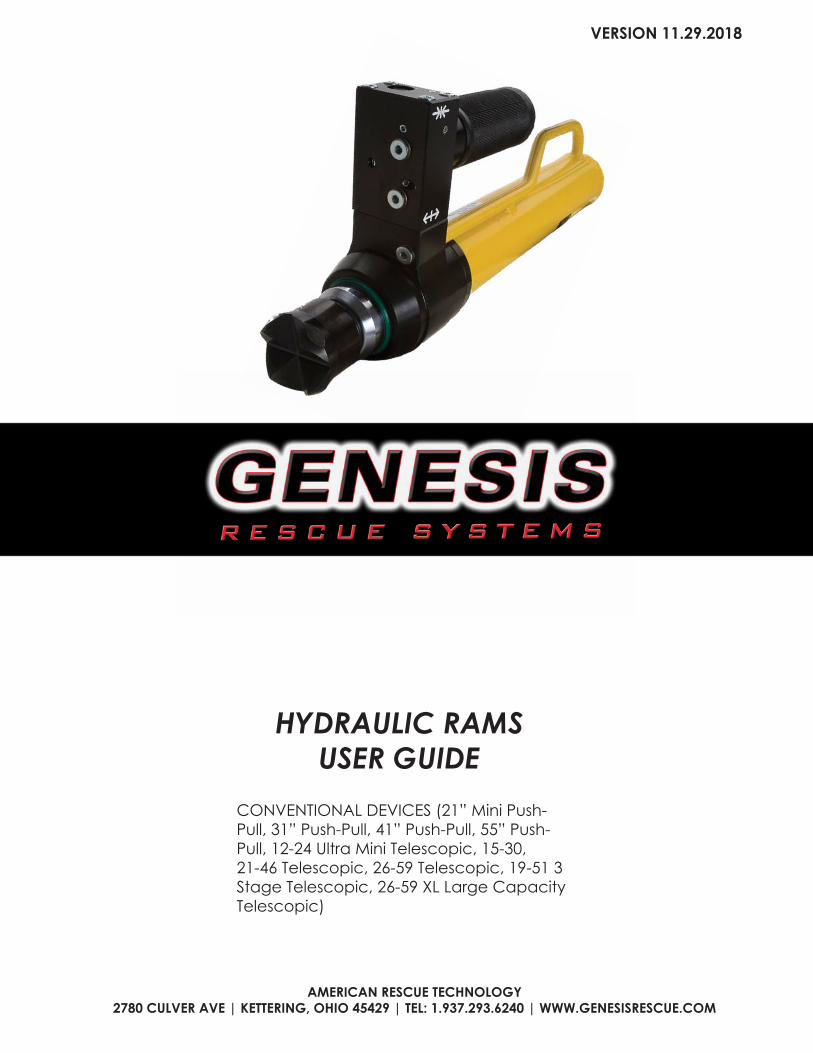
CONVENTIONAL DEVICES (21” Mini Push-Pull, 31” Push-Pull, 41” Push-Pull, 55” Push-Pull, 12-24 Ultra Mini Telescopic, 15-30, 21-46 Telescopic, 26-59 Telescopic, 19-51 3 Stage Telescopic, 26-59 XL Large Capacity Telescopic)
HYDRAULIC RAMS USER GUIDE
AMERICAN RESCUE TECHNOLOGY2780 CULVER AVE | KETTERING, OHIO 45429 | TEL: 1.937.293.6240 | WWW.GENESISRESCUE.COM
VERSION 11.29.2018
WWW.GENESISRESCUE.COM2
GENERAL INFO 4ABOUT THE USER GUIDE 4EXPLANATION OF SYMBOLS 5LIMITATIONS OF LIABILITY 6COPYRIGHT 6WARRANTY CONDITIONS 7CUSTOMER SERVICE 7
SAFETY 8INTENDED USE 8-9RESPONSIBILITY OF USER 10OPERATING PERSONNEL 11PERSONAL PROTECTIVE EQUIPMENT 12SPECIFIC HAZARDS 13-14HOW TO RESPOND 15SIGNAGE 16
TECHNICAL DATA 17CUTTERS 17COMBINATION 19OPERATING CONDITIONS 20TYPE PLATE 20
DESIGN AND FUNCTION 21OVERVIEW OF DEVICES 21-24HYDRAULIC SUPPLY 25EQUIPMENT CONNECTIONS 26-27CONTROL HANDLE 28CHANGING SPREADER TIPS 29CHANGING BLADES 30
POSSIBLE APPLICATIONS 31SAFETY INFORMATION 31CUTTING 31-32SPREADING 33PULLING 34CRUSHING 35LIFTING 35CONTINUOUS CUTS MTC 36
CONTENTS
3
TRANSPORT AND STORAGE 37SAFETY INFORMATION 37TRANSPORT INSPECTION 37DISPOSAL OF PACKAGING 38STORAGE 38
INSTALLATION AND USE 39SAFETY INFORMATION 39CHECKING 40INSTALLATION 41SHUT-DOWN 41
SERVICE 42SAFETY INFORMATION 42CARE AND MAINTENANCE 42MAINTENANCE SCHEDULE 43
TROUBLESHOOTING 44DISPOSAL 45 NOTES 46-47

WWW.GENESISRESCUE.COM4
GENERAL INFORMATIONAbout the operating manual
This operating manual provides important information on using the hydraulic Rams. Proper compliance with all specified safety instructions and guidelines is a prerequisite for safe work.
Furthermore, adhere to the local accident prevention guidelines and general safetyregulations for the region in which the devices are used.
These operating instructions must be carefully read prior to starting any work!They are an inherent part of the product and must be kept in a place that is knownand accessible to personnel at all times.
This documentation contains information for operating your equipment. However,you may also find information which may not directly apply to your specificequipment.
All information, technical data, graphics and diagrams contained in these operatinginstructions are based on the latest data available at the time of the document‘screation.
We recommend that, in addition to carefully reading through the operating manual,you be trained on handling the rescue equipment (possible applications, applicationtactics, etc.) by our qualified trainers.
5
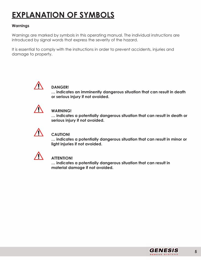
EXPLANATION OF SYMBOLSWarnings
Warnings are marked by symbols in this operating manual. The individual instructions are introduced by signal words that express the severity of the hazard.
It is essential to comply with the instructions in order to prevent accidents, injuries and damage to property.
DANGER!… indicates an imminently dangerous situation that can result in death or serious injury if not avoided.
WARNING!… indicates a potentially dangerous situation that can result in death or serious injury if not avoided.
CAUTION!… indicates a potentially dangerous situation that can result in minor or light injuries if not avoided.
ATTENTION!… indicates a potentially dangerous situation that can result inmaterial damage if not avoided.

WWW.GENESISRESCUE.COM6
NOTE!... highlights useful tips and recommendations, as well as information for efficient, trouble-free operation.
LIMITATIONS OF LIABILITYAll information and instructions in this operating manual have been compiled in keeping with applicable standards and guidelines, the current state of technology, and our many years of knowledge and experience.The manufacturer assumes no liability for damage due to:
• Failure to comply with the operating manual
• Unintended use
• Assignment of untrained personnel
• Unauthorized modifications
• Technical changes
• Use of non-approved replacement parts
• Use of non-original replacement parts
The actual scope of delivery can vary from the explanations and graphic representations provided in this manual in the case of special versions, or due to technical changes.
COPYRIGHTAll texts, diagrams, drawings and images in this operating manual may be used withoutrestriction and without any prior approval.

7
NOTE!Further information, images and drawings can be found on our website www.genesisrescue.com
WARRANTY CONDITIONSThe warranty conditions can be found as a separate document in the sales documentation.
CUSTOMER SERVICEContact your local Genesis sales representative. If you are unsure you can contact Genesis Rescue Systems direct at.
American Rescue Technology2780 Culver Ave.Kettering, Ohio45429
Tel: 1.937.293.6240Fax: 1.937.293.7049www.genesisrescue.com
NOTE!When contacting customer service please state your equipment’s des-ignation, type and production year. These details can be found on the equipment type plate.
WWW.GENESISRESCUE.COM8
SAFETYThis section of the operating manual provides a comprehensive overview of all important safety aspects for optimal protecting operating personnel and for safe, trouble-free operation.
Significant hazards may occur if the handling and safety instructions in this manual are not complied with.
INTENDED USEThe hydraulic devices are designed and tested exclusively for the intended applications described here. All other activities are strictly forbidden.
CONVENTIONAL DEVICES (21” Mini Push-Pull, 31” Push-Pull, 41” Push-Pull, 55” Push-Pull, 12-24 Ultra Mini Telescopic, 15-30, 21-46 Telescopic, 26-59 Telescopic, 19-51 3 Stage Telescopic, 26-59 XL Large Capacity Telescopic)
• All of the rescue rams are designed as one-man devices and maytherefore be operated by one person only.
• The devices serve exclusively to push steering columns, vehicle roofsand other obstacles upwards and to push vehicle parts out of the way.
• In addition, they can be used to brace, stiffen and pull.
• The chain set is to be used exclusively for pulling.
WARNING!Improper use can be dangerous!
Any improper or unintended use of the devices can be hazardous!
Therefore, make absolutely sure that:» The devices are used only for the applications stated above.
9
RESPONSIBILITY OF THE CUSTOMER
In addition to the health and safety instructions in this operating manual, one must adhere to the safety, accident prevention, and environmental protection guidelines for the region in which the equipment is used. Particularly applicable in this regard:
• The customer must be familiar with the applicable health and safety provisions and in a hazard analysis identify other hazards that may exist at the equipment’s installation site due to the special working conditions.
• The customer must clearly regulate and specify responsibilities for installation, operation, maintenance and cleaning.
• The customer must ensure that all personnel who handle the equipment have fully read and understood the operating manual.
• In addition, at regular intervals, the operator must train personnel and inform them of the hazards of working with the equipment.
Moreover, the customer is responsible for ensuring that the equipment is always in technically faultless condition. Consequently, the following applies:
• After each use, and at least once a year, a visual inspection of the equipment must be carried out by a trained individual (according to GUV-G 9102 or country-specific guidelines).
• Every three years, or if you have doubts about the safety or reliabilityof the equipment, functional testing and stress testing must be carried out (according to GUV-G 9102 or country-specific guidelines).

WWW.GENESISRESCUE.COM10
OPERATING PERSONNEL
The following qualifications are cited in the operating instructions for the various activity areas:
• Trained individualis informed through training offered by the customer about the tasks assigned to him and the possible dangers of improper conduct.
• Specialistis someone who, due to specialized training, skills and experience, as well as knowledge of the applicable stipulations by the manufacturer, is capable of executing the tasks assigned to him or her and of independently recognizing possible hazards.
WARNING!Inadequate training can result in injuries!Improper handling of the equipment can lead to serious injury or material damage.
Therefore, make absolutely sure to:» allow particular tasks to be carried out only by the persons stated in the relevant chapter of this manual.» When in doubt, call in specialists immediately.
NOTE!The equipment may not be used by personnel who have consumedalcohol, medication or drugs!
11
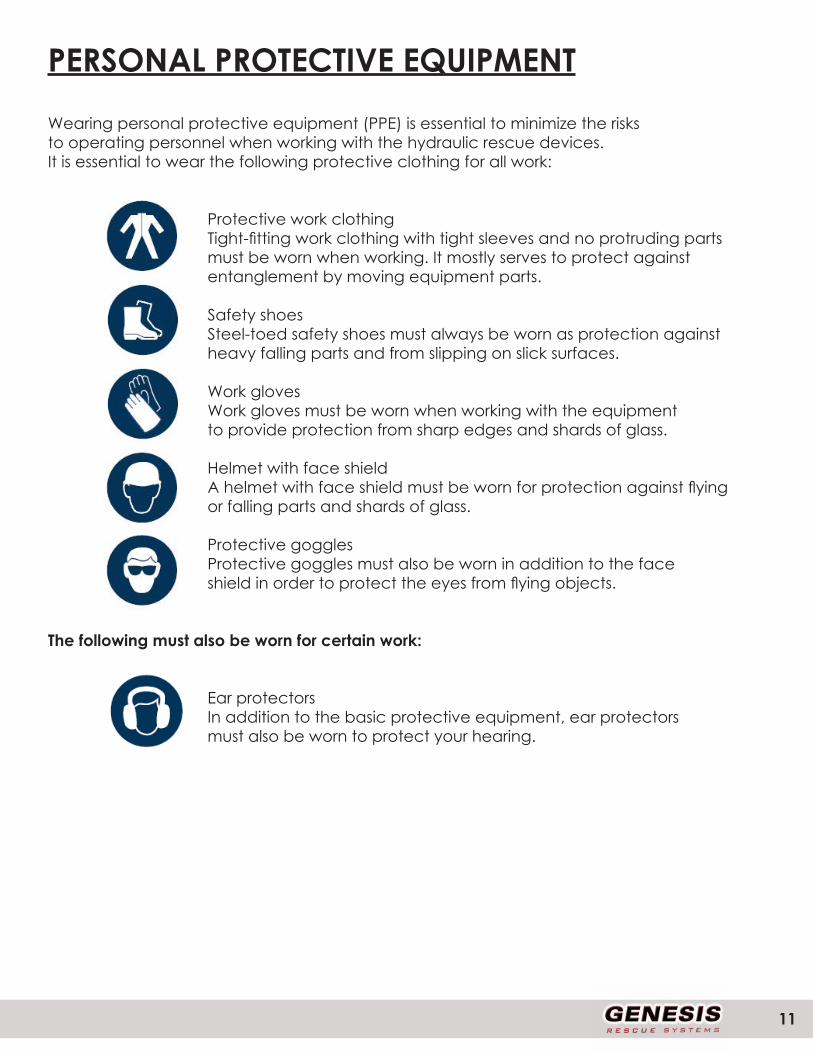
PERSONAL PROTECTIVE EQUIPMENT
Wearing personal protective equipment (PPE) is essential to minimize the risksto operating personnel when working with the hydraulic rescue devices.It is essential to wear the following protective clothing for all work:
Protective work clothingTight-fitting work clothing with tight sleeves and no protruding partsmust be worn when working. It mostly serves to protect againstentanglement by moving equipment parts.
Safety shoesSteel-toed safety shoes must always be worn as protection againstheavy falling parts and from slipping on slick surfaces.
Work glovesWork gloves must be worn when working with the equipmentto provide protection from sharp edges and shards of glass.
Helmet with face shieldA helmet with face shield must be worn for protection against flyingor falling parts and shards of glass.
Protective gogglesProtective goggles must also be worn in addition to the faceshield in order to protect the eyes from flying objects.
The following must also be worn for certain work:
Ear protectorsIn addition to the basic protective equipment, ear protectorsmust also be worn to protect your hearing.
WWW.GENESISRESCUE.COM12
SPECIFIC HAZARDS
The hazards arising from the risk analysis are listed in the following section.
Follow the safety instructions listed here and the warnings in the other sections of this manual to minimize potential health hazards and avoid dangerous situations.
ELECTRICITY
DANGER!Danger of fatal electric shock!There is an imminent life-threatening danger if live parts are touched. Damage to insulation or to specific components can pose a fatal hazard.
Therefore:» If the insulation is damaged, immediately disconnect the power supply and arrange for repairs.» Allow only qualified electricians to work on the electrical equipment.» For all work on the electrical equipment, it must be disconnected from the power source, and it must be checked that the device is powered off.» Prior to maintenance, cleaning and repair work, the power supply must be switched off and secured to prevent it from being switched back on again.» Do not bypass or disable fuses. When changing the fuses, ensure that they have the correct amperage.» Keep moisture away from live parts. This can lead to a short-circuit.
NOISE
WARNING!Noise can damage hearing!The noise occurring in the work area can cause severe hearingdamage.Therefore:»» You should also wear ear protectors when carrying outcertain noise-producing tasks.»» Do not stay in the hazardous area longer than necessary.
13
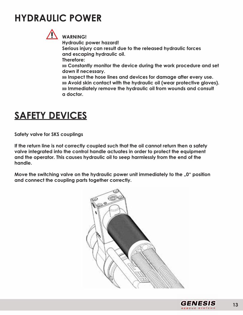
HYDRAULIC POWER
WARNING!Hydraulic power hazard!Serious injury can result due to the released hydraulic forcesand escaping hydraulic oil.Therefore:»» Constantly monitor the device during the work procedure and setdown if necessary.»» Inspect the hose lines and devices for damage after every use.»» Avoid skin contact with the hydraulic oil (wear protective gloves).»» Immediately remove the hydraulic oil from wounds and consulta doctor.
SAFETY DEVICES
Safety valve for SKS couplings
If the return line is not correctly coupled such that the oil cannot return then a safetyvalve integrated into the control handle actuates in order to protect the equipmentand the operator. This causes hydraulic oil to seep harmlessly from the end of thehandle.
Move the switching valve on the hydraulic power unit immediately to the „0“ positionand connect the coupling parts together correctly.
WWW.GENESISRESCUE.COM14
HOW TO RESPOND IN THE EVENT OF DANGER OR ACCIDENTS
Preventive measures
• Always be prepared for accidents
• Keep first aid equipment (first aid kit, blankets, etc.) at hand
• Familiarize personnel with accident alarms, first aid gear, and emer-gency equipment
• Keep entryways clear for emergency vehicles
In the event of an accident
• Shut down equipment immediately
• Initiate first aid measures
• Get people out of the danger zone
• Inform the responsible parties at the site of the incident
• Notify a doctor and/or the fire brigade
• Clear entryways for emergency vehicles
15
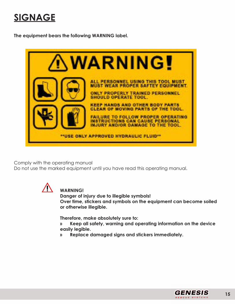
SIGNAGE
The equipment bears the following WARNING label.
Comply with the operating manualDo not use the marked equipment until you have read this operating manual.
WARNING!Danger of injury due to illegible symbols!Over time, stickers and symbols on the equipment can become soiled or otherwise illegible.
Therefore, make absolutely sure to:» Keep all safety, warning and operating information on the device easily legible.» Replace damaged signs and stickers immediately.

WWW.GENESISRESCUE.COM16
TECHNICAL DATAVERSION PCT.11.29.2018
ART.021.900.1
21” PUSH-PULL RAM
SPECIFICATIONS
LENGTH(IN/MM) - 16.4/416
WIDTH(IN/MM) - 4/101
DEPTH(IN/MM) - 10.4/265
WEIGHT(LBS/KGS) - 26/11.9
OPERATING PRESSURE(PSI/BAR) - 10,000/700
LENGHT OPEN(IN/MM) - 23.4/594
LENGTH RETRACTED(IN/MM) - 16.4/416
NFPA 1936 COMPLIANT - YES
NFPA 1936 HSF (LBF/KN) - 32,300/143.7
NFPA 1936 HPF (LBF/KN) - 10,300/45.8
CERTIFICATIONS• NFPA 1936:2015 COMPLIANT• ISO 9001:2008

17
TECHNICAL DATAVERSION PCT.11.28.2018
ART.031.900.1
31” PUSH-PULL RAM
SPECIFICATIONS
LENGTH(IN/MM) - 20.5/521
WIDTH(IN/MM) - 4/101
DEPTH(IN/MM) - 8/204
WEIGHT(LBS/KGS) - 30/13.6
OPERATING PRESSURE(PSI/BAR) - 10,000/700
LENGHT OPEN(IN/MM) - 31.8/807
LENGTH RETRACTED(IN/MM) - 20.5/521
STROKE(IN/MM) - 11.3/286
NFPA 1936 COMPLIANT - YES
NFPA 1936 HSF (LBF/KN) - 32,300/143.7
NFPA 1936 HPF (LBF/KN) - 10,300/45.8
CERTIFICATIONS• NFPA 1936:2015 COMPLIANT• ISO 9001:2008

WWW.GENESISRESCUE.COM18
TECHNICAL DATAVERSION PCT.2.2016
ART.041.900.1
41” PUSH-PULL RAM
SPECIFICATIONS
LENGTH(IN/MM) - 25.4/646
WIDTH(IN/MM) - 4/101
DEPTH(IN/MM) - 8/204
WEIGHT(LBS/KGS) - 35.7/16.2
OPERATING PRESSURE(PSI/BAR) - 10,000/700
LENGHT OPEN(IN/MM) - 41.5/1054
LENGTH RETRACTED(IN/MM) - 25.4/646
STROKE(IN/MM) - 16/408
NFPA 1936 COMPLIANT - YES
NFPA 1936 HSF (LBF/KN) - 32,300/143.7
NFPA 1936 HPF (LBF/KN) - 10,300/45.8
CERTIFICATIONS• NFPA 1936:2015 COMPLIANT• ISO 9001:2008

19
TECHNICAL DATAVERSION PCT.11.28.2018
ART.055.900.1
55” PUSH-PULL RAM
SPECIFICATIONS
LENGTH(IN/MM) - 36.0/914
WIDTH(IN/MM) - 4/101
DEPTH(IN/MM) - 8/204
WEIGHT(LBS/KGS) - 50.5/22.9
OPERATING PRESSURE(PSI/BAR) - 10,000/700
LENGHT OPEN(IN/MM) - 55.7/1415
LENGTH RETRACTED(IN/MM) - 36/914
STROKE(IN/MM) - 19.7/501
NFPA 1936 COMPLIANT - YES
NFPA 1936 HSF (LBF/KN) - 21,892/97.3
NFPA 1936 HPF (LBF/KN) - 10,300/45.8
CERTIFICATIONS• NFPA 1936:2015 COMPLIANT• ISO 9001:2008

WWW.GENESISRESCUE.COM20
TECHNICAL DATAVERSION ACT.3.2016
ART.593.693.4
12-24 TELESCOPIC RAM
SPECIFICATIONS
LENGTH(IN/MM) - 11.8/300
WIDTH(IN/MM) - 3.5/88
HEIGHT(IN/MM) - 11.6/295
WEIGHT(LBS/KGS) - 20.5/9.3
OPERATING PRESSURE(PSI/BAR) - 10,000/700
LENGTH EXTENDED(IN/MM) - 23.6/600
LENGTH RETRACTED(IN/MM) - 11.8/300
STROKE(IN/MM) - 11.8/300
NFPA 1936 COMPLIANT - YES
HIGHEST SPREADING FORCE 1 STAGE(LBF/KN) - 42,615/189.4
HIGHEST SPREADING FORCE 2 STAGE(LBF/KN) - 22,250/99
CERTIFICATIONS• NFPA 1936:2015 COMPLIANT• ISO 9001:2008

21
TECHNICAL DATAVERSION ACT.3.2016
ART.593.140.1
15-30 TELESCOPIC RAM
SPECIFICATIONS
LENGTH CLOSED(IN/MM) - 15.5/393
WIDTH(IN/MM) - 7.9/200
HEIGHT(IN/MM) - 3.4/86
WEIGHT(LBS/KGS) - 28.4/12.9
OPERATING PRESSURE(PSI/BAR) - 10,500/720
LENGTH EXTENDED(IN/MM) - 29.6/751
HIGHEST SPREADING FORCE 1 STAGE(LBF/KN) - 42,615/189.4
HIGHEST SPREADING FORCE 2 STAGE(LBF/KN) - 22,275/99
NFPA 1936 COMPLIANT - YES
CERTIFICATIONS• NFPA 1936:2015 COMPLIANT• ISO 9001:2008

WWW.GENESISRESCUE.COM22
TECHNICAL DATAVERSION ACT.3.2016
ART.593.414.1
19-52 3-STAGE TELESCOPIC RAM
SPECIFICATIONS
LENGTH(IN/MM) - 18.9/480
WIDTH(IN/MM) - 8.7/221
HEIGHT(IN/MM) - 4.3/109
WEIGHT(LBS/KGS) - 38/17.2
OPERATING PRESSURE(PSI/BAR) - 10,000/700
LENGTH EXTENDED(IN/MM) - 51.6/1310
LENGTH RETRACTED(IN/MM) - 18.9/480
STROKE(IN/MM) - 1.8/45.4
NFPA 1936 COMPLIANT - YES
HIGHEST SPREADING FORCE 1 STAGE(LBF/KN) - 60,615/269.4
HIGHEST SPREADING FORCE 2 STAGE(LBF/KN) - 29,137/129.5
HIGHEST SPREADING FORCE 3 STAGE(LBF/KN) - 10,215/45.4
CERTIFICATIONS• NFPA 1936:2015 COMPLIANT• ISO 9001:2008

23
TECHNICAL DATAVERSION ACT.11.17
ART.105.014.9
21-46 TELESCOPIC RAM
SPECIFICATIONS
LENGTH CLOSED(IN/MM) - 21.3/540
WIDTH(IN/MM) - 7.9/200
HEIGHT(IN/MM) - 3.5/88
WEIGHT(LBS/KGS) - 33.5/15.2
OPERATING PRESSURE(PSI/BAR) - 10,000/700
LENGTH EXTENDED(IN/MM) - 49/1170
LENGTH RETRACTED(IN/MM) - 21.3/540
STROKE(IN/MM) - 24.8/630
NFPA 1936 COMPLIANT - YES
HIGHEST SPREADING FORCE 1 STAGE(LBF/KN) - 42,615/189.4
HIGHEST SPREADING FORCE 2 STAGE(LBF/KN) - 22,275/99
CERTIFICATIONS• NFPA 1936:2015 COMPLIANT• ISO 9001:2008

WWW.GENESISRESCUE.COM24
TECHNICAL DATAVERSION PCT.2.2016
ART.105.004.1
26/59 TELESCOPIC RAM
SPECIFICATIONS
LENGTH(IN/MM) - 25.6/650
WIDTH(IN/MM) - 7.9/200
DEPTH(IN/MM) - 3.5/88
WEIGHT(LBS/KGS) - 39.6/18
OPERATING PRESSURE(PSI/BAR) - 10,000/700
LENGTH OPEN(IN/MM) - 59/1500
LENGTH RETRACTED(IN/MM) - 25.6/650
STROKE(IN/MM) - 33.5/850
NFPA 1936 COMPLIANT - YES
1 STAGE MAX FORCE(LBF/KN) - 42,615/189.4
2 STAGE MAX FORCE(LBF/KN) - 22,275/99
CERTIFICATIONS• NFPA 1936:2015 COMPLIANT• ISO 9001:2008
The 26/59 Telescopic Ram provides res-cue personnel with an optimal pushing distance and power.

25
TECHNICAL DATAVERSION ACT.3.2016
ART.593.229.7
26/59XL TELESCOPIC RAM
SPECIFICATIONS
LENGTH CLOSED(IN/MM) - 25.6/650
WIDTH(IN/MM) - 3.5/88
HEIGHT(IN/MM) - 7.8/199
WEIGHT(LBS/KGS) - 46.1/20.9
OPERATING PRESSURE(PSI/BAR) - 10,000/700
LENGTH EXTENDED(IN/MM) - 59.1/1502
LENGTH CLOSED(IN/MM) - 25.6/650
STROKE(IN/MM) - 33.4/850
NFPA 1936 COMPLIANT - YES
HIGHEST SPREADING FORCE 1 STAGE(LBF/KN) - 60,473/269.4
HIGHEST SPREADING FORCE 2 STAGE(LBF/KN) - 29,112/129.5
CERTIFICATIONS• NFPA 1936:2015 COMPLIANT• ISO 9001:2008

WWW.GENESISRESCUE.COM26
OPERATING CONDITIONSThe permissible temperature range of the E-FORCE devices is between -4°F and +176°F. Reliable operation cannot be guaranteed outside of this range.Underwater operationThe cutters (exception: Hand Vario) can also be used under water. Do not exceedthe maximum submersion depth of 40 metres with this. At this depth the waterpressure still has no influence on the hydraulic pressure in the equipment and thehoses.
TYPE PLATEOn all E-FORCE devices, the type plate is located on the body. It shows the serialnumber, production date, nominal pressure and device designation.
27
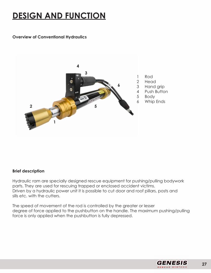
DESIGN AND FUNCTION
Overview of Conventional Hydraulics
1 Rod2 Head3 Hand grip4 Push Button5 Body6 Whip Ends
Brief description
Hydraulic ram are specially designed rescue equipment for pushing/pulling bodyworkparts. They are used for rescuing trapped or enclosed accident victims.Driven by a hydraulic power unit it is possible to cut door and roof pillars, posts andsills etc. with the cutters.
The speed of movement of the rod is controlled by the greater or lesserdegree of force applied to the pushbutton on the handle. The maximum pushing/pullingforce is only applied when the pushbutton is fully depressed.
1
2
34
5
6
WWW.GENESISRESCUE.COM28
HYDRAULIC SUPPLY
Power units and pumps
Only Genesis Rescue power units and hand pumps may be used to drive the ram.Equipment from other manufacturers can only be used under certain conditions. Therefore always consult with us before operating a device with a power unit fromanother manufacturer!
ATTENTION !Before using pumps and power units from other manufacturersalways contact Genesis Rescue or an authorized dealer.Incorrect application can lead to hazardous situations for which wecannot accept any liability!
Hoses
The connection of the device with the power unit is carried out via high pressurehoses. Hoses are available various lengths. As the length of the hoses increases so too does the associated pressure loss. With a line length of 50 yards this pressure loss remains accept-able and has no significant effect.
CAUTION !Do not use damaged hoses !With damaged hoses there is a danger of escaping hydraulicmedium under pressure, or of the hoses whipping around.Therefore:»» The hoses should be subjected to a visual inspection(leak-tightness, surface damage such as kinks) afterevery use and at least once per year.
29
»» Every three years, or in the event of doubts about the safetyor reliability, carry out an additional functional and load test (asper GUV-G 9102 or specific national directive).»» Replace hoses every 10 years! The date (code letters orquarter/year) is specified on the hose bonding.»» Ensure that the hoses are not exposed to tension or torsion(turning).»» Do not kink the hoses or draw them over edges (smallestbend radius 40 mm).»» Do not subject the hoses to high temperatures.»» Protect hoses from contact with materials that can causedamage to the outer covering e.g. acids, alkalis, or solvents.
Hydraulic oil
All cutters are designed and tested for Genesis hydraulic oil ID No. 804932.This oil possesses a particularly high purity level and also works flawlessly attemperatures below zero, down to -20° C.
NOTE !In addition to the oil mentioned above we recommend:»» AERO Fluid 41 (Shell)»» Univis HVI-13 (Esso)»» Aero-hydraulic 520 (Total)»» Hydraulik DB (Castrol)»» Renolin/MR310 (Fuchs)

WWW.GENESISRESCUE.COM30
EQUIPMENT CONNECTIONS
OSC
Connecting:
Remove the protective cap from the coupling male and the coupling female (Fig. 1).Conflate Single coupling male and female in the bayonet catch (Fig. 2). Hold couplingfemale on the black slew ring and turn clockwise until the coupling snaps in(Fig. 3). Put protective caps together (Fig. 4). You don’t have to switch the powerunit to position 0 to connect or disconnect the coupling!
Disconnecting:
Remove the protective caps. Hold coupling female on the black slew ring and turncounter clockwise direction. Turn the black slew ring until you can release the couplingeasily. Put protective caps to coupling male and the coupling female.
31
PLUG-IN COUPLING
Connecting:
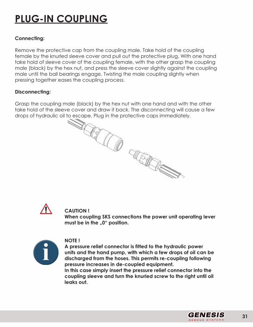
Remove the protective cap from the coupling male. Take hold of the couplingfemale by the knurled sleeve cover and pull out the protective plug. With one handtake hold of sleeve cover of the coupling female, with the other grasp the couplingmale (black) by the hex nut, and press the sleeve cover slightly against the couplingmale until the ball bearings engage. Twisting the male coupling slightly whenpressing together eases the coupling process.
Disconnecting:
Grasp the coupling male (black) by the hex nut with one hand and with the othertake hold of the sleeve cover and draw it back. The disconnecting will cause a fewdrops of hydraulic oil to escape. Plug in the protective caps immediately.
CAUTION !When coupling SKS connections the power unit operating levermust be in the „0“ position.
NOTE !A pressure relief connector is fitted to the hydraulic powerunits and the hand pump, with which a few drops of oil can bedischarged from the hoses. This permits re-coupling followingpressure increases in de-coupled equipment.In this case simply insert the pressure relief connector into thecoupling sleeve and turn the knurled screw to the right until oilleaks out.
WWW.GENESISRESCUE.COM32
USE OF THE CONTROL HANDLE
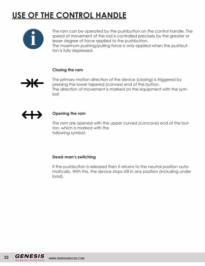
The ram can be operated by the pushbutton on the control handle. The speed of movement of the rod is controlled precisely by the greater or lesser degree of force applied to the pushbutton.The maximum pushing/pulling force is only applied when the pushbut-ton is fully depressed.
Closing the ram
The primary motion direction of the device (closing) is triggered by pressing the lower tapered (convex) end of the button.The direction of movement is marked on the equipment with the sym-bol:
Opening the ram
The ram are opened with the upper curved (concave) end of the but-ton, which is marked with the following symbol:
Dead-man‘s switching
If the pushbutton is released then it returns to the neutral position auto-matically. With this, the device stops still in any position (including under load).
33
TRANSPORT, PACKAGING AND STORAGE
Safety information
CAUTION!Incorrect transport can cause damage!Improper transport can cause significant material damage.
Therefore:» Proceed with caution when unloading the packages, and observe the symbols on the packaging.» Do not fully open and remove the package until it has reached its actual storage location.
Transport inspection
Upon receipt, the delivery should be checked immediately for completenessand damage during transport so that a quick remedy can be performed, if necessary.
If there is visible external damage, please proceed as follows:
• Do not accept the delivery, or only accept it with reservation.• Note the extent of the transport damage on the transport documents or on the transport company’s delivery note.• File a complaint.
NOTE!Report any defect as soon as it is detected.Claims for damages can be directed to our customer servicedepartment.
WWW.GENESISRESCUE.COM34
DISPOSAL OF PACKAGING
All packaging materials and disassembled parts (transport protection)must be disposed of properly, in accordance with local regulations.
STORAGE
The equipment must be stored in a dry and dust-free environment, where possible.Avoid direct UV radiation to the hoses.
CAUTION!The equipment must be stowed securely in the mountings providedin order to avoid damage during transit, etc.
35
INSTALLATION AND COMMISSIONING
Safety information
WARNING!Danger of injury due to improper operation!Improper operation can cause serious injury or material damage.
Therefore, make absolutely sure to:» All operating steps are executed in keeping with the information in this operating manual.» All covers and protective devices are installed and in proper work-ing order prior to starting work.
Personal protective equipmentWear the protective equipment for all work!
NOTE!Special reference is made where it is necessary to wear additional pro-tective equipment for certain work with or on the device.
WWW.GENESISRESCUE.COM36
CHECKING
Inspect the Cutter devices for damage. If the cutting device is not in pristinecondition, it must not be used! In this case, immediately contact your supplier.
• Check the blades (damage)
• Check the control handle including pushbutton (function)
• Check the couplings (damage, dirt)
• Check the hand grip (securely fastened)
• Check the protective cover (damage)
• Check the hoses (damage)
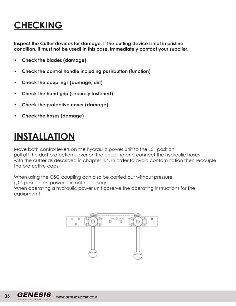
INSTALLATIONMove both control levers on the hydraulic power unit to the „0“ position,pull off the dust protection cover on the coupling and connect the hydraulic hoseswith the cutter as described in chapter 4.4. In order to avoid contamination then recouplethe protective caps.
When using the OSC coupling can also be carried out without pressure(„0“ position on power unit not necessary).When operating a hydraulic power unit observe the operating instructions for theequipment!
37
SHUT-DOWN (END OF WORK)
After work is over, the blade tips must be placed one above the other to preventinjury. The blades of the cutting device must not be completely closed, as otherwisetension will build up in the device.
NOTE !With combi tools, drive the spreader arms to within a fewmillimetres of each other in order to relieve the hydraulics.
Then the equipment can be disconnected providing that the power unit controllever is in the „0“ position. Care must be taken to ensure that no dirt ends up on thecoupling and that the protective caps are immediately fitted.
WWW.GENESISRESCUE.COM38
SERVICESafety information
WARNING!Risk of injury due to improperly performed maintenance work!
Improper maintenance of the equipment can cause serious injury or material damage.
Therefore, make absolutely sure to:» Only let qualified personnel carry out maintenance work.» Make sure the installation site is organized and clean! Loose com-ponents and tools lying around are sources of danger.» Wear protective gloves for all work!
CARE AND MAINTENANCEPREVENTATIVE MAINTENANCE
Genesis recommends that all hydraulic rescue tools be serviced by a certified factory technician at a frequency of once every 12 months. Just like a vehicle this crucial maintenace ensures the tool functions at top performance and safety. Your sales representative can answer any question you may have.
We recommend only quailified personnel carry out maintenance.
GENESIS PREVENTATIVE MAINTENANCE PROGRAM
The following are recommended service intervals for Genesis tools.
Each Use-Equipment should be wiped down to remove debris-Clean male and female couplers-Clean ram parts-check whipends for damage-check for damage
Weekly Inspections and Maintenance-Check all couplers and fittings for tightness-Run each tool and build pressure-Check handles and guards, tighten if necessary
39
CARE AND MAINTENANCE
Annual Maintenance-Change and replace the engines oil-Change and replace the hydraulic fluid-Test the engines performance-Change the spark plug-Clean and replace the air filter-Lubricate moving parts-Pressure check all lines and fittings-Check opening and closing pressure-Disassemble and examine all critical components-Check the power units operating pressure-Check all valves-Provide loaner equipment during service-Provide a detailed report
ATTENTION!Prior to all maintenance work, the equipment must be cleaned of any dirt so that it does not get into the hydraulic system.The cleaning can be carried out using a conventional citrus cleaner or using WD 40.
NOTE!If there are any problems with the maintenance of the devices, contact your local sales representative.

WWW.GENESISRESCUE.COM40
TROUBLE SHOOTING

41
DECOMMISSIONING/RECYCLING
After the end of the normal service life, the equipment must be professionally disposedof. Individual parts can, however, certainly be used again.
The hydraulic oil must be completely drained and collected. Make sure thatthe hydraulic oil is disposed of separately!
For disposal of all device components and packaging materials, the disposal conditionsof the specific location apply.
Do not discard electric tools with household waste!
NOTE!Please ask your supplier about disposing of the device.

WWW.GENESISRESCUE.COM42
NOTES

43
NOTES

GENESIS RESCUE SYSTEMS2780 CULVER AVE.
KETTERING, OHIO 45329TEL: 1.937.293.6240
WWW.GENESISRESCUE.COM


