Embed Size (px)
Citation preview
2 3 2 . 5
8 9 H Y
Hydraulic Rams
August 1969 J.H.P.M. Tacke and C. Verspuy
Delft University of Technology
CICAT7 Faculty of Civil Engineering
132-5 -S3 \*1-
HYDRAULIC RAMS
In 1987 Peter de Jong of CICAT (the coordinating centre of the developmentcooperation effort of Delft University of Technology) published: "Hydraulic Rams,a consumers' guide".
This guide summarized the results of research on hydraulic rams, commissioned bythe Section of Research and Technology of the Netherlands Ministry of ForeignAffairs.
The research comprised comparative tests of commercially available and newlydesigned hydraulic rams, and was carried out by the Delft University of Technologyand in the field in Rwanda.
The laboratory research has been reported upon in 'World Pumps' (July 1989) by ir.J.H.P.M. Tacke and ir. C. Verspuy. This booklet is based on that article.
Drs. A. WoutersCoordinator CICAT
CICAT/Delft Universily of technology 1
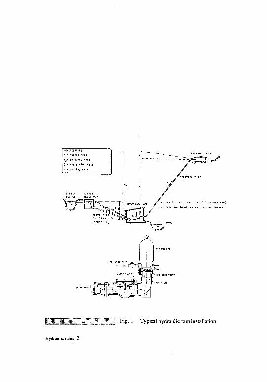
liiJTr^il"-,; ~~^'~~l I F'E- ' Typical hydraulic ram installation
Hydraulic rams 2

HYDRAULIC RAMS
IntroductionThe hydraulic ram is an automatic waterpumping device that utilizes the energycontained in a flow of water runningthrough it, to lift a small volume of thiswater to a higher level. The phenomenoninvolved is that of a pressure surge whichdevelops when a moving mass of water issuddenly stopped (waterhammer.)
Hydraulic rams can be used for pumpingdrinking-water from a spring or stream toa tank or reservoir at a higher level. Asteady and reliable supply of water isrequired with a fall sufficient to operatethe ram. Favourable conditions are mostlyfound in hilly and mountainous areaswith fairly plentiful supplies of water. Awell-made ram will pump an appropriateamount of water to a height from about 20to 30 times the supply head, with an effi-ciency of about 60 to 70 per cent. Alter-natively, hydraulic rams can be used forpumping water to low heads over largedistances (up to 10 km or more), i.e.vertical lift can be traded off for horizon-tal distance.
In the past quite a number of hydraulicrams have been installed and many havegiven long and reliable service. But inmodern times the availability of pipedwater systems using engine-driven pumpshas relegated the hydraulic ram to acomparatively unimportant position.Recently, though, it has revived as a po-tentially useful component in rural watersupply programs in developing countries.Yet, up to now the use of the hydraulic
ram in developing countries has not be-come as widespread as its simplicity,ease of operation and maintenance, de-pendability and economy would seem towarrant. This has largely been due to thelack of reliable information concerningthe limiting conditions under which theram is applicable and the phenomenagoverning its action.
In this article the essential features ofhydraulic ram operation are described,using a limited number of experimentalresults. These results are part of the re-sults obtained from a comparative inves-tigation on commercially-available hy-draulic rams, carried out at the DelftUniversity of Technology (lit. [4]).
Mode of operationFig. 1 shows the various componentsfrom which a typical hydraulic ram in-stallation isconstructed: supply reservoir- drive pipe - hydraulic ram - deliverypipe - storage tank. The hydraulic ramitself is structurally simple, consisting ofa pump chamber fitted with only twomoving pans: an impulse valve throughwhich the driving water is wasted (wastevalve) and a check valve through whichthe pumped water is delivered (deliveryvalve). Surmounting the delivery valve isthe air chamber or surge tank. When theram operates this tank is partly filled withwater and partly wiih air. Connected tothe air chamber is the delivery pipe, sothat the pressure in the air chamber is thedelivery pressure. An inclined conduit,the so-called drive pipe, connects the ram
CICAT/Dclfl University of Technology 3
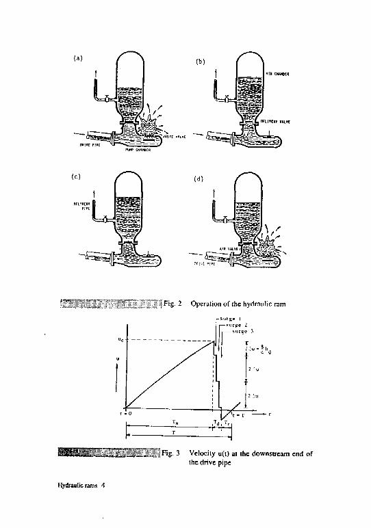
) F l 8- 2 Operation of the hydraulic ram
^ S S i l S s ^ ^ W ^ F'E- 3 Velocity u(t) at the downstream end ofthe drive pipe
Hydraulic rams 4
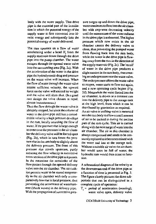
body with the water supply. This drivepipe is the essential pan of the installa-tion in which the potential energy of thesupply water is first convened into ki-netic energy and subsequently into thepotential energy of water delivered.
The ram operates on a now of wateraccelerating under a head H, from thesupply reservoir down through ihe drivepipe into the pump chamber. The waterescapes through the opened waste valveinto the surrounding area (Fig. 2a). Withthe acceleration of the water in the drivepipe the hydrodynamic drag and pressureon the waste valve will increase. Whenthe flow of water through the waste valveattains sufficient velocity, the upwardforce on the valve will exceed its weightand the valve will slam shut. (In a goodram design the valve closure is rapid,almost instantaneous.)Thus the flow through the waste valve isabruptly stopped, but since the column ofwater in the drive pipe still has a consid-erable velocity a high pressure developsin the ram, locally retarding the flow ofwater. If the pressure rise is large enoughto overcome the pressure in the air cham-ber the delivery valve will be forced open(Fig. 2b), which in turn limits the pres-sure rise in ihe ram body to slightly abovethe delivery pressure. The front of thispressure rise travels upstream, partlyreducing the flow velocity in successivecross-sections of the drive pipe as it passes.In the meantime the remainder of theflow passes through the opened deliveryvalve into the air chamber. The air cush-ion permits water to be stored temporar-ily in the air chamber with only a com-paratively low rise in local pressure, thuspreventing the occurrence of waterham-mer (shock waves) in the delivery pipe.With the propagation of successive pres-
sure surges up and down the drive pipe,water continues to flow into the air cham-ber with step-wise decreasing velocityuntil the momentum of the water columnin the drive pipe is exhausted. The higherpressure which now exists in the airchamber causes the delivery valve toclose, thus preventing the pumped waterfrom flowing back into the ram body,while the water in the drive pipe is flow-ing away from the ram in the direction ofthe supply reservoir (Fig. 2c). The 'recoil'of water in the drive pipe produces aslight suction in the ram body, thus creat-ing an underpressure near the waste valve.The underpressure allows the waste valveto reopen, water starts to flow out again,and a new operating cycle begins (Fig.2d). Meanwhile the water forced into theair chamber, is driven at a constant rateinto the delivery pipe to the storage lankat the high level, from which it can bedistributed by gravitation as required.An air valve or snifting-valve is mountedinto the ram body to allow a small amountof air to be sucked in during the suctionpan of the ram cycle. This air is carriedalong with the next surgeof water into theair chamber. The air in this chamber isalways compressed and needs to be con-stantly replaced as it becomes mixed withthe water and lost to the storage tank.Without a suitable air valve the air cham-ber would soon be full of water; thehydraulic ram would then cease to func-
A schematized diagram of the velocity atthe downstream end of the drive pipe asa function of time is presented in Fig. 3.The figure clearly pictures the three sub-periods that can be distinguished in acomplete cycle of operation:T = period of acceleration (wasting);
waste valve open, delivery valve
CICAT/Dclft University of Technology 5

driv* pip«(point A)
1: L L
Fir
4DD
P*P0
L
•00 1DDD 1200
Li
1 tn«]
a i t chubcr(point 8) I
L Ll^ I!
HOD 1A0O JBOO 3000
hUJ BO
ht.J
BSO 7D0 71D 720 730 740 750 760 770
6S0 700 710 7?0 730 7(0 7S0 7ED 770
fTj Fig. 4 Pressure + time recordings
Hydraulic rams 6
closed; positive velocity (towardsthe ram).
Td = period of retardation (pumping);waste valve closed, delivery valveopen; decelerating flow into the airchamber.
Tr = period of recoil (reverse flow); de-livery valve closed, waste valvereopens; negative flow (towardsthe supply reservoir).
During Tt and Tw the velocity u(t), theo-retically described by a hyperbolic tan-gent function, is almost linear, during T(
the velocity u(t) decreases step-wise inproportion to the delivery head h4.
Depending on supply head (Ht), drivepipe length (L_), waste valve adjustmentand to a lesser degree on delivery head(hp the cycle is repeated with a frequencyof about 30 to 150 times a minute (periodT=0.40 - 2.00 s). Once the adjustment ofthe waste valve has been set, the hydrau-lic ram needs almost no attention pro-vided the water flow from the supplysource is continuous and at an adequaterate and no foreign matters get into thepump blocking the valves.
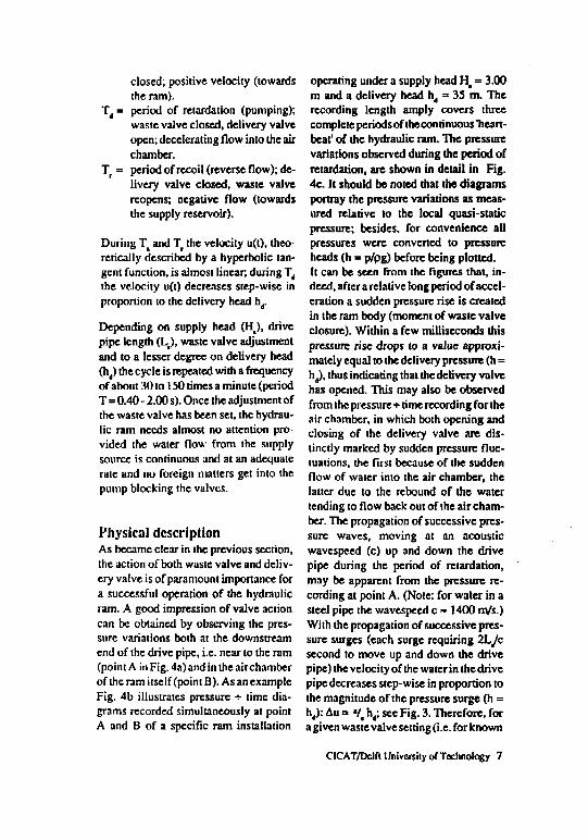
Physical descriptionAs became clear in the previous section,the action of both waste valve and deliv-ery valve is of paramount importance fora successful operation of the hydraulicram. A good impression of valve actioncan be obtained by observing the pres-sure variations both at the downstreamend of the drive pipe, i.e. near to the ram(point A in Fig. 4a) and in the airchamberof the ram itself (point B). As an exampleFig. 4b illustrates pressure •»• time dia-grams recorded simultaneously at pointA and B of a specific ram installation
operating under a supply head H, = 3.00m and a delivery head ht = 35 m. Therecording length amply covers threecomplete periods of the continuous 'heart-beat' of the hydraulic ram. The pressurevariations observed during the period ofretardation, are shown in detail in Fig.4c. It should be noted that the diagramsportray the pressure variations as meas-ured relative to the local quasi-staticpressure; besides, for convenience allpressures were converted to pressureheads (h = p/pg) before being plotted.It can be seen from the figures that, in-deed, after a relative long period of accel-eration a sudden pressure rise is createdin the ram body (moment of waste valveclosure). Within a few milliseconds thispressure rise drops to a value approxi-mately equal to the delivery pressure (h =h ), thus indicating that the delivery valvehas opened. This may also be observedfrom the pressure + rime recording for theair chamber, in which both opening andclosing of the delivery valve are dis-tinctly marked by sudden pressure fluc-tuations, the first because of the suddenflow of water into the air chamber, thelatter due to the rebound of the watertending to flow back out of the air cham-ber. The propagation of successive pres-sure waves, moving at an acousticwavespeed (c) up and down the drivepipe during the period of retardation,may be apparent from the pressure re-cording at point A. (Note: for water in asteel pipe the wavespeed c - 1400 m/s.)With the propagation of successive pres-sure surges (each surge requiring 2L/csecond to move up and down the drivepipe) the velocity of the water in the drivepipe decreases step-wise in proportion tothe magnitude of the pressure surge (h =h4): Au a •/, h4; see Fig. 3. Therefore, fora given waste valve setting (i .e. for known
CICAT/Dclft University of Technology 7
c" la
I"I 12
10
I I 1 I(D Pumping rate Q
A Efficiency n-Q x MS
^
100 ^^;
90 ^o
ao «
70 ^
60 —
" I40
30
20
100 10 Z0 30 40 $0 60 70 80 90 100 110 120
22
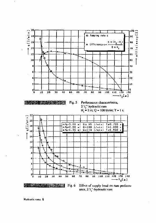
F 'E-5 Perfonnance characteristics,2 Vj"-hydraulic ramH, = 2 m; Q = 1001/min; T - 1 s.
-A\4
\
h\
IT?
1 \«
\
= 3 . 0 0 m: 0 = 9S I /ml n: T 00 <« H , = 2 . 0 Q m: Qt=100 l / m l n ; T ^ l . 0 0 0 c l* H , = 1 . 3 S ml 0 = 1 1 0 l / m l n ; T ^ l . S O O t |
—^e-—A
- n
—A — = = ( '-a—0 10 20 30 40 SO E0 70 BO 3D 1D0 110 120 130 140
Fig. 6 Effect of supply head on ram perform-ance, 2 '/j"-hydraulic ram
Hydraulic rams 8
velocity ue of the weater in the drive pipeat waste valve closure), the number ofsurges (N) observed during the period ofretardation is determined by the deliveryhead h (when hd decreases, Au decreasesand N increases). In this case Qtt = 35 m)it was found that N = 3, see Fig. 4c,resulting in the velocity steps as alreadyshown in Fig. 3.
From Fig. 3 two volumes of water can beestablished, Vw and V , by integration ofu(t) with respect to time and multiplica-tion by the cross-sectional area of thedrive pipe:
71D'
4
• I
[u(t)dt + I ui(t)dt
T.+T,
Finally, from these expressions the wasteflow Q can be obtained from:
and the pumping rate q from:
Performance characteristicsFor the end-users of the hydraulic raminstallation the pumping rate q is the firstconsideration, since this amount shouldmeet their demand. Given an availablesource supply the pumping rate q of ahydraulic ram is primarily determined bythe supply head H, and the delivery head\ . As an example Fig. 5 shows perform-
ance characteristics compiled from meas-urements taken on a commercially-made2 Vj"-hydraulic ram operating under asupply head H_ = 2.00 m. It can be seenfrom the figure that the hydraulic ram canpump much water for low delivery heads,but as the delivery head increases thepumping rate decreases as might be ex-pected. Fig. 5 also pictures efficiencyversus delivery head; the efficiency curveshows that this specific ram can pumpwater with an efficiency of about 60 %over a broad range of delivery heads.
An increase of supply head H( increasesthe pumping frequency (more beats perminute) and by that the pumping rate qincreases. This may be noted from Fig. 6showing q,hj-curvcs resulting from ex-periments carried out on the same 2 '/,"-hydraulic ram, for H, = 1.33 m, 2.00 mand 3.00 m respectively.
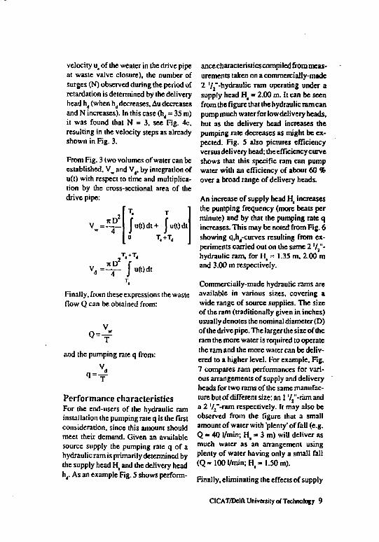
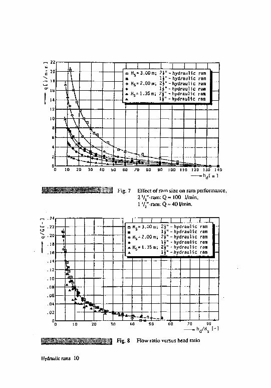
Commercially-made hydraulic rams areavailable in various sizes, covering awide range of source supplies. The sizeof the ram (traditionally given in inches)usually denotes the nominal diameter (D)of the drive pipe. The larger the size of theram the more water is required to operatethe ram and the more water can be deliv-ered to a higher level. For example. Fig.7 compares ram performances for vari-ous arrangements of supply and deliveryheads for two rams of the same manufac-ture but of different size: an 1 '//-ram anda 2 '/2"-ram respectively. It may also beobserved from the figure that a smallamount of water with 'plenty' of fall (e.g.Q » 40 l/min; H( * 3 m) will deliver asmuch water as an arrangement usingplenty of water having only a small fall( Q - 1 0 0 l/min; H t - 1 . 5 0 m).
Finally, eliminating the effects of supply
CICAT/Dclft University of Technology 9
,-. 22
a Hs» 3.00 m; 2J"- hydraulic ram• 1J" - hydraulic ram* Hs= 2.00m; 2}" - hydraulic ram• lj" - hydraulic ramA Hs= 1.35m; ZJ" - hydraulic ram». lj" - hydraulic ram
10 20 30 40 50 GO 70 BO 30 100 H O 120 130 140
_ " 1 J Fig. 7 Effect of ram size on ram performance,2 V2"-ram: Q » 100 1/min,1 '/2"-ram: Q » 40 l/min.
csex
1.22
.20
. 18
.16
. 10
.08
.06
.04
.02
••;"'?.'•>
j—mi
i|
>i
i
kn
^ *
1 I- n H,= 3.00m; H" - hydraulic ram• lj" -hydraulic ram«H s=2.00m; 2J" - hydraulic ram* lj"- hydraulic ram* Hs= 1.35m; 2J" - hydraulic ram
—n t
-
3D 40 SO 60 80• hd /Hs I - l
l '~f; >,'; , j Fig. 8 Flow ratio versus head ratio
Hydraulic rams 10
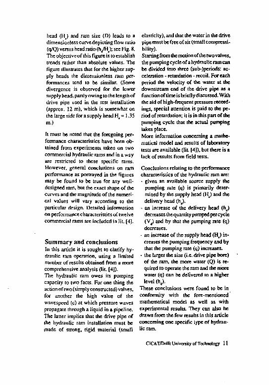
head (H_) and ram size (D) leads to adimcnsionlcss curve depicting flow ratio(q/Q) versus head ratio (h /H ; see Fig. 8.The objective of this figure is toesiablishtrends rather than absolute values. Thefigure illustrates that for the higher sup-ply heads the dimensionlcss ram per-formances tend to be similar. (Somedivergence is observed for the lowersupply head, partly owing to the length ofdrive pipe used in the test installation(approx. 12 m), which is somewhat onthe large side for a supply head Ht = 1.35m.)
Ft must be noted that the foregoing per-formance characteristics have been ob-tained from experiments taken on twocommercial hydraulic rams and in a wayare restricted to these specific rams.However, general conclusions on ramperformance as portrayed in the figuresmay be found to be true for any well-designed ram, but the exact shape of thecurves and the magnitude of the numeri-cal values will vary according to theparticular design. Detailed informationon performance characteristics of twelvecommercial rams are included in lit. [4].
Summary and conclusionsIn this article it is sought to clarify hy-draulic ram operation, using a limitednumber of results obtained from a morecomprehensive analysis (lit. [4]).The hydraulic ram owes its pumpingcapacity to two facts. For one thing theaction of two(simply constructed) valves,for another the high value of thewavespced (c) at which pressure wavespropagate through a liquid in a pipeline.The latter implies that the drive pipe ofthe hydraulic ram installation must bemade of strong, rigid material (small
elasticity), and that the water in the drivepipe must be free of air (small compressi-bility).Starting from the motion of the two valves,the pumpingcycleof a hydraulic ram canbe divided into three (sub-)periods: ac-celeration - retardation - recoil. For eachperiod the velocity of the water at thedownstream end of the drive pipe as afunction of time is briefly discussed. Withthe aid of high-frequent pressure record-ings, special attention is paid to the pe-riod of retardation; it is in this pan of thepumping cycle that the actual pumpingtakes place.More information concerning a mathe-matical model and results of laboratorytests are available (lit. [4]), but there is alack of results from field tests.
Conclusions relating to the performancecharacteristics of the hydraulic ram arc:- given an available source supply the
pumping rate (q) is primarily deter-mined by the supply head (Ha) and thedelivery head (h,).
- an increase of the delivery head (h,)decreases the quantity pumped per cycle(Vj) and by that the pumping rate (q)decreases.
- an increase of the supply head (Ha) in-creases the pumping frequency and bythat the pumping rate (q) increases.
• the larger the size (i.e. drive pipe bore)of the ram, the more water (Q) is re-quired to operate the ram and the morewater (q) can be delivered to a higherlevel (h,).
These conclusions were found to be inconformity with the fore-mentionedmathematical model as well as withexperimental results. They can also bedrawn from the few results in this articleconcerning one specific type of hydrau-lic ram.
CICAT/Dclft University of Technology 11
References[J] Lansford, W.M, Dugan, W.D.
'An Analytical and ExperimentalStudy of the Hydraulic Ram', Uni-
. vcrsity of Illinois Engineering Ex-periment Station, Bulletin Series No.326, Urbana, Illinois, 1941.
[2] Renaud, H.'Le Bilier Hydraulique', Dunod,Paris, 1950.
[3] Schiller, E.J. (ed.)'Proceedings of a Workshop onHydraulic Ram Pump (Hydram)Technology - held at Arusha, Tanza-nia, 1984', International Develop-ment Research Centre - ManuscriptReport (IDRC-MR 102e), Ottawa,Canada, 1985.
[4] Tacke, J.H.P.M.'Hydraulic rams - a comparativeinvestigation', Communications onhydraulic and geotechnical engineer-ing - Report no. 88-1, Delft Univer-sity of Technology, Department ofCivil Engineering, Delft, 1988.
[5] Jong.P.de'Hydraulic rams - consumers guide',CICAT, Delft University of Tech-nology, Delft, 1988.
For further information please contact:Laboratory of Fluid Mechanics, Depart-ment of Civil Engineering, Delft Univer-sity of Technology, P.O. Box 5048,2600GA Delft, the Netherlands.
Hydraulic rams 12


