Embed Size (px)
Citation preview
RESCUECooperative Navigation for Rescue Robots
Final Technical Report
A. Bernardino, L. Custodio, J. Frazao,
P. Lima, F. Melo, M. I. Ribeiro,J. Santos-Victor, A. Vale
November 4, 2004
1
Contents
1 Introduction 31.1 Reference Scenario . . . . . . . . . . . . . . . . . . . . . . . . . . . . . . . . 41.2 Robots . . . . . . . . . . . . . . . . . . . . . . . . . . . . . . . . . . . . . . . 41.3 Organization . . . . . . . . . . . . . . . . . . . . . . . . . . . . . . . . . . . 5
2 Topological Navigation of Land Robot 72.1 Introduction . . . . . . . . . . . . . . . . . . . . . . . . . . . . . . . . . . . . 72.2 Mobile Robot Navigation . . . . . . . . . . . . . . . . . . . . . . . . . . . . . 7
2.2.1 The three main problems: Localization, Navigation and Mapping . . 82.2.2 Environment Representation . . . . . . . . . . . . . . . . . . . . . . . 92.2.3 Localization . . . . . . . . . . . . . . . . . . . . . . . . . . . . . . . . 102.2.4 Navigation . . . . . . . . . . . . . . . . . . . . . . . . . . . . . . . . . 102.2.5 Mapping . . . . . . . . . . . . . . . . . . . . . . . . . . . . . . . . . . 11
2.3 Experimental Results . . . . . . . . . . . . . . . . . . . . . . . . . . . . . . . 112.3.1 Indoor Results . . . . . . . . . . . . . . . . . . . . . . . . . . . . . . 122.3.2 Outdoor Results . . . . . . . . . . . . . . . . . . . . . . . . . . . . . 13
3 Vision-Based Control of the Aerial Robot 16
4 Navigation Controllability for Heterogeneous Robot
Teams 184.1 The Environment Representation . . . . . . . . . . . . . . . . . . . . . . . . 184.2 The Navigation Automata . . . . . . . . . . . . . . . . . . . . . . . . . . . . 194.3 The Blocking Information Matrix . . . . . . . . . . . . . . . . . . . . . . . . 19
4.3.1 Example . . . . . . . . . . . . . . . . . . . . . . . . . . . . . . . . . . 20
5 Formation Control 23
6 Distributed Planning for a Multi-Robot Rescue Team 24
7 Software and Functional Architectures 27
8 Conclusions and Future Plans 28
2

1 Introduction
The main goal of the “RESCUE – Cooperative Navigation for Rescue Robots” project was,as stated in its proposal, to provide integrated solutions for the design of teams of cooperativerobots operating in outdoors environments, with special focus in the short and mid-termson perception and representation issues, as well as cooperative navigation, and, in the midto long-terms, on task modeling, planning and coordination.
One potential scenario for outdoors robot operation is the search and rescue for victimsafter a catastrophic event. This may be due to causes that range from natural occurrences,such as earthquakes or floods, to urban riots or terrorist attacks. Many regions of Europe,such as the Balkans, Italy, the South of Spain and Portugal are regions of high or moderateseismic activity.
Earthquakes are specially daunting phenomena. Even though their occurrence is fortu-nately sparse, the consequences are often tragic, leading to thousands of deaths and manymore injured people, besides mass building destruction. Reports from the infamous 1995Kobe earthquake in Japan show that many unexpected events hit the communications andcivil protection infrastructure, disabling the execution of most of the available plans fordisaster situations [21]. Especially the serious damage to the telecommunications networkand the fact that the buildings of disaster mitigation organizations were hit caused seriousdelays in the arrival of local and external assistance to the victims. Structures in risk ofcollapsing are often inaccessible to humans because they are too dangerous. Survivors maybe unintentionally injured during removal of debris due to the unawareness of their locationor presence by the rescue teams.
Teams of heterogeneous robots can represent an invaluable help for future search andrescue operations. Robots can crawl over the collapsed structures, depositing small-sizedrobots, and feeding air, water, food and medication to trapped individuals through tubessnaked into the collapsed structure. Small-sized robots can sneak inside very confined spaces,taking with them tiny cameras and other sensors to detect survivors and map survivor loca-tions. Aerial robots can provide a broad view of the search and rescue scenario and map high-destruction locations. Cooperation among human-operated stations, a distributed networkof sensors located around the disaster area and teams of tele-operated and/or autonomousrobots can increase the amount of available information to the rescue teams. Whenever com-munications with the networked sensors or the sensors themselves fail due to the earthquakeimpact, robots can be dispatched to cover the areas most unaccessible to humans and helpfinding victims at those locations. These mobile robot networks can also provide a dynamicview of the scene at relevant locations.
The major drives of the project were:
• To foster research advances in its enabling disciplines (Computer Vision, Robot Navi-gation, Control and Artificial Intelligence), extendable to other outdoors applications,such as environmental monitoring and surveillance, agriculture or planetary explo-ration.
• To develop an application of strong social impact.
During the project lifetime, other initiatives helped promoting these goals:
3

• The creation, at the Associate Laboratory Institute for Systems and Robotics, at IST(ISR/IST), of a research line on “Robot Monitoring and Surveillance” that, amongothers, is concerned with the development of outdoors cooperative rescue robots.
• The approval of the RAPOSA project proposal by the Agencia de Inovacao, wherea tele-operated rescue robot has been built and will soon be start its tests at LisbonFire Department. The project promoted the collaboration between ISR/IST and theLisbon Fire Department on this type of activities.
1.1 Reference Scenario
In the first year of the RESCUE project, thorough scientific discussions took place amongthe involved groups. The objective of these discussions was three-folded:
• to help the different involved groups sharing a common language;
• to provide an integrated view of the project scientific goals, instead of a simple con-catenation of each group contributions;
• to specify a reference scenario that would illustrate the research goals, including therequired hardware and software.
After these discussions, a scenario was approved as the project reference scenario. Itsmain goals are to provide a realistic step toward the long term goal of developing practicalrescue robots and to encompass the scientific interests of the project members. The referencescenario, is based on the ATRV-Jr land and the MiniZepp blimp aerial robots, described inthe next subsection, which perform cooperative navigation tasks, some of them requiringformation control.
The reference scenario consists of two robots: one aerial blimp/zeppelin robot; one landoutdoors robot. The aerial robot will perform several tasks, such as making a visual topolog-ical map of the destroyed site. The map will include information on the relevance of each ofthe mapped locations concerning degree of destruction, presence of victims, etc, as well as onthe difficulty of traversing regions between them, due to the presence of debris or obstructedpaths. The map will be stored as a graph and will be used to choose the best path for theland robot to reach a goal location (e.g., one with a larger number of victims). It can alsobe used to help the aerial robot navigating. The land robot will use several sensors (GPS,inertial, vision, sonars) to navigate toward the goal, handling the details associated to thepath (e.g., debris, trees, people on the way, etc). While the land robot moves toward thegoal location, the aerial robot should follow it using a formation control algorithm, so as tokeep a reliable communications link and to serve as a relay for informations that the landrobot may need to send to distant stations.
An animation illustrating the scenario above was developed to better explain the referencescenario to project members and non-members and is included in the companion CD as a.mpeg file.
1.2 Robots
In the initial phases of the project, and following the reference scenario discussion, thespecification, purchase and integration of the hardware required to accomplish the goals of
4

the reference scenario were carried out, resulting in the purchase of an iRobot ATRV-Jr landmobile robot and a BlimpGuys commercial blimp, to be used as the aerial robot. The latterwas purchased using ISR funding, not provided by this project.
The ATRV-Jr is a 4-wheel differential drive robot, with 2 high torque 24V DC servomotors, capable of achieving linear speeds up to 1 m/s and turning speeds up to 120 deg/s.With a 25 Kg payload, it weights 50 Kg and is capable of overcoming 45 deg slopes. Its 2lead acid, 672 Watt/hr batteries provide an autonomy of 3 to 5 hours, depending on terrain.The onboard computer is a Pentium III running at 800 MHz. Communications with otherrobots and external computers are ensured by either a 100/10 Mbps Ethernet board or IEEE802.11b Wireless radio Ethernet. The robot includes an odometry system and Linux-basedmanagement software and libraries.
The ATRV-Jr was endowed with several navigation sensors:
• one computerized navigation compass,
• one 12-channel GPS receiver,
• one Inertial Navigation System (INS), including rate-gyros, and
• seventeen sonars (5 forward facing, 10 side facing and 2 rear facing).
The land robot was initially tested on several runs at IST gardens, with simple navigationalgorithms based on odometry and sonars. The GPS, compass and INS were also tested andtheir performance assessed under several different conditions (e.g., number of available GPSsatellites, robot inclination). A report on this work, performed by the company IdMind, canbe found in the companion CD, detailing the robot hardware and the results of experimentsmade with it.
The blimp is 4 m long, with a 2 m diameter and 5.5 m3 volume polyurethane bag. Two ofits speed-controlled servo-motors can control altitude, as well as forward and reverse speed,under less than 5 Km/h winds. The remaining servo-motor is attached to the bottom tailand helps controlling the blimp orientation. The payload is 2 Kg. The onboard sensor isa pan and tilt color CCD camera with HF transmitter. Originally, it had a seven channel41Mhz FM radio transmitter from Graupner (mc-10), now modified to act as a 5-channelPC-Radio Controller transmitter interface using RS-232 communication. The 5 channels areused to control, from a ground computer, the speed, altitude and rotation servos, as well asthe pan and tilt system. The ground computer receives the video signal sent through the HFvideo channel, processes the images and closes the navigation loop by sending commandsto the servos and the pan and tilt systems. The modified hardware includes an emergencyswitch for manual control. The robot is powered by 2 NiMh 7.2v 1900mAh batteries formotors and control, and 8 NiMh 1.2v 600mAh batteries for camera and transmitter power,providing an autonomy of 30–120 minutes.
A report on the blimp, performed by the company IdMind, is also included in the com-panion CD, detailing the aerial robot hardware, the modifications made and the results ofexperiments made with it.
1.3 Organization
This final project report summarizes the main scientific and technological achievements ofthe RESCUE project and is organized as follows. Section 2 focus on the topological navi-
5
gation methods developed for the land robot. Section 3 covers the different work done onvision-based indoors blimp navigation. In Section 4, some theoretical work on the naviga-tion controllability of heterogeneous robot teams, based on Discrete Event Systems theory,is presented. Some methods for Formation Control, and the corresponding simulations,where the aerial blimp and up to 6 land robots follow paths while keeping a geometricalformation, are presented in Section 5. Section 6 introduces work on distributed planningfor a multi-robot rescue team, based on distributed Artificial Intelligence and Multi-AgentSystems techniques, and tested on a simulator which emulates scenarios that could well bethe subject of future applications using real robots, as an extension of the current project.Section 7 summarizes the concepts concerning the software and functional architectures thatwill support the project development, and its implementation. Finally, major conclusions ofthe work carried out within the RESCUE project are drawn in Section 8, where plans forfuture research are also briefly listed.
6
2 Topological Navigation of Land Robot
2.1 Introduction
In this section it is proposed a topological based methodology to solve the problem of mobilerobot navigation in unstructured outdoor scenarios. The methodology was tested in realisticindoors and outdoors scenarios, supported on a real mobile land robot. Its main contribu-tions include a new topological environment representation built from a set of nodes definedby sum of Gaussian pdfs and connected by orientation, a dynamic version of expectationand maximization algorithm to build the world representation, a probabilistic approach forlocalization and navigation using an optimized version of forward-backward algorithm anda procedure for feature extraction and selection.
The operation of mobile robots in outdoors environments has become widely used in thepast years raising a set of challenging scientific problems that include environment represen-tation, map building and localization.
The most common approaches for environment representation are divided in three groups:geometric, topological and hybrid. The choice of the type of world representation constraintsthe approaches taken for localization and navigation.
Most of the topological research to recognize places and to record them as references, isbundled on information retrieved by vision sensors, in particular with edges, [18], the maincomponents of the image [28] and by colors [16]. There are several approaches that use visionand motion commands as a qualitative way [15] for mapping and navigation, based on bio-inspired techniques. Given the uncertainty associated to the environments, as justified by[27], it is important that topological maps also include a probabilistic approach. Geometricmaps and topological maps can be combined as hybrid maps, described in [2], where mostoften the topological representation arises from the metric information [11].
In spite of individual problems, the localization and map building must be handled as asingle issue. One promising research area lays on Simultaneous Localization and Mapping -SLAM, [23], [14], [3], also known as Concurrent Map Localization - CML, [1] and [12]. Mostof the SLAM approaches are oriented to indoors, well structured and static environments(like domestic ones [32]) and give only metric information of the position of the mobile robotand the landmarks.
Rather than using a metric approach, this methodology solves the SLAM underlinedproblem, including localization, navigation and mapping, relying on a topological approach.A topological map is incrementally built along the robot operation. This map supportsmethodologies for topological localization and navigation.
2.2 Mobile Robot Navigation
The mobile robot navigation has to deal with uncertainty included in the world, the percep-tion of the world (observations and/or consequently on features) and also on the motion.
The localization problem is associated to the world representation, not limited to a simplereferential, where the metric information is related. Using the perception given by the sensorsaccording to the selected environment representation, the localization has to provide theinformation to bound the uncertainty increasing.
Once an appropriate world representation is selected, no less important is the problem of
7

building the map that endows the environment representation. It is necessary to understandhow to start the localization on the initial map and to progressively update that map. Theupdating procedure, or mapping algorithm must be running every time that new observationsare acquired, which can be retrieved in places not visited yet.
Features discriminate the different types of information, which result from processingthe acquired observations. The map can be used as a referential again but, at this time,with more dimensions, where each dimension corresponds to a different feature. This mapprovides a high level of abstraction of the environment, a topological representation. Theprecision is accomplished by the type and the amount of features extracted.
2.2.1 The three main problems: Localization, Navigation and Mapping
The mobile robot navigation has three main problems: Localization, Navigation and Map-ping. When the robot is moving, it is necessary to estimate the position (the localizationproblem) and compute a new path (the navigation problem). Moreover if the robot moves,it yields to a new position, where the new acquired observations could improve the currentmap, the mapping problem. From these three problems emerges the loop in Figure 1, thatis executed while the robot performs its mission.
Localization Navigation
Mapping
Figure 1: The main loop of mobile robot navigation
The loop does not require a specific sequence. Moreover, each problem can be accom-plished at different frequencies, which could change dynamically, this meaning that the threeissues have different priorities. Given that the robot is moving to reach a specific target orgoal, it is important to recognizing its position at each time instant and to update theplanned path if necessary. The localization and navigation are based on a map, which isbuild by the mapping algorithm. Since it is assumed that the robot does not travel longdistance during short periods of time, it is expected that the scenario is still covered by thecurrent map. Therefore, the map should be updated when the localization ambiguities occurand/or added/removed new/old type of features. Consequently, it is not necessary to runthe mapping permanently.
The navigation is the next priority, to evaluate the best way to reach the main goal ofthe mission. Since all the procedures are based on the environment representation, it is alsonecessary to run the mapping procedure, even though it is not necessary to run it every timethe robot acquires a new observation. Based on this concept, the procedure implementedwith the highest rate is the localization, followed by the navigation and finally the mapping,as illustrated in Figure 2. If there is no map available at the beginning, the loop must startfrom the mapping procedure to provide a first map, or loading a previous estimation of thescenario.
8

LocalizationMappingInitialization
Navigation
Figure 2: The 3 steps of mobile robot navigation at different rates
The localization starts with the initial robot position in the map. If not known, theinitial position is assumed as equiprobable in all map. In the navigation, it is initializedor, imposed by the mission, a target goal. If there is a map available at the beginning, thetarget goal can be pointed in the map. After the initialization, the loop starts, following thepriorities illustrated in Figure 2.
2.2.2 Environment Representation
The navigation is accomplished based on the available map and there are different types ofmaps, as illustrated in Figure 3.
x
y
State 1
State 2
State 3
State n
Metric
Grid
Hybrid
TopologicalAbstr
action
Figure 3: Environment representations at different levels of abstraction
Current global methods can be classified as topological (adjacency-graph based represen-tation of the environment composed by nodes or states and links), geometric (metric rep-resentation of the environment landmarks position with respect to a referential; the metricrepresentation also includes the common grid maps) or hybrid (topological maps containingsub-topological and metric maps in each state).
9
A topological map is a representation of an environment with no metric informationavailable, showing physical (natural or artificial) features that characterize particular loca-tions or places. The map expresses a functional relationship among relevant features with aresolution that is proportional to the complexity of the environment’s representation.
The topological maps, are complex enough to travel long distances according to theappropriate way and simple to avoid the incumbency of recording ever information overthe physical location covered by the map. This type of representation, topological maps,is the only one prepared for the diversity of scenarios, the large spectrum of informationacquired by the available sensors, the unexpected events that occur during the operationand also robust to the scenario changes. The notation used to define a topological mapis the following: si is the state i, i = 1 . . . , N of the map defined by a sum of Gaussiansmodeling the features that characterize each state, aij is the transition probability betweenstate i and state j and θij is the direction between these states.
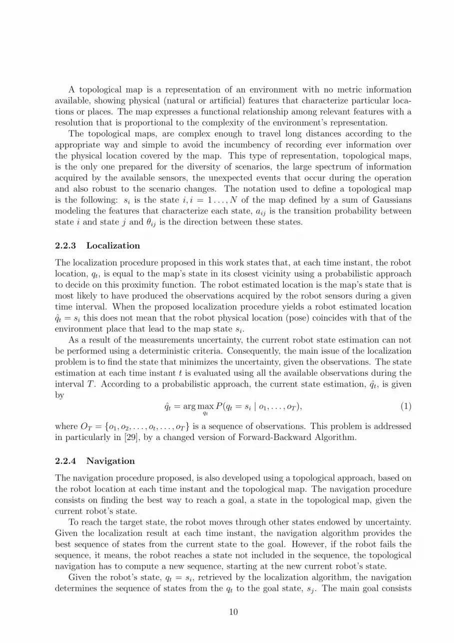
2.2.3 Localization
The localization procedure proposed in this work states that, at each time instant, the robotlocation, qt, is equal to the map’s state in its closest vicinity using a probabilistic approachto decide on this proximity function. The robot estimated location is the map’s state that ismost likely to have produced the observations acquired by the robot sensors during a giventime interval. When the proposed localization procedure yields a robot estimated locationqt = si this does not mean that the robot physical location (pose) coincides with that of theenvironment place that lead to the map state si.
As a result of the measurements uncertainty, the current robot state estimation can notbe performed using a deterministic criteria. Consequently, the main issue of the localizationproblem is to find the state that minimizes the uncertainty, given the observations. The stateestimation at each time instant t is evaluated using all the available observations during theinterval T . According to a probabilistic approach, the current state estimation, qt, is givenby
qt = arg maxqt
P (qt = si | o1, . . . , oT ), (1)
where OT = {o1, o2, . . . , ot, . . . , oT} is a sequence of observations. This problem is addressedin particularly in [29], by a changed version of Forward-Backward Algorithm.
2.2.4 Navigation
The navigation procedure proposed, is also developed using a topological approach, based onthe robot location at each time instant and the topological map. The navigation procedureconsists on finding the best way to reach a goal, a state in the topological map, given thecurrent robot’s state.
To reach the target state, the robot moves through other states endowed by uncertainty.Given the localization result at each time instant, the navigation algorithm provides thebest sequence of states from the current state to the goal. However, if the robot fails thesequence, it means, the robot reaches a state not included in the sequence, the topologicalnavigation has to compute a new sequence, starting at the new current robot’s state.
Given the robot’s state, qt = si, retrieved by the localization algorithm, the navigationdetermines the sequence of states from the qt to the goal state, sj. The main goal consists
10
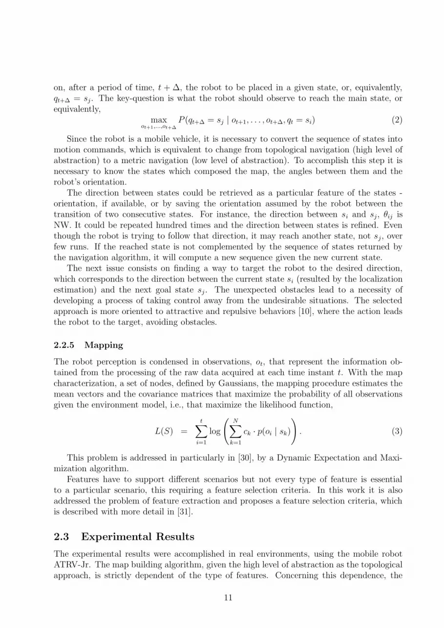
on, after a period of time, t + ∆, the robot to be placed in a given state, or, equivalently,qt+∆ = sj. The key-question is what the robot should observe to reach the main state, orequivalently,
maxot+1,...,ot+∆
P (qt+∆ = sj | ot+1, . . . , ot+∆, qt = si) (2)
Since the robot is a mobile vehicle, it is necessary to convert the sequence of states intomotion commands, which is equivalent to change from topological navigation (high level ofabstraction) to a metric navigation (low level of abstraction). To accomplish this step it isnecessary to know the states which composed the map, the angles between them and therobot’s orientation.
The direction between states could be retrieved as a particular feature of the states -orientation, if available, or by saving the orientation assumed by the robot between thetransition of two consecutive states. For instance, the direction between si and sj, θij isNW. It could be repeated hundred times and the direction between states is refined. Eventhough the robot is trying to follow that direction, it may reach another state, not sj, overfew runs. If the reached state is not complemented by the sequence of states returned bythe navigation algorithm, it will compute a new sequence given the new current state.
The next issue consists on finding a way to target the robot to the desired direction,which corresponds to the direction between the current state si (resulted by the localizationestimation) and the next goal state sj. The unexpected obstacles lead to a necessity ofdeveloping a process of taking control away from the undesirable situations. The selectedapproach is more oriented to attractive and repulsive behaviors [10], where the action leadsthe robot to the target, avoiding obstacles.
2.2.5 Mapping
The robot perception is condensed in observations, ot, that represent the information ob-tained from the processing of the raw data acquired at each time instant t. With the mapcharacterization, a set of nodes, defined by Gaussians, the mapping procedure estimates themean vectors and the covariance matrices that maximize the probability of all observationsgiven the environment model, i.e., that maximize the likelihood function,
L(S) =
t∑
i=1
log
(N∑
k=1
ck · p(oi | sk)). (3)
This problem is addressed in particularly in [30], by a Dynamic Expectation and Maxi-mization algorithm.
Features have to support different scenarios but not every type of feature is essentialto a particular scenario, this requiring a feature selection criteria. In this work it is alsoaddressed the problem of feature extraction and proposes a feature selection criteria, whichis described with more detail in [31].
2.3 Experimental Results
The experimental results were accomplished in real environments, using the mobile robotATRV-Jr. The map building algorithm, given the high level of abstraction as the topologicalapproach, is strictly dependent of the type of features. Concerning this dependence, the
11

experimental results presented in this section also enable understanding how the featuresselected improve the topological approach.
2.3.1 Indoor Results
In this first experience, it was only used range sensors: the laser range scanner and the ringof ultra-sonic sensors installed at ATRV-Jr. The type of features were based on free-areameasured by the laser and the sonars. The free-area could be represented by the mean,variance or other combinations of the free-area along different directions measured by thesensors.
The selected indoor scenario to test the mapping algorithm based on the type of featuresdescribed above, is a laboratory environment, where the robot moved from a room to acorridor. The room is a common place containing chairs, tables and people walking, usuallylarger than a corridor.
The mapping algorithm was tested using the observed features (related with free-area)acquired during the travel from the middle of the room to the corridor. Since the selectedfeatures do not contain metric information of the robot’s position, the raw-data recordedduring the trajectory is displayed in Figure 4-a) using the odometry (sensor fusion), only forillustration and to simplify the data visualization.
a) b)
Figure 4: The resulted topological map: a) the laser and sonar measurements and b) thestates that compose the map
Setting low accuracy to the mapping algorithm, the result is a topological map withthree states, corresponding to the room and the corridor as expected and to another state,which corresponds to the transition between them, defined as an entrance. The Figure 4-b)represents the measurements of the laser and sonar with three different colors, correspondingto each state.
The resulted topological map, presented in Figure 4, does not contain neither metricinformation nor features extracted from a vision camera. However, during the experience,the images were grabbed at same time as the laser and sonar data. The camera is mountedon the top of the robot pointing in the front direction. After knowing the topological map,the images were divided according to each state, as depicted in Figure 5.
The images were clustered according to each state, based only on range sensor data andno vision information. Just by a vision inspection, the first state may be also decomposed
12

a) b) c)
Figure 5: The images associated to the a) state 1 (equivalent to the lab), b) state 2 (equivalentto the entrance) and c) state 3 (equivalent to the corridor)
in two possible new states. Therefore, image sensor retains more information than rangefinders.
2.3.2 Outdoor Results
The next experience was targeted to test the topological representation using features ex-tracted from the images. The proposed scenario is the Campus of IST (Instituto SuperiorTecnico) at Lisbon - Alameda. The robot acquired the raw-data, while it was navigatingaround the central building and computing the topological map. Since no map was availableat the beginning, the navigation algorithm was proposed to guide the robot to follow somevia-points defined by latitude and longitude coordinates, using the behavior approach. Therobot moved along a distance of approximately 400 meters and acquired raw-data during1586 iterations, later converted into features.
At this point, it is necessary to evaluate the resulted topological map and the quality ofthe information retained by the features extraction procedure. The central building of ISTis located in the center of image in Figure 6-a), surrounded by trees, cars, people walkingand other buildings. Only features extracted from the vision camera were used, given therange sensors’ limitations. The resulted topological map using histograms (of colors) andPCA is presented in Figure 6-b).
The quality of information included in the features is not enough to create a middlestate between state 3 and 4, leading to an ambiguity between these two states. Increasingthe number of features does not imply an information improvement to represent what isobserved, which requires to analyze the features correlation and choose the low correlated.
As expected, the correlation differs between experiences and features, as shown in [31],where vertical edges, Hue/Saturation-colors histograms parameterization, 2D histograms
13

a) b)
Figure 6: The resulted topological map using color histograms and PCA: a) the laser mea-surements and b) the 5 states
(boundary-boxes), PCA and ICA were tested in different scenarios. ¿From the results pre-sented in the previous paper, the edges and ICA or edges and histograms (or even the threetype of features simultaneously) are the best features to build a map in current scenario.Based on the results obtained from the features selection, it was adopted the histograms andedges as one of the best features combinations. Moreover, the orientation was also includedon the features: histograms, edges, and orientation.
The mapping algorithm computed a new topological map, as illustrated in Figure 7,containing six states. The ambiguity of the previous experiment was removed, since thetopological map identified a new state (state 5) according to the selected features.
a) b)
Figure 7: The topological map using color histograms and edges a) the laser measurementsand b) the states identified by circles
Using the topological map resulted from the last experience, in Figure 7, the localizationalgorithm was tested. To localize the robot in the topological map it is also necessary the
14

same type of features used in the mapping algorithm.The experimental results of localization are presented in Figure 8, with the probabilities
of the robot to be localized in each state, given the observed features along time. The robotstarted with some doubt between state 2 and 3, quickly solved after few iterations, remainingin state 2 during more than 200 iterations. The following state is 3 and there is a periodof uncertainty between state 3 and 4, lately solved to the last one. It is also verified inFigure 7, when the mapping algorithm shows a small noise between state 3 and 4, visible bythe blue and red colors. This subject stresses not only the features selection issue, but alsothe importance of the topological map resolution.
0 200 400 600 800 1000 1200 1400 1600
0
0.5
1
stat
e 3
0 200 400 600 800 1000 1200 1400 1600
0
0.5
1
stat
e 2
0 200 400 600 800 1000 1200 1400 1600
0
0.5
1
stat
e 6
Iterations
0 200 400 600 800 1000 1200 1400 1600
0
0.5
1
stat
e 4
0 200 400 600 800 1000 1200 1400 1600
0
0.5
1
stat
e 5
0 200 400 600 800 1000 1200 1400 1600
0
0.5
1
stat
e 1
Figure 8: The localization evolution on the resulted topological map
Along the path and based on the localization results on the topological map, it is alsopossible to estimate the transition probability between states. The robot has a high prob-ability to remain in the current state, for every state of the topological map. If the robottransits to another state, it is more probable to jump to the next or to the previous state.It is also possible to estimate the orientation between states.
15

3 Vision-Based Control of the Aerial Robot
The aerial blimp robot was first flown autonomously during the project second year. Thefirst step consisted of developing a driver to provide access to the radio controller, whosehardware had been modified in the first year to allow remote control by a ground computer.Then, several measurements were made to obtain the characteristic functions that relate thevoltage sent to the motors with the thrust generated by the propellers. Using that, a controllibrary for position and velocity control was developed. The library is modular and consistsof three control levels (see Figure 9), from position control in world coordinates down tovelocity control of forward/backward, upward/downward and rotation around the verticalaxis movements, in vehicle coordinates. This control library can be used like a black box.The user can control separately the local velocities over the global direction control up tothe global position control.
Level 1local velocity vontrol
rotation
forward/backward
up/down
Level 2global direction and
velocity control
Level 3global position
control
velocityguidancecontroller
positionguidancecontroller
Figure 9: Aerial blimp control architecture.
During the RESCUE project, the only sensor used in the aerial robot was a vision systemconsisting of a micro-camera placed onboard the blimp, whose images are subject to real-time processing. From the homographies between consecutive images and assuming someprior information regarding the surrounding environment, it is possible to estimate velocitiesand displacements of the robot in 3D space.
Several indoors autonomous navigation tests were performed and their results are avail-able in a technical report TKrause-TechRep.pdf included in the companion CD. Generally,the results were positive, and it is possible to control the robot velocity in 3D space, includ-ing the compensation of dynamical effects like simulated weak wind. Nevertheless, opticalflow has some drawbacks, especially notable after integration, resulting in an often poorodometric estimate of the blimp position in world coordinates.
To perform positioning or trajectory following tasks with an aerial robot, the developmentof control algorithms that overcome the underlying limitations of the system dynamics andkinematics, as well as the external disturbances, is required. Control methodologies weredeveloped for the aerial robot that enable the system to accomplish positioning or trajectoryfollowing tasks, surpassing some limitations imposed by the physical system and the sensor.Image processing algorithms that enable obtaining the vehicle pose (position + orientation)and velocity were studied. Several types of linear and non-linear controllers were used tocontrol the vehicle velocity, as well as its heading in 3D space. Two strategies for thereference definition were proposed, one based in position and coordinates in Cartesian space
16

and the other based in image measurements, thus avoiding the need for high precision cameracalibration.
The work developed consisted of system modeling and parameter identification, as wellas control and image processing tests in a special-purpose simulator developed within theproject. Furthermore, experiments were made with the real setup in which the algorithmswere implemented, running in real-time.
More detailed information on this work can be found in the FilipeLuis-TechRep.pdf fileincluded in the companion CD.
Additional work has been done on localization and landmark selection for navigationon aerial images. It is assumed that the aerial robot has previously extracted an extendedvisual map of the working area. Once this is done, alternative techniques are comparedto select salient regions in the scene that can be used as visual landmarks for navigation.The work is described in [19]. Salient regions are defined as regions very distinct from theirneighborhood and this can also be useful in the detection of isolated destruction loci (fires,wrecks), though this was not fully exploited in this project.
More detailed information on this work can be found in the Lorenz-TechRep.pdf file in-cluded in the companion CD.
17

4 Navigation Controllability for Heterogeneous Robot
Teams
In order to achieve coordination/cooperation between a set of robots, it is of great importanceto understand how the ability of each individual robot to achieve some goal affects the team’soverall ability to succeed in the mission.
In order to have a deeper insight regarding this problem, in this section an analysis toolis presented, which will allow better understanding of how the navigation of each robot in arobot population may or may not prevent the final objective from being attained.
4.1 The Environment Representation
Consider, then, a set of N mobile robots. The robots are moving in a discrete environment,i.e., an environment which can be divided in a discrete set of sites, S = {1, ...,M}. Adiscrete environment can properly be described using a topological map T = (S, E), where,as stated, S is a finite set of sites and E = S × S is a set of edges, such that, given s1, s2 ∈ S,(s1, s2) ∈ E if it is possible to move from site s1 to site s2. In figure 10 an example of anindoors environment and its topological map are depicted.
Although this kind of representation is particularly suited for describing indoors environ-ments, since these environments are naturally divided in sites (rooms, hallways, etc), recentwork has been developed regarding mapping of unstructured environments as topologicalmaps (e.g. outdoors environments [30]).
Room B
Room ARoom C
(a)
A B C
(b)
Figure 10: Example of topological map (the gray zones are bi-directional pathways). Noticethat, although there are two pathways between rooms B and C, they aren’t both repre-sented in the topological map. (a) Example of an indoors environment. (b) Correspondingtopological map.
However, the topology of the environment is not enough to model the movement of amobile robot in that environment. For example, in Figure 10, suppose that the pathway
18

between rooms A and B is a staircase. If the robot is not properly equipped to cope withsuch a terrain, it may be impossible for it to travel between rooms A and B, although thereis a physical pathway between the two rooms.
This leads to an immediate conclusion: the information in the topological map of theenvironment may not be enough to represent the movement of the robot in the environment.
In the next sub-section, a model of the robot will then be introduced.
4.2 The Navigation Automata
¿From what was stated in the previous subsection, a robot moving in an environment de-scribed by a topological map T = (S, E) may not be able to move across all edges of thetopological map.
Thus, it is necessary to have a model for the mobile robot which properly describes itsmovement on the environment. A first approach would be to describe the workspace of therobot as a topological map T ′ = (S, E ′), where E ′ ⊂ E is the subset of edges in E which therobot can traverse. However, in order to model the control actions and the state of the robot,a more complete representation of the robot is necessary.
Since the robot is moving in a discrete environment, it is possible to model it as adiscrete-event system. Automata theory provides a sound framework when working withdiscrete-event systems (see [5] for details on automata theory). If a robot’s workspace isdescribed by a topological map T ′ = (S, E ′), it is now possible to model the mobile robot asan unmarked automaton G = (X,E, f,Γ, x0) [24], where
• X is the state-space and X = S;
• E is the event set, a set of unique labels for the edges in E ′;
• f : X ×E −→ X is the transition function; for x ∈ X, e ∈ E, f(x, e) = y, with y ∈ X,if and only if (x, y) ∈ E and the label of (x, y) ∈ E ′ is e ∈ E;
• Γ : X −→ 2E is the active event function, such that, for x, y ∈ X, y ∈ Γ(x) if and onlyif (x, y) ∈ E ′;
• x0 is the initial state.
Since each robot is meant to reach one of a set of target sites ST , define NavigationAutomata G(Yk) as the marked automata G(Yk) = (X,E, f,Γ, x0, Yk), where X,E, f,Γ, x0
are as defined previously and Yk is the set of marked states Yk ⊂ ST .One may think of a navigation automaton G(Yk) as being obtained from the topological
map T ′ by labeling the edges E ′ in T ′, setting an initial state x0 and defining as marked statesthe set Yk. For example, a navigation automaton for a robot moving in the environment ofFigure 10 may be seen in Figure 11.
4.3 The Blocking Information Matrix
The Navigation Automata described in the previous subsection, although modeling the move-ment of a single robot, can be used to determine the properties of the system of N robots.
19
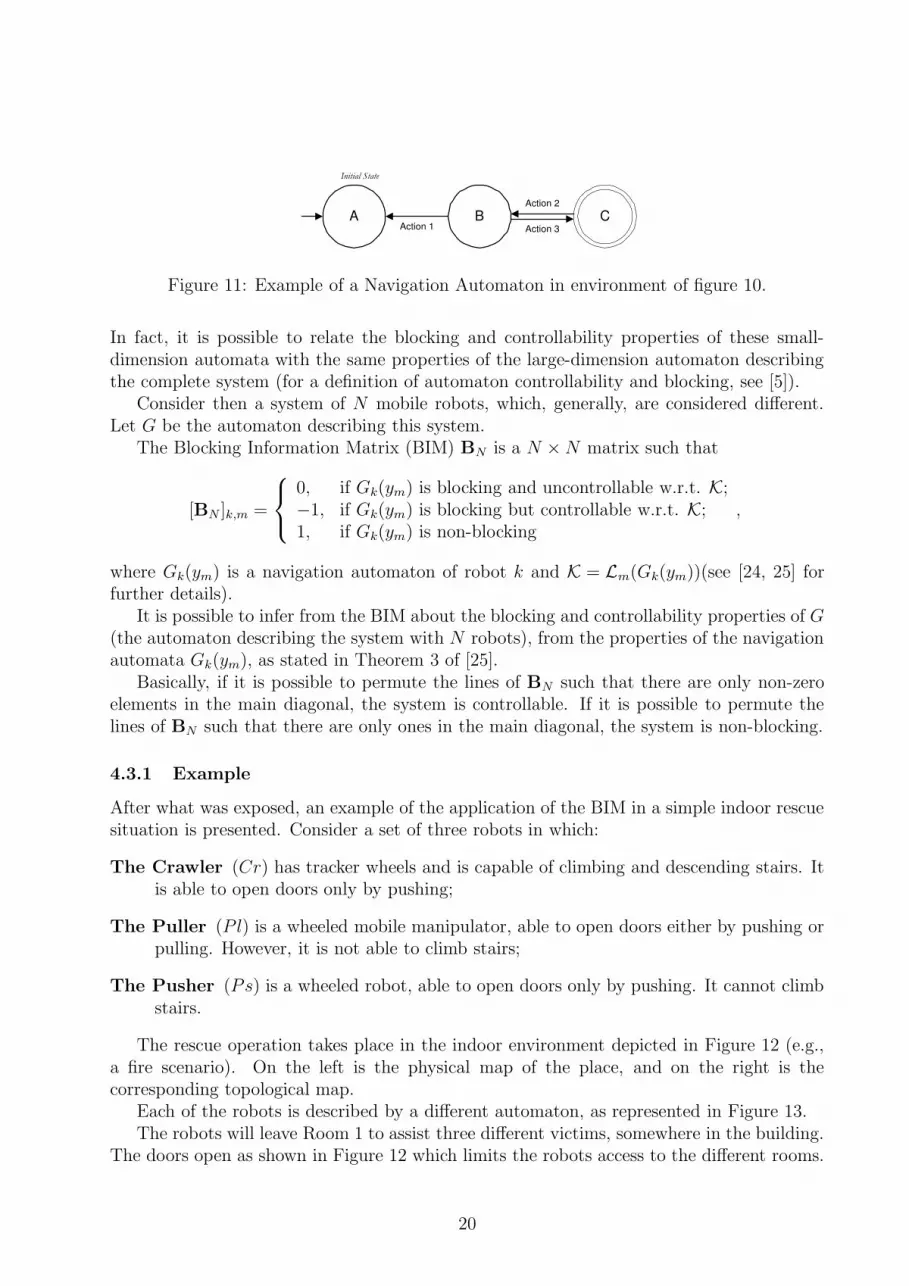
A B CAction 3
Action 2
Action 1C
Initial State
Figure 11: Example of a Navigation Automaton in environment of figure 10.
In fact, it is possible to relate the blocking and controllability properties of these small-dimension automata with the same properties of the large-dimension automaton describingthe complete system (for a definition of automaton controllability and blocking, see [5]).
Consider then a system of N mobile robots, which, generally, are considered different.Let G be the automaton describing this system.
The Blocking Information Matrix (BIM) BN is a N ×N matrix such that
[BN ]k,m =
0, if Gk(ym) is blocking and uncontrollable w.r.t. K;−1, if Gk(ym) is blocking but controllable w.r.t. K;1, if Gk(ym) is non-blocking
,
where Gk(ym) is a navigation automaton of robot k and K = Lm(Gk(ym))(see [24, 25] forfurther details).
It is possible to infer from the BIM about the blocking and controllability properties of G(the automaton describing the system with N robots), from the properties of the navigationautomata Gk(ym), as stated in Theorem 3 of [25].
Basically, if it is possible to permute the lines of BN such that there are only non-zeroelements in the main diagonal, the system is controllable. If it is possible to permute thelines of BN such that there are only ones in the main diagonal, the system is non-blocking.
4.3.1 Example
After what was exposed, an example of the application of the BIM in a simple indoor rescuesituation is presented. Consider a set of three robots in which:
The Crawler (Cr) has tracker wheels and is capable of climbing and descending stairs. Itis able to open doors only by pushing;
The Puller (P l) is a wheeled mobile manipulator, able to open doors either by pushing orpulling. However, it is not able to climb stairs;
The Pusher (Ps) is a wheeled robot, able to open doors only by pushing. It cannot climbstairs.
The rescue operation takes place in the indoor environment depicted in Figure 12 (e.g.,a fire scenario). On the left is the physical map of the place, and on the right is thecorresponding topological map.
Each of the robots is described by a different automaton, as represented in Figure 13.The robots will leave Room 1 to assist three different victims, somewhere in the building.
The doors open as shown in Figure 12 which limits the robots access to the different rooms.
20

Ground floor
Room 7
First floor
Room 1
First floor
Room 3
First floor
Room 4
Ground floor
Room 6
First floor
Room 2
First floor
Room 5
First floor
Room 8
DownDown
Door opening
this way
Door opening
both ways
Staircase down
this way
7 6
3 1 4
2 5 8
a) b)
Figure 12: Map of the Environment.
a) Crawler b) Puller c) Pusher
Figure 13: Automata for the robots.
Moreover, when in Rooms 6 or 7, only the Crawler can go upstairs. Finally, when in Rooms3 and 4, all the robots may fall downstairs. The automata for the robots are in Figure 13.
The following example illustrates the practical use of the BIM in determining configura-tions that prevent the success of a given rescue operation. The victims will be in rooms 6,7 and 8.
In this situation, the BIM for the system is:
B3 =
−1 −1 0
1 1 0−1 −1 1
, (4)
where the lines correspond to Pusher, Puller and Crawler and the columns correspond totarget sites 6, 7 and 8, respectively.
Note that both Pusher and Crawler, once inside Room 8, are not able to leave. However,by preventing Pusher from going to room 8, this can be prevented. On the other hand, ifPusher or Puller get downstairs, they cannot go back upstairs. However, they cannot get toRoom 8 without going through Room 4 and eventually falling to Room 6. Finally, there is
21

no room from which Puller cannot reach Rooms 6 and 7, and from which Crawler cannotreach Room 8.
Looking at matrix B3 the system is blocking but controllable. In fact, for example in theconfiguration where Crawler and Pusher are in room 8, it is impossible to reach the targetconfiguration. However, this can be avoided, by preventing, for example, Pusher from goingto room 8.
22

5 Formation Control
The control of robots moving in formation is a relevant research topic these days, as itprovides new results of utmost importance for several applications, namely for formationflying spacecraft. Within the RESCUE project, the focus of the preliminary research onthis topic, carried out in the last year of the project, has been on formations of land robotsmoving on flat surfaces, borrowing algorithms from previous work [7], as well as on theextension of such algorithms to formations which include an aerial robot. The mid-termgoal is to have these algorithms implemented in the robots so that, in a rescue operation,the blimp may follow a formation of land robots moving toward a destruction scenario, andact as a relay of information, or also making the blimp act as the leader that guides the landrobots to the destruction area determined from the aerial observation.
The algorithms used are based on a leader-following principle, but several robots can beconnected through a structural formation graph, representing the internal topology of theformation, where followers of one robot may act as leaders of other robot(s) [13].
Algorithms such as Separation-Bearing (where a follower robot attempts to keep givendistance and orientation with respect to a leader robot) and Separation-Separation (wherea follower robot attempts to keep given distances with respect to two leader robots) [7]were simulated for up to 6 land robots linked by a structural graph, where only the robotkinematics was considered.
Then, an extension of such algorithms that allows the inclusion of an aerial robot inthe formation was developed. This extension consists of Separation-Bearing algorithms onthe plane orthogonal to the (assumed flat) ground where the land robots move, with somepeculiarities resulting from the problem geometry. Simulations of 6 land robots moving information with an aerial blimp were carried out, using a linearized version of a detaileddynamics model of the aerial blimp robot, including the identification of its parameters fromactual measurements made in the real blimp.
All the algorithms and results are detailed in the JCostal-TechReport.pdf file included inthe companion CD. They seem very promising for a future implementation in the actualrobots, given the realistic models used.
23
6 Distributed Planning for a Multi-Robot Rescue Team
Typically, a rescue operation within a situation of catastrophe involves several and differentrescue elements (individuals and/or teams), none of which can effectively handling the rescuesituation by itself. Only the cooperative work among all those rescue elements may solveit. Considering that most of the rescue operations involve a certain level of risk for humans,depending on the type of catastrophe and its extension, it is understandable why roboticscan play a major role in Search and Rescue situations (SaR), especially teams of multipleheterogeneous robots.
The overall goal of the RESCUE project is to develop a robotic team, constituted by morethan one robot, capable of autonomously handle a rescue operation. This project can be seenat different levels of abstraction, such as a technological level (e.g., hardware development),a control level (e.g., motor control), a robot navigation level, and a task planning level, ifan individual robot is considered. If we are to consider a team of robots, new levels mustbe added, for instance a level of robot cooperation and a level of mission management. Atthese levels, the objectives are making robots cooperate to fulfill their common goals, boththrough cooperative planning and cooperative execution. The RESCUE project aims at thedevelopment of an integrated approach to most of referred levels of abstraction, initially fora simplified rescue scenario and a team of two robots (an aerial one and a terrestrial one).
The work developed on multi-robot planning is mainly focused on the problem of dis-tributed task planning for a team of heterogeneous robots. However, all considerationsrelated with technology and utilization of real robots was not an issue in this work. So ourrescue team is composed of agents, virtual entities interacting within a simulated environ-ment and capable of some intelligent actions, both individual and cooperative.
The problems of task planning, task allocation and cooperative execution are dealt withmainly in the areas of Distributed Artificial Intelligence or Multi-Agent Systems. The mainquestions to be answered when solving these problems are:
Selection of goals and their allocation among agents Given a non-empty set of (res-cue) objectives, agents must be capable of selecting the right sequence of goals to befulfilled and distributing these goals among them.
Task planning restricted by the agents actions Given a particular goal, an agent mustdesign a plan of actions that enable it to achieve the goal. Planning in this contextmeans finding a sequence of actions that takes the agent from an initial state of beliefsto another state where a certain set of beliefs is included. This plan can include notonly the actions the agent has but also all actions it knows other agents have. There-fore, plans tend to become non linear, i.e., there are actions to be performed in parallelby different agents.
Plan execution Besides ensuring that all pre-conditions for the whole plan and each oneof its actions are met, some actions must be synchronized among agents.
Resources management One of the main resources in rescue operations is time, in thesense that timing is usually vital for the rescue success, not only the plan executiontime but also the planning time. So a trade off is needed between the quality of plansand time to determine them.
24

Failures recovery The problem here is to decide what to do when premises for the planbeing executed change. Agents must react promptly to changing conditions not onlyby deciding what to do next, either adapt the current plan or re-plan, but also in orderto bring the team of robots, if that is the case, to a common and consistent state ofbeliefs.
Distributed planning One of the advantages of having several robots is also the possibilityof dividing the computational needs among them. For instance, instead of performingtask planning in only one robot or computer, one might divide it between two, threeor even more robots. The problem of course is to decide who and what each one willplan.
Coherence and cooperation A known problem in multi-robot/agent systems is the pos-sibility that one agents actions could invalidate other agents actions, due to, e.g.,non-shared resources. So it is necessary to ensure at execution time the coherence ofplan being executed.
Communication Obviously, in a multiple robot scenario, communication is always a rele-vant issue, both because it is limited and the agent must decide what to communicate.
Given all the problems described above, the project work has focused mainly on thetopics of task planning and task allocation in a multi-robot rescue system, assuming thatteamwork (i.e., cooperative tasks) plays an important role on the overall planning system.
An agent architecture has been developed, inspired on a Belief-Desire-Intention (BDI)architecture [4], considering that each agent interacts with others in the same rescue scenario,with the same interface and ontology. Moreover, the proposed architecture takes into accountissues as agent heterogeneity, failures recover, cooperation, to name but a few. Besides that,agents equipped with this architecture are prepared to act in a non deterministic environment(where its state could change without any agent action), incomplete (meaning that onlyinformation agents have is acquired by their sensors which provided only incomplete dataabout the environment state), dynamic (meaning that planning decisions made for a certainenvironment state could be invalid when they are executed, claiming for some re-planning).
Since teamwork is a key aspect of this work, agents need to negotiate the execution ofcertain actions, either because an agent does not have the right skills to do it, or it evaluatesthat another agent could do it better (with a lower cost). To implement this a Contract-Netsystem [8] was developed and integrate in the agent architecture. This system allows agentsto propose and negotiate contracts with other agents, and gives the necessary guarantees formaintaining signed contracts consistency (i.e., if an agent cannot fulfill a contract it mustinform others involved in that contract).
The main decision process, the planner, was implemented based on a Hierarchical De-composition Partial Order Planner (HDPOP) approach, with an important extension, thepossibility to handle (plan) the resources needed for each of the tasks [6, 9]. The planner wasdeveloped using the STRIPS language and is supported on a variation of the well-known A∗
search algorithm, the Iterative Deepening A∗ (IDA∗).To experiment and evaluate the proposed planning system, a simplified version of a rescue
simulator was also developed. This simulator allows to create virtual rescue scenarios whererescue teams should face building and forest fires, civilians trapped in collapsed buildings,
25

and roads blocked. The rescue teams are composed of aerial and land robots, with differentskills. The former could perform a survey of the affected region (for instance, by defininga topological map and send it to the other robots, namely the land ones). They are alsocapable of transporting victims to rescue spots. On the other hand, the latter are endowedwith first aid resources and have the autonomy to decide if the victim might be transportby air (in which case it contracts an aerial robot to take care of that transport).
Although this work did not cover all the problems mentioned earlier, the results obtainedshow that a distributed approach to a rescue problem is clearly an interesting solution whencompared with a centralized one. One might lose some quality of the planning solutions, butgains more flexibility, redundancy and the possibility of parallelizing the planning process.One key word emerging from this work and its results was delegation, meaning that agentsshould delegate as much as possible given other agents skills, particularly whenever planningis concerned.
A detailed report on this work can be found in the DinisRodrigo-TechReport.pdf file in-cluded in the companion CD.
26

7 Software and Functional Architectures
The software architecture developed for the RESCUE project is supported on agent-orientedprogramming concepts that provide a systematic method for task design, task planning, taskexecution, task coordination and task analysis for a multi- robot system. An applicationprogram interface (API) was implemented [17].
The conceptual model of the agent-based software architecture includes different typesof agents that can be combined both hierarchically and in a distributed manner. The archi-tecture supports information fusion between several sensors and the sharing of informationbetween the agents by a Blackboard (a distributed structure that gives support to the dataexchange between the Agents), and is geared toward the cooperation between robots. Agentsare generically organized hierarchically. At the top of the hierarchy, the algorithms asso-ciated with the agents are likely to be planners, whilst at the bottom they are interfacesto control and sensing hardware. The planner agents are able to control the execution ofthe lower level agents to service high-level goals. The latter can be distributed across sev-eral processors and/or robots. To offer platform independence, only the lowest level agentsare specific to the hardware, and these have a consistent interface for communication withthe planning agents that control their execution. The elements of the architecture are theAgents, the Blackboard, and the Control/Communication Ports. Agents communi-cate with each other through control ports and with the blackboard through data ports. Thelatter is effectively another means of sharing information among the agents.
In Robotics research and development, much time and resources are consumed in systemdesign, system calibration and system analysis. A well-designed architecture targets thesupport and speed-up of these development phases. Usually, properties such as systemdistribution and concurrency are relevant during the mission execution, since they providebetter resource allocation and robustness. Under this architecture, a different executionmode exists for each development phase of a multi-robot system. Five execution modes areavailable for each of the elements described in the previous section:
Control Mode that refers mostly to the run-time interactions between the elements.
Design Mode
Calibration Mode
Supervisory Control Mode
Logging and Data Mode .
A detailed report on this work can be found in the JFrazao-TechRep.pdf file included inthe companion CD. This reference guide is targeted for researchers and students workingon the RESCUE project, as well as to future users of the architecture, extendable to otherprojects.
27

8 Conclusions and Future Plans
During the RESCUE project lifetime, the research team at ISR/IST, composed of seniorand young researchers from the Intelligent Systems, Mobile Robotics and Computer VisionLabs, was engaged in carrying out the implementation of a reference scenario defined in the1st year, that drove, as intended, research in multiple complementary fields, namely on thenavigation of multiple outdoors robots.
Major achievements of the project were:
• the topological navigation of a land robot, with tests in both indoors and outdoorsscenarios - this work contributed to the accomplishment of a PhD thesis;
• vision-based navigation of the aerial (blimp) robot in indoors environment, includinga full modeling of its dynamics, used in control simulations (a simplified version wasused in real tests);
• theoretical results on the navigation controllability (using Discrete Event System mod-els) of a Mobile Robot population, composed of heterogeneous robots, with examplesin a Search and Rescue application;
• simulated results of formation control involving 1 aerial blimp robot and up to 6 landrobots moving in formation according to a specified geometry, and changing that ge-ometry at some point in the path;
• simulated results of distributed planning for a multi-robot rescue team, mainly focusingon task planning and task allocation, assuming that teamwork (i.e., cooperative tasks)plays an important role on the overall planning system.
• foundations of software and functional architectures which support the integrationand development of all the multi-robot team sub-systems (e.g., navigation, formationcontrol, planning).
Not all goals of the reference scenario were accomplished, but the research will pro-ceed under the Theme B of the Associate Laboratory ISR-Lisboa, “Robot Monitoring andSurveillance”.
Future plans include at least the following topics:
• use vision to track robots in formation control;
• obtain aerial topological maps of disaster scenes using the vision camera onboard theblimp robot;
• endow the aerial robot with GPS to decouple navigation and mapping/robot-trackingsensors;
• tackle representation problems resulting from the required matching between the topo-logical maps created by the aerial and land robots;
• move on to research on task planning and coordination for multi-robot teams, appliedto real outdoors robots.
28

References
[1] J. Andrade-Cetto, A. Sanfeliu (2002). Concurrent map building and localization on in-door dynamic environment. International Journal of Pattern Recognition and ArtificialIntelligence 16(3), 361 – 374.
[2] T. Bailey, E. Nebot (2001). Localization in large-scale environment. Robotics and Au-tonomous Systems 37, 261 – 281.
[3] M. Bosse, P. Newman, J. Leonard S. Teller (2004). Slam in large-scale cyclic environ-ments using the atlas framework. International Journal of Robotics Research.
[4] M.E. Bratman “Intentions, Plans and Pratical Reason” (2nd edition) Addison-Wesley,1987.
[5] C. G. Cassandras, S. Lafortune, “Introduction to Discrete Event Systems”, KluwerAcademic Publishers, 1999
[6] K. Decker and V. Lesser “Designing a Family of Coordination Algorithms” U. Mas-sachussets Computer Science Technical Report 94-14, Aug 1995
[7] J. P. Desai, J. Ostrowski, V. Kumar, “Controlling formations of multiple mobile robots”IEEE International Conference on Robotics and Automation, Belgium, May 1998, vol.4, 2864 -2869
[8] M. D’Inverno and M. Luck “Normalizing the Contract-Net as a Goal Directed System”in MAAMAW’96, Springer-Verlag, 1996
[9] E. Durfee and V. Lesser “Generalizing the Partial Global Planning Algorithm” U.Massachusetts, June 1993.
[10] M. Egerstedt, (2000). Behavior based robotics using hybrid automata. Hybrid Systems:Computation and Control, Lecture Notes in Computer Science. Springer-Verlag pp. 103– 116.
[11] E. Fabrizi, A. Saffioti (2000). Extracting topology-based maps from gridmaps. Proceed-ings of the 2000 IEEE Conference on Robotics and Automation, San Francisco pp. 2972– 2978.
[12] J. Fenwick, P. Newman, J. Leonard (2002). Collaborative concurrent mapping andlocalization. IEEE Conf on Robotics and Automation - Washington, DC.
[13] R. Fierro, A. Das, J. Spletzer, R. Alur, J. Esposito, Y. Hur, G. Grudic, V. Kumar,I. Lee, J. P. Ostrowski, G. Pappas, J. Southall and C. J. Taylor, “A framework andarchitecture for multirobot coordination” International Journal of Robotics Research,vol 21, num 10-11, pp 977-995, Oct-Nov 2002.
[14] J. Folkesson, H. Christensen (2004). Graphical slam - a self-correcting map. Proceedingsof IEEE International Conference on Robotics and Automation 1, 383 – 390.
29

[15] M. Franz, H. Mallot (2000). Biomimetic robot navigation. Robotics and AutonomousSystems 30.
[16] M. Franz, B. Scholkopf, H. Mallot, H. Bulthoff (1998). Learning view graphs for robotnavigation. Autonomous Robots 5.
[17] J. Frazao, P. Lima, (2004). Agent-Based Software Architecture for Multi-Robot Teams,Proceedings of The 5th IFAC/EURON Symposium on Intelligent Autonomous Vehicles,Lisbon, Portugal.
[18] J. Gaspar, N. Winters, J. Santos-Victor (2000). Vision based navigation and environ-mental representations with an omni-directional camera. IEEE TRA.
[19] L. Gerstmayr, A. Bernardino, J. Santos-Victor (2004). Appearance based landmarkselection and reliability evaluation for topological navigation. Proceedings of The 4thIFAC/EURON Symposium on Autonomous Vehicles (IAV04), Lisbon, Portugal, July2004.
[20] S. Grigorescu, N. Petkov, P. Kruizinga. ”Comparison of Texture Features Based onGabor Filters”, IEEE Transactions on Image Processing, 11(10), 2002.
[21] H. Kitano, S. Tadokoro, I. Noda, H. Matsubara, T. Takahashi, A. Shinjou, S. Shimada“RoboCup Rescue: Search and Rescue in Large-Scale Disasters as a Domain for Au-tonomous Agents Research” Proceedings of IEEE International Conference on Man,Systems and Cybernetics, 1999
[22] P. Lima, M. I. Ribeiro, L. Custodio, J. Santos-Victor ”The RESCUE Project - Coop-erative Navigation for Rescue Robots”, Proc. of ASER’03 - 1st International Workshopon Advances in Service Robotics, March 13-15, 2003 - Bardolino, Italy.
[23] Y. Liu, S. Thrun (2003). Results for outdoor-SLAM using sparse extended informationfilters. Proceedings of The IEEE International Conference on Robotics and Automation(ICRA), Taipei, Taiwan pp. 1227 – 1233.
[24] F. A. Melo, M. I. Ribeiro, P. Lima, “Blocking Controllability of a Mobile Robot Popu-lation”, Technical Report RT-601-04, Institute for Systems and Robotics, 2004
[25] F. A. Melo, M. I. Ribeiro, P. Lima, “Navigation Controllability of a Mobile RobotPopulation”, RoboCup 2004 Symposium, Lisboa, Portugal, 2004
[26] F. A. Melo, P. Lima, M. I. Ribeiro, “Event-driven Modelling and Control of a MobileRobot Population”, Proceedings of the 8th Conference on Intelligent AutonomousSystems, Amsterdam, Netherlands, 2004
[27] R. Smith, P. Cheeseman (1987). On the representation and estimation of spatial uncer-tainty. The International Journal of Robotics Research, Published by MIT Press 5(4), 56– 68.
[28] I. Ulrich, I. Nourbakhsh (2000). Appearance-based place recognition for topologicallocalization. Proceedings IEEE International Conference on Robotics and Automation,San Francisco, pp. 1023 – 1029.
30

[29] A. Vale, M. I. Ribeiro. ”A Probabilistic Approach for the Localization of Mobile Robotsin Topological Maps”, Proc. of the 10th IEEE Mediterranean Conf. on Control andAutomation, Lisboa, Portugal, 2002.
[30] A. Vale, M. I. Ribeiro. ”Environment Mapping as a Topological Representation”, Proc.of the 11th International Conference on Advanced Robotics, Coimbra, Portugal, vol. 1,pp. 29-34, 2003.
[31] A. Vale, J. M. Lucas and M. I. Ribeiro (2004). Feature extraction and selection for mobilerobot navigation in unstructured environments. Proceedings of The 5th IFAC/EURONSymposium on Intelligent Autonomous Vehicles, Lisbon, Portugal.
[32] G. Zunino, H. I. Christensen (2001). Simultaneous localisation and mapping in domesticenvironments. Multisensor Fusion and Integration for Intelligent Systems pp. 67 – 72.
31


