Embed Size (px)
Citation preview

JOURNAL DE PHYSIQUE Colloque C3, supplbment au no 7, Tome 47, juillet 1986
HIGH RESOLUTION ELECTRON MICROSCOPY OF ICOSAHEDRAL PHASES
M. CORNIER, K. ZHANG, R. PORTIER and D. GRATIAS
C.E.C.M./C.N.R.S., 15, Rue G. Urbain, F-94400 V i t r y , France
Introduction
The newly discovered long-range ordered icosahedral phase C1,23 without translational periodicity creates new interesting problems for the understanding of high resolution electron microscopy images. The diffraction patterns consist of dense arrays of well-defined fine spots as for incommensurate phases which makes the interpretation of the diffraction process and the resulting images a priori different from those invoked for usual crystals. All the arguments based on the periodicity of the materials have to be reexaminated before being used for these phases. The present paper is a attempt to discuss several problems encountered in both experiment and theory about the electron microscopy of quasicrystals.
The first part of the paper is devoted to the elementary interpretation of the images based on the mathematical description of the cut and projection method (hereafter called CPM)C3-83. In the second part, a formalism for dynamical simulations will be illustrated with examples of simulated images compared to the experimental ones.
Interpretation of High Resolution Images
An A16Mn alloy was made by levitation in pure helium atmosphere. Ribbons of about 7mm width and 40 micrometers thick have been obtained by standard planar flow casting technique on a 20 cm diameter Cu-Cr wheel rotating at 2150 rpm in helium atmosphere. The melts were ejected from a quartz tube under 160 MPa of purified Argon. Microstructural studies have been performed in a 200 keV TPI Jeol-200CX with a ultra-hight resolution polar piece and a top entry goniometer. The ribbons were thinned by jet electropolishing with a solution of 104 H2S04 in methanol at -40qC.
As already discussed in C7,9,103, the diffraction patterns lead unambiguously to a quasi-lattice constant of a=.46 nm which is the projection of a 6-dim hypercubic lattice of parameter A=.65 nm.
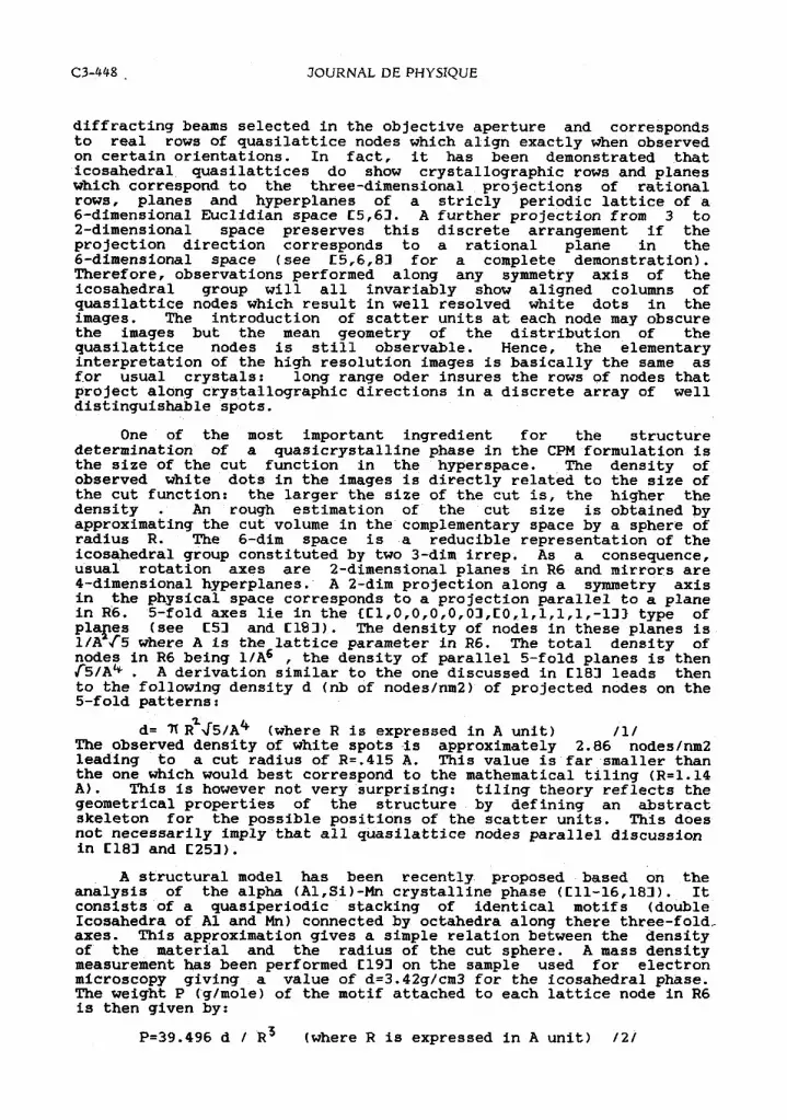
Electron microscopy images are basically two-dimensional projections of three-dimensional objects. A typical 5-fold orientation of a i(A1-t4n) alloy is seen on figures 1 and 2 (see also similar images in C10,11,14,15,16,173) which exhibits discretely spaced white dots forming an aperiodic array of pentagons of different scales based on the successive power of the golden mean (t = 1.618034..) as expected in Penrose-type two- dimensional tilings. This discrete array results from the partial Fourier transform of the
Article published online by EDP Sciences and available at http://dx.doi.org/10.1051/jphyscol:1986345
C3-448 . JOURNAL DE PHYSIQUE
diffracting beams selected in the objective aperture and corresponds to real rows of quasilattice nodes which align exactly when observed on certain orientations. In fact, it has been demonstrated that icosahedral quasilattices do show crystallographic rows and planes which correspond to the three-dimensional projections of rational rows, planes and hyperplanes of a stricly periodic lattice of a 6-dimensional Euclidian space C5,63. A further projection from 3 to 2-dimensional space preserves this discrete arrangement if the projection direction corresponds to a rational plane in the 6-dimensional space (see C5,6,83 for a complete demonstration). Therefore, observations performed along any symmetry axis of the icosahedral group will all invariably show aligned columns of quasilattice nodes which result in well resolved white dots in the images. The introduction of scatter units at each node may obscure the images but the mean geometry of the distribution of the quasilattice nodes is still observable. Hence, the elementary interpretation of the high resolution images is basically the same as for usual crystals: long range oder insures the rows of nodes that project along crystallographic directions in a discrete array of well distinguishable spots.
One of the most important ingredient for the structure determination of a quasicrystalline phase in the CPM farmulation is the size of the cut function in the hyperspace. The density of observed white dots in the images is directly related to the size of the cut function: the larger the size of the cut is, the higher the density . An rough estimation of the cut size is obtained by approximating the cut volume in the complementary space by a sphere of radius R. The 6-dim space is a reducible representation of the icosahedral group constituted by two 3-dim irrep. As a consequence, usual rotation axes are 2-dimensional planes in R6 and mirrors are 4-dimensional hyperplanes. A 2-dim projection along a symmetry axis in the physical space corresponds to a projection parallel to a plane in R6. 5-fold axes lie in the CC1,0,0,0,0,03,EO,1,1,1,1,-133 type of plapes (see CS3 and C193). The density of nodes in these planes is 1 / ~ J 5 where A is the lattice parameter in R6. The total density of nodes in R6 being 1 / ~ ~ , the density of parallel 5-fold planes is then (5/A4 . A derivation similar to the one discussed in El83 leads then to the following density d (nb of nodes/nm2) of projected nodes on the 5-fold patterns:
d= 7l R%\c~/A~ (where R is expressed in A unit) /1/ The observed density of white spots is approximately 2.86 nodes/nm2 leading to a cut radius of Rz.415 A. This value is far smaller than the one which would best correspond to the mathematical tiling (R=1.14 A). This is however not very surprising: tiling theory reflects the geometrical properties of the structure by defining an abstract skeleton for the possible positions of the scatter units. This does not necessarily imply that all quasilattice nodes parallel discussion in El83 and C253).
A structural model has been recently proposed based on the analysis of the alpha (A1,Si)-Mn crystalline phase (Ell-16,183). It consists of a quasiperiodic stacking of identical motifs (double Icosahedra of A1 and Mn) connected by octahedra along there three-fold, axes. This approximation gives a simple relation between the density of the material and the radius of the cut sphere. A mass density measurement has been performed El93 on the sample used for electron microscopy giving a value of d=3.42g/cm3 for the icosahedral phase. The weight P (g/mole) of the motif attached to each lattice node in R6 is then given by:
P=39.496 d / R~ (where R is expressed in A unit) /2/
Figure 1: High resolution electron micrograph of i(A1-Mn) showing the typical geometry of uniformely distributed
pentagons of white dots; (a) objective aperture - 2 7 A-1

C3-450 JOURNAL DE PHYSIQUE
Figure 1: High resolution electron micr raph of i(A1-Mn) (b) objective aperture .03?-1.
have to be occupied by atoms. In fact, the present result strongly suggests that only a few of the nodes are actually decorated (see a
leading to a value of 1889 g/mole. This value is in good agreement with the one corresponding to the 'Mackay Icosahedron'C203 (1792 g/mole) proposed by C113, El23 and C133. The excess is probably du to some remaining Aluminium atoms which have not been taken into account in the model.
Dynamical diffraction calculations
It is clear that kinematical calculations should invariably failed since the reciprocal basis is a dense set of points: for any orientation there will always be an infinite number of beams which are close to the Bragg positions. Dynamical calculations are therfore required. There are two ways for solving the problem: one is to introduce an arbitrarily large periodicity in replacing the quasiperiodic structure by a chosen periodic approximant (the periodic approximants of quasi-crystals are discussed in C12,13,213).This technique has the advantage of avoiding the aperiodicity but has the disadvantage of requiring large computers and long CPU time. Moreover, it masks totally all the original properties of the quasiperiodicity. The second way, which is described here, consists in taking into account the aperiodicity within the calculations by taking full advantage of the fundamental fact that the reciprocal basis has a dense spectrum but with an enumerable set of spots. It turns out that this latter technique is not only far easier but also very efficient in the computational process.
A formulation has already been proposed C22,233 which transforms the usual dynamical differential equations into a pseudo 2-dimensional Hamiltonian well suited for analytical manipulations. In the usual Dirac notations this Hamiltonian is written as:
This expression shows that strict periodicity is not required for building the matrix elements <QIHIQ1>: any enumerable set of Q vectors may be used in such a manner that quasiperiodicity can be described exactly with the same formalism as the one used for crystals. The major difference is that, here, the q-basis is dense instead of relatively dense. The problem is therefore to define a proper algorithm which selects a discrete pertinent subset for performing the numerical calculations.
Choice of a discrete Q-basis for the matrix elements of the Hamiltonian
A natural hierarchical indexing has been recently proposed C243 which classifies the reflections according to their intrinsic form factors: the dense set splits into a infinite number of discrete subsets of decreasing intrinsic form factor. If Q6 is a six-dimensional reciprocal vector projecting on the 2 complementary orthogonal 3-dim spaces R3 and R'3 along respectively Q and Qperp, the squared lengths of these vectors are given by the following relations:
where N and M are integers simply related to the indices of the considered reflection in either the 6- or the 3-dimensional spaces (for a complete discussion see C24-253). Simple geometric arguments show that M is bounded between -CN/t3 and CNt3 where Cx3 means integer

C3-452 JOURNAL DE PHYSIQUE
part of x. In the CPM, the Fourier transform of the quasilattice results from a convolution of the Dirac lattice with the cut function: reciprocal nodes located near the cutting reciprocal space are the most intense: the strongest reflections are those with the smallest Qperp, i.e., those for which M is the closest to its upper limit. For each given N value, the various allowed M values sort the reflections in decreasing intensity. The strongest reflections corresponding to the maximum M have a (QperpI smaller or equal to 2 Jt (in the 26-lattice parameter unit) and define the first series. The second series is defined by the reflections the IQperpl of which are in the range E2Jt, 4 Jt 3, etc... X-ray , Neutron and electron diffractions show that, as expected, the few first series are actually of observable intensities C251 : almost all strong reflections belong to the first set, the few remaining ones belong to the second set. Selecting both the maximum Q length actually observed in the electron diffraction patterns and the maximum Qperp length leads to a discrete, although nonperiodic array of q diffracting vectors and therefore to a finite basis for the Hamiltonian matrix. The larger the allowed Qperp maximum length is, the more accurate the calculation.
Fourier coefficients <QIVIQ1> calculations
Two ingredients are required for calculating the scattering potential matrix elements. The first one is the usual motif form factor F(Q6 ) which is obtained by a 6-dimensional usual structure factor calculation:
2 f,( ,Q, )exp(2inQ . & ) F(Q6 ) = /5/
where f,((Q() are the atomic form factors of species d and ca( the corresponding R6 Wyckoff positions. The second term is inherent of the CPM and results in the slicing of the 6-dimensional space before projection: F(Q6) is multiplied by the Fourier transform of the cut function G(iQperp0. Assuming a spherical approximation leads to a simple analytical expression of G ( lQperp0:
where 4 = 2 K I Qperpl .R and R is the cut radius expressed in A unit. Finally, the normalized potential matrix element is given by
Dynamical calculations and comparisons
The dynamical calculations are performed in the standard way by diagonalizing the Hamiltonian / 3 / . The expression of the diffracted beams $ C/ z) for a thickness z are given by:
where Jj> and Ej are respectively the eingenstates and eigenvalues of 3 The optical abberations (defocus, spherical and chromatic abberations) are introduced in the standard diagonal approximation before back Fourier transforming. Two situations have been simulated
The first one mimics the bare quasilattice: the motif form factor has been calculated from an average spherical cluster A142Mn12 located at the nodes of the Z6 lattice:

The second model uses explicitely the 'Mackay Icosahedron' in R6 with the following orbits determined within the "parallel motif approximation" C181:
These orbits have been calculated from the existing data of the crystalline alpha (A1,Si)-Mn phase C263. The stoechiometry of the model is here A142Mn12. The size of the acceptance sphere in the calculation is .375 A which corresponds to the optimum convex compact volume consistent with a stacking of MI'S (C18,27,283). The agreement between experimental and computed images is remarkably good as seen on figures 2 and 3 which show a selection of computed images which can be compared with the experimental ones presented in the litterature. For small objective apertures there are essentially no differences between the two models: they both give pentagonal shaped contrasts outlining the projections of a fraction ofthe surviving quasilattice nodes. No inference can be made concerning the nature of the elementary motif: both models give the same kind of images but at different defocus values. Unfortunately, the experimental defocus is determined a posteriori by comparing through focus series with computed ones, once a structural model has been chosen... For medium and large objective aperture size there are still differences between the two models within the whole through focus series. This is expected since the partial Fourier transform reconstructing the image includes now larger Q-vectors. The improvement in resolution makes the two models distinguishable: the best agreement is clearly obtained with the Mackay motif although a careful comparison between the computed and experimental images shows that the ideal quasiperiodic stacking is not exactly reproduced in the experimental images at long distances; the actual stacking diverges slightly from the ideal one in allowing for some disorder which could lead to a better packing of the MI'S. This is in good agreement with the recent theoretical investigations of A. Katz C273 and C. L. Henley C283 who independently showed that the optimum quasiperiodic stacking of MI'S cannot account for the experimental density mass of the alloy.
The basic assumption we made in the first part of the paper in correlating the white dots of the best images with the projected quasilattice nodes independently from the actual motif, has been checked a posteriori by a weak phase object calculation. At the optimum defocus this asymptotic model gives directly the image of the electronic density: in the first model the quasilattice nodes are visualized as dark spots as seen of figure 2. A perfect one-to-one correspondance is observed between this test model and the realistic one; each white dot of the latter correspond to a dark dot of the test model. The motif simply influences the image in modifying the relative intensities between projected quasilattice nodes. A detailed discussion of the computed through focus series will be presented elsewhere.

JOURNAL DE PHYSIQUE
figure 2: computed images of a bare quasilattice (141 beams); (a) Weak phase object calculation ghowing the projected quasilattice nodes (defocus=-600 A;,Aperture= .43 A-1) (b) Same as (a) at thickness z= 100 A; the quasilattice nodes appear as white dots with various intensities.

figure 3: computed images of a q asiperiodic stacking of MI'S; la) for small aperture size ( . 2 7 1-1) the images are essentially similar to the ones obtained with the bar quasilattice but at different defocus values. ~Defocus;-1600efocus=-0 1, thickness= 75 A.
(b)large aperture size (.43 A-1); Defocus=-700 A; thickness= 75 both calculations are made with 141 pertinent beams. They can be
directly compared with respectively fig 1 (a) and (b).

JOURNAL DE PHYSIQUE
Acknowledgements
We are pleased to thank Professor J. W. Cahn for his critical comments during the redaction of the present paper; we thank Drs. A. Katz and M. Duneau for many fruitful discussions and Dr. C. L. Henley for having kindly communicated results prior to publication.
References
C13 D. Shechtman and I. Blech; Met. Trans. 16A, (1985) 1005 C23 D. Shechtman. I. Blech. D. Gratias and J. W. Cahn; Phys. Rev. Lett. 53, (1984) 1951- C33 M. Duneau and A. Katz: Phvs. Rev. Lett. 54.(1985) 2688 C43 P. A. Kalugin, A. Y.. ~itaev akd L. c.. Levitov; J. de Physique 46, (1985) L601 C53 A. Katz and M. Duneau; J. de Physique 47, (1986) 181 L63 V. Elser; Acta Crystall. A42, (1986) 36 C73 V. Elser; Phys. Rev. B32 (1985) 4892 C83 A. Katz and M. Duneau; this issue C93 D. Shechtman, D. Gratias and J. W. Cahn; C. R. Acad. Sci. Paris 300 serieII 18 (1985) 909 C103 R. Portier, D. Shechtman, D. Gratias and J. W. Cahn; J. Microsc. Spectrosc. Electron 10 n2 (1985) 107 C113 P. Guyot and M. Audier; Phil. Mag. B,52 (1985) L15 C123 C. L. Henley; J. Non-Cryst. Sol 75 (1985) 91 C133 V. Elser and C. L. Henley; Phys. Rev. Let. 55 (1985) 2883 C143 M. Audier and P. Guyot; Phil. Mag. B,53 11986) L43 C153 P. Guyot, M. Audier and R. Lequette; this issue C163 M. Audier and P. Guyot; this issue C173 K. Urban, J. Mayer, M. Rapp and M. Wilkens; this issue C183 3. W. Cahn and D. Gratias; this issue El93 P. Favreau; private communication C203 A. L. Mackay; Acta Crystal1 15, (1962) 916 C213 D. Gratias and J. R. Cahn; Scripta Met. to appear C223 D. Gratias and R. Portier; Acta Crystall. A39, (1983) 576 C233 M. Cornier, R. Portier and D. Gratias; Inst. Phys. Conf. Ser. 78 chap 3 (1985) 91 C243 J. W. Cahn, D. Shechtman and D. Gratias; J. of Mat. Res. 1, (19861, 13 C253 B. Mozer, J. W. Cahn, D. Gratias and D. Shechtman; this issue C263 M. Cooper and K. Robinson; Acta Crystall. 20, (1966) 614 C273 A. Katz Private communication; unpublished results C283 C. L. Henley; Preprint submitted to Phys. Rev. B


