Embed Size (px)
Citation preview
International Journal of Heat and Mass Transfer 82 (2015) 521–529
Contents lists available at ScienceDirect
International Journal of Heat and Mass Transfer
journal homepage: www.elsevier .com/locate / i jhmt
Heat transfer performance of an anodized two-phase closedthermosyphon with refrigerant as working fluid
http://dx.doi.org/10.1016/j.ijheatmasstransfer.2014.11.0340017-9310/� 2014 Elsevier Ltd. All rights reserved.
⇑ Corresponding author.E-mail address: [email protected] (A.B. Solomon).
A. Brusly Solomon a,⇑, R. Roshan a, Walter Vincent a, V.K. Karthikeyan b, L. Godson Asirvatham a
a Centre for Research in Material Science and Thermal Management, School of Mechanical Sciences, Karunya University, Coimbatore 641114, Indiab Department of Mechanical Engineering, Sri Ramakrishna Engineering College, Coimbatore, India
a r t i c l e i n f o
Article history:Received 29 July 2014Received in revised form 7 October 2014Accepted 7 November 2014Available online 26 November 2014
Keywords:AnodizationThermosyphonElectronic coolingPorous coatingRefrigerant
a b s t r a c t
Heat transfer characteristics of an anodized two-phase closed thermosyphon (TPCT) with refrigerant asthe working fluid is studied and compared with that of a non-anodized one. A simple anodization is per-formed to make a porous structure on the inner wall of TPCT. The anodized and non-anodized TPCTscharged with a blend of R600a and R290 are tested for the heat input range of 50–200 W. The effectsof filling ratio, inclination angle, heat input and anodized surface on the performance of the TPCTs areinvestigated. Due to the anodization, the evaporator heat transfer coefficient enhances up to 33% atthe inclination angle of 45� for the heat input of 200 W. Also, total thermal resistance of the anodizedTPCT is reduced by 17%, 20% and 23% respectively for horizontal, inclined and vertical positions whencompared to the non-anodized TPCT. Enhancements in the surface area, number of nucleation sites,increased bubble frequency, intensified bubble interaction and thin film evaporation are major factorsfor the performance enhancement in the anodized TPCT. Also it is found that the filling ratio, inclinationangle and heat input have a significant role on the performance of the TPCT.
� 2014 Elsevier Ltd. All rights reserved.
1. Introduction
Every day, cooling requirement in electronic industriesincreases abruptly due to greater functionality, faster operation,reduction in size and weight, and cost reduction of electronicproducts. Combination of faster operation and reduction in sizeresulted in high volumetric heat generation in electronic compo-nents leading to failure in the electronic device. Hence high per-formance heat dissipation devices are required to meet thisdemand. TPCT is one of the promising devices and hence, it isadopted for electronic cooling applications [1]. Also the device isused in many applications such as energy storage system [2], ther-moelectric power generators [3], power electronics [4], seasonalcooling load reduction of buildings [5], refrigeration systems [6],cooling super conducting bearings [7], boiler application [8], andheating and cooling applications [9]. A thermosyphon is a two-phase heat transfer device that transports heat from one pointto another by phase change mechanism. In which the heat transfertakes place through evaporation and condensation processes, andthe working fluid is re-circulated from the condenser to the
evaporator by gravitational force. However, in some cases, theworking fluid is re-circulated by capillary forces. Since the highperformance weightless TPCTs are demanded in industries, manyinvestigations have been performed by altering the design andworking fluids.
Recently, nanofluids [10–17] have been incorporated into theTPCTs and found substantial enhancement in the heat transfer ofthe device. Liu et al. [10] conducted a performance study on a min-iature TPCT with CuO/water nanofluids. In another study, Liu et al.[11] studied the performance of open type thermosyphons usingCNT/water nanofluids. Lu et al. [12] carried out an experiment tostudy the thermal performance of an open type thermosyphonwith CuO/water nanofluids. Khandekar et al. [13] analyzed a TPCTwith pure water and various water based nanofluids (Al2O3, CuOand laponite clay) as the working fluids. Noie et al. [14] studiedthe efficiency enhancement of a TPCT with Al2O3/water nanofluids.Parametthanuwat et al. [15,16] conducted an experimental studyto analyze the heat transfer characteristics of a TPCT with Ag/waternanofluids. Huminic et al. [17] conducted an experimental study toanalyze the effect of iron oxide/water nanofluids on theperformance of TPCT. Furthermore refrigerants and refrigerantbased nanofluids were also used as potential working fluids inTPCTs for low temperature applications. In this context, very few
Nomenclature
cp,l specific heat of coolant fluid (J/kg K)d diameter of the tube (m)Db bubble diameter (m)f bubble frequency (1/s)h heat transfer coefficient (W/m2 K)T temperature (�C)k thermal conductivity (W/m K)l length (m)_mi mass flow rate of coolant (kg/s)
Na active nucleation site density (sites per m2)Q heat transfer rate (W)q heat flux (W/m2)R resistance (�C/W)r radius (m)
q density (kg/m3)
Subscriptshp heat pipeout outletin inlete evaporatorc condensere,i evaporator inner wallc,i condenser inner wallsat saturationo outerT totall liquid
522 A.B. Solomon et al. / International Journal of Heat and Mass Transfer 82 (2015) 521–529
investigations have been performed to study the performance ofTPCT [18–21]. In the past few decades, the performances of TPCTswith R-11, R-12 and R-22 as the working fluids were studied. How-ever, R-11 and R-12 were banned due to high ozone depletingpotential and hence to reduce the risk of ozone depletion, R-134awas used in later investigations [18,19].
From the above literatures [10–17], it was observed that theperformance of the TPCT was enhanced/deteriorated due to thedeposition of nanoparticles. However, most of the experimentsrevealed that the performance of the TPCT enhances [10–12,14–17]. The reason for the performance enhancement/deteriorationdepends on the mechanism behind the heat transfer. Thethermo-physical properties [16] of nanofluids and formation ofthin porous coating [12] in the evaporator are responsible for theheat transfer enhancement. Previous experiments by the presentauthor [22,23] and other experiments [24,25] confirmed that thethin porous coating on the wall plays a vital role in the heat trans-fer enhancement. Hence, the present study is performed to predictthe effect of thin porous coating on the performance of TPCT. Anod-ization process has been known to produce a uniform porous coat-ing over the past several years. Also it is noticed that none of theresearchers studied the performance of an anodized TPCT withrefrigerant as a working fluids. Hence in the present study, theeffect of anodization on the performance of TPCT is studied usingrefrigerant as the working fluid. The effects of filling ratio, heatinput and the inclination angle on the performance of TPCTs arealso investigated.
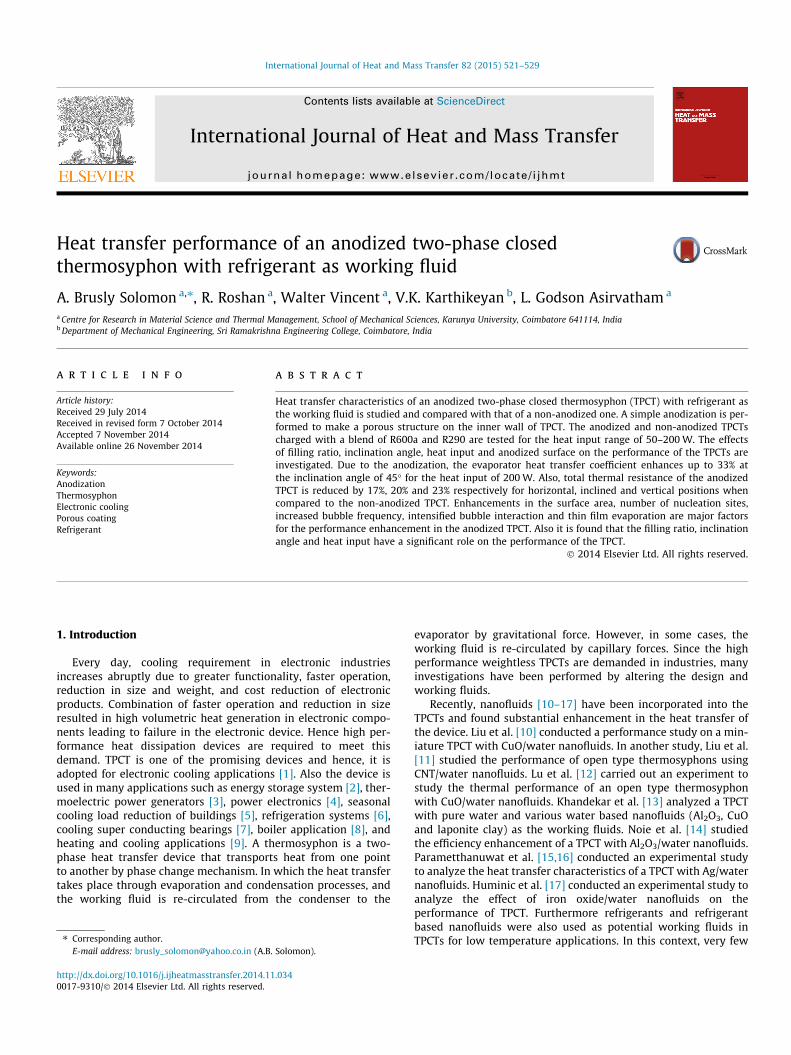
Fig. 1. SEM images of (a) non-anod
2. Experimental details
2.1. Preparation of coating
Anodization is performed to prepare a uniform porous coatingat the inner wall of TPCT. Before anodization, necessary cleaningprocess is performed to ensure a uniform and stable coating. Thetest section consisted of an aluminum tube with an inner diam-eter of 16.5 mm and length of 350 mm. The aluminum tube anda stainless steel rod (SS303) are considered as an anode andcathode respectively. The diameter of the cathode is consideredas 10 mm. The cathode is placed at the inner side of the anodewith a distance of 3 mm from the anode. To avoid a physicalcontact between anode and cathode, Teflon sleeves are used atboth ends of the anodizing cell. A constant temperature is main-tained at the cell assembly by circulating cooling water aroundthe entire anodize ng cell setup. The anodization processinvolves two steps, which are pre-treatment and internal anodicoxidization. For the pre-treatment, 50 g/l NaOH solution is circu-lated through the gap between the anode and cathode for 2 minfollowed by DI water is circulated for about 5 min. Afterwards,impurities are removed by circulating 10 vol.% HNO3 solutionfor 2 min. Following that DI water is circulated for 5 min andrinsed. After the pre-treatment process, internal anodicoxidization is performed by circulating electrolytic solution(10 vol.% H2SO4). The uniform coating is achieved by using theoptimized anodizing conditions of 10 vol.% concentration,
ized and (b) anodized surface.
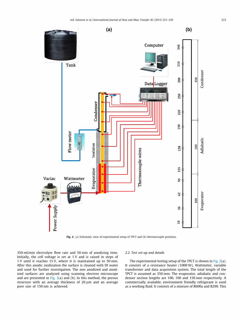
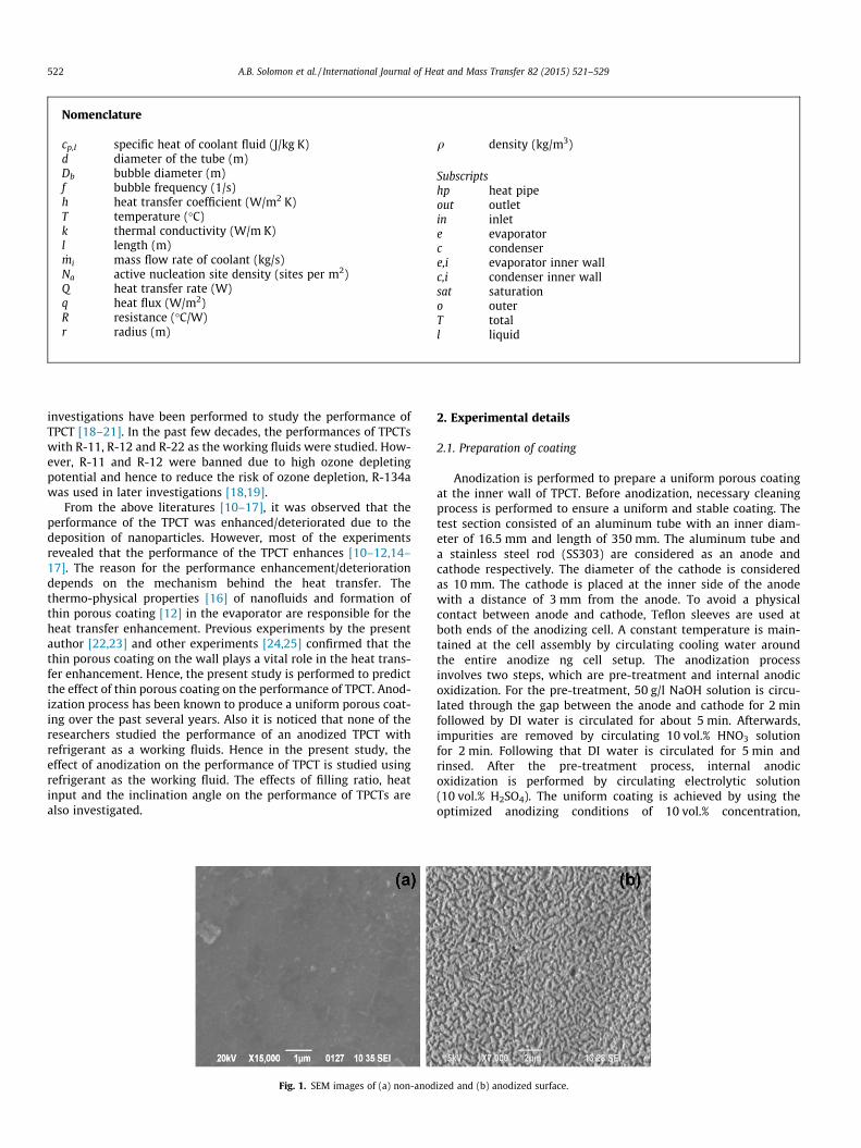
Fig. 2. (a) Schematic view of experimental setup of TPCT and (b) thermocouple positions.
A.B. Solomon et al. / International Journal of Heat and Mass Transfer 82 (2015) 521–529 523
350 ml/min electrolyte flow rate and 50 min of anodizing time.Initially, the cell voltage is set at 1 V and is raised in steps of1 V until it reaches 15 V, where it is maintained up to 50 min.After this anodic oxidization the surface is cleaned with DI waterand used for further investigation. The non anodized and anod-ized surfaces are analyzed using scanning electron microscopeand are presented in Fig. 1(a) and (b). In this method, the porousstructure with an average thickness of 20 lm and an averagepore size of 150 nm is achieved.
2.2. Test set-up and details
The experimental testing setup of the TPCT is shown in Fig. 2(a).It consists of a resistance heater (1000 W), Wattmeter, variabletransformer and data acquisition system. The total length of theTPCT is assumed as 350 mm. The evaporator, adiabatic and con-denser section lengths are 100, 100 and 150 mm respectively. Acommercially available, environment friendly refrigerant is usedas a working fluid. It consists of a mixture of R600a and R290. This
0.4
0.5
0.6
0.7
0.8
0.9
1
20 30 40 50 60 70 80
Res
ista
nce
(o C/W
)
Fill ratio (%)
50 watts 75 watts 100 watts
125 watts 150 watts 175 watts
200 watts
Fig. 3. Effect of filling ratio on the thermal resistance of non-anodized TPCT.
0.3
0.4
0.5
0.6
0.7
0.8
0.9
1
1.1
1.2
-10 10 30 50 70 90
Res
ista
nce
(o C/W
)
Inclination angle ( o )
25W 50W 75W 100W
125W 150W 175W 200W
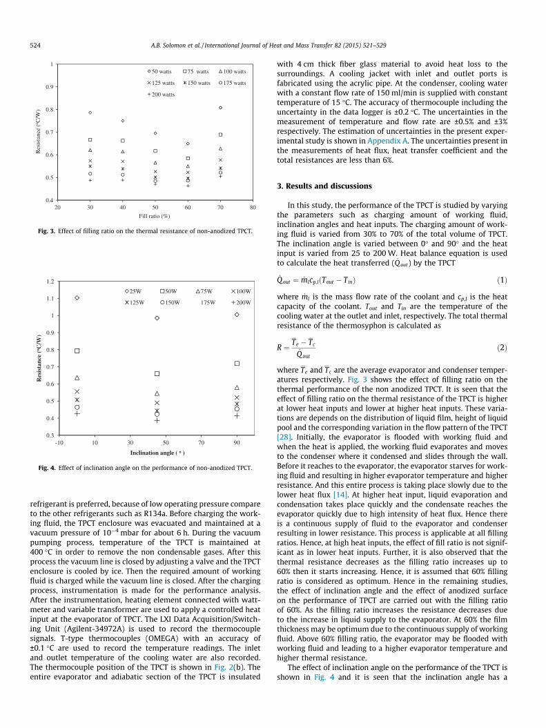
Fig. 4. Effect of inclination angle on the performance of non-anodized TPCT.
524 A.B. Solomon et al. / International Journal of Heat and Mass Transfer 82 (2015) 521–529
refrigerant is preferred, because of low operating pressure compareto the other refrigerants such as R134a. Before charging the work-ing fluid, the TPCT enclosure was evacuated and maintained at avacuum pressure of 10�4 mbar for about 6 h. During the vacuumpumping process, temperature of the TPCT is maintained at400 �C in order to remove the non condensable gases. After thisprocess the vacuum line is closed by adjusting a valve and the TPCTenclosure is cooled by ice. Then the required amount of workingfluid is charged while the vacuum line is closed. After the chargingprocess, instrumentation is made for the performance analysis.After the instrumentation, heating element connected with watt-meter and variable transformer are used to apply a controlled heatinput at the evaporator of TPCT. The LXI Data Acquisition/Switch-ing Unit (Agilent-34972A) is used to record the thermocouplesignals. T-type thermocouples (OMEGA) with an accuracy of±0.1 �C are used to record the temperature readings. The inletand outlet temperature of the cooling water are also recorded.The thermocouple position of the TPCT is shown in Fig. 2(b). Theentire evaporator and adiabatic section of the TPCT is insulated
with 4 cm thick fiber glass material to avoid heat loss to thesurroundings. A cooling jacket with inlet and outlet ports isfabricated using the acrylic pipe. At the condenser, cooling waterwith a constant flow rate of 150 ml/min is supplied with constanttemperature of 15 �C. The accuracy of thermocouple including theuncertainty in the data logger is ±0.2 �C. The uncertainties in themeasurement of temperature and flow rate are ±0.5% and ±3%respectively. The estimation of uncertainties in the present exper-imental study is shown in Appendix A. The uncertainties present inthe measurements of heat flux, heat transfer coefficient and thetotal resistances are less than 6%.
3. Results and discussions
In this study, the performance of the TPCT is studied by varyingthe parameters such as charging amount of working fluid,inclination angles and heat inputs. The charging amount of work-ing fluid is varied from 30% to 70% of the total volume of TPCT.The inclination angle is varied between 0� and 90� and the heatinput is varied from 25 to 200 W. Heat balance equation is usedto calculate the heat transferred ( _Q out) by the TPCT
_Qout ¼ _mlcp;l Tout � Tinð Þ ð1Þ
where _ml is the mass flow rate of the coolant and cp,l is the heatcapacity of the coolant. Tout and Tin are the temperature of thecooling water at the outlet and inlet, respectively. The total thermalresistance of the thermosyphon is calculated as
R ¼ Te � Tc
_Q out
ð2Þ
where Te and Tc are the average evaporator and condenser temper-atures respectively. Fig. 3 shows the effect of filling ratio on thethermal performance of the non anodized TPCT. It is seen that theeffect of filling ratio on the thermal resistance of the TPCT is higherat lower heat inputs and lower at higher heat inputs. These varia-tions are depends on the distribution of liquid film, height of liquidpool and the corresponding variation in the flow pattern of the TPCT[28]. Initially, the evaporator is flooded with working fluid andwhen the heat is applied, the working fluid evaporates and movesto the condenser where it condensed and slides through the wall.Before it reaches to the evaporator, the evaporator starves for work-ing fluid and resulting in higher evaporator temperature and higherresistance. And this entire process is taking place slowly due to thelower heat flux [14]. At higher heat input, liquid evaporation andcondensation takes place quickly and the condensate reaches theevaporator quickly due to high intensity of heat flux. Hence thereis a continuous supply of fluid to the evaporator and condenserresulting in lower resistance. This process is applicable at all fillingratios. Hence, at high heat inputs, the effect of fill ratio is not signif-icant as in lower heat inputs. Further, it is also observed that thethermal resistance decreases as the filling ratio increases up to60% then it starts increasing. Hence, it is assumed that 60% fillingratio is considered as optimum. Hence in the remaining studies,the effect of inclination angle and the effect of anodized surfaceon the performance of TPCT are carried out with the filling ratioof 60%. As the filling ratio increases the resistance decreases dueto the increase in liquid supply to the evaporator. At 60% the filmthickness may be optimum due to the continuous supply of workingfluid. Above 60% filling ratio, the evaporator may be flooded withworking fluid and leading to a higher evaporator temperature andhigher thermal resistance.
The effect of inclination angle on the performance of the TPCT isshown in Fig. 4 and it is seen that the inclination angle has a
0
20
40
60
80
100
120
140
160
0 50 100 150 200 250 300 350
Tem
pera
ure
(o C)
Height (mm)
50 watts
100 watts
150 watts
200 watts
0
20
40
60
80
100
120
140
160
0 50 100 150 200 250 300 350
Tem
pera
ure
(o C)
Height (mm)
50 watts
100 watts
150 watts
200 watts
(d)
0
20
40
60
80
100
120
140
160
0 50 100 150 200 250 300 350
Tem
pera
ture
(o C
)
Height (mm)
50 watts
100 watts
150 watts
200 watts
(b)
0
20
40
60
80
100
120
140
160
0 50 100 150 200 250 300 350
Tem
pera
ture
(o C
)
Height (mm)
50 watts
100 watts
150 watts
200 watts
(e)
0
20
40
60
80
100
120
140
160
0 50 100 150 200 250 300 350
Tem
pera
ture
(o C
)
Height (mm)
50 watts
100 watts
150 watts
200 watts
(c)
0
20
40
60
80
100
120
140
160
0 50 100 150 200 250 300 350
Tem
pera
ture
(o C
)
Height (mm)
50 watts
100 watts
150 watts
200 watts
(f)
(a)
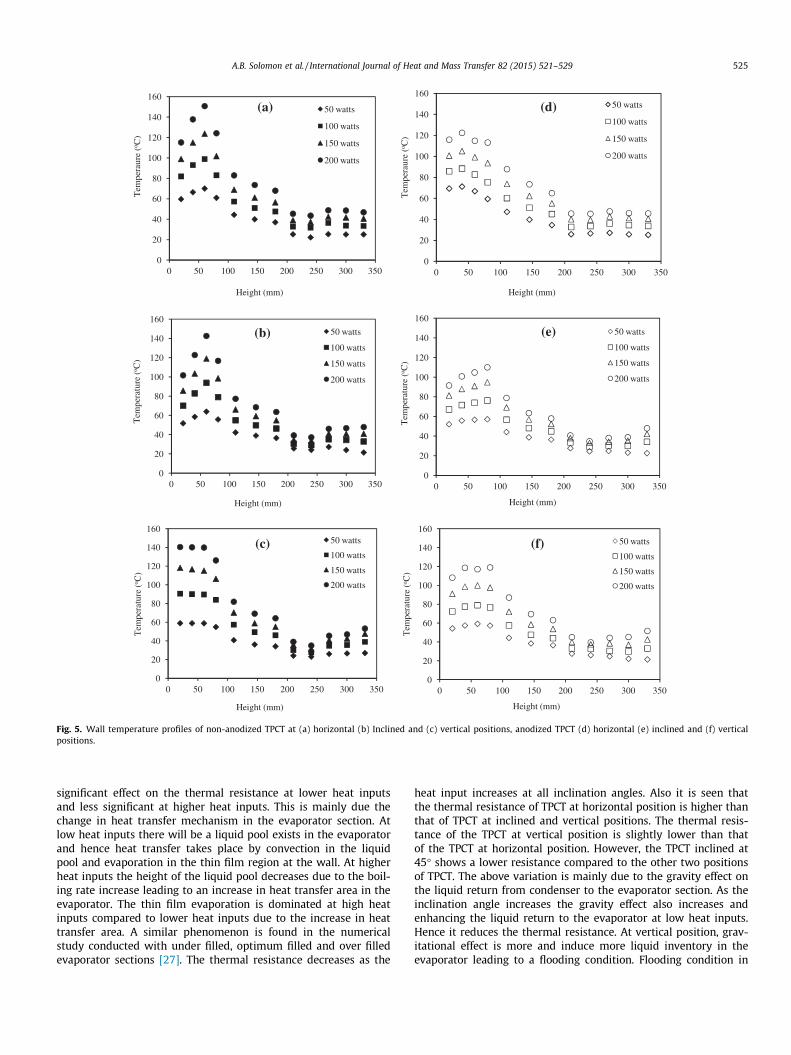
Fig. 5. Wall temperature profiles of non-anodized TPCT at (a) horizontal (b) Inclined and (c) vertical positions, anodized TPCT (d) horizontal (e) inclined and (f) verticalpositions.
A.B. Solomon et al. / International Journal of Heat and Mass Transfer 82 (2015) 521–529 525
significant effect on the thermal resistance at lower heat inputsand less significant at higher heat inputs. This is mainly due thechange in heat transfer mechanism in the evaporator section. Atlow heat inputs there will be a liquid pool exists in the evaporatorand hence heat transfer takes place by convection in the liquidpool and evaporation in the thin film region at the wall. At higherheat inputs the height of the liquid pool decreases due to the boil-ing rate increase leading to an increase in heat transfer area in theevaporator. The thin film evaporation is dominated at high heatinputs compared to lower heat inputs due to the increase in heattransfer area. A similar phenomenon is found in the numericalstudy conducted with under filled, optimum filled and over filledevaporator sections [27]. The thermal resistance decreases as the
heat input increases at all inclination angles. Also it is seen thatthe thermal resistance of TPCT at horizontal position is higher thanthat of TPCT at inclined and vertical positions. The thermal resis-tance of the TPCT at vertical position is slightly lower than thatof the TPCT at horizontal position. However, the TPCT inclined at45� shows a lower resistance compared to the other two positionsof TPCT. The above variation is mainly due to the gravity effect onthe liquid return from condenser to the evaporator section. As theinclination angle increases the gravity effect also increases andenhancing the liquid return to the evaporator at low heat inputs.Hence it reduces the thermal resistance. At vertical position, grav-itational effect is more and induce more liquid inventory in theevaporator leading to a flooding condition. Flooding condition in
100
300
500
700
900
1100
0 5 10 15 20 25 30 35 40 45
Hea
t tra
nsfe
r co
effi
cien
t (W
/m2 -
K)
Heat flux (kW/m2)
non anodised TPCT
anodised TPCT
0
200
400
600
800
1000
0 5 10 15 20 25 30
Hea
t tra
nsfe
r co
effi
cien
t (W
/m2
-K)
Heat flux (kW/m2)
non anodised TPCT
anodised TPCT
(d)
300
400
500
600
700
800
900
1000
1100
1200
0 5 10 15 20 25 30 35 40 45
Hea
t tra
nsfe
r co
effi
cien
t (W
/m2
-K)
Heat flux (kW/m2)
non anodised TPCT
anodised TPCT
(b)
0
200
400
600
800
1000
1200
0 5 10 15 20 25 30
Hea
t tra
nsfe
r co
effi
cien
t (W
/m2 -
K)
Heat flux (kW/m2)
non anodised TPCT
anodised TPCT
300
400
500
600
700
800
900
1000
0 5 10 15 20 25 30 35 40 45
Hea
t tra
nsfe
r co
effi
cien
t (W
/m2 -
K)
Heat flux (kW/m2)
non anodised TPCT
anodised TPCT
(c)
0
100
200
300
400
500
600
700
800
900
1000
0 5 10 15 20 25 30
Hea
t tra
nsfe
r co
effi
cien
t (W
/m2 -
K)
Heat flux (kW/m2)
non anodised TPCT
anodised TPCT
(a)
(e)
(f)
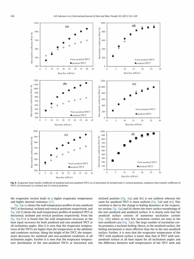
Fig. 6. Evaporator heat transfer coefficient of anodized and non-anodized TPCTs at (a) horizontal (b) inclined and (c) vertical positions, condenser heat transfer coefficient ofTPCTs (d) horizontal (e) inclined and (f) vertical positions.
526 A.B. Solomon et al. / International Journal of Heat and Mass Transfer 82 (2015) 521–529
the evaporator section leads to a higher evaporator temperatureand higher thermal resistance [27].
Fig. 5(a–c) shows the wall temperature profiles of non-anodizedTPCT at horizontal, inclined and vertical positions respectively, andFig. 5(d–f) shows the wall temperature profiles of anodized TPCT athorizontal, inclined and vertical positions respectively. From theFig. 5(a–f) it is found that the wall temperature increases as theheat input increases for both anodized and non-anodized TPCT atall inclination angles. Also it is seen that the evaporator tempera-tures of the TPCTs are higher than the temperature at the adiabaticand condenser sections. Along the height of the TPCT, the temper-ature decreases for anodized and non-anodized conditions at allinclination angles. Further it is seen that the evaporator tempera-ture distribution of the non-anodized TPCTs at horizontal and
inclined position (Fig. 5(a) and (b)) is not uniform whereas thesame for anodized TPCT is more uniform (Fig. 5(d) and (e)). Thisvariation is due to the change in boiling dynamics at the evapora-tor section. Fig. 1(a) and (b) shows the inner surface morphology ofthe non-anodized and anodized surface. It is clearly seen that theanodized surface consists of numerous nucleation cavities(Fig. 1(b)) where as very few nucleation cavities are seen in thenon-anodized case (Fig. 1(a)). The large number of nucleation cav-ity promotes a nucleate boiling. Hence, in the anodized surface, theboiling mechanism is more effective than the in the non-anodizedsurface. Further, it is seen that the evaporator temperature of theTPCT with anodized surface is lower than that of TPCT with non-anodized surface at all heat inputs for all inclination angles andthe difference between wall temperatures of the TPCT with and
0
10
20
30
40
50
60
70
0 50 100 150 200
Tw-T
sat(o C
)
Heat input (W)
non-anodised (0 degree)
non-anodised (45 degree)
non-anodised (90 degree)
anodised (0 degree)
anodised (45 degree)
anodised (90 degree)
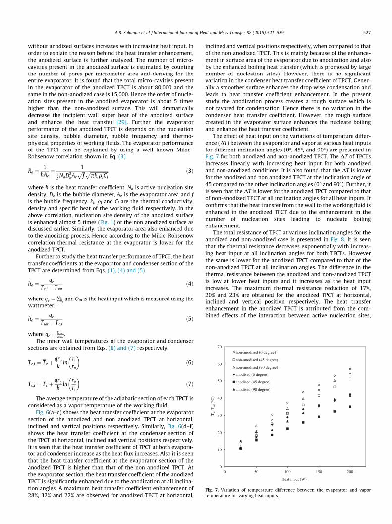
Fig. 7. Variation of temperature difference between the evaporator and vaportemperature for varying heat inputs.
A.B. Solomon et al. / International Journal of Heat and Mass Transfer 82 (2015) 521–529 527
without anodized surfaces increases with increasing heat input. Inorder to explain the reason behind the heat transfer enhancement,the anodized surface is further analyzed. The number of micro-cavities present in the anodized surface is estimated by countingthe number of pores per micrometer area and deriving for theentire evaporator. It is found that the total micro-cavities presentin the evaporator of the anodized TPCT is about 80,000 and thesame in the non-anodized case is 15,000. Hence the order of nucle-ation sites present in the anodized evaporator is about 5 timeshigher than the non-anodized surface. This will dramaticallydecrease the incipient wall super heat of the anodized surfaceand enhance the heat transfer [29]. Further the evaporatorperformance of the anodized TPCT is depends on the nucleationsite density, bubble diameter, bubble frequency and thermo-physical properties of working fluids. The evaporator performanceof the TPCT can be explained by using a well known Mikic–Rohsenow correlation shown in Eq. (3)
Re ¼1
hAe¼ 1
12 NaD2
bAe
ffiffiffif
p ffiffiffiffiffiffiffiffiffiffiffiffiffiffiffiffipklqlCl
p ð3Þ
where h is the heat transfer coefficient, Na is active nucleation sitedensity, Db is the bubble diameter, Ae is the evaporator area and fis the bubble frequency. kl, ql and Cl are the thermal conductivity,density and specific heat of the working fluid respectively. In theabove correlation, nucleation site density of the anodized surfaceis enhanced almost 5 times (Fig. 1) of the non anodized surface asdiscussed earlier. Similarly, the evaporator area also enhanced dueto the anodizing process. Hence according to the Mikic–Rohsenowcorrelation thermal resistance at the evaporator is lower for theanodized TPCT.
Further to study the heat transfer performance of TPCT, the heattransfer coefficients at the evaporator and condenser section of theTPCT are determined from Eqs. (1), (4) and (5)
he ¼qe
Te;i � Tsatð4Þ
where qe ¼ Qinpdle
and Qin is the heat input which is measured using thewattmeter.
hc ¼qc
Tsat � Tc;ið5Þ
where qc ¼ Qoutpdlc
.The inner wall temperatures of the evaporator and condenser
sections are obtained from Eqs. (6) and (7) respectively.
Te;i ¼ Te þqro
kln
ri
ro
� �ð6Þ
Tc;i ¼ Tc þqro
kln
ro
ri
� �ð7Þ
The average temperature of the adiabatic section of each TPCT isconsidered as a vapor temperature of the working fluid.
Fig. 6(a–c) shows the heat transfer coefficient at the evaporatorsection of the anodized and non anodized TPCT at horizontal,inclined and vertical positions respectively. Similarly, Fig. 6(d–f)shows the heat transfer coefficient at the condenser section ofthe TPCT at horizontal, inclined and vertical positions respectively.It is seen that the heat transfer coefficient of TPCT at both evapora-tor and condenser increase as the heat flux increases. Also it is seenthat the heat transfer coefficient at the evaporator section of theanodized TPCT is higher than that of the non anodized TPCT. Atthe evaporator section, the heat transfer coefficient of the anodizedTPCT is significantly enhanced due to the anodization at all inclina-tion angles. A maximum heat transfer coefficient enhancement of28%, 32% and 22% are observed for anodized TPCT at horizontal,
inclined and vertical positions respectively, when compared to thatof the non anodized TPCT. This is mainly because of the enhance-ment in surface area of the evaporator due to anodization and alsoby the enhanced boiling heat transfer (which is promoted by largenumber of nucleation sites). However, there is no significantvariation in the condenser heat transfer coefficient of TPCT. Gener-ally a smoother surface enhances the drop wise condensation andleads to heat transfer coefficient enhancement. In the presentstudy the anodization process creates a rough surface which isnot favored for condensation. Hence there is no variation in thecondenser heat transfer coefficient. However, the rough surfacecreated in the evaporator surface enhances the nucleate boilingand enhance the heat transfer coefficient.
The effect of heat input on the variations of temperature differ-ence (DT) between the evaporator and vapor at various heat inputsfor different inclination angles (0�, 45�, and 90�) are presented inFig. 7 for both anodized and non-anodized TPCT. The DT of TPCTsincreases linearly with increasing heat input for both anodizedand non-anodized conditions. It is also found that the DT is lowerfor the anodized and non anodized TPCT at the inclination angle of45 compared to the other inclination angles (0� and 90�). Further, itis seen that the DT is lower for the anodized TPCT compared to thatof non-anodized TPCT at all inclination angles for all heat inputs. Itconfirms that the heat transfer from the wall to the working fluid isenhanced in the anodized TPCT due to the enhancement in thenumber of nucleation sites leading to nucleate boilingenhancement.
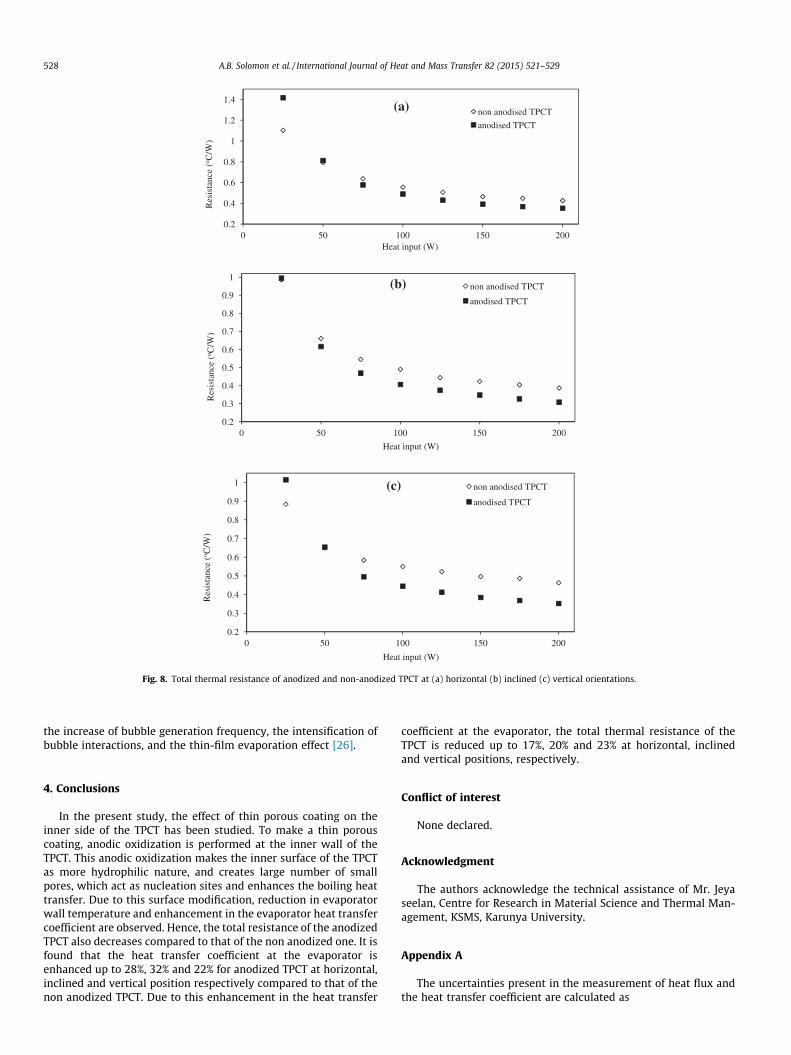
The total resistance of TPCT at various inclination angles for theanodized and non-anodized case is presented in Fig. 8. It is seenthat the thermal resistance decreases exponentially with increas-ing heat input at all inclination angles for both TPCTs. Howeverthe same is lower for the anodized TPCT compared to that of thenon-anodized TPCT at all inclination angles. The difference in thethermal resistance between the anodized and non-anodized TPCTis low at lower heat inputs and it increases as the heat inputincreases. The maximum thermal resistance reduction of 17%,20% and 23% are obtained for the anodized TPCT at horizontal,inclined and vertical position respectively. The heat transferenhancement in the anodized TPCT is attributed from the com-bined effects of the interaction between active nucleation sites,
0.2
0.4
0.6
0.8
1
1.2
1.4
0 50 100 150 200
Res
ista
nce
(o C/W
)
Heat input (W)
non anodised TPCT
anodised TPCT
(a)
0.2
0.3
0.4
0.5
0.6
0.7
0.8
0.9
1
0 50 100 150 200
Res
ista
nce
(o C/W
)
Heat input (W)
non anodised TPCT
anodised TPCT
(b)
0.2
0.3
0.4
0.5
0.6
0.7
0.8
0.9
1
0 50 100 150 200
Res
ista
nce
(o C/W
)
Heat input (W)
non anodised TPCT
anodised TPCT
(c)
Fig. 8. Total thermal resistance of anodized and non-anodized TPCT at (a) horizontal (b) inclined (c) vertical orientations.
528 A.B. Solomon et al. / International Journal of Heat and Mass Transfer 82 (2015) 521–529
the increase of bubble generation frequency, the intensification ofbubble interactions, and the thin-film evaporation effect [26].
4. Conclusions
In the present study, the effect of thin porous coating on theinner side of the TPCT has been studied. To make a thin porouscoating, anodic oxidization is performed at the inner wall of theTPCT. This anodic oxidization makes the inner surface of the TPCTas more hydrophilic nature, and creates large number of smallpores, which act as nucleation sites and enhances the boiling heattransfer. Due to this surface modification, reduction in evaporatorwall temperature and enhancement in the evaporator heat transfercoefficient are observed. Hence, the total resistance of the anodizedTPCT also decreases compared to that of the non anodized one. It isfound that the heat transfer coefficient at the evaporator isenhanced up to 28%, 32% and 22% for anodized TPCT at horizontal,inclined and vertical position respectively compared to that of thenon anodized TPCT. Due to this enhancement in the heat transfer
coefficient at the evaporator, the total thermal resistance of theTPCT is reduced up to 17%, 20% and 23% at horizontal, inclinedand vertical positions, respectively.
Conflict of interest
None declared.
Acknowledgment
The authors acknowledge the technical assistance of Mr. Jeyaseelan, Centre for Research in Material Science and Thermal Man-agement, KSMS, Karunya University.
Appendix A
The uncertainties present in the measurement of heat flux andthe heat transfer coefficient are calculated as
A.B. Solomon et al. / International Journal of Heat and Mass Transfer 82 (2015) 521–529 529
Dqq¼
ffiffiffiffiffiffiffiffiffiffiffiffiffiffiffiffiffiffiffiffiffiffiffiffiffiffiffiffiffiffiffiffiffiffiffiffiffiffiDQQ
� �2
þ DAA
� �2s
ðA:1Þ
Dhh¼
ffiffiffiffiffiffiffiffiffiffiffiffiffiffiffiffiffiffiffiffiffiffiffiffiffiffiffiffiffiffiffiffiffiffiffiffiffiffiffiffiffiffiffiffiDqq
� �2
þ DðDTÞDT
� �2s
ðA:2Þ
The uncertainty in the measurements of the total resistance ofthe TPCT is calculated using Eq. (A.3) as
DRR¼
ffiffiffiffiffiffiffiffiffiffiffiffiffiffiffiffiffiffiffiffiffiffiffiffiffiffiffiffiffiffiffiffiffiffiffiffiffiffiffiffiffiffiffiffiffiffiffiffiDQQ
� �2
þ DðDThpÞDT
� �2s
ðA:3Þ
References
[1] Y. Cao, M. Gao, Wickless network heat pipes for high heat flux spreadingapplications, Int. J. Heat Mass Transfer 45 (2002) 2539–2547.
[2] M.C. Lin, L.J. Chun, W.S. Lee, S.L. Chen, Thermal performance of a two-phasethermosyphon energy storage system, Sol. Energy 75 (2003) 295–306.
[3] L. Tan, R. Singh, A. Date, A. Akbarzade, Thermal performance of two-phaseclosed thermosyphon in application of concentrated thermoelectric powergenerator using phase change material thermal storage, in: 10th IHPS, Taipei,Taiwan, Nov. 6–9, 2011.
[4] B. Carman, D. Rini, Hybrid thermosyphon for power electronics thermalmanagement in high gravity applications, SAE Technical Paper 1 (2008) 2920.
[5] N. Chotivisarut, N. Nuntaphan, T. Kiatsiriroat, Seasonal cooling load reductionof building by thermosyphon heat pipe radiator in different climate areas,Renew Energy 38 (2012) 188–194.
[6] R.E. Critoph, The use of thermosyphon heat pipes to improve the performanceof a carbon–ammonia absorption refrigerator, Int. J. Environ. Cons. Des. Manuf.9 (3) (2000) 3–10.
[7] J. Lee, J. Ko, Y. Kim, S. Jeong, T. Sung, Y. Han, J.-P. Lee, S. Jung, Experimentalstudy on the double-evaporator thermosiphon for cooling HTS (hightemperature super-conductor) system, Cryogenics 49 (2009) 390–397.
[8] M.A. Hakeem, M. Kamil, I. Arman, Prediction of temperature profiles usingartificial neural networks in a vertical thermosiphon re-boiler, Appl. Therm.Eng. 28 (2008) 1572–1579.
[9] P. Byrne, J. Miriel, Y. Lénat, Experimental study of an air-source heat pump forsimultaneous heating and cooling – part 2: dynamic behavior and two-phasethermosiphon defrosting technique, Appl. Energy 88 (2011) 3072–3078.
[10] Z.H. Liu, X.F. Yang, G.L. Guo, Effect of nanoparticles in nanofluid on thermalperformance in a miniature thermosyphon, J. Appl. Phys. 102 (2007) 013526.
[11] Z.H. Liu, X.F. Yang, G.S. Wang, G.L. Guo, Influence of carbon nanotubesuspension on the thermal performance of a miniature thermosyphon, Int. J.Heat Mass Transfer 53 (9–10) (2010) 1914–1920.
[12] L. Lu, Z.H. Liu, H.S. Xiao, Thermal performance of an open thermosyphon usingnanofluids for high-temperature evacuated tubular solar collectors Part 1:indoor experiment, Sol. Energy 85 (2011) 379–387.
[13] S. Khandekar, Y. Joshi, B. Mehta, Thermal performance of closed two-phasethermosyphon using nanofluids, Int. J. Therm. Sci. 47 (2008) 659–667.
[14] S.H. Noie, S.Z. Heris, M. Kahani, S.M. Nowee, Heat transfer enhancement usingAl2O3/water nanofluid in a two-phase closed thermosyphon, Int. J. Heat FluidFlow 30 (2009) 700–709.
[15] T. Parametthanuwat, S. Rittidech, A. Pattiya, A correlation to predict heattransfer rates of a two-phase closed thermosyphon (TPCT) using silvernanofluid at normal operating conditions, Int. J. Heat Mass Transfer 53 (21–22) (2010) 4960–4965.
[16] T. Paramatthanuwat, S. Boothaisong, S. Rittidech, K. Booddachan, Heat transfercharacteristics of a two-phase closed thermosyphon using de-ionized watermixed with silver nanoparticles, Heat Mass Transfer 46 (2010) 281–285.
[17] G. Huminic, A. Huminic, I. Morjan, F. Dumitrache, Experimental study of thethermal performance of thermosyphon heat pipe using iron oxidenanoparticles, Int. J. Heat Mass Transfer 54 (1–3) (2011) 656–661.
[18] H.Z. Abou-Ziyan, A. Helali, M. Fatouh, M.M. Abo El-Nasr, Performance of astationary and vibrated thermosyphon working with water and R-134a, Appl.Therm. Eng. 21 (2001) 813–830.
[19] K.S. Ong, E.A. Haider, Performance of an R-134a-filled thermosyphon, Appl.Therm. Eng. 23 (2003) 2373–2381.
[20] M.A. Islam, M. Monde, Y. Mitsutake, CHF characteristics and correlations ofconcentric-tube open thermosyphon working with R22, Int. J. Heat MassTransfer 48 (2005) 4615–4622.
[21] R. Khodabandeh, R. Furberg, Heat transfer, flow regime and instability of anano- and micro-porous structure evaporator in a two-phase thermosyphonloop, Int. J. Therm. Sci. 49 (2010) 1183–1192.
[22] A.B. Solomon, K. Ramachandran, B.C. Pillai, Thermal performance of a heat pipewith nanoparticles coated wick, Appl. Therm. Eng. 36 (2012) 106–112.
[23] A.B. Solomon, A. Mathew, K. Ramachandran, B.C. Pillai, V.K. Karthikeyan,Thermal performance of anodized two phase closed thermosyphon (TPCT),Exp. Therm. Fluid Sci. 48 (2013) 49–57.
[24] L. Vasiliev, L. Grakovich, M. Rabetsky, V. Romanenkov, L. Vasiliev, V. Ayel, Y.Bertin, C. Romestant, J. Hugon, Grooved heat pipes with nanoporous deposit inan evaporator, Heat Pipe Sci. Technol. 1 (3) (2010) 219–236.
[25] M. Rahimi, K. Asgary, S. Jesri, Thermal characteristics of a resurfaced condenserand evaporator closed two-phase thermosyphon, Int. Commun. Heat MassTransfer 37 (2010) 703–710.
[26] C. Li, G.P. Peterson, Parametric study of pool boiling on horizontal highlyconductive micro-porous coated surfaces, J. Heat Transfer 129 (11) (2007)1465–1475.
[27] H. Shabgard, B. Xiao, A. Faghri, R. Gupta, W. Weissman, Thermal characteristicsof a closed thermosyphon under various filling conditions, Int. J. Heat MassTransfer 70 (2014) 91–102.
[28] B. Jiao, L.M. Qiu, X.B. Zhang, Y. Zhang, Investigation on the effect of filling ratioon the steady-state heat transfer performance of a vertical two-phase closedthermosyphon, Appl. Therm. Eng. 28 (2008) 1417–1426.
[29] C.Y. Lee, M.M.H. Bhuiya, K.J. Kim, Pool boiling heat transfer with nanoporoussurface, Int. J. Heat Mass Transfer 53 (2010) 4274–4279.


