Embed Size (px)
Citation preview
GT-1108-GKGPS Receiver Module
www.gotop-zzu.com Page 1 of 32 Revision: V1.0-September 2018
General Description
The Gotop GT-1108-GK is a complete GPS
engine module that features super sensitivity,
ultra low power and small form factor. The GPS
signal is applied to the antenna input of module,
and a complete serial data message with position,
velocity and time information is presented at the
serial interface with NMEA protocol or custom
protocol.
Its –165dBm tracking sensitivity extends
positioning coverage into place like urban
canyons and dense foliage environment where
the GPS was not possible before. The small form
factor and low power consumption make the
module easy to integrate into portable device like
PNDs, mobile phones, cameras and vehicle
navigation systems.
Applications
LBS (Location Based Service)
PND (Portable Navigation Device)
Vehicle navigation system
Mobile phone
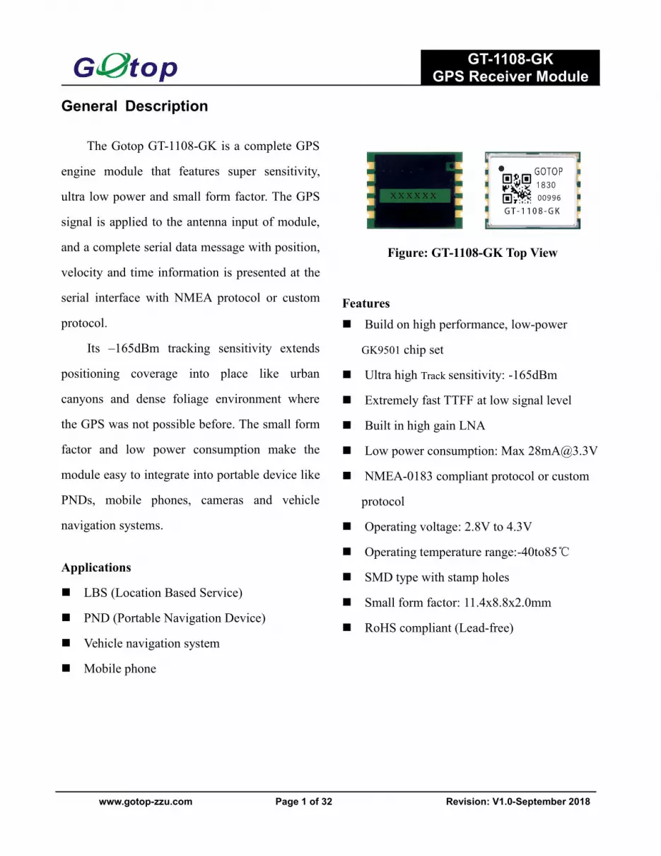
Figure: GT-1108-GK Top View
Features Build on high performance, low-power
GK9501 chip set
Ultra high Track sensitivity: -165dBm
Extremely fast TTFF at low signal level
Built in high gain LNA
Low power consumption: Max [email protected]
NMEA-0183 compliant protocol or custom
protocol
Operating voltage: 2.8V to 4.3V
Operating temperature range:-40to85℃
SMD type with stamp holes
Small form factor: 11.4x8.8x2.0mm
RoHS compliant (Lead-free)
GT-1108-GKGPS Receiver Module
www.gotop-zzu.com Page 2 of 32 Revision: V1.0-September 2018
1 Description...................................................................................................................................................................... 31.1 General Description...............................................................................................................................................31.2. Key Features.........................................................................................................................................................41.3. Block Diagram..................................................................................................................................................... 51.4. Protocols Supported by the Module.....................................................................................................................5
2 Application...................................................................................................................................................................... 62.1. Pin Assignment.....................................................................................................................................................62.2. Pin Definition....................................................................................................................................................... 62.3. Power Supply....................................................................................................................................................... 72.4. Operating Modes.................................................................................................................................................. 9
2.4.1. Full on Mode........................................................................................................................................... 102.4.2. Standby Mode..........................................................................................................................................112.4.3. Backup Mode.......................................................................................................................................... 112.4.4. Periodic Mode......................................................................................................................................... 122.4.5. AlwaysLocateTM Mode......................................................................................................................... 142.4.6. FLP Mode................................................................................................................................................15
2.5. UART Interface.................................................................................................................................................. 162.6. EASY Technology..............................................................................................................................................172.7. Multi-tone AIC................................................................................................................................................... 182.8. LOCUS...............................................................................................................................................................182.9. PPS VS. NMEA................................................................................................................................................. 19
3 Antenna Interfaces....................................................................................................................................................... 193.1. PCB Design Guide............................................................................................................................................. 193.2. External Active Antenna.................................................................................................................................... 20
4 Electrical, Reliability and Radio Characteristics......................................................................................................214.1. Absolute Maximum Ratings...............................................................................................................................214.2. Operating Conditions......................................................................................................................................... 214.3. Current Consumption......................................................................................................................................... 224.4. Electrostatic Discharge.......................................................................................................................................224.5. Reliability Test................................................................................................................................................... 23
5 Mechanical Dimensions............................................................................................................................................... 236 Manufacturing, Packaging and Ordering Information........................................................................................... 24
6.1. Assembly and Soldering.....................................................................................................................................246.2. Moisture Sensitivity........................................................................................................................................... 246.3. ESD Protection...................................................................................................................................................246.4. Tape and Reel Packaging................................................................................................................................... 25
7 Appendix References....................................................................................................................................................268 NMEA 0183 Protocol....................................................................................................................................................27

GT-1108-GKGPS Receiver Module
www.gotop-zzu.com Page 3 of 32 Revision: V1.0-September 2018
1 Description1.1 General Description
GOTOP GT-1108-GK GPS module embedded LNA brings high performance of GK positioning engine to theindustrial applications. It is able to achieve the industry’s highest level of sensitivity, accuracy and TTFF with thelowest power consumption in a small-footprint leadless package. With 66 search channels and 22 simultaneoustracking channels, it acquires and tracks satellites in the shortest time even at indoor signal level.
GT-1108-GK module combines many advanced features including EASY, AIC, LOCUS, AlwaysLocate ™ , FLP.These features are beneficial to accelerate TTFF, improve sensitivity,save consumption. The module supports variouspositioning,navigation and industrial applications. including autonomous GPS, SBAS (including WAAS,EGNOS,MSAS, and GAGAN), QZSS, and AGPS.
EASY technology as the key feature of GT-1108-GK is one kind of AGPS. Capable collecting and processing allinternal aiding information like GPS time,Ephemeris, Last Position,etc.,the GPS module delivers a very short TTFFin either Hot or Warm start.
GT-1108-GK module is a SMD type module with the compact 11.4mm×8.8mm×2.0mm form factor. It can bethrough the 10-pin pads embedded in your applications. It provides necessary hardware interfaces for connection withthe main PCB.
Made of lead-free technology, conforms to the RoHS standard, Single patch, two times more rapid application ofSMT scheme
GT-1108-GKGPS Receiver Module
www.gotop-zzu.com Page 4 of 32 Revision: V1.0-September 2018
1.2. Key Features
Table 1: Key FeaturesParameter SpecificationPower Supply • Supply voltage: 2.8V~4.3V Typical: 3.3V
Power Consumption
• Acquisition: 28mA @VCC=VBAT=3.3V• Tracking: 20mA @VCC=VBAT=3.3V• Standby: 1.0mA @VCC=VBAT=3.3V• Backup: 7uA @VBAT=3.3V
Receiver Type• Code 66 search channels, GPS&QZSS L1 1575.42MHz C/A• 22 simultan ous tracking channels
Sensitivity• Tracking: -165dBm• Re-acquisition: -156dBm• Acquisition: -148dBm
TTFF (EASY enabled)• Cold start: 15s typ @-130dBm• Warm start: 5s typ @-130dBm• Hot start : 1s typ @-130dBm
TTFF (EASY disabled)• Cold start(Autonomous): 35s typ @-130dBm• Warm start (Autonomous): 30s typ @-130dBm• Hot start (Autonomous): 1s typ @-130dBm
Horizontal PositionAccuracy (Autonomous)
• <2.5m CEP @-130 dBm
Max Update Rate • Up to 10Hz,1Hz by fault
Acceleration Accuracy • Without aid: 0.1m/s²
Dynamic Performance• Maximum altitude: 18,000m• Maximum velocity: 515m/s• Acceleration: 4G
UART Port
• UART Port: TXD and RXD• Supports baud rate from 4800bps to 115200bps, 9600bps by
default• UART port is used for NMEA output, GK proprietary
commands input
Temperature Range• Normal operation: -40°C ~ +85°C• Storage temperature: -45°C ~ +125°C
Physical Characteristics• Size: 11.4±0.15 × 8.8±0.15 ×2.0±0.1mm• Weight: Approx. 0.41g
GT-1108-GKGPS Receiver Module
www.gotop-zzu.com Page 5 of 32 Revision: V1.0-September 2018
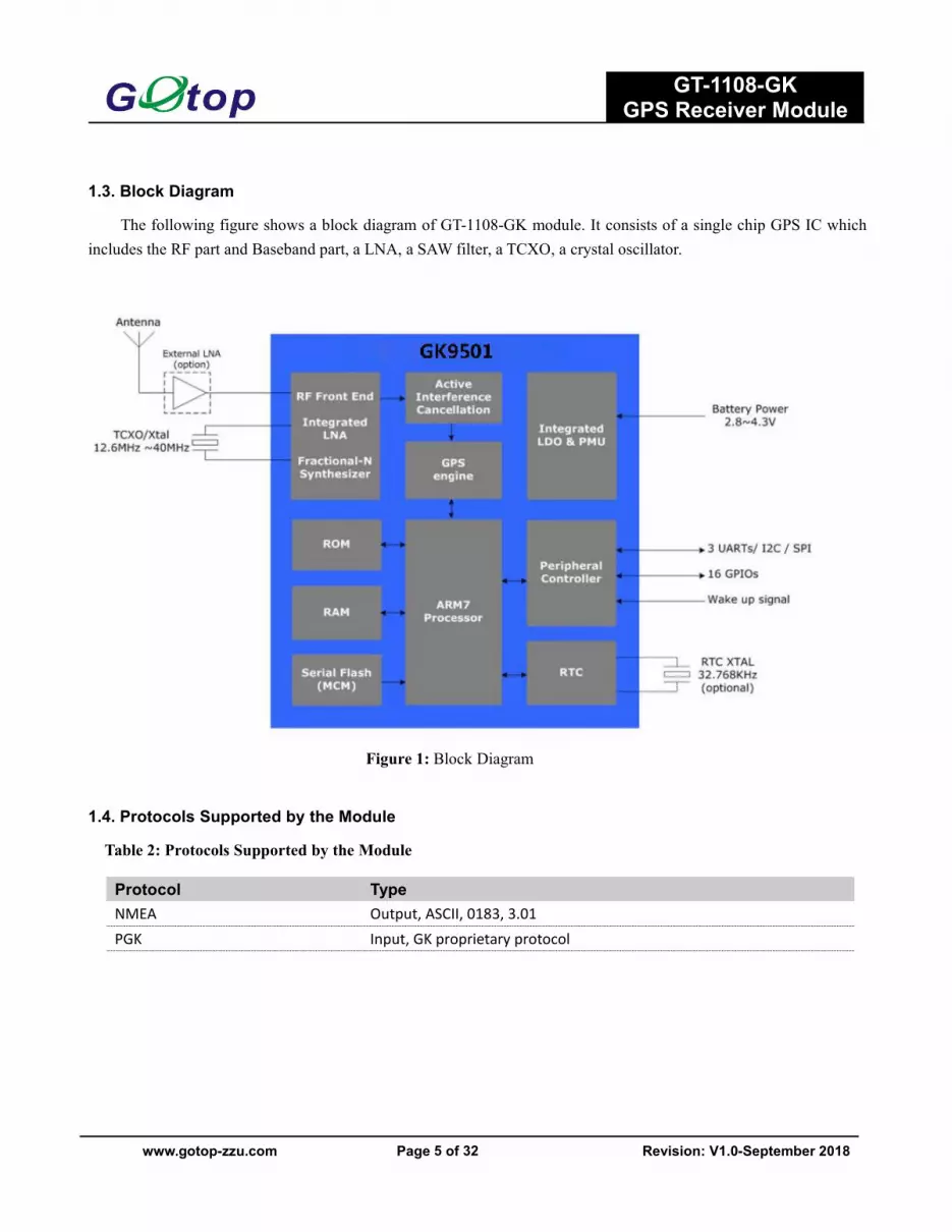
1.3. Block Diagram
The following figure shows a block diagram of GT-1108-GK module. It consists of a single chip GPS IC whichincludes the RF part and Baseband part, a LNA, a SAW filter, a TCXO, a crystal oscillator.
Figure 1: Block Diagram
1.4. Protocols Supported by the Module
Table 2: Protocols Supported by the Module
Protocol TypeNMEA Output, ASCII, 0183, 3.01PGK Input, GK proprietary protocol
GT-1108-GKGPS Receiver Module
www.gotop-zzu.com Page 6 of 32 Revision: V1.0-September 2018
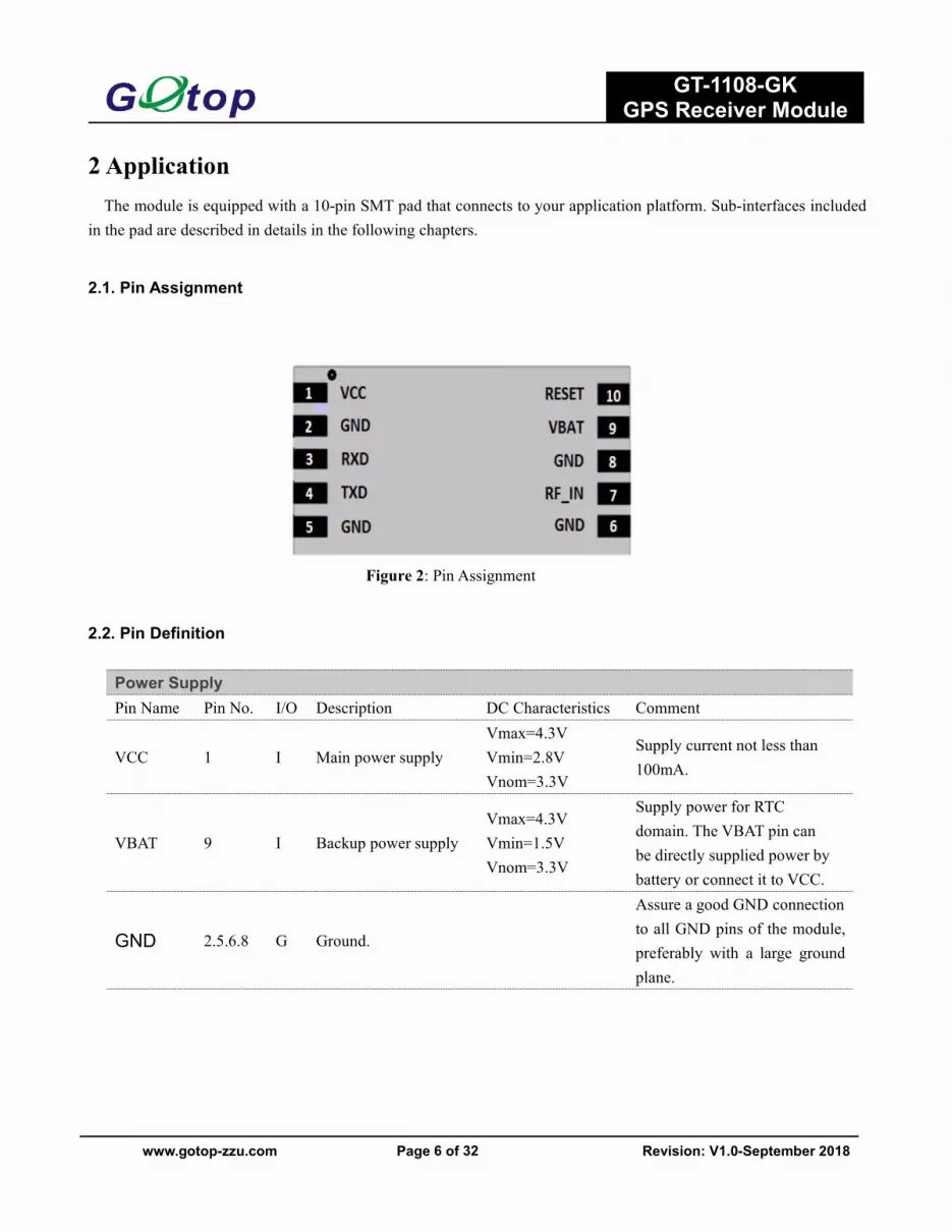
2 ApplicationThe module is equipped with a 10-pin SMT pad that connects to your application platform. Sub-interfaces included
in the pad are described in details in the following chapters.
2.1. Pin Assignment
Figure 2: Pin Assignment
2.2. Pin Definition
Power SupplyPin Name Pin No. I/O Description DC Characteristics Comment
VCC 1 I Main power supplyVmax=4.3VVmin=2.8VVnom=3.3V
Supply current not less than100mA.
VBAT 9 I Backup power supplyVmax=4.3VVmin=1.5VVnom=3.3V
Supply power for RTCdomain. The VBAT pin canbe directly supplied power bybattery or connect it to VCC.
GND 2.5.6.8 G Ground.
Assure a good GND connectionto all GND pins of the module,preferably with a large groundplane.

GT-1108-GKGPS Receiver Module
www.gotop-zzu.com Page 7 of 32 Revision: V1.0-September 2018
2.3. Power Supply
VCC pin supplies power for BB, RF, I/O, LNA, short protection and antenna detection circuit. The load current ofVCC varies according to the VCC level, processor load, the number of tracked satellites and the rate of satellitere-acquisition. Using external active antenna will consume additional 11mA from our module. So it is important tosupply sufficient current and make the power clean and stable. VCC supply ripple voltage should meet therequirement: 54mV (RMS) max @f=0… 3MHz and 15mV (RMS) max@f >3MHz. You should choose the LDOwithout built-in output high-speed discharge function to keep long output voltage drop-down period. The decouplecombination of 10uF and 100nF capacitor is recommended nearby VCC pin.
The VBAT pin supplies power for RTC domain. It should be valid when power on the module. The voltage ofRTC domain ranges from 1.5V to 4.3V. In order to achieve a better TTFF, RTC domain should be valid all the time. Itcan supply power for SRAM memory in RTC domain which contains all the necessary GPS information for quickstart-up and a small amount of user configuration variables.
UART PortPin Name Pin No. I/O Description DC Characteristics Comment
RXD 3 I Receive data
VILmin=-0.3VVILmax=0.8VVIHmin=2.0VVIHmax=3.6V
TXD 4 O Transmit data
VOLmin=-0.3VVOLmax=0.4VVOHmin=2.4VVOHmax=3.1V
RF InterfacePin Name Pin No. I/O Description DC Characteristics Comment
RF_IN 7 IExternal activeantenna RF input
Characteristic impedance of50Ω
ResetPin Name Pin No. I/O Description DC Characteristics Comment
RESET 10 I System reset
VILmin=-0.3VVILmax=0.8VVIHmin=2.0VVIHmax=3.6V
Low level active. If unused,keep this pin open or connectit to VCC.
GT-1108-GKGPS Receiver Module
www.gotop-zzu.com Page 8 of 32 Revision: V1.0-September 2018
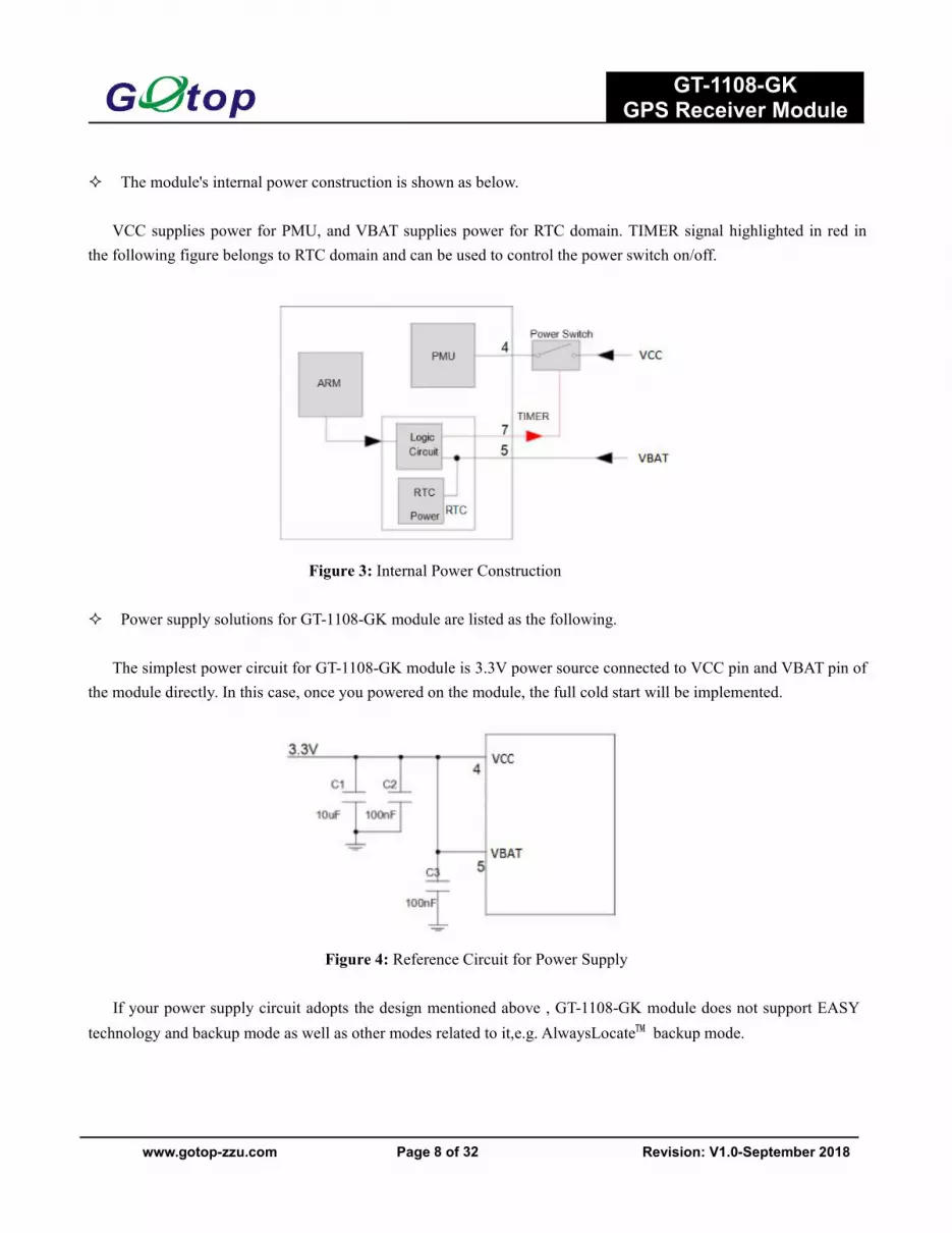
The module's internal power construction is shown as below.
VCC supplies power for PMU, and VBAT supplies power for RTC domain. TIMER signal highlighted in red inthe following figure belongs to RTC domain and can be used to control the power switch on/off.
Figure 3: Internal Power Construction
Power supply solutions for GT-1108-GK module are listed as the following.
The simplest power circuit for GT-1108-GK module is 3.3V power source connected to VCC pin and VBAT pin ofthe module directly. In this case, once you powered on the module, the full cold start will be implemented.
Figure 4: Reference Circuit for Power Supply
If your power supply circuit adopts the design mentioned above , GT-1108-GK module does not support EASYtechnology and backup mode as well as other modes related to it,e.g. AlwaysLocate™ backup mode.

GT-1108-GKGPS Receiver Module
www.gotop-zzu.com Page 9 of 32 Revision: V1.0-September 2018
The other way is feeding VBAT through a backup battery directly. The module will enter into backup mode whenpower source (3.3V) is cut off. Furthermore,it is necessary to add an external charging circuit.for rechargeable battery.The detailed schematic (mount R2 with 0R to replace Power switch) is shown as there is no charge source whenpower source (3.3V) is cut off. MS621FE FL11E from Seiko is recommended. The consumption of VBAT is as low as7uA in backup mode.
The schematic with power supply circuit is shown as below. As power source (3.3V) is always valid and thebattery is charged continuously, the capacity of the battery can be small. The detailed schematic for power switchcircuit is shown in Figure 5.
For more details about backup mode, periodic backup mode and AlwaysLocate™ backup mode, please refer to therelated chapters.
Figure 5: Reference Charging Circuit for Chargeable Battery
VCC does not supply power for RTC domain in GT-1108-GK module, so the VBAT pin must be poweredexternally. Furthermore, it is strongly recommended to supply power to VBAT through a backup battery, which canensure GT-1108-GK module supports EASY technology and improves TTFF after next restart. For details about TTFF,please refer to chapter 1.2.
2.4. Operating Modes
The table below briefly illustrates the relationship among different operating modes of GT-1108-GK module.
GT-1108-GKGPS Receiver Module
www.gotop-zzu.com Page 10 of 32 Revision: V1.0-September 2018
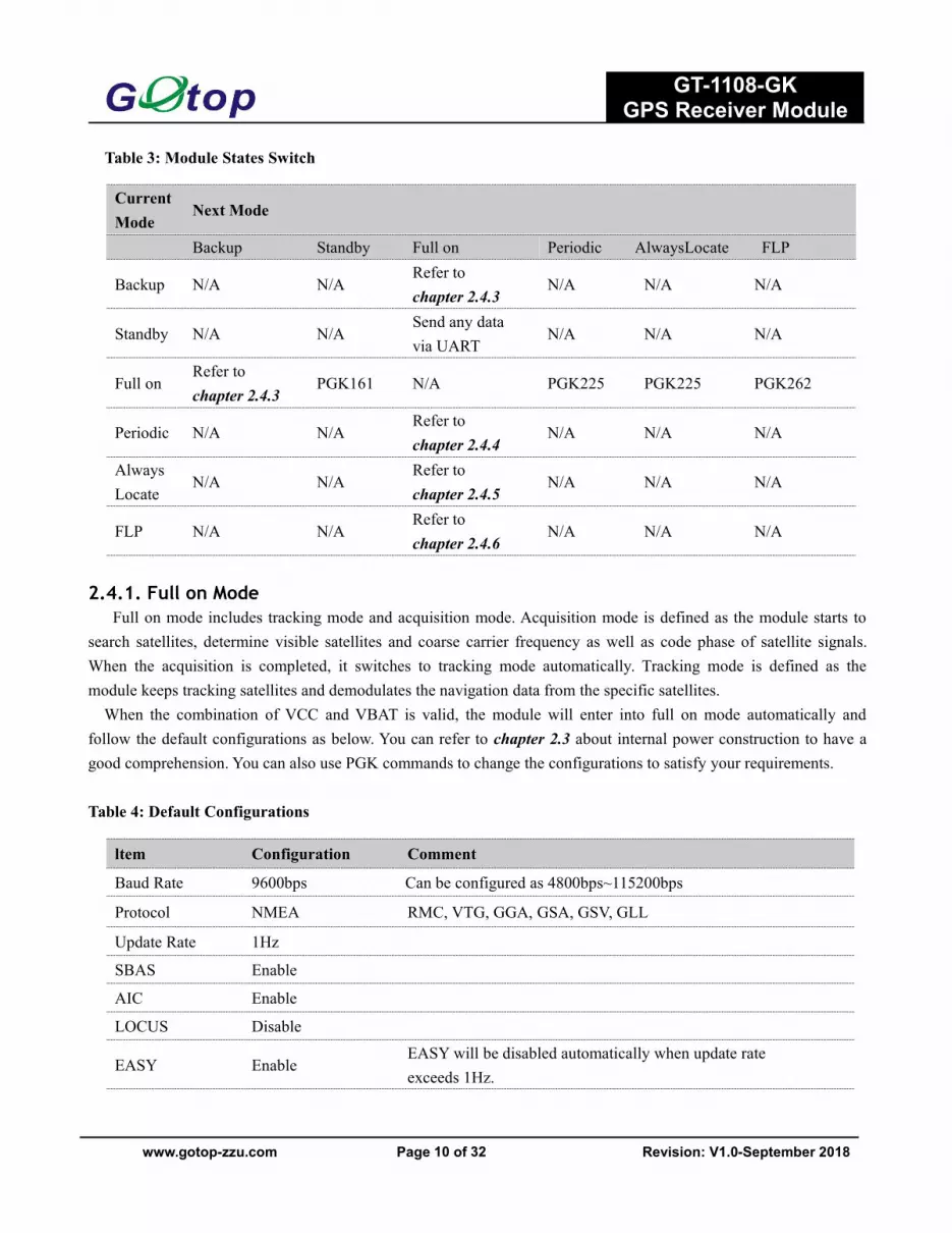
Table 3: Module States Switch
2.4.1. Full on ModeFull on mode includes tracking mode and acquisition mode. Acquisition mode is defined as the module starts to
search satellites, determine visible satellites and coarse carrier frequency as well as code phase of satellite signals.When the acquisition is completed, it switches to tracking mode automatically. Tracking mode is defined as themodule keeps tracking satellites and demodulates the navigation data from the specific satellites.When the combination of VCC and VBAT is valid, the module will enter into full on mode automatically and
follow the default configurations as below. You can refer to chapter 2.3 about internal power construction to have agood comprehension. You can also use PGK commands to change the configurations to satisfy your requirements.
Table 4: Default Configurations
CurrentMode
Next Mode
Backup Standby Full on Periodic AlwaysLocate FLP
Backup N/A N/ARefer tochapter 2.4.3
N/A N/A N/A
Standby N/A N/ASend any datavia UART
N/A N/A N/A
Full onRefer tochapter 2.4.3
PGK161 N/A PGK225 PGK225 PGK262
Periodic N/A N/ARefer tochapter 2.4.4
N/A N/A N/A
AlwaysLocate
N/A N/ARefer tochapter 2.4.5
N/A N/A N/A
FLP N/A N/ARefer tochapter 2.4.6
N/A N/A N/A
ltem Configuration Comment
Baud Rate 9600bps Can be configured as 4800bps~115200bps
Protocol NMEA RMC, VTG, GGA, GSA, GSV, GLL
Update Rate 1Hz
SBAS Enable
AIC Enable
LOCUS Disable
EASY EnableEASY will be disabled automatically when update rateexceeds 1Hz.
GT-1108-GKGPS Receiver Module
www.gotop-zzu.com Page 11 of 32 Revision: V1.0-September 2018
2.4.2. Standby ModeStandby mode is a low-power consumption mode. In standby mode, the internal core and I/O power domain are
still active, but RF and TCXO are powered off, and the module stops satellites search and navigation. UART is stillaccessible through PGK commands or any other data, but there is no NMEAmessages output.
Sending PGK command “$PGK161,0*28” will make GT-1108-GK module enter into standby mode. Sending anydata via UART can wake the module up. When the module exits from standby mode, it will use all internal aidinginformation like GPS time, Ephemeris, Last Position, etc., resulting to the fastest possible TTFF in either Hot or Warmstart. The typical standby current consumption in this way is about 1mA@VCC=3.3V.
When the external active antenna is used, an additional 11mA will be consumed because the VCC still suppliespower for external active antenna in standby mode.
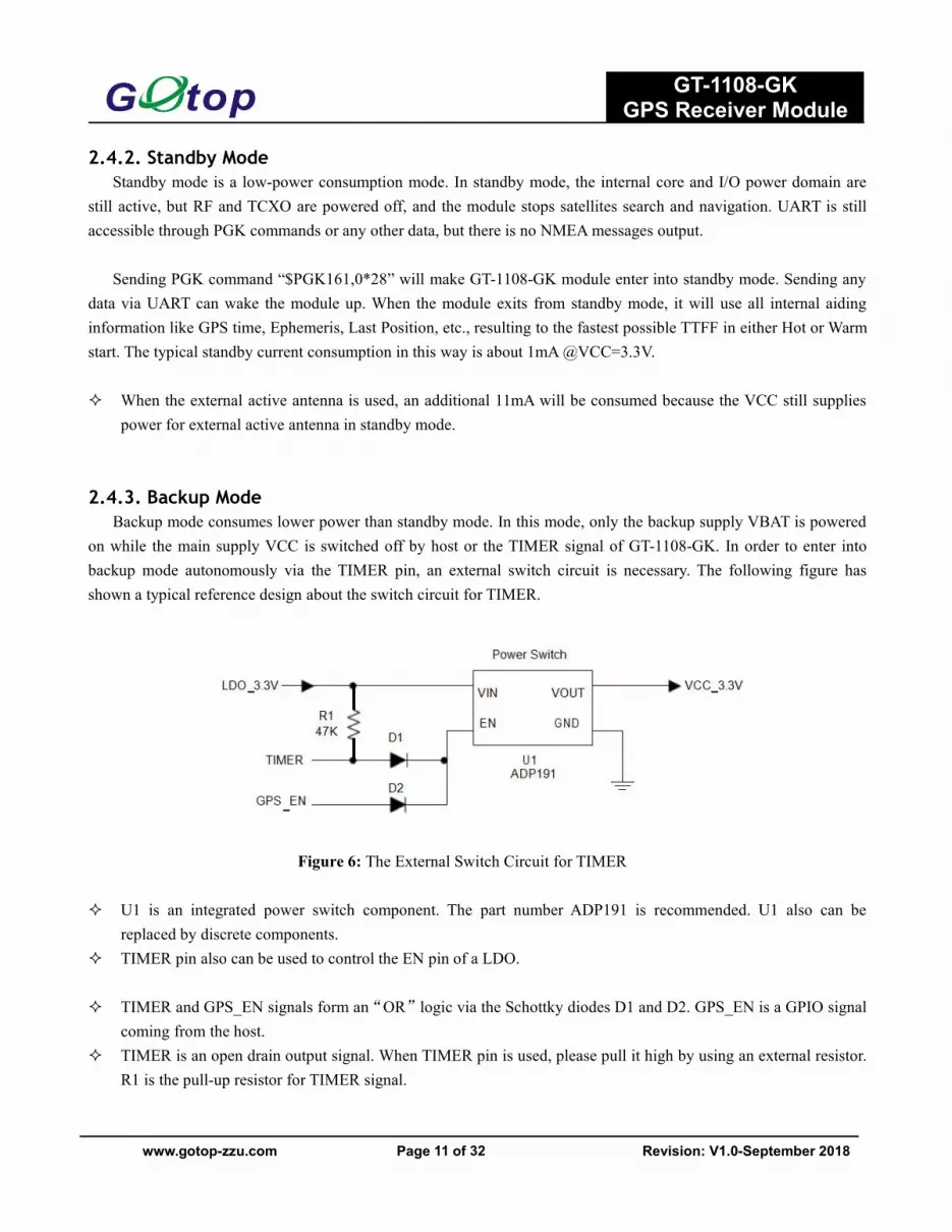
2.4.3. Backup ModeBackup mode consumes lower power than standby mode. In this mode, only the backup supply VBAT is powered
on while the main supply VCC is switched off by host or the TIMER signal of GT-1108-GK. In order to enter intobackup mode autonomously via the TIMER pin, an external switch circuit is necessary. The following figure hasshown a typical reference design about the switch circuit for TIMER.
Figure 6: The External Switch Circuit for TIMER
U1 is an integrated power switch component. The part number ADP191 is recommended. U1 also can bereplaced by discrete components.
TIMER pin also can be used to control the EN pin of a LDO.
TIMER and GPS_EN signals form an“OR”logic via the Schottky diodes D1 and D2. GPS_EN is a GPIO signalcoming from the host.
TIMER is an open drain output signal. When TIMER pin is used, please pull it high by using an external resistor.R1 is the pull-up resistor for TIMER signal.

GT-1108-GKGPS Receiver Module
www.gotop-zzu.com Page 12 of 32 Revision: V1.0-September 2018
Keeping GPS_EN signal low and sending PGK command“$PGK225,4*2F” will make GT-1108-GK module enterinto backup mode forever. When this command is executed successfully, TIMER signal will be pulled down to closethe power switch, so GT-1108-GK module can go into backup mode as the main power VCC is cut off. For this case,pulling the GPS_EN signal high by host is the only way to wake the module up.
In backup mode, GT-1108-GK module stops to acquire and track satellites. UART is not accessible. But thebacked-up memory in RTC domain which contains all the necessary GPS information for quick start up and a smallamount of user configuration variables is alive. Due to the backed up memory, EASY technology is available. Thetypical consumption in backup mode can be as ow as 7uA.
As the main power supply for VBAT pin is battery. Coin-type rechargeable capacitor such as MS920SE fromSeiko can be used and Schottky diode such as RB520S30T1G from ON Semiconductor is recommended to be usedhere for its low voltage drop.
Figure 7: Seiko MS920SE Charge and Discharge Characteristics
2.4.4. Periodic ModePeriodic mode is a power saving mode of GT-1108-GK that can control the full on mode and standby/backup
mode periodically to reduce power consumption. It contains periodic standby mode and periodic backup mode.
The format of the command which enables the module to enter into periodic mode is as follows:

GT-1108-GKGPS Receiver Module
www.gotop-zzu.com Page 13 of 32 Revision: V1.0-September 2018
Table 5: PGK Command Format
Example$PGK225,1,3000,12000,18000,72000*16<CR><LF>$PGK225,2,3000,12000,18000,72000*15<CR><LF>
Sending “$PGK225,0*2B” in any time will make the module enter into full on mode from periodic standbymode.
Sending “$PGK225,0*2B” just in Run_time or 2nd_run_time can make the module enter into full on modefrom periodic backup mode.
The precondition is that the external switch circuit supports periodic backup mode. For details, please refer tochapter 2.4.3.
Before entering into periodic backup mode, please ensure the GPS_EN signal is low and power supply for VBATis alive.
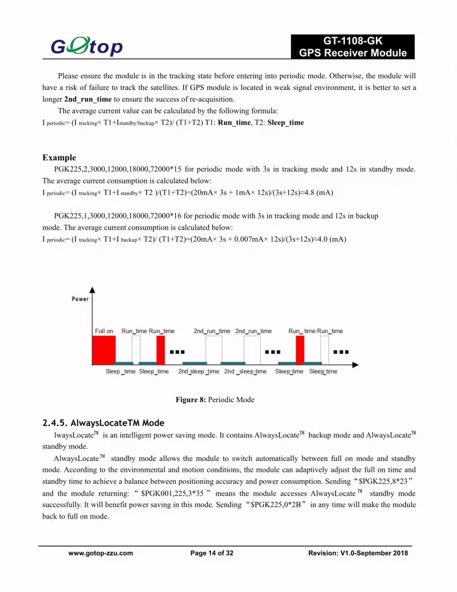
The following figure has shown the operation of periodic mode. When you send PGK command, the module willbe in the full on mode firstly. After several minutes, the module will enter into the periodic mode and follow theparameters set by you. When the module fails to fix the position in run_time, the module will switch to2nd_run_time and 2nd_sleep_time automatically. As long as the module fixes the position again, the module willreturn to Run_time and Sleep_time.
Format: $PGK225,<Type>,<Run_time>,<Sleep_time>,<2nd_run_time>,<2nd_sleep_time>*<checksum>< CR><LF>
Parameter Format Description
Type DecimalType=1 for Periodic Backup ModeType=2 for Periodic Standby Mode
Run_time Decimal Full on mode period (ms)
Sleep_time Decimal Standby/Backup mode period (ms)
2nd_run_time DecimalFull on mode period (ms) for extended acquisition in caseGPS module’s acquisition fails during the Run_time
2nd_sleep time DecimalStandby/Backup mode period (ms) for extended sleep incase GPS module’s acquisition fails during the Run_time
Checksum Hexadecimal Hexadecimal checksum
GT-1108-GKGPS Receiver Module
www.gotop-zzu.com Page 14 of 32 Revision: V1.0-September 2018
Please ensure the module is in the tracking state before entering into periodic mode. Otherwise, the module willhave a risk of failure to track the satellites. If GPS module is located in weak signal environment, it is better to set alonger 2nd_run_time to ensure the success of re-acquisition.
The average current value can be calculated by the following formula:I periodic= (I tracking× T1+Istandby/backup× T2)/ (T1+T2) T1: Run_time, T2: Sleep_time
ExamplePGK225,2,3000,12000,18000,72000*15 for periodic mode with 3s in tracking mode and 12s in standby mode.
The average current consumption is calculated below:I periodic= (I tracking× T1+I standby× T2 )/(T1+T2)=(20mA× 3s + 1mA× 12s)/(3s+12s)≈4.8 (mA)
PGK225,1,3000,12000,18000,72000*16 for periodic mode with 3s in tracking mode and 12s in backupmode. The average current consumption is calculated below:I periodic= (I tracking× T1+I backup× T2)/ (T1+T2)=(20mA× 3s + 0.007mA× 12s)/(3s+12s)≈4.0 (mA)
Figure 8: Periodic Mode
2.4.5. AlwaysLocateTM ModelwaysLocate™ is an intelligent power saving mode. It contains AlwaysLocate™ backup mode and AlwaysLocate™
standby mode.AlwaysLocate™ standby mode allows the module to switch automatically between full on mode and standby
mode. According to the environmental and motion conditions, the module can adaptively adjust the full on time andstandby time to achieve a balance between positioning accuracy and power consumption. Sending“$PGK225,8*23”and the module returning:“ $PGK001,225,3*35” means the module accesses AlwaysLocate ™ standby modesuccessfully. It will benefit power saving in this mode. Sending“$PGK225,0*2B” in any time will make the moduleback to full on mode.

GT-1108-GKGPS Receiver Module
www.gotop-zzu.com Page 15 of 32 Revision: V1.0-September 2018
AlwaysLocate™ backup mode is similar to AlwaysLocate™ standby mode. The difference is that AlwaysLocate™backup mode can switch between full on mode and backup mode automatically. The PGK command to enter intoAlwaysLocate ™ backup mode is “$PGK225,9*22”.The module can exit from AlwaysLocate ™ backup mode bycommand “$PGK225,0*2B” sent just after the module has been waked up from previous backup cycle.
The positioning accuracy in AlwaysLocate™ mode will be somewhat degraded, especially in high speed. Thefollowing picture shows the rough power consumption of GT-1108-GK module in different daily scenes whenAlwaysLocate™ mode is enabled.
Figure 9:AlwaysLocate™ Mode
Example
The typical average consumption is about 3.5mA in AlwaysLocate™ standby mode and 3.0mA in AlwaysLocate™backup mode.
Power consumption is measured under outdoor static mode with patch antenna. Using external active antennawill increase the power consumption.
Before entering into periodic backup mode, please ensure the GPS_EN signal is low and power supply for VBATis alive.
2.4.6. FLP ModeThe Fitness Low Power (FLP) feature provides low power GPS solution for fitness application. FLP is a duty
cycle concept to achieve low power target. It is specifically designed for walking/running/cycling applications.
FLP function is disabled by default. You can enable FLP by SDK or PGK command. Sending“$PGK262,1*29” will enable FLP function, and wait until GT-1108-GK module gets a valid fix. Then wait at least60s for GT-1108-GK to enter FLP mode. FLP function will be disabled after sending “$PGK262,0*28”.
GT-1108-GKGPS Receiver Module
www.gotop-zzu.com Page 16 of 32 Revision: V1.0-September 2018
Table 6: Average Current for FLPMode and Tracking Mode of GT-1108-GK.
The EASY and FLP function cannot work at the same time. When you enable FLP by SDK or PGK command,the EASY function will be disabled automatically.
SBAS data downloading will be influenced by FLP function. It is suggested that you should disable the SBASwhile enabling FLP mode.
The power consumption is measured in the open sky under different states of motion. The current is the average of multiple measurements.
2.5. UART Interface
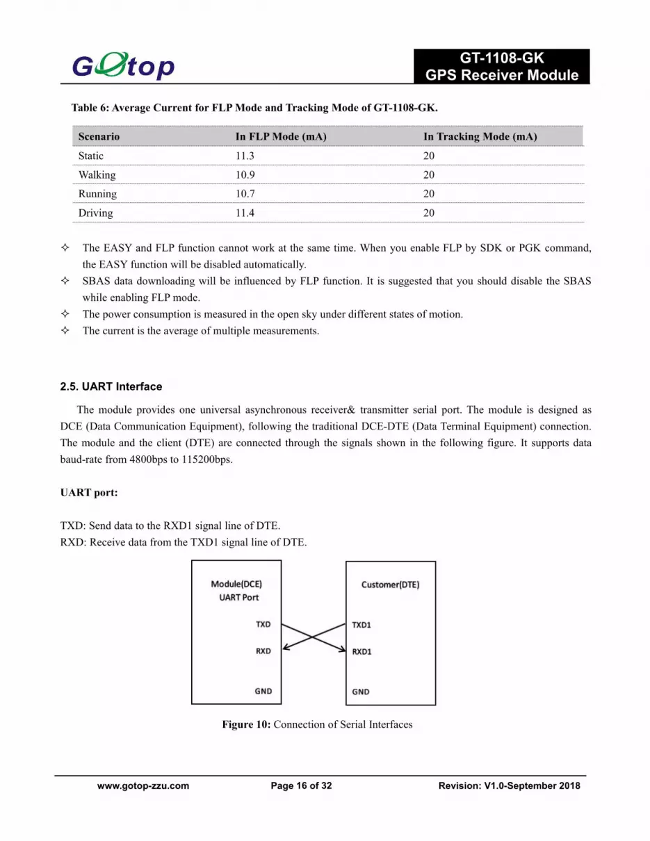
The module provides one universal asynchronous receiver& transmitter serial port. The module is designed asDCE (Data Communication Equipment), following the traditional DCE-DTE (Data Terminal Equipment) connection.The module and the client (DTE) are connected through the signals shown in the following figure. It supports databaud-rate from 4800bps to 115200bps.
UART port:
TXD: Send data to the RXD1 signal line of DTE.RXD: Receive data from the TXD1 signal line of DTE.
Figure 10: Connection of Serial Interfaces
Scenario In FLPMode (mA) In Tracking Mode (mA)
Static 11.3 20
Walking 10.9 20
Running 10.7 20
Driving 11.4 20

GT-1108-GKGPS Receiver Module
www.gotop-zzu.com Page 17 of 32 Revision: V1.0-September 2018
This UART port has the following features:
UART port can be used NMEA output and PGK proprietary commands input. The default output NMEA type setting is RMC, VTG, GGA, GSA, GSV, GLL UART port supports the following data rates:
4800, 9600, 14400, 19200, 38400, 57600, 115200bps.The default setting is 9600bps, 8 bits, no parity bit, 1 stop bit.
Hardware flow control and synchronous operation are not supported.
The UART port does not support the RS-232 level but only CMOS level. If the module’s UART port is connectedto the UART port of a computer, it is necessary to add a level shift circuit between the module and the computer.Please refer to the following figure.
Figure 11: RS-232 Level Shift Circuit
2.6. EASY Technology
EASY technology works as embedded software which can accelerate TTFF by predicting satellite navigationmessages from received ephemeris.The GPS engine will calculate and predict orbit.
information automatically up to 3 days after first receiving the broadcast ephemeris, and then save the predictedinformation into the internal memory. GPS engine will use the information for positioning if no enough informationfrom satellites, so the function is helpful for positioning and TTFF improvement.
GT-1108-GKGPS Receiver Module
www.gotop-zzu.com Page 18 of 32 Revision: V1.0-September 2018
The EASY function can reduce TTFF to 5s in warm start. In this case, RTC domain should be valid. In order to getenough broadcast ephemeris information from GPS satellites, the GPS module should receive the information for atleast 5 minutes in good signal conditions after fixing the position.
EASY function is enabled by default. Command “$PGK869,1,0*34” can be used to disable EASY.
2.7. Multi-tone AIC
GT-1108-GK module provides an advanced technology called multi-tone AIC (Active Interference Cancellation)to reject RF interference which comes from other active components on the main board.
Up to 12 multi-tone AIC embedded in the module can provide effective narrow -band interference and jammingelimination. The GPS signal could be recovered from the jammed signal, which can ensure better navigation quality.AIC is enabled by default, closing it wi save about 1mA@VCC=3.3V consumption. The following commands can beused to set AIC.
Enable AIC function: “$PGK 286,1*23”.Disable AIC function: “$PGK 286,0*22”.
2.8. LOCUS
GT-1108-GK module supports the embedded logger function called LOCUS. It can log position information to theinternal flash memory automatically when this function is enabled by sending PGK command“$PGK183,0*22”.Dueto this function, the host can go to sleep to save power consumption and does not need to receive the NMEAinformation all the time. The module can provide a log capacity of more than 16 hours.
The detail procedures of this function are illustrated bellow: The module has fixed the position (only 3D_fixed is available); Sending PGK command “$PGK184,1*22” to erase internal flash; Sending PGK command “$PGK185,0*22” to start log; Module logs the basic information (UTC time, latitude, longitude and height) every 15 seconds to internal flash
memory; Stop logging the information by sending “$PGK185,1*23”; Host can get the data from the module via UART by sending“$PGK622,1*29”.
The raw data which host gets has to be parsed via LOCUS parser code provided by GOTOP. For more details,please contact GOTOP technical supports.

GT-1108-GKGPS Receiver Module
www.gotop-zzu.com Page 19 of 32 Revision: V1.0-September 2018
2.9. PPS VS. NMEA
Figure 12: PPS VS. NMEATiming
This feature only supports 1Hz NMEA output and baud rate at 14400~115200bps. At baud rate of 9600 and4800bps, it only supports RMC NMEA sentence. Because at low baud rate, per second transmission may exceed onesecond if there are many NMEA sentences output. You can enable this function by sending “$PGK255,1*2D”, anddisable the function by sending “$PGK255,0*2C”. GT-1108-GK does not support the use of PPS functions.
3 Antenna Interfaces3.1. PCB Design Guide
The GT-1108-GK GPS receiver is designed for supporting the active antenna or passive antenna connected withpin RF_IN. The gain of active antenna should be no less than 15dB. The maximum noise figure should be no morethan 2.5dB and output impedance is at 50 Ohm.
Figure 13: Antenna design requirements

GT-1108-GKGPS Receiver Module
www.gotop-zzu.com Page 20 of 32 Revision: V1.0-September 2018
3.2. External Active Antenna
The following figure is a typical reference design with active antenna. In this mode, DC on the VDD_3.3V pin ispowered to power the external active antenna.
Figure 14: Reference Design for Active Antenna
C1, C2, L1 is used for power supply and filtering effect to the external active antenna, RF_IN antenna to a circuitpart (BOLD line) for high frequency microstrip line, PCB in the design of this part of the line to calculate thecharacteristic impedance of the high-frequency line according to the principle of high frequency wiring.
Requirements: this section of the line in the 1575.42MHz frequency characteristic impedance requirement is 50ohm.
Table 7: Recommended Active Antenna Specification
Antenna Type Specification
Active Antenna
Center frequency: 1575.42MHzBand width: >5MHZVSWR: <2 (Typ.)Polarization: RHCP or LinearNoise figure: <1.5dBGain (antenna): >-2dBiGain ( mb dd d LNA): 20dB (Typ.)Total gain: >18dBi(Typ.)
GT-1108-GKGPS Receiver Module
www.gotop-zzu.com Page 21 of 32 Revision: V1.0-September 2018
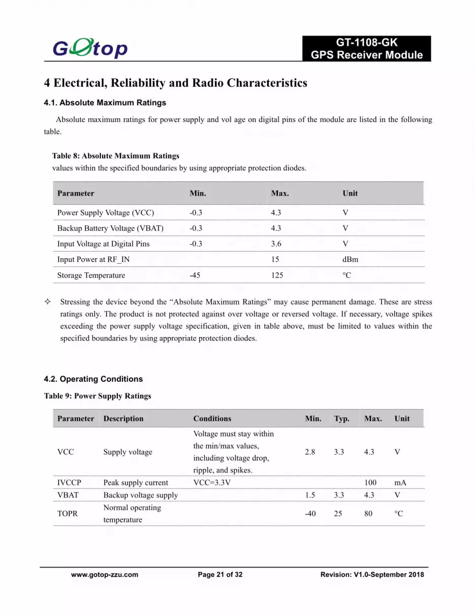
4 Electrical, Reliability and Radio Characteristics4.1. Absolute Maximum Ratings
Absolute maximum ratings for power supply and vol age on digital pins of the module are listed in the followingtable.
Table 8: Absolute Maximum Ratingsvalues within the specified boundaries by using appropriate protection diodes.
Stressing the device beyond the “Absolute Maximum Ratings” may cause permanent damage. These are stressratings only. The product is not protected against over voltage or reversed voltage. If necessary, voltage spikesexceeding the power supply voltage specification, given in table above, must be limited to values within thespecified boundaries by using appropriate protection diodes.
4.2. Operating Conditions
Table 9: Power Supply Ratings
Parameter Min. Max. Unit
Power Supply Voltage (VCC) -0.3 4.3 V
Backup Battery Voltage (VBAT) -0.3 4.3 V
Input Voltage at Digital Pins -0.3 3.6 V
Input Power at RF_IN 15 dBm
Storage Temperature -45 125 °C
Parameter Description Conditions Min. Typ. Max. Unit
VCC Supply voltage
Voltage must stay withinthe min/max values,including voltage drop,ripple, and spikes.
2.8 3.3 4.3 V
IVCCP Peak supply current VCC=3.3V 100 mAVBAT Backup voltage supply 1.5 3.3 4.3 V
TOPRNormal operatingtemperature
-40 25 80 °C

GT-1108-GKGPS Receiver Module
www.gotop-zzu.com Page 22 of 32 Revision: V1.0-September 2018
The figure IVCCP can be used to determine the maximum current capability of power supply. Operation beyond the "Operating Conditions" is not recommended and extended exposure beyond the "Operating
Conditions" may affect the device’s reliability.
4.3. Current Consumption
The values for current consumption are shown in the following table.Table 10: Current Consumption
The tracking current is tested in the following conditions:
In Cold Start, 10 minutes after First Fix. In Hot Start, 15 seconds after First Fix.
4.4. Electrostatic Discharge
GT-1108-GK module is an ESD sensitive device. ESD protection precautions should still be emphasized. ProperESD handling and packaging procedures must be applied throughout the processing, handling and operation of anyapplication.
The ESD bearing capability of the module is listed in the following table. Note that you should add ESDcomponents to module pins in particular applications.
Table 11: ESD Endurance Table (Temperature : 25°C, Humidity: 45%)
Parameter Conditions Min. Typ. Max. Unit
IVCC @Acquisition VCC=VBAT=3.3V 40 mA
IVCC @Tracking VCC=VBAT=3.3V 35 mA
IVCC @Standby VCC=VBAT=3.3V 2.0 mA
IBCKP @Backup VBAT=3.3V 15 uA
Pin Contact Discharge Air Discharge
RF_IN ±5KV ±10KV
Patch Antenna ±5KV ±10KV
VCC ±5KV ±10KV
UART ±3KV ±6KV
Others ±2KV ±4KV
GT-1108-GKGPS Receiver Module
www.gotop-zzu.com Page 23 of 32 Revision: V1.0-September 2018
4.5. Reliability Test
Table 12: Reliability Test
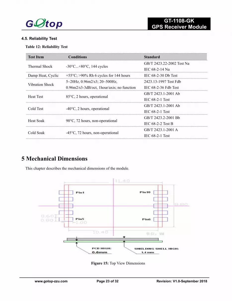
5 Mechanical DimensionsThis chapter describes the mechanical dimensions of the module.
Figure 15: Top View Dimensions
Test Item Conditions Standard
Thermal Shock -30°C...+80°C, 144 cyclesGB/T 2423.22-2002 Test NaIEC 68-2-14 Na
Damp Heat, Cyclic +55°C; >90% Rh 6 cycles for 144 hours IEC 68-2-30 Db Test
Vibration Shock5~20Hz, 0.96m2/s3; 20~500Hz,0.96m2/s3-3dB/oct, 1hour/axis; no function
2423.13-1997 Test FdbIEC 68-2-36 Fdb Test
Heat Test 85°C, 2 hours, operationalGB/T 2423.1-2001 AbIEC 68-2-1 Test
Cold Test -40°C, 2 hours, operationalGB/T 2423.1-2001 AbIEC 68-2-1 Test
Heat Soak 90°C, 72 hours, non-operationalGB/T 2423.2-2001 BbIEC 68-2-2 Test B
Cold Soak -45°C, 72 hours, non-operationalGB/T 2423.1-2001 AIEC 68-2-1 Test
GT-1108-GKGPS Receiver Module
www.gotop-zzu.com Page 24 of 32 Revision: V1.0-September 2018
6 Manufacturing, Packaging and Ordering Information6.1. Assembly and Soldering
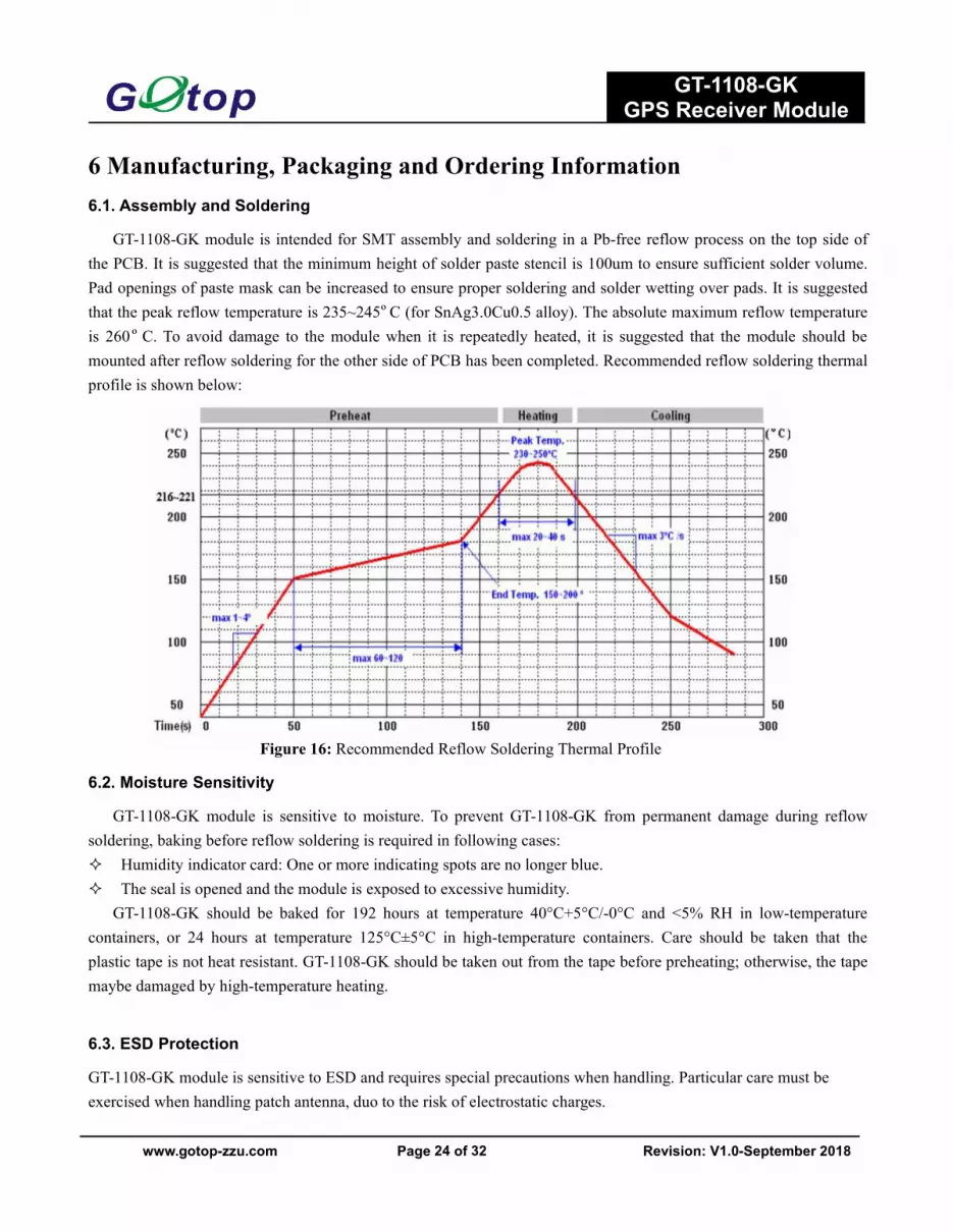
GT-1108-GK module is intended for SMT assembly and soldering in a Pb-free reflow process on the top side ofthe PCB. It is suggested that the minimum height of solder paste stencil is 100um to ensure sufficient solder volume.Pad openings of paste mask can be increased to ensure proper soldering and solder wetting over pads. It is suggestedthat the peak reflow temperature is 235~245ºC (for SnAg3.0Cu0.5 alloy). The absolute maximum reflow temperatureis 260ºC. To avoid damage to the module when it is repeatedly heated, it is suggested that the module should bemounted after reflow soldering for the other side of PCB has been completed. Recommended reflow soldering thermalprofile is shown below:
Figure 16: Recommended Reflow Soldering Thermal Profile
6.2. Moisture Sensitivity
GT-1108-GK module is sensitive to moisture. To prevent GT-1108-GK from permanent damage during reflowsoldering, baking before reflow soldering is required in following cases: Humidity indicator card: One or more indicating spots are no longer blue. The seal is opened and the module is exposed to excessive humidity.
GT-1108-GK should be baked for 192 hours at temperature 40°C+5°C/-0°C and <5% RH in low-temperaturecontainers, or 24 hours at temperature 125°C±5°C in high-temperature containers. Care should be taken that theplastic tape is not heat resistant. GT-1108-GK should be taken out from the tape before preheating; otherwise, the tapemaybe damaged by high-temperature heating.
6.3. ESD Protection
GT-1108-GK module is sensitive to ESD and requires special precautions when handling. Particular care must beexercised when handling patch antenna, duo to the risk of electrostatic charges.
GT-1108-GKGPS Receiver Module
www.gotop-zzu.com Page 25 of 32 Revision: V1.0-September 2018
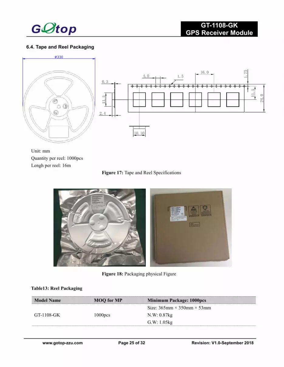
6.4. Tape and Reel Packaging
Unit: mmQuantity per reel: 1000pcsLengh per reel: 16m
Figure 17: Tape and Reel Specifications
Figure 18: Packaging physical Figure
Table13: Reel Packaging
Model Name MOQ for MP Minimum Package: 1000pcs
GT-1108-GK 1000pcsSize: 365mm × 350mm × 53mmN.W: 0.87kgG.W: 1.05kg

GT-1108-GKGPS Receiver Module
www.gotop-zzu.com Page 26 of 32 Revision: V1.0-September 2018
7 Appendix ReferencesTable 14: Terms and Abbreviations
Abbreviation DescriptionAGPS Assisted GPSAIC Active Interference CancellationCEP Circular Error ProbableDGPS Differential GPSEASY Embedded Assist SystemEGNOS European Geostationary Navigation Overlay ServiceEPO Extended Prediction OrbitESD Electrostatic DischargeGPS Global Positioning SystemGNSS Global Navigation Satellite SystemGGA GPS Fix DataGLL Geographic Position – Latitude/LongitudeGLONASS Global Navigation Satellite SystemGSA GNSS DOP and Active SatellitesGSV GNSS Satellites in ViewHDOP Horizontal Dilution of PrecisionI/O Input/OutputKbps Kilo Bits Per SecondLNA Low Noise AmplifierMSAS Multi-Functional Satellite Augmentation SystemMOQ Minimum Order QuantityNMEA National Marine Electronics AssociationPDOP Position Dilution of PrecisionPGK GK Proprietary ProtocolPPS Pulse Per SecondPRN Pseudo Random Noise CodeQZSS Quasi-Zenith Satellite SystemRHCP Right Hand Circular PolarizationRMC Recommended Minimum Specific GNSS DataSBAS Satellite-based Augmentation SystemSAW Surface Acoustic WaveSPDT Single-Pole Double-ThrowTTFF Time To First Fix
GT-1108-GKGPS Receiver Module
www.gotop-zzu.com Page 27 of 32 Revision: V1.0-September 2018
8 NMEA 0183 ProtocolThe NMEA protocol is an ASCII-based protocol, Records start with a $ and with carriage return/line feed. GPS
specific messages all start with $GPxxx where xxx is a three-letter identifier of the message data that follows. NMEAmessages have a check sum, which allows detection of corrupted data transfers.
The Gotop GT-1108-GK supports the following NMEA-0183 messages: $GPRMC. $GPGGA. $GPGSV. $GPGSA.$GPGLL. $GPVTG.Table 15: NMEA-0183 Output MessagesNMEARecord DESCRIPTIONGGA Global positioning system fixed dataGLL Geographic position—latitude/longitudeGSA GNSS DOP and active satellitesGSV GNSS satellites in viewRMC Recommended minimum specific GNSS dataVTG Course over ground and ground speed
UART Universal Asynchronous Receiver & TransmitterVDOP Vertical Dilution of PrecisionVTG Course over Ground and Ground Speed, Horizontal Course and Horizontal VelocityWAAS Wide Area Augmentation SystemInom Nominal CurrentImax Maximum Load CurrentVmax Maximum Voltage ValueVnom Nominal Voltage ValueVmin Minimum Voltage ValueVIHmax Maximum Input High Level Voltage ValueVIHmin Minimum Input High Level Voltage ValueVILmax Maximum Input Low Level Voltage ValueVILmin Minimum Input Low Level Voltage ValueVImax Absolute Maximum Input Vol age ValueVImin Absolute Minimum Input Vol age ValueVOHmax Maximum Output High Level Vol age ValueVOHmin Minimum Output High Level Voltage ValueVOLmax Maximum Output Low Level Voltage ValueVOLmin Minimum Output Low Level Voltage Value

GT-1108-GKGPS Receiver Module
www.gotop-zzu.com Page 28 of 32 Revision: V1.0-September 2018
8.1 GGA-Global Positioning System Fixed Data
$GPGGA, 161229.487,3723.2475,N, 12158.3416,W, 1,07,1.0,9.0,M.0000*18
Table 16: GGAData FormatName Example Units Description
Message ID $GPGGA GGA protocol header
UTC Position 161229.487 hhmmss.sss
Latitude 3723.2457 ddmm.mmmm
N/S indicator N N=north or S=south
Longitude 12158.3416 dddmm.mmmm
E/W Indicator W E=east or W=west
Position Fix Indicator 1 See Table 16-1
Satellites Used 07 Range 0 to 12
HDOP 1.0 Horizontal Dilution of Precision
MSLAltitude 9.0 meters
Units M meters
Geoids Separation meters
Units M meters
Age of Diff.Corr. second Null fields when DGPS is not Used
Diff.Ref.Station ID 0000
Check sum *18
<CR> <LF> End of message termination
Table 16-1: Position Fix IndicatorsValue Description0 Fix not available or invalid1 GPS SPS Mode, fix valid2 Differential GPS, SPS Mode, fix valid
3 GPS PPS Mode, fix valid
8.2 GLL-Geographic Position – Latitude/Longitude
$GPGLL , 3723.2475, N,12158.3416, W,161229.487, A*2C.

GT-1108-GKGPS Receiver Module
www.gotop-zzu.com Page 29 of 32 Revision: V1.0-September 2018
Table 17: GLLData FormatName Example Units DescriptionMessage ID $GPGLL GLL protocol headerLatitude 3723.2475 ddmm.mmmmN/S Indicator N N=north or S=southLongitude 12158.3416 dddmm.mmmmE/W Indicator W E=east or W=westUTC Position 161229.487 hhmmss.sssStatus A A=data valid or V=data not validCheck sum *2C
<CR> <LF> End of message temination
8.3 GSA-GNSS DOP and Active Satellites
$GPGSA , A, 3, 07, 02, 26,27, 09, 04,15, , , , , , 1.8,1.0,1.5*33.
Table18: GSA Data FormatName Example Units Description
Message $GPGSA GSA protocol header
Mode 1 A See Table 18-2
Mode 2 3 See Table 18-1
Satellite Used 07 Sv on Channel 1
Satellite Used 02 Sv on Channel 2
… … …
Satellite Used Sv on Channel 12
PDOP 1.8 Position Dilution of Precision
HDOP 1.0 Horizontal Dilution of Precision
VDOP 1.5 Vertical Dilution of Precision
Check sum *33
<CR> <LF> End of message termination
Table 18-1: Mode 1Value Description
1 Fix not available
2 2D
3 3D

GT-1108-GKGPS Receiver Module
www.gotop-zzu.com Page 30 of 32 Revision: V1.0-September 2018
Table 18-2: Mode 2Value Description
M Manual-forced to operate in 2D or 3D mode
A Automatic-allowed to automatically switch 2D/3D
8.4 GSV-GNSS Satellites in View
$GPGSV , 2, 1, 07, 07, 79,048, 42, 02, 51,062, 43, 26, 36,256, 42, 27, 27, 138,42*71$GPGSV, 2, 2, 07, 09, 23,313, 42, 04, 19, 159, 41, 15,12,041, 42*41.
Table 19: GGAData FormatName Example Units Description
Message ID $GPGSV GSV protocol header
Number of Message 2 Range 1 to 3
Message Number 1 Range 1 to 3
Satellites in View 07
Satellite ID 07 Channel 1(Range 1 to 32)
Elevation 79 degrees Channel 1(Maximum 90)
Azinmuth 048 degrees Channel 1(True, Range 0 to 359)
SNR(C/NO) 42 dBHz Range 0 to 99,null when not tracking
… …
Satellite ID 27 Channel 4(Range 1 to 32)
Elevation 27 degrees Channel 4(Maximum 90)
Azimuth 138 degrees Channel 4(True, Range 0 to 359)
SNR(C/NO) 42 dBHz Range 0 to 99, null when not tracking
Check sum *71
<CR> <LF> End of message termination
Depending on the number of satellites tracked multiple messages of GSV data may be required.
8.5 RMC-Recommended Minimum Specific GNSS Data
$GPRMC, 161229.487, A, 3723.2475, N, 12158.3416, W, 0.13,309.62, 120598,, *10

GT-1108-GKGPS Receiver Module
www.gotop-zzu.com Page 31 of 32 Revision: V1.0-September 2018
Table 20: RMC Data FormatName Example Units DescriptionMessage ID $GPRMC RMC protocol headerUTS Position 161229.487 hhmmss.sssStatus A A=data valid or V=data not validLatitude 3723.2475 ddmm.mmmmN/S Indicator N N=north or S=southLongitude 12158.3416 dddmm.mmmmE/W Indicator W E=east or W=westSpeed Over Ground 0.13 KnotsCourse Over 309.62 Degrees TrueGroundDate 120598 dummyMagnetic variation Degrees E=east or W=westCheck sum *10<CR> <LF> End of message termination
8.6 VTG-Course Over Ground and Ground Speed
$GPVTG, 309.62, T, M, 0.13, N, 0.2, K*6E
Table 21: VTG Data Format
Name Example Units Description
Message ID $GPVTG VTG protocol header
Course 309.62 Degrees Measured heading
Reference T True
Course Degrees Measured heading
Reference M Magnetic
Speed 0.13 Knots Measured horizontal speed
Units N Knots
Speed 0.2 Km/hr Measured horizontal speed
Units K Kilometer per hour
Check sum *6E
<CR> <LF> End of message termination

GT-1108-GKGPS Receiver Module
www.gotop-zzu.com Page 32 of 32 Revision: V1.0-September 2018
©Copyright 2017 Gotop Technology Co., Ltd. All Right Reserved
The information contained herein is subject to change without notice.
Gotop Technology Co. ,LTD
Add:AreaB,4th layer,A1 building,QingHu Silicon Valley Power,LongHua district ,Shenzhen ,ChinaPhone: 86-755-23804156fax: 86-755-23804155N 22° 32' 17", E 114° 07' 07“http://www.gotop-zzu.com
Not to be reproduced in whole or part for any purpose without written permission of Gotop Technology Inc(‘Gotop’). Information provided by Gotop is believed to be accurate and reliable. These materials are providedby Gotop as a service to its customers and may be used for informational purposes only. Gotop assumes noresponsibility for errors or omissions in these materials, nor for its use. Gotop reserves the right to changespecification at any time without notice.
These materials are provides ‘as is’ without warranty of any kind, either expressed or implied, relating to saleand/or use of Gotop products including liability or warranties relating to fitness for a particular purpose,consequential or incidental damages, merchantability, or infringement of any patent, copyright or otherintellectual property right. Gotop further does not warrant the accuracy or completeness of the information, text,graphics or other items contained within these materials. Gotop shall not be liable for any special, indirect,incidental, or consequential damages, including without limitation, lost revenues or lost profits, which may resultfrom the use of these materials.
Gotop products are not intended for use in medical, life-support devices, or applications involving potentialrisk of death, personal injury, or severe property damage in case of failure of the product.


