Embed Size (px)
Citation preview
GPU-based algorithms for optimized visualization and crosstalk
mitigation on a multiview display
Atanas Boev, Kalle Raunio, Atanas Gotchev, Karen Egiazarian
Institute of Signal Processing, Tampere University of Technology, Tampere, Finland
ABSTRACT
In this contribution, we present two GPU-optimized algorithms for displaying the frames of 2D-plus-Z stream on a
multiview 3D display. We aim at mitigating the cross-talk artifacts, which are inherent for such displays. In our
approach, a 3D mesh is generated using the given depth map, then textured by the given 2D scene and properly
interdigitized on the screen. We make use of the GPU built-in libraries to perform these operations in a fast manner. To
reduce the global crosstalk presence, we investigate two approaches. In the first approach, the 2D image is appropriately
smoothed before texturing. The smoothing is done in horizontal direction by a 1-D filter bank driven by the given depth
map. Such smoothing provides the needed anti-aliasing at the same filtering step. In the second approach, we introduce a
higher number of properly blended virtual views than the display views supported and demonstrate that this is equivalent
to a smoothing operation. We provide experimental results and discuss the performance and computational complexity of
the two approaches. While the first approach is more appropriate for higher-resolution displays equipped with newer
graphical accelerators, the latter approach is more general and suitable for lower-resolution displays and wider range of
graphic accelerators.
Keywords: multiview display, crosstalk mitigation, GPU, visualization, 3D rendering
1. INTRODUCTION
Not very long ago, the spectators of a 3D visual presentation were usually required to wear purposely designed glasses,
in order to perceive the scene in 3D. Recently, advances in display technology allowed the mass-production of screens,
which could recreate a 3D scene without the need of glasses. Such displays are also known as ―autostereoscopic‖, as
initially they provided ―left‖ and ―right‖ images, separately targeted at the corresponding eye of the observer. The later
generation of autostereoscopic displays is able to reconstruct multiple images of a scene, each seen from different
observation angle. These are known as ―multiview autostereoscopic‖ displays, and their advantage is that they can
provide a 3D image to many users simultaneously, without requiring them to stay at a particular ―sweet spot‖. Overview
of various types of multiview displays can be found in1,2
. It is expected that multiview displays utilizing lenticular sheets
or parallax barrier will provide the first generation of 3D displays for widespread use2.
Key factor for the wide adoption of 3D displays is the availability of compatible 3D content. An effective 3D scene
representation format would need to support a large variety of 3D content creation and 3D visualization methodologies3.
While there are many different formats for encoding 3D video, they can be divided in three main groups: multiview
video, where two or more video streams showing the same scene from different viewpoints; Video-plus-depth, where to
each pixel is augmented with information of its distance from the camera; and dynamic 3D meshes, where 3D video
represented by dynamic 3D surface geometry4. Video-plus-depth format is suitable for multiview displays, as it can be
used regardless of the number of views a particular screen provides5,6
. Furthermore, video-plus-depth can be efficiently
compressed5. Recently, MPEG specified a container format for video-plus-depth data, known as MPEG-3 Part 3
7,8. On
the downside, video-plus-depth rendering requires interpolation of occluded areas, which may be source of artifacts. This
is being addressed by using layered depth images (LDI)3 or by multi-video-plus-depth encoding
9.
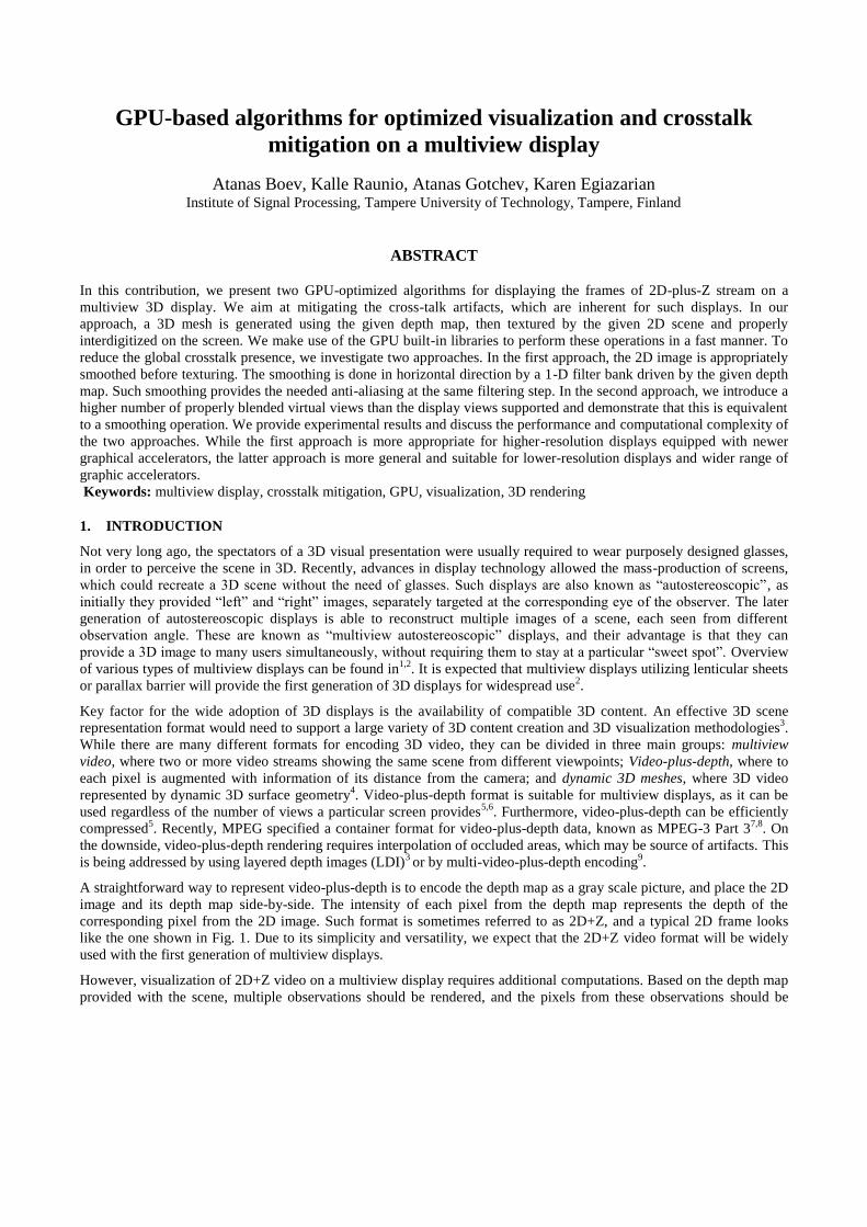
A straightforward way to represent video-plus-depth is to encode the depth map as a gray scale picture, and place the 2D
image and its depth map side-by-side. The intensity of each pixel from the depth map represents the depth of the
corresponding pixel from the 2D image. Such format is sometimes referred to as 2D+Z, and a typical 2D frame looks
like the one shown in Fig. 1. Due to its simplicity and versatility, we expect that the 2D+Z video format will be widely
used with the first generation of multiview displays.
However, visualization of 2D+Z video on a multiview display requires additional computations. Based on the depth map
provided with the scene, multiple observations should be rendered, and the pixels from these observations should be
interleaved in the way required for the display. Furthermore, some multiview displays suffer from additional artifacts,
which have to be corrected on-the-fly. It is likely, that a device with a 3D display would not only play video, but also
will support gaming, or at least 3D menu navigation. With graphical accelerators being almost ubiquitous nowadays, we
expect that many devices, equipped with multiview screens will also include a graphical accelerator (or GPU) of some
kind. As OpenGL is the industry standard for programming GPUs, it is to be expected that such device is OpenGL-
compatible too.
This paper studies how 2D+Z video can be rendered on a multiview display using OpenGL coping with cross-talk
artifacts, inherent for such displays. In the next section, we discuss the principles of work of multiview displays, and the
typical visual artifacts, created by them. In Section III we explain the reason for crosstalk, being the most severe artifact
for the screen used in our experiments, and an approach to mitigate it. The following section describes two alternative
algorithms for crosstalk mitigation that we implemented using OpenGL. Finally, we present the results of the two
implementations, comparing speed, memory requirements and visual quality.
Fig.1. An example 2D+Z image
2. MULTIVIEW DISPLAYS
2.1 Principles of work
Multiview autostereoscopic display creates 3D illusion by ―casting‖ different images in different directions. Currently,
the majority of multiview displays are using TFT screen for image creation10,11,12,13,14,15
. Additional optical layer is used
to redirect the light passing through the LCD. As a result, only a subset of the pixel color components (also known as
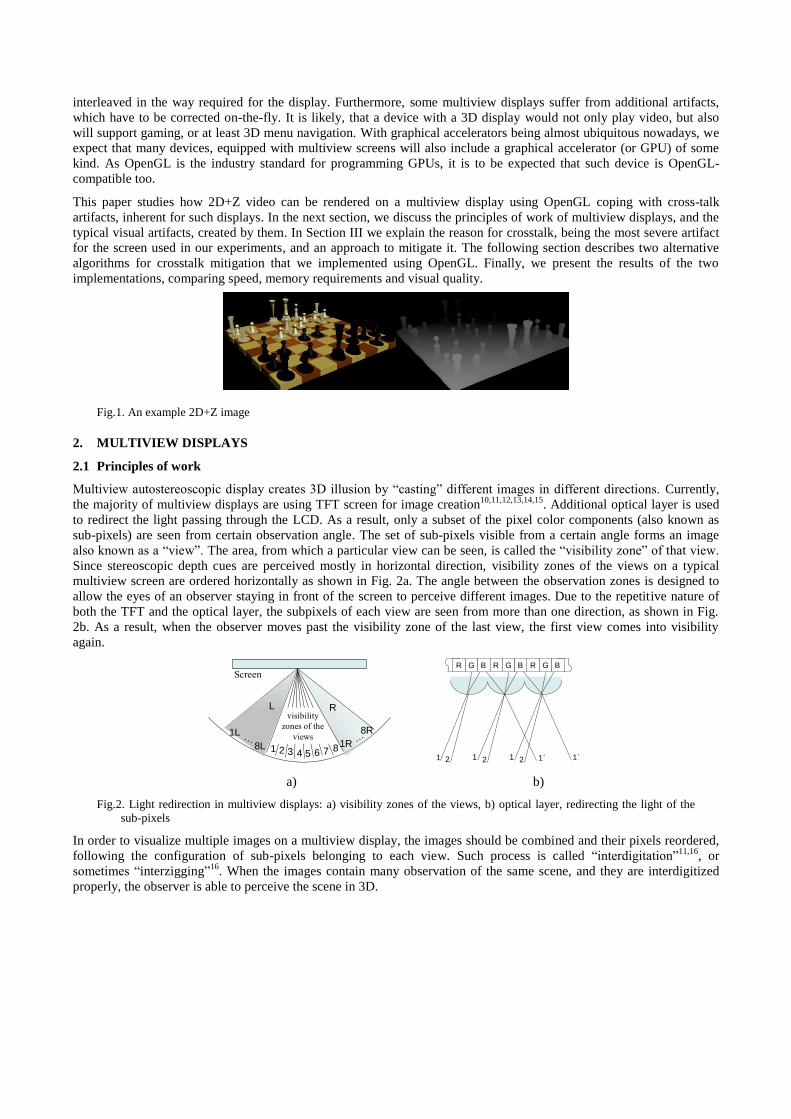
sub-pixels) are seen from certain observation angle. The set of sub-pixels visible from a certain angle forms an image
also known as a ―view‖. The area, from which a particular view can be seen, is called the ―visibility zone‖ of that view.
Since stereoscopic depth cues are perceived mostly in horizontal direction, visibility zones of the views on a typical
multiview screen are ordered horizontally as shown in Fig. 2a. The angle between the observation zones is designed to
allow the eyes of an observer staying in front of the screen to perceive different images. Due to the repetitive nature of
both the TFT and the optical layer, the subpixels of each view are seen from more than one direction, as shown in Fig.
2b. As a result, when the observer moves past the visibility zone of the last view, the first view comes into visibility
again.
Screen
1 2 3 4 5 6 7
visibility
zones of the
views
81R
8R
R
8L
1L
L
R G B R G R G B
1 2 1 2 1 2 1΄ 1΄
B
a) b)
Fig.2. Light redirection in multiview displays: a) visibility zones of the views, b) optical layer, redirecting the light of the
sub-pixels
In order to visualize multiple images on a multiview display, the images should be combined and their pixels reordered,
following the configuration of sub-pixels belonging to each view. Such process is called ―interdigitation‖11,16
, or
sometimes ―interzigging‖16
. When the images contain many observation of the same scene, and they are interdigitized
properly, the observer is able to perceive the scene in 3D.
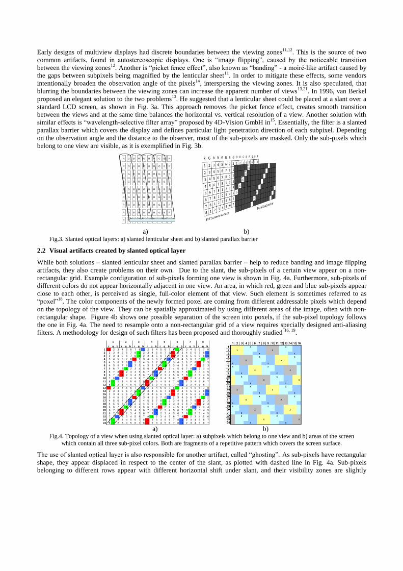
Early designs of multiview displays had discrete boundaries between the viewing zones11,12
. This is the source of two
common artifacts, found in autostereoscopic displays. One is ―image flipping‖, caused by the noticeable transition
between the viewing zones12
. Another is ―picket fence effect‖, also known as ―banding‖ - a moiré-like artifact caused by
the gaps between subpixels being magnified by the lenticular sheet11
. In order to mitigate these effects, some vendors
intentionally broaden the observation angle of the pixels14
, interspersing the viewing zones. It is also speculated, that
blurring the boundaries between the viewing zones can increase the apparent number of views13,21
. In 1996, van Berkel
proposed an elegant solution to the two problems13
. He suggested that a lenticular sheet could be placed at a slant over a
standard LCD screen, as shown in Fig. 3a. This approach removes the picket fence effect, creates smooth transition
between the views and at the same time balances the horizontal vs. vertical resolution of a view. Another solution with
similar effects is ―wavelength-selective filter array‖ proposed by 4D-Vision GmbH in15
. Essentially, the filter is a slanted
parallax barrier which covers the display and defines particular light penetration direction of each subpixel. Depending
on the observation angle and the distance to the observer, most of the sub-pixels are masked. Only the sub-pixels which
belong to one view are visible, as it is exemplified in Fig. 3b.
R G B R G B R G B R
R G B R G B R G B R
R G B R G B R G B R
R G B R G B R G B R
R G B R G B R G B R
R G B R G B R G B R
R G B R G B R G B R
R G B R G B R G B R
R G B R G B R G B R
a) b) Fig.3. Slanted optical layers: a) slanted lenticular sheet and b) slanted parallax barrier
2.2 Visual artifacts created by slanted optical layer
While both solutions – slanted lenticular sheet and slanted parallax barrier – help to reduce banding and image flipping
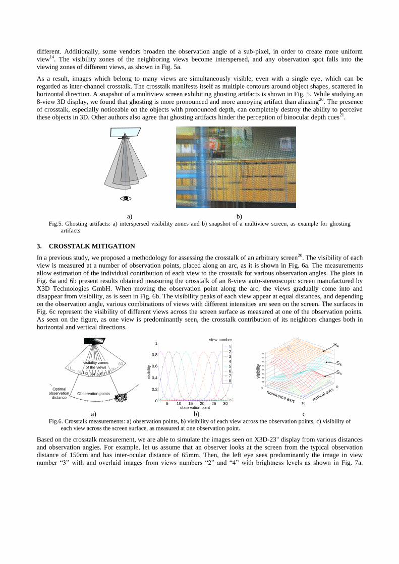
artifacts, they also create problems on their own. Due to the slant, the sub-pixels of a certain view appear on a non-
rectangular grid. Example configuration of sub-pixels forming one view is shown in Fig. 4a. Furthermore, sub-pixels of
different colors do not appear horizontally adjacent in one view. An area, in which red, green and blue sub-pixels appear
close to each other, is perceived as single, full-color element of that view. Such element is sometimes referred to as
―poxel‖18
. The color components of the newly formed poxel are coming from different addressable pixels which depend
on the topology of the view. They can be spatially approximated by using different areas of the image, often with non-
rectangular shape. Figure 4b shows one possible separation of the screen into poxels, if the sub-pixel topology follows
the one in Fig. 4a. The need to resample onto a non-rectangular grid of a view requires specially designed anti-aliasing
filters. A methodology for design of such filters has been proposed and thoroughly studied 16, 19
.
r g b r g b r g b r g b r g b r g b r g b r g b
1 1 2 3 4 5 6 7 8 1 2 3 4 5 6 7 8 1 2 3 4 5 6 7 8
2 2 3 4 5 6 7 8 1 2 3 4 5 6 7 8 1 2 3 4 5 6 7 8 1
3 2 3 4 5 6 7 8 1 2 3 4 5 6 7 8 1 2 3 4 5 6 7 8 1
4 3 4 5 6 7 8 1 2 3 4 5 6 7 8 1 2 3 4 5 6 7 8 1 2
5 4 5 6 7 8 1 2 3 4 5 6 7 8 1 2 3 4 5 6 7 8 1 2 3
6 4 5 6 7 8 1 2 3 4 5 6 7 8 1 2 3 4 5 6 7 8 1 2 3
7 5 6 7 8 1 2 3 4 5 6 7 8 1 2 3 4 5 6 7 8 1 2 3 4
8 6 7 8 1 2 3 4 5 6 7 8 1 2 3 4 5 6 7 8 1 2 3 4 5
9 6 7 8 1 2 3 4 5 6 7 8 1 2 3 4 5 6 7 8 1 2 3 4 5
10 7 8 1 2 3 4 5 6 7 8 1 2 3 4 5 6 7 8 1 2 3 4 5 6
11 8 1 2 3 4 5 6 7 8 1 2 3 4 5 6 7 8 1 2 3 4 5 6 7
12 8 1 2 3 4 5 6 7 8 1 2 3 4 5 6 7 8 1 2 3 4 5 6 7
13 1 2 3 4 5 6 7 8 1 2 3 4 5 6 7 8 1 2 3 4 5 6 7 8
14 2 3 4 5 6 7 8 1 2 3 4 5 6 7 8 1 2 3 4 5 6 7 8 1
15 2 3 4 5 6 7 8 1 2 3 4 5 6 7 8 1 2 3 4 5 6 7 8 1
16 3 4 5 6 7 8 1 2 3 4 5 6 7 8 1 2 3 4 5 6 7 8 1 2
17 4 5 6 7 8 1 2 3 4 5 6 7 8 1 2 3 4 5 6 7 8 1 2 3
18 4 5 6 7 8 1 2 3 4 5 6 7 8 1 2 3 4 5 6 7 8 1 2 3
19 5 6 7 8 1 2 3 4 5 6 7 8 1 2 3 4 5 6 7 8 1 2 3 4
20 6 7 8 1 2 3 4 5 6 7 8 1 2 3 4 5 6 7 8 1 2 3 4 5
21 6 7 8 1 2 3 4 5 6 7 8 1 2 3 4 5 6 7 8 1 2 3 4 5
22 7 8 1 2 3 4 5 6 7 8 1 2 3 4 5 6 7 8 1 2 3 4 5 6
23 8 1 2 3 4 5 6 7 8 1 2 3 4 5 6 7 8 1 2 3 4 5 6 7
24 8 1 2 3 4 5 6 7 8 1 2 3 4 5 6 7 8 1 2 3 4 5 6 7
7 81 2 3 4 5 6
a) b)
Fig.4. Topology of a view when using slanted optical layer: a) subpixels which belong to one view and b) areas of the screen
which contain all three sub-pixel colors. Both are fragments of a repetitive pattern which covers the screen surface.
The use of slanted optical layer is also responsible for another artifact, called ―ghosting‖. As sub-pixels have rectangular
shape, they appear displaced in respect to the center of the slant, as plotted with dashed line in Fig. 4a. Sub-pixels
belonging to different rows appear with different horizontal shift under slant, and their visibility zones are slightly
different. Additionally, some vendors broaden the observation angle of a sub-pixel, in order to create more uniform
view14
. The visibility zones of the neighboring views become interspersed, and any observation spot falls into the
viewing zones of different views, as shown in Fig. 5a.
As a result, images which belong to many views are simultaneously visible, even with a single eye, which can be
regarded as inter-channel crosstalk. The crosstalk manifests itself as multiple contours around object shapes, scattered in
horizontal direction. A snapshot of a multiview screen exhibiting ghosting artifacts is shown in Fig. 5. While studying an
8-view 3D display, we found that ghosting is more pronounced and more annoying artifact than aliasing20
. The presence
of crosstalk, especially noticeable on the objects with pronounced depth, can completely destroy the ability to perceive
these objects in 3D. Other authors also agree that ghosting artifacts hinder the perception of binocular depth cues21
.
a) b) Fig.5. Ghosting artifacts: a) interspersed visibility zones and b) snapshot of a multiview screen, as example for ghosting
artifacts
3. CROSSTALK MITIGATION
In a previous study, we proposed a methodology for assessing the crosstalk of an arbitrary screen20
. The visibility of each
view is measured at a number of observation points, placed along an arc, as it is shown in Fig. 6a. The measurements
allow estimation of the individual contribution of each view to the crosstalk for various observation angles. The plots in
Fig. 6a and 6b present results obtained measuring the crosstalk of an 8-view auto-stereoscopic screen manufactured by
X3D Technologies GmbH. When moving the observation point along the arc, the views gradually come into and
disappear from visibility, as is seen in Fig. 6b. The visibility peaks of each view appear at equal distances, and depending
on the observation angle, various combinations of views with different intensities are seen on the screen. The surfaces in
Fig. 6c represent the visibility of different views across the screen surface as measured at one of the observation points.
As seen on the figure, as one view is predominantly seen, the crosstalk contribution of its neighbors changes both in
horizontal and vertical directions.
Observation points
1 2 3 4 5 6 71R
8L1L
8R
x
xx
x xx x
xx
8
Optimalobservation
distance
visibility zones
of the views
5 10 15 20 25 30
0
0.2
0.4
0.6
0.8
1
observation point
vis
ibili
ty
1
2
3
4
5
6
7
8
view number
0
5
10
15
0
5
10
15
0
0.1
0.2
0.3
0.4
0.5
0.6
0.7
0.8
screen x
obervation point 9
screen y
visi
bilit
y
S4
S5
S3
horisontal axis vertical a
xis
visi
bili
ty
0 0
16
a) b) c
Fig.6. Crosstalk measurements: a) observation points, b) visibility of each view across the observation points, c) visibility of
each view across the screen surface, as measured at one observation point.
Based on the crosstalk measurement, we are able to simulate the images seen on X3D-23" display from various distances
and observation angles. For example, let us assume that an observer looks at the screen from the typical observation
distance of 150cm and has inter-ocular distance of 65mm. Then, the left eye sees predominantly the image in view
number ―3‖ with and overlaid images from views numbers ―2‖ and ―4‖ with brightness levels as shown in Fig. 7a.
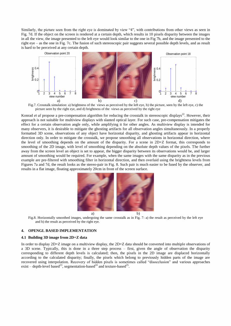
Similarly, the picture seen from the right eye is dominated by view ―4‖, with contributions from other views as seen in
Fig. 7d. If the object on the screen is rendered at a certain depth, which results in 10 pixels disparity between the images
in all the view, the image presented to the left eye would look similar to the one in Fig 7b, and the image presented to the
right eye – as the one in Fig. 7c. The fusion of such stereoscopic pair suggests several possible depth levels, and as result
is hard to be perceived at any certain depth.
1 2 3 4 5 6 7 80
0.2
0.4
Observation point 20
view number
bri
gh
ne
ss
Observation point 20
Observation point 18
1 2 3 4 5 6 7 8
0
0.2
0.4
Observation point 18
view number
bri
gh
ne
ss
a) b) c) d)
Fig.7. Crosstalk simulation: a) brightness of the views as perceived by the left eye, b) the picture, seen by the left eye, c) the
picture seen by the right eye, and d) brightness of the views as perceived by the right eye
Konrad et al propose a pre-compensation algorithm for reducing the crosstalk in stereoscopic displays22
. However, their
approach is not suitable for multiview displays with slanted optical layer. For such case, pre-compensation mitigates the
effect for a certain observation angle only, while amplifying it for other angles. As multiview display is intended for
many observers, it is desirable to mitigate the ghosting artifacts for all observation angles simultaneously. In a properly
formatted 3D scene, observations of any object have horizontal disparity, and ghosting artifacts appear in horizontal
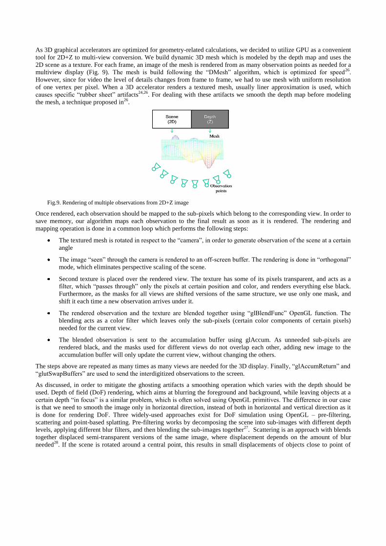
direction only. In order to mitigate the crosstalk, we propose smoothing all observations in horizontal direction, where
the level of smoothing depends on the amount of the disparity. For a scene in 2D+Z format, this corresponds to
smoothing of the 2D image, with level of smoothing depending on the absolute depth values of the pixels. The further
away from the screen level an object is set to appear, the bigger disparity between its observations would be, and larger
amount of smoothing would be required. For example, when the same images with the same disparity as in the previous
example are pre-filtered with smoothing filter in horizontal direction, and then overlaid using the brightness levels from
Figures 7a and 7d, the result looks as the stereo-pair in Fig. 8. Such pair is much easier to be fused by the observer, and
results in a flat image, floating approximately 20cm in front of the screen surface.
Observation point 18
Observation point 20
a) b)
Fig.8. Horizontally smoothed images, undergoing the same crosstalk as in Fig. 7: a) the result as perceived by the left eye
and b) the result as perceived by the right eye.
4. OPENGL BASED IMPLEMENTATION
4.1 Building 3D image from 2D+Z data
In order to display 2D+Z image on a multiview display, the 2D+Z data should be converted into multiple observations of
a 3D scene. Typically, this is done in a three step process – first, given the angle of observation the disparity
corresponding to different depth levels is calculated; then, the pixels in the 2D image are displaced horizontally
according to the calculated disparity; finally, the pixels which belong to previously hidden parts of the image are
recovered using interpolation. Recovery of hidden pixels is sometimes called ―disocclusion‖ and various approaches
exist – depth-level based23
, segmentation-based24
and texture-based25
.
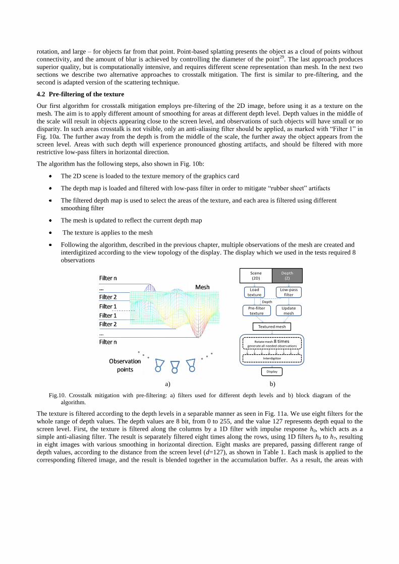
As 3D graphical accelerators are optimized for geometry-related calculations, we decided to utilize GPU as a convenient
tool for 2D+Z to multi-view conversion. We build dynamic 3D mesh which is modeled by the depth map and uses the
2D scene as a texture. For each frame, an image of the mesh is rendered from as many observation points as needed for a
multiview display (Fig. 9). The mesh is build following the ―DMesh‖ algorithm, which is optimized for speed26
.
However, since for video the level of details changes from frame to frame, we had to use mesh with uniform resolution
of one vertex per pixel. When a 3D accelerator renders a textured mesh, usually liner approximation is used, which
causes specific ―rubber sheet‖ artifacts24,26
. For dealing with these artifacts we smooth the depth map before modeling
the mesh, a technique proposed in26
.
Fig.9. Rendering of multiple observations from 2D+Z image
Once rendered, each observation should be mapped to the sub-pixels which belong to the corresponding view. In order to
save memory, our algorithm maps each observation to the final result as soon as it is rendered. The rendering and
mapping operation is done in a common loop which performs the following steps:
The textured mesh is rotated in respect to the ―camera‖, in order to generate observation of the scene at a certain
angle
The image ―seen‖ through the camera is rendered to an off-screen buffer. The rendering is done in ―orthogonal‖
mode, which eliminates perspective scaling of the scene.
Second texture is placed over the rendered view. The texture has some of its pixels transparent, and acts as a
filter, which ―passes through‖ only the pixels at certain position and color, and renders everything else black.
Furthermore, as the masks for all views are shifted versions of the same structure, we use only one mask, and
shift it each time a new observation arrives under it.
The rendered observation and the texture are blended together using ―glBlendFunc‖ OpenGL function. The
blending acts as a color filter which leaves only the sub-pixels (certain color components of certain pixels)
needed for the current view.
The blended observation is sent to the accumulation buffer using glAccum. As unneeded sub-pixels are
rendered black, and the masks used for different views do not overlap each other, adding new image to the
accumulation buffer will only update the current view, without changing the others.
The steps above are repeated as many times as many views are needed for the 3D display. Finally, ―glAccumReturn‖ and
―glutSwapBuffers‖ are used to send the interdigitized observations to the screen.
As discussed, in order to mitigate the ghosting artifacts a smoothing operation which varies with the depth should be
used. Depth of field (DoF) rendering, which aims at blurring the foreground and background, while leaving objects at a
certain depth ―in focus‖ is a similar problem, which is often solved using OpenGL primitives. The difference in our case
is that we need to smooth the image only in horizontal direction, instead of both in horizontal and vertical direction as it
is done for rendering DoF. Three widely-used approaches exist for DoF simulation using OpenGL – pre-filtering,
scattering and point-based splatting. Pre-filtering works by decomposing the scene into sub-images with different depth
levels, applying different blur filters, and then blending the sub-images together27
. Scattering is an approach with blends
together displaced semi-transparent versions of the same image, where displacement depends on the amount of blur
needed28
. If the scene is rotated around a central point, this results in small displacements of objects close to point of
rotation, and large – for objects far from that point. Point-based splatting presents the object as a cloud of points without
connectivity, and the amount of blur is achieved by controlling the diameter of the point29
. The last approach produces
superior quality, but is computationally intensive, and requires different scene representation than mesh. In the next two
sections we describe two alternative approaches to crosstalk mitigation. The first is similar to pre-filtering, and the
second is adapted version of the scattering technique.
4.2 Pre-filtering of the texture
Our first algorithm for crosstalk mitigation employs pre-filtering of the 2D image, before using it as a texture on the
mesh. The aim is to apply different amount of smoothing for areas at different depth level. Depth values in the middle of
the scale will result in objects appearing close to the screen level, and observations of such objects will have small or no
disparity. In such areas crosstalk is not visible, only an anti-aliasing filter should be applied, as marked with ―Filter 1‖ in
Fig. 10a. The further away from the depth is from the middle of the scale, the further away the object appears from the
screen level. Areas with such depth will experience pronounced ghosting artifacts, and should be filtered with more
restrictive low-pass filters in horizontal direction.
The algorithm has the following steps, also shown in Fig. 10b:
The 2D scene is loaded to the texture memory of the graphics card
The depth map is loaded and filtered with low-pass filter in order to mitigate ―rubber sheet‖ artifacts
The filtered depth map is used to select the areas of the texture, and each area is filtered using different
smoothing filter
The mesh is updated to reflect the current depth map
The texture is applies to the mesh
Following the algorithm, described in the previous chapter, multiple observations of the mesh are created and
interdigitized according to the view topology of the display. The display which we used in the tests required 8
observations
Scene(2D)
Depth(Z)
Load texture
Low-pass filter
Update mesh
Textured mesh
Rotate mesh 8 timesgenerate all needed observations
Display
Interdigitize
Pre-filter texture
Depth
a) b)
Fig.10. Crosstalk mitigation with pre-filtering: a) filters used for different depth levels and b) block diagram of the
algorithm.
The texture is filtered according to the depth levels in a separable manner as seen in Fig. 11a. We use eight filters for the
whole range of depth values. The depth values are 8 bit, from 0 to 255, and the value 127 represents depth equal to the
screen level. First, the texture is filtered along the columns by a 1D filter with impulse response h0, which acts as a
simple anti-aliasing filter. The result is separately filtered eight times along the rows, using 1D filters h0 to h7, resulting
in eight images with various smoothing in horizontal direction. Eight masks are prepared, passing different range of
depth values, according to the distance from the screen level (d=127), as shown in Table 1. Each mask is applied to the
corresponding filtered image, and the result is blended together in the accumulation buffer. As a result, the areas with
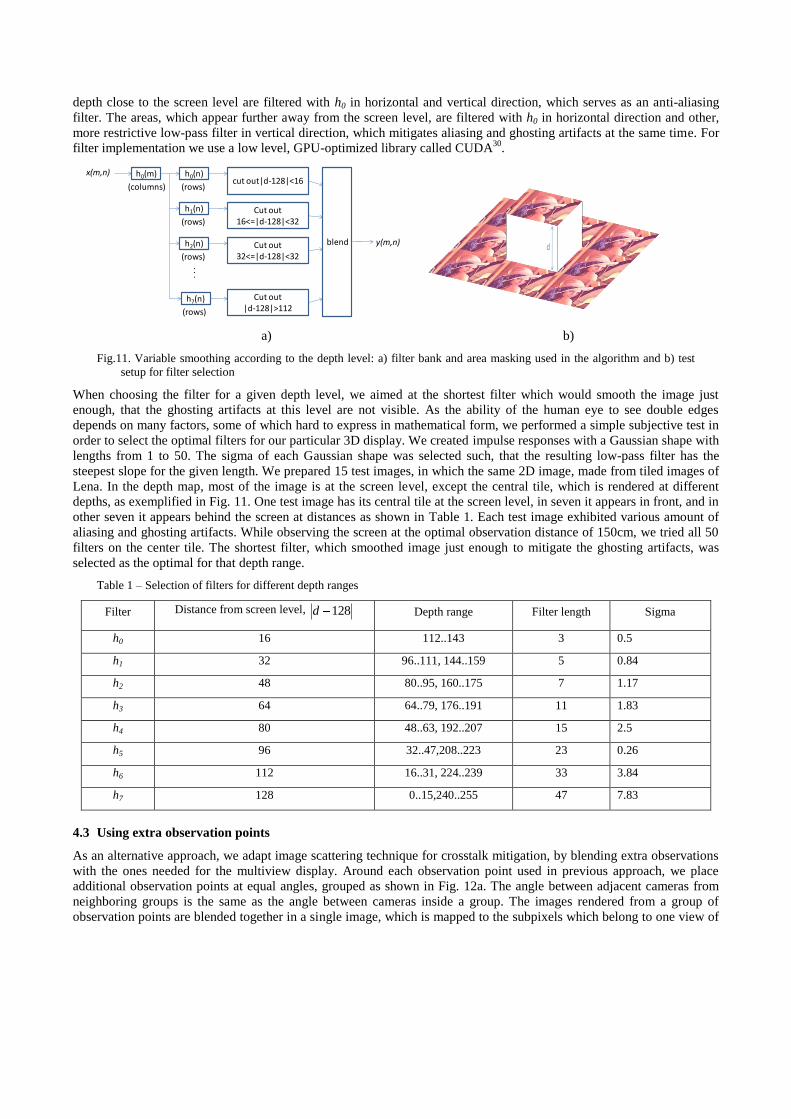
depth close to the screen level are filtered with h0 in horizontal and vertical direction, which serves as an anti-aliasing
filter. The areas, which appear further away from the screen level, are filtered with h0 in horizontal direction and other,
more restrictive low-pass filter in vertical direction, which mitigates aliasing and ghosting artifacts at the same time. For
filter implementation we use a low level, GPU-optimized library called CUDA30
.
x(m,n) h0(m)
(columns)
h0(n)
(rows)
h1(n)
(rows)
h2(n)
(rows)
h7(n)
(rows)
. . .
cut out|d-128|<16
Cut out 16<=|d-128|<32
Cut out 32<=|d-128|<32
Cut out |d-128|>112
blend y(m,n)
Gaussianfilter
Vector size
Sigma(size/6)
h0 3 0.5
h1 5 0.83
h2 7 1.17
h3 11 1.83
h4 15 2.5
h5 23 3.83
h6 33 5.5
h7 47 7.83
d
a) b)
Fig.11. Variable smoothing according to the depth level: a) filter bank and area masking used in the algorithm and b) test
setup for filter selection
When choosing the filter for a given depth level, we aimed at the shortest filter which would smooth the image just
enough, that the ghosting artifacts at this level are not visible. As the ability of the human eye to see double edges
depends on many factors, some of which hard to express in mathematical form, we performed a simple subjective test in
order to select the optimal filters for our particular 3D display. We created impulse responses with a Gaussian shape with
lengths from 1 to 50. The sigma of each Gaussian shape was selected such, that the resulting low-pass filter has the
steepest slope for the given length. We prepared 15 test images, in which the same 2D image, made from tiled images of
Lena. In the depth map, most of the image is at the screen level, except the central tile, which is rendered at different
depths, as exemplified in Fig. 11. One test image has its central tile at the screen level, in seven it appears in front, and in
other seven it appears behind the screen at distances as shown in Table 1. Each test image exhibited various amount of
aliasing and ghosting artifacts. While observing the screen at the optimal observation distance of 150cm, we tried all 50
filters on the center tile. The shortest filter, which smoothed image just enough to mitigate the ghosting artifacts, was
selected as the optimal for that depth range.
Table 1 – Selection of filters for different depth ranges
Filter Distance from screen level, 128d Depth range Filter length Sigma
h0 16 112..143 3 0.5
h1 32 96..111, 144..159 5 0.84
h2 48 80..95, 160..175 7 1.17
h3 64 64..79, 176..191 11 1.83
h4 80 48..63, 192..207 15 2.5
h5 96 32..47,208..223 23 0.26
h6 112 16..31, 224..239 33 3.84
h7 128 0..15,240..255 47 7.83
4.3 Using extra observation points
As an alternative approach, we adapt image scattering technique for crosstalk mitigation, by blending extra observations
with the ones needed for the multiview display. Around each observation point used in previous approach, we place
additional observation points at equal angles, grouped as shown in Fig. 12a. The angle between adjacent cameras from
neighboring groups is the same as the angle between cameras inside a group. The images rendered from a group of
observation points are blended together in a single image, which is mapped to the subpixels which belong to one view of
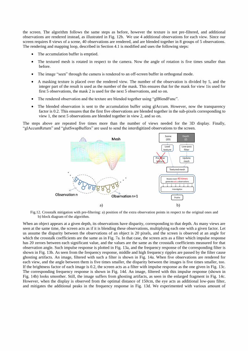
the screen. The algorithm follows the same steps as before, however the texture is not pre-filtered, and additional
observations are rendered instead, as illustrated in Fig. 12b. We use 4 additional observations for each view. Since our
screen requires 8 views of a scene, 40 observations are rendered, and are blended together in 8 groups of 5 observations.
The rendering and mapping loop, described in Section 4.1 is modified and uses the following steps:
The accumulation buffer is emptied.
The textured mesh is rotated in respect to the camera. Now the angle of rotation is five times smaller than
before.
The image ―seen‖ through the camera is rendered to an off-screen buffer in orthogonal mode.
A masking texture is placed over the rendered view. The number of the observation is divided by 5, and the
integer part of the result is used as the number of the mask. This ensures that for the mask for view 1is used for
first 5 observations, the mask 2 is used for the next 5 observations, and so on.
The rendered observation and the texture are blended together using ―glBlendFunc‖.
The blended observation is sent to the accumulation buffer using glAccum. However, now the transparency
factor is 0.2. This ensures that the first five observations are blended together in the sub-pixels corresponding to
view 1, the next 5 observations are blended together in view 2, and so on.
The steps above are repeated five times more than the number of views needed for the 3D display. Finally,
―glAccumReturn‖ and ―glutSwapBuffers‖ are used to send the interdigitized observations to the screen.
Scene(2D)
Depth(Z)
Load texture
Low-pass filter
Update mesh
Textured mesh
Rotate mesh 40 timesgenerate extra observations
Display
Interdigitize
Pre-filter texture
a) b)
Fig.12. Crosstalk mitigation with pre-filtering: a) position of the extra observation points in respect to the original ones and
b) block diagram of the algorithm.
When an object appears at a given depth, its observations have disparity, corresponding to that depth. As many views are
seen at the same time, the screen acts as if it is blending these observations, multiplying each one with a given factor. Let
us assume the disparity between the observations of an object is 20 pixels, and the screen is observed at an angle for
which the crosstalk coefficients are the same as in Fig. 7a. In that case, the screen acts as a filter which impulse response
has 20 zeroes between each significant value, and the values are the same as the crosstalk coefficients measured for that
observation angle. Such impulse response is plotted in Fig. 13a, and the frequency response of the corresponding filter is
shown in Fig. 13b. As seen from the frequency response, middle and high frequency ripples are passed by the filter cause
ghosting artifacts. An image, filtered with such a filter is shown in Fig. 14a. When five observations are rendered for
each view, and the angle between them is five times smaller, the disparity between the images is five times smaller, too.
If the brightness factor of each image is 0.2, the screen acts as a filter with impulse response as the one given in Fig. 13c.
The corresponding frequency response is shown in Fig. 14d. An image, filtered with this impulse response (shown in
Fig. 14b) looks smoother. Still, the image suffers from ghosting artifacts, as seen in the enlarged fragment in Fig. 14c.
However, when the display is observed from the optimal distance of 150cm, the eye acts as additional low-pass filter,
and mitigates the additional peaks in the frequency response in Fig. 13d. We experimented with various amount of
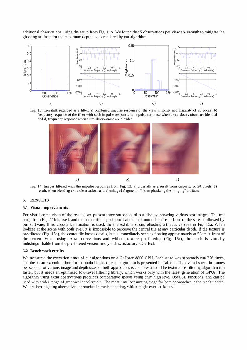
additional observations, using the setup from Fig. 11b. We found that 5 observations per view are enough to mitigate the
ghosting artifacts for the maximum depth levels rendered by out algorithm.
0 50 100 1500
0.1
0.2
0.3
0.4
0.5
0.6
Observation
Bri
gh
tne
ss
0 0.2 0.4 0.6 0.8 1
-15000
-10000
-5000
0
Normalized Frequency ( rad/sample)
Ph
ase
(d
eg
ree
s)
0 0.2 0.4 0.6 0.8 1-30
-20
-10
0
Normalized Frequency ( rad/sample)
Ma
gn
itu
de
(d
B)
0 50 100 1500
0.05
0.1
0.15
Observation
Bri
gh
tne
ss
0 0.2 0.4 0.6 0.8 1-15000
-10000
-5000
0
Normalized Frequency ( rad/sample)
Ph
ase
(d
eg
ree
s)
0 0.2 0.4 0.6 0.8 1-60
-40
-20
0
Normalized Frequency ( rad/sample)
Ma
gn
itu
de
(d
B)
a) b) c) d)
Fig. 13. Crosstalk regarded as a filter: a) combined impulse response of the view visibility and disparity of 20 pixels, b)
frequency response of the filter with such impulse response, c) impulse response when extra observations are blended
and d) frequency response when extra observations are blended.
a) b) c)
Fig. 14. Images filtered with the impulse responses from Fig. 13: a) crosstalk as a result from disparity of 20 pixels, b)
result, when blending extra observations and c) enlarged fragment of b), emphasizing the ―ringing‖ artifacts
5. RESULTS
5.1 Visual improvements
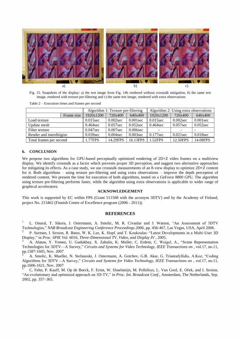
For visual comparison of the results, we present three snapshots of our display, showing various test images. The test
setup from Fig. 11b is used, and the center tile is positioned at the maximum distance in front of the screen, allowed by
our software. If no crosstalk mitigation is used, the tile exhibits strong ghosting artifacts, as seen in Fig. 15a. When
looking at the scene with both eyes, it is impossible to perceive the central tile at any particular depth. If the texture is
pre-filtered (Fig. 15b), the center tile looses details, but is immediately seen as floating approximately at 50cm in front of
the screen. When using extra observations and without texture pre-filtering (Fig. 15c), the result is virtually
indistinguishable from the pre-filtered version and yields satisfactory 3D effect.
5.2 Benchmark results
We measured the execution times of our algorithms on a GeForce 8800 GPU. Each stage was separately run 256 times,
and the mean execution time for the main blocks of each algorithm is presented in Table 2. The overall speed in frames
per second for various image and depth sizes of both approaches is also presented. The texture pre-filtering algorithm run
faster, but it needs an optimized low-level filtering library, which works only with the latest generation of GPUs. The
algorithm using extra observations produces comparative speeds using only high level OpenGL functions, and can be
used with wider range of graphical accelerators. The most time-consuming stage for both approaches is the mesh update.
We are investigating alternative approaches in mesh updating, which might execute faster.
a) b) c)
Fig. 15. Snapshots of the display: a) the test image from Fig. 14b rendered without crosstalk mitigation, b) the same test
image, rendered with texture pre-filtering and c) the same test image, rendered with extra observations
Table 2 – Execution times and frames per second
Algorithm 1: Texture pre-filtering Algorithm 2: Using extra observations
Frame size 1920x1200 720x400 640x400 1920x1200 720x400 640x400
Load texture 0.015sec 0.002sec 0.001sec 0.015sec 0.002sec 0.001sec
Update mesh 0.464sec 0.057sec 0.052sec 0.464sec 0.057sec 0.052sec
Filter texture 0.047sec 0.007sec 0.006sec - - -
Render and interditigize 0.039sec 0.004sec 0.003sec 0.177sec 0.021sec 0.018sec
Total frames per second 1.77FPS 14.29FPS 16.13FPS 1.52FPS 12.50FPS 14.08FPS
6. CONCLUSION
We propose two algorithms for GPU-based perceptually optimized rendering of 2D+Z video frames on a multiview
display. We identify crosstalk as a factor which prevents proper 3D perception, and suggest two alternative approaches
for mitigating its effects. As a case study, we use crosstalk measurements of an 8-view display to optimize 2D+Z content
for it. Both algorithms – using texture pre-filtering and using extra observations – improve the depth perception of
rendered content. We present the time for execution of both algorithms, tested on a GeForce 8800 GPU. The algorithm
using texture pre-filtering performs faster, while the algorithm using extra observations is applicable to wider range of
graphical accelerators.
ACKNOWLEDGEMENT
This work is supported by EC within FP6 (Grant 511568 with the acronym 3DTV) and by the Academy of Finland,
project No. 213462 (Finnish Centre of Excellence program (2006 - 2011)).
REFERENCES
1 L. Onural, T. Sikora, J. Ostermann, A. Smolic, M. R. Civanlar and J. Watson, ―An Assessment of 3DTV
Technologies,‖ NAB Broadcast Engineering Conference Proceedings 2006, pp. 456-467, Las Vegas, USA, April 2006. 2 P. Surman, I. Sexton, R. Bates, W. K. Lee, K. Hopf, and T. Koukoulas: ―Latest Developments in a Multi-User 3D
Display,‖ in Proc. SPIE Vol. 6016, Three-Dimensional TV, Video, and Display IV , 2005. 3 A. Alatan, Y. Yemez, U. Gudukbay, X. Zabulis, K. Muller, C. Erdem, C. Weigel, A., ―Scene Representation
Technologies for 3DTV—A Survey,‖ Circuits and Systems for Video Technology, IEEE Transactions on , vol.17, no.11,
pp.1587-1605, Nov. 2007 4 A. Smolic, K. Mueller, N. Stefanoski, J. Ostermann, A. Gotchev, G.B. Akar, G. Triantafyllidis, A.Koz, ―Coding
Algorithms for 3DTV—A Survey,‖ Circuits and Systems for Video Technology, IEEE Transactions on , vol.17, no.11,
pp.1606-1621, Nov. 2007 5 C. Fehn, P. Kauff, M. Op de Beeck, F. Ernst, W. IJsselsteijn, M. Pollefeys, L. Van Gool, E. Ofek, and I. Sexton,
―An evolutionary and optimized approach on 3D-TV,‖ in Proc. Int. Broadcast Conf., Amsterdam, The Netherlands, Sep.
2002, pp. 357–365.
6 C. Fehn, ―3D-TV using depth-image-based rendering (DIBR),‖ in Proc. Picture Coding Symp., San Francisco, CA,
USA, Dec. 2004. 7 Text of ISO/IEC FDIS 23002-3 Representation of Auxiliary Video and Supplemental Information, ISO/IEC
JTC1/SC29/WG11, Jan. 2007, Doc. N8768, Marrakesh, Morocco. 8 Text of ISO/IEC 13818-1:2003/FDAM2 Carriage of Auxiliary Data, ISO/IEC JTC1/SC29/WG11, Jan. 2007, Doc.
N8799, Marrakech, Morocco. 9 C. Fehn, N. Atzpadin, M. Muller, O. Schreer, A. Smolic, R. Tanger, P. Kauff, P., ―An Advanced 3DTV Concept
Providing Interoperability and Scalability for a Wide Range of Multi-Baseline Geometries,‖ Image Processing, 2006
IEEE International Conference on , vol., no., pp.2961-2964, 8-11 Oct. 2006 10 P. Surman, K. Hopf, I. Sexton, W.K. Lee, R. Bates, ―Solving the 3D problem - The history and development of
viable domestic 3-dimensional video displays‖, In (Haldun M. Ozaktas, Levent Onural, Eds.), Three-Dimensional
Television: Capture, Transmission, and Display (ch. 13), Springer Verlag, 2007 11 Pastoor, ―3D displays‖, in (Schreer, Kauff, Sikora, edts.) 3D Video Communication, Wiley, 2005. 12 C. Van Berkel and J. Clarke, ―Characterisation and optimisation of 3D-LCD module design‖, in Proc. SPIE Vol.
2653, Stereoscopic Displays and Virtual Reality Systems IV, (Fisher, Merritt, Bolas, edts.), p. 179-186, May 1997 13 C. van Berkel, D. Parker and A. Franklin, ―Multiview 3D LCD,‖ in Proc. SPIE Vol. 3012, Stereoscopic Displays
and Virtual Reality Systems III, (Fisher, Merritt, Bolas, edts.), p. 32-39, 1996 14 W. IJzerman et al., ―Design of 2d/3d switchable displays,‖ in Proc of the SID, volume 36, Issue 1, pp. 98-101, May
2005 15 A. Schmidt and A. Grasnick, "Multi-viewpoint autostereoscopic displays from 4D-vision", in Proc. SPIE Photonics
West 2002: Electronic Imaging, vol. 4660, pp. 212-221, 2002 16 J. Konrad and P. Agniel, ―Artifact reduction in lenticular multiscopic 3-D displays by means of anti-alias filtering,‖
in Proc. SPIE Stereoscopic Displays and Virtual Reality Systems, vol. 5006, pp. 336-347, Jan. 2003 17 W. Tzschoppe, T. Brueggert, M. Klipstein, I. Relke and U. Hofmann, ―Arrangement for two-or-three-dimensional
display‖, US pat. 2006/0192908, issued Aug. 31, 2006 18 D. Marr and T. Poggio, ―Cooperative computation of stereo disparity‖, Science, vol. 194, pp. 283-287, 1976. 19 J. Konrad and P. Angiel, ―Subsampling models and anti-alias filters for 3-D automultiscopic displays‖, Image
Processing, IEEE Transactions on , vol.15, no.1, pp. 128-140, Jan. 2006 20 A. Boev, A. Gotchev and K. Egiazarian: ―Crosstalk Measurement Methodology For Auto-Stereoscopic Screens‖,
IEEE 3DTV Conference, Kos, Greece, May 7-9, 2007. 21 Y. Yeh and L. Silverstein, ―Limits of Fusion and Depth Judgement in Stereoscopic Colour Displays‖, Human
Factors, vol 32(1), pp. 45-60, 1990 22 J. Konrad, B. Lacotte, and E. Dubois, ―Cancellation of image crosstalk in time-sequential displays of stereoscopic
video,‖ Tech. Rep. 97-01, INRS-Télécommunications, Feb. 1997 23 S. Masnou, J. Morel, ―Level lines based disocclusion,‖ Image Processing, 1998. ICIP 98. Proceedings. 1998
International Conference on , vol., no., pp.259-263 vol.3, 4-7 Oct 1998 24 W. Wang, L. Huo, W. Zeng, Q. Huang, W. Gao, ―Depth image segmentation for improved virtual view image
quality in 3-DTV,‖ Intelligent Signal Processing and Communication Systems, 2007. ISPACS 2007. International
Symposium on , vol., no., pp.300-303, Nov. 28 2007-Dec. 1 2007 25 S. Acton, D. Mukherjee, J. Havlicek, A. Bovik, ―Oriented texture completion by AM-FM reaction-diffusion,‖ Image
Processing, IEEE Transactions on , vol.10, no.6, pp.885-896, Jun 2001 26 R. Pajarola, M. Sainz, Y. Meng, ―Dmesh: Fast Depth-Image Meshing And Warping‖. Int. J. Image Graphics 4(4):
653-681 (2004) 27 M. Kraus, M. Strengert, ―Depth-of-Field Rendering by Pyramidal Image Processing‖, Computer Graphics Forum 26
(3), 645–654, 2007 28 M. Shinya, ―Post-filtering for depth of field simulation with ray distribution buffer,‖ In Proceedings of Graphics
Interface ’94 (1994), pp. 59–66. 29 M. Botsch, A. Hornung, M. Zwicker, L. Kobbelt, ―High-quality surface splatting on today's GPUs,‖ Point-Based
Graphics, 2005. Eurographics/IEEE VGTC Symposium Proceedings , vol., no., pp. 17-141, 20-21 June 2005 30 V. Podlozhnyuk, ―Image Convolution with CUDA‖, White paper, Nvidia Corp, June 2007, available online at
http://developer.download.nvidia.com/compute/cuda/sdk/website/projects/convolutionSeparable/doc/convolutionSeparab
le.pdf


