Embed Size (px)
Citation preview
GPU-based ultra fast IMRT plan optimization
Chunhua Men1, Xuejun Gu1, Dongju Choi2, Amitava Majumdar2, Ziyi Zheng3, Klaus Mueller3, and Steve B. Jiang1
1Department of Radiation Oncology, University of California San Diego, La 5 Jolla, CA 92037, USA 2San Diego Supercomputer Center, University of California San Diego, La Jolla, CA 92093, USA 3Center for Visual Computing, Computer Science Department, Stony Brook University, NY 11794, USA 10 E-mail: [email protected]
The widespread adoption of on-board volumetric imaging in cancer radiotherapy has stimulated research efforts to develop online adaptive radiotherapy 15 techniques to handle the inter-fraction variation of the patient's geometry. Such efforts face major technical challenges to perform treatment planning in real-time. To overcome this challenge, we are developing a supercomputing online re-planning environment (SCORE) at the University of California San Diego (UCSD). As part of the SCORE project, this paper presents our work on the 20 implementation of an intensity modulated radiation therapy (IMRT) optimization algorithm on graphics processing units (GPUs). We adopt a penalty-based quadratic optimization model, which is solved by using a gradient projection method with Armijo’s line search rule. Our optimization algorithm has been implemented in CUDA for parallel GPU computing as well as in C for 25 serial CPU computing for comparison purpose. A prostate IMRT case with various beamlet and voxel sizes was used to evaluate our implementation. On an NVIDIA Tesla C1060 GPU card, we have achieved speedup factors of 20-40 without losing accuracy, compared to the results from an Intel Xeon 2.27 GHz CPU. For a specific 9-field prostate IMRT case with 5×5 mm2 beamlet size and 30 2.5×2.5×2.5 mm3 voxel size, our GPU implementation takes only 2.8 seconds to generate an optimal IMRT plan. Our work has therefore solved a major problem in developing online re-planning technologies for adaptive radiotherapy.
2 C Men et al.
2
1. Introduction The goal of radiation oncology is to deliver a prescribed radiation dose to targets containing tumor and cancerous regions while sparing surrounding functional organs and normal tissues. In current clinical practice, an “optimal” treatment plan is designed based 5 on patient geometry acquired before the first treatment fraction and used for the whole treatment course. This practice implicitly (and erroneously) assumes that the patient anatomy is static and ignores the facts that 1) the position and shape of the tumor and nearby organs may vary substantially from day and day, and 2) there might be significant dynamic change in tumor geometry in response to the radiotherapy. As a 10 result, the quality of this pre-designed treatment plan may deteriorate during the course of treatment. To address this issue, various adaptive radiotherapy (ART) technologies have been developed, with the basic idea of imaging the patient's changed geometry during the treatment course and modifying the treatment plan accordingly (Yan et al., 1997; Wu et al., 2002; Birkner et al., 2003; Wu et al., 2004; Mohan et al., 2005; de la 15 Zerda et al., 2007; Lu et al., 2008; Wu et al., 2008; Fu et al., 2009; Godley et al., 2009).
One way to implement ART is called online ART, where the treatment plan is re-designed in a real-time fashion based on the patient's updated geometry to ensure the optimality of the treatment and to ensure that the treatment objectives are met (Wu et al., 2002; Mohan et al., 2005; Wu et al., 2008; Fu et al., 2009). The major challenge of this 20 technology is that the re-planning process has to be done in a few minutes since the patient is lying on the treatment couch and waiting for the treatment. At the University of California San Diego (UCSD), we are developing a supercomputing online re-planning environment (SCORE) for online ART. The system consists of three major components: (1) patient modeling based on deformable image registration, (2) dose calculation, and 25 (3) plan optimization. The general aim of the SCORE project is to parallelize, implement, and test the algorithms of those three major components on supercomputing platforms that are affordable and easy to maintain for regular radiotherapy clinics. One such platform that we are evaluating is a workstation PC accelerated with graphics processing units (GPUs). 30
Intensity modulated radiation therapy (IMRT) plan optimization is a large-scale optimization problem. The current state of the art optimization models implemented on a single CPU still at least take several minutes to optimize a treatment plan (Romeijn et al., 2003; Men et al., 2007; Scherrer and Kuefer, 2008; Wu et al., 2008). Parallel computing potentially has the ability to increase the computation efficiency. One way is 35 to use computer clusters or traditional supercomputers. However, they are not readily available to most clinical users. In addition, communication among CPUs can be expensive, leading to marginal efficiency gains for the IMRT optimization problem. The advent of multi-core processor PCs implementing multiprocessing in a single physical package makes parallel computing affordable for most users. However, the level of 40 parallelism is very limited --- in the best case, the speedup factor gained by the use of a multi-core processor is near the number of cores. GPUs, on the other hand, have up to hundreds of processing cores, can be effectively used for parallel computing, and are
3 C Men et al.
3
affordable to most users. While GPUs were initially used primarily for graphics applications, they have recently been increasingly used for general purpose scientific computing (Jung and O'Leary, 2007; Munekawa et al., 2008; Xing et al., 2008; Su et al., 2009; Wallner, 2009). For cancer radiotherapy, researchers have also started to use GPUs to accelerate some heavy computational tasks, such as CBCT reconstruction, 5 deformable image registration, and dose calculation (Sharp et al., 2007; Xu and Mueller, 2007; Noe et al., 2008; Samant et al., 2008; Hissoiny et al., 2009). However, based on our knowledge, no work has been done to speed up treatment plan optimization using GPUs.
In this paper, we report our implementation of an IMRT optimization algorithm using 10 Compute Unified Device Architecture (CUDA) on GPUs. The performance of the CUDA implementation will be evaluated against a corresponding C implementation on a CPU.
2. Methods and Materials 15 2.1 Fluence map (re-)optimization model In IMRT optimization, each beam is decomposed into a set of beamlets (denoted by N). The set of voxels that represents the patient's CT image is denoted by V. In addition, we 20
denote the dose to voxel Vj by zj and the intensity of beamlet Ni by xi. The voxel
dose is calculated as
Ni
iijj xDz , where Dij is called dose deposition coefficients and
represents the dose received by voxel Vj from beamlet Ni of unit intensity. Finally,
our fluence map (re-)optimization model employs treatment plan evaluation criteria that are quadratic one-sided voxel-based penalties. If we denote the set of target voxels by VT, 25 then we can write the criteria as:
VjTzzF
VjzTzF
jjjj
Tjjjj
2
2
}),0(max{)(
}),0(max{)(, (1)
where Tj for all Vj represents the dose distribution in the original treatment plan. In
this work, we are not trying to generate "the best plan of the day"; instead, we are trying to reproduce the dose distribution from the original plan within a tolerance by re-optimizing the fluence maps to accommodate the changed patient's geometry. The 30 advantage of this approach is that, if the new plan is the equivalent to the original plan within a pre-specified tolerance, it can be used to treat the patient without the physician's re-approval. Later in the paper we will discuss alternative re-optimization models.
If we let )()()( jjjjjj zFzFzF , then our model can be written as:
Vj
jj zF )(min
Subject to
(2)
4 C Men et al.
4
Ni
iijj VjxDz
.0 Nixi
2.2 The optimization algorithm The objective function is convex quadratic in our model, thus the direction of steepest descent is that of the negative gradient. However, since the decision variables, which are 5 the intensities of beamlets, should be nonnegative, moving along the steepest descent direction may lead to infeasible intensities. We therefore use the gradient projection method (see, e.g., (Bazaraa et al., 2006)) which projects the negative gradient in a way that improves the objective function while maintaining feasibility. For convenience, we denote: 10
).()()( xjNi
iijjjj GxDFzF
(3)
Then our model can be rewritten as:
)(min xG
Subject to
.0 Nixi
(4)
The gradient projection method is an iterative method and the new solution is given
by ))((1
kkkk GP xxx , where )( kG x denotes the gradient of )(xG at xk, λk
denotes the step size at iteration k, and P denotes the projection onto the feasible field.
That is, given nRy , ||)(||minarg)( xyy0x
P , where |||| is the Euclidean norm. 15
Since the nonnegativity constraints are the only ones that need to be satisfied in the
model, we can simply obtain ),max()( y0y P .
To obtain λk, we use Armijo’s rule (see, e.g., (Bazaraa et al., 2006)), which balances the sufficient degree of accuracy and the convergence of the overall algorithm. Armijo's rule is driven by two parameters, 0 < ε < 1 and α > 1. At the beginning of the line search 20 in each iteration, a fixed step size λ is given, and the step size is acceptable if the new objective function is less than a threshold Ck. Otherwise, the step size is sequentially decreased by letting λ = λ/α. In our model, the descent direction of line search is the negative gradient, and by derivation, we obtain the threshold as follows:
.))(()( 11T
kkkkkk GC xxxxx
(5)
We denote the stop tolerance by . Our algorithm can be summarized as follows: 25
Initialization Select initial solution x1 satisfying x1 ≥ 0. Select parameters ε, α and λ0. Let k = 1.
Main Iterative Loop
1. Let dk = - )( kG x . 30
5 C Men et al.
5
2. λ = λ0; xk+1 = max(0, xk + λdk ). 3. If G(xk+1) < Ck , go to step 5; else go to step 4. 4. λ = λ/α ; xk+1 = max(0, xk + λdk ); go to step 3.
5. If )()()( 1 kkk GGG xxx , stop; else k = k + 1, go to step 1.
In this work, we specify the stopping criterion as 510 . 5
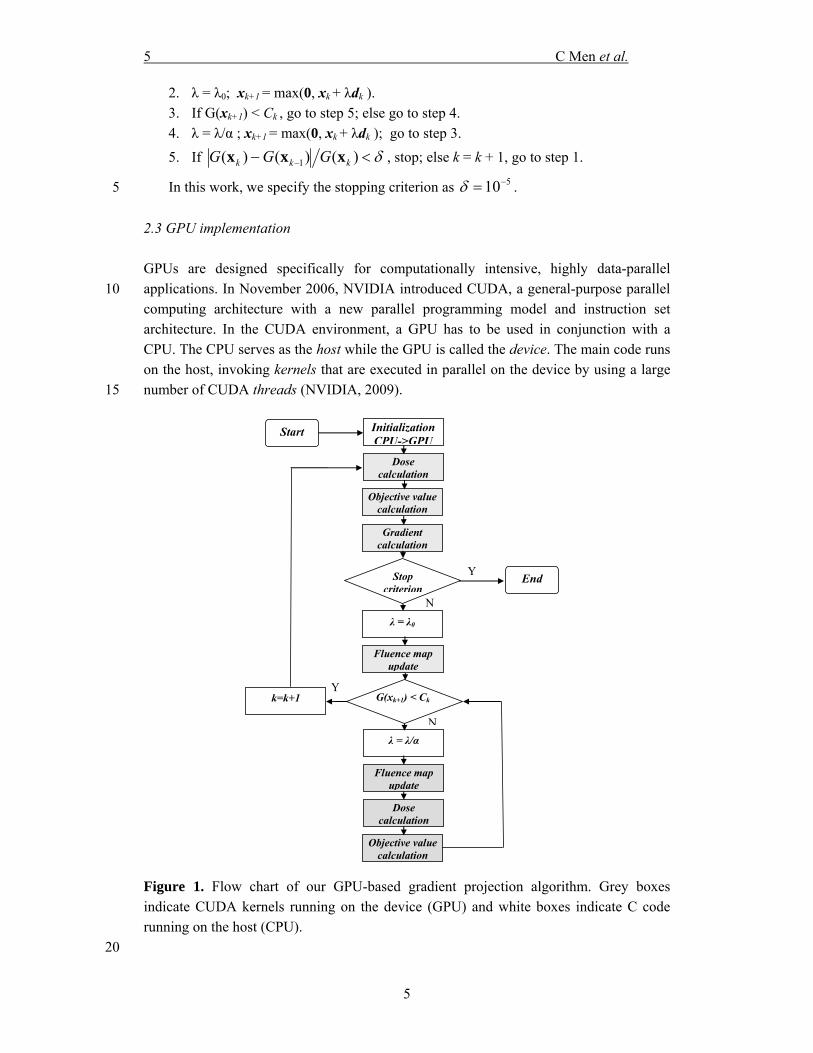
2.3 GPU implementation GPUs are designed specifically for computationally intensive, highly data-parallel applications. In November 2006, NVIDIA introduced CUDA, a general-purpose parallel 10 computing architecture with a new parallel programming model and instruction set architecture. In the CUDA environment, a GPU has to be used in conjunction with a CPU. The CPU serves as the host while the GPU is called the device. The main code runs on the host, invoking kernels that are executed in parallel on the device by using a large number of CUDA threads (NVIDIA, 2009). 15
Initialization CPU->GPU
Start
Dose calculation
Objective value calculation
Gradient calculation
N
λ = λ0
Stop criterion
Fluence map update
G(xk+1) < Ck
λ = λ/α
N
Fluence map update
Dose calculation
Objective value calculation
k=k+1 Y
End Y
Figure 1. Flow chart of our GPU-based gradient projection algorithm. Grey boxes indicate CUDA kernels running on the device (GPU) and white boxes indicate C code running on the host (CPU).
20
6 C Men et al.
6
Figure 1 depicts the flow chart of our GPU implementation of the gradient projection algorithm. The majority of the algorithm runs on the device as CUDA kernels (grey boxes), while the remaining simple arithmetic operations run on the host (white boxes). We use 4 kernels in our CUDA implementation: dose calculation, objective function calculation, gradient calculation, and fluence map update (xk+1 = max(0, xk + λdk )). For 5 the dose calculation, each thread calculates the dose received by a certain voxel. For the objective function calculation, each thread calculates the objective value contributed by a certain voxel, which is summarized to a total objective value using parallel reduction and loop unrolling operations. For the gradient calculation, each thread calculates the gradient value at a certain bixel. 10
Some global variables, such as xk, may be accessed by various threads simultaneously, causing massive memory accesses which can significantly impair the efficiency. To avoid this, we store those variables in texture memory which can be accessed as cached data.
The dose deposition coefficient matrix is a sparse matrix due to the fact that a 15 beamlet only contributes to voxels close to its path. We therefore store the Dij's using the compressed sparse row (CSR) format, which is the most popular general-purpose sparse matrix representation. To improve the performance of our CUDA code for calculating the voxel dose, which is actually a sparse matrix-vector multiplication, we use a newly developed method (Bell and Garland, 2008) on GPU. 20
3. Experiments and Results 3.1 Clinical testing case 25 To test our implementation, we used one clinical case of prostate cancer with three scenarios of different beamlet/voxel sizes (Table 1). For each scenario, nine co-planar beams were evenly distributed around the patient and the prescription dose to PTV was 73.8 Gy. For target and organs at risk (OARs), we used a voxel size of 4×4×4 mm3 in the first two scenarios and 2.5×2.5×2.5 mm3 in the last scenario. For unspecified tissue (i.e., 30 tissues outside the target and OARs), we increased the voxel size in each dimension by a factor of 2 to reduce the optimization problem size. The full resolution was used when evaluating the treatment quality (does volume histograms (DVHs), dose color wash, isodose curves, etc.).
35 Table 1. Running times for plan optimization for CPU and GPU implementations tested on a clinical case with various beamlet and voxel sizes.
# #
beams
beamlet size
(mm2)
# beamlets
voxel size (mm3)
# voxels# non-zero
Dij’s CPU (s)
GPU (s)
Speedup
1 9 10×10 2,055 4×4×4 35,988 3,137,805 3.81 0.19 20.1 2 9 5×5 6,453 4×4×4 35,988 10,612,611 16.4 0.49 33.5
7 C Men et al.
7
3 9 5×5 6,453 2.5×2.5×2.5 143,329 43,266,357 111.8 2.79 40.1
3.2 Test results We tested our CUDA implementation on an NVIDIA Tesla C1060 GPU card, which has 30 multiprocessors (each with 8 SIMD processing cores) and 4GB of memory. For 5 comparison purposes, we also implemented our algorithm in sequential C code and tested it on an Intel Xeon 2.27GHz CPU. We used the same sparse matrix format to represent sparse matrix D for both implementations.
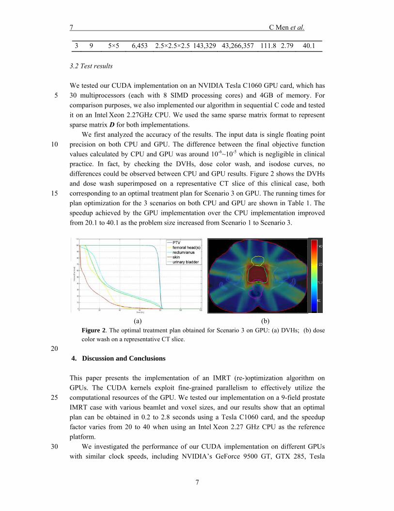
We first analyzed the accuracy of the results. The input data is single floating point precision on both CPU and GPU. The difference between the final objective function 10 values calculated by CPU and GPU was around 10-6~10-5 which is negligible in clinical practice. In fact, by checking the DVHs, dose color wash, and isodose curves, no differences could be observed between CPU and GPU results. Figure 2 shows the DVHs and dose wash superimposed on a representative CT slice of this clinical case, both corresponding to an optimal treatment plan for Scenario 3 on GPU. The running times for 15 plan optimization for the 3 scenarios on both CPU and GPU are shown in Table 1. The speedup achieved by the GPU implementation over the CPU implementation improved from 20.1 to 40.1 as the problem size increased from Scenario 1 to Scenario 3.
(a) (b) Figure 2. The optimal treatment plan obtained for Scenario 3 on GPU: (a) DVHs; (b) dosecolor wash on a representative CT slice.
20 4. Discussion and Conclusions This paper presents the implementation of an IMRT (re-)optimization algorithm on GPUs. The CUDA kernels exploit fine-grained parallelism to effectively utilize the computational resources of the GPU. We tested our implementation on a 9-field prostate 25 IMRT case with various beamlet and voxel sizes, and our results show that an optimal plan can be obtained in 0.2 to 2.8 seconds using a Tesla C1060 card, and the speedup factor varies from 20 to 40 when using an Intel Xeon 2.27 GHz CPU as the reference platform.
We investigated the performance of our CUDA implementation on different GPUs 30 with similar clock speeds, including NVIDIA’s GeForce 9500 GT, GTX 285, Tesla
8 C Men et al.
8
C1060, and Tesla S1070. The GeForce 9500 GT has only 4 multiprocessors and produced limited speedup (1x-3x). The GPUs on the GTX 285 and S1070 each have 30 multiprocessors (same as C1060) and delivered similar speedup results as described for the C1060 (Table 1). The memory required for the largest dataset tested (Scenario 3) is less than 1GB, which could be accommodated by all of the GPUs that were tested. We 5 found, for these test scenarios, that the speedup factors solely dependent on the number of multiprocessors per GPU.
We also noticed that the speedup factor is different for different CUDA kernels. In Scenario 3, the speedup factor is 46 for the dose calculation kernel, 18 for the objective value calculation kernel, 12 for the gradient calculation kernel. The dose and objective 10 calculations are parallelized based on voxels while the gradient calculation is parallelized based on bixels. In general, the number of voxels is much greater than the number of bixels. Therefore, it is not surprising to see that we can obtain better speed up for the dose and objective calculations. The speedup for the objective function value calculation is not as good as that for the dose calculation due to the communication cost of the parallel 15 reduction algorithm.
In the re-optimization model presented in this paper, we are trying to reproduce the dose distribution from the original plan for each individual fraction. This model might be too rigid. We may not be able to reproduce the exact dose distribution for some new geometries. In that case, the accumulative dose distribution may differ significantly from 20 the desired dose distribution. A better re-optimization model should take into account the accumulative dose distribution delivered in pervious fractions, by either using dose volume constraints or setting Tj in Equation (1) as the difference between the desired accumulative dose distribution up to the current fraction and the delivered accumulative dose distribution in previous fractions. We will explore both approaches in our future 25 work.
Multi-leaf collimator (MLC) leaf sequences have to be generated from our optimized fluence maps, which is usually very fast (less than 1 second on CPU). A major drawback of fluence map optimization followed by a leaf-sequencing stage is that there is a potential loss in the treatment quality. To overcome this, we plan to implement a direct 30 aperture optimization (DAO) algorithm on GPUs (Men et al., 2007).
Acknowledgements We would like to thank NVIDIA for providing GPU cards and Hubert Pan for his 35 constructive comments on the manuscript. This work is supported in part by the University of California Lab Fees Research Program. Ziyi Zheng and Klaus Mueller are supported by NSF grant CCF-0702699. 40
9 C Men et al.
9
References Bazaraa M S, Sherali H D and Shetty C M 2006 Nonlinear Programming: Theory and Algorithms
(Hoboken: A John Wiley & Sons) Bell N and Garland M 2008 Efficient sparse matrix-vector multiplication on CUDA. In: NVIDIA 5
Technical Report, (Santa Clara: NVIDIA Corporation) Birkner M, Yan D, Alber M, Liang J and Nusslin F 2003 Adapting inverse planning to patient and
organ geometrical variation: algorithm and implementation Medical Physics 30 2822-31 de la Zerda A, Armbruster B and Xing L 2007 Formulating adaptive radiation therapy (ART)
treatment planning into a closed-loop control framework Physics in Medicine and 10 Biology 52 4137-53
Fu W H, Yang Y, Yue N J, Heron D E and Huq M S 2009 A cone beam CT-guided online plan modification technique to correct interfractional anatomic changes for prostate cancer IMRT treatment Physics in Medicine and Biology 54 1691-703
Godley A, Ahunbay E, Peng C and Li X A 2009 Automated registration of large deformations for 15 adaptive radiation therapy of prostate cancer Medical Physics 36 1433-41
Hissoiny S, Ozell B and Despres P 2009 Fast convolution-superposition dose calculation on graphics hardware Medical Physics 36 1998-2005
Jung J H and O'Leary D P 2007 Implementing an interior point method for linear programs on a CPU-GPU system Electron. Trans. Numer. Anal. 28 174-89 20
Lu W G, Chen M, Chen Q, Ruchala K and Olivera G 2008 Adaptive fractionation therapy: I. Basic concept and strategy Physics in Medicine and Biology 53 5495-511
Men C, Romeijn H E, Taskin Z C and Dempsey J F 2007 An exact approach to direct aperture optimization in IMRT treatment planning Physics in Medicine and Biology 7333-52
Mohan R, Zhang X D, Wang H, Kang Y X, Wang X C, Liu H, Ang K, Kuban D and Dong L 2005 25 Use of deformed intensity distributions for on-line modification of image-guided IMRT to account for interfractional anatomic changes International Journal of Radiation Oncology Biology Physics 61 1258-66
Munekawa Y, Ino F and Hagihara K 2008 Design and implementation of the Smith-Waterman algorithm on the CUDA-compatible GPU 2008 8th IEEE International Conference on 30 Bioinformatics and BioEngineering 6 pp.
Noe K O, De Senneville B D, Elstrom U V, Tanderup K and Sorensen T S 2008 Acceleration and validation of optical flow based deformable registration for image-guided radiotherapy Acta Oncologica 47 1286-93
NVIDIA 2009 NVIDIA CUDA Programming Guide 2.2 35 Romeijn H E, Ahuja R K, Dempsey J F, Kumar A and Li J G 2003 A novel linear programming
approach to fluence map optimization for intensity modulated radiation therapy treatment planning Physics in Medicine and Biology 48 3521-42
Samant S S, Xia J Y, Muyan-Ozcelilk P and Owens J D 2008 High performance computing for deformable image registration: Towards a new paradigm in adaptive radiotherapy 40 Medical Physics 35 3546-53
Scherrer A and Kuefer K H 2008 Accelerated IMRT plan optimization using the adaptive clustering method Linear Algebra and Its Applications 428 1250-71
Sharp G C, Kandasamy N, Singh H and Folkert M 2007 GPU-based streaming architectures for fast cone-beam CT image reconstruction and demons deformable registration Physics in 45 Medicine and Biology 52 5771-83
Su C, Fu Z-l and Tan Y-c 2009 Fast operation of large-scale high-precision matrix based on GPU Journal of Computer Applications 1177-9, 92
Wallner G 2009 An extended GPU radiosity solver Visual Computer 25 529-37 Wu C, Jeraj R, Lu W G and Mackie T R 2004 Fast treatment plan modification with an over-50
relaxed Cimmino algorithm Medical Physics 31 191-200 Wu C, Jeraj R, Olivera G H and Mackie T R 2002 Re-optimization in adaptive radiotherapy
Physics in Medicine and Biology 47 3181-95 Wu Q J, Thongphiew D, Wang Z, Mathayomchan B, Chankong V, Yoo S, Lee W R and Yin F F
2008 On-line re-optimization of prostate IMRT plans for adaptive radiation therapy 55 Physics in Medicine and Biology 53 673-91

10 C Men et al.
10
Xing M, Decaudin P, Baogang H and Xiaopeng Z 2008 Real-time marker level set on GPU 2008 International Conference on Cyberworlds 209-16
Xu F and Mueller K 2007 Real-time 3D computed tomographic reconstruction using commodity graphics hardware Physics in Medicine and Biology 52 3405-19
Yan D, Vicini F, Wong J and Martinez A 1997 Adaptive radiation therapy Physics in Medicine 5 and Biology 42 123-32


