Embed Size (px)
Citation preview
ENVIRONMENTAL
WATER
WASTEWATER
GEOTECHNICAL
CIVIL
PROJECT
MANAGEMENT
ma
rte
ns
co
nsu
ltin
g e
ng
ine
ers
Waterbrook Lifestyle Resort
C/- Marchese Partners Engineering
P1706099JR02V03
August 2018
Geotechnical and Acid Sulfate Soils
Assessment: Proposed Seniors Living
Development, Cabbage Tree Road,
Bayview, NSW
martens
Geotechnical and Acid Sulfate Soils Assessment:
Proposed Seniors Living Development, Cabbage Tree Road, Bayview, NSW
P1706099JR02V03 – August 2018
Page 2
Copyright Statement
Martens & Associates Pty Ltd (Publisher) is the owner of the copyright subsisting in this publication. Other than as
permitted by the Copyright Act and as outlined in the Terms of Engagement, no part of this report may be reprinted
or reproduced or used in any form, copied or transmitted, by any electronic, mechanical, or by other means, now
known or hereafter invented (including microcopying, photocopying, recording, recording tape or through electronic
information storage and retrieval systems or otherwise), without the prior written permission of Martens & Associates Pty
Ltd. Legal action will be taken against any breach of its copyright. This report is available only as book form unless
specifically distributed by Martens & Associates in electronic form. No part of it is authorised to be copied, sold,
distributed or offered in any other form.
The document may only be used for the purposes for which it was commissioned. Unauthorised use of this document
in any form whatsoever is prohibited. Martens & Associates Pty Ltd assumes no responsibility where the document is
used for purposes other than those for which it was commissioned.
Limitations Statement
The sole purpose of this report and the associated services performed by Martens & Associates Pty Ltd is to complete
a geotechnical and acid sulfate soils assessment of the subject site in accordance with the scope of services set out
in the contract / quotation between Martens & Associates Pty Ltd and Waterbrook Lifestyle Resort C/- Marchese
Partners Engineering (the Client). That scope of works and services were defined by the requests of the Client, by the
time and budgetary constraints imposed by the Client, and by the availability of access to the site.
Martens & Associates Pty Ltd derived the data in this report primarily from a number of sources which may include for
example site inspections, correspondence regarding the proposal, examination of records in the public domain,
interviews with individuals with information about the site or the project, and field explorations conducted on the dates
indicated. The passage of time, manifestation of latent conditions or impacts of future events may require further
examination / exploration of the site and subsequent data analyses, together with a re-evaluation of the findings,
observations and conclusions expressed in this report.
In preparing this report, Martens & Associates Pty Ltd may have relied upon and presumed accurate certain
information (or absence thereof) relative to the site. Except as otherwise stated in the report, Martens & Associates Pty
Ltd has not attempted to verify the accuracy of completeness of any such information (including for example survey
data supplied by others).
The findings, observations and conclusions expressed by Martens & Associates Pty Ltd in this report are not, and should
not be considered an opinion concerning the completeness and accuracy of information supplied by others. No
warranty or guarantee, whether express or implied, is made with respect to the data reported or to the findings,
observations and conclusions expressed in this report. Further, such data, findings and conclusions are based solely
upon site conditions, information and drawings supplied by the Client etc. in existence at the time of the investigation.
This report has been prepared on behalf of and for the exclusive use of the Client, and is subject to and issued in
connection with the provisions of the agreement between Martens & Associates Pty Ltd and the Client. Martens &
Associates Pty Ltd accepts no liability or responsibility whatsoever for or in respect of any use of or reliance upon this
report by any third party.
martens
Geotechnical and Acid Sulfate Soils Assessment:
Proposed Seniors Living Development, Cabbage Tree Road, Bayview, NSW
P1706099JR02V03 – August 2018
Page 3
@ August 2018
Copyright Martens & Associates Pty Ltd
All Rights Reserved
Head Office
Suite 201, 20 George Street
Hornsby, NSW 2077, Australia
ACN 070 240 890 ABN 85 070 240 890
Phone: +61-2-9476-9999
Fax: +61-2-9476-8767
Email: [email protected]
Web: www.martens.com.au
Document and Distribution Status
Author(s) Reviewer(s) Project Manager/ Director Signature
Grant Taylor, Adam Budji,
Hamed Naghibi Ralph Erni Gray Taylor
Re
vis
ion
No
.
Description Status Release
Date
Document Location
File
Co
py
Ma
rch
ese
Pa
rtn
ers
En
gin
ee
rin
g
1 Geotechnical and Acid
Sulfate Soils Assessment Draft 12.10.2017 1H, 1P, 1E 1P
2 Geotechnical and Acid
Sulfate Soils Assessment Final 27.08.2018 1H, 1P, 1E 1P
Distribution Types: F = Fax, H = Hard copy, P = PDF document, E = Other electronic format. Digits indicate number of document copies.
All enquiries regarding this project are to be directed to the Project Manager.
martens
Geotechnical and Acid Sulfate Soils Assessment:
Proposed Seniors Living Development, Cabbage Tree Road, Bayview, NSW
P1706099JR02V03 – August 2018
Page 4
Contents 1 DEVELOPMENT AND INVESTIGATION SCOPE ........................................................ 6
2 FINDINGS ................................................................................................................. 7
2.1 Site Details and Conditions 7
2.2 Ground Conditions 7
2.3 Groundwater 8
3 GEOTECHNICAL ASSESSMENT .............................................................................. 11
3.1 Laboratory Testing 11
3.1.1 Atterberg Limits Testing 11
3.1.2 Rock Coring and Laboratory Test Results 11
3.2 Preliminary Soil and Rock Strength Properties 12
3.3 Risk Assessment of Proposed Development Works 13
3.3.1 Preliminary Slide Model Analysis 14
3.3.2 Conclusion 16
3.4 Foundation Exposure Classification 17
4 GEOTECHNICAL RECOMMENDATIONS ............................................................... 18
4.1 Recommendations 18
4.2 Preliminary Design Parameters 21
4.3 Site Classification 22
5 ACID SULFATE SOILS (ASS) ASSESSMENT ............................................................. 23
5.1 Overview 23
5.2 Desktop Review 23
5.2.1 ASS Risk Map Classification 23
5.2.2 Geomorphic Setting 23
5.3 Laboratory Testing 24
5.3.1 Soil Sampling 24
5.3.2 Laboratory Test Results 25
5.3.3 ASS Classification 27
5.3.4 Action Criteria 27
5.3.5 Conclusion 28
6 PRELIMINARY PAVEMENT THICKNESS DESIGN .................................................... 29
6.1 Overview 29
6.2 Design Parameters 29
6.3 Pavement Thickness 29
6.4 Earthworks 30
6.4.1 Subgrade Preparation 30
6.4.2 Subsoil Drainage 30
6.4.3 Placement and Testing of Pavement Material 30
6.4.4 Fill Placement 31
martens
Geotechnical and Acid Sulfate Soils Assessment:
Proposed Seniors Living Development, Cabbage Tree Road, Bayview, NSW
P1706099JR02V03 – August 2018
Page 5
6.4.5 Other Considerations 31
7 FURTHER ASSESSMENTS AND MONITORING / INSPECTIONS .............................. 32
7.1 Further Works 32
7.2 Construction Monitoring and Inspections 32
8 REFERENCES ........................................................................................................... 34
9 ATTACHMENT A – FIGURES ................................................................................... 36
10 ATTACHMENT B – BOREHOLE AND MONITORING WELL LOGS ........................... 43
11 ATTACHMENT C – DCP ‘N’ COUNTS ..................................................................... 79
12 ATTACHMENT D – GEOLOGICAL SITE SECTIONS ................................................. 83
13 ATTACHMENT E – PRELIMINARY LANDSLIDE MODELLING RESULTS .................... 86
14 ATTACHMENT F – GEOTECHNICAL RISK CALCULATIONS ................................... 91
15 ATTACHMENT G – LABORATORY TEST CERTIFICATES .......................................... 94
16 ATTACHMENT H – HILLSIDE CONSTRUCTION GUIDELINES (AGS, 2007) ........... 122
17 ATTACHMENT I – GENERAL GEOTECHNICAL RECOMMENDATIONS ............... 125
18 ATTACHMENT J – NOTES ABOUT THIS REPORT ................................................... 128
martens
Geotechnical and Acid Sulfate Soils Assessment:
Proposed Seniors Living Development, Cabbage Tree Road, Bayview, NSW
P1706099JR02V03 – August 2018
Page 6
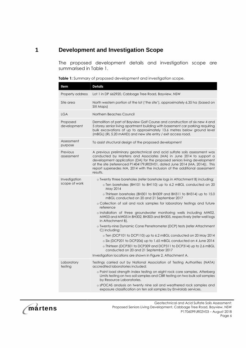
1 Development and Investigation Scope
The proposed development details and investigation scope are
summarised in Table 1.
Table 1: Summary of proposed development and investigation scope.
Item Details
Property address Lot 1 in DP 662920, Cabbage Tree Road, Bayview, NSW
Site area North western portion of the lot (‘the site’), approximately 6.35 ha (based on
SIX Maps)
LGA Northern Beaches Council
Proposed
development
Demolition of part of Bayview Golf Course and construction of six new 4 and
5 storey senior living apartment building with basement car parking requiring
bulk excavations of up to approximately 13.6 metres below ground level
(mBGL) (RL 5.20 mAHD) and new site entry / exit access road.
Assessment
purpose To assist structural design of the proposed development
Previous
assessment
A previous preliminary geotechnical and acid sulfate soils assessment was
conducted by Martens and Associates (MA) in June 2014 to support a
development application (DA) for the proposed seniors living development
at the site (referenced P1404179JR03V01, dated June 2014 (MA, 2014)). This
report supersedes MA, 2014 with the inclusion of the additional assessment
results.
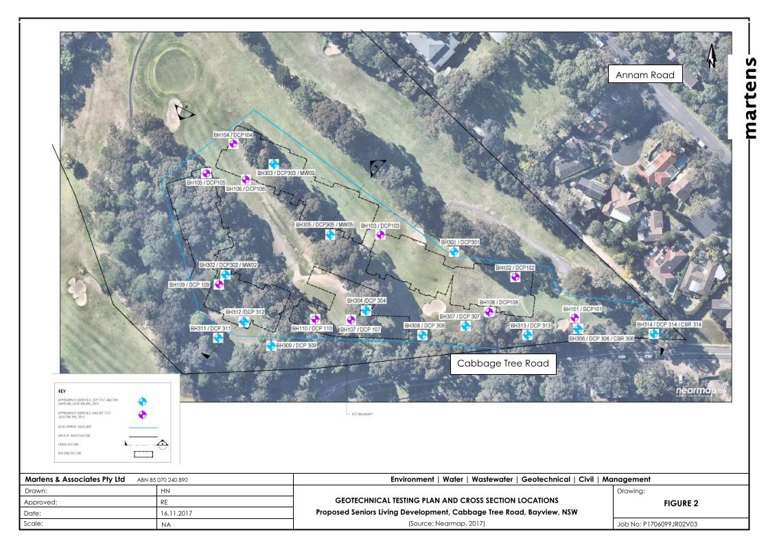
Investigation
scope of work
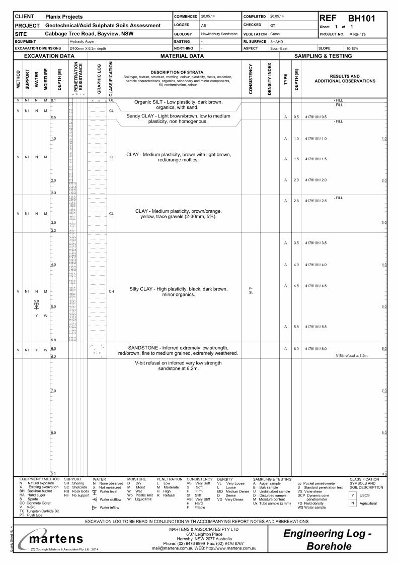
o Twenty three boreholes (refer borehole logs in Attachment B) including:
o Ten boreholes (BH101 to BH110) up to 6.2 mBGL conducted on 20
May 2014
o Thirteen boreholes (BH301 to BH309 and BH311 to BH314) up to 15.0
mBGL conducted on 20 and 21 September 2017
o Collection of soil and rock samples for laboratory testings and future
reference
o Installation of three groundwater monitoring wells including MW02,
MW03 and MW05 in BH302, BH303 and BH305, respectively (refer well logs
in Attachment B).
o Twenty-nine Dynamic Cone Penetrometer (DCP) tests (refer Attachment
C) including:
o Ten (DCP101 to DCP110) up to 6.2 mBGL conducted on 20 May 2014
o Six (DCP201 to DCP206) up to 1.65 mBGL conducted on 4 June 2014
o Thirteen (DCP301 to DCP309 and DCP311 to DCP314) up to 2.6 mBGL
conducted on 20 and 21 September 2017
Investigation locations are shown in Figure 2, Attachment A.
Laboratory
testing
Testings carried out by National Association of Testing Authorities (NATA)
accredited laboratories included:
o Point load strength index testing on eight rock core samples, Atterberg
Limits testing on two soil samples and CBR testing on two bulk soil samples
by Resource Laboratories. o sPOCAS analysis on twenty nine soil and weathered rock samples and
exposure classification on ten soil samples by Envirolab services.
martens
Geotechnical and Acid Sulfate Soils Assessment:
Proposed Seniors Living Development, Cabbage Tree Road, Bayview, NSW
P1706099JR02V03 – August 2018
Page 7
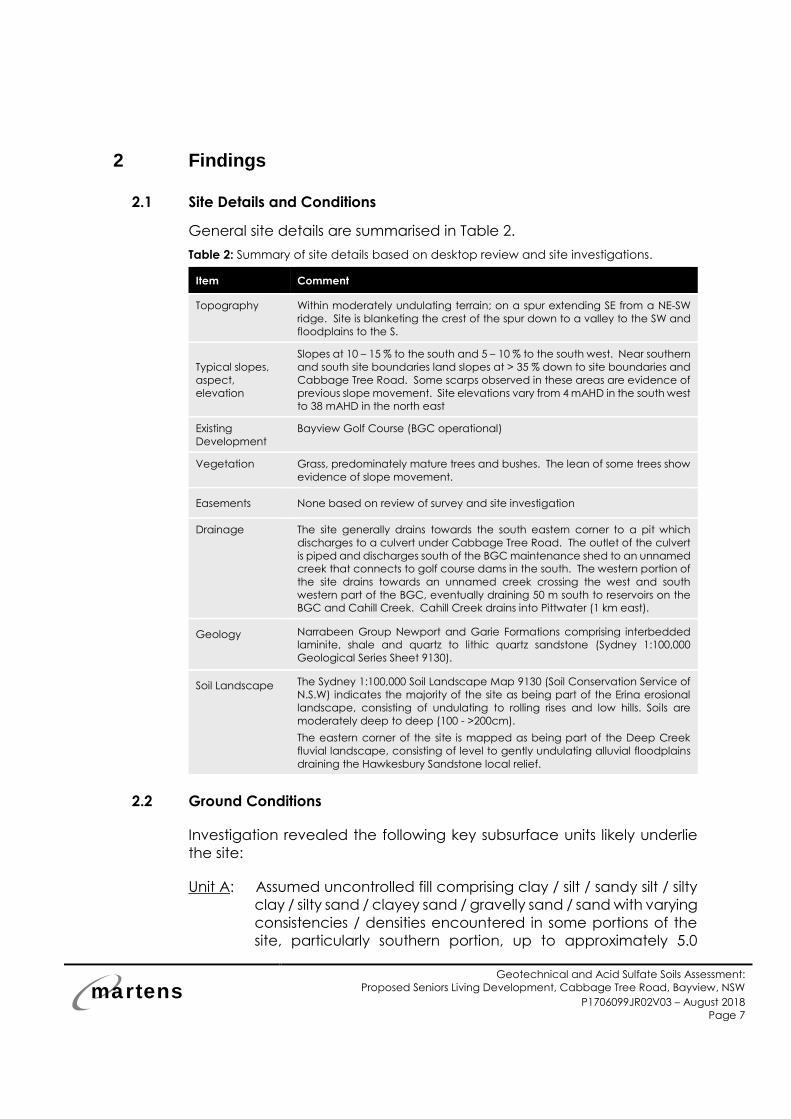
2 Findings
2.1 Site Details and Conditions
General site details are summarised in Table 2.
Table 2: Summary of site details based on desktop review and site investigations.
Item Comment
Topography Within moderately undulating terrain; on a spur extending SE from a NE-SW
ridge. Site is blanketing the crest of the spur down to a valley to the SW and
floodplains to the S.
Typical slopes,
aspect,
elevation
Slopes at 10 – 15 % to the south and 5 – 10 % to the south west. Near southern
and south site boundaries land slopes at > 35 % down to site boundaries and
Cabbage Tree Road. Some scarps observed in these areas are evidence of
previous slope movement. Site elevations vary from 4 mAHD in the south west
to 38 mAHD in the north east
Existing
Development
Bayview Golf Course (BGC operational)
Vegetation Grass, predominately mature trees and bushes. The lean of some trees show
evidence of slope movement.
Easements None based on review of survey and site investigation
Drainage The site generally drains towards the south eastern corner to a pit which
discharges to a culvert under Cabbage Tree Road. The outlet of the culvert
is piped and discharges south of the BGC maintenance shed to an unnamed
creek that connects to golf course dams in the south. The western portion of
the site drains towards an unnamed creek crossing the west and south
western part of the BGC, eventually draining 50 m south to reservoirs on the
BGC and Cahill Creek. Cahill Creek drains into Pittwater (1 km east).
Geology
Narrabeen Group Newport and Garie Formations comprising interbedded
laminite, shale and quartz to lithic quartz sandstone (Sydney 1:100,000
Geological Series Sheet 9130).
Soil Landscape The Sydney 1:100,000 Soil Landscape Map 9130 (Soil Conservation Service of
N.S.W) indicates the majority of the site as being part of the Erina erosional
landscape, consisting of undulating to rolling rises and low hills. Soils are
moderately deep to deep (100 - >200cm).
The eastern corner of the site is mapped as being part of the Deep Creek
fluvial landscape, consisting of level to gently undulating alluvial floodplains
draining the Hawkesbury Sandstone local relief.
2.2 Ground Conditions
Investigation revealed the following key subsurface units likely underlie
the site:
Unit A: Assumed uncontrolled fill comprising clay / silt / sandy silt / silty
clay / silty sand / clayey sand / gravelly sand / sand with varying
consistencies / densities encountered in some portions of the
site, particularly southern portion, up to approximately 5.0
martens
Geotechnical and Acid Sulfate Soils Assessment:
Proposed Seniors Living Development, Cabbage Tree Road, Bayview, NSW
P1706099JR02V03 – August 2018
Page 8
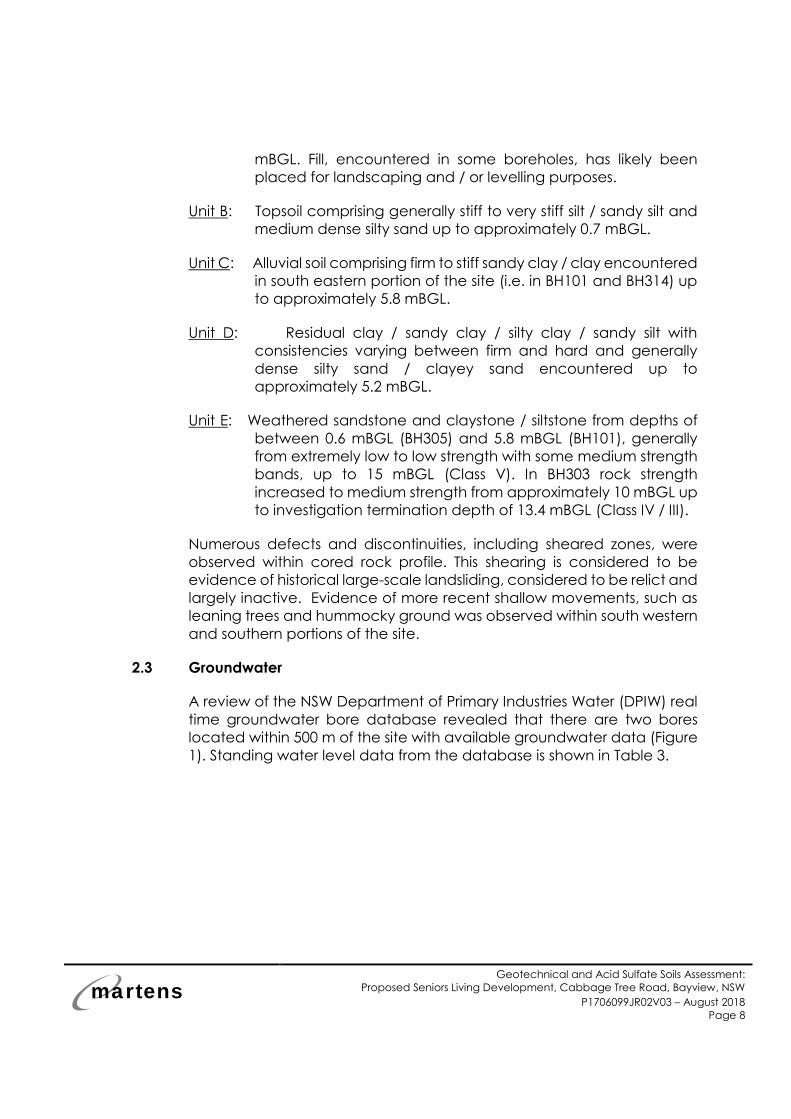
mBGL. Fill, encountered in some boreholes, has likely been
placed for landscaping and / or levelling purposes.
Unit B: Topsoil comprising generally stiff to very stiff silt / sandy silt and
medium dense silty sand up to approximately 0.7 mBGL.
Unit C: Alluvial soil comprising firm to stiff sandy clay / clay encountered
in south eastern portion of the site (i.e. in BH101 and BH314) up
to approximately 5.8 mBGL.
Unit D: Residual clay / sandy clay / silty clay / sandy silt with
consistencies varying between firm and hard and generally
dense silty sand / clayey sand encountered up to
approximately 5.2 mBGL.
Unit E: Weathered sandstone and claystone / siltstone from depths of
between 0.6 mBGL (BH305) and 5.8 mBGL (BH101), generally
from extremely low to low strength with some medium strength
bands, up to 15 mBGL (Class V). In BH303 rock strength
increased to medium strength from approximately 10 mBGL up
to investigation termination depth of 13.4 mBGL (Class IV / III).
Numerous defects and discontinuities, including sheared zones, were
observed within cored rock profile. This shearing is considered to be
evidence of historical large-scale landsliding, considered to be relict and
largely inactive. Evidence of more recent shallow movements, such as
leaning trees and hummocky ground was observed within south western
and southern portions of the site.
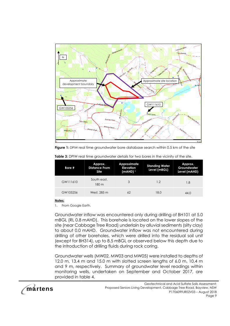
2.3 Groundwater
A review of the NSW Department of Primary Industries Water (DPIW) real
time groundwater bore database revealed that there are two bores
located within 500 m of the site with available groundwater data (Figure
1). Standing water level data from the database is shown in Table 3.
N
martens
Geotechnical and Acid Sulfate Soils Assessment:
Proposed Seniors Living Development, Cabbage Tree Road, Bayview, NSW
P1706099JR02V03 – August 2018
Page 9
Figure 1: DPIW real time groundwater bore database search within 0.5 km of the site
Table 3: DPIW real time groundwater details for two bores in the vicinity of the site.
Bore #
Approx.
Distance From
Site
Approximate
Elevation
(mAHD) 1
Standing Water
Level (mBGL)
Approx.
Groundwater
Level (mAHD)
GW111610 South east,
180 m 3 1.2 1.8
GW105256 West, 285 m 62 18.0 44.0
Notes:
1. From Google Earth.
Groundwater inflow was encountered only during drilling of BH101 at 5.0
mBGL (RL 0.8 mAHD). This borehole is located on the lower slopes of the
site (near Cabbage Tree Road) underlain by alluvial sediments (silty clay)
to about 0.0 mAHD. Groundwater inflow was not encountered during
drilling of other boreholes, which were drilled into the residual soil unit
(except for BH314), up to 8.5 mBGL or observed below this depth due to
the introduction of drilling fluids during rock coring.
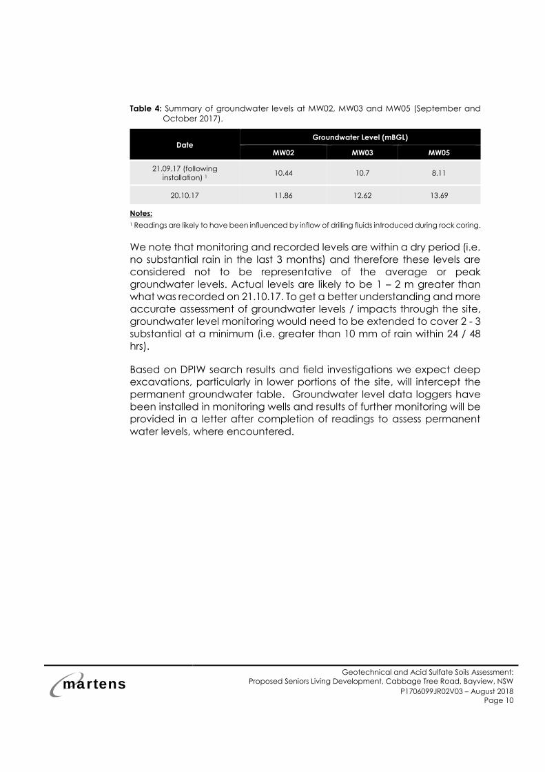
Groundwater wells (MW02, MW03 and MW05) were installed to depths of
12.0 m, 13.4 m and 15.0 m with slotted screen lengths of 6.0 m, 10.4 m
and 9 m, respectively. Summary of groundwater level readings within
monitoring wells, undertaken on September and October 2017, are
provided in table 4.
Approximate site location Approximate
development boundary
N
GW111610
GW105256
martens
Geotechnical and Acid Sulfate Soils Assessment:
Proposed Seniors Living Development, Cabbage Tree Road, Bayview, NSW
P1706099JR02V03 – August 2018
Page 10
Table 4: Summary of groundwater levels at MW02, MW03 and MW05 (September and
October 2017).
Date Groundwater Level (mBGL)
MW02 MW03 MW05
21.09.17 (following
installation) 1 10.44 10.7 8.11
20.10.17 11.86 12.62 13.69
Notes:
1 Readings are likely to have been influenced by inflow of drilling fluids introduced during rock coring.
We note that monitoring and recorded levels are within a dry period (i.e.
no substantial rain in the last 3 months) and therefore these levels are
considered not to be representative of the average or peak
groundwater levels. Actual levels are likely to be 1 – 2 m greater than
what was recorded on 21.10.17. To get a better understanding and more
accurate assessment of groundwater levels / impacts through the site,
groundwater level monitoring would need to be extended to cover 2 - 3
substantial at a minimum (i.e. greater than 10 mm of rain within 24 / 48
hrs).
Based on DPIW search results and field investigations we expect deep
excavations, particularly in lower portions of the site, will intercept the
permanent groundwater table. Groundwater level data loggers have
been installed in monitoring wells and results of further monitoring will be
provided in a letter after completion of readings to assess permanent
water levels, where encountered.
martens
Geotechnical and Acid Sulfate Soils Assessment:
Proposed Seniors Living Development, Cabbage Tree Road, Bayview, NSW
P1706099JR02V03 – August 2018
Page 11
3 Geotechnical Assessment
3.1 Laboratory Testing
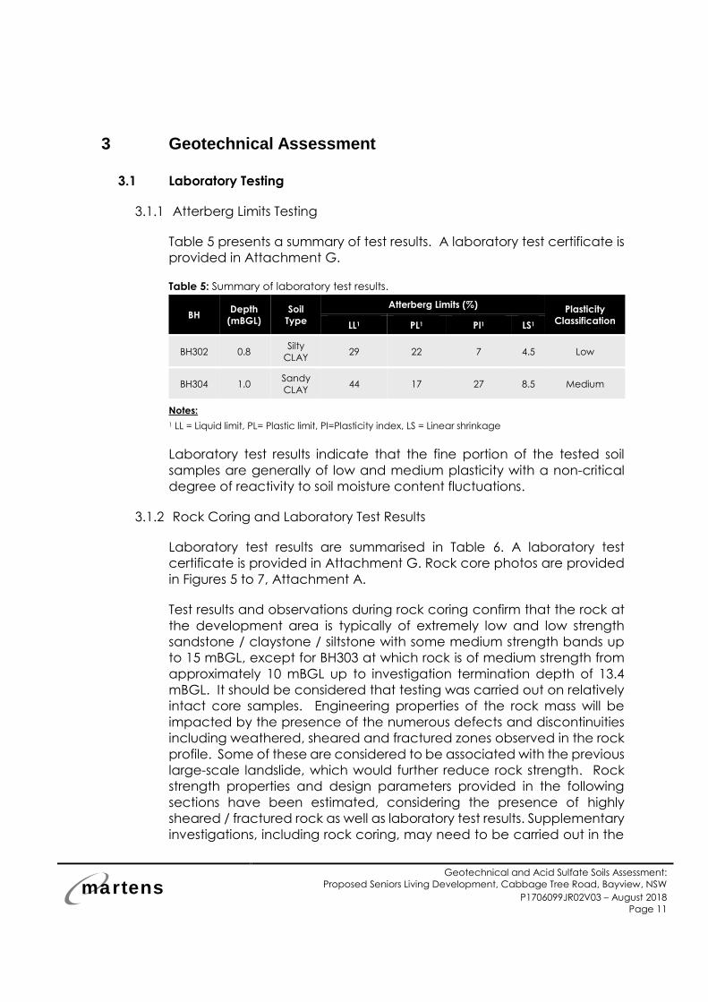
3.1.1 Atterberg Limits Testing
Table 5 presents a summary of test results. A laboratory test certificate is
provided in Attachment G.
Table 5: Summary of laboratory test results.
BH Depth
(mBGL)
Soil
Type
Atterberg Limits (%) Plasticity
Classification LL1 PL1 PI1 LS1
BH302 0.8 Silty
CLAY 29 22 7 4.5 Low
BH304 1.0 Sandy
CLAY 44 17 27 8.5 Medium
Notes:
1 LL = Liquid limit, PL= Plastic limit, PI=Plasticity index, LS = Linear shrinkage
Laboratory test results indicate that the fine portion of the tested soil
samples are generally of low and medium plasticity with a non-critical
degree of reactivity to soil moisture content fluctuations.
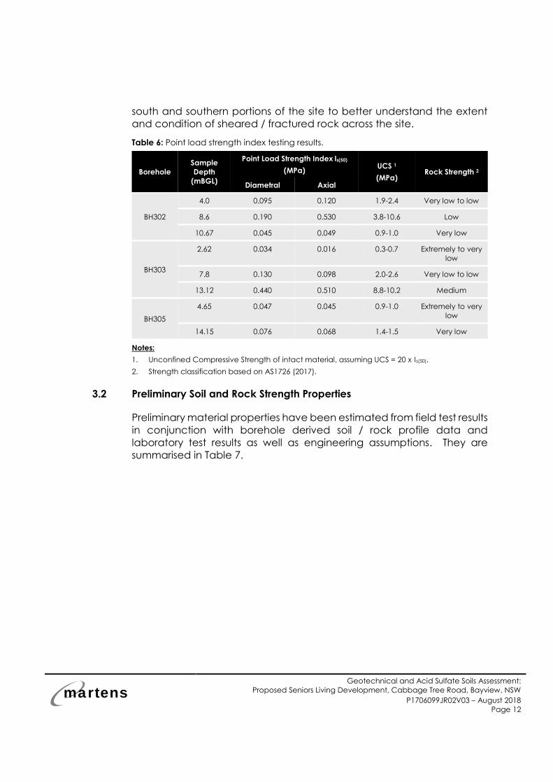
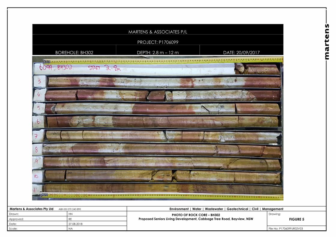
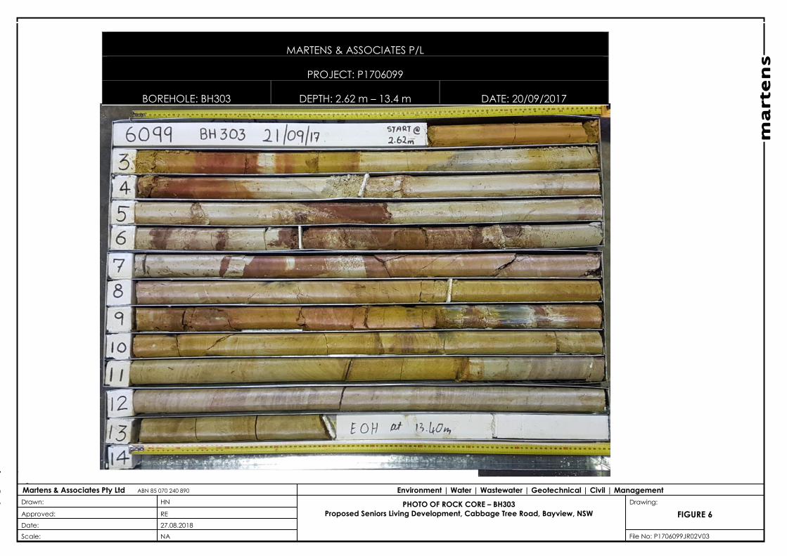
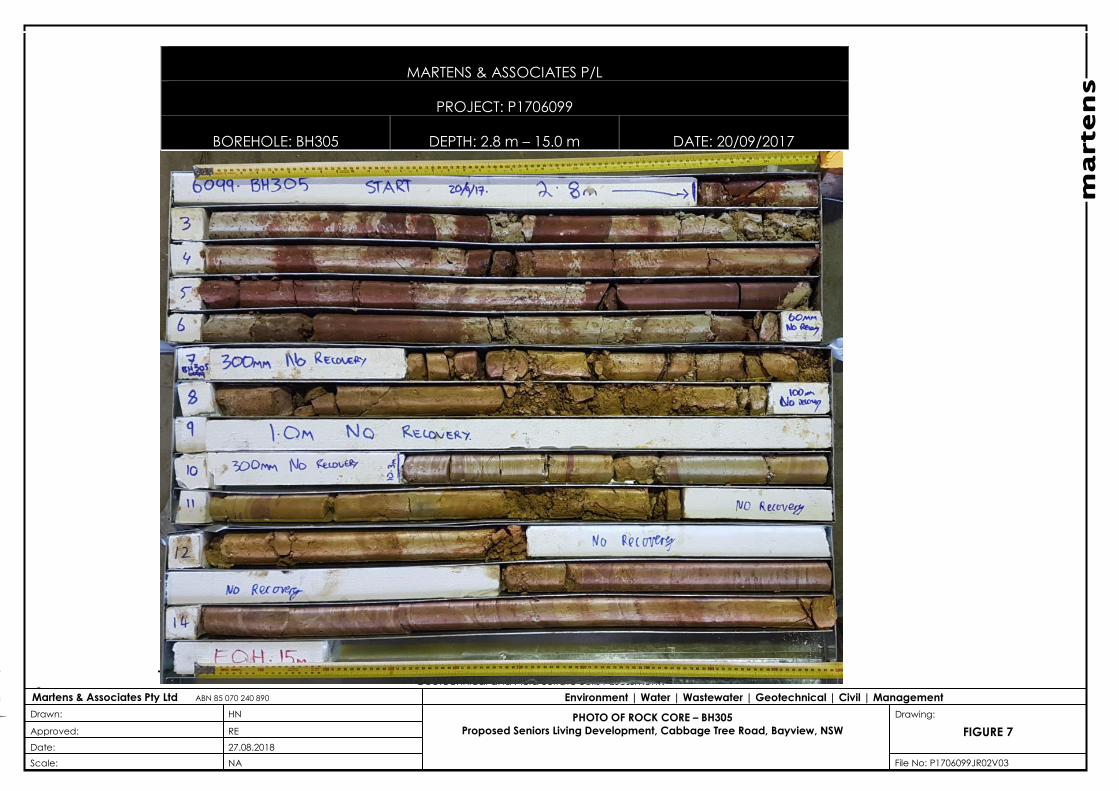
3.1.2 Rock Coring and Laboratory Test Results
Laboratory test results are summarised in Table 6. A laboratory test
certificate is provided in Attachment G. Rock core photos are provided
in Figures 5 to 7, Attachment A.
Test results and observations during rock coring confirm that the rock at
the development area is typically of extremely low and low strength
sandstone / claystone / siltstone with some medium strength bands up
to 15 mBGL, except for BH303 at which rock is of medium strength from
approximately 10 mBGL up to investigation termination depth of 13.4
mBGL. It should be considered that testing was carried out on relatively
intact core samples. Engineering properties of the rock mass will be
impacted by the presence of the numerous defects and discontinuities
including weathered, sheared and fractured zones observed in the rock
profile. Some of these are considered to be associated with the previous
large-scale landslide, which would further reduce rock strength. Rock
strength properties and design parameters provided in the following
sections have been estimated, considering the presence of highly
sheared / fractured rock as well as laboratory test results. Supplementary
investigations, including rock coring, may need to be carried out in the
martens
Geotechnical and Acid Sulfate Soils Assessment:
Proposed Seniors Living Development, Cabbage Tree Road, Bayview, NSW
P1706099JR02V03 – August 2018
Page 12
south and southern portions of the site to better understand the extent
and condition of sheared / fractured rock across the site.
Table 6: Point load strength index testing results.
Borehole
Sample
Depth
(mBGL)
Point Load Strength Index Is(50)
(MPa) UCS 1
(MPa) Rock Strength 2
Diametral Axial
BH302
4.0 0.095 0.120 1.9-2.4 Very low to low
8.6 0.190 0.530 3.8-10.6 Low
10.67 0.045 0.049 0.9-1.0 Very low
BH303
2.62 0.034 0.016 0.3-0.7 Extremely to very
low
7.8 0.130 0.098 2.0-2.6 Very low to low
13.12 0.440 0.510 8.8-10.2 Medium
BH305
4.65 0.047 0.045 0.9-1.0 Extremely to very
low
14.15 0.076 0.068 1.4-1.5 Very low
Notes:
1. Unconfined Compressive Strength of intact material, assuming UCS = 20 x Is(50).
2. Strength classification based on AS1726 (2017).
3.2 Preliminary Soil and Rock Strength Properties
Preliminary material properties have been estimated from field test results
in conjunction with borehole derived soil / rock profile data and
laboratory test results as well as engineering assumptions. They are
summarised in Table 7.
martens
Geotechnical and Acid Sulfate Soils Assessment:
Proposed Seniors Living Development, Cabbage Tree Road, Bayview, NSW
P1706099JR02V03 – August 2018
Page 13
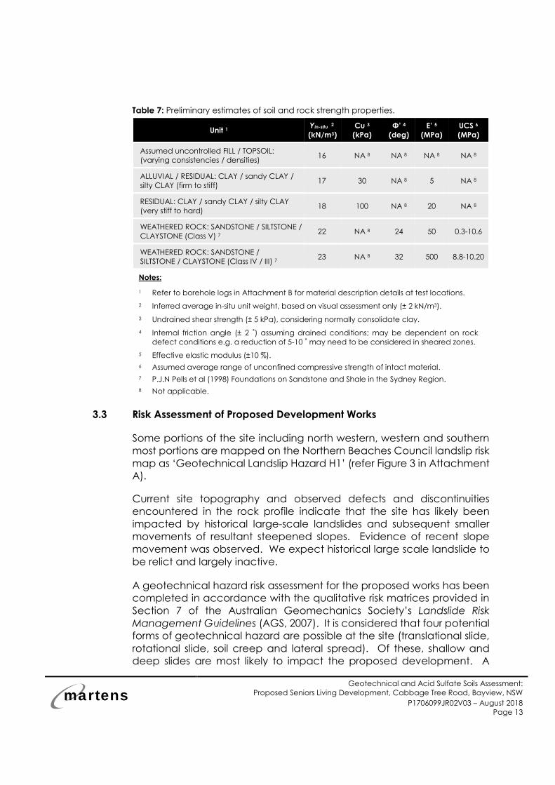
Table 7: Preliminary estimates of soil and rock strength properties.
Unit 1 Yin-situ 2
(kN/m3)
Cu 3
(kPa)
Φ’ 4
(deg)
E’ 5
(MPa)
UCS 6
(MPa)
Assumed uncontrolled FILL / TOPSOIL:
(varying consistencies / densities) 16 NA 8 NA 8 NA 8 NA 8
ALLUVIAL / RESIDUAL: CLAY / sandy CLAY /
silty CLAY (firm to stiff) 17 30 NA 8 5 NA 8
RESIDUAL: CLAY / sandy CLAY / silty CLAY
(very stiff to hard) 18 100 NA 8 20 NA 8
WEATHERED ROCK: SANDSTONE / SILTSTONE /
CLAYSTONE (Class V) 7 22 NA 8 24 50 0.3-10.6
WEATHERED ROCK: SANDSTONE /
SILTSTONE / CLAYSTONE (Class IV / III) 7 23 NA 8 32 500 8.8-10.20
Notes:
1 Refer to borehole logs in Attachment B for material description details at test locations.
2 Inferred average in-situ unit weight, based on visual assessment only (± 2 kN/m3).
3 Undrained shear strength (± 5 kPa), considering normally consolidate clay.
4 Internal friction angle (± 2 ˚) assuming drained conditions; may be dependent on rock
defect conditions e.g. a reduction of 5-10 ˚ may need to be considered in sheared zones.
5 Effective elastic modulus (±10 %).
6 Assumed average range of unconfined compressive strength of intact material.
7 P.J.N Pells et al (1998) Foundations on Sandstone and Shale in the Sydney Region.
8 Not applicable.
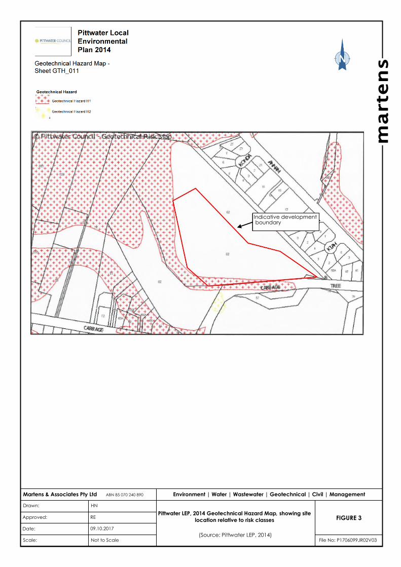
3.3 Risk Assessment of Proposed Development Works
Some portions of the site including north western, western and southern
most portions are mapped on the Northern Beaches Council landslip risk
map as ‘Geotechnical Landslip Hazard H1’ (refer Figure 3 in Attachment
A).
Current site topography and observed defects and discontinuities
encountered in the rock profile indicate that the site has likely been
impacted by historical large-scale landslides and subsequent smaller
movements of resultant steepened slopes. Evidence of recent slope
movement was observed. We expect historical large scale landslide to
be relict and largely inactive.
A geotechnical hazard risk assessment for the proposed works has been
completed in accordance with the qualitative risk matrices provided in
Section 7 of the Australian Geomechanics Society’s Landslide Risk
Management Guidelines (AGS, 2007). It is considered that four potential
forms of geotechnical hazard are possible at the site (translational slide,
rotational slide, soil creep and lateral spread). Of these, shallow and
deep slides are most likely to impact the proposed development. A
martens
Geotechnical and Acid Sulfate Soils Assessment:
Proposed Seniors Living Development, Cabbage Tree Road, Bayview, NSW
P1706099JR02V03 – August 2018
Page 14
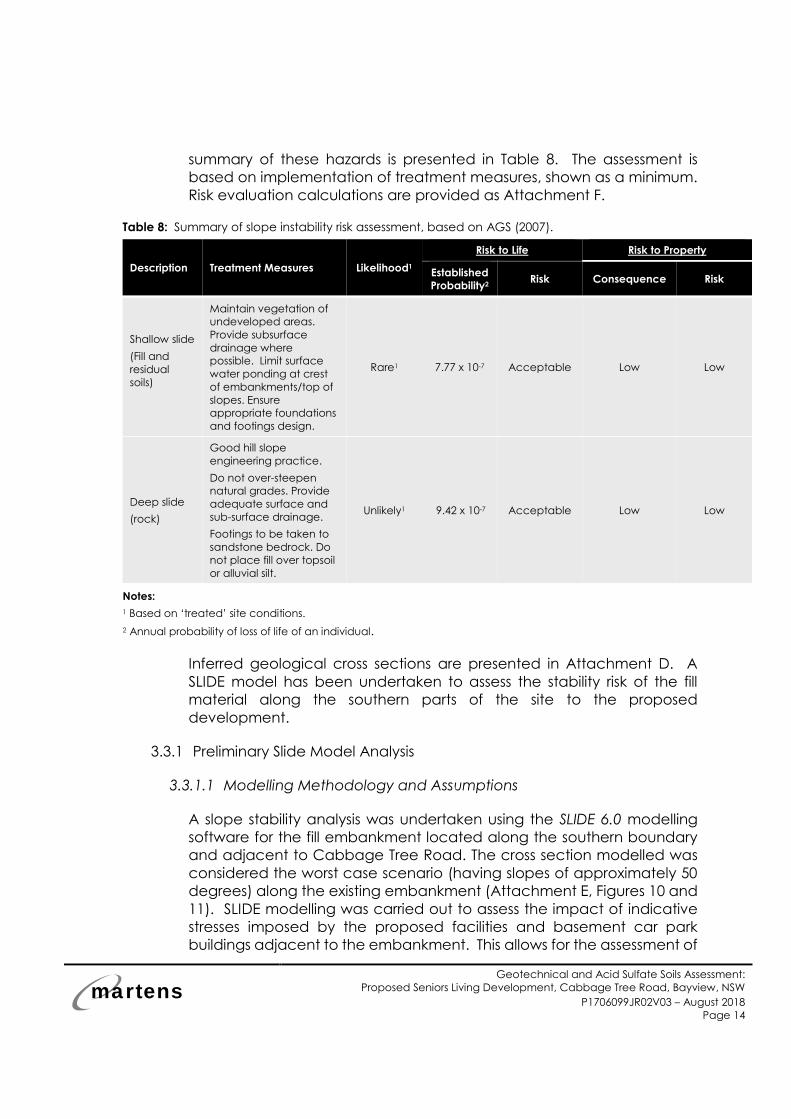
summary of these hazards is presented in Table 8. The assessment is
based on implementation of treatment measures, shown as a minimum.
Risk evaluation calculations are provided as Attachment F.
Table 8: Summary of slope instability risk assessment, based on AGS (2007).
Description Treatment Measures Likelihood1
Risk to Life Risk to Property
Established
Probability2 Risk Consequence Risk
Shallow slide
(Fill and
residual
soils)
Maintain vegetation of
undeveloped areas.
Provide subsurface
drainage where
possible. Limit surface
water ponding at crest
of embankments/top of
slopes. Ensure
appropriate foundations
and footings design.
Rare1 7.77 x 10⁻⁷ Acceptable Low Low
Deep slide
(rock)
Good hill slope
engineering practice.
Do not over-steepen
natural grades. Provide
adequate surface and
sub-surface drainage.
Footings to be taken to
sandstone bedrock. Do
not place fill over topsoil
or alluvial silt.
Unlikely1 9.42 x 10⁻⁷ Acceptable Low Low
Notes:
1 Based on ‘treated’ site conditions.
2 Annual probability of loss of life of an individual.
Inferred geological cross sections are presented in Attachment D. A
SLIDE model has been undertaken to assess the stability risk of the fill
material along the southern parts of the site to the proposed
development.
3.3.1 Preliminary Slide Model Analysis
3.3.1.1 Modelling Methodology and Assumptions
A slope stability analysis was undertaken using the SLIDE 6.0 modelling
software for the fill embankment located along the southern boundary
and adjacent to Cabbage Tree Road. The cross section modelled was
considered the worst case scenario (having slopes of approximately 50
degrees) along the existing embankment (Attachment E, Figures 10 and
11). SLIDE modelling was carried out to assess the impact of indicative
stresses imposed by the proposed facilities and basement car park
buildings adjacent to the embankment. This allows for the assessment of
martens
Geotechnical and Acid Sulfate Soils Assessment:
Proposed Seniors Living Development, Cabbage Tree Road, Bayview, NSW
P1706099JR02V03 – August 2018
Page 15
Factor of Safety (FOS) against sliding for existing ground conditions and
under loading (i.e. proposed development) conditions. We provide the
following comments:
o Additional penetration tests were conducted in the vicinity of the
existing embankment (Attachment C) to identify depth to rock
downslope of the embankment.
o Existing ground levels were taken from existing survey data by Bee
& Lethbridge Pty Ltd (dated April 2014, drawing number 18990).
o Two modelling scenarios were assessed based on the proposed
development: Embankment with loading assuming a design load
of 150 kPa; and without loading.
o The existing soil overburden comprises fill overlying a layer of
residual clay overlying weathered rock.
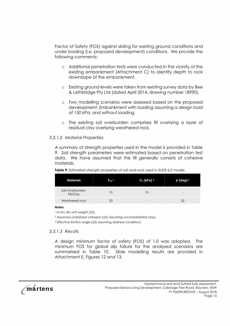
3.3.1.2 Material Properties
A summary of strength properties used in the model is provided in Table
9. Soil strength parameters were estimated based on penetration test
data. We have assumed that the fill generally consists of cohesive
materials.
Table 9: Estimated strength properties of soil and rock used in SLIDE 6.0 model.
Materials Ydry 1 Cu (kPa) 2 ' (deg) 3
Soil Overburden:
Fill/Clay 15 15 -
Weathered rock 23 - 32
Notes:
1 In-situ dry unit weight (±2).
2 Assumed undrained cohesion (±5) assuming unconsolidated clays.
3 Effective friction angle (±2) assuming drained conditions.
3.3.1.3 Results
A design minimum factor of safety (FOS) of 1.0 was adopted. The
minimum FOS for global slip failure for the analysed scenarios are
summarised in Table 10. Slide modelling results are provided in
Attachment E, Figures 12 and 13.
martens
Geotechnical and Acid Sulfate Soils Assessment:
Proposed Seniors Living Development, Cabbage Tree Road, Bayview, NSW
P1706099JR02V03 – August 2018
Page 16
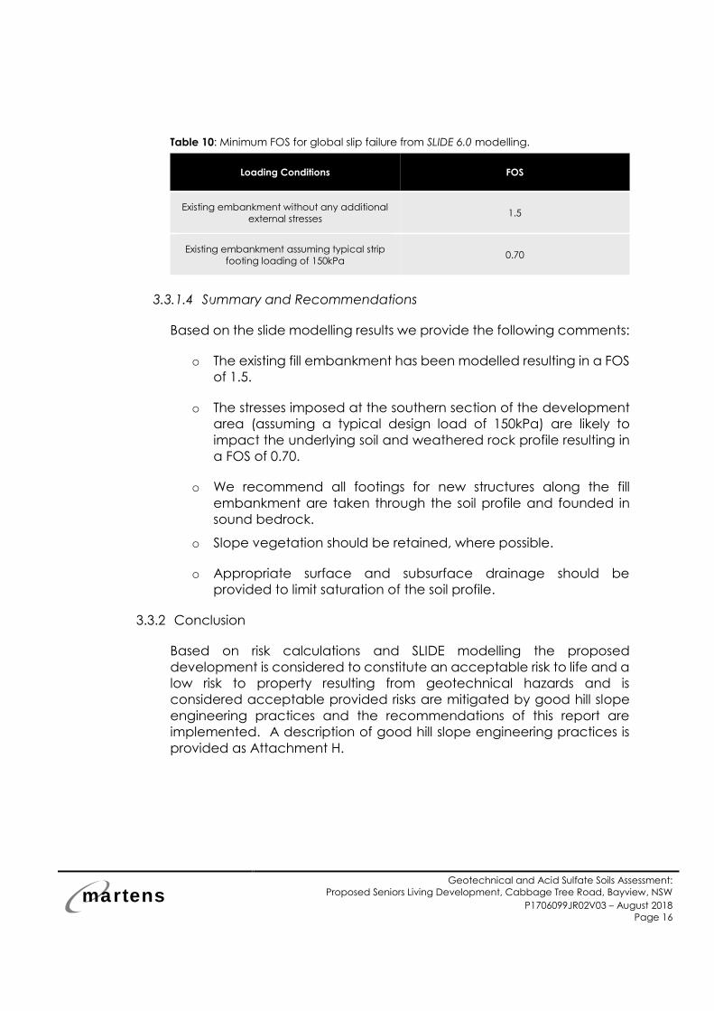
Table 10: Minimum FOS for global slip failure from SLIDE 6.0 modelling.
Loading Conditions FOS
Existing embankment without any additional
external stresses 1.5
Existing embankment assuming typical strip
footing loading of 150kPa 0.70
3.3.1.4 Summary and Recommendations
Based on the slide modelling results we provide the following comments:
o The existing fill embankment has been modelled resulting in a FOS
of 1.5.
o The stresses imposed at the southern section of the development
area (assuming a typical design load of 150kPa) are likely to
impact the underlying soil and weathered rock profile resulting in
a FOS of 0.70.
o We recommend all footings for new structures along the fill
embankment are taken through the soil profile and founded in
sound bedrock.
o Slope vegetation should be retained, where possible.
o Appropriate surface and subsurface drainage should be
provided to limit saturation of the soil profile.
3.3.2 Conclusion
Based on risk calculations and SLIDE modelling the proposed
development is considered to constitute an acceptable risk to life and a
low risk to property resulting from geotechnical hazards and is
considered acceptable provided risks are mitigated by good hill slope
engineering practices and the recommendations of this report are
implemented. A description of good hill slope engineering practices is
provided as Attachment H.
martens
Geotechnical and Acid Sulfate Soils Assessment:
Proposed Seniors Living Development, Cabbage Tree Road, Bayview, NSW
P1706099JR02V03 – August 2018
Page 17
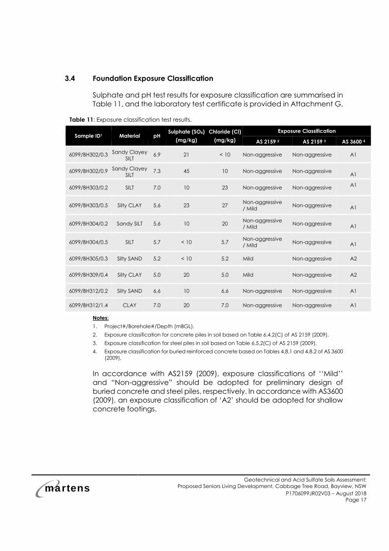
3.4 Foundation Exposure Classification
Sulphate and pH test results for exposure classification are summarised in
Table 11, and the laboratory test certificate is provided in Attachment G.
Table 11: Exposure classification test results.
Sample ID1 Material pH Sulphate (SO4)
(mg/kg)
Chloride (Cl)
(mg/kg)
Exposure Classification
AS 2159 2 AS 2159 3 AS 3600 4
6099/BH302/0.3 Sandy Clayey
SILT 6.9 21 < 10 Non-aggressive Non-aggressive A1
6099/BH302/0.9 Sandy Clayey
SILT 7.3 45 10 Non-aggressive Non-aggressive
A1
6099/BH303/0.2 SILT 7.0 10 23 Non-aggressive Non-aggressive A1
6099/BH303/0.5 Silty CLAY 5.6 23 27 Non-aggressive
/ Mild Non-aggressive A1
6099/BH304/0.2 Sandy SILT 5.6 10 20 Non-aggressive
/ Mild Non-aggressive
A1
6099/BH304/0.5 SILT 5.7 < 10 5.7 Non-aggressive
/ Mild Non-aggressive A1
6099/BH305/0.3 Silty SAND 5.2 < 10 5.2 Mild Non-aggressive A2
6099/BH309/0.4 Silty CLAY 5.0 20 5.0 Mild Non-aggressive A2
6099/BH312/0.2 Silty SAND 6.6 10 6.6 Non-aggressive Non-aggressive A1
6099/BH312/1.4 CLAY 7.0 20 7.0 Non-aggressive Non-aggressive A1
Notes:
1. Project#/Borehole#/Depth (mBGL).
2. Exposure classification for concrete piles in soil based on Table 6.4.2(C) of AS 2159 (2009).
3. Exposure classification for steel piles in soil based on Table 6.5.2(C) of AS 2159 (2009).
4. Exposure classification for buried reinforced concrete based on Tables 4.8.1 and 4.8.2 of AS 3600
(2009).
In accordance with AS2159 (2009), exposure classifications of ‘‘Mild’’
and “Non-aggressive” should be adopted for preliminary design of
buried concrete and steel piles, respectively. In accordance with AS3600
(2009), an exposure classification of ‘A2’ should be adopted for shallow
concrete footings.
martens
Geotechnical and Acid Sulfate Soils Assessment:
Proposed Seniors Living Development, Cabbage Tree Road, Bayview, NSW
P1706099JR02V03 – August 2018
Page 18
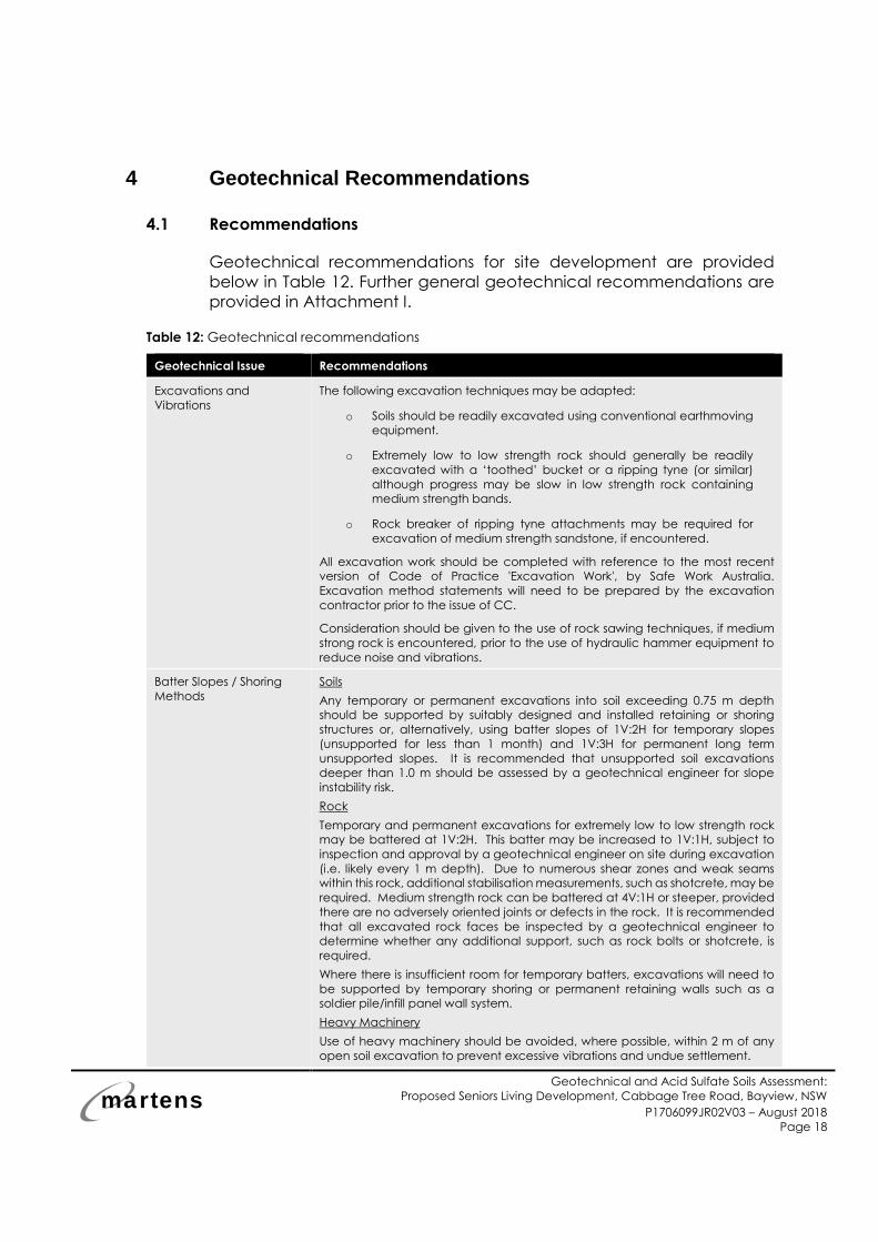
4 Geotechnical Recommendations
4.1 Recommendations
Geotechnical recommendations for site development are provided
below in Table 12. Further general geotechnical recommendations are
provided in Attachment I.
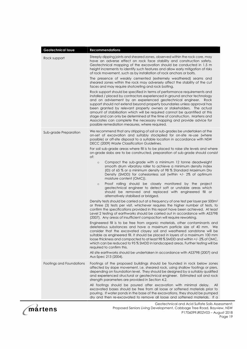
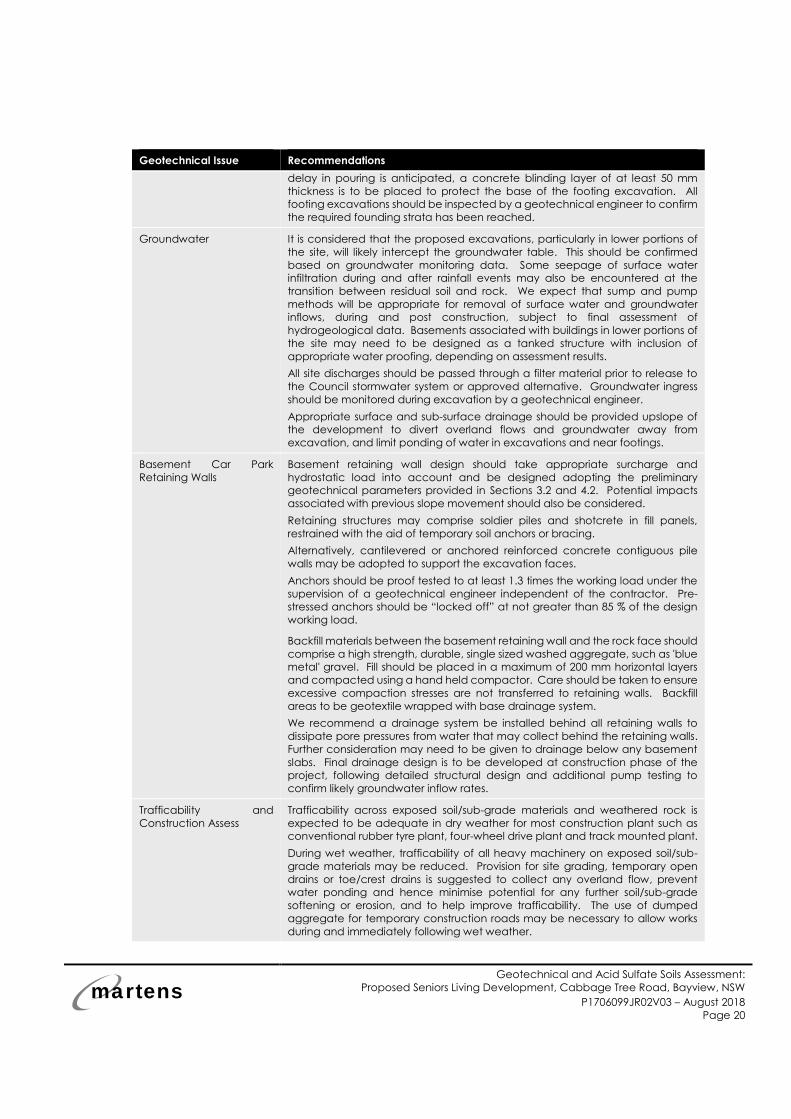
Table 12: Geotechnical recommendations
Geotechnical Issue Recommendations
Excavations and
Vibrations
The following excavation techniques may be adapted:
o Soils should be readily excavated using conventional earthmoving
equipment.
o Extremely low to low strength rock should generally be readily
excavated with a ‘toothed’ bucket or a ripping tyne (or similar)
although progress may be slow in low strength rock containing
medium strength bands.
o Rock breaker of ripping tyne attachments may be required for
excavation of medium strength sandstone, if encountered.
All excavation work should be completed with reference to the most recent
version of Code of Practice 'Excavation Work', by Safe Work Australia.
Excavation method statements will need to be prepared by the excavation
contractor prior to the issue of CC.
Consideration should be given to the use of rock sawing techniques, if medium
strong rock is encountered, prior to the use of hydraulic hammer equipment to
reduce noise and vibrations.
Batter Slopes / Shoring
Methods
Soils
Any temporary or permanent excavations into soil exceeding 0.75 m depth
should be supported by suitably designed and installed retaining or shoring
structures or, alternatively, using batter slopes of 1V:2H for temporary slopes
(unsupported for less than 1 month) and 1V:3H for permanent long term
unsupported slopes. It is recommended that unsupported soil excavations
deeper than 1.0 m should be assessed by a geotechnical engineer for slope
instability risk.
Rock
Temporary and permanent excavations for extremely low to low strength rock
may be battered at 1V:2H. This batter may be increased to 1V:1H, subject to
inspection and approval by a geotechnical engineer on site during excavation
(i.e. likely every 1 m depth). Due to numerous shear zones and weak seams
within this rock, additional stabilisation measurements, such as shotcrete, may be
required. Medium strength rock can be battered at 4V:1H or steeper, provided
there are no adversely oriented joints or defects in the rock. It is recommended
that all excavated rock faces be inspected by a geotechnical engineer to
determine whether any additional support, such as rock bolts or shotcrete, is
required.
Where there is insufficient room for temporary batters, excavations will need to
be supported by temporary shoring or permanent retaining walls such as a
soldier pile/infill panel wall system.
Heavy Machinery
Use of heavy machinery should be avoided, where possible, within 2 m of any
open soil excavation to prevent excessive vibrations and undue settlement.
martens
Geotechnical and Acid Sulfate Soils Assessment:
Proposed Seniors Living Development, Cabbage Tree Road, Bayview, NSW
P1706099JR02V03 – August 2018
Page 19
Geotechnical Issue Recommendations
Rock support Steeply dipping joints and sheared zones, observed within the rock core, may
have an adverse effect on rock face stability and construction safety.
Geotechnical mapping of the excavation should be conducted in 1.5 m
height increments to identify such features and allow early mitigation of risks
of rock movement, such as by installation of rock anchors or bolts.
The presence of weakly cemented (extremely weathered) seams and
sheared zones within the rock may adversely affect the stability of the cut
faces and may require shotcreting and rock bolting.
Rock support should be specified in terms of performance requirements and
installed / placed by contractors experienced in ground anchor technology
and on advisement by an experienced geotechnical engineer. Rock
support should not extend beyond property boundaries unless approval has
been granted by relevant property owners or stakeholders. The actual
amount of stabilisation which will be required cannot be quantified at this
stage and can only be determined at the time of construction. Martens and
Associates can complete the necessary mapping and provide advice for
possible remediation measures, where required.
Sub-grade Preparation
We recommend that any stripping of soil or sub-grades be undertaken at the
on-set of excavation and suitably stockpiled for on-site re-use (where
possible) or off-site disposal to a suitable location in accordance with NSW
DECC (2009) Waste Classification Guidelines.
For soil sub-grade areas where fill is to be placed to raise site levels and where
on-grade slabs are to be constructed, preparation of sub-grade should consist
of:
o Compact the sub-grade with a minimum 12 tonne deadweight
smooth drum vibratory roller to achieve a minimum density index
(ID) of 65 % or a minimum density of 98 % Standard Maximum Dry
Density (SMDD) for cohesionless soil (within +/- 2% of optimum
moisture content (OMC)).
o Proof rolling should be closely monitored by the project
geotechnical engineer to detect soft or unstable areas which
should be removed and replaced with engineered fill or
alternatively stabilised or bridged.
Density tests should be carried out at a frequency of one test per layer per 500m2
or three (3) tests per visit, whichever requires the higher number of tests, to
confirm the specifications provided in this report have been achieved. At least
Level 2 testing of earthworks should be carried out in accordance with AS3798
(2007). Any areas of insufficient compaction will require reworking.
Engineered fill is to be free from organic materials, other contaminants and
deleterious substances and have a maximum particle size of 40 mm. We
consider that the excavated clayey soil and weathered sandstone will be
suitable as engineered fill. It should be placed in layers of a maximum 100 mm
loose thickness and compacted to at least 98 % SMDD and within +/- 2% of OMC,
which can be reduced to 95 % SMDD in landscaped areas. Further testing will be
required to confirm this.
All site earthworks should be undertaken in accordance with AS3798 (2007) and
Aus-Spec 213 (2004).
Footings and Foundations Footings of the proposed buildings should be founded in rock below zones
affected by slope movement, i.e. sheared rock, using shallow footings or piers,
depending on foundation level. They should be designed by a suitably qualified
and experienced structural or geotechnical engineer. Estimated soil and rock
strength parameters are provided in Section 4.2.
All footings should be poured after excavation with minimal delay. All
excavated bases should be free from all loose or softened materials prior to
pouring. If water ponds in the base of the excavations, they should be pumped
dry and then re-excavated to remove all loose and softened materials. If a
martens
Geotechnical and Acid Sulfate Soils Assessment:
Proposed Seniors Living Development, Cabbage Tree Road, Bayview, NSW
P1706099JR02V03 – August 2018
Page 20
Geotechnical Issue Recommendations
delay in pouring is anticipated, a concrete blinding layer of at least 50 mm
thickness is to be placed to protect the base of the footing excavation. All
footing excavations should be inspected by a geotechnical engineer to confirm
the required founding strata has been reached.
Groundwater It is considered that the proposed excavations, particularly in lower portions of
the site, will likely intercept the groundwater table. This should be confirmed
based on groundwater monitoring data. Some seepage of surface water
infiltration during and after rainfall events may also be encountered at the
transition between residual soil and rock. We expect that sump and pump
methods will be appropriate for removal of surface water and groundwater
inflows, during and post construction, subject to final assessment of
hydrogeological data. Basements associated with buildings in lower portions of
the site may need to be designed as a tanked structure with inclusion of
appropriate water proofing, depending on assessment results.
All site discharges should be passed through a filter material prior to release to
the Council stormwater system or approved alternative. Groundwater ingress
should be monitored during excavation by a geotechnical engineer.
Appropriate surface and sub-surface drainage should be provided upslope of
the development to divert overland flows and groundwater away from
excavation, and limit ponding of water in excavations and near footings.
Basement Car Park
Retaining Walls
Basement retaining wall design should take appropriate surcharge and
hydrostatic load into account and be designed adopting the preliminary
geotechnical parameters provided in Sections 3.2 and 4.2. Potential impacts
associated with previous slope movement should also be considered.
Retaining structures may comprise soldier piles and shotcrete in fill panels,
restrained with the aid of temporary soil anchors or bracing.
Alternatively, cantilevered or anchored reinforced concrete contiguous pile
walls may be adopted to support the excavation faces.
Anchors should be proof tested to at least 1.3 times the working load under the
supervision of a geotechnical engineer independent of the contractor. Pre-
stressed anchors should be “locked off” at not greater than 85 % of the design
working load.
Backfill materials between the basement retaining wall and the rock face should
comprise a high strength, durable, single sized washed aggregate, such as 'blue
metal' gravel. Fill should be placed in a maximum of 200 mm horizontal layers
and compacted using a hand held compactor. Care should be taken to ensure
excessive compaction stresses are not transferred to retaining walls. Backfill
areas to be geotextile wrapped with base drainage system.
We recommend a drainage system be installed behind all retaining walls to
dissipate pore pressures from water that may collect behind the retaining walls.
Further consideration may need to be given to drainage below any basement
slabs. Final drainage design is to be developed at construction phase of the
project, following detailed structural design and additional pump testing to
confirm likely groundwater inflow rates.
Trafficability and
Construction Assess
Trafficability across exposed soil/sub-grade materials and weathered rock is
expected to be adequate in dry weather for most construction plant such as
conventional rubber tyre plant, four-wheel drive plant and track mounted plant.
During wet weather, trafficability of all heavy machinery on exposed soil/sub-
grade materials may be reduced. Provision for site grading, temporary open
drains or toe/crest drains is suggested to collect any overland flow, prevent
water ponding and hence minimise potential for any further soil/sub-grade
softening or erosion, and to help improve trafficability. The use of dumped
aggregate for temporary construction roads may be necessary to allow works
during and immediately following wet weather.
martens
Geotechnical and Acid Sulfate Soils Assessment:
Proposed Seniors Living Development, Cabbage Tree Road, Bayview, NSW
P1706099JR02V03 – August 2018
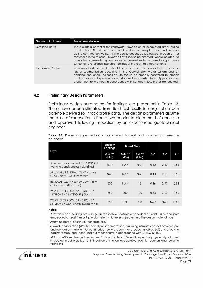
Page 21
Geotechnical Issue Recommendations
Overland Flows There exists a potential for stormwater flows to enter excavated areas during
construction. All surface runoff should be diverted away from excavation areas
during construction works. All site discharges should be passed through a filter
material prior to release. Diverted flows should be directed (where possible) to
a suitable stormwater system so as to prevent water accumulating in areas
surrounding retaining structures, footings or the crest of embankments.
Soil Erosion Control Removal of soil overburden should be performed in a manner that reduces the
risk of sedimentation occurring in the Council stormwater system and on
neighbouring lands. All spoil on site should be properly controlled by erosion
control measures to prevent transportation of sediments off-site. Appropriate soil
erosion control methods in accordance with Landcom (2004) shall be required.
4.2 Preliminary Design Parameters
Preliminary design parameters for footings are presented in Table 13.
These have been estimated from field test results in conjunction with
borehole derived soil / rock profile data. The design parameters assume
the base of excavation is free of water prior to placement of concrete
and approved following inspection by an experienced geotechnical
engineer.
Table 13: Preliminary geotechnical parameters for soil and rock encountered in
boreholes.
Layer
Shallow
Footings Bored Piers
AEB 1&4
(kPa)
AEB 2&4
(kPa)
ASF 3&4
(kPa)
Ka 5 Kp
5 K0 5
Assumed uncontrolled FILL / TOPSOIL:
(varying consistencies / densities) NA 6 NA 6 NA 6 0.40 2.50 0.55
ALLUVIAL / RESIDUAL: CLAY / sandy
CLAY / silty CLAY (firm to stiff) NA 6 NA 6 NA 6 0.40 2.50 0.55
RESIDUAL: CLAY / sandy CLAY / silty
CLAY (very stiff to hard) 200 NA 6 15 0.36 2.77 0.53
WEATHERED ROCK: SANDSTONE /
SILTSTONE / CLAYSTONE (Class V) 450 700 100 0.33 3.00 0.50
WEATHERED ROCK: SANDSTONE /
SILTSTONE / CLAYSTONE (Class IV / III) 750 1500 300 NA 6 NA 6 NA 6
Notes:
1 Allowable end bearing pressure (kPa) for shallow footings embedded at least 0.3 m and piles
embedded at least 1 m or 1 pile diameter, whichever is greater, into the design material type.
2 Assuming bored, cast in-situ concrete pile.
3 Allowable skin friction (kPa) for bored pile in compression, assuming intimate contact between pile
and foundation material. For up lift resistance, we recommend reducing ASF by 50% and checking
against ‘piston’ and ‘cone’ pull-out mechanisms in accordance with AS2159 (2009).
4 AEB and ASF are given with estimated factors of safety of 3 and 2 respectively, generally adopted
in geotechnical practice to limit settlement to an acceptable level for conventional building
structures.
martens
Geotechnical and Acid Sulfate Soils Assessment:
Proposed Seniors Living Development, Cabbage Tree Road, Bayview, NSW
P1706099JR02V03 – August 2018
Page 22
5 ka = Coefficient of active earth pressure; kp = Coefficient of passive earth pressure; k0 = Coefficient
of earth pressure at rest.
6 Not applicable, or not recommended either due to depth or potential internal settlement of
materials.
4.3 Site Classification
The site is classified as a class ‘P’ site in accordance with AS 2870 (2011),
due to slope movement risk and variable ground conditions across the
site. Subject to the inclusion of appropriate slope risk mitigation measures
and on-site assessment of foundation conditions and confirmation by a
geotechnical engineer at construction stage, a reclassification of ‘H1’
may be considered for design of shallow footings.
martens
Geotechnical and Acid Sulfate Soils Assessment:
Proposed Seniors Living Development, Cabbage Tree Road, Bayview, NSW
P1706099JR02V03 – August 2018
Page 23
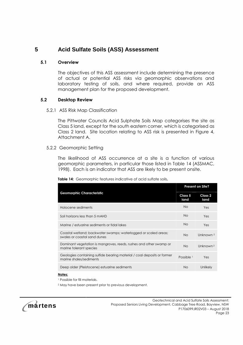
5 Acid Sulfate Soils (ASS) Assessment
5.1 Overview
The objectives of this ASS assessment include determining the presence
of actual or potential ASS risks via geomorphic observations and
laboratory testing of soils, and where required, provide an ASS
management plan for the proposed development.
5.2 Desktop Review
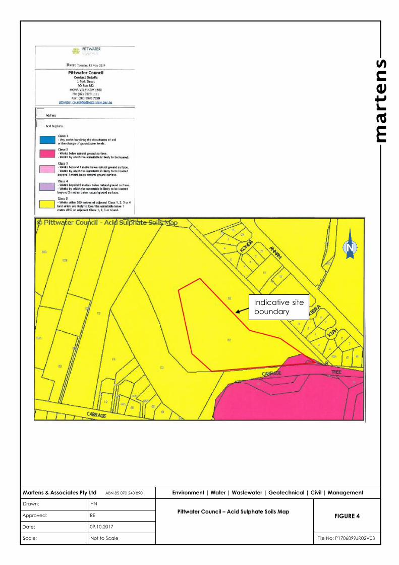
5.2.1 ASS Risk Map Classification
The Pittwater Councils Acid Sulphate Soils Map categorises the site as
Class 5 land, except for the south eastern corner, which is categorised as
Class 2 land. Site location relating to ASS risk is presented in Figure 4,
Attachment A.
5.2.2 Geomorphic Setting
The likelihood of ASS occurrence at a site is a function of various
geomorphic parameters, in particular those listed in Table 14 (ASSMAC,
1998). Each is an indicator that ASS are likely to be present onsite.
Table 14: Geomorphic features indicative of acid sulfate soils.
Geomorphic Characteristic
Present on Site?
Class 5
land
Class 2
land
Holocene sediments No Yes
Soil horizons less than 5 mAHD No Yes
Marine / estuarine sediments or tidal lakes No Yes
Coastal wetland; backwater swamps; waterlogged or scaled areas;
swales or coastal sand dunes No Unknown 2
Dominant vegetation is mangroves, reeds, rushes and other swamp or
marine tolerant species No Unknown 2
Geologies containing sulfide bearing material / coal deposits or former
marine shales/sediments Possible 1 Yes
Deep older (Pleistocene) estuarine sediments No Unlikely
Notes:
1 Possible for fill materials.
2 May have been present prior to previous development.
martens
Geotechnical and Acid Sulfate Soils Assessment:
Proposed Seniors Living Development, Cabbage Tree Road, Bayview, NSW
P1706099JR02V03 – August 2018
Page 24
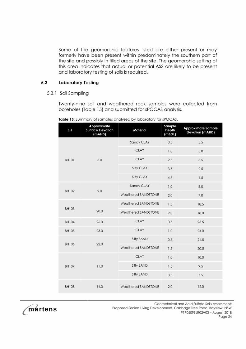
Some of the geomorphic features listed are either present or may
formerly have been present within predominately the southern part of
the site and possibly in filled areas of the site. The geomorphic setting of
this area indicates that actual or potential ASS are likely to be present
and laboratory testing of soils is required.
5.3 Laboratory Testing
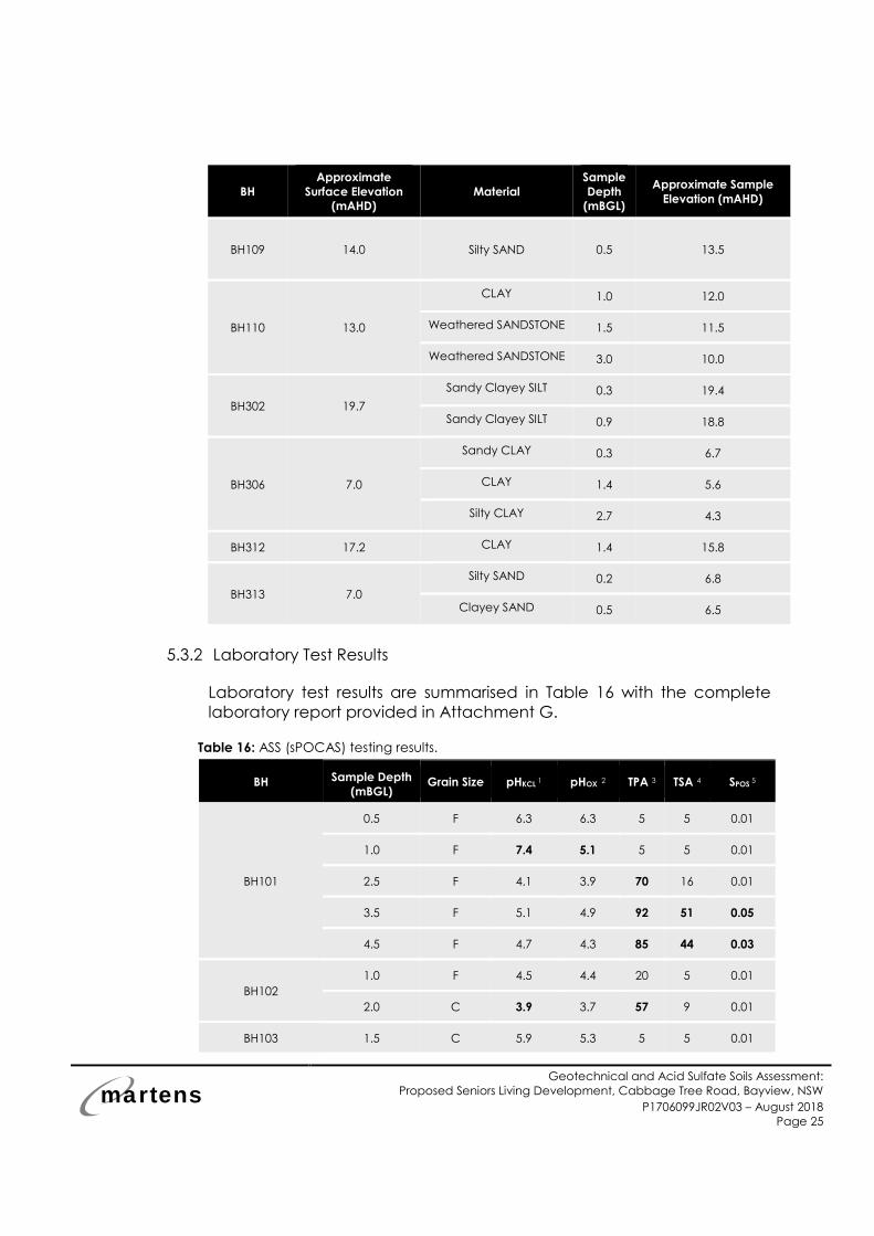
5.3.1 Soil Sampling
Twenty-nine soil and weathered rock samples were collected from
boreholes (Table 15) and submitted for sPOCAS analysis.
Table 15: Summary of samples analysed by laboratory for sPOCAS.
BH
Approximate
Surface Elevation
(mAHD)
Material
Sample
Depth
(mBGL)
Approximate Sample
Elevation (mAHD)
BH101 6.0
Sandy CLAY 0.5 5.5
CLAY 1.0 5.0
CLAY 2.5 3.5
Silty CLAY 3.5 2.5
Silty CLAY 4.5 1.5
BH102 9.0
Sandy CLAY 1.0 8.0
Weathered SANDSTONE 2.0 7.0
BH103 20.0
Weathered SANDSTONE 1.5 18.5
Weathered SANDSTONE 2.0 18.0
BH104 26.0 CLAY 0.5 25.5
BH105 23.0 CLAY 1.0 24.0
BH106 22.0
Silty SAND 0.5 21.5
Weathered SANDSTONE 1.5 20.5
BH107 11.0
CLAY 1.0 10.0
Silty SAND 1.5 9.5
Silty SAND 3.5 7.5
BH108 14.0 Weathered SANDSTONE 2.0 12.0
martens
Geotechnical and Acid Sulfate Soils Assessment:
Proposed Seniors Living Development, Cabbage Tree Road, Bayview, NSW
P1706099JR02V03 – August 2018
Page 25
BH
Approximate
Surface Elevation
(mAHD)
Material
Sample
Depth
(mBGL)
Approximate Sample
Elevation (mAHD)
BH109 14.0 Silty SAND 0.5 13.5
BH110 13.0
CLAY 1.0 12.0
Weathered SANDSTONE 1.5 11.5
Weathered SANDSTONE 3.0 10.0
BH302 19.7
Sandy Clayey SILT 0.3 19.4
Sandy Clayey SILT 0.9 18.8
BH306 7.0
Sandy CLAY 0.3 6.7
CLAY 1.4 5.6
Silty CLAY 2.7 4.3
BH312 17.2 CLAY 1.4 15.8
BH313 7.0
Silty SAND 0.2 6.8
Clayey SAND 0.5 6.5
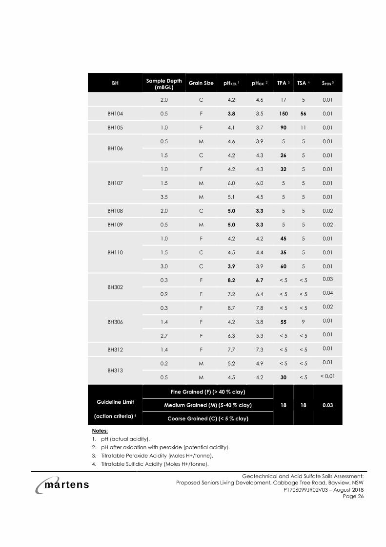
5.3.2 Laboratory Test Results
Laboratory test results are summarised in Table 16 with the complete
laboratory report provided in Attachment G.
Table 16: ASS (sPOCAS) testing results.
BH Sample Depth
(mBGL) Grain Size pHKCL
1 pHOX 2 TPA 3 TSA 4 SPOS
5
BH101
0.5 F 6.3 6.3 5 5 0.01
1.0 F 7.4 5.1 5 5 0.01
2.5 F 4.1 3.9 70 16 0.01
3.5 F 5.1 4.9 92 51 0.05
4.5 F 4.7 4.3 85 44 0.03
BH102
1.0 F 4.5 4.4 20 5 0.01
2.0 C 3.9 3.7 57 9 0.01
BH103 1.5 C 5.9 5.3 5 5 0.01
martens
Geotechnical and Acid Sulfate Soils Assessment:
Proposed Seniors Living Development, Cabbage Tree Road, Bayview, NSW
P1706099JR02V03 – August 2018
Page 26
BH Sample Depth
(mBGL) Grain Size pHKCL
1 pHOX 2 TPA 3 TSA 4 SPOS
5
2.0 C 4.2 4.6 17 5 0.01
BH104 0.5 F 3.8 3.5 150 56 0.01
BH105 1.0 F 4.1 3.7 90 11 0.01
BH106
0.5 M 4.6 3.9 5 5 0.01
1.5 C 4.2 4.3 26 5 0.01
BH107
1.0 F 4.2 4.3 32 5 0.01
1.5 M 6.0 6.0 5 5 0.01
3.5 M 5.1 4.5 5 5 0.01
BH108 2.0 C 5.0 3.3 5 5 0.02
BH109 0.5 M 5.0 3.3 5 5 0.02
BH110
1.0 F 4.2 4.2 45 5 0.01
1.5 C 4.5 4.4 35 5 0.01
3.0 C 3.9 3.9 60 5 0.01
BH302
0.3 F 8.2 6.7 < 5 < 5 0.03
0.9 F 7.2 6.4 < 5 < 5 0.04
BH306
0.3 F 8.7 7.8 < 5 < 5 0.02
1.4 F 4.2 3.8 55 9 0.01
2.7 F 6.3 5.3 < 5 < 5 0.01
BH312 1.4 F 7.7 7.3 < 5 < 5 0.01
BH313
0.2 M 5.2 4.9 < 5 < 5 0.01
0.5 M 4.5 4.2 30 < 5 < 0.01
Guideline Limit
(action criteria) 6
Fine Grained (F) (> 40 % clay)
18 18 0.03 Medium Grained (M) (5-40 % clay)
Coarse Grained (C) (< 5 % clay)
Notes:
1. pH (actual acidity).
2. pH after oxidation with peroxide (potential acidity).
3. Titratable Peroxide Acidity (Moles H+/tonne).
4. Titratable Sulfidic Acidity (Moles H+/tonne).

martens
Geotechnical and Acid Sulfate Soils Assessment:
Proposed Seniors Living Development, Cabbage Tree Road, Bayview, NSW
P1706099JR02V03 – August 2018
Page 27
5. Oxidisable sulphur (%).
6. ASSMAC (1998) p.27, for 1-1,000 tonnes disturbed soil. Bolded values in table indicate
exceedance of ASSMAC action criteria considering expected > 1000 tonnes soil disturbance.
5.3.3 ASS Classification
Based on the pHKCL and post peroxide oxidation pHOX criteria derived
from the ASSMAC (1998) guidelines:
o Soils with a pHKCL of < 4.0 are classified as actual ASS.
o Soils with pHKCL - pHox > 1 are classified as potential ASS.
o Soils with pHox < 3.5 are classified as potential ASS.
On the basis of these criteria we conclude the following:
o Three samples including two weathered rock samples (BH102
depth 2.0 m and BH110 depth 3.0 m) and one residual clay
sample (BH104, depth 0.5 m) are classified as actual ASS.
o Four samples including one weathered rock sample (BH108 depth
2.0 m) and three soil samples (BH101 depth 1.0 m (fill), BH109 depth
0.5 m (topsoil) and BH302 depth 0.3 m (residual)) are classified as
potential ASS.
o The remaining tested samples are neither actual nor potential ASS.
5.3.4 Action Criteria
According to Table 4.4 of ASSMAC (1998), a detailed management plan
is required if the soil exhibits one of the following criteria (for >1,000 tonnes
disturbed soil):
o Oxidisable sulphur (SPOS) is ≥ 0.03%; or
o TPA or TSA is ≥18 mol H+/tonne.
On the basis of these action criteria we conclude that thirteen samples
including three fill samples, one alluvial sample, five residual soil samples
and four weathered rock samples (i.e. BH101 depths 2.5 m and 3.5 m (fill)
and 4.5 m (alluvial), BH102 depth 2.0 m (weathered sandstone), BH104
depth 0.5 m (residual), BH105 depth 1.0 m (residual), BH106 depth 1.5 m
(weathered sandstone), BH107 depth 1.0 m (fill), BH110 depths 1.0 m
(residual),1.5 m and 3 m (weathered sandstone), BH306 depth 1.4 m
(residual) and BH313 depth 0.5 m (residual)) exceed the criteria based
on TPA, TSA and Spos.
martens
Geotechnical and Acid Sulfate Soils Assessment:
Proposed Seniors Living Development, Cabbage Tree Road, Bayview, NSW
P1706099JR02V03 – August 2018
Page 28
5.3.5 Conclusion
o AAS criteria exceedance within the proposed apartment building
area was found in some sandstone bedrock samples and
overlying clay samples. The origin of this acidity is therefore likely
to be related to geology rather than from ASS. We conclude that
preparation of a management plan is not essential for
construction works (based on the current development proposal)
of the proposed buildings as they are predominantly located
within the residual soil landscape.
o AAS action criteria exceedance within the south eastern portion
(proposed new entry / exit road) was found in one alluvial soil
sample. We conclude that preparation of a management plan is
required for any construction works, including the proposed new
entry / exit road, within the south eastern portion of the site.
martens
Geotechnical and Acid Sulfate Soils Assessment:
Proposed Seniors Living Development, Cabbage Tree Road, Bayview, NSW
P1706099JR02V03 – August 2018
Page 29
6 Preliminary Pavement Thickness Design
6.1 Overview
A preliminary pavement thickness design was undertaken for the
proposed new entry / exit to the site. The design adopted a traffic
loading of Equivalent Standard Axles (ESA) in accordance with Northern
Beaches’s Civil Engineering requirements, AUS-SPEC Specifications and
Austroads (2012) Guide to Pavement Technology Part 2 Pavement
Structural Design. A CBR value, adopted for the preliminary design, was
estimated using limited lab and field test results.
6.2 Design Parameters
An ESA value of 3x10⁵ was adopted for design of the proposed new entry
/ exit to the site.
Two bulk soil samples were collected for CBR testing (Figure 2,
Attachment A). A laboratory test certificate is provided in Attachment
G. Given the limited laboratory test results, DCP-CBR correlations were
carried out using Austroads (2012). Considering the variation in DCP ‘N’
counts, resulting from variable soil consistency, the potential variation in
soil moisture conditions as well as the likely variable cut and fill
requirements across the site, we have adopted a CBR value of 4 % for
preliminary design purposes.
Subgrade improvement / replacement will likely be required where
material of inferior quality is uncovered during excavation (i.e. CBR < 4
%). Alternatively, lower CBR values may be applicable and pavement
material thickness may need to be revised. If material of superior quality
is uncovered during excavation, higher CBR values may be applicable
and pavement material thickness may be revised, subject to verification
during construction by a geotechnical engineer and further on-site /
laboratory testing.
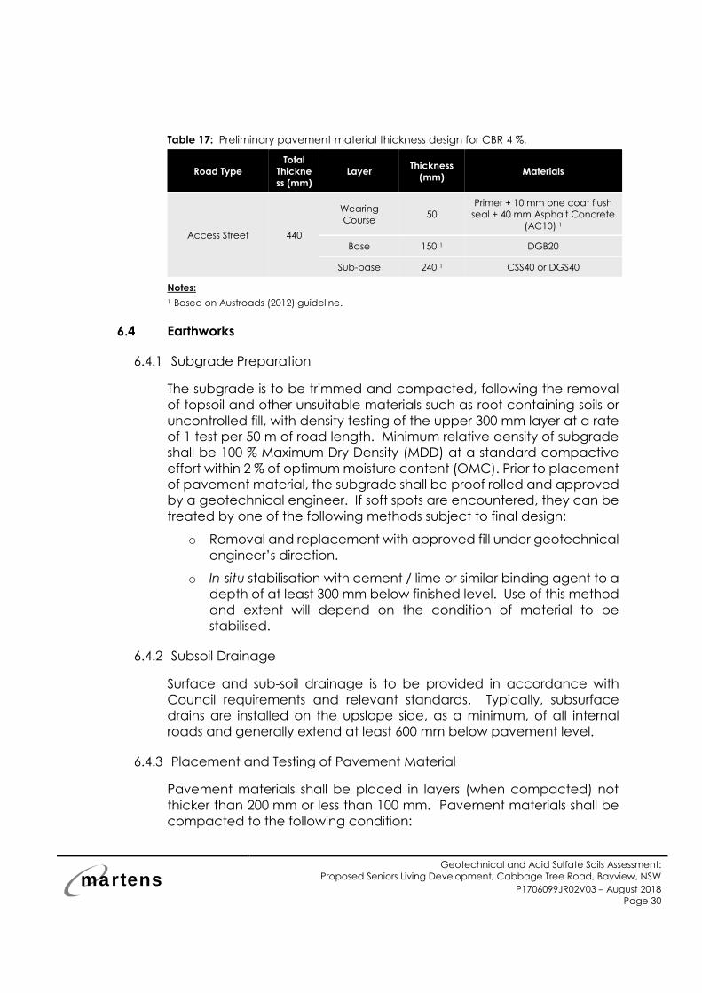
6.3 Pavement Thickness
Table 17 presents recommended pavement types and material
thicknesses for the proposed road.
martens
Geotechnical and Acid Sulfate Soils Assessment:
Proposed Seniors Living Development, Cabbage Tree Road, Bayview, NSW
P1706099JR02V03 – August 2018
Page 30
Table 17: Preliminary pavement material thickness design for CBR 4 %.
Road Type
Total
Thickne
ss (mm)
Layer Thickness
(mm) Materials
Access Street 440
Wearing
Course 50
Primer + 10 mm one coat flush
seal + 40 mm Asphalt Concrete
(AC10) 1
Base 150 1 DGB20
Sub-base 240 1 CSS40 or DGS40
Notes: 1 Based on Austroads (2012) guideline.
6.4 Earthworks
6.4.1 Subgrade Preparation
The subgrade is to be trimmed and compacted, following the removal
of topsoil and other unsuitable materials such as root containing soils or
uncontrolled fill, with density testing of the upper 300 mm layer at a rate
of 1 test per 50 m of road length. Minimum relative density of subgrade
shall be 100 % Maximum Dry Density (MDD) at a standard compactive
effort within 2 % of optimum moisture content (OMC). Prior to placement
of pavement material, the subgrade shall be proof rolled and approved
by a geotechnical engineer. If soft spots are encountered, they can be
treated by one of the following methods subject to final design:
o Removal and replacement with approved fill under geotechnical
engineer’s direction.
o In-situ stabilisation with cement / lime or similar binding agent to a
depth of at least 300 mm below finished level. Use of this method
and extent will depend on the condition of material to be
stabilised.
6.4.2 Subsoil Drainage
Surface and sub-soil drainage is to be provided in accordance with
Council requirements and relevant standards. Typically, subsurface
drains are installed on the upslope side, as a minimum, of all internal
roads and generally extend at least 600 mm below pavement level.
6.4.3 Placement and Testing of Pavement Material
Pavement materials shall be placed in layers (when compacted) not
thicker than 200 mm or less than 100 mm. Pavement materials shall be
compacted to the following condition:
martens
Geotechnical and Acid Sulfate Soils Assessment:
Proposed Seniors Living Development, Cabbage Tree Road, Bayview, NSW
P1706099JR02V03 – August 2018
Page 31
o Sub-base - Minimum 98 % MDD at modified compactive effort
(±2% OMC).
o Base - Minimum 98% MDD at modified compactive effort (±2%
OMC).
Compaction testing shall be undertaken by a NATA accredited
laboratory in accordance with procedures as outlined in AS1289, and at
a rate of no less than 1 per 50 linear metres, or per 250 m2, whichever is
the greater, with a minimum of 2 tests in any one length. Each pavement
layer shall be proof rolled under Geotechnical Engineers’ supervision.
Subsequent pavement layers shall not be placed prior to approval of
underlying layer by the Geotechnical Engineer.
6.4.4 Fill Placement
Should filling be required to raise subgrade levels, the use of site-won
excavated residual soils may be considered, subject to implementing
stringent moisture conditioning and compaction controls, or mixing with
lime to assist placement of medium to high plasticity clay, and testing.
Alternatively, suitable granular fill, approved for use by a Geotechnical
Engineer may be adopted. All earthworks specification is to be prepared
by the supervising engineer and be implemented by the contractor.
6.4.5 Other Considerations
Transitioning of existing and new pavement sections needs to be
included in detailed design. The transition zone is to be keyed and
adequately offset from wheel paths.
martens
Geotechnical and Acid Sulfate Soils Assessment:
Proposed Seniors Living Development, Cabbage Tree Road, Bayview, NSW
P1706099JR02V03 – August 2018
Page 32
7 Further Assessments and Monitoring / Inspections
7.1 Further Works
We recommend the following additional geotechnical assessments are
carried out to develop the final design:
1. Detailed design of any shoring / retaining/ foundation structures.
2. Supplementary investigations, including rock coring, particularly in
the southern and south western portions of the site, to better
understand the potential risks associated with sheared / fractured
rock across the site.
3. Installation of inclinometers upslope of proposed excavations for
the proposed development to measure ground movements and
identify deflections in the support structures to manage risks
associated with potential ground movements.
4. Review of the final design and construction staging plan by a
senior geotechnical engineer to confirm adequate consideration
of the geotechnical risks and adoption of the recommendations
provided in this report.
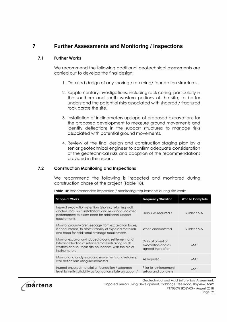
7.2 Construction Monitoring and Inspections
We recommend the following is inspected and monitored during
construction phase of the project (Table 18).
Table 18: Recommended inspection / monitoring requirements during site works.
Scope of Works Frequency/Duration Who to Complete
Inspect excavation retention (shoring, retaining wall,
anchor, rock bolt) installations and monitor associated
performance to assess need for additional support
requirements.
Daily / As required 2 Builder / MA 1
Monitor groundwater seepage from excavation faces,
if encountered, to assess stability of exposed materials
and need for additional drainage requirements.
When encountered Builder / MA 1
Monitor excavation-induced ground settlement and
lateral deflection of retained materials along south
western and southern site boundaries, with the aid of
inclinometers.
Daily at on-set of
excavation and as
agreed thereafter
MA 1
Monitor and analyse ground movements and retaining
wall deflections using inclinometers As required MA 1
Inspect exposed material at foundation / subgrade
level to verify suitability as foundation / lateral support /
Prior to reinforcement
set-up and concrete MA 1

martens
Geotechnical and Acid Sulfate Soils Assessment:
Proposed Seniors Living Development, Cabbage Tree Road, Bayview, NSW
P1706099JR02V03 – August 2018
Page 33
Scope of Works Frequency/Duration Who to Complete
subgrade. placement
Monitor sedimentation downslope of excavated areas. During and after
rainfall events Builder
Monitor sediment and erosion control structures to
assess adequacy and for removal of built up spoil. After rainfall events Builder
Notes:
1 MA = Martens and Associates engineer
2 MA inspection frequency to be determined based on initial inspection findings in line with
construction program.
martens
Geotechnical and Acid Sulfate Soils Assessment:
Proposed Seniors Living Development, Cabbage Tree Road, Bayview, NSW
P1706099JR02V03 – August 2018
Page 34
8 References
Australian Geomechanics Society (2007) Practice Note Guidelines For
Landslide Risk Management 2007, Journal and News of the
Australian Geomechanics Society Volume 42 No 1 March 2007.
Australian Standard 1289.6.3.2 (1997) Determination of the penetration
resistance of a soil - 9kg dynamic cone penetrometer test.
Australian Standard 1726 (2017) Geotechnical site investigations.
Australian Standards 2159 (2009) Piling-Design and Installation.
Australian Standard 2870 (2011) Residential slabs and footings.
Australian Standard 3798 (2007) Guidelines on earthworks for commercial
and residential developments.
Bertuzzi, R. and Pells, P. J. N. (2002) Geotechnical parameters of Sydney
sandstone and shale, Australian Geomechanics, Vol. 37, No 5, pp
41-54.
Bee and Lethbridge Surveying Plan (2014), Drawing No. 18990, dated
April 2014 (Bee and Lethbridge, 2014).
Department of Land and Water Conservation (DLWC, 2002), Site
Investigations for Urban Salinity.
Herbert C. (1983) Sydney 1:100 000 Geological Sheet 9130, 1st edition,
Geological Survey of New South Wales, Sydney.
Marchese Partners International Pty Ltd (2018) Job No. 14023, Drawing
Nos. DA1.02, DA1.04, DA2.01 to DA07, DA2.21 to DA2.43, DA3.01 to
DA3.08 and DA4.01 to DA4.04, dated June 2017, Drawing Nos.
LEC2.01 to LEC2.06, LEC3.01, LEC3.03 to LEC3.05 and LEC5.23 dated
August 2018 (Marchese Partners, 2018).
Northern Beaches Council (2015) Development Control Plan,
Amendment 19.
NSW Department of Primary Industries Water (DPIW) real time
groundwater bore database.
Pittwater Local Environmental Plan (2014) Geotechnical Hazard Map –
Sheet GTH_011.

martens
Geotechnical and Acid Sulfate Soils Assessment:
Proposed Seniors Living Development, Cabbage Tree Road, Bayview, NSW
P1706099JR02V03 – August 2018
Page 35
Safe Work Australia (2015) Code of Practice ‘Excavation Work’.
Soil Conservation Service of NSW (1983), Sydney Australia 1:100,000 Soil
Landscape Series Sheet 9130.

martens
Geotechnical and Acid Sulfate Soils Assessment:
Proposed Seniors Living Development, Cabbage Tree Road, Bayview, NSW
P1706099JR02V03 – August 2018
Page 36
9 Attachment A – Figures
Key:
marte
ns
Drawn:
Approved:
Date:
HN
RE
16.11.2017
NA
Environment | Water | Wastewater | Geotechnical | Civil | Management Martens & Associates Pty Ltd ABN 85 070 240 890
FIGURE 2
Drawing:
GEOTECHNICAL TESTING PLAN AND CROSS SECTION LOCATIONS
Proposed Seniors Living Development, Cabbage Tree Road, Bayview, NSW
(Source: Nearmap, 2017) Job No: P1706099JR02V03
V01 Scale:
Scale:
Cabbage Tree Road
Annam Road
martens
Geotechnical and Acid Sulfate Soils Assessment:
Proposed Seniors Living Development, Cabbage Tree Road, Bayview, NSW
P1706099JR02V02 – November 2017
Page 38
marten
s
Drawn:
Approved:
Date:
Scale:
HN
RE
09.10.2017
Not to Scale File No: P1706099JR02V03
Environment | Water | Wastewater | Geotechnical | Civil | Management Martens & Associates Pty Ltd ABN 85 070 240 890
FIGURE 3 Drawing No: Pittwater LEP, 2014 Geotechnical Hazard Map, showing site
location relative to risk classes
(Source: Pittwater LEP, 2014)
Indicative development boundary
martens
Geotechnical and Acid Sulfate Soils Assessment:
Proposed Seniors Living Development, Cabbage Tree Road, Bayview, NSW
P1706099JR02V02 – November 2017
Page 39
marten
s
Drawn:
Approved:
Date:
Scale:
HN
RE
09.10.2017
Not to Scale File No: P1706099JR02V03
Environment | Water | Wastewater | Geotechnical | Civil | Management Martens & Associates Pty Ltd ABN 85 070 240 890
FIGURE 4 Drawing No: Pittwater Council – Acid Sulphate Soils Map
Indicative site
boundary
martens
Geotechnical and Acid Sulfate Soils Assessment:
Proposed Seniors Living Development, Cabbage Tree Road, Bayview, NSW
P1706099JR02V02 – November 2017
Page 40
MARTENS & ASSOCIATES P/L
PROJECT: P1706099
BOREHOLE: BH302 DEPTH: 2.8 m – 12 m DATE: 20/09/2017
marten
s
Drawn:
Approved:
Date:
Scale:
HN
RE
27.08.2018
NA File No: P1706099JR02V03
Environment | Water | Wastewater | Geotechnical | Civil | Management Martens & Associates Pty Ltd ABN 85 070 240 890
FIGURE 5
Drawing: PHOTO OF ROCK CORE – BH302
Proposed Seniors Living Development, Cabbage Tree Road, Bayview, NSW
martens
Geotechnical and Acid Sulfate Soils Assessment:
Proposed Seniors Living Development, Cabbage Tree Road, Bayview, NSW
P1706099JR02V02 – November 2017
Page 41
MARTENS & ASSOCIATES P/L
PROJECT: P1706099
BOREHOLE: BH303 DEPTH: 2.62 m – 13.4 m DATE: 20/09/2017
marten
s
Drawn:
Approved:
Date:
Scale:
HN
RE
27.08.2018
NA File No: P1706099JR02V03
Environment | Water | Wastewater | Geotechnical | Civil | Management Martens & Associates Pty Ltd ABN 85 070 240 890
FIGURE 6
Drawing: PHOTO OF ROCK CORE – BH303
Proposed Seniors Living Development, Cabbage Tree Road, Bayview, NSW
martens
Geotechnical and Acid Sulfate Soils Assessment:
Proposed Seniors Living Development, Cabbage Tree Road, Bayview, NSW
P1706099JR02V02 – November 2017
Page 42
MARTENS & ASSOCIATES P/L
PROJECT: P1706099
BOREHOLE: BH305 DEPTH: 2.8 m – 15.0 m DATE: 20/09/2017
marten
s
Drawn:
Approved:
Date:
Scale:
HN
RE
27.08.2018
NA File No: P1706099JR02V03
Environment | Water | Wastewater | Geotechnical | Civil | Management Martens & Associates Pty Ltd ABN 85 070 240 890
FIGURE 7
Drawing: PHOTO OF ROCK CORE – BH305
Proposed Seniors Living Development, Cabbage Tree Road, Bayview, NSW
martens
Geotechnical and Acid Sulfate Soils Assessment:
Proposed Seniors Living Development, Cabbage Tree Road, Bayview, NSW
P1706099JR02V02 – November 2017
Page 43
10 Attachment B – Borehole and Monitoring Well Logs
Qualit
yS
he
etN
o.4
(C) Copyright Martens & Associates Pty. Ltd . 2014
Engineering Log -MARTENS & ASSOCIATES PTY LTD
6/37 Leighton PlaceHornsby, NSW 2077 Australia
Phone: (02) 9476 9999 Fax: (02) 9476 [email protected] WEB: http://www.martens.com.au
P1404179
2.0
4.0
6.0
8.0
2.0
4.0
6.0
8.0
9.09.0
1.0
3.0
5.0
7.0
1.0
3.0
5.0
7.0
martens
REFSheet of
SU
PP
OR
T
WA
TE
R
RESULTS ANDADDITIONAL OBSERVATIONS
EXCAVATION DATA
ME
TH
OD
MATERIAL DATA SAMPLING & TESTING
EXCAVATION LOG TO BE READ IN CONJUNCTION WITH ACCOMPANYING REPORT NOTES AND ABBREVIATIONS
MO
IST
UR
E
DE
PT
H(M
)
TY
PE
DE
PT
H(M
)
CLIENT
PROJECT NO.
PROJECT
SITE
PE
NE
TR
AT
ION
RE
SIS
TA
NC
E
L M H R
EQUIPMENT
EXCAVATION DIMENSIONS
EASTING
NORTHING
RL SURFACE
ASPECT
COMMENCED
LOGGED
GEOLOGY
COMPLETED
CHECKED
VEGETATION
EQUIPMENT / METHODN Natural exposureX Existing excavationBH Backhoe bucketHA Hand augerS SpadeCC Concrete CorerV V-BitTC Tungsten Carbide BitPT Push tube
MOISTURED DryM MoistW WetWp Plastic limitWl Liquid limit
WATERN None observedX Not measured
Water level
Water outflow
Water inflow
SUPPORTSH ShoringSC ShotcreteRB Rock BoltsNil No support
CLASSIFICATIONSYMBOLS ANDSOIL DESCRIPTION
USCS
Agricultural
CONSISTENCYVS Very SoftS SoftF FirmSt StiffVSt Very StiffH HardF Friable
DENSITYVL Very LooseL LooseMD Medium DenseD DenseVD Very Dense
PENETRATIONL LowM ModerateH HighR Refusal
SLOPE
SAMPLING & TESTINGA Auger sampleB Bulk sampleU Undisturbed sampleD Disturbed sampleM Moisture contentUx Tube sample (x mm)
pp Pocket penetrometerS Standard penetration testVS Vane shearDCP Dynamic cone
penetrometerFD Field densityWS Water sample
GR
AP
HIC
LO
G
CL
AS
SIF
ICA
TIO
N
DESCRIPTION OF STRATASoil type, texture, structure, mottling, colour, plasticity, rocks, oxidation,
particle characteristics, organics, secondary and minor components,fill, contamination, odour.
CO
NS
IST
EN
CY
DE
NS
ITY
IND
EX
BH101
Hydraulic Auger
Ø100mm X 6.2m depth
Borehole
1 1
10-15%
N
Y
-
-
6mAHD
South East
20.05.14
AB
20.05.14
GT
Grass
Planix Projects
Geotechnical/Acid Sulphate Soils Assessment
Cabbage Tree Road, Bayview, NSW Hawkesbury Sandstone
Organic SILT - Low plasticity, dark brown,organics, with sand.
V Nil N M OL
V-bit refusal on inferred very low strengthsandstone at 6.2m.
CLAY - Medium plasticity, brown with light brown,red/orange mottles.
V Nil N M CI
- FILL
- V Bit refusal at 6.2m.
Sandy CLAY - Light brown/brown, low to mediumplasticity, non homogenous.
V Nil N M CL
- FILL
3.2
CLAY - Medium plasticity, brown/orange,yellow, trace gravels (2-30mm, 5%).
V Nil N M CL
SANDSTONE - Inferred extremely low strength,red/brown, fine to medium grained, extremely weathered.
V Nil Y W
0.1
5.8
A 0.5 4179/101/ 0.5
A 1.5 4179/101/ 1.5
A 2.5 4179/101/ 2.5
A 3.5 4179/101/ 3.5
A 1.0 4179/101/ 1.0
A 2.0 4179/101/ 2.0
6.2
2.3
0.5- FILL
5.0
Silty CLAY - High plasticity, black, dark brown,minor organics.
V Nil N M CH
A 4.0 4179/101/ 4.0
A 4.5 4179/101/ 4.5
A 5.5 4179/101/ 5.5
A 6.0 4179/101/ 6.0
Y W
- FILL
F-St
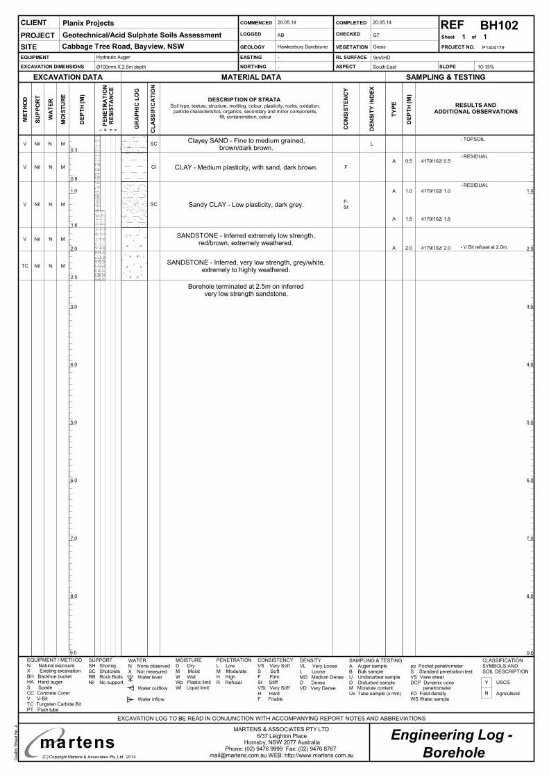
Qualit
yS
he
etN
o.4
(C) Copyright Martens & Associates Pty. Ltd . 2014
Engineering Log -MARTENS & ASSOCIATES PTY LTD
6/37 Leighton PlaceHornsby, NSW 2077 Australia
Phone: (02) 9476 9999 Fax: (02) 9476 [email protected] WEB: http://www.martens.com.au
P1404179
2.0
4.0
6.0
8.0
2.0
4.0
6.0
8.0
9.09.0
1.0
3.0
5.0
7.0
1.0
3.0
5.0
7.0
martens
REFSheet of
SU
PP
OR
T
WA
TE
R
RESULTS ANDADDITIONAL OBSERVATIONS
EXCAVATION DATA
ME
TH
OD
MATERIAL DATA SAMPLING & TESTING
EXCAVATION LOG TO BE READ IN CONJUNCTION WITH ACCOMPANYING REPORT NOTES AND ABBREVIATIONS
MO
IST
UR
E
DE
PT
H(M
)
TY
PE
DE
PT
H(M
)
CLIENT
PROJECT NO.
PROJECT
SITE
PE
NE
TR
AT
ION
RE
SIS
TA
NC
E
L M H R
EQUIPMENT
EXCAVATION DIMENSIONS
EASTING
NORTHING
RL SURFACE
ASPECT
COMMENCED
LOGGED
GEOLOGY
COMPLETED
CHECKED
VEGETATION
EQUIPMENT / METHODN Natural exposureX Existing excavationBH Backhoe bucketHA Hand augerS SpadeCC Concrete CorerV V-BitTC Tungsten Carbide BitPT Push tube
MOISTURED DryM MoistW WetWp Plastic limitWl Liquid limit
WATERN None observedX Not measured
Water level
Water outflow
Water inflow
SUPPORTSH ShoringSC ShotcreteRB Rock BoltsNil No support
CLASSIFICATIONSYMBOLS ANDSOIL DESCRIPTION
USCS
Agricultural
CONSISTENCYVS Very SoftS SoftF FirmSt StiffVSt Very StiffH HardF Friable
DENSITYVL Very LooseL LooseMD Medium DenseD DenseVD Very Dense
PENETRATIONL LowM ModerateH HighR Refusal
SLOPE
SAMPLING & TESTINGA Auger sampleB Bulk sampleU Undisturbed sampleD Disturbed sampleM Moisture contentUx Tube sample (x mm)
pp Pocket penetrometerS Standard penetration testVS Vane shearDCP Dynamic cone
penetrometerFD Field densityWS Water sample
GR
AP
HIC
LO
G
CL
AS
SIF
ICA
TIO
N
DESCRIPTION OF STRATASoil type, texture, structure, mottling, colour, plasticity, rocks, oxidation,
particle characteristics, organics, secondary and minor components,fill, contamination, odour.
CO
NS
IST
EN
CY
DE
NS
ITY
IND
EX
BH102
Hydraulic Auger
Ø100mm X 2.5m depth
Borehole
1 1
10-15%
N
Y
-
-
9mAHD
South East
20.05.14
AB
20.05.14
GT
Grass
Planix Projects
Geotechnical/Acid Sulphate Soils Assessment
Cabbage Tree Road, Bayview, NSW Hawkesbury Sandstone
Clayey SAND - Fine to medium grained,brown/dark brown.
V Nil N M SC
Borehole terminated at 2.5m on inferredvery low strength sandstone.
Sandy CLAY - Low plasticity, dark grey.V Nil N M SC
- V Bit refusal at 2.0m.
CLAY - Medium plasticity, with sand, dark brown.V Nil N M CI
SANDSTONE - Inferred extremely low strength,red/brown, extremely weathered.
V Nil N M
0.3
A 0.5 4179/102/ 0.5
A 1.5 4179/102/ 1.5
A 1.0 4179/102/ 1.0
A 2.0 4179/102/ 2.0
2.5
1.6
0.8
SANDSTONE - Inferred, very low strength, grey/white,extremely to highly weathered.
TC Nil N M
F-St
F
L- TOPSOIL
- RESIDUAL
- RESIDUAL
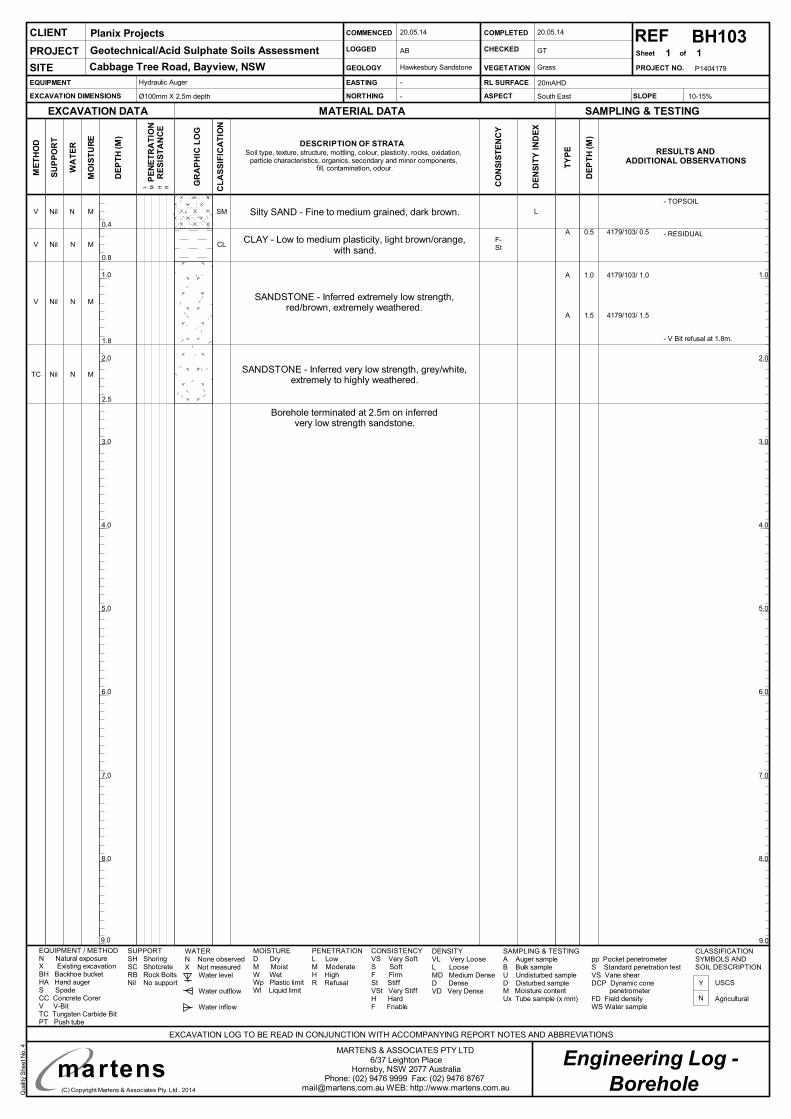
Qualit
yS
he
etN
o.4
(C) Copyright Martens & Associates Pty. Ltd . 2014
Engineering Log -MARTENS & ASSOCIATES PTY LTD
6/37 Leighton PlaceHornsby, NSW 2077 Australia
Phone: (02) 9476 9999 Fax: (02) 9476 [email protected] WEB: http://www.martens.com.au
P1404179
2.0
4.0
6.0
8.0
2.0
4.0
6.0
8.0
9.09.0
1.0
3.0
5.0
7.0
1.0
3.0
5.0
7.0
martens
REFSheet of
SU
PP
OR
T
WA
TE
R
RESULTS ANDADDITIONAL OBSERVATIONS
EXCAVATION DATA
ME
TH
OD
MATERIAL DATA SAMPLING & TESTING
EXCAVATION LOG TO BE READ IN CONJUNCTION WITH ACCOMPANYING REPORT NOTES AND ABBREVIATIONS
MO
IST
UR
E
DE
PT
H(M
)
TY
PE
DE
PT
H(M
)
CLIENT
PROJECT NO.
PROJECT
SITE
PE
NE
TR
AT
ION
RE
SIS
TA
NC
E
L M H R
EQUIPMENT
EXCAVATION DIMENSIONS
EASTING
NORTHING
RL SURFACE
ASPECT
COMMENCED
LOGGED
GEOLOGY
COMPLETED
CHECKED
VEGETATION
EQUIPMENT / METHODN Natural exposureX Existing excavationBH Backhoe bucketHA Hand augerS SpadeCC Concrete CorerV V-BitTC Tungsten Carbide BitPT Push tube
MOISTURED DryM MoistW WetWp Plastic limitWl Liquid limit
WATERN None observedX Not measured
Water level
Water outflow
Water inflow
SUPPORTSH ShoringSC ShotcreteRB Rock BoltsNil No support
CLASSIFICATIONSYMBOLS ANDSOIL DESCRIPTION
USCS
Agricultural
CONSISTENCYVS Very SoftS SoftF FirmSt StiffVSt Very StiffH HardF Friable
DENSITYVL Very LooseL LooseMD Medium DenseD DenseVD Very Dense
PENETRATIONL LowM ModerateH HighR Refusal
SLOPE
SAMPLING & TESTINGA Auger sampleB Bulk sampleU Undisturbed sampleD Disturbed sampleM Moisture contentUx Tube sample (x mm)
pp Pocket penetrometerS Standard penetration testVS Vane shearDCP Dynamic cone
penetrometerFD Field densityWS Water sample
GR
AP
HIC
LO
G
CL
AS
SIF
ICA
TIO
N
DESCRIPTION OF STRATASoil type, texture, structure, mottling, colour, plasticity, rocks, oxidation,
particle characteristics, organics, secondary and minor components,fill, contamination, odour.
CO
NS
IST
EN
CY
DE
NS
ITY
IND
EX
BH103
Hydraulic Auger
Ø100mm X 2.5m depth
Borehole
1 1
10-15%
N
Y
-
-
20mAHD
South East
20.05.14
AB
20.05.14
GT
Grass
Planix Projects
Geotechnical/Acid Sulphate Soils Assessment
Cabbage Tree Road, Bayview, NSW Hawkesbury Sandstone
V Nil N M SM
- V Bit refusal at 1.8m.
V Nil N M CL
V Nil N M
0.4A 0.5 4179/103/ 0.5
A 1.5 4179/103/ 1.5
A 1.0 4179/103/ 1.0
2.5
1.8
TC Nil N M
0.8
F-St
Silty SAND - Fine to medium grained, dark brown.
Borehole terminated at 2.5m on inferredvery low strength sandstone.
CLAY - Low to medium plasticity, light brown/orange,with sand.
SANDSTONE - Inferred extremely low strength,red/brown, extremely weathered.
SANDSTONE - Inferred very low strength, grey/white,extremely to highly weathered.
- RESIDUAL
- TOPSOIL
L
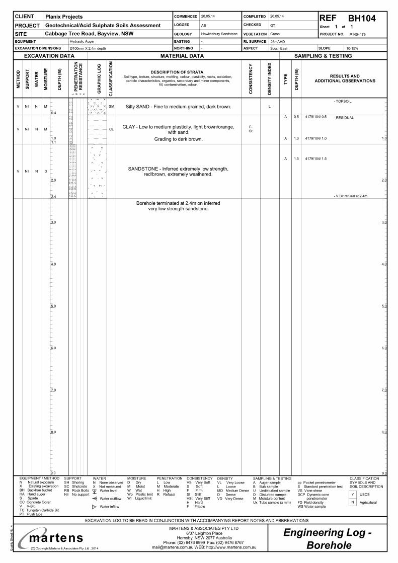
Qualit
yS
he
etN
o.4
(C) Copyright Martens & Associates Pty. Ltd . 2014
Engineering Log -MARTENS & ASSOCIATES PTY LTD
6/37 Leighton PlaceHornsby, NSW 2077 Australia
Phone: (02) 9476 9999 Fax: (02) 9476 [email protected] WEB: http://www.martens.com.au
P1404179
2.0
4.0
6.0
8.0
2.0
4.0
6.0
8.0
9.09.0
1.0
3.0
5.0
7.0
1.0
3.0
5.0
7.0
martens
REFSheet of
SU
PP
OR
T
WA
TE
R
RESULTS ANDADDITIONAL OBSERVATIONS
EXCAVATION DATA
ME
TH
OD
MATERIAL DATA SAMPLING & TESTING
EXCAVATION LOG TO BE READ IN CONJUNCTION WITH ACCOMPANYING REPORT NOTES AND ABBREVIATIONS
MO
IST
UR
E
DE
PT
H(M
)
TY
PE
DE
PT
H(M
)
CLIENT
PROJECT NO.
PROJECT
SITE
PE
NE
TR
AT
ION
RE
SIS
TA
NC
E
L M H R
EQUIPMENT
EXCAVATION DIMENSIONS
EASTING
NORTHING
RL SURFACE
ASPECT
COMMENCED
LOGGED
GEOLOGY
COMPLETED
CHECKED
VEGETATION
EQUIPMENT / METHODN Natural exposureX Existing excavationBH Backhoe bucketHA Hand augerS SpadeCC Concrete CorerV V-BitTC Tungsten Carbide BitPT Push tube
MOISTURED DryM MoistW WetWp Plastic limitWl Liquid limit
WATERN None observedX Not measured
Water level
Water outflow
Water inflow
SUPPORTSH ShoringSC ShotcreteRB Rock BoltsNil No support
CLASSIFICATIONSYMBOLS ANDSOIL DESCRIPTION
USCS
Agricultural
CONSISTENCYVS Very SoftS SoftF FirmSt StiffVSt Very StiffH HardF Friable
DENSITYVL Very LooseL LooseMD Medium DenseD DenseVD Very Dense
PENETRATIONL LowM ModerateH HighR Refusal
SLOPE
SAMPLING & TESTINGA Auger sampleB Bulk sampleU Undisturbed sampleD Disturbed sampleM Moisture contentUx Tube sample (x mm)
pp Pocket penetrometerS Standard penetration testVS Vane shearDCP Dynamic cone
penetrometerFD Field densityWS Water sample
GR
AP
HIC
LO
G
CL
AS
SIF
ICA
TIO
N
DESCRIPTION OF STRATASoil type, texture, structure, mottling, colour, plasticity, rocks, oxidation,
particle characteristics, organics, secondary and minor components,fill, contamination, odour.
CO
NS
IST
EN
CY
DE
NS
ITY
IND
EX
BH104
Hydraulic Auger
Ø100mm X 2.4m depth
Borehole
1 1
10-15%
N
Y
-
-
26mAHD
South East
20.05.14
AB
20.05.14
GT
Grass
Planix Projects
Geotechnical/Acid Sulphate Soils Assessment
Cabbage Tree Road, Bayview, NSW Hawkesbury Sandstone
Silty SAND - Fine to medium grained, dark brown.V Nil N M SM
Borehole terminated at 2.4m on inferredvery low strength sandstone.
- V Bit refusal at 2.4m.
CLAY - Low to medium plasticity, light brown/orange,with sand.
V Nil N M CL
SANDSTONE - Inferred extremely low strength,red/brown, extremely weathered.
V Nil N D
0.4A 0.5 4179/104/ 0.5
A 1.5 4179/104/ 1.5
A 1.0 4179/104/ 1.0
2.4
1.1Grading to dark brown.
F-St
- RESIDUAL
- TOPSOIL
L
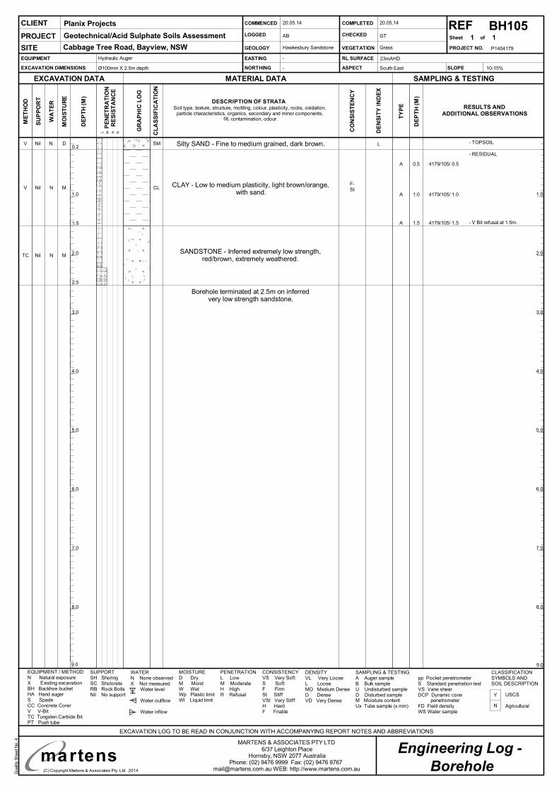
Qualit
yS
he
etN
o.4
(C) Copyright Martens & Associates Pty. Ltd . 2014
Engineering Log -MARTENS & ASSOCIATES PTY LTD
6/37 Leighton PlaceHornsby, NSW 2077 Australia
Phone: (02) 9476 9999 Fax: (02) 9476 [email protected] WEB: http://www.martens.com.au
P1404179
2.0
4.0
6.0
8.0
2.0
4.0
6.0
8.0
9.09.0
1.0
3.0
5.0
7.0
1.0
3.0
5.0
7.0
martens
REFSheet of
SU
PP
OR
T
WA
TE
R
RESULTS ANDADDITIONAL OBSERVATIONS
EXCAVATION DATA
ME
TH
OD
MATERIAL DATA SAMPLING & TESTING
EXCAVATION LOG TO BE READ IN CONJUNCTION WITH ACCOMPANYING REPORT NOTES AND ABBREVIATIONS
MO
IST
UR
E
DE
PT
H(M
)
TY
PE
DE
PT
H(M
)
CLIENT
PROJECT NO.
PROJECT
SITE
PE
NE
TR
AT
ION
RE
SIS
TA
NC
E
L M H R
EQUIPMENT
EXCAVATION DIMENSIONS
EASTING
NORTHING
RL SURFACE
ASPECT
COMMENCED
LOGGED
GEOLOGY
COMPLETED
CHECKED
VEGETATION
EQUIPMENT / METHODN Natural exposureX Existing excavationBH Backhoe bucketHA Hand augerS SpadeCC Concrete CorerV V-BitTC Tungsten Carbide BitPT Push tube
MOISTURED DryM MoistW WetWp Plastic limitWl Liquid limit
WATERN None observedX Not measured
Water level
Water outflow
Water inflow
SUPPORTSH ShoringSC ShotcreteRB Rock BoltsNil No support
CLASSIFICATIONSYMBOLS ANDSOIL DESCRIPTION
USCS
Agricultural
CONSISTENCYVS Very SoftS SoftF FirmSt StiffVSt Very StiffH HardF Friable
DENSITYVL Very LooseL LooseMD Medium DenseD DenseVD Very Dense
PENETRATIONL LowM ModerateH HighR Refusal
SLOPE
SAMPLING & TESTINGA Auger sampleB Bulk sampleU Undisturbed sampleD Disturbed sampleM Moisture contentUx Tube sample (x mm)
pp Pocket penetrometerS Standard penetration testVS Vane shearDCP Dynamic cone
penetrometerFD Field densityWS Water sample
GR
AP
HIC
LO
G
CL
AS
SIF
ICA
TIO
N
DESCRIPTION OF STRATASoil type, texture, structure, mottling, colour, plasticity, rocks, oxidation,
particle characteristics, organics, secondary and minor components,fill, contamination, odour.
CO
NS
IST
EN
CY
DE
NS
ITY
IND
EX
Hydraulic Auger
Ø100mm X 2.5m depth
Borehole
1 1
10-15%
N
Y
-
-
23mAHD
South East
20.05.14
AB
20.05.14
GT
Grass
Planix Projects
Geotechnical/Acid Sulphate Soils Assessment
Cabbage Tree Road, Bayview, NSW Hawkesbury Sandstone
V Nil N D SM
V Nil N M CL
TC Nil N M
0.2
A 0.5 4179/105/ 0.5
A 1.5 4179/105/ 1.5
A 1.0 4179/105/ 1.0
2.5
BH105
1.5
Borehole terminated at 2.5m on inferredvery low strength sandstone.
F-St
- V Bit refusal at 1.5m.
- RESIDUAL
LSilty SAND - Fine to medium grained, dark brown.
CLAY - Low to medium plasticity, light brown/orange,with sand.
SANDSTONE - Inferred extremely low strength,red/brown, extremely weathered.
- TOPSOIL
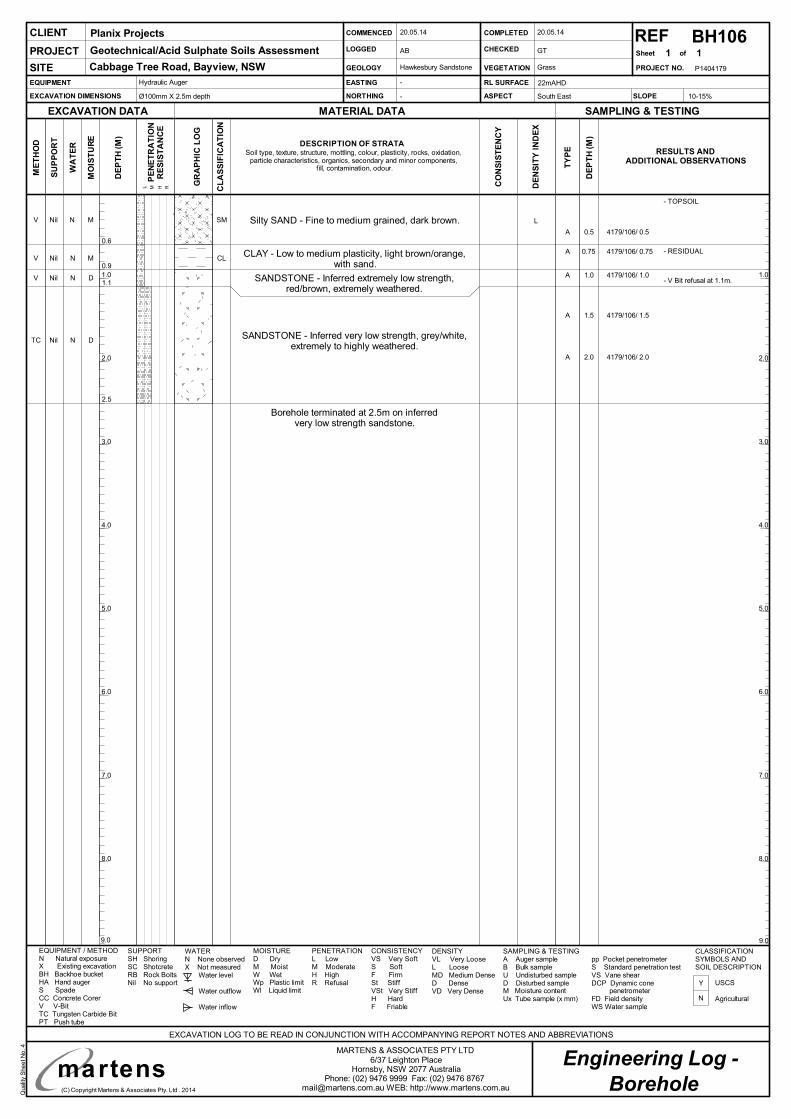
Qualit
yS
he
etN
o.4
(C) Copyright Martens & Associates Pty. Ltd . 2014
Engineering Log -MARTENS & ASSOCIATES PTY LTD
6/37 Leighton PlaceHornsby, NSW 2077 Australia
Phone: (02) 9476 9999 Fax: (02) 9476 [email protected] WEB: http://www.martens.com.au
P1404179
2.0
4.0
6.0
8.0
2.0
4.0
6.0
8.0
9.09.0
1.0
3.0
5.0
7.0
1.0
3.0
5.0
7.0
martens
REFSheet of
SU
PP
OR
T
WA
TE
R
RESULTS ANDADDITIONAL OBSERVATIONS
EXCAVATION DATA
ME
TH
OD
MATERIAL DATA SAMPLING & TESTING
EXCAVATION LOG TO BE READ IN CONJUNCTION WITH ACCOMPANYING REPORT NOTES AND ABBREVIATIONS
MO
IST
UR
E
DE
PT
H(M
)
TY
PE
DE
PT
H(M
)
CLIENT
PROJECT NO.
PROJECT
SITE
PE
NE
TR
AT
ION
RE
SIS
TA
NC
E
L M H R
EQUIPMENT
EXCAVATION DIMENSIONS
EASTING
NORTHING
RL SURFACE
ASPECT
COMMENCED
LOGGED
GEOLOGY
COMPLETED
CHECKED
VEGETATION
EQUIPMENT / METHODN Natural exposureX Existing excavationBH Backhoe bucketHA Hand augerS SpadeCC Concrete CorerV V-BitTC Tungsten Carbide BitPT Push tube
MOISTURED DryM MoistW WetWp Plastic limitWl Liquid limit
WATERN None observedX Not measured
Water level
Water outflow
Water inflow
SUPPORTSH ShoringSC ShotcreteRB Rock BoltsNil No support
CLASSIFICATIONSYMBOLS ANDSOIL DESCRIPTION
USCS
Agricultural
CONSISTENCYVS Very SoftS SoftF FirmSt StiffVSt Very StiffH HardF Friable
DENSITYVL Very LooseL LooseMD Medium DenseD DenseVD Very Dense
PENETRATIONL LowM ModerateH HighR Refusal
SLOPE
SAMPLING & TESTINGA Auger sampleB Bulk sampleU Undisturbed sampleD Disturbed sampleM Moisture contentUx Tube sample (x mm)
pp Pocket penetrometerS Standard penetration testVS Vane shearDCP Dynamic cone
penetrometerFD Field densityWS Water sample
GR
AP
HIC
LO
G
CL
AS
SIF
ICA
TIO
N
DESCRIPTION OF STRATASoil type, texture, structure, mottling, colour, plasticity, rocks, oxidation,
particle characteristics, organics, secondary and minor components,fill, contamination, odour.
CO
NS
IST
EN
CY
DE
NS
ITY
IND
EX
- V Bit refusal at 1.1m.
BH106
Hydraulic Auger
Ø100mm X 2.5m depth
Borehole
1 1
10-15%
N
Y
-
-
22mAHD
South East
20.05.14
AB
20.05.14
GT
Grass
Planix Projects
Geotechnical/Acid Sulphate Soils Assessment
Cabbage Tree Road, Bayview, NSW Hawkesbury Sandstone
Silty SAND - Fine to medium grained, dark brown.V Nil N M SM
Borehole terminated at 2.5m on inferredvery low strength sandstone.
CLAY - Low to medium plasticity, light brown/orange,with sand.
V Nil N M CL
SANDSTONE - Inferred extremely low strength,red/brown, extremely weathered.
V Nil N D
0.6
A 0.5 4179/106/ 0.5
A 1.5 4179/106/ 1.5
A 1.0 4179/106/ 1.0
2.5
1.1
SANDSTONE - Inferred very low strength, grey/white,extremely to highly weathered.
TC Nil N D
0.9
A 0.75 4179/106/ 0.75
A 2.0 4179/106/ 2.0
- RESIDUAL
- TOPSOIL
L
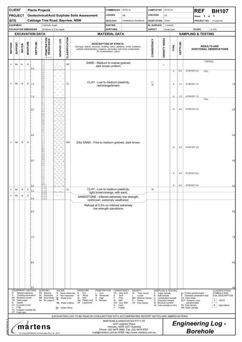
Qualit
yS
he
etN
o.4
(C) Copyright Martens & Associates Pty. Ltd . 2014
Engineering Log -MARTENS & ASSOCIATES PTY LTD
6/37 Leighton PlaceHornsby, NSW 2077 Australia
Phone: (02) 9476 9999 Fax: (02) 9476 [email protected] WEB: http://www.martens.com.au
P1404179
2.0
4.0
6.0
8.0
2.0
4.0
6.0
8.0
9.09.0
1.0
3.0
5.0
7.0
1.0
3.0
5.0
7.0
martens
REFSheet of
SU
PP
OR
T
WA
TE
R
RESULTS ANDADDITIONAL OBSERVATIONS
EXCAVATION DATA
ME
TH
OD
MATERIAL DATA SAMPLING & TESTING
EXCAVATION LOG TO BE READ IN CONJUNCTION WITH ACCOMPANYING REPORT NOTES AND ABBREVIATIONS
MO
IST
UR
E
DE
PT
H(M
)
TY
PE
DE
PT
H(M
)
CLIENT
PROJECT NO.
PROJECT
SITE
PE
NE
TR
AT
ION
RE
SIS
TA
NC
E
L M H R
EQUIPMENT
EXCAVATION DIMENSIONS
EASTING
NORTHING
RL SURFACE
ASPECT
COMMENCED
LOGGED
GEOLOGY
COMPLETED
CHECKED
VEGETATION
EQUIPMENT / METHODN Natural exposureX Existing excavationBH Backhoe bucketHA Hand augerS SpadeCC Concrete CorerV V-BitTC Tungsten Carbide BitPT Push tube
MOISTURED DryM MoistW WetWp Plastic limitWl Liquid limit
WATERN None observedX Not measured
Water level
Water outflow
Water inflow
SUPPORTSH ShoringSC ShotcreteRB Rock BoltsNil No support
CLASSIFICATIONSYMBOLS ANDSOIL DESCRIPTION
USCS
Agricultural
CONSISTENCYVS Very SoftS SoftF FirmSt StiffVSt Very StiffH HardF Friable
DENSITYVL Very LooseL LooseMD Medium DenseD DenseVD Very Dense
PENETRATIONL LowM ModerateH HighR Refusal
SLOPE
SAMPLING & TESTINGA Auger sampleB Bulk sampleU Undisturbed sampleD Disturbed sampleM Moisture contentUx Tube sample (x mm)
pp Pocket penetrometerS Standard penetration testVS Vane shearDCP Dynamic cone
penetrometerFD Field densityWS Water sample
GR
AP
HIC
LO
G
CL
AS
SIF
ICA
TIO
N
DESCRIPTION OF STRATASoil type, texture, structure, mottling, colour, plasticity, rocks, oxidation,
particle characteristics, organics, secondary and minor components,fill, contamination, odour.
CO
NS
IST
EN
CY
DE
NS
ITY
IND
EX
BH107
Hydraulic Auger
Ø100mm X 5.5m depth
Borehole
1 1
5-10%
N
Y
-
-
11mAHD
South East
20.05.14
AB
20.05.14
GT
Grass
Planix Projects
Geotechnical/Acid Sulphate Soils Assessment
Cabbage Tree Road, Bayview, NSW Hawkesbury Sandstone
SAND - Medium to coarse grained,dark brown,uniform.
V Nil N D SP
Refusal at 5.5m on inferred extremelylow strength sandstone.
Silty SAND - Fine to medium grained, dark brown.V Nil N D SM
CLAY - Low to medium plasticity,red/orange/brown.
V Nil N D CL
CLAY - Low to medium plasticity,light brown/orange, with sand.
V Nil N D CL
0.4A 0.5 4179/107/ 0.5
A 1.5 4179/107/ 1.5
A 1.0 4179/107/ 1.0
A 2.0 4179/107/ 2.0
5.5
5.2
1.5
SANDSTONE - Inferred extremely low strength,red/brown, extremely weathered.
V Nil N D
- FILL
- FILL
A 3.5 4179/107/ 3.5
A 4.5 4179/107/ 4.5
A 5.0 4179/107/ 5.0
F-St
- TOPSOIL
L
St
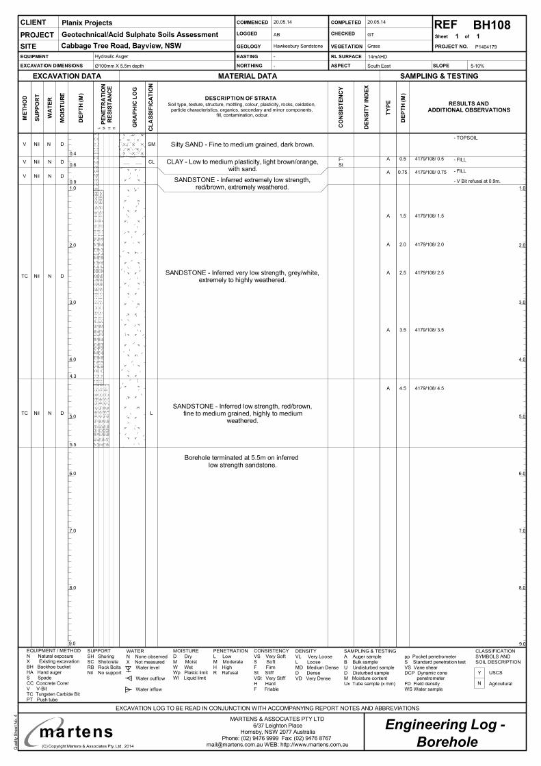
Qualit
yS
he
etN
o.4
(C) Copyright Martens & Associates Pty. Ltd . 2014
Engineering Log -MARTENS & ASSOCIATES PTY LTD
6/37 Leighton PlaceHornsby, NSW 2077 Australia
Phone: (02) 9476 9999 Fax: (02) 9476 [email protected] WEB: http://www.martens.com.au
P1404179
2.0
4.0
6.0
8.0
2.0
4.0
6.0
8.0
9.09.0
1.0
3.0
5.0
7.0
1.0
3.0
5.0
7.0
martens
REFSheet of
SU
PP
OR
T
WA
TE
R
RESULTS ANDADDITIONAL OBSERVATIONS
EXCAVATION DATA
ME
TH
OD
MATERIAL DATA SAMPLING & TESTING
EXCAVATION LOG TO BE READ IN CONJUNCTION WITH ACCOMPANYING REPORT NOTES AND ABBREVIATIONS
MO
IST
UR
E
DE
PT
H(M
)
TY
PE
DE
PT
H(M
)
CLIENT
PROJECT NO.
PROJECT
SITE
PE
NE
TR
AT
ION
RE
SIS
TA
NC
E
L M H R
EQUIPMENT
EXCAVATION DIMENSIONS
EASTING
NORTHING
RL SURFACE
ASPECT
COMMENCED
LOGGED
GEOLOGY
COMPLETED
CHECKED
VEGETATION
EQUIPMENT / METHODN Natural exposureX Existing excavationBH Backhoe bucketHA Hand augerS SpadeCC Concrete CorerV V-BitTC Tungsten Carbide BitPT Push tube
MOISTURED DryM MoistW WetWp Plastic limitWl Liquid limit
WATERN None observedX Not measured
Water level
Water outflow
Water inflow
SUPPORTSH ShoringSC ShotcreteRB Rock BoltsNil No support
CLASSIFICATIONSYMBOLS ANDSOIL DESCRIPTION
USCS
Agricultural
CONSISTENCYVS Very SoftS SoftF FirmSt StiffVSt Very StiffH HardF Friable
DENSITYVL Very LooseL LooseMD Medium DenseD DenseVD Very Dense
PENETRATIONL LowM ModerateH HighR Refusal
SLOPE
SAMPLING & TESTINGA Auger sampleB Bulk sampleU Undisturbed sampleD Disturbed sampleM Moisture contentUx Tube sample (x mm)
pp Pocket penetrometerS Standard penetration testVS Vane shearDCP Dynamic cone
penetrometerFD Field densityWS Water sample
GR
AP
HIC
LO
G
CL
AS
SIF
ICA
TIO
N
DESCRIPTION OF STRATASoil type, texture, structure, mottling, colour, plasticity, rocks, oxidation,
particle characteristics, organics, secondary and minor components,fill, contamination, odour.
CO
NS
IST
EN
CY
DE
NS
ITY
IND
EX
BH108
Hydraulic Auger
Ø100mm X 5.5m depth
Borehole
1 1
5-10%
N
Y
-
-
14mAHD
South East
20.05.14
AB
20.05.14
GT
Grass
Planix Projects
Geotechnical/Acid Sulphate Soils Assessment
Cabbage Tree Road, Bayview, NSW Hawkesbury Sandstone
V Nil N D SM
Borehole terminated at 5.5m on inferredlow strength sandstone.
V Nil N D
V Nil N D CL
SANDSTONE - Inferred very low strength, grey/white,extremely to highly weathered.
TC Nil N D
0.4A 0.5 4179/108/ 0.5
A 1.5 4179/108/ 1.5
A 2.0 4179/108/ 2.0
5.5
4.3
0.6
SANDSTONE - Inferred low strength, red/brown,fine to medium grained, highly to medium
weathered.TC Nil N D L
- FILL
- FILL
A 3.5 4179/108/ 3.5
A 4.5 4179/108/ 4.5
0.9
A 0.75 4179/108/ 0.75
A 2.5 4179/108/ 2.5
F-St
- V Bit refusal at 0.9m.
Silty SAND - Fine to medium grained, dark brown.
CLAY - Low to medium plasticity, light brown/orange,with sand.
SANDSTONE - Inferred extremely low strength,red/brown, extremely weathered.
- TOPSOIL
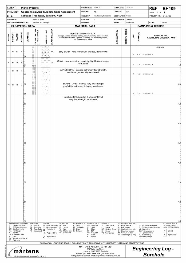
Qualit
yS
he
etN
o.4
(C) Copyright Martens & Associates Pty. Ltd . 2014
Engineering Log -MARTENS & ASSOCIATES PTY LTD
6/37 Leighton PlaceHornsby, NSW 2077 Australia
Phone: (02) 9476 9999 Fax: (02) 9476 [email protected] WEB: http://www.martens.com.au
P1404179
2.0
4.0
6.0
8.0
2.0
4.0
6.0
8.0
9.09.0
1.0
3.0
5.0
7.0
1.0
3.0
5.0
7.0
martens
REFSheet of
SU
PP
OR
T
WA
TE
R
RESULTS ANDADDITIONAL OBSERVATIONS
EXCAVATION DATA
ME
TH
OD
MATERIAL DATA SAMPLING & TESTING
EXCAVATION LOG TO BE READ IN CONJUNCTION WITH ACCOMPANYING REPORT NOTES AND ABBREVIATIONS
MO
IST
UR
E
DE
PT
H(M
)
TY
PE
DE
PT
H(M
)
CLIENT
PROJECT NO.
PROJECT
SITE
PE
NE
TR
AT
ION
RE
SIS
TA
NC
E
L M H R
EQUIPMENT
EXCAVATION DIMENSIONS
EASTING
NORTHING
RL SURFACE
ASPECT
COMMENCED
LOGGED
GEOLOGY
COMPLETED
CHECKED
VEGETATION
EQUIPMENT / METHODN Natural exposureX Existing excavationBH Backhoe bucketHA Hand augerS SpadeCC Concrete CorerV V-BitTC Tungsten Carbide BitPT Push tube
MOISTURED DryM MoistW WetWp Plastic limitWl Liquid limit
WATERN None observedX Not measured
Water level
Water outflow
Water inflow
SUPPORTSH ShoringSC ShotcreteRB Rock BoltsNil No support
CLASSIFICATIONSYMBOLS ANDSOIL DESCRIPTION
USCS
Agricultural
CONSISTENCYVS Very SoftS SoftF FirmSt StiffVSt Very StiffH HardF Friable
DENSITYVL Very LooseL LooseMD Medium DenseD DenseVD Very Dense
PENETRATIONL LowM ModerateH HighR Refusal
SLOPE
SAMPLING & TESTINGA Auger sampleB Bulk sampleU Undisturbed sampleD Disturbed sampleM Moisture contentUx Tube sample (x mm)
pp Pocket penetrometerS Standard penetration testVS Vane shearDCP Dynamic cone
penetrometerFD Field densityWS Water sample
GR
AP
HIC
LO
G
CL
AS
SIF
ICA
TIO
N
DESCRIPTION OF STRATASoil type, texture, structure, mottling, colour, plasticity, rocks, oxidation,
particle characteristics, organics, secondary and minor components,fill, contamination, odour.
CO
NS
IST
EN
CY
DE
NS
ITY
IND
EX
BH109
Hydraulic Auger
Ø100mm X 2.5m depth
Borehole
1 1
10-15%
N
Y
-
-
14mAHD
South East
20.05.14
AB
20.05.14
GT
Grass
Planix Projects
Geotechnical/Acid Sulphate Soils Assessment
Cabbage Tree Road, Bayview, NSW Hawkesbury Sandstone
V Nil N M SM
Borehole terminated at 2.5m on inferredvery low strength sandstone.
V Nil N M CL
V Nil N M
0.6
A 0.5 4179/109/ 0.5
A 1.5 4179/109/ 1.5
A 1.0 4179/109/ 1.0
2.5
1.5
SANDSTONE - Inferred very low strength,grey/white, extremely to highly weathered.
TC Nil N D
1.1
Silty SAND - Fine to medium grained, dark brown.
CLAY - Low to medium plasticity, light brown/orange,with sand.
SANDSTONE - Inferred extremely low strength,red/brown, extremely weathered.
A 2.5 4179/109/ 2.5
- TOPSOIL
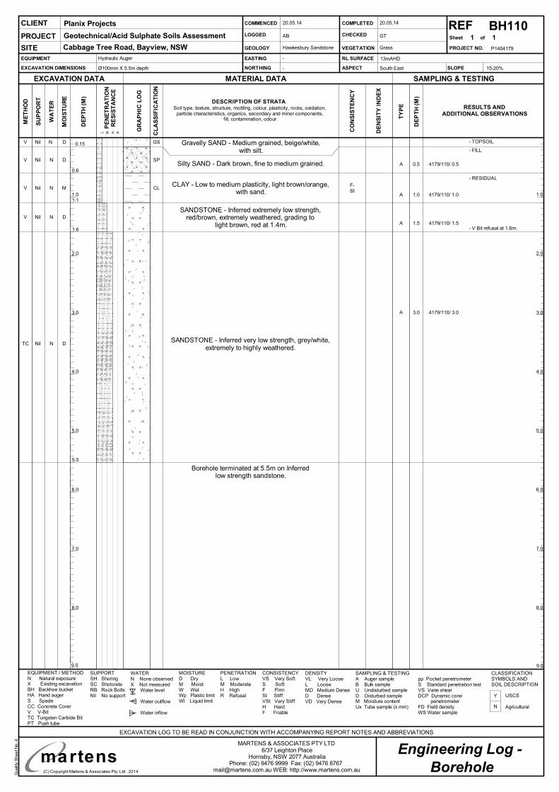
Qualit
yS
he
etN
o.4
(C) Copyright Martens & Associates Pty. Ltd . 2014
Engineering Log -MARTENS & ASSOCIATES PTY LTD
6/37 Leighton PlaceHornsby, NSW 2077 Australia
Phone: (02) 9476 9999 Fax: (02) 9476 [email protected] WEB: http://www.martens.com.au
P1404179
2.0
4.0
6.0
8.0
2.0
4.0
6.0
8.0
9.09.0
1.0
3.0
5.0
7.0
1.0
3.0
5.0
7.0
martens
REFSheet of
SU
PP
OR
T
WA
TE
R
RESULTS ANDADDITIONAL OBSERVATIONS
EXCAVATION DATA
ME
TH
OD
MATERIAL DATA SAMPLING & TESTING
EXCAVATION LOG TO BE READ IN CONJUNCTION WITH ACCOMPANYING REPORT NOTES AND ABBREVIATIONS
MO
IST
UR
E
DE
PT
H(M
)
TY
PE
DE
PT
H(M
)
CLIENT
PROJECT NO.
PROJECT
SITE
PE
NE
TR
AT
ION
RE
SIS
TA
NC
E
L M H R
EQUIPMENT
EXCAVATION DIMENSIONS
EASTING
NORTHING
RL SURFACE
ASPECT
COMMENCED
LOGGED
GEOLOGY
COMPLETED
CHECKED
VEGETATION
EQUIPMENT / METHODN Natural exposureX Existing excavationBH Backhoe bucketHA Hand augerS SpadeCC Concrete CorerV V-BitTC Tungsten Carbide BitPT Push tube
MOISTURED DryM MoistW WetWp Plastic limitWl Liquid limit
WATERN None observedX Not measured
Water level
Water outflow
Water inflow
SUPPORTSH ShoringSC ShotcreteRB Rock BoltsNil No support
CLASSIFICATIONSYMBOLS ANDSOIL DESCRIPTION
USCS
Agricultural
CONSISTENCYVS Very SoftS SoftF FirmSt StiffVSt Very StiffH HardF Friable
DENSITYVL Very LooseL LooseMD Medium DenseD DenseVD Very Dense
PENETRATIONL LowM ModerateH HighR Refusal
SLOPE
SAMPLING & TESTINGA Auger sampleB Bulk sampleU Undisturbed sampleD Disturbed sampleM Moisture contentUx Tube sample (x mm)
pp Pocket penetrometerS Standard penetration testVS Vane shearDCP Dynamic cone
penetrometerFD Field densityWS Water sample
GR
AP
HIC
LO
G
CL
AS
SIF
ICA
TIO
N
DESCRIPTION OF STRATASoil type, texture, structure, mottling, colour, plasticity, rocks, oxidation,
particle characteristics, organics, secondary and minor components,fill, contamination, odour.
CO
NS
IST
EN
CY
DE
NS
ITY
IND
EX
BH110
Hydraulic Auger
Ø100mm X 5.5m depth
Borehole
1 1
15-20%
N
Y
-
-
13mAHD
South East
20.05.14
AB
20.05.14
GT
Grass
Planix Projects
Geotechnical/Acid Sulphate Soils Assessment
Cabbage Tree Road, Bayview, NSW Hawkesbury Sandstone
Gravelly SAND - Medium grained, beige/white,with silt.
V Nil N D GS
Borehole terminated at 5.5m on Inferredlow strength sandstone.
CLAY - Low to medium plasticity, light brown/orange,with sand.
V Nil N M CL
Silty SAND - Dark brown, fine to medium grained.V Nil N D SP
SANDSTONE - Inferred extremely low strength,red/brown, extremely weathered, grading to
light brown, red at 1.4m.V Nil N D
0.6
A 0.5 4179/110/ 0.5
A 1.5 4179/110/ 1.5
A 1.0 4179/110/ 1.0
5.5
1.6
1.1
SANDSTONE - Inferred very low strength, grey/white,extremely to highly weathered.
TC Nil N D
- TOPSOIL
- FILL
A 3.0 4179/110/ 3.0
0.15
F-St
- V Bit refusal at 1.6m.
- RESIDUAL
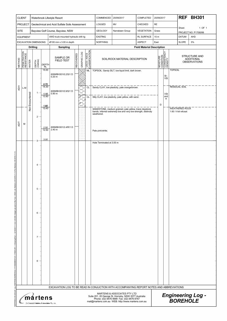
St -VSt
VStandH
0.70
1.10
1.60
3.00
15.00
14.30
13.90
13.40
12.50
0.70
1.10
1.60
2.50
L-M
M
AD
/VA
D/T
D
6099/BH301/0.2/S/1 D0.20 m
6099/BH301/0.9/S/1 D0.90 m
6099/BH301/2.4/R/1 D2.40 m
TOPSOIL: Sandy SILT, low liquid limit, dark brown.
Sandy CLAY, low plasticity, pale orange/brown.
Silty CLAY, low plasticity, pale yellow, with sand.
SANDSTONE, medium grained, pale yellow, trace claystonebands, inferred extremely low and very low strength, distinctlyweathered.
Pale pink/white.
Hole Terminated at 3.00 m
ML
CL
CL
Not
Enc
ount
ered
TOPSOIL
RESIDUAL SOIL
WEATHERED ROCK1.60: V-bit refusal.
PE
NE
TR
AT
ION
RE
SIS
TA
NC
E
WA
TE
R
DE
PT
H(m
etre
s)
Sampling
RE
CO
VE
RE
D
Field Material Description
RLDEPTH
ME
TH
OD
Drilling
GR
AP
HIC
LO
G
SAMPLE ORFIELD TEST SOIL/ROCK MATERIAL DESCRIPTION
MO
IST
UR
EC
ON
DIT
ION
CO
NS
IST
EN
CY
DE
NS
ITY
U
SC
S /
AS
CS
CLA
SS
IFIC
AT
ION
COMMENCED
LOGGED
GEOLOGY
20/09/2017
CHECKED
VEGETATION
RE
Grass
4WD truck-mounted hydraulic drill rig
NORTHING ASPECT East SLOPE
Narrabeen Group
MV
COMPLETED
Sheet 1 OF 1
EASTING DATUM
100 mm x 3.00 m depth 5%
AHDEQUIPMENT
EXCAVATION DIMENSIONS
RL SURFACE
Engineering Log -BOREHOLE
20/09/2017 REF BH301
15 m
EXCAVATION LOG TO BE READ IN CONJUCTION WITH ACCOMPANYING REPORT NOTES AND ABBREVIATIONS
PROJECT NO. P1706099
PROJECT
CLIENT
SITE
Waterbrook Lifestyle Resort
Bayview Golf Course, Bayview, NSW
Geotechnical and Acid Sulfate Soils Assessment
MARTENS & ASSOCIATES PTY LTDSuite 201, 20 George St. Hornsby, NSW 2077 Australia
Phone: (02) 9476 9999 Fax: (02) 9476 [email protected] WEB: http://www.martens.com.au
MA
RT
EN
S 2
.00
LIB
.GLB
Log
MA
RT
EN
S B
OR
EH
OLE
P17
0609
9BH
01V
01 1
7092
5.G
PJ
<<
Dra
win
gFile
>>
12/
10/2
017
11:3
2 8
.30.
004
Dat
gel L
ab a
nd In
Situ
Too
l - D
GD
| Li
b: M
arte
ns 2
.00
2016
-11-
13 P
rj: M
arte
ns 2
.00
2016
-11-
13
STRUCTURE ANDADDITIONAL
OBSERVATIONS
1
2
3
4
5
6
7
8
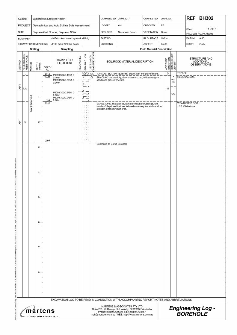
FandSt
VSt
0.15
1.20
2.80
19.55
18.50
0.15
1.20
2.80
L
L-M
M
AD
/VA
D/T
D
M
P6099/302/0.1/S/1 D0.10 mP6099/302/0.3/S/1 D0.30 m
P6099/302/0.8/S/1 D0.80 mP6099/302/0.9/S/1 D0.90 m
TOPSOIL: SILT, low liquid limit, brown, with fine grained sand.
Silty CLAY, low plasticity, dark brown and red, with subangularsandstone gravels (<7mm).
SANDSTONE, fine grained, light grey/red/brown/orange, withbands of claystone/siltstone, inferred extremely low and very lowstrength, distinctly weathered.
Continued as Cored Borehole
ML
CL
Not
Obs
erve
d
TOPSOIL
RESIDUAL SOIL
WEATHERED ROCK1.20: V-bit refusal.
PE
NE
TR
AT
ION
RE
SIS
TA
NC
E
WA
TE
R
DE
PT
H(m
etre
s)
Sampling
RE
CO
VE
RE
D
Field Material Description
RLDEPTH
ME
TH
OD
Drilling
GR
AP
HIC
LO
G
SAMPLE ORFIELD TEST SOIL/ROCK MATERIAL DESCRIPTION
MO
IST
UR
EC
ON
DIT
ION
CO
NS
IST
EN
CY
DE
NS
ITY
U
SC
S /
AS
CS
CLA
SS
IFIC
AT
ION
COMMENCED
LOGGED
GEOLOGY
20/09/2017
CHECKED
VEGETATION
RE
Grass
4WD truck-mounted hydraulic drill rig
NORTHING ASPECT South SLOPE
Narrabeen Group
AM
COMPLETED
Sheet 1 OF 3
EASTING DATUM
100 mm x 12.00 m depth 2-5%
AHDEQUIPMENT
EXCAVATION DIMENSIONS
RL SURFACE
Engineering Log -BOREHOLE
20/09/2017 REF BH302
19.7 m
EXCAVATION LOG TO BE READ IN CONJUCTION WITH ACCOMPANYING REPORT NOTES AND ABBREVIATIONS
PROJECT NO. P1706099
PROJECT
CLIENT
SITE
Waterbrook Lifestyle Resort
Bayview Golf Course, Bayview, NSW
Geotechnical and Acid Sulfate Soils Assessment
MARTENS & ASSOCIATES PTY LTDSuite 201, 20 George St. Hornsby, NSW 2077 Australia
Phone: (02) 9476 9999 Fax: (02) 9476 [email protected] WEB: http://www.martens.com.au
MA
RT
EN
S 2
.00
LIB
.GLB
Log
MA
RT
EN
S B
OR
EH
OLE
P17
0609
9BH
01V
01 1
7092
5.G
PJ
<<
Dra
win
gFile
>>
12/
10/2
017
11:3
2 8
.30.
004
Dat
gel L
ab a
nd In
Situ
Too
l - D
GD
| Li
b: M
arte
ns 2
.00
2016
-11-
13 P
rj: M
arte
ns 2
.00
2016
-11-
13
STRUCTURE ANDADDITIONAL
OBSERVATIONS
1
2
3
4
5
6
7
8
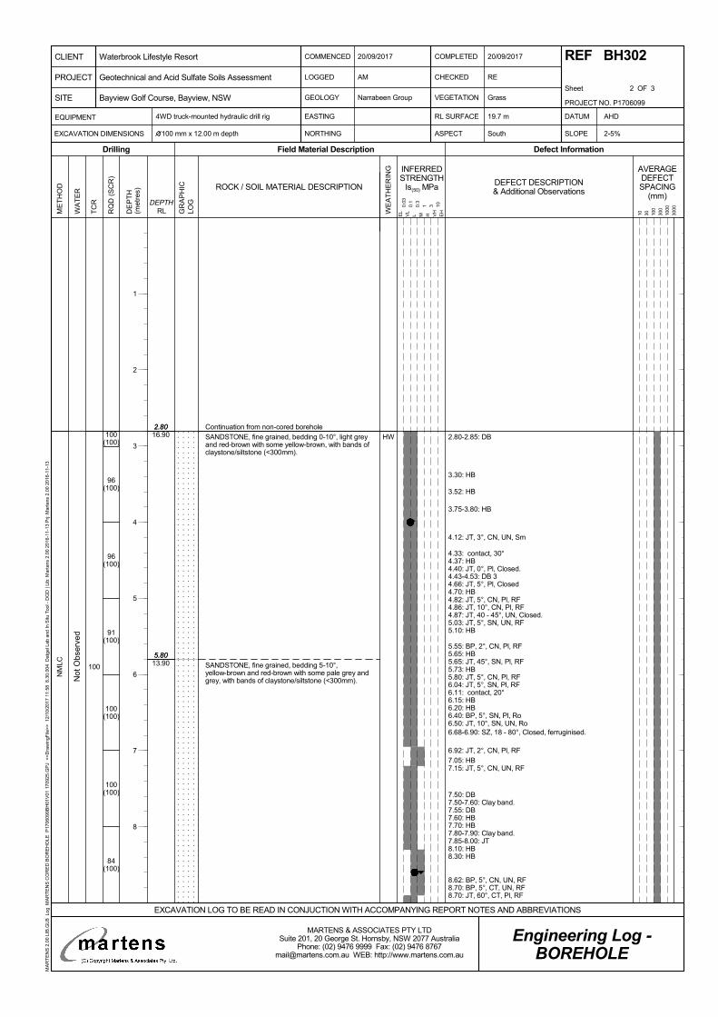
2.80
5.80
2.80
5.80
16.90
13.90100
100(100)
96(100)
96(100)
91(100)
100(100)
100(100)
84(100)
HW
NM
LC
Continuation from non-cored borehole
2.80-2.85: DB
3.30: HB
3.52: HB
3.75-3.80: HB
4.12: JT, 3°, CN, UN, Sm
4.33: contact, 30°4.37: HB4.40: JT, 0°, Pl, Closed.4.43-4.53: DB 34.66: JT, 5°, Pl, Closed4.70: HB4.82: JT, 5°, CN, Pl, RF4.86: JT, 10°, CN, Pl, RF4.87: JT, 40 - 45°, UN, Closed.5.03: JT, 5°, SN, UN, RF5.10: HB
5.55: BP, 2°, CN, Pl, RF5.65: HB5.65: JT, 45°, SN, Pl, RF5.73: HB5.80: JT, 5°, CN, Pl, RF6.04: JT, 5°, SN, Pl, RF6.11: contact, 20°6.15: HB6.20: HB6.40: BP, 5°, SN, Pl, Ro6.50: JT, 10°, SN, UN, Ro6.68-6.90: SZ, 18 - 80°, Closed, ferruginised.
6.92: JT, 2°, CN, Pl, RF7.05: HB7.15: JT, 5°, CN, UN, RF
7.50: DB7.50-7.60: Clay band.7.55: DB7.60: HB7.70: HB7.80-7.90: Clay band.7.85-8.00: JT8.10: HB8.30: HB
8.62: BP, 5°, CN, UN, RF8.70: BP, 5°, CT, UN, RF8.70: JT, 60°, CT, Pl, RF
SANDSTONE, fine grained, bedding 0-10°, light greyand red-brown with some yellow-brown, with bands ofclaystone/siltstone (<300mm).
SANDSTONE, fine grained, bedding 5-10°,yellow-brown and red-brown with some pale grey andgrey, with bands of claystone/siltstone (<300mm).N
ot O
bser
ved
TC
R
RQ
D (
SC
R)
GR
AP
HIC
LOG
WE
AT
HE
RIN
G
ME
TH
OD
DE
PT
H(m
etre
s)
Field Material DescriptionDrilling
INFERREDSTRENGTH
Is(50) MPa
Defect Information
DEPTHRLW
AT
ER
AVERAGEDEFECTSPACING
(mm)
10 30 100
300
1000
3000
DEFECT DESCRIPTION& Additional Observations
EL
VL
L M H VH
EH
0.03
0.1
0.3
1 3 10
ROCK / SOIL MATERIAL DESCRIPTION
COMMENCED
LOGGED
GEOLOGY
20/09/2017
CHECKED
VEGETATION
RE
Grass
4WD truck-mounted hydraulic drill rig
NORTHING ASPECT South SLOPE
Narrabeen Group
AM
COMPLETED
Sheet 2 OF 3
EASTING DATUM
100 mm x 12.00 m depth 2-5%
AHDEQUIPMENT
EXCAVATION DIMENSIONS
RL SURFACE
Engineering Log -BOREHOLE
20/09/2017 REF BH302
19.7 m
EXCAVATION LOG TO BE READ IN CONJUCTION WITH ACCOMPANYING REPORT NOTES AND ABBREVIATIONS
PROJECT NO. P1706099
PROJECT
CLIENT
SITE
Waterbrook Lifestyle Resort
Bayview Golf Course, Bayview, NSW
Geotechnical and Acid Sulfate Soils Assessment
MARTENS & ASSOCIATES PTY LTDSuite 201, 20 George St. Hornsby, NSW 2077 Australia
Phone: (02) 9476 9999 Fax: (02) 9476 [email protected] WEB: http://www.martens.com.au
MA
RT
EN
S 2
.00
LIB
.GLB
Log
MA
RT
EN
S C
OR
ED
BO
RE
HO
LE P
1706
099B
H01
V01
170
925.
GP
J <
<D
raw
ingF
ile>
> 1
2/10
/201
7 11
:58
8.3
0.00
4 D
atge
l Lab
and
In S
itu T
ool -
DG
D |
Lib:
Mar
tens
2.0
0 20
16-1
1-13
Prj:
Mar
tens
2.0
0 20
16-1
1-13
1
2
3
4
5
6
7
8
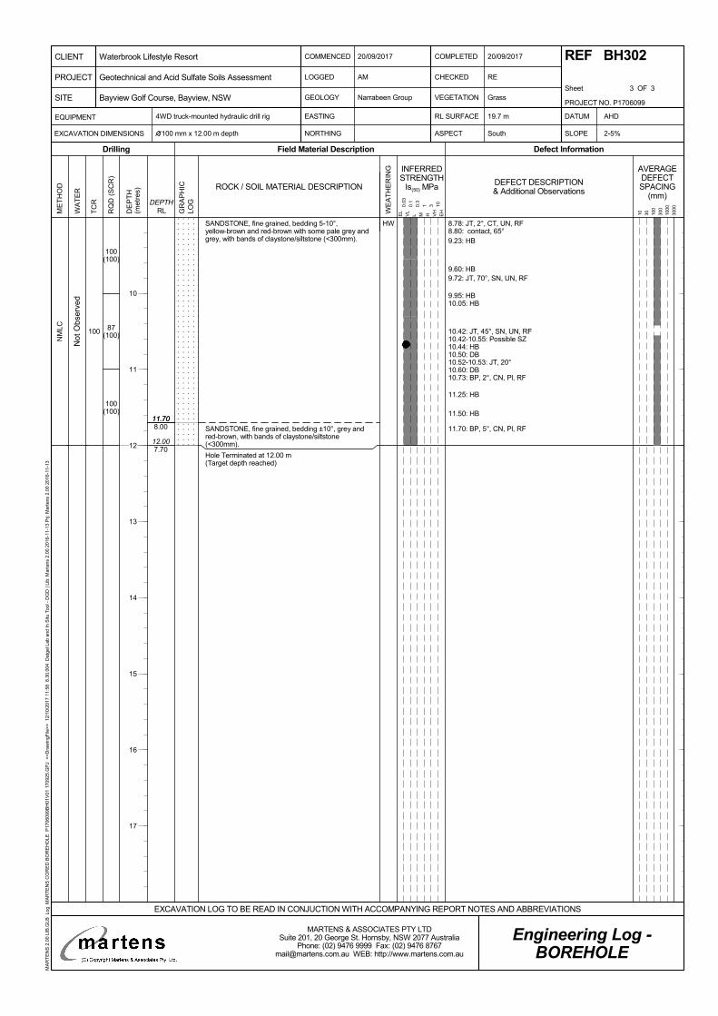
11.70
12.00
11.70
7.70
8.00
100
100(100)
87(100)
100(100)
HW
NM
LC
8.78: JT, 2°, CT, UN, RF8.80: contact, 65°9.23: HB
9.60: HB9.72: JT, 70°, SN, UN, RF
9.95: HB10.05: HB
10.42: JT, 45°, SN, UN, RF10.42-10.55: Possible SZ10.44: HB10.50: DB10.52-10.53: JT, 20°10.60: DB10.73: BP, 2°, CN, Pl, RF
11.25: HB
11.50: HB
11.70: BP, 5°, CN, Pl, RF
SANDSTONE, fine grained, bedding 5-10°,yellow-brown and red-brown with some pale grey andgrey, with bands of claystone/siltstone (<300mm).
SANDSTONE, fine grained, bedding ±10°, grey andred-brown, with bands of claystone/siltstone(<300mm).
Hole Terminated at 12.00 m(Target depth reached)
Not
Obs
erve
d
TC
R
RQ
D (
SC
R)
GR
AP
HIC
LOG
WE
AT
HE
RIN
G
ME
TH
OD
DE
PT
H(m
etre
s)
Field Material DescriptionDrilling
INFERREDSTRENGTH
Is(50) MPa
Defect Information
DEPTHRLW
AT
ER
AVERAGEDEFECTSPACING
(mm)
10 30 100
300
1000
3000
DEFECT DESCRIPTION& Additional Observations
EL
VL
L M H VH
EH
0.03
0.1
0.3
1 3 10
ROCK / SOIL MATERIAL DESCRIPTION
COMMENCED
LOGGED
GEOLOGY
20/09/2017
CHECKED
VEGETATION
RE
Grass
4WD truck-mounted hydraulic drill rig
NORTHING ASPECT South SLOPE
Narrabeen Group
AM
COMPLETED
Sheet 3 OF 3
EASTING DATUM
100 mm x 12.00 m depth 2-5%
AHDEQUIPMENT
EXCAVATION DIMENSIONS
RL SURFACE
Engineering Log -BOREHOLE
20/09/2017 REF BH302
19.7 m
EXCAVATION LOG TO BE READ IN CONJUCTION WITH ACCOMPANYING REPORT NOTES AND ABBREVIATIONS
PROJECT NO. P1706099
PROJECT
CLIENT
SITE
Waterbrook Lifestyle Resort
Bayview Golf Course, Bayview, NSW
Geotechnical and Acid Sulfate Soils Assessment
MARTENS & ASSOCIATES PTY LTDSuite 201, 20 George St. Hornsby, NSW 2077 Australia
Phone: (02) 9476 9999 Fax: (02) 9476 [email protected] WEB: http://www.martens.com.au
MA
RT
EN
S 2
.00
LIB
.GLB
Log
MA
RT
EN
S C
OR
ED
BO
RE
HO
LE P
1706
099B
H01
V01
170
925.
GP
J <
<D
raw
ingF
ile>
> 1
2/10
/201
7 11
:58
8.3
0.00
4 D
atge
l Lab
and
In S
itu T
ool -
DG
D |
Lib:
Mar
tens
2.0
0 20
16-1
1-13
Prj:
Mar
tens
2.0
0 20
16-1
1-13
10
11
12
13
14
15
16
17
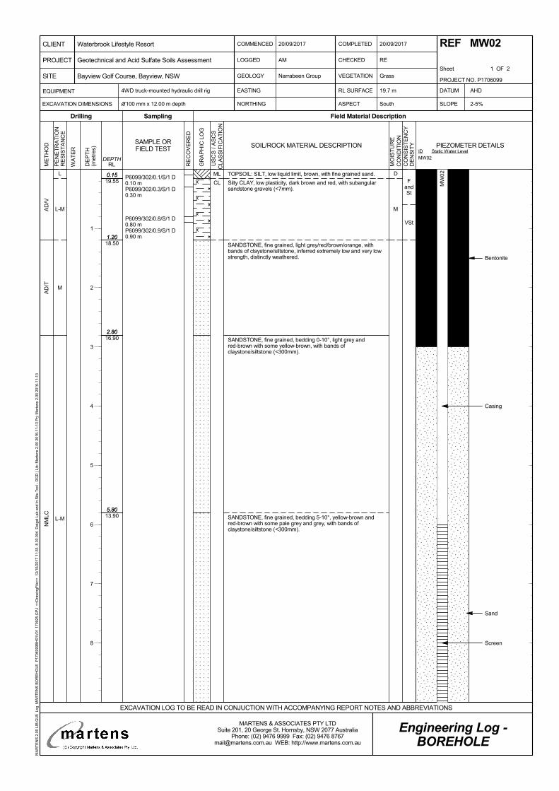
FandSt
VSt
0.15
1.20
2.80
5.80
19.55
18.50
16.90
13.90
0.15
1.20
2.80
5.80
L
L-M
M
L-M
AD
/VA
D/T
NM
LC
D
M
P6099/302/0.1/S/1 D0.10 mP6099/302/0.3/S/1 D0.30 m
P6099/302/0.8/S/1 D0.80 mP6099/302/0.9/S/1 D0.90 m
TOPSOIL: SILT, low liquid limit, brown, with fine grained sand.
Silty CLAY, low plasticity, dark brown and red, with subangularsandstone gravels (<7mm).
SANDSTONE, fine grained, light grey/red/brown/orange, withbands of claystone/siltstone, inferred extremely low and very lowstrength, distinctly weathered.
SANDSTONE, fine grained, bedding 0-10°, light grey andred-brown with some yellow-brown, with bands ofclaystone/siltstone (<300mm).
SANDSTONE, fine grained, bedding 5-10°, yellow-brown andred-brown with some pale grey and grey, with bands ofclaystone/siltstone (<300mm).
ML
CL
Bentonite
Casing
Sand
Screen
PE
NE
TR
AT
ION
RE
SIS
TA
NC
E
WA
TE
R
DE
PT
H(m
etre
s)
Sampling
RE
CO
VE
RE
D
Field Material Description
RLDEPTH
ME
TH
OD
Drilling
GR
AP
HIC
LO
G
SAMPLE ORFIELD TEST SOIL/ROCK MATERIAL DESCRIPTION
MO
IST
UR
EC
ON
DIT
ION
CO
NS
IST
EN
CY
DE
NS
ITY
U
SC
S /
AS
CS
CLA
SS
IFIC
AT
ION
COMMENCED
LOGGED
GEOLOGY
20/09/2017
CHECKED
VEGETATION
RE
Grass
4WD truck-mounted hydraulic drill rig
NORTHING ASPECT South SLOPE
Narrabeen Group
AM
COMPLETED
Sheet 1 OF 2
EASTING DATUM
100 mm x 12.00 m depth 2-5%
AHDEQUIPMENT
EXCAVATION DIMENSIONS
RL SURFACE
Engineering Log -BOREHOLE
20/09/2017 REF MW02
19.7 m
EXCAVATION LOG TO BE READ IN CONJUCTION WITH ACCOMPANYING REPORT NOTES AND ABBREVIATIONS
PROJECT NO. P1706099
PROJECT
CLIENT
SITE
Waterbrook Lifestyle Resort
Bayview Golf Course, Bayview, NSW
Geotechnical and Acid Sulfate Soils Assessment
MARTENS & ASSOCIATES PTY LTDSuite 201, 20 George St. Hornsby, NSW 2077 Australia
Phone: (02) 9476 9999 Fax: (02) 9476 [email protected] WEB: http://www.martens.com.au
MA
RT
EN
S 2
.00
LIB
.GLB
Log
MA
RT
EN
S B
OR
EH
OLE
P17
0609
9BH
01V
01 1
7092
5.G
PJ
<<
Dra
win
gFile
>>
12/
10/2
017
11:3
3 8
.30.
004
Dat
gel L
ab a
nd In
Situ
Too
l - D
GD
| Li
b: M
arte
ns 2
.00
2016
-11-
13 P
rj: M
arte
ns 2
.00
2016
-11-
13
ID
MW02
Static Water LevelPIEZOMETER DETAILS
1
2
3
4
5
6
7
8
MW
02
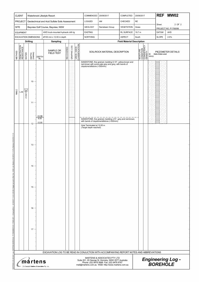
11.70
12.00
8.0011.70
L-M
NM
LC
SANDSTONE, fine grained, bedding 5-10°, yellow-brown andred-brown with some pale grey and grey, with bands ofclaystone/siltstone (<300mm).
SANDSTONE, fine grained, bedding ±10°, grey and red-brown,with bands of claystone/siltstone (<300mm).
Hole Terminated at 12.00 m(Target depth reached)
21/0
9/17
PE
NE
TR
AT
ION
RE
SIS
TA
NC
E
WA
TE
R
DE
PT
H(m
etre
s)
Sampling
RE
CO
VE
RE
D
Field Material Description
RLDEPTH
ME
TH
OD
Drilling
GR
AP
HIC
LO
G
SAMPLE ORFIELD TEST SOIL/ROCK MATERIAL DESCRIPTION
MO
IST
UR
EC
ON
DIT
ION
CO
NS
IST
EN
CY
DE
NS
ITY
U
SC
S /
AS
CS
CLA
SS
IFIC
AT
ION
COMMENCED
LOGGED
GEOLOGY
20/09/2017
CHECKED
VEGETATION
RE
Grass
4WD truck-mounted hydraulic drill rig
NORTHING ASPECT South SLOPE
Narrabeen Group
AM
COMPLETED
Sheet 2 OF 2
EASTING DATUM
100 mm x 12.00 m depth 2-5%
AHDEQUIPMENT
EXCAVATION DIMENSIONS
RL SURFACE
Engineering Log -BOREHOLE
20/09/2017 REF MW02
19.7 m
EXCAVATION LOG TO BE READ IN CONJUCTION WITH ACCOMPANYING REPORT NOTES AND ABBREVIATIONS
PROJECT NO. P1706099
PROJECT
CLIENT
SITE
Waterbrook Lifestyle Resort
Bayview Golf Course, Bayview, NSW
Geotechnical and Acid Sulfate Soils Assessment
MARTENS & ASSOCIATES PTY LTDSuite 201, 20 George St. Hornsby, NSW 2077 Australia
Phone: (02) 9476 9999 Fax: (02) 9476 [email protected] WEB: http://www.martens.com.au
MA
RT
EN
S 2
.00
LIB
.GLB
Log
MA
RT
EN
S B
OR
EH
OLE
P17
0609
9BH
01V
01 1
7092
5.G
PJ
<<
Dra
win
gFile
>>
12/
10/2
017
11:3
3 8
.30.
004
Dat
gel L
ab a
nd In
Situ
Too
l - D
GD
| Li
b: M
arte
ns 2
.00
2016
-11-
13 P
rj: M
arte
ns 2
.00
2016
-11-
13
ID
MW02
Static Water LevelPIEZOMETER DETAILS
10
11
12
13
14
15
16
17
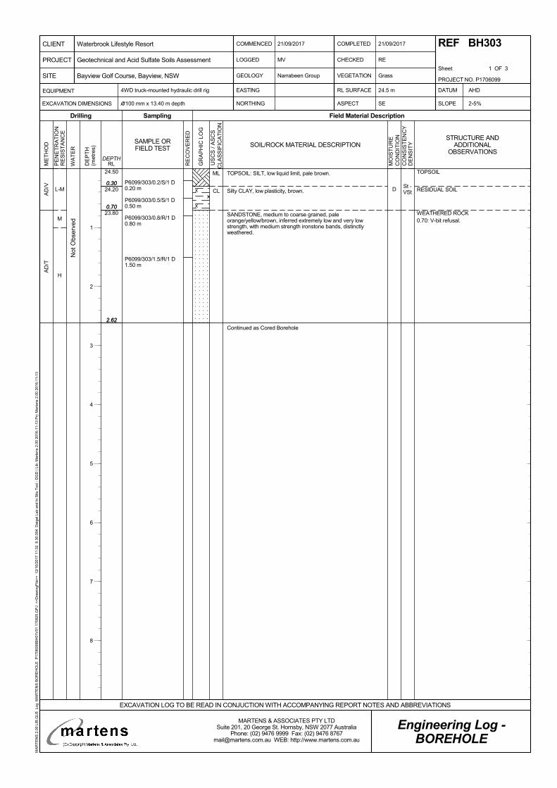
St -VSt
0.30
0.70
2.62
24.50
24.20
23.80
0.30
0.70
2.62
L-M
M
H
AD
/VA
D/T
DP6099/303/0.2/S/1 D0.20 m
P6099/303/0.5/S/1 D0.50 m
P6099/303/0.8/R/1 D0.80 m
P6099/303/1.5/R/1 D1.50 m
TOPSOIL: SILT, low liquid limit, pale brown.
Silty CLAY, low plasticity, brown.
SANDSTONE, medium to coarse grained, paleorange/yellow/brown, inferred extremely low and very lowstrength, with medium strength ironstone bands, distinctlyweathered.
Continued as Cored Borehole
ML
CL
Not
Obs
erve
d
TOPSOIL
RESIDUAL SOIL
WEATHERED ROCK0.70: V-bit refusal.
PE
NE
TR
AT
ION
RE
SIS
TA
NC
E
WA
TE
R
DE
PT
H(m
etre
s)
Sampling
RE
CO
VE
RE
D
Field Material Description
RLDEPTH
ME
TH
OD
Drilling
GR
AP
HIC
LO
G
SAMPLE ORFIELD TEST SOIL/ROCK MATERIAL DESCRIPTION
MO
IST
UR
EC
ON
DIT
ION
CO
NS
IST
EN
CY
DE
NS
ITY
U
SC
S /
AS
CS
CLA
SS
IFIC
AT
ION
COMMENCED
LOGGED
GEOLOGY
21/09/2017
CHECKED
VEGETATION
RE
Grass
4WD truck-mounted hydraulic drill rig
NORTHING ASPECT SE SLOPE
Narrabeen Group
MV
COMPLETED
Sheet 1 OF 3
EASTING DATUM
100 mm x 13.40 m depth 2-5%
AHDEQUIPMENT
EXCAVATION DIMENSIONS
RL SURFACE
Engineering Log -BOREHOLE
21/09/2017 REF BH303
24.5 m
EXCAVATION LOG TO BE READ IN CONJUCTION WITH ACCOMPANYING REPORT NOTES AND ABBREVIATIONS
PROJECT NO. P1706099
PROJECT
CLIENT
SITE
Waterbrook Lifestyle Resort
Bayview Golf Course, Bayview, NSW
Geotechnical and Acid Sulfate Soils Assessment
MARTENS & ASSOCIATES PTY LTDSuite 201, 20 George St. Hornsby, NSW 2077 Australia
Phone: (02) 9476 9999 Fax: (02) 9476 [email protected] WEB: http://www.martens.com.au
MA
RT
EN
S 2
.00
LIB
.GLB
Log
MA
RT
EN
S B
OR
EH
OLE
P17
0609
9BH
01V
01 1
7092
5.G
PJ
<<
Dra
win
gFile
>>
12/
10/2
017
11:3
2 8
.30.
004
Dat
gel L
ab a
nd In
Situ
Too
l - D
GD
| Li
b: M
arte
ns 2
.00
2016
-11-
13 P
rj: M
arte
ns 2
.00
2016
-11-
13
STRUCTURE ANDADDITIONAL
OBSERVATIONS
1
2
3
4
5
6
7
8
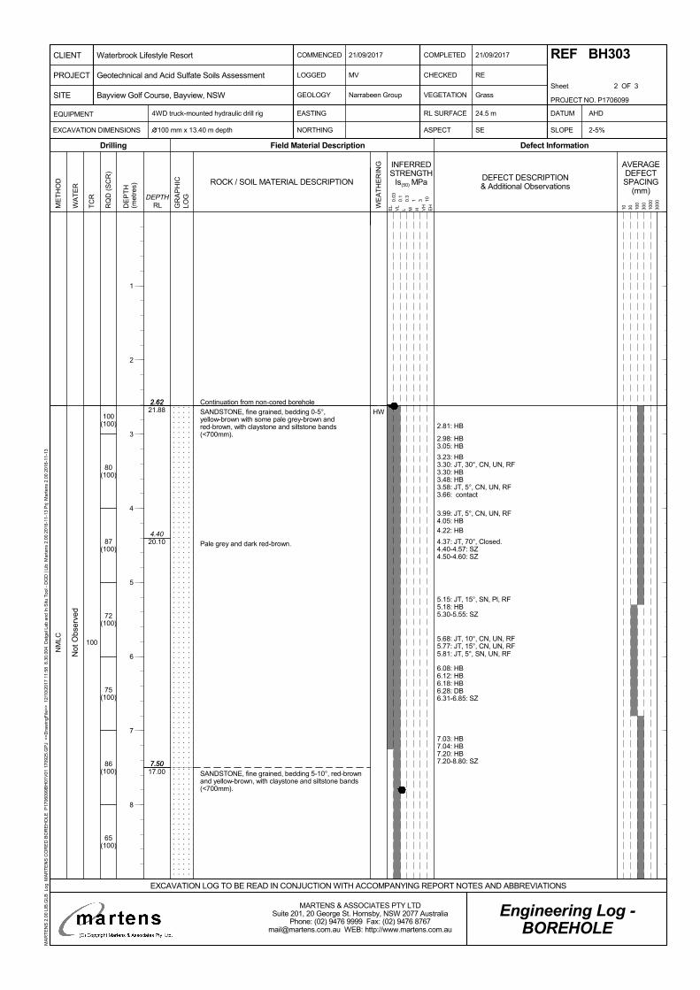
2.62
7.50
2.62
4.40
7.50
21.88
20.10
17.00
100
100(100)
80(100)
87(100)
72(100)
75(100)
86(100)
65(100)
HW
NM
LC
Continuation from non-cored borehole
2.81: HB
2.98: HB3.05: HB
3.23: HB3.30: JT, 30°, CN, UN, RF3.30: HB3.48: HB3.58: JT, 5°, CN, UN, RF3.66: contact
3.99: JT, 5°, CN, UN, RF4.05: HB4.22: HB
4.37: JT, 70°, Closed.4.40-4.57: SZ4.50-4.60: SZ
5.15: JT, 15°, SN, Pl, RF5.18: HB5.30-5.55: SZ
5.68: JT, 10°, CN, UN, RF5.77: JT, 15°, CN, UN, RF5.81: JT, 5°, SN, UN, RF
6.08: HB6.12: HB6.18: HB6.28: DB6.31-6.85: SZ
7.03: HB7.04: HB7.20: HB7.20-8.80: SZ
SANDSTONE, fine grained, bedding 0-5°,yellow-brown with some pale grey-brown andred-brown, with claystone and siltstone bands(<700mm).
Pale grey and dark red-brown.
SANDSTONE, fine grained, bedding 5-10°, red-brownand yellow-brown, with claystone and siltstone bands(<700mm).
Not
Obs
erve
d
TC
R
RQ
D (
SC
R)
GR
AP
HIC
LOG
WE
AT
HE
RIN
G
ME
TH
OD
DE
PT
H(m
etre
s)
Field Material DescriptionDrilling
INFERREDSTRENGTH
Is(50) MPa
Defect Information
DEPTHRLW
AT
ER
AVERAGEDEFECTSPACING
(mm)
10 30 100
300
1000
3000
DEFECT DESCRIPTION& Additional Observations
EL
VL
L M H VH
EH
0.03
0.1
0.3
1 3 10
ROCK / SOIL MATERIAL DESCRIPTION
COMMENCED
LOGGED
GEOLOGY
21/09/2017
CHECKED
VEGETATION
RE
Grass
4WD truck-mounted hydraulic drill rig
NORTHING ASPECT SE SLOPE
Narrabeen Group
MV
COMPLETED
Sheet 2 OF 3
EASTING DATUM
100 mm x 13.40 m depth 2-5%
AHDEQUIPMENT
EXCAVATION DIMENSIONS
RL SURFACE
Engineering Log -BOREHOLE
21/09/2017 REF BH303
24.5 m
EXCAVATION LOG TO BE READ IN CONJUCTION WITH ACCOMPANYING REPORT NOTES AND ABBREVIATIONS
PROJECT NO. P1706099
PROJECT
CLIENT
SITE
Waterbrook Lifestyle Resort
Bayview Golf Course, Bayview, NSW
Geotechnical and Acid Sulfate Soils Assessment
MARTENS & ASSOCIATES PTY LTDSuite 201, 20 George St. Hornsby, NSW 2077 Australia
Phone: (02) 9476 9999 Fax: (02) 9476 [email protected] WEB: http://www.martens.com.au
MA
RT
EN
S 2
.00
LIB
.GLB
Log
MA
RT
EN
S C
OR
ED
BO
RE
HO
LE P
1706
099B
H01
V01
170
925.
GP
J <
<D
raw
ingF
ile>
> 1
2/10
/201
7 11
:58
8.3
0.00
4 D
atge
l Lab
and
In S
itu T
ool -
DG
D |
Lib:
Mar
tens
2.0
0 20
16-1
1-13
Prj:
Mar
tens
2.0
0 20
16-1
1-13
1
2
3
4
5
6
7
8
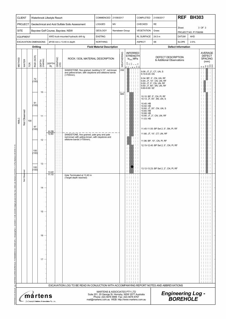
11.70
13.40
11.70
11.10
12.80
100
72(100)
91(100)
97(100)
100(100)
100(100)
HW
MW
NM
LC
9.06: JT, 2°, CT, UN, S9.10-9.20: DS
9.34: BP, 3°, CN, UN, RF9.45: JT, 10°, CN, UN, RF9.50: JT, 5°, CN, UN, RF9.50: JT, 80°, SN, UN, RF9.60-9.90: SZ
10.10: BP, 5°, CN, Pl, RF10.13: JT, 45°, SN, UN, S
10.40: HB10.50: HB10.60: JT, 20°, CN, UN, S10.65: HB10.68: HB10.90: JT, 2°, CN, UN, RF11.03: HB
11.45-11.55: BP Set 2, 5°, SN, Pl, RF
11.66: JT, 15°, CT, UN, RF
11.96: BP, 10°, CN, Pl, RF
12.15-12.40: BP Set 2, 5°, CN, Pl, RF
13.12-13.23: BP Set 2, 2°, CN, Pl, RF
SANDSTONE, fine grained, bedding 5-10°, red-brownand yellow-brown, with claystone and siltstone bands(<700mm).
SANDSTONE, fine grained, pale grey and palered-brown with yellow-brown, with claystone andsiltstone bands (<700mm).
Hole Terminated at 13.40 m(Target depth reached)
Not
Obs
erv
edN
ot O
bser
ved
TC
R
RQ
D (
SC
R)
GR
AP
HIC
LOG
WE
AT
HE
RIN
G
ME
TH
OD
DE
PT
H(m
etre
s)
Field Material DescriptionDrilling
INFERREDSTRENGTH
Is(50) MPa
Defect Information
DEPTHRLW
AT
ER
AVERAGEDEFECTSPACING
(mm)
10 30 100
300
1000
3000
DEFECT DESCRIPTION& Additional Observations
EL
VL
L M H VH
EH
0.03
0.1
0.3
1 3 10
ROCK / SOIL MATERIAL DESCRIPTION
COMMENCED
LOGGED
GEOLOGY
21/09/2017
CHECKED
VEGETATION
RE
Grass
4WD truck-mounted hydraulic drill rig
NORTHING ASPECT SE SLOPE
Narrabeen Group
MV
COMPLETED
Sheet 3 OF 3
EASTING DATUM
100 mm x 13.40 m depth 2-5%
AHDEQUIPMENT
EXCAVATION DIMENSIONS
RL SURFACE
Engineering Log -BOREHOLE
21/09/2017 REF BH303
24.5 m
EXCAVATION LOG TO BE READ IN CONJUCTION WITH ACCOMPANYING REPORT NOTES AND ABBREVIATIONS
PROJECT NO. P1706099
PROJECT
CLIENT
SITE
Waterbrook Lifestyle Resort
Bayview Golf Course, Bayview, NSW
Geotechnical and Acid Sulfate Soils Assessment
MARTENS & ASSOCIATES PTY LTDSuite 201, 20 George St. Hornsby, NSW 2077 Australia
Phone: (02) 9476 9999 Fax: (02) 9476 [email protected] WEB: http://www.martens.com.au
MA
RT
EN
S 2
.00
LIB
.GLB
Log
MA
RT
EN
S C
OR
ED
BO
RE
HO
LE P
1706
099B
H01
V01
170
925.
GP
J <
<D
raw
ingF
ile>
> 1
2/10
/201
7 11
:58
8.3
0.00
4 D
atge
l Lab
and
In S
itu T
ool -
DG
D |
Lib:
Mar
tens
2.0
0 20
16-1
1-13
Prj:
Mar
tens
2.0
0 20
16-1
1-13
10
11
12
13
14
15
16
17
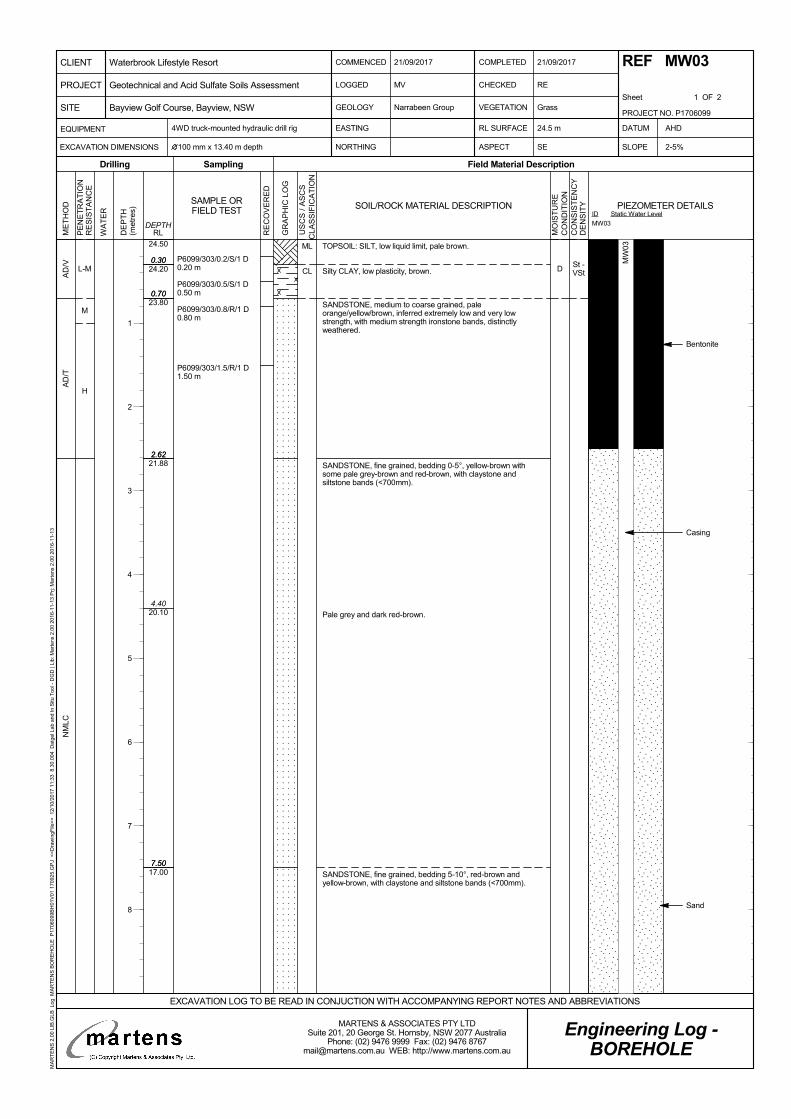
St -VSt
0.30
0.70
2.62
7.50
24.50
24.20
23.80
21.88
20.10
17.00
0.30
0.70
2.62
4.40
7.50
L-M
M
H
AD
/VA
D/T
NM
LC
DP6099/303/0.2/S/1 D0.20 m
P6099/303/0.5/S/1 D0.50 m
P6099/303/0.8/R/1 D0.80 m
P6099/303/1.5/R/1 D1.50 m
TOPSOIL: SILT, low liquid limit, pale brown.
Silty CLAY, low plasticity, brown.
SANDSTONE, medium to coarse grained, paleorange/yellow/brown, inferred extremely low and very lowstrength, with medium strength ironstone bands, distinctlyweathered.
SANDSTONE, fine grained, bedding 0-5°, yellow-brown withsome pale grey-brown and red-brown, with claystone andsiltstone bands (<700mm).
Pale grey and dark red-brown.
SANDSTONE, fine grained, bedding 5-10°, red-brown andyellow-brown, with claystone and siltstone bands (<700mm).
ML
CL
Bentonite
Casing
Sand
PE
NE
TR
AT
ION
RE
SIS
TA
NC
E
WA
TE
R
DE
PT
H(m
etre
s)
Sampling
RE
CO
VE
RE
D
Field Material Description
RLDEPTH
ME
TH
OD
Drilling
GR
AP
HIC
LO
G
SAMPLE ORFIELD TEST SOIL/ROCK MATERIAL DESCRIPTION
MO
IST
UR
EC
ON
DIT
ION
CO
NS
IST
EN
CY
DE
NS
ITY
U
SC
S /
AS
CS
CLA
SS
IFIC
AT
ION
COMMENCED
LOGGED
GEOLOGY
21/09/2017
CHECKED
VEGETATION
RE
Grass
4WD truck-mounted hydraulic drill rig
NORTHING ASPECT SE SLOPE
Narrabeen Group
MV
COMPLETED
Sheet 1 OF 2
EASTING DATUM
100 mm x 13.40 m depth 2-5%
AHDEQUIPMENT
EXCAVATION DIMENSIONS
RL SURFACE
Engineering Log -BOREHOLE
21/09/2017 REF MW03
24.5 m
EXCAVATION LOG TO BE READ IN CONJUCTION WITH ACCOMPANYING REPORT NOTES AND ABBREVIATIONS
PROJECT NO. P1706099
PROJECT
CLIENT
SITE
Waterbrook Lifestyle Resort
Bayview Golf Course, Bayview, NSW
Geotechnical and Acid Sulfate Soils Assessment
MARTENS & ASSOCIATES PTY LTDSuite 201, 20 George St. Hornsby, NSW 2077 Australia
Phone: (02) 9476 9999 Fax: (02) 9476 [email protected] WEB: http://www.martens.com.au
MA
RT
EN
S 2
.00
LIB
.GLB
Log
MA
RT
EN
S B
OR
EH
OLE
P17
0609
9BH
01V
01 1
7092
5.G
PJ
<<
Dra
win
gFile
>>
12/
10/2
017
11:3
3 8
.30.
004
Dat
gel L
ab a
nd In
Situ
Too
l - D
GD
| Li
b: M
arte
ns 2
.00
2016
-11-
13 P
rj: M
arte
ns 2
.00
2016
-11-
13
ID
MW03
Static Water LevelPIEZOMETER DETAILS
1
2
3
4
5
6
7
8
MW
03
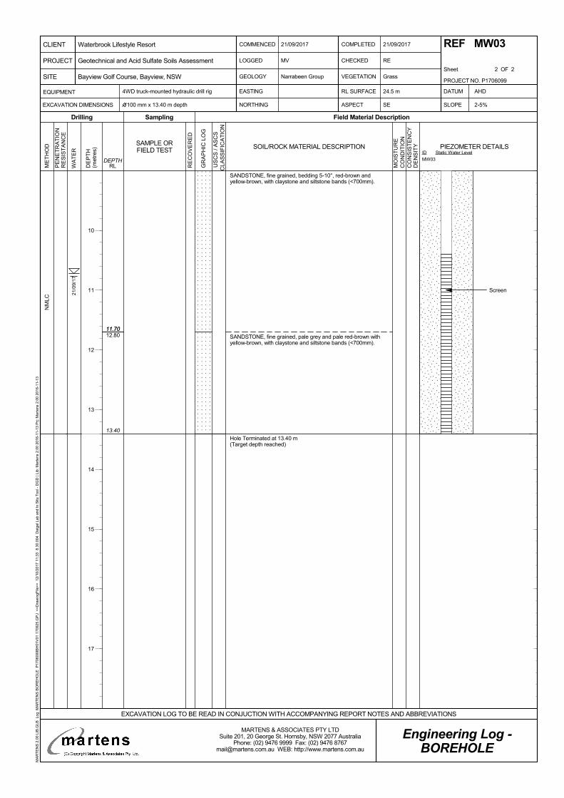
11.70
13.40
12.8011.70
NM
LC
SANDSTONE, fine grained, bedding 5-10°, red-brown andyellow-brown, with claystone and siltstone bands (<700mm).
SANDSTONE, fine grained, pale grey and pale red-brown withyellow-brown, with claystone and siltstone bands (<700mm).
Hole Terminated at 13.40 m(Target depth reached)
21/0
9/17
Screen
PE
NE
TR
AT
ION
RE
SIS
TA
NC
E
WA
TE
R
DE
PT
H(m
etre
s)
Sampling
RE
CO
VE
RE
D
Field Material Description
RLDEPTH
ME
TH
OD
Drilling
GR
AP
HIC
LO
G
SAMPLE ORFIELD TEST SOIL/ROCK MATERIAL DESCRIPTION
MO
IST
UR
EC
ON
DIT
ION
CO
NS
IST
EN
CY
DE
NS
ITY
U
SC
S /
AS
CS
CLA
SS
IFIC
AT
ION
COMMENCED
LOGGED
GEOLOGY
21/09/2017
CHECKED
VEGETATION
RE
Grass
4WD truck-mounted hydraulic drill rig
NORTHING ASPECT SE SLOPE
Narrabeen Group
MV
COMPLETED
Sheet 2 OF 2
EASTING DATUM
100 mm x 13.40 m depth 2-5%
AHDEQUIPMENT
EXCAVATION DIMENSIONS
RL SURFACE
Engineering Log -BOREHOLE
21/09/2017 REF MW03
24.5 m
EXCAVATION LOG TO BE READ IN CONJUCTION WITH ACCOMPANYING REPORT NOTES AND ABBREVIATIONS
PROJECT NO. P1706099
PROJECT
CLIENT
SITE
Waterbrook Lifestyle Resort
Bayview Golf Course, Bayview, NSW
Geotechnical and Acid Sulfate Soils Assessment
MARTENS & ASSOCIATES PTY LTDSuite 201, 20 George St. Hornsby, NSW 2077 Australia
Phone: (02) 9476 9999 Fax: (02) 9476 [email protected] WEB: http://www.martens.com.au
MA
RT
EN
S 2
.00
LIB
.GLB
Log
MA
RT
EN
S B
OR
EH
OLE
P17
0609
9BH
01V
01 1
7092
5.G
PJ
<<
Dra
win
gFile
>>
12/
10/2
017
11:3
3 8
.30.
004
Dat
gel L
ab a
nd In
Situ
Too
l - D
GD
| Li
b: M
arte
ns 2
.00
2016
-11-
13 P
rj: M
arte
ns 2
.00
2016
-11-
13
ID
MW03
Static Water LevelPIEZOMETER DETAILS
10
11
12
13
14
15
16
17
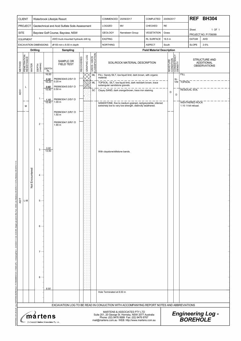
St -VSt
D
0.30
0.60
1.10
8.50
16.50
16.20
15.90
15.40
13.50
0.30
0.60
1.10
3.00
L
M
L-M
AD
/VA
D/T
D
P6099/304/0.2/S/1 D0.20 m
P6099/304/0.5/S/1 D0.50 m
P6099/304/1.0/S/1 D1.00 m
P6099/304/1.5/R/1 D1.50 m
P6099/304/1.9/R/1 D1.90 m
FILL: Sandy SILT, low liquid limit, dark brown, with organicmaterial.
TOPSOIL: SILT, low liquid limit, dark red/dark brown, tracesubangular sandstone gravels.
Clayey SAND, dark orange/brown, trace iron staining.
SANDSTONE, fine to medium grained, red/grey/white, inferredextremely low to very low strength, distinctly weathered.
With claystone/siltstone bands.
Hole Terminated at 8.50 m
ML
ML
SC
Not
Enc
ount
ered
FILL
TOPSOIL
RESIDUAL SOIL
WEATHERED ROCK1.10: V-bit refusal.
PE
NE
TR
AT
ION
RE
SIS
TA
NC
E
WA
TE
R
DE
PT
H(m
etre
s)
Sampling
RE
CO
VE
RE
D
Field Material Description
RLDEPTH
ME
TH
OD
Drilling
GR
AP
HIC
LO
G
SAMPLE ORFIELD TEST SOIL/ROCK MATERIAL DESCRIPTION
MO
IST
UR
EC
ON
DIT
ION
CO
NS
IST
EN
CY
DE
NS
ITY
U
SC
S /
AS
CS
CLA
SS
IFIC
AT
ION
COMMENCED
LOGGED
GEOLOGY
20/09/2017
CHECKED
VEGETATION
RE
Grass
4WD truck-mounted hydraulic drill rig
NORTHING ASPECT South SLOPE
Narrabeen Group
MV
COMPLETED
Sheet 1 OF 1
EASTING DATUM
100 mm x 8.50 m depth 2-5%
AHDEQUIPMENT
EXCAVATION DIMENSIONS
RL SURFACE
Engineering Log -BOREHOLE
20/09/2017 REF BH304
16.5 m
EXCAVATION LOG TO BE READ IN CONJUCTION WITH ACCOMPANYING REPORT NOTES AND ABBREVIATIONS
PROJECT NO. P1706099
PROJECT
CLIENT
SITE
Waterbrook Lifestyle Resort
Bayview Golf Course, Bayview, NSW
Geotechnical and Acid Sulfate Soils Assessment
MARTENS & ASSOCIATES PTY LTDSuite 201, 20 George St. Hornsby, NSW 2077 Australia
Phone: (02) 9476 9999 Fax: (02) 9476 [email protected] WEB: http://www.martens.com.au
MA
RT
EN
S 2
.00
LIB
.GLB
Log
MA
RT
EN
S B
OR
EH
OLE
P17
0609
9BH
01V
01 1
7092
5.G
PJ
<<
Dra
win
gFile
>>
12/
10/2
017
11:3
2 8
.30.
004
Dat
gel L
ab a
nd In
Situ
Too
l - D
GD
| Li
b: M
arte
ns 2
.00
2016
-11-
13 P
rj: M
arte
ns 2
.00
2016
-11-
13
STRUCTURE ANDADDITIONAL
OBSERVATIONS
1
2
3
4
5
6
7
8
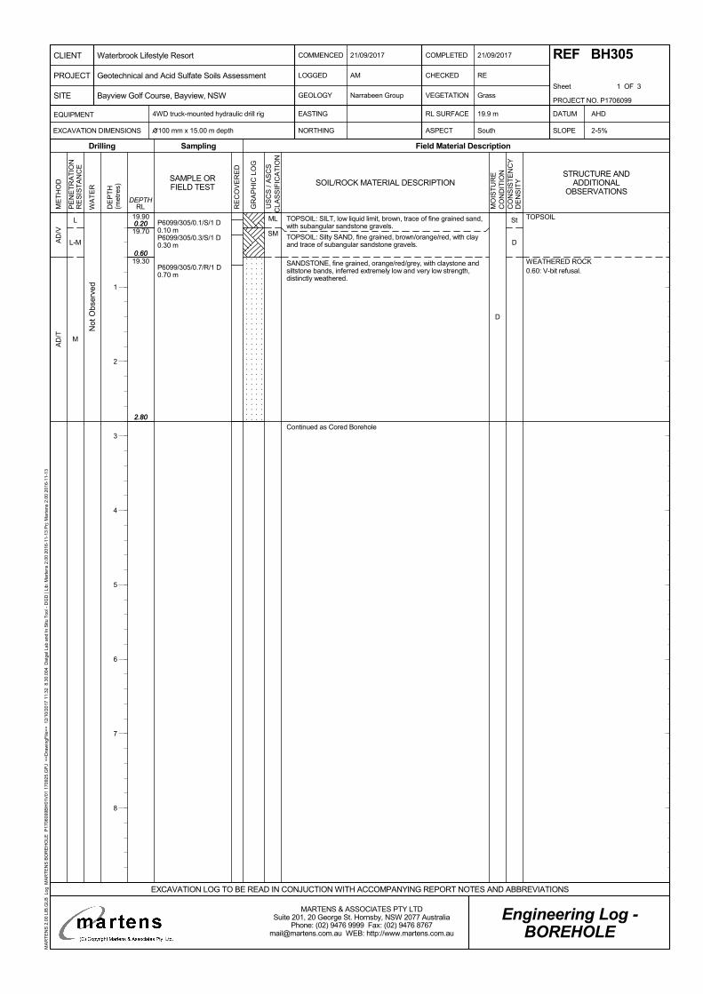
St
D
0.20
0.60
2.80
19.90
19.70
19.30
0.20
0.60
2.80
L
L-M
M
AD
/VA
D/T
D
P6099/305/0.1/S/1 D0.10 mP6099/305/0.3/S/1 D0.30 m
P6099/305/0.7/R/1 D0.70 m
TOPSOIL: SILT, low liquid limit, brown, trace of fine grained sand,with subangular sandstone gravels.
TOPSOIL: Silty SAND, fine grained, brown/orange/red, with clayand trace of subangular sandstone gravels.
SANDSTONE, fine grained, orange/red/grey, with claystone andsiltstone bands, inferred extremely low and very low strength,distinctly weathered.
Continued as Cored Borehole
ML
SM
Not
Obs
erve
d
TOPSOIL
WEATHERED ROCK0.60: V-bit refusal.
PE
NE
TR
AT
ION
RE
SIS
TA
NC
E
WA
TE
R
DE
PT
H(m
etre
s)
Sampling
RE
CO
VE
RE
D
Field Material Description
RLDEPTH
ME
TH
OD
Drilling
GR
AP
HIC
LO
G
SAMPLE ORFIELD TEST SOIL/ROCK MATERIAL DESCRIPTION
MO
IST
UR
EC
ON
DIT
ION
CO
NS
IST
EN
CY
DE
NS
ITY
U
SC
S /
AS
CS
CLA
SS
IFIC
AT
ION
COMMENCED
LOGGED
GEOLOGY
21/09/2017
CHECKED
VEGETATION
RE
Grass
4WD truck-mounted hydraulic drill rig
NORTHING ASPECT South SLOPE
Narrabeen Group
AM
COMPLETED
Sheet 1 OF 3
EASTING DATUM
100 mm x 15.00 m depth 2-5%
AHDEQUIPMENT
EXCAVATION DIMENSIONS
RL SURFACE
Engineering Log -BOREHOLE
21/09/2017 REF BH305
19.9 m
EXCAVATION LOG TO BE READ IN CONJUCTION WITH ACCOMPANYING REPORT NOTES AND ABBREVIATIONS
PROJECT NO. P1706099
PROJECT
CLIENT
SITE
Waterbrook Lifestyle Resort
Bayview Golf Course, Bayview, NSW
Geotechnical and Acid Sulfate Soils Assessment
MARTENS & ASSOCIATES PTY LTDSuite 201, 20 George St. Hornsby, NSW 2077 Australia
Phone: (02) 9476 9999 Fax: (02) 9476 [email protected] WEB: http://www.martens.com.au
MA
RT
EN
S 2
.00
LIB
.GLB
Log
MA
RT
EN
S B
OR
EH
OLE
P17
0609
9BH
01V
01 1
7092
5.G
PJ
<<
Dra
win
gFile
>>
12/
10/2
017
11:3
2 8
.30.
004
Dat
gel L
ab a
nd In
Situ
Too
l - D
GD
| Li
b: M
arte
ns 2
.00
2016
-11-
13 P
rj: M
arte
ns 2
.00
2016
-11-
13
STRUCTURE ANDADDITIONAL
OBSERVATIONS
1
2
3
4
5
6
7
8
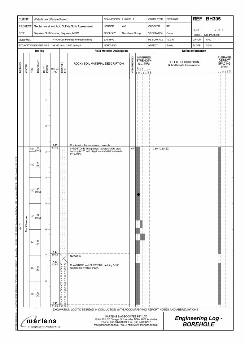
2.80
6.94
7.30
8.90
2.80
6.94
7.30
8.90
17.10
12.96
12.60
11.00
100
100
100
100
94
70
90
0(100)
71(71)
83(100)
57(100)
94(94)
0(60)
10(40)
HW
NM
LC
Continuation from non-cored borehole
2.80-10.30: SZSANDSTONE, fine grained, red/brown/light grey,bedding 0-10°, with claystone and siltstone bands(<400mm).
NO CORE
CLAYSTONE and SILTSTONE, bedding 5-10°,red/light grey/yellow-brown.
Not
Obs
erve
d
TC
R
RQ
D (
SC
R)
GR
AP
HIC
LOG
WE
AT
HE
RIN
G
ME
TH
OD
DE
PT
H(m
etre
s)
Field Material DescriptionDrilling
INFERREDSTRENGTH
Is(50) MPa
Defect Information
DEPTHRLW
AT
ER
AVERAGEDEFECTSPACING
(mm)
10 30 100
300
1000
3000
DEFECT DESCRIPTION& Additional Observations
EL
VL
L M H VH
EH
0.03
0.1
0.3
1 3 10
ROCK / SOIL MATERIAL DESCRIPTION
COMMENCED
LOGGED
GEOLOGY
21/09/2017
CHECKED
VEGETATION
RE
Grass
4WD truck-mounted hydraulic drill rig
NORTHING ASPECT South SLOPE
Narrabeen Group
AM
COMPLETED
Sheet 2 OF 3
EASTING DATUM
100 mm x 15.00 m depth 2-5%
AHDEQUIPMENT
EXCAVATION DIMENSIONS
RL SURFACE
Engineering Log -BOREHOLE
21/09/2017 REF BH305
19.9 m
EXCAVATION LOG TO BE READ IN CONJUCTION WITH ACCOMPANYING REPORT NOTES AND ABBREVIATIONS
PROJECT NO. P1706099
PROJECT
CLIENT
SITE
Waterbrook Lifestyle Resort
Bayview Golf Course, Bayview, NSW
Geotechnical and Acid Sulfate Soils Assessment
MARTENS & ASSOCIATES PTY LTDSuite 201, 20 George St. Hornsby, NSW 2077 Australia
Phone: (02) 9476 9999 Fax: (02) 9476 [email protected] WEB: http://www.martens.com.au
MA
RT
EN
S 2
.00
LIB
.GLB
Log
MA
RT
EN
S C
OR
ED
BO
RE
HO
LE P
1706
099B
H01
V01
170
925.
GP
J <
<D
raw
ingF
ile>
> 1
2/10
/201
7 11
:58
8.3
0.00
4 D
atge
l Lab
and
In S
itu T
ool -
DG
D |
Lib:
Mar
tens
2.0
0 20
16-1
1-13
Prj:
Mar
tens
2.0
0 20
16-1
1-13
1
2
3
4
5
6
7
8
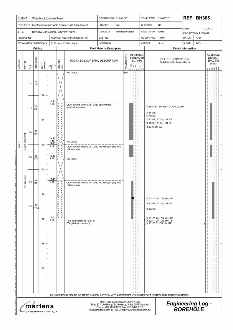
10.30
11.80
12.00
12.50
13.45
15.00
10.30
11.80
12.00
12.50
13.45
4.90
9.60
8.10
7.90
7.40
6.45
0
70
80
55
50
100
0(0)
60(70)
45(50)
50(50)
46(46)
90(100)
HW
NM
LC
10.38-10.54: BP Set 4, 2°, CN, UN, RF
10.65: DB10.74: DB
10.90: BP, 5°, CN, UN, RF
11.04: BP, 3°, CN, UN, RF
11.20-13.60: SZ
14.10: JT, 20°, CN, UN, RF
14.30: BP, 5°, CN, UN, RF
14.52: HB
14.90: JT, 70°, CN, UN, RF14.93: JT, 20°, CN, UN, RF14.96: JT, 5°, CN, UN, RF
NO CORE
CLAYSTONE and SILTSTONE, light red/lightgrey/yellow-brown.
NO CORE
CLAYSTONE and SILTSTONE, red with light grey andyellow-brown.
NO CORE
CLAYSTONE and SILTSTONE, red with light grey andyellow-brown.
Hole Terminated at 15.00 m(Target depth reached)
Not
Obs
erv
edN
ot O
bser
ved
TC
R
RQ
D (
SC
R)
GR
AP
HIC
LOG
WE
AT
HE
RIN
G
ME
TH
OD
DE
PT
H(m
etre
s)
Field Material DescriptionDrilling
INFERREDSTRENGTH
Is(50) MPa
Defect Information
DEPTHRLW
AT
ER
AVERAGEDEFECTSPACING
(mm)
10 30 100
300
1000
3000
DEFECT DESCRIPTION& Additional Observations
EL
VL
L M H VH
EH
0.03
0.1
0.3
1 3 10
ROCK / SOIL MATERIAL DESCRIPTION
COMMENCED
LOGGED
GEOLOGY
21/09/2017
CHECKED
VEGETATION
RE
Grass
4WD truck-mounted hydraulic drill rig
NORTHING ASPECT South SLOPE
Narrabeen Group
AM
COMPLETED
Sheet 3 OF 3
EASTING DATUM
100 mm x 15.00 m depth 2-5%
AHDEQUIPMENT
EXCAVATION DIMENSIONS
RL SURFACE
Engineering Log -BOREHOLE
21/09/2017 REF BH305
19.9 m
EXCAVATION LOG TO BE READ IN CONJUCTION WITH ACCOMPANYING REPORT NOTES AND ABBREVIATIONS
PROJECT NO. P1706099
PROJECT
CLIENT
SITE
Waterbrook Lifestyle Resort
Bayview Golf Course, Bayview, NSW
Geotechnical and Acid Sulfate Soils Assessment
MARTENS & ASSOCIATES PTY LTDSuite 201, 20 George St. Hornsby, NSW 2077 Australia
Phone: (02) 9476 9999 Fax: (02) 9476 [email protected] WEB: http://www.martens.com.au
MA
RT
EN
S 2
.00
LIB
.GLB
Log
MA
RT
EN
S C
OR
ED
BO
RE
HO
LE P
1706
099B
H01
V01
170
925.
GP
J <
<D
raw
ingF
ile>
> 1
2/10
/201
7 11
:58
8.3
0.00
4 D
atge
l Lab
and
In S
itu T
ool -
DG
D |
Lib:
Mar
tens
2.0
0 20
16-1
1-13
Prj:
Mar
tens
2.0
0 20
16-1
1-13
10
11
12
13
14
15
16
17
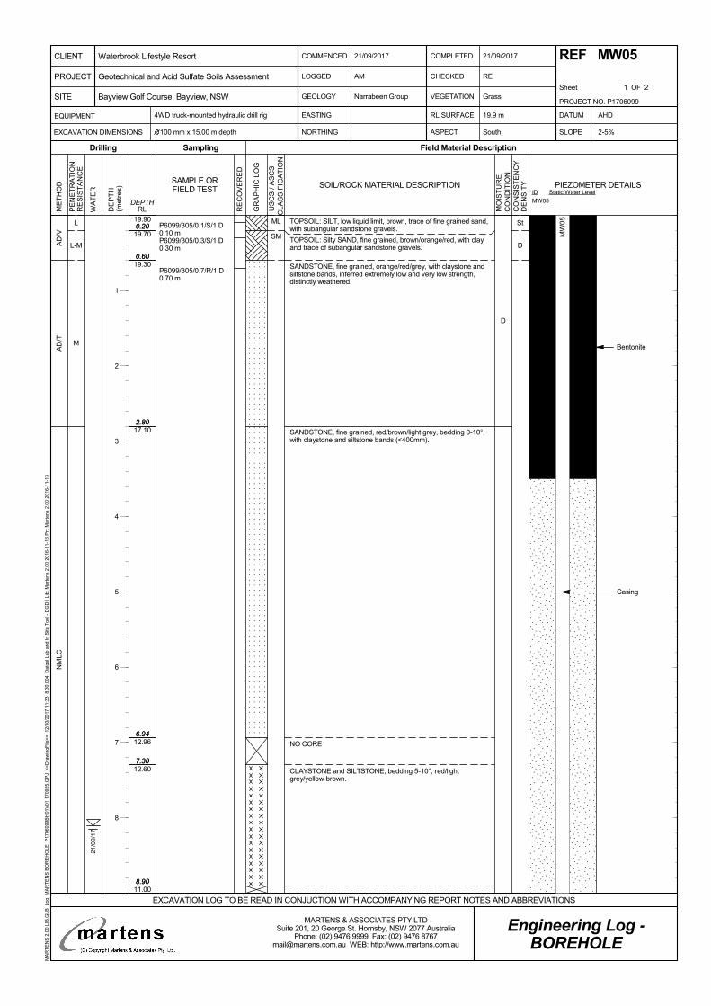
St
D
0.20
0.60
2.80
6.94
7.30
8.90
19.90
19.70
19.30
17.10
12.96
12.60
11.00
0.20
0.60
2.80
6.94
7.30
8.90
L
L-M
M
AD
/VA
D/T
NM
LC
D
P6099/305/0.1/S/1 D0.10 mP6099/305/0.3/S/1 D0.30 m
P6099/305/0.7/R/1 D0.70 m
TOPSOIL: SILT, low liquid limit, brown, trace of fine grained sand,with subangular sandstone gravels.
TOPSOIL: Silty SAND, fine grained, brown/orange/red, with clayand trace of subangular sandstone gravels.
SANDSTONE, fine grained, orange/red/grey, with claystone andsiltstone bands, inferred extremely low and very low strength,distinctly weathered.
SANDSTONE, fine grained, red/brown/light grey, bedding 0-10°,with claystone and siltstone bands (<400mm).
NO CORE
CLAYSTONE and SILTSTONE, bedding 5-10°, red/lightgrey/yellow-brown.
ML
SM
21/0
9/17
Bentonite
Casing
PE
NE
TR
AT
ION
RE
SIS
TA
NC
E
WA
TE
R
DE
PT
H(m
etre
s)
Sampling
RE
CO
VE
RE
D
Field Material Description
RLDEPTH
ME
TH
OD
Drilling
GR
AP
HIC
LO
G
SAMPLE ORFIELD TEST SOIL/ROCK MATERIAL DESCRIPTION
MO
IST
UR
EC
ON
DIT
ION
CO
NS
IST
EN
CY
DE
NS
ITY
U
SC
S /
AS
CS
CLA
SS
IFIC
AT
ION
COMMENCED
LOGGED
GEOLOGY
21/09/2017
CHECKED
VEGETATION
RE
Grass
4WD truck-mounted hydraulic drill rig
NORTHING ASPECT South SLOPE
Narrabeen Group
AM
COMPLETED
Sheet 1 OF 2
EASTING DATUM
100 mm x 15.00 m depth 2-5%
AHDEQUIPMENT
EXCAVATION DIMENSIONS
RL SURFACE
Engineering Log -BOREHOLE
21/09/2017 REF MW05
19.9 m
EXCAVATION LOG TO BE READ IN CONJUCTION WITH ACCOMPANYING REPORT NOTES AND ABBREVIATIONS
PROJECT NO. P1706099
PROJECT
CLIENT
SITE
Waterbrook Lifestyle Resort
Bayview Golf Course, Bayview, NSW
Geotechnical and Acid Sulfate Soils Assessment
MARTENS & ASSOCIATES PTY LTDSuite 201, 20 George St. Hornsby, NSW 2077 Australia
Phone: (02) 9476 9999 Fax: (02) 9476 [email protected] WEB: http://www.martens.com.au
MA
RT
EN
S 2
.00
LIB
.GLB
Log
MA
RT
EN
S B
OR
EH
OLE
P17
0609
9BH
01V
01 1
7092
5.G
PJ
<<
Dra
win
gFile
>>
12/
10/2
017
11:3
3 8
.30.
004
Dat
gel L
ab a
nd In
Situ
Too
l - D
GD
| Li
b: M
arte
ns 2
.00
2016
-11-
13 P
rj: M
arte
ns 2
.00
2016
-11-
13
ID
MW05
Static Water LevelPIEZOMETER DETAILS
1
2
3
4
5
6
7
8
MW
05
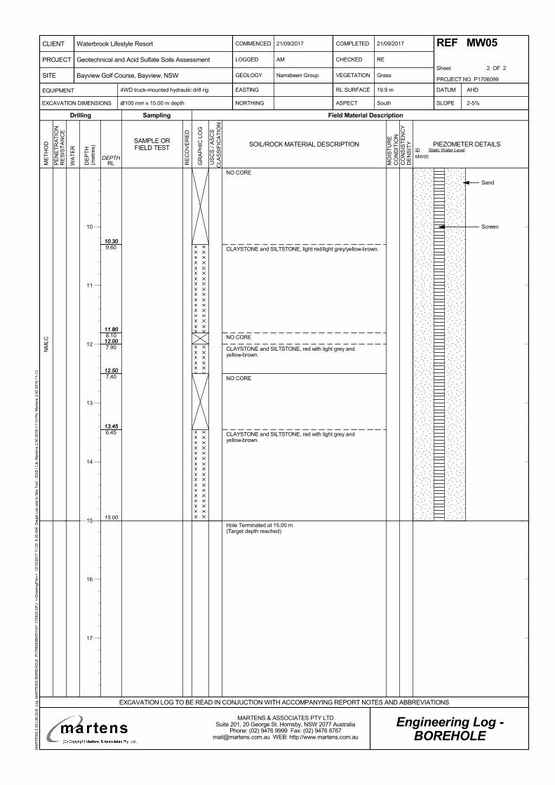
10.30
11.80
12.00
12.50
13.45
15.00
9.60
8.10
7.90
7.40
6.45
10.30
11.80
12.00
12.50
13.45
NM
LC
NO CORE
CLAYSTONE and SILTSTONE, light red/light grey/yellow-brown.
NO CORE
CLAYSTONE and SILTSTONE, red with light grey andyellow-brown.
NO CORE
CLAYSTONE and SILTSTONE, red with light grey andyellow-brown.
Hole Terminated at 15.00 m(Target depth reached)
Sand
Screen
PE
NE
TR
AT
ION
RE
SIS
TA
NC
E
WA
TE
R
DE
PT
H(m
etre
s)
Sampling
RE
CO
VE
RE
D
Field Material Description
RLDEPTH
ME
TH
OD
Drilling
GR
AP
HIC
LO
G
SAMPLE ORFIELD TEST SOIL/ROCK MATERIAL DESCRIPTION
MO
IST
UR
EC
ON
DIT
ION
CO
NS
IST
EN
CY
DE
NS
ITY
U
SC
S /
AS
CS
CLA
SS
IFIC
AT
ION
COMMENCED
LOGGED
GEOLOGY
21/09/2017
CHECKED
VEGETATION
RE
Grass
4WD truck-mounted hydraulic drill rig
NORTHING ASPECT South SLOPE
Narrabeen Group
AM
COMPLETED
Sheet 2 OF 2
EASTING DATUM
100 mm x 15.00 m depth 2-5%
AHDEQUIPMENT
EXCAVATION DIMENSIONS
RL SURFACE
Engineering Log -BOREHOLE
21/09/2017 REF MW05
19.9 m
EXCAVATION LOG TO BE READ IN CONJUCTION WITH ACCOMPANYING REPORT NOTES AND ABBREVIATIONS
PROJECT NO. P1706099
PROJECT
CLIENT
SITE
Waterbrook Lifestyle Resort
Bayview Golf Course, Bayview, NSW
Geotechnical and Acid Sulfate Soils Assessment
MARTENS & ASSOCIATES PTY LTDSuite 201, 20 George St. Hornsby, NSW 2077 Australia
Phone: (02) 9476 9999 Fax: (02) 9476 [email protected] WEB: http://www.martens.com.au
MA
RT
EN
S 2
.00
LIB
.GLB
Log
MA
RT
EN
S B
OR
EH
OLE
P17
0609
9BH
01V
01 1
7092
5.G
PJ
<<
Dra
win
gFile
>>
12/
10/2
017
11:3
3 8
.30.
004
Dat
gel L
ab a
nd In
Situ
Too
l - D
GD
| Li
b: M
arte
ns 2
.00
2016
-11-
13 P
rj: M
arte
ns 2
.00
2016
-11-
13
ID
MW05
Static Water LevelPIEZOMETER DETAILS
10
11
12
13
14
15
16
17
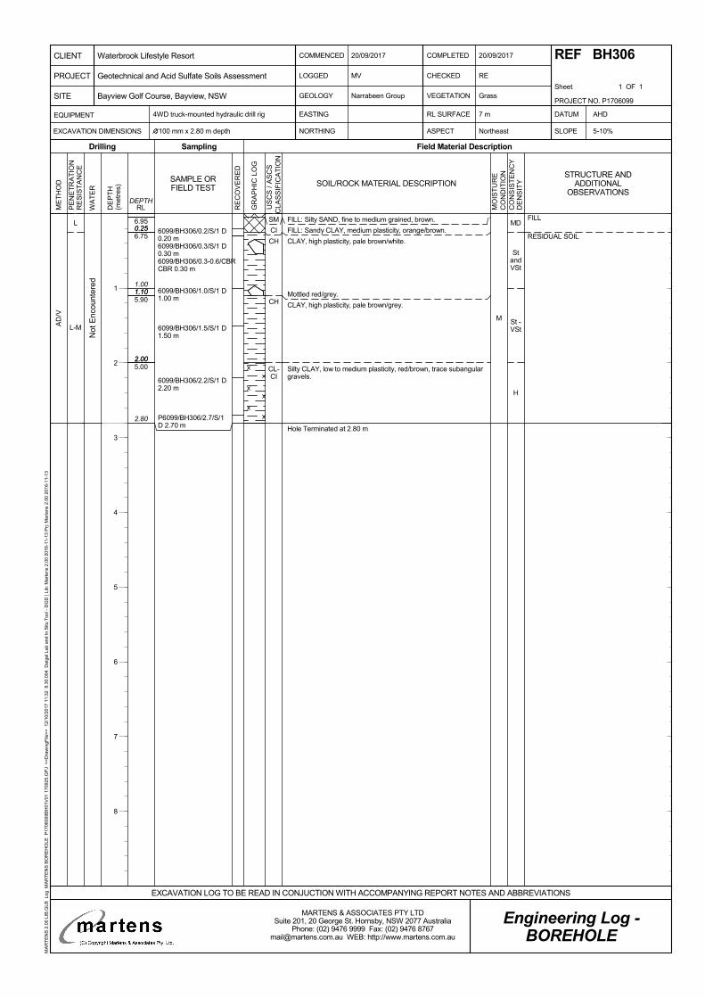
MD
StandVSt
St -VSt
H
0.25
1.10
2.00
2.80
6.95
6.75
5.90
5.00
0.25
1.001.10
2.00
L
L-MAD
/V
M
6099/BH306/0.2/S/1 D0.20 m6099/BH306/0.3/S/1 D0.30 m6099/BH306/0.3-0.6/CBRCBR 0.30 m
6099/BH306/1.0/S/1 D1.00 m
6099/BH306/1.5/S/1 D1.50 m
6099/BH306/2.2/S/1 D2.20 m
P6099/BH306/2.7/S/1D 2.70 m
FILL: Silty SAND, fine to medium grained, brown.
FILL: Sandy CLAY, medium plasticity, orange/brown.
CLAY, high plasticity, pale brown/white.
Mottled red/grey.
CLAY, high plasticity, pale brown/grey.
Silty CLAY, low to medium plasticity, red/brown, trace subangulargravels.
Hole Terminated at 2.80 m
SM
CI
CH
CH
CL-CI
Not
Enc
ount
ered
FILL
RESIDUAL SOIL
PE
NE
TR
AT
ION
RE
SIS
TA
NC
E
WA
TE
R
DE
PT
H(m
etre
s)
Sampling
RE
CO
VE
RE
D
Field Material Description
RLDEPTH
ME
TH
OD
Drilling
GR
AP
HIC
LO
G
SAMPLE ORFIELD TEST SOIL/ROCK MATERIAL DESCRIPTION
MO
IST
UR
EC
ON
DIT
ION
CO
NS
IST
EN
CY
DE
NS
ITY
U
SC
S /
AS
CS
CLA
SS
IFIC
AT
ION
COMMENCED
LOGGED
GEOLOGY
20/09/2017
CHECKED
VEGETATION
RE
Grass
4WD truck-mounted hydraulic drill rig
NORTHING ASPECT Northeast SLOPE
Narrabeen Group
MV
COMPLETED
Sheet 1 OF 1
EASTING DATUM
100 mm x 2.80 m depth 5-10%
AHDEQUIPMENT
EXCAVATION DIMENSIONS
RL SURFACE
Engineering Log -BOREHOLE
20/09/2017 REF BH306
7 m
EXCAVATION LOG TO BE READ IN CONJUCTION WITH ACCOMPANYING REPORT NOTES AND ABBREVIATIONS
PROJECT NO. P1706099
PROJECT
CLIENT
SITE
Waterbrook Lifestyle Resort
Bayview Golf Course, Bayview, NSW
Geotechnical and Acid Sulfate Soils Assessment
MARTENS & ASSOCIATES PTY LTDSuite 201, 20 George St. Hornsby, NSW 2077 Australia
Phone: (02) 9476 9999 Fax: (02) 9476 [email protected] WEB: http://www.martens.com.au
MA
RT
EN
S 2
.00
LIB
.GLB
Log
MA
RT
EN
S B
OR
EH
OLE
P17
0609
9BH
01V
01 1
7092
5.G
PJ
<<
Dra
win
gFile
>>
12/
10/2
017
11:3
2 8
.30.
004
Dat
gel L
ab a
nd In
Situ
Too
l - D
GD
| Li
b: M
arte
ns 2
.00
2016
-11-
13 P
rj: M
arte
ns 2
.00
2016
-11-
13
STRUCTURE ANDADDITIONAL
OBSERVATIONS
1
2
3
4
5
6
7
8
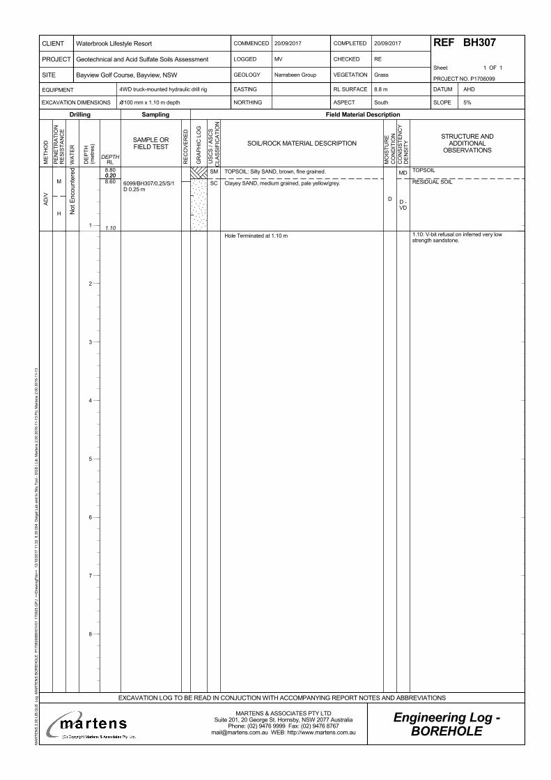
MD
D -VD
0.20
1.10
8.80
8.600.20
M
H
AD
/V
D
6099/BH307/0.25/S/1D 0.25 m
TOPSOIL: Silty SAND, brown, fine grained.
Clayey SAND, medium grained, pale yellow/grey.
Hole Terminated at 1.10 m
SM
SC
Not
Enc
ount
ered TOPSOIL
RESIDUAL SOIL
1.10: V-bit refusal on inferred very lowstrength sandstone.
PE
NE
TR
AT
ION
RE
SIS
TA
NC
E
WA
TE
R
DE
PT
H(m
etre
s)
Sampling
RE
CO
VE
RE
D
Field Material Description
RLDEPTH
ME
TH
OD
Drilling
GR
AP
HIC
LO
G
SAMPLE ORFIELD TEST SOIL/ROCK MATERIAL DESCRIPTION
MO
IST
UR
EC
ON
DIT
ION
CO
NS
IST
EN
CY
DE
NS
ITY
U
SC
S /
AS
CS
CLA
SS
IFIC
AT
ION
COMMENCED
LOGGED
GEOLOGY
20/09/2017
CHECKED
VEGETATION
RE
Grass
4WD truck-mounted hydraulic drill rig
NORTHING ASPECT South SLOPE
Narrabeen Group
MV
COMPLETED
Sheet 1 OF 1
EASTING DATUM
100 mm x 1.10 m depth 5%
AHDEQUIPMENT
EXCAVATION DIMENSIONS
RL SURFACE
Engineering Log -BOREHOLE
20/09/2017 REF BH307
8.8 m
EXCAVATION LOG TO BE READ IN CONJUCTION WITH ACCOMPANYING REPORT NOTES AND ABBREVIATIONS
PROJECT NO. P1706099
PROJECT
CLIENT
SITE
Waterbrook Lifestyle Resort
Bayview Golf Course, Bayview, NSW
Geotechnical and Acid Sulfate Soils Assessment
MARTENS & ASSOCIATES PTY LTDSuite 201, 20 George St. Hornsby, NSW 2077 Australia
Phone: (02) 9476 9999 Fax: (02) 9476 [email protected] WEB: http://www.martens.com.au
MA
RT
EN
S 2
.00
LIB
.GLB
Log
MA
RT
EN
S B
OR
EH
OLE
P17
0609
9BH
01V
01 1
7092
5.G
PJ
<<
Dra
win
gFile
>>
12/
10/2
017
11:3
2 8
.30.
004
Dat
gel L
ab a
nd In
Situ
Too
l - D
GD
| Li
b: M
arte
ns 2
.00
2016
-11-
13 P
rj: M
arte
ns 2
.00
2016
-11-
13
STRUCTURE ANDADDITIONAL
OBSERVATIONS
1
2
3
4
5
6
7
8
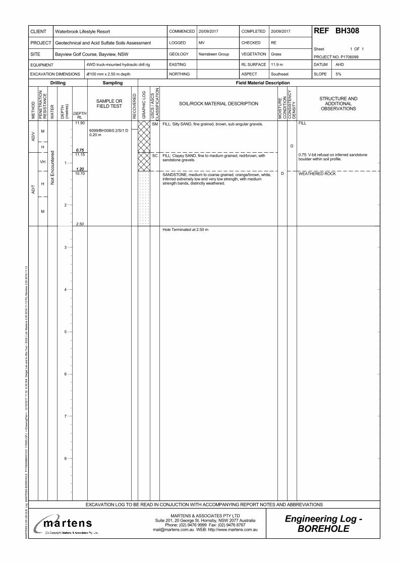
D0.75
1.20
2.50
11.90
11.15
10.70
0.75
1.20
M
H
VH
H
M
AD
/VA
D/T
D
6099/BH308/0.2/S/1 D0.20 m
FILL: Silty SAND, fine grained, brown, sub angular gravels.
FILL: Clayey SAND, fine to medium grained, red/brown, withsandstone gravels.
SANDSTONE, medium to coarse grained, orange/brown, white,inferred extremely low and very low strength, with mediumstrength bands, distinctly weathered.
Hole Terminated at 2.50 m
SM
SC
Not
Enc
ount
ered
FILL
0.75: V-bit refusal on inferred sandstoneboulder within soil profile.
WEATHERED ROCK
PE
NE
TR
AT
ION
RE
SIS
TA
NC
E
WA
TE
R
DE
PT
H(m
etre
s)
Sampling
RE
CO
VE
RE
D
Field Material Description
RLDEPTH
ME
TH
OD
Drilling
GR
AP
HIC
LO
G
SAMPLE ORFIELD TEST SOIL/ROCK MATERIAL DESCRIPTION
MO
IST
UR
EC
ON
DIT
ION
CO
NS
IST
EN
CY
DE
NS
ITY
U
SC
S /
AS
CS
CLA
SS
IFIC
AT
ION
COMMENCED
LOGGED
GEOLOGY
20/09/2017
CHECKED
VEGETATION
RE
Grass
4WD truck-mounted hydraulic drill rig
NORTHING ASPECT Southeast SLOPE
Narrabeen Group
MV
COMPLETED
Sheet 1 OF 1
EASTING DATUM
100 mm x 2.50 m depth 5%
AHDEQUIPMENT
EXCAVATION DIMENSIONS
RL SURFACE
Engineering Log -BOREHOLE
20/09/2017 REF BH308
11.9 m
EXCAVATION LOG TO BE READ IN CONJUCTION WITH ACCOMPANYING REPORT NOTES AND ABBREVIATIONS
PROJECT NO. P1706099
PROJECT
CLIENT
SITE
Waterbrook Lifestyle Resort
Bayview Golf Course, Bayview, NSW
Geotechnical and Acid Sulfate Soils Assessment
MARTENS & ASSOCIATES PTY LTDSuite 201, 20 George St. Hornsby, NSW 2077 Australia
Phone: (02) 9476 9999 Fax: (02) 9476 [email protected] WEB: http://www.martens.com.au
MA
RT
EN
S 2
.00
LIB
.GLB
Log
MA
RT
EN
S B
OR
EH
OLE
P17
0609
9BH
01V
01 1
7092
5.G
PJ
<<
Dra
win
gFile
>>
12/
10/2
017
11:3
2 8
.30.
004
Dat
gel L
ab a
nd In
Situ
Too
l - D
GD
| Li
b: M
arte
ns 2
.00
2016
-11-
13 P
rj: M
arte
ns 2
.00
2016
-11-
13
STRUCTURE ANDADDITIONAL
OBSERVATIONS
1
2
3
4
5
6
7
8
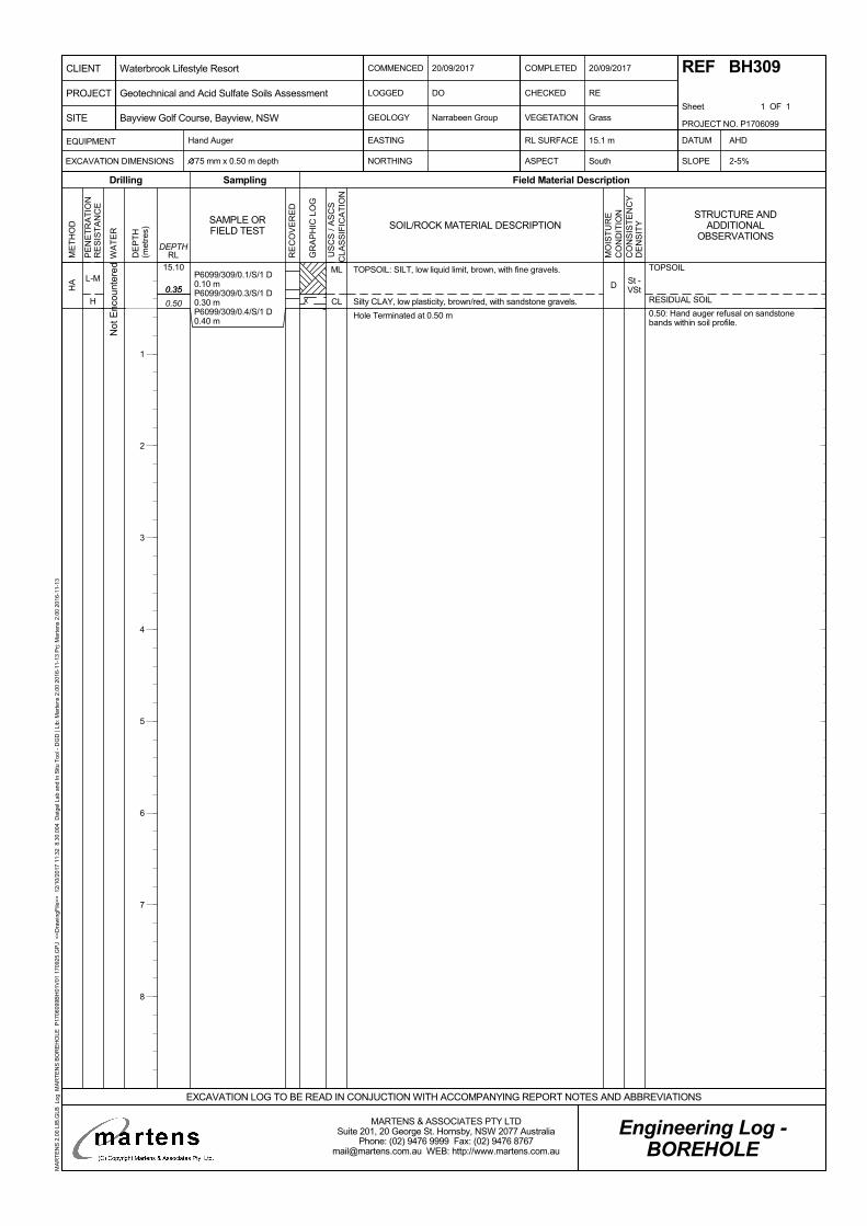
St -VSt0.35
0.50
15.10
0.35L-M
H
HA D
P6099/309/0.1/S/1 D0.10 mP6099/309/0.3/S/1 D0.30 mP6099/309/0.4/S/1 D0.40 m
TOPSOIL: SILT, low liquid limit, brown, with fine gravels.
Silty CLAY, low plasticity, brown/red, with sandstone gravels.
Hole Terminated at 0.50 m
ML
CL
Not
Enc
ount
ered TOPSOIL
RESIDUAL SOIL
0.50: Hand auger refusal on sandstonebands within soil profile.
PE
NE
TR
AT
ION
RE
SIS
TA
NC
E
WA
TE
R
DE
PT
H(m
etre
s)
Sampling
RE
CO
VE
RE
D
Field Material Description
RLDEPTH
ME
TH
OD
Drilling
GR
AP
HIC
LO
G
SAMPLE ORFIELD TEST SOIL/ROCK MATERIAL DESCRIPTION
MO
IST
UR
EC
ON
DIT
ION
CO
NS
IST
EN
CY
DE
NS
ITY
U
SC
S /
AS
CS
CLA
SS
IFIC
AT
ION
COMMENCED
LOGGED
GEOLOGY
20/09/2017
CHECKED
VEGETATION
RE
Grass
Hand Auger
NORTHING ASPECT South SLOPE
Narrabeen Group
DO
COMPLETED
Sheet 1 OF 1
EASTING DATUM
75 mm x 0.50 m depth 2-5%
AHDEQUIPMENT
EXCAVATION DIMENSIONS
RL SURFACE
Engineering Log -BOREHOLE
20/09/2017 REF BH309
15.1 m
EXCAVATION LOG TO BE READ IN CONJUCTION WITH ACCOMPANYING REPORT NOTES AND ABBREVIATIONS
PROJECT NO. P1706099
PROJECT
CLIENT
SITE
Waterbrook Lifestyle Resort
Bayview Golf Course, Bayview, NSW
Geotechnical and Acid Sulfate Soils Assessment
MARTENS & ASSOCIATES PTY LTDSuite 201, 20 George St. Hornsby, NSW 2077 Australia
Phone: (02) 9476 9999 Fax: (02) 9476 [email protected] WEB: http://www.martens.com.au
MA
RT
EN
S 2
.00
LIB
.GLB
Log
MA
RT
EN
S B
OR
EH
OLE
P17
0609
9BH
01V
01 1
7092
5.G
PJ
<<
Dra
win
gFile
>>
12/
10/2
017
11:3
2 8
.30.
004
Dat
gel L
ab a
nd In
Situ
Too
l - D
GD
| Li
b: M
arte
ns 2
.00
2016
-11-
13 P
rj: M
arte
ns 2
.00
2016
-11-
13
STRUCTURE ANDADDITIONAL
OBSERVATIONS
1
2
3
4
5
6
7
8
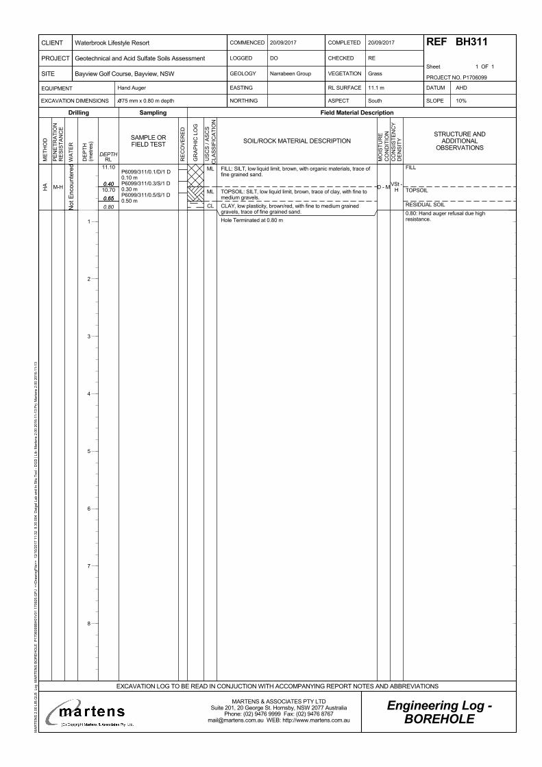
VSt -H
0.40
0.65
0.80
11.10
10.700.40
0.65
M-HHA D - M
P6099/311/0.1/D/1 D0.10 mP6099/311/0.3/S/1 D0.30 mP6099/311/0.5/S/1 D0.50 m
FILL: SILT, low liquid limit, brown, with organic materials, trace offine grained sand.
TOPSOIL: SILT, low liquid limit, brown, trace of clay, with fine tomedium gravels.
CLAY, low plasticity, brown/red, with fine to medium grainedgravels, trace of fine grained sand.
Hole Terminated at 0.80 m
ML
ML
CLNot
Enc
ount
ered FILL
TOPSOIL
RESIDUAL SOIL
0.80: Hand auger refusal due highresistance.
PE
NE
TR
AT
ION
RE
SIS
TA
NC
E
WA
TE
R
DE
PT
H(m
etre
s)
Sampling
RE
CO
VE
RE
D
Field Material Description
RLDEPTH
ME
TH
OD
Drilling
GR
AP
HIC
LO
G
SAMPLE ORFIELD TEST SOIL/ROCK MATERIAL DESCRIPTION
MO
IST
UR
EC
ON
DIT
ION
CO
NS
IST
EN
CY
DE
NS
ITY
U
SC
S /
AS
CS
CLA
SS
IFIC
AT
ION
COMMENCED
LOGGED
GEOLOGY
20/09/2017
CHECKED
VEGETATION
RE
Grass
Hand Auger
NORTHING ASPECT South SLOPE
Narrabeen Group
DO
COMPLETED
Sheet 1 OF 1
EASTING DATUM
75 mm x 0.80 m depth 10%
AHDEQUIPMENT
EXCAVATION DIMENSIONS
RL SURFACE
Engineering Log -BOREHOLE
20/09/2017 REF BH311
11.1 m
EXCAVATION LOG TO BE READ IN CONJUCTION WITH ACCOMPANYING REPORT NOTES AND ABBREVIATIONS
PROJECT NO. P1706099
PROJECT
CLIENT
SITE
Waterbrook Lifestyle Resort
Bayview Golf Course, Bayview, NSW
Geotechnical and Acid Sulfate Soils Assessment
MARTENS & ASSOCIATES PTY LTDSuite 201, 20 George St. Hornsby, NSW 2077 Australia
Phone: (02) 9476 9999 Fax: (02) 9476 [email protected] WEB: http://www.martens.com.au
MA
RT
EN
S 2
.00
LIB
.GLB
Log
MA
RT
EN
S B
OR
EH
OLE
P17
0609
9BH
01V
01 1
7092
5.G
PJ
<<
Dra
win
gFile
>>
12/
10/2
017
11:3
2 8
.30.
004
Dat
gel L
ab a
nd In
Situ
Too
l - D
GD
| Li
b: M
arte
ns 2
.00
2016
-11-
13 P
rj: M
arte
ns 2
.00
2016
-11-
13
STRUCTURE ANDADDITIONAL
OBSERVATIONS
1
2
3
4
5
6
7
8
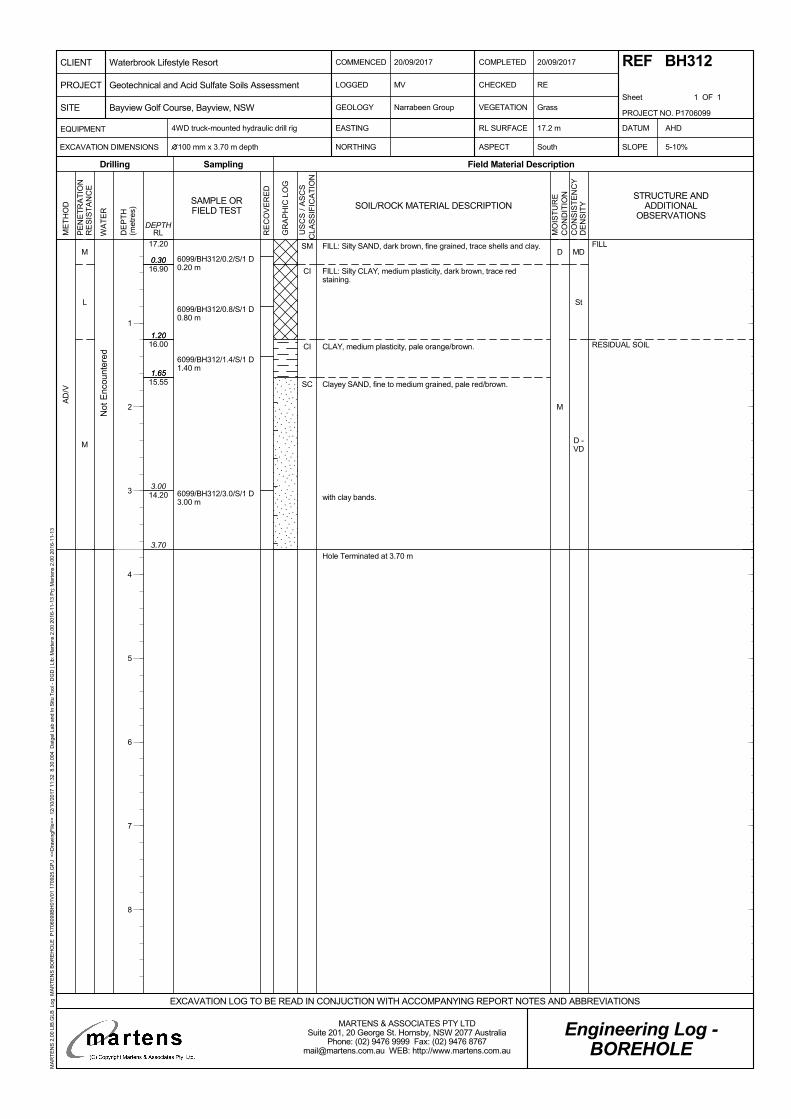
MD
St
D -VD
0.30
1.20
1.65
3.70
17.20
16.90
16.00
15.55
14.20
0.30
1.20
1.65
3.00
M
L
M
AD
/V
D
M
6099/BH312/0.2/S/1 D0.20 m
6099/BH312/0.8/S/1 D0.80 m
6099/BH312/1.4/S/1 D1.40 m
6099/BH312/3.0/S/1 D3.00 m
FILL: Silty SAND, dark brown, fine grained, trace shells and clay.
FILL: Silty CLAY, medium plasticity, dark brown, trace redstaining.
CLAY, medium plasticity, pale orange/brown.
Clayey SAND, fine to medium grained, pale red/brown.
with clay bands.
Hole Terminated at 3.70 m
SM
CI
CI
SC
Not
Enc
ount
ered
FILL
RESIDUAL SOIL
PE
NE
TR
AT
ION
RE
SIS
TA
NC
E
WA
TE
R
DE
PT
H(m
etre
s)
Sampling
RE
CO
VE
RE
D
Field Material Description
RLDEPTH
ME
TH
OD
Drilling
GR
AP
HIC
LO
G
SAMPLE ORFIELD TEST SOIL/ROCK MATERIAL DESCRIPTION
MO
IST
UR
EC
ON
DIT
ION
CO
NS
IST
EN
CY
DE
NS
ITY
U
SC
S /
AS
CS
CLA
SS
IFIC
AT
ION
COMMENCED
LOGGED
GEOLOGY
20/09/2017
CHECKED
VEGETATION
RE
Grass
4WD truck-mounted hydraulic drill rig
NORTHING ASPECT South SLOPE
Narrabeen Group
MV
COMPLETED
Sheet 1 OF 1
EASTING DATUM
100 mm x 3.70 m depth 5-10%
AHDEQUIPMENT
EXCAVATION DIMENSIONS
RL SURFACE
Engineering Log -BOREHOLE
20/09/2017 REF BH312
17.2 m
EXCAVATION LOG TO BE READ IN CONJUCTION WITH ACCOMPANYING REPORT NOTES AND ABBREVIATIONS
PROJECT NO. P1706099
PROJECT
CLIENT
SITE
Waterbrook Lifestyle Resort
Bayview Golf Course, Bayview, NSW
Geotechnical and Acid Sulfate Soils Assessment
MARTENS & ASSOCIATES PTY LTDSuite 201, 20 George St. Hornsby, NSW 2077 Australia
Phone: (02) 9476 9999 Fax: (02) 9476 [email protected] WEB: http://www.martens.com.au
MA
RT
EN
S 2
.00
LIB
.GLB
Log
MA
RT
EN
S B
OR
EH
OLE
P17
0609
9BH
01V
01 1
7092
5.G
PJ
<<
Dra
win
gFile
>>
12/
10/2
017
11:3
2 8
.30.
004
Dat
gel L
ab a
nd In
Situ
Too
l - D
GD
| Li
b: M
arte
ns 2
.00
2016
-11-
13 P
rj: M
arte
ns 2
.00
2016
-11-
13
STRUCTURE ANDADDITIONAL
OBSERVATIONS
1
2
3
4
5
6
7
8
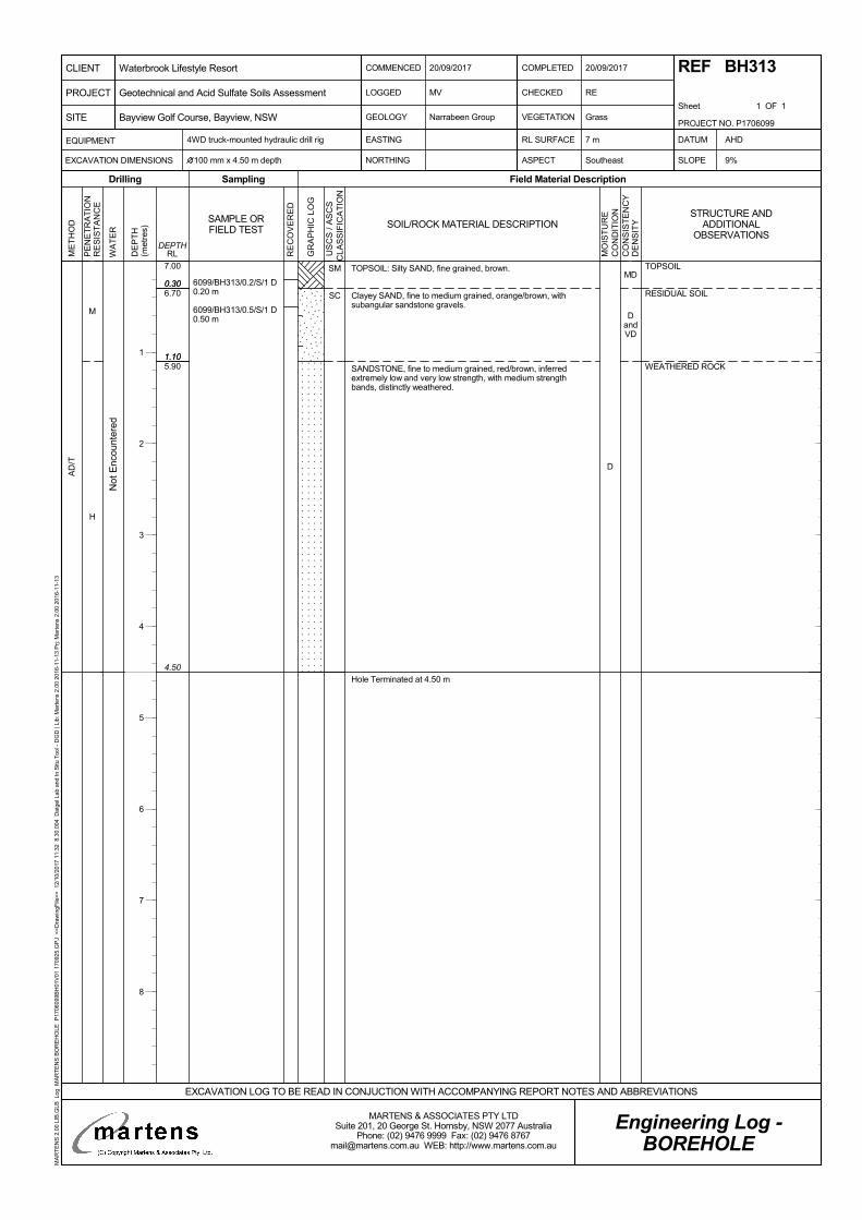
MD
DandVD
0.30
1.10
4.50
7.00
6.70
5.90
0.30
1.10
M
H
AD
/T
D
6099/BH313/0.2/S/1 D0.20 m
6099/BH313/0.5/S/1 D0.50 m
TOPSOIL: Silty SAND, fine grained, brown.
Clayey SAND, fine to medium grained, orange/brown, withsubangular sandstone gravels.
SANDSTONE, fine to medium grained, red/brown, inferredextremely low and very low strength, with medium strengthbands, distinctly weathered.
Hole Terminated at 4.50 m
SM
SC
Not
Enc
ount
ered
TOPSOIL
RESIDUAL SOIL
WEATHERED ROCK
PE
NE
TR
AT
ION
RE
SIS
TA
NC
E
WA
TE
R
DE
PT
H(m
etre
s)
Sampling
RE
CO
VE
RE
D
Field Material Description
RLDEPTH
ME
TH
OD
Drilling
GR
AP
HIC
LO
G
SAMPLE ORFIELD TEST SOIL/ROCK MATERIAL DESCRIPTION
MO
IST
UR
EC
ON
DIT
ION
CO
NS
IST
EN
CY
DE
NS
ITY
U
SC
S /
AS
CS
CLA
SS
IFIC
AT
ION
COMMENCED
LOGGED
GEOLOGY
20/09/2017
CHECKED
VEGETATION
RE
Grass
4WD truck-mounted hydraulic drill rig
NORTHING ASPECT Southeast SLOPE
Narrabeen Group
MV
COMPLETED
Sheet 1 OF 1
EASTING DATUM
100 mm x 4.50 m depth 9%
AHDEQUIPMENT
EXCAVATION DIMENSIONS
RL SURFACE
Engineering Log -BOREHOLE
20/09/2017 REF BH313
7 m
EXCAVATION LOG TO BE READ IN CONJUCTION WITH ACCOMPANYING REPORT NOTES AND ABBREVIATIONS
PROJECT NO. P1706099
PROJECT
CLIENT
SITE
Waterbrook Lifestyle Resort
Bayview Golf Course, Bayview, NSW
Geotechnical and Acid Sulfate Soils Assessment
MARTENS & ASSOCIATES PTY LTDSuite 201, 20 George St. Hornsby, NSW 2077 Australia
Phone: (02) 9476 9999 Fax: (02) 9476 [email protected] WEB: http://www.martens.com.au
MA
RT
EN
S 2
.00
LIB
.GLB
Log
MA
RT
EN
S B
OR
EH
OLE
P17
0609
9BH
01V
01 1
7092
5.G
PJ
<<
Dra
win
gFile
>>
12/
10/2
017
11:3
2 8
.30.
004
Dat
gel L
ab a
nd In
Situ
Too
l - D
GD
| Li
b: M
arte
ns 2
.00
2016
-11-
13 P
rj: M
arte
ns 2
.00
2016
-11-
13
STRUCTURE ANDADDITIONAL
OBSERVATIONS
1
2
3
4
5
6
7
8

D
MD
St
0.40
0.60
1.00
1.50
2.30
2.50
3.20
2.80
2.60
2.20
1.70
0.90
0.40
0.60
1.00
1.50
2.30
H
L
AD
/V
D
M
6099/BH314/0.2/S/1 D0.20 m6099/BH314/0.3-0.6/CBRCBR 0.30 m6099/BH314/0.5/S/1 D0.50 m6099/BH314/0.8/S/1 D0.80 m
6099/BH314/2.0/S/1 D2.00 m
6099/BH314/2.4/S/1 D2.40 m
FILL: Silty SAND, fine grained, brown, trace fine to mediumsubangular igneous gravel, trace clay.
FILL: SAND, brown, fine grained, trace subangular gravels.
FILL: SAND, fine grained, dark brown, with clay, trace fine tomedium subangular gravels.
FILL: Clayey SAND, fine grained, dark brown.
Sandy CLAY, medium plasticity, dark brown.
CLAY high plasticity, pale grey/red, with sand.
Hole Terminated at 2.50 m
SM
SP
SP
SC
CI
CH
Not
Enc
ount
ered
FILL
ALLUVIUM
PE
NE
TR
AT
ION
RE
SIS
TA
NC
E
WA
TE
R
DE
PT
H(m
etre
s)
Sampling
RE
CO
VE
RE
D
Field Material Description
RLDEPTH
ME
TH
OD
Drilling
GR
AP
HIC
LO
G
SAMPLE ORFIELD TEST SOIL/ROCK MATERIAL DESCRIPTION
MO
IST
UR
EC
ON
DIT
ION
CO
NS
IST
EN
CY
DE
NS
ITY
U
SC
S /
AS
CS
CLA
SS
IFIC
AT
ION
COMMENCED
LOGGED
GEOLOGY
20/09/2017
CHECKED
VEGETATION
RE
Grass
4WD truck-mounted hydraulic drill rig
NORTHING ASPECT East SLOPE
Narrabeen Group
MV
COMPLETED
Sheet 1 OF 1
EASTING DATUM
100 mm x 2.50 m depth <2%
AHDEQUIPMENT
EXCAVATION DIMENSIONS
RL SURFACE
Engineering Log -BOREHOLE
20/09/2017 REF BH314
3.2 m
EXCAVATION LOG TO BE READ IN CONJUCTION WITH ACCOMPANYING REPORT NOTES AND ABBREVIATIONS
PROJECT NO. P1706099
PROJECT
CLIENT
SITE
Waterbrook Lifestyle Resort
Bayview Golf Course, Bayview, NSW
Geotechnical and Acid Sulfate Soils Assessment
MARTENS & ASSOCIATES PTY LTDSuite 201, 20 George St. Hornsby, NSW 2077 Australia
Phone: (02) 9476 9999 Fax: (02) 9476 [email protected] WEB: http://www.martens.com.au
MA
RT
EN
S 2
.00
LIB
.GLB
Log
MA
RT
EN
S B
OR
EH
OLE
P17
0609
9BH
01V
01 1
7092
5.G
PJ
<<
Dra
win
gFile
>>
12/
10/2
017
11:3
3 8
.30.
004
Dat
gel L
ab a
nd In
Situ
Too
l - D
GD
| Li
b: M
arte
ns 2
.00
2016
-11-
13 P
rj: M
arte
ns 2
.00
2016
-11-
13
STRUCTURE ANDADDITIONAL
OBSERVATIONS
1
2
3
4
5
6
7
8
martens
Geotechnical and Acid Sulfate Soils Assessment:
Proposed Seniors Living Development, Cabbage Tree Road, Bayview, NSW
P1706099JR02V02 – November 2017
Page 79
11 Attachment C – DCP ‘N’ Counts
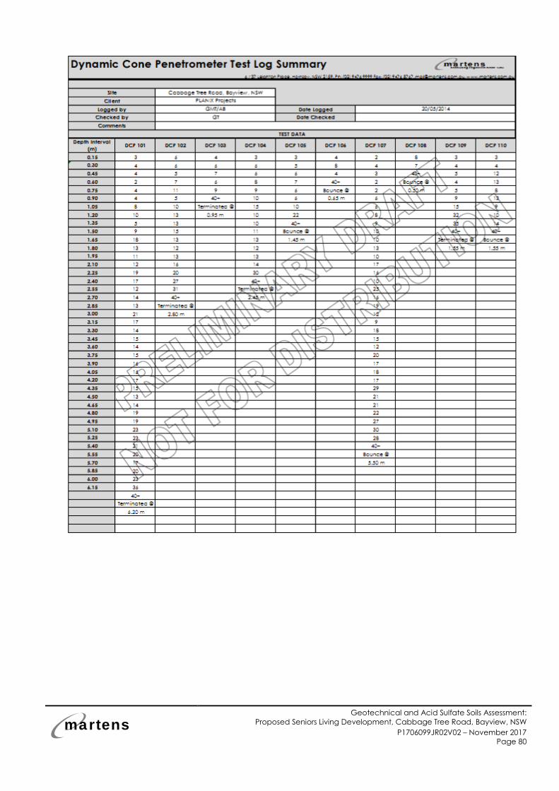
martens
Geotechnical and Acid Sulfate Soils Assessment:
Proposed Seniors Living Development, Cabbage Tree Road, Bayview, NSW
P1706099JR02V02 – November 2017
Page 80
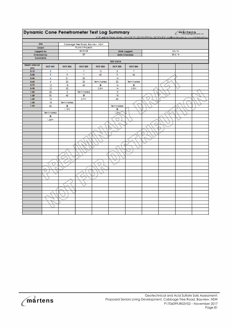
martens
Geotechnical and Acid Sulfate Soils Assessment:
Proposed Seniors Living Development, Cabbage Tree Road, Bayview, NSW
P1706099JR02V02 – November 2017
Page 81
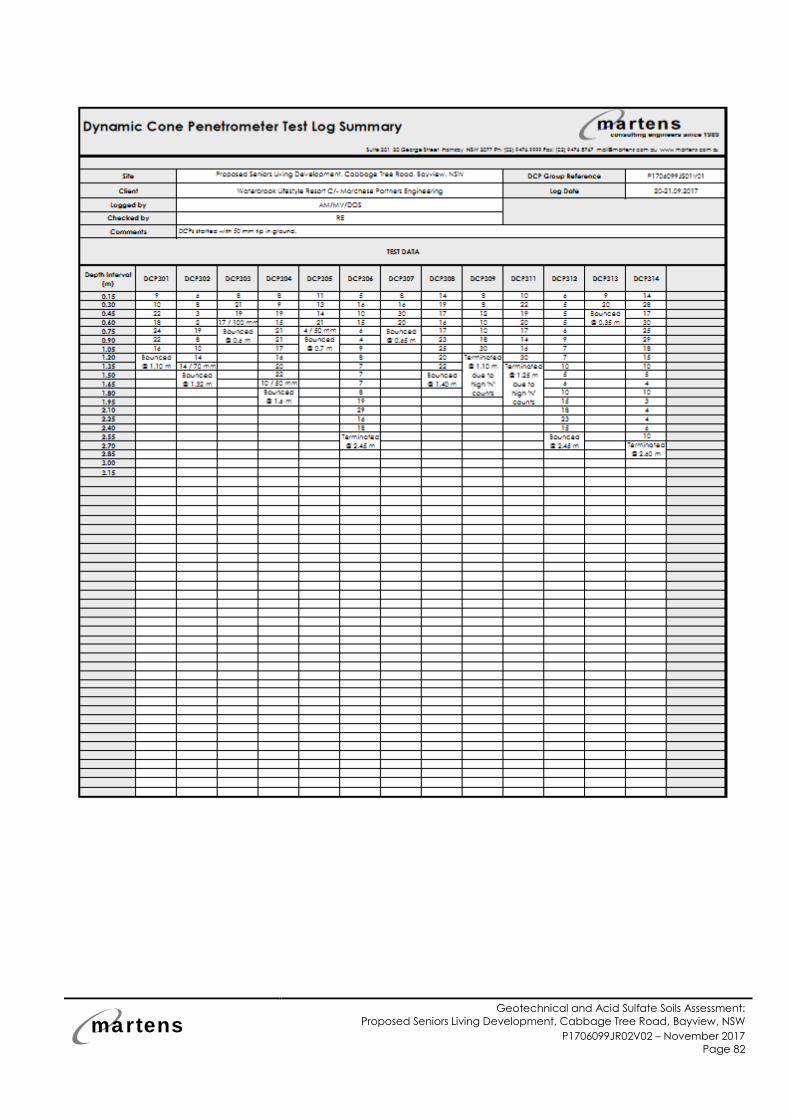
martens
Geotechnical and Acid Sulfate Soils Assessment:
Proposed Seniors Living Development, Cabbage Tree Road, Bayview, NSW
P1706099JR02V02 – November 2017
Page 82
martens
Geotechnical and Acid Sulfate Soils Assessment:
Proposed Seniors Living Development, Cabbage Tree Road, Bayview, NSW
P1706099JR02V02 – November 2017
Page 83
12 Attachment D – Geological Site Sections
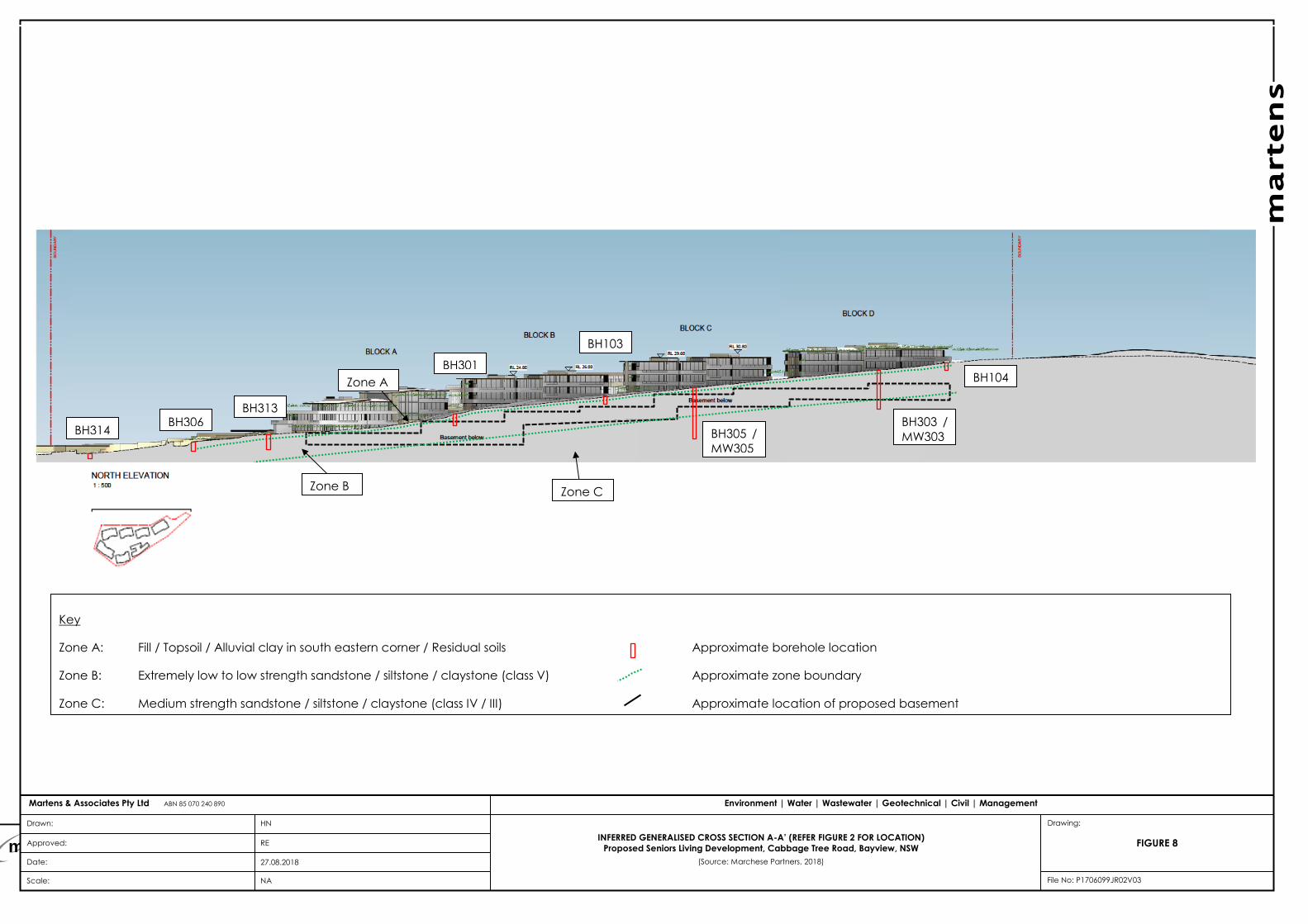
martens
Geotechnical and Acid Sulfate Soils Assessment:
Proposed Seniors Living Development, Cabbage Tree Road, Bayview, NSW
P1706099JR02V02 – November 2017
Page 84
marten
s
Drawn:
Approved:
Date:
Scale:
HN
RE
27.08.2018
NA File No: P1706099JR02V03
Environment | Water | Wastewater | Geotechnical | Civil | Management Martens & Associates Pty Ltd ABN 85 070 240 890
FIGURE 8
Drawing:
INFERRED GENERALISED CROSS SECTION A-A’ (REFER FIGURE 2 FOR LOCATION)
Proposed Seniors Living Development, Cabbage Tree Road, Bayview, NSW
(Source: Marchese Partners, 2018)
Key
Zone A: Fill / Topsoil / Alluvial clay in south eastern corner / Residual soils Approximate borehole location
Zone B: Extremely low to low strength sandstone / siltstone / claystone (class V) Approximate zone boundary
Zone C: Medium strength sandstone / siltstone / claystone (class IV / III) Approximate location of proposed basement
Zone A
Zone B Zone C
BH306 BH314
BH301
BH103
BH303 /
MW303
BH104
BH305 /
MW305
BH313
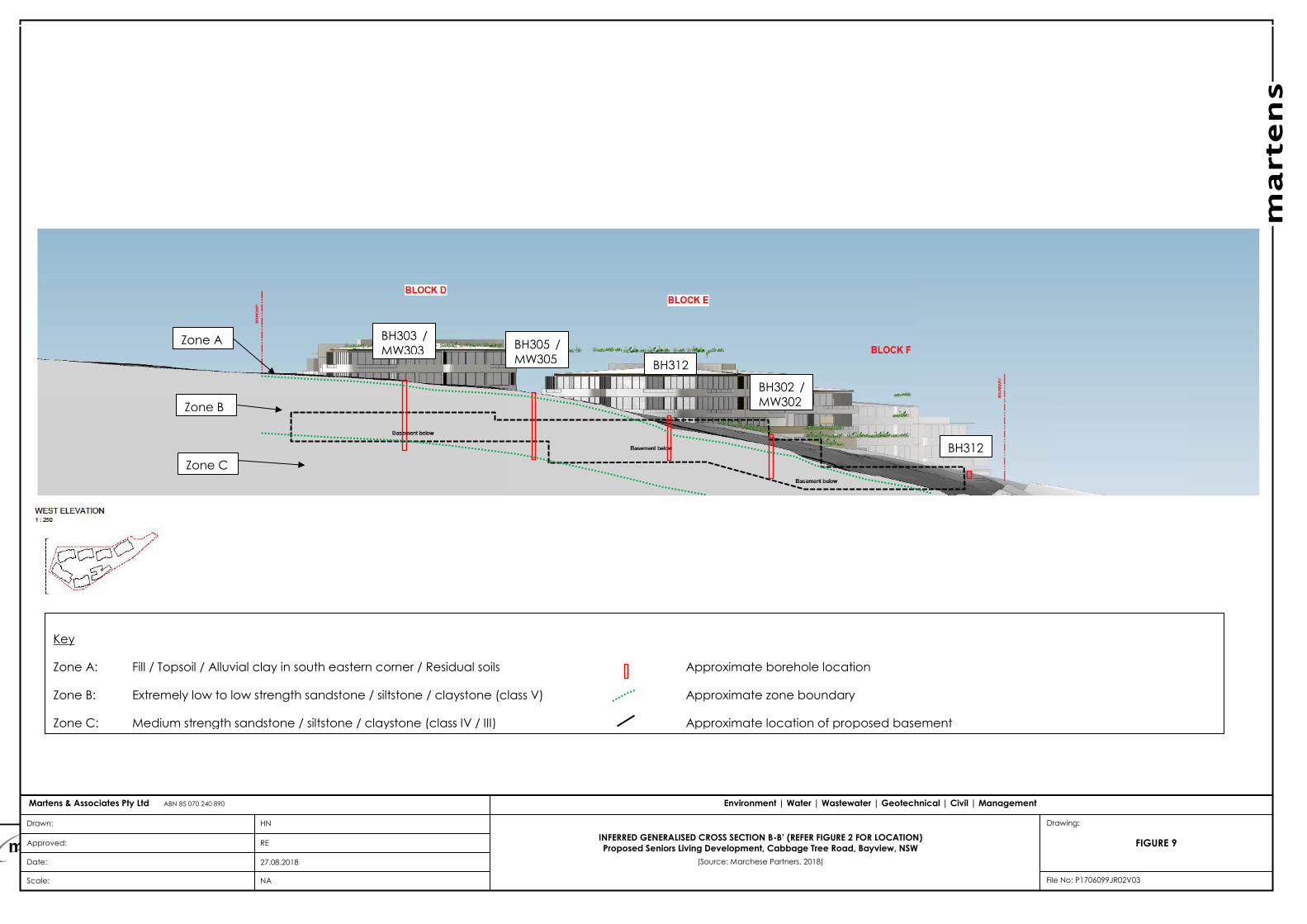
martens
Geotechnical and Acid Sulfate Soils Assessment:
Proposed Seniors Living Development, Cabbage Tree Road, Bayview, NSW
P1706099JR02V02 – November 2017
Page 85
marten
s
Drawn:
Approved:
Date:
Scale:
HN
RE
27.08.2018
NA File No: P1706099JR02V03
Environment | Water | Wastewater | Geotechnical | Civil | Management Martens & Associates Pty Ltd ABN 85 070 240 890
FIGURE 9
Drawing:
INFERRED GENERALISED CROSS SECTION B-B’ (REFER FIGURE 2 FOR LOCATION)
Proposed Seniors Living Development, Cabbage Tree Road, Bayview, NSW
(Source: Marchese Partners, 2018)
Key
Zone A: Fill / Topsoil / Alluvial clay in south eastern corner / Residual soils Approximate borehole location
Zone B: Extremely low to low strength sandstone / siltstone / claystone (class V) Approximate zone boundary
Zone C: Medium strength sandstone / siltstone / claystone (class IV / III) Approximate location of proposed basement
BH305 /
MW305
BH303 /
MW303
BH302 /
MW302
BH312
BH312
Zone C
Zone B
Zone A
martens
Geotechnical and Acid Sulfate Soils Assessment:
Proposed Seniors Living Development, Cabbage Tree Road, Bayview, NSW
P1706099JR02V02 – November 2017
Page 86
13 Attachment E – Preliminary Landslide Modelling Results
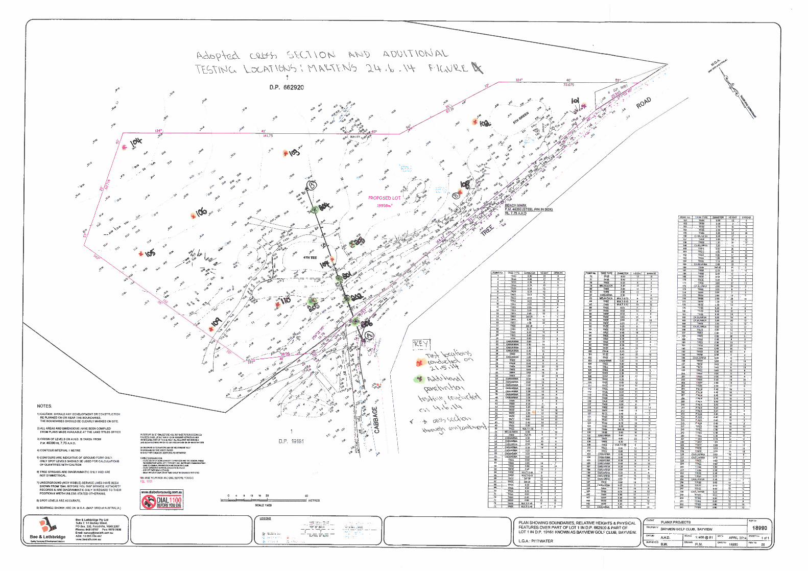
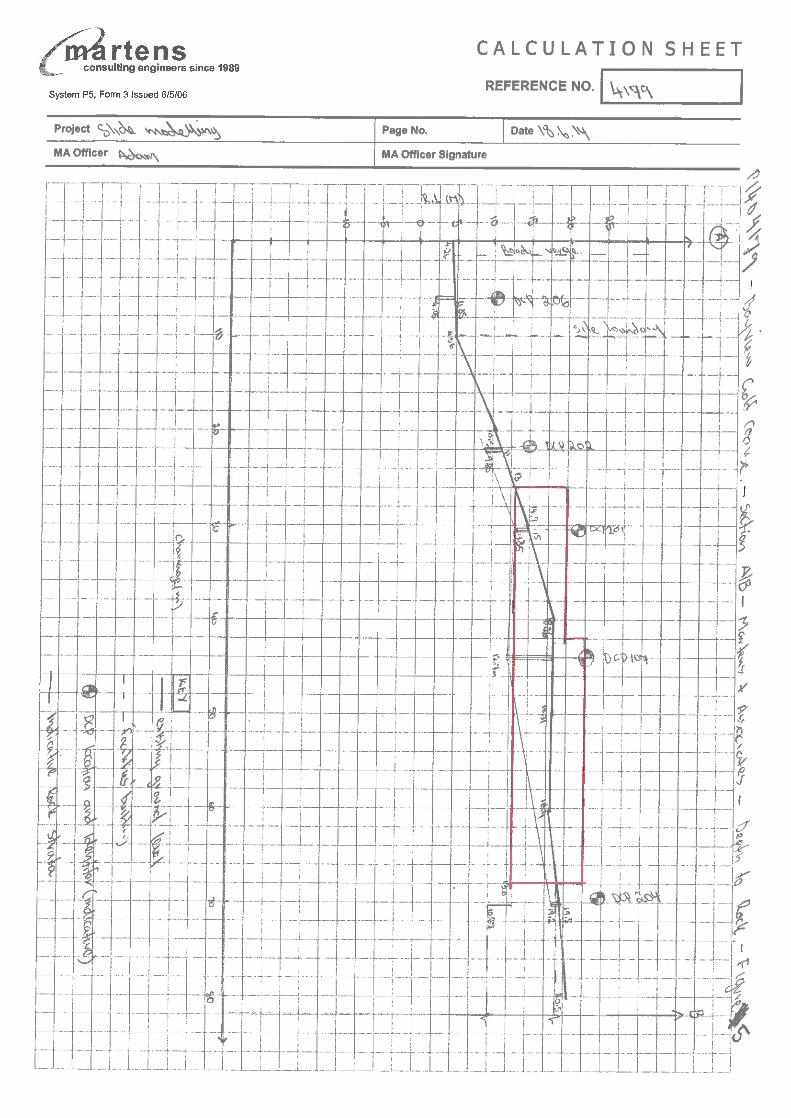
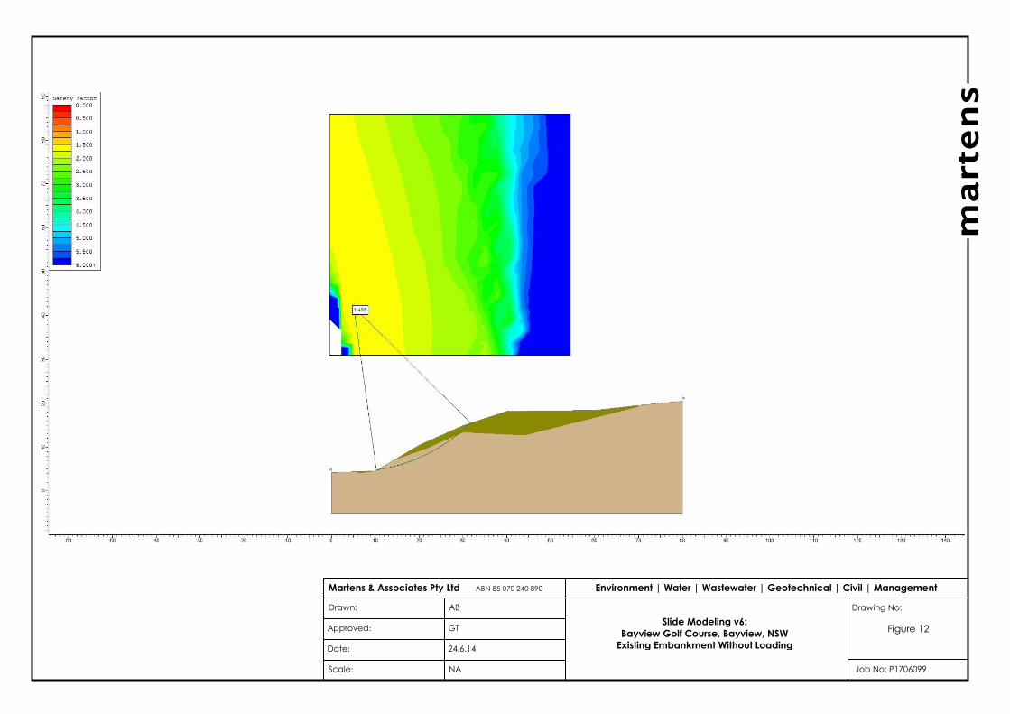
marten
s
Drawn:
Approved:
Date:
Scale:
AB
GT
24.6.14
NA Job No: P1706099
Environment | Water | Wastewater | Geotechnical | Civil | Management Martens & Associates Pty Ltd ABN 85 070 240 890
Figure 12
Drawing No:
Slide Modeling v6:
Bayview Golf Course, Bayview, NSW
Existing Embankment Without Loading
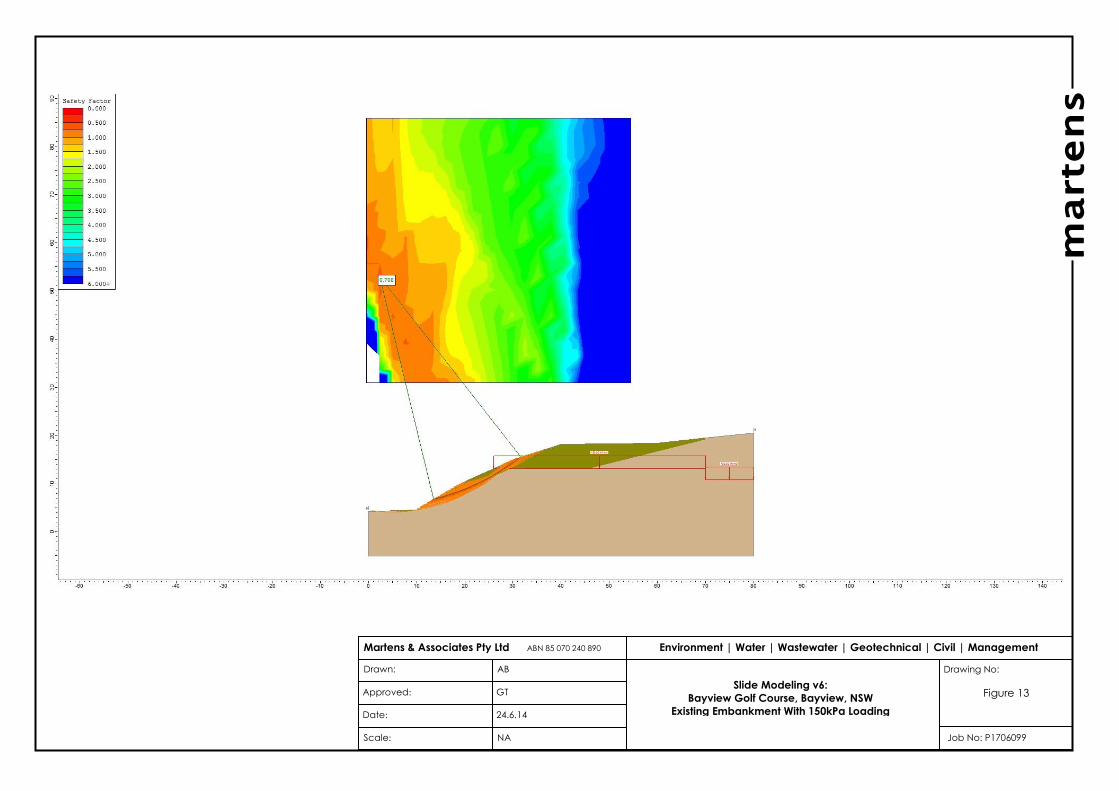
marten
s
Drawn:
Approved:
Date:
Scale:
AB
GT
24.6.14
NA Job No: P1706099
Environment | Water | Wastewater | Geotechnical | Civil | Management Martens & Associates Pty Ltd ABN 85 070 240 890
Figure 13
Drawing No:
Slide Modeling v6:
Bayview Golf Course, Bayview, NSW
Existing Embankment With 150kPa Loading
martens
Geotechnical and Acid Sulfate Soils Assessment:
Proposed Seniors Living Development, Cabbage Tree Road, Bayview, NSW
P1706099JR02V02 – November 2017
Page 91
14 Attachment F – Geotechnical Risk Calculations
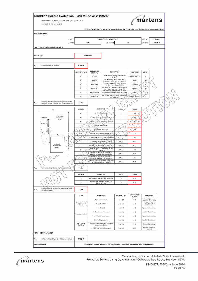
martensGeotechnical and Acid Sulfate Soils Assessment:
Proposed Seniors Living Development, Cabbage Tree Road, Bayview, NSW.
P1404179JR03V01 – June 2014Page 46
Landslide Hazard Evaluation - Risk to Life Assessment
Method based on Walker et al. in AGS Vol 42 No. 1 March 2007
Method ST-24 Rev ised 20.02.08
PROJECT DETAILS
Project Ref. No.
Author Reviewed Date Created
STEP 1 : ENTER SITE AND DESIGN DATA
Hazard Type
P(H) Annual probability of landslide 0.00001
INDICATIVEVALUERECURRENCE
INTERVALDESCRIPTOR LEVEL
10-1 10 years ALMOST CERTAIN A
10-2 100 years LIKELY B
10-3 1000 years POSSIBLE C
10-4 10,000 years UNLIKELY D
10-5 100,000 years RARE E
10-6 1,000,000 years BARELY CREDIBLE F
P(S:H)Probablity of spatial impact impacting building location
taking into account travel distance and travel direction0.96
FACTOR UNITS VALUE
W1 m 180
W2 m 180
W3 m 60
L1Min m 1
L1Max m 200
L2 m 270
L3 m 50
LPMin (0 - 1) 0.05
LPMax (0 - 1) 0.95
WF (0 - 1) 1.00
LF Min (0 - 1) 0.19
LF Max (0 - 1) 1.00
LF Design (0 - 1) 0.96
P(T:S) Temporal spatial probability given the spatial impact 0.81
FACTOR UNITS VALUE
T1 m 90%
T2 m 90%
V(V:D)Vulnerability of the individual (ie. probability of loss of
life given the impact)0.10
CASE RANGEIN DATARECOMMENDED
VALUE
0.1 - 0.7 0.50
0.8 - 1.0 1.00
0.1 - 0.5 0.10
0.9 - 1.0 1.00
0.0 - 0.3 0.30
0.9 - 1.0 1.00
0.8 - 1.0 1.00
0.0 - 0.1 0.05
STEP 2 : RISK EVALUATION
V(D:T) Risk (annual probability of loss of life of an individual) 7.77E-07
Risk Assessment
Soil Creep
Person in open
space
Person in a vehicle
Persons in
building
Likely slide/fall w idth
DESCRIPTION
Width of allotment / investigation area
Width of dw elling / investigation element
Minimum run-out length
Maximum run-out length
The event is inconceivable or fanciful over
the design life.
DESCRIPTION
The event w ill probably occur under
adverse conditions over the design life.
The event could occur under tadverse
conditions over the design life.
The enent might occur under very adverse
circumstances over the design life.The event is conceivable but only under
exceptional circumstances over the design
life.
Length of allotment / investigation area
Length of dw elling / investigation element
Probability of runout being 0 - 1 m long
Probability of runout being 0 - 200 m long
P1404179
GMT GT 23.05.14
Geotechnical Assessment
The event is expected to occur over the
design life.
DESCRIPTION
Percentage of time person(s) are on-site
Percentage of dw elling / element that
person(s) occupy
COMMENTS
Likelihood of across slope strike on risk
element
Likelihood of dow nslope strike on risk
element for minimum run-out distance
Likelihood of dow nslope strike on risk
element for maximum run-out distance
Likelihood of dow nslope strike (integrated)
on risk element run-out distance
Death is almost certain
If struck by a rockfall
If buried by debris
If not buried
May be injured but
unlikely to cause death
DESCRIPTION
Death by asphyxia
almost certain
High chance of survival
If the debris strikes the building only
Acceptable risk for loss of life for the person(s). Risk level suitable for new developments.
If vehicle is buried / crushed
If the vehicle is damaged only
If the building collapses
If the building is inundated w ith debris and
the person is buried
High chance of survival
Dealth is almost certain
Death is highly likely
Very high chance of
survival
6/37 Leighton Place, Hornsby, NSW2007, Ph: (02) 9476 9999 Fax: (02) 9476 8767, [email protected],www.martens.com.au
W2
Allotment /Investigation
Area
Dw elling /Investigation
Element
Slide/Fall
W3
L3
W1
L1 Max
L1 Min
L2
martens
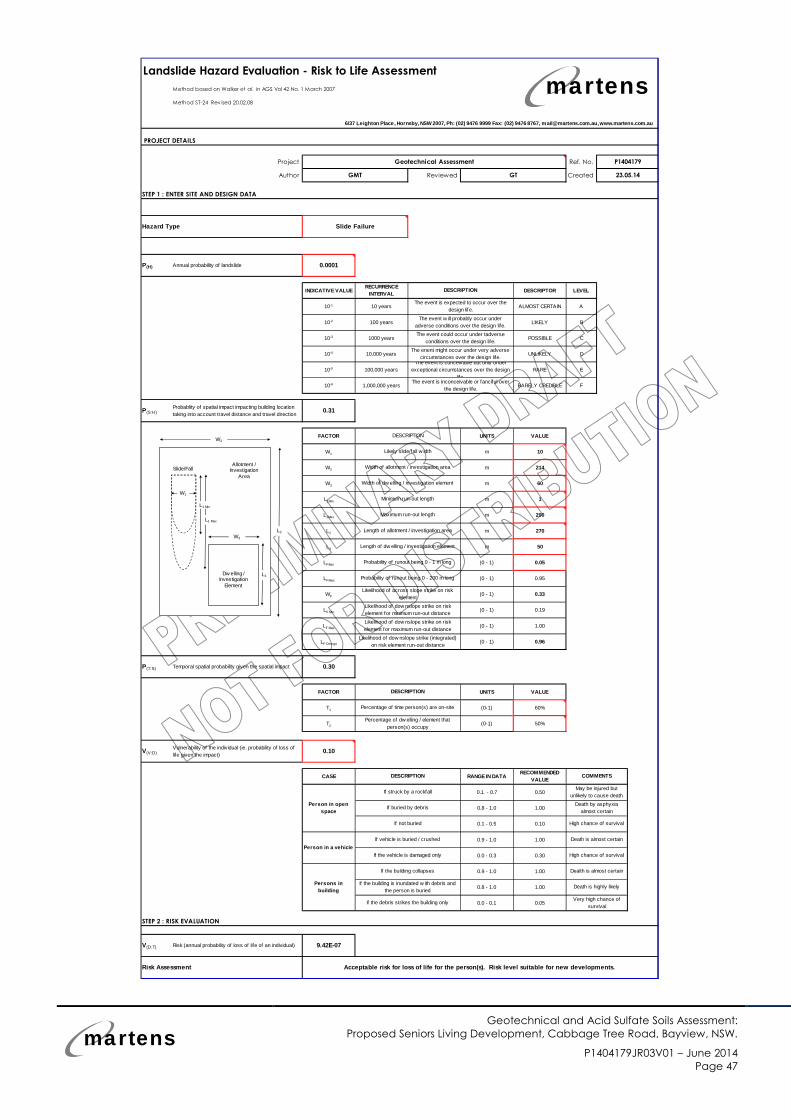
martensGeotechnical and Acid Sulfate Soils Assessment:
Proposed Seniors Living Development, Cabbage Tree Road, Bayview, NSW.
P1404179JR03V01 – June 2014Page 47
Landslide Hazard Evaluation - Risk to Life Assessment
Method based on Walker et al. in AGS Vol 42 No. 1 March 2007
Method ST-24 Rev ised 20.02.08
PROJECT DETAILS
Project Ref. No.
Author Reviewed Date Created
STEP 1 : ENTER SITE AND DESIGN DATA
Hazard Type
P(H) Annual probability of landslide 0.0001
INDICATIVE VALUERECURRENCE
INTERVALDESCRIPTOR LEVEL
10-1 10 years ALMOST CERTAIN A
10-2 100 years LIKELY B
10-3 1000 years POSSIBLE C
10-4 10,000 years UNLIKELY D
10-5 100,000 years RARE E
10-6 1,000,000 years BARELY CREDIBLE F
P(S:H)Probablity of spatial impact impacting building location
taking into account travel distance and travel direction0.31
FACTOR UNITS VALUE
W1 m 10
W2 m 214
W3 m 60
L1Min m 1
L1Max m 200
L2 m 270
L3 m 50
LPMin (0 - 1) 0.05
LPMax (0 - 1) 0.95
WF (0 - 1) 0.33
LF Min (0 - 1) 0.19
LF Max (0 - 1) 1.00
LF Design (0 - 1) 0.96
P(T:S) Temporal spatial probability given the spatial impact 0.30
FACTOR UNITS VALUE
T1 (0-1) 60%
T2 (0-1) 50%
V(V:D)Vulnerability of the individual (ie. probability of loss of
life given the impact)0.10
CASE RANGE IN DATARECOMMENDED
VALUE
0.1 - 0.7 0.50
0.8 - 1.0 1.00
0.1 - 0.5 0.10
0.9 - 1.0 1.00
0.0 - 0.3 0.30
0.9 - 1.0 1.00
0.8 - 1.0 1.00
0.0 - 0.1 0.05
STEP 2 : RISK EVALUATION
V(D:T) Risk (annual probability of loss of life of an individual) 9.42E-07
Risk Assessment
Slide Failure
Person in open
space
Person in a vehicle
Persons in
building
Likely slide/fall w idth
DESCRIPTION
Width of allotment / investigation area
Width of dw elling / investigation element
Minimum run-out length
Maximum run-out length
The event is inconceivable or fanciful over
the design life.
DESCRIPTION
The event w ill probably occur under
adverse conditions over the design life.
The event could occur under tadverse
conditions over the design life.
The enent might occur under very adverse
circumstances over the design life.The event is conceivable but only under
exceptional circumstances over the design
life.
Length of allotment / investigation area
Length of dw elling / investigation element
Probability of runout being 0 - 1 m long
Probability of runout being 0 - 200 m long
P1404179
GMT GT 23.05.14
Geotechnical Assessment
The event is expected to occur over the
design life.
DESCRIPTION
Percentage of time person(s) are on-site
Percentage of dw elling / element that
person(s) occupy
COMMENTS
Likelihood of across slope strike on risk
element
Likelihood of dow nslope strike on risk
element for minimum run-out distance
Likelihood of dow nslope strike on risk
element for maximum run-out distance
Likelihood of dow nslope strike (integrated)
on risk element run-out distance
Death is almost certain
If struck by a rockfall
If buried by debris
If not buried
May be injured but
unlikely to cause death
DESCRIPTION
Death by asphyxia
almost certain
High chance of survival
If the debris strikes the building only
Acceptable risk for loss of life for the person(s). Risk level suitable for new developments.
If vehicle is buried / crushed
If the vehicle is damaged only
If the building collapses
If the building is inundated w ith debris and
the person is buried
High chance of survival
Dealth is almost certain
Death is highly likely
Very high chance of
survival
6/37 Leighton Place, Hornsby, NSW 2007, Ph: (02) 9476 9999 Fax: (02) 9476 8767, [email protected],www.martens.com.au
W2
Allotment /Investigation
Area
Dw elling /Investigation
Element
Slide/Fall
W3
L3
W1
L1 Max
L1 Min
L2
martens
martens
Geotechnical and Acid Sulfate Soils Assessment:
Proposed Seniors Living Development, Cabbage Tree Road, Bayview, NSW
P1706099JR02V02 – November 2017
Page 94
15 Attachment G – Laboratory Test Certificates
CERTIFICATE OF ANALYSIS 110182
Client:
Martens & Associates Pty Ltd
6/37 Leighton Place
Hornsby
NSW 2077
Attention: Adam Budji
Sample log in details:
Your Reference: P1404179 - Bayview Golf Club
No. of samples: 21 soils
Date samples received / completed instructions received 21/05/14 / 21/05/14
Analysis Details:
Please refer to the following pages for results, methodology summary and quality control data.
Samples were analysed as received from the client. Results relate specifically to the samples as received.
Results are reported on a dry weight basis for solids and on an as received basis for other matrices.
Please refer to the last page of this report for any comments relating to the results.
Report Details:
Date results requested by: / Issue Date: 29/05/14 / 29/05/14
Date of Preliminary Report: not issued
NATA accreditation number 2901. This document shall not be reproduced except in full.
Accredited for compliance with ISO/IEC 17025. Tests not covered by NATA are denoted with *.
Results Approved By:
Page 1 of 13Envirolab Reference: 110182
Revision No: R 00
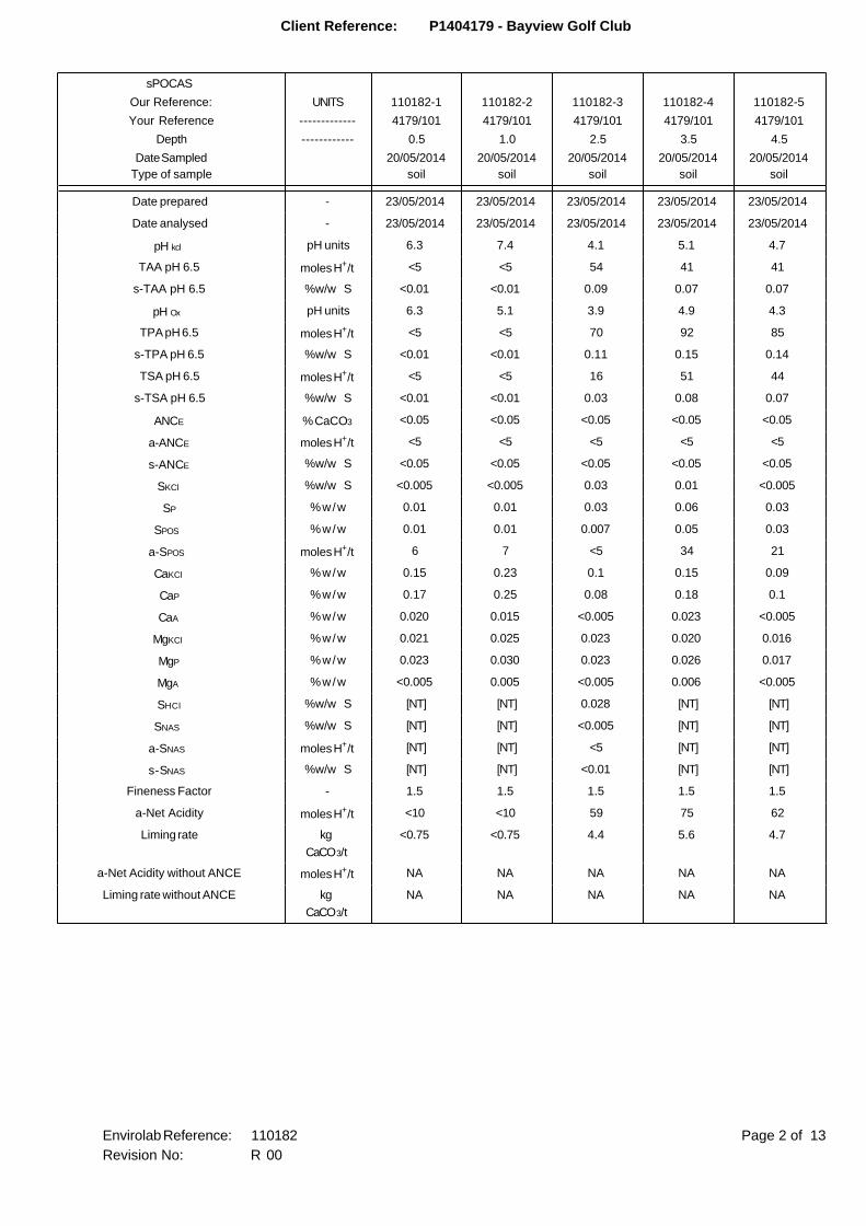
Client Reference: P1404179 - Bayview Golf Club
sPOCAS
Our Reference: UNITS 110182-1 110182-2 110182-3 110182-4 110182-5
Your Reference ------------- 4179/101 4179/101 4179/101 4179/101 4179/101
Depth ------------ 0.5 1.0 2.5 3.5 4.5
Date Sampled
Type of sample
20/05/2014
soil
20/05/2014
soil
20/05/2014
soil
20/05/2014
soil
20/05/2014
soil
Date prepared - 23/05/2014 23/05/2014 23/05/2014 23/05/2014 23/05/2014
Date analysed - 23/05/2014 23/05/2014 23/05/2014 23/05/2014 23/05/2014
pH kcl pH units 6.3 7.4 4.1 5.1 4.7
TAA pH 6.5 moles H+/t <5 <5 54 41 41
s-TAA pH 6.5 %w/w S <0.01 <0.01 0.09 0.07 0.07
pH Ox pH units 6.3 5.1 3.9 4.9 4.3
TPA pH 6.5 moles H+/t <5 <5 70 92 85
s-TPA pH 6.5 %w/w S <0.01 <0.01 0.11 0.15 0.14
TSA pH 6.5 moles H+/t <5 <5 16 51 44
s-TSA pH 6.5 %w/w S <0.01 <0.01 0.03 0.08 0.07
ANCE % CaCO3 <0.05 <0.05 <0.05 <0.05 <0.05
a-ANCE moles H+/t <5 <5 <5 <5 <5
s-ANCE %w/w S <0.05 <0.05 <0.05 <0.05 <0.05
SKCl %w/w S <0.005 <0.005 0.03 0.01 <0.005
SP %w/w 0.01 0.01 0.03 0.06 0.03
SPOS %w/w 0.01 0.01 0.007 0.05 0.03
a-SPOS moles H+/t 6 7 <5 34 21
CaKCl %w/w 0.15 0.23 0.1 0.15 0.09
CaP %w/w 0.17 0.25 0.08 0.18 0.1
CaA %w/w 0.020 0.015 <0.005 0.023 <0.005
MgKCl %w/w 0.021 0.025 0.023 0.020 0.016
MgP %w/w 0.023 0.030 0.023 0.026 0.017
MgA %w/w <0.005 0.005 <0.005 0.006 <0.005
SHCl %w/w S [NT] [NT] 0.028 [NT] [NT]
SNAS %w/w S [NT] [NT] <0.005 [NT] [NT]
a-SNAS moles H+/t [NT] [NT] <5 [NT] [NT]
s-SNAS %w/w S [NT] [NT] <0.01 [NT] [NT]
Fineness Factor - 1.5 1.5 1.5 1.5 1.5
a-Net Acidity moles H+/t <10 <10 59 75 62
Liming rate kg
CaCO3/t
<0.75 <0.75 4.4 5.6 4.7
a-Net Acidity without ANCE moles H+/t NA NA NA NA NA
Liming rate without ANCE kg
CaCO3/t
NA NA NA NA NA
Page 2 of 13Envirolab Reference: 110182
Revision No: R 00
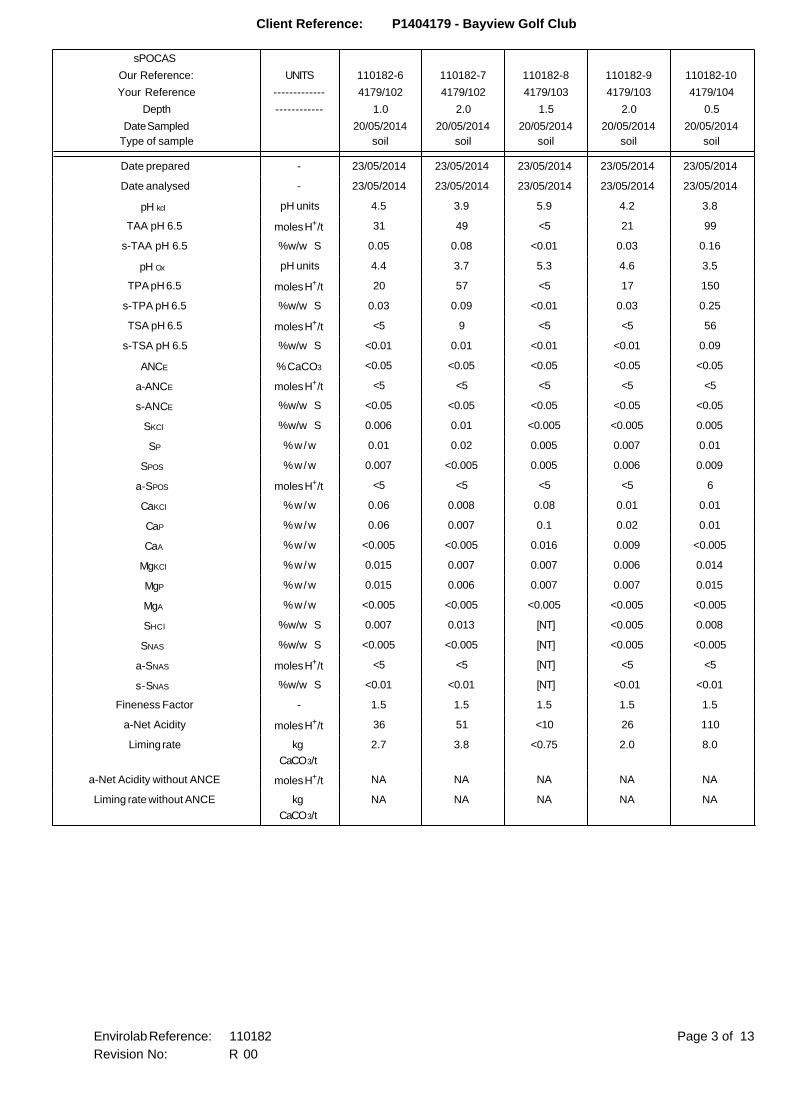
Client Reference: P1404179 - Bayview Golf Club
sPOCAS
Our Reference: UNITS 110182-6 110182-7 110182-8 110182-9 110182-10
Your Reference ------------- 4179/102 4179/102 4179/103 4179/103 4179/104
Depth ------------ 1.0 2.0 1.5 2.0 0.5
Date Sampled
Type of sample
20/05/2014
soil
20/05/2014
soil
20/05/2014
soil
20/05/2014
soil
20/05/2014
soil
Date prepared - 23/05/2014 23/05/2014 23/05/2014 23/05/2014 23/05/2014
Date analysed - 23/05/2014 23/05/2014 23/05/2014 23/05/2014 23/05/2014
pH kcl pH units 4.5 3.9 5.9 4.2 3.8
TAA pH 6.5 moles H+/t 31 49 <5 21 99
s-TAA pH 6.5 %w/w S 0.05 0.08 <0.01 0.03 0.16
pH Ox pH units 4.4 3.7 5.3 4.6 3.5
TPA pH 6.5 moles H+/t 20 57 <5 17 150
s-TPA pH 6.5 %w/w S 0.03 0.09 <0.01 0.03 0.25
TSA pH 6.5 moles H+/t <5 9 <5 <5 56
s-TSA pH 6.5 %w/w S <0.01 0.01 <0.01 <0.01 0.09
ANCE % CaCO3 <0.05 <0.05 <0.05 <0.05 <0.05
a-ANCE moles H+/t <5 <5 <5 <5 <5
s-ANCE %w/w S <0.05 <0.05 <0.05 <0.05 <0.05
SKCl %w/w S 0.006 0.01 <0.005 <0.005 0.005
SP %w/w 0.01 0.02 0.005 0.007 0.01
SPOS %w/w 0.007 <0.005 0.005 0.006 0.009
a-SPOS moles H+/t <5 <5 <5 <5 6
CaKCl %w/w 0.06 0.008 0.08 0.01 0.01
CaP %w/w 0.06 0.007 0.1 0.02 0.01
CaA %w/w <0.005 <0.005 0.016 0.009 <0.005
MgKCl %w/w 0.015 0.007 0.007 0.006 0.014
MgP %w/w 0.015 0.006 0.007 0.007 0.015
MgA %w/w <0.005 <0.005 <0.005 <0.005 <0.005
SHCl %w/w S 0.007 0.013 [NT] <0.005 0.008
SNAS %w/w S <0.005 <0.005 [NT] <0.005 <0.005
a-SNAS moles H+/t <5 <5 [NT] <5 <5
s-SNAS %w/w S <0.01 <0.01 [NT] <0.01 <0.01
Fineness Factor - 1.5 1.5 1.5 1.5 1.5
a-Net Acidity moles H+/t 36 51 <10 26 110
Liming rate kg
CaCO3/t
2.7 3.8 <0.75 2.0 8.0
a-Net Acidity without ANCE moles H+/t NA NA NA NA NA
Liming rate without ANCE kg
CaCO3/t
NA NA NA NA NA
Page 3 of 13Envirolab Reference: 110182
Revision No: R 00
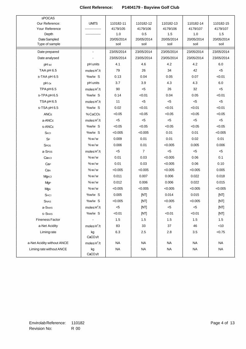
Client Reference: P1404179 - Bayview Golf Club
sPOCAS
Our Reference: UNITS 110182-11 110182-12 110182-13 110182-14 110182-15
Your Reference ------------- 4179/105 4179/106 4179/106 4179/107 4179/107
Depth ------------ 1.0 0.5 1.5 1.0 1.5
Date Sampled
Type of sample
20/05/2014
soil
20/05/2014
soil
20/05/2014
soil
20/05/2014
soil
20/05/2014
soil
Date prepared - 23/05/2014 23/05/2014 23/05/2014 23/05/2014 23/05/2014
Date analysed - 23/05/2014 23/05/2014 23/05/2014 23/05/2014 23/05/2014
pH kcl pH units 4.1 4.6 4.2 4.2 6.0
TAA pH 6.5 moles H+/t 79 26 34 42 <5
s-TAA pH 6.5 %w/w S 0.13 0.04 0.05 0.07 <0.01
pH Ox pH units 3.7 3.9 4.3 4.3 6.0
TPA pH 6.5 moles H+/t 90 <5 26 32 <5
s-TPA pH 6.5 %w/w S 0.14 <0.01 0.04 0.05 <0.01
TSA pH 6.5 moles H+/t 11 <5 <5 <5 <5
s-TSA pH 6.5 %w/w S 0.02 <0.01 <0.01 <0.01 <0.01
ANCE % CaCO3 <0.05 <0.05 <0.05 <0.05 <0.05
a-ANCE moles H+/t <5 <5 <5 <5 <5
s-ANCE %w/w S <0.05 <0.05 <0.05 <0.05 <0.05
SKCl %w/w S <0.005 <0.005 0.01 0.01 <0.005
SP %w/w 0.009 0.01 0.01 0.02 0.01
SPOS %w/w 0.006 0.01 <0.005 0.005 0.006
a-SPOS moles H+/t <5 7 <5 <5 <5
CaKCl %w/w 0.01 0.03 <0.005 0.06 0.1
CaP %w/w 0.01 0.03 <0.005 0.06 0.10
CaA %w/w <0.005 <0.005 <0.005 <0.005 0.005
MgKCl %w/w 0.011 0.007 0.006 0.022 0.018
MgP %w/w 0.012 0.006 0.006 0.022 0.015
MgA %w/w <0.005 <0.005 <0.005 <0.005 <0.005
SHCl %w/w S 0.005 [NT] 0.014 0.015 [NT]
SNAS %w/w S <0.005 [NT] <0.005 <0.005 [NT]
a-SNAS moles H+/t <5 [NT] <5 <5 [NT]
s-SNAS %w/w S <0.01 [NT] <0.01 <0.01 [NT]
Fineness Factor - 1.5 1.5 1.5 1.5 1.5
a-Net Acidity moles H+/t 83 33 37 46 <10
Liming rate kg
CaCO3/t
6.3 2.5 2.8 3.5 <0.75
a-Net Acidity without ANCE moles H+/t NA NA NA NA NA
Liming rate without ANCE kg
CaCO3/t
NA NA NA NA NA
Page 4 of 13Envirolab Reference: 110182
Revision No: R 00
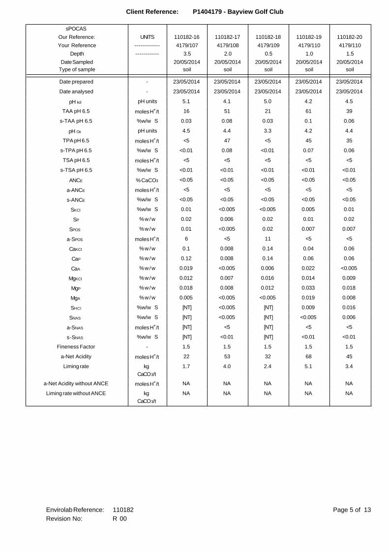
Client Reference: P1404179 - Bayview Golf Club
sPOCAS
Our Reference: UNITS 110182-16 110182-17 110182-18 110182-19 110182-20
Your Reference ------------- 4179/107 4179/108 4179/109 4179/110 4179/110
Depth ------------ 3.5 2.0 0.5 1.0 1.5
Date Sampled
Type of sample
20/05/2014
soil
20/05/2014
soil
20/05/2014
soil
20/05/2014
soil
20/05/2014
soil
Date prepared - 23/05/2014 23/05/2014 23/05/2014 23/05/2014 23/05/2014
Date analysed - 23/05/2014 23/05/2014 23/05/2014 23/05/2014 23/05/2014
pH kcl pH units 5.1 4.1 5.0 4.2 4.5
TAA pH 6.5 moles H+/t 16 51 21 61 39
s-TAA pH 6.5 %w/w S 0.03 0.08 0.03 0.1 0.06
pH Ox pH units 4.5 4.4 3.3 4.2 4.4
TPA pH 6.5 moles H+/t <5 47 <5 45 35
s-TPA pH 6.5 %w/w S <0.01 0.08 <0.01 0.07 0.06
TSA pH 6.5 moles H+/t <5 <5 <5 <5 <5
s-TSA pH 6.5 %w/w S <0.01 <0.01 <0.01 <0.01 <0.01
ANCE % CaCO3 <0.05 <0.05 <0.05 <0.05 <0.05
a-ANCE moles H+/t <5 <5 <5 <5 <5
s-ANCE %w/w S <0.05 <0.05 <0.05 <0.05 <0.05
SKCl %w/w S 0.01 <0.005 <0.005 0.005 0.01
SP %w/w 0.02 0.006 0.02 0.01 0.02
SPOS %w/w 0.01 <0.005 0.02 0.007 0.007
a-SPOS moles H+/t 6 <5 11 <5 <5
CaKCl %w/w 0.1 0.008 0.14 0.04 0.06
CaP %w/w 0.12 0.008 0.14 0.06 0.06
CaA %w/w 0.019 <0.005 0.006 0.022 <0.005
MgKCl %w/w 0.012 0.007 0.016 0.014 0.009
MgP %w/w 0.018 0.008 0.012 0.033 0.018
MgA %w/w 0.005 <0.005 <0.005 0.019 0.008
SHCl %w/w S [NT] <0.005 [NT] 0.009 0.016
SNAS %w/w S [NT] <0.005 [NT] <0.005 0.006
a-SNAS moles H+/t [NT] <5 [NT] <5 <5
s-SNAS %w/w S [NT] <0.01 [NT] <0.01 <0.01
Fineness Factor - 1.5 1.5 1.5 1.5 1.5
a-Net Acidity moles H+/t 22 53 32 68 45
Liming rate kg
CaCO3/t
1.7 4.0 2.4 5.1 3.4
a-Net Acidity without ANCE moles H+/t NA NA NA NA NA
Liming rate without ANCE kg
CaCO3/t
NA NA NA NA NA
Page 5 of 13Envirolab Reference: 110182
Revision No: R 00
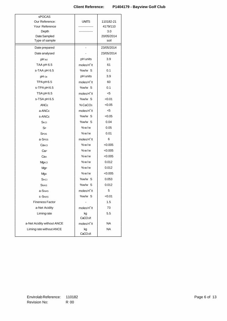
Client Reference: P1404179 - Bayview Golf Club
sPOCAS
Our Reference: UNITS 110182-21
Your Reference ------------- 4179/110
Depth ------------ 3.0
Date Sampled
Type of sample
20/05/2014
soil
Date prepared - 23/05/2014
Date analysed - 23/05/2014
pH kcl pH units 3.9
TAA pH 6.5 moles H+/t 61
s-TAA pH 6.5 %w/w S 0.1
pH Ox pH units 3.9
TPA pH 6.5 moles H+/t 60
s-TPA pH 6.5 %w/w S 0.1
TSA pH 6.5 moles H+/t <5
s-TSA pH 6.5 %w/w S <0.01
ANCE % CaCO3 <0.05
a-ANCE moles H+/t <5
s-ANCE %w/w S <0.05
SKCl %w/w S 0.04
SP %w/w 0.05
SPOS %w/w 0.01
a-SPOS moles H+/t 6
CaKCl %w/w <0.005
CaP %w/w <0.005
CaA %w/w <0.005
MgKCl %w/w 0.012
MgP %w/w 0.012
MgA %w/w <0.005
SHCl %w/w S 0.053
SNAS %w/w S 0.012
a-SNAS moles H+/t 5
s-SNAS %w/w S <0.01
Fineness Factor - 1.5
a-Net Acidity moles H+/t 73
Liming rate kg
CaCO3/t
5.5
a-Net Acidity without ANCE moles H+/t NA
Liming rate without ANCE kg
CaCO3/t
NA
Page 6 of 13Envirolab Reference: 110182
Revision No: R 00

Client Reference: P1404179 - Bayview Golf Club
Method ID Methodology Summary
Inorg-064 sPOCAS determined using titrimetric and ICP-AES techniques. Based on Acid Sulfate Soils Laboratory
Methods Guidelines, Version 2.1 - June 2004.
Page 7 of 13Envirolab Reference: 110182
Revision No: R 00
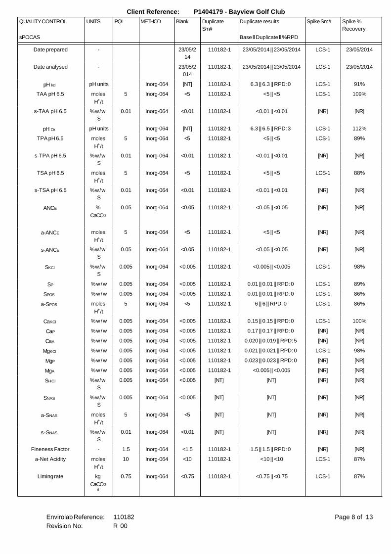
Client Reference: P1404179 - Bayview Golf Club
QUALITY CONTROL UNITS PQL METHOD Blank Duplicate
Sm#
Duplicate results Spike Sm# Spike %
Recovery
sPOCAS Base ll Duplicate ll %RPD
Date prepared - 23/05/2
14
110182-1 23/05/2014 || 23/05/2014 LCS-1 23/05/2014
Date analysed - 23/05/2
014
110182-1 23/05/2014 || 23/05/2014 LCS-1 23/05/2014
pH kcl pH units Inorg-064 [NT] 110182-1 6.3 || 6.3 || RPD: 0 LCS-1 91%
TAA pH 6.5 moles
H+/t
5 Inorg-064 <5 110182-1 <5 || <5 LCS-1 109%
s-TAA pH 6.5 %w/w
S
0.01 Inorg-064 <0.01 110182-1 <0.01 || <0.01 [NR] [NR]
pH Ox pH units Inorg-064 [NT] 110182-1 6.3 || 6.5 || RPD: 3 LCS-1 112%
TPA pH 6.5 moles
H+/t
5 Inorg-064 <5 110182-1 <5 || <5 LCS-1 89%
s-TPA pH 6.5 %w/w
S
0.01 Inorg-064 <0.01 110182-1 <0.01 || <0.01 [NR] [NR]
TSA pH 6.5 moles
H+/t
5 Inorg-064 <5 110182-1 <5 || <5 LCS-1 88%
s-TSA pH 6.5 %w/w
S
0.01 Inorg-064 <0.01 110182-1 <0.01 || <0.01 [NR] [NR]
ANCE %
CaCO3
0.05 Inorg-064 <0.05 110182-1 <0.05 || <0.05 [NR] [NR]
a-ANCE moles
H+/t
5 Inorg-064 <5 110182-1 <5 || <5 [NR] [NR]
s-ANCE %w/w
S
0.05 Inorg-064 <0.05 110182-1 <0.05 || <0.05 [NR] [NR]
SKCl %w/w
S
0.005 Inorg-064 <0.005 110182-1 <0.005 || <0.005 LCS-1 98%
SP %w/w 0.005 Inorg-064 <0.005 110182-1 0.01 || 0.01 || RPD: 0 LCS-1 89%
SPOS %w/w 0.005 Inorg-064 <0.005 110182-1 0.01 || 0.01 || RPD: 0 LCS-1 86%
a-SPOS moles
H+/t
5 Inorg-064 <5 110182-1 6 || 6 || RPD: 0 LCS-1 86%
CaKCl %w/w 0.005 Inorg-064 <0.005 110182-1 0.15 || 0.15 || RPD: 0 LCS-1 100%
CaP %w/w 0.005 Inorg-064 <0.005 110182-1 0.17 || 0.17 || RPD: 0 [NR] [NR]
CaA %w/w 0.005 Inorg-064 <0.005 110182-1 0.020 || 0.019 || RPD: 5 [NR] [NR]
MgKCl %w/w 0.005 Inorg-064 <0.005 110182-1 0.021 || 0.021 || RPD: 0 LCS-1 98%
MgP %w/w 0.005 Inorg-064 <0.005 110182-1 0.023 || 0.023 || RPD: 0 [NR] [NR]
MgA %w/w 0.005 Inorg-064 <0.005 110182-1 <0.005 || <0.005 [NR] [NR]
SHCl %w/w
S
0.005 Inorg-064 <0.005 [NT] [NT] [NR] [NR]
SNAS %w/w
S
0.005 Inorg-064 <0.005 [NT] [NT] [NR] [NR]
a-SNAS moles
H+/t
5 Inorg-064 <5 [NT] [NT] [NR] [NR]
s-SNAS %w/w
S
0.01 Inorg-064 <0.01 [NT] [NT] [NR] [NR]
Fineness Factor - 1.5 Inorg-064 <1.5 110182-1 1.5 || 1.5 || RPD: 0 [NR] [NR]
a-Net Acidity moles
H+/t
10 Inorg-064 <10 110182-1 <10 || <10 LCS-1 87%
Liming rate kg
CaCO3/t
0.75 Inorg-064 <0.75 110182-1 <0.75 || <0.75 LCS-1 87%
Page 8 of 13Envirolab Reference: 110182
Revision No: R 00
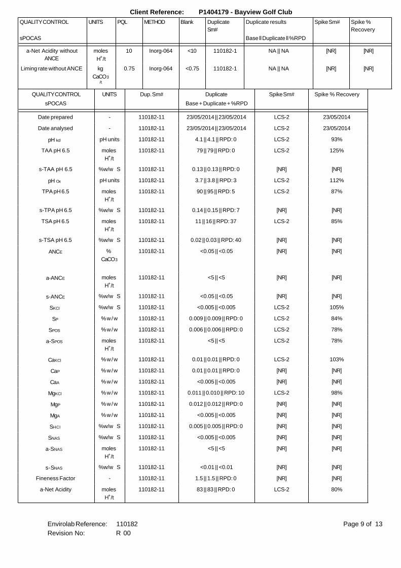
Client Reference: P1404179 - Bayview Golf Club
QUALITY CONTROL UNITS PQL METHOD Blank Duplicate
Sm#
Duplicate results Spike Sm# Spike %
Recovery
sPOCAS Base ll Duplicate ll %RPD
a-Net Acidity without
ANCE
moles
H+/t
10 Inorg-064 <10 110182-1 NA || NA [NR] [NR]
Liming rate without ANCE kg
CaCO3/t
0.75 Inorg-064 <0.75 110182-1 NA || NA [NR] [NR]
QUALITY CONTROL UNITS Dup. Sm# Duplicate Spike Sm# Spike % Recovery
sPOCAS Base + Duplicate + %RPD
Date prepared - 110182-11 23/05/2014 || 23/05/2014 LCS-2 23/05/2014
Date analysed - 110182-11 23/05/2014 || 23/05/2014 LCS-2 23/05/2014
pH kcl pH units 110182-11 4.1 || 4.1 || RPD: 0 LCS-2 93%
TAA pH 6.5 moles
H+/t
110182-11 79 || 79 || RPD: 0 LCS-2 125%
s-TAA pH 6.5 %w/w S 110182-11 0.13 || 0.13 || RPD: 0 [NR] [NR]
pH Ox pH units 110182-11 3.7 || 3.8 || RPD: 3 LCS-2 112%
TPA pH 6.5 moles
H+/t
110182-11 90 || 95 || RPD: 5 LCS-2 87%
s-TPA pH 6.5 %w/w S 110182-11 0.14 || 0.15 || RPD: 7 [NR] [NR]
TSA pH 6.5 moles
H+/t
110182-11 11 || 16 || RPD: 37 LCS-2 85%
s-TSA pH 6.5 %w/w S 110182-11 0.02 || 0.03 || RPD: 40 [NR] [NR]
ANCE %
CaCO3
110182-11 <0.05 || <0.05 [NR] [NR]
a-ANCE moles
H+/t
110182-11 <5 || <5 [NR] [NR]
s-ANCE %w/w S 110182-11 <0.05 || <0.05 [NR] [NR]
SKCl %w/w S 110182-11 <0.005 || <0.005 LCS-2 105%
SP %w/w 110182-11 0.009 || 0.009 || RPD: 0 LCS-2 84%
SPOS %w/w 110182-11 0.006 || 0.006 || RPD: 0 LCS-2 78%
a-SPOS moles
H+/t
110182-11 <5 || <5 LCS-2 78%
CaKCl %w/w 110182-11 0.01 || 0.01 || RPD: 0 LCS-2 103%
CaP %w/w 110182-11 0.01 || 0.01 || RPD: 0 [NR] [NR]
CaA %w/w 110182-11 <0.005 || <0.005 [NR] [NR]
MgKCl %w/w 110182-11 0.011 || 0.010 || RPD: 10 LCS-2 98%
MgP %w/w 110182-11 0.012 || 0.012 || RPD: 0 [NR] [NR]
MgA %w/w 110182-11 <0.005 || <0.005 [NR] [NR]
SHCl %w/w S 110182-11 0.005 || 0.005 || RPD: 0 [NR] [NR]
SNAS %w/w S 110182-11 <0.005 || <0.005 [NR] [NR]
a-SNAS moles
H+/t
110182-11 <5 || <5 [NR] [NR]
s-SNAS %w/w S 110182-11 <0.01 || <0.01 [NR] [NR]
Fineness Factor - 110182-11 1.5 || 1.5 || RPD: 0 [NR] [NR]
a-Net Acidity moles
H+/t
110182-11 83 || 83 || RPD: 0 LCS-2 80%
Page 9 of 13Envirolab Reference: 110182
Revision No: R 00
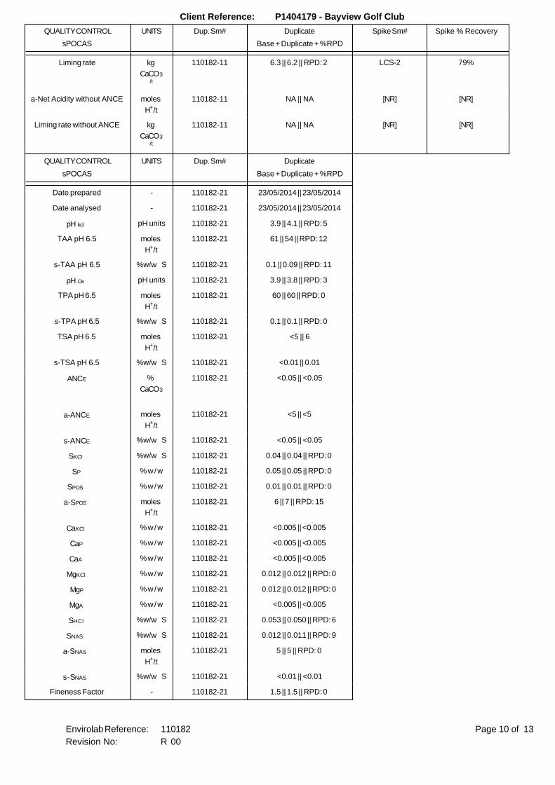
Client Reference: P1404179 - Bayview Golf Club
QUALITY CONTROL UNITS Dup. Sm# Duplicate Spike Sm# Spike % Recovery
sPOCAS Base + Duplicate + %RPD
Liming rate kg
CaCO3/t
110182-11 6.3 || 6.2 || RPD: 2 LCS-2 79%
a-Net Acidity without ANCE moles
H+/t
110182-11 NA || NA [NR] [NR]
Liming rate without ANCE kg
CaCO3/t
110182-11 NA || NA [NR] [NR]
QUALITY CONTROL UNITS Dup. Sm# Duplicate
sPOCAS Base + Duplicate + %RPD
Date prepared - 110182-21 23/05/2014 || 23/05/2014
Date analysed - 110182-21 23/05/2014 || 23/05/2014
pH kcl pH units 110182-21 3.9 || 4.1 || RPD: 5
TAA pH 6.5 moles
H+/t
110182-21 61 || 54 || RPD: 12
s-TAA pH 6.5 %w/w S 110182-21 0.1 || 0.09 || RPD: 11
pH Ox pH units 110182-21 3.9 || 3.8 || RPD: 3
TPA pH 6.5 moles
H+/t
110182-21 60 || 60 || RPD: 0
s-TPA pH 6.5 %w/w S 110182-21 0.1 || 0.1 || RPD: 0
TSA pH 6.5 moles
H+/t
110182-21 <5 || 6
s-TSA pH 6.5 %w/w S 110182-21 <0.01 || 0.01
ANCE %
CaCO3
110182-21 <0.05 || <0.05
a-ANCE moles
H+/t
110182-21 <5 || <5
s-ANCE %w/w S 110182-21 <0.05 || <0.05
SKCl %w/w S 110182-21 0.04 || 0.04 || RPD: 0
SP %w/w 110182-21 0.05 || 0.05 || RPD: 0
SPOS %w/w 110182-21 0.01 || 0.01 || RPD: 0
a-SPOS moles
H+/t
110182-21 6 || 7 || RPD: 15
CaKCl %w/w 110182-21 <0.005 || <0.005
CaP %w/w 110182-21 <0.005 || <0.005
CaA %w/w 110182-21 <0.005 || <0.005
MgKCl %w/w 110182-21 0.012 || 0.012 || RPD: 0
MgP %w/w 110182-21 0.012 || 0.012 || RPD: 0
MgA %w/w 110182-21 <0.005 || <0.005
SHCl %w/w S 110182-21 0.053 || 0.050 || RPD: 6
SNAS %w/w S 110182-21 0.012 || 0.011 || RPD: 9
a-SNAS moles
H+/t
110182-21 5 || 5 || RPD: 0
s-SNAS %w/w S 110182-21 <0.01 || <0.01
Fineness Factor - 110182-21 1.5 || 1.5 || RPD: 0
Page 10 of 13Envirolab Reference: 110182
Revision No: R 00
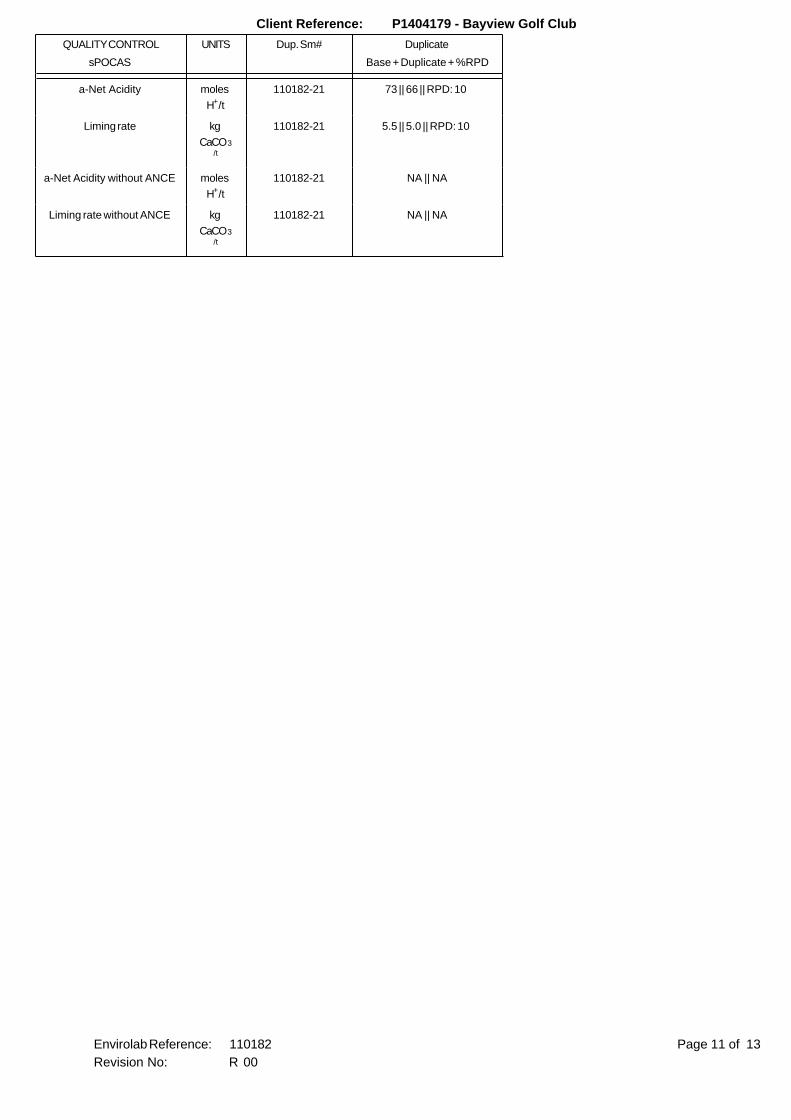
Client Reference: P1404179 - Bayview Golf Club
QUALITY CONTROL UNITS Dup. Sm# Duplicate
sPOCAS Base + Duplicate + %RPD
a-Net Acidity moles
H+/t
110182-21 73 || 66 || RPD: 10
Liming rate kg
CaCO3/t
110182-21 5.5 || 5.0 || RPD: 10
a-Net Acidity without ANCE moles
H+/t
110182-21 NA || NA
Liming rate without ANCE kg
CaCO3/t
110182-21 NA || NA
Page 11 of 13Envirolab Reference: 110182
Revision No: R 00
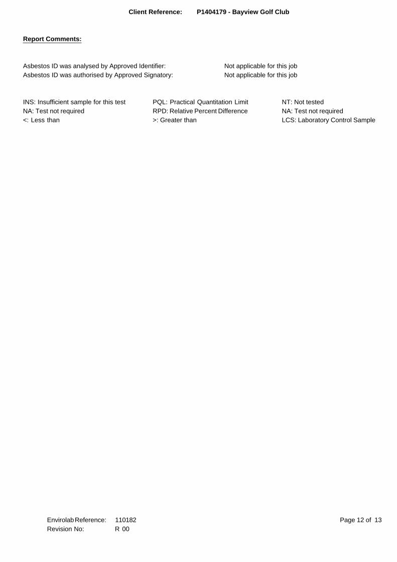
Client Reference: P1404179 - Bayview Golf Club
Report Comments:
Asbestos ID was analysed by Approved Identifier: Not applicable for this job
Asbestos ID was authorised by Approved Signatory: Not applicable for this job
INS: Insufficient sample for this test PQL: Practical Quantitation Limit NT: Not tested
NA: Test not required RPD: Relative Percent Difference NA: Test not required
<: Less than >: Greater than LCS: Laboratory Control Sample
Page 12 of 13Envirolab Reference: 110182
Revision No: R 00
Client Reference: P1404179 - Bayview Golf Club
Quality Control Definitions
Blank: This is the component of the analytical signal which is not derived from the sample but from reagents,
glassware etc, can be determined by processing solvents and reagents in exactly the same manner as for samples.
Duplicate : This is the complete duplicate analysis of a sample from the process batch. If possible, the sample
selected should be one where the analyte concentration is easily measurable.
Matrix Spike : A portion of the sample is spiked with a known concentration of target analyte. The purpose of the matrix
spike is to monitor the performance of the analytical method used and to determine whether matrix interferences exist.
LCS (Laboratory Control Sample) : This comprises either a standard reference material or a control matrix (such as a blank
sand or water) fortified with analytes representative of the analyte class. It is simply a check sample.
Surrogate Spike: Surrogates are known additions to each sample, blank, matrix spike and LCS in a batch, of compounds
which are similar to the analyte of interest, however are not expected to be found in real samples.
Laboratory Acceptance Criteria
Duplicate sample and matrix spike recoveries may not be reported on smaller jobs, however, were analysed at a frequency
to meet or exceed NEPM requirements. All samples are tested in batches of 20. The duplicate sample RPD and matrix
spike recoveries for the batch were within the laboratory acceptance criteria.
Filters, swabs, wipes, tubes and badges will not have duplicate data as the whole sample is
generally extracted during sample extraction.
Spikes for Physical and Aggregate Tests are not applicable.
For VOCs in water samples, three vials are required for duplicate or spike analysis.
Duplicates: <5xPQL - any RPD is acceptable; >5xPQL - 0-50% RPD is acceptable.
Matrix Spikes, LCS and Surrogate recoveries: Generally 70-130% for inorganics/metals; 60-140%
for organics and 10-140% for SVOC and speciated phenols is acceptable.
In circumstances where no duplicate and/or sample spike has been reported at 1 in 10 and/or
1 in 20 samples respectively, the sample volume submitted was insufficient in order to satisfy
laboratory QA/QC protocols.
When samples are received where certain analytes are outside of recommended technical
holding times (THTs), the analysis has proceeded. Where analytes are on the verge
of breaching THTs, every effort will be made to analyse within the THT
or as soon as practicable.
Page 13 of 13Envirolab Reference: 110182
Revision No: R 00
Envirolab Services Pty Ltd
ABN 37 112 535 645
12 Ashley St Chatswood NSW 2067
ph 02 9910 6200 fax 02 9910 6201
www.envirolab.com.au
CERTIFICATE OF ANALYSIS 176282-A
Suite 201, 20 George St, Hornsby, NSW, 2077Address
Hamed NaghibiAttention
Martens & Associates Pty LtdClient
Client Details
25/09/2017Date completed instructions received
22/09/2017Date samples received
Additional Testing on 15 SoilsNumber of Samples
P1706099 - Contamination Investigation at CabbageYour Reference
Sample Details
Results are reported on a dry weight basis for solids and on an as received basis for other matrices.
Samples were analysed as received from the client. Results relate specifically to the samples as received.
Please refer to the following pages for results, methodology summary and quality control data.
Analysis Details
Tests not covered by NATA are denoted with *Accredited for compliance with ISO/IEC 17025 - Testing.
NATA Accreditation Number 2901. This document shall not be reproduced except in full.
03/10/2017Date of Issue
03/10/2017Date results requested by
Report Details
David Springer, General Manager
Authorised By
Priya Samarawickrama, Senior Chemist
Nick Sarlamis, Inorganics Supervisor
Results Approved By
Revision No: R00
176282-AEnvirolab Reference: Page | 1 of 10
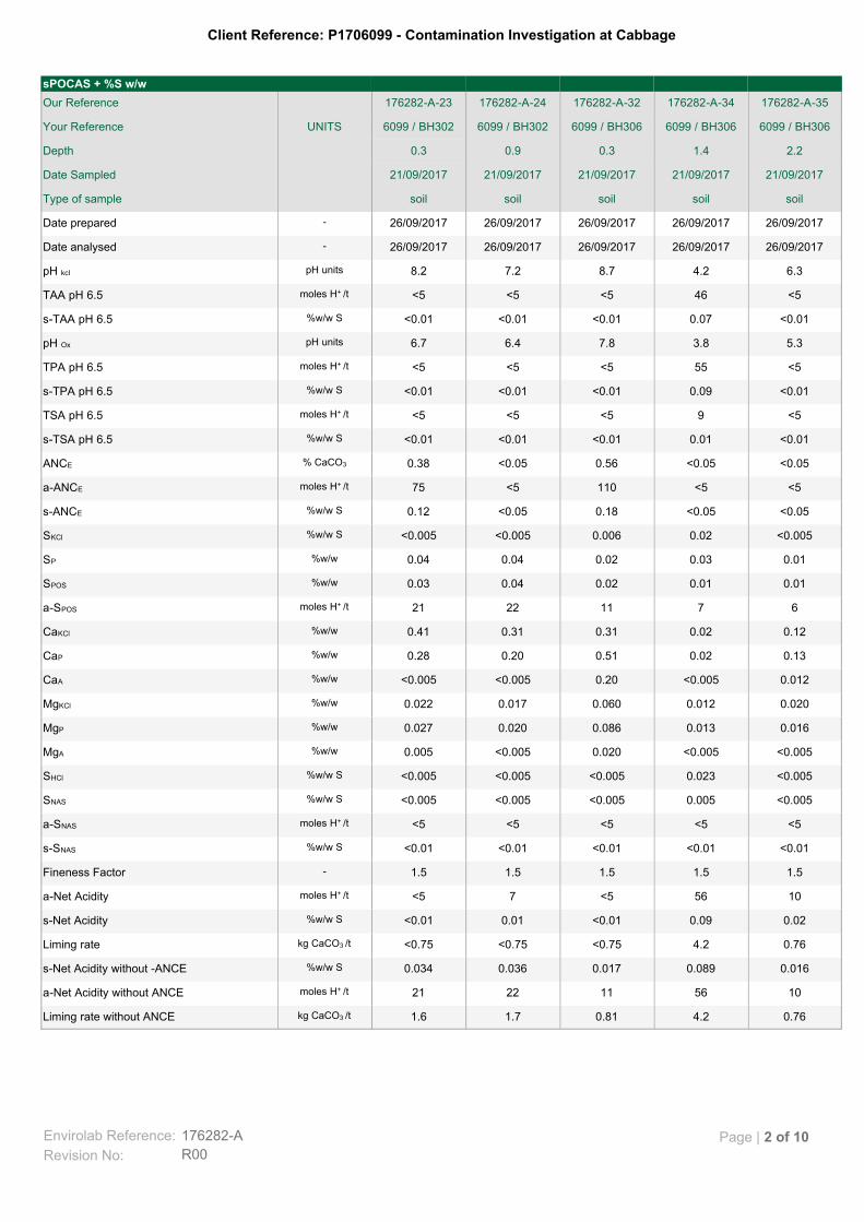
Client Reference: P1706099 - Contamination Investigation at Cabbage
0.764.20.811.71.6kg CaCO3 /tLiming rate without ANCE
1056112221moles H+ /ta-Net Acidity without ANCE
0.0160.0890.0170.0360.034%w/w Ss-Net Acidity without -ANCE
0.764.2<0.75<0.75<0.75kg CaCO3 /tLiming rate
0.020.09<0.010.01<0.01%w/w Ss-Net Acidity
1056<57<5moles H+ /ta-Net Acidity
1.51.51.51.51.5-Fineness Factor
<0.01<0.01<0.01<0.01<0.01%w/w Ss-SNAS
<5<5<5<5<5moles H+ /ta-SNAS
<0.0050.005<0.005<0.005<0.005%w/w SSNAS
<0.0050.023<0.005<0.005<0.005%w/w SSHCl
<0.005<0.0050.020<0.0050.005%w/wMgA
0.0160.0130.0860.0200.027%w/wMgP
0.0200.0120.0600.0170.022%w/wMgKCl
0.012<0.0050.20<0.005<0.005%w/wCaA
0.130.020.510.200.28%w/wCaP
0.120.020.310.310.41%w/wCaKCl
67112221moles H+ /ta-SPOS
0.010.010.020.040.03%w/wSPOS
0.010.030.020.040.04%w/wSP
<0.0050.020.006<0.005<0.005%w/w SSKCl
<0.05<0.050.18<0.050.12%w/w Ss-ANCE
<5<5110<575moles H+ /ta-ANCE
<0.05<0.050.56<0.050.38% CaCO3 ANCE
<0.010.01<0.01<0.01<0.01%w/w Ss-TSA pH 6.5
<59<5<5<5moles H+ /tTSA pH 6.5
<0.010.09<0.01<0.01<0.01%w/w Ss-TPA pH 6.5
<555<5<5<5moles H+ /tTPA pH 6.5
5.33.87.86.46.7pH unitspH Ox
<0.010.07<0.01<0.01<0.01%w/w Ss-TAA pH 6.5
<546<5<5<5moles H+ /tTAA pH 6.5
6.34.28.77.28.2pH unitspH kcl
26/09/201726/09/201726/09/201726/09/201726/09/2017-Date analysed
26/09/201726/09/201726/09/201726/09/201726/09/2017-Date prepared
soilsoilsoilsoilsoilType of sample
21/09/201721/09/201721/09/201721/09/201721/09/2017Date Sampled
2.21.40.30.90.3Depth
6099 / BH3066099 / BH3066099 / BH3066099 / BH302 6099 / BH302 UNITSYour Reference
176282-A-35176282-A-34176282-A-32176282-A-24176282-A-23Our Reference
sPOCAS + %S w/w
Envirolab Reference: 176282-A
R00Revision No:
Page | 2 of 10
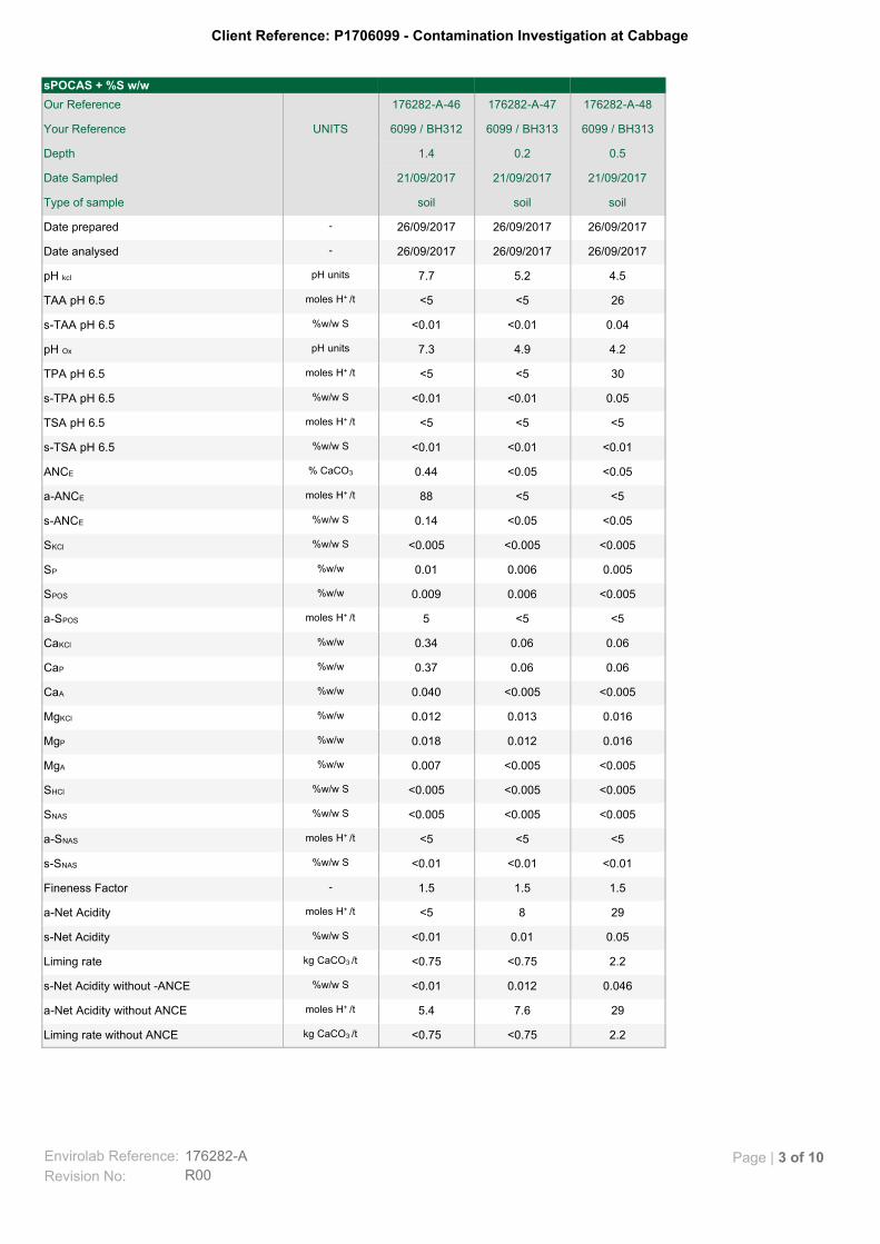
Client Reference: P1706099 - Contamination Investigation at Cabbage
2.2<0.75<0.75kg CaCO3 /tLiming rate without ANCE
297.65.4moles H+ /ta-Net Acidity without ANCE
0.0460.012<0.01%w/w Ss-Net Acidity without -ANCE
2.2<0.75<0.75kg CaCO3 /tLiming rate
0.050.01<0.01%w/w Ss-Net Acidity
298<5moles H+ /ta-Net Acidity
1.51.51.5-Fineness Factor
<0.01<0.01<0.01%w/w Ss-SNAS
<5<5<5moles H+ /ta-SNAS
<0.005<0.005<0.005%w/w SSNAS
<0.005<0.005<0.005%w/w SSHCl
<0.005<0.0050.007%w/wMgA
0.0160.0120.018%w/wMgP
0.0160.0130.012%w/wMgKCl
<0.005<0.0050.040%w/wCaA
0.060.060.37%w/wCaP
0.060.060.34%w/wCaKCl
<5<55moles H+ /ta-SPOS
<0.0050.0060.009%w/wSPOS
0.0050.0060.01%w/wSP
<0.005<0.005<0.005%w/w SSKCl
<0.05<0.050.14%w/w Ss-ANCE
<5<588moles H+ /ta-ANCE
<0.05<0.050.44% CaCO3 ANCE
<0.01<0.01<0.01%w/w Ss-TSA pH 6.5
<5<5<5moles H+ /tTSA pH 6.5
0.05<0.01<0.01%w/w Ss-TPA pH 6.5
30<5<5moles H+ /tTPA pH 6.5
4.24.97.3pH unitspH Ox
0.04<0.01<0.01%w/w Ss-TAA pH 6.5
26<5<5moles H+ /tTAA pH 6.5
4.55.27.7pH unitspH kcl
26/09/201726/09/201726/09/2017-Date analysed
26/09/201726/09/201726/09/2017-Date prepared
soilsoilsoilType of sample
21/09/201721/09/201721/09/2017Date Sampled
0.50.21.4Depth
6099 / BH3136099 / BH3136099 / BH312UNITSYour Reference
176282-A-48176282-A-47176282-A-46Our Reference
sPOCAS + %S w/w
Envirolab Reference: 176282-A
R00Revision No:
Page | 3 of 10
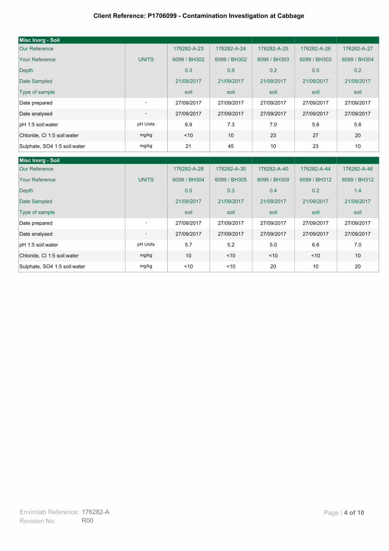
Client Reference: P1706099 - Contamination Investigation at Cabbage
201020<10<10mg/kgSulphate, SO4 1:5 soil:water
10<10<10<1010mg/kgChloride, Cl 1:5 soil:water
7.06.65.05.25.7pH UnitspH 1:5 soil:water
27/09/201727/09/201727/09/201727/09/201727/09/2017-Date analysed
27/09/201727/09/201727/09/201727/09/201727/09/2017-Date prepared
soilsoilsoilsoilsoilType of sample
21/09/201721/09/201721/09/201721/09/201721/09/2017Date Sampled
1.40.20.40.30.5Depth
6099 / BH3126099 / BH3126099 / BH3096099 / BH3056099 / BH304 UNITSYour Reference
176282-A-46176282-A-44176282-A-40176282-A-30176282-A-28Our Reference
Misc Inorg - Soil
1023104521mg/kgSulphate, SO4 1:5 soil:water
20272310<10mg/kgChloride, Cl 1:5 soil:water
5.65.67.07.36.9pH UnitspH 1:5 soil:water
27/09/201727/09/201727/09/201727/09/201727/09/2017-Date analysed
27/09/201727/09/201727/09/201727/09/201727/09/2017-Date prepared
soilsoilsoilsoilsoilType of sample
21/09/201721/09/201721/09/201721/09/201721/09/2017Date Sampled
0.20.50.20.90.3Depth
6099 / BH3046099 / BH3036099 / BH3036099 / BH302 6099 / BH302 UNITSYour Reference
176282-A-27176282-A-26176282-A-25176282-A-24176282-A-23Our Reference
Misc Inorg - Soil
Envirolab Reference: 176282-A
R00Revision No:
Page | 4 of 10

Client Reference: P1706099 - Contamination Investigation at Cabbage
Anions - a range of Anions are determined by Ion Chromatography, in accordance with APHA latest edition, 4110-B. Alternatively determined by colourimetry/turbidity using Discrete Analyer.
Inorg-081
sPOCAS determined using titrimetric and ICP-AES techniques. Based on Acid Sulfate Soils Laboratory Methods Guidelines, Version 2.1 - June 2004.
Inorg-064
pH - Measured using pH meter and electrode in accordance with APHA latest edition, 4500-H+. Please note that the results for water analyses are indicative only, as analysis outside of the APHA storage times.
Inorg-001
Methodology SummaryMethod ID
Envirolab Reference: 176282-A
R00Revision No:
Page | 5 of 10
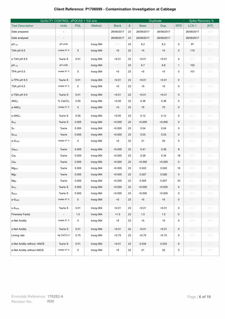
Client Reference: P1706099 - Contamination Investigation at Cabbage
[NT][NT]5202123<5Inorg-0645moles H+ /ta-Net Acidity without ANCE
[NT][NT]60.0320.03423<0.01Inorg-0640.01%w/w Ss-Net Acidity without -ANCE
[NT][NT]0<0.75<0.7523<0.75Inorg-0640.75kg CaCO3 /tLiming rate
[NT][NT]0<0.01<0.0123<0.01Inorg-0640.01%w/w Ss-Net Acidity
[NT][NT]0<5<523<5Inorg-0645moles H+ /ta-Net Acidity
[NT][NT]01.51.523<1.5Inorg-0641.5-Fineness Factor
[NT][NT]0<0.01<0.0123<0.01Inorg-0640.01%w/w Ss-SNAS
[NT][NT]0<5<523<5Inorg-0645moles H+ /ta-SNAS
[NT][NT]0<0.005<0.00523<0.005Inorg-0640.005%w/w SSNAS
[NT][NT]0<0.005<0.00523<0.005Inorg-0640.005%w/w SSHCl
[NT][NT]330.0070.00523<0.005Inorg-0640.005%w/wMgA
[NT][NT]40.0260.02723<0.005Inorg-0640.005%w/wMgP
[NT][NT]100.0200.02223<0.005Inorg-0640.005%w/wMgKCl
[NT][NT]0<0.005<0.00523<0.005Inorg-0640.005%w/wCaA
[NT][NT]190.340.2823<0.005Inorg-0640.005%w/wCaP
[NT][NT]80.380.4123<0.005Inorg-0640.005%w/wCaKCl
[NT][NT]5202123<5Inorg-0645moles H+ /ta-SPOS
[NT][NT]00.030.0323<0.005Inorg-0640.005%w/wSPOS
[NT][NT]00.040.0423<0.005Inorg-0640.005%w/wSP
[NT][NT]0<0.005<0.00523<0.005Inorg-0640.005%w/w SSKCl
[NT][NT]00.120.1223<0.05Inorg-0640.05%w/w Ss-ANCE
[NT][NT]0757523<5Inorg-0645moles H+ /ta-ANCE
[NT][NT]00.380.3823<0.05Inorg-0640.05% CaCO3 ANCE
[NT][NT]0<0.01<0.0123<0.01Inorg-0640.01%w/w Ss-TSA pH 6.5
[NT][NT]0<5<523<5Inorg-0645moles H+ /tTSA pH 6.5
[NT][NT]0<0.01<0.0123<0.01Inorg-0640.01%w/w Ss-TPA pH 6.5
[NT]1010<5<523<5Inorg-0645moles H+ /tTPA pH 6.5
[NT]10216.86.723[NT]Inorg-064pH unitspH Ox
[NT][NT]0<0.01<0.0123<0.01Inorg-0640.01%w/w Ss-TAA pH 6.5
[NT]1150<5<523<5Inorg-0645moles H+ /tTAA pH 6.5
[NT]9708.28.223[NT]Inorg-064pH unitspH kcl
[NT]26/09/201726/09/201726/09/20172326/09/2017-Date analysed
[NT]26/09/201726/09/201726/09/20172326/09/2017-Date prepared
[NT]LCS-1RPDDup.Base#BlankMethodPQLUnitsTest Description
Spike Recovery %DuplicateQUALITY CONTROL: sPOCAS + %S w/w
Envirolab Reference: 176282-A
R00Revision No:
Page | 6 of 10

Client Reference: P1706099 - Contamination Investigation at Cabbage
[NT][NT]61.51.623<0.75Inorg-0640.75kg CaCO3 /tLiming rate without ANCE
[NT]LCS-1RPDDup.Base#BlankMethodPQLUnitsTest Description
Spike Recovery %DuplicateQUALITY CONTROL: sPOCAS + %S w/w
Envirolab Reference: 176282-A
R00Revision No:
Page | 7 of 10
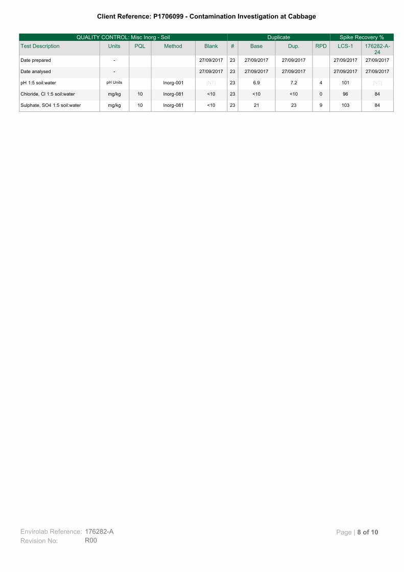
Client Reference: P1706099 - Contamination Investigation at Cabbage
841039232123<10Inorg-08110mg/kgSulphate, SO4 1:5 soil:water
84960<10<1023<10Inorg-08110mg/kgChloride, Cl 1:5 soil:water
[NT]10147.26.923[NT]Inorg-001pH UnitspH 1:5 soil:water
27/09/201727/09/201727/09/201727/09/20172327/09/2017-Date analysed
27/09/201727/09/201727/09/201727/09/20172327/09/2017-Date prepared
176282-A-24
LCS-1RPDDup.Base#BlankMethodPQLUnitsTest Description
Spike Recovery %DuplicateQUALITY CONTROL: Misc Inorg - Soil
Envirolab Reference: 176282-A
R00Revision No:
Page | 8 of 10
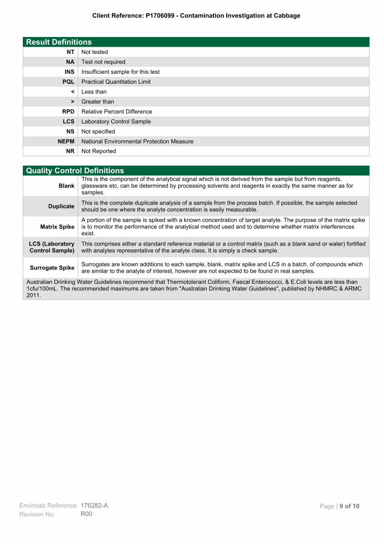
Client Reference: P1706099 - Contamination Investigation at Cabbage
Not ReportedNR
National Environmental Protection MeasureNEPM
Not specifiedNS
Laboratory Control SampleLCS
Relative Percent DifferenceRPD
Greater than>
Less than<
Practical Quantitation LimitPQL
Insufficient sample for this testINS
Test not requiredNA
Not testedNT
Result Definitions
Australian Drinking Water Guidelines recommend that Thermotolerant Coliform, Faecal Enterococci, & E.Coli levels are less than1cfu/100mL. The recommended maximums are taken from "Australian Drinking Water Guidelines", published by NHMRC & ARMC2011.
Surrogates are known additions to each sample, blank, matrix spike and LCS in a batch, of compounds whichare similar to the analyte of interest, however are not expected to be found in real samples.
Surrogate Spike
This comprises either a standard reference material or a control matrix (such as a blank sand or water) fortifiedwith analytes representative of the analyte class. It is simply a check sample.
LCS (LaboratoryControl Sample)
A portion of the sample is spiked with a known concentration of target analyte. The purpose of the matrix spikeis to monitor the performance of the analytical method used and to determine whether matrix interferencesexist.
Matrix Spike
This is the complete duplicate analysis of a sample from the process batch. If possible, the sample selectedshould be one where the analyte concentration is easily measurable.
Duplicate
This is the component of the analytical signal which is not derived from the sample but from reagents,glassware etc, can be determined by processing solvents and reagents in exactly the same manner as forsamples.
Blank
Quality Control Definitions
Envirolab Reference: 176282-A
R00Revision No:
Page | 9 of 10
Client Reference: P1706099 - Contamination Investigation at Cabbage
Measurement Uncertainty estimates are available for most tests upon request.
Where sampling dates are not provided, Envirolab are not in a position to comment on the validity of the analysis whererecommended technical holding times may have been breached.
When samples are received where certain analytes are outside of recommended technical holding times (THTs), the analysis hasproceeded. Where analytes are on the verge of breaching THTs, every effort will be made to analyse within the THT or as soon aspracticable.
In circumstances where no duplicate and/or sample spike has been reported at 1 in 10 and/or 1 in 20 samples respectively, thesample volume submitted was insufficient in order to satisfy laboratory QA/QC protocols.
Matrix Spikes, LCS and Surrogate recoveries: Generally 70-130% for inorganics/metals; 60-140% for organics (+/-50% surrogates)and 10-140% for labile SVOCs (including labile surrogates), ultra trace organics and speciated phenols is acceptable.
Duplicates: <5xPQL - any RPD is acceptable; >5xPQL - 0-50% RPD is acceptable.
For VOCs in water samples, three vials are required for duplicate or spike analysis.
Spikes for Physical and Aggregate Tests are not applicable.
Filters, swabs, wipes, tubes and badges will not have duplicate data as the whole sample is generally extracted during sampleextraction.
Duplicate sample and matrix spike recoveries may not be reported on smaller jobs, however, were analysed at a frequency to meetor exceed NEPM requirements. All samples are tested in batches of 20. The duplicate sample RPD and matrix spike recoveries forthe batch were within the laboratory acceptance criteria.
Laboratory Acceptance Criteria
Envirolab Reference: 176282-A
R00Revision No:
Page | 10 of 10
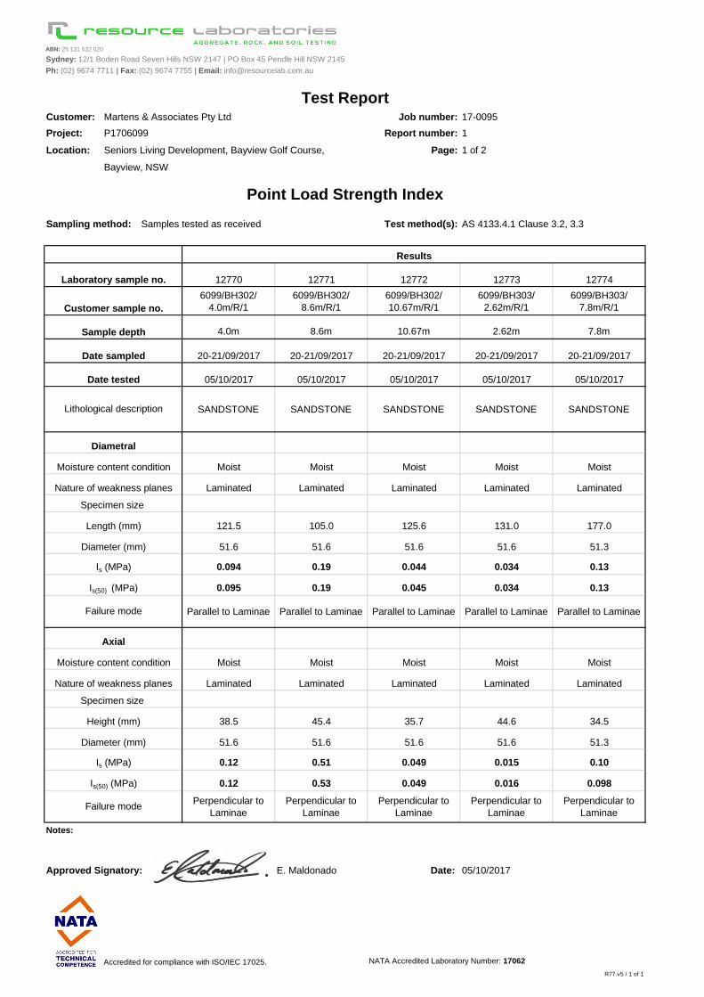
ABN: 25 131 532 020
Sydney: 12/1 Boden Road Seven Hills NSW 2147 | PO Box 45 Pendle Hill NSW 2145
Ph: (02) 9674 7711 | Fax: (02) 9674 7755 | Email: [email protected]
Customer: Job number: 17-0095
Project: Report number: 1
Location: Seniors Living Development, Bayview Golf Course, Page: 1 of 2
Bayview, NSW
Sampling method: Samples tested as received Test method(s): AS 4133.4.1 Clause 3.2, 3.3
12770 12771 12772 12773 12774
6099/BH302/
4.0m/R/1
6099/BH302/
8.6m/R/1
6099/BH302/
10.67m/R/1
6099/BH303/
2.62m/R/1
6099/BH303/
7.8m/R/1
4.0m 8.6m 10.67m 2.62m 7.8m
20-21/09/2017 20-21/09/2017 20-21/09/2017 20-21/09/2017 20-21/09/2017
05/10/2017 05/10/2017 05/10/2017 05/10/2017 05/10/2017
SANDSTONE SANDSTONE SANDSTONE SANDSTONE SANDSTONE
Moist Moist Moist Moist Moist
Laminated Laminated Laminated Laminated Laminated
121.5 105.0 125.6 131.0 177.0
51.6 51.6 51.6 51.6 51.3
0.094 0.19 0.044 0.034 0.13
0.095 0.19 0.045 0.034 0.13
Parallel to Laminae Parallel to Laminae Parallel to Laminae Parallel to Laminae Parallel to Laminae
Moist Moist Moist Moist Moist
Laminated Laminated Laminated Laminated Laminated
38.5 45.4 35.7 44.6 34.5
51.6 51.6 51.6 51.6 51.3
0.12 0.51 0.049 0.015 0.10
0.12 0.53 0.049 0.016 0.098
Perpendicular to
Laminae
Perpendicular to
Laminae
Perpendicular to
Laminae
Perpendicular to
Laminae
Perpendicular to
Laminae
Notes:
Approved Signatory: E. Maldonado Date: 05/10/2017
Accredited for compliance with ISO/IEC 17025. NATA Accredited Laboratory Number: 17062
R77.v5 / 1 of 1
Sample depth
Test Report
Point Load Strength Index
Results
Laboratory sample no.
Customer sample no.
Martens & Associates Pty Ltd
P1706099
Failure mode
Date sampled
Date tested
Lithological description
Diametral
Specimen size
Length (mm)
Diameter (mm)
Is (MPa)
Is(50) (MPa)
Moisture content condition
Nature of weakness planes
Failure mode
Axial
Specimen size
Height (mm)
Diameter (mm)
Is (MPa)
Is(50) (MPa)
Moisture content condition
Nature of weakness planes
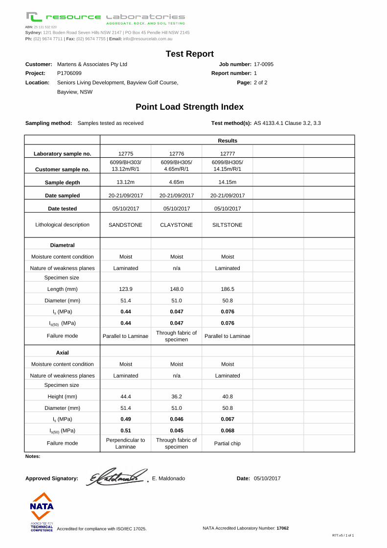
ABN: 25 131 532 020
Sydney: 12/1 Boden Road Seven Hills NSW 2147 | PO Box 45 Pendle Hill NSW 2145
Ph: (02) 9674 7711 | Fax: (02) 9674 7755 | Email: [email protected]
Customer: Job number: 17-0095
Project: Report number: 1
Location: Seniors Living Development, Bayview Golf Course, Page: 2 of 2
Bayview, NSW
Sampling method: Samples tested as received Test method(s): AS 4133.4.1 Clause 3.2, 3.3
12775 12776 12777
6099/BH303/
13.12m/R/1
6099/BH305/
4.65m/R/1
6099/BH305/
14.15m/R/1 #N/A #N/A
13.12m 4.65m 14.15m
20-21/09/2017 20-21/09/2017 20-21/09/2017 #N/A #N/A
05/10/2017 05/10/2017 05/10/2017
SANDSTONE CLAYSTONE SILTSTONE #N/A #N/A
Moist Moist Moist
Laminated n/a Laminated
123.9 148.0 186.5
51.4 51.0 50.8
0.44 0.047 0.076
0.44 0.047 0.076
Parallel to LaminaeThrough fabric of
specimenParallel to Laminae
Moist Moist Moist
Laminated n/a Laminated
44.4 36.2 40.8
51.4 51.0 50.8
0.49 0.046 0.067
0.51 0.045 0.068
Perpendicular to
Laminae
Through fabric of
specimenPartial chip
Notes:
Approved Signatory: E. Maldonado Date: 05/10/2017
Accredited for compliance with ISO/IEC 17025. NATA Accredited Laboratory Number: 17062
R77.v5 / 1 of 1
Diametral
Test ReportMartens & Associates Pty Ltd
P1706099
Point Load Strength Index
Results
Laboratory sample no.
Customer sample no.
Sample depth
Date sampled
Date tested
Lithological description
Specimen size
Moisture content condition
Nature of weakness planes
Specimen size
Length (mm)
Diameter (mm)
Is (MPa)
Is(50) (MPa)
Failure mode
Axial
Moisture content condition
Nature of weakness planes
Height (mm)
Diameter (mm)
Is (MPa)
Is(50) (MPa)
Failure mode
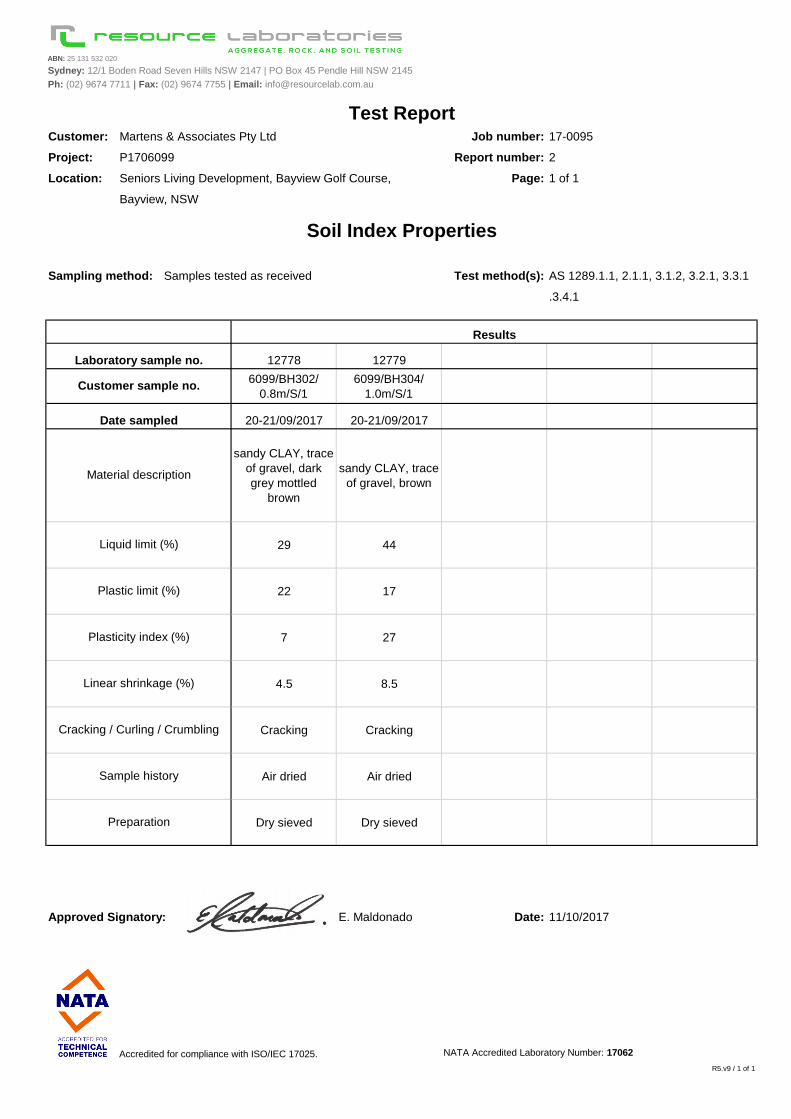
ABN: 25 131 532 020
Sydney: 12/1 Boden Road Seven Hills NSW 2147 | PO Box 45 Pendle Hill NSW 2145
Ph: (02) 9674 7711 | Fax: (02) 9674 7755 | Email: [email protected]
Customer: Job number: 17-0095
Project: Report number: 2
Location: Seniors Living Development, Bayview Golf Course, Page: 1 of 1
Bayview, NSW
Sampling method: Samples tested as received Test method(s):
.3.4.1
12778 12779
6099/BH302/
0.8m/S/1
6099/BH304/
1.0m/S/1 #N/A #N/A #N/A
20-21/09/2017 20-21/09/2017 #N/A #N/A #N/A
sandy CLAY, trace
of gravel, dark
grey mottled
brown
sandy CLAY, trace
of gravel, brown#N/A #N/A #N/A
29 44
22 17
7 27
4.5 8.5
Cracking Cracking
Air dried Air dried
Dry sieved Dry sieved
Approved Signatory: E. Maldonado Date: 11/10/2017
Accredited for compliance with ISO/IEC 17025. NATA Accredited Laboratory Number: 17062
R5.v9 / 1 of 1
Cracking / Curling / Crumbling
Sample history
Preparation
Plasticity index (%)
Linear shrinkage (%)
Test Report
Soil Index Properties
Results
Liquid limit (%)
Plastic limit (%)
Material description
AS 1289.1.1, 2.1.1, 3.1.2, 3.2.1, 3.3.1
Laboratory sample no.
Customer sample no.
Date sampled
Martens & Associates Pty Ltd
P1706099
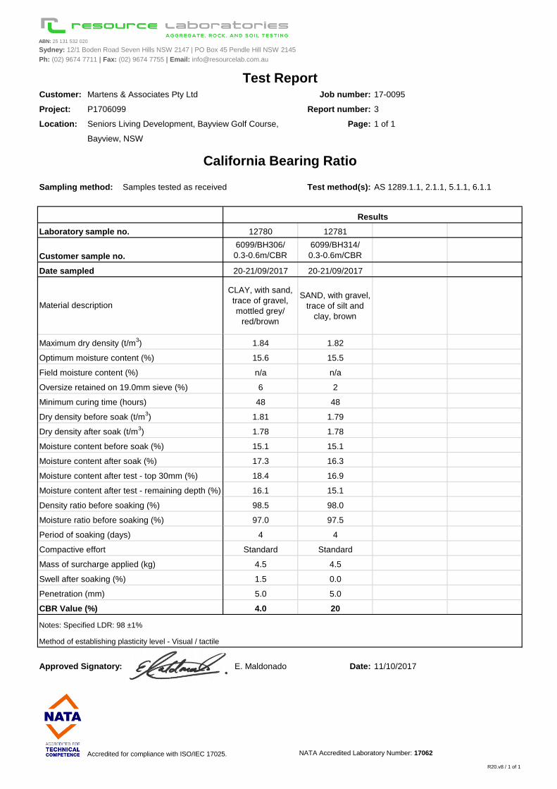
ABN: 25 131 532 020
Sydney: 12/1 Boden Road Seven Hills NSW 2147 | PO Box 45 Pendle Hill NSW 2145
Ph: (02) 9674 7711 | Fax: (02) 9674 7755 | Email: [email protected]
Customer: Job number: 17-0095
Project: P1706099 Report number: 3
Location: Seniors Living Development, Bayview Golf Course, Page: 1 of 1
Bayview, NSW
Sampling method: Samples tested as received Test method(s):
12780 12781
6099/BH306/
0.3-0.6m/CBR
6099/BH314/
0.3-0.6m/CBR #N/A #N/A
20-21/09/2017 20-21/09/2017 #N/A #N/A
CLAY, with sand,
trace of gravel,
mottled grey/
red/brown
SAND, with gravel,
trace of silt and
clay, brown
#N/A #N/A
1.84 1.82
15.6 15.5
n/a n/a
6 2
48 48
1.81 1.79
1.78 1.78
15.1 15.1
17.3 16.3
18.4 16.9
16.1 15.1
98.5 98.0
97.0 97.5
4 4
Standard Standard
4.5 4.5
1.5 0.0
5.0 5.0
4.0 20
Approved Signatory: E. Maldonado Date: 11/10/2017
Accredited for compliance with ISO/IEC 17025. NATA Accredited Laboratory Number: 17062
R20.v8 / 1 of 1
Notes: Specified LDR: 98 ±1%
Method of establishing plasticity level - Visual / tactile
Test Report
California Bearing Ratio
Material description
Dry density before soak (t/m3)
Laboratory sample no.
Maximum dry density (t/m3)
Optimum moisture content (%)
Oversize retained on 19.0mm sieve (%)
Field moisture content (%)
Minimum curing time (hours)
Customer sample no.
Date sampled
Results
Martens & Associates Pty Ltd
AS 1289.1.1, 2.1.1, 5.1.1, 6.1.1
CBR Value (%)
Compactive effort
Swell after soaking (%)
Penetration (mm)
Dry density after soak (t/m3)
Period of soaking (days)
Mass of surcharge applied (kg)
Density ratio before soaking (%)
Moisture ratio before soaking (%)
Moisture content after soak (%)
Moisture content after test - remaining depth (%)
Moisture content after test - top 30mm (%)
Moisture content before soak (%)
martens
Geotechnical and Acid Sulfate Soils Assessment:
Proposed Seniors Living Development, Cabbage Tree Road, Bayview, NSW
P1706099JR02V02 – November 2017
Page 122
16 Attachment H – Hillside Construction Guidelines (AGS,
2007)
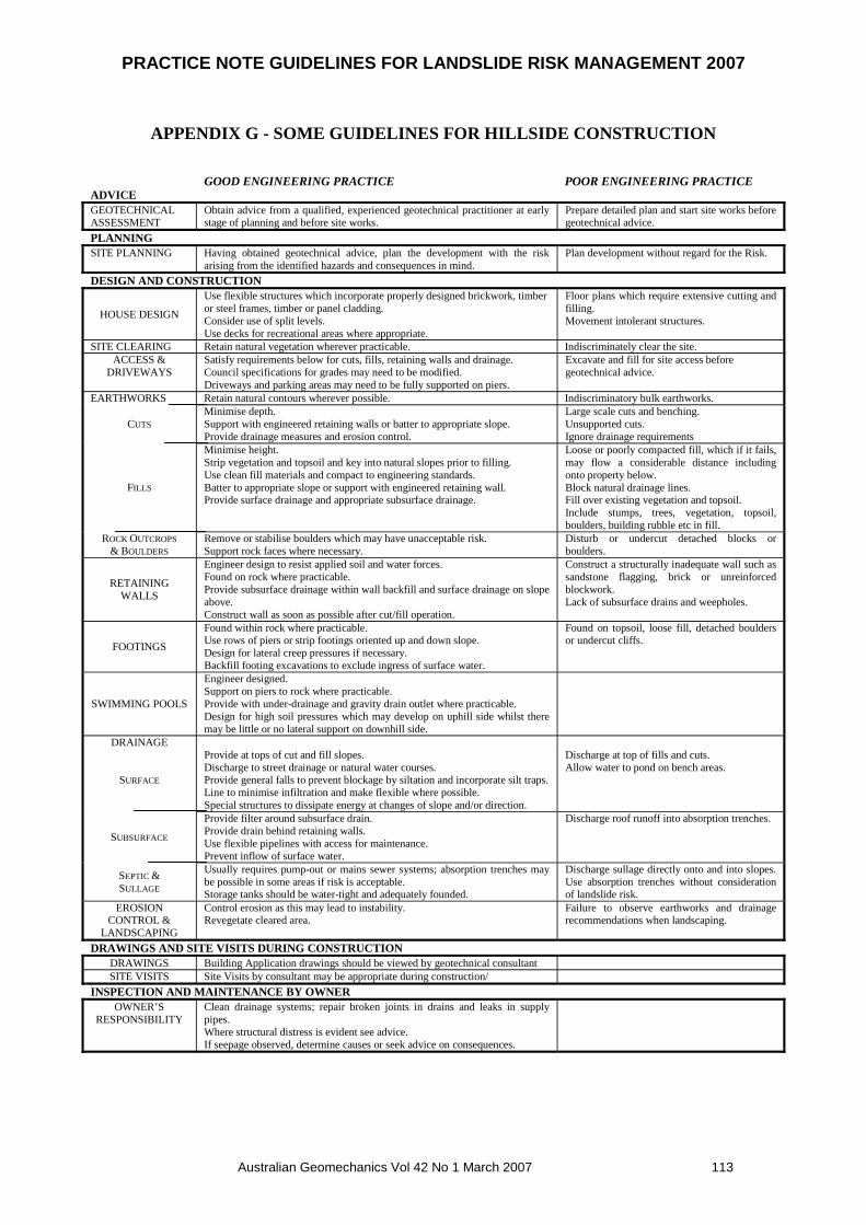
PRACTICE NOTE GUIDELINES FOR LANDSLIDE RISK MANAGEMENT 2007
Australian Geomechanics Vol 42 No 1 March 2007 113
APPENDIX G - SOME GUIDELINES FOR HILLSIDE CONSTRUCTION
GOOD ENGINEERING PRACTICE POOR ENGINEERING PRACTICEADVICE
GEOTECHNICALASSESSMENT
Obtain advice from a qualified, experienced geotechnical practitioner at earlystage of planning and before site works.
Prepare detailed plan and start site works beforegeotechnical advice.
PLANNING
SITE PLANNING Having obtained geotechnical advice, plan the development with the riskarising from the identified hazards and consequences in mind.
Plan development without regard for the Risk.
DESIGN AND CONSTRUCTION
HOUSE DESIGN
Use flexible structures which incorporate properly designed brickwork, timberor steel frames, timber or panel cladding.Consider use of split levels.Use decks for recreational areas where appropriate.
Floor plans which require extensive cutting andfilling.Movement intolerant structures.
SITE CLEARING Retain natural vegetation wherever practicable. Indiscriminately clear the site.ACCESS &
DRIVEWAYSSatisfy requirements below for cuts, fills, retaining walls and drainage.Council specifications for grades may need to be modified.Driveways and parking areas may need to be fully supported on piers.
Excavate and fill for site access beforegeotechnical advice.
EARTHWORKS Retain natural contours wherever possible. Indiscriminatory bulk earthworks.
CUTS
Minimise depth.Support with engineered retaining walls or batter to appropriate slope.Provide drainage measures and erosion control.
Large scale cuts and benching.Unsupported cuts.Ignore drainage requirements
FILLS
Minimise height.Strip vegetation and topsoil and key into natural slopes prior to filling.Use clean fill materials and compact to engineering standards.Batter to appropriate slope or support with engineered retaining wall.Provide surface drainage and appropriate subsurface drainage.
Loose or poorly compacted fill, which if it fails,may flow a considerable distance includingonto property below.Block natural drainage lines.Fill over existing vegetation and topsoil.Include stumps, trees, vegetation, topsoil,boulders, building rubble etc in fill.
ROCK OUTCROPS
& BOULDERS
Remove or stabilise boulders which may have unacceptable risk.Support rock faces where necessary.
Disturb or undercut detached blocks orboulders.
RETAININGWALLS
Engineer design to resist applied soil and water forces.Found on rock where practicable.Provide subsurface drainage within wall backfill and surface drainage on slopeabove.Construct wall as soon as possible after cut/fill operation.
Construct a structurally inadequate wall such assandstone flagging, brick or unreinforcedblockwork.Lack of subsurface drains and weepholes.
FOOTINGS
Found within rock where practicable.Use rows of piers or strip footings oriented up and down slope.Design for lateral creep pressures if necessary.Backfill footing excavations to exclude ingress of surface water.
Found on topsoil, loose fill, detached bouldersor undercut cliffs.
SWIMMING POOLS
Engineer designed.Support on piers to rock where practicable.Provide with under-drainage and gravity drain outlet where practicable.Design for high soil pressures which may develop on uphill side whilst theremay be little or no lateral support on downhill side.
DRAINAGE
SURFACE
Provide at tops of cut and fill slopes.Discharge to street drainage or natural water courses.Provide general falls to prevent blockage by siltation and incorporate silt traps.Line to minimise infiltration and make flexible where possible.Special structures to dissipate energy at changes of slope and/or direction.
Discharge at top of fills and cuts.Allow water to pond on bench areas.
SUBSURFACE
Provide filter around subsurface drain.Provide drain behind retaining walls.Use flexible pipelines with access for maintenance.Prevent inflow of surface water.
Discharge roof runoff into absorption trenches.
SEPTIC &SULLAGE
Usually requires pump-out or mains sewer systems; absorption trenches maybe possible in some areas if risk is acceptable.Storage tanks should be water-tight and adequately founded.
Discharge sullage directly onto and into slopes.Use absorption trenches without considerationof landslide risk.
EROSIONCONTROL &
LANDSCAPING
Control erosion as this may lead to instability.Revegetate cleared area.
Failure to observe earthworks and drainagerecommendations when landscaping.
DRAWINGS AND SITE VISITS DURING CONSTRUCTION
DRAWINGS Building Application drawings should be viewed by geotechnical consultantSITE VISITS Site Visits by consultant may be appropriate during construction/
INSPECTION AND MAINTENANCE BY OWNER
OWNER’SRESPONSIBILITY
Clean drainage systems; repair broken joints in drains and leaks in supplypipes.Where structural distress is evident see advice.If seepage observed, determine causes or seek advice on consequences.
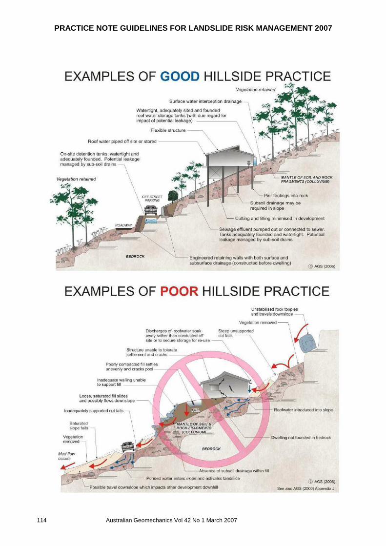
PRACTICE NOTE GUIDELINES FOR LANDSLIDE RISK MANAGEMENT 2007
114 Australian Geomechanics Vol 42 No 1 March 2007
martens
Geotechnical and Acid Sulfate Soils Assessment:
Proposed Seniors Living Development, Cabbage Tree Road, Bayview, NSW
P1706099JR02V02 – November 2017
Page 125
17 Attachment I – General Geotechnical Recommendations
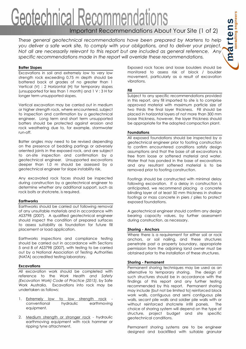
ma
rte
ns
con
sult
ing
en
gin
ee
rs
These general geotechnical recommendations have been prepared by Martens to helpyou deliver a safe work site, to comply with your obligations, and to deliver your project.Not all are necessarily relevant to this report but are included as general reference. Anyspecific recommendations made in the report will override these recommendations.
Batter Slopes
Excavations in soil and extremely low to very lowstrength rock exceeding 0.75 m depth should bebattered back at grades of no greater than 1Vertical (V) : 2 Horizontal (H) for temporary slopes(unsupported for less than 1 month) and 1 V : 3 H forlonger term unsupported slopes.
Vertical excavation may be carried out in mediumor higher strength rock, where encountered, subjectto inspection and confirmation by a geotechnicalengineer. Long term and short term unsupportedbatters should be protected against erosion androck weathering due to, for example, stormwaterrun-off.
Batter angles may need to be revised dependingon the presence of bedding partings or adverselyoriented joints in the exposed rock, and are subjectto on-site inspection and confirmation by ageotechnical engineer. Unsupported excavationsdeeper than 1.0 m should be assessed by ageotechnical engineer for slope instability risk.
Any excavated rock faces should be inspectedduring construction by a geotechnical engineer todetermine whether any additional support, such asrock bolts or shotcrete, is required.
Earthworks
Earthworks should be carried out following removalof any unsuitable materials and in accordance withAS3798 (2007). A qualified geotechnical engineershould inspect the condition of prepared surfacesto assess suitability as foundation for future fillplacement or load application.
Earthworks inspections and compliance testingshould be carried out in accordance with Sections5 and 8 of AS3798 (2007), with testing to be carriedout by a National Association of Testing Authorities(NATA) accredited testing laboratory.
Excavations
All excavation work should be completed withreference to the Work Health and Safety(Excavation Work) Code of Practice (2015), by SafeWork Australia. Excavations into rock may beundertaken as follows:
1. Extremely low to low strength rock -conventional hydraulic earthmovingequipment.
2. Medium strength or stronger rock - hydraulicearthmoving equipment with rock hammer orripping tyne attachment.
Exposed rock faces and loose boulders should bemonitored to assess risk of block / bouldermovement, particularly as a result of excavationvibrations.
Fill
Subject to any specific recommendations providedin this report, any fill imported to site is to compriseapproved material with maximum particle size oftwo thirds the final layer thickness. Fill should beplaced in horizontal layers of not more than 300 mmloose thickness, however, the layer thickness shouldbe appropriate for the adopted compaction plant.
Foundations
All exposed foundations should be inspected by ageotechnical engineer prior to footing constructionto confirm encountered conditions satisfy designassumptions and that the base of all excavations isfree from loose or softened material and water.Water that has ponded in the base of excavationsand any resultant softened material is to beremoved prior to footing construction.
Footings should be constructed with minimal delayfollowing excavation. If a delay in construction isanticipated, we recommend placing a concreteblinding layer of at least 50 mm thickness in shallowfootings or mass concrete in piers / piles to protectexposed foundations.
A geotechnical engineer should confirm any designbearing capacity values, by further assessmentduring construction, as necessary.
Shoring - Anchors
Where there is a requirement for either soil or rockanchors, or soil nailing, and these structurespenetrate past a property boundary, appropriatepermission from the adjoining land owner must beobtained prior to the installation of these structures.
Shoring - Permanent
Permanent shoring techniques may be used as analternative to temporary shoring. The design ofsuch structures should be in accordance with thefindings of this report and any further testingrecommended by this report. Permanent shoringmay include [but not be limited to] reinforced blockwork walls, contiguous and semi contiguous pilewalls, secant pile walls and soldier pile walls with orwithout reinforced shotcrete infill panels. Thechoice of shoring system will depend on the type ofstructure, project budget and site specificgeotechnical conditions.
Permanent shoring systems are to be engineerdesigned and backfilled with suitable granular
Important Recommendations About Your Site (1 of 2)

ma
rte
ns
con
sult
ing
en
gin
ee
rs
material and free-draining drainage material.Backfill should be placed in maximum 100 mm thicklayers compacted using a hand operatedcompactor. Care should be taken to ensureexcessive compaction stresses are not transferredto retaining walls.
Shoring design should consider any surchargeloading from sloping / raised ground behind shoringstructures, live loads, new structures, constructionequipment, backfill compaction and static waterpressures. All shoring systems shall be provided withadequate foundation designs.
Suitable drainage measures, such as geotextileenclosed 100 mm agricultural pipes embedded infree-draining gravel, should be included to redirectwater that may collect behind the shoring structureto a suitable discharge point.
Shoring - Temporary
In the absence of providing acceptableexcavation batters, excavations should besupported by suitably designed and installedtemporary shoring / retaining structures to limitlateral deflection of excavation faces andassociated ground surface settlements.
Soil Erosion Control
Removal of any soil overburden should beperformed in a manner that reduces the risk ofsedimentation occurring in any formal stormwaterdrainage system, on neighbouring land and inreceiving waters. Where possible, this may beachieved by one or more of the following means:
1. Maintain vegetation where possible2. Disturb minimal areas during excavation3. Revegetate disturbed areas if possible
All spoil on site should be properly controlled byerosion control measures to prevent transportationof sediments off-site. Appropriate soil erosion controlmethods in accordance with Landcom (2004) shallbe required.
Trafficability and Access
Consideration should be given to the impact of theproposed works and site subsurface conditions ontrafficability within the site e.g. wet clay soils willlead to poor trafficability by tyred plant or vehicles.
Where site access is likely to be affected by any siteworks, construction staging should be organisedsuch that any impacts on adequate access areminimised as best as possible.
Vibration Management
Where excavation is to be extended into mediumor higher strength rock, care will be required whenusing a rock hammer to limit potential structuraldistress from excavation-induced vibrations wherenearby structures may be affected by the works.
To limit vibrations, we recommend limiting rockhammer size and set frequency, and setting thehammer parallel to bedding planes and alongdefect planes, where possible, or as advised by ageotechnical engineer. We recommend limitingvibration peak particle velocities (PPV) caused byconstruction equipment or resulting fromexcavation at the site to 5 mm/s (AS 2187.2, 2006,Appendix J).
Waste – Spoil and Water
Soil to be disposed off-site should be classified inaccordance with the relevant State Authorityguidelines and requirements.
Any collected waste stormwater or groundwatershould also be tested prior to discharge to ensurecontaminant levels (where applicable) areappropriate for the nominated discharge location.
MA can complete the necessary classification andtesting if required. Time allowance should be madefor such testing in the construction program.
Water Management - Groundwater
If the proposed works are likely to intersectephemeral or permanent groundwater levels, themanagement of any potential acid soil drainageshould be considered. If groundwater tables arelikely to be lowered, this should be further discussedwith the relevant State Government Agency.
Water Management – Surface Water
All surface runoff should be diverted away fromexcavation areas during construction works andprevented from accumulating in areas surroundingany retaining structures, footings or the base ofexcavations.
Any collected surface water should be dischargedinto a suitable Council approved drainage systemand not adversely impact downslope surface andsubsurface conditions.
All site discharges should be passed through a filtermaterial prior to release. Sump and pump methodswill generally be suitable for collection and removalof accumulated surface water within anyexcavations.
Contingency Plan
In the event that proposed development workscause an adverse impact on geotechnical hazards,overall site stability or adjacent properties, thefollowing actions are to be undertaken:
1. Works shall cease immediately.2. The nature of the impact shall be documented
and the reason(s) for the adverse impactinvestigated.
3. A qualified geotechnical engineer should beconsulted to provide further advice in relationto the issue.
Important Recommendations About Your Site (2 of 2)

martens
Geotechnical and Acid Sulfate Soils Assessment:
Proposed Seniors Living Development, Cabbage Tree Road, Bayview, NSW
P1706099JR02V02 – November 2017
Page 128
18 Attachment J – Notes About This Report

ma
rte
ns
con
su
ltin
g e
ng
ine
ers
These notes have been prepared by Martens to help you interpret and understand the limitations of your report. Not all are necessarily relevant to all reports but are included as general reference. Engineering Reports - Limitations The recommendations presented in this report are based on limited investigations and include specific issues to be addressed during various phases of the project. If the recommendations presented in this report are not implemented in full, the general recommendations may become inapplicable and Martens & Associates accept no responsibility whatsoever for the performance of the works undertaken. Occasionally, sub-surface conditions between and below the completed boreholes or other tests may be found to be different (or may be interpreted to be different) from those expected. Variation can also occur with groundwater conditions, especially after climatic changes. If such differences appear to exist, we recommend that you immediately contact Martens & Associates. Relative ground surface levels at borehole locations may not be accurate and should be verified by on-site survey. Engineering Reports – Project Specific Criteria Engineering reports are prepared by qualified personnel. They are based on information obtained, on current engineering standards of interpretation and analysis, and on the basis of your unique project specific requirements as understood by Martens. Project criteria typically include the general nature of the project; its size and configuration; the location of any structures on the site; other site improvements; the presence of underground utilities; and the additional risk imposed by scope-of-service limitations imposed by the Client. Where the report has been prepared for a specific design proposal (e.g. a three storey building), the information and interpretation may not be relevant if the design proposal is changed (e.g. to a twenty storey building). Your report should not be relied upon, if there are changes to the project, without first asking Martens to assess how factors, which changed subsequent to the date of the report, affect the report’s recommendations. Martens will not accept responsibility for problems that may occur due to design changes, if not consulted. Engineering Reports – Recommendations Your report is based on the assumption that site conditions, as may be revealed through selective point sampling, are indicative of actual conditions throughout an area. This assumption often cannot be substantiated until project implementation has commenced. Therefore your site investigation report recommendations should only be regarded as preliminary.
Only Martens, who prepared the report, are fully familiar with the background information needed to assess whether or not the report’s recommendations are valid and whether or not changes should be considered as the project develops. If another party undertakes the implementation of the recommendations of this report, there is a risk that the report will be misinterpreted and Martens cannot be held responsible for such misinterpretation. Engineering Reports – Use for Tendering Purposes Where information obtained from investigations is provided for tendering purposes, Martens recommend that all information, including the written report and discussion, be made available. In circumstances where the discussion or comments section is not relevant to the contractual situation, it may be appropriate to prepare a specially edited document. Martens would be pleased to assist in this regard and/or to make additional report copies available for contract purposes at a nominal charge. Engineering Reports – Data The report as a whole presents the findings of a site assessment and should not be copied in part or altered in any way. Logs, figures, drawings etc are customarily included in a Martens report and are developed by scientists, engineers or geologists based on their interpretation of field logs (assembled by field personnel), desktop studies and laboratory evaluation of field samples. These data should not under any circumstances be redrawn for inclusion in other documents or separated from the report in any way. Engineering Reports – Other Projects To avoid misuse of the information contained in your report it is recommended that you confer with Martens before passing your report on to another party who may not be familiar with the background and purpose of the report. Your report should not be applied to any project other than that originally specified at the time the report was issued. Subsurface Conditions - General Every care is taken with the report in relation to interpretation of subsurface conditions, discussion of geotechnical aspects, relevant standards and recommendations or suggestions for design and construction. However, the Company cannot always anticipate or assume responsibility for: o Unexpected variations in ground conditions -
the potential will depend partly on test point
Important Information About Your Report (1 of 2)
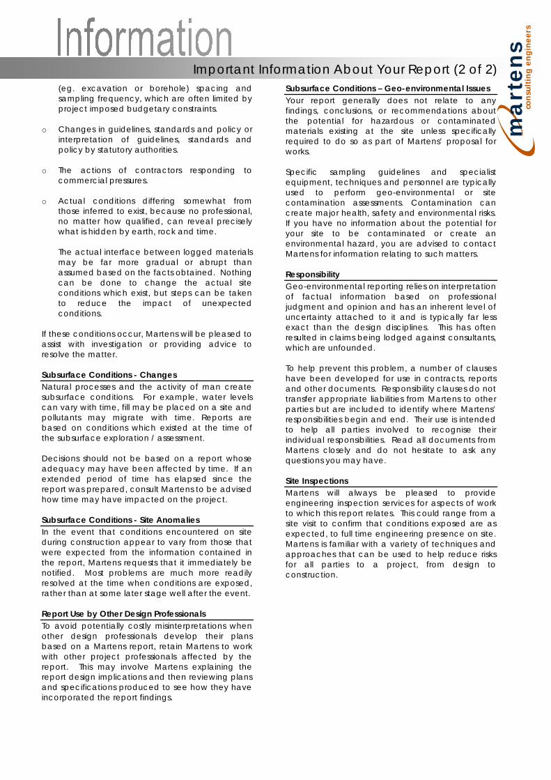
ma
rte
ns
con
su
ltin
g e
ng
ine
ers
(eg. excavation or borehole) spacing and sampling frequency, which are often limited by project imposed budgetary constraints.
o Changes in guidelines, standards and policy or interpretation of guidelines, standards and policy by statutory authorities.
o The actions of contractors responding to commercial pressures.
o Actual conditions differing somewhat from those inferred to exist, because no professional, no matter how qualified, can reveal precisely what is hidden by earth, rock and time. The actual interface between logged materials may be far more gradual or abrupt than assumed based on the facts obtained. Nothing can be done to change the actual site conditions which exist, but steps can be taken to reduce the impact of unexpected conditions.
If these conditions occur, Martens will be pleased to assist with investigation or providing advice to resolve the matter. Subsurface Conditions - Changes Natural processes and the activity of man create subsurface conditions. For example, water levels can vary with time, fill may be placed on a site and pollutants may migrate with time. Reports are based on conditions which existed at the time of the subsurface exploration / assessment. Decisions should not be based on a report whose adequacy may have been affected by time. If an extended period of time has elapsed since the report was prepared, consult Martens to be advised how time may have impacted on the project. Subsurface Conditions - Site Anomalies In the event that conditions encountered on site during construction appear to vary from those that were expected from the information contained in the report, Martens requests that it immediately be notified. Most problems are much more readily resolved at the time when conditions are exposed, rather than at some later stage well after the event. Report Use by Other Design Professionals To avoid potentially costly misinterpretations when other design professionals develop their plans based on a Martens report, retain Martens to work with other project professionals affected by the report. This may involve Martens explaining the report design implications and then reviewing plans and specifications produced to see how they have incorporated the report findings.
Subsurface Conditions – Geo-environmental Issues Your report generally does not relate to any findings, conclusions, or recommendations about the potential for hazardous or contaminated materials existing at the site unless specifically required to do so as part of Martens’ proposal for works. Specific sampling guidelines and specialist equipment, techniques and personnel are typically used to perform geo-environmental or site contamination assessments. Contamination can create major health, safety and environmental risks. If you have no information about the potential for your site to be contaminated or create an environmental hazard, you are advised to contact Martens for information relating to such matters. Responsibility Geo-environmental reporting relies on interpretation of factual information based on professional judgment and opinion and has an inherent level of uncertainty attached to it and is typically far less exact than the design disciplines. This has often resulted in claims being lodged against consultants, which are unfounded. To help prevent this problem, a number of clauses have been developed for use in contracts, reports and other documents. Responsibility clauses do not transfer appropriate liabilities from Martens to other parties but are included to identify where Martens’ responsibilities begin and end. Their use is intended to help all parties involved to recognise their individual responsibilities. Read all documents from Martens closely and do not hesitate to ask any questions you may have. Site Inspections Martens will always be pleased to provide engineering inspection services for aspects of work to which this report relates. This could range from a site visit to confirm that conditions exposed are as expected, to full time engineering presence on site. Martens is familiar with a variety of techniques and approaches that can be used to help reduce risks for all parties to a project, from design to construction.
Important Information About Your Report (2 of 2)
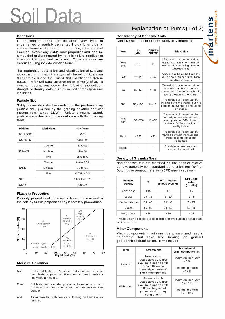
ma
rte
ns
con
su
ltin
g e
ng
ine
ers
Definitions In engineering terms, soil includes every type of uncemented or partially cemented inorganic or organic material found in the ground. In practice, if the material does not exhibit any visible rock properties and can be remoulded or disintegrated by hand in its field condition or in water it is described as a soil. Other materials are described using rock description terms. The methods of description and classification of soils and rocks used in this report are typically based on Australian Standard 1726 and the Unified Soil Classification System (USCS) – refer Soil Data Explanation of Terms (2 of 3). In general, descriptions cover the following properties - strength or density, colour, structure, soil or rock type and inclusions. Particle Size Soil types are described according to the predominating particle size, qualified by the grading of other particles present (e.g. sandy CLAY). Unless otherwise stated, particle size is described in accordance with the following table.
Division Subdivision Size (mm)
BOULDERS >200
COBBLES 63 to 200
GRAVEL
Coarse 20 to 63
Medium 6 to 20
Fine 2.36 to 6
SAND
Coarse 0.6 to 2.36
Medium 0.2 to 0.6
Fine 0.075 to 0.2
SILT 0.002 to 0.075
CLAY < 0.002
Plasticity Properties Plasticity properties of cohesive soils can be assessed in the field by tactile properties or by laboratory procedures.
Moisture Condition Dry Looks and feels dry. Cohesive and cemented soils are
hard, friable or powdery. Uncemented granular soils run freely through hands.
Moist Soil feels cool and damp and is darkened in colour.
Cohesive soils can be moulded. Granular soils tend to cohere.
Wet As for moist but with free water forming on hands when
handled.
Consistency of Cohesive Soils Cohesive soils refer to predominantly clay materials.
Term Cu (kPa)
Approx. SPT “N” Field Guide
Very Soft <12 2
A finger can be pushed well into the soil with little effort. Sample extrudes between fingers when
squeezed in fist.
Soft 12 - 25 2 – 4 A finger can be pushed into the soil to about 25mm depth. Easily
moulded in fingers.
Firm 25 - 50 4 – 8
The soil can be indented about 5mm with the thumb, but not
penetrated. Can be moulded by strong pressure in the figures.
Stiff 50 - 100 8 – 15
The surface of the soil can be indented with the thumb, but not penetrated. Cannot be moulded
by fingers.
Very Stiff 100 - 200 15 – 30
The surface of the soil can be marked, but not indented with thumb pressure. Difficult to cut
with a knife. Thumbnail can readily indent.
Hard > 200 > 30
The surface of the soil can be marked only with the thumbnail.
Brittle. Tends to break into fragments.
Friable - - Crumbles or powders when scraped by thumbnail.
Density of Granular Soils Non-cohesive soils are classified on the basis of relative density, generally from standard penetration test (SPT) or Dutch cone penetrometer test (CPT) results as below:
Relative Density % SPT ‘N’ Value*
(blows/300mm)
CPT Cone Value
(qc MPa)
Very loose < 15 < 5 < 2
Loose 15 - 35 5 - 10 2 - 5
Medium dense 35 - 65 10 - 30 5 - 15
Dense 65 - 85 30 - 50 15 - 25
Very dense > 85 > 50 > 25
* Values may be subject to corrections for overburden pressures and equipment type. Minor Components Minor components in soils may be present and readily detectable, but have little bearing on general geotechnical classification. Terms include:
Term Assessment Proportion of Minor component In:
Trace of
Presence just detectable by feel or
eye. Soil properties little or no different to
general properties of primary component.
Coarse grained soils: < 5 %
Fine grained soils:
< 15 %
With some
Presence easily detectable by feel or
eye. Soil properties little different to general
properties of primary component.
Coarse grained soils: 5 – 12 %
Fine grained soils:
15 – 30 %
Explanation of Terms (1 of 3)
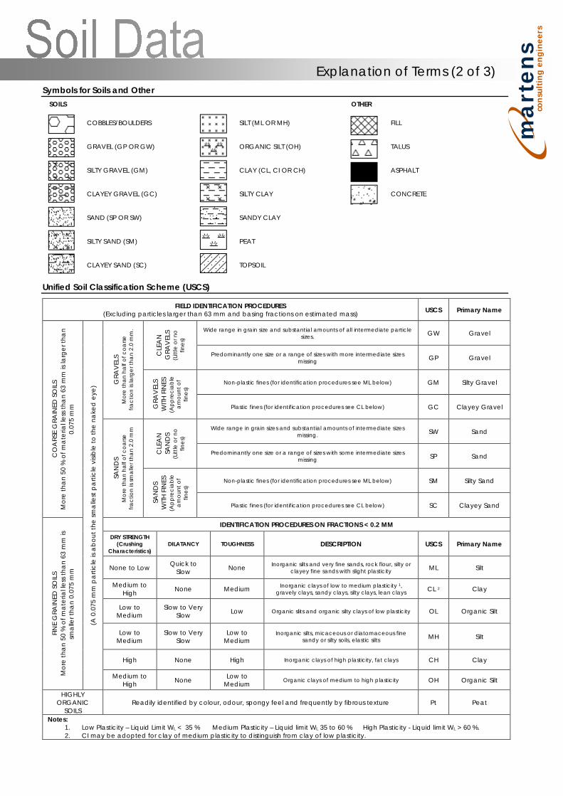
ma
rte
ns
con
su
ltin
g e
ng
ine
ers
Symbols for Soils and Other SOILS OTHER
COBBLES/BOULDERS
SILT (ML OR MH)
FILL
GRAVEL (GP OR GW) ORGANIC SILT (OH) TALUS
SILTY GRAVEL (GM) CLAY (CL, CI OR CH) ASPHALT
CLAYEY GRAVEL (GC) SILTY CLAY CONCRETE
SAND (SP OR SW) SANDY CLAY
SILTY SAND (SM) PEAT
CLAYEY SAND (SC) TOPSOIL
Unified Soil Classification Scheme (USCS)
FIELD IDENTIFICATION PROCEDURES (Excluding particles larger than 63 mm and basing fractions on estimated mass) USCS Primary Name
CO
ARS
E G
RAIN
ED S
OIL
S M
ore
tha
n 50
% o
f ma
teria
l les
s tha
n 63
mm
is la
rger
tha
n 0.
075
mm
(A 0
.075
mm
pa
rticl
e is
ab
out t
he sm
alle
st p
arti
cle
visib
le to
the
nake
d e
ye) G
RAV
ELS
Mor
e th
an h
alf o
f coa
rse
fract
ion
is la
rger
than
2.0
mm
.
CLE
AN
G
RAV
ELS
(Litt
le o
r no
fines
)
Wide range in grain size and substantial amounts of all intermediate particle sizes. GW Gravel
Predominantly one size or a range of sizes with more intermediate sizes missing GP Gravel
GRA
VEL
S W
ITH F
INES
(A
ppre
ciab
le
amou
nt o
f fin
es)
Non-plastic fines (for identification procedures see ML below) GM Silty Gravel
Plastic fines (for identification procedures see CL below) GC Clayey Gravel
SAN
DS
Mor
e th
an h
alf o
f coa
rse
fract
ion
is sm
alle
r tha
n 2.
0 m
m
CLE
AN
SA
ND
S (L
ittle
or n
o fin
es)
Wide range in grain sizes and substantial amounts of intermediate sizes missing. SW Sand
Predominantly one size or a range of sizes with some intermediate sizes missing SP Sand
SAN
DS
WITH
FIN
ES
(App
reci
able
am
ount
of
fines
)
Non-plastic fines (for identification procedures see ML below) SM Silty Sand
Plastic fines (for identification procedures see CL below) SC Clayey Sand
FIN
E G
RAIN
ED S
OIL
S M
ore
tha
n 50
% o
f ma
teria
l les
s tha
n 63
mm
is
sma
ller t
han
0.07
5 m
m
IDENTIFICATION PROCEDURES ON FRACTIONS < 0.2 MM
DRY STRENGTH (Crushing
Characteristics) DILATANCY TOUGHNESS
DESCRIPTION
USCS Primary Name
None to Low Quick to Slow None Inorganic silts and very fine sands, rock flour, silty or
clayey fine sands with slight plasticity ML Silt
Medium to High None Medium Inorganic clays of low to medium plasticity 1,
gravely clays, sandy clays, silty clays, lean clays CL 2 Clay
Low to Medium
Slow to Very Slow Low Organic slits and organic silty clays of low plasticity OL Organic Silt
Low to Medium
Slow to Very Slow
Low to Medium
Inorganic silts, micaceous or diatomaceous fine sandy or silty soils, elastic silts MH Silt
High None High Inorganic clays of high plasticity, fat clays CH Clay
Medium to High None Low to
Medium Organic clays of medium to high plasticity OH Organic Silt
HIGHLY ORGANIC
SOILS Readily identified by colour, odour, spongy feel and frequently by fibrous texture Pt Peat
Notes: 1. Low Plasticity – Liquid Limit WL < 35 % Medium Plasticity – Liquid limit WL 35 to 60 % High Plasticity - Liquid limit WL > 60 %. 2. CI may be adopted for clay of medium plasticity to distinguish from clay of low plasticity.
Explanation of Terms (2 of 3)
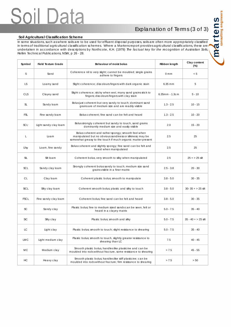
ma
rte
ns
con
su
ltin
g e
ng
ine
ers
Soil Agricultural Classification Scheme In some situations, such as where soils are to be used for effluent disposal purposes, soils are often more appropriately classified in terms of traditional agricultural classification schemes. Where a Martens report provides agricultural classifications, these are undertaken in accordance with descriptions by Northcote, K.H. (1979) The factual key for the recognition of Australian Soils, Rellim Technical Publications, NSW, p 26 - 28.
Symbol Field Texture Grade Behaviour of moist bolus Ribbon length Clay content (%)
S Sand Coherence nil to very slight; cannot be moulded; single grains adhere to fingers 0 mm < 5
LS Loamy sand Slight coherence; discolours fingers with dark organic stain 6.35 mm 5
CLS Clayey sand Slight coherence; sticky when wet; many sand grains stick to fingers; discolours fingers with clay stain 6.35mm - 1.3cm 5 - 10
SL Sandy loam Bolus just coherent but very sandy to touch; dominant sand grains are of medium size and are readily visible 1.3 - 2.5 10 - 15
FSL Fine sandy loam Bolus coherent; fine sand can be felt and heard 1.3 - 2.5 10 - 20
SCL- Light sandy clay loam Bolus strongly coherent but sandy to touch, sand grains dominantly medium size and easily visible 2.0 15 - 20
L Loam Bolus coherent and rather spongy; smooth feel when
manipulated but no obvious sandiness or silkiness; may be somewhat greasy to the touch if much organic matter present
2.5 25
Lfsy Loam, fine sandy Bolus coherent and slightly spongy; fine sand can be felt and heard when manipulated 2.5 25
SiL Silt loam Coherent bolus, very smooth to silky when manipulated 2.5 25 + > 25 silt
SCL Sandy clay loam Strongly coherent bolus sandy to touch; medium size sand grains visible in a finer matrix 2.5 - 3.8 20 - 30
CL Clay loam Coherent plastic bolus; smooth to manipulate 3.8 - 5.0 30 - 35
SiCL Silty clay loam Coherent smooth bolus; plastic and silky to touch 3.8 - 5.0 30- 35 + > 25 silt
FSCL Fine sandy clay loam Coherent bolus; fine sand can be felt and heard 3.8 - 5.0 30 - 35
SC Sandy clay Plastic bolus; fine to medium sized sands can be seen, felt or heard in a clayey matrix 5.0 - 7.5 35 - 40
SiC Silty clay Plastic bolus; smooth and silky 5.0 - 7.5 35 - 40 + > 25 silt
LC Light clay Plastic bolus; smooth to touch; slight resistance to shearing 5.0 - 7.5 35 - 40
LMC Light medium clay Plastic bolus; smooth to touch, slightly greater resistance to shearing than LC 7.5 40 - 45
MC Medium clay Smooth plastic bolus, handles like plasticine and can be moulded into rods without fracture, some resistance to shearing > 7.5 45 - 55
HC Heavy clay Smooth plastic bolus; handles like stiff plasticine; can be moulded into rods without fracture; firm resistance to shearing > 7.5 > 50
Explanation of Terms (3 of 3)
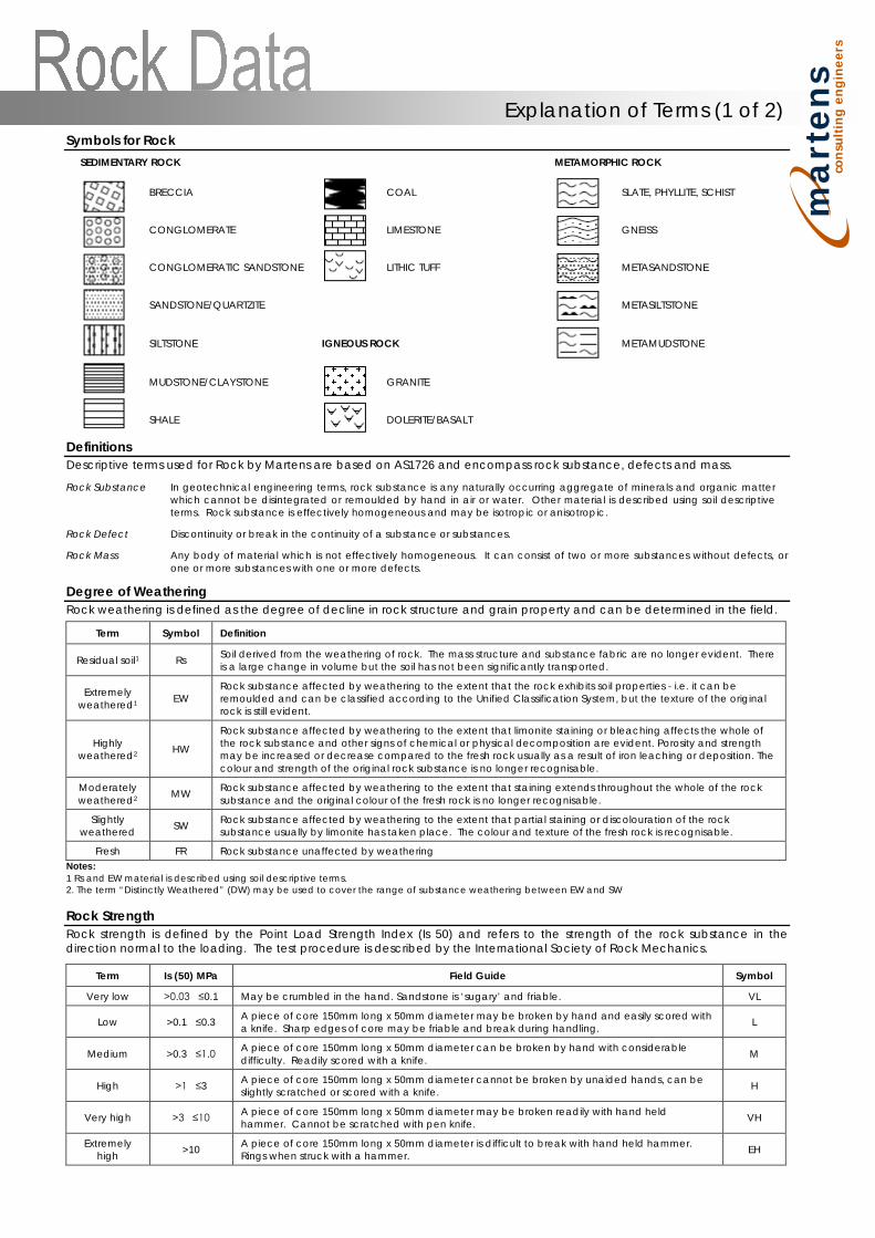
ma
rte
ns
con
su
ltin
g e
ng
ine
ers
Symbols for Rock SEDIMENTARY ROCK METAMORPHIC ROCK
BRECCIA
COAL
SLATE, PHYLLITE, SCHIST
CONGLOMERATE LIMESTONE GNEISS
CONGLOMERATIC SANDSTONE LITHIC TUFF METASANDSTONE
SANDSTONE/QUARTZITE METASILTSTONE
SILTSTONE IGNEOUS ROCK METAMUDSTONE
MUDSTONE/CLAYSTONE
GRANITE
SHALE DOLERITE/BASALT
Definitions Descriptive terms used for Rock by Martens are based on AS1726 and encompass rock substance, defects and mass.
Rock Substance In geotechnical engineering terms, rock substance is any naturally occurring aggregate of minerals and organic matter which cannot be disintegrated or remoulded by hand in air or water. Other material is described using soil descriptive terms. Rock substance is effectively homogeneous and may be isotropic or anisotropic.
Rock Defect Discontinuity or break in the continuity of a substance or substances.
Rock Mass Any body of material which is not effectively homogeneous. It can consist of two or more substances without defects, or one or more substances with one or more defects.
Degree of Weathering Rock weathering is defined as the degree of decline in rock structure and grain property and can be determined in the field.
Term Symbol Definition
Residual soil1 Rs Soil derived from the weathering of rock. The mass structure and substance fabric are no longer evident. There is a large change in volume but the soil has not been significantly transported.
Extremely weathered1 EW
Rock substance affected by weathering to the extent that the rock exhibits soil properties - i.e. it can be remoulded and can be classified according to the Unified Classification System, but the texture of the original rock is still evident.
Highly weathered2 HW
Rock substance affected by weathering to the extent that limonite staining or bleaching affects the whole of the rock substance and other signs of chemical or physical decomposition are evident. Porosity and strength may be increased or decrease compared to the fresh rock usually as a result of iron leaching or deposition. The colour and strength of the original rock substance is no longer recognisable.
Moderately weathered2 MW Rock substance affected by weathering to the extent that staining extends throughout the whole of the rock
substance and the original colour of the fresh rock is no longer recognisable.
Slightly weathered SW Rock substance affected by weathering to the extent that partial staining or discolouration of the rock
substance usually by limonite has taken place. The colour and texture of the fresh rock is recognisable.
Fresh FR Rock substance unaffected by weathering Notes:
1 Rs and EW material is described using soil descriptive terms. 2. The term “Distinctly Weathered” (DW) may be used to cover the range of substance weathering between EW and SW Rock Strength Rock strength is defined by the Point Load Strength Index (Is 50) and refers to the strength of the rock substance in the direction normal to the loading. The test procedure is described by the International Society of Rock Mechanics.
Term Is (50) MPa Field Guide Symbol
Very low >0.03 ≤0.1 May be crumbled in the hand. Sandstone is ‘sugary’ and friable. VL
Low >0.1 ≤0.3 A piece of core 150mm long x 50mm diameter may be broken by hand and easily scored with a knife. Sharp edges of core may be friable and break during handling. L
Medium >0.3 ≤1.0 A piece of core 150mm long x 50mm diameter can be broken by hand with considerable difficulty. Readily scored with a knife. M
High >1 ≤3 A piece of core 150mm long x 50mm diameter cannot be broken by unaided hands, can be slightly scratched or scored with a knife. H
Very high >3 ≤10 A piece of core 150mm long x 50mm diameter may be broken readily with hand held hammer. Cannot be scratched with pen knife. VH
Extremely high >10 A piece of core 150mm long x 50mm diameter is difficult to break with hand held hammer.
Rings when struck with a hammer. EH
Explanation of Terms (1 of 2)
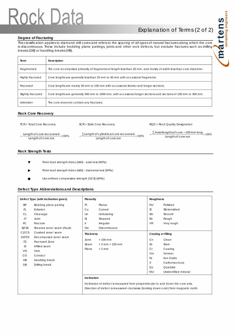
ma
rte
ns
con
su
ltin
g e
ng
ine
ers
Degree of Fracturing This classification applies to diamond drill cores and refers to the spacing of all types of natural fractures along which the core is discontinuous. These include bedding plane partings, joints and other rock defects, but exclude fractures such as drilling breaks (DB) or handling breaks (HB).
Term Description
Fragmented The core is comprised primarily of fragments of length less than 20 mm, and mostly of width less than core diameter.
Highly fractured Core lengths are generally less than 20 mm to 40 mm with occasional fragments.
Fractured Core lengths are mainly 30 mm to 100 mm with occasional shorter and longer sections.
Slightly fractured Core lengths are generally 300 mm to 1000 mm, with occasional longer sections and sections of 100 mm to 300 mm.
Unbroken The core does not contain any fractures.
Rock Core Recovery
TCR = Total Core Recovery SCR = Solid Core Recovery RQD = Rock Quality Designation
%100×=run core of Length
recovered core of Length %100×
∑=
run core of Lengthrecovered core lcylindrica of Length %100×
>∑=
run core of Lengthlong mm 100 core of lengths Axial
Rock Strength Tests
Point load strength Index (Is50) - axial test (MPa)
Point load strength Index (Is50) - diametral test (MPa)
Unconfined compressive strength (UCS) (MPa)
Defect Type Abbreviations and Descriptions
Defect Type (with inclination given) Planarity Roughness
BP FL CL JT FC
SZ/SS CZ/CS DZ/DS
FZ IS
VN CO HB DB
Bedding plane parting Foliation Cleavage Joint Fracture Sheared zone/ seam (Fault) Crushed zone/ seam Decomposed zone/ seam Fractured Zone Infilled seam Vein Contact Handling break Drilling break
Pl Cu Un St Ir Dis
Planar Curved Undulating Stepped Irregular Discontinuous
Pol Sl Sm Ro VR
Polished Slickensided Smooth Rough Very rough
Thickness Coating or Filling
Zone Seam Plane
> 100 mm > 2 mm < 100 mm < 2 mm
Cn Sn Ct Vnr Fe X Qz MU
Clean Stain Coating Veneer Iron Oxide Carbonaceous Quartzite Unidentified mineral
Inclination
Inclination of defect is measured from perpendicular to and down the core axis. Direction of defect is measured clockwise (looking down core) from magnetic north.
Explanation of Terms (2 of 2)
ma
rte
ns
con
su
ltin
g e
ng
ine
ers
Sampling Sampling is carried out during drilling or excavation to allow engineering examination (and laboratory testing where required) of the soil or rock. Disturbed samples taken during drilling or excavation provide information on colour, type, inclusions and, depending upon the degree of disturbance, some information on strength and structure. Undisturbed samples may be taken by pushing a thin-walled sampling tube, e.g. U50 (50 mm internal diameter thin walled tube), into soils and withdrawing a soil sample in a relatively undisturbed state. Such samples yield information on structure and strength and are necessary for laboratory determination of shear strength and compressibility. Undisturbed sampling is generally effective only in cohesive soils. Other sampling methods may be used. Details of the type and method of sampling are given in the report. Drilling / Excavation Methods The following is a brief summary of drilling and excavation methods currently adopted by the Company and some comments on their use and application. Hand Excavation - in some situations, excavation using hand tools, such as mattock and spade, may be required due to limited site access or shallow soil profiles. Hand Auger - the hole is advanced by pushing and rotating either a sand or clay auger, generally 75-100 mm in diameter, into the ground. The penetration depth is usually limited to the length of the auger pole; however extender pieces can be added to lengthen this. Test Pits - these are excavated with a backhoe or a tracked excavator, allowing close examination of the in-situ soils and, if it is safe to descend into the pit, collection of bulk disturbed samples. The depth of penetration is limited to about 3 m for a backhoe and up to 6 m for an excavator. A potential disadvantage is the disturbance caused by the excavation. Large Diameter Auger (e.g. Pengo) - the hole is advanced by a rotating plate or short spiral auger, generally 300 mm or larger in diameter. The cuttings are returned to the surface at intervals (generally of not more than 0.5 m) and are disturbed but usually unchanged in moisture content. Identification of soil strata is generally much more reliable than with continuous spiral flight augers, and is usually supplemented by occasional undisturbed tube sampling. Continuous Sample Drilling (Push Tube) - the hole is advanced by pushing a 50 - 100 mm diameter socket into the ground and withdrawing it at intervals to extrude the sample. This is the most reliable method of drilling in soils, since moisture content is unchanged and soil structure, strength etc. is only marginally affected. Continuous Spiral Flight Augers - the hole is advanced using 90 - 115 mm diameter continuous spiral flight augers, which are withdrawn at intervals to allow sampling or in-situ testing. This is a relatively economical means of drilling in clays and in sands above the water table. Samples are returned to the surface or, or may be collected after withdrawal of the auger flights, but they are very disturbed and may be contaminated. Information from the drilling (as distinct from specific sampling by SPTs or undisturbed samples) is of relatively lower reliability, due to remoulding, contamination or softening of samples by ground water.
Non-core Rotary Drilling - the hole is advanced by a rotary bit, with water being pumped down the drill rods and returned up the annulus, carrying the drill cuttings. Only major changes in stratification can be determined from the cuttings, together with some information from ‘feel’ and rate of penetration. Rotary Mud Drilling - similar to rotary drilling, but using drilling mud as a circulating fluid. The mud tends to mask the cuttings and reliable identification is again only possible from separate intact sampling (eg. from SPT). Continuous Core Drilling - a continuous core sample is obtained using a diamond tipped core barrel of usually 50 mm internal diameter. Provided full core recovery is achieved (not always possible in very weak or fractured rocks and granular soils), this technique provides a very reliable (but relatively expensive) method of investigation. In-situ Testing and Interpretation Cone Penetrometer Testing (CPT) Cone penetrometer testing (sometimes referred to as Dutch Cone) described in this report has been carried out using an electrical friction cone penetrometer. The test is described in AS 1289.6.5.1-1999 (R2013). In the test, a 35 mm diameter rod with a cone tipped end is pushed continuously into the soil, the reaction being provided by a specially designed truck or rig which is fitted with an hydraulic ram system. Measurements are made of the end bearing resistance on the cone and the friction resistance on a separate 130 mm long sleeve, immediately behind the cone. Transducers in the tip of the assembly are connected by electrical wires passing through the push rod centre to an amplifier and recorder unit mounted on the control truck. As penetration occurs (at a rate of approximately 20 mm per second) the information is output on continuous chart recorders. The plotted results given in this report have been traced from the original records. The information provided on the charts comprises:
(i) Cone resistance (qc) - the actual end bearing force divided by the cross sectional area of the cone, expressed in MPa.
(ii) Sleeve friction (qf) - the frictional force of the sleeve divided by the surface area, expressed in kPa.
(iii) Friction ratio - the ratio of sleeve friction to cone resistance, expressed in percent.
There are two scales available for measurement of cone resistance. The lower (A) scale (0 - 5 MPa) is used in very soft soils where increased sensitivity is required and is shown in the graphs as a dotted line. The main (B) scale (0 - 50 MPa) is less sensitive and is shown as a full line. The ratios of the sleeve resistance to cone resistance will vary with the type of soil encountered, with higher relative friction in clays than in sands. Friction ratios of 1 % - 2 % are commonly encountered in sands and very soft clays rising to 4 % - 10 % in stiff clays. In sands, the relationship between cone resistance and SPT value is commonly in the range:
qc (MPa) = (0.4 to 0.6) N (blows/300 mm) In clays, the relationship between undrained shear strength and cone resistance is commonly in the range:
qc = (12 to 18) Cu
Explanation of Terms (1 of 3)
ma
rte
ns
con
su
ltin
g e
ng
ine
ers
Interpretation of CPT values can also be made to allow estimation of modulus or compressibility values to allow calculation of foundation settlements. Inferred stratification as shown on the attached reports is assessed from the cone and friction traces and from experience and information from nearby boreholes etc. This information is presented for general guidance, but must be regarded as being to some extent interpretive. The test method provides a continuous profile of engineering properties, and where precise information on soil classification is required, direct drilling and sampling may be preferable.
Standard Penetration Testing (SPT) Standard penetration tests are used mainly in non-cohesive soils, but occasionally also in cohesive soils as a means of determining density or strength and also of obtaining a relatively undisturbed sample. The test procedure is described in AS 1289.6.3.1-2004. The test is carried out in a borehole by driving a 50 mm diameter split sample tube under the impact of a 63 kg hammer with a free fall of 760 mm. It is normal for the tube to be driven in three successive 150 mm penetration depth increments and the ‘N’ value is taken as the number of blows for the last two 150 mm depth increments (300 mm total penetration). In dense sands, very hard clays or weak rock, the full 450 mm penetration may not be practicable and the test is discontinued. The test results are reported in the following form:
(i) Where full 450 mm penetration is obtained with successive blow counts for each 150 mm of say 4, 6 and 7 blows:
as 4, 6, 7 N = 13
(ii) Where the test is discontinued, short of full penetration,
say after 15 blows for the first 150mm and 30 blows for the next 40mm
as 15, 30/40 mm. The results of the tests can be related empirically to the engineering properties of the soil. Occasionally, the test method is used to obtain samples in 50 mm diameter thin walled sample tubes in clays. In such circumstances, the test results are shown on the borehole logs in brackets. Dynamic Cone (Hand) Penetrometers Hand penetrometer tests are carried out by driving a rod into the ground with a falling weight hammer and measuring the blows for successive 150mm increments of penetration. Normally, there is a depth limitation of 1.2m but this may be extended in certain conditions by the use of extension rods. Two relatively similar tests are used. Perth sand penetrometer (PSP) - a 16 mm diameter flat ended rod is driven with a 9 kg hammer, dropping 600 mm. The test, described in AS 1289.6.3.3-1997 (R2013), was developed for testing the density of sands (originating in Perth) and is mainly used in granular soils and filling. Cone penetrometer (DCP) - sometimes known as the Scala Penetrometer, a 16 mm rod with a 20 mm diameter cone end is driven with a 9 kg hammer dropping 510 mm. The test, described in AS 1289.6.3.2-1997 (R2013), was developed initially for pavement sub-grade investigations, with correlations of the test results with California Bearing Ratio published by various Road Authorities. Pocket Penetrometers The pocket (hand) penetrometer (PP) is typically a light weight spring hand operated device with a stainless steel
loading piston, used to estimate unconfined compressive strength, qu, (UCS in kPa) of a fine grained soil in field conditions. In use, the free end of the piston is pressed into the soil at a uniform penetration rate until a line, engraved near the piston tip, reaches the soil surface level. The reading is taken from a gradation scale, which is attached to the piston via a built-in spring mechanism and calibrated to kilograms per square centimetre (kPa) UCS. The UCS measurements are used to evaluate consistency of the soil in the field moisture condition. The results may be used to assess the undrained shear strength, Cu, of fine grained soil using the approximate relationship:
qu = 2 x Cu.
It should be noted that accuracy of the results may be influenced by condition variations at selected test surfaces. Also, the readings obtained from the PP test are based on a small area of penetration and could give misleading results. They should not replace laboratory test results. The use of the results from this test is typically limited to an assessment of consistency of the soil in the field and not used directly for design of foundations. Test Pit / Borehole Logs Test pit / borehole log(s) presented herein are an engineering and / or geological interpretation of the subsurface conditions. Their reliability will depend to some extent on frequency of sampling and methods of excavation / drilling. Ideally, continuous undisturbed sampling or excavation / core drilling will provide the most reliable assessment but this is not always practicable, or possible to justify on economic grounds. In any case, the test pit / borehole logs represent only a very small sample of the total subsurface profile. Interpretation of the information and its application to design and construction should therefore take into account the spacing of test pits / boreholes, the frequency of sampling and the possibility of other than ‘straight line’ variation between the test pits / boreholes. Laboratory Testing Laboratory testing is carried out in accordance with AS 1289 Methods of Testing Soil for Engineering Purposes. Details of the test procedure used are given on the individual report forms. Ground Water Where ground water levels are measured in boreholes, there are several potential problems:
• In low permeability soils, ground water although present, may enter the hole slowly, or perhaps not at all during the time it is left open.
• A localised perched water table may lead to an erroneous indication of the true water table.
• Water table levels will vary from time to time with seasons or recent prior weather changes. They may not be the same at the time of construction as are indicated in the report.
• The use of water or mud as a drilling fluid will mask any ground water inflow. Water has to be blown out of the hole and drilling mud must first be washed out of the hole if water observations are to be made.
More reliable measurements can be made by installing standpipes, which are read at intervals over several days, or perhaps weeks for low permeability soils. Piezometers sealed in a particular stratum, may be advisable in low permeability soils or where there may be interference from a perched water table.
Explanation of Terms (2 of 3)
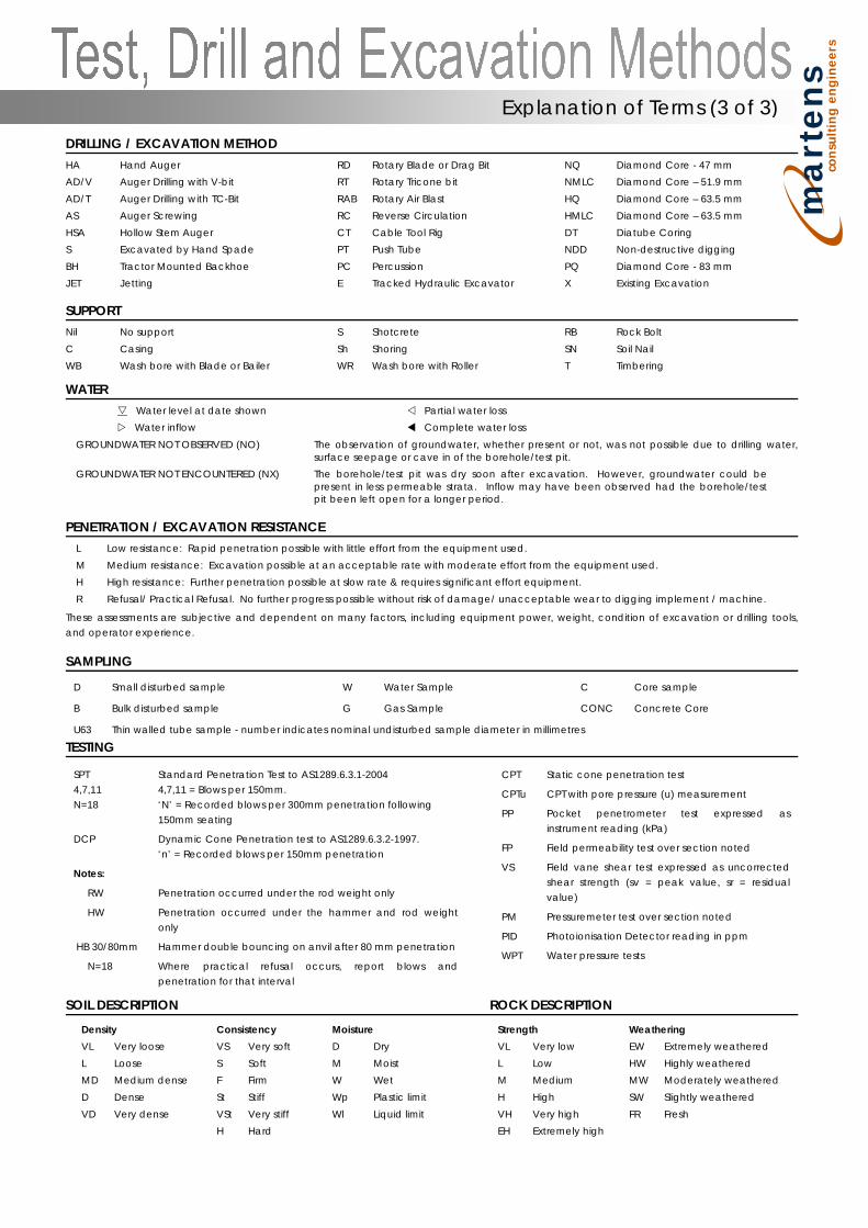
ma
rte
ns
con
su
ltin
g e
ng
ine
ers
DRILLING / EXCAVATION METHOD HA Hand Auger RD Rotary Blade or Drag Bit NQ Diamond Core - 47 mm AD/V Auger Drilling with V-bit RT Rotary Tricone bit NMLC Diamond Core – 51.9 mm AD/T Auger Drilling with TC-Bit RAB Rotary Air Blast HQ Diamond Core – 63.5 mm AS Auger Screwing RC Reverse Circulation HMLC Diamond Core – 63.5 mm HSA Hollow Stem Auger CT Cable Tool Rig DT Diatube Coring S Excavated by Hand Spade PT Push Tube NDD Non-destructive digging BH Tractor Mounted Backhoe PC Percussion PQ Diamond Core - 83 mm JET Jetting E Tracked Hydraulic Excavator X Existing Excavation
SUPPORT Nil No support S Shotcrete RB Rock Bolt C Casing Sh Shoring SN Soil Nail WB Wash bore with Blade or Bailer WR Wash bore with Roller T Timbering
WATER
Water level at date shown Partial water loss Water inflow Complete water loss
GROUNDWATER NOT OBSERVED (NO) The observation of groundwater, whether present or not, was not possible due to drilling water, surface seepage or cave in of the borehole/test pit.
GROUNDWATER NOT ENCOUNTERED (NX) The borehole/test pit was dry soon after excavation. However, groundwater could be present in less permeable strata. Inflow may have been observed had the borehole/test pit been left open for a longer period.
PENETRATION / EXCAVATION RESISTANCE L Low resistance: Rapid penetration possible with little effort from the equipment used. M Medium resistance: Excavation possible at an acceptable rate with moderate effort from the equipment used. H High resistance: Further penetration possible at slow rate & requires significant effort equipment. R Refusal/ Practical Refusal. No further progress possible without risk of damage/ unacceptable wear to digging implement / machine.
These assessments are subjective and dependent on many factors, including equipment power, weight, condition of excavation or drilling tools, and operator experience.
SAMPLING
D Small disturbed sample W Water Sample C Core sample
B Bulk disturbed sample G Gas Sample CONC Concrete Core
U63 Thin walled tube sample - number indicates nominal undisturbed sample diameter in millimetres
TESTING
SPT 4,7,11 N=18
DCP
Notes:
RW
HW
HB 30/80mm
N=18
Standard Penetration Test to AS1289.6.3.1-2004 4,7,11 = Blows per 150mm. ‘N’ = Recorded blows per 300mm penetration following 150mm seating
Dynamic Cone Penetration test to AS1289.6.3.2-1997. ‘n’ = Recorded blows per 150mm penetration
Penetration occurred under the rod weight only
Penetration occurred under the hammer and rod weight only
Hammer double bouncing on anvil after 80 mm penetration
Where practical refusal occurs, report blows and penetration for that interval
CPT
CPTu
PP
FP
VS
PM
PID
WPT
Static cone penetration test
CPT with pore pressure (u) measurement
Pocket penetrometer test expressed as instrument reading (kPa)
Field permeability test over section noted
Field vane shear test expressed as uncorrected shear strength (sv = peak value, sr = residual value)
Pressuremeter test over section noted
Photoionisation Detector reading in ppm
Water pressure tests
SOIL DESCRIPTION ROCK DESCRIPTION
Density Consistency Moisture Strength Weathering VL Very loose VS Very soft D Dry VL Very low EW Extremely weathered L Loose S Soft M Moist L Low HW Highly weathered MD Medium dense F Firm W Wet M Medium MW Moderately weathered D Dense St Stiff Wp Plastic limit H High SW Slightly weathered VD Very dense VSt Very stiff Wl Liquid limit VH Very high FR Fresh H Hard EH Extremely high
Explanation of Terms (3 of 3)