Embed Size (px)
Citation preview
COMMUN. MATH. SCI. c© 2018 International Press
Vol. 16, No. 1, pp. 77–95
GENERATION OFSURFACE PLASMON-POLARITONS BY EDGE EFFECTS∗
MATTHIAS MAIER† , DIONISIOS MARGETIS‡ , AND MITCHELL LUSKIN§
Abstract. By using numerical and analytical methods, we describe the generation of fine-scalelateral electromagnetic waves, called surface plasmon-polaritons (SPPs), on atomically thick, meta-material conducting sheets in two spatial dimensions (2D). Our computations capture the two-scalecharacter of the total field and reveal how each edge of the sheet acts as a source of an SPP that maydominate the diffracted field. We use the finite element method to numerically implement a variationalformulation for a weak discontinuity of the tangential magnetic field across a hypersurface. An adap-tive, local mesh refinement strategy based on a posteriori error estimators is applied to resolve thepronounced two-scale character of wave propagation and radiation over the metamaterial sheet. Wedemonstrate by numerical examples how a singular geometry, e.g., sheets with sharp edges, and sharpspatial changes in the associated surface conductivity may significantly influence surface plasmons innanophotonics.
Keywords. time-harmonic Maxwell’s equations, finite element method, surface plasmon-polariton,singular geometry, weak discontinuity on hypersurface.
AMS subject classifications. 65N30; 78M10; 78M30; 78A45.
1. IntroductionRecently, advances in nanophotonics have been made possible through the design of
atomically thick materials, e.g., graphene, with tunable, novel electronic structure andmacroscopic conductivity [18, 34]. A far-reaching goal is to precisely control coherentlight at the nanoscale, in the terahertz frequency range [40]. This objective can bepursued by manipulation of the microscopic parameters of conducting sheets. Undersuitable conditions, the sheet may behave as a metamaterial, exhibiting a dielectricpermittivity with a negative real part as a function of frequency. By appropriate current-carrying sources and geometry, one may generate electromagnetic waves that propagatewith relatively short wavelength along the sheet [4]. A celebrated type of wave, linkedto various technological applications, is the surface plasmon-polariton (SPP) [4,16,27].
The present paper focuses on the computation of time-harmonic SPPs intimatelyrelated to geometric effects, specifically the presence of edges on conducting films, inthe frequency regime in which the metamaterial character of the sheet is evident. Ourgoal is to demonstrate numerically how spatial changes in the morphology and surfaceconductivity of the sheet may amplify, or spoil, the observation of SPPs. To this end, wecombine computational tools that include: (i) an implementation of the finite elementmethod allowing for the discontinuity of the tangential magnetic field across the sheetwhich is inherent to a class of thin conducting metamaterials; and (ii) an approximatesolution by the method of Wiener and Hopf for an integral equation describing theelectric field tangent to a semi-infinite sheet (“reference case”) [29].
Our main results can be summarized as follows.
∗Received: February 3, 2017; accepted (in revised form): September 21, 2017. Communicated byPierre Degond.†School of Mathematics, University of Minnesota Twin-Cities, Minneapolis, Minnesota 55455, USA
([email protected]).‡Department of Mathematics, and Institute for Physical Science and Technology, and Center for
Scientific Computation and Mathematical Modeling, University of Maryland, College Park, Maryland20742, USA ([email protected]).§School of Mathematics, University of Minnesota Twin-Cities, Minneapolis, Minnesota 55455, USA
77
78 GENERATION OF SURFACE PLASMON-POLARITONS BY EDGE EFFECTS
• We formulate a two-dimensional (2D) model for fine-scale SPPs induced byedge discontinuities. A few prototypical geometries are investigated numeri-cally. In particular, we describe SPPs generated by: the edge discontinuity ofa semi-infinite sheet; the gap between two co-planar, semi-infinite sheets; anda resonant, finite conducting strip.
• For the numerics, we adapt a variational framework for the finite element treat-ment of wave propagation [26] to the 2D setting of SPP generation by edgeeffects. The underlying weak formulation embodies a discontinuity of the tan-gential magnetic-field component across the sheet and point singularities atmaterial edges or discontinuities of the surface conductivity.
• We validate our numerical treatment by comparison of numerics to an approx-imate solution for the reference case of the semi-infinite sheet. We verify theanalytically predicted singular behavior of the electric field near the edge.
• Based on our numerical simulations, we predict means of enhancing the ob-servation of SPPs. Specifically, we demonstrate that the presence of a highlyconducting material in the gap between two co-planar, semi-infinite metamate-rial sheets may lead to an increase of the SPP amplitude. We also show that inthis setting the dependence of the SPP amplitude on the gap width is distinctlydifferent from the case with an “empty gap”, i.e., when the material of the gapis the ambient medium. In addition, we characterize resonances for SPPs on afinite strip numerically, and demonstrate that the SPP maximal magnitude asa function of the gap width is described by a Lorentzian function.
It has been well known that, because of phase matching in electromagnetic wavepropagation, SPPs cannot be excited by plane waves incident upon an (idealized) infiniteconducting sheet [4]. The relatively large wavenumber of the desired SPP cannot bedirectly matched at the interface. This limitation is usually remedied by introductionof suitably tuned gratings or localized current-carrying sources such as dipole antennasnear resonance [1, 4].
In this paper, we use a finite element approach to explore an alternate scenario: thegeneration of SPPs via diffraction of waves by material defects such as sharp edges ofconducting sheets. We point out that such geometric singularities, edges, can induceSPPs under radiation by appropriately polarized plane waves. Our numerical simula-tions involve hypersurfaces embedded in a 2D space for the sake of computational ease.However, our key conclusions can be generalized to higher dimensions. One of theseconclusions is that the induced SPP may dominate over the diffracted field in a rangeof distances away from the edge.
Our work here forms an extension of the approach in [26] to more realistic, singulargeometries. In [26], we introduced a numerical framework for tackling propagation ofSPPs on planar hypersurfaces via the finite element method. Our formulation relieson a variational statement that incorporates the weak discontinuity of the tangentialcomponent of the magnetic field across the sheet. This approach offers the advantage oflocal refinement based on a-posteriori error control. The computational work reportedin [26] is restricted to idealized geometries, aiming to introduce a general platform ratherthan address realistic applications.
In the present paper, we take a major step closer to applications by extending ourfinite element approach [26] to settings with sharp edges and gaps on metamaterial,conducting films. Our ultimate purpose is to model and simulate the effect of defectson the generation and propagation of SPPs. We validate our numerics via comparison to
MATTHIAS MAIER, DIONISIOS MARGETIS, AND MITCHELL LUSKIN 79
an approximate analytical solution for the semi-infinite conducting sheet with recourseto the Wiener–Hopf method of factorization [29]. This solution analytically reveals thatthe algebraically singular field near the edge transitions to a slowly decaying, fine-scaleSPP away from the edge.
1.1. Scope: excitation of SPPs. The excitation of SPPs on interfaces betweenmetals and dielectrics has been conceived as a means of confining and manipulating co-herent light in the infrared spectrum [16]. Surface plasmons form the macroscopicmanifestation of the resonant interaction of electromagnetic radiation (photons) withelectrons in the plasma of the metal surface. SPPs, in particular, are loosely definedmacroscopically as waves that have a relatively short wavelength and decay slowly alongthe interface. SPPs may offer significant technological advantages; for example, improve-ment of the emission of light from corrugated metallic surfaces or nanoparticles [19,31].
The macroscopic theory of surface plasmonics usually relies on Maxwell’s equations,specifically notions of classical electromagnetic wave propagation near boundaries. Thissubject has been the focus of systematic investigations in the case with radiowavespropagating over the earth or sea; see, e.g., [8, 23]. A central concept is the surfaceor lateral wave, which is confined closely to the boundary [23]. Typically, at radiofrequencies the surface wave between air and earth has a phase velocity approximatelyequal to the phase velocity in air.
In surface plasmonics in the terahertz frequency regime, however, the constitutiverelations and geometry of the associated materials become more intricate. Hence, thecharacter of the ensuing surface wave is substantially different from that at radio fre-quencies [27]. Here, we view the SPP as a type of surface wave. Notably, the wavelengthof the SPP with transverse-magnetic polarization can plausibly be made much smallerthan the wavelength of a plane wave in free space at the same frequency [4, 7].
An emerging question is the following. How can the geometry or surface con-ductivity of a low-dimensional material be controlled to generate a desirable SPP? Asatisfactory answer to this question requires understanding through reliable computa-tions how geometry affects solutions to a class of boundary value problems for Maxwell’sequations. In these problems, an atomically thick material, e.g., graphene, may intro-duce a jump proportional to a local property such as conductivity in components ofthe electromagnetic field tangent to the sheet. The coupling of this type of boundarycondition to singular geometries in 2D is the subject of the present paper.
1.2. Past computational approaches. Computational methods for plas-monics appear to be tailored to specific applications. Next, we provide a brief, non-exhaustive summary of the main computational tools found in the existing literature.
First, we comment on analytical treatments. In relatively simple settings withplanar boundaries, dispersion relations of SPPs have been sought analytically throughthe use of plane-wave excitations; see, e.g., the recent review in [4]. Interestingly, thecorresponding geometries lack singular regions, e.g., sharp edges. A notable exceptionconcerns a metallic contact modeled as a strip of fixed width on a substrate in 2D [4,36].For this geometry, an analytical solution has been found via solving an integral equationin the Fourier domain for the electric field tangent to the strip in the simplified casewith an electrically small strip width [4]. This solution is not applicable to conductingsheets with edges, since in the latter case the edge may not be treated as a perturbation.A numerical study of electrically large metal contacts by spectral methods is providedin [36]; however, the transition of the field from a singular behavior near the edge to anSPP is not discussed in this work [36].
80 GENERATION OF SURFACE PLASMON-POLARITONS BY EDGE EFFECTS
Other settings in plasmonics consist of dipole sources over infinite planar boundaries;then, analytical and semi-analytical solutions are developed via the Fourier transformof the field [20]. In some exceptional cases, when the dipole and observation point lieon the sheet, exact evaluation of field components is possible [28]. These approacheshave the merit of yielding features of SPPs inherent to the nature of the point source;but they convey little or no information about how realistic geometric effects related tothe finite size of the sheet may influence the SPP.
In more complicated geometries, the excitation of plasmons has been studied underthe “quasistatic approximation” in which the typical size of the scatterer is much smallerthan the wavelength of the incident radiation field [27]. However, this approximation isexpected to be questionable as the frequency becomes higher or the size of the scattereris comparable to the free-space wavelength [27].
A variety of numerical methods for nanophotonics have been reported in the lit-erature; for a recent review, see, e.g., [17]. These approaches include: the volumeintegral-equation approach [21, 22, 24], which exploits the integral form of Maxwell’sequations along with the respective Green’s function in closed form in the frequencydomain; and the akin boundary element method [14, 30, 37], which makes use of Diracmasses as test functions and often employs the scalar and vector potentials. Numer-ical methods of different nature are the finite-difference time-domain method [25, 32]and the finite-difference method [15], which invoke space discretization and the respec-tive approximation of the electromagnetic field by piecewise-constant functions. Thistype of approximation may be challenged in plasmonics, where the electromagnetic fieldmay vary appreciably over short distances. An improvement has been offered by thefinite element method [8, 33, 39] with certain choices of basis functions, for example,divergence-free functions. An issue of importance is to satisfy the radiation conditionfar away from the source. This can be accomplished in the numerical scheme via thenotion of the perfectly matched layer (PML) [5, 9]. In passing, we should also mentionthe discrete dipole approximation [11,13] by which the (continuum) scatterer is replacedby a finite array of polarizable particles or dipoles; this technique can be viewed as theoutcome of discretization of the volume integral equation.
1.3. Our computational treatment. Recently, we formulated a variationalframework for the finite element treatment of wave propagation along metamaterialconducting sheets embedded in spaces of arbitrary dimensions [26]. Our formulationincorporates a weak discontinuity of the tangential component of the magnetic field;this jump is responsible for the fine scale of the SPP. The corresponding discretizationscheme was implemented with a modern finite element toolkit [2], and accounts bothfor the small wavelength of the SPP as well as for the radiation condition at infinityvia a PML. This approach allows for error control and, thus, an efficient numericalapproximation of the underlying boundary value problem. In our past work [26], wevalidated this approach by numerical simulations restricted to settings with dipoles overinfinite planar geometries in 2D.
With the present paper, our goal is to adapt the aforementioned approach to morerealistic settings and real-world applications. Hence, we extend our finite element treat-ment to more complicated geometries, especially conducting sheets with edges and gapsin 2D. We demonstrate via simulations that our variational framework and numeri-cal implementation by appropriate curl-conforming Ndlec-elements correctly producesthe edge singularity of the electric field. Our numerics for finite sheets show how thediffracted electric field transitions from a singular behavior near each edge to the SPPaway from the edge. We validate our numerical approach by use of a semi-infinite sheet:
MATTHIAS MAIER, DIONISIOS MARGETIS, AND MITCHELL LUSKIN 81
in this case, our numerical results are in excellent agreement with the analytical predic-tion [29]. This study places on a firm foundation our finite element approach for SPPsgenerated and sustained by defects and finite-size effects.
1.4. Pending issues. Our work here leaves a few open problems for near-futurestudy. For example, we do not solve the related boundary value problem for Maxwell’sequations in three spatial dimensions (3D). This important topic is the subject of workin progress. Furthermore, in our model we use homogeneous and isotropic materialparameters. The case with spatially varying conductivity of the sheet, where the SPPmay be the result of homogenization [7], lies beyond our present scope. In a similarvein, we have not made any attempt to study more complicated forms of discontinuitiesfor the electromagnetic-field components across the sheet, say, in the presence of amagneto-electric effect [38]. We should also mention the experimentally appealing casewith a receiving antenna lying on graphene [1]. This problem can be described by ourvariational approach, and is the subject of future research as well.
Note that surface plasmonics comprise a class of multiscale problems: the electronicstructure of low-dimensional materials should be linked to the phenomenology of SPPs.Here, we invoke a macroscopic model of SPPs via Maxwell’s equations. The emergence ofthe related phenomenology from microscopic principles needs to be further understood.
1.5. Paper organization. The remainder of this paper is organized as follows.In Section 2, we introduce the relevant boundary value problem and summarize analyt-ical results for the reference case [29]. Section 3 focuses on our numerical approach; inparticular, the use of a PML and adaptive local refinement for good resolution of theSPP is discussed. In Section 4, we present and discuss computational results for thefollowing geometries: a semi-infinite sheet (reference case); two co-planar, semi-infinitesheets with a gap; and a resonant, finite conducting strip. Section 5 concludes our paperwith a summary of the main findings.
2. Model and analytical results
In this section, we introduce the main ingredients of the model and analytical ap-proach: a boundary value problem for Maxwell’s equations, which incorporates a dis-continuity for the magnetic-field component tangent to an arbitrary conducting sheetin 2D (Section 2.1); and an analytical formula for the SPP on a semi-infinite sheet(Section 2.2). Our formula manifests the fine scale of the SPP if the sheet conductivitysatisfies a certain condition consistent with the metamaterial nature of the sheet. Inthis vein, we describe solutions for the electric field far from and near the edge on asemi-infinite sheet [29] (Section 2.2).
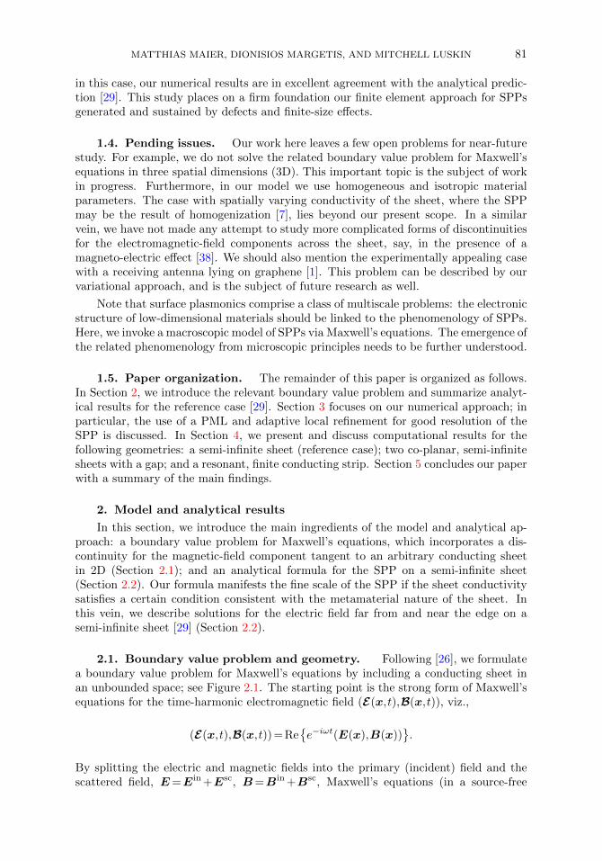
2.1. Boundary value problem and geometry. Following [26], we formulatea boundary value problem for Maxwell’s equations by including a conducting sheet inan unbounded space; see Figure 2.1. The starting point is the strong form of Maxwell’sequations for the time-harmonic electromagnetic field (E(x,t),B(x,t)), viz.,
(E(x,t),B(x,t)) = Ree−iωt(E(x),B(x))
.
By splitting the electric and magnetic fields into the primary (incident) field and thescattered field, E=Ein +Esc, B=Bin +Bsc, Maxwell’s equations (in a source-free
82 GENERATION OF SURFACE PLASMON-POLARITONS BY EDGE EFFECTS
k
Σν
Fig. 2.1: Schematic of the geometry. A plane wave with wave vector k is incident upon an (arbitrarilyoriented) interface Σ of unit normal ν in an unbounded domain, in order to excite an SPP.
form) for the scattered field outside the sheet are written as [8]−iωBsc +∇×Esc = 0,
iωεEsc +∇×(µ−1Bsc
)= 0,
∇·Bsc = 0,
∇·(εEsc
)= 0.
(2.1)
Here, Gauss’ law, expressed by the last two equations, is redundant. In system (2.1),the material parameters are time independent. The second-rank tensors µ(x) and ε(x)denote the effective magnetic permeability and complex permittivity of the unboundedmedium; in particular, ε(x) =ε(x)+ iσ(x)/ω, where ε(x) and σ(x) are the usualpermittivity and conductivity of the medium.
Equations (2.1) are enforced in suitable unbounded regions of the Euclidean spaceRn (n= 2, 3), by exclusion of the conducting sheet. Hence, system (2.1) must be comple-mented with the appropriate boundary condition across the sheet which is representedby an oriented hypersurface Σ, Σ⊂Rn, with unit normal ν and surface conductivityσΣ(x) [4]. For a conducting sheet, the electromagnetic field satisfies the conditions [4]ν×
[(µ−1B
)+−(µ−1B)−]∣∣∣
Σ= σΣ(x)[(ν×E)×ν]
∣∣∣Σ,
ν×(E+−E−
)∣∣∣Σ
= 0,(2.2)
where E±,B± is the restriction of the field to each side (±) of the sheet and σΣ(x) isa second-rank tensor with domain on Σ.
In the presence of compactly supported external sources, e.g., electric or magneticdipoles, systems (2.1) and (2.2) must be complemented with a radiation condition atinfinity. For an isotropic medium, this condition takes the form of a Silver-Mullercondition [8]. Specifically, if c is the speed of light at infinity, we require that
lim|x|→∞
Bsc×x−c−1|x|Esc
= 0, lim
|x|→∞Esc×x+c|x|Bsc= 0 (x /∈Σ). (2.3)
Although the use of both of these conditions is mathematically redundant, we providethem here for the sake of full correspondence to system (2.1).
Motivated by the setting with an infinite planar sheet [4], we will pay particularattention to material properties and external sources that allow for the generation of
MATTHIAS MAIER, DIONISIOS MARGETIS, AND MITCHELL LUSKIN 83
a short-wavelength SPP on the conducting sheet. Specifically, for an isotropic andhomogeneous sheet we expect that a necessary condition for such an SPP is ImσΣ>0.In addition, the sheet needs to be irradiated by an appropriately (transverse-magnetic)polarized wave. We conclude this subsection with a practically appealing definition [7]:Definition 2.1. For scalar σΣ, the nonretarded frequency regime is characterized by
∣∣∣∣ωµσΣ
k
∣∣∣∣1, (2.4)
i.e., a surface resistivity (1/σΣ) that is much larger in magnitude than the intrinsicimpedance of the ambient medium.
By recourse to an analytical solution for the reference case (Section 2.2), we will seethat condition (2.4) along with the condition ImσΣ>0 imply that an SPP is presenton a semi-infinite sheet and has a wavenumber, km, with |km|k. The nonretardedfrequency regime thus yields SPPs on a distinct length scale than the incident wave.The importance of this regime is related to predicted optical behavior of the sheet con-ductivity, σΣ, as a function of frequency, ω, by use of electronic structure calculations;see, e. g. [7].
2.2. Reference case: explicit formulas. In the case with a semi-infinitesheet, Σ =(x,0)∈R2 : x≥0 [see Figure 2.2(a)], Maxwell’s Equations (2.1) with jumpcondition (2.2) admit a closed-form solution for the electric field, Ex(x,0), tangential tothe sheet. This solution is obtained by application of the Wiener–Hopf method to anintegral equation [29]. In the following we briefly motivate and describe our formalismand results; for a detailed discussion we refer the reader to [29].
The key ingredient of the analytical approach is the formulation of systems (2.1) and(2.2) in terms of an integral equation for the (non-dimensional) x-component, u(x) =Ex(k−1x,0)/E0, of the electric field on the sheet, where E0 is a typical amplitude of theincident electric field. The governing integral equation reads
u(x) =uin(x)+iωµσΣ
k
(d2
dx2+1
)∫ ∞0
dx′K(x−x′)u(x′) x>0, (2.5)
where uin corresponds to the incident field, x is scaled by 1/k where k is real, and the
kernel K(z) = i/4H(1)0 (|z|) is expressed in terms of the first-kind, zeroth-order Hankel
function H(1)0 , which corresponds to a Green’s function for the scalar Helmholtz equa-
tion; see [29, Sec. 1]. Note that equation (2.5) can be generalized to geometries thatinclude a more complicated yet isotropic ambient space of the sheet through use of asuitable, modified kernel.
By formally extending u and uin to the whole real axis through setting u(x) =uin(x)≡0 for x<0, and introducing an unknown function, g, for consistency (g(x)≡0if x>0), we write
u(x)− iωµσΣ
k
(d2
dx2+1
)∫ ∞−∞
dx′K(x−x′)u(x′) =uin(x)+g(x) x∈R. (2.6)
Equation (2.6) is solved explicitly in terms of a Fourier integral by use of the Wiener–Hopf method [29]. To this end, we consider a plane wave as the incident field, Ein
x =E0e
ix sinα, for some incidence angle, α. In the following, we summarize the main findingsof this approach.
84 GENERATION OF SURFACE PLASMON-POLARITONS BY EDGE EFFECTS
Ω:
x
y
ρ R
σΣr
PML
(a)
Ω:
x
y
ρ R
σΣr σΣ
r
PML
(b)
Ω:
x
y
ρ R
σΣr σΣ
r
σΣr,2
PML
(c)
Ω:
x
y
ρ R
σΣr
PML
(d)
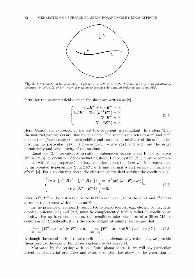
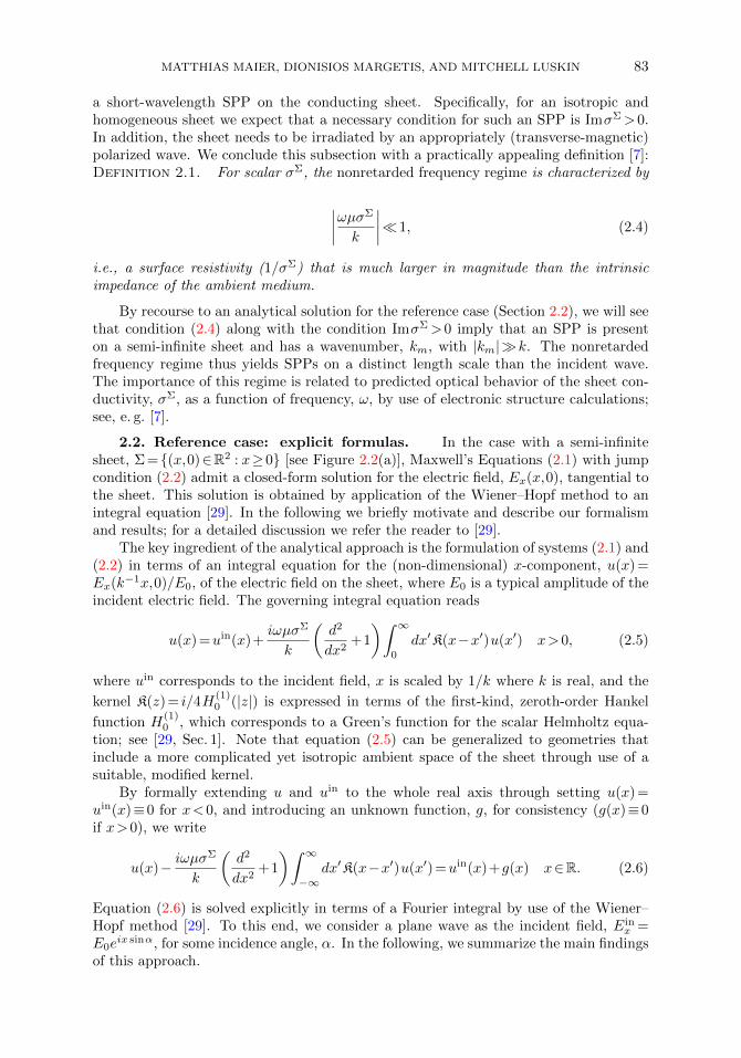
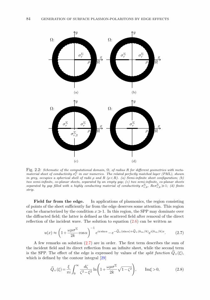
Fig. 2.2: Schematic of the computational domain, Ω, of radius R for different geometries with meta-material sheet of conductivity σΣ
r in our numerics. The related perfectly matched layer (PML), shownin grey, occupies a spherical shell of radii ρ and R (ρ<R). (a) Semi-infinite sheet configuration; (b)two semi-infinite, co-planar sheets, separated by an empty gap; (c) two semi-infinite, co-planar sheetsseparated by gap filled with a highly conducting material of conductivity σΣ
r,2, ReσΣr,21; (d) finite
strip.
Field far from the edge. In applications of plasmonics, the region consistingof points of the sheet sufficiently far from the edge deserves some attention. This regioncan be characterized by the condition x1. In this region, the SPP may dominate overthe diffracted field; the latter is defined as the scattered field after removal of the directreflection of the incident wave. The solution to equation (2.6) can be written as
u(x) ≈(
1+ωµσΣ
2kcosα
)−1
eixsinα−e−Q+(sinα)+Q+(km/k)ei(km/k)x. (2.7)
A few remarks on solution (2.7) are in order. The first term describes the sum ofthe incident field and its direct reflection from an infinite sheet, while the second termis the SPP. The effect of the edge is expressed by values of the split function Q+(ξ),which is defined by the contour integral [29]
Q+(ξ) =ξ
πi
∫ ∞0
dζ
ζ2−ξ2ln
(1+
ωµσΣ
2k
√1−ζ2
), Imξ >0, (2.8)
MATTHIAS MAIER, DIONISIOS MARGETIS, AND MITCHELL LUSKIN 85
and can be evaluated approximately, in closed form, in the nonretarded regime (Defini-
tion 2.1) [29]. In principle, this Q+(ξ) enters the Fourier integral for the exact solution,
u, for x>0 [29]. In the region under consideration (if x1), Q(ξ) needs to be computedfor particular values of ξ in order to compare formula (2.7) against numerical results of
the finite element method (Section 4). For example, for α= 0, we compute Q+(ξ) forξ= 0 and ξ=km/k approximately (see [29, Sec. 3]), viz.,
Q+(0)≈0.0005+0.05i, Q+(km/k)≈0.346574+0.392699i.
We should add that the SPP wavenumber, km, obeys the dispersion relationk⊥ :=
√k2−k2
m=−2k2/(ωµσΣ), which furnishes the wavenumber, k⊥, of propagation
transverse to the sheet; thus, km/k=√
1−4k2/(ωµ0σΣ)2, and |km/k|1 in the non-retarded regime (Definition 2.1) [29]. By imposing Imk⊥>0 according to the radiationcondition at infinity vertically to the sheet, we obtain ImσΣ>0 which expresses themetamaterial character of the sheet.
An additional contribution to u(x), not included in formula (2.7), is the radiationfield due to the edge. It corresponds to a residual contribution not captured by theincident and directly reflected fields and the SPP; see [29, Sec. 3.2.1]. The radiationfield is found to be negligible in the region considered here and, thus, is omitted.
Near-edge field. Another region of significance is the vicinity of the edge,where |(km/k)x|1. In this region, the SPP interferes with the incident, reflected andradiation fields to yield a vanishing x-component of the (total) electric field on the sheet.Hence, as x0, the solution, u, of integral equation (2.6) cannot be separated into thedistinct (physical) contributions that are evident in the field far from the edge. Instead,we analytically compute the asymptotic behavior [29]
u(x) ≈ 2√π
√2k
ωµσΣe−iπ/4
√x as x0. (2.9)
This formula manifests the singular behavior of the field at the edge.
3. Numerical approachIn this section, we describe an implementation of the finite element method in
order to solve the boundary value problem of Section 2.1 based on curl-conformingNdlec-elements [35]. First, we state boundary-value problem (2.1) in terms of a weakformulation that embodies discontinuity (2.2) of the tangential magnetic-field implicitlyby means of an interior interface integral. Second, we discuss a number of numericalaspects to solve the weak formulation; in particular, the use of a specifically tuned PML,as well as a local refinement strategy to resolve the SPP.
3.1. Variational formulation and discretization. By a standard manip-ulation in electromagnetic theory, the substitution of the first equation of (2.1) intothe second one yields a second-order partial differential equation for the vector-valuedelectric field, E. To rescale the resulting equation to a desired, dimensionless form, wechoose to set k= 1, or, equivalently, scale the vector position x by 1/k, in the spirit ofSection 2.2. Thus, we introduce the following related scalings [26]:
x→ kx, ∇ → 1
k∇, km,r =
kmk, (3.1a)
µ→ µr =1
µ0µ, ε→ εr =
1
ε0ε, σΣ → σΣ
r =
õ0
ε0σΣ. (3.1b)
86 GENERATION OF SURFACE PLASMON-POLARITONS BY EDGE EFFECTS
Accordingly, the equation for E now reads
∇×(µ−1r ∇×E
)− εrE = 0. (3.2)
The multiplication of the last equation with a test function ϕ and subsequent integrationby parts yield [26]∫
Ω
(µ−1r ∇×Esc) ·(∇×ϕ)dx−
∫Ω
(εrEsc) ·ϕdx
− i∫
Σ
(σΣr E
scT ) ·ϕT dox− i
∫∂Ω
√µ−1r εrE
scT ·ϕT dox
=i
∫Σ
(σΣr E
inT ) ·ϕT dox. (3.3)
where Esc is the scattered field and Ein denotes the incident field (Section 2.1). Anappropriate trial and test space for the weak formulation is [26], [33, Theorem 4.1]
X(Ω) =ϕ∈L2(Ω) : ∇×ϕ∈L2(Σ)3,ϕT
∣∣Σ∈L2(Σ)3,ϕT
∣∣∂Ω∈L2(∂Ω)3
,
where L2 denotes the space of measurable and square integrable functions. By choosingthis space, the formerly strong interface condition (2.2) is now naturally embedded inthe variational formulation. In more detail, the statement
ν×(E+−E−
)∣∣∣Σ
= 0
is a consequence of E∈H(curl;Ω), and the jump condition
ν×[(µ−1B
)+−(µ−1B)−]∣∣∣
Σ= σΣ(x)[(ν×E)×ν]
∣∣∣Σ
is enforced by the term −i∫
ΣσΣr ET ·ϕT dox in the variational formulation [26].
We implement equation (3.3) by using curl-conforming Ndlec-elements [35] withthe help of the finite element toolkit deal.II [2]. The computational domain Ω wasdiscretized with a quadrilateral mesh. In order to allow for local refinement, we use thewell-known concept of hanging nodes (see, e. g., [6] for an overview) to relax the usualmesh regularity assumptions [10]. The resulting system of linear equations is solvedwith the direct solver Umfpack [12].
3.2. Perfectly matched layer for SPPs. Next, we discuss a construction ofa PML [5, 9] for the rescaled Maxwell equations with a jump condition in connectionto the boundary problem of Section 2.1 [26]. The concept of a PML was pioneeredby Brenger [5] and can be viewed as a layer with modified material parameters (εr ,µr ) placed near the boundary of the computational domain; cf. Figure 2.2. The coreidea is to tune the material parameters inside the PML in such a way that all outgoingelectromagnetic waves decay exponentially with no artificial reflection due to truncationof the domain. The PML is an indispensable tool for truncating unbounded domainsfor time-harmonic Maxwell’s equations, and other, akin partial differential equations,and is often used in the numerical approximation of scattering problems [5, 9, 33].
We follow the approach to a PML for time-harmonic Maxwell’s equations discussedin [9]. The idea is to use a formal change of coordinates from the computational domainΩ⊂R3 with real-valued coordinates to a domain Ω⊂z∈C : Imz≥03 with complex-valued coordinates (and non-negative imaginary part) [33]; and then transform back to
MATTHIAS MAIER, DIONISIOS MARGETIS, AND MITCHELL LUSKIN 87
the real-valued domain. For simplicity, we assume that the interface Σ is parallel tothe unit vector er within the PML (i.e., the normal ν is orthogonal to er). For details,we refer the reader to [26]. This procedure results in the following modified materialparameters εr , µr and σΣ
r within the PML:µ−1r −→ µ−1
r =Bµ−1r A,
εr −→ εr = A−1εrB−1,
σΣr −→ σΣ
r =C−1σΣr B−1.
(3.4)
In the above, we introduced the 3×3 matrices
A=T−1exer
diag( 1
d2,
1
dd,
1
dd
)Texer
, B=T−1exer
diag(d,d,d
)Texer
, (3.5)
C=T−1exer
diag(1
d,1
d,1
d
)Texer ,
where
d= 1+ is(r), d= 1+ i/r
∫ r
ρ
s(τ)dτ, (3.6)
for an appropriately chosen scaling factor s(τ) that will be defined later. Note thatTexer
is the matrix that rotates er onto ex, and τ is the distance from the origin. ThePML is assumed to be a spherical shell starting at distance ρ from the origin, as shownin Figure 2.2. For a detailed parameter study of the performance of the PML we referthe reader to [26].
3.3. Adaptive local refinement. By the assumption that ImσΣr >0 in the
nonretarded frequency regime (Definition 2.1), the SPP has a wavelength much smallerthan the one in the ambient medium (at the same frequency, ω). Thus, wave propa-gation along the metamaterial sheet, Σ, has a pronounced two-scale character, beingcharacterized by length scales of the order of 1/(Rekm) and 1/k; here, Rekmk.
In our numerical simulation, we use typical values of σΣr in the nonretarded regime
for which the SPP wavelength is one to two orders of magnitude smaller than thewavelength in the surrounding medium. This poses a challenge because, on the onehand, the minimal computational domain (that still has a well-controlled error in slowoscillating modes) is limited by the free-space wavelength, 2π/k; on the other hand, theminimal resolution necessary to resolve SPPs scales with 1/|km|. Accordingly, in orderto minimize computational cost while ensuring that the SPP is sufficiently resolved, weuse an adaptive, local refinement strategy based on the dual weighted residual method [3].
Next, we outline the basics of our strategy. Starting from a relatively coarse mesh,the resolution is successively improved by a number of iterative refinement steps wherea subset of cells is chosen for refinement. The selection of cells for refinement is madewith the help of local (per cell K) error indicators, ηk, that are given by
η2K = ρ2
Kω2K +ρ2
∂K ω2∂K .
The cell-wise residuals, viz., the integrals [3, 26]
ρ2K =
∫K
∥∥∇×(µ−1r ∇×Eh)+ εrEh
∥∥2dx,
ρ2∂K =
1
2
∫K
∥∥[ν×(µ−1r ∇×Eh)− iσΣ
r EhχΣ− i√µ−1r εr (Eh)TχΩ
]∥∥2dox,
88 GENERATION OF SURFACE PLASMON-POLARITONS BY EDGE EFFECTS
are multiplied by the weights
ω2K =
∫K
∥∥z−Ihz∥∥2dx, ω2
∂K =
∫K
∥∥z−Ihz∥∥2dox.
In the above, Eh denotes the finite element approximation on E. The weights, ωK andω∂K , are in turn computed with the help of: the solutions, zK , of a “dual” problemand their respective interpolants, Ihz, in the finite element space. The rationale ofusing a dual problem for computing the requisite weights is that these can be tunedto a quantity of interest in the form of a (possibly non-linear) functional [3]. In ourparticular application, we choose to use
J (E) :=1
2
∫Σ
∥∥∇×E∥∥2dox (3.7)
as the quantity of interest. Hence, the dual problem reads∫Ω
(µ−1r ∇×ϕ) ·(∇× z)dx −
∫Ω
(εrϕ) · zdx− i∫
Σ
(σΣr ϕT ) · zT dox
− i∫∂Ω
√µ−1r εrϕT · zT dox =
∫Σ
(∇×Eh) ·(∇×ϕ)dx, (3.8)
where the dual solution z and the test function ϕ are again in X(Ω).
4. Validation of numerical method and further numericsIn this section, we focus on numerical computations by our finite element method.
These computations have a two-fold purpose: validation of our numerical method andextraction of further predictions. First, we address the prototypical geometry of thesemi-infinite metamaterial sheet in order to validate and verify our numerical approachby comparison of simulations against the analytical description of Section 2.2. Second,we numerically simulate wave propagation under an incident plane wave in a number ofrealistic geometries which are relevant to nanophotonics applications; to our knowledge,no analytical results are available for these geometries in the existing literature. Forthe numerical experiments, we use (an arbitrarily chosen) Ein
x = i (i.e., E0 = i and α= 0)throughout. Further, motivated by a previous parameter study [26], we choose a fixedscaling function
s(τ) = 2(τ−0.8R)2
(0.2R)2
for the PML. Figure 2.2 depicts the geometries used in our numerical tests. We examinethe following configurations.
• The reference case, i.e., the semi-infinite metamaterial sheet [Figure 2.2(a)].Our numerical simulations for this setting are compared against an analyticalsolution. In particular, we verify the quality of approximation (2.7) for thex-component of the electric field.
• Two co-planar, symmetrically placed, semi-infinite metamaterial sheets with agap [Figure 2.2(b, c)]. In this configuration, the incident plane wave excites anSPP on each sheet. If the edges of the sheets are sufficiently close to each other,the induced SPPs may interfere destructively. We numerically examine therelative amplitude of the resulting SPP (compared to the reference case) on onesheet as a function of the gap width, d. We consider two different cases for the
MATTHIAS MAIER, DIONISIOS MARGETIS, AND MITCHELL LUSKIN 89
material of the gap. First, the gap is empty (Figure 2.2b); and, second, the gapis filled with a highly conducting material (Figure 2.2c). Accordingly, we shownumerically that the dependence of the SPP amplitude on d is dramaticallydifferent in these cases.
• A finite strip of metamaterial [Figure 2.2(d)]. For our numerics, the width,d, of the strip is chosen to have small to intermediate values compared to1/k. Because of a standing wave formed on the strip, we expect that a strongresonance effect can occur for suitable values of d. We numerically verify thisresonance and quantify the (maximal) SPP magnitude as a function of d.
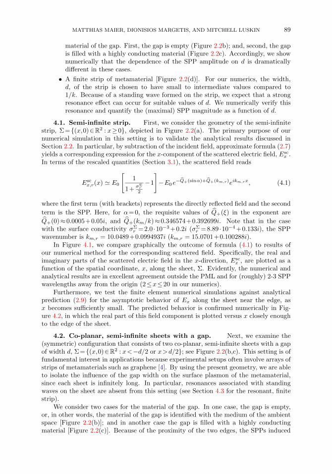
4.1. Semi-infinite strip. First, we consider the geometry of the semi-infinitestrip, Σ =(x,0)∈R2 : x≥0, depicted in Figure 2.2(a). The primary purpose of ournumerical simulation in this setting is to validate the analytical results discussed inSection 2.2. In particular, by subtraction of the incident field, approximate formula (2.7)yields a corresponding expression for the x-component of the scattered electric field, Esc
x .In terms of the rescaled quantities (Section 3.1), the scattered field reads
Escx,r(x) ' E0
[1
1+σΣr
2
−1
]−E0e
−Q+(sinα)+Q+(km,r)eikm,rx, (4.1)
where the first term (with brackets) represents the directly reflected field and the second
term is the SPP. Here, for α= 0, the requisite values of Q+(ξ) in the exponent are
Q+(0)≈0.0005+0.05i, and Q+(km/k)≈0.346574+0.392699i. Note that in the casewith the surface conductivity σΣ
r = 2.0 ·10−3 +0.2i (σΣr = 8.89 ·10−4 +0.133i), the SPP
wavenumber is km,r = 10.0489+0.0994937i (km,r = 15.0701+0.100288i).In Figure 4.1, we compare graphically the outcome of formula (4.1) to results of
our numerical method for the corresponding scattered field. Specifically, the real andimaginary parts of the scattered electric field in the x-direction, Esc
x , are plotted as afunction of the spatial coordinate, x, along the sheet, Σ. Evidently, the numerical andanalytical results are in excellent agreement outside the PML and for (roughly) 2-3 SPPwavelengths away from the origin (2≤x≤20 in our numerics).
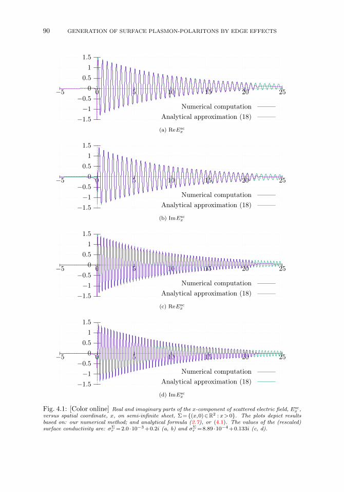
Furthermore, we test the finite element numerical simulations against analyticalprediction (2.9) for the asymptotic behavior of Ex along the sheet near the edge, asx becomes sufficiently small. The predicted behavior is confirmed numerically in Fig-ure 4.2, in which the real part of this field component is plotted versus x closely enoughto the edge of the sheet.
4.2. Co-planar, semi-infinite sheets with a gap. Next, we examine the(symmetric) configuration that consists of two co-planar, semi-infinite sheets with a gapof width d, Σ =(x,0)∈R2 : x<−d/2 or x>d/2; see Figure 2.2(b,c). This setting is offundamental interest in applications because experimental setups often involve arrays ofstrips of metamaterials such as graphene [4]. By using the present geometry, we are ableto isolate the influence of the gap width on the surface plasmon of the metamaterial,since each sheet is infinitely long. In particular, resonances associated with standingwaves on the sheet are absent from this setting (see Section 4.3 for the resonant, finitestrip).
We consider two cases for the material of the gap. In one case, the gap is empty,or, in other words, the material of the gap is identified with the medium of the ambientspace [Figure 2.2(b)]; and in another case the gap is filled with a highly conductingmaterial [Figure 2.2(c)]. Because of the proximity of the two edges, the SPPs induced
90 GENERATION OF SURFACE PLASMON-POLARITONS BY EDGE EFFECTS
−1.5
−1
−0.5
0
0.5
1
1.5
−5 0 5 10 15 20 25
Numerical computationAnalytical approximation (18)
(a) ReEscx
−1.5
−1
−0.5
0
0.5
1
1.5
−5 0 5 10 15 20 25
Numerical computationAnalytical approximation (18)
(b) ImEscx
−1.5
−1
−0.5
0
0.5
1
1.5
−5 0 5 10 15 20 25
Numerical computationAnalytical approximation (18)
(c) ReEscx
−1.5
−1
−0.5
0
0.5
1
1.5
−5 0 5 10 15 20 25
Numerical computationAnalytical approximation (18)
(d) ImEscx
Fig. 4.1: [Color online] Real and imaginary parts of the x-component of scattered electric field, Escx ,
versus spatial coordinate, x, on semi-infinite sheet, Σ =(x,0)∈R2 : x>0. The plots depict resultsbased on: our numerical method; and analytical formula (2.7), or (4.1). The values of the (rescaled)surface conductivity are: σΣ
r = 2.0 ·10−3 +0.2i (a, b) and σΣr = 8.89 ·10−4 +0.133i (c, d).
MATTHIAS MAIER, DIONISIOS MARGETIS, AND MITCHELL LUSKIN 91
−0.5
0
0.5
1
1.5
−0.2 −0.1 0 0.1 0.2 0.3 0.4
Numerical comp.Analytical approx. (9)
Fig. 4.2: [Color online] Real part of the x-component of (total) electric field, Ex, near the edge ofthe sheet versus spatial coordinate, x. The value of (rescaled) surface conductivity is σΣ
r = 2.0 ·10−3 +0.2i. Our numerical computation (solid line) is compared against near-edge asymptotic formula (2.9)(dashes). In the limit as x→0, the numerical and analytical results are in good agreement.
−2.5
−2
−1.5
−1
−0.5
0
0.5
1
1.5
−1 −0.5 0 0.5 1
d = 2−1
d = 2−4
d = 2−8
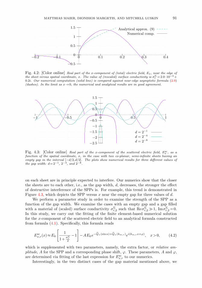
Fig. 4.3: [Color online] Real part of the x-component of the scattered electric field, Escx , as a
function of the spatial coordinate, x, in the case with two co-planar, semi-infinite sheets having anempty gap in the interval [−d/2,d/2]. The plots show numerical results for three different values ofthe gap width: d= 2−1, 2−4, and 2−8.
on each sheet are in principle expected to interfere. Our numerics show that the closerthe sheets are to each other, i.e., as the gap width, d, decreases, the stronger the effectof destructive interference of the SPPs is. For example, this trend is demonstrated inFigure 4.3, which depicts the SPP versus x near the empty gap for three values of d.
We perform a parameter study in order to examine the strength of the SPP as afunction of the gap width. We examine the cases with an empty gap and a gap filledwith a material of (scaled) surface conductivity σΣ
r,2 such that ReσΣr,21, ImσΣ
r,2 = 0.In this study, we carry out the fitting of the finite element-based numerical solutionfor the x-component of the scattered electric field to an analytical formula constructedfrom formula (4.1). Specifically, this formula reads
Escx,r(x)≈E0
[1
1+σΣr
2
−1
]−AE0e
−Q+(sinα)+Q+(km,r)ei(km,rx+ϕ), x>0, (4.2)
which is supplemented with two parameters, namely, the extra factor, or relative am-plitude, A for the SPP and a corresponding phase shift, ϕ. These parameters, A and ϕ,are determined via fitting of the last expression for Esc
x,r to our numerics.Interestingly, in the two distinct cases of the gap material mentioned above, we
92 GENERATION OF SURFACE PLASMON-POLARITONS BY EDGE EFFECTS
0
0.5
1
1.5
2
2−8 2−7 2−6 2−5 2−4 2−3 2−2 2−1
rel.
SPP
ampl
itud
e,A
gap width, d
empty gap
gap with conductor
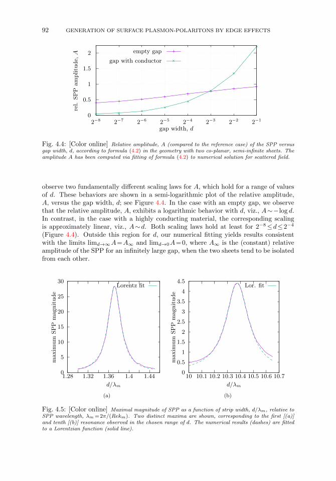
Fig. 4.4: [Color online] Relative amplitude, A (compared to the reference case) of the SPP versusgap width, d, according to formula (4.2) in the geometry with two co-planar, semi-infinite sheets. Theamplitude A has been computed via fitting of formula (4.2) to numerical solution for scattered field.
observe two fundamentally different scaling laws for A, which hold for a range of valuesof d. These behaviors are shown in a semi-logarithmic plot of the relative amplitude,A, versus the gap width, d; see Figure 4.4. In the case with an empty gap, we observethat the relative amplitude, A, exhibits a logarithmic behavior with d, viz., A∼−log d.In contrast, in the case with a highly conducting material, the corresponding scalingis approximately linear, viz., A∼d. Both scaling laws hold at least for 2−8≤d≤2−4
(Figure 4.4). Outside this region for d, our numerical fitting yields results consistentwith the limits limd→∞A=A∞ and limd→0A= 0, where A∞ is the (constant) relativeamplitude of the SPP for an infinitely large gap, when the two sheets tend to be isolatedfrom each other.
0
5
10
15
20
25
30
1.28 1.32 1.36 1.4 1.44
max
imum
SPP
magnitude
d/λm
Lorentz fit
(a)
0
0.5
1
1.5
2
2.5
3
3.5
4
4.5
10 10.1 10.2 10.3 10.4 10.5 10.6 10.7
max
imum
SPP
magnitude
d/λm
Lor. fit
(b)
Fig. 4.5: [Color online] Maximal magnitude of SPP as a function of strip width, d/λm, relative toSPP wavelength, λm = 2π/(Rekm). Two distinct maxima are shown, corresponding to the first [(a)]and tenth [(b)] resonance observed in the chosen range of d. The numerical results (dashes) are fittedto a Lorentzian function (solid line).
MATTHIAS MAIER, DIONISIOS MARGETIS, AND MITCHELL LUSKIN 93
4.3. Finite strip. Next, we consider the geometry of a finite metamaterialstrip, Σ =(x,0)∈R2 :−d/2≤x≤d/2 [Figure 2.2(d)]. In this case, if the length d ofthe strip is sufficiently large, the two edges are expected to cause resonances to theobserved SPP. In other words, the maximal magnitude of the SPP generated in thisstructure should exhibit peaks as a function of the strip width, d (for fixed k).
In our numerical simulations, we compute the resulting, maximal magnitude of theSPP as a function of d; see Figure 4.5. For these numerics, we choose the surfaceconductivity to be equal to σΣ
r = 2.0 ·10−3 +0.2i. We select two peaks among thoseobserved in the chosen range of values of d. These resonances are depicted in separateplots here [Figure 4.5(a,b)]. In order to quantify the two selected resonances, we carryout the fitting of the numerical results in each case to the Lorentzian function
ϕ(d) =Aπ
γ
[1+(d−d0)2/γ2
]−1.
The parameters d0, γ and A of this formula are determined via the fitting procedure.Specifically, we obtain the following values: d0 = 1.372λm, γ= 0.015λm, A= 1.34 forthe first resonance [Figure 4.5(a)]; and d0 = 10.375λm, γ= 0.11λm, A= 1.49 for an-other (tenth) resonance [Figure 4.5(b)] in the chosen range of values of d. Here,λm= 2π/(Rekm) is the SPP wavelength on the semi-infinite sheet of the same con-ductivity (see Section 2.2).
5. ConclusionIn this paper, we numerically studied the generation of SPPs on atomically thick
metamaterial sheets by edge effects in different geometries. Our chosen configurationsincluded: a semi-infinite sheet; two co-planar, semi-infinite sheets with a gap of variablewidth; and a finite strip of variable width. In our computations, we used an adaptivefinite element method with curl-conforming Ndlec-elements in order to resolve the finescale of the SPP propagating along the sheet in the presence of edges. Our numericalapproach here forms an extension of the method introduced in [26] to more realisticgeometries.
We validated our numerical treatment by comparison of the finite element-basednumerics to an analytical solution for the semi-infinite sheet [29]. By further numericalsimulations, we demonstrated that the presence of a highly conducting material in thegap between two co-planar, semi-infinite metamaterial sheets can increase the SPPmagnitude, and leads to a distinctly different dependence of the SPP on the gap widthin comparison to the case with an empty gap. In addition, we numerically characterizedSPP resonances on a finite strip, and demonstrated that the SPP maximal magnitude(as a function of gap width) is well described by a Lorentzian function.
Our results point to a few open problems. For instance, our computations havefocused on 2D, although our approach is applicable to arbitrary spatial dimensions. Anemerging question concerns the use of truly three-dimensional (3D) geometries, whichmay contain metamaterial sheets with corners, conical singularities or arbitrarily curvedhypersurfaces. The generation and propagation of SPPs in 3D settings is the subject ofongoing work.
Acknowledgments. The first and third authors (MM and ML) were supportedin part by ARO MURI Award W911NF-14-1-0247. The second author research wassupported in part by NSF DMS-1412769.
94 GENERATION OF SURFACE PLASMON-POLARITONS BY EDGE EFFECTS
REFERENCES
[1] P. Alonso-Gonzalez, A.Y. Nikitin, F. Golmar, A. Centeno, A. Pesquera, S. Velez, J. Chen, G. Nav-ickaite, F. Koppens, A. Zurutuza, F. Casanova, L.E. Hueso, and R. Hillenbrand, Controllinggraphene plasmons with resonant metal antennas and spatial conductivity patterns, Science,344:1369–1373, 2014.
[2] W. Bangerth, D. Davydov, T. Heister, L. Heltai, G. Kanschat, M. Kronbichler, M. Maier, B. Tur-cksin, and D. Wells, The deal. II Library, Version 8.4, Journal of Numerical Mathematics,24:135–141, 2016.
[3] R. Becker and R. Rannacher, An optimal control approach to a posteriori error estimation infinite element methods, Acta Numerica, 10:1–102, 2001.
[4] Y.V. Bludov, A. Ferreira, N. Peres, and M.I. Vasileskiy, A primer on surface plasmon-polaritonsin graphene, International Journal of Modern Physics, 27:1341001, 2013.
[5] J.-P. Brenger, A perfectly matched layer for the absorption of electromagnetic waves, J. Comput.Phys., 114:185–200, 1994.
[6] C. Carstensen, Hanging nodes in the unifying theory of a posteriori finit element error control,J. Comput. Math., 27:215–236, 2009.
[7] J. Cheng, W.L. Wang, H. Mosallaei, and E. Kaxiras, Surface plasmon engineering in graphenefunctionalized with organic molecules: A multiscale theoretical investigation, Nano Letters,14:50–56, 2014.
[8] W.C. Chew, Waves and Fields in Inhomogenous Media, Wiley-IEEE Press, New York, 1999.[9] W.C. Chew and W.H. Weedon, A 3D perfectly matched medium from modified maxwell’s equa-
tions with stretched coordinates, Microwave and Optical Technology Letters, 7:599–604, 1994.[10] P.G. Ciarlet, The Finite Element Method for Elliptic Problems, Classics in Applied Mathematics,
SIAM, Second Edition, 40, 2002.[11] S. D’Agostino, F.D. Sala, and L.C. Andreani, Dipole-excited surface plasmons in metallic
nanoparticles: Engineering decay dynamics within the discrete-dipole approximation, Physi-cal Review B, 87:205413, 2013.
[12] T.A. Davis, P.R. Amestoy, I.S. Duff, et al., SuiteSparse 4.2.1, A Suite of Sparse Matrix Software,2013.
[13] H. DeVoe, Optical properties of molecular aggregates. I. Classical model of electronic absorptionand refraction, Journal of Chemical Physics, 41:393–400, 1964.
[14] F.J. Garcıa de Abajo and A. Howie, Retarded field calculation of electron energy loss in inhomo-geneous dielectrics, Physical Review B, 65:115418, 2002.
[15] L. Felsen and N. Marcuvitz, Radiation and Scattering of Waves, IEEE Press, New York, 1994.[16] G.W. Ford and W.H. Weber, Electromagnetic interactions of molecules with metal surfaces,
Physics Reports, 113:195–287, 1984.[17] B. Gallinet, J. Butet, and O.J.F. Martin, Numerical methods for nanophotonics: standard prob-
lems and future challenges, Laser Photonics Reviews, 9:577–603, 2015.[18] A.K. Geim and I.V. Grigorieva, Van der Waals heterostructures, Nature, 499:419–425, 2013.[19] R.W. Gruhlke, W.R. Holland, and D.G. Hall, Surface-plasmon cross coupling in molecular fluo-
rescence near a corrugated thin metal filml, Physical Review Letters, 56:2838–2841, 1986.[20] G.W. Hanson, Dyadic Green’s functions and guided surface waves for a surface conductivity
model of graphene, J. Appl. Phys., 103:064302, 2008.[21] A. Kern, Realistic modeling of 3D plasmonic systems: A surface integral equation approach,
Ph.D. dissertation, Ecole Polytechnique Feederale de Lausanne, Switzerland, 2011.[22] A.M. Kern and O.J.F. Martin, Surface integral formulation for 3D simulations of plasmonic and
high permittivity nanostructures, Journal of the Optical Society of America A, 26:732–740,2009.
[23] R.W.P. King, M. Owens, and T.T. Wu, Lateral Electromagnetic Waves: Theory and Applicationsto Communications, Geophysical Exploration, and Remote Sensing, Springer-Verlag, NewYork, 1992.
[24] J.P. Kottmann and O.J.F. Martin, Accurate solution of the volume integral equation for high-permittivity scatterers, IEEE Transactions on Antennas and Propagation, 48(11):1719–1726,2000.
[25] Z. Liu, Y. Wang, J. Yao, H. Lee, W. Srituravanich, and X. Zhang, Broad band two-dimensionalmanipulation of surface plasmons, Nano Letters, 9:462–466, 2009.
[26] M. Maier, D. Margetis, and M. Luskin, Dipole excitation of surface plasmon on a conductingsheet: Finite element approximation and validation, J. Comput. Phys., 339:126–145, 2017.
[27] S.A. Maier, Plasmonics: Fundamentals and Applications, Springer, New York, 2007.[28] D. Margetis and M. Luskin, On solutions of Maxwell’s equations with dipole sources over a thin
conducting film, J. Math. Phys., 57:042903, 2016.
MATTHIAS MAIER, DIONISIOS MARGETIS, AND MITCHELL LUSKIN 95
[29] D. Margetis, M. Maier, and M. Luskin, On the Wiener-Hopf method for surface plasmons:Diffraction from semi-infinite metamaterial sheet, Studies in Applied Mathematics, (pub-lished online) 139:599-625, 2017.
[30] I.D. Mayergoyz, D.R. Fredkin, and Z. Zhang, Electrostatic (plasmon) resonances in nanoparticles,Physical Review B, 72:155412, 2005.
[31] H. Mertens, A.F. Koenderink, and A. Polman, Plasmon-enhanced luminescence near noble-metalnanospheres: Comparison of exact theory and an improved Gersten and Nitzan model, Phys-ical Review B, 76:115123, 2007.
[32] A. Mohammadi, V. Sandoghdar, and M. Agio, Gold nanorods and nanospheroids for enhancingspontaneous emission, New Journal of Physics, 10:105015, 2008.
[33] P. Monk, Finite Element Methods for Maxwell’s Equations, Numerical Mathematics and ScientificComputation, Oxford University Press, 2003.
[34] A.H.C. Neto, F. Guinea, N.M.R. Peres, K.S. Novoselov, and A.K. Geim, The electronic propertiesof graphene, Reviews of Modern Physics, 81:109–162, 2009.
[35] J.-C. Nedelec, A new family of mixed finite elements in R3, Numerische Mathematik, 50:57–81,1986.
[36] A. Satou and S.A. Mikhailov, Excitation of two-dimensional plasmon polaritons by an incidentelectromagnetic wave at a contact, Phys. Rev. B, 75:045328, 2007.
[37] U. Hohenester and A. Trugler, MNPBEM-A Matlab toolbox for the simulation of plasmonicnanoparticles, Comput. Phys. Commun., 183:370–381, 2012.
[38] U. Zulicke and R. Winkler, Magnetoelectric effect in bilayer graphene controlled by valley-isospindensity, Physical Review B, 90:125412, 2014.
[39] J.P. Webb, Hierarchal vector basis functions of arbitrary order for triangular and tetrahedralfinite elements, IEEE Transactions on Antennas and Propagation, 47:1244–1253, 1999.
[40] X.C. Zhang and J. Xu, Introduction to THz Wave Photonics, Springer, Berlin, 2010.


