Embed Size (px)
Citation preview
OMRON
General Selection Guide
Vol. 3
i
Table of Contents
Industrial Components/Devices
General-purpose & Power Relays 1
Solid State Relays 2
Measuring and Monitoring Relays 3
Basic Switches 4
Limit Switches 4
Timers 5
Cam Positioners 8
Counters 8
Switching Power Supplies 9
Temperature Controllers 11
Intelligent Signal Processors 17
Digital Panel Meters 19
Digital Heater Element Burnout Detectors 20
Interface Converters 20
Level Controllers 21
Liquid Leakage Sensors 21
Sensing Solutions
Photoelectric Sensors 23
Photomicrosensors 27
Rotary Encoders 28
Proximity Sensors 29
Smart Sensors 31
Ultrasonic Sensors 31
Vision Sensors 32
Ionizers 33
Clean Sensing Systems 34
Data Loggers 35
UV Bonding 36
Automation Systems
Simple Logic Controllers 37
Programmable Controllers 37
CompoNet 39
DeviceNet 40
Multiple I/O Terminals 41
Programmable Terminals 42
Inverters 43
Servo Motors and Servo Drives 43
Motion Controllers 44
Software 45
RFID Systems 46
Safety Solutions
Safety Door Switches 51
Safety Limit Switches 52
Safety Light Curtains / Safety Sensors 52
Presence Detection Sensors 53
Emergency Stop Switches 53
Rope-Pull E-Stop Switches 54
Relays with Forcibly Guided Contacts 54
Enabling Switches 55
DeviceNet Safety System 55
Flexible Safety Units 56
Safety Controllers 56
Safety Relay Units 56
1
Industrial Devices/Components
General-purpose Relays & Power Relays
Model Features/ Weight
Contact Coil Electrical life
expectan-cy
Terminals
Form Ratings (resistive
load)
Max. switching
current
Rated voltage
Power consumption
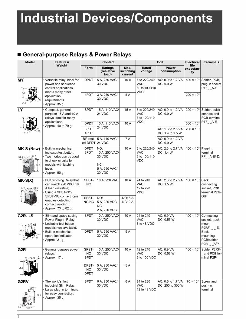
MY • Versatile relay, ideal for
power and sequence
control applications,
meets many other
application
requirements.
• Approx. 35 g.
DPDT 5 A, 250 VAC/
30 VDC
10 A 6 to 220/240
VAC
60 to 100/110
VDC
AC: 0.9 to 1.2 VA
DC: 0.9 W
500 × 10³ Solder, PCB,
plug-in socket
PYF_ _A-E
4PDT 3 A, 250 VAC/
30 VDC
5 A 200 × 10³
LY • Compact, general-
purpose 15 A and 10 A
relays ideal for many
applications.
• Approx. 40 to 70 g.
SPDT 15 A, 110 VAC/
24 VDC
15 A 6 to 220/240
VAC
6 to 100/110
VDC
AC: 0.9 to 1.2 VA
DC: 0.9 W
200 × 10³ Solder, quick-
connect and
PCB terminal
PTF_ _A-EDPDT 10 A, 110 VAC/
24 VDC
10 A 500 × 10³
3PDT
4PDT
AC: 1.6 to 2.5 VA
DC: 1.4 to 1.5 W
200 × 10³
Bifurcat-
ed-DPDT
5 A, 110 VAC/
24 VDC
7 A AC: 0.9 to 1.2 VA
DC: 0.9 W
MK-S (New) • Built-in mechanical
indicator/test button.
• Two modes can be used
to check circuits for
models with latching
lever.
• Approx. 90 g.
DPDT
3PDT
NO:
10 A, 250 VAC/
30 VDC
NC:
5 A, 250 VAC/
30 VDC
10 A 6 to 220/240
VAC
6 to 100/110
VDC
AC: 2.3 to 2.7 VA
DC: 1.4 W
100 × 10³ Plug-in
terminal
PF_ _A-E/-D.
MK-S(X) • DC Switching Relay that
can switch 220 VDC, 10
A load (resistive).
• Using a SPST-NO/
SPST-NC contact form
enables detecting
contact welding.
• Approx. 73 to 82 g.
SPST-
NO
10 A, 220 VAC 10 A 24 to 240
VAC
12 to 220
VDC
AC: 2.3 to 2.7 VA
DC: 1.5 W
100 × 10³ Back
connecting
socket, PCB
terminal P7M-
06PSPST-
NO/NC
NO:
5 A, 220 VDC
NC:
2 A, 220 VDC
NO: 5 A
NC: 2 A
G2R-_-S • Slim and space saving
Power Plug-in Relay.
• Lockable test button
models now available.
• Built-in mechanical
operation indicator.
• Approx. 21 g.
SPDT 10 A, 250 VAC/
30 VDC
10 A 24 to 240
VAC
6 to 48 VDC
AC: 0.9 VA
DC: 0.53 W
100 × 10³ Connecting
socket, track-
mount
P2RF- _ _-E.
Back-
mounting
PCB/solder
P2R- _ _A/P.
DPDT 5 A, 250 VAC/
30 VDC
5 A
G2R • General-purpose power
relays.
• Approx. 17 g.
SPST-
NO
SPDT
10 A, 250 VAC/
30 VDC
10 A 12 to 240
VAC
5 to 100 VDC
AC: 0.9 VA
DC: 0.53 W
100 × 10³ Solder P2RF-
_ and PCB ter-
minal P2R-_
DPST-
NO
DPDT
5 A, 250 VAC/
30 VDC
5 A
G2RV • The world's first
industrial Slim Relay.
• Large plug-in terminals
for easy connection.
• Approx. 35 g.
SPDT 6 A, 250 VAC/
30 VDC
6 A 24 to 230
VAC
12 to 48 VDC
AC: 0.5 to 1.7 VA
DC: 250 to 300 W
70 × 10³ Screw and
push-in
terminal
36
28
21.5
36
2821.5
52.5
34.534.5
44
34.534.5
35.5
2913
25.5
1329
92.7
6.2106.7
2
Ind
us
tria
l D
ev
ice
s
” Magnetic Latching and Ratchet Relays
Solid State Relays
Model Features/ Weight
Contact Coil Electrical life ex-
pectancy
Terminals
Form Ratings (resistive
load)
Max. switching
current
Rated voltage
Power consumption
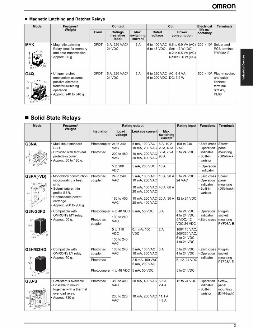
MYK • Magnetic Latching
Relay ideal for memory
and data transmission.
• Approx. 30 g.
DPDT 3 A, 220 VAC/
24 VDC
3 A 6 to 100 VAC
6 to 48 VDC
0.6 to 0.9 VA (AC)
Set: 1.3 W (DC)
0.2 to 0.5 VA (AC)
Reset: 0.6 W (DC)
200 × 10³ Solder and
PCB terminal
PYF08A-E
G4Q • Unique ratchet
mechanism assures
positive alternate
transfer/switching
operation.
• Approx. 240 to 340 g
DPDT 5 A, 220 VAC/
24 VDC
5 A 6 to 220 VAC
6 to 200 VDC
AC: 6.4 VA
DC: 3.9 W
500 × 10³ Plug-in socket
and quick-
connect
terminal
8PFA1,
PL08
Model Features/ Weight
Rating output Rating input Functions Terminals
Insulation Load voltage
Leakage current Max. switching
current
G3NA • Multi-input standard
SSR.
• Provided with terminal
protection cover.
• Approx. 60 to 120 g.
Photocoupler
Phototriac
24 to 240
VAC
200 to 480
VAC
5 mA, 100 VAC
10 mA, 200 VAC
10 mA, 200 VAC
20 mA, 400 VAC
5 A, 10 A,
20 A, 40 A,
50 A, 75 A,
90 A
100 to 240
VAC
5 to 24 VDC
• Zero cross
• Operation
indicator
• Built-in
varistor
Screw,
panel
mounting
(DIN-track)
5 to 200
VDC
5 mA, 200 VDC 10 A • Operation
indicator
G3PA(-VD) • Monoblock construction
incorporating a heat
sink.
• Subminiature, thin
profile SSR.
• Replaceable power
cartridge.
• Approx. 260 to 900 g.
Phototriac
coupler
24 to 240
VAC
5 mA, 100 VAC
10 mA, 200 VAC
10 A, 20 A 5 to 24 VDC
24 VAC
• Zero cross
• Operation
indicator
• Built-in
varistor
Screw,
panel
mounting
(DIN-track)10 mA, 100 VAC
20 mA, 200 VAC
40 A, 60 A
180 to 400
VAC
10 mA, 200 VAC
20 mA, 400 VAC
20 A, 30 A 12 to 24 VDC
G3F/G3FD • Compatible with
OMRON’s MY relay.
• Approx. 50 g.
Photocoupler
Phototriac
coupler
4 to 48 VDC
100 to 240
VAC
5 mA, 50 VDC 3 A 5 to 24 VDC,
4 to 24 VDC,
5 VDC, 12
VDC,24 VDC
• Operation
indicator
• Zero cross
Plug-in
socket
mounting
PYF08A-E
5 to 110
VDC
100 to 240
VAC
0.1 mA, 100
VDC
2 A 100/110 VAC,
200/220 VAC,
5 to 24 VDC,
4 to 24 VDC
G3H/G3HD • Compatible with
OMRON’s LY relay.
• Approx. 50 g.
Phototriac
coupler
100 to 240
VAC
5 mA, 100 VAC
10 mA, 200 VAC
3 A 5 to 24 VDC,
4 to 24 VDC
• Zero cross
• Operation
indicator
Plug-in
socket
mounting
PTF08A-EPhototriac 2.5 mA, 100 VAC
5 mA, 200 VAC
5, 12, 24 VDC
Photocoupler 4 to 48 VDC 5 mA, 50 VDC 5 to 24 VDC
G3J-S • Soft-start is available.
• Possible to mount
together with a thermal
overload relay.
• Approx. 730 g.
Phototriac 380 to 400
VAC
20 mA, 400 VAC 5.5 A
2.4 A
12 to 24 VDC • Operation
indicator
• Built-in
varistor
Screw,
panel
mounting
(DIN-track)200 to 220
VAC
10 mA, 200 VAC 11.1 A
4.8 A
36
2821.5
85
63.592.5
27
4358
100
80
27
36.5
21.5
28
36.5
21.5
28
100
100
80
3 Industrial Devices/Components
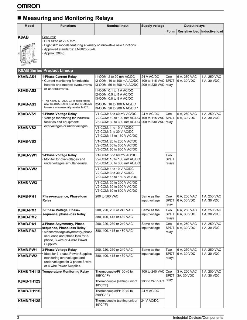
Measuring and Monitoring Relays
Model Functions Nominal input Supply voltage Output relays
Form Resistive load Inductive load
K8AB Features:
• DIN sized at 22.5 mm.
• Eight slim models featuring a variety of innovative new functions.
• Approved standards: EN60255-5/-6.
• Approx. 200 g.
K8AB Series Product Lineup
K8AB-AS1 1-Phase Current Relay
• Current monitoring for industrial
heaters and motors: overcurrents
or undercurrents.
* The K8AC-CT200L CT is required to use the K8AB-AS3. Use the K8AB-AS to use a commercially available CT.
l1-COM: 2 to 20 mA AC/DC
l2-COM: 10 to 100 mA AC/DC
l3-COM: 50 to 500 mA AC/DC
24 V AC/DC
100 to 115 VAC
200 to 230 VAC
One
SPDT
relay
6 A, 250 VAC
6 A, 30 VDC
1 A, 250 VAC
1 A, 30 VDC
K8AB-AS2 l1-COM: 0.1 to 1 A AC/DC
l2-COM: 0.5 to 5 A AC/DC
l3-COM: 0.8 to 8 A AC/DC
K8AB-AS3 l2-COM: 10 to 100 A AC/DC
l3-COM: 20 to 200 A AC/DC *
K8AB-VS1 1-Phase Voltage Relay
• Voltage monitoring for industrial
facilities and equipment:
overvoltages or undervoltages.
V1-COM: 6 to 60 mV AC/DC
V2-COM: 10 to 100 mV AC/DC
V3-COM: 30 to 300 mV AC/DC
24 V AC/DC
100 to 115 VAC
200 to 230 VAC
One
SPDT
relay
6 A, 250 VAC
6 A, 30 VDC
1 A, 250 VAC
1 A, 30 VDC
K8AB-VS2 V1-COM: 1 to 10 V AC/DC
V2-COM: 3 to 30 V AC/DC
V3-COM: 15 to 150 V AC/DC
K8AB-VS3 V1-COM: 20 to 200 V AC/DC
V2-COM: 30 to 300 V AC/DC
V3-COM: 60 to 600 V AC/DC
K8AB-VW1 1-Phase Voltage Relay
• Monitor for overvoltages and
undervoltages simultaneously.
V1-COM: 6 to 60 mV AC/DC
V2-COM: 10 to 100 mV AC/DC
V3-COM: 30 to 300 mV AC/DC
Two
SPDT
relays
K8AB-VW2 V1-COM: 1 to 10 V AC/DC
V2-COM: 3 to 30 V AC/DC
V3-COM: 15 to 150 V AC/DC
K8AB-VW3 V1-COM: 20 to 200 V AC/DC
V2-COM: 30 to 300 V AC/DC
V3-COM: 60 to 600 V AC/DC
K8AB-PH1 Phase-sequence, Phase-loss
Relay
200 to 500 VAC Same as the
input voltage
One
SPDT
relay
6 A, 250 VAC
6 A, 30 VDC
1 A, 250 VAC
1 A, 30 VDC
K8AB-PM1 3-Phase Voltage, Phase-
sequence, phase-loss Relay
200, 220, 230 or 240 VAC Same as the
input voltage
Two
SPDT
relays
6 A, 250 VAC
6 A, 30 VDC
1 A, 250 VAC
1 A, 30 VDCK8AB-PM2 380, 400, 415 or 480 VAC
K8AB-PA1 3-Phase Asymmetry, Phase-
sequence, Phase-loss Relay
• Monitor voltage asymmetry, phase
sequence and phase loss for 3-
phase, 3-wire or 4-wire Power
Supplies.
200, 220, 230 or 240 VAC Same as the
input voltage
One
SPDT
relay
6 A, 250 VAC
6 A, 30 VDC
1 A, 250 VAC
1 A, 30 VDCK8AB-PA2 380, 400, 415 or 480 VAC
K8AB-PW1 3-Phase Voltage Relay
• Ideal for 3-phase Power Supplies
monitoring overvoltages and
undervoltages for 3-phase 3-wire
or 4-wire Power Supplies.
200, 220, 230 or 240 VAC Same as the
input voltage
Two
SPDT
relays
6 A, 250 VAC
6 A, 30 VDC
1 A, 250 VAC
1 A, 30 VDCK8AB-PW2 380, 400, 415 or 480 VAC
K8AB-TH11S Temperature Monitoring Relay Thermocouple/Pt100 (0 to
399°C/°F)
100 to 240 VAC One
SPDT
relay
3 A, 250 VAC
3A, 30 VDC
1 A, 250 VAC
1 A, 30 VDC
K8AB-TH12S Thermocouple (setting unit of
10°C/°F)
100 to 240 VAC
K8AB-TH11S Thermocouple/Pt100 (0 to
399°C/°F)
24 V AC/DC
K8AB-TH12S Thermocouple (setting unit of
10°C/°F)
24 V AC/DC
90
22.5
100
4
Ind
us
tria
l D
ev
ice
s
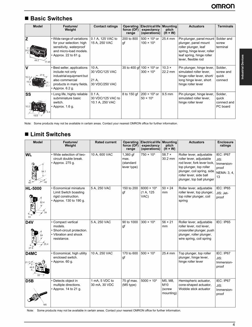
Basic Switches
Note: Some products may not be available in certain areas. Contact your nearest OMRON office for further information.
Limit Switches
Model Features/ Weight
Contact ratings Operating force (OF)
range
Electrical life expectancy (operations)
Mounting pitch
(H × W)
Actuators Terminals
Z • Wide range of variations
for your selection: high
sensitivity, waterproof
and micro-load models.
• Approx. 22 to 61 g.
0.1 A, 125 VAC to
15 A, 250 VAC
200 to 800
gf
500 × 10³ or
100 × 10³
25.4 mm Pin plunger, panel mount
plunger, panel mount
roller plunger, leaf
spring, hinge lever, roller
leaf spring, hinge roller
lever, flexible rod
Solder and
screw
terminal
V • Best seller, applications
include not only
industrial equipment but
also commercial
products in many fields.
• Approx. 6.2 g.
10 A,
30 VDC/125 VAC
21 A,
30 VDC/250 VAC
35 to 400 gf 100 × 10³ or
300 × 10³
10.3 ×
22.2 mm
Pin plunger, hinge lever,
simulated roller lever,
hinge roller lever, short/
long hinge lever, short
hinge roller lever
Solder,
screw and
quick
connect
SS • Long life, highly reliable
subminiature basic
switch.
• Approx. 1.6 g.
0.1 A,
30 VDC/125 VAC to
10.1 A, 250 VAC
8 to 150 gf 200 × 10³ or
50 × 10³
9.5 mm Pin plunger, hinge lever,
simulated roller lever,
hinge roller lever
Solder,
quick
connect and
PC board
Model Features/ Weight
Rated current Operating force (OF)
range
Electrical life expectancy (operations)
Mounting pitch
(H × W)
Actuators Enclosure ratings
WL • Wide selection of two-
circuit double break.
• Approx. 275 g.
10 A, 600 VAC 1,360 gf
max.
(standard
lever type)
750 × 10³ 58.7 ×
30.2 mm
Roller lever, adjustable
roller lever, adjustable
rod lever, fork lever lock,
top plunger, top roller
plunger, coil spring, side
roller lever, side ball
plunger, top ball plunger
IEC: IP67
JIS:
Immersion-
proof
NEMA: 3, 4,
13
HL-5000 • Economical miniature
Limit Switch boasting
rigid construction.
• Approx. 130 to 190 g.
5 A, 250 VAC 150 to 200
gf
6000 × 10³
(1 A, 125
VAC)
50 × 24
mm
Roller lever, adjustable
roller lever, top plunger,
top roller plunger, coil
spring
IEC: IP65
JIS: Jet-
proof
D4V • Compact vertical
models.
• Short-circuit protection.
• Vibration and shock
resistance.
5 A, 250 VAC 90 to 1000
gf
300 × 10³ 56 × 21
mm
Roller lever, adjustable
roller lever, rod lever,
crossroller plunger, push
plunger, roller plunger,
wire spring, coil spring
IEC: IP65
D4MC • Economical, high utility
enclosed switch.
• Approx. 60 g.
10 A, 250 VAC 170 to 600
gf
500 × 10³ 25.4 mm Top plunger, top roller
plunger, hinge lever,
hinge roller lever
IEC: IP67
JIS:
Immersion-
proof
D5B • Detects object in
multiple directions.
• Approx. 14 to 21 g.
1 mA, 5 VDC to
30 mA, 30 VDC
75 gf max.
(M5 type)
5000 × 10³ M5, M8,
M10
(screw
mounting)
Hemispheric actuator,
cone-shaped actuator,
Wobble stick actuator
IEC: IP67
JIS:
Immersion-
proof
24.2
49.217.45
27.810.3
15.9
19.8
6.4
10.2
94.1
4240
82.4
34
33
64
25.4
27.8
55
21.7
44.8
M5
Note: Some products may not be available in certain areas. Contact your nearest OMRON office for further information.
5 Industrial Devices/Components
Note: Some products may not be available in certain areas. Contact your nearest OMRON office for further information.
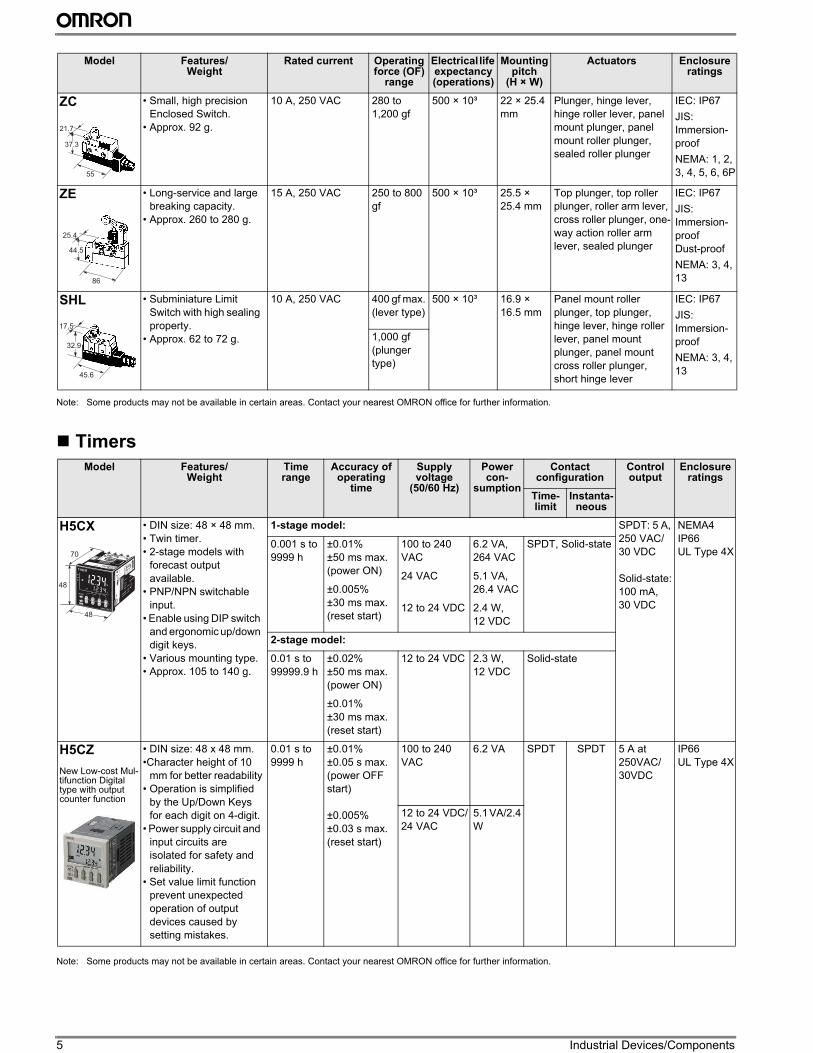
Timers
Note: Some products may not be available in certain areas. Contact your nearest OMRON office for further information.
ZC • Small, high precision
Enclosed Switch.
• Approx. 92 g.
10 A, 250 VAC 280 to
1,200 gf
500 × 10³ 22 × 25.4
mm
Plunger, hinge lever,
hinge roller lever, panel
mount plunger, panel
mount roller plunger,
sealed roller plunger
IEC: IP67
JIS:
Immersion-
proof
NEMA: 1, 2,
3, 4, 5, 6, 6P
ZE • Long-service and large
breaking capacity.
• Approx. 260 to 280 g.
15 A, 250 VAC 250 to 800
gf
500 × 10³ 25.5 ×
25.4 mm
Top plunger, top roller
plunger, roller arm lever,
cross roller plunger, one-
way action roller arm
lever, sealed plunger
IEC: IP67
JIS:
Immersion-
proof
Dust-proof
NEMA: 3, 4,
13
SHL • Subminiature Limit
Switch with high sealing
property.
• Approx. 62 to 72 g.
10 A, 250 VAC 400 gf max.
(lever type)
500 × 10³ 16.9 ×
16.5 mm
Panel mount roller
plunger, top plunger,
hinge lever, hinge roller
lever, panel mount
plunger, panel mount
cross roller plunger,
short hinge lever
IEC: IP67
JIS:
Immersion-
proof
NEMA: 3, 4,
13
1,000 gf
(plunger
type)
Model Features/ Weight
Time range
Accuracy of operating
time
Supply voltage
(50/60 Hz)
Power con-
sumption
Contact configuration
Control output
Enclosure ratings
Time-limit
Instanta-neous
H5CX • DIN size: 48 × 48 mm.
• Twin timer.
• 2-stage models with
forecast output
available.
• PNP/NPN switchable
input.
• Enable using DIP switch
and ergonomic up/down
digit keys.
• Various mounting type.
• Approx. 105 to 140 g.
1-stage model: SPDT: 5 A,
250 VAC/
30 VDC
Solid-state:
100 mA,
30 VDC
NEMA4
IP66
UL Type 4X0.001 s to
9999 h
±0.01%
±50 ms max.
(power ON)
±0.005%
±30 ms max.
(reset start)
100 to 240
VAC
24 VAC
12 to 24 VDC
6.2 VA,
264 VAC
5.1 VA,
26.4 VAC
2.4 W,
12 VDC
SPDT, Solid-state
2-stage model:
0.01 s to
99999.9 h
±0.02%
±50 ms max.
(power ON)
±0.01%
±30 ms max.
(reset start)
12 to 24 VDC 2.3 W,
12 VDC
Solid-state
H5CZ
New Low-cost Mul-tifunction Digital type with output counter function
• DIN size: 48 x 48 mm.
•Character height of 10
mm for better readability
• Operation is simplified
by the Up/Down Keys
for each digit on 4-digit.
• Power supply circuit and
input circuits are
isolated for safety and
reliability.
• Set value limit function
prevent unexpected
operation of output
devices caused by
setting mistakes.
0.01 s to
9999 h
±0.01%
±0.05 s max.
(power OFF
start)
±0.005%
±0.03 s max.
(reset start)
100 to 240
VAC
6.2 VA SPDT SPDT 5 A at
250VAC/
30VDC
IP66
UL Type 4X
12 to 24 VDC/
24 VAC
5.1 VA/2.4
W
Model Features/ Weight
Rated current Operating force (OF)
range
Electrical life expectancy (operations)
Mounting pitch
(H × W)
Actuators Enclosure ratings
55
21.7
37.3
44.5
86
25.4
45.6
17.5
32.9
48
48
70
6
Ind
us
tria
l D
ev
ice
s
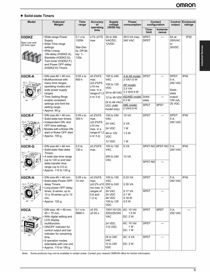
” Solid-state Timers
Model Features/ Weight
Time range
Accuracy of
operating time
Supply voltage
(50/60 Hz)
Power consumption
Contact configuration
Control output
Enclosure ratings
Time-limit
Instanta-neous
H3DKZ
New Low-cost 22.5mm type
• Wide-range Power
Supply
• Wide Time range
settings
• Wide Lineup:
ON-delay (H3DKZ-A),
Stardelta (H3DKZ-G),
Twin-timer (H3DKZ-F),
and Power OFF-delay
(H3DKZ-H) Timers
0.1 s to
1200h
Star-Del-
ta, Off-de-
lay: 1-
120s
±1% of FS
max
24 to 240
VAC/DC,
12VDC
29.5 VA max,
240 VAC
SPDT,
DPDT
--- 5A at
250VAC
or
30VDC
IP30
H3CR-A • DIN size:48 × 48 mm.
• Multifunctional with
many time ranges,
operating modes and
wide power supply
ranges.
• Time Setting Rings
enable consistent
settings and limit the
setting range.
• Approx. 90 g.
0.05 s to
600 h
±0.2%FS
max.
(±0.2%FS
±10 ms
max. in a
range of 1.2
s or 3 s)
100 to 240
VAC
100 to 125
VDC
24 to 48 VAC
12 to 48 VDC
24 to 48 VAC/
VDC (A8E
model only)
A & A8 model:
2 VA/1.6 W
AP model:
2.5 VA/
2.2 W/0.9 W
DPDT --- DPDT:
5 A,
250 VAC
Solid-
state
output:
100 mA,
30 VDC
IP40
AS/A8S model:
0.3 W
Solid-
state
---
A8E model:
2 VA/0.9 W
SPDT SPDT
H3CR-F • DIN size:48 × 48 mm.
• Solid-state twin timers.
• Independent ON- and
OFF-time settings.
• Models with a flicker ON
start or flicker OFF start.
• Approx. 100 g.
0.05 s to
300 h
±0.2%FS
max.
(±0.2%FS
±10 ms
max. in a
range of 1.2
s or 3 s)
100 to 240
VAC
24 VAC
24 VDC
48 to 125
VDC
12 VDC
10 VA
2 VA
1 W
1.5 W
1 W
DPDT --- DPDT:
5 A,
250 VAC
IP40
H3CR-G • DIN size:48 × 48 mm
• Solid-state Star-delta
Timers.
• A wide star-time range
(up to 120 s) and star-
delta transfer time
range (up to 0.5 s).
• Approx. 110 to 130 g.
0.5 to
120 s
±0.2%FS
max.
100 to 120
VAC
200 to 240
VAC
6 VA
12 VA
SPST-NO SPST-NO 5 A,
250 VAC
IP40
SPST-NO ---
H3CR-H • DIN size:48 × 48 mm.
• Solid-state Power OFF-
delay Timers.
• Long power OFF-delay
times; S-series: up to
12 s; M-series up to 12
min.
• Approx. 120 g.
0.05 s to
12 min
±0.2%FS
max.
(±0.2% ±10
ms max. in
ranges of
0.6 and
1.2 s)
100 to 120
VAC
200 to 240
VAC
24 VAC
24 VDC
48 VDC
100 to 125
VDC
0.23 VA
0.35 VA
0.17 VA
0.1 W
0.18 W
0.5 W
DPDT --- 5 A,
250 VAC
IP40
SPDT ---
H3CA • DIN size: 48 × 48 mm,
45 × 75 mm.
• With digital setting and
LCD display
multifunction.
• ON/OFF indicator for
control output and bar
indicator for remaining
time.
• 8 operation modes
selectable with one unit.
• Approx. 110 to 190 g.
0.1 s to
9990 h
±0.3%
±0.05 s
100/110/120,
200/220/240
VAC
24 VDC
110 VDC
AC: 10 VA/
1.5 W
DC: 2 W
SPDT SPDT 3 A,
250 VAC
---
AC: 10 VA/
1 W
DC: 1 W
DPDT ---
24 to 240
VAC
12 to 240
VDC
AC: 4 VA
DC: 2 W
SPDT ---
48
48
52.3
48
48
52.3
48
48
63.7
48
48
63.7
48
48
89
Note: Some products may not be available in certain areas. Contact your nearest OMRON office for further information.
7 Industrial Devices/Components
Note: Some products may not be available in certain areas. Contact your nearest OMRON office for further information.
” Time Switches
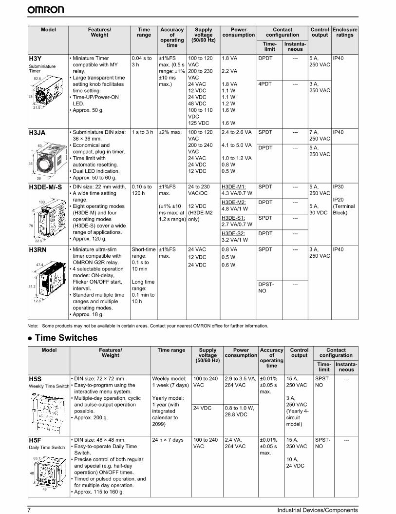
H3YSubminiature Timer
• Miniature Timer
compatible with MY
relay.
• Large transparent time
setting knob facilitates
time setting.
• Time-UP/Power-ON
LED.
• Approx. 50 g.
0.04 s to
3 h
±1%FS
max. (0.5 s
range: ±1%
±10 ms
max.)
100 to 120
VAC
200 to 230
VAC
24 VAC
12 VDC
24 VDC
48 VDC
100 to 110
VDC
125 VDC
1.8 VA
2.2 VA
1.8 VA
1.1 W
1.1 W
1.2 W
1.6 W
1.6 W
DPDT --- 5 A,
250 VAC
IP40
4PDT --- 3 A,
250 VAC
H3JA • Subminiature DIN size:
36 × 36 mm.
• Economical and
compact, plug-in timer.
• Time limit with
automatic resetting.
• Dual LED indication.
• Approx. 50 to 60 g.
1 s to 3 h ±2% max. 100 to 120
VAC
200 to 240
VAC
24 VAC
24 VDC
12 VDC
2.4 to 2.6 VA
4.1 to 5.0 VA
1.0 to 1.2 VA
0.8 W
0.5 W
SPDT --- 7 A,
250 VAC
IP40
DPDT --- 5 A,
250 VAC
H3DE-M/-S • DIN size: 22 mm width.
• A wide time setting
range.
• Eight operating modes
(H3DE-M) and four
operating modes
(H3DE-S) cover a wide
range of applications.
• Approx. 120 g.
0.10 s to
120 h
±1%FS
max.
(±1% ±10
ms max. at
1.2 s range)
24 to 230
VAC/DC
12 VDC
(H3DE-M2
only)
H3DE-M1:
4.3 VA/0.7 W
SPDT --- 5 A,
250 VAC
5 A,
30 VDC
IP30
IP20
(Terminal
Block)
H3DE-M2:
4.8 VA/1 W
DPDT ---
H3DE-S1:
2.7 VA/0.7 W
SPDT ---
H3DE-S2:
3.2 VA/1 W
DPDT ---
H3RN • Miniature ultra-slim
timer compatible with
OMRON G2R relay.
• 4 selectable operation
modes: ON-delay,
Flicker ON/OFF start,
interval.
• Standard multiple time
ranges and multiple
operating modes.
• Approx. 18 g.
Short-time
range:
0.1 s to
10 min
Long time
range:
0.1 min to
10 h
±1%FS
max.
24 VAC
12 VDC
24 VDC
0.8 VA
0.5 W
0.6 W
SPDT --- 3 A,
250 VAC
IP40
DPST-
NO
---
Model Features/ Weight
Time range Supply voltage
(50/60 Hz)
Power consumption
Accuracy of
operating time
Control output
Contact configuration
Time-limit
Instanta-neous
H5SWeekly Time Switch
• DIN size: 72 × 72 mm.
• Easy-to-program using the
interactive menu system.
• Multiple-day operation, cyclic
and pulse-output operation
possible.
• Approx. 200 g.
Weekly model:
1 week (7 days)
Yearly model:
1 year (with
integrated
calendar to
2099)
100 to 240
VAC
2.9 to 3.5 VA,
264 VAC
±0.01%
±0.05 s
max.
15 A,
250 VAC
3 A,
250 VAC
(Yearly 4-
circuit
model)
SPST-
NO
---
24 VDC 0.8 to 1.0 W,
28.8 VDC
H5FDaily Time Switch
• DIN size: 48 × 48 mm.
• Easy-to-operate Daily Time
Switch.
• Precise control of both regular
and special (e.g. half-day
operation) ON/OFF times.
• Timed or pulsed operation, and
for multiple day operation.
• Approx. 115 to 160 g.
24 h × 7 days 100 to 240
VAC
2.4 VA,
264 VAC
±0.01%
±0.05 s
max.
15 A,
250 VAC
10 A,
24 VDC
SPST-
NO
---
Model Features/ Weight
Time range
Accuracy of
operating time
Supply voltage
(50/60 Hz)
Power consumption
Contact configuration
Control output
Enclosure ratings
Time-limit
Instanta-neous
28
21.5
52.6
36
36
60
100
79
22.5
47.4
31.2
12.8
48
63.7
48
8
Ind
us
tria
l D
ev
ice
s
Cam Positioners
Counters
Note: Some products may not be available in certain areas. Contact your nearest OMRON office for further information.
Model Features/ Weight
Max. response
speed
Supply voltage
(50/60 Hz)
Power consumption
Number of digits
displayed
Control input Control output
Mounting method
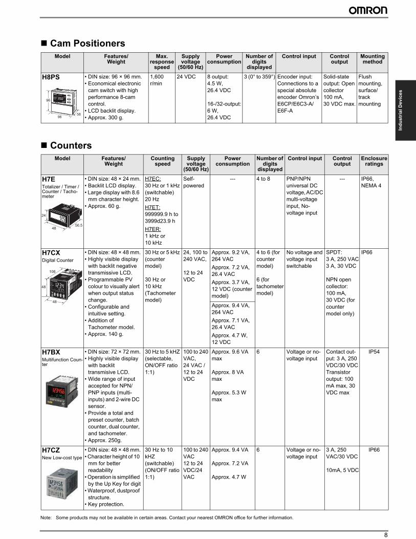
H8PS • DIN size: 96 × 96 mm.
• Economical electronic
cam switch with high
performance 8-cam
control.
• LCD backlit display.
• Approx. 300 g.
1,600
r/min
24 VDC 8 output:
4.5 W,
26.4 VDC
16-/32-output:
6 W,
26.4 VDC
3 (0° to 359°) Encoder input:
Connections to a
special absolute
encoder Omron’s
E6CP/E6C3-A/
E6F-A
Solid-state
output: Open
collector
100 mA,
30 VDC max.
Flush
mounting,
surface/
track
mounting
Model Features/ Weight
Counting speed
Supply voltage
(50/60 Hz)
Power consumption
Number of digits
displayed
Control input Control output
Enclosure ratings
H7ETotalizer / Timer / Counter / Tacho-meter
• DIN size: 48 × 24 mm.
• Backlit LCD display.
• Large display with 8.6
mm character height.
• Approx. 60 g.
H7EC:
30 Hz or 1 kHz
(switchable)
20 Hz
H7ET:
999999.9 h to
3999d23.9 h
H7ER:
1 kHz or
10 kHz
Self-
powered
--- 4 to 8 PNP/NPN
universal DC
voltage, AC/DC
multi-voltage
input, No-
voltage input
--- IP66,
NEMA 4
H7CXDigital Counter
• DIN size: 48 × 48 mm.
• Highly visible display
with backlit negative
transmissive LCD.
• Programmable PV
colour to visually alert
when output status
change.
• Configurable and
intuitive setting.
• Addition of
Tachometer model.
• Approx. 140 g.
30 Hz or 5 kHz
(counter
model)
30 Hz or
10 kHz
(Tachometer
model)
24, 100 to
240 VAC,
12 to 24
VDC
Approx. 9.2 VA,
264 VAC
Approx. 7.2 VA,
26.4 VAC
Approx. 3.7 VA,
12 VDC (counter
model)
4 to 6 (for
counter
model)
6 (for
tachometer
model)
No voltage and
voltage input
switchable
SPDT:
3 A, 250 VAC
3 A, 30 VDC
NPN open
collector:
100 mA,
30 VDC (for
counter
model only)
IP66
Approx. 9.4 VA,
264 VAC
Approx. 7.1 VA,
26.4 VAC
Approx. 4.7 W,
12 VDC
H7BXMultifunction Coun-ter
• DIN size: 72 × 72 mm.
• Highly visible display
with backlit
transmisive LCD.
• Wide range of input
accepted for NPN/
PNP inputs (multi-
inputs) and 2-wire DC
sensor.
• Provide a total and
preset counter, batch
counter, dual counter,
and tachometer.
• Approx. 250g.
30 Hz to 5 kHZ
(selectable,
ON/OFF ratio
1:1)
100 to 240
VAC,
24 VAC /
12 to 24
VDC
Approx. 9.6 VA
max
Approx. 8 VA
max
Approx. 5.3 W
max
6 Voltage or no-
voltage input
Contact out-
put: 3 A, 250
VDC/30 VDC
Transistor
output: 100
mA max, 30
VDC max
IP54
H7CZNew Low-cost type
• DIN size: 48 × 48 mm.
• Character height of 10
mm for better
readability
• Operation is simplified
by the Up Key for digit
• Waterproof, dustproof
structure.
• Key protection.
30 Hz to 10
kHZ
(switchable)
(ON/OFF ratio
1:1)
100 to 240
VAC
12 to 24
VDC/24
VAC
Approx. 9.4 VA
Approx. 7.2 VA
Approx. 4.7 W
6 Voltage or no-
voltage input
3 A, 250
VAC/30 VDC
10mA, 5 VDC
IP66
96
9658
4856.5
24
48
48
106
9 Industrial Devices/Components
Switching Power Supplies
Model Features/ Weight
Supply voltage(50/60 Hz)
Power ratings
Output voltage (VDC)
Output current
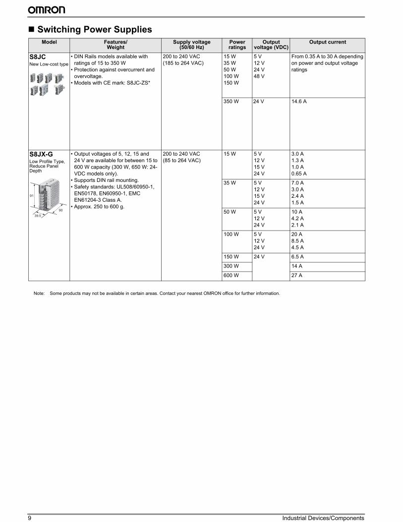
S8JCNew Low-cost type
• DIN Rails models available with
ratings of 15 to 350 W
• Protection against overcurrent and
overvoltage.
• Models with CE mark: S8JC-ZS*
200 to 240 VAC
(185 to 264 VAC)
15 W
35 W
50 W
100 W
150 W
5 V
12 V
24 V
48 V
From 0.35 A to 30 A depending
on power and output voltage
ratings
350 W 24 V 14.6 A
S8JX-GLow Profile Type, Reduce Panel Depth
• Output voltages of 5, 12, 15 and
24 V are available for between 15 to
600 W capacity (300 W, 650 W: 24-
VDC models only).
• Supports DIN rail mounting.
• Safety standards: UL508/60950-1,
EN50178, EN60950-1, EMC
EN61204-3 Class A.
• Approx. 250 to 600 g.
200 to 240 VAC
(85 to 264 VAC)
15 W 5 V
12 V
15 V
24 V
3.0 A
1.3 A
1.0 A
0.65 A
35 W 5 V
12 V
15 V
24 V
7.0 A
3.0 A
2.4 A
1.5 A
50 W 5 V
12 V
24 V
10 A
4.2 A
2.1 A
100 W 5 V
12 V
24 V
20 A
8.5 A
4.5 A
150 W 24 V 6.5 A
300 W 14 A
600 W 27 A
91
39.5
90
Note: Some products may not be available in certain areas. Contact your nearest OMRON office for further information.
10
Ind
us
tria
l D
ev
ice
s
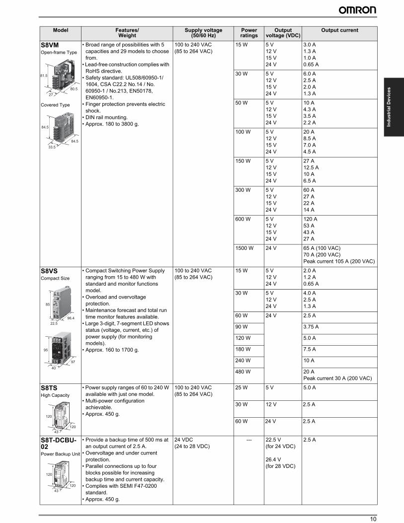
S8VMOpen-frame Type
Covered Type
• Broad range of possibilities with 5
capacities and 29 models to choose
from.
• Lead-free construction complies with
RoHS directive.
• Safety standard: UL508/60950-1/
1604, CSA C22.2 No.14 / No.
60950-1 / No.213, EN50178,
EN60950-1.
• Finger protection prevents electric
shock.
• DIN rail mounting.
• Approx. 180 to 3800 g.
100 to 240 VAC
(85 to 264 VAC)
15 W 5 V
12 V
15 V
24 V
3.0 A
1.3 A
1.0 A
0.65 A
30 W 5 V
12 V
15 V
24 V
6.0 A
2.5 A
2.0 A
1.3 A
50 W 5 V
12 V
15 V
24 V
10 A
4.3 A
3.5 A
2.2 A
100 W 5 V
12 V
15 V
24 V
20 A
8.5 A
7.0 A
4.5 A
150 W 5 V
12 V
15 V
24 V
27 A
12.5 A
10 A
6.5 A
300 W 5 V
12 V
15 V
24 V
60 A
27 A
22 A
14 A
600 W 5 V
12 V
15 V
24 V
120 A
53 A
43 A
27 A
1500 W 24 V 65 A (100 VAC)
70 A (200 VAC)
Peak current 105 A (200 VAC)
S8VSCompact Size
• Compact Switching Power Supply
ranging from 15 to 480 W with
standard and monitor functions
model.
• Overload and overvoltage
protection.
• Maintenance forecast and total run
time monitor features available.
• Large 3-digit, 7-segment LED shows
status (voltage, current, etc.) of
power supply (for monitoring
models).
• Approx. 160 to 1700 g.
100 to 240 VAC
(85 to 264 VAC)
15 W 5 V
12 V
24 V
2.0 A
1.2 A
0.65 A
30 W 5 V
12 V
24 V
4.0 A
2.5 A
1.3 A
60 W 24 V 2.5 A
90 W 3.75 A
120 W 5.0 A
180 W 7.5 A
240 W 10 A
480 W 20 A
Peak current 30 A (200 VAC)
S8TSHigh Capacity
• Power supply ranges of 60 to 240 W
available with just one model.
• Multi-power configuration
achievable.
• Approx. 450 g.
100 to 240 VAC
(85 to 264 VAC)
25 W 5 V 5.0 A
30 W 12 V 2.5 A
60 W 24 V 2.5 A
S8T-DCBU-02Power Backup Unit
• Provide a backup time of 500 ms at
an output current of 2.5 A.
• Overvoltage and under current
protection.
• Parallel connections up to four
blocks possible for increasing
backup time and current capacity.
• Complies with SEMI F47-0200
standard.
• Approx. 450 g.
24 VDC
(24 to 28 VDC)
--- 22.5 V
(for 24 VDC)
26.4 V
(for 28 VDC)
2.5 A
Model Features/ Weight
Supply voltage(50/60 Hz)
Power ratings
Output voltage (VDC)
Output current
81.5
27
80.5
84.5
33.5
84.5
95
40
97
85
22.5
96.4
120
43
120
120
43
120
11 Industrial Devices/Components
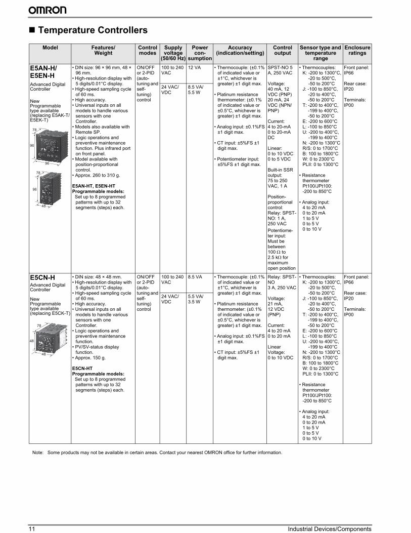
Temperature Controllers
Model Features/ Weight
Control modes
Supply voltage
(50/60 Hz)
Power con-
sumption
Accuracy (indication/setting)
Control output
Sensor type and temperature
range
Enclosure ratings
E5AN-H/E5EN-H
Advanced Digital Controller
New Programmable type available (replacing E5AK-T/E5EK-T)
• DIN size: 96 × 96 mm, 48 × 96 mm.
• High-resolution display with 5 digits/0.01°C display.
• High-speed sampling cycle of 60 ms.
• High accuracy.• Universal inputs on all
models to handle various sensors with one Controller.
• Models also available with Remote SP.
• Logic operations and preventive maintenance function. Plus infrared port on front panel.
• Model available with position-proportional control.
• Approx. 260 to 310 g.
E5AN-HT, E5EN-HTProgrammable models: Set up to 8 programmed
patterns with up to 32 segments (steps) each.
ON/OFF or 2-PID (auto-tuning and self-tuning) control
100 to 240 VAC
12 VA • Thermocouple: (±0.1% of indicated value or ±1°C, whichever is greater) ±1 digit max.
• Platinum resistance thermometer: (±0.1% of indicated value or ±0.5°C, whichever is greater) ±1 digit max.
• Analog input: ±0.1%FS ±1 digit max.
• CT input: ±5%FS ±1 digit max.
• Potentiometer input: ±5%FS ±1 digit max.
SPST-NO 5 A, 250 VAC
Voltage:40 mA, 12 VDC (PNP)20 mA, 24 VDC (NPN/PNP)
Current:4 to 20-mA0 to 20-mA DC
Linear:0 to 10 VDC0 to 5 VDC
Built-in SSR output:75 to 250 VAC, 1 A
Position-proportional control:Relay: SPST-NO: 1 A, 250 VAC
Potentiome-ter input:Must be between 100 Ω to 2.5 kΩ for maximum open position
• Thermocouples:K: -200 to 1300°C,
-20 to 500°C,-50 to 200°C
J: -100 to 850°C,-20 to 400°C,-50 to 200°C
T: -200 to 400°C,-199 to 400°C,-50 to 200°C
E: -200 to 600°CL: -100 to 850°CU: -200 to 400°C,
-199 to 400°CN: -200 to 1300°CR/S: 0 to 1700°CB: 100 to 1800°CW: 0 to 2300°CPLII: 0 to 1300°C
• Resistance thermometer Pt100/JPt100: -200 to 850°C
• Analog input: 4 to 20 mA0 to 20 mA1 to 5 V0 to 5 V0 to 10 V
Front panel:IP66
Rear case:IP20
Terminals:IP00
24 VAC/VDC
8.5 VA/5.5 W
E5CN-HAdvanced Digital Controller
New Programmable type available (replacing E5CK-T)
• DIN size: 48 × 48 mm.• High-resolution display with
5 digits/0.01°C display. • High-speed sampling cycle
of 60 ms. • High accuracy.• Universal inputs on all
models to handle various sensors with one Controller.
• Logic operations and preventive maintenance function.
• PV/SV-status display function.
• Approx. 150 g.
E5CN-HTProgrammable models: Set up to 8 programmed
patterns with up to 32 segments (steps) each.
ON/OFF or 2-PID (auto-tuning and self-tuning) control
100 to 240 VAC
8.5 VA • Thermocouple: (±0.1% of indicated value or ±1°C, whichever is greater) ±1 digit max.
• Platinum resistance thermometer: (±0.1% of indicated value or ±0.5°C, whichever is greater) ±1 digit max.
• Analog input: ±0.1%FS ±1 digit max.
• CT input: ±5%FS ±1 digit max.
Relay: SPST-NO 3 A, 250 VAC
Voltage: 21 mA, 12 VDC (PNP)
Current: 4 to 20 mA0 to 20 mA
Linear Voltage:0 to 10 VDC
• Thermocouples:K: -200 to 1300°C,
-20 to 500°C,-50 to 200°C
J: -100 to 850°C,-20 to 400°C,-50 to 200°C
T: -200 to 400°C,-199 to 400°C,-50 to 200°C
E: -200 to 600°CL: -100 to 850°CU: -200 to 400°C,
-199 to 400°CN: -200 to 1300°CR/S: 0 to 1700°CB: 100 to 1800°CW: 0 to 2300°CPLII: 0 to 1300°C
• Resistance thermometer Pt100/JPt100: -200 to 850°C
• Analog input: 4 to 20 mA0 to 20 mA1 to 5 V0 to 5 V0 to 10 V
Front panel:IP66
Rear case:IP20
Terminals:IP00
24 VAC/VDC
5.5 VA/3.5 W
96
96
78
96
48
78
48
48
78
Note: Some products may not be available in certain areas. Contact your nearest OMRON office for further information.
12
Ind
us
tria
l D
ev
ice
s
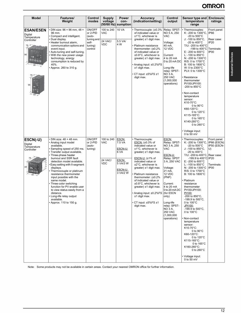
E5AN/E5ENDigital Temperature Controller
• DIN size: 96 × 96 mm, 48 × 96 mm.
• Compact and intelligent.• Dual display.• Heater burnout alarm,
communication options and event input.
• Auto-tuning and self-tuning.• With the new power usage
technology, energy consumption is reduced by 40%.
• Approx. 260 to 310 g.
ON/OFF or 2-PID (auto-tuning and self-tuning) control
100 to 240 VAC
10 VA • Thermocouple: (±0.3% of indicated value or ±1°C, whichever is greater) ±1 digit max.
• Platinum resistance thermometer: (±0.2% of indicated value or ±0.8°C, whichever is greater) ±1 digit max.
• Analog input: ±0.2%FS ±1 digit max.
• CT input: ±5%FS ±1 digit max.
Relay: SPST-NO 5 A, 250 VAC
Voltage: 40 mA, 12 VDC
Current: 4 to 20 mA0 to 20 mA DC
Long-life relay: SPST-NO 3 A, 250 VAC (1,000,000 operations)
• Thermocouples:K: -200 to 1300°C,
-20 to 500°CJ: -100 to 850°C,
-20 to 400°CT/U: -200 to 400°C
-199 to 400°CE: -200 to 600°CL: -100 to 850°CN: -200 to 1300°CR/S: 0 to 1700°CB: 100 to 1800°CW: 0 to 2300°CPLII: 0 to 1300°C
• Resistance thermometer Pt100/JPt100: -200 to 850°C
• Non-contact temperature sensor: K10-70°C: 0 to 90°CK60-120°C: 0 to 120°CK115-165°C: 0 to 165°CK140-260°C: 0 to 260°C
• Voltage input: 0 to 50 mV
Front panel:IP66
Rear case:IP20
Terminals:IP00
24 VAC/VDC
5.5 VA/4 W
E5CN(-U)Digital Temperature Controller
• DIN size: 48 × 48 mm.• Analog input model
available.• Sampling speed of 250 ms.• Transfer output available.• Three-phase heater
burnout and SSR fault detection model available.
• Easy setting with II-segment displays.
• Thermocouple or platinum resistance thermometer input possible with the same model.
• Three-color switching function for PV enable user to view status easily from a distance.
• Long-life relay output available.
• Approx. 110 to 150 g.
ON/OFF or 2-PID (auto-tuning)
100 to 240 VAC
E5CN: 7.5 VA
E5CN-U: 6 VA
• Thermocouple:E5CN: (±0.3% of indicated value or ±1°C, whichever is greater) ±1 digit max.
E5CN-U: (±1% of indicated value or ±2°C, whichever is greater) ±1 digit max.
• Platinum resistance thermometer: (±0.2% of indicated value or ±0.8°C, whichever is greater) ±1 digit max.
• Analog input: ±0.2%FS ±1 digit max.
• CT input: ±5%FS ±1 digit max.
E5CN: Relay: SPST-NO 3 A, 250 VAC
E5CN-U: Relay: SPDT 3 A, 250 VAC
Voltage: 21 mA, 12 VDC (PNP)
Current: 4 to 20 mA0 to 20 mA DC (for E5CN only)
Long-life relay: SPST-NO 3 A, 250 VAC (1,000,000 operations)
• Thermocouples:K: -200 to 1300°C,
-20 to 500°CJ: -100 to 850°C,
-20 to 400°CT/U: -200 to 400°C,
-199.9 to 400°CE: -200 to 600°CL: -100 to 850°CN: -200 to 1300°CR/S: 0 to 1700°CB: 100 to 1800°C
• Platinum resistance thermometer Pt100/JPt100: Pt100: -200 to 850°C,-199.9 to 500°C,0 to 100°CJPt100: -199.9 to 500°C,0 to 100°C
• Non-contact temperature sensor: K10-70°C: 0 to 90°CK60-120°C: 0 to 120°CK115-165°C: 0 to 165°CK160-260°C: 0 to 260°C
• Voltage input: 0 to 50 mV
Front panel:IP66 (E5CN)IP50 (E5CN-U)
Rear case:IP20
Terminals:IP00
24 VAC/VDC
E5CN: 5 VA/3 W
E5CN-U: 3 VA/2 W
Model Features/ Weight
Control modes
Supply voltage
(50/60 Hz)
Power con-
sumption
Accuracy (indication/setting)
Control output
Sensor type and temperature
range
Enclosure ratings
96
96
78
96
48
78
48
48
78
Note: Some products may not be available in certain areas. Contact your nearest OMRON office for further information.
13 Industrial Devices/Components
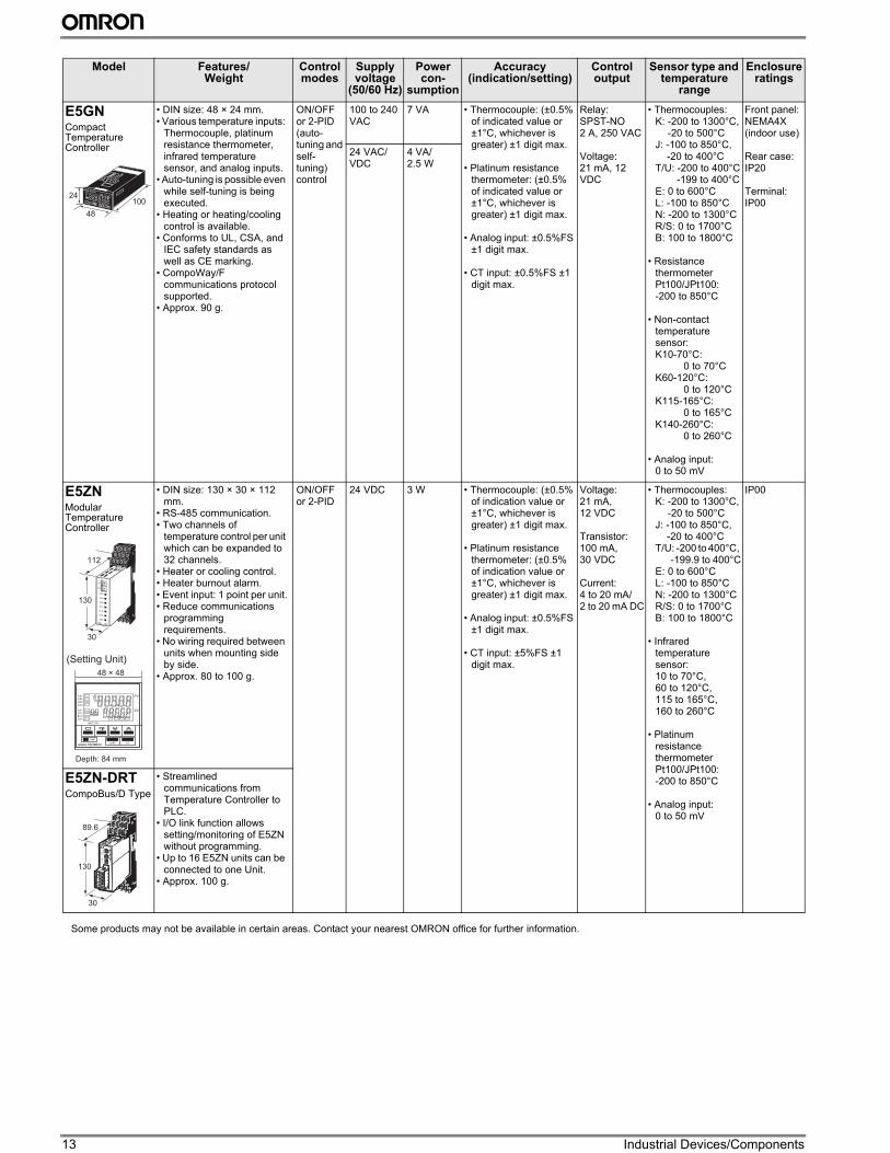
E5GNCompact Temperature Controller
• DIN size: 48 × 24 mm.• Various temperature inputs:
Thermocouple, platinum resistance thermometer, infrared temperature sensor, and analog inputs.
• Auto-tuning is possible even while self-tuning is being executed.
• Heating or heating/cooling control is available.
• Conforms to UL, CSA, and IEC safety standards as well as CE marking.
• CompoWay/F communications protocol supported.
• Approx. 90 g.
ON/OFF or 2-PID (auto-tuning and self-tuning) control
100 to 240 VAC
7 VA • Thermocouple: (±0.5% of indicated value or ±1°C, whichever is greater) ±1 digit max.
• Platinum resistance thermometer: (±0.5% of indicated value or ±1°C, whichever is greater) ±1 digit max.
• Analog input: ±0.5%FS ±1 digit max.
• CT input: ±0.5%FS ±1 digit max.
Relay: SPST-NO2 A, 250 VAC
Voltage: 21 mA, 12 VDC
• Thermocouples:K: -200 to 1300°C,
-20 to 500°CJ: -100 to 850°C,
-20 to 400°CT/U: -200 to 400°C
-199 to 400°CE: 0 to 600°CL: -100 to 850°CN: -200 to 1300°CR/S: 0 to 1700°CB: 100 to 1800°C
• Resistance thermometer Pt100/JPt100: -200 to 850°C
• Non-contact temperature sensor: K10-70°C: 0 to 70°CK60-120°C: 0 to 120°CK115-165°C: 0 to 165°CK140-260°C: 0 to 260°C
• Analog input: 0 to 50 mV
Front panel:NEMA4X(indoor use)
Rear case:IP20
Terminal:IP00
24 VAC/VDC
4 VA/2.5 W
E5ZNModular Temperature Controller
• DIN size: 130 × 30 × 112 mm.
• RS-485 communication.• Two channels of
temperature control per unit which can be expanded to 32 channels.
• Heater or cooling control.• Heater burnout alarm.• Event input: 1 point per unit.• Reduce communications
programming requirements.
• No wiring required between units when mounting side by side.
• Approx. 80 to 100 g.
ON/OFF or 2-PID
24 VDC 3 W • Thermocouple: (±0.5% of indication value or ±1°C, whichever is greater) ±1 digit max.
• Platinum resistance thermometer: (±0.5% of indication value or ±1°C, whichever is greater) ±1 digit max.
• Analog input: ±0.5%FS ±1 digit max.
• CT input: ±5%FS ±1 digit max.
Voltage: 21 mA, 12 VDC
Transistor: 100 mA, 30 VDC
Current:4 to 20 mA/2 to 20 mA DC
• Thermocouples:K: -200 to 1300°C,
-20 to 500°CJ: -100 to 850°C,
-20 to 400°CT/U: -200 to 400°C,
-199.9 to 400°CE: 0 to 600°CL: -100 to 850°CN: -200 to 1300°CR/S: 0 to 1700°CB: 100 to 1800°C
• Infrared temperature sensor: 10 to 70°C, 60 to 120°C, 115 to 165°C, 160 to 260°C
• Platinum resistance thermometer Pt100/JPt100: -200 to 850°C
• Analog input: 0 to 50 mV
IP00
E5ZN-DRTCompoBus/D Type
• Streamlined communications from Temperature Controller to PLC.
• I/O link function allows setting/monitoring of E5ZN without programming.
• Up to 16 E5ZN units can be connected to one Unit.
• Approx. 100 g.
Model Features/ Weight
Control modes
Supply voltage
(50/60 Hz)
Power con-
sumption
Accuracy (indication/setting)
Control output
Sensor type and temperature
range
Enclosure ratings
S V
P V
AL
48
10024
112
30
130
48 × 48
Depth: 84 mm
(Setting Unit)
89.6
30
130
Some products may not be available in certain areas. Contact your nearest OMRON office for further information.
14
Ind
us
tria
l D
ev
ice
s
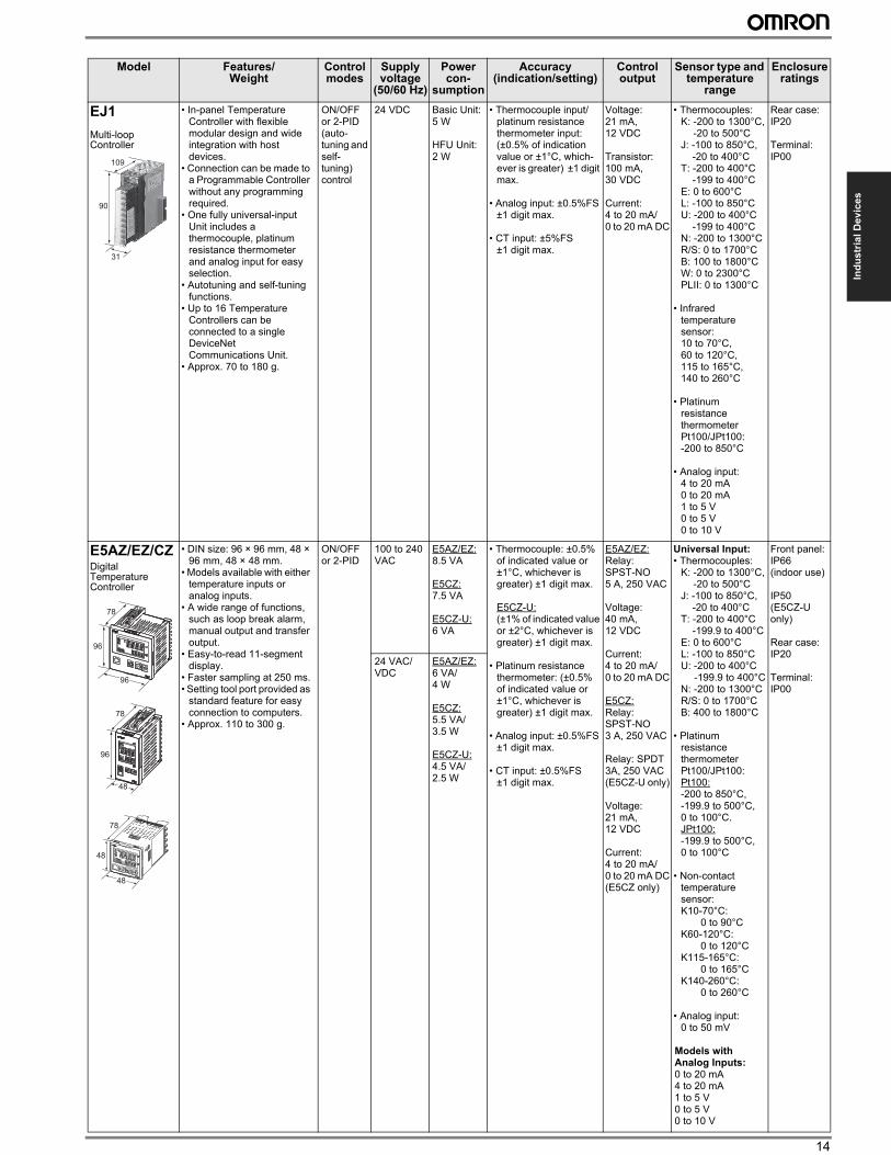
EJ1
Multi-loop Controller
• In-panel Temperature Controller with flexible modular design and wide integration with host devices.
• Connection can be made to a Programmable Controller without any programming required.
• One fully universal-input Unit includes a thermocouple, platinum resistance thermometer and analog input for easy selection.
• Autotuning and self-tuning functions.
• Up to 16 Temperature Controllers can be connected to a single DeviceNet Communications Unit.
• Approx. 70 to 180 g.
ON/OFF or 2-PID (auto-tuning and self-tuning) control
24 VDC Basic Unit:5 W
HFU Unit:2 W
• Thermocouple input/platinum resistance thermometer input:(±0.5% of indication value or ±1°C, which-ever is greater) ±1 digit max.
• Analog input: ±0.5%FS ±1 digit max.
• CT input: ±5%FS ±1 digit max.
Voltage: 21 mA, 12 VDC
Transistor: 100 mA, 30 VDC
Current:4 to 20 mA/0 to 20 mA DC
• Thermocouples:K: -200 to 1300°C,
-20 to 500°CJ: -100 to 850°C,
-20 to 400°CT: -200 to 400°C
-199 to 400°CE: 0 to 600°CL: -100 to 850°CU: -200 to 400°C
-199 to 400°CN: -200 to 1300°CR/S: 0 to 1700°CB: 100 to 1800°CW: 0 to 2300°CPLII: 0 to 1300°C
• Infrared temperature sensor: 10 to 70°C, 60 to 120°C, 115 to 165°C, 140 to 260°C
• Platinum resistance thermometer Pt100/JPt100: -200 to 850°C
• Analog input: 4 to 20 mA0 to 20 mA1 to 5 V0 to 5 V0 to 10 V
Rear case:IP20
Terminal:IP00
E5AZ/EZ/CZDigital Temperature Controller
• DIN size: 96 × 96 mm, 48 × 96 mm, 48 × 48 mm.
• Models available with either temperature inputs or analog inputs.
• A wide range of functions, such as loop break alarm, manual output and transfer output.
• Easy-to-read 11-segment display.
• Faster sampling at 250 ms.• Setting tool port provided as
standard feature for easy connection to computers.
• Approx. 110 to 300 g.
ON/OFF or 2-PID
100 to 240 VAC
E5AZ/EZ: 8.5 VA
E5CZ:7.5 VA
E5CZ-U:6 VA
• Thermocouple: ±0.5% of indicated value or ±1°C, whichever is greater) ±1 digit max.
E5CZ-U: (±1% of indicated value or ±2°C, whichever isgreater) ±1 digit max.
• Platinum resistance thermometer: (±0.5% of indicated value or ±1°C, whichever is greater) ±1 digit max.
• Analog input: ±0.5%FS ±1 digit max.
• CT input: ±0.5%FS ±1 digit max.
E5AZ/EZ:Relay: SPST-NO 5 A, 250 VAC
Voltage: 40 mA, 12 VDC
Current: 4 to 20 mA/0 to 20 mA DC
E5CZ:Relay: SPST-NO 3 A, 250 VAC
Relay: SPDT3A, 250 VAC (E5CZ-U only)
Voltage: 21 mA, 12 VDC
Current: 4 to 20 mA/0 to 20 mA DC(E5CZ only)
Universal Input:• Thermocouples:
K: -200 to 1300°C,-20 to 500°C
J: -100 to 850°C,-20 to 400°C
T: -200 to 400°C-199.9 to 400°C
E: 0 to 600°CL: -100 to 850°CU: -200 to 400°C
-199.9 to 400°CN: -200 to 1300°CR/S: 0 to 1700°CB: 400 to 1800°C
• Platinum resistance thermometer Pt100/JPt100:Pt100:-200 to 850°C, -199.9 to 500°C, 0 to 100°C. JPt100: -199.9 to 500°C, 0 to 100°C
• Non-contact temperature sensor: K10-70°C: 0 to 90°CK60-120°C: 0 to 120°CK115-165°C: 0 to 165°CK140-260°C: 0 to 260°C
• Analog input: 0 to 50 mV
Models with Analog Inputs:0 to 20 mA4 to 20 mA1 to 5 V0 to 5 V0 to 10 V
Front panel:IP66(indoor use)
IP50 (E5CZ-U only)
Rear case:IP20
Terminal:IP00
24 VAC/VDC
E5AZ/EZ:6 VA/4 W
E5CZ:5.5 VA/3.5 W
E5CZ-U:4.5 VA/2.5 W
Model Features/ Weight
Control modes
Supply voltage
(50/60 Hz)
Power con-
sumption
Accuracy (indication/setting)
Control output
Sensor type and temperature
range
Enclosure ratings
90
31
109
96
96
78
96
48
78
48
48
78
15 Industrial Devices/Components
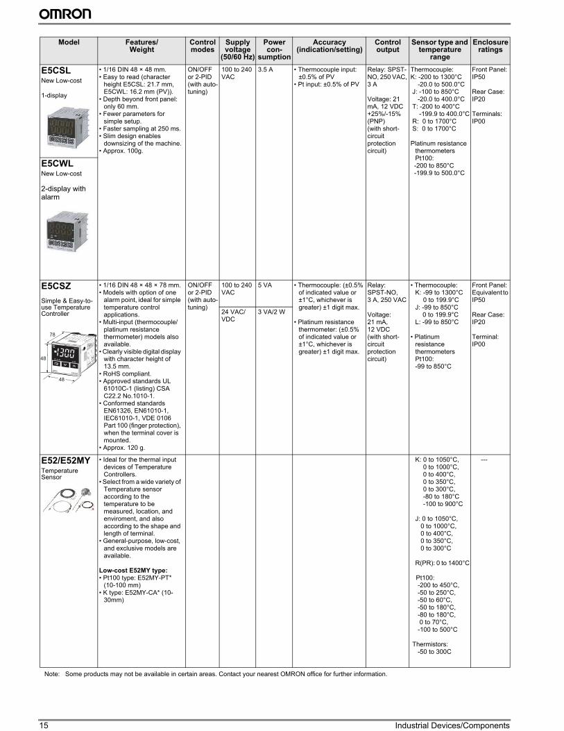
E5CSLNew Low-cost
1-display
• 1/16 DIN 48 × 48 mm.• Easy to read (character
height E5CSL: 21.7 mm, E5CWL: 16.2 mm (PV)).
• Depth beyond front panel: only 60 mm.
• Fewer parameters for simple setup.
• Faster sampling at 250 ms.• Slim design enables
downsizing of the machine.• Approx. 100g.
ON/OFF or 2-PID (with auto-tuning)
100 to 240 VAC
3.5 A • Thermocouple input: ±0.5% of PV
• Pt input: ±0.5% of PV
Relay: SPST-NO, 250 VAC, 3 A
Voltage: 21 mA, 12 VDC +25%/-15% (PNP)(with short-circuit protection circuit)
Thermocouple:K: -200 to 1300°C -20.0 to 500.0°C J: -100 to 850°C -20.0 to 400.0°C T: -200 to 400°C -199.9 to 400.0°C R: 0 to 1700°C S: 0 to 1700°C
Platinum resistance thermometers Pt100:
-200 to 850°C -199.9 to 500.0°C
Front Panel: IP50
Rear Case: IP20
Terminals: IP00
E5CWLNew Low-cost
2-display with alarm
E5CSZ
Simple & Easy-to-use Temperature Controller
• 1/16 DIN 48 × 48 × 78 mm.• Models with option of one
alarm point, ideal for simple temperature control applications.
• Multi-input (thermocouple/ platinum resistance thermometer) models also available.
• Clearly visible digital display with character height of 13.5 mm.
• RoHS compliant.• Approved standards UL
61010C-1 (listing) CSA C22.2 No.1010-1.
• Conformed standards EN61326, EN61010-1, IEC61010-1, VDE 0106 Part 100 (finger protection), when the terminal cover is mounted.
• Approx. 120 g.
ON/OFF or 2-PID (with auto-tuning)
100 to 240 VAC
5 VA • Thermocouple: (±0.5% of indicated value or ±1°C, whichever is greater) ±1 digit max.
• Platinum resistance thermometer: (±0.5% of indicated value or ±1°C, whichever is greater) ±1 digit max.
Relay: SPST-NO, 3 A, 250 VAC
Voltage: 21 mA, 12 VDC (with short-circuit protection circuit)
• Thermocouple:K: -99 to 1300°C
0 to 199.9°CJ: -99 to 850°C
0 to 199.9°CL: -99 to 850°C
• Platinum resistance thermometers Pt100:-99 to 850°C
Front Panel:Equivalent to IP50
Rear Case:IP20
Terminal:IP00
24 VAC/VDC
3 VA/2 W
E52/E52MYTemperature Sensor
• Ideal for the thermal input devices of Temperature Controllers.
• Select from a wide variety of Temperature sensor according to the temperature to be measured, location, and enviroment, and also according to the shape and length of terminal.
• General-purpose, low-cost, and exclusive models are available.
Low-cost E52MY type:• Pt100 type: E52MY-PT*
(10-100 mm)• K type: E52MY-CA* (10-
30mm)
K: 0 to 1050°C,0 to 1000°C,0 to 400°C,0 to 350°C,0 to 300°C,-80 to 180°C-100 to 900°C
J: 0 to 1050°C, 0 to 1000°C, 0 to 400°C, 0 to 350°C, 0 to 300°C
R(PR): 0 to 1400°C
Pt100: -200 to 450°C, -50 to 250°C, -50 to 60°C, -50 to 180°C, -80 to 180°C, 0 to 70°C, -100 to 500°C
Thermistors: -50 to 300C
---
Model Features/ Weight
Control modes
Supply voltage
(50/60 Hz)
Power con-
sumption
Accuracy (indication/setting)
Control output
Sensor type and temperature
range
Enclosure ratings
z
48
48
78
Note: Some products may not be available in certain areas. Contact your nearest OMRON office for further information.
16
Ind
us
tria
l D
ev
ice
s
Note: Some products may not be available in certain areas. Contact your nearest OMRON office for further information.
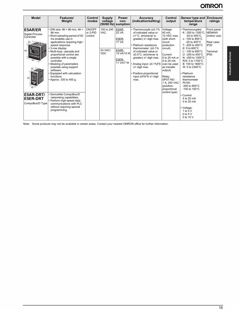
E5AR/ERDigital Process Controller
• DIN size: 96 × 96 mm, 48 × 96 mm.
• Short sampling period of 50 ms enables use in applications requiring high-speed response.
• 3-row display.• Multi-loop, cascade and
proportional control are possible with a single controller.
• Masking of parameters possible using support software.
• Equipped with calculation functions.
• Approx. 330 to 450 g.
ON/OFF or 2-PID control
100 to 240 VAC
E5AR: 22 VA
E5ER: 17 VA
• Thermocouple (±0.1% of indicated value or ±1°C, whichever is greater) ±1 digit max.
• Platinum resistance thermometer: (±0.1% of indicated value or ±0.5°C, whichever is greater) ±1 digit max.
• Analog input: ±0.1%FS ±1 digit max.
• Position-proportional input ±5%FS ±1 digit max.
Voltage: 40 mA, 12 VDC max. (with short-circuit protection circuit)
Current: 0 to 20 mA or 4 to 20 mA (can be used as transfer output)
Relay: SPST-NO 1 A, 250 VAC (position-proportional control type)
• Thermocouples:K: -200 to 1300°C,
-20 to 500°C,J: -100 to 850°C
-20 to 400°CT: -200 to 400°CE: 0 to 600°CL: -100 to 850°CU: -200 to 400°CN: -200 to 1300°CR/S: 0 to 1700°CB: 100 to 1800°CW: 0 to 2300°C
• Platinum resistance thermometer Pt100:-200 to 850°C-150 to 150°C
• Current:4 to 20 mA0 to 20 mA
• Voltage:1 to 5 V0 to 5 V0 to 10 V
Front panel:NEMA4X(indoor use)
Rear case:IP20
Terminal:IP00
24 VAC/VDC
E5AR: 15 VA/10 W
E5ER: 11 VA/7 W
E5AR-DRT/E5ER-DRTCompoBus/D Type
• DeviceNet CompoBus/D networking capabilities.
• Perform high-speed data communications with PLC without requiring special programming.
Model Features/ Weight
Control modes
Supply voltage
(50/60 Hz)
Power con-
sumption
Accuracy (indication/setting)
Control output
Sensor type and temperature
range
Enclosure ratings
96
96
95
96
48
95
17 Industrial Devices/Components
Intelligent Signal Processors
Model Features/ Weight
Load power supply
Accuracy (indication/setting)
Outputs Inputs
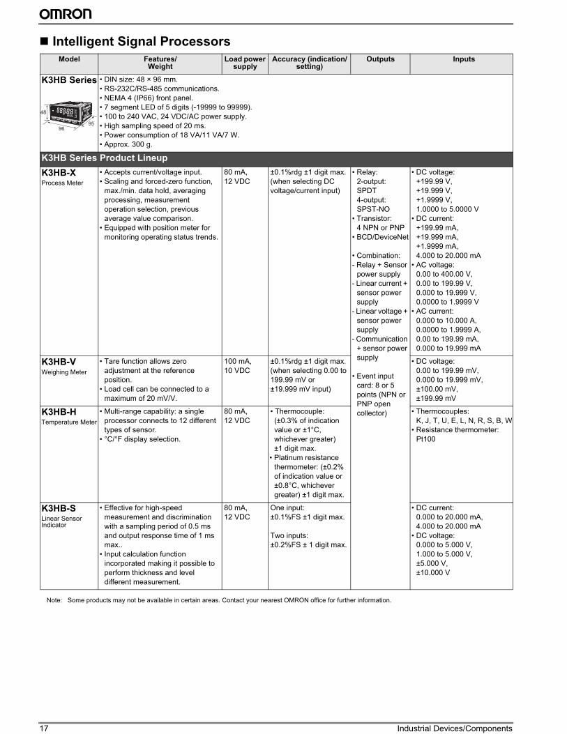
K3HB Series • DIN size: 48 × 96 mm.
• RS-232C/RS-485 communications.
• NEMA 4 (IP66) front panel.
• 7 segment LED of 5 digits (-19999 to 99999).
• 100 to 240 VAC, 24 VDC/AC power supply.
• High sampling speed of 20 ms.
• Power consumption of 18 VA/11 VA/7 W.
• Approx. 300 g.
K3HB Series Product Lineup
K3HB-XProcess Meter
• Accepts current/voltage input.
• Scaling and forced-zero function,
max./min. data hold, averaging
processing, measurement
operation selection, previous
average value comparison.
• Equipped with position meter for
monitoring operating status trends.
80 mA,
12 VDC
±0.1%rdg ±1 digit max.
(when selecting DC
voltage/current input)
• Relay:
2-output:
SPDT
4-output:
SPST-NO
• Transistor:
4 NPN or PNP
• BCD/DeviceNet
• Combination:
- Relay + Sensor
power supply
- Linear current +
sensor power
supply
- Linear voltage +
sensor power
supply
- Communication
+ sensor power
supply
• Event input
card: 8 or 5
points (NPN or
PNP open
collector)
• DC voltage:
+199.99 V,
+19.999 V,
+1.9999 V,
1.0000 to 5.0000 V
• DC current:
+199.99 mA,
+19.999 mA,
+1.9999 mA,
4.000 to 20.000 mA
• AC voltage:
0.00 to 400.00 V,
0.00 to 199.99 V,
0.000 to 19.999 V,
0.0000 to 1.9999 V
• AC current:
0.000 to 10.000 A,
0.0000 to 1.9999 A,
0.00 to 199.99 mA,
0.000 to 19.999 mA
K3HB-VWeighing Meter
• Tare function allows zero
adjustment at the reference
position.
• Load cell can be connected to a
maximum of 20 mV/V.
100 mA,
10 VDC
±0.1%rdg ±1 digit max.
(when selecting 0.00 to
199.99 mV or
±19.999 mV input)
• DC voltage:
0.00 to 199.99 mV,
0.000 to 19.999 mV,
±100.00 mV,
±199.99 mV
K3HB-HTemperature Meter
• Multi-range capability: a single
processor connects to 12 different
types of sensor.
• °C/°F display selection.
80 mA,
12 VDC
• Thermocouple:
(±0.3% of indication
value or ±1°C,
whichever greater)
±1 digit max.
• Platinum resistance
thermometer: (±0.2%
of indication value or
±0.8°C, whichever
greater) ±1 digit max.
• Thermocouples:
K, J, T, U, E, L, N, R, S, B, W
• Resistance thermometer:
Pt100
K3HB-SLinear Sensor Indicator
• Effective for high-speed
measurement and discrimination
with a sampling period of 0.5 ms
and output response time of 1 ms
max..
• Input calculation function
incorporated making it possible to
perform thickness and level
different measurement.
80 mA,
12 VDC
One input:
±0.1%FS ±1 digit max.
Two inputs:
±0.2%FS ± 1 digit max.
• DC current:
0.000 to 20.000 mA,
4.000 to 20.000 mA
• DC voltage:
0.000 to 5.000 V,
1.000 to 5.000 V,
±5.000 V,
±10.000 V
9695
48
Note: Some products may not be available in certain areas. Contact your nearest OMRON office for further information.
18
Ind
us
tria
l D
ev
ice
s
Note: Some products may not be available in certain areas. Contact your nearest OMRON office for further information.
Model Features/ Weight
Load power supply
Accuracy (indication/
setting)
Outputs Inputs
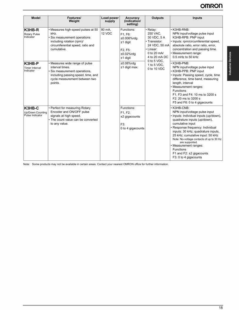
K3HB-RRotary Pulse Indicator
• Measures high-speed pulses at 50
kHz.
• Six measurement operations
including rotation (rpm)/
circumferential speed, ratio and
cumulative.
80 mA,
12 VDC
Functions:
F1, F6:
±0.006%rdg
±1 digit
F2, F5:
±0.02%rdg
±1 digit
• Relay:
250 VAC,
30 VDC, 5 A
• Transistor:
24 VDC, 50 mA
• Linear:
0 to 20 mA/
4 to 20 mA DC
0 to 5 VDC,
1 to 5 VDC,
0 to 10 VDC
• K3HB-RNB:
NPN input/voltage pulse input
K3HB-RPB: PNP input
• Inputs: rpm/circumferential speed,
absolute ratio, error ratio, error,
concentration and passing time.
• Measurement range:
0.5 mHz to 50 kHz
K3HB-PTimer Interval Indicator
• Measures wide range of pulse
interval times.
• Six measurement operations,
including passing speed, time, and
cycle measurement between two
points.
±0.08%rdg
±1 digit max.
• K3HB-PNB:
NPN input/voltage pulse input
• K3HB-PPB: PNP input
• Inputs: Passing speed, cycle, time
difference, time band, measuring
length, interval
• Measurement ranges:
Functions
F1, F3 and F4: 10 ms to 3200 s
F2: 20 ms to 3200 s
F5 and F6: 0 to 4 gigacounts
K3HB-CUp/Down Counting Pulse Indicator
• Perfect for measuring Rotary
Encoder and ON/OFF pulse
signals at high speed.
• The count value can be converted
to any value.
Functions:
F1, F2:
±2 gigacounts
F3:
0 to 4 gigacounts
• K3HB-CNB:
NPN input/voltage pulse input
• Inputs: Individual inputs (up/down),
quadrature inputs (up/down),
cumulative input
• Response frequency: Individual
inputs: 30 kHz; quadrature inputs,
25 kHz; cumulative input: 50 kHzNote: No-voltage contacts of up to 30 Hz
are supported.
• Measurement ranges:
Functions
F1 and F2: ±2 gigacounts
F3: 0 to 4 gigacounts
19 Industrial Devices/Components
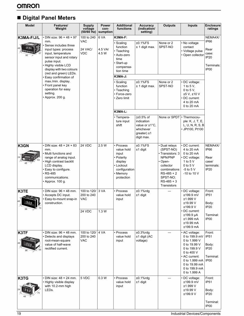
Digital Panel Meters
Model Features/ Weight
Supply voltage
(50/60 Hz)
Power con-
sumption
Additional functions
Accuracy (indication/
setting)
Outputs Inputs Enclosure ratings
K3MA-F/J/L • DIN size: 96 × 48 × 97
mm.
• Sense includes three
input types: process
input, temperature
sensor input and rotary
pulse input.
• Highly visible LCD
display with two colours
(red and green) LEDs.
• Easy confirmation of
max./min. display.
• Front panel key
operation for easy
setting.
• Approx. 200 g.
100 to 240
VAC
24 VAC/
VDC
6 VA
4.5 VA/
4.5 W
K3MA-F: NEMA4X/
IP66
Rear
case:
IP20
Terminals:
IP00
• Scaling
function
• Teaching
• Auto-zero
time
• Start-up
compensa-
tion time
±0.1%FS
± 1 digit max.
None or 2
SPST-NO
• No voltage
contact
• Voltage pulse
• Open collector
K3MA-J:
• Scaling
function
• Teaching
• Force-zero
• Zero limit
±0.1%FS
± 1 digit max.
None or 2
SPST-NO
• DC voltage:
1 to 5 V,
0 to 5 V,
±5 V, ±10 V
• DC current:
4 to 20 mA
0 to 20 mA
K3MA-L:
• Tempera-
ture input
shift
(±0.5% of
indication
value or ±1°C,
whichever
greater) ±1
digit max.
None or SPDT • Thermocou-
ple: K, J, T, E,
L, U, N, R, S, B
• JPt100, Pt100
K3GN • DIN size: 48 × 24 × 83
mm.
• Multi functions and
range of analog input.
• High contrast backlit
LCD display.
• Easy to configure.
• RS-485
communications.
• Approx. 100 g.
24 VDC 2.5 W • Process
value hold
input
• Polarity
display
• Lockout
configuration
• Memory
protection
±0.1%FS
±1 digit
• Dual relays
(SPST-NO)
• Transistors: 3
NPN/PNP
• Open-
collector
combinations
RS-485 + 2
SPST-NO;
RS-485 + 3
Transistors
• DC current:
4 to 20 mA
0 to 20 mA
• DC voltage:
1 to 5 V
0 to 5 V
-5 to 5 V
-10 to 10 V
NEMA4X/
IP66
Rear
case/
terminals:
IP20
K3TE • DIN size: 96 × 48 mm.
• Accepts DC input.
• Easy-to-mount snap-in
construction.
100 to 120/
200 to 240
VAC
3 VA • Process
value hold
input
±0.1%rdg
±1 digit
--- • DC voltage:
±199.9 mV
±1.999 V
±19.99 V
±199.9 V
• DC current:
±199.9 µA
±1.999 mA
±19.99 mA
±199.9 mA
Front:
IP51
Body:
IP20
Terminal:
IP00
24 VDC 1.3 W
K3TF • DIN size: 96 × 48 mm.
• Detects and displays
root-mean-square
value of half-wave
rectified current.
100 to 120/
200 to 240
VAC
4 VA • Process
value hold
input
±0.3%rdg
±1 digit (AC
voltage)
--- • AC voltage:
0 to 199.9 mV
0 to 1.999 V
0 to 19.99 V
0 to 199.9 V
0 to 400 V
• AC current:
0 to 1.999 mA
0 to 19.99 mA
0 to 199.9 mA
0 to 1.999 A
Front:
IP51
Body:
IP20
Terminal:
IP00
K3TG • DIN size: 48 × 24 mm.
• Highly visible display
with 10.2-mm high
LEDs.
5 VDC 0.3 W • Process
value hold
input
±0.1%rdg
±1 digit
--- • DC voltage:
±199.9 mV
±1.999 V
±19.99 V
±199.9 V
Front:
IP51
Body:
IP20
Terminal:
IP00
9697
48
48
83
24
96 70
48
96 66
48
48
70
24
20
Ind
us
tria
l D
ev
ice
s
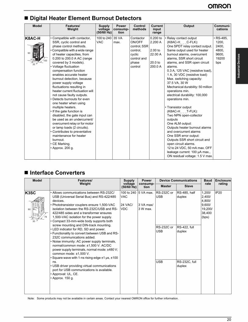
Digital Heater Element Burnout Detectors
Interface Converters
Model Features/ Weight
Supply voltage
(50/60 Hz)
Power consump-
tion
Control methods
Current input range
Output Communi-cations
K8AC-H • Compatible with contactor,
SSR, cyclic control and
phase control methods.
• Compatible with a wide range
of heater capacities, from
0.200 to 200.0 A AC (range
covered by 3 models).
• Voltage fluctuation
compensation function
enables accurate heater
burnout detection, because
power supply voltage
fluctuations resulting in
heater current fluctuation will
not cause faulty outputs.
• Detects burnouts for even
one heater when using
multiple heaters.
• If the gate function is
disabled, the gate input can
be used as an undercurrent/
overcurrent relay or for motor
or lamp loads (2 circuits).
• Contributes to preventative
maintenance for heater
burnout.
• CE Marking.
• Approx. 200 g.
100 to 240
VAC
35 VA
max.
Contactor
ON/OFF
control, SSR
control,
cyclic
control and
phase
control
0.200 to
2.200 A
2.00 to
22.00 A
20.0 to
200.0 A
• Relay contact output
(K8AC-H_ _ _C-FLK):
One SPDT relay contact output.
Same output used for heater
burnout alarms, overcurrent
alarms, SSR short circuit
alarms, and SSR open circuit
alarms.
0.3 A, 125 VAC (resistive load),
1 A, 30 VDC (resistive load)
Max. switching capacity:
37.5 VA, 30 W
Mechanical durability: 50 million
operations min.
electrical durability: 100,000
operations min.
• Transistor output
(K8AC-H_ _ _T-FLK):
Two NPN open-collector
outputs
One ALM output:
Outputs heater burnout alarms
and overcurrent alarms
One SSR error output:
Outputs SSR short circuit and
open circuit alarms.
12 to 24 VDC, 50 mA max. OFF
leakage current: 100 µA max.,
ON residual voltage: 1.5 V max.
• RS-485,
1200,
2400,
4800,
9600,
19200
bps
Model Features/ Weight
Supply voltage
(50/60 Hz)
Power consump-
tion
Device Communications Baud rate
Enclosure rating
Master Slave
K3SC • Allows communications between RS-232C/
USB (Universal Serial Bus) and RS-422/485
devices.
• Phototransistor couplers ensure 1,500-VAC
isolation between the RS-232C/USB and RS-
422/485 sides and a transformer ensures
1,500-VAC isolation for the power supply.
• Compact 33-mm-wide body supports both
screw mounting and DIN-track mounting.
• LED indicator for RD, SD and power.
• Functionality to convert between USB and RS-
232C communications added.
• Noise immunity: AC power supply terminals,
normal/common mode: ±1,500 V. AC/DC
power supply terminals, normal mode: ±480 V;
common mode: ±1,500 V.
• Square wave with 1-ns rising edge ±1 µs, ±100
ns.
• USB driver providing virtual communications
port for USB communications is available.
• Approval: UL, CE.
• Approx. 150 g.
100 to 240
VAC
24 VAC/
VDC
5 VA max.
3 VA max/
3 W max.
RS-232C or
USB
RS-485, half
duplex
1,200/
2,400/
4,800/
9,600/
19,200/
38,400
(bps)
IP20
RS-232C or
USB
RS-422, full
duplex
USB RS-232C, full
duplex
90
35
100
80
30
78
Note: Some products may not be available in certain areas. Contact your nearest OMRON office for further information.
21 Industrial Devices/Components
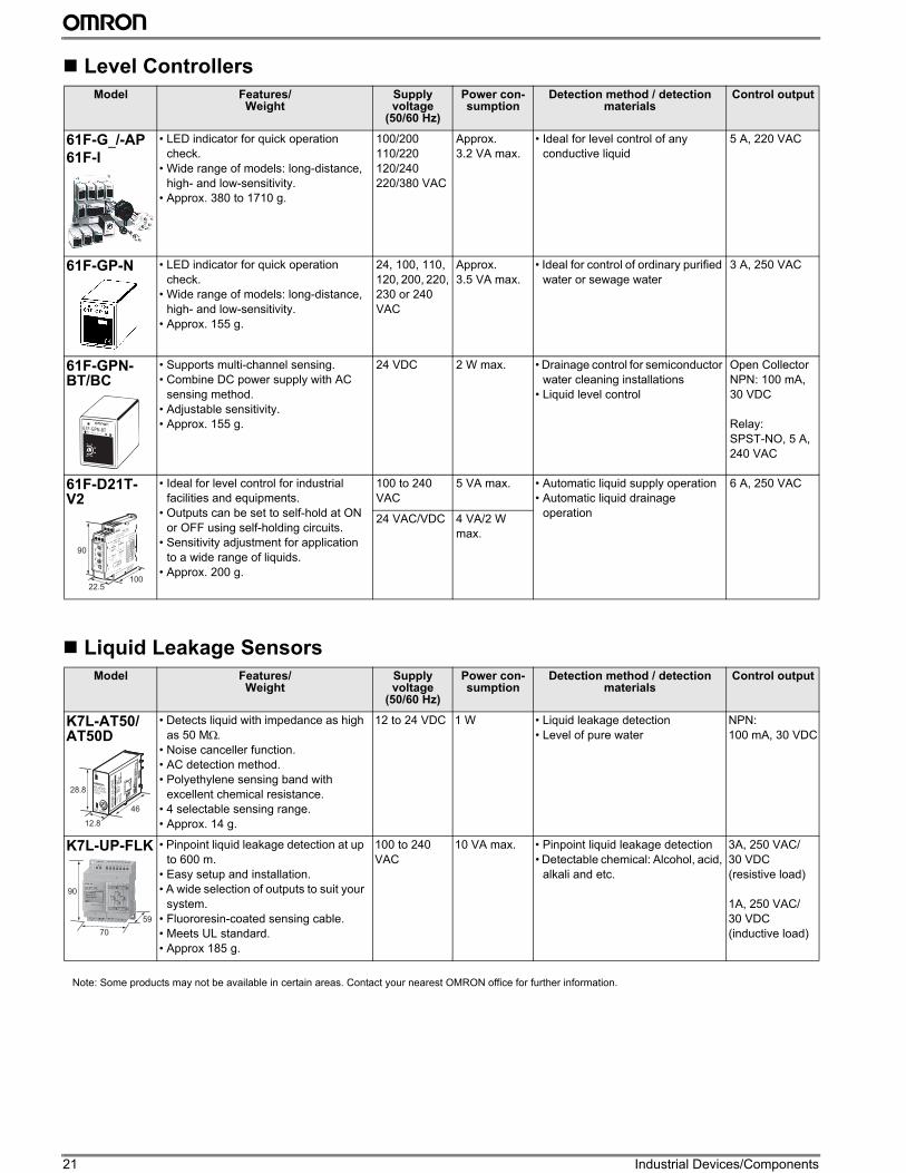
Level Controllers
Liquid Leakage Sensors
Model Features/ Weight
Supply voltage
(50/60 Hz)
Power con-sumption
Detection method / detection materials
Control output
61F-G_/-AP
61F-I
• LED indicator for quick operation
check.
• Wide range of models: long-distance,
high- and low-sensitivity.
• Approx. 380 to 1710 g.
100/200
110/220
120/240
220/380 VAC
Approx.
3.2 VA max.
• Ideal for level control of any
conductive liquid
5 A, 220 VAC
61F-GP-N • LED indicator for quick operation
check.
• Wide range of models: long-distance,
high- and low-sensitivity.
• Approx. 155 g.
24, 100, 110,
120, 200, 220,
230 or 240
VAC
Approx.
3.5 VA max.
• Ideal for control of ordinary purified
water or sewage water
3 A, 250 VAC
61F-GPN-BT/BC
• Supports multi-channel sensing.
• Combine DC power supply with AC
sensing method.
• Adjustable sensitivity.
• Approx. 155 g.
24 VDC 2 W max. • Drainage control for semiconductor
water cleaning installations
• Liquid level control
Open Collector
NPN: 100 mA,
30 VDC
Relay:
SPST-NO, 5 A,
240 VAC
61F-D21T-V2
• Ideal for level control for industrial
facilities and equipments.
• Outputs can be set to self-hold at ON
or OFF using self-holding circuits.
• Sensitivity adjustment for application
to a wide range of liquids.
• Approx. 200 g.
100 to 240
VAC
5 VA max. • Automatic liquid supply operation
• Automatic liquid drainage
operation
6 A, 250 VAC
24 VAC/VDC 4 VA/2 W
max.
Model Features/ Weight
Supply voltage
(50/60 Hz)
Power con-sumption
Detection method / detection materials
Control output
K7L-AT50/AT50D
• Detects liquid with impedance as high
as 50 MΩ.• Noise canceller function.
• AC detection method.
• Polyethylene sensing band with
excellent chemical resistance.
• 4 selectable sensing range.
• Approx. 14 g.
12 to 24 VDC 1 W • Liquid leakage detection
• Level of pure water
NPN:
100 mA, 30 VDC
K7L-UP-FLK • Pinpoint liquid leakage detection at up
to 600 m.
• Easy setup and installation.
• A wide selection of outputs to suit your
system.
• Fluororesin-coated sensing cable.
• Meets UL standard.
• Approx 185 g.
100 to 240
VAC
10 VA max. • Pinpoint liquid leakage detection
• Detectable chemical: Alcohol, acid,
alkali and etc.
3A, 250 VAC/
30 VDC
(resistive load)
1A, 250 VAC/
30 VDC
(inductive load)
61F-GPN-BT
90
22.5100
K7L-AT50DLIQ UID L E AK AG ES E NS OR K7
L-A
T5
0D
PW
OUT ADJUST
28.8
12.8
46
90
70
59
Note: Some products may not be available in certain areas. Contact your nearest OMRON office for further information.
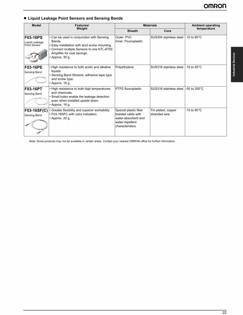
22
Ind
us
tria
l D
ev
ice
s
” Liquid Leakage Point Sensors and Sensing Bands
Model Features/ Weight
Materials Ambient operating temperature
Sheath Core
F03-16PSLiquid Leakage Point Sensor
• Can be used in conjunction with Sensing
Bands.
• Easy installation with stud screw mounting.
• Connect multiple Sensors to one K7L-AT50
Amplifier for cost savings.
• Approx. 30 g.
Outer: PVC
Inner: Fluoroplastic
SUS304 stainless steel -10 to 60°C
F03-16PESensing Band
• High resistance to both acidic and alkaline
liquids.
• Sensing Band Stickers: adhesive tape type
and screw type.
• Approx. 16 g.
Polyethylene SUS316 stainless steel -15 to 55°C
F03-16PTSensing Band
• High resistance to both high temperatures
and chemicals.
• Small holes enable the leakage detection
even when installed upside down.
• Approx. 16 g.
PTFE fluoroplastic SUS316 stainless steel -50 to 200°C
F03-16SF(C)Sensing Band
• Greater flexibility and superior workability.
• F03-16SFC with color indication.
• Approx. 20 g.
Special plastic fiber
braided cable with
water-absorbent and
water-repellent
characteristics
Tin-plated, copper
stranded wire
-15 to 60°C
Note: Some products may not be available in certain areas. Contact your nearest OMRON office for further information.
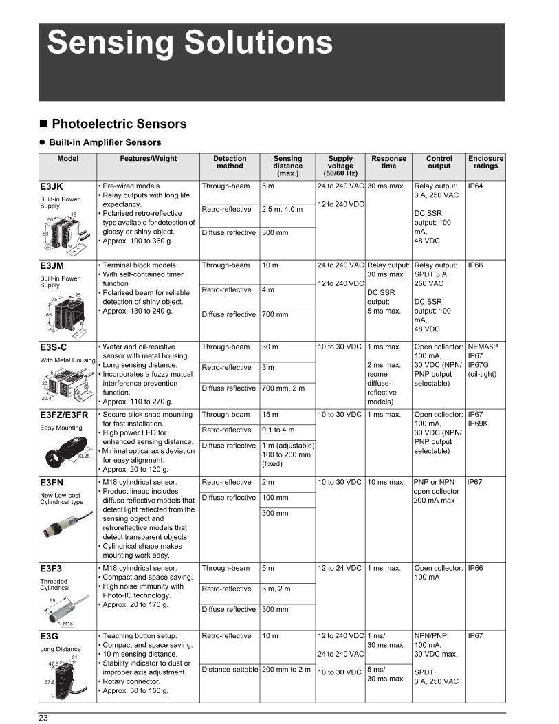
23
Sensing Solutions
Photoelectric Sensors
” Built-in Amplifier Sensors
Model Features/Weight Detection method
Sensing distance
(max.)
Supply voltage
(50/60 Hz)
Response time
Controloutput
Enclosure ratings
E3JK
Built-in Power Supply
• Pre-wired models.
• Relay outputs with long life
expectancy.
• Polarised retro-reflective
type available for detection of
glossy or shiny object.
• Approx. 190 to 360 g.
Through-beam 5 m 24 to 240 VAC
12 to 240 VDC
30 ms max. Relay output:
3 A, 250 VAC
DC SSR
output: 100
mA,
48 VDC
IP64
Retro-reflective 2.5 m, 4.0 m
Diffuse reflective 300 mm
E3JM
Built-in Power Supply
• Terminal block models.
• With self-contained timer
function
• Polarised beam for reliable
detection of shiny object.
• Approx. 130 to 240 g.
Through-beam 10 m 24 to 240 VAC
12 to 240 VDC
Relay output:
30 ms max.
DC SSR
output:
5 ms max.
Relay output:
SPDT 3 A,
250 VAC
DC SSR
output: 100
mA,
48 VDC
IP66
Retro-reflective 4 m
Diffuse reflective 700 mm
E3S-C
With Metal Housing
• Water and oil-resistive
sensor with metal housing.
• Long sensing distance.
• Incorporates a fuzzy mutual
interference prevention
function.
• Approx. 110 to 270 g.
Through-beam 30 m 10 to 30 VDC 1 ms max.
2 ms max.
(some
diffuse-
reflective
models)
Open collector:
100 mA,
30 VDC (NPN/
PNP output
selectable)
NEMA6P
IP67
IP67G
(oil-tight)Retro-reflective 3 m
Diffuse reflective 700 mm, 2 m
E3FZ/E3FR
Easy Mounting
• Secure-click snap mounting
for fast installation.
• High power LED for
enhanced sensing distance.
• Minimal optical axis deviation
for easy alignment.
• Approx. 20 to 120 g.
Through-beam 15 m 10 to 30 VDC 1 ms max. Open collector:
100 mA,
30 VDC (NPN/
PNP output
selectable)
IP67
IP69KRetro-reflective 0.1 to 4 m
Diffuse reflective 1 m (adjustable)
100 to 200 mm
(fixed)
E3FN
New Low-cost Cylindrical type
• M18 cylindrical sensor.
• Product lineup includes
diffuse reflective models that
detect light reflected from the
sensing object and
retroreflective models that
detect transparent objects.
• Cylindrical shape makes
mounting work easy.
Retro-reflective 2 m 10 to 30 VDC 10 ms max. PNP or NPN
open collector
200 mA max
IP67
Diffuse reflective 100 mm
300 mm
E3F3
Threaded Cylindrical
• M18 cylindrical sensor.
• Compact and space saving.
• High noise immunity with
Photo-IC technology.
• Approx. 20 to 170 g.
Through-beam 5 m 12 to 24 VDC 1 ms max. Open collector:
100 mA
IP66
Retro-reflective 3 m, 2 m
Diffuse reflective 300 mm
E3G
Long Distance
• Teaching button setup.
• Compact and space saving.
• 10 m sensing distance.
• Stability indicator to dust or
improper axis adjustment.
• Rotary connector.
• Approx. 50 to 150 g.
Retro-reflective 10 m 12 to 240 VDC
24 to 240 VAC
10 to 30 VDC
1 ms/
30 ms max.
NPN/PNP:
100 mA,
30 VDC max.
SPDT:
3 A, 250 VAC
IP67
Distance-settable 200 mm to 2 m 5 ms/
30 ms max.
50
5018
65
7525
23
20.4
50
30.25
M18
65
67.8
47.8
21
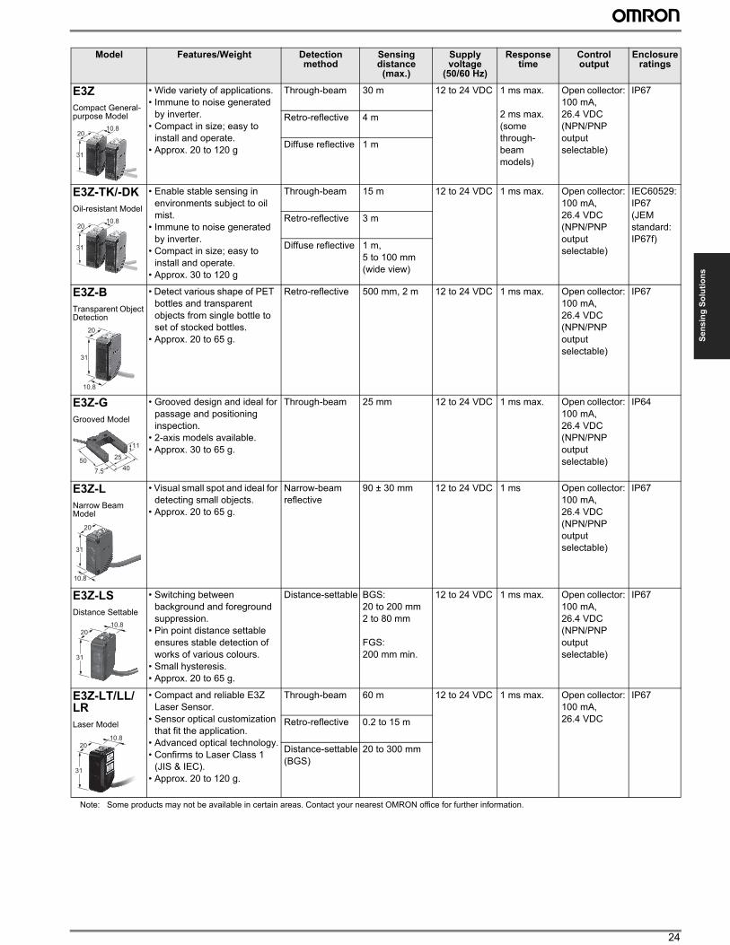
24
Se
ns
ing
So
luti
on
s
E3Z
Compact General-purpose Model
• Wide variety of applications.
• Immune to noise generated
by inverter.
• Compact in size; easy to
install and operate.
• Approx. 20 to 120 g
Through-beam 30 m 12 to 24 VDC 1 ms max.
2 ms max.
(some
through-
beam
models)
Open collector:
100 mA,
26.4 VDC
(NPN/PNP
output
selectable)
IP67
Retro-reflective 4 m
Diffuse reflective 1 m
E3Z-TK/-DK
Oil-resistant Model
• Enable stable sensing in
environments subject to oil
mist.
• Immune to noise generated
by inverter.
• Compact in size; easy to
install and operate.
• Approx. 30 to 120 g
Through-beam 15 m 12 to 24 VDC 1 ms max. Open collector:
100 mA,
26.4 VDC
(NPN/PNP
output
selectable)
IEC60529:
IP67
(JEM
standard:
IP67f)
Retro-reflective 3 m
Diffuse reflective 1 m,
5 to 100 mm
(wide view)
E3Z-B
Transparent Object Detection
• Detect various shape of PET
bottles and transparent
objects from single bottle to
set of stocked bottles.
• Approx. 20 to 65 g.
Retro-reflective 500 mm, 2 m 12 to 24 VDC 1 ms max. Open collector:
100 mA,
26.4 VDC
(NPN/PNP
output
selectable)
IP67
E3Z-G
Grooved Model
• Grooved design and ideal for
passage and positioning
inspection.
• 2-axis models available.
• Approx. 30 to 65 g.
Through-beam 25 mm 12 to 24 VDC 1 ms max. Open collector:
100 mA,
26.4 VDC
(NPN/PNP
output
selectable)
IP64
E3Z-L
Narrow Beam Model
• Visual small spot and ideal for
detecting small objects.
• Approx. 20 to 65 g.
Narrow-beam
reflective
90 ± 30 mm 12 to 24 VDC 1 ms Open collector:
100 mA,
26.4 VDC
(NPN/PNP
output
selectable)
IP67
E3Z-LS
Distance Settable
• Switching between
background and foreground
suppression.
• Pin point distance settable
ensures stable detection of
works of various colours.
• Small hysteresis.
• Approx. 20 to 65 g.
Distance-settable BGS:
20 to 200 mm
2 to 80 mm
FGS:
200 mm min.
12 to 24 VDC 1 ms max. Open collector:
100 mA,
26.4 VDC
(NPN/PNP
output
selectable)
IP67
E3Z-LT/LL/LR
Laser Model
• Compact and reliable E3Z
Laser Sensor.
• Sensor optical customization
that fit the application.
• Advanced optical technology.
• Confirms to Laser Class 1
(JIS & IEC).
• Approx. 20 to 120 g.
Through-beam 60 m 12 to 24 VDC 1 ms max. Open collector:
100 mA,
26.4 VDC
IP67
Retro-reflective 0.2 to 15 m
Distance-settable
(BGS)
20 to 300 mm
Model Features/Weight Detection method
Sensing distance
(max.)
Supply voltage
(50/60 Hz)
Response time
Controloutput
Enclosure ratings
31
2010.8
31
2010.8
31
20
10.8
40
25
7.5
11
50
20
31
10.8
31
2010.8
31
2010.8
Note: Some products may not be available in certain areas. Contact your nearest OMRON office for further information.
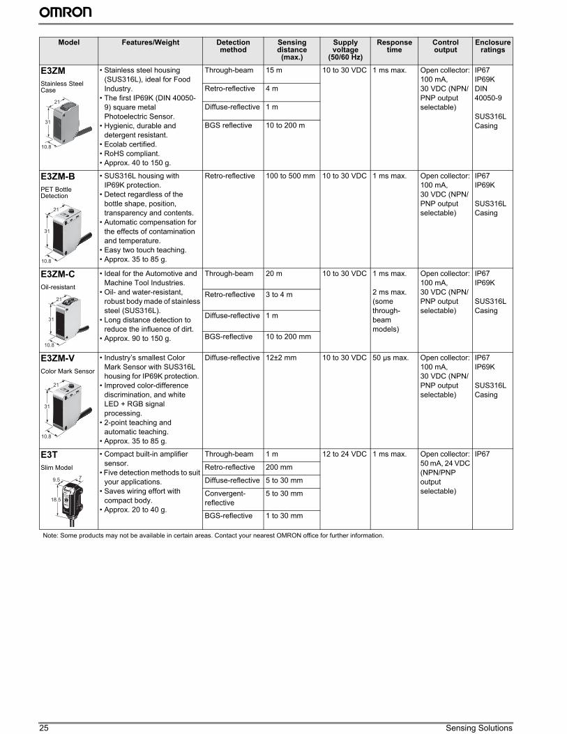
25 Sensing Solutions
E3ZM
Stainless Steel Case
• Stainless steel housing
(SUS316L), ideal for Food
Industry.
• The first IP69K (DIN 40050-
9) square metal
Photoelectric Sensor.
• Hygienic, durable and
detergent resistant.
• Ecolab certified.
• RoHS compliant.
• Approx. 40 to 150 g.
Through-beam 15 m 10 to 30 VDC 1 ms max. Open collector:
100 mA,
30 VDC (NPN/
PNP output
selectable)
IP67
IP69K
DIN
40050-9
SUS316L
Casing
Retro-reflective 4 m
Diffuse-reflective 1 m
BGS reflective 10 to 200 m
E3ZM-B
PET Bottle Detection
• SUS316L housing with
IP69K protection.
• Detect regardless of the
bottle shape, position,
transparency and contents.
• Automatic compensation for
the effects of contamination
and temperature.
• Easy two touch teaching.
• Approx. 35 to 85 g.
Retro-reflective 100 to 500 mm 10 to 30 VDC 1 ms max. Open collector:
100 mA,
30 VDC (NPN/
PNP output
selectable)
IP67
IP69K
SUS316L
Casing
E3ZM-C
Oil-resistant
• Ideal for the Automotive and
Machine Tool Industries.
• Oil- and water-resistant,
robust body made of stainless
steel (SUS316L).
• Long distance detection to
reduce the influence of dirt.
• Approx. 90 to 150 g.
Through-beam 20 m 10 to 30 VDC 1 ms max.
2 ms max.
(some
through-
beam
models)
Open collector:
100 mA,
30 VDC (NPN/
PNP output
selectable)
IP67
IP69K
SUS316L
Casing
Retro-reflective 3 to 4 m
Diffuse-reflective 1 m
BGS-reflective 10 to 200 mm
E3ZM-V
Color Mark Sensor
• Industry’s smallest Color
Mark Sensor with SUS316L
housing for IP69K protection.
• Improved color-difference
discrimination, and white
LED + RGB signal
processing.
• 2-point teaching and
automatic teaching.
• Approx. 35 to 85 g.
Diffuse-reflective 12±2 mm 10 to 30 VDC 50 µs max. Open collector:
100 mA,
30 VDC (NPN/
PNP output
selectable)
IP67
IP69K
SUS316L
Casing
E3T
Slim Model
• Compact built-in amplifier
sensor.
• Five detection methods to suit
your applications.
• Saves wiring effort with
compact body.
• Approx. 20 to 40 g.
Through-beam 1 m 12 to 24 VDC 1 ms max. Open collector:
50 mA, 24 VDC
(NPN/PNP
output
selectable)
IP67
Retro-reflective 200 mm
Diffuse-reflective 5 to 30 mm
Convergent-
reflective
5 to 30 mm
BGS-reflective 1 to 30 mm
Model Features/Weight Detection method
Sensing distance
(max.)
Supply voltage
(50/60 Hz)
Response time
Controloutput
Enclosure ratings
31
21
10.8
10.8
31
21
10.8
31
21
10.8
31
21
18.5
9.5 7
Note: Some products may not be available in certain areas. Contact your nearest OMRON office for further information.
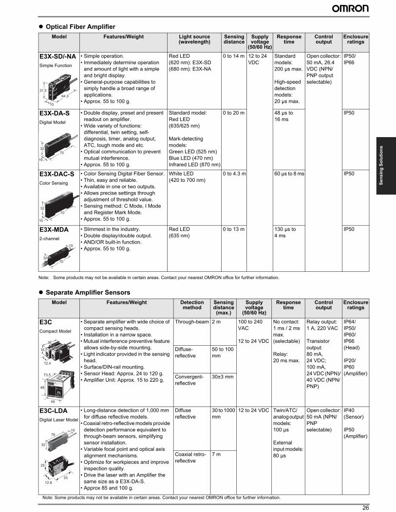
26
Se
ns
ing
So
luti
on
s
” Optical Fiber Amplifier
Note: Some products may not be available in certain areas. Contact your nearest OMRON office for further information.
” Separate Amplifier Sensors
Model Features/Weight Light source (wavelength)
Sensing distance
Supply voltage
(50/60 Hz)
Response time
Control output
Enclosure ratings
E3X-SD/-NA
Simple Function
• Simple operation.
• Immediately determine operation
and amount of light with a simple
and bright display.
• General-purpose capabilities to
simply handle a broad range of
applications.
• Approx. 55 to 100 g.
Red LED
(620 nm): E3X-SD
(680 nm): E3X-NA
0 to 14 m 12 to 24
VDC
Standard
models:
200 µs max.
High-speed
detection
models:
20 µs max.
Open collector:
50 mA, 26.4
VDC (NPN/
PNP output
selectable)
IP50/
IP66
E3X-DA-S
Digital Model
• Double display, preset and present
readout on amplifier.
• Wide variety of functions:
differential, twin setting, self-
diagnosis, timer, analog output,
ATC, tough mode and etc.
• Optical communication to prevent
mutual interference.
• Approx. 55 to 100 g.
Standard model:
Red LED
(635/625 nm)
Mark-detecting
models:
Green LED (525 nm)
Blue LED (470 nm)
Infrared LED (870 nm)
0 to 20 m 48 µs to
16 ms
IP50
E3X-DAC-S
Color Sensing
• Color Sensing Digital Fiber Sensor.
• Thin, easy and reliable.
• Available in one or two outputs.
• Allows precise settings through
adjustment of threshold value.
• Sensing method: C Mode, I Mode
and Register Mark Mode.
• Approx. 55 to 100 g.
White LED
(420 to 700 nm)
0 to 4.3 m 60 µs to 8 ms IP50
E3X-MDA
2-channel
• Slimmest in the industry.
• Double display/double output.
• AND/OR built-in function.
• Approx. 55 to 100 g.
Red LED
(635 nm)
0 to 13 m 130 µs to
4 ms
IP50
Model Features/Weight Detection method
Sensing distance
(max.)
Supply voltage
(50/60 Hz)
Response time
Control output
Enclosure ratings
E3C
Compact Model
• Separate amplifier with wide choice of
compact sensing heads.
• Installation in a narrow space.
• Mutual interference preventive feature
allows side-by-side mounting.
• Light indicator provided in the sensing
head.
• Surface/DIN-rail mounting.
• Sensor Head: Approx. 24 to 120 g.
• Amplifier Unit: Approx. 15 to 220 g.
Through-beam 2 m 100 to 240
VAC
12 to 24 VDC
No contact:
1 ms / 2 ms
max.
(selectable)
Relay:
20 ms max.
Relay output:
1 A, 220 VAC
Transistor
output:
80 mA,
24 VDC;
100 mA,
24 VDC (NPN)/
40 VDC (NPN/
PNP)
IP64/
IP50/
IP60/
IP66
(Head)
IP20/
IP60
(Amplifier)
Diffuse-
reflective
50 to 100
mm
Convergent-
reflective
30±3 mm
E3C-LDA
Digital Laser Model
• Long-distance detection of 1,000 mm
for diffuse reflective models.
• Coaxial retro-reflective models provide
detection performance equivalent to
through-beam sensors, simplifying
sensor installation.
• Variable focal point and optical axis
alignment mechanisms.
• Optimize for workpieces and improve
inspection quality.
• Drive the laser with an Amplifier the
same size as a E3X-DA-S.
• Approx 85 and 100 g.
Diffuse
reflective
30 to 1000
mm
12 to 24 VDC Twin/ATC/
analog output
models:
100 µs
External
input models:
80 µs
Open collector:
50 mA (NPN/
PNP
selectable)
IP40
(Sensor)
IP50
(Amplifier)
Coaxial retro-
reflective
7 m
31.5
64.3
10
32
10
70
32
10
70
32
10
70
16
12.4
36
48
73.5
49
33
12.8
25
76
32
10
Note: Some products may not be available in certain areas. Contact your nearest OMRON office for further information.
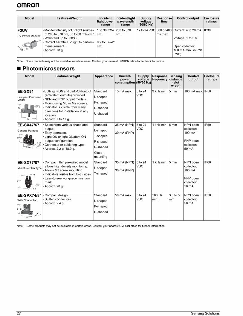
27 Sensing Solutions
Note: Some products may not be available in certain areas. Contact your nearest OMRON office for further information.
Photomicrosensors
Note: Some products may not be available in certain areas. Contact your nearest OMRON office for further information.
Model Features/Weight Incident light power
range
Incident light wavelength
range
Supply voltage
(50/60 Hz)
Response time
Control output Enclosure ratings
F3UV
UV Power Monitor
• Monitor intensity of UV light sources
of 200 to 370 nm, up to 30 mW/cm².
• Withstand up to 300°C.
• Correct harmful UV light to perform
measurement.
• Approx. 78 g.
1 to 30 mW/
cm²
0.2 to 3 mW/
cm²
200 to 370
nm
12 to 24 VDC 300 or 400
ms max.
Current: 4 to 20 mA
Voltage: 1 to 5 V
Open collector:
100 mA max. (NPN/
PNP)
IP30
Model Features/Weight Appearance Current/power
consumption
Supply voltage
(50/60 Hz)
Response frequency
Sensing distance
(slot width)
Control output
Enclosure ratings
EE-SX91
Compact Pre-wired Model
• Both light-ON and dark-ON output
(antivalent outputs) provided.
• NPN and PNP output models.
• Mount using M3 or M2 screws.
• Indicator is visible from many
directions for installation in any
location.
• Approx. 7 to 17 g.
Standard
L-shaped
F-shaped
R-shaped
U-shaped
15 mA max. 5 to 24
VDC
3 kHz min. 5 mm 100 mA max. IP50
EE-SX47/67
General Purpose
• Select from various shape and
output.
• Easy operation.
• Light ON or light ON/dark ON
output configuration.
• Connector or soldering type.
• Approx. 2.2 to 18.9 g.
Standard
L-shaped
T-shaped
F-shaped
R-shaped
Close-
mounting
35 mA (NPN)
30 mA (PNP)
5 to 24
VDC
1 kHz min. 5 mm NPN open
collector:
100 mA
PNP open
collector:
50 mA
IP50
EE-SX77/87
Miniature Slim Type
• Compact, thin pre-wired model
allows high density monitoring.
• Allows M3 screw mounting.
• Indicators visible from both sides.
• Easy-to-see workpiece insertion
mark.
• Approx. 20 g.
Standard
L-shaped
T-shaped
35 mA (NPN)
30 mA (PNP)
5 to 24
VDC
1 kHz min. 5 mm NPN open
collector:
100 mA
PNP open
collector:
50 mA
IP60
EE-SPX74/84With Connector
• Compact design.
• Built-in connectors.
• Approx. 2.4 g.
Standard
L-shaped
F-shaped
R-shaped
50 mA max. 5 to 24
VDC
500 Hz
min.
3.6 to 5
mm
NPN open
collector:
50 mA
IP50
12
24
6
6.95
25.4
22.2
31.1
4.6
18
21.2
25
7.4
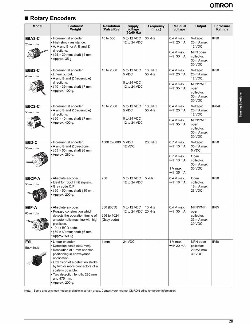
28
Se
ns
ing
So
luti
on
s
Rotary Encoders
Note: Some products may not be available in certain areas. Contact your nearest OMRON office for further information.
Model Features/ Weight
Resolution (Pulse/Rev)
Supply voltage
(50/60 Hz)
Frequency(max.)
Residual voltage
Output Enclosure Ratings
E6A2-C
25-mm dia.
• Incremental encoder.
• High shock resistance.
• A, A and B, or A, B and Z
directions.
• φ25 × 29 mm; shaft φ4 mm.
• Approx. 35 g.
10 to 500 5 to 12 VDC
12 to 24 VDC
30 kHz 0.4 V max.
with 20 mA
Voltage:
20 mA max.
12 VDC
IP50
0.4 V max.
with 30 mA
NPN open
collector:
30 mA max.
30 VDC
E6B2-C
40-mm dia.
• Incremental encoder.
• Linear output.
• A and B and Z (reversible)
directions.
• φ40 × 39 mm; shaft φ7 mm.
• Approx. 100 g.
10 to 2000 5 to 12 VDC
5 VDC
5 to 24 VDC
12 to 24 VDC
100 kHz
50 kHz
0.4 V max.
with 20 mA
Voltage:
20 mA max.
12 VDC
IP50
0.4 V max.
with 35 mA
NPN/PNP
open
collector:
35 mA max.
30 VDC
E6C2-C
50-mm dia.
• Incremental encoder.
• A and B and Z (reversible)
directions.
• φ50 × 40 mm; shaft φ7 mm.
• Approx. 400 g.
10 to 2000 5 to 12 VDC
5 VDC
5 to 24 VDC
12 to 24 VDC
100 kHz
50 kHz
0.4 V max.
with 20 mA
Voltage:
20 mA max.
12 VDC
IP64F
0.4 V max.
with 35 mA
NPN/PNP
open
collector:
35 mA max.
30 VDC
E6D-C
55-mm dia.
• Incremental encoder.
• A and B and Z directions.
• φ55 × 50 mm; shaft φ6 mm.
• Approx. 280 g.
1000 to 6000 5 VDC
12 VDC
200 kHz 0.7 V max.
with 10 mA
Voltage:
35 mA max.
5 VDC
IP50
0.7 V max.
with 10 mA
1 V max.
with 35 mA
Open
collector:
35 mA max.
30 VDC
E6CP-A
50-mm dia.
• Absolute encoder.
• Ideal for robot limit signals.
• Gray code O/P.
• φ50 × 50 mm; shaft φ10 mm.
• Approx. 200 g.
256 5 to 12 VDC
12 to 24 VDC
5 kHz 0.4 V max.
with 16 mA
Open
collector:
16 mA max.
28 VDC
IP50
E6F-A
60-mm dia.
• Absolute encoder.
• Rugged construction which
detects the operation timing of
an automatic machine with high
precision.
• 10-bit BCD code.
• φ60 × 60 mm; shaft φ6 mm.
• Approx. 500 g.
360 (BCD)
256 to 1024
(Gray code)
5 to 12 VDC
12 to 24 VDC
10 kHz
20 kHz
0.4 V max.
with 35 mA
NPN/PNP
open
collector:
35 mA max.
30 VDC
IP65
E6L
Easy Scale
• Linear encoder.
• Detection scale (6±3 mm).
• Resolution of 1 mm enables
positioning in conveyance
application.
• Extension of a detection stroke
by two or more connectors of a
scale is possible.
• Two detection length: 280 mm
and 475 mm.
• Approx. 200 g.
1 mm 24 VDC --- 1 V max.
with 20 mA
NPN open
collector:
20 mA max.
30 VDC
IP50
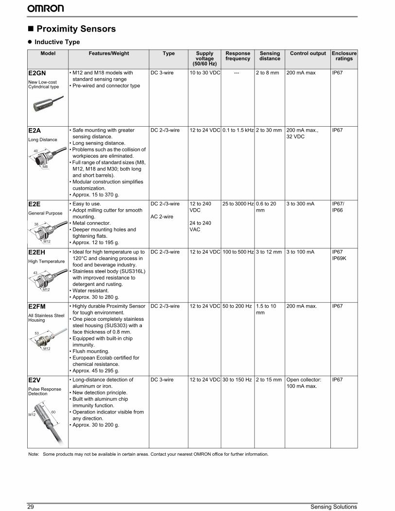
29 Sensing Solutions
Proximity Sensors
” Inductive Type
Model Features/Weight Type Supply voltage
(50/60 Hz)
Response frequency
Sensing distance
Control output Enclosure ratings
E2GN
New Low-cost Cylindrical type
• M12 and M18 models with
standard sensing range
• Pre-wired and connector type
DC 3-wire 10 to 30 VDC --- 2 to 8 mm 200 mA max IP67
E2A
Long Distance
• Safe mounting with greater
sensing distance.
• Long sensing distance.
• Problems such as the collision of
workpieces are eliminated.
• Full range of standard sizes (M8,
M12, M18 and M30; both long
and short barrels).
• Modular construction simplifies
customization.
• Approx. 15 to 370 g.
DC 2-/3-wire 12 to 24 VDC 0.1 to 1.5 kHz 2 to 30 mm 200 mA max.,
32 VDC
IP67
E2E
General Purpose
• Easy to use.
• Adopt milling cutter for smooth
mounting.
• Metal connector.
• Deeper mounting holes and
tightening flats.
• Approx. 12 to 195 g.
DC 2-/3-wire
AC 2-wire
12 to 240
VDC
24 to 240
VAC
25 to 3000 Hz 0.6 to 20
mm
3 to 300 mA IP67/
IP66
E2EH
High Temperature
• Ideal for high temperature up to
120°C and cleaning process in
food and beverage industry.
• Stainless steel body (SUS316L)
with improved resistance to
detergent and rusting.
• Water resistant.
• Approx. 30 to 280 g.
DC 2-/3-wire 12 to 24 VDC 100 to 500 Hz 3 to 12 mm 3 to 100 mA IP67
IP69K
E2FM
All Stainless Steel Housing
• Highly durable Proximity Sensor
for tough environment.
• One piece completely stainless
steel housing (SUS303) with a
face thickness of 0.8 mm.
• Equipped with built-in chip
immunity.
• Flush mounting.
• European Ecolab certified for
chemical resistance.
• Approx. 45 to 295 g.
DC 2-/3-wire 12 to 24 VDC 50 to 200 Hz 1.5 to 10
mm
200 mA max. IP67
E2V
Pulse Response Detection
• Long-distance detection of
aluminum or iron.
• New detection principle.
• Built with aluminum chip
immunity function.
• Operation indicator visible from
any direction.
• Approx. 30 to 200 g.
DC 3-wire 12 to 24 VDC 30 to 150 Hz 2 to 15 mm Open collector:
100 mA max.
IP67
M8
40
M12
38
M12
43
M12
53
M1260
Note: Some products may not be available in certain areas. Contact your nearest OMRON office for further information.
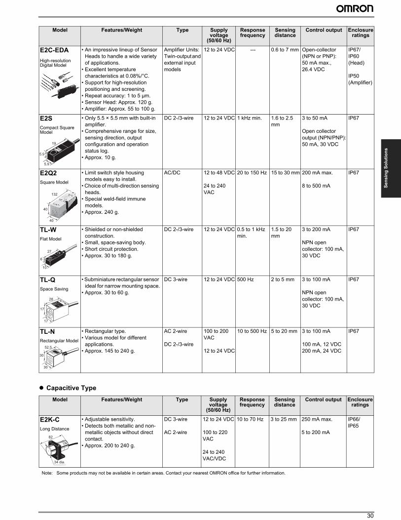
30
Se
ns
ing
So
luti
on
s” Capacitive Type
E2C-EDA
High-resolution Digital Model
• An impressive lineup of Sensor
Heads to handle a wide variety
of applications.
• Excellent temperature
characteristics at 0.08%/°C.
• Support for high-resolution
positioning and screening.
• Repeat accuracy: 1 to 5 µm.
• Sensor Head: Approx. 120 g.
• Amplifier: Approx. 55 to 100 g.
Amplifier Units:
Twin-output and
external input
models
12 to 24 VDC --- 0.6 to 7 mm Open-collector
(NPN or PNP):
50 mA max.,
26.4 VDC
IP67/
IP60
(Head)
IP50
(Amplifier)
E2S
Compact Square Model
• Only 5.5 × 5.5 mm with built-in
amplifier.
• Comprehensive range for size,
sensing direction, output
configuration and operation
status log.
• Approx. 10 g.
DC 2-/3-wire 12 to 24 VDC 1 kHz min. 1.6 to 2.5
mm
3 to 50 mA
Open collector
output (NPN/PNP):
50 mA, 30 VDC
IP67
E2Q2
Square Model
• Limit switch style housing
models easy to install.
• Choice of multi-direction sensing
heads.
• Special weld-field immune
models.
• Approx. 240 g.
AC/DC 12 to 48 VDC
24 to 240
VAC
20 to 150 Hz 15 to 30 mm 200 mA max.
8 to 500 mA
IP67
TL-W
Flat Model
• Shielded or non-shielded
construction.
• Small, space-saving body.
• Short circuit protection.
• Approx. 30 to 180 g.
DC 2-/3-wire 12 to 24 VDC 0.5 to 1 kHz
min.
1.5 to 20
mm
3 to 200 mA
NPN open
collector: 100 mA,
30 VDC
IP67
TL-Q
Space Saving
• Subminiature rectangular sensor
ideal for narrow mounting space.
• Approx. 30 to 60 g.
DC 3-wire 12 to 24 VDC 500 Hz 2 to 5 mm 3 to 100 mA
NPN open
collector: 100 mA,
30 VDC
IP67
TL-N
Rectangular Model
• Rectangular type.
• Various model for different
applications.
• Approx. 145 to 240 g.
AC 2-wire
DC 2-/3-wire
100 to 200
VAC
12 to 24 VDC
10 to 500 Hz 5 to 20 mm 3 to 100 mA
100 mA, 12 VDC
200 mA, 24 VDC
IP67
Model Features/Weight Type Supply voltage
(50/60 Hz)
Response frequency
Sensing distance
Control output Enclosure ratings
E2K-C
Long Distance
• Adjustable sensitivity.
• Detects both metallic and non-
metallic objects without direct
contact.
• Approx. 200 to 240 g.
DC 3-wire
AC 2-wire
12 to 24 VDC
100 to 220
VAC
24 to 240
VAC/VDC
10 to 70 Hz 3 to 25 mm 250 mA max.
5 to 200 mA
IP66/
IP65
Model Features/Weight Type Supply voltage
(50/60 Hz)
Response frequency
Sensing distance
Control output Enclosure ratings
5.9
19
5.9
40
132
40
6
27
10
17
28
17
30
52.5
30
34 dia.
82
Note: Some products may not be available in certain areas. Contact your nearest OMRON office for further information.
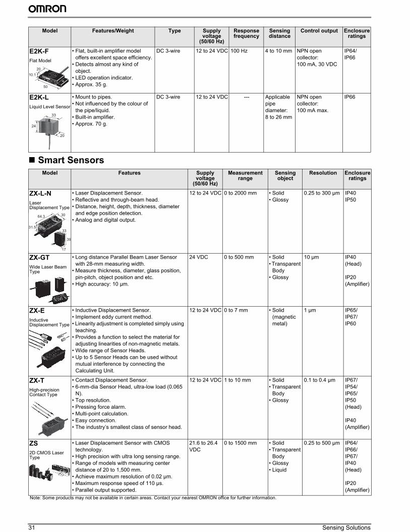
31 Sensing Solutions
Smart Sensors
E2K-F
Flat Model
• Flat, built-in amplifier model
offers excellent space efficiency.
• Detects almost any kind of
object.
• LED operation indicator.
• Approx. 35 g.
DC 3-wire 12 to 24 VDC 100 Hz 4 to 10 mm NPN open
collector:
100 mA, 30 VDC
IP64/
IP66
E2K-L
Liquid Level Sensor
• Mount to pipes.
• Not influenced by the colour of
the pipe/liquid.
• Built-in amplifier.
• Approx. 70 g.
DC 3-wire 12 to 24 VDC --- Applicable
pipe
diameter:
8 to 26 mm
NPN open
collector:
100 mA max.
IP66
Model Features Supply voltage
(50/60 Hz)
Measurement range
Sensing object
Resolution Enclosure ratings
ZX-L-N
Laser Displacement Type
• Laser Displacement Sensor.
• Reflective and through-beam head.
• Distance, height, depth, thickness, diameter
and edge position detection.
• Analog and digital output.
12 to 24 VDC 0 to 2000 mm • Solid
• Glossy
0.25 to 300 µm IP40
IP50
ZX-GT
Wide Laser Beam Type
• Long distance Parallel Beam Laser Sensor
with 28-mm measuring width.
• Measure thickness, diameter, glass position,
pin-pitch, object position and etc.
• High accuracy: 10 µm.
24 VDC 0 to 500 mm • Solid
• Transparent
Body
• Glossy
10 µm IP40
(Head)
IP20
(Amplifier)
ZX-E
Inductive Displacement Type
• Inductive Displacement Sensor.
• Implement eddy current method.
• Linearity adjustment is completed simply using
teaching.
• Provides a function to select the material for
adjusting linearities of non-magnetic metals.
• Wide range of Sensor Heads.
• Up to 5 Sensor Heads can be used without
mutual interference by connecting the
Calculating Unit.
12 to 24 VDC 0 to 7 mm • Solid
(magnetic
metal)
1 µm IP65/
IP67/
IP60
ZX-T
High-precision Contact Type
• Contact Displacement Sensor.
• 6-mm-dia Sensor Head, ultra-low load (0.065
N).
• Top resolution.
• Pressing force alarm.
• Multi-point calculation.
• Easy connection.
• The industry’s smallest class of sensor head.
12 to 24 VDC 1 to 10 mm • Solid
• Transparent
Body
• Glossy
0.1 to 0.4 µm IP67/
IP54/
IP65/
IP50
(Head)
IP40
(Amplifier)
ZS
2D CMOS Laser Type
• Laser Displacement Sensor with CMOS
technology.
• High precision with ultra long sensing range.
• Range of models with measuring center
distance of 20 to 1,500 mm.
• Achieve maximum resolution of 0.02 µm.
• Maximum response speed of 110 µs.
• Parallel output supported.
21.6 to 26.4
VDC
0 to 1500 mm • Solid
• Transparent
Body
• Glossy
• Liquid
0.25 to 500 µm IP64/
IP66/
IP67/
IP40
(Head)
IP20
(Amplifier)
Model Features/Weight Type Supply voltage
(50/60 Hz)
Response frequency
Sensing distance
Control output Enclosure ratings
10.1
20
50
24
20
33
31.5
64.3 30
39
17
33
Note: Some products may not be available in certain areas. Contact your nearest OMRON office for further information.
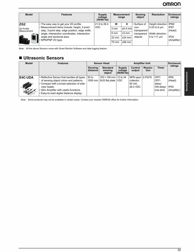
32
Se
ns
ing
So
luti
on
s
Note: All the above Sensors come with Smart Monitor Software and data logging feature.
Ultrasonic Sensors
ZG2
2D Profile Measurement
• The easy way to get your 2D profile.
• Measurement items include: height, 2-point
step, 3-point step, edge position, edge width,
angle, intersection coordinates, intersection
angle and sectional area.
• NPN/PNP I/O type.
21.6 to 26.4
VDC
W D • Surface of
non-
transparent/
transparent
objects
Height direction:
0.25 to 6 µm
Width direction:
5 to 111 µm
IP66/
IP67
(Head)
IP20
(Amplifier)
3 mm ±0.4 mm
8 mm ±3 mm
22 mm ±24 mm
70 mm ±96 mm
Model Features Sensor Head Amplifier Unit Enclosure ratings
Sensing distance
Standard sensing object
Supply voltage
(50/60 Hz)
Control output
Resolu-tion
Timer
E4C-UDA • Reflective Sensor that handles all types
of sensing object colors and patterns.
• Compact with a broad selection of side-
view heads.
• Slim Amplifier with useful functions.
• Easy-to-read digital distance display.
50 to
1000 mm
100 × 100 mm
SUS flat plate
12 to 24
VDC
NPN open
collector:
50 mA,
26.4 VDC
2.0%FS OFF/
OFF-
delay/
ON-delay/
one-shot
IP65
(Head)
IP50
(Amplifier)
Model Features Supply voltage
(50/60 Hz)
Measurement range
Sensing object
Resolution Enclosure ratings
73.5
Note: Some products may not be available in certain areas. Contact your nearest OMRON office for further information.
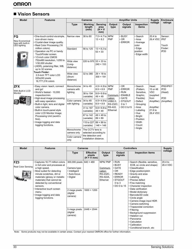
33 Sensing Solutions
Vision Sensors
Model Features Cameras Amplifier Units Supply voltage
Enclosure ratings
Type Working length (mm)
Sensingarea
(H × V mm)
Output type
Output signals
Inspection items
FQ
New Economical type with built-in LED lighting
• One-touch control via simple,
icon-driven menu
• Crystal-clear image quality.
• Real Color Processing (16
million colors).
• Operation via PC or handy
TouchFinder screen.
• 1/3-inch color CMOS
752x480 resolution, 1/250 to
1/30,000 shutter
• (HDR), polarizing filter, WB,
up to 32 scenes
Touch Finder:
3.5-inch TFT color LCD
320x240 pixels
16,777,216 colors
Narrow view 38 to 60 7.5 × 4.7 to
13 × 8.2
NPN/
PNP
• BUSY
• OR
• ERROR
• Search
• Area
• Average
color
• Edge
position
• Edge width
20.4 to
26.4 VDC
Sensor:
IP67
Touch
Finder:
IP20Standard 56 to 125 13 × 8.2 to
53 × 33
Wide view
(Long-
distance)
220 to 970 53 × 33 to
240 × 153
Wide view
(Short-
distance)
32 to 380 29 × 18 to
300 × 191
ZFX
With Built-in LCD Monitor
• Easy vision: teach, connect
and go!
• World’s fastest - 10,000
inspection/min.
• High-level image processing
with easy operation.
• Built-in light, lens and digital
color camera.
• Built-in touch-panel style
color LCD Monitor Image
Processing Unit (world’s
first).
• Image logging and data
logging functions.
Monochrome
camera with
lighting
34 to 49 4.9 × 4.9 to
8.9 × 8.9
NPN/
PNP
Communi-
cation:
USB2.0,
RS-232C,
RS-422,
Ethernet
• OR
• ERROR
• RUN
• ENABLE
• GATE
• STGOUT
0 to 1
• DO 0 to15
• Search
(Pattern,
Sensitive,
Graphic,
Flexible)
• Defect
• Grouping
• Area
• Labeling
• Hue
• Bright
• Position
• Width
• Count
• Angle
Head:
15 or 48
VDC
(supplied
from
Amplifier)
Amplifier:
21.6 to
26.4 VDC
IP65/IP67/
IP20
(Head)
IP20
(Amplifier)
38 to 194
(variable)
9.8 × 9.8 to
49 × 49
Color camera
with lighting
34 to 49
(variable)
4.9 × 4.9 to
8.9 × 8.9
31 to 187
(variable)
9.8 × 9.8 to
49 × 49
67 to 142
(variable)
49 × 49 to
89 × 89
115 to 227
(variable)
89 × 89 to
148 × 148
Monochrome
camera only
The CCTV lens is
selected according to
the detection and
installation distance.Color camera
only
Model Features Cameras Controllers Supply voltage
Type Effective pixels
(H × V mm)
Output type
Output signals
Inspection items
FZ3
Real Color Sensing
• Captures 16.77 million colors
in full color and processes at
a high speed.
• Most suited for detecting
minute scratches, dirt or
materials (glossy or metallic
materials) that cannot be
detected by conventional
sensors.
• Interactive touch screen
menu.
• Image logging and data
logging functions.
300,000 pixels
Camera type:
• Intelligent
• Auto-focus
• Digital
640 × 480 NPN/ PNP
Communi-
cation:
RS-232C,
RS-422A,
Ethernet
• RUN
• BUSY
• GATE
• OR
• READY
• ERROR
• STGOUT
0 to 3
• DO 0 to 15
• Search (flexible, sensitive,
ECB, ec circle and shape)
• Classification
• Edge position/pitch
• Gravity and area
• Labeling
• Precise defect
• Fine matching
• Character inspection
• Data verification
• Model dictionary
• Barcode/2D code
• Circle angle
• Camera image input HDR
• Camera switching
• Trapezoidal correction
• Filtering
• Background suppression
• Halation cut
• Panorama
• Calculation
• Calibration
• Conditional branch, etc
20.4 to
26.4 VDC
2 mega pixels
(digital
camera)
1600 × 1200
5 mega pixels
(digital
camera)
2448 × 2044
Note: Some products may not be available in certain areas. Contact your nearest OMRON office for further information.
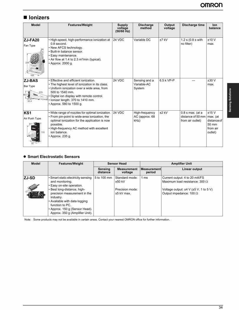
34
Se
ns
ing
So
luti
on
s
Ionizers
” Smart Electrostatic Sensors
Model Features/Weight Supply voltage
(50/60 Hz)
Discharge method
Output voltage
Discharge time Ion balance
ZJ-FA20
Fan Type
• High-speed, high-performance ionization at
0.8 second.
• New AFCS technology.
• Built-in balance sensor.
• Easy maintenance.
• Air flow at 1.4 to 2.3 m³/min (typical).
• Approx. 2000 g.
24 VDC Variable DC ±7 kV 1.2 s (0.8 s with
no filter)
±10 V
max.
ZJ-BAS
Bar Type
• Effective and efficient ionization.
• The highest level of ionization in its class.
• Uniform ionization over a wide area, from
500 to 1540 mm.
• Digital ion display with remote control.
• Ionizer length: 370 to 1410 mm.
• Approx. 580 to 1500 g.
24 VDC Sensing and a
Variable-AC
System
6.5 k VP-P --- ±30 V
max.
KS1
Air Push Type
• Wide range of nozzles for optimal ionization.
• From pin-point to wide-area ionization, the
optimal ionization for the application is now
possible.
• High-frequency AC method with excellent
ion balance.
• Approx. 235 g.
24 VDC High-frequency
AC (approx. 68
kHz)
±2 kV 0.8 s max. (at a
distance of 50 mm
from air outlet)
±15 V
max. (at
distance of
50 mm
from air
outlet)
Model Features/Weight Sensor Head Amplifier Unit
Sensing distance
Measurement voltage
Measurement period
Linear output
ZJ-SD • Smart static electricity sensing
and monitoring.
• Easy on-site operation.
• Best long-distance, high-
precision measurement in the
industry.
• Available with data logging
function to PC.
• Approx. 150 g (Sensor Head).
Approx. 350 g (Amplifier Unit).
5 to 100 mm Standard mode:
±50 kV
Precision mode:
±5 kV max.
1 ms Current output: 4 to 20 mA/FS
Maximum load resistance: 300 Ω
Voltage output: ±4 V (±5 V, 1 to 5 V)
Output impedance: 100 Ω
165
220
80
32.4
60.7370
32
110
61
Note: Some products may not be available in certain areas. Contact your nearest OMRON office for further information.
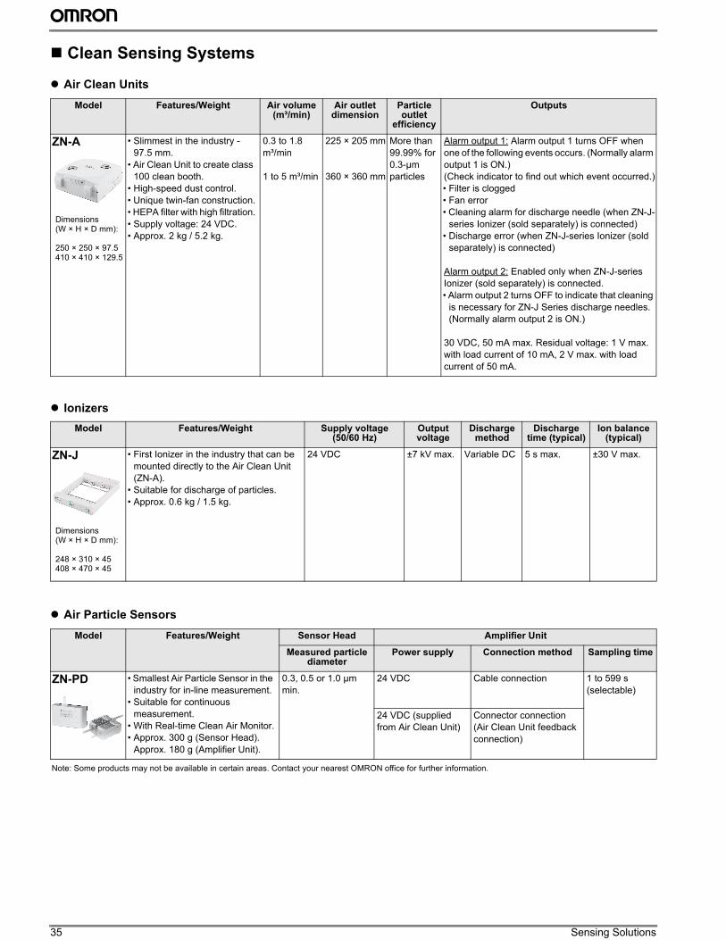
35 Sensing Solutions
Clean Sensing Systems
” Air Clean Units
” Ionizers
” Air Particle Sensors
Model Features/Weight Air volume (m³/min)
Air outlet dimension
Particle outlet
efficiency
Outputs
ZN-A
Dimensions(W × H × D mm):
250 × 250 × 97.5410 × 410 × 129.5
• Slimmest in the industry -
97.5 mm.
• Air Clean Unit to create class
100 clean booth.
• High-speed dust control.
• Unique twin-fan construction.
• HEPA filter with high filtration.
• Supply voltage: 24 VDC.
• Approx. 2 kg / 5.2 kg.
0.3 to 1.8
m³/min
1 to 5 m³/min
225 × 205 mm
360 × 360 mm
More than
99.99% for
0.3-µm
particles
Alarm output 1: Alarm output 1 turns OFF when
one of the following events occurs. (Normally alarm
output 1 is ON.)
(Check indicator to find out which event occurred.)
• Filter is clogged
• Fan error
• Cleaning alarm for discharge needle (when ZN-J-
series Ionizer (sold separately) is connected)
• Discharge error (when ZN-J-series Ionizer (sold
separately) is connected)
Alarm output 2: Enabled only when ZN-J-series
Ionizer (sold separately) is connected.
• Alarm output 2 turns OFF to indicate that cleaning
is necessary for ZN-J Series discharge needles.
(Normally alarm output 2 is ON.)
30 VDC, 50 mA max. Residual voltage: 1 V max.
with load current of 10 mA, 2 V max. with load
current of 50 mA.
Model Features/Weight Supply voltage(50/60 Hz)
Output voltage
Discharge method
Discharge time (typical)
Ion balance (typical)
ZN-J
Dimensions(W × H × D mm):
248 × 310 × 45408 × 470 × 45
• First Ionizer in the industry that can be
mounted directly to the Air Clean Unit
(ZN-A).
• Suitable for discharge of particles.
• Approx. 0.6 kg / 1.5 kg.
24 VDC ±7 kV max. Variable DC 5 s max. ±30 V max.
Model Features/Weight Sensor Head Amplifier Unit
Measured particle diameter
Power supply Connection method Sampling time
ZN-PD • Smallest Air Particle Sensor in the
industry for in-line measurement.
• Suitable for continuous
measurement.
• With Real-time Clean Air Monitor.
• Approx. 300 g (Sensor Head).
Approx. 180 g (Amplifier Unit).
0.3, 0.5 or 1.0 µm
min.
24 VDC Cable connection 1 to 599 s
(selectable)
24 VDC (supplied
from Air Clean Unit)
Connector connection
(Air Clean Unit feedback
connection)
Note: Some products may not be available in certain areas. Contact your nearest OMRON office for further information.
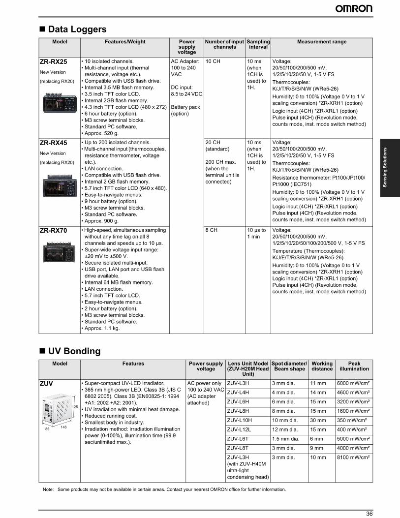
36
Se
ns
ing
So
luti
on
s
Data Loggers
UV Bonding
Model Features/Weight Power supply voltage
Number of input channels
Sampling interval
Measurement range
ZR-RX25
New Version
(replacing RX20)
• 10 isolated channels.
• Multi-channel input (thermal
resistance, voltage etc.).
• Compatible with USB flash drive.
• Internal 3.5 MB flash memory.
• 3.5 inch TFT color LCD.
• Internal 2GB flash memory.
• 4.3 inch TFT color LCD (480 x 272)
• 6 hour battery (option).
• M3 screw terminal blocks.
• Standard PC software.
• Approx. 520 g.
AC Adapter:
100 to 240
VAC
DC input:
8.5 to 24 VDC
Battery pack
(option)
10 CH 10 ms
(when
1CH is
used) to
1H.
Voltage:
20/50/100/200/500 mV,
1/2/5/10/20/50 V, 1-5 V FS
Thermocouples:
K/J/T/R/S/B/N/W (WRe5-26)
Humidity: 0 to 100% (Voltage 0 V to 1 V
scaling conversion) *ZR-XRH1 (option)
Logic input (4CH) *ZR-XRL1 (option)
Pulse input (4CH) (Revolution mode,
counts mode, inst. mode switch method)
ZR-RX45
New Version
(replacing RX20)
• Up to 200 isolated channels.
• Multi-channel input (thermocouples,
resistance thermometer, voltage
etc.).
• LAN connection.
• Compatible with USB flash drive.
• Internal 2 GB flash memory.
• 5.7 inch TFT color LCD (640 x 480).
• Easy-to-navigate menus.
• 9 hour battery (option).
• M3 screw terminal blocks.
• Standard PC software.
• Approx. 900 g.
20 CH
(standard)
200 CH max.
(when the
terminal unit is
connected)
10 ms
(when
1CH is
used) to
1H.
Voltage:
20/50/100/200/500 mV,
1/2/5/10/20/50 V, 1-5 V FS
Thermocouples:
K/J/T/R/S/B/N/W (WRe5-26)
Resistance thermometer: Pt100/JPt100/
Pt1000 (IEC751)
Humidity: 0 to 100% (Voltage 0 V to 1 V
scaling conversion) *ZR-XRH1 (option)
Logic input (4CH) *ZR-XRL1 (option)
Pulse input (4CH) (Revolution mode,
counts mode, inst. mode switch method)
ZR-RX70 • High-speed, simultaneous sampling
without any time lag on all 8
channels and speeds up to 10 µs.
• Super-wide voltage input range:
±20 mV to ±500 V.
• Secure isolated multi-input.
• USB port, LAN port and USB flash
drive available.
• Internal 64 MB flash memory.
• LAN connection.
• 5.7 inch TFT color LCD.
• Easy-to-navigate menus.
• 2 hour battery (option).
• M3 screw terminal blocks.
• Standard PC software.
• Approx. 1.1 kg.
8 CH 10 µs to
1 min
Voltage:
20/50/100/200/500 mV,
1/2/5/10/20/50/100/200/500 V, 1-5 V FS
Temperature (Thermocouples):
K/J/E/T/R/S/B/N/W (WRe5-26)
Humidity: 0 to 100% (Voltage 0 to 1 V
scaling conversion) *ZR-XRH1 (option)
Logic input (4CH) *ZR-XRL1 (option)
Pulse input (4CH) (Revolution mode,
counts mode, inst. mode switch method)
Model Features Power supply voltage
Lens Unit Model(ZUV-H20M Head
Unit)
Spot diameter/ Beam shape
Working distance
Peak illumination
ZUV • Super-compact UV-LED Irradiator.
• 365 nm high-power LED, Class 3B (JIS C
6802 2005), Class 3B (EN60825-1: 1994
+A1: 2002 +A2: 2001).
• UV irradiation with minimal heat damage.
• Reduced running cost.
• Smallest body in industry.
• Irradiation method: irradiation illumination
power (0-100%), illumination time (99.9
sec/unlimited max.).
AC power only
100 to 240 VAC
(AC adapter
attached)
ZUV-L3H 3 mm dia. 11 mm 6000 mW/cm²
ZUV-L4H 4 mm dia. 14 mm 4600 mW/cm²
ZUV-L6H 6 mm dia. 15 mm 3200 mW/cm²
ZUV-L8H 8 mm dia. 15 mm 1600 mW/cm²
ZUV-L10H 10 mm dia. 30 mm 350 mW/cm²
ZUV-L12L 12 mm dia. 15 mm 400 mW/cm²
ZUV-L6T 1.5 mm dia. 6 mm 5000 mW/cm²
ZUV-L8T 3 mm dia. 9 mm 4000 mW/cm²
ZUV-L3H
(with ZUV-H40M
ultra-light
condensing head)
3 mm dia. 10 mm 8100 mW/cm²
14685
125
Note: Some products may not be available in certain areas. Contact your nearest OMRON office for further information.

37
Automation Systems
Simple Logic Controllers
Programmable Controllers
Model Features/ Weight
Supply voltage Program capacity
Additional functions No. of control I/O
points
Calendar and clock function
(at 25°C)
ZEN V2 • Easy programming.
• Hold functions for peace of mind.
• Flexible expansion.
• Memory cassettes.
• Wider selection with additional of
20 I/O points CPU units.
• Provides relay, timer, counter
and time switch functions.
• Approx. 300 to 350 g.
100 to 240 VAC 96 lines • 8 digit counter, 150 Hz
counter
• Twin timer operation
• Multiple-day operation
• Pulse output operation
• More precise analog input
• CPU Units with RS-485
communications
44 max. Accuracy: ±15 s/
month
12 to 24 VDC
Model Features/ Weight
Supply voltage Power ratings
Output voltage
Output current
ZEN-PA03024Power Supply
• Slim size with a depth of 56 mm.
• Allows parallel operation.
• EMI: Conforms to EN61000-6-3
(Class B).
100 to 240 VAC 30 W 24 VDC 1.3 A
Model Features Supply voltage (50/60 Hz)
Program capacity
Additional functions Max. I/O points
Instruction execution
time
CP1EAdvanced Micro PLC
• Easy ladder programming with
"smart input".
• Full motion control instruction for 2 ×
100 kHz pulse output, and 4/6 high-
speed counter for close loop control.
• RS-232C (built-in for N-models) and
RS-422/485 (optional)
communication port.
100 to 240 VAC E-model:
2 K Steps
N-model:
8 K Steps
• PT connection
• High-speed counters
• Pulse outputs
• Modbus-RTU easy master
• Serial PLC links
• USB peripheral port
20 to 160 1.19 µs min.
24 VDC
CP1LAdvanced Micro PLC
• Support floating point, function block
programming.
• Full motion control instruction for 2 ×
100 kHz pulse output, and 4/6 high-
speed counter for close loop control.
• Optional RS-232C or RS-422/485
communication port.
100 to 240 VAC L-model:
5 K Steps
M-model:
10 K Steps
• Pulse outputs
• High-speed counters
• USB peripheral port
• Serial communication
• Ethernet communication (using
an option board)
• LCD display and settings (using
an option board)
10 to 180 0.55 µs min.
24 VDC
CP1HAdvanced Micro PLC
• Three basic CPU units: High-speed
positioning (CP1H-Y) Built-in analog
I/O (CP1H-XA) and standard model
(CP1H-X).
• Pulse output and high-speed
counter for 4 axes.
• Built-in analog I/O: 4 analog inputs
and 2 analog outputs.
• Serial communications: RS-232C or
RS-422A/485 option board, up to
two option board can be mounted.
100 to 240 VAC 20 K Steps • Pulse outputs
• High-speed counters
• Built-in Analog I/O
• USB peripheral port
• Serial communication
• Ethernet communication (using
an option board)
• LCD display and settings (using
an option board)
300 to 320 0.1 µs min
24 VDC
90
7056
90
70 56
8685
90
90
66
85
85
90
150
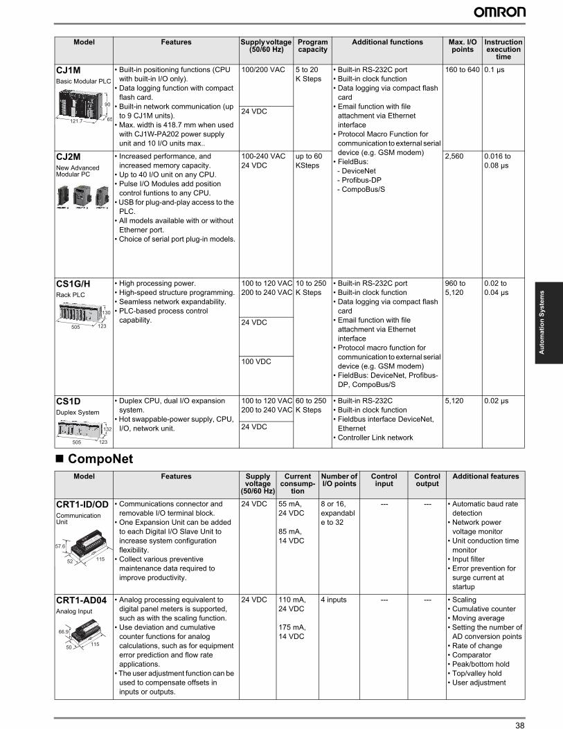
38
Au
tom
ati
on
Sy
ste
ms
CompoNet
CJ1MBasic Modular PLC
• Built-in positioning functions (CPU
with built-in I/O only).
• Data logging function with compact
flash card.
• Built-in network communication (up
to 9 CJ1M units).
• Max. width is 418.7 mm when used
with CJ1W-PA202 power supply
unit and 10 I/O units max..
100/200 VAC 5 to 20
K Steps
• Built-in RS-232C port
• Built-in clock function
• Data logging via compact flash
card
• Email function with file
attachment via Ethernet
interface
• Protocol Macro Function for
communication to external serial
device (e.g. GSM modem)
• FieldBus:
- DeviceNet
- Profibus-DP
- CompoBus/S
160 to 640 0.1 µs
24 VDC
CJ2MNew Advanced Modular PC
• Increased performance, and
increased memory capacity.
• Up to 40 I/O unit on any CPU.
• Pulse I/O Modules add position
control funtions to any CPU.
• USB for plug-and-play access to the
PLC.
• All models available with or without
Etherner port.
• Choice of serial port plug-in models.
100-240 VAC
24 VDC
up to 60
KSteps
2,560 0.016 to
0.08 µs
CS1G/HRack PLC
• High processing power.
• High-speed structure programming.
• Seamless network expandability.
• PLC-based process control
capability.
100 to 120 VAC
200 to 240 VAC
10 to 250
K Steps
• Built-in RS-232C port
• Built-in clock function
• Data logging via compact flash
card
• Email function with file
attachment via Ethernet
interface
• Protocol macro function for
communication to external serial
device (e.g. GSM modem)
• FieldBus: DeviceNet, Profibus-
DP, CompoBus/S
960 to
5,120
0.02 to
0.04 µs
24 VDC
100 VDC
CS1DDuplex System
• Duplex CPU, dual I/O expansion
system.
• Hot swappable-power supply, CPU,
I/O, network unit.
100 to 120 VAC
200 to 240 VAC
60 to 250
K Steps
• Built-in RS-232C
• Built-in clock function
• Fieldbus interface DeviceNet,
Ethernet
• Controller Link network
5,120 0.02 µs
24 VDC
Model Features Supply voltage
(50/60 Hz)
Current consump-
tion
Number of I/O points
Control input
Control output
Additional features
CRT1-ID/ODCommunication Unit
• Communications connector and
removable I/O terminal block.
• One Expansion Unit can be added
to each Digital I/O Slave Unit to
increase system configuration
flexibility.
• Collect various preventive
maintenance data required to
improve productivity.
24 VDC 55 mA,
24 VDC
85 mA,
14 VDC
8 or 16,
expandabl
e to 32
--- --- • Automatic baud rate
detection
• Network power
voltage monitor
• Unit conduction time
monitor
• Input filter
• Error prevention for
surge current at
startup
CRT1-AD04Analog Input
• Analog processing equivalent to
digital panel meters is supported,
such as with the scaling function.
• Use deviation and cumulative
counter functions for analog
calculations, such as for equipment
error prediction and flow rate
applications.
• The user adjustment function can be
used to compensate offsets in
inputs or outputs.
24 VDC 110 mA,
24 VDC
175 mA,
14 VDC
4 inputs --- --- • Scaling
• Cumulative counter
• Moving average
• Setting the number of
AD conversion points
• Rate of change
• Comparator
• Peak/bottom hold
• Top/valley hold
• User adjustment
Model Features Supply voltage (50/60 Hz)
Program capacity
Additional functions Max. I/O points
Instruction execution
time
65
90
121.7
123505
130
123505
132
57.6
52 115
66.9
50115
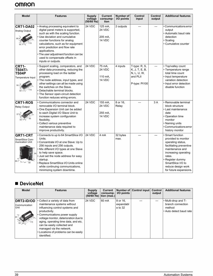
39 Automation Systems
DeviceNet
CRT1-DA02Analog Output
• Analog processing equivalent to
digital panel meters is supported,
such as with the scaling function.
• Use deviation and cumulative
counter functions for analog
calculations, such as for equipment
error prediction and flow rate
applications.
• The user adjustment function can be
used to compensate offsets in
inputs or outputs.
24 VDC 125 mA,
24 VDC
205 mA,
14 VDC
2 outputs --- --- • Communications error
output
• Automatic baud rate
detection
• Scaling
• Cumulative counter
CRT1-TS04T/-TS04PTemperature Input
• Support scaling, comparators, and
other data processing, reducing the
processing load on the ladder
program.
• The node address, input types, and
other settings can all be made using
the switches on the Slave.
• Detachable terminal blocks.
• The Sensor open-circuit detection
function reduces wiring errors.
24 VDC 75 mA,
24 VDC
110 mA,
14 VDC
4 inputs T-type: R, S,
K, J, T, E, B,
N, L, U, W,
and PLII
P-type: Pt100
--- • Top/valley count
• Temperature range
total time count
• Input temperature
variation detection
• Input error detection
disable function
CRT1-ROSRelay Output
• Communications connector and
removable I/O terminal block.
• One Expansion Unit can be added
to each Digital I/O Slave Unit to
increase system configuration
flexibility.
• Collect various preventive
maintenance data required to
improve productivity.
24 VDC 155 mA,
24 VDC
255 mA,
14 VDC
8 or 16,
Relay
--- 3 A • Removable terminal
block structure
• Last maintenance
date
• Operation time
monitor
• Naming units
• Communications error
history monitor
GRT1-CRTSmartSlice Com-munication Unit
• Connects to up to 64 SmartSlice I/O
Units.
• Concentrate I/O at one Slave: Up to
256 inputs and 256 outputs.
• Mix different I/O types at one Slave
to help save space.
• Just set the node address for easy
startup.
• Replace SmartSlice I/O Units online
while continuing communications,
minimizing system downtime.
24 VDC 4 mA 32 bytes
max.
--- --- • Smart function
provided to monitor
operating status,
facilitating preventive
maintenance and
increasing operating
rates.
• Register dummy
SmartSlice I/O to
reduce design work
for future expansions.
Model Features Supply voltage
(50/60 Hz)
Current consump-tion (max.)
Number of I/O points
Control input Control output
Additional features
DRT2-ID/ODCommunication Unit
• Collect a variety of data from
maintenance systems without
influencing control systems and
productivity.
• Communications power supply
voltage monitor, deterioration due to
aging, operating time data, and etc.
can be easily collected and
managed via the network.
• Locations of problems can be easily
identified.
24 VDC 60 mA 8 or 16,
expandabl
e to 32
--- --- • Multi-drop and T-
branch connection
method
• Auto detect baud rate
Model Features Supply voltage
(50/60 Hz)
Current consump-
tion
Number of I/O points
Control input
Control output
Additional features
66.9
50115
50.1
50115
57.6
5295
84
69.758
40
50115
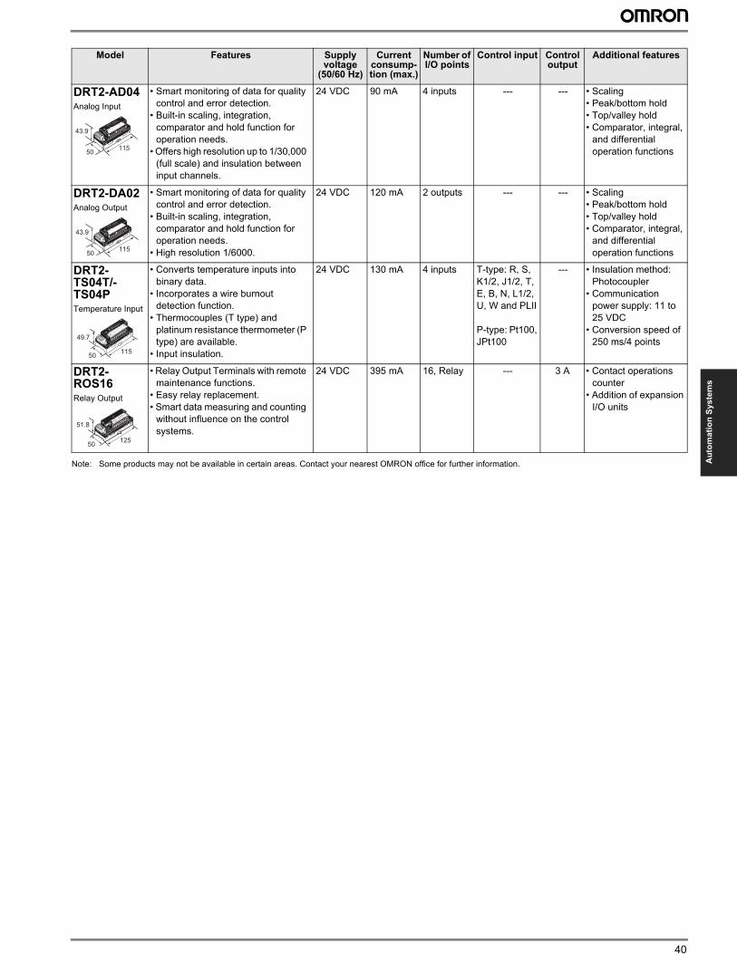
40
Au
tom
ati
on
Sy
ste
ms
Note: Some products may not be available in certain areas. Contact your nearest OMRON office for further information.
DRT2-AD04Analog Input
• Smart monitoring of data for quality
control and error detection.
• Built-in scaling, integration,
comparator and hold function for
operation needs.
• Offers high resolution up to 1/30,000
(full scale) and insulation between
input channels.
24 VDC 90 mA 4 inputs --- --- • Scaling
• Peak/bottom hold
• Top/valley hold
• Comparator, integral,
and differential
operation functions
DRT2-DA02Analog Output
• Smart monitoring of data for quality
control and error detection.
• Built-in scaling, integration,
comparator and hold function for
operation needs.
• High resolution 1/6000.
24 VDC 120 mA 2 outputs --- --- • Scaling
• Peak/bottom hold
• Top/valley hold
• Comparator, integral,
and differential
operation functions
DRT2-TS04T/-TS04PTemperature Input
• Converts temperature inputs into
binary data.
• Incorporates a wire burnout
detection function.
• Thermocouples (T type) and
platinum resistance thermometer (P
type) are available.
• Input insulation.
24 VDC 130 mA 4 inputs T-type: R, S,
K1/2, J1/2, T,
E, B, N, L1/2,
U, W and PLII
P-type: Pt100,
JPt100
--- • Insulation method:
Photocoupler
• Communication
power supply: 11 to
25 VDC
• Conversion speed of
250 ms/4 points
DRT2-ROS16Relay Output
• Relay Output Terminals with remote
maintenance functions.
• Easy relay replacement.
• Smart data measuring and counting
without influence on the control
systems.
24 VDC 395 mA 16, Relay --- 3 A • Contact operations
counter
• Addition of expansion
I/O units
Model Features Supply voltage
(50/60 Hz)
Current consump-tion (max.)
Number of I/O points
Control input Control output
Additional features
43.9
50115
43.9
50115
49.7
50115
51.8
50125
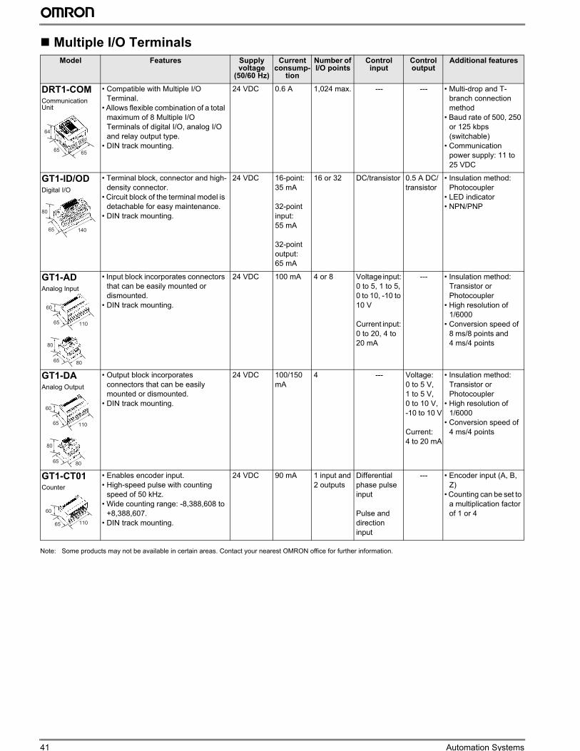
41 Automation Systems
Multiple I/O Terminals
Note: Some products may not be available in certain areas. Contact your nearest OMRON office for further information.
Model Features Supply voltage
(50/60 Hz)
Current consump-
tion
Number of I/O points
Control input
Control output
Additional features
DRT1-COMCommunication Unit
• Compatible with Multiple I/O
Terminal.
• Allows flexible combination of a total
maximum of 8 Multiple I/O
Terminals of digital I/O, analog I/O
and relay output type.
• DIN track mounting.
24 VDC 0.6 A 1,024 max. --- --- • Multi-drop and T-
branch connection
method
• Baud rate of 500, 250
or 125 kbps
(switchable)
• Communication
power supply: 11 to
25 VDC
GT1-ID/ODDigital I/O
• Terminal block, connector and high-
density connector.
• Circuit block of the terminal model is
detachable for easy maintenance.
• DIN track mounting.
24 VDC 16-point:
35 mA
32-point
input:
55 mA
32-point
output:
65 mA
16 or 32 DC/transistor 0.5 A DC/
transistor
• Insulation method:
Photocoupler
• LED indicator
• NPN/PNP
GT1-ADAnalog Input
• Input block incorporates connectors
that can be easily mounted or
dismounted.
• DIN track mounting.
24 VDC 100 mA 4 or 8 Voltage input:
0 to 5, 1 to 5,
0 to 10, -10 to
10 V
Current input:
0 to 20, 4 to
20 mA
--- • Insulation method:
Transistor or
Photocoupler
• High resolution of
1/6000
• Conversion speed of
8 ms/8 points and
4 ms/4 points
GT1-DAAnalog Output
• Output block incorporates
connectors that can be easily
mounted or dismounted.
• DIN track mounting.
24 VDC 100/150
mA
4 --- Voltage:
0 to 5 V,
1 to 5 V,
0 to 10 V,
-10 to 10 V
Current:
4 to 20 mA
• Insulation method:
Transistor or
Photocoupler
• High resolution of
1/6000
• Conversion speed of
4 ms/4 points
GT1-CT01Counter
• Enables encoder input.
• High-speed pulse with counting
speed of 50 kHz.
• Wide counting range: -8,388,608 to
+8,388,607.
• DIN track mounting.
24 VDC 90 mA 1 input and
2 outputs
Differential
phase pulse
input
Pulse and
direction
input
--- • Encoder input (A, B,
Z)
• Counting can be set to
a multiplication factor
of 1 or 4
64
6565
80
65 140
60
65 110
80
65 80
60
65 110
80
65 80
60
65 110
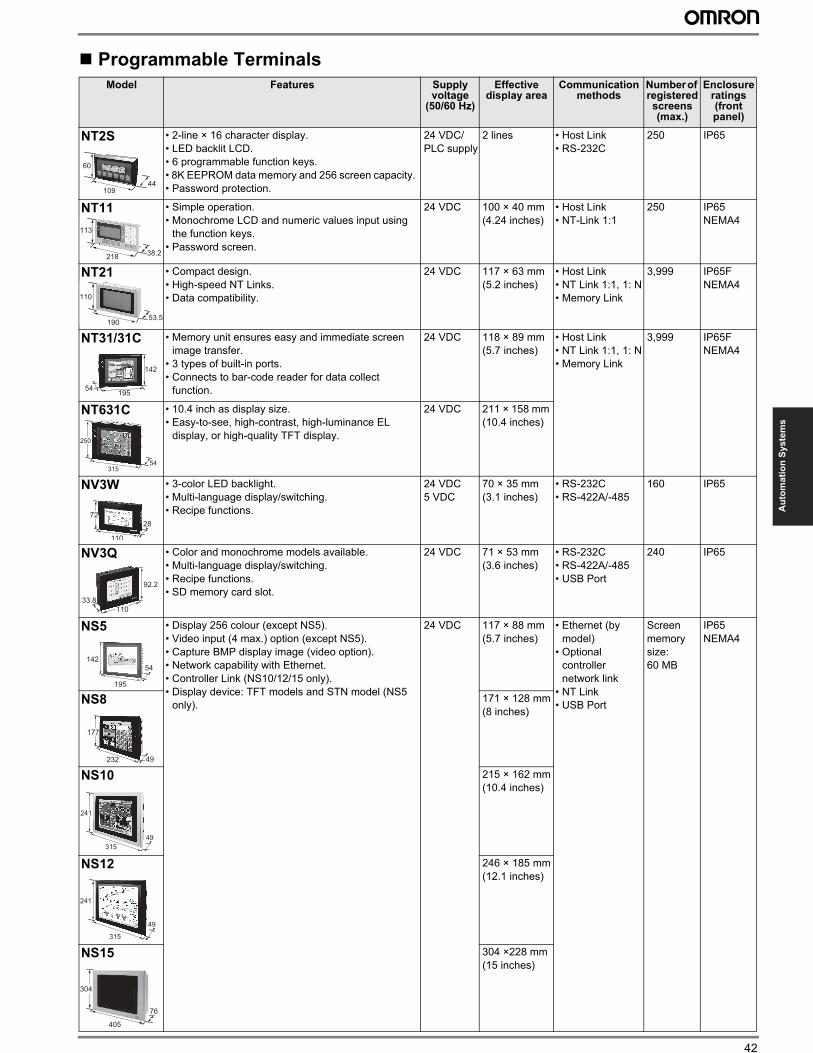
42
Au
tom
ati
on
Sy
ste
ms
Programmable Terminals
Model Features Supply voltage
(50/60 Hz)
Effective display area
Communication methods
Number of registered screens (max.)
Enclosure ratings (front panel)
NT2S • 2-line × 16 character display.
• LED backlit LCD.
• 6 programmable function keys.
• 8K EEPROM data memory and 256 screen capacity.
• Password protection.
24 VDC/
PLC supply
2 lines • Host Link
• RS-232C
250 IP65
NT11 • Simple operation.
• Monochrome LCD and numeric values input using
the function keys.
• Password screen.
24 VDC 100 × 40 mm
(4.24 inches)
• Host Link
• NT-Link 1:1
250 IP65
NEMA4
NT21 • Compact design.
• High-speed NT Links.
• Data compatibility.
24 VDC 117 × 63 mm
(5.2 inches)
• Host Link
• NT Link 1:1, 1: N
• Memory Link
3,999 IP65F
NEMA4
NT31/31C • Memory unit ensures easy and immediate screen
image transfer.
• 3 types of built-in ports.
• Connects to bar-code reader for data collect
function.
24 VDC 118 × 89 mm
(5.7 inches)
• Host Link
• NT Link 1:1, 1: N
• Memory Link
3,999 IP65F
NEMA4
NT631C • 10.4 inch as display size.
• Easy-to-see, high-contrast, high-luminance EL
display, or high-quality TFT display.
24 VDC 211 × 158 mm
(10.4 inches)
NV3W • 3-color LED backlight.
• Multi-language display/switching.
• Recipe functions.
24 VDC
5 VDC
70 × 35 mm
(3.1 inches)
• RS-232C
• RS-422A/-485
160 IP65
NV3Q • Color and monochrome models available.
• Multi-language display/switching.
• Recipe functions.
• SD memory card slot.
24 VDC 71 × 53 mm
(3.6 inches)
• RS-232C
• RS-422A/-485
• USB Port
240 IP65
NS5 • Display 256 colour (except NS5).
• Video input (4 max.) option (except NS5).
• Capture BMP display image (video option).
• Network capability with Ethernet.
• Controller Link (NS10/12/15 only).
• Display device: TFT models and STN model (NS5
only).
24 VDC 117 × 88 mm
(5.7 inches)
• Ethernet (by
model)
• Optional
controller
network link
• NT Link
• USB Port
Screen
memory
size:
60 MB
IP65
NEMA4
NS8 171 × 128 mm
(8 inches)
NS10 215 × 162 mm
(10.4 inches)
NS12 246 × 185 mm
(12.1 inches)
NS15 304 ×228 mm
(15 inches)
60
44109
113
38.2218
110
53.5190
142
54195
54315
250
28
110
72
92.2
33.8
110
54
195
142
49232
177
49
315
241
241
49
315
76
405
304
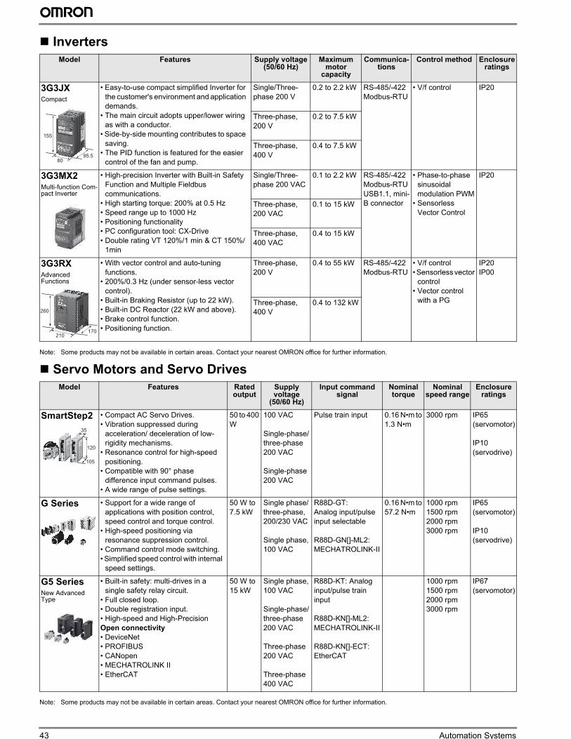
43 Automation Systems
Inverters
Note: Some products may not be available in certain areas. Contact your nearest OMRON office for further information.
Servo Motors and Servo Drives
Note: Some products may not be available in certain areas. Contact your nearest OMRON office for further information.
Model Features Supply voltage (50/60 Hz)
Maximum motor
capacity
Communica-tions
Control method Enclosure ratings
3G3JXCompact
• Easy-to-use compact simplified Inverter for
the customer's environment and application
demands.
• The main circuit adopts upper/lower wiring
as with a conductor.
• Side-by-side mounting contributes to space
saving.
• The PID function is featured for the easier
control of the fan and pump.
Single/Three-
phase 200 V
0.2 to 2.2 kW RS-485/-422
Modbus-RTU
• V/f control IP20
Three-phase,
200 V
0.2 to 7.5 kW
Three-phase,
400 V
0.4 to 7.5 kW
3G3MX2Multi-function Com-pact Inverter
• High-precision Inverter with Built-in Safety
Function and Multiple Fieldbus
communications.
• High starting torque: 200% at 0.5 Hz
• Speed range up to 1000 Hz
• Positioning functionality
• PC configuration tool: CX-Drive
• Double rating VT 120%/1 min & CT 150%/
1min
Single/Three-
phase 200 VAC
0.1 to 2.2 kW RS-485/-422
Modbus-RTU
USB1.1, mini-
B connector
• Phase-to-phase
sinusoidal
modulation PWM
• Sensorless
Vector Control
IP20
Three-phase,
200 VAC
0.1 to 15 kW
Three-phase,
400 VAC
0.4 to 15 kW
3G3RXAdvanced Functions
• With vector control and auto-tuning
functions.
• 200%/0.3 Hz (under sensor-less vector
control).
• Built-in Braking Resistor (up to 22 kW).
• Built-in DC Reactor (22 kW and above).
• Brake control function.
• Positioning function.
Three-phase,
200 V
0.4 to 55 kW RS-485/-422
Modbus-RTU
• V/f control
• Sensorless vector
control
• Vector control
with a PG
IP20
IP00
Three-phase,
400 V
0.4 to 132 kW
Model Features Rated output
Supply voltage
(50/60 Hz)
Input command signal
Nominal torque
Nominal speed range
Enclosure ratings
SmartStep2 • Compact AC Servo Drives.
• Vibration suppressed during
acceleration/ deceleration of low-
rigidity mechanisms.
• Resonance control for high-speed
positioning.
• Compatible with 90° phase
difference input command pulses.
• A wide range of pulse settings.
50 to 400
W
100 VAC
Single-phase/
three-phase
200 VAC
Single-phase
200 VAC
Pulse train input 0.16 N•m to
1.3 N•m
3000 rpm IP65
(servomotor)
IP10
(servodrive)
G Series • Support for a wide range of
applications with position control,
speed control and torque control.
• High-speed positioning via
resonance suppression control.
• Command control mode switching.
• Simplified speed control with internal
speed settings.
50 W to
7.5 kW
Single phase/
three-phase,
200/230 VAC
Single phase,
100 VAC
R88D-GT:
Analog input/pulse
input selectable
R88D-GN[]-ML2:
MECHATROLINK-II
0.16 N•m to
57.2 N•m
1000 rpm
1500 rpm
2000 rpm
3000 rpm
IP65
(servomotor)
IP10
(servodrive)
G5 SeriesNew Advanced Type
• Built-in safety: multi-drives in a
single safety relay circuit.
• Full closed loop.
• Double registration input.
• High-speed and High-Precision
Open connectivity
• DeviceNet
• PROFIBUS
• CANopen
• MECHATROLINK II
• EtherCAT
50 W to
15 kW
Single phase,
100 VAC
Single-phase/
three-phase
200 VAC
Three-phase
200 VAC
Three-phase
400 VAC
R88D-KT: Analog
input/pulse train
input
R88D-KN[]-ML2:
MECHATROLINK-II
R88D-KN[]-ECT:
EtherCAT
1000 rpm
1500 rpm
2000 rpm
3000 rpm
IP67
(servomotor)
155
95.580
260
170210
120
35
105
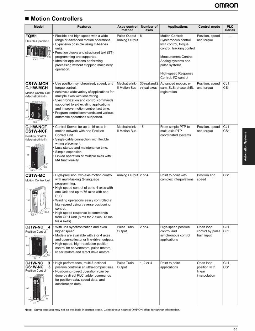
44
Au
tom
ati
on
Sy
ste
ms
Motion Controllers
Note: Some products may not be available in certain areas. Contact your nearest OMRON office for further information.
Model Features Axes control method
Number of axes
Applications Control mode PLC Series
FQM1Flexible Operation
• Flexible and high speed with a wide
range of advanced motion operations.
• Expansion possible using CJ-series
units.
• Function blocks and structured text (ST)
programming are supported.
• Ideal for applications performing
processing without stopping machinery
operation.
Pulse Output
Analog Output
8 Motion Control:
Synchronous control,
limit control, torque
control, tracking control
Measurement Control:
Analog systems and
pulse systems
High-speed Response
Control: I/O control
Position, speed
and torque
---
CS1W-MCHCJ1W-MCHMotion Control Unit(Mechatrolink-II)
• Use position, synchronized, speed, and
torque control.
• Achieve a wide variety of applications for
multiple axes with less wiring.
• Synchronization and control commands
supported to aid existing applications
and improve motion control tact time.
• Program control commands and various
arithmetic operations supported.
Mechatrolink-
II Motion Bus
30 real and 2
virtual axes
Advanced motion, e-
cam, ELS, phase shift,
registration
Position, speed
and torque
CJ1
CS1
CJ1W-NCFCS1W-NCFPosition Control(Mechatrolink-II)
• Control Servos for up to 16 axes in
motion network with one Position
Control Unit.
• Single-cable connection with flexible
wiring placement.
• Less startup and maintenance time.
• Simple expansion.
• Linked operation of multiple axes with
MA functionality.
Mechatrolink-
II Motion Bus
16 From simple PTP to
multi-axis PTP
coordinated systems
Position, speed
and torque
CJ1
CS1
CS1W-MCMotion Control Unit
• High-precision, two-axis motion control
with multi-tasking G-language
programming.
• High-speed control of up to 4 axes with
one Unit and up to 76 axes with one
PLC.
• Winding operations easily controlled at
high-speed using traverse positioning
control.
• High-speed response to commands
from CPU Unit (8 ms for 2 axes, 13 ms
for 4 axes).
Analog Output 2 or 4 Point to point with
complex interpolations
Position and
speed
CS1
CJ1W-NC_ _4Position Control
• With unit synchronization and even
higher speed.
• Models are available with 2 or 4 axes
and open-collector or line-driver outputs.
• High-speed, high-resolution position
control for servomotors, pulse motors,
linear motors and direct drive motors.
Pulse Train
Output
2 or 4 High-speed position
control and
synchronous control
applications
Open loop
control by pulse
train input
CJ1
CJ2
CJ1W-NC_ _3CS1W-NC_ _3Position Control
• High performance, multi-functional
position control in an ultra-compact size.
• Positioning (direct operation) can be
done by direct PLC ladder commands
for position data, speed data, and
acceleration data.
Pulse Train
Output
1, 2 or 4 Point to point
applications
Open loop
position with
linear
interpolation
CJ1
CS1
80
90
206.7
90
65
79.8
90
31
65
130
100.5
35
90
65
51
90
65
31
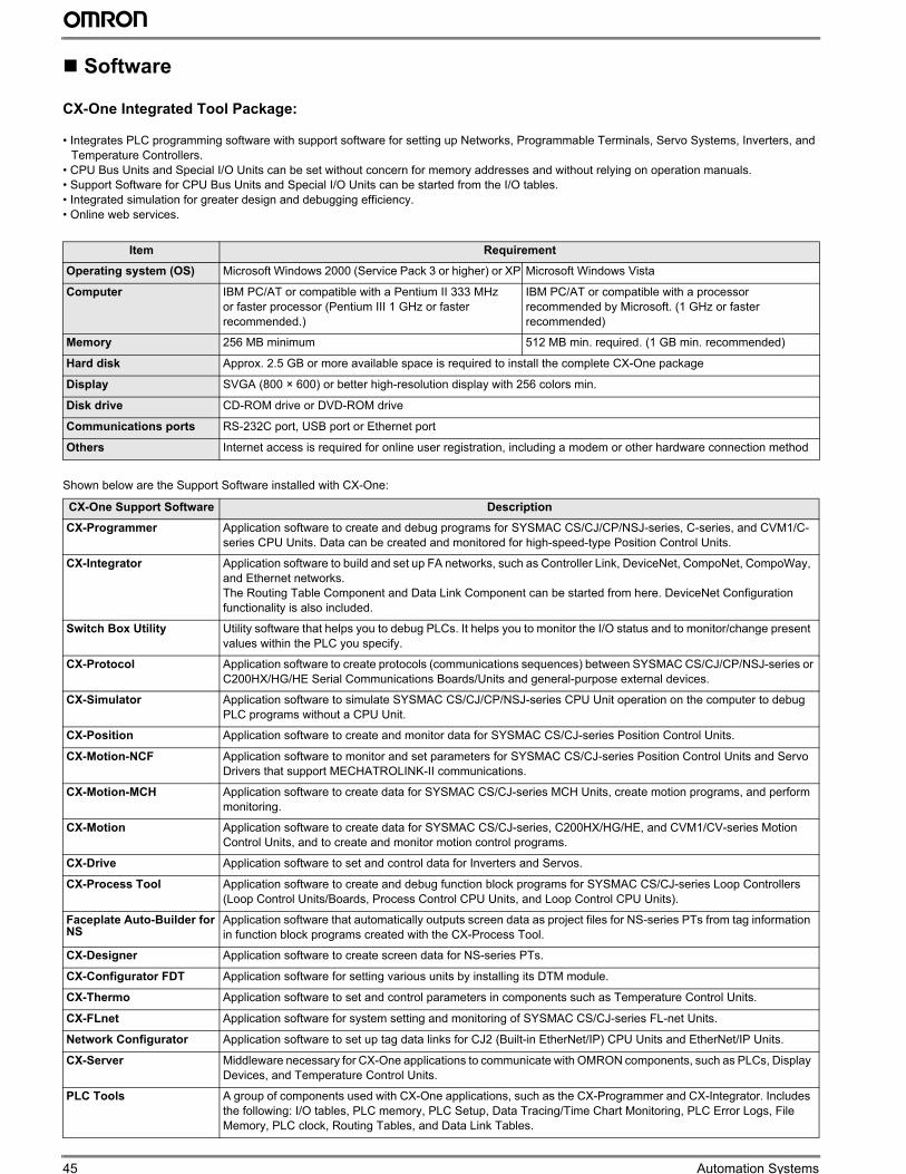
45 Automation Systems
Software
CX-One Integrated Tool Package:
• Integrates PLC programming software with support software for setting up Networks, Programmable Terminals, Servo Systems, Inverters, and
Temperature Controllers.
• CPU Bus Units and Special I/O Units can be set without concern for memory addresses and without relying on operation manuals.
• Support Software for CPU Bus Units and Special I/O Units can be started from the I/O tables.
• Integrated simulation for greater design and debugging efficiency.
• Online web services.
Shown below are the Support Software installed with CX-One:
Item Requirement
Operating system (OS) Microsoft Windows 2000 (Service Pack 3 or higher) or XP Microsoft Windows Vista
Computer IBM PC/AT or compatible with a Pentium II 333 MHz
or faster processor (Pentium III 1 GHz or faster
recommended.)
IBM PC/AT or compatible with a processor
recommended by Microsoft. (1 GHz or faster
recommended)
Memory 256 MB minimum 512 MB min. required. (1 GB min. recommended)
Hard disk Approx. 2.5 GB or more available space is required to install the complete CX-One package
Display SVGA (800 × 600) or better high-resolution display with 256 colors min.
Disk drive CD-ROM drive or DVD-ROM drive
Communications ports RS-232C port, USB port or Ethernet port
Others Internet access is required for online user registration, including a modem or other hardware connection method
CX-One Support Software Description
CX-Programmer Application software to create and debug programs for SYSMAC CS/CJ/CP/NSJ-series, C-series, and CVM1/C-
series CPU Units. Data can be created and monitored for high-speed-type Position Control Units.
CX-Integrator Application software to build and set up FA networks, such as Controller Link, DeviceNet, CompoNet, CompoWay,
and Ethernet networks.
The Routing Table Component and Data Link Component can be started from here. DeviceNet Configuration
functionality is also included.
Switch Box Utility Utility software that helps you to debug PLCs. It helps you to monitor the I/O status and to monitor/change present
values within the PLC you specify.
CX-Protocol Application software to create protocols (communications sequences) between SYSMAC CS/CJ/CP/NSJ-series or
C200HX/HG/HE Serial Communications Boards/Units and general-purpose external devices.
CX-Simulator Application software to simulate SYSMAC CS/CJ/CP/NSJ-series CPU Unit operation on the computer to debug
PLC programs without a CPU Unit.
CX-Position Application software to create and monitor data for SYSMAC CS/CJ-series Position Control Units.
CX-Motion-NCF Application software to monitor and set parameters for SYSMAC CS/CJ-series Position Control Units and Servo
Drivers that support MECHATROLINK-II communications.
CX-Motion-MCH Application software to create data for SYSMAC CS/CJ-series MCH Units, create motion programs, and perform
monitoring.
CX-Motion Application software to create data for SYSMAC CS/CJ-series, C200HX/HG/HE, and CVM1/CV-series Motion
Control Units, and to create and monitor motion control programs.
CX-Drive Application software to set and control data for Inverters and Servos.
CX-Process Tool Application software to create and debug function block programs for SYSMAC CS/CJ-series Loop Controllers
(Loop Control Units/Boards, Process Control CPU Units, and Loop Control CPU Units).
Faceplate Auto-Builder for NS
Application software that automatically outputs screen data as project files for NS-series PTs from tag information
in function block programs created with the CX-Process Tool.
CX-Designer Application software to create screen data for NS-series PTs.
CX-Configurator FDT Application software for setting various units by installing its DTM module.
CX-Thermo Application software to set and control parameters in components such as Temperature Control Units.
CX-FLnet Application software for system setting and monitoring of SYSMAC CS/CJ-series FL-net Units.
Network Configurator Application software to set up tag data links for CJ2 (Built-in EtherNet/IP) CPU Units and EtherNet/IP Units.
CX-Server Middleware necessary for CX-One applications to communicate with OMRON components, such as PLCs, Display
Devices, and Temperature Control Units.
PLC Tools A group of components used with CX-One applications, such as the CX-Programmer and CX-Integrator. Includes
the following: I/O tables, PLC memory, PLC Setup, Data Tracing/Time Chart Monitoring, PLC Error Logs, File
Memory, PLC clock, Routing Tables, and Data Link Tables.
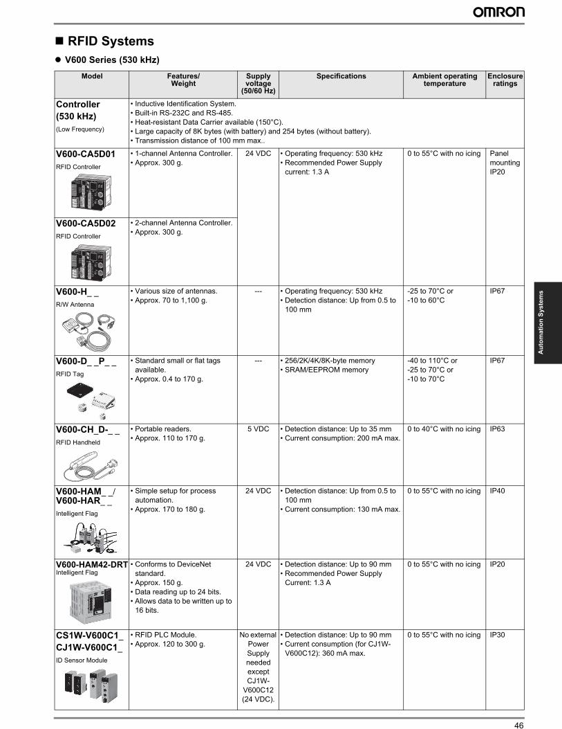
46
Au
tom
ati
on
Sy
ste
ms
RFID Systems
” V600 Series (530 kHz)
Model Features/ Weight
Supply voltage
(50/60 Hz)
Specifications Ambient operating temperature
Enclosure ratings
Controller
(530 kHz)
(Low Frequency)
• Inductive Identification System.
• Built-in RS-232C and RS-485.
• Heat-resistant Data Carrier available (150°C).
• Large capacity of 8K bytes (with battery) and 254 bytes (without battery).
• Transmission distance of 100 mm max..
V600-CA5D01
RFID Controller
• 1-channel Antenna Controller.
• Approx. 300 g.
24 VDC • Operating frequency: 530 kHz
• Recommended Power Supply
current: 1.3 A
0 to 55°C with no icing Panel
mounting
IP20
V600-CA5D02
RFID Controller
• 2-channel Antenna Controller.
• Approx. 300 g.
V600-H_ _
R/W Antenna
• Various size of antennas.
• Approx. 70 to 1,100 g.
--- • Operating frequency: 530 kHz
• Detection distance: Up from 0.5 to
100 mm
-25 to 70°C or
-10 to 60°C
IP67
V600-D_ _P_ _
RFID Tag
• Standard small or flat tags
available.
• Approx. 0.4 to 170 g.
--- • 256/2K/4K/8K-byte memory
• SRAM/EEPROM memory
-40 to 110°C or
-25 to 70°C or
-10 to 70°C
IP67
V600-CH_D-_ _
RFID Handheld
• Portable readers.
• Approx. 110 to 170 g.
5 VDC • Detection distance: Up to 35 mm
• Current consumption: 200 mA max.
0 to 40°C with no icing IP63
V600-HAM_ _/V600-HAR_ _
Intelligent Flag
• Simple setup for process
automation.
• Approx. 170 to 180 g.
24 VDC • Detection distance: Up from 0.5 to
100 mm
• Current consumption: 130 mA max.
0 to 55°C with no icing IP40
V600-HAM42-DRTIntelligent Flag
• Conforms to DeviceNet
standard.
• Approx. 150 g.
• Data reading up to 24 bits.
• Allows data to be written up to
16 bits.
24 VDC • Detection distance: Up to 90 mm
• Recommended Power Supply
Current: 1.3 A
0 to 55°C with no icing IP20
CS1W-V600C1_
CJ1W-V600C1_
ID Sensor Module
• RFID PLC Module.
• Approx. 120 to 300 g.
No external
Power
Supply
needed
except
CJ1W-
V600C12
(24 VDC).
• Detection distance: Up to 90 mm
• Current consumption (for CJ1W-
V600C12): 360 mA max.
0 to 55°C with no icing IP30
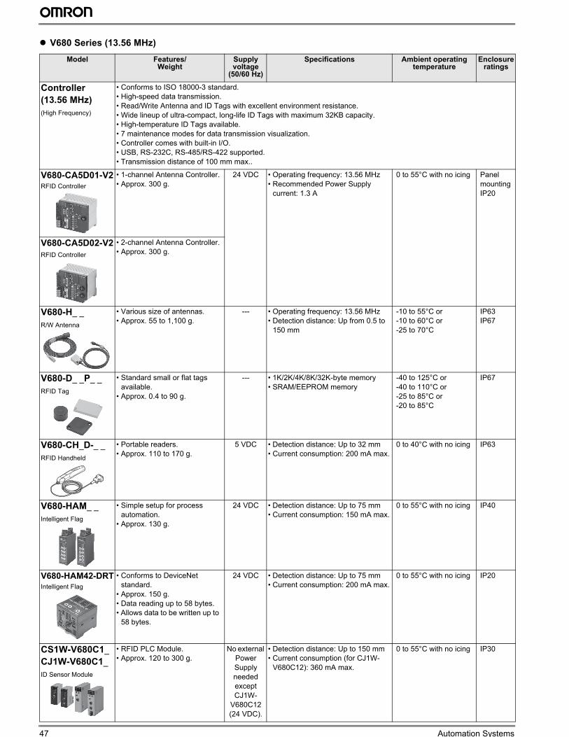
47 Automation Systems
” V680 Series (13.56 MHz)
Model Features/ Weight
Supply voltage
(50/60 Hz)
Specifications Ambient operating temperature
Enclosure ratings
Controller
(13.56 MHz)
(High Frequency)
• Conforms to ISO 18000-3 standard.
• High-speed data transmission.
• Read/Write Antenna and ID Tags with excellent environment resistance.
• Wide lineup of ultra-compact, long-life ID Tags with maximum 32KB capacity.
• High-temperature ID Tags available.
• 7 maintenance modes for data transmission visualization.
• Controller comes with built-in I/O.
• USB, RS-232C, RS-485/RS-422 supported.
• Transmission distance of 100 mm max..
V680-CA5D01-V2RFID Controller
• 1-channel Antenna Controller.
• Approx. 300 g.
24 VDC • Operating frequency: 13.56 MHz
• Recommended Power Supply
current: 1.3 A
0 to 55°C with no icing Panel
mounting
IP20
V680-CA5D02-V2
RFID Controller
• 2-channel Antenna Controller.
• Approx. 300 g.
V680-H_ _
R/W Antenna
• Various size of antennas.
• Approx. 55 to 1,100 g.
--- • Operating frequency: 13.56 MHz
• Detection distance: Up from 0.5 to
150 mm
-10 to 55°C or
-10 to 60°C or
-25 to 70°C
IP63
IP67
V680-D_ _P_ _
RFID Tag
• Standard small or flat tags
available.
• Approx. 0.4 to 90 g.
--- • 1K/2K/4K/8K/32K-byte memory
• SRAM/EEPROM memory
-40 to 125°C or
-40 to 110°C or
-25 to 85°C or
-20 to 85°C
IP67
V680-CH_D-_ _
RFID Handheld
• Portable readers.
• Approx. 110 to 170 g.
5 VDC • Detection distance: Up to 32 mm
• Current consumption: 200 mA max.
0 to 40°C with no icing IP63
V680-HAM_ _
Intelligent Flag
• Simple setup for process
automation.
• Approx. 130 g.
24 VDC • Detection distance: Up to 75 mm
• Current consumption: 150 mA max.
0 to 55°C with no icing IP40
V680-HAM42-DRTIntelligent Flag
• Conforms to DeviceNet
standard.
• Approx. 150 g.
• Data reading up to 58 bytes.
• Allows data to be written up to
58 bytes.
24 VDC • Detection distance: Up to 75 mm
• Current consumption: 200 mA max.
0 to 55°C with no icing IP20
CS1W-V680C1_
CJ1W-V680C1_
ID Sensor Module
• RFID PLC Module.
• Approx. 120 to 300 g.
No external
Power
Supply
needed
except
CJ1W-
V680C12
(24 VDC).
• Detection distance: Up to 150 mm
• Current consumption (for CJ1W-
V680C12): 360 mA max.
0 to 55°C with no icing IP30
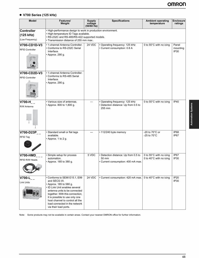
48
Au
tom
ati
on
Sy
ste
ms
” V700 Series (125 kHz)
Note: Some products may not be available in certain areas. Contact your nearest OMRON office for further information.
Model Features/ Weight
Supply voltage
(50/60 Hz)
Specifications Ambient operating temperature
Enclosure ratings
Controller
(125 kHz)
(Low Frequency)
• High-performance design to work in production environment.
• High-temperature ID Tags available.
• RS-232C and RS-485/RS-422 supported models.
• Transmission distance of 255 mm max..
V700-CD1D-V3
RFID Controller
• 1-channel Antenna Controller.
• Conforms to RS-232C Serial
Interface.
• Approx. 290 g.
24 VDC • Operating frequency: 125 kHz
• Current consumption: 0.8 A
0 to 55°C with no icing Panel
mounting
IP30
V700-CD2D-V3
RFID Controller
• 1-channel Antenna Controller.
• Conforms to RS-485 Serial
Interface.
• Approx. 290 g.
V700-H_ _
R/W Antenna
• Various size of antennas.
• Approx. 800 to 1,800 g.
--- • Operating frequency: 125 kHz
• Detection distance: Up from 0.5 to
255 mm
0 to 55°C with no icing IP40
V700-D23P_ _
RFID Tag
• Standard small or flat tags
available.
• Approx. 1 to 2 g.
--- • 112/240 byte memory -20 to 70°C or
-25 to 70°C
IP68
IP67
V700-HMD_ _ _
RFID R/W Heads
• Simple setup for process
automation.
• Approx. 185 to 380 g.
5 VDC • Detection distance: Up from 0.5 to
50 mm
• Current consumption: 400 mA max.
0 to 55°C with no icing
0 to 40°C with no icing
IP67
IP30
V700-L_ _
Link Units
• Conforms to SEMI E15.1, E99
and SECS I/II.
• Approx. 185 to 580 g.
• ID Link Unit enables several
antenna units to be connected
together. With this connection,
it is possible to use only one
host channel to control all the
load connected in the network
via their load ports.
24 VDC • Current consumption: 420 mA max. 0 to 40°C with no icing IP20
IP30
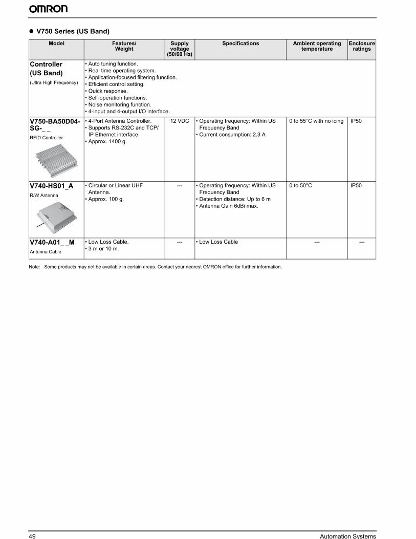
49 Automation Systems
” V750 Series (US Band)
Note: Some products may not be available in certain areas. Contact your nearest OMRON office for further information.
Model Features/ Weight
Supply voltage
(50/60 Hz)
Specifications Ambient operating temperature
Enclosure ratings
Controller
(US Band)
(Ultra High Frequency)
• Auto tuning function.
• Real time operating system.
• Application-focused filtering function.
• Efficient control setting.
• Quick response.
• Self-operation functions.
• Noise monitoring function.
• 4-input and 4-output I/O interface.
V750-BA50D04-SG-_ _
RFID Controller
• 4-Port Antenna Controller.
• Supports RS-232C and TCP/
IP Ethernet interface.
• Approx. 1400 g.
12 VDC • Operating frequency: Within US
Frequency Band
• Current consumption: 2.3 A
0 to 55°C with no icing IP50
V740-HS01_A
R/W Antenna
• Circular or Linear UHF
Antenna.
• Approx. 100 g.
--- • Operating frequency: Within US
Frequency Band
• Detection distance: Up to 6 m
• Antenna Gain 6dBi max.
0 to 50°C IP50
V740-A01_ _M
Antenna Cable
• Low Loss Cable.
• 3 m or 10 m.
--- • Low Loss Cable --- ---
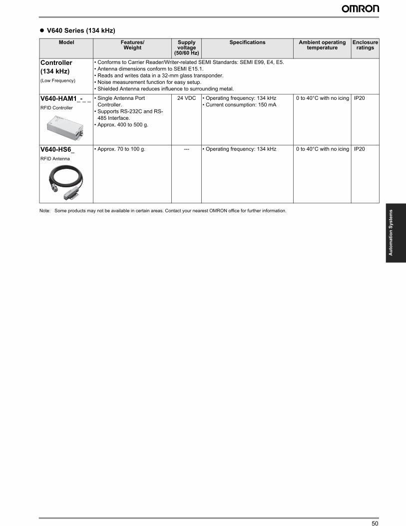
50
Au
tom
ati
on
Sy
ste
ms
” V640 Series (134 kHz)
Note: Some products may not be available in certain areas. Contact your nearest OMRON office for further information.
Model Features/ Weight
Supply voltage
(50/60 Hz)
Specifications Ambient operating temperature
Enclosure ratings
Controller
(134 kHz)
(Low Frequency)
• Conforms to Carrier Reader/Writer-related SEMI Standards: SEMI E99, E4, E5.
• Antenna dimensions conform to SEMI E15.1.
• Reads and writes data in a 32-mm glass transponder.
• Noise measurement function for easy setup.
• Shielded Antenna reduces influence to surrounding metal.
V640-HAM1_-_ _
RFID Controller
• Single Antenna Port
Controller.
• Supports RS-232C and RS-
485 Interface.
• Approx. 400 to 500 g.
24 VDC • Operating frequency: 134 kHz
• Current consumption: 150 mA
0 to 40°C with no icing IP20
V640-HS6_
RFID Antenna
• Approx. 70 to 100 g. --- • Operating frequency: 134 kHz 0 to 40°C with no icing IP20
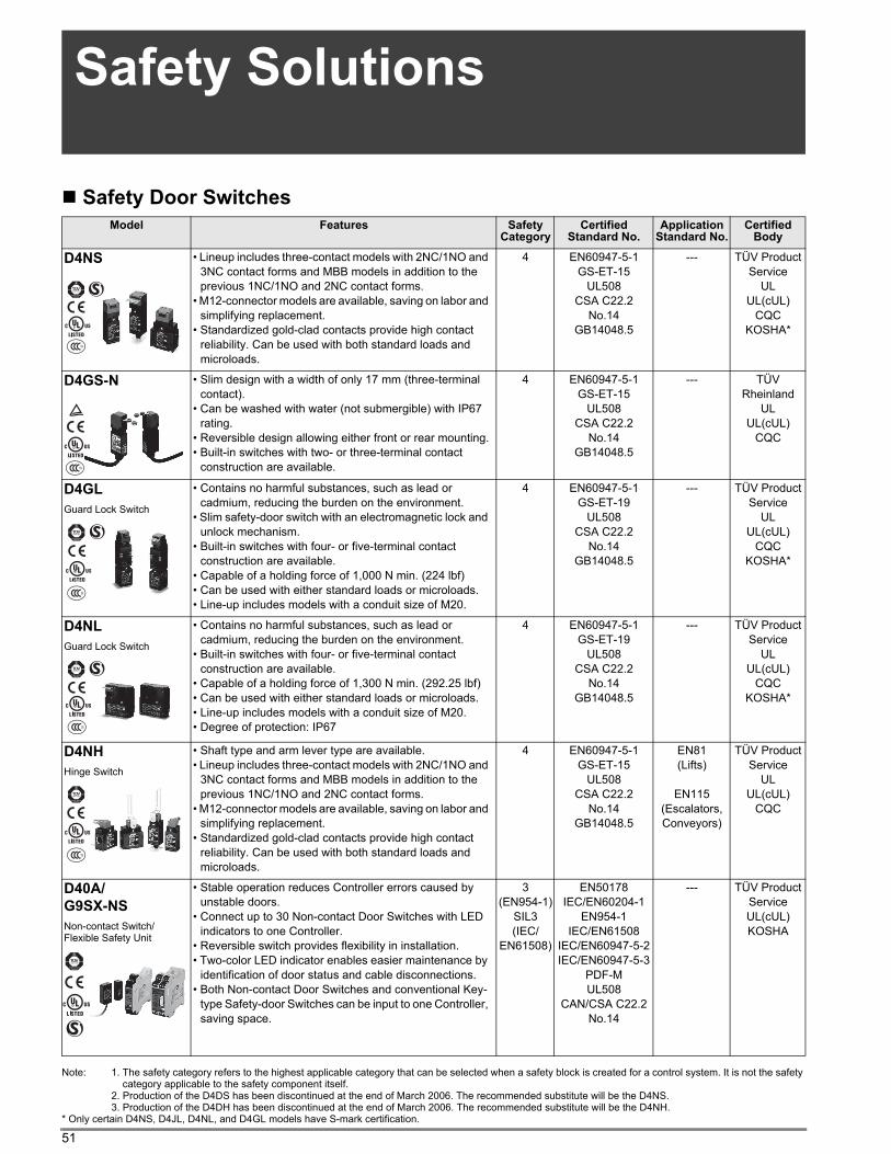
51
Safety Solutions
Safety Door Switches
Note: 1. The safety category refers to the highest applicable category that can be selected when a safety block is created for a control system. It is not the safety category applicable to the safety component itself.
2. Production of the D4DS has been discontinued at the end of March 2006. The recommended substitute will be the D4NS.3. Production of the D4DH has been discontinued at the end of March 2006. The recommended substitute will be the D4NH.
* Only certain D4NS, D4JL, D4NL, and D4GL models have S-mark certification.
Model Features Safety Category
Certified Standard No.
Application Standard No.
Certified Body
D4NS • Lineup includes three-contact models with 2NC/1NO and 3NC contact forms and MBB models in addition to the previous 1NC/1NO and 2NC contact forms.
• M12-connector models are available, saving on labor and simplifying replacement.
• Standardized gold-clad contacts provide high contact reliability. Can be used with both standard loads and microloads.
4 EN60947-5-1GS-ET-15
UL508CSA C22.2
No.14GB14048.5
--- TÜV ProductService
ULUL(cUL)
CQCKOSHA*
D4GS-N • Slim design with a width of only 17 mm (three-terminal contact).
• Can be washed with water (not submergible) with IP67 rating.
• Reversible design allowing either front or rear mounting.• Built-in switches with two- or three-terminal contact
construction are available.
4 EN60947-5-1GS-ET-15
UL508CSA C22.2
No.14GB14048.5
--- TÜV Rheinland
ULUL(cUL)
CQC
D4GL
Guard Lock Switch
• Contains no harmful substances, such as lead or cadmium, reducing the burden on the environment.
• Slim safety-door switch with an electromagnetic lock and unlock mechanism.
• Built-in switches with four- or five-terminal contact construction are available.
• Capable of a holding force of 1,000 N min. (224 lbf)• Can be used with either standard loads or microloads.• Line-up includes models with a conduit size of M20.
4 EN60947-5-1GS-ET-19
UL508CSA C22.2
No.14GB14048.5
--- TÜV ProductService
ULUL(cUL)
CQCKOSHA*
D4NL
Guard Lock Switch
• Contains no harmful substances, such as lead or cadmium, reducing the burden on the environment.
• Built-in switches with four- or five-terminal contact construction are available.
• Capable of a holding force of 1,300 N min. (292.25 lbf)• Can be used with either standard loads or microloads.• Line-up includes models with a conduit size of M20.• Degree of protection: IP67
4 EN60947-5-1GS-ET-19
UL508CSA C22.2
No.14GB14048.5
--- TÜV ProductService
ULUL(cUL)
CQCKOSHA*
D4NH
Hinge Switch
• Shaft type and arm lever type are available.• Lineup includes three-contact models with 2NC/1NO and
3NC contact forms and MBB models in addition to the previous 1NC/1NO and 2NC contact forms.
• M12-connector models are available, saving on labor and simplifying replacement.
• Standardized gold-clad contacts provide high contact reliability. Can be used with both standard loads and microloads.
4 EN60947-5-1GS-ET-15
UL508CSA C22.2
No.14GB14048.5
EN81(Lifts)
EN115(Escalators,Conveyors)
TÜV ProductService
ULUL(cUL)
CQC
D40A/
G9SX-NS
Non-contact Switch/Flexible Safety Unit
• Stable operation reduces Controller errors caused by unstable doors.
• Connect up to 30 Non-contact Door Switches with LED indicators to one Controller.
• Reversible switch provides flexibility in installation.• Two-color LED indicator enables easier maintenance by
identification of door status and cable disconnections.• Both Non-contact Door Switches and conventional Key-
type Safety-door Switches can be input to one Controller, saving space.
3(EN954-1)
SIL3(IEC/
EN61508)
EN50178IEC/EN60204-1
EN954-1IEC/EN61508
IEC/EN60947-5-2IEC/EN60947-5-3
PDF-MUL508
CAN/CSA C22.2No.14
--- TÜV ProductServiceUL(cUL)KOSHA
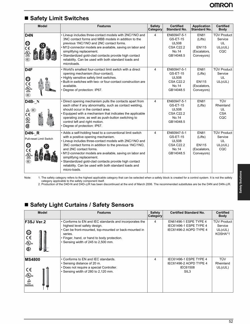
52
Sa
fety
So
luti
on
s
Safety Limit Switches
Note: 1. The safety category refers to the highest applicable category that can be selected when a safety block is created for a control system. It is not the safety category applicable to the safety component itself.
2. Production of the D4D-N and D4D-@R has been discontinued at the end of March 2006. The recommended substitutes are be the D4N and D4N-@R.
Safety Light Curtains / Safety Sensors
Model Features Safety Category
Certified Standard No.
Application Standard No.
Certified Body
D4N • Lineup includes three-contact models with 2NC/1NO and 3NC contact forms and MBB models in addition to the previous 1NC/1NO and 2NC contact forms.
• M12-connector models are available, saving on labor and simplifying replacement.
• Standardized gold-clad contacts provide high contact reliability. Can be used with both standard loads and microloads.
4 EN60947-5-1GS-ET-15
UL508CSA C22.2
No.14GB14048.5
EN81(Lifts)
EN115(Escalators,Conveyors)
TÜV ProductService
ULUL(cUL)
CQC
D4F • World's smallest four-contact limit switch with a direct opening mechanism (four-contact).
• Highly sensitive safety limit switches.• Built-in switches with two- or four-contact construction are
available.• Degree of protection: IP67.
4 EN60947-5-1GS-ET-15
UL508CSA C22.2
No.14GB14048.5
EN81(Lifts)
EN115(Escalators,Conveyors)
TÜV ProductService
ULUL(cUL)
D4B-_N • Direct opening mechanism pulls the contacts apart from each other if any abnormality, such as contact welding, should occur in the contact area.
• Equipped with a mechanism that indicates the applicable operating zone, as well as push-button switching to control left and right motion.
• Degree of protection: IP67.
4 EN60947-5-1GS-ET-15
UL508CSA C22.2
No.14GB14048.5
EN81(Lifts)
TÜV Rheinland
ULCSACQC
D4N-_R
Pull-reset Limit Switch
• Adds a self-holding head to a conventional limit switch with a positive opening mechanism.
• Lineup includes three-contact models with 2NC/1NO and 3NC contact forms in addition to the previous 1NC/1NO, and 2NC contact forms.
• M12-connector models are available, saving on labor and simplifying replacement.
• Standardized gold-clad contacts provide high contact reliability. Can be used with both standard loads and micro-loads.
4 EN60947-5-1GS-ET-15
UL508CSA C22.2
No.14GB14048.5
EN81(Lifts)
EN115(Escalators,Conveyors)
TÜV ProductService
ULUL(cUL)
CQC
Model Features Safety Category
Certified Standard No. Certified Body
F3SJ Ver.2 • Conforms to EN and IEC standards and incorporates the highest level safety design.
• Can be front-mounted, top-mounted or back-mounted in series.
• Finger, hand, or hand to body protection.• Sensing width of 245 to 2,500 mm.
4 EN61496-1 ESPE TYPE 4 IEC61496-1 ESPE TYPE 4 IEC61496-2 AOPD TYPE 4
TÜV ProductServiceUL(cUL)
KOSHA*1
MS4800 • Conforms to EN and IEC standards.• Sensing distance of 20 m.• Does not require a special Controller.• Sensing width of 280 to 2,120 mm.
4 IEC61496-1 ESPE TYPE 4 IEC61496-2 AOPD TYPE 4
IEC61508SIL3
TÜV RheinlandUL(cUL)
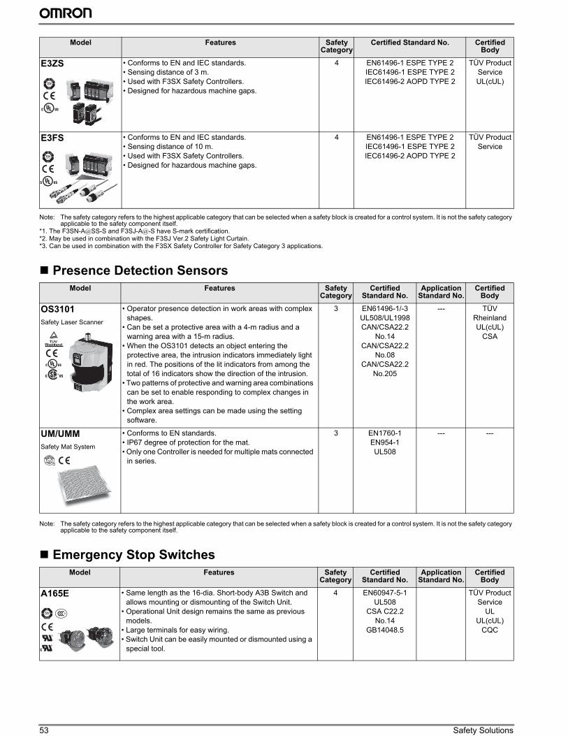
53 Safety Solutions
Note: The safety category refers to the highest applicable category that can be selected when a safety block is created for a control system. It is not the safety category applicable to the safety component itself.
*1. The F3SN-A@SS-S and F3SJ-A@-S have S-mark certification.*2. May be used in combination with the F3SJ Ver.2 Safety Light Curtain.*3. Can be used in combination with the F3SX Safety Controller for Safety Category 3 applications.
Presence Detection Sensors
Note: The safety category refers to the highest applicable category that can be selected when a safety block is created for a control system. It is not the safety category applicable to the safety component itself.
Emergency Stop Switches
E3ZS • Conforms to EN and IEC standards.• Sensing distance of 3 m.• Used with F3SX Safety Controllers.• Designed for hazardous machine gaps.
4 EN61496-1 ESPE TYPE 2IEC61496-1 ESPE TYPE 2IEC61496-2 AOPD TYPE 2
TÜV ProductServiceUL(cUL)
E3FS • Conforms to EN and IEC standards.• Sensing distance of 10 m.• Used with F3SX Safety Controllers.• Designed for hazardous machine gaps.
4 EN61496-1 ESPE TYPE 2IEC61496-1 ESPE TYPE 2IEC61496-2 AOPD TYPE 2
TÜV ProductService
Model Features Safety Category
Certified Standard No.
Application Standard No.
Certified Body
OS3101
Safety Laser Scanner
• Operator presence detection in work areas with complex shapes.
• Can be set a protective area with a 4-m radius and a warning area with a 15-m radius.
• When the OS3101 detects an object entering the protective area, the intrusion indicators immediately light in red. The positions of the lit indicators from among the total of 16 indicators show the direction of the intrusion.
• Two patterns of protective and warning area combinations can be set to enable responding to complex changes in the work area.
• Complex area settings can be made using the setting software.
3 EN61496-1/-3UL508/UL1998CAN/CSA22.2
No.14CAN/CSA22.2
No.08CAN/CSA22.2
No.205
--- TÜV RheinlandUL(cUL)
CSA
UM/UMM
Safety Mat System
• Conforms to EN standards.• IP67 degree of protection for the mat.• Only one Controller is needed for multiple mats connected
in series.
3 EN1760-1EN954-1UL508
--- ---
Model Features Safety Category
Certified Standard No.
Application Standard No.
Certified Body
A165E • Same length as the 16-dia. Short-body A3B Switch and allows mounting or dismounting of the Switch Unit.
• Operational Unit design remains the same as previous models.
• Large terminals for easy wiring.• Switch Unit can be easily mounted or dismounted using a
special tool.
4 EN60947-5-1UL508
CSA C22.2No.14
GB14048.5
TÜV ProductService
ULUL(cUL)
CQC
Model Features Safety Category
Certified Standard No. Certified Body
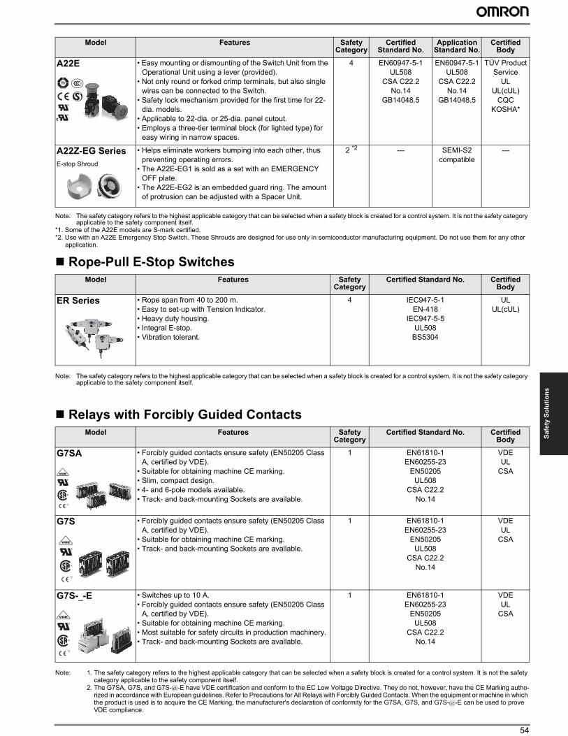
54
Sa
fety
So
luti
on
s
Note: The safety category refers to the highest applicable category that can be selected when a safety block is created for a control system. It is not the safety category applicable to the safety component itself.
*1. Some of the A22E models are S-mark certified.*2. Use with an A22E Emergency Stop Switch. These Shrouds are designed for use only in semiconductor manufacturing equipment. Do not use them for any other
application.
Rope-Pull E-Stop Switches
Note: The safety category refers to the highest applicable category that can be selected when a safety block is created for a control system. It is not the safety category applicable to the safety component itself.
Relays with Forcibly Guided Contacts
Note: 1. The safety category refers to the highest applicable category that can be selected when a safety block is created for a control system. It is not the safety category applicable to the safety component itself.
2. The G7SA, G7S, and G7S-@-E have VDE certification and conform to the EC Low Voltage Directive. They do not, however, have the CE Marking autho-rized in accordance with European guidelines. Refer to Precautions for All Relays with Forcibly Guided Contacts. When the equipment or machine in which the product is used is to acquire the CE Marking, the manufacturer's declaration of conformity for the G7SA, G7S, and G7S-@-E can be used to prove VDE compliance.
A22E • Easy mounting or dismounting of the Switch Unit from the Operational Unit using a lever (provided).
• Not only round or forked crimp terminals, but also single wires can be connected to the Switch.
• Safety lock mechanism provided for the first time for 22-dia. models.
• Applicable to 22-dia. or 25-dia. panel cutout.• Employs a three-tier terminal block (for lighted type) for
easy wiring in narrow spaces.
4 EN60947-5-1UL508
CSA C22.2No.14
GB14048.5
EN60947-5-1UL508
CSA C22.2No.14
GB14048.5
TÜV ProductService
ULUL(cUL)
CQCKOSHA*
A22Z-EG Series
E-stop Shroud
• Helps eliminate workers bumping into each other, thus preventing operating errors.
• The A22E-EG1 is sold as a set with an EMERGENCY OFF plate.
• The A22E-EG2 is an embedded guard ring. The amount of protrusion can be adjusted with a Spacer Unit.
2 *2 --- SEMI-S2compatible
---
Model Features Safety Category
Certified Standard No. Certified Body
ER Series • Rope span from 40 to 200 m.• Easy to set-up with Tension Indicator.• Heavy duty housing.• Integral E-stop.• Vibration tolerant.
4 IEC947-5-1EN-418
IEC947-5-5UL508
BS5304
ULUL(cUL)
Model Features Safety Category
Certified Standard No. Certified Body
G7SA • Forcibly guided contacts ensure safety (EN50205 Class A, certified by VDE).
• Suitable for obtaining machine CE marking.• Slim, compact design.• 4- and 6-pole models available.• Track- and back-mounting Sockets are available.
1 EN61810-1EN60255-23
EN50205UL508
CSA C22.2No.14
VDEUL
CSA
G7S • Forcibly guided contacts ensure safety (EN50205 Class A, certified by VDE).
• Suitable for obtaining machine CE marking.• Track- and back-mounting Sockets are available.
1 EN61810-1EN60255-23
EN50205UL508
CSA C22.2No.14
VDEUL
CSA
G7S-_-E • Switches up to 10 A.• Forcibly guided contacts ensure safety (EN50205 Class
A, certified by VDE).• Suitable for obtaining machine CE marking.• Most suitable for safety circuits in production machinery.• Track- and back-mounting Sockets are available.
1 EN61810-1EN60255-23
EN50205UL508
CSA C22.2No.14
VDEUL
CSA
Model Features Safety Category
Certified Standard No.
Application Standard No.
Certified Body
*2
*2
*2
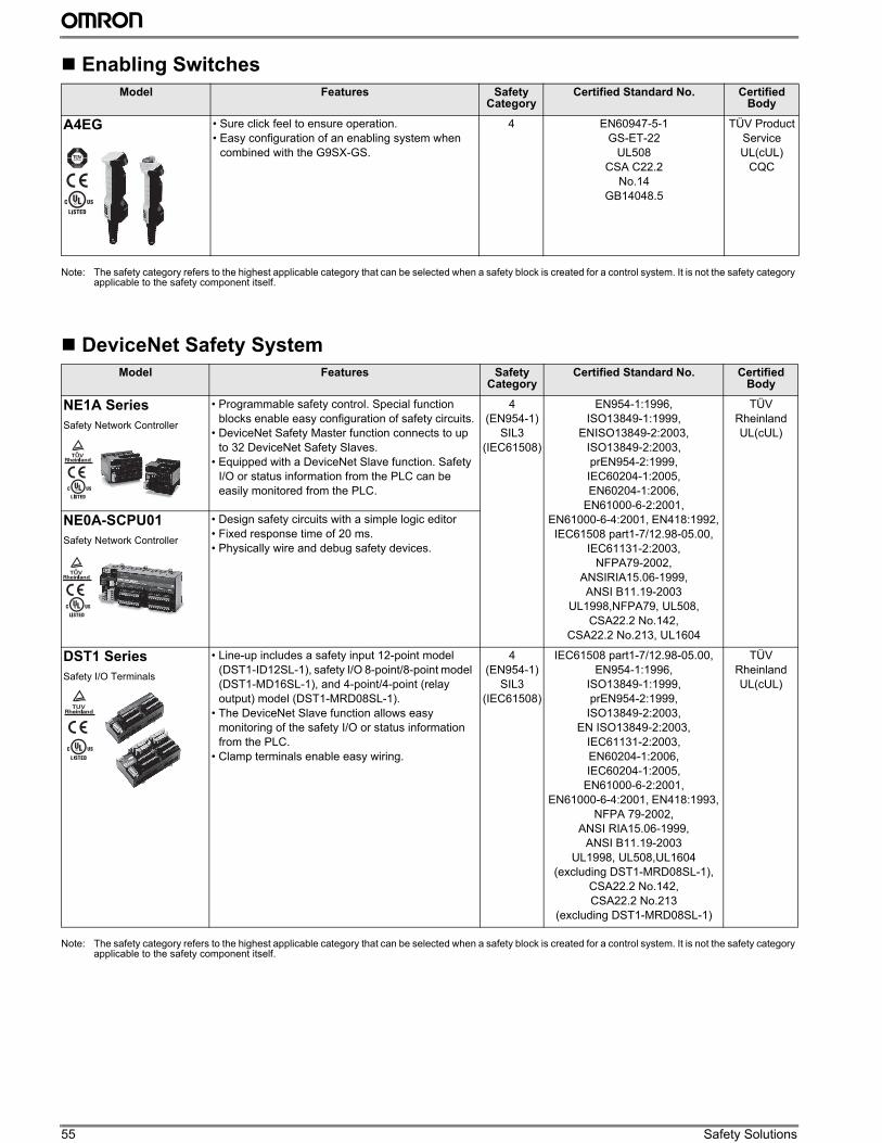
55 Safety Solutions
Enabling Switches
Note: The safety category refers to the highest applicable category that can be selected when a safety block is created for a control system. It is not the safety category applicable to the safety component itself.
DeviceNet Safety System
Note: The safety category refers to the highest applicable category that can be selected when a safety block is created for a control system. It is not the safety category applicable to the safety component itself.
Model Features Safety Category
Certified Standard No. Certified Body
A4EG • Sure click feel to ensure operation.• Easy configuration of an enabling system when
combined with the G9SX-GS.
4 EN60947-5-1GS-ET-22
UL508CSA C22.2
No.14GB14048.5
TÜV ProductServiceUL(cUL)
CQC
Model Features Safety Category
Certified Standard No. Certified Body
NE1A Series
Safety Network Controller
• Programmable safety control. Special function blocks enable easy configuration of safety circuits.
• DeviceNet Safety Master function connects to up to 32 DeviceNet Safety Slaves.
• Equipped with a DeviceNet Slave function. Safety I/O or status information from the PLC can be easily monitored from the PLC.
4(EN954-1)
SIL3(IEC61508)
EN954-1:1996, ISO13849-1:1999,
ENISO13849-2:2003,ISO13849-2:2003,prEN954-2:1999,IEC60204-1:2005,EN60204-1:2006,
EN61000-6-2:2001,EN61000-6-4:2001, EN418:1992, IEC61508 part1-7/12.98-05.00,
IEC61131-2:2003,NFPA79-2002,
ANSIRIA15.06-1999,ANSI B11.19-2003
UL1998,NFPA79, UL508,CSA22.2 No.142,
CSA22.2 No.213, UL1604
TÜV RheinlandUL(cUL)
NE0A-SCPU01
Safety Network Controller
• Design safety circuits with a simple logic editor• Fixed response time of 20 ms.• Physically wire and debug safety devices.
DST1 Series
Safety I/O Terminals
• Line-up includes a safety input 12-point model (DST1-ID12SL-1), safety I/O 8-point/8-point model (DST1-MD16SL-1), and 4-point/4-point (relay output) model (DST1-MRD08SL-1).
• The DeviceNet Slave function allows easy monitoring of the safety I/O or status information from the PLC.
• Clamp terminals enable easy wiring.
4(EN954-1)
SIL3(IEC61508)
IEC61508 part1-7/12.98-05.00,EN954-1:1996,
ISO13849-1:1999,prEN954-2:1999,
ISO13849-2:2003,EN ISO13849-2:2003,
IEC61131-2:2003,EN60204-1:2006,IEC60204-1:2005,
EN61000-6-2:2001,EN61000-6-4:2001, EN418:1993,
NFPA 79-2002,ANSI RIA15.06-1999,
ANSI B11.19-2003UL1998, UL508,UL1604
(excluding DST1-MRD08SL-1),CSA22.2 No.142, CSA22.2 No.213
(excluding DST1-MRD08SL-1)
TÜV RheinlandUL(cUL)
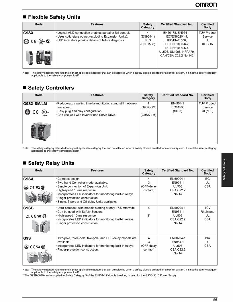
56
Sa
fety
So
luti
on
s
Flexible Safety Units
Note: The safety category refers to the highest applicable category that can be selected when a safety block is created for a control system. It is not the safety category applicable to the safety component itself.
Safety Controllers
Note: The safety category refers to the highest applicable category that can be selected when a safety block is created for a control system. It is not the safety category applicable to the safety component itself.
Safety Relay Units
Note: The safety category refers to the highest applicable category that can be selected when a safety block is created for a control system. It is not the safety category applicable to the safety component itself.
* The G9SB-3010 can be applied to Safety Category 3 of the EN954-1 if double breaking is used for the G9SB-3010 Power Supply.
Model Features Safety Category
Certified Standard No. Certified Body
G9SX • Logical AND connection enables partial or full control.• Uses solid-state output (excluding Expansion Units).• LED indicators provide details of failure diagnosis.
4(EN954-1)
SIL3(EN61508)
EN50178, EN954-1,IEC/EN60204-1,IEC/EN61508,
IEC/EN61000-6-2,IEC/EN61000-6-4,
UL508, UL1998, NFPA79,CAN/CSA C22.2 No.142
TÜV ProductService
ULKOSHA
Model Features Safety Category
Certified Standard No. Certified Body
G9SX-SM/LM • Reduce extra waiting time by monitoring stand-still motion or low speed.
• Easy plug and play configuration.• Can use well with Inverter and Servo Drive.
4(G9SX-SM)
3(G9SX-LM)
EN-954-1IEC61508
(SIL 3)
TÜV ProductServiceUL(cUL)
Model Features Safety Category
Certified Standard No. Certified Body
G9SA • Compact design.• Two-hand Controller model available.• Simple connection of Expansion Unit.• High-speed 10-ms response• Incorporates LED indicators for monitoring built-in relays.• Finger protection construction.• 3-pole, 5-pole and Off-delay Units available.
43
(OFF-delay contact)
EN60204-1EN954-1UL508
CSA C22.2No.14
BGUL
CSA
G9SB • Ultra-compact, with models starting at only 17.5 mm wide.• Can be used with Safety Sensors.• High-speed 10-ms response.• Incorporates LED indicators for monitoring built-in relays.• Finger protection construction.
4
3*
EN60204-1EN954-1UL508
CSA C22.2No.14
TÜV Rheinland
ULCSA
G9S • Two-pole, three-pole, five-pole, and OFF-delay models are available.
• Incorporates LED indicators for monitoring built-in relays.• Finger-protection construction.
43
(OFF-delay contact)
EN60204-1EN954-1UL508
CSA C22.2No.14
BIAUL
CSA

Model Index
3G3JX ..................................................... 43
3G3MX2 .................................................. 43
3G3RX..................................................... 43
61F-AP .................................................... 21
61F-D21T-V2........................................... 21
61F-G_ .................................................... 21
61F-GP-N................................................ 21
61F-GPN-BT/BC ..................................... 21
61F-I ........................................................ 21
A165E...................................................... 53
A22E........................................................ 54
A22Z-EG ................................................. 54
A4EG....................................................... 55
CJ1G ....................................................... 38
CJ1H ....................................................... 38
CJ1M....................................................... 38
CJ2M....................................................... 38
CJ1W-MCH ............................................. 44
CJ1W-NC_ _3.......................................... 44
CJ1W-NC_ _4.......................................... 44
CJ1W-NCF.............................................. 44
CJ1W-V600C1_....................................... 46
CJ1W-V680C1_....................................... 47
CP1E....................................................... 38
CP1H....................................................... 38
CP1L ....................................................... 38
CRT1-AD04............................................. 39
CRT1-DA02............................................. 39
CRT1-ID .................................................. 39
CRT1-OD ................................................ 39
CRT1-ROS.............................................. 39
CRT1-TS04T/P........................................ 39
CS1D....................................................... 38
CS1G....................................................... 38
CS1H....................................................... 38
CS1W-MC ............................................... 44
CS1W-MCH............................................. 44
CS1W-NC_ _3 ......................................... 44
CS1W-NCF ............................................. 44
CS1W-V600C1_ ...................................... 46
CS1W-V680C1_ ...................................... 47
CX-One ................................................... 45
D40A ....................................................... 51
D4B-_N.................................................... 52
D4F.......................................................... 52
D4GL....................................................... 51
D4GS-N................................................... 51
D4MC ........................................................ 4
D4N ......................................................... 52
D4N-_R.................................................... 52
D4NH....................................................... 51
D4NL ....................................................... 51
D4NS....................................................... 51
D4V............................................................ 4
D5B............................................................ 4
DRT1-COM.............................................. 41
DRT2-AD04 ............................................. 40
DRT2-DA02 ............................................. 40
DRT2-ID .................................................. 40
DRT2-OD................................................. 40
DRT2-ROS16 .......................................... 40
DRT2-TS04T/P........................................ 40
DST1 ....................................................... 55
E2GN....................................................... 29
E2A.......................................................... 29
E2C-EDA................................................. 29
E2E.......................................................... 29
E2EH ....................................................... 29
E2FM....................................................... 29
E2K-C ...................................................... 30
E2K-F ...................................................... 30
E2K-L....................................................... 30
E2Q2 ....................................................... 30
E2S.......................................................... 30
E2V.......................................................... 29
E3C.......................................................... 26
E3C-LDA ................................................. 26
E3FN ....................................................... 23
E3F3 ........................................................ 23
E3FR ....................................................... 23
E3FS........................................................ 53
E3FZ........................................................ 23
E3G ......................................................... 23
E3JK ........................................................ 23
E3JM ....................................................... 23
E3S-C ...................................................... 23
E3T .......................................................... 25
E3X-DAC-S ............................................. 26
E3X-DA-S ................................................ 26
E3X-MDA................................................. 26
E3X-NA.................................................... 26
E3X-SD.................................................... 26
E3Z .......................................................... 23
E3Z-B ...................................................... 24
E3Z-DK.................................................... 24
E3Z-G...................................................... 24
E3Z-L....................................................... 24
E3Z-LL..................................................... 24
E3Z-LR .................................................... 24
E3Z-LS .................................................... 24
E3Z-LT..................................................... 24
E3ZM....................................................... 24
E3ZM-B ................................................... 25
E3ZM-C ................................................... 25
E3ZM-V.................................................... 25
E3ZS........................................................ 53
E3Z-TK .................................................... 24
E4C-UDA ................................................. 31
E5_K ........................................................ 16
E5_N ........................................................ 12
E5_N-H .................................................... 11
E5_R ........................................................ 16
E5_Z ........................................................ 24
E52/E52MY.............................................. 15
E5AK........................................................ 16
E5AN ....................................................... 12
E5AN-H.................................................... 11
E5AR ....................................................... 16
E5AR-DRT............................................... 16
E5AZ........................................................ 14
E5CK ....................................................... 16
E5CN(-U) ................................................. 12
E5CN-H ................................................... 11
E5CSL/E5CWL ........................................ 15
E5CSZ ..................................................... 15
E5CZ........................................................ 14
E5EK........................................................ 16
E5EN ....................................................... 12
E5EN-H.................................................... 11
E5ER ....................................................... 16
E5ER-DRT............................................... 16
E5EZ........................................................ 14
E5GN ....................................................... 13
E5ZN........................................................ 13
E5ZN-DRT ............................................... 13
E6A2-C .................................................... 28
E6B2-C .................................................... 28
E6C2-C .................................................... 28
E6CP-A.................................................... 28
E6D-C ...................................................... 28
E6F-A....................................................... 28
E6L .......................................................... 28
EE-SPX74................................................ 27
EE-SPX84................................................ 27
EE-SX47 .................................................. 27
EE-SX67 .................................................. 27
EE-SX77 .................................................. 27
EE-SX87 .................................................. 27
EE-SX91 .................................................. 27
EJ1........................................................... 14
ER............................................................ 54
FQ............................................................ 33
F03-16PE................................................. 22
F03-16PS................................................. 22
F03-16PT................................................. 22
F03-16SF(C)............................................ 22
F3SJ Ver.2............................................... 52
F3UV........................................................ 27
3
6
A
C
D
E
F
Model IndexFQM1....................................................... 44
FZ3 .......................................................... 32
G Series................................................... 43
G5 Series................................................. 43
G2R ........................................................... 1
G2R-_-S..................................................... 1
G2RV......................................................... 1
G3F/G3FD................................................. 2
G3H/G3HD ................................................ 2
G3J-S ........................................................ 2
G3NA......................................................... 2
G3PA(-VD) ................................................ 2
G4Q........................................................... 2
G7S ......................................................... 54
G7S-_-E................................................... 54
G7SA....................................................... 54
G9S ......................................................... 56
G9SA....................................................... 56
G9SB....................................................... 56
G9SX....................................................... 56
G9SX-LM................................................. 56
G9SX-NS................................................. 51
G9SX-SM ................................................ 56
GRT1-CRT .............................................. 39
GT1-AD ................................................... 41
GT1-CT01................................................ 41
GT1-DA ................................................... 41
GT1-ID..................................................... 41
GT1-OD................................................... 41
H3CA......................................................... 6
H3CR-A ..................................................... 6
H3CR-F ..................................................... 6
H3CR-G..................................................... 6
H3CR-H..................................................... 6
H3DE-M/-S ................................................ 7
H3DKZ....................................................... 6
H3JA.......................................................... 7
H3RN......................................................... 7
H3Y ........................................................... 6
H5CZ ......................................................... 5
H5CX......................................................... 5
H5F............................................................ 7
H5S ........................................................... 7
H7BX ......................................................... 8
H7CZ ......................................................... 8
H7CX......................................................... 8
H7E ........................................................... 8
H8PS ......................................................... 8
HL-5000..................................................... 4
K3GN....................................................... 19
K3HB-C ................................................... 18
K3HB-H ................................................... 17
K3HB-P.................................................... 18
K3HB-R.................................................... 18
K3HB-S.................................................... 17
K3HB-V.................................................... 17
K3HB-X.................................................... 17
K3MA-F.................................................... 19
K3MA-J .................................................... 19
K3MA-L.................................................... 19
K3SC ....................................................... 20
K3TE........................................................ 19
K3TF........................................................ 19
K3TG ....................................................... 19
K7L-AT50(D)............................................ 21
K7L-UP-FLK ............................................ 21
K8AB.......................................................... 3
K8AC-H.................................................... 20
KS1 .......................................................... 33
LY .............................................................. 1
MK-S (New) ............................................... 1
MK-S(X) ..................................................... 1
MS4800 ................................................... 52
MY ............................................................. 1
MYK........................................................... 2
NE0A-SCPU01 ........................................ 55
NE1A ....................................................... 55
NS10........................................................ 42
NS12........................................................ 42
NS15........................................................ 42
NS5.......................................................... 42
NS8.......................................................... 42
NT11........................................................ 42
NT21........................................................ 42
NT2S........................................................ 42
NT31(C) ................................................... 42
NT631C ................................................... 42
NV3Q....................................................... 42
NV3W ...................................................... 42
OS3101.................................................... 53
R7D-BP.................................................... 43
R88D-G.................................................... 43
R88M-G ................................................... 43
S8JC.......................................................... 9
S8JX-G ...................................................... 9
S8T-DCBU-02.......................................... 10
S8TS........................................................ 10
S8VM....................................................... 10
S8VS........................................................ 10
SHL............................................................5
SmartStep2 ..............................................43
SS ..............................................................4
TL-N .........................................................30
TL-Q.........................................................30
TL-W ........................................................30
UM/UMM..................................................53
V.................................................................4
V600.........................................................46
V640.........................................................50
V680.........................................................47
V700.........................................................48
V740.........................................................49
V750.........................................................49
WL..............................................................4
Z.................................................................4
ZC ..............................................................5
ZE ..............................................................5
ZEN V2 ....................................................37
ZEN-PA03024..........................................37
ZFV ..........................................................32
ZFV-C ......................................................32
ZFX ..........................................................32
ZG2..........................................................31
ZJ-BAS.....................................................33
ZJ-FA20 ...................................................33
ZJ-SD.......................................................33
ZN-A.........................................................34
ZN-J .........................................................34
ZN-PD......................................................34
ZR-RX25 ..................................................36
ZR-RX45 ..................................................36
ZR-RX70 ..................................................36
ZS ............................................................31
ZUV..........................................................36
ZX-E.........................................................31
ZX-GT ......................................................31
ZX-L-N .....................................................31
ZX-T .........................................................31
G
H
K
L
M
N
O
R
S
T
U
V
W
Z
Selection Guide V39-2011
Authorized DistributorAsia Pacific Head Office:
OMRON ASIA PACIFIC PTE. LTD.438A Alexandra Road#05-05/08(Lobby 2) Alexandra TechnoparkSingapore 119967Tel: (65) 6835 3011 Fax: (65) 6835 2711E-mail: [email protected]
Website: www.omron-ap.com
Singapore Office:OMRON ELECTRONICS PTE. LTD.438A Alexandra Road, #05-05/08(Lobby 2) Alexandra TechnoparkSingapore 119967Tel: (65) 6547 6789Fax: (65) 6547 6769E-mail: [email protected]
Malaysia Office:OMRON ELECTRONICS SDN. BHD.1101 Level 11 Uptown 11 Jalan SS21/58 Damansara Uptown47400 Petaling Jaya, SelangorMalaysiaTel: (60-3) 7688 2888Fax: (60-3) 7688 2833E-mail: [email protected]
Thailand Office:OMRON ELECTRONICS CO. LTD.Rasa Tower 20th Floor555 Phaholyothin RoadChatuchak, Bangkok10900, ThailandTel: (66-2) 937 0500Fax: (66-2) 937 0501CRM Call Centre: (66-2) 942 6700E-mail: [email protected]
Australia Offices:Sydney Office:OMRON ELECTRONICS PTY. LTD.Omron House71 Epping Road, North RydeSydney, New South Wales 2113AustraliaTel: (61-2) 9878 6377Fax: (61-2) 9878 6981Toll Free: 1800 678838E-mail: [email protected]
Melbourne Office:OMRON ELECTRONICS PTY. LTD.Axxess Corporate ParkUnit 98, 45 Gilby RoadMt Waverley Victoria 3149AustraliaTel: (61-3) 8588 2600Fax: (61-3) 8588 2690E-mail: [email protected]
Brisbane Office:OMRON ELECTRONICS PTY. LTD.Unit 14, 1378 Lytton RoadHemmant 4174, QueenslandAustraliaTel: (61-7) 3859 3900Fax: (61-7) 3348 8701E-mail: [email protected]
Adelaide Office:OMRON ELECTRONICS PTY. LTD.Suite 12, 18 Humpheries TerraceKilkenny, SA 5009AustraliaTel: (61-8) 8440 6412Fax: (61-8) 8345 1204E-mail: [email protected]
New Zealand Office:OMRON ELECTRONICS LTD.65 Boston Road, Mt EdenPrivate Bag 92620Symonds Street, AucklandNew ZealandTel: (64-9) 358 4400Fax: (64-9) 358 4411E-mail: [email protected]
Indonesia Office:PT. OMRON ELECTRONICSGraha Pratama Building, 3A FloorJl. M.T. Haryono Kav 15Jakarta Selatan 12810IndonesiaTel: (62-21) 8370 9555Fax: (62-21) 8370 9550E-mail: [email protected]
Philippines Office:OMRON ASIA PACIFIC PTE. LTD.MANILA REPRESENTATIVE OFFICE2nd Floor, Kings Court II Building2129 Do Chino Roces AvenueCorner Dela Rosa Street1231 Makati City, Metro ManilaPhilippinesTel: (63-2) 811 2831Fax: (63-2) 811 2583E-mail: [email protected]
Vietnam Offices:OMRON ASIA PACIFIC PTE. LTD.HANOI REPRESENTATIVE OFFICE6th Floor, 92 Hoang Ngan StreetTrung Hoa, Cau GiayHanoi, VietnamTel: (84-4) 3556 3444Fax: (84-4) 3556 3443E-mail: [email protected]
HO CHI MINH REPRESENTATIVE OFFICE2nd floor, IWA bldg, 102 A-B Cong QuynhQ.1, Ho Chi Minh CityVietnamTel: (84-8) 39204338Fax: (84-8) 39204335E-mail: [email protected]
India Offices:Bangalore Office:OMRON AUTOMATION PVT. LTD.No. 43, G.N. ComplexSt.Johns RoadBangalore - 560 042IndiaTel: (91-80) 4072 6400Fax: (91-80) 4146 6403E-mail: [email protected]
Noida Office:OMRON AUTOMATION PVT. LTD.212 & 213, 2nd FloorInternational Home Deco Park (IHDP)Plot No.7, Sector 127, Taj Express WayNoida - 201 301IndiaTel: (91-120) 4745 800Fax: (91-120) 4745 801E-mail: [email protected]
Mumbai Office:OMRON AUTOMATION PVT. LTD.102 & 103, Meadows, Sahar Plaza,Andheri-Kurla Road, Andheri East Mumbai - 400 059IndiaTel: (91-22) 6679 2767Fax: (91-22) 6679 2768E-mail: [email protected]


