Embed Size (px)
Citation preview
Journal of Materials Processing Technology 66 (1997) 186-194
a, a
a Danmarks Tekniske Universitet, Laboratoriet for Mekaniske Materialeprocesser, Bygn. 425, 2800 Lyngby, Denmarkb Instituto Superior Tecnico, Departamento de Engenharia Mecanica, Av. Rovisco Pais, 1096 Lisboa Codex, Portugal
Received 21 September 1995
ELSEVIER
ELSEVIER Journal of Materials Processing Technology 66 (1997) 186-194
Journal of
Petersen a, a
a Danwzarks Tekniske Universitet, Laboratoriet for Mekaniske Materialeprocesser, Bygn. 425, 2800 Lyngby, Den/narkb Instituto Superior Tecnico, Departwnento de Engenharia Mecanica, Av. Rovisco Pais, 1096 Lisboa Codex, Portugal
Received 21 September 1995
Abstract
Commercially available finite-element programs for the simulation of bulk metal-forming processes usually model the frictionalrestraint acting at the interface between the workpiece and the tools' according to the law of constant friction. Such descriptionis often inadequate and does not represent the state-of-the-art in tribo10gy. In the present paper it is shown that the applicationof the general friction model, developed by Wanheim and Bay, involves a major improvement in the ability to simulate processeswhere low tool-workpiece interface stresses may prevail. This is confirmed by experimental and numerical investigations into theupsetting of a semi-tapered specimen between parallel dies. Additionally, it has led to the proposal of a new ring-compression testgeometry intended to complement the conventional ring test for the calibration of friction models under conditions where thenormal stresses over considerable parts of the tool-workpiece interface lnay be lower than the yield stress of the material. © 1997Elsevier Science S.A.
Keywords: Friction; Metal forming; Law of constant friction; General friction model
Introduction
The heavy loading of tools in bulk metal-formingprocesses makes it important to be able to estimate thelocal tool stresses accurately in order to avoid/preventinappropriate tool design. Friction plays a central rolein these calculations due to its large influence on thelocal normal stresses.
The development and application of the finite-element method has allowed, when compared to the classical analytical n1ethods, a more accurate calculation ofprocess parameters, including the tool stresses. However, increased accuracy in the prediction of the material flow at the tool-workpiece interface, andconsequently in the calculation of the tool stresses, isunrealistic as long as inadequate friction models areapplied.
The friction model usually adopted in FE computerprograms is either Amonton's law T == JLq or the law ofconstant friction, T == mk. In the simulation of bulkmetal-forming processes, the use of Amonton's law
* Corresponding author. Fax: + 351 I 847 4045.
0924-0136/97/$17.00 © 1997 Elsevier Science S.A. All rights reserved.
PII SO 924 - 0 I 36 (96) 0 2 5 I 8 - 6
gives occasion for an overestimation of the frictionstresses at the tool-workpiece interface, because thenormal pressure often is considerably greater than theyield stress of the material: consequently, the frictionstress becomes greater than the yield stress of thematerial in pure shear.
The difficulties with Amonton's law prompted several researchers to include the law of constant frictionin finite-element programs for bulk metal-forming.However, as the friction does not depend on the currentstate of stress at the tool-workpiece interface, butsimply on a material property, the friction stress isoverestimated at low normal pressures.
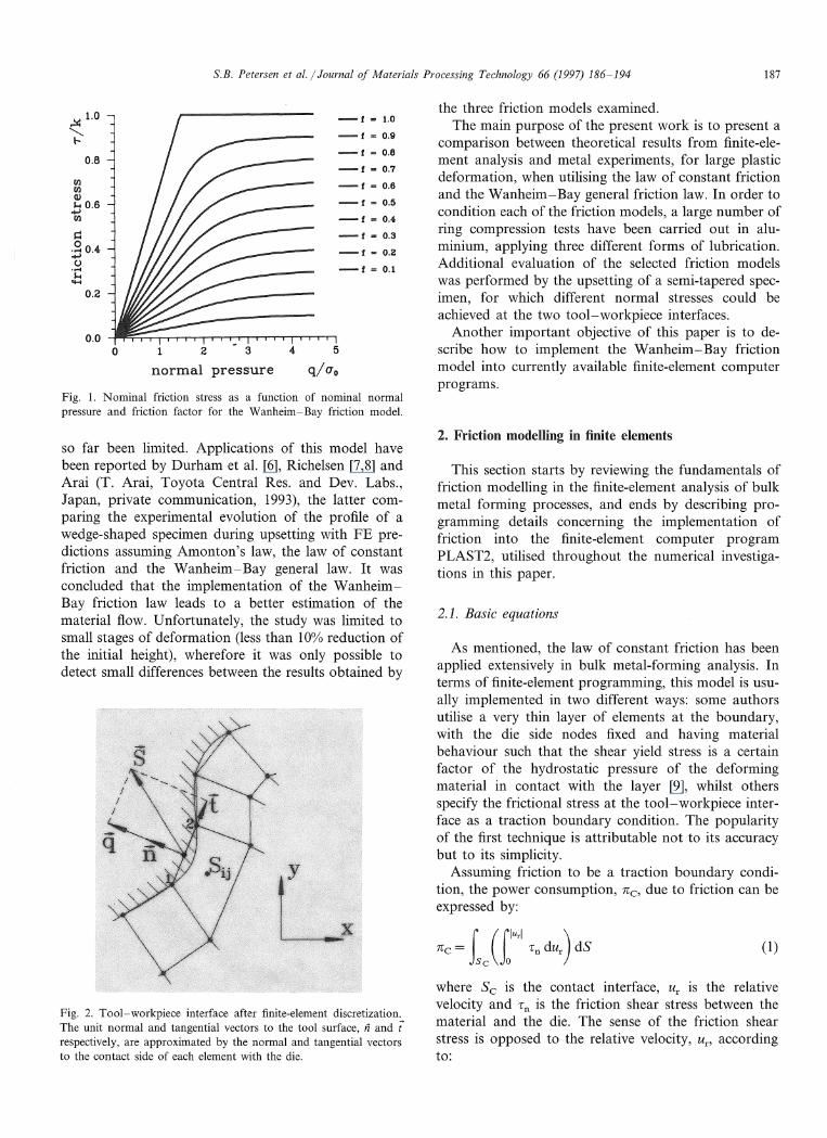
Wanheim and Bay [1] developed a general model forexpressing friction at the tool-workpiece interface. Inpractical terms the model assumes friction to be proportional to the normal stress at low normal pressure(q/ao< 1.5), but going towards a constant value at highnormal pressure (q /a0 > 3), Fig. 1, the two ranges beingcombined via an intermediate transition region.
Even though the validity of the Wanheim-Baymodel has been demonstrated experimentally [2-5], itsimplementation in FE software for metal forming has
S.B. Petersen et al. / Journal of Materials Processing Technology 66 (1997) 186-194 187
Fig. 1. Nominal friction stress as a function of nominal normalpressure and friction factor for the Wanheim- Bay friction model.
the three friction models examined.The main purpose of the present work is to present a
comparison between theoretical results from finite-element analysis and metal experiments, for large plasticdeformation, when utilising the law of constant frictionand the Wanheim-Bay general friction law. In order tocondition each of the friction models, a large number ofring compression tests have been carried out in aluminium, applying three different forms of lubrication.Additional evaluation of the selected friction modelswas performed by the upsetting of a semi-tapered specimen, for which different normal stresses could beachieved at the two tool-workpiece interfaces.
Another important objective of this paper is to describe how to implement the Wanheim-Bay frictionmodel into currently available finite-element computerprograms.
4 5
q/uo
123
normal pressureo
0.0
~ 1.0 -1 = 1.0
"'" -1 = 0.9~
-I = 0.80.8
-1:::: 0.7fI}
-1 = 0.6fI}(l)
-I == 0.5~ 0.6.....,fI} -1 = 0.4-
~ -I == 0.3
.~ 0.4 -f...: 0.2.....,C)
-1 = 0.1......~
'H
0.2
so far been limited. Applications of this model havebeen reported by Durham et al. [6], Richelsen [7,8] andArai (T. Arai, Toyota Central Res. and Dev. Labs.,Japan, private communication, 1993), the latter comparing the experimental evolution of the profile of awedge-shaped specimen during upsetting with FE predictions assuming Amonton's law, the law of constantfriction and the Wanheim-Bay general law. It wasconcluded that the implementation of the WanheimBay friction law leads to a better estimation of thematerial flow. Unfortunately, the study was limited tosmall stages of deformation (less than 100/0 reduction ofthe initial height), wherefore it was only possible todetect small differences between the results obtained by
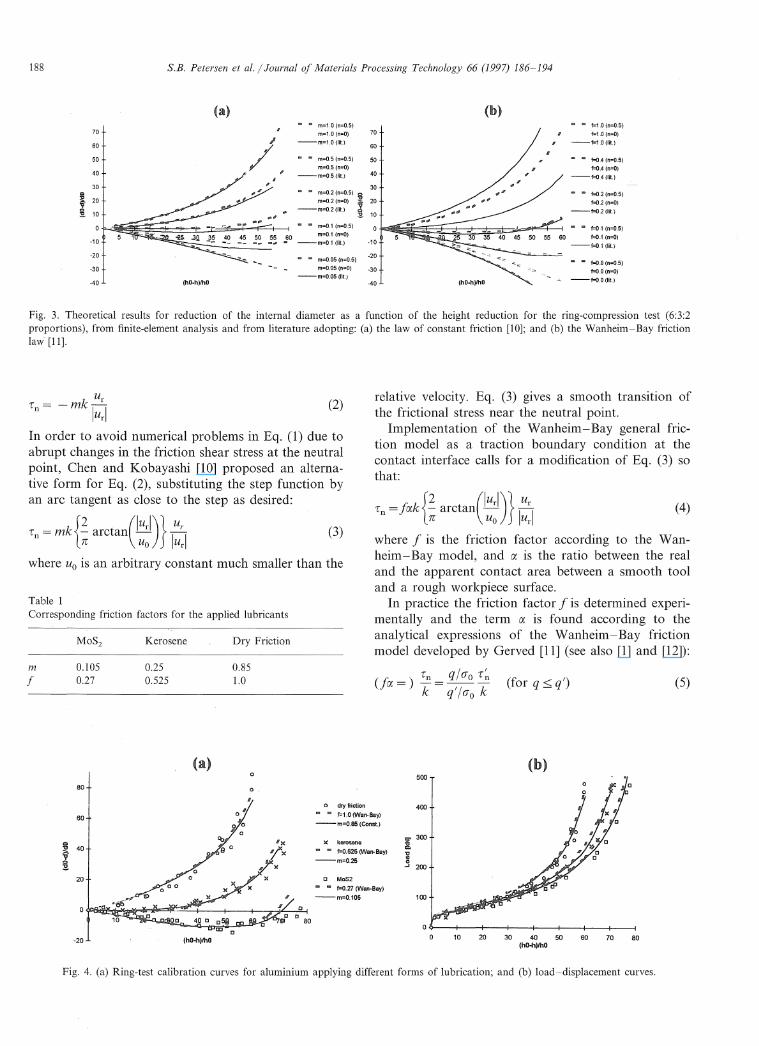
Fig. 2. Tool-workpiece interface after finite-element discretization.The unit normal and tangential vectors to the tool surface, fi and trespectively, are approximated by the normal and tangential vectorsto the contact side of each element with the die.
2. Friction modelling in finite elements
This section starts by reviewing the fundamentals offriction modelling in the finite-element analysis of bulkmetal forming processes, and ends by describing programming details concerning the implementation offriction into the finite-element computer programPLAST2, utilised throughout the numerical investigations in this paper.
2.1. Basic equations
As mentioned, the law of constant friction has beenapplied extensively in bulk metal-forming analysis. Interms of finite-element programming, this model is usually implemented in two different ways: some authorsutilise a very thin layer of elements at the boundary,with the die side nodes fixed and having materialbehaviour such that the shear yield stress is a certainfactor of the hydrostatic pressure of the deformingmaterial in contact with the layer [9], whilst othersspecify the frictional stress at the tool-workpiece interface as a traction boundary condition. The popularityof the first technique is attributable not to its accuracybut to its simplicity.
Assuming friction to be a traction boundary condition, the power consumption, TCc, due to friction can beexpressed by:
(1)
where Sc is the contact interface, Ur is the relativevelocity and r n is the friction shear stress between thematerial and the die. The sense of the friction shearstress is opposed to the relative velocity, Un accordingto:
188 S.B. Petersen et al. / Journal of Materials Processing Technology 66 (1997) 186-194
-40
.. m=0.05 (n=0.5) -20
m=0.05 (n=O) -30-m=0.05 (lit.)
... f=O,2 (n=0.5)
f=O.2 (n=O)
-f=O,2(1it.)
... f=O.4 (n=0.5)
f=O.4 (n=O)
--f=O.4(Iit.)
f=1,O (n=0.5)
f=1,O (n=O)
·-f=1.0(lit)
... f=01 (n=0,5)
60 f=O,1 (n=O)
--f=O.1 (lit.)
f=O.O (n=0.5)
f=O.O (n=O)-. --f=O,O (lit.)(hO·h)/hO
40
30
70
60
50
-10
.. m=1.0 (n=0.5)
m=1,0 (n=O)--m=1,0(1it)
m=0,5 (n=0.5)
m=0.5 (n=O)--m=05 (lit.)
m=O.2 (n=0.5) Cl
m=0,2 (n=O) i 20
fIIiA --m=0.2(1it.) i 10
.. .. m=0,1 (n=0,5)
~O __ ~:~.~ ~~~~)
(hO-h)/hO
30
40
70
60
50
-10
-20
-30
-40
Cl
~ 20
~~ 10
Fig. 3. Theoretical results for reduction of the internal diameter as a function of the height reduction for the ring-compression test (6:3:2proportions), from finite-element analysis and from literature adopting: (a) the law of constant friction [10]; and (b) the Wanheim-Bay frictionlaw' [11].
(4)
relative velocity. Eq. (3) gives a smooth transition ofthe frictional stress near the neutral point.
Implementation of the Wanheim-Bay general friction model as a traction boundary condition at thecontact interface calls for a modification of Eq. (3) sothat:
Tn ==fak{~ arctan(lurl)}!!!-TC Uo IUrl
where f is the friction factor according to the Wanheim-Bay model, and a is the ratio between the realand the apparent contact area between a smooth tooland a rough workpiece surface.
In practice the friction factor f is determined experimentally and the term a is found according to theanalytical expressions of the Wanheim-Bay frictionmodel developed by Gerved [11] (see also [1] and [12]):
(2)
(3)
Dry FrictionKerosene
Ur
Tn = -mk IurlIn order to avoid nun1erical problems in Eq. (1) due toabrupt changes in the friction shear stress at the neutralpoint, Chen and Kobayashi [10] proposed an alternative form for Eq. (2), substituting the step function byan arc tangent' as close to the step as desired:
Tn = mkH arctan(':D} I~:Iwhere Uo is an arbitrary constant much smaller than the
Table 1Corresponding friction factors for the applied lubricants
f0.1050.27
0.250.525
0.851.0 (fia ==) Tn _ q / (JOT ~ (D ')
k-q'/(Jok orq~q (5)
500
80
60
40
20
-20 (hO-h)/hO
0 '
o 0
o
c
o dry friction
...... f=1,0(Wan-Bay)
--m=O.85 (Canst.)
)( kerosene
f=0.525 (Wan-Bay)
--m=O.25
c MoS2
... f=0.27 (Wan-Bay)
--m=0.105
400
Z" 300c=."Ccoo....I 200
100
10 20 30 40 50 60 70 80(hO-h)lhO
Fig. 4. (a) Ring-test calibration curves for aluminium applying different forms of lubrication; and (b) load-displacement curves.
S.B. Petersen et ala / Journal of Materials Processing Technology 66 (1997) 186-194 189
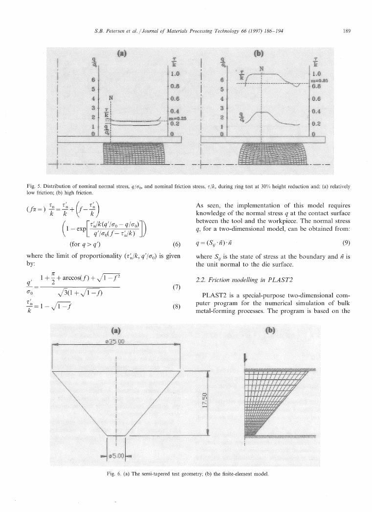
Fig. 5. Distribution of nominal normal stress, qlao, and nominal friction stress, r Ik, during ring test at 300/0 height reduction and: (a) relativelylow friction; (b) high friction.
r~ (f r~)-+ --k k
(1 - exp[r~/k(ql/(Jo - q/(JO)])
q'/(Jo(f- r~/k)
(for q > q') (6)
As seen, the implementation of this model requiresknowledge of the normal stress q at the contact surfacebetween the tool and the workpiece. The normal stressq, for a two-dimensional model, can be obtained from:
(9)
(8)
(7)
where the limit of proportionality (r ~/k, q'/ (J0) is givenby:
q' 1+~+arccos(f) +.J1=72
(J0 J3(1 + J1=j)r ';=1-~
where Sij is the state of stress at the boundary and ii isthe unit normal to the die surface.
2.2. Friction modelling in PLAST2
PLAST2 is a special-purpose two-dimensional computer program for the numerical simulation of bulkmetal-forming processes. The program is based on the
Fig. 6. (a) The semi-tapered test geometry; (b) the finite-element model.
S.B. Petersen et al. / Journal of Materials Processing Technology 66 (1997) 186-194
4.0
6.0
.£.~
8.0
1.0 mmH
f(m=o.e5)
Tk
- Exp.
0.8
1.0
0.2
0.4
0.6
2.01.0
O.O-L..-------...,.----------::::::m-iIIIlI--..L-_ 0
t(m=O.85)
fCf=1.0)
190
TK
1.0
0.8
0.6
0.4
0.2
0.0
0.0-.------------------
0.2
0.0 0-------------------------------------------------------- 1.0
0.2 2.0
0.4
0.6
0.4
0.6
4.0
6.0
O.BI---+--~---
1.0
t(m=O.B5)
f(f=LO)
0.8
1.0-+--------- f (f=1.0)
8.0
Tk
TF
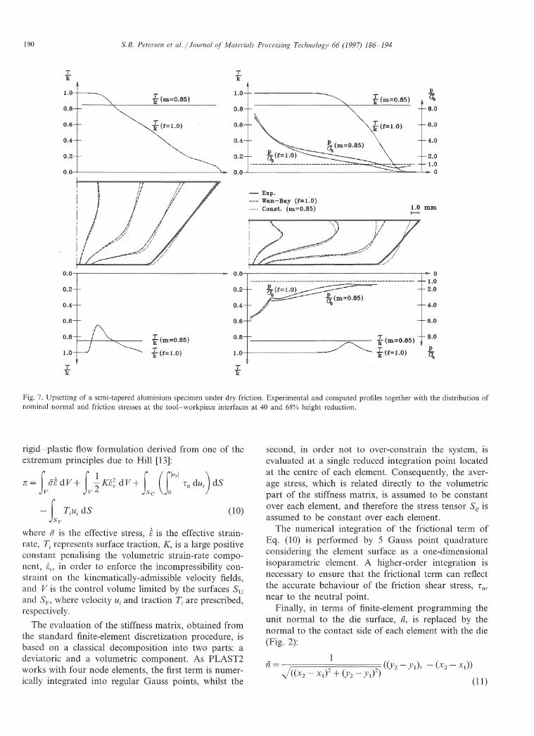
Fig. 7. Upsetting of a semi-tapered aluminium specimen under dry friction. Experimental and computed profiles together with the distribution ofnominal normal and friction stresses at the tool-workpiece interfaces at 40 and 680/0 height reduction.
rigid-plastic flow formulation derived from one of theextremum principles due to Hill [13]:
n= LBidV+ L~K8; dV+ Le (i,ur'Tn dUr ) dS
- f Tiui dS (10)SF
where a is the effective stress, Bis the effective strainrate, Ti represents surface traction, is a large positiveconstant penalising the volumetric strain-rate component, Bv, in order to enforce the incompressibility constraint on the kinematically-admissible velocity fields,and V is the control volume limited by the surfaces Suand where velocity Ui and traction T i are prescribed,respectively.
The evaluation of the stiffness matrix, obtained fromthe standard finite-element discretization procedure, isbased on a classical decomposition into two parts: adeviatoric and a volumetric component. As PLAST2works with four node elements, the first term is numerically integrated into regular Gauss points, whilst the
second, in order not to over-constrain the system, isevaluated at a single reduced integration point locatedat the centre of each element. Consequently, the average stress, which is related directly to the volumetricpart of the stiffness matrix, is assumed to be constantover each element, and therefore the stress tensor Sij isassumed to be constant over each element.
The numerical integration of the frictional term ofEq. (10) is performed by 5 Gauss point quadratureconsidering the element surface as a one-dimensionalisoparametric element. A higher-order integration isnecessary to ensure that the frictional term can reflectthe accurate behaviour of the friction shear stress, Tn,
near to the neutral point.Finally, in terms of finite-element programming the
unit normal to the die surface, ;1, is replaced by thenormal to the contact side of each element with the die(Fig. 2):
~ 1n = J((x
2_ X
I)2 + (Y2 _ Yl)2) ((Y2 - Yl), - (x2 - Xl))
(11)
S.B. Petersen et al. / Journal of Materials Processing Technology 66 (1997) 186-194 191
350
m=O".0
/
300
250
SF 200~
"(\'J.9 150
100
50
o dry friction
II f=10 (Wan-Bay)
--m=O.85 (Const.)
10 20 30 40 50 60 70 80
height reduction (%)
Fig. 8. (a) computed profiles from the upsetting of a tapered specimen at 600/0 height reduction; (b) experimental and theoreticalload-displacement curves for the upsetting of semi-tapered aluminium specimen under dry friction.
3.1. Finite-element siJnulation vs. standard charts
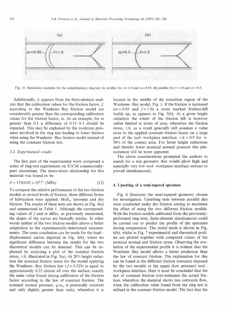
Fig. 9. Proposed complementary ring-test geometry for the calibration of friction models at low levels of nominal normal pressure.
As the intention with this section is to quantifyfriction from finite-element modelling in conjunctionwith ring-compression tests in aluminium, simulationsfor various friction factors have had to be carried out.
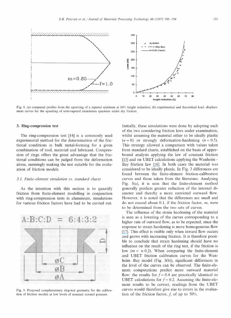
Initially, these simulations were done by adopting eachof the two considering friction laws under examination,whilst assuming the material either to be ideally plastic(n == 0) or strongly deformation-hardening (n == 0.5).This strategy allowed a comparison with values takenfrom standard charts, established on the basis of upperbound analysis applying the law of constant friction[15] and on UBET calculations applying the WanheimBay friction law [16]. In both cases the material wasconsidered to be ideally plastic. In Fig. 3 differences arefound between the finite-element friction-calibrationcurves and those taken from the literature. AnalysingFig. 3(a), it is seen that the finite-element methodgenerally predicts greater reduction of the internal diameter and thereby a more restricted outward flow.However, it is noted that the differences are small anddo not exceed about 0.1, if the friction factor, n1, wereto be determined from the two sets of curves.
The influence of the strain hardening of the materialis seen as a lowering of the curves corresponding to ahigher rate of outward flow, as to be expected, since theresponse to strain hardening is more homogeneous flow[17]. This effect is visible only when inward flow occursand grows with increasing friction. It is therefore possible to conclude that strain hardening should have noinfluence on the result of the ring test, if the friction islow (n1 < ~ 0.2). When comparing the finite-elementand UBET friction calibration curves for the Wanheim- Bay model (Fig. 3(b)), significant differences inthe level of the curves can be observed. The finite-element computations predict more outward materialflow: the results for f == 0.4 are practically identical toUBET calculations for f == 0.2. Assuming the finite-element results to be correct, readings from the UBETcurves would therefore give rise to errors in the evaluation of the friction factor, f, of up to 500/0.
KjI1U!-'~OnlDression test
The ring-compression test [14] is a commonly usedexperimental method for the determination of the frictional conditions in bulk metal-forming for a givencombination of tool, material and lubricant. Compression of rings offers the great advantage that the frictional conditions can be judged from the deformationalone, seemingly making the test suitable for the evaluation of friction models.
3"
192 S.B. Petersen et al. / Journal of Materials Processing Technology 66 (1997) 186-194
Fig. 10. Simulation examples for the complementary ring-test: (a) profiles for f = 1.0 and 111 = 0.85; (b) profiles for f = 1.0 and 111 = 0.5.
Additionally, it appears from the finite-element analysis that the calibration values for the friction factor, haccording to the Wanheim-Bay friction model areconsiderably greater than the corresponding calibrationvalues for the friction factor, m. As an example, for mgreater than 0.1 a difference of 0.15-0.3 should beexpected. This may be explained by the moderate pressures involved in the ring test leading to lower frictionwhen using the Wanheim-Bay friction model instead ofusing the constant friction law.
3.2. Experimental results
The first part of the experimental work comprised aseries of ring-test experiments on EICM commerciallypure aluminium. The stress-strain relationship for thismaterial was found to be:
located in the middle of the transition region of theWanheim- Bay model, Fig. 1. If the friction is increased(n1 0.85 and 1 == 1.0) a more marked friction-hillbuilds up, as appears in Fig. 5(b). At a given heightreduction the extent of the friction hill is howeverrather limited in terms of area, wherefore the frictionstress, 1: / k, as a result generally still assumes a valueclose to the applied constant friction factor on a largepart of the tool-workpiece interface: 1: /k < 0.9 for ~
50% of the contact area. For lesser height reductionsand thereby lower nominal normal pressure this phenomenon will be more apparent.
The above considerations prompted the authors tosearch for a test geometry that would allow high andespecially very low tool-workpiece interface stresses toprevail simultaneously.
To compare the relative performance of the two frictionmodels at several levels of friction, three different formsof lubrication were applied: MoSb kerosene and dryfriction. The results of these tests are shown in Fig. 4(a)and summarised in Table 1. Although the corresponding values of1 and m differ, as previously mentioned,the slopes of the curves are basically similar. In otherwords neither of the two friction models allows a betteradaptation to the experimentally-determined measurements. The same conclusion can be made for the loaddisplacement curves depicted in Fig. 4(b), where nosignificant difference between the results for the twotheoretical models can be detected. This can be explained by analysing a plot of the nominal frictionstress, 1: /k, illustrated in Fig. 5(a). At 200/0 height reduction the nominal friction stress for the model applyingthe Wanheim-Bay friction law (/==0.525) is equal toapproximately 0.25 almost all over the surface; exactlythe same value found during calibration of the frictionfactor according to the law of constant friction. Thenominal normal pressure, q / (J0, is practically constantand only slightly greater than unity, wherefore it is
(j == 155(0.02 + 8)°·27 (MPa) (12)
Fig. 6 illustrates the semi-tapered geometry chosenfor investigation. Upsetting tests between parallel dieswere conducted under dry friction aiming to maximisethe effect of using the two different friction models.With the friction models calibrated from the previouslyperformed ring tests, finite-element simultaneous couldbe carried out to predict the profile of the specimenduring compression. The initial mesh is shown in Fig.6(b), whilst in Fig. 7 experimental and theoretical profiles are plotted together with computed values of thenominal normal and friction stress. Observing the evolution of the experimental profile it is evident that theWanheim-Bay model allows a better prediction thanthe law of constant friction. The explanation for thiscan be found in the different friction restraints imposedby the two models at the upper (low pressure) toolworkpiece interface. Here it must be concluded that thelaw of constant friction over-estimates the actual friction, wherefore the material shows less outwards flow,when the calibration value found from the ring test isutilised in the constant friction model. The fact that the
S.B. Petersen et al. / Journal of Materials Processing Technology 66 (1997) 186-194 193
flow at the lower (high pressure) interface is too littlerestricted when the law of constant friction is applied, isbelieved not to be caused by the different frictionalrestraints imposed by the two models, but induced bythe significant differences predicted in the material flowat the upper (low pressure) interface. This assumptionis supported by simulations of the upsetting of a tapered specimen, Fig. 8(a), indicating that the appliedfriction model at the lower (high pressure) interface haslittle influence on the material flow. By plotting theload-displacement evolution, Fig. 8(b), it can be notedthat the curve for the law of constant friction lies abovethe experimental data, presumably because the frictionis over-estimated at the tool-workpiece interfaces.
Finite-element analysis performed for friction factors,f == 0.525 and m == 0.25, corresponding to the frictionconditions that prevail using kerosene as a lubricant,reveals that the two friction models result in practicallythe same outer contour and load-displacement curves.
5. A COll11pllelneJnt2lry ..-......_.LA....'.
In the light of the reported results a complementaryring-test geometry is proposed by the authors for thecalibration of friction models with special reference toprocesses where high friction and low nominal normalpressure is anticipated. The geometry is based on amodification of the conventional ring-test geometry soas to have a double frustum of a cone shape, whilstkeeping the original height-diameter proportions, Fig.9.
Finite-element simulations were conducted with thisgeometry whilst applying the tow considered frictionmodels calibrated according to the conventional ringcompression test performed under dry friction. Workin-progress indicates the feasibility of the chosengeometry, and for the example given in Fig. 10 theexpected effect of the applied friction model on thepredicted material flow can be observed.
In order to estimate a more appropriate frictionfactor, m, a simulation was carried out for m 0.5. Theagreement between the profile found in this simulationand that predicted when using the Wanheim-Baymodel, indicates that the factor, m == 0.85, found bycalibration according to the conventional ring-compression test is much too high for the interface conditionsconsidered in the proposed test.
6. Conclusions
The importance of applying an adequate frictionmodel has been dealt with in connection with thefinite-element simulation of bulk metal-forming processes. Based on the estimation of the friction through
the ring-compression test, a comparison has been madebetween the experimentally-determined material flowduring the upsetting of a semi-tapered aluminium specimen under dry friction and that predicted by finite-element simulation when applying the law of constantfriction and the Wanheim-Bay general friction model.Under such high variations in the level of friction it canbe concluded that, as expected, the latter is more adequate for modelling the boundary conditions at thetool-workpiece interface when the nominal surfacepressure over a considerable part of the contact areaassumes low values (q/(Jo < 1). The results emphasisethe necessity of having a friction test available for thisrange of nominal normal pressure. For this purpose,the authors propose a new complimentary ring-compression test.
References
[1] N. Bay and T. Wanheim, Real area of contact and friction stressat high pressure sliding contact, Wear, 38 (1976) 201-209.
[2] J. Danckert and T. Wanheim, The friction shear stress distribution at the material-tool interface, when upsetting a flat circularcylinder between flat parallel platens, Proc. Con! Modelling ofMetal Fonning Processes, Chicago, 1979, pp. 429-448.
[3] N. Bay, Tool/workpiece interface stresses in cold forward extrusion, in Adv. Technol. of Plasticity, H. Kudo (ed.), Proc. 1st Int.Con! on Technology of Plasticity, Tokyo, 1 (1984) 259-266.
[4] N. Bay and G. Gerved, Tool/workpiece interface stresses insimple upsetting, J. Mech. Work. Tech., 14 (1987) 263-282.
[5] W. Zhang, J.P.A. Peeters and N. Bay, Numerical modelling ofcold rolling of metal plate adopting a general friction model, inSimulation of Materials Processing: Theory, Methods and Applications, Shan-Fu Shen and P.R. Dawson, (eds.), Proc. NUMIFORM 95, 5th Int. Con! on Nun1erical Methods in IndustrialFonning Processes, Ithaca, NY, 1995, pp. 997-1004.
[6] D.R. Durham, B.F. von Turkovich and A. Assempoor, Modelling the frictional boundary condition in material deformation,Ann. CIRP, 40 (1991) 235-238.
[7] A.B. Richelsen, Viscoplastic analysis of plane-strain rolling usingdifferent friction models, Int. J. Mech. Sci., 33 (1991) 761-774.
[8] A.B. Richelsen, Comparison of a numerical analysis of rollingwith experimental data, DCAMM Report No. 493, TechnicalUniversity of Denmark, Lyngby, Denmark, 1994, to appear in J.Mater. Process. Technol.
[9] O.C. Zienkiewicz, P.C. Jain and E. Ofiate, Flow of solids duringforming and extrusion: some aspects of numerical solutions, Int.J. Solids Struct., 14 (1978) 15-38.
[10] C. Chen and S. Kobayashi, Rigid plastic finite element analysisof ring compression, applications of numerical methods of forming processes, ASME-AMD, 28 (1978) 163.
[11] G. Gerved, Analyse af Friktions- og Trykfordeling ved Stukning,M M Report No. 85, Institute of Manufacturing Engineering,Technical University of Denmark, 1985.
[12] P. Christensen, H. Everfelt and N. Bay, Pressure distribption inplate rolling, Ann. CIRP, 35 (1986) 141-146.
[13] R. Hill, The Mathelnatical Theory of Plasticity, Oxford University Press, London, 1950.
[14] A.T. Male and M.G. Cockcroft, A method for the determinationof the coefficient of friction of metals under conditions of bulkplastic deformation, J. Inst. Met., 93 (1964) 38-46.

194 S.B. Petersen et al. / Journal of Materials Processing Technology 66 (1997) 186-194
[15] V. Nagpal, G.D. Lahoti and T. Altan, A numerical methodfor simultaneous prediction of metal flow and temperatures inupset forging of rings, Trans. ASME, J. Eng. Ind., 100 (1978)413-420.
[16] P.H. Hansen, N. Bay and P. Christensen, Analysis of the ring
test using ~ general friction model and the upper bound elementtechnique, 16th NAMRC (1988) 41-47.
[17] J. Danckert, Analysis of the ring test method for the evaluationof frictional stresses in bulk metal forming processes, Ann.CIRP, 37 (1988) 217-220.