Embed Size (px)
Citation preview

Wear 304 (2013) 1–12
Contents lists available at SciVerse ScienceDirect
Wear
0043-16http://d
n CorrE-m
journal homepage: www.elsevier.com/locate/wear
Friction and wear performance of copper–graphite surface compositesfabricated by friction stir processing (FSP)
H. Sarmadi n, A.H. Kokabi, S.M. Seyed ReihaniDepartment of Materials Science and Engineering, Sharif University of Technology, Azadi Street, Tehran, Iran
a r t i c l e i n f o
Article history:Received 31 August 2012Received in revised form5 April 2013Accepted 15 April 2013Available online 30 April 2013
Keywords:Sliding wearMetal-matrix compositeSolid lubricantsLubricant additivesOther surface engineering processesWear testing
48/$ - see front matter & 2013 Elsevier B.V. Ax.doi.org/10.1016/j.wear.2013.04.023
esponding author. Tel.: +98 919 2710735; fax:ail address: [email protected] (H. Sarm
a b s t r a c t
Copper–graphite composites which have low friction coefficient can be used as bearing materials in lieuof materials containing lead which cause environmental problems. So far, some methods such as powdermetallurgy and centrifugal casting have been employed to produce these composites. In this study,friction stir processing (FSP) was used to produce copper–graphite surface composites. Five tools withdifferent pin profile were employed in order to achieve a comprehensive dispersion. Results show thatthe tool with triangular pin gives rise to a better dispersion of graphite particles. Furthermore, fourcopper–graphite composites containing different graphite content were prepared using triangular toolthrough repeating the process passes. Friction and wear performance of the composites were studiedusing a pin-on-disc tribometer. It was indicated that the friction coefficients of composites were lowerthan pure annealed copper and decreased with increase in graphite content. The reduction in frictioncoefficient is due to decrease in metal–metal contact points, originated from the presence of graphiteparticles as a solid lubricant. Wear loss of the composites was also decreased with increase in graphitecontent. This is related to change in wear mechanism from adhesive to delamination wear and reductionof friction coefficient.
& 2013 Elsevier B.V. All rights reserved.
1. Introduction
Friction stir welding (FSW) is a solid-state joining techniquewhich was devised at The Welding Institute (TWI) of UK in 1991and at first was applied to aluminum alloys [1,2]. In FSW, a non-consumable rotating tool with a pin and a shoulder is inserted intothe opening of joint in adjoining sheets or plates and traversedalong the line of joint and cause plates to be joined [2]. Friction stirprocessing (FSP) has been recently developed by Mishra et al. [3,4]based on basic principles of FSW. In this case, a rotating tool isinserted in a monolithic work piece in order for modification ofmicrostructure (Fig. 1). Furthermore, FSP technique has beenemployed by Mishra et al. [5] to produce surface composite onaluminum substrate. It is reported that process parameters such astool geometry, rotating speed and transverse speed have a sig-nificant effect on production of surface composite layer [5]. FSPhave also been employed to produce some other composites suchas Al–Al2O3, AZ31–MWCNT (multi walled carbon nano tube),AZ61–SiO2, Al–SiC, etc. [6–9].
In former times several different types of materials such ascopper alloys like leaded bronzes, aluminum bronzes, phosphorusbronzes as well as aluminum alloys like aluminum–-tin and
ll rights reserved.
+98 263 92108077.adi).
aluminum–silicon alloys have been reported to be studied fortheir tribological properties [10]. Most of the bearing alloys thatwere used so far had contained a soft phase like lead, whichprovide the required antifriction property. Because of its harmfuleffects on environment, restrictions have been imposed on leaduse. This has made researchers find alternative materials, whichhave tribological properties similar to materials containing lead[10]. Self-lubricant composites such as aluminum–graphite, cop-per–graphite, and aluminum–MoS2 composites have beenreported to be investigated for tribological applications [10]. Thesemetal matrix composites (MMCs) not only reduce friction coeffi-cient but also reduce the wear of counterparts [10,11]. Graphite isvery effective in reducing the wear and friction coefficient of thecomposites. By contrast, molybdenum disulfide (MoS2) is ineffec-tive as a solid lubricant for sintered composites due to itsinstability and reactivity with the metals at the sintering tem-perature [12].
Copper–graphite composites possess the properties of copper, i.e. excellent thermal and electrical conductivities, and properties ofgraphite, i.e. solid lubricating and low thermal expansion coeffi-cient. These composites are widely used as brushes, and bearingmaterials in many applications [11]. Wear mechanism and frictioncoefficient of copper–graphite composites fabricated by powdermetallurgy from Cu-coated and Cu-uncoated graphite particlescontaining 0–20 vol% of graphite was studied by Moustafa et al.[11]. They described that the involved wear mechanisms of pure

Fig. 1. Schematic illustration of FSP process [10].
H. Sarmadi et al. / Wear 304 (2013) 1–122
copper at low, mild and severe wear regimes could be oxidative-dominated, delamination, and seizure wear mechanisms, respec-tively. However, both Cu-coated and uncoated graphite compositesexhibited the same wear mechanisms, namely, oxidation induceddelamination, high strained delamination and sub-surface dela-mination. They stated that at constant load the higher graphitecontent in either coated or uncoated Cu–graphite composite, thelower is the coefficient of friction. However, Rohatgi et al. [13]stated that when the graphite content of metal matrix compositesis more than about 20 vol% the friction coefficient approaches thatof pure graphite and becomes independent of the graphite con-tent. Kovacik et al. [14] investigated the effect of composition onthe friction coefficient of copper–graphite composites in the rangeof 0–50 vol% of graphite at constant load to determine criticalgraphite content above which the coefficient of friction of compo-site remains almost composition independent and constant. It wasstated that with increase in concentration of graphite, the coeffi-cient of friction and wear rate of coated and uncoated compositesat first decreases and after reaching certain critical concentrationthreshold of graphite, the coefficient of friction of compositesbecomes independent of the composition and equal to the frictioncoefficient of used graphite material while the wear rate decreasesfurther. This concentration threshold is determined to be 12 vol%and about 25 vol% in the case of composites with uncoated andcoated graphite particles, respectively. Due to the complication ofwear mechanisms, no general relationship between microstruc-tural factors, processing parameters and the wear resistance ofmetal matrix composites could be established. Recent studiesshowed that in addition to the volume fraction of particles, spatialdistribution of the graphite particles and particles size has a greateffect on friction coefficient [14,15]. Furthermore, because ofhigher mechanical properties, in some studies carbon fibers andnanotubes have been employed in preference to graphite particles[16–20]. Apart from high strength and modulus, carbon fibers havegood lubrication effect and wear resistance. The carbon fiberreinforces the matrix and improves the tribological properties ofthe composite as a solid lubricant. Therefore, the wear resistanceof the carbon fiber-reinforced composites is much higher thanpure metals [16]. In addition, the effect of graphite on hightemperature wear has been investigated and it is reported thatadding graphite particles to Cu–SiC composite prevent compositesfrom high temperature severe wear [21].
So far, some methods such as powder metallurgy [11] andcentrifugal casting [10,22] have been used to fabricate thesecomposites. The most important problem of these methods isagglomeration of graphite particles. Because of lower density ofgraphite than copper, graphite particles tend to agglomerate intographite clusters. In addition, being greasy is another reason for
agglomeration of graphite particles. Coating graphite particleswith copper by electro-less process leads to less agglomeration[11]. Residual porosity can also be present, since in both powdermetallurgy and casting processes porosity may be present in thefinal product.
The aim of this research is using friction stir processing toproduce Cu–graphite composite. Simultaneous stirring of materialsduring fabrication process which is one of the features of thisprocess, can solve the agglomeration of graphite particles. There-fore, FSP was employed to produce these composites. Tribologicalproperties of the composite were studied. The effect of graphitecontent on friction coefficient and wear loss of the composites as amain aim of the research were investigated.
2. Experimental procedure
2.1. Material and procedure
Commercial pure copper plates (100 mm�60 mm�5 mm insize) were used as substrates. The plates were annealed at 620 ℃for 2 h. Graphite particles (average particles size 5 μm, purity99.9%) were used as solid lubricant materials.
In order to prepare FSP tools, H13 tool steel was employed. Theshoulder diameter was 20 mm and the pin was 3 mm in lengthand the pin diameter of all the tools was effectively 6.5 mm. Pinprofile plays a vital role in material flow [23,24]. In this study(exactly the same as Elangovan and Balasubramanian [24]) fivetools with different pin profiles (straight cylindrical (SC), taperedcylindrical (TC), threaded cylindrical (TH), square (SQ), and trian-gular (TR)) were applied which are shown schematically in Fig. 2.All of the tools were hardened in order to be prevented fromwear.The hardness of tools after heat treatment was 5272 HRC.
A groove was machined on the surface of plates along thelength of plate. The grooves were 0.9 mm in width. Then, graphiteparticles were added into grooves so that the grooves werecompletely filled. After that, plates were fixed on the FSP machineand at first, the surface of grooves were sealed by a tool withoutpin in order to prevent particles from coming out and beingwasted. The FSP machine used here was a modified horizontalmilling machine. And finally, specimens were FSPed by tools thathad pin.
The main source of heat in FSP is friction between tool andwork piece [2,25]. Since the objective of this study was fabricationof low friction coefficient copper base composites, there were twolimitations: (1) high heat transfer coefficient of copper resulting inwasting produced heat (2) low friction coefficient of used materialcausing less heat production. To solve these problems, specimenswere isolated and high rotating speed and low transverse speedwere employed. Thus, rotating and transverse speed were1600 rpm and 20 mmmin−1 respectively and tool angle was1.5 degree.
In order to increase in graphite content, specimens weresubjected to repetitive passes of process, i.e. after grooving plates,filling with graphite particles, and FSPing them, the specimenswere grooved, filled with graphite particles and FSPed again. Usingthis procedure, copper–graphite composites with 1, 2, 3, and4 passes were produced. For specimens prepared by differenttools, two passes were applied. The reason of using two passes ofprocess was making more difference in order to compare better.Furthermore, a pure copper plate without graphite particles wasprepared as a representative sample and its friction coefficient andwear loss were measured and compared with copper–graphitecomposites. Table 1 shows all the specimens produced inthis study.

Fig. 2. FSP tool pin profile [24]. (a) Straight cylinder(SC), (b) Threaded cylindrical(TH), (c) Tapered Cylindrical(TC), (d) Square(SQ) and (e) Triangle(TR).
Table 1Produced specimens.
H. Sarmadi et al. / Wear 304 (2013) 1–12 3
2.2. Friction coefficient and wear test
Friction coefficients and wear properties of specimens weremeasured using pin-on-disk tribometer. A steel disk (SAE1045)according to ASTM G99 standard was prepared and heat treated tobe hardened. The hardness of disk after heat treatment was6072 HRC (�700 HV). After that, the surface of disk was polishedand the roughness of surface was measured, Rmax¼0.6 μm. Cylind-rical specimens were wire cut along composites thickness with5 mm in diameter from center of composites. For specimensprepared by different tools (specimen 1 to 5) one pin was alsocut from 3 mm beside centerline of specimens. The pins were thenpolished and cleaned by acetone to remove all the contaminationbefore testing. All the tests were carried out at the temperature of2072℃ and ambient humidity (�50%). The nominal load andsliding speed were 10 N and 0.3 ms−1, respectively. In frictioncoefficient test the sliding distance for all the specimens was1000 m and friction coefficient was determined by tribometerautomatically. In wear test specimens were initially weighed onthe digital scales with 0.0001 g accuracy and then were tested for100 m and weighed again. This procedure was performed for1000 m (10 steps-three times for each individual testing condi-tion) and wear loss and wear rate of specimens were determinedas average of three measurements. Wear rate of specimens wasmeasured using following equation
W ¼ MLD
ð1Þ
where W is wear rate (g=N m), M is the wear loss (g), L is theapplied load (N), and D is sliding distance (m).
2.3. Microscopic and hardness examinations
Metallographic investigation was carried out using both opticaland scanning electron microscopes. SEM (scanning electron micro-scopy) and EDS (energy dispersive spectroscopy) analysis wasused for both pin and disk to determine wear mechanism. Vikersmicrohardness of specimens was also measured using 50 g loadfor 10 s applying on cross-section of each specimen.
3. Results and discussion
3.1. Effect of tool geometry on particle dispersion and frictioncoefficient
Fig. 3 shows optical micrographs of particles distribution on thesurface of samples 1 to 5. These images have been taken fromcenter of composites’ surface. As can be seen, in the case ofcomposites produced by tools with straight cylindrical, taperedcylindrical, and threaded cylindrical pins, i.e. Cu-2G-SC, Cu-2G-TC,and Cu-2G-TH, respectively, particles have aggregated in thecenter of composites, but in the case of composites produced bytools with square and triangular pins, i.e. Cu-2G-SQ and Cu-2G-TR,respectively, particles have totally dispersed in the matrix and thedistribution of particles is adequate.
This is related to flow patterns of copper substrate againstdifferent tools during FSP. Three microscopic images were takenfrom center of each composite and then particles volume percentsand particles size after process were determined by Image Analy-zer software represented in Table 2. These results confirm micro-scopic observations. According to Table 2, particles volume percenthas a maximum value in composite produced by SC pin being13.95%, but in the case of composite produced by TR pin, this is10.89 vol% which is minimum value among all of the composites.Composite produced by SQ pin has 11.90 vol% graphite particleswhich is lower than composites produced by SC, TC, and TH pins.Lower particles volume percent of composites produced by SQ andTR pins shows that particles have not aggregate in the center ofthese composites and distribution of particles on surface of thesecomposites is better than three other composites. The size oflargest cluster in Cu-2G-SC, Cu-2G-TC, and Cu-2G-TH composites ismore than 40 μm which proves that particles have agglomeratedand as can be seen from Fig. 3a–c, the amount of these clusters arehigh. In the case of Cu-2G-SQ and Cu-2G-TR composites, the size oflargest cluster is about 27 and 22 μm, respectively which are
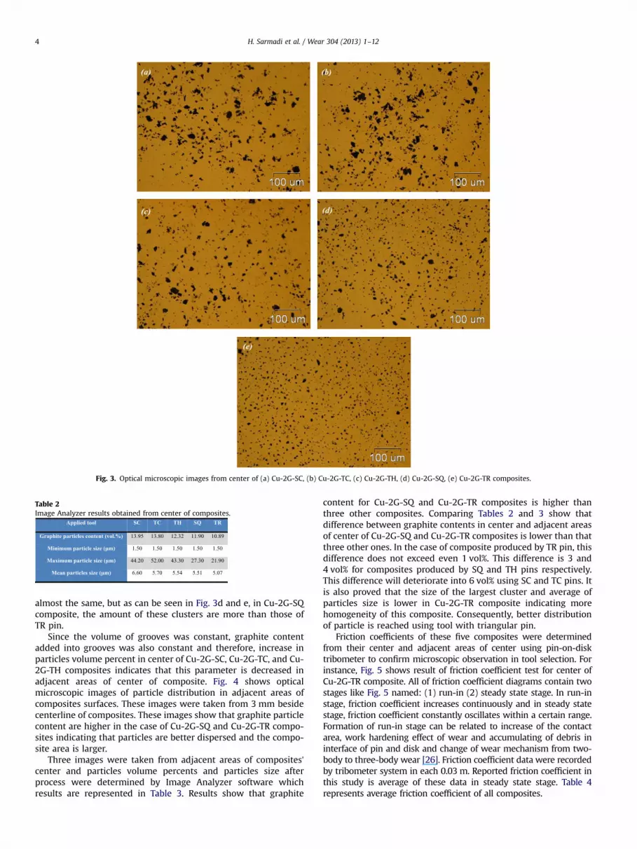
Fig. 3. Optical microscopic images from center of (a) Cu-2G-SC, (b) Cu-2G-TC, (c) Cu-2G-TH, (d) Cu-2G-SQ, (e) Cu-2G-TR composites.
Table 2Image Analyzer results obtained from center of composites.
H. Sarmadi et al. / Wear 304 (2013) 1–124
almost the same, but as can be seen in Fig. 3d and e, in Cu-2G-SQcomposite, the amount of these clusters are more than those ofTR pin.
Since the volume of grooves was constant, graphite contentadded into grooves was also constant and therefore, increase inparticles volume percent in center of Cu-2G-SC, Cu-2G-TC, and Cu-2G-TH composites indicates that this parameter is decreased inadjacent areas of center of composite. Fig. 4 shows opticalmicroscopic images of particle distribution in adjacent areas ofcomposites surfaces. These images were taken from 3 mm besidecenterline of composites. These images show that graphite particlecontent are higher in the case of Cu-2G-SQ and Cu-2G-TR compo-sites indicating that particles are better dispersed and the compo-site area is larger.
Three images were taken from adjacent areas of composites’center and particles volume percents and particles size afterprocess were determined by Image Analyzer software whichresults are represented in Table 3. Results show that graphite
content for Cu-2G-SQ and Cu-2G-TR composites is higher thanthree other composites. Comparing Tables 2 and 3 show thatdifference between graphite contents in center and adjacent areasof center of Cu-2G-SQ and Cu-2G-TR composites is lower than thatthree other ones. In the case of composite produced by TR pin, thisdifference does not exceed even 1 vol%. This difference is 3 and4 vol% for composites produced by SQ and TH pins respectively.This difference will deteriorate into 6 vol% using SC and TC pins. Itis also proved that the size of the largest cluster and average ofparticles size is lower in Cu-2G-TR composite indicating morehomogeneity of this composite. Consequently, better distributionof particle is reached using tool with triangular pin.
Friction coefficients of these five composites were determinedfrom their center and adjacent areas of center using pin-on-disktribometer to confirm microscopic observation in tool selection. Forinstance, Fig. 5 shows result of friction coefficient test for center ofCu-2G-TR composite. All of friction coefficient diagrams contain twostages like Fig. 5 named: (1) run-in (2) steady state stage. In run-instage, friction coefficient increases continuously and in steady statestage, friction coefficient constantly oscillates within a certain range.Formation of run-in stage can be related to increase of the contactarea, work hardening effect of wear and accumulating of debris ininterface of pin and disk and change of wear mechanism from two-body to three-body wear [26]. Friction coefficient data were recordedby tribometer system in each 0.03 m. Reported friction coefficient inthis study is average of these data in steady state stage. Table 4represents average friction coefficient of all composites.

Fig. 4. Optical microscopic images from adjacent areas of center of (a) Cu-2G-SC, (b) Cu-2G-TC, (c) Cu-2G-TH, (d) Cu-2G-SQ, (e) Cu-2G-TR composites.
Table 3Image Analyzer results obtained from adjacent areas of center of composites.
0
0.1
0.2
0.3
0.4
0.5
0.6
0.7
0.8
0.9
1
0 100 200 300 400 500 600 700 800 900 1000
Fric
tion
Coe
ffic
ient
Distance (m)Cu-2G-TR(Ave=0.3)
Fig. 5. friction coefficient of Cu-2G-TR composite obtained from center ofspecimen.
H. Sarmadi et al. / Wear 304 (2013) 1–12 5
As can be seen from Table 4, friction coefficient of compositeproduced by tool with triangular pin has the highest value (0.3) incenter of composite due to lower graphite content and the lowestvalue (0.35) in adjacent areas of center of composite due to highergraphite content rather than other specimens. In other words,difference between friction coefficient of center and adjacent areasof center of this composite is lower than other compositesindicating better distribution of particles in this specimen. There-fore, friction coefficient data confirm microscopic observations.
Table 4Friction coefficient of composites.
3.2. Effect of graphite content on tribological performance of copper–graphite composites
3.2.1. Friction coefficient behaviorOptical microscope images of Cu-1G, Cu-2G, Cu-3G, and Cu-4G
composites are shown in Fig. 6.

Fig. 6. Optical microscopic images from center of (a) Cu-1G, (b) Cu-2G, (c) Cu-3G, (d) Cu-4G composites.
Table 5Image Analyzer results obtained from center Cu-1G, Cu-2G, Cu-3G, and Cu-4Gcomposites.
0
20
40
60
80
100
120
140
160
-10 -5 0 5 10
Har
dnes
s (H
V)
Distance from center (mm)Cu-1G Cu-2G Cu-3G Cu-4G
Fig. 7. Microhardness of Cu-1G, Cu-2G, Cu-3G, and Cu-4G composites.
00.10.20.30.40.50.60.70.80.9
1
0 100 200 300 400 500 600 700 800 900 1000
Fric
tion
Coe
ffici
ent
Distance (m)
Cu-1G(Ave=0.45) Cu-2G(Ave=0.3)
Cu-3G(Ave=0.22) Cu-4G(Ave=0.17)
Fig. 8. Friction coefficient behavior of Cu-1G, Cu-2G, Cu-3G, and Cu-4G composites.
H. Sarmadi et al. / Wear 304 (2013) 1–126
Three images were prepared from center of each individualcomposite and then particles volume percents and particles sizeafter process were determined by Image Analyzer software repre-sented in Table 5. As it was anticipated, with increase in number ofprocess passes the volume percent of particles was increased from6 vol% for one-pass to about 22 vol% for four-pass specimens. It isalso clear that particle average size and the size of largest clusterare increased as the graphite volume percent increases showingthat the particles tend to change into clusters as the graphitevolume percent increases.
Microhardness data are represented in Fig. 7. According tothese data, the average hardness of Cu-1G, Cu-2G, Cu-3G, and Cu-4G composites are 133, 128, 118, and 101 HV, respectively. In otherwords, the hardness of composites is reduced when graphitecontent increases which is due to presence of softer graphiteparticle in comparison with the copper matrix [12].
The results of friction coefficient test for the composites andpure annealed copper are shown in Figs. 8 and 9, respectively. Ascan be seen, the average of friction coefficient is decreased withincrease in number of process passes or graphite content.
The friction coefficient values and the percent of its reductionfor each pass are indicated in Table 6. It is clear that frictioncoefficient is dramatically decreased with increase in graphitecontent so that friction coefficient of Cu-4G composite containingabout 22 vol% graphite is 79% lower than pure annealed copper.This is due to presence of graphite as a solid lubricant.
Due to mutual sliding of wear counterparts, graphite particlesare smeared over contact surface and regarding good lubricatingproperty of graphite, friction coefficient is decreased. In fact,graphite decreases metal to metal (composite to steel disk) direct
contact points leading to decrease in friction coefficient [12,18,19]and graphite has hexagonal structure and its atomic bonds in basalplanes are covalent which are very strong, but atomic bondsbetween basal planes are van der Waals which are weak. Theseweak bonds are easily broken by low load. In other words, shearstrength of graphite is too low leading to sliding of the planes over

00.10.20.30.40.50.60.70.80.9
1
0 100 200 300 400 500 600 700 800 900 1000
Fric
tion
Coe
ffic
ient
Distance (m)Annealed Copper(Ave=0.81)
Fig. 9. Friction coefficient behavior of pure annealed copper.
Table 6Friction coefficient variations of the specimens.
Fig. 10. Schematic illustration of the graphite particles squeezed out and smearedto the surface of composite [22].
H. Sarmadi et al. / Wear 304 (2013) 1–12 7
each other and decrease in friction coefficient. Another feature ofgraphite that leads to reduction in friction coefficient is sticking ofgraphite particles to sliding surfaces; therefore, sliding take placewithin interior layers of graphite particles, so sliding of counter-parts over each other is facilitated. Another point is that because oflow hardness of graphite rather than copper and steel, wear doesnot occur in counterparts; therefore, friction coefficient is notincreased. In addition to graphite present in surface of composite,graphite particles present in subsurface layer are also squeezed outto surface during sliding and increase covered areas of surface bygraphite [22]. One of the important points in use of graphite as asolid lubricant is applying graphite particles continuously duringsliding. Fig. 10 schematically shows squeezing out of graphiteparticles to surface of composite. According to Fig. 10, if matrixpossesses low strength and high plastic deformation capability,squeezing out of graphite particles to surface will be eased. Since
in this study the matrix is copper and has a good plasticdeformation capability, squeezing out of graphite particles tosurface is very likely taken place. In addition, amount of graphitesqueezed out to surface is probably related to the mechanicalproperties of matrix, the morphology of graphite, the temperaturein sliding surface, and more importantly, the bond betweengraphite particles and matrix. Due to low solubility of carbon incopper (it does not exceed 0.02 at%), there is no chemical andmetallurgical bonding between copper and graphite atoms and thebond between them is only very weak mechanical bonding,therefore, separating of graphite particles from copper matrixand movement of them to sliding surface do not need considerableforce [14]. However, because of the fact that graphite is softer thancopper matrix, the bonding between graphite and matrix has lesseffect on amount of graphite squeezed out to surface rather thanplastic deformation capability of matrix [22]. It is clear that thesmaller the size of particles and the better their distribution are,the easier they are squeezed out.
As mentioned above, graphite particles are squeezed out tosurface from matrix during sliding and this graphite and thegraphite existed on the surface are smeared over counterpartsinterface as a layer. With increase in graphite content in compo-site, this layer becomes thicker and denser leading to decrease infriction coefficient and wear rate [11]. In fact, a tribolayer is formedon sliding interface which covers the surface. This layer is calledmechanical mixed layer (MML). MML reduces the direct contactsurface between composite and disk and so friction coefficient andwear loss are decreased. Copper, graphite, oxygen, and atmospheremoisture are the components of MML in copper–graphite compo-sites. Since graphite is good lubricant, presence of small amount ofit causes friction coefficient to be dramatically decreased (Table 6).In low graphite content, the particles form apart clusters (flakes) inMML. With increase in graphite content, MML become graphite-rich layer and graphite is not apart clusters anymore. Thisdecreases friction coefficient even more.
Although, friction coefficient decreases to some extent asgraphite content increases and after a threshold value of graphitecontent, it remains constant. There are some different valuesreported as the threshold. For instance, Rohatgi et al. [13] statedthat when graphite content exceeds 20 vol%, friction coefficientapproaches pure graphite friction coefficient and becomes inde-pendent of composite chemical composition. However, Kovaciket al. [14] studied the effect of graphite content on frictioncoefficient on copper–graphite composites. It is reported thatthere are some key parameters influencing on composition-dependent friction coefficient such as particles size and spatialdistribution of graphite particles. It is clear that in low graphitecontents, the smaller particles and the more homogenous are, thelower friction coefficient is. Thus, friction coefficient is decreasedto a threshold and then remains constant even if graphite volumepercent decreases. The most likely reason is that in thresholdgraphite content, other debris forming MML such as Cu2O andcopper particles have no effect on tribological behavior of MMLand these properties are controlled by graphite particles. Thisgraphite-saturated MML prevent subsurface area from significantdeformation and therefore, shear strength of area close to surfaceand consequently friction coefficient remains nearly constant.
According to Table 6 and as can be seen from Fig. 11, reductionof friction in each step (pass) decreases demonstrating that frictioncoefficient is approaching a constant value as graphite contentincreases. Some suitable equations can be fitted with diagram ofFig. 11.
Here, both exponential and third-degree polynomial equations(as below) were derived according to the diagram indicating inFig. 12, respectively. These equations govern over frictional beha-vior of copper–graphite composite according to graphite volume

a) y = 0.81e-0.076x
b) y = -5E-05x3 + 0.003x2 - 0.074x + 0.8110
0.1
0.2
0.3
0.4
0.5
0.6
0.7
0.8
0.9
0 5 15 20 25
Fric
tion
Coe
ffici
ent
Graphite Content (Vol%)10
Fig. 12. Fitting equations representing frictional behavior of copper–graphitecomposite (a) exponential equation and (b) third-degree polynomial equation.
0
0.0025
0.005
0.0075
0.01
0.0125
0.015
0.0175
0.02
0.0225
0 100 200 300 400 500 600 700 800 900 1000
Wea
r W
eigh
t los
s (g)
Sliding Distance (m)
Cu-1G Cu-2G Cu-3G Cu-4G Pure Annealed Copper
Fig. 13. Wear behavior of the specimens.
Table 7Wear loss variations of the specimens.
1.99
1.3
1.030.87
0.69
0
0.2
0.4
0.6
0.8
1
1.2
1.4
1.6
1.8
2
0 5 10 15 20 25
Wea
r R
ate
(10-6
g.N
-1.m
-1)
Graphite Volume Percent (%)
Fig. 14. Wear rate variations against graphite content.
0.81
0.45
0.3
0.220.17
0
0.1
0.2
0.3
0.4
0.5
0.6
0.7
0.8
0.9
0 5 10 15 20 25
Fric
tion
Coe
ffici
ent
Graphite Volume Fraction (%)
Fig. 11. Friction coefficient variations according to graphite content.
H. Sarmadi et al. / Wear 304 (2013) 1–128
percent
y¼ 0:81e−0:076x ð2Þ
y¼ −5E−05x3 þ 0:0031x2−0:0743xþ 0:81 ð3Þwhere y is friction coefficient and x is graphite volume percent. Itshall be noted that these equations have been derived consideringno microstructural effect on friction coefficient.
As mentioned before, in threshold graphite content, frictioncoefficient approaches a constant value approximately equal tofriction coefficient of pure graphite. Friction coefficient of puregraphite is in range of 0.1–0.15 depending on load and testconditions (environment conditions). Since in this study, the loadis 10 N which is nearly small, it can be assumed that frictioncoefficient of pure graphite possesses the lowest value being 0.1. Ifin exponential equation y¼0.1, the threshold graphite contentwould be 27.52 vol%. Although this equation has a tangent in y¼0,but as we know, friction coefficient is not allowed to be lower than0.1, typical value for pure graphite. Therefore, this exponentialequation can be used just for predicting the friction coefficient inconcentration lower than threshold graphite content and is notapplied to calculating the threshold. In a same way, if in third-degree polynomial equation y¼0.1, the threshold graphite contentwould be 25.65 vol% which lower than that exponential equation.Thus, the threshold for graphite content in this study is about25 vol%.
3.2.2. Wear behaviorWear test was carried out on the specimens according to the
procedure mentioned in Section 2.2. Fig. 13 shows variations ofwear loss against sliding distance. These curves consist of twostages known as (1) running-in wear and (2) steady-state wear.Running-in wear ends when an equilibrium contact surface isestablished between the counterparts and a work hardened area isformed near the surface. In this stage, an adhesive oxide layer can
prevent specimens from severe wear. In next stage, wear rate(curves slope) remains constant due to formation of a stablecontact surface between counterparts. As can be seen, the wearloss of specimens is decreased with increase in graphite content.
Wear loss values after 1000 m sliding and the percent of itsreduction for each pass are indicated in Table 7. Wear loss of purecopper after 1000 m sliding is about 0.0199 g, but this has changedto 0.0069 for Cu-4G composite i.e. adding about 22 vol% graphiteto copper increases wear resistance of the composite by 65%. Thisis due to presence of graphite as a solid lubricant. As mentionedbefore, friction coefficient of the Cu-4G composite is decreased by79% in comparison with pure copper. On the other hand, in somematerials, reduction of friction coefficient leads to increase in wearresistance. Comparison between 65 and 79% reduction in wear lossand friction coefficient, respectively, shows that there is not alinear correlation between increase in wear resistance anddecrease in friction coefficient. This needs more investigation ofwear mechanism.
Average wear rate of specimens after 1000 m is plotted againstgraphite content in Fig. 14. It is clear that wear rate is decreased asgraphite content is increased.
SEM image of worn surface of pure copper and EDS analyses ofworn surface of the specimen and counterpart running against

H. Sarmadi et al. / Wear 304 (2013) 1–12 9
specimen (wear disk) are shown in Figs. 15–17, respectively. As canbe seen from Fig. 15, there is a high amount of plastic deformationin worn surface being one of the prominent characteristics ofadhesive wear. During wear test, copper pin and steel disk havecontact with each other in some projections. These contact pointsare deformed during wear process and form a solid state joint. Thismakes sliding more difficult for counterparts leading to increase infriction coefficient and wear loss. Adjacent area of contact points(adhesive area) is harden due to repetitive deformation resulting
Fig. 15. SEM image of worn surface of pure copper pin.
Fig. 16. EDS analysis of pur
Fig. 17. EDS analysis of counterpart (wear d
in formation of micro cracks in imperfections such as cavities anddislocations. These micro cracks then grow and lead to detach-ment of surface layer and as a result, intensive adhesive occurs[16,17,19,20] and these cracks can easily be seen in deformed areaof Fig. 15. Therefore, the reason of high wear loss of pure annealedcopper is occurrence of adhesive wear.
In addition to large amount of deformation in wear surface,mass transfer between pin and disk is another characteristic ofadhesive wear [20]. Friction force originates in metal joining incontact points. It is demonstrated that the strength of thesejoining can be as strong as counterparts and so rupture canhappen in the distance below the junction inside of the counter-parts. This causes material to be transferred from one part toanother. Commonly, mass transfer happens mutually between pinand disk. Although, in the case of counterparts which there are ahigh difference in their hardness, mass transfer is from softer partto harder one [20]. The hardness of pure annealed copper is muchlower than steel disk and so mass transfer is from copper pin tosteel disk. EDS analysis of worn surface of copper pin showpresence of no iron element and on the other hand, EDS analysisof wear disk running against copper pin show a high amount ofcopper element representing high mass transfer from pin to disk.This high mass transfer proves occurrence of adhesive wear.
Also, presence of plate-like debris in Fig. 15 is undeniable whichone of characteristics of delamination wear. The amount of thesedebris is lower than deformed area. Presence of oxygen in EDSanalyses of counterparts shows that a small amount of oxidationwear most likely has occurred. As can be seen, the dominant wearmechanism of pure annealed copper is adhesive and a smallamount of delamination and oxidation happen beside.
SEM image of worn surface of Cu-1G specimen and EDSanalyses of worn surface of the specimen and counterpart runningagainst specimen (wear disk) are shown in Figs. 18–20, respec-tively. As can be seen from Fig. 18, a small amount plasticdeformation has happened on wear surface and the majority ofwear surface is formed of large plate-like debris indicating that
e copper worn surface.
isk) running against pure copper pin.

H. Sarmadi et al. / Wear 304 (2013) 1–1210
probably the wear mechanism is mainly delamination and adhe-sive wear has taken place less than pure copper.
EDS analysis counterpart running against Cu-1G pin (Fig. 20)shows small copper and carbon peak showing that mass transferfrom pin to disk and as a result adhesive wear has occurred less incomparison with pure copper. Although, presence of oxygen in
Fig. 18. SEM image of Cu-1G worn surface.
Fig. 19. EDS analysis of C
Fig. 20. EDS analysis of counterpart (wear d
EDS analysis of Figs. 19 and 20 show that oxidation wear hasprobably occurred. The reason for reduction in adhesive wear ispresence of graphite particle and decrease in number of metal tometal contact points.
Formation of plate-like debris and occurrence of delaminationwear can be explained with respect to delamination wear theory.In delamination wear, the substance is considered as layered(laminated) which is detached from surface due to wear process.According to delamination wear theory, shear plastic deformationcauses nucleation and growth of crack to be happened in a bitdepth of the surface and these cracks eventually join togetherleading to detachment of layered area. In fact, accumulation ofdislocations beneath the surface results in formation of pores insubsurface area (although because of severe plastic deformationresulted from FSP process, dislocations density in subsurface areais initially and before wear process high). These pores can also beformed in interface between graphite particles and copper due toabsence of chemical bonds between graphite and copper. Joiningof these pores leads to formation of cracks and subsequent growthduring wear process results in formation of plate-like debris.
On the other side, in addition to above mechanism, anotherreason can be stated to explain delamination wear of copper–graphite composites. As mentioned before, graphite particles aresqueezed out to composite surface during wear process. Thus,aggregation and accumulation of graphite on surface and subsur-face area result in reduction of shear strength of subsurface areaand because of sliding during wear process; these regions aredetached from the surface as thin layers. Laminating of MML canalso lead to delamination wear on the wear surface.
SEM image of worn surface of Cu-4G specimen and EDSanalyses of worn surface of the specimen and counterpart runningagainst specimen (wear disk) are shown in Figs. 21–23, respec-tively. As can be seen from Fig. 21, with increase in graphitecontent from 6 to 22 vol%, small plastic deformed area observed in
u-1G worn surface.
isk) running against Cu-1G pin.

H. Sarmadi et al. / Wear 304 (2013) 1–12 11
Fig. 18 is disappeared and delamination wear characteristics isobserved almost in whole area.
In addition, the size of these plate-like debris is decreased withincrease in graphite content. Although, EDS analysis of counterpartrunning against the specimen (Fig. 23) shows a short copper peak(small amount of copper) indicating occurrence of a small amountof adhesive wear.
Fig. 21. SEM image of Cu-4G worn surface.
Fig. 22. EDS analysis of C
Fig. 23. EDS analysis of counterpart (we
However, adhesive wear characteristics are not observed on thewear surface. This can be probably related to not smearinggraphite particles over the surface in early stages of sliding sothat adhesive wear has occurred at first and before delaminationand accordingly a small amount of copper has transferred to weardisk. Although, continuing sliding and so smearing graphiteparticles over the surface and also squeezing particles out fromsubsurface area to the wear surface stop adhesive wear.
Consequently, increase in graphite content results in increase indelamination wear and decrease in adhesive wear. Also, increasein graphite content lead to increase in pores quantities and sodecrease in their distances. Therefore, these pores and resultantcracks join together faster and thus; the size of the debris isdecreased.
4. Conclusions
1.
u-4
ar d
Fabrication of copper–graphite composites by friction stirprocessing (FSP) is possible. Using this technique leads to morehomogenous distribution of particles in surface of compositeand prevents particle changing into clusters which was themost important problem in prior techniques such as powdermetallurgy and centrifugal casting. It should be noted that inorder to produce more heat and avoid wasting produced heat,rotating speed and transverse speed should be chosen high andlow respectively and specimens should be isolated.
2.
Using tool with triangular pin leads to better distribution ofparticle rather than other tools which are because of flowpattern of materials against this tool. The area of compositeproduced with this tool is larger in comparison with compo-sites produced by other tools.3.
Friction coefficient is dramatically decreased with increase ingraphite content so that friction coefficient of Cu-4G compositecontaining about 22 vol% graphite is 79% lower than pureG worn surface.
isk) running against Cu-4G pin.

H. Sarmadi et al. / Wear 304 (2013) 1–1212
annealed copper. This is due to presence of graphite as a solidlubricant and decrease in number of metal to metal contactpoint.
4.
Friction coefficient decreases to some extent as graphite con-tent increases and after a threshold value of graphite content, itremains constant. The threshold graphite content in this studyis about 25 vol%.5.
Wear loss of specimens is decreased with increase in graphitecontent. Adding about 22 vol% graphite to copper increaseswear resistance of the composite by 65%. This is due topresence of graphite as a solid lubricant.6.
Increase in graphite content results in increase in delaminationwear and decrease in adhesive wear.References
[1] W.M. Thomas, E.D. Nicholas, J.C. Needham, M.G. Murch, P. Temple smith, C.J.Dawes, G.B. Patent Application No. 9125978.8, 1991.
[2] R.S. Mishra, Z.Y. Ma, Friction stir welding and processing, Materials Scienceand Engineering: R: Reports 50 (2005) 1–78.
[3] R.S. Mishra, M.W. Mahoney, S.X. McFadden, N.A. Mara, A.K. Mukherjee, Highstrain rate superplasticity in a friction stir processed 7075 Al alloy, ScriptaMaterialia 42 (2000) 163–168.
[4] R.S. Mishra, M.W. Mahoney, Friction stir processing: a new grain refinementtechnique to achieve high strain rate superplasticity in commercial alloys,Materials Science Forum 357–359 (2001) 507–514 12.
[5] R.S. Mishra, Z.Y. Ma, I. Charit, Friction stir processing: a novel technique forfabrication of surface composite, Materials Science and Engineering: A 341(2003) 307–310.
[6] Y. Morisada, H. Fujii, T. Nagaoka, M. Fukusumi, MWCNTs/AZ31 surfacecomposites fabricated by friction stir processing, Materials Science andEngineering: A 419 (2006) 344–348.
[7] A. Shafiei-Zarghani, S.F. Kashani-Bozorg, A. Zarei-Hanzaki, Microstructures andmechanical properties of Al/Al2O3 surface nano-composite layer produced byfriction stir processing, Materials Science and Engineering: A 500 (2009)84–91.
[8] W. Wang, Q.Y. Shi, P. Liu, H.K. Li, T. Li, A novel way to produce bulk SiCpreinforced aluminum metal matrix composites by friction stir processing,Journal of Materials Processing Technology 209 (2009) 2099–2103.
[9] C.J. Lee, J.C. Huang, P.J. Hsieh, Mg based nano-composites fabricated by frictionstir processing, Scripta Materialia 54 (2006) 1415–1420.
[10] M. Kestursatya, J.K. Kim, P.K. Rohatgi, Wear performance of copper–graphitecomposite and a leaded copper alloy, Materials Science and Engineering: A339 (2003) 150–158.
[11] S.F. Moustafa, S.A. El-Badry, A.M. Sanad, B. Kieback, Friction and wear ofcopper–graphite composites made with Cu-coated and uncoated graphitepowders, Wear 253 (2002) 699–710.
[12] H. Kato, M. Takama, Y. Iwai, K. Washida, Y. Sasaki, Wear and mechanicalproperties of sintered copper–tin composites containing graphite or molyb-denum disulfide, Wear 255 (2003) 573–578.
[13] P.K. Rohatgi, S. Ray, Y. Liu, Tribological properties of metal matrix graphiteparticle composites, International Metallurgical Reviews 37 (1992) 129–149.
[14] J. Kovacik, S. Emmer, J. Bielek, L. Kelesi, Effect of composition on frictioncoefficient of Cu–graphite composites, Wear 265 (2008) 417–421.
[15] K. Rajkumar, S. Aravindan, Tribological behavior of microwave processedcopper–nanographite composites, Tribology International 57 (2013) 282–296.
[16] X. Jincheng, Y. Hui, X. long, L. Xiaolong, Y. Hua, Effects of some factors on thetribological properties of the short carbon fiber-reinforced copper composite,Materials & Design 25 (2004) 489–493.
[17] Y. Tang, H. Liu, H. Zhao, L. Liu, Y. Wu, Friction and wear properties of coppermatrix composites reinforced with short carbon fibers, Materials & Design 29(2008) 257–261.
[18] J. Jinlong, D. Jianfeng, Y. Hua, W. Qing, Effects of some factors on thetribological properties of the short carbon fiber-reinforced copper composite,Materials & Design 25 (2004) 489–493.
[19] Z. Jun, X. Jincheng, H. Wei, X. Long, D. Xiaoyan, W. Sen, T. Peng, M. Xiaoming,Y. Jing, J. Chao, L. Lei, Wear performance of the lead free tin bronze matrixcomposite reinforced by short carbon fibers, Applied Surface Science 255(2009) 6647–6651.
[20] L. Xia, B. Jia, J. Zeng, J. Xu, Wear and mechanical properties of carbon fiberreinforced copper alloy composites, Materials Characterization 60 (2009)363–369.
[21] Y. Zhan, G. Zhang, The role of graphite particles in the high-temperature wearof copper hybrid composites against steel, Materials & Design 27 (2006)79–84.
[22] J.K. Kim, M. Kestursatya, P.K. Rohatgi, Tribological properties of centrifugallycast copper alloy–graphite particle composite, Metallurgical and MaterialsTransactions A 31A (2000) 1283–1293.
[23] B. Zahmatkesh, M.H. Enayati, A novel approach for development of surfacenanocomposite by friction stir processing, Materials Science and Engineering:A 527 (2010) 6734–6740.
[24] K. Elangovan, V. Balasubramanian, Influences of pin profile and rotationalspeed of the tool on the formation of friction stir processing zone in AA2219aluminum alloy, Materials Science and Engineering: A 459 (2007) 7–18.
[25] Z.Y. Ma, Friction stir processing technology: a review, Metallurgical andMaterials Transactions A 39 (2008) 1–17.
[26] Y.S. Zhang, Z. Han, K. Wang, K. Lu, Friction and wear behaviors of nanocrystal-line surface layer of pure copper, Wear 260 (2006) 942–948.


