Embed Size (px)
Citation preview

Pergamon Chemical En#ineering Science, Vol. 50, No. 20, pp. 3275 3284, 1995 Copyright © 1995 Elsevier Science Ltd
Printed in Great Britain. All rights reserved 0009-2509/95 $9.50 + 0.00
0009-2509(95)00154-9
FRACTIONATION OF MIXED PARTICULATE SOLIDS ACCORDING TO COMPRESSIBILITY USING ULTRASONIC
STANDING WAVE FIELDS
SAN JAY GUPTA, DONALD L. FEKE t Department of Chemical Engineering, Case Western Reserve University, Cleveland, OH 44106, U.S.A.
and
ICA MANAS-ZLOCZOWER Department of Macromolecular Science, Case Western Reserve University, Cleveland, OH, U.S.A.
(First received 5 August 1994; revised manuscript received 13 March 1995; accepted 20 March 1995)
Abstraet--A continuous fractionation method for mixed particulate solids has been developed. When applied to suspensions of solids having substantially equal densities, the separation method distinguishes the particulates on the basis of their compressibility. The technique can be applied to solids ranging from micron to millimeter scale with overlapping or distinct particle size distributions. The method involves suspension of the solids into an appropriate processing medium, the application of a standing acoustic wave field to sort the particles across a separator channel, and the use of laminar flow fields along the channel to accomplish the ultimate separation. An analytical model of the separation process, based om particle trajectories through the separator chamber, is presented to show the sensitivity of the method to system properties and to illustrate its selectivity. Results of prototypical experiments with polymer particles further demonstrate the method.
INTRODUCTION
Very few separation or purification methods for par- ticulate materials discriminate the solids on the basis of compressibility. Conventional methods rely upon differences in particle size (sieving or filtration), elec- trical charge (electrophoresis), density (centrifugation or sedimentation), interracial properties (flotation), or thermodynamic properties (selective solubility). How- ever, there are a variety of systems in which the components to be separated have widely varying compressibility, but very little contrast in other phys- ical parameters on which other conventional separ- ation methods are based.
One such example arises in polymer recycling tech- nologies. Typically, the polymers to be sorted have densities within a narrow range, but have much larger variation in modulus. Some separation methods have been suggested for polymers. These include methods based on selective solubility (Seymour et al., 1976; Drain et al., 1983), triboelectrical charging (Pearse and Hickey, 1978), density (Holman et al., 1974), and interracial properties (Maczko and Kobler, 1993). However, still there is need for faster, more efficient, and more economical techniques for this purpose.
In this work, we have investigated the combination of standing ultrasonic wave fields and an orthogonal laminar flow field as a means to sort polymer particles selectively within a suspension. When a planar acous-
tCorresponding author. Tel: 216-368-4182. Fax: 216-368- 3016.
tic standing wave field is generated in a liquid contain- ing small particles, the different types of solids are driven by acoustic radiation pressure forces to either the nodes or antinodes of the field where they can be separately harvested. The tendency of a particle to reside at the node or antinode depends on the acoustic contrast, which is a combination of the particle and fluid density and compressibility. For particles in which there is little or no density difference between the components, the technique is able to discriminate on the basis of compressibility.
In the sections to follow, we present some back- ground on acoustic forces and the particular separ- ation concept. A simple theoretical model based on particle trajectories through the cell indicates the po- tential of the method to achieve sharp and selective separation between components. Lastly, some rep- resentative experimental results with some prototypi- cal polymer systems have been presented which illus- trate the applicability of this new technique.
BACKGROUND In this work we utilize resonant ultrasonic fields
having intensity well below the threshold for cavita- tion or acoustic streaming (Gould et al., 1992). The response of any particulate solid, suspended in a fluid, to a resonant acoustic field depends on the acoustic contrast factor, F. For any solid particle (with size R <~ acoustic wavelength 2) suspended in a fluid, the acoustic contrast is given by (Yosioka and Kawasima,
3275

3276
1955)
= ! [ 5 A - - 2 1 ] F 3 [1 + 2A cfiA (1)
where A is the ratio of the particle density to the fluid density and tr is the ratio of the longitudinal sound speed in the particle to that in the fluid. The longitudi- nal sound speed in a material, c, depends on its modulus, M, density, p, and Poisson's ratio, r/, accord- ing to
/3M(1 -- t/) c = ~ - ~ + - ~ (2)
and therefore the acoustic contrast depends on the compressibility of the particle relative to that of the suspending fluid. Note that depending on A and a, F may take on positive or negative values and that even for neutrally buoyant solids (A = 1), there will be a nonzero acoustic contrast as long as ¢r :~ 1.
In an ultrasonic standing wave field, particles ex- perience a time-averaged primary acoustic force, Fac, given by (Yosioka and Kawasima, 1955)
Fac = 4nRakE~F sin (2kx) (3)
where x is the distance from a pressure antinode of the standing wave field, k is the wavenumber ( = 2n/2) and ~ , is the acoustic energy density in the fluid. This force acts in the direction parallel to the direction the acoustic field propagates. Secondary acoustic forces, known as Bjerkness forces [see Apfel (1988) and Weiser et al. (1984)], may also act between the solids if they are in each others vicinity (within a few particle diameters). However, for the case of dilute suspen- sions that we study here, we neglect these secondary forces for our analysis but will later discuss the com- plications they impose on achieving efficient separ- ations.
A simple stability analysis of eq. (3) reveals that particles with positive acoustic contrast collect at pressure nodes, while those with negative contrast are driven to the pressure antinodes of the standing wave field.
Acoustic fields have been used in the past to filter or agglomerate micron-scale particles from suspension (Tolt and Feke, 1992, 1993; Hager et al., 1991; Whit- worth et al., 1991). In these studies, particles were collected at nodal or antinodal positions in stagnant or flowing liquids with acoustic fields excited at a fixed or modulated frequencies. Other studies have shown how the combination of acoustic and laminar flow fields can be used to sort one type of particle according to size in a variety of process concepts (Mandralis and Feke, 1993a, b; Mandralis et al., 1994). These processes take advantage of differences in the transient response of different types of particles to the applied sound field to effect the separation. The tran- sient response of fibers in stationary ultrasonic fields has also been used for fiber characterization (Brodeur et al., 1989).
All of the studies cited above dealt with suspension having acoustic contrast of a single polarity (usually
S. GUPTA et al.
positive). In this case, the dispersed materials all tend toward the same positions within the separation chambers, but possibly with rates that depend on solid characteristics. In the present work, we pur- posely choose a processing fluid such that the key components to be separated will have acoustic con- trast of opposite polarity. This leads to effective separ- ations since, in theory, an acoustic field will drive the two types of particles to different locations where they can be individually harvested. This principle has been demonstrated by Apfel (1990), who was able to sort hollow glass spheres and red blood cells suspended within a macroscopically stagnant fluid through the application of a one-dimensional ultrasonic standing field. The scientific basis for this type of separation is similar to dielectrophoretic separations wherein the medium has permittivity between those of the key components [see e.g. Lin and Benguigui (1981)-I.
CONCEPT
A continuous separation process for opposite po- larity acoustic contrast particles is depicted in Fig. 1. Here the two types of particle (positive acoustic con- trast P+ and negative acoustic contrast P - ) are fed to a chamber having two walls that consist of a piezoelectric transducer and a reflector spaced one- half wavelength apart. This arrangement generates a pressure node at the midplane of the chamber and pressure antinodes at the upper and lower walls. As the suspension flows through the chamber, the acous- tic field sorts the different particles across the channel, with P + particles collecting at the midplane (pressure node) and P - particles collecting on the walls (pres- sure antinodes). At the exit, a barrier splits the flow and allows collection of separate streams containing the different types of particles.
THEORETICAL ANALYSIS
In order to determine the importance of different process variables on the separation efficiency and for scale-up purposes, the acoustic separation technique was analyzed by a simplified trajectory analysis ap- proach. Here, the response of the particles to the various forces, and their ultimate path through the separation chamber were calculated.
There are several different types of forces acting on particles in an acoustic standing wave field. An order of magnitude analysis (Mandralis and Feke, 1993a)
~ . ~ Reflector ~ " ~<~)'.-"{~1 • ~ . . . _ ~ O Plow • ~ ' - ' - - ' - -J ' : ' : -~, , splitters
Flow o- . . . . . . . . . . . . . . . . . . ~/2 ~ D . . . . . . . . . . . . . . . . 0 O
ii...o. " .~. ~:--....~i~ ~i...~i~~....:iii Antinodal
• Positive contrast particles stream o Negative contrast particles
Nodal D stream
Fig. 1. Schematic of the separation concept.

Fractionation of mixed particulate solids
shows that the principle forces are primary acoustic radiation forces, hydrodynamic viscous drag, and gravity (Fig. 2). Particle trajectories are given by a force balance in x and y directions as
- 6n/tR ~ + 4zrR a kEac F sin (2kx) = 0 (4)
6~l~e U : - ~ + r ~ 9 = 0 (5)
where U: is the laminar flow velocity and ~g is the buoyant weight of the particle (gravity is aligned with the - y direction). For convenience, the trajectory equations are cast into dimensionless form. The char- acteristic length in x direction is selected as the dis- tance between a node and an adjacent antinode, 2/4 (which corresponds to the maximum x-distance a par- ticle has to travel before it is trapped by the acoustic field). For the y-direction, the active chamber length, L, is used:
x* = 2kx/zr (6a)
y* = y/L. (6b)
The characteristic time is based on the flow speed
t* = tUI/L. (7)
In dimensionless form, the trajectory equations are
dx* - AK sin (~zx*) (8)
dt*
with
and
with
A - m 8kR2EacF L
and K = --
dy* = B (9)
dt*
B = 1 2R2(pv -- pf)g 9I~U:
3277
The dimensionless group A is the ratio of the resi- dence time of fluid to characteristic time for particle transport across a 2/4 distance, whereas group B can be viewed as the ratio of residence time of fluid rela- tive to that of the particle. K is the aspect ratio of the chamber.
For simplification of the calculations, we ignore the variation of the flow velocity with position across the channel. This is a reasonable assumption because the range of interest of x-values (one-quarter wavelength) is small compared to the one wavelength (or larger) distance between transducer and reflector (see Fig. 2). Integration of the governing equations yields
2 x* = - arctan[exp OrAKt*) tan (nx*/2)] (10)
7Z
y* = Bt* (11)
where x~ is the starting position of the particle at the inlet of the chamber relative to a pressure antinode.
From these trajectory equations, one can determine the critical inlet positions of both positive and nega- tive contrast particles that just reach the flow splitter at the exit of the chamber. With the assumption that the particles are uniformly distributed across the
channel at the inlet, the expected selectivity of the
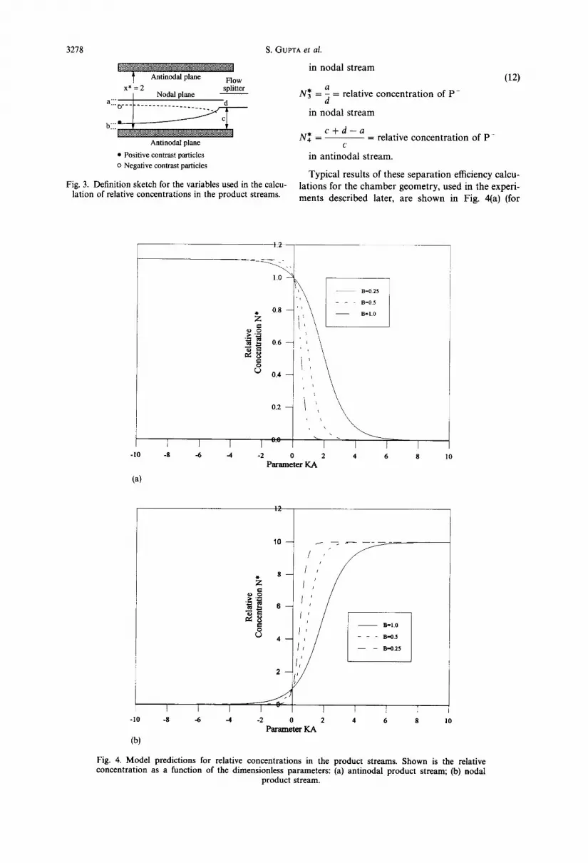
separation method can be computed on the basis of these critical trajectories. As depicted in Fig. 3, the critical trajectory for positive contrast particles has an inlet position b relative to the wall, while the critical trajectory for a negative contrast particle is a distance a away from a nodal plane. The exit splitter is de- picted to be a distance c from the wall, and distance d from the nodal plane. In terms of the dimensionless number concentration of particles N * ( = p a r t i c l e concentration in the exit stream/particle concentra- tion in the feed stream), we find that
N* = _b = relative concentration of P+in ¢
antinodal stream
d + c - b N* = - - = relative concentration of P+
d
( y
REFLECTOR
1
4
Aatinode
Antinode
Z/2 $
TRANSDUCER
Fig. 2. Depiction of the forces in an acoustic chamber; (1) drag force resisting particle motion across the chamber; (2) drag force on the particle resisting motion of the particle relative to the flow; (3) gravity; (4) acoustic force. The magnification of a half-wavelength region shows that the flow profile is essentially flat
over this small distance.
3278
Anfinodal plane Flow x* = 2 splitter
Nodal plane a:7 o . . . . . . . . . . . . . . . . . . . . . . . d
b " ' ~ ~:~.~ Antinodal plane
• Positive contrast particles o Negative contrast particles
Fig. 3. Definition sketch for the variables used in the calcu- lation of relative concentrations in the product streams.
S. GUPTA et al.
in noda l s t r eam (12)
a
N* = ~ = relative c o n c e n t r a t i o n of P -
in n o d a l s t r eam
c + d - a N* - - - relative c o n c e n t r a t i o n o f P -
c in an t i noda l s t ream.
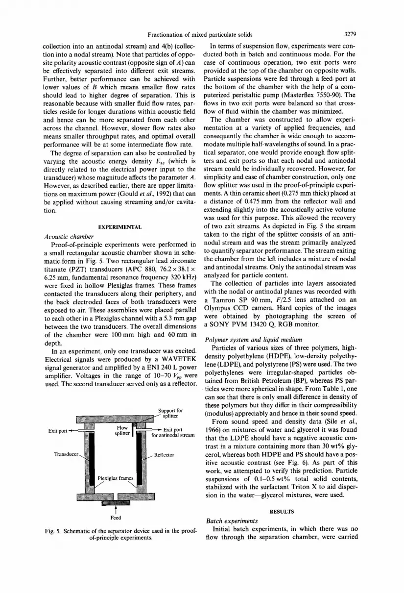
Typical results o f these s epa ra t ion efficiency calcu- la t ions for the c h a m b e r geomet ry , used in the exper i - m e n t s desc r ibed later, a re s h o w n in Fig. 4(a) (for
-10
(a)
1.2
B=0.25
- - B = 0 . 5
~, 0 . 8 - - - B = t . 0
o O
e~
~'~ 0 . 4
0.2
n ~
1 I I I ~'~ I I I I -8 -6 -4 -2 0 2 4 6 8
P a r a m e t e r K A
I0
1 0 - -
l l l - 1 0 - 8 - 6 8 10
i/y / / !
_ s - / '
o g ~ t , ' ._~ "~ N 6 - -
e~ - - B=I .0 O cO 4 - - - - e - ,0 .5
B. .0 .25
1 1 l -4 -2 0 2 4 6
P a r a m e t e r K A
(b)
Fig. 4. Model predictions for relative concentrations in the product streams. Shown is the relative concentration as a function of the dimensionless parameters: (a) antinodal product stream; (b) nodal
product stream.
Fractionation of mixed particulate solids
collection into an antinodal stream) and 4(b) (collec- tion into a nodal stream). Note that particles of oppo- site polarity acoustic contrast (opposite sign of A) can be effectively separated into different exit streams. Further, better performance can be achieved with lower values of B which means smaller flow rates should lead to higher degree of separation. This is reasonable because with smaller fluid flow rates, par- ticles reside for longer durations within acoustic field and hence can be more separated from each other across the channel. However, slower flow rates also means smaller throughput rates, and optimal overall performance will be at some intermediate flow rate.
The degree of separation can also be controlled by varying the acoustic energy density Eac (which is directly related to the electrical power input to the transducer) whose magnitude affects the parameter A. However, as described earlier, there are upper limita- tions on maximum power (Gould et al., 1992) that can be applied without causing streaming and/or cavita- tion.
EXPERIMENTAL
Acoustic chamber Proof-of-principle experiments were performed in
a small rectangular acoustic chamber shown in sche- matic form in Fig. 5. Two rectangular lead zirconate titanate (PZT) transducers (APC 880, 76.2 x 38.1 x 6.25 mm, fundamental resonance frequency 320 kHz) were fixed in hollow Plexiglas frames. These frames contacted the transducers along their periphery, and the back electroded faces of both transducers were exposed to air. These assemblies were placed parallel to each other in a Plexiglas channel with a 5.3 mm gap between the two transducers. The overall dimensions of the chamber were 100 mm high and 60 mm in depth.
In an experiment, only one transducer was excited. Electrical signals were produced by a WAVETEK signal generator and amplified by a ENI 240 L power amplifier. Voltages in the range of 10-70 ~p were used. The second transducer served only as a reflector.
Support for splitter
........... ~ - - - - - ~ Exit port Exit port ~ Flow ::~'~=: • splitter for antinodal stream
Plexiglas frame~ /
3279
In terms of suspension flow, experiments were con- ducted both in batch and continuous mode. For the case of continuous operation, two exit ports were provided at the top of the chamber on opposite walls. Particle suspensions were fed through a feed port at the bottom of the chamber with the help of a com- puterized peristaltic pump (Masterflex 7550-90). The flows in two exit ports were balanced so that cross- flow of fluid within the chamber was minimized.
The chamber was constructed to allow experi- mentation at a variety of applied frequencies, and consequently the chamber is wide enough to accom- modate multiple half-wavelengths of sound. In a prac- tical separator, one would provide enough flow split- ters and exit ports so that each nodal and antinodal stream could be individually recovered. However, for simplicity and ease of chamber construction, only one flow splitter was used in the proof-of-principle experi- ments. A thin ceramic sheet (0.275 mm thick) placed at a distance of 0.475 mm from the reflector wall and extending slightly into the acoustically active volume was used for this purpose. This allowed the recovery of two exit streams. As depicted in Fig. 5 the stream taken to the right of the splitter consists of an anti- nodal stream and was the stream primarily analyzed to quantify separator performance. The stream exiting the chamber from the left includes a mixture of nodal and antinodal streams. Only the antinodal stream was analyzed for particle content.
The collection of particles into layers associated with the nodal or antinodal planes was recorded with a Tamron SP 90 mm, F/2.5 lens attached on an Olympus CCD camera. Hard copies of the images were obtained by photographing the screen of a SONY PVM 13420 Q, RGB monitor.
Polymer system and liquid medium Particles of various sizes of three polymers, high-
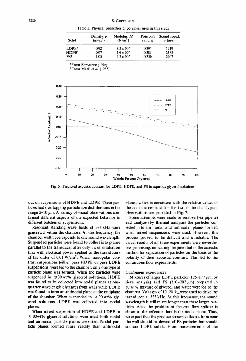
density polyethylene (HDPE), low-density polyethy- lene (LDPE), and polystyrene (PS) were used. The two polyethylenes were irregular-shaped particles ob- tained from British Petroleum (BP), whereas PS par- ticles were more spherical in shape. From Table 1, one can see that there is only small difference in density of these polymers but they differ in their compressibility (modulus) appreciably and hence in their sound speed.
From sound speed and density data (Sile et al., 1966) on mixtures of water and glycerol it was found that the LDPE should have a negative acoustic con- trast in a mixture containing more than 30 wt% gly- cerol, whereas both HDPE and PS should have a pos- itive acoustic contrast (see Fig. 6). As part of this work, we attempted to verify this prediction. Particle suspensions of 0.1-0.5wt% total solid contents, stabilized with the surfactant Triton X to aid disper- sion in the water glycerol mixtures, were used.
Feed
Fig. 5. Schematic of the separator device used in the proof- of-principle experiments.
RESULTS
Batch experiments Initial batch experiments, in which there was no
flow through the separation chamber, were carried
3280 S. GUPTA et al.
Table 1. Physical properties of polymers used in this study
Density, p Modulus, M Poisson's Sound speed, Solid (g/cm 3) (N/m 2 ) ratio, ~/ c (m/s)
LDPE t 0.92 3.3 × 1 0 9 0.397 1919 HDPE* 0.97 5.0 × 10 9 0.385 2583 PS ~ 1.05 4.2 x 1 0 9 0.350 2407
tFrom Krevelene (1976). ~From Mark et al. (1985).
0 . 4 0
g.h . . r
o L) .o_
o <
0 . 3 0 - -
0 . 2 0 - -
0 . 1 0 - -
0 . 0 0
- 0 . 1 0 - -
- 0 . 2 0 - -
- 0 . 3 0 - -
- 0 . 4 0
- - LDPE
~ ~ - - - H D P E
r I I I I J I I I 0 1 0 2 0 3 0 4 0 5 0 6 0 7 0 S 0 9 0 1 0 0
Weight Percent Glycerol
Fig. 6. Predicted acoustic contrast for LDPE, HDPE, and PS in aqueous glycerol solutions.
out on suspensions of HDPE and LDPE. These par- ticles had overlapping particle size distributions in the range 5-10 #m. A variety of visual observations con- firmed different aspects of the expected behavior in different batches of suspensions.
Resonant standing wave fields of 333 kHz were generated within the chamber. At this frequency, the chamber width corresponds to one sound wavelength. Suspended particles were found to collect into planes parallel to the transducer after only 1 s of irradiation time with electrical power applied to the transducers of the order of 0.01 W/cm 2. When monopolar con- trast suspensions (either pure HDPE or pure LDPE suspensions) were fed to the chamber, only one type of particle plane was formed. When the particles were suspended in ~ 3 0 w t % glycerol solutions, HDPE was found to be collected into nodal planes at one- quarter wavelength distances from walls while LDPE was found to form an antinodal plane at the midplane of the chamber. When suspended in < 30 wt% gly- cerol solutions, LDPE was collected into nodal planes.
When mixed suspension of HDPE and LDPE in 30wt% glycerol solutions were used, both nodal
and antinodal particle planes coexisted. Nodal par- ticle planes formed more readily than antinodal
planes, which is consistent with the relative values of the acoustic contrast for the two materials. Typical observations are provided in Fig. 7.
Some attempts were made to remove (via pipette) and analyze (by thermal analysis) the particles col- lected into the nodal and antinodal planes formed when mixed suspensions were used. However, this process proved to be difficult and unreliable. The visual results of all these experiments were neverthe- less promising, indicating the potential of the acoustic method for separation of particles on the basis of the polarity of their acoustic contrast. This led to the continuous-flow experiments.
Cont inuous exper imen t s
Mixtures of larger LDPE particles (125-177/lm, by sieve analysis) and PS (210-297/tm) prepared in 30 wt% mixture of glycerol and water were fed to the chamber. Voltages of 10-20 Vpp were used to drive the transducer at 333 kHz. At this frequency, the sound wavelength is still much longer than these larger par- tides. Also, the position of the exit flow splitter is closer to the reflector than is the nodal plane. Thus, we expect that the product stream collected from near the wall should be devoid of PS particles but should contain LDPE solids. From measurements of the

Fractionation of mixed particulate solids 3281
P U R E H D P E 1 : 1 H D P E : L D P E P U R E L D P E
Fig. 7. Photographs of the planes formed in the acoustic chamber in the batch experiments. The chamber was illuminated from the back, and the dark vertical lines are the planes formed by the collected particles. The top photograph shows the suspension condition before the acoustic field was applied. The bottom three photographs show, from left to right, the response ot" suspensions of pure HDPE, a 1 : 1 mixture of
HDPE: LDPE, and pure LDPE, respectively.

3282 S. GUr'TA et al.
Sound Field OFF Sound Field ON
atinodal plane
i Nodal Plane
Fig. 8. Photographs showing the planes formed in continuous-flow experiments using mixtures of LDPE and PS. PS particles are collected in a nodal plane while the LDPE particles form antinodal planes and flow
out of the chamber near the wall. The flow direction is anti-parallel to gravity.
Fractionation of mixed particulate solids
current supplied to the transducers, the electrical power density was estimated to be of the order of 0.01 W/cm 2.
The photographs in Fig. 8 show typical results. When the acoustic field is energized, particles begin to form planes near the chamber inlet, and flow upward and out of the chamber in fairly orderly fashion within their respective planes. Typical runs lasted more than 3 rain, and the heating of the fluid due to losses in the transducer and suspension did not seem to affect the acoustic resonance over this time span.
Samples of suspension were collected from the anti- nodal product stream over fixed time intervals. The effluent collected with the sound field off was analyzed to show the characteristics of the feed. Similar samples were taken after 1 min of operation with the acoustic field on.
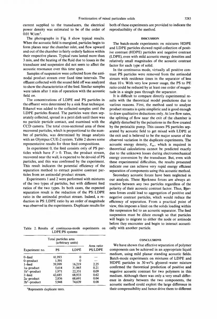
The concentrations of LDPE and PS particles in the effluent were determined by a sink float technique. Ethanol was added to the collected samples until the LDPE particles floated. The particles were then sep- arately collected, spread in a petri dish until there was no particle particle contact, and examined with the CCD camera. The total cross-sectional area of these recovered particles, which is proportional to the num- ber of particles, was determined by image analysis with an Olympus CUE-2 system. Table 2 shows some representative results for three feed compositions.
In experiment 0, the feed consists only of PS par- ticles which have F > 0. Thus, the product stream, recovered near the wall, is expected to be devoid of PS particles, and this was confirmed by the experiment. This result indicates the potential efficiency of the separation method to extract positive contrast par- ticles from an antinodal product stream.
Experiments 1 and 2 were performed with mixtures of the two types of particles, but with different feed ratios of the two types. In both cases, the expected separation result is the reduction of the PS:LDPE ratio in the antinodal product stream. Indeed, a re- duction in PS : LDPE ratio by an order of magnitude was observed in the experiments. Duplicate results for
Table 2. Results of continuous-mode experiments on LDPE/PS systems
Total particles area (arbitrary units)
Area ratio Experiment no. PS LDPE PS/LDPE
0-feed 41,993 0 - - 0-product 1,591 0 - - 1-feed 39,999 16,219 2.25 la-product 5,614 31,965 0.21 lbt-product 1,971 22,351 0.09 2-feed 42,685 68,933 0.62 2a-product 2,836 68,691 0.04 2bt-product 5,948 74,639 0.08
tRepresents duplicate tests.
3283
both of these experiments are provided to indicate the reproducibility of the method.
DISCUSSION
The batch-mode experiments on mixtures HDPE and LDPE particles showed rapid collection of posit- ive contrast (HDPE) particles and negative contrast (LDPE), even with mild acoustic energy densities and relatively small magnitudes of the acoustic contrast factor for each type of solid.
In the continuous mode, virtually all positive con- trast PS particles were removed from the antinodal stream with residence times in the separator of less than 10 s. With very low power usage, the PS to PE ratio could be reduced by at least one order of magni- tude in a single pass through the separator.
It is difficult to compare directly experimental re- sults with the theoretical model predictions due to various reasons. First, the method used to analyze product streams is quite simplistic and is good enough to draw qualitative deductions only. At low flow rates, the splitting of flow near the exit of the chamber is slightly disturbed by the pulsations in the flow created by the peristaltic pump. This causes PS particles sep- arated by acoustic field to get mixed with LDPE at the exit and is believed to be the major source of the observed variation in the duplicate experiments. The acoustic energy density, Eac, which is required in theoretical calculations cannot be predicted exactly due to the unknown losses during electromechanical energy conversion by the transducer. But, even with these experimental difficulties, the results presented indicate one can achieve very rapid energy efficient separation of components using this acoustic method.
Secondary acoustic forces have been neglected in our analysis. These Bjerkness forces are always at- tractive between any two particles regardless of the polarity of their acoustic contrast factor. Thus, Bjer- ness forces could lead to aggregation of positive and negative contrast particles, which would reduce the efficiency of separation. From a practical point of view, this imposes a limit on the solids loading within the suspension fed to an acoustic separator. The feed suspension must be dilute enough so that particles will begin to migrate to either the node or antinode before they encounter and begin to interact acousti- cally with another particle.
CONCLUSIONS
We have shown that effective separation of polymer components can be achieved in an appropriate liquid medium, using mild planar standing acoustic fields. Batch-mode experiments on mixtures of LDPE and HDPE particles in 30 wt% glycerol-water mixture confirmed the theoretical prediction of positive and negative acoustic contrast for two polymers in this medium. Although there was only a very small differ- ence in density between the two components, the acoustic method could exploit the large difference in their compressibility and hence drive them to different

3284
locations in the standing wave field. High degrees of separation were observed in the continuous-mode ex- periments on L D P E and PS. This new separation concept is suitable for polymer separation in waste streams or for any separation process in which the components exhibit variations in compressibility.
Acknowledgement--This work was supported in part by a BP Partners in Polymer Science Fellowship.
REFERENCES
Apfel, R. E., 1988, Acoustically-induced square law forces and some speculations about gravity. Am. J. Phys. 56, 726-729.
Apfel, R. E., 1990, Acoustic radiation pressure-principles and application to separation science. Proceedinos Fort- schritte der Akustik-DAGA, Part A, pp. 19-36.
Brodeur, P., Dion, J. L., Garceau, J. J., Pelletier, G. and Massicotte, D., 1989, Fiber characterization in a station- ary ultrasonic field. IEEE Trans. Ultrasonics Ferroelec- tries Frequency Control 36, 549-553.
Drain, K. F., Murphy, W. R. and Otterburn, M. S., 1983, Solvents for polypropylene: their selection for a recycling process. Conservation Recylin O 6, 107-122.
Gould, R. K., Coakley, W. T. and Grundy, M. A., 1992, Upper sound pressure limits on particle concentration in fields of ultrasonic standing-waves at megahertz frequen- cies. Ultrasonics 30, 239-244.
Hager, F., Benes, E., Bolek, W. and Greoeschl, M., 1991, Investigation of a new ultrasonic drifting resonance field cell for the refinement of aerosols. Proceedinos of the FACE Symposium, 261, Hungary.
Holman, J. L., Stephenson, J. B. and Adam, M. J., 1974, Recycling of plastics from urban and industrial refuse. U.S. Bureau of Mines, Reports of Investigation, 7955, 44pp.
Krevelene, D. W. V., 1976, Properties of Polymers, their
S. GUPTA et al.
Estimation and Correlation with Chemical Structure, 2nd Edition. Elsevier Scientific, New York.
Lin, I. J. and Benguigui, L., 1981, Dielectrophoretic filtration and separation: general outlook. Separation Purification Methods 10, 53-72.
Maczko, J. and Kobler, R., 1993, Another way of removing PVC contamination from PET. Abstracts of Papers American Chemical Society, 205, No. 488.
Mandralis, Z. I., Bolek, W., Burger, W., Benes, E. and Feke, D. L., 1994, Enhanced synchronized ultrasonic and flow- field fractionation of suspensions. Ultrasonics 32, 113-121.
Mandralis. Z. I. and Feke, D. L, 1993a, Continuous suspen- sion fractionation using ultrasonic and flow fields. Chem. Engn9 Sci. 48, 3897-3905.
Mandralis, Z. I. and Feke, D. L., 1993b, Fractionation of suspensions using synchronized ultrasonic and flow fields. A.I.Ch.E.J. 39, 197-206.
Mark, H. F., Bikales, N. M., Overberger, C. G. and Menges, G. (eds), 1985, Encyclopedia of Polymer Science and Enoin- eerin9, 2rid Edition, Vol. 1, p. 147. Wiley, New York.
Pearse, M. J. and Hickey, T. J., 1978, The separation of mixed plastics using a dry triboelectric technique. Re- source Recovery Conservation 3, 179-190.
Sile, W. M., Donfor, A. R. and Litovitz, T. A., 1966, Ultra- sonic shear and longitudinal measurements in aqueous glycerol. J. Chem. Phys. 44, 3712-3718.
Seymour, R. Stahl, B. and Allan, G., 1976, Separation of waste plastics. J. Chem. Educ. 53, 653.
Tolt, T. L. and Feke, D. L., 1992, Separation devices based on forced coincidence resonance of fluid-filled pipes. J. Acoust. Soc. Am. 91, 3152-3156.
Tolt, T. L. and Feke, D. L., 1993, Separation of dispersed phases from liquids in acoustically driven chambers. Chem. Engng Sci. 48, 527-540.
Weiser, M. H., Apfel, R. E. and Neppiras, E. A., 1984, Interparticle forces on red cells in a standing wave field. Acustica 56, 114-119.
Whitworth, G., Grundy, M. A. and Coakley, W. T., 1991, Transport and harvesting of suspended particles using modulated ultrasound. Ultrasonics 28, 439-444.
Yosioka, K. and Kawasima, Y., 1955, Acoustic radiation pressure on a compressible sphere. Acustica 5, 167-173.