Embed Size (px)
Citation preview
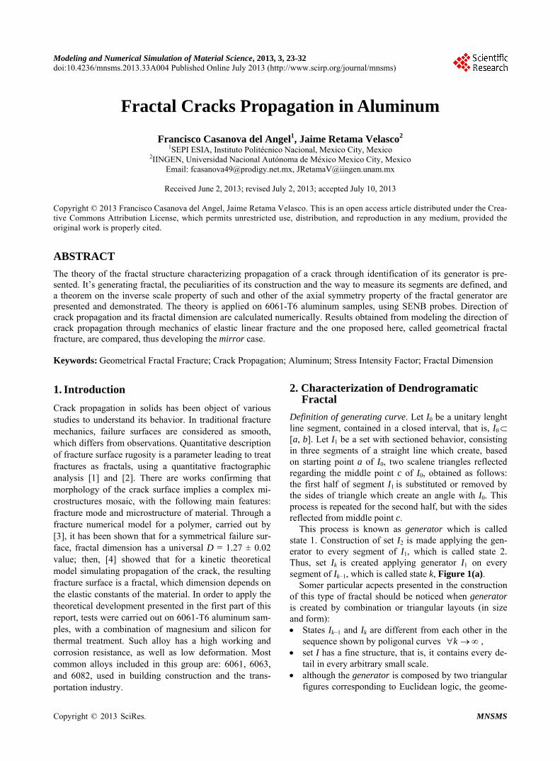
Modeling and Numerical Simulation of Material Science, 2013, 3, 23-32 doi:10.4236/mnsms.2013.33A004 Published Online July 2013 (http://www.scirp.org/journal/mnsms)
Fractal Cracks Propagation in Aluminum
Francisco Casanova del Angel1, Jaime Retama Velasco2 1SEPI ESIA, Instituto Politécnico Nacional, Mexico City, Mexico
2IINGEN, Universidad Nacional Autónoma de México Mexico City, Mexico Email: [email protected], [email protected]
Received June 2, 2013; revised July 2, 2013; accepted July 10, 2013
Copyright © 2013 Francisco Casanova del Angel, Jaime Retama Velasco. This is an open access article distributed under the Crea- tive Commons Attribution License, which permits unrestricted use, distribution, and reproduction in any medium, provided the original work is properly cited.
ABSTRACT
The theory of the fractal structure characterizing propagation of a crack through identification of its generator is pre- sented. It’s generating fractal, the peculiarities of its construction and the way to measure its segments are defined, and a theorem on the inverse scale property of such and other of the axial symmetry property of the fractal generator are presented and demonstrated. The theory is applied on 6061-T6 aluminum samples, using SENB probes. Direction of crack propagation and its fractal dimension are calculated numerically. Results obtained from modeling the direction of crack propagation through mechanics of elastic linear fracture and the one proposed here, called geometrical fractal fracture, are compared, thus developing the mirror case. Keywords: Geometrical Fractal Fracture; Crack Propagation; Aluminum; Stress Intensity Factor; Fractal Dimension
1. Introduction
Crack propagation in solids has been object of various studies to understand its behavior. In traditional fracture mechanics, failure surfaces are considered as smooth, which differs from observations. Quantitative description of fracture surface rugosity is a parameter leading to treat fractures as fractals, using a quantitative fractographic analysis [1] and [2]. There are works confirming that morphology of the crack surface implies a complex mi- crostructures mosaic, with the following main features: fracture mode and microstructure of material. Through a fracture numerical model for a polymer, carried out by [3], it has been shown that for a symmetrical failure sur- face, fractal dimension has a universal D = 1.27 ± 0.02 value; then, [4] showed that for a kinetic theoretical model simulating propagation of the crack, the resulting fracture surface is a fractal, which dimension depends on the elastic constants of the material. In order to apply the theoretical development presented in the first part of this report, tests were carried out on 6061-T6 aluminum sam- ples, with a combination of magnesium and silicon for thermal treatment. Such alloy has a high working and corrosion resistance, as well as low deformation. Most common alloys included in this group are: 6061, 6063, and 6082, used in building construction and the trans- portation industry.
2. Characterization of Dendrogramatic Fractal
Definition of generating curve. Let I0 be a unitary lenght line segment, contained in a closed interval, that is, I0 [a, b]. Let I1 be a set with sectioned behavior, consisting in three segments of a straight line which create, based on starting point a of I0, two scalene triangles reflected regarding the middle point c of I0, obtained as follows: the first half of segment I1 is substituted or removed by the sides of triangle which create an angle with I0. This process is repeated for the second half, but with the sides reflected from middle point c.
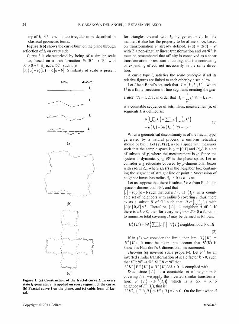
This process is known as generator which is called state 1. Construction of set I2 is made applying the gen- erator to every segment of I1, which is called state 2. Thus, set Ik is created applying generator I1 on every segment of Ik−1, which is called state k, Figure 1(a).
Somer particular acpects presented in the construction of this type of fractal should be noticed when generator is created by combination or triangular layouts (in size and form): States Ik−1 and Ik are different from each other in the
sequence shown by poligonal curves k , set I has a fine structure, that is, it contains every de-
tail in every arbitrary small scale. although the generator is composed by two triangular
figures corresponding to Euclidean logic, the geome-
Copyright © 2013 SciRes. MNSMS
F. CASANOVA DEL ANGEL, J. RETAMA VELASCO 24
try of Ik k is too irregular to be described in classical geometric terms.
Figure 1(b) shows the curve built on the plane through reflection of Ik on every side.
Curve I is characterized by being of a similar scale since, based on a transformation F: n n with
0i i
such that , Rnn a b
i i iF a F b a b . Similarity of scale is present
(a)
(b)
(c)
Figure 1. (a) Construction of the fractal curve I. In every state Ik generator I1 is applied on every segment of the curve. (b) Fractal curve I on the plane, and (c) cubic form of fac- tal.
for triangles created with I0, by generator I1. In like manner, it also has the property to be affine since, based on transformation F already defined, F(a) = T(a) + with T a non-singular linear transformation and n. It must be remembered that affinity is conceived as a shear transformation or resistant to cutting, and is a contracting or expanding effect, not necessarily in the same direc- tion.
A curve type lk satisfies the scale principle if all its relative figures are linked to each other by a scale law.
Let I be a Borel’s set such that 1 2 3, , I I I I where I j is a finite succesion of line segments creating the gen-
erator 1, 2, 3j , in order that 3
1
1, 2,ji i
j
I I i
is a countable sequence of sets. Thus, measurement , of segments Ii is defined as:
11
1
3
3 1
1
,
ji ii
i i
ijI I
I I i
(1)
When a geometrical discontinuity is of the fractal type, generated by a natural process, a uniform reticulate should be built. Let (, P(), ) be a space with measures such that the sample space is = [0,1] and P() is a set of subsets of , where the measurement is . Since the system is dynamic, p is the phase space. Let us consider a reticulate covered by p-dimensional boxes with radius n, where Bn(t) is the neighbor box contain-ing the segment of straight line or point t. Succession of neighbor boxes has radius n 0 as n .
Let us suppose that there is subset I from Euclidian space n-dimensional, n, and that
sup such that ,I a b a b I . If iI is a count- able set of neighbors with radius coveringexists a subset II of n such that
1 ii
I, thus, there
II I
with 0,iI i . Therefore, iI is neighbor of I. If
there is a k 0, then for every neighbor 0 a function to minimize total covering II may be defined as follows:
1neighborhood of
kki ii
H II inf I I II
(2)
If in (2) we consider the limit, then lím kH II = kH II . It must be taken into account that k(II) is
known as Hausdorf’s k-dimensional measurement. Theorem (of inverted scale property). Let F−1 be an
inverted similar transformation of scale factor k 0, such that F−1: n n. Si II n then
1 0k k kK F II H II is complied with. Dem: since iI is a countable set of neighbors
covering I, if we apply the inverted similar transforma-tion: 1
i i1F I F I which is a / = −1
neighbor of F−1(II), that is: 1 kH F H I
0k k I II . On the limit when
Copyright © 2013 SciRes. MNSMS
F. CASANOVA DEL ANGEL, J. RETAMA VELASCO
Copyright © 2013 SciRes. MNSMS
25
k
logn
nn
M tC t
0, the above inequality becomes:
1k kH F II H II
where Cn describes the local behavior of measurement. The theorem herein proven allows us to reduce the length of a fractal object.
2.2. Behavior Pattern 2.1. Meshing and Definition of Fractal Outline The fractal behavior of a geometrical discontinuity takes
us to the concept to of diagonal self-affinity diagonal. In order to define the pattern of the fractal generator, let us begin drawing straight lines from its base to the points where such curves all along its length, thus obtaining a fractioned curve. It is convenient to draw horizontal lines in case there is a change in its path behavior, in order to identify the affinity along such path.
Let N(t*, t*) be the number of squares contained by re- ticulate, and N(t, t) the number of squares intersected by the fractal curve. D°(I) shall be the fractal dimension, L the total length of the object, and l the length of every segment. Therefore, L/l quotient defines the number of subdivisions contained by every side of the intersected reticulate. These scale properties correspond to a frag- mented fractal, and the multifractal 5, p. 45] concept is applied. Based on the above:
Horizontal lines identifying the beginning of the gen- erator, must show the feature of proportionality d such that:
** * * *,Δ Δ
f tN t t t t t (3)
sin where sin and cos d k
d (5) where t [t*, t* + t*. P(t*) is the probability of distri- bution of intersection points t [t*, t* + t* and f(t*) the fractal dimension of such points.
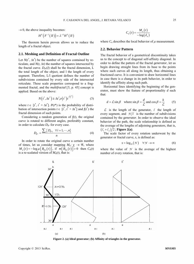
is the length of the generator, l the length of every segment, and N l is the number of subdivisions contained by the generator. In order to observe the ideal behavior of the path, the scale relationship is defined as the average of the lengths of adjoining generators, that is, 1 2 2l l ; Figure 2(a).
Considering a random generation of f(t), the original curve is rotated to different angles, preferably constant, in order to calculate D for every case.
1, ,iiD i n
Dn
(4) The scale factor of every rotation underwent by the generator or fractal curve, s, is defined as:
In order to rotate the original curve a certain number of times, let us consider mapping Mn: , where
logn nM t B
10logs N N (6)
t , if then Cn(t) is a re-scalated version of Mn(t), that is:
0nm B t where the value of N is the average of the highest number of every rotation, that is:
(a) (b)
Figure 2. (a) Ideal generator; (b) Affinity of triangles in the generator.

F. CASANOVA DEL ANGEL, J. RETAMA VELASCO 26
and 1, ,ii
R b i n N (7)
Based on the above, we may get the scale factor of the generator, defined as the inversion of s which, applied, generates the geometrical structure.
2.3. Parameters of Fractal Geometry
Since the fact that the real length of a fractal line depends on accurateness of measurement is an important issue, the real total length of the line increases in accordance with equation number 8:
1 j j n N (8)
with j as number of iterations, N the number of elements in the base generator (j = 1) and n the factor of reduction applied. Therefore, the real length of a fractal line j after j iterations is given by equation number 9:
d D
j p j
(9)
where j = nj represents the lowest measurement unit in order to measure relative length of a segment of the frac-tal line. Parameter d represents the Euclidian dimension of the object, D* is the fraction of the fractal dimension D and Lp is the length of the whole fractal, from one end to the other, without taking into consideration its roughness. In order to apply the above to fractals gener-ated from a natural process j is cleared up from equa-tion number 9, thus obtaining:
*
jd D
jp
(10)
Property of axial symmetry of generator. Triangles creating segments of I1, based on I0 may vary regarding size and shape.
Generator I1 may be considered as the union of two scalene Triangles II1 (triagle lower than I0) and II2 (train- gle higher than I0) created based on I0, and reflected on 1/2I0, that is:
1 1 1 2 3 2
1 1 2 2 3 2
1 2
,0 , , , ,0 , , , ,0
,0 , , , ,0 ,0 , , , ,0
I a z a z z a b
a z a z z z a b
II II
When z1 = 1/3I0; z2 = 1/2I0 and z3 = 2/3I0 we talk about generator I1, Figure 2(b) left. When z1 1/3I0; z2 1/2I0 and z3 2/3I0, we talk about 1I , Figure 2(b) right. When z1 1/3I0; z2 1/2I0 and z3 2/3I0, we talk about 1I . In the two latter cases, the homologous angles creating the segments of the generator are congruent and their ho- mologous sides are proportional, thus complying with the property of similarity of triangles, that is, I1 and I1 are generators similar to I0.
Theorem of transformation of linear affinity. If G is a geometrical transformation of scale factors r, s , such that G: n n, there are translation factors h, k , which go back to Im+1 an affine generator of Im.
Dem: let r and s be scale factors in x and y directions, respectively, of generator I1, which may be described by Equation (1), that is, I1 = 3(Ii−1) with i = 1. Since r and s are scale factors of I1, then I1 × (r, s) increases (r, s 1), decreases (r, s 1) or is non-variable (r, s = 1) and generator I1 is similar. Generator I1 may be re-scalated and translated if 1 1, : , ,Rh k I I r s h k
, ,m m mI r s h k I,
therefore, 1:m I By means of induction we have that, by Equation (1),
for m = 1:
1 1
0
1
1
, ,
3 ,
, ,
I I r s h k
,I r s h k
I r s h k
I
If we consider the above is valid for m 1, then r, s 1, h and k 0:
, ,m m mI I r s h k I
Let us demonstrate this for m = m+1.
1 1
1
1
, ,
3 ,
, ,
m m
m
m
m
I I r s h k
,I r s h k
I r s h k
I
3. Methods to Measure the Crack’s Length
An approximate measurement of the crack’s length, a, is a requirement in order to obtain strength to fracture and to measure crack propagation due to stress. In addition to optical methods used to determine the point where the crack enters the surface, there are methods measuring the crack’s length, generating a history of such measure- ments. Two of the most used methods to measure the crack’s length are: potential drop and acoustic.
In this paper, cracks propagation in a solid, aluminum alloy 6061-T6, is been studied using the Fractal Geome- try theory (FG). Firstly, toughness to fracture for failure Mode I was experimentally determined, and then, critical stress intensity factor was determined for Mode II using the results obtained by Henry Vaughan (1998). Then, direction of propagation was calculated in accordance with the LEFM theory (FM).Using the FG theory, fractal dimension of cracks has been determined for the studied aluminum, in order to relate it afterwards with facture properties of the material. Regarding propagation, a gen- erator with which it is possible to determine the direction
Copyright © 2013 SciRes. MNSMS
F. CASANOVA DEL ANGEL, J. RETAMA VELASCO 27
of crack propagation may be determined using a graphi- cal procedure.
3.1. Materials and Methods
Experimental test have been carried out in order to measure fracture properties of the material, critical stress intensity factor for Mode I and propagation direction of the crack using the LEFM theory. Then, the same pa- rameters are calculated using the FG theory in order to make a comparison analysis.
Materials. The tested material was structural alumi- num alloy 6061-T6, which is a material thermally treated through magnesium and silicon. Chemical contents and mechanical properties are summarized in Tables 1 and 2, respectively. The key features of the aluminum alloys used are its high working and corrosion resistance, as well as low deformation.
Table 1. Chemical contents.
Component Wt (%)
Aluminum, Al 95.8 - 98.3
Chromium, Cr 0.04 - 0.35
Copper, Cu 0.15 - 0.4
Iron, Fe 0.7 maximum
Magnesium, Mg 0.8 - 1.2
Manganese, Mn 0.15 maximum
Silicon, Si 0.4 - 0.8
Titanium, Ti 0.15 maximum
Zinc, Zn 0.25 maximum
Other, each 0.05 maximum
Other, total 0.15 maximum
Table 2. Mechanical properties.
Property Value
Density 2.7 gr/cm3
Tensile Strength, Ultimate 310 Mpa
Tensile Strength, Yield 276 Mpa
Modulus of Elasticity 68.9 Gpa
Poissons Ratio 0.33
Fatigue Strength 96.5 Mpa
Fracture Toughness 29 Mpa*m1/2
Shear Modulus 26 Mpa
Shear Strength 207 Mpa
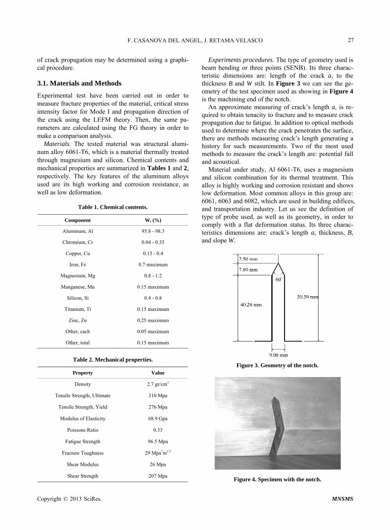
Experiments procedures. The type of geometry used is beam bending or three points (SENB). Its three charac- teristic dimensions are: length of the crack a, to the thickness B and W stilt. In Figure 3 we can see the ge- ometry of the test specimen used as showing in Figure 4 is the machining end of the notch.
An approximate measuring of crack’s length a, is re- quired to obtain tenacity to fracture and to measure crack propagation due to fatigue. In addition to optical methods used to determine where the crack penetrates the surface, there are methods measuring crack’s length generating a history for such measurements. Two of the most used methods to measure the crack’s length are: potential fall and acoustical.
Material under study, Al 6061-T6, uses a magnesium and silicon combination for its thermal treatment. This alloy is highly working and corrosion resistant and shows low deformation. Most common alloys in this group are: 6061, 6063 and 6082, which are used in building edifices, and transportation industry. Let us see the definition of type of probe used, as well as its geometry, in order to comply with a flat deformation status. Its three charac- teristics dimensions are: crack’s length a, thickness, B, and slope W.
Figure 3. Geometry of the notch.
Figure 4. Specimen with the notch.
Copyright © 2013 SciRes. MNSMS
F. CASANOVA DEL ANGEL, J. RETAMA VELASCO 28
In order that obtained values may be considered as valid, the following relationships must be complied with: a, B 2.5 (KIC/0)
2; 1 W/B 4; S = 4W; L = 4.2W, where the crack’s length a is 50.5 mm, thickness B is 50 mm, width W is 100 mm, and spacing between support S is 400 mm.
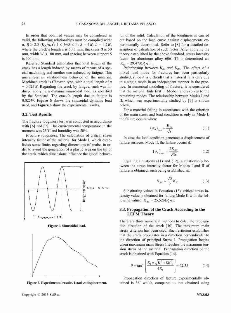
Referred Standard establishes that total length of the crack has a length induced by means of means of a spe- cial machining and another one induced by fatigue. This guarantees an elastic-linear behavior of the material. Machined crack is Chevron type, with a total length of a − 0.025W. Regarding the crack by fatigue, such was in- duced applying a dynamic sinusoidal load, as specified by the Standard. The crack’s length due to fatigue is 0.025W. Figure 5 shows the sinusoidal dynamic load used, and Figure 6 show the experimental results.
3.2. Test Results
The fracture toughness test was conducted in accordance with 6 and 7. The environmental temperature in the moment was 25˚C and humidity was 50%.
Fracture toughness. The calculation of critical stress intensity factor of the material for Mode I, which estab- lishes some limits regarding dimensions of probe, in or- der to avoid the generation of a plastic area on the tip of the crack, which dimensions influence the global behave-
Figure 5. Sinusoidal load.
Figure 6. Experimental results. Load vs displacement.
ior of the solid. Calculation of the toughness is carried out based on the load curve against displacements ex- perimentally determined. Refer to 8 for a detailed de- scription of calculation of such factor. After applying the theory established by the above Standard, stress intensity factor for aluminum alloy 6061-T6 is determined as:
29.47IC aK MP m . Relationship between KIC and KIIC. The effect of a
mixed load mode for fractures has been particularly studied, since it is difficult that a material fails only due to a single mode in an independent manner in the prac- tice. In numerical modeling of fracture, it is considered that the material fails first in Mode I and evolves to the remaining modes. The relationship between Modes I and II, which was experimentally studied by 9 is shown below.
For a material failing in accordance with the criterion of the main stress and load condition is only in Mode I, the failure occurs when:
0 maxICK
r (11)
In case the load condition generates a displacement of failure surfaces, Mode II, the failure occurs if:
0 max
2
3IICK
r (12)
Equaling Equations (11) and (12), a relationship be- tween the stress intensity factor for Modes I and II of failure is obtained; such being established as:
3
2IIC ICK K (13)
Substituting values in Equation (13), critical stress in- tensity value is obtained for failure Mode II with the fol- lowing value: 25.52IIC aK MP m
3.3. Propagation of the Crack According to the LEFM Theory
There are three numerical methods to calculate propaga- tion direction of the crack 10. The maximum main stress criterion has been used. Such criterion establishes that the crack propagates in a direction perpendicular to the direction of principal Stress I. Propagation begins when maximum main Stress I reaches the maximum ten- sion stress of the material. Propagation direction of the crack is obtained with Equation (14).
2 21 1 111
1
8tan 42.35
4
K K K
K
(14)
Propagation direction of facture experimentally ob- tained is 36˚ which, compared to that obtained using
Copyright © 2013 SciRes. MNSMS

F. CASANOVA DEL ANGEL, J. RETAMA VELASCO 29
Equation (14), shows a 6.35˚ variation. Figure 7 shows the propagation direction of fractures obtained in the laboratory.
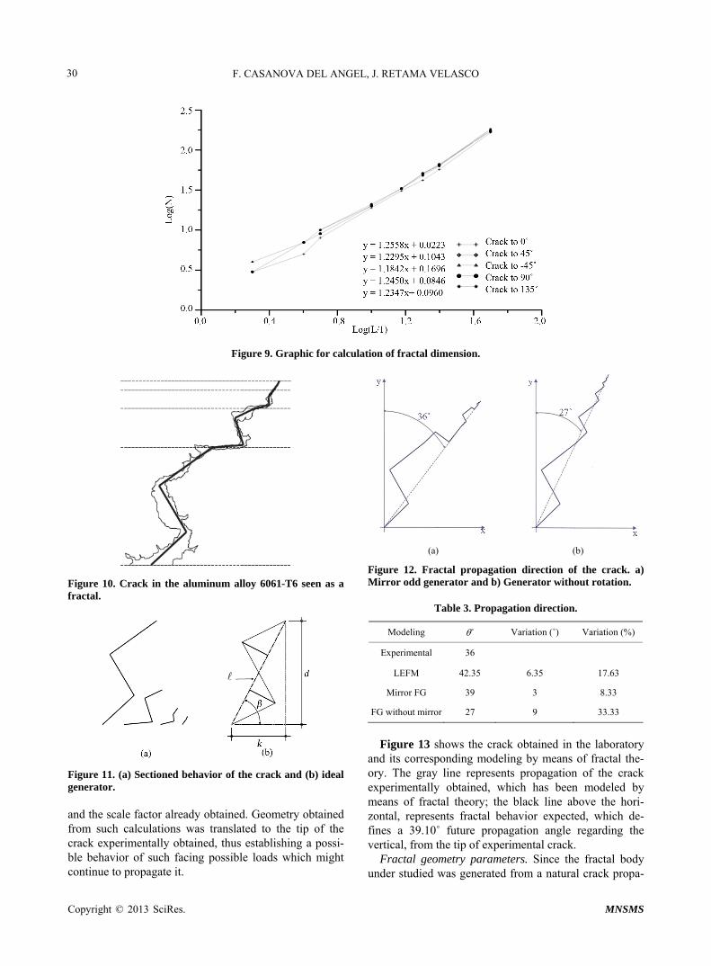
3.4. Computation of the Fractal Dimension
In order to calculate the fractal dimension of crack gen- erated, the box counting method applied in a graphical manner was used. The original crack was rotated at vari- ous degrees in order to determine in a reliable manner the fractal dimension D, since such must be the same in every case. The process carried out in order to determine D was to choose a picture, Figure 8, which outline might be vectorized. Once the outline was draw, it was delim- ited in a rectangle, the required meshing for calculation of fractal dimension were built, calculation s were carried out and the results were graphed.
In order to obtain the fractal dimension of every graphed curve, a trend line was calculated, extrapolated backwards and its equation was calculated, obtaining its corresponding slope 11 and 12. This is the fractal dimension of the fracture and Figure 9 shows such graphics. In order to obtain final dimension D, an aver- age of dimensions of every of the four rotations applied
Figure 7. Fractal behavior of the crack.
Figure 8. Propagation direction of factures obtained in the laboratory.
on the fractal curve was calculated, concluding that frac- tal dimension for a crack in Al-6061-T6 is:
0 45 90 135 1.24354
D D D DD
Therefore, fractal dimension of cracks or fractures in Al 6061-T6 is 1.2435 ± 0.0085. This value of fractal di- mension is used to relate FM to FG in determining the critical stress intensity factor for Modes I and II from FG theory, using the fracture dimension.
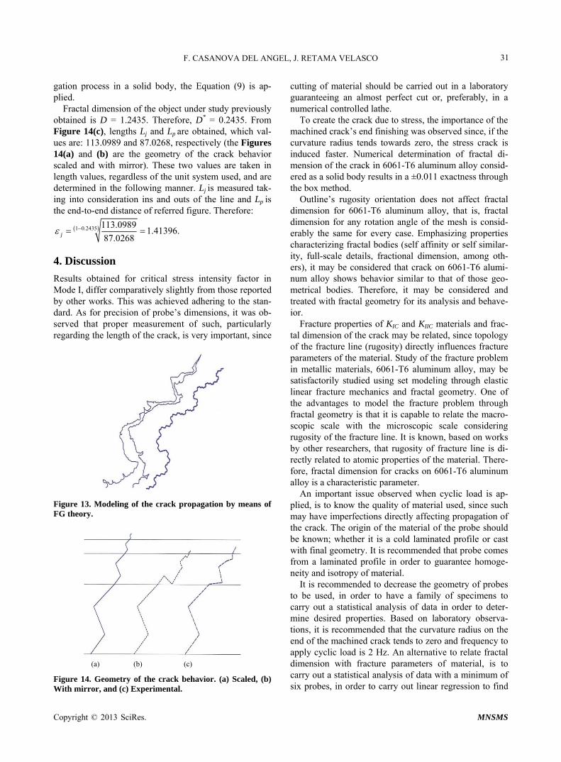
Figure 10 shows that the crack in the aluminum has the auto-affinity property characterizing fractal bodies generated by means of a natural propagation process, and there is a pattern repeating itself throughout it. From the basis middle point, straight lines have been drawn to the middle points of every fractioned curve along its path, thus obtaining a fractioned curve denoted by means of a thick gray line. When identifying a change on its path, horizontal lines have been drawn. This sectioned behave- ior has been manifested up to four times all along its path, Figure 11(a), shown affinity along its path. The best delineated line has been defined as curve generator and its ideal form is shown in Figure 11(b).
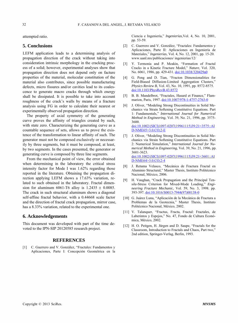
3.5. Direction of Fractal Propagation of the Crack
Propagation direction of the crack was numerically de- termined by means of FM theory, considering that such is propagated perpendicular to maximum main stress I. Line of trend of propagation direction of the crack was carried out based on roughness compensation philosophy on both sides of such.
Fractal propagation direction of the crack has been de- termined under the following two considerations: Case in which a mirror effect is applied on even itera-
tions of the generator, thus determining a = 39˚ pro- pagation angle regarding the vertical, Figure 12(a); and
Case where the mirror effect is not applied on even iterations, thus obtaining a = 27˚ propagation angle regarding the vertical, Figure 12(b).
With the first conditions a better modeling of crack’s behavior is obtained, since experimentally a = 36˚ was obtained.
Table 3 shows results obtained by modeling propaga- tion direction of the crack by means of FM and FG. In like manner, it is observed that, when modeling propaga- tion direction of the crack by means of mirror FG case, a good approach to real behavior is obtained, as well as its corresponding modeling by means of FM. In accordance with crack’s modeling, it is possible to predict its behav- ior, as well as its possible propagation direction, using an iterative auto-similarity process, feature of fractals, in accordance with the generation pattern in Figure 12(a)
Copyright © 2013 SciRes. MNSMS
F. CASANOVA DEL ANGEL, J. RETAMA VELASCO
Copyright © 2013 SciRes. MNSMS
30
Figure 9. Graphic for calculation of fractal dimension.
(a) (b)
Figure 12. Fractal propagation direction of the crack. a) Mirror odd generator and b) Generator without rotation. Figure 10. Crack in the aluminum alloy 6061-T6 seen as a
fractal. Table 3. Propagation direction.
Modeling ˚ Variation (˚) Variation (%)
Experimental 36
LEFM 42.35 6.35 17.63
Mirror FG 39 3 8.33
FG without mirror 27 9 33.33
Figure 13 shows the crack obtained in the laboratory
and its corresponding modeling by means of fractal the- ory. The gray line represents propagation of the crack experimentally obtained, which has been modeled by means of fractal theory; the black line above the hori- zontal, represents fractal behavior expected, which de- fines a 39.10˚ future propagation angle regarding the vertical, from the tip of experimental crack.
Figure 11. (a) Sectioned behavior of the crack and (b) ideal generator. and the scale factor already obtained. Geometry obtained from such calculations was translated to the tip of the crack experimentally obtained, thus establishing a possi- ble behavior of such facing possible loads which might continue to propagate it.
Fractal geometry parameters. Since the fractal body under studied was generated from a natural crack propa-
F. CASANOVA DEL ANGEL, J. RETAMA VELASCO 31
gation process in a solid body, the Equation (9) is ap- plied.
Fractal dimension of the object under study previously obtained is D = 1.2435. Therefore, D* = 0.2435. From Figure 14(c), lengths Lj and Lp are obtained, which val- ues are: 113.0989 and 87.0268, respectively (the Figures 14(a) and (b) are the geometry of the crack behavior scaled and with mirror). These two values are taken in length values, regardless of the unit system used, and are determined in the following manner. Lj is measured tak- ing into consideration ins and outs of the line and Lp is the end-to-end distance of referred figure. Therefore:
1 0.2435 113.09891.41396.
87.0268j
4. Discussion
Results obtained for critical stress intensity factor in Mode I, differ comparatively slightly from those reported by other works. This was achieved adhering to the stan- dard. As for precision of probe’s dimensions, it was ob- served that proper measurement of such, particularly regarding the length of the crack, is very important, since
Figure 13. Modeling of the crack propagation by means of FG theory.
(a) (b) (c)
Figure 14. Geometry of the crack behavior. (a) Scaled, (b) With mirror, and (c) Experimental.
cutting of material should be carried out in a laboratory guaranteeing an almost perfect cut or, preferably, in a numerical controlled lathe.
To create the crack due to stress, the importance of the machined crack’s end finishing was observed since, if the curvature radius tends towards zero, the stress crack is induced faster. Numerical determination of fractal di- mension of the crack in 6061-T6 aluminum alloy consid- ered as a solid body results in a ±0.011 exactness through the box method.
Outline’s rugosity orientation does not affect fractal dimension for 6061-T6 aluminum alloy, that is, fractal dimension for any rotation angle of the mesh is consid- erably the same for every case. Emphasizing properties characterizing fractal bodies (self affinity or self similar- ity, full-scale details, fractional dimension, among oth- ers), it may be considered that crack on 6061-T6 alumi- num alloy shows behavior similar to that of those geo- metrical bodies. Therefore, it may be considered and treated with fractal geometry for its analysis and behave- ior.
Fracture properties of KIC and KIIC materials and frac- tal dimension of the crack may be related, since topology of the fracture line (rugosity) directly influences fracture parameters of the material. Study of the fracture problem in metallic materials, 6061-T6 aluminum alloy, may be satisfactorily studied using set modeling through elastic linear fracture mechanics and fractal geometry. One of the advantages to model the fracture problem through fractal geometry is that it is capable to relate the macro- scopic scale with the microscopic scale considering rugosity of the fracture line. It is known, based on works by other researchers, that rugosity of fracture line is di- rectly related to atomic properties of the material. There- fore, fractal dimension for cracks on 6061-T6 aluminum alloy is a characteristic parameter.
An important issue observed when cyclic load is ap- plied, is to know the quality of material used, since such may have imperfections directly affecting propagation of the crack. The origin of the material of the probe should be known; whether it is a cold laminated profile or cast with final geometry. It is recommended that probe comes from a laminated profile in order to guarantee homoge- neity and isotropy of material.
It is recommended to decrease the geometry of probes to be used, in order to have a family of specimens to carry out a statistical analysis of data in order to deter- mine desired properties. Based on laboratory observa- tions, it is recommended that the curvature radius on the end of the machined crack tends to zero and frequency to apply cyclic load is 2 Hz. An alternative to relate fractal dimension with fracture parameters of material, is to carry out a statistical analysis of data with a minimum of six probes, in order to carry out linear regression to find
Copyright © 2013 SciRes. MNSMS
F. CASANOVA DEL ANGEL, J. RETAMA VELASCO
Copyright © 2013 SciRes. MNSMS
32
attempted ratio.
5. Conclusions
LEFM application leads to a determining analysis of propagation direction of the crack without taking into consideration intrinsic morphology in the cracking proc- ess of a solid; however, experimental analyses show that propagation direction does not depend only on facture properties of the material, molecular constitution of the material also contributes, since possible manufacturing defects, micro fissures and/or cavities lead to its coales- cence to generate macro cracks through which energy shall be dissipated. It is possible to take into account roughness of the crack’s walls by means of a fracture analysis using FG in order to calculate their nearest or experimentally observed propagation direction.
The property of axial symmetry of the generating curve proves the affinity of triangles created by such, with state zero. Characterizing the generating curve as a countable sequence of sets, allows us to prove the exis- tence of the transformation to linear affinity of such. The generator must not be composed exclusively or necessar- ily by three segments, but it must be composed, at least, by two segments. In the cases presented, the generator or generating curve is composed by three line segments.
From the mechanical point of view, the error obtained when determining in the laboratory the critical stress intensity factor for Mode I was 1.62% regarding those reported in the literature. Obtaining the propagation di- rection applying LEFM shows a 17.63% variation, re- lated to such obtained in the laboratory. Fractal dimen- sion for aluminum 6061-T6 alloy is 1.2435 0.0085. The crack in such structural aluminum shows a diagonal self-affine fractal behavior, with a 0.44668 scale factor and the direction of fractal crack propagation, mirror case, has a 8.33% variation, related to the experimental one.
6. Acknowledgements
This document was developed with part of the time de- voted to the IPN-SIP 20120585 research project.
REFERENCES [1] C. Guerrero and V. González, “Fractales: Fundamentos y
Aplicaciones, Parte I: Concepción Geométrica en la
Ciencia e Ingeniería,” Ingenierías,Vol. 4, No. 10, 2001, pp. 53-59.
[2] C. Guerrero and V. González, “Fractales: Fundamentos y Aplicaciones, Parte II: Aplicaciones en Ingeniería de Materiales,” Ingenierías, Vol. 4, No. 12, 2001, pp. 15-20. www.uanl.mx/publicaciones/ ingenierias/12/
[3] Y. Termonia and P. Meakin, “Formation of Fractal Cracks in a Kinetic Fracture Model,” Nature, Vol. 320, No. 6061, 1986, pp. 429-431. doi:10.1038/320429a0
[4] G. Peng and D. Tian, “Fracton Dimensionalities for Field-Biased Diffusion-Limited Aggregation Clusters,” Physics Review B, Vol. 43, No. 10, 1991, pp. 8572-8575. doi:10.1103/PhysRevB.43.8572
[5] B. B. Mandelbrot, “Fractales, Hasard et Finance,” Flam- marion, Paris, 1997. doi:10.1007/978-1-4757-2763-0
[6] J. Oliver, “Modeling Strong Discontinuities in Solid Me-chanics via Strain Softening Constitutive Equations. Part 1: Fundamentals,” International Journal for Numerical Method in Engineering, Vol. 39, No. 21, 1996, pp. 3575- 3600. doi:10.1002/(SICI)1097-0207(19961115)39:21<3575::AID-NME65>3.0.CO;2-E
[7] J. Oliver, “Modeling Strong Discontinuities in Solid Me- chanics via Strain Softening Constitutive Equations. Part 2: Numerical Simulation,” International Journal for Nu- merical Method in Engineering, Vol. 39, No. 21, 1996, pp. 3601-3623. doi:10.1002/(SICI)1097-0207(19961115)39:21<3601::AID-NME64>3.0.CO;2-4
[8] J. Retama Velasco, “Mecánica de Fractura Fractal en Aluminio Structural,” Master Thesis, Instituto Politécnico Nacional, México, 2006.
[9] H. Vaughan, “Crack Propagation and the Principal Ten- sile-Stress Criterion for Mixed-Mode Loading,” Engi- neering Fracture Mechanic, Vol. 59, No. 3, 1998. pp. 393-397. doi:10.1016/S0013-7944(97)00138-0
[10] G. Juárez Luna, “Aplicación de la Mecánica de Fractura a Problemas de la Geotecnia,” Master Thesis, Instituto Politécnico Nacional, México, 2002.
[11] V. Talanquer, “Fractus, Fracta, Fractal: Fractales, de Laberintos y Espejos,” No. 47, Fondo de Cultura Econó- mica, México, 2002.
[12] H. O. Peitgen, H. Jürgen and D. Saupe, “Fractals for the Classroom, Introduction to Fractals and Chaos, Part two,” 2nd edition, Springer-Verlag, Berlin, 1993.


