Embed Size (px)
Citation preview
In Proceedings of IIW International Congress “Welding and Joining Technologies for a Sustainable Development and Environment” The 1st South-East European
Welding Congress 24–26 May 2006, Timisoara, Romania, (2006), pp. 412-421
FILLER MATERIAL CHOICE FOR STOP VALVE REPAIR WELDING
Sijacki Zeravcic V. 1, Bakic G. 1, Djukic M.1, Andjelic B. 2, Rajicic B. 1 ABSTRACT Filler material choice for repair welding of stop valve spindle of thermal power plant by-pass pipeline was presented in this paper. Repair welding of the stop valve spindle was necessary because of plant operating problems due to very frequent localized damage appearance in the form of erosive wear on it. For this purpose it was necessary to choice appropriate filler material with high wear resistance characteristic. Experimental investigation and testing (hardness measurement, chemical composition analysis and microstructural investigation) of prepared specimens after welding simulation with different kind of filler material was performed. On the basis of obtained results it was recommended procedure for application of the filler material with generally preferable characteristic. KEYWORDS Repair welding, Weld defect, Stellite, Microstructure, Valve AUTHOR DETAILS 1Faculty of Mechanical Engineering, University of Belgrade, Kraljice Marije 16, Belgrade, Serbia 2Technical Faculty Cacak, University of Kragujevac, Svetog Save 65, Cacak, Serbia
1
1. INTRODUCTION After some period of exploitation, the surface of many engineering components needs repairing in order to extend their service life and efficiency. In the chemical, petrochemical and pump industries, machine parts often operate in conditions where erosion and corrosion processes, acting together, are the main failure mechanisms. The deleterious synergistic effect of the erosion removes either corrosion product or the passive layer that is protecting the underlying surface. When a passive layer is removed, the time taken for it repassivisation is an important consideration in the assessment of wear rates. On stainless steels it was shown that higher amounts of key elements (chromium, molybdenum) can lead to faster repassivation during erosion impacts 1. It is well known that welding process, in the broadest sense of the word, is possible to perform using the filler metal, either similar to the parent metal or different in composition from the parent metal (so called: dissimilar metal welding). Dissimilar metal repair welding of machine part made of austenitic stainless steel are very often performed using different Ni-based alloys as a filler metal. However, in the last decade cobalt-based alloy filler metal, because of good wear properties, has a enlarge application. Various kinds of cobalt-based alloys called "Stellite" have been used in fields requiring high heat and corrosion resistance and high wear strength, such as the nuclear, aerospace and gas-turbine industries [2]. The conventional Co-based alloys can be categorized into three types, namely, wear resistant alloys, high temperature alloys and corrosion resistant alloys. The wear resistant alloys, such as Stellite 6, are essentially Co Cr W C quaternaries, with Cr providing strength and corrosion resistance to the Co-rich solid solution, as well as functioning as the main carbide former during alloy solidification. [3]. The carbon contents of contemporary Stellite alloys vary from 0.1 to 3.2%. In cobalt-based alloys, the key element chromium is added in the range of 20–30 wt.% to improve corrosion resistance and impart some measure of solid-solution strengthening [4]. The aim of this work was the choice of filler material for the purpose of repair welding of stop valve spindle of thermal power plant by-pass pipeline mainly on the basis of microstructural investigation and hardness measurement results. 2. GENERAL DATA During operation of the low pressure stop valve, significant erosion damaging on the valve spindle in the vicinity of the valve plate is taking place, Figs. 1 and 2. Since this kind of damage started to appear very often, it became necessary not only to protect this valve area but also to increase the erosion resistance of spindle surface layer. As the safety regulations do not permit operation of the stop valve with damages and reduced cross section of the spindle, it is required to either replace or repair these components before the plant is put back into operation. Because the damage of spindle surface layer appeared very frequently almost at the same location, there was opinion that the best solution for further exploitation was the replacement of spindle which was repair a several time in previous periods by filler metal UTP 68HH. But there were many practical limitations for exercising this option. Because of insuperable limitations decision was made to perform an experiment concerning application of different repair welding of damaged zone with different filler metal [5]. The damaged area appeared in the case - spindle contact zone with dimension: 11-13 mm in depth and 110 mm in length. The spindle made from austenitic stainless steel X8CrNiMoVNb 1613 has a diameter in damage area app. 89 mm. Because the previously applied technics (which is consider in this paper as "I approach") for renewal of spindle surface obviously were unsatisfactory, some investigation were carried out concerning the selection of filler material, characteristic structure and hardness as the indicator of
2
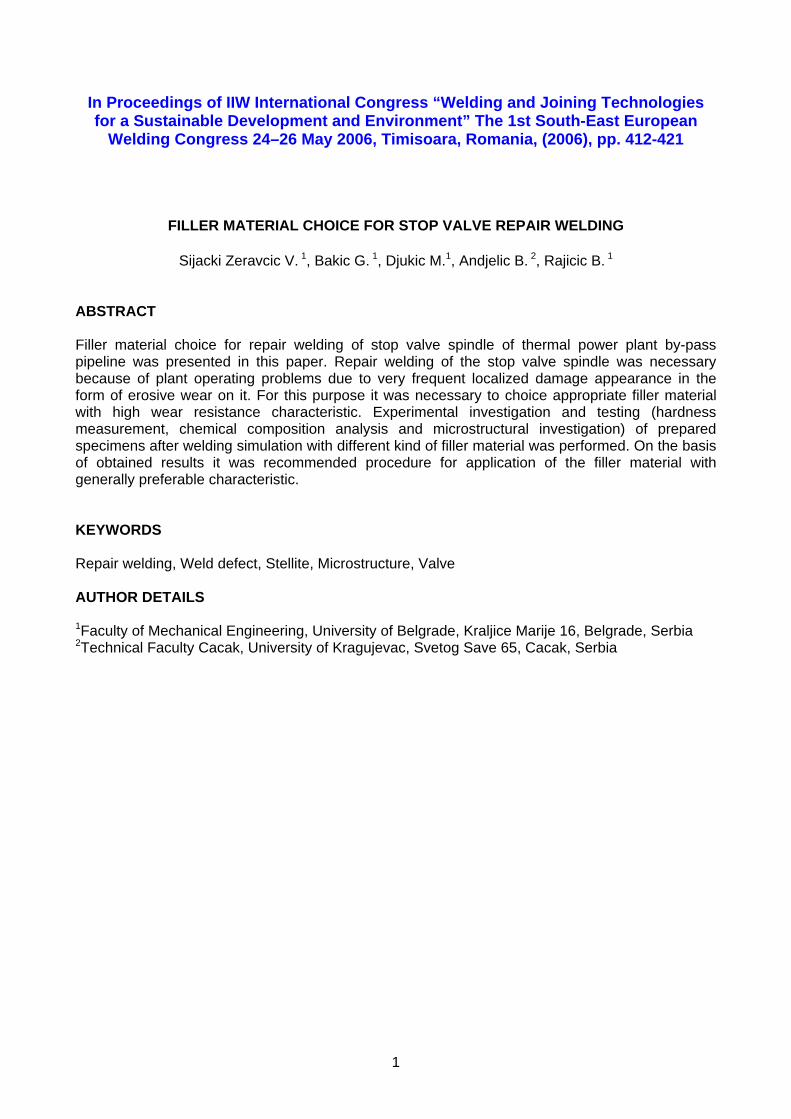
erossion resistance. The focus of this work is to assess which kind of filler material among investigated is the best for this purpose.
Figure 1 – View of low pressure stop valve part Damaged area is denoted by arrow
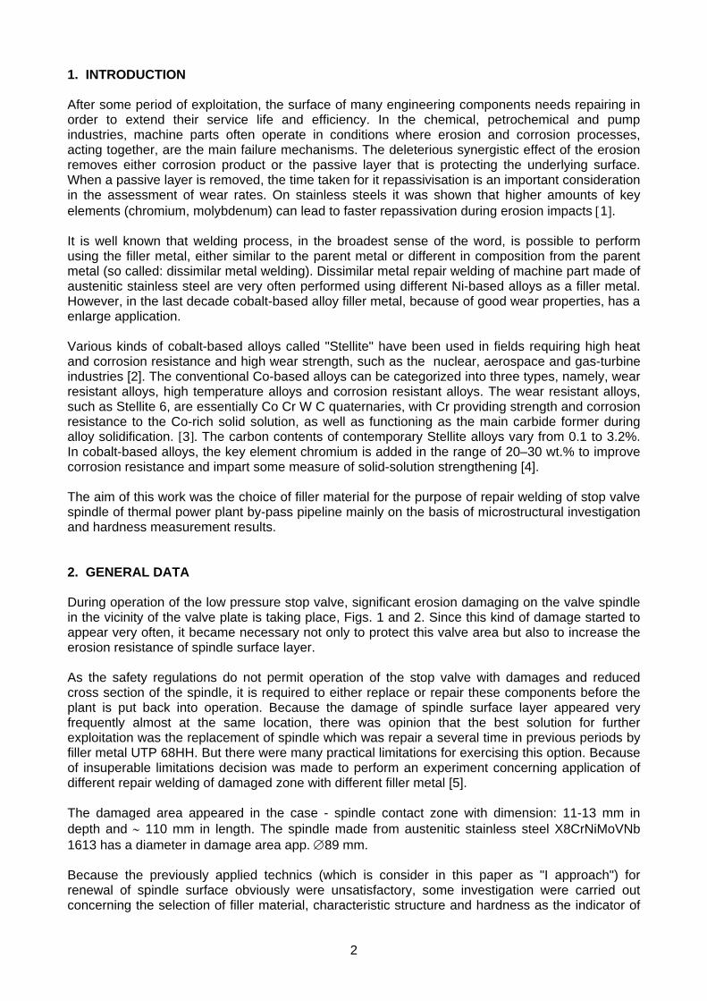
Figure 2 – Schematic view of damaged area location 3. EXPERIMENTAL DETAILS The first task for executing of the actual repair is the removal of the existing damage surface layer by careful grinding, and final fine grinding tools creating the groove. The groove was then subsequently built-up to their original shape by re-welding and machining. After removal of the damage zone Dye Penentrant Testing, (DPT), was carried out to ensure that any cracks did not appeared. After ensuring that the preparation is complete in all respect, repair welding was taken up. The repair welding was performed in situ in the thermal power plant. After repair welding and mashining, DPT was carried out to ensure that no crack is present. For comparative purposes repair welding on the same valve spindle, in three different locations, were performed with different techniques and filler material, as follows:
I approach - Repair welding was carried out in two steps. As a first, several layer of filler material (shielded electrode of commercial mark UTP 068HH) was deposited circumferentially on the base material by MMAW technique in the aim of damaged area elimination; in the second step, the powder UTP 6H was deposited as a final layer by the treatment of hot metallization.
II approach - Repair welding was carried in two steps, too. Damaged area was filled with UTP 068HH shielded electrode, but over the last layer Stellite 6 was deposited by GTAW technique;
III approach - On the damaged parent material, Stellite 6 was directly deposited. Before repair welding (I and II approach), UTP 068HH shielded electrode was drained at 250oC during 2 hours. For all passes during welding shielded electrode of 2,5 x 300 mm was used.
3
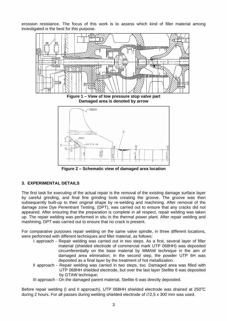
The view of valve spindle with repair weld positions and the scheme of sampling are shown on Fig. 3. Samples were taken in a two mutual normal direction. All samples were submitted to hardness measurement and microstructural investigations.
Figure 3 – Schematic view of sampling positions
1A (transverse)
1C (transverse) 1D (longitudinal)
3 (longitudinal)
1B (longitudinal) 3 (transverse)
2 (transverse)
2 (longitudinal)
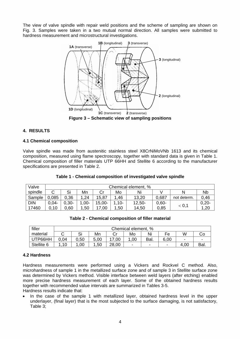
4. RESULTS 4.1 Chemical composition Valve spindle was made from austenitic stainless steel X8CrNiMoVNb 1613 and its chemical composition, measured using flame spectroscopy, together with standard data is given in Table 1. Chemical composition of filler materials UTP 66HH and Stellite 6 according to the manufacturer specifications are presented in Table 2.
Table 1 - Chemical composition of investigated valve spindle
Chemical element, % Valve spindle C Si Mn Cr Mo Ni V N Nb Sample 0,085 0,36 1,24 15,87 1,46 13,20 0,687 not determ. 0,46 DIN 17460
0,04-0,10
0,30-0,60
1,00-1,50
15,00-17,00
1,10-1,50
12,50-14,50
0,60-0,85 0,1
0,20-1,20
Table 2 - Chemical composition of filler material
Chemical element, % filler
material C Si Mn Cr Mo Ni Fe W Co UTP66HH 0,04 0,50 5,00 17,00 1,00 Bal. 6,00 - - Stellite 6 1,10 1,00 1,50 28,00 - - - 4,00 Bal.
4.2 Hardness Hardness measurements were performed using a Vickers and Rockvel C method. Also, microhardness of sample 1 in the metallized surface zone and of sample 3 in Stellite surface zone was determined by Vickers method. Visible interface between weld layers (after etching) enabled more precise hardness measurement of each layer. Some of the obtained hardness results together with recommended value intervals are summarized in Tables 3-5. Hardness results indicate that: In the case of the sample 1 with metallized layer, obtained hardness level in the upper
underlayer, (final layer) that is the most subjected to the surface damaging, is not satisfactory, Table 3;
4
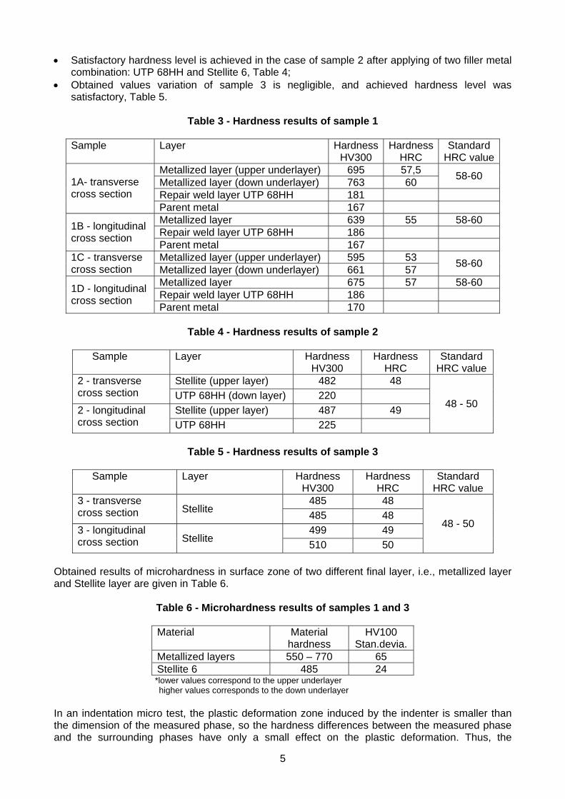
Satisfactory hardness level is achieved in the case of sample 2 after applying of two filler metal combination: UTP 68HH and Stellite 6, Table 4;
Obtained values variation of sample 3 is negligible, and achieved hardness level was satisfactory, Table 5.
Table 3 - Hardness results of sample 1
Sample Layer Hardness
HV300 Hardness
HRC Standard
HRC valueMetallized layer (upper underlayer) 695 57,5 Metallized layer (down underlayer) 763 60
58-60
Repair weld layer UTP 68HH 181
1A- transverse cross section
Parent metal 167 Metallized layer 639 55 58-60 Repair weld layer UTP 68HH 186
1B - longitudinal cross section
Parent metal 167 Metallized layer (upper underlayer) 595 53 1C - transverse
cross section Metallized layer (down underlayer) 661 57 58-60
Metallized layer 675 57 58-60 Repair weld layer UTP 68HH 186
1D - longitudinal cross section
Parent metal 170
Table 4 - Hardness results of sample 2
Sample Layer Hardness HV300
Hardness HRC
Standard HRC value
Stellite (upper layer) 482 48 2 - transverse cross section UTP 68HH (down layer) 220
Stellite (upper layer) 487 49 2 - longitudinal cross section UTP 68HH 225
48 - 50
Table 5 - Hardness results of sample 3
Sample Layer Hardness
HV300 Hardness
HRC Standard
HRC value 485 48 3 - transverse
cross section Stellite 485 48
499 49 3 - longitudinal cross section Stellite
510 50
48 - 50
Obtained results of microhardness in surface zone of two different final layer, i.e., metallized layer and Stellite layer are given in Table 6.
Table 6 - Microhardness results of samples 1 and 3
Material Material hardness
HV100 Stan.devia.
Metallized layers 550 – 770 65 Stellite 6 485 24 *lower values correspond to the upper underlayer higher values corresponds to the down underlayer
In an indentation micro test, the plastic deformation zone induced by the indenter is smaller than the dimension of the measured phase, so the hardness differences between the measured phase and the surrounding phases have only a small effect on the plastic deformation. Thus, the
5
measured hardness value can reflect the real hardness of the phase. From the results presented in Table 6 it can be concluded that the Stellite surface zone has a lower but relatively uniform level of hardness values in comparison with data of metallized surface zone. It can be assumed, on the basis of the obtained hardness results in metallized layers, that the cracks reveled during the microscopic investigation were initiated and propagated through the metallized layer not only because of poor quality of performed metallization but also because of great difference in hardness in the narrow zone. Therefore, the first criterion for elimination of particular approach of repair welding was the hardness level and its variation, because the very high hardness level [6] does not mean at the same time the highest erosion resistance.
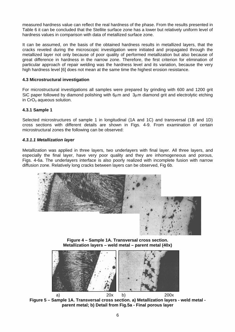
4.3 Microstructural investigation For microstructural investigations all samples were prepared by grinding with 600 and 1200 grit SiC paper followed by diamond polishing with 6m and 3m diamond grit and electrolytic etching in CrO3 aqueous solution. 4.3.1 Sample 1 Selected microstructures of sample 1 in longitudinal (1A and 1C) and transversal (1B and 1D) cross sections with different details are shown in Figs. 4-9. From examination of certain microstructural zones the following can be observed: 4.3.1.1 Metallization layer Metallization was applied in three layers, two underlayers with final layer. All three layers, and especially the final layer, have very poor quality and they are inhomogeneous and porous, Figs. 4-6a. The underlayers interface is also poorly realized with incomplete fusion with narrow diffusion zone. Relatively long cracks between layers can be observed, Fig 6b.
Figure 4 – Sample 1A. Transversal cross section. Metallization layers – weld metal – parent metal (40x)
a) 20x b) 200x Figure 5 – Sample 1A. Transversal cross section. a) Metallization layers - weld metal -
parent metal; b) Detail from Fig.5a - Final porous layer
6
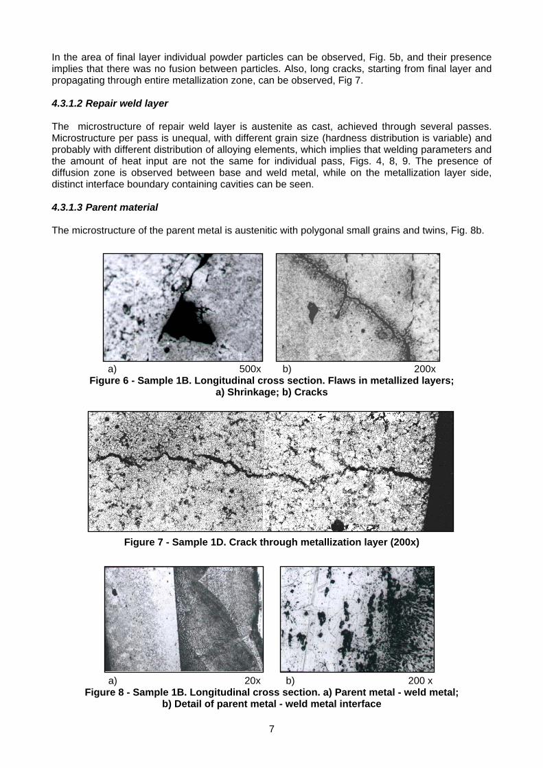
In the area of final layer individual powder particles can be observed, Fig. 5b, and their presence implies that there was no fusion between particles. Also, long cracks, starting from final layer and propagating through entire metallization zone, can be observed, Fig 7. 4.3.1.2 Repair weld layer The microstructure of repair weld layer is austenite as cast, achieved through several passes. Microstructure per pass is unequal, with different grain size (hardness distribution is variable) and probably with different distribution of alloying elements, which implies that welding parameters and the amount of heat input are not the same for individual pass, Figs. 4, 8, 9. The presence of diffusion zone is observed between base and weld metal, while on the metallization layer side, distinct interface boundary containing cavities can be seen. 4.3.1.3 Parent material The microstructure of the parent metal is austenitic with polygonal small grains and twins, Fig. 8b.
a) 500x b) 200x Figure 6 - Sample 1B. Longitudinal cross section. Flaws in metallized layers;
a) Shrinkage; b) Cracks
Figure 7 - Sample 1D. Crack through metallization layer (200x)
a) 20x b) 200 x Figure 8 - Sample 1B. Longitudinal cross section. a) Parent metal - weld metal;
b) Detail of parent metal - weld metal interface
7
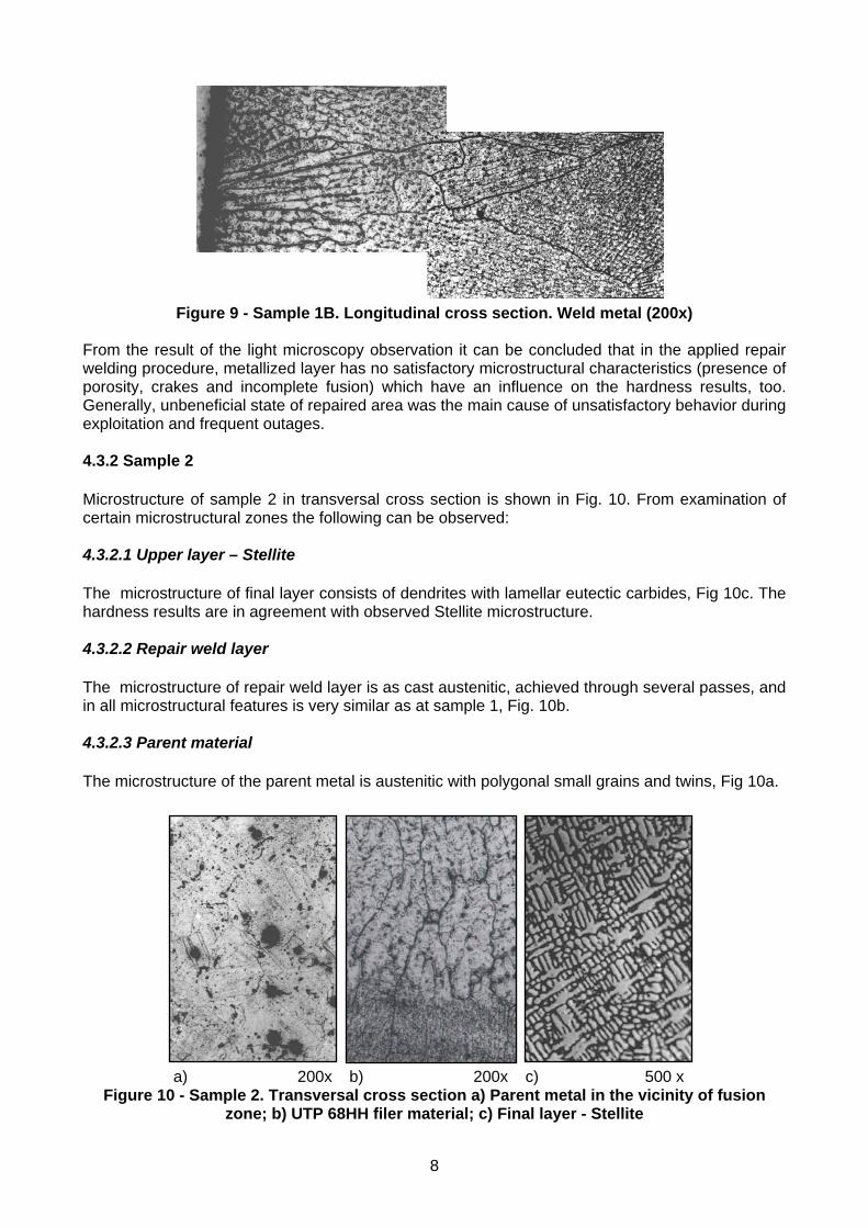
Figure 9 - Sample 1B. Longitudinal cross section. Weld metal (200x) From the result of the light microscopy observation it can be concluded that in the applied repair welding procedure, metallized layer has no satisfactory microstructural characteristics (presence of porosity, crakes and incomplete fusion) which have an influence on the hardness results, too. Generally, unbeneficial state of repaired area was the main cause of unsatisfactory behavior during exploitation and frequent outages. 4.3.2 Sample 2 Microstructure of sample 2 in transversal cross section is shown in Fig. 10. From examination of certain microstructural zones the following can be observed: 4.3.2.1 Upper layer – Stellite The microstructure of final layer consists of dendrites with lamellar eutectic carbides, Fig 10c. The hardness results are in agreement with observed Stellite microstructure. 4.3.2.2 Repair weld layer The microstructure of repair weld layer is as cast austenitic, achieved through several passes, and in all microstructural features is very similar as at sample 1, Fig. 10b. 4.3.2.3 Parent material The microstructure of the parent metal is austenitic with polygonal small grains and twins, Fig 10a.
a) 200x b) 200x c) 500 x Figure 10 - Sample 2. Transversal cross section a) Parent metal in the vicinity of fusion
zone; b) UTP 68HH filer material; c) Final layer - Stellite
8
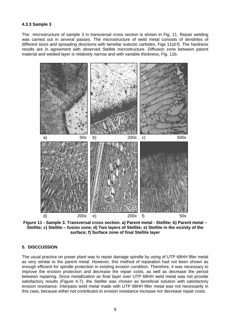
4.3.3 Sample 3 The microstructure of sample 3 in transversal cross section is shown in Fig. 11. Repair welding was carried out in several passes. The microstructure of weld metal consists of dendrites of different sizes and spreading directions with lamellar eutectic carbides, Figs 11(d-f). The hardness results are in agreement with observed Stellite microstructure. Diffusion zone between parent material and welded layer is relatively narrow and with variable thickness, Fig. 11b.
a) 50x b) 200x c) 500x
d) 200x e) 200x f) 50x
Figure 11 - Sample 3. Transversal cross section. a) Parent metal - Stellite; b) Parent metal – Stellite; c) Stellite – fusion zone; d) Two layers of Stellite; e) Stellite in the vicinity of the
surface; f) Surface zone of final Stellite layer 5. DISCCUSSION The usual practice on power plant was to repair damage spindle by using of UTP 68HH filler metal as very similar to the parent metal. However, this method of reparation had not been shown as enough efficient for spindle protection in existing erosion condition. Therefore, it was necessary to improve the erosion protection and decrease the repair costs, as well as decrease the period between repairing. Since metallization as final layer over UTP 68HH weld metal was not provide satisfactory results (Figure 4-7), the Stellite was chosen as beneficial solution with satisfactory erosion resistance. Interpass weld metal made with UTP 68HH filler metal was not necessarily in this case, because either not contributes to erosion resistance increase nor decrease repair costs.
9
It is well known [7] that Stellite overlayer were advantageous for use in erosion-corrosion environments and can even function at relatively high temperatures and it is reported that this is because wear resistance is promoted by the harder complex carbides of chromium and tungsten, while corrosion resistance is enhanced by the presence of cobalt in the matrix. Because of their good quality, studies on the production of new kinds of cobalt-based alloys are still being carried out extensively. Cr and Co are inevitably present in Stellite hardfacing alloys and they form the needed "Cr carbides" for wear resistance, which are typically in the form of M7C3 and M23C6 carbides [7,8] and their relative amounts and matrix composition depend on the Cr, W and C levels. Large amount of carbides, high hardness and high Young's modulus are important to the wear resistance of Stellite alloys. Alloys with carbon contents less than about 2% exhibit a hypo-eutectic microstructure while alloys with a carbon content greater than about 2% possess a hyper-eutectic microstructure. The first phase to form during Stellite 6 cooling from the liquid state consists of cobalt-rich dendrites with a face-centered cubic (FCC) crystal structure [8] with carbide phases dispersed in inter-dendritic regions in the cobalt-rich matrix (Figure 11c). The remaining liquid eventually solidifies by a eutectic reaction into an interdendritic, intimate lamellar mixture of the FCC phase and M7C3- eutectic carbides. Most of the W remains in solid solution and therefore it provide additional solid solution strength. The excellent wear resistance of these alloys is attributed to the high volume carbides and the unusual deformation characteristics imparted by Co-rich matrix. This strain hardening of the matrix by alloy addition is explained through the change in the stacking fault energy (SFE) [8]. Most cobalt-based alloys possess outstanding cavitation resistance compared to stainless steels which has been shown to be independent of the carbon content (hence hardness), and has been attributed to crystallographic transformation [9], under stress, from the face centered cubic (FCC) to hexagonal close packed (HCP) structure by twinning. Cavitation resistance of a number of Stellite alloys, cemented carbides and surface-treated alloy steels studied in [10] are shown that in Stellite alloys the cobalt-rich solid solution, incorporating elements such as chromium, tungsten and molybdenum is highly resistant to erosion due to a rapid increase in the work-hardening rate and the strain to fracture which are caused by deformation twinning. For pure metals, some correlation between erosion rate and hardness has been shown [8], although, several other observations have shown that the erosion rate is not dependent on material hardness [11,12]. Erosion resistance of Stellite cannot always be predicted by macro hardness of a material [13]. Taking into account all emphasized beneficial of Stellite, including procedure incomplexity in comparison with two other applied repair welding techniques, it was clear that the Stellite overlay application directly on parent metal was optimal choice. The confirmation of correctness of Stellite choice was also significantly prolonged period of reliable and safety operation of repaired stop valve spindle. 6. CONCLUSIONS On the bases of the obtained hardness and microstructural results, the III approach of damaged spindle repair welding only with Stellite as filler metal was recommended. The reason for this decision was obvious because of:
uniform hardness distribution in comparison with hardness distribution obtained in I and II approach of repair welding
relatively uniform microstructure without flaws and welding defects compared with obtained in I approach of repair welding the least fusion zone width was obtained in III approach (0.006-0.010 mm) compared with
width (0.018-0.050 mm) obtained in the I approach, i.e. II approach (0.01-0.025 mm)
10
11
parameters of techno-economical analyses were more beneficial in the III approach of repair welding, compared with the II one with two different techniques and two different filler material, and with longer period for process.
REFERENCES [1] Hu X., Neville A.: An examination of the electrochemical characteristics of two stainless
steels (UNS S32654 and UNS S31603) under liquid-solid impingement, Wear 256 (2004) 537-544.
[2] Crook P.: Properties and Selection: Nonferrous Alloys and Special-Purpose Materials, vol. 2, edn. 10, Metals Handbook, ASM International, 1993, 446 p.
[3] Yao M.X., et.al: Metallographic study and wear resistance of a high – C wrought Co-based alloy Stellite 706K, Mat. Sci. and Eng. A 407 (2005) 291-298
[4] Yao M.X., et.al: Wear, corrosion and cracking resistance of some W – or Mo- containing Stellite hardfacing alloys, Mat. Sci. and Eng. A 407 (2005) 234-244.
[5] Sijacki V., et. al: Report 12-11-12.04/1996, Fac. of Mech. Eng. Belgrade, Serbia [6] Meuronen V., Wear, 240 (2000) 164-167. [7] Wong-Kian M., Cornish L.A., Van Bennekom A.: Comparison of erosion-corrosion behaviour
of Hot Iso-Statically pressed and welded Stellite coatings, J. South Afr. Inst. Mining Metall. Nov/Dec (1995) 319-335.
[8] Finnie I., Wolak J., Kabil Y.: Erosion of metals by solid particles, J. Mater. 2 (1967) 682-700. [9] P. Crook, The effect of dilution upon the corrosion and wear properties of cobalt-based weld
overlays, Corr. Sci. 35 (1993) 647-653. [10] Heathcock C.J., Ball A.: Cavitations erosion of cobalt-based Stellite alloys, cemented
carbides and surface-treated low alloy steels, Wear 74 (1982) 11-26. [11] Levy A., Jahanmir S.: The effect of microstructure of ductile alloys on solid particle erosion
behavior, in: K. Natesan (Ed.), Corrosion-Erosion Behavior of Materials, The Metallurgical Society of AIME, Warrendale, PA, 1980, pp. 177-189.
[12] Levin B.F., Dupont J.N., Marder A.R.: Weld overlay coatings for erosion control, Wear 181-183 (1995) 810-820.
[13] Miller A.E., Coyle J.P.: An erosion test sensitive to metallurgical microstructure, Wear 47 (1978) 211-214.