Embed Size (px)
Citation preview

www.welding-and-cutting.info Technical journal for welding and allied processes
Wel
ding
and
Cut
ting
01/
2022
Friction stir welding of steel for shipbuilding and marine applications
Weld overlay cladding offers enhanced performance
Simulation of laser beam and gas-shielded metal arc welding
Issue
012022
iWave300i / 400i / 500i
Multiprozess
Pro SystemWIG System
190i / 230i / 300i /
400i / 500i
Mehr Informationen
finden Sie unter:
www.fronius.com/iwave
Full freedom to unleash your welding potential.
Titelseite_Welding_Cutting_Fronius_iWave_210x185mm.indd 1 14.02.22 11:15

JOINING PLASTICSFÜGEN VON KUNSTSTOFFENwww.joining-plastics.info
Be fully informed with the JOINING PLASTICS NEWSLETTER:
• Four times a year• News hot off the press• Latest research developments• More about upcoming fairs and events
Sign up at www.joining-plastics.info/newsletter
The NEWSLETTER of JOINING PLASTICS
DVS Media GmbH • Aachener Straße 172 • D-40223 DüsseldorfT +49 211 1591-0 • F +49 211 1591-150 • [email protected] • www.dvs-media.eu
Sign up
now!

3Welding and Cutting 21 (2022) No. 1
EDITORIAL
Uncertainty remainsAfter the Coronavirus pandemic severely restricted us for more
than two years, signs of improvement begin to show, especially since vaccinations can prevent severe cases of the disease. There are legitimate expectations that the pandemic will weaken with the spring months to come, as was the case before, and that lifting or possibly termination of protective measures will be decided. This raises the possibility that by the middle of the year at the latest, trade fairs will be held “normally” again, i.e. can be attended in person.
In the field of thermal spraying – a regularly addressed topic also in this journal – attention is turning to the ITSC – International Thermal Spray Conference and Exposition, which will take place in Vienna, Austria, from 4 to 6 May 2022 and offers trade visitors a comprehensive programme as well as up-to-date information on all aspects of surface treatment technologies (see page 38 in this issue).
As far as welding technology is concerned, one of the next inter-national highlights in Europe is the “EuroBlech” trade fair, which is scheduled for 25 to 28 October 2022 at the exhibition centre in Hanover and, in addition to its materials focus, will also place a dis-tinct emphasis on welding technology. This event will be covered accordingly in WELDING AND CUTTING.
However, recent political developments with the war in Ukraine and the worldwide reactions to it are fuelling a new and unfortu-nately all too justified uncertainty. To what extent this may affect not only the state of the economy and thus also future trade fair events, but also our entire life situation, is currently completely up in the air. We all sincerely hope for an end to the horrible warfare and a return to peaceful negotiations. Until then, much remains uncertain.
Dietmar RippegatherEditor-in-Chief
Photos: Mack Brooks Exhibitions
Photo: © vichie81 – stock.adobe.com

4 Welding and Cutting 21 (2022) No. 1
CONTENTS WELDING AND CUTTING 01/2022
Metallographic structure of a tube to header joint – etched with hydrofluoric acid (HF). 32
New data from ITU suggest “COVID connectivity boost”, but the world’s poorest being left far behind. (Picture: ITU) 9
Production is automated to the greatest possible extent and exclusively controlled from a control room. 14
News 6 What is required for a true digital trans-formation in materials science R&D?
8 EWF prepares personnel qualification for powder bed fusion processes
9 2.9 billion people worldwide still offline
10 Global exhibition industry: UFI announces themes for 2022 Awards
11 Climate failure and social crisis as top global risks 2022
12 Conferences and Exhibitions
From Companies 14 Industry 4.0: Dutch steelworker on a digital journey
17 “Tight weld-flatness tolerance” secures multiple sales of dual weld-head FSW machines
18 Diffusion welding: More variety in the production of tool inserts
19 Cloud-based CNC monitoring brought to the shop floor of an aerospace parts manufacturer
21 Laboratory at TU Braunschweig for resi-dual stress analysis successfully accre-dited
22 The right parts cleaning process ensures product quality and cost effectiveness
24 Oerlikon Metco: Enhancing the custo-mer experience through digitalisation
25 High-performance cold gas coating for wear protection and emission reduc-tion for brake discs
26 Short Messages
28 Products
Welding Practice 32 Analysis of brazing imperfections by
metallographic investigation / optical microscopy – Part 1
33 When and why truncate the tip of the electrode?
Events 38 A lot to discover at the ITSC in 2022 in Vienna
38 Call for abstracts: 24th IAS Steel Confe-rence in October in Rosario, Argentina
39 International trade fairs “wire” and “Tube” in Düsseldorf postponed to early summer 2022

5Welding and Cutting 21 (2022) No. 1
Sectional view of a coin specimen for measuring hydrogen tightness. (Source: ifs TU Braunschweig) 52
The ITSC 2022 in Vienna will offer a full spectrum of coating solutions. (Picture: DVS) 38
“μ-Habitat” product manufacture process framework. 43
Reports 40 Development of a micro-habitat hyper-baric welding system – Part 2
44 Friction stir welding of steel for ship-building and marine applications
48 Weld overlay cladding offers enhanced performance
Specialist Article 50 Flexible bonding of flexible hybrid plastic bipolar plates
Dennis Weiser, Elisabeth Stammen, Klaus Dilger, Sebastian Brokamp, Fabian Bergenthun, Jörg Karstedt, Peter Beckhaus
56 Increase in understanding of the welding process through simulation of laser beam and gas-shielded metal arc welding
Oleg Mokrov, Marek Simon, Rahul Sharma, Uwe Reisgen, Christoph Schöler, Markus Nießen, Wolfgang Schulz
National Pages 36 Information from the DVS – German Welding Society
63 Editorial Preview
64 Books
64 Imprint/Ad Index
Technical journal for welding and allied processes of the DVS – German Welding Society, Düsseldorf, and the Institut de Soudure, Paris
Produced in Collaboration between
www.welding-and-cutting.info Technical journal for welding and allied processes

6 Welding and Cutting 21 (2022) No. 1
NEWS
What is required for a true digital transformation in materials science research and development (R&D)?
Digital transformation is a buzzword in almost every sector; materials science and chemistry research and development (R&D) is certainly no exception. The pros-pects are, of course, very attractive, but the reality is far harder. The status of this transformation, the enabling solutions and those unresolved pain points are all exam-ined below.
The heart of this R&D transformation is the field of materials informatics; this is a data-centric approach to materials R&D that builds data infrastructures and lever-ages machine learning solutions. IDTechEx has released a new version of their leading report on the topic, “Materials Informatics 2022-2032” (www.IDTechEx.com/Materi-alInformatics), which provides a compre-hensive commercial overview of the field.
There are three main considerations to truly enable a digital transformation in materials science R&D:
◾ data entry and management, ◾ the physical or computation experi-
mental data and ◾ AI-driven screening and analysis.
Data entry and managementThis is the genesis of any digital transfor-
mation and shows quite how far chemistry
and materials science must go. Before you get anywhere, you need to have your data electronically available in suitable for-mats, even today the jump to electronic lab notebooks and overcoming data silos is not widely employed. There are plenty of solutions out there, but until this is tackled the transformation can only go far, as Sasha Novakovich, CEO of Alchemy Cloud, stated to IDTechEx:
“For years firms have lauded the benefits of Artificial Intelligence (AI) in material sci-ence: accelerated discovery, faster deriva-tive product development and streamlined material compatibility. The dirty secret you likely didn’t hear: none of these outcomes are possible with mismanaged, unstruc-tured data. If you bought into AI thinking that decades’ worth of stitched together Excel files were the magic wand, you’re likely on a longer – and more expensive – journey than required. From day 1, driven by our insight that better data quality yields better predictive accuracy, Alchemy has been building software solutions to opti-mise for AI-ready data. AI-ready, in the con-text of the lab, means data that is automat-ically validated, formatted, labeled based on your custom ontology and connected to other data in real-time without the need
for chemists to do anything other than their routine work.”
Many notable companies have made this change, most notably in Japan, with some even going back to get their extensive his-torical data in a usable format.
Internal data is an essential part of any companies IP, but there is also the ability to leverage external data sources within a digital approach to R&D. Public and private data repositories are increasingly common that vary from being highly specific to very broad. In addition, there are many consor-tia being established to pool knowledge and establish best practices even amongst traditional competitors. A prime example is the Materials Open Platform (MOP) which is a joint effort in establishing a polyole-fin database and involves data sharing between Mitsubishi Chemical, Sumitomo Chemical, Asahi Kasei, Mitsui Chemicals and with NIMS at its core.
Physical and/or computational experimental data
How the data is stored is important, but materials informatics is nothing with-out the data itself. One routine challenge is sparse, high-dimensional, biased and noisy data. Combinatorial chemistry, high
Summary of different Materials Informatics players. (Source: “Material Informatics 2022-2032”)

7Welding and Cutting 21 (2022) No. 1
throughput screening and general labora-tory automation has become much more common for physical experiments with numerous tailored instruments available. However, this is still not mature and in many cases still an overly manual process that results in scientists carrying out repeti-tive tasks rather than applying their domain expertise. There are still innovations aris-ing to tackle this solution, as shown by a spin-out from Northwestern University in the USA. Professor Chad Mirkin stated to IDTechEx that:
“In the race to bring AI to materials dis-covery, it is all about the size and quality of the datasets. Stoicheia, with its proprie-tary ‘Meglibrary’ technology (high-density chips that contain upwards of billions of positionally-encoded materials) and com-panion screening tools, is uniquely posi-tioned to mine and monetise the materials genome.”
Modifying the synthetic composition or process is essential but characterising and quality control also become key pieces of the puzzle that must not become a bot-tleneck. Computational chemistry and materials science has come a long way in the past decade and can provide key insights and data inputs to this data-centric approach. The challenge is the speed and degree of complexity that can be achieved with current computing technology, it is no surprise that chemistry is considered as one of the key applications for quantum computers. The modeling field continues to advance at pace, typified by the likes of OTI Lumionics who are initially applying their approach to advanced materials for OLED displays. Dr Michael Helander, President and CEO, stated to IDTechEx:
“The key bottleneck in materials informatics, regardless of the approach, algorithms or AI used, is access to large high-quality datasets, which is typically lacking in chemistry and materials science. Highly accurate simulations of chemical and materials properties are thus required to accelerate the digital transformation of these fields. Quantum computing tech-niques, which offer a path to high accuracy simulations in reasonable compute time, are therefore an essential element of future materials informatics roadmaps.”
AI-driven screening and analysisThe third piece of the equation is the one
that grabs the headlines, using artificial intelligence in R&D to drive the screening,
guide experimentation and enhance the analysis. Machine learning can be used in several ways, it can be looking to optimise many multi-variable properties, it can be in learning new structure-property rela-tionships or virtual screening for a desired candidate.
A wide range of bespoke supervised and unsupervised learning techniques have been deployed and although there are success stories, many are tackling the same challenging data problems. Two cen-tral themes arise across many approaches when handling challenging materials data-sets, understanding the uncertainty in your model and leveraging domain knowledge. There are numerous emerging companies offering materials informatics platforms, one of the most prominent is Citrine Infor-matics and their CEO, Greg Mulholland, stated to IDTechEx that:
“At Citrine, our approach to AI is tai-lor-made for materials and chemicals. We know that our customers don’t have enor-mous volumes of structured data like big tech companies, and often their data is sparse or incomplete, so we’ve developed a modeling approach that leverages uncer-tainty quantification for each prediction and allows our customers to incorporate their scientific knowledge into the mode-ling process in the form of analytical rela-tionships and materials-specific descriptor libraries. These capabilities, plus ‘no-code’ AI model creation and deployment, allow our customers to develop new materials up to 98% faster than traditional product development approaches.”
This problem is very different to the deep learning advancements many envis-age when considering autonomous cars or search engines. Certain examples do have access to reasonable datasets and more known inputs, but this is not the case for most of the real-world problems and is perceived as an insurmountable barrier. Intellegens is another company tackling this problem for numerous sectors, Steven Warde commented on this problem:
“To fully leverage this technology there is a perception that vast amounts of data will be required. However, in the real world data is often limited and of poor quality, especially in industrial or experimental set-tings. Whilst many organisations are mov-ing ahead with digitalisation strategies to collect and manage this data in an attempt to improve the quality, there are options for working with the limited data they do have
now. Using techniques that clearly high-light uncertainty will enable insights from available data no matter how small, using models from limited data to help guide which data is most important to collect next and merging with other information sources, internal or external, will add more understanding to the models.”
Interestingly both Citrine Informatics and Intellegens have partnered with large companies primarily in engineering soft-ware in Siemens and Ansys, respectively. This shows the capability of these processes progressing towards inverse design and reversing the relationship between design engineers and their material suppliers. It should also be noted that this analysis does not have to stop at physical properties, but could be content with supply chain varia-tions, toxicity and price.
So, what’s the end goal?The ideal goal is where this transforma-
tion is not discussed and instead, a mate-rials informatics solution is any scientist’s toolkit. That is a long way to go, but not starting that journey could be catastrophic as more agile and disruptive R&D divisions emerge.
One idealised solution is a way in which all three solutions are combined into a self-driving or autonomous laboratory. There are a handful of exciting university demonstrations, but this is now starting to even come into the commercial sphere. The leading start-up at the forefront here is Kebotix, and their CEO, Dr Jill Baker, stated to IDTechEx that:
“Our secure cloud and data technolo-gies coupled with AI, machine learning, physical modeling and automation ena-ble Kebotix’s revolutionary autonomous, ‘self-driving’ lab to deliver an efficient, opti-mised R&D process – something I like to call ‘Fast R&D @Scale’. By discovering novel materials quicker, Kebotix offers inventive solutions that create new, disruptive chem-istries and materials at a rapid pace while reducing costs. Even better, our sustaina-ble solutions are addressing some of the world’s most urgent needs.”
Where are the early successes?Many will read this article and think this
is great, but how will they get involved? There are numerous strategic approaches to end-users and a range of business mod-els being deployed by external providers, each with their respective strengths and

8 Welding and Cutting 21 (2022) No. 1
NEWS
weaknesses. As seen, this is an attractive place for young companies; not only is there plenty of interest in AI but rather than requiring considerable funds and taking 10+ years to generate any notable revenue to bring a new material to market, just a small amount of computing power and a start-up can start bringing in consulting revenue overnight or progress towards a MI subscription platform.
Lots of end-users are looking to build these capabilities in-house and there are even external companies, such as En thought, looking to support this train-ing. Many of these companies have been highlighted throughout the article and a full comprehensive list is available in the market report, but a more recent trend has been in companies more focussed on
specific applications such as Matmerize and Polymerize (for polymers) and Aionics (for battery electrolytes).
The other key question that arises is: Where are the demonstrated success sto-ries that have shown a clear value-add? Now, this is always challenging to prove, and despite claims from early adopters of rapidly reduced research hours and expenditures, a genuine side-by-side comparison is practically never seen. IDTechEx have reported on these case studies and believe that given the status of the technology the most promising fields are in thin film materials and liq-uid formulations, the latter is certainly where most of the commercial activity is seen in polymers, coatings, lubricants and electrolytes.
That is not to say we will not see increas-ing results and adoption elsewhere, there are some early wins in metal alloys, heter-ogeneous catalysts, superconductors and many more. Rather than considering the material families, it can also be beneficial to look at problems that this has seen suc-cess in such as screening for a band gap, mapping a phase diagram, or reducing your computational load.
The digital transformation of chemistry and materials science R&D is behind the times and in many ways only just waking up to all the technology advances the first two decades of the 21st century have offered. This will change a lot in the next two dec-ades as the revolution begins. (According to press information from IDTechEx; www.IDTechEx.com)
EWF prepares personnel qualification for powder bed fusion processes
Additive manufacturing – also known as 3D printing – has an undeniable impact on manufacturing. Additive manufacturing by powder bed fusion with metal is a sustain-able alternative compared to traditional forging and manufacturing. EWF – the European Welding Federation (www.ewf.be) is preparing qualification for powder bed fusion processes for all the interested.
Good quality and cheaper products
The speed and quality with which a product is placed on the market is the most important factor for the consumer in today’s world. At the same time, the way in which this product is manufactured, the production costs, the time taken to market it, the sustainability of the raw material and energy that is spent are priority elements for any manufacturer. Both elements encompass the life cycle of a product. Both parties, consumer and manufacturer, are looking forward to the same result: good quality and cheaper products.
One of the elements that contributes to the new industrial sustainability, part of industry 4.0, is powder bed fusion (PBF): A 3D printing method that joins powdered material point by point using an energy source, typically a laser beam or an electron beam. It is one of the most common 3D print-ing techniques used for industrial additive
manufacturing. PBF is possible with both metals and polymers. Manufacturers can benefit from substantial freedom of design considering that powder bed fusion presents several viable technologies and materials.
Electron beam manufacturing tends to produce parts with less thermal stress and deformation than laser-based systems. Associated with producing thicker fin-ishes, it can easily manufacture thin-walled components. In addition to reducing large-scale production costs, the technology also allows for the elaboration of customised parts. For example, orthopedic compo-nents, in the case of the medical sector or turbochargers in “exotic” cars, with low production numbers. In these cases, it is less expensive to manufacture the part than the tool needed to produce the parts.
Creating training curriculaTo answer the needs for qualified per-
sonnel in these processes, EWF’s Interna-tional Additive Manufacturing Qualifica-tion System (IAMQS) started by creating training curricula for “Powder Bed Fusion – Laser Beam”, at the level of engineer and operator, also having a qualification for PBF process designers in general. In this way, it covers the chain of needs in this process.
Due to the bet/demand and advantages associated with PBF with electron beam, the need to create profiles associated with this
technology arose. The first need identified was the operator – a profile that aims to train professionals with knowledge and skills to operate PBF-electron beam machines. This qualification was recently released into the system. Soon, the engineer profile for this technology will train professionals with the necessary skills to implement “Powder Bed Fusion – Electron Beam process” in the manufacturing chain assuring the efficient production and post-processing of addi-tively manufactured parts.
Faced with an increasingly diversified sector with a particular need and goals of becoming increasingly independent and sustainable, EWF answers with solutions that satisfy every requirement of today’s manufacturing. You can check for your qualification at https://www.ewf.be/qual-ification/iamqs.aspx. (According to press information from EWF)

9Welding and Cutting 21 (2022) No. 1
2.9 billion people worldwide still offline
An estimated 37% of the world’s popula-tion – or 2.9 billion people – have still never used the Internet. The new report “Facts and Figures” (available for free download at https://www.itu.int/en/ITU-D/Statis-tics/Documents/facts/FactsFigures2021.pdf) from the International Telecommu-nication Union (ITU), the United Nations specialised agency for information and communication technologies (ICTs), also reveals strong global growth in Internet use, with the estimated number of peo-ple who have used the Internet surging to 4.9 billion in 2021, from an estimated 4.1 billion in 2019. This comes as good news for global development. However, ITU data confirm that the ability to connect remains profoundly unequal.
96% of people offline live in developing countries
Of the 2.9 billion still offline, an esti-mated 96% live in developing countries. And even among the 4.9 billion counted as ‘Internet users’, many hundreds of mil-lions may only get the chance to go online infrequently, via shared devices, or using connectivity speeds that markedly limit the usefulness of their connection.
“While almost two-thirds of the world’s population is now online, there is a lot more to do to get everyone connected to the Internet,” said ITU Secretary General Houlin Zhao. “ITU will work with all parties
to make sure that the building blocks are in place to connect the remaining 2.9 billion. We are determined to ensure no one will be left behind.”
The unusually sharp rise in the number of people online suggests that measures taken during the pandemic – such as wide-spread lockdowns and school closures, combined with people’s need for access to news, government services, health updates, e-commerce and online banking – contrib-uted to a “COVID connectivity boost” that has brought an estimated 782 million addi-tional people online since 2019, an increase of 17%.
What it means for sustainable development
The 2021 edition of “Facts and Figures”, ITU’s annual overview of the state of digital connectivity worldwide, shows the number of Internet users globally growing by more than 10% in the first year of the pandemic. This was by far the largest annual increase in a decade. Strong growth since 2019 was largely driven by increases in develop-ing countries, where Internet penetration climbed more than 13%. In the 46 UN-des-ignated Least Developed Countries (LDCs), the average increase exceeded 20%.
“These statistics show great progress towards ITU’s mission to connect the world,” said Doreen Bogdan-Martin, Director of ITU’s Telecommunication
Development Bureau, which oversees ITU’s data and analytics work. “But a vast ‘connectivity chasm’ remains in the LDCs, where almost three quarters of people have never connected to the Internet. Women in LDCs are particularly marginalised, with roughly four out of every five still offline.” Many of these ‘digitally excluded’ face for-midable challenges including poverty, illit-eracy, limited access to electricity, and lack of digital skills and awareness.
“Digital solutions would be needed to re-energise sustainable development and help put countries back on track to meet the UN Sustainable Development Goals (SDGs) for 2030,” Bogdan-Martin added.
“Unfortunately, the communities iden-tified in the 2030 Agenda as most at risk of being left behind are the very same com-munities now being digitally left behind.”
Key report findingsThe digital gender divide is narrowing
globally, but large gaps remain in poorer countries.
Globally, an average of 62% of men use the Internet compared with 57% of women. Although the digital gender divide has been narrowing in all world regions and has been virtually eliminated in the devel-oped world (89% of men and 88% of women online) wide gaps remain in Least Devel-oped Countries (31% of men compared to just 19% of women) and in Landlocked Developing Countries (38% of men com-pared to 27% of women).
The gender divide remains particularly pronounced in Africa (35% of men com-pared to 24% of women) and the Arab States (68% of men compared to 56% of women).
The urban-rural gap, though less severe in developed countries, remains a major challenge for digital connectivity in the rest of the world.
Globally, people in urban areas are twice as likely to use the Internet than those in rural areas (76% urban compared to 39% rural). In developed economies, the urban-rural gap appears negligible in terms of Internet usage (with 89% of peo-ple in urban areas having used the Inter-net in the last three months, compared to 85% in rural areas), whereas in developing countries, people in urban areas are twice as likely to use the Internet as those in rural
New data from ITU suggest “COVID connectivity boost”, but the world’s poorest being left far behind. (Picture: ITU)

10 Welding and Cutting 21 (2022) No. 1
NEWS
areas (72% urban compared to 34% rural). In the LDCs, urban dwellers are almost four times as likely to use the Internet as people living in rural areas (47% urban compared to 13% rural).
A generational gap is evident across all world regions.
On average, 71% of the world’s popula-tion aged 15-24 is using the Internet, com-pared with 57% of all other age groups. This generational gap is reflected across all regions. It is most pronounced in the LDCs, where 34% of young people are connected, compared with only 22% of the rest of the population.
Greater uptake among young peo-ple bodes well for connectivity and
development. In the LDCs, for example, half of the population is less than 20 years old, suggesting that local labour markets will become progressively more connected and technology-savvy as the younger gen-eration enters the workforce.
ITU continues monitoring the world’s evolving digital divide
ITU figures also point to a glaring gap between digital network availability versus actual connection. While 95% of people in the world could theoretically access a 3G or 4G mobile broadband network, billions of them do not connect.
Affordability of devices and services remains a major barrier. The widely
accepted target for affordable broadband connectivity in developing countries sets the cost of an entry-level mobile broad-band package at 2% of gross national income (GNI) per capita. Yet in some of the world’s poorest nations, getting online can cost a staggering 20% or more of per capita GNI.
Lack of digital skills and an appreciation of the benefits of an online connection is another bottleneck, compounded by a lack of content in local languages, as well as by interfaces that demand literacy and numer-acy skills that many people do not possess. (According to press information from ITU; www.itu.int)
Global exhibition industry: UFI announces themes for 2022 Awards
UFI, the Global Association of the Exhibition Industry with headquarters in Levallois-Perret near Paris/France (www.ufi.org), has launched the 2022 UFI Awards, designed to acknowledge and honour best practices and outstanding activities across the industry. This pres-tigious award programme, globally rec-ognised for more than a decade, is open to exhibition organisers, venue operators and service providers. Participants are encouraged to enter their best practice cases across five categories:
◾ Marketing, ◾ Industry Partner, ◾ Digital Innovation, ◾ Operations & Services, ◾ Sustainable Development.
Since the exhibition industry took a hit like never before when the COVID-19 pandemic hit, 2021 has seen an accelerating comeback for the exhibition industry in more and more regions across the globe. Throughout this, the industry is showing its adaptability to accommodate changing conditions on the road towards a post pandemic ‘new normal’.
“Through the UFI awards, we can pro-vide our members and the industry with a double win every year: The winners receive global recognition from what has become the most reputable global exhibition awards scheme. And the industry benefits from many best industry practices being shared,” says Kai Hattendorf, UFI’s Manag-ing Director and CEO.
The entry deadline for all categories is 21 March 2022. Winners in each category will receive their awards during an official cer-emony at the UFI Global Congress 2022, in

11Welding and Cutting 21 (2022) No. 1
Climate failure and social crisis as top global risks 2022Climate risks dominate global con-
cerns as the world enters the third year of the pandemic. According to the “Global Risks Report 2022”, published by the World Economic Forum (https://www3.wefo-rum.org/docs/WEF_The_Global_Risks_Report_2022.pdf), while the top long-term risks relate to climate, the top shorter-term global concerns include societal divides, livelihood crises and mental health deteri-oration. Additionally, most experts believe a global economic recovery will be volatile and uneven over the next three years.
Create policies that manage risks and shape the agenda for the next years
Now in its 17th edition, the report encour-ages leaders to think outside the quarterly reporting cycle and create policies that man-age risks and shape the agenda for the com-ing years. It explores four areas of emerging risk: cybersecurity; competition in space; a disorderly climate transition; and migration pressures, each requiring global coordina-tion for successful management.
“Health and economic disruptions are compounding social cleavages”, said Saadia Zahidi, Managing Director, World Eco-nomic Forum. “This is creating tensions at a time when collaboration within societies and among the international community will be fundamental to ensure a more even and rapid global recovery. Global leaders must come together and adopt a coordi-nated multistakeholder approach to tackle unrelenting global challenges and build resilience ahead of the next crisis.”
Sophisticated cyber risk management plans needed
Carolina Klint, Risk Management Leader, Continental Europe, Marsh, said:
“As companies recover from the pandemic, they are rightly sharpening their focus on organisational resilience and ESG (Envi-ronmental, Social and Corporate Govern-ance) credentials. With cyber threats now growing faster than our ability to eradicate them permanently, it is clear that neither resilience nor governance are possible without credible and sophisticated cyber risk management plans. Similarly, organ-isations need to start understanding their space risks, particularly the risk to satellites on which we have become increasingly reli-ant, given the rise in geopolitical ambitions and tensions.”
Peter Giger, Group Chief Risk Officer, Zurich Insurance Group, said: “The cli-mate crisis remains the biggest long-term threat facing humanity. Failure to act on climate change could shrink global GDP by one-sixth and the commitments taken at COP26 are still not enough to achieve the 1.5°C goal. It is not too late for governments and businesses to act on the risks they face and to drive an innovative, determined and
inclusive transition that protects econo-mies and people.”
The report closes with reflections on year two of the COVID-19 pandemic, yielding fresh insights on national-level resilience. The chapter also draws on the World Eco-nomic Forum’s communities of risk experts – the Chief Risk Officers Community and Global Future Council on Frontier Risks – to offer practical advice for implementing resilience for organisations.
The “Global Risks Report 2022” has been developed with the invaluable support of the World Economic Forum’s Global Risks Advisory Board. It also benefits from ongo-ing collaboration with its strategic partners, Marsh McLennan, SK Group and Zurich Insurance Group, and its academic advis-ers at the Oxford Martin School (University of Oxford), the National University of Sin-gapore and the Wharton Risk Management and Decision Processes Center (Univer-sity of Pennsylvania). (According to press information from World Economic Forum; www.weforum.org)
Muscat, Oman, scheduled for 14-17 Novem-ber 2022. They will also have the opportunity to present their projects at the event. Win-ning entries will be displayed on the UFI website and will gain significant coverage in major international tradeshow publications.
Entries should reflect the theme of each category, decided upon by UFI Working Groups – industry experts who manage and lead the UFI Awards. The awards and themes for 2022 are:
◾ Marketing Award: The best marketing strategy in a changing exhibition world,
◾ Industry Partner Award: Success sto-ries: Alliances shaping the future of the exhibition industry
◾ Digital Innovation Award: How does your Digital Innovation support physi-cal events?
◾ Operations & Services Award: How to get back in operations with our services & providers in uncertain times
◾ Sustainable Development Award: Best carbon emissions reduction initiative
The UFI Awards are open to both UFI members and non-members. There is no participation fee. The 2021 Award winners as well as more information about the UFI Awards can found at www.ufi.org/awards. (According to press information from UFI)

12 Welding and Cutting 21 (2022) No. 1
NEWS
Conferences and Exhibitions24.04.-29.04.2022 Munich/Germany “Laser World of Photonics“ – 25th trade fair for components, systems and applications of photonics
Information: Messe München, Internet: www.world-of-photonics.com/en/
03.05.-05.05.2022 Monterrey/Mexico “Fabtech Mexico“ – International Metal Forming, Fabricating, Welding and Finishing EventInformation: Fabtech, Internet: mexico.fabtechexpo.com
04.05.-06.05.2022 Vienna/Austria “ITSC 2022“ – International Thermal Spray Conference and ExpositionInformation: DVS, Internet: www.dvs-ev.de/itsc2022
04.05.-06.05.2022 Aachen/Germany “AKL’22“ – 13th International Laser Technology CongressInformation: Fraunhofer ILT, Internet: www.lasercongress.org
10.05.-13.05.2022 Jönköping/Sweden “Elmia Welding & Joining Technology“Information: Elmia AB, Internet: www.elmia.se/en/Welding/
11.05.-12.05.2022 Warsaw/Poland “Join Trans 2022“ – 6th European Conference on Joining and Construction of Railway Vehicles (Hybrid Event)Information: SLV Halle, Internet: www.slv-halle.de/en/tagungen/fachtagungen/join-trans
08.06.-09.06.2022 Online “ICWAM 2022“ – Third International Congress on Welding, Additive Manufacturing and Non-destructive TestingInformation: Institut de Soudure, Internet: https://icwam.com
14.06.-16.06.2022 Toronto/Canada “Fabtech Canada“ – International Metal Forming, Fabricating, Welding and Finishing EventInformation: Fabtech, Internet: canada.fabtechexpo.com
20.06.-24.06.2022 Düsseldorf/Germany International Trade Fairs “wire 2022“ and “Tube 2022“Information: Messe Düsseldorf, Internet: www.wire-tradefair.com / www.tube-tradefair.com
21.06.-24.06.2022 Düsseldorf/Germany “METAV“ – 22nd International Exhibition for Metalworking TechnologiesInformation: Messe Düsseldorf, Internet: www.metav.com
21.06.-23.06.2022 Aachen/Germany “LÖT 2022“ – 13th International Conference on Brazing, High Temperature Brazing and Diffusion BondingInformation: DVS, Internet: www.dvs-ev.de/loet202
21.06.-23.06.2022 Stuttgart/Germany “LASYS“ – International Trade Fair for Laser Material ProcessingInformation: Messe Stuttgart, Internet: www.messe-stuttgart.de/lasys/en/
17.07.-22.07.2022 Tokyo/Japan The 75th IIW Annual Assembly & International ConferenceInformation: Japan Institute of Welding, Internet: www.iiw2022.com
04.09.-07.09.2022 Graz/Austria 13th International Seminar “Numerical Analysis of Weldability“Information: Graz University of Technology, Internet: www.tugraz.at/events/seggau/
08.09.-09.09.2022 Miskolc/Hungary 4th International Conference on Vehicle and Automotive EngineeringInformation: University of Miskolc, Internet: http://vae2022.uni-miskolc.hu
PLEASE NOTE: Due to the worldwide spread of the Coronavirus, numerous events have been cancelled or postponed. This table shows the status as of February 2022. All information is subject to change due to the dynamic situation. For any updates please check the indicated websites of the events’ organisers.
DVS Media GmbH • Aachener Straße 172 • 40223 Düsseldorf • P +49 2 11 15 91-162 • F +49 2 11 15 91-150 • [email protected] • www.dvs-media.eu
Phased ArrayENGLISH EDIT ION
IIW Handbook
Moles · Sjerve
Mol
es ·
Sje
rve
Phase
d A
rray
4
ISSN 1618-4513ISBN 978-3-87155-608-1
IIW H
andbook
Publications of the International Institute of Welding (IIW)
216 Pages, 384 Pictures / 4 Tables, Article number: 180004, Date of publication: July 2012
Price: 85.00 Euro
Phased Array IIW Handbook
The Phased Array IIW Handbook describes, among other things, the basic physics required for an understanding of phased arrays, how arrays are manufactured, and some inherent limitations. It also provides an update of phased array code developments, plus indications of future trends with codes. The Handbook presents in addition a Glossary of phased array terms.

A T S SDVANCED HERMAL PRAY YSTEM
MASS FLOW CONTROLLED PLASMA SPRAY SYSTEM
MASS FLOW VIEW PLASMA SPRAY SYSTEM
PLASMA SPRAY SYSTEM
FLAME SPRAY SYSTEM
AP-2700 FEATURES :-
Ÿ Data logging.
Ÿ Recipe selection.
Ÿ Remote diagnostics.
Ÿ Slave / master / manual modes.
Ÿ Meet Requirement of Industry 4.0.
Ÿ Touch screen mass flow controlled.
Ÿ 80kw Standard, 120kw Optional Power Capacity.
MPS-80 FEATURES :-Ÿ “CE” Approved.
Ÿ PLC Controlled.
Ÿ Auto & Manual Modes.
Ÿ Support 2 Powder Feeder Operation.
Ÿ Can Be Integrated With Chiller, Door, External Interlock.
HIGH VELOCITY OXY FUEL SPRAY SYSTEM
XPOJET-5250
XPOJET-5000
MJP-6000
CERAJET GUN(Patent Applied)
POWDERJET-86 A
CONTROL PANEL, HV-3100Massflow controlled.
Auto Ignition.
Built in powder feeder.
AK-2700 FEATURES :-
Ÿ Data logging.
Ÿ Recipe selection.
Ÿ Remote diagnostics.
Ÿ Slave / master / manual modes.
Ÿ Meet Requirement of Industry 4.0.
Ÿ Touch screen mass flow controlled.
SINCE 1967www.mecpl.com
PVT.LTD.
Model - AP-2700
Model - MPS-80
Model - AK-2700

14 Welding and Cutting 21 (2022) No. 1
FROM COMPANIES
Industry 4.0: Dutch steelworker on a digital journey
Bart Kroesbergen, Managing Director at steel service centre Joop van Zanten in Veenendaal, the Netherlands is a visionary. In ten years at the latest, the entire produc-tion should be automated. “To achieve this, we have to break with standards and need courageous partners who can join us on the extraordinary journey towards Indus-try 4.0,” he claims. This report shows why Messer Cutting Systems became the right travel partner and what “travel experi-ences” the team had.
The dawn of a new ageThe family-owned company Joop van
Zanten has been a full-service provider for plasma and oxyfuel cutting of steel since 1966. The steel service centre works in the segment from 2 to 350 mm includ-ing almost all finishing operations such
as press braking, straightening, blasting, machining and welding. With over 40 employees, a turnover of more than Euro 12 million and a modern designed floor space of 10,000 m², the company is now one of the most modern in the Netherlands.
“When I joined the company in the sum-mer of 2018, Joop van Zanten was a stable but very traditional company that focused on thick sheet metal and would certainly have survived with that for a while,” recalls Bart Kroesbergen. “But in order to stand up to the high-cost pressure of the Asian mar-kets, to compensate for the lack of skilled workers in the future and to meet the cus-tomers’ demands for fast and high-quality one-stop shopping, a consistent break with the existing situation was necessary.”
It soon became clear that individual actions, such as a new ERP system or
optimising the hall layout, did not bring the desired strategical progress. For Kroesber-gen, this meant that only the automation and digitalisation of the entire production process, including the business processes involved, could be an adequate solution. The idea of Joop van Zanten’s “journey” to Industry 4.0 was born. The technology change from a traditional job shop to a high-tech company with completely auto-mated 24/7 production within ten years was the new ambitious goal.
Too far ahead of the timesHaving a vision is one thing, but finding
the right partners is quite another. “We had to realise in many conversations that the providers of machine or software systems were stuck at the same, in our opinion, tra-ditional approach as the entire industry. In terms of technology, they were not capable of embarking on the digitalisation journey with us. They believed our vision of fully automated production, for thicker steel up to 40 mm and larger plates up to 6 m × 3.5 m, was impossible to implement,” Kro-esbergen sums up. Initial approaches with existing suppliers failed completely until Messer Cutting Systems from Groß-Um-stadt, Germany was brought on board.
For years, Messer Cutting Systems had been a set supplier of cutting machines with complete solutions from a single source, including maintenance, service and software. Due to the good relations with Messer’s local staff in the Benelux coun-tries, initial exploratory talks were held in which the company presented itself as innovative and flexible.
Overview of the automation system in the production hall with Messer machines and Remmert material handling system. (All photos: Messer Cutting Systems)
Production is automated to the greatest possible extent and exclusively controlled from a control room.
The “PowerBlade” fibre laser machine is characterised by its dynamic performance and accuracy.

15Welding and Cutting 21 (2022) No. 1
Messer was surprised by the nature and scope of the enquiry, as no customer had previously requested such a solution. “We wanted a supplier capable of delivering the full range of specialised machine equip-ment. This includes state-of-the-art tech-nologies for laser and plasma processes as well as software and material handling experience,” says Kroesbergen. “Above all, there was a clear willingness to go along the journey and do everything possible to find an innovative and working solution with us.”
After extensive discussions and meetings with internal specialists, Messer Cutting Systems offered a completely new automa-tion system that was previously unique to the manufacturer and its partners. “It was clear to all of us from the start that we were in for a long journey that would require staying power, a lot of energy and a high level of concentration,” says Bas Sanders von Well, Business Unit Manager Benelux at Messer Cutting Systems. “After all, this was a project that we admittedly had not yet implemented to this extent and degree of innovation.”
Integration as a key componentThe core of the solution is the software
and 4.0 intelligence that links everything together. In workshops, a team with ERP manufacturer Ridder, the ISD Group as supplier of the 2D/3D CAD software “HiCAD” and Messer Cutting Systems with the digitalisation solutions from MesserSoft defined the integration of the various IT solutions. The goal was a process that maps and automates cutting and further process-ing in one workflow. The superordinate unit is the Ridder “IQ” ERP system. “HiCAD” functions as the CAD/CAM environment. MesserSoft’s “OmniFab” Software Suite digitalises the processes as an integration and data refinement tool.
“Integration was one of the most ele-mentary steps towards digitalisation and complete automation. If we can implement the automation path consistently, the rest is as easy as baking cheesecake,” Kroesber-gen says with a wink. “OmniFab” is thus the central element of automation. The suite connects the various software systems, the cutting machines and the material han-dling system via various interfaces.
Digital transformationAs soon as Joop van Zanten receives
step files from the customers with the 3D
models of the components to be manufac-tured, “HiCAD” checks and analyses how the component is to be manufactured. The software recognises whether the compo-nents are to be cut, edged, drilled or milled. The file is then imported into the design and nesting software “OmniWin” via “OmniFab ERP Connect”. “OmniWin” calculates the machining time with cutting times, drilling times and material consumption and sends back the results to the ERP system, which calculates the price from the data.
This fully integrated analysis and calcu-lation software structure makes it possible to not only calculate the cost price for an offer but also the production preparation and machine programming has been done in the offer phase. If customers agree with the conditions, all preparations including planning are done and the production pro-cess can start immediately. This saves a lot of preparation time and creates the possi-bility for quick delivery.
If an order is placed, the data runs again via “OmniFab ERP Connect” to “OmniWin”, where the nesting plan is created. “Omni-Fab” generates the job from this, takes over the order control, process data selection and the automated production as well as loading and unloading processes. On the two new Messer machines, the scheduled jobs are displayed at the loading station. Here, the operator selects the job to be cut, brings the appropriate panel to the loading station, which moves the panel on a shuttle to the storage tower. As soon as the sched-uled machine is available, “OmniFab Mate-rial Flow” automatically steers the match-ing pallet to the machine and initiates the cutting process. After cutting, the pallet then automatically returns to the tower.
“OmniFab” reports to the ERP system all the information about the nesting plan and confirms that it has been successfully cut. At the unloading station, the opera-tor sees all the finished jobs and requests them from the tower for unloading at the unloading station. From there it goes to fur-ther processing such as blasting, sanding, edging, etc.
Everything under controlToday, production is automated to the
greatest possible extent and is controlled exclusively from a control room. The plant operators always have an overview of the entire plant, including an interior view of the enclosed machines, via control mon-itors. In addition to the transmission of
The “OmniMat” cutting machine equipped with the “Skew Delta” plasma bevel unit for weld preparation.
Both machines are equipped with a drilling unit including 24 tool changer.

16 Welding and Cutting 21 (2022) No. 1
FROM COMPANIES
the machine work screens, there is also an “OmniWin” programming station for nest-ing as well as for order, material and job management.
“This way we always have an up-to-date overview of which jobs need to be cut, what is currently happening on the machines and which jobs have been cut and can be cleared,” explains Johnathan Jacobus, head of purchasing and project manager for automation at Joop van Zanten.
At the loading station, a control termi-nal reads out the required material, which is loaded onto the pallet and fed into the process. At the unloading station, an opera-tor uses a tablet to monitor the finished cut panels on the transport shuttles so that they can be removed. Via the tablet, he queries information about the individual compo-nents, books good and bad parts into the system and confirms manual work. The operating terminals directly at the machine housing are now only used for maintenance or testing purposes and for setting complex new programmes.
Investment in the latest cutting technology
An important part in the digitalisation process are two new machines with the latest cutting technology: a “PowerBlade 6500” with laser, 6 KW bevel head, drilling unit with 24 tool changers and LNC nozzle changer, as well as an “OmniMat 6500” with 2* HiFocus 360I, Skew Delta plasma bevel head, OmniScript and drilling unit with 24 tool changers.
With the fibre laser technology, pow-erful drives, precise linear guides in both longitudinal and transverse directions and a multifaceted bevel head, the “Power-Blade” is equipped for a wide range of applications. As well as vertical cuts, a wide range of bevel cuts can be combined in one part, for example to produce optimum weld seam preparations all that in one operation.
The “PowerBlade” is characterised by dynamic performance and accuracy. With working widths of over 4 m and track lengths up to 50 m and more, the laser cut-ting machine is predestined for large for-mat plates. The fibre laser is characterised by a high degree of efficiency as well as a robust and durable design.
“OmniMat” is a large size CNC cutting machine with a heavy-duty structure and multi axis control, suitable for a wide field of applications and complicated cutting jobs. Whether oxyfuel, underwater or dry
plasma, whether vertical or bevel cutting or with drilling, the “OmniMat” is the ideal solution for large working areas and tough production conditions. A number of differ-ent tools are available, e.g. marking tools and drilling devices, strip cutting device, triple or rotating triple torch and plasma bevel unit.
Excellent teamworkThe overall solution is characterised by
a particularly high level of complexity. Not only was the integration of the software systems, the machines, and the material handling system from Remmert complex. The solution was completed by the large gas tanks from Messer, the gas supply technology from Spectron and the cutting tables from Beuting. Matthias Breitwieser, Manager Advanced Engineering Global R&D from Messer Cutting Systems, there-fore took on the role of project manager and coordinated the teams involved until approval in spring 2021.
“We formed a development partnership with Joop van Zanten and learned a lot from each other. Characteristic were the high motivation, perseverance and com-petence of everyone involved,” Breitwieser sums up. Of course, there were always new challenges and some delays. The Corona-virus also made the work of the teams on site much more difficult. But all topics could be solved through joint commitment.
“It was an exciting journey with a few surprises. We knew that not everything would be perfect immediately. But setbacks
have not affected us; they have advanced us. Things are developing and will work in the future,” explains Kroesbergen. Realis-tic planning and timely countermeasures in the event of developments in the wrong direction are important. Meetings at which the right questions are asked are goal- directing.
“Especially the 3D model of the entire project in the production hall requested by Bart Kroesbergen gave us decisive insights,” Breitwieser recalls. “It allowed us to see much better how we needed to optimally position the machine components, also in terms of cabling and gas supply.”
Far-reaching developmentOnly in use for a short time, everyone in
the company – from sales to work prepa-ration, production to logistics – benefited very quickly from the automation. Routine tasks are completed automatically in a noticeably short time without media dis-ruption and without errors. A production planner monitors two machines simulta-neously and becomes the automation con-troller responsible for the entire system. His tasks thus become more demanding.
Several work steps are completed on one machine. The reduction of logistical steps speeds up the completion of orders. Today, Joop van Zanten is going to a 24-hour pro-duction, so that orders can be processed overnight without dedicated personnel and are ready in the storage tower when the factory opens in the morning. Digitali-sation has led to a considerable reduction
Bart Kroesbergen, Managing Director, Joop van Zanten (left) and Matthias Breitwieser, Manager Advanced Engineering Global R&D, Messer Cutting Systems GmbH (right).

17Welding and Cutting 21 (2022) No. 1
in the overall production throughput times, to greater utilisation of the machines and to lower costs for personnel, logistics and consumables.
Breaking the rules“We know where we want to be in ten
years. To achieve that, we will continue to break existing industry rules and rede-fine standards if required for our strate-gical vision,” Kroesbergen answers when asked about future developments at Joop
van Zanten. “We have proven that cutting speed is not the main issue, but avoiding ways and achieving speed through process integration and optimisation as well as the use of smaller plates. In one shift we pro-cess a larger amount of ‘raw material’, that is plates, with extremely high flexibility dur-ing changeover and minimal time loss. This significantly shortens the total time com-pared to long large machines. The logistical goal for 2022 is to deliver at least 80% of the orders within 48 hours after ordering.”
In the future, he plans a completely integrated shop with all technologies for cutting, machining and material handling of larger parts. This includes system expan-sion with automated unloading including transport to the next production step, the deburring. Talks with Messer Cutting Sys-tems are already underway. (According to press information from Messer Cutting Sys-tems; www.messer-cutting.com)
“Tight weld-flatness tolerance” secures multiple sales of dual weld-head FSW machines
Just two years after the launch of its range of “Powerstir dual weld-head” friction stir welding machines, UK-based Precision Technologies Group (PTG) from Rochdale, Lancashire (www.holroyd.com) reports achieving double-digit sales of these spe-cially developed FSW technologies for elec-tric vehicle OEMs. Designed specifically for use in the volume production of auto-motive battery tray floor assemblies from extruded aluminium panels, the company’s dual weld-head process is aimed directly at manufacturers of skateboard chassis struc-tures and ensures that a tight weld-flatness tolerance is achieved during battery tray floor construction.
PTG has been a leading name in the manufacture of friction stir welding machine tools for transport applica-tions ever since its “Powerstir” range was launched at the EMO Hannover trade fair some 20 years ago. More recently, however, it has used its considerable knowledge of the FSW process to assist automotive OEMs in producing lightweight, robust and aes-thetic components for both battery electric vehicles (BEV) and plug-in hybrid electric vehicles (PHEV).
Even and stable welding processA tight weld-flatness tolerance, as pro-
vided by PTG “Powerstir” dual weld-head machines, is essential to ensure that each EV battery cell sits perfectly level within its housing. The dual weld-head method achieves an even and stable welding pro-cess – something that is made possible thanks to PTG’s unique ‘matched’ dual-force control systems and balanced upper and lower head welding parameters. The
result is exceptionally stable friction stir welding by both the upper and lower weld heads, producing matched weld seams with balanced heat input. This, in turn, minimises post-weld distortion and equips each welded assembly with a significantly improved flatness tolerance when com-pared to existing conventional single-side FSW techniques.
As aluminium extrusion lines usually produce panels of 300 mm to 600 mm wide, PTG has also developed a fully automated, high-output “Powerstir” FSW production cell for the rapid friction stir welding of multiple extrusions, to create single struc-tures for fabrication into battery tray floors. These structures are typically up to 2.4 m wide.
“Our dual weld-head FSW techniques, whereby both sides of an extrusion are welded simultaneously, not only remove the time-consuming process of lifting and turning extrusions between welds, but also allow for equal heat dispersion which results in minimal distortion,” comments PTG sales director, Mark Curran. “In the PTG “Powerstir” dual weld-head FSW process, typically 4 to 12 individual child-part extrusions are brought together for assembly. Following gantry loading, each extrusion is automatically positioned and clamped ready for friction stir welding, after which the partially completed vehicle component is automatically repositioned, ready for the next panel to be welded in place. ▶
PTG “Powerstir” friction stir welding machine (Photo: PTG Holroyd)

18 Welding and Cutting 21 (2022) No. 1
FROM COMPANIES
Reducing vehicle weight“In addition to providing automotive
OEMs with a state-of-the-art means of joining metals and achieving extremely high-strength results, it is also important to consider that in many instances, the use of friction stir welding also allows for reduced wall thickness – an important aspect in reducing vehicle weight,” he adds. “As the friction stir welding process generates very little heat, the crystalline structure of the metal remains unchanged, retaining its original strength. There is no need for inert gas, no need for heat-treating post weld, and no requirement for additional surface finishing.”
PTG is widely considered to be a leader in the development of FSW technologies for transport applications. Organisations involved in the manufacture of aerospace components and the production of alumin-ium carriage panels for high-speed trains were among the first to recognise the ben-efits of “Powerstir” friction stir welding. Working with 5000 and 6000 Series alu-minium alloys and magnesium alloys from
3 mm to 6 mm in thickness, PTG is cur-rently developing new FSW processes for several automotive OEMs.
Through the use of industry standard CNC systems, equipped with PTG “Power-stir” software, data-logging and interpola-tion technologies, 2D welding – guided by laser tracking – can be carried out on pre-cise tool paths, with force control ensur-ing consistent welded seams. QR codes are used to identify each extrusion before welding commences. Each completed panel is then DMC coded to identify the panel, for complete and ongoing trace-ability throughout the manufacturing cycle.
Coolant units and body panelsIn addition to building “Powerstir”
machines specifically for the production of battery tray floor assemblies, PTG is also creating FSW techniques for the produc-tion of coolant units, control box panels and car body panels, as well as body pan-els and components for commercial vehi-cles. Through its recently opened friction stir welding research centre, the company
is also assisting a number of organisations in developing FSW processes for specific manufacturing challenges.
Friction stir welding combines fric-tional heat with precisely controlled forg-ing pressure to produce extremely high-strength joints that are virtually defect free. Due to the very low welding temper-ature, mechanical distortion is practically eliminated, with minimal heat affected zone (HAZ) and an excellent surface fin-ish. Friction stir welding transforms the parent metal from a solid to a plasticised state. This occurs during a process that involves mechanically stirring the mate-rials to be joined together, to form a high integrity, full-penetration welded joint. The “Powerstir” FSW process is effective on flat plates, cylindrical components and even on parts of irregular thickness. Although used primarily for joining alu-minium, the “Powerstir” process can also be applied to magnesium, copper, tita-nium and steel alloys. (According to press information from PTG Holroyd Precision; www.holroyd.com)
Diffusion welding: More variety in the production of tool inserts
A promising joining process for the production of large, segmented tools with large joining surfaces is diffusion weld-ing. The bond between the components is realised by diffusion across the interfaces of two solid bodies under the influence of increased temperatures and compressive forces. The joining surface is dissolved in
the process and after joining has the same properties as the base material with high mechanical strength and at the same time reduced susceptibility to corrosion.
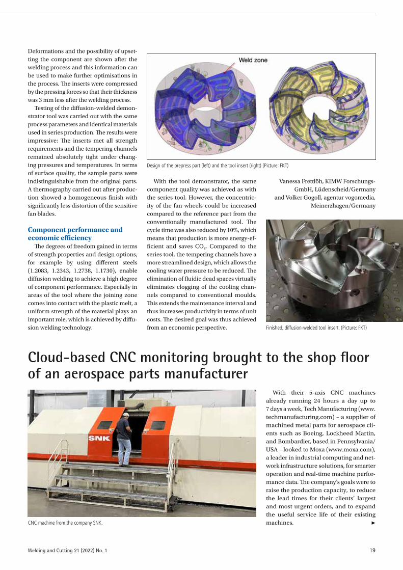
In the “Diffmold” project, which was funded by the former German Federal Ministry for Economic Affairs and Energy (BMWi) as part of the Central Innovation Programme (ZIM), the project participants investigated the entire process chain for manufacturing an injection mould using diffusion welding. In the defined project sequence, a demonstrator tool was built for the planned tests. The project consortium around the non-profit KIMW Forschungs-GmbH (KIMW-F) from Lüdenscheid/Ger-many used a series tool for the production of fan wheels, made of a polypropylene with glass fibre filling (PP GF40), from Formenbau und Kunststofftechnik GmbH (FKT), Triptis/Germany as a sample. In parallel to the design for welding, the tool was also optimised in the design phase using simulation tools with regard to rhe-ology, tempering and warpage behaviour of the component.
Designing a demonstrator mouldWhen designing the demonstrator
mould, one of the main tasks was to keep the existing interfaces (temperature control connections, number and cross-sections of the temperature control circuits, sprue manifold) usable. In addition, the handling of the components during production also had to be taken into account.
To determine the force distribution at preset welding temperatures, the Günter-Köhler-Institut für Fügetech-nik und Werkstoffprüfung GmbH (ifw Jena) developed a simulation model in coordination with the other project part-ners (Formenbau und Kunststofftechnik GmbH, Gemeinnützige KIMW Forschungs-GmbH and PVA Löt- und Werkstofftechnik GmbH). This model, consisting of press system and demonstrator component, was used to support adjustments and optimisa-tions of the joining surface geometry.
The actual welding was done by the pro-ject partner PVA. A diffusion welding sys-tem with a pressing area of 900 mm × 1,000 mm, unique in its design, was used for this.
Cross-section through the joining zone of a diffu-sion-welded specimen made of 1.2738 steel: The joining zone is indicated by a white line on the left and is completely dissolved. (Picture: ifw)
19Welding and Cutting 21 (2022) No. 1
Deformations and the possibility of upset-ting the component are shown after the welding process and this information can be used to make further optimisations in the process. The inserts were compressed by the pressing forces so that their thickness was 3 mm less after the welding process.
Testing of the diffusion-welded demon-strator tool was carried out with the same process parameters and identical materials used in series production. The results were impressive: The inserts met all strength requirements and the tempering channels remained absolutely tight under chang-ing pressures and temperatures. In terms of surface quality, the sample parts were indistinguishable from the original parts. A thermography carried out after produc-tion showed a homogeneous finish with significantly less distortion of the sensitive fan blades.
Component performance and economic efficiency
The degrees of freedom gained in terms of strength properties and design options, for example by using different steels (1.2083, 1.2343, 1.2738, 1.1730), enable diffusion welding to achieve a high degree of component performance. Especially in areas of the tool where the joining zone comes into contact with the plastic melt, a uniform strength of the material plays an important role, which is achieved by diffu-sion welding technology.
With the tool demonstrator, the same component quality was achieved as with the series tool. However, the concentric-ity of the fan wheels could be increased compared to the reference part from the conventionally manufactured tool. The cycle time was also reduced by 10%, which means that production is more energy-ef-ficient and saves CO2. Compared to the series tool, the tempering channels have a more streamlined design, which allows the cooling water pressure to be reduced. The elimination of fluidic dead spaces virtually eliminates clogging of the cooling chan-nels compared to conventional moulds. This extends the maintenance interval and thus increases productivity in terms of unit costs. The desired goal was thus achieved from an economic perspective.
Vanessa Frettlöh, KIMW Forschungs-GmbH, Lüdenscheid/Germany
and Volker Gogoll, agentur vogomedia, Meinerzhagen/Germany
Design of the prepress part (left) and the tool insert (right) (Picture: FKT)
Finished, diffusion-welded tool insert. (Picture: FKT)
Cloud-based CNC monitoring brought to the shop floor of an aerospace parts manufacturer
With their 5-axis CNC machines already running 24 hours a day up to 7 days a week, Tech Manufacturing (www.techmanufacturing.com) – a supplier of machined metal parts for aerospace cli-ents such as Boeing, Lockheed Martin, and Bombardier, based in Pennsylvania/USA – looked to Moxa (www.moxa.com), a leader in industrial computing and net-work infrastructure solutions, for smarter operation and real-time machine perfor-mance data. The company’s goals were to raise the production capacity, to reduce the lead times for their clients’ largest and most urgent orders, and to expand the useful service life of their existing machines. ▶CNC machine from the company SNK.

20 Welding and Cutting 21 (2022) No. 1
FROM COMPANIES
“We needed a better understanding of how our machines were actually perform-ing for us in real-time. Live and historical machine performance data would also help us identify technical or process issues that were detrimental to productivity,” said Jerry Halley, Chief Engineer of Tech Manufacturing, and one of the company’s 70 employees.
Purchasing additional machines would, of course, be one way to achieve this. But Halley was interested in finding a smarter, more efficient approach that did not require a large capital investment. That “smarter way” was a CNC monitoring system that would collect, analyse and visualise nec-essary performance metrics. Before taking the next step, however, Halley carefully weighed the productivity gains of such a system against the cost and effort of deploy-ment, especially if it involved a new and unfamiliar server-based IT infrastructure. The ideal system would be easily deployed
without specialised IT equipment, knowl-edge or effort, and would not require repeated software installation, updates or configuration.
New life to older machinesTech Manufacturing selected Shop Floor
Automations (www.shopfloorautomations.com), one of the most prominent systems integrators in North America, to assist with a cloud-based CNC monitoring sys-tem. Each of Tech Manufacturing’s CNC machines were connected to the existing local area network, so no additional IT infrastructure was required.
For legacy machines that did not have a readily available Ethernet port, Shop Floor Automations provided an easy-to-deploy solution that was developed based on “Moxa NPort W2150A” and “W2250A” wireless device servers that permit com-munications software to access serial and Ethernet devices over the wireless LAN.
Being wireless, the device servers required far fewer cables and the users can roam between several access points. As such, the servers offered an excellent solution for devices that are frequently moved from place to place, as is the case in many factory settings.
Getting machines connected and monitored
“Getting our CNC machines connected and monitored has made it much easier for us to deliver on our clients’ build-to-print orders with maximum efficiency and minimum lead time. It is a lot easier to get connected than a lot of people may realise,” said Halley.
With the local network connected to the Internet, CNC machine performance data at Tech Manufacturing can now be eas-ily viewed and analysed by cloud-based software such as “Scytec DataXchange” or “Predator Machine Data Collection”. Key performance metrics are organised on a visual dashboard so the company’s own-ers and machine operators are able to see exactly how productive each cell is per-forming, down to the machine level.
With a cloud-based monitoring system, Tech Manufacturing was able to mini-mise their upfront cost and deployment effort, explained a representative from Shop Floor Automations: “Many clients perceive it to be difficult and expensive to set up a CNC monitoring system. How-ever, with today’s cloud-based solutions, you can be set up in less than a day, with almost zero additional IT infrastructure or maintenance effort.”
Tech Manufacturing diagram.
Moxa Device server. Jerry Halley, Chief Engineer of Tech Manufacturing.

21Welding and Cutting 21 (2022) No. 1
With the system now up and running, a live dashboard has made it easy for Tech Manufacturing to identify critical productivity issues. For example, one immediate finding was that set-up times on certain machines were unnecessarily long, leading to hours of lost productivity every day. By rearranging setup sequence
and on/off times, Halley quickly achieved significant productivity gains with those machines.
Having comprehensive machine per-formance data on hand also provided an additional benefit: better service from CNC manufacturers. Service calls are now backed by a rich set of historical data,
making it easier to identify and trouble-shoot potential hardware issues. “Manu-facturers have become more willing and able to provide support when we need it because we have the data to show abnor-mal operation,” noted Halley. (According to press information from Moxa; www.moxa.com)
Laboratory at TU Braunschweig for residual stress analysis successfully accredited
At the Institute of Joining and Welding Technology at the Technische Universität (TU) Braunschweig in Brunswick/Ger-many, residual stresses can now be meas-ured and analysed at the “Norddeutsches Zentrum für Spannungsanalytik” (North German Centre for Stress Analysis – NOSA) in the recently accredited test laboratory. This makes the TU Braunschweig the per-fect contact for industry and companies of welding technology when it comes to X-ray residual stress determination.
Residual stresses are internal stresses that occur in the component without the action of external forces. They arise during production or manufacturing under the effect of plastic deformation of microscopic and macroscopic material areas. They also play a role when heat is applied to any type of component processing, e.g. gear com-ponents, turbines or other components in the automotive and aerospace industries. Therefore, they are also of high importance in welding technology and are mostly ana-lysed in development.
Residual stresses can have both a posi-tive and a negative influence on component behavior. Due to the broad knowledge of the effect of residual stresses accumulated over decades, they now represent an indus-trially used engineering tool for the optimi-sation of component properties, especially for high-strength and ultrahigh-strength materials.
High requirements for competence confirmed
For many years, the Institute of Joining and Welding Technology at TU Braun-schweig has been involved in the deter-mination of residual stresses in metal-lic materials and components as part of NOSA. Destructive and non-destructive testing methods are used for materials analysis. Since autumn 2021, NOSA has been accredited by the German Accredita-tion Office (DAkkS) as a testing laboratory for residual stress analysis according to DIN 17025. This confirms the high require-ments on competence, the uniform work-ing method as well as the quality standards.
Accreditation as basic prerequisite for many industry cooperations
A large number of residual stress-, phase- and texture analyses are carried out daily in various specially developed sta-tionary and mobile X-ray diffracto meters as part of basic and application-oriented research projects. With a diffractome-ter, non-destructive investigations of the
Accreditation certificate. (Photo: Markus Köhler, TU Braunschweig)
Test lab: Positioning of a sample in the X-ray diffractometer. (Photo: Paul Diekhoff, TU Braunschweig)

22 Welding and Cutting 21 (2022) No. 1
FROM COMPANIES
structure of crystalline phases in materials can be carried out.
Since the determination of residual stress states has long been an industrially established method for quality control during series production and prototype development, the institute is also a service partner in this field of bilateral industrial projects. These tests are offered to compa-nies that are interested in such analyses but do not have the necessary know-how or equipment themselves. “The accred-itation of the testing laboratory is a basic requirement for many industrial partners for cooperative projects and represents a great development opportunity for NOSA,” says NOSA director Dr. Thomas Nitschke-Pagel.
Equipment extended by a portable small size diffractometer
The laboratory has a large number of X-ray diffractometers for residual stress determination. The self-developed meas-uring stations are primarily designed to examine relatively large test specimens non-destructively with a high level of automatisation. This offers scientists the
possibility of carrying out very detailed analyses of the residual stress state on different test specimens within an accept-able time frame. In addition to scientific applications, the facilities are also used for application-related work on behalf of the customers.
Since this year, the laboratory also has a new portable small size diffractometer, which can be used to perform residual stress analyses on test specimens and com-ponents for which non-destructive inves-tigations using laboratory diffractometers are no longer possible due to their size and/or weight. The compactness of the instru-ment also allows, for example, direct appli-cation in test setups and in-situ measure-ment, e.g. in fatigue testing, and therefore offers the possibility of monitoring variable residual stress states in much greater detail over the service life of test pieces, whereby a more refined evaluation of the residual stress influence on the fatigue strength can be achieved. Due to a modified measure-ment and evaluation principle compared to laboratory diffractometers, considerable reductions in measurement times can also be achieved.
More information is available at https://www.tu-braunschweig.de/ifs/institut/for-schung/abteilungen-und-kompetenzen/festigkeit-und-bauteilverhalten/nosa – or follow the QR code shown in the picture above. (According to press information from TU Braunschweig; www.tu-braun-schweig.de/en/)
Portable X-ray diffractometer in use. (Photo: Paul Diekhoff, TU Braunschweig)
The right parts cleaning process ensures product quality and cost effectiveness
Today, parts cleaning has become a quality critical manufacturing step in all industry sectors. Often it takes great effort to reproducibly meet particulate and film-type cleanliness specifications. At the same time cleaning is to be done at the lowest possible cost. These contradictory require-ments call for processes and machines tai-lored to specific needs.
From machine and plant engineering, electrical and power engineering to con-necting elements, the so-called general industry contains a multitude of sectors. In these industry sectors, components made of materials like metals, plas-tics, ceramic and composite materials are manufactured and processed using different manufacturing technologies. Products include, for example, cast and machined parts, stamped, bent, pressed and deep-drawn parts, hydraulic parts and, more and more, additively manufac-tured components.
Meeting defined particulate and film-type cleanliness specifications that can be reproduced and at the lowest possible cost: These requirements can only be implemented with cleaning solutions that are optimally adapted to the task (in the picture: Detail of the cleaning system “Mega” from Ecoclean). (Photos: Ecoclean)

23Welding and Cutting 21 (2022) No. 1
Although the parts are manifold, they have one thing in common: to ensure the quality of downstream processes such as machining, heat treatment, coating, bond-ing and assembly and to guarantee lasting functionality, they necessitate cleanliness levels in line with requirements. In many areas, ever higher requirements concern-ing particulate and film-type cleanliness must be met. And there are often addi-tional challenges such as high throughput rates and weights, a strongly varying range of parts to be cleaned, short delivery times and also small margins in some cases.
Adapting cleaning processes to tasks on hand
This means there are different require-ments for part cleaning. As a supplier of flexible and energy-efficient solutions for industrial parts cleaning, Ecoclean GmbH from Filderstadt near Stuttgart/Germany (www.ecoclean-group.net) covers the com-plete range of wet-chemical procedures. Cleaning processes and systems for batch or single-part cleaning can be optimally adapted to the respective specifications.
To do so the following factors have to be taken into consideration: Material, size, geometry and weight of the part, type and quantity of contaminants, downstream process and the resulting cleanliness speci-fications and throughput requirements. On this basis it can be determined whether the contaminants can be removed most effec-tively with a water-based detergent, an environment-friendly solvent or a modi-fied alcohol with lipophilic and hydrophilic properties. What is more, this information enables engineers to define the best suited process and drying technology.
A matching process technology minimises cleaning cost
In order to minimise the cost per cleaned part, it is necessary that the exist-ing cleanliness specification is not only reliable, but also quickly reached. There-fore the systems are equipped with various application-specific treatment technolo-gies such as spray, high-pressure, immer-sion, ultrasonic and plasma cleaning, vapour decreasing, injection flood wash-ing, deburring, pulsated pressure cleaning (PPC) as well as a passivation/preservation process as required.
By combining these cleaning proce-dures, the cleaning result and duration for the specific parts can be influenced
in a pinpointed manner. The PPC pro-cedure in combination with an aqueous or solvent-based immersion cleaning for example, reliably and quickly removes con-taminations from small cavities. In case of complex and bulk parts, spray processes and injection flood washing with adjust-able nozzles between 10 and 16 bar also deliver markedly improved cleaning results and shorter process times in solvent clean-ing processes.
Quality and cost can be optimised by combining processes that formerly required several machines in one single cleaning system. Among them are chamber machines designed for solvent-based or aqueous batch cleaning with a subsequent low-pressure plasma process. Among other things, this method effectively and efficiently prepares the part surface for a subsequent coating or bonding. Eco-clean’s extensive product range also offers the respective solutions for pinpointed deburring and cleaning of single parts, for example hydraulic and motor components in one system.
Dry cleaning: selective or whole surfaces
Cleaning tasks also change along with changing manufacturing and joining tech-nologies. The focus lies more and more on dry-cleaning processes, be it for removing film-type contaminations from joint sur-faces in a pinpointed manner, cleaning electronic components and assemblies, removing powder residues from additively manufactured components or cleaning integrated in assembly.
For this and many more applications, Ecoclean has developed a special toolbox for cleaning processes with atmospheric pressure plasma, laser, CO2 snow, con-ditioned vacuum air as well as saturated and dry water vapour. Depending on the specific application, these ‘tools’ too are applied alone or combined. This extensive portfolio of cleaning solutions is supple-mented by technology centres around the world. They perform tests with original soiled parts under conditions similar to production for all the different tasks exist-ing in part cleaning.
Doris Schulz (Journalist), Korntal/Germany
By integrating two cleaning processes in one system, such as wet-chemical and low-pressure plasma cleaning, quality, cost and cycle times can be optimised.
Dry cleaning methods such as vacuum air cleaning can be integrated into assembly lines and used for depowdering of additively manufactured parts.

24 Welding and Cutting 21 (2022) No. 1
FROM COMPANIES
Oerlikon Metco: Enhancing the customer experience through digitalisation
For nearly 90 years, Oerlikon Metco (www.oerlikon.com/metco) has provided customers with advanced materials for industrial processes, as well as thermal spray application technology. Today, the company offers these materials and spare parts for their thermal spray equipment online 24/7.
Oerlikon Metco successfully launched their “myMetco” e-commerce site to its US customers in 2020, and has now expanded this online ordering platform to its Euro-pean customers in five languages. Sign up (at https://mymetco-europe.oerlikon.com) is easy for new and existing customers.
The platform offers customers a digital way to simplify and accelerate their order-ing process. As the market leader and orig-inal manufacturer of innovative solutions for critical processes such as thermal spray, metal additive manufacturing, and others, myMetco customers can trust that they will receive products with the same quality and benefits they have come to expect from Oerlikon Metco. Customers benefit from:
◾ Current product pricing and avail-ability,
◾ Strong product search and compare capabilities,
◾ Free access to expert product technical support,
◾ Increase in efficiency with quick order-ing and 24/7 shopping service,
◾ Easily track orders and order fulfillment online.
In addition to online ordering, the company offers users an easy way to search and find materials digitally. The “Materials e-Guide” (https://mymetco-europe.oerlikon.com/en-us/?utm_source=brochure&utm_medi-um=print&utm_campaign=2022-Mar) pro-vides query fields based upon chemistry, process, primary function, service envi-ronment, specification and other filters.
Whether the goal is better durability from wear or corrosion, thermal protection, sur-face restoration, additive manufacturing, dimensional control or other desirable properties for a component or system, the “Materials e-Guide” will help find the right material for the application. It can be used by anyone whether they are a “my Metco” customer or not. This powerful combi-nation allows users to confidently search and shop solutions at their convenience. (According to press information from Oer-likon Metco)
“myMetco“ process chain.
Oerlikon Metco “Material Finder”.
Place your job offer or job application specifically and effectively in our specialist magazines.
You can reach our advertising department directly at the following numbers:
+49 211 1591-155/-152 +49 211 1591-150 [email protected] [email protected]
www.dvs-media.eu

25Welding and Cutting 21 (2022) No. 1
High-performance cold gas coating for wear protection and emission reduction for brake discs
Brake discs are subjected to extremely high loads and are among the most stressed parts of a car. Not only do they have to be replaced at relatively short intervals, due to the high level of wear and tear they cre-ate an immense environmental impact through particulate matter. Thanks to improved emission control, a reduction in exhaust gas emissions can be achieved in modern cars.
However, it is still neglected how much particulate matter is caused by the abra-sion of tires and brakes. A good half of the particulate matter in German road traffic is caused by tire and road abrasion and another quarter by brake pad abrasion. Emissions from brake wear, such as brake dust and particulate matter, are a growing concern for the automotive industry due to more stringent and environmental EU regulations.
Grey cast iron with embedded graphite as most common material for brake discs
Grey cast iron with embedded graphite is the most common material from which
brake discs are produced. Grey cast iron brake discs are not only cheap to manu-facture, they also have all the necessary mechanical properties that are required. However, poor corrosion resistance and excessive wear of the brake disc during operation are the main problem areas. Since no material can yet compete with grey cast iron for vehicle brake discs from a cost perspective, the coating of cast iron discs represents a practical and cost-effi-cient solution. But conventional thermal coating processes are still very material- and cost-intensive and the required prop-erties in terms of coating adhesion, cor-rosion resistance and cracking behaviour cannot yet be fulfilled. In contrast to laser cladding, the cold spray process is free of patent protection from any major automo-tive manufacturer.
With a high-performance cold gas coat-ing with the Cold Spray System “EvoCSII” by Impact Innovations (www.impact-inno-vations.com), there is no delamination or severe cracking in the coating and the parti-cle emission is reduced drastically. The per-formance of the coating was evaluated in terms of corrosion resistance, wear resist-ance and tensile bond strength between the coating and the brake disc. The cold gas sprayed composite coating of the cast iron brake disc showed a 95% reduction in wear in the SAE J2522 test. In addition, the coating showed excellent adhesion even after extreme bench test runs without any delamination. 720 hours of salt spray tests were successfully completed without cor-rosion.
Simplicity, high performance and low costs
The cold spray process wins over other coating technologies with its simplicity, high performance and low costs. As it is
a cold process, all process parameters are always constant independent of the dimensions and shape of the brake discs. There is no thermal distortion of the discs, and the layer build-up stands out with its uniformity. Thus, the coating thick-ness can be reduced to a minimum and the subsequent grinding costs are mini-mised. A standard brake disc can also be coated in a one-layer system (no interme-diate layer) in less than 30 seconds. The present results show a cost-effective and resource-saving solution for the brake disc application with cold sprayed com-posite coatings.
Dr. Reeti Singh, Ján Kondás, Max Meinicke and Leonhard Holzgaßner,
Impact Innovations GmbH, Haun/Rattenkirchen, Germanywww.impact-innovations.com
Brake disc with high performance cold gas coating after grinding (Photos: Impact Innovations GmbH).
Brake disc with high performance cold gas coating after coating.
Visit our website!
When it comes to technical information for welding technology, joining technology, cutting technology and coating technology, DVS Media is the first choice.
www.dvs-media.eu

26 Welding and Cutting 21 (2022) No. 1
FROM COMPANIES
Short MessagesABB provides digital-ready solutions for modernisation of steel mill
Global technology company ABB (www.abb.com) is providing a package of metals industry-specific digital-ready solutions, including drives, controller and converter infrastructure, to enable Global Steel Wire (GSW; www.globalsteelwire.com), part of CELSA Group, to modernise opera-tions at its steel mill in Santander/Spain. GSW manufactures and brings to market a range of steel products, including wire rod, cables and ropes. Its high-quality steel cables are used extensively in the automo-tive industry as well as in mattress springs. The steelmaker had been exploring the use of digital technologies to optimise its rolling wire production and will now ben-efit from the expertise and metals indus-try domain knowledge of ABB. As part of the contract, ABB will provide its medium voltage drives for high power applica-tions, “Megadrive-LCI”, together with “AC 800PEC” controllers. The demand-based medium voltage drives will result in optimised power consumption and higher process efficiency. Teams from the two companies had the chance to incorporate the use of augmented reality during the Factory Acceptance Test, with representa-tives at the LCI factory in Switzerland col-laborating with others in Spain. It encom-passed audio, video, document-sharing and live annotations. This allowed progress to continue during the Covid-19 travel lim-itations. The use of proven ABB technology will allow GSW to save energy and reduce its carbon emissions through increased efficiencies. The drives voltage scalabil-ity minimises harmonic influence on the supply system, and a converter efficiency of more than 99% will ensure that the system works for many years.
ABB has been appointed to provide digital-ready solutions that will help to improve efficiency, increase reliability and boost quality at Global Steel Wire’s facility in Santander. (Photo: ABB)
New laboratory for industrial diagnostics and advanced robotics
Comau from Grugliasco (Turin)/Italy (www.comau.com) and the Politecnico di Bari (Poliba) have signed a five-year agreement for the joint creation of the new “Cognitive Diagnostics public-private lab-oratory”, aimed at the development of inno-vative solutions for industrial diagnostics
and advanced robotics. The collaboration provides for the use of a research and experimentation space where Comau, in synergy with the University, intends to launch projects related to artificial vision for non-invasive diagnostics and robot guidance. The “Cognitive Diagnostics” lab-oratory was created to respond to the grow-ing demand for flexible automation that is adaptable to any production context and able to make Factory 4.0 work processes more efficient through the use of enabling technologies. In particular, the new labora-tory will allow Comau to deepen the study
of innovative vision systems and platforms that allow easier robot programming, thus facilitating and speeding the management and control of operators (“low code pro-gramming”). Comau will collaborate with the Politecnico’s educational activities through its participation in tutoring during training and company internships. To start the lab, Comau will fund research grants, scholarships and researcher positions. The initial work team will consist of individu-als contracted from the Politecnico di Bari, with the possibility to gradually increase the workforce.
Comau and the Polytechnic University of Bari will collaborate in the design of new technologies in the field of industrial diagnostics and advanced robotics. (Photo: Comau)

27Welding and Cutting 21 (2022) No. 1
MicroStep continues to expand: New partnership in the UK
For more than 25 years, City Plasma Services has taken care of the distribu-tion of CNC plasma cutting systems in the United Kingdom. From now on, the family-owned company is the contact for the CNC cutting systems and automation systems from MicroStep. With MicroStep’s broad portfolio, customers in the UK can now be served even more tailor-made and comprehensively. City Plasma Services has worked closely with plasma power source manufacturer Hypertherm for many years and brings this experience to its collabo-ration with MicroStep in the UK. In doing so, beyond plasma cutting systems, City Plasma Services also sells laser, waterjet and oxyfuel cutting machines with the MicroStep product range, as well as a vari-ety of additional integrable options for drilling, tapping, scanning and marking. The specialist dealer is thus placing a new focus on supplying high-tech machines to a wide range of customers. Requests are served for single compact machines up to automated process lines with different cutting technologies as well as automatic loading and unloading solutions, CAPP applications and Smart Factory solutions with CAM software and ERP systems. More information is available at: www.cityplasma.co.uk.
Atlas Copco acquires French distributor of compressors
Atlas Copco – a global industrial group, founded in 1873 in Stockholm/Sweden, with today about 40,000 employees – has acquired AEP, a French distributor of com-pressors and provider of service. The pri-vately owned company has a strong mar-ket presence in Paris and the Île-de-France region. It serves a diverse group of small to medium-sized customers in industries such as manufacturing, food and beverage, and automotive. “AEP has highly qualified service technicians, and the company has for many years been a distributor of Atlas Copco”, said Vagner Rego, Business Area President Compressor Technique. “By this acquisition we will reinforce our commit-ment to better serve our customers and strengthen our capabilities for the growing market of small- and medium-size com-panies.” The company will become part of the Service division within the Compressor Technique Business Area.
Supertec chooses NUM technology for its latest CNC cylindrical grinding machines
Supertec Machinery Inc., one of Tai-wan’s leading machine tool manufactur-ers, has chosen to base new versions of its renowned plunge type of CNC cylindrical grinding machines on NUM’s “Flexium+” CNC platform from NUM, Coventry/UK (www.num.com). Founded in 1954, Supertec Machinery Inc. specialises in precision grinding automation and pro-duces a diverse range of centreless, cylin-drical and surface grinding machines. When NUM added non-circular grinding functionality to its popular “NUMgrind” cylindrical grinding software back in June 2020, the company realised that this inno-vative CNC technology provided exactly what many of its customers needed on their cylindrical grinders. “NUMgrind” simplifies the creation of G code programs for CNC grinding machines through the use of a highly intuitive graphical human machine interface (HMI), and unlike conventional CAD/CAM workstation tools, it is designed specifically for use by shop floor personnel in a production environment. Supertec’s plunge type of CNC cylindrical grinding machines offer a choice of six capacities, covering dis-tances between centres from 500 to 2,000 mm. The machines can also accommodate grinding diameters from 300 up to 430 mm (3 sizes), grinding wheel speeds up to 1,390 rpm and workhead spindle speeds from 30 to 350 rpm.
Supertec’s latest plunge type CNC cylindrical grinding machine is based on NUM’s Flexium+ CNC platform (From left to right: Mr. Chu, General Manager of Supertec, and Adrian Kiener, CSO Asia NUM). (Photo: NUM)
thyssenkrupp Materials Services with strategic investments in growth market North America
thyssenkrupp Materials Services is sig-nificantly expanding its North American business and investing in several states in one of its core markets. The biggest mill-independent materials distribu-tor and service provider in the western world is exploiting the market potential for expansion as well as for the imple-mentation of new, scalable business models. “Demand for our products but especially for our services is high and has grown strongly in recent years,” says Martin Stillger, Chairman of the Board of Management of Materials Services. “We now want to use our affinity for services in particular to improve our market position
even further – if possible also with fur-ther acquisitions. Today we are already number 3 in America. That is not enough for us.” Business in North America alone accounts for around 25% of total sales of Materials Services. With 94 service centres and more than 4,000 employees, Materials Services already has a strong, nationwide network that serves more than 55,000 cus-tomers with precision fit. These include, for example, various Fiat/Chrysler plants with around 70,000 parts a day from three “just in sequence” delivery centers.
thyssenkrupp Materials Services plans to create additional capacity to meet growing demand from the manufacturing industry at various locations across the US (Photo: thyssenkrupp Materials Services)

28 Welding and Cutting 21 (2022) No. 1
FROM COMPANIES
ProductsNew multiprocess welding system series
Fronius is launching the “iWave” (Fig. 1), an intelligent, high-end TIG series that sets new standards in quality, flexi-bility and connectivity, available in power categories from 190 A to 500 A. The “iWave” was developed to enable the best TIG weld quality and flawless results to be produced on different metals. The innovative option “CycleTIG” provides for maximum control over the arc and targeted heat input. Fur-ther highlights include improved ignition control and greater ease of use with intu-itive operation. The new welding system proves its worth with sophisticated TIG technology and is ideally suited for man-ual metal arc welding – even with cellulose electrodes. The “Multiprocess PRO” option gives the user unlimited access to all MIG/MAG processes in power categories from 300 A. Customers can choose the specific features they actually need and have the assurance that they can add to the range of functions as and when needed. Starting with standard TIG or MIG/MAG applica-tions, the “iWave” enables upgrades to the full Fronius range, including the Cold Metal Transfer (CMT), Pulse Multi Con-trol (PMC) and Low Spatter Control (LSC). Modern wireless connections give welders freedom and security. Peripheral devices, such as a remote control or the “Vizor Con-nect” welding helmet, can be wirelessly connected via Bluetooth. WiFi enables communication with other devices in the same network so the user can enjoy a whole host of digital advantages, such as central user management, real-time data transfer and rapid updates. (Fronius International GmbH, Froniusplatz 1, 4600 Wels/Austria; www.fronius.com2
Fig. 1
Compact welding cells with pre-assembled welding equipment
To make it easier for small and medi-um-sized enterprises to get started with automation, Kuka and Abicor Binzel are intensifying their cooperation: With “Kuka cell4_arc powered by Abicor Binzel”, the two companies offer cost-effective com-plete welding cells that are easy to use (Fig. 2, from left: Jörg Lehnhäuser, Director Sales Western Europe from Abicor Binzel
and Sascha Liese, Head of Business Unit Arc Welding & Laser Applications KIO from Kuka). Neither a high level of expertise in automation technology and programming is necessary, nor a special operating sys-tem. Areas of application can be found in the production of small assemblies made of steel or aluminium, small to medium-sized production volumes and generally in appli-cations with the MIG/MAG welding pro-cess. Of course, customer-specific adjust-ments and additional options are possible with the robot welding cell. It is ideally suited for the automated welding of smaller components up to 800 mm × 1,200 mm, which can be loaded/unloaded and welded
at the same time. Additional devices such as tools can easily be integrated. The pos-sibility of constant process monitoring and documentation reduces production errors and ensures process quality. Appropriate protocols are created for quality assurance. As a high-performance unit mounted on a base frame, this compact, space-saving welding cell can also be easily transported to the respective destination using a forklift and be repositioned again and again indi-vidually. (Alexander Binzel Schweisstech-nik GmbH & Co. KG, Kiesacker 7-9, 35418 Buseck/Germany; www.binzel-abicor.com and Kuka AG, Zugspitzstraße 140, 86165 Augsburg/Germany; www.kuka.com)
Fig. 2

29Welding and Cutting 21 (2022) No. 1
Compact spark-OES metals analyser
Fig. 5
Modular MIG/MAG welding machines
With the modular versions of the “Phoenix XQ puls”, “Taurus XQ Synergic” and “Taurus XQ Basic” MIG/MAG welding machines (Fig. 3), it’s all about user custo-misation. While the power source remains at the heart of the machine, other parts of the welding machine are not permanently installed and can be freely configured. This means users can pick and choose which wire feeder or what cooling they prefer to use for their daily tasks. Cus-tomers can also retrofit their machines as needed, gradually completing their set-up with new modules. The wide range of user-oriented accessories – including a toolbox and cover lens for the control – also gives users the freedom to adapt their modular “XQ” series machines to any working area. The machines are also space-saving and lightweight, offering more mobility and flexibility. They are compatible with the ewm “Xnet” welding management software. This software solu-tion supports, documents and analyses the entire production process, from work preparation to final costing, all completely paperless. This makes quality assurance even easier and allows users to extensively evaluate any welding parameters used for a job after the fact. (EWM AG, Dr. Günter-Henle-Str. 8, 56271 Mündersbach/Ger-many; www.ewm-group.com/en)
Fig. 3
Desktop resistance weld checkerWith the “MM-400A” desktop resistance
weld checker (Fig. 4), operators can easily monitor and manage key welding vari-ables that result in changes in weld heat, including current, voltage, time, force and displacement. The compact unit supports AC/DC inverter, AC inverter, transistor and capacitive discharge resistance weld-ing technologies. The “MM-400A” is ideal for use in process development, where it can be used to correlate waveform and numeric data with process results and pro-vide detailed weld data for process opti-misation and validation. In a production environment, it reduces scrap by detecting drifts in the weld process and alerting oper-ators before process failure. The device also reduces the frequency of destructive testing and provides an independent way of moni-toring the welding power supply. It features a simple and intuitive user interface and colour touch panel display. An envelope
function allows the operator to set upper and lower segmented or continuous limits around the entire waveform. The unique seam welding mode monitors AC current and voltage or DC voltage for up to 5 min. The unit provides ISO17657-compliant measurement for current (when used with available ISO-compliant toroidal coil) and offers Ethernet (TCP/IP), and RS-232/485 communication. Pre-weld displacement measures workpiece thickness prior to welding. Multi-language support includes English, Spanish, Japanese, Chinese, Korean, German and French. (Amada Weld Tech GmbH, Lindberghstr. 1, 82178 Puch-heim/Germany; www.amadaweldtech.eu)
Fig. 4
“Q4 Polo” (Fig. 5) is a compact Spark Optical Emission Spectrometer (OES) with superior analytical performance for multiple applications across the met-als industry. It extends Bruker’s line of benchtop OES systems, combining high precision elemental analysis capabilities with low cost of ownership and small foot-print. In addition to excellent analytical performance for the large element range from lithium (Li) to bismuth (Bi), the “Q4 Polo” enables applications previously not addressable by such compact instru-ments:
◾ Outstanding precision, particularly on light elements,
◾ Excellent results in the challenging analysis of cast iron,

30 Welding and Cutting 21 (2022) No. 1
FROM COMPANIES
◾ Reliable analysis of nitrogen at low ppm levels in low alloyed steels,
◾ Analysis of oxygen in copper.The “Q4 Polo” has very good long-term stability. The absence of thermal- and contamination-based drifts reduces the need for cleaning and recalibrations. Bruker’s patented “Automatic Ambient Compensation” (AAC) ensures that the optical system keeps its focus by elim-inating thermal drift. The new “Argon-Shield” prevents contamination of the optical window during measurements. The active sensing digital “SmartSpark” source further improves analytical pre-cision and long-term stability, enabling shorter measurement times. The coverage of the full elemental range is achieved by a unique electromagnetic light junction as core component of the “MultiVision” optics. (Bruker Corporation, 40 Manning Road, Billerica, MA 01821/USA; www.bruker.com/q4polo)
MIG/MAG welding machine with integrated wire drive for manual welding
Fig. 6
high frequency. This allows an even bet-ter arc control for excellent results. The configuration possibilities are as flexible as the welding applications are versatile. This is guaranteed by the modular prod-uct concept. From the capacity class to the wire tip, each “Qineo StarT” is customised. The easy, quick and intuitive operation is a convincing feature of the welding machine. Users benefit from the com-fortable operating concept that they can adapt to their individual requirements. The “Qineo StarT” is characterised by high-quality components with numerous optional functions. (Carl Cloos Schweiss-technik GmbH, Carl-Cloos-Str. 1, 35708 Haiger/Germany; www.cloos.de/de-en)
New web-based module for CAD/CAM nesting software
Hypertherm released “Production Manager”, an optional module for its “ProNest” CAD/CAM nesting soft-ware (Fig. 7). This web-based module is designed to improve productivity, max-imise machine up-time, boost on-time delivery and increase material utilisa-tion. It seamlessly integrates with Hyper-therm’s “Edge Connect” CNC, to auto-matically capture machine data without the need for operator intervention. In addition, it displays real-time production data so team members across an organ-isation can track the status of job orders,
Fig. 7
the production schedule and pending inventory requirements. Additional fea-tures include:
◾ An intuitive dashboard view provides production stats and trends in one view. Colour-coded status alerts help users quickly understand the on-screen information while an interac-tive display allows users to drill down for additional insight.
◾ Real-time machine data from the CNC is transferred to “Production Manag-er”. This enables users to track job pro-gress from pending, to in-production, to actual completion time making it easier to respond to customer inquir-ies and forecast the production sched-ule.
◾ Orders can be canceled or held to add or remove parts based on last-minute changes. Users can view machine backlogs and ensure loads are evenly distributed across cutting machines in a way that optimises the production schedule.
◾ Remote access makes it easy for users to access “Production Manager” via a computer, mobile phone or tablet any-time and anywhere they have a se-cured network or VPN connection. (Hypertherm Europe B.V., Vaartveld
9, 4704 SE Roosendaal/The Netherlands; www.hypertherm.com)
The MIG/MAG welding power source “Qineo StarT” (Fig. 6) offers an easy entry into the world of modern welding tech-nology. Due to the excellent price-per-formance ratio, users can weld any work-piece at economic conditions. The heart of the machine is an inverter power unit developed by Cloos which clocks with a

31Welding and Cutting 21 (2022) No. 1
Compact welding cells as easy gateway into automation
With a portfolio of new, turn-key com-pact welding cells, Lorch Schweißtech-nik and Yaskawa enable small and medi-um-sized enterprises to easily enter robot-automated welding to produce small assemblies with great efficiency and at high quality (Fig. 9). These space-sav-ing and efficient welding cells take just a few minutes to be ready for operation. Their compact build keeps their footprint small and makes them easy to relocate later. The special cell construction max-imises freedom of movement for the robot and permits complete integration of the welding power source in spite of its small
Control system to handle multiple thermal spray processes
Lincotek Equipment – turn-key equip-ment provider for thermal spray coating solutions, diffusion coatings and related processes – has announced the launch of a new equipment control system (Fig. 8). Combined with next-genera-tion proprietary software and a newly designed HMI console, it is designed to improve efficiency, flexibility and usabil-ity, while still delivering the same high standards of reliability and repeatability. The concept is to provide a tailor-made platform which handles multiple thermal spray processes, different spray guns and unlimited handling options. Only one ergonomic console is required, featuring a single touch-screen monitor for process control, three short-cuts for key functions, USB connection for data storage, as well as ethernet connections to allow direct dialogue with equipment and factory LANs. Interfaces can be tailor-made with innovative communication protocols. The HMI software allows for unlimited versa-tility and equipment control over process parameters, powder feeders, handling system, doors, cooling and filtering sys-tems. It also provides unlimited storage of recipes, parameters and data logs. The coating process has Industry 4.0 and IoT features that provide real-time monitor-ing, equipment health checks and the recording of critical parameters. Safety is provided by an automatic stop on all equipment in the event of any critical situation. (Lincotek Surface Solutions, Via Mistrali 7, 43046 Rubbiano, PR/Italy; www.lincoteksurfacesolutions.com)
Fig. 8
Fig. 9
size. The welding cells are available as the “ArcWorld HS Micro”, with a footprint of 1.3 m2 and the “ArcWorld RS Mini” with a footprint of 2.3 m2. A maxi version with the “ArcWorld CS” is also availa-ble for larger parts or customer-specific requirements. The platform and housings are equipped with a blue polycarbonate glare protection and use the “Motoman AR900” robot by Yaskawa. The “S3”- and “S3-RoboMIG XT” with their complete Lorch Speed welding processes are avail-able as welding power sources (MIG/
MAG). The combined Lorch and Yaskawa solution is made special by integrating the control in a single operating panel. The Universal Welding Interface (UWI) is used to program robots, to set and select the welding processes. The opti-mal adjustment of the components makes operation of the welding system much easier. (Lorch Schweißtechnik GmbH, Im Anwänder 24-26, 71549 Auenwald/Ger-many; www.lorch.eu/en; Yaskawa Europe GmbH, Hauptstr. 185, 6560 Eschborn/Germany; www.yaskawa.eu.com)

32 Welding and Cutting 21 (2022) No. 1
WELDING PRACTICE
Analysis of brazing imperfections by metallographic investigation / optical microscopy – Part 1
In everyday practice we can encounter problems connected with brazing imper-fections – often manifested as leaking. To identify the failure root causes, usually a detailed examination needs to be per-formed. Optical metallography is one of the most important tools for such an analysis.
The purpose of this article is to present the basic principles for performing analysis of brazing joints, and to show what infor-mation can be obtained from the investi-gation.
Before starting to work with an optical microscope, the part to be examined must be prepared appropriately. There are sev-eral steps in this procedure:
◾ Cutting out smaller pieces to about 30 mm to 40 mm with a band saw.
◾ Embedding the cut sections in epoxy resin.
◾ Step grinding with sandpaper (220 grit, 500 grit, 1000 grit).
◾ Polishing with diamond suspension (6 µm and 3 µm) and with oxide polish-ing suspensions (OP-S).
◾ Microscopic observation in non-etched conditions – mainly to determine if the quality of polishing is sufficient.
◾ Microscopic observation after etching – most common etchant: 0.5% hydrofluo-ric acid, (10 – 15 seconds immersion).
There are usually two steps in a metallo-graphic examination.
The first one is to evaluate the braz-ing quality. It is usually performed when introducing a new product. In such case the manufacturer should define the way the sample is cut for microscope observa-tions. In most cases the tube to header and the fin to tube joints are examined. Such exemplary cutting is shown in Fig. 1.
The second step is connected with the actual examination of the parts – looking for root causes of not brazed parts.
It is of primary importance to choose properly the observation plain. In most cases it runs across the examined defect. This will be seen case by case in the follow-ing industrial cases examples.
However, before we go into fault anal-ysis, we should understand what can be seen in an optical microscope met-allographic picture. Fig. 2 represents the metallurgical structure of a tube
to header joint of a brazed aluminium radiator.
Apart from the intrinsic features of the brazed structure quite often we can observe another phenomenon strictly connected with the brazing process. An example of such phenomenon is shown in Fig. 3.
Silicon diffusion is a phenomenon where silicon diffuses from static liquid filler into the base metal and aluminium diffuses into the liquid filler – resulting in partial melting of the base metal at brazing temperature. The extent of this phenomenon is enhanced by too high brazing temperature and/or too long time at brazing temperature.
The phenomenon of diffusion some-times can develop into so-called erosion. In such cases the liquid part of the base metal had flown away – leaving a gutter behind. That can potentially happen at the end of a brazing cycle, when signifi-cant temperature gradients develop dur-ing cooling. It should be noticed that this phenomenon, which results in thinning out of for example the tube wall cross section, is very dangerous for part per-formance, because the thinner tube wall could be a potential place for fatigue and/or corrosion failure.
Fig. 1 • Cutting of a radiator for examination of the joint quality; a) brazed part with marked cutting lines, b) part after cutting along line 1, c) part after cutting along line 2.
Fig. 3 • Examples of structural brazing phenomena; a) silicon diffusion, b) erosion, c) liquid film migration.Fig. 2 • Metallographic structure of a tube to header joint – etched with hydrofluoric acid (HF).
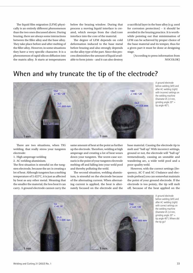
33Welding and Cutting 21 (2022) No. 1
When and why truncate the tip of the electrode?A ground electrode before welding (left) and after AC welding (right) with incorrect settings on the welding machine (Diameter Ø 2,4 mm, grinding angle 20° = tip angle 40°).
A ground electrode before welding (left) and after AC welding (right) with correct settings on the welding machine (Diameter Ø 2,4 mm, grinding angle 20° = tip angle 40°). Where did the tip go?
The liquid film migration (LFM) physi-cally is an entirely different phenomenon than the two ones discussed above. During brazing, there are always some interactions between the filler alloy and the base alloy. They take place before and after melting of the filler alloy. However, in some situations they have a very specific character. It is a phenomenon of rapid silicon diffusion into the matrix alloy. It starts at temperatures
below the brazing window. During that process a moving liquid interface is cre-ated, which sweeps from the clad/core interface into the core of the material.
The degree of LFM depends on cold deformation induced to the base metal before brazing and also strongly depends on the alloy type of the part. Since this pro-cess diminishes the amount of liquid avail-able to form joints – and it can also destroy
a sacrificial layer in the base alloy (e.g. used for corrosion protection) – it should be avoided in the brazing practice. It is worth-while pointing out that minimisation of LFM can be achieved by proper choice of the base material and its temper, thus for a given part it must be done at designing stage.
(According to press information from NOCOLOK)
There are two situations, when TIG welding, that really stress your tungsten electrode:1. High amperage welding2. AC welding aluminium.The first situation is stressful on the tung-sten electrode, because the arc is creating a lot of heat. Although tungsten has a melting temperature of 3.422°C, it is just as affected by heat as any other metal. Meaning that the smaller the material, the less heat it can carry. A ground electrode cannot carry the
same amount of heat at the point as further up the electrode. Therefore, welding at high amperage and creating a lot of heat wears down your tungsten. The worst-case sce-nario is the point of your tungsten electrode melting off and falling into your weld pool and thereby polluting the weld.
The second situation, welding alumin-ium, is stressful on the electrode because of the alternating current. When alternat-ing current is applied, the heat is alter-nately focused on the electrode and the
base material. Causing the electrode tip to melt and “ball up”. With incorrect settings, ground or not, the electrode will “ball up” tremendously, causing an unstable and wandering arc, a wide weld pool and a poor-quality weld.
However, with the correct settings (fre-quency, AC-T and AC-I balance and elec-trode preheat) you can somewhat maintain the point of your ground electrode. If the electrode is too pointy, the tip will melt off, because of the heat applied on the

34 Welding and Cutting 21 (2022) No. 1
WELDING PRACTICE
electrode. In this case, your tip might fall into your weld pool and pollute the weld.
In both situations you can diminish the risk of melting of the tip by truncating your tungsten electrode. Research has shown, that truncating the tip prevents the tip from melting off, preserves the tip and a
stable arc, and extends the amount of time between regrinds.
ConclusionTruncate the tip of the electrode
if welding with high current or if AC welding!
Because it provides: ◾ Better welding quality ◾ More stable arc ◾ Less wear on the electrode.
(According to press information from Inelco Grinders)
A ground and truncated electrode before welding (left) and after AC welding (right) with correct settings on the welding machine (Diameter Ø 2,4 mm, grinding angle 20° = tip angle 40°).
DVS Media GmbH • Aachener Straße 172 • 40223 Düsseldorf, Germany • P +49 211/1591-152 • F +49 211/1591-150 • www.dvs-media.eu
www.abc-der-fuegetechnik.de/en/www.abc-der-fuegetechnik.de/en/www.abc-der-fuegetechnik.de/en/www.abc-der-fuegetechnik.de/en/www.abc-der-fuegetechnik.de/en/www.abc-der-fuegetechnik.de/en/
www.welding-and-cutting.info
Technical journal for welding and allied processes
Wel
ding
and
Cut
ting
01/2
020
Empowering professionals with
welding qualifications through
work-based learning opportunities
Investigation of arc based addi-
tive manufacturing
Reducing the risk of hydrogen-
induced cold cracking in hyper-
baric wet welding
Issue
012020
The new technical journal
WE ACCOMPANY THE FUTURE OF
THE INTERNATIONAL STEEL INDUSTRY
steel production
application technology
innovation + management
processing
FREE SAMPLE PRINT ISSUES AND FURTHER INFORMATION AT
WWW.HOMEOFSTEEL.DE
AZ_Steel_Technology.indd 2
06.06.2019 16:54:19
The strong connection
Let you inspire at:
www.youtube.com/valkweldingHigh reliability and better welding
quality with Valk Welding robot solutions
cover Welding & Cutting 4-2020.indd 1
13-02-20 10:04DER
PRA
KTI
KER
– D
as M
agaz
in f
ür S
chw
eißt
echn
ik u
nd m
ehr
3/20
ISSN 0554-9965
32020
Das Magazin für Schweißtechnik und mehr
DVS Media GmbH, 40010 Düsseldorf
Postfach 10 19 65
Postvertriebsstück
Gebühr bezahlt
G 3794
Schneller und flexibler
fertigen:
Schweißen von Drehleitern
für Hubrettungsfahrzeuge
Seite 92
Hinweise für die
Anwendung:
Arbeitsanleitung zum Licht-
bogen-Druckluftfugen
Seite 100
Elektroschlacke-
Schweißen im neuen
Gewand:
Elektroschlacke-Schweißen
mit Anwendung im Stahlbau
Seite 110
T E C H N O L O G Y F O R T H E W E L D E R ’ S W O R L D .
w w w.binzel - abicor.com
ROBiPAKDer gesundheitsbewusste »Kollege«
Hier gehen automatisiertes Schweißen, Gesundheit und
Produktivität Hand in Hand – durch diese perfekt aufeinander
abgestimmte Schweißausrüstung mit Rauchgasabsaugung
für Cobots. Als Team unschlagbar!
■ Produktivitätssteigerung für den Mittelstand
■ Gleichbleibende Qualität
■ Top Gesundheitsschutz durch Punktabsaugung
■ Ohne körperliche Beanspruchung beim Schweißen
■ Keine spezielle Schulung notwendig
■ Einfache, intuitive Programmierung
Diese kollegenfreundliche Systemlösung beinhaltet Schweißbrenner, Halter
und Schlauchpaket, die Stromquelle iROB sowie das xFUME ROBO Absaugkit.
Für perfekte Schweißnähte, gesunde Schweißer und saubere Luft.
Sprechen Sie uns an!
Neuerscheinung
You´ll Never Work Alone
Schweißen verbindet
Aber nicht nur Stahl. Auch Menschen. Berufl ich und privat.
Über Ländergrenzen hinweg. Interkontinental.
DVS Media GmbH • Aachener Straße 172 • 40223 Düsseldorf
T +49 2 11 15 91-162 • F +49 2 11 15 91-150 • [email protected] • www.dvs-media.eu
SCHWEISSENundSCHNEIDEN
ISSN 0036-7184
Schw
eiße
n un
d Sc
hnei
den
3/20
20
Neuerscheinung
You´ll Never Work Alone Schweißen verbindet
Aber nicht nur Stahl. Auch Menschen. Beruflich und privat. Über Ländergrenzen hinweg. Interkontinental.
DVS Media GmbH • Aachener Straße 172 • 40223 DüsseldorfT +49 211 1591-162 • F +49 211 1591-150 • [email protected] • www.dvs-media.eu
30% NETZSPANNUNGSTOLERANZ BEI MAXIMALER AUSGANGSLEISTUNG.
What’s your welding challenge?
Let’s get connected.
www.fronius.com/transtig
Qualitätssteigerungadditiv laserstrahl-gefertigter Bauteile
Remote-Laserstrahl-schweißen von Al-Mehrschichtblechen
Reduzierung vonSchweißrauch durchMSG-Impulstechnik
Entwicklung beim einseitigen Wider- standspunktschweißen
www.schweissenundschneiden.de 72. JAHRGANG
32020Fachzeitschrift für Schweißen und verwandte Verfahren
G 6
253
G 6253
DVS Media GmbH, 40010 DüsseldorfPostfach 10 19 65PostvertriebsstückGebühr bezahlt
welding challenge?Let’s get connected.
Schneller und flexibler
fertigen:
Schweißen von Drehleitern
für Hubrettungsfahrzeuge
Seite 92
T E C H N O L O G Y F O R T H E W E L D E R ’ S W O R L D .
ROBiPAKDer gesundheitsbewusste »Kollege«
Hier gehen automatisiertes Schweißen, Gesundheit und
Produktivität Hand in Hand – durch diese perfekt aufeinander
abgestimmte Schweißausrüstung mit Rauchgasabsaugung
für Cobots. Als Team unschlagbar!
■ Produktivitätssteigerung für den Mittelstand
■ Gleichbleibende Qualität
■ Top Gesundheitsschutz durch Punktabsaugung
■ Ohne körperliche Beanspruchung beim Schweißen
■ Keine spezielle Schulung notwendig
■ Einfache, intuitive Programmierung
Diese kollegenfreundliche Systemlösung beinhaltet Schweißbrenner, Halter
und Schlauchpaket, die Stromquelle iROB sowie das xFUME ROBO Absaugkit.
Für perfekte Schweißnähte, gesunde Schweißer und saubere Luft.
Sprechen Sie uns an!
www.welding-and-cutting.info
Technical journal for welding and allied processes
Empowering professionals with
welding qualifications through
work-based learning opportunities
Let you inspire at:
www.youtube.com/valkweldingHigh reliability and better welding
quality with Valk Welding robot solutions
Technical journal for welding and allied processes
Empowering professionals with
welding qualifications through
work-based learning opportunities
Investigation of arc based addi
tive manufacturing
baric wet welding
www.youtube.com/valkweldingHigh reliability and better welding
quality with Valk Welding robot solutions
ROBiPAKDer gesundheitsbewusste »Kollege«
Hier gehen automatisiertes Schweißen, Gesundheit und
Produktivität Hand in Hand – durch diese perfekt aufeinander
abgestimmte Schweißausrüstung mit Rauchgasabsaugung
für Cobots. Als Team unschlagbar!
Produktivitätssteigerung für den Mittelstand
Top Gesundheitsschutz durch Punktabsaugung
Ohne körperliche Beanspruchung beim Schweißen
Keine spezielle Schulung notwendig
Einfache, intuitive Programmierung
Diese kollegenfreundliche Systemlösung beinhaltet Schweißbrenner, Halter
und Schlauchpaket, die Stromquelle iROB sowie das xFUME ROBO Absaugkit.
Schneller und flexibler
fertigen:
Schweißen von Drehleitern
für Hubrettungsfahrzeuge
Seite 92
und Schlauchpaket, die Stromquelle iROB sowie das xFUME ROBO Absaugkit.
Für perfekte Schweißnähte, gesunde Schweißer und saubere Luft.
baric wet welding
What’s your welding challenge?
Let’s get connected.
www.fronius.com/transtig
QualitätssteigerungQualitätssteigerungadditiv laserstrahl-additiv laserstrahl-gefertigter Bauteilegefertigter BauteileSchneller und flexibler
fertigen:
Schweißen von Drehleitern
für Hubrettungsfahrzeuge
Seite 92
Hinweise für die
Anwendung:
Arbeitsanleitung zum Licht-
bogen-Druckluftfugen
Seite 100
Der gesundheitsbewusste »Kollege«
Hier gehen automatisiertes Schweißen, Gesundheit und
Produktivität Hand in Hand – durch diese perfekt aufeinander
abgestimmte Schweißausrüstung mit Rauchgasabsaugung
für Cobots. Als Team unschlagbar!
Produktivitätssteigerung für den Mittelstand
Top Gesundheitsschutz durch Punktabsaugung
Ohne körperliche Beanspruchung beim Schweißen
Keine spezielle Schulung notwendig
Einfache, intuitive Programmierung
Diese kollegenfreundliche Systemlösung beinhaltet Schweißbrenner, Halter
und Schlauchpaket, die Stromquelle iROB sowie das xFUME ROBO Absaugkit.
Für perfekte Schweißnähte, gesunde Schweißer und saubere Luft.
baric wet welding
Elektroschlacke-
Schweißen im neuen
Gewand:
Elektroschlacke-Schweißen
Seite 110
w w w.binzel - abicor.com
Online with yourcompany logo
The ABC of Joining - International Industry Guide
SCHWEISSEN UND SCHNEIDENDER PRAKTIKER 6 main groups
business partners Market overview manufacturersSuppliers service providers German English
WELDING AND CUTTING 46 categories830 keywords
Your contact person:Vanessa Wollstein +49 211 1591-152 [email protected]
Not listed yet?Small cost for big effect!Do not hesitate to contact me.
We are happy to advise you!Britta Wingartz | Vanessa WollsteinP +49 211 15 91-155 /-152 | [email protected]
in cooperation with
The job market for the branch.www.home-of-welding.com/jobportal

DVS Media GmbH • Aachener Straße 172 • 40223 Düsseldorf, Germany • P +49 211/1591-152 • F +49 211/1591-150 • www.dvs-media.eu
www.abc-der-fuegetechnik.de/en/www.abc-der-fuegetechnik.de/en/www.abc-der-fuegetechnik.de/en/www.abc-der-fuegetechnik.de/en/www.abc-der-fuegetechnik.de/en/www.abc-der-fuegetechnik.de/en/
www.welding-and-cutting.info
Technical journal for welding and allied processes
Wel
ding
and
Cut
ting
01/2
020
Empowering professionals with
welding qualifications through
work-based learning opportunities
Investigation of arc based addi-
tive manufacturing
Reducing the risk of hydrogen-
induced cold cracking in hyper-
baric wet welding
Issue
012020
The new technical journal
WE ACCOMPANY THE FUTURE OF
THE INTERNATIONAL STEEL INDUSTRY
steel production
application technology
innovation + management
processing
FREE SAMPLE PRINT ISSUES AND FURTHER INFORMATION AT
WWW.HOMEOFSTEEL.DE
AZ_Steel_Technology.indd 2
06.06.2019 16:54:19
The strong connection
Let you inspire at:
www.youtube.com/valkweldingHigh reliability and better welding
quality with Valk Welding robot solutions
cover Welding & Cutting 4-2020.indd 1
13-02-20 10:04DER
PRA
KTI
KER
– D
as M
agaz
in f
ür S
chw
eißt
echn
ik u
nd m
ehr
3/20
ISSN 0554-9965
32020
Das Magazin für Schweißtechnik und mehr
DVS Media GmbH, 40010 Düsseldorf
Postfach 10 19 65
Postvertriebsstück
Gebühr bezahlt
G 3794
Schneller und flexibler
fertigen:
Schweißen von Drehleitern
für Hubrettungsfahrzeuge
Seite 92
Hinweise für die
Anwendung:
Arbeitsanleitung zum Licht-
bogen-Druckluftfugen
Seite 100
Elektroschlacke-
Schweißen im neuen
Gewand:
Elektroschlacke-Schweißen
mit Anwendung im Stahlbau
Seite 110
T E C H N O L O G Y F O R T H E W E L D E R ’ S W O R L D .
w w w.binzel - abicor.com
ROBiPAKDer gesundheitsbewusste »Kollege«
Hier gehen automatisiertes Schweißen, Gesundheit und
Produktivität Hand in Hand – durch diese perfekt aufeinander
abgestimmte Schweißausrüstung mit Rauchgasabsaugung
für Cobots. Als Team unschlagbar!
■ Produktivitätssteigerung für den Mittelstand
■ Gleichbleibende Qualität
■ Top Gesundheitsschutz durch Punktabsaugung
■ Ohne körperliche Beanspruchung beim Schweißen
■ Keine spezielle Schulung notwendig
■ Einfache, intuitive Programmierung
Diese kollegenfreundliche Systemlösung beinhaltet Schweißbrenner, Halter
und Schlauchpaket, die Stromquelle iROB sowie das xFUME ROBO Absaugkit.
Für perfekte Schweißnähte, gesunde Schweißer und saubere Luft.
Sprechen Sie uns an!
Neuerscheinung
You´ll Never Work Alone
Schweißen verbindet
Aber nicht nur Stahl. Auch Menschen. Berufl ich und privat.
Über Ländergrenzen hinweg. Interkontinental.
DVS Media GmbH • Aachener Straße 172 • 40223 Düsseldorf
T +49 2 11 15 91-162 • F +49 2 11 15 91-150 • [email protected] • www.dvs-media.eu
SCHWEISSENundSCHNEIDEN
ISSN 0036-7184
Schw
eiße
n un
d Sc
hnei
den
3/20
20
Neuerscheinung
You´ll Never Work Alone Schweißen verbindet
Aber nicht nur Stahl. Auch Menschen. Beruflich und privat. Über Ländergrenzen hinweg. Interkontinental.
DVS Media GmbH • Aachener Straße 172 • 40223 DüsseldorfT +49 211 1591-162 • F +49 211 1591-150 • [email protected] • www.dvs-media.eu
30% NETZSPANNUNGSTOLERANZ BEI MAXIMALER AUSGANGSLEISTUNG.
What’s your welding challenge?
Let’s get connected.
www.fronius.com/transtig
Qualitätssteigerungadditiv laserstrahl-gefertigter Bauteile
Remote-Laserstrahl-schweißen von Al-Mehrschichtblechen
Reduzierung vonSchweißrauch durchMSG-Impulstechnik
Entwicklung beim einseitigen Wider- standspunktschweißen
www.schweissenundschneiden.de 72. JAHRGANG
32020Fachzeitschrift für Schweißen und verwandte Verfahren
G 6
253
G 6253
DVS Media GmbH, 40010 DüsseldorfPostfach 10 19 65PostvertriebsstückGebühr bezahlt
welding challenge?Let’s get connected.
Schneller und flexibler
fertigen:
Schweißen von Drehleitern
für Hubrettungsfahrzeuge
Seite 92
T E C H N O L O G Y F O R T H E W E L D E R ’ S W O R L D .
ROBiPAKDer gesundheitsbewusste »Kollege«
Hier gehen automatisiertes Schweißen, Gesundheit und
Produktivität Hand in Hand – durch diese perfekt aufeinander
abgestimmte Schweißausrüstung mit Rauchgasabsaugung
für Cobots. Als Team unschlagbar!
■ Produktivitätssteigerung für den Mittelstand
■ Gleichbleibende Qualität
■ Top Gesundheitsschutz durch Punktabsaugung
■ Ohne körperliche Beanspruchung beim Schweißen
■ Keine spezielle Schulung notwendig
■ Einfache, intuitive Programmierung
Diese kollegenfreundliche Systemlösung beinhaltet Schweißbrenner, Halter
und Schlauchpaket, die Stromquelle iROB sowie das xFUME ROBO Absaugkit.
Für perfekte Schweißnähte, gesunde Schweißer und saubere Luft.
Sprechen Sie uns an!
www.welding-and-cutting.info
Technical journal for welding and allied processes
Empowering professionals with
welding qualifications through
work-based learning opportunities
Let you inspire at:
www.youtube.com/valkweldingHigh reliability and better welding
quality with Valk Welding robot solutions
Technical journal for welding and allied processes
Empowering professionals with
welding qualifications through
work-based learning opportunities
Investigation of arc based addi
tive manufacturing
baric wet welding
www.youtube.com/valkweldingHigh reliability and better welding
quality with Valk Welding robot solutions
ROBiPAKDer gesundheitsbewusste »Kollege«
Hier gehen automatisiertes Schweißen, Gesundheit und
Produktivität Hand in Hand – durch diese perfekt aufeinander
abgestimmte Schweißausrüstung mit Rauchgasabsaugung
für Cobots. Als Team unschlagbar!
Produktivitätssteigerung für den Mittelstand
Top Gesundheitsschutz durch Punktabsaugung
Ohne körperliche Beanspruchung beim Schweißen
Keine spezielle Schulung notwendig
Einfache, intuitive Programmierung
Diese kollegenfreundliche Systemlösung beinhaltet Schweißbrenner, Halter
und Schlauchpaket, die Stromquelle iROB sowie das xFUME ROBO Absaugkit.
Schneller und flexibler
fertigen:
Schweißen von Drehleitern
für Hubrettungsfahrzeuge
Seite 92
und Schlauchpaket, die Stromquelle iROB sowie das xFUME ROBO Absaugkit.
Für perfekte Schweißnähte, gesunde Schweißer und saubere Luft.
baric wet welding
What’s your welding challenge?
Let’s get connected.
www.fronius.com/transtig
QualitätssteigerungQualitätssteigerungadditiv laserstrahl-additiv laserstrahl-gefertigter Bauteilegefertigter BauteileSchneller und flexibler
fertigen:
Schweißen von Drehleitern
für Hubrettungsfahrzeuge
Seite 92
Hinweise für die
Anwendung:
Arbeitsanleitung zum Licht-
bogen-Druckluftfugen
Seite 100
Der gesundheitsbewusste »Kollege«
Hier gehen automatisiertes Schweißen, Gesundheit und
Produktivität Hand in Hand – durch diese perfekt aufeinander
abgestimmte Schweißausrüstung mit Rauchgasabsaugung
für Cobots. Als Team unschlagbar!
Produktivitätssteigerung für den Mittelstand
Top Gesundheitsschutz durch Punktabsaugung
Ohne körperliche Beanspruchung beim Schweißen
Keine spezielle Schulung notwendig
Einfache, intuitive Programmierung
Diese kollegenfreundliche Systemlösung beinhaltet Schweißbrenner, Halter
und Schlauchpaket, die Stromquelle iROB sowie das xFUME ROBO Absaugkit.
Für perfekte Schweißnähte, gesunde Schweißer und saubere Luft.
baric wet welding
Elektroschlacke-
Schweißen im neuen
Gewand:
Elektroschlacke-Schweißen
Seite 110
w w w.binzel - abicor.com
Online with yourcompany logo
The ABC of Joining - International Industry Guide
SCHWEISSEN UND SCHNEIDENDER PRAKTIKER 6 main groups
business partners Market overview manufacturersSuppliers service providers German English
WELDING AND CUTTING 46 categories830 keywords
Your contact person:Vanessa Wollstein +49 211 1591-152 [email protected]
Not listed yet?Small cost for big effect!Do not hesitate to contact me.

Information from the DVS
36 Welding and Cutting 21 (2022) No. 1
DVS student groups: Staying in touch during the pandemic
For many students, the past two years have been a difficult time: hardly any per-sonal contact with other students, no lec-tures or seminars at the university or col-lege, and sometimes technical challenges to study online. The DVS student groups felt this, too. Therefore, they changed to other formats to keep in touch with each other. One example is the group from TU Braunschweig.
Practice room with closed doorsAt the Institute for Joining and Welding
Technology at the Technische Universität Braunschweig, the consequences of the Coronavirus pandemic were clearly felt. Particularly painful for the students were the closed doors of the practice room in the institute basement. The welding machines were turned off. “Usually, we get together with our student group every two weeks in the evenings after the lecture and show the beginners various welding techniques,” explains Paul Diekhoff, chairman of the group. The students were also unable to carry out their own projects, such as the design and manufacture of a barbecue a few years ago.
Normally, the meetings offer a lot more besides improving practical skills and learning different welding processes. The
get-together is mainly for networking pur-poses. “The personal contact with the stu-dents as well as the relaxed socialising are missing and make it difficult to maintain the student group’s network,” says Diekhoff.
Social media channelsTo stay in touch, the student group
increasingly used social media channels. The exchange of information between the 45 participants is currently taking
place in a separate WhatsApp group. With Instagram, another digital offer was created to inform the followers about the events of the DVS student group Braun-schweig, @dvs.tu.braunschweig. Under the hashtags #WeldingWednesday and #HappyWelding, they regularly post pic-tures or they exchange ideas with each other in the chat group. There, many questions about welding are discussed and answered.
The two chairpersons of the DVS student group Braunschweig, Paul Diekhoff (left) and Tamás Tóth, kept in touch with their students digitally during the pandemic. Now they are looking forward to welding in the group again as well as to the personal exchange. (Photo: Paul Diekhoff, TU Braunschweig)
DVS launches website in EnglishThe English-language version of the
website www.dvs-home.de/en has been online since January 2022: International users can now find out about DVS and its range of services quickly and easily. The English-language site now gives users an initial insight into the association’s far-reaching network, the diverse career paths in welding technology and DVS’s international events.
The new DVS website was launched only last year: The online presence, which is optimised for all devices, provides all the necessary information about education,
technology, research and the events of the DVS in a clear and concise manner, in addi-tion to intuitive navigation. Talent promo-tion at DVS has found its own home under “Next Generation” at dvs-home.de.
“For years, we have been a strong part-ner all over the world when it comes to standards and norms in technology and in education and training,” says Dr.-Ing. Roland Boecking, DVS Managing Director. “With the International Institute of Welding (IIW) and the EWF – European Federation for Welding, Joining and Cutting, we share more than a passion for technology. We are
pleased that this is now also visible to visi-tors to our website.”
In addition, the extensive DVS edu-cation system and the English-language DVS rules and regulations are of particular interest to international users, he said. “We experience this frequently through email enquiries or at trade fairs abroad,” confirms Roland Boecking. “It is precisely here that we are now offering users an initial intro-duction to the world of joining, cutting and coating and making them curious about the extensive network of DVS educational insti-tutions.”

Information from the DVS
37Welding and Cutting 21 (2022) No. 1
50 years of Tallinna Lasnamäe Mehaanikakool
In September, the training years for school leavers in Estonia begin at voca-tional schools. In 2021, it was a special event for DVS’s partner institution, Tal-linna Lasnamäe Mahaanikakool (TLMK). The state-recognised educational insti-tution could look back on 50 years of vocational education in Estonia. The last 30 years were marked by the gateway to Europe being opened. DVS, DVS PersZert, DVS ZERT, the Welding Training and Research Institute Mecklenburg-West-ern Pomerania and the DVS Mecklen-burg-Western Pomerania Federal State Branch have maintained a partnership with this institution for about 25 years.
The then director Vladimir L. Beloi, with the support of the Ministry of Economics of Mecklenburg-Western Pomerania, laid the foundation for the establishment and development of the first DVS-recognised welding education institution in the Bal-tic States in Estonia. Estonian colleagues
from the shipbuilding, steel construction and education sectors and colleagues from Mecklenburg-Western Pomerania, represented by Prof. Peter Seyffarth and Dr. Hans-Georg Groß, concluded a frame-work agreement for the establishment of a welding training centre according to DVS/EWF/IIW regulations.
The DVS Baltic Regional Branch and the DVS Mecklenburg-Western Pomera-nia Federal State Branch (LV) successfully worked towards national and international awareness. They succeeded in establishing a network with the German Embassy in Estonia, welding associations from Lithua-nia and Latvia came for consultations, the European Welding Federation (EWF), the International Institute of Welding (IIW) as well as the main certification committee of DVS use the educational institution for their meetings, seminars and courses.
One of the highlights of the events in the Baltic region was the “International Baltic
DVS & GSI Forum” 2018 with the theme “Lifelong Learning & Industry 4.0”, which helped the TLMK to gain further recogni-tion. The cooperation made it possible to conduct qualifications for welding tech-nical and management personnel as well as inspectors for visual, dye penetrant or magnetic particle inspection according to ISO 9712.
Today, the Welding Education Centre of Tallinna Lasnamäe Mehaanikakool operates as an accredited BE2 PS2 course centre of DVS PersZert. LV Mecklen-burg-Western Pomerania continues to support the DVS Examination and Cer-tification Committee and the DVS Baltic Regional ABranch in their cooperation in the interest of the Estonian and German economy.
More information is available from Dr. Hans-Georg Groß, email [email protected], and Vladimir L. Beloi, email [email protected].
Director Vladimir L. Beloi in his office in the 1990s. View into the welding workshop of Tallinna Lasnamäe Mehaanikakool.
Since the winter semester of 2021, “the basement” has been open again and partic-ipants of the student group Braunschweig have returned there to weld and discuss with each other. “We hope that we can now keep the meetings going,” says Diekhoff. Perhaps a new project will be started this
year. Instagram and WhatsApp will con-tinue to be used for exchanges, however. Interested parties are cordially invited to drop by there.
There are currently 15 student groups in DVS, which are supported by their respec-tive district branch. If you would like to
join a group or found a new one, you can get more information from Simone Wein-reich at the DVS head office, phone +49 211 1591-302, email [email protected].

38 Welding and Cutting 21 (2022) No. 1
EVENTS
A lot to discover at the ITSC 2022 in Vienna, AustriaAccess to the ITSC has never been so easy:
First, this year’s ITSC – International Ther-mal Spray Conference & Exposition will take place on 4 to 6 May in Vienna, right in the middle of Europe. In addition, two free-en-trance events within the ITSC framework are aimed at parties interested in new coating solutions that want to learn without obliga-tion about the practical possibilities of using various surface treatment technologies.
Not only thermal spraying techniques are part of ITSC 2022, but also cladding, soldering and additive manufacturing pro-cesses. The ITSC in Vienna offers attractive opportunities to learn about the various application possibilities of different coat-ing processes:
◾ The “Industry Forum” presents applica-tion-related products, services and solutions from the industry – from prac-tical experience for practical applica-tion.
◾ The forum “Thermal Spray in a Nut-shell” is new at the ITSC. It examines the main application areas of thermal spraying in a clear and concise manner. Short, focused presentations provide
information on the importance and practical application of processes across various industries.
Furthermore, a visit to ITSC is always worthwhile because of the high-calibre technical papers, discussions and the exhi-bition (“3-Days-Exposition”). The ITSC – International Thermal Spray Conference & Exposition takes place at the Austria Center Vienna (ACV). It is organised by
DVS – Deutscher Verband für Schweißen und verwandte Verfahren e. V. (German Welding Society) in cooperation with the ASM International and the International Institute of Welding (IIW).
More information and the complete conference program is available online at www.dvs-ev.de/itsc2022/.
Isabel Nocker M. A., DVS Media, Düsseldorf/Germany
The ITSC 2022 in Vienna will offer a full spectrum of coating solutions. (Picture: DVS)
Call for abstracts: 24th IAS Steel Conference in October in Rosario, Argentina
The Instituto Argentino de Siderurgia (www.siderurgia.org.ar/home-e.php) will organise the 24th IAS Steel Conference with exhibition in Rosario, Santa Fe/Argentina on 25 to 27 October 2022. It will include top-ics ranging from raw materials to end-prod-ucts, including sessions on safety and environment and with a special emphasis on “Steel Industry 4.0”. The event will pro-vide a good opportunity for researchers, manufacturers, suppliers and users in the steel industry around the world to review the progress in recent years, to assess new developments in steel research, production and application and to promote further international exchange and collaboration.
The Conference 2022 is the place for speakers to share ideas, experiences and knowledge of the industry. Thus, the organ-isers invite interested parties to submit their abstracts for consideration by 8 April 2022 on the following topics:
◾ Ironmaking, ◾ Steelmaking, ◾ Rolling, ◾ Processing, Products and Applications, ◾ Maintenance and Automation, ◾ Safety and Environmental Issues, ◾ Industry 4.0.
Abstracts may be submitted online at https://events.siderurgia.org.ar/24th-ias-steel-conference/ by 8 April 2022. The abstract must be written in English and it
should provide sufficient information for a fair assessment including the objective of the paper, the methodology used and the conclusions or results of the work.
The Conference will be enhanced with the “Expo IAS 2022” to the steel industry at which companies will have the oppor-tunity to share their latest developments and products. The exhibit area will be a key point of the conference. The exhibition will run throughout the event.

39Welding and Cutting 21 (2022) No. 1
International trade fairs “wire” and “Tube” in Düsseldorf postponed to early summer 2022
Messe Düsseldorf postpones the inter-national trade fairs “wire” (www.wire-tra-defair.com) and “Tube” (www.tube-trade-fair.com) in consultation with the partners and associations involved to 20 to 24 June 2022. The currently very dynamic infection patterns and rapidly spreading Omicron variant have resulted in adjustments in the Düsseldorf trade fair calendar that require re-scheduling the events originally planned for 9 to 13 May.
The new period offers more planning security and added value due to “Metav” (www.metav.com) held concurrently in part. This leading trade fair for metal-work-ing technologies was already postponed by the organiser VDW (German Machine Tool Builders’ Association) to 21 to 24 June.
Wolfram N. Diener, CEO of Messe Düs-seldorf, emphasises the backing for the new trade fair dates: “The tenor among our exhibitors is: We want and need ‘wire’ and ‘Tube’ – but at a point in time that promises the biggest prospects of success. Together with the partners and associations involved
we regard early summer as the ideal period for this. We not only expect infection pat-terns to calm down but also more people to be able to enter the country and take part. This means exhibiting companies as well as visitors can do their business in an environment that is clearly less affected by Covid-19.”
As the No.1 international trade fairs for their industries, “wire” and “Tube” have global appeal and require particularly long lead times. Traditionally, two thirds of all exhibiting companies travel to Germany from abroad every two years. Trade visitors from over 80 countries meet at the Düssel-dorf Fairgrounds at peak times. The new fair date from 20 to 24 June 2022 therefore now provides these industries with clear plan-ning security.
Exhibitors at wire will present their tech-nological highlights in exhibition halls 9 to 15, while Tube exhibitors will be in halls 1 to 7a. The guest event “Metav”, international trade fair for metal-working technologies, will be held from 21 to 24 June 2022 in
exhibition halls 16 and 17. (According to press information from Messe Düsseldorf; www.messe-duesseldorf.com)
DVS Media GmbH • Aachener Straße 172 • 40223 Düsseldorf • P +49 211 15 91-162 • F +49 211 15 91-150 • [email protected] • www.dvs-media.eu
This book contains more than 130 significant DVS codes that deal with the joining of plastics in the field of piping, containers and apparatus construction as well as series fabrication.
DVS Technical Codes on Plastics Joining Technologies
From the content:
welding, adhesive bonding and mechanical joining processes
testing and design calculation of joints and constructions
practical application of joining processes
training and examination of quali� ed personnel Also available as USB-pen
Order now!
7th edition, 2021
Order-no. 180020
Price: 120.00 Euro

40 Welding and Cutting 21 (2022) No. 1
REPORTS
Development of a micro-habitat hyperbaric welding system – Part 2
Part 1 of this article was published in issue 4/2021 of WELDING AND CUTTING.
4 Diver safety4.1 Regulatory measures
Compliance with the statutory requirements specified in (Health & Safety at Work Act 1974, 2019) concern-ing the management of major accident hazards (MAH) on offshore installations, is determined through various industry regulations, namely ‘The Offshore Instal-lations (Offshore Safety Directive) (Safety Case etc.) Regulations 2015’ (UK Legisla-tion, 2015). These regulations combine to determine an MAH (major accident haz-ard) by the definition given within the Approved Code of Practice (Health and Safety Commission, 2014). Not all are listed here, but the definition most appli-cable to the discussion is as follows: “The failure of life support systems for diving operations in connection with the instal-lation, the detachment of a diving bell used for such operations or the trapping of a diver in a diving bell or other subsea chamber used for such operations.”
The differentiating factor between a modular habitat and the “µ-Habitat” is that the former requires divers to remove their diving suits, making them more vulnerable in an emergency. In a scenario where the divers cannot return to their diving support vessel (DSV), they must enter a temporary refuge in the habitat. With the “µ-Habitat”, the diver remains fully dressed in their personal protective equipment. Therefore, emergency scenarios are no different from any other diving operation, whereby the diver makes their way back to the safety of the diving-bell and DSV.
Modular habitat systems have been and will continue to be operated safely from offshore installations with no other viable means of repair. The primary aim of ‘The Offshore Installations (Offshore Safety Directive) (Safety Case Etc.) Regula-tions 2015’ is to reduce the risk from MAH to workforce personnel (UK Legislation, 2015). In line with the Health and Safety at Work Act, this constitutes a continual demonstration that MAH risks are ALARP (as low as reasonably practicable). In other words, operators should only consider a modular habitat if the “µ-Habitat” is not a viable option, as in the case of a severed brace, for example.
The “µ-Habitat” significantly reduces risk to divers, and in certain instances, it eliminates some of the hazards associated with the use of a modular habitat. Remark-ably, this technology innovation reduces risk and business costs, which is in contrast with the traditional model shown in Fig. 7,
where the cost associated with risk reduc-tion efforts is often grossly disproportionate to the achieved risk reduction.
4.2. Step change in safetyThe development of the “µ-Habitat”
marks a significant step forward in diver safety. Some of the main advantages are as follows:
◾ no requirement for a life support pack-age (LSP),
◾ no requirement for diver safety module (DSM)/escape refuge,
◾ no working in a confined space, and ◾ no explosive environment.
The most notable feature is that the diver can remain fully dressed in their diving suit, supported by an umbilical line from their DSV, as per any standard diving operation, avoiding the requirement for a topside LSP. In an emergency, the diver returns to the bell instead of being forced to seek refuge in a DSM. Another significant improvement
Fig. 7 • Framework risk assessment model.
Table 1 • Comparison of prevention of fire and explosion and emergency response regulations (PFEER) requirements between modular and “µ-Habitat” systems.

41Welding and Cutting 21 (2022) No. 1
is eliminating the confined space work-ing environment, negating the need for a breathing gas regeneration system and extraction of welding fumes and gases.
The “µ-Habitat” significantly reduces the time required to complete a repair com-pared to a modular habitat. The reduction in offshore dive time alone results in a risk reduction as there is less hazard potential, Table 1.
Aside from the commercial advantages that the “µ-Habitat” offers, one can easily see that operators should aim to adopt the “µ-Habitat” as the base-case repair tech-nology in all compatible scenarios. In doing so, they would meet the ALARP criteria.
5 “µ-Habitat” concept design and selection
The “µ-Habitat” concept originated because of a distinct technological gap in current subsea repair methodologies. Subsea structural repairs have typically relied on purpose-built bespoke welding habitats that require long lead times and significant upfront costs. More recent techniques use modular habitat systems, which are more flexible in that a single habitat can fit multiple weld locations rather than a single location (Mann et al., 2013). Although an improvement on ear-lier designs, the modular habitat system is not without drawbacks, such as a sig-nificant amount of topside support being required and long installation times, ulti-mately leading to costly high-risk repairs.
The solution, whatever it may be, must be safer, more efficient, and more cost-ef-fective while remaining flexible. Employing a combination of design techniques, such as design thinking, first principles, and minimum viable product (MVP), to design and engineer a practical and effective repair solution was highly effective.
5.1 Design thinkingDesign thinking has been around for
many years but not widely used outside of the design community until about ten years ago. The process can be very effec-tive in developing new products, services or formulating innovative solutions to a wide range of problems (Brown 2019).
Design thinking sets out to simplify the design process by breaking it down into simple steps (Dam & Teo 2019):1. Empathy:
Understand the problem from every point of view.
2. Exploration: Explore every possible solution, i.e. even the radical.
3. Iteration: Engage rapid iterative prototyping.
4. Validation: Function testing in a real-world application, i.e. mock-ups.
The process is not without its criticism – an oversimplification of the design process and diminishing technical importance are common complaints (Brown 2019). How-ever, a modified version of design thinking in conjunction with first principles, MVP and AGILE, were highly effective process facilitators for the development of the “µ-Habitat” from concept to final delivery (offshore execution), Fig. 8.
5.2 First principle thinkingApplying first principle thinking
– focusing on function and not form, allowed us to break free from current narrow constructs to find a new and inno-vative solution. When tackling complex problems and developing cutting-edge ideas or radical innovations, it is often very effective to break down the problem or solution into their fundamental parts, we know to be true, using first principles (Anderson 2012), Fig. 9.
5.3 Front end engineering design (FEED)
Conducting a FEED study and pro-ducing a basic design report is necessary before fabrication and full-scale produc-tion of the “µ-Habitat”. Thus allowing an investigation into the system feasibility and likelihood of making surface quality welds in a “µ-Habitat”.
5.4 Design driversThe primary and overarching design
driver for the “µ-Habitat” was diver safety, risk reduction and restoration of the plat-form jacket integrity. The secondary design driver was cost reduction in both (CAPEX), and project operating (OPEX) costs. This results in the following strategies:
◾ Reduce or eliminate project safety haz-ards and risks.
◾ Reduce fabrication and construction costs by reducing the habitat size, with standardised components compatible with all “µ-Habitats”.
◾ Reduce topside support services as much as practicable.
◾ Reduce installation cost by reducing the “µ-Habitat” footprint and improving the sealing efficiency.
◾ Reduce repair execution cost via exten-sive mock-up testing to ensure opera-tional efficiency.
The evolution of the “µ-Habitat” design resulted in a significant increase in the maximum number of weld configurations
Fig. 9 • “µ-Habitat” concept development using first principle thinking.
Fig. 8 • “µ-Habitat” development process framework.

42 Welding and Cutting 21 (2022) No. 1
REPORTS
and locations accessible via this radical new approach, Fig. 10. The key to this achieve-ment was a collaborative effort between the contractor and asset owner. Extensive prototyping and factory acceptance testing of completed “µ-Habitats”, prior to use, pro-vides the necessary validation and learn-ing, facilitating continuous improvement.
5.5 “µ-Habitat” key criteriaThe “µ-Habitat” key requirements are as
follows: ◾ The habitat design and selection of
hardware/tooling shall minimise Non-Productive Time (NPT) during off-shore operations.
◾ The habitat shall be capable of perform-ing a complete through-thickness re-pair at any radial position on either ver-tical, horizontal or diagonal members.
◾ The habitat shall be capable of achiev-ing and maintaining a positive pressure differential.
◾ The habitat shall provide the diver with a clear, unobscured view of the repair site.
◾ The habitat shall permit the use of pre-heat.
◾ The habitat shall permit the use of a portable arc monitoring system (PAMS).
◾ The habitat shall permit the use of grinding or power wire brushing.
◾ The habitat shall be capable of allowing non-destructive testing (NDT) of the re-paired weld.
◾ Multiple welding processes must be able to be used inside the habitat.
◾ The option to supply the habitat with welding gas/electrical/air from DSV or topsides.
◾ The habitat shall ensure that the health and safety risk of all activities is as low as reasonably practicable.
5.6 Detailed design, fabrication & assembly
Using a product development meth-odology such as AGILE or SCRUM (com-monly used in software development) for producing, implementing, and advancing emergent technologies reduces the prepa-ration time, making the system excep-tionally responsive yet flexible. Addition-ally, employing a dedicated, small, and cross-functional team in combination with a standardised product further reduces the response time required to execute a subsea repair.
The approach outlined below resulted in the delivery of four “µ-Habitats” in the first six months of production. With each habi-tat gaining in sophistication and addressing specific requirements, yet the design, fab-rication and testing, Fig. 11, took less time than the previous version demonstrating the value and need for a product develop-ment/process improvement framework to be in place.
Similar to design thinking, process improvement methods break product development into small increments that decrease the time required for planning and design. Short, iterative and incre-mental development cycles stimulate the creative product evolution. In the interval between each of the production cycles, it was possible to produce a working unit. The lessons learned from the previous phase are applied in the subsequent production cycle, resulting in continuous improve-ment, Fig. 12. The phased approach min-imises risk and allows the “µ-Habitat” system to adapt to new requirements or specifications.
5.7 Design verificationAcceptance testing is conducted on
each unit after production to determine if
Fig. 10 • “µ-Habitat” concept evolution.
Table 2 • Factory acceptance testing summary.

43Welding and Cutting 21 (2022) No. 1
Fig. 12 • “µ-Habitat” product manufacture process framework.
the specifications’ requirements have been met. As a minimum acceptance testing of the “µ-Habitat” consists of the physical and performance tests showing in Table 2.
6 Conclusion / SummaryMany North Sea platforms are projected
to achieve sustained production for more than 20 years. The capability to effectively repair structural defects is fundamental to meeting these targets, particularly in the context of mature fields. According to Ikeda (Ikeda, 2015):
“As production curves decline and the production infrastructure ages, these fields become technically, operation-ally and economically challenging.” … “Contrary to the notion that the life of a producing asset ends when production runs out, the reality is that the life of the asset ends when profit runs out. This sit-uation presents a conundrum for many operators.”
The “µ-Habitat” can help shift the eco-nomics in mature fields by offering opera-tors a cost-effective means of meeting this challenge. As a result of these savings, the “µ-Habitat” can go a long way in main-taining the economic viability of mature assets.
The “µ-Habitat” creates a step-change for future repair projects and facilitates the ongoing effort to reduce asset integrity costs as follows:A step-change in diver safety
◾ divers remain within their suits at all times,
◾ no requirement for temporary refuge, ◾ no reliance on a topside life support fa-
cility, and ◾ reduction in offshore execution time,
reducing the risk to divers.A step-change in weld repair technology
◾ significant cost savings due to faster re-pair times (reduced vessel days), re-duced weather dependency, and mini-mal topside spread,
◾ significant cost savings owing to the ability to qualify welders in a test tank rather than the hyperbaric centre,
◾ reduced project risk profile from the knowledge that further divers can be rapidly qualified and sent offshore,
◾ offers a rapid response solution in < 2 months from defect discovery,
◾ ability to access all subsea welds with-out depth restriction (within SAT diving ranges),
◾ ability to access congested areas, ◾ minimal disruption to topside asset.
The “µ-Habitat” is regarded as a relatively radical approach, so much that when the concept was initially conceived, it was met with significant scepticism. Gaining confi-dence in the idea and the backing of manage-ment were the first challenges to overcome.
The following approaches were adopted to convince critics and gain sanctioning for the project:
◾ Phased approach with predefined gate criteria to limit exposure/control cost.
◾ Minimum capital expenditure through the use of existing parts/equipment/fa-cilities.
◾ Capital expenditure minimised during product development until the concept was proven.
◾ Standardisation was applied where pos-sible.
◾ All parts/components were standard-ised and interchangeable, reducing cost while simplifying the solution.
◾ Early prototyping/testing of the “µ-Hab-itat” validated assumptions while pro-viding proof of concept resulted in man-agement buy-in.
Of course, the “µ-Habitat” has its limita-tions, which appear in the form of brace severances. The central underlying premise of any integrity strategy should be a con-scious effort to minimise the risk of brace severance. However, by harnessing the flex-ibility of the “µ-Habitat”, it offers operators the best chance of avoiding a severance scenario and ensuring structural integrity compliance.
Earl L. Toups, Edinburgh, Scotland/UK and Russell Morrison, Aberdeen,
Scotland/UKEmail: [email protected]
Literature
Anderson, C. 2012. Elon Musk’s Mission to Mars. Wired. October 21. https://www.wired.com/2012/10/ff-elon-musk-qa/.
AWS D3.6M: 2017. Underwater Welding Code. American Welding Society, Miami, USA.
Fig. 11 • “µ-Habitat” factory acceptance test (FAT) / mock-up trials.

44 Welding and Cutting 21 (2022) No. 1
REPORTS
Brown, T. 2019. CHANGE by DESIGN: How Design Thinking Transforms Organisations and Inspires In-novation. Harper Business.
Dam, R. and Siang, T. Y. 2019. What Is Design Thinking and Why Is It So Popular? The Interac-tion Design Foundation. UX courses. March. https://www.interaction-design.org/literature/article/what-is-design-thinking-and-why-is-it-so-popular.
El-Reedy, M. A. 2019. Offshore Structures: Design, Construction and Maintenance, second edition. Oxford, UK: Gulf Professional Publish-ing.
Fydrych, D. and Kozak, T. 2006. Effect of welding conditions on susceptibility to cold cracking of underwater welded joints. Presented at Wissen-schaft fur die Praxis: XVI Internationale Tagung, Bremen, 8–10. November.
Fydrych, D. and Rogalski, G 2013. Weldability of high strength steels in wet welding conditions. Polish Maritime Research 20:67–73. 10.2478/pomr-2013-0018.
Fydrych, D. and Rogalski, G. 2008. Effect of shielded-electrode wet welding conditions on hydrogen content in deposited metal. Przegląd Spawalnictwa 2.
Fydrych, D., Świerczyńska, A., and Rogalski, G. 2015. Effect of underwater wet welding condi-tions on the diffusible hydrogen content in deposited metal. Metallurgia Italiana 11/12:47–52.
Health and Safety Commission. 2014. Commer-cial Diving Projects Offshore: Diving at Work Regulations 1997: Approved Code of Practice and Guidance, second edition. Merseyside: https://www.hse.gov.uk/pubns/books/l103.htm.
Health and Safety Commission. 2016. Prevention of Fire and Explosion, and Emergency Response on Offshore Installations: Offshore Installations (Prevention of Fire and Explosion, and Emer-gency Response) Regulations 1995, third edition. Sudbury: https://www.hse.gov.uk/pubns/books/l65.htm.
Ikeda, M. 2015. Shifting Economics In Mature Fields. https://www.hartenergy.com/ep/exclu-sives/shifting-economics-mature-%1Ffields- 175584
Mann, G., Wilson, M., Martin, Branch R., and Branch I. 2013. Ninian Southern Platform Jacket Repair Readiness Strategy: Development of a Modular Hyperbaric Habitat System. Presented at the SPE Off-shore Europe Oil and Gas Confer-ence and Exhibition, Aberdeen, 3–6 September. https://doi.org/10.2118/166614-MS
The Offshore Installations (Offshore Safety Directive) (Safety Case Etc.) Regulations. 2015. https://www.legislation.gov.uk/uksi/2015/398/contents/made.
Rowe M., Liu S., and Reynolds T. J. 2002. The Effect of Ferro-Alloy Additions and Depth on the Quality of Underwater Wet Welds. Welding Jour-nal 08.
UK Government. 2019. Health and Safety at Work Etc. Act 1974. https://www.legislation.gov.uk/ukpga/1974/37/contents.
Friction stir welding of steel for shipbuilding and marine applications1 Executive summary
Friction stir welding is a solid-state joining process invented by TWI and originally used for making strong, light-weight, fatigue resistant, aluminium fab-rications. Its success in that application has spurred demand for the process to be developed for joining steel, particularly for the European shipbuilding industry, and project RESURGAM was set up to
achieve that. RESURGAM is a three year, EU funded, multi-national research initi-ative managed by the European Welding Federation (EWF) to develop the equip-ment, processes and qualification routes needed for fabricating ships and con-ducting underwater repairs of steel struc-tures using FSW. This Technical Bulletin summarises progress made during the first six months of the project, specifically
regarding the technical achievements in developing the FSW tools and welding techniques that provide the underlying process technology.
The objectives of the process develop-ment that forms Work Package 1 of the RESURGAM project are to:
◾ develop FSW tools suitable for welding marine grade steels in air and liquids;
◾ establish the performance (longevity and reliability) of FSW tools for steel used in air and water;
◾ establish the FSW process envelope for specific tool sizes in air and water;
◾ determine the weld properties of ma-rine grade steels welded by FSW in air and water;
◾ develop a route map that will enable guidelines to be drawn up to allow the use of steel FSW for marine applica-tions.
Work performed on the fundamental fric-tion stir welding technology that underpins RESURGAM during the first six months of the project has shown that:
◾ Steel up to 12 mm thick can be friction stir welded by the tools developed by El-ement Six (UK) Ltd.;
◾ Butt welds in the grades of steel being targeted can be made whose strength is at least equal to that of the parent metal;Fig. 1 • The basic principle of friction stir welding.

45Welding and Cutting 21 (2022) No. 1
◾ Two-dimensional lap welds suitable for making fully sealed patch repairs can be made through 6 mm thick steel plate;
◾ An integrally stiffened panel (ISP) can be made from rolled T sections and flat plate, reducing the number of welds re-quired by half when compared with conventional welding techniques.
2 Introduction and the need for steel FSW
Friction stir welding is a solid-state weld-ing process invented by TWI in 1991 and subsequently widely used for the fabrica-tion of structures requiring high strength, lightweight, fatigue resistant joints. The process was originally developed for join-ing aluminium, as this is considered a difficult material to weld, and was subse-quently developed for other hard to weld metals such as magnesium and copper. The process of friction stir welding, illustrated schematically in Fig. 1, is very simple:
◾ A rotating tool is used to generate fric-tional heating which softens the materi-al to be welded;
◾ The tool is then traversed along the joint line, mechanically stirring the two com-ponents together.
FSW was quickly adopted as a fabrication technique for spacecraft, trains, shipping and automotive components, as well as electronics assemblies and consumer goods, all applications where aluminium joints needed to be made that were strong, tough, fatigue resistant and lightweight. Once the good mechanical properties of FSW joints were recognised, along with the benefits of the potentially low cost and automated means of creating them, users began to request that the process be devel-oped for steel too.
An area where FSW in steel is likely to see early use is in shipbuilding and ship repair, for which the technology is being developed as part of the RESURGAM pro-ject. This is a three-year, EU funded, mul-ti-national research initiative to develop the equipment, processes and qualifica-tion routes needed for fabricating ships and conducting underwater repairs of steel structures using FSW.
3 Tool developmentThe development of tools sufficiently
strong to stir steel, and to be chemically inert to the steel itself at the high temper-atures required to soften it, means that introducing FSW to steel is a challenging
undertaking. Steel does not soften and flow sufficiently for friction stir welding until almost twice the temperatures expe-rienced with aluminium, typically around 900 to 1,000°C. Few materials retain ade-quate strength, toughness and abrasion resistance to stir steel at such temperatures and of those that do, the problems of steel’s high chemical reactivity results in rapid tool wear as the hot steel effectively alloys with and dissolves the tool.
Consortium member Element Six is a world leader in the development of mate-rials for use in extreme environments, par-ticularly at high temperatures and under extremely abrasive conditions. Using that expertise, Element Six developed a Poly-crystalline Cubic Boron Nitride (PCBN) based tool for welding steel of 6 mm and 12 mm thickness. Examples of the tools are shown in Fig. 2.
Work is ongoing to refine the design of the tools and the materials used to manu-facture them, the intent being to:
◾ enhance tool life; ◾ reduce tool cost; ◾ increase the thickness of steel that can
be welded.
4 Process development for steel FSW4.1 Preliminary tool evaluation
The prototype tools developed by Ele-ment Six for welding 6 mm thick steel have been tested at TWI and shown to be con-sistent from batch to batch, and capable of producing defect free welds in carbon steel under several different testing conditions described below:
Regimen 1: Multiple 2 m welds ◾ Multiple tool plunges into cold, hard
steel; ◾ Tool operating several minutes at ele-
vated temperatures; ◾ Typical of pipeline welding, repair
welds, assembly work.Regimen 2: Multiple 5 m welds
◾ Fewer tool plunges into cold, hard steel; ◾ Tool operating typically 20 minutes at
elevated temperature; ◾ Typical of modular construction, pres-
sure vessels.Regimen 3: Fewer, but longer, 20 m welds
◾ Two or three tool plunges into cold, hard steel;
◾ Tool operating at elevated temperature for an hour or more;
◾ Typical of panel production for ships.The welds were made at a welding speed of 300 mm/min in S355J2+N steel. Under all service conditions, the tools were capable of producing consistent, defect free welds. All tools tested reached an accumulated weld length of 40 m, with no failures experi-enced during the trials. Testing is still ongo-ing to determine the ultimate longevity of the tools.
4.2 FSW objectives in project RESURGAM
A second series of tools, designed for welding steel 12 mm thick, was then developed by Element Six and provided for further development of the FSW process at TWI. The objectives of the process development that forms Work Package 1 of the RESURGAM project are to:
Fig. 2 • Element Six FSW tools for welding 6 mm and 12 mm thick steel.

46 Welding and Cutting 21 (2022) No. 1
REPORTS
◾ develop FSW tools suitable for welding marine grade steels in air and liquids;
◾ establish the performance (longevity and reliability) of FSW tools for steel used in air and water;
◾ establish the FSW process envelope for specific tool sizes in air and water;
◾ determine the weld properties of ma-rine grade steels welded by FSW in air and water;
◾ develop a route map that will enable guidelines to be developed to allow the use of steel FSW for marine applica-tions.
4.3 FSW parameter and process envelope development
As part of RESURGAM, process control parameters will be developed for steel that will allow good welds to be made in S355, S460 and DH36 steel, in both air and water, in thicknesses up to 12 mm. These param-eters will need to be suitable for the two application cases being considered under RESURGAM:1. The fabrication of modular assemblies,
e.g. stiffened panels, using a converted milling machine, for dockyard con-struction;
2. The welding of a repair patch, under wa-ter, to a representative section of dam-aged ship’s hull.
4.3.1 Primary and secondary process control parameters
Parameters exist that, by varying them, allow control to be exerted over the FSW process. These may be termed Primary or Control parameters and include:
◾ Tool rotation speed; ◾ Welding speed; ◾ Tool plunge depth; ◾ Tool tilt angle. ◾ Tool down force (FZ).
During the weld, other parameters can be measured to give some degree of feedback as to how the FSW operation is proceeding. These are the Secondary parameters and include:
◾ Spindle torque; ◾ Traverse force (FX); ◾ Lateral force (FY); ◾ Tool temperature; ◾ Workpiece temperature.
4.4. Operational constraintsDifferent constraints will apply to the
two applications cases. It is envisaged
that the force and torque requirements in particular will place limitations upon the thickness of steel that can be friction stir welded by a retro-fit head on a converted milling machine. Previous experience has shown that it is possible to friction stir weld 6 mm thick carbon steels at industrially useful speeds (around 300 mm/min) using axial forces of around 60 kN, and it is the aim within RESURGAM to try and develop tool designs and process parameters that will bring this force requirement down to around 40 kN for similar thicknesses of steel. Consideration will also be given to developing parameters that minimise heat transfer into the welding machine.
The FSW machine that is required to work under water will need to be marinised, and be capable of remote operation. These par-ticular attributes will be addressed by con-sortium partner Forth Engineering, who have considerable experience in this type of work. It is likely that the machine will need to be hydraulically rather than electrically actuated, and the marine environment may present problems with control systems that rely on vision. The machine can probably be reasonably large, thus space is not likely to be a constraint, and cooling of the tool
Fig. 3 • Surface detail of a friction stir weld in 12 mm thick S460 steel. Fig. 4 • Image of a DH36 steel ‘patch’ lap welded to a 12 mm thick S460 ‘hull’ plate.
Fig. 5 • Concept of stiffened panel construction from rolled T sections spaced apart with rolled plate (left); integrally stiffened plate demonstration piece fabricated by friction stir butt welding two rolled T sections to a steel plate.

47Welding and Cutting 21 (2022) No. 1
Fig. 6 • A metallographic section through a multi-pass arc weld in 20 mm thick carbon steel, with the weld cap re-processed by FSW to show the difference in weld microstructure. The FSW has a fine microstructure close to that of the parent metal, whereas the arc weld has a coarse, cast microstructure.
holder may not be a critical factor either as the marine environment will provide a large and effective heat sink.
5 Proof of concept demonstrations5.1 Butt welds
The simplest weld geometry is a square butt weld where the two plates to be joined are laid edge to edge and joined by mak-ing a single pass with the FSW tool along the joint line. This has been demonstrated for DH36, S355 and S460 steel in two thick-nesses, 6 mm and 12 mm. Fig. 3 shows just such a weld made between two plates of 12 mm thick S460 steel.
To represent a real world rather than a laboratory welding scenario, the plates to be welded were not cleaned and degreased, nor were the mating edges prepared. Despite being made through a layer of sur-face rust, the weld was smooth and regular with no toe flash or surface imperfections.
A macro-section through the weld showed there to be no internal defects and, under tensile testing, the cross weld test piece failed in a ductile manner in the parent metal outside the weld and heat affected zone. Test pieces cut from the weld at the weld start, middle and end all passed face and root bend tests.
More detailed mechanical testing of the welds, including hardness, toughness and fatigue testing will be undertaken by consortium member TUD (Technical Uni-versity of Delft) at a later stage in project RESURGAM.
5.2 Lap weldsA second application of friction stir weld-
ing being developed in RESURGAM makes use of the ability of FSW to make good welds under water – or even other fluids such as oil. Consortium member Forth Engineering Ltd is developing a robotic system that will be capable of being deployed underwater to weld a repair patch over a damaged struc-ture, such as a ship’s hull, to effect a tem-porary or even permanent repair without the need for either dry docking the vessel or using a hyperbaric welding chamber and conventional welding techniques.
Such a weld is most easily achieved by making a lap weld through a steel patch placed over the damaged region of the ship’s hull, and the feasibility of this has been demonstrated at TWI. Fig. 4 shows a 4 mm thick DH36 steel patch lap welded to a 12 mm thick S460 steel hull plate using a 2D weld. The weld was made using a
12 mm tool, so penetrating 8 mm into the hull plate to provide a watertight seal. The weld was made through the primer coat of the patch, and the underlying hull plate was not cleaned or degreased prior to welding.
5.3 Integrally stiffened panelsMany ships (and civil engineering struc-
tures) are built in a modular fashion from assemblies of stiffened panels. Traditionally, these stiffened panels are made by welding ribs onto a flat steel plate, usually by mak-ing a fillet weld along both sides of the rib. Complex welding procedures are necessary to minimise distortion arising from the heat input to the weld zone and so allow good fit up of the panels produced. An alternative technique, maximising the benefits of fric-tion stir welding, replaces the two fillet welds with a single butt weld to join a wrought plate spacer to a rolled T section, Fig. 5. This results in a fully forged structure that is potentially stronger, more fatigue resistant and less dis-torted than an arc welded equivalent.
6 Metallurgical considerationsThe fine grained microstructure seen in
friction stir welds generally provides them with tensile strength properties closer to the parent metal than is typically the case with conventional fusion welding, Fig. 6. With steel, this benefit is further enhanced by the fact that welding takes place in the transfor-mation temperature range and careful selec-tion of the welding parameters can exert a useful degree of control over the phase transformations that take place during the welding process. It is possible, for example to make welds optimised for strength or for toughness, or a combination of both, depending upon the service requirement. It is generally the case that friction stir welds in steel are found to be stronger than
the parent metal in which they were made. Where friction stir welds are made between dissimilar grades of steel, for example a carbon steel and a stainless steel, the fail-ure tends to occur in the weaker of the two parent metals and away from the weld zone.
During RESURGAM, TUD will investi-gate the microstructures generated in steel FSW and assess how they influence the mechanical properties of the welds made.
7 ConclusionsWork performed on the fundamen-
tal friction stir welding technology that underpins RESURGAM during the first six months of the project has shown that:
◾ Steel up to 12 mm thick can be friction stir welded by the tools developed by Element Six;
◾ Butt welds in the grades of steel being targeted can be made whose strength is at least equal to that of the parent metal;
◾ Two-dimensional lap welds suitable for making fully sealed patch repairs can be made through 6 mm thick steel plate;
◾ An integrally stiffened panel (ISP) can be made from rolled T sections and flat plate, reducing the number of welds re-quired by half when compared with conventional welding echniques.
(According to press information from © TWI Ltd and Element Six (UK) Ltd)
INFOThis project has received funding from the European Commission’s Research and Innovation programme under Grant Agreement Nr 101007005. This publi-cation reflects the views only of the author, and the Commission cannot be held responsible for any use which may be made of the information contain therein.

48 Welding and Cutting 21 (2022) No. 1
REPORTS
Weld overlay cladding offers enhanced performance
Since many years the French company Polysoude enjoys excellent reputation in the area of weld overlay cladding. Pro-cess controller, power source, mechani-cal system components, cladding lances are the result of continous improvement and close cooperation with end users. In 2013 Polysoude has introduced the unique TIGer technology, a modified TIG hot wire process. The two TIG arcs released by the bi-cathodic torch are controlled and trans-formed to one single arc with characteristics
which differ significantly from an ordinary TIG arc (Fig. 1). The enhanced energy con-centration allows remarkably improved melting rates whereas low dilution between layer and base metal helps to meet the strict requirements of today’s cladding standards and guidelines.
Originally, the TIGer cladding lances have been made for circular or longitudinal cladding of the inside or outside of cylindri-cal bodies. However, the outstanding per-formance of the TIGer process especially if mounted on a CNC machine, has created the demand to handle more complex work-piece geometries.
For the design of a cladding lance a lot of technical marginal conditions have to be taken into consideration, e.g. the weld-ing position which depends on the orien-tation of the workpiece, the shape and size of the surface which has to be clad-ded, the characteristics of the machines which hold and lead the lances on their trajectories (column and boom equip-ment, longitudinal seam welders, gantry devices, etc.). Based on a comprehensive analysis of the related problems Poly-soude has developed a torch which can be configured to meet most of the technical requirements.
Reclining welding lance for the TIGer process
The reclining welding lance is composed of a beam which allows mounting the clad-ding lance at its right or left side, an adjust-able, modular and symmetric torch bloc (Fig. 2). A bore diameter of only 150 mm is sufficient to introduce the lance, the length of the cladded area can be up to 1 m.
The torch bloc is adjustable in what-ever axis by means of an Allen key, the two torches can be reclined independently of one another so that the optimum config-uration for each particular cladding task becomes possible.
Within the duty cycle of the torch two welding currents, one per electrode with an intensity of up to 2 × 300 A can be applied, complemented by a hot wire current of up to 140 A.
For easy set-up of the lance the so-called preferred positions P1, P2 and P3 (Fig. 3) are indicated on the different components. To fit the desired application, the indicated reference points on the torch bloc and the used sector have to be aligned.
In the same manner the wire guide is mounted on a setting ring to ease the find-ing of the best position for correct wire impact (Fig. 3).
Fig. 1 • TIG welding overlay cladding with reclining lance.
Fig. 2 • Reclining welding lance for the TIGer process.
Fig. 3 • Preferred positions P1, P2 and P3: position P1 has to be taken if a cylindrical body has to be cladded at the inside; position P2 is chosen if the wire impact shall be suitable for cladding of a corner; position P3 is selected if the bottom of a workpiece shall be cladded (left). Example of a workpiece where the three preferred torch positions are used (right).
Fig. 4 • Scheme of a flange to be sealed with a metallic joint and schematic drawing illustrating the principle of groove filling.

49Welding and Cutting 21 (2022) No. 1
The modular design of the reclining TIGer torch is perfect for cladding in tilted position, the orientation of electrodes and wire impact can be different so cladding in reverse directions becomes possible.
Components for high temperatures or high pressure are often equipped with flanges which are to be sealed with circular metallic joints. The grooves in the flanges are filled by weld overlay cladding, after this the entire surface is cladded with corro-sion-resistant alloy. The final geometry and surface quality are obtained by machining.
The cladding operation is executed in two phases: during the first one the groove is filled, the second one consists of depos-iting a coating on the entire surface of the flange.
The filling of the groove starts at the cor-ners, matching welding speed and proper filler wire setting. The TIGer torch is tilted, the wire impact is adjusted in front of the arc (Fig. 4).
Several filler passes are afterwards laid with the TIGer torch perpendicular to the surface of the groove bottom, the two elec-trodes are set in line and the wire impact occurs behind the arc.
During the second phase of the proce-dure the surface of the flange is cladded with two layers; the TIGer torch is posi-tioned perpendicular to the surface of the flange and the two electrodes, and the wire are set in the classic TIGer configuration (Fig. 5).
As further innovation: a software-based solution
For cladding equipment with CNC machines, i.e. of the type Polyclad CN, Polysoude has introduced a function named “Patch” which is quite useful for areas which cannot be described easily in geometric terms (Fig. 6). The function is based on torch trajectory control and may be applied for the cold and hot wire TIG process as well as for the TIGer tech-nology. The choice of “Teaching” sim-plifies the specification of the zone to be cladded.
The indicated surface is cladded by means of a cladding cycle where the torch is moving back and forth (with indexed feed and inversion of the welding direction).
The “Patch” function is part of the menu “Cylinder” within the process controller software of the CNC machine. The shape of each surface has to be specified by the coordinates of 4 points which can be mem-orised either by teaching or by direct input of their position. In cladding direction, the points are memorised in pairs marking the limits of the surface to be cladded. The turning points of the direction are interpo-lated by the software, due to the particular radius of gyration an additional correction of the welding speed can be carried out (Fig. 7).
Within the “Patch” mode the reverse function can be activated; the automatic reversion of the cladding direction serves to avoid multiple stops and starts during the cladding cycle (Fig. 8).
The combination of a reclining TIGer lance with the “Patch” mode simplifies considerably the programming of complex
workpiece geometries, often the areas which have been accessible in the past only by manually can now be cladded automat-ically.
The entire equipment for improved weld overlay cladding operations is now available: besides the unrivalled quality as result of the TIG hot wire process the TIGer technology can be used to obtain increased deposit rates whereas a reclining welding lance together with related software stand for higher productivity. Virtually all work-piece geometries from simple cylinder bodies up to complex penetrations can thus be programmed and cladded easily.
(According to press information from Polysoude, www.polysoude.com)
Fig. 5 • Adjustment of electrodes and wire for the cladding of the flange surface and example of a cladded specimen.
Fig. 6 • Example of an area where the “Patch” function becomes indispensable.
Fig. 7 • Examples of a surface defined by memorising four reference points (above) and of surfaces which can be specified with the software.
Fig. 8 • Cladded surface obtained by the “Patch” mode including reversion and welding speed correction.

SPECIALIST ARTICLES
50 Welding and Cutting 21 (2022) No. 1
Flexible bonding of flexible hybrid plastic bipolar plates
THE AUTHORSDipl.-Ing. Dennis WeiserResearch assistant at the Institute of Joining and Welding,Technical University Braunschweig [email protected]
Dr.-Ing. Elisabeth StammenHead of adhesive department of the Institute of Joining and Welding,Technical University [email protected]
Univ.-Prof. Dr.-Ing. Prof. h.c. Klaus DilgerHead of the Institute of Joining and Welding, Technical University [email protected]
Dipl.-Ing. Sebastian Brokamp Group leader stack technology at the hydrogen and fuel cell centerZBT GmbH, [email protected]
Fabian Bergenthun, M.Sc.Research assistant at the hydrogen and fuel cell center ZBT [email protected]
Dr.-Ing. Jörg KarstedtHead of fuel cells and stacks departmentof the hydrogen and fuel cell centerZBT GmbH, [email protected]
Dr.-Ing. Peter BeckhausManaging director of the hydrogen and fuel cell center ZBT GmbH, [email protected]
KEYWORDSadhesive bonding, material questions, fuel cell, bipolar plate
The production of graphitic bipolar plates by building them up layer by layer from individual flexible foils, instead of preformed halves, represents a new manu-facturing approach. Five layers of a special compound foil were individually cut with a CO2 laser according to a previously constructed cell design and joined into a bipolar plate with the help of adhesives. Selected epoxy resin adhesives, acrylate pressure-sensitive ad-hesive tapes and polyolefin hotmelts were tested for their suitability in the fuel cell environment with re-gard to electrical conductivity, chemical resistance and hydrogen impermeability. The bonded, foil-based bipolar plate showed significantly higher elec-trical contact resistances than the injection-moulded reference. In the test rig, such a bipolar plate was suc-cessfully operated for 379 h under fuel cell operating conditions without any leaks occurring.
1 IntroductionDue to the Paris Climate Agreement and the uncer-
tain long-term availability of fossil fuels, alternatives to the combustion of fossil raw materials are being sought for the propulsion of vehicles, or for the provision of electrical energy. For this reason, the purchase of elec-tric cars is already being subsidised in Europe and the registration of new petrol and diesel vehicles will be restricted or even completely banned in the coming decades [1]. Alternatives to the petrol and diesel engines are battery-powered or fuel cell-equipped vehicles and systems. The combination of battery-powered drive and on-board power supply via a fuel cell also represents a possible alternative for energy-intensive luxury and commercial vehicles (e.g. refrigerated transport) [2].
Hydrogen fuel cells (FC) are an efficient solution for providing electrical energy for several applications. With up to 65%, the fuel cell has a considerably higher effi-ciency than heat-power machines [3]. Compared to bat-teries, power and capacity of the fuel cell can be scaled independently by increasing the active area (flow field) of a bipolar plate (BPP) or the size of the hydrogen tank [4]. The Toyota Mirai has a ready-to-use fuel cell stack, which consists of 330 individual fuel cells or bipolar plates. These components are by far the most important repeating elements in a fuel cell.
2 State of the art2.1 Materials for bipolar plates
The basic design of a bipolar plate can be divided into three functional areas: 1. The flow field, which is responsible for the gas distri-
bution of the process media and the electrical con-tacting of the bipolar plate to the membrane and can be found on both the front and the back of a bipolar plate.
2. Inside of the hollow bipolar plate is the cooling structure. It contains channels where a cooling liquid can pass.
Further information on the authors athttps://www.welding-and-cutting.info/authors
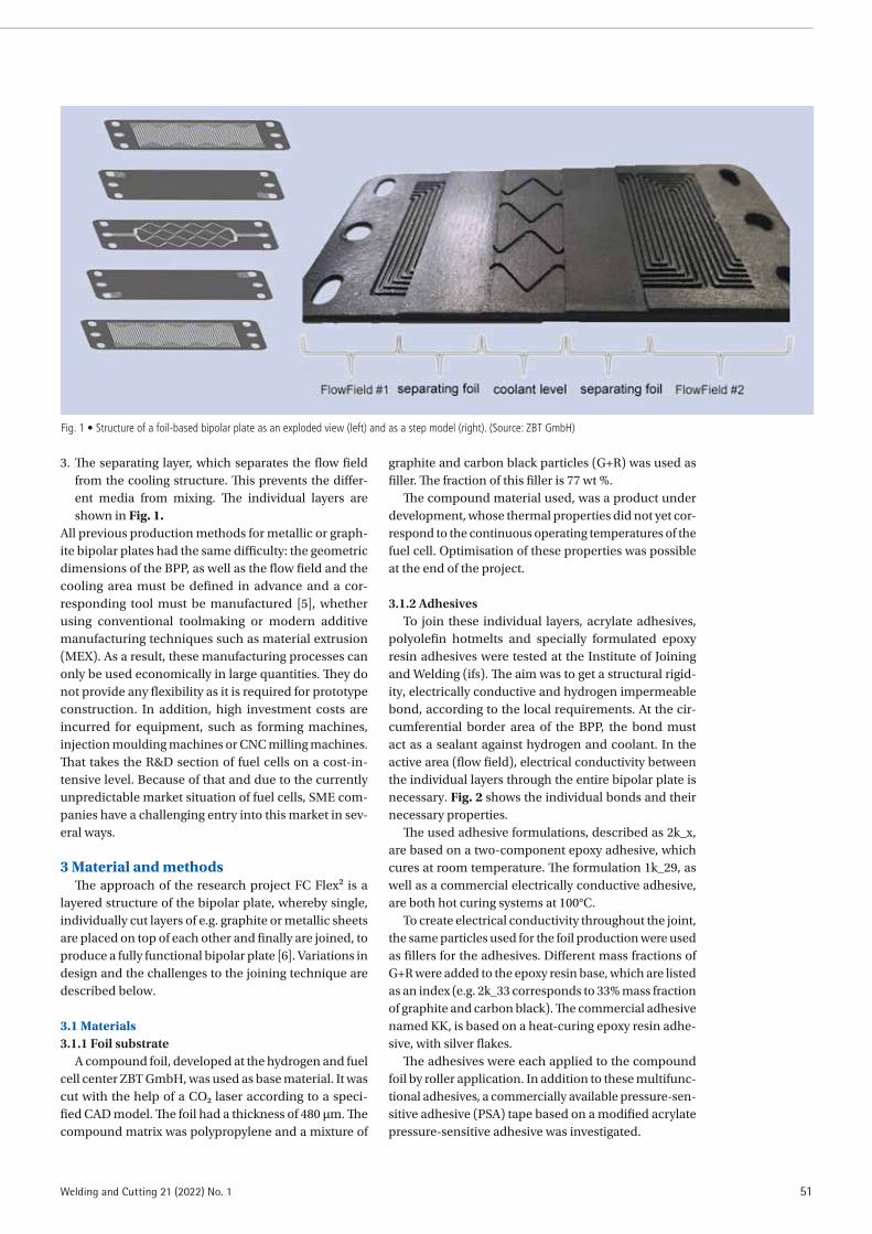
51Welding and Cutting 21 (2022) No. 1
3. The separating layer, which separates the flow field from the cooling structure. This prevents the differ-ent media from mixing. The individual layers are shown in Fig. 1.
All previous production methods for metallic or graph-ite bipolar plates had the same difficulty: the geometric dimensions of the BPP, as well as the flow field and the cooling area must be defined in advance and a cor-responding tool must be manufactured [5], whether using conventional toolmaking or modern additive manufacturing techniques such as material extrusion (MEX). As a result, these manufacturing processes can only be used economically in large quantities. They do not provide any flexibility as it is required for prototype construction. In addition, high investment costs are incurred for equipment, such as forming machines, injection moulding machines or CNC milling machines. That takes the R&D section of fuel cells on a cost-in-tensive level. Because of that and due to the currently unpredictable market situation of fuel cells, SME com-panies have a challenging entry into this market in sev-eral ways.
3 Material and methodsThe approach of the research project FC Flex² is a
layered structure of the bipolar plate, whereby single, individually cut layers of e.g. graphite or metallic sheets are placed on top of each other and finally are joined, to produce a fully functional bipolar plate [6]. Variations in design and the challenges to the joining technique are described below.
3.1 Materials 3.1.1 Foil substrate
A compound foil, developed at the hydrogen and fuel cell center ZBT GmbH, was used as base material. It was cut with the help of a CO2 laser according to a speci-fied CAD model. The foil had a thickness of 480 µm. The compound matrix was polypropylene and a mixture of
graphite and carbon black particles (G+R) was used as filler. The fraction of this filler is 77 wt %.
The compound material used, was a product under development, whose thermal properties did not yet cor-respond to the continuous operating temperatures of the fuel cell. Optimisation of these properties was possible at the end of the project.
3.1.2 Adhesives To join these individual layers, acrylate adhesives,
polyolefin hotmelts and specially formulated epoxy resin adhesives were tested at the Institute of Joining and Welding (ifs). The aim was to get a structural rigid-ity, electrically conductive and hydrogen impermeable bond, according to the local requirements. At the cir-cumferential border area of the BPP, the bond must act as a sealant against hydrogen and coolant. In the active area (flow field), electrical conductivity between the individual layers through the entire bipolar plate is necessary. Fig. 2 shows the individual bonds and their necessary properties.
The used adhesive formulations, described as 2k_x, are based on a two-component epoxy adhesive, which cures at room temperature. The formulation 1k_29, as well as a commercial electrically conductive adhesive, are both hot curing systems at 100°C.
To create electrical conductivity throughout the joint, the same particles used for the foil production were used as fillers for the adhesives. Different mass fractions of G+R were added to the epoxy resin base, which are listed as an index (e.g. 2k_33 corresponds to 33% mass fraction of graphite and carbon black). The commercial adhesive named KK, is based on a heat-curing epoxy resin adhe-sive, with silver flakes.
The adhesives were each applied to the compound foil by roller application. In addition to these multifunc-tional adhesives, a commercially available pressure-sen-sitive adhesive (PSA) tape based on a modified acrylate pressure-sensitive adhesive was investigated.
Fig. 1 • Structure of a foil-based bipolar plate as an exploded view (left) and as a step model (right). (Source: ZBT GmbH)

SPECIALIST ARTICLES
52 Welding and Cutting 21 (2022) No. 1
3.1.3 Testing methodsThe tensile strength of the compound film was tested
in a tensile test according to ISO 527. For this purpose, type 5a tensile bars were punched out longitudinally from the compound film and pulled at a test speed of 100 mm/min.
To characterise the joint, tensile shear specimens with the dimensions 100 × 25 mm and an overlap length of 12.5 mm were produced according to EN 1465. To rein-force the foil, it was structurally bonded to an aluminium substrate (2 mm) beforehand. The test was carried out at room temperature (RT) at a test speed of 1 mm/min.
Peel specimens of the compound foil and the PSA tape were prepared according to EN 1464 with a length of 125 mm and a width of 25 mm. They were tested with a test speed of 100 mm/min at RT.
The substrate was primarily cleaned with isopro-panol and then treated with an 800 W atmospheric pressure plasma prior to the adhesive application, to increase the surface energy and polar fractions. The evaluation of the surface tension was carried out via contact angle measurements (goniome-ter OCA 30) and the implemented software via the
parameterisation according to Owens, Wendt, Rabel and Kaelble (OWRK model).
3.2 Measuring method – electrical resistanceTo determine the electrical resistances, a measuring
setup was used at the ZBT, where both the total resist-ance of a substrate and the individual partial resistances (contact, material) can be determined separately. The measuring setup consisted of a pneumatic press with two measuring tips punches and centred measuring needles. There was a gas diffusion layer (GDL) between the sample and the measuring plunger to obtain a sit-uation that was as close to reality as possible. Within a series of measurements, the specimens were measured at increasing contact pressure (standard: 5 bar, 10 bar, 20 bar, 30 bar) and increasing currents were applied (standard: 500 mA, 1000 mA, 1500 mA, 2000 mA). The resulting voltages were used to determine the resistances.
The total resistance Rtotal resulting from the measured values is composed as follows, Formula 1.
Rtotal= 2 × RGDL + 2 × Rcontact + Rbulk (1)
This consists of the GDL resistance RGDL, the contact resistance Rcontact and the material resistance Rbulk. RGDL was determined in an initial series of measurements and then taken as given. Rbulk resulted from the measurement via the measuring needles. Rcontact can be determined by calculation. In the following, we will primarily refer to the area-specific volume resistance Rforward, which is determined according to Formula 2.
Rforward = Rtotal – 2 × RGDL (2)
For the investigation of the electrical contact between two compound foils, so called sandwich specimens were prepared. For this purpose, the compound foil was cut into pieces of 4 cm × 4 cm size, cleaned with isopro-panol and pretreated with atmospheric plasma. Subse-quently, two compound sheets with an adhesive layer in between were produced to form a sandwich specimen. Curing was performed at two different contact pressures (1.8 MPa and 0.625 MPa). In addition, the adhesives were cured at 60°C and 100°C, respectively.
As a reference, two sheets of the compound material were placed on top of each other and measured for elec-trical contact resistance without any bonding process.
3.3 Measuring method – hydrogen permeabilityThe hydrogen impermeability of the composite is an
elementary property for fuel cell operation. It is nec-essary, that the adhesive layers are as impermeable against hydrogen as possible. The setup to measure the hydrogen leakage consists of a cylindrical chamber, which is sealed against the environment. A specimen is placed in the centre of this chamber; doing so it divides the chamber into an upper and a lower area. While one area of the chamber is flooded with hydrogen at 1 bar, the amount of hydrogen in the other chamber
Fig. 2 • Locally resolved functional requirements for the bonding points on the active or cooling side of a bipolar panel. (Source: ZBT GmbH)
Fig. 3 • Sectional view of a coin specimen for measuring hydrogen tightness. (Source: ifs TU Braunschweig)
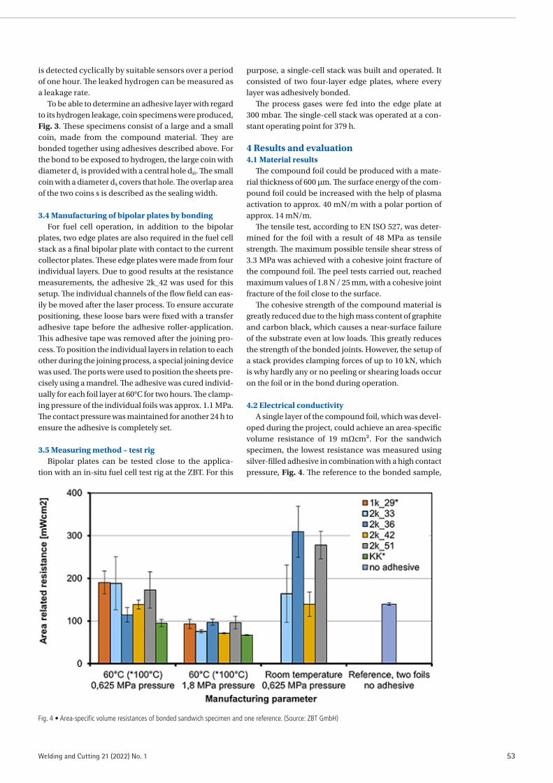
53Welding and Cutting 21 (2022) No. 1
is detected cyclically by suitable sensors over a period of one hour. The leaked hydrogen can be measured as a leakage rate.
To be able to determine an adhesive layer with regard to its hydrogen leakage, coin specimens were produced, Fig. 3. These specimens consist of a large and a small coin, made from the compound material. They are bonded together using adhesives described above. For the bond to be exposed to hydrogen, the large coin with diameter dL is provided with a central hole dH. The small coin with a diameter dS covers that hole. The overlap area of the two coins s is described as the sealing width.
3.4 Manufacturing of bipolar plates by bondingFor fuel cell operation, in addition to the bipolar
plates, two edge plates are also required in the fuel cell stack as a final bipolar plate with contact to the current collector plates. These edge plates were made from four individual layers. Due to good results at the resistance measurements, the adhesive 2k_42 was used for this setup. The individual channels of the flow field can eas-ily be moved after the laser process. To ensure accurate positioning, these loose bars were fixed with a transfer adhesive tape before the adhesive roller-application. This adhesive tape was removed after the joining pro-cess. To position the individual layers in relation to each other during the joining process, a special joining device was used. The ports were used to position the sheets pre-cisely using a mandrel. The adhesive was cured individ-ually for each foil layer at 60°C for two hours. The clamp-ing pressure of the individual foils was approx. 1.1 MPa. The contact pressure was maintained for another 24 h to ensure the adhesive is completely set.
3.5 Measuring method – test rigBipolar plates can be tested close to the applica-
tion with an in-situ fuel cell test rig at the ZBT. For this
purpose, a single-cell stack was built and operated. It consisted of two four-layer edge plates, where every layer was adhesively bonded.
The process gases were fed into the edge plate at 300 mbar. The single-cell stack was operated at a con-stant operating point for 379 h.
4 Results and evaluation4.1 Material results
The compound foil could be produced with a mate-rial thickness of 600 µm. The surface energy of the com-pound foil could be increased with the help of plasma activation to approx. 40 mN/m with a polar portion of approx. 14 mN/m.
The tensile test, according to EN ISO 527, was deter-mined for the foil with a result of 48 MPa as tensile strength. The maximum possible tensile shear stress of 3.3 MPa was achieved with a cohesive joint fracture of the compound foil. The peel tests carried out, reached maximum values of 1.8 N / 25 mm, with a cohesive joint fracture of the foil close to the surface.
The cohesive strength of the compound material is greatly reduced due to the high mass content of graphite and carbon black, which causes a near-surface failure of the substrate even at low loads. This greatly reduces the strength of the bonded joints. However, the setup of a stack provides clamping forces of up to 10 kN, which is why hardly any or no peeling or shearing loads occur on the foil or in the bond during operation.
4.2 Electrical conductivityA single layer of the compound foil, which was devel-
oped during the project, could achieve an area-specific volume resistance of 19 mΩcm². For the sandwich specimen, the lowest resistance was measured using silver-filled adhesive in combination with a high contact pressure, Fig. 4. The reference to the bonded sample,
Fig. 4 • Area-specific volume resistances of bonded sandwich specimen and one reference. (Source: ZBT GmbH)

SPECIALIST ARTICLES
54 Welding and Cutting 21 (2022) No. 1
two foils placed on top of each other without any adhe-sive, has a resistance of 139 mΩcm². This is more than the resistance of specimen which were bonded using high pressure and high temperature. With these curing parameters, the two adhesives 2k_33 and 2k_42 showed lower resistance than the adhesive formula filled with the highest proportion of G+R (50% by mass). This shows that the proportion of conductive particles is not the only criterion for a good electrical conductivity in reac-tive adhesives in conjunction with the compound foil under investigation.
Overall, all adhesives show lower resistances at a high contact pressure than at a lower contact pressure. Fur-thermore, the resistance can be reduced, by increasing the curing temperature of the two-component epoxy adhesives from RT to 60°C.
4.3 Hydrogen permeabilityCompound foil was measured as a reference to
determine its hydrogen permeability. The leakage rate of one compound layer is 0.73 × 10⁻⁸ cm²/s. The adhesives examined are between 1.0 × 10⁻⁸ cm²/s and 1.4 × 10⁻⁸ cm²/s.
During the assembling of a fuel cell stack, individ-ual components are sealed against each other with the help of a silicone sealant, Fig. 5. The leakage rates of the silicones used are usually between 15 × 10–8 cm²/s and over 100 × 10–8 cm²/s. From this point of view, none of the newly developed and investigated adhesives showed any leakage against hydrogen and both the substrate and the adhesive can be rated as technically impermeable.
4.4 Manufacturing of bipolar plates by bondingThe bonded, multi-layer bipolar plate was made
from five individual layers of foil. The total thickness of this component was 2.14 mm, the injection-moulded
reference is 5.08 mm, Fig. 6. By using layer based BPP the component thickness can be reduced by approx. 60%. Due to the combination of several bonded foils, the final bipolar plate was no longer flexible like one single sheet. Nevertheless, in contrast to the reference, small mechanical deformations could be carried out without the plate suffering a brittle fracture.
The volume resistivity of the four-layer edge plate was 748 mΩcm² which is significantly higher than the reference with 61 mΩcm². There is a need for further research here.
4.5 Test rig The endurance test of the single-cell unit was car-
ried out as planned for 379 h and completed success-fully, as neither leaks nor power losses occurred over the entire measurement period. At a current density of 0.25 A/cm², a voltage of approx. 0.3 V was achieved, Fig. 7. The reference, a bipolar plate produced by injection moulding, achieved a voltage of 0.8 V at the same cur-rent density. The difference in performance is mainly due to the ohmic losses caused by the greatly increased volume resistivity of the edge plates used (748 mΩcm²), compared to the injection-moulded reference (61 mΩcm²).
At the end of the test, small plastic deformations of the compound material could be observed in the area of the applied silicone seals and the flow field. The cooling channel structure within the edge plate was pressed into the flow field, underlining the flex-ibility of the foil. The combination of operating pres-sure and high operating temperature of 80°C shows special demands on the structural strength of the thin compound material. The goal for a durable foil-based bipolar plate is a compromise between thin-walled material and mechanical rigidity under operating conditions.
5 Summary and conclusionThe experiments have shown that it is possible
to manufacture bipolar plates without moulds and thus with a high degree of flexibility. The degrees of freedom that can be achieved for the variance of the individual structures can be extremely helpful for the development of new bipolar plate designs and further development of existing solutions through cost-effec-tive experiments. A realisation of the layer-by-layer structure in combination with an industrial roll-to-roll process can lead to the large-scale suitability of this production method for bipolar plates.
The adhesives investigated showed sufficiently high hydrogen impermeability. The tests carried out with the variance of the mass fraction of graphite and carbon
Fig. 6 • Comparison of an injection-moulded BPP (left) and a foil-based BPP (right). (Source: ZBT GmbH)
Fig. 5 • Flow field sealed with silicone. (Source: ZBT GmbH)

55Welding and Cutting 21 (2022) No. 1
ACKNOWLEDGEMENTSThe IGF Project number 20.093 N /DVS number 08.2253 of the research associ-ation ”Forschungsvereinigung Schweißen und verwandte Verfahren e. V. des DVS, Aachener Str. 172, 40223 Düsseldorf” was, on the basis of a resolution of the German Bundestag, promoted by the German Ministry of Economic Affairs and Climate Action via the Federation of Industrial Research Associations (AiF) within the framework of the programme for the promotion of joint industrial research (IGF).
Fig. 7 • Voltage – current density curves of a foil-based edge plate operated in the test rig. (Source: ZBT GmbH)
black could not be brought into line with a linear reduc-tion of the electrical contact resistance. On the contrary, an ideal filling level was found at 42% mass fraction in the adhesive. A further increase of the contact forces during the joining process seems to be target-oriented. The consideration of the volume shrinkage of the adhe-sives in connection with their curing temperature and the effect on a further reduction of the resistance is a further step in the direction of efficient, bonded bipolar plates.
The layered bipolar plate had a component thick-ness approx. 60% less than the reference made of injec-tion-moulded material. The electrical conductivity, on the other hand, was much higher than that of the refer-ence, which resulted in a much lower performance in the voltage-current density test than with the reference plate. Curing the adhesive used under higher contact pressure may solve this challenge.
The deformations of the foils due to the combination of increased temperature and pressure show that the mechanical loads have been too high for the compound material at hand. For this reason, the compound foil is being further developed at the ZBT to get closer to the reference in this respect.
The presented production method provides SMEs with the possibility for design variation and flexible production that does not require high investment costs for moulding tools. This facilitates an active entry into the energy transition market and enables rapid product development.
Literature[1] Deutscher Bundesrat (Ed.): Eine europäische Strategie für
emissionsarme Mobilität. Printing 387/16. Köln, 2016
[2] Agnolucci, P.: Prospects of fuel cell auxiliary power units in the civil markets. International Journal of Hydrogen Energy 32 (2007), No. 17, pp. 4306/18.
[3] Vielstich, W. (Ed.), A. Lamm (Ed.) u. H. Gasteiger (Ed.): Handbook of fuel cells: Fundamentals, technology and applications. Wiley, Chichester 2003.
[4] Klell, M., H. Eichlseder u. A. Trattner: Wasserstoff in der Fahrzeugtechnik: Erzeugung, Speicherung, Anwendung, 4. Edition. Springer Vieweg, Wiesbaden 2018.
[5] Hickmann, T.: Effizientes Herstellungsverfahren für metal-lische Bipolarplatten zum Einsatz in Brennstoffzellen. Final report. Deutsche Bundestiftung Umwelt, DBU Az. 32644/01, 2016.
[6] N. N.: Flexibles Kleben von flexiblen Hybrid-Kunststoff-Bi-polarplatten. Final report. Research project IGF 20.093 N/DVS 08.2253, Braunschweig, Duisburg 2020.

SPECIALIST ARTICLES
56 Welding and Cutting 21 (2022) No. 1
Increase in understanding of the welding process through simulation of laser beam and gas-shielded metal arc welding
THE AUTHORSDr.-Ing. Oleg MokrovGroup Leader Simulation of the Welding and Joining Institute (ISF), RWTH Aachen [email protected]
Dr. rer. nat. Marek SimonFormer Research Associate of the Welding and Joining Institute (ISF), RWTH Aachen [email protected]
M. Sc. Rahul SharmaSenior Engineer at the Welding andJoining Institute (ISF), RWTH Aachen [email protected]
Prof. Dr.-Ing. Uwe ReisgenHead of the Welding and Joining Institute (ISF), RWTH Aachen [email protected]
M. Sc. Christoph SchölerResearch Associate of Instruction and Research Department for Nonlinear Dynamicsof Laser Manufacturing Processes (NLD)at RWTH Aachen [email protected]
Dr. rer. nat. Markus NießenResearch Associate of the Modelling Department and Simulation at the Fraunhofer Institute for Laser [email protected]
Prof. Dr. rer. nat. habil. Wolfgang SchulzHead of the Nonlinear Dynamics of Laser Manufacturing Processes Instruction and Research Department (NLD) at RWTH Aachen University and Head of the Modelling and Simulation Department at the Fraunhofer Institute for Laser [email protected]
KEYWORDSlaser welding, gas-shielded arc welding, simulation and calculation, heat distribution
In welding structure simulation, the thermal effect of welding in the component is represented by an equiv-alent heat source. In order to be able to capture phe-nomena such as grain growth and structural transfor-mation in the structure simulation, in addition to the amount of heat input, its distribution on mesoscopic, spatial scales must also be specified. With known ap-proaches for the equivalent heat source, the physical process is still not sufficiently understood, and an ex-act calibration is very complex. With the aim of find-ing more accurate equivalent heat sources for the consideration of mesoscale phenomena, this work analyses laser beam and gas-shielded metal arc weld-ing (GMAW) in selected areas of the process parame-ters and discusses process properties that should be taken into account when formulating the heat source. These include formation of welding capillary in laser deep welding, which is significantly influenced by the absorption properties of the metallic material sur-face, as well as the distribution of heat flow and elec-trical current density on the cathode in the GMAW process, which are significantly influenced by evapo-ration.
1 IntroductionAccording to [1], welding structural simulation deals
with the prediction of residual stresses and distortion due to transient temperature fields on macroscale com-ponents during welding. This is contrasted with mate-rial simulation, which deals with the microstructure and material properties, and welding process simulation, which aims to accurately determine the heat introduced and its distribution in the process. These three areas are interdependent. Of outstanding importance for indus-trial applications, however, is the weld structural sim-ulation, since it supports component design and the planning of welding instructions, where it enables many expensive preliminary tests to be saved.
It corresponds to the state of the art in weld structure simulation that the microstructural transformations are also taken into account as essential factors when calculating residual stresses and distortion [2]. How-ever, while for the calculation of the temperature fields in the entire component the mesoscale distribution of heat is secondary and primarily the amount of heat coupled into the weld pool is decisive, the exact tem-perature-time histories in the heat-affected zone (HAZ)
are necessary for the determination of the influence of the heat input on the microstructure. Since the HAZ is
Further information on the authors athttps://www.welding-and-cutting.info/authors

57Welding and Cutting 21 (2022) No. 1
adjacent to the molten pool and gradients there can vary greatly in both spatial and temporal dimensions, the most accurate possible description of the process is critical for accounting for processes that are sensitive to the precise distribution of heat.
These consequences for structure simulation are cur-rently becoming even more important when applied to new materials (for example duplex or TWIP steels) for which no empirical values are yet available. Although limited information about the process can also be obtained via experimental measurements, for example by recording temperature-time histories with thermo-couples, these reach their limits particularly in heat-af-fected zones where high temperature gradients occur. This is partly due to the local resolution of the measuring points, but also to the distance from the weld pool and the reaction time. An ordinary temperature measure-ment with thermocouples gives a good indication of the amount of heat that is introduced, but it is hardly sensitive to the exact distribution of heat in the heat-af-fected zone.
Process simulation, on the other hand, provides insight into areas that are not accessible experimentally. These include the processes in the melt and the details of the heat input by the real energy source used. In particu-lar, the temporally and spatially resolved distribution of heat flows near the melt pool boundary can be studied, which is not possible with conventional measurement methods. In this way, equivalent heat source (ÄWQ) models can be evaluated with respect to their suitabil-ity for mapping the heat distributions near the melt pool in specified process windows and new concepts for the realisation of ÄWQ models can be derived.
2 State of the artThe representation of the coupled physical processes
in MSG and laser beam welding in a process model is associated with great numerical effort and long calcula-tion times. In welding structural simulation, the spatial and temporal distribution of the temperature is used as an input variable to consider the thermal history of the component [3]. Here, the thermal effect of the process on the component is abstracted by a heat conduction (WL) model in which the energy input is through a usu-ally volumetric equivalent heat source. This approach neglects the causes and details of the origin of the tem-perature distribution in the workpiece and allows an efficient calculation of residual stresses and distortion. In addition to the low computation times for the heat conduction task, another advantage of ÄWQ models is the simplicity of their implementation in commercial simulation software.
2.1 Heat conduction modelsFor the calculation of the three-dimensional temper-
ature distribution, models based on the heat conduction equation have been established, which allow the find-ing of analytical or numerical solutions. The advantages of the analytical models are the short time required for
the calculation of the temperature distribution and the existence of a closed, resolution-independent solution of the heat conduction problem. The solution results from the superposition of individual solutions for a mov-ing point heat source [4], which are weighted according to the heat source distribution used. Finite component dimensions as well as boundary conditions can be taken into account by using virtual heat sources [5].
The analytical models are limited to simple compo-nent shapes (plane plates, cuboids) with adiabatic or convective boundary conditions in the butt joint at con-stant thermophysical material properties [6]. Numerical solution methods, on the other hand, offer great flexi-bility with respect to component shape, weld arrange-ment, and material properties, but require much longer computation times [7].
2.2 Equivalent heat source modelsKnown volumetric heat source models include distri-
butions of both infinitesimal and finite spatial extent. The former include point sources as well as line sources with different dependencies on penetration depth [8]. These are mainly used in analytical heat conduction models, where they lead to a simplification of the mathematical expression for the calculated temperature distribution, since the solution structure here takes the form of a convolution of the source distribution with the Green’s function of the heat conduction problem (see Section 2.1). Heat sources with finite spatial extent are applied in analytical and numerical solution. An overview of models is given in [6; 9], specifying the temperature field solutions for analytically solvable heat conduction problems. Arbitrary combinations of the elementary source distributions in the three spatial dimensions are possible and lead to prominent representatives such as the symmetric Gaussian source or the asymmetric dou-ble ellipsoidal Goldak source [10]. There are no limits to the creativity of the user. However, it must be taken into account that with an increasing number of free heat source parameters, the calibration process also becomes more elaborate and thus generally requires more skill and time.
In addition to volumetric heat sources, the use of surface sources is common [11]. They can be used, for example, to take into account the workpiece-surface portion of the absorbed energy in laser beam welding, which leads to nail heads in the weld seam. Furthermore, especially in laser beam welding, the energy input into the capillary surface is represented by an infinitesimal line source [8] or a normally distributed heat source [6], also known as a Gaussian source, with a corresponding depth dependence. The final form of the model depends on the process window considered and the physical phe-nomena involved leading to the energy input. Further-more, the welding arrangement (for example, in case of position-counterposition welding) and the welded materials, which generally lead to asymmetric welds, have to be taken into account. Application examples for laser beam welding can be found in [7; 8; 11].

SPECIALIST ARTICLES
58 Welding and Cutting 21 (2022) No. 1
2.3 Calibration of the heat source parametersAfter the selection of an equivalent heat source
model, there is the task of solving an inverse heat con-duction problem. The model parameters of the equiv-alent heat source must be determined under variation by an iterative matching of the calculated temperature distributions with experimental data [3]. The process can be time consuming and requires experiential knowledge and skill in manually adjusting the parameters. The time required to solve the optimisation problem is largely determined by the duration of a single temperature field calculation, which limits the number of possible itera-tion steps per time. Analytical heat conduction models offer a clear advantage here. They have a better conver-gence behaviour due to the closed source formulation and can be used in conjunction with global optimisation algorithms for an automated calibration of the equiva-lent heat source [8]. Numerical temperature calculations can also be used in conjunction with local optimisation methods for automated adjustment of the equivalent heat source parameters, but have longer individual cal-culation times. Numerical model reduction methods can be used here to accelerate the optimisation steps [7]. Furthermore, due to the discrete formulation of the source, the calibration result generally depends on both the meshing used and the numerical integration method employed and is therefore not directly transfer-able between different simulation programs.
3 Findings from the process simulationProcess simulation for welding deals with the ques-
tion of how much heat is introduced into the process zone and in which form the molten pool is formed. The challenge in modelling the energy input for weld struc-ture simulation is physical. Heat input from the real energy source occurs primarily on the surface in both the cathode region for GMAW and laser beam welding. However, the mathematical formulation of a surface source via embedded edges is non-trivial and so far not feasible in the context of a weld structural simulation
for the industrial environment. This is especially true for deep penetration welding as well as laser penetration welding, where energy is coupled into the process via the surface of the weld capillary. In the following, the latest findings from process simulations of both manu-facturing processes are presented and the distributions of characteristic quantities relevant for modelling the heat input are discussed.
3.1 Gas-shielded metal arc welding (GMAW)GMAW is an arc welding process and should be dis-
tinguished in particular from tungsten inert gas (TIG) welding. An essential difference between the two pro-cesses is that in TIG welding the arc burns between the workpiece and a non-melting tungsten electrode, whereas in GMAW the arc burns between the workpiece and a melting wire electrode. Another difference also lies in the current polarity when direct current is used, so that in TIG welding the tungsten electrode is mostly poled as the cathode and the workpiece as the anode, whereas in GMAW the workpiece is commonly the cath-ode and the wire electrode is the anode.
In TIG welding, the transfer of heat and electric cur-rent from the arc to the workpiece occurs via a relatively uniform, so-called anode spot, which can only be addi-tionally activated locally in special cases, for example when a flux is used or by laser radiation. In GMAW, however, heat transfer occurs via the so-called cathode area, the underlying physical mechanisms of which are not yet well understood, and in addition there is a heat input by the molten droplets into the molten pool. It is important to note here that both the effect of the droplets (heat, mass, momentum) and the effect of the cathode region (heat and electric current density, thus also electromagnetic forces) significantly influence the flows in the molten pool, and therefore the shaping of the molten pool in the TIG process differs significantly from the shaping of the molten pool in the MSG pro-cess. In the MSG process, however, a distinction is made between the following common variants: the short arc
Fig. 1 • Heat flux density and electric current density according to the model from [12].
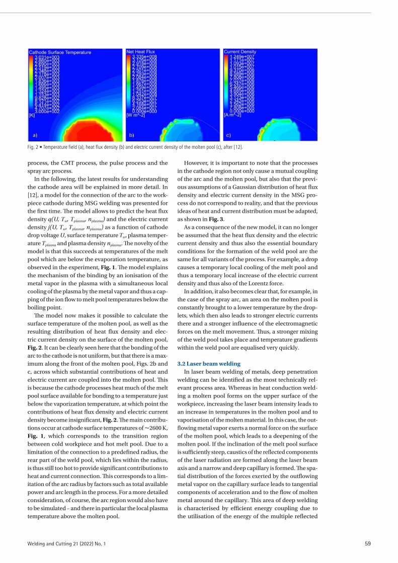
59Welding and Cutting 21 (2022) No. 1
process, the CMT process, the pulse process and the spray arc process.
In the following, the latest results for understanding the cathode area will be explained in more detail. In [12], a model for the connection of the arc to the work-piece cathode during MSG welding was presented for the first time. The model allows to predict the heat flux density q(U, Tw, Tplasma, nplasma) and the electric current density j(U, Tw, Tplasma, nplasma) as a function of cathode drop voltage U, surface temperature Tw, plasma temper-ature Tplasma and plasma density nplasma. The novelty of the model is that this succeeds at temperatures of the melt pool which are below the evaporation temperature, as observed in the experiment, Fig. 1. The model explains the mechanism of the binding by an ionisation of the metal vapor in the plasma with a simultaneous local cooling of the plasma by the metal vapor and thus a cap-ping of the ion flow to melt pool temperatures below the boiling point.
The model now makes it possible to calculate the surface temperature of the molten pool, as well as the resulting distribution of heat flux density and elec-tric current density on the surface of the molten pool, Fig. 2. It can be clearly seen here that the bonding of the arc to the cathode is not uniform, but that there is a max-imum along the front of the molten pool, Figs. 2b and c, across which substantial contributions of heat and electric current are coupled into the molten pool. This is because the cathode processes heat much of the melt pool surface available for bonding to a temperature just below the vaporization temperature, at which point the contributions of heat flux density and electric current density become insignificant, Fig. 2. The main contribu-tions occur at cathode surface temperatures of ≈2600 K, Fig. 1, which corresponds to the transition region between cold workpiece and hot melt pool. Due to a limitation of the connection to a predefined radius, the rear part of the weld pool, which lies within the radius, is thus still too hot to provide significant contributions to heat and current connection. This corresponds to a lim-itation of the arc radius by factors such as total available power and arc length in the process. For a more detailed consideration, of course, the arc region would also have to be simulated – and there in particular the local plasma temperature above the molten pool.
However, it is important to note that the processes in the cathode region not only cause a mutual coupling of the arc and the molten pool, but also that the previ-ous assumptions of a Gaussian distribution of heat flux density and electric current density in the MSG pro-cess do not correspond to reality, and that the previous ideas of heat and current distribution must be adapted, as shown in Fig. 3.
As a consequence of the new model, it can no longer be assumed that the heat flux density and the electric current density and thus also the essential boundary conditions for the formation of the weld pool are the same for all variants of the process. For example, a drop causes a temporary local cooling of the melt pool and thus a temporary local increase of the electric current density and thus also of the Lorentz force.
In addition, it also becomes clear that, for example, in the case of the spray arc, an area on the molten pool is constantly brought to a lower temperature by the drop-lets, which then also leads to stronger electric currents there and a stronger influence of the electromagnetic forces on the melt movement. Thus, a stronger mixing of the weld pool takes place and temperature gradients within the weld pool are equalised very quickly.
3.2 Laser beam weldingIn laser beam welding of metals, deep penetration
welding can be identified as the most technically rel-evant process area. Whereas in heat conduction weld-ing a molten pool forms on the upper surface of the workpiece, increasing the laser beam intensity leads to an increase in temperatures in the molten pool and to vaporisation of the molten material. In this case, the out-flowing metal vapor exerts a normal force on the surface of the molten pool, which leads to a deepening of the molten pool. If the inclination of the melt pool surface is sufficiently steep, caustics of the reflected components of the laser radiation are formed along the laser beam axis and a narrow and deep capillary is formed. The spa-tial distribution of the forces exerted by the outflowing metal vapor on the capillary surface leads to tangential components of acceleration and to the flow of molten metal around the capillary. This area of deep welding is characterised by efficient energy coupling due to the utilisation of the energy of the multiple reflected
Fig. 2 • Temperature field (a), heat flux density (b) and electric current density of the molten pool (c), after [12].

SPECIALIST ARTICLES
60 Welding and Cutting 21 (2022) No. 1
components of the laser radiation and enables large aspect ratios of the weld.
The absorption of laser radiation in metals occurs close to the surface at optical penetration depths of a few nanometres. Therefore, in the context of process mod-elling, the description of absorption as a surface phe-nomenon is appropriate. A phenomenological approach is provided by the Fresnel equations, which establish a relationship between the absorption coefficient, the angle of incidence and the optical constants. A detailed description of the mechanisms involved in absorption can be found in [13]. Especially for metals as good elec-trical conductors, the form of the equations simplifies and the absorption coefficient depends only on one material parameter [14]. This can strongly depend on the frequency of the laser light used and thus, depending on the process parameters, limit the achievable process ranges for a given laser beam source. An example of this is laser beam microwelding of copper materials with infrared laser light and laser light in the visible range [15]. Furthermore, the polarisation state of the laser light has an influence on the absorption, since the Fresnel coefficients for s-polarised and p-polarised components differ. Since these fractions are determined by the plane of incidence of the light and thus by the local orientation of the surface, the coupling of any light beam generally changes during its propagation through the capillary in deep welding. Ultimately, volume absorption of the laser radiation by the plasma can occur when the metal vapor is ionised. Consequently, the global geometric shape of the welding capillary and the intensity distribution of the absorbed laser radiation are the result of a complex chain of interactions between laser light and material, which is pronounced by locally existing conditions.
The complexity of absorption in laser deep pen-etration welding indicates a generally sensitive and highly dynamic process and makes a detailed analysis of heat input difficult. In [16], a steady-state geometric shape of the capillary was calculated under simplifying
assumptions in an approximate process model. Laser beam microwelding of Cu-ETP (oxygenated copper pro-duced by electrolytic refining with very high conductiv-ity for heat and electricity) with a laser of wavelength 515 nm was considered as the object of research. The model considers a free propagation of the laser radiation within the capillary and solves continuum physical balances at the capillary surface within two-dimensional layers per-pendicular to the laser beam axis. The geometric shape of the capillary within the layers is given as circles and parameterised by a radius and a centre position. In addi-tion to a local balance at the capillary apex, an integral power balance between absorbed laser radiation and heat flows in the material is considered in each layer. As a further solution parameter, a surface temperature constant within this layer is obtained for each layer. The result of a three-dimensional geometric capillary shape for a deep weld with the representation of different quantities on the capillary surface is shown in Fig. 4.
A comparison of the distribution of the total absorbed laser beam intensity qa with the distribution of the por-tion MR originating from reflected laser radiation shows the depth at which the formation of the capillary is deter-mined by reflections. Accordingly, the observed local excesses of the absorbed intensity (red areas in Fig. 4) indicate non-uniform propagation of the laser radiation along the depth of the capillary. Due to the simplified model structure, they are neither compensated by the heat flux ql nor by the surface temperature TS nor by local deviations of the geometric shape from a circle. Nevertheless, the intensity overshoots provide indica-tions for areas of the capillary tending to instabilities. The heat flux ql is largely determined by the feed rate, the thermal diffusivity and the radius of the capillary layers. Due to the feed (here in the X direction), it var-ies cosinusoidally with the polar angle of the cylindrical coordinate system used, with a maximum at the apex in the feed direction, and increases with decreasing cap-illary radius due to heat conduction losses caused by
Fig. 3 • Comparison between the conventional (Gaussian) notion of heat flux density (left) and the distribution of heat flux density considering a physics-based cathode model [12].

61Welding and Cutting 21 (2022) No. 1
curvature. Another reason for the increase in heat flux at depth is the increase in surface temperature. This results from the consideration of a momentum balance at the apex, in which the recoil forces of the metal vapor are balanced with the capillary forces of the surface ten-sion. The latter also depend inversely proportional on the capillary radius. Due to the non-equilibrium evap-oration, temperatures arise which are greater than the equilibrium evaporation temperature of the material at the saturation vapor pressure.
4 Process-relevant aspects for implementation in weld structure simulation4.1 Gas-shielded metal arc welding
The analysis of the cathode region in GMAW shows that the distribution of heat and electric current den-sity, which significantly contribute to the shaping of the molten pool, depends very much on the present process type and, in particular, on the current (via the plasma temperature). While the short arc should result in a dis-tribution concentrated under the electrode, the pulsed and spray arc processes should result in a distribution which should have a substantial coupling in the front part of the molten pool at the melt front.
Thus, Goldak’s equivalent heat source is probably a good assumption for low currents (as well as for non-ac-tivated TIG welding). But with increasing currents, the agreement of the heat flux density distribution with that
according to Goldak becomes increasingly imprecise. At higher currents, stronger electromagnetic forces are to be expected, and hence stronger currents and con-sequently stronger melt mixing. In these cases, a power density distribution as predicted by the MR10 equivalent heat source is preferable [17].
A further analysis of the heat input in the moving weld-ing process shows that the main part of the heat is intro-duced in the front part of the weld pool. This also seems to make sense, since a lot of energy is needed there to melt the material. In addition, the temperature gradients and thus the heat flux densities are also strongest there, while in the trailing part of the melt pool the heat is mainly trans-ported by flows from the front part. This should be taken into account when creating an equivalent heat source for the structural simulation, since an equivalent heat source with a significant energy input in the rear section might also provide a good match in the seam cross-section but would correspond much less to the real process.
However, in welding processes where the weld pro-trusion is no longer negligible, the case may arise where the intensive melt movement from the front into the rear part of the weld pool dominates, with the result that the main part of the heat must be introduced into the rear part of the weld pool. The front part must then be very spatially restricted in order to still ensure a power den-sity sufficient for melting. A suitable solution here would be the equivalent heat source MR10 in the second mod-ification [17].
Fig. 4 • Calculated geometrical shape of a capillary during blind welding in Cu-ETP with a laser of wavelength 515 nm (the black vertical lines indicate the laser beam axis; the Péclet numbers formed with the capillary radii are smaller than 0.64; beam diameter 240 µm, feed rate 60 mm/s, laser beam power 920 W); left: distribution of total absorbed laser beam intensity, centre left: distribution of the fraction of the total absorbed laser beam intensity coming from reflected light, centre right: distribution of the heat flow in the material, right: distribution of surface temperature.

SPECIALIST ARTICLES
62 Welding and Cutting 21 (2022) No. 1
4.2 Laser beam weldingFor the mapping of the heat effect of laser beam
welding, the following statements can be made based on the current understanding of the process: While heat conduction welding or the laser beam heat components absorbed on the top of the workpiece can be imple-mented in the weld structure simulation by a surface source, the consideration of heat input by the capillary during deep and through welding requires a differenti-ated view. The observation of an increase of the surface temperature with a simultaneous decrease of the capil-lary radius with depth initially coincides well with the notion of a volume source whose horizontal expansion decreases (for example linearly) with depth while the power per layer remains constant. However, the geomet-ric shape of the capillary is increasingly affected by the absorbed fractions of the reflected laser radiation when the absorption behaviour is poorer (for example, IR laser radiation on Cu-ETP), which can lead to a nonmono-tonic depth dependence. In particular, this applies to joints of materials with strongly different material prop-erties in the lap joint.
A first indication for the evaluation of the heat distribution generated by equivalent heat source is provided by the ratio of the lateral expansions of capil-lary and melt pool, which can be determined from the isotherms of the temperature distribution. While the capillary radius is of the order of the laser beam radius, the quotient of thermal diffusivity and feed rate gives a measure of the lateral expansion of the melt pool. The ratio of these length scales is the Péclet number formed with the capillary radius. For small Péclet numbers (Pe “ 1), i.e. large melt pools compared to the capillary, the spatial distribution of heat input into the melt pool is no longer resolved by the temperature distribution in the HAZ. For modelling using equivalent heat source, this means that only the power introduced by the source is decisive for the formation of the temperature distri-bution in the HAZ, but not its spatial distribution. Both Gaussian and line sources give equivalent results when calibrated appropriately. However, the situation is dif-ferent for larger Péclet numbers. The distributions of the isotherms produced by equivalent heat source models are more sensitive to the spatial distribution of equiv-alent heat source. Here, differences near the melt pool boundary are expected despite calibration for different source types. Also, the differences in heat flux along the capillary surface calculated from the process model increase, differences in surface temperature between the front and back walls are expected, and flow-induced advective heat transport becomes relevant.
4.3 Influence of fluid flow The shape of the weld pool during welding is largely
dependent on the flows that form. The flows not only influence the shape of the weld pool, but also com-pensate for the temperatures within the molten area. Without a more precise knowledge of the cause of the flows, the change in shape of the molten pool cannot
be compensated, but the temperature gradients in the molten pool can still be equalised. An artificial increase in thermal conductivity in the molten region can be used for this purpose. This method is also called “efficient thermal conductivity” [18]. By using this method, unre-alistically high temperatures in the effective centre of the equivalent heat source can be avoided, while the tem-peratures at the edge of the molten pool are increased, which corresponds more to the real process.
5 ConclusionThe results of a numerical structure simulation are
always a compromise between the accuracy and the speed of the calculation as well as the computer capac-ities and the available material parameters. For large or complex components, the mesh density is one of the critical influencing variables. In this case, the equiva-lent heat source method is the only way to calculate a transient temperature field in a reasonable time, and the results can be considered reliable to a first approx-imation, provided that the introduced energy has been properly captured.
However, with higher requirements on the precision of the temperature field calculation, deviations can occur which have their cause in specific process pecu-liarities which are lost when modelling the heat input with equivalent heat source. The inclusion of these pro-cess peculiarities requires a deep understanding of the process, which can be obtained from the process sim-ulation.
For the calibration of a selected heat source in the structural simulation, knowledge about the course of the real process can also bring a clear advantage, since it limits the selection of possible heat sources and the resulting distribution of heat is thus closer to reality.
Literature
[1] Radaj, D.: Welding Process Simulation: Fundamentals and Applications. Fachbuchreihe Schweißechnik, Vol. 141. DVS Media, Düsseldorf 1999.
[2] Lindgren, L.-E., et al.: Thermal stresses and computational welding mechanics. J. of Thermal Stresses 42 (2019), No. 1, pp. 107/21.
[3] Radaj, D.: Residual stresses and distortion in welding: Cal-culation and measurement methods. Fachbuchreihe Schweißechnik, Vol. 143. DVS Media, Düsseldorf 2002.
[4] Rosenthal, D.: The theory of moving sources of heat and its application to metal treatments. Transactions of the ASME 68 (1946), No. 8, pp. 849/66.
[5] Rykalin, N. N: The thermal fundamentals of the welding process. VEB Verlag Technik, Berlin 1952.
[6] Karkhin, V., et al.: Models for volume heat sources and functional-analytical technique for calculating the temper-ature fields in butt welding. Lecture Notes, 8th Int. Seminar “Mathematical modeling of weld phenomena”. TU Graz 2007.
[7] Nießen, M., and A. Pittner: Fast numerical methods for efficient temperature field calculation in geometries close to components and multi-layer welds. Final Report, IGF project 16.718 N/DVS 12.005. Fraunhofer ILT, Aachen / BAM, Berlin 2013.

63Welding and Cutting 21 (2022) No. 1
[8] Karkhin, V., et al.: Inverse modeling of fusion welding pro-cesses. Weld World 46 (2002), No. 11-12, pp. 2/13.
[9] Karkhin, V., et al.: Simulation of inverse heat conduction problems in fusion welding with extended analytical heat source models. Front. Mater. Sci. 5 (2011), No. 2, pp. 119/25.
[10] Goldak, J., et al.: A new finite element model for welding heat sources. MTB 15 1984), No. 2, pp. 299/305.
[11] Pittner, A., et al.: Methodology to improve applicability of welding simulation. Science and Techn. of Wdg. and Join-ing 13 (2008), No. 6, pp. 496/508.
[12] Mokrov, O., et al.: Arc-cathode attachment in GMA welding. J. Phys. D: Appl. Phys. 52 (2019), No. 36, pp. 364003.
[13] Bergström, D., and A. Kaplan: Mathematical modeling of laser absorption mechanisms in metals: A Review. Confer-ence paper, M4PL16 – 16th Meeting on Mathematical Mod-elling of Materials Processing with Lasers (2003).
[14] Schulz, W., et al.: On laser fusion cutting of metals. Phys. D: Appl. Phys. 20 (1987), No. 4, pp. 481/88.
[15] Hess, A., et al.: Continuous wave laser welding of copper with combined beams at wavelengths of 1030 nm and 515 nm. Physics Procedia 12 (2011), pp. 88/94.
[16] Schöler, C., et al.: Modeling and simulation of laser micro welding. Proc., Int. Congress “Lasers in Manufacturing LIM 2019“. Wissenschaftliche Gesellschaft Lasertechnik, Munich 2019.
[17] Mokrov, O., et al.: A fine modification of the double ellip-soid heat source. Proc., Conference “Mathematical mode-ling of weld phenomena 12”. TU Graz 2019.
[18] Reisgen, U., et al.: Welding process simulation for the cal-culation of an equivalent heat source. Proc., Conference “Mathematical modelling of weld phenomena 9”. TU Graz 2010.
ACKNOWLEDGEMENTSThe presented investigations were conducted in the context of the Collaborative Research Centre SFB1120 “Precision Melt Engineer-ing” at RWTH Aachen University and were funded by the German Research Foundation (DFG). For the sponsorship and the support, we wish to express our sincere gratitude. (Project ID 236616214)
Welding and Cutting – editorial preview
Issue 2-2022 ◾ Special from institutes and companies: Latest results from
joining and separation technology research
Closing date for editiorial contributions: 2 May 2022Closing date for advertisements: 10 May 2022
The editorial preview is subject to modifications.
Issue 3-2022 ◾ EuroBLECH in Hanover – Announcements from exhibitors ◾ Use of adhesive bonding technology to join metallic and
non-metallic materials ◾ Additive manufacturing ◾ Special joining processes
Closing date for editiorial contributions: 1 August 2022Closing date for advertisements: 9 August 2022
For information about advertising, please contact:Markus Winterhalter, DVS Media GmbH, Düsseldorf/Germany, e-mail [email protected]
For information about submitting editorial contributions, please contact:Anja Labussek, DVS Media GmbH, Düsseldorf/Germany, e-mail [email protected]
EXCLUSIVE E-PAPER EDITION
The current media kit is ready for you!
You can reach our advertising department directly at the following numbers:
+49 211 1591-155/-152 +49 211 1591-150

64 Welding and Cutting 21 (2022) No. 1
PUBLICATIONS
Books
DVS Media GmbH Düsseldorf/Germany U2/IFC, 12, 34, 35, 39
Fronius International GmbH Wels-Thalheim/Austria title
Metallizing Equipment Co. PVT Ltd. Jodhpur/India 13
Oerlikon Metco AG, Wohlen Wohlen/Austria U4/BC
List of companies in the advertisement section
On the Mechanism of Evaporation-Determined Arc-Cathode Coupling in GMA Welding
By Marek Sebastian Simon. 144 pages with numerous figures. Shaker Verlag, Düren 2021. Price Euro 45.80.
In gas metal arc welding (GMAW) pro-cess simulation, it is desired to predict the energy transferred to the process as well as the weld pool geometry. For this reason, the coupling of the arc to the welded material is of high interest, both at the cathode and the anode. Although there exists a substantial body of work on the coupling of the arc to the cathode, the present models cannot be applied in the conditions of GMAW weld-ing, as they give unphysical results. In par-ticular, the current models usually result in very high cathode surface temperatures, i.e. above boiling temperature of the metals.
After relevant experiments are presented and discussed in this publication, it is con-cluded that the current state of the art does not reflect the observations and that there-fore a new approach needs to be devel-oped. Furthermore, a dialectic argument
is developed, namely that the coupling of the arc to the cathode in diffuse attachment of GMAW must be strongly determined by evaporation. The argument concludes that the current transfer is mainly carried by metal ions that are evaporated from the cathode surface and ionised in the near cathode plasma, and that this current transfer must be limited to below boiling temperature. The core hypothesis is that this limit results from a decrease of the ion-isation degree, due to cooling of the near cathode plasma by the cold metal vapor.
Based on this argument, a mathemat-ical model for the Evaporation-Deter-mined Arc-Cathode Coupling (EDACC) is introduced in detail. The properties of the model are then analysed by applying it to a simplified computational fluid dynamics (CFD) weld pool simulation and it shows that the model is in line with the observed cathode surface temperatures below boil-ing. Finally, also an outlook is given on pos-sible applications of this new understand-ing of the arc-cathode coupling, as well as a discussion of open questions and current limitations of the model.
Your article from “WELDING AND CUTTING” separately printed
We arrange your article according to your instructions, also advertisements are possible.For any further information please contact Mrs. Reintjens.
+49 211 1591-156 [email protected]
Publisher:DVS – German Welding Society, Düsseldorf/Germany, incollaboration with the Institut de Soudure, Paris/France
Publishing House:DVS Media GmbH,PO Box 10 19 65, 40010 Düsseldorf, GermanyAachener Straße 172, 40223 Düsseldorf, GermanyTelephone +49 211 1591-0,Telefax +49 211 1591-150,E-mail [email protected],Internet www.dvs-media.eu,Management: Dirk Sieben
Editorial Board: Dipl.-Ing. Dietmar Rippegather(managing editor/responsible),E-mail [email protected],Anja Labussek M.A., Dipl.-Ing. Viktor TravkinFrédérique Champigny (IS News),E-mail [email protected]
Advisory Board: Dr.-Ing. R. Boecking (representing thepublisher), Prof. Dr.-Ing. Prof. h.c. S. Böhm, Dr.-Ing. C. Bruns,Prof. Dr.-Ing. H. Cramer, Prof. Dr.-Ing. K. Dilger, Prof. Dr.-Ing.habil. U. Füssel, Dr.-Ing. P. Gröger, Prof. Dr.-Ing. A. Hobbacher,Dr.-Ing. S. Jahn, Prof. Dr.-Ing. T. Kannengießer, Dipl.-Ing. W.Kleinkröger, Dr.-Ing. H. Krappitz, Dr. C. Mayer, Prof. Dr.-Ing. K.Möhwald, Dr. rer. nat. L. Nickenig, Prof. Dr.-Ing. D. Paulinus,Dipl.-Ing. C. Prinz, Prof. Dr.-Ing. C. Radscheit, Prof. Dr.-Ing.U. Reisgen, Dipl.-Ing. E. Schofer, Dr.-Ing. F. Schreiber, Dr. sc.techn. K.-R. Schulze, D. Sieben (CEO of the DVS PublishingHouse), Dr.-Ing. V. E. Spiegel-Ciobanu, Dr.-Ing. S. Trube, Prof.Dr.-Ing. V. Wesling, Dr. C. Wiesner Prof. Dr.-Ing. G. Wilhelm
Advertising: Markus Winterhalter (responsible),Telephone + 49 211 1591-142E-mail [email protected],Vanessa Wollstein, Telephone +49 211 1591-152,E-mail [email protected].
For currently valid prices please see Price ListNo. 19, effective 1st January 2020
Circulation: DVS Media GmbH, Reader Service,Telephone +49 6123 9238-242E-mail [email protected]
Printing: D+L Printpartner GmbH, Bocholt/Germany
Terms of Delivery: WELDING and CUTTING is publishedsix times a year. Members of the DVS (German WeldingSociety) receive a discount on the regular subscription price.Subscription is possible either directly through the DVSMedia GmbH or through your local bookstore. Single issuesare available at a price of 22.-€ (plus shipment costs), theprice for a one-year subscription for print is 134.-€, online+ print 178.-€ plus shipment costs (25.-€ within Germany,29.20€ abroad); online 99.-€. Delivery by airmail is possibleupon request. The subscribers and/or the advertisers can-not assert any compensation claims for a reduction in services due to force majeure or to other circumstances for which the publishing house is not a fault (e.g. strike).WELDING and CUTTING as well as all the contributions,figures and tables included in this journal are protected bycopyright. With the exception of the statutorily authorisedcases, any utilisation without the consent of the DVS MediaGmbH is punishable.
When the work is accepted for publication, the authortransfers to the publishing house the exclusive publishingrights for the period until the copyright expires. This transfer of rights relates, in particular, to the rights of the publishing house to reproduce the work for commercial purposes as a copy (microfilm, photocopy, CD-ROM or other processes) and/or to include it in electronic or other databases.
We do not accept any liability for manuscripts submittedwithout solicitation.
ISSN 1612-3433
Technical journal for welding and allied processes

65Welding and Cutting 21 (2022) No. 1
Publication in: SCHWEISSEN UND SCHNEIDEN; DER PRAKTIKER; WELDING AND CUTTING
© DVS Media GmbH Aachener Straße 172 Fon: +49 211 1591-0 40223 Düsseldorf Fax: +49 211 1591-150
I Plant and equipment for joining, surfacing and cutting processes
II Plant and equipment for heat treatment and other production processes
III Plant equipment, including automation, mechanization and industrial robots, for thermal cutting and erosion
IV General productions equipment for automation
V Contract work and services for joining, separating and coating
VI Plant and equipment, including automation, mechanization and industrial robots, for thermal spraying

66 Welding and Cutting 21 (2022) No. 1
The ABC of Joining – International Industry Guide
I Plant and equipment for joining, surfacing and cutting processes
1 Plant and equipment, including automation, mechanization and industrial robots, for the welding of metal, ceramic and composite materials
▼ Stud welding 20
AS - ARNHOLD - GmbHWullener Feld 48, D-58454 Witten( +49 2302 95 640-0 7 +49 2302 95 640-22-Mail: E [email protected]
nternet: I www.bolzenschweissen.com
Köster & Co. GmbH BolzenschweißtechnikSpreeler Weg 32, D-58256 Ennepetal( +49 23 33 83 06-0 7 +49 23 33 83 06-38-Mail: E [email protected]
nternet: I www.bolzenschweisstechnik.de
Heinz Soyer Bolzenschweißtechnik GmbHInninger Straße 14, D-82237 Wörthsee( +49 81 53 885-0 7 +49 81 53 885-221-Mail: E [email protected]
nternet: I www.soyer.de
▼ Projection welding 30
Bergmann & Steffen GmbHRaiffeisenstraße 176, D-32139 Spenge( +49 5225 8786-0 7 +49 5225 8786-27-Mail: E [email protected]
nternet: I www.bergmann-steffen.de
▼ Electron beam welding 60
Evobeam GmbHAm Hofgut 5 , D-55268 Nieder-Olm( +49 6136 9229-210 7 +49 6136 9229-212-Mail: E [email protected]
nternet: I www.evobeam.com
Josch Strahlschweißtechnik GmbHGewerbehof - Dorfplatz 0, D-06193 Petersberg OT Teicha( +49 34606 353-0 7 +49 34606 353-14-Mail: E [email protected]
nternet: I www.josch.net
LaVa-X GmbHKaiserstraße 100, 52134 Herzogenrath( +49 2407-95389-81-Mail: E [email protected]
nternet: I www.lava-x.de
pro-beam GmbH & Co. KGaAZeppelinstraße 26, 82205 Gilching( +49 89 899 233-0 7 +49 89 899 233-11-Mail: E [email protected]
nternet: I www.pro-beam.com
PTR Strahltechnik GmbHAm Erlenbruch 9, D-63505 Langenselbold( +49 61 84 20 55-0 7 +49 61 84 20 55-300-Mail: E [email protected]
nternet: I www.ptr-ebeam.com
Steigerwald Strahltechnik GmbHEmmy-Noether-Straße 2, D-82216 Maisach( +49 81 41 35 35-0 7 +49 81 41 35 35-215-Mail: E [email protected]
nternet: I www.sst-ebeam.com
▼ Narrow gap welding 80
Carl Cloos Schweißtechnik GmbHCarl-Cloos-Straße 1, D-35708 Haiger( +49 27 73 85-0 7 +49 27 73 85-275-Mail: E [email protected]
nternet: I www.cloos.de
▼ Flux cored arc welding 100
DURUM VERSCHLEISS-SCHUTZ GMBHCarl-Friedrich-Benz-Straße 7, D-47877 Willich( +49 21 54 48 37-0 7 +49 21 54 48 37-78-Mail: E [email protected]
nternet: I www.durmat.com
EWM AGDr.-Günter-Henle-Straße 8, D-56271 Mündersbach( +49 2680 181-0 7 +49 2680 181-244-Mail: E [email protected]
nternet: I www.ewm-group.com
Fronius Deutschland GmbHFronius Straße 1, D-36119 Neuhof-Dorfborn( +49 6655 91694-0 7 +49 6655 91694-30-Mail: E [email protected]
nternet: I www.fronius.de
Welding Alloys Deutschland GmbHOstring 52, D-47669 Wachtendonk( +49 2836 9119-0 7 +49 2836 9119-18-Mail: E [email protected]
nternet: I www.welding-alloys.com
▼ Laser welding 180
Bergmann & Steffen GmbHRaiffeisenstraße 176, D-32139 Spenge( +49 5225 8786-0 7 +49 5225 8786-27-Mail: E [email protected]
nternet: I www.bergmann-steffen.de
Carl Cloos Schweißtechnik GmbHCarl-Cloos-Straße 1, D-35708 Haiger( +49 27 73 85-0 7 +49 27 73 85-275-Mail: E [email protected]
nternet: I www.cloos.de
DURUM VERSCHLEISS-SCHUTZ GMBHCarl-Friedrich-Benz-Straße 7, D-47877 Willich( +49 21 54 48 37-0 7 +49 21 54 48 37-78-Mail: E [email protected]
nternet: I www.durmat.com
Evobeam GmbHAm Hofgut 5 , D-55268 Nieder-Olm( +49 6136 9229-210 7 +49 6136 9229-212-Mail: E [email protected]
nternet: I www.evobeam.com
LaVa-X GmbHKaiserstraße 100, 52134 Herzogenrath( +49 2407-95389-81-Mail: E [email protected]
nternet: I www.lava-x.de
OTC DAIHEN EUROPE GmbHKrefelder Straße 675-677, D-41066 Mönchengladbach( +49 2161 69497-60 7 +49 2161 69497-61-Mail: E [email protected]
nternet: I www.otc-daihen.de
Panasonic Industry Europe GmbHJagenbergstraße 11a, 41468 Neuss( +49 2131 60899-0 7 +49 2131 60899-200-Mail: E [email protected]
nternet: I www.panasonicrobotics.eu
pro-beam GmbH & Co. KGaAZeppelinstraße 26, 82205 Gilching( +49 89 899 233-0 7 +49 89 899 233-11-Mail: E [email protected]
nternet: I www.pro-beam.com
▼ Manual metal arc welding 190
Carl Cloos Schweißtechnik GmbHCarl-Cloos-Straße 1, D-35708 Haiger( +49 27 73 85-0 7 +49 27 73 85-275-Mail: E [email protected]
nternet: I www.cloos.de
EWM AGDr.-Günter-Henle-Straße 8, D-56271 Mündersbach( +49 2680 181-0 7 +49 2680 181-244-Mail: E [email protected]
nternet: I www.ewm-group.com
Fronius Deutschland GmbHFronius Straße 1, D-36119 Neuhof-Dorfborn( +49 6655 91694-0 7 +49 6655 91694-30-Mail: E [email protected]
nternet: I www.fronius.de
JÄCKLE & ESS System GmbHRiedweg 4 + 9, D-88339 Bad Waldsee( +49 7524 9700-0 7 +49 7524 9700-30-Mail: E [email protected]
nternet: I www.jaeckleess.com
Lorch Schweißtechnik GmbHIm Anwänder 24-26, D-71549 Auenwald( +49 71 91 503-0 7 +49 71 91 503-199-Mail: E [email protected]
nternet: I www.lorch.eu
MERKLE Schweißanlagen-Technik GmbHIndustriestraße 3, D-89359 Kötz( +49 82 21 915-0 7 +49 82 21 915-40-Mail: E [email protected]
nternet: I www.merkle.de
Migatronic Schweißmaschinen GmbHSandusweg 12, 35435 Wettenberg( +49 641 98 284-0 7 +49 641 98 284-50-Mail: E [email protected]
nternet: I www.migatronic.de
OTC DAIHEN EUROPE GmbHKrefelder Straße 675-677, D-41066 Mönchengladbach( +49 2161 69497-60 7 +49 2161 69497-61-Mail: E [email protected]
nternet: I www.otc-daihen.de
SKS Welding Systems GmbHMarie-Curie-Straße 14, D-67661 Kaiserslautern( +49 6301 7986-0 7 +49 6301 7986-119-Mail: E [email protected]
nternet: I www.sks-welding.com
▼ Pulsed arc welding 200
Carl Cloos Schweißtechnik GmbHCarl-Cloos-Straße 1, D-35708 Haiger( +49 27 73 85-0 7 +49 27 73 85-275-Mail: E [email protected]
nternet: I www.cloos.de
EWM AGDr.-Günter-Henle-Straße 8, D-56271 Mündersbach( +49 2680 181-0 7 +49 2680 181-244-Mail: E [email protected]
nternet: I www.ewm-group.com
Fronius Deutschland GmbHFronius Straße 1, D-36119 Neuhof-Dorfborn( +49 6655 91694-0 7 +49 6655 91694-30-Mail: E [email protected]
nternet: I www.fronius.de
JÄCKLE & ESS System GmbHRiedweg 4 + 9, D-88339 Bad Waldsee( +49 7524 9700-0 7 +49 7524 9700-30-Mail: E [email protected]
nternet: I www.jaeckleess.com
Lorch Schweißtechnik GmbHIm Anwänder 24-26, D-71549 Auenwald( +49 71 91 503-0 7 +49 71 91 503-199-Mail: E [email protected]
nternet: I www.lorch.eu
MERKLE Schweißanlagen-Technik GmbHIndustriestraße 3, D-89359 Kötz( +49 82 21 915-0 7 +49 82 21 915-40-Mail: E [email protected]
nternet: I www.merkle.de
Migatronic Schweißmaschinen GmbHSandusweg 12, 35435 Wettenberg( +49 641 98 284-0 7 +49 641 98 284-50-Mail: E [email protected]
nternet: I www.migatronic.de
OTC DAIHEN EUROPE GmbHKrefelder Straße 675-677, D-41066 Mönchengladbach( +49 2161 69497-60 7 +49 2161 69497-61-Mail: E [email protected]
nternet: I www.otc-daihen.de
Panasonic Industry Europe GmbHJagenbergstraße 11a, 41468 Neuss( +49 2131 60899-0 7 +49 2131 60899-200-Mail: E [email protected]
nternet: I www.panasonicrobotics.eu
SKS Welding Systems GmbHMarie-Curie-Straße 14, D-67661 Kaiserslautern( +49 6301 7986-0 7 +49 6301 7986-119-Mail: E [email protected]
nternet: I www.sks-welding.com
Valk Welding B.V.Staalindustrieweg 15, NL-2952 AT Alblasserdam( +31 78 691-7011 7 +31 78 691-9515-Mail: E [email protected]
nternet: I www.valkwelding.com
▼ Multiple-wire welding 240
Fronius Deutschland GmbHFronius Straße 1, D-36119 Neuhof-Dorfborn( +49 6655 91694-0 7 +49 6655 91694-30-Mail: E [email protected]
nternet: I www.fronius.de

67Welding and Cutting 21 (2022) No. 1
The ABC of Joining – International Industry Guide
▼ MIG/MAG (GMA) welding 250
Bergmann & Steffen GmbHRaiffeisenstraße 176, D-32139 Spenge( +49 5225 8786-0 7 +49 5225 8786-27-Mail: E [email protected]
nternet: I www.bergmann-steffen.de
Carl Cloos Schweißtechnik GmbHCarl-Cloos-Straße 1, D-35708 Haiger( +49 27 73 85-0 7 +49 27 73 85-275-Mail: E [email protected]
nternet: I www.cloos.de
EWM AGDr.-Günter-Henle-Straße 8, D-56271 Mündersbach( +49 2680 181-0 7 +49 2680 181-244-Mail: E [email protected]
nternet: I www.ewm-group.com
Fronius Deutschland GmbHFronius Straße 1, D-36119 Neuhof-Dorfborn( +49 6655 91694-0 7 +49 6655 91694-30-Mail: E [email protected]
nternet: I www.fronius.de
igm Robotersysteme AGIndustriezentrum Niederösterreich Süd, Straße 2, A-2355 Wiener Neudorf( +43 22 36 6-706 7 +43 22 36 6-1576-Mail: E [email protected]
nternet: I www.igm.at
JÄCKLE & ESS System GmbHRiedweg 4 + 9, D-88339 Bad Waldsee( +49 7524 9700-0 7 +49 7524 9700-30-Mail: E [email protected]
nternet: I www.jaeckleess.com
Lorch Schweißtechnik GmbHIm Anwänder 24-26, D-71549 Auenwald( +49 71 91 503-0 7 +49 71 91 503-199-Mail: E [email protected]
nternet: I www.lorch.eu
MERKLE Schweißanlagen-Technik GmbHIndustriestraße 3, D-89359 Kötz( +49 82 21 915-0 7 +49 82 21 915-40-Mail: E [email protected]
nternet: I www.merkle.de
Migatronic Schweißmaschinen GmbHSandusweg 12, 35435 Wettenberg( +49 641 98 284-0 7 +49 641 98 284-50-Mail: E [email protected]
nternet: I www.migatronic.de
OTC DAIHEN EUROPE GmbHKrefelder Straße 675-677, D-41066 Mönchengladbach( +49 2161 69497-60 7 +49 2161 69497-61-Mail: E [email protected]
nternet: I www.otc-daihen.de
Panasonic Industry Europe GmbHJagenbergstraße 11a, 41468 Neuss( +49 2131 60899-0 7 +49 2131 60899-200-Mail: E [email protected]
nternet: I www.panasonicrobotics.eu
REHM GmbH u. Co. KG SchweißtechnikOttostraße 2, D-73066 Uhingen( +49 71 61 30 07-0 7 +49 71 61 30 07-20-Mail: E [email protected]
nternet: I www.rehm-online.de
SKS Welding Systems GmbHMarie-Curie-Straße 14, D-67661 Kaiserslautern( +49 6301 7986-0 7 +49 6301 7986-119-Mail: E [email protected]
nternet: I www.sks-welding.com
TECHNOLIT GmbH Industriestr. 8, 36137 Großenlüder( +49 66 48 69 - 0 7 +49 66 48 69 - 569-Mail: E [email protected]
nternet: I www.technolit.de
Valk Welding B.V.Staalindustrieweg 15, NL-2952 AT Alblasserdam( +31 78 691-7011 7 +31 78 691-9515-Mail: E [email protected]
nternet: I www.valkwelding.com
▼ Plasma-TIG welding 270
Fronius Deutschland GmbHFronius Straße 1, D-36119 Neuhof-Dorfborn( +49 6655 91694-0 7 +49 6655 91694-30-Mail: E [email protected]
nternet: I www.fronius.de
igm Robotersysteme AGIndustriezentrum Niederösterreich Süd, Straße 2, A-2355 Wiener Neudorf( +43 22 36 6-706 7 +43 22 36 6-1576-Mail: E [email protected]
nternet: I www.igm.at
MERKLE Schweißanlagen-Technik GmbHIndustriestraße 3, D-89359 Kötz( +49 82 21 915-0 7 +49 82 21 915-40-Mail: E [email protected]
nternet: I www.merkle.de
Migatronic Schweißmaschinen GmbHSandusweg 12, 35435 Wettenberg( +49 641 98 284-0 7 +49 641 98 284-50-Mail: E [email protected]
nternet: I www.migatronic.de
OTC DAIHEN EUROPE GmbHKrefelder Straße 675-677, D-41066 Mönchengladbach( +49 2161 69497-60 7 +49 2161 69497-61-Mail: E [email protected]
nternet: I www.otc-daihen.de
Panasonic Industry Europe GmbHJagenbergstraße 11a, 41468 Neuss( +49 2131 60899-0 7 +49 2131 60899-200-Mail: E [email protected]
nternet: I www.panasonicrobotics.eu
SKS Welding Systems GmbHMarie-Curie-Straße 14, D-67661 Kaiserslautern( +49 6301 7986-0 7 +49 6301 7986-119-Mail: E [email protected]
nternet: I www.sks-welding.com
▼ Plasma welding 280
Bergmann & Steffen GmbHRaiffeisenstraße 176, D-32139 Spenge( +49 5225 8786-0 7 +49 5225 8786-27-Mail: E [email protected]
nternet: I www.bergmann-steffen.de
Carl Cloos Schweißtechnik GmbHCarl-Cloos-Straße 1, D-35708 Haiger( +49 27 73 85-0 7 +49 27 73 85-275-Mail: E [email protected]
nternet: I www.cloos.de
Deloro Wear Solutions GmbHZur Bergpflege 51-53, D-56070 Koblenz( +49 261 8088-0 7 +49 261 8088-23-Mail: E [email protected]
nternet: I www.deloro.com
DURUM VERSCHLEISS-SCHUTZ GMBHCarl-Friedrich-Benz-Straße 7, D-47877 Willich( +49 21 54 48 37-0 7 +49 21 54 48 37-78-Mail: E [email protected]
nternet: I www.durmat.com
EWM AGDr.-Günter-Henle-Straße 8, D-56271 Mündersbach( +49 2680 181-0 7 +49 2680 181-244-Mail: E [email protected]
nternet: I www.ewm-group.com
MIG·O·MAT Mikrofügetechnik GmbHWerkstraße 20, D-57299 Burbach( +49 27 36 41 54-0 7 +49 27 36 41 54-99-Mail: E [email protected]
nternet: I www.mig-o-mat.com
Migatronic Schweißmaschinen GmbHSandusweg 12, 35435 Wettenberg( +49 641 98 284-0 7 +49 641 98 284-50-Mail: E [email protected]
nternet: I www.migatronic.de
▼ Tandem welding 360
Carl Cloos Schweißtechnik GmbHCarl-Cloos-Straße 1, D-35708 Haiger( +49 27 73 85-0 7 +49 27 73 85-275-Mail: E [email protected]
nternet: I www.cloos.de
Fronius Deutschland GmbHFronius Straße 1, D-36119 Neuhof-Dorfborn( +49 6655 91694-0 7 +49 6655 91694-30-Mail: E [email protected]
nternet: I www.fronius.de
igm Robotersysteme AGIndustriezentrum Niederösterreich Süd, Straße 2, A-2355 Wiener Neudorf( +43 22 36 6-706 7 +43 22 36 6-1576-Mail: E [email protected]
nternet: I www.igm.at
Panasonic Industry Europe GmbHJagenbergstraße 11a, 41468 Neuss( +49 2131 60899-0 7 +49 2131 60899-200-Mail: E [email protected]
nternet: I www.panasonicrobotics.eu
▼ Resistance spot welding 410
Bergmann & Steffen GmbHRaiffeisenstraße 176, D-32139 Spenge( +49 5225 8786-0 7 +49 5225 8786-27-Mail: E [email protected]
nternet: I www.bergmann-steffen.de
▼ TIG (GTA) welding 420
Carl Cloos Schweißtechnik GmbHCarl-Cloos-Straße 1, D-35708 Haiger( +49 27 73 85-0 7 +49 27 73 85-275-Mail: E [email protected]
nternet: I www.cloos.de
EWM AGDr.-Günter-Henle-Straße 8, D-56271 Mündersbach( +49 2680 181-0 7 +49 2680 181-244-Mail: E [email protected]
nternet: I www.ewm-group.com
Fronius Deutschland GmbHFronius Straße 1, D-36119 Neuhof-Dorfborn( +49 6655 91694-0 7 +49 6655 91694-30-Mail: E [email protected]
nternet: I www.fronius.de
Inelco Grinders A/SIndustrivej 3, DNK-9690 Fjerritslev( +45 9650 62-33 7 +45 9650 62-32-Mail: E [email protected]
nternet: I www.inelco-grinders.com
JÄCKLE & ESS System GmbHRiedweg 4 + 9, D-88339 Bad Waldsee( +49 7524 9700-0 7 +49 7524 9700-30-Mail: E [email protected]
nternet: I www.jaeckleess.com
Lorch Schweißtechnik GmbHIm Anwänder 24-26, D-71549 Auenwald( +49 71 91 503-0 7 +49 71 91 503-199-Mail: E [email protected]
nternet: I www.lorch.eu
MERKLE Schweißanlagen-Technik GmbHIndustriestraße 3, D-89359 Kötz( +49 82 21 915-0 7 +49 82 21 915-40-Mail: E [email protected]
nternet: I www.merkle.de
Migatronic Schweißmaschinen GmbHSandusweg 12, 35435 Wettenberg( +49 641 98 284-0 7 +49 641 98 284-50-Mail: E [email protected]
nternet: I www.migatronic.de
OTC DAIHEN EUROPE GmbHKrefelder Straße 675-677, D-41066 Mönchengladbach( +49 2161 69497-60 7 +49 2161 69497-61-Mail: E [email protected]
nternet: I www.otc-daihen.de
REHM GmbH u. Co. KG SchweißtechnikOttostraße 2, D-73066 Uhingen( +49 71 61 30 07-0 7 +49 71 61 30 07-20-Mail: E [email protected]
nternet: I www.rehm-online.de
Valk Welding B.V.Staalindustrieweg 15, NL-2952 AT Alblasserdam( +31 78 691-7011 7 +31 78 691-9515-Mail: E [email protected]
nternet: I www.valkwelding.com
2 Plant and equipment, including automation, mechanization and industrial robots, for weld surfacing and cladding
▼ Plasma cladding 460
Deloro Wear Solutions GmbHZur Bergpflege 51-53, D-56070 Koblenz( +49 261 8088-0 7 +49 261 8088-23-Mail: E [email protected]
nternet: I www.deloro.com

68 Welding and Cutting 21 (2022) No. 1
The ABC of Joining – International Industry Guide
▼ Gas shielded arc cladding 490
EWM AGDr.-Günter-Henle-Straße 8, D-56271 Mündersbach( +49 2680 181-0 7 +49 2680 181-244-Mail: E [email protected]
nternet: I www.ewm-group.com
Fronius Deutschland GmbHFronius Straße 1, D-36119 Neuhof-Dorfborn( +49 6655 91694-0 7 +49 6655 91694-30-Mail: E [email protected]
nternet: I www.fronius.de
Lorch Schweißtechnik GmbHIm Anwänder 24-26, D-71549 Auenwald( +49 71 91 503-0 7 +49 71 91 503-199-Mail: E [email protected]
nternet: I www.lorch.eu
Panasonic Industry Europe GmbHJagenbergstraße 11a, 41468 Neuss( +49 2131 60899-0 7 +49 2131 60899-200-Mail: E [email protected]
nternet: I www.panasonicrobotics.eu
Valk Welding B.V.Staalindustrieweg 15, NL-2952 AT Alblasserdam( +31 78 691-7011 7 +31 78 691-9515-Mail: E [email protected]
nternet: I www.valkwelding.com
Welding Alloys Deutschland GmbHOstring 52, D-47669 Wachtendonk( +49 2836 9119-0 7 +49 2836 9119-18-Mail: E [email protected]
nternet: I www.welding-alloys.com
▼ Submerged arc cladding 500
Welding Alloys Deutschland GmbHOstring 52, D-47669 Wachtendonk( +49 2836 9119-0 7 +49 2836 9119-18-Mail: E [email protected]
nternet: I www.welding-alloys.com
3 Plant and equipment, including automation, mechanization and industrial robots, for brazing and soldering
▼ Arc brazing 600
EWM AGDr.-Günter-Henle-Straße 8, D-56271 Mündersbach( +49 2680 181-0 7 +49 2680 181-244-Mail: E [email protected]
nternet: I www.ewm-group.com
Fronius Deutschland GmbHFronius Straße 1, D-36119 Neuhof-Dorfborn( +49 6655 91694-0 7 +49 6655 91694-30-Mail: E [email protected]
nternet: I www.fronius.de
Migatronic Schweißmaschinen GmbHSandusweg 12, 35435 Wettenberg( +49 641 98 284-0 7 +49 641 98 284-50-Mail: E [email protected]
nternet: I www.migatronic.de
OTC DAIHEN EUROPE GmbHKrefelder Straße 675-677, D-41066 Mönchengladbach( +49 2161 69497-60 7 +49 2161 69497-61-Mail: E [email protected]
nternet: I www.otc-daihen.de
SKS Welding Systems GmbHMarie-Curie-Straße 14, D-67661 Kaiserslautern( +49 6301 7986-0 7 +49 6301 7986-119-Mail: E [email protected]
nternet: I www.sks-welding.com
5 Plant and equipment and joining elements, including automation, mechanization and industrial robots, for positive and non-positive joining
▼ Joining elements (rivets, tubular rivets, tap rivets, pop rivets, blind rivet nuts, bolts, screws) 1000
Köster & Co. GmbH BolzenschweißtechnikSpreeler Weg 32, D-58256 Ennepetal( +49 23 33 83 06-0 7 +49 23 33 83 06-38-Mail: E [email protected]
nternet: I www.bolzenschweisstechnik.de
Heinz Soyer Bolzenschweißtechnik GmbHInninger Straße 14, D-82237 Wörthsee( +49 81 53 885-0 7 +49 81 53 885-221-Mail: E [email protected]
nternet: I www.soyer.de
6 Plant and equipment, including automation, mechanization and industrial robots, for special applications
▼ Torch cleaning, automatic torch cleaning systems 1010
Fronius Deutschland GmbHFronius Straße 1, D-36119 Neuhof-Dorfborn( +49 6655 91694-0 7 +49 6655 91694-30-Mail: E [email protected]
nternet: I www.fronius.de
J. Thielmann Gesellschaft fürAutomatisierungstechnik mbHAuf der Stuecke 19, D-35708 Haiger( +49 2773 71133 7 +49 2773 2701-Mail: E [email protected]
nternet: I www.j-thielmann.de
▼ Systems for feeding, positioning, tipping or conveying (e.g. nut feeding systems) 1020
Dodek GmbH & Co. KGLanzstraße 2, D-88410 Bad Wurzach( +49 7564 948 95-0 7 +49 7564 948 95-9-Mail: E [email protected]
nternet: I www.dodek.de
▼ Production equipment and production lines 1030
Carl Cloos Schweißtechnik GmbHCarl-Cloos-Straße 1, D-35708 Haiger( +49 27 73 85-0 7 +49 27 73 85-275-Mail: E [email protected]
nternet: I www.cloos.de
Dodek GmbH & Co. KGLanzstraße 2, D-88410 Bad Wurzach( +49 7564 948 95-0 7 +49 7564 948 95-9-Mail: E [email protected]
nternet: I www.dodek.de
pro-beam GmbH & Co. KGaAZeppelinstraße 26, 82205 Gilching( +49 89 899 233-0 7 +49 89 899 233-11-Mail: E [email protected]
nternet: I www.pro-beam.com
PTR Strahltechnik GmbHAm Erlenbruch 9, D-63505 Langenselbold( +49 61 84 20 55-0 7 +49 61 84 20 55-300-Mail: E [email protected]
nternet: I www.ptr-ebeam.com
▼ Orbital welding equipment 1040
Fronius Deutschland GmbHFronius Straße 1, D-36119 Neuhof-Dorfborn( +49 6655 91694-0 7 +49 6655 91694-30-Mail: E [email protected]
nternet: I www.fronius.de
7 Services
▼ Leasing of welding plant and welding Equipment 1091
MSS Magdeburger Schweißtechnik GmbHAn der Sülze 6, D-39179 Barleben( +49 392 03 75 19-3 7 +49 392 03 75 19-40-Mail: E [email protected]
nternet: I www.mss-schweisstechnik.de
II Plant and equipment for heat treatment and other production processes
2 Plant and equipment, including automation, mechanization and industrial robots, for other production processes
▼ Turning, milling, planing 1240
PROTEM GmbHAm Hambiegel 27, D-76706 Dettenheim-Liedolsheim( +49 7247 9393-0-Mail: E [email protected]
nternet: I www.protem.fr/de
▼ Edge preparation (e.g. plate and pipe chamfering machines) 1250
DWT GmbHWilhelm-Tenhagen-Str. 5, D-46240 Bottrop( +49 2041 77 144-0 7 +49 2041 77 144-99-Mail: E [email protected]
nternet: I www.dwt-gmbh.de
PROTEM GmbHAm Hambiegel 27, D-76706 Dettenheim-Liedolsheim( +49 7247 9393-0-Mail: E [email protected]
nternet: I www.protem.fr/de
▼ Sawing 1300
PROTEM GmbHAm Hambiegel 27, D-76706 Dettenheim-Liedolsheim( +49 7247 9393-0-Mail: E [email protected]
nternet: I www.protem.fr/de
3 Workshop and workplace equipment, safety equipment
▼ Slinging gear, cranes and elevators (crane systems, lifting forks and beams, slewing cranes, lifting magnets, electric chain hoists) 1380
DWT GmbHWilhelm-Tenhagen-Str. 5, D-46240 Bottrop( +49 2041 77 144-0 7 +49 2041 77 144-99-Mail: E [email protected]
nternet: I www.dwt-gmbh.de
▼ Work tables (e.g. welding and cutting tables) 1390
Absaugtechnik KalkhofRudolf-Diesel-Str. 2, 59425 Unna( +49 2303 2586459 7 +49 2303 9421184-Mail: E [email protected]
nternet: I www.absaugtechnik-kalkhof.de
Demmeler Maschinenbau GmbH & Co. KGAlpenstraße 10, 87751 Heimertingen
ostfach: P 51, 87751 Heimertingen( +49 8335 9859-0 7 +49 8335 9859-27-Mail: E [email protected]
nternet: I www.demmeler.com
Dodek GmbH & Co. KGLanzstraße 2, D-88410 Bad Wurzach( +49 7564 948 95-0 7 +49 7564 948 95-9-Mail: E [email protected]
nternet: I www.dodek.de
Füchtenkötter GmbHVon-Liebig-Straße 26, D-33428 Marienfeld( +49 5247 80-048 7 +49 5247 80-952-Mail: E [email protected]
nternet: I www.fuechtenkoetter.de

69Welding and Cutting 21 (2022) No. 1
The ABC of Joining – International Industry Guide
KEMPER GmbHVon-Siemens-Straße 20, D-48691 Vreden( +49 25 6468-0 7 +49 25 6468-120-Mail: E [email protected]
nternet: I www.kemper.de
PlymoVent GmbHRolandsecker Weg 30, 53619 Rheinbreitbach( +49 22 24 91 99 3-0 7 +49 22 24 91 99 3-30-Mail: E [email protected]
nternet: I www.plymovent.de
Bernd Siegmund GmbHLandsberger Straße 180, 86507 Oberottmarshausen( +49 8203 9607-0 7 +49 8203 9607-33-Mail: E [email protected]
nternet: I www.siegmund.com
TEKA Absaug- und Entsorgungstechnologie GmbHMillenkamp 9 , D-48653 Coesfeld( +49 2863 9282-0 7 +49 2863 9282-72-Mail: E [email protected]
nternet: I www.teka.eu
▼ Heat recovery systems 1400
Dodek GmbH & Co. KGLanzstraße 2, D-88410 Bad Wurzach( +49 7564 948 95-0 7 +49 7564 948 95-9-Mail: E [email protected]
nternet: I www.dodek.de
▼ Soldering fume filters 1430
KEMPER GmbHVon-Siemens-Straße 20, D-48691 Vreden( +49 25 6468-0 7 +49 25 6468-120-Mail: E [email protected]
nternet: I www.kemper.de
PlymoVent GmbHRolandsecker Weg 30, 53619 Rheinbreitbach( +49 22 24 91 99 3-0 7 +49 22 24 91 99 3-30-Mail: E [email protected]
nternet: I www.plymovent.de
TEKA Absaug- und Entsorgungstechnologie GmbHMillenkamp 9 , D-48653 Coesfeld( +49 2863 9282-0 7 +49 2863 9282-72-Mail: E [email protected]
nternet: I www.teka.eu
▼ At-source welding fume extraction systems (stationary, mobile) 1450
Absaugtechnik KalkhofRudolf-Diesel-Str. 2, 59425 Unna( +49 2303 2586459 7 +49 2303 9421184-Mail: E [email protected]
nternet: I www.absaugtechnik-kalkhof.de
Dodek GmbH & Co. KGLanzstraße 2, D-88410 Bad Wurzach( +49 7564 948 95-0 7 +49 7564 948 95-9-Mail: E [email protected]
nternet: I www.dodek.de
Füchtenkötter GmbHVon-Liebig-Straße 26, D-33428 Marienfeld( +49 5247 80-048 7 +49 5247 80-952-Mail: E [email protected]
nternet: I www.fuechtenkoetter.de
KEMPER GmbHVon-Siemens-Straße 20, D-48691 Vreden( +49 25 6468-0 7 +49 25 6468-120-Mail: E [email protected]
nternet: I www.kemper.de
PlymoVent GmbHRolandsecker Weg 30, 53619 Rheinbreitbach( +49 22 24 91 99 3-0 7 +49 22 24 91 99 3-30-Mail: E [email protected]
nternet: I www.plymovent.de
TEKA Absaug- und Entsorgungstechnologie GmbHMillenkamp 9 , D-48653 Coesfeld( +49 2863 9282-0 7 +49 2863 9282-72-Mail: E [email protected]
nternet: I www.teka.eu
▼ Sound absorbing materials, soundproof chambers 1460
Dodek GmbH & Co. KGLanzstraße 2, D-88410 Bad Wurzach( +49 7564 948 95-0 7 +49 7564 948 95-9-Mail: E [email protected]
nternet: I www.dodek.de
Füchtenkötter GmbHVon-Liebig-Straße 26, D-33428 Marienfeld( +49 5247 80-048 7 +49 5247 80-952-Mail: E [email protected]
nternet: I www.fuechtenkoetter.de
▼ Welding booths 1480
Füchtenkötter GmbHVon-Liebig-Straße 26, D-33428 Marienfeld( +49 5247 80-048 7 +49 5247 80-952-Mail: E [email protected]
nternet: I www.fuechtenkoetter.de
KEMPER GmbHVon-Siemens-Straße 20, D-48691 Vreden( +49 25 6468-0 7 +49 25 6468-120-Mail: E [email protected]
nternet: I www.kemper.de
TEKA Absaug- und Entsorgungstechnologie GmbHMillenkamp 9 , D-48653 Coesfeld( +49 2863 9282-0 7 +49 2863 9282-72-Mail: E [email protected]
nternet: I www.teka.eu
▼ Welding curtains 1490
KEMPER GmbHVon-Siemens-Straße 20, D-48691 Vreden( +49 25 6468-0 7 +49 25 6468-120-Mail: E [email protected]
nternet: I www.kemper.de
TEKA Absaug- und Entsorgungstechnologie GmbHMillenkamp 9 , D-48653 Coesfeld( +49 2863 9282-0 7 +49 2863 9282-72-Mail: E [email protected]
nternet: I www.teka.eu
▼ Protective screens 1500
KEMPER GmbHVon-Siemens-Straße 20, D-48691 Vreden( +49 25 6468-0 7 +49 25 6468-120-Mail: E [email protected]
nternet: I www.kemper.de
TEKA Absaug- und Entsorgungstechnologie GmbHMillenkamp 9 , D-48653 Coesfeld( +49 2863 9282-0 7 +49 2863 9282-72-Mail: E [email protected]
nternet: I www.teka.eu
▼ Weld fume filters and filtration systems 1510
Absaugtechnik KalkhofRudolf-Diesel-Str. 2, 59425 Unna( +49 2303 2586459 7 +49 2303 9421184-Mail: E [email protected]
nternet: I www.absaugtechnik-kalkhof.de
Dodek GmbH & Co. KGLanzstraße 2, D-88410 Bad Wurzach( +49 7564 948 95-0 7 +49 7564 948 95-9-Mail: E [email protected]
nternet: I www.dodek.de
Füchtenkötter GmbHVon-Liebig-Straße 26, D-33428 Marienfeld( +49 5247 80-048 7 +49 5247 80-952-Mail: E [email protected]
nternet: I www.fuechtenkoetter.de
KEMPER GmbHVon-Siemens-Straße 20, D-48691 Vreden( +49 25 6468-0 7 +49 25 6468-120-Mail: E [email protected]
nternet: I www.kemper.de
PlymoVent GmbHRolandsecker Weg 30, 53619 Rheinbreitbach( +49 22 24 91 99 3-0 7 +49 22 24 91 99 3-30-Mail: E [email protected]
nternet: I www.plymovent.de
TEKA Absaug- und Entsorgungstechnologie GmbHMillenkamp 9 , D-48653 Coesfeld( +49 2863 9282-0 7 +49 2863 9282-72-Mail: E [email protected]
nternet: I www.teka.eu
▼ Protection equipment against high energy radiation (e.g. X-rays, laser radiation) 1530
Füchtenkötter GmbHVon-Liebig-Straße 26, D-33428 Marienfeld( +49 5247 80-048 7 +49 5247 80-952-Mail: E [email protected]
nternet: I www.fuechtenkoetter.de
▼ Exhaust and ventilation systems 1550
KEMPER GmbHVon-Siemens-Straße 20, D-48691 Vreden( +49 25 6468-0 7 +49 25 6468-120-Mail: E [email protected]
nternet: I www.kemper.de
4 Health and safety (personal protective equipment)
▼ Laser protection 1650
TEKA Absaug- und Entsorgungstechnologie GmbHMillenkamp 9 , D-48653 Coesfeld( +49 2863 9282-0 7 +49 2863 9282-72-Mail: E [email protected]
nternet: I www.teka.eu
▼ Welder's head screens and shields, protective goggles, eye protective filters 1670
KEMPER GmbHVon-Siemens-Straße 20, D-48691 Vreden( +49 25 6468-0 7 +49 25 6468-120-Mail: E [email protected]
nternet: I www.kemper.de
Optrel AGIndustriestraße 2, CH-9630 Wattwil( +41 71 9874-200 7 +41 71 9874-299nternet: I www.optrel.com
5 General accessories
▼ Wire-guide spiral 1740
Valk Welding B.V.Staalindustrieweg 15, NL-2952 AT Alblasserdam( +31 78 691-7011 7 +31 78 691-9515-Mail: E [email protected]
nternet: I www.valkwelding.com
▼ Wire feeders 1750
SKS Welding Systems GmbHMarie-Curie-Straße 14, D-67661 Kaiserslautern( +49 6301 7986-0 7 +49 6301 7986-119-Mail: E [email protected]
nternet: I www.sks-welding.com
Valk Welding B.V.Staalindustrieweg 15, NL-2952 AT Alblasserdam( +31 78 691-7011 7 +31 78 691-9515-Mail: E [email protected]
nternet: I www.valkwelding.com
▼ Turntables and tilt-turn positioners, lift tables 1760
Demmeler Maschinenbau GmbH & Co. KGAlpenstraße 10, 87751 Heimertingen
ostfach: P 51, 87751 Heimertingen( +49 8335 9859-0 7 +49 8335 9859-27-Mail: E [email protected]
nternet: I www.demmeler.com
MERKLE Schweißanlagen-Technik GmbHIndustriestraße 3, D-89359 Kötz( +49 82 21 915-0 7 +49 82 21 915-40-Mail: E [email protected]
nternet: I www.merkle.de
▼ Assembly systems, assembling and positioning devices (clamps, roller blocks, line-up clamps) 1910
Demmeler Maschinenbau GmbH & Co. KGAlpenstraße 10, 87751 Heimertingen
ostfach: P 51, 87751 Heimertingen( +49 8335 9859-0 7 +49 8335 9859-27-Mail: E [email protected]
nternet: I www.demmeler.com

70 Welding and Cutting 21 (2022) No. 1
The ABC of Joining – International Industry Guide
DWT GmbHWilhelm-Tenhagen-Str. 5, D-46240 Bottrop( +49 2041 77 144-0 7 +49 2041 77 144-99-Mail: E [email protected]
nternet: I www.dwt-gmbh.de
Bernd Siegmund GmbHLandsberger Straße 180, 86507 Oberottmarshausen( +49 8203 9607-0 7 +49 8203 9607-33-Mail: E [email protected]
nternet: I www.siegmund.com
▼ Hoses, hose couplings, hose connections, hose packages 1960
Dipl.-Ing. K. Weinhold GmbH & Co. KGKreitzweg 8 + 43, D-41472 Neuss( +49 2131 98 13 0 7 +49 2131 85 66 6-Mail: E [email protected]
nternet: I www.armaturen-weinhold.de
▼ Welding leads and connectors 2020
P. Druseidt ElektrotechnischeSpezialfabrik GmbH & Co. KGNeuenkamper Straße 105, D-42855 Remscheid( +49 2191 9352-0 7 +49 2191 9352-150-Mail: E [email protected]
nternet: I www.druseidt.de
▼ Secondary cables for resistance welding 2030
P. Druseidt ElektrotechnischeSpezialfabrik GmbH & Co. KGNeuenkamper Straße 105, D-42855 Remscheid( +49 2191 9352-0 7 +49 2191 9352-150-Mail: E [email protected]
nternet: I www.druseidt.de
▼ Clamping systems, clamping elements 2040
Demmeler Maschinenbau GmbH & Co. KGAlpenstraße 10, 87751 Heimertingen
ostfach: P 51, 87751 Heimertingen( +49 8335 9859-0 7 +49 8335 9859-27-Mail: E [email protected]
nternet: I www.demmeler.com
Bernd Siegmund GmbHLandsberger Straße 180, 86507 Oberottmarshausen( +49 8203 9607-0 7 +49 8203 9607-33-Mail: E [email protected]
nternet: I www.siegmund.com
▼ Drying cabinets (electrodes and fluxes), heated quivers, baking ovens 2060
DWT GmbHWilhelm-Tenhagen-Str. 5, D-46240 Bottrop( +49 2041 77 144-0 7 +49 2041 77 144-99-Mail: E [email protected]
nternet: I www.dwt-gmbh.de
▼ Tools for joint preparation 2090
DWT GmbHWilhelm-Tenhagen-Str. 5, D-46240 Bottrop( +49 2041 77 144-0 7 +49 2041 77 144-99-Mail: E [email protected]
nternet: I www.dwt-gmbh.de
7 Filler materials for welding and coating specific materials (classified by material groups)
▼ Filler materials for high alloy steels 2160
EWM AGDr.-Günter-Henle-Straße 8, D-56271 Mündersbach( +49 2680 181-0 7 +49 2680 181-244-Mail: E [email protected]
nternet: I www.ewm-group.com
Hyundai Welding GmbHBahnhof Weidenau 6, 57076 Siegen( +49 271 7701759-0 7 +49 271 7701759-2-Mail: E [email protected]
nternet: I www.hyundaiwelding.com
Valk Welding B.V.Staalindustrieweg 15, NL-2952 AT Alblasserdam( +31 78 691-7011 7 +31 78 691-9515-Mail: E [email protected]
nternet: I www.valkwelding.com
Welding Alloys Deutschland GmbHOstring 52, D-47669 Wachtendonk( +49 2836 9119-0 7 +49 2836 9119-18-Mail: E [email protected]
nternet: I www.welding-alloys.com
▼ Filler materials for high alloy cast steels 2170
Welding Alloys Deutschland GmbHOstring 52, D-47669 Wachtendonk( +49 2836 9119-0 7 +49 2836 9119-18-Mail: E [email protected]
nternet: I www.welding-alloys.com
▼ Filler materials for plastics 2180
Welding Alloys Deutschland GmbHOstring 52, D-47669 Wachtendonk( +49 2836 9119-0 7 +49 2836 9119-18-Mail: E [email protected]
nternet: I www.welding-alloys.com
▼ Filler materials for non-ferrous metals and alloys 2190
Valk Welding B.V.Staalindustrieweg 15, NL-2952 AT Alblasserdam( +31 78 691-7011 7 +31 78 691-9515-Mail: E [email protected]
nternet: I www.valkwelding.com
Welding Alloys Deutschland GmbHOstring 52, D-47669 Wachtendonk( +49 2836 9119-0 7 +49 2836 9119-18-Mail: E [email protected]
nternet: I www.welding-alloys.com
▼ Filler materials for unalloyed and low alloy steels 2200
Bavaria Schweißtechnik GmbHWiesenweg 23, D-85716 Unterschleißheim( +49 89 3171 035-Mail: E [email protected]
nternet: I www.subarcflux.com
EWM AGDr.-Günter-Henle-Straße 8, D-56271 Mündersbach( +49 2680 181-0 7 +49 2680 181-244-Mail: E [email protected]
nternet: I www.ewm-group.com
Hyundai Welding GmbHBahnhof Weidenau 6, 57076 Siegen( +49 271 7701759-0 7 +49 271 7701759-2-Mail: E [email protected]
nternet: I www.hyundaiwelding.com
Valk Welding B.V.Staalindustrieweg 15, NL-2952 AT Alblasserdam( +31 78 691-7011 7 +31 78 691-9515-Mail: E [email protected]
nternet: I www.valkwelding.com
Welding Alloys Deutschland GmbHOstring 52, D-47669 Wachtendonk( +49 2836 9119-0 7 +49 2836 9119-18-Mail: E [email protected]
nternet: I www.welding-alloys.com
Westfälische Drahtindustrie GmbHWilhelmstraße 7, 59067 Hamm( +49 2381 276-438 7 +49 2381 276-232-Mail: E [email protected]
▼ Filler materials for unalloyed and low alloy cast steels 2210
Welding Alloys Deutschland GmbHOstring 52, D-47669 Wachtendonk( +49 2836 9119-0 7 +49 2836 9119-18-Mail: E [email protected]
nternet: I www.welding-alloys.com
▼ Filler materials for wear and corrosion resisting deposits 2220
Deloro Wear Solutions GmbHZur Bergpflege 51-53, D-56070 Koblenz( +49 261 8088-0 7 +49 261 8088-23-Mail: E [email protected]
nternet: I www.deloro.com
DURUM VERSCHLEISS-SCHUTZ GMBHCarl-Friedrich-Benz-Straße 7, D-47877 Willich( +49 21 54 48 37-0 7 +49 21 54 48 37-78-Mail: E [email protected]
nternet: I www.durmat.com
EWM AGDr.-Günter-Henle-Straße 8, D-56271 Mündersbach( +49 2680 181-0 7 +49 2680 181-244-Mail: E [email protected]
nternet: I www.ewm-group.com
Valk Welding B.V.Staalindustrieweg 15, NL-2952 AT Alblasserdam( +31 78 691-7011 7 +31 78 691-9515-Mail: E [email protected]
nternet: I www.valkwelding.com
VAUTID GmbHPioneering Wear ProtectionBrunnwiesenstraße 5, D-73760 Ostfildern( +49 711 4404-0 7 +49 711 4420-39-Mail: E [email protected]
nternet: I www.vautid.com
Welding Alloys Deutschland GmbHOstring 52, D-47669 Wachtendonk( +49 2836 9119-0 7 +49 2836 9119-18-Mail: E [email protected]
nternet: I www.welding-alloys.com
8 Filler materials for welding, cutting and coating (classified by types)
▼ Wires, strips and plates for submerged arc and electroslag welding 2250
Bavaria Schweißtechnik GmbHWiesenweg 23, D-85716 Unterschleißheim( +49 89 3171 035-Mail: E [email protected]
nternet: I www.subarcflux.com
DURUM VERSCHLEISS-SCHUTZ GMBHCarl-Friedrich-Benz-Straße 7, D-47877 Willich( +49 21 54 48 37-0 7 +49 21 54 48 37-78-Mail: E [email protected]
nternet: I www.durmat.com
VAUTID GmbHPioneering Wear ProtectionBrunnwiesenstraße 5, D-73760 Ostfildern( +49 711 4404-0 7 +49 711 4420-39-Mail: E [email protected]
nternet: I www.vautid.com
▼ Wire electrodes for gas metal-arc welding 2270
Deloro Wear Solutions GmbHZur Bergpflege 51-53, D-56070 Koblenz( +49 261 8088-0 7 +49 261 8088-23-Mail: E [email protected]
nternet: I www.deloro.com
DURUM VERSCHLEISS-SCHUTZ GMBHCarl-Friedrich-Benz-Straße 7, D-47877 Willich( +49 21 54 48 37-0 7 +49 21 54 48 37-78-Mail: E [email protected]
nternet: I www.durmat.com
EWM AGDr.-Günter-Henle-Straße 8, D-56271 Mündersbach( +49 2680 181-0 7 +49 2680 181-244-Mail: E [email protected]
nternet: I www.ewm-group.com
TECHNOLIT GmbH Industriestr. 8, 36137 Großenlüder( +49 66 48 69 - 0 7 +49 66 48 69 - 569-Mail: E [email protected]
nternet: I www.technolit.de
Valk Welding B.V.Staalindustrieweg 15, NL-2952 AT Alblasserdam( +31 78 691-7011 7 +31 78 691-9515-Mail: E [email protected]
nternet: I www.valkwelding.com
VAUTID GmbHPioneering Wear ProtectionBrunnwiesenstraße 5, D-73760 Ostfildern( +49 711 4404-0 7 +49 711 4420-39-Mail: E [email protected]
nternet: I www.vautid.com
Westfälische Drahtindustrie GmbHWilhelmstraße 7, 59067 Hamm( +49 2381 276-438 7 +49 2381 276-232-Mail: E [email protected]

71Welding and Cutting 21 (2022) No. 1
The ABC of Joining – International Industry Guide
▼ Flux cored wires and strips 2280
DURUM VERSCHLEISS-SCHUTZ GMBHCarl-Friedrich-Benz-Straße 7, D-47877 Willich( +49 21 54 48 37-0 7 +49 21 54 48 37-78-Mail: E [email protected]
nternet: I www.durmat.com
EWM AGDr.-Günter-Henle-Straße 8, D-56271 Mündersbach( +49 2680 181-0 7 +49 2680 181-244-Mail: E [email protected]
nternet: I www.ewm-group.com
Hyundai Welding GmbHBahnhof Weidenau 6, 57076 Siegen( +49 271 7701759-0 7 +49 271 7701759-2-Mail: E [email protected]
nternet: I www.hyundaiwelding.com
VAUTID GmbHPioneering Wear ProtectionBrunnwiesenstraße 5, D-73760 Ostfildern( +49 711 4404-0 7 +49 711 4420-39-Mail: E [email protected]
nternet: I www.vautid.com
Welding Alloys Deutschland GmbHOstring 52, D-47669 Wachtendonk( +49 2836 9119-0 7 +49 2836 9119-18-Mail: E [email protected]
nternet: I www.welding-alloys.com
▼ Tubular stick electrodes 2290
DURUM VERSCHLEISS-SCHUTZ GMBHCarl-Friedrich-Benz-Straße 7, D-47877 Willich( +49 21 54 48 37-0 7 +49 21 54 48 37-78-Mail: E [email protected]
nternet: I www.durmat.com
▼ Welding fluxes 2300
Bavaria Schweißtechnik GmbHWiesenweg 23, D-85716 Unterschleißheim( +49 89 3171 035-Mail: E [email protected]
nternet: I www.subarcflux.com
Deloro Wear Solutions GmbHZur Bergpflege 51-53, D-56070 Koblenz( +49 261 8088-0 7 +49 261 8088-23-Mail: E [email protected]
nternet: I www.deloro.com
▼ Gas welding rods 2310
Westfälische Drahtindustrie GmbHWilhelmstraße 7, 59067 Hamm( +49 2381 276-438 7 +49 2381 276-232-Mail: E [email protected]
▼ TIG (GTA) welding rods 2320
EWM AGDr.-Günter-Henle-Straße 8, D-56271 Mündersbach( +49 2680 181-0 7 +49 2680 181-244-Mail: E [email protected]
nternet: I www.ewm-group.com
Valk Welding B.V.Staalindustrieweg 15, NL-2952 AT Alblasserdam( +31 78 691-7011 7 +31 78 691-9515-Mail: E [email protected]
nternet: I www.valkwelding.com
▼ Covered electrodes (manual metal arc welding) 2360
DURUM VERSCHLEISS-SCHUTZ GMBHCarl-Friedrich-Benz-Straße 7, D-47877 Willich( +49 21 54 48 37-0 7 +49 21 54 48 37-78-Mail: E [email protected]
nternet: I www.durmat.com
▼ Filler materials for laser beam welding 2370
DURUM VERSCHLEISS-SCHUTZ GMBHCarl-Friedrich-Benz-Straße 7, D-47877 Willich( +49 21 54 48 37-0 7 +49 21 54 48 37-78-Mail: E [email protected]
nternet: I www.durmat.com
9 Filler materials for thermal spraying (classified by composition)
▼ Carbide powders 2380
Deloro Wear Solutions GmbHZur Bergpflege 51-53, D-56070 Koblenz( +49 261 8088-0 7 +49 261 8088-23-Mail: E [email protected]
nternet: I www.deloro.com
DURUM VERSCHLEISS-SCHUTZ GMBHCarl-Friedrich-Benz-Straße 7, D-47877 Willich( +49 21 54 48 37-0 7 +49 21 54 48 37-78-Mail: E [email protected]
nternet: I www.durmat.com
▼ Metal powders and wires 2400
DURUM VERSCHLEISS-SCHUTZ GMBHCarl-Friedrich-Benz-Straße 7, D-47877 Willich( +49 21 54 48 37-0 7 +49 21 54 48 37-78-Mail: E [email protected]
nternet: I www.durmat.com
Welding Alloys Deutschland GmbHOstring 52, D-47669 Wachtendonk( +49 2836 9119-0 7 +49 2836 9119-18-Mail: E [email protected]
nternet: I www.welding-alloys.com
▼ Powder mixtures 2410
Deloro Wear Solutions GmbHZur Bergpflege 51-53, D-56070 Koblenz( +49 261 8088-0 7 +49 261 8088-23-Mail: E [email protected]
nternet: I www.deloro.com
DURUM VERSCHLEISS-SCHUTZ GMBHCarl-Friedrich-Benz-Straße 7, D-47877 Willich( +49 21 54 48 37-0 7 +49 21 54 48 37-78-Mail: E [email protected]
nternet: I www.durmat.com
10 Filler materials for thermal spraying (classified by process and type of spray material)
▼ Filler materials for flame spraying (wires, rods, powders) 2440
DURUM VERSCHLEISS-SCHUTZ GMBHCarl-Friedrich-Benz-Straße 7, D-47877 Willich( +49 21 54 48 37-0 7 +49 21 54 48 37-78-Mail: E [email protected]
nternet: I www.durmat.com
▼ Filler materials for arc spraying(wires) 2450
DURUM VERSCHLEISS-SCHUTZ GMBHCarl-Friedrich-Benz-Straße 7, D-47877 Willich( +49 21 54 48 37-0 7 +49 21 54 48 37-78-Mail: E [email protected]
nternet: I www.durmat.com
Westfälische Drahtindustrie GmbHWilhelmstraße 7, 59067 Hamm( +49 2381 276-438 7 +49 2381 276-232-Mail: E [email protected]
▼ Filler materials for plasma spraying (powders) 2460
DURUM VERSCHLEISS-SCHUTZ GMBHCarl-Friedrich-Benz-Straße 7, D-47877 Willich( +49 21 54 48 37-0 7 +49 21 54 48 37-78-Mail: E [email protected]
nternet: I www.durmat.com
▼ Filler materials for molten metal spraying 2470
DURUM VERSCHLEISS-SCHUTZ GMBHCarl-Friedrich-Benz-Straße 7, D-47877 Willich( +49 21 54 48 37-0 7 +49 21 54 48 37-78-Mail: E [email protected]
nternet: I www.durmat.com
11 Solders (classified by composition)
▼ Lead-tin solders 2510
Johnson Matthey & Brandenberger AGGlattalstrasse 18, CH-8052 Zürich( +41 44 307 19-30 7 +41 44 307 19-20-Mail: E [email protected]
nternet: I www.johnson-matthey.ch
▼ Tin-lead solders with or without Cu, Ag, P additions 2530
Johnson Matthey & Brandenberger AGGlattalstrasse 18, CH-8052 Zürich( +41 44 307 19-30 7 +41 44 307 19-20-Mail: E [email protected]
nternet: I www.johnson-matthey.ch
▼ Leadfree solders 2540
Johnson Matthey & Brandenberger AGGlattalstrasse 18, CH-8052 Zürich( +41 44 307 19-30 7 +41 44 307 19-20-Mail: E [email protected]
nternet: I www.johnson-matthey.ch
▼ Other solders 2550
PFARR Stanztechnik GmbHAm kleinen Sand 1, D-36419 Buttlar( +49 36967 747-0 7 +49 36967 747-47-Mail: E [email protected]
nternet: I www.pfarr.de
12 Brazing fillers (classified by composition)
▼ Aluminium brazing fillers 2560
H.P. Wirth GmbHWeberstraße 46, D-75239 Eisingen( +49 7232 809 78-0 7 +49 7232 809 78-15-Mail: E [email protected]
nternet: I www.hpwirth.com
▼ Gold containing brazing fillers 2570
Johnson Matthey & Brandenberger AGGlattalstrasse 18, CH-8052 Zürich( +41 44 307 19-30 7 +41 44 307 19-20-Mail: E [email protected]
nternet: I www.johnson-matthey.ch
▼ Copper/brass brazing fillers 2580
INNOBRAZE GmbH für Löt- und VerschleisstechnikFritz-Müller-Straße 97, D-73730 Esslingen( +49 711 3154 76-0 7 +49 711 3154 76-29-Mail: E [email protected]
nternet: I www.innobraze.de
Johnson Matthey & Brandenberger AGGlattalstrasse 18, CH-8052 Zürich( +41 44 307 19-30 7 +41 44 307 19-20-Mail: E [email protected]
nternet: I www.johnson-matthey.ch
H.P. Wirth GmbHWeberstraße 46, D-75239 Eisingen( +49 7232 809 78-0 7 +49 7232 809 78-15-Mail: E [email protected]
nternet: I www.hpwirth.com
▼ Nickel base brazing fillers 2590
INNOBRAZE GmbH für Löt- und VerschleisstechnikFritz-Müller-Straße 97, D-73730 Esslingen( +49 711 3154 76-0 7 +49 711 3154 76-29-Mail: E [email protected]
nternet: I www.innobraze.de
Johnson Matthey & Brandenberger AGGlattalstrasse 18, CH-8052 Zürich( +41 44 307 19-30 7 +41 44 307 19-20-Mail: E [email protected]
nternet: I www.johnson-matthey.ch

72 Welding and Cutting 21 (2022) No. 1
The ABC of Joining – International Industry Guide
▼ Palladium containing brazing fillers 2600
Johnson Matthey & Brandenberger AGGlattalstrasse 18, CH-8052 Zürich( +41 44 307 19-30 7 +41 44 307 19-20-Mail: E [email protected]
nternet: I www.johnson-matthey.ch
PFARR Stanztechnik GmbHAm kleinen Sand 1, D-36419 Buttlar( +49 36967 747-0 7 +49 36967 747-47-Mail: E [email protected]
nternet: I www.pfarr.de
▼ Phosphorus containing brazing fillers 2610
INNOBRAZE GmbH für Löt- und VerschleisstechnikFritz-Müller-Straße 97, D-73730 Esslingen( +49 711 3154 76-0 7 +49 711 3154 76-29-Mail: E [email protected]
nternet: I www.innobraze.de
Johnson Matthey & Brandenberger AGGlattalstrasse 18, CH-8052 Zürich( +41 44 307 19-30 7 +41 44 307 19-20-Mail: E [email protected]
nternet: I www.johnson-matthey.ch
H.P. Wirth GmbHWeberstraße 46, D-75239 Eisingen( +49 7232 809 78-0 7 +49 7232 809 78-15-Mail: E [email protected]
nternet: I www.hpwirth.com
▼ Platinum containing brazing fillers 2620
Johnson Matthey & Brandenberger AGGlattalstrasse 18, CH-8052 Zürich( +41 44 307 19-30 7 +41 44 307 19-20-Mail: E [email protected]
nternet: I www.johnson-matthey.ch
▼ Silver brazing fillers 2630
Johnson Matthey & Brandenberger AGGlattalstrasse 18, CH-8052 Zürich( +41 44 307 19-30 7 +41 44 307 19-20-Mail: E [email protected]
nternet: I www.johnson-matthey.ch
PFARR Stanztechnik GmbHAm kleinen Sand 1, D-36419 Buttlar( +49 36967 747-0 7 +49 36967 747-47-Mail: E [email protected]
nternet: I www.pfarr.de
H.P. Wirth GmbHWeberstraße 46, D-75239 Eisingen( +49 7232 809 78-0 7 +49 7232 809 78-15-Mail: E [email protected]
nternet: I www.hpwirth.com
▼ Other brazing fillers 2650
Johnson Matthey & Brandenberger AGGlattalstrasse 18, CH-8052 Zürich( +41 44 307 19-30 7 +41 44 307 19-20-Mail: E [email protected]
nternet: I www.johnson-matthey.ch
13 Forms of solders and brazing filler
▼ Flux cored rods 2660
Johnson Matthey & Brandenberger AGGlattalstrasse 18, CH-8052 Zürich( +41 44 307 19-30 7 +41 44 307 19-20-Mail: E [email protected]
nternet: I www.johnson-matthey.ch
▼ Flux coated rods 2670
Johnson Matthey & Brandenberger AGGlattalstrasse 18, CH-8052 Zürich( +41 44 307 19-30 7 +41 44 307 19-20-Mail: E [email protected]
nternet: I www.johnson-matthey.ch
H.P. Wirth GmbHWeberstraße 46, D-75239 Eisingen( +49 7232 809 78-0 7 +49 7232 809 78-15-Mail: E [email protected]
nternet: I www.hpwirth.com
▼ Brazing and soldering wires, rods and strips 2680
Johnson Matthey & Brandenberger AGGlattalstrasse 18, CH-8052 Zürich( +41 44 307 19-30 7 +41 44 307 19-20-Mail: E [email protected]
nternet: I www.johnson-matthey.ch
PFARR Stanztechnik GmbHAm kleinen Sand 1, D-36419 Buttlar( +49 36967 747-0 7 +49 36967 747-47-Mail: E [email protected]
nternet: I www.pfarr.de
H.P. Wirth GmbHWeberstraße 46, D-75239 Eisingen( +49 7232 809 78-0 7 +49 7232 809 78-15-Mail: E [email protected]
nternet: I www.hpwirth.com
▼ Preforms and foils 2690
INNOBRAZE GmbH für Löt- und VerschleisstechnikFritz-Müller-Straße 97, D-73730 Esslingen( +49 711 3154 76-0 7 +49 711 3154 76-29-Mail: E [email protected]
nternet: I www.innobraze.de
Johnson Matthey & Brandenberger AGGlattalstrasse 18, CH-8052 Zürich( +41 44 307 19-30 7 +41 44 307 19-20-Mail: E [email protected]
nternet: I www.johnson-matthey.ch
PFARR Stanztechnik GmbHAm kleinen Sand 1, D-36419 Buttlar( +49 36967 747-0 7 +49 36967 747-47-Mail: E [email protected]
nternet: I www.pfarr.de
H.P. Wirth GmbHWeberstraße 46, D-75239 Eisingen( +49 7232 809 78-0 7 +49 7232 809 78-15-Mail: E [email protected]
nternet: I www.hpwirth.com
▼ Brazing and soldering pastes 2700
INNOBRAZE GmbH für Löt- und VerschleisstechnikFritz-Müller-Straße 97, D-73730 Esslingen( +49 711 3154 76-0 7 +49 711 3154 76-29-Mail: E [email protected]
nternet: I www.innobraze.de
Johnson Matthey & Brandenberger AGGlattalstrasse 18, CH-8052 Zürich( +41 44 307 19-30 7 +41 44 307 19-20-Mail: E [email protected]
nternet: I www.johnson-matthey.ch
▼ Filler precoated plates 2710
Johnson Matthey & Brandenberger AGGlattalstrasse 18, CH-8052 Zürich( +41 44 307 19-30 7 +41 44 307 19-20-Mail: E [email protected]
nternet: I www.johnson-matthey.ch
▼ Brazing and soldering powders 2720
INNOBRAZE GmbH für Löt- und VerschleisstechnikFritz-Müller-Straße 97, D-73730 Esslingen( +49 711 3154 76-0 7 +49 711 3154 76-29-Mail: E [email protected]
nternet: I www.innobraze.de
Johnson Matthey & Brandenberger AGGlattalstrasse 18, CH-8052 Zürich( +41 44 307 19-30 7 +41 44 307 19-20-Mail: E [email protected]
nternet: I www.johnson-matthey.ch
▼ Stranded rods 2730
Johnson Matthey & Brandenberger AGGlattalstrasse 18, CH-8052 Zürich( +41 44 307 19-30 7 +41 44 307 19-20-Mail: E [email protected]
nternet: I www.johnson-matthey.ch
III Plant equipment, including automation, mecha-nization and industrial robots, for thermal cutting and erosion
1 Plant equipment, including automation, mechanization and industrial robots, for thermal cutting and erosion
▼ Oxy-fuel gas cutting 2740
Dodek GmbH & Co. KGLanzstraße 2, D-88410 Bad Wurzach( +49 7564 948 95-0 7 +49 7564 948 95-9-Mail: E [email protected]
nternet: I www.dodek.de
Valk Welding B.V.Staalindustrieweg 15, NL-2952 AT Alblasserdam( +31 78 691-7011 7 +31 78 691-9515-Mail: E [email protected]
nternet: I www.valkwelding.com
▼ Laser beam cutting and drilling, electron beam drilling 2810
PTR Strahltechnik GmbHAm Erlenbruch 9, D-63505 Langenselbold( +49 61 84 20 55-0 7 +49 61 84 20 55-300-Mail: E [email protected]
nternet: I www.ptr-ebeam.com
Steigerwald Strahltechnik GmbHEmmy-Noether-Straße 2, D-82216 Maisach( +49 81 41 35 35-0 7 +49 81 41 35 35-215-Mail: E [email protected]
nternet: I www.sst-ebeam.com
▼ Plasma cutting 2860
Carl Cloos Schweißtechnik GmbHCarl-Cloos-Straße 1, D-35708 Haiger( +49 27 73 85-0 7 +49 27 73 85-275-Mail: E [email protected]
nternet: I www.cloos.de
Dodek GmbH & Co. KGLanzstraße 2, D-88410 Bad Wurzach( +49 7564 948 95-0 7 +49 7564 948 95-9-Mail: E [email protected]
nternet: I www.dodek.de
JÄCKLE & ESS System GmbHRiedweg 4 + 9, D-88339 Bad Waldsee( +49 7524 9700-0 7 +49 7524 9700-30-Mail: E [email protected]
nternet: I www.jaeckleess.com
OTC DAIHEN EUROPE GmbHKrefelder Straße 675-677, D-41066 Mönchengladbach( +49 2161 69497-60 7 +49 2161 69497-61-Mail: E [email protected]
nternet: I www.otc-daihen.de
Valk Welding B.V.Staalindustrieweg 15, NL-2952 AT Alblasserdam( +31 78 691-7011 7 +31 78 691-9515-Mail: E [email protected]
nternet: I www.valkwelding.com
2 Plant for production of filler materials
▼ Gas manufacturing and liquefying plants 2900
DWT GmbHWilhelm-Tenhagen-Str. 5, D-46240 Bottrop( +49 2041 77 144-0 7 +49 2041 77 144-99-Mail: E [email protected]
nternet: I www.dwt-gmbh.de
The ABC of Joining – International Industry Guide
3 Plant for production of consumbales
▼ Welding electrode and flux cored wire production plants 2930
Welding Alloys Deutschland GmbHOstring 52, D-47669 Wachtendonk( +49 2836 9119-0 7 +49 2836 9119-18-Mail: E [email protected]
nternet: I www.welding-alloys.com
IV General productions equipment for automation
1 General productions equipment, systems for computer aided manufacture, data processing, manual and automatic control engineering
▼ CAD, CAM, CAQ, CIM and CAP systems 2950
simufact engineering gmbhTempowerkring 19, 21079 Hamburg( +40 790 128-000 7 +40 790 128-199-Mail: E [email protected]
nternet: I www.simufact.de
▼ Capture, checking and processing of process and production parameters 2960
EWM AGDr.-Günter-Henle-Straße 8, D-56271 Mündersbach( +49 2680 181-0 7 +49 2680 181-244-Mail: E [email protected]
nternet: I www.ewm-group.com
SKS Welding Systems GmbHMarie-Curie-Straße 14, D-67661 Kaiserslautern( +49 6301 7986-0 7 +49 6301 7986-119-Mail: E [email protected]
nternet: I www.sks-welding.com
▼ Optics for laser beam welding and/or cutting 3000
OTC DAIHEN EUROPE GmbHKrefelder Straße 675-677, D-41066 Mönchengladbach( +49 2161 69497-60 7 +49 2161 69497-61-Mail: E [email protected]
nternet: I www.otc-daihen.de
▼ Programs (software) 3010
simufact engineering gmbhTempowerkring 19, 21079 Hamburg( +40 790 128-000 7 +40 790 128-199-Mail: E [email protected]
nternet: I www.simufact.de
SKS Welding Systems GmbHMarie-Curie-Straße 14, D-67661 Kaiserslautern( +49 6301 7986-0 7 +49 6301 7986-119-Mail: E [email protected]
nternet: I www.sks-welding.com
▼ Mass production, flexible production facilities and welding lines 3030
pro-beam GmbH & Co. KGaAZeppelinstraße 26, 82205 Gilching( +49 89 899 233-0 7 +49 89 899 233-11-Mail: E [email protected]
nternet: I www.pro-beam.com
PTR Strahltechnik GmbHAm Erlenbruch 9, D-63505 Langenselbold( +49 61 84 20 55-0 7 +49 61 84 20 55-300-Mail: E [email protected]
nternet: I www.ptr-ebeam.com
10 Other consumables
▼ Pickling pastes 3830
Chemetall GmbHAarauerstrasse 51, CH-5200 Brugg( +41 56 616 90 30 7 +41 56 616 90 40-Mail: E [email protected]
nternet: I www.chemetall.com
▼ Brazing and soldering fluxes 3890
Johnson Matthey & Brandenberger AGGlattalstrasse 18, CH-8052 Zürich( +41 44 307 19-30 7 +41 44 307 19-20-Mail: E [email protected]
nternet: I www.johnson-matthey.ch
Solvay Fluor GmbHHans-Böckler-Allee 20, D-30173 Hannover( +49 511 857-2035 7 +49 511 857-3176-Mail: E [email protected]
nternet: I www.solvay.de
H.P. Wirth GmbHWeberstraße 46, D-75239 Eisingen( +49 7232 809 78-0 7 +49 7232 809 78-15-Mail: E [email protected]
nternet: I www.hpwirth.com
▼ Solder masks and resists 3960
INNOBRAZE GmbH für Löt- und VerschleisstechnikFritz-Müller-Straße 97, D-73730 Esslingen( +49 711 3154 76-0 7 +49 711 3154 76-29-Mail: E [email protected]
nternet: I www.innobraze.de
11 Measurement and sensor technology
▼ Manual and miscellaneous measuring devices for arc welding (current, voltage, wire-feed rate, gas-feed rate, welding speed and energy per unit length) 4200
EWM AGDr.-Günter-Henle-Straße 8, D-56271 Mündersbach( +49 2680 181-0 7 +49 2680 181-244-Mail: E [email protected]
nternet: I www.ewm-group.com
Valk Welding B.V.Staalindustrieweg 15, NL-2952 AT Alblasserdam( +31 78 691-7011 7 +31 78 691-9515-Mail: E [email protected]
nternet: I www.valkwelding.com
▼ Calibration 4220
EWM AGDr.-Günter-Henle-Straße 8, D-56271 Mündersbach( +49 2680 181-0 7 +49 2680 181-244-Mail: E [email protected]
nternet: I www.ewm-group.com
▼ Coat-thickness, wall-thickness and crack-depth measurement 4370
KARL DEUTSCHPrüf- und Messgerätebau GmbH + Co KGOtto-Hausmann-Ring 101, D-42115 Wuppertal
ostfach: P 132354, D-42050 Wuppertal( +49 202 71-920 7 +49 202 71-4932-Mail: E [email protected]
nternet: I www.karldeutsch.de
▼ Monitoring devices for arc welding 4440
Valk Welding B.V.Staalindustrieweg 15, NL-2952 AT Alblasserdam( +31 78 691-7011 7 +31 78 691-9515-Mail: E [email protected]
nternet: I www.valkwelding.com
12 Testing Technology – Non-Destructive Testing
▼ Determination and testing of products, joining processes and fabrication operations 4561
Ingenieurbüro Jürgen BialekHalsbrücker Straße 34, D-09599 Freiberg( +49 3731 1625-29 7 +49 3731 1625-30-Mail: E [email protected]
nternet: I www.bialek-ing.de
▼ consultancy and planning of fabrication and application of materials, energy and processes 4562
Ingenieurbüro Jürgen BialekHalsbrücker Straße 34, D-09599 Freiberg( +49 3731 1625-29 7 +49 3731 1625-30-Mail: E [email protected]
nternet: I www.bialek-ing.de
▼ Leak testing 4670
Helling GmbHWerkstoffprüfung und GerätebauSpökerdamm 2, D-25436 Heidgraben( +49 4122 922-0 7 +49 4122 922-201-Mail: E [email protected]
nternet: I www.helling.de
▼ Radiographic testing 4710
Helling GmbHWerkstoffprüfung und GerätebauSpökerdamm 2, D-25436 Heidgraben( +49 4122 922-0 7 +49 4122 922-201-Mail: E [email protected]
nternet: I www.helling.de
▼ Dye-penetration testing 4820
KARL DEUTSCHPrüf- und Messgerätebau GmbH + Co KGOtto-Hausmann-Ring 101, D-42115 Wuppertal
ostfach: P 132354, D-42050 Wuppertal( +49 202 71-920 7 +49 202 71-4932-Mail: E [email protected]
nternet: I www.karldeutsch.de
Helling GmbHWerkstoffprüfung und GerätebauSpökerdamm 2, D-25436 Heidgraben( +49 4122 922-0 7 +49 4122 922-201-Mail: E [email protected]
nternet: I www.helling.de
Helmut KlumpfTechnische Chemie KGIndustriestraße 15, D-45699 Herten( +49 2366 1003-0 7 +49 2366 1003-11-Mail: E [email protected]
nternet: I www.diffu-therm.de
▼ Design and analysis of welded structures 4905
Ingenieurbüro Jürgen BialekHalsbrücker Straße 34, D-09599 Freiberg( +49 3731 1625-29 7 +49 3731 1625-30-Mail: E [email protected]
nternet: I www.bialek-ing.de
▼ Magnetic testing 5110
KARL DEUTSCHPrüf- und Messgerätebau GmbH + Co KGOtto-Hausmann-Ring 101, D-42115 Wuppertal
ostfach: P 132354, D-42050 Wuppertal( +49 202 71-920 7 +49 202 71-4932-Mail: E [email protected]
nternet: I www.karldeutsch.de
Helling GmbHWerkstoffprüfung und GerätebauSpökerdamm 2, D-25436 Heidgraben( +49 4122 922-0 7 +49 4122 922-201-Mail: E [email protected]
nternet: I www.helling.de
Helmut KlumpfTechnische Chemie KGIndustriestraße 15, D-45699 Herten( +49 2366 1003-0 7 +49 2366 1003-11-Mail: E [email protected]
nternet: I www.diffu-therm.de
▼ Supervision of welding and fabrication operations, on site and in-plant 5505
Ingenieurbüro Jürgen BialekHalsbrücker Straße 34, D-09599 Freiberg( +49 3731 1625-29 7 +49 3731 1625-30-Mail: E [email protected]
nternet: I www.bialek-ing.de
▼ Miscellaneous non-destructive testing procedures 5580
Helling GmbHWerkstoffprüfung und GerätebauSpökerdamm 2, D-25436 Heidgraben( +49 4122 922-0 7 +49 4122 922-201-Mail: E [email protected]
nternet: I www.helling.de

73Welding and Cutting 21 (2022) No. 1
The ABC of Joining – International Industry Guide
3 Plant for production of consumbales
▼ Welding electrode and flux cored wire production plants 2930
Welding Alloys Deutschland GmbHOstring 52, D-47669 Wachtendonk( +49 2836 9119-0 7 +49 2836 9119-18-Mail: E [email protected]
nternet: I www.welding-alloys.com
IV General productions equipment for automation
1 General productions equipment, systems for computer aided manufacture, data processing, manual and automatic control engineering
▼ CAD, CAM, CAQ, CIM and CAP systems 2950
simufact engineering gmbhTempowerkring 19, 21079 Hamburg( +40 790 128-000 7 +40 790 128-199-Mail: E [email protected]
nternet: I www.simufact.de
▼ Capture, checking and processing of process and production parameters 2960
EWM AGDr.-Günter-Henle-Straße 8, D-56271 Mündersbach( +49 2680 181-0 7 +49 2680 181-244-Mail: E [email protected]
nternet: I www.ewm-group.com
SKS Welding Systems GmbHMarie-Curie-Straße 14, D-67661 Kaiserslautern( +49 6301 7986-0 7 +49 6301 7986-119-Mail: E [email protected]
nternet: I www.sks-welding.com
▼ Optics for laser beam welding and/or cutting 3000
OTC DAIHEN EUROPE GmbHKrefelder Straße 675-677, D-41066 Mönchengladbach( +49 2161 69497-60 7 +49 2161 69497-61-Mail: E [email protected]
nternet: I www.otc-daihen.de
▼ Programs (software) 3010
simufact engineering gmbhTempowerkring 19, 21079 Hamburg( +40 790 128-000 7 +40 790 128-199-Mail: E [email protected]
nternet: I www.simufact.de
SKS Welding Systems GmbHMarie-Curie-Straße 14, D-67661 Kaiserslautern( +49 6301 7986-0 7 +49 6301 7986-119-Mail: E [email protected]
nternet: I www.sks-welding.com
▼ Mass production, flexible production facilities and welding lines 3030
pro-beam GmbH & Co. KGaAZeppelinstraße 26, 82205 Gilching( +49 89 899 233-0 7 +49 89 899 233-11-Mail: E [email protected]
nternet: I www.pro-beam.com
PTR Strahltechnik GmbHAm Erlenbruch 9, D-63505 Langenselbold( +49 61 84 20 55-0 7 +49 61 84 20 55-300-Mail: E [email protected]
nternet: I www.ptr-ebeam.com
10 Other consumables
▼ Pickling pastes 3830
Chemetall GmbHAarauerstrasse 51, CH-5200 Brugg( +41 56 616 90 30 7 +41 56 616 90 40-Mail: E [email protected]
nternet: I www.chemetall.com
▼ Brazing and soldering fluxes 3890
Johnson Matthey & Brandenberger AGGlattalstrasse 18, CH-8052 Zürich( +41 44 307 19-30 7 +41 44 307 19-20-Mail: E [email protected]
nternet: I www.johnson-matthey.ch
Solvay Fluor GmbHHans-Böckler-Allee 20, D-30173 Hannover( +49 511 857-2035 7 +49 511 857-3176-Mail: E [email protected]
nternet: I www.solvay.de
H.P. Wirth GmbHWeberstraße 46, D-75239 Eisingen( +49 7232 809 78-0 7 +49 7232 809 78-15-Mail: E [email protected]
nternet: I www.hpwirth.com
▼ Solder masks and resists 3960
INNOBRAZE GmbH für Löt- und VerschleisstechnikFritz-Müller-Straße 97, D-73730 Esslingen( +49 711 3154 76-0 7 +49 711 3154 76-29-Mail: E [email protected]
nternet: I www.innobraze.de
11 Measurement and sensor technology
▼ Manual and miscellaneous measuring devices for arc welding (current, voltage, wire-feed rate, gas-feed rate, welding speed and energy per unit length) 4200
EWM AGDr.-Günter-Henle-Straße 8, D-56271 Mündersbach( +49 2680 181-0 7 +49 2680 181-244-Mail: E [email protected]
nternet: I www.ewm-group.com
Valk Welding B.V.Staalindustrieweg 15, NL-2952 AT Alblasserdam( +31 78 691-7011 7 +31 78 691-9515-Mail: E [email protected]
nternet: I www.valkwelding.com
▼ Calibration 4220
EWM AGDr.-Günter-Henle-Straße 8, D-56271 Mündersbach( +49 2680 181-0 7 +49 2680 181-244-Mail: E [email protected]
nternet: I www.ewm-group.com
▼ Coat-thickness, wall-thickness and crack-depth measurement 4370
KARL DEUTSCHPrüf- und Messgerätebau GmbH + Co KGOtto-Hausmann-Ring 101, D-42115 Wuppertal
ostfach: P 132354, D-42050 Wuppertal( +49 202 71-920 7 +49 202 71-4932-Mail: E [email protected]
nternet: I www.karldeutsch.de
▼ Monitoring devices for arc welding 4440
Valk Welding B.V.Staalindustrieweg 15, NL-2952 AT Alblasserdam( +31 78 691-7011 7 +31 78 691-9515-Mail: E [email protected]
nternet: I www.valkwelding.com
12 Testing Technology – Non-Destructive Testing
▼ Determination and testing of products, joining processes and fabrication operations 4561
Ingenieurbüro Jürgen BialekHalsbrücker Straße 34, D-09599 Freiberg( +49 3731 1625-29 7 +49 3731 1625-30-Mail: E [email protected]
nternet: I www.bialek-ing.de
▼ consultancy and planning of fabrication and application of materials, energy and processes 4562
Ingenieurbüro Jürgen BialekHalsbrücker Straße 34, D-09599 Freiberg( +49 3731 1625-29 7 +49 3731 1625-30-Mail: E [email protected]
nternet: I www.bialek-ing.de
▼ Leak testing 4670
Helling GmbHWerkstoffprüfung und GerätebauSpökerdamm 2, D-25436 Heidgraben( +49 4122 922-0 7 +49 4122 922-201-Mail: E [email protected]
nternet: I www.helling.de
▼ Radiographic testing 4710
Helling GmbHWerkstoffprüfung und GerätebauSpökerdamm 2, D-25436 Heidgraben( +49 4122 922-0 7 +49 4122 922-201-Mail: E [email protected]
nternet: I www.helling.de
▼ Dye-penetration testing 4820
KARL DEUTSCHPrüf- und Messgerätebau GmbH + Co KGOtto-Hausmann-Ring 101, D-42115 Wuppertal
ostfach: P 132354, D-42050 Wuppertal( +49 202 71-920 7 +49 202 71-4932-Mail: E [email protected]
nternet: I www.karldeutsch.de
Helling GmbHWerkstoffprüfung und GerätebauSpökerdamm 2, D-25436 Heidgraben( +49 4122 922-0 7 +49 4122 922-201-Mail: E [email protected]
nternet: I www.helling.de
Helmut KlumpfTechnische Chemie KGIndustriestraße 15, D-45699 Herten( +49 2366 1003-0 7 +49 2366 1003-11-Mail: E [email protected]
nternet: I www.diffu-therm.de
▼ Design and analysis of welded structures 4905
Ingenieurbüro Jürgen BialekHalsbrücker Straße 34, D-09599 Freiberg( +49 3731 1625-29 7 +49 3731 1625-30-Mail: E [email protected]
nternet: I www.bialek-ing.de
▼ Magnetic testing 5110
KARL DEUTSCHPrüf- und Messgerätebau GmbH + Co KGOtto-Hausmann-Ring 101, D-42115 Wuppertal
ostfach: P 132354, D-42050 Wuppertal( +49 202 71-920 7 +49 202 71-4932-Mail: E [email protected]
nternet: I www.karldeutsch.de
Helling GmbHWerkstoffprüfung und GerätebauSpökerdamm 2, D-25436 Heidgraben( +49 4122 922-0 7 +49 4122 922-201-Mail: E [email protected]
nternet: I www.helling.de
Helmut KlumpfTechnische Chemie KGIndustriestraße 15, D-45699 Herten( +49 2366 1003-0 7 +49 2366 1003-11-Mail: E [email protected]
nternet: I www.diffu-therm.de
▼ Supervision of welding and fabrication operations, on site and in-plant 5505
Ingenieurbüro Jürgen BialekHalsbrücker Straße 34, D-09599 Freiberg( +49 3731 1625-29 7 +49 3731 1625-30-Mail: E [email protected]
nternet: I www.bialek-ing.de
▼ Miscellaneous non-destructive testing procedures 5580
Helling GmbHWerkstoffprüfung und GerätebauSpökerdamm 2, D-25436 Heidgraben( +49 4122 922-0 7 +49 4122 922-201-Mail: E [email protected]
nternet: I www.helling.de

74 Welding and Cutting 21 (2022) No. 1
The ABC of Joining – International Industry Guide
▼ Ultrasonic testing 5730
KARL DEUTSCHPrüf- und Messgerätebau GmbH + Co KGOtto-Hausmann-Ring 101, D-42115 Wuppertal
ostfach: P 132354, D-42050 Wuppertal( +49 202 71-920 7 +49 202 71-4932-Mail: E [email protected]
nternet: I www.karldeutsch.de
▼ ultraviolet lamps 5755
KARL DEUTSCHPrüf- und Messgerätebau GmbH + Co KGOtto-Hausmann-Ring 101, D-42115 Wuppertal
ostfach: P 132354, D-42050 Wuppertal( +49 202 71-920 7 +49 202 71-4932-Mail: E [email protected]
nternet: I www.karldeutsch.de
Helling GmbHWerkstoffprüfung und GerätebauSpökerdamm 2, D-25436 Heidgraben( +49 4122 922-0 7 +49 4122 922-201-Mail: E [email protected]
nternet: I www.helling.de
15 Testing Technology – Testing Procedures/ Testing Facilities
▼ Test tables 6125
Absaugtechnik KalkhofRudolf-Diesel-Str. 2, 59425 Unna( +49 2303 2586459 7 +49 2303 9421184-Mail: E [email protected]
nternet: I www.absaugtechnik-kalkhof.de
V Contract work and services for joining, separat-ing and coating
2 Sub-contracting – Processing of specific materials
▼ Coated and plated materials 7050
DURUM VERSCHLEISS-SCHUTZ GMBHCarl-Friedrich-Benz-Straße 7, D-47877 Willich( +49 21 54 48 37-0 7 +49 21 54 48 37-78-Mail: E [email protected]
nternet: I www.durmat.com
VAUTID GmbHPioneering Wear ProtectionBrunnwiesenstraße 5, D-73760 Ostfildern( +49 711 4404-0 7 +49 711 4420-39-Mail: E [email protected]
nternet: I www.vautid.com
Welding Alloys Deutschland GmbHOstring 52, D-47669 Wachtendonk( +49 2836 9119-0 7 +49 2836 9119-18-Mail: E [email protected]
nternet: I www.welding-alloys.com
▼ Platinum, gold, silver 7320
Johnson Matthey & Brandenberger AGGlattalstrasse 18, CH-8052 Zürich( +41 44 307 19-30 7 +41 44 307 19-20-Mail: E [email protected]
nternet: I www.johnson-matthey.ch
▼ Superalloys (hot isostatic pressure) 7390
DURUM VERSCHLEISS-SCHUTZ GMBHCarl-Friedrich-Benz-Straße 7, D-47877 Willich( +49 21 54 48 37-0 7 +49 21 54 48 37-78-Mail: E [email protected]
nternet: I www.durmat.com
4 Sub-contracting – Application of joining and other manufacturing processes
▼ Surfacing 7710
DURUM VERSCHLEISS-SCHUTZ GMBHCarl-Friedrich-Benz-Straße 7, D-47877 Willich( +49 21 54 48 37-0 7 +49 21 54 48 37-78-Mail: E [email protected]
nternet: I www.durmat.com
VAUTID GmbHPioneering Wear ProtectionBrunnwiesenstraße 5, D-73760 Ostfildern( +49 711 4404-0 7 +49 711 4420-39-Mail: E [email protected]
nternet: I www.vautid.com
Welding Alloys Deutschland GmbHOstring 52, D-47669 Wachtendonk( +49 2836 9119-0 7 +49 2836 9119-18-Mail: E [email protected]
nternet: I www.welding-alloys.com
▼ Electron, laser beam welding 7770
Listemann AGWerkstoff- und WärmebehandlungstechnikSulzer Allee 25, CH-8404 Oberwinterthur( +41 52 2625 622-Mail: E [email protected]
nternet: I www.listemann.com
pro-beam GmbH & Co. KGaAZeppelinstraße 26, 82205 Gilching( +49 89 899 233-0 7 +49 89 899 233-11-Mail: E [email protected]
nternet: I www.pro-beam.com
PTR Strahltechnik GmbHAm Erlenbruch 9, D-63505 Langenselbold( +49 61 84 20 55-0 7 +49 61 84 20 55-300-Mail: E [email protected]
nternet: I www.ptr-ebeam.com
SLV Service GmbHKöthener Straße 33a, 06118 Halle/Saale( +49 345 1325-2040 7 +49 345 1325-2041-Mail: E [email protected]
nternet: I www.slv-service.de
Steigerwald Strahltechnik GmbHEmmy-Noether-Straße 2, D-82216 Maisach( +49 81 41 35 35-0 7 +49 81 41 35 35-215-Mail: E [email protected]
nternet: I www.sst-ebeam.com
▼ High-temperature brazing in vacuum 7805
Harnischmacher GmbHHans-Böckler-Str. 5, 58730 Fröndenberg( +49 2373 9772-30 7 +49 2373 9772-48-Mail: E [email protected]
nternet: I www.harnischmacher.de
▼ Metal spraying 7890
DURUM VERSCHLEISS-SCHUTZ GMBHCarl-Friedrich-Benz-Straße 7, D-47877 Willich( +49 21 54 48 37-0 7 +49 21 54 48 37-78-Mail: E [email protected]
nternet: I www.durmat.com
▼ Robot welding TIG/MIG/MAG 7940
Panasonic Industry Europe GmbHJagenbergstraße 11a, 41468 Neuss( +49 2131 60899-0 7 +49 2131 60899-200-Mail: E [email protected]
nternet: I www.panasonicrobotics.eu
Valk Welding B.V.Staalindustrieweg 15, NL-2952 AT Alblasserdam( +31 78 691-7011 7 +31 78 691-9515-Mail: E [email protected]
nternet: I www.valkwelding.com
▼ Friction stir welding 7960
RRS Schilling GmbHIndustriestraße 30, D-21493 Schwarzenbek (Hamburg)( +49 4151 87945-71 7 +49 4151 87945-73-Mail: E [email protected]
nternet: I www.schweissen-aber-sicher.de
▼ Maintenance, servicing, repair 8070
KEMPER GmbHVon-Siemens-Straße 20, D-48691 Vreden( +49 25 6468-0 7 +49 25 6468-120-Mail: E [email protected]
nternet: I www.kemper.de
Welding Alloys Deutschland GmbHOstring 52, D-47669 Wachtendonk( +49 2836 9119-0 7 +49 2836 9119-18-Mail: E [email protected]
nternet: I www.welding-alloys.com
5 Organizations, education and training, certification, research, information transfer, technical literature and regulations
▼ Accreditation and certification organizations 8090
DVS – Kursstättennternet: I www.DVS-Bildungseinrichtungen.de
▼ Acceptance, approval, examination and supervisory organizations 8100
DVS – Kursstättennternet: I www.DVS-Bildungseinrichtungen.de
▼ Technical publishers, Libraries (literature, codes of practice, educational films, software, CD-ROM services, audiovisual media, digital media) 8130
DVS Media GmbHAachener Straße 172, 40223 Düsseldorf( +49 211 1591-0 7 +49 211 1591-150-Mail: E [email protected]
nternet: I www.dvs-media.eu

75Welding and Cutting 21 (2022) No. 1
Index to Companies
Absaugtechnik Kalkhof 1390, 1450, 1510, 6125
AS - Arnhold - GmbH 20
BAVARIA Schweißtechnik GmbH 2200, 2250, 2300
Bergmann & Steffen GmbH 30, 180, 250, 280, 410
Chemetall GmbH 3830
Carl Cloos Schweißtechnik GmbH 80, 180, 190, 200, 250, 280, 360, 420, 1030, 2860
Deloro Wear Solutions GmbH 280, 460, 2220, 2270, 2300, 2380, 2410
Demmeler Maschinenbau GmbH & Co. KG 1390, 1760, 1910, 2040
KARL DEUTSCH 4370, 4820, 5110, 5730, 5755Prüf- und Messgerätebau GmbH + Co KG
Dodek GmbH & Co. KG 1020, 1030, 1390, 1400, 1450, 1460, 1510, 2740, 2860
Paul Druseidt Elektrotechnische 2020, 2030Spezialfabrik GmbH & Co. KG
DURUM VERSCHLEISS-SCHUTZ GMBH 100, 180, 280, 2220, 2250, 2270, 2280, 2290, 2360, 2370, 2380, 2400, 2410, 2440, 2450, 2460, 2470, 7050, 7390, 7710, 7890
DVS – Deutscher Verband für Schweißen 8090, 8100und verwandte Verfahren e. V.
DVS Media GmbH 8130
DWT GmbH 1250, 1380, 1910, 2060, 2090, 2900
Evobeam GmbH 60, 180
EWM AG 100, 190, 200, 250, 280, 420, 490, 600, 2160, 2200, 2220, 2270, 2280, 2320, 2960, 4200, 4220
Fronius Deutschland GmbH 100, 190, 200, 240, 250, 270, 360, 420, 490, 600, 1010, 1040
Füchtenkötter GmbH 1390, 1450, 1460, 1480, 1510, 1530
Harnischmacher GmbH 7805Löttechnik & Wärmebehandlungen
Helling GmbH 4670, 4710, 4820, 5110, 5580,Werkstoffprüfung und Gerätebau 5755
Hyundai Welding GmbH 2160, 2200, 2280
igm Robotersysteme AG 250, 270, 360
Inelco Grinders A/S 420
Ingenieurbüro Jürgen Bialek 4561, 4562, 4905, 5505
INNOBRAZE GmbH 2580, 2590, 2610, 2690, 2700, 2720, 3960
JÄCKLE & ESS System GmbH 190, 200, 250, 420, 2860
Johnson Matthey & Brandenberger AG 2510, 2530, 2540, 2570, 2580, 2590, 2600, 2610, 2620, 2630, 2650, 2660, 2670, 2680, 2690, 2700, 2710, 2720, 2730, 3890, 7320
Josch Strahlschweißtechnik 60GmbH
KEMPER GmbH 1390, 1430, 1450, 1480, 1490, 1500, 1510, 1550, 1670, 8070
Helmut Klumpf 4820, 5110Technische Chemie KG
Köster & Co. GmbH 20, 1000
LaVa-X GmbH 60, 180
Listemann Technology AG 7770
Lorch Schweißtechnik GmbH 190, 200, 250, 420, 490
MERKLE 190, 200, 250, 270, 420, 1760Schweißanlagen-Technik GmbH
MIG·O·MAT Mikrofügetechnik GmbH 280
MIGATRONIC Schweißmaschinen GmbH 190, 200, 250, 270, 280, 420, 600
MSS Magdeburger Schweißtechnik GmbH 1091
Optrel AG 1670
OTC DAIHEN EUROPE GmbH 180, 190, 200, 250, 270, 420, 600, 2860, 3000
Panasonic Industry Europe GmbH 180, 200, 250, 270, 360, 490, 7940
PFARR Stanztechnik GmbH 2550, 2600, 2630, 2680, 2690
PLYMOVENT GmbH 1390, 1430, 1450, 1510
pro-beam GmbH & Co. KGaA 60, 180, 1030, 3030, 7770
PROTEM GmbH 1240, 1250, 1300
PTR Strahltechnik GmbH 60, 1030, 2810, 3030, 7770
REHM GmbH u. Co. KG Schweißtechnik 250, 420
RRS Schilling GmbH 7960
Bernd Siegmund GmbH 1390, 1910, 2040
simufact engineering gmbh 2950, 3010
SKS Welding Systems GmbH 190, 200, 250, 270, 600, 1750, 2960, 3010
Company Product Company Product

76 Welding and Cutting 21 (2022) No. 1
Index to Companies
SLV Service GmbH 7770
Solvay Fluor GmbH 3890
Heinz Soyer GmbH 20, 1000Bolzenschweißtechnik
Steigerwald Strahltechnik GmbH 60, 2810, 7770
Technolit GmbH 250, 2270
TEKA Absaug- und 1390, 1430, 1450, 1480, 1490,Entsorgungstechnologie GmbH 1500, 1510, 1650
J. Thielmann Gesellschaft für 1010Automatisierungstechnik mbH
Valk Welding B.V. 200, 250, 420, 490, 1740, 1750, 2160, 2190, 2200, 2220, 2270, 2320, 2740, 2860, 4200, 4440, 7940
VAUTID GmbHPioneering Wear Protecion 2220, 2250, 2270, 2280, 7050,
7710
Welding Alloys Deutschland GmbH 100, 490, 500, 2160, 2170, 2180, 2190, 2200, 2210, 2220, 2280, 2400, 2930, 7050, 7710, 8070
Dipl.-Ing. K. Weinhold GmbH & Co. KG 1960
Westfälische Drahtindustrie GmbH 2200, 2270, 2310, 2450
H.P. Wirth GmbH 2560, 2580, 2610, 2630, 2670, 2680, 2690, 3890
Company Product Company Product

77Welding and Cutting 21 (2022) No. 1
The ABC of Joining - International Industry GuideList of Products
I Plant and equipment for joining, surfacing and cutting processes
1 Plant and equipment, including auto-mation, mechanization and industrial robots, for the welding of metal, cera-mic and composite materials
� 10 Flash welding � 20 Stud welding � 30 Projection welding � 40 Diffusion welding � 50 Electrogas welding � 60 Electron beam welding � 70 Electroslag welding � 80 Narrow gap welding � 90 Tubular wire welding � 100 Flux cored arc welding � 110 Gas pressure welding � 120 Gas welding � 130 Thermit welding � 140 Induction welding � 150 Cold pressure welding � 160 Enclosed resistance fusion welding � 170 Capacitor discharge welding � 180 Laser welding � 190 Manual metal arc welding � 200 Pulsed arc welding � 210 Light beam welding � 220 Linear friction welding, Friction stir Welding � 230 Magnetic pulse welding � 240 Multiple-wire welding � 250 MIG/MAG (GMA) welding � 260 Microwelding � 270 Plasma-TIG welding � 280 Plasma welding � 290 Resistance butt welding � 300 Seam welding � 310 Butt seam welding with rotary transformer � 320 Frictin stir welding � 330 Explosive welding � 340 Butt seam welding with sliding contacts � 350 Magnetically impelled arc butt (MIAB) welding � 360 Tandem welding � 370 Ultrasonic welding � 380 Firecracker welding � 390 Submerged arc welding � 400 Roll butt seam welding � 410 Resistance spot welding � 420 TIG (GTA) welding
2 Plant and equipment, including auto-mation, mechanization and industrial robots, for weld surfacing and cladding
� 430 Additive manufacturing � 440 Electroslag cladding � 450 Laser cladding � 460 Plasma cladding � 470 Friction cladding � 480 Explosive and roll cladding � 490 Gas shielded arc cladding � 500 Submerged arc cladding
3 Plant and equipment, including auto-mation, mechanization and industrial robots, for brazing and soldering
� 510 Surfacing by brazing and soldering � 520 Hot bar reflow soldering � 530 Electron beam brazing � 540 Debrazing, desoldering � 550 Flame brazing and soldering � 560 High-temperature brazing � 570 Induction brazing and soldering � 580 Bit soldering, block brazing, roller tinning � 590 Laser beam brazing � 600 Arc brazing
� 610 Light beam brazing and soldering � 620 Bath, wave and drag soldering � 630 Microbrazing and soldering � 640 Furnace brazing and soldering � 650 Friction soldering � 660 Salt bath brazing � 670 Wave soldering � 680 Wave Soldering � 690 Dip brazing and soldering � 700 Ultrasonic soldering � 710 Hot gas soldering � 720 Resistance brazing � 730 Reflow soldering
4 Plant and equipment, including auto-mation, mechanization and industrial robots, for the welding of plastics
� 740 Extrusion welding � 750 Heated tool welding � 760 High frequency welding of plastics � 770 Infrared-welding � 780 Laser welding of plastics � 790 Light beam welding of plastics � 800 Friction welding of plastics � 810 Rotational friction welding � 820 Ultrasonic welding of plastics � 830 Vibration welding of plastics � 840 Hot gas welding of plastics
5 Plant and equipment and joining elements, including automation, mechanization and industrial robots, for positive and non-positive joining
� 850 Flanging � 860 Wire netting, wire weaving � 870 Tamp joining � 880 Hanging, expanding, clamping, wedging,
extending � 890 Seaming � 900 Joining by extrusion or drawing � 910 Joining by forming � 920 Joining by lockforming (lockseaming) � 930 Joining by compression or squeezing � 940 Joining by widening or tightening (rolling in of
tubes, botting, beading) � 950 Joining by winding � 960 Stapeling (using by wirestaples) � 970 Riveting � 980 Pressure joining (press-fitting, shrink-fitting,
expansion-fitting) � 990 Screwing � 1000 Joining elements (rivets, tubular rivets, tap rivets,
pop rivets, blind rivet nuts, bolts, screws)
6 Plant and equipment, including auto-mation, mechanization and industrial robots, for special applications
� 1010 Torch cleaning, automatic torch cleaning systems
� 1020 Systems for feeding, positioning, tipping or conveying (e.g. nut feeding systems)
� 1030 Production equipment and production lines � 1040 Orbital welding equipment � 1050 Stack cutting � 1060 Repair welding and cutting � 1063 Welding trainer � 1070 Underwater cutting � 1080 Underwater welding � 1090 Welding, brazing, soldering and thermal cutting
and surfacing in aerospace applications
7 Services
� 1091 Leasing of welding plant and welding Equipment
� 1092 leasing of welding manipulators
II Plant and equipment for heat treatment and other production processes
1 Plant and equipment, including auto-mation, mechanization and industrial robots, for heat treatment
� 1100 Diffusion annealing � 1110 Flame stress relieving � 1120 Flame straightening � 1130 Flame heating � 1140 Hardening, tempering, annealing � 1150 Induction heating � 1160 Normalizing � 1170 Furnace heating � 1180 Stress relief annealing � 1190 Soft annealing � 1200 Resistance heating
2 Plant and equipment, including auto-mation, mechanization and industrial robots, for other production processes
� 1210 Bending, pipe bending � 1220 Millining, compressing, drawing � 1230 Drilling � 1240 Turning, milling, planing � 1250 Edge preparation (e.g. plate and pipe
chamfering machines) � 1260 Casting � 1270 Surface preparation and finishing � 1280 Polishing � 1290 Cold dressing � 1300 Sawing � 1310 Sintering and hot isostatic pressing � 1320 Grinding � 1330 Cutting (e.g. plate shearing), slamping, nibbling � 1340 Welding conditioning � 1345 Impact treatment � 1350 Blasting � 1360 Vibratory stress relieving � 1370 Pumping
3 Workshop and workplace equipment, safety equipment
� 1380 Slinging gear, cranes and elevators (crane systems, lifting forks and beams, slewing cranes, lifting magnets, electric chain hoists)
� 1390 Work tables (e.g. welding and cutting tables) � 1400 Heat recovery systems � 1410 Load turning devices � 1420 Transparent/opaque screens � 1430 Soldering fume filters � 1440 Machine protection gates � 1450 At-source welding fume extraction systems
(stationary, mobile) � 1460 Sound absorbing materials, soundproof
chambers � 1470 Safety device for industrial robots
(e.g. door locking systems, control boards, � visual supervision systems) � 1480 Welding booths � 1490 Welding curtains � 1500 Protective screens � 1510 Weld fume filters and filtration systems � 1520 Protection devices against fires and explosions � 1530 Protection equipment against high energy
radiation (e.g. X-rays, laser radiation) � 1540 Stationary vacuum cleaners for industrial use � 1550 Exhaust and ventilation systems � 1560 Work benches, workshop lockers

78 Welding and Cutting 21 (2022) No. 1
The ABC of Joining - International Industry GuideList of Products
� 1570 Workshop stools, aids to stability � 1580 Workshop trolleys, cylinder trolleys � 1590 Tools � 1600 Other protective and safety devices (e.g. signs
warning against possible Hazards, fire extinguishers, fire blankets)
4 Health and safety (personal protective equipment)
� 1610 Respiratory protection (filters-, insulating devices)
� 1620 First aid equipment, medicines � 1630 Externally ventilated welding helmets � 1640 Ear protection (wadding, ear plugs, ear muffs) � 1650 Laser protection � 1660 Protective clothing (helmets, aprons, garments,
shoes, gloves) � 1670 Welder's head screens and shields, protective
goggles, eye protective filters � 1680 Other protective equipment
5 General accessories
� 1690 Equalizing systems (e.g. for spot welding guns) � 1700 Weld backings and adhesive tapes
(for one sided welding) � 1710 Torch-neck changing systems � 1720 Torch and welding head manipulation systems � 1730 Controlled feeding devices (e.g. for adhesives,
solders and powders) � 1740 Wire-guide spiral � 1750 Wire feeders � 1760 Turntables and tilt-turn positioners, lift tables � 1770 Pressure cylinders for pressure and resistance
welding � 1780 Workpiece storage equipment (belts, pallets,
stores) � 1790 Resistance welding electrodes � 1800 Materials for resistance welding electrodes � 1810 TIG (GTA) welding electrodes � 1820 Electrode holders � 1830 Electrode grinding devices � 1840 Gas lighters � 1850 Globoidal drive � 1860 Clamps (terminals, earthing, workpiece) and
polarity testers � 1870 Cooling systems � 1880 Magnetic valves � 1890 Water-, oil-, air-cooler � 1900 Magnets for welding, magnetic handling
equipment � 1910 Assembly systems, assembling and positioning
devices (clamps, roller blocks, line-up clamps) � 1920 Plasma valves � 1930 Spot welding guns � 1940 Robot holding bracket � 1950 Chipping hammers and wire brushes � 1960 Hoses, hose couplings, hose connections,
hose packages � 1970 Hose press � 1980 Welding-sets, diesel or gasoline driven � 1990 Filler, wire spools � 2000 Welding flux feeding and recovery devices � 2010 Welding mirrors � 2020 Welding leads and connectors � 2030 Secondary cables for resistance welding � 2040 Clamping systems, clamping elements � 2050 Steel-wire brushes and hand brushes for welds � 2060 Drying cabinets (electrodes and fluxes), heated
quivers, baking ovens � 2070 Workpiece handling systems (lift and shift
systems, dial tables) other accessories, pumps and other auxiliary equipment
� 2080 Tool changing systems � 2090 Tools for joint preparation � 2100 Other accessories, pumps and other
auxiliary equipment
6 Gas supply accessories
� 2110 Gas sources/tanks with pipework and valves (storage tanks, tankers, containers, cylinder racks and batteries, individual cylinders)
� 2120 Central switching, pressure regulating and safety units, gas mixing units and valves for supply pipework (switching, pressure regulating and safety devices, valves, gas filters, gas flow and pressure meters)
� 2130 Equipment for gas take-off stations (stop valves, pressure regulators, gas mixers, safety devices, take-off boards)
� 2140 Individual cylinders (pressure reducers and anti-flashback and backflow devices)
� 2150 Special equipment and general accessories (automatic switching and pressure control systems, gas analyzers, pipe identification stickers, clamps etc.)
7 Filler materials for welding and coating specific materials (classified by materi-al groups)
� 2160 Filler materials for high alloy steels � 2170 Filler materials for high alloy cast steels � 2180 Filler materials for plastics � 2190 Filler materials for non-ferrous metals and alloys � 2200 Filler materials for unalloyed and low alloy steels � 2210 Filler materials for unalloyed and low alloy
cast steels � 2220 Filler materials for wear and corrosion
resisting deposits � 2230 Filler materials for underwater welding � 2240 Filler materials for other materials
8 Filler materials for welding, cutting and coating (classified by types)
� 2250 Wires, strips and plates for submerged arc and electroslag welding
� 2260 Wires and strips for micro welding � 2270 Wire electrodes for gas metal-arc welding � 2280 Flux cored wires and strips � 2290 Tubular stick electrodes � 2295 Metal powder for welding, coating and
additive finishing as well as cored wire and rod electrode manufacture
� 2300 Welding fluxes � 2310 Gas welding rods � 2320 TIG (GTA) welding rods � 2330 Gouging and thermal cutting electrodes � 2340 Underwater welding and cutting electrodes � 2350 Thermit welding materials � 2360 Covered electrodes (manual metal arc welding) � 2370 Filler materials for laser beam welding
9 Filler materials for thermal spraying (classified by composition)
� 2380 Carbide powders � 2390 Ceramic powders (metal oxides/nitrides) � 2400 Metal powders and wires � 2410 Powder mixtures � 2420 Suspensions � 2430 Thermoplastics
10 Filler materials for thermal spraying (classified by process and type of spray material)
� 2440 Filler materials for flame spraying (wires, rods, powders)
� 2450 Filler materials for arc spraying(wires) � 2460 Filler materials for plasma spraying (powders) � 2470 Filler materials for molten metal spraying � 2480 Filler materials for HVOF-spraying (powder)
� 2490 Filler materials for coldgas spraying (powder) � 2500 Filler materials for suspension spraying
(suspension)
11 Solders (classified by composition)
� 2510 Lead-tin solders � 2520 Solders for aluminium � 2530 Tin-lead solders with or without Cu, Ag,
P additions � 2540 Leadfree solders � 2550 Other solders
12 Brazing fillers (classified by composition)
� 2560 Aluminium brazing fillers � 2570 Gold containing brazing fillers � 2580 Copper/brass brazing fillers � 2590 Nickel base brazing fillers � 2600 Palladium containing brazing fillers � 2610 Phosphorus containing brazing fillers � 2620 Platinum containing brazing fillers � 2630 Silver brazing fillers � 2640 Special brazing fillers (cobalt, titanium,
zirconium base) � 2650 Other brazing fillers
13 Forms of solders and brazing filler
� 2660 Flux cored rods � 2670 Flux coated rods � 2680 Brazing and soldering wires, rods and strips � 2690 Preforms and foils � 2700 Brazing and soldering pastes � 2710 Filler precoated plates � 2720 Brazing and soldering powders � 2730 Stranded rods
III Plant equipment, including automation, mechanization and industrial robots, for thermal cutting and erosion
1 Plant equipment, including automation, mechanization and industrial robots, for thermal cutting and erosion
� 2740 Oxy-fuel gas cutting � 2750 Oxygen lancing � 2760 Flame scarfing � 2770 Flame gouging � 2780 Spark erosion and chemical machining � 2790 Flame cleaning � 2800 Carbon arc cutting � 2810 Laser beam cutting and drilling,
electron beam drilling � 2820 Air arc gouging � 2830 Arc-oxygen cutting � 2840 Flame and fusion cutting with metal or
mineral powder � 2850 Plasma scarfing � 2860 Plasma cutting � 2870 Water jet cutting, water abrasive jet cutting
2 Plant for production of filler materials
� 2880 Acetylene generators and filling stations � 2890 Conveying systems � 2900 Gas manufacturing and liquefying plants

79Welding and Cutting 21 (2022) No. 1
The ABC of Joining - International Industry GuideList of Products
3 Plant for production of consumbales
� 2910 Brazing filler and solder production plants � 2920 Welding wire production plants � 2930 Welding electrode and flux cored wire
production plants � 2940 Welding flux production plants
IV General productions equipment for automation
1 General productions equipment, sys-tems for computer aided manufacture, data processing, manual and automatic control engineering
� 2950 CAD, CAM, CAQ, CIM and CAP systems � 2960 Capture, checking and processing of process
and production parameters � 2970 Industrial plant � 2980 Camera systems for monitoring design and
production processes � 2990 Seam tracking and welding head
guidance systems � 3000 Optics for laser beam welding and/or cutting � 3010 Programs (software) � 3020 Computers and other hardware (mini and
microcomputers, PCs, mainframes, process computers, printers, plotters, processors, etc.)
� 3030 Mass production, flexible production facilities and welding lines
� 3040 Control engineering (pressure switches, solenoid and plasma valves, etc.)
2 Adhesives
� 3050 Epoxy resins (1C, 2C) � 3060 Polyurethanes (1C, 2C) � 3070 Reactive hotmelts � 3080 Cyanoacrylates � 3090 Anaerobically curing adhesives � 3100 Curing on demand via UV radiation � 3110 Silan netted polymer adhesives � 3120 Phenol-formaldehyde resol adhesives � 3130 Pressure sensitive adhesives � 3140 Acrylate adhesives � 3150 Silicones � 3160 MS-polymers � 3170 Structural pressure sensitive adhesives (PSA) �
3 Adhesive application
� 3180 Cartridges � 3190 Application systems � 3200 Automatisation � 3210 Control system adhesive application � 3220 Metering appliances � 3230 Supply/Metering pumps � 3240 Mixers (dynamic, static)
4 Surface treatment
� 3250 Solvent containing systems � 3260 Mechanical processes (grinding, blasting) � 3270 Water based systems (neutral, acid, alkaline) � 3280 Wet chemical processes (etching,
phosphatating, anodizing, others) � 3290 Dry chemical processes (silicoater, low pressure
plasma, atmospheric pressure plasma, others) � 3300 Primer/Adhesion promoters
5 Consulting
� 3310 Adhesive selection
� 3320 Design in adhesive bonding � 3330 Characterisation of adhesives � 3340 Quality management � 3350 Auditing of processes � 3360 Auditing of companies � 3370 Plant construction (Plasma equipment) � 3380 Paint/lacquer technology � 3390 Fibre reinforced plastic technology � 3400 Adhesive application � 3410 Integration into the production (production
planning) � 3420 Health and safety � 3430 Surface analysis � 3440 Adhesive development � 3450 Electrochemistry/corrosion � 3460 Testing of materials and components � 3470 Simulation and calculation of adhesive
bonded joints
6 Research and development
� 3480 Adhesive selection � 3490 Design in adhesive bonding � 3500 Characterisation of adhesives � 3510 Plant construction (plasma equipment) � 3520 Paint/lacquer technology � 3530 Fibre reinforced plastic technology � 3540 Adhesive application � 3550 Integration into the production
(production planning) � 3560 Surface analysis � 3570 Molecular modelling � 3580 Adhesive development � 3590 Electrochemistry/corrosion � 3600 Testing of materials and components � 3610 Simulation and calculation of adhesive
bonded joints
7 Workforce qualification
� 3620 European Adhesive Bonder (EAB) � 3630 European Adhesive Specialist (EAS) � 3640 European Adhesive Engineer (EAE) � 3650 Fiber Composite Assembler
8 Others
� 3660 Specialist printer � 3670 Technology broker � 3680 Certification body of the Federal
Railway Authority
9 Gases
� 3690 Fuel gases (acetylene, butane, natural gas, methane)
� 3700 Active gas � 3710 Doping and test gas � 3720 Compressed air � 3730 Liquid gas � 3740 Hydrogen-nitrogen mixture � 3750 Inert gases (argon, neon, helium) � 3760 Carbon dioxide � 3761 lasing gas � 3762 gas for laser welding and cutting processes � 3770 Gas mixtures � 3780 Oxygen � 3790 Nitrogen � 3800 Hydrogen
10 Other consumables
� 3810 Asbestos substitutes � 3820 (weld) backing � 3830 Pickling pastes � 3840 Calcium carbide � 3850 Leak-test materials
� 3860 Anti-spatter compounds � 3870 Electro-burnish chemicals � 3880 Paints and varnishes � 3890 Brazing and soldering fluxes � 3900 Auxiliary materials for thermit welding � 3910 Heat protection equipment for welding work � 3920 Impregnating compounds � 3930 Ceramic performs � 3940 Ceramic powders � 3950 Solvents � 3960 Solder masks and resists � 3970 Surface cleaner � 3980 Deadener � 3990 Cleaning agents � 4000 Raw materials for electrode coatings � 4010 Anti-rust compounds � 4020 Oxygen and powder lances � 4030 Marking paints � 4040 Explosives � 4050 Lubricants � 4060 Cutting powders for concrete, cast iron and
other materials � 4070 Chalk � 4080 Weld primers � 4090 Weld cleaning � 4100 Sprays, technical � 4110 Abrasives � 4120 Cutting and snagging wheels
11 Measurement and sensor technology
� 4130 Chemical analysis � 4140 Elongation, path and angle measurement � 4150 Throughput and flow-rate measurement � 4160 Scanning electron microscopes � 4170 Ferrite-content measuring devices � 4180 Photography and cinematography � 4190 Speed and rotational-speed measurement � 4200 Manual and miscellaneous measuring devices
for arc welding (current, voltage, wire-feed rate, gas-feed rate, welding speed and energy per unit length)
� 4210 Holography � 4220 Calibration � 4230 Capacitance and inductance measurement � 4240 Force measuring systems � 4250 Gauges and weld gauges � 4260 Power measurement � 4270 Mass, density, force, torque and pressure
measurement � 4280 Measuring devices for gases, fumes and dusts � 4290 Measuring devices for sound/noise � 4300 Measuring devices for radiation � 4310 Measuring devices for resistance welding
(pulses, periods, current and voltage) and Rogovski belts
� 4320 Measuring and monitoring devices for the electrode-penetration depth in resistance welding
� 4330 Microscopy � 4340 Surface quality (cut-surface quality) � 4350 Specimen-preparation installations � 4360 Roughness measurement of
surfaces / roughness depths � 4370 Coat-thickness, wall-thickness and
crack-depth measurement � 4380 Sensor technology � 4390 Miscellaneous measurement technology and
measuring devices � 4400 Photoelasticity � 4410 Current and voltage measurement � 4420 Temperature measurement (optical, electrical,
chemical and mechanical) � 4430 Thermography � 4440 Monitoring devices for arc welding � 4450 Monitoring devices for resistance welding � 4460 Hydrogen determination � 4470 Resistance and insulation measurement � 4480 Time, event-number and frequency
measurement

80 Welding and Cutting 21 (2022) No. 1
The ABC of Joining - International Industry GuideList of Products
12 Testing Technology – Non-Destructive Testing
� 4490 Acoustic measuring devices � 4500 Acoustic microscopy � 4510 Analysis devices � 4520 Atomic-absorption spectrometers � 4530 Auger probes � 4540 Automation and computer assistance for
non-destructive testing � 4550 Automatic testing systems � 4560 Automation in measurement and testing
technology � 4561 Determination and testing of products, joining
processes and fabrication operations � 4562 consultancy and planning of fabrication and
application of materials, energy and processes � 4570 Betatron and linear accelerators � 4580 Image-processing installations � 4590 Image intensifiers � 4600 CAQ � 4610 CCD cameras � 4620 CIM � 4630 Computerised tomography � 4640 Elongation and stress determination methods � 4650 Elongation gauges � 4660 Densitometers Leak-testing installations
and devices � 4670 Leak testing � 4680 Thickness measuring devices � 4690 Dose and dose-rate measuring devices � 4700 Darkroom facilities � 4710 Radiographic testing � 4720 Real-time radiographic systems � 4730 Borescope � 4740 Residual-stress measuring devices � 4750 Penetration testing installations � 4760 Electrical testing � 4770 Electrodynamic testing � 4780 Scanning electron microscopy � 4790 Electronic measuring devices � 4800 Demagnetization installations � 4810 Dye penetrants � 4820 Dye-penetration testing � 4830 Color measuring devices � 4840 Field-strength measuring devices � 4850 Production measuring devices � 4860 Production monitoring � 4870 Configuration measuring devices � 4880 Photographic devices � 4890 Filling-level measuring devices � 4900 Structural testing � 4905 Design and analysis of welded structures � 4910 Gammagraphic devices � 4920 Hardness testing � 4930 ICP spectrometers � 4940 Information systems � 4950 Infrared measurement technology � 4960 Infrared thermography � 4970 Calibration � 4980 Parameter determination � 4990 Nuclear magnetic resonance � 5000 Corrosion testing � 5010 Laboratory quality assurance � 5020 Length measuring and testing devices � 5030 Laminography � 5040 Laser-beam testing � 5050 Laser technology � 5060 Leak detection � 5070 Light measuring devices � 5080 Light microscopy � 5090 Magnetic powders � 5100 Magnetic-powder testing devices
and installations � 5110 Magnetic testing � 5120 Manipulators � 5130 Marking systems � 5140 Mathematics, statistics and computers � 5150 Measured-data collection � 5160 Measuring systems � 5170 Metallography � 5180 Metallographic tests � 5190 Microfocus x-ray installations
� 5200 Mobile spectrometers � 5210 Neutron-beam testing � 5220 Surface testing devices � 5230 Optical testing � 5240 Penetration installations and penetrants � 5250 Physical tests � 5260 Testing documentation � 5270 Testing machines � 5280 Testing agents for magnetic-powder testing � 5290 Testing-agent monitoring � 5300 Testing of welded joints � 5310 Quality control � 5320 Quality planning � 5330 Quality assurance in process monitoring � 5340 Quality assurance in repair/maintenance � 5350 Quality assurance in series production � 5360 Radioactive materials � 5370 Radiography � 5380 X-ray film � 5390 X-ray apparatus � 5400 X-ray diffractometers � 5410 X-ray-film viewers � 5420 X-ray fluorescence analysis � 5430 X-ray tubes � 5440 X-ray carriages � 5450 X-ray accessories � 5460 Scanners � 5470 Damage analysis � 5480 Acoustic-emission analysis � 5490 Acoustic-emission devices � 5500 Coat-thickness measuring devices � 5505 Supervision of welding and fabrication
operations, on site and in-plant � 5510 Weld testing � 5520 Vibration measurement � 5530 Safety technology � 5540 Visual inspection � 5550 Signal and image processing � 5560 Computional Modeling/Simulation � 5570 Software packages � 5580 Miscellaneous non-destructive
testing procedures � 5590 Spectral analysis � 5600 Spectral-analysis devices � 5610 Spectral photometers � 5620 Spectrometers � 5630 Radiation measuring devices � 5640 Radiation-protection measuring devices,
components and materials � 5650 Control systems � 5660 Stray-flux testing devices � 5670 Temperature measuring devices � 5680 Thermal analysis � 5690 Thermal testing � 5700 Thermographic installations � 5710 Ultrasonic applications � 5720 Ultrasonic testing devices and installations � 5730 Ultrasonic testing � 5740 Ultrasonic cleaning installations � 5750 Ultrasonic transducers � 5755 ultraviolet lamps � 5760 Wear tests / erosion tests � 5770 Confusion testing � 5780 Vibration analysis � 5790 Video installations and cameras � 5800 Thermal-conductivity measuring devices � 5810 Materials testing � 5820 Eddy-current testing � 5830 Eddy-current testing devices and installations � 5840 Non-destructive testing � 5850 Accessories for testing facilities
13 Testing Technology – Destructive Testing
� 5860 Dynamic fracture testing (Battelle, drop-weight, double-torsion, explosion-bulge, Esso notched-bar bend impact, notched-bar tensile impact, Niblink and Robertson tests)
� 5870 Hardness testing � 5880 Resources, automation and computer
assistance for destructive testing
� 5890 Kic test and crack-opening displace-ment (COD) test
� 5900 Weldability testing (cold-cracking and hot-cracking testing and others)
� 5910 Miscellaneous and mechanical-technological tests
� 5920 Static fracture testing (longitudinal-weld bend, bursting, deep-notch, bend, notched-bar bend, notched-bar tensile and wide-plate tests)
� 5930 Universal testing facilities � 5940 Creep rupture and fatigue-endurance strength
testing and vibration-fatigue testing installations � 5950 Tensile, pressure, torsion and bend testing
14 Testing Technology – Materials Testing
� 5960 Plant monitoring and production monitoring � 5970 Parameter determination � 5980 Quality and defect testing � 5990 Environmental-protection tests � 6000 Properties to be tested � 6010 Materials to be tested � 6020 Components to be tested (areas of application)
15 Testing Technology – Testing Procedu-res/ Testing Facilities
� 6030 Component testing / design testing � 6040 Fracture-mechanical parameters � 6050 Chemical tests � 6060 Strength and toughness � 6070 Structural investigations � 6080 Resources for metallography (etching agents,
polishing agents and embedding compounds) � 6090 Mechanical testing procedures � 6100 Physical tests � 6110 Weldability tests � 6120 Technological testing procedures � 6125 Test tables
16 Quality Assurance (According to Ma-sing’s “QA Manual”)
� 6130 A+F in QM � 6140 Bilatrometry � 6150 Ergonomics of workplaces � 6160 Instructions for use � 6170 Mathematics, statistics and computers � 6180 Measurement technology � 6190 Organization for QA and insurance policies � 6200 Quality planning and assessment � 6210 Quality assurance in packing,
storage and transport � 6220 Quality assurance in small and medium-sized
businesses and in skilled trades � 6230 Quality assurance of software
17 Miscellaneous
� 6240 Training and education � 6250 Consultancy companies � 6260 Data processing � 6270 Service companies � 6280 Trade journals / specialist books � 6290 Research institutes � 6300 Information systems � 6310 Calculation systems � 6320 Societies and organizations � 6330 Certification

81Welding and Cutting 21 (2022) No. 1
The ABC of Joining - International Industry GuideList of Products
V Contract work and services for joining, separating and coating
2 Sub-contracting – Processing of speci-fic materials
� 7030 Aluminum � 7040 Free machining steels � 7050 Coated and plated materials � 7060 Concrete � 7070 Concrete reinforcing bars � 7080 Lead, bismuth, cobalt, cadmium � 7090 Cermets � 7100 Chromium � 7110 Duplex steels � 7120 Termosets � 7130 Elastomers � 7140 Fiber reinforced materials � 7150 Fine grained structural steels � 7160 Refractory materials � 7170 Glass � 7180 Cast iron � 7190 High alloy steels � 7200 High temperature materials � 7210 Ceramics � 7220 Carbon � 7230 Copper � 7240 Laminates � 7250 Leather � 7260 Magnesium � 7270 Brass � 7280 Nickel � 7290 Low alloy steels � 7300 Niobium, manganese � 7310 Cardboard, paper � 7320 Platinum, gold, silver � 7330 Compression moulding compounds (polymers) � 7340 Pipe steels � 7350 Rail steels � 7360 Shipbuilding steels � 7370 Sintered materials � 7380 Cast steel � 7390 Superalloys (hot isostatic pressure) � 7400 Thermoplastics � 7410 Titanium � 7420 Unalloyed steels � 7430 Tool steels � 7440 Weathering steels � 7450 Tungsten, tantalum, molybdenum � 7460 Tin, zinc � 7470 Zirconium, vanadium, beryllium � 7480 New materials (high strength, light weight
constructions and superhard materials, nanomaterials, light and electricity conducting materials, magnetic materials, implant materials etc.)
3 Sub-contracting – Processing of speci-fic semi-finished products
� 7490 Strip and wide strip � 7500 Reinforcing bars and mesh � 7510 Sheet, plate, checker plate, perforated plate � 7520 Wires � 7530 Springs � 7540 Foils, thin strip � 7550 Castings � 7560 Plastic films, strips, sheets � 7570 Plastic pipes, flanges and other plastic
semi-finished products � 7580 Plastic tubes and sleeving � 7590 Plastic products � 7600 Copper pipes � 7610 Brass pipes � 7620 Sections (girders) � 7630 Pipes and flanges � 7640 Circular blanks � 7650 Rails � 7660 Hoses (metal) � 7670 Forgings
� 7680 Sintered parts � 7690 Extruded products
4 Sub-contracting – Application of joining and other manufacturing processes
� 7700 Flash welding � 7710 Surfacing � 7720 Pickling, sand blasting, polishing,
deburring and/or grinding � 7730 Stud welding � 7740 Flame cleaning � 7750 Flame cutting blanks � 7760 Spark erosion � 7770 Electron, laser beam welding � 7780 Electroslag welding � 7790 Gas pressure welding � 7800 Gas welding � 7810 Adhesive bonding of plastics � 7820 Adhesive bonding of metals � 7830 Welding of plastics � 7840 Plastic spraying � 7850 Laser beam welding and/or cutting � 7860 Manual metal arc welding � 7870 Brazing and soldering � 7880 Metallizing, dip coating and anodizing � 7890 Metal spraying � 7900 Oxidized ceramic spraying � 7910 Computional modeling of processes � 7920 Resistance spot and/or projection welding � 7930 Friction welding � 7940 Robot welding TIG/MIG/MAG � 7950 Seam welding � 7960 Friction stir welding � 7970 Gas shielded arc welding � 7980 Magnetically impelled arc butt welding (MIAB) � 7990 Computional modeling/Simulation of weld
processes � 8000 Computional modeling/Simulation of structures � 8010 Thermal cutting � 8020 Ultrasonic welding � 8030 Firecracker, electrogas and/or submerged arc
welding � 8040 Scrapping � 8050 Vibratory stress relieving � 8060 Heat treating and/or quenching and tempering � 8070 Maintenance, servicing, repair � 8080 Comutational modeling of materials � 8085 waste containing precious metal
5 Organizations, education and training, certification, research, information transfer, technical literature and regulations
� 8090 Accreditation and certification organizations � 8100 Acceptance, approval, examination and
supervisory organizations � 8110 Training, continuing education and examination
of specialist personnel � 8120 Supervisory bodies, Chambers of Trade,
Employers Associations � 8130 Technical publishers, Libraries (literature,
codes of practice, educational films, software, CD-ROM and diskette services, audiovisual media)
� 8140 Joining research and education � 8150 Consultants, experts � 8160 Information services (literature and factual
database searches, expert systems, expert certification, literature appraisal, state of the art and trend analyses)
� 8170 Codes of practice, standardization, patents (incl. organizations)
� 8180 Technical and scientific associations, industrial associations
VI Plant and equipment, including automation, mechanization and industrial robots, for thermal spraying
1 Plant and equipment, including auto-mation, mechanization and industrial robots, for thermal spraying
� 6340 Flame spraying with wire or rod � 6350 Flame spraying with powder � 6360 Plastic Flame spraying � 6370 High-velocity oxy-fuel spraying (HVOF) � 6380 Detonation spraying � 6390 Plasma spraying � 6400 Suspension spraying � 6410 Laser spraying � 6420 Arc spraying � 6430 Cold gas spraying � 6440 Plasma transfer arc welding (PTA) � 6450 Pressure & vacuum blasting � 6460 Masking compounds & tapes � 6470 Blasting media � 6480 Finishing tools/grinding wheels � 6490 Sand-blasting equipment � 6500 Sealants � 6510 Exhaust systems / bag houses � 6520 Automated spraying systems � 6530 Flow controller � 6540 Air compressors � 6550 Manipulators � 6560 Wet collectors � 6570 Testing equipment � 6580 Powder feeder � 6590 Robotics � 6600 Soundproof rooms � 6610 Spray booths � 6620 Other powders � 6630 Wires � 6640 Intermetallic powders � 6650 Carbide powders � 6660 Ceramic powders (metal oxides/nitrides) � 6670 Ceramic rods � 6680 Metal powders � 6690 Self Fluxing powders � 6700 Powder mixtures � 6710 Suspensions � 6720 Thermoplastics � 6730 Superfinishing � 6740 Grinding � 6750 Machining � 6760 Other � 6770 Education � 6780 Market research � 6790 Test coupons � 6800 Testing services / equipment / supplies � 6810 Virtual spraying � 6820 Atmospheric corrosion � 6830 Abradable applications � 6840 Electrical / electronics � 6850 Clearance control � 6860 High temperature corrosion � 6870 Reclamation � 6880 Vacuum plasma � 6890 Wear resistance � 6900 Thermal barrier � 6910 Aluminizing � 6920 Anodizing � 6930 CVD (chemical vapor deposition) � 6940 Electrolytic oxidation � 6950 Enameling � 6960 Painting, varnishing � 6970 Flame cleaning and phosphatising � 6980 Plastic coating � 6990 Metallizing � 7000 PVD (physical vapor deposition) � 7010 Dip coating � 7020 Tin, zinc, nickel, copper and chromium plating

82 Welding and Cutting 21 (2022) No. 1ABC (2020) No. 2
Publication in:
Prices:
Pricelist
The advantages at a glance:
Something for everyone: Organised topically into 13 main groupswith more than 500 relevant keywords
Everything a glance: Each entry encompasses the firm's completepostal address including its email and Internet addresses.
Save costs: We offer you attractive graduated prices according tothe number of keywords
One price - three trade journals: You pay once per year and yourentry is included in a total of 16 issues month on month throughoutthe year.
Cross-border contacts: The publication in our journals in Germanand English makes it possible for you to establish contacts beyondGermany's borders too.
In addition and free of charge: The entry in the Internet atwww.abc-der-fuegetechnik.de/en/ with a link to your homepage.
Publication of your firm's logo on our Internet site free of charge.Please send the logo (jpg-file) to: [email protected]
Possibility of beginning the entries every month(deadline: 15th of the previous month).
Number of keywords Cost per annum/per keyword (EUR)*
1 145.00
2 – 5 128.00
6 – 10 113.00
from 11 100.00
* The prices are subject to VAT.
Fachzeitschrift für Schweißen und verwandte Verfahren
SCHWEISSENSCHNEIDENund
■ Wasserstoff in Fein-kornstahl bei modifizier-tem Sprühlichtbogen
■ Kupferlotsysteme mithoher Wiederauf-schmelztemperatur
■ Die Gefüge-Eigen-schafts-Beziehungenvon Eisenbasisloten
■ Konzept zu Perspekti-ven der additiven Ferti-gung mit Lichtbogen
www.schweissenundschneiden.de 70. JAHRGANG
G 6
253
52018
Circulation:6,000 copiesFrequency:in 6 of 12 issues annualLanguage: German
www.derpraktiker.de
Das Magazin für Schweißtechnik und mehr
2018
Was ist Schweiß-metallurgie?Die Metallurgie des Schmelz-schweißens – eine Einführung
Seite 82
Technologie, sinnvoll eingesetzt:Effiziente Schweißverfahren und Auto-mation in der modernen Fertigung
Seite 90
Schnell, sicher undkostengünstig:Neue Schweißverfahrens-variante für Panzerstähle
Seite 74D
ERPR
AK
TIK
ER-
Das
Mag
azin
für
Schw
eißt
echn
ikun
dm
ehr
3/18
Titel_DP_3_18_2009 01.03.18 14:17 Seite 1
Circulation:9,000 copiesFrequency:in 6 of 12 issues annualLanguage: German
www.welding-and-cutting.info Technical journal for welding and allied processes
The Welding Institute
Issue
201802
New collaborative projectinvestigates powder metallurgyfor aerospace applications
Introduction to the brazing of aluminium and its alloys – Part 4:Furnace heating when brazingaluminium
Manufacture of composite diamond/metal coatings usingthermal spraying procedures
Circulation: 8,000 copiesFrequency:4 issues per annumLanguage: English
Now with improved Internet presence!
Your complete company entry including logo and linking to your homepage appears at www.abc-der-fuegetechnik.de/en/ and that without any additional costs whatsoever.
The new online presence doubles the range of your advertising measures.
Your contact person:Vanessa Wollstein
DVS Media GmbHP. O. Box 10 19 65, 40010 Düsseldorf, GermanyPhone: +49 211 15 91-152Fax: +49 211 15 91-150email: [email protected]: www.dvs-media.eu

Circulation: 8,000 copiesFrequency:4 issues per annumLanguage: English
Order
Contact person
Sign
Date Signature
under the following keywords:
Code-No.: (you can find the list of products at the previous page)
1.
2.
3.
4.
5.
6.
7.
8.
9.
10.
11.
12.
13.
14.
15.
16.
17.
18.
19.
20.
21.
22.
23.
24.
25.
26.
27.
28.
29.
30.
Alphabetical classification under letter: (please mark with a cross)
A | B | C | D | E | F | G | H | I | J | K | L | M | N | O | P | Q | R | S | T | U | V | W | X | Y | Z
Entry:
Company
Street Address
Postal Code, City
Phone
Fax
Internet
The entries in the Industry Guide take place in each case with a term of 12 month until they are canceled. Discontinuation will be accepted at the end of a subscribtion year considering 6 weeks notice. Deadline is the 15th of each month.
In addition and at no charge: Your entry on the internet on www.abc-der-fuegetechnik.de/en/ with a link to your homepage and also the Publicationof your company logo. Please send the order formular with your logo (jpg-file) to: [email protected].

Wel
ding
and
Cut
ting
01/
2022
Now Available in Europe!
Start Your Online Ordering Experience with
myMetco24/7 Access to
Advanced Materials and Spare Partsand Spare Parts
Visit us at ITSCBooth #117