Embed Size (px)
Citation preview

Operating manual
Brugsanvisning
Gebrauchsanweisung
Manual de instrucciones
Käyttöohje
Manuel d’utilisation
Manuale d’uso
Gebruiksaanwijzing
Bruksanvisning
Instrukcja obsługi
Manual de utilização
Инструкции по эксплуатации
Bruksanvisning
操作手册
EN
DA
DE
ES
FI
FR
IT
NL
NO
PL
PT
RU
SV
ZH
WFX200, 300200 P Fe, 300 P Fe200 P Ss, 300 P Ss200 AMC, 300 AMC200-T, 300 P-T, 300-T


OPERATING MANUALEnglish

WFX 200, 300, 200 P Fe/Ss, 300 P Fe/Ss, 200-T, 300 P-T, 300-T, 200 AMC, 300 AMC2
EN
CONTENTS
1. Introduction . . . . . . . . . . . . . . . . . . . . . . . . . . . . . . . . . . . . . . . . . . . . . . . . . . . . . . . . . . . . . . . . . . . . . . . . . . . . . . . . . . . . . . . . . . . . . . . . . 31.1 General . . . . . . . . . . . . . . . . . . . . . . . . . . . . . . . . . . . . . . . . . . . . . . . . . . . . . . . . . . . . . . . . . . . . . . . . . . . . . . . . . . . . . . . . . . . . . . . . . . . . . . . . . . . . . . . . . . . . . . . . . . . . . . . . . . . . . . . 31.2 About WFX wire feeders . . . . . . . . . . . . . . . . . . . . . . . . . . . . . . . . . . . . . . . . . . . . . . . . . . . . . . . . . . . . . . . . . . . . . . . . . . . . . . . . . . . . . . . . . . . . . . . . . . . . . . 3
2. Installation . . . . . . . . . . . . . . . . . . . . . . . . . . . . . . . . . . . . . . . . . . . . . . . . . . . . . . . . . . . . . . . . . . . . . . . . . . . . . . . . . . . . . . . . . . . . . . . . . . . . 42.1 Machine introduction . . . . . . . . . . . . . . . . . . . . . . . . . . . . . . . . . . . . . . . . . . . . . . . . . . . . . . . . . . . . . . . . . . . . . . . . . . . . . . . . . . . . . . . . . . . . . . . . . . . . . . . . . . . 42.2 Connecting cables . . . . . . . . . . . . . . . . . . . . . . . . . . . . . . . . . . . . . . . . . . . . . . . . . . . . . . . . . . . . . . . . . . . . . . . . . . . . . . . . . . . . . . . . . . . . . . . . . . . . . . . . . . . . . . . . . 62.3 Assembly of MIG/MAG system . . . . . . . . . . . . . . . . . . . . . . . . . . . . . . . . . . . . . . . . . . . . . . . . . . . . . . . . . . . . . . . . . . . . . . . . . . . . . . . . . . . . . . . . . . 82.4 Accessories corresponding to wire diameter . . . . . . . . . . . . . . . . . . . . . . . . . . . . . . . . . . . . . . . . . . . . . . . . . . . . . . . . . . . . . . 82.5 Welding gun selection . . . . . . . . . . . . . . . . . . . . . . . . . . . . . . . . . . . . . . . . . . . . . . . . . . . . . . . . . . . . . . . . . . . . . . . . . . . . . . . . . . . . . . . . . . . . . . . . . . . . . . . . . . 82.6 Mounting and locking of wire spool . . . . . . . . . . . . . . . . . . . . . . . . . . . . . . . . . . . . . . . . . . . . . . . . . . . . . . . . . . . . . . . . . . . . . . . . . . . . . . . 92.7 Loading the filler wire and automatic feed . . . . . . . . . . . . . . . . . . . . . . . . . . . . . . . . . . . . . . . . . . . . . . . . . . . . . . . . . . . . . . . . . . 92.8 GT04 wire feed mechanism . . . . . . . . . . . . . . . . . . . . . . . . . . . . . . . . . . . . . . . . . . . . . . . . . . . . . . . . . . . . . . . . . . . . . . . . . . . . . . . . . . . . . . . . . . . . . . 102.9 DuraTorque™ 400, 4-wheel wire feed mechanism . . . . . . . . . . . . . . . . . . . . . . . . . . . . . . . . . . . . . . . . . . . . . . . . . . . 122.10 Adjustment of pressure arms . . . . . . . . . . . . . . . . . . . . . . . . . . . . . . . . . . . . . . . . . . . . . . . . . . . . . . . . . . . . . . . . . . . . . . . . . . . . . . . . . . . . . . . . . . . 142.11 Adjustment of spool brake . . . . . . . . . . . . . . . . . . . . . . . . . . . . . . . . . . . . . . . . . . . . . . . . . . . . . . . . . . . . . . . . . . . . . . . . . . . . . . . . . . . . . . . . . . . . . . . 142.12 Burn back time . . . . . . . . . . . . . . . . . . . . . . . . . . . . . . . . . . . . . . . . . . . . . . . . . . . . . . . . . . . . . . . . . . . . . . . . . . . . . . . . . . . . . . . . . . . . . . . . . . . . . . . . . . . . . . . . . . . . . . 142.13 Earth return cable . . . . . . . . . . . . . . . . . . . . . . . . . . . . . . . . . . . . . . . . . . . . . . . . . . . . . . . . . . . . . . . . . . . . . . . . . . . . . . . . . . . . . . . . . . . . . . . . . . . . . . . . . . . . . . . . . 142.14 Shielding gas . . . . . . . . . . . . . . . . . . . . . . . . . . . . . . . . . . . . . . . . . . . . . . . . . . . . . . . . . . . . . . . . . . . . . . . . . . . . . . . . . . . . . . . . . . . . . . . . . . . . . . . . . . . . . . . . . . . . . . . . . . 152.15 Main switch I/O . . . . . . . . . . . . . . . . . . . . . . . . . . . . . . . . . . . . . . . . . . . . . . . . . . . . . . . . . . . . . . . . . . . . . . . . . . . . . . . . . . . . . . . . . . . . . . . . . . . . . . . . . . . . . . . . . . . . . 162.16 Operation of cooling unit, Cool X . . . . . . . . . . . . . . . . . . . . . . . . . . . . . . . . . . . . . . . . . . . . . . . . . . . . . . . . . . . . . . . . . . . . . . . . . . . . . . . . . . . 162.17 Hanging kit . . . . . . . . . . . . . . . . . . . . . . . . . . . . . . . . . . . . . . . . . . . . . . . . . . . . . . . . . . . . . . . . . . . . . . . . . . . . . . . . . . . . . . . . . . . . . . . . . . . . . . . . . . . . . . . . . . . . . . . . . . . . . 16
3. XF 37 and XF 38 control panel . . . . . . . . . . . . . . . . . . . . . . . . . . . . . . . . . . . . . . . . . . . . . . . . . . . . . . . . . . . . . . 163.1 Connecting and mounting . . . . . . . . . . . . . . . . . . . . . . . . . . . . . . . . . . . . . . . . . . . . . . . . . . . . . . . . . . . . . . . . . . . . . . . . . . . . . . . . . . . . . . . . . . . . . . . 163.2 Layout . . . . . . . . . . . . . . . . . . . . . . . . . . . . . . . . . . . . . . . . . . . . . . . . . . . . . . . . . . . . . . . . . . . . . . . . . . . . . . . . . . . . . . . . . . . . . . . . . . . . . . . . . . . . . . . . . . . . . . . . . . . . . . . . . . . . . . . 173.3 Button functions . . . . . . . . . . . . . . . . . . . . . . . . . . . . . . . . . . . . . . . . . . . . . . . . . . . . . . . . . . . . . . . . . . . . . . . . . . . . . . . . . . . . . . . . . . . . . . . . . . . . . . . . . . . . . . . . . . . 173.4 Welding software . . . . . . . . . . . . . . . . . . . . . . . . . . . . . . . . . . . . . . . . . . . . . . . . . . . . . . . . . . . . . . . . . . . . . . . . . . . . . . . . . . . . . . . . . . . . . . . . . . . . . . . . . . . . . . . . . 203.5 Arc voltage display . . . . . . . . . . . . . . . . . . . . . . . . . . . . . . . . . . . . . . . . . . . . . . . . . . . . . . . . . . . . . . . . . . . . . . . . . . . . . . . . . . . . . . . . . . . . . . . . . . . . . . . . . . . . . . . 24
4. Basic troubleshooting . . . . . . . . . . . . . . . . . . . . . . . . . . . . . . . . . . . . . . . . . . . . . . . . . . . . . . . . . . . . . . . . . . . . . . . . . . . . . 25
5. Maintenance . . . . . . . . . . . . . . . . . . . . . . . . . . . . . . . . . . . . . . . . . . . . . . . . . . . . . . . . . . . . . . . . . . . . . . . . . . . . . . . . . . . . . . . . . . . . . . 275.1 Daily maintenance . . . . . . . . . . . . . . . . . . . . . . . . . . . . . . . . . . . . . . . . . . . . . . . . . . . . . . . . . . . . . . . . . . . . . . . . . . . . . . . . . . . . . . . . . . . . . . . . . . . . . . . . . . . . . . . 275.2 Periodic maintenance . . . . . . . . . . . . . . . . . . . . . . . . . . . . . . . . . . . . . . . . . . . . . . . . . . . . . . . . . . . . . . . . . . . . . . . . . . . . . . . . . . . . . . . . . . . . . . . . . . . . . . . . . 275.3 Service Workshop maintenance . . . . . . . . . . . . . . . . . . . . . . . . . . . . . . . . . . . . . . . . . . . . . . . . . . . . . . . . . . . . . . . . . . . . . . . . . . . . . . . . . . . . . 27
6. Disposal of the machine . . . . . . . . . . . . . . . . . . . . . . . . . . . . . . . . . . . . . . . . . . . . . . . . . . . . . . . . . . . . . . . . . . . . . . . . . 28
7. Ordering codes. . . . . . . . . . . . . . . . . . . . . . . . . . . . . . . . . . . . . . . . . . . . . . . . . . . . . . . . . . . . . . . . . . . . . . . . . . . . . . . . . . . . . . . . . . 28
8. Technical data . . . . . . . . . . . . . . . . . . . . . . . . . . . . . . . . . . . . . . . . . . . . . . . . . . . . . . . . . . . . . . . . . . . . . . . . . . . . . . . . . . . . . . . . . . . . 32
3© Kemppi Oy / 1520
EN
1. INTRODUCTION
1.1 GeneralCongratulations on choosing the Kemppi WFX welding equipment. Used correctly, Kemppi products can significantly increase the productivity of your welding, and provide years of economical service. This operating manual contains important information on the use, maintenance and safety of your Kemppi product. The technical specifications of the equipment can be found at the end of the manual. Please read the operating manual and the safety instructions booklet carefully before using the equipment for the first time. For your own safety and that of your working environment, pay particular attention to the safety instructions in the manual.For more information on Kemppi products, contact Kemppi Oy, consult an authorised Kemppi dealer, or visit the Kemppi web site at www.kemppi.com.The specifications presented in this manual are subject to change without prior notice.
Important notesItems in the manual that require particular attention in order to minimise damage and personal harm are indicated with the ’NOTE!’ notation. Read these sections carefully and follow their instructions.
DisclaimerWhile every effort has been made to ensure that the information contained in this guide is accurate and complete, no liability can be accepted for any errors or omissions. Kemppi reserves the right to change the specification of the product described at any time without prior notice. Do not copy, record, reproduce or transmit the contents of this guide without prior permission from Kemppi.
1.2 About WFX wire feedersKemppi WFX 200 and 300 are basic wire feeders for regular pulse welding. They are equipped with the WiseFusion™ welding process and are best suitable for basic MIG/MAG welding purposes with robust thick metal plates.Kemppi WFX 200 P Fe, WFX 300 P Fe, WFX 200 P Ss and WFX 300 P Ss are wire feeders for more demanding professional use for example in pipe welding. They are equipped with the WiseRoot+™ welding process developed especially for efficient root welding on pipes and plates. Based on the model chosen, the wire feeder comes with either steel (Fe) or stainless steel (Ss) pack preinstalled.Kemppi WFX 200 AMC and 300 AMC are wire feeders designed for demanding professional use featuring most of the Kemppi software options available. They are equipped for example with the WiseThin+™ welding process, developed especially for efficient welding for thin sheets and position welding, also with CO2 shielding gas.WFX 200 AMC and 300 AMC wire feeders can also be controlled in conjunction with FastMig X power sources through Kemppi's ARC Mobile Control, which is a tablet computer based wireless control interface. The required ARC Mobile Control adapter is included with the AMC wire feeder models and provided as an option for the rest of the WFX wire feeders.If a customer needs a specific set of software for their production, there is a tailored wire feeder option available. With a special configuration tool customers can select the desired software products to be factory-installed on the wire feeder, or they can just order an empty wire feeder with no software pre-installed and only MIG welding enabled.WFX wire feeders can be used with FastMig X power sources.Operation of the wire feeder is controlled and adjusted by microprocessor. By adding an optional synchronization unit MXF Sync 65, the SuperSnake sub-feeder device may be connected to the WFX 300 series wire feeders (not available for WFX 200 series).

WFX 200, 300, 200 P Fe/Ss, 300 P Fe/Ss, 200-T, 300 P-T, 300-T, 200 AMC, 300 AMC4
EN
2. INSTALLATION
2.1 Machine introductionWFX 300 P Fe, WFX 300 P Ss, WFX 300 P-T WFX 300, WFX 300 AMC, WFX 300-T
4.
2. 1.
3.
5.
2.
1.
3.5.
4.
6.
1. Control panel2. ON/OFF button3. Euro gun connection4. Voltage sensing cable connection5. Remote control connection6. Sub-feeder sync connector (kit optional)
8.
11.
10.
9.
7.
8.
10.9.
7.
7. Shielding gas connection8. Control cable connection9. Measurement cable connection10. Welding current cable connection11. Lead-in and clamping of cooling
liquid hoses
7. Shielding gas connection8. Measurement cable connection9. Control cable connection10. Welding current cable connection
5© Kemppi Oy / 1520
EN
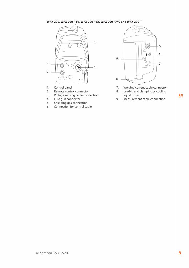
WFX 200, WFX 200 P Fe, WFX 200 P Ss, WFX 200 AMC and WFX 200-T
4.
1.
2.
3.
7.
6.
5.
8.
9.
1. Control panel2. Remote control connector3. Voltage sensing cable connection4. Euro gun connector5. Shielding gas connection6. Connection for control cable
7. Welding current cable connector8. Lead-in and clamping of cooling
liquid hoses9. Measurement cable connection

WFX 200, 300, 200 P Fe/Ss, 300 P Fe/Ss, 200-T, 300 P-T, 300-T, 200 AMC, 300 AMC6
EN
2.2 Connecting cables
2.2.1 Liquid-cooled system: FastMig X + WFX + Cool X
1.
4.
8.10.
2.
3.
9.
5.
6.
11.
7.
V
V
1. WFX wire feed unit2. FastMig X power source3. Cool X cooling unit and power connection4. Gas supply5. MMA electrode holder6. Remote control device7. Liquid-cooled welding gun8. Power cable9. Earth return cable and clamp10. Measurement cable (from power source to wire feeder)11. Voltage sensing cable (from wire feeder to work piece)
NOTE! WFX wire feeders can also be used with FastMig Pulse power source, but in that case measurement cable and voltage sensing cable will not be used.
7© Kemppi Oy / 1520
EN
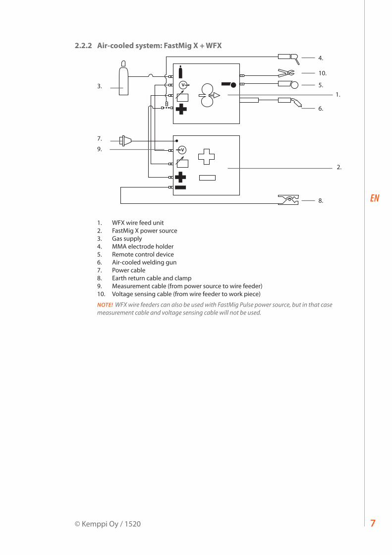
2.2.2 Air-cooled system: FastMig X + WFX
1.
4.
5.
10.
6.
8.
2.
3.
7.
9. V
V
1. WFX wire feed unit2. FastMig X power source3. Gas supply4. MMA electrode holder5. Remote control device6. Air-cooled welding gun7. Power cable8. Earth return cable and clamp9. Measurement cable (from power source to wire feeder)10. Voltage sensing cable (from wire feeder to work piece)
NOTE! WFX wire feeders can also be used with FastMig Pulse power source, but in that case measurement cable and voltage sensing cable will not be used.

WFX 200, 300, 200 P Fe/Ss, 300 P Fe/Ss, 200-T, 300 P-T, 300-T, 200 AMC, 300 AMC8
EN
2.3 Assembly of MIG/MAG systemAssemble the units in the order mentioned below. Follow the additional mounting and operation instructions delivered with each package.
1. Installation of power sourceRead and follow the installation instructions given in the FastMig power source operating manual.
2. Mounting of power sources to transport cartRead and follow the instructions given in the transport cart assembly instructions.
3. Mounting the FastMig WFX wire feed unit to the power sourceRemove the cover sticker on top of the power source. Screw the fastening pivot into the power source – hand tighten only. Place the supplied plastic spacers over the pivot. Lift the WFX wire feeder into place, locating over the pivot.
4. Connecting cablesConnect the cables in accordance with the equipment notes provided in this manual.The polarity of the welding wire (+ or –) can be selected by connecting the wire feed unit to either the positive or negative power source terminals.Most MIG/MAG applications run the wire feed unit connected to the positive terminal of the power source.
5. Mounting FastMig wire feed units to boom and swing armsWhen mounting wire feed units to boom and swing arms, the unit must be electrically isolated from both.Suspension angle of wire feed unit can be changed by moving the fixing point in handle.
2.4 Accessories corresponding to wire diameterColour coded wire feed rolls and guide tubes are available to suit a variety of filler wire types and sizes. Feed roll groove geometry and design vary depending on the application. Further details are available in the spare parts tables.Please ensure you select the correct drive rolls and guide tubes from the table to suit your particular welding application.
2.5 Welding gun selectionPlease ensure that the welding gun selected is suitable for the target application. Kemppi welding gun products are designed to meet many different applications. Special wire liners and contact tips are available for different wire types and sizes.For FastMig X pipe welding package Kemppi offers the PMT MN welding gun model, which is specially designed for welding root and fill passes on pipe. The neck is replaceable, so you can select just the right bending angle for different work stages.Distance wire feeding is accommodated with WeldSnake and SuperSnake products in either air or liquid cooled models.

9© Kemppi Oy / 1520
EN
2.6 Mounting and locking of wire spool
NOTE! Check that in filler wire spool is correctly mounted and locked into position. Ensure the spool is not damaged or deformed in such a way that it can rub or chaff against the internal surface of the wire feed unit chassis or door. This may result in increased drag, impacting on weld quality. This may also result in long term wire feed unit damage, rendering the unit unserviceable or unsafe to use.
2.7 Loading the filler wire and automatic feedAutomatic wire feed makes wire spool changes faster. When changing the wire spool, the pressure of feed rolls need not be released.Simply ensure that the groove of the feed roll matches the diameter of filler wire used. Release the wire end from the spool and cut off any deformed section. Be careful that the wire does not spill from the spool sides.Straighten about 20 cm of filler wire and ensure the tip has no sharp edges. File if necessary, as a sharp wire edge may damage the wire gun liner - particularly softer plastic liners.Present the filler wire tip to the back of the wire feed rolls and press the wire inch switch on the wire feeder panel. Feed the wire to the gun contact tip and prepare to weld.
NOTE! Smaller diameter filler wires may need to be loaded manually and with the feed roll pressure arms released. This is because it is easy to over estimate the pressure required to feed these smaller filler wires. Too high feed roll pressures can easily deform filler wires and contribute to later feeding problems.

WFX 200, 300, 200 P Fe/Ss, 300 P Fe/Ss, 200-T, 300 P-T, 300-T, 200 AMC, 300 AMC10
EN
2.8 GT04 wire feed mechanismThis is used in WFX 300 P Fe, WFX 300 P Ss and WFX 300 P-T wire feeders.
Wire guide tubesø mm outlet tube middle tube inlet tube
Al, Ss (Fe, Mc, Fc)plastic
0.6 W007285 W007273 W007293
0.8 – 0.9 W007286 W007274 W007294
1.0 W007287 W007275 W007295
1.2 W007288 W007276 W007296
1.4 W007289 W007277 W007297
1.6 W007290 W007278 W007298
2.0 W007291 W007279 W007299
2.4 W007292 W007280 W007300
Fe, Mc, Fcmetal
0.8 – 0.9 W007454 W007536
1.0 W007455 W007537
1.2 W007456 W007538
1.4 – 1.6 W007458 W007539
2.0 W007459 W007540
2.4 W007460 W007541
11© Kemppi Oy / 1520
EN
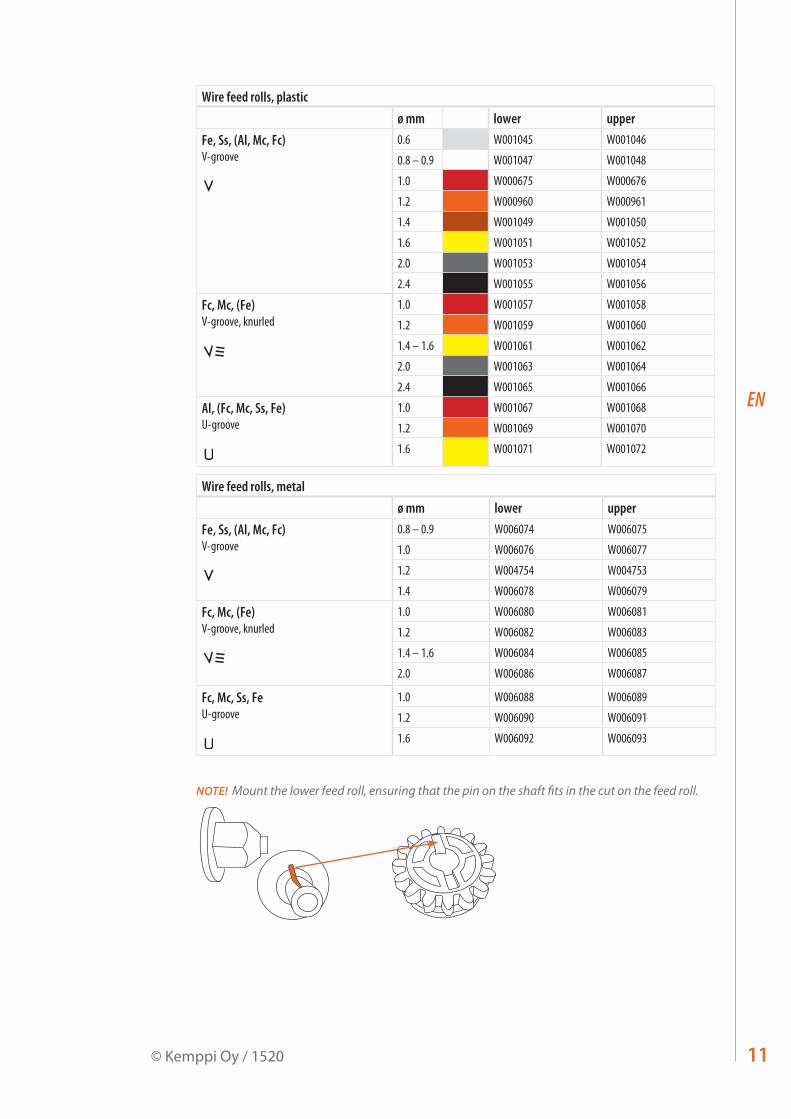
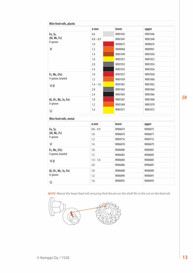
Wire feed rolls, plasticø mm lower upper
Fe, Ss, (Al, Mc, Fc)V-groove
0.6 W001045 W001046
0.8 – 0.9 W001047 W001048
1.0 W000675 W000676
1.2 W000960 W000961
1.4 W001049 W001050
1.6 W001051 W001052
2.0 W001053 W001054
2.4 W001055 W001056
Fc, Mc, (Fe)V-groove, knurled
1.0 W001057 W001058
1.2 W001059 W001060
1.4 – 1.6 W001061 W001062
2.0 W001063 W001064
2.4 W001065 W001066
Al, (Fc, Mc, Ss, Fe)U-groove
1.0 W001067 W001068
1.2 W001069 W001070
1.6 W001071 W001072
Wire feed rolls, metalø mm lower upper
Fe, Ss, (Al, Mc, Fc)V-groove
0.8 – 0.9 W006074 W006075
1.0 W006076 W006077
1.2 W004754 W004753
1.4 W006078 W006079
Fc, Mc, (Fe)V-groove, knurled
1.0 W006080 W006081
1.2 W006082 W006083
1.4 – 1.6 W006084 W006085
2.0 W006086 W006087
Fc, Mc, Ss, FeU-groove
1.0 W006088 W006089
1.2 W006090 W006091
1.6 W006092 W006093
NOTE! Mount the lower feed roll, ensuring that the pin on the shaft fits in the cut on the feed roll.

WFX 200, 300, 200 P Fe/Ss, 300 P Fe/Ss, 200-T, 300 P-T, 300-T, 200 AMC, 300 AMC12
EN
2.9 DuraTorque™ 400, 4-wheel wire feed mechanismThis is used in WFX 200, WFX 200 P Fe, WFX 200 P Ss, WFX 200 AMC, WFX 300, WFX 300 AMC, WFX 200-T and WFX 300-T wire feeders.
Wire guide tubesø mm outlet tube middle tube inlet tube
Ss, Al, (Fe, Mc, Fc)plastic
0.6 W007437 W007429 W007293
0.8 – 0.9 W007438 W007430 W007294
1.0 W007439 W007431 W007295
1.2 W007440 W007432 W007296
1.4 W007441 W007433 W007297
1.6 W007442 W007434 W007298
2.0 W007443 W007435 W007299
2.4 W007444 W007436 W007300
Fe, Mc, Fcmetal
0.8 – 0.9 W007454 W007465 W007536
1.0 W007455 W007466 W007537
1.2 W007456 W007467 W007538
1.4 – 1.6 W007458 W007469 W007539
2.0 W007459 W007470 W007540
2.4 W007460 W007471 W007541
24.8.2005 12:55
13© Kemppi Oy / 1520
EN
Wire feed rolls, plasticø mm lower upper
Fe, Ss, (Al, Mc, Fc)V-groove
0.6 W001045 W001046
0.8 – 0.9 W001047 W001048
1.0 W000675 W000676
1.2 W000960 W000961
1.4 W001049 W001050
1.6 W001051 W001052
2.0 W001053 W001054
2.4 W001055 W001056
Fc, Mc, (Fe)V-groove, knurled
1.0 W001057 W001058
1.2 W001059 W001060
1.4 – 1.6 W001061 W001062
2.0 W001063 W001064
2.4 W001065 W001066
Al, (Fc, Mc, Ss, Fe)U-groove
1.0 W001067 W001068
1.2 W001069 W001070
1.6 W001071 W001072
Wire feed rolls, metalø mm lower upper
Fe, Ss, (Al, Mc, Fc)V-groove
0.8 – 0.9 W006074 W006075
1.0 W006076 W006077
1.2 W004754 W004753
1.4 W006078 W006079
Fc, Mc, (Fe)V-groove, knurled
1.0 W006080 W006081
1.2 W006082 W006083
1.4 – 1.6 W006084 W006085
2.0 W006086 W006087
Al, (Fc, Mc, Ss, Fe)U-groove
1.0 W006088 W006089
1.2 W006090 W006091
1.6 W006092 W006093
NOTE! Mount the lower feed roll, ensuring that the pin on the shaft fits in the cut on the feed roll.
WFX 200, 300, 200 P Fe/Ss, 300 P Fe/Ss, 200-T, 300 P-T, 300-T, 200 AMC, 300 AMC14
EN
2.10 Adjustment of pressure armsAdjust the drive pressure to the filler wire with the thumb screws mounted over the pressure arms. Notice the graduated scales indicating load. The load applied should be sufficient to overcome a light braking force applied by hand to the filler wire, as it exits the welding gun contact tip.For smaller diameter and soft filler wires, less feed pressure is required. It should be possible to apply a light breaking force to the filler wire by hand, as it exits the gun contact tip. But slightly more wire flow restriction should render the drives rolls to slip slightly over the filler wire without deforming the wire.
NOTE! Excessive pressure causes flattening of the filler wire and damage to coated or cored filler wires. It also causes undue wear of the feed rolls and increases gearbox load, so reducing service life.
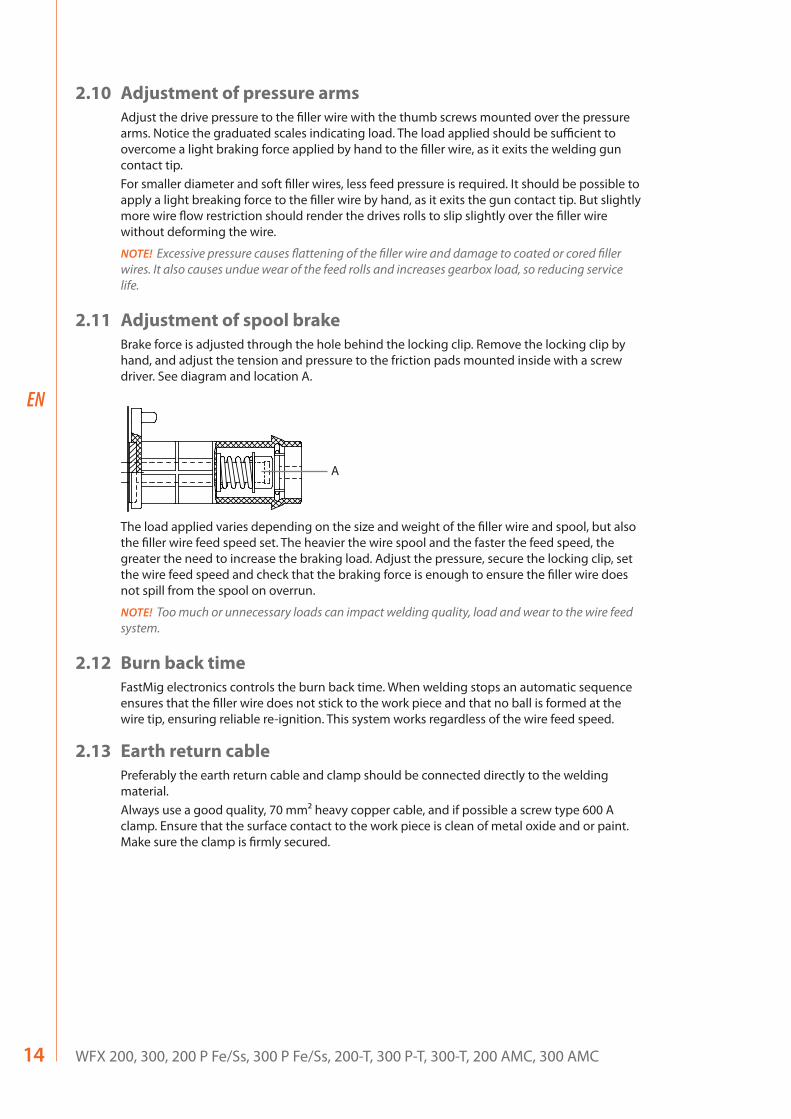
2.11 Adjustment of spool brakeBrake force is adjusted through the hole behind the locking clip. Remove the locking clip by hand, and adjust the tension and pressure to the friction pads mounted inside with a screw driver. See diagram and location A.
A
The load applied varies depending on the size and weight of the filler wire and spool, but also the filler wire feed speed set. The heavier the wire spool and the faster the feed speed, the greater the need to increase the braking load. Adjust the pressure, secure the locking clip, set the wire feed speed and check that the braking force is enough to ensure the filler wire does not spill from the spool on overrun.
NOTE! Too much or unnecessary loads can impact welding quality, load and wear to the wire feed system.
2.12 Burn back timeFastMig electronics controls the burn back time. When welding stops an automatic sequence ensures that the filler wire does not stick to the work piece and that no ball is formed at the wire tip, ensuring reliable re-ignition. This system works regardless of the wire feed speed.
2.13 Earth return cablePreferably the earth return cable and clamp should be connected directly to the welding material.Always use a good quality, 70 mm² heavy copper cable, and if possible a screw type 600 A clamp. Ensure that the surface contact to the work piece is clean of metal oxide and or paint. Make sure the clamp is firmly secured.

15© Kemppi Oy / 1520
EN
2.14 Shielding gasNOTE! Handle shielding gas bottle with care. Assess the risks associated with handling and using compressed gas. Always use a cylinder transport carriage and secure the cylinder safely.
There are many different suppliers of quality shielding gases for welding. Please ensure that you are selecting the correct gas for your application. FastMig products use welding programs for synergic and pulsed welding. These programs are created and recommend against a particular shielding gas.Shielding gas effects welding performance and is a fundamental component to overall weld quality.
MMT 32
l/min
5
10
15
20
NOTE! Shielding gas flow rate from the welding gun is set according to the application, weld joint, gas type and gas nozzle shape and size. The flow rate should be measured at the welding gun nozzle before welding via a rotameter, and normally measure's between 10 – 20 litres per minute for many welding applications.
2.14.1 Installing gas bottleAlways fasten the gas bottle properly in the vertical position, in a special holder against the wall or on a cylinder carriage. Remember to close gas bottle valve after welding.
Parts of gas flow regulator
5
2
4
7
1 63
1. Gas bottle valve2. Flow regulation screw3. Connecting nut4. Hose tail5. Hose tail nut6. Gas bottle pressure gauge7. Shielding gas flow meter

WFX 200, 300, 200 P Fe/Ss, 300 P Fe/Ss, 200-T, 300 P-T, 300-T, 200 AMC, 300 AMC16
EN
2.15 Main switch I/OWhen you turn the main switch of the FastMig power source into I-position, the pilot lamp closest to this switch will illuminate, indicating the power source is ready for welding. The equipment will return to the same operation state where it was before the last shutdown.Always start and switch off the machine with the main switch, never use the mains plug as a switch.
2.16 Operation of cooling unit, Cool XWhen liquid-cooling unit Cool X is connected to the FastMig power source for the first time, the cooler function is normally active. To deselect the cooler function, follow the instructions stated in the Cool X operating manual.
2.17 Hanging kitThe WFX wire feeders can be mounted on a welding boom using the KFH 1000 hanging device available as an accessory. This allows the wire feed unit to be suspended above the work area.
3. XF 37 AND XF 38 CONTROL PANEL
3.1 Connecting and mounting
Fasten the ribbon cable connector from the WFX wire feed unit to the control panel. Attach the yellow-green earth lead into the fork connector on the XF control panel.
XF 37 XF 38
+
17© Kemppi Oy / 1520
EN
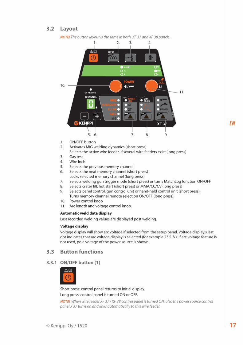
3.2 LayoutNOTE! The button layout is the same in both, XF 37 and XF 38 panels.
XF 37
W007241
CH REMOTE
CHANNEL
PANEL4T2T
1. 3.2. 4.
5. 6. 7. 8. 9.
10.
11.
1. ON/OFF button2. Activates MIG welding dynamics (short press)
Selects the active wire feeder, if several wire feeders exist (long press)3. Gas test4. Wire inch 5. Selects the previous memory channel6. Selects the next memory channel (short press)
Locks selected memory channel (long press)7. Selects welding gun trigger mode (short press) or turns MatchLog function ON/OFF8. Selects crater fill, hot start (short press) or MMA/CC/CV (long press)9. Selects panel control, gun control unit or hand-held control unit (short press).
Turns memory channel remote selection ON/OFF (long press).10. Power control knob11. Arc length and voltage control knob.
Automatic weld data displayLast recorded welding values are displayed post welding.
Voltage displayVoltage display will show arc voltage if selected from the setup panel. Voltage display's last dot indicates that arc voltage display is selected (for example 23.5. V). If arc voltage feature is not used, pole voltage of the power source is shown.
3.3 Button functions
3.3.1 ON/OFF button (1)
XF 37
W007241
CH REMOTE
CHANNEL
PANEL4T2T
Short press: control panel returns to initial display.Long press: control panel is turned ON or OFF.
NOTE! When wire feeder XF 37 / XF 38 control panel is turned ON, also the power source control panel X 37 turns on and links automatically to this wire feeder.

WFX 200, 300, 200 P Fe/Ss, 300 P Fe/Ss, 200-T, 300 P-T, 300-T, 200 AMC, 300 AMC18
EN
3.3.2 Dynamics button (2)
XF 37
W007241
CH REMOTE
CHANNEL
PANEL4T2T
Short press: Dynamics setting for 1-MIG, synergic MIG and CC/CV. ArcForce setting for MMA.Long press: Wire feeder number selection. If there is more than one wire feeder connected to the system, you can select which of them is active. Each wire feeder has its own number (1–3).
NOTE! Wire feeder number is not available in MMA, CC and CV processes.
3.3.3 Gas test button (3)
XF 37
W007241
CH REMOTE
CHANNEL
PANEL4T2T
This button displays the gas test time. You can change it with the control knob.Gas test starts when the time adjustment is made, after a short delay.You can stop gas test by pressing any button.
3.3.4 Wire inch button (3)
XF 37
W007241
CH REMOTE
CHANNEL
PANEL4T2T
This button starts feeding the wire with the default speed of 5.0 m/min. The wire feed stops when you release the button.You can change the wire feed speed with the control knob. The changed speed is used if you press the button again.
3.3.5 Channel down button (5)
XF 37
W007241
CH REMOTE
CHANNEL
PANEL4T2T
This button selects the previous memory channel that can be found.
3.3.6 Channel up button (6)
XF 37
W007241
CH REMOTE
CHANNEL
PANEL4T2T
Short press: Selects the next memory channel that can be found.Long press: Locks or unlocs the selected memory channel. No parameter changes are allowed to a locked memory channel.
3.3.7 2T/4T button (7)
XF 37
W007241
CH REMOTE
CHANNEL
PANEL4T2T
Short press: Toggles between 2T or 4T gun trigger mode.Long press: Turns MatchLog ON/OFF. This can be either MatchChannel or Minilog functionality, depending on which one is defined in the selected memory channel. If neither one is defined, this selection is unavailable.
19© Kemppi Oy / 1520
EN
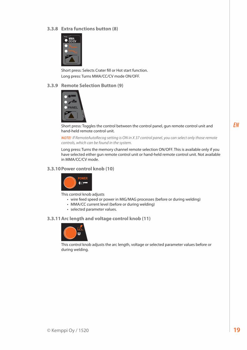
3.3.8 Extra functions button (8)
XF 37
W007241
CH REMOTE
CHANNEL
PANEL4T2T
Short press: Selects Crater fill or Hot start function.Long press: Turns MMA/CC/CV mode ON/OFF.
3.3.9 Remote Selection Button (9)
XF 37
W007241
CH REMOTE
CHANNEL
PANEL4T2T
Short press: Toggles the control between the control panel, gun remote control unit and hand-held remote control unit.
NOTE! If RemoteAutoRecog setting is ON in X 37 control panel, you can select only those remote controls, which can be found in the system.
Long press: Turns the memory channel remote selection ON/OFF. This is available only if you have selected either gun remote control unit or hand-held remote control unit. Not available in MMA/CC/CV mode.
3.3.10 Power control knob (10)
XF 37
W007241
CH REMOTE
CHANNEL
PANEL4T2T
This control knob adjusts • wire feed speed or power in MIG/MAG processes (before or during welding)• MMA/CC current level (before or during welding)• selected parameter values.
3.3.11 Arc length and voltage control knob (11)
XF 37
W007241
CH REMOTE
CHANNEL
PANEL4T2T
This control knob adjusts the arc length, voltage or selected parameter values before or during welding.

WFX 200, 300, 200 P Fe/Ss, 300 P Fe/Ss, 200-T, 300 P-T, 300-T, 200 AMC, 300 AMC20
EN
3.4 Welding softwareThe FastMig WFX wire feeders are compatible with the following modified welding processes and functions
• WiseRoot+™ is a modified welding process for open gap root welding without backing.• WiseThin+™ is a modified welding process developed especially for efficient welding for
thin sheets and position welding, also with the CO2 shielding gas.• WiseFusion™ is a welding function for ensuring consistent weld quality in all positions. • WisePenetration™ is a welding function for delivering constant welding power
regardless of changes in the stick out length. • MatchLog™ contains MiniLog™ function and the MatchChannel™ function for quickly
changing welding parameters on the run.
Wire feeder Factory-installedWFX 200, 300 WiseFusion
WorkPack
WFX 200 P Fe, 300 P Fe WiseFusion, WiseRoot+, MatchLogPipe Steel pack FE
WFX 200 P Ss, 300 P Ss WiseFusion, WiseRoot+, MatchLog, Pipe Stainless pack Ss
WFX 200 AMC, 300 AMC WiseFusion, WisePenetration, WiseThin+, MatchLog,Steel Pack, Steel Pack for WiseThin+, Stainless Steel Pack, Aluminium Pack
WFX 200-T, 300 P-T, 300-T MIG as standard. Other welding software factory-installed according to order.
If your welding needs change and you wish to update your system in the future, you can order additional welding programs or other welding software and load them to your system with Kemppi DataGun field programming device. Optional features can be purchased through Kemppi DataStore.For further information about the available welding programs, modified processes and special enhanced arc performance solutions, visit Kemppi web site at www.kemppi.com or contact the local Kemppi dealer.
PIPE STAINLESS PACK
Group Material Wire ø (mm) Shielding gas Process NumberSs CrNiMo 19 12 0.8 Ar+2%CO₂ WiseRoot+ S01
Ss CrNiMo 19 12 0.9 Ar+2%CO₂ WiseRoot+ S02
Ss CrNiMo 19 12 1.0 Ar+2%CO₂ WiseRoot+ S03
Ss CrNiMo 19 12 1.2 Ar+2%CO₂ WiseRoot+ S04
Ss CrNiMo 19 12 0.8 Ar+2%CO₂ 1-MIG S01
Ss CrNiMo 19 12 0.9 Ar+2%CO₂ 1-MIG S02
Ss CrNiMo 19 12 1.0 Ar+2%CO₂ 1-MIG S03
Ss CrNiMo 19 12 1.2 Ar+2%CO₂ 1-MIG S04
Ss FC-CrNiMo 19 12 1.2 Ar+15–25%CO₂ 1-MIG S84
Ss FC-CrNiMo 19 12 1.2 CO₂ 1-MIG S85
Ss MC-CrNiMo 19 12 1.2 Ar+2%CO₂ 1-MIG S87
Ss CrNiMo 19 12 0.8 Ar+2%CO₂ Pulse/Double Pulse S01
Ss CrNiMo 19 12 0.9 Ar+2%CO₂ Pulse/Double Pulse S02
Ss CrNiMo 19 12 1.0 Ar+2%CO₂ Pulse/Double Pulse S06
Ss CrNiMo 19 12 1.2 Ar+2%CO₂ Pulse/Double Pulse S04
Ss CrNiMo 19 12 1.0 Ar+He+CO₂ Pulse/Double Pulse S26
Ss CrNiMo 19 12 1.2 Ar+He+CO₂ Pulse/Double Pulse S24

21© Kemppi Oy / 1520
EN
PIPE STEEL PACK
Group Material Wire ø (mm) Shielding gas Process NumberFe Fe 0.8 Ar+15–25%CO₂ WiseRoot+ F01
Fe Fe 0.9 Ar+15–25%CO₂ WiseRoot+ F02
Fe Fe 1.0 Ar+15–25%CO₂ WiseRoot+ F03
Fe Fe 1.2 Ar+15–25%CO₂ WiseRoot+ F04
Fe Fe 0.8 CO₂ WiseRoot+ F21
Fe Fe 0.9 CO₂ WiseRoot+ F22
Fe Fe 1.0 CO₂ WiseRoot+ F23
Fe Fe 1.2 CO₂ WiseRoot+ F24
Fe Fe Metal 1.2 Ar+15–25%CO₂ WiseRoot+ M04
Fe Fe Metal 1.2 CO₂ WiseRoot+ M24
Fe Fe 0.8 Ar+15–25%CO₂ 1-MIG F01
Fe Fe 0.9 Ar+15–25%CO₂ 1-MIG F02
Fe Fe 1.0 Ar+15–25%CO₂ 1-MIG F03
Fe Fe 1.2 Ar+15–25%CO₂ 1-MIG F04
Fe Fe 0.8 CO₂ 1-MIG F21
Fe Fe 0.9 CO₂ 1-MIG F22
Fe Fe 1.0 CO₂ 1-MIG F23
Fe Fe 1.2 CO₂ 1-MIG F24
Fe Fe Metal 1.2 Ar+15–25%CO₂ 1-MIG M04
Fe Fe Metal 1.2 CO₂ 1-MIG M24
Fe Fe Rutil 1.2 Ar+15–25%CO₂ 1-MIG R04
Fe Fe Rutil 1.2 CO₂ 1-MIG R14
Fe Fe 1.6 InnerShield 1-MIG R56
Fe Fe 2.0 InnerShield 1-MIG R57
Fe Fe 2.4 InnerShield 1-MIG R58
STEEL PACK FOR WISETHIN+
Group Material Wire ø (mm) Shielding gas Process NumberFe Fe 0.8 Ar+15–25%CO₂ WiseThin+ F01
Fe Fe 0.9 Ar+15–25%CO₂ WiseThin+ F02
Fe Fe 1.0 Ar+15–25%CO₂ WiseThin+ F03
Fe Fe 1.2 Ar+15–25%CO₂ WiseThin+ F04
Fe Fe 0.8 CO₂ WiseThin+ F21
Fe Fe 0.9 CO₂ WiseThin+ F22
Fe Fe 1.0 CO₂ WiseThin+ F23
Fe Fe 1.2 CO₂ WiseThin+ F24
WFX 200, 300, 200 P Fe/Ss, 300 P Fe/Ss, 200-T, 300 P-T, 300-T, 200 AMC, 300 AMC22
EN
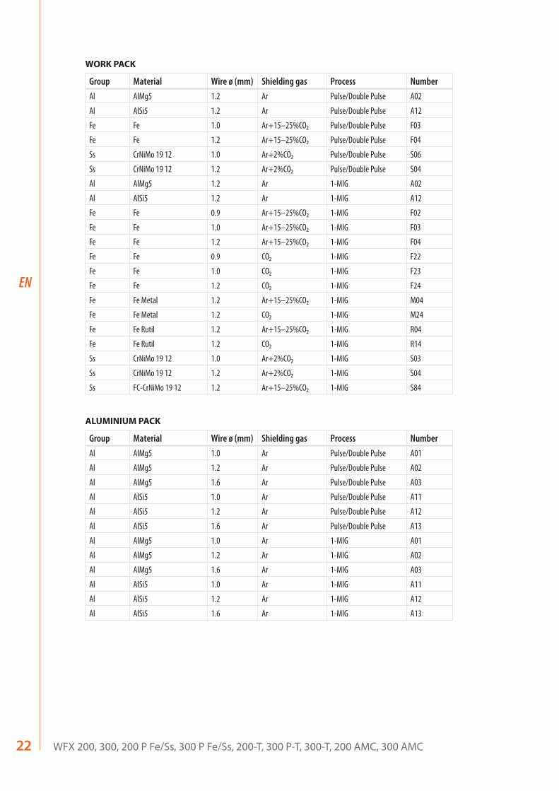
WORK PACK
Group Material Wire ø (mm) Shielding gas Process NumberAl AlMg5 1.2 Ar Pulse/Double Pulse A02
Al AlSi5 1.2 Ar Pulse/Double Pulse A12
Fe Fe 1.0 Ar+15–25%CO₂ Pulse/Double Pulse F03
Fe Fe 1.2 Ar+15–25%CO₂ Pulse/Double Pulse F04
Ss CrNiMo 19 12 1.0 Ar+2%CO₂ Pulse/Double Pulse S06
Ss CrNiMo 19 12 1.2 Ar+2%CO₂ Pulse/Double Pulse S04
Al AlMg5 1.2 Ar 1-MIG A02
Al AlSi5 1.2 Ar 1-MIG A12
Fe Fe 0.9 Ar+15–25%CO₂ 1-MIG F02
Fe Fe 1.0 Ar+15–25%CO₂ 1-MIG F03
Fe Fe 1.2 Ar+15–25%CO₂ 1-MIG F04
Fe Fe 0.9 CO₂ 1-MIG F22
Fe Fe 1.0 CO₂ 1-MIG F23
Fe Fe 1.2 CO₂ 1-MIG F24
Fe Fe Metal 1.2 Ar+15–25%CO₂ 1-MIG M04
Fe Fe Metal 1.2 CO₂ 1-MIG M24
Fe Fe Rutil 1.2 Ar+15–25%CO₂ 1-MIG R04
Fe Fe Rutil 1.2 CO₂ 1-MIG R14
Ss CrNiMo 19 12 1.0 Ar+2%CO₂ 1-MIG S03
Ss CrNiMo 19 12 1.2 Ar+2%CO₂ 1-MIG S04
Ss FC-CrNiMo 19 12 1.2 Ar+15–25%CO₂ 1-MIG S84
ALUMINIUM PACK
Group Material Wire ø (mm) Shielding gas Process NumberAl AlMg5 1.0 Ar Pulse/Double Pulse A01
Al AlMg5 1.2 Ar Pulse/Double Pulse A02
Al AlMg5 1.6 Ar Pulse/Double Pulse A03
Al AlSi5 1.0 Ar Pulse/Double Pulse A11
Al AlSi5 1.2 Ar Pulse/Double Pulse A12
Al AlSi5 1.6 Ar Pulse/Double Pulse A13
Al AlMg5 1.0 Ar 1-MIG A01
Al AlMg5 1.2 Ar 1-MIG A02
Al AlMg5 1.6 Ar 1-MIG A03
Al AlSi5 1.0 Ar 1-MIG A11
Al AlSi5 1.2 Ar 1-MIG A12
Al AlSi5 1.6 Ar 1-MIG A13
23© Kemppi Oy / 1520
EN
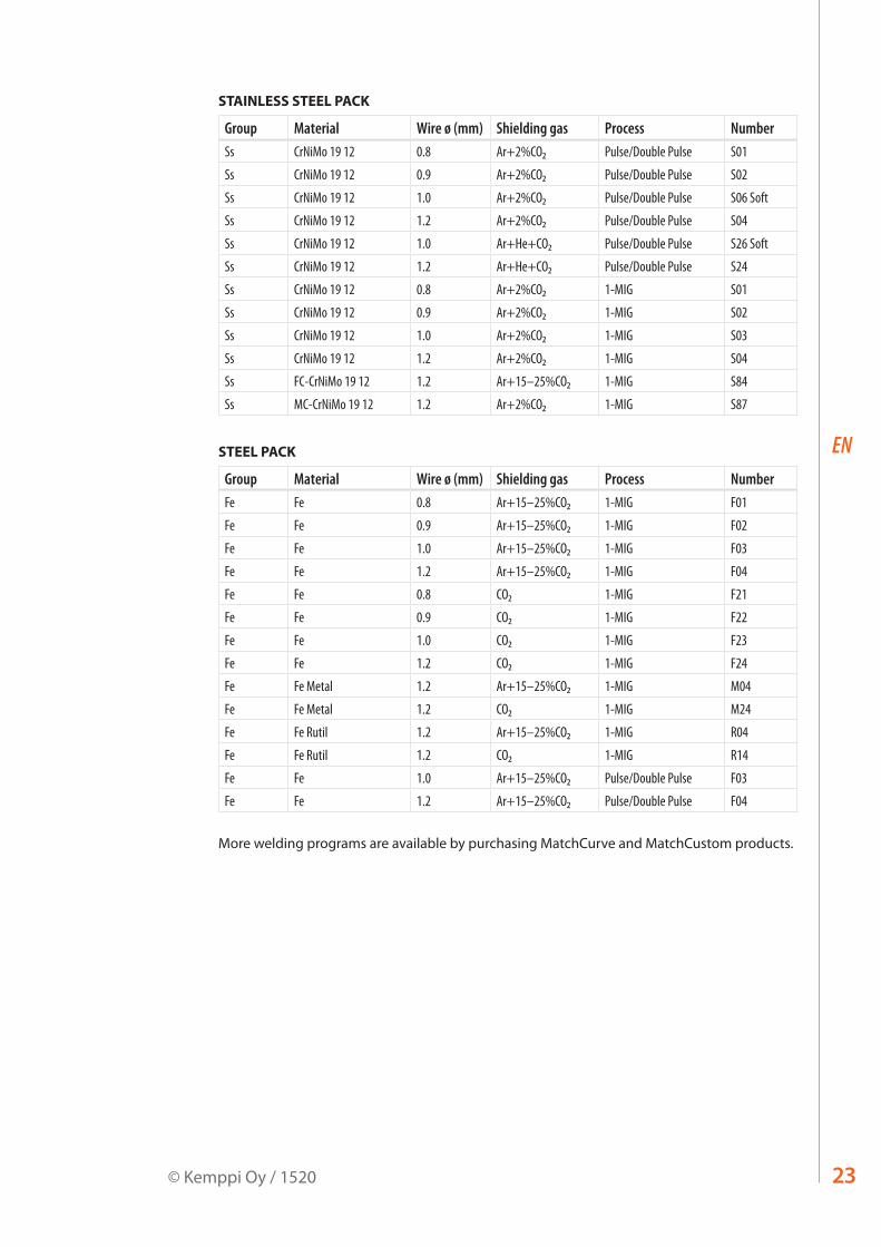
STAINLESS STEEL PACK
Group Material Wire ø (mm) Shielding gas Process NumberSs CrNiMo 19 12 0.8 Ar+2%CO₂ Pulse/Double Pulse S01
Ss CrNiMo 19 12 0.9 Ar+2%CO₂ Pulse/Double Pulse S02
Ss CrNiMo 19 12 1.0 Ar+2%CO₂ Pulse/Double Pulse S06 Soft
Ss CrNiMo 19 12 1.2 Ar+2%CO₂ Pulse/Double Pulse S04
Ss CrNiMo 19 12 1.0 Ar+He+CO₂ Pulse/Double Pulse S26 Soft
Ss CrNiMo 19 12 1.2 Ar+He+CO₂ Pulse/Double Pulse S24
Ss CrNiMo 19 12 0.8 Ar+2%CO₂ 1-MIG S01
Ss CrNiMo 19 12 0.9 Ar+2%CO₂ 1-MIG S02
Ss CrNiMo 19 12 1.0 Ar+2%CO₂ 1-MIG S03
Ss CrNiMo 19 12 1.2 Ar+2%CO₂ 1-MIG S04
Ss FC-CrNiMo 19 12 1.2 Ar+15–25%CO₂ 1-MIG S84
Ss MC-CrNiMo 19 12 1.2 Ar+2%CO₂ 1-MIG S87
STEEL PACK
Group Material Wire ø (mm) Shielding gas Process NumberFe Fe 0.8 Ar+15–25%CO₂ 1-MIG F01
Fe Fe 0.9 Ar+15–25%CO₂ 1-MIG F02
Fe Fe 1.0 Ar+15–25%CO₂ 1-MIG F03
Fe Fe 1.2 Ar+15–25%CO₂ 1-MIG F04
Fe Fe 0.8 CO₂ 1-MIG F21
Fe Fe 0.9 CO₂ 1-MIG F22
Fe Fe 1.0 CO₂ 1-MIG F23
Fe Fe 1.2 CO₂ 1-MIG F24
Fe Fe Metal 1.2 Ar+15–25%CO₂ 1-MIG M04
Fe Fe Metal 1.2 CO₂ 1-MIG M24
Fe Fe Rutil 1.2 Ar+15–25%CO₂ 1-MIG R04
Fe Fe Rutil 1.2 CO₂ 1-MIG R14
Fe Fe 1.0 Ar+15–25%CO₂ Pulse/Double Pulse F03
Fe Fe 1.2 Ar+15–25%CO₂ Pulse/Double Pulse F04
More welding programs are available by purchasing MatchCurve and MatchCustom products.
WFX 200, 300, 200 P Fe/Ss, 300 P Fe/Ss, 200-T, 300 P-T, 300-T, 200 AMC, 300 AMC24
EN
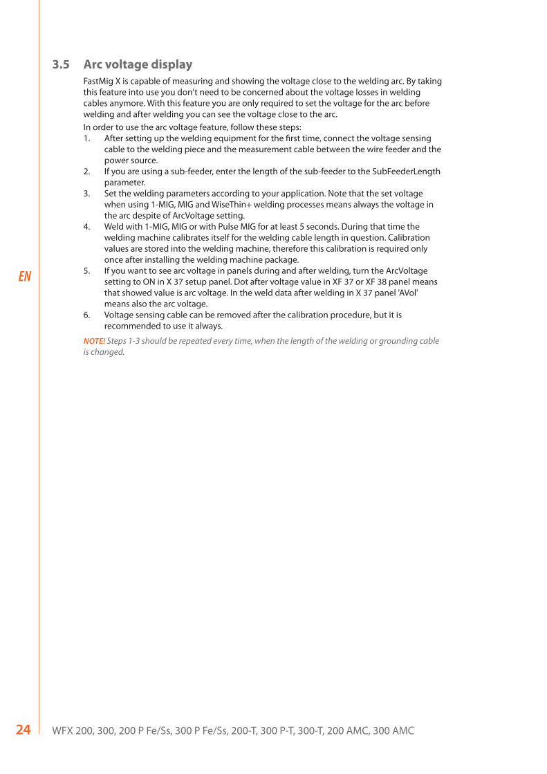
3.5 Arc voltage displayFastMig X is capable of measuring and showing the voltage close to the welding arc. By taking this feature into use you don't need to be concerned about the voltage losses in welding cables anymore. With this feature you are only required to set the voltage for the arc before welding and after welding you can see the voltage close to the arc.In order to use the arc voltage feature, follow these steps:1. After setting up the welding equipment for the first time, connect the voltage sensing
cable to the welding piece and the measurement cable between the wire feeder and the power source.
2. If you are using a sub-feeder, enter the length of the sub-feeder to the SubFeederLength parameter.
3. Set the welding parameters according to your application. Note that the set voltage when using 1-MIG, MIG and WiseThin+ welding processes means always the voltage in the arc despite of ArcVoltage setting.
4. Weld with 1-MIG, MIG or with Pulse MIG for at least 5 seconds. During that time the welding machine calibrates itself for the welding cable length in question. Calibration values are stored into the welding machine, therefore this calibration is required only once after installing the welding machine package.
5. If you want to see arc voltage in panels during and after welding, turn the ArcVoltage setting to ON in X 37 setup panel. Dot after voltage value in XF 37 or XF 38 panel means that showed value is arc voltage. In the weld data after welding in X 37 panel 'AVol' means also the arc voltage.
6. Voltage sensing cable can be removed after the calibration procedure, but it is recommended to use it always.
NOTE! Steps 1-3 should be repeated every time, when the length of the welding or grounding cable is changed.
25© Kemppi Oy / 1520
EN
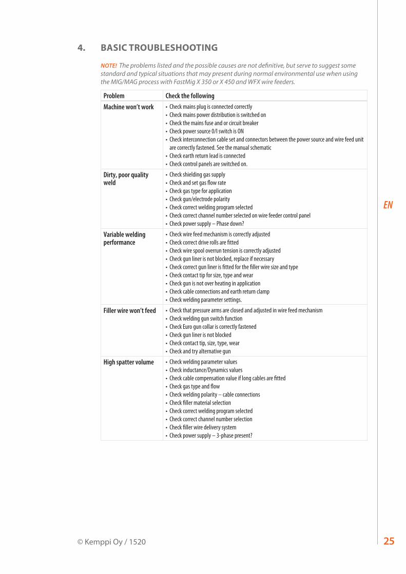
4. BASIC TROUBLESHOOTING
NOTE! The problems listed and the possible causes are not definitive, but serve to suggest some standard and typical situations that may present during normal environmental use when using the MIG/MAG process with FastMig X 350 or X 450 and WFX wire feeders.
Problem Check the followingMachine won’t work • Check mains plug is connected correctly
• Check mains power distribution is switched on• Check the mains fuse and or circuit breaker• Check power source 0/I switch is ON• Check interconnection cable set and connectors between the power source and wire feed unit
are correctly fastened. See the manual schematic• Check earth return lead is connected• Check control panels are switched on.
Dirty, poor quality weld
• Check shielding gas supply• Check and set gas flow rate• Check gas type for application• Check gun/electrode polarity• Check correct welding program selected• Check correct channel number selected on wire feeder control panel • Check power supply – Phase down?
Variable welding performance
• Check wire feed mechanism is correctly adjusted• Check correct drive rolls are fitted• Check wire spool overrun tension is correctly adjusted• Check gun liner is not blocked, replace if necessary• Check correct gun liner is fitted for the filler wire size and type• Check contact tip for size, type and wear• Check gun is not over heating in application • Check cable connections and earth return clamp• Check welding parameter settings.
Filler wire won’t feed • Check that pressure arms are closed and adjusted in wire feed mechanism• Check welding gun switch function• Check Euro gun collar is correctly fastened• Check gun liner is not blocked• Check contact tip, size, type, wear• Check and try alternative gun
High spatter volume • Check welding parameter values• Check inductance/Dynamics values• Check cable compensation value if long cables are fitted• Check gas type and flow• Check welding polarity – cable connections• Check filler material selection• Check correct welding program selected• Check correct channel number selection • Check filler wire delivery system• Check power supply – 3-phase present?
WFX 200, 300, 200 P Fe/Ss, 300 P Fe/Ss, 200-T, 300 P-T, 300-T, 200 AMC, 300 AMC26
EN
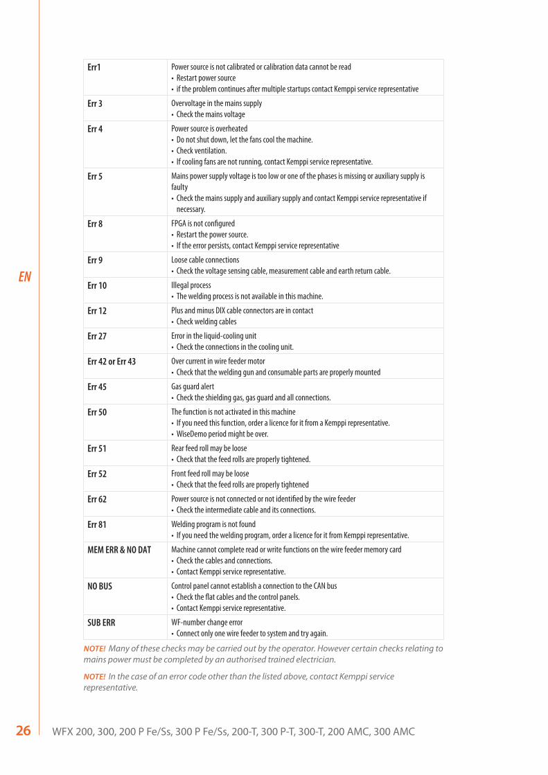
Err1 Power source is not calibrated or calibration data cannot be read• Restart power source• if the problem continues after multiple startups contact Kemppi service representative
Err 3 Overvoltage in the mains supply• Check the mains voltage
Err 4 Power source is overheated• Do not shut down, let the fans cool the machine. • Check ventilation. • If cooling fans are not running, contact Kemppi service representative.
Err 5 Mains power supply voltage is too low or one of the phases is missing or auxiliary supply is faulty• Check the mains supply and auxiliary supply and contact Kemppi service representative if
necessary.
Err 8 FPGA is not configured• Restart the power source.• If the error persists, contact Kemppi service representative
Err 9 Loose cable connections• Check the voltage sensing cable, measurement cable and earth return cable.
Err 10 Illegal process• The welding process is not available in this machine.
Err 12 Plus and minus DIX cable connectors are in contact• Check welding cables
Err 27 Error in the liquid-cooling unit• Check the connections in the cooling unit.
Err 42 or Err 43 Over current in wire feeder motor• Check that the welding gun and consumable parts are properly mounted
Err 45 Gas guard alert• Check the shielding gas, gas guard and all connections.
Err 50 The function is not activated in this machine• If you need this function, order a licence for it from a Kemppi representative.• WiseDemo period might be over.
Err 51 Rear feed roll may be loose• Check that the feed rolls are properly tightened.
Err 52 Front feed roll may be loose• Check that the feed rolls are properly tightened
Err 62 Power source is not connected or not identified by the wire feeder• Check the intermediate cable and its connections.
Err 81 Welding program is not found• If you need the welding program, order a licence for it from Kemppi representative.
MEM ERR & NO DAT Machine cannot complete read or write functions on the wire feeder memory card• Check the cables and connections.• Contact Kemppi service representative.
NO BUS Control panel cannot establish a connection to the CAN bus• Check the flat cables and the control panels.• Contact Kemppi service representative.
SUB ERR WF-number change error• Connect only one wire feeder to system and try again.
NOTE! Many of these checks may be carried out by the operator. However certain checks relating to mains power must be completed by an authorised trained electrician.
NOTE! In the case of an error code other than the listed above, contact Kemppi service representative.

27© Kemppi Oy / 1520
EN
5. MAINTENANCE
When considering and planning routine maintenance, please consider the frequency of machine use and the working environment. Correct operation of the machine and regular maintenance will help you avoid unnecessary downtime and equipment failure.
NOTE! Disconnect the machine from the mains before handling the electrical cables.
5.1 Daily maintenance• Check the overall condition of the welding gun. Remove welding spatter from the
contact tip and clean the gas nozzle. Replace worn or damaged parts. Only use original Kemppi spare parts.
• Check the condition and connection of the welding circuit components: welding gun, earth return cable and clamp, sockets and connectors.
• Check the condition of the feed rolls, needle bearings and shafts. Clean and lubricate bearings and shafts with a small quantity of light machine oil if necessary. Assemble, adjust and test function.
• Check that the feed rolls are suitable for the filler wire you are using, and that their pressure adjustment is correct.
5.2 Periodic maintenanceNOTE! Periodic maintenance should only be carried out by a suitably qualified person. Disconnect the plug of the machine from the mains socket and wait about 2 minutes (capacitor charge) before removing the cover plate.
Check at least every half year:• Electric connectors of the machine – clean any oxidized parts and tighten loose
connections.
NOTE! You must know the correct tension torques values before starting the reparation of the loose joints.
Clean the inner parts of the machine from dust and dirt e.g. with a soft brush and vacuum cleaner. Also clean the ventilation net behind the front grill.Do not use compressed air, there is a risk that the dirt will compact even more tightly into gaps of cooling profiles.Do not use pressure washing devices.Only an authorized trained electrician should carry out repairs to Kemppi machines.
5.3 Service Workshop maintenanceKemppi Service Workshops complete maintenance according to their Kemppi service agreement.The major points in the maintenance procedure are listed as follows:
• Cleaning of the machine• Checking and maintenance of the welding tools• Checking of connectors, switches and potentiometers• Checking of electric connections• Checking of mains cable and plug• Damaged parts or parts in bad condition are replaced by new ones• Maintenance testing. • Operation and performance values of the machine are checked, and when necessary
adjusted by means of software and test equipment.
Software loadingKemppi Service Workshops can also test and load firmware and welding software.

WFX 200, 300, 200 P Fe/Ss, 300 P Fe/Ss, 200-T, 300 P-T, 300-T, 200 AMC, 300 AMC28
EN
6. DISPOSAL OF THE MACHINE
Do not dispose of electrical equipment with normal waste!In observance of European Directive 2002/96/EC on waste electrical and electronic equipment, and its implementation in accordance with national law, electrical equipment that has reached the end of its life must be collected separately and taken to an appropriate environmentally responsible recycling facility. The owner of the equipment is obliged to deliver a decommissioned unit to a regional collection centre, as per the instructions of local authorities or a Kemppi representative. By applying this European Directive you will improve the environment and human health.
7. ORDERING CODES
WFX 200 wire feeder 200 mm, regular pulse welding 6103520
WFX 300 wire feeder 300 mm, regular pulse welding 6103530
WFX 200 P Fe wire feeder 200 mm, pipe welding, steel 6103521
WFX 300 P Fe wire feeder 300 mm, pipe welding, steel 6103531
WFX 200 P Ss wire feeder 200 mm, pipe welding, stainless steel 6103522
WFX 300 P Ss wire feeder 300 mm, pipe welding, stainless steel 6103532
WFX 200 AMC wire feeder 200 mm, intelligent pulse welding 6103523
WFX 300 AMC wire feeder 300 mm, intelligent pulse welding 6103533
WFX 200-T wire feeder 200 mm, tailored 6103524
WFX 300 P-T wire feeder 300 mm, tailored 6103535
WFX 300-T wire feeder 300 mm, tailored 6103534
CablesEarth return cable 5 m, 50 mm² 6184511
Earth return cable 5 m, 70 mm² 6184711
MMA welding cable 5 m, 50 mm² 6184501
MMA welding cable 5 m, 70 mm² 6184701
Magnetic clamp (voltage sensing cable) 200 A 9871580
Magnetic clamp (earth return cable) 600 A 9871570
Interconnection cables, air-cooledFASTMIG X 70-1.8-GH 1.8 m 6260468
FASTMIG X 70-5-GH 5 m 6260469
FASTMIG X 70-10-GH 10 m 6260470
FASTMIG X 70-20-GH 20 m 6260471
FASTMIG X 70-30-GH 30 m 6260472
– For other lengths, please contact Kemppi.

29© Kemppi Oy / 1520
EN
Interconnection cables, liquid-cooledFASTMIG X 70-1.8-WH 1.8 m 6260473
FASTMIG X 70-5-WH 5 m 6260474
FASTMIG X 70-10-WH 10 m 6260475
FASTMIG X 70-20-WH 20 m 6260476
FASTMIG X 70-30-WH 30 m 6260477
– For other lengths, please contact Kemppi.
Software productsMatchLog™ Included with WFX 200 AMC and 300 AMC 9991017
MatchChannel™ Included with MatchLog™ licence
WiseRoot+™ Included with WFX 200 P Fe/Ss and 300 P Fe/Ss 9990418
WiseThin+™ Included with WFX 200 AMC and 300 AMC 9990419
WiseFusion™ Included with all WFX wire feeders 9991014
WisePenetration™ function Included with WFX 200 AMC and 300 AMC 9991000
Pipe Steel welding program package Inlcuded with WFX 200 P Fe and 300 P Fe 99904274
Pipe Stainless welding program package Inlcuded with WFX 200 P Ss and 300 P Ss 99904275
Steel Pack for WiseThin+ welding program package Included with WFX 200 AMC and 300 AMC 99904301
Steel Pack Included with WFX 200 AMC and 300 AMC 99904232
Stainless Steel Pack Included with WFX 200 AMC and 300 AMC 99904233
Aluminium Pack Included with WFX 200 AMC and 300 AMC 99904231
Work Pack Included with WFX 200 and 300 99904230
– Other welding software available. Note that WiseRoot+ and WiseThin+ welding processes are not available with SuperSnake sub feeder.

WFX 200, 300, 200 P Fe/Ss, 300 P Fe/Ss, 200-T, 300 P-T, 300-T, 200 AMC, 300 AMC30
EN
AccessoriesCooling unit Cool X 6068200
SuperSnake GT02S sub feeder 10 m 6153100
SuperSnake GT02S sub feeder 15 m 6153150
SuperSnake GT02S sub feeder 20 m 6153200
SuperSnake GT02S sub feeder 25 m 6153250
SuperSnake GT02S W sub feeder 10 m 6154100
SuperSnake GT02S W sub feeder 15 m 6154150
SuperSnake GT02S W sub feeder 20 m 6154200
SuperSnake GT02S W sub feeder 25 m 6154250
SuperSnake GT02S sub feeder synchronization unit for WFX 300 series wire feeders
W004030
KV 200 mounting plate for two wire feeders and TIG unit
6185249
Gun holder GH 30 6256030
Transport unit PM 500 6185291
Remote control unit R10 5 m 6185409
Remote control unit R10 10 m 618540901
Remote control unit R20 5 m 6185419
Remote control unit R30 DataRemote 5 m 6185420
Remote control unit R30 DataRemote 10 m 618542001
Remote control extension cable 10 m 6185481
DataGun software installation tool 6265023
ARC Mobile Control adapter * Included with WFX 200 AMC and WFX 300 AMC 6103100
* To use the ARC Mobile Control you need a mobile device with Android 4.0 operating system or newer, Bluetooth feature, and Kemppi’s ARC Mobile Control application. With certain mobile device models, Near Field Communication (NFC) can also be used for smart connection between the welding machine and the mobile device. For more information, please visit www.kemppi.com.

31© Kemppi Oy / 1520
EN
MIG gunsPMT MN 1.2 mm / 60° / L198 / ROOT 3.5 m 62503230N04
PMT MN 1.2 mm / 60° / L168 / ROOT 3.5 m 62503230N06
PMT MN 1.2 mm / 60° / L198 / ROOT 5 m 62503250N04
PMT MN 1.2 mm / 60° / L198 3.5 m 62503230N08
PMT MN 1.2 mm / 60° / L198 5 m 62503250N08
PMT MN 1.2 mm / 45° / L222 3.5 m 62503230N02
PMT MN 1.2 mm / 45° / L222 5 m 62503250N02
PMT MN 1.0 mm / Ss / 60° / L198 / ROOT 5 m 62503250N03SS
PMT MN 1.0 mm / Ss / 60° / L198 5 m 62503250N07SS
PMT MN 1.0 mm / Ss / 45° / L222 5 m 62503250N01SS
Neck 45° / L222 SP007229
Neck 60° / L198 / ROOT SP007811
Neck 60° / L168 / ROOT SP007810
Neck 60° / L198 SP008006
Neck 60° / L168 SP008007
PMT 35 3 m 6253513
PMT 35 4.5 m 6253514
PMT 42 3 m 6254213
PMT 42 4.5 m 6254214
PMT 50 3 m 6255013
PMT 50 4.5 m 6255014
PMT 30W 3 m 6253043
PMT 30W 4.5 m 6253044
PMT 42W 3 m 6254203
PMT 42W 4.5 m 6254204
PMT 52W 3 m 6255203
PMT 52W 4.5 m 6255204
WS 35 AL 1.2 mm 6 m 6253516A12
WS 30 W AL 1.2 – 1.6 mm 6 m 6253046A12
WS 30 W AL 1.2 – 1.6 mm 8 m 6253048A12
WS 42 W AL 1.2 – 1.6 mm 6 m 6254206A12
WS 42 W AL 1.2 – 1.6 mm 8 m 6254208A12
WS 35 Ss 1.0 mm 6 m 6253516S10
WS 30 W Ss 1.0 mm 6 m 6253046S10
WS 30 W Ss 1.2 mm 6 m 6253046S12
WS 30 W Ss 1.0 mm 8 m 6253048S10
WS 30 W Ss 1.2 mm 8 m 6253048S12
WS 42 W Ss 1.0 mm 6 m 6254206S10
WS 42 W Ss 1.2 mm 6 m 6254206S12
WS 42 W Ss 1.0 mm 8 m 6254208S10
WS 42 W Ss 1.2 mm 8 m 6254208S12
For a complete list of welding guns, please visit Kemppi web site at www.kemppi.com.

WFX 200, 300, 200 P Fe/Ss, 300 P Fe/Ss, 200-T, 300 P-T, 300-T, 200 AMC, 300 AMC32
EN
8. TECHNICAL DATA
WFX 200, 200 P Fe, 200 P Ss, 200-T, 200 AMC
300 P Fe, 300 P Ss, 300 P-T
300, 300-T, 300 AMC
Operating voltage(safety voltage)
50 V DC 50 V DC 50 V DC
Rated power 100 W 250 W 100 W
Output 40 °C 60 % ED 520 A 520 A 520 A
100 % ED 440 A 440 A 440 A
Wire feed speed 1 – 25 m/min 0.5 – 25 m/min 1 – 25 m/min
Wire feed mechanism 4-roll 4-roll, two motors 4-roll
Diameter of feed rolls 32 mm 32 mm 32 mm
Filler wires ø Fe, Ss 0.6 – 1.6 mm 0.6 – 2.0 mm 0.6 – 1.6 mm
ø Cored wire 0.8 – 2.0 mm 0.8 – 2.4 mm 0.8 – 2.0 mm
ø Al 0.8 – 2.4 mm 0.8 – 2.4 mm 0.8 – 2.4 mm
Wire spool max. weight 5 kg 20 kg 20 kg
max. ø 200 mm 300 mm 300 mm
Maximum gas pressure 0.5 MPa 0.5 MPa 0.5 MPa
Gun connection Euro Euro Euro
Operation temperature range -20 ... +40 °C -20 ... +40 °C -20 ... +40 °C
Storage temperature range -40 ... +60 °C -40 ... +60 °C -40 ... +60 °C
EMC class A A A
Degree of protection IP23S IP23S IP23S
External dimensions L x W x H 510 x 200 x 310 mm 590 x 240 x 445 mm 625 x 243 x 476 mm
Weight 9.4 kg 13.1 kg 12.5 kg


www.kemppi.com
19037101520
KEMPPI OYKempinkatu 1PL 13FIN-15801 LAHTIFINLANDTel +358 3 899 11Telefax +358 3 899 [email protected]
Kotimaan myynti:Tel +358 3 899 11Telefax +358 3 734 [email protected]
KEMPPI SVERIGE ABBox 717S-194 27 UPPLANDS VÄSBYSVERIGETel +46 8 590 783 00Telefax +46 8 590 823 [email protected]
KEMPPI NORGE A/SPostboks 2151, PostterminalenN-3103 TØNSBERGNORGETel +47 33 346000Telefax +47 33 [email protected]
KEMPPI DANMARK A/SLiterbuen 11DK-2740 SKOVLUNDEDANMARKTel +45 4494 1677Telefax +45 4494 [email protected]
KEMPPI BENELUX B.V.NL-4801 EA BREDANEDERLANDTel +31 765717750Telefax +31 [email protected]
KEMPPI (UK) LTDMartti Kemppi BuildingFraser RoadPriory Business ParkBEDFORD, MK44 3WHUNITED KINGDOMTel +44 (0)845 6444201
Telefax +44 (0)845 [email protected]
KEMPPI FRANCE S.A.S.65 Avenue de la Couronne des Prés78681 EPONE CEDEXFRANCETel +33 1 30 90 04 40Telefax +33 1 30 90 04 [email protected]
KEMPPI GMBHPerchstetten 10D-35428 LANGGÖNSDEUTSCHLANDTel +49 6 403 7792 0Telefax +49 6 403 779 79 [email protected]
KEMPPI SPÓŁKA Z O.O.Ul. Borzymowska 3203-565 WARSZAWAPOLANDTel +48 22 7816162Telefax +48 22 [email protected]
KEMPPI AUSTRALIA PTY LTD13 Cullen PlaceP.O. Box 5256, Greystanes NSW 2145SMITHFIELD NSW 2164 AUSTRALIATel. +61 2 9605 9500Telefax +61 2 9605 [email protected]
OOO KEMPPIPolkovaya str. 1, Building 6127018 MOSCOWRUSSIATel +7 495 240 84 03Telefax +7 495 240 84 [email protected]
ООО КЕМППИул. Полковая 1, строение 6127018 МоскваTel +7 495 240 84 03Telefax +7 495 240 84 [email protected]
KEMPPI WELDING TECHNOLOGY (BEIJING) CO., LTD.Unit 105, 1/F, Building #1, No. 26 Xihuan South Rd.,Beijing Economic-Technological Development Area (BDA),100176 BEIJINGCHINATel +86-10-6787 6064+86-10-6787 1282Telefax +86-10-6787 [email protected]
肯倍焊接技术(北京) 有限公司中国北京经济技术开发区 西环南路26号1号楼1层105室(100176)电话:+86-10-6787 6064/1282传真:+86-10-6787 [email protected]
KEMPPI INDIA PVT LTDLAKSHMI TOWERSNew No. 2/770, First Main Road, Kazura Garden, Neelankarai, CHENNAI - 600 041 TAMIL NADUTel +91-44-4567 1200Telefax +91-44-4567 [email protected]
KEMPPI WELDING SOLUTIONS SDN BHDNo 12A, Jalan TP5A,Taman Perindustrian UEP,47600 Subang Jaya, SELANGOR, MALAYSIATel +60 3 80207035Telefax +60 3 [email protected]