Embed Size (px)
Citation preview
________________________________________________________________________________
________________________________________________________________________________
Feasibility Report of Standalone Pumped Storage Component of Pinnapuram IREP Rev - R1Page 0
STANDALONE PUMPED STORAGE COMPONENT OF
PINNAPURAM INTEGRATED RENEWABLE ENERGY PROJECT
FEASIBILITY REPORT
STANDALONE PUMPED STORAGE COMPONENT OF PINNAPURAM IREP
(5 X 200 MW + 2 X 100 MW)
TABLE OF CONTENTS
Sl.No Description Page
Chapter - 1Executive Summary 1
Chapter - 2Salient Features of The Project 9
Chapter - 3Project Area 15
Chapter - 4Power Scenario 19
Chapter - 5 Survey and Geotechnical Investigations 25
Chapter - 6Hydrology & Power Potential Studies 46
Chapter - 7Design Features of Major Components 52
Chapter - 8Electro-Mechanical Equipments 59
Chapter - 9Environmental Aspects 83
Chapter – 10Construction Programme Schedule 94
Chapter – 11Cost Estimate 97
Chapter – 12Financial and Economic Analysis 103
DRAWINGS
Drawing -1 General Layout Plan on Topo Sheet
Drawing - 2 General Layout Plan
Drawing - 3 Longitudinal Section
Drawing - 4 Land Requirement Details
________________________________________________________________________________
________________________________________________________________________________
Feasibility Report of Standalone Pumped Storage Component of Pinnapuram IREP Rev - R1Page 1
CHAPTER – 1
EXECUTIVE SUMMARY
1.1 Introduction
India is leading the world’s renewable energy revolution and is on track to achieve 175 GWof RE capacity by 2022. Today, Wind & Solar, are the lowest cost source of new energy,however their inherent infirm nature & non-schedulability presents a huge challengefor integrating large RE capacities, while maintaining grid stability. Today, increasingRE capacities coupled with ever changing dynamic demand curves of theStates/DISCOMs/STUs are leading to sub-optimal utilization of the existing base-loadassets resulting in high fixed cost pass through per kWh and additional burden to theconsumers.
Flexible Energy Generation Assets that have a capability to supply both Base Load &Peaking Power efficiently and economically are the need of the future and the necessarysolution to address the dynamic evolving energy needs of India. The increasing energydemand of the country can only be met sustainably by developing the much requiredFlexible Energy Generation Assets immediately.
Wind-Solar-Storage Hybrid Projects present a viable solution to the problem at handand also for future wherein large RE capacities are being planned to be added to Nationalgrid. While battery storage solutions are still evolving, integrating Wind & Solar withtime tested and proven Pumped Storage solutions presents an optimal, economicallyviable & scalable solution to supply Schedulable Power On-Demand (SPOD) withboth base load and peak load capabilities to the Nation. Pumped Storage solutions providethe necessary scale (large volume of energy storage) and have a long life cycle resulting inlowest cost of delivered SPOD energy over the life of the projects. Developing suchintegrated projects in Wind-Solar resource rich locations along with standalone PumpedStorage capacities independently, without impacting the existing natural water systems /irrigation systems is necessary to sustainably power the future needs of our country whilemaintaining grid stability.
Greenko Group is India’s leading clean energy company, with ~3.3 GW operationalportfolio across 15 states in India. Greenko Group has an existing asset base of over USD5 Billion with an equity investment of USD 1.5 Billion. Greenko enjoys strongshareholder support of the world’s largest sovereign wealth funds of Singapore (GIC) andAbu Dhabi (ADIA). Greenko Group has an experienced & diverse management team todevelop, execute and operate challenging projects with expertise across large-scale Wind,
________________________________________________________________________________
________________________________________________________________________________
Feasibility Report of Standalone Pumped Storage Component of Pinnapuram IREP Rev - R1Page 2
Solar PV and Hydro projects. The team has recently commissioned one of the World’slargest single 816 MWDC Solar PV Plant in Kurnool, Andhra Pradesh within a recordtime of 6 months.
Greenko Group has over the past 10 years, developed capabilities not just in RE projectexecution, but also state of the art digital capabilities for efficiently forecastingrenewable generation trends in Solar & Wind domains giving it a unique capabilityto integrate diverse generation streams of energy to lead the creation of aDecarbonized, Digitized future on the Energy sector in India.
Greenko Group has been in the process of evaluating suitable locations for such integratedprojects for over 1 year and has identified Pinnapuram, Kurnool District, Andhra Pradesh forthe proposed Pinnapuram Integrated Renewable Energy Project (IREP).Pinnapuram IREP has been conceived as the World’s First & Largest Gigawatt Scaleintegrated project with solar, wind and pumped storage components that can supplySchedulable Power On Demand (SPOD) which is Dispatchable & Schedulable RenewableEnergy for the first time to consumers across India.
After evaluating the site for over 1 year, assessing the Wind & Solar resources, GreenkoGroup has approached the Government of Andhra Pradesh (GoAP) for necessarypermissions and approvals for the proposed Project. Presently, GoAP has approved theproject with 1000 MW Solar, 550 MW Wind & 1200 MW of Standalone PumpedStorage capacities to be developed in Phase I with possibility to enhance capacities insubsequent stages to 3000 MW Solar, 2000 MW Wind & 2400 MW Standalone PumpedStorage depending on technical feasibility, site suitability and associated requirements anddemand from various State DISCOMs/STUs and other consumers. GoAP has also allocated1 TMC of water for establishing the 1200 MW Pumped Storage component with 7 hourstorage capacity and process has been initiated to increase the allocation to 1.2 TMC forfacilitating 8 hour storage capacity.
All three components of Pinnapuram IREP are in close vicinity of each other and thereforepower from all three components will be pooled into common pooling station and will beconnected to PGCIL/CTU sub-station at Orvakallu for further supply into the National Grid.The IREP Project is a self-identified project and first of its kind in the world and our countrywhich can meet the dynamic needs of DISCOMs/STUs, through:
1 24 Hours Round The Clock (RTC) Base Load Energy
2 18 Hours Base Load Energy as per Demand
3 12 Hour Peak Load Energy (6 hours + 6 hours)
________________________________________________________________________________
________________________________________________________________________________
Feasibility Report of Standalone Pumped Storage Component of Pinnapuram IREP Rev - R1Page 3
4 Energy Storage Service, Grid Management, Frequency Management &Ancillary Services
The GoAP has approved the project with First Right of Refusal to utilize the energy from theproject, however with no obligation to consume the same.
This PFR is for the standalone Pumped Storage component of IREP of 1200 MW / 9600MWH storage capacity, located at Kurnool District, Andhra Pradesh. Pinnapuram IREPStandalone Pumped Storage Project will comprise of two reservoirs to be constructed inexisting natural depressions with low height embankments of average height 12-14m (withmaximum height 35m) to create the desired storage capacity. This Project is standalone innature and both the reservoirs are located away from all existing natural water systems andhave no/negligible catchment area. Water will be lifted one time from existing GorakalluReservoir irrigation system and will be stored in the reservoirs to be constructed and usedcyclically for energy storage and discharge. Evaporation losses, if any will be recoupedperiodically.
This Project envisages non-consumptive re-utilization of 1.20 TMC of water for recirculationamong two proposed reservoirs. The geographical coordinates of the proposed upperreservoir are at longitude 78°15'13" East & latitude is 15°36'26" North and that of lowerreservoir are at 78°15'30" E and 15°37'26" N.
1.2 Scope of Report
The proposed Standalone Pumped Storage Component of Pinnapuram IREP is a self-identified project and this Feasibility Study Report has been prepared by M/s AarveeAssociates to study, evaluate and establish the technical feasibility and economic viability ofthe proposed Pinnapuram IREP.
1.3 Scope of Works
The Standalone Pumped Storage Component of Pinnapuram IREP envisages construction ofupper and lower reservoir near Pinnapuram village in Nandyal Mandal of Kurnool District.The existing Gorakallu balancing reservoir is under operation with a live storage capacity of12.44 TMC. The one time filling of the proposed Pinnapuram IREP upper reservoir will betaken up from Gorakallu Reservoir.
Proposed Scheme will involve construction Rock fill embankments of average height ofaround 12m to 14m with maximum of 33m height in lower reservoir and 35m in upperreservoir for very short reach for creation of Pinnapuram IREP reservoirs. Intake structure
________________________________________________________________________________
________________________________________________________________________________
Feasibility Report of Standalone Pumped Storage Component of Pinnapuram IREP Rev - R1Page 4
and trash rack for Five numbers of independent penstocks and one number of independentpenstock bifurcated into two will be taking off from Power block of Pinnapuram IREP upperreservoir. A surface Power House will be located on the downstream of the power block andshall be equipped with five vertical-axis reversible Francis type units composed each of agenerator/motor and a pump/turbine having generating/pumping capacity of200MW/244MW and two units of 100MW/130MW respectively. The individual unit capacityof turbine of 200 MW likely to be changed to 240 MW and also the individual unit capacityof turbine of 100MW likely to be changed to 120 MW and the same will be finalized duringDPR stage, provided it is techno economically feasible.
Gas insulated switchgear (GIS) will be provided suitably located nearby area of the PowerHouse. Step up transformers will also be placed, which will be connected to machine hall.
2 nos 400kV moose double circuit transmission lines are proposed for the project. One no400 KV double circuit transmission line to connect at Pinnapuram IREP central Poolingstation and one no. 400 KV moose double circuit transmission line to connect at PGCIL765/400KV Substation at Orvakallu. These 2 transmission lines will be used for bothevacuation of generated power and input of power during pumping mode.
The Standalone Pumped Storage Component of Pinnapuram IREP envisages construction of
Rock fill embankments of average height of around 12m to 14m with maximum of33m height in lower reservoir and 35m in upper reservoir for very short reach forcreation of Pinnapuram IREP upper & lower reservoir with 1.20 TMC live storagecapacity
45m high RCC Intake structure
5 nos. of 760 m long and 7.0m dia. inclined circular steel lined Penstock / PressureShaft each for each unit of 200 MW
1 no 760m long and 7.0m dia inclined circular steel lined Penstock / Pressure shaftbifurcated into 2 penstocks to feed 2 units of 100 MW
A surface Power house having an installation of five nos. reversible Francis turbineeach of 200 MW capacity (3 units of fixed speed and 2 units of variable speedturbines) and two nos. reversible Francis turbine each of 100 MW capacity (1 unit offixed speed and 1 unit of variable speed turbines) operating under a rated head of119.27 m in generating mode and 125.77 m in pumping mode.
70m wide concrete lined Tail race channel with FSD of 6.00m and 1300 m longconnecting Tail race channel to the lower reservoir.
________________________________________________________________________________
________________________________________________________________________________
Feasibility Report of Standalone Pumped Storage Component of Pinnapuram IREP Rev - R1Page 5
1.4 Hydrology
The total catchment area of the existing Gorakallu Reservoir is 77.70 Sq.Km and the designflood discharge is 848 cumec. The gross storage capacity of the Gorakallu reservoir is352.26 Mcum (12.44 TMC) and the live storage is 291.38 Mcum (10.29 TMC). Operationalpattern of Pinnapuram IREP has been kept in such a way that 1.20 TMC of water will beutilized for the proposed Pinnapuram IREP and one-time filling of the proposed upperreservoir will be taken up from Gorakallu reservoir. The project is a pumped storagescheme and hence, no consumptive utilization of water is required for its operation.
1.5 Installed Capacity
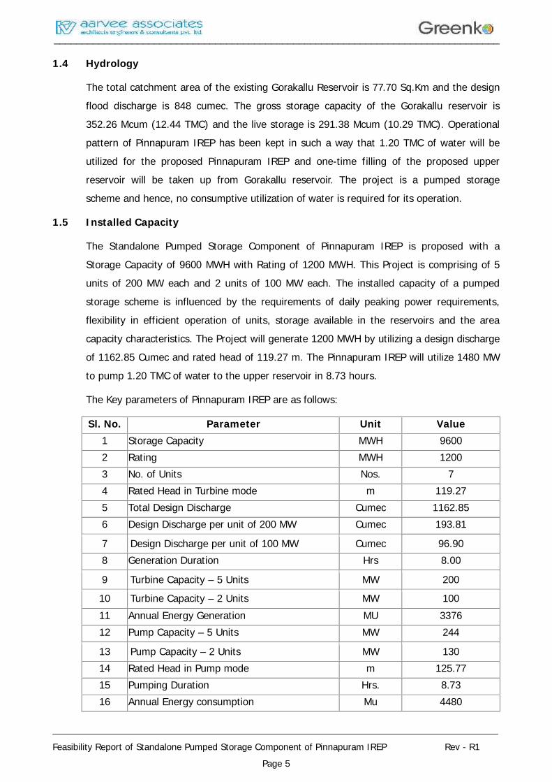
The Standalone Pumped Storage Component of Pinnapuram IREP is proposed with aStorage Capacity of 9600 MWH with Rating of 1200 MWH. This Project is comprising of 5units of 200 MW each and 2 units of 100 MW each. The installed capacity of a pumpedstorage scheme is influenced by the requirements of daily peaking power requirements,flexibility in efficient operation of units, storage available in the reservoirs and the areacapacity characteristics. The Project will generate 1200 MWH by utilizing a design dischargeof 1162.85 Cumec and rated head of 119.27 m. The Pinnapuram IREP will utilize 1480 MWto pump 1.20 TMC of water to the upper reservoir in 8.73 hours.
The Key parameters of Pinnapuram IREP are as follows:
Sl. No. Parameter Unit Value1 Storage Capacity MWH 96002 Rating MWH 12003 No. of Units Nos. 74 Rated Head in Turbine mode m 119.275 Total Design Discharge Cumec 1162.856 Design Discharge per unit of 200 MW Cumec 193.81
7 Design Discharge per unit of 100 MW Cumec 96.908 Generation Duration Hrs 8.00
9 Turbine Capacity – 5 Units MW 200
10 Turbine Capacity – 2 Units MW 10011 Annual Energy Generation MU 337612 Pump Capacity – 5 Units MW 244
13 Pump Capacity – 2 Units MW 13014 Rated Head in Pump mode m 125.7715 Pumping Duration Hrs. 8.7316 Annual Energy consumption Mu 4480
________________________________________________________________________________
________________________________________________________________________________
Feasibility Report of Standalone Pumped Storage Component of Pinnapuram IREP Rev - R1Page 6
The volume of water required for turbine mode of operation is equated to the pumpedmode. Annual energy generation by Pinnapuram IREP in Turbine mode is 3376 MU, Annualenergy consumption by Pinnapuram IREP in Pump mode is 4480 MU.
1.6 Power Evacuation
2 nos 400kV moose double circuit transmission lines are proposed for the project. Of these,1 no 400 KV moose double circuit transmission line to connect at Pinnapuram IREP CentralPooling station and 1 no 400 KV moose double circuit transmission line to connect at PGCIL765/400KV Substation at Orvakallu. These 2 transmission lines will be used for bothevacuation of generated power and input of power during pumping mode.
1.7 Environmental Aspects
Upper and lower reservoir for Pinnapuram IREP will be constructed newly and the onetimefilling of the Pinnapuram IREP upper reservoir will be taken up from existing Gorakallureservoir. There will be submergence of land required for the proposed Pinnapuramreservoir for the Pinnapuram IREP. Also, the land is required for the construction of powerhouse complex and its appurtanent works viz., Intake structure, penstocks, Tail Pool, TailRace Channel etc. Total land required for the construction of various components is about714 Ha including submergence by formation of Pinnapuram IREP upper and lower reservoir.The project components of Pinnapuram IREP are in Gani forest under Kurnool Range.Based on assessment of environmental impacts, management plans have to be formulatedfor compensatory afforestation and other environmental issues like rehabilitation &resettlement. These issues would be addressed during the investigations for DPR.
1.8 Construction Planning & Schedule
It is proposed to construct the project within a period of 3.0 years including infrastructuredevelopment which is proposed to be completed within 6 months.
1.9 Project Cost Estimate
The estimate of the project cost has been prepared as per the "Guidelines for formulationof Detailed Project Reports for Hydro- Electric Schemes" issued by Central ElectricityAuthority in January 2015 (Revision 5.0) to arrive at hard cost of the project at March 2018price level. Quantities have been worked out on the basis of preliminary designs anddrawings of different component works. Unit rate analysis was done as per the Guidelinesfor the preparation of Detailed Project Report of Irrigation and Multipurpose Projects andGuidelines for the preparation of Estimates for River valley projects. The quantities andratings of various Hydro Mechanical and Electro-mechanical equipment’s have been worked
________________________________________________________________________________
________________________________________________________________________________
Feasibility Report of Standalone Pumped Storage Component of Pinnapuram IREP Rev - R1Page 7
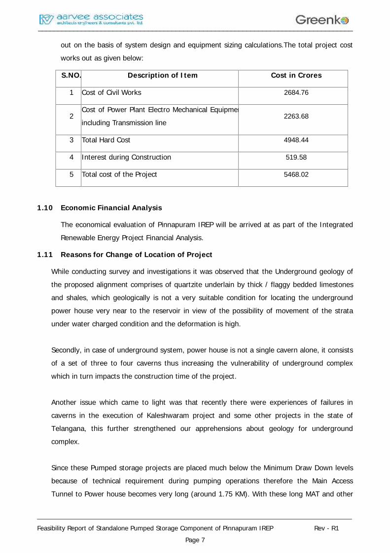
out on the basis of system design and equipment sizing calculations.The total project costworks out as given below:
S.NO. Description of Item Cost in Crores
1 Cost of Civil Works 2684.76
2Cost of Power Plant Electro Mechanical Equipmentincluding Transmission line
2263.68
3 Total Hard Cost 4948.44
4 Interest during Construction 519.58
5 Total cost of the Project 5468.02
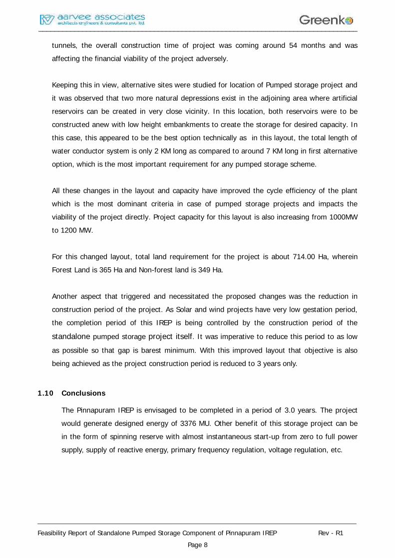
1.10 Economic Financial Analysis
The economical evaluation of Pinnapuram IREP will be arrived at as part of the IntegratedRenewable Energy Project Financial Analysis.
1.11 Reasons for Change of Location of Project
While conducting survey and investigations it was observed that the Underground geology ofthe proposed alignment comprises of quartzite underlain by thick / flaggy bedded limestonesand shales, which geologically is not a very suitable condition for locating the undergroundpower house very near to the reservoir in view of the possibility of movement of the strataunder water charged condition and the deformation is high.
Secondly, in case of underground system, power house is not a single cavern alone, it consistsof a set of three to four caverns thus increasing the vulnerability of underground complexwhich in turn impacts the construction time of the project.
Another issue which came to light was that recently there were experiences of failures incaverns in the execution of Kaleshwaram project and some other projects in the state ofTelangana, this further strengthened our apprehensions about geology for undergroundcomplex.
Since these Pumped storage projects are placed much below the Minimum Draw Down levelsbecause of technical requirement during pumping operations therefore the Main AccessTunnel to Power house becomes very long (around 1.75 KM). With these long MAT and other
________________________________________________________________________________
________________________________________________________________________________
Feasibility Report of Standalone Pumped Storage Component of Pinnapuram IREP Rev - R1Page 8
tunnels, the overall construction time of project was coming around 54 months and wasaffecting the financial viability of the project adversely.
Keeping this in view, alternative sites were studied for location of Pumped storage project andit was observed that two more natural depressions exist in the adjoining area where artificialreservoirs can be created in very close vicinity. In this location, both reservoirs were to beconstructed anew with low height embankments to create the storage for desired capacity. Inthis case, this appeared to be the best option technically as in this layout, the total length ofwater conductor system is only 2 KM long as compared to around 7 KM long in first alternativeoption, which is the most important requirement for any pumped storage scheme.
All these changes in the layout and capacity have improved the cycle efficiency of the plantwhich is the most dominant criteria in case of pumped storage projects and impacts theviability of the project directly. Project capacity for this layout is also increasing from 1000MWto 1200 MW.
For this changed layout, total land requirement for the project is about 714.00 Ha, whereinForest Land is 365 Ha and Non-forest land is 349 Ha.
Another aspect that triggered and necessitated the proposed changes was the reduction inconstruction period of the project. As Solar and wind projects have very low gestation period,the completion period of this IREP is being controlled by the construction period of the
standalone pumped storage project itself. It was imperative to reduce this period to as low
as possible so that gap is barest minimum. With this improved layout that objective is alsobeing achieved as the project construction period is reduced to 3 years only.
1.10 Conclusions
The Pinnapuram IREP is envisaged to be completed in a period of 3.0 years. The projectwould generate designed energy of 3376 MU. Other benefit of this storage project can bein the form of spinning reserve with almost instantaneous start-up from zero to full powersupply, supply of reactive energy, primary frequency regulation, voltage regulation, etc.
________________________________________________________________________________
________________________________________________________________________________
Feasibility Report of Standalone Pumped Storage Component of Pinnapuram IREP Rev - R1Page 9
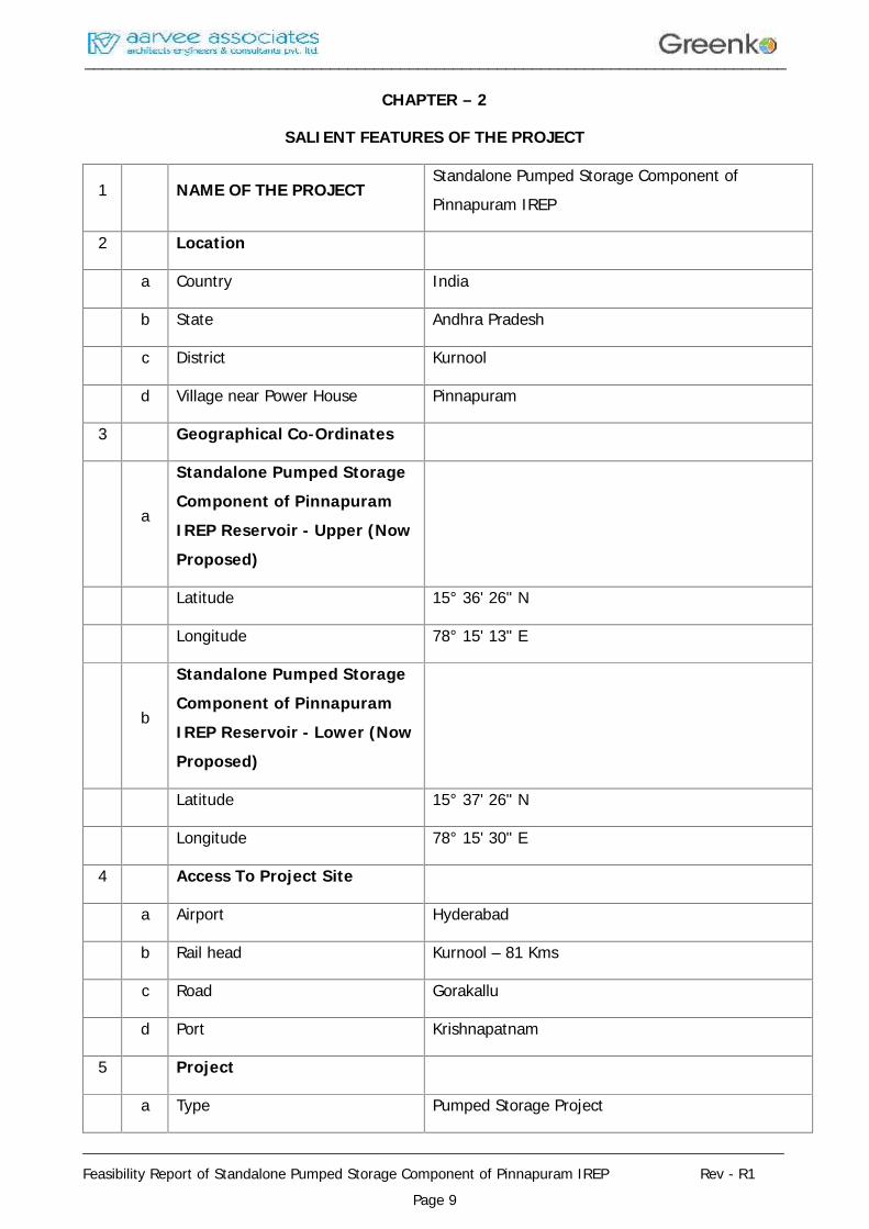
CHAPTER – 2
SALIENT FEATURES OF THE PROJECT
1 NAME OF THE PROJECTStandalone Pumped Storage Component ofPinnapuram IREP
2 Location
a Country India
b State Andhra Pradesh
c District Kurnool
d Village near Power House Pinnapuram
3 Geographical Co-Ordinates
a
Standalone Pumped StorageComponent of PinnapuramIREP Reservoir - Upper (NowProposed)
Latitude 15° 36' 26" N
Longitude 78° 15' 13" E
b
Standalone Pumped StorageComponent of PinnapuramIREP Reservoir - Lower (NowProposed)
Latitude 15° 37' 26" N
Longitude 78° 15' 30" E
4 Access To Project Site
a Airport Hyderabad
b Rail head Kurnool – 81 Kms
c Road Gorakallu
d Port Krishnapatnam
5 Project
a Type Pumped Storage Project
________________________________________________________________________________
________________________________________________________________________________
Feasibility Report of Standalone Pumped Storage Component of Pinnapuram IREP Rev - R1Page 10
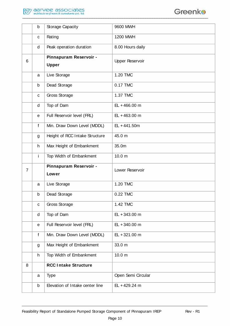
b Storage Capacity 9600 MWH
c Rating 1200 MWH
d Peak operation duration 8.00 Hours daily
6Pinnapuram Reservoir -Upper
Upper Reservoir
a Live Storage 1.20 TMC
b Dead Storage 0.17 TMC
c Gross Storage 1.37 TMC
d Top of Dam EL +466.00 m
e Full Reservoir level (FRL) EL +463.00 m
f Min. Draw Down Level (MDDL) EL +441.50m
g Height of RCC Intake Structure 45.0 m
h Max Height of Embankment 35.0m
i Top Width of Embankment 10.0 m
7Pinnapuram Reservoir -Lower
Lower Reservoir
a Live Storage 1.20 TMC
b Dead Storage 0.22 TMC
c Gross Storage 1.42 TMC
d Top of Dam EL +343.00 m
e Full Reservoir level (FRL) EL +340.00 m
f Min. Draw Down Level (MDDL) EL +321.00 m
g Max Height of Embankment 33.0 m
h Top Width of Embankment 10.0 m
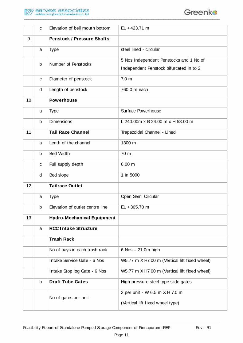
8 RCC Intake Structure
a Type Open Semi Circular
b Elevation of Intake center line EL +429.24 m
________________________________________________________________________________
________________________________________________________________________________
Feasibility Report of Standalone Pumped Storage Component of Pinnapuram IREP Rev - R1Page 11
c Elevation of bell mouth bottom EL +423.71 m
9 Penstock /Pressure Shafts
a Type steel lined - circular
b Number of Penstocks5 Nos Independent Penstocks and 1 No ofIndependent Penstock bifurcated in to 2
c Diameter of penstock 7.0 m
d Length of penstock 760.0 m each
10 Powerhouse
a Type Surface Powerhouse
b Dimensions L 240.00m x B 24.00 m x H 58.00 m
11 Tail Race Channel Trapezoidal Channel - Lined
a Lenth of the channel 1300 m
b Bed Width 70 m
c Full supply depth 6.00 m
d Bed slope 1 in 5000
12 Tailrace Outlet
a Type Open Semi Circular
b Elevation of outlet centre line EL +305.70 m
13 Hydro-Mechanical Equipment
a RCC Intake Structure
Trash Rack
No of bays in each trash rack 6 Nos – 21.0m high
Intake Service Gate - 6 Nos W5.77 m X H7.00 m (Vertical lift fixed wheel)
Intake Stop log Gate - 6 Nos W5.77 m X H7.00 m (Vertical lift fixed wheel)
b Draft Tube Gates High pressure steel type slide gates
No of gates per unit2 per unit - W 6.5 m X H 7.0 m
(Vertical lift fixed wheel type)
________________________________________________________________________________
________________________________________________________________________________
Feasibility Report of Standalone Pumped Storage Component of Pinnapuram IREP Rev - R1Page 12
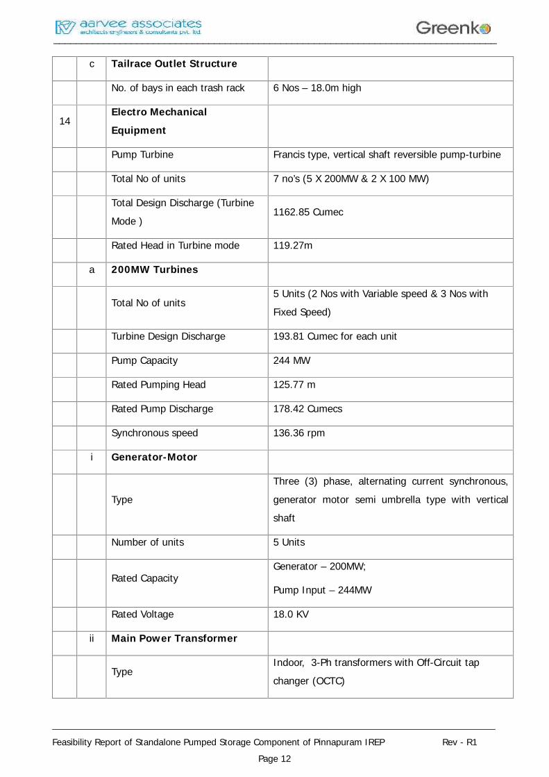
c Tailrace Outlet Structure
No. of bays in each trash rack 6 Nos – 18.0m high
14Electro MechanicalEquipment
Pump Turbine Francis type, vertical shaft reversible pump-turbine
Total No of units 7 no’s (5 X 200MW & 2 X 100 MW)
Total Design Discharge (TurbineMode )
1162.85 Cumec
Rated Head in Turbine mode 119.27m
a 200MW Turbines
Total No of units5 Units (2 Nos with Variable speed & 3 Nos withFixed Speed)
Turbine Design Discharge 193.81 Cumec for each unit
Pump Capacity 244 MW
Rated Pumping Head 125.77 m
Rated Pump Discharge 178.42 Cumecs
Synchronous speed 136.36 rpm
i Generator-Motor
TypeThree (3) phase, alternating current synchronous,generator motor semi umbrella type with verticalshaft
Number of units 5 Units
Rated CapacityGenerator – 200MW;
Pump Input – 244MW
Rated Voltage 18.0 KV
ii Main Power Transformer
TypeIndoor, 3-Ph transformers with Off-Circuit tapchanger (OCTC)
________________________________________________________________________________
________________________________________________________________________________
Feasibility Report of Standalone Pumped Storage Component of Pinnapuram IREP Rev - R1Page 13
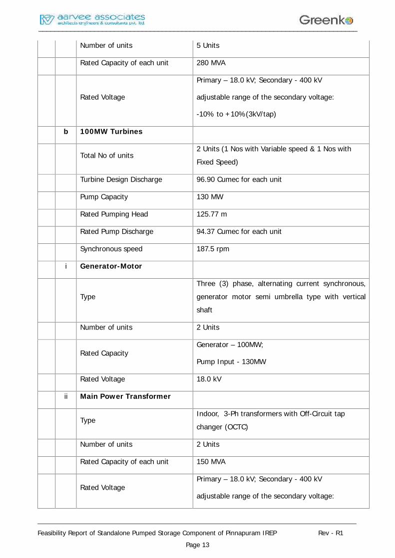
Number of units 5 Units
Rated Capacity of each unit 280 MVA
Rated Voltage
Primary – 18.0 kV; Secondary - 400 kV
adjustable range of the secondary voltage:
-10% to +10%(3kV/tap)
b 100MW Turbines
Total No of units2 Units (1 Nos with Variable speed & 1 Nos withFixed Speed)
Turbine Design Discharge 96.90 Cumec for each unit
Pump Capacity 130 MW
Rated Pumping Head 125.77 m
Rated Pump Discharge 94.37 Cumec for each unit
Synchronous speed 187.5 rpm
i Generator-Motor
TypeThree (3) phase, alternating current synchronous,generator motor semi umbrella type with verticalshaft
Number of units 2 Units
Rated CapacityGenerator – 100MW;
Pump Input - 130MW
Rated Voltage 18.0 kV
ii Main Power Transformer
TypeIndoor, 3-Ph transformers with Off-Circuit tapchanger (OCTC)
Number of units 2 Units
Rated Capacity of each unit 150 MVA
Rated VoltagePrimary – 18.0 kV; Secondary - 400 kV
adjustable range of the secondary voltage:
________________________________________________________________________________
________________________________________________________________________________
Feasibility Report of Standalone Pumped Storage Component of Pinnapuram IREP Rev - R1Page 14
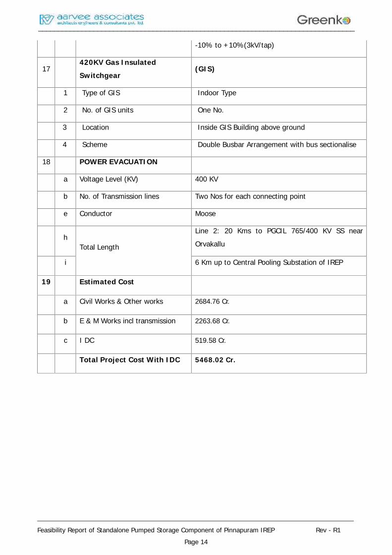
-10% to +10%(3kV/tap)
17420KV Gas InsulatedSwitchgear
(GIS)
1 Type of GIS Indoor Type
2 No. of GIS units One No.
3 Location Inside GIS Building above ground
4 Scheme Double Busbar Arrangement with bus sectionalise
18 POWER EVACUATION
a Voltage Level (KV) 400 KV
b No. of Transmission lines Two Nos for each connecting point
e Conductor Moose
hTotal Length
Line 2: 20 Kms to PGCIL 765/400 KV SS nearOrvakallu
i 6 Km up to Central Pooling Substation of IREP
19 Estimated Cost
a Civil Works & Other works 2684.76 Cr.
b E & M Works incl transmission 2263.68 Cr.
c I DC 519.58 Cr.
Total Project Cost With IDC 5468.02 Cr.

________________________________________________________________________________
________________________________________________________________________________
Feasibility Report of Standalone Pumped Storage Component of Pinnapuram IREP Rev - R1Page 15
CHAPTER – 3
PROJECT AREA
3.1 General
Pinnapuram IREP is located in Kurnool district of Andhra Pradesh. It envisages creation ofboth upper and lower reservoir near Pinnapuram depression which is flowing NW – SEdirection. The project is about 80 km from District headquarters Kurnool via Nannur.Nearest railhead is at Kurnool and Airport is at Hyderabad. The nearest Village to project isPinnapuram about 2 Km, which comes under Mandyal Mandal. The Installed capacity of theProject is proposed as 1200 MWH.
Andhra Pradesh is one of the 29 states of India, situated on the country's southeasterncoast. The state is the eighth largest state in India covering an area of 160,205 km2
(61,855 sqmi). As per 2011 census of India, the state is tenth largest by population with49,386,799 inhabitants.
The state has the second longest coastline of 972 km (604 mi) among all the states ofIndia. It borders Telangana in the northwest, Odisha in the northeast, Karnataka in thewest, Tamil Nadu in the south and the water body of Bay of Bengal in the east. A smallenclave of 31 km2 (12 sq mi) of Yanam, a district of Pondicherry, lies south of Kakinada inthe Godavari delta to the northeast of the state. There are 13 districts with 9 in CoastalAndhra and 4 in Rayalaseema. Visakhapatnam is the largest city and a commercial hub ofthe state.
Geographically, Andhra Pradesh is bestowed with two mighty river systems of Krishna andGodavari. Its varied topography ranging from the hills of Eastern Ghats and Nallamallas tothe shores of Bay of Bengal supports varied ecotypes, rich diversity of flora and fauna. Thestate has two regions Coastal Andhra and Rayalaseema. The plains to the east of EasternGhats form the Eastern coastal plains. The coastal plains are for the most part of deltaregions formed by the Godavari, Krishna, and Penna rivers. The Eastern Ghats arediscontinuous and individual sections have local names. The Eastern Ghats are a majordividing line in the state's geography. The Kadapa Basin formed by two arching branches ofthe Eastern Ghats is a mineral-rich area. The Ghats become more pronounced towards thesouth and extreme north of the coast. Most of the coastal plains are put to intenseagricultural use. The Rayalaseema region has semi-arid conditions. Lambasingi (orLammasingi), a village in the Chintapalli Mandal of Visakhapatnam district is situated at1000 meters above the sea level. It is the only place in South India which has snowfall andis also nicknamed as Kashmir of Andhra Pradesh. Throughout the year the temperature
________________________________________________________________________________
________________________________________________________________________________
Feasibility Report of Standalone Pumped Storage Component of Pinnapuram IREP Rev - R1Page 16
here ranges from 0 °C to 10 °C
The total forest cover of the state after the bifurcation is left with an area of 22,862 km2
The forest in the state can be broadly divided into four major biotic provinces. They are:
Deccan Plateau
Central Plateau
Eastern Highland
East Coastal Plains
Eastern Ghats region is home to dense tropical forests, while the vegetation becomessparse as the Ghats give way to the Deccan Plateau, where shrub vegetation is morecommon. These ghats has rich biological diversity with wide variety of plants, birds andlesser forms of animal life. The vegetation found in the state is largely of dry deciduoustype with a mixture of Teak, Terminalias, Dalbergias, Pterocarpus, Anogeissus etc. TheState possesses some rare and endemic plants like Cycas beddomei, Pterocarpussantalinus, Terminalia pallida, Syzygium alternifolium, Shorea talura, Shorea tumburgia,Psilotum nudum etc.
The diversity of fauna includes tigers, panthers, hyenas, black bucks, cheetals, sambars,sea turtles and a number of birds and reptiles. The estuaries of river Godavari and Krishnasupport rich mangrove forests with fishing cats and otters as keystone species
3.2 Gorakallu Reservoir
The KWDT in 1973 has allocated 800 TMC (75% dependable flows) of Krishna waters to APState. Under this award, the state is entitled to make any adjustments and re-allocationswithin the allotment made specially to the state and also entitled to utilize 11 TMC ofregenerated water as its share to irrigate 1,90,000 Acres of Nandyal, Banaganapalli,Koilkuntla Taluks of Kurnool Dist. and Jammalmadugu taluk of Kadapa District.The sourceof water to the scheme is river Krishna tapped from foreshore of Srisailam reservoir ( Nownamed as N.S.R.S.Project ). Water will be drawn from reservoir through Pothidreddy paduhead regulator with an approach channel of 3.40 Kms long inside the reservoir and fromthe head regulator the Sri Sailam Right main canal is aligned cutting across theMittakandala ridge up to Banakacherla village to enter the Kundu sub-valley. AtBanakacherla, a cross regulator complex is constructed and from this point the main canali.e.,SRMC branches into three canals. The right side canal taking off to feed SRBC schemewith a capacity of 5,000 Cusecs, left canal taking off to feed the TGP and the middleescape channel to feed K.C.Canal. Thus SRBC starts from Banakacherla cross regulator
________________________________________________________________________________
________________________________________________________________________________
Feasibility Report of Standalone Pumped Storage Component of Pinnapuram IREP Rev - R1Page 17
complex and runs for a length of 198.00 Km and joins in pennar river duly filling twobalancing reservoirs one at Goralkallu village and another at owk village.The length of canalin Kurnool district is 141 km. This S.R.B.C Scheme was formulated to irrigate an Ayacut of1,90,000 Acres to benefit the chronic drought prone areas in 82 villages of Nandyal,Panyam, Banaganapalli, Owk, Koilakuntla, Vuyyalwada and sanjamala mandals of Kurnooldistrict (1,57,422 Acres ) and 18 villages of Jammalamadugu mandal of Kadapa district(32,578 Acres).
3.3 Climate
The climate of Andhra Pradesh varies considerably, depending on the geographical region.Monsoons play a major role in determining the climate of the state. Summers last fromMarch to June. In the coastal plain, the summer temperatures are generally higher than therest of the state, with temperature ranging between 20 °C and 41 °C.
July to September is the season for tropical rains in Andhra Pradesh. The state receivesheavy rainfall from the Southwest Monsoon during these months. About one third of thetotal rainfall in Andhra Pradesh is brought by the Northeast Monsoon. October andNovember see low-pressure systems and tropical cyclones form in the Bay of Bengal which,along with the Northeast Monsoon, bring rains to the southern and coastal regions of thestate. November, December, January, and February are the winter months in AndhraPradesh. Since the state has a long coastal belt the winters are not very cold. The range ofwinter temperature is generally 12 °C to 30 °C
3.4 Mineral Resources
Andhra Pradesh is one of the storehouses of mineral resources in India. Andhra Pradeshwith varied geological formations, contain rich and variety of industrial minerals andbuilding stones.
Andhra Pradesh is listed top in the deposit and production of mica in India. Minerals foundin the state include limestone, reserves of Oil and natural gas, manganese, asbestos, IronOre, Ball Clay, Fire Clay, Gold Diamonds, graphite, Dolomite, quartz, Tungsten, Steatitic,Feldspar, Silica Sand. It has about one third of India's limestone reserves and is known forlarge exclusive deposits of Barytes and Galaxy granite in the international market.
Mining is identified as one of the growth engines for the overall development of industryand infrastructure. The Tummalapalle Uranium mine in Andhra has confirmed 49,000tonnes of ore and there are indications that it could hold reserves totaling three times itscurrent size. 700 million tonnes of metal grade Bauxite deposits in close proximity toVisakhapatnam Port.
________________________________________________________________________________
________________________________________________________________________________
Feasibility Report of Standalone Pumped Storage Component of Pinnapuram IREP Rev - R1Page 18
3.5 Education
Andhra Pradesh has an overall literacy rate of 91.01% (2014). According to the report ofSarva Shiksha Abhiyan (2011–12) and Statistical Abstract (2012–13), 37,45,340 childrenout of 38,05,791 (98.4%), were enrolled in Primary schools with a teacher/student ratio of29.3%. 21,01,928 children out of 21,56,577 (97.5%), were enrolled in Upper Primaryschools with a teacher/student ratio of 24.6%. Schools in Andhra Pradesh require Telugu tobe learned. Apart from thousands of schools ranging from the pre-primary to the seniorsecondary ones, the state is home to a number of institutes, which impart highereducation.
The Ministry of Human Resource Development has sanctioned The Indian Institute ofManagement (IIM) at Visakhapatnam which will start functioning from the academic year2015-16. The Government of Andhra Pradesh has established Rajiv Gandhi University ofKnowledge Technologies (RGUKT) in 2008 to cater to the educational needs of the giftedrural youth of Andhra Pradesh. The higher education includes many colleges, universitiesand research institutes providing professional education in the fields of arts, humanities,science, engineering, law, medicine, business, and veterinary sciences, with undergraduateand post graduation.
3.6 General Features of the Project
Pinnapuram IREP is located in Kurnool district of Andhra Pradesh, and is proposed betweentwo reservoirs i.e. Pinnapuram IREP upper and lower reservoir (both to be constructednewly) and one time water will be pumped from existing Gorakallu reservoir to fill up theproposed upper reservoir.The project envisages construction of a RCC intake Structure,Penstock, surface Power House and Tail Race Channel. Installed capacity of the Project isproposed as 1200 MW (5x200MW + 2x100MW). There are no monuments of archeologicalor national importance which would be affected by project activities directly or indirectly.
________________________________________________________________________________
________________________________________________________________________________
Feasibility Report of Standalone Pumped Storage Component of Pinnapuram IREP Rev - R1Page 19
CHAPTER – 4
POWER SCENARIO
4.1. INTRODUCTION
Power sector is a critical infrastructure element required for the smooth functioning of theeconomy. An efficient, resilient and financially healthy power sector is essential for growthand poverty reduction. The availability of reliable, quality and affordable power helps in therapid agriculture, industrial and overall economic development of the state.
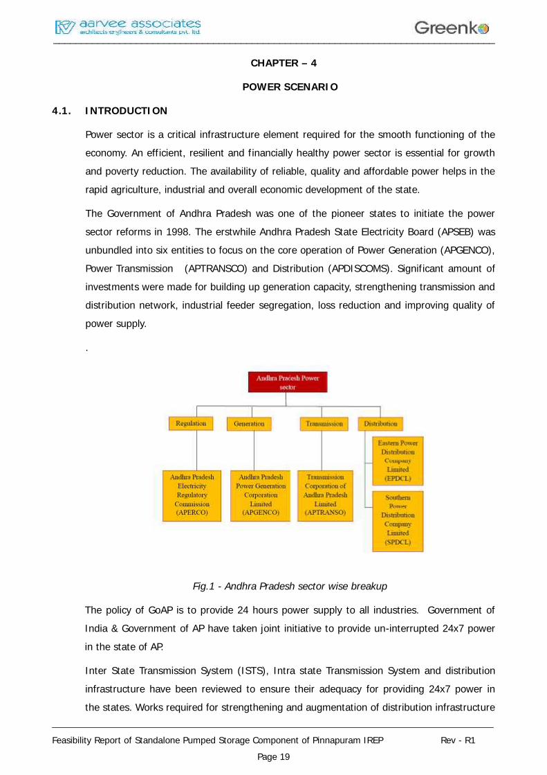
The Government of Andhra Pradesh was one of the pioneer states to initiate the powersector reforms in 1998. The erstwhile Andhra Pradesh State Electricity Board (APSEB) wasunbundled into six entities to focus on the core operation of Power Generation (APGENCO),Power Transmission (APTRANSCO) and Distribution (APDISCOMS). Significant amount ofinvestments were made for building up generation capacity, strengthening transmission anddistribution network, industrial feeder segregation, loss reduction and improving quality ofpower supply.
.
Fig.1 - Andhra Pradesh sector wise breakup
The policy of GoAP is to provide 24 hours power supply to all industries. Government ofIndia & Government of AP have taken joint initiative to provide un-interrupted 24x7 powerin the state of AP.
Inter State Transmission System (ISTS), Intra state Transmission System and distributioninfrastructure have been reviewed to ensure their adequacy for providing 24x7 power inthe states. Works required for strengthening and augmentation of distribution infrastructure
________________________________________________________________________________
________________________________________________________________________________
Feasibility Report of Standalone Pumped Storage Component of Pinnapuram IREP Rev - R1Page 20
have been identified for supplying uninterrupted power to the consumers. CentralGovernment will supplement the efforts of the State Government through schemes whichare being finalized by Ministry of Power for funding of works required for strengthening andaugmentation of distribution infrastructure, feeder segregation and 100% metering.
This joint initiative of Government of India and Government of Andhra Pradesh aims toenhance the satisfaction levels of the consumers, improve the quality of life of people andincrease the economic activities resulting into inclusive development of the State.
4.2 POWER SUPPLYSCENARIO
The requirement of electricity, i.e. both energy and peak demand are expected to increasesignificantly in Andhra Pradesh from the present level of demand 54,301MU & 7,969 MWto 82,392 MU and 13,436 MW respectively by FY 2018-19 due to:
1. Natural Load Growth.
2. 24x7 power supply to all consumers
3. Increase in electrification of households
4. 9 hours supply to agricultural consumers
5. Additional energy requirement for upcoming capital city and associatedinvestments
6. New Industrial corridors
7. New Lift Irrigation schemes.
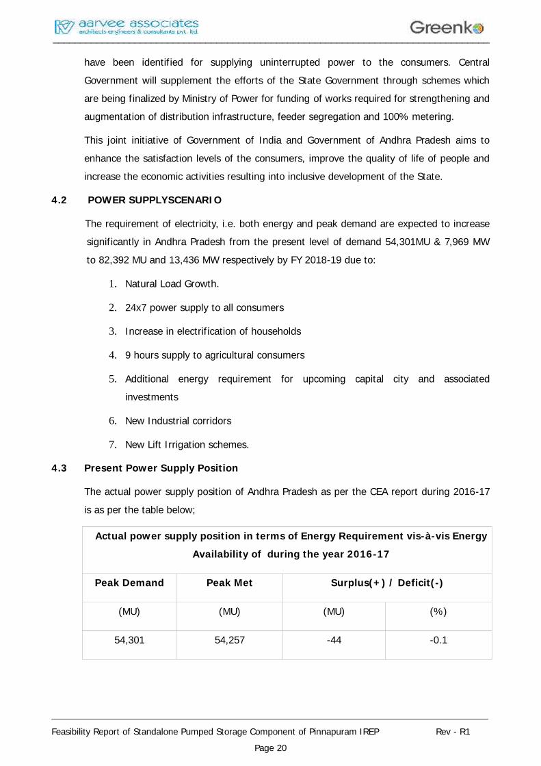
4.3 Present Power Supply Position
The actual power supply position of Andhra Pradesh as per the CEA report during 2016-17is as per the table below;
Actual power supply position in terms of Energy Requirement vis-à-vis EnergyAvailability of during the year 2016-17
Peak Demand Peak Met Surplus(+) / Deficit(-)
(MU) (MU) (MU) (%)
54,301 54,257 -44 -0.1
________________________________________________________________________________
________________________________________________________________________________
Feasibility Report of Standalone Pumped Storage Component of Pinnapuram IREP Rev - R1Page 21
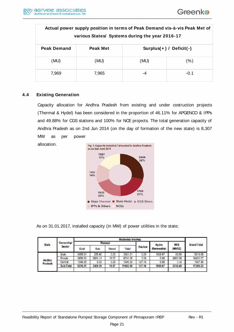
Actual power supply position in terms of Peak Demand vis-à-vis Peak Met ofvarious States/ Systems during the year 2016-17
Peak Demand Peak Met Surplus(+) / Deficit(-)
(MU) (MU) (MU) (%)
7,969 7,965 -4 -0.1
4.4 Existing Generation
Capacity allocation for Andhra Pradesh from existing and under costruction projects(Thermal & Hydel) has been considered in the proportion of 46.11% for APGENCO & IPPsand 49.88% for CGS stations and 100% for NCE projects. The total generation capacity ofAndhra Pradesh as on 2nd Jun 2014 (on the day of formation of the new state) is 8,307MW as per powerallocation.
As on 31.01.2017, installed capacity (in MW) of power utilities in the state;
________________________________________________________________________________
________________________________________________________________________________
Feasibility Report of Standalone Pumped Storage Component of Pinnapuram IREP Rev - R1Page 22
4.5 Action points for GoAP / APGENCO
In the current situation, there are a host of measures that are being taken up immediatelyby GoAP/APGENCO, while others will be implemented in a phased manner for long termreduction of fuel deficit.
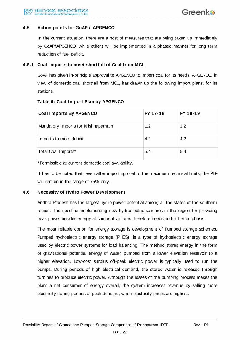
4.5.1 Coal Imports to meet shortfall of Coal from MCL
GoAP has given in-principle approval to APGENCO to import coal for its needs. APGENCO, inview of domestic coal shortfall from MCL, has drawn up the following import plans, for itsstations.
Table 6: Coal Import Plan by APGENCO
Coal Imports By APGENCO FY 17-18 FY 18-19
Mandatory Imports for Krishnapatnam 1.2 1.2
Imports to meet deficit 4.2 4.2
Total Coal Imports* 5.4 5.4
*Permissible at current domestic coal availability.
It has to be noted that, even after importing coal to the maximum technical limits, the PLFwill remain in the range of 75% only.
4.6 Necessity of Hydro Power Development
Andhra Pradesh has the largest hydro power potential among all the states of the southernregion. The need for implementing new hydroelectric schemes in the region for providingpeak power besides energy at competitive rates therefore needs no further emphasis.
The most reliable option for energy storage is development of Pumped storage schemes.Pumped hydroelectric energy storage (PHES), is a type of hydroelectric energy storageused by electric power systems for load balancing. The method stores energy in the formof gravitational potential energy of water, pumped from a lower elevation reservoir to ahigher elevation. Low-cost surplus off-peak electric power is typically used to run thepumps. During periods of high electrical demand, the stored water is released throughturbines to produce electric power. Although the losses of the pumping process makes theplant a net consumer of energy overall, the system increases revenue by selling moreelectricity during periods of peak demand, when electricity prices are highest.
________________________________________________________________________________
________________________________________________________________________________
Feasibility Report of Standalone Pumped Storage Component of Pinnapuram IREP Rev - R1Page 23
Pumped-storage hydroelectricity allows energy from intermittent sources (such as solar,wind) and other renewables, or excess electricity from continuous base-load sources (suchas coal or nuclear) to be saved for periods of higher demand. The reservoirs used withpumped storage are quite small when compared to conventional hydroelectric dams ofsimilar power capacity, and generating periods are often less than half a day. Along withenergy management, pumped storage systems are also helpful in controlling electricalnetwork frequency and provide reserve energy.
In view of the power scenario described above, the Pinnapuram IREP envisaged withStorage Capacity of 9600 MWH with rating of 1200 MWH and will help a long way inmeeting the projected power demand.
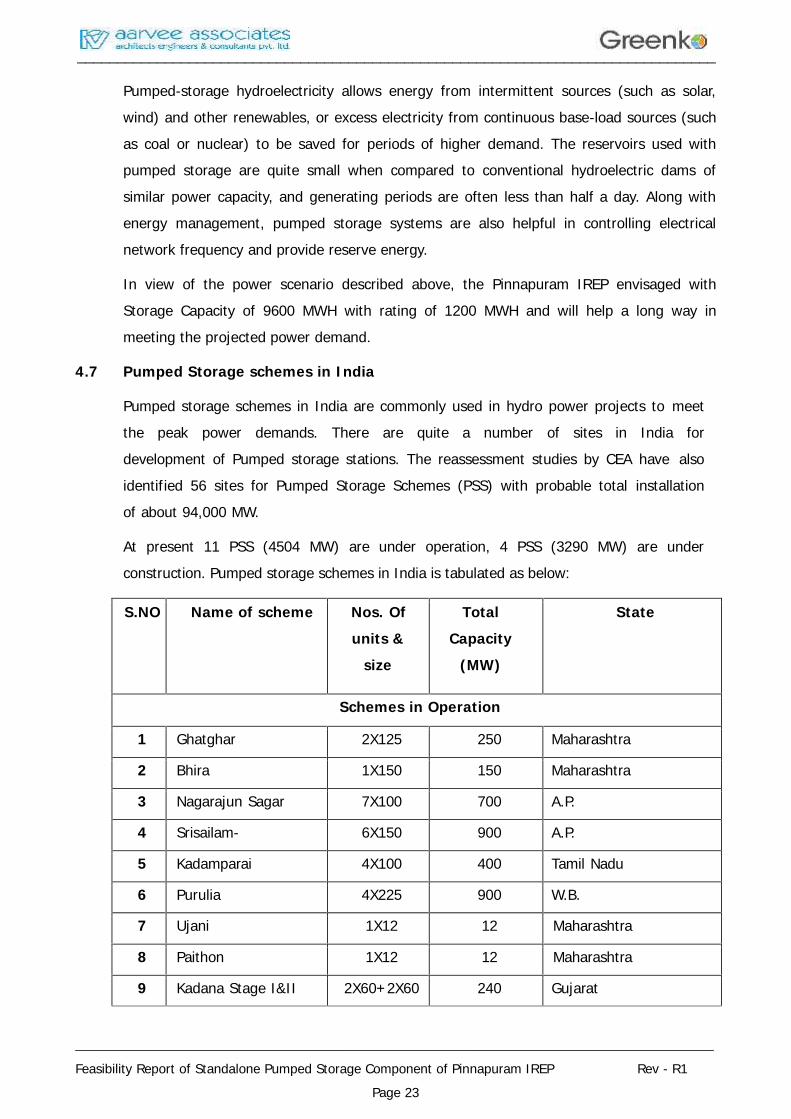
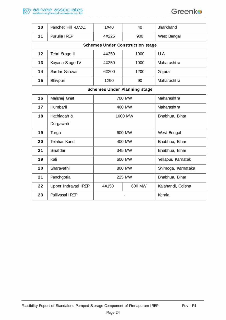
4.7 Pumped Storage schemes in India
Pumped storage schemes in India are commonly used in hydro power projects to meetthe peak power demands. There are quite a number of sites in India fordevelopment of Pumped storage stations. The reassessment studies by CEA have alsoidentified 56 sites for Pumped Storage Schemes (PSS) with probable total installationof about 94,000 MW.
At present 11 PSS (4504 MW) are under operation, 4 PSS (3290 MW) are underconstruction. Pumped storage schemes in India is tabulated as below:
S.NO Name of scheme Nos. Ofunits &
size
TotalCapacity
(MW)
State
Schemes in Operation
1 Ghatghar 2X125 250 Maharashtra
2 Bhira 1X150 150 Maharashtra
3 Nagarajun Sagar 7X100 700 A.P.
4 Srisailam- 6X150 900 A.P.
5 Kadamparai 4X100 400 Tamil Nadu
6 Purulia 4X225 900 W.B.
7 Ujani 1X12 12 Maharashtra
8 Paithon 1X12 12 Maharashtra
9 Kadana Stage I&II 2X60+2X60 240 Gujarat
________________________________________________________________________________
________________________________________________________________________________
Feasibility Report of Standalone Pumped Storage Component of Pinnapuram IREP Rev - R1Page 24
10 Panchet Hill -D.V.C. 1X40 40 Jharkhand
11 Purulia IREP 4X225 900 West Bengal
Schemes Under Construction stage
12 Tehri Stage II 4X250 1000 U.A.
13 Koyana Stage IV 4X250 1000 Maharashtra
14 Sardar Sarovar 6X200 1200 Gujarat
15 Bhivpuri 1X90 90 Maharashtra
Schemes Under Planning stage
16 Malshej Ghat 700 MW Maharashtra
17 Humbarli 400 MW Maharashtra
18 Hathiadah &Durgawati
1600 MW Bhabhua, Bihar
19 Turga 600 MW West Bengal
20 Telahar Kund 400 MW Bhabhua, Bihar
21 Sinafdar 345 MW Bhabhua, Bihar
19 Kali 600 MW Yellapur, Karnatak
20 Sharavathi 800 MW Shimoga, Karnataka
21 Panchgotia 225 MW Bhabhua, Bihar
22 Upper Indravati IREP 4X150 600 MW Kalahandi, Odisha
23 Pallivasal IREP - Kerala
________________________________________________________________________________
________________________________________________________________________________
Feasibility Report of Standalone Pumped Storage Component of Pinnapuram IREP Rev - R1Page 25
CHAPTER – 5
SURVEY & GEOTECHNICAL INVESTIGATIONS
5.1 General
The following investigations shall be carried out specifically for the proposed project andare briefly discussed in this Chapter:
Topographical survey
Geology & Geotechnical investigations
Construction material investigations
5.2 Topographical Survey
Topographical maps (57 I/2 and 57 I/6) of Survey of India were referred for preliminaryinvestigation, reconnaissance and for finalizing the proposed project layout.
5.3 Reconnaissance Survey
Two offstream reservoirs are proposed to act as lower and upper reservoirs respectivelyfor the proposed Pinnapuram IREP. The water required for the Pumped storage operationwill be drawn from Gorakallu Reservoir for onetime filling of the proposed PinnapuramIREP upper reservoir.
A reconnaissance survey is made for the river, existing reservoirs, possible intake and exitlocations, penstock tunnels, power house area and TRC. All salient features of the area arenoted during the reconnaissance survey.
5.4 PRIMARY CONTROL BENCH MARKS
A network of control points has been established in the project area, using auto-levels andDifferential Global Positioning System (DGPS). Traversing was conducted between theDGPS points by using Total Station.
Height control has been established with respect to the existing bench mark. The benchmark has been carried to site by DCBM method using precision auto levels.
5.5 SECONDARY CONTROL POINTS
To facilitate the detailed survey of remote areas, which are not directly accessible fromprimary control GPS points, temporary secondary level control points have beenestablished. Several such points were established during detailed survey depending uponthe area to be covered and accessibility. A stone pillar, marking on rock or driving a peg intofirm ground were the various ways adopted for establishing these temporary bench marks.
________________________________________________________________________________
________________________________________________________________________________
Feasibility Report of Standalone Pumped Storage Component of Pinnapuram IREP Rev - R1Page 26
All the reference points established were also interconnected elevation wise. The errorallowed in these elevations was 12√k mm where k is in kilometers. A double check levelingprocedure has been adopted to transfer the level of bench mark. High precision auto levelswere used for the entire leveling job.
5.6 DEVELOPMENT OF PLAN
The overall plan of the project site indicating the streams, topographical features like cliffs,rocky outcrops, mounds, ditches, was generated by taking coordinates using total station.Proposed alignment of penstock, power house and tail race channel are indicated in theplan.
5.7 Geological Survey & Investigation
5.7.1 Introduction of Study Area
Kurnool district is the third largest district in Andhra Pradesh situated between Northlatitudes 14°35′35″:16°09′36″ and East longitudes 75°58′42″:78°56′06″. It is bounded byTungabhadra and Krishna rivers and Mahabubnagar district in the north and Prakasamdistrict in the East, Bellary district of Karnataka State in the west and Anantapur andCuddapah districts in the South. The total geographical area of the district is 17600 sq.kmwith headquarters at Kurnool and divided into 54 revenue mandals.
5.7.2 Physiography
The Nallamalais and Erramalias constitute the principle hill ranges in the district. Theaverage altitutde ofthe Nallamalais is 600m. The highest point in the range is Manikondawhich is having altitude about 909 m.and the other prominent peak is Durgaonda which ishaving altitude 851m.
5.7.3 DRAINAGE SYSTEM
The important rivers flowing in the district are the Tungabhadra, its tributaries, the Handri,the Krishna and the Kunderu. Tungabhadra rises in the Western Ghats and forms thenorthern boundary between Kurnool and Mahabubnagar district. The Handri drainsPattikonda and Dhone areas and joins Tungabhadra near Kurnool town. Kunderu is atributary of the river Pennar which rises on the western side of the Erramalais and flows inthe southern direction thorough Nandikotkur, Nahdyal, Allagadda and Koilakuntla andenters Cuddapah district. In addition to these, small streams The Sogileru, The Rallavagu,The Munimaduguleru, The Bandrapavagu and The Sudamvagu, Paleru, Gandaleru andBhavanari drains are flowing in the district.
________________________________________________________________________________
________________________________________________________________________________
Feasibility Report of Standalone Pumped Storage Component of Pinnapuram IREP Rev - R1Page 27
5.7.4 STRATIGRAPHY OF THE INDIAN PENINSULA
The Proterozoic rocks are present in the northern as well as the southern parts of Indianpeninsula. These rock formations of the Cuddapah Supergroup and, its equivalent, wereearlier referred to as Purana Formation, including both the Cuddapah and VindhyanSupergroup. The stratigraphic succession of Indian Peninsula as follows:
It divided in to two main divisions as Upper Purana Group and Lower Purana Group, TheKurnool formation belong to Southern Peninsula of the grate Indian Peninsula
Main division Southern Peninsula Northern Peninsula
Upper Purana Kumool Group, Bhima Upper Vindhyan
Group, Indravati Group Malani Volcanics,
Sullaria Group
Lower Purana Chhattisgarh Group. Lower Vindhyan
Cuddapah Supergroup, Gwalior Group
Kaladgi Group, Bijawar Group
Pakhal Group. Kolhan Group
Delhi Super group.
5.7.5 REAGIONAL GEOLOGY OF STUDY AREA
The Kurnool district is situated within the stable shield of Indian Peninsula. The oldest rocksexposed in the district are a group of metamorphic rocks of early Precambrian or Archaeanage. They comprise of quartzites, phyllites, schists, gneisses, migmatites, granites andamphibiolites. These rocks have been highly folded and intruded in to granites. Thecomposite gneisses associated with granites were formed as a result of the injection ofgranitic magma along weak planes in the pre-existing rocks and reaction between them.Apart from this, there are periods of erosion and non-deposition of sediments known as theEparchaean interval, followed when there was a termination of earth movement andigneous activity and the country was exposed to denudation.
This prolonged period of dormancy came to a close when in the late Precambrian times alarge tract of Landin the district and adjacent districts formed into a sallow sea. Sedimentsstarted accumulating in the basin referred to as Cuddapah basin. The sedimentary rocks ofthe Cuddapah Super group comprises of conglomerates, quartzites, shales, dolomite,limestones and chert. The floor of the sea was unstable and it sunk periodically. Landconditions appear to have prevailed intermittently in this region before the deposition of the
________________________________________________________________________________
________________________________________________________________________________
Feasibility Report of Standalone Pumped Storage Component of Pinnapuram IREP Rev - R1Page 28
Cuddapah sedimentation was completed. Further, in the early Cuddapah times, there wasintermittent volcanic activity, when lavas of basic igneous rocks in the form of sills intrudedthe cuddapah formations. When the deposition of Cuddapah sediments ended, the regionwas uplifted and the strata tilted, fractured and exposed to denudation.
With the passage of time, the basin in the west was again submerged beneath a shallowsea and in the upper Precambrian and Cambrian times, the sedimentary rocks of Kurnoolgroup comprising of limestones, shales, quartzites and conglomerates were deposited.
The overlapping nature of the different formations and the lateral variation in the thicknessof Kurnool strata suggest that the basin in which the Kurnool sediments accumulated wasunstable with frequents oscillations of the sea level. In the post Kurnool times, theCuddapath basin was again uplifted and along its eastern margin, the Kurnool andCuddapahs were folded, the later more severely.
These rocks occupy the western part of the district exposed in Adoni, Alur, Pattikondaareas. Granites and composite gneisses are the dominant rock types. Amphibolies,hornblende schists, quartzites, phyllites, chlorite schists and mica schists are very muchrestricted in their extent and confined to small patches. The schists are highly folded. Thecomposite gneisses are grey in colour and show alternate banding of quartz and feldsparwith biotite or hornblende. The granites are seen in pink, grey, and with massive, gneissicfine-to-coarse grained and porphyritic texture. The granites are composed of potashfeldspar, plagioclase, quartz, biotite and hornblende. Numerous felsite, pegmatites quartzveins and dykes of dolerite have intruded into the granites.
5.7.6 THE CUDDAPAH ROCKS
The rocks of Cuddapah Super group mostly occupy the eastern part of the district, roughly100 Km long in N-S (roughly) 50 Km wide extending westwards from Nallamalai range. Thenorthern and eastern parts of Atmakur, eastern parts of Nandyal, and east of Allagadda areoccupied by Cuddapah formations. They are concealed by the younger Kurnool formations.
The Cuddapah sediments are over 6000 meters in thickness. They are sub divisible asfollows-
PAPAGNI GROUP –
Guvalacheruvu quartzites, Vempalli dolomites, The dips are gentle towards ESE or S. In theVeldurthy – Kalva area, the Gulcheruvu and Vempallies have faulted along with ChitravathiGroup of rocks. The faults have E-N-E and W-S-W or E-W trends.
________________________________________________________________________________
________________________________________________________________________________
Feasibility Report of Standalone Pumped Storage Component of Pinnapuram IREP Rev - R1Page 29
CHITRAVATHI GROUP –
Pulivendla qucquartzites and Tadpatri shales, are main Rocks types of group, exposed ataround Dhone, Banganapalli areas over a narrow belt.
NALLAMALAI GROUP –
Bairenkonda quartzites, Cumbum shales. Nallamallai Group of rocks are highly folded andintruded by dolorites, prophyritic rocksof alkaline composition, and rocks of probableKimberlite composition.
KRISHNA GROUP –
THE KURNOOL GROUP ROCKS
The Kurnool Group of rocks are mainly composed of limestones and calcarious shales andattained at thickness of about 600 m. It is divisible into four formations as follows:
Kundair formaiton
Paniam formation
Jammulamadugu formation
Banganapalli formation
The Banganapalli formation consists of quartzites, sandstones and conglomerates, exposedat Banganmpalli, Nandavaram, Nandyal, Gani, Mithur and Nandikotkur areas. They arehorizontal or show gentle dips (<10°). The basal conglomerate is made up of clasts ofshale, chert, laser quartzite in a sandy or clayey matrix. Diamonds are picked up from theseconglomerate. The quartzites and sandstone are medium to coarse grained, grey in colour.
The Jammalamadugu Group overlies the Banganapalli formation comprises of Narjilimestones at the base and Owk shales at the top. They are exposed at Koilakuntla, Dhone,Nandyal, Nandi kotkur and Kurnool. The Narji limestones are massive and variegated incolour intercalated with shale and quartzite bands. The Narji formation contain enormouslimestone reserves.
The Panyam Group of rocks which comprises of the plateau quartzites at the bottom andthe pinnacle quartzite at the top, constitute the flat topped ridges and plateau to the westof Kundeir plains.
The Kundair formarmations are the youngest of Kurnool Group comprising of Koilakuntlabeds at the bottom and the Nandyal shales at the top. They attain a thickness ranging from60 to 300 m. and exposed in the plains of Kunderu river, south of Allagadda to north ofAtmakur. The Koilakuntla consists of grey, massive or flaggy limestones, while the Nandyals
________________________________________________________________________________
________________________________________________________________________________
Feasibility Report of Standalone Pumped Storage Component of Pinnapuram IREP Rev - R1Page 30
are made up of calcareous shale and shaley limestone.
RECENT GEOLOGICAL SUCESSION OF KURNOOL GROUP AS CONFIRMED BY GSI
Banganapalli Quartzite 10 – 57m
Narji Limestone 100 – 200m
Owk shales 10 – 15m
Panyam Quartzite 10 – 15m
Koilakuntla Limestone 15 – 50m
Nandyal Shale 50 – 100m
5.8 GENERAL GEOLOGY OF PROPOSED RESERVOIRS
5.8.1 Lower Reservoir
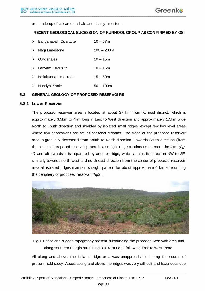
The proposed reservoir area is located at about 37 km from Kurnool district, which isapproximately 3.5km to 4km long in East to West direction and approximately 1.5km wideNorth to South direction and shielded by isolated small ridges, except few low level areaswhere few depressions are act as seasonal streams. The slope of the proposed reservoirarea is gradually decreased from South to North direction. Towards South direction (fromthe center of proposed reservoir) there is a straight ridge contineous for more the 4km (fig.1) and afterwards it is separated by another ridge, which attains its direction NW to SE,similarly towards north west and north east direction from the center of proposed reservoirarea all isolated ridges maintain straight pattern for about approximate 4 km surroundingthe periphery of proposed reservoir (fig2).
Fig-1 Dense and rugged topography present surrounding the proposed Reservoir area andalong southern margin stretching 3 & 4km ridge following East to west trend.
All along and above, the isolated ridge area was unapproachable during the course ofpresent field study. Access along and above the ridges was very difficult and hazardous due
________________________________________________________________________________
________________________________________________________________________________
Feasibility Report of Standalone Pumped Storage Component of Pinnapuram IREP Rev - R1Page 31
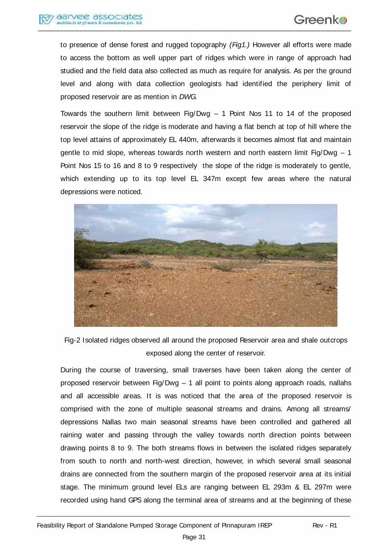
to presence of dense forest and rugged topography (Fig1.) However all efforts were madeto access the bottom as well upper part of ridges which were in range of approach hadstudied and the field data also collected as much as require for analysis. As per the groundlevel and along with data collection geologists had identified the periphery limit ofproposed reservoir are as mention in DWG.
Towards the southern limit between Fig/Dwg – 1 Point Nos 11 to 14 of the proposedreservoir the slope of the ridge is moderate and having a flat bench at top of hill where thetop level attains of approximately EL 440m, afterwards it becomes almost flat and maintaingentle to mid slope, whereas towards north western and north eastern limit Fig/Dwg – 1Point Nos 15 to 16 and 8 to 9 respectively the slope of the ridge is moderately to gentle,which extending up to its top level EL 347m except few areas where the naturaldepressions were noticed.
Fig-2 Isolated ridges observed all around the proposed Reservoir area and shale outcropsexposed along the center of reservoir.
During the course of traversing, small traverses have been taken along the center ofproposed reservoir between Fig/Dwg – 1 all point to points along approach roads, nallahsand all accessible areas. It is was noticed that the area of the proposed reservoir iscomprised with the zone of multiple seasonal streams and drains. Among all streams/depressions Nallas two main seasonal streams have been controlled and gathered allraining water and passing through the valley towards north direction points betweendrawing points 8 to 9. The both streams flows in between the isolated ridges separatelyfrom south to north and north-west direction, however, in which several small seasonaldrains are connected from the southern margin of the proposed reservoir area at its initialstage. The minimum ground level ELs are ranging between EL 293m & EL 297m wererecorded using hand GPS along the terminal area of streams and at the beginning of these
________________________________________________________________________________
________________________________________________________________________________
Feasibility Report of Standalone Pumped Storage Component of Pinnapuram IREP Rev - R1Page 32
streams were varies in between El 316m to EL 322m which clearly indicate that the slopeof reservoir is south to North.
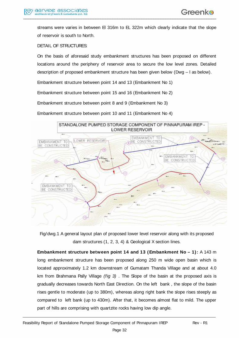
DETAIL OF STRUCTURES:
On the basis of aforesaid study embankment structures has been proposed on differentlocations around the periphery of reservoir area to secure the low level zones. Detaileddescription of proposed embankment structure has been given below (Dwg – l as below).
Embankment structure between point 14 and 13 (Embankment No 1)
Embankment structure between point 15 and 16 (Embankment No 2)
Embankment structure between point 8 and 9 (Embankment No 3)
Embankment structure between point 10 and 11 (Embankment No 4)
Fig/dwg.1 A general layout plan of proposed lower level reservoir along with its proposeddam structures (1, 2, 3, 4) & Geological X section lines.
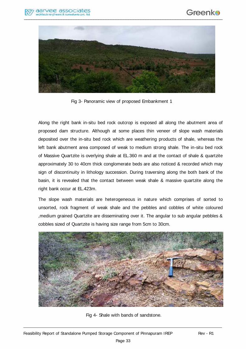
Embankment structure between point 14 and 13 (Embankment No – 1): A 143 mlong embankment structure has been proposed along 250 m wide open basin which islocated approximately 1.2 km downstream of Gumatam Thanda Village and at about 4.0km from Brahmana Pally Village (fig 3) . The Slope of the basin at the proposed axis isgradually decreases towards North East Direction. On the left bank , the slope of the basinrises gentle to moderate (up to 380m), whereas along right bank the slope rises steeply ascompared to left bank (up to 430m). After that, it becomes almost flat to mild. The upperpart of hills are comprising with quartzite rocks having low dip angle.
________________________________________________________________________________
________________________________________________________________________________
Feasibility Report of Standalone Pumped Storage Component of Pinnapuram IREP Rev - R1Page 33
Fig 3- Panoramic view of proposed Embankment 1
Along the right bank in-situ bed rock outcrop is exposed all along the abutment area ofproposed dam structure. Although at some places thin veneer of slope wash materialsdeposited over the in-situ bed rock which are weathering products of shale, whereas theleft bank abutment area composed of weak to medium strong shale. The in-situ bed rockof Massive Quartzite is overlying shale at EL.360 m and at the contact of shale & quartziteapproximately 30 to 40cm thick conglomerate beds are also noticed & recorded which maysign of discontinuity in lithology succession. During traversing along the both bank of thebasin, it is revealed that the contact between weak shale & massive quartzite along theright bank occur at EL.423m.
The slope wash materials are heterogeneous in nature which comprises of sorted tounsorted, rock fragment of weak shale and the pebbles and cobbles of white coloured,medium grained Quartzite are disseminating over it. The angular to sub angular pebbles &cobbles sized of Quartzite is having size range from 5cm to 30cm.
Fig 4- Shale with bands of sandstone.
________________________________________________________________________________
________________________________________________________________________________
Feasibility Report of Standalone Pumped Storage Component of Pinnapuram IREP Rev - R1Page 34
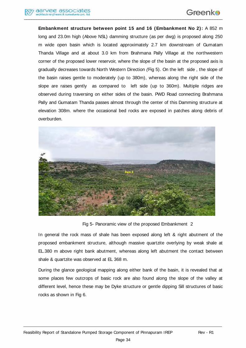
Embankment structure between point 15 and 16 (Embankment No 2): A 852 mlong and 23.0m high (Above NSL) damming structure (as per dwg) is proposed along 250m wide open basin which is located approximately 2.7 km downstream of GumatamThanda Village and at about 3.0 km from Brahmana Pally Village at the northwesterncorner of the proposed lower reservoir, where the slope of the basin at the proposed axis isgradually decreases towards North Western Direction (Fig 5). On the left side , the slope ofthe basin raises gentle to moderately (up to 380m), whereas along the right side of theslope are raises gently as compared to left side (up to 360m). Multiple ridges areobserved during traversing on either sides of the basin. PWD Road connecting BrahmanaPally and Gumatam Thanda passes almost through the center of this Damming structure atelevation 308m. where the occasional bed rocks are exposed in patches along debris ofoverburden.
Fig 5- Panoramic view of the proposed Embankment 2
In general the rock mass of shale has been exposed along left & right abutment of theproposed embankment structure, although massive quartzite overlying by weak shale atEL.380 m above right bank abutment, whereas along left abutment the contact betweenshale & quartzite was observed at EL 368 m.
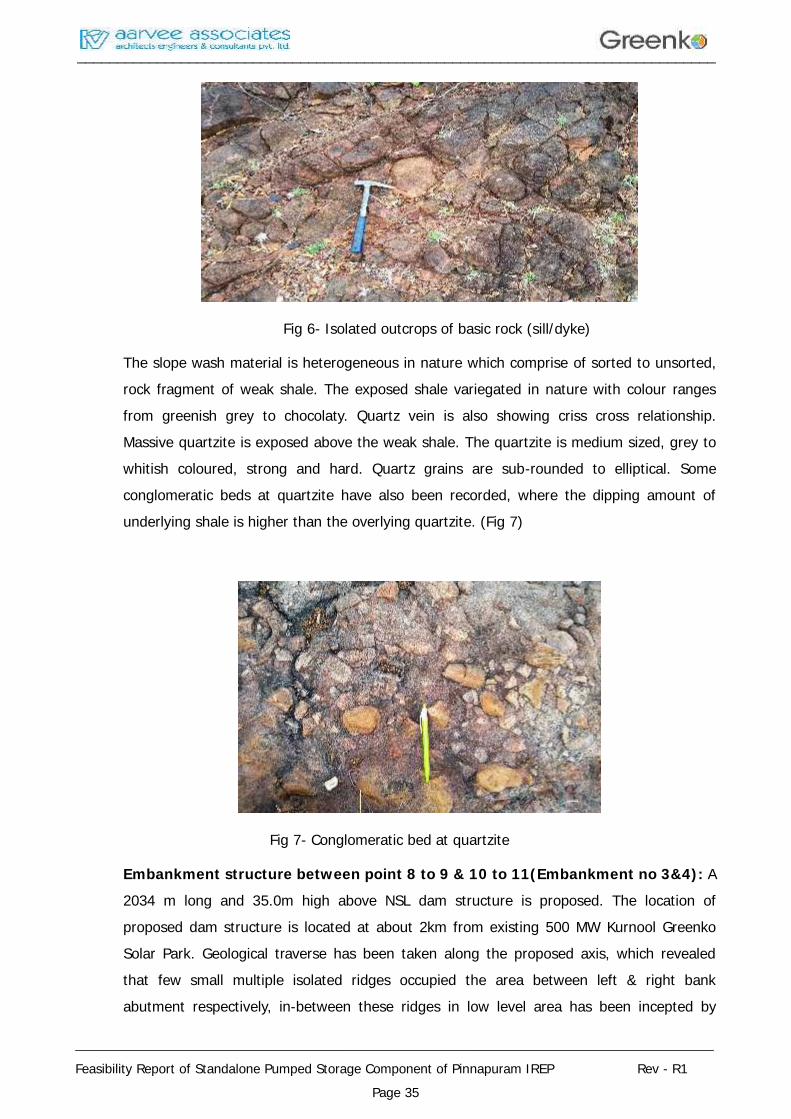
During the glance geological mapping along either bank of the basin, it is revealed that atsome places few outcrops of basic rock are also found along the slope of the valley atdifferent level, hence these may be Dyke structure or gentle dipping Sill structures of basicrocks as shown in Fig 6.
________________________________________________________________________________
________________________________________________________________________________
Feasibility Report of Standalone Pumped Storage Component of Pinnapuram IREP Rev - R1Page 35
Fig 6- Isolated outcrops of basic rock (sill/dyke)
The slope wash material is heterogeneous in nature which comprise of sorted to unsorted,rock fragment of weak shale. The exposed shale variegated in nature with colour rangesfrom greenish grey to chocolaty. Quartz vein is also showing criss cross relationship.Massive quartzite is exposed above the weak shale. The quartzite is medium sized, grey towhitish coloured, strong and hard. Quartz grains are sub-rounded to elliptical. Someconglomeratic beds at quartzite have also been recorded, where the dipping amount ofunderlying shale is higher than the overlying quartzite. (Fig 7)
Fig 7- Conglomeratic bed at quartzite
Embankment structure between point 8 to 9 & 10 to 11(Embankment no 3&4): A2034 m long and 35.0m high above NSL dam structure is proposed. The location ofproposed dam structure is located at about 2km from existing 500 MW Kurnool GreenkoSolar Park. Geological traverse has been taken along the proposed axis, which revealedthat few small multiple isolated ridges occupied the area between left & right bankabutment respectively, in-between these ridges in low level area has been incepted by
________________________________________________________________________________
________________________________________________________________________________
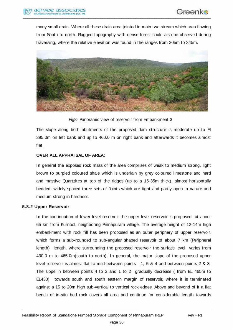
Feasibility Report of Standalone Pumped Storage Component of Pinnapuram IREP Rev - R1Page 36
many small drain. Where all these drain area jointed in main two stream which area flowingfrom South to north. Rugged topography with dense forest could also be observed duringtraversing, where the relative elevation was found in the ranges from 305m to 345m.
Fig8- Panoramic view of reservoir from Embankment 3
The slope along both abutments of the proposed dam structure is moderate up to El395.0m on left bank and up to 460.0 m on right bank and afterwards it becomes almostflat.
OVER ALL APPRAISAL OF AREA:
In general the exposed rock mass of the area comprises of weak to medium strong, lightbrown to purpled coloured shale which is underlain by grey coloured limestone and hardand massive Quartzites at top of the ridges (up to a 15-35m thick), almost horizontallybedded, widely spaced three sets of Joints which are tight and partly open in nature andmedium strong in hardness.
5.8.2 Upper Reservoir
In the continuation of lower level reservoir the upper level reservoir is proposed at about65 km from Kurnool, neighboring Pinnapuram village. The average height of 12-14m highembankment with rock fill has been proposed as an outer periphery of upper reservoir,which forms a sub-rounded to sub-angular shaped reservoir of about 7 km (Peripherallength) length, where surrounding the proposed reservoir the surface level varies from430.0 m to 465.0m(south to north). In general, the major slope of the proposed upperlevel reservoir is almost flat to mild between points 1, 5 & 4 and between points 2 & 3;The slope in between points 4 to 3 and 1 to 2 gradually decrease ( from EL 465m toEL430) towards south and south eastern margin of reservoir, where it is terminatedagainst a 15 to 20m high sub-vertical to vertical rock edges. Above and beyond of it a flatbench of in-situ bed rock covers all area and continue for considerable length towards
________________________________________________________________________________
________________________________________________________________________________
Feasibility Report of Standalone Pumped Storage Component of Pinnapuram IREP Rev - R1Page 37
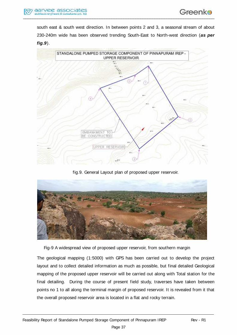
south east & south west direction. In between points 2 and 3, a seasonal stream of about230-240m wide has been observed trending South-East to North-west direction (as perfig.9).
fig.9. General Layout plan of proposed upper reservoir.
Fig-9 A widespread view of proposed upper reservoir, from southern margin
The geological mapping (1:5000) with GPS has been carried out to develop the projectlayout and to collect detailed information as much as possible, but final detailed Geologicalmapping of the proposed upper reservoir will be carried out along with Total station for thefinal detailing. During the course of present field study, traverses have taken betweenpoints no 1 to all along the terminal margin of proposed reservoir. It is revealed from it thatthe overall proposed reservoir area is located in a flat and rocky terrain.
________________________________________________________________________________
________________________________________________________________________________
Feasibility Report of Standalone Pumped Storage Component of Pinnapuram IREP Rev - R1Page 38
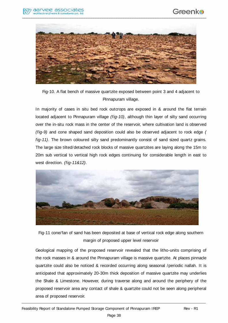
Fig-10. A flat bench of massive quartzite exposed between point 3 and 4 adjacent toPinnapuram village.
In majority of cases in situ bed rock outcrops are exposed in & around the flat terrainlocated adjacent to Pinnapuram village (fig-10), although thin layer of silty sand occurringover the in-situ rock mass in the center of the reservoir, where cultivation land is observed(fig-9) and cone shaped sand deposition could also be observed adjacent to rock edge (fig-11). The brown coloured silty sand predominantly consist of sand sized quartz grains.The large size tilted/detached rock blocks of massive quartzites are laying along the 15m to20m sub vertical to vertical high rock edges continuing for considerable length in east towest direction. (fig-11&12).
Fig-11 cone/fan of sand has been deposited at base of vertical rock edge along southernmargin of proposed upper level reservoir
Geological mapping of the proposed reservoir revealed that the litho-units comprising ofthe rock masses in & around the Pinnapuram village is massive quartzite. At places pinnaclequartzite could also be noticed & recorded occurring along seasonal /periodic nallah. It isanticipated that approximately 20-30m thick deposition of massive quartzite may underliesthe Shale & Limestone. However, during traverse along and around the periphery of theproposed reservoir area any contact of shale & quartzite could not be seen along peripheralarea of proposed reservoir.
________________________________________________________________________________
________________________________________________________________________________
Feasibility Report of Standalone Pumped Storage Component of Pinnapuram IREP Rev - R1Page 39
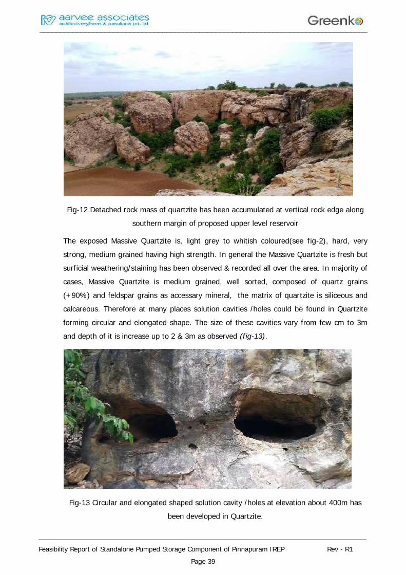
Fig-12 Detached rock mass of quartzite has been accumulated at vertical rock edge alongsouthern margin of proposed upper level reservoir
The exposed Massive Quartzite is, light grey to whitish coloured(see fig-2), hard, verystrong, medium grained having high strength. In general the Massive Quartzite is fresh butsurficial weathering/staining has been observed & recorded all over the area. In majority ofcases, Massive Quartzite is medium grained, well sorted, composed of quartz grains(+90%) and feldspar grains as accessary mineral, the matrix of quartzite is siliceous andcalcareous. Therefore at many places solution cavities /holes could be found in Quartziteforming circular and elongated shape. The size of these cavities vary from few cm to 3mand depth of it is increase up to 2 & 3m as observed (fig-13).
Fig-13 Circular and elongated shaped solution cavity /holes at elevation about 400m hasbeen developed in Quartzite.
________________________________________________________________________________
________________________________________________________________________________
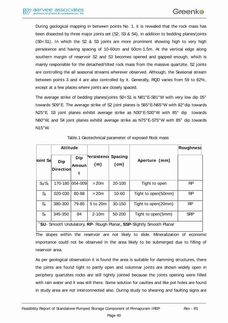
Feasibility Report of Standalone Pumped Storage Component of Pinnapuram IREP Rev - R1Page 40
During geological mapping in between points No. 1, it is revealed that the rock mass hasbeen dissected by three major joints set (S2, S3 & S4), in addition to bedding planes/joints(S0=S1). In which the S2 & S3 joints are more prominent showing high to very highpersistence and having spacing of 10-60cm and 60cm-1.5m. At the vertical edge alongsouthern margin of reservoir S2 and S3 becomes opened and gapped enough, which ismainly responsible for the detached/tilted rock mass from the massive quartzite. S2 jointsare controlling the all seasonal streams wherever observed. Although, the Seasonal streambetween points 3 and 4 are also controlled by it. Generally, RQD varies from 59 to 82%,except at a few places where joints are closely spaced.
The average strike of bedding planes/joints S0=S1 is N81°E-S81°W with very low dip 05°towards S09°E. The average strike of S2 joint planes is S65°E-N65°W with 82°dip towardsN25°E. S3 joint planes exhibit average strike as N30°E-S30°W with 85° dip towardsN60°W, and S4 joint planes exhibit average strike as N75°E-S75°W with 85° dip towardsN15°W.
Table.1 Geotechnical parameter of exposed Rock mass
Joint Set
Attitude
Persistence(m)
Spacing(cm)
Aperture (mm)
Roughness
DipDirection
DipAmoun
t
S0/S1 170-180 004-009 >20m 20-100 Tight to open RP
S2 020-030 80-88 >20m 10-60 Tight to open(50mm) RP
S3 380-300 79-85 5 to 20m 30-150 Tight to open(20mm) RP
S4 345-350 84 2-10m 50-200 Tight to open(5mm) SRP
*SU- Smooth Undulatory, RP- Rough Planar, SSP-Slightly Smooth Planar
The slopes within the reservoir are not likely to slide. Mineralization of economicimportance could not be observed in the area likely to be submerged due to filling ofreservoir area.
As per geological observation it is found the area is suitable for damming structures, therethe joints are found tight to partly open and columnar joints are shown widely open inperiphery quartzites rocks are still tightly jointed because the joints opening were filledwith rain water and it was still there. Some solution for cavities and like pot holes are foundin study area are not interconnected also. During study no shearing and faulting signs are
________________________________________________________________________________
________________________________________________________________________________
Feasibility Report of Standalone Pumped Storage Component of Pinnapuram IREP Rev - R1Page 41
also founded by site geologist team, although a detail Geological mapping will give themore confirmation of Site Suitability.
5.9 TESTS & INVESTIGATIONS AND GEOLOGICAL MAPPING SCALES:
Considering that detail and dependable geological map of site constitute the backbone ofall investigation and civil design, it is necessary that the detail geological map of the projectcomponents is carried out with all details. The desired mapping shall pay special attentionto demarcation of exposed rock and overburden deposits, and structural details, inparticular foliation, master joints and shears as well as minor weak zones of area.
The bed rocks are exposed in both sides of RCC intake Structure and its physical propertyalso known with field tests but for chemical property need to test in laboratory hencerequire testing to be conducted in laboratory at DPR Stage. In-situ test also need to beconducted for foundations.
Engineering geological mapping of Penstock area is to be carried out to cover lithology,discontinuities, any major structural features like faults, folds, etc. in 1:5000 scale. ForProposed Power House area the geological mapping of the entire complex is required. It isnecessary to cover sufficient area around the components of the powerhouse complex. Asthe site is in rather complex geological setting, special efforts are required to carefullydemarcate features like the rock slide, rock condition of the rock.
5.10 GEOLOGY OF POWERHOUSE & PENSTOCK:
As per the details collected during surface geological mapping at glance it was confirmedthe proposed location is comprising with excellent rocks and suitable for housingpowerhouse.
For making any size of tunnels the adjacent rock outcrops are very suitable excepts someminor faults and shear joints may negotiate during construction of tunnels. The housing ofPower house has to be limited between multiple shear joints which are trending NW – SEat about 100 – 250m spacing as reflect on Topo sheet and confirming by GSI also in theirpublished documents. The parallel shear may be possible along the proposed power houseand Penstock also. Hence the detail investigations are required during detail engineering ofproject with exploratory drill holes at several intervals so that the alignment of penstockcan be optimized accordingly. The tunneling media is good enough and may categorized inClass II (Good Rock Mass Class) to III (fair rock Mass Class) except some pockets of Poorrock Mass Class (IV).
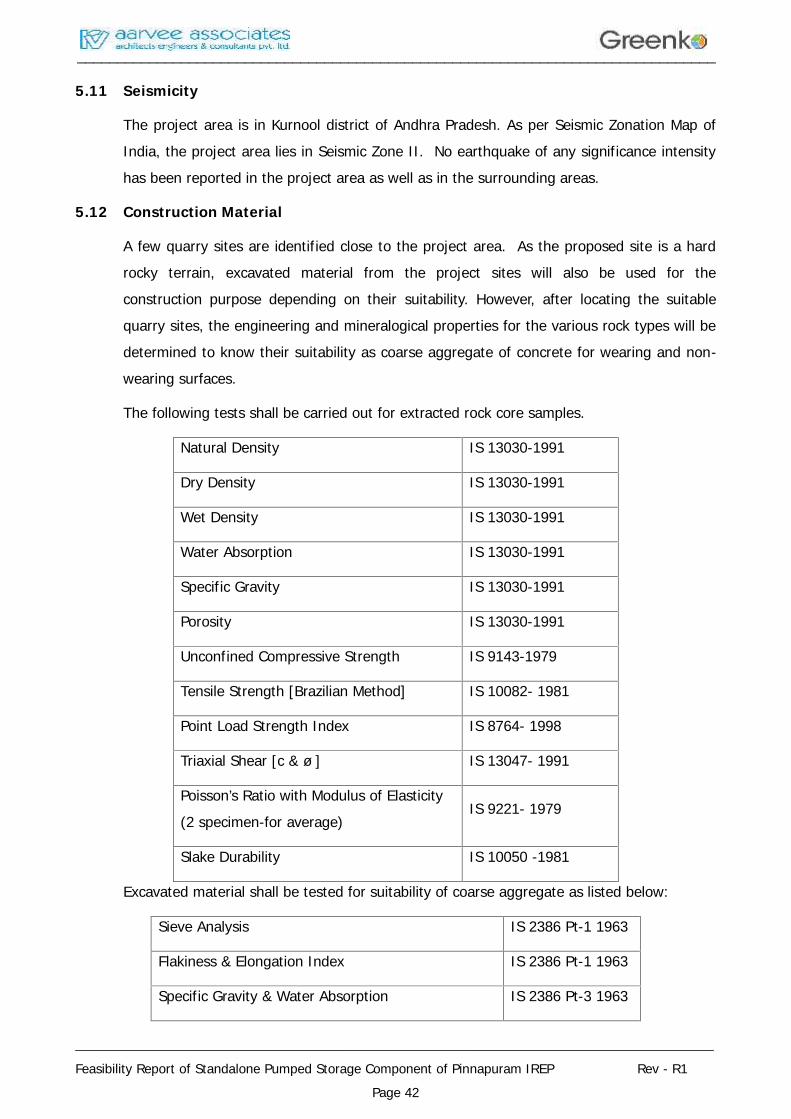
________________________________________________________________________________
________________________________________________________________________________
Feasibility Report of Standalone Pumped Storage Component of Pinnapuram IREP Rev - R1Page 42
5.11 Seismicity
The project area is in Kurnool district of Andhra Pradesh. As per Seismic Zonation Map ofIndia, the project area lies in Seismic Zone II. No earthquake of any significance intensityhas been reported in the project area as well as in the surrounding areas.
5.12 Construction Material
A few quarry sites are identified close to the project area. As the proposed site is a hardrocky terrain, excavated material from the project sites will also be used for theconstruction purpose depending on their suitability. However, after locating the suitablequarry sites, the engineering and mineralogical properties for the various rock types will bedetermined to know their suitability as coarse aggregate of concrete for wearing and non-wearing surfaces.
The following tests shall be carried out for extracted rock core samples.
Natural Density IS 13030-1991
Dry Density IS 13030-1991
Wet Density IS 13030-1991
Water Absorption IS 13030-1991
Specific Gravity IS 13030-1991
Porosity IS 13030-1991
Unconfined Compressive Strength IS 9143-1979
Tensile Strength [Brazilian Method] IS 10082- 1981
Point Load Strength Index IS 8764- 1998
Triaxial Shear [c & ø ] IS 13047- 1991
Poisson’s Ratio with Modulus of Elasticity(2 specimen-for average)
IS 9221- 1979
Slake Durability IS 10050 -1981
Excavated material shall be tested for suitability of coarse aggregate as listed below:
Sieve Analysis IS 2386 Pt-1 1963
Flakiness & Elongation Index IS 2386 Pt-1 1963
Specific Gravity & Water Absorption IS 2386 Pt-3 1963
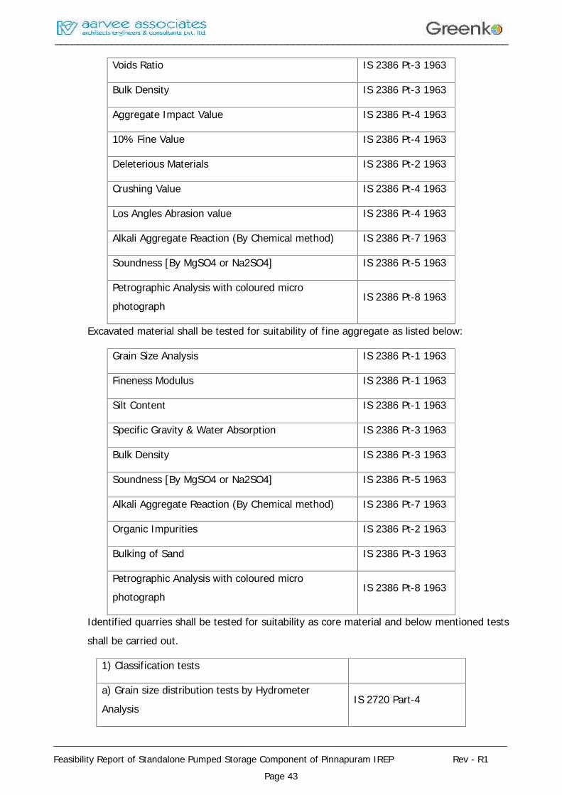
________________________________________________________________________________
________________________________________________________________________________
Feasibility Report of Standalone Pumped Storage Component of Pinnapuram IREP Rev - R1Page 43
Voids Ratio IS 2386 Pt-3 1963
Bulk Density IS 2386 Pt-3 1963
Aggregate Impact Value IS 2386 Pt-4 1963
10% Fine Value IS 2386 Pt-4 1963
Deleterious Materials IS 2386 Pt-2 1963
Crushing Value IS 2386 Pt-4 1963
Los Angles Abrasion value IS 2386 Pt-4 1963
Alkali Aggregate Reaction (By Chemical method) IS 2386 Pt-7 1963
Soundness [By MgSO4 or Na2SO4] IS 2386 Pt-5 1963
Petrographic Analysis with coloured microphotograph
IS 2386 Pt-8 1963
Excavated material shall be tested for suitability of fine aggregate as listed below:
Grain Size Analysis IS 2386 Pt-1 1963
Fineness Modulus IS 2386 Pt-1 1963
Silt Content IS 2386 Pt-1 1963
Specific Gravity & Water Absorption IS 2386 Pt-3 1963
Bulk Density IS 2386 Pt-3 1963
Soundness [By MgSO4 or Na2SO4] IS 2386 Pt-5 1963
Alkali Aggregate Reaction (By Chemical method) IS 2386 Pt-7 1963
Organic Impurities IS 2386 Pt-2 1963
Bulking of Sand IS 2386 Pt-3 1963
Petrographic Analysis with coloured microphotograph
IS 2386 Pt-8 1963
Identified quarries shall be tested for suitability as core material and below mentioned testsshall be carried out.
1) Classification tests
a) Grain size distribution tests by HydrometerAnalysis
IS 2720 Part-4
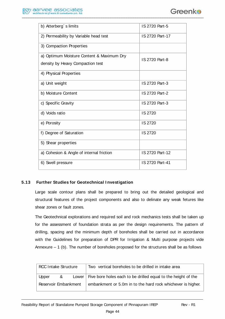
________________________________________________________________________________
________________________________________________________________________________
Feasibility Report of Standalone Pumped Storage Component of Pinnapuram IREP Rev - R1Page 44
b) Atterberg`s limits IS 2720 Part-5
2) Permeability by Variable head test IS 2720 Part-17
3) Compaction Properties
a) Optimum Moisture Content & Maximum Drydensity by Heavy Compaction test
IS 2720 Part-8
4) Physical Properties
a) Unit weight IS 2720 Part-3
b) Moisture Content IS 2720 Part-2
c) Specific Gravity IS 2720 Part-3
d) Voids ratio IS 2720
e) Porosity IS 2720
f) Degree of Saturation IS 2720
5) Shear properties
a) Cohesion & Angle of internal friction IS 2720 Part-12
6) Swell pressure IS 2720 Part-41
5.13 Further Studies for Geotechnical Investigation
Large scale contour plans shall be prepared to bring out the detailed geological andstructural features of the project components and also to delinate any weak fetures likeshear zones or fault zones.
The Geotechnical explorations and required soil and rock mechanics tests shall be taken upfor the assessment of foundation strata as per the design requirements. The pattern ofdrilling, spacing and the minimum depth of boreholes shall be carried out in accordancewith the Guidelines for preparation of DPR for Irrigation & Multi purpose projects videAnnexure – 1 (b). The number of boreholes proposed for the structures shall be as follows
RCC Intake Structure Two vertical boreholes to be drilled in intake area
Upper & LowerReservoir Embankment
Five bore holes each to be drilled equal to the height of theembankment or 5.0m in to the hard rock whichever is higher.

________________________________________________________________________________
________________________________________________________________________________
Feasibility Report of Standalone Pumped Storage Component of Pinnapuram IREP Rev - R1Page 45
Penstock/Pressure Shaft One vertical drill hole at penstock area
Power House Three vertical drill hole at power house area
The following tests shall be carried out:
1. Standard Penetration Test shall be conducted in 150mm dia of boreholes using splitspoon sampler (SPT). Test shall be conducted in boreholes at intervals of 1.5m. Test shallbe discontinued when the blow count is equal to 100 or drilling 3m into hard stratawhichever is earlier. Test shall conform to IS 2131-1963 for Dam & Power House
2. Permeability tests in rock using calibrated pressure and water meters at every 3minterval or as directed by geologist/engineer, using double packer system, applyingpressures in cyclic order, and including arrangement of necessary clean water for testingand giving permeability values in lugeons as per IS standards for Dam Location
3. Shear strength parameters of soil/rock mass
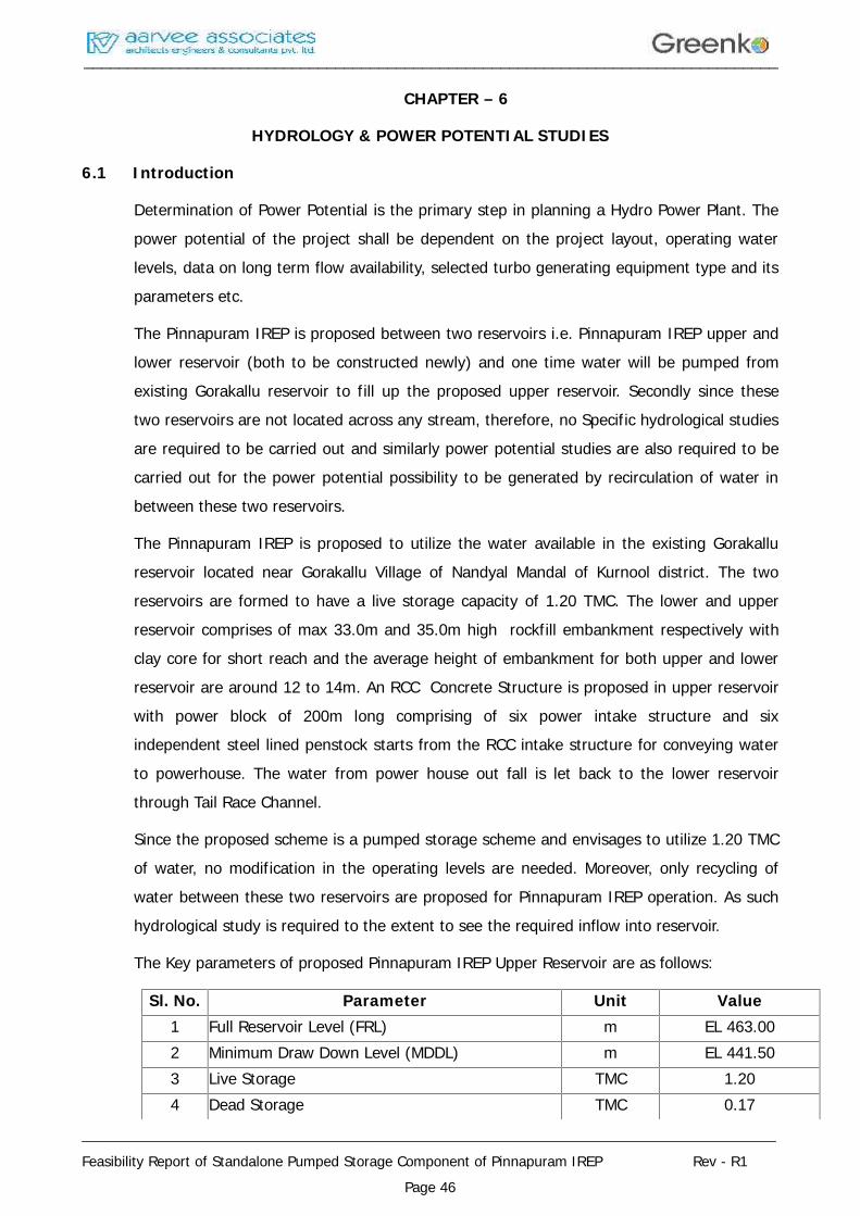
________________________________________________________________________________
________________________________________________________________________________
Feasibility Report of Standalone Pumped Storage Component of Pinnapuram IREP Rev - R1Page 46
CHAPTER – 6
HYDROLOGY & POWER POTENTIAL STUDIES
6.1 Introduction
Determination of Power Potential is the primary step in planning a Hydro Power Plant. Thepower potential of the project shall be dependent on the project layout, operating waterlevels, data on long term flow availability, selected turbo generating equipment type and itsparameters etc.
The Pinnapuram IREP is proposed between two reservoirs i.e. Pinnapuram IREP upper andlower reservoir (both to be constructed newly) and one time water will be pumped fromexisting Gorakallu reservoir to fill up the proposed upper reservoir. Secondly since thesetwo reservoirs are not located across any stream, therefore, no Specific hydrological studiesare required to be carried out and similarly power potential studies are also required to becarried out for the power potential possibility to be generated by recirculation of water inbetween these two reservoirs.
The Pinnapuram IREP is proposed to utilize the water available in the existing Gorakallureservoir located near Gorakallu Village of Nandyal Mandal of Kurnool district. The tworeservoirs are formed to have a live storage capacity of 1.20 TMC. The lower and upperreservoir comprises of max 33.0m and 35.0m high rockfill embankment respectively withclay core for short reach and the average height of embankment for both upper and lowerreservoir are around 12 to 14m. An RCC Concrete Structure is proposed in upper reservoirwith power block of 200m long comprising of six power intake structure and sixindependent steel lined penstock starts from the RCC intake structure for conveying waterto powerhouse. The water from power house out fall is let back to the lower reservoirthrough Tail Race Channel.
Since the proposed scheme is a pumped storage scheme and envisages to utilize 1.20 TMCof water, no modification in the operating levels are needed. Moreover, only recycling ofwater between these two reservoirs are proposed for Pinnapuram IREP operation. As suchhydrological study is required to the extent to see the required inflow into reservoir.
The Key parameters of proposed Pinnapuram IREP Upper Reservoir are as follows:
Sl. No. Parameter Unit Value1 Full Reservoir Level (FRL) m EL 463.002 Minimum Draw Down Level (MDDL) m EL 441.503 Live Storage TMC 1.204 Dead Storage TMC 0.17
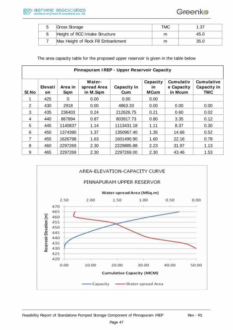
________________________________________________________________________________
________________________________________________________________________________
Feasibility Report of Standalone Pumped Storage Component of Pinnapuram IREP Rev - R1Page 47
5 Gross Storage TMC 1.376 Height of RCC Intake Structure m 45.07 Max Height of Rock Fill Embankment m 35.0
The area capacity table for the proposed upper reservoir is given in the table below
Pinnapuram IREP - Upper Reservoir Capacity
Sl.NoElevati
onArea in
Sqm
Water-spread Area
in M.SqmCapacity in
Cum
Capacityin
MCum
Cumulative Capacityin Mcum
CumulativeCapacity in
TMC1 425 0 0.00 0.00 0.002 430 2918 0.00 4863.33 0.00 0.00 0.003 435 236403 0.24 212626.75 0.21 0.60 0.024 440 867894 0.87 803917.73 0.80 3.35 0.125 445 1140837 1.14 1113431.18 1.11 8.37 0.306 450 1374390 1.37 1350967.40 1.35 14.66 0.527 455 1626798 1.63 1601490.90 1.60 22.16 0.788 460 2297269 2.30 2229885.88 2.23 31.97 1.139 465 2297269 2.30 2297269.00 2.30 43.46 1.53
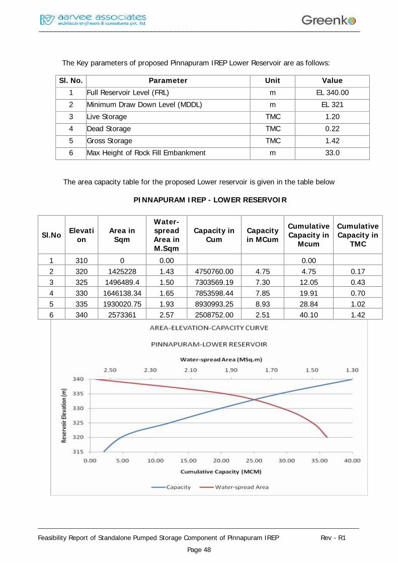
________________________________________________________________________________
________________________________________________________________________________
Feasibility Report of Standalone Pumped Storage Component of Pinnapuram IREP Rev - R1Page 48
The Key parameters of proposed Pinnapuram IREP Lower Reservoir are as follows:
Sl. No. Parameter Unit Value1 Full Reservoir Level (FRL) m EL 340.002 Minimum Draw Down Level (MDDL) m EL 3213 Live Storage TMC 1.204 Dead Storage TMC 0.225 Gross Storage TMC 1.426 Max Height of Rock Fill Embankment m 33.0
The area capacity table for the proposed Lower reservoir is given in the table below
PINNAPURAM IREP - LOWER RESERVOIR
Sl.No Elevation
Area inSqm
Water-spreadArea inM.Sqm
Capacity inCum
Capacityin MCum
CumulativeCapacity in
Mcum
CumulativeCapacity in
TMC
1 310 0 0.00 0.002 320 1425228 1.43 4750760.00 4.75 4.75 0.173 325 1496489.4 1.50 7303569.19 7.30 12.05 0.434 330 1646138.34 1.65 7853598.44 7.85 19.91 0.705 335 1930020.75 1.93 8930993.25 8.93 28.84 1.026 340 2573361 2.57 2508752.00 2.51 40.10 1.42
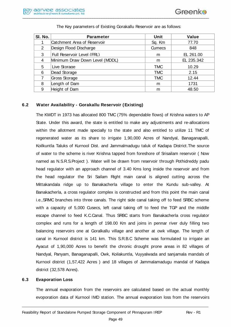
________________________________________________________________________________
________________________________________________________________________________
Feasibility Report of Standalone Pumped Storage Component of Pinnapuram IREP Rev - R1Page 49
The Key parameters of Existing Gorakallu Reservoir are as follows:
Sl. No. Parameter Unit Value1 Catchment Area of Reservoir Sq. Km 77.702 Design Flood Discharge Cumecs 8483 Full Reservoir Level (FRL) m EL 261.004 Minimum Draw Down Level (MDDL) m EL 235.3425 Live Storage TMC 10.296 Dead Storage TMC 2.157 Gross Storage TMC 12.448 Length of Dam m 17319 Height of Dam m 48.50
6.2 Water Availability - Gorakallu Reservoir (Existing)
The KWDT in 1973 has allocated 800 TMC (75% dependable flows) of Krishna waters to APState. Under this award, the state is entitled to make any adjustments and re-allocationswithin the allotment made specially to the state and also entitled to utilize 11 TMC ofregenerated water as its share to irrigate 1,90,000 Acres of Nandyal, Banaganapalli,Koilkuntla Taluks of Kurnool Dist. and Jammalmadugu taluk of Kadapa District.The sourceof water to the scheme is river Krishna tapped from foreshore of Srisailam reservoir ( Nownamed as N.S.R.S.Project ). Water will be drawn from reservoir through Pothidreddy paduhead regulator with an approach channel of 3.40 Kms long inside the reservoir and fromthe head regulator the Sri Sailam Right main canal is aligned cutting across theMittakandala ridge up to Banakacherla village to enter the Kundu sub-valley. AtBanakacherla, a cross regulator complex is constructed and from this point the main canali.e.,SRMC branches into three canals. The right side canal taking off to feed SRBC schemewith a capacity of 5,000 Cusecs, left canal taking off to feed the TGP and the middleescape channel to feed K.C.Canal. Thus SRBC starts from Banakacherla cross regulatorcomplex and runs for a length of 198.00 Km and joins in pennar river duly filling twobalancing reservoirs one at Goralkallu village and another at owk village. The length ofcanal in Kurnool district is 141 km. This S.R.B.C Scheme was formulated to irrigate anAyacut of 1,90,000 Acres to benefit the chronic drought prone areas in 82 villages ofNandyal, Panyam, Banaganapalli, Owk, Koilakuntla, Vuyyalwada and sanjamala mandals ofKurnool district (1,57,422 Acres ) and 18 villages of Jammalamadugu mandal of Kadapadistrict (32,578 Acres).
6.3 Evaporation Loss
The annual evaporation from the reservoirs are calculated based on the actual monthlyevoporation data of Kurnool IMD station. The annual evaporation loss from the reservoirs
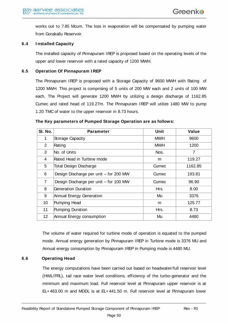
________________________________________________________________________________
________________________________________________________________________________
Feasibility Report of Standalone Pumped Storage Component of Pinnapuram IREP Rev - R1Page 50
works out to 7.85 Mcum. The loss in evaporation will be compensated by pumping waterfrom Gorakallu Reservoir.
6.4 Installed Capacity
The installed capacity of Pinnapuram IREP is proposed based on the operating levels of theupper and lower reservoir with a rated capacity of 1200 MWH.
6.5 Operation Of Pinnapuram IREP
The Pinnapuram IREP is proposed with a Storage Capacity of 9600 MWH with Rating of1200 MWH. This project is comprising of 5 units of 200 MW each and 2 units of 100 MWeach. The Project will generate 1200 MWH by utilizing a design discharge of 1162.85Cumec and rated head of 119.27m. The Pinnapuram IREP will utilize 1480 MW to pump1.20 TMC of water to the upper reservoir in 8.73 hours.
The Key parameters of Pumped Storage Operation are as follows:
Sl. No. Parameter Unit Value1 Storage Capacity MWH 96002 Rating MWH 12003 No. of Units Nos. 74 Rated Head in Turbine mode m 119.275 Total Design Discharge Cumec 1162.85
6 Design Discharge per unit – for 200 MW Cumec 193.81
7 Design Discharge per unit – for 100 MW Cumec 96.908 Generation Duration Hrs. 8.009 Annual Energy Generation Mu 337610 Pumping Head m 125.7711 Pumping Duration Hrs. 8.7312 Annual Energy consumption Mu 4480
The volume of water required for turbine mode of operation is equated to the pumpedmode. Annual energy generation by Pinnapuram IREP in Turbine mode is 3376 MU andAnnual energy consumption by Pinnapuram IREP in Pumping mode is 4480 MU.
6.6 Operating Head
The energy computations have been carried out based on headwater/full reservoir level(HWL/FRL), tail race water level conditions, efficiency of the turbo-generator and theminimum and maximum load. Full reservoir level at Pinnapuram upper reservoir is atEL+463.00 m and MDDL is at EL+441.50 m. Full reservoir level at Pinnapuram lower
________________________________________________________________________________
________________________________________________________________________________
Feasibility Report of Standalone Pumped Storage Component of Pinnapuram IREP Rev - R1Page 51
reservoir is at EL+340.00 m and MDDL is at EL+321 m. The total head loss in thesystem is arrived as 2.90m. Thus, the rated head of 119.27m is considered for theproposed project. The normal tail water level is the level at the tail race outletcorresponds to design discharge flow of 1162.85 Cumec passing through the turbineconsidering all machines running at full plant load. Normal tail water levelcorresponding to above design discharge is EL +320.76m. The bed level of the tail raceChannel is kept at EL + 314.76m.
________________________________________________________________________________
________________________________________________________________________________
Feasibility Report of Standalone Pumped Storage Component of Pinnapuram IREP Rev - R1Page 52
CHAPTER – 7
DESIGN FEATURES OF MAJOR COMPONENTS
7.1 Introduction
The Pinnapuram IREP is located in Kurnool district of Andhra Pradesh. It envisagescreation of offstream reservoirs near Pinnapuram village.
The scheme will involve construction of rock fill embankment of average height of around12m to 14m with the maximum height of 35m for short reach for creation of PinnapuramIREP upper reservoir of 1.37 TMC gross capacity. The lower reservoir is formed with rockfill embankment with the average height of around 12m to 14m with the maximum heightof 33m for short reach with 1.42 TMC gross capacity. The Pinnapuram IREP is proposed inbetween two reservoirs i.e. Pinnapuram IREP Upper & Lower Reservoirs (both to beconstructed newly) and one time water will be pumped from existing Gorakallu Reservoirto fill up the proposed Upper reservoir. The total design discharge for the proposedscheme is 1162.85 Cumec with the rated head of 119.27 m.
The proposed layout of the project has been finalized after considering variousalternatives from techno-economic considerations. The proposed Pinnapuram IREPenvisages construction of
Embankment for formation of upper & lower reservoir
RCC intake Structure
Penstock / Pressure shaft
Surface Power House
Tail Pool & Tail Race Channel
Pothead yard
7.2 Pinnapuram Upper & Lower Reservoir
The upper reservoir site is proposed at Latitude 15° 36' 26" N and Longitude 78° 15' 13" E.The lower reservoir offtake site is proposed at Latitude 15° 37' 26" N and Longitude 78° 15'30" E. An RCC Intake structure proposed at this location envisages construction of 45.0mhigh Concrete Gravity Intake structure for 200m long and non over flow rock fillembankment of average height around 12m to 14m with maximum height of 35m for shortreach for formation of upper reservoir. The lower reservoir is formed with rock fillembankment of average height around 12m to 14m with maximum height of 33m for shortreach. The gross storage capacity of the upper reservoir at this location is 1.37 TMC with a
________________________________________________________________________________
________________________________________________________________________________
Feasibility Report of Standalone Pumped Storage Component of Pinnapuram IREP Rev - R1Page 53
live storage of 1.20 TMC keeping the FRL and MDDL at EL + 463.0m and EL + 441.50 mrespectively. The gross storage capacity of the lower reservoir at this location is 1.42 TMCwith a live storage of 1.20 TMC keeping the FRL and MDDL at EL + 340.0m and EL + 321.0m respectively. The one time filling of upper reservoir is taken up by pumping the waterfrom existing Gorakallu Reservoir.
7.3 Project Layout
Six power intakes have been provided in the RCC intake structure with six independentsteel lined pressure penstocks of 760m long and 7.0m dia to convey water to the surfacepowerhouse. Five penstocks will be feeding 5 units of 200 MW and one penstock bifurcatedin to two will be feeding 2 units of 100 MW each. The General Layout plan is shown indrawing no. AA/PSP/POWER/2154/001
The L/H ratio of the proposed alignment is 6.3 and no separate surge shaft is provided inthis layout. The water after power generation will be conveyed through 1300m long TailRace Channel to discharge water in to Lower reservoir.
After considering the above factors, this layout is found to be technically feasible and thesame is adopted considering the following.
1. It is easier and faster to construct at lesser cost.
2. The sites are suitable for formation of reservoir.
3. The length of the penstock / pressure shaft is short in this case.
4. A surface powerhouse can be suitably located.
5. All the project components are easily accessible.
As the proposed project is a part of integrated renewable energy scheme, the constructiontime for the project shall be in line with the solar and wind power developments.Considering the economics of the cost for the integrated project, the scheme is moreviable.
The details of project layout are explained in the following paragraphs.
7.4 Pinnapuram Embankment (Upper & Lower Reservoir)
The upper reservoir is formed by constructing a 45.0m high RCC intake structure forhousing the power blocks along with non over flow rock fill embankment of average heightaround 12m to 14m with maximum height of 35m for short reach. The lower reservoir isformed with rock fill embankment of average height of around 12m to 14m with maximumheight of 33.0m for short reach.
________________________________________________________________________________
________________________________________________________________________________
Feasibility Report of Standalone Pumped Storage Component of Pinnapuram IREP Rev - R1Page 54
The top width of RCC intake structure is 8.0m. The d/s slope of the intake structure hasbeen proposed as 0.6H: 1V and u/s slope as 1H:5V.
According to IS.1843, the location of proposed structures is falling within Zone-II for whicha seismic factor 0.02 will be adopted. No seismic activity is reported from the area andtaking the project site with respect to seismo tectonic setting, an importance factor 3.0 hasbeen provided in the design. Accordingly, the horizontal seismic co-efficient works out to0.06 α, which is considered adequate. The vertical seismic co-efficient where applicable has
been taken as half of the horizontal co-efficient. No earthquake of any significance intensityhas been reported in the project area as well as in the surrounding areas. Hence, no sitespecific seismic design parameter study is required. However, if required the seismicparameters adopted in the design of Gorakallu dam will be verified and adopted in thedesign of Pinnapuram IREP.
The stability analysis of the RCC Intake Structure shall be carried out in accordance with IS6512-1984 and earthquake loading in accordance with IS 1893-1984. Tentative proposalsfor curtain grouting, consolidation grouting and drainage arrangements have beenprovided. The curtain grouting depth is taken as 2/3 H. The consolidation grouting is takenas H/4. Depth of grouting may be modified if necessary in consultation with geologist afteropening the foundation.
The most important cause of failure of an embankment structure is sliding. A portion of theRock fill embankment will slide downwards and outwards with respect to remaining part,generally along a well defined slice surface. The failure is caused when the averageshearing stress exceeds the average shearing resistance along the sliding surface due tovarious loading conditions. Simplified Bishops method is used to assess the stability ofslopes under the following loading conditions
1. Construction condition (u/s and d/s slopes).
2. Reservoir partially full (u/s slope).
3. Sudden Drawdown (u/s slope).
4. Steady seepage (d/s slope).
5. Steady seepage with sustained rainfall (d/s slope).
6. Earthquake condition (u/s and d/s slopes).
The water from the upper reservoir will be let out through penstocks of 760m long to feedthe Pinnapuram IREP Power House, having an Storage Capacity of 9600 MWH with ratingof 1200 MWH. This project is comprising 5 units of 200 MW and 2 units of 100 MW each.
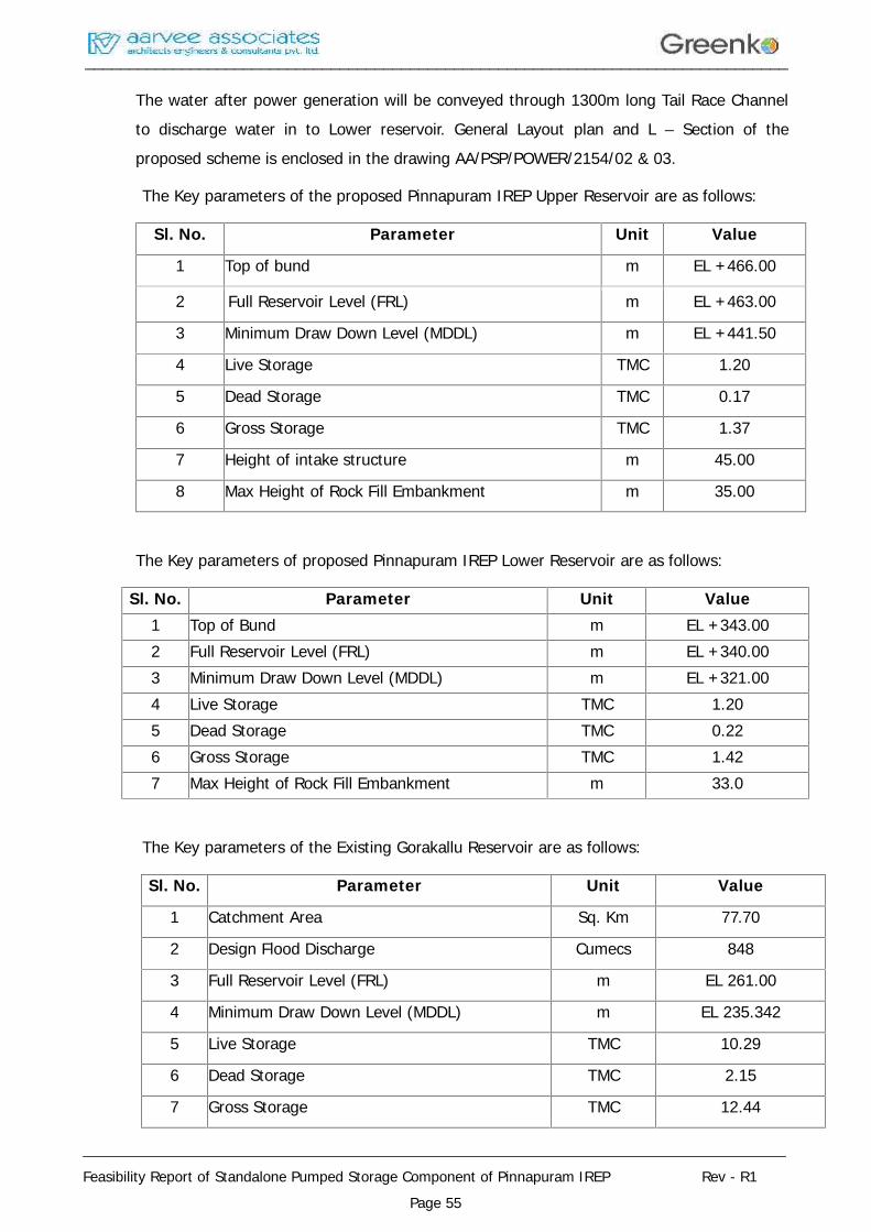
________________________________________________________________________________
________________________________________________________________________________
Feasibility Report of Standalone Pumped Storage Component of Pinnapuram IREP Rev - R1Page 55
The water after power generation will be conveyed through 1300m long Tail Race Channelto discharge water in to Lower reservoir. General Layout plan and L – Section of theproposed scheme is enclosed in the drawing AA/PSP/POWER/2154/02 & 03.
The Key parameters of the proposed Pinnapuram IREP Upper Reservoir are as follows:
Sl. No. Parameter Unit Value
1 Top of bund m EL +466.00
2 Full Reservoir Level (FRL) m EL +463.00
3 Minimum Draw Down Level (MDDL) m EL +441.50
4 Live Storage TMC 1.20
5 Dead Storage TMC 0.17
6 Gross Storage TMC 1.37
7 Height of intake structure m 45.00
8 Max Height of Rock Fill Embankment m 35.00
The Key parameters of proposed Pinnapuram IREP Lower Reservoir are as follows:
Sl. No. Parameter Unit Value1 Top of Bund m EL +343.002 Full Reservoir Level (FRL) m EL +340.003 Minimum Draw Down Level (MDDL) m EL +321.004 Live Storage TMC 1.205 Dead Storage TMC 0.226 Gross Storage TMC 1.427 Max Height of Rock Fill Embankment m 33.0
The Key parameters of the Existing Gorakallu Reservoir are as follows:
Sl. No. Parameter Unit Value
1 Catchment Area Sq. Km 77.70
2 Design Flood Discharge Cumecs 848
3 Full Reservoir Level (FRL) m EL 261.00
4 Minimum Draw Down Level (MDDL) m EL 235.342
5 Live Storage TMC 10.29
6 Dead Storage TMC 2.15
7 Gross Storage TMC 12.44
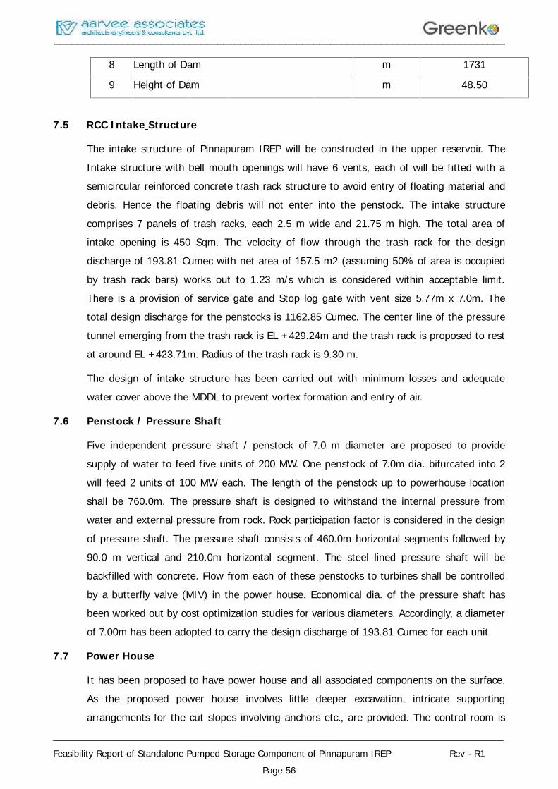
________________________________________________________________________________
________________________________________________________________________________
Feasibility Report of Standalone Pumped Storage Component of Pinnapuram IREP Rev - R1Page 56
8 Length of Dam m 1731
9 Height of Dam m 48.50
7.5 RCC Intake Structure
The intake structure of Pinnapuram IREP will be constructed in the upper reservoir. TheIntake structure with bell mouth openings will have 6 vents, each of will be fitted with asemicircular reinforced concrete trash rack structure to avoid entry of floating material anddebris. Hence the floating debris will not enter into the penstock. The intake structurecomprises 7 panels of trash racks, each 2.5 m wide and 21.75 m high. The total area ofintake opening is 450 Sqm. The velocity of flow through the trash rack for the designdischarge of 193.81 Cumec with net area of 157.5 m2 (assuming 50% of area is occupiedby trash rack bars) works out to 1.23 m/s which is considered within acceptable limit.There is a provision of service gate and Stop log gate with vent size 5.77m x 7.0m. Thetotal design discharge for the penstocks is 1162.85 Cumec. The center line of the pressuretunnel emerging from the trash rack is EL +429.24m and the trash rack is proposed to restat around EL +423.71m. Radius of the trash rack is 9.30 m.
The design of intake structure has been carried out with minimum losses and adequatewater cover above the MDDL to prevent vortex formation and entry of air.
7.6 Penstock / Pressure Shaft
Five independent pressure shaft / penstock of 7.0 m diameter are proposed to providesupply of water to feed five units of 200 MW. One penstock of 7.0m dia. bifurcated into 2will feed 2 units of 100 MW each. The length of the penstock up to powerhouse locationshall be 760.0m. The pressure shaft is designed to withstand the internal pressure fromwater and external pressure from rock. Rock participation factor is considered in the designof pressure shaft. The pressure shaft consists of 460.0m horizontal segments followed by90.0 m vertical and 210.0m horizontal segment. The steel lined pressure shaft will bebackfilled with concrete. Flow from each of these penstocks to turbines shall be controlledby a butterfly valve (MIV) in the power house. Economical dia. of the pressure shaft hasbeen worked out by cost optimization studies for various diameters. Accordingly, a diameterof 7.00m has been adopted to carry the design discharge of 193.81 Cumec for each unit.
7.7 Power House
It has been proposed to have power house and all associated components on the surface.As the proposed power house involves little deeper excavation, intricate supportingarrangements for the cut slopes involving anchors etc., are provided. The control room is
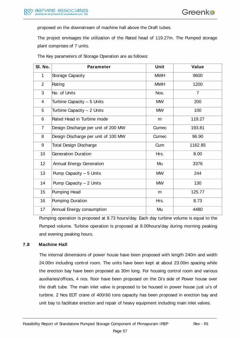
________________________________________________________________________________
________________________________________________________________________________
Feasibility Report of Standalone Pumped Storage Component of Pinnapuram IREP Rev - R1Page 57
proposed on the downstream of machine hall above the Draft tubes.
The project envisages the utilization of the Rated head of 119.27m. The Pumped storageplant comprises of 7 units.
The Key parameters of Storage Operation are as follows:
Sl. No. Parameter Unit Value
1 Storage Capacity MWH 9600
2 Rating MWH 1200
3 No. of Units Nos. 7
4 Turbine Capacity – 5 Units MW 200
5 Turbine Capacity – 2 Units MW 100
6 Rated Head in Turbine mode m 119.27
7 Design Discharge per unit of 200 MW Cumec 193.81
8 Design Discharge per unit of 100 MW Cumec 96.90
9 Total Design Discharge Cum 1162.85
10 Generation Duration Hrs. 8.00
12 Annual Energy Generation Mu 3376
13 Pump Capacity – 5 Units MW 244
14 Pump Capacity – 2 Units MW 130
15 Pumping Head m 125.77
16 Pumping Duration Hrs. 8.73
17 Annual Energy consumption Mu 4480
Pumping operation is proposed at 8.73 hours/day. Each day turbine volume is equal to thePumped volume. Turbine operation is proposed at 8.00hours/day during morning peakingand evening peaking hours.
7.8 Machine Hall
The internal dimensions of power house have been proposed with length 240m and width24.00m including control room. The units have been kept at about 23.00m spacing whilethe erection bay have been proposed as 30m long. For housing control room and variousauxiliaries/offices, 4 nos. floor have been proposed on the D/s side of Power house overthe draft tube. The main inlet valve is proposed to be housed in power house just u/s ofturbine. 2 Nos EOT crane of 400/60 tons capacity has been proposed in erection bay andunit bay to facilitate erection and repair of heavy equipment including main inlet valves.
________________________________________________________________________________
________________________________________________________________________________
Feasibility Report of Standalone Pumped Storage Component of Pinnapuram IREP Rev - R1Page 58
The machine floor is designed to carry load of machines, live load and thrust transferredthrough turbines, generators and other machinery. The machine floor is designed as anRCC raft with adequate openings as required for equipment foundations and cabletrenches etc.
7.9 Tail Pool and Tail Race Channel
The tail water from the machines, is led back to the lower reservoir through a tailracechannel. Each turbine is provided with gated draft tube. Water from the draft tube of eachof the machines will enter in to a tail pool constructed with RCC walls on three sides. Thedownstream wall of the powerhouse completes the tail pool structure. The tail pool isconnected to a tail race channel that conveys the water into the Lower Reservoir.
________________________________________________________________________________
________________________________________________________________________________
Feasibility Report of Standalone Pumped Storage Component of Pinnapuram IREP Rev - R1Page 59
CHAPTER – 8
ELECTRO - MECHANICAL EQUIPMENTS
8.1 Electro-Mechanical Equipments
The Electro-Mechanical equipment required for the proposed Hydel scheme comprises ofthe following:
Butterfly Valve for each Turbine.
Turbine/Pump and its auxiliaries like lubricating oil system, Governor and its oilpressure unit, Grease lubrication system and cooling water system etc.
Generator/Motor and its auxiliaries like Excitation & Automatic Voltage Regulationsystem, SFC, Cooling system, Electrical and mechanical Brakes, PLC and Automationarrangement etc.,
Control, Protection, metering, measurement and annunciation panels for Turbine,generators, and 400KV feeders.
Bus duct shall be provided for connecting generator to the generating transformer,UAT, LAVT, NGT etc., for trouble free reliable operation.
Generator Transformers with OFF LOAD TAP changer along with control and protectivegear and breakers etc.
One no. 420KV Gas Insulated switch-gear (GIS) unit with bus sectionalize is proposedfor connecting to two different sources.
Auxiliary Power supply system consisting of unit auxiliary transformers, stationauxiliary transformer, D.G Set for alternative emergency supply and station/ unitauxiliary boards for station auxiliaries, unit auxiliaries.
Control supply system consisting of station battery, charger and its distributionsystem.
The station auxiliaries like EOT crane, D.T crane, Air Compressor system, Dewateringand Drainage system, firefighting equipment, Air conditioning, Ventilation system,Public addressing system and illumination system.
Power evacuation system consists of transmission line, protection/ meteringequipment, CT's, PT's, LA's along with its supporting structures and Receiving endequipment including bay extension at the other end.
A brief description of the Electro-Mechanical equipment is as follows.
________________________________________________________________________________
________________________________________________________________________________
Feasibility Report of Standalone Pumped Storage Component of Pinnapuram IREP Rev - R1Page 60
8.2 MECHANICAL EQUIPMENT:
The Mechanical equipment consists of Turbine, Main Inlet Valve, Governor, instrumentation& control system, oil pumping, cooling water, Drainage, Dewatering system, crane etc.
8.2.1 Butter Fly Valve:
Each Turbine is provided with a Butterfly valve to act as a main inlet valve in order toachieve quick closing to cut off the water supply for the Turbine in the event of anymachine tripping on a lock out fault. The Butter fly valve will be of plain door type withrubber seals designed to open under unbalanced conditions and close against full flow inemergency. The Butter fly valve shall be normally opened and closed by hydraulic systemand also have backup closing system with dead weight for closing during emergency.Hydraulic operated Bypass valve is provided across the Butterfly valve for smooth operationwith pressure balance condition.
i) Size and Body:
The Size of the Butter fly valve proposed is 6000mm. It shall be fabricated from steelplates and provided with PTFE/Grease lubricated bronze bushes for bearings and cupseals for trunnions and stainless-steel sealing ring for the main seal.
ii) Door:
It shall have plane door fabricated from steel plates. The valve door shall haveperipheral sealing ring of solid rubber.
iii) Sealing Device:
The valve will be provided with adequately reinforced rubber sealing held in position bymeans of removable sealing ring fixed by rust less screws against stainless steel ringsecured to the valve body.
iv) Dismantling Joint:
The Joint shall be of Telescopic type and located on downstream of valve facilitatingdismantling of valve during maintenance.
v) Lever:
A lever will be provided to the trunnion and a dead weight will be mounted on otherend.
vi) Servo Motor:
Servo Motor of double acting type comprising of fabricated steel cylinder with covers,
________________________________________________________________________________
________________________________________________________________________________
Feasibility Report of Standalone Pumped Storage Component of Pinnapuram IREP Rev - R1Page 61
piston and pressure oil system will be provided in a complete shape.
8.2.2 Turbine/Pump:
The machines have four running modes namely
"generate"
"spin generate"
"spin pump"
"pump"
Involving two directions of rotations and power flow. The shutdown condition can betreated as a further mode. The diversity of the control requirements is therefore muchgreater. In the first two modes of operation, a machine rotates in the turbines (as opposedto pump) direction that is clockwise when viewed from above. It can generate at any load(generate) or having been started in the "generate mode” can have its load reduced andwater level in the pump/turbine runner chamber and the draft tube lowered by compressedair, thus leaving the machine spinning as a synchronous compensator with its runner in air.
In the second operation (two modes), the direction of rotation is reversed. The set is runas a motor with a SFC controller, the water level in the pump turbine having lowered. Whenthe machine is synchronizing it can remain running as a synchronous compensator (spinpump) or water can be admitted to the pump/turbine and pumping carried out at a fixedguide vane setting (pump).
Final Design:
The final design of the Turbine components would be carried out by means of Model Testresults of Turbine.
8.2.3 Materials and Construction Features of Turbine:
Runner:
The turbine runner will be integrally cast / welded in stainless steel material having 13%chromium and 4% nickel and properly stress relieved. The runner will have suitable no. Ofvanes polished and ground smooth and will be mounted on the turbine shaft. Adequatenumber of relief holes will be provided in the runner for the water past runner crown seal.
Guide Vanes:
Guide vanes will be of cast stainless steel material conforming to 13% chromium and 4%nickel and finished smooth. Guide vane operating mechanism will be of forged or fabricated
________________________________________________________________________________
________________________________________________________________________________
Feasibility Report of Standalone Pumped Storage Component of Pinnapuram IREP Rev - R1Page 62
steel. Each guide vane will be supported in grease or self-lubricated bearings. Syntheticrubber seals will be provided to prevent leakage of water. The guide vanes will be operatedby guide vane servomotor for which the pressurized oil will be supplied from the pressureoil system. The control of guide vane opening will be through the governor.
Guide Vane Operating Mechanism:
Guide vane operating mechanism will consist of levers, friction coupling / shear pins, links,servomotor connecting rods, guide vane, regulating ring etc. The mechanism will bedesigned and constructed to withstand stresses due to servomotor and wear and tear.
Turbine/pump Shaft:
A turbine/pump shaft will be provided for mounting the turbine runner. The material ofturbine/pump shaft will be of carbon steel forging conforming to BS 29 or ASTM A 668Class D.
The shaft will have adequate diameter to operate safely in combination with generator. Theturbine shaft will be connected directly to the generator shaft by means of a suitablecoupling.
Shaft Sleeves:
The shaft will be provided with renewable stainless-steel sleeve. The sleeve will be of splitconstruction and securely fastened to the turbine shaft.
Shaft Seal:
The shaft seal will be provided to prevent leakage of water through the gap between theshaft and turbine cover. The shaft seal will be of labyrinth type seal with white metal lining.
Thrust and Guide Bearing:
The Thrust and Guide Bearing will be of the self-contained, oil lubricated pedestal type,water cooled. The bearing assembly will consist of Vertical tilting pad thrust and journalbearing. The journal pads will be lined with tin base white metal. The bearingaccommodates the thrust pads below the thrust collar to carry thrust load. As the bearingis self-lubricated / oil bath type, no external lubrication system required.
Stay Ring Assembly:
The stay ring assembly will be made of fabricated steel plate conforming to IS - 2062 Gr.‘B’. The stay ring assembly will have set of streamlined stay vanes to guide the water flow.
________________________________________________________________________________
________________________________________________________________________________
Feasibility Report of Standalone Pumped Storage Component of Pinnapuram IREP Rev - R1Page 63
Spiral Casing:
Spiral casing will be of welded construction fabricated from steel plates conforming toIS -2062 Gr. ‘B’ designed to withstand the maximum operating pressure including waterhammer. The stay ring assembly will be welded to the spiral casing. The spiral casing willbe anchored in concrete. The upstream flanged end of spiral casing will be bolted to thedismantling joint of turbine inlet BF valve.
Draft Tube:
The draft tube will be made of fabricated steel plates conforming to IS – 2062 Gr. - ‘B’.Draft tube will be fabricated in 2 or 3 parts namely draft tube cone and draft tube liner etc.,and will be heavily reinforced by ribs and anchored in the concrete.
Oil Pumping Unit:
The oil pumping unit will be provided for supply of pressurized oil for the following:
a) Guide vane Servomotor
b)Turbine inlet butterfly valve
For regulation of flow through guide vanes, the pressurized oil will be supplied throughservo valve, which will receive an electronic signal from governor. The oil-pumping unit willbe provided with two pumps (one main and one standby) with auto-changeover facilityalong with other required accessories. For ensuring availability of stored pressurized oil,adequate capacity of nitrogen bladder type accumulators will be provided which is amodern practice and this will avoid compressed air system with air receiver, pressure oilreceiver etc., for the governor pressure oil system. The pressure oil system will be providedwith necessary instrumentation and control system for the safe and reliable operation ofthe units.
OPU system for the inlet valve and for Governing system shall be separate and of adequatecapacity. i.e, two complete operations could be carried out with absence of power supply.Two electrical pumps shall be operated in Main and standby pump will operate at level – 2pressure drop.
Governing System:
The turbine will be controlled by an electronic governor. The system will be so designedthat the main functions of speed control, power control are handled as a separate programparts and shall be programmed to suit Francis turbine having adjustable guide vanes.Governor shall also support RGMO mode of operation as per clause 5.2(f) of the Indian
________________________________________________________________________________
________________________________________________________________________________
Feasibility Report of Standalone Pumped Storage Component of Pinnapuram IREP Rev - R1Page 64
Electricity Grid Code with latest amendments.
Cooling Water System:
Water required for cooling and shaft sealing of the machine will be taken from the Tail raceand supplied to various coolers such as turbine bearing coolers, generator bearing oilcoolers, governor oil cooler, stator air coolers and turbine shaft seal etc. through boosterpumps and suitable duplex strainers as required. The cooling water system will be providedwith necessary instrumentation such as flow switches, differential pressure switches andtransmitters across the strainers and pressure switches etc., for safe and reliable operationof the units.
Considering site ambient condition option for Chilled water to be considered during detailedengineering for cooling water system. Type of cooling water system i.e. whether Commonor individual shall be decided during detailed engineering.
8.2.4 Auxiliary systems:
I) Air Conditioning System:
Chiller units of adequate capacity shall be provided for air-conditioning of theimportant areas of the plant. Chiller units are to be placed in transformer room.Detailed design of same shall be done at DPR stage.
II) Ventilation System:
Adequate ventilation tunnels have been proposed in this report for the undergroundsystem, consists of Transformer room, Power house and other areas. Air Handlingunits are to be placed in transformer room. Detailed design of same shall be done atDPR stage.
III) Crane and Hoists:
Two nos. EOT cranes of 400/60 Tons capacity each will be installed in the powerhouse building for handling equipment during erection and maintenance. Forhandling of intake and draft tube gates suitable electrically operated hoistingmechanism will be provided individually. Tandem operation of two EOT cranes shallbe provided.
IV) Dewatering and Drainage System:
For Dewatering of turbine casing water up to the Tail race gate, Six (6) numbers ofsubmersible pumps each of capacity 500 m3/hr. will be provided. The Dewateringsump will be located in the station floor and a pipe from the Tail race will be
________________________________________________________________________________
________________________________________________________________________________
Feasibility Report of Standalone Pumped Storage Component of Pinnapuram IREP Rev - R1Page 65
embedded and connected to the Dewatering sump. An isolation valve will be providedin this pipe which will be opened during Dewatering. The discharge from the pumpswill be taken above the maximum flood level. The discharge line will be provided withnecessary isolation valves and piping. Necessary level switches will be provided in theDewatering sump to facilitate auto start / stop of the pumps.
To remove drain water collected in the drainage sump located in the BF valve pit /Station floor, Six (6) numbers of sump pumps each of capacity 400 m3/hr. will beinstalled with necessary piping and valves. The discharge from the pumps will betaken above the maximum flood level. The discharge line will be provided withnecessary isolation valves and piping. Necessary level switches will be provided in thedrainage sump to facilitate auto start/stop of the pumps.
V) Fire Protection System:
The proposed fire protection system shall be designed to provide adequate safetymeasures in the area susceptible to fire in the power station. TAC classifies hydelpower generating stations as “Light hazard Occupancy” and hence the system shallbe designed accordingly. This system is designed as per applicable requirements ofNFPA 850 (recommended practice for Fire Protection for Hydroelectric GeneratingPlants).
Fire protection system design and drawings enclosed.
VI) Air Compressor System
Suitable Tank mounted air compressor system to meet the station requirements suchas for brakes, cleaning etc. is provided
8.3 ELECTRICAL EQUIPMENT:
The Electrical scheme showing the major system, such as the Generator and itsconnections to 420KV GIS switchgear for Power evacuation to near by substations, 18KVSwitchgear and 415V Auxiliary Power distribution.
8.3.1 Generator/Motor:
The synchronous generator/Motor will be 200/244 MW (5 Nos.), & 100/130 MW (2No’s),18KV, 3 phase with 0.9 PF (lag), 50Hz with Static type excitation system, suitable forparallel operation with the grid. The generator winding will be of Class F insulation withtemperature rise limited to Class B and will be star connected. The generator neutral (starpoint) will be grounded through suitably rated grounding/ distribution Transformer withloading resistor connected to secondary side to restrict earth fault current to a safe limit.
________________________________________________________________________________
________________________________________________________________________________
Feasibility Report of Standalone Pumped Storage Component of Pinnapuram IREP Rev - R1Page 66
Six terminals of the generator, 3 on the phase side and 3 on the neutral side will bebrought out for external connection. The short circuit ratio of the generator shall be greaterthan 1 for better stability on faults.
I) Generator Stator:
The stator frame makes up part of the stator segments and is assembled togetherwith the core and coil. The stator winding is insulated with epoxy resin.
II) Generator Rotor:
The rotor comprises of a welded steel rotor center (outside serves as a yoke) andmagnetic poles bolted on the periphery.
III) Excitation System:
The excitation system will be of static type system. This is also one of the mostpopular and very fast response excitation system for large synchronous machines.The excitation voltage is controlled by (silicon Controlled Rectifier – SCR). The voltageis supplied by a pair of brushes and slip rings. The ceiling voltage of the excitationsystem will be at least 150% to 200% of the normal field voltage and response ratiowill be about 2.0.
Static excitation system consists of mainly following parts -
a) Rectifier Transformer.
b) Thyristor Rectifier Banks.
c) Excitation start up and field discharge equipment.
d) Regulator and operation control circuit.
Excitation system will have both auto mode and manual mode.
IV) Brakes:
Generator will be provided with both Electrical braking and mechanical braking tobring the rotor parts of the generator and turbine to stop from 80% of rated speedwith electrical braking and mechanical brakes applied at 15% of rated speed duringnormal operation. The brakes will also be suitable for application at higher speedduring emergency shutdown of the unit, in order to bring the rotor to rest at fasterrate. The brakes will operate automatically/ manually from local control panel/ unitcontrol board.
VI) Neutral grounding cubicle
________________________________________________________________________________
________________________________________________________________________________
Feasibility Report of Standalone Pumped Storage Component of Pinnapuram IREP Rev - R1Page 67
Neutral grounding cubicle consists of current transformers for protection, 3 phase starformation, Grounding transformer with resistor connected to the secondary oftransformer, earth isolation switch with pad lock arrangement.
8.3.2 18KV LAVT Cubicle:
The power generated will be fed to 18KV side of the each transformer through respectiveLightning Protection Voltage Transformer (LAVT) cubicle, CT’s and neutral terminals areconnected to Neutral grounding cubicle by means of Bus Duct. The auxiliary loads of therespective Units will be fed from Unit Auxiliary Transformers. These transformers shall beconnected to the 18KV LAVT Cubicle.
The main electrical parameters of the switchgear will be:
a) Rated voltage - 18KV
b) Rated short circuit current - 120kArms & 75kArms for 3 sec
c) Rated current of bus bars - 10,000 A & 5500 A
LAVT Cubicle will consist of Lightning Protection equipment and voltage transformers. TheLightning Protection equipment would comprise of lightning arresters with suitabledischarge characteristics to suit the Generator insulation level in parallel with suitably ratedcapacitor for smoothening the rate of rise of impulse voltage.
The LAVT cubicle will be connected by means of Bus Duct to Generator and to theGenerator transformer. The Voltage transformer will be single phase, star connected, drytype units with draw out features. Current transformers for protection metering on line sideof the Generator were provided in this cubicle.
8.3.3 Step-up Transformers:
Power generated at 18kV will be stepped up to 400KV by means of 5 nos 3-Ph 280MVA & 2Nos 3-Ph 150MVA 18/400KV oil filled transformers. These Step-up transformers will beinstalled in Transformer room. Capacity of the transformers arrived based on the PowerFactor 0.9, Derating factor.
The main electrical parameters of each transformer will be:
(a) Voltage ratio - 18KV/400KV, 3 phase, 50 Hz
(b) Rating - 280 MVA and 150 MVA
(c) Cooling Method - OFWF (Oil Forced and Water Forced)
(d) 18KV connection - Delta
________________________________________________________________________________
________________________________________________________________________________
Feasibility Report of Standalone Pumped Storage Component of Pinnapuram IREP Rev - R1Page 68
(e) 400KV connection - Star with neutral solidly earthed.
(f) OFF load tap changer - In the range of +/-10.0% in step of 2.5%
as per IS 10028 (part – I)
The 18KV terminals (Primary) will be suitable for Bus Duct connection and 400KV terminalsfor connection to GIS.
8.3.4 420KV GIS (1 No.):
One number 420KV Gas Insulated switch-gear (GIS) units are proposed. Each GIS unit isconnected on the secondary side of 3-phase transformer each.
Standards
The system and equipment shall be designed to the latest revisions of the followingapplicable standards. In the event of other standards being applicable they will becompared for specific requirement and specifically approved during detailed engineering forthe purpose:
Sl.No.
Standards Description
1 IEC 62271(All Parts) “High voltage switchgear and control gear”,
2 IEEE C37.122-1993 IEEE Standard for Gas-Insulated Substations (GIS)
3 IEEE C37.123-1996 IEEE Guide to specifications for Gas- Insulated,Electric Power Substation Equipment
4 IEC 60694 1996 Edition Common Clauses for high-voltage switchgear andcontrol gear standards
5 IEC 60376 – 2005 Edition Specification of technical grade sulphur hexafluoride(SF6) for use in electrical equipment
Arrangement and assembly
The arrangement shall be single-phase enclosed. The assembly shall consist of completelyseparate pressurized sections designed to minimize the risk of damage to personnel oradjacent sections in the event of a failure occurring within the equipment. Rupturediaphragms shall be provided to prevent the enclosures from uncontrolled bursting andsuitable deflectors provide protection for the operating personnel. In order to achievemaximum operating reliability, no internal relief devices shall be installed because adjacent
________________________________________________________________________________
________________________________________________________________________________
Feasibility Report of Standalone Pumped Storage Component of Pinnapuram IREP Rev - R1Page 69
compartments would be affected. Modular design, complete segregation, arc-proofbushings and “plug-in” connection pieces shall allow ready removal of any section and
8.3.5 400KV Outdoor Connection:
Four incomers of 1CX1000Sqmm XLPE Cu cables from 420KV GIS will be connected tooverhead 400KV D/C moose transmission lines separately.
8.3.6 Station & Unit Auxiliary Power Supply arrangement:
I) Reactor Transformers
2No’s of 80MVA, 400kV reactor transformer to compensate the reactive powerrequirement when running the units in pumping mode will be installed in thetransformer room. Based on the manufacturer design, this may change to unit wise in18kV level.
I) Station Transformers
HT station power will be derived by providing 2 nos 20/25.0 MVA, 400/18KVStation Transformer through 2 nos 20MVA 18/18KV SFC (Static FrequencyConverter) Transformers. These transformers will be connected to their respective18kV bus through SFC Equipment’s, Starter Panel and necessary switchgear.
II) SFC Equipments:
The static frequency converter is a modular multilevel direct converter for fixedmachines and AC excitation for variable machines. SFC system is referred to as self-controlled synchronous motor. The thyristor converter is used to convert DC power toAC power with variable frequency in order to perform the varying frequencygoverning of synchronous motor. Different from the varying frequency governing ofordinary asynchronous and synchronous motor, the output frequency of self-controlled synchronous motor is controlled by synchronous motor rotor position. Eachtime the motor rotates passing a pair of magnetic poles, the converter AC output willchange by one cycle accordingly, ensuring the synchronization between converteroutput frequency and motor rotation speed throughout the whole operation period.
The SFC system consists of thyristor rectifier, reactor, thyristor inverter and controller.The controller adjusts DC voltage output according to its operating conditions,controls the inverter to supply AC current with varying frequency to the stator ofsynchronous motor according to the rotor position, regulates the excitation equipmentto provide DC current to the rotor of synchronous motor, and drags the motor rotationspeed to the required value. According to different inverter control modes, the SFC
________________________________________________________________________________
________________________________________________________________________________
Feasibility Report of Standalone Pumped Storage Component of Pinnapuram IREP Rev - R1Page 70
working stages are divided into pulse commutation stage and load commutationstage.
SFC is mainly used for the startup of pumped storage power plant, gas turbine unit,and large synchronous motor. So far, it has been applied to most of large pumpedstorage power generation units and gas turbine power generation units.
III) Station Auxiliary Transformers
415V station power will be derived by providing 2 nos 2.5 MVA, 18KV/415V StationTransformers. These transformers will be connected to the 18kV HT bus of 2 stationtransformers separately through necessary switchgear. The output at 415V is fed tothe Station Board through incomer breakers. The Station Board feeds the auxiliaryloads of the power plant which includes startup loads of units through Unit auxiliaryboards, Dewatering pumps, drainage pumps, crane, air conditioning, ventilation,lighting load etc.
(a) Voltage ratio - 18KV/415V, 3 phase, 50 Hz
(b) Rating - 2 X 2.5 MVA
(c) Type - Dry Type (CRT)
(d) Primary connection - Delta
(e) Secondary connection - Star with neutral solidlyearthed.
(f) Off circuit Tap Changer (OCTC) - +/- 5% in step of 2.5%
IV) 415V Switchgear:
Station Auxiliary Board (SAB)
Station Auxiliary transformers will be connected to a separate bus section of 415Vauxiliary switchgear.
The 415V auxiliary switchgear will feed the entire unit and station loads. Theswitchgear will be equipped with the following.
2. Two nos ACB controlled incomer feeders from Station auxiliary transformers.
3. ACB controlled Outgoing feeders to Unit auxiliary boards
4. Outgoing feeders to battery chargers / lighting panels with MCCB.
5. Motor feeders fitted with MPCB, DOL / Star- Delta Starter, thermal overloadrelays etc., are of draw out type
________________________________________________________________________________
________________________________________________________________________________
Feasibility Report of Standalone Pumped Storage Component of Pinnapuram IREP Rev - R1Page 71
6. The switchgear will be provided with the necessary current transformers,indicating instruments, relays, lamps, push buttons etc,
The main electrical parameters of the switchgear will be:
a) Rated Voltage – 415V
b) Rated short circuit breaking current 50kA for One Second
c) Rated bus bar current – 2500A
Unit Auxiliary Boards
The Unit Auxiliary transformer will be connected to a separate bus section of 415Vauxiliary switchgear of unit auxiliary Board. The Unit Auxiliary board will feed theentire unit loads of each Turbine-Generator. The switchgear will be equipped with thefollowing.
ACB controlled incomer feeder from Station auxiliary Board.
ACB controlled incomer feeder from Unit auxiliary Transformer
Outgoing feeders with MCCB.
Motor feeders fitted with MPCB, DOL / Star- Delta Starter, thermal overload relaysetc., are of draw out type
The switchgear will be provided with the necessary current transformers, indicatinginstruments, relays, lamps, push buttons etc,
The main electrical parameters of the switchgear will be:
a) Rated Voltage – 415V
b) Rated short circuit breaking current – 50kA for One Second
c) Rated bus bar current – 2000 A
V) Power Station Auxiliary Services:
The various services in the power plant will be supplied at the following nominalvoltages depending upon their ratings and function:
a) Motors - 415V, 3 phase AC supply
b) Lighting and space heaters - 230V, 1 phase AC supply
c) Power receptacles - 415V, 3 phase AC supply
d) Control circuits - 110V, 1 phase grounded AC supply for
________________________________________________________________________________
________________________________________________________________________________
Feasibility Report of Standalone Pumped Storage Component of Pinnapuram IREP Rev - R1Page 72
AC control circuits.
- 220V ungrounded DC supply forcontrol, indication and Instrumentation& Control system.
8.3.7 Emergency Power System:
I) Diesel Generator Set:
One number of 1.0 MVA, 415V, 3 phase Diesel Generator set will be provided tomeet the requirement of power supply during construction. This DG set will meet therequirement of power supply for emergency lighting and maintenance purposesduring AC power failure like operation of crane, operation of drainage and Dewateringpumps, ventilation system etc. The DG set will consist of a Diesel engine with enginemounted accessories, an Alternator rated for 1.0 MVA, 415V, 3 phase, 50 Hz withexhaust system, fuel oil system, filters, piping, valves and fittings, etc.
II) Direct Current Supply System:
The DC system is the most reliable source of supply in the power station and will beused for the control and protection of power plant equipment. The DC system will beused for the following:
(a) Electrical control of equipment and indications / annunciations on the controlpanel.
(b) Emergency D.C lighting in case of total AC power failure
(c) The station battery will be sized to cater to the following type of loads:
i) Momentary load for 1 minute.
ii) Emergency load for 2 hours.
iii) Continuous load for 10 hours.
Four sets of 220 V, 400 AH (tentative) battery bank with four nos. float and float cumboost charger and DC distribution board will meet the DC loads. The batteries will be LeadAcid type only either Tubular or plante type, complete with racks, porcelain insulators, intercell and inter-tier connectors. The chargers will be of silicon rectifier type with automaticvoltage control and load limiting features. Under normal conditions, the battery will be onfloat charge. The float charger is connected to a distribution board and meets therequirements of DC load. In case of additional demand of load or AC supply failure, thebattery will meet the requirements of DC loads. The boost charger will be designed to
________________________________________________________________________________
________________________________________________________________________________
Feasibility Report of Standalone Pumped Storage Component of Pinnapuram IREP Rev - R1Page 73
charge the fully discharged battery in 10 hours before putting it back on float charge.
8.3.8 Control, Instrumentation & Protection Systems:
I) Turbine-Generator/Pump-Motor Control Board:
There shall be one control panel each for the Turbine and the Generator fabricatedout of 2 mm thick mild steel. It shall be freestanding type with single front design.The control panel shall be mounted on anti vibration pads. The panel shall beapplied with synthetic enamel paint on antirust primer after sand blasting and acidpicking.
Each Turbine-Generator control cubicle shall contain the following:
Measuring & Indicating instruments comprising of the following:
MDM Meters (On HV and LV side) - 2 Nos.
Voltmeter with selector switch - 1 No.
Ammeter with selector switch - 1 No.
Megawatt meter - 1 No.
Megavar meter - 1 No.
Power factor - 1 No.
Frequency meter - 1 No.
Speed indicator - 1 No.
Temperature recorder of paper less type-60 points - 1 No.
Energy meter – 0.2s class - 1 Set
(One main and check meters on the HT side of the GT
One meter on the LT side of the GT
One meter on the 11 KV tap off of the generator bus.
One main and check meters on the HT side of the ST.
One main and check meters on the 400KV feeder.)
Indicating lamps for ON/OFF/ Trip - 1 set
Controls comprising of the following:
Start control switch with relays - 1 set
Stop control switch with relay - 1 set
________________________________________________________________________________
________________________________________________________________________________
Feasibility Report of Standalone Pumped Storage Component of Pinnapuram IREP Rev - R1Page 74
Alarm annunciator - I set
Master protection relays -1 set
D.C. Failure
Synchronizing scheme with auto synchronizer - 1 set
One set of acknowledge, reset and test push button
One hooter and blinking relay.
Programmable logic controller (PLC) - 1 set
The control system shall be with manual controls with interlocks to facilitate the operationof Unit in case of failure of Automation system with programmable logic controller.
Programmable Logic Controller (PLC) System:
It is proposed to provide a programmable logic controller for the following functions:
a) Start/Stop of the turbine and generator/pump in sequence control.
b) Monitoring, recording & trending of the temperature inputs from RTD's
c) Monitoring of the alarm inputs from the turbine and generator/pump protectionsystem.
d) Monitoring, recording & trending of all electrical and analog parameters throughsuitable transducers
e) Man Machine interface unit
The system shall be provided with redundant CPU and POWER SUPPLY and adequatememory.
The system shall have self-checking and self-diagnostic features for all internal faults andshall be capable of isolating the defective sub-system.
The system should be suitable for continuously operating without air conditioner in thepower plant environment with temperature upto 45°C and high humidity.
II) Local Instrumentation:
The following instruments shall be mounted locally:
(1) Flow transmitters to check flow of cooling and sealing water to the bearings,Shaft Seal & Generator as required.
(2) DTT ‘s & RTD’s for Turbine & Generator bearing temperature.
________________________________________________________________________________
________________________________________________________________________________
Feasibility Report of Standalone Pumped Storage Component of Pinnapuram IREP Rev - R1Page 75
(3) Oil pressure gauge, Pressure transmitter, pressure switches of the Oil pressureunit, Level transmitters, gauges, and switches of bearing sumps, drainage
and dewatering pits etc.,
All necessary instruments required for safe and auto operation of the turbine-Generator areprovided.
III) Communication system:
a) Internal Telephone System: An Electronic telephone exchange is to beprovided in the powerhouse control room for Communication system betweendifferent vulnerable locations of the project. It is also proposed to install a 10-lineexchange with subscribers at various important locations of the project for quickcommunication of the information and instructions etc. Some of the typical locationsmay be as follows:
Control room
Switchgear room
Turbine pit
Machine hall
Unloading/erection bay
Drainage/ dewatering motor starter panel
Transformer room
Outdoor yard
Staff quarters
Pump house
Security gates
b) External Communication: One Telephone connection shall be provided in thepower station from the local Department of Telecommunication network for externalcommunication.
c) Power Line Carrier Communication (PLCC): 1No PLCC set is proposed. Power-line communications systems operate by adding a modulated carrier signal to thewiring system. Different types of power-line communications use different frequencybands. Since the power distribution system was originally intended for transmission ofAC power at typical frequencies of 50Hz, power wire circuits have only a limited ability
________________________________________________________________________________
________________________________________________________________________________
Feasibility Report of Standalone Pumped Storage Component of Pinnapuram IREP Rev - R1Page 76
to carry higher frequencies. The propagation problem is a limiting factor for each typeof power-line communications. PLCC panels shall be provided with protection couplersfor carrier inter tripping.
Data rates and distance limits vary widely over many power-line communicationstandards. Low-frequency (about 100–200 kHz) carriers impressed on high-voltagetransmission lines may carry one or two analog voice circuits, or telemetry and controlcircuits with an equivalent data rate of a few hundred bits per second; however, thesecircuits may be many miles long. Higher data rates generally imply shorter ranges; alocal area network operating at millions of bits per second may only cover one floor ofan office building, but eliminates the need for installation of dedicated networkcabling.
RTU panel shall be provided for Data and speech communication with the state LoadDispatch center. In addition with Data and Speech communications separate dedicatedchannels shall be provided for protection along with protection couplers.
GPS time synchronization equipments are provided for all the relays, governors,SCADA systems. For this purpose dual redundant gps antenna, dual redundant gpsreceiver / master clock with comparator, slave clock, slave distribution amplifier, signalconditioners, signal receiver, power supply unit equipments are used.
FEATURES:
a. Continuous UTC reference, +5.30 hours offset (IST)
b.IRIG B Time Code output
c.RS 232 & 485 serial port interface
d.SNTP & NTP Ethernet Output
e.Pulse Output
f. BCD Output
g.DCF77 Output
h.Large size Time display
i. All weather water proof antenna
j. Synchronization software for Server /PC
k.Hot Redundant GPS / Master clock with comparator
l. Redundant power supply with Diode O-ring
________________________________________________________________________________
________________________________________________________________________________
Feasibility Report of Standalone Pumped Storage Component of Pinnapuram IREP Rev - R1Page 77
m. Signal conditioner for various outputs
IV) Generator, Turbine, Auxiliary Transformer, Generator Transformer, 400KVline Protection relay equipments:
Integrated Numerical protection relays will be provided in redundant for each Generatorand Generator transformer.
Generator protection
Redundant Generator numerical protection relays shall be of different make as per thelatest protection philosophy. Relays shall be IEC61850 complaint and shall have GPS timesynchronization provision in addition with Disturbance Reporting and Event loggingprovisions.
The following protections will be provided for the generators:
Backup Impedance (21)
Over Excitation (24)
Under Voltage/ Over Voltage (27/59)
Reverse power (32)
Under Power (37)
Loss of Field/ excitation (40)
Negative phase sequence (46)
Thermal Over Loading (49)
Breaker Failure (50BF)
Voltage Restrained Over current (51V)
PT fuse failure (60FL)
100% Stator earth fault (64G)
Under/ Over frequency (81O/U)
Generator Differential (87G)
Annunciator (30)
Rotor Earth Fault (64F)
Master Trip relay (86G)
Trip Circuit Supervision (95)
________________________________________________________________________________
________________________________________________________________________________
Feasibility Report of Standalone Pumped Storage Component of Pinnapuram IREP Rev - R1Page 78
Split phase based inter turn protection
Overall differential protection with 3 winding inputs (Generator, GT HV, andGenerator Tap off).
Turbine Protections
The following protections will be provided:
a) Over / Under Speed (12/14)
b) Governor Failure Relay (33/63)
c) Bearing Temperature (38T)
d) Oil pressure Failure (96.2 OPU)
e) Oil levels
f) Shear pin
g) vibrations etc
Auxiliary Transformer Protections
The following protections will be provided:
Under Voltage (27)
Instantaneous O/C & E/F (50/50N)
IDMTO/C & E/F (51/51N)
Master Trip (86)
Step-Up Generator Transformer Protections:
The following protections will be provided for step-up transformer:
Transformer Over Fluxing (49)
Instantaneous O/C & E/F (50/50N)
IDMT O/C & E/F (51/51N)
Transformer Differential (87GT)
Restricted earth fault (64Ref)
Annunciator (30)
Oil temperature, Alarm/Trip Aux (49OA/OT)
Winding temperature, Alarm/Trip Aux (49 WA/WT)
________________________________________________________________________________
________________________________________________________________________________
Feasibility Report of Standalone Pumped Storage Component of Pinnapuram IREP Rev - R1Page 79
Buchholz/ Alarm/Trip Aux (63 A/T)
High Speed Tripping (Master) (86T)
Trip Circuit Supervision (95)
Low Oil Level Alarm (LOLA)
Oil Surge Trip (OSR-T)
Pressure Relief Device Trip Aux. (PRD-T)
Apparatus thermal device (26)
Liquid Switch (71)
400KV Line protections:
400KV feeder protection shall be redundant with numerical protection relays and shall be ofdifferent make as per the latest protection philosophy. Relays shall be compatible to IEC61850 Protocol. Disturbance Recorder evaluation cum event logger units shall be included.
The following protections will be provided for the lines:
Impedance (21)
Over/ under voltage (27/59)
AC Directional over current (67/67N)
Frequency (81)
Master Trip (86)
Trip Circuit Supervision (95)
AC Reclosing Relay / Auto Reclose (79)
Instantaneous Overcurrent Relay (50)
Phase Angle Measuring or Out-of-Step Protective Relay (78)
Bus Differential (87B)
Overvoltage Relay (59)
400KV reactor protection
400KV bus bar protection
400KV cables protection
Bus coupler protection
________________________________________________________________________________
________________________________________________________________________________
Feasibility Report of Standalone Pumped Storage Component of Pinnapuram IREP Rev - R1Page 80
V) Safety Earthing & Lighting protection system:
Separate earthing grids will be provided for powerhouse and switchyard area and they willbe interconnected. The buried portion of the earth conductor will be of mild steel andexposed earth conductors will be of galvanized steel. Required number of earthing pits willbe provided. The earthing grid will be designed to have a system resistance below 1 ohm.Detailed Design and drawings enclosed.
A lightning protection system will be provided as per IS - 2309 and Indian Electricity Rules.The protections will consist of roof conductors, air terminals and down conductors and willbe provided for outdoor Switch Yard.
VI) Fire detection and Alarm System:
Control rooms, switchgear rooms, battery rooms etc shall be provided with AnalogueAddressable Microprocessor based fire detection and alarm system. Multi-sensor detectors,Heat detectors, Manual call points, Sounders etc shall be provided wherever required asper IS – 2189.
8.3.9 Lighting System:
The power station lighting system will comprise the following:
I) Normal 230V AC Lighting System:
The lighting circuit in the normal 230V AC lighting system would be fed through18/0.415KV, 3-phase, 4 wire transformer connected to 415V distribution system. Detaileddesign enclosed.
II) Direct Current Emergency Lighting system:
Direct current emergency lights would be provided at strategic points in the power station,viz. Near entrances, staircases, the main control room, Turbine area, switchyard area etc.
These would be fed from the station 220V DC system and would be off when the normalAC power supply is available. These would be automatically switched on when the normalAC supply fails.
The proposed illumination levels for various areas are given below:-
AREA Illumination Level
Control Room 300 lux
Switchgear/MCC room 250-300 lux
TG building 260lux
________________________________________________________________________________
________________________________________________________________________________
Feasibility Report of Standalone Pumped Storage Component of Pinnapuram IREP Rev - R1Page 81
Outlying areas 30-40 lux
Switch yard 25-35 lux
stores 100-150 lux
Battery Room 100 lux
Administration building and Office rooms 300 lux
Roads 20 lux
8.3.10 Cabling:
All cables will be selected to carry the full load current under site conditions, withpermissible voltage drop/dip. In addition, these cables will be rated for short circuitcapacity wherever required. The following types of cables will be used:
-Four nos 400kV XLPE 1C Copper Cables of 1000 Sqmm dia:
FEATURES: Copper conductor – stranded, Inner semi-conductive layer – firmly bondedto the XLPE insulation, XLPE main insulation – cross-linked, Outer semi-conductivelayer – firmly bonded to the XLPE insulation, Copper wire screen with semi-conductiveswelling tapes as longitudinal water barrier, HDPE oversheath – halogen-free, asmechanical protection, optionally: with semi-conductive and/or flame-retardant layer.
- For 18KV power cables – 18KV (UE) grade, stranded aluminum conductor, XLPEinsulated, extruded PVC Inner sheathed, armoured, extruded FRLS-PVC (Flameretardant and low smoke – poly vinyl chloride) outer sheathed cables conforming toIS-7098.
- For low voltage power cables – 1100 V grade, stranded aluminum conductor, extrudedPVC insulated, extruded PVC inner sheathed, armoured, extruded FRLSPVC outersheathed cables conforming to IS-1554.
- Control and protection cables – 1100 V grade, annealed high conductivity copperconductor, extruded PVC insulated, extruded PVC inner sheathed, armoured, andextruded FRLS-PVC outer sheathed.
- Signal and supervisory cables – Annealed tinned copper conductor in stranded circularconstruction, extruded PVC insulated, extruded PVC inner sheathed, armoured, andextruded FRLS – PVC outer sheathed, in twisted pairs and screened.
- Cables will be laid in ladder type galvanized steel cable trays or in trenches.

________________________________________________________________________________
________________________________________________________________________________
Feasibility Report of Standalone Pumped Storage Component of Pinnapuram IREP Rev - R1Page 82
8.3.11 Power Evacuation & Transmission Lines:
The most feasible option for power evacuation is to establish 2 nos. separate 400KV D/Cmoose transmission lines, which will be connected to two separate substations at PGCIL765/400KV Substation at ORVAKALLU and IREP pooling station.
________________________________________________________________________________
________________________________________________________________________________
Feasibility Report of Standalone Pumped Storage Component of Pinnapuram IREP Rev - R1Page 83
CHAPTER – 9
ENVIRONMENTAL ASPECTS
9.1 Introduction
The Project is envisaged as a Pumped Storage Project being developed near existingGorakallu Reservoir. The project is in Kurnool district of Andhra Pradesh. The Projectenvisages creation of upper and lower reservoir near Pinnapuram Village, about 80 Kmsfrom Kurnool. This chapter broadly covers the impacts likely to occur during constructionand operation of the project.
9.2 Description of the Environment
9.2.1 Upper & Lower Reservoirs
The upper reservoir site is proposed at Latitude 15° 36' 26" N and Longitude 78° 15' 13" E.The lower reservoir offtake site is proposed at Latitude 15° 37' 26" N and Longitude 78° 15'30" E. The RCC intake structure is proposed at upper reservoir location and envisagesconstruction of 45.0m high Concrete Gravity Structure with non over flow rock fillembankment of average height of around 12m to 14m with maximum height of 35m forshort reach for formation of upper reservoir. The lower reservoir is formed with rock fillembankment of average height of around 12m to 14m with maximum height of 33m forshort reach. The gross storage capacity of the upper reservoir at this location is 1.37 TMCwith a live storage of 1.20 TMC keeping the FRL and MDDL at EL + 463.0m and EL +441.50 m respectively. The gross storage capacity of the lower reservoir at this location is1.42 TMC with a live storage of 1.20 TMC keeping the FRL and MDDL at EL + 340.0m andEL + 321.0 m respectively. The onetime filling of the reservoir is taken up by pumping thewater from existing Gorakallu Reservoir.
9.2.2 Climate
The climate of Andhra Pradesh varies considerably, depending on the geographical region.Monsoons play a major role in determining the climate of the state. Summers last fromMarch to June. In the coastal plain, the summer temperatures are generally higher than therest of the state, with temperature ranging between 20 °C and 41 °C.
July to September is the season for tropical rains in Andhra Pradesh. The state receivesheavy rainfall from the Southwest Monsoon during these months. About one third of thetotal rainfall in Andhra Pradesh is brought by the Northeast Monsoon. October andNovember see low-pressure systems and tropical cyclones form in the Bay of Bengal which,along with the Northeast Monsoon, bring rains to the southern and coastal regions of the
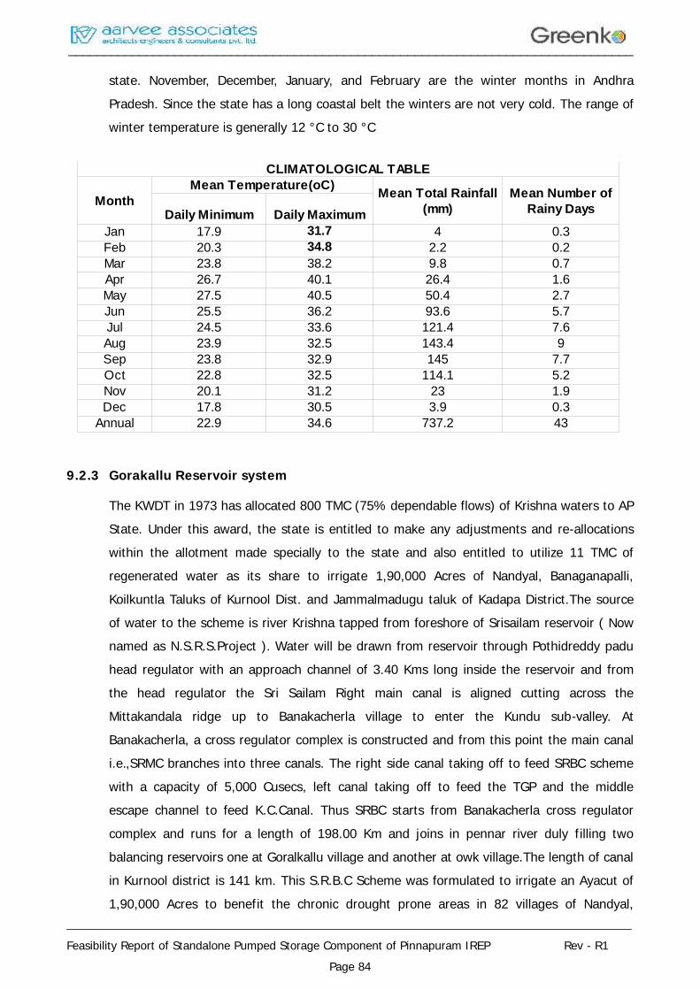
________________________________________________________________________________
________________________________________________________________________________
Feasibility Report of Standalone Pumped Storage Component of Pinnapuram IREP Rev - R1Page 84
state. November, December, January, and February are the winter months in AndhraPradesh. Since the state has a long coastal belt the winters are not very cold. The range ofwinter temperature is generally 12 °C to 30 °C
9.2.3 Gorakallu Reservoir system
The KWDT in 1973 has allocated 800 TMC (75% dependable flows) of Krishna waters to APState. Under this award, the state is entitled to make any adjustments and re-allocationswithin the allotment made specially to the state and also entitled to utilize 11 TMC ofregenerated water as its share to irrigate 1,90,000 Acres of Nandyal, Banaganapalli,Koilkuntla Taluks of Kurnool Dist. and Jammalmadugu taluk of Kadapa District.The sourceof water to the scheme is river Krishna tapped from foreshore of Srisailam reservoir ( Nownamed as N.S.R.S.Project ). Water will be drawn from reservoir through Pothidreddy paduhead regulator with an approach channel of 3.40 Kms long inside the reservoir and fromthe head regulator the Sri Sailam Right main canal is aligned cutting across theMittakandala ridge up to Banakacherla village to enter the Kundu sub-valley. AtBanakacherla, a cross regulator complex is constructed and from this point the main canali.e.,SRMC branches into three canals. The right side canal taking off to feed SRBC schemewith a capacity of 5,000 Cusecs, left canal taking off to feed the TGP and the middleescape channel to feed K.C.Canal. Thus SRBC starts from Banakacherla cross regulatorcomplex and runs for a length of 198.00 Km and joins in pennar river duly filling twobalancing reservoirs one at Goralkallu village and another at owk village.The length of canalin Kurnool district is 141 km. This S.R.B.C Scheme was formulated to irrigate an Ayacut of1,90,000 Acres to benefit the chronic drought prone areas in 82 villages of Nandyal,
CLIMATOLOGICAL TABLE
MonthMean Temperature(oC)
Daily Minimum Daily MaximumJan 17.9 31.7 4 0.3Feb 20.3 34.8 2.2 0.2Mar 23.8 38.2 9.8 0.7Apr 26.7 40.1 26.4 1.6May 27.5 40.5 50.4 2.7Jun 25.5 36.2 93.6 5.7Jul 24.5 33.6 121.4 7.6Aug 23.9 32.5 143.4 9Sep 23.8 32.9 145 7.7Oct 22.8 32.5 114.1 5.2Nov 20.1 31.2 23 1.9Dec 17.8 30.5 3.9 0.3
Annual 22.9 34.6 737.2 43
Mean Total Rainfall(mm)
Mean Number ofRainy Days
________________________________________________________________________________
________________________________________________________________________________
Feasibility Report of Standalone Pumped Storage Component of Pinnapuram IREP Rev - R1Page 85
Panyam, Banaganapalli, Owk, Koilakuntla, Vuyyalwada and sanjamala mandals of Kurnooldistrict (1,57,422 Acres ) and 18 villages of Jammalamadugu mandal of Kadapa district(32,578 Acres).
9.2.4 REAGIONAL GEOLOGY OF STUDY AREA
The Kurnool district is situated within the stable shield of Indian Peninsula. The oldest rocksexposed in the district are a group of metamorphic rocks of early Precambrian or Archaeanage. They comprise of quartzites, phyllites, schists, gneisses, migmatites, granites andamphibiolites. These rocks have been highly folded and intruded in to granites. Thecomposite gneisses associated with granites were formed as a result of the injection ofgranitic magma along weak planes in the pre-existing rocks and reaction between them.Apart from this, there are periods of erosion and non-deposition of sediments known as theEparchaean interval, followed when there was a termination of earth movement andigneous activity and the country was exposed to denudation.
This prolonged period of dormancy came to a close when in the late Precambrian times alarge tract of Landin the district and adjacent districts formed into a sallow sea. Sedimentsstarted accumulating in the basin referred to as Cuddapah basin. The sedimentary rocks ofthe Cuddapah Super group comprises of conglom-erates, quartzites, shales, dolomite,limestones and chert. The floor of the sea was unstable and it sunk periodically. Landconditions appear to have prevailed intermittently in this region before the deposition of theCuddapah sedimentation was completed. Further, in the early Cuddapah times, there wasintermittent volcanic activity, when lavas of basic igneous rocks in the form of sills intrudedthe cuddapah formations. When the deposition of Cuddapah sediments ended, the regionwas uplifted and the strata tilted, fractured and exposed to denudation.
With the passage of time, the basin in the west was again submerged beneath a shallowsea and in the upper Precambrian and Cambrian times, the sedimentary rocks of Kurnoolgroup comprising of limestones, shales, quartzites and conglomerates were deposited.
The overlapping nature of the different formations and the lateral variation in the thicknessof Kurnool strata suggest that the basin in which the Kurnool sediments accumulated wasunstable with frequents oscillations of the sea level. In the post Kurnool times, theCuddapatl basin was again uplifted and along its eastern margin, the Kurnool andCuddapahs were folded, the later more severely.
These rocks occupy the western part of the district exposed in Adoni, Alur, Pattikondaareas. Granites and composite gneisses are the dominant rock types. Amphibolies,hornblende schists, quartzites, phyllites, chlorite schists and mica schists are very much
________________________________________________________________________________
________________________________________________________________________________
Feasibility Report of Standalone Pumped Storage Component of Pinnapuram IREP Rev - R1Page 86
restricted in their extent and confined to small patches. The schists are highly folded. Thecomposite gneisses are grey in colour and show alternate banding of quartz and feldsparwith biotite or hornblende. The granites are seen in pink, grey, and with massive, gneissicfine-to-coarse grained and porphyritic texture. The granites are composed of potashfeldspar, plagioclase, quartz, biotite and hornblende. Numerous felsite, pegmatites quartzveins and dykes of dolerite have intruded into the granites.
9.2.5 Seismicity
The project area is in Kurnool district of Andhra Pradesh. As per Seismic Zonation Map ofIndia, the project area lies in Seismic Zone II.
9.2.6 Flora
The floral diversity of this Kurnool district is incredible, which covers 353 species of plantsincluding trees, herbs, shrubs, climbers, grasses. The forest present in this district area isabode to medicinal plants. The plants like Madhuca longifolia, Dillenia Pentagyna,Aristolochia indica, Terminalia arjuna, Pithecolobium dulce, Adina cordifolia, Terminaliatomentosa, T.bellerica, Chloroxylon swietenia, Boswellia serrata, Teak and Vanda spp. etc;are there.
Kurnool District has two major forest Nallamalais and Yerramalais forest. Yerramalis forestare the eastern ghat extensions. The Gani Reserve forest is a dry deciduous forest. Forestcomes under the Sothern thorn forest. The vegetation is varied depending upon the climateand edaphic factors. Apparently there are signs of forest becoming degraded from moistdeciduous and to scrub type dominated by thorny. Succulent and xerophytic bushes. Theforest is luxuriant in vegetation and enriched with many medicinal, rare, endemic andthreatened categories of plants.
9.2.7 Fauna
The invertebrate life is enthralling with an over hundred species of Butterflies, Over 50species of moths, and a huge diversity among other insects. East Asian tree frog, narrowmouthed frog, Indian cricket frog etc, represent the 18 species of amphibians, while theirreptilian counterparts include snakes like Russell’s viper, common cobra, Indian rock pythonalong with other reptiles such as marsh crocodile, monitor lizard, star tortoise, etc. 200species of birds like wood sand piper, Temminck’s stint, lesser golden backed wood pecker,Gray horn bill, Brown fish owl, wigeon, Vultures etc. Mammals like leopard, Indian wolf,wild dog, Jackal, Striped hyena, Spotted deer, sambar, Barking deer, chinkara, chowsingha,Nilgai, Honey badger etc. are present in Kurnool District.
________________________________________________________________________________
________________________________________________________________________________
Feasibility Report of Standalone Pumped Storage Component of Pinnapuram IREP Rev - R1Page 87
9.3 Prediction of Impacts
The environmental impacts of the proposed Standalone Pumped Storage Component ofPinnapuram IREP have been predicted and are being forecast in light of the activities thatwould be undertaken during the construction of various project appurtenances, e.g. Dam,drilling and blasting during excavation of pressure shafts, roads, construction of permanentand temporary housing and labour colonies, quarrying for construction material anddumping of muck generated from various project activities. The likely impacts have beenconsidered for various aspects of environment, including physico-chemical, ecological andsocio-economic aspects are briefly detailed as below
9.4 Impacts on Land Environment
9.4.1 Construction Phase
Only very few impacts of construction phase are permanent. Majority of the environmentalimpacts attributed to construction works are temporary in nature, lasting mainly during theconstruction phase and often little beyond the construction period. However, if these issuesare not properly addressed, the impacts can continue even after the construction phase forlonger duration. The time required for construction of the project has been assumed asabout 3.0 years.
Foundation works will involve land excavation, filling and concrete works effectingenvironment by noise and dust pollution. Structural, deployment of machinery, approachroads construction and erection work will also result in dust, noise pollution and vehiculartraffic. Material handling and transportation may significantly increase noise pollution.
The labour for various activities during the construction phase shall be engaged from thesurrounding villages. Some essential services are also required to be provided. This willhave an impact on drinking water supply and sanitary facilities. Economy of the nearbyarea will be improved due to increased job opportunities with corresponding increase inincome. Other associated business activities like transport, hotels, consumer goods etc., willalso be benefited. The major environmental parameters likely to be affected duringconstruction phase are noise, dust pollution and sanitation. Water spraying during highdust will minimise the dust level to some extent. A proper temporary housing with watersupply and sanitation for workers should be planned. The effect due to construction phaseis however, of temporary in nature and has no permanent effect on environment.
________________________________________________________________________________
________________________________________________________________________________
Feasibility Report of Standalone Pumped Storage Component of Pinnapuram IREP Rev - R1Page 88
9.4.1.1 Environmental degradation due to immigration of labour population
About 400 workers and 100 technical staff are likely to work during the peakconstruction phase in the project area. Thus a total of 400 persons along with theirfamilies will reside in the project area during peak construction phase. Thus thepeak manpower would be around 1200 including their families.
Separate accommodation and related facilities for workers, service providers andtechnical staff are to be arranged. The volume of labour force is most likely willcreate problems of sewage disposal, solid waste management and requirement offuel etc.
9.4.1.2 Quarrying Operations
The coarse aggregate requirement and construction materials for formation ofembankment, various roads and buildings of 73.40 lakh Cum will be extracted fromthe excavated muck from various project components. However a separate quarry isbeing identified to meet the balance requirement of construction materials.
9.4.1.3 Operation of construction equipment
During construction phase of the project, various types of construction equipmentwill be brought to the site. These include crushers, batching plant, drillers, earthmovers, rock bolters, etc. The siting of these construction equipments would requiresignificant amount of space. Land required will be temporarily acquired, i.e. for theduration of project construction for storage of the material before crushing, crushedmaterial, cement, rubble, etc. Efforts shall be made to select the site for locatingthe construction equipment in such a way that the adverse impacts on environmentare minimal. There are no major habitations in the project area. Thus, no significantimpacts are anticipated on this account.
9.4.1.4 Soil Erosion
The runoff from various construction sites, will have a natural tendency to flowtowards along with the natural drainage. Thus, the disposal of drainage effluentwith such high turbidity levels is bound to affect the water quality, especially in thelean season. The drains/nallahs close to various construction sites are seasonal innature. However, for the present project proposal no significant drains/nallahs arepresent. Hence, the increase in turbidity levels are not envisaged to be significant innature.
________________________________________________________________________________
________________________________________________________________________________
Feasibility Report of Standalone Pumped Storage Component of Pinnapuram IREP Rev - R1Page 89
9.4.1.5 Muck Disposal
About 85.30 Lakh cum of muck is expected to be generated as a result of constructionof Power house and other appurtenant works. The project proposes to utilize 73.4 Lakhcum of the muck to be generated as construction material in various project structures.
Therefore, 11.90 Lakh Cum muck is proposed to be dumped at pre-identified locations.The muck is proposed to be dumped in an environmentally sound manner in pre-identified dumping sites, which are proposed to be rehabilitated subsequently in anenvironmentally sound manner. Retaining walls will be constructed. After the filling isdone, rehabilitation of this site will be done to ensure that neither it flows in to thewater stream nor it poses any other environmental threat. Plantation, whereverpossible, will also be done on these sites so that these get stabilized over a period oftime and do not pose any environmental problem.
9.4.2 Impact identification during operational phase
There would be little environmental and ecological changes during the operationalphase. Since, only a small number of O&M staff will reside in the area in a well-designed colony with sewage treatment plant and other infrastructure facilities,problems of water pollution due to disposal of sewage are not anticipated.
9.5 Impacts on Air Environment
Considerable amount of air pollution will be caused during different stages ofconstruction of pressure shafts, roads and other operations such as excavation, drilling,blasting, loading and transportation of material. Suspended Particulate Matter (SPM) isthe main pollutant during construction. Most of the dust arises from drilling, blasting,excavation, crushing and transportation operations. Large quantities of dust becomewind borne and are carried away from overburden dumps. The fugitive dust releasedduring the construction activities may cause immediate effect on the constructionworkers who are directly exposed to the fugitive dust. Vegetation will also be adverselyaffected as deposition of dust on the leaves will choke the photosynthesis activity,which, in turn, will have adverse effect on the health of the plants. The other sources ofair pollution is Pollution due to fuel combustion in various equipment. The operation ofvarious construction equipment requires combustion of fuel. Normally, diesel is used insuch equipment. The major pollutant which gets emitted as a result of combustion ofdiesel is SO2. The SPM emissions are minimal due to low ash content in diesel. Theshort-term increase in SO2, even assuming that all the equipment are operating at acommon point, is quite low. Hence, no major impact is anticipated on this account on
________________________________________________________________________________
________________________________________________________________________________
Feasibility Report of Standalone Pumped Storage Component of Pinnapuram IREP Rev - R1Page 90
ambient air quality.
9.6 Impacts on Noise Environment
The noise will be generated at the time of construction of powerhouse, pressure shafts,drilling machines, dumpers, etc. Continuous exposure of workers to high level of noisemay result in annoyance, fatigue, and may cause temporary shift of threshold limit ofhearing and even permanent loss of hearing. During operational phase, noise level willbe increased due trouncing machinery and vehicular movement in the area. However,these impacts are only localized.
9.7 Impacts on Water Quality
The project construction is likely to last for a period of 3.0 years. As mentioned earlierin about 400 workers and 100 technical staff are likely to work during projectconstruction phase. However, most of the employees/workers during constructionphase are likely to be employed from outside the project area. But, the constructionphase, also leads to mushrooming of various allied activities to meet the demand ofimmigrant labour population in the project area. It is recommended to commission unitsfor treatment of sewage generated from labour camps prior to disposal.
During construction phase, one crusher will be commissioned at the muck dumpingareas. It is proposed only crushed material would be brought at construction site.Water is required to wash the boulders and to lower the temperature of the crushingedge. About 0.1 m3 of water is required per ton of material crushed. The effluent fromthe crusher would contain high-suspended solids. The effluent from crushers will betreated by providing settling tank prior to disposal.
9.8 Impacts on Flora and Fauna
There is no vegetation worth its name or any wild life, hence, there will not be anyadverse impact. There is no Wild Life Sanctuary or National Park in the Project area.During the detailed study at DPR stage, it is recommended that detailed studies to beconducted to ascertain the ownership status of the lands, i.e. whether the land belongsForest Department or is it a non-forest government land. Even barren land, could becategorized as forest land, if it is under the jurisdiction of forest department. In such ascenario, compensatory afforestation as per the norms of Forest Conservation Act willhave to be done in lieu of entire forest land as per ownership, irrespective of its vegetalstatus to be acquired for the project. The ownership category of land required forvarious project appurtenances can be ascertained, once project layout is finalized as apart of DPR preparation. Based on the type of land being acquired for the project,
________________________________________________________________________________
________________________________________________________________________________
Feasibility Report of Standalone Pumped Storage Component of Pinnapuram IREP Rev - R1Page 91
suitable compensatory measures if any can be suggested as a part of Forestconservation act, 1980.
9.9 R&R Aspects
The Pinnapuram IREP is proposed between two reservoirs i.e. Pinnapuram IREP upperand lower reservoir (both to be constructed newly) and one time water will be pumpedfrom existing Gorakallu reservoir to fill up the proposed upper reservoir. No dwellings,houses or hamlets will be submerged with the proposed upper reservoir. So, there is nodisplacement and resettlement is involved. However, for construction of civil structuresand other components acquisition of forest land in forest block and private land invarious settlements are required. A detailed socioeconomic survey needs to beconducted to ascertain the actual number of families losing land, as a result ofacquisition of land for various project features as a part of Social Impact Assessment(SIA) under Land Acquisition, Rehabilitation and Resettlement Act, 2013 based onwhich, if required suitable Resettlement & Rehabilitation Plan can be formulated.
9.10 Environmental Management Plan
Environmental Management Plan (EMP) aims at the preservation of ecological systemby considering certain mitigating measures at the proposed site. The mitigationmeasures are used to minimize or prevent adverse impacts on environment due to theproposed development activity. Some of the major criteria governing the environmentalmeasures will be adopted, and the same is described below
9.11 Environmental Management
It is expected that the project area shall not be affected much with the proposedactivity and likely to get new economic fillip due to power generation, not only for thestudy area but also for the region as a whole. The majority of the environmental impactpertains to the construction phase. It is planned to take corrective measures to ensurethat these effects are kept to bare minimum. The EMP will therefore, be initiated duringplanning stage itself.
9.11.1 Environmental Management during Construction
Dust emission and solid waste will be generated during initial site preparation activityand there will be slight increase in the noise levels around the site. The environmentalimpacts during the clearing or clearing for site preparation will be temporary, localisedand negligible. Water sprays at appropriate location will be provided for dustsuppression, hence reducing the impacts. Solid waste will be disposed off along with
________________________________________________________________________________
________________________________________________________________________________
Feasibility Report of Standalone Pumped Storage Component of Pinnapuram IREP Rev - R1Page 92
the muck at the designated sites.
9.11.2 Air Environment
The construction activities will generate large quantities of dust during drilling, blasting,loading and transportation operations. The following measures are required be taken tomitigate the dust from different operations.
To avoid the dust generation from the drilling operations, wet-drilling methods will beadopted.
Ceasing dust -generating activities during high winds
Covering of vehicles carrying solid waste (muck).
Watering of haul roads and other roads at regular intervals
Plantation near muck disposal places and dumping yards.
9.11.3 Noise environment
The major noise generating sources from the proposed activity are working machinery,blasting and movement of vehicles. The following control measures are to beundertaken to bring down the noise levels.
Traffic (vehicular movement) to be managed to produce a smooth flow instead of anoisier stop -and start flow.
Ensuring timely preventive maintenance of the equipment involved. Since a wellmaintained equipment is generally quieter than poorly maintained equipment.
Ensuring usage of personal protective devices i.e., earmuffs and earplugs by workers,working in high noise activity canters.
Plantation in the vicinity of the construction area will further reduce the noise levels.
9.11.4 Water environment
During construction phase the wastewater (sewage) coming from temporaryArrangements like offices, labour camp sheds, canteens etc., and impact due to soilerosion during monsoon period may cause surface water pollution. Some of the controlmeasures adopted for controlling water pollution are as follows:
Establishing septic tanks followed by soak pits to treat the domestic waste watergenerated from the offices, canteens, labour camp sheds.
9.11.5 Compensatory Afforestation
The loss of vegetal cover can be compensated by compensatory afforestation. The
________________________________________________________________________________
________________________________________________________________________________
Feasibility Report of Standalone Pumped Storage Component of Pinnapuram IREP Rev - R1Page 93
Indian Forest Conservation Act (1980) stipulates:
if non-forest land is not available, compensatory forest plantations are to beestablished on degraded forest lands, which must be twice the forest area affected orlost, and if non-forest land is available, compensatory forest are to be raised over anarea equivalent to the forest area affected or lost.
As per the applicable forest laws in vogue, the cost of compensatory afforestation, theNPV for environment loss as well as cost of trees are also payable as per the applicablenorms.
9.11.6 Greenbelt Development
The forest loss due to various project appurtenances has been compensated as a partof compensatory afforestation. However, in addition to compensatory afforestation, it isproposed to develop greenbelt around the perimeter of various project appurtenances,selected stretches along the periphery of water spread area, roads, etc.
________________________________________________________________________________
________________________________________________________________________________
Feasibility Report of Standalone Pumped Storage Component of Pinnapuram IREP Rev - R1Page 94
CHAPTER – 10
CONSTRUCTION PROGRAMME AND SCHEDULE
10.1 General
Construction of Pinnapuram IREP including erection of seven generating units are plannedto be completed in a period of 36 months including Pre-constructions works, creation ofinfrastructure facilities viz. additional investigations, improvement of road network andcolonies.
Two shift working is considered economical for surface works. Opting 25 working days in amonth, shift wise scheduled working hours annually are adopted as follows:
For Surface Works
Two Shift Work = 25x12x10 hrs. = 3000 hrs.
10.2 Main Components of the Project
10.2.1 Main Structure/ Components
The Construction schedule has been detailed for major items of the following mainstructures/ components.
Civil Works
Embankment for forming upper and lower reservoir
Head Race Channel
RCC intake Structure
Penstock / Pressure shaft
Surface Power House
Tail pool and Tailrace channel
Electrical Works
a) E.O.T cranes
b) Supply and erection of T.G sets 7 nos.
c) 400 KV G.I.S. equipment
d) Main Power Transformers
e) Other auxiliary electro-mechanical equipment
Hydraulic equipment
________________________________________________________________________________
________________________________________________________________________________
Feasibility Report of Standalone Pumped Storage Component of Pinnapuram IREP Rev - R1Page 95
Intake gates
Intake trash rack
Steel liner Penstock
Draft Tube gates
Trash Rack at Tail pool
10.2.2 Target Schedule
The Total Construction period is scheduled as follows.
Preconstruction Period : 6 months
Construction Period (Main Works) : 2.5 Years
Total Construction Period : 3 Years
10.3 Infrastructure Facilities
The Pinnapuram IREP, however creation of additional infrastructure facilities orRenovation of existing infrastructure facilities will be taken up in the first year.Construction/improvement of project roads and improvements/ upgrading of access roadswill be taken up and completed on priority basis. The construction of office andresidential buildings will be started and completed in the 1st year. The facilities forworkshop and stores etc. are also included.
10.3.1 Head Race Channel
Excavation of Head Race channel may start from 2nd month of year 1 and will becompleted by 7th month of year 1.
10.3.2 Embankment for Upper & Lower Reservoir
Excavation of embankment area will be started from the 3rd month of year 1 utilisng themuck generated from approach channel and will be completed by 12th month of year 2.
10.3.3 RCC intake Structure
Excavation of intake structure may start from 5th month of year 1 and will be completedby 4th month of year 2. The concreting of intake may take place from 5th month of year2 and will be completed by 9th month of year 2.
10.3.4 Penstock / Pressure shaft
Excavation in penstock / Pressure shaft will be taken up in the 8th month of year 1 andwill be completed by the end of 6th month of the 2nd year. The Lining & erection of steel
________________________________________________________________________________
________________________________________________________________________________
Feasibility Report of Standalone Pumped Storage Component of Pinnapuram IREP Rev - R1Page 96
liners will be started from 7th month of year 2 and will be completed by the end of 12thmonth of year 2.
10.3.5 Powerhouse
Excavation of the power house will be taken up in the 6th month of the 1st year and willbe completed by 2nd month of year 2. The concreting will be taken up in the 2nd monthof the second year and will take 8 months for completion along with the trash rackstructure.
10.3.6 Tail pool and Tailrace Channel
Excavation of Tail pool and Tailrace Channel will be taken up in the 3rd month of the 2nd
year and will be completed by 9th month of year 2. The concreting will be taken up in the10th month of the second year and will be completed by 2nd month of 3rd year.
10.3.7 Electro-Mechanical Works
Action for procurement of EOT cranes is proposed to be initiated in the 1st year itself.The entire process of inviting the tender, placing orders, manufacture, supply, erectionand testing is planned to be carried out in the 1st year to end of the 2nd year.
Pre-manufacture activities such as preparation of specifications, inviting and evaluation oftender etc. can be completed within the 1st year so that the supply orders are placed bythe end of the 1st year. The model tests and approval to the supplier’s drawings willrequire six months. Installation period for each pump/turbine and generator/motor hasbeen considered as 12 months.
________________________________________________________________________________
________________________________________________________________________________
Feasibility Report of Standalone Pumped Storage Component of Pinnapuram IREP Rev - R1Page 97
CHAPTER - 11
COST ESTIMATE
11.1 General Description Of The Project
The Pinnapuram IREP is proposed between two reservoirs i.e. Pinnapuram upper and lowerreservoir (both to be constructed newly) and one time water will be pumped from existingGorakallu reservoir to fill up the proposed upper reservoir.
11.2 Cost Estimates
The Civil Cost Estimates of the project has been prepared as per "Guidelines forpreparation of estimates for the river valley projects" issued by CWC and Indian StandardIS: 4877 "Guide for Preparation of Estimate for River Valley Projects".
Rates of major items of works have been prepared based on SSR of Andhra Pradesh & localprevailing rates are adopted for the items not covered by the SSR wherever quantificationhas not been possible at the present stage of design, lumpsum provisions have been madebased on judgement / experience of other projects.
The estimates of the Hydro Electric Scheme has been divided under the following accountheads:
A. Direct Cost
I. Works
A - Preliminary
B - Land
C - Works
J - Power Plant Civil Works
K - Buildings
M - Plantation
O - Miscellaneous
P - Maintenance during construction
Q - Special T&P R - Communications
S - Power Plant and Electro-Mechanical system
X - Environment and Ecology
Y - Losses on stock
________________________________________________________________________________
________________________________________________________________________________
Feasibility Report of Standalone Pumped Storage Component of Pinnapuram IREP Rev - R1Page 98
Total I-Works
Establishment
Tools and Plants
Suspense
Receipt and Recoveries
Total (A) - Direct Cost
B. Indirect Cost
Capitalization of Abatement of Land Revenue
Audit and Account Charges
Consultancy Charges
Upfront fee for loan
Total (B) - Indirect Cost
Total Cost (A+B)
11.3 Preparation Of Estimates
The capital cost of the project includes all costs associated with investigations, design,construction and maintenance during construction period of the project.
For preparation of cost estimates of civil works, the unit costs of labor, materials andequipment necessary to perform the work designated in the various pay-items for theproposed construction are determined based on Schedule of Rates for the year 2017-18 ofAndhra Pradesh Irrigation and Command Area Development and for items for which therates are not available, the accepted schedule of rates of similar ongoing/recently executedprojects adopted. The rates of major items have been worked out by rate analysis.
The quantities of Civil Works are estimated based on designs and drawings prepared forvarious components of the project. The Daily wage rates have been taken as per AndhraPradesh I&CAD Schedule of Rates for the year 2017 - 18.
Provision for contingencies are considered at 3% of the works cost and are provided in thedetailed works estimates prepared on the heads of item rates and quantities of works to beexecuted. These percentage provisions are not considered on lump-sum items.
________________________________________________________________________________
________________________________________________________________________________
Feasibility Report of Standalone Pumped Storage Component of Pinnapuram IREP Rev - R1Page 99
PREPARATION OF DETAILED ESTIMATES OF COST (I-WORKS)
11.3.1 A - Preliminary
The provision under this head covers the works relating to various Investigations, Surveys,Model tests, Ecological studies etc. Provision for preliminary expenses is provided not toexceed 2% of total cost of I-Works.
11.3.2B – Land
The provision under this head covers Acquisition of Land, Rehabilitation & Resettlementincluding compensation for property, Interest charges, Solatium charges, demarcation &measurement charges, etc. have been made as per actuals.
11.3.3C - Works
The provisions under this head covers the costs of Rockfill embankment, Head RaceChannel, RCC intake structure, Penstocks/Pressure Shaft, Power House, Tail Pool and TailRace Channel.
Important items considered under this head are
11.3.4 J - Power plant civil works
Important items to be considered under this head are
Embankment, Head Race Channel & Intake Structure
Excavation
Foundation treatment
Cement concrete for foundation, piers and abutments
Masonry/concrete for guide walls of Head Race Channel
Concrete for trash racks including raking arrangement
Gates with auxiliary equipment’s
Reinforcement Steel
Instrumentation etc.,
Penstock / Pressure Shaft
Excavation
Cement concrete for
Bed
________________________________________________________________________________
________________________________________________________________________________
Feasibility Report of Standalone Pumped Storage Component of Pinnapuram IREP Rev - R1Page 100
Anchor blocks
Intermediate supports
Stiffener, Reducers, Bends, Penstock valves, Instrumentation
Power House
Excavation
Concrete for foundation, sub-structure, super-structure and supports forturbines and generators.
Masonry/concrete for super-structure and other necessary items for buildingwork.
Scroll casing / Generator barrel
Draft tube
Bulkhead gates, crane and hoisting equipment
Power-house crane
Miscellaneous items such as anchor bolts, grouting etc.
Instrumentation
Tail Pool and Tail Race channel
Excavation
Embankment
Lining with cement concrete in bed and sides with drainage pipes and valves
Pucca works
Cross Drainage(s)
Escape(s)
Bridge(s)
Instrumentation
11.4 K – Buildings
The provisions under this head covers the Residential / Nonresidential buildings, officebuildings, Stores, Testing laboratories, Workshops, Other Service Buildings, CommunityCentre etc. A provision of 2% J-Power plant civil works is made under this head.
________________________________________________________________________________
________________________________________________________________________________
Feasibility Report of Standalone Pumped Storage Component of Pinnapuram IREP Rev - R1Page 101
11.5 M – Plantation
The provisions under this head covers the plantation program including Gardens etc.required for beautification which is considered necessary at downstream of Weir andaround Power House and other important structures. A provision of Rs. 100 Lakhs is madeunder this head.
11.6 O – Miscellaneous
The provision under this head covers the capital cost & maintenance of Electrification,Water supply, Sewage disposal and drainage works, Recreation, Medical, Firefightingequipments, Inspection vehicles, School bus, Pay van, visit of dignitaries, welfare worksetc. A provision of around 2% J-Power plant civil works is made under this head.
11.7 P - Maintenance during Construction
The provision under this head covers the cost of maintenance of all works during theconstruction period. A provision of around 1% J-Power plant civil works is made under thishead.
11.8 Q - Special Tools & Plants
The provisions under this head covers the Drilling & Grouting equipment’s, Transport,Compaction, Electrical equipment’s, Construction Plant & Earth Moving equipment’s andother Miscellaneous equipment’s. A provision of Rs.200.00 lakhs has been made under thishead. As the project works have been planned for construction through contractors, and itis expected that the contractors will procure their own equipment’s for work.
The project estimates therefore do not provide for purchase of heavy earth movingequipment and concreting equipment by the department.
11.9 R – Communication
The provisions under this head covers the construction of main approach roads, quarryroads, temporary or permanent river crossing, railways, bridges and connecting roads.
11.10 S-Power plant and Electro - Mechanical System
The provision under this head cover the Electro-Mechanical equipment for the power plantand associated substation under the sub-head as indicated in Annexure – S for "Abstract ofCost Estimates of Electro-Mechanical Equipment’s". The cost of the Electro-Mechanicalequipment is arrived at based on the preliminary size and compared with recent projects.Cost of transmission line is also included in the project cost.
________________________________________________________________________________
________________________________________________________________________________
Feasibility Report of Standalone Pumped Storage Component of Pinnapuram IREP Rev - R1Page 102
11.11 X - Environment and Ecology
Under this head provisions for items like, compensatory afforestation, catchment areatreatment, establishment of fuel depot, salvage / rehabilitation of any rare or endangeredspecies of flora and fauna, control of aquatic weeds, public health measures to controlwater or soil borne diseases, Restoration of land, seismological measures etc., areconsidered as per their requirements. A provision of around 2% J-Power plant civil works ismade under this head
11.12 Y - Losses On Stock
The provision under this head has been made at 0.25% of the total cost of C Works, J -Power Plant Civil Works and K – Buildings.
11.13 Establishment
The provision under this head has been made in the corresponding items of the work.
11.14 Tools & Plants
Provision for ordinary tools and plants is made at 1.0% of I - Works less land.
11.15 Suspense
The net provision under this minor head is "NIL", as all the outstanding suspense accountsare expected to be cleared by adjustment to appropriate heads.
11.16 Receipts & Recoveries On Capital Account
Provision is made under this head towards estimated recoveries by way of resale at 15% ofthe total cost incurred towards Q-Special tools and plants.
11.17 Indirect Charges
A provision of 0.25% of I - Work cost is made for Audit and Account.
11.18 Project Cost
The total project cost has been estimated at 5468.02 Crores at March 2018 price level. Thecost works out to Rs. 4.56 Crore per MW including IDC.
________________________________________________________________________________
________________________________________________________________________________
Feasibility Report of Standalone Pumped Storage Component of Pinnapuram IREP Rev - R1Page 103
CHAPTER – 12
FINANCIAL AND ECONOMIC ANALYSIS
12.1 Introduction
The economic viability of a project is determined by comparison with the alternativesources at the same place considering therein all elements such as cost oftransmission/distribution etc., In isolated areas, it is often compared with diesel or othersources available for affording the same energy benefits. The economics of the project,where existing facility is required to meet the demand could be computed consideringsystem requirements and the ability of the scheme for meeting the demand. When a HydroProject is to be developed by an Independent producer, he would have to consider returnsto him considering all factors such as rate offered to him by third party sale or captiveconsumption or sale to state electricity boards, any subsidies and concessions available forfunding or otherwise.
12.2 General Description Of The Project
The Pinnapuram IREP has been conceived as an off stream project near PinnapuramVillage, in the state of Andhra Pradesh
12.3 Generation
In a year, the planned peak power generation will be 2806 hours considering the rate of8.11 hours per day for 346 days operation the estimated maximum annual energygeneration will be 3376MU. Only net volume turbine by PSP during the non -monsoonperiod is considered.
12.4 Annual Requirement Of Pumping Energy
The pumping will have to be carried out for 3021 hours (i.e., 346 days and 8.73 hours eachday) per year. The energy required for pumping works out to 4480 MU per annum.
Load factor in turbine mode – 32.11 %
Load factor in Pump mode – 34.55 %
Optimization studies with actual parameters of Pump Turbine, Generator Motor and otherequipment’s as obtained from the manufacturers shall be carried out at the time ofpreparation of DPR in line with the latest international practice and guidelines issued byCEA.
________________________________________________________________________________
________________________________________________________________________________
Feasibility Report of Standalone Pumped Storage Component of Pinnapuram IREP Rev - R1Page 104
12.5 Means Of Finance
The project is proposed to be financed through term loans from financial institutes andbalance through equity participation or as in practice of Corporation.
Equity: The developer will provide Equity to the extent of 30% of the project cost based onthe estimates by adopting a debt equity ratio of 70:30 is borrowed.
Debt: The term loan to the extent of 70% of the project cost based on the estimates willbe obtained from the financial institutions.
The analysis has been carried out, considering the rate of interest equal to 10.20% on termloan. Repayment of loan is assumed to be over a period of 12 years in Quarterly equalinstallments for principal amount and interest charges on balance outstanding. Interestcharges have been computed based on average of opening and closing amount ofoutstanding loan in each quarter. Loan amount would also account for payment of interestcharges during construction period and other incidental charges associated with financing.
12.6 Cost Of Project
Estimated cost of the project is Rs.5468.02 Crores (including IDC) based on year 2017-2018 prices. The actual cost, till the completion of the project is higher due to interestcharges during construction. Construction work is assumed to take 36 months and thepower station is expected to be commissioned in 3.0 Years.
12.7 Interest During Construction
Interest charges during construction would depend on phasing of expenditure. IDC hasbeen considered for scheduled completion period of 30months. The Interest duringConstruction period is expected to be Rs. 519.58 Crore.
12.8 Depreciation Provision
Depreciation is considered @5.28% p.a. for the initial period of 12 years and the remainingdepreciation to cover 90% depreciable value shall spread over balance useful life of 35years of the project.
Land is not a depreciable asset; hence depreciation is to be provided on total cost of theproject other than Land.
12.9 Sales Revenue
The annual sales revenue is considered based on projected rate and following assumptionsare made to arrive at the annual charges for calculation of Cost of Energy. The operatingexpenditure has been arrived based on the estimated cost.

________________________________________________________________________________
________________________________________________________________________________
Feasibility Report of Standalone Pumped Storage Component of Pinnapuram IREP Rev - R1Page 105
Operation and maintenance O & M Expenses @2.0%, escalated @ 6.64% per annum.
Interest on working capital has been arrived as follows: The total working capital is arrivedat by considering sum of 15.00% on maintenance of spares, one-month operation andmaintenance cost, two months receivables.
Discount Factor is taken as Post tax weighted average cost of capital, which comes to9.08%
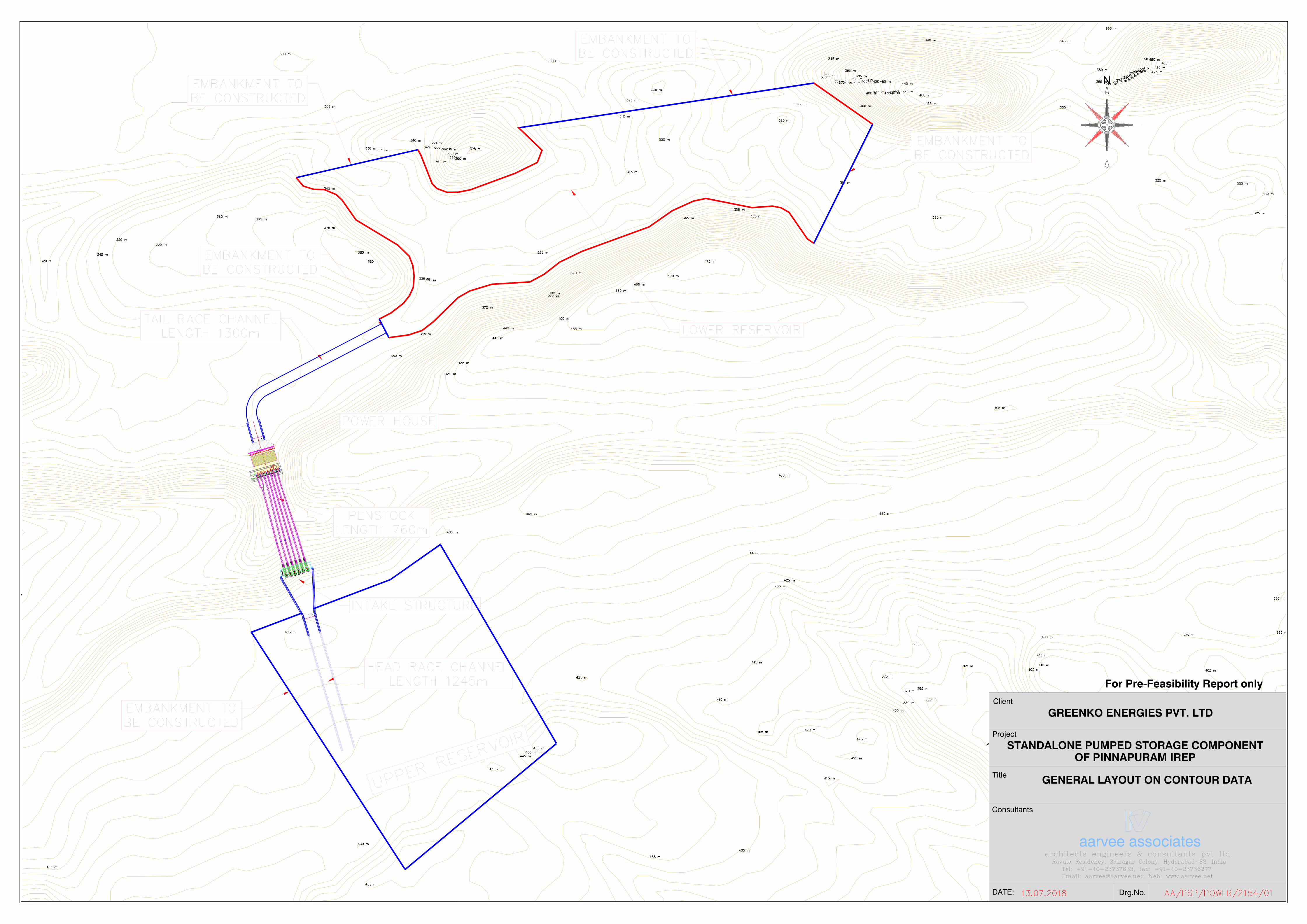
AB
UTM
EN
T
SE
RV
ICE
GA
TE
5600X
11000
R=
6500
UN
IT -
6
7000
Ø P
EN
STO
CK
AN
CH
OR
BLO
CK
EM
ER
GE
NC
Y G
AT
E G
RO
OV
E
DEWATERING PIT
OIL LEAKAGE UNIT
INSPECTION GALLERY ACCESS 2000WX2300H.
DEWATERING PITOIL LEAKAGE UNIT
DEWATERING PITOIL LEAKAGE UNIT
DEWATERING PIT
DEWATERING PITPower House
DEWATERING PITOIL LEAKAGE UNIT
OIL LEAKAGE UNIT
DEWATERING PIT
OIL LEAKAGE UNIT
OIL LEAKAGE UNIT
BERM 6 m
+329.50
+341.50 BERM 6 m
Silt Trap
+303.22
+302.20
TAIL RACE CHANNEL
+313.76BED LEVEL
+320.5
5
BE
RM
+332.5
5
BE
RM
+341.0
0
EX
GL
+320.5
5
BE
RM
+332.5
5
BE
RM
+341.0
0
EX
GL
SE
RV
ICE
BA
Y
+319.5
0
APPROACH CHANNEL +424.00
BED LEVEL
+430.7
5B
ER
M
+442.7
5B
ER
M
+460.0
0E
X G
L
+430.7
5B
ER
M+
442.7
5B
ER
M+
460.0
0E
X G
L
41
AB
UTM
EN
T
SE
RV
ICE
GA
TE
5600X
11000
R=
6500
UN
IT -
6
EM
ER
GE
NC
Y G
AT
E G
RO
OV
E
AB
UT
ME
NT
SE
RV
ICE
GA
TE
5600X
11000
R=
6500
UN
IT -
6
EM
ER
GE
NC
Y G
AT
E G
RO
OV
E
AB
UTM
EN
T
SE
RV
ICE
GA
TE
5600X
11000
R=
6500
UN
IT -
6
EM
ER
GE
NC
Y G
AT
E G
RO
OV
E
AB
UTM
EN
T
SE
RV
ICE
GA
TE
5600X
11000
R=
6500
UN
IT -
6
EM
ER
GE
NC
Y G
AT
E G
RO
OV
E
AB
UT
ME
NT
SE
RV
ICE
GA
TE
5600X
11000
R=
6500
UN
IT -
6
EM
ER
GE
NC
Y G
AT
E G
RO
OV
E
7000
Ø P
EN
STO
CK
AN
CH
OR
BLO
CK
7000
Ø P
EN
STO
CK
AN
CH
OR
BLO
CK
7000
Ø P
EN
STO
CK
AN
CH
OR
BLO
CK
7000
Ø P
EN
STO
CK
AN
CH
OR
BLO
CK
7000
Ø P
EN
STO
CK
AN
CH
OR
BLO
CK
Drg.No.
aarvee associates
DATE:
Title
Project
Client
Consultants
GREENKO ENERGIES PVT. LTD
STANDALONE PUMPED STORAGE COMPONENT
GENERAL LAYOUT ON CONTOUR DATA
For Pre-Feasibility Report only
OF PINNAPURAM IREP

ABUTMENT
SERVICE GATE 5600X11000
R=7250
UNIT - 6
7000Ø PENSTOCK ANCHOR BLOCK
EMERGENCY GATE GROOVE
DE
WA
TE
RIN
G P
IT
OIL
LE
AK
AG
E U
NIT
INS
PE
CT
ION
GA
LLE
RY
AC
CE
SS
20
00
WX
23
00
H.
DE
WA
TE
RIN
G P
IT
OIL
LE
AK
AG
E U
NIT
DE
WA
TE
RIN
G P
IT
OIL
LE
AK
AG
E U
NIT
DE
WA
TE
RIN
G P
ITD
EW
AT
ER
ING
PIT
Po
wer H
ou
se
DE
WA
TE
RIN
G P
IT
OIL
LE
AK
AG
E U
NIT
OIL
LE
AK
AG
E U
NIT
DE
WA
TE
RIN
G P
IT
OIL
LE
AK
AG
E U
NIT
OIL
LE
AK
AG
E U
NIT
BE
RM
6 m
+3
29
.50
+3
41
.50
BE
RM
6 m
Silt
Tra
p
+3
03
.22
+3
02
.20
TA
IL R
AC
E C
HA
NN
EL
+3
13
.76
BE
D L
EV
EL
+320.55BERM
+332.55BERM
D
D
B
B
+341.00EX GL
+320.55BERM
+332.55BERM
+341.00EX GL
SERVICE BAY
+319.50
AP
PR
OA
CH
CH
AN
NE
L
+4
24
.00
BE
D L
EV
EL
+430.75 BERM
+442.75 BERM
A
A
+460.00 EX GL
+430.75 BERM
+442.75 BERM
+460.00 EX GL
41
ABUTMENT
SERVICE GATE 5600X11000
UNIT - 6
EMERGENCY GATE GROOVE
ABUTMENT
SERVICE GATE 5600X11000
UNIT - 6
EMERGENCY GATE GROOVE
ABUTMENT
SERVICE GATE 5600X11000
UNIT - 6
EMERGENCY GATE GROOVE
ABUTMENT
SERVICE GATE 5600X11000
UNIT - 6
EMERGENCY GATE GROOVE
ABUTMENT
SERVICE GATE 5600X11000
UNIT - 6
EMERGENCY GATE GROOVE
7000Ø PENSTOCK ANCHOR BLOCK
7000Ø PENSTOCK ANCHOR BLOCK
7000Ø PENSTOCK ANCHOR BLOCK
7000Ø PENSTOCK ANCHOR BLOCK
7000Ø PENSTOCK ANCHOR BLOCK
R=7250
R=7250
R=7250
R=7250
R=7250
Drg.No.
aarvee associatesarchitects engineers & consultants pvt ltd.
DATE:
Title
Project
Client
Consultants
GREENKO ENERGIES PVT. LTD
STANDALONE PUMPED STORAGE COMPONENT
PLAN
For Pre-Feasibility Report only
OF PINNAPURAM IREP

PENSTOCK LENGTH = 763.00m
1
5 0.6
1
C OF PENSTOCKL7.00 m Ø PENSTOCK
TRANSITION
+334.50
(L3.5MXW2.5MXH3M)
Dewatering Gallery
HMC &Air Accumulator
Air Compressors
Drainage Pit
Dewatering Sump
EOT CRANE
ControlRoom
C/L of M/c
THRUST/GUIDE
BEARING
Generator
Slip Ring
LA
VT
& U
AT
EX TRF
MAIN
HOOKAUXILIARY
HOOK
+340.50
+299.00
Sillt Trap
+350.00
+282.50
SERVICE BAY +319.50
+329.50
+341.50
25mm Rock BoltsShotcreting 75mm Thk
Tailrace Channel Bed Level+313.76
MDDL+320.00
FRL+340.00
+313.50
+283.50
+303.22
14
Trashrack
81
24000
5496
3000 Long @2m C/C
+306.70
+311.20
+294.00
+301.187147
+295.50
+291.50
W 2.0 M X H 2.5M
Length 8.0 M
+279.50
8500
5067
7200 72003500 5100
500
GIS FLOOR
GIS Equipment
CV
T
+341.50
+351.80
Top Guide Bearing
+321.00
+351.80
Approach Channel Bed Level+419.82
7000
Drg.No.
aarvee associatesarchitects engineers & consultants pvt ltd.
DATE:
Title
Project
Client
Consultants
GREENKO ENERGIES PVT. LTD
LONGITUDINAL SECTION
For Pre-Feasibility Report only
STANDALONE PUMPED STORAGE COMPONENTOF PINNAPURAM IREP
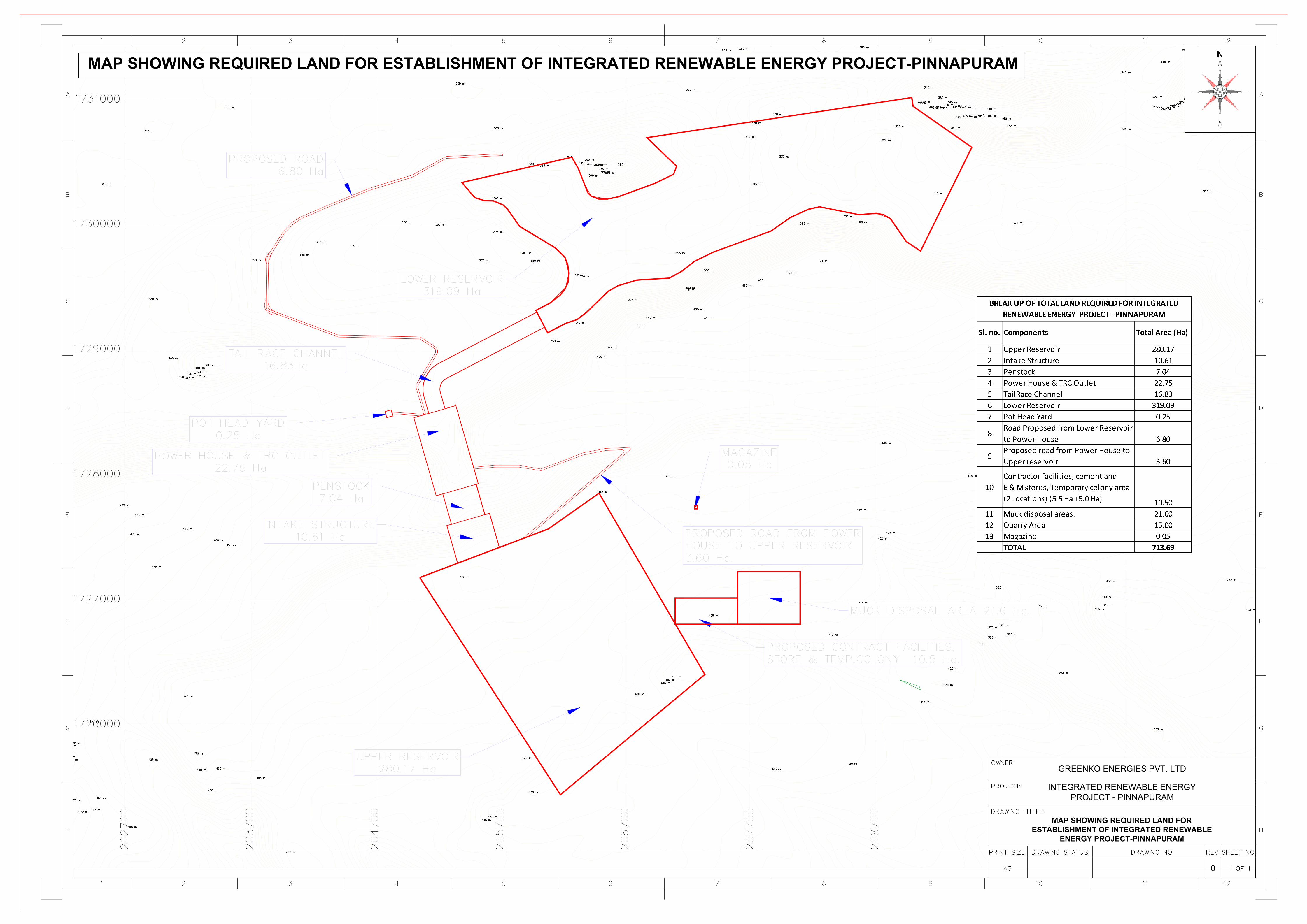
INTEGRATED RENEWABLE ENERGY
PROJECT - PINNAPURAM
MAP SHOWING REQUIRED LAND FOR
ESTABLISHMENT OF INTEGRATED RENEWABLE
ENERGY PROJECT-PINNAPURAM
0
GREENKO ENERGIES PVT. LTD
MAP SHOWING REQUIRED LAND FOR ESTABLISHMENT OF INTEGRATED RENEWABLE ENERGY PROJECT-PINNAPURAM


