Embed Size (px)
Citation preview
Fast diffusion of graphene flake on graphene layer
Irina V. Lebedeva1,2,3,* , Andrey A. Knizhnik1,2,† , Andrey M. Popov4,‡, Olga V. Ershova3,5, Yurii E.
Lozovik4,3,§, and Boris V. Potapkin1,2
1RRC "Kurchatov Institute", Kurchatov Sq. 1, Moscow, 123182, Russia,
2Kintech Lab Ltd, Kurchatov Sq. 1, Moscow, 123182, Russia,
3Moscow Institute of Physics and Technology, Institutskii pereulok 9, Dolgoprudny, Moscow Region,
141701, Russia,
4Institute of Spectroscopy, Fizicheskaya St. 5, Troitsk, Moscow Region, 142190, Russia
5School of Chemistry, University of Nottingham, University Park, Nottingham NG7 2RD, United
Kingdom
ABSTRACT
Diffusion of a graphene flake on a graphene layer is analyzed and a new diffusion mechanism is
proposed for the system under consideration. According to this mechanism, rotational transition of the
flake from commensurate to incommensurate states takes place with subsequent simultaneous rotation
and translational motion until the commensurate state is reached again, and so on. The molecular
* [email protected] † [email protected] ‡[email protected] § [email protected]

2
dynamics simulations and analytic estimates based on ab initio and semi-empirical calculations
demonstrate that the proposed diffusion mechanism is dominant at temperatures T ~ com(1÷3)T , where
comT corresponds to the barrier for transitions of the flake between adjacent energy minima in the
commensurate states. For example, for the flake consisting of ~ 40, 200 and 700 atoms the contribution
of the proposed diffusion mechanism through rotation of the flake to the incommensurate states exceeds
that for diffusion of the flake in the commensurate states by one-two orders of magnitude at
temperatures 50 – 150 K, 200 – 600 K and 800 – 2400 K, respectively. The possibility to
experimentally measure the barriers to relative motion of graphene layers based on the study of
diffusion of a graphene flake is considered. The results obtained are also relevant for understanding of
dynamic behavior of polycyclic aromatic molecules on graphene and should be qualitatively valid for a
set of commensurate adsorbate-adsorbent systems.
PACS numbers: 65.80.Ck, 68.35.Fx, 68.43.Jk, 85.85.+j
I. INTRODUCTION
Since the discovery of graphene, this new material attracted attention of the scientific community due to
its unique electronic and mechanical properties1. Intensive studies of relative rotational and translational
quasistatic motion of graphene layers are currently carried out2-12. One of the most interesting
phenomenon for graphene goes by the name of “superlubricity”, i. e., the ultra low static friction
between incommensurate graphene layers3-12. Here we for the first time study dynamic behavior of a
graphene flake on a graphene layer. Namely, we show that anomalous fast diffusion of the free
graphene flake on the underlying graphene layer is possible through rotation of the flake to
incommensurate states. As opposed to superlubricity observed in non-equilibrium systems (such as a
flake moved by the tip of the friction force microscope), diffusion refers to the behavior of a free system

3
in thermodynamic equilibrium.
The relative motion of flat nanoobjects is determined by the potential energy relief, i.e. the
dependence of the interaction energy between the nanoobject and the surface on three coordinates, two
of which correspond to the position of the center of mass and the third one is the rotation angle with
respect to the surface. The quasistatic superlubricity is observed when the motion takes place across the
nearly flat potential energy relief. The fact that this phenomenon is observed for graphene is related to
features of the potential energy relief for a graphene flake on a graphene layer. At particular rotation
angles, the lattice vectors of the flake can be chosen similar to those of the underlying graphene layer. In
these states, the flake is commensurate with the graphene layer and the potential energy relief is highly
non-uniform with significant barriers to motion of the flake. At other rotation angles, the flake is
incommensurate with the graphene layer and the energy of the flake almost does not depend on its
position, i.e. there are no barriers to its motion. Such incommensurate states are observed in the form of
so-called Moiré patterns13,14. The mechanism of ultra low static friction related to the structural
incompatibility of contacting surfaces was first suggested by Hirano and Shinjo15,16. Later, Dienwiebel
et al.3-5 demonstrated that the static friction force between a graphene flake attached to the tip of the
friction force microscope and a graphite surface can become negligibly small at some orientations of the
flake. In the present work, we suggest that transition of the flake to the incommensurate states affects
not only the static tribological behavior of the graphene flake attached to the tip of the friction force
microscope but also the dynamic behavior of the free flake and thus might provide anomalous fast
diffusion of the flake. Therefore, there is the fundamental distinction between the well-studied
superlubricity and the anomalous fast diffusion proposed here in spite of the fact that both phenomena
are based on the same features of the potential energy relief.
Incommensurability in adsorbate-adsorbent systems is known to result in fast diffusion of the
4
adsorbate. Experimentally it was demonstrated that large non-epitaxially oriented gold or antimony
clusters can diffuse on a graphite surface with a surprising diffusion coefficient of about 10-8 cm2/s at
room temperature17,18, which is significantly higher than the diffusion coefficients for clusters
epitaxially oriented on the surface (of the order of 10-17 cm2/s, see Ref. [19, 20]). However, such a fast
diffusivity was found up to now only for systems where the adsorbate and adsorbent are not
commensurate at the ground state 21-23. Based on the systematic study of diffusion mechanisms for a
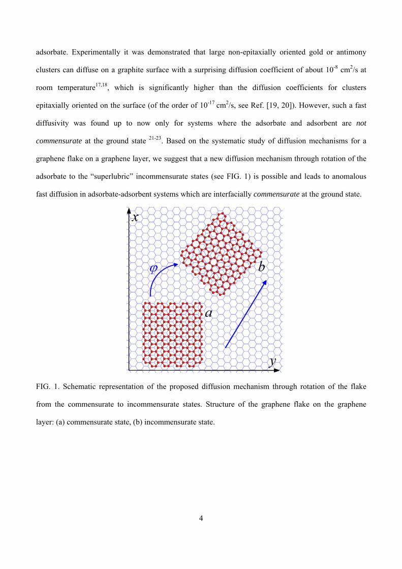
graphene flake on a graphene layer, we suggest that a new diffusion mechanism through rotation of the
adsorbate to the “superlubric” incommensurate states (see FIG. 1) is possible and leads to anomalous
fast diffusion in adsorbate-adsorbent systems which are interfacially commensurate at the ground state.
FIG. 1. Schematic representation of the proposed diffusion mechanism through rotation of the flake
from the commensurate to incommensurate states. Structure of the graphene flake on the graphene
layer: (a) commensurate state, (b) incommensurate state.
5
In the present work, we perform both density functional theory (DFT) calculations and calculations
with empirical potentials to study the dependence of the interlayer interaction energy on the relative
position and orientation of graphene layers. These calculations show that the barrier for rotation of the
flake to the incommensurate states is of the same order of magnitude as the barrier for motion between
adjacent energy minima in the commensurate state. Therefore, there should be a competition between
the diffusion mechanisms corresponding the fixed commensurate orientation and incommensurate
orientations of the flake. We analyze the diffusion mechanisms both for the incommensurate and
commensurate orientations and perform molecular dynamics (MD) simulations of diffusion of a
graphene flake on a graphene layer. The estimates and simulations demonstrate that under certain
conditions, the proposed diffusion mechanism through rotation of the flake to the incommensurate states
is dominant. We believe that a similar diffusion mechanism should also be prominent in any other
commensurate adsorbate-adsorbent systems. Particularly, the results obtained here can be useful for
understanding of dynamics of polycyclic aromatic molecules on graphene24.
In addition to the fundamental problems discussed above, the study of diffusion characteristics of
graphene is also of interest with regard to the use of graphene in nanoelectromechanical systems
(NEMS)25. Because of the small size of NEMS, such systems are subject to significant thermodynamic
fluctuations26,27. On the one hand, relative diffusion28 or displacement29 of NEMS components due to
thermodynamic fluctuations can disturb the NEMS operation29,28. On the other hand, the diffusion can
be used in Brownian motors30. Experimental measurements of the barriers to relative motion of
graphene layers or nanotube walls is also a problem of high importance for elaboration of graphene-
based and nanotube-based NEMS2,31-34. We propose that experimental measurements of the diffusion
coefficient of a graphene flake on a graphene layer can provide the true value of the barrier to relative
motion of graphene layers.

6
The paper is organized in the following way. The model used in the calculations and analysis of the
dependence of the interlayer interaction energy of graphene layers on their relative position and
orientation are presented in Sec. II. Sec. III is devoted to MD simulations demonstrating the proposed
diffusion mechanism of a graphene flake. The analytic estimates for the diffusion coefficient at different
temperatures and sizes of the flake are obtained in Sec. IV. Our conclusions are summarized in Sec. V.
II. ANALYSIS OF POTENTIAL ENERGY RELIEF
To analyze the possible mechanisms of diffusion of a graphene flake on a graphene layer, it is needed to
know the potential energy relief of the flake (see FIG. 2). As a model system for energy calculations and
MD simulations, we considered a rectangular graphene flake placed on an infinite graphene layer (see
FIG. 1). The periodic boundary conditions were applied along mutually perpendicular armchair and
zigzag directions to model the infinite substrate layer. In calculations with empirical potentials, the size
of the graphene flake was 2.0 nm along the armchair edge and 2.1 nm along the zigzag edge (178
carbon atoms). The size of the model cell was 5.5 nm x 5.7 nm, respectively. The interaction between
atoms i and j of the graphene flake and the underlying graphene layer at distance ijr was described by
the Lennard–Jones 12–6 potential
( )12 6
4LJ ijij ij
U rr rσ σε
⎛ ⎞⎛ ⎞ ⎛ ⎞⎜ ⎟= −⎜ ⎟ ⎜ ⎟⎜ ⎟ ⎜ ⎟⎜ ⎟⎝ ⎠ ⎝ ⎠⎝ ⎠ (1)
with the parameters ε = 3.73 meV, σ = 3.40 Å taken from the AMBER database35 for aromatic carbon.
The cut-off distance of the Lennard–Jones potential was taken equal to 20 Å. The Lennard-Jones
potential provides the interlayer interaction energy in graphite of about 62 meV/atom, which is
consistent with the experimental value 52±5 meV/atom36. The covalent carbon-carbon interactions in
the layers were described by the empirical Brenner potential37, which was shown to correctly reproduce

7
the vibrational spectra of carbon nanotubes38 and graphene nanoribbons39 and has been widely applied
to study carbon systems26,27,40.
FIG. 2. The interlayer interaction energy between the graphene flake and the graphene layer (in
meV/atom) calculated using the Lennard–Jones potential (1) as a function of the position of the center
of mass of the flake x, y (in Å, x and y axes are chosen along the armchair and zigzag direction,

8
respectively) and its relative orientation ϕ (in degrees). (a) 0ϕ = o , (b) 4ϕ = o , (c) 10ϕ = o and (d)
0x = . The energy is given relative to the global energy minimum. Triangle A corresponding to a
single energy minimum in the commensurate state is shown with the dashed white lines.
To calculate the dependences of the interlayer interaction energy on the position and orientation of the
flake, the structures of the flake and graphene layer were separately relaxed using the Brenner potential
and then the flake was rigidly shifted and rotated parallel to the underlying graphene layer. The distance
between the flake and the infinite graphene layer was 0.34 nm. The calculated potential energy of the
flake as a function of its position and orientation is shown in FIG. 2. The rotation angle ϕ is measured
relative to the commensurate orientation of the flake, so that 0 , 60 ,120ϕ = o o o , etc. are attributed to the
commensurate states. All other rotation angles correspond to the incommensurate states. The found
minimum energy states of the flake correspond to the commensurate AB-stacking, in agreement with
the experiment [41]. There is an energy barrier com 0 10 meV/atom.ε = for transition of the flake
between adjacent energy minima. However, even at temperature above this energy barrier, a long-
distance free motion of the flake is not possible due to the numerous energy hills on the potential energy
relief, which are higher than the energy barrier comε by an order of magnitude. The maximum energy
states of the flake correspond to the AA-stacking. The energy difference between the AA and AB-
stackings was calculated to be max 1 1 meV/atom.ε = .
Based on the approximation10,42 for the interaction of a single carbon atom in the graphene flake with
the graphene layer containing only the first Fourier components, it is easy to show that the potential
energy relief for the flake in the commensurate states can be roughly approximated in the form
( ) ( ) ( )( )1 1 1 2 02 2U U cos k x cos k x cos k y U= − + , (2)
9
where 02 2 a/k π= and 321 /kk = , x and y axes are chosen along the armchair and zigzag
directions, respectively. The parameters 1 0 225 meV/atomU .= and 0 61 92 meV/atomU .= − were fitted
to reproduce the potential energy relief calculated using the Lennard–Jones potential. For these
parameters, the root-mean square deviation of the potential energy relief (2) from the one calculated
using the Lennard–Jones potential equals 10 15. U .
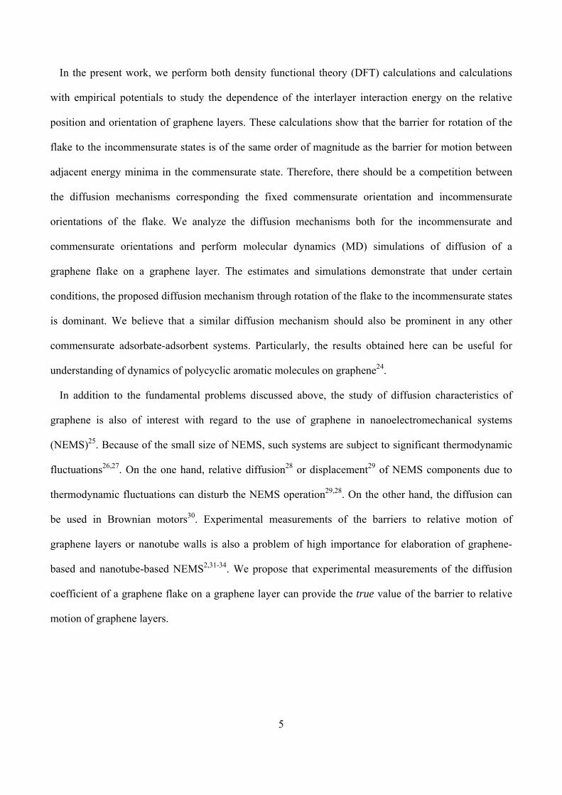
It is seen from FIG. 2 that with rotation of the graphene flake, the magnitude of corrugation of the
potential energy relief decreases. At the angle of 10º (see FIG. 2c), the magnitude of this corrugation is
negligibly small (less than 10 25. U ). At the angle of 60º, the flake becomes again commensurate with
the graphene layer. The width of the energy wells and energy peaks in the dependence of the interlayer
interaction energy on the orientation of the flake was found to be about 02 2a / Lδϕ ≈ 3/π<< (see FIG.
2d and FIG. 3), where 0 2 46a .= Å is the lattice constant for graphene and L is the size of the flake, in
agreement with Refs. [3-5, 10]. The energy of the incommensurate states relative to the commensurate
ones (which is equal to the energy needed to rotate the flake by the angle 0a / Lδϕ ≈ ) was calculated to
be in 0 37 meV/atom.ε = (see FIG. 2 and FIG. 3).
FIG. 3. The interlayer interaction energy between the graphene flake and the graphene layer (in
meV/atom) calculated using the Lennard–Jones potential for the 178-atom flake (red solid line; left

10
axis) and DFT for the 54-atom flake (blue dashed line; right axis) as a function of the rotation angle ϕ
(in degrees). The point 0ϕ = o corresponds to the global energy minimum.
Since Lennard-Jones potential was claimed not to be sensitive enough to the relative position of the
graphene layers33, we repeated the similar calculations on the basis of DFT for a smaller system. In
these calculations, the graphene flake consisted of 54 carbon atoms and had all edges terminated with
hydrogen atoms to prevent distortions of the flake structure at the edges. The size of the model cell was
2.0 nm x 2.1 nm x 1.3 nm. The VASP code43 with the local density approximation44 was used. The basis
set consisted of plane waves with the maximum kinetic energy of 358 eV. The interaction of valence
electrons with atomic cores was described using ultrasoft pseudopotentials45. The error in calculations
of the system energy was less than 0.005 meV/atom for the chosen cutoff energy of the plane waves.
Integration over the Brillouin zone was performed using a single k-point sampling.
According to the DFT calculations, the minimum energy states of the system also correspond to the
commensurate AB-stacking. The energy difference between the AA and AB-stackings was calculated to
be max 10.77 meV/atomε = , in agreement with the previous DFT calculations33. The barrier for motion
of the flake from one energy minimum to another was found to be com 1.28 meV/atomε = . The relative
energy of the incommensurate states was found to be in 4 0 meV/atom.ε = (see FIG. 3). The potential
energy relief obtained by the DFT calculations was approximated using expression (2) with the
parameters 1 2 38 meV/atomU .= and 0 34 04 meV/atomU .= − . The corresponding root-mean square
deviation of the potential energy relief (2) equals 10 08. U .
It is seen that the shapes of the potential energy reliefs obtained using the empirical potentials and
DFT calculations are qualitatively the same but the magnitudes of corrugation of the interlayer energy
differ by an order of magnitude. Therefore, the potential relief of the interaction energy of a graphene
11
flake and a graphene layer can be characterized with a single energy parameter, e.g., comε
( comin 53 εε .≈ and commax 10εε ≈ ), which, however, takes different values for different calculation
methods. Nevertheless, we show below that the diffusion characteristics of the flake should be mostly
determined by the ratio of this energy parameter multiplied by the size of the flake to temperature
Tk/N Bcomε ( Bk is the Boltzmann constant and N is the number of atoms in the flake) rather than by
the energy parameter alone. Note that the energy parameter comε has not been yet measured
experimentally. The results obtained below for certain temperature T and number N of atoms in the
flake should be valid for the system with the same ratio Tk/N Bcomε .
Based on the calculations of the potential energy relief for the graphene flake on the infinite graphene
layer (see FIG. 2), we propose that different diffusion mechanisms corresponding to commensurate and
incommensurate orientations of the flake can be realized depending on temperature and size of the
flake. The diffusion of the flake commensurate with the underlying graphene layer at low temperatures
comT T<< , where
com com BT N / kε= , (3)
can proceed only by rare jumps between adjacent energy minima. On increasing temperature to the
region com maxT T T≤ << , where
max max BT N / kε= , (4)
the barriers for transitions of the flake between adjacent energy minima become less than the thermal
kinetic energy of the flake. So these barriers are not noticeable for the flake during its motion. However,
there are still many high potential energy hills, which serve as scattering centers to motion of the flake
in the commensurate states and restrict its diffusion length.
Another diffusion mechanism of the flake should be related to rotation of the flake to the

12
incommensurate states. At temperatures inT T<< , where
in in BT N / kε= , (5)
the probability for the flake to acquire the energy required for rotation to the incommensurate states is
small compared to that for jumping between two adjacent energy minima in the commensurate states.
However, we show below that this factor can be compensated by long distances passed by the flake
before it returns to the commensurate states. Furthermore, on increasing temperature, the time spent by
the flake in the incommensurate states also increases. Therefore, we predict that there can be a
competition between the diffusion mechanisms for the commensurate and incommensurate states of the
flake. At temperatures inT T≥ , rotation of the flake becomes almost free, which should provide the
dominant contribution of the proposed diffusion mechanism to the diffusion of the flake.
At high temperatures maxT T>> , the magnitude of corrugation of the potential energy relief of the
graphene flake becomes small compared to the thermal kinetic energy ( B maxk T Nε>> ). At these
temperatures, the difference between the diffusion of the flake in the commensurate and
incommensurate states disappears and the diffusion coefficient of the flake should reach its ultimate
value.
III. MOLECULAR DYNAMICS DEMONSTRATION OF FAST DIFFUSION
To demonstrate that diffusion of a graphene flake can actually proceed through rotation of the flake to
the incommensurate states, we performed microcanonical MD simulations of diffusion of the graphene
flake at temperatures T = 50 – 500 K using the Lennard-Jones potential (1) and the Brenner potential.
The flake consisting of 178 atoms was considered. An in-house MD-kMC code was implemented. The
time step was 0.4 fs. The initial configuration of the system was optimized at zero temperature. During

13
the simulations, the substrate layer was fixed at three atoms, while the flake was left unconstrained.
Transitions of the flake through the boundaries of the model cell were properly taken into account in the
calculations of the diffusion length.
FIG. 4. (Color online) Calculated position x / a and y / a (red and blue lines, respectively; 0 3a a /= )
of the center of mass of the graphene flake and orientation of the flake cosϕ (black line) as functions of
time t (in ns) at temperature 300 K. The shaded areas correspond to the fast diffusion of the graphene
flake in the incommensurate states. Insert: Scaled-up time dependence of coordinate x / a of the center
of mass of the graphene flake corresponding to the slow diffusion of the flake in the commensurate
14
states.
Let us first discuss the results obtained at room temperature. For the flake consisting of 178 atoms,
temperature 300 K corresponds to com1 4T . T≈ and lies in the range com inT T T< < (see Eqs. (3) and (5)).
Therefore, the competition between the diffusion mechanisms in the commensurate states with
scattering at the potential energy hills and through rotation of the flake to the incommensurate states
should be observed at this temperature. The MD simulations clearly demonstrate that the flake can be
found in two states (see FIG. 4). In the first state, the flake stays almost commensurate with the
underlying graphene layer and the rotation angle of the flake only slightly oscillates. The transitions of
the flake between the energy minima are observed (see the insert of FIG. 4). Nevertheless, the distances
passed by the flake across the surface are small and comparable to the lattice constant of graphene. In
the second state, as the flake acquires the energy equal to the relative energy of the incommensurate
states, it starts the free motion across the surface accompanied by simultaneous rotation.
The trajectories of the flake and the mean-square displacement of the flake obtained on the basis of 6
simulations of 3-3.5 ns duration at temperature 300 K are shown in FIG. 5. It is seen that the asymptotic
behavior ( )2 4r t Dt= , where D is the diffusion coefficient, is almost reached at the times
considered. We estimated the diffusion coefficient to be ( ) 4 23 6 0 5 10 cm /sD . . −= ± ⋅ .
To investigate the behavior of the diffusion coefficient with temperature we performed the MD
simulations of the diffusion of the flake in the temperature range of 50 – 500 K. The diffusion
coefficients at temperatures 200 and 500 K calculated on the basis of 4 simulations of 1-2 ns duration
are given in TABLE I. The same as at 300 K, both diffusion mechanisms for the commensurate and
incommensurate states contribute to the diffusion of the flake at these temperatures. At temperatures 50
and 100 K, no rotation to the incommensurate states was detected within the simulation time of a few

15
nanoseconds. Our estimates show that the time required to observe such a rotation at temperatures
below 100 K exceeds μs10. , which is beyond the reach of our MD simulations. Nevertheless, the fact
that these events are rare and cannot be observed in the MD simulations does not necessarily mean that
they do not provide a noticeable contribution to the diffusion of the flake. So the diffusion coefficients
calculated at temperatures 50 and 100 K should be attributed only to the diffusion in the commensurate
states and are listed in TABLE II. The contribution of the diffusion mechanism through rotation of the
flake to the incommensurate states at these temperatures is estimated in Sec. IV.
TABLE I. Calculated diffusion characteristics of the free flake at different temperatures.
T (K) D (cm2/s) stτ (ps) rotτ (ps) 2l (Å2)
200 (2.9 ± 1.7)·10-4 11 ± 3 42 ± 12 300 ± 100
300 (3.6 ± 0.5)·10-4 13.4 ± 1.2 20.0 ± 0.9 240 ± 30
500 (7 ± 3)·10-4 9.0 ± 1.1 18.0 ± 1.5 280 ± 60
TABLE II. Calculated diffusion characteristics of the flake with the fixed commensurate orientation at
different temperatures.
T (K) cD (cm2/s) τ (ps)
50 (2.6 ± 0.5)·10-7 196 ± 34
100 (1.09 ± 0.11)·10-6 47 ± 5
200 (5.3 ± 0.5)·10-6 9.5 ± 0.8
300 (6.7 ± 0.6)·10-6 9.0 ± 1.0
To clarify the relative contributions of the diffusion mechanisms to the diffusion of the flake, we

16
performed the MD simulations of the diffusion of the flake with the fixed commensurate orientation.
The diffusion coefficients cD calculated on the basis of 2-3 simulations of 1-2 ns duration at
temperatures 50 – 300 K are given in TABLE II. From comparison of TABLE I and TABLE II, it
follows that at temperatures 200 – 500 K, the diffusion coefficient cD corresponding to the diffusion of
the flake only in the commensurate state is orders of magnitude smaller than the total diffusion
coefficient D of the free flake. This proves that the proposed diffusion mechanism through rotation of
the flake to the incommensurate states should provide the most significant contribution to the diffusion
of the flake under these conditions.
FIG. 5. (a) Calculated trajectories of the flake. (b) Calculated mean-square displacement ( )2r t (in
nm2) of the center of mass of the flake averaged over the trajectories of the flake as a function of time t
(in ns) at temperature 300 K (solid line). The dashed line shows the linear approximation of the obtained
dependence.
17
To get a deeper insight into the diffusion mechanisms we performed analysis of the trajectories of the
flake (see FIG. 4 and FIG. 5). In the simulations of the diffusion of the free flake, it was assumed that
the flake reaches the commensurate state as soon as the rotation angle of the flake gets to the interval
δϕϕϕδϕϕ +<<− 00 ( ,60,00oo=ϕ etc.). The average time rotτ of rotation by the angle
3 2/ϕ π δϕΔ ≈ >> , the average time stτ of stay in the commensurate states between these rotations
and the mean-square distance 2l passed by the flake as it rotates by the angle ϕΔ calculated at
different temperatures are given in TABLE I. It is seen from TABLE I that in the temperature range of
200 – 500 K, the flake spends most of the time in the incommensurate states ( rot st 2 4/τ τ = − ). This
is related to abundance of the incommensurate states compared to the commensurate ones. The average
distance l passed by the flake during its rotation by the angle ϕΔ considerably exceeds the distance
0 3 1 42a a / .= = Å between adjacent energy minima in the commensurate states (see TABLE I).
Further analysis showed that when the flake passes the commensurate state, it can be trapped in a
potential energy well (see FIG. 3), reflect from a potential energy hill (see FIG. 2) or continue its
rotation in the same direction. Assuming that the flake is trapped in the commensurate state if it stays
there for time longer than 0 6 2 ps.τ ′ = (which corresponds to the period of small rotational vibration in
the potential well shown in FIG. 3), the probability for the flake to get trapped in the commensurate
states was found to be about 0.27. The probabilities for the flake to reflect from the potential energy
hills (see FIG. 2) and to pass the commensurate state were estimated to be about 0.17 and 0.56,
respectively. Though the probability for the flake to get trapped in the commensurate states is rather
low, the linear velocity of the flake is noticeably changed (by the value VΔr
~ V , where V is the linear
velocity of the flake) almost every time the flake passes the commensurate state, restricting the diffusion

18
length of the flake. For simplicity, we assume that the translational motion of the flake is strongly
disturbed every time as it rotates by the angle 3/πϕ ≈Δ in our estimates in Sec. IV. The simulations
for the flake with the fixed commensurate orientation showed that the diffusion of such a flake proceeds
by transitions between adjacent energy minima at distance 0 3 1 42a a / .= = Å from each other. The
average time between these transitions τ is given in TABLE II.
IV. DISCUSSION
Let us derive an analytic expression for the diffusion coefficient of the flake taking into account the
proposed diffusion mechanism. The effective Langevin motion equations for the center of mass and
orientation of the flake can be written as
( ) ( ) ( ) ( )1 2 3c
i ii i i
i i
U x ,x ,x M x tM x t t
xξ
τ∂
= − − +∂
&&& , 1 2 3i , ,= (6)
where 1x , 2x and 3x correspond to the coordinates x and y and angle ϕ , respectively;
1 2M M M Nm= = = is the mass of the flake; 2 23 0M I N ma= ∝ ( 35 22 7 10 g cmI . −= ⋅ ⋅ for the flake
under consideration consisting of 178 atoms) is the moment of inertia of the flake; ( )U x, y,ϕ is the
potential energy relief for the flake on the graphene layer dependent on the two coordinates of the flake
and the rotation angle; c c1 2 cτ τ τ= = is the linear velocity correlation time and c
3 cτ τ ′= is the angular
velocity correlation time characterizing the friction between the flake and the graphene layer; ( )i tξ is
the white noise satisfying the fluctuation-dissipation relation cB i2i j ijMk T /ξ ξ δ τ= .
The characteristics of dynamic friction between the graphene flake and graphene layer were studied
using microcanonical MD simulations in the temperature range of 50 – 300 K. The linear and angular
19
velocity correlation times cτ and cτ ′ were calculated on the basis of 100 simulations of 10 ps duration at
each temperature and were found to be
( )1 1 3 9 -1c c 7 5 10 [K]+1.72 10 s. Tτ τ− − −′≈ ≈ ⋅ ⋅ . (7)
At room temperature, the linear and angular velocity correlation times were found to be approximately
c c 250 psτ τ ′≈ ≈ .
It is seen from motion equations (6) that while the flake stays in the commensurate state, the
translational and rotational motions of the flake are determined by three forces: the potential force
iU / x−∂ ∂ , the dynamic friction force ci i iM x / τ− & and the random force iξ . As the flake leaves the
commensurate state, the potential force iU / x−∂ ∂ becomes negligibly small compared to the friction
and random forces and can be omitted. While the flake rotates by the angle 3/πϕ ≈Δ , the rotational
and translational motions of the flake can proceed either in ballistic or diffusive regimes depending on
the relation between the time rotτ of rotation by this angle and the velocity correlation times c cτ τ′ ≈ . In
the ballistic regime ( rot c cτ τ τ′<< ≈ ), the friction between the flake and underlying graphene layer and
the thermal noise can be disregarded, i.e. the linear and angular velocities of the flake can be assumed
virtually constant. In the diffusive regime ( rot c cτ τ τ′>> ≈ ), the rotational and translational motions of the
flake during a single diffusion step are damped and should be described using the diffusion equations
with the diffusion coefficients B cD k T / Iϕ τ ′= and t B cD k T / Mτ= , respectively, following from the
Einstein relation. As soon as the flake reaches again the commensurate state, the potential force
becomes relevant. Due to the increased dissipation of the rotational energy and the energy exchange
between the rotational and translational degrees of freedom in the commensurate state, the flake can be
trapped. However, even if the flake continues its rotation, the potential force disturbs the translational

20
motion of the flake, which limits the diffusion length of the flake in the ballistic regime. In the diffusive
regime, the diffusion length of the flake is limited by friction. As shown by the MD simulations, for the
flake consisting of about 200 atoms, the ballistic regime is realized in the wide temperature range. The
diffusive regime will be considered elsewhere.
Let us consider diffusion of the flake through rotation to the incommensurate states in the ballistic
regime ( rot c cτ τ τ′<< ≈ ). To estimate the contribution of this diffusion mechanism to the diffusion
coefficient of the flake, we assume that the translational motion of the flake is strongly disturbed every
time the flake passes the commensurate states and a single diffusion step corresponds to rotation by the
angle ϕΔ , which is supported by the MD simulations. In the ballistic regime ( rot c cτ τ τ′<< ≈ ), the
angular velocity of the flake does not change significantly within the time of rotation from one
commensurate state to another. The time of rotation by a small angle dϕ at an angular velocity ω can
be found as ( )d d / f dτ ϕ ω ω ω= ⋅ , where ( )f ω is the probability for the flake in the incommensurate
states to rotate with the angular velocity ω . On the other hand, since the average times of stay in the
states at an angle ϕ with the angular velocity ω should have the equilibrium Maxwell–Boltzmann
distribution, the time of rotation by the angle dϕ can also be found as ( )2 2Td exp / d dτ ω ω ω ϕ∝ − ,
where B2T k T / Iω = is the thermal angular velocity of the flake (about 110 s105.5 −⋅ for the
considered flake at room temperature). Based on these two equations, it is seen that
( ) ( )2 2Tf exp /ω ω ω ω∝ − and the average time of rotation by the angle 3/πϕ ≈Δ between the
commensurate states can be estimated as
min
2
rot 2 2
2
T T T
exp dω
ϕ ω π ϕτ ωω ω ω
∞ ⎛ ⎞Δ Δ≈ − ≈⎜ ⎟
⎝ ⎠∫ , (8)

21
where min c T/ω ϕ τ ω′≈ Δ << is the minimum angular velocity for which the condition of ballistic rotation
( rot c cτ τ τ′<< ≈ ) is satisfied. At room temperature rot 22 psτ ≈ , in agreement with the result of the MD
simulations (see TABLE I). It is seen that the condition of the ballistic rotation rot cτ τ ′<< is satisfied
for the flake under consideration at room temperature (see Eq. (7)).
In addition to the time rotτ , which characterizes the time spent by the flake in the incommensurate
states in a single diffusion step, the average time of stay in the commensurate states stτ between the
rotations by the angle ϕΔ should be taken into account in calculations of the diffusion coefficient. The
average time of stay in the commensurate states can be found from thermodynamic considerations
( ) B0st6
rot
B
x ,y/
x ,y
Uexp dxdydk T
TUexp dxdyd
k T
δϕ
π
δϕ
ϕτ
φτ
ϕ
⎛ ⎞−⎜ ⎟⎝ ⎠= =⎛ ⎞−⎜ ⎟⎝ ⎠
∫ ∫
∫ ∫. (9)
The function ( )Tφ was calculated numerically in the wide temperature range. Following the discussion
of Sec. II, the function ( )Tφ should depend on the ratio of the energy parameter characterizing the
potential energy relief of the flake multiplied by the size of the flake to temperature
in B com B3 5N / k T . N / k Tε ε≈ . At temperatures in com0 28T . T T< ≈ (see Eqs. (3) and (5)), the function
( )Tφ exponentially decreases with temperature ( ) ( ) ( )1 67B in in B0 2 .T . k T / N exp N / k Tφ ε ε≈ . At
temperatures in com0 8 2 8T . T . T> ≈ , the temperature dependence of the function ( )Tφ is weak and the
function reaches about ( ) 0 25T .φ ≈ . From Eqs. (8) and (9), it follows that at room temperature
st 11 psτ ≈ , in agreement with the result of the MD simulations (see TABLE I).
Since the linear and angular velocity correlation times are equal c cτ τ ′≈ , the velocity of the flake

22
should also be nearly constant during the rotation of the flake by the angle ϕΔ . Therefore, the diffusion
length of the flake corresponding to the rotation by the angle ϕΔ can be found as rot Tl Vτ= , where
B2TV k T / M= is the thermal linear velocity of the flake ( 34 8 10 cm/sTV .≈ ⋅ at room temperature for
the flake consisting of 178 atoms). Analogously to Eq. (8), the mean-square distance passed by the flake
while it rotates by the angle ϕΔ is given by
min
2 2 2 222 c
2 2 2 2
2 2 TT T
T T T
V Vdl exp lnω
ω τϕ ϕω ω ωω ω ω ω ϕ
∞ ′⎛ ⎞ ⎛ ⎞Δ Δ= − ≈⎜ ⎟ ⎜ ⎟Δ⎝ ⎠⎝ ⎠
∫ . (10)
At room temperature, this distance is 10l a≈ = 1.5 nm, in agreement with the result of the MD
simulations (see TABLE I). This quantity considerably exceeds the distance between adjacent energy
minima 0 3a a /= , which corresponds to the diffusion length for the flake with the commensurate
orientation.
The contribution of the proposed diffusion mechanism through rotation of the flake to the
incommensurate states to the total diffusion coefficient of the free flake can be estimated as
( ) ( )( )2 2
ci
st rot 14 2TT
T
l VD lnT
ω τϕϕω φτ τ π′⎛ ⎞Δ
≈ = ⎜ ⎟Δ++ ⎝ ⎠. (11)
At room temperature, the formula gives /scm1071 24i
−⋅≈ .D , in reasonable agreement with the result of
the MD simulations (see TABLE I). The difference by the factor of ~ 2 from the value obtained on the
basis of the MD simulations is related to some probability for the flake to skip the commensurate states
without disturbing the translational motion of the flake.
Let us discuss the limitations of expression (11). This expression is valid as long as the condition of
ballistic rotation rotτ ~ T/ϕ ωΔ c cτ τ′<< ≈ is satisfied and temperature is maxT T<< (see Eq. (4)). As it
follows from Eqs. (7) and (8), the condition of ballistic rotation, rot c cτ τ τ′<< ≈ , is violated at very low

23
and high temperatures ( 3com10T T−≤ and maxT T>> for the flake under consideration). However, the
proposed diffusion mechanism through rotation of the flake to the incommensurate states is not
dominant in both these cases of very low and high temperatures. At low temperatures comT T<< , the
transition of the flake to the incommensurate states requires the relatively high energy compared to the
barrier for transitions of the flake between adjacent energy minima in the commensurate states
( in comN Nε ε>> ). Therefore, the diffusion of the flake mostly proceeds in the commensurate states and
the proposed diffusion mechanism provides the negligibly small contribution to the diffusion of the
flake. At high temperatures maxT T>> , the magnitude of corrugation of the potential energy relief of the
graphene flake becomes small compared to the thermal kinetic energy ( B maxk T Nε>> ). In this case, the
potential force in motion equations (6) can be disregarded, i.e. the difference between the diffusion of
the flake in the commensurate and incommensurate states vanishes. At these temperatures, the diffusion
coefficient of the flake reaches its ultimate value determined by friction 2t B c c 2TD k T / M V /τ τ= = .
The contribution iD of the proposed diffusion mechanism through rotation of the flake to the
incommensurate states to the diffusion coefficient should be compared to the contribution c1D of the
diffusion of the flake in the commensurate states. Let us consider diffusion of the flake with the fixed
commensurate orientation (such a system was studied by the MD simulations). At temperatures
maxT T<< (see Eq. (4)), the diffusion of the flake in the commensurate states is possible only by
transitions between adjacent energy minima. The rate constant for transitions from one energy minimum
to another can be found in the framework of the transition state theory (see Ref. [46] and references
therein) as

24
( ) A
A
B
B
32
x x yl
x yS
EV exp dxdydV dVk T
k TEexp dxdydV dV
k T
⎛ ⎞−⎜ ⎟⎝ ⎠=
⎛ ⎞−⎜ ⎟⎝ ⎠
∫
∫. (12)
The expression in the denominator is the integral over the area AS of the triangle A corresponding to a
single energy minimum (shown in FIG. 2). The expression in the numerator is the integral along an edge
of the triangle Al . The factor of 1/2 is related to the fact that the motion over the barrier should proceed
only in the direction out of the considered energy minimum and the factor of 3 is due to the triangle
having three edges. The rate constant ( )k T was calculated numerically. Note that the function ( )k T ,
analogously to the function ( )Tφ , depends on the ratio of the energy parameter characterizing the
potential energy relief of the flake multiplied by the size of the flake to temperature com BN / k Tε .
Particularly, it can be interpolated as ( ) ( )10 com B2 1k T . exp N / k Tτ ε−≈ − at temperatures com0 25T . T< and
( ) ( )0 91610 B com0 39 .k T . k T / Nτ ε−≈ at temperatures com1 5T . T> , where 0 5 8 ps.τ ≈ is the period of small
translational vibrations of the flake about the energy minimum.
The average time between transitions of the flake from one energy minimum to another can be found
as 1 / kτ = . The diffusion length of the flake in the commensurate state equals the distance 0 3l a /=
between adjacent energy minima. Similar to Eq. (11), the diffusion coefficient of the flake with the
fixed commensurate orientation can be found as
( )220
c 4 12a k TlD
τ= = . (13)
At room temperature this diffusion coefficient equals 6 2c 9 10 cm /sD −≈ ⋅ , which is close to the diffusion
coefficient estimated on the basis of the MD simulations for the flake in the commensurate state (see
25
TABLE II and FIG. 6c).
The free flake stays in the commensurate states only for the fraction of time
( ) ( )c st rot st 1/ /α τ τ τ φ φ= + = + , where φ is defined by Eq. (9). Therefore, the actual contribution
of the diffusion of the flake in the commensurate states to the total diffusion coefficient is given by
relation c1 c cD Dα= . The fraction cα is close to unity at low temperatures ( comTT << ) and decreases
with increasing temperature (see FIG. 6a). This means that the contribution of the diffusion mechanism
for the flake in the commensurate states to the total diffusion coefficient is even smaller than cD . At
room temperature for the flake consisting about 200 atoms, the contribution of this diffusion mechanism
is only c0 3. D .
The total diffusion coefficient resulting from the diffusion both in the commensurate and
incommensurate states can be found as
i c1 i c1D D D D Dφ
φ= + = +
+. (14)
The ratio of the contributions of the diffusion mechanisms i c1D / D and the dependences of the
diffusion coefficients D and cD for the free flake and the flake with the fixed commensurate
orientation on temperature com B comT / T k T / Nε= obtained using expressions (11), (13) and (14) are
shown in FIG. 6b,c. Let us use FIG. 6 to discuss the diffusion mechanisms of the flake at different
temperatures. At low temperatures comT T<< , the contributions of different diffusion mechanisms iD
and c1D exponentially depend on the reciprocal of temperature (which is provided by functions ( )Tφ
and ( )k T in expressions (11) and (13)). Since the barrier comNε for transitions of the flake between
adjacent energy minima in the commensurate states is much smaller than the energy inNε required for

26
rotation of the flake to the incommensurate states com inN Nε ε<< , at these temperatures, the flake can
stay only in the commensurate states and jump between adjacent energy minima (see FIG. 6a). At
T ~ comT the temperature dependences of iD and c1D switch from the exponential ones to the
dependences weaker than linear ones (see Eqs. (11) and (13)). The diffusion mechanism through
rotation to the incommensurate states becomes dominant and the ratio of the contributions of the
diffusion mechanisms i c1D / D reaches 10-100 (see FIG. 6b). This is provided both by the decrease of
the time spent in the commensurate states (see FIG. 6a) and the long distances passed by the flake in the
incommensurate states. As a result, in the temperature range of T ~ com(1÷3)T , the diffusion coefficient
D of the free flake is greater by one-two orders of magnitude than the diffusion coefficient cD of the
flake with the fixed commensurate orientation (see FIG. 6c). This temperature range corresponds to T ~
50 150 K− for the size of the flake 40N = , T ~ 200 600 K− for 178N = and T ~800 2400 K− for
700N = . At T ~ comin 53 T.T ≈ , the flake starts rotating freely. However, the translational motion of the
flake is still disturbed as it passes the commensurate states. So the diffusion coefficient is still lowered
compared to the maximum diffusion coefficient t B cD k T / Mτ= determined by friction. Only at
temperature T ~ commax 10TT ≈ , the diffusion coefficient of the flake reaches its ultimate value tD . It is
also seen from FIG. 6c that the diffusion coefficients D and cD estimated on the basis of Eqs. (11) and
(13) are in agreement with the results of the MD simulations at different temperatures (see TABLE I
and TABLE II).

27
FIG. 6. (a) Calculated fraction of time cα spent by the flake in the commensurate states as a function of
temperature comT / T . (b) Calculated ratio of the contributions of the diffusion mechanisms i c1D / D as a

28
function of temperature comT / T for different sizes of the flake: 40N = (upper blue line), 178N =
(middle green line), 700N = (lower red line). (c) Calculated total diffusion coefficient D (red line; in
cm2/s) of the free flake and diffusion coefficient cD (blue line; in cm2/s) of the flake with the fixed
commensurate orientation as functions of temperature comT / T for 178N = . The results of the MD
simulations are shown with black squares for the total diffusion coefficient D of the free flake and with
black triangles for the diffusion coefficient cD of the flake with the fixed commensurate orientation.
As shown above, the magnitudes of corrugation of the potential relief of the interlayer interaction
energy between the graphene flake and the graphene layer obtained through the DFT calculations and
using the empirical potentials differ by an order of magnitude. However, even using the data obtained
by the DFT calculations, the results of our MD simulations and analytic estimates can still be assigned
to flakes of smaller size or at higher temperature. From FIG. 6 and Eqs. (11) and (13), it is seen that the
diffusion coefficients iD and c1D depend on the energy parameters of the interlayer interaction in
graphite via the factor com B comT / T k T / Nε= , as discussed above. Therefore, relying on the results of the
DFT calculations, it can be, for example, shown that diffusion of a flake consisting of about 70 atoms at
room temperature should proceed mostly through its rotation to the incommensurate states
( i c1D / D ~10).
V. CONCLUSION
Diffusion of the graphene flake on the graphene layer was analyzed and the new diffusion mechanism
through rotation of the flake from the commensurate to incommensurate states was proposed. The
molecular dynamics simulations of diffusion of the free flake and the flake with the fixed commensurate
orientation were performed in the temperature range of 50–500 K. The analytic expressions for the

29
contributions of the different diffusion mechanisms to the total diffusion coefficient of the flake were
obtained. Both the molecular dynamics simulations and estimates based on the analytic expressions
demonstrated that the proposed diffusion mechanism is dominant at temperatures T ~ com(1÷3)T . It was,
for example, shown that for the flake consisting of ~ 40, 200 and 700 atoms, the contribution of the
proposed diffusion mechanism through rotation of the flake to the incommensurate states exceeds that
for diffusion of the flake in the commensurate states by one-two orders of magnitude at temperatures 50
– 150 K, 200 – 600 K and 800 – 2400 K, respectively. We believe that these results can be also applied
to polycyclic aromatic molecules on graphene and should be qualitatively valid for a set of
commensurate adsorbate-adsorbent systems.
From the analytic expressions derived here, it is seen that the diffusion coefficient of the flake
depends exponentially on the difference in the interlayer energies of the commensurate and
incommensurate states of the flake and the barrier for transitions of the flake between adjacent energy
minima in the commensurate states. Both ab initio and semi-empirical calculations were shown to
provide similar potential reliefs of the interlayer interaction energy between the graphene flake and the
graphene layer (see Eq. (2)), which can be characterized with a single energy parameter. Therefore, we
suggest that measurements of the temperature dependence of the diffusion coefficient of a graphene
flake on a graphene layer can also give the true value of the barrier for relative motion of graphene
layers. In particular, the knowledge of this barrier is valuable for interpretation of the data obtained
using the friction force microscope3-12.
ACKNOWLEGDEMENT
This work has been partially supported by the RFBR grants 08-02-00685 and 10-02-90021-Bel.
30
REFERENCES
1A. H. Castro Neto, F. Guinea, N. M. R. Peres, K. S. Novoselov and A. K. Geim, Rev. Mod. Phys. 81,
109 (2009).
2Q. Zheng, B. Jiang, S. Liu, J. Zhu, Q. Jiang, Y. Weng, L. Lu, S. Wang, Q. Xue and L. Peng, Phys. Rev.
Lett. 100, 067205 (2008).
3M. Dienwiebel, G. S. Verhoeven, N. Pradeep, J. W. M. Frenken, J. A. Heimberg, and H. W.
Zandbergen, Phys. Rev. Lett. 92, 126101 (2004).
4M. Dienwiebel, N. Pradeep, G. S.Verhoeven, H. W. Zandbergen, and J.W.M. Frenken, Surf. Sci. 576,
197 (2005).
5A.E. Filippov, M. Dienwiebel, J. W. M. Frenken, J. Klafter, and M. Urbakh, Phys. Rev. Lett. 100,
046102 (2008).
6N. Sasaki, M. Tsukada, S. Fujisawa, Y. Sugawara, S. Morita, and K. Kobayashi, Phys. Rev. B 57, 3785
(1998).
7H. Hölscher, U. D. Schwarz, O. Zwörner, and R. Wiesendanger, Phys. Rev. B 57, 2477 (1998).
8Yu. Guo, W. Guo, and Ch. Chen, Phys. Rev. B 76, 155429 (2007).
9K. Matsushita, H. Matsukawa, and N. Sasaki, Solid State Commun. 136, 51 (2005).
10G. S. Verhoeven, M. Dienwiebel, and J.W. M. Frenken, Phys. Rev. B 70, 165418 (2004).
11N. Sasaki, K. Kobayashi, and M. Tsukada, Phys. Rev. B 54, 2138 (1996).
12F. Bonelli, N. Manini, E. Cadelano, and L. Colombo, Eur. Phys. J. B 70, 449 (2009).
13Z. Y. Rong, and P. Kuiper, Phys. Rev. B 48, 17427 (1993).

31
14J. H. Warner, M. H. Rummeli, T. Gemming, B. Buchner, and G. A. D. Briggs, Nano Lett. 9, 102
(2009).
15M. Hirano, and K. Shinjo, Phys. Rev. B 41, 11837 (1990).
16M. Hirano, and K. Shinjo, Surf. Sci. 283, 473 (1993).
17L. Bardotti, P. Jensen, A. Hoareau, M. Treilleux,and B. Cabaud, Phys. Rev. Lett. 74, 4694 (1995).
18L. Bardotti, P. Jensen, A. Hoareau, M. Treilleux, B. Cabaud, A. Perez, and F. Cadete Santos Aires,
Surf. Sci. 367, 276 (1996).
19J.-M. Wen, S.-L. Chang, J. W. Burnett , J. W. Evans, and P. A. Thiel, Phys. Rev. Lett. 73, 2591
(1994).
20G. L. Kellogg, Phys. Rev. Lett. 73, 1833 (1994).
21P. Deltour, J.-L. Barrat, and P. Jensen, Phys. Rev. Lett. 78, 4597 (1997).
22W. D. Luedtke, and U. Landman, Phys. Rev. Lett. 82, 3835 (1999).
23L. J. Lewis, P. Jensen, N. Combe, and J.-L. Barrat, Phys. Rev. B 61, 16084 (2000).
24J. C. Meyer, C. O. Girit, M. F. Crommie, and A. Zettl, Nature Lett. 454, 319 (2008).
25J. S. Bunch, A. M. van der Zande, S. S. Verbridge, I. W. Frank, D. M. Tanenbaum, J. M. Parpia, H. G.
Craighead, and P. L. McEuen, Science 315, 490 (2007).
26I. V. Lebedeva, A. A. Knizhnik, A. M. Popov, Yu. E. Lozovik, and B. V. Potapkin, Nanotechnology
20, 105202 (2009).
27E. Bichoutskaia, A. M. Popov, Yu. E. Lozovik, O. V. Ershova, I. V. Lebedeva, and A. A. Knizhnik,
Phys. Rev. B 80, 165427 (2009).

32
28E. Bichoutskaia, A. M. Popov, Yu. E. Lozovik, G. S. Ivanchenko and N. G. Lebedev Phys. Lett. A
366, 480 (2007).
29A. M. Popov, E. Bichoutskaia, Yu. E. Lozovik, and A. S. Kulish, Phys. Stat. Sol. (a) 204, 1911 (2007).
30Z. C. Tu, and X. Hu, Phys. Rev. B 72, 033404 (2005).
31A. Kis, K. Jensen, S. Aloni, W. Mickelson, and A. Zettl, Phys. Rev. Lett. 97, 025501 (2006).
32A.M. Popov, Yu.E. Lozovik, A.S. Sobennikov, A.A. Knizhnik, JETP 108, 621 (2009).
33A. N. Kolmogorov and V. H. Crespi, Phys. Rev. Lett. 85, 4727 (2000).
34E. Bichoutskaia, O. V. Ershova, Yu. E. Lozovik and A. M. Popov, Tech. Phys. Lett. 35, 666 (2009).
35 http://amber.scripps.edu//#ff.
36R. Zacharia, H. Ulbricht, and T. Hertel, Phys. Rev. B 69, 155406 (2004).
37D. W. Brenner, O. A. Shenderova, J. A. Harrison, S. J. Stuart, B. Ni, and S. B. Sinnott, J. Phys.:
Condens. Matter 14, 783 (2002).
38M. Vandescuren, H. Amara, R. Langlet, and Ph. Lambin, Carbon 45, 349 (2007).
39M. Vandescuren, P. Hermet, V. Meunier, L. Henrard, and Ph. Lambin, Phys. Rev. B 78, 195401
(2008).
40I. V. Lebedeva, A. A. Knizhnik, A. A. Bagatur’yants, and B. V. Potapkin, Physica E 40, 2589 (2008).
41Y. Gamo, A. Nagashima, M. Wakabayashi, M. Terai, and C. Oshima, Surf. Sci. 374, 61 (1997).
42J. W. J. Kerssemakers, Ph.D. thesis, University of Groningen, The Netherlands, 1997.
43G. Kresse, and J. Furthmüller, Phys. Rev. B 54, 11169 (1996).

33
44J. P. Perdew, A. Zunger, Phys. Rev. B 23, 5048 (1981).
45G. Kresse, J. Hafner, J. Phys.: Condens. Matter 6, 8245 (1994).
46 P. Hanggi, P. Talkner, and M. Borkovec, Rev. Mod. Phys. 62, 251 (1990).


