Embed Size (px)
Citation preview
F O U N D A T I O N S O F C I V I L A N D E N V I R O N M E N T A L E N G I N E E R I N G
No. 6 2005
© Publishing House of Poznan University of Technology, Pozna 2005 ISSN 1642-9303
Tomasz JANKOWIAK, Tomasz ODYGOWSKI Poznan University of Technology, Institute of Structural Engineering (ISE)
ul.Piotrowo 5, 60-975 Poznan, Poland [email protected], [email protected]
IDENTIFICATION OF PARAMETERS OF CONCRETE
DAMAGE PLASTICITY CONSTITUTIVE MODEL
The paper presents a method and requiremens of the material parameters identi-fication for concrete damage plasticity constitutive model. The laboratory tests, which are necessary to identify constitutive parameters of this model have been presented. Two standard applications have been shown that test the constitutive model of the concrete. The first one is the analysis of the three-point bending single-edge notched conrete beam specimen. The second presents the four-point bending single-edge notched conrete beam specimen under static loadings.
In conclusion, the comparison of crack patterns in the numerical and laboratory [2,9] tests has been presented and discussed.
Keywords: Concrete Damage Plasticity (CDP), indentification of parameters, failure and fracture of concrete
1. INTRODUCTION
The Identification of constitutive parameters, that describe the material properties is fundamental. A numerical strategy for solving any boundary value problem (BVP) with location of fracture should consider a complex constitutive modelling. If structural material such as concrete is taken into account, it is neces-sary to identify a large number of parameters. The notion of concrete constitutes a wide range of materials, whose properties are quantitatively and qualitatively dif-ferent for typical tests (compression and tension). Recently, modelling of failure and fracture has become one of the fundamental issues in structural mechanics
54 Tomasz Jankowiak, Tomasz odygowski
particularly in concrete structures. In this paper, a scalar variable is used to model the failure (in both compresion and tension). The main task in failure descripton is the recognition of crack patterns. Concrete Damage Plasticity (CDP) is one of the possible constitutive model. In this paper, the typical laboratory tests of concrete, that are necessary to identify the process, have been proposed. Introduced by Kachanov [5] and further developed by Rabotnov [8] and others [1,5,7,8], the constitutive equation of material with scalar isotropic dam-age takes the following form:
plelplel01 :D:Dd , (1.1)
where is Cauchy stress tensor, by d is the scalar stiffness degradation vari-
able, respectively, is the strain tensor, el0D the initial (undamaged) elastic
stiffness of the material, while el0
el 1 D)d(D is the degraded elastic stiffness
tensor. The effective stress tensor is defined as:
plel0 :D , (1.3)
where pl is the plastic strain. In the formulation, it is necessary to propose the evolution of the scalar degradation variable:
pl~,dd (1.2)
governed by a set of the effective stress tensor and hardening (softening) vari-
ables pl~ . In CDP model, the stiffness degradation is initially isotropic and de-fined by degradation variable cd in a compression zone and variable td in a tension zone.
Thus, finally, the Cauchy stress tensor is related to the effective stress ten-sor through the scalar degradation parameter (1- d):
d1 . (1.4)
Damage states in tension and compression are characterized independ-
ently by two hardening variables, plt
~ and plc
~ , which are referred to equivalent plastic strains in tension and compression, respectively. The evolution of the hardening variables is given by the following expression:
plt
plcpl
~
~~ and plplpl ~~ ,h . (1.5)
Identification of parameters of concrete damage plasticity constitutive model 55
Cracking (tension) and crushing (compression) in concrete are represented by increasing values of the hardening (softening) variables. These variables con-trol the evolution of the yield surface and the degradation of the elastic stiffness.
The yield function represents a surface in effective stress space which de-termines the states of failure or damage. For the inviscid plastic-damage model the yield function arrives at:
0pl~,F . (1.6)
Plastic flow is governed by a flow potential function G according to nonassociative flow rule:
Gpl . (1.7)
The plastic potential function G is also defined in the effective stress space. Constitutive model of concrete (CDP) is one of the possible concept. The
behaviour of concrete depends on material parameters, which are identified in the paper.
2. ESSENTIAL CONSTITUTIVE PARAMETERS FOR IDENTIFI-
CATION AND THE NECESSARY LABORATORY TESTS
The laboratory tests, which are necessary for the identification process of constitutive parameters , m, f and have been presented in this section. The parameters and m are used to describe the shape of the flow potential function,
while f and are responsible for the shape of the yield function. The identification procedure is realizeded for concrete, class B50. The
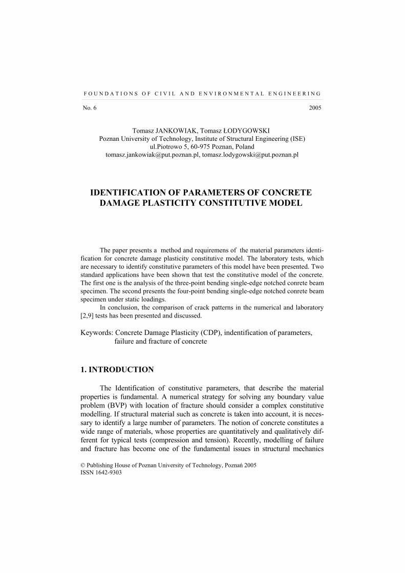
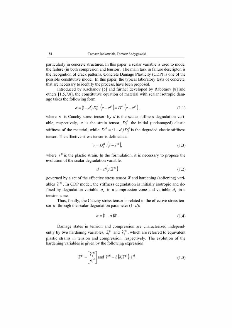
sources of the experimental results are the works [2,4,9] and experiments (uniax-ial compression and tension tests) elaborated at home Institute. A curves for both uniaxial compression and tension tests and for multiaxial tests are presented in Figs 1-3.
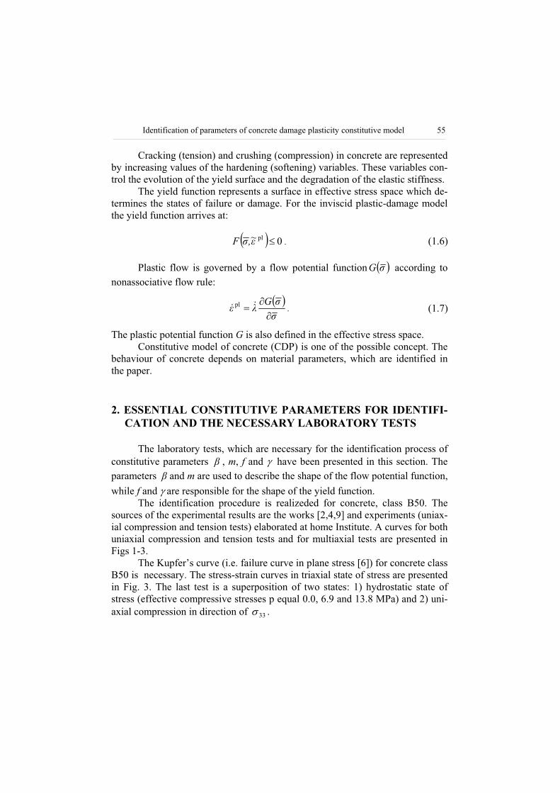
The Kupfer’s curve (i.e. failure curve in plane stress [6]) for concrete class B50 is necessary. The stress-strain curves in triaxial state of stress are presented in Fig. 3. The last test is a superposition of two states: 1) hydrostatic state of stress (effective compressive stresses p equal 0.0, 6.9 and 13.8 MPa) and 2) uni-axial compression in direction of 33 .
56 Tomasz Jankowiak, Tomasz odygowski
Fig. 1. Uniaxial compression test of concrete, class B50 – experimental curve (Home Institute)
Fig. 2. Uniaxial tension test of concrete, class B50 – experimental curve (Home Institute)
Fig. 3. Triaxial compression of concrete, class B50 – experimental curve [4]
Identification of parameters of concrete damage plasticity constitutive model 57
3. THE PROCEDURE OF CONSTITUTIVE PARAMETERS
IDENTIFICATION FOR CDP MODEL
The fundamental group of the constitutive parameters consists of four values, which identify the shape of the flow potential surface and the yield sur-face. In this model for the flow potential G, the Drucker-Prager hyperbolic func-tion is accepted in the form:
pqfmfG tantan 22tc , (3.1)
where tf and cf are the uniaxial tensile and compressive strengths of concrete, respectively. is the dilation angle measured in the p-q plane at high confining pressure, while m is an eccentricity of the plastic potential surface. The flow potential surface is defined in the p-q plane, where Ip 3
1 is the effective
hydrostatic stress and SSq 23 is the Mises equivalent effective stress,
while S is the deviatoric part of the effective stress tensor The nonassociative flow rule, which is used here requires a loading sur-
face definition. The plastic-damage concrete model uses a yield condition based on the loading function (3.2) proposed by Lubliner in [7] in the form:
plccmaxmax
pl1
1 3 ~~pqF . (3.2)
The shape of loading surface in the deviatoric plane is determined by parameter ,while the parameter is calculated based on Kupfer’s curve. max is the
algebraically maximum eigenvalue of .The Macauley bracket is defined
by xxx 21 . The function pl~ is given as
~
~~ 11
pltt
plccpl , (3.3)
where t and c are the effective tensile and compressive cohesion stresses, respectively.
It is neccesary to definite the parameter:
12
1
cb0
cb0
ff
ff. (3.4)
The compressive strength under biaxial loading of concrete is denoted by b0f .
58 Tomasz Jankowiak, Tomasz odygowski
The parameter depends on the ratio of the biaxial compressive strength and uniaxial compressive strength. Thus, the biaxial laboratory test [6] is neces-sary to define the value of . The procedure of identification of m and pa-rameters will be presented in this section. It is clearly seen, that the behaviour of concrete depends on four constitu-tive parameters. Other parameters such as tensile uniaxial strength and uniaxial or biaxial compressive strength of concrete should be taken from experimental curves. Moreover, the parameter should be defined based on the full triaxial tests of concrete. Identification of that parameter is possible only if the full triaxial compression tests of concrete are done. In accordance to [7] the parame-ter is prescribed in the form:
32
13, (3.5)
where the coefficient:
CM
TM
J
J
2
2 is defined at a given state p . (3.6)
2J is the second invarient of stress deviator for TM and CM subscribes. In Eqn. (3.6), designate TM and CM mean, respectively, the „tensile me-
ridian” ( 321 ) and the „compressive meridian” ( 321 ) in the yield surface. Typical values range for are between 0.64 to 0.8 [7].
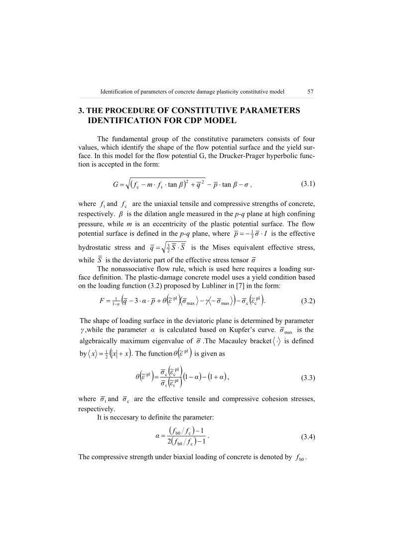
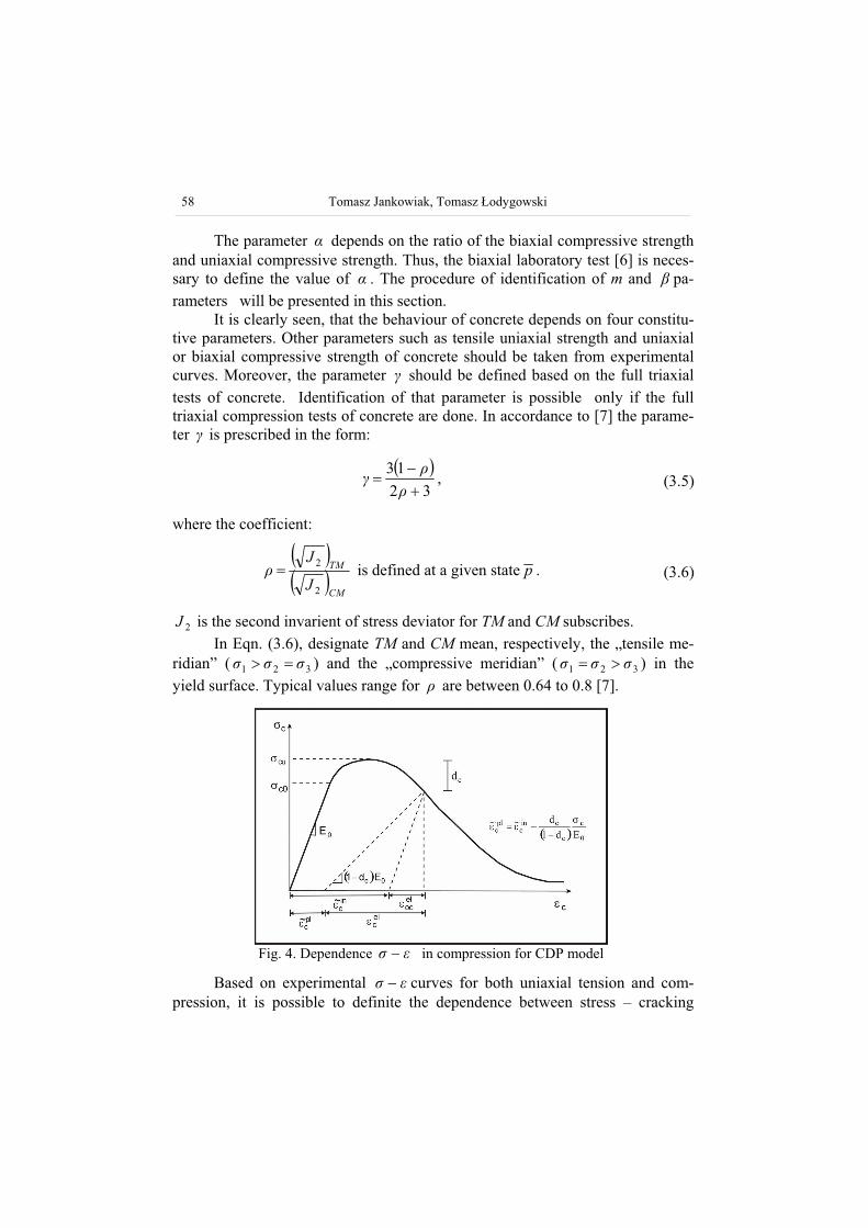
Fig. 4. Dependence in compression for CDP model
Based on experimental curves for both uniaxial tension and com-pression, it is possible to definite the dependence between stress – cracking
Identification of parameters of concrete damage plasticity constitutive model 59
strain ( ckt
~ ) in uniaxial tension and stress – crushing strain ( inc
~ ) in uniaxial compression. Figs 4, 5 show, which values in CDP model are interpreted as the
cracking strain ( ckt
~ ) and the crushing strain ( inc
~ ).
Fig. 5. Dependence in tension for CDP model
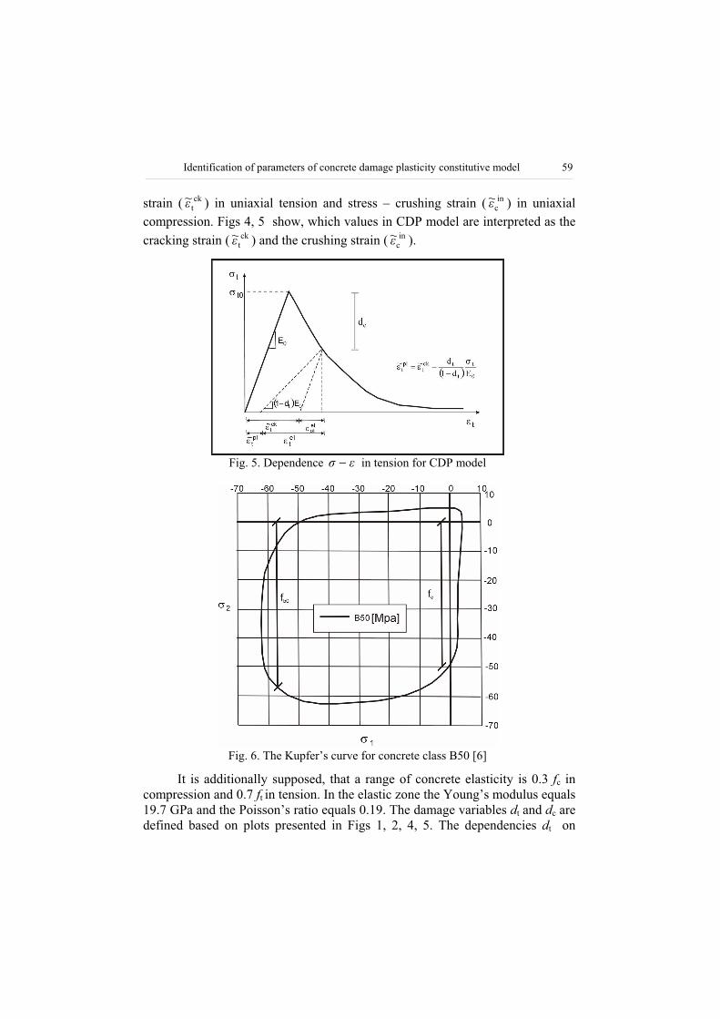
Fig. 6. The Kupfer’s curve for concrete class B50 [6]
It is additionally supposed, that a range of concrete elasticity is 0.3 fc in compression and 0.7 ft in tension. In the elastic zone the Young’s modulus equals 19.7 GPa and the Poisson’s ratio equals 0.19. The damage variables dt and dc are defined based on plots presented in Figs 1, 2, 4, 5. The dependencies dt on
60 Tomasz Jankowiak, Tomasz odygowski
cracking strain ( ckt
~ ) and dc on crushing strain ( inc
~ ) should be determined. To identify the shape of the flow potential and the loading surfaces the strength of concrete for uniaxial tests, both compressive and tensile were used. Both sur-faces are defined by the four parameters: , m, f and . The value 0.666 is ac-
cepted for parameter . The shape of the loading surface in deviatoric plane is determined by this parameter. This paper does not discuss the identification pro-cedure for parameter, because the authors had no the results of full triaxial tests of concrete. The Kupfer’s curve is used to define the parameter cb0 fff , as
is shown in Fig. 6. The parameter is computed based on f, according to Eqn. 3.4.
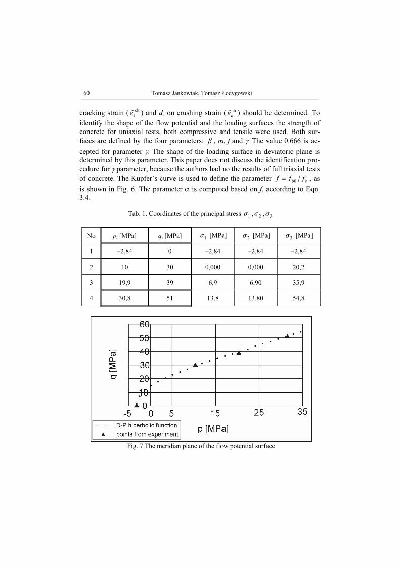
Fig. 7 The meridian plane of the flow potential surface
Tab. 1. Coordinates of the principal stress 1 , 2 , 3
No pi [MPa] qi [MPa] 1 [MPa] 2 [MPa] 3 [MPa]
1 –2,84 0 –2,84 –2,84 –2,84
2 10 30 0,000 0,000 20,2
3 19,9 39 6,9 6,90 35,9
4 30,8 51 13,8 13,80 54,8
Identification of parameters of concrete damage plasticity constitutive model 61
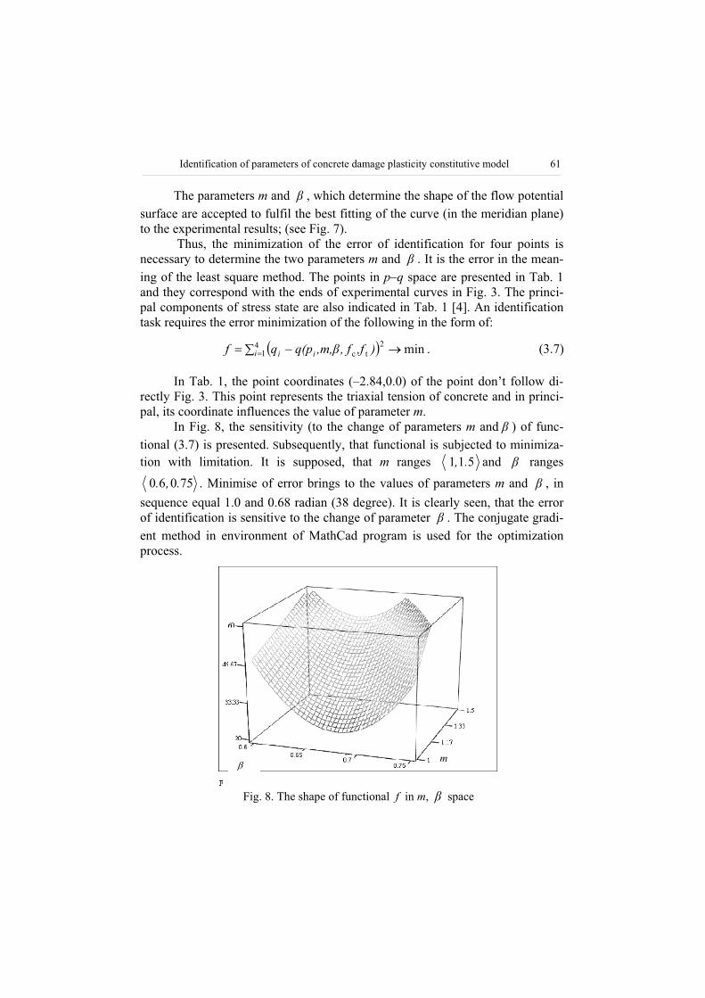
The parameters m and , which determine the shape of the flow potential surface are accepted to fulfil the best fitting of the curve (in the meridian plane) to the experimental results; (see Fig. 7).
Thus, the minimization of the error of identification for four points is necessary to determine the two parameters m and . It is the error in the mean-ing of the least square method. The points in p–q space are presented in Tab. 1 and they correspond with the ends of experimental curves in Fig. 3. The princi-pal components of stress state are also indicated in Tab. 1 [4]. An identification task requires the error minimization of the following in the form of:
min41
2tci ii ),ff,,m,q(pqf . (3.7)
In Tab. 1, the point coordinates (–2.84,0.0) of the point don’t follow di-rectly Fig. 3. This point represents the triaxial tension of concrete and in princi-pal, its coordinate influences the value of parameter m.
In Fig. 8, the sensitivity (to the change of parameters m and ) of func-tional (3.7) is presented. Subsequently, that functional is subjected to minimiza-tion with limitation. It is supposed, that m ranges 511 ., and ranges
75060 .,. . Minimise of error brings to the values of parameters m and , in
sequence equal 1.0 and 0.68 radian (38 degree). It is clearly seen, that the error of identification is sensitive to the change of parameter . The conjugate gradi-ent method in environment of MathCad program is used for the optimization process.
Fig. 8. The shape of functional f in m, space
m
62 Tomasz Jankowiak, Tomasz odygowski
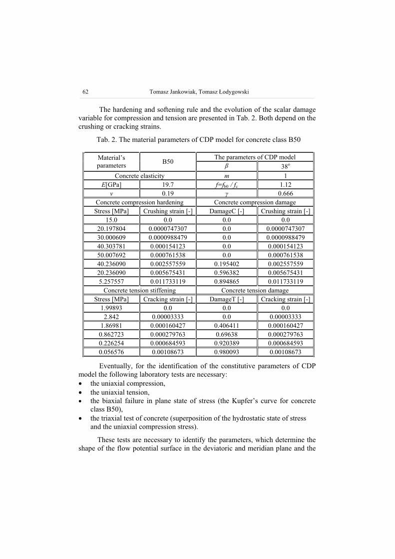
The hardening and softening rule and the evolution of the scalar damage variable for compression and tension are presented in Tab. 2. Both depend on the crushing or cracking strains.
Tab. 2. The material parameters of CDP model for concrete class B50
The parameters of CDP model Material’sparameters
B50 38o
Concrete elasticity m 1 E[GPa] 19.7 f=fb0 / fc 1.12
0.19 0.666 Concrete compression hardening Concrete compression damage Stress [MPa] Crushing strain [-] DamageC [-] Crushing strain [-]
15.0 0.0 0.0 0.0 20.197804 0.0000747307 0.0 0.0000747307 30.000609 0.0000988479 0.0 0.0000988479 40.303781 0.000154123 0.0 0.000154123 50.007692 0.000761538 0.0 0.000761538 40.236090 0.002557559 0.195402 0.002557559 20.236090 0.005675431 0.596382 0.005675431 5.257557 0.011733119 0.894865 0.011733119
Concrete tension stiffening Concrete tension damage Stress [MPa] Cracking strain [-] DamageT [-] Cracking strain [-]
1.99893 0.0 0.0 0.0 2.842 0.00003333 0.0 0.00003333
1.86981 0.000160427 0.406411 0.000160427 0.862723 0.000279763 0.69638 0.000279763 0.226254 0.000684593 0.920389 0.000684593 0.056576 0.00108673 0.980093 0.00108673
Eventually, for the identification of the constitutive parameters of CDP model the following laboratory tests are necessary:
the uniaxial compression, the uniaxial tension, the biaxial failure in plane state of stress (the Kupfer’s curve for concrete class B50),the triaxial test of concrete (superposition of the hydrostatic state of stress and the uniaxial compression stress).
These tests are necessary to identify the parameters, which determine the shape of the flow potential surface in the deviatoric and meridian plane and the
Identification of parameters of concrete damage plasticity constitutive model 63
evolution rule of the material parameters (the hardening and the softening rule in tension and compression).
4. NUMERICAL COMPUTATIONS
In the computations of the standard applications we used the finite ele-ment code, implemented in the environment of ABAQUS/Explicit. The models and the computations lead to the estimation of the nucleation and the evolution of fracture in bending beams with notches (three-point and four-point bending). The numerical results are in agreement with the experiments [2,9]. The scalar damage variable in tension is used to compare crack patterns for the numerical and experimental models.
4.1. The three-point bending beamThe applications of CDM model to the selected BVPs and the compari-
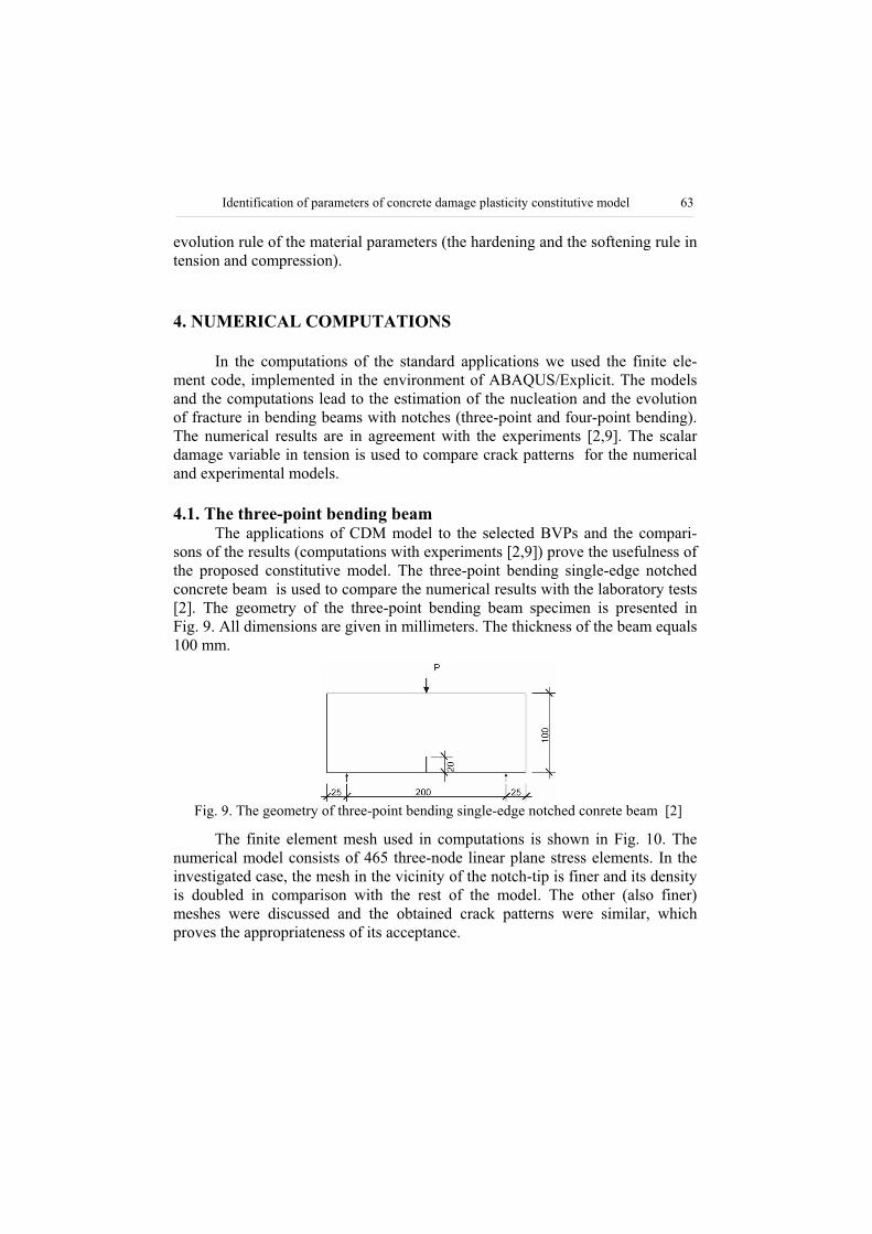
sons of the results (computations with experiments [2,9]) prove the usefulness of the proposed constitutive model. The three-point bending single-edge notched concrete beam is used to compare the numerical results with the laboratory tests [2]. The geometry of the three-point bending beam specimen is presented in Fig. 9. All dimensions are given in millimeters. The thickness of the beam equals 100 mm.
Fig. 9. The geometry of three-point bending single-edge notched conrete beam [2]
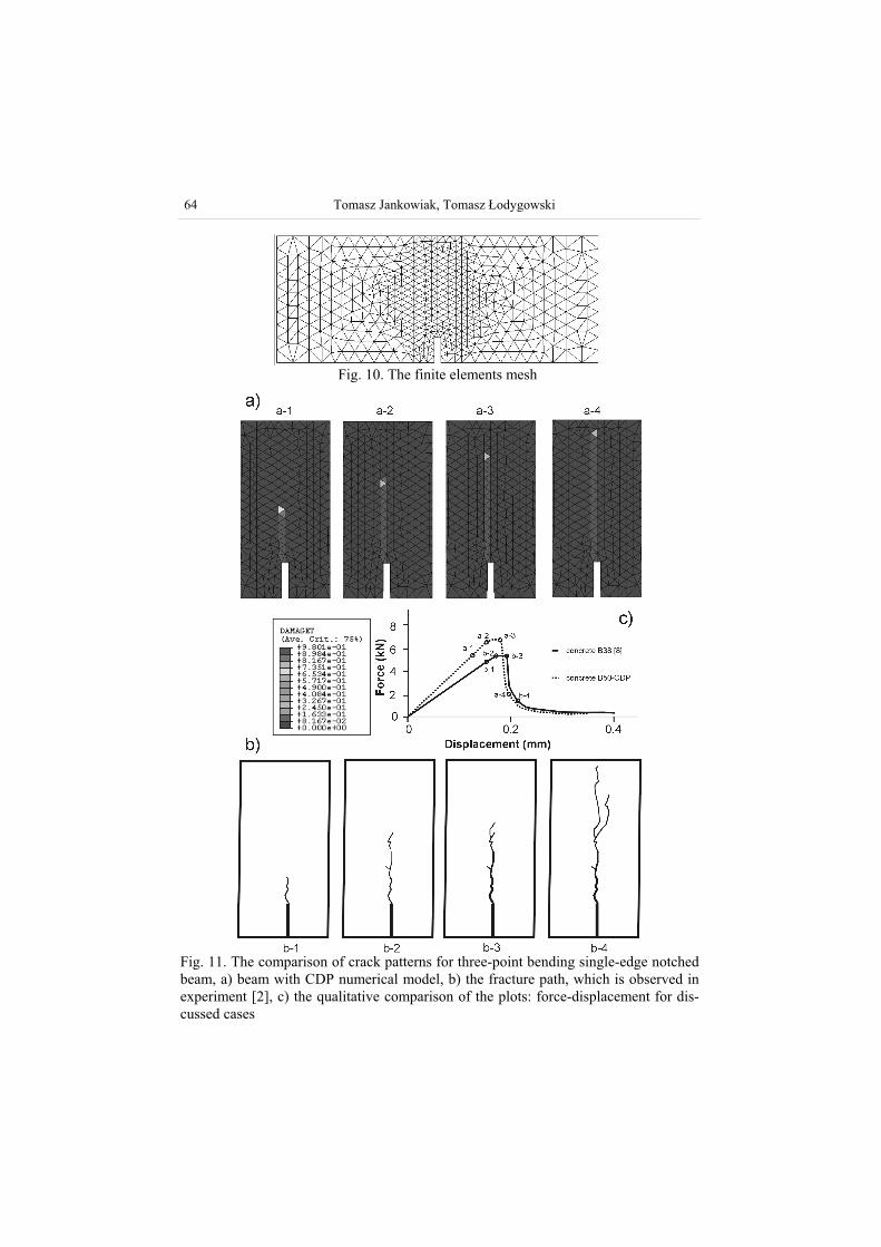
The finite element mesh used in computations is shown in Fig. 10. The numerical model consists of 465 three-node linear plane stress elements. In the investigated case, the mesh in the vicinity of the notch-tip is finer and its density is doubled in comparison with the rest of the model. The other (also finer) meshes were discussed and the obtained crack patterns were similar, which proves the appropriateness of its acceptance.
64 Tomasz Jankowiak, Tomasz odygowski
Fig. 10. The finite elements mesh
Fig. 11. The comparison of crack patterns for three-point bending single-edge notched beam, a) beam with CDP numerical model, b) the fracture path, which is observed in experiment [2], c) the qualitative comparison of the plots: force-displacement for dis-cussed cases
Identification of parameters of concrete damage plasticity constitutive model 65
The calculated crack pattern is similar to that observed in the experimental model [2]. The qualitative comparison of the results is presented in Fig. 11c.
The single dominant crack appeared in the concrete three-point bending beam specimen. The shape of the fracture zone location is shown in Fig. 11a. In the experiment presented by Davies in [2], the crack pattern is similar to the obtain numerical results, Fig. 11b. The results, which are presented in Fig. 11a) and b), correspond to the respective level of load and are shown in Fig. 11c.
4.2. The four-point bending beamThe following numerical experiment, which can verify the constitutive
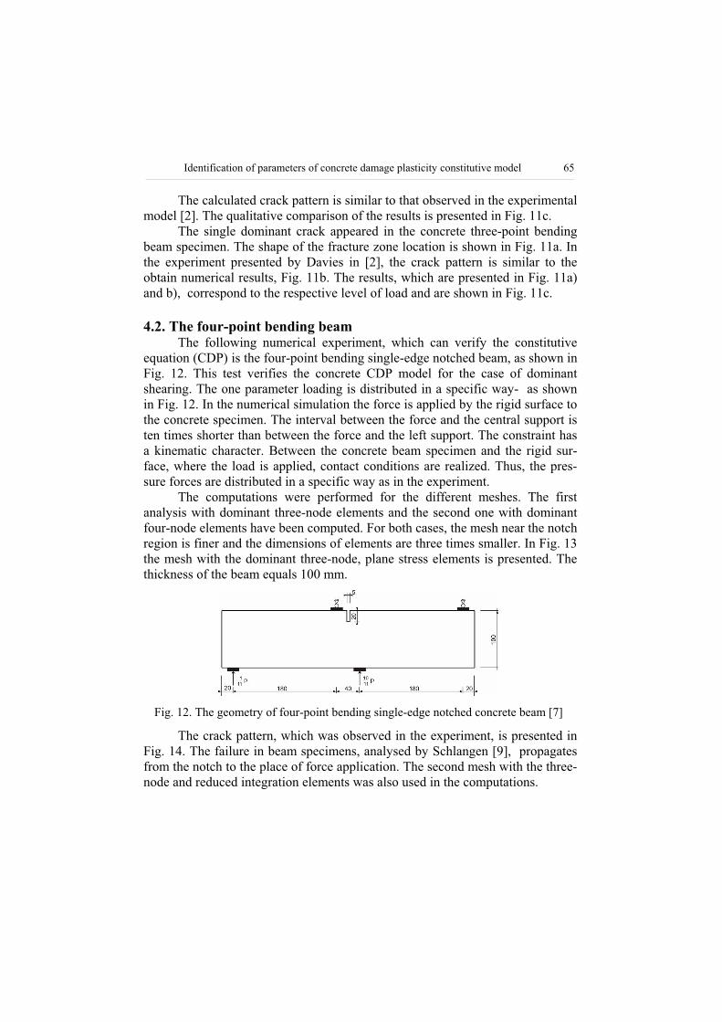
equation (CDP) is the four-point bending single-edge notched beam, as shown in Fig. 12. This test verifies the concrete CDP model for the case of dominant shearing. The one parameter loading is distributed in a specific way- as shown in Fig. 12. In the numerical simulation the force is applied by the rigid surface to the concrete specimen. The interval between the force and the central support is ten times shorter than between the force and the left support. The constraint has a kinematic character. Between the concrete beam specimen and the rigid sur-face, where the load is applied, contact conditions are realized. Thus, the pres-sure forces are distributed in a specific way as in the experiment.
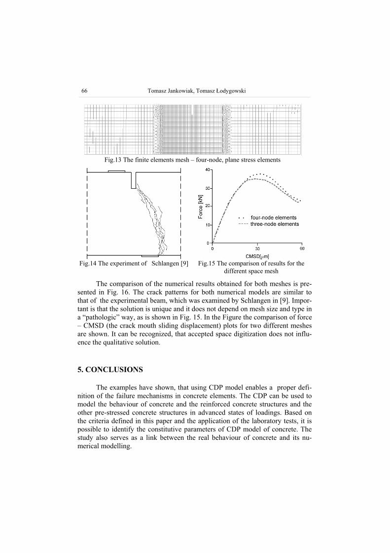
The computations were performed for the different meshes. The first analysis with dominant three-node elements and the second one with dominant four-node elements have been computed. For both cases, the mesh near the notch region is finer and the dimensions of elements are three times smaller. In Fig. 13 the mesh with the dominant three-node, plane stress elements is presented. The thickness of the beam equals 100 mm.
Fig. 12. The geometry of four-point bending single-edge notched concrete beam [7]
The crack pattern, which was observed in the experiment, is presented in Fig. 14. The failure in beam specimens, analysed by Schlangen [9], propagates from the notch to the place of force application. The second mesh with the three-node and reduced integration elements was also used in the computations.
66 Tomasz Jankowiak, Tomasz odygowski
Fig.13 The finite elements mesh – four-node, plane stress elements
Fig.14 The experiment of Schlangen [9] Fig.15 The comparison of results for the different space mesh
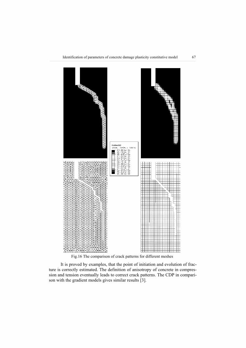
The comparison of the numerical results obtained for both meshes is pre-sented in Fig. 16. The crack patterns for both numerical models are similar to that of the experimental beam, which was examined by Schlangen in [9]. Impor-tant is that the solution is unique and it does not depend on mesh size and type in a “pathologic” way, as is shown in Fig. 15. In the Figure the comparison of force – CMSD (the crack mouth sliding displacement) plots for two different meshes are shown. It can be recognized, that accepted space digitization does not influ-ence the qualitative solution.
5. CONCLUSIONS
The examples have shown, that using CDP model enables a proper defi-nition of the failure mechanisms in concrete elements. The CDP can be used to model the behaviour of concrete and the reinforced concrete structures and the other pre-stressed concrete structures in advanced states of loadings. Based on the criteria defined in this paper and the application of the laboratory tests, it is possible to identify the constitutive parameters of CDP model of concrete. The study also serves as a link between the real behaviour of concrete and its nu-merical modelling.
Identification of parameters of concrete damage plasticity constitutive model 67
Fig.16 The comparison of crack patterns for different meshes
It is proved by examples, that the point of initiation and evolution of frac-ture is correctly estimated. The definition of anisotropy of concrete in compres-sion and tension eventually leads to correct crack patterns. The CDP in compari-son with the gradient models gives similar results [3].
68 Tomasz Jankowiak, Tomasz odygowski
The proposed model with the estimated constitutive parameters can suc-cessfully serve for analyses of the R-C structures in advanced states of stresses far beyond the limits defined in engineering codes.
ACKNOWLEDGEMENTSThis paper has been partly prepared within the reserch project BW 11-506/04.
REFERENCES
1. ABAQUS Theory Manual, version 6.3, Hibbitt Karlson & Sorensen, Inc 2002.
2. Davies J., Observation of fracture path development in mortar beam speci-ments, Advn. Cem. Bas. Mat., 3(1996)31-36.
3. Geers M.G.D., Borst R. de, Peerlings R.H.J., Damage and crack modelling in single-edge and double-edge notched concrete beams, Engineering Fracture Mechanics, 65(2000)247-261.
4. Green S.J., Swanson S.R., Static constitutive relations for concrete, AWFL-TR-72-244, U.S.Air Force Weapon Laboratory, Kirtland Air Force Base, NM, 1973.
5. Kachanov,L.,M., O vremeni razrušenija v usloviach polzu esti, Izv. Ak. Na-uk CCCP, Otd. Techn. Nauk, nr 8,1958;26-31.
6. Kupfer H., Hilsdorf H.,K., Rusch H., Behavior of concrete under biaxial stresses, ACI Journal, 65, 8(1979),656-666.
7. Lubliner J.J., Oliver S.O., Oñate E., A plastic-damage model for concrete, International Journal of Solids and Structures, 25, 3(1989)229-326.
8. Rabotnov Y.N., Creep problems in structural members, North-Holland, Amsterdam 1969.
9. Schlangen E., Experimental and numerical analysis of fracture processes in concrete, Ph.D. Thesis, Delft University of Technology, 1993.
T. Jankowiak, T. odygowski
IDENTYFIKACJA PARAMETRÓW KONSTYTUTYWNYCH MODELU BETONU PLASTYCZNEGO ZE ZNISZCZENIEM
S t r e s z c z e n i e
W pracy przedstawiono metod identyfikacji parametrów materia owych betonu klasy B50. Przyj to model matematyczny betonu plastycznego ze zniszczeniem. Okre lono, jakie testy laboratoryjne s niezb dne do identyfikacji parametrów

Identification of parameters of concrete damage plasticity constitutive model 69
konstytutywnych tego modelu. Przetestowano u yteczno modelu konstytutywnego w wybranych dwóch zadaniach brzegowych (zginanie trójpunktowe oraz czteropunktowe belki betonowej z naci ciem). Porównano otrzymane mechanizmy zniszczenia ze znanymi wynikami eksperymentów laboratoryjnych [2, 9].
Received, 19.04.2004.


