Embed Size (px)
Citation preview
V %m
FLOWER'VETER!NAflY\,
U3RARY /
w If
0^1 3
QP 519 WI9"*""""'"*"'""'"'>'
pl.3
IIIMmSin P""^"*'"' physiology.
3 1924 000 228 746

Cornell University
Library
The original of tiiis book is in
tine Cornell University Library.
There are no known copyright restrictions in
the United States on the use of the text.
http://www.archive.org/cletails/cu31924000228746

CORNELL UNIVERSITY.
THE
THE GIFT OF
ROSWELL P. FLOWERFOR THE USE OF
THE N. Y. STATE VETERINARY COLLEGE.
1897


EXERCISES IN
PRACTICAL PHYSIOLOGY
AUGUSTUS D. WALLER, M.D., F.R.S
LECTURER ON PHYSIOLOGY TO ST. MARYS HOSPITAL MEDICAL SCHOOL
PART IN.
PHYSIOLOGY OF THE NERVOUS SYSTEM
ELEC'IRO-PHYSIOLOGY
LONGMANS, GEEEN, AND CO.
39 PATERNOSTBE EOW, LONDON
NEW YOBK, AND BOMBAY
1897
-%^,' './1 T f"
BY THE SAME AUTHOR.
Third Edition. With ^[4 Illustrations. 8vo, i8s.
An Introduction to HumanPhysiology.
In the Press.
Lectures on Animal Electricity
(Delivered at the Royal Institute of Great Britain).
LONGMANS, GREEN AND CO.,
LONDON, NEW YORK AND BOMBAY.
rio^^^
J., d
Physiological Laroratoet,
St. Mart's Hospital Medical School.
May, 1897.
PREFATORY NOTE.
The folloiving pages form Part III. of a series of Exercises and
Demonstrations to accompany " An Inteoduction to HumanPhysiology," and are primarily intended to facilitate the class
-
ivork of this Laboratory.
The Directions given in them are addressed to "advanced"
stVydents who have properly expended one year in the sticdy of
Physiology.
In some cases it will be found that an exercise may be carried
out by each student working independently ; in others, that the
student ivill reqiiire much assistance from a skilled demonstrator
;
in others still, that the student will at most take some part in a
carefully-prepared demonstration.
A. D. Waller.

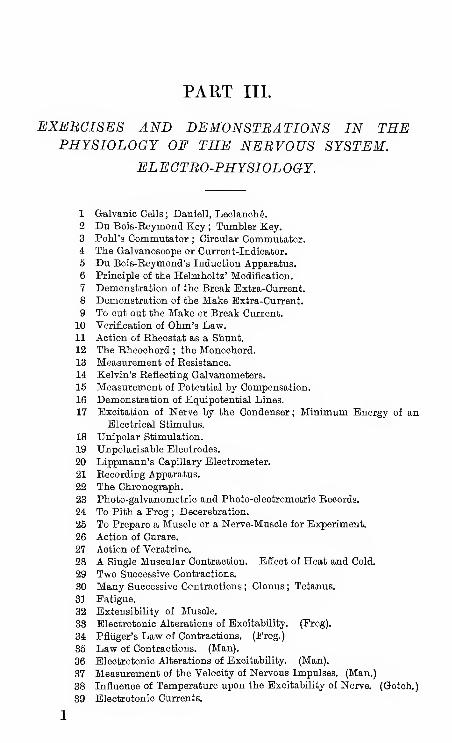
PART III.
EXEBCISES AND DEMONSTRATIONS IN THEPHYSIOLOGY OF THE NEBVOUS SYSTEM.
ELEGTBO'PHYSIOLOGY.
1 Galvanic Cells ; Daniell, Leolanohfe.
2 Du Bois-Eeymond Key ; Tumbler Key.
3 Pohl's Commutator ; Circular Commutator.4 The Galvanoscope or Current-Indicator.
5 Du Bois-Beymond's Induction Apparatus.
6 Principle of the Helmholtz' Modification.
7 Demonstration of the Break Extra-Current.
8 Deraonstration of the Make Extra-Current.
9 To cut out the Make or Break Current.
10 Verification of Ohm's Law.11 Action of Rheostat as a Shunt.
12 The Bheoohord ; the Monochord.
13 Measurement of Resistance.
14 Kelvin's Reflecting Galvanometers.
15 Measurement of Potential by Compensation.
16 Demionstration of Equipotential Lines.
17 Excitation of Nerve by the Condenser ; Minimum Energy of anElectrical Stimulus.
18 Unipolar Stimulation.
19 Unpolarisable Electrodes.
20 Lippmann's Capillary Electrometer.
21 Recording Apparatus.
22 The Chronograph.
23 Photo-galvanometric and Photo-electrometric Records.
24 To Pith a Frog ; Decerebration.
25 To Prepare a Muscle or a Nerve-Muscle for Experim.ent.
26 Action of Curare.
27 Action of Veratrine.
28 A Single Muscular Contraction. Efiect of Heat and Cold.
29 Two Successive Contractions.
30 Many Successive Contractions ; Clonus ; Tetanus.
31 Fatigue.
32 Extensibility of Muscle.
33 Electrotonic Alterations of Excitability. (Frog).
34 PflUger's Law of Contractions. (Frog.)
36 Law of Contractions. (Man).
36 Electrotonic Alterations of Excitability. (Man).
37 Measurement of the Velocity of Nervous Impulses. (Man.)
38 Influence of Temperature upon the Excitability of Nerve. (Gotoh.)
39 Electrotonic Currents.
EXERCISES AND DEMONSTRATIONS
40 The Paradoxical Contraction.
41-2 Galvani's First and Last Experiments with and without metals.
43 Muscle-Currents.
44 Nerve-Currents : the Current of Injury and its Negative Variation.
45 Action of Anaesthetics upon Isolated Nerve. Carbon Dioxide,
Chloroform, and Ether.
46 The Secondary Contraction.
47 Secondary Contraction from the Heart.
48 An Apparent Anomaly due to Secondary Contraction. (Hering.
)
49 Secondary Excitation from Nerve to Nerve.
50 Currents of Action of Prog's Heart.
51 Currents of Action of Mammalian Heart.
52 Currents of Action of Human Heart.
53 Retinal Currents. (Erog.)
54 Sound is Produced during Muscular Contraction.
55 Heat is Produced during Muscular Contraction.
56 Tendon-Reflex Time. (Man.)
57 Tendon-Reflex Time. (Rabbit.)
58 Function of Nerve-Roots. (Muller's Experiment.)
59 " Overlap " of Nerve-Supply. (Sherrington.)
60 Reflex Actions of Brainless Prog. (Goltz' Klopf-Versuch.
)
61 Inhibitory Action of Superior upon Inferior Centres.
62 Time of Reflex Action. (Prog.)
63 Action of Strychnia. (Prog.)
64 Summation of Stimuli. (Prog.
65 Reflex Winking Time. (Man.)
66 Sensory Reaction-Timing. (Man.
67 Discrimination Time. (Man.)
68 Volition Time. (Man.)
ELECTEOPHYSIOLOGICAL INSTEUMBNTS ANDPEINCIPLES.
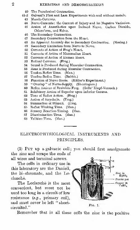
(1) Put up a galvanic cell; you should first amalgamate
the zinc and scrape the ends of
all wires and terminal screws.
The cells in ordinary use in
this laboratory are the Daniell,
the bi-chromate, and the Le-
clanche.
The Leclanche is the mostconvenient, but must not be
used too long in a circuit of low
resistance {e.g., primary coil),
and must never be left " short-
circuited."
Eemember that in all these cells the zinc is the positive
Pig. 1.
IN THE PHYSIOLOGY OP THE NERVOUS SYSTEM. 3
element, the end of the wire from it is the negative electrode
or kathode, and the direction of current is from anode to
kathode ; we shall habitually designate any kind of cell by
the conventional figure (2.
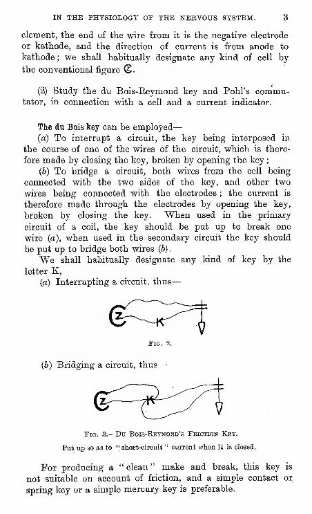
(2) Study the du Bois-Reymond key and Pohl's commu-tator, in connection with a cell and a current indicator.
The du Bois key can be employed
—
(a) To interrupt a circuit, the key being interposed in
the course of one of the wires of the circuit, which is there-
fore made by closing the key, broken by opening the key
;
(6) To bridge a circuit, both wires from the cell being
connected with the two sides of the key, and other two
wires being connected with the electrodes ; the current is
therefore made through the electrodes by opening the key,
broken by closing the key. When used in the primary
circuit of a coil, the key should be put up to break one
wire (a), when used in the secondary circuit the key should
be put up to bridge both wires (6)
.
We shall habitually designate any kind of key by the
letter K,
{a) Interrupting a circuit, thus
—
Fig. 2.
(b) Bridging a circuit, thus
—
Fig. 3.- Du Bois-Ebymomd's Feiction Key.
Put up so as to " short-circuit " current when it is closed.
For producing a " clean " make and break, this key is
not suitable on account of friction, and a simple contact oi;
spring key or a simple mercury key is preferable.
EXEECISES AND DEMONSTRATIONS
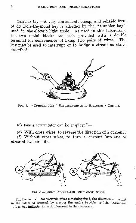
Tumbler iey.—A very convenient, cheap, and reliable form
of du Bois-Eeymond key is afforded by the "tumbler key"
used in the electric light trade. As used in this laboratory,
the two metal blocks are each provided with a double
terminal for convenience of fixing two pairs of wires. The
key may be used to interrupt or to bridge a circuit as above
described.
Pig. 4.—" Tumbler Key," Ebpeesented as if Bbidging a Cikouit.
(3) Pohl's commutator can be employed
—
(a) With cross wires, to reverse the direction of a current
;
(6) Without cross wires, to turn a current into one or
other of two circuits.
Fig. 5.
—
Pohl's Commutator (with cboss wiees).
The Daniell cell and electrode wires remaining fixed, the direction of current
in the latter is reversed by moving the cradle to right or left. Numbers1, 2, 3, &c., indicate the path of current in the two cases.
IN THE PHYSIOLOGY OF THE NERVOUS SYSTEM.
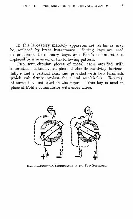
In ttis laboratory mercury apparatus are, as far as maybe, replaced by brass instruments. Spring keys are used
in preference to mercury keys, and Pohl's commutator is
replaced by a reverser of the following pattern.
Two semi-circular pieces of metal, each provided with
a terminal ; a transverse piece of ebonite revolving horizon-
tally round a vertical axis, and provided with two terminals
which rub firmly against the metal semicircles. Keversal
of current as indicated in the figure. This key is used in
place of Pohl's commutator with cross wires.
Pig. 6.—Cibcdlae Commutator in its Two Positions.
6 EXERCISES AND DEMONSTRATIONS
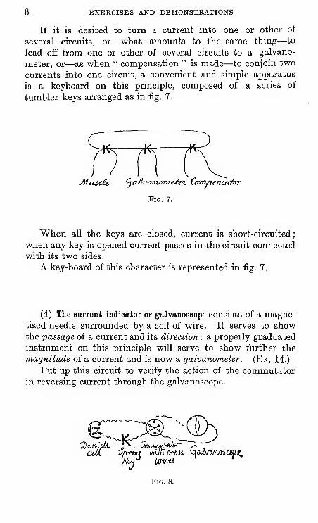
If it is desired to turn a current into one or other of
several circuits, or—what amounts to the same thing—to
lead off from one or other of several circuits to a galvano-
meter, or—as -when " compensation " is made—to conjoin two
currents into one circuit, a convenient and simple apparatus
is a keyboard on this principle, composed of a series of
tumbler keys arranged as in fig. 7.
Fig. 7.
When all the keys are closed, current is short-circuited
;
when any key is opened current passes in the circuit connected
with its two sides.
A key-board of this character is represented in fig. 7.
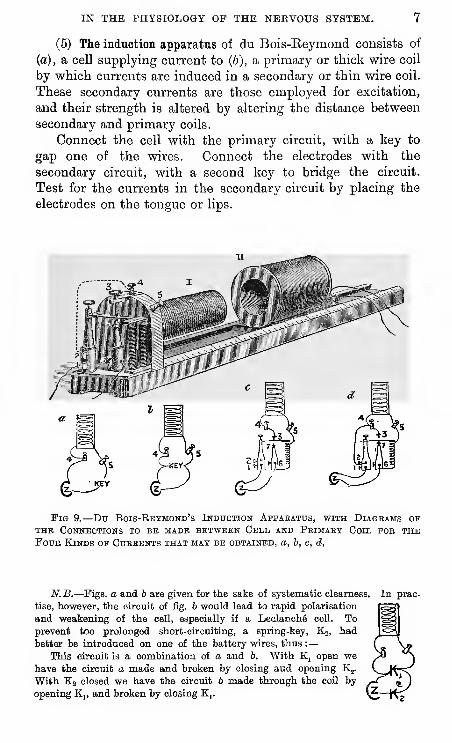
(4) The current-indicator or galvanoscope consists of a magne-tised needle siirrounded by a coil, of wire. It serves to showthe passage of a current and its direction; a properly graduated
instrument on this principle will serve to show further the
magnitude of a current and is now a galvanometer. (Ex. 14.)
Put up this circuit to verify the action of the commutatorin reversing current through the galvanoscope.
Fig. 8.
IN THE PHYSIOLOGY OP THE NERVOUS SYSTEM. 7
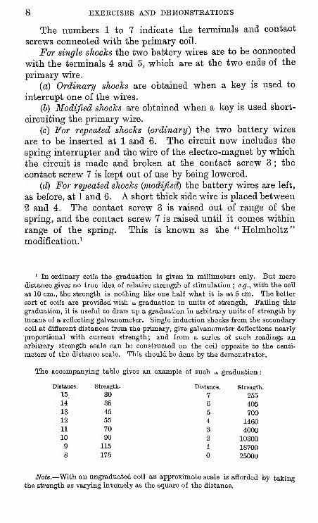
(5) The induction apparatus of du Bois-Eeymond consists of
(a), a cell supplying current to (6), a primary or thick wire coil
by which currents are induced in a secondary or thin wire coil.
These secondary currents are those employed for excitation,
and their strength is altered by altering the distance between
secondary and primary coils.
Connect the cell with the primary circuit, with a key to
gap one of the wires. Connect the electrodes with the
secondary circuit, with a second key to bridge the circuit.
Test for the currents in the secondary circuit by placing the
electrodes on the tongue or lips.
Fig 9.—Du Bois-Bbymond's iNDncTiON Appabatus, with Diagbams opTHE CONKECTIONS TO BB MADE BETWEEN CkLL AND PbIMABY OoIL FOB THEFouB Kinds op Cubbbnts that may be obtained, a, b, c, d.
N.B.—Figs, a and 6 are given for the sake of systematic clearness,
tise, however, the circuit of fig. b would lead to rapid polarisation
and weakening of the cell, especially if a Ledanchfi cell. Toprevent too prolonged short-circuiting, a spring-key, K2, had
better be introduced on one of the battery wires, thus :—
This circuit is a combination of a and 6. With K, open wehave the circuit a made and broken by closing and opening K^.
With K2 closed we have the circuit 6 made through the coil by
opening K„ and broken by closing K,.
In prac-
8 BXEECISES AND DBMONSTEATIONS
The numbers 1 to 7 indicate the terminals and contact
screws connected with the primary coil.
For single shocks the two battery wires are to be connected
with the terminals 4 and 5, which are at the two ends of the
primary wire.
(a) Ordinary shocks are obtained when a key is used to
interrupt one of the wires.
(5) Modified shocks are obtained when a key is used short-
circuiting the primary wire.
(c) For repeated shocks (ordinary) the two battery wires
are to be inserted at 1 and 6. The circuit now includes the
spring interrupter and the wire of the electro-magnet by which
the circuit is raade and broken at the contact screw 3 ; the
contact screw 7 is kept out of use by being lowered.
(d) For repeated shocks (modified) the battery wires are left,
as before, at 1 and 6. A short thick side wire is placed between
2 and 4. The contact screw 3 is raised out of range of the
spring, and the contact screw 7 is raised until it comes within
range of the spring. This is known as the " Helmholtz
"
modification.^
' In ordinary coils the graduation is given in millimeters only. But meredistance gives no true idea of relative strength of stimulation ; e.g., with the coil
at 10 cm., the strength is nothing like one half what it is at 5 cm. The better
sort of coils are provided with a graduation in units of strength. Failing this
graduation, it is useful to draw up a graduation in arbitrary units of strength by
means of a reflecting galvanometer. Single induction shocks from the secondary
coU at different distances from the primary, give galvanometer deflections nearly
proportional with current strength; and from a series of such readings anarbitrary strength scale can be constructed on the coil opposite to the centi-
meters of the distance scale. This should be done by the demonstrator.
The accompanying table gives an example of such a graduation
:
Distance.
IN THE PHYSIOLOGY OP THE NERVOUS SYSTEM. 9
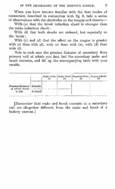
When you have become famiHar with the four modes of
connection described in connection with fig. 9, take a series
of observations with the electrodes on the tongue and observe
—
With (a) that the break induction shock is stronger than
the make induction shock
;
With (6) that both shocks are reduced, but especially so
the break
;
With (c) and (d) that the effect on the tongue is greater
with (c) than with (d), with (c) than with (a), with (d) than
with (6).
Note in each case the greatest distance of secondary from
primary coil at which you first feel the secondary make and
break currents, and fill up the accompanying table with your
results.
Greatest distanceat which shoolc
is felt.
Atmake
At break
Single Ordin.(«)
Single Modif. Repeated Ordin, Repeated Modif.(d)
[Kemember that make and break currents in a secondary
coil are altogether different from the make and break of a
battery current.]
10 EXBECISBS AND DEMONSTRATIONS
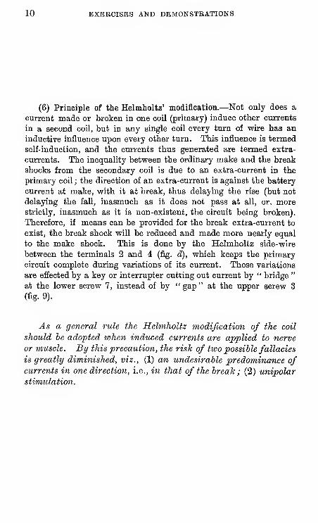
(6) Principle of the Helmholtz' modification.—Not only does a
current made or broken in one coil (primary) induce other currents
in a second coil, but in any single coil every turn of wire has an
inductive influence upon every other turn. This influence is termed
self-induction, and the currents thus generated are termed extra-
currents. The inequality between the ordinary make and the break
shocks from the secondary coil is due to an extra-current in the
primary coil ; the direction of an extra-current is against the battery
current at make, with it at break, thus delaying the rise (but not
delaying the fall, inasmuch as it does not pass at aU, or, morestrictly, inasmuch as it is non-existent, the circuit being broken).
Therefore, if means can be provided for the break extra-current to
exist, the break shock will be reduced and made more nearly equal
to the make shock. This is done by the Helmholtz side-wire
between the terminals 2 and 4 (fig. d), which keeps the primary
circuit complete during variations of its current. Those variations
are effected by a key or interrupter cutting out current by " bridge"
at the lower screw 7, instead of by "gap" at the upper screw 3
(fig. 9).
As a general rule the Helmholtz modification of the coil
should he adopted when induced currents are applied to nerve
or muscle. By this precaution, the risJc of two possible fallacies
is greatly diminished, viz., (1) an undesirable predominance ofcurrents in one direction, i.e., in that of the break ; (2) unipolar
stimulation.
IN THE PHYSIOLOGY OP THE NERVOUS SYSTEM. 11
CY" "wvdAA-calcL
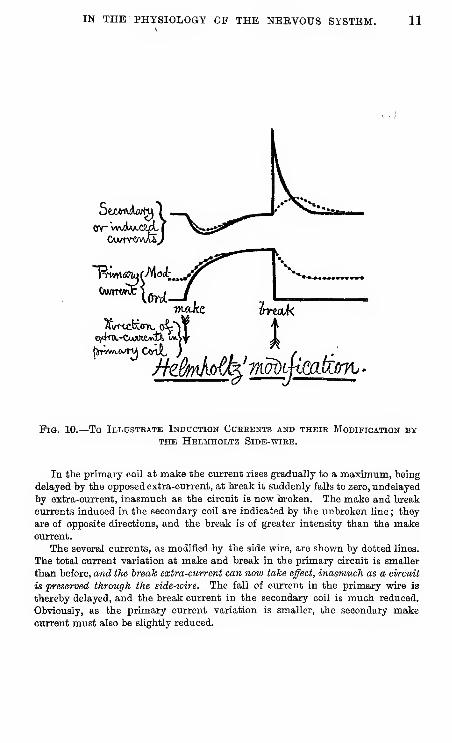
Pig. 10.—To Illustbate Induction Cuerbnts and their Modification byTHE HeLMHOLTZ SIDB-WIKE.
In the primary coil at make the current rises gradually to a maximum, heing
delayed by the opposed extra-current, at break it suddenly falls to zero, undelayed
by extra-current, inasmuch as the circuit is now broken. The make and break
currents induced in the secondary coil are indicated by the unbroken line ; they
are of opposite directions, and the break is of greater intensity than the makecurrent.
The several currents, as modified by the side wire, are shown by dotted lines.
The total current variation at make and break in the primary circuit is smaller
than before, and the break extra-current can now take effect, inasmuch as a circuit
is preserved through the side-wire. The fall of current in the primary wire is
thereby delayed, and the break current in the secondary coil is much reduced.
Obviously, as the primary current variation is smaller, the secondary makecurrent must also be slightly reduced.
12 EXEECISBS AND DEMONSTRATIONS
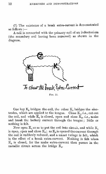
(7) The existence of a break extra-current is demonstrated
as follows :
—
A cell is connected with the primary coil of an inductorium
(the secondary coil having been removed) as shown in the
diagram.
To ^Imtrim trmJti o/iY^-Cu/m»vi
Pig. 11.
One key K^ bridges the coil, the other Kj bridges the elec-
trodes, which are applied to the tongue. Close K;^, i.e., cut out
the coil, and while K^ is closed, open and close Kg, i.e., makeand break the battery current through the tongue ; little or
nothing is felt.
Now open K^ so as to put the coil into circuit, and while Kjis open, open and close Kg ; as Kg is opened the current throughthe coil is suddenly reduced, and a smart twinge is felt, whichis the effect of a break extra-current. Nothing is felt whenKg is closed, for the make extra-current then passes in themetallic circuit across the bridge Kg.
IN THE PHYSIOLOGY OP THE NERVOUS SYSTEM. 13
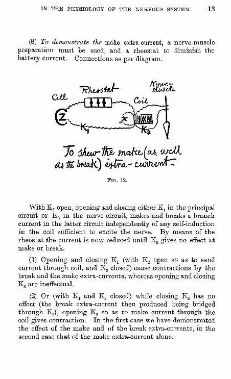
(8) To demonstrate the make extra-current, a nerve-musclepreparation must be used, and a rheostat to diminish the
battery current. Connections as per diagram.
QJll?/Le^W-
Pig. 12.
With Kg open, opening and closing either Kj in the principal
circuit or Kg in the nerve circuit, makes and breaks a branch
current in the latter circuit independently of any self-induction
in the coil sufficient to excite the nerve. By means of the
rheostat the current is now reduced until K3 gives no effect at
make or break.
(1) Opening and closing K^ (with Kg open so as to send
current through coil, and K3 closed) cause contractions by the
break and the make extra-currents, whereas opening and closing
Kg are ineffectual.
(2) Or (with K^ and Kg closed) while closing Kg has noeffect (the break extra-current then produced being bridged
through Kg), opening Kg so as to make current through the
coil gives contraction. In the first case we have demonstrated
the effect of the make and of the break extra-currents, in the
second case that of the make extra-current alone.
14 EXERCISES AND DEMONSTRATIONS
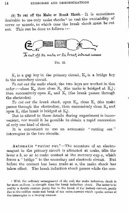
(9) To cut off the Make or Break Shock.—It is sometimes
desirable to use only make shocks ^ to test the excitability of
nerve or muscle, in which case the break shock must be cut
out. This can be done as follows :
—
^^;piHiii3C::; e
Fig. 13.
K^ is a gap key in the primary circuit, Kg is a bridge key
in the secondary circuit.
To cut out the make shock, the two keys are worked in this
order :—close Kj, then close K^ (the make is bridged at Kg)
;
then successively open Kj and Kj (the break passes through
the electrodes).
To cut out the break shock, open Kg, close K^ (the makepasses through the electrodes), then successively close Kg and
open Ki (the break is bridged at Kg)
.
But to attend to these details during experiment is incon-
venient, nor would it be possible to obtain a rapid succession
of only one kind of shock.
It is convenient to use an automatic " cutting out
"
interrupter in the two circuits.
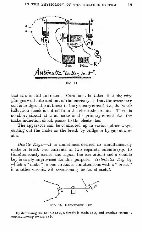
Automatic "cutter out."—The armature of an electro-
magnet in the primary circuit is attracted at make, tilts the
lever a b, so as to make contact at the mercury cup a, whichforms a " bridge " to the secondary and electrode circuit. Butbefore the contact has been made at a, the make shock has
taken effect. The break induction shock passes while the con-
' Witli the ordinary arrangement of the coil, the make induction shook is
far more uniform in strength than the break induction shock. The latter is in
reality a double current partly due to the break of the battery current, partly
due to the sudden make and break of the extra-current which sparks across at
the interrupter in a varying manner.
IN THE PHYSIOLOGY OF THE NEBVOUS SYSTEM. 15
5ec. Ftvm.,
jllitmaMc "OuMoi oujh".
Pig. 14.
tact at a is still unbroken. Care must be taken that the wireplunges well into and out of the mercury, so that the secondary-
coil is bridged at a at break in the primary circuit, i.e., the breakinduction shock is cut off from the electrode circuit. There is
no short circuit at a at make in the primary circuit, i.e., the
make induction shock passes to the electrodes.
The apparatus can be connected up in various other ways,
cutting out the make or the break by bridge or by gap at a or
at h.
Double Keys.—It is sometimes, desired to simultaneously
make or break two currents in two separate circuits (e.g., to
simultaneously excite and signal the excitation) and a double
key is easily improvised for this purpose. Helmholtz' Key, bywhich a " make" in one circuit is simultaneous with a " break"
in another circuit, will occasionally be found useful.
-& \.^
Fig. 15. Helmholtz' Key.
By depressing the handle at a, a circuit is made at a, and another circuit is
simultaneously broken at b.
16 EXERCISES AND DEMONSTEATIONS
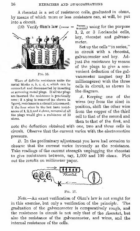
A rheostat is a set of resistance coils, graduated in ohms,
by means of which more or less resistance can, at will, be put
into a circuit.
(10) Verify Ohm's law (crrem = ^^^~) using for the purpose
1, 2, or 3 Leclanche cells,
key, rheostat and galvano-
meter.
Set up the cells "in series,"
in circuit with a rheostat,
galvanometer and key. Ad-
just the resistance by meansof the plugs to give a con-
venient deflection of the gal-
vanometer magnet (say 10
milliamperes) with the three
cells in circuit, as shown in
the diagram.
A. Keeping one of the
wires (say from the zinc) in
position, shift the other wire
from the copper of the third
cell to that of the second and
then to that of the first, and
note the deflection obtained with one, two and three cells in
circuit. Observe that the current varies with the electromotive
pressure.
B. In the preliminary a,djustment you have had occasion to
observe that the current varies inversely as the resistance.
Take readings of the current strength unplugging the rheostat
to give resistances between, say, 1,000 and 100 ohms. Plot
out the results on millimeter paper.
Pig. 16.
Wires of definite resistance unite the
metal blocks a, b, c, d, e, whioh can be
connected and disconnected by inserting
or removing metal plugs. If all the plugs
are inserted the resistance is practically
zero ; if a plug is removed (as shown in
figure), resistance in a circuit is increased
:
if the four wires in the box have resist-
ances of 1, 2, 3, and 4 ohms, removal of all
the plugs would give a resistance of 10
ohms.
Pig. 17.
Note.—An exact verification of Ohm's law is not sought for
in this exercise, but only a verification of the principle. Thegraduation of the galvanometer is comparatively rough, andthe resistance in circuit is not only that of the rheostat, but
also the resistance of the galvanometer, and wires, and the
internal resistance of the cells.
IN THE PHYSIOLOGY OP THE NBRVOtTS SYSTEM. 17
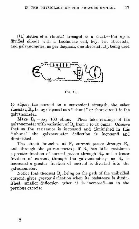
(11) Action of a rheostat arranged as a shunt.—Put up a
divided circuit with a Leclanche cell, key, two rheostats,
and galvanometer, as per diagram, one rheostat, E^, being used
Pig. 18.
to adjust the current to a convenient strength, the other
rheostat, Eg, being disposed as a " shunt " or short-circuit to the
galvanometer.
Make Ej = say 100 ohms. Then take readings of the
galvanometer with variation of E2 from 1 to 10 ohms. Observethat as the resistance is increased and diminished in this
" shunt " the galvanometer deflection is increased anddiminished.
The circuit branches at Eg current passes through Eg,
and through the galvanometer ; if Eg has little resistance
a greater fraction of current passes through E^, and a lesser
fraction of current through the galvanometer ; as Eg is
increased a greater fraction of current is diverted into the
galvanometer.
Notice that rheostat Ej, being on the path of the undivided
current, gives greater deflection when its resistance is dimin-
ished, smaller deflection when it is increased—as in the
previous exercise.
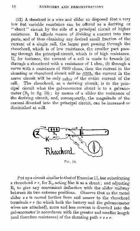
18 EXEECISES AND DEMONSTRATIONS
(12) A rheochord is a wire and slider so disposed that a very
low but variable resistance can be offered as a deriving or
" shunt " circuit by the side of a principal circuit of higher
resistance. It affords means of dividing a current into twoparts, and of thus obtaining any desired small fraction of the
current of a single cell, the larger part passing through the
rheochord, which is of low resistance, the smaller part pass-
ing through the principal circuit, which is of high resistance.
If, for instance, the current of a cell is made to branch (a)
through a rheochord with a resistance of 1 ohm, (b) through a
nerve with a resistance of 9999 ohms, then the current in the
shunting or rheochord circuit will be j^"^, the current in the
nerve circuit will be only xoino of the entire current of the
cell. The rheochord, as a deriving circuit, is to the prin-
cipal circuit what the galvanometer shunt is to a galvano-
meter (Eg in fig. 18) ; by means of a slider the resistance of
the deriving circuit, and, consequently, the magnitude of the
current diverted into the principal circuit, can be increased or
diminished at will.
Pig. 39.
Put up a circuit similar to that of Exercise 11, but substituting
a rheochord r r, for Eg, acting like it as a shunt ; and adjusting
Ej to give any convenient deflection with the slider midwaybetween its two extreme positions. Observe that as the metalslider s s is moved further from and nearer to the rheochordterminals r r (to which both the battery and the galvanometerwires are attached), more and less current is diverted into thegalvanometer in accordance with the greater and smaller length(and therefore resistance) of the shunting path r s s r.
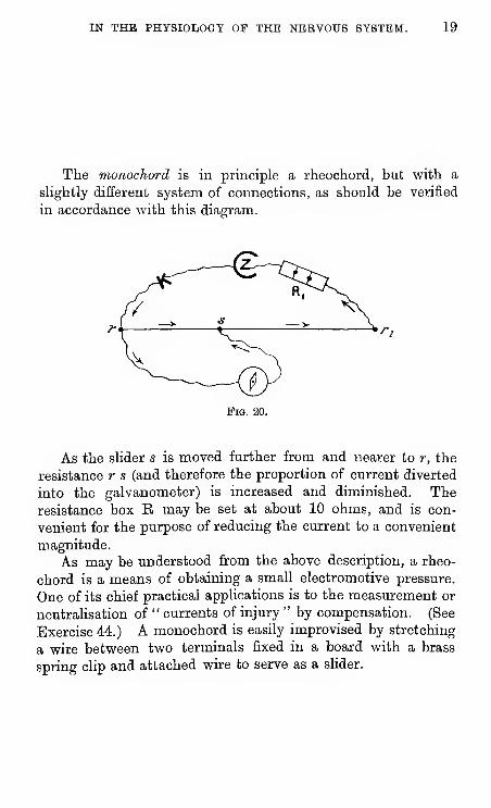
IN THE PHYSIOLOGY OF THE NERVOUS SYSTEM. 19
The monochord is in principle a rheochord, but with a
slightly different system of connections, as should be verified
in accordance with this diagram.
Fis. 20.
As the slider s is moved further from and nearer to r, the
resistance r s (and therefore the proportion of current diverted
into the galvanometer) is increased and diminished. Theresistance box B may be set at about 10 ohms, and is con-
venient for the purpose of reducing the current to a convenient
magnitude.
As may be understood from the above description, a rheo-
chord is a means of obtaining a small electromotive pressure.
One of its chief practical applications is to the measurement or
neutrahsation of " currents of injury " by compensation. (See
Exercise 44.) A monochord is easily improvised by stretching
a wire between two terminals fixed in a board with a brass
spring clip and attached wire to serve as a slider.
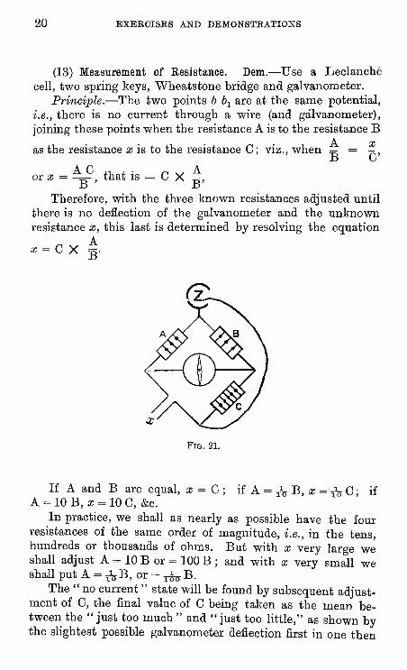
20 BXBECISES AND DEMONSTBATIONS
(13) Measurement of Resistance. Dem.—Use a Leclanche
cell, two spring keys, Wheatstone bridge and galvanometer.
Principle.—The two points h \ are at the same potential,
i.e., there is no current through a wire (and galvanometer),
joining these points when the resistance A is to the resistance B
as the resistance x is to the resistance C; viz., when =5 = 7;,,
or a; = -^^^, that is = C X -g,a ±5
Therefore, with the three known resistances adjusted until
there is no deflection of the galvanometer and the unknownresistance x, this last is determined by resolving the equation
Fig. 21.
If A and B are equal, x = G ; if A = ^i^ B, a; =^ C ; if
A = 10 B, a; = 10 C, &c.
In practice, we shall as nearly as possible have the fourresistances of the same order of magnitude, i.e., in the tens,
hundreds or thousands of ohms. But with x very large vyeshall adjust A = 10 B or = 100 B ; and with x very small weshall put A = 335B, or = j^B.
The " no current " state will be found by subsequent adjust-ment of C, the final value of C being taken as the mean be-tween the " just too much " and " just too Httle," as shown bythe shghtest possible galvanometer deflection first in one then
IN THE PHYSIOLOGY OF THE NERVOUS SYSTEM. 21
in the opposite direction. In the first rough trial we note in
which direction the magnet swings when C is evidently too
great and evidently too small. In testing for the current first
close the battery key K^, and then keeping Kj closed, close the
galvanometer key K^. The connections of the Wheatstone
box put into your hands are figured below.
Note.—The small galvanometers placed in your hands
will serve only for resistances not exceeding 1000 ohms. Formeasuring higher resistances a Kelvin's reflecting galvanometer
must be used. This instrument cannot be put into the hands
of students who have not previously worked in a physical
laboratory, until they have become familiar with the use of the
small galvanometer.
22 EXERCISES AND DEMONSTEATIONS
H
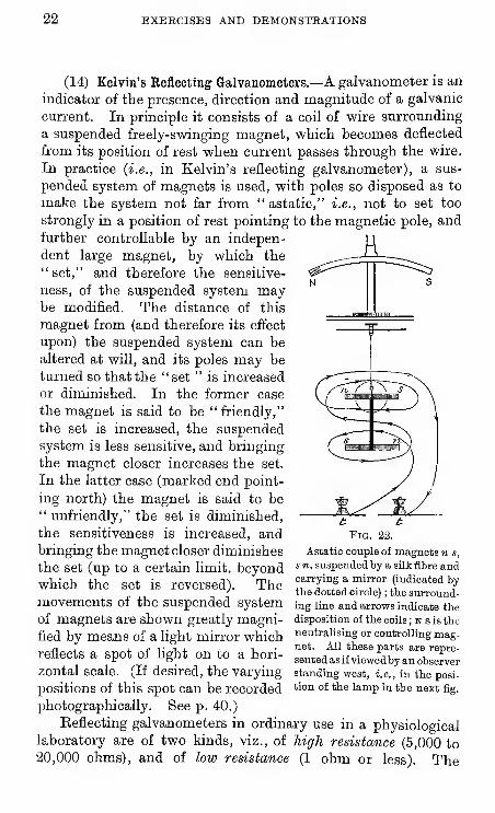
(14) Kelvin's Reflecting Galvanometers.—A galvanometer is an
indicator of the presence, direction and magnitude of a galvanic
current. In principle it consists of a coil of wire surrounding
a suspended freely-svpinging magnet, vs^hich becomes deflected
from its position of rest vs^hen current passes through the wire.
In practice (i.e., in Kelvin's reflecting galvanometer), a sus-
pended system of magnets is used, with poles so disposed as to
make the system not far from " astatic," i.e., not to set too
strongly in a position of rest pointing to the magnetic pole, and
further controllable by an indepen-
dent large magnet, by which the" set," and therefore the sensitive-
ness, of the suspended system maybe modified. The distance of this
magnet from (and therefore its effect
upon) the suspended system can be
altered at will, and its poles may be
turned so that the "set " is increased
or diminished. In the former case
the magnet is said to be "friendly,"
the set is increased, the suspended
system is less sensitive, and bringing
the magnet closer increases the set.
In the latter case (marked end point-
ing north) the magnet is said to be" unfriendly," the set is diminished,
the sensitiveness is increased, andbringing the magnet closer diminishes
''™"''^'i' ^
Pig. 22.
Astatic couple of magnets n s,
the set (up to a certain hmit. beyond s»t, suspended by a silk fibre and
which the set is reversed). Themovements of the suspended system
of magnets are shown greatly magni-
fied by means of a light mirror whichreflects a spot of light on to a hori-
zontal scale. (If desired, the varying
positions of this spot can be recorded
photographically. See p. 40.)
Keflecting galvanometers in ordinary use in a physiologicallaboratory are of two kinds, viz., of high resistance (5,000 to
20,000 ohms), and of low resistance (1 ohm or less). The
carrying a mirror (indicated bythe dotted circle) ; the surround-ing line and arrows indicate the
disposition of the coils ; n s is the
neutralising or controlling mag-net. All these parts are repre-
sented as if viewedby an observerstanding west, i.e., in the posi-
tion of the lamp in the next fig.
IN THE PHYSIOLOGY OF THE NERVOUS SYSTEM. 23
former are used for currents of muscle and nerve, the latterfor thermo-electric currents.
In connection with a high-resistance galvanometer, a''shunt" is frequently employed; this serves to reduce thesensitiveness when desired by carrying off f-^ or ^% or ^^^.j^ ofany given current (the coils in the shunt having respectively
i or -/g or g^-^ of the resistance of the galvanometer coils),
thus leaving to pass through the galvanometer i^s or xitr or
ToW of the total current. As ordinarily used this galvanometeris an indicator of current, but by adopting the method ofcompensation it becomes an indicator of potential or pressure,being in this case used to indicate equahty of opposite poten-tials by absence of current. (See next exercise 15).
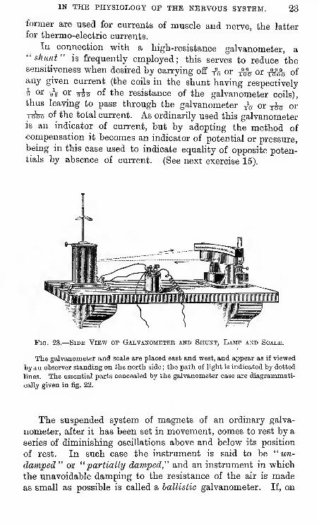
Fig. 23.
—
Side View op Galvanometer and Shunt, Lamp and Scale.
The galvanometer and scale are placed east and west, and appear as if viewed
by an observer standing on the north side ; the path of light is indicated by dotted
lines. The essential parts concealed by the galvanometer case are diagrammati-
cally given in fig. 22.
The suspended system of magnets of an ordinary galva-
nometer, after it has been set in movement, comes to rest by a
series of diminishing oscillations above and below its position
of rest. In such case the instrument is said to be "un-
damped" or "partially damped," and an instrument in which
the unavoidable damping to the resistance of the air is madeas small as possible is called a ballistic galvanometer. If, on
24 EXERCISES AND DEMONSTRATIONS
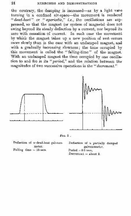
the contrary, the damping is increased—as by a light vane
turning in a confined air-space—the movement is rendered
"dead-beat" or "aperiodic," i.e., the oscillations are snp-
pressed, so that the magnet (or system of magnets) does not
swing beyond its steady deflection by a current, nor beyond its
zero with cessation of current. In such case the movementby which the magnet takes up a new position of rest occurs
more slowly than is the case with an undamped magnet, andwith a gradually increasing slowness ; the time occupied bythis movement is called the "falling-time" of the magnet.With an undamped magnet the time occupied by one oscilla-
tion to and fro is its "period," and the relation between the
magnitudes of two successive operations is the "decrement."
Pig. 2
Deflection of a- dead-beat galvano-
meter.
Falling time = 15 sees.
Deflection of a partially dampedgalvanometer.
Period =8-5 sees.
Decrement = about 2.
IN THE PHYSIOLOGY OF THE NERVOUS SYSTEM. 25
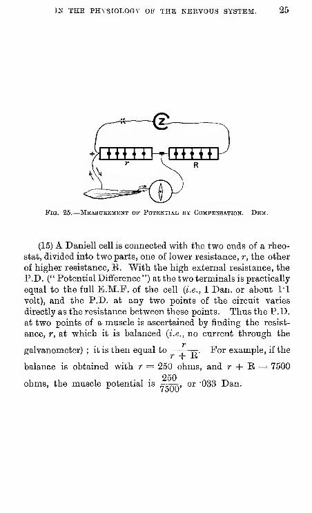
Fig. 25.
—
Mbasuebment op Potential by Compensation. Dem.
(15) A Daniell cell is connected with the two ends of a rheo-
stat, divided into two parts, one of lower resistance, r, the other
of higher resistance, E. With the high external resistance, the
P.D. (" Potential Difference ") at the two terminals is practically
equal to the full E.M.F. of the cell (i.e., 1 Dan. or about I'l
volt), and the P.D. at any two points of the circuit varies
directly as the resistance between these points. Thus the P.D.
at two points of a muscle is ascertained by finding the resist-
ance, r, at which it is balanced (i.e., no current through the
galvanometer) ; it is then equal to -p . Por example, if the
balance is obtained -with r = 250 ohms, and r -|- E = 7500
250ohms, the muscle potential is , or '033 Dan.
•26 EXERCISES AND DEMONSTRATIONS
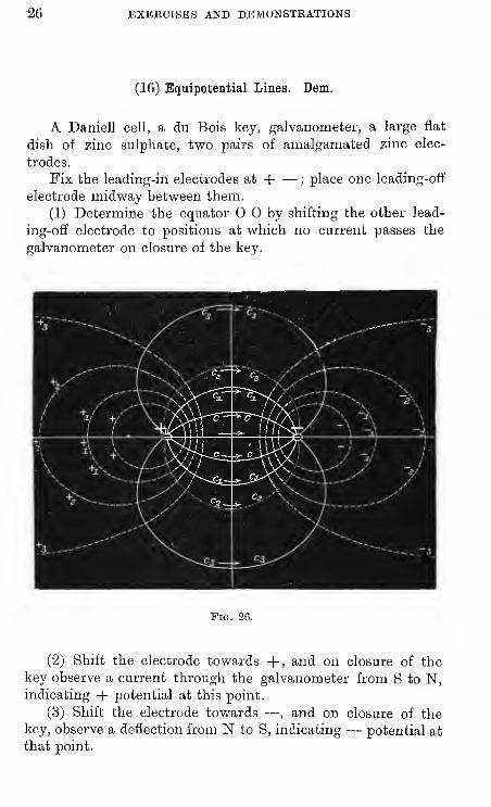
(16) Equipotential Lines. Dem.
A Daniell cell, a du Bois key, galvanometer, a large flat
dish of zinc sulphate, two pairs of amalgamated zinc elec-
trodes.
Fix the leading-in electrodes at H ;place one leading-off
electrode midway between them.
(1) Determine the equator by shifting the other lead-
ing-off electrode to positions at which no current passes the
galvanometer on closure of the key.
Fig. 2G.
(2) Shift the electrode towards +, and on closure of the
key observe a current through the galvanometer from S to N,indicating -|- potential at this point.
(3) Shift the electrode towards — , and on closure of thekey, observe a deflection from N to S, indicating — potential at
that point.
IN THE, PHYSIOLOGY OF THE NERVOUS SYSTEM. 27
(4) Shift the first leading-off electrode nearer to — , and bysuccessive trials of shifting the second lead-off, find several
equipotential points, from which construct a curve.
(5) Repeat the observation with the first leading-off electrode
nearer to +. {Vide "Human Physiology," p. 306).
(6) Find equipotential curves near and far from one of the
poles, place the leading-off electrodes on any two points of
each of these curves, and observe the galvanometer on closure
of the key ; or, more simply, take a pair of leading-off electrodes
at a fixed distance from each other, and find positions in the
field at which more or less current passes in one or other
direction.
28 EXERCISES AND DEMONSTRATIONS
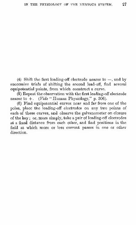
(17) Excitation of nerve by the Condenser.
A condenser in its simplest form is a pair of metallic
surfaces separated by a thin layer of air, glass, paraffin, mica,
&c., that are charged by being brought into metallic connectionwith points of different electrical pressure, such as the copper
Fig. 27.
and zinc of a Daniell cell, and discharged when connected bya sufficient conductor. Either the charge or the discharge
may be made through a nerve.
Connect the middle pair of pools of a commutator without
cross wires to the terminals of a "condenser," connect the
two lateral pairs with a cell and with the nerve of a nerve-
muscle preparation as in fig. 27.
With the cradle of the commutator as shown in the
diagram, the condenser is connected with the cell and"charged." When the cradle is turned over, the chargedcondenser is disconnected from the cell and connected withthe nerve through which it is " discharged," provoking a
single twitch of the attached muscle.
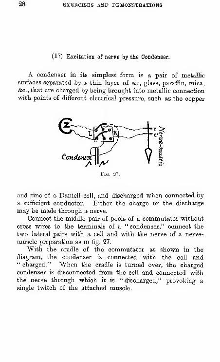
IN THE PHYSIOLOGY OF THE NERVOUS SYSTEM. 29
Minimum energy of stimulus. Dem.
With stimulation by the discharge (or charge) of a con-denser we can express in terms of energy the value of theelectrical stimulus.
CoTLdLcustr
Fig. 28.
Charge from + through b c e' e p' p to — when contact is made at 6 by depres-
sing the Morse key (and broken at a) viz., ascending in the nerve.
Discharge from p' through e e'c a to p when contact is made at a by recoil of
the Morse key (and broken at b) viz., descending in the nerve.
The bridging key is for the purpose of cutting out from the nerve either the
charge or the discharge. If desired this may be efiected without the bridging
key by the circuits 1 and 2 of fig. 29, substituting the exciting electrodes e e' for
the galvonometer SN.
Put up connections in accordance with fig. 28, using a
condenser of O'lO microfarad, subdivided into parts =0"01.
Determine by adjustment of the rheostats r, E, the smallest
fraction of a volt that will excite the nerve of a nerve-muscle
preparation :—
(A) with the condenser at O'lO microfarad
;
(B) with the condenser at 0"01 microfarad
;
and calculate in the two cases the quantity and the energy of
such a minimal electrical stimulus.
(C) with a convenient fraction (say O'l of a volt)
find the minimum effective condenser value (between O'Ol and
O'lO microfarad) and calculate as before.
N.B.—^You may expect the energy value of a minimal
effective stimulus to come out at something like O'OOl erg.,
viz., 1 millierg.
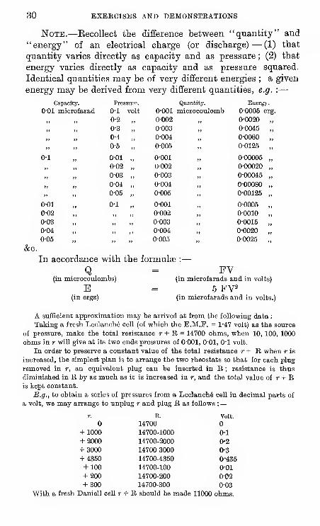
30 EXERCISES AND DEMONSTRATIONS
Note.—Eecollect the difference between "quantity" and
"energy" of an electrical charge (or discharge) — (1) that
quantity varies directly as capacity and as pressure ; (2) that
energy varies directly as capacity and as pressure squared.
Identical quantities may be of very different energies ; a given
energy may be derived from very different quantities, e.g. :—
&c.
Capacity.
IN THE PHYSIOLOGY OF THE NERVOUS SYSTEM. 31
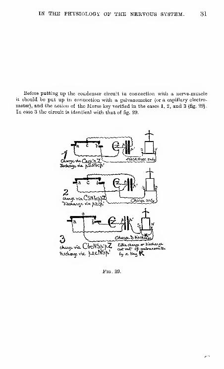
Before putting up the condenser circuit in connection with a nerve-muscle
it should be put up in connection with a galvanometer (or a capillary electro-
meter), and the action of the Morse key verified in the cases 1, 2, and 3 (fig. 29)-
In case 3 the circuit is identical with that of fig. 29.
c V,
ICK«n3t. vio.Cadv'ftX^-"HtdnM^t. via. jvSM'IrCj'-
•&UCA.£lrt0z. grvfyj
ffc^
Pig. 29.
32 EXERCISES AND DEMONSTRATIONS
(18) Unipolar stimulation.—Lay the nerve across a single
•electrode connected by a single wire with the secondary coil.
Carefully insulate the frog or nerve-muscle preparation ona dry glass plate, also the coil in the same way. If the in-
sulation is perfect, no contraction occurs when the coil is set
in action. But if the insulation be destroyed, contractions
occur although only one pole is connected with the nerve.
Note that unipolar contraction is most apt to occur at the
break shock with the ordinary arrangement of the coil. This
is one reason for using the Helmholtz modification ; also for
using a key as a bridge when it is desired to cut off the
secondary current from a nerve.
IN THE PHYSIOLOGY OP THE NEEVOUS SYSTEM. 33
(19) Unpolarisable electrodes are constructed as follows. Acarefully amalgamated^ zinc rod dips into a saturated solution
of zinc sulphate, which in turn communicates with a plug of
china clay made up into a paste with normal saline ; a glass
tube shaped according to requirements and fixed in a suitable
holder. Such an electrode has the following qualities : it is
unpolarisable by weak currents, it is not itself a source of
electromotive force, it is of high resistance, it can be applied
to living tissues without appreciably injuring them. A pair
of unpolarisable electrodes should be tested before use bybringing their plugs into contact while they are connected
with the galvanometer ; they should then give little or no
current. Another form of unpolarisable electrode is that
of d'Arsonval ; it consists of a silver rod coated with fused
silver chloride dipping into a tube filled with normal saline.
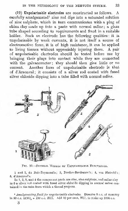
Fig. 30.
—
Sevebal Models op Unpolabisaele Electbodes.
1 and 2, du Bois-Reymond's ; 3, Burdon-Sanderson's ; 4, von Meischl's;
5, d'Arsonval's.
In 1, 2, 3, and 4 the component parts are zino, zino-snlphate, and saline clay
in 5 a silver rod coated with fused silver chloride dipping in normal saline con-
tained in the tube from which a thread projects.
' Amalgamating fluid for unpolarisable electrodes. Dissolve 3 c.o. of mercury
in 50 c.c. HNO3 + 150 c.o. HCl. Add 10 per cent. HGl. to make up 1000 o.c.
3
34 EXERCISES AND DEMONSTRATIONS
(20) The capillary electrometer may be used instead of the
galvanometer for the demonstration of muscle and nerve
currents; it is more suitable than the galvanometer for the
electrical variations of the frog's heart, and it is the only-
instrument by M^hich the electrical variations of the humanheart can be demonstrated. The galvanometer indicates
electrical current, the electrometer indicates electrical pres-
sure, being, in fact, an extremely delicate electrical manometer,
by which minute differences of potential between any two
points of muscle, nerve or other tissue can be exhibited.
The apparatus consists essentially in a glass tube drawnout at one end to a fine bore (20 to 30 /i) filled with clean
mercury, and in air connection with a pressure apparatus.
The capillary end dips into a tube containing 10 per cent,
sulphuric acid, and is viewed through a microscope magnifying
60 to 300 diameters or more.^ Two platinum wires establish
connection with the mercury and the sulphuric acid respec-
tively. By means of the pressure apparatus mercury is forced
along the capillary (which tapers slightly towards its end) upto a certain point, according to the pressure used, and the
meniscus is adjusted in the field of the microscope. The sur-
face of the mercury meniscus is in a state of tension, which is
very easily altered by variations of electrical pressure, suchalterations causing the mercury to advance or to recede in
the capillary. Advance or retreat of the mercury signifies rise
or fall of potential at its electrode.
N.B.—In putting up the instrument for the first time becareful to use clean mercury and filling pipettes ; do not allow
the mercury in the glass tube to come in contact with india-
rubber tubing, nor with mercury from the pressure apparatus.
In testing a new instrument see that the mercury movesfreely (1) to slight variations of pressure, (2) to slight electrical
variations caused by touching the electrodes, (3) to the electrical
variations accompanying the action of your owm heart. (Ex.
51) . If it responds to this third test, it is more than sufficiently
sensitive for the exposed heart of a frog or mammal.When you have done with the instrument lower the pres-
sure bulb nearly to, but not below zero, and close the sbort-
' With the higher powers the definition of the edge of the meniscus is muobimproved by using a drop of water between the tube and objective, thus convertingthe latter into an immersion lens.
IN THE PHYSIOLOGY OP THE NERVOUS SYSTEM. 35
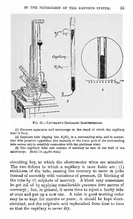
Fig. 31.
—
Lippmann's Capillary Bleoteomkteh.
(1) Pressure apparatus and microscope on the stand of which the capillary
tube is fixed.
(2) Capillary tube dipping into H^SO^ in a surrounding tube, and in connec-
tion with pressure apparatus (the mercury in the lower part of the surrounding
tube serves only to establish connection with the platinum wire).
(3) The capillary tube and column of mercury as seen in the field of the
microscope. (Scale in -j-os*!'^ mm.)
circuiting key, to which the electrometer wires are attached.
The two defects to which a capillary is most liable are : (1)
stickiness of the tube, causing the mercury to move in jerks
instead of smoothly with variations of pressure, (2) blocking of
the tube by (?) sulphate of mercury. A block may sometimes
be got rid of by applying considerable pressure (two metres of
mercury) ; but, in general, it saves time to reject a faulty tube
at once and put up a new one. A tube in good working order
may be so kept for months or years ; it should be kept short-
circuited, and the sulphuric acid replenished from time to time
so that the ca.pi]lary is never dry.
36 EXEECISES AND DBMONSTBATIONS
(21) Recording Apparatus.
The recording apparatus in use in this laboratory are :
—
(1) A cyhnder fitting either the hour or the minute axis of
an American clock; speed 25 mm., and 300 mm. per hour.
Used for e.g., fatigue of muscle, action of drugs on frog's.
heart, temperature records on man, respiration records onman.
(2) Cylinders driven by a water motor ; ordinary speeds
between 10 and 100 mm. per second.
(3) The spring myograph.
(4) The pendulum myograph.
(5) The railway myograph.
For all ordinary purposes (sphygmograms, cardiograms^
myograms, latent period, rate of nerve-impulse, reaction times,
&c.), the cylinder is sufficient. For the higher speed phe-
nomena (latent period, rate of nerve-impulse), the spring or
pendulum myograph is more convenient ; the railway myo-graph consists essentially in a vertical smoked plate carried
horizontally across the field of a lantern, and is used only for-
demonstrations.
In the sprmg-myograpJi a smoked glas3 plate is fixed in a
metal frame which is shot along wire guides by the release of
a spring. The speed of movement can be varied by varying
the strength of the spring, and it is indicated by means of a.
vibrating reed (100 per sec.) that is set in movement by the
release of the spring. One (or two) trigger keys are set so
as to be struck open by the carrier in its passage, and th&instant of stimulation is marked in the usual way by bringing
the carrier slowly up to each key and then marking the
position of the recording lever.
In the pendulum myograph a smoked glass is fixed in a.
frame at the end of a pendulum, which is allowed to swing fromone clutch to another clutch, adjusted so that the pendulum,when released from the first, swings so as to be just caught bythe second. The frame and plate sweep past the myographicand chronographic levers and strike open one or more trigger
keys ; the levers are adjusted so as to come into light contactwith the plate, and the instant or instants of stimulation aremarked in the usual way. The speed of movement can bevaried by varying the ampHtude of swing with alteration of the.
position of the clutches ; but a convenient speed having oncebeen obtained, it is best to let well alone.
IN THE PHYSIOLOGY OF THE NERVOUS SYSTEM. 37
With these two instruments the usual and convenient
speeds are such that ri^jth sec. measures 5 to 10 millimeters.
The " railway myograph," consisting of a miniature truck
slowly moved along rails, and carrying a smoked glass plate, is
very convenient for the deixionstration of experiments in which•changes are gradually developed, e.g., fatigue, action of drugs
on heart. The apparatus is arranged so that the smoked plate,
against which the lever is writing, is slowly carried across the
field of a lantern by which the magnified tracing is projected
on a screen.
The trigger key and peg fixed respectively to the clock,
or cylinder or plate-carrier, are for the purpose of obtaining a
break induction shock by the revolution of the cylinder at a
•definite point. The key is placed in the primary circuit, left
open until the cylinder is at full speed, then closed so that the
next time the peg comes round, the trigger is knocked over and
the contact broken. It is used, e.g., to measure the latent
period or the rapidity of transmission of a nerve-impulse. Thelever indicating muscular contraction begins to rise a small
space {i.e., timej after the point corresponding with the knock
down of the trigger. To determine this correspondence on the
stationary cylinder or plate bring the peg very slowly against
the trigger, and mark the point on the cylinder by a touch on
the lever ; having done this, do not disturb the lever before
taking your observation, and verify the correspondence at its
conclusion.^
The principle upon which the use of these instruments is
based will at once be realised by one or two simple experi-
ments ; of these the easiest is a determination of the latent
period
—
{a) By a break induction shock applied to an isolated
gastrocnemius muscle of the frog.
(&) By make of a constant current to muscles of the human
forearm.
(c) By break of a constant current to muscles of the humanforearm.
In a, b and c, the latent periods should come out re-
spectively at about 0-01, 0-02. and 0-05 sec, but, except in the
last case, the latent period is more apparent than real.
' A slip of flexible metal {e.g., a piece of -watcli spring), fixed to the cylinder
so as to strike against a pin at each revolution, will answer the same purpose as
the more complicated trigger key.
38 EXBECISBS AND DEMONSTEATIOKS
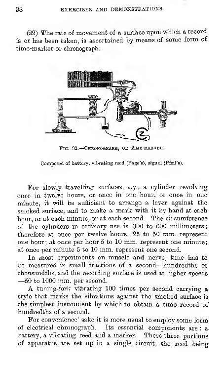
(22) a?he rate of movement of a surface upon which a record
is or has been taken, is ascertained by means of some form of
time-marker or chronograph.
Fig. 32.—Chbonogeaph, ob Time-mabkbk.
Composed of battery, vibrating reed (Page's), signal (Pfeil's).
For slowly travelling surfaces, e.g., a cylinder revolving-
once in twelve hours, or once in one hour, or once in one
minute, it will be sufficient to arrange a lever against the
smoked surface, and to make a mark with it by hand at each
hour, or at each minute, or at each second. The circumference
of the cylinders in ordinary use is 300 to 600 millimeters
;
therefore at once per twelve hours, 25 to 50 mm. represent
one hour; at once per hour 5 to 10 mm. represent one minute;
at once per minute 5 to 10 mm. represent one second.
In most experiments on muscle and nerve, time has to
be measured in small fractions of a second—hundredths or
thousandths, and the recording surface is used at higher speeds—50 to 1000 mm. per second.
A tuning-fork vibrating 100 times per second carrying astyle that marks the vibrations against the smoked surface is
the simplest instrument by which to obtain a time record of
hundredths of a second.
For convenience' sake it is more usual to employ some formof electrical chronograph. Its essential components are : abattery, a vibrating reed and a marker. These three portions
of apparatus are set up in a single circuit, the reed being
IN THE PHYSIOLOGY OF THE NEEVOUS SYSTEM. 39
arranged so as to give a succession to interruptions by vibrat-
ing in and out of a mercury pool in the circuit. The makesand breaks of current thus produced act as makes and breaks
of two electro-magnets A and B ; A keeps up the vibrations
of the reed, B gives corresponding vibrations of the recording
lever.
Take chronograms.
(a) With a 100 tuning fork. Arrange the fork close to
but not touching the cylinder ; start the clock, and when the
cylinder is at full speed, set the fork in vibration by a smart
blow, and make its vibrating style come into contact with the
revolving surface. Stop the cylinder. The fork has vibrated
100 times per sec. ; with a slowly revolving surface you will be
unable to distinguish the vibrations. With speeds at or above
50 mm. per sec. they will be visible as separate teeth—2 per
mm. at 50 mm. per sec, 1 per mm. at a speed of 100 mm. per
sec, 1 per 2'5 mm. at a speed of 250 mm. per sec. By this
means you ascertain the time values of distances traversed
by the revolving cylinder.
(6) With an electrical chronograph. Set up the chrono-
graph as per diagram. See that the reed-points and mercury
surface are clean. By raising or lowering the mercury cup
and the two electro-magnets A and B by the two milled
head screws (a) and (h), find such an adjustment of parts
that the reed shall continue vibrating automatically when once
its vibrations are started by a twinge or tap.
Take as neatly as you can for future reference the following
series of chronograms
:
20 per sec. reed on fast, medium and slow rates.
50 per sec. reed on fast and medium rates.
100 per sec. reed on fast and medium rates.
100 tuning-fork on fast and medium rates.
Finally, put up a Marey tympanum and closed India rubber
tube connected with it, and mark seconds on the three rates
by pressing the tube in time with the ticking of a watch.
40 BXBBCISES AND DEMONSTEATIONS
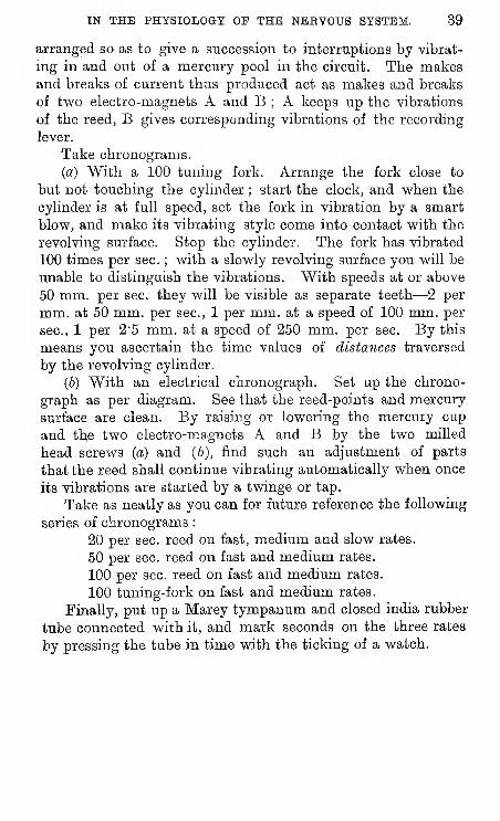
(23) Photo-Gralvanometric and Photo-Electrometric Records.
The value of galvanometric and electrometric indications is
greatly increased when they are photographically recorded.
This can be done by very simple apparatus, of which the
essential part is a sensitive plate moved by clockwork. Formost galvanometer experiments it will be found convenient to
use " ordinary photographic quarter-plates" let down behind a
screen with a horizontal slit, about 0"5 mm. broad, at a speed
of 10 to 20 cm, per hour, by means of a wheel fixed to the
minute axis of an American clock ; the spot of light being
formed by an ordinary paraffin lamp at a distance of about 50
cm. from the galvanometer, and focussed upon the slit by a
lens of about + 5 D.
For most electrometer experiments, a more sensitive plate
and a greater speed of movement, i.e., 1 to 10 cm. per sec, will
be found suitable.
The recording apparatus must be used in a dark chamber
—
which may be a simple box, or preferably a dark room. Thephotographic plates are developed and fixed by any of the usual
methods; in this laboratory the " hydroquinone developer" is
usually employed.
Fig. 33.
—
Recording Galvanometer.
IN THE PHYSIOLOGY OP THE NERVOUS SYSTEM. 41
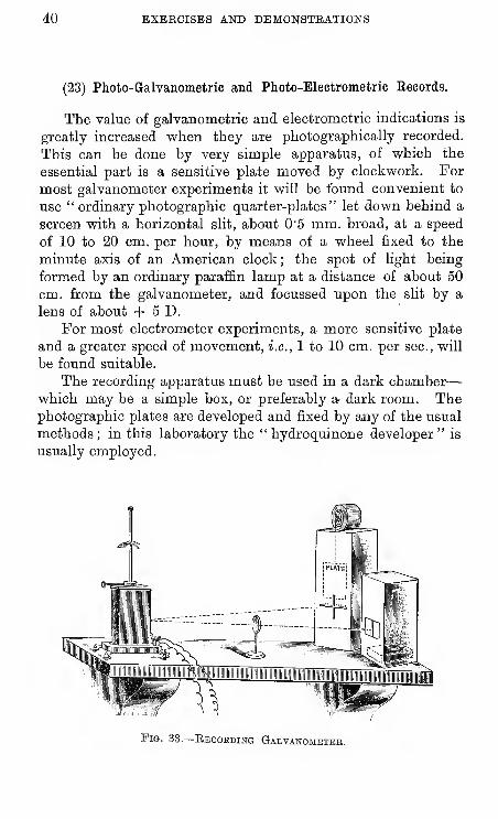
Galvanometer Ebcords.—The vertical spot of light from
the lamp is reflected to cross the horizontal slit S N in the
front of a dark box, within which a sensitive plate is let downvertically by clock-work. The spot of light deflected to right
and left between S and N yields a black line on the developed
plate, and thus records the movements of the galvanometric
magnet and mirror.
Mvx^x^
"Pig. 34.
N
i! I M I f ! n f I M 11 M i I f n M ! I
^ ^ « n i i i ii i ii i i i » 1 H «
J* ^ "
'
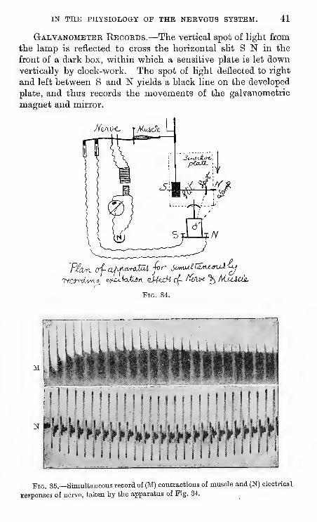
Fig. 35.—Simultaneous record of (M) contractions of muscle and (N) electrical
lesponses of nerve, taken by tte apparatus of Pig. 34.
42 EXERCISES AND DEMONSTEATIONS
To obtain a simultaneous record of, e.g., the negative varia-
tion of nerve and the contraction of the supplied muscle, half
the slit (and plate) left obscured is used for the record of the
galvanometer spot, and the other half, illuminated by a candle,
is used for the record of the muscular contraction, by means of
the lever and small screen, as shown in fig. 34.
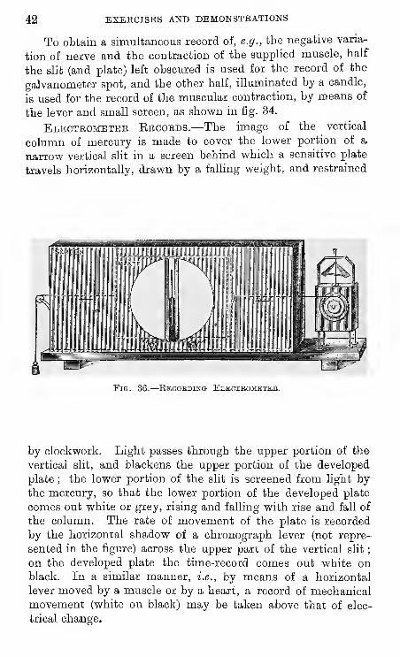
Electrometer Ebcords.—The image of the vertical
column of mercury is made to cover the lower portion of a
narrow vertical sht in a screen behind which a sensitive plate
travels horizontally, drawn by a falling weight, and restrained
Pig. 36.
—
Eecobding Electbometee.
by clockwork. Light passes through the upper portion of the
vertical slit, and blackens the upper portion of the developed
plate ; the lower portion of the slit is screened from light bythe mercury, so that the lower portion of the developed plate
comes out white or grey, rising and falling with rise and fall of
the column. The rate of movement of the plate is recorded
by the horizontal shadow of a chronograph lever (not repre-
sented in the figure) across the upper part of the vertical slit
;
on the developed plate the time-record comes out white onblack. In a similar manner, i.e., by means of a horizontal
lever moved by a muscle or by a heart, a record of mechanicalmovement (white on black) may be taken above that of elec-
trical change.
IN THE PHYSIOLOGY OF THE NBEVOUS SYSTEM. 43
HjSO,
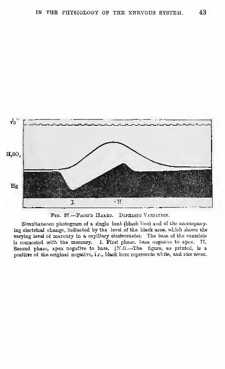
Fig. 37.
—
Fbog's Hbaet. Diphasic Vaeiation.
Simultaneous photogram of a single beat (black line) and of the accompany-
ing electrical change, indicated by the level of the black area, which shows the
varying level of mercury in a capillary electrometer. The base of the ventricle
is connected with the mercury. I. First phase, base negative to apex. II.
Second phase, apex negative to base. {N.B.—The figure, as printed, is a
positive of the original negative, i.e., black here represents white, and vice versa.
44 BXEECISBS AND DEMONSTRATIONS
(24) To Pith a Frog; Decerebration.
Insert one blade of a strong pair of scissors into the mouthas far back as it will go, and cut off the top of the head. Thebrain (hemispheres and optic lobes) will thus be removed, or
at least exposed at the first scissor cut ; in any case, all
sensibility is at once abolished by " shock." Thoroughly
destroy the brain, bulb, and cord by means of a stout wire
pushed several times down the spinal canal. The frog is nowthoroughly " pithed," and should remain permanently flaccid
and motionless ; any movements of the limbs signify that the
spinal cord has not been thoroughly destroyed.
For certain experiments it is necessary to only decerebrate .
the frog
—
i.e., to destroy only the hemispheres or the hemi-spheres and optic lobes. In this case, the scissor cut mustnot be made quite so far back, and the brain carefully
removed.
In some experiments, again, it is desirable to decerebrate
the frog with as little haemorrhage as possible. In this case
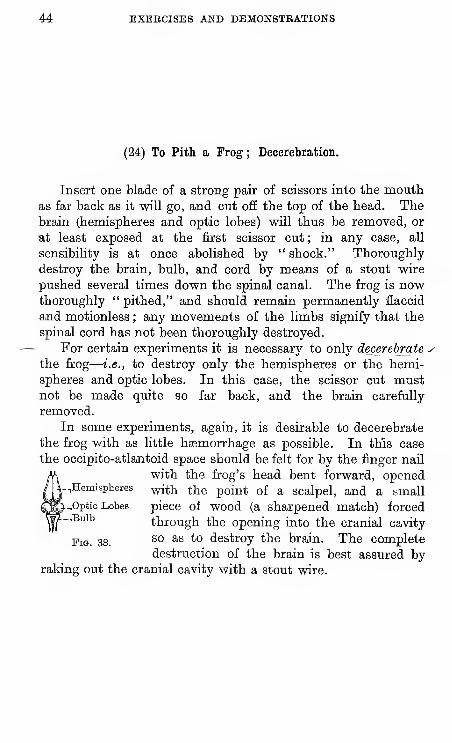
the occipito-atlantoid space should be felt for by the finger nail
with the frog's head bent forward, opened--.Hemispheres with the point of a scalpel, and a small,Optio Lobes piece of wood (a sharpened match) forced-,Bulb through the opening into the cranial cavity
Fig. 38.^^ ^^ *° destroy the brain. The completedestruction of the brain is best assured by
raking out the cranial cavity with a stout wire.
IN THE PHYSIOLOGY OP THE NERVOUS SYSTEM. 45
(25) To Prepare a Muscle or a Nerve-Muscle for Experiment.
Proceed in the following order
:
—Pith a frog ; expose the
tendon of the gastrocnemius muscle and tie a thread or fine
wire round it ; expose the sciatic nerve, tearing aside the
muscles and keeping them open by pins ; cut through the
ileo-coccygeus and remove the urostyle ; cut through the spinal
column and use the bit to handle the nerve by ; raise the
nerve and set it free ; clear the lower end of the femur, pass a
pin through the joint, or cut the femur if you are about to use
a muscle clamp ; cut through the tibia below the joint.
Put up the muscle or the nerve-muscle according to whatyou want to do. For elasticity, single and double contraction,
tetanus, you do not need the nerve, and should use direct
stimulation.
46 EXERCISES AND DEMONSTEATIONS
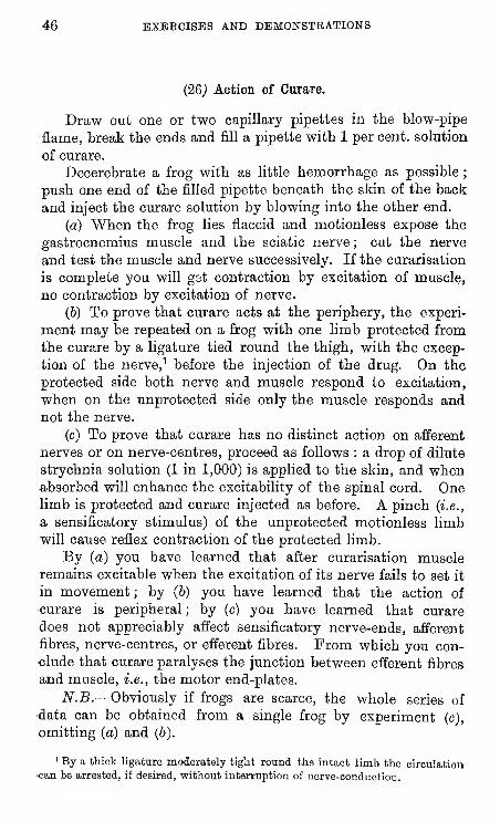
(26j Action of Curare.
Draw out one or two capillary pipettes in the blow-pipe
flame, break the ends and fill a pipette with 1 per cent, solution
of curare.
Decerebrate a frog with as little hemorrhage as possible
;
push one end of the filled pipette beneath the skin of the back
and inject the curare solution by blowing into the other end.
(a) "When the frog lies flaccid and motionless expose the
gastrocnemius muscle and the sciatic nerve ; cut the nerve
and test the muscle and nerve successively. If the curarisation
is complete you will g3t contraction by excitation of muscle,
no contraction by excitation of nerve.
(6) To prove that curare acts at the periphery, the experi-
ment may be repeated on a frog with one limb protected from
the curare by a ligature tied round the thigh, with the excep-
tion of the nerve, ^ before the injection of the drug. On the
protected side both nerve and muscle respond to excitation,
when on the unprotected side only the muscle responds andnot the nerve.
(c) To prove that curare has no distinct action on afferent
nerves or on nerve-centres, proceed as follows : a drop of dilute
strychnia solution (1 in 1,000) is applied to the skin, and whenabsorbed will enhance the excitability of the spinal cord. Onelimb is protected and curare injected as before. A pinch {i.e.,
a sensificatory stimulus) of the unprotected motionless limbwill cause reflex contraction of the protected limb.
By (a) you have learned that after curarisation muscleremains excitable when the excitation of its nerve fails to set it
in movement ; by (b) you have learned that the action of
curare is peripheral ; by (c) you have learned that curare
does not appreciably affect sensificatory nerve-ends, afferent
fibres, nerve-centres, or efferent fibres. From which you con-clude that curare paralyses the junction between efferent fibres
and muscle, i.e., the motor end-plates.
N.B.—Obviously if frogs are scarce, the whole series of
data can be obtained from a single frog by experiment (c),
omitting (a) and (&).
' By a thick ligature moderately tight round the intact limb the circulation-can be arrested, if desired, without interruption of nerve-conduction.
IN THE PHYSIOLOGY OF THE NERVOUS SYSTEM. 47
(27) Action of Veratrine.
Proceed as before (Ex. 26) by using a 1 per cent, solution
of veratrine.
On the slowest axis of the cylinder take a record of a normal
twitch, and of the twitch of a veratrinised muscle. Make a
time tracing (in seconds) below the latter curve. Write a de-
scription of the alteration.
(28) Take a tracing of a single contraction of frog's gastroc-
nemius on the cylinder or on the swing, or on the shooter.
Mark the latent period. Do not forget to put in a time tracing
(100 fork or reed). Take note of the temperature of the roomat the time of the experiraent, it will probably be between 12°
and 18°.
Take a similiar tracing with the muscle put up in the hot
and cold air chamber.
(6) With raised temperature.
(c) With lowered temperature.
Sufficiently well-marked effects will be produced by using
for the former a heated poker held not too near the muscle, and
for the latter a lump of ice.
48 EXEBCISBS AND DBMONSTEATIONS
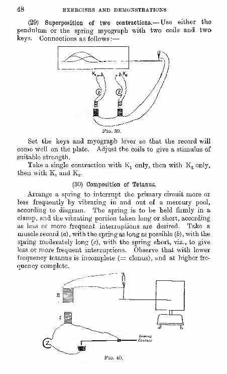
(29) Superposition of two contractions.— Use either the
pendulum or the spring myograph with two coils and twokeys. Connections as follows :
—
Fig. 39.
Set the keys and myograph lever so that the record will
come well on the plate. Adjust the coils to give a stimulus of
suitable strength.
Take a single contraction with Kj only, then with Kg only,
then with Kj and Kg.
(30) Composition of Tetanus.
Arrange a spring to interrupt the primary circuit more or
less frequently by vibrating in and out of a mercury pool,
according to diagram. The spring is to be held firmly in a
clamp, and the vibrating portion taken long or short, according
as less or more frequent interruptions are desired. Take a
muscle record (a) , with the spring as long as possible (6) , with the
spring moderately long (c), with the spring short, viz., to give
less or more frequent interruptions. Observe that with lower
frequency tetanus is incomplete (= clonus), and at higher fre-
quency complete.
SPfF/zvc
Co/vTAcr
Fig. 40.
IN THE PHYSIOLOGY OF THE NERVOUS SYSTEM. 49
(31) Fatigue (and Recovery).—Put up a frog's gastrocnemiusin connection with a lever to record its movements, against a
smoked cylinder.
(1) First take a record of a series of contractions on a slovir
cylinder, stimulating the muscle by break induction shocks at
1 sec. intervals, by means of a spring key in the primary cir-
cuits, rhythming yourself by aid of the clock sounds, and having
found a strength of stim. such that the break gives maximaleffects, the make nothing. Take two such records with the
two gastrocnemii, one with the ordinary (isotonic) lever, and
an after-load of ten grammes, the other with the spring
(isometric) lever. Observe in each case the gradual decline
of the record, i.e., muscular fatigue. Keep on stimulating
until the muscle is quite or nearly exhausted, then pause
for two minutes and begin again. Observe that the muscle
has recovered power.
(2) With a fresh gastrocnemius take a record of a series of
contractions (by either isotonic or isometric method) on a
rapid cylinder (250 mm. per sec), using a trigger-key or other
contact fixed to the clock in the primary circuit (p. 37). Eachrevolution takes about 1'5 sec. Keep on stimulating thus
until the muscle is nearly exhausted, then stop the cylinder.
60 ESEECISES AND DEMONSTRATIONS
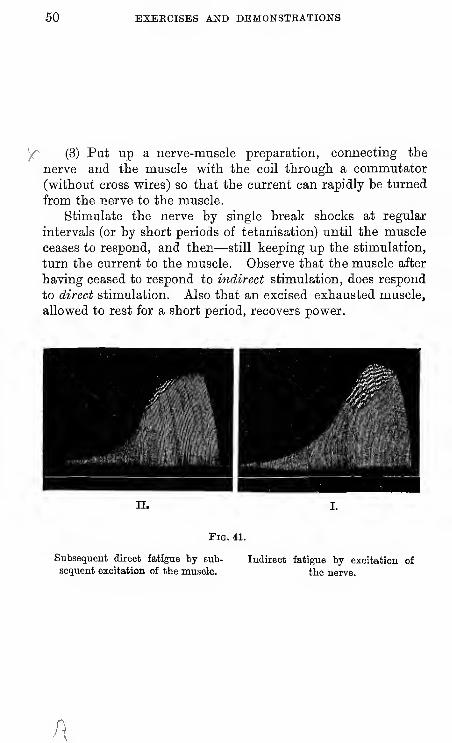
y^ (3) Put up a nerve-muscle preparation, connecting the
nerve and the muscle vfith the coil through a commutator
(without cross vpires) so that the current can rapidly be turned
from the nerve to the muscle.
Stimulate the nerve by single break shocks at regular
intervals (or by short periods of tetanisation) until the muscle
ceases to respond, and then—still keeping up the stimulation,
turn the current to the muscle. Observe that the muscle after
having ceased to respond to indirect stimulation, does respond
to direct stimulation. Also that an excised exhausted muscle,
allowed to rest for a short period, recovers power.
11.
Fig. 41.
Subsequent direct fatigue by sub-
sequent excitation of the muscle.
Indirect fatigue by excitation of
the nerve.
A
IN THE PHYSIOLOGY OP THE NEEVOUS SYSTEM. 61
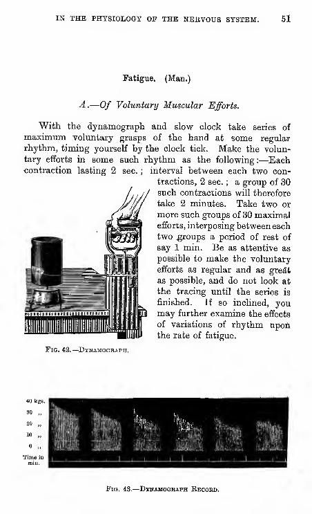
Fatigue. (Man.)
A.—Of Voluntary Muscular Efforts.
With the dynamograph and slow clock take series of
maximum volmitary grasps of the hand at some regular
rhythm, timing yourself by the clock tick. Make the volun-
tary efforts in some such rhythm as the following :—Eachcontraction lasting 2 sec. ; interval between each two con-
tractions, 2 sec. ; a group of 30such contractions will therefore
take 2 minutes. Take two or
more such groups of 30 maximalefforts, interposing between eachtwo^oups a period of rest of
say 1 min. Be as attentive as
possible to make the voluntary
efforts as regular and as gre*fc
as possible, and do not look at
the tracing until the series is
finished. If so inclined, youmay further examine the effects
of variations of rhythm upoii
the rate of fatigue.
Pig. 42.
—
Dynamogeaph.
40 kgs.
52 EXERCISES AND DEMONSTEATIONS
B.—Of Electrically Excited Muscular Contractions.
With the lighter dynamograph and slow clock take series,
of muscular tetani of the muscles of the forearm, put into
contraction at some regular rhythm by direct excitation,,
placing one electrode from the induction coil on the muscles,
of the forearm, the other on any convenient part of the body
{e.g., the calf of the leg).
If so inclined, you may test the effect of voluntary muscular
action upon the muscle itself, by taking series of electrically
excited contractions before and after a series of voluntary
muscular contractions.
IN THE PHYSIOLOGY OF THE NBRVOtTS SYSTEM. 53
(32) Extensibility of Muscle. — Isolate the gastrocnemius
muscle of a pithed frog: tie a strong thread securely to the
tendon, divide the femur, and fix the lower end firmly in a
clamp. Tie the end of the thread from the. tendon to a light,
long lever, and to the same thread attach a light scale-pan to
receive a succession of weights (pennies, which weigh about
10 grammes each, are convenient for the purpose of the experi-
ment).
Make the point of the lever touch a smoked cylinder or plate,
which is to be moved on by hand by an equal space as each
equal increment of weight has been made. Carefully place in
the scale-pan 1, 2, 3, &c., pennies, and move the recording
surface as just directed. Observe that the successive incre-
ments of length of muscle, caused by successive equal incre-
ments of extending weight, form a diminishing series, forming
a curve convex towards the abscissa. Eemove the weights one
by one, and observe the converse series of elastic shortenings
of the progressively unloaded muscle. Repeat a similar experi-
ment with a rather strong piece of elastic substituted for the
muscle, and observe that successive equal increments of weight
produce successive equal increments of length.
54 BXBECISES AND DEMONSTEATIONS
(33) Electrotonic Alterations of Excitability. (Frog.)
Apparatus.—Battery, cell and coil, wires, rheochord, 2
unpolarisable electrodes, moist chamber, myograph, 2 keys,
commutator.
First prepare the unpolarisable electrodes and arrange
them close to a pair of ordinary electrodes in the moist
chamber, ready for the nerve to be laid upon them, and so
that the ordinary electrodes shall be nearer to the muscle.
Connect the unpolarisable electrodes with the battery, for the
"polarising current"; and the ordinary electrodes with the
coil for the testing current. Place an interrupting key and acommutator in the polarising circuit, and mark what direction
the current has in the nerve according as the cradle is turned
right or left. Arrange a key in the testing current for single
shocks.
Then make a nerve-muscle preparation (Ex. 25) ; lay the
nerve across the electrodes, and attach the tendon of the
muscle to the lever of the myograph.
{A) Find a distance of secondary from primary coil suchthat a break induction shock just fails to cause contraction.
Now let the polarising current pass through the nerve in
the descending direction, i.e., so that the pole near the testing
electrodes is its kathode, and observe that the previously
ineffectual stimulus now causes a contraction, proving that
the excitability is increased near the kathode.
{B) Find a distance of secondary from primary coil suchthat a break induction shock is rather more than sufficient togive a contraction.
Ijet the polarising current pass in an ascending directionso that the pole near the testing electrodes is its anode, and
IN THE PHYSIOLOGY OF THE NERVOUS SYSTEM. 55
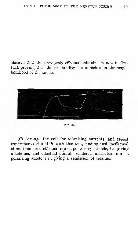
observe that the previously effectual stimulus is now ineffec-
tual, proving that the excitability is diminished in the neigh-
bourhood of the anode.
Fig. a.
(C) Arrange the coil for tetanising currents, and repeat
experiments A and B with this test, finding just ineffectual
stimuli rendered effectual near a polarising kathode, i.e., giving
a tetanus, and effectual stimuli rendered ineffectual near a
polarising anode, i.e., giving a remission of tetanus.
66 EXEECISBS AND DEMONSTEATIONS
(34) Law of Contractions. (Frog.)
Apparatus.—As in preceding experiments, omitting the
coil and testing electrodes, and using a rheochord to get a" weak" current.
Prepare the unpolarisable electrodes, and arrange them in
the moist chamber. Trace the current through the commu-tator, and mark what the direction will be in the nerve with
the two positions of the cradle. Put up a single cell of the
battery in connection with the rheochord, key, and commutator,
using the rheochord as a shunt, as shown in fig. 19.
Make a nerve-muscle preparation and lay the nerve across
the electrodes.
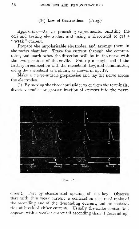
(1) By moving the rheochord slider to or from the terminals,
divert a smaller or greater fraction of current into the nerve
Fig. 45
circuit. Test by closure and opening of the key. Observethat with this weak current a contraction occurs at make of
the ascending and of the descending current, and no contrac-tion at break of either current. Usually the make contraction
appears with a weaker current if ascending than if descending.
IN THE PHYSIOLOGY OP THE NERVOUS SYSTEM. 57
(2) Remove the rheochord, bringing the battery wires
straight to the commutator, but keeping the key in.
Test as before, and observe with this stronger current that
a contraction occurs at make and at break of the ascending andof the descending current.
(3) Use a stronger electromotive force, i.e., more cells.
Test as before, and find such a strength of current that con-
traction shall occur at break of the ascending and at make of
the descending current, but no contraction at make of the
ascending nor at break of the descending current.
You have now verified Pfliiger's law of contractions :
—
58 EXERCISES AND DEMONSTRATIONS
(35) Law of Contractions. (Man.)
Apply one electrode of a galvanic battery (of say thirty
Leclanche cells) to any indifferent part of the body. Use the
other as a testing electrode, applying it as close as possible to-
some superficial nerve such as the ulnar or median at the
elbow, or the peroneal at the head of the fibula. Test on such
nerve the effect as regards muscular contraction of make and
of break of the kathode and anode, gradually increasing the
number of cells in use by means of the collecting dial on the
battery.
Observe (1) that the first effect is obtained with kathodic
closure ; (2) that the next to appear is the anodic closure, or
the anodic opening contraction ; and (3) that (unless an exces-
sively strong current is used) kathodic opening produces noeffect. Note in each case the smallest number of cells with
which an effect is visible, oy preferably put into the circuit th&galvanoscope mentioned on p. 6, and note in each case the
smallest deflection with which an effect is visible. [N.B.
—
The graduation of the galvanoscope is supposed to indicate
milliamperes.J
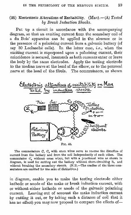
IN THE PHYSIOLOGY OP THE NBBVOUS SYSTEM. 59
(36) Electrotonic Alterations of Excitability. (Man).—(A) Tested
by Break Induction Shocks.
Put up a circuit in accordance with the accompanyingdiagram, so that an exciting current from the secondary coil of
a du Bois' apparatus can be appHed in the absence or in
the presence of a polarising current from a galvanic battery (of
say 30 Leclanche cells). In the latter case, i.e., when the
exciting current is superposed upon a polarising current, their
coincidence is secured, inasmuch as both currents enter or leave
the body by the same electrodes. Apply the testing electrode
to the median nerve at the bend of the elbow, or to the peroneal
nerve at the head of the fibula. The commutators, as shown
+ o r—
Fig. 46.
The commutators C, C^ with cross wires serve to reverse the direction of
current from the battery and from the coil independently of each other. Thecommutator Cj without cross wires, but with a Junctional wire as shown in
diagram, is used for cutting out the battery without short-oirouiting it, and
without breaking the secondary circuit. (N.B.—The cradles of the three com-
mutators are omitted for the sake of distinction.)
in diagram, enable you to make the testing electrode either
kathode or anode of the make or break induction current, with
or without either kathode or anode of the galvanic polarising
current. Leaving out of account the make induction current
by cutting it out, or by taking such a distance of coil that it
has no effect) you may now proceed to compare the effects of
—
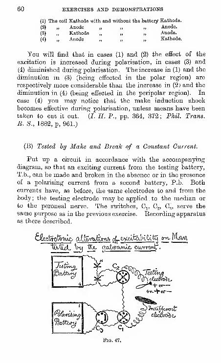
60 EXERCISES AND DEMONSTRATIONS
(1) The eoil Kathode with and without the battery Kathode.
(2) „ Anode „ „ „ Anode.
(3) „ Kathode „ „ „ Anode.
(4) „ Anode „ „ „ Kathode.
You will find that in cases (1) and (2) the effect of the
excitation is increased during polarisation, in cases (3) and
(4) diminished during polarisation. The increase in (1) and the
diminution in (3) (being effected in the polar region) are
respectively more considerable than the increase in (2) and the
diminution in (4) (being effected in the peripolar region). In
case (4) you may notice that the make induction shock
becomes effective during polarisation, unless means have been
taken to cut it out. (J. H. P., pp. 364, 372; Phil. Trans.
B. S., 1882, p, 961.)
(B) Tested by Make and Break of a Constant Current.
Put up a circuit in accordance vyith the accompanyingdiagram, so that an exciting current from the testing battery,
T.b., can be made and broken in the absence or in the presence
of a polarising current from a second battery, P.b. Bothcurrents have, as before, the same electrodes to and from the
body ; the testing electrode may be applied,to the median or
to the peroneal nerve
same purpose as in the previous exercise,
as there described.
The switches, G^, G^, G^, serve the
Recording apparatus
()-rt.+(sr
—
Fig. 47.
IN THE PHYSIOLOGY OP THE NEEVOUS SYSTEM. 61
The keys, K^, Kg, are introduced in order to allow the test-ing current from T.b. to be made and broken without affectingthe circuit of the polarising current from P.b., K^ being usedas a short-circuiting key that breaks the test current whenclosed, and makes it, when opened ; Kg being used as a guardkey to save the battery from remaining short-circuited when Kjis closed ; to this end K„ must be opened directly after K^is closed, for a test break ; K^ must be closed directly before K^is opened, for a test make.
The comparisons that are to be made with this dispositionof apparatus are the effects of
—
(1) K.C.C. alone and K.C.C. upon a Kathodic current.
(2) A.C.C. alone and A.C.C. upon an Anodic current.
(3) A.O.C. alone and A.O.C. from an Anodic current.
(1) K.C.C. alone and K.C.C. during Kathodic polarisation.
(2) A.C.C. alone and A.C.C. during Anodic polarisation.
(3) A.O.C. alone and during Anodic polarisation.
Observe that
—
(1) K.C.C. is increased during Kathodic polarisation.
(2) A.C.C. is increased during Anodic polarisation.
(3) The increase of K.C.C. in (1) is greater than theincrease of A.C.C. in (2) ; i.e., in (1) the increase is effected inthe polar region, in (2) it is effected in the peripolar region.
(4) A.O.C. is diminished during Anodic polarisation; inthis case the diminution is effected in the peripolar region.
With regard to the strengths of current to be used for test-
ing and for polarising, no numerical directions are given ; themost suitable numbers of cells to be used in each case are to beascertained by trial. If a galvanometer is used (and properly it
should be) it is to be placed on the course of the wire joining
the reversers, Cj, Cg.
(C) Tested by Mechanical Excitation.
This is the simplest and most unobjectionable mode of
demonstrating kathodic augmentation and anodic diminution of
excitability. It is best made on the ulnar nerve ; the apparatus
required being a battery, a reverser, electrodes, and a mallet.
As before, the object aimed at is coincidence of test excitation,
and of polarisation in a nerve.
62 EXERCISES AND DEMONSTRATIONS
Applying the testing-electrode against the ulnar nerve, find,
by tapping it with the mallet, a force of blow sufficient to makethe fingers twitch slightly. While taps are being applied
at regular intervals, giving regular finger twitches, make a
polarising current, kathodic, through the test-electrode, and
observe that the twitches are strengthened ; then make a
polarising current, anodic, through the test-electrode, and
observe that the twitches are weakened or abolished. Theaugmentation and diminution are effected in the polar region of
the current passing through the nerve.
IN THE PHYSIOLOGY OP THE NERVOUS SYSTEM. 63
(37) Measurement of the Velocity of Transmission of Nerve-
Impulses in the Motor Nerves of Man.
Use the pendulum myograph, or a spring-myograph. Pre-
pare also (1) a small, thick-walled india-rubber bag, connected
by tubing with a Marey's tympanum; (2) a cell, induction coil,
and electrodes (one large flat electrode, and one small electrode,
fixed to a handle); (3) a tuning-fork (100 per sec.)
Put up the circuit as follows : primary circuit to include a
fixed " snap " key, which is struck open by the plate-carrier of
the myograph ; secondary circuit in connection with yourself,
by strapping the flat electrode to one leg, and using the small
electrode to excite the brachial nerves. Assure yourself that
the contact at the snap key is not loose when the key is closed.
Hold the india-rubber bag between the middle finger and
thumb of the left hand, and taking the small electrode in the
right hand, press it against the nerves (A), above the left
clavicle (B), at the bend of the forearm. Find the best points
of application by trial stimuli (these should be made by an
assistant, by a simple key in the primary circuit.)
All being ready (i.e., plate ready to let off, electrodes
appUed, primary circuit closed, india-rubber ball in hand, lever
of tympanum just touching the recording surface) the plate is
let off. In its passage the plate-carrier strikes open the key,
giving a break induction shock, by which the nerves at A are
excited, the flexor muscles pinch the bag, and cause a sharp
rise of the tympanum-lever.
A second observation is taken with the small electrode
applied at B, great care being taken in re-setting the plate-
carrier not to disturb the position of the tympanum.
It will be found that the contraction caused by distal excita-
tion (at A) commences to rise from the base-line a little earlier
than that caused by proximal excitation (at B). For measur-
ing purposes a pair of contractions should be selected which
are as equal as possible.
The time-value of the interval between the two rises is
ascertained by the tuning-fork.
The velocity of impulse is calculated from this time-value,
and from the length of nerve between A and B. It will be
found to be about 50 metres per second.
64 BXBECISBS AND DBMONSTBATIONS
(38) Influence of Temperature upon the Excitability of Nerve.
Dem. Tested (a) by induction currents; (6) by make of the
constant current. (Gotch.)
Preliminaries.—Arrange two beakers, tubing and clips, to
deliver a flow of hot, or of cold water through a thin glass tube
across which the nerve is to be laid.
Prepare a cell and rheochord to obtain a weak constant
current by a small fraction of a volt. Wire rheostats, as
shown in fig. 16, had better not be used, on account of the
possibility of induction ; a short zinc rheostat, as figured below,
is preferable.
Put up the induction apparatus, using a spring key Kj^
in the primary circuit, and a short-circuiting key Kg in the
secondary circuit.
Connect the coil and the rheochord respectively with the
two sides of a commutator without cross-wires, and lead off
the exciting (unpolarisable) electrodes from the two middle
pools (or in place of the commutator use two short-circuiting
keys, connected as in fig. 7); make the connections so as to
have current descending in the nerve.
Put up the nerve-muscle preparation, laying the nerve across
the water-tube (and upon short, rather stiff cords), moistenedwith saline, projecting from the clay ends of the exciting elec-
trodes. Let the water-tube be as close as possible to theelectrode nearest the muscle.
Experi^nents.—Find the minimum stimulus to :
(a) A descending induced cur-
rent
Do. Do.
(6) Make of descending con-
stant current
Do. Do.
with warm water passing
through the tube.
with cold water.
with warm water.
with cold water.
or, having found a moderately effective strength of stimulation
at ordinary room-temperature (about 15"), make stimuli at
regular intervals (conveniently so by a metronome) and test theeffect of warming and cooling upon :
—
(a) the effects of induction shocks;
{b) the effects of make of the constant current.
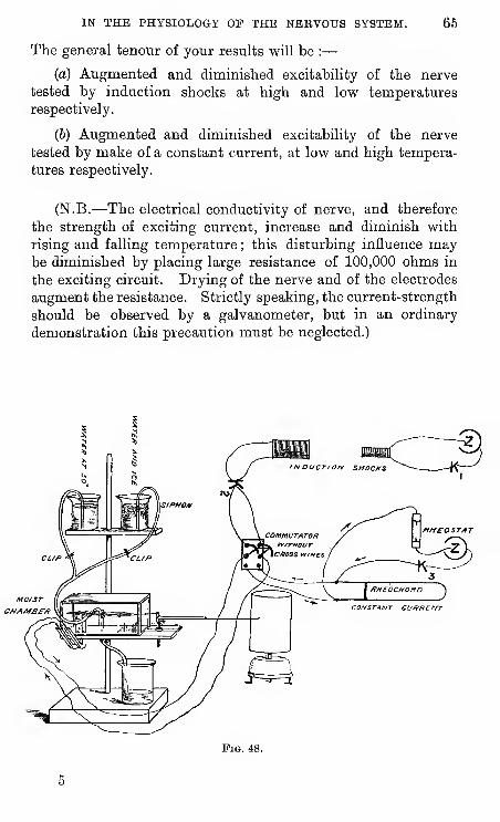
IN THE PHYSIOLOGY OP THE NERVOUS SYSTEM. 66
The general tenour of your results will be :
—
(a) Augmented and diminished excitability of the nerve
tested by induction shocks at high and low temperatures
respectively.
(b) Augmented and diminished excitability of the nerve
tested by make of a constant current, at low and high tempera-
tures respectively.
(N.B.—The electrical conductivity of nerve, and therefore
the strength of exciting current, increase and diminish with
rising and falling temperature ; this disturbing influence maybe diminished by placing large resistance of 100,000 ohms in
the exciting circuit. Drying of the nerve and of the electrodes
augment the resistance. Strictly speaking, the current-strength
should be observed by a galvanometer, but in an ordinary
demonstration this precaution must be neglected.)
MO/srCHA/HB£-/t
Fig. 48.
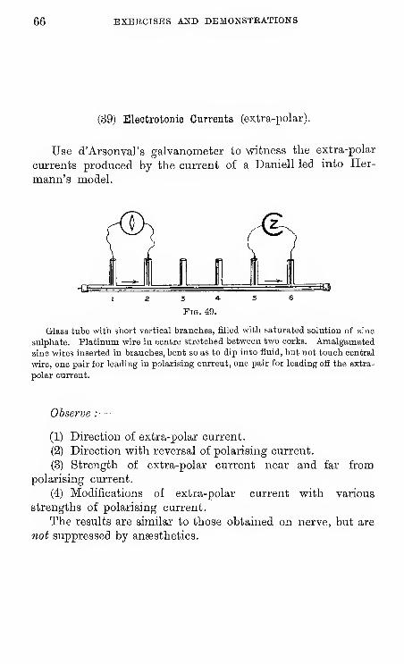
66 EXBECISES AND DEMONSTRATIONS
(39) Electrotonic Currents (extra-polar).
Use d'Arsonval's galvanometer to witness the extra-polar
currents produced by the current of a Daniell led into Her-
mann's model.
Glass tube with short vertical branches, filled with saturated solution of zinc
sulphate. Platinum wire in centre stretched between two corks. Amalgamated
zinc wires inserted in branches, bent so as to dip into fluid, but not touch central
wire, one pair for leading in polarising current, one pair for leading off the extra-
polar current.
Observe :—
(1) Direction of extra-polar current.
(2) Direction with reversal of polarising current.
(3) Strength of extra-polar current near and far from
polarising current.
(4) Modifications of extra-polar current with various
strengths of polarising current.
The results are similar to those obtained on nerve, but are
not suppressed by anaesthetics.
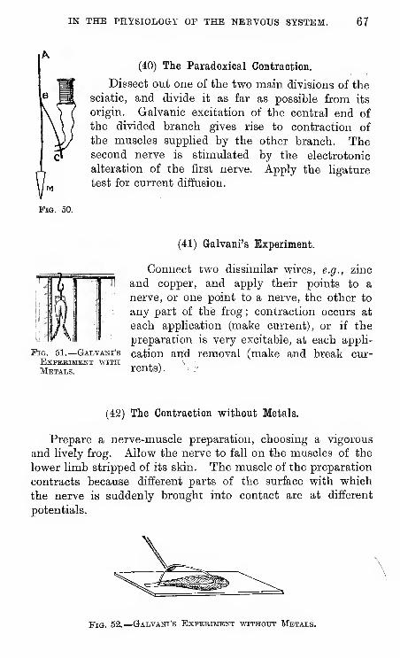
IN THE PHYSIOLOGY OF THE NERVOUS SYSTEM. 67
(40) The Paradoxical Contraction.
Dissect out one of the two main divisions of the
sciatic, and divide it as far as possible from its
origin. Galvanic excitation of the central end of
the divided branch gives rise to contraction of
the muscles supplied by the other branch. Thesecond nerve is stimulated by the electrotonic
alteration of the first nerve. Apply the ligature
test for current diffusion.
50.
(41) Galvani's Experiment.
Connect two dissimilar wires, e.g., zinc
and copper, and apply their points to a
nerve, or one point to a nerve, the other to
any part of the frog ; contraction occurs at
each application (make current), or if the
preparation is very excitable, at each appli-
PiG. 51.—Gadvani's cation and removal (make and break cur-EXPERIMEHT WITH , , \
Metals. rents). :'
(42) The Contraction without Metals.
Prepare a nerve-muscle preparation, choosing a vigorous
and lively frog. Allow the nerve to fall on the muscles of the
lower limb stripped of its skin. The muscle of the preparation
contracts because different parts of the surface with which
the nerve is suddenly brought into contact are at different
potentials.
Fig. 52.
—
Galvani's Expebiment without Metals.
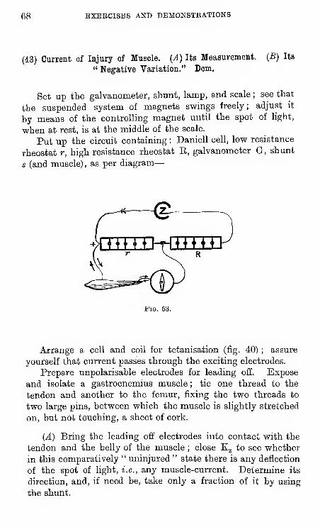
68 EXEBCISBS AND DEMONSTRATIONS
(43) Current of Injury of Muscle. {A) Its Measurement. (B) Its
" Negative Variation." Dem.
Set up the galvanometer, shunt, lamp, and scale ; see that
the suspended system of magnets svsrings freely; adjust it
by means of the controlling magnet until the spot of light,
when at rest, is at the middle of the scale.
Put up the circuit containing : Daniell cell, low resistance
rheostat r, high resistance rheostat E, galvanometer G, shunt
s (and muscle), as per diagram
—
FiQ. 53.
Arrange a cell and coil for tetanisation (fig. 40) ; assure
yourself that current passes through the exciting electrodes.
Prepare unpolarisable electrodes for leading off. Expose
and isolate a gastrocnemius muscle ; tie one thread to the
tendon and another to the femur, fixing the two threads to
two large pins, between which the muscle is slightly stretched
on, but not touching, a sheet of cork.
(A) Bring the leading off electrodes into contact with the
tendon and the belly of the muscle ; close Kg to see whether
in this comparatively " uninjured " state there is any deflection
of the spot of light, i.e., any muscle-current. Determine its
direction, and, if need be, take only a fraction of it by using
the shunt.
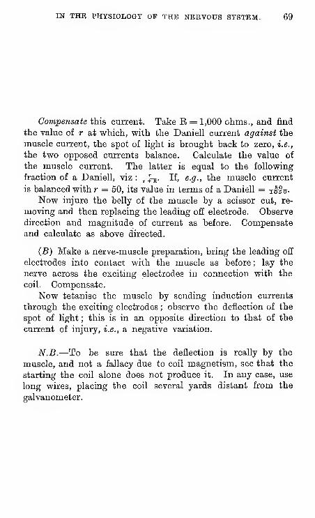
IN THE PHYSIOLOGY OP THE NERVOUS SYSTEM. 69
Compensate this current. Take E = 1,000 ohms., and find
the value of r at which, with the Daniell current against the
muscle current, the spot of light is brought back to zero, i.e.,
the two opposed currents balance. Calculate the value of
the muscle current. The latter is equal to the following
fraction of a Daniell, viz : y^. If, e.g., the muscle current
is balanced with?- = 50, its value in terms of a Daniell = Tufij-
Now injure the belly of the muscle by a scissor cut, re-
moving and then replacing the leading off electrode. Observe
direction and magnitude of current as before. Compensateand calculate as above directed.
(B) Make a nerve-muscle preparation, bring the leading off
electrodes into contact with the muscle as before ; lay the
nerve across the exciting electrodes in connection with the
coil. Compensate.
Now tetanise the muscle by sending induction currents
through the exciting electrodes ; observe the deflection of the
spot of light ; this is in an opposite direction to that of the
current of injury, i.e., a negative variation.
N.B.—To be sure that the deflection is really by the
muscle, and not a fallacy due to coil magnetism, see that the
starting the coil alone does not produce it. In any case, use
long wires, placing the coil several yards distant from the
galvanometer.
70 EXERCISES AND DEMONSTRATIONS
(44) Nerve-currents ; the Current of Injury and its Negative
Variation. Dem.
Same apparatus and preparations as for the analogous
experiments on muscle. Connections as in fig. 53, an excised
sciatic nerve enclosed in a moist chamber (fig. 48) taking the
place of the muscle.
Having assured yourself that all parts of the apparatus are
in vforking order, isolate and excise a frog's sciatic, and lay it
upon the exciting and leading-off electrodes ; let the cut end
of the nerve rest upon one of the latter.
Close the galvanometer key ; observe the deflection, and
trace the current from longitudinal to transverse section
through the galvanometer, viz., transverse section or injured
part negative to longitudinal surface.
Measure this current of injury by compensation, as in the
case of muscle.
Nov? tetanise the nerve for five to ten seconds by sending
induction currents through the exciting electrodes. Observe
the deflection, which is opposed to that caused by the current
of injury, i.e., a negative variation.
Bepeat the tetanisation with the direction of the exciting
currents reversed, and observe that the negative variation is
unchanged in direction.
[N.B.—You may repeat this experiment an indefinite
number of times without any diminution of the variation
becoming apparent;you will be tired out before the nerve
shows any signs of fatigue, provided you do not injure it bycurrents of excessive strength. The fallacies of current-
escape and of electrotonic current have been met by the
reversal of the exciting current ; that of unipolar excitation
can be tested by detaching one of the wires from the secondary
coil ; any magnetic effect of the coil has been tested for at the
outset.]
IN THE PHYSIOLOGY OP THE NERVOUS SYSTEM. 71
(45) Action of Anaesthetics upon Isolated Nerve. Carbon Dioxide,
Chloroform, and Ether. Dem.
Tetanise the nerve during regular periods at regularintervals and observe that the negative deflections are of
regular magnitude. To do this, time yourself by the seconds'hand of a watch, tetanising during say five or ten seconds at
minute intervals.^
(a) Having assured yourself of the regularity of the de-
flections, blow a little strong ether vapour into the nervechamber, and continue to tetanise at minute intervals ; observethat the deflection is abohshed. Clear out the ether vapour,and observe that the deflection returns.
(6) Repeat the experiment with strong chloroform vapour.The results are similar; the difference, if any, being to theeffect that the abolition is more prompt, the return moredelayed.
(c) Send a stream of COg gas through the nerve chamberfor two or three minutes, then blow it out. The deflection is
diminished or abolished during the passage of COg, and subse-
quently greatly augmented.
(d, e, f) If the three preceding experiments are made withweaker reagents—with, e.g., a very slow stream of COg, or
with one per cent, ether or one per cent, chloroform in the
wash bottle, a primary stimulant instead of a primary de-
pressant effect will be obtained, i.e., the deflection will be
augmented while the nerve is under the influence of the
reagent.
[N.B.—Strong chloroform and ether vapour clear off very
slowly, and should be used last if it is intended to show each
of the six experiments above described. The best order then
isd, e,f, c, a, b.]
' It is convenient, but not indispensable, to stimulate automatically. Thesimplest means to this end is an ordinary clock with a platinum wire soldered to
the seconds' wheel, arranged to complete a circuit once a minute for say seven
and a half seconds by passing through a mercury pool.

72 EXEKCISES AND DEMONSTRATIONS
(46) The Secondary Contraction.— Pith a frog. Make two
nerve-muscle preparations. Lay the nerve of II. across the
muscle of I. Tetanise the nerve of I., and observe that the
muscle of II., as well as that of I., enters into contraction.
Test for current escape by crushing or ligaturing the nerve
of II. If tetanisation of nerve I. still gives a contraction of
muscle II., there has been current escape. A true secondary
contraction (abolished by ligature) is due to excitation of nerve
II. by a negative variation of the current of muscle I.
Fig. 54.
—
The Secondaby Contbaction.
(47) Secondary Contraction from the Heart.
Excise the heart
Pig. 55.
lay the nerve of a fresh nerve-muscle
preparation upon it as per dia-
gram. The muscle contracts
at each beat of the heart, being
excited by the electrical cur-
rent which accompanies eachbeat.
(48) An Apparent Anomaly due to Secondary Contraction.(Hering.)—After the foregoing experiments have been per-formed, the following simple and striking experiment by Heringmay be undertaken without arousing misconception.
A frog is pithed, and the urostyle removed, exposing onboth sides the long nerve roots lying on the ileo-coccygealmuscle, and which form the sciatic nerve. These are to becleanly divided by scissors on both sides, at or about the middleof their exposed length. The motor nerve roots above are nowexposed, or a pair of stiff wire electrodes are pushed down thespinal canal so as to come in contact with them.
IN THE PHYSIOLOGY OF THE NERVOUS SYSTEM. 73
On weak tetanisation of these roots the limbs are tetaiiised.
The result is due to contraction of the coccygeal inuscles
(supplied by nerves arising above the point of division) whichexcites the peripheral ends of the divided sciatic roots.
[Superficially regarded, the result appears as if division of
nerve has not interfered with the conduction of impulses ; but
equally obviously (1896) this is absurd.]
(49) Secondary Excitation from Nerve to Nerve. (Hering.)
—
A frog is pithed, a sciatic nerve is exposed from hip to knee,
ligatured at the knee, divided beyond the knee, and isolated
from knee to hip.
By means of the thread, the distal part of this central end
is laid across electrodes and tested by weak tetanisation. Astrength of current is thus found at which the muscles of the
thigh are made to contract.
This contraction is not augmented, but, on the contrary,
disappears when the electrodes are slipped higher up the nerve,
i.e., nearer to rest of the frog. Therefore the contraction is not
due to current-escape. For the same reason it cannot be a
" paradoxical contraction "—an excitation of centrifugal nerve-
fibres to thigh muscles by electrotonic currents aroused in ad-
jacent nerve-fibres. Therefore, by exclusion, it is due to the
excitation of nerve-fibres to the thigh by the action-currents of
adjacent nerve-fibres, i.e., a true secondary excitation of nerve
by nerve.
[N.B.—-This experiment goes best with " cold frogs," i.e.,
frogs kept in the cold—0° to 2°—and left for a few hours before
use at room temperature, about 15°. On beginning to test the
distal end of the nerve, vary the direction of excitation by
turning the electrodes one way or the other, and continue to
test with the electrodes in the more favourable direction (which
will be such that the kathode of the break shock is distal to the
anode.)
The "paradoxical contraction" itself is, in certain cases,
attributable to action-currents ; in such case it diminishes as
the electrodes are slipped upwards from the distal end; whenit increases with this changed situation of the electrodes, it is
of electrotonic origin (or, it may be by reason of current-
escape).]
74 EXERCISES AND DEMONSTEATIONS
(50) Electrical Variations of the Prog's Heart.
Arrange the capillary electrometer under a low power of
the microscope, and assure yourself that the mercury movesfreely (Ex. 20). Connect a pair of silver electrodes with the
two sides of its short-circuiting key.
(1) Pith a frog and expose the heart. Bring the electrodes
in contact with apex and base of the beating ventricle, using
bits of moist wool tied to the ends of the electrodes, as the
connecting links between electrodes and ventricle, so as to
avoid shifting of contacts. Open the key, and, if necessary,
readjust the pressure apparatus so as to bring the mercury
into field. See w-hether the mercury pulsates with the pulsa-
tion of the heart, and if it does, note the order and direction
of its movements, and interpret their significance.^
(2) Arrest the heart by a Stannius' ligature. Excise it, andplace it on a moist slip of wood. Bring the wool ends of the
electrodes in contact with the apex and base of the ventricle.
Observe the effect of a beat provoked by exciting the ventricle
with a needle-touch (a) near the base, (b) near the apex.
(3) Separate the ventricle from the rest of the heart by a
scissor cut through the auriculo-ventricular junction. Connectthe electrodes with base and apex of ventricle, and note the
effects on electrometer (a) of spontaneous beats, if such occur
;
(h) of beats provoked by a needle-touch, if the ventricle is not
beating spontaneously.
' With the heart in situ, the movements of the mercury are not always easyto interpret; they may apparently be mono-, di-, tri-, or poly-phasic, accordingto various circumstances, and in consequence of auricle, or sinus, or bulb con-
tributing to the main efiect vphich is of the ventricle.
With a stanniused heart, the effect of a beat excited by a needle touch is
normally diphasic, being| g^ ^^^^
''^^- when excitation is applied to the -base,
i 2 base nen''^^^^ excitation is applied to the apex. But here again the
variation may be complicated by an effect from the bulbus arteriosus.
With a ventricle preparation, it will be noted, that the injured base becomesstrongly negative, and that the main, or, it may be, the sole variation with eachbeat, whether spontaneous or provoked, is such as to indicate apex neg.
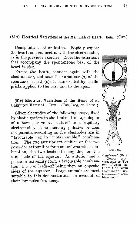
IN THE PHYSIOLOGY OF THE NERVOUS SYSTEM. 75
(51a) Electrical Variations of the Mammalian Heart. Dem. (Cat.)
Decapitate a cat or kitten. Rapidly expose
the heart, and connect it with the electrometer,
as in the previous exercise. Note the variations
that accompany the spontaneous heat of the
heart in situ.
Excise the heart, connect again with the
electrometer, and note the variations (a) of the
spontaneous beat, (b) of beats excited by needle-
pricks applied to the base and to the apex.
(516) Electrical Variations of the Heart of an
Uninjnred Mammal. Dem. (Cat, Dog, or Horse.)
Silver electrodes of the following shape, fixed
by elastic garters to the limbs of a large dog or
of a horse, serve as leads-off to a capillary
electrometer. The mercury pulsates or does
not pulsate, according as the electrodes are in
"favourable" or in "unfavourable" combina-
tion. The two anterior extremities or the two
posterior extremities form an unfavourable com-
bination, the two leads-off being then on the
same side of the equator. An anterior and a
posterior extremity form a favourable combina-
tion, the two leads-off being then on opposite
sides of the equator. Large animals are most
suitable to this demonstration on account of
their low pulse frequency.
Quadruped (Gat).
— Nearly trans-
verse equator. Thetwo anterior ex-
tremities formtherefore an "un-favourable " com-bination.
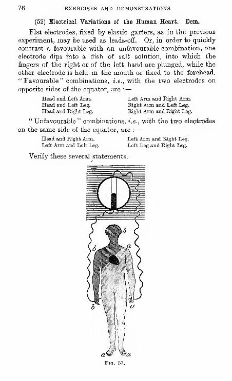
76 EXERCISES AND DEMONSTRATIONS
(52) Electrical Variations of the Human Heart. Dem.
Flat electrodes, fixed by elastic garters, as in the previous
experiment, may be used as leads-off. Or, in order to quickly
contrast a favourable with an unfavourable combination, one
electrode dips into a dish of salt solution, into which the
fingers of the right or of the left hand are plunged, while the
other electrode is held in the mouth or fixed to the forehead.
"Favourable" combinations, i.e., with the two electrodes on
opposite sides of the equator, are :
—
Head and Left Arm.Head and Left Leg.
Head and Bight Leg.
" Unfavourable " combinations, i.e., with the two electrodes
on the same side of the equator, are :
—
Head and Eight Arm. Left Arm and Right Leg.
Left Arm and Left Leg. Left Leg and Kight Leg.
Verify these several statements.
Left Arm and Right Arm.Right Arm and Left Leg.
Right Arm and Right Leg.
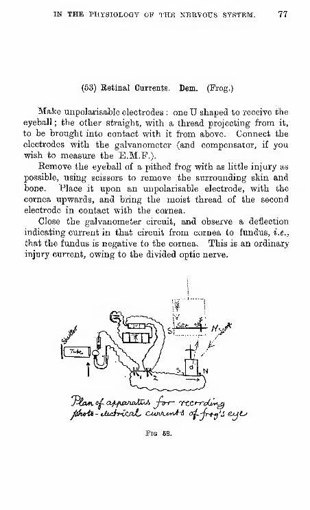
IN THE PHYSIOLOGY OF THE NEEVOUS SYSTEM. 77
(53) Retinal Currents. Dam. (Frog.)
Make unpolarisable electrodes : one U shaped to receive the
eyeball ; the other straight, with a thread projecting from it,
to be brought into contact with it from above. Connect the
electrodes with the galvanometer (and compensator, if youwish to measure the E.M.F.).
Eemove the eyeball of a pithed frog with as little injury as
possible, using scissors to remove the surrounding skin and
bone. Place it upon an unpolarisable electrode, with the
cornea upwards, and bring the moist thread of the second
electrode in contact with the cornea.
Close the galvanometer circuit, and observe a deflection
indicating current in that circuit from cornea to fundus, i.e.,
that the fundus is negative to the cornea. This is an ordinary
injury current, owing to the divided optic nerve.
ji^i^ - ubuJiricajL C-UnA.t'y^A-i ai.-(r^'S &<jt^
Fig 68.
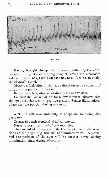
78 BXEECISES AND DEMONSTRATIONS
rt-^Z
« I Si
f -, s J ' f' < M
.' ' /t
Pig. 59.
Having brought the spot to mid-scale, either by the com-
pensator or by the controlhng magnet, cover the electrodes
with an opaque box, taking all care not to shift wires or shake
the electrode stand.
Observe a deflection in the same direction as the current of
injury, i.e., a positive variation.
Bemove the box, observe again a positive variation.
Leaving the box on or off for a few minutes, observe that
the spot occupies a more positive position during illumination,
a less positive position during obscurity.
N.B.—It will save ambiguity to adopt the following dis-
position :
—
Cornea to south terminal of galvanometer.
Nerve to north terminal of galvanometer.
The current of injury will deflect the spot north, the varia-
tions at the beginning and end of illumination will be north,
and the position of the spot will be further north during
illumination than during obscurity.
IN THE PHYSIOLOGY OP THE NERVOUS SYSTEM. 79
(54) Sound is Produced during Muscular Contraction.
{A) With Voluntary Contraction.—^Place the junction of
the hand and wrist against the ear, and alternately clench andrelax the fist ; a low rumbling sound is heard throughout,
which is much intensified during contraction. The less in-
tense rumbling heard while the fist is relaxed is due to musclesby which the arm is raised to the ear. During the moreintense rumbling heard while the fist is clenched, an overtone
an octave above the rumbling sound may become audible.
With an ordinary stethoscope auscultate the flexor musclesin the forearm of a second person, who alternately clenches andrelaxes the fist.
{B) With Contraction by Faradisation.—Arrange a battery,
induction coil, and interrupter in one room, and connect the
secondary coil by long wires with a Du Bois key in another
room in which the vibrations of the interrupter are not
audible. Use Page's reeds as the interrupter, and tetanise the
muscles of the forearm at frequencies of 20, 50, and 100 per
second, auscultating as before. A note of corresponding pitch
will be plainly audible.
N.B.—You may compare this muscular note with that of
the interrupter by means of a telephone introduced into the
secondary circuit.
(C) During Galvanotonus.—Use a strong galvanic current
to tetanise the muscles, applying the exciting electrode o^'er
the median nerve at the bend of the elbow, and auscultate
as before. The pitch of the muscle-sound heard during
galvanotonus is identical with that of the sound heard with
voluntary contraction.
;tJote.—^You may with reason doubt whether the pitch of
the sounds heard in experiments A and G is due to muscular
vibrations, and not simply a resonation tone of your own ear ..
80 EXEECISES AND DEMONSTRATIONS
(56) Heat is produced during Muscular Contraction.
A.—With the Excised Muscles of a Frog. Dem.
Apparatus andpreparations.—Low resistance galvanometer.
Two thermo-electric needles. Cell, coil, keys, and two pairs
ordinary electrodes. Commutator without cross wires, arranged
to turn the secondary current to one or other pair of electrodes.
See that the apparatus is in good working order before pro-
ceeding further. Note in what direction the spot of light
moves when one or other of the two thermo-electric needles
is touched.
Pith the frog, expose and isolate both sciatic nerves, and
both gastrocnemii ; insert each of the two needles longitudinally
into each of the two muscles, and lay each of the two nerves
across a pair of electrodes. Wait till the galvanometer spot is
steady.
Now tetanise one of the muscles for, say one minute, and
watch the spot for the next few minutes ; it should move in a
direction indicating greater heat of the contracting muscle.
After a short interval, turn the commutator so that the
other nerve shall be excited when the key in the secondary cir-
cuit is raised. Bepeat the excitation on that side and watchthe spot, which should move in the opposite direction to its
movement in the first experiment, indicating however, as
before, greater heat of contracting muscle.
N.B.—The galvanometer, and all other terminals, shouldbe protected from draughts of air by wadding, to guard against
accidental effects of temperature changes at adventitious
junctions of dissimilar metals.
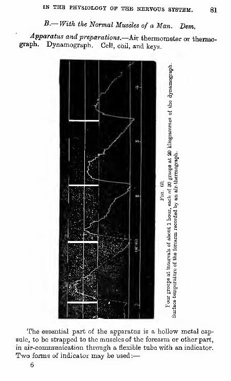
IN THE PHYSIOLOGY OF THE NERVOUS SYSTEM. 81
B.—With the Normal Muscles of a Man. Bern.
Apparatus and preparations.—Mx thermometer or thermo-graph. Dynamograph. Cell, cbil, and keys.
The essential part of the apparatus is a hollow metal cap-
sule, to be strapped to the muscles of the forearm or other part,
in air-communication through a flexible tube with an indicator.
Two forms of indicator may be used:
—
6
82 EXERCISES AND DEMONSTRATIONS
(1) For the purpose of demonstration, a small water-mano-
meter in which the level of water can be watched directly, or
projected on a screen, by placing the manometer in the magic
lantern.
(2) For the purpose of recording the variations, a piston-
recorder, the lever of which is adjusted above that of the
dynamograph, on the same cylinder.
Whichever form of indicator be adopted, it should be
graduated in tenths of a degree, by immersing the capsule
in a vessel of cooling water by the side of a mercury ther-
mometer.
When the apparatus is iirst applied to the skin it should be
left in situ, with the side tap open until it is in temperature
equilibrium. This is known by the lever or manometer re-
maining stationary with the side tap closed. This occurs with
less delay, i.e., in about say five min., if the capsule is warmedbetween the hands or kept in a pocket against the body before
use.
While an observation is in progress, the side-tap is kept
shut, the object being to record variations of temperature, andnot absolute values. These variations should not exceed 1"5°,
if they do, the indicator should be zeroed, by opening the tap.
Using the piston-recorder on the forearm, and the dynamo-graph, take a record of
—
(1) The effect of, say 30 grasps of 20 kilos, of 2 sec. duration,with 2 sec. intervals.
(a) With normal circulation.
(b) With the circulation arrested by an elastic bandageapplied tightly round the arm.
Notice the effect in (a), i.e., that the temperature of the fore-
arm is raised, and the much smaller effect in (b), i.e., that the rise
is in greatest part due to an augmented circulation of blood.
(2) Compare the effect of 30 with that of 15 similar graspsof 20 kilos at 2"—2" rhythm.
(3) Compare the effect of 30 grasps of 20 kilos at 2" 2"
rhythm with that of 30 grasps of 10 kilos at the same rhythm.(4) Compare the effect of 30 voluntary grasps of 10 kilos at
2"—2" rhythm with that of 30 similar grasps provoked byfaradisation of the muscles. Notice that the temperatureeffect is greater in the former case than in the latter.
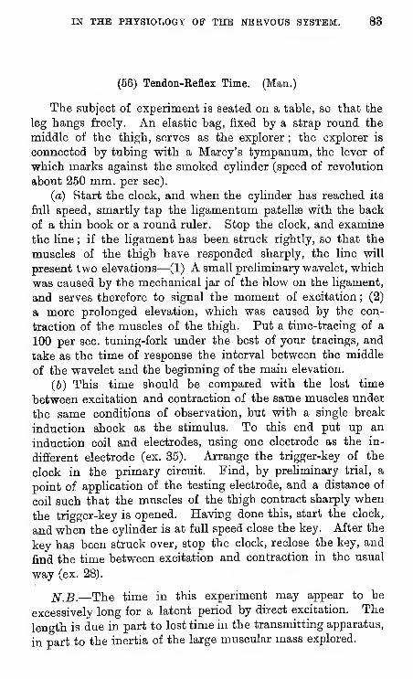
IN THE PHYSIOLOGY OF THE NERVOUS SYSTEM. 83
(56) Teadon-Reflex Time. (Man.)
The subject of experiment is seated on a table, so that the
leg hangs freely. An elastic bag, fixed by a strap round the
middle of the thigh, serves as the explorer ; the explorer is
connected by tubing with a Marey's tympanum, the lever of
which marks against the smoked cylinder (speed of revolution
about 250 mm. per sec).
(a) Start the clock, and when the cylinder has reached its
full speed, smartly tap the ligamentum patellae with the back
of a thin book or a round ruler. Stop the clock, and examine
the hne ; if the ligament has been struck rightly, so that the
muscles of the thigh have responded sharply, the line will
present two elevations—(1) A small preliminary wavelet, which
was caused by the mechanical jar of the blow on the ligament,
and serves therefore to signal the moment of excitation; (2)
a more prolonged elevation, which was caused by the con-
traction of the muscles of the thigh. Put a time-tracing of a
100 per sec. tuning-fork under the best of your tracings, and
take as the time of response the interval between the middle
of the wavelet and the beginning of the main elevation.
(6) This time should be compared with the lost time
between excitation and contraction of the same muscles under
the same conditions of observation, but with a single break
induction shock as the stimulus. To this end put up an
induction coil and electrodes, using one electrode as the in-
different electrode (ex. 35). Arrange the trigger-key of the
clock in the primary circuit. Find, by preUminary trial, a
point of application of the testing electrode, and a distance of
coil such that the muscles of the thigh contract sharply when
the trigger-key is opened. Having done this, start the clock,
and when the cyHnder is at full speed close the key. After the
key has been struck over, stop the clock, reclose the key, and
find the time between excitation and contraction in the usual
way (ex. 28).
N.B.—The time in this experiment may appear to be
excessively long for a latent period by direct excitation. The
length is due in part to lost time in the transmitting apparatus,
in part to the inertia of the large muscular mass explored.
84 EXERCISES AND DBMONSTBATIONS
The lost time in the transmitting apparatus can be deter-
mined as follows:—The explorer is arranged on a firm base
under a lever, the point of which is adjusted against the cylinder
under the point of the tympanum lever. With the cylinder
at full speed, the lower lever is tapped ; both levers record the
movement, the tympanum lever beginning to move slightly
after the explorer lever. The difference between the initial
points of the two elevations gives the lost time in the trans-
mission of movement from explorer to recorder. To measure
this difference at all accurately, these initial points should be
measured from " corresponding points," i.e., pairs of points
on the abscissae of the two levers marked by tapping the
explorer lever with the cylinder stationary.
(57) Tendon-Reflex Time. Dam. (Eabbit.)
A rabbit laid on its back in a shallow wooden trough,
unrestrained by any ligature, will remain quiet for an in-
definite time in an attitude that is convenient for the study of
" tendon-reflex " and its comparison with other movements.
(a) Connect the leg of a rabbit so disposed by a fine thread
to a light lever touching the smoked cylinder. Start the
clock, and when the cylinder is at full speed tap the lig.
patellae with the edge of a paper-knife. A record is obtained,
on which the tap and the response can be identified, and the
interval of time between them measured.
(b) This time should be compared with the time of a true
reflex action of the same muscles under the same conditions
of observation. To this end it is sufficient to smartly tap thetable or rabbit trough with a slip of wood, while the cylinder
revolves past the recording lever. A rabbit in this state of
slight hypnosis gives at each tap a slight reflex start withoutotherwise agitating itself. The excitatory tap and the muscularresponse are easily identified on the tracing, and the interval
of time between them measured as before.
(c) (If desired, the lost time of direct excitation of thesame muscles by a break induction shock may be taken, theelectrical apparatus being arranged as in exp. 56 b).
IN THE PHYSIOLOGY OF THE NEBVOtJS SYSTEM. 85
(58) Function of Nerve-roots. (Miiller's experiment.)
The spinal column of a decerebrated frog is exposed by amedian incision and cleared of the muscles on each side of the
spinous processes ; the cord is then exposed by a pair of saw-cuts on each side, fine bone-forceps or stout scissors being
used to complete the exposure of the nerve-roots.
The three posterior roots of the 7th, 8th, and 9th nerves,
lying upon the corresponding anterior roots, are now to beisolated by a fine seeker. A posterior root is ligatured anddivided as far as possible from the cord ; electrical or mechani-cal excitation of its central end gives rise to general (reflex)
movement. Another posterior root is ligatured and divided as
near the cord as possible ; excitation of its peripheral end pro-
duces no effect.
A similar pair of experiments is then made upori two of the
underlying anterior roots. Excitation of a central end pro-
duces no effect ; excitation of a peripheral end produces move-ment of the corresponding limb.
With a little care, the demonstration may be made as
follows :—The three posterior roots are divided on one side (say
the left) ; on the other side the posterior roots are carefully
turned aside and the three anterior roots divided. On touching
the skin of the left leg with a drop of acid, nothing happens ;
on touching the right leg with a drop of acid, general (reflex)
movements are elicited, with the exception of that leg. Theleft leg is deprived of sensation, the right leg of motion.
(Miiller.)
86 BXBECISBS AND DEMONSTRATIONS
(59) Overlap of Distribution of Spinal Nerves in Skin and in
Muscles. Dam. (Sherrington.)
Exercise.—A frog, freshly killed ; the brain and the upper
part of the spinal cord have been destroyed by "pithing."
Eemove the coccyx vrith its surrounding tissues (by seizing
the tip with forceps and somewhat lifting it, then cutting from
behind, forward with strong scissors). By raising the lips of
the opening thus made each sciatic plexus is brought in view.
This plexus consists of the seventh, eighth and ninth spinal
nerves joining to form the sciatic trunk. On one side cut
through these nerves except the eighth, on the other except
the ninth.
Hang up the preparation by a thread so that it is free from
contact with anything except the thread.
With fine forceps pinch a toe of one foot. A movement is
provoked ; this is " reflex ;" it proves the persistence of an
afferent channel between the toe and the spinal cord, although
two nerves out of the three have been cut through.
Pinch the corresponding toe of the opposite foot. A reflex
again ensues, proving similarly existence of an afferent path
from it to the cord. The spinal nerve uncut on one side is not
the one left uncut on the other : either the distributions of
the spinal nerves right and left are asymmetrical, or the
stimulated toe receives sensory fibres from two segmental
nerves. As the segmental nerves are symmetrically distributed,
the latter alternative must be the explanation.
Eepeat the observation on other toes and on the planta anddorsum of the feet, applying the stimuli to right and left
alternately, and placing them as symmetrically as possible. It
will be found that the skin of the foot contains sensory nerve-
endings all over it from each of the two spinal nerves.
Take the preparation down and pith it now completely.Fix the lower end of each tibia with a pin to the cork of thefrog-board in such a way as to let the foot hang over the edgeof the board. Slit up the skin over the pre-tibial and post-tibial muscles. Place the preparation in a good light so thatany twitching of the post and pre-tibial muscles can be seen.
IN THE PHYSIOLOGY OF THE NERVOUS SYSTEM. 87
Place a thick cotton thread round the uncut nerve, both
right and left. Draw the ligature tight slowly whilst observing
the exposed muscles. It will be found that all the muscles of
the pre- and post-tibial groups twitch while the ligatures
tightened, both left and right.
Each of the muscles of these groups is therefore supplied
with motor nerve- fibres by each of the two roots excited.
The contractions can, if desired, be studied, of course,
graphically by the myograph.
88 , .^BXEBCISES AND DBMONSTBATIONS.
(60) Reflex Actions of the Brainless Frog. (Goltz.)
Expose the cranial cavity of a frog, by a scissor cut, with
one blade in the mouth as far back as it will go, and the pt^er
blade over the top of the heart.
Eemove the brain^ (hemispheres and optic lobes) and
observe that the frog placed at liberty assumes a normal
attitude, springs when stimulated, resumes its normal attitude
if turned over, avoids obstacles in springing.
Hang the frog up and touch the side of the skin with a
glass rod dipped in strong acid ; the frog raises the leg of the
same side and wipes the irritated spot, and if that leg be held
it repeats the manoeuvre with the other leg. All these highly
co-ordinated movements are reflex movements effected by the
bulbo-spinal centres, and not involving sensation. Open the
abdomen and draw out a loop of intestine. Expose the heart,
and while its movements are under observation, strike Or
pinch the intestine ; the heart is temporarily arrested (Goltz's
" Klopfversuch "). If you divide the vagi or destroy the spinal
medulla and repeat the stimulus^ the arrest does not occur. ,
Or instead of the intestine you may employ strong stimula-
tioll of a limb by the sudden tightening of a string round it.
The heart will stop, and the body of the frog vsdll becomeinert and flaccid, and will not respond to cutaneous stimuli^
The bulbo-spinal axis is in a state of " shock."
(61) Inhibitory Action of Superior upon Inferior Centres. (Frog,)
Prepare a couple of beakers, one containing one per cent.
HgS04, t^^ other saline solution.
Prepare a frog as before, removing only the hemispheres.
Hang the frog up by the lower maxilla, and when it has cometo rest raise the vessel of acid until the longest toe of one
lim.b just touches the surface. Count the number of seconds
elapsing between the stimulus and the retractation of the
limb. Place a crystal of sodium chloride upon the exposed
optic lobes, and measure the stimulus-to-reaction interval as
before. The interval is longer in the second than in the first
instance, because the excitability of the spinal cord upon whichthe reaction depends has been interfered with—" inhibited "
—
by the excitation of the optic lobes (Setschenow).
' You will probably have removed the brain at the first scissor cut.
IN THB PHYSIOLOGY OP THE NBEVOttfl SYSTEM. 8§
(62) Time of Reflex Action. (Frog.)
The stimulus-to-reaction interval obtained by the above-described acid method (Tiirck's) is not a true " time of reflex
action " ; the former is many seconds, the latter is only a
small fraction of a second.
To measure it you must ernploy recording apparatus, myo-graph, and electric signal, measuring the interval of timebjetween the application of a single induction shock to the
akin and the response of the gastrocnemius muscle.
Use a decerebrated frog as above, adjust electrodes from a
secondary coil to touch a toe, expose a gastrocnemius muscle,
and connect its tendon with a bell-crank myograph, arrange ai
chrcaiC^raph "or a trigger-key in the primary circuit. You maymeasure the reflex on the same side as the stimulus, or on the
opposite side (crossed reflex)
.
(63) Action of Strychnine on Spinal Cord.
,y{a) Proceed as in experiment on curare, using a 1 per I
1,000 solution of strychnia. Note the gradual incidence of the !
effec^S^ and vyrite out a description of them.
J
(6) Take a tracing (on the slow axis) of a strychnia con7
vulsipn.
j(c^ Measure the time of reflex action, using the muscle of
ef^e limb as your indicator, and stimulating the central end of
the other limb by a single shock through the trigger-key fixed
to&e clock (p. 37).
,(d) Pass electrodes under the exposed, but undivided,
nerves of a frog before and after the intoxication by strychnia.
N-oiie in each case the minimum distance at which direct andreflex effects are obtained.
(64) Summation.
. Take the same occasion to recognise the effects of Sum-mation of stimuli. Excite with single shocks, and with a
series of shocks, the central end of one nerve before and after
stigrchninisation, and note the minimum distance at which
reflex effects are observed in the opposite limb. (No need
to use recording apparatus;)
.Demonstration.—Comparison of the reflex times of strychni-
nised frog in limb excited opposite limb, ahd limb above ; by
means of the double myograph.
90 BXEECISES AND DBMONSTEATIONS
(65) Eeflex Winking Time. (Man.)
Fix a fine thread to the eyelid and to the lever of a bell
crank myograph.
From the secondary coil take a wire to a large electrode
fixed to any convenient part of the body, and for the second
electrode take a silver chloride silver wire covered with chamois
leather and moistened with salt solution.
Use the cylinder on the quickest axis, or else use a shooting
myograph, placing the trigger-key in the primary circuit.
Press the silver electrode against the conjunctiva of the
lower lid ; select by trial a suitable strength of shock ; see that
the thread from the upper eyelid is kept taut, and that the
trigger-key is shut ; let off the apparatus, and measure the
interval between the moment when the conjunctiva is stimu-
lated and the moment when the upper eyelid moves.
(66) Sensory Reaction-Timing. (Man.)
Two persons co-operate in such experiments—(a) the
examiner, (6) the examinee.
The simple reaction-timer consists of a wooden lever resting
across a closed india-rubber tube connected with a Marey's
tympanum, marking against a smoked cylinder on the middle
axis of the ordinary physiological clock. (Speed = somethingunder 50 mm. per sec, but must be carefully measured before
beginning). The butt-end of the lever is painted white to serve
as a visual stimulus.
(a) Touch.—The examinee, blind-folded, rests a finger lightly
on a lever of the " timer." The examiner taps the finger. Theexaminee responds by pressing the lever down as soon as hefeels the tap. The instant of the tap, and that of the response,
are thus marked on the revolving cyhnder, and the interval
between them gives the reaction time to a tactile stimulus, e.g.,
with the speed given above, an interval of 10 mm. indicates a
reaction time of 20 hundredths of a second.
(6) Hearing,—The examinee, blindfolded, holds the handready to press down the lever. The examiner strikes the
lever so as to make a sharp sound, and signal it at the sameinstant. The examinee responds by pressing his lever down ae
soon as he hears the sound. The interval measured as before
gives the reaction-time to an auditory stimulus. (The examinee
IN THE PHYSIOLOGY OF THE -NEBVOTTS SYSTEM. 91
must be careful not to have his hand in contact with the lever
when the sounding tap is made, as in this case there would benothing to show whether the reaction is auditory or tactile.)
(c) Sight.—^A screen through which the white end of thelever protrudes is placed so as to conceal the rest of the appa-ratus, and the examiner from the examinee, who watches the
white end, with his hand ready to strike it as soon as he sees it
move. Eeaction-time determined as before.
Take an average of 10 observations in each of the three
preceding cases.
(67) The Discrimination Time.
A timer with a double lever is now used ; the end of onelever is painted white. Both levers rest across the same tube,
so that the question and the answer signals are made by onetympanum.
(a) Touch.—The examinee places a finger of each hand oneach lever, it being agreed that he is to react to a touch on oneside, but not to a touch on the other. Sometimes one andsometimes the other finger is tapped by the examiner.
Take the averages of the responses made in succession
without mistake.
(6) Hearing.—The signal is struck either with a bell or with
a ruler. The examinee, blind-folded, has to answer only to one
or other of these sounds. Take average as before.
(c) Sight.—With a screen arranged as in ex. 66 c, the
subject has to signal when he sees one of the levers move,
but not when he sees the other. Average as before.
The result in these three cases = the sensory reaction-
time + the discrimination-time ; the latter is therefore
roughly known by subtracting the results of ex. 66 from
those of ex. 67.
(68) The Volition or Choice-time.
Repeat the pre-vious trio of observations with the double
" timer," but with the understanding that the left hand is to
be used to signal touch, sound, or sight connected with the
left hand lever, and the right hand for the stimuli connected
with the right hand lever. Take averages as before.
The result = sensory reaction-time + discrimination-
time -f volition-time ; the latter is therefore roughly known
by subtracting the results of 67 from those of 68.