Embed Size (px)
Citation preview
Institute of Defence Scientists and Technologists Journal, December 2013 Special Issue on Naval Systems
1
EVOLUTION OF NON ACOUSTIC DETECTION SYSTEMS
Rao Tatavarti1, Sanjaya Kumar Swain2, K. Trinath2, P. Arulmozhivarman3
1Gayatri Vidya Parishad Scientific and Industrial Research Centre, GVP College of Engineering, Madhurawada, Visakhapatnam 530048, India
2Sensors Group, Naval Science and Technological Laboratory, Visakhapatnam 530027, India 3School of Electronics Engineering, VIT University, Vellore 632014, India
ABSTRACT
Although, acoustic techniques are currently the in vogue technologies for detection and tracking of submerged bodies like submarine and autonomous underwater vehicles, the advent of silent submarines and the ensuing technologies resulting in the reduction of acoustic signatures is making naval surveillance very difficult, especially in shallow water environments. Although the non-acoustic techniques such as Magnetic Anomaly Detection, LIDAR, bioluminescence detection, etc. were earlier thought to be promising, subsequent research showed their inherent limitations which restrict their use for detection over a wide area and also from a large distance. Of late, detection of physical manifestations such as turbulent wake and internal waves generated due to moving platforms in ocean, have increasingly become popular mechanisms for naval surveillance of moving platforms. Against this backdrop, the paper discusses the general features of turbulent wake and internal waves generated by moving platforms in ocean and describes a novel optoelectronic technique and technology which was designed and developed for naval surveillance. Index Terms — Photonics, Optoelectronics, Scattering of Light, Sensor, Stratified Fluid, Monitoring, Moving Platforms, Sonar, MAD, SAR, Kelvin Wake, Turbulent Wake, Internal Wave.
1. INTRODUCTION
Naval strategists have long realized that the conventional acoustic surveillance systems have significant constraints imposed both by the technological advances as well as the complexity introduced by the environment, especially in shallow waters. This led to a growing interest as well as demand to look at non acoustic systems for naval surveillance. Although , a number of non-acoustic signatures that can be associated with a moving ship or a submarine – signatures of pressure, surface waves, wake, static electric field (UEP), static magnetic field, extreme low-frequency electromagnetic (ELFE) field, internal waves, changed biological activity, chemical trace metal concentrations and spillages, showed initial promise vis-à-vis the detection and identification of the moving platforms, only the hydrodynamic signatures generated by moving bodies in the ocean have received critical attention from the R&D community. It is now well known that, while the ship itself can be designed to reduce its signatures, it will still leave a trace (wake and wave) in the sea when moving. Current knowledge also indicates that the viscous part of the wake contains different types of perturbations, for example velocity and pressure fluctuations, bubbles, surface and internal waves, temperature fluctuations, biological and chemical changes. However, the complexity of the nature of these phenomena and the perturbations that they generate and their effects on the wake and wave signatures is still poorly understood. Nevertheless, the growing number of publications pertaining to this exciting field, is an indication of the importance and the urgent desire to develop pertinent non-acoustic technologies for surveillance purposes, especially by the western world countries.
2. WAKE GENERATION BY MOVING PLATFORMS AND THEIR CHARACTERISTICS
Researchers have studied wakes behind submerged bodies for many decades. Text books on the fundamentals of turbulence and the associated dynamics (viz., the seminal works on turbulence by
Institute of Defence Scientists and Technologists Journal, December 2013 Special Issue on Naval Systems
2
respected authors like Batchelor, Tennekes and Lumley, and Townsend) presented simplified theories for scaling laws of self-similar turbulent wakes. As many of the known analytical theories of turbulent wake dynamics in stratified fluids were intrinsically complex - with no simple solutions, a vast majority of the studies reportedly dealt with numerical simulations and laboratory investigations. Studies reported so far primarily revolved around laboratory investigations on spheres in uniform and steady flows. There were many experimental studies on jets and wakes essentially dealing with simplistic controlled conditions, with no background current shear imposed. Generally, most of the studies pertained to:
i. Steady state flows ii. Disturbances created by 3-D bluff bodies (i.e., spherical bodies or bodies with spherical cross-
sections) iii. Near wakes iv. Non-stratified fluids v. Low Re (Reynolds Number = ratio of inertial to viscous forces) and Fr (Froude number = ratio of
inertial to gravitational forces) conditions vi. Momentum less wakes generated by self-propelled bodies – i.e., assumption being the thrust
produced by the body is compensated by the drag created by the body. vii. Far wakes or late wakes (Although though several investigators reported that a three dimensional
bluff body towed in stratified fluid leaves behind a highly organized vortex street, there have been very few studies reported on these phenomena). The studies suggested that for initially turbulent flows the formation of the vortex street occurs at
dimensionless times of = Nt = 50 to 70 due to periodic shedding of vortices from the surface of the body for different Fr. Here N is the Brunt-Vaisala number or the buoyancy frequency defined as the ratio of buoyant forces to the inertial forces, and t is the time. The typical wake collapse time is Nt = 2 to 3 due to the action of stratification. Such vortex streets are rather stable and remain visible in stratified flows until very large dimensionless times Nt = 500 to 1000 and are observed to be independent of the body Re. In other words the formation of vortex street occurs at large dimensionless distances, X/D = Ut / D = (50-70) Fr, from the body. These studies however, need to be assessed vis-à-vis the real world scenario which comprises of unsteady, stratified geophysical fluid flows which have large Re and Fr, with significant background current shear present when irregularly shaped bodies are moving unsteadily.
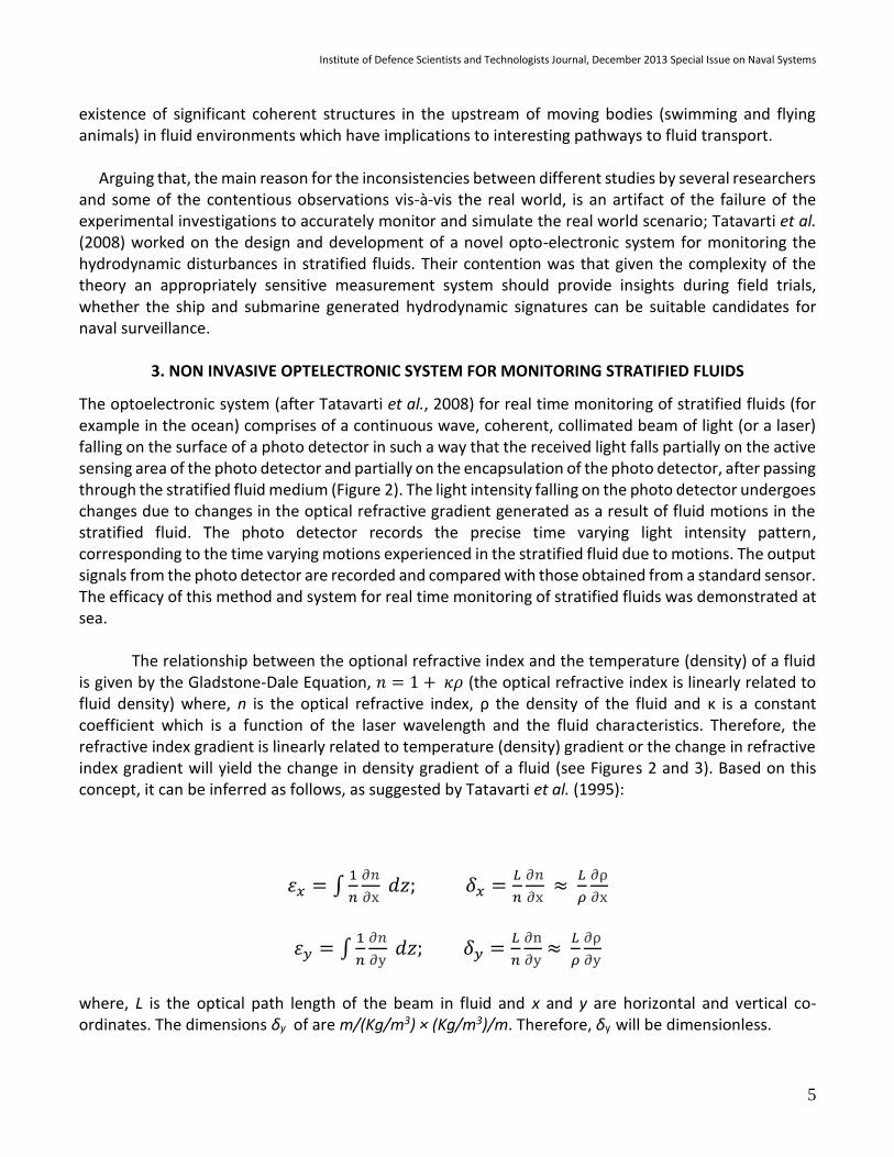
The primary manifestation of a moving platform (body) in stratified fluid is the turbulence and the
associated wake and wave generation (Figure 1). Hydrodynamic phenomena like Bernoulli hump, Kelvin wake and internal waves are all related to the initial turbulence generation by moving bodies. Bernoulli hump and Kevin wake phenomena which move with the moving body are non-propagating components, while the vortex motions and waves are the propagating components of a complex system of hydrodynamic disturbances resulting from the initial turbulence. The propagating components of the complex system are responsible for the spatial and temporal persistence of signatures (Tennekes and Lumley, 1972; Reed et. al., 1990; Sarpkaya, 1998; Han et. al., 2000; Svennberg, 2001; Rottman et al., 2002; Srikanth et al., 2011; Golbraikh et al., 2013).
Institute of Defence Scientists and Technologists Journal, December 2013 Special Issue on Naval Systems
3
For a moving ship there are several sources of turbulence. The shear flow in the boundary layer at the hull is a main contributor to turbulence in the wake. Hull and propeller induced vortices transport and produce turbulence in the interface region between swirling vortex and surrounding fluid. The breaking bow wave is another region of turbulence, but since this turbulence is shallow and positioned along the Kelvin wave system it will be quite isolated from the turbulence in the viscous wake (Hoekstra and Aalbers, 1997). At sea there will not only be the turbulence produced by the ship, but also the background turbulence of the ocean upper layer, originating from breaking of waves and the turbulent energy production of the mean shear flow (Benilov et al., 2001). Though the turbulence in the wake eventually will reach the turbulent level of ocean, these two turbulent fields can for the most part be viewed separately since the wake turbulence significantly exceeds the upper layer turbulence. By diffusion the wake width increases roughly according to a power law of x 1/5, where x is the distance from the ship (Milgram et al., 1993). The turbulence in the wake is also an important factor when dealing with remote sensors. The physical mechanism allowing the detection of a ship wake on the ocean surface (for example SAR) is basically a result of the diffusion of surface active films and materials in the wake, together with vortex interaction with the free surface and the presence of short wave lengths which essentially affect the backscatter of radar waves, enabling a SAR image of the far wake that looks like a railroad track (Reed et al., 1990; Benilov et al., 2001). In good weather, the far wake can be seen with conventional high altitude photographs as a region of smooth water as far as 100 km behind the ship (Reed et al., 1990). It has been indicated that the change in physical properties (temperature, salinity, density) caused by the wake can persist for an hour or more after the passage of the ship. Also SAR (Synthetic Aperture Radar) imagery can trace the wake up to 100 km aft of the ship. The turbulent kinetic energy in the viscous wake can also be traced for a long time after passage. The distance depends on the sea state, but 2-4 km is not impossible as indicated by Benilov et al. (2001).
Benilov et al.’s (2001) comprehensive studies covering analytical, numerical and experimental
aspects of ship generated wakes in ocean ushered in significant breakthroughs in characterizing the spatial and temporal features of wake - wherein it was demonstrated that the ship wake turbulence is well detectable (considering a ship length of L, under fair sea conditions the numerical approach predicted a range of ~50L while the results from the experiments were more modest, ~10L). The turbulent kinetic energy is a good and convenient measure of turbulent activity and the decay of turbulence in the wake can be viewed from the energy perspective (Hoekstra and Aalbers, 1997). Benilov et al. [9] relied on decay rate for the turbulent kinetic energy in the wake of ship model and found that the decay could be described by a power law of x - 4/5. Subsequently Rottman et al. (2002) provided another view on the decay of energy in the wake, and observed that the thrust and drag wake dominates and the energy decays as x - 3/2, while the swirl from the propeller was shown to have less energy but decays as x - 1. Thus, with the fast decay of the thrust and drag, the swirl will eventually dominate and the decay of the wake will be slowed down. The stratified case, which probably only is of interest when dealing with submarines, alters the decay of the total energy. It gives higher energy in the far wake than for the non-stratified case. This effect is probably due to the generation of internal waves, which do not decay as rapidly as turbulence, as well as the mixing of water layers of different density.
One of the important insights was provided by Vorapayev et al. (2001) who considered the moving bodies to have unsteady motions and a background shear in ocean (which is consistent with the real world scenario where moving bodies are continuously changing their speed and direction over a
Institute of Defence Scientists and Technologists Journal, December 2013 Special Issue on Naval Systems
4
background shear in ocean). Vorapayev et al. (2001) experimentally established that large (compared to the size of the body generating them) coherent vortex structures exist behind a maneuvering self-propelled body in stratified fluids. Spedding (2002) based on digital particle image velocimetry measurements on wakes caused by spherical bodies suggested that the combination of Kelvin-Helmholtz and spiral mode instabilities may account for the observed wavelengths in late wake eddies (i.e., a combination of instabilities and pairing-merging mechanisms are responsible).
Recent studies further demonstrated that large coherent eddies (monopoles, dipoles, and their
combinations) are the persistent flow patterns which are easily formed in stratified and rotating fluids. It was also suggested that the planar dipolar eddies possess a linear momentum and can propagate significant distances from the origin. Observations have shown that the flow in the far wake consists of long lasting patches of vertical vorticity of opposite signs (pancake eddies) organized into a vortex street, the vertical length and velocity scales of which are much smaller than those in the horizontal direction. However, until now there has been no satisfactory theory explaining the mechanism of vortex street formation in the far wake. In the late wake, coherent vortex structures appear and last for very long durations. Although recent detailed experiments by Spedding (2002); Meunier and Spedding (2006); and others provided information about the physics behind the late wake structures, the experiments provided data only in individual planes, so speculation remained about the vortex geometry and about the roles of dissipation and buoyancy in those structures. Gourlay et al., (2001, 2002) revealing simulations provided volumetric data for wakes (analysis of the fully three-dimensional flow) which complemented the body of previous and ongoing research work. Gourlay et al.’s simulations of statistical quantities, such as mean velocity profiles, wake velocity and length scaling and turbulence amplitudes provided precise fully three-dimensional data for every fluid dynamical field. This volumetric data provided vortex geometry data that was earlier unavailable, as it was felt that it is extremely difficult to measure with high sensitivity and accuracy in water tank and wind tunnel experiments. Gourlay and other researchers’ simulations further suggested that (i) the fundamental origins of late wake vortices lie in the vortex loop geometry required by Helmholtz’ characterization, (ii) that viscous diffusion smoothens initially convoluted loops into smooth rings, and (iii) that the organized configuration of those vortices come from the mean jet flow. Further they have shown that the vortex rings do not require stratification to exist. It is now believed that in stratified fluids, buoyancy suppresses vertical motions, and the vortex lines weave through adjacent vortex rings so that they do not propagate away from each other- which accounts for their more regular organization as compared with the non-stratified case.
In almost all the works related to wakes and waves generated by moving bodies in ocean
(stratified fluids) it has been customary to discuss about the wake and wave aft of a moving body but not on the bow side, primarily because a majority of researchers believed that the bow wake (upstream wake) and wave is not significant enough in terms of disturbing the fluid per se, although it has been known that shock systems can extend upstream and downstream and appear as unsteady discontinuities. Interestingly, Turner discussed (in his book, Buoyancy Effects In Fluids) about the existence of upstream wakes generated by moving bodies in stratified fluids - as only upstream of the body, the vorticity generated by the buoyancy is in the opposite sense to that generated by viscosity, so that a balance between the two becomes possible. However, recent studies in the field of Bioengineering (for example, Peng and Dabiri, 2008) which employed new techniques in fluid mechanics, revealed the
Institute of Defence Scientists and Technologists Journal, December 2013 Special Issue on Naval Systems
5
existence of significant coherent structures in the upstream of moving bodies (swimming and flying animals) in fluid environments which have implications to interesting pathways to fluid transport.
Arguing that, the main reason for the inconsistencies between different studies by several researchers
and some of the contentious observations vis-à-vis the real world, is an artifact of the failure of the experimental investigations to accurately monitor and simulate the real world scenario; Tatavarti et al. (2008) worked on the design and development of a novel opto-electronic system for monitoring the hydrodynamic disturbances in stratified fluids. Their contention was that given the complexity of the theory an appropriately sensitive measurement system should provide insights during field trials, whether the ship and submarine generated hydrodynamic signatures can be suitable candidates for naval surveillance.
3. NON INVASIVE OPTELECTRONIC SYSTEM FOR MONITORING STRATIFIED FLUIDS
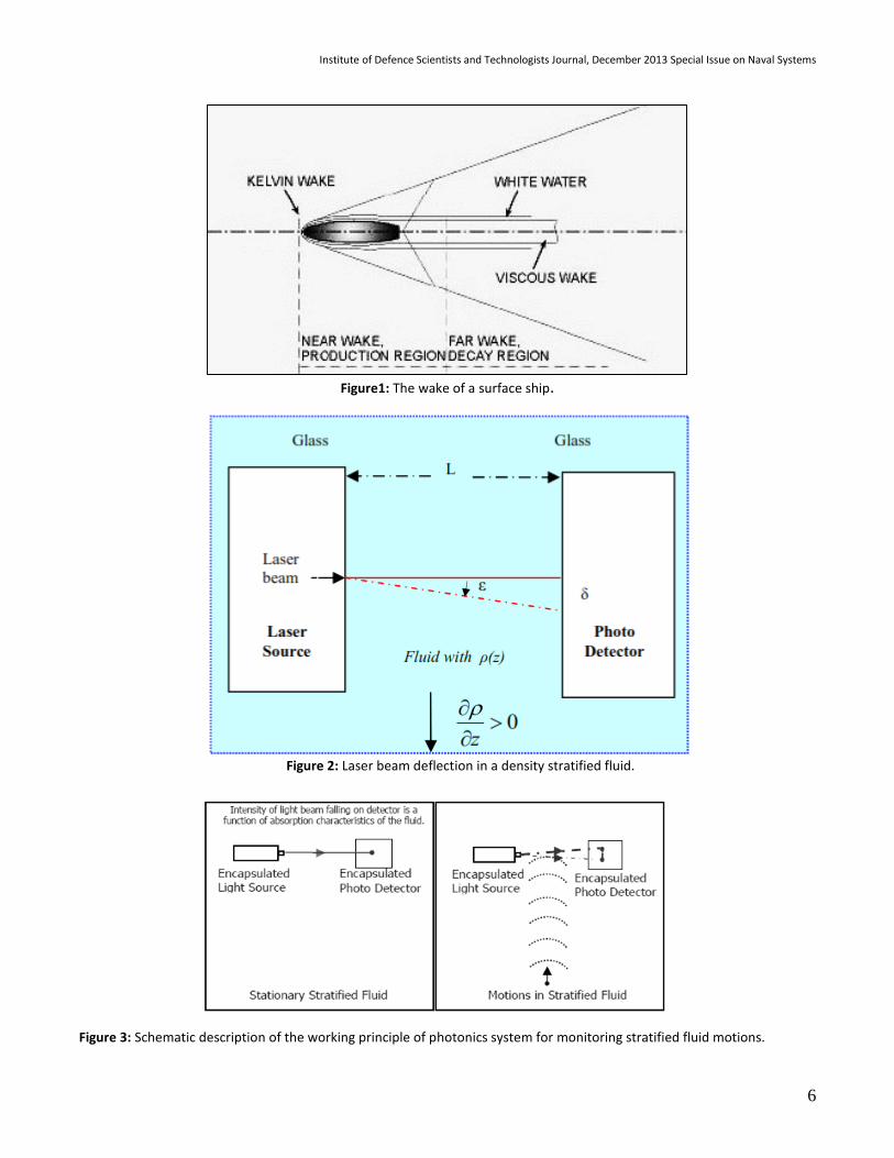
The optoelectronic system (after Tatavarti et al., 2008) for real time monitoring of stratified fluids (for example in the ocean) comprises of a continuous wave, coherent, collimated beam of light (or a laser) falling on the surface of a photo detector in such a way that the received light falls partially on the active sensing area of the photo detector and partially on the encapsulation of the photo detector, after passing through the stratified fluid medium (Figure 2). The light intensity falling on the photo detector undergoes changes due to changes in the optical refractive gradient generated as a result of fluid motions in the stratified fluid. The photo detector records the precise time varying light intensity pattern, corresponding to the time varying motions experienced in the stratified fluid due to motions. The output signals from the photo detector are recorded and compared with those obtained from a standard sensor. The efficacy of this method and system for real time monitoring of stratified fluids was demonstrated at sea.
The relationship between the optional refractive index and the temperature (density) of a fluid is given by the Gladstone-Dale Equation, 𝑛 = 1 + 𝜅𝜌 (the optical refractive index is linearly related to fluid density) where, n is the optical refractive index, ρ the density of the fluid and κ is a constant coefficient which is a function of the laser wavelength and the fluid characteristics. Therefore, the refractive index gradient is linearly related to temperature (density) gradient or the change in refractive index gradient will yield the change in density gradient of a fluid (see Figures 2 and 3). Based on this concept, it can be inferred as follows, as suggested by Tatavarti et al. (1995):
휀𝑥 = ∫1
𝑛
∂𝑛
∂x 𝑑𝑧; 𝛿𝑥 =
𝐿
𝑛
∂𝑛
∂x ≈
𝐿
𝜌
∂ρ
∂x
휀𝑦 = ∫1
𝑛
∂𝑛
∂y 𝑑𝑧; 𝛿𝑦 =
𝐿
𝑛
∂n
∂y ≈
𝐿
𝜌
∂ρ
∂y
where, L is the optical path length of the beam in fluid and x and y are horizontal and vertical co-ordinates. The dimensions δy of are m/(Kg/m3) × (Kg/m3)/m. Therefore, δy will be dimensionless.
Institute of Defence Scientists and Technologists Journal, December 2013 Special Issue on Naval Systems
6
Figure1: The wake of a surface ship.
Figure 2: Laser beam deflection in a density stratified fluid.
Figure 3: Schematic description of the working principle of photonics system for monitoring stratified fluid motions.
Institute of Defence Scientists and Technologists Journal, December 2013 Special Issue on Naval Systems
7
For the optoelectronic systems the minimum resolvable δ (an artefact of the sensitivity of the position sensing detector used), say, 0.1µm = 1×10⁻⁷m; an optical path length L designed as, say, 0.1m;
δy = 1m; and an average density value of ρ (air) 1Kg/m3. For calculating the minimum resolvable ∆𝜌 (∆T) we have
𝛿𝑦𝜌
𝐿=
𝜕𝜌
𝜕𝑦
i.e., the minimum resolvable ∆ρ is, O (10-6) Kg/m3 (or the minimum resolvable temperature is 0.001oC).
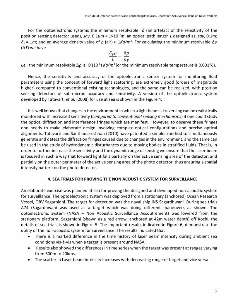
Hence, the sensitivity and accuracy of the optoelectronic sensor system for monitoring fluid parameters using the concept of forward light scattering, are extremely good (orders of magnitude higher) compared to conventional existing technologies, and the same can be realized, with position sensing detectors of sub-micron accuracy and sensitivity. A version of the optoelectronic system developed by Tatavarti et al. (2008) for use at sea is shown in the Figure 4.
It is well known that changes in the environment in which a light beam is traversing can be realistically
monitored with increased sensitivity (compared to conventional sensing mechanisms) if one could study the optical diffraction and interference fringes which are manifest. However, to observe these fringes one needs to make elaborate design involving complex optical configurations and precise optical alignments. Tatavarti and Santhanakrishnan (2010) have patented a simpler method to simultaneously generate and detect the diffraction fringes caused due to changes in the environment, and the same can be used in the study of hydrodynamic disturbances due to moving bodies in stratified fluids. That is, in order to further increase the sensitivity and the dynamic range of sensing we ensure that the laser beam is focused in such a way that forward light falls partially on the active sensing area of the detector, and partially on the outer perimeter of the active sensing area of the photo detector, thus ensuring a spatial intensity pattern on the photo detector.
4. SEA TRIALS FOR PROVING THE NON ACOUSTIC SYSTEM FOR SURVEILLANCE
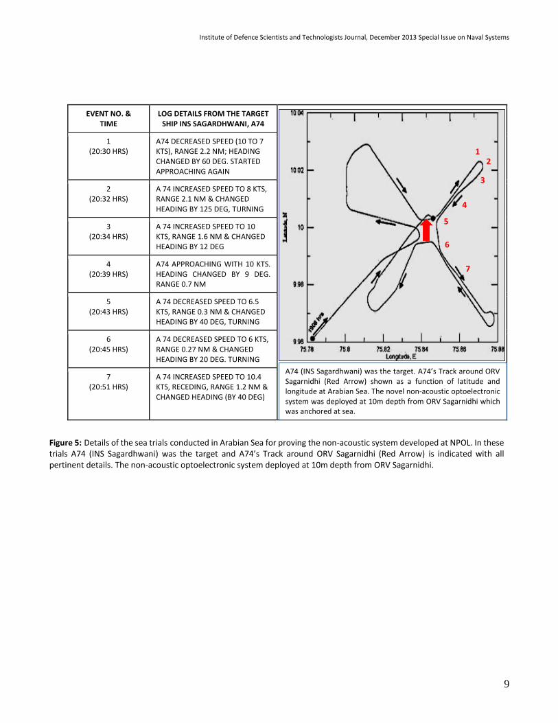
An elaborate exercise was planned at sea for proving the designed and developed non-acoustic system for surveillance. The optoelectronic system was deployed from a stationary (anchored) Ocean Research Vessel, ORV Sagarnidhi. The target for detection was the naval ship INS Sagardhwani. During sea trials A74 (Sagardhwani was used as a target which was doing different maneuvers as shown. The optoelectronic system (NASA – Non Acoustic Surveillance Accoutrement) was lowered from the stationary platform, Sagarnidhi (shown as a red arrow, anchored at 42m water depth) off Kochi, the details of sea trials is shown in Figure 5. The important results indicated in Figure 6, demonstrate the utility of the non-acoustic system for surveillance. The results indicated that
There is a marked difference in the time history of laser beam intensity during ambient sea conditions vis-à-vis when a target is present around NASA.
Results also showed the differences in time series when the target was present at ranges varying from 600m to 20kms.
The scatter in Laser beam intensity increases with decreasing range of target and vice versa.
Institute of Defence Scientists and Technologists Journal, December 2013 Special Issue on Naval Systems
8
Figure 4: NASA- Non Acoustic Surveillance Accoutrement, used for sea trials. This Optoelectronic System is a self-recording unit with real time display and can either be moored at mid ocean or fixed on the bottom of the seabed.
Institute of Defence Scientists and Technologists Journal, December 2013 Special Issue on Naval Systems
9
EVENT NO. & TIME
LOG DETAILS FROM THE TARGET SHIP INS SAGARDHWANI, A74
1 (20:30 HRS)
A74 DECREASED SPEED (10 TO 7 KTS), RANGE 2.2 NM; HEADING CHANGED BY 60 DEG. STARTED APPROACHING AGAIN
2 (20:32 HRS)
A 74 INCREASED SPEED TO 8 KTS, RANGE 2.1 NM & CHANGED HEADING BY 125 DEG, TURNING
3 (20:34 HRS)
A 74 INCREASED SPEED TO 10 KTS, RANGE 1.6 NM & CHANGED HEADING BY 12 DEG
4 (20:39 HRS)
A74 APPROACHING WITH 10 KTS. HEADING CHANGED BY 9 DEG. RANGE 0.7 NM
5 (20:43 HRS)
A 74 DECREASED SPEED TO 6.5 KTS, RANGE 0.3 NM & CHANGED HEADING BY 40 DEG, TURNING
6 (20:45 HRS)
A 74 DECREASED SPEED TO 6 KTS, RANGE 0.27 NM & CHANGED HEADING BY 20 DEG. TURNING
7 (20:51 HRS)
A 74 INCREASED SPEED TO 10.4 KTS, RECEDING, RANGE 1.2 NM & CHANGED HEADING (BY 40 DEG)
A74 (INS Sagardhwani) was the target. A74’s Track around ORV Sagarnidhi (Red Arrow) shown as a function of latitude and longitude at Arabian Sea. The novel non-acoustic optoelectronic system was deployed at 10m depth from ORV Sagarnidhi which was anchored at sea.
1 2
3
4
5
6
7
Figure 5: Details of the sea trials conducted in Arabian Sea for proving the non-acoustic system developed at NPOL. In these trials A74 (INS Sagardhwani) was the target and A74’s Track around ORV Sagarnidhi (Red Arrow) is indicated with all pertinent details. The non-acoustic optoelectronic system deployed at 10m depth from ORV Sagarnidhi.
Institute of Defence Scientists and Technologists Journal, December 2013 Special Issue on Naval Systems
10
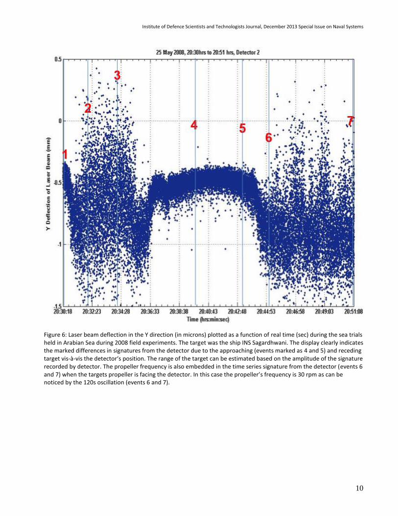
Figure 6: Laser beam deflection in the Y direction (in microns) plotted as a function of real time (sec) during the sea trials held in Arabian Sea during 2008 field experiments. The target was the ship INS Sagardhwani. The display clearly indicates the marked differences in signatures from the detector due to the approaching (events marked as 4 and 5) and receding target vis-à-vis the detector‘s position. The range of the target can be estimated based on the amplitude of the signature recorded by detector. The propeller frequency is also embedded in the time series signature from the detector (events 6 and 7) when the targets propeller is facing the detector. In this case the propeller’s frequency is 30 rpm as can be noticed by the 120s oscillation (events 6 and 7).
Institute of Defence Scientists and Technologists Journal, December 2013 Special Issue on Naval Systems
11
As the target’s range increases the mean value of the laser intensity increases (i.e., less dense water is pushed to traverse between the laser source and detector).
When the target changes course, especially when the propulsion system of the target faces the laser beam the laser intensity scatter increases.
Detection of targets when they are approaching as well as when they are receding from NASA is possible.
Even target (bulk carrier) at a range of 20kms detected by NASA – confirmed from Ship’s radar.
Temporal laser beam intensity changes with the changing range and course of target vis-à-vis NASA. NASA could detect passing ship traffic at 20kms and A74 at 8kms as per the trial. The speed of travel of hydrodynamic signatures was confirmed to be more than the known √gh values.
5. CONCLUSIONS
Tatavarti et al. (2008) demonstrated that one can discriminate, detect and localize targets, using the
novel non-acoustic detection system (which can be easily implemented on board a stationary platform
(like a surface or subsurface buoy) or a dynamic platform (like a ship, submarine or even a torpedo)
indicating clearly the non-acoustic detection system’s use for naval surveillance. The feasibility and scope
for implementation of this non acoustic technology on board torpedoes for homing purposes has been
the recent research focus at NSTL.
This new science naturally needs critical review, without any a priori biases - which is what is lacking
in the Indian scenario. The system can be implemented by the Navy for surveillance purposes.
6. ACKNOWLEDGEMENTS
The work described was initiated and funded at NPOL by DRDO over many years. Tatavarti gratefully acknowledges the entire project team involved, the Directors and the DRDO management. The support and encouragement given by Director, NSTL to pursue this technology for future torpedo systems is gratefully acknowledged. Special thanks to Dr. V.K. Aatre who was instrumental in suggesting this exciting work when the first author returned from Canada to take up an R&D career at DRDO. Tatavarti is also grateful to Dr. Aatre’s ongoing support. Critical review / suggestions by Prof. V.K. Aatre and Prof. G.V. Anand brought more focus to the manuscript.
Institute of Defence Scientists and Technologists Journal, December 2013 Special Issue on Naval Systems
12
7. REFERENCES Benilov, A., Bang G., Safray, A. and Tkachenko, I.; “Ship Wake Detectability in the Ocean Turbulent Environment”, Proc. Twenty-Third Symposium on Naval Hydrodynamics, p. 687-703, 2001. Golbraikh E., A. Eidelman, and A. Soloviev, “On the helical behavior of turbulence in the ship wake”, Journal of Hydrodynamics, Ser. B, Elsevier, 2013. Gourlay M. J., SC Arendt, DC Fritts, and J Werne “Numerical modeling of initially turbulent wakes with zero net momentum”, Physics of Fluids, 2000. Gourlay, M.J., SC Arendt, DC Fritts, and J. Werne, “Numerical modeling of initially turbulent wakes with net momentum”, Phys. Fluids 13, 3783, 2001. Han, J., Lin, Y.L., Pal Arya, S. & Proctor F.H.; “Numerical Study of Wake Vortex Decay and Descent in Homogenous Atmospheric Turbulence”, AIAA Journal, Vol. 38, No. 4, April 2000 Jifeng Peng and John O. Dabiri, “The upstream wake of swimming and flying animals and its correlation with propulsive efficiency”, The Journal of Experimental Biology, 211, 2669-2677, 2008. Milgram J. H., R D. Peltzer, and O. M. Griffin, "Suppression of Short Sea Waves in Ship Wakes: Measurements and Observations", J.Geophys. Res., Vol. 98, No C4, pp7103-7114, 1993. Peter B. V. Johansson, William K. George and Michael J. Gourlay, “Equilibrium similarity, effects of initial conditions and local Reynolds number on the axisymmetric wake”,Phys. Fluids 15, 603, 2003. Hoekstra, M. and Aalbers A.; “Macro Wake Measurements for a Range of Ships”, Proc. Twenty-First Symposium on Naval Hydrodynamics, Marine Research Institute, The Netherlands, p. 278-290, 1997. Rao Tatavarti, P.N. Ananth, K. Rajasree, V. Vidyalal, P. Radhakrishnan, V.P.N. Nampoori, and C.P.G. Vallaban. “Internal waves: A novel measurement technique”, Current Science, Vol.69, No. 8, p.678-684, 1995. Rao Tatavarti, P. Naresh T. Santhanakrishnan, P. Panchal, R.L. Awasthi, V.Venugopal (2008). Results from sea trials off Kochi regarding naval surveillance with opto-electronic system. Research Report NPOL-RR-16-2008. NPOL, pp. 82. Reed, A.M., Beck, R.F., Griffin, O.M. and Pletzer, R.D.; “Hydrodynamics of Remotely Sensed Surface Ship Wakes”, SNAME Transactions, Vol. 98, pp. 319-363, 1990. Rottman, J.W., Dommermuth, D.G., Innis, G.E., O’Shea, T.T., Novikov, E.; ”Numerical Simulation of Wakes in a Weakly Stratified Fluid”, Proc. Twenty-Fourth Symposium on Naval Hydrodynamics, Fukuoka, Japan, p. 206-218, 2002. Santhanakrishnan T and Rao Tatavarti (2010). Method and apparatus for the simultaneous generation and detection of the optical diffraction pattern of detector, United States Patent, US 2010/0321698 A1. Sarpkaya, T.; “Decay of Wake Vortices of Large Aircraft”, AIAA Journal, Vol. 36, No. 9, 1998 Spedding G. R.., “The stream wise spacing of adjacent coherent structures in stratified wakes”, Phys. Fluids 14, 3820, 2002. Srikanth T., Harish N. Dixit, Rao Tatavarti, and Rama Govindarajan “Vortex shedding patterns, their competition, and chaos in flow inline oscillating rectangular cylinders”, Physics of Fluids 23, 073603, 2011. Meunier P. and Spedding G. R. “Stratified propelled wakes”, Journal of Fluid Mechanics, Volume 552, pp 229-256, April 2006. Svennberg, S.U.; “On Turbulence Modelling for Bilge Vortices: A Test of Eight Models for Three Cases”, Ph.D. Thesis; Chalmers University of Technology, 2001 Tennekes, H., Lumley, J.L.; “A First Course in Turbulence”, The MIT Press, 1972

Institute of Defence Scientists and Technologists Journal, December 2013 Special Issue on Naval Systems
13
Dr. Rao Tatavarti is currently a Senior Professor and Director at Gayatri Vidya Parishad Scientific and Industrial Research Centre and Gayatri Vidya Parishad College of Engineering, Visakhapatnam. Dr Tatavarti is also the Regional Director of National Maritime Foundation, Visakhapatnam Regional Chapter. Dr Tatavarti was earlier with NPOL, DRDO and was the Project Director of all Non Acoustic Technology Projects.
Sanjaya Kumar Swain is working as a Scientist in Sensors Division of Naval Science & Technological Laboratory (NSTL), Visakhapatnam. He is presently involved in design and development of acoustic sensors for different underwater weapon system and studies and characterization of turbulent wake generated by moving submerged bodies in a stratified medium.
Dr. K. Trinath is heading Sensors Division at Naval Science and Technological Laboratory, Visakhapatnam. He is working in the areas of Acoustic Sensors for Underwater Applications and Detection and Characterization of Underwater Turbulence by Opto-electronic Techniques.
Dr. P. Arulmozhivarman is working as a Professor in Signal & Image Processing Division under the School of Electronics Engineering, Vellore Institute of Technology University (VIT), Vellore, India. He is a member of IEEE signal processing society.


