Embed Size (px)
Citation preview

How to Model and
Analyze Structures Using
ETABS
Prepared by: Yamen Ammar Dannan

2 | P a g e
Prepared by Yamen Dannan For more questions
Install ETABS 2013
Open ETABS
MAIN STEPS
1. New Model
Press (File -> New Model)
Choose the following settings
Design the (Grid Only) according to building plan of beams. (Spacing
method). It is better to fill the uniform grid spacing, and then modify it with the
custom grid.
Define story data (similar stories, heights). It is advised to fill in the simple
story data, and then modify it using the Custom story.
Press Ok. The project is ready to start.
2. Define Materials “Steel and Concrete” from (Define -> Material Properties) Use default
numbers (only change Strength of concrete(Fc’) if needed)
Note: (4000psi is the Concrete), and (A992fy50 is the Structural steel), and
(A615Gr60 is the Rebar Steel).

3 | P a g e
Prepared by Yamen Dannan For more questions
3. Define your Beams/Columns (Define -> Section property-> Frame Sections)
Press Add new Property…
Choose section shape
Name the section
Choose material (4000psi)
Define Dimensions
Press “Modify/Show Rebar” button -> If it’s a column, you can choose the
reinforcement, and choose “to be checked”, or leave it as default and choose
Choose section type (Beam or Column)
FOR BEAMS (Special Purpose): Set Modifiers as shown
FOR COLUMNS (Special Purpose): Set Modifiers as shown
Repeat steps for as many beams/columns as required
4. Define your Slabs (Define -> Section property-> Slab Sections -> Add new Property)
Modeling type (Shell - Thin)
Type -> Slab and choose required thickness.
FOR SLABS (Special Purpose): Set Modifiers as shown
4 | P a g e
Prepared by Yamen Dannan For more questions
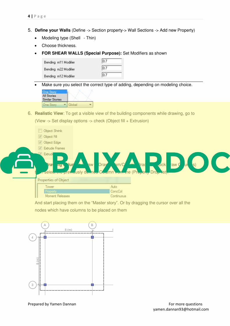
5. Define your Walls (Define -> Section property-> Wall Sections -> Add new Property)
Modeling type (Shell - Thin)
Choose thickness.
FOR SHEAR WALLS (Special Purpose): Set Modifiers as shown
Make sure you select the correct type of adding, depending on modeling choice.
6. Realistic View: To get a visible view of the building components while drawing, go to
(View -> Set display options -> check (Object fill + Extrusion)
7. Start drawing columns (Draw ->Draw Beam/Column/Brace -> Quick Draw Columns)
then select the previously defined Column from the (Property Drop list).
And start placing them on the “Master story”. Or by dragging the cursor over all the
nodes which have columns to be placed on them

5 | P a g e
Prepared by Yamen Dannan For more questions
8. Draw the beams (Draw ->Draw Beam/Column/Brace -> Draw Beams/Columns/Braces)
then select the previously defined beam sections from the (Property Drop list).
Start drawing the beams extending from corner to corner, depending on required design.
IMPORTANT NOTE: after you’re done drawing Columns and Beams, It is essential
to release the moments at the end of continuous beams, to make them semi-
rigid….Being Fully Rigid decreases the negative moment at the middle supports,
which results in wrong design….
The Solution is to release the edge moments, and apply them as a point Moments.
As shown in the following diagram.
which is done by selecting the continuous beams which have fixed ends, and going
to (Assign -> Frame -> Release ->
Then select the end (Points) and go to (Assign -> Joint/Point Loads -> Force ->
select LIVE -> Fill in MOMENT GLOBAL XX AND YY, with M = .
Where “w” is the standard live load which you transfer on the beam as KN/m. (THIS
MOMENT IS RELATIVELY SMALL, AND THIS STEP CAN BE PARTIALLY
NEGLECTABLE IF YOU KNOW HOW MUCH EDGE REINFORCEMENT YOU
SHOULD USE)
6 | P a g e
Prepared by Yamen Dannan For more questions
1
Ref:(ACI-318-11, Section 8.3.3)
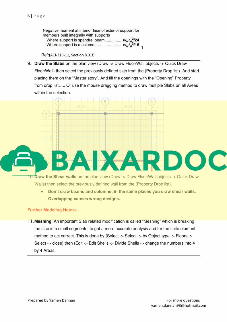
9. Draw the Slabs on the plan view (Draw -> Draw Floor/Wall objects -> Quick Draw
Floor/Wall) then select the previously defined slab from the (Property Drop list). And start
placing them on the “Master story”. And fill the openings with the “Opening” Property
from drop list….. Or use the mouse dragging method to draw multiple Slabs on all Areas
within the selection.
10. Draw the Shear walls on the plan view (Draw -> Draw Floor/Wall objects -> Quick Draw
Walls) then select the previously defined wall from the (Property Drop list).
Don’t draw beams and columns; in the same places you draw shear walls.
Overlapping causes wrong designs.
Further Modeling Notes:-
11. Meshing: An important Slab related modification is called “Meshing” which is breaking
the slab into small segments, to get a more accurate analysis and for the finite element
method to act correct. This is done by (Select -> Select -> by Object type -> Floors ->
Select -> close) then (Edit -> Edit Shells -> Divide Shells -> change the numbers into 4
by 4 Areas.

7 | P a g e
Prepared by Yamen Dannan For more questions
Assigning Loads on model
12. Define Loads: Go into (Define -> patterns)
Don’t change the dead and live load, (dead load will be automatically calculated by
ETABS, and live will be assigned manually by us).
Add a new kind of load by writing into the empty box (Super) and Choose (Super
Dead) from the drop list -> set weight multiplier to 0 -> press Add/new Load.
Add another kind of load called “Wall” with same options as “Super”.
Press Ok to close the window.
13. To add live load, check the local standard depending on the building purpose. And
follow these steps:
(Select -> Select -> by Object type -> Floors ->Select -> close)
(Assign -> Shell Loads -> Uniform)
Load case: Live -> Load = from standard (ignore number is the picture) ->
Direction: Gravity -> Ok.
14. To add wall load, calculate the wall load per meter, and apply it as follows:
Wall Load per meter = 1.7 Ton/m3 x 9.81 x Story height x Wall thickness = KN/m.
(Select the beams that have walls on them).
(Assign -> Frame loads -> Distributed)
Load case name : Wall -> Load = Wall Load per meter ( calculated, ignore number in
picture)

8 | P a g e
Prepared by Yamen Dannan For more questions
15. To add super imposed load, check the local standard depending on the building
purpose. And follow these steps:
(Select -> Select -> by Object type -> Floors -> Select -> close)
(Assign -> Shell Loads -> Uniform)
Load case: SUPER -> Load = from standard -> Direction: Gravity -> Ok.
16. To add wind load, follow the following steps:-
IMPORTANT NOTE: Use “UBC-97” For wind and earthquake loads.
Go into (Define -> load patterns)
Add a new kind of load by writing into the empty box (WINDX) and Choose (WIND)
from the drop list -> set weight multiplier to 0 -> press Add/new Load.
Press on the WINDX that was added into the list, and click “Modify Lateral Load”
button
Keep the values default, and only change the Wind speed and exposure Type,
according to your country standard, and press “OK”.
Add another new load by writing into the empty box (WINDY) and press Add/new
Load.
Press on the WINDY that was added into the list, and click “Modify Lateral Load”
button

9 | P a g e
Prepared by Yamen Dannan For more questions
Only change the Angle from its default value to “90” and keep the rest as WINDX.
17. To add earthquake load, follow the following steps:-
Go into (Define -> Patterns)
Add a new kind of load by writing into the empty box (EQX) and Choose (QUAKE)
from the drop list -> set weight multiplier to 0 -> press Add/new Load.
Press on the EQX that was added into the list, and click “Modify Lateral Load” button.
Choose “X Dir + Eccen Y” and change the over strength factor according to the
standard or simply use “4.5” for general cases. And Press “OK”.
Add a new kind of load by writing into the empty box (EQY) and Choose (QUAKE)
from the drop list -> set weight multiplier to 0 -> press Add/new Load.
Press on the EQY that was added into the list, and click “Modify Lateral Load” button.
Choose “Y Dir + Eccen X” and change the over strength factor according to the
standard or simply use “4.5” for general cases. And Press “OK”.
By The end of adding loads, you should have this.


