Embed Size (px)
Citation preview
LEARNING OF ETABS SOFTWARE
PROBLEM Beam sizes 300×450 mm Columns sizes 300×450 mm Slab thickness 120 mm Storey Height 3.2 m.Live Load 3 kN/mFloor Finish Load 1 kN/m2
Concrete grade M25Steel Fe415Earthquake parameters considered are: Zone V Response Reduction Factor :5Importance Factor :1Soil : Medium
STEP BY STEP PROCEURE:STEP 1: (Creation of geometry)Open the ETABS Program.
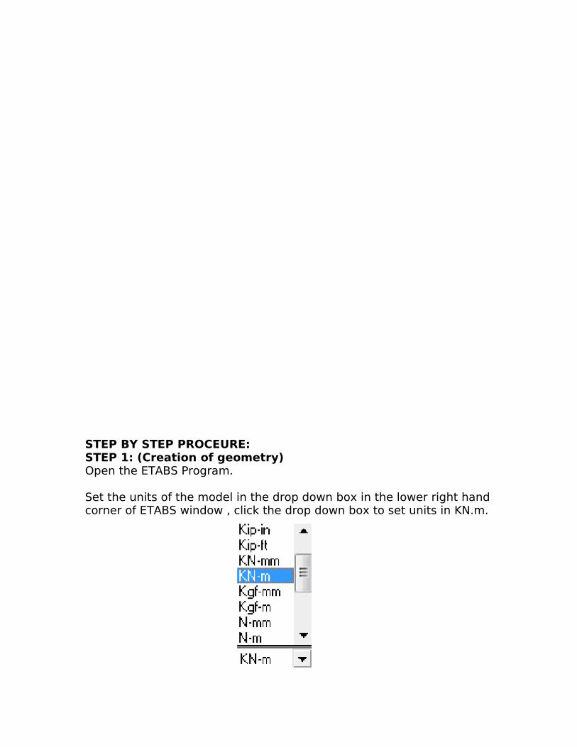
Set the units of the model in the drop down box in the lower right hand corner of ETABS window , click the drop down box to set units in KN.m.
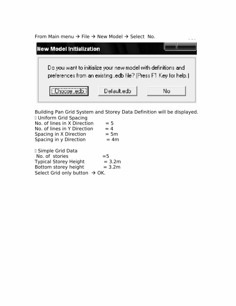
From Main menu File New Model Select No.
Building Pan Grid System and Storey Data Definition will be displayed. Uniform Grid SpacingNo. of lines in X Direction = 5No. of lines in Y Direction = 4Spacing in X Direction = 5mSpacing in y Direction = 4m
Simple Grid Data No. of stories =5Typical Storey Height = 3.2mBottom storey height = 3.2mSelect Grid only button OK.
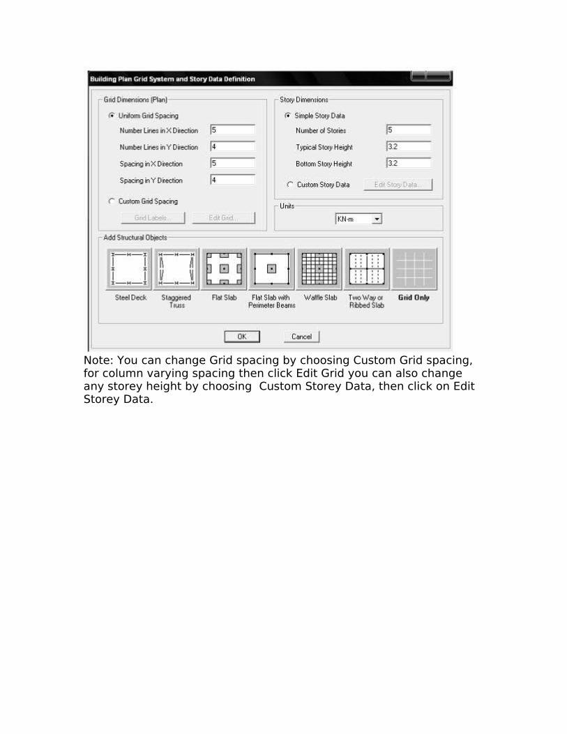
Note: You can change Grid spacing by choosing Custom Grid spacing, for column varying spacing then click Edit Grid you can also change any storey height by choosing Custom Storey Data, then click on Edit Storey Data.
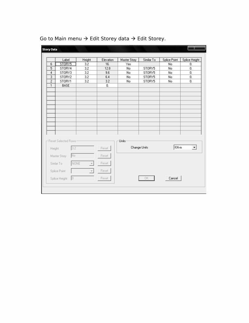
Go to Main menu Edit Storey data Edit Storey.
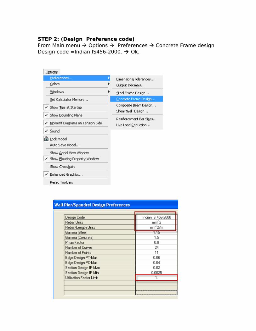
STEP 2: (Design Preference code)From Main menu Options Preferences Concrete Frame designDesign code =Indian IS456-2000. Ok.
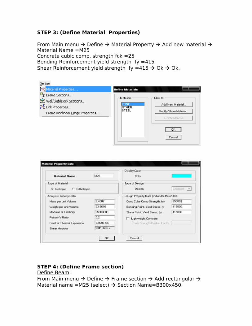
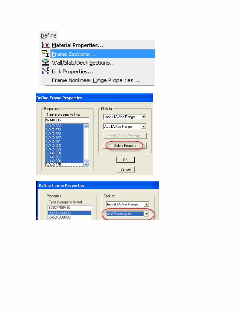
STEP 3: (Define Material Properties)
From Main menu Define Material Property Add new material Material Name =M25Concrete cubic comp. strength fck =25Bending Reinforcement yield strength fy =415Shear Reinforcement yield strength fy =415 Ok Ok.
STEP 4: (Define Frame section)Define Beam:From Main menu Define Frame section Add rectangular Material name =M25 (select) Section Name=B300x450.
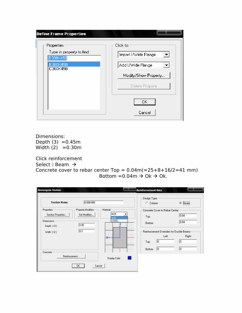
Dimensions:Depth (3) =0.45mWidth (2) =0.30m Click reinforcementSelect Beam Concrete cover to rebar center Top = 0.04m(=25+8+16/2=41 mm) Bottom =0.04m Ok Ok.
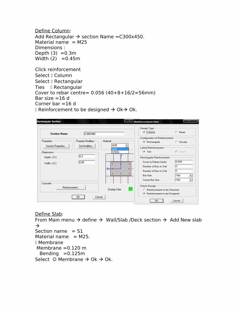
Define Column:Add Rectangular section Name =C300x450.Material name = M25Dimensions :Depth (3) =0.3mWidth (2) =0.45m
Click reinforcementSelect Column Select Rectangular Ties Rectangular Cover to rebar centre= 0.056 (40+8+16/2=56mm)Bar size =16 dCorner bar =16 d Reinforcement to be designed Ok Ok.
Define Slab:From Main menu define Wall/Slab /Deck section Add New slab Section name = S1Material name = M25. Membrane Membrane =0.120 m Bending =0.125mSelect Membrane Ok Ok.
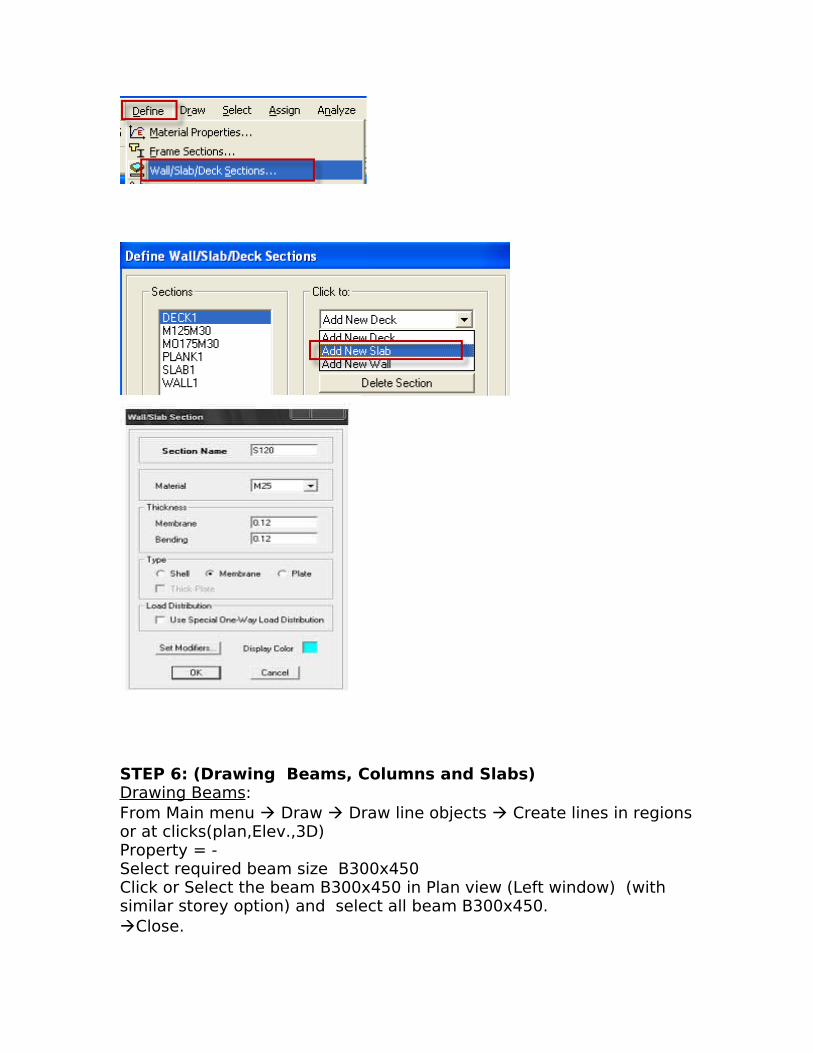
STEP 6: (Drawing Beams, Columns and Slabs)Drawing Beams:From Main menu Draw Draw line objects Create lines in regions or at clicks(plan,Elev.,3D) Property = - Select required beam size B300x450 Click or Select the beam B300x450 in Plan view (Left window) (with similar storey option) and select all beam B300x450.Close.
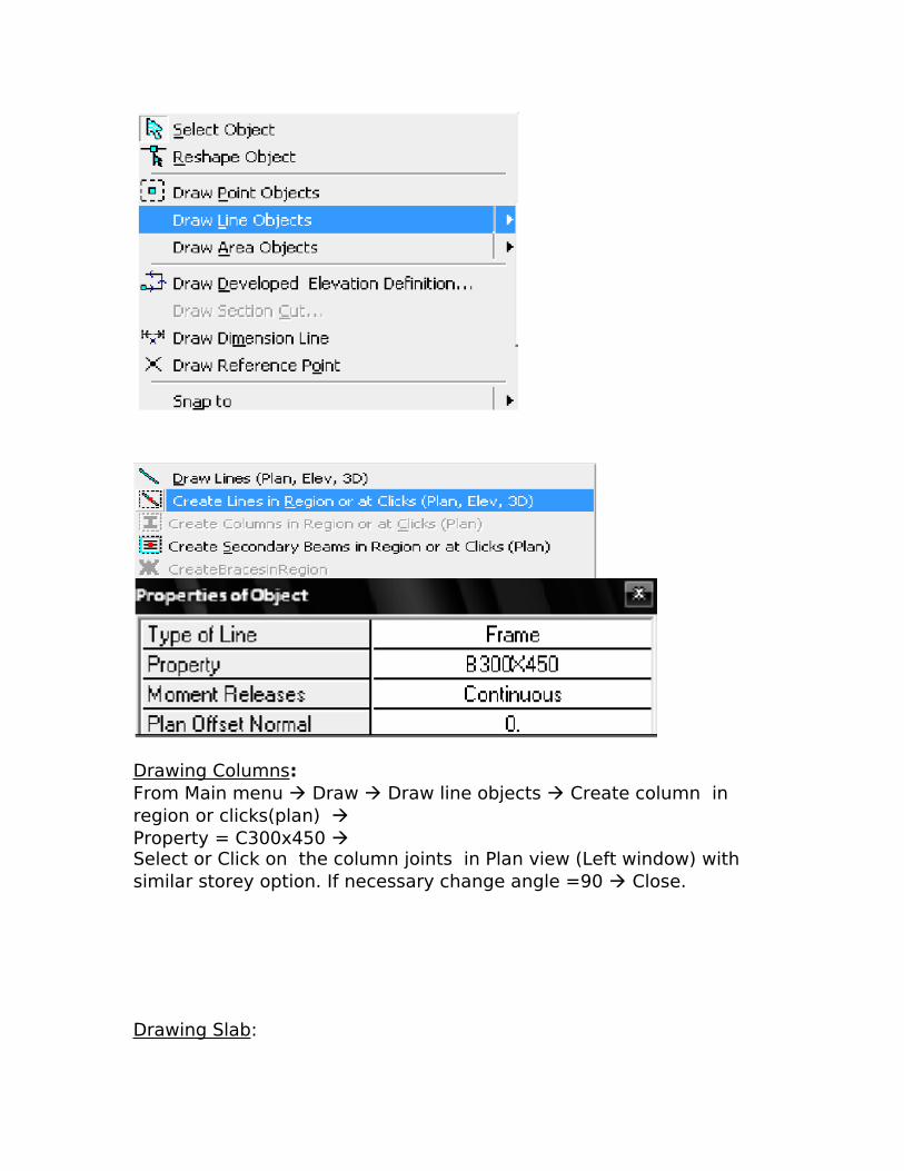
Drawing Columns:From Main menu Draw Draw line objects Create column in region or clicks(plan) Property = C300x450 Select or Click on the column joints in Plan view (Left window) with similar storey option. If necessary change angle =90 Close.
Drawing Slab:
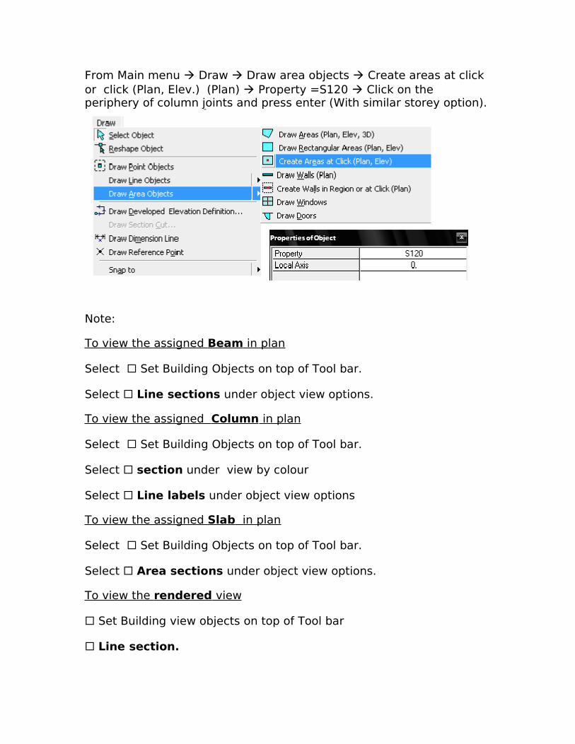
From Main menu Draw Draw area objects Create areas at click or click (Plan, Elev.) (Plan) Property =S120 Click on the periphery of column joints and press enter (With similar storey option).
Note:
To view the assigned Beam in plan
Select Set Building Objects on top of Tool bar.
Select Line sections under object view options.
To view the assigned Column in plan
Select Set Building Objects on top of Tool bar.
Select section under view by colour
Select Line labels under object view options
To view the assigned Slab in plan
Select Set Building Objects on top of Tool bar.
Select Area sections under object view options.
To view the rendered view
Set Building view objects on top of Tool bar
Line section.
Special Effects:
Object Fill
Extrusion
Apply to all windows Ok.
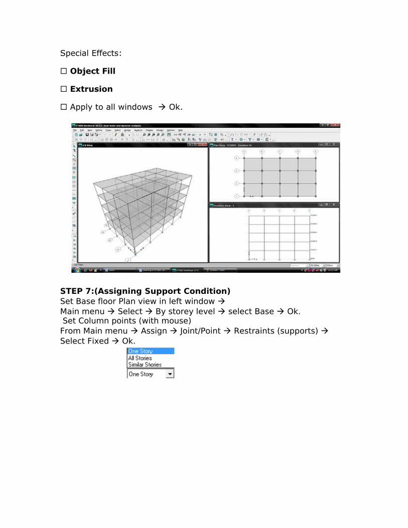
STEP 7:(Assigning Support Condition)Set Base floor Plan view in left window Main menu Select By storey level select Base Ok. Set Column points (with mouse) From Main menu Assign Joint/Point Restraints (supports) Select Fixed Ok.
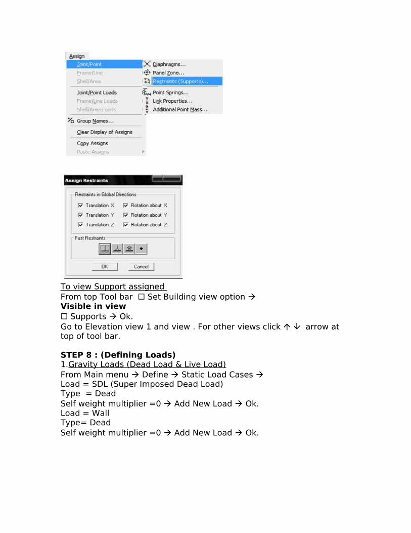
To view Support assigned From top Tool bar Set Building view option Visible in view Supports Ok.Go to Elevation view 1 and view . For other views click arrow at top of tool bar.
STEP 8 : (Defining Loads)1.Gravity Loads (Dead Load & Live Load)From Main menu Define Static Load Cases Load = SDL (Super Imposed Dead Load)Type = DeadSelf weight multiplier =0 Add New Load Ok.Load = WallType= DeadSelf weight multiplier =0 Add New Load Ok.
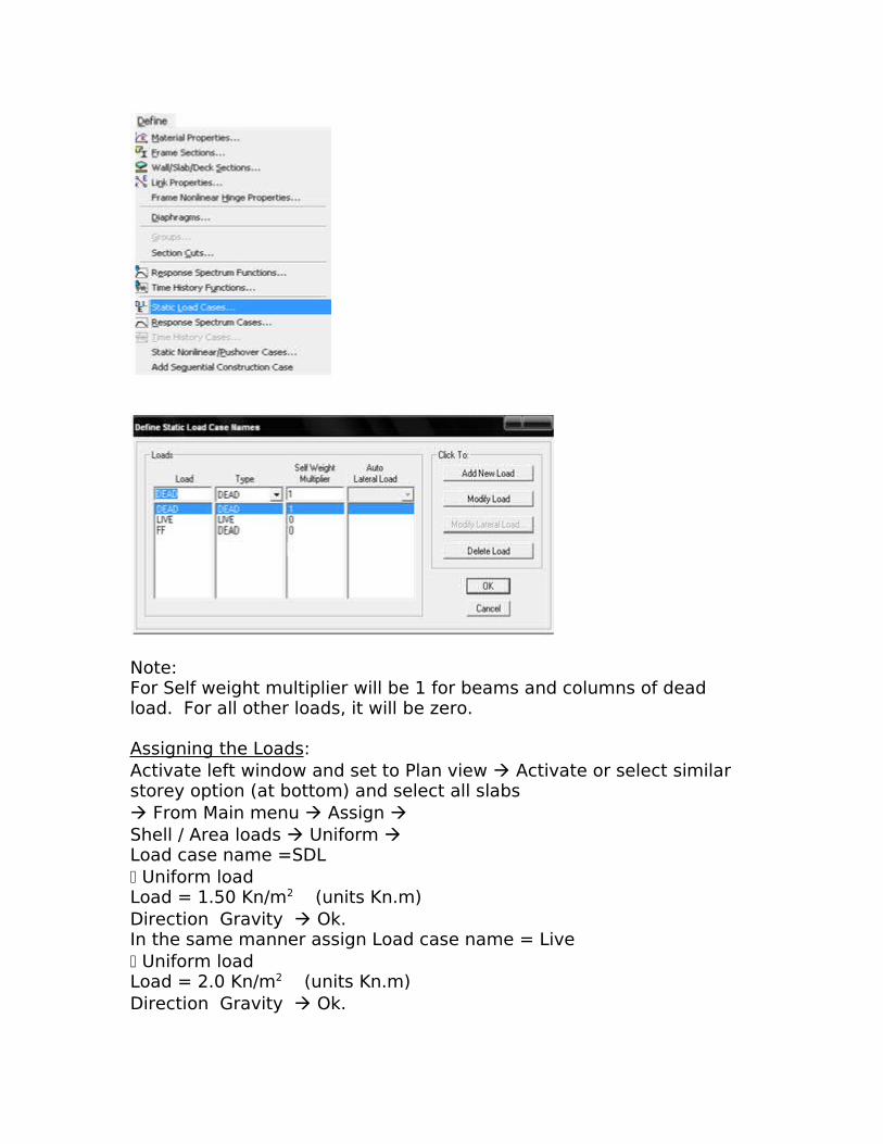
Note:For Self weight multiplier will be 1 for beams and columns of dead load. For all other loads, it will be zero.
Assigning the Loads:Activate left window and set to Plan view Activate or select similar storey option (at bottom) and select all slabs From Main menu Assign Shell / Area loads Uniform Load case name =SDL Uniform loadLoad = 1.50 Kn/m2 (units Kn.m)Direction Gravity Ok.In the same manner assign Load case name = Live Uniform loadLoad = 2.0 Kn/m2 (units Kn.m)Direction Gravity Ok.
Assigning Wall loads: 9” wall load = 12Kn/m (For external or outer beams)41/2” wall load=6 Kn/m (For internal beams).In left side window select all outer beams in top floor by setting similar storey options and view the status bar to know no. of beams selected From Main menu Assign Frame /Line loads Distributed Load case name = wall. Unit Kn.m ForcesDirection GravityUniform load=12 Kn/m Replace existing loads Ok.In the same manner apply 41/2” wall udl load to internal beams by setting “all floor options”.
To see the load assigned :Right click the particular member corresponding load Ok.
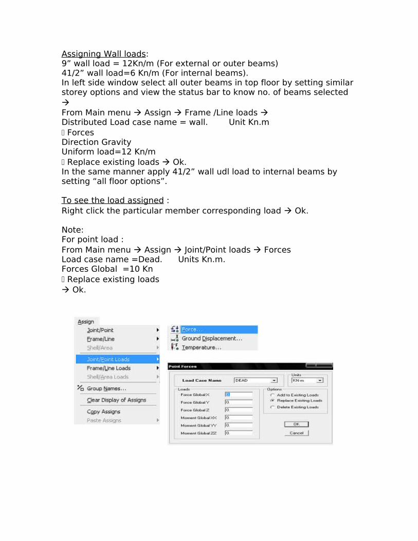
Note:For point load :From Main menu Assign Joint/Point loads ForcesLoad case name =Dead. Units Kn.m.Forces Global =10 Kn Replace existing loads Ok.
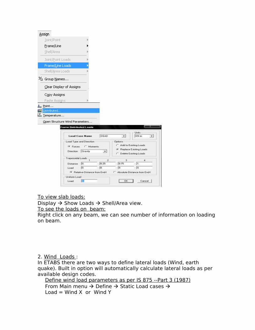
To view slab loads:Display Show Loads Shell/Area view.To see the loads on beam:Right click on any beam, we can see number of information on loading on beam.
2. Wind Loads :In ETABS there are two ways to define lateral loads (Wind, earth quake). Built in option will automatically calculate lateral loads as per available design codes.
Define wind load parameters as per IS 875 --Part 3 (1987)From Main menu Define Static Load cases Load = Wind X or Wind Y
Type = WindSelf weight multiplier =0Auto Lateral load =IS 875—1987 Add New Load Select wind X load and click on modify lateral loads to specify required wind load parameter as per IS 875 Ok Ok.
Creating dummy areas with property =None Set required elevation view in right window From Main menu Draw Draw area objects Draw rectangular areas Property = None Click on the perimeter of area and press enter.
Foot Note: Apply wind load for selections.To select wind area
Main menu Select By area object type select null Ok.
Assigning wind loads Select drawing area of required elevation From Main menu Assign Shell/area loads Wind Pressure coefficients Wind load case name =Wind X Coefficient Cp= - (Change if required) Ok.
To see wind load selection Set Building view option Area section Line section Ok.
3. Earthquake AnalysisIn building, slab is considered as single rigid member during earthquake analysis.Select left side window.Select all slabs by setting all floors/ similar storey option From Main menu Define Diaphragms Select D1 Modify/ Show diaphragms Select Rigid Ok Ok.
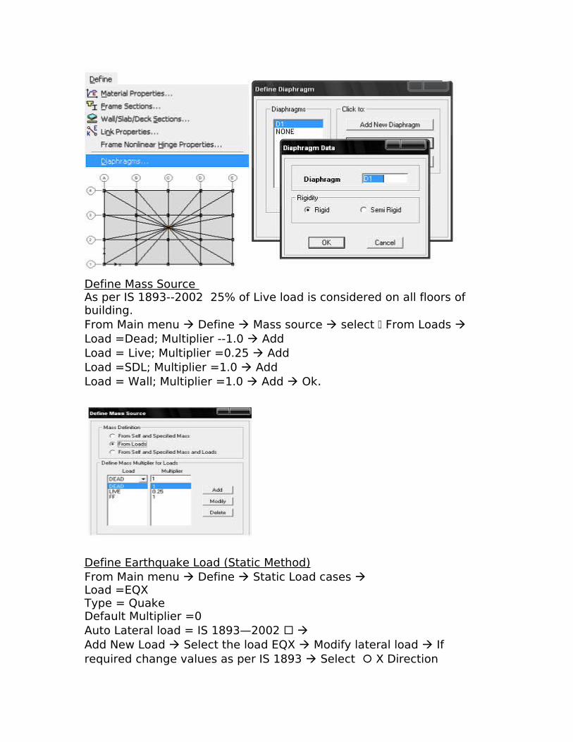
Define Mass Source As per IS 1893--2002 25% of Live load is considered on all floors of building.From Main menu Define Mass source select From Loads Load =Dead; Multiplier --1.0 AddLoad = Live; Multiplier =0.25 Add Load =SDL; Multiplier =1.0 AddLoad = Wall; Multiplier =1.0 Add Ok.
Define Earthquake Load (Static Method)From Main menu Define Static Load cases Load =EQXType = QuakeDefault Multiplier =0Auto Lateral load = IS 1893—2002 Add New Load Select the load EQX Modify lateral load If required change values as per IS 1893 Select X Direction
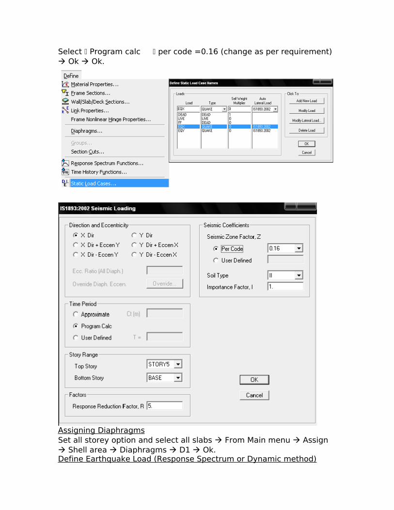
Select Program calc per code =0.16 (change as per requirement) Ok Ok.
Assigning DiaphragmsSet all storey option and select all slabs From Main menu Assign Shell area Diaphragms D1 Ok.Define Earthquake Load (Response Spectrum or Dynamic method)
From Main menu Define Response Spectrum Functions IS 1893 -2002 select IS 1893-2002Spectrum Ok. Select IS1893 Modify/Show Spectrum Spectrum case name =IS1893 Damping =0.05 Modal combination CQC Directed Combination SRSSFunction name=1893; Function damping ration=0.05Seismic zone factor z=0.16 ; Soil type =1 Ok.
To view the DiaphragmGo to Set Building View objects Diaphragm
STEP 8 : ( Design)
Selecting Indian Code From Main menu Options Preferences Concrete Frame Design code = Indian IS 456-2000. Ok.
Defining Load CombinationFrom Main menu Define Load Combinations Add New Load Comb Load Combination Name =DL+LLLoad Combination type =Add Change scale factor =1.5 for DL and LL by clicking add button Add New Load Comb Load Combination Name =DL+WLLoad Combination type =Add Change scale factor =1.5 for DL and WL by clicking add button Add New Load Comb Load Combination Name =DL+EQXLoad Combination type =Add Change scale factor =1.5 for DL and EQX by clicking add button Ok Ok.
Selecting Design Load ( i.e. DL+LL)From Main menu Design Concrete Frame design Select design comb Select our combination load from the list Add Ok.
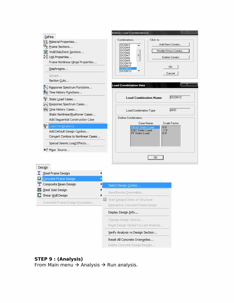
STEP 9 : (Analysis) From Main menu Analysis Run analysis.
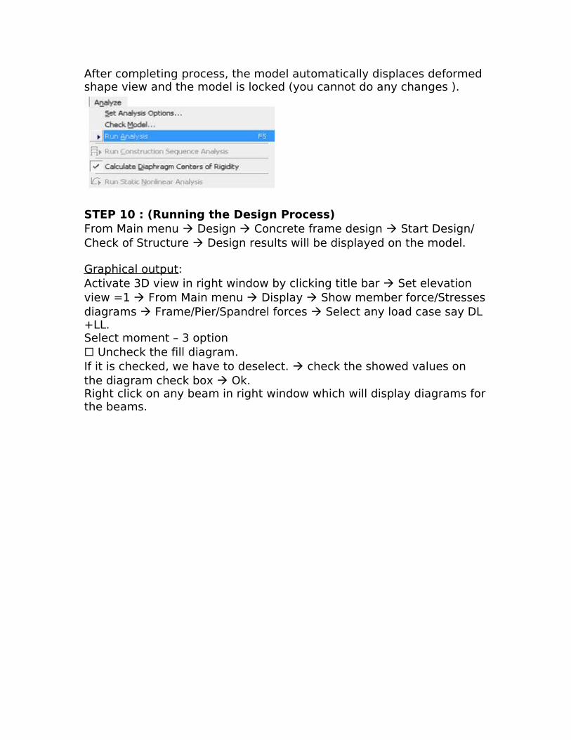
After completing process, the model automatically displaces deformed shape view and the model is locked (you cannot do any changes ).
STEP 10 : (Running the Design Process)From Main menu Design Concrete frame design Start Design/ Check of Structure Design results will be displayed on the model.
Graphical output:Activate 3D view in right window by clicking title bar Set elevation view =1 From Main menu Display Show member force/Stresses diagrams Frame/Pier/Spandrel forces Select any load case say DL +LL.Select moment – 3 option Uncheck the fill diagram.If it is checked, we have to deselect. check the showed values on the diagram check box Ok.Right click on any beam in right window which will display diagrams for the beams.
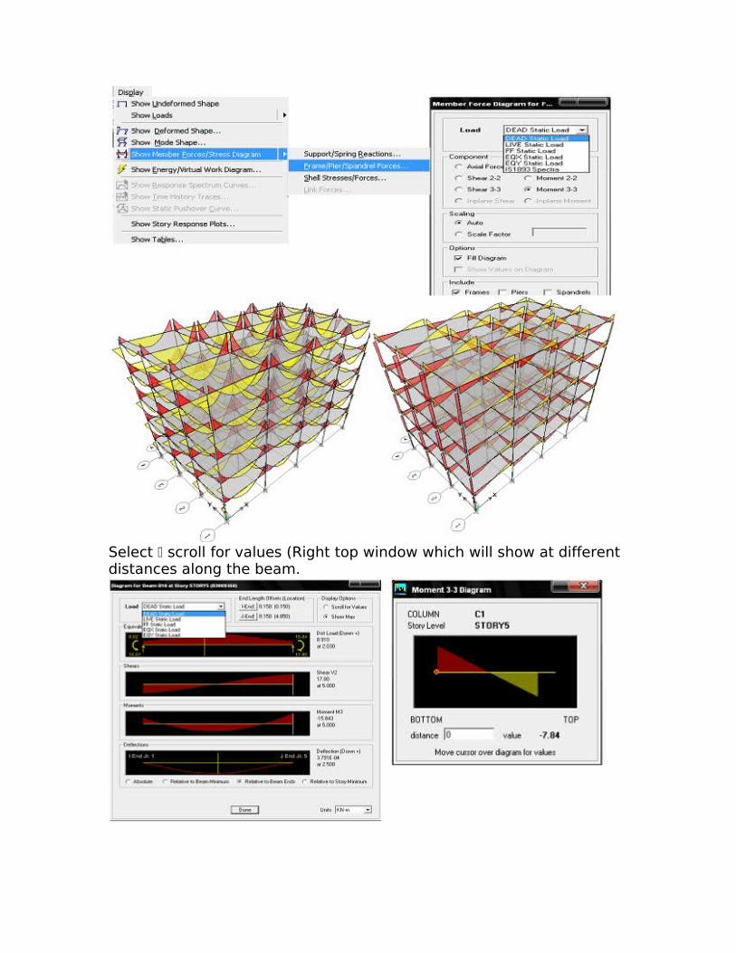
Select scroll for values (Right top window which will show at different distances along the beam.
To clear the display: Activate right window From Main menu Display Show un deformed shape Click on 3D button from top tool bar to display 3D view.To view reinforcement detail:
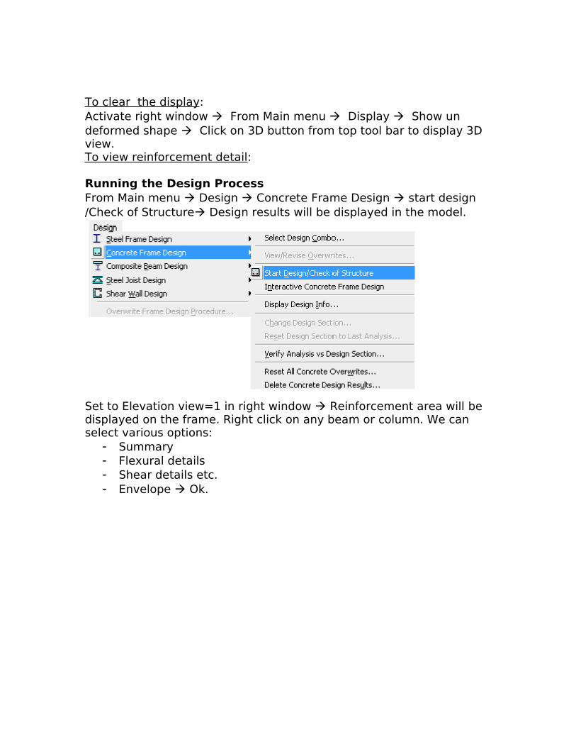
Running the Design ProcessFrom Main menu Design Concrete Frame Design start design /Check of Structure Design results will be displayed in the model.
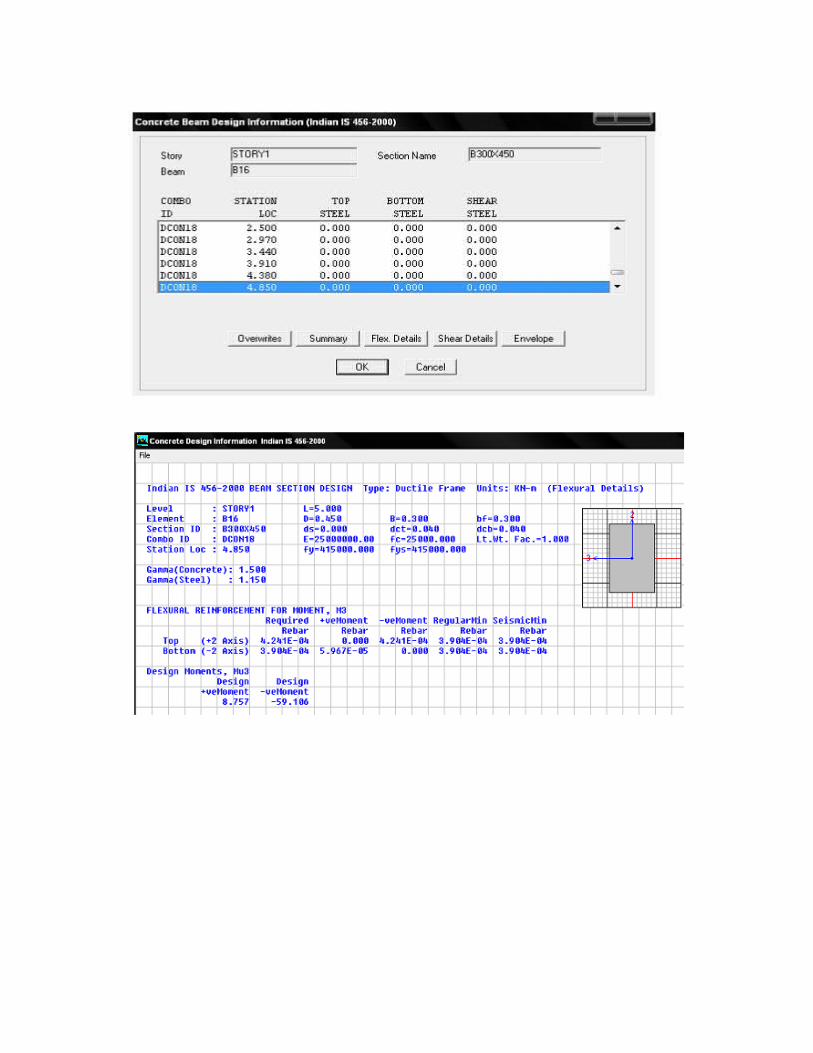
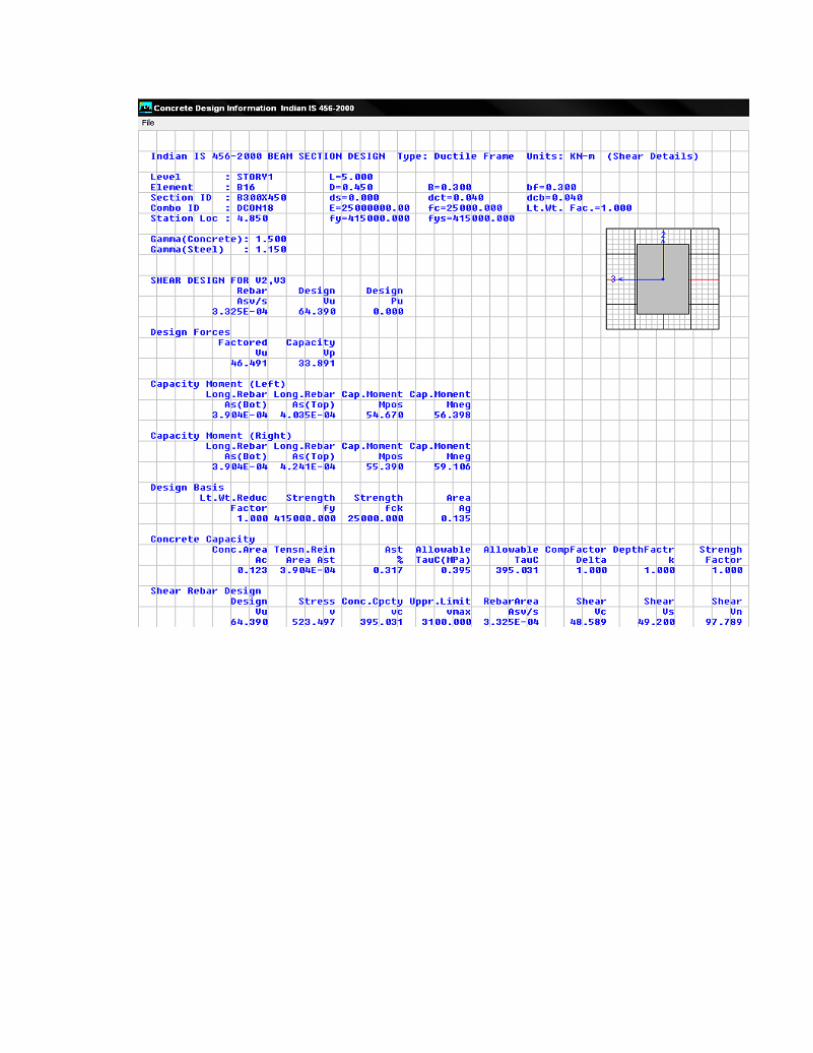
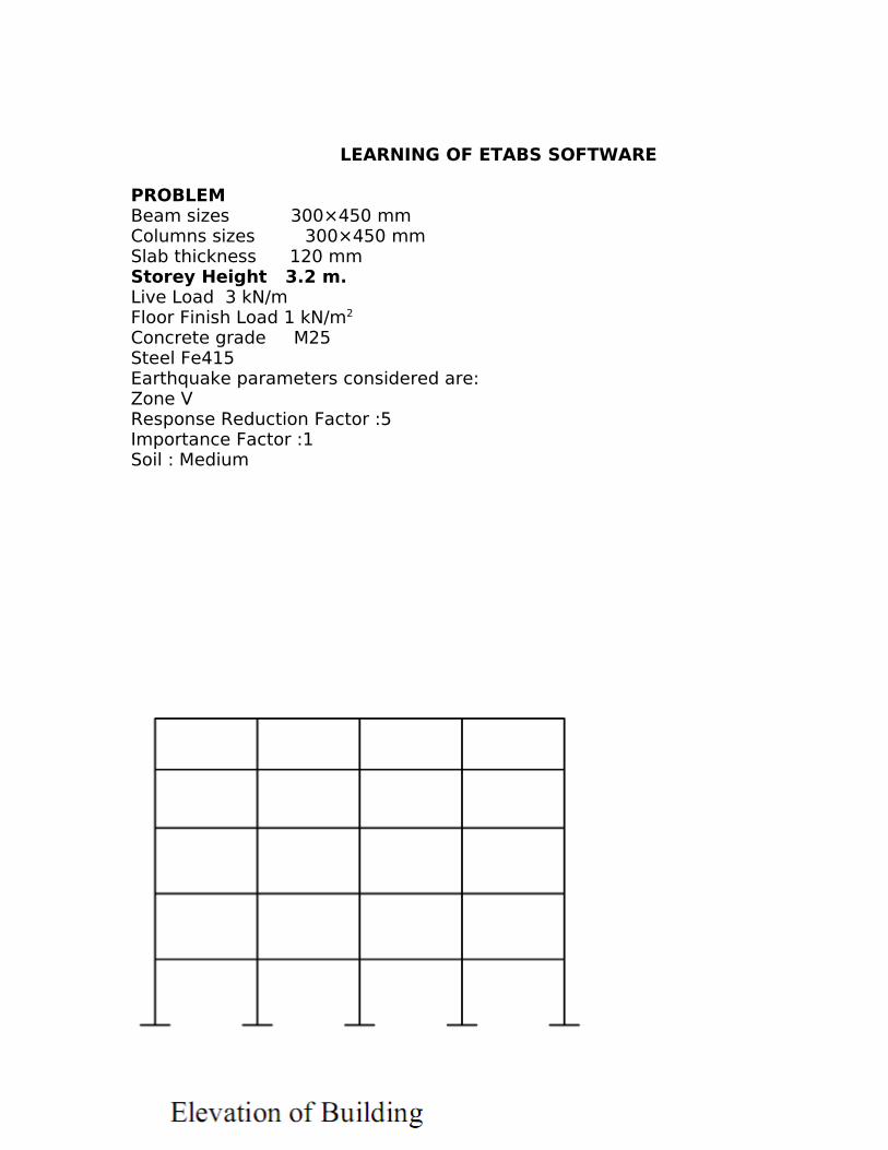
Set to Elevation view=1 in right window Reinforcement area will be displayed on the frame. Right click on any beam or column. We can select various options:
- Summary- Flexural details- Shear details etc.- Envelope Ok.
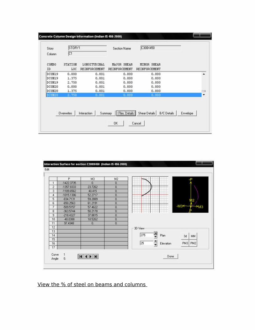
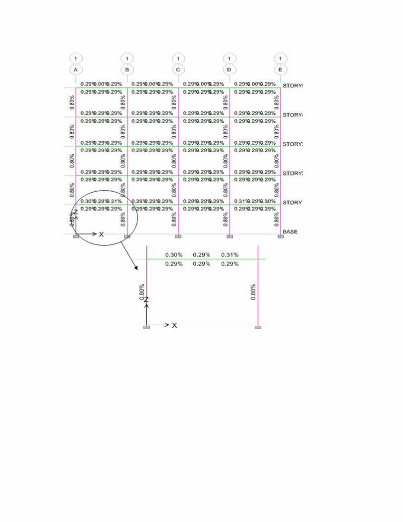
View the % of steel on beams and columns
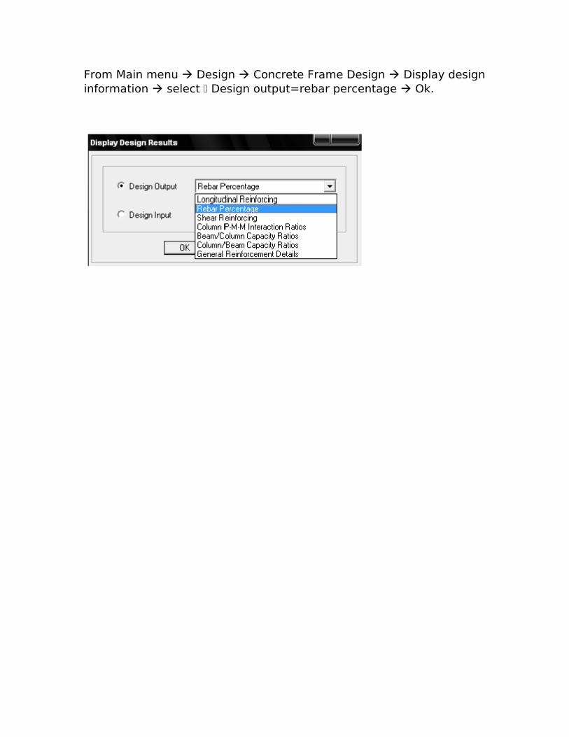
From Main menu Design Concrete Frame Design Display design information select Design output=rebar percentage Ok.