Embed Size (px)
Citation preview

SCHOOL OFCIVIL ENGINEERING
INDIANA
DEPARTMENT OF HIGHWAYS
JOINT HIGHWAY RESEARCH PROJECT
FHWA/ IN/JHRP/ 9 2 / 19
Final Report
PHASE II - EMBANKMENT WIDENING ANDGRADE RAISING ON SOFT FOUNDATION SOILS
Scott J. Ludlow
Wai-Fah Chen
Philippe L. Bourdeau
C. William Lovell
UNIVERSITY

JOINT HIGHWAY RESEARCH PROJECT
FHWA/ IN/JHRP/ 9 2 / 19
Final Report
PHASE II - EMBANKMENT WIDENING ANDGRADE RAISING ON SOFT FOUNDATION SOILS
Scott J. Ludlow
Wai-Fah Chen
Philippe L. Bourdeau
C. William Lovell

Digitized by the Internet Archive
in 2011 with funding from
LYRASIS members and Sloan Foundation; Indiana Department of Transportation
http://www.archive.org/details/embankmentwideniOOIudl

Final Report
Phase II - Embankment Widening and GradeRaising on Soft Foundation Soils
by
Scott J. LudlowGraduate Research Assistant
Wai-Fah ChenProfessor of Civil Engineering
Philippe L. BourdeauAssistant Professor of Civil Engineering
and
C. William LovellProfessor of Civil Engineering
Joint Highway Research ProjectProject No: C-36-36U
File No: 6-14-21
This study was conducted by theJoint Highway Research Project
in cooperation with theIndiana Department of Transportation
and theFederal Highway Administration
The contents of this report reflect the views of the authors whoare responsible for the facts and the accuracy of the datapresented herein. The contents do not necessarily reflect theofficial views or policies of the Federal Highway Administration orof the Indiana Department of Transportation. This report does notconstitute a standard, specification, or regulation.
Purdue UniversityWest Lafayette, Indiana 47907
April 13, 1993

TECHNICAL REPORT STANDARD TITLE PACE
1. Report No.
FHWA/IN/JHRP-92/1 9
7. Government Acce
4. Till* and Subtitle
Phase II - embankment widening and grade risingon soft foundation soils
3. Recipient's Catalog No.
5. Report Data
June 30, 1992
6. Performing Organization Code
7. Aufhor(s)
Scott J. Ludlow, Wai-Fah Chen, Philippe L. Bourdeauand C. William TovpI 1
8. Performing Organization Report No.
FHWA/IN/JHRP-92/1
9
9. Performing Organization Nome and Address
Joint Highway Research ProjectCivil Engineering BuildingPurdue UniversityWest Lafayette, IN 47907
10. Work Unit No.
11. Controcf or Grant No.
HPR-2031
12. Sponsoring Agency Nome and Addres"
Indiana Department of TransportationState Office Building100 North Senate AvenueIndianapolis, IN 46204
13. Type of Report and Period Covered
Final Report
14. Sponsoring Agency Code
15. Supplementary Notes
Prepared in cooperation with the U.S. Department of Transportation, FederalHighway Administration.
16. Abstract
The finite element technique using a cap elastic-plastic work-hardening soilbehavior model was applied to the analysis of embankments constructed on softfoundation soils. A procedure was provided to estimate the cap model parametersfrom conventional field and laboratory test results. A sensitivity analysisof the cap model parameters comparing the observed and calculated responses wasalso provided. Results indicate that the undrained shear strength and over-consolidation ratios were observed to have the most-significant influence on thepredicted model behavior.
The technique was then applied to the analysis of two examples. The examples werebased on actual highway projects in Indiana where information on these projectswas provided by INDOT personnel. Results of the analysis were used to determinethe influence of several factors on reinforced and unreinforced embankmentbehavior. The results indicated that the crust strength and foundationcompressibility had the most-significant influence on embankment fill and foundationsoil behavior and the potential benefit possible with reinforcement. Reinforcementtype/modulus also influenced the behavior of the embankment fill and foundationsoil but to a lesser extent when compared to crush strength. The use ofreinforcement for widening and grade raising of existing embankments appeared tobe beneficial in reducing lateral movement.
17. Key Words
Embankments, reinforcement, geotextilesfinite element method, soft foundations,settlements, cap plasticity model
18. Distribution Statement
No restrictions. This document is
available to the public through theNational Technical Information Service,Springfield, Virginia 22161
19. Security Clossii. (of this report)
Unclassified
2C Security Classif. (of this page)
Unclassified
21. No. of Poges
356
22. Price
Form DOT F 1700.7 is-ssi

Purdue University
WSchool of Civil Engineering
DRAFT FINAL REPORT
TO: Vincent P. Drnevich, Director
Joint Highway Research Project
FROM: W. F. Chen, Research Engineer
Joint Highway Research Project
July 23, 1992
Project No: C-36-36U
File: 6-14-21
Attached is the draft final Report on the HPR Part II study entitled, "Embankment
Widening and Grade Raising on Soft Foundation Soils". The authors of the report are Scott J.
Ludlow, Wai-Fah Chen, Philippe L. Bourdeau and C. William Lovell.
Copies of this report will be submitted to the IDOH and FHWA for their review. My co-
authors and I look forward to receiving their comments on the report.
Respectfully submitted,
/)
W.F. Chen
Research Engineer
WFC/cak
Attachment
cc: A.G. Altschaeffl
D. Andrewski
P.L. Bourdeau
M.D. BowmanM.J. Cassidy
L.M. Chang
S. DiamondJ.J. Dillon
W.L. Dolch
V.P. Drnevich
A.R. Fendrick
J.D. Flicker
D.W. Halpin
K.R. Hoover
R.H. Lee
C.W. Lovell
R.H. LowryD.W. Lucas
B.G. McCullouch
B.K. Partridge
J.A. Ramirez
G.J. Rorbakken
C.F. Scholer
G.B. Shoener
K.C. Sinha
D.L. Tolbert
C.A. Venable
T.D. White
L.E. WoodJ.R. Wright
R.F. Wukasch
Civil Engineering Building . West Lafayette, IN 47907-1284 . FAX (317)49&-1 105
TABLE OF CONTENTS
Page No.
LIST OP TABLES i
LIST OP FIGURES ii
ABSTRACT iii
CHAPTER 1:INTRODUCTION 1
1 .
1
Motivation 1
1 .
2
General Background 3
1 .
3
Objective and Scope of Work 6
1 .
4
Report Organization 6
CHAPTER 2:A PROCEDURE FOR ESTIMATING CAP MODEL PARAMETERS FROMCONVENTIONAL FIELD AND LABORATORY TEST RESULTS 8
2 .
1
Introduction 8
2.2 Description of the Cap Model 102.3 A Procedure for Estimating Cap Model
Parameters for NFAP 142.3.1 Ultimate Failure Surface (3) 142.3.2 Elastic and Plastic Behavior (4) 222.3.3 Cap Parameters (2) 262.3.4 Initial Stress State (2) 322.3.5 Pore Pressure Response Factor (1) .... 3 2
2.4 Discussion of Sensitivity of CapModel Parameters 352.4.1 Poisson's Ratio (v) 372.4.2 Compression Index (Cc ) 382.4.3 Recompression Index (Cr ) 382.4.4 Pore Pressure Response Factor (P) .... 392.4.5 Angle of Internal Friction (0) 392.4.6 Undrained Shear Strength Ratio 4
2.4.7 Over-consolidation Ratio (OCR) 42 .
5
Limitations of the Cap Model 402 .
6
Summary 4 2
CHAPTER 3:APPLICATION OF THE FINITE ELEMENT METHODTO NFAP 44
3 .
1
Introduction 443 .
2
Modeling Foundation Soils 453 .
3
Modeling Embankment Fill 463 .
4
Modeling Reinforcement 483 .
5
Incremental Construction 513 .
6
Concluding Remarks 53
Page No.
CHAPTER 4:CASE STUDIES 56
4 .
1
Introduction 564 .
2
Example 1 564 . 3 Example 2 . 62
CHAPTER 5:
DESIGN GUIDELINES 75
5 .
1
Introduction 7 5
5.2 Design Analysis . . . 7 6
5.2.1 Deformation Behavior of Reinforced andUnreinforced Embankments 7 6
5.2.2 Effect of Crust Strength 775.2.3 Effect of Reinforcement on Stability . 795.2.4 Effect of Foundation Compressibility . 805 . 2 .
5
Effect of Embankment Width 815.2.6 Effect of Embankment Widening and
Grade Raising 815.2.7 Summary 83
5.3 Design Analysis Limitations of NFAP program . 855 .
4
Design Recommendations 90
CHAPTER 6:SUMMARY, CONCLUSIONS AND RECOMMENDATIONS 91
6 .
1
Summary and Conclusions 916.1.1 General 916.1.2 Cap Plasticity Model 916.1.3 Case Studies 93
6 .
2
General Recommendations 95
APPENDICES:
Appendix A: List of References 97Appendix B: Interim Report: "A Sensitivity
Analysis of the Parameters fora Cap Plasticity Model," Report No.FHWA/JHRP/IN - 92-1 . 23 pp.
Appendix C: Interim Report: "Embankment Wideningand Grade Raising on Soft FoundationSoils: Example 1 - Indiana StateRoute 55 over Turkey Creek in LakeCounty, Indiana," Report No. FHWA/IN/JHRP - 91-18 . 56 pp.
Appendix D: Interim Report: "Embankment Wideningand Grade Raising on Soft FoundationSoils: Example 2 - Indiana StateRoute 1 over Ramsey Creek in FranklinCounty, Indiana," Report No. FHWA/IN/JHRP - 92-9 . 173 pp.

LIST OF TABLES
Table Page No,
2 • 1 Summary of Cap Model Parameters 15
2.2 Constants for Determiningthe Cap Model Parameters . 16
2.3 Summary of Sensitivity Analysis of the CapPlasticity Model Parameters . 3 6
4.1 General Soil Profile for State Route 55 58
4 .
2
Example 1 - Summary of Cases for Indiana StateRoute 55 over Turkey Creek/Lake County, Indiana . . 63
4.3 General Soil Profile for State Route 1 . 67
4 .
4
Example 2 - Summary of Cases for Indiana StateRoute 1 over Ramsey Creek/ FranklinCounty , Indiana 7
5.
1
Relative Influence of Reinforcement 77
5.2 Relative Influence of Crust Strength 78
5.3 Relative Influence of Foundation Compressibilityon Crust Strength 81
6 . 1 Summary of Procedures for Determining Cap Parametersfrom Conventional Laboratory and Field Tests ..... 92
11
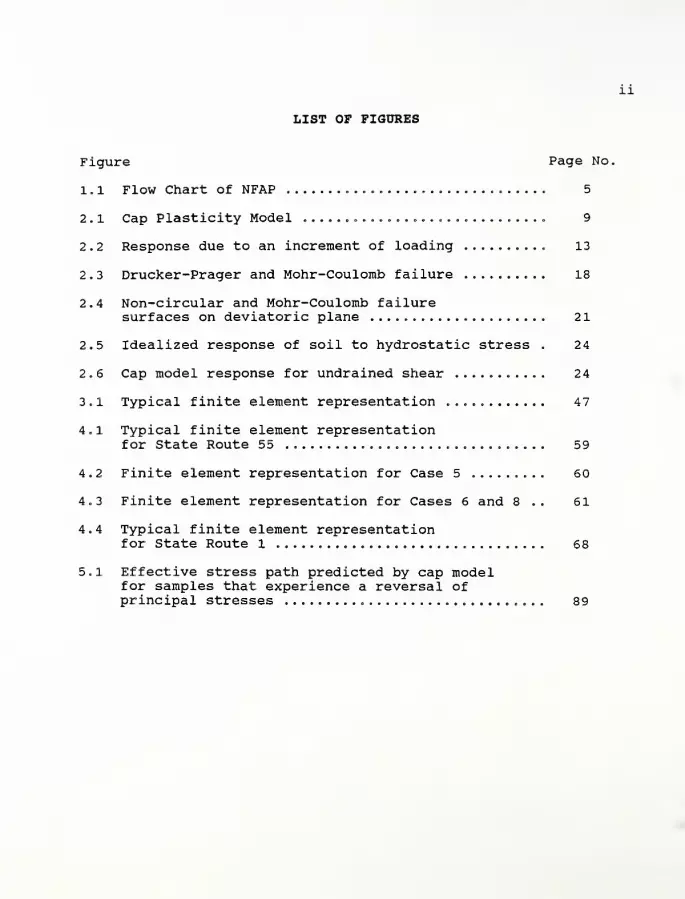
LIST OF FIGURES
Figure Page No.
1 . 1 Flow Chart of NFAP ....... 5
2 .
1
Cap Plasticity Model ............................. 9
2.2 Response due to an increment of loading 13
2.3 Drucker-Prager and Mohr-Coulomb failure 18
2.4 Non-circular and Mohr-Coulomb failuresurfaces on deviatoric plane 21
2.5 Idealized response of soil to hydrostatic stress . 2 4
2.6 Cap model response for undrained shear 24
3 . 1 Typical finite element representation 47
4.1 Typical finite element representationfor State Route 55 59
4.2 Finite element representation for Case 5 60
4.3 Finite element representation for Cases 6 and 8 .. 61
4.4 Typical finite element representationfor State Route 1 68
5.1 Effective stress path predicted by cap modelfor samples that experience a reversal ofprincipal stresses 89
Ill
ABSTRACT
The finite element technique using a cap elastic-plastic work-hardening soil behavior model was applied to the analysis ofembankments constructed on soft foundation soils. A procedure wasprovided to estimate the cap model parameters from conventionalfield and laboratory test results. A sensitivity analysis of thecap model parameters comparing the observed and calculatedresponses was also provided. Results indicate that the undrainedshear strength and over-consolidation ratios were observed to havethe most-significant influence on the predicted model behavior.
The technique was then applied to the analysis of twoexamples. The examples were based on actual highway projects inIndiana where information on these projects was provided by INDOTpersonnel. Results of the analysis were used to determine theinfluence of several factors on reinforced and unreinforcedembankment behavior. The results indicated that the crust strengthand foundation compressibility had the most-significant influenceon embankment fill and foundation soil behavior and the potentialbenefit possible with reinforcement. Reinforcement type/modulusalso influenced the behavior of the embankment fill and foundationsoil but to a lesser extent when compared to crust strength. Theuse of reinforcement for widening and grade raising of existingembankments appeared to be beneficial in reducing lateral movement.
IMPLEMENTATION REPORT
PHASE II - EMBANKMENT WIDENING ANDGRADE RAISING OVER SOFT FOUNDATION SOILS
The Need
The draft final report for this project includes the study of
embankment widening and grade raising over soft foundation soils.
With the urgent need to upgrade our nation's highway system,
engineers face challenging problems of widening existing highway
embankments and raising new embankments, particularly over soft
foundation soils. For the analysis/design of these problems,
engineers often rely on a combination of limit equilibrium type
methods; simplified load/deformation responses; and experience.
However, as a result of the complex interaction of the embankment
and foundation soils, the above methods provide only approximate
information concerning the embankment and foundation deformations
and the serviceability of the embankment following construction.
To assess the performance of the embankment/ foundation system,
advanced modeling techniques are needed that account for nonlinear
and elastic-plastic material behavior. A technique that has gained
acceptance for the analysis of such problems is the finite element
method (FEM)
.
The FEM
Use of finite element techniques have the ability to allow us
to:
1. model complex geometry and deformation patterns;
2. simulate nonlinear material behavior, including yielding,using advanced constitutive models;
3. analyze the interaction of different materials; and

2
4. combine geometrical nonlinearity with materialnonlinearity.
Thus, the FEM can help engineers to:
1. improve their understanding of observed behavior in thefield;
2. model the response of an embankment/ foundation underincreasing load level;
3. analyze the effects of changes in the components of thesystem (i.e. the properties of the embankment andfoundation soil) ; and
4
.
assess the impact of construction procedures and theresponse of the system.
The finite element technique is well recognized as being a
powerful tool for design and analysis of embankment/ foundation
systems, and numerous examples can be found in the literature.
However, the use of finite element analysis for performing studies
which could answer the questions raised above is subject to some
important limitations.
If one is to model the response of the embankment in the range
of large deformations, then it is essential to employ a finite
element formulation and constitutive model which:
1. models the stress-dependent properties of the embankmentfill and foundation soil(s);
2. correctly models plastic yielding and flow in the filland foundation soil; and
3. allows for potential slip at the interface of soil andreinforcement in cases where geosythetics are used toimprove the stability of the embankment.
The Problem
It is unfortunate that such methodologies that have been
proposed in the geotechnical literature are still of very sparse

3
use in the practicing community. A major hurdle for the application
of the FEM to the analysis of such previously-mentioned problems is
the lack of practical guidelines and step-by-step procedures to
determine the material parameters required by the model and
interpret the results in a design context. The ultimate goal of the
present study is to bridge this gap. This study outlines a set of
procedures to enable engineers to make use of available technology,
and provides guidelines for the design and analysis of reinforced
and unreinforced embankments over soft foundation soils.
The Objective
The major objective of. this study (Phase II) has been to
outline a set of procedures to enable engineers to make use of the
available finite element methodology, and provide guidelines for
the design and analysis of reinforced and unreinforced embankments,
particularly over soft foundation soils. In order to achieve this
objective, it is necessary to provide:
1. a simple and reliable procedure to derive the capplasticity model parameters from data obtained byconventional field and laboratory soil tests;
2. background on the application/modeling techniques of theFEM to NFAP program;
3. complete case example studies in order to illustrate thecapabilities of the method for the analysis and design ofembankment widening and grade raising over soft founda-tion soils; and
4. practical guidelines for the analysis of embankmentwidening and grade raising over soft foundation soilsusing the FEM methodology.

4
Results and Guidelines for Practical Implementation
• Practical Procedure for Cap Parameter Determination
A straight forward procedure to determine the cap parameters
for normally consolidated soils from conventional laboratory and
field tests and a sensitivity study which examines the effect of
the input soil parameters was provided. The main input soil
properties are the compressibilities ( Cc , Cz ) , the effective
Mohr-Coulomb shear strength parameters ( <j>, c ) / the undrained
S„ ...shear strength ratio ( USR; «=-
) and the over-consolidation ratio
( OCR ) . Solutions are given in graphical form and equations
suitable for hand calculation.
The procedure was used to determine the cap parameters for an
impact-compacted lacustrine clay using results from isotropically-
consolidated undrained-compression (CIUC) tests. These parameters
were then used in a computer program called CAP to calculate
stress-strain curves, pore pressure response and effective stress
paths. Comparisons were made to observed test results. In
general, there was good agreement except for a discrepancy for pore
pressures and effective stress paths.
• Sensitivity Study of Cap Model Parameters
In addition, a sensitivity study was made of the effect of the
input soil properties on calculated CIUC triaxial sample behavior.
The results show which parameters have the greatest effect on
computed behavior and provide guidance in the selection and
adjustment of input soil properties to obtain a better fit between
the calculated and observed response. The USR and OCR were
5
observed to have the most-significant influence on the predicted
behavior.
• Practical Case Study
A comparative finite element study of two practical examples
involving a total of 30 cases was made using an incremental
procedure which simulated embankment construction. Embankment fill
and foundation soil behavior was represented with an isotropic,
strain-hardening cap-plasticity model.
The results indicated that the properties of a stiff or of a
tensile resistant reinforcement had the most significant influence
on embankment fill and foundation soil behavior. Reinforcement
type/modulus also influenced the behavior of the embankment fill
and foundation soil but to a lesser extent when compared to crust
strength
.
For compressible foundation soils and a relatively stiff
embankment, a high-modulus woven geotextile was very effective in
reducing displacements within the embankment fill and foundation
soils and increasing the stability near the embankment toe. For a
given embankment stiffness, the foundation compressibility directly
influences the effectiveness of the crust strength. The foundation
compressibility had only a limited influence on embankment behavior
and the benefit from using reinforcement was modest except for that
noted previously. The effect of increasing the embankment width by
the use of a stabilizing berm only slightly reduced the displace-
ments within the embankment fill and foundation soil and modestly
increased the stability at the toe.
6
The widening and grade raising of an embankment locally
altered the magnitude of the state of stress and stability but did
not alter the overall pattern. Displacements developed primarily
near the former shoulder and the widened toe (horizontally) and
along the sideslope of the former embankment (vertically)
.
In several cases, the local factors of safety within the
foundation soil near the centerline of the embankment and continu-
ing outwardly to the toe and slightly beyond the toe were yielding
(strain hardening) . The other portions of the embankment fill and
foundation soils were either experiencing stress states on the cap
(elastic-plastic), or within the cap (elastic state)
.
Limitations
• On Strain-Softening Soil
The cap model has some limitations which impact the calculated
response. One limitation which was observed during this study was
the inability of the model to predict the reduction in undrained
strength or increase in pore pressure that occurs after the peak
strength is reached in strain softening soil. Consequently, this
would overestimate the shear strength and underestimate the pore
pressures and deformations.
• On Over-consolidated Soils
A second limitation is the ability to model the behavior of
over-consolidated soils. The cap model correctly predicts the
undrained strength at large strains. However, pore pressures are
not predicted correctly and plastic strains which many over-
7
consolidated soils experience for stress changes in the elastic
region bounded by the cap and ultimate failure surfaces are not
accounted for. Also, strain softening after failure can not be
modeled. It is speculated that this would lead to underestimation
of deformations.
• On Trial-and-error Procedure
Another limitation which can be attributed to the model's
formulation is the need to perform a trial-and-error calculation to
estimate the best-fit of the observed response. Although time-
consuming, a reasonable fit of the observed response can be
obtained rather quickly by making a critical review of the OCR and
USR parameters and then modifying one of the other five (from the
previous sensitivity study) parameters, if necessary.
* On Long-term Behavior of Soils
Another limitation which requires considerable attention and
can also be attributed to the model's formulation is the model's
inability to account for long-term behavior (e.g. creep and
consolidation) . Presently, the model is best-suited for depicting
short-term behavior only. To account for creep and consolidation,
the model would require extensive modifications.
Further Research Needs
The work presented in the study aims to facilitate the
application of the cap plasticity model to practical problems and
in design of embankments constructed on soft foundation soils.
However, there are some aspects of unreinforced and reinforced
embankment analysis that require further development of the

8
software program for this study. The ability of the cap model to
accurately predict soil behavior could be extended to a wider range
of soils, stress paths and drainage conditions. The following are
additional research needs:
1. A parametric study of the effect of reinforcement shouldbe made using NFAP for a wider range of embankmentgeometries and soil properties. It should includenarrower embankments, different crust thicknesses anddifferent reinforcement moduli. The tensile forces inthe reinforcement should be analyzed in this study.
2. The cap plasticity model should be extended to improveits ability to model soil behavior during rotation ofprincipal stresses and the behavior of over-consolidatedsoils.
3. Compacted cohesive soils are more often used as fillmaterial for embankments. The behavior of embankmentswith cohesive fill (which include the effects of compac-tive prestress) should be evaluated with the cap plastic-ity model.
4. Presently, the cap plasticity model is better at accomo-dating either drained or undrained conditions. The modelshould be extended to partially drained conditions andthen evaluated.
5. Slippage often occurs at or near the interface of theembankment fill/geosynthetic/foundation soil interface.NFAP should be modified to include slippage consider-ations.
6. To provide beneficial use to practicing engineers, NFAPshould be modified to include pre- and post-processinggraphics capabilities.
7. Post construction effects need to be considered, particu-larly since the original embankment and widening/raisinghave different chronologies. Foundation creep andembankment settling upon wetting in service are examples.
CHAPTER 1
INTRODUCTION
1.1 Motivation
With the urgent need to upgrade our nation's highway system,
engineers face challenging problems of widening existing highway
embankments and raising new embankments, particularly over soft
foundation soils. For the analysis/design of these problems,
engineers often rely on a combination of limiting equilibrium type
methods; simplified load/deformation responses; and experience.
However, as a result of the complex interaction of the embankment
and foundation soils, the above methods provide only approximate
information concerning the embankment and foundation deformations
and the serviceability of the embankment following construction.
To assess the performance of the embankment/ foundation system,
advanced modeling techniques are needed that account for nonlinear
and elastic-plastic material behavior. A technique that has gained
acceptance for the analysis of such problems is the finite element
method (FEM)
.
Use of finite element techniques have the ability to allow us
to:
1. model complex geometry and deformation patterns;
2. simulate nonlinear material behavior, including yielding,using advanced constitutive models; and
3. analyze the interaction of different materials.
Thus, the FEM can help engineers to:
1. improve their understanding of observed behavior in thefield;

2. model the response of an embankment/ foundation underincreasing load level;
3. analyze the effects of changes in the components of thesystem (i.e. the properties of the embankment andfoundation soil) ; and
4
.
assess the impact of construction procedures and theresponse of the system.
The finite element technique is well recognized as being a
powerful tool for design and analysis of embankment/ foundation
systems, and numerous examples can be found in the literature (e.g.
Boutrup and Holtz, 1983; Hird and Jewell, 1990; Kwok, 1987;
Leroueil et al., 1978; Rowe, 1982). However, the use of finite
element analysis for performing studies which could answer the
questions raised above is subject to some important limitations.
If one is to model the response of the embankment in the range
of large deformations, then it is essential to employ a finite
element formulation and constitutive model which:
1. models the stress-dependent properties of the embankmentfill and foundation soil(s);
2. correctly models plastic yielding and flow in the filland foundation soil; and
3. allows for potential slip at the interface of soil andreinforcement in cases where geosythetics are used toimprove the stability of the embankment.
It is unfortunate that such methodologies that have been
proposed in the geotechnical literature are still of very sparse
use in the practicing community. A major hurdle for the applica-
tion of the FEM to the analysis of such previously-mentioned
problems is the lack of practical guidelines and step-by-step
procedures to determine the material parameters required by the
3
model and interpret the results in a design context. The ultimate
goal of the present study is to bridge this gap. This study
outlines a set of procedures to enable engineers to make use of
available technology, and provides guidelines for the design and
analysis of reinforced and unreinforced embankments over soft
foundation soils.
1.2 General Background
Prior to widening or raising an embankment, it is common
practice to partially or totally undercut and replace soft or
otherwise unstable foundation soils with compacted "special" fill,
which is expensive (not only the fill but also the construction
techniques) . Alternatively, the foundation soils can be treated in
such a way as to accommodate the proposed loads. Numerous
techniques which are within the category of ground modification are
available, e.g. dewatering, grouting, preloading, compacting, etc.
However, these techniques are site specific, often costly and
generally time consuming. In this study, the focus with respect to
soil improvement is on the use of geosynthetic reinforcement
(specifically geotextile or geogrid) placed directly at the
interface of the soft ground and the new or added embankment. The
result of the embankment loading is to induce excess pore water
pressure in the underlying foundation soils which is subsequently
dissipated when consolidation occurs. During the critical stage
for the stability (short term) , the function of the geosynthetic is
of reinforcing and providing support (horizontally) to the
embankment. However, the situation may change somewhat with time
4
as the foundation soil gains strength through consolidation and
begins to support part, or all, of the embankment loading.
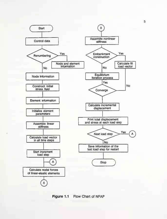
The software used in this study is based on a general purpose
finite element program named NFAP (nonlinear finite analysis
program) developed by Chang (1980) . NFAP was originally developed
for the use of nonlinear large deformation analysis of structures.
However, the program was later expanded and refined by Mizuno
(1981) and McCarron and Chen (1985) to include a cap plasticity
model to simulate the behavior of soils. Then, Humphrey (198 6)
condensed McCarron' s version of the program for use on personal
computers
.
During Phase I of this research study, Huang (1991) modified
and extended NFAP to include: double precision/ floating point
variables; foundations with sloping boundaries and a variable
groundwater level; and a procedure for determining the ini-
tial/existing stress state within an embankment. A flow chart for
the NFAP computer program is shown in Figure 1.1.
As previously stated, NFAP employs a cap plasticity model to
simulate the behavior of the soil. From a theoretical point of
view, the cap model employed herein is particularly appropriate in
modeling soil behavior, because it is capable of treating the
conditions of stress history, stress path dependency, dilatancy,
and the effect of the intermediate principal stress. At present,
however, many practicing engineers are not familiar with the
process of determining the material parameters of the cap model.
Often, existing procedures from well-known texts or more recent
f~ StartJ
Control data
Yes
No
Node and elementinformation
Node information
Construct initial
stress field
Element information
Initialize elementparameters
Assemble linear
stiffness
Calculate load vectorin all time steps
Start incrementload step
Calculate nodal forces
of linear-elastic elements
Assemble nonlinear
stiffness
Yes
No
Calculate fill
load vector
Equilibrium
iteration process
No
Calculate incremental
displacement
Print total displacement
and stress at each load step
Save information of the
last load step for restart
Stop
Figure 1.1 Flow Chart of NFAP
6
literature, which are mostly developed by mechanicians from the
engineering-mechanics viewpoint, are employed rather than using
data obtained from commonly performed soil tests.
1.3 Objective and Scope of Work
The major objective of this study (Phase II) has been to
outline a set of procedures to enable engineers to make use of the
available finite element methodology of NFAP, and provide guide-
lines for the design and analysis of reinforced and unreinforced
embankments, particularly over soft foundation soils. In order to
achieve this objective, it is necessary to provide:
1. a simple and reliable procedure to derive the capplasticity model parameters from data obtained byconventional field and laboratory soil tests;
2. background on the application/modeling techniques of theFEM to the NFAP program;
3. complete case example studies in order to illustrate thecapabilities of the method for the analysis and design ofembankment widening and grade raising over soft founda-tion soils; and
4
.
practical guidelines for the analysis of embankmentwidening and grade raising over soft foundation soilsusing the FEM methodology.
1.4 Report Organization
No theoretical or technical details are included beyond what
is absolutely necessary for following the report and making use of
the procedures and recommendations contained herein. Those
interested in acquiring a more thorough knowledge of the applica-
tions of the cap plasticity model and finite element formulation
and related work on soil reinforcement of soft embankment founda-
tions are referred to the references listed in Appendix A.
7
Chapter 2 discusses a proposed procedure for estimating cap
plasticity model parameters from conventional field and laboratory
test results. Often during a design process, many geotechnical
engineers are unable to perform a sufficient site investigation to
accurately estimate the soil parameters because of the project's
budgetary restraints. Consequently, the soil parameters are
obtained from empirical correlations using conventional field and
laboratory test results and/or engineering judgement. This chapter
employs these correlations and judgement to estimating cap
plasticity model parameters. In addition, a sensitivity study of
the cap parameters is performed.
Chapter 3 concentrates on the application and modeling
techniques of the FEM to the NFAP program.
Chapter 4 contains case studies of application of the
procedures outlined in Chapters 2 and 3. The cases in Chapter 4
are based on actual highway projects in Indiana where information
on these projects was provided by Indiana Department of Transporta-
tion (INDOT) personnel.
Chapter 5 presents the developed guidelines for the analysis
of embankment widening and grade raising over soft foundation soils
by using the NFAP methodology, based on the results obtained from
Chapter 4
.
Chapter 6 contains conclusions and recommendations, including
further work involving soil reinforcement, and expanding the
capabilities of the analytical model to better accommodate the
deformations of embankment/ foundations in service.
CHAPTER 2
A PROCEDURE FOR ESTIMATING CAP PLASTICITY MODEL PARAMETERS FROMCONVENTIONAL FIELD AND LABORATORY TEST RESULTS
2.1 Introduction
The deformational behavior of soils is primarily influenced by
stress-strain history, soil type and direction, rate, and magnitude
of loading. To successfully apply a soil model, it is essential
that the model expresses the significant characteristics of the
soil response for a particular state. One model that has received
acceptance in the area of finite element analysis of geotechnical
engineering problems is the cap plasticity (cap) model (e.g. Nelson
and Baladi 1977; Baladi and Rohani 1979; Chen and McCarron 1983;
Mizuno and Chen 1984; Daddazio et.al. 1987; McCarron and Chen
1987) .
In general, cap models describe the failure and yielding
behavior of soil with an ultimate yield surface that is fitted with
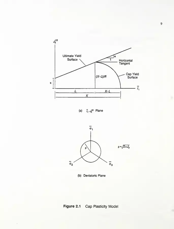
a movable end cap (see Figure 2.1). Both the ultimate or failure
and cap yield surfaces are symmetrical about the hydrostatic axis.
A "hardening rule" specifies the movement of the cap as a result
of the hardening or softening behavior of the soil when loaded.
Other cap models also permit the movement of the failure surface in
addition to the cap. Movement in these types of models are also
expressed by a hardening rule. It should also be noted that
strains are elastic for stress changes that lie within the region
of the failure and cap surfaces but are both elastic and plastic
for stress changes on the surfaces. The cap model utilized in this
study is an isotropic strain-hardening plasticity model with an
J1/2
2
Ultimate Yield
Surface \ ^s^" 1
fa
HorizontalTangent
(X-L)IR.^. Cap Yie
V"^ Surfac
K
x-z.
(a) 7,-jf Plane
9=j2xJ,
(b) Deviatoric Plane
Figure 2.1 Cap Plasticity Model
10
elliptical cap. This model is briefly described in the following
sections. Readers interested in acquiring more knowledge about cap
models are referred to a recent book by Chen and Mizuno (1990)
.
In this chapter, the reader is first given a brief description
of the cap model including a discussion of the yield functions
(ultimate and cap yield surfaces) and the hardening rule. Then, a
procedure for estimating the cap model parameters from conventional
field and laboratory test results is given. Finally, the results
of a sensitivity study are given which examine the effect of the
input soil properties on the calculated response.
2.2 Description of the Cap Model
The primary features of the cap model include the cone-shaped
ultimate/ failure surface and an elliptical-shaped cap. Figure 2.1
illustrates the model in an 1r-j\ lz space where ~ix
is the first
invariant of the effective stress tensor and J2 is the second
invariant of the deviatoric stress tensor. The invariants are
defined in terms of the principal stresses as:
Jx
= ax
+ a2
+ o3
(2.1)
J2 = \ t(°i ~ o2 )
2 + (o2
- o3 )
2 + (a3
- o x )2
] (2.2)
where a1,a
2 ,a 3 are the major, intermediate and minor effective
principal stresses, respectively.
The equation for the ultimate failure surface, ff , is based
on a generalization of the Mohr-Coulomb hypothesis (Drucker and
Prager, 1952) which is a smooth surface of the simple form:
11
ff = alx- J\n * K = (2.3)
where a and k are material parameters that are related to the
angle of internal friction and cohesion of the soil, respectively.
It should also be noted that the sign convention used herein is
positive for compressive stresses and strains, and therefore
consistent with soil mechanics sign convention.
The equation used to describe the shape of the cap is based on
a quarter of an ellipse:
fc = (Ja - L(l)) 2 + R2J2- (X - L(l)) 2 = (2.4)
where R is defined as the (aspect) ratio of the major and minor
radii in Figure 2.1. In addition, x and L(l) are defined as the
hardening rule and failure function, respectively. It should also
be recognized that x and L(l) define the l1-value at the inter-
sections of the elliptical cap with the Ix-axis and the failure
function, respectively. The location, x, of the cap is related to
the plastic volumetric strain, e£ / and this relation is assumed as
(DiMaggio and Sandler, 1971)
:
x = -lln(l - i?) (2.5)D W
where D is a curve fitting parameter with units of (stress)" 1 and W
is the limiting value of e£ at high stress.
Elastic volumetric and shear (distortion) strains are governed
by the bulk, K , and shear, G , moduli, respectively. Elastic
volumetric strain, e£ , is produced by changes in Jx
.
12
Jl (2.6)€v =(3J0
The elastic shear strain is given by:
e- = iJ (2.7)^ (2G)
where ei7- is the deviatoric strain tensor and 8^ is the deviatoric
stress tensor. To reiterate, stress changes in the region bounded
by the ultimate and cap yield surfaces produce only elastic
strains. However, loading on the ultimate yield surface or beyond
the initial location of the cap results in both elastic and plastic
strains.
In order to compute plastic strains for loading on the
ultimate and cap yield surfaces, an associated flow rule is
assumed. The flow rule defines the relationship between the next
increment of the plastic strain increment, de?j , and the present
state of stress, o_y , for an element of soil that is either on the
ultimate or cap yield surfaces and when subjected to further
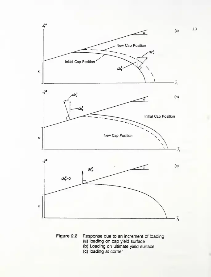
loading. As indicated by Figure 2.2a, an increment of loading on
the cap causes it to expand and results in positive plastic
volumetric (contraction) strain and plastic shear strain. However,
loading on the ultimate yield surface produces negative plastic
volumetric (dilation) strain and plastic shear strain. As a result
of the dilation, the cap contracts (as shown in Figure 2.2b) by an
amount that is proportional to the hardening rule (Eguation 2.5).
For a stress state at the intersection between the cap and the
ultimate yield surface, the increment of plastic strain is taken to
(a)13
J?y(K ^^- (b)
— *?,
Initial Cap Position
~~""">
,
New Cap PositionN X\ \\ \\ \
\ ' 7
Figure 2.2 Response due to an increment of loading
(a) loading on cap yield surface
(b) Loading on ultimate yield surface
(c) loading at corner

14
be normal to the cap. Therefore, plastic shear strain occurs at a
constant volumetric strain (Figure 2.2c). In addition, this is
consistent with the observed behavior of soils at large strain.
2.3 A Procedure for Estimating Cap Model Parameters for NFAP
There are 12 cap model parameters and they are generally-
grouped into five categories. These categories include: 1) an
ultimate yield surface (3 parameters) ; 2) elastic and plastic
behavior (4); 3) cap surface (2); 4) initial stress state (2); and
5) pore pressure response factor (1) . Table 2.1 provides a summary
of the parameters, while the required constants for NFAP for
determining the model parameters are indicated on Table 2.2. The
difference between the required constants for NFAP and the
conventional parameters is in the descriptions of the elastic
behavior and hardening rule.
Parameters that are required to perform the analysis can be
obtained from soil properties of commonly performed laboratory and
field tests [e.g. consolidation (oedometer) test; unconsolidated
and consolidated undrained triaxial tests; standard penetration
test; field vane shear; and empirical correlations from index
property tests] . In some cases, it may be necessary to estimate a
few of these properties. The following procedures are given for
the use of estimating cap model parameters for NFAP. Chapter 4
will apply the procedures contained herein to estimate cap model
parameters from conventional field and laboratory test results.
2.3.1 Ultimate Failure Surface ( a,K,Tc )
As stated previously, the equation for the ultimate yield

15
Table 2 . 1 Summary of Cap Model Parameters
Ultimate yield surface
a slope of ultimate yield surface in ~lx-j\ 12 space
(degrees)
k slope intercept along j\12 axis in Y
x-j\ /2 space
(force per unit area)
Tc tension cut-off/crack potential (force per unitarea - also related to the minimum principal ten-sile strength of the soil)
Elastic and Plastic Behavior
Kmin minimum value of the elastic bulk modulus (forceper unit area)
CAr= r r total bulk modulus parameter
c 2.303 (l + e„)
A= r r elastic bulk modulus parametere 2.303 (l+e )
where ea is the initial void ratio and Cc and Cr arethe compression and recompression indices, respec-tively
v Poisson's ratio
Cap Surface
R cap aspect ratio (ratio of the major and minorradii in Figure 2.1)
OCR overconsolidation ratio
Initial Stress State
Y saturated or moist unit weight of the soil (forceper unit volume)
KQ initial coefficient of lateral earth pressure
Pore Pressure Response Factor
P a ratio relating the apparent bulk modulus of thefluids to the total stiffness (which includes boththe soil and fluid)

16
Table 2.2 Constants for Determining the Cap Model Parameters
K^in minimum value of the elastic bulk modulus(force per unit area)
v Poisson's ratio
ea initial void ratio
<(> angle of internal friction (degrees)
c cohesion (force per unit area)
Cc compression index
Cr recompression index
S„undramed shear strength to effective over-burden pressureo.
OCR overconsolidation ratio
Tc tension cut-off (force per unit area)
Y saturated or moist unit weight of the soil(force per unit volume)
KQ coefficient of initial lateral earth pressure
P pore water pressure response factor

17
surface , ff , is based on a generalization of the Mohr-Coulomb
hypothesis (Drucker and Prager, 1952) which is:
ft = alx
- J\n * k = (2.8)
where a and k are material parameters that are related to the
angle of internal friction and cohesion of the soil, respectively.
However, before estimating the parameters, it is important to
recognize that there are several ways to approximate the Mohr-
Coulomb hexagonal failure surface by the Drucker-Prager circular
section in three-dimensional stress space as indicated in Figure
2.3. For geotechnical engineering applications, soil will either
experience some compression or extension depending primarily upon
the stress-strain history, soil type and direction of loading.
To simulate triaxial compression behavior of the soil (where
°2 =a 3 ) ' tne two sets of material constants ( a, k and c, <t> ) are
related by (Chen and Saleeb, 1982)
:
„ _ 2sin4> ._ _.a - —— (2.9)y/3(3 - Sin<j>)
6ccosd>K = —
—
T (2.10)v/3(3 - sin<|>)
To simulate triaxial extension behavior of the soil, the relations
are given by:
a - - 25in<t>(2.11)
^(3 + sin(J>)
K = ^ccosi_v/3(3 + sin<l>)
For plane strain conditions (e.g. a relatively long embankment)
,

18
Mohr-Coulomb
Drucker-Prager (matching
at 8 = 60°; Tensile Meridian)
Drucker-Prager
(matching at 8 = 0°;
Compressive Meridian)
Figure 2.3 Drucker-Prager and Mohr-Coulomb failure
criterion matched on compression and extension
meridians (after Chen and Saleeb, 1982)

19
the material constants are related by (Drucker and Prager, 1952)
:
_ tancfra 7 (2.13)
(9 + 12tan2<|>)
2
ic- 2£i (2.14)
(9 + I2tan2<|>)
2
However, for stress states within the soil mass other than triaxial
compression or extension, the match between the Mohr-Coulomb and
the Drucker-Prager criteria depends upon the Lode angle, , or
the intermediate principal stress at failure. Therefore, the
material constants are given by:
— sin<J>
a = — (2.15)[sin(8 + — )
- ^cos(6 + -£)sin<b]3 y/3
3
K = CCOS({>
;sin(6 + -J)" — (cos(9 + -£)sind>] (2.16)
3 ^3 3
where
9 = Acos-M^, „.„,2J2
2
J2 and J
3 in Equation 2.17 are the second and third invariants of
the deviatoric stress tensor, respectively.
When the stress state within the soil mass reaches the
intersection of the ultimate and cap yield surfaces, only shear
(distortion) strains ( y ) occur without plastic volume change

20
(i.e. de%.=0 )• As a result, the direction of the incremental
plastic strain must be normal to the elliptical cap rather than the
ultimate surface in order to satisfy normality conditions. For the
plane strain case with shear distortion allowed only at failure,
the material constants are derived in a similar manner by Drucker
and Prager (1952) and expressed as:
a = -sin<f> (2.18)
K = CC0S<(> (2 . 19)
Often, soils will exhibit a greater angle of internal friction
under plane strain conditions than those obtained from triaxial
test conditions (Lee, 1970) . This indicates that the failure
surface, which connects the triaxial compression and extension
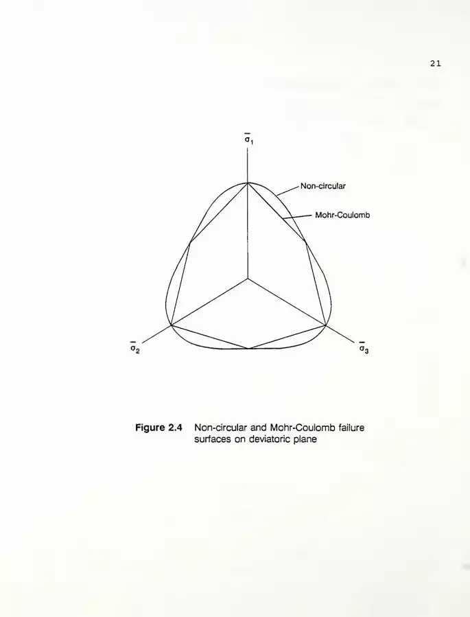
zones on the deviatoric plane for the Mohr-Coulomb failure
criterion (see Figure 2.4), underestimates the actual behavior of
the soil. In order to represent the actual behavior of the soil
mass, Dafalias and Herrmann (1986) modified the material constants
with a non-circular cross section of the failure surface on the
deviatoric plane such that the parameters a and k depend on the
Lode angle, , where:
a = a c g(B,m) (2.20)
k = K. g(Q,m) (2.21)
and
21
Non-circular
Mohr-Coulomb
Figure 2.4 Non-circular and Mohr-Coulomb failure
surfaces on deviatoric plane
22
a c k_ 3 + sm<p
in which
2mg(Q,m)
1 + m - (1 - /n)sin(^ + 36) (2.23)
where the subscripts t and c denote the values with respect to
triaxial extension ( 8=60° ) and compression ( 0=0° ) • For a
condition of pure shear ( 0=30°)/ Equation 2.23 reduces to:
g(6,m) = -20- (2.24)1 + 777
In addition to the compressive stresses within the soil mass,
tensile stresses may occur. In NFAP, the tension potential is
evaluated using the minimum principal stress in the "in-plane"
stress state for the two-dimensional plane strain case. Since most
soils are not capable of supporting significant tensile stresses,
a small value of tension cut-off is generally assumed.
2.3.2 Elastic and Plastic Behavior ( Kmln ,A t,Ae , v)
Prior to discussing the elastic and plastic behavior of soils
within the cap model framework, it is important to realize that two
assumptions are incorporated herein. These include: (1) the one-
dimensional compression and rebound curves are parallel and linear
to the respective curves for hydrostatic loading; and (2) the ratio
of Cc and Cr to the specific volume, V , ( l +e ) is constant for
all values of p , the (mean) effective hydrostatic stress.
Based on the above assumptions, an idealized response of the
23
one-dimensional consolidation behavior (for simulating isotropic
consolidation conditions) is shown in Figure 2.5. The equation for
the virgin isotropic consolidation line is:
Cc = - . /1
de^ (2.25)c d(logp)
where e is the void ratio and Cc is the compression index. Recall
that p is the effective hydrostatic stress where:
p = ii (2.26)3
Based on the assumption that one-dimensional consolidation behavior
represents isotropic consolidation conditions, the total volumetric
strain, de£ , is then a function of the change in the void ratio
where
:
Cfe$ = " -d+
S
e(2.27)
Substituting Equation 2.27 into Equation 2.25 and rearranging
results:
C dec - ^ (2.28)
or
1 + e d(logp)
v _ dp _ p
where Kt is the total bulk modulus and is a function of the
effective hydrostatic stress, p , and Ac is a constant which has
the form:

24
Virgin isotropic
consolidation
Unloading
-reloading
Lift)
Figure 2.5 Idealized response of soil to hydrostatic stress
Stress Path A ('v^,)
Figure 2.6 Cap model response for undrained shear
25
A. = - (2.30)c 2.303(1 + eo )
The elastic bulk modulus, Ke , can be derived in the same
manner and expressed as:
with
A = - (2.32)2.303(1 + ej
where Cr is the recompression index and e* is the elastic or
recoverable volumetric strain. The total volumetric strain
consists of elastic/recoverable strains and plastic/ irrecoverable
strains.
e£ = < + e£ (2.33)
Based on Equations 2.29 and 2.31, it is apparent that both
bulk moduli, Kt and Kg , are proportional to the effective hydro-
static stress. Therefore, Km±n , which is the minimum value of the
elastic bulk modulus for a specific effective hydrostatic stress or
possibly a free stress state is required and can be estimated from
elastic moduli relations.
As mentioned earlier, the other elastic constant that is
required is the shear modulus, G , which can be evaluated from
Poisson's ratio, v , which must also be determined or approximated:

26
C - 3*» (1 " 2V)(2.34)
2(1 + v)
2.3.3 Cap Parameters ( i? , OCR )
The aspect ratio, R , is generally evaluated from shear
tests on normally consolidated soil where the loading path causes
the cap to expand. It is assumed that R remains constant as the
state of stress moves from the initial to the failure condition and
that R is independent of the initial hydrostatic stress state.
The initial state of stress ( j j\'o) for normally consoli-
dated soil is on the cap and the failure state of stress
( Tlf , j\f2) is at the intersection of the cap and ultimate failure
surface as shown in Figure 2.6 (page 24). The initial state of
stress is calculated from the effective vertical consolidation
stress ~o vo and the at-rest normally-consolidated coefficient of
lateral earth pressure KQ which is given by:
K = £fi£ (2.35)
where "aho is the horizontal effective stress. Equations 2.1 and
2.2 are used to calculate J1o and j\'J- for "ox= a vo and
Or, = (J, = Oho
I±a = m (l + 2Ka) (2.36)
j\o = -^o vo (l - KQ ) (2.37)
However, at failure, Equation 2.3 is used to relate the final
states of stress ( f' j\f2)

27
- _ (J2f k) (2.38)if ~
The undrained shear strength ratio (USR) is introduced as a
normalized measure of the shear stress at failure. At final state,
the USR can be expressed as:
DBB, 3L = <°i- q3> f( 2 .39)
where (c^ - o3 ) f is the principal stress difference at failure. At
failure, the second invariant of the deviatoric stress tensor J2f
is:
**t = 3^1 " °3>i (2.40)
or from Equation 2.39: .
J?f -^(2 t7Si?o vo )(2.41)
Substitution of Equation 2.41 into Equation 2.8 gives:
Ilf = - (-K + 2^2 USR) (2.42)
Using these relations and Equation 2.29, the elastic volumet-
ric strain change can be evaluated as:
deev = Ae Jlf ~_Jla
(2.43)(Ilf * Jla )/2
For undrained behavior, de£ = -del • From Equations 2.36, 2.42 and
2.43, cfe£ can also be written as:
28
(-=£- + 2-^5) - (1 + 2iC )a
d< = -2^e
^2 j£_ (2.44)(-JL + 2-^) + (1 + 2K )a
The hardening rule as described earlier by Equation 2.5 will
not be used herein. However, a modification as proposed by Huang
and Chen (1991) describing the evolution of the cap will be used.
Since the hardening rule describes the evolution of subsequent
loading or yielding surfaces, it will be necessary to determine the
initial yielding surface, and then any subsequent yielding surface
due to additional loading. From Equations 2.29 and 2.31, the
plastic volumetric strain change, cfe£ , can then be related to the
effective hydrostatic stress change, dp , as:
de£ = del ' <K = U, - Ae )M (2.45)c e p
and assuming K -consolidation in which:
X = (1 + 2K )p (2.46)
and
rearranging yields:
dX - (1 + 2K )dp (2.47)
d< = -(At- Ae)4r (2.48)
Then, the evolution of the cap, dX , can be approximated by
Equation 2.48 as:
29
dX = .
Xa- cfe£ (2.49)
where Xa is the initial cap position (see Figure 2.6) for a stress
state at point A which can also be evaluated for subsequent
loadings as follows.
The equations for the ultimate failure (Equation 2.3) and cap
(Equation 2.4) surfaces are used to determine La .
(1 - a 2R 2 )L 2
a- 2(Jla
+ a<R 2 )La+ (J^a + R 2J2a - R 2k2
) = (2.50)
Then, the cap position Xa at A is:
Xa= La
+ (k + aLa )R (2.51)
and the position of the cap at state B , Xb is:
Xb » Xa+ dX (2.52)
where dX and Xa can be obtained respectively from Equations 2.49
and 2.51. The value of the cap aspect ratio is:
R =X„ - Iif
(2.53)
Jif
From the above equations, the cap aspect ratio can then be
evaluated through a trial-and-error procedure. However, if K
equals one, the stress state experiences a hydrostatic condition
and the cap aspect ratio can be evaluated after substitution:
30
2A{ m+ 2
USR _3)
= y/J/n _ J. + 3/3{
_« /3a ,
(2#54)2aC75i? a 2J75i? ,A - & )
(M + 2 USR + 3)
where -m = =— . When k = , Equation 2.54 simplifies to:
2Ae(2-^-3)
i? = -1 + 3_j/I_[i - j£E«] (2.55)
2USR<A
t-A.)(2-^ + 3>
/3a
It should be noted that the foregoing discussion is limited to
a triaxial condition only. For the plane strain case, the initial
stress state at A can be expressed as:
Ola " "°Vo (2.56)
(2.57)
o 2a= v(o
1+ o3 ) = v(l + # )a vo (2.58)
Assuming undrained conditions (v = 0.5) , o 2a becomes:
o 2a= 0.5(1 + K )a vo (2.59)
. — l
From Equations 2.56, 2.57 and 2.58, the values of J. and Tl at1
<~>2
point A are obtained as:
Jla = 1.5(1 * 2Ko)0 vo (2.60)
J~\ = 0.5(1 - K )o vo(2 ' 61)
The same procedure to evaluate the cap aspect ratio under
plane strain conditions can be obtained in a similar manner as the
triaxial condition.
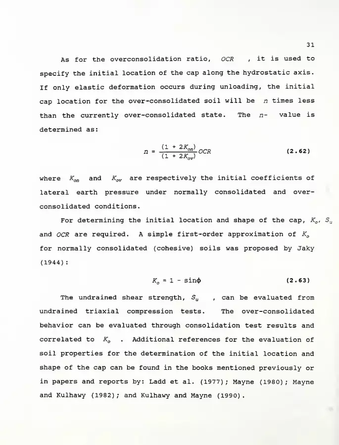
31
As for the overconsolidation ratio, OCR , it is used to
specify the initial location of the cap along the hydrostatic axis.
If only elastic deformation occurs during unloading, the initial
cap location for the over-consolidated soil will be n times less
than the currently over-consolidated state. The n- value is
determined as:
( 1 + O XT \
= 1± t±2RL CR (2.62)(1 + 2Kov )
where Kon and Kov are respectively the initial coefficients of
lateral earth pressure under normally consolidated and over-
consolidated conditions.
For determining the initial location and shape of the cap, KQ , Su
and OCR are required. A simple first-order approximation of KQ
for normally consolidated (cohesive) soils was proposed by Jaky
(1944) :
K = 1 - sin<(> (2.63)
The undrained shear strength, Su , can be evaluated from
undrained triaxial compression tests. The over-consolidated
behavior can be evaluated through consolidation test results and
correlated to KQ . Additional references for the evaluation of
soil properties for the determination of the initial location and
shape of the cap can be found in the books mentioned previously or
in papers and reports by: Ladd et al. (1977); Mayne (1980); Mayne
and Kulhawy (1982); and Kulhawy and Mayne (1990).
32
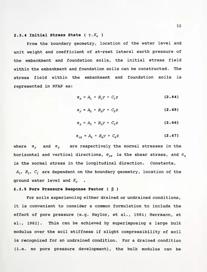
2.3.4 Initial Stress State ( y,K )
From the boundary geometry, location of the water level and
unit weight and coefficient of at-rest lateral earth pressure of
the embankment and foundation soils, the initial stress field
within the embankment and foundation soils can be constructed. The
stress field within the embankment and foundation soils is
represented in NFAP as:
ax = Ax
+ Bxy + Cxz (2.64)
ay
= A2* B
2y + C2 z (2.65)
a z= A, + B3y + C
3z (2.66)
ayz = A, + BiY + C4 2 (2.67)
where oy and a z are respectively the normal stresses in the
horizontal and vertical directions, oyz is the shear stress, and ox
is the normal stress in the longitudinal direction. Constants,
Aif Bit Ct are dependent on the boundary geometry, location of the
ground water level and K
2.3.5 Pore Pressure Response Factor ( p )
For soils experiencing either drained or undrained conditions,
it is convenient to consider a common formulation to include the
effect of pore pressure (e.g. Naylor, et al., 1981; Herrmann, et
al., 1982). This can be achieved by superimposing a large bulk
modulus over the soil stiffness if slight compressibility of soil
is recognized for an undrained condition. For a drained condition
(i.e. no pore pressure development), the bulk modulus can be

33
assumed to be zero while a partially-saturated soil can be managed
as a value which is a function of the Henkel pore pressure
parameter (Naylor, et al., 1981).
The total stiffness, Dt , is given by:
DC= DS
+ Df(2.68)
where Dc
is the total stiffness, D3is the soil stiffness and Df
is the stiffness contributed by the pore fluid/ solid system. Df
has the form [K^] where Ktj are the components of the stiffness
matrix. Since fluids cannot resist shear distortions, Df has the
form:
Kf Kf KfKf Kf Kf
5f= Kf KfKf (2>69)
where Kf is the apparent bulk modulus of pore fluid/ solid system.
For a given displacement field, the resistance provided by the soil
is
[a] = Ds [€] (2.70)
where the transpose of a is
[a-
]T =[a'a'o'irxTl (2.71)1 J L x "y "z xy k yz w zx J * '
and the transpose of e is
[e]T = lex ey ez y^ yyz y zx] (2.72)
The pore pressure developed is

34
\i = Kt ev (2.73)
where ev is the total volumetric strain given by
ev = ex + ey+ ez (2.74)
The total stress [o] is then
[a] = [o] + [ill] (2.75)
where
[I] T= [1110 0] (2.76)
The apparent bulk modulus K of the pore fluid/ solid
particle system for saturated undrained conditions is (Nay lor, et
al., 1981)
1 = JL + 1 ~ n(2.77)K Kw Ks
where Kw , K3 are respectively the bulk modulus of the water and
solid particles and n is the porosity. Since Ks- 3 0JCW (Lambe
and Whitman, 1969), the second term in Equation 2.77 can be
neglected with only a few percent error, therefore,
K = -^ (2.78)n
The bulk modulus of water is 2.1xl0 6 kPa (43xl0 5psf; 300,000
psi) . It is convenient to express Kf in terms of the bulk modulus
of the soil skeleton K using a pore pressure response factor p
which is defined as:
p = £k (2.79)
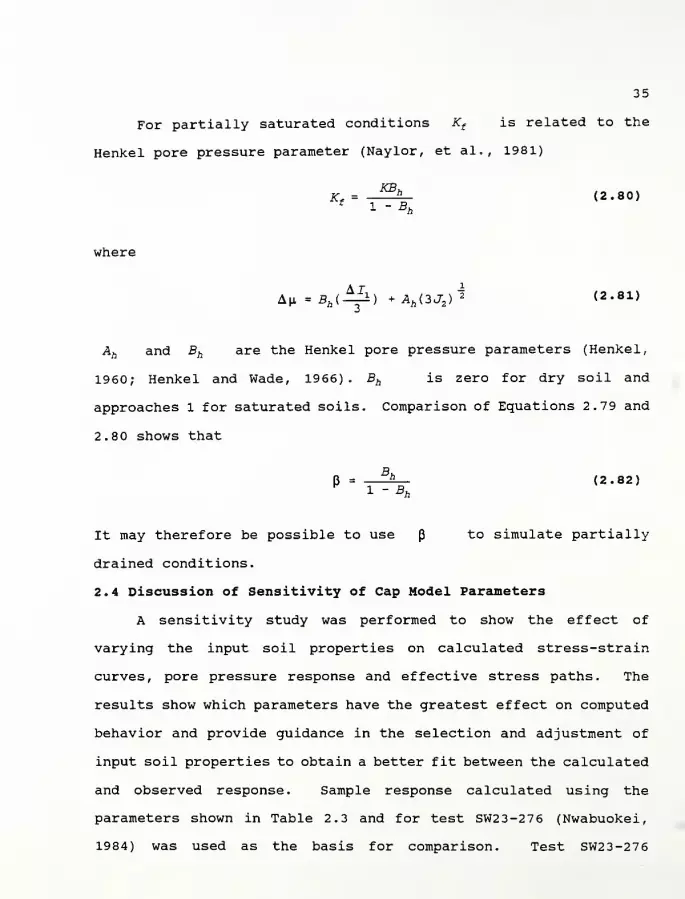
35
For partially saturated conditions Kf is related to the
Henkel pore pressure parameter (Naylor, et al., 1981)
K„=-JX- (2.80)
where
An -**(-££) +Ab (3J2 )$ (2.81)
Ah and Bh are the Henkel pore pressure parameters (Henkel,
1960; Henkel and Wade, 1966). Bh is zero for dry soil and
approaches 1 for saturated soils. Comparison of Equations 2.79 and
2.80 shows that
B = —^— (2.82)
It may therefore be possible to use p to simulate partially
drained conditions.
2.4 Discussion of Sensitivity of Cap Model Parameters
A sensitivity study was performed to show the effect of
varying the input soil properties on calculated stress-strain
curves, pore pressure response and effective stress paths. The
results show which parameters have the greatest effect on computed
behavior and provide guidance in the selection and adjustment of
input soil properties to obtain a better fit between the calculated
and observed response. Sample response calculated using the
parameters shown in Table 2.3 and for test SW23-276 (Nwabuokei,
1984) was used as the basis for comparison. Test SW23-276

8<3\ a\ C* ff> en en
^ <* CN*? «* «tf «* *r i"
co
o i-H rH rH H rH rH1-1
rH CN
wEh
H32
£9
CN CN CN CN CN CN rH CO CN
KCN CN CN CN CN CM CO «* CN
0.
t> O d o O d odd o
JWQOa>HE-t
Mo •6>
^> «* «* "* (Xi "* o •<* "*CN CN CN CN rH CN ro CM CM
HCO
<Ja,
<uwK ca O O O rHin° o O OH rH rH rH rH t-H rH
Cu
ocoHCOXdz -* <* 0> ^ vo <* * "* <*
< u «* <tf CM ^* VO ^f ^, «* "*
>H<J O O O O O o O o O
Eh o O O O O o O o dM>MEHMCO2uco CN P> CN O CN CN CN CM CN
fa
O10 O VO «* \0 VO VO vO vO
o rH rH rH CN rH rH H rH rH
>HO odd d O o o O
Dco
n LO O If) IT) in in in in in
CN r»rH ro <* f -* «* ^" >* «a*
w O O O o O d d o oJ00<H
aHEh w3 co rt! 03 O < m o < 03 O < m o «c oa o < m u < 03 O3 < rH rH rH CN CN CN co ro ro ^ ^* ^ in in in vO vO lO r» r» r-
§ o<&
B3 . -0 <D 73s <0 .C t/1 -H
Appendix
ity
Model
rs
remain
-P 4->
rH >3 (0
-P Ul
rH
Q)
14-1
CD
rH JJ
-P _Ul o
_ U 0) rH QJ-H
C -H(-J -p id•H JJ JJ f0
udy
Plas
he
o •H4->
(0rH
O Ul
-P -
n (0 cU
itivity
for
a
Ca
ed
while
c
wUl
•H
Ul
J3 ul
cd -hrH
Ohd)
5^t/i a)
•r-1 <D _ -pC U rH £1 e
the
se
Paramete]
r
was
va
t
for
t
ned
frc
ed
for
A •H Ul
4h QJ0) fD 3
d) +J
rC d)
-p
014J g QJ u(0
e
result
lysis
of
one
pararH
0)
-P(1)
etd
rH
(0
a
*"«ui <y>
aoUl
a) cC r0 u_irH rO
*S° rCrj
rGT3 4->
igures
of
nsitivity
the
value
a)
<rH
s
(observe
5
rather
bility.
Ul
a)
3rHn Q) in 0) * rC
w «r > 3 . +jo> S rH O 01
-c < 2 •p (0 CJJ s <w^ c > <W-H
id
+* 0) u c
.p Q) <-i
tn m (0
c §crH (0 (0 n
U -P 0) 4-> o -H « ^0) fo 0)
<4-i > e01 -H 01
MH -P rH C a)
<D C O JC 0) 3CC <D En tH rH < C
36
37
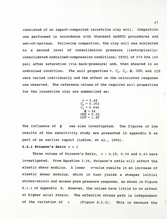
consisted of an impact-compacted lacustrine clay soil. Compaction
was performed in accordance with Standard AASHTO procedures and
wet-of-optimum. Following compaction, the clay soil was subjected
to a second level of consolidation pressure (isotropically-
consolidated undrained-compression conditions; CIUC) of 276 kPa (40
psi) after saturation (via back-pressure) and, then sheared in an
undrained condition. The soil properties v, Cc , Cr , <J>, USR, and OCR
were varied individually and the effect on the calculated response
was observed. The reference values of the required soil properties
for the lacustrine clay are summarized as:
v = 0.49Cc = 0.162Cz = 0.044
<J>= 24
USR = 0.22OCR = 1.49
The influence of p was also investigated. The figures of the
results of the sensitivity study are presented in Appendix B as
part of an earlier report (Ludlow, et al., 1992).
2.4.1 Poisson's Ratio ( v )
Three values of Poisson's Ratio, v : 0.15, 0.3 and 0.4 5 were
investigated. From Equation 2.34, Poisson's ratio will affect the
elastic shear modulus. A lower v-value results in an increase of
elastic shear modulus, which in turn yields a steeper initial
stress-strain and excess pore pressure response, as shown in Figure
A. 1.1 of Appendix B. However, the values have little to no effect
at higher axial strain. The effective stress path is independent
of the variation of v (Figure A. 1.3). This is because the
38
determination of the cap shape is not related to v .
2.4.2 Compression Index ( Cc )
The effect of the compression index with a ± 50% variation
was examined. Figure A. 2.1 illustrates that a lower compression
index results in a slightly-higher calculated stress-strain
response and a moderately-lower excess pore pressure. Within 2%
axial strain, the effects are insignificant. A comparison of the
calculated and observed response indicates relatively good
agreement for the stress-strain relation with the "best-fit"
occurring within the range of 0.107 and 0.162. However, the
calculated excess pore pressure in all cases is considerably less
than the observed response. The influence on the effective stress
path was relatively small.
2.4.3 Recompression Index ( Cr )
The influence of the recompression index with a ± 50%
variation was investigated. From Eguations 2.31 and 2.32, Cr
will affect the elastic bulk modulus, which results in a consider-
able change in the stress-strain relation and pore pressure
response (Figure A. 3.1). A lower Cr results in a steeper initial
stress-strain response and a higher pore pressure. However, at
larger strains, lower Cr -values result in a slightly lower
stress-strain response. A comparison of the calculated and
observed response indicates relatively good agreement for the
stress-strain relation with the "best-fit" occurring within the
range of 0.044 and 0.066. However, the calculated excess pore
pressure in all cases is considerably less than the observed

39
response. The influence on the effective stress path or also cap
shape was relatively small (Figure A. 3. 3).
2.4.4 Pore Pressure Response Factor ( p )
The influence of the pore pressure response factor ( p : 1,
5 and 10) on the calculated response was examined. It should be
noted that a p -value of 10 is recommended by Nay lor, et al.
(1983) for simulating an undrained condition in practice.
Lower values of p result in a higher stress-strain response
and a lower pore pressure (Figure A. 4.1). A comparison of the
calculated and observed response indicates relatively good
agreement for the stress-strain relation with the "best-fit"
occurring near 5. However, the calculated excess pore pressure in
all cases is considerably less than the observed response. For
smaller p -values in which partial drainage is permitted, the
results indicate a lower pore pressure response which also shifts
the effective stress path to the right (Figure A. 4. 3).
2.4.5 Angle of Internal Friction (<J> )
The influence of varying the effective stress angle of
internal friction was studied. The parameters corresponding to a
± 25% variation of<J>
are shown in Figures A. 5.1 and A. 5. 3.
Observations indicate that increasing 4> results in a
slightly flatter stress-strain curve, causes higher pore pressures
at failure and shifts the effective stress path to the left which
results in a greater aspect ratio of the cap. A comparison of the
calculated and observed response indicates relatively good
agreement for the stress-strain relation with the "best-fit"

40
occurring within the range of 24 and 3 degrees. However, the
calculated excess pore pressure in all cases is considerably less
than the observed response.
2.4.6 Undrained Shear Strength Ratio ( USR )
The effect of the USR with values of 0.22, 0.31 and 0.43 was
investigated; other parameters are given in Table 2.3. Figures
A. 6.1 and A. 6. 3 indicate a significant change in the calculated
response of the USR . A higher USR results in a lower aspect
ratio of the cap which shifts the effective stress path to the
right (Figure A. 6. 3). For a higher value of USR , a shorter
path is required and a smaller pore pressure is induced at failure.
2.4.7 Over-consolidation Ratio ( OCR )
The variation of the OCR with values of 1.0, 1.49 and 2.2 5
was examined. The calculated response for describing the over-
consolidated (describes the initial location of the cap along the
hydrostatic axis) condition is shown on Figures A. 7.1 and A. 7. 3.
Observations of the figures indicate that an increasing OCR
causes a significantly steeper and higher stress-strain response.
A comparison of the calculated and observed response indicates
relatively good agreement for the stress-strain relation with the
"best-fit" occurring near an OCR value of 1.49. However, the
calculated excess pore pressure is considerably less than the
observed response except in the case where the OCR has a value of
2.25 and limited in strain.
2 . 5 Limitations of the Cap Model
The cap model has some limitations which impact the calculated
41
response. One limitation which was observed during this study was
the inability of the model to predict the reduction in undrained
strength or increase in pore pressure that occurs after the peak
strength is reached in strain softening soil. Consequently, this
would overestimate the shear strength and underestimate the pore
pressures and deformations.
A second limitation is the ability to model the behavior of
over-consolidated soils. The cap model correctly predicts the
undrained strength at large strains. However, pore pressures are
not predicted correctly and plastic strains which many over-
consolidated soils experience for stress changes in the elastic
region bounded by the cap and ultimate failure surfaces are not
accounted for. Also, strain softening after failure can not be
modeled. It is speculated that this would lead to underestimation
of deformations.
Another limitation which can be attributed to the model's
formulation is the need to perform a trial-and-error calculation to
estimate the best-fit of the observed response. Although time-
consuming, a reasonable fit of the observed response can be
obtained rather quickly by making a critical review of the OCR and
USR parameters and then modifying one of the other five (from the
previous sensitivity study) parameters, if necessary.
Another limitation which requires considerable attention and
can also be attributed to the model's formulation is the model's
inability to account for long-term behavior (e.g. creep and
consolidation) . Presently, the model is best-suited for depicting

42
short-term behavior only. To account for creep and consolidation,
the model would require extensive modifications.
2.6 summary
A straight forward procedure to determine the cap parameters
for normally consolidated soils from conventional laboratory and
field tests and a sensitivity study which examines the effect of
the input soil parameters was provided. The main input soil
properties are the compressibilities ( Cc , Cz ) , the effective
Mohr-Coulomb shear strength parameters ( <j), c ) , the undrained
Su ...shear strength ratio ( USR; =-=
) and the over-consolidation ratio
( OCR ) . Solutions are given in graphical form and equations
suitable for hand calculation.
The procedure was used to determine the cap parameters for an
impact-compacted lacustrine clay using results from isotropically-
consolidated undrained-compression (CIUC) tests. These parameters
were then used in a computer program called CAP to calculate
stress-strain curves, pore pressure response and effective stress
paths. Comparisons were made to observed test results. In
general, there was good agreement except for a discrepancy for pore
pressures and effective stress paths. The discrepancy is at least
partially because this formulation of the cap model does not allow
plastic volumetric strain for stress changes within the region
bounded by the cap and ultimate failure surfaces.
In addition, a sensitivity study was made of the effect of the
input soil properties on calculated CIUC triaxial sample behavior.
The results show which parameters have the greatest effect on

43
computed behavior and provide guidance in the selection and
adjustment of input soil properties to obtain a better fit between
the calculated and observed response. The USR and OCR were
observed to have the most-significant influence on the predicted
behavior.
44
CHAPTER 3
APPLICATION OF THE FINITE ELEMENT METHOD TO NFAP
3.1 Introduction
The software used in this study is based on a general purpose
finite element program named NFAP (nonlinear finite analysis
program) developed by Chang (1980) . NFAP was originally developed
for the use of nonlinear large deformation analysis of structures.
However, the program was later expanded and refined by Mizuno
(1981) and McCarron and Chen (1985) to include a cap plasticity
model to simulate the behavior of soils. Then, Humphrey (1986)
condensed McCarron' s version of the program for use on personal
computers
.
During Phase I of this research study, Huang (1991) modified
and extended NFAP to include: double precision/ floating point
variables; foundations with sloping boundaries and a variable
groundwater level; and a procedure for determining the ini-
tial/existing stress state within an embankment.
NFAP employs a cap plasticity model, as discussed in the
previous chapter, to simulate the behavior of the soil. From a
theoretical point of view, the cap model employed herein is
particularly appropriate in modeling soil behavior, because it is
capable of treating the conditions of stress history, stress path
dependency, dilatancy (positive and negative) , and the effect of
the intermediate principal stress.
The program performs an incremental load-displacement
analysis. After each increment of load is applied, the

45
displacement field is modified using an iterative procedure (The
Newton-Raphson or the modified Newton-Raphson can be selected.)
until an equilibrium configuration is reached. Convergence is
based on the difference between two successive displacement norms,
and 1% is used in the case studies of Chapter 4
.
NFAP also incorporates a large strain deformation analysis
which is based on the assumption of small strain and large
rotation, for which the structural stiffness of the global
equilibrium equations is symmetric. For solution of the
equilibrium equations, gaussian quadrature using second or third
order integration is recommended. In addition, a node-renumbering
system in NFAP is introduced to minimize the band-width of the
global stiffness matrix and improve solution efficiency. It should
also be noted that, presently, NFAP is only capable of accepting a
finite element mesh with 500 or fewer nodes. However, there are no
restrictions to the number of elements. If necessary, NFAP can be
easily modified to accommodate a mesh that may have more than 500
nodes. This can be achieved by changing the FORTRAN code "common"
statement within the subroutine "GIBB" to the number of nodes that
are required. Presently, the size of the one-dimensional arrays
are established at 500.
3.2 Modeling Foundation Soils
In NFAP, the foundation soils are modeled with two-dimensional
4-, 6- or 8-node isoparametric (implying that the shape functions
for the displacements are the same as those for coordinate
transformation) plane strain continuum elements. Figure 3.1

46
illustrates a typical finite element mesh. Soil behavior is
represented by the strain-hardening cap model (which is time and
temperature independent) described in the previous chapter or a
linear elastic response by specifying Young's modulus and Poisson's
ratio. In addition, cap parameters for the foundation soils were
chosen using the procedure given in Chapter 2. The linear elastic
response was not discussed herein since the behavior of soils is
often non-linear and inelastic and because one of the major thrusts
of this study was to analyze practical engineering problems using
the cap model. However, it should be noted that the solutions of
linear elastic models are often used as a benchmark to evaluate
other results from more sophisticated models (e.g. cap plasticity
model)
.
3.3 Modeling Embankment Fill
The embankment fill is also modeled with two-dimensional 4-,
6- or 8-node isoparametric plane strain continuum elements. Again,
soil behavior is represented by the strain-hardening cap model
described in the previous chapter or a linear elastic response by
specifying Young's modulus and Poisson's ratio. Just as in the
case of the foundation soil, use of the cap model would also
require knowledge of the compaction-induced preconsolidation
pressure or compactive prestress (stiffness related) and at-rest
lateral earth pressure coefficient in the compacted fill. For
compacted clay fills, these are generally unknown. Therefore,
plastic strains within the soil mass may not be accurately
predicted by the model. In addition, finite element studies (e.g.
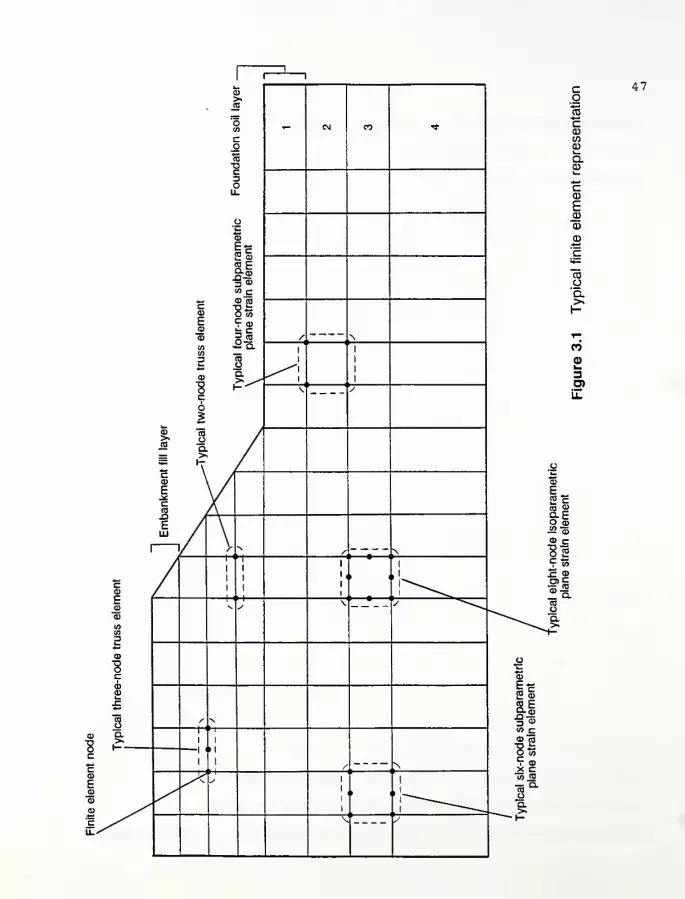
....•
I
CD>»TO
.-=
Oco i- <N co **
node
truss
element
Typical
four-node
subparametric
Foundation
\
plane
strain
element
/;•\
i
i
1
1
1
1
\' j
k.CD
oICO /o /Q- />> /hr /
CCD
EScCOXI
ELU
/ y N{, ^f
i /1
'(
1
1.
» i
1
ECD V y
\' VmCOCO
ECD
1CDCD
3 / N
Q.
» 1
fK
>
y^^ S 1
!
i
> <
1
1
V !/
cCD
Q.
CO
g'o.
CO
0)w3
il
47
cd
FCO cm CD
Q. Ho ci)
<f>CD
CD c8 sc
to
X CD
m cmu.
COoQ.><
E2cCD
s.b
XI3 "cd
to cCD CO
E toc
CDX cCO CO
n8Q.>•
48
Rowe, 1982; Kwok, 1987; Hird and Jewell, 1989) have shown that an
increase in the embankment stiffness can modestly reduce the
deformations in the soft foundation soils.
3.4 Modeling Reinforcement
The reinforcement is modeled with 2 or 3 node one-dimensional
truss elements which can only sustain axial tensile load. One- or
multiple- layer reinforcement can be modeled during embankment
construction. The reinforcement behavior is modeled as a linear
elastic or non-linear elastic response where the stress-strain
relation of the reinforcement is specified. For this study, a non-
linear elastic response of the reinforcement was used in the case
studies of Chapter 4
.
Slippage at the embankment fill-reinforcement or
reinforcement-foundation soil interfaces cannot be explicitly
modeled by NFAP (i.e. assumes perfect adherence between the
soil/fill and reinforcement) . This assumption is adequate
provided: (1) the shear stresses developed at the interface are
less than the interface strength; or (2) the soil-reinforcement
interface shear strength equals or exceeds the soil-soil shear
strength. The latter case was assumed for this study. It implies
that slip will occur in the adjacent soil when the shear strength
is exceeded rather than at the interface. This may underestimate
the interface movement. Experimental studies reported in the
literature indicate soil-reinforcement interface resistance is
often greater than 80% of the soil shear strength.
However, if the interaction between the soil mass (embankment

49
fill and foundation soil) and the reinforcement became a concern
for a particular application, three approaches could be considered
of which two would require extensive modification to the existing
program. The approaches are: (1) the use of joint elements (Al-
Hussaini and Johnson, 1978) ; (2) nodal-compatibility slip elements;
or (3) substructuring which involves refinement of the mesh and
soil element properties at and near the interface of the
reinforcement (applicable to NFAP)
.
Common approaches to modeling the soil reinforcement interface
by the joint element involve three nodes at each point along the
reinforcement; one attached to the soil above the reinforcement,
one on the reinforcement, and one to the soil below the
reinforcement. The nodal-compatibility slip element which may be
formulated initially in terms of normal and tangential (shear)
springs with very high stiffnesses:
1. ensures compatible displacement between a pair of dualnodes until some failure criterion is reached; and
2. replaces the compatibility conditions by a failurecondition and dilatancy equation once the interfacestrength is exceeded.
Joint elements allow relative deformation of the soil and
reinforcement, prior to failure of the interface. This is based on
some assumed constitutive relationship of what is in effect on the
interface layer between the reinforcement and the soil continuum.
The joint element may be modelled as a pair of normal and
tangential springs. As the stiffness of a joint element increases,
it tends to a nodal-compatibility slip element. The distinction
between the two is related to the question of whether a discrete
50
interface layer exists or whether the deformations at the interface
(prior to failure) are simply due to the interaction between the
reinforcement and the soil on the either side of the reinforcement.
According to Rowe (1988), any modeling of the interface
behavior must consider three possible mechanisms of failure as
noted below.
1. If there is insufficient anchorage capacity, failure willoccur at the soil reinforcement interface above and belowthe reinforcement as the reinforcement is pulled out ofthe soil. This "pullout" mode involves displacement ofthe reinforcement relative to the soil on both sides ofthe reinforcement.
2. If the shear strength of the soil reinforcement is lessthan the shear strength of the soil alone, then failuremay occur by sliding of the soil along the upper surfaceof the reinforcement and the upper soil mass movesrelative to both the reinforcement and the underlyingsoil.
3. The soil below the reinforcement (for cases of softfoundation soils) may be "squeezed out" laterally frombeneath the lowest reinforcement layer. In this case,the lower soil may move relative to the reinforcement andthe overlying soil.
In the case of geotextiles, since the reinforcement is in the
form of a sheet, which completely separates the soil above and
below the reinforcement, the interface resistance can be readily
determined by direct shear tests (Rowe et.al., 1985). In this
case, provision for slip at the interface is the same irrespective
of the mechanism of failure (that is, direct shear or pullout)
.
This difference, in addition to boundary effects and stress
concentrations, makes the pull-out test results difficult to
analyze. It is noted that during direct shear tests the geotextile
reinforcement experiences simple shear deformation instead of
51
tensile deformation developed in the pull-out mode. However, if
the reinforcement consists of a geogrid, with openings that are
large compared to the grain size of the soil, or if the
reinforcement consists of separate reinforcing strips, then special
care is required to correctly model the failure mechanism.
For planar reinforcement, independent movement of the soil may
occur above and below the reinforcement following either a direct
shear or pullout failure. On the hand, for strip reinforcement,
independent movement of the soil above and below the plane of
reinforcement can only occur during a direct shear mode of failure
(Rowe et.al., 1985). Pullout of strips is really a three
dimensional phenomenon in which the strips move relative to the
soil around them but the soil between strips remains continuous.
As noted by Naylor and Richards (1978) , the common approach of
using a conventional joint element (or nodal compatibility element)
implicitly treats the strips as an equivalent two dimensional sheet
and will cause error since it interrupts the transfer of shear
stress through the soil.
3.5 Incremental Construction
Construction of the embankment is simulated using an
incremental loading technique (McCarron, 1985) which does not
directly account for compactive prestress during embankment
construction. The embankment is usually divided into horizontal
layers each represented by a row of elements with zero initial
stress. During each increment, the gravity stresses in the next
layer are increased from zero to their full value in one or more
52
subincrements (which are specified by the user) . Additional layers
are then applied until construction of the embankment is complete
and/or failure of the side slope or foundation occurs.
There is a trade-off between layer thickness and the number of
subincrements. Thicker layers require more subincrements to
achieve a stable solution (Naylor, et al., 1981), so there is
little savings in solution time by using excessively thick layers.
Thicker layers also result in a stiffer embankment response. It is
not necessary to represent each construction lift (typically 6 to
8 inches thick) by a layer of elements. Provided the thickness of
the layers is chosen so that 4 to 5 layers are applied prior to
embankment failure, computed behavior is approximately the same as
obtained with thinner layers. This recommendation should be re-
examined for layers that are many times thicker than the
construction lift.
As stated previously, the incremental loading technique used
in NFAP does not directly account for stresses produced by the
compaction equipment during construction of the embankment.
Compaction prestress which is analgous to preconsolidation stress
represents the fraction of the compaction energy which is
effectively transmitted to the soil matrix due to plastic
straining/deformations. To account for compactive prestresses,
knowledge of the compressibility and shear strength responses would
be required within defined layers of the embankment. Often, this
is not known. One approach, again which would require knowledge of
the compressibility and shear strength responses of the fill (which

53
is limited to cohesive type soils only) , is SHANSEP (Soil History
and Normalized Soil Engineering Properties)
.
3
.
6 Concluding Remarks
The following comments are also related to the application of
the FEM and should be regarded as general guidelines for the setup
and analysis of practical engineering problems. These points
include:
1. Create a general subsurface (soil/groundwater) profilefrom the test boring information and appropriatelaboratory test results;
2. Determine the cap parameters from the procedure outlinedin the previous chapter;
3
.
Input the parameters from step 2 into the CAP program andperform the analysis;
4. Compare the computed (from the CAP program) and observed(from the laboratory test results) results and iterate toobtain the "best-fit";
5. Draw a finite element mesh showing the geometricboundaries and the different soil layers (regions)
;
• Draw the elements as square as possible keeping anaspect ratio (length to height) of the element lessthan 2L:1H;
• Avoid inverted elements (interior angle of anyelement must be less than 180 degrees)
;
• Avoid triangle elements in a 4-node element scheme(if needed, use them in a region away from the zoneof interest)
;
• Keep the mesh fine near the region of interest orwhere changes in shear stress and strain aresignificant;
• Avoid sudden jumps in element size;
• Ideally model the subsurface profile to arelatively incompressible layer (e.g. rock or densesand and gravel) or model the bottom foundationlayer to a depth of two to three times the

54
6.
7.
embankment height and/ or width;
• Ideally model the foundation layer to a distanceaway from the embankment toe of two to four timesthe embankment width;
• Take advantage of embankment symmetry, if possible;
• Minimize bandwidth of global element stiffnessmatrix by decreasing the maximum difference of thenode numbering in each element;
• When performing an incremental analysis, simulatethe construction seguencing as much as possible;and
• Keep it simple (i.e. do not try to model everydetail of the soil-embankment system)
;
Setup the data file and check the data input; and
Perform the finite element analysis and interpret andcheck the results. Verification of the solution shouldinclude:
A. A check against a well-documented case history orphysical model;
B. Simple hand calculation; and
C. Reasonable checks of output including:
effective vertical stress;
effective horizontal stress (for rough caseonly)
;
stress level;
boundary conditions and deformed mesh;
shear strain; and
orientation and magnitude of principalstresses (best check)
.
A few additional notes on the application of the FEM include:
1. The FEM is relatively good at predicting stresses butsomewhat poor at estimating strains and displacements;
The FEM formulation over-estimates the global element

55
stiffness matrix because of the assumption thatdisplacements across an element are defined by someinterpolation function of the displacements at the nodesof the element; and
Four primary errors associated with the FEM include:
• error due to numerical integration (slightly under-estimates the stiffness)
;
• error due to above-mentioned item 2 (over-estimatesthe stiffness)
;
• FEM used to analyze boundary value problem (i.e.error from not accurately modeling system geometryand boundary conditions) ; and
• error due to constitutive law from not modeling thesoil behavior (dominant)
.

56
CHAPTER 4
CASE STUDIES
4.1 Introduction
This chapter summarizes the case studies contained in this
report and describes the implementation procedures, which are
outlined in Chapters 2 and 3, that were used to setup each example.
The examples in this chapter are based on actual highway projects
in Indiana where information on these projects was provided by
INDOT personnel. These examples include: (1) State Route 55 over
Turkey Creek in Lake County; and (2) State Route 1 over Ramsey
Creek in Franklin County.
The influence of several factors on the short term behavior of
reinforced and unreinforced embankments was studied. The influence
of reinforcement was assessed by comparing behavior of reinforced
and unreinforced embankments. A total of 3 cases (12 cases for
State Route 55 and 18 cases for State Route 1) including various
embankment geometries and soil properties was considered. The
effect of the crust strength, foundation thickness and compress-
ibility and embankment width and widening and grade raising were
examined.
4.2 Example l - State Route 55 over Turkey Creek in Lake County
This example involved a 13-ft high and 60-ft wide (at the top)
approach embankment for State Route 55 over Turkey Creek in Lake
County, Indiana. A representative section was assumed near Station
52+00 along the centerline of the proposed roadway. Again,
information regarding this example was provided by INDOT personnel

57
[Project No. ST-4145(B), Structure No. 55-45-7366] and summarized
in a geotechnical report prepared by Engineering Testing Service
(1989) . For this case, engineering properties of the foundation
soils and embankment fill were limited and as a result, many of the
cap model parameters were estimated from empirical correlations.
The rationale for estimating these parameters is contained in
Appendix C (entitled Interim Report: "Embankment Widening and
Grade Raising on Soft Foundation Soils: Example 1 - Indiana State
Route 55 over Turkey Creek in Lake County, Indiana") and a general
soil profile is summarized in Table 4.1.
As stated previously, 12 cases were analyzed for this example.
In all cases, the groundwater level was assumed to be at the ground
surface. Typically, the drainage conditions during simulation of
the embankment construction were assumed to be undrained except for
case 2 where drainage of the embankment fill was permitted.
In all of the cases except for three, the finite element
representation of the embankment fill and foundation soil consisted
of 349 nodes and 102 eight-node isoparametric plane strain
continuum elements (Figure 4.1). The exceptions consisted either
of: (1) 355 nodes and 104 eight-node isoparametric plane strain
continuum elements [case 5 - which included the construction of a
stabilizing berm (Figure 4.2)]; or (2) 397 nodes and 118 eight-node
isoparametric plane strain continuum elements [cases 6 and 8 -
which included embankment widening and grade raising (Figure 4.3) ] .
It should also be noted that the embankment construction was
simulated with eight 1.625-ft (0.5 m) thick lifts (or sixteen 0.81-

58
Table 4.1. General Soil Profile for State Route 5 5
Cap ModelParameter
Foundation Layer/Value 1
1 2 3 4
-Kmin
300 ksf 300 ksf 300 ksf 300 ksf
V0.45 0.45 0.45 0.45
eo
0.700 0.700 0.700 0.700
*33° 33° 33° 33°
Cpsf psf psf psf
<?c
0.246 0.246 0.246 0.246
Cr0.0246 0.0246 0.0246 0.0246
0.36 0.36 0.36 0.36
OCR3.0 2.5 1.5 1.0
Y125 pcf 125 pcf 125 pcf 125 pcf
K°0.71 0.66 0.54 0.46
P10 10 10 10
Notes; l. Refer to Figure 4.1 for location of foundationlayers.
2
.
Refer to Geotechnical Investigation of State Route55 (1989) for additional soils information.
3. Refer to Chapter 2 for additional informationregarding the cap plasticity model.
4. Refer to Appendix C for rationale for estimatingthe cap model parameters.
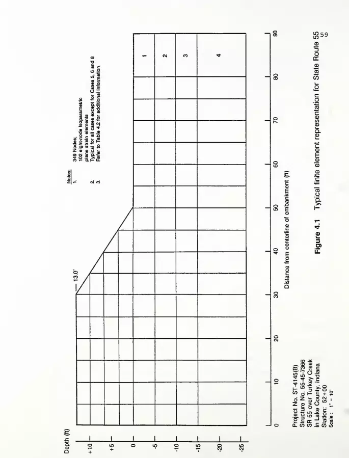
o & §
i * -oa x o
Illso » = JS
.. o _ a a9 "r = >- 3e i fl o Hf §§| 2
5 2l^S
i
^59
3oa:
2CO
cCDCOCDi—Q.CD
03Oa.
h-
CD
O)il
-^ co <» nj
145( -45-7
ey
CIndia
1 "> -^ - —.
to d»- I +o z fc o g It
Z <D > OV. 3 ° <D c
''
Projec Struct
SR55
InLak Statio
1

c J=o _
i i 3
i I !a - • oa. c ^ —— 5 fl c *§•!•-§i «i <3>l-
5 "» — OM _ M «•10 S = s
in o "<3 3«2
5
10 60<DcoCD
U
cCD00CDi_aCD
CN
a>i—
3
u.
~8
CO o
Z CO
t3 2CO o
Q. CO
>"Sco —
•2 -2 o •lO (0 — »OCZ 3 SCO ^ CO (A
aa
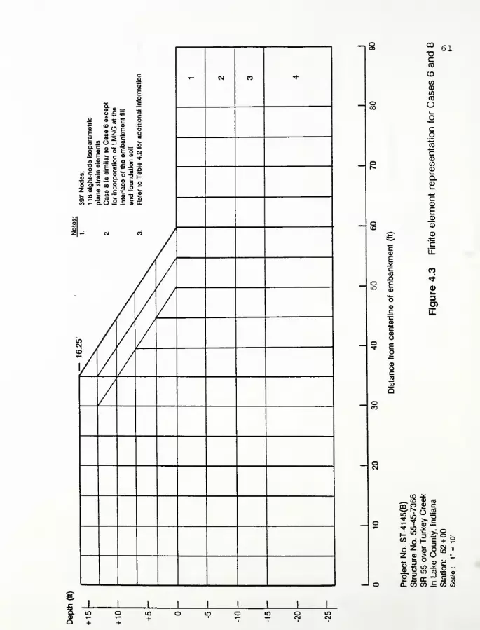
co CM m rtsaEo
Q. CS" » _ _3 £ = «
S 3 = 5X <o ,- «> •=
1 111 «f « 5 c c0
9
Isopaiements
lar
to
C
on
of
LI
a
emba
n
soil
4.2
for
F
Nodes;
3
eight-noc
ne
strain
<
se
8Is
sin
Incorpora
srface
of
tl
d
foundati
fer
to
Tab
CO - Q.O 5 = o DC
COCI)
oz .- oi ri
/
In / //
C\J / r
/«b / /
/ //
CO
DcCD
CD
inotoco
O
cO
IcCDt73
CDu.
Q.CDu.
*-<
cCD
E
CD
Cu_
CO
<*
0)l_
O)Li.
61
~8 $ s
2 £?b
S 2
0. CO
.33° 9 cm eo
cn "Z «co 5 co I
<» T-Q +
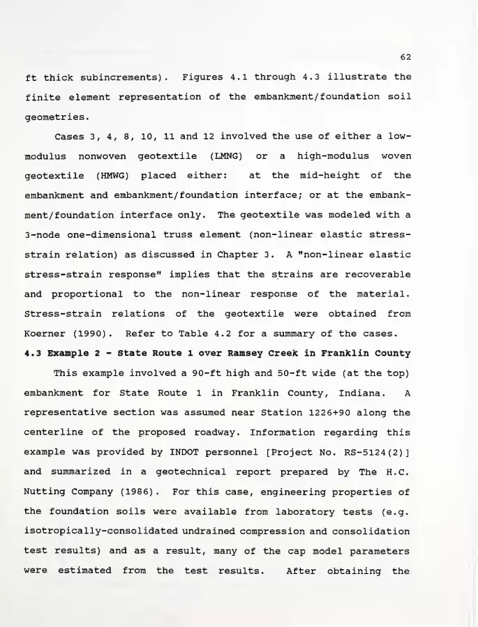
62
ft thick subincrements) . Figures 4.1 through 4.3 illustrate the
finite element representation of the embankment/ foundation soil
geometries
.
Cases 3, 4, 8, 10, 11 and 12 involved the use of either a low-
modulus nonwoven geotextile (LMNG) or a high-modulus woven
geotextile (HMWG) placed either: at the mid-height of the
embankment and embankment/ foundation interface; or at the embank-
ment/foundation interface only. The geotextile was modeled with a
3-node one-dimensional truss element (non-linear elastic stress-
strain relation) as discussed in Chapter 3. A "non-linear elastic
stress-strain response" implies that the strains are recoverable
and proportional to the non-linear response of the material.
Stress-strain relations of the geotextile were obtained from
Koerner (1990). Refer to Table 4.2 for a summary of the cases.
4.3 Example 2 - State Route l over Ramsey Creek in Franklin County
This example involved a 90-ft high and 50-ft wide (at the top)
embankment for State Route 1 in Franklin County, Indiana. A
representative section was assumed near Station 122 6+90 along the
centerline of the proposed roadway. Information regarding this
example was provided by INDOT personnel [Project No. RS-5124(2)]
and summarized in a geotechnical report prepared by The H.C.
Nutting Company (1986) . For this case, engineering properties of
the foundation soils were available from laboratory tests (e.g.
isotropically-consolidated undrained compression and consolidation
test results) and as a result, many of the cap model parameters
were estimated from the test results. After obtaining the
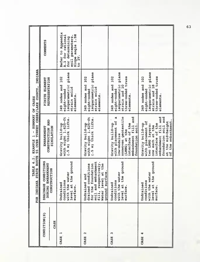
X•rl rH • SCTJ id O* 01 Lflcccu •
coQ) -H HI rHft-rl C Pz ftp -4 Q) 0)
rtS (0 £= £ Hu u 3 o>
oo
(DUE4-> U P * TJ
o a) aH mh TJ Q) >Q) rH ftrHMH i-H S4 -rl
CU 'OOHO
<05 rC MH CO CO 4J
a>
cHI
cCU
cCU
CazH
H ZZ OW M2 Hw <J HH ZH
W COH EdM gZ 0.M Wfa 05
cn <n CN id CN Id 01 CN id 01
O rH o ^ O rH 01 O rH 01
H ft
TJ O
rH ft
a o
rH ft 3u
a cjoprH ft 3
UTJ O 00 P
>4HZD
CO OIB CJI/I
< wo «
°^5h w
C -) X) C -rl TJ C -^ rH C -rl rH
KTJ U-H id TJ U -rl (d T5 U T3 id TJ IH TJHI P rH CU p rH HI P T3 CU 0) p TJ HI
01 TJ HI • onto • 01 TJ 0) C T3 • 01 TJ CU C TJ •
CD £ 01 01 III ED CO cu o £ id o co Q) £ id mT3 C 3 P TJ C (d 4-> TJ C id C P TJ C id C p
1 u c c 1 u c c oi nc i c 1 iH C 1 cC P CHll C P Id -rl HI c p id -ri cu <u C 4-> <d -rl cu a;
.c ft m e x: ft id £ £ ft id <U £ £ ft id (U e<n 0> )h <D CTl 0> Sh CU a* di o u u cu cri cn o u u ai
«* -r| CO P rH «* -r4 01 4J •-I <* -r| 01 P £ rH rf -rl 01 p £ ^-t
m a) -rt 01 Q) n Q) -rl CD CD n cu -ri co p cu n cu -ri co p ai
i§p • p • id m TJ TJ TJ
QZ
H Z
mh m MH CO rH C c CS o 1 P 1 4-1 MH -H id MH <d id p ps ft in <*h ft ID <4H ft P HI • ft •• HI JZ cD 5* 3 CN -rH 3 CN -rl 3 X £r|rl 3 01 CU .C rH rH O1 CU
CO H Z Z OCd O H
1 VO rH 1 vO <-\ 1 -P CU P r^ -H 1 P In J" P r-l -H --4 £« tj • •a • TJ C P CU •rl TJ C HI P r| OJ 5
1 05 S M Eh rlHJ< rld^ i-^ Q) £ MH MH 01 rH CU >1 MH H-l 01 £ CD 2 H < -rl •rl rl £ CO CU P -rl £ Id P 1 idH Eh Z O J 3 +J •-( 3 4J -rl 3 0J 3 Oi P c 3 CU rH Id P C TJ XI
< D D jQ A 43 J3 XI £ J3 UH p CU C XI O HI c -rl £w ts
OQ 05 X Oi-P Oi-P id 3 c id o CU -rl id o .c o (1) •rl £ HI
£g S Eh m >1-rl >1-rl >,ri XJ H> id E P >irH 2 O Id £ pEd CO CO +) CI" 4J ai--> P ft > ~<<H .2 id P ftS id MH 2 id HI CU2 O 2 -rl g -rl £ •rl £ O U C TJ •rl ,4 CU U c TJ J= JZ
^ o > £ > s: > JZ 1 3 2 CU id C > J= fl) (TJ C P PX in u (d 4-> m Id 4-1 LO id p 3 C S p£*§
id p o cu p -Q 3w in U ^ • U -rl . rl -rl J C IH -rl 3 C C £ P MH
• (HCJ 3 ~ O 3 — O 3 rH C -"-rl HI MH O 3 P "rl 0) mh id o
CN H• D
CO •a +J o TJ TJ
05Z Eh c co c c >i 0) c c
H o z 3 C tt) rH £ 3 3i-J Ld
M H _bl ^5* "5S 5 o
-rl £ CU 4->
CO H u •rl +J M > u u< < ^ 5 H u & -P id C -rl 4J (U u o« U Oi
H H Q Z rjz «* g
HI T3 -rl T3 id P <d cj HI CU
CO 4J CU cn c n cj id P CU P HIo m s; id £ id C 3 £ CU rH l*H id £ id j=
tH ° S « 01 3 P CU ft CU rl oi 3 P CD 3 Pz M W H TJ C a u *m 01 > 3 TJ C TJ Crtj S ,, a HI CU 4-» • cu -o CU CU CO HI HI P • 0) CU P •
M 25oC -rl £ Id CD C "0 CU c U <-t C -rl .C id CU c -ri x: id a)
Q •r| +J +J O rl cu £ id •a •r| 4J 4J CJ •rl 4J 4J CJ
z 5 £ o Id -rl rH Id id c 4J v u c (d "H rH Id Id "4 rH Id
M H 05v-/ u tj s: Q> MH U -rl iH rH CU 3 IH TJ .C HI IH In TJ £ CU MH
2 a TJ C P > lH T3 id U -rl rH P O TJ C P > In TJ C P > Vj
PS C -rl OJ 3 C Vi •rl Id U C -rl CU 3 C -rl 0) 3o o D O 3 rH 01 D TJ in 01 XH S D> D O 3 rH CO D O 3 rH m
co
zo wM coH <M oazo rH CN n ^o w
CO COHCO
uco
rf << < <CJ o CJ o
63

o in 4->
3 •» +J CM <M rH OJ ue -p •> 0) V £ • 1 x: oj ooC P T3 M-l 3 DivO O oj u 4J X; rH 4-1 ^M
0) >> u M-i id OJ -H rH ro ra oj Id 4-> rH CCQHZ
Si -* 0) U in Z OJ <d > c 4J --4 U 4->
to 3 a) O D>CN OJ £ MH T3 >i CJ O 144 Id MH MH -4 (d ft0<73 3 XI • rH . SI • C rH •rl 4J rH OJ •
gg C 0J rH +J -P — "O ro -P -P -P «J OJ O OJ -P u 4-> id -rl OJ
a -h +j a) a C «- C C SZ > 4-> x; id ra • 4J0J0JC73gXrHoo
N U CIWIII o»io moiojoj-P-~»-r< +J 73 Id 73 C >l OJ C -rl Q) -4••h 3 <d £ o g C D> O C g g T3 g — -P U -rl 3 OJ OJ id <d g 3 co -Pr-l S-| JJ +J Si •H «-« C —< 5 ^ -rl gO Id 4J rH "4 g ,-i <i-i Si o <-o x•r1 4J .-h m c cg-r4-^4JCC3m oj h aoow OJ U C <4H . OJ
XI 01 3 £ 4-> id a) ra g ra id (d -^ih ft •r) OJ CD -H -r| O O OJ Id rH OJ 4->
(0 C g -P <u XI 73 rH -rl -rl XI XI T3 • 01
•ri .(dinxggC4Jcnojg O C 4J 73 (dZ-PXlTJ-l to
4J -H "4 "4 2 -4 X O Id O rig CE CO «0)
<za
wi u tn 3 r-i a) 3n U •0J0)0J(d>iH-^^ co 0) o u g cUrJ-riojidmcjcn
OJ OJ 4J OJ OJ 4J
c C CD C c C 01 caz
H ZZ O
* Id oo (d g m oj 0> oi CM Id co id g ra OJ o» o>O -{ rH ^A HO10J gec
rH ft C U M -H -rl
O rH rH ri U 0> OJ g c cr-l a H ft rH ft C U Si -H -r|
w zEd
a co
z cum EdEu CC
IM -r| JJ C C 01 <*H -r| 4J C C 01
73 O T3 o titira (dcu-H 73 U 73 u u m Id OJ -4
w zw a<o° o
C --4 73 C -<T30JO 0JXlT3(d C -rl 73 C -4 730JO 0JXl73id(d 73 U --4 (flT3 U-4 0<4-lrH£ g-rl U Id 73 14 "H <d73 i4--iai4JrHx: g -rl U
OJ 4-> rH a) 4-1 r-i ra<d-POJ3 OJ -P rH OJ -P rH 01 Id 4J OJ 3CQ 73 OJ • CD 73 OJ • --I 0) m 73 oj o • CD 73 OJ • -^ OJ
CD £ en en QjOgramcojjM-irHOTJ oj o g ra to 0JOgCDmCD4JM-l rH 7373 C id -P 73C(d .p-H-Hoid-Pid 73 C Id 4J 73 C Id 4J -4 -r4 id 4-) id
1 M C C O 1 U C C 01 c c u o i u c c 1 lH C C CD c c u
° *
S3a ua wco O
c jj <a -h oj c jj (d -ri a) >i-h oj •-< ij en c -p id -4 OJ C 4-> Id -4 0) >i-rl oj -rl U OIx: ft m g £ am eh 4->o>o x; ft id g X; ft Id g rH 4-1 Oi
in 0>0 Vi 0) r^OiOljCUnJOJid -ri-rt 73 CTi Oi O lJ OJ r-oioucuidojid •rl -r| 73in --4 CD JJ rH 0>-HCQ-prHCJ3-Pr(rlC «tf -rl CD 4J rH Crt-H C04JrH CXT4J 14 S4 Cm oj -h ra a> ncu-^oiojid+jraoftid n a) -h m oj rr)0J-rlC00J(d4JC0 o ft id
P • <4H o 4J • M-l .
mh m £ o -p oj ra <*H CD 4J 11 01
a1 +j <d 0>^ 73 4J 1 4J T3 •p
i .z ftm mh -h g oi ft U Id 4-> M-l ft in mh ft u id 4-i M-l
1 >4 H * Z 3 CN ~H MH X! C 3 O U MH -r( 3 CN -H 3 U •u •H
rH H z 2 o£ Eh
1 lOrl O rH -4 1 * G> £ 1 rH 1 I4D ^ i -ri o> x: i f-trt « 73 • ~ . N 73 U +J in 73 • 73 u 4-> m
cuH
rlHAl C E"l-H rHrHftT3 C-rlCN^J hha; rH rH ft 73 C -rl CN X2 2* "4 O "—'-I -rl <d C O JlOO •rl O •ri id c o 3 yo oz r> j 3 +J —< "H lH -rH 3 C -P (d -M • -rl 3 -P -rl 3 C 4-> Id --4 •H
3 g Dm 3 sw 72 co
xi x: x: -p ~~±> Si Xl-H C +J 73 H £ Si sz sz XI --4 C 4-> 73 rH JZ§ OS oi+j u iw <a Oi OJ Oi • O OJ +J Oi-P Oi OJ Oi • OJ p5 w >,-H 3 +J 1 +) >i-rl g C 0> 3 -P C >i-H >i-4 E C Oi 3 -P C
«§ 4J OJ — u mh o tn JJU^-rlCtlldQ) — •P OJ -~ 4JVj^--4ClH(dOJ —
—
w to •rH g -P 1 rH •r^OCC-rljJrHOJg •rl g -4 C C -rl 4-> rH OJ g"O u,
z > x: en in oj g > id oj m m 3 4J > X! > id oj m oi 3 -Po (0-pin g <n 73 73 >h idOJX173-riCgxin id xj in idOJX!73-rlCgX in
w
o
o U "4 »0 • C -4 <D u jt; g -ri id o -ri •-< • U -rl . U XI g --4 Id --4 -4 •
o 3 ^o m <a 3 xi Ci4J0J3MOmra~- O 3 — O-P0J3IHO01C0 *-"
to "0 73 13 73
«n§Z H c c c co z 3 3 3 3
«EH Ed -,r_j v ^£ 5 o u
Ou u u
r, rt ^ C M u o< u o< U Oi U OiQZh£30
0)
+J OJ
OJ
J-> OJ
aj4J OJ
OJ
-P Q)CQ O CQ X id £ id j= (d X! id jz
£ < ra 3 -P m 3 +J m 3 -P to 3 -PH Z n H H T3 C 73 c 73 C 73 C< " „s OJ OJ +J • oj o ai +i • OJ Q) 4J • OJ -P •
M O U £ C -H £ (0 Q) c -< x: id oj c -ri x; id oj c-hx id oj
Q 3 5 o -H +J +J (J •H JJ +J o •r| 4J 4J O •r| 4-1 -P Oa 2 2 o (0 -H rH (0 Id —t rH fl Id -H rH id Id -4 rH id
M h ctiw
2 a^ T3 £ OJ UH in 73 x: oj i*h 14 73 £ Q) MH in 73 x; OJ iw
O C V > rl 73 C +J > -4 73 C -P > U 73 C 4-> > Ua C O -H OJ 3 C O •-< 0) 3 C -rl OJ 3 C --4 3oto
a D O 3 rH ra D o 3 rH ra D CJ 3 rH ra D o 3 rH ra
co
zo EdM toH rtMa
Ozo in >4D r» 00
uEd Ed Ed EdCO co co CO< rt! < <O u o u
64
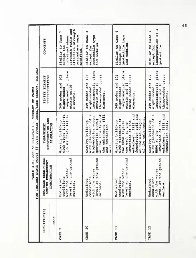
73 £ td
r- c 4-> n «* r-id en <4H
at u a 01 01 01 ai ai 01
m A o d) M ca a 0) ft 01
CO (0 0) -4 S-i 0) rd >i id >t td cEh O XI 4-> -P 3 CJ 4-> • U 4-1 • Oz CD (0 CD n a •rl •
w0) U ca V4 01 3 o u ai 3 U 4-> 0)
*§ u x: t3 o» 14 • 4J rH rH 4J rH rH 4J Id rH
oo
4J cij: > 01 73 <tH -rl 3 MH -4 3 MH U -r4
U C 4-> •-! 4-> 01 14 4J 73 rl 4J 73 U 4J
<d v •-• o» -p 01 -H id -p x o Id 4-> X td 4J ft xHBiHC U £ <4H rH ft 01 g rH ft 0) g rH ft U 01
•rl 0) U 01 tt) td "4 •rl 01 4-> •rt 0) 4J •rl 0) 4-1
S 73 )H Mh ll 73 g CJ 73 g O 73 g O•rl X G -P MH (d •rl X 01 C •rl X 01 C •rl X C 01
<z<
oi oi 3 n ill as co oi oi <d co oi oi <d CO 0) -rl 01
01 01 01 01
c a c cazH
H Zz oH M§ HEd <J Hw zn
W wM 2z a.M Hb. OS
CM nj cm id in cn id tn cm id cn
O -H O rH tn O rH 01 O rH 01
rH arl
rH ft 3u
rH ft 3rl
73 O 73 O 4-> 73 00 4J 73 O 4J
w z2so Q
C -H 73 C -rl rH C -HH C -rl rH
(d 73 In --
1
id 73 1h 73 Id 73 14 73 Id 73 U 730) -P H 01 4J 73 01 01 4J 73 0) 0) 4J 73 01
0) 73 0) • 01 73 0) C 73 • CO 73 01 C 73 • 01 73 01 C 73 •
0) o e ai en 01 g id m oi o g <d o n 01 g id CD
73 C fl 4-> 73 C Id C 4J 73 c id c 4-1 73 G id G 4->
o i u c c 1 rl G 1 C o i u a i c 1 U C 1 c
° «
a «a w
CO Q
c -p id -4 oi c 4-i id --) o> 0) C 4-1 Id -rl 0) 01 C 4J Id -rl 01 0)
j= a re e x; a id oi g x; ftid oi g x; ft id oi gm cn u oi en & o m m ai a* o> o u u 01 01 o> U U 01
>* -4 0) 4-> rH <* -rl 01 4J XI rH >* -M 01 4J X! rH »T -r| 01 4-> XI rHCO 01 -H CD 0) m 01 -rl 01 4-> 0) CI 01 --4 CD 4-> 0) n 0) .ri cn 4-i Oi
4-> • (0 MH rH 73 73 td 73MH CO C rH c c • ca
1 4-1 U 11 ^ .,4 MH id id 4-> 4-> mh id
1 j
z ftin mh ft > O 01 mh ft •• 0) XI c ft 011 X Eh * Z 3 CM "H 3 S CJ 3 CD 01 XI rH rH Cn 01 3 XI f-< r-t
rH H z z O 1 VO ^H 1 4J 3 S id 4J C 1 4-1 U JS +• r^ --4 -rl E 1 4-1 4-> rH -r|rt
r< 73 • 73 C X mh C 73 C 01 4-1 •rl OI J2 73 C -rl
04H 2£«
rH rH J* H oi <n •— M 0) 'rl rlH>, M-l MH 01 XI c rH 0) Mh Mh 01
•rl O •rl g 3 0) E 4J
3 01 rH 01 4-> 5 id
•-4 g Id 4-> 1 rfl •rl g 0)
3 -P -4 3 01 rH Id 4J G 73 XI 3 oi x: 4-i cxi x: x: X! 3 rH C C 73 XI 01 C -4 g XI O 4-) 0) C
§ *SB £ h
0>4J id 73 -4 -rl id c id O X! o 01 -rl g ai id o oi ~4>1-r| rNrH 4J XI 3 >irH S CJ Id g 4-> >irH 4-> Id E 4J
M W W V 0) — 4J ft g X 01 S 4J ftS id MH .2 id oi 01 4-i ft id mh .3 id
h e •rl | 0) XI 0) MH • •rl X 01 rl C 73 XI XI •-4 U G 73
•0 inZ > X! > XI XI 4J 4J ^ > XI 01 id c 4-> 4J > x: o 0) id co (d 4-> u*i id 4J en o oi 73 -4 id 4-1 01 4-1 XI 3 id 4-) S 4-> Xi 3
o
cj U -r) . U -4 -4 0) 4J XI C 14 -rl 3 C C g 4J MH H -rl 2 C gCJ 3 — 03x;o>id4->idai CJ 3 4-> -rl oi mh id ca 3 s -4 oi mh
to 73 73 73 73
CM wZ H C a c co z 3 3 3 3
«BH W _b 5* «g S o u u rl
r, rt S S M U CJi rl 0> u cn -1 OiQ Z £]2 < o
01
jj 01
01
4J CU
01
4J ai
01
4J 0)00 O era is <d £ id x; id xi id x;
£ < ° S « CO 3 4-> co 3 v CO 3 4J tn 3 -P
z ., M H 73 C 73 C 73 C 73 C2 " ,n 0) 01 4-> • 01 01 4J • 01 0) 4J • 01 01 4J •
M cj tJ X;<2§ C -H X! <d 0) C -rl XI id 01 c -ri xi id 0) c --4 x; id oi
a -4 4J +J U rl +j +j o •rl ±J +J CJ -rl .U 4J CJ
2 5 2 o (d "4 rH (d (fl -4 rH id Id -H rH (d Id -rl rH Id
M hb! u
os a1H 73 XI 0) MH U 73 XI 0) MH -1 73 X! 01 MH u 73 x: oi mh73 C +J > U 73 C 4J > U 73 G 4-> > U 73 C 4-1 > U
K C -rl 01 3 C -H 0) 3 G -H 01 3 C O -4 0) 3Ob4
Q D 3 rH m D 3 rH 01 D O 3 rH CO D O 3 rH CD
CO
zO HM COEh <M oQ O rH CM
o cn rH rH rH
cjtoCO
WCO
III
CO CO< 4 < <co u o CJ

66
appropriate information from the laboratory test results, a
comparison of the calculated and observed (from laboratory test
results) responses was performed using the CAP program. Several
iterations were performed to obtain the "best-fit" with results
shown in Appendix D (entitled Interim Report: "Embankment Widening
and Grade Raising on Soft Foundation Soils: Example 2 - Indiana
State Route 1 over Ramsey Creek in Franklin County, Indiana") . A
general soil profile is also provided for review in Table 4.3.
As stated previously, 18 cases were analyzed for this example.
In all cases, the groundwater level was assumed to be at 11.5 ft
below the existing ground surface except for case 3 where the
groundwater level was assumed to be at 7.5 ft. Typically, the
drainage conditions during simulation of the embankment construc-
tion were assumed to be undrained and drained for the foundation
soils and embankment fill, respectively. Based on the geotechnical
report, rock fill from roadway excavations would be used to
construct the embankment fill.
In all of the cases, the finite element representation of the
embankment fill and foundation soil consisted of 460 nodes and 409
four-node subparametric plane strain continuum elements. It should
also be noted that the embankment construction was simulated with
eighteen 5.0-ft (1.52 m) thick lifts. Figure 4.4 illustrates the
finite element representation of the embankment/ foundation soil
geometries. This example focuses more on the effect of the
reinforcement and the foundation soil properties rather than the
issue of embankment widening and grade raising. This is because

67
Table 4.3. General Soil Profile for State Route 1
Cap Model Foundation Layer/Value 1
Parameter1 2 3 4 5 6 7
-^min
3002 3002 3002 3002 3002 3002 3002
V0.40 0.40 0.40 0.40 0.40 0.40 0.40
So0.700 0.700 0.700 0.700 0.700 0.700 0.700
*21 21 21 21 21 21 21
c0.7202 0.7202 0.7202 0.7202 0.720 2 0.720 2 0.720 2
Cc0.230 0.250 0.250 0.250 0.250 0.250 0.124
Cr0.039 0.050 0.050 0.050 0.050 0.020 0.020
in°
1.58 1.46 1.07 0.96 0.87 0.80 0.63
OCR8.0 7.2 4.9 4.3 3.8 3o4 2.5
Y0.125 2 0.1202 0.1202 0.1202 0.1202 0.1202 0.1202
Ko1.50 1.44 1.23 1.17 1.11 1.06 0.94
P10 10 10 10 10 10 10
Notes; 1. Refer to Figure 4.4 for location of foundationlayers.
2. Units of ksf.3
.
Refer to Geotechnical Investigation of State Route1 (1986) for additional soils information.
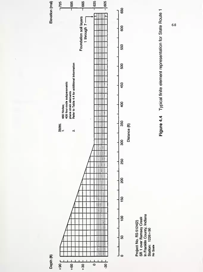
1 B
UJ
a0)
Q
2 1
i 1
- tv
1 o>to ^c oIIC3ou.
co
§o
ac
elric ditio
S « Jr
ubpmen
1.4
fc
» o -< i •
-"Re 29 2 •§ .5B c a —"S ^ a p
460
Nc
409
fo
plane Refer
t
0)CD
•^ ojoz
/
/
//
/'
/1
1 1 1 1 1 1 1 1 1 1 J_l.
o
a>oc(0
*^DOQC
CD*-CO*—
'
CO
cg'"S
cCDtoCDi_a£cCD
E
CD
CD
COOQ.
3O)
68
too .* co 0) CO*"
cnT 2 "2
^o£sitscoF = +
oo.
RrRa
n
Cc1226
z o => 2C . .
roject
R1o
i
Frantatlon
o
Scale
o Q-WiMZ
8 3
69
the number of nodes used in this example was near the maximum
number (500) permitted by NFAP. Further modification of the mesh
for embankment widening and grade raising would require additional
nodes which would have exceeded the capacity of the program.
Cases 4, 5, 6, 7, 8, and 12 through 17 involved the use of
either a LMNG or a HMWG placed either: at the 3 0-ft and 60-ft
height of the embankment and at the embankment/ foundation inter-
face; or at the embankment/ foundation interface only. The
geotextile was modeled with a 2 node one-dimensional truss element
(non-linear elastic stress-strain relation) . Again, stress-strain
relations of the geotextile were obtained from Koerner (1990) .
Refer to Table 4.4 for a summary of the cases.
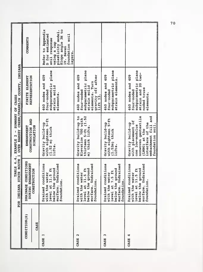
X •
-rl rH p73 73 a) <-<
coHZca
c a) -ax •Aoi p o> o na id co s CO
a e c a a>
(*! -r| fl r'l'H c§ 4j a o p oi coo
CO CO -: C <D •HP 0) <D <T> <d > p •
X 'H II <d co
U U 0>P © CO 73 Uoi o -h c co a C 01
IH MH -rl -rl (d • 3 >i0) O I0HH > o <d
A « O. CO 3 a CO H *4 r-i
§M o> 01 01 01
Q c c c C 1
S H ZZ Otd M
oi id ct\ <d in CT> Id CTi id
M o fH O rH fl) O rH • O rH 3«* a ^ a p <s* a co «* ap
* 2 Eh
J EHca z
EdEd CO
£gZ &M Edfa 3
C MH p>M TJ U 73 O U (d 73 O C 73 o oEh C -rl 73 C -I 73 3 C -HO) C -rl CNZ id U * (d H-H Hw id u e id Li CO
D 73 P rH 73 P rH MH 73 P 01 73 P 73 CO
O CO Q) CD O • CO 01 0) O • CQ 0) 01 rH 0) OJ 0) C 3 •
w z01 73 £j CQ CO 01 73 £ CO CO 0) 73 g 0) 0) 73 § (d U CO
73 O <d P 73 O id P >iO 73 id 73 O 3 P POCKCC C 14 C C P H OCUfi C U C CCI D--KJ C 1 Id ~H 0) -H C 1 Id -rl CI (d -H 73 0)
M Pud i h a id e > p u a id u a id oi eO 3J3 HI) O 3 Xl U 01 id Mh O 3 XI !h O 3 Xl -1 73 0)
En 3o g
5 Ed
is
li) O 3+irH tf> 3 P rH H -H iO 3 P W3 3 P rH^ MH CO CQ (1) f MH CO CO 0> C-H "S" MH CO CO tf <W CO CO C 0)
CN 0) 73
Q P P .C Lf) p r-t C>H p • <M <*J -H (d
J3 a i a-t <h a i a o p oi
Eh Z 3 m 3 3 — • 3 in 3 CQ X SZ r-{ r4
Z Z O 1 ^ 1 CO 1 1 P 3 0) P rH -r|
1*
1
Edco
Ed O M 73 C O 73 O P P 73 C X 73 C rH 4-> 0) -12 H Eh rH 0) -rl rH O <4H MH rH CD O rHO)30£>*HMHCQ2 Eh sC •H 0)£ •h r» I -h •rl CD -H •rl g 73 0) P OM s Z O p-J 3 -P -P 3 in rH 3 P £ 3 01 Oi PC
ii < D D xi £ -Q C XI £ P Xl O S P 0) Cw S> CQ « SS3 Eh H
Oi-~ oc^ o< (d i c (d o 0) -ri
J °">i-h e >1-H 0) O S-rl -> >irH 3 oi (d i +J
4J a o > -~mh £ (dEd CO CO P 0) P P 0) -I P 0) e •
2 •rl CN CO •h id p £ •rl CN CO •r| rH O rl C 73
o > £ in P > > U P > -C in p > SZ 3 Z 0) id co (dp • mh (d 0) -H Id P • MH idP0)CSPXl3
Vl -rl rH -rl u <-\ s: ~ U -rl rH -r| H-rHCOrH-CEOO 3 ~rH O Ed P S O 3 -"* U 3 C ~H 1) w
coZ Eh 01 73 CO 73 CO 73 CO 73
M 9 O Z C 0) C 0) C 01 C 01
3 w HHg O P 73 C O P 73 C 73 C O P 73 CCO r. m 2 o rl MH G -rl •rl <u C -rl -r| p C -rl •rl MH C -rl
3 £ P H 3 id P U 3 id p u mh a id P rl 3 Id
f-4 H Q Z r. H ID m O U h 1) in o M •rl 0) 0-1 •ri Q) in U5 "< oO CO g
73 P • rl 73 73 P • rl 73 73 P in Vj 73 73 P • 1-1 73Eh C <d rH o> C ' c <d -h o> c • C id • o> C • C Id rH 01 C •
CO O 3 -H DC 3 rH DC 3 r- DC 3 rH DC«:
„ W H u o> o O 0) O O 0) Q)
S FN CO 0) p £ • -rH 01 p £ • -rl 0) P £ • -rl 0) +J SZ • -rlZ2
O O i;<2§ 73 SZ <d P d) P 73 SZ (dp 01 P 73 SZ id P 0) P 73 x: id p oi p<D P O (d 0) p o id 0) P o id Oi p o idM Z H X
M « °
2 a
C rH 3 id 73 C rH 3 (d 73 C rH 3 (d 73 C rH 3 (d 73QSS
•-H £ 01 MH C •h j: u o >w c •rl £ 0) ^ C •rl £ Q) 4H C(d P > rH fc 3 fl P > rH H 3 fl P > rH Vj 3 RJ P > r-i U 3H ll -H 0) 0> 3 O U -rl 01 0) 3 !H -rl 01 0) 3 U -H 0) 0) 3
ofa
a Q 3 -< Xl CO MH Q 3 rH J2 CO IM Q 3 rH XI CO MH Q 3 rH Xl CO MH
CO
zo EdH COH «:M oQZo rH CN ro ^,
oEd Ed Ed EdCO CO CO CO< < A <O
1
o O o
70
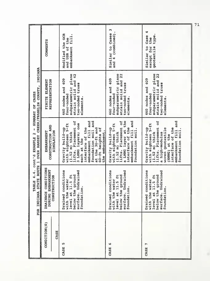
n•«*
a m ^ •
O 'H 0) T3 0) 0)
o a> ^h CO 0) to 0) ftco £ -rl (fl c (fl X >nH
4-> <M U-rl <J 4J 4JZ £ XI
9 •P MH -P o e U 0)
5 c 4J P rH
oo
TJ fl) u '4-! Hfl) OS I•rl CO .2
u ~-(fl
U 4-1
Ifl 4J X«JD c ^1 -* rH 04 fl)
•rH (0 •H •rl 0) 4->
TJ TJ X e -o e o oC £ •rl C •rl X fl)
<
M
S cd 3 co (fl co a) a>
fl) CN a cn CN
Q C "* C CN C CN
s Eh ZZ OEd MS EhEd <J EhEd Z
EdEd COEh EdM OSZ CUM Edfc OS
en * cn (fl cn (fl
M O rH 73 O rH T3 O rH 73* a c co <? o, a oj •* ft c co
«, (d ca (fl CO Ifl CO
>H TJ 3 73 3 73 O 3H c -h -a u C -^ T3 )H C -rl 73 !h
CO Z IB 14 --I 4-> (fl V4 -4 4-1 Ifl U -rl 4-1
Ed D 73 4-> ^ T3 4J rH 73 4-1 rH
CO O 01 CD 0) O TJ • CO Q) CD T3 • 01 OJ fl) 73 •
< O id *a £ en a) to cu tj s co a) co 0) 73 E CO OJ CO
O TJ S3 TJ 4-> a o (o tj 4-i 73 <0 TJ 4J
z C U C C C U C c C -4 C cEi4 H CI «-h C 01 CI (fl -rl C 0) CI (fl -rl C 0)
O iJ u am i s u Old I g -4 ft (fl 1 E2 O 3 X M fl) O 3 XI U O 0) O 3 X -4 0)
* z ^0 3 4-1 3 rH >a 3 4J 3 rH lO 3 -P 3 rH
31•* MH 01 CO 4-> CD <* 14-1 CO CO 4-1 HI 9<M 1 B4JO
D «CO Ed
pai «u
CN>4
Ed Cdi-J Wa- x
<4H •o TJ <ih ai tj MH 73•P 0) c c 4J 0£ C •P c
a MH C (fl (fl 4h 4J (fl MH (0
z ft 1 4J CD T) ^ a, i 4-1 oj ft i 4-1 a) cu
Eh * Z 3 in C £ rH rH C • 3 m C4JJ:rlr4 3 in G •-< X rH •-!
Z - O 1 .* fl) •« JJ rH -4 (fl 4J 1 J4 0) id -P <-l -H 1 .* fl) CO -rl 4J rH -r|
TJ C U S CO •-HO CO C a c o g -ri o 73COE34-I0) -HO
2 £ <:z n J•j; y d
rH Q) -r) U 4H MH CO +J 4-1 CD rHOJriajU^MHCO rH fl) -H flJrH XXMHMH COH 0) £ U (U 11 iw£ E <H OJ £ U ID •-lfl)XO3flj4->03 4J -P (0 >iX 4-1 C 1 <J>M 3 4-1 4-1 Ifl >1 4-> C 34->4J(0734-l 4JCx x ^h <a +j 0) C O -rl C X C rH (fl <D c XX rHOO4->0JCO
2 3S £ i-!
CTi'-O. H U CD "H ro 0) (fl Ol ^- 04 rH 0) -4 cn-~ci4Efl)(flooj-ri5 >i-h e -p (0 e 4J js & >i-h e (0 e 4-i >,-H E 1 Oi ifl E -P
w a Ed ^ CO ii ai u mu^ m m >~ 4J 0) • O "M ^ (fl 4-1 0) • X ~MH ^ (fl™ w rl CN CO Z u c -a £ 4-i a) •rl CN CO Z U C TJ •H <NC0OiCOlHC73a >- o•pC rH
O Cd
Z >£UHJS£ 0) (fl C 4-1 >rl >cm4Js:o)iflc >Xin4J-rio)SO)(OC1 o (0 +J • MH 3 u 4J XI 3 10) (fl 4-1 • 4H .J 4J X 3 (fl4J •hhX>S4JX3o (h -^ i-t -i m c e o 4-i o c 1H -rl rH -4 ceo -4-rlrH-H OXCEO
O 3 — i-h m <i) rl CU <4H (fl VO 4-1 O 3^rH Ifl -rl OJIIH O 3^rH Ifl 3— -H flJMH
H co• D Z Eh ca tj CO 73 CO 73
<* o O Z C CD C 0) C OJ• OS H Ed 2 -P TJ c 4-1 "O C 4-1 TJ C
"*H S °s; s m
•H MH C -H •H MH C -rl -4 14-1 C -rl
Ed 4-1 r4 3 fl 4-1 U 3 (fl 4-> -4 3 (fl
Ed H DZS •rH d) U1 U r4 a) in o U •H fl) in -1J. < s 5 o TJ 4-1 • In TJ 73 4-1 < 14 T3 TJ 4-1 • V4 TJ00 H O DQ X C (d H o> C • C (fl rH C« C • C (fl rH 01 C •< co ° 1 K 3 rH DC 3 rH DC 3 rH DCEh Ed S O 0) CJ 0) O 0)
rt! 5j„n 4) 4-1 X « -H OJ 4-1 X • -rl OJ 4-> X • -rlZ3
o o g TJ X (fl +J fl) 4-> 73 X Ifl 4-1 0) 4J 73 X (fl 4-> OJ -P^ 2 n fl) .p O (0 0) 4J O (fl 0) 4-1 O (flMDURI
CI C rH 3 ifl TJ C rH 3 ifl 73 C rH 3 (fl TJQ ~h x a> o mh c •rl X 0) "H C •rl X 0) mh CZ(fl 4J > rH rl 3 (fl 4J > rH 14 3 (fl 4J > rH 1-| 3H -4 -rl fl) fl) 3 -4 -rl 0) 0) 3 rl -rl fl) 0J 3
BSO
i-i a 3 rH xi CO MH a 3 -H x co hh CI 3 r4 X CO <4H
co
zo Edl-H COH <M Oazo in iJ3 r-
oEdCO
EdCO
EdCO
< rf <u o o
71

TJ O TJin rH TJ
0)
a> cid p
rH Cid c
0) fl) d) rH -rl d) CO rH C a) ^ ai
n Hi a 0) rH MH CO OS 3 -rl d) CO os -ri aico U£ >, 18 <U -r| -r| duxan id cj XlHZ 04J4J U OWTJ O O CO X! O O CO
CDcd o u ai o os p e d) d) P CO O fl) fl) 0> id
A P H P o c p x; x: co id • p x; x: c x; •
x MH -rl O ffi fl P p O XI TJ P P -rl TJo Sh -P U Ed) U g 01 rl N fl) fl)o Id P X id p .2 d) Id P MH IH ^"rl Id P MH rH rH -r|
r-t 04 ai rH ft C XI rH ft 0) IH MH rH ft O JH -rl MH•rl fl) P •ri d) id •rl 0) ft <U -rl •r| fl) fl) MH -r|
E3 O S o Xj CQ
•rl x g id
g O OS ft >iTJ g O OS TJ TJ•3 X 41 ri x co 3 id •rl X CO C (H O
< CO CD 01 CO d) d) J3 CO 0) D ^"-1 S CO 0) D 3 ft g
§M CD CN d) 01 fl)
a C <* c c CZ H Z
Z Offi id ai id en id • cn id
M O -H TJ o ^ • O rH CO O rH •
t ft C CO rf O4 CO «* ftp * ft CO
it. 2 HCd <iJ Htd Z
CdEd COEh Edm OSZ 04M Cdb S
it) tn p c pX TJ CJ 3 TJ O C TJ CJ d) TJ O CH C -rH "O 1H C -rl d) C -rl g C -rl fl)
CO Z id K^*J id u g id u a) (d Sh gEd D TJ P ^H TJ P 0) TJ P rH TJ P fl)
W O co d) oj o tj • 01 CD d) rH CD ID d) d) CO 0) fl) rH
< o d) TJ g CO d> CO d) TJ g <D fl) TJ g d) TJ g d)
o TJ O Hi -OP TJ id TJ id TJ i3
z O C Sh C C C in c C Sh C O C U CE»4 M ci nj -^ c a) C 1 Id -rl C 1 Id -rl C 1 OJ "rl
°£ u cum i § M ft id M ft id Sh ft id
O 3 XI >H fl) O 3 XI rl O 3 Xl rl O 3 X! Sh
X 2. vO 3 P 3 rH VO 3 P yj 3 P ^£> O 3 Pos 2
1 fa
D «co a
. go
CN>H
Ed HiJ CO04 £
«* mh co co p d> <* MH CD CO >* MH CO CO >* MH CO CO
MH TJ TIP O Q) c c p p Pa MH C id id IH MH MH
z ft i p o a) TJ Mh ft 1 ft 1 ft 1HZ 3 in C £hh c o • 3 m 3 in 3 in
z z O 1 X fl) •» 4J rH -rl Id P 1 1 1 ^TJ C CJ g CO •-H CO c TJ C ^ TJ CAI TJ C O
!i ° Eh
2 S <rH J) -H HI tl MH Mh CO p p fl) rH OJ CJ rH d) CJ rH (J) "H»h a) a o a> ai o MH C g •rl d) -rl •rl d) 'H rl OJ x:3 P P (d >iX! P C 1 01.3 3 P .C 3 p x; 3 P PXI £ rH Id P 0) C O -rl C X! £ P xi x; p xi x;
lr S s S 2Ed t2 CO
0>~Ph rH O aj -ri n ai id o> o> ai^-5 >i-h S p id s p x: xj >1-r| ~ SH-rl — >1-rl g
-a >- opC rH
Ed
+j ai • o id tn M * ai g p d) g • P fll g • p ojw W ' •rl CN CO 3 U C TJ X! P d) •rl CN CO rl CN CO •rl CN CO
Z >£inii££ a) id c p mh > £ in +j > X! in +j > C in +Jo id .p • mh 3 cj p XI 3 Id) Id P • <4H id P • MH id p • mho 1^ -H H -H (d C £ P O S2. U -H H -r| SH -rl rH -r| SH -rl rH -r|
O 3^-rin <D -h a> mh id in p O 3 ~rH O 3 ~r-1 O 3 ~r-i
H CO• D Z Eh 0) TJ CO TJ CD TJ CO TJt o O Z c ai C dl C dl C 0). a; HH- P TJ C O P TJ C P TJ C O P TJ C^
M 2 OS S M
•rl <U C-H •r| >4H C -rl •r| MH C -rl •rl MH C -rl
H P Sh 3 id P U 3 fl P U 3 Id P Sh 3 id
Ed Eh DZf] •H CO in >h •ri ai m u •H fl) m -1 rl OJ in O ShJ < ?5o TJ P • )H TJ TJ P • U TJ TJ P • U TJ TJ P • Sh TJ03 f-t O o s C id iH o> C • C Id rH 01 c • C Id rH 0> C • C id rH ai C •< CO °
r? os O 3 rH DC 3 H DC 3 rH DC O 3 -H DCH n w H CJ OJ O dl CJ d) CJ fl) O< W„b OJ P XI • -rl d) P Xi • -rl a) p x; • -rl d) P XI • -rl
z o o £ TJ XI id P 0) P TJ .C id P d) P TJ x; id p di p tj x; id p di prtj 5 z n 0) p cj id dl p u id 0) p id fl) P cj idH C -H 3 id TJ C rH 3 fl TJ C rH 3 Id TJ C rH 3 id TJa H OS
w•H J3 0) «H C •rl XI 0) HH C -ri x; oj mh c •rl Xi (1) O MH Cz
a a fl P > rH S-l 3 fl) P > rH U 3 Id P > rH JH 3 id p > rH sh 3M r) -rl 0) 0) 3 rl -rl d) d) 3 U -rl flj d) 3 Sh -rl fl) fl) 3
oa Q JHJ BIW Q 3 rH XI CO tH Cl 3 rH Xl CO MH a Sria co mh
co
zo EdM COH <M OQZo
rHoo en rH rH
oEd Ed Ed EdCO CO CO co< rC < <U
72

oCT> "fr t-t
MH M-l Mh
0) CD 0)
CO CO COco
<o c (0 c •0 CH o O Uzo u a o)
JJ A t-t
O U 4J CD
*J O flrlM-l U -H
•rJ •
O Jh JJ CD
JJ O 10 rHMH U -H
o H O JJ 14 O 4J M O JJo
imilaxcept
ncorpeotex imila
xceptncorp
eotex imilaxcept
ncorpeotex
< CO CD -rl 0> CO CD -rl 0> CO CD -rl C7>
§M Q( CN CD CN CD CN
Q C CN C CN C CN
Z Eh ZZ O
en (0 ffi (0 (Ti 10
M O rH 73 O rH TJ O rH TJ«* ft G CO * ft c co <3- ft C CO
^ 2 Eh
Ed Z
id co (0 co (0 CO
tH TJ O 3 T3 O 3 73 O 3H C -rl TJ U C -H T3 U C --< 73 JH
CO Z 10 Sh --I j-> 10 H -rl +J <0 lH -rl JJ
Cd D EdCd COEh CdM «Z 0.M Cdfa 2
•O+JH T3 -P rH 73 JJ rHCO O co cd cd o tj • CO CD CD O T3 • CO CD CD O 73 •
< o CD TJ S CO CD CO CD TJ S CO CD CO CD 73 g CO CD CO
o 73 10 73 JJ 13 O (0 73 JJ 73 O i0 73 JJ
z OChCOC O C U C O C O C JH C C&4 H CI iU-hCII CI 10 -rl C CD CI 10 -H C CD
°3 u ft <o i g u ft <o i a b ft io i gO 3 XI U (1) O 3 XI U CD O 3 XI U O CD
:* z iDO 3JJ JH U3 O 3 4J 3 rH vO O 3 -P 3 rH
1 ^
D «CO W
, gU>H
K CdJ wa. 2
«* mh m 0) +J CD "* M-l CO CP 4J OJ•rj. mh CO CO JJ CD
MH 73 Mh CD V Mh 73JJ O C +J 0£ C JJ O C
! Q MH <0 MH 4-> <0 MH 10
z ft 1 -P 0) CD ft 1 -P CD ft 1 JJ CD CD
Eh ^ Zz a O
3 in C m Xi rH rH 3 CO C +J £ rH rH 3 in C <-* Xi r-t ^1 J4 CD CO -rl J.) rH -rj 1 .* 0) (0 4J rH -rl 1 X CD CO -rl JJ rH -rj
73 C O g 3 -P 0) -rl O TJ C O 6 -rl O 73 C O g 3 JJ CD -r|
|OfJ H HI -1 11 H X £ MH M-l 0) rH CD r! Cll U MH MH CO rHCD-rlCDrHXCMHMHCQ-•H CD Xi O 3 CD JJ •ri cd x: O CD •rl CD x; O 3 CD -P o
z Pi J 3 -P -P (073 V JJ c 3 4J JJ <0 >i JJ C 3 JJ JJ 10 73 JJ JJ c<"d XI Xi HOO*J CD C O XI XT rH (0 CD C O xi x; rH o o jj CD Ccd a 2 « S
JS S HOi-^O. g CD IT) O CD -rl CJI ^> Of rH O CD -rl 0*^0. g CD (0 O CD -rl
X
«E- oJJC rH
o u
>i-rl g 1 0> (0 g JJMH J2 tfl
t-l-ri g 10 g 4J >1-rl g 1 C< 10 g JJ
W r« to jj cd • x: -> JJ (D • O MH .3 10 jj cd • x; — MH H r0M" CO -H CN CO D< C O u c tj •rl CN CO Z H C TJ •H (N CO U> C O Jh C 73z > X! in JJ -r| CD 3 CD <fl C >X!in4J_CCDiOC > xi in jj -h cd 3 CD 10 CO ifl JJ • Mh £ > £ •p ja 3 (fl JJ • MH J -P XI 3 10 JJ • MH X! > a JJ XI 3CJ Jj -rl rH -rl OX ceo U -rl rH -r| CgO Vj -rl rH -rj OX ego
O 3 ^-H <0 3 — H CD MH O 3^rH (U-rl CDMH O 3 ~r* 10 3 — •H CD MH
H co• D Z Eh CO 73 CO Ti CO 73
<tf O O Z C CD C CD C CD• CC HWg O 4JT3 C O 4J TJ C JJ 73 C
«*h 2 -rl MH C -1 •r| IHC-H •rl MH C -rl
H 4J h 3 <0 P Jh 3 10 P U 3 (0W Eh D 3 H •h HI in O h -rl CD in O U •-J cd in o uJ < 2 ri* n 73 JJ • U 73 TJ -P • In TJ 73 JJ • lH 73OQ E-i O ai ;=; C (0 rH CF> C • C (0 rH 0> C • C (0 rH Qi C •
<C CO ° s « OSH DC O 3 rH DC 3 rH DCE-i n M H O CD O O CD O O CD< « ,5 a> jj x: • -ri CD -P X! • -rl CD JJ XI • -r|
Z o o ~25o
•a £ to jj cd -p TJ X! <0 JJ CD JJ 73 Xi 10 JJ CD JJfl; CD -P O (0 CD JJ 10 CD JJ U 10M 2 £ o C -1 3 «J 73 C rH 3 IT) 73 C rH 3 «J 73Q h a ""
§ Q•rl Xi CD O Mh C -H x: cd o mh e •rl Xi CD MH CZ CO JJ > H U 3 10 JJ > rH Vj 3 (0 JJ > rH U 3M U -H CD CD 3 O lH -rl CD CD 3 O U -rl CD CD 3
oEei
a O 3 H XI CO MH Q 3 rH XI CO MH Q 3 rH X) CO MH
co
zo wM CO
H <M CJQ
CN n fo rH <-< rH
oEdCO
wCO
CdCO
< < <o O U
73
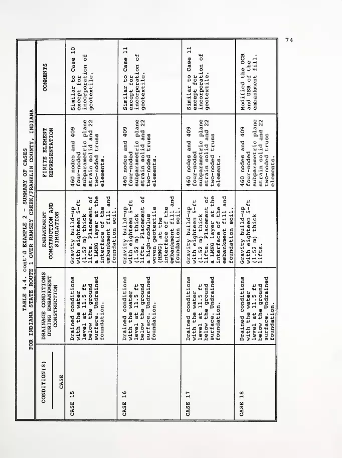
O rH rHrH rH rH
<u IH H ao o 0) U rH
01 to to O O rHco
ifl c <d c id c x: -hEh O O O O P 4-1
Z H •
P P4J o <a h
•P •
P P 0)
P <d rH
•H •
P PP Id rH
+J 4-1 4Jc
o M-l U -H 4H P -H <*-) U -H 73 OP OP P OP P OP 0) OS E
•H tO 5 jo id +i Oi x id 4- ft N id p ft x
Hpiug rH ft P flj rH ft P 4-1 D C•POOP •H 0J P •HOOP -h cd
£ o o E O E O O 73 73 X!'Hxeti •H X C 0) •H X C C £
<\ %
M
CO -H D> CO 0) "H 0> CO -H 01 s (fl ai
CD (N 0J CM CM (N
Q C eg C CN C CN C CN
Z Eh ZZ O[VI 1—
|
ffi <d a* <d en id cn id
M O ^ 73 O rH XI O rH XI O rH 73<* ft c co <? ft c to *r ft c en «* ft C CO
< 2 Ehfa <4 EhU Z
fafa tOEh fam faZ faM fafa fa
(fl B) <d to id to id oi
>H XI O 3 XI O 3 XI O 3 73 O 3H C -P XJ P C -P XI u C -H XI P C -H XI P
w z 10 P -P P (d P -H 4-> Id P -H 4J Id P -H 4-1
u s •0 P rH 73 P rH XI P rH XI P rH
to o 01 73 • to 0) OJ O XI • to O O O XI • to O O XI •
< o o -0 £ m 0) to 73 £ to 0J a o xi E m o oj XI £ 01 O 0)
o 73 (fl 73 P •a o <d xi p 73 O id XI P XI O id 73 P>i
z C P C C G P C O C C P c o c O C P C O cfa H ci gin cm ci id -i fi oj ci m-ncoi ci id -h c oQ
flP ft (d 1 £ P ft <d l E p ft id i e p ft id i £
O 3 X) P O 3 XI U OJ O 3 X! P O 3 Xl P OX z <£• 3 P 3 rH ID 3 P 3 rH i£> O 3 P 3 rH i£> 3 P 3 rH
9 3s **»»
D «tO fah
i ao
CMJ
Xfa HJ COa, s
^ MH tO tO JJ OJ >* <u to co p aj >* MH CO CO P O ^ 4H 01 CO P
<«H QJ XI <4H •o MH O T3P ox: c P c p ox: C Pa 4H 4-1 <d MH id MH 4J id 4-1
Z ft i 4-t tu ft 1 P 0J OJ ft 1 P • ft 1
Eh * Z 3 in C +J£HH 3 m c •-< X! rH rH 3 m c p x: rH rH 3 in
Z 2 OM " |—
|
1 _* OJ Id 4J rH -P 1 ,* 0J CO -H 4J rH -H i x o id p rH •H l Jia c o £ •H XI C O £ 3 P 0J •H XI C O £ H T3 C O
E O H rH0-H0P4-l4Hal rHflJ-HOJrHXXIMHMHCO rH O -H OJ P <4H 4-1 en rH -H-H OJ X! O Q) •h ai x: o 3 a) p O -p o x: o o o •h o x:
2 It J 3 P P cd >i P c 3 P P fl XI P P C 3 p p nj >i p c 3 P P2 ° 3 XI £ rH (fl OJ C xi x: rH o o p O C Xi x: rH <d o C XI XI
^1 S S « sJS £ h
Olr-fcrl O OJ H Oi^fa £ d) id O -H o<—~fa rH o •H cn —w a
>i-h £ m IS >i-P £ 1 0> id £ p >i-h £ co £ P >1-H £fa Y2 </)
jj oj • rj mh P 0) • JS -^ 4-1 a (D p o • a tn ,2 (fl P™ o ' •H cn to Z M C XI A CN tO 0> C O K CD •P CN 01 Z P c XI H CN to
73 !>- opC rH
O fa
z > x: in 4J S OJ id c > x: in +J -H OS o id c > x: in 4J s id c > x: m po (B 4J • KH J JJ XI 3 id p • mh x: > s P XI 3 cop .mj+i o 3 cop • 4-1
o p -H rH -H C £ p -H rH -H OX CEO H H H H C £ p -H rH -HO 3 ^"H (fl -H a) uh O 3 — ^ id 3 — -H tl<H O 3 ^"H Id -H 4-1 O 3 ~rH
H to• D Z H to 73 CO T3 CD XI oi xi
«* o O Z C 0) C O c c o• a H fa j- O 4JT3 C P TJ C O P T5 c O P XI c
>*H 3 °S S H
•rH 4H C -P •H MH C -P •H K-e c -H -P 4H C -Hfa P P 3 m p p 3 id P P 3 id P p 3 (d
fa H a z £ •h 0J in o P •h O m o P •H o in P •H in PJ < 73 P • -H XI XI P • P XI XJ P • P XI XI P • P 73QQ H Offli, C «H D>C • C «H tJlC • C id >h cn c • C (d -H Oi C •* to ° ^ « 3 rH DC 3 rH DC 3 rH DC 3 -H DC< n " H O 0) O O
K ,„ tO OJ P .C • -H o p x: • -h o p x: • -h o p x: • -hZ O O g xi x: <dp oj p xj x: id p o p XI X! (d P P xi x: id p o prti <2§ 0) P O IT) op o id OP O (fl op o idM 5 £ o C rH 3 fl T3 C rH 3 id XJ C rH 3 Id XI C rH 3 (fl 73a M fa
w H£ Jl CH C h x: o o ^ c h x: o o ^ c •h x: o o 'w cza a rd +J > rH U 3 Id P > rH p 3 CO P > rH p 3 Id P > rH u 3M p -H 3 P -H O O 3 P -H 3 O P -H O O 3
faOfa
a a 3 rH XI tO <4H a 3 rH .q a m C1 3 rH XI CO ItH a 3 rH XI CD 4-1
co
zo faM coEh rt!
M Oa2 in lO r» co
O rH rH rH r-t
ofaco
faco
fato
faco
< 4 < <o o o o
74

75
CHAPTER 5
DESIGN GUIDELINES
5.1 Introduction
This chapter investigates the effect of reinforcement, crust
strength, stability, foundation compressibility, embankment width
and embankment widening and grade raising on short term deforma-
tions and stresses to identify which aspects of embankment geometry
and foundation properties have the greatest effect on the overall
behavior. To evaluate these effects, 3 cases as described in the
previous chapter were considered. Although a significant number of
cases were analyzed with NFAP, the effect of the above-mentioned
aspects, which are discussed herein, provides merely a gualitative
assessment of the behavior. During the design process, the results
of NFAP should be only used to assess/check the design and not be
used as a "stand alone" design tool.
To discern these effects, computer-generated contour plots of
the horizontal and vertical displacements, principal stress ratios
and local factors of safety were created. These plots for examples
1 (State Route 55) and 2 (State Route 1) are provided in Appendices
C and D, respectively.
After executing the program NFAP, an output file known as
"TTT" is generated in ASCII format. The file contains information
regarding coordinates of the nodal points (original mesh) , nodal
connectivity, coordinates of the deformed mesh and local factors of
safety (defined as the ratio between the available shear strength
and mobilized shear stress at the same average compressive stress,
76
Z ) and principal stresses (and angle of rotation) of each
element in sequential order. A post-processing program written in
BASIC language interfaces with the TTT file and a commercial
software package (Surfer, 1989) which was used to generate the
contour plots.
5.2 Design Analysis
5.2.1 Deformation Behavior of Reinforced and UnreinforcedEmbankments
In this section a detailed examination is presented of the
behavior of reinforced and unreinforced embankments in relationship
with the examples discussed previously in Chapter 4. A comparison
of similar cases in Appendices C and D involving reinforced and
unreinforced embankments indicates that the reinforcement locally
alters the magnitude of the short term displacements but does not
alter the overall pattern of displacements. Horizontal displace-
ments at the embankment toe and maximum settlement (not in the
sense of consolidation but rather displacements/deformations during
undrained shear) at the base of the embankment were slightly
reduced with single and multiple layers of reinforcement and with
the type/modulus of the reinforcement. However, in comparison of
cases 7 and 12 of State Route 55, a considerable reduction of the
horizontal and vertical displacements at the toe of the embankment
(in the foundation soil) and beneath the shoulder (embankment fill)
were observed. The reduction was about 3 3% at each location. It
should be noted that the over-consolidation ratio of the foundation
soil was reduced to yield a softer response for cases 7 and 12 and
a high-modulus woven geotextile was placed at the interface of the
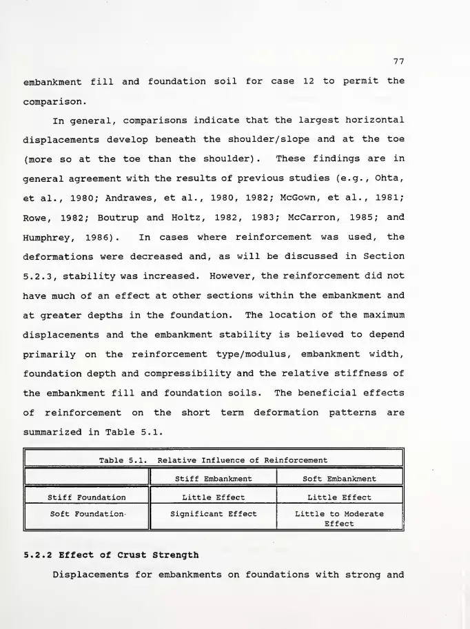
77
embankment fill and foundation soil for case 12 to permit the
comparison.
In general, comparisons indicate that the largest horizontal
displacements develop beneath the shoulder/ slope and at the toe
(more so at the toe than the shoulder) . These findings are in
general agreement with the results of previous studies (e.g., Ohta,
et al., 1980; Andrawes, et al., 1980, 1982; McGown, et al., 1981;
Rowe, 1982; Boutrup and Holtz, 1982, 1983; McCarron, 1985; and
Humphrey, 1986) . In cases where reinforcement was used, the
deformations were decreased and, as will be discussed in Section
5.2.3, stability was increased. However, the reinforcement did not
have much of an effect at other sections within the embankment and
at greater depths in the foundation. The location of the maximum
displacements and the embankment stability is believed to depend
primarily on the reinforcement type/modulus, embankment width,
foundation depth and compressibility and the relative stiffness of
the embankment fill and foundation soils. The beneficial effects
of reinforcement on the short term deformation patterns are
summarized in Table 5.1.
Table 5.1. Relative Influence of Reinforcement
Stiff Embankment Soft Embankment
Stiff Foundation Little Effect Little Effect
Soft Foundation- Significant Effect Little to ModerateEffect
5.2.2 Effect of Crust Strength
Displacements for embankments on foundations with strong and
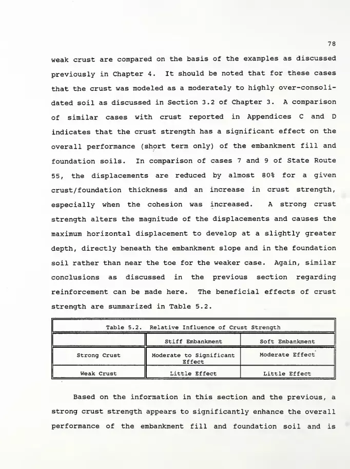
78
weak crust are compared on the basis of the examples as discussed
previously in Chapter 4. It should be noted that for these cases
that the crust was modeled as a moderately to highly over-consoli-
dated soil as discussed in Section 3.2 of Chapter 3. A comparison
of similar cases with crust reported in Appendices C and D
indicates that the crust strength has a significant effect on the
overall performance (short term only) of the embankment fill and
foundation soils. In comparison of cases 7 and 9 of State Route
55, the displacements are reduced by almost 80% for a given
crust/ foundation thickness and an increase in crust strength,
especially when the cohesion was increased. A strong crust
strength alters the magnitude of the displacements and causes the
maximum horizontal displacement to develop at a slightly greater
depth, directly beneath the embankment slope and in the foundation
soil rather than near the toe for the weaker case. Again, similar
conclusions as discussed in the previous section regarding
reinforcement can be made here. The beneficial effects of crust
strength are summarized in Table 5.2.
Table 5.2. Relative Influence of Crust Strength
Stiff Embankment Soft Embankment
Strong Crust Moderate to SignificantEffect
Moderate Effect
Weak Crust - Little Effect Little Effect
Based on the information in this section and the previous, a
strong crust strength appears to significantly enhance the overall
performance of the embankment fill and foundation soil and is

79
somewhat analogous to reinforcement. However, the beneficial
effects of crust strength appear to outweigh those of reinforcement
for the range of crust/ foundation thicknesses ratio (i.e. 20% to
25%) considered in the examples.
5.2.3 Effect of Reinforcement on Stability
The effect of reinforcement on stability was investigated. A
comparison of similar cases in Appendices C and D involving
reinforced embankments indicates that the reinforcement locally
alters the magnitude of the safety factor but does not influence
the overall pattern of stability. Safety factors in the zone of
the embankment toe and sideslope were slightly increased by the
presence of reinforcement and more significantly by the presence of
multiple layers of reinforcement. The potential benefit was more
noticeable when using a high-modulus woven geotextile. In a
comparison of cases 7 and 12 of State Route 55, a pronounced
increase of the stability by about 2 0% at the toe (foundation soil)
and by nearly 8% beneath the shoulder (embankment fill) was
observed. It should be noted that the over-consolidation ratio of
the foundation soil was reduced to yield a softer response for
cases 7 and 12 and a high-modulus woven geotextile was placed at
the interface of the embankment fill and foundation soil for case
12 to allow comparison. The effects of reinforcement on stability
are extremely beneficial in situations where a relatively stiff
embankment is established on very weak and compressible foundation
soils. An interesting point in the comparison of cases 10 and 14
of State Route 1 indicates an increase by about 2 0% in the
80
embankment stability near the toe upon incorporation of a high-
modulus woven geotextile placed at the interface of the embankment
fill and foundation soil.
5.2.4 Effect of Foundation Compressibility
The effect of foundation compressibility was investigated on
the basis of the examples discussed in Tables 4.2 and 4.4 of
Chapter 4 . A comparison of similar cases in Appendices C and D
indicates that the foundation compressibility locally alters the
magnitude of the short term displacements but does not alter the
overall pattern of displacements. In general, comparisons indicate
that the largest horizontal displacements develop at the toe.
However, the largest vertical displacements develop near the
shoulder and to a lesser extent at the center of the embankment and
migrate to the sideslope with increasing foundation compressibili-
ty. Recall that a strong crust strength alters the magnitude of
the short term displacements and causes the maximum horizontal
displacement to develop at a slightly greater depth, directly
beneath the embankment slope and in the foundation soil rather than
near the toe for the weaker case. For a given embankment stiff-
ness, the foundation compressibility directly influences the
effectiveness of the crust strength. The effects of the foundation
compressibility on the short term performance of the crust strength
are summarized in Table 5.3.

31
Table 5.3. Relative Influence of Foundation Compressibilityon Crust Strength
Normal Compressibility High Compressibility
Strong Crust Little Effect Significant Effect
Weak Crust Moderate to SignificantEffect
Significant Effect
5.2.5 Effect of Embankment Width
The effect of embankment width was investigated by comparing
cases 1 and 5 of State Route 55. The embankment width of case 5
[originally 45 ft (13.7 m) in case 1] was increased by the
placement of a 10-ft (3 m) wide and 3.25-ft (1 m) high stabilizing
berm of similar soil properties as the embankment fill. The effect
of increasing the embankment width slightly reduces the short term
displacements within the embankment fill and foundation soil.
However, at a distance of approximately 20 ft (6.1 m) to 3 ft (9.1
m) from the toe of the berm, foundation heave slightly increases.
In addition, the stability increases modestly near the toe of the
embankment. Although the height of the berm is relatively low, the
beneficial effect is somewhat modest in comparison to the use of
reinforcement and/ or an increase of crust strength.
5.2.6 Effect of Embankment Widening and Grade Raising
The effect of embankment widening and grade raising was
investigated by comparing cases 1, 6 and 8 of State Route 55. Case
6 involves the widening (10 ft; 3 m) and grade raising (3.25 ft; 3
m) of the existing embankment in case 1. Case 8 includes the
placement of a low-modulus nonwoven geotextile at the interface of
82
the embankment fill and foundation soil. Case 8 is similar to case
6 except for the incorporation of a geotextile.
Comparisons of cases 1 and 6 indicate that the horizontal
displacements increase by as much as 0.4 in. (1 cm) to 0.6 in. (1.5
cm) following widening and grade raising. Settlements increase by
as much as 1 in. (2.5 cm). Displacements develop primarily near
the former shoulder and the widened toe (horizontally) and along
the sideslope of the former embankment (vertically) . Because of
the loading and undrained conditions, some displacements develop
causing movement of the existing embankment fill and foundation
soil toward and upward along the centerline of the embankment.
However, these displacements are relatively small.
The widening and raising locally alters the magnitude of the
state of stress and stability but does not alter the overall
pattern. Recall that the local factor of safety is defined as the
ratio between the available shear strength (which is defined on the
ultimate yield surface) and mobilized shear stress [which is
defined by the stress state either on the ultimate yield surface
(failure) , within the cap (for overly-consolidated soils/elastic
response) or on the cap (for normally-consolidated soils/elastic-
plastic response)] at the same hydrostatic stress state. In review
of the local factors of safety of cases 1 and 6, a greater portion
of the foundation soil near the centerline of the embankment is
yielding in case 1. By definition, a factor of safety of 1 implies
that the strength is fully mobilized [i.e. the stress state is
located at the corner of the ultimate and cap yielding surfaces
83
(see Figure 2.2c)]. As the embankment is widened, foundation soils
near the centerline of the embankment and outwardly from the toe
experience slight increases and decreases of the stability,
respectively. In other words for the foundation soil near the
centerline, the mobilized shear stress is slightly reduced upon
widening and hence the stability is somewhat increased. While
outwards from the toe, the widening of the embankment causes a
slight increase in the mobilized shear stress in the foundation
soil and hence the stability is somewhat decreased.
As stated previously, case 8 involves the incorporation of a
low-modulus nonwoven geotextile at the interface of the embankment
fill and foundation soil prior to widening and grade raising.
Comparisons of cases 6 and 8 indicate only localized beneficial
effects by the reinforcement. Again, the location of the maximum
displacements and the embankment stability is believed to depend
primarily on the reinforcement type/modulus, embankment width,
foundation depth and compressibility and the relative stiff-
ness/strength of the embankment fill and foundation soils.
5.2.7 Summary
Finite element analyses of two practical examples involving a
total of 3 cases were performed. An incremental procedure was
used in these computations to simulate embankment construction.
The responses of the modeled embankment fill and foundation soils
were represented using an isotropic, strain-hardening cap-plastici-
ty model.
The results indicated that the presence of a stiff superficial

84
crust or of high tensile modulus geosynthetic reinforcement had the
most significant influence and potential benefit on the system's
short term performance. Reinforcement type/modulus also influenced
the behavior of the embankment fill and foundation soil but to a
lesser extent when compared to crust strength.
For compressible foundation soils and a relatively stiff
embankment, a high-modulus woven geotextile was very effective in
reducing displacements within the embankment fill and foundation
soils and increasing the stability near the embankment toe. For a
given embankment stiffness, the foundation compressibility directly
influences the effectiveness of the crust strength. The foundation
compressibility had only a limited influence, on embankment behavior
and the benefit from using reinforcement was modest except for that
noted previously. The effect of increasing the embankment width by
the use of a stabilizing berm only slightly reduced the displace-
ments within the embankment fill and foundation soil and modestly
increased the stability at the toe.
The widening and grade raising of an embankment locally
altered the magnitude of the state of stress and stability but did
not alter the overall pattern. Displacements developed primarily
near the former shoulder and the widened toe (horizontally) and
along the sideslope of the former embankment (vertically)
.
In several cases, the local factors of safety within the
foundation soil near the centerline of the embankment and continu-
ing outwardly to the toe and slightly beyond the toe were yielding
(strain-hardening) . The other portions of the embankment fill and
85
foundation soils were either experiencing stress states on the cap
(compressive hardening) , or within the cap (elastic state) as
discussed in Chapter 2
.
5.3 Design Analysis Limitations of NFAP program
NFAP is an extremely useful tool in gaining insight on the
short-term behavior of embankments constructed on soil foundation
soils. However, to fully appreciate the program's unique capabili-
ties as a practical analysis tool requires a basic knowledge of
such items as: the cap plasticity model (Chapter 2) ; the applica-
tion of the FEM to NFAP (Chapter 3) ; and interpretation of the
results as discussed in this chapter. NFAP does not have the
capability to answer such questions as: "Is the design accept-
able?"; and "How will the embankment behave during long-term
conditions (e.g. consolidation, creep and certain environmental
conditions/changes)?". Nevertheless, these are questions that the
engineer must answer during the design process. These types of
questions usually require engineering judgement or experience on
the part of the engineer and there may not be one "right" solution
but rather several.
As discussed in Chapter 2, NFAP employs a cap plasticity model
to simulate the behavior of the soil. From a theoretical point of
view, the cap model employed herein is particularly appropriate in
modeling soil behavior, because it is capable of handling the
conditions of stress history, stress path dependency, dilatancy,
and the effect of the intermediate principal stress. However, the
model is incapable of treating such time-dependant phenomena as

86
consolidation and creep. Rather than using the cap model to
simulate quasi-time-dependant effects, it is recommended that the
engineer: (1) modify the output subroutine of NFAP to yield
information regarding excess pore pressures or utilize the CAP
program to estimate excess pore pressures based on loading
conditions similar to that at critical locations within the
embankment. In either circumstance estimate the consolidation
settlements using an approximate coefficient permeability of the
soils. Another approach to simulate long term time-dependant
effects (e.g. consolidation) could be the use of isotropically-
consolidated drained compression (CIDC) tests. Although embank-
ments are typically constructed in a relatively short time frame,
this solution will provide a reasonable upper bound to the overall
performance (deformation and stability) of the embankment/ founda-
tion system. In the case of creep, use a variable moduli model
(e.g. Duncan and Chang, 1970) however, the Duncan and Chang model
is not based on plasticity theory and nor will it adapt to NFAP.
At present, the FEM is the only technique available to the
geotechnical engineering community which allows a detailed
assessment of deformations within the embankment fill and founda-
tion soils during and following construction. The FEM technique is
based on continuum mechanics. In the continuum theory of soil
mechanics that includes the mathematical theory of elasticity,
plasticity and viscosity, the following three basic sets of
equations must be applied:
1. Equations of equilibrium of motion for a static ordynamic analysis, respectively;
87
2. Conditions of geometry or the compatibility of strainsand displacements; and
3. Material constitutive laws or stress-strain relations.
As a result of the formulation, NFAP and for that matter most
other FEM-based approaches are incapable of producing a physical
crack and the associated propagation of the crack (violates item 2
above) . However, NFAP is capable of evaluating the crack poten-
tial. By reviewing the output, the user is able to locate zones of
potential tensile stresses (e.g. at the embankment toe or shoul-
der) . Presently, the crack potential is evaluated in NFAP using
the minimum principal stress in the in-plane stress state for two-
dimensional plane strain analysis. When tension is recognized, the
program performs a stress re-distribution (Chen, 1982) . Upon
completion of the analysis, the output of the program provides the
computed stress at the Gauss points as well as the stress situation
for each element, including the potential for tension. Hence, the
user can identify where such a potential crack exists. From a
practical standpoint, this could lead the analyst to modify the
geometry/soil characteristics and re-analyze the problem, or
possibly to perform a limit eguilibrium analysis that includes a
tension crack.
Another point of particular interest and related to the
previous discussions is the aspect of reversal of principal
stresses. Reversal of principal stresses develops when the minor
principal stress is increased to failure or the major principal
stress is decreased to failure. This occurs for KQ consolidated
samples sheared on axial extension and lateral compression stress
88
paths (e.g. near the toe of an embankment) . The state of stress
begins on the cap, however, the shear stress in initially reduced
and the stress state moves into the elastic region. The cap model
predicts a stress path having the shape shown in Figure 5.1. For
convenience, states of stress where ~o v < ~oh are plotted below the
~T. axis. The path moves vertically downward until it reaches the
cap and only elastic strains occur. Then, the path follows the cap
and the cap expands causing plastic strains. Failure occurs when
the state of stress reaches the ultimate yield surface. This
stress path differs significantly from the behavior of many soils
i i
(Figure 5.1) and often T 2 is less than T 2 . It is not possibleu2f u2o
_i
to calibrate the model for this situation. However, when , 2 isd2o
1
less than T 2 the model can be calibrated to yield the correctd2£
jL
T 2 , although predicted pore pressures will likely be in error.Lj2f
The inability of the model to represent this behavior is
because stress changes within the region bounded by the cap and
ultimate yield surfaces cause only elastic strains and the cap and
ultimate yield surfaces are symmetric about the Jx
axis. This is
not the case for real soils.
It should also be recognized during the design process that
NFAP does not account for three-dimensional effects. NFAP is based
on a two-dimensional formulation where the tensorial and engineer-
ing shear strains are set egual to zero. In the practical sense,
this may not be so where the edge of a slip/ failure surface
intersects the longitudinal axis of an embankment.

89
,1/2
Initial Position of Cap
I A' Failure Position of Cap
Figure 5.1 Effective stress path predicted by cap model for
samples that experience a reversal of principal stresses

90
5.4 Design Recommendations
Examples 1 and 2 involved the use of empirical correlations
and laboratory test data, respectively, to determine the cap
plasticity model parameters. Once an initial estimate of the
parameters were determined for Example 2 from laboratory test
results, an analysis using the CAP program was performed. Results
from the CAP program were then compared to the observed behavior to
assess the "fit". Once a reasonable fit of the observed data was
attained for Example 2, the data file was constructed. However in
Example 1, no comparison of the calculated and observed behavior
was performed since no laboratory tests were performed. Develop-
ment of the data file also reguires the construction of a finite
element mesh which represents the geometry and soil conditions of
the specific problem. Once the mesh and data file are prepared, an
analysis of the design can be performed using NFAP. Following the
analysis, it is recommended that the results be carefully re-
viewed/evaluated with respect to those points discussed in Chapter
3.

91
CHAPTER 6
SUMMARY, CONCLUSIONS AND RECOMMENDATIONS
6.1 Summary and Conclusions
6.1.1 General
The finite element technique using the cap soil behavior model
was applied to the analysis of embankments constructed on soft
foundation soils. A procedure was provided to estimate the cap
model parameters from conventional field and laboratory test
results. A sensitivity analysis of the cap model parameters
comparing the observed and calculated responses was also provided.
The technique was then applied to the analysis of two examples.
The examples were based on actual highway projects in Indiana where
information on these projects was provided by INDOT personnel.
Results of the analysis were used to determine the influence of
several factors on reinforced and unreinforced embankment behavior.
6.1.2 Cap Plasticity Model
A straight forward procedure to determine the cap parameters
for normally consolidated soils from conventional laboratory and
field tests is proposed. Table 6.1 on the following page summariz-
es the procedure for determining the cap parameters from conven-
tional laboratory and field tests. A sensitivity study which
examines the effect of the input soil parameters was performed.
The main input soil properties are the compressibilities
( Cc , Cr ) , the effective Mohr-Coulomb shear strength parameters
g( <|>, c ) , the undrained shear strength ratio ( USR; -=J±- ) and the
over-consolidation ratio ( OCR ) . Solutions are given in

92
Table 6.1. Summary of Procedures for Determining Cap Parameters fromConventional Laboratory and Field Tests
Cap ModelParameter
Procedure
Cohesive Soil Granular Soil
^ninCIUC/CIDC/Correlations Correlations/
Standard Penetration Test(SPT) /PressuremeterTesting ( PMT ) /Vacuum
Triaxial
VCIUC/CIDC/Correlations Correlations/Vacuum
Triaxial
eCIUC/CIDC/Correlations/Consolidation Testing
Correlations/SPT/ Index Property
Testing
«F
CIUC/CIDC/Correlations Correlations/Vacuum Tri-axial/SPT/Cone Penetrometer
Testing (CPT)/Dilatometer Testing
(DMT) /PMT
cCIUC/CIDC/Correlations -
CcCorrelations /Consolidation
TestingCorrelations/Consolidation
Testing
CrCorrelations/Consolidation
TestingCorrelat ions/Consolidation
Testing
CIUC/CIDC/Correlations/VaneShear/CPT
Assume a fictitious valueand iterate using the CAPprogram comparing results
OCRCorrelations/Consolidation
TestingCorrelat ions/ConsolidationTesting/Plate Load Tests
YCorrelat ions / Index
Property TestsCorrelations/ IndexProperty Testing
K Correlations/CIUC/CIDCPMT/DMT/CPT
Correlations/PMT/DMT/CPT/SPT

93
graphical form and equations suitable for hand calculation.
The procedure was used to determine the cap parameters for an
impact-compacted lacustrine clay using results from isotropically-
consolidated undrained-compression (CIUC) tests. These parameters
were then used in a computer program called CAP to calculate
stress-strain curves, pore pressure response and effective stress
paths. Comparisons were made to observed test results. In
general, there was good agreement except for a discrepancy for pore
pressures and effective stress paths. The discrepancy is at least
partially because this formulation of the cap model does not allow
plastic volumetric strain for stress changes within the region
bounded by the cap and ultimate failure surfaces.
In addition, a sensitivity study was made of the effect of the
input soil properties on calculated CIUC triaxial sample behavior.
The results show which parameters have the greatest effect on
computed behavior and provide guidance in the selection and
adjustment of input soil properties to obtain a better fit between
the calculated and observed response. The USR and OCR were
observed to have the most-significant influence on the predicted
behavior.
6.1.3 Case Studies
A comparative finite element study of two practical examples
involving a total of 30 cases was made using an incremental
procedure which simulated embankment construction. Embankment fill
and foundation soil behavior was represented with an isotropic,
strain-hardening cap-plasticity model.

94
The results indicated that the properties of a stiff or of a
tensile resistant reinforcement had the most significant influence
on embankment fill and foundation soil behavior. Reinforcement
type/modulus also influenced the behavior of the embankment fill
and foundation soil but to a lesser extent when compared to crust
strength
.
For compressible foundation soils and a relatively stiff
embankment, a high-modulus woven geotextile was very effective in
reducing displacements within the embankment fill and foundation
soils and increasing the stability near the embankment toe. For a
given embankment stiffness, the foundation compressibility directly
influences the effectiveness of the crust strength. The foundation
compressibility had only a limited influence on embankment behavior
and the benefit from using reinforcement was modest except for that
noted previously. The effect of increasing the embankment width by
the use of a stabilizing berm only slightly reduced the displace-
ments within the embankment fill and foundation soil and modestly
increased the stability at the toe.
The widening and grade raising of an embankment locally
altered the magnitude of the state of stress and stability but did
not alter the overall pattern. Displacements developed primarily
near the former shoulder and the widened toe (horizontally) and
along the sideslope of the former embankment (vertically)
.
In several cases, the local factors of safety within the
foundation soil near the centerline of the embankment and continu-
ing outwardly to the toe and slightly beyond the toe were yielding

95
(strain hardening) . The other portions of the embankment fill and
foundation soils were either experiencing stress states on the cap
(elastic-plastic) , or within the cap (elastic state)
.
6.2 General Recommendations
The work presented herein aims to facilitate the application
of the cap plasticity model to practical problems and in design of
embankments constructed on soft foundation soils. However, there
are some aspects of unreinforced and reinforced embankment analysis
that reguire further development of the NFAP program. The ability
of the cap model to accurately predict soil behavior could be
extended to a wider range of soils, stress paths and drainage
conditions. The following are recommended as additional research
topics:
1. A parametric study of the effect of reinforcement shouldbe made using NFAP for a wider range of embankmentgeometries and soil properties. It should includenarrower embankments, different crust thicknesses anddifferent reinforcement moduli. The tensile forces inthe reinforcement should be analyzed in this study.
2
.
The cap plasticity model should be extended to improveits ability to model soil behavior during rotation ofprincipal stresses and the behavior of over-consolidatedsoils.
3. Compacted cohesive soils are more often used as fillmaterial for embankments. The behavior of embankmentswith cohesive fill (which include the effects of compac-tive prestress) should be evaluated with the cap plastic-ity model.
4. Presently, the cap plasticity model is better at accomo-dating either drained or undrained conditions. The modelshould be extended to partially drained conditions andthen evaluated.
5. Slippage often occurs at or near the interface of theembankment fill/geosynthetic/ foundation soil interface.NFAP should be modified to include slippage consider-
96
ations.
To provide beneficial use to practicing engineers, NFAPshould be modified to include pre- and post-processinggraphics capabilities.
Post construction effects need to be considered, particu-larly since the original embankment and widening/raisinghave different chronologies. Foundation creep andembankment settling upon wetting in service are examples.

Appendix A
List of References
97
LIST OF REFERENCES
Al-Hussaini, M.M. , and Johnson, L.D. (1978), "NumericalAnalysis of Reinforced Earth Wall," Proceedings from a
Symposium on Earth Reinforcement , ASCE, Pittsburgh, pp. 98-126.
Andrawes, K.Z., McGown, A., Mashhour, M.M. , and Wilson-Fahmy,R.F. (1980), "Tension Resistant Inclusions in Soils," Journalof Geotechnical Engineering Division . ASCE, Vol. 106, No.GT12, December, pp. 1313-1326.
Andrawes, K.Z., McGown, A., Wilson-Fahmy, R.F., and Mashhour,M.M. (1982) , "The Finite Element Method of Analysis Applied toSoil-Geotextile Systems," Proceedings of the Second Interna-tional Conference on Geotextiles , Las Vegas, Nevada, August,Vol. Ill, pp. 695-700.
Baladi, G.Y., and Rohani, B. (1979), "An Elastic-PlasticConstitutive Model for Saturated Sand Subjected to Monotonicand/or Cyclic Loadings," Third International Conference onNumerical Methods in Geomechanics , Aachen, Germany, pp. 3 89-404.
Bjerrum, L. (1972), "Embankments on Soft Ground," Proceedingsof the Specialty Conference on Performance of Earth and Earth-Supported Structures , ASCE, Vol. II, pp. 1-54.
Boutrup, E., and Holtz, R.D. (1982), "Fabric ReinforcedEmbankments Constructed on Weak foundations," Report No
.
FHWA/IN/JHRP-82/21 . Joint Highway Research Project, School ofCivil Engineering, Purdue University, West Lafayette, Indiana,December, 4 68 pp.
Boutrup, E. , and Holtz, R.D. (1983), "Analysis of Embankmentson Soft Ground Reinforced with Geotextiles," VIII EuropeanConference on Soil Mechanics and Foundation Engineering ,
Helsinki, May, pp. 469-472.
Bowles, J.E. (1982), Foundation Analysis and Design , McGraw-Hill, New York, 733 pp.
Chang, T.Y. (1980), A Nonlinear Finite Element AnalysisProgram - NFAP. User's Manual , Vol. 2, Department of CivilEngineering, The University of Akron, Akron, Ohio.
Chen, W.F., and Baladi, G.Y. (1985), Soil Plasticity - Theoryand Implementation . Elsevier Science Publishing Company, Inc.
,
New York, 231 pp.

98
Chen, W.F., and Liu, X.L. (1990), Limit Analysis in SoilMechanics , Elsevier Science Publishing Company, Inc. , Amster-dam, 477 pp.
Chen, W.F., and Saleeb, A.F. (1982), "Constitutive Equationsfor Engineering Materials," Vol. 1; Elasticity and Modeling ,
John Wiley and Sons, New York, 580 pp.
Chen, W.F., and McCarron, W.O. (1983), "Modeling of Soils andRocks Based on Concepts of Plasticity," Proceedings of theSymposium on Recent Developments in Laboratory and Field Testsand Analysis of Geotechnical Problems , Bangkok, pp. 467-510.
Chen, W.F., and Mizuno, E. (1990), Nonlinear Analysis in SoilMechanics: Theory and Implementation , Elsevier SciencePublishing Company, Inc., Amsterdam, 661 pp.
Christopher, B.R., and Holtz, R.D. (1984), "GeotextileEngineering Manual," Federal Highway Administration, Washing-ton, D.C. , 850 pp.
Crowl, T. , and Lovell, C.W. (1987), "Behavior of Mucks andAmorphous Peats as Embankment Foundation," Report No . JHRP-87/2 , Joint Highway Research Project, School of Civil Engi-neering, Purdue University, West Lafayette, Indiana, 132 pp.
Crowl, T. , and Lovell, C.W. (1989), "Design and Constructionof Highway Embankments Over Amorphous Peat or Muck," Transpor-tation Research Record 1192 , Washington, D.C, November, pp.51-59.
Dafalias, Y.F., and Herrmann, L.R. (1986), "Bounding SurfacePlasticity II: Application to Isotropic Cohesive Soils,"Journal of the Engineering Mechanics Division . ASCE, Vol. 112,No. EM12, pp. 1263-1291.
Desai, C.S., and Siriwardane, H.J. (1984), Constitutive Lawsfor Engineering Materials . Prentice-Hall, NJ, 468 pp.
DiBernardo, A., and Lovell, C.W. (1984), "Compactive PrestressEffects in Clays," Transportation Research Record 945 .
Washington, D.C, October, pp. 51-58.
DiMaggio, F.L., and Sandler, I.S. (1971), "Material Models forGranular Soils," Journal of Engineering Mechanics Division .
ASCE, Vol. 97, No. EM3 . pp. 936-950.
Drucker, D.C, and Prager, W. (1952), "Soil Mechanics andPlasticity Analysis or Limit Design," Quarterly of AppliedMathematics . Vol. 10, No. 2, July, pp. 157-175.
Drucker, D.C, Gibson, R.E., and Henkel, D.J. (1957), "Soil
99
Mechanics and Work-Hardening Theories of Plasticity," Transac-tion, ASCE, Vol. 122, pp. 338-346.
Duncan, J.M., and Chang, C.Y. (1970), "Non-linear Analysis ofStress and Strain in Soils," Journal of the Soil Mechanics andFoundations Division , ASCE, Vol. 96, No. SM5, pp. 1629-1653.
Geotechnical Investigation, (1986), Project No. RS-5124(2),"Indiana State Route 1 Realignment near Cedar Grove inFranklin County, Indiana," prepared by The H.C. NuttingCompany of Cincinnati, Ohio, June 27, 1986.
Geotechnical Investigation, (1989), Project No. ST-4145(B),Structure No. 55-45-7366, "Indiana State Route 55 over TurkeyCreek in Lake County, Indiana," prepared by EngineeringTesting Service, Inc. of Indianapolis, Indiana, May, 10 pp.
Gruen, H.A. , Jr., and Lovell, C.W. (1985), "Compression ofPeat Under Embankment Loading," Transportation Research Record978 , Washington, D.C., April, pp. 1-5.
Henkel, D.J. (1960), "The Shear Strength of Saturated Remoul-ded Clays," Shear Strength of Cohesive Soils , ASCE, Universityof Colorado, pp. 533-554.
Henkel, D.J., and Wade, N.H. (1966), "Plane Strain Tests on aSaturated Remolded Clay," Journal of the Soil Mechanics andFoundation Division , ASCE, Vol. 92, No. SM6 , pp. 67-80.
Herrmann, L.R., Dafalias, Y.F., and DeNatale, J.S. (1982),"Numerical Implementation of a Bounding Surface Soil Plastici-ty Model," Proceedings of International Symposium on NumericalModels in Geomechanics . Zurich, pp. 334-343.
Hird, C.C., and Jewell, R.A. , (1990), The Theory of ReinforcedEmbankments. In Reinforced Embankments: Theory and Practicein the British Isles . Thomas Telford, London.
Holtz, R.D., and Kovacs, W.D. (1981), An Introduction toGeotechnical Engineering , Prentice-Hall, Inc. , New Jersey, 73 3
pp.
Huang, T.K., Chen, W.F., and Chameau, J.L. (1990a), "TheApplication of Cap-Plasticity-Model to Embankment Problems,"Report No. CE-STR-90-21 , School of Civil Engineering, PurdueUniversity, West Lafayette, Indiana, 3 7 pp.
Huang, T.K., and Chen, W.F. (1990b), "Simple Procedure forDetermining Cap-Plasticity-Model Parameters," Journal ofGeotechnical Engineering . ASCE, Vol. 116, No. 3, pp. 492-513.
Huang, T.K. , and Chen, W.F. (1991), "Embankment Widening and

100
Grade Raising on Soft Foundation Soils: Computer ProgramImplementation," Report No. CE-STR-91-3 , School of CivilEngineering, Purdue University, West Lafayette, Indiana,January, 244 pp.
Humphrey, D.N., and Holtz, R.D. (1986a), "Finite ElementAnalysis of Plane Strain Problems with PS-NFAP and the CapModel," Report No. JHRP-86 . Joint Highway Research Project,School of Civil Engineering, Purdue University, West Lafay-ette, Indiana, August, 175 pp.
Humphrey, D.N. (1986b), "Design of Reinforced Embankments,"Report No. JHRP-86- 16 , Joint Highway Research Project, Schoolof Civil Engineering, Purdue University, West Lafayette,Indiana, October, 42 3 pp.
Hvorslev, M.J. (1960) , "Physical Components of the ShearStrength of Saturated Clays," Shear Strength of CohesiveSoils , ASCE, University of Colorado, pp. 169-273.
Jaky, J. (1944), "The Coefficient of Earth Pressure at Rest,"Journal of the Society of Hungarian Architects and Engineers ,
pp. 355-358.
Janbu, N. (1963) , "Soil Compressibility as Determined byOedometer and Triaxial Tests," Proceedings of the ThirdEuropean conference on Soil Mechanics and Foundation Engineer-ing , Wiesbaden, pp. 19-24.
Koerner, R.M. (1990) , Designing with Geosvnthetics 2ndEdition, Prentice-Hall, Englewood Cliffs, NJ.
Kulhawy, F.H., and Mayne, P.W. (1990), "Manual on EstimatingSoil Properties for Foundation Design," Research Project 1493-6_, Prepared for Electric Power Research Institute, Prepared byCornell University, Geotechnical Engineering Group, Ithaca,New York, August.
Kwok, CM. (1987), "Finite Element Studies of ReinforcedEmbankments on Soft Ground," Ph.D. Thesis, Department of Civiland Structural Engineering, University of Sheffield, October,163 pp.
Ladd, C.C. , and Foott, R. (1974), "New Design Procedure forStability of Soft Clays," Journal of the Geotechnical Engi-neering Division . ASCE, Vol. 100, No. GT7 , July, pp. 773-786.
Ladd, C.C., Foott, R. , Ishihara, K. , Schlosser, F., andPoulos, H.G. (1977) , "Stress-Deformation and Strength Charac-teristics," State-of-the-Art Report, Proceedings of the NinthInternational Conference on Soil Mechanics and FoundationEngineering . Tokyo, Vol. 2, pp. 421-494.

101
Lambe, T.W. , and Whitman, R.V. (1969), Soil Mechanics , JohnWiley and Sons, New York, 553 pp.
Lee, K.L. (1970) , "Comparison of Plane Strain and TriaxialTests on Sands," Journal of Soil Mechanics and FoundationDivision . ASCE, Vol. 96, SM3 , pp. 901-923.
Leroueil, S., Tavenas, F., Mieussens, C. , and Peignaud, M.
(1978) , "Construction Pore Pressures in Clay Foundations underEmbankments; Part II: Generalized Behavior," Canadian Geotech-nical Journal , Vol. 15, No.l, pp. 66-82.
Liang, Y., and Lovell, C.W. (1983), "Strength of FieldCompacted Clays," Canadian Geotechnical Journal , Vol. 20, No.1, February, pp. 36-4 6.
Lin, P.S., and Lovell, C.W. (1983), "Compressibility of Field-Compacted Clay," Transportation Research Record 897 , Washing-ton, D.C., May, pp. 51-60.
Lovell, C.W. (1983) , "Compacted Fills: Predicting FieldCompacted Behavior from Laboratory Compacted Samples,"Proceedings of the 8th European Conference on Soil Mechanicsand Foundation Engineering , Vol. 1, Paper 4.12, Helsinki,Finland, May, pp. 385-388.
Ludlow, S.J. (1992) , Personal data base - "EngineeringProperties of Soils,".
Ludlow, S.J. (1987) , "Analysis of a Reinforced Earth RetainingWall," M.S. Thesis, Department of Civil Engineering, SouthDakota School of Mines and Technology, Rapid City, May, 110pp.
Ludlow, S.J., Chen, W.F., Bourdeau, P.L., and Lovell, C.W.(1991) , "Embankment Widening and Grade Raising on SoftFoundation Soils: Example 1 - Indiana State Route 55 overTurkey Creek in Lake County, Indiana," Report No. FHWA/IN/JHRP- 91-18 . Joint Highway Research Project, School of CivilEngineering, Purdue University, West Lafayette, Indiana,December, 56 pp.
Ludlow, S.J., Chen, W.F., Bourdeau, P.L., and Lovell, C.W.(1992a) , "A Sensitivity Analysis of the Parameters for a CapPlasticity Model," Report No. FHWA/JHRP/IN - 92-1 . JointHighway Research Project, School of Civil Engineering, PurdueUniversity, West Lafayette, Indiana, January, 2 3 pp.
Ludlow, S.J., Chen, W.F., Bourdeau, P.L., and Lovell, C.W.(1992b) , "Embankment Widening and Grade Raising on SoftFoundation Soils: Example 2 - Indiana State Route 1 overRamsey Creek in Franklin County, Indiana," Report No. FHWA/IN-

102
/JHRP - 92-9 , Joint Highway Research Project, School of CivilEngineering, Purdue University, West Lafayette, Indiana,March, 173 pp.
Mayne, P.W. (1980) , "Cam-Clay Predictions of UndrainedStrength," Journal of the Geotechnical Engineering Division ,
ASCE, Vol. 106, No. GT11, pp. 1219-1242.
Mayne, P.W., and Kulhawy, F.H. (1982), "Ko-0CR Relationshipsin Soil," Journal of the Geotechnical Engineering Division ,
ASCE, Vol. 108, No. GT6, pp. 851-872.
Mesri, G. (1975) , Discussion of "New Design Procedures forStability of Soft clays," by C.C. Ladd and R. Foott, Journalof Geotechnical Engineering Division . ASCE, vol. 103, No. GT5,pp. 417-430.
McCarron, W.O. (1985a) , "Soil Plasticity and Finite ElementApplications," Ph.D. Thesis, School of Civil Engineering,Purdue University, West Lafayette, Indiana, 2 65 pp.
McCarron, W.O., and Chen, W.F. (1985b), "An Input Guide toAUTOGEN - A Preprocessor for 2-D F.E. with NFAP," StructuralEngineering Report No. CE-STR-85-41 , School of Civil Engineer-ing, Purdue University, West Lafayette, Indiana, 48 pp.
McCarron, W.O., and Chen, W.F. (1987), "A Capped PlasticityModel applied to Boston Blue Clay," Canadian GeotechnicalJournal . Vol. 24, No. 4, pp. 630-644.
McGown, A., Andrawes, K.Z., Mashhour, M.M. , and Myles B.
(1981), "Strain Behaviour of Soil-Fabric Model Embankments,"Proceedings of the Tenth International Conference on SoilMechanics and Foundation Engineering . Stockholm, Vol. Ill, pp.739-744.
Mitchell, J.K. (1976) , Fundamentals of Soil Behavior , JohnWiley and Sons, Inc., New York, NY, pp. 283-339.
Mizuno, E. (1981) , "Plasticity Modeling of Soils and FiniteElement Applications," Ph.D. Thesis, School of Civil Engineer-ing, Purdue University, West Lafayette, Indiana.
Mizuno, E., and Chen, W.F. (1984), "Plasticity Modeling andIts Application to Geomechanics,
"
Proceedings of the Symposiumon Recent Developments in Laboratory and Field Tests andAnalysis of Geotechnical Problems . Rotterdam, pp. 391-42 6.
Naylor, D. J. , and Richards, H. (1978), "Slipping StripAnalysis of Reinforced Earth," International Journal forNumerical and Analytical Methods in Geomechanics , Vol. 2, pp.343-366.
103
Naylor, D.J., Pande, G.N. , and Tabb, R. (1981), FiniteElements in Geotechnical Engineering , Pineridge Press,Swansea, 245 pp.
Nelson, I., and Baladi, G.Y. (1977), "Outrunning Ground ShockComputed with Different Models," Journal of the EngineeringMechanics Division . ASCE, Vol. 103, No. EM3, pp. 399-417.
Nwabuokei, S.O. (1984), "Compressibility and Shear StrengthCharacteristics of Impact Compacted Lacustrine Clay," Ph.D.Thesis, School of Civil Engineering, Purdue University, WestLafayette, Indiana.
Nwabuokei, S.O., and Lovell, C.W. (1985a), "Compressibilityand Settlement of Compacted Fills," Consolidated Soils:Testing and Evaluation . STP 892, ASTM, Philadelphia, PA, pp.184-202.
Nwabuokei, S.O., and Lovell, C.W. (1985b), "Comparison ofShear Strength Characteristics of Laboratory and FieldCompacted Soil." Transportation Research Record 998 , Washing-ton, D.C., July, pp. 63-71.
Ohta, H. , Mochinaga, R. , and Kurihara, N. (1980), "Investiga-tion of Soft Foundations with Surface Reinforcement," Proceed-ings of the Third Australia-New Zealand Conference on Geomech-anics, Wellington, May 12-16, Vol. I, pp. 1-123 to 1-128
Roscoe, K.H., and Burland, J.B. (1968), "On the GeneralizedStress-Strain Behaviour of 'Wet' Clay," Engineering Plastici-ty, Heymen, J. and Leckie, F.A. , (eds.), Cambridge UniversityPress, Cambridge, U.K., pp. 535-609.
Roscoe, K.H., Schofield, A.N. , and Thurairajah, A. (1963),"Yielding of Clays in States Wetter than Critical," Geotech-nique . Vol. 13, pp. 211-240.
Rowe, R.K. (1982) , "The Analysis of an Embankment Constructedon a Geotextile," Proceedings of the Second InternationalConference on Geotextiles . Las Vegas, Nevada, August, Vol.Ill, pp. 677-682.
Rowe, R.K., and Soderman, K.L., (1985), "Geotextile Reinforce-ment of Embankment on Peat," Geotextiles and Geomembranes .
Vol. 2, pp. 277-298.
Rowe, R.K., and Ho, S.K. (1988), "Application of FiniteElement Techniques to the Analysis of Reinforced Soil Walls,"The Application of Polymeric Reinforcement in Soil RetainingStructures . Kluwer Academic Publishers, pp. 541-553.
Terzaghi, K. , and Peck, R.B. (1967), Soil Mechanics in

104
Engineering Practice , Second edition, John Wiley & Sons, NewYork, 429 pp.
Appendix B:
Interim Report: "A Sensitivity Analysis of the Parameters fora Cap Plasticity Model," Report No. FHWA/JHRP/IN - 92-1 , 2 3
pp.
Joint Highway Research Project
Draft Interim ReportFHWA/JHRP/IN - 92/1
A SENSITIVITY ANALYSIS OF THEPARAMETERS FOR A CAPPLASTICITY MODEL
Scott J. Ludlow,Wai-Fah Chen,Philippe L. Bourdeau, andC. William Lovell

Interim Report: "A Sensitivity Analysisof the Parameters for a Cap Plasticity Model"
by
Scott J. LudlowGraduate Research Assistant
Wai-Fah ChenProfessor of Civil Engineering
Philippe L. BourdeauAssistant Professor of Civil Engineering
and
C. William LovellProfessor of Civil Engineering
Joint Highway Research ProjectHPR 2031
Project No.: C-36-36UFile No. : 6-14-21
This study is proposed to be conducted by
the Joint Highway Research Project
in Cooperation with
the Indiana Department of Highways
and the
U.S. Department of TransportationFederal Highway Administration
The contents of this report reflect the views of the authors whoare responsible for the facts and the accuracy of the datapresented herein.
Purdue UniversityWest Lafayette, Indiana 47907
Date: January 23, 1991

TABLE OP CONTENTS
LIST OF TABLES .
LIST OF FIGURES
APPENDIX A -
APPENDIX BAPPENDIX C
A.lA.
2
A.
3
A.
4
A.
5
A.
6
A.
7
Page
i
i
APPENDICES
CaseCaseCaseCaseCaseCaseCase
Computer disk with input data filesList of References
LIST OF TABLES
Table Page
1. Summary of Sensitivity Analysis of the CapPlasticity Model Parameters 1
LIST OF FIGURES
Figure
A. 1.1 Case 1 - Effect of Poisson's Ratio onthe Principal Stress Difference andExcess Pore Pressure vs. Axial Strain . . 2
A. 1.2 Case 1 - Effect of Poisson's Ratio onthe Principal Stress Ratio vs. AxialStrain 3
A. 1.3 Case 1 - Effect of Poisson's Ratio on thelocation of the Cap in the J2 1 ^ 2 ~liSpace and on the g-p ' Diagram 4
A. 2.1 Case 2 - Effect of the Compression Index onthe Principal Stress Difference andExcess Pore Pressure vs. Axial Strain . . 5
A. 2. 2 Case 2 - Effect of the Compression Index onthe Principal Stress Ratio vs. AxialStrain 6
A. 2. 3 Case 2 - Effect of the Compression Index onlocation of the Cap in the J2 1/,2-I
iSpace and on the g-p ' Diagram 7
A. 3.1 Case 3 - Effect of the Recompression Index onthe Principal Stress Difference andExcess Pore Pressure vs. Axial Strain . . 8
A. 3. 2 Case 3 - Effect of the Recompression Index onthe Principal Stress Ratio vs. AxialStrain 9
A. 3. 3 Case 3 - Effect of the Recompression Index onlocation of the Cap in the J2 1/,2-I iSpace and on the g-p' Diagram 10
A. 4.1 Case 4 - Effect of the Pore Pressure ResponseFactor on the Principal StressDifference and Excess Pore Pressure vs.Axial Strain 11
A. 4. 2 Case 4 - Effect of the Pore Pressure ResponseFactor on the Principal Stress Ratio vs.Axial Strain 12
A. 4. 3 Case 4 - Effect of the Pore Pressure ResponseFactor on location of the Cap in theJ2 1 / 2 -!! Space and on the g-p' Diagram .. 13
11
LIST OF FIGURES cont'd
Figure Page
A. 5.1 Case 5 - Effect of the Angle of InternalFriction on the Principal StressDifference and Excess Pore Pressure vs.Axial Strain 14
A. 5. 2 Case 5 - Effect of the Angle of InternalFriction on the Principal Stress Ratiovs. Axial Strain 15
A. 5. 3 Case 5 - Effect of the Angle of InternalFriction on location of the Cap in the^2
1 ^ 2~^-i sPace an^ on tne ^"P '
Diagram .. 16
A. 6.1 Case 6 - Effect of the Undrained Shear StrengthRatio on the Principal StressDifference and Excess Pore Pressure vs.Axial Strain 17
A. 6.2 Case 6 - Effect of the Undrained Shear StrengthRatio on the Principal Stress Ratiovs . Axial Strain 18
A. 6. 3 Case 6 - Effect of the Undrained Shear StrengthRatio on location of the Cap in theJ2
1 ^ 2 -I1Space and on the q-p 1 Diagram .. 19
A. 7.1 Case 7 - Effect of the Over-consolidationRatio on the Principal StressDifference and Excess Pore Pressure vs.Axial Strain 2
A. 7. 2 Case 7 - Effect of the Over-consolidationRatio on the Principal Stress Ratiovs . Axial Strain 21
A. 7. 3 Case 7 - Effect of the Over-consolidationRatio on location of the Cap in theJ21 ^2_Ii Space and on the q-p 1 Diagram .. 2 2

APPENDIX A
A.l - Case 1

e<n CM ffl en en ffi Q o> m° «tf CN*T ^ «* >* •*!• **
! ° rH rH iH rH H rH ^ rH CN
wOSEdEhEd CN CN CN CN CN CNHM CN2ia.
CN
OCN
OCN
0'
CN
0'
CN
Ocn m tO 0' 0'
CN
O
jEd
ao2!hEh
e-if «* «* rf en •* t T
O CN CN CN CN rH CN HI CN CN
MEh«<JD4
Pi<OEd ca O O O rH^° O O OX rH iH rH rH rH !-H
HfaO
MwXij>* <* T cm «tf 10 <* <* rf Ws |y
"* "* CN <*• U3 •31 ^ *t «tf
rt O O O OOO O O O O>H O O 000' O O O OEhM>MEhMw2CdW CN r- cn CN CN CN CN CN
in O lO^ vO lO in lO 10
En O rt HHM rH rH rH rH rH
O OOO O' O O O»«!S
2DW
•ir> O in in in in in in in
> <-h n >* «* >* <* •* «* «*
Ed OOO O O O O OmrtEh
«EdEhEd
EdW < ca < ca u < ca rt CD O < ca < ca < mri! rlHH CN CN CN n n n in in in lOifliO r- r- r»
OSO
<a,

40Principal Stress Difference vs. Axial Strain
Observed Response
v = 0.45
15 20 25 30
Axial Strain (%)
35 40
Excess Pore Pressure vs. Axial Strain40
35 -
30 -
25 .^^^" '—*— ^_
j/* "* Observed Response
20 // i/ = 0.15/ v = 0.30
15 - / . ,, - n 4g
10
5
n i 1 1 F 1 I 1 1 1
10 15 20 25
Axial Strain (%)
30 35 40
Figure A. 1.1 - Effect of Poisson's Ratio on the Principal StressDifference and Excess Pore Pressure vs. AxialStrain
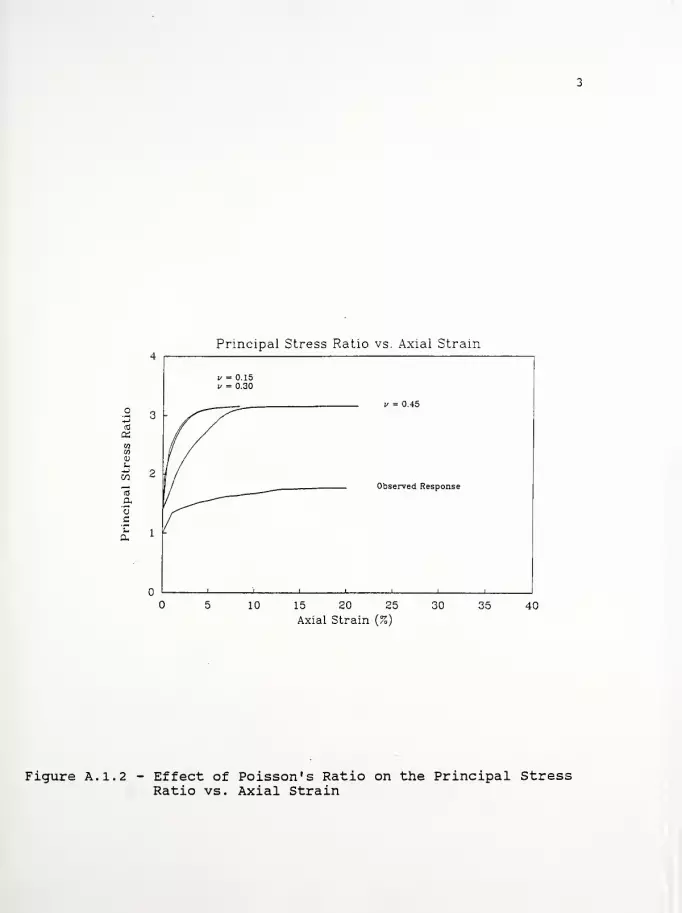
4Principal Stress Ratio vs. Axial Strain
v = 0.15V = 0.30
,/ = n is
3
2/ nhsprverf Rpspnnso
1
n I I i I i i i
10 15 20 25
Axial Strain (%)
30 35 40
Figure A. 1.2 - Effect of Poisson's Ratio on the Principal StressRatio vs. Axial Strain
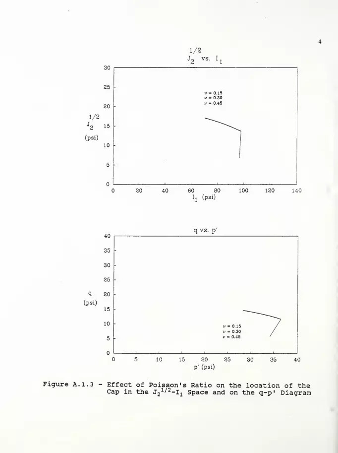
1/2J2
(psi)
30
25
20
10
20 40
1/2J2
vs. I
1/ = 0.15
i/ = 0.30
i> = 0.45
60 80
Ij (psi)
100 120 140
q
(psi)
40
35
30
25
20
15
10
5
10
q vs. p
15 20
P' (psi)
25 30 35 40
Figure A. 1.3 - Effect of Poisson's Ratio on the location of theCap in the J2 1/
^
2 ~ Ii
sPace and on the q-p * Diagram

A. 2 - Case 2

40
35
Principal Stress Difference vs. Axial Strain
C = 0.107
- Observed Response
C„ = 0.162
15 20 25 30Axial Strain (%)
35 40
40
35
30
£ 10
Excess Pore Pressure vs. Axial Strain
Observed Response
C„ = 0.163
15 20 25Axial Strain (%)
30 35 40
Figure A. 2.1 - Effect of the Compression Index on the PrincipalStress Difference and Excess Pore Pressure vs.Axial Strain

Principal Stress Ratio vs. Axial Strain
C„ = 0.162
Observed Response
10 15 20 25Axial Strain (%)
30 40
Figure A. 2. 2 - Effect of the Compression Index on the PrincipalStress Ratio vs. Axial Strain

30
25
20
1/2J2 15
(psi)
10
5 -
1/2Jq vs. I-
20 40 60 80 100 120 140
h (Psi)
q vs. p40
35
30
25
q 20
(psi)15
10
5
10 15 20 25
P' (psi)
30 35 40
Figure A. 2. 3 - Effect of the Compression Index on location of theCap in the J2 1//2-I i sPace and on the q-p 1 Diagram
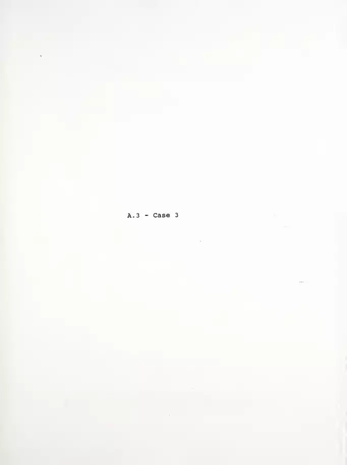
A. 3 - Case 3
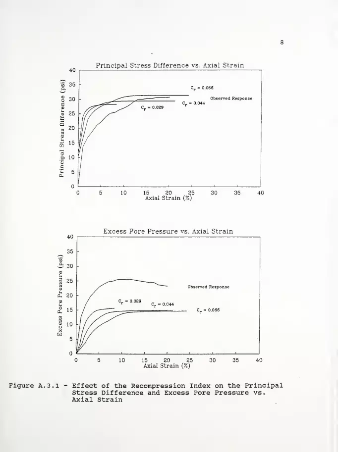
40Principal Stress Difference vs. Axial Strain
5 10
Cr= 0.066
Observed Response
15 20 25 30 35 40Axial Strain (%)
40
35
30
01
£ 20
a io -
Excess Pore Pressure vs. Axial Strain
Observed Response
15 20 25Axial Strain (%)
30 35 40
Figure A. 3.1 - Effect of the Recompression Index on the PrincipalStress Difference and Excess Pore Pressure vs.Axial Strain
Principal Stress Ratio vs. Axial Strain
Cr= 0.029 c
r= 0.044= C„ = 0.066
10
Observed Response
_i i i i_
15 20 25Axial Strain (%)
30 35 40
Figure A. 3. 2 - Effect of the Recompression Index on the PrincipalStress Ratio vs. Axial Strain

10
30
25
20
1/2J2 15
(psi)
10
20
1/2J2 vs. Ij
C^ = 0.066
40 60 80Ij (psi)
100 120 140
40
35
30
25
q 20
(psi)15
10
5
q vs. p
10 15 20P' (psi)
25 30 35 40
Figure A. 3. 3 - Effect of the Recompression Index on location ofthe Cap in the J2 1 -I
iSpace and on the q-p
'
Diagram
A. 4 - Case 4

11
Principal Stress Difference vs. Axial Strain
10 15 20 25 30Axial Strain (%)
35 40
Excess Pore Pressure vs. Axial Strain
15 20 25Axial Strain (%)
Figure A. 4.1 - Effect of the Pore Pressure Response Factor on thePrincipal Stress Difference and Excess PorePressure vs. Axial Strain
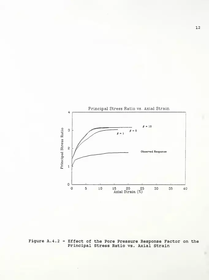
12
Principal Stress Ratio vs. Axial Strain
jr
/J = 10
Observed Response
1 !
-"""^/S = 1
fi= 5
I1
i
10 15 20 25Axial Strain (%)
JO 35 40
Figure A. 4. 2 - Effect of the Pore Pressure Response Factor on thePrincipal Stress Ratio vs. Axial Strain
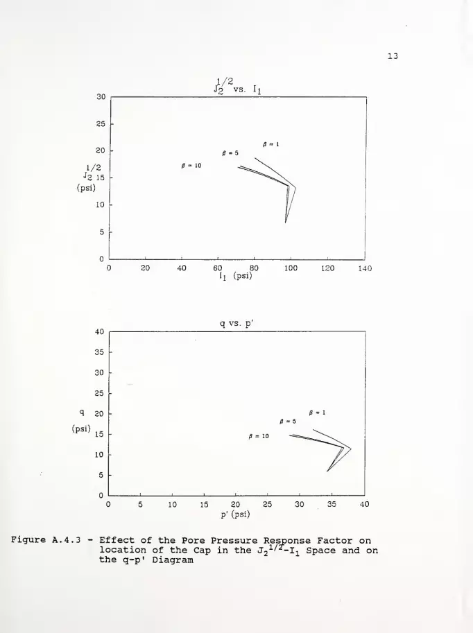
13
(psi)
60 80II (psi)
120 140
40
35
30
25
q 20
(PS1)15
10
5
q vs. p
-
-
= 5
= 1
= 10 -*S=B-^1
11 1 1
/10 15 20 25
P' (psi)
30 35 40
Figure A. 4. 3 - Effect of the Pore Pressure Response Factor onlocation of the Cap in the J^l *i Space and onthe q-p" Diagram

A. 5 - Case 5

14
40Principal Stress Difference vs. Axial Strain
<p = 30°
Observed Response
p = 24°
15 20 25Axial Strain (%)
30 35 40
Excess Pore Pressure vs. Axial Strain
15 20 25Axial Strain (%)
Figure A. 5.1 - Effect of the Angle of Internal Friction on thePrincipal Stress Difference and Excess PorePressure vs. Axial Strain

15
Principal Stress Ratio vs. Axial Strain
15 20 25Axial Strain (%)
Figure A. 5. 2 - Effect of the Angle of Internal Friction on thePrincipal Stress Ratio vs. Axial Strain

16
(psi)
40 60 80
h (psi)
140
q vs. p
15 20 25
P' (psi)
Figure A. 5. 3 - Effect of the Angle of Internal Friction onlocation of the Cap in the ^"^"li Space andthe q-p' Diagram
on

A. 6 - Case 6

17
60
a 50
Principal Stress Difference vs. Axial Strain
Observed Response
10 15 20 25 30 35 40Axial Strain (%)
60
cr 50
u 403
&h 30
Excess Pore Pressure vs. Axial Strain
Observed Response
USR = 0.22
USR = 0.31
15 20 25Axial Strain (%)
30 35 40
Figure A. 6.1 - Effect of the Undrained Shear Strength Ratio onthe Principal Stress Difference and Excess PorePressure vs. Axial Strain

18
Principal Stress Ratio vs. Axial Strain
usr = 0.43
5
Observed Response
10 15 20 25 30 35 40Axial Strain (%)
Figure A. 6. 2 - Effect of the Undrained Shear Strength Ratio onthe Principal Stress Ratio vs. Axial Strain
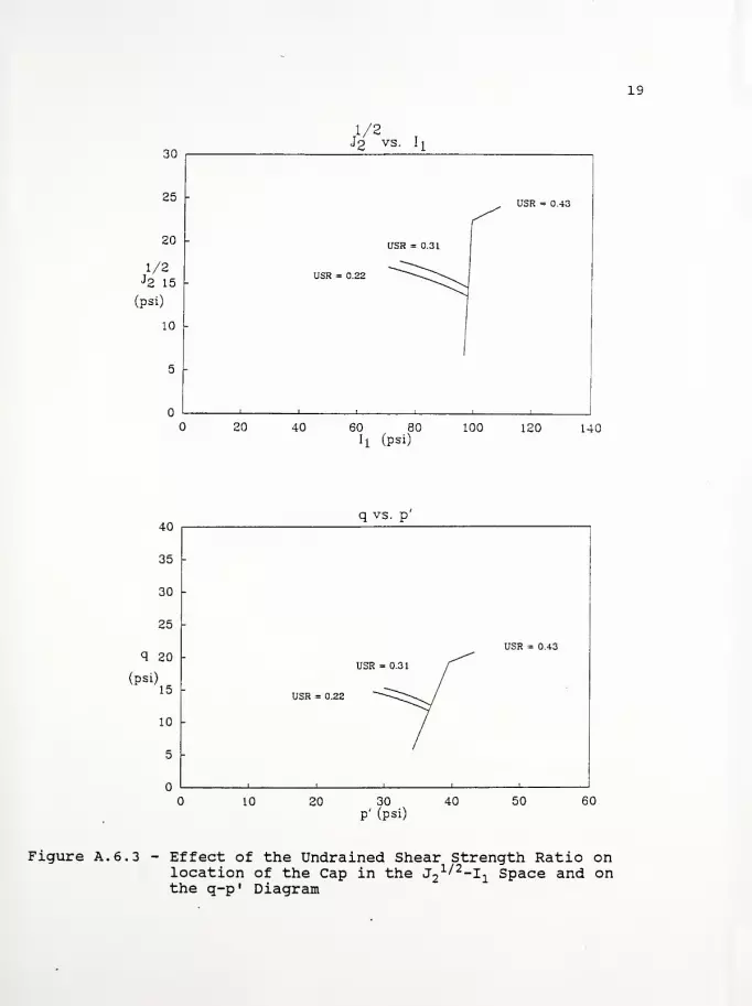
19
30
25
20 -
1/2J2 15
(psi)
10
1/2J2 vs. I
x
-
USR = 0.43
-
USR = 0.31
USR = 0.22
i i
20 40 60 80 100 120 140
h (psi)
40
35
30
25
q 20
(psi)15
10
5
q vs. p
10 20 30
P' (psi)40 50 60
Figure A. 6. 3 - Effect of the Undrained Shear Strength Ratio onlocation of the Cap in the J2 1/
' 2 ~I 1 sPace and onthe q-p 1 Diagram

A. 7 - Case 7
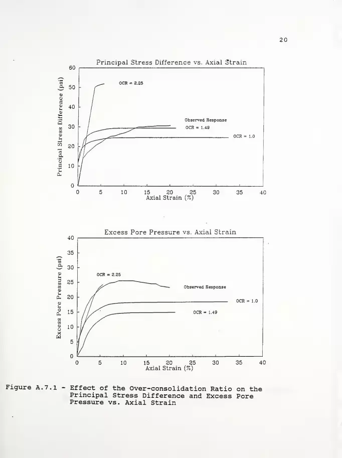
20
60Principal Stress Difference vs. Axial Strain
Observed Response
OCR = 1.49
10 15 20 25 30 35 40Axial Strain (%)
Excess Pore Pressure vs. Axial Strain40
35 -
30 -
25
0- 20
0. 15
01w
u 10Xw
-
OCR = 2.25
jT Observed Response
- /OCR = 1.0
-/^~~~~
OCR 1 10
'iii i i i
10 15 20 25Axial Strain (%)
30 35 40
Figure A. 7.1 - Effect of the Over-consolidation Ratio on thePrincipal Stress Difference and Excess PorePressure vs. Axial Strain
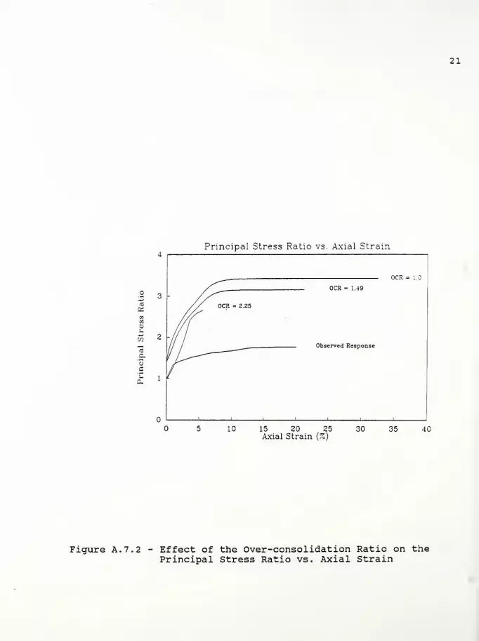
21
Principal Stress Ratio vs. Axial Strain
OCR = 1.49
Observed Response
10 15 20 25 30 35 40Axial Strain (%)
Figure A. 7. 2 - Effect of the Over-consolidation Ratio on thePrincipal Stress Ratio vs. Axial Strain

22
60
50
u 2vs. h
-
40 -
1/2J2 30 OCR = 2.25
(psi)"1
20OCR = 1.49
OCR = 1.0 —•i
10
n i i i
1
\
20 40 60 80 100 120 140 160lj (psi)
40
35
30
25
q 20
(psi)
15
10
5
q vs. p
-
-OCR = 2.25
-
OCR= 1.49 /OCR = 1.0 N.
/
-
i
120 40
P' (psi)
60 80
Figure A. 7. 3 - Effect of the Over-consolidation Ratio on locationof the Cap in the J2 1//2
~li Space and on the q-p 1
Diagram
APPENDIX B
Computer disk with input data files
APPENDIX C
List of References
LIST OP REFERENCES 2 3
Holtz, R.D., and Kovacs, W.D. (1981), An Introduction toGeotechnical Engineering , Prentice-Hall, Inc., New Jersey, 733
pp.
Huang, T.K., and Chen, W.F. (1990), "Simple Procedure forDetermining Cap-Plasticity-Model Parameters," Journal ofGeotechnical Engineering , ASCE, Vol. 116, No. 3, pp. 492-513.
Huang, T.K., and Chen, W.F. (1991), "Embankment Widening andGrade Raising on Soft Foundation Soils: Computer ProgramImplementation," Report No. CE-STR-91-3 , School of CivilEngineering, Purdue University, West Lafayette, Indiana,January, 244 pp.
Huang, T.K., Chen, W.F., and Chameau, J.L. (1990), "TheApplication of Cap-Plasticity-Model to Embankment Problems,"Report No. CE-STR-90-21 , School of Civil Engineering, PurdueUniversity, West Lafayette, Indiana, 37 pp.
Humphrey, D.N. (1986), "Design of Reinforced Embankments,"Report No. JHRP-86-16 , Joint Highway Research Project, Schoolof Civil Engineering, Purdue University, West Lafayette,Indiana, October, 423 pp.
Kulhawy, F.H., and Mayne, P.W. (1990), "Manual on EstimatingSoil Properties for Foundation Design," Research Project 1493-6, Prepared for Electric Power Research Institute, Prepared byCornell University, Geotechnical Engineering Group, Ithaca,New York, August.
Ladd, C.C., Foote, R. , Ishihara, K., Schlosser, F., andPoulos, H.G., (1977), "Stress-Deformation and StrengthCharacteristics," State-of-the-Art Report, Proceedings of theNinth International Conference on Soil Mechanics andFoundation Engineering , Tokyo, Vol. 2, pp. 421-494.
Ludlow, S.J., Personal data base - "Engineering Properties ofSoils,".
Ludlow, S.J., Chen, W.F., Bourdeau, P.L., and Lovell, C.W.,(1991) , "Interim Report: Embankment Widening and Grade Raisingon Soft Foundation Soils: Example 1 - Indiana State Route 55over Turkey Creek in Lake County, Indiana," Report No. JHRP-91-18 , Joint Highway Research Project, School of CivilEngineering, Purdue University, West Lafayette, Indiana,December, 56 pp.
Nwabuokei, S.O., (1984), "Compressibility and Shear StrengthCharacteristics of Impact Compacted Lacustrine Clay," Ph.D.Thesis, Purdue University, West Lafayette, Indiana.

Appendix C:
Interim Report: "Embankment Widening and Grade Raising on SoftFoundation Soils: Example 1 - Indiana State Route 55 overTurkey Creek in Lake County, Indiana," Report No. FHWA/IN/JHRP- 91-18 , 56 pp.
JOINT HIGHWAY RESEARCH PROJECT
FHWA/IN/JHRP - 91-18
Interim Report
Embankment Widening and GradeRaising on Soft Foundation Soils
Scott J. LudlowWai-Fah Chen
Philippe L. BourdeauC. William Lovell

Interim Report: "Embankment Widening and GradeRaising on Soft Foundation Soils:
Example 1 - Indiana State Route 55 overTurkey Creek in Lake County/ Indiana"
by
Scott J. LudlowGraduate Research Assistant
Wai-Fah ChenProfessor of Civil Engineering
Philippe L. BourdeauAssistant Professor of Civil Engineering
and
C. William LovellProfessor of Civil Engineering
Joint Highway Research ProjectHPR 2031
Project No.: C-36-36UFile No. : 6-14-21
This study is proposed to be conducted by
the Joint Highway Research Project
in Cooperation with
the Indiana Department of Highways
and the
U.S. Department of TransportationFederal Highway Administration
The contents of this report reflect the views of the authors whoare responsible for the facts and the accuracy of the datapresented herein.
Purdue UniversityWest Lafayette, Indiana 47907
Date: December 23, 1991

TABLE OP CONTENTS
Page
LIST OF TABLES
LIST OF FIGURES
APPENDICES
APPENDIX A -
APPENDIX BAPPENDIX C
Example 1 - Indiana State Route 55 over TurkeyCreek in Lake County, IndianaA.l - Rational for estimating cap/soil model
parametersA. 2 - Case 1
A. 3 - Case 2
A. 4 - Case 3
A. 5 - Case 4
A. 6 - Case 5
A. 7 - Case 6
A. 8 - Case 7
A. 9 - Case 8
A. 10 - Case 9
A. 11 - Case 10A. 12 - Case 11A. 13 - Case 12Computer disk with input data filesList of References
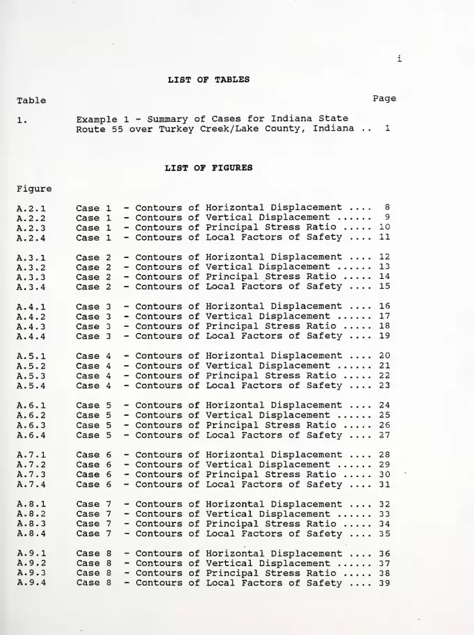
LIST OP TABLES
Table
1. Example 1 - Summary of Cases for Indiana StateRoute 55 over Turkey Creek/Lake County, Indiana
Page
LIST OF FIGURES
Figure
A. 2.1 Case 1 - Contours of Horizontal DisplacementA. 2. 2 Case 1 - Contours of Vertical Displacement ..
A. 2. 3 Case 1 - Contours of Principal Stress Ratio .
A. 2. 4 Case 1 - Contours of Local Factors of Safety
A. 3.1 Case 2 - Contours of Horizontal DisplacementA. 3. 2 Case 2 - Contours of Vertical Displacement ..
A. 3. 3 Case 2 - Contours of Principal Stress Ratio ,
A. 3. 4 Case 2 - Contours of Local Factors of Safety
A. 4.1 Case 3 - Contours of Horizontal DisplacementA. 4. 2 Case 3 - Contours of Vertical Displacement .,
A. 4. 3 Case 3 - Contours of Principal Stress Ratio ,
A. 4. 4 Case 3 - Contours of Local Factors of Safety
A. 5.1 Case 4 - Contours of Horizontal DisplacementA. 5. 2 Case 4 - Contours of Vertical Displacement ..
A. 5. 3 Case 4 - Contours of Principal Stress Ratio .
A. 5. 4 Case 4 - Contours of Local Factors of Safety
Case 5 - Contours of Horizontal DisplacementCase 5 - Contours of Vertical Displacement .
,
Case 5 - Contours of Principal Stress Ratio .
Case 5 - Contours of Local Factors of Safety
Case 6 - Contours of Horizontal DisplacementCase 6 - Contours of Vertical Displacement .
,
Case 6 - Contours of Principal Stress Ratio ,
Case 6 - Contours of Local Factors of Safety
Case 7 - Contours of Horizontal DisplacementCase 7 - Contours of Vertical Displacement .
,
Case 7 - Contours of Principal Stress Ratio .
Case 7 - Contours of Local Factors of Safety
Case 8 - Contours of Horizontal DisplacementCase 8 - Contours of Vertical Displacement .
,
Case 8 - Contours of Principal Stress Ratio .
Case 8 - Contours of Local Factors of Safety
A. 6.
A. 6.
A. 6.
A. 6,
A. 7.
A. 7,
A. 7,
A. 7,
A. 8.
A. 8.
A. 8,
A. 8,
A. 9.
A. 9.
A. 9,
A. 9,
9
1011
12131415
16171819
20212223
24252627
28293031
32333435
36373839
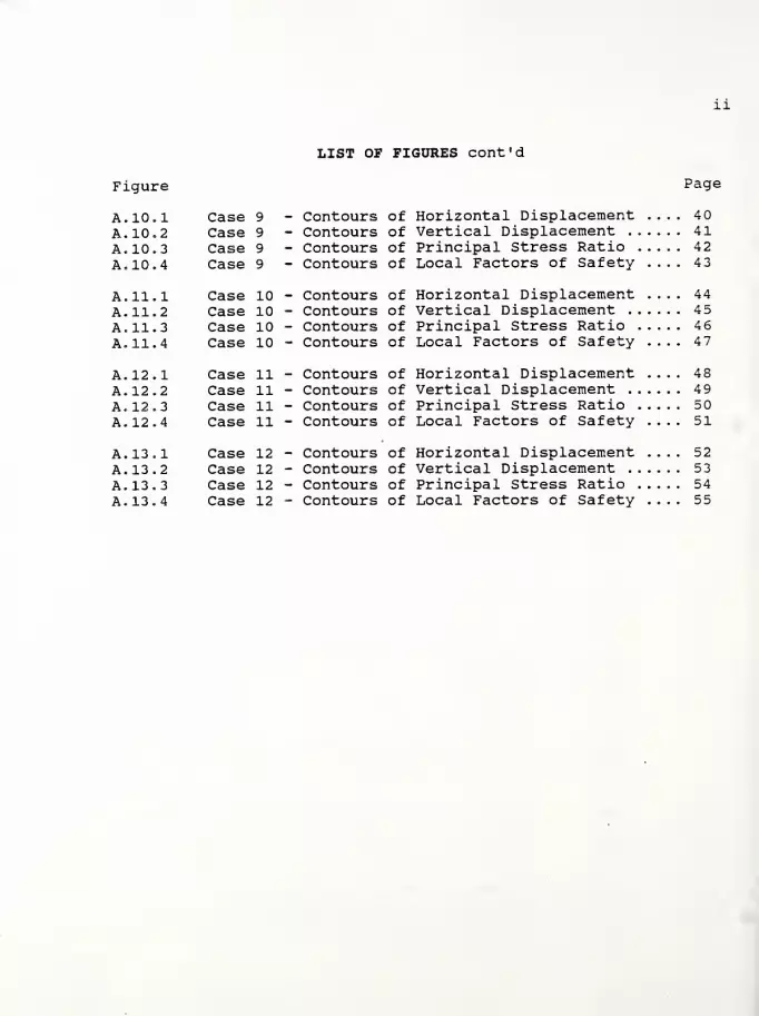
LIST OP FIGURES cont'd
Figure
A. 10 .1 Case 9
A. 10 2 Case 9
A, 10 3 Case 9
A, 10 4 Case 9
A. 11 1 Case 10A. 11 2 Case 10A. 11 3 Case 10A. 11 4 Case 10
A. 12 1 Case 11A. 12 2 Case 11A. 12 3 Case 11A. 12 4 Case 11
A. 13 1 Case 12A. 13 2 Case 12A. 13 3 Case 12
A. 13 4 Case 12
Contours of Horizontal DisplacementContours of Vertical Displacement .
.
Contours of Principal Stress Ratio ,
Contours of Local Factors of Safety-
Contours of Horizontal DisplacementContours of Vertical Displacement .
.
Contours of Principal Stress Ratio ,
Contours of Local Factors of Safety
Contours of Horizontal DisplacementContours of Vertical Displacement .
,
Contours of Principal Stress Ratio .
Contours of Local Factors of Safety
Contours of Horizontal DisplacementContours of Vertical Displacement .
.
Contours of Principal Stress Ratio .
Contours of Local Factors of Safety
Page
40414243
44454647
48495051
52535455
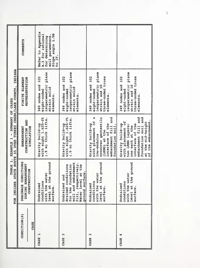
X•hh • ac73 co oi co m
coEH2
c c c u •
CD -H 0) Hft-rl C 4-1
d<+j -h <d aS < Ifl £ £ rHs u u id oi
ocj
0) u cjj vi jj <n to
o a) an mh -a en >a) ^h ft-n«4H ^-Hcu . o o ^h o
<a <C 14-1 ai co 4-i
5 to 1) CD CD
Maz
c c C CEh 2s o
CN Ifl CN Ifl CN Id CO CN Cfl CO
O rH O rH O rH CO O rH CO
h ft H 04 rH ft 3 H ft 3S Eh rl UCd <C 73 O 73 73 O 4-> 73 O 00 4-1
>4H2Do
co cj
u< mo «:
j 9-i C -H 73 C -H 73 C --4 rH C --4 rH
Ed 2 ATI U-H ifl 73 14 -4 cd 73 U 73 cfl 73 U 73
Ed CD 4-> ^H fl) 4J rH CD 4-1 73 CD CD 4J 73 CD
Ed CO to 73 CI) • CO 73 CD O • CO 73 CD C 73 • CO 73 CD C 73 •
Kg 0) O £ CO CO CD £ CO CO CD O £ id O CO CD O £ cfl O cn
T3 C Hi 4J 73 C cfl 4J 73 C cd C 4-1 73 C cfl C 4-1
2 Oj Since 1 14 C c O 1 U C 1 c O 1 rl C 1 cH Edfa OS
c 4J u -h m C 4-) rd -rl CD C 4-> cd -4 0) CD C 4-> Ifl -rl 1) CD
x: ft fl £ x. a. <d £ x: ft cd <d £ x: ft co £cn oi o u cd CT> Oi O U CD 01 OlO tl w CD Oi Oi O u u CD
<* -rl 0) 4-> rH -J> -rl CO 4-> •-I >* -ri co 4-> x: H <* -ri co 4J x: Hro <D -H CO CD m oj -ri to CD O 0) --4 CD 4-> CD Cr,
(J) -4 CO 4-1 0)
o «>h Cd 4-> • 4J • CO CD 73 73 73OS CC Q <4-l CO <4H CO •-< C c ca ° 2 1 4-1 1 4-1 <4H -rl id 4-1 ifl cfl 4-1 4-1
2 a OllO <4H ftin it-i ft O -P 0) • ft O •• CD X. Ca jh
Eh 2 3 CM -rl 3 CN -rl 3 X X; rH rH 3 m cd x. rH f-t Oi CD
D Ed 2 2 OEd O H
1 VO ^ 1 >43 <-t 1 -P 0) -P rH -rl| 4J rl x: 4- fi -4 •H £w
r273 . 73 . 73 C 4-> CD •rl O 73 C CD 4-1 -rl O CD r2
X M Eh •-> rH ^ r(HJl| -t cd ox: 4-1 MH cn rH CD >1 4H mh cn X! C1 D 2 Eh < •rl O rl O -rl £ CO 0) 4-> •rl £ cfl 4J O 1 cfl
H 2 O i-5 3 4J -4 3 4J -4 3 CD 3 Oi 4-1 c 3 CD rH CO 4J c 73 X.iH < D D xi £ ja xi x: x: J3 Url 4J CD C X. O CD C O •rl £
o: CO EC E 0>4J (3>4-> CO 3 C cfl CJ <D •rl cfl CJ JS O 01 -rl £ CD
32 S Eh M >i-H >1-r| >irH 73 CD CO £ 4-1 >irH 2 O cfl JsCd CO CO 4J 0) >» P CD — 4J ft O > — IH i2 (0 4-1 ftS Cfl 4H CD 0)CLi O 2 -rl £ •rl £ -rl £ O CJ 14 C 73 rl rJ 0) 14 C 73 x: x:~c o > X. > x: > X. 1 3 2 CD cfl a > rS CD cfl C 4-1 4-1
AC to o rj 4-i in cd 4-> m (0 4J 3 C X -U X) 3 id 4J O CD 4J XI 3X LO -1 -H • rl -rl • M-HO Orl C £ O M -rl 3 C C £ O 4J 4HEd
Cd• EhH D
cj 3 — CJ 3 ~ B3HC- •r| CD 4-1 CJ 3 -P O -rl CD <4H Ifl O
o co 73 4-> a 73 73U (X
2 Eh c ca c c >i CD C cJ O 2 3 c o a) ^ x: 3 3(0 a HH»
C-l ^* *5S o o
-rl £ CD -P O O< H M -rl 4J 3. > u rl
H *C* i_i U Cn -p cd c -rl V 0) U Oi -1 Oi
EH Q 5 Eh <D 73 -4 73 cd 4J CO O CD 0)
co00 9 4-1 CU CO CXI O cfl -P CD 4J CD
<d x: cd C 3 £ CD rH <4H co x: cd x:rt! ° *. « CO 3 4J 0) ft 0) rl 01 3 -P CO 3 -P
Z M M H 73 C 73 O MH 0) > 3 73 C 73 Ctt, CD CD 4- • CD 73 CD CD CO CD O CD -P • CD O CD 4-1 •
M C -rl XI id CD C 73 CD C u ^ c -ri x: id <D c -ri x: cd id
Q •-4 4J 4J U -ri cd x: co 73 •r| 4-) JJ CJ •-4 4-> 4-1 OZ 2 H ><
K Q
Id -4 rH (0 id c 4-i - rl C Ifl -rl ft Cfl (0 -r4 rH Cfl
M u t> x; cu <«h rl -rl rH rH CD 3 U 73 XI CD >4H V4 73 X; CD 4H73 C 4J > 14 73 fl rl -rl rH 4J O 73 C 4J > U 73 C 4-1 > 14
« C O -4 (D 3 C rl O •rl Cfl 14 C O --4<l) 3 C O -4 CD 3
oE*
Q D O S ^ CO D 73 IH CO <4H S Oi D O 3 rH ffl D O 3 rH cn
CO
Zo aM COEh n.M oQ2O rH CN CO «»
CJCdCO
aCO
EdCO
EdCO
< rt rC <CJ CJ CJ o

in p3 •-. 4J CN <4H rH 0J VJ
g p •» oj p x: • 1 x; oj O5 P T3 MH 3 D>vO O 0) u P JZ ^ jj >4-l
a) >i u >n nj oj -h h tn to oi id *jh :CO A rid) ^ in Z 0) id > c P -HO •-J pEhZ M o okn oj x; >*h "O >i O O >4-l Id U U <H id ft
0>73 3 X • rH . x; • C rH ~H OOP rH 0) •
w C 0) H P P —a n p p p fl oj O OJ P u p <d •rl O OJ
§ •rl +J OJ C c ~ c c x; > p x: id m • P OJ 0) C 73 g >: rH
o N C 0) tH Q) o>id in t?m J) -y ^ --h P XJ id T3 c >i o a> c -H OJ -I
•rl 3 (d X g c o>ocig'Og-~P U -rl 3 0) a) id id g 3Sh w iJ Ow -U
r-l U -P ±> -X •H -~ C -H 5 5 -H go Id P rH ~i lO >;
~H -p ^H CO C cg-H^4JCC3m oj HftO 0*1 oj '-j c -j • CD
jQ 01 3 -C 4-1 <fl OJ CO g m rd rd «i-h ft •rl 0) 01 — 1 -r| o o oj id rH OJ 4-)
<d c E3 jj mh ja T3 rH -H .^ X) XI "O -CD g O C P -o id Z P X 73 •H tO
4J -H -H -H g •ri .(dmxggcpcTiOJ •Hxom o rH a c g c O <d 0)
z<
w o to 3 h a> Snij .0J0J0Jid>w^>H W OJ u g Oi J -rl 0) id to O CT>
0) 1) p OJ OJ pc c to c c c 01 c
QzH
H ZZ O
>* <d co id g to oj o> oi CN (d co id g 01 0) Oi Oi
O ^H rH rH ^lOlCl) gCCrH ft O C l-l 5 -H -rl
o -> l-H rH fi Oi OJ e c cH ft r4 ft rH ft O c u J* "rl -H
S Ehw <J HW Z« co£h Hm 04Z &
mh -ri +j ecu U-l --1 4J C C 01
•a o T3 O UU01 idOJ-H 73 O 73 O U P 01 id CD —1
5h
M Z
C -H 73 C -rl-OOJO OJXlT3n3 C -rl 73 C -H 73 0) 0) X 73 aiflTJ 1J-H (dTJ tl-rlQj+JrHX: g-rl ^ Id 73 U -H Id 73 U -rl Oj P r-4 X g —1 in
0J P rH OjprH ca(dP0J3 OJ P rH OJ P rH to id 4J CD 3oi T3 ai o • 01 T3 OJ • -H OJ 01 73 OJ O • 01 73 OJ O • •rl CD
a) o e to tn 0JOgtQ0101pMHrHOT3 OJ o g to to OJ O g to 01 10 4-1 4-1 HOD73 G <d P "OC(d p -H -rl o (d 4J <d 73 C id P 73 C (d P •rl -H id p id
1 hCC 1 Sh c c 01 c c u O 1 u c c O 1 u c c CO c C rl
5 H
C 4J Id -1 OJ c p <d -H o) >i--h o) -H h 0< C P Id -rl OJ c p id -ri CD >1-rl a —I P Oi
fe< 2 x ft a) e x;ft(dgrH poio xi ft id S x: ft id g rH 4J Oi oin 0^ In OJ r-OiOM0Jid0J<d-ri-HT3 en o> o u oj r» Oi O U 0) id oj n3 -rl -rl T3IT) -rl 01 4J rH Ol-J U^rl C£JJ ll ll C «* -H HUH 0! -rl 01 U H C X AJ P 14 Cn U -H gi gi ClOJ-HCQOJIdPCDOftld CO OJ -H 01 OJ n 0) -ri oi oj id p 01 o ft <d
p • <4H • p • HH O
go <4H 0] £ P 0) 01 >tH tO O P OJ CD
ai +j nj oi—
»
a p 1 p 73 pz ft in <4h h g en ft u id p M-i ft in 4-i ft u id 4-1 m
ix Eh ^ Z 3 CN -rl MH x c 3 IH IM -rl 3 CN —
1
3 O ^ UH —1
1 w Z g O 1 vD ^H H -H 1 -H 01 £ 1 H 1 >0 rH 1 -rl 01 x; 1 rH
Hg 73 • -~ • N O U P in 73 • 73 U p LO|oS HHi C g C) .rH rHrHftT3 C-rlCN^ HHi! •-I •-{ ft73 C -rl CN .*
gj X
2 *"H w* •H U ^"H •rl id c o 3 vo o •rl O -rl Id C O 3*Z £t J 3 4J -H -H H -pH 3 C P Id -rl . -r| 3 P -rl 3 C P (d •H —
1
a 2 d X x x p ^p xi J3 -rl C P T3 rH XI xi s. x; X "rl C P 73 rH X(Q 5 g a>-p o >m nj Oi 0) en • OJ P Olp Oi OJ Oi • O 0) ps £ h >,-rl 3 P 1 P >1-r| g C Oi 3 P C >1-H >1-r| g C 01 3 P cw S w 4J aj ^ in hh o oi PlH^-rlClHldOJ^- P OJ -^ 4-> U J2 -rl C P id CD r"*w w H S -P 1 H •rIOCC-rlprHOJg •H g •rl O C C —
1
P rH 0) gz > £ 01 in aj g > (d oj to to 3 P > X! > id 0) to 01 3 4J
•a"
. ino <d4->in c cn 73 73 U (dOJXtTJ-riCgxm id P in id OJ X 73 --I c g X ino u -h -o • c -h a) U XI g "rl Id O 'rl -rl • U -A • u x: g -ri id O -H •H
° o
O 3 — cj n id 3 X CJPCD3V4OC001 — O 3 — O P OJ 3 in O CO 01 "
w a T3 73 73
. « Z Eh c c c cO Z 3 3 3 3M w M S 2t-t *5* -*2 5 o
Or-. H u u M u^ s ^ S H u en u en U Oi u o<
3 wQ «5 ph5: «r
~?! S; u
ai
pOJ
P OJ
OJ
P OJ
OJ
P OJ«C O ffl si (d x: id x: id x: fl x;H < "S« tn 3 -p to 3 P to 3 p to 3 Pz tw
W H o c T3 C 73 C 73 C5 S .. 0) OJ OJ P OJ O 0) P • OJ O OJ P • 0) O OJ P •
M "gz c-hj; <d ai a -ri x; id oj c -ri x; id oj c -ri x; id oj
a *" z o5S°
•rH +J 4J O •rl JJ +J O •rl 4J JJ (J •H*)U Oz id -^ rH <d (d -H rH Id rO -rH rH (d Id -rl rH rd
M H 05w
§ QV4 T3 x: OJ M-i Vj "O X! OJ MH Sh 73 £ 0) mh U 73 X 0) mhT3 C P > U T3 C P > H 73 C P > Sh 73 C P > Ij
OS C -t OJ 3 C O -^ 0) 3 c o -ri a) 3 C O -rl OJ 3o D D O 3 H n D O 3 rH CD 3U3H 11 D O 3 rH CQ
wzo wl-H wEh <MQ
uZo in vO r» CO
u wen
Edw
< < < <o o o o

tj X id
r- G P m "fr r~id en M-l
o> n e 0) 0) 0) 01 CD CD OcoE-i
z
to id (1) tj 0) ft CO ft CO
id a) -h w CD id >i id >i id cO X P P 3 O p • O +J • U
co rd o) 01 CO H .
eg on n CO O U 0) 3 O U CD 3 O U P CD
§ P X TJ CD u • P O -1 rH P O rH rH 4-1 O Id rH
oo
4J CD X > 01 TJ <H -H 3 HH -H 3 MH U -HJh C P -H 4J d) U P T3 Jh P TJ )H 4-1
id p -h en p CD -H id P X O id p x o fd p ft xHbKCU g 4-1 rH ft4) e rH ft CD g rH ft t( CD
H 111 H 111 (1) id -h •H 01 P H CD P •H CD O PEUTJ llW 14 TJ g OOfl g O TJ g O OH X C+HH id •H X 0) C •H X CD C -H X C CD
<z<Haz
CO <D 3 CO 0) ft a co at Di id co a) en id co CD -h en
01 01 CD CD
c c c cEh Z CN <d CN Id CO CN id CO CN Id CO
z ofa M
o ^ O rH CO O rH CO O rH CD
rH ft •H ft 3 rH ft 3 rH ft 3JS H u u ufa <CJ E-i
TJ O T3 OOP TJ O CD P TJ OOP
™zfa §
o °
C -H TJ C HH C -H rH C HHw z id TJ U -H (d TJ H TJ (d TJ >H TJ id TJ U TJ
fa CD P rH CD P TJ 0) CD +J TJ CD CD 4J TJ CD
H CO CO T! CD • CO TJ CD C TJ • CO TJ CD C TJ 01 TJ CD C TJ •
E-i W CD 6 m to CD O £ id CO CD O g id O CD CD O g id O CD
(H PS TJ C id P TJ C id C +J TJ C rd C J-> TJ C <d C 4J
Z 0< 1 Vi c c 1 U C 1 C O 1 MC 1 c 1 Jh C 1 Cr .
fa OS
C P id -H (D C P rd -H CD CD C P id -H CD CD C 4-> id -H CD CD
fa 3 x ft td s x; ft m a) e x; ft id cd g Xi ft id CD gOS cr. en o u cd <T> Cn O U U CD cti en o in u CD cri en o u u cd
IS
•* -H tO 4-> r-4 <* -H CO JJ Xi rH <* -H CO P XI rH <* -H CO 4-1 X rHn cd -h co oi ro CD -H CD P CD n cd -h co -p CD CO CD -H CO 4-) CD
P • td <u ^i TJ TJ id TJM-i cn C O rH C C • cQ
I P <4H CD *- -H MH id id p M mh id
z ftin mh ft O > O CD >M ft O •• CD x; c ft O CD
i M En **" Z 3 CN -H 3 O 3J O 3 0) CD X! rH rH Cn CD 3 X rH rH1
fa Z 2 O 1 ^O -H 1 P 3 S <d P C 1 -p U JC 4J r-i -H -H g IP 4-> rH -H
H £ SoS •o • TJ C X 'u C O TJ C CD P HO 11 J2 TJ C -HOPS rH rH X rH CD CO ~- U CD -H rH CD >i MH mh co x; c rH CD MH M-l CO
H 5 2 H rf •H O •H g 3 (DSP h g id p o i id •H g CD O3 H Z rl J 3 P M 3 CD rH CD P M <d 3 CD rH id P C TJ X 3 CD x; PCOj ^ 2 3 XX X! X O 3 rH C C TJ XI O CD C O -H g X O 4J CD C OS ps 03 2 X Cn+J id tj -h -h td c id cj x; o CD -H g CD id O CD -H? u s £
* >1-H >irH OP & 3 >irH s o id g P >trH 4-> Id g PS > W £ CO P 0J — -p a g x cd s o +j fts id mh M id CD CD 4-> ft id m-i M id
fa °w W •h £ h i cd x; CD MH • -H £ CD JH c tj x; x; H U C TJzo > X! > x; x; p p rH > x; cd id c p U > x: o cd id c
-a ^ id p in id p en o cd tj -h cd P O CD P X 3 id P 3 4J X 3. in o U -H • u -h -h cd p x; c o Jh -H 3 c c g O P M-l H -H s C S
° o
O 3 «- c93x:oiidpidca O 3 P O -H CD M-l Id O 3 X -H CD M-l
co TJ TJ TJ TJ
. PSZ E-i
o z C3
c3
c3
c3
rtfa
M S s*Eil ^ *5S 5 o
O On E-1 u u U u
3gM * LJQ Z Sz a gO CO ^
u enCD
4J CD
U Oi0)
P CD
in enCD
P CD
U cnCD
P CDid x: id X! id x; id x;h < CD 3 4-> co 3 P co 3 p CO 3 4J
z
DRAINAGE DURING
E
const:
TJ c TJ C TJ c TJ C< <D O 0J P • CD O CD P • CD O CD P • CD O CD P •
M c -h x <d <d c -h x: id cd c -h jz id cd C -H X id CD
a •H 4-> P •H +J 4J O •H +) +J O •H 4-> P Oz Cd -H r-l Id Id -H rH id Id -H rH Id rd -H rH id
M 1-1 T3 XI CD M-l U TJ XI CD •« U TJ X! CD MH W TJ X CD MHTJ C P > >H TJ C P > Jh TJ C P > 1H TJ C P > in
OS C -H CD 3 C O -H CD 3 C O -H CD 3 C O -H CD 3ofa
D O 3 •-* CO D o 3 rH m D O 3 rH 01 D O 3 rH 01
co
zo faM coH <M o
o rH CN
O <T> rH rH rH
ofaCO
faCO
faCO
faCO
< < < <CJ ° o o

APPENDIX A
Example l - Indiana State Route 55 over TurkeyCreek in Lake County, Indiana
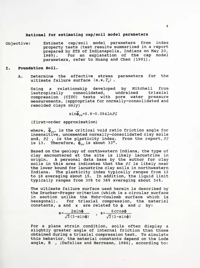
Rational for estimating cap/ soil model parameters
Objective: Estimate cap/ soil model parameters from indexproperty tests (test results summarized in a reportprepared by ETS of Indianapolis, Indiana on May 20,
1989) . For an explanation of the cap modelparameters, refer to Huang and Chen (1991)
.
I. Foundation Soil.
A. Determine the effective stress parameters for theultimate failure surface (a,K, Tc) .
Using a relationship developed by Mitchell fromisotropically consolidated, undrained triaxialcompression (CIUC) tests with pore water pressuremeasurements, (appropriate for normally-consolidated andremolded clays only)
sin<t>cv=0 . 8-0 . 094lnPJ
(first-order approximation)
where, ^cv , is the critical void ratio friction angle forinsensitive, uncemented normally-consolidated clay soilsand, PI , is the plasticity index. From the report, PIis 13. Therefore, 4^ is about 33°.
Based on the geology of northwestern Indiana, the type ofclay encountered at the site is likely lacustrine inorigin. A personal data base by the author for claysoils in this area indicates that the PI is likely nearthe lower bound for lacustrine clay soils in northwesternIndiana. The plasticity index typically ranges from 12to 18 averaging about 15. In addition, the liguid limittypically ranges from 30% to 38% averaging about 34%.
The ultimate failure surface used herein is described bythe Drucker-Prager criterion (which is a circular surfacein section unlike the Mohr-Coulomb surface which ishexagonal) . For triaxial compression, the materialconstants, a and k are related to <j> and c by:
a _ 2sin<t> 6ccos<{)
^(3-sin<t>) ''
v/3 (3-sin<t>)
For a plane strain condition, soils often display aslightly greater angle of internal friction than thoseobtained during a triaxial compression test. To simulatethis behavior, the material constants depend on the Lodeangle, 6 , (Dafalias and Herrmann, 1986) , according to:

a=a cg-(e,i7?) , K=Kcg(d,m)
and - „4„xm 3-sinpm= :—
r
3+sin<p
g(B,m)=- 2w1+/7?
Assume k=0 and a=0.209 from the above-mentionedrelationships
.
B. Determine the elastic and plastic parameters (Kmln ,A t ,Ae^v)
Km±n ; Because of the problems with the laboratorydetermination of undrained elastic modulus,^ , andbecause large-scale field loading tests are expensive, itis common to assume that£"u is somehow related to theundrained shear strength. For example, Bjerrum (1972)proposed that the ratio Eu/Su ranges from 500 to 1500,with Su determined by the vane shear test. However,there appears to be much scatter about the data. Anotherway to estimate ^is from !?u test results. Based onthe laboratory test results, the undrained elasticmodulus varies from 9.4 to 25 ksf^ In addition, theundrained shear strength ratio, Su/a ol varies from 0.2 3
(in Boring TB-4) to . 8 (in Boring TB-2) . Eu appears tobe considerably low and is likely a result of sampledisturbance. In addition, the Cutests were performed onsplitspoon samples. Based on the author's personal database, Qu tests performed on lacustrine clays from similardepths and moisture contents, in which a piston sampler(Osterberg type) was used, indicate Rvalues as high as150 ksf. Use an Eu of 90 ksf (Eu for soft claystypically ranges from 100 to 500 ksf) . Therefore,
p.
3 (l-2v)
^ = 300 ksf
assuming v is 0.45.
A t ,A e ; No laboratory consolidation tests were performed,Recall that:
C*'" 2.303 (l + e )
and
A -Cr
e 2.303(l+eJ
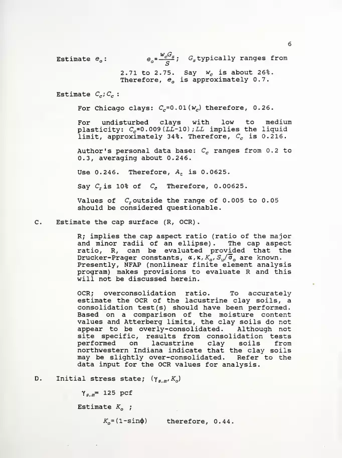
Estimate e : eo=Z2_£; Gs typically ranges from
2.71 to 2.75. Say wc is about 26%.Therefore, eQ is approximately 0.7.
Estimate Cc ; Cc :
For Chicago clays: Cc=0.01(wc ) therefore, 0.26.
For undisturbed clays with low to mediumplasticity: Cc=0 . 009 (LL-10) ; LL implies the liguidlimit, approximately 34%. Therefore, Cc is 0.216.
Author's personal data base: Cc ranges from 0.2 to0.3, averaging about 0.246.
Use 0.246. Therefore, At is 0.0625.
Say Cr is 10% of Ce Therefore, 0.00625.
Values of Cr outside the range of 0.005 to 0.05should be considered guestionable.
C. Estimate the cap surface (R, OCR)
.
R; implies the cap aspect ratio (ratio of the majorand minor radii of an ellipse) . The cap aspectratio, R, can be evaluated provided that theDrucker-Prager constants, a, k, Kq , Su/a Q are known.Presently, NFAP (nonlinear finite element analysisprogram) makes provisions to evaluate R and thiswill not be discussed herein.
OCR; overconsolidation ratio. To accuratelyestimate the OCR of the lacustrine clay soils, aconsolidation test(s) should have been performed.Based on a comparison of the moisture contentvalues and Atterberg limits, the clay soils do notappear to be overly-consolidated. Although notsite specific, results from consolidation testsperformed on lacustrine clay soils fromnorthwestern Indiana indicate that the clay soilsmay be slightly over-consolidated. Refer to thedata input for the OCR values for analysis.
D. Initial stress state; (y 3imiK )
y SiW= 125 pcf
K" =(l-sin<t>) therefore, 0.44

Ko=0. 44+0. 42 (PI/100) therefore, 0.49.
Say 0.5.
Pore pressure response factor; (P)
Say 10 for undrained conditions otherwise fordrained. Note NFAP does not account fordissipation of pore water pressure. The porepressure response factor is actually a ratio of theapparent bulk modulus of the fluids to the total(soil and water) bulk modulus.
gUndrained shear strength ratio; (--£)
For normally- to slightly over-consolidated clays:
^=0.11 +0.0037 (PI)
S°•=£ typically ranges from 0.16 to 0.6.
Based on Boring TB-1 (sample depth/ interval; 3 3.5to 35 ft), say 0.36 (first-order approximation).Another technigue in estimating the undrained shearstrength ratio is to use SHANSEP (Ladd etal)
.
II. Embankment Fill.
For a first approximation of the embankment behavior,assume the soil conditions of the fill are similar tothose of the foundation soil near the surface.

Figure A. 2.1 Case 1 - Contours of Horizontal DisplacementFigure A. 2. 2 Case 1 - Contours of Vertical DisplacementFigure A. 2. 3 Case 1 - Contours of Principal Stress RatioFigure A. 2. 4 Case 1 - Contours of Local Factors of Safety
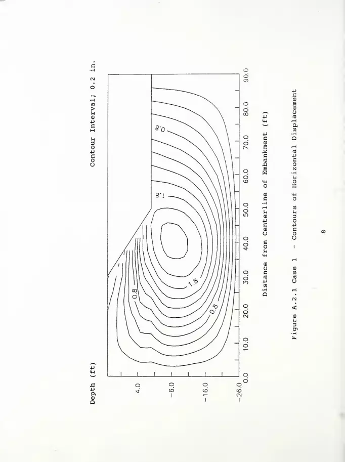
p
+J
aa>
Q
PCa
c gdcc P
a)
oS3
U-i r-{
*"'
10
P Ho c ao <D
1^ e ^H
X (0
c p(0 cJQ
o e•H
d PCO IM
IB
a) (Wc
o HrH loo P. P
in0) 3Pc P<D Cu
o CJ
dst-
e
i-l
1
u QJ
O c ta
o (0 «m p u
•H HD
CM
o <dCM GJ
o o
I
OCO
otoCM
I

-pM-l
si-po<<D
Q
Po cd00 P
Q)
Ea)
<h o""^ (0
p aq c wd 0) •Hrv g Q
c l-i
(0 (T3
ja Ue •Ho w P
d J-l
CD 4-1 a)
>0) <uc
o •HU)d M ^m (1) 3
Pc PQ) cU o
o ud g
u**
<uiH
a)
o (1)
q c en
o (0 <s
ro ptfl
o•H OJQ
(N
q <coCM a)
3
o oCD
OCD CO
CM

(0
>u0)
pcHS^
3OPcou
-p
5a)
Q
-P(0
lD Pa
CN <*-l tfl
I
s". '
CO
aJJ MC 4Jcu Wg
LO X rH
CNCO
c
XI
«3
a-H
gw c
•H<4-l M
lOa.
Csl <D CMlO C
•H.—
1
tfl
M M<D 3-P
in C +J
CN 0)
u
g
u
c
u1
LO0)
HCN <D
rO c Q]
(0 ia
+1 CJtfl
•H nin
QCM
CNCN <
CO
MD
od
od
od o
CN

>ua)
-Pc
u3O•Pcou
-pft0)
Q
mOJ
>.P0)
IW03
in PCO
CN <H <wr*. *-*
P 0)
c ha) oe +j
in X uCN c to
CO (0 fa
e f-i
w (0
u<« o
in JCN <D 4-1m C
•HrH tfl
^ nQJ 3P o
in C pCM cu c^ o
gou
u1
inCO
HCN (1)
ro c u(0 (0
p CJ01
•H -*
Q •
in CN]
CNCN <
a)
u
od
odCN
Figure A. 3.1 Case 2 - Contours of Horizontal DisplacementFigure A. 3. 2 Case 2 - Contours of Vertical DisplacementFigure A. 3. 3 Case 2 - Contours of Principal Stress RatioFigure A. 3. 4 Case 2 - Contours of Local Factors of Safety
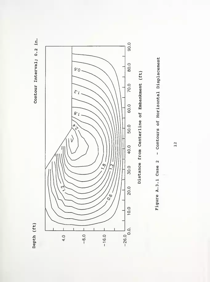
(0
>u0)
pc
Pa0)
Q
pc0)
eMcro
gW
o
C
d)
+Jc<u
ogo14
M-l
<D
cITS
-pen
pc0)
E0)
Ha
m
CPH
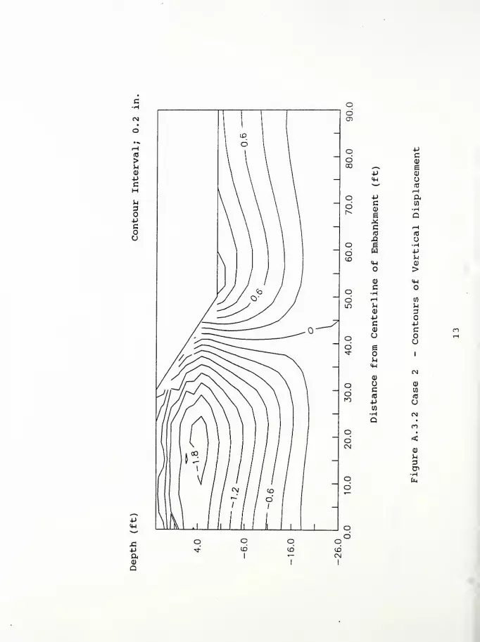
p4-1
XiPa<D
a
o pco Q)
GO ^ ep <D
<H U^^
(T3
i—
1
o P a6 c
a)
e•HQ
c r-
1
ITJ (0
XI uO g •H
d w pCD p
4-1 a)
o ><D 4-1
Co •Hd i—
1
wlo P u
a) apc pa> c
o u oud g
<*
p4-1
0)
1
o a>
c ao (0 (0rO -p u
m
o oto
oto
p3en

r-t
(0
>u<D
*iCHu
%pcou
-p
PaO
•HP<c
«—
^
alT> •PCN IW (0
r^ >~' 01
0)
P ^c 4Ja> CO
im ^ <H
c (0CN
(0 &<£> A -H
g oW<+-! b
a.mcn 0) M—
«
ID c•H.H 10
^ S-i
0) 3p
m c -pa) c
1
u1
CMin 0)
CN u a>
fO c CO
(0 (0
p u10
•H ro
a •
in mCNCN <
o6
CD
3
H
OCN
I

to
>uCD
-pcM^1
3opGoo
p«M
sipaa)
a
uu >+J
a)
<H(0
0*^ COin -pcn <h IUr^ w"
p wc Ma>
E pto s
£ idCNC£>
43t-
e rHW (0
<HJ
LO
CN CD (4-1
m C-HH tfl
J-l uQ) 3P
m C -p<D c
CN Ue
M-l
u1
ina)
CM
CN CD
m c 10
(0 CD
p UCfl
•H •*
Q •
m mCNCN <
a)
3
o6
o6
oa
odCN
I

Figure A. 4.1 Case 3 - Contours of Horizontal DisplacementFigure A. 4. 2 Case 3 - Contours of Vertical DisplacementFigure A. 4. 3 Case 3 - Contours of Principal Stress RatioFigure A. 4. 4 Case 3 - Contours of Local Factors of Safety
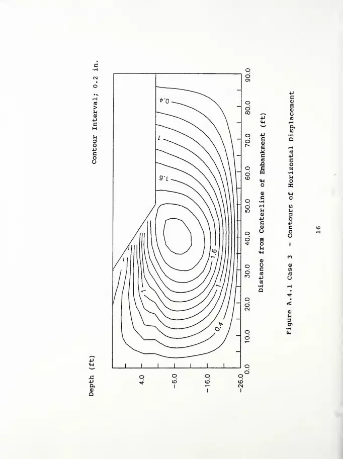
>uCO
4->
C
uao-pcoo
.p
aQ)
Q
pc
q ai
go QJoo ^^
P id<u H^~' a
mo p •H
din.
C(1)
g
a
« (0
c •P(0 CX5 o
q E Nd W •Hto fc
<HX
0) <Hc Oo •H
d .H nin ^ b
o 3+Jc *Ja; c
o uud e
«*
u
at
1
o u a)
c wd (0 (0fO P u
to
o oCO
I
qdodCM
I

c•H
(0
>u0)
pc
o
cou
•P
a)
a
p
PCa)
e
c(0
JQ
O
(1)
PCa>
ueou<w
<D
Uc(0
pCO
pcCD
eQ)
U(0>-{
a
(0
o•HPa)
>
O
10
3OPcou
u3

(0
>
0)
-pc
-paa)
a
Pm
«M>S aIf) •PCN <H CO
r* ** co
a)P mC pCD co
im * Hc (0
CN(0 aCOXI -HE oWiw ^1
O Phin
CN a) <Hm c O
.H CO
M ba> 3•P O
m c P0) c
CN uB
u1
in a)
m
CN CD
m c CO
(0 id
p oto
>H mQ •
in *r
CNCN <
ai
o6
o6
odCN
I

o-pcoo
si-paoQ
UJ>iPai
«H(0
m 4JCO
CN M-l IHr>. w O
4-> Wc hQ)
e +J
w ,* oCM c (0
<D (0
It)
o«H
m O JCN 0) <Hm c
•Ho
M wM uCO 3+J o
in c pCN c-* u
Iu
u1
ifi0)
PI
CN o a)fO c w
id (C+> uia
•H <r
Q •
in **
CNCN
0)
o6
od
od
odCN
I
Figure A. 5.1 Case 4 - Contours of Horizontal DisplacementFigure A. 5. 2 Case 4 - Contours of Vertical DisplacementFigure A. 5. 3 Case 4 - Contours of Principal Stress RatioFigure A. 5. 4 Case 4 - Contours of Local Factors of Safety

c•H
(0
>u<D+JcHu3O-PGOU
•P
4J
CCDo B
6 0)
00 *-«.
•P (0
<H fH**
+J •Ho c Q6 a)
r^ e H^ (0
c =P(0 C£1 o
o 6WIS]
•H6 MCD <H
S3
0) <Hc O
o •HH (0d U i-l
lO0) 3+J
e +J
0) c ou CN
O ud
1
U 0)
q c (0
o 10 (0
to03
o•H »H
QID
o<cd
CN a)
u
o qID
I
qCDCN
I

4->
4->
c<D
*-^ E+J <Uo 4-1
tri"
—
ffl
r*- H•P ac W<u -He Q^c H(0 (0
Ao i •H
4->o MCO 4-1 a
>0) 4-1
c•HrH to
M u0) a
O 4-1
C 4J
(1) cu
ueo 1
u4-1
*ro
<Do c nd 10 03
n uH C\3
aIT)
•
<0)
q 3LO B>
o olbCM
I
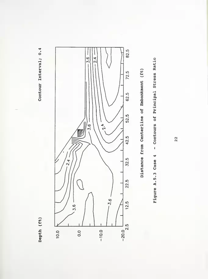
uoopcou
p
sip0)
Q
<0*-^. ap«w to>^
a)
p ^C p0) CO
e.* rHc (0
(0 aA H6 uW cH<w (-1
O a.
0) <wc»HrH en
^ u<D 3p oc p0) cU
ugo 1
MIH
*tf
u oc 10
fC (C
P u03
>H ro
Q •
in
<ou
en

us»o-pcou
p
•p
D
moo >i
4->
a)
(0^-* en
IT) PCN <H
o
P CO
c uQ) oe 4->
in Xc (0
CN (0 feto XI
e rHw 10
oH-l o
JmIT)
0)
c-H
<4-l
rH in
n MID 3P O
inco
Pc m
CN a <N]*£
u*4—
1
u
1*m 0)
CN Oc<0
a)
in
ro
p CJto
-H «*
Q •
m in
CN <CM
od
od
odCN
I
0)
u
•HIn

Figure A. 6.1 Case 5 - Contours of Horizontal DisplacementFigure A. 6. 2 Case 5 - Contours of Vertical DisplacementFigure A. 6. 3 Case 5 - Contours of Principal Stress RatioFigure A. 6. 4 Case 5 - Contours of Local Factors of Safety

>ua>
-pc
P
a
oCD
pcCD
o Ed <D
CO*~««. u-p to
U-l rH"
—
p -Ho c a6 or^ g H
X «c pA3 cA
offi •H
d P,to <H
XQ) 14-1
co •H
iH Uld P pm a) 3pB pai ca
o od B
p14-1
Q)
1
in
U <Do C CO
d (C (0
m p u•H <H
atD
o <dCN CD
p
•H
o En
d
o oto
I
oto to
CN
I
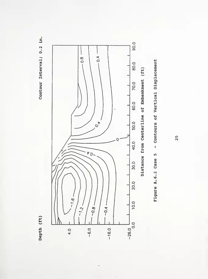
J3+J
ft0)
Q
odCD
-p
o c6 0)
ECO P a>
<w o>"' (0
4J ao c 09
d 0)
e Qc i-H
(0 (0
xt Oi °rto w P
d ^to <M 0)
>a) <wc O•Ho H to
d ^ Min 0) 3
+J oc pa) cu o
q eo
d1
*» u
0)
in
o 0)
o c in
(0 (0o 4->
10
u•H f\)
a•
o <dCNJ a>
oCD
qCO
o
I
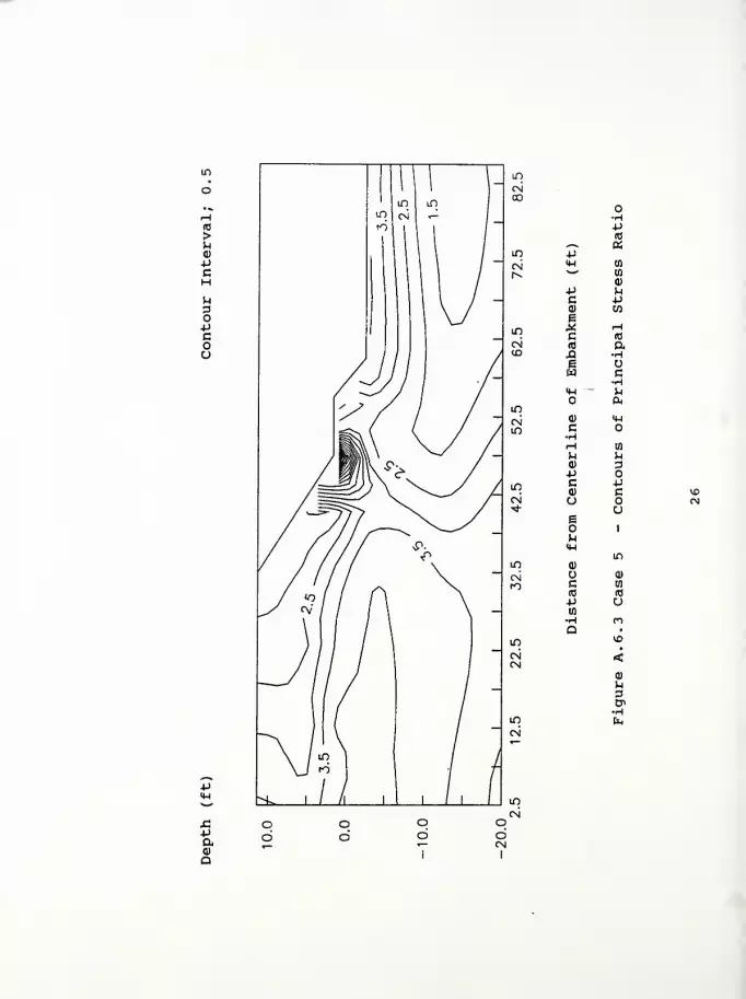
(0
>
0)
-pcMu
O-Pcou
-pa0)
a
P(0
^-^ ain PC\i <u nr^ w
p hc pa) en
Ein C
rH(0
<N (0 a<X> A •H
E ow c
•H<W Mo &
ina)
c
rH U)
M ^a) 3-p
in c p<u c 10
c\j u CN"*
e
u0-4
o1
IT)
in 0)
CNfO c (0
(0 (0
p U(0
•H mQ •
in VO
CN <CM
m
0)
3
H
od
od
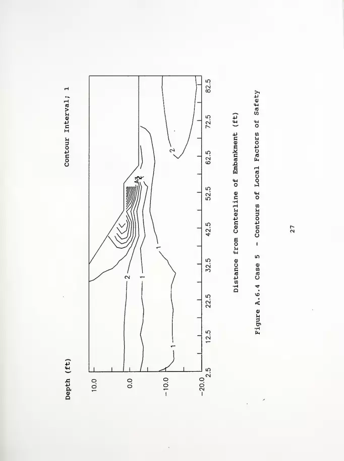
s:pa0)
Q
>i4J
0)
<ua
1 1
w4-1w o
p wC ha) os 4J
^ uc (0
«c En.qe rHw m
u<M o
Ja) <WG o
(H in
u VJ
«u 3uc +J
<u cu
ue
1
MIH
in
0)
O a)
C wid (0
=p uwH *a •
vo•
<0)
u3cr>
En
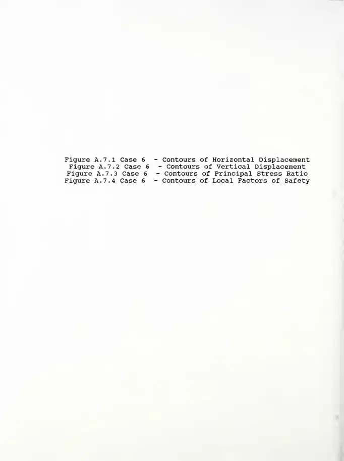
Figure A. 7.1 Case 6 - Contours of Horizontal DisplacementFigure A. 7. 2 Case 6 - Contours of Vertical DisplacementFigure A. 7. 3 Case 6 - Contours of Principal Stress RatioFigure A. 7. 4 Case 6 - Contours of Local Factors of Safety

PC
o Ed <D00 ^^ O
•P (0
<W ^H*'*
o P •HC Qd Q)
r- e r-l
X ro
c P(0 Ca O
o e Ndto U
OX
0) <4-l
c oq •H
d iH wLT> (-1 u
0) 3-P oc p(U cu oo u
d e•*
u<4-l
1
o c0)
d (C (0ro p
en
u-H HQ
t^
od <CN
0)
O fc
d
4J
CD
Q
O qd CDCN

c•H
-paQ)
Q
«Jo cd <D
CO -—
*
e-P <DH*•"" to
O 4JC
ad <D •Hh* a
C iH(0 (0
J2 oo e •H
W +)dJ-i
CD H-l a)
o >a) Mc
q -HM mo0)
M3
+Jc *j
(D c CTi
o (N
q ud B<«
n14-1
0)
1
u IDo c to
d (0 (0
ro -p a-H f\j
Qr«
O <dCM
•Ho E*
d
o qdo10CM
I

(0
>uQ)
-PC
uoopcoo
p
pft0)
Q
P(0
in 4J&
CN <W wr^ *
—
CD
P ^c +J0) COam x fH
CNCO
c(0
XJ •H
i ow cH<W h
ino &
cn a) <wm G
rH to
h uQ) 3P o
in C •p
CN a> c Ou o
um
Eo 1
u<u
in0)
VD
CN u 0)rO c 03
«c (0
4-> O(0H enQ •
in r-
CNCN
od
od
od
odCM
I
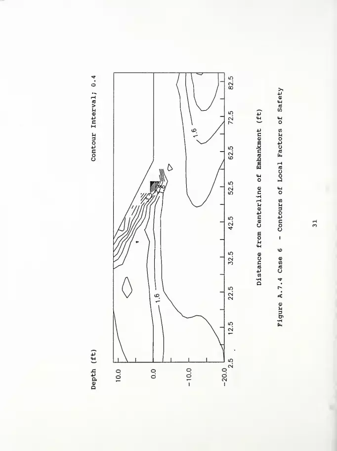
p
XIP&<D
Q
>i+J
(1)
4-1
id.—
*
m4->
M-l 4-1
**"
P to
C MQ)
e -p
X uc (0
(0 feXIe Hw (0
<H oJ
(1) <wc o•H(H (fl
H MID 3P OC P
co
ueo i
uIH
VD
<D
0)
c (0
(0 (0
p u(0
•H >*
Q •
r»•
<Q)
Ufl
CP

Figure A. 8.1 Case 7 - Contours of Horizontal DisplacementFigure A. 8. 2 Case 7 - Contours of Vertical DisplacementFigure A. 8. 3 Case 7 - Contours of Principal Stress RatioFigure A. 8. 4 Case 7 - Contours of Local Factors of Safety

uao-pcou
APaQ
o6en
pc(1)
o ed aCO +T
«H i-H
^~"
CO
P •Ho c Q6 0)
l*- e -HX (0
c -p10 cA
o -Hd M(0 IH O
sa) 0-1
co •H
tod M um a> 3P oC *J(1) CCJ
o ud g
u
0)
1
u CDo c en
o (0 id
ifj pa
u•H Ha
CO
o <d(N Q)
M3&•H
O fa
d
o oto
I
od CD
I
-p
jsp0)
Q
+J
q Cd 0)
03 *-*• 6P 0)
4-1 o*"'
rH-P ao c w
d a> »Hr^ Q
c iHid (0
Ao | Pd H<x> <4-l Q)
>0) <Uc
o •HH 01dS-i J-i
LO0) 3-p Oc P0) cu
o ad
0)
r*
0)
q c tn
d eo (C
ro P(A
o•H <NQ
CO
O <dCM
•H
q fe
d
o qdI
qdqdCN
I

a<D
Q
Pid
^-^ auo PCN «W mr^
*w'to
ai
P Sj
c po CO
HlO X
cCN (C aCO =n •H
c
<w P.
o &in
c\i 0) 4-1
m H o
rH wu pQ) D-p
lO C PCD C
oi U o>*
Bo
u1
in Q)
CN oro C m
A3 to
P oW-H roQ •
in 00
CN <CN
Q)
U
od
o6
od
odCN
I
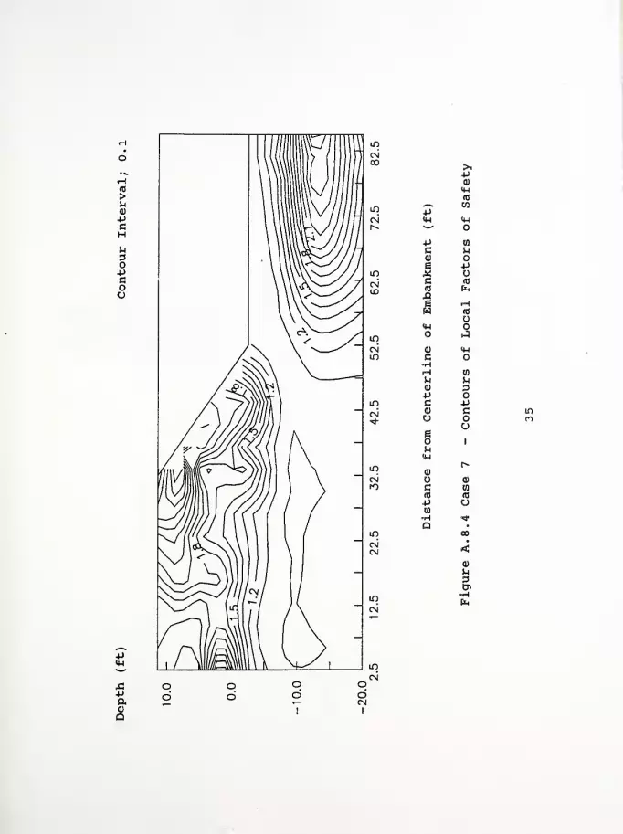
A3
>uCD
PcH
OPcoa
J3•Paa
muu
>ipCD
IMro
m +>"w
C\i M-l lHr^ w
P 10
C uCO
e p"1 ,2
CNCD
c(0
(0
e «Hw
o«H o
in aCsi 0) <wm c
rH to
M UCD dP
m C pCN 0) c IT)
uu
me
1
MCM
in0)
r-
CN o <DfO c to
(0 (0
+> uCO
•H "*
Q •
m eo
CNCN <
CO
u
in•HEn
od
od
CN
oCN
I
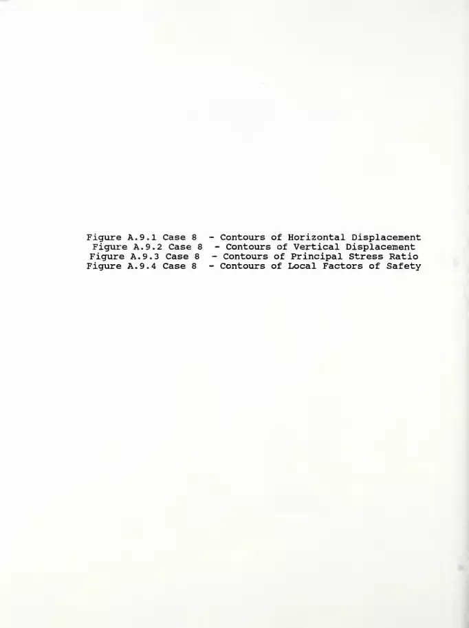
Figure A. 9.1 Case 8 - Contours of Horizontal DisplacementFigure A. 9. 2 Case 8 - Contours of Vertical DisplacementFigure A. 9. 3 Case 8 - Contours of Principal Stress RatioFigure A. 9. 4 Case 8 - Contours of Local Factors of Safety
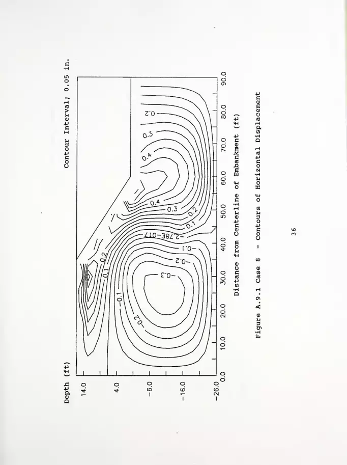
JcCD
o e600 P
<D
U(0
M-l <-4wP •rH
o C Qd 0)
r-i
S (0
c -P<c c.Q o1 No W -H
d MCO <w O
O B5
<4-l
co •H
09d u bCD <1> 3
P oc po cu o
q eu
d o 1*
CO
U 0)
o C in
d (0
pto
(0
u•H rH
Q0\
q <dC\l Q)
U3tP
•Pfta)
a
o qCD
qcd
od
I

c-H
>uQ)
-Pc
u
oPcou
J3pa<D
Q
oai
-Po Cd <D
00 *—». e•P a)
<w o**
i-i
o C6 0) -Hr> a
C r-H
(0 (C
ja uo e •H
W +Jd MID M-l a>
>a> <wc o
q -Hi-H Wo0)+J Oc P0) c r^o mO u
d E"3- o
p.
a)
1
oo
o 0)o c wd (C <T3
lO pen
u-H r\j
QCTi
o <dCM <l)
•H
O fen
d
q o o<r>
CM
I

u
OPcou
p
•Paa
o•H-P(0
in 4J«
<N <H toh- *"' to
0)
•P >-l
C p(1) CO
ito S iH
(N c <0
CD id aQ »He uw c
•H<u H
in 04
<N <D IHm G O
iH to
W Ma) 3-p O
in c P0) cu O
uEo 1
H<H
ma)
co
oi 0)fO c 10
m (0
=P uD9
»H Ma •
in 01
CM <
u3
od
od
od
odCM
I

H(0
>u0)
pc
u
§
ou
paa)
a
>P(1)
H-l
id.—
*
03•p<4-l 4-1
*""
-P in
c U0) oe pXG (0
id Pn
£6 rHw (0
M-l
JCD iwc o•HH en
P. Ua) 2pc p<D cu o
ue
J
u<u
CO(1)
CD
c en
(0 id4-1 uw•H ^D •
en
<a>
p3en

Figure A. 10.1 Case 9 - Contours of Horizontal DisplacementFigure A. 10. 2 Case 9 - Contours of Vertical DisplacementFigure A. 10. 3 Case 9 - Contours of Principal Stress RatioFigure A. 10.4 Case 9 - Contours of Local Factors of Safety
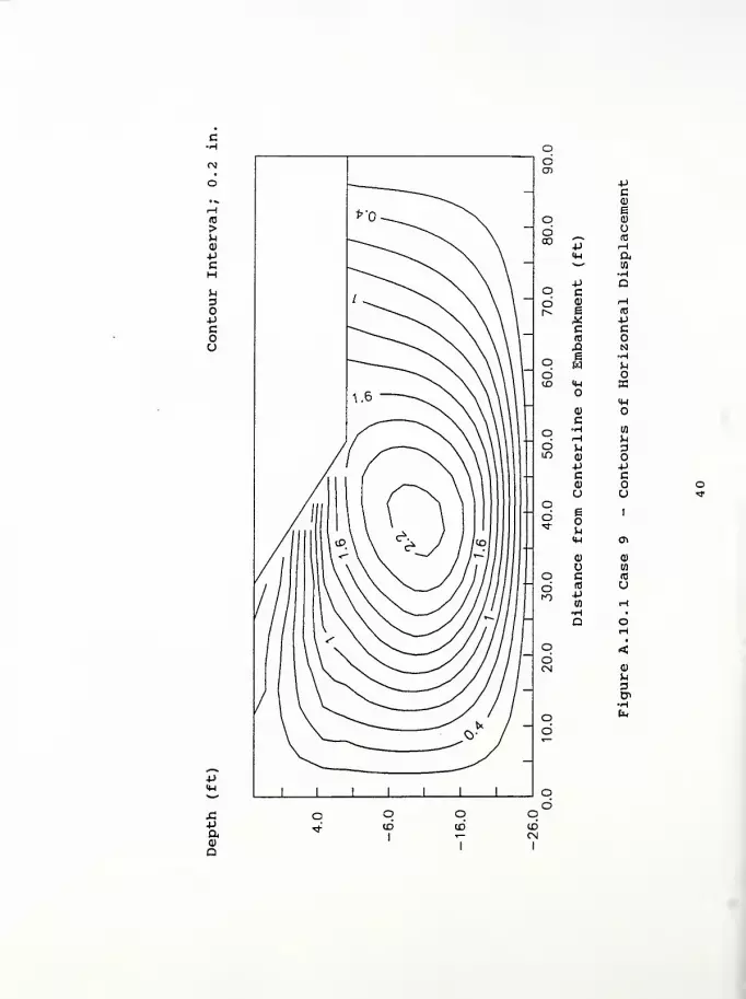
APaQ)
Q
o01
pc0)
go 0)
600 P
id
4-1 a*
—
-HP Q
q co a) rH
i^ g (0
^ Pc c(0 oX5 Ng Ho H ^
6 o<£>
4-1
a>
co -.-I
6 u pm <D
P pC c<D
O uod g 1
H-l tfi
0) <D
Wo c (0
d (0
pU
to rH
o qd
qdCM
Q)
-H

odO)
co 0)
d e03 *-N a)
P u«w re*"* H
aO 4J
cto
-Hd a) ar» i
^ rHc (0
«s
XI Ho g 4->
w Ud 0)to >
0)
co •H 0]
d H3
0) O+J -Pc c(1) ou uo
d e 1
"Sf o
IM o\
<u Q)
u 09O c (0
d m uro j->
in (M•H •
a oH
o <dCM a)
Ho fc
d
X!-P
a>
Q
o o
I
qCN
I
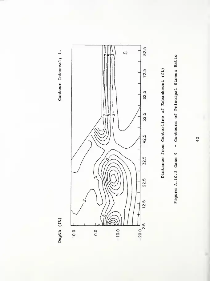
-p
43paoa
P(C
aID P wCN H-l w1^ *"* Q)
pP pc wa>
E i-H
in * (D
C aCM
(0 •H(£>
X!c•HP
<w a.
in <w
CN a)
ID c•H wM pP DID
P pID C c
0) (NCN u
e
p
u1
»tf
I+-I 0^
m Q) Q)
CN U Ul
n c (C
(0 CJpw CO
•H •
Q oin r-l
CNCN <
Q)
P
o6
od
odCN
I
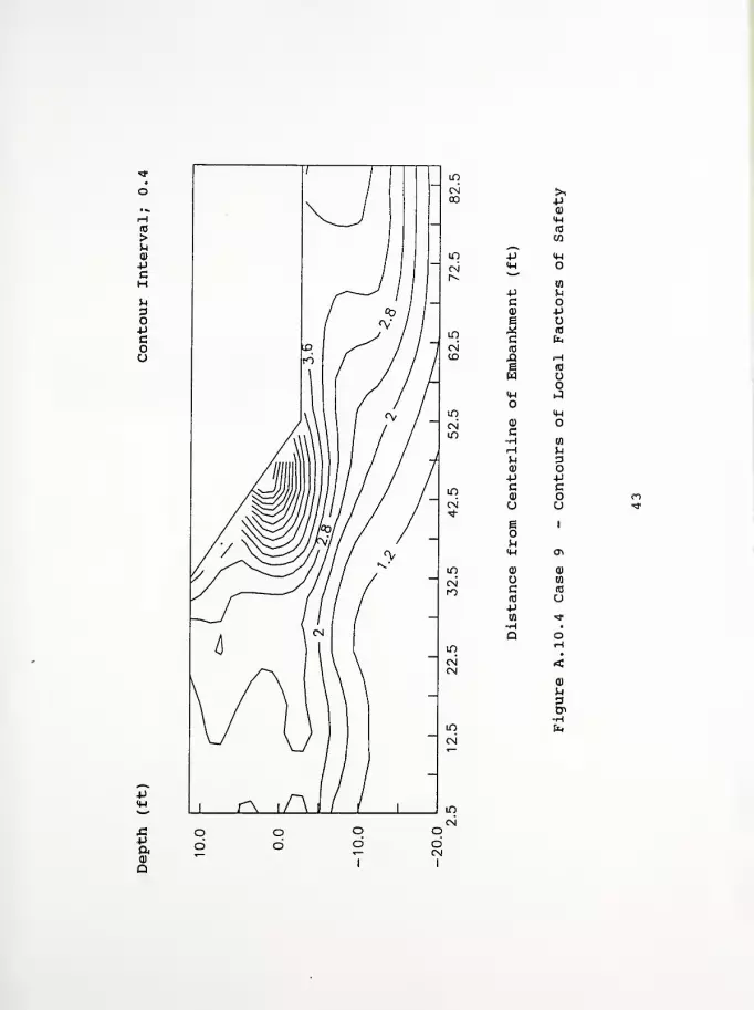
id
>ua)
pcMu
OPcou
-p
+»ao
CM >,00 -P
0)
<4-l
to
in p IM
cm IW
r»V)
p unQ) pg o
LO C faCsl (0CD A .H
g «3
w oo
<M iJ
in «w
CM a) otfi c
•H to
fH ^1
u 30) OP P
in C0)
co n
oi CJ o "*><i-
e 1
<w a\
iO 0) 0)
CN to
ro c «0
«0 uPw 'tf
•H •
Q oin HCM <CM
m
0)
3
•Hfa
CM
Od
od
od
odCM
I
Figure A. 11.1 Case 10 - Contours of Horizontal DisplacementFigure A. 11.2 Case 10 - Contours of Vertical DisplacementFigure A. 11. 3 Case 10 - Contours of Principal Stress RatioFigure A. 11. 4 Case 10 - Contours of Local Factors of Safety

uBo+jcou
-P
xs
aa)
Q
oden -P
cd)
e0)
O od (0
rH00 P &
<w (fl
'
—
-HQ
Po C rH
d A3px C3 O(0 NX) -H1 r<
q w Od w<£> «H
o «4H
O0)
c 0)
-H Mo rH 3d u om <D P-P cC oa) u <r
u =>*
q B1
d<3- u o
0-1 rH
0) 0)
o to
o c (0
d (C
•P(0
uH
qd
I
od
odCM
I
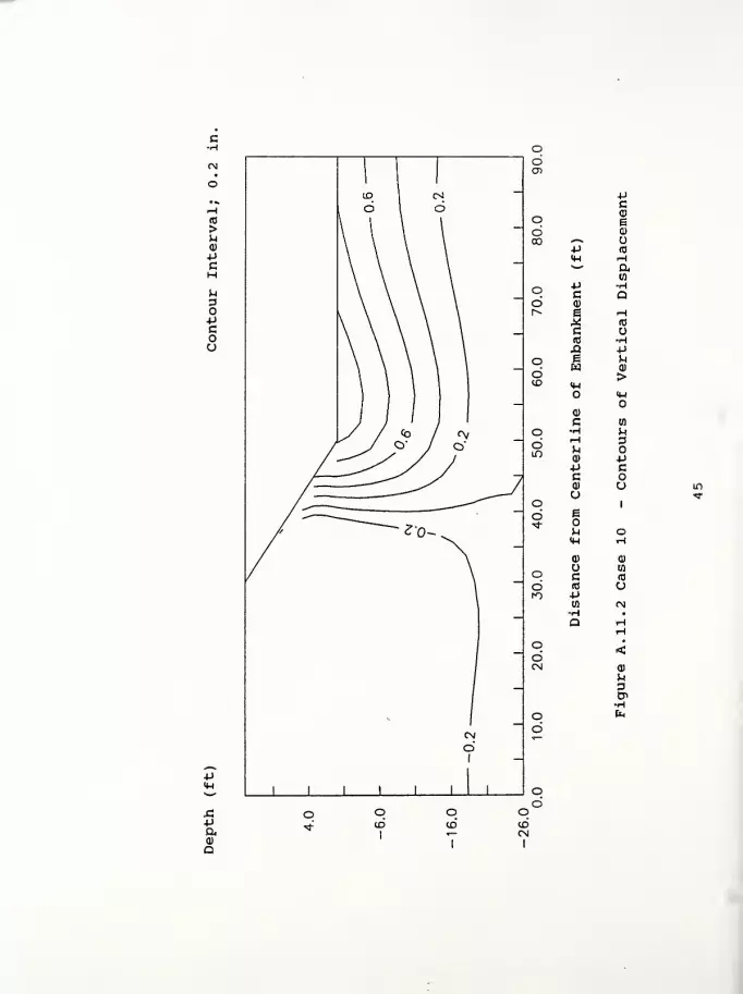
u3O-Pcoo
paa)
Q
odCD
PCa)o e
d Q)
00 *—* U+1 (0
<4-i rH
o c-HQd Q)
r^ e rHX to
c o(0 •HJ3 p
o i pw a>d >
to <M<*H
Q)
C Mo •H Pdin
rHP0)
3
Pp cc o« CJao 1
d etf
u o<M <H
Q) CD
10o C (C
d (0 uro p
w r\j
•H •
Q rH
o <dCM <D
P3tn•H
o fa
d
o od
I
od
odCN
I
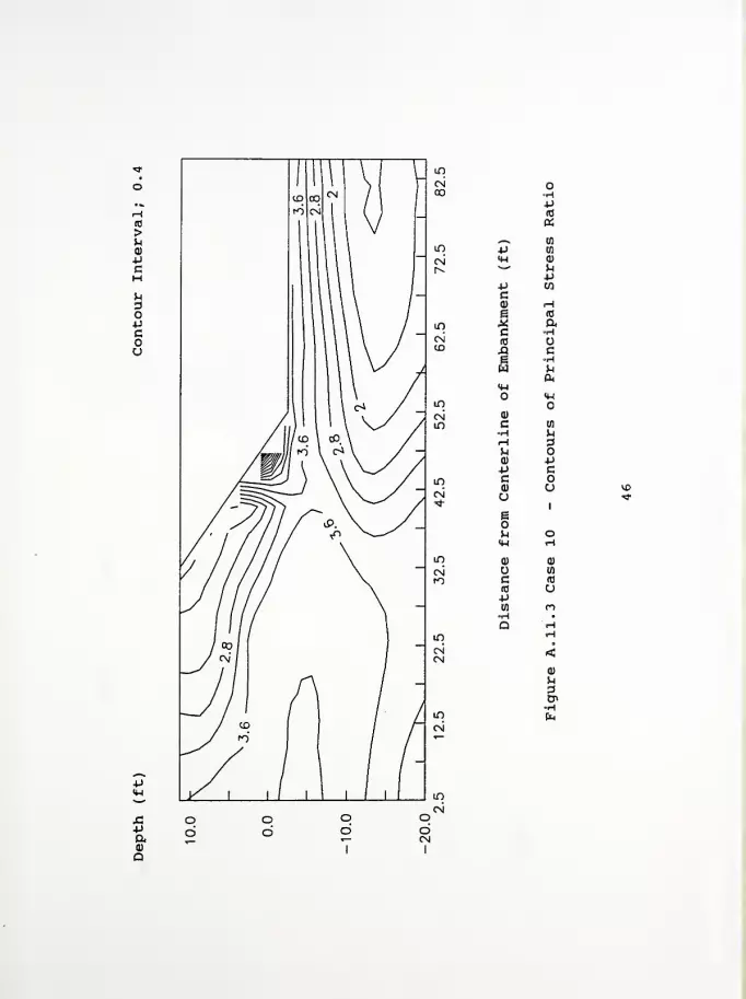
(0
>uCD
Pc
u
opcou
JSpaa)
a
(0
«_^ (0
in P (0
CN <W 0)
r^>te^*
p wca) (Hg <0
m * ac •H
CN (8 o(D 13 c
1 •HW<MO <w
in
CN a)
m c in
•H pr-\ 3u Oa) +Jp c
in c oa) u >X>
CN u *"*
eo
1
h o<w <-H
in(1) CD
CN O (fl
m c Id
(0 u+Jw n•H •
Q <H
m HCN <CN
oCD
OdCN
I
CD
Uaen•H

p&CD
Q
in
CN00
>n•PCD
^^ IHli") P oeg <Wr^ S«rf-
Ifl
-Pc -pa) ue fO
in .* fo
CNCD
C(0
XI (0
e oH<W
<wmCN Q)
CO C wH >-l
iH 3^0) pp c
in cCN a)
u
§
a
^ oy-i <H
IfiCD <d
CN U wrO c fO
<c opw ^•H »
Q r-l
CO rH
CNCN <
od
od
odCN
I
CD
U
g.
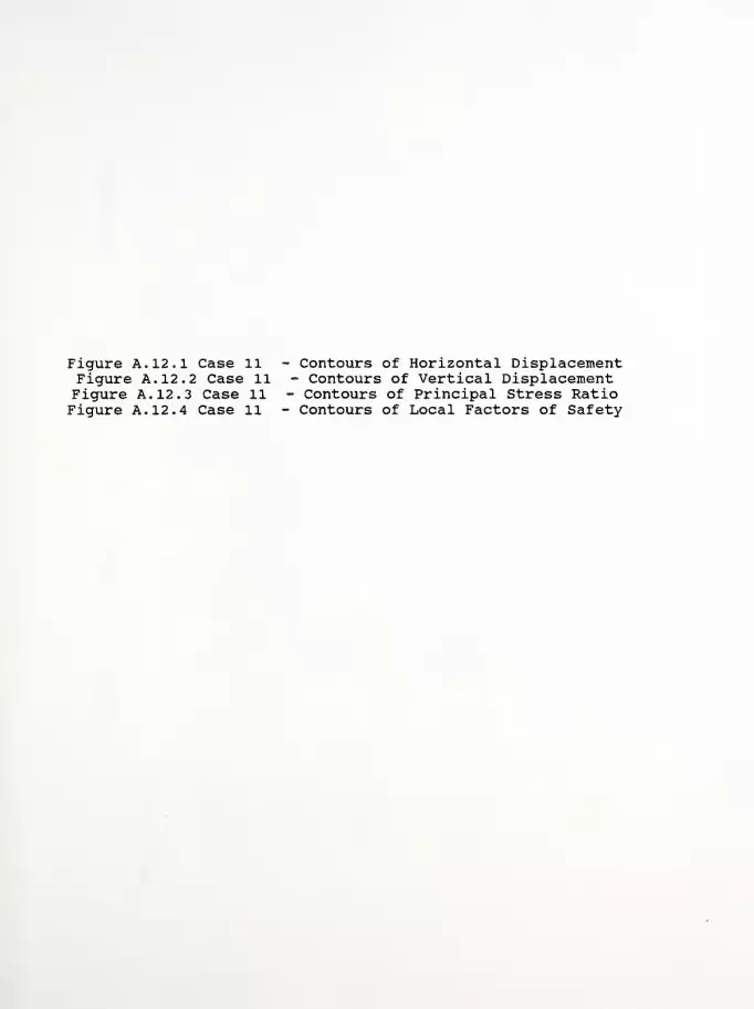
Figure A. 12.1 Case 11 - Contours of Horizontal DisplacementFigure A. 12. 2 Case 11 - Contours of Vertical DisplacementFigure A. 12. 3 Case 11 - Contours of Principal Stress RatioFigure A. 12. 4 Case 11 - Contours of Local Factors of Safety
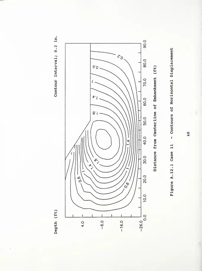
Vaa>
a
4JCQ)
e0)
uid
aen
u3
si
a)
Q
ucCD
od ^^ U00 +J (0
m rH*-*'
in+J •H
q c Qd 0)
e H(0
c oCO •HXI +>
p uo w 0)
dID <w
>
o0)
c 10•rH uO fH 3
d ^m 0) +J
V cc oai u Ou ^=r
o e1
d"* k H
<H H0) ou w
o c (0
<C ud 4->rO
0) (M
o oCD
I
oto
CD
U3
to
I

-P
a>
Q
*jid
a^^ u
in p DQ
CN y-i <D
r^ *'P
-p COca> rH
e ID
w ^ ac •H
CN<C
tD £ c6 Hw
a.IH
<Hin OCN a>
m c u-H MH 3u OQ) 4JP C
in C0) u o
cn Ueo
1
tn
h HIH «-H
IT)0) a)
CN lq
ro c 10
10 up(0 tn•Ha <N
m HCN(N <
0)
3CT
od
odCN
I

(0
>uopc
CN00
4->
CD
<H(0
CO
^.-^ 4-4m •P oCN <wr^ 10
u.p oC PQ> ue ro
inc
Si,
oi (0 HCD .Q (C
g OW O
J<M
«HlO OC\i a)
IS) c to
•H u.H 3U O0) Pp c
in c oCN
ai
u
1
u1
M Htw H
in0) O
Csi tfl
m c (0
a up03 -*•H •
Q OJ
in r-i
CNCN <
-p
CD
Q
qd
od
od
odCN
I
CD
UaCT
Figure A. 13.1 Case 12 - Contours of Horizontal DisplacementFigure A. 13. 2 Case 12 - Contours of Vertical DisplacementFigure A. 13. 3 Case 12 - Contours of Principal Stress RatioFigure A. 13. 4 Case 12 - Contours of Local Factors of Safety

paQ
O) -Pc<D
ea)
o ud (d
CD 4J a«W w*
—
•HQ
+J
q C (H
d a) (0
r^ e •p<* cc om NX! •He fco w
d asCD <u
oO
0)
c yj
o -H 5-1
3d M Om 0) 4J+J cc o0) u CN
u in
o 1
d Bo< ^ CN*w rH
a) d)
u cn
o c (0
d «5
-Pcn
o oCD
qCD
qCDCN
CD
u
On
fa

(0
>u<D
PC
P
5aoa
odO)
pc0)
q ed00 +J*
a)
<w 1—
1
**""
09+J •Ho c Q
d <p
r^ e .-I
X (0
c(0 -Hja 4J
o li a>
d >in <w
o
c 10
o H 3d M OIT) 0) P
•p cc(1) u mu lt>
q e1
d* M (N
iw ^H
a) 0)
!fl
o c (0
d id u
o qCD
I
qtoCNJ
I
ou

u3OPcou
paa>
a
*J
id
a
lD 4J en
CN <M 0)
r* '
—
PP OD
co rH
e ID
in .* ato
c(0
Hu
ja cp •Hw<M
mCN CD
LD c in
H ^^H 3u Oa> +Jp c
in c oC\|
CD u *<+
e1
in
m rs)
IH Hin
CD d)
CN 09ro c (0
re o+J
in m•H •
Q min h
CN <
o6
od
od
0)
3

(0
>uCD
-pcHH3O4->
Cou
•p
pa<D
D
ID>,
oioo
P0)14-1
W^^ IN
in pc\i (4-1
|v **
4->
c pa> ue <c
inc
fc,
CN(0 .-H
CO £ (13
e Ow O
**-!
twif)
oi 0)
iO c en
•H ^rH Dtl OCD PP c
LO C oCO u IT)
CN
e1
in
^ CM«-i rH
in <D CD
CN O arO C (0
ro upw ^•H •
Q ro
in rH
CNCN <
o6
o6
od
odCN
i
CD
M3

APPENDIX B
Computer disk with input data files

APPENDIX C
List of References

56
LIST OF REFERENCES
Geotechnical Investigation, (1989), Project No. St-4145(B),Structure No. 55-45-7366, "Indiana State Route 55 over TurkeyCreek in Lake County, Indiana," prepared by ETS, Inc. ofIndianapolis, Indiana, May, 10 pp.
Holtz, R.D., and Kovacs, W.D. (1981), An Introduction toGeotechnical Engineering , Prentice-Hall, Inc., New Jersey, 733pp.
Huang, T.K., and Chen, W.F. (1990), "Simple Procedure forDetermining Cap-Plasticity-Model Parameters," Journal ofGeotechnical Engineering . ASCE, Vol. 116, No. 3, pp. 492-513.
Huang, T.K. , and Chen, W.F. (1991), "Embankment Widening andGrade Raising on Soft Foundation Soils: Computer ProgramImplementation," Report No. CE-STR-91-3 . School of CivilEngineering, Purdue University, West Lafayette, Indiana,January, 244 pp.
Huang, T.K. , Chen, W.F., and Chameau, J.L. (1990), "TheApplication of Cap-Plasticity-Model to Embankment Problems,"Report No. CE-STR-90-21 . School of Civil Engineering, PurdueUniversity, West Lafayette, Indiana, 37 pp.
Humphrey, D.N. (1986), "Design of Reinforced Embankments,"Report No. JHRP-86-16 , Joint Highway Research Project, Schoolof Civil Engineering, Purdue University, West Lafayette,Indiana, October, 42 3 pp.
Kulhawy, F.H. , and Mayne, P.W. (1990), "Manual on EstimatingSoil Properties for Foundation Design," Research Project 1493-6, Prepared for Electric Power Research Institute, Prepared byCornell University, Geotechnical Engineering Group, Ithaca,New York, August.
Ladd, C.C., Foote, R. , Ishihara, K. , Schlosser, F. , andPoulos, H.G., (1977), "Stress-Deformation and StrengthCharacteristics," State-of-the-Art Report, Proceedings of theNinth International Conference on Soil Mechanics andFoundation Engineering . Tokyo, Vol. 2, pp. 421-494.
Ludlow, S.J., Personal data base - "Engineering Properties ofSoils,".
Nwabuokei, S.O., (1984), "Compressibility and Shear StrengthCharacteristics of Impact Compacted Lacustrine Clay," Ph.D.Thesis, Purdue University, West Lafayette, Indiana.
Appendix D:
Interim Report: "Embankment Widening and Grade Raising on SoftFoundation Soils: Example 2 - Indiana State Route 1 overRamsey Creek in Franklin County, Indiana," Report No
.
FHWA/IN/JHRP - 92-9 . 173 pp.

JOINT HIGHWAY RESEARCH PROJECT
FHWA/IN/JHRP 92/9
Interim Report: Embankment Wideningand Grade Raising on Soft Foundation
SoilsExample 2 - Indiana State Route 1 Over
Ramsey Creek in Franklin County
Philippe Bourdeau,Wai-Fah Chen,C. William Lovell, andScott J. Ludlow
Interim Report: "Embankment Widening and GradeRaising on Soft Foundation Soils:
Example 2 - Indiana State Route 1 overRamsey Creek in Franklin County, Indiana"
by
Scott J. LudlowGraduate Research Assistant
Wai-Fah ChenProfessor of Civil Engineering
Philippe L. BourdeauAssistant Professor of Civil Engineering
and
C. William LovellProfessor of Civil Engineering
Joint Highway Research ProjectHPR 2031
Project No.: C-36-36UFile No. : 6-14-21
This study is proposed to be conducted by
the Joint Highway Research Project
in Cooperation with
the Indiana Department of Highways
and the
U.S. Department of TransportationFederal Highway Administration
The contents of this report reflect the views of the authors whoare responsible for the facts and the accuracy of the datapresented herein.
Purdue UniversityWest Lafayette, Indiana 47907
Date: March 31, 1991
TABLE OF CONTENTS
LIST OF TABLES ,
LIST OF FIGURES
Page
i
i
APPENDIX A
APPENDICES
Example 2 - Indiana State Route 1 over Ramsey Creekin Franklin County, IndianaA.l
APPENDIX BAPPENDIX C
Estimated Soil ResponsePlasticity ModelCase 1
2
3
4
5
6
7
8
9
101112131415161718
Computer disk with input data filesList of References
using Cap
A.
2
A.
3
A.
4
A.
5
A.
6
A.
7
A.
8
A.
9
A. 10A. 11A. 12A. 13A. 14A. 15A. 16A. 17A. 18A. 19
CaseCaseCaseCaseCaseCaseCaseCaseCaseCaseCaseCaseCaseCaseCaseCaseCase
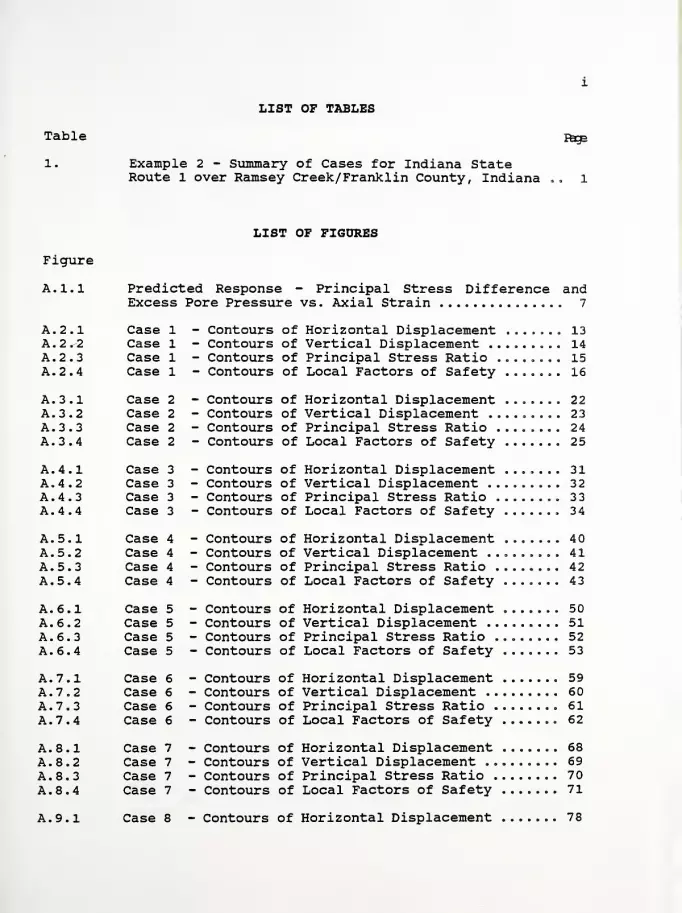
LIST OF TABLES
Table
1.
Page
Example 2 - Summary of Cases for Indiana StateRoute 1 over Ramsey Creek/Franklin County, Indiana
LIST OF FIGURES
Figure
A .1 .1
A .2 .1A .2 .2A .2 .3A .2 .4
A..3 .1A,.3 .2
A,.3 .3
A,.3 .4
A..4 .1A,,4,.2A.,4..3A..4,.4
A.,5,.1
A.,5..2A.,5.,3A. 5.,4
A. 6.,1
A. 6.,2
A. 6..3
A. 6. 4
A. 7. 1A. 7 = 2A. 7. 3
A. 7. 4
A. 8. 1A. 8. 2
A. 8. 3
A. 8. 4
A. 9.1
Predicted Response - Principal Stress Difference andExcess Pore Pressure vs. Axial Strain 7
Case 1 - Contours of Horizontal Displacement ....... 13Case 1 - Contours of Vertical Displacement 14Case 1 - Contours of Principal Stress Ratio 15Case 1 - Contours of Local Factors of Safety 16
Case 2 - Contours of Horizontal Displacement ....... 22Case 2 - Contours of Vertical Displacement ......... 23Case 2 - Contours of Principal Stress Ratio ........ 24Case 2 - Contours of Local Factors of Safety 25
Case 3 - Contours of Horizontal Displacement ....... 31Case 3 - Contours of Vertical Displacement 32Case 3 - Contours of Principal Stress Ratio 3 3
Case 3 - Contours of Local Factors of Safety 34
Case 4 - Contours of Horizontal Displacement 40Case 4 - Contours of Vertical Displacement 41Case 4 - Contours of Principal Stress Ratio 42Case 4 - Contours of Local Factors of Safety ....... 43
Case 5 - Contours of Horizontal Displacement 50Case 5 - Contours of Vertical Displacement 51Case 5 - Contours of Principal Stress Ratio 52Case 5 - Contours of Local Factors of Safety 53
Case 6 - Contours of Horizontal Displacement 59Case 6 - Contours of Vertical Displacement 60Case 6 - Contours of Principal Stress Ratio 61Case 6 - Contours of Local Factors of Safety 62
Case 7 - Contours of Horizontal Displacement 68Case 7 - Contours of Vertical Displacement 69Case 7 - Contours of Principal Stress Ratio 70Case 7 - Contours of Local Factors of Safety 71
Case 8 - Contours of Horizontal Displacement 78
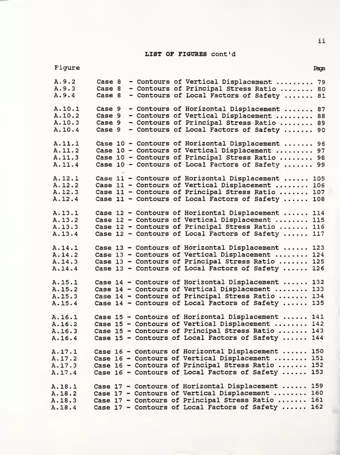
11
LIST OF FIGURES cont'd
Figure
A. 9.
2
Case 8
A. 9.
3
Case 8A. 9.
4
Case 8
A. 10.1 Case 9A. 10.2 Case 9
A. 10.
3
Case 9
A. 10.
4
Case 9
A. 11.1 Case 10A. 11.2 Case 10A. 11.
3
Case 10A. 11.4 Case 10
A. 12.1 Case 11A. 12.2 Case 11A. 12.3 Case 11A. 12.
4
Case 11
A. 13.1 Case 12A. 13.
2
Case 12A. 13.
3
Case 12A. 13.
4
Case 12
A. 14.1 Case 13A. 14.
2
Case 13A. 14.
3
Case 13A. 14.
4
Case 13
A. 15.1 Case 14A. 15.2 Case 14A. 15.
3
Case 14A. 15.4 Case 14
A. 16.1 Case 15A. 16.2 Case 15A. 16.
3
Case 15A. 16.
4
Case 15
A. 17.1 Case 16A. 17.2 Case 16A. 17.3 Case 16A. 17.4 Case 16
A. 18.1 Case 17A. 18.2 Case 17A. 18.
3
Case 17A. 18.4 Case 17
Pags
Contours of Vertical Displacement 79Contours of Principal Stress Ratio 80Contours of Local Factors of Safety 81
Contours of Horizontal Displacement 87Contours of Vertical Displacement 88Contours of Principal Stress Ratio 89Contours of Local Factors of Safety 9
Contours of Horizontal Displacement ....... 96Contours of Vertical Displacement 97Contours of Principal Stress Ratio 98Contours of Local Factors of Safety 99
Contours of Horizontal Displacement 105Contours of Vertical Displacement 106Contours of Principal Stress Ratio 107Contours of Local Factors of Safety 108
Contours of Horizontal Displacement 114Contours of Vertical Displacement 115Contours of Principal Stress Ratio 116Contours of Local Factors of Safety 117
Contours of Horizontal Displacement 123Contours of Vertical Displacement 124Contours of Principal Stress Ratio 125Contours of Local Factors of Safety 126
Contours of Horizontal Displacement 132Contours of Vertical Displacement 133Contours of Principal Stress Ratio 134Contours of Local Factors of Safety 135
Contours of Horizontal Displacement 141Contours of Vertical Displacement 142Contours of Principal Stress Ratio 143Contours of Local Factors of Safety 144
Contours of Horizontal Displacement ...... 150Contours of Vertical Displacement 151Contours of Principal Stress Ratio 152Contours of Local Factors of Safety 153
Contours of Horizontal Displacement 159Contours of Vertical Displacement 160Contours of Principal Stress Ratio 161Contours of Local Factors of Safety 162

Ill
LIST OF FIGURES cont'd
Figure Page
A. 19.1 Case 18 - Contours of Horizontal Displacement 168A. 19.2 Case 18 - Contours of Vertical Displacement 169A. 19. 3 Case 18 - Contours of Principal Stress Ratio ....... 170A. 19. 4 Case 18 - Contours of Local Factors of Safety 171
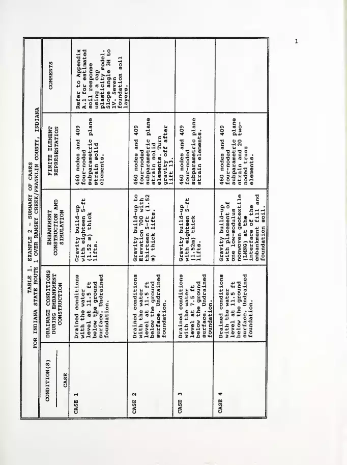
x tj -0-HO H 4JTJ JJ ID -H
COEiZEd
C 18 TJ B5 -h0) E CD Oro04 -w ID E CO
04+J C 04 OJ
< CO « >irt C5 OJ O4 O JJ 0> COo
CO -1 C CD -H4J)H©(BO<fl>4J •
u -i id 18 mS-i <4H Cn JJ CD CO TJ UID rt C CO & C CO
UM rH —1 —1 (0 • 3 >lCD • uhh> «
<zrt
cc rt co s amHWH
a> CD CD
Q c c c C 1
Z E-i Z 0> ifl 0> ifl !h en ib ffi IB
H z oIII M
O ^H O -1 CD O •-! • O -4 3«* Cm «* 04 4J <*> Cm go * &44
w 2 H C <w 44>H Ed <
J EhEd z
TJ O TJ U IB TJ O C TJ O OH C -H TJ C -4 TJ 3 C -4 CO C -HMZ (8 U -4 (8 U -1 Eh Hh IB U S IB U CO
D wDd CO
TJ JJ rt TJ 4J H wh TJ 44 0) TJ 44 TJ ID
O CO CD CD • CO CD CD • 03 CO CO r* CO 0) CO C 3 •
o Eh EdM «Z CmM EdEm Cm
CD TJ E CO CO CD TJ £ CO O CD TJ £ CD CO TJ E IB >J CO
TJ 18 4-> TJ 3 4J >in TJ S TJ IB JJ JJ
o c u e c C U C C 4J H C 14 C c u c cC 1 (8 -H 0) CI (8 -I CO "4 C 1 IB -4 C 1 IB ~4 TJ CD
>J Q. Ifl £ JJ Cm (B E > 4J M Oi IB U Oj IB CD EO 3 XI U CD O 3 £1 U 0) IB Xh 03I1H O 3 43 Sh TJ CD
vD 3 4-> H lOO 3t>H b-H lO 3 44 VD 3 JJ -4«3* uh CO CO CO «* hh m co CD o>.-h f t-i m m ^ MH CO CD C CD
go
CN CD TJ
aZ
Eh Zz z oEd O M25 M Eh2 Eh O,Z O JS D DCO Cm SS Eh MEd CO COZoo
4-1 jj 45 m 44 -m eUH 4J • MH 14-1 --4 IB
a i Ot-4 H a i a o 4J co
3 m 3 3 ~- • 3 m 3 ID X 45 -4 r-i
1 Jm 1 CO 1 1 4)3 U JJ --4 "4w
>4
1 w
TJ C O TJ O JJ JJ TJ C JC TJ C ^ JJ CD -4.
rt CD rt i-H O MH HJ H CD ^HCDSO-CMHUHCOrt CO -C •-I f» 1 ~i m4 «D t4 -4 g TJ CD 449 4)41 3 m H 3 44 45 3 0) D> 44 C
CM 5 42 £ 43 C 42 45 JJ 43 O g JJ CD Cip o>~ OCK 01 IB 1 C IB CO -4
EdR
>r-( e >4-W CD O >i~4 -» >i^H 3 CO IB g 44
siigo
jj CD 4J 4J CO -W jj CD E • 44 a > — *h M IB
—1 (NO rt IB JJ .C -4 CN CO •W HOOHCO>J3 m 4-> > > M 44 > 45 in 44 > 45 3 Z CD 18 C18 4-> • <M IB CO rt IB 44 • '4H I844C0CS4J433jj ^ H -H U -* 45 — U -4 H ^4 U-^COiJCEOU 3 —
^
O 63 JJ g O 3 ~<-4 O 3 C «-~H CD <4H
co
a S§8
Z Eh CO TJ CO TJ CO TJ CO TJO Z C CD C CD C CD C COrt Ed 5,t-i V **
H 2 o^r sr m
4J TJ G 4J TJ C TJ C 44 TJ C•H Mh Grt ~4 <»H C -^ -4 44 C-4 -4 IU C-4U Ij 3 18 4J U 3 IB 44 U HH 3 IB JJ U 3 IB
Q z Eart ao co a
Ed £O CJ S
•h a) in o u -4 CO in U -4 0) u -4 0) in o u<C TJ 44 • Jj TJ TJ 4J • >4 TJ TJ 44 in U TJ TJ J4 • Jj TJH C 18 i-l 01 C • C IB rt O" C • C IB • D> C • C IB -1 & C •
CO 3 H DC 3 H DC 3 r- DC 3 ^ DCO CD CD O CD O CD
rt CD 4J 45. • »< 0) 44 JC • •* CD 44 45 • -H CO 44 45 • -HZ TJ J> 01 4-> CD 4J TJ 4- IB 4J CD 44 TJ 45 « 44 CD 44 TJ 45 IB 4J CD 44rt ID jj O 18 CO 44 IB CO 44 O « CO 44 O IB
M C i-l 3 IB TJ C ^H 3 IB TJ C rH 3 IB TJ C -1 3 IB TJa ~h £ a> o mh c -4 45 CD "4H C -4 4= CO HH C h£ gi o<h ez
2 Q(8 4-1 > -4 Jj 3 IB 44 > <H U 3 IB JJ > *-l U 3 IB 4J > -4 U 3H Jh -H CD CD 3 U -4 CD OJ 3 •J -4 CD (D 3 U rt CD CD 3
«a O SHAIBiU D 3 H 43 CO mm D 3 H 43 CO HH D 3 rt 43 CD Mh
oEm
CO
zoMEhMa
EdCOrto
zo r-l CN m «o
Ed Ed Ed EdCO CO CO CO
rt rt rt <o o o O
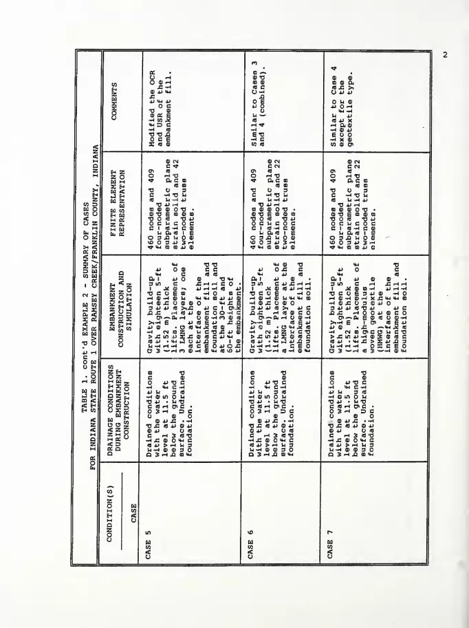
nor
« CO -»O rH CD TJ CD CD
co
H2Ed
O CD rH CO CD CO CD Cm£ -H (0 C B-C >iCD 4J MH O-l O JJ JJ£ QJJ MH JJ e O U CDa C jj Jl OH
oo
TJ Q) MH -riUSE-1 CO 5
u — U JJ(0 10 JJ X
mh d c ^H «* Hftll-H (0 -h •^ CD JJtjtj ja ETJ E O Opes -H C •HXdl
rta id cd co <o CO CD 0>
2<H <D CN CD CN CD CNQ c ^, C CN C CNz f-i 2 CTi 10 o\ 10 a* coM 2 O O rH TJ O -H TJ HTJ
Ed M rf be g "91 Cm C CO <r Cm C co^ X H m m 10 CO (fl CO
X Cd < TJ U 3 TJ O 3 TJ O 3H J Eh C -H tj u C -W TJ >h C -J TJ U2 Ed 2 (0 In -H JJ 10 Vj -1 JJ (0 U -A JJ
co o Ed T3 4JH TJ JJ ^ TJ JJ rHa o w co CO CD CD TJ • CO CD CD O TJ • CO CD CD O TJ •
co oS2 CD TJ S a CD CO CD TJ E CO CD CO CD TJ S CO CD CD
TJ O S TJ JJ< TJ ifl TJ JJ TJ O ifl TJ JJO SB 2 On o e u e o c c u c s O C SH C O CM W Ed
En KCI (0 -I C CD CI (0 -H C CD CI (0 •-! C 0)
Eb J h a <o i § U Di (0 1 I !h Cm <fl 1 EO « osxiuoi 3 xi u m O 3 jQ U O CD
2 W5 O 3 JJ 3 rH O034JSH 10 O 3 JJ 3 H
< t,
2 Md aCO Cd3
1 u
tt mh m so jj cd »* MH CO CO JJ CD ^ Mh CO CO JJ CD
MH TJ TJ MH CD TJ MH TJjj o CD C C JJ O J= C JJ O CQ MH C 10 (0 MH JJ (0 MH 102 a i jj o cd TJ MH Cm 1 JJ CD Cm 1 JJ OJ CD
H "* 2 3 in C £rt^CO • 3 in C JJ J3 ^h ^h 3 W C H J3 *H rH
2 _ Oy Sh1 .* CD ~ JJ rH -H Ifl JJ 1 J<! CD <0 JJ ^H ~J- 1 J< CD B -H JJ rH —
1
CN JhCd
Cd CO-J -3
TJ C O E CO -io co c TJ C O E -HO TJCUE3JJCD -HO
| ggiH CD «H CD U MH MH CO JJ JJ CD rHCD-^CDJ-lMHM-ICa rH CD H CDrH X -C MH MH CO
•H CD £ U CD CD Mh S. 1jj c 1 enJ2
-h ai x: cd H «£ U 3 Hji2 ?1 iJ 3 jj 4J A >i£ 3 JJ JJ 10 >i JJ c 3JJJJ«TJJJ JJC< Rd J3 ,C <H (0 JJ CD c O -1 c JO. ,C H * « c J3J3 rHOOJJCDCOS tt
SS S H
Oi— & rH O CD -H m CD ifl 01— Cm H tl 0)^ o>-»a. e a) 10 <d -j
rf n-h e jj <o
J2 10 CD S>i«h e 10 E +J >i-i E 1 C" ifl E -r1
JJ CD • rC —MH .2 18x a:w w>
TJ O
w K to jj CD • O <0 Mh jj cd • e 41 i «•** CO J —
i cn a 2 u C TJ £ JJ CD •w cm m 2 Jh c tj -H CNC0O<CC3JhCTJ2 > j: in ,u 2 £ CD (0 C JJ MH >j=injJSCD<0C >.CmjJ.H<D3:CDioeO (0 JJ • MH (J O JJ Jp 3 1 CD
E jj jr.
nj JJ • mh iJ jj jO 3In -W rH -H CEO ifljj •mh£>SjJj-3
U -H rH -H (0 C Vj^rH^ OXCEOJJ «Hc
63
O 3 ~"H m cd -h CD MH (0 lO JJ O 3 ~"H 10 "4 CD MH O 3 ^"H 10 3 — -1 CD mh
O H COD 2 H CO TJ CO TJ CO TJ
• o O 2 C CD C CD C CDrH « M ca s 4J-B C O JJ TJ C JJ TJ C
5§ oT" BS u
•H MH C -H ^ MH C -J H MH C -Iw ca JJ In 3 10 JJ U 3 (0 JJ U 3 iflJ H
E
COND
!
EMBAN
struct:
•H in M •w CD in u -1 co in nCO «* O JJ • 1-1 TJ TJ JJ • M TJ TJ JJ • U TJ** H C <fl iH o> C ' C <fl H 0> C • C Ifl rH 0> C •
H CO 3 «-h DC O 3 H DC 3 rH DCO CD O CD O CD< CD JJ -C «-rJ CD JJ £ »-W cd jj x: >-i
2 u u ~ TJ £ « JJ <D JJ TJ J3 10 JJ CD JJ tj s: * JJ CD JJA s5g
H « °CD JJ 0« CD JJ O Ifl CD JJ O IflH C rH 3 10 TJ C ^H 3 <fl TJ C rH 3 Ifl TJ
Q •h jz cd mh e •w s: cd mh c -h s: cd mh cZ «c d ro JJ > rH U 3 « JJ >H M 3 Ifl JJ > rH U 3M a a h-H V 01 30 H-H CD 0) 3 O U -H CD CD 3
PSa D 3 *H JH CO mh a 3 -h jo to mh a 3 .-h jj a mh
oSi
ca
2OMHMa
wCO<
2o m lO r«
oCdCO
CdCO
Cdco
rt rt rtO CJ

xs O TJin rH TJ
CD
en Cid JJ
rH Cid C
a> cu CD r-i -A CD OH C CD rH CD
COH2
co a) a m hiw CO OS 3 -^ CD CO Oj —1 Q)
10 JS >i id mh -j ~h id O U CD id u oxO JJ JJ O CHTJ06 jj E
O O U CD X O O co
CO
CD 111 ffi idEd OUl CD CD JJ CO
3 JJ rH JJ CJ c jj js js co id • JJ JS JS C JS •
oo
Mh -H O CD C JJ JJ JS TJ JJ JJ -H TJU JJ V4 E CD
id JJ J? CD
U E OJ In >, CD CD10 JJ X Id JJ MH IH — -J Id JJ MH rH rH —IrH ft CD -! a c x h ao ai ihh ^ ft U -»4 MH~J CD JJ -J CD 10 -4 CD ft CD —I •A CD CD mh —
1
E CJ H X CO E K ft >iT3 E CJ « TJ TJ•n X OJ -i x £ id •h X013 « HKiachO
< CO Ol CO CD CD JS CO CD D <-^H g CO CD D 3 ft g
CD CN CD CD CD
Q c *f c c C2 Eh 2 a\ io a> id a\ id » ai id
M 2 OEd m
O rH TJ O ^H . O 'H CO o ^ •
<? a, c m <* Oi CO «* Oijj <* ft IS^ S Eh a D JJ c jj
>l Ed < •a o 3 tj c 73 CD TJ CJ CEh J Eh c -i -d u C -J CD C -IE C -H CD
2 Ed 2 Id U -1 JJ id u E 10 U CD id u eCO D Ed TJ JJ >-t •0 JJ CD O JJH TJ JJ CD
Ed O Ed (0 co oj cu o •a • CO CD CD .-h CO CD CD CD CO CD CD rHCO O £g
CD "0 E CD 0) co CD -0 E CD CD T3 E Q) TJ E CD
< CO « TJ JJ 0 id a Id TJ id
CJ 2 2 Ch ocheoe £ U C c u c OS h BM m Cd CI fd M C CD c 1 id -h c 1 id -h C 1 Id -Afc. J b a u a id i i u a id in ft* t-i ft id
o * osiihoi O 3 X >n O 3 X M O 3 X Sh
2 1C034J JH vfi 3 JJ VO 3 JJ vO 3 JJ
a 2< b2 bi
Tf Mh 03 CO 4-> 0) «* MH CO CO ^ MH CO CD «<H • 1
<M •O TJ
D EdCO Eds
1 o
oj o ai C C JJ JJ JJo Mh C td id MH MH MH2 a i jj o oj TJ MJ Oi 1 ft 1 ft 1
Eh **• 2 3 in C £HH C O • 3 m 3 in 3 m2 9 O 1 .X CD •» JJ rH -1 Id JJ 1 1 i a.
CN >HEd
Ed CO
J Sft- 2s 22X «>
•a o
Cd § M O c o g n -HO DC •o C J^ V C it TJ C CJ
S ^ Eh rH CD —1 <D U »h MH CO JJ JJ CD H HI U rH CD CJ rH OJ M•^ CO £ U CO 11 O MH JS g
JJ C 1 Cn.2W CD -H -J CD -1 -1 CD JS
2 ft J 3 4-> 4J ft) >i JS 3 JJ JS 3 JJ JS 3 JJ JJ
<"d X J= rH (0 4-> CD C O -^ C A JS JJ X JS JJ X JS
Ed Si W
oi — a. >•* o CD -^ fl CD id C7> ffi 01—>i-^ £ jj id £ JJ JS X >i-l — >,-r4 — >i-! E4J CD • O ffl MH 5 id CD e JJ CD E • JJ CD E • JJ CDw CO •H N D S l-l C T! JS JJ CD •»4 CN CO •^ CN CO •A (N CO2 >£ifl 4JS£ ID id C JJ MH > JS in jj > js in jj > JS in JJ
O Id 4J • MH X CJ JJ XI 3 1 CD
E JJ O JSid JJ • MH id jj • mh 10 JJ • MH
u u -w rt -a id c ^ ~l H -H ^•HH-l U -rH rH -rj
JJ rHcH
C5 3 >^^h m 0) -h CD MH Id vO JJ O 3 "-H CJ 3 ~*H O 3 ~-rH
O Eh coD 2 Eh co tj CO "O CO T> CO TJ
• O O 2 C CD C CD C CD C 0)•h a: M Cd _
M 2 °T1 «* kd
JJ TJ C o jj -a c 4J TJ C JJ TJ C-J MH C ~H ~H MH C -1 -J MH C ~H -rH MH C -^
Ed Eel jj M 3 td 4J IH 3 Id U U 3 0) jj h 3 idJ Eh
E
CONDEMBAN
struct:
-4 CD IO 14 •h a) in o u H tlin U -I CD lt> UCO < •0 4J • In TJ V JJ • U TJ TJ JJ • U TJ TJ JJ • >H TJ< Eh c td i-i ai c • C AH OiC • C Id H ffl C • C Id rH pi C •
Eh CO 03H DC 3 >H DC 3 <H DC 3 rH DCCD CD O U OJ O CD
«C CD JJ JS ••* CD JJ JS * -H CD JJ JS • -H CD JJ JS «-J2
INAG RING CON!
tj js td jj cd 4J TJ JS Id JJ CD JJ TJ JS Id JJ CD JJ TJ JS Id JJ CD JJ< CD jj id cd jj o a) CD JJ O 10 oj jj o «M c h s ifo c <-< 3 id XJ C -H 3 id TJ C rH 3 id TJa •H JS CD MH C •H JS CD mh C •H JS CD MH C t| JS CD mh C2
2 Q10 JJ > rH U 3 id jj > ^ in 3 Id JJ > <-* U 3 10 JJ > rH >H 3M In -H CD CD 3 U «J CD CD 3 U -h CO 11 g Jh -1 CD CD 3
aa D 3 i-H X CO MH a 3 h xi co mh Q 3 H J2 CO MH Q 3 rH X CO MH
oEb
CO
2OMEhMa2O
EdCO
OO rH
co o »H Ho
Ed Ed Ed EdCO CO CO CO
4! < < 1 <U o o V
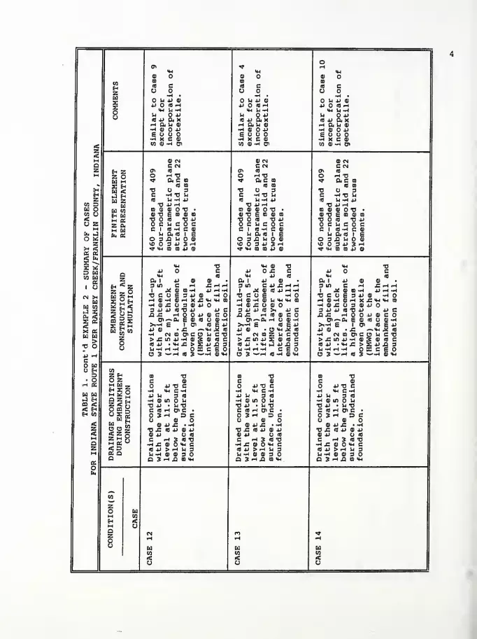
a* ^ <-H
<M IH Hd> dl O 01 O
COEh
ZEd
a CO CO
id c id c id cO O
•H • -4 . —1 •
U JJ Q) U JJ ID O U JJ dls 4J O fl-4 4-1 id i-t JJ O Id rH
oo
M J4*rl «H U-W <*4 U -WJj JJ U O 4-J Jj O JJId JJ ft X nj jj a x d jj ft xHfiibl h an ^h ft u a>•H 111 0-U •W d) O JJ * d) jjE O E O O O EDDO-4 X C 0) H KCll •^ X C d)
<
M
CO d) -4 01 CO d) -4 C71 CO 0) -H t?
0) CN 0) CN d) CNa C CN C CN C CNz Eh Z ffl Id en id cr> id
M Z O O -4 TJ O ^4 TJ O -H TJ
Ed m >3- a c CO <? Ol C ffl >* ft C ffl
^ S Eh <a a id a id
X Ed «C TJ O 3 TJ 3 TJ O 3H J Eh C -*4 TJ U C ~4 TJ u C ~4 TJ JJ
a Ed Z (0 U -M JJ id li-h y id u -w jjW D Ed O WH TJ 4-> ^4 TJ 4J ^HM O Ed CO ffl 0) 0) TJ • CD d) d) O TJ • ffl a o) tj •
CO O Eh Ed d) TJ £ CO 0) CO d) TJ E ffl dl ffl 0) TJ E ffl 0) CO
< m a TJ O id TJ JJ TJ O id TJ 4J TJ O id TJ JJO 2 Z O4 c n c c O C U C O C O C U C O CM m Ed CI id -H C d) CI id t4 c d) ci id -4 c ai
fc J Et, (S Jj ft id 1 £ h ft id 1 g 14 ft id 1 Eo « 3 jQ Jj 0) O 3 J2 U O 01 O S JQ H O 0)
z I0034JSH vo O 3 4J 3 rH OODJIJH
-
SUMMARY
CREEK/FRA
T'W 111 HI) 9 <• >m a d 4-1 d) ^ mh a ffl jj di
4H TJ MH dl TJ H TJJJ O C 4J O J= C JJ O Ca IH id >H 4J Id IH dz a 1 j-> a) 0) ft 1 4J d) ft 1 JJ <D ID
Eh "" Z 3 in C *-l £HH 3 in C 4J J3 * rH 3 m c .-1 JB •-! •-!
Z _ OEd S! w
1 .* 01 ffl --4 JJ .-4 ~41 J< 0) Id 4-) 'H -W 1 a; o) eo -4 JJ -H -H
CN XEd COj a
TJ C O £ 3 JJ <D -1 O TJ C O E -J. O TJ C O E 3 JJ 0) -4
S 2 Eh H (-( (rt XiWWIO .-1 d> -4 d) 14 MH MH ffl HH^tlHKf^lugl2 2< ~4 0) £ O 3 d) 4J H 0) J= O 0) H d) jS O S 0) JJ
z £, j 3 JJ JJ (0 "O 4J JJ C 3 JJ 4-1 <d >i 4J c 3 JJ JJ id TJ JJ JJ ca S S ££ -H O O JJ SCO jQ.C -H id ID C O jQ £ nOOil 0) C
X S Mo^— o< E d) ffl O OJ-J o>— CU ^H oj -1 o>-~04 E di id a> -h
2 >1-H E 1 O id E 4-1 >,^4 e * E +» >1«H E 1 P id i JJ>w iZ id
>tj o
Ed £ EO jj 01 • .c — •« x id jj dl • O "h S id JJ IS • J= —™ 01" -4 fN co en c HCfl -4 cn in z Jj C TJ -4 CM CO D> C O li COz > £ LD 4J ~4 (1) 2 id c >j=injj£diidC > JS IT) JJ ~4 CI) S 0) id cId JJ • «H £ > £ JJfl 3 Id JJ • MH J JJ jQ 3 id jj • <tj jr, > s JJ JQ 3U-HH--I O S CEO >4 -4 iH ~4 CEO Jj -4 .H ^4 OS CEO
JJ >Hco w
C5 3 —^ nj 3 ~ •H 0) «H O 3 -^^ id -^ id "h O 3 —H id 3 >- ~4 0) <u
H COD Z Eh to TJ CO TJ ffl TJ
• O O Z C d) C 0) c ai«H OS M Ed z O JJ TJ C O JJ TJ C JJ TJ c
M S °— KM-4 «M C ~4 •H <W C -4 —I MH C -HW Ed y sj 3 a) JJ V4 3 id JJ Vj 3 IdJ H •h Oin O h .-1 d) in O Jj -4 d) in 14m < TJ JJ • lj TJ TJ JJ • >J TJ TJ JJ • Jj TJ< H O CD X C «H PC • c «j <-i a> c • C id 1-1 01 C •
H W O 3 H DC O 3 H DC 3 H DCEd £ O dl O O 0) O 01< 0) JJ £ ••* d) JJ £ • -* <d jj jr. . -4
z52 S z TJ jC id JJ d) 4J TJ £ Id JJ dl JJ TJ J= id JJ CD JJ
< < Z KZ M gM « U
a) 4-1 id 0) jj id ai jj idl-l C ^H 3 Id TJ C .H 3 id TJ C -h 3 id TJQ •H £ 0) O >n C -4 JS d) O >M C -* JB fl) 0<H CZ
2 QId JJ > r-t U 3 id JJ > ^H 14 3 (d JJ > ^H M 3M U -H 0) 0) 3 O h -4 oj oj 3 Jj -J ffl 3
oEu
O a 3 ^h ja to <w a 3 «-h jq m iw D 3 H jQ a «H
CO
ZO EdM COEh <M VOz CN n «S"
•H iH iH II
EdCO
Edco
Edco
< rt rt :
O OII
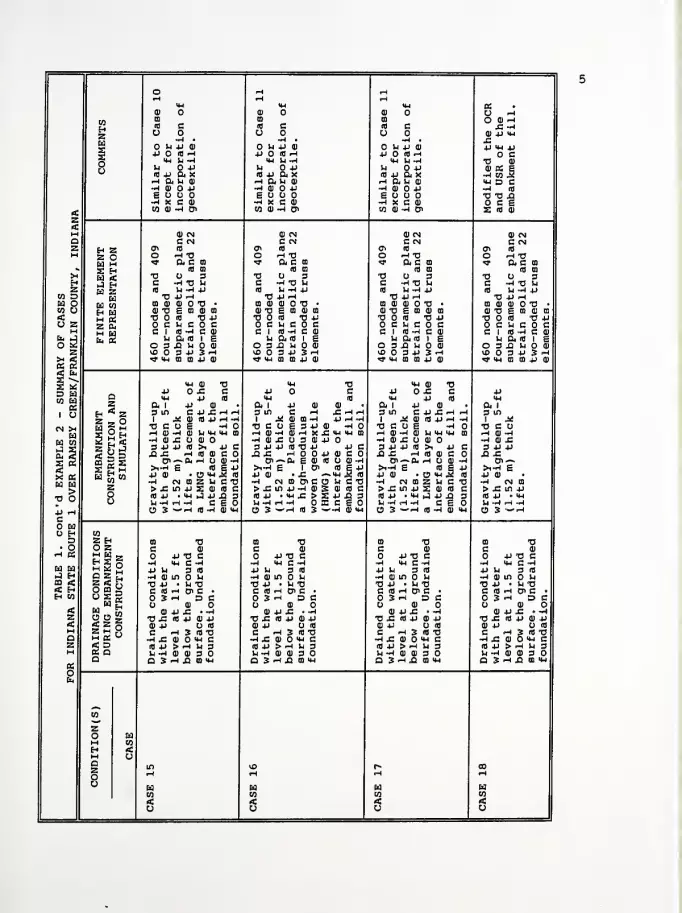
<D OIB
(fl CO O
-4 •
U 4J CD
P O fl HHj Ll -I
Li P«4J axnahtlE O O-j x c a)
co a) -4 a\
U P CB
i) O *H»H Ll -4
Vi OP(fl 4J 0< XrH a u a)•H fl) O 4J
£ U O-4 X C 0)
CO 0) -H 0<
ao ^o a) ^£ -i0) p u-i
P M-l po c
TJ fl)
0) « S-4 CO J2<4-i D C•~i (fl
TJ TJ £•O C Es m a>
73C(fl
•om ai
ai tj•o oo cc I
Ll
O 3VO O«* <*-i
01 CMC CN10
r* TJft c m
<o co
o 3
Ll -4 p-P -4
gov •
E co fl) co
ifl TJ pu c o c(0 -I C 0)
& (0 I ££ U O 01
3 P 3 -Ico co jj 0)
Oc(0
aCO 01
0) TJ•o
cC I
uO 3vO O«* <*4
(0
^ TJa c co
(0 CO
O 3-4 tj li
U -4 pP r-l
fl) O TJ •
E CO CD CO
<fl "OPu c o c
an i e£ Li O 0)
3 P 3 ^CO CO p CD
Vc(fl
•aCO a)
fl) TJ•o
cC I
uO 3vO Of M-i
fl) CNC CN(0
"I TJft C CO
a mO 3-4 TJ Li
Li -4 PP ~l(DOT!E £0 fl) CO
10 TJ PLl C O C<0 -4 C fl)
ft 10 I SQ U O 11
3 P 3 -Ico co p at
> £ in10 p •
Ll -4 H(9 3 —
>« ai tj£ cp a
P 0)
C4)£Hrl0) (0 P H -HE -401 UHHJ oO fl)
<0 >i PCh (0 at c o0<H O 0)-^
(fl £ jj• o <u j2 ifl
CO 2 Ll C TJJJ S fl) ifl cM-i J p £ 3•* CEO-4 (0 -4 fl) IW
Mft I
3 ini XTJCUr-l fl) -J-I fl) £3 P P££>i-4 EP 0)
-4 CM
O 3 —
P CD
C ~40) CO -4E 3 JJ 0)
0JH X£U 3 fl) Pifl TJ PH O O Pa. e fl) io
I Oi• JC ^
CO o> c oP -4 fl) S«w jc > a-4 OX
73cIfl
0)
JC ~l »-4
P p-4 -4-J
ti-i vu m
P cfl) CO fl) -Iifl £ P>w J2 (fl
L4 C TJfl) Ifl cp ja 3CEO-4 fl) <M
ft I p3 m cI JJJ 0)
TJ C U £,—
i en —id)-J CD £ O3 P P 10
£ £ -i
>i-< EP 0>
-4 (NO)> £ in pn) P • <wLl -4 .H -4
p10
tjc3
_ oO 3 ~"^ (0 -4 fl) M-l
<P TJJC cp Ifl
fl)
P jC r*(fl p
-4
0)
>! P(fl 01 c-I O fl)
10 £O *4 3.z u cS fl) 10
u-i
ft I
3 inI -XTJ C U-4 fl) -4-4 fl) JC3 P P£ jc
C7>-«>l-4 EP 0)-4 CN CO
> JC in p«j P • o-i
Ll -4 rH -4O 3 ~"rH
Q 3 -
P Ll
-4 0)
•C PC 10
O 3o
4)
73 JC0) Pc-4 JC10 PLl -4a 3
fl)
P TJ C>W C -4
3 10
in Ll
• Ll TJ.-I D> C •
rt DC0)
P £ • -4ifl jj CO P
O (0
-4 3 (fl TJCD O Mj C> -I U 3fl) fl) 3 O-4 J2 CO H-i
CO TJC 0)
P TJ C-4 V-l C -4P Ll 3 (0
-4 CD in O Ll
TJ P • Ll TJC ifl .H o> CO 3 H D cO 0)
fl) P £ o -4TJ J= (0 P fl) Pfl) P (0
C <-i 3 (0 TJ-4 jC 0) O «-i c(0 P > ^ Ll 3Ll -4 0) 0) 3 OQ 3 *h XI CO <u
P Ll
-4 fl)
TJ PC (0
O 3O
fl)
TJ £fl) PC-4 £(fl PLl -4a 3
TJ01
P TJ Cin e-H
3 (0
in O Ll
• Ll TJH PC^4 D
0)
P £ • •
<fl P 0) PO (0
H 3 10 TJfl) O >M C>-l U 30) O 3 O>-4 £ CO >t-l

APPENDIX A
Indiana State Route 1 over Ramsey Creekin Franklin County, Indiana

A.l Estimated Soil Response using a CapPlasticity Model

Indiana State Route 1 over Ramsey Creek Franklin County, Indiana (10 psi)
1. 0.40 0.75 21. 5.0 0.25 0.05 .63 2.5 0.01 10.0 .730 10
900
0. 0.020 0. 0.
0. 0. 0. 0.
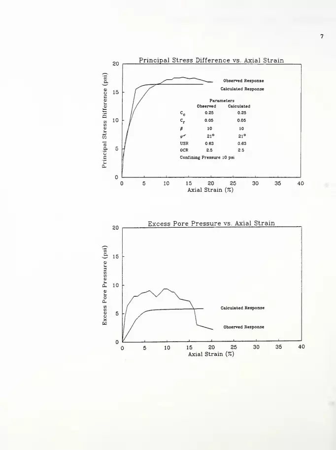
20Principal Stress Difference vs. Axial Strain
Observed Response
Calculated Response
Observed Calculated
Cc 0.25 0.25
Cr
0.05 0.05
fi 10 10
<t' 21° 21°
USB 63 63
OCR 25 2.5
Confining Pressure 10 psi
10 15 20 25
Axial Strain (%)
30 35 40
20
15
Excess Pore Pressure vs. Axial Strain
Calculated Response
Observed Response
15 20 25
Axial Strain (%)
30 35 40

Computer Program InputFigure A. 2.1 Case 1 - Contours of Horizontal DisplacementFigure A. 2. 2 Case 1 - Contours of Vertical DisplacementFigure A. 2. 3 Case 1 —Contours of Principal Stress RatioFigure A. 2. 4 Case 1 - Contours of Local Factors of Safety

State Route 1 over Ramsey Creek - Franklin County, Indiana Case 1
460 1 1 18 1
1 15 . 01
,0 o.: 9.0
1 1 0.000 0.000
2 1 0.000 -7.500
7 1 0.000 -27.500
8 1 1 0.000 -35.000
9 12.500 0.000
17 25.000 0.000
337 625.000 0.000
345 1 640.000 0.000
10 12.500 -7.500
15 12.500 -27.500
16 1 12.500 -35.000
13 25.000 -7.500
338 625.000 -7.500
346 1 640.000 -7.500
351 1 640.000 -27.500
352 1 1 640.000 -35.000
19 25.000 -11.500
339 625.000 -11.500
20 25.000 -15.500
340 625.000 -15.500
21 25.000 -19.500
34 I625.000 -19.500
22 25.000 -23.500
342 625.000 -23.500
23 25.000 -27.500
343 625.000 -27.500
24 1 25.000 -35.000
344 1 625.000 -35.000
353 1 0.000 10.000
361 1 0.000 90.000
362 12.500 10.000
370 12.500 90.000
371 25.000 10.000
387 265.000 10.000
388 280.000 5.000
389 250.000 15.000
390 25.000 20.000
404 235.000 20.000
405 220.000 25.000
406 25.000 30.000
418 205.000 30.000
419 190.000 35.000
420 25.000 40.000
430 175.000 40.000
431 160.000 45.000
432 25.000 50.000
440 145.000 50.000
441 130.000 55.000
442 25.000 60.000
448 115.000 60.000
449 100.000 65.000
450 25.000 70.000
454 85.000 70.000
455 70.000 75.000
456 25.000 80.000
458 55.000 80.000
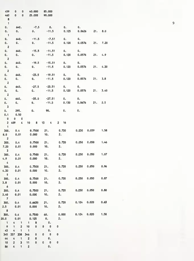
459 40.000 85.000
460 25.000 90.000
8
1
0. 640. -7.5 0. 0. 0.
0.
1
0. 0. -11.5 0. 125 0.0626 21
1
0. 640. -11.5 -7.51 0. 0.
0. 0. 0. -11.5 0. 120 0.0576 21
2
0. 640. -15.5 -11.51 0. 0.
0. 0. 0. -11.5 0. 120 0.0576 21
2
0. 640. -19.5 -15.51 0. 0.
0. 0. 0. -11.5 0. 120 0.0576 21
2
0. 640. -23.5 -19.51 0. 0.
0. 0. 0. -11.5 0. 120 0.0576 21
2
0. 640. -27.5 -23.51 0. 0.
0. 0. 0. -11.5 0. 120 0.0576 21
2
0. 640. -35.0 -27.51 0. 0.
0. 0. 0. -11.5 0. 130 0.0676 21
3
0. 295. 0. 90. 0. 0.
0.1 0.50
2 409 4 10 8 13 4 2 16
1
300. 0.4 0.7500 21. 0,.720 0.230 .039
8.0 0.01 0.000 10. 2.
2
300. 0.4 0.7500 21. 0,,720 0.250 .050
7.20 0.01 0.000 10. 2.
3
300. 0.4 0.7500 21. 0. 720 0.250 .050
4.9 0.01 0.000 10. 2.
4
300. 0.4 0.7500 21. 0. 720 0.250 0,.050
4.30 0.01 0.000 10. 2.
5
300. 0.4 0.7500 21. 0. 720 0.250 0,,050
3.8 0.01 0.000 10. 2.
6
300. 0.4 0.7500 21. 0. 720 0.250 0..050
3.40 0.01 0.000 10. 2.
7
300. 0.4 0.6630 21. 0. 720 0.124 0..020
2.5 0.01 0.000 10. 2.
8
300. 0.4 0.7500 60. 0. 000 0.124 0. 020
20.0
1
0.01
4 1
0.125
1 8
0.
0.
2.
9 1 2 10
43 4 1 1 0.
345 337 338 346
44 4 1 2 8 0.
10 2 3 11
86 4 1 2 0.
8.0
7.20
4,9
4.30
3.8
3.40
2,5
1.58
1.46
1.07
0.96
0.87
0.80
0.63
1.58
388 388 153 161
322 4 1 8 1.
363 354 353 362
323 4 1 8 1.
390 363 362 371
324 4 1 8 1 1.
391 390 371 372
337 4 1 8 1.
404 403 384 385
338 4 1 8 1.
389 404 385 386
339 4 1 8 1.
389 389 386 387
340 4 1 8 2.
364 355 354 363
341 4 1 8 2.
406 364 363 390
342 4 1 8 1 2.
407 406 390 391
353 4 1 8 2.
418 417 401 402
354 4 1 8 2.
405 418 402 403
355 4 1 8 2.
405 405 403 404
356 4 1 8 3.
365 356 355 364
357 4 1 8 3.
420 365 364 406
358 4 1 8 1 3.
421 420 406 407
367 4 1 8 3.
430 429 415 416
368 4 1 8 3.
419 430 416 417
369 4 1 8 3.
419 419 417 418
370 4 1 8 4.
366 357 356 365
371 4 1 8 4.
432 366 365 420
372 4 1 8 1 4.
433 432 420 421
379 4 1 8 4.
440 439 427 428
380 4 1 8 4.
431 440 428 429
381 4 1 8 4.
431 431 429 430
382 4 1 8 5.
367 358 357 366
383 4 1 8 5.
442 367 366 432
384 4 1 8 1 5.
443 442 432 433
389 4 1 8 5.
448 447 437 438
390 4 1 8 5.
441 448 438 439
391 4 1 8 5.
10

346 338 339 347
87 4 1 3 8 0.
11 3 4 12
129 4 1 3 0.
347 339 340 348
130 4 1 4 8 0.
12 4 5 13
172 4 1 4 0.
348 340 341 349
173 4 1 5 8 0.
13 5 6 14
215 4 1 5 0.
349 341 342 350
216 4 1 6 8 0.
14 6 7 15
258 4 1 6 0.
350 342 343 351
259 4 1 7 8 0.
15 7 8 16
301 4 1 7 0.
351 343 344 352
302 4 1 8 0.01
362 353 1 9
303 4 1 8 0.01
371 362 9 17
304 4 1 8 0.01
372 371 17 25
305 4 1 8 0.01
373 372 25 33
306 4 1 8 0.01
374 373 33 41
307 4 1 8 0.01
375 374 41 49
308 4 1 8 0.01
376 375 49 57
309 4 1 8 0.01
377 376 57 65
310 4 1 8 0.01
378 377 65 73
311 4 1 8 0.01
379 378 73 81
312 4 1 8 0.01
380 379 81 89
313 4 1 8 0.01
381 380 89 97
314 4 1 8 0.01
382 381 97 105
315 4 1 8 0.01
383 382 105 113
316 4 1 8 0.01
384 383 113 121
317 4 1 8 0.01
385 384 121 129
318 4 1 8 0.01
386 385 129 137
319 4 1 8 0.01
387 386 137 145
320 4 1 8 0.01
388 387 145 153
321 4 1 8 0.01
11
441 441 439
392 4 1
368 359 358
393 4 1
450 368 367
394 4 1
451 450 442
397 4 1
454 453 445
398 4 1
449 454 446
399 4 1
449 449 447
400 4 1
369 360 359
401 4 1
456 369 368
402 4 1
45^ 456 450
403 4 1
458 457 451
404 4 1
455 458 452
405 4 1
455 455 453
406 4 1
370 361 360
407 4 1
460 570 369
408 4 1
459 460 456
409 4 1
459 459 457
440
8 6.
367
8 6.
442
8 1 6.
443
8 6.
446
8 6.
447
8 6.
448
8 7.
368
8 7.
450
8 7.
451
8 7.
452
8 7.
453
8 7.
454
8 8.
369
8 8.
456
8 8.
457
8 8.
458
12

(0
>UQ)
VCH
^3O4J
cou
D
UeQ)
s(1)
*—
*
(04J i-H
<t-l a*-*
in
•H4J aCa) HE id
2 pc c(0 oX! Ne •Hw U
U X<u
a) oc•H (0H JM
n 3Q)
*J 4J
c Ca)
u as i
h<w H0) 4)
(fl
c (0
ID u4J
01 HH •
Q fNJ
<0)
P.
3enH&H

u3
Pcou
+J
C0)
e0)
^-^
4-1 (0
4-1 .HN—
'
ad
+J »Hc Qe HX ia
c(0 •HX! -P
e M&j 0)
><u
IM
(1)
C a•H MH DM0) 4J4J cc(1) uu
1
e
u H<U
<u
QJ u(0
c a10
*J CN
m •
•H NQ •
<OS
W3cr>
Paa)
a

to
>uQ)
c
3O4J
cou
45•Paa)
Q
4->
n<u
B
c(C
J2Sw
o
a)
c
MQ)
4->
C0)
osou<w
0)
uc«3
4->
05HQ
4->
(0
aen
in
a>
S-i
4->
w
10
a•HocHS-I
a-
O
CO
U3O4J
BOu
<0)
U3

+1aa
i i i i i
>i*j0)
4-1
(TJ
CO^Mh
p IM<M^—
'
n*J s-i
c0) -pe3 (0
c fa(0
XI He Id
Wu J
IM0) oe•HH ub 30)
4-> *i
c cQ)
U a£ i
M<u H0) ai
ac (0
(0 u*J
n *•H •
a <N
<<D
U3EP
m
cm
in'CM

Computer Program InputFigure A. 3.1 Case 2 - Contours of Horizontal DisplacementFigure A. 3. 2 Case 2 - Contours of Vertical DisplacementFigure A. 3. 3 Case 2 - Contours of Principal Stress RatioFigure A. 3. 4 Case 2 - Contours of Local Factors of Safety
State Route 1 over Ramsey Creek - Franklin County, Indiana Case 2
17
460 1 1 13 1
1 15 . 01
,0 0.! 9.0
1 1 0.000 0.000
2 1 0.000 -7.500
7 1 0.000 -27.500
8 1 1 0.000 -35.000
9 12.500 0.000
17 25.000 0.000
337 625.000 0.000
345 1 640.000 0.000
10 12.500 -7.500
15 12.500 -27.500
16 1 12.500 -35.000
18 25.000 -7.500
338 625.000 -7.500
346 1 640.000 -7.500
351 1 640.000 -27.500
352 1 1 640.000 -35.000
19 25.000 -11.500
339 625.000 -11.500
20 25.000 -15.500
340 625.000 -15.500
21 25.000 -19.500
341 625.000 -19.500
22 25.000 -23.500
342 625.000 -23.500
23 25.000 -27.500
343 625.000 -27.500
24 1 25.000 -35.000
344 1 625.000 -35.000
353 1 0.000 10.000
361 1 0.000 90.000
362 12.500 10.000
370 12.500 90.000
371 25.000 10.000
387 265.000 10.000
388 280.000 5.000
389 250.000 15.000
390 25.000 20.000
404 235.000 20.000
405 220.000 25.000
406 25.000 30.000
418 205.000 30.000
419 190.000 35.000
420 25.000 40.000
430 175.000 40.000
431 160.000 45.000
432 25.000 50.000
440 145.000 50.000
441 130.000 55.000
442 25.000 60.000
448 115.000 60.000
449 100.000 65.000
450 25.000 70.000
454 85.000 70.000
455 70.000 75.000
456 25.000 80.000
458 55.000 80.000
459 40.000 85.000
460 25.000 90.000
8
1
0. 640. -7.5 0. 0. 0.
0. 0. 0. -11.5 0. 125 0.0626 21
1
0. 640. -11.5 -7.51 0. 0.
0. 0. 0. -11.5 0. 120 0.0576 21
2
0. 640. -15.5 -11.51 0. 0.
0. 0. 0. -11.5 0. 120 0.0576 21
2
0. 640. -19.5 -15.51 0. 0.
0. 0. 0. -11.5 0. 120 0.0576 21
2
0. 640. -23.5 -19.51 0. 0.
0. 0. 0. -11.5 0. 120 0.0576 21
2
0. 640. -27.5 -23.51 0. 0.
0. 0. 0. -11.5 0. 120 0.0576 21
2
0. 640. -35.0 -27.51 0. 0.
0. 0. 0. -11.5 0. 130 0.0676 21
3
0. 295. 0. 90. 0, 0.
0.1 0.50
2 409 4 10 8 13 4 2 16
1
300. 0.4 0.7500 21. 0,.720 0.230 0.039
8.0 0.01 0.000 10. 2.
2
300. 0.4 0.7500 21. .720 0.250 0.050
7.20 0.01 0.000 10. 2
3
300. 0.4 0.7500 21. 0. 720 0.250 0.050
4.9 0.01 0.000 10. 2.
4
300. 0.4 0.7500 21. 0. 720 0.250 0.050
4.30 0.01 0.000 10. 2.
5
300. 0.4 0.7500 21. 0, 720 0.250 0.050
3.8 0.01 0.000 10. 2.
6
300. 0.4 0.7500 21. 0. 720 0.250 0.050
3.40 0.01 0.000 10. 2.
7
300. 0.4 0.6630 21. 0, 720 0.124 0.020
2.5 0.01 0.000 10. 2.
8
300. 0.4 0.7500 60. 0. 000 0.124 0.020
20.0
1
0.01
4 1
0.125
1 8
0.
0.
2.
9 1 2 10
43 4 1 1 0.
345 337 338 346
44 4 1 2 8 0.
10 2 3 11
86 4 1 2 0.
18
8.0
7.20
4.9
4.30
3,8
3.40
2.5
1.58
1.46
1.07
0.96
0.87
0.80
0.63
1.58

346 338 339 347
87 4 1 3 8 0.
11 3 4 12
129 4 1 3 0.
347 339 340 348
130 4 1 4 8 0.
12 4 5 13
172 4 1 4 0.
348 340 341 349
173 4 1 5 8 0.
13 5 6 14
215 4 1 5 0.
349 341 342 350
216 4 1 6 8 0.
14 6 7 15
258 4 1 6 0.
350 342 343 351
259 4 1 7 8 0.
15 7 8 16
301 4 1 7 0.
351 343 344 352
302 4 1 8 0.01
362 353 1 9
303 4 1 8 0.01
371 362 9 17
304 4 1 8 0.01
372 371 17 25
305 4 1 8 0.01
373 372 25 33
306 4 1 8 0.01
374 373 33 41
307 4 1 8 0.01
375 374 41 49
308 4 1 8 0.01
376 375 49 57
309 4 1 8 0.01
377 376 57 65
310 4 1 8 0.01
378 377 65 73
311 4 1 8 0.01
379 378 73 81
312 4 1 8 0.01
380 379 81 89
313 4 1 8 0.01
381 380 89 97
314 4 1 8 0.01
382 381 97 105
315 4 1 8 0.01
383 382 105 113
316 4 1 8 0.01
384 383 113 121
317 4 1 8 0.01
385 384 121 129
318 4 1 8 0.01
386 385 129 137
319 4 1 8 0.01
387 386 137 145
320 4 1 8 0.01
388 387 145 153
321 4 1 8 0.01
19
388 388 153 161
322 4 1 8 1.
363 354 353 362
323 4 1 8 1.
390 363 362 371
324 4 1 8 1 1.
391 390 371 372
337 4 1 8 1.
404 403 384 385
338 4 1 8 1.
389 404 385 386
339 4 1 8 1.
389 389 386 387
340 4 1 8 2.
364 355 354 363
341 4 1 8 2.
406 364 363 390
342 4 1 8 1 2.
407 406 390 391
353 4 1 8 2.
418 417 401 402
354 4 1 8 2.
405 418 402 403
355 4 1 8 2.
405 405 403 404
356 4 1 8 3.
365 356 355 364
357 4 1 8 3.
420 365 364 406
358 4 1 8 1 3.
421 420 406 407
367 4 1 8 3.
430 429 415 416
368 4 1 8 3.
419 430 416 417
369 4 1 8 3.
419 419 417 418
370 4 1 8 4.
366 357 356 365
371 4 1 8 4.
432 366 365 420
372 4 1 8 1 4.
433 432 420 421
379 4 1 8 4.
440 439 427 428
380 4 1 8 4.
431 440 428 429
381 4 1 8 4.
431 431 429 430
382 4 1 8 5.
367 358 357 366
383 4 1 8 5.
442 367 366 432
384 4 1 8 1 5.
443 442 432 433
389 4 1 8 5.
448
390
447
4
437
1
438
8 5.
441 448 438 439
391 4 1 8 5.
20
441 441 439 440
392 4 1 8 6.
368 359 358 367
393 4 1 8 6.
450 368 367 442
394 4 1 8 1 6.
451 450 442 443
397 4 1 8 6.
454 453 445 446
398 4 1 8 6.
449 454 446 447
399 4 1 8 6.
449 449 447 448
400 4 1 8 7.
369 360 359 368
401 4 1 8 7.
456 369 368 450
21
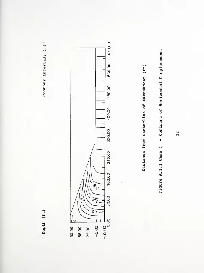
&a
iiii
4J
Cai
eo
«»% (0
P H<H a^*'
•H-P QCa) Hi (0
M 4J
C cid
XI Ns HW
O<H XO
<u0)
c-H wH h^ 3q)4J Pc ca> (N
u u fN
e 1
m<w OJ
<U 0)
O to
c (C
(0 o4JW HH •
Q<0)
3en
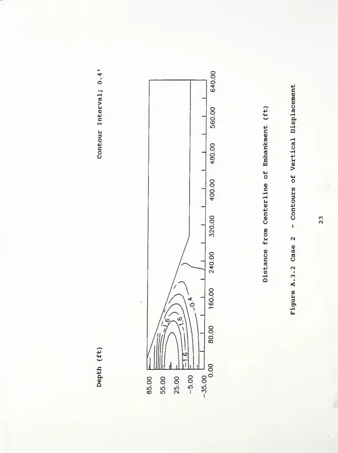
id
>UCD
HP.
O+Jcou
H-l
-paa;
Q
ucCD
e0)
0N* u±J 10
4-1 Hs—
^
aen
J-l Hc a0)
i HS to
c10 H£1 +J
e uw ai
>(U
<H
a)
C 01
•H ueH 3uCD +J4J cC<D uU
1
6
M CM4-1
CD
<D nU (0
c u(0
+J OJtn •
•H Ma •
<CD
H3&hfc
LD

X!-PaQ
-P
O
0)
CHHQ)
Pc<D
UBOM<h
0)
cR3
P-Ha
oHP10
«co
to
0)
pCO
10
aHoc•H
PL,
o
CO
u3OPCou
<0)
M3
ro

C\l
idCDm
<l _
id00
O
4J
a0)
a
>pOJ
H-l
(0
CO,—«,
•P (H<W*""'
(fl
p PC<D 4J
eX (0
c fc(0
£ He S3
w U
<W JIW
a;
c•H BO
H P.
M 3(1)
4-) Pc c0) in
a o <N
g 1
ou<U (N
(1) <d
CO
c (0
ia up01 *f•H •
a<
p3
Computer Program InputFigure A. 4.1 Case 3 - Contours of Horizontal DisplacementFigure A. 4. 2 Case 3 - Contours of Vertical DisplacementFigure A. 4. 3 Case 3 - Contours of Principal Stress RatioFigure A. 4. 4 Case 3 - Contours of Local Factors of Safety
State Route 1 over Ramsey Creek - Franklin County, Indiana Case 3
26
460 1 1 18 1
1 15 . 01
,0 0. 5 9.0
1 1 0.000 0.000
2 1 0.000 -7.500
7 1 0.000 -27.500
8 1 1 0.000 -35.000
9 12.500 0.000
17 25.000 0.000
337 625.000 0.000
345 1 640.000 0.000
10 12.500 -7.500
15 12.500 -27.500
16 1 12.500 -35.000
18 25.000 -7.500
338 625.000 -7.500
346 1 640.000 -7.500
351 1 640.000 -27.500
352 1 1 640.000 -35.000
19 25.000 -11.500
339 625.000 -11.500
20 25.000 -15.500
340 625.000 -15.500
21 25.000 -19.500
341 625.000 -19.500
22 25.000 -23.500
342 625.000 -23.500
2? 25.000 -27.500
343 625.000 -27.500
24 1 25.000 -35.000
544 1 625.000 -35.000
353 1 0.000 10.000
361 1 0.000 90.000
362 12.500 10.000
370 12.500 90.000
371 25.000 10.000
387 265.000 10.000
388 280.000 5.000
389 250.000 15.000
390 25.000 20.000
404 235.000 20.000
405 220.000 25.000
406 25.000 30.000
418 205.000 30.000
419 190.000 35.000
420 25.000 40.000
430 175.000 40.000
431 160.000 45.000
432 25.000 50.000
440 145.000 50.000
441 130.000 55.000
442 25.000 60.000
448 115.000 60.000
449 100.000 65.000
450 25.000 70.000
454 85.000 70.000
455 70.000 75.000
456 25.000 80.000
458 55.000 80.000
459 40.000 85.000
460 25.000 90.000
8
1I
0. 640. -7.5 0. 0. 0.
0. 0. 0. -7.5 0. 125 0.0626 21
0. 640. -11.5 -7.51 0. 0.
0. 0. 0. -7.5 0. 120 0.0576 21
2
0. 640. -15.5 -11.51 0. 0.
0. 0. 0. -7.5 0. 120 0.0576 21
2
0. 640. -19.5 -15.51 0. 0.
0. 0. 0. -7.5 0. 120 0.0576 21
2
0. 640. -23.5 -19.51 0. 0.
0. 0. 0. -7.5 0. 120 0.0576 21
2
0. 640. -27.5 -23.51 0. 0.
0. 0. 0. -7.5 0, 120 0.0576 21.
2
0. 640. -35.0 -27.51 0. 0.
0. 0. 0. -7.5 0. 130 0.0676 21,
3
0. 295. 0. 90. 0. 0.
0.1 0.50
2
1
409 4 10 8 13 4 2 16
1
300. 0.4 0.7500 21. .720 0.230 0.039
8.0 0.01 0.000 10. 2.
2
300. 0.4 0.7500 21. ,720 0.250 0.050
7.20 0.01 0.000 10. 2.
3
300. 0.4 0.7500 21. 0.,720 0.250 0.050
4.9 0.01 0.000 10. 2,
4
300. 0.4 0.7500 21. 0,,720 0.250 0.050
4.30 0.01 0.000 10. 2.
5
300. 0.4 0.7500 21. 0. 720 0.250 0.050
3.8 0.01 0.000 10. 2.
6
300. 0.4 0.7500 21. 0, 720 0.250 0.050
3.40 0.01 0.000 10. 2.
7
300. 0.4 0.6630 21. 0. 720 0.124 0.020
2.5 0.01 0.000 10. 2.
8
300. 0.4 0.7500 60. 0. 000 0.124 0.020
20.0
1
0.01
4 1
0.125
1 8
0.
0.
2.
9 1 2 10
43 4 1 1 0.
345 337 338 346
44 4 1 2 8 0.
10 2 3 11
86 4 1 2 0.
27
8.0
7.20
4,9
4.30
3.8
3.40
2.5
1.58
1.46
1.07
0.96
0.87
0.80
0.63
1.58
346 338 339 347
87 4 1 3 8 0.
11 3 4 12
129 4 1 3 0.
347 339 340 348
130 4 1 4 8 0.
12 4 5 13
172 4 1 4 0.
348 340 341 349
173 4 1 5 8 0.
13 5 6 14
215 4 1 5 0.
349 341 342 350
216 4 1 6 8 0.
14 6 7 15
258 4 1 6 0.
350 342 343 351
259 4 1 7 8 0.
15 7 8 16
301 4 1 7 0.
351 343 344 352
302 4 1 8 0.01
362 353 1 9
303 4 1 8 0.01
371 362 9 17
304 4 1 8 0.01
372 371 17 25
305 4 1 8 0.01
373 372 25 33
306 4 1 8 0.01
374 373 33 41
307 4 1 8 0.01
375 374 41 49
308 4 1 8 0.01
376 375 49 57
309 4 1 8 0.01
377 376 57 65
310 4 1 8 0.01
378 377 65 73
311 4 1 8 0.01
379 378 73 81
312 4 1 8 0.01
380 379 81 89
313 4 1 8 0.01
381 380 89 97
314 4 1 8 0.01
382 381 97 105
315 4 1 8 0.01
383 382 105 113
316 4 1 8 0.01
384 383 113 121
317 4 1 8 0.01
385 384 121 129
318 4 1 8 0.01
386 385 129 137
319 4 1 8 0.01
387 386 137 145
320 4 1 8 0.01
388 387 145 153
321 4 1 8 0.01
28

388 388 153 161
322 4 1 8 1.
363 354 353 362
323 4 1 8 1.
390 363 362 371
324 4 1 8 1 1.
391 390 371 372
337 4 1 8 1.
404 403 384 385
338 4 1 8 1.
389 404 385 386
339 4 1 8 1.
389 389 386 387
340 4 1 8 2.
364 355 354 363
341 4 1 8 2.
406 364 363 390
342 4 1 8 1 2.
407 406 390 391
353 4 1 8 2.
418 417 401 402
354 4 1 8 2.
405 418 402 403
355 4 1 8 2.
405 405 403 404
356 4 1 8 3.
365 356 355 364
357 4 1 8 3.
420 365 364 406
358 4 1 8 1 3.
421 420 406 407
367 4 1 8 3.
430 429 415 416
368 4 1 8 3.
419 430 416 417
369 4 1 8 3.
419 419 417 418
370 4 1 8 4.
366 357 356 365
371 4 1 8 4.
432 366 365 420
372 4 1 8 1 4.
433 432 420 421
379 4 1 8 4.
440 439 427 428
380 4 1 8 4.
431 440 428 429
381 4 1 8 4.
431 431 429 430
382 4 1 8 5.
367 358 357 366
383 4 1 8 5.
442 367 366 432
384 4 1 8 1 5.
443 442 432 433
389 4 1 8 5.
448 447 437 438
390 4 1 8 5.
441 448 438 439
391 4 1 8 5.
29
441 441 439 440
392 4 1 8 6.
36S 359 358 367
393 4 1 8 6.
450 368 367 442
394 4 1 8 1 6.
451 450 442 443
397 4 1 8 6.
454 453 445 446
398 4 1 8 6.
449 454 446 447
399 4 1 8 6.
449 449 447 448
400 4 1 8 7.
369 360 359 366
401 4 1 8 7.
456 369 368 450
402 4 1 8 7.
457 456 450 451
403 4 1 8 7.
458 457 451 452
404 4 1 8 7.
455 458 452 453
405 4 1 8 7.
455 455 453 454
406 4 1 8 8.
370 361 360 369
407 4 1 8 8.
460 370 369 456
408 4 1 8 8.
459 460 456 457
409 4 1 8 8.
459 459 457 458
30

oodto
oodm
oodCD
oodo
-p&Q
4->
c<D
sQ)
-—
»
10+J rH•4-1 av«* W
•H4-> Qc(1) i-(
6 (0
3 +Jc c(0
fl Ne Hw h
4-1 ffi
<t-4
<u
eH wH Mu 3<D o4-> 4->
c cCO
u ug 1
K(H n0) a)
wc (0
to u4-1
W HH •
Q «3"
<Q)
S-i
30>

(0
>u<D
4->
c
u3o-pcou
4->
C0)
B01
*-^
+J ro
<4-l H•«^ a
m4-> HC ad)
E HM 10
c U(0 •HX2 4-1
B HW <D
>IM
(4-1
0)
c 10
•H nrH 3M O0) P4-> CC01 uue
1
u ny-i
0)
mu (0
c a(8
+J (N
w •
•H «*
Q •
<0)
u3Cn
Pa0)
a
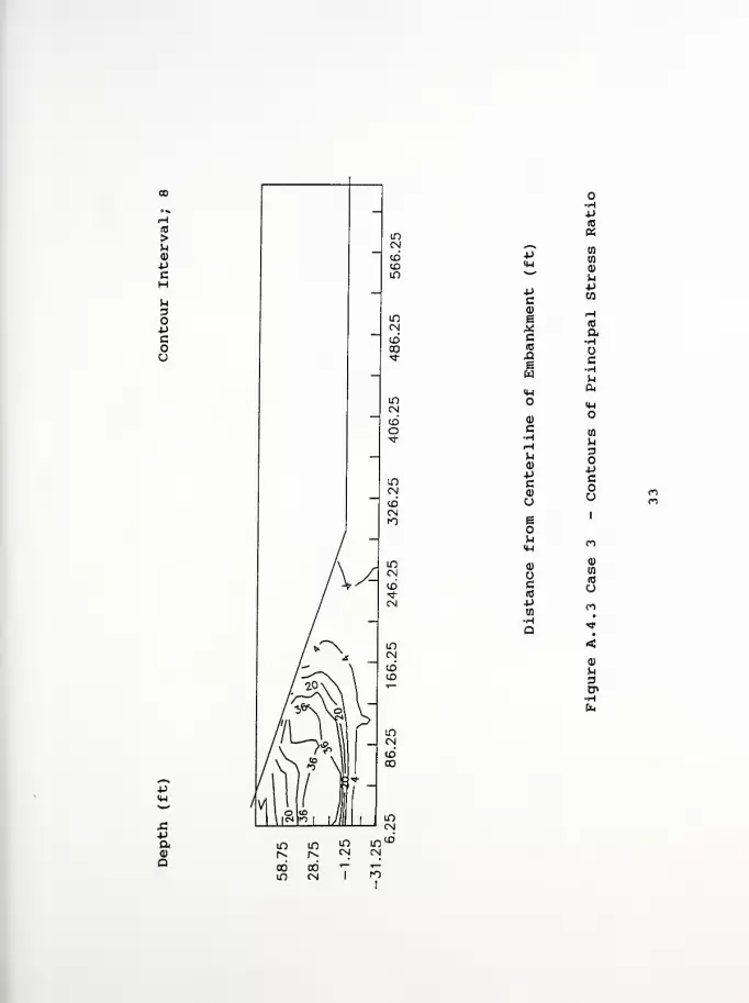
-P(0
«
p4-1
in
en
CD'""'
Mpc
4J
CD
e
cid
X!e
H(0
a•H
c
<w&H-l
<Do
c
<v
PCCD
CO
D
pcou
e 1
fO
0)
GIB
0)
en
um
Q -*
<a)
^3CP
X!Paa)
a
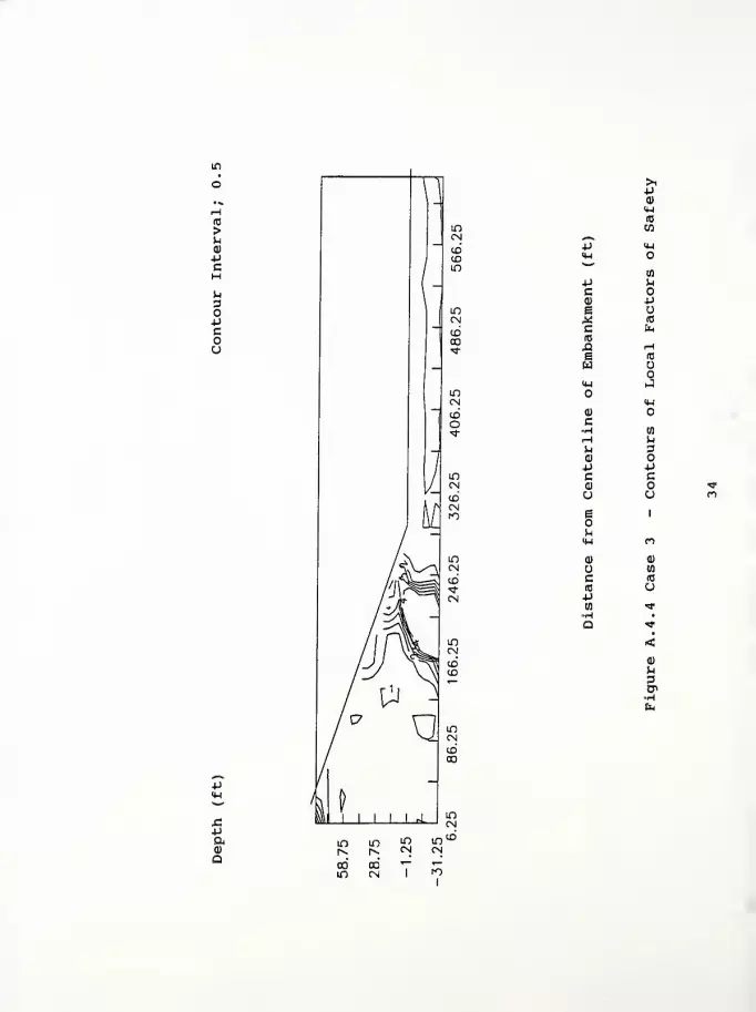
(0
>UQ)
PcHP.
3OPcou
-
p
P
>iP01
<w(0
CO0*S*i 14-1
«H^-*
to
P pcQ) 4J
ew 10
c &H(0
XI rH
i (0
WH-l J
<HQ)
C-H mH P.
M 3Q)
J *J
c C0)
u u
g 1
p.
<U m0) (D
wc 10
(0 o+J
><*
•H •
Q <*
<0)
p3er
uV

Computer Program InputFigure A. 5.1 Case 4 - Contours of Horizontal DisplacementFigure A. 5. 2 Case 4 - Contours of Vertical DisplacementFigure A. 5. 3 Case 4 - Contours of Principal Stress RatioFigure A* 5. 4 Case 4 - Contours of Local Factors of Safety
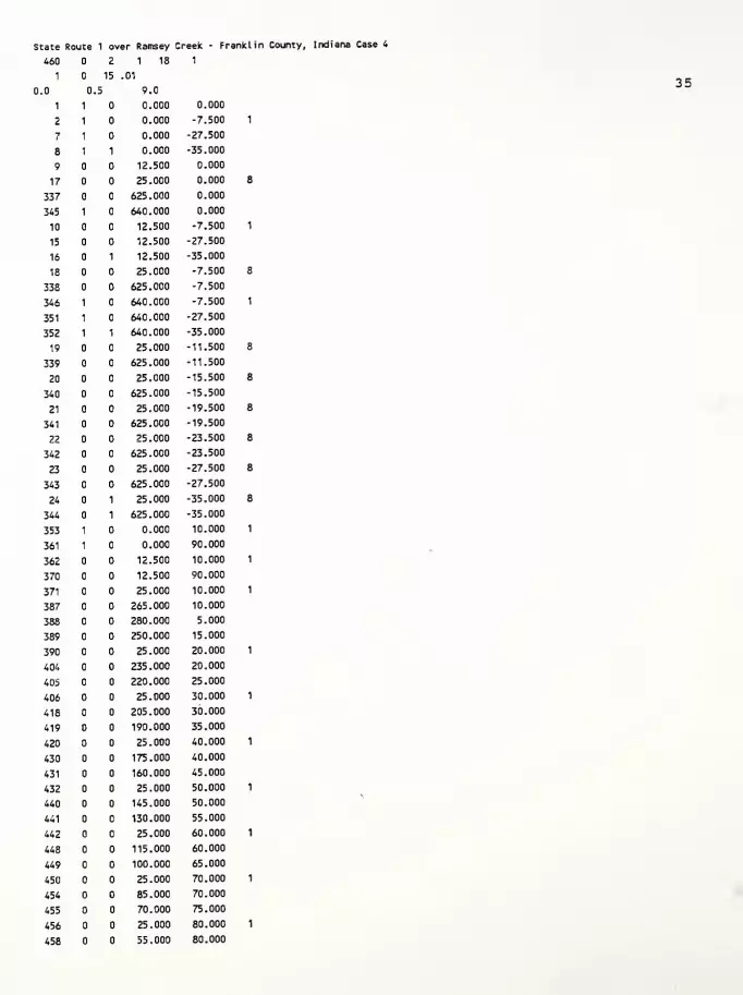
State Route 1 over Ramsey Creek - Franklin County, Indiana Case 4
460 2 1 18 1
1 15 .01
0.0 0.5 9.0
1 1 0.000 0.000
2 1 0.000 -7.500 1
7 1 0.000 -27.500
8 1 1 0.000 -35.000
9 12.500 0.000
17 25.000 0.000 8
337 625.000 0.000
345 1 640.000 0.000
10 12.500 -7.500 1
15 12.500 -27.500
16 1 12.500 -35.000
18 25.000 -7.500 8
338 625.000 -7.500
346 1 640.000 -7.500 1
351 1 640.000 -27.500
352 1 1 640.000 -35.000
19 25.000 -11.500 8
339 625.000 -11.500
20 25.000 -15.500 8
340 625.000 -15.500
21 25.000 -19.500 8
341 625.000 -19.500
22 25.000 -23.500 8
342 625.000 -23.500
23 25.000 -27.500 8
343 625.000 -27.500
24 1 25.000 -35.000 8
344 1 625.000 -35.000
353 1 0.000 10.000 1
361 1 0.000 90.000
362 12.500 10.000 1
370 12.500 90.000
371 25.000 10.000 1
387 265.000 10.000
388 280.000 5.000
389 250.000 15.000
390 25.000 20.000 1
404 235.000 20.000
405 220.000 25.000
406 25.000 30.000 1
418 205.000 30.000
419 190.000 35.000
420 25.000 40.000 1
430 175.000 40.000
431 160.000 45.000
432 25.000 50.000 1
440 145.000 50.000
441 130.000 55.000
442 25.000 60.000 1
448 115.000 60.000
449 100.000 65.000
450 25.000 70.000 1
454 85.000 70.000
455 70.000 75.000
456 25.000 80.000 1
458 55.000 80.000
35

459 40.000 85.000
460 25.000 90.000
8
1
0. 640. -7.5 0. 0. 0.
0.
1
0. 0. -11.5 0. 125 0.0626 21
0. 640. -11.5 -7.51 0. 0.
0. 0. 0. -11.5 0. 120 0.0576 21
2
0. 640. -15.5 -11.51 0. 0.
0. 0. 0. -11.5 0. 120 0.0576 21
2
0. 640. -19.5 -15.51 0. 0.
0. 0. 0. -11.5 0. 120 0.0576 21
2
0. 640. -23.5 -19.51 0. 0.
0. 0. 0. -11.5 0. 120 0.0576 21
2
0. 640. -27.5 -23.51 0, 0.
0. 0. 0. -11.5 0. 120 0.0576 21
2
0. 640. -35.0 -27.51 0. 0.
0. 0. 0. -11.5 0. 130 0.0676 21,
3
0. 295. 0. 90. 0. 0.
0.1 0.50
2 409 4 10 8 13 4 2 16
1
300. 0.4 0.7500 21. ,720 0.230 0.039
8.0 0.01 0.000 10. 2
2
300. 0.4 0.7500 21. 0.,720 0.250 0.050
7.20 0.01 0.000 10. 2.
3
300. 0.4 0.7500 21. 720 0.250 0.050
4.9 0.01 0.000 10. 2,
4
300. 0.4 0.7500 21. 0..720 0.250 0.050
4.30 0.01 0.000 10. 2.
5
300. 0.4 0.7500 21. 0. 720 0.250 0.050
3.8 0.01 0.000 10. 2.
6
300. 0.4 0.7500 21. 0. 720 0.250 0.050
3.40 0.01 0.000 10. 2.
7
300. 0.4 0.6630 21. 0. 720 0.124 0.020
2.5 0.01 0.000 10. 2.
8
300. 0.4 0.7500 60. 0. 000 0.124 0.020
20.0
1
0.01
4 1
0.125
1 8
0.
0.
2.
9 1 2 10
43 4 1 1 0.
345 337 338 346
44 4 1 2 8 0.
10 2 3 11
86 4 1 2 0.
36
8.0
7.20
4.9
4.30
3.8
3.40
2.5
1.58
1.46
1.07
0.96
0.87
0.80
0.63
1.58
346 338 339 347
87 4 1 3 8 0.
11 3 4 12
129 4 1 3 0.
347 339 340 348
130 4 1 4 8 0.
12 4 5 13
172 4 1 4 0.
348 340 341 349
173 4 1 5 8 0.
13 5 6 14
215 4 1 5 0.
349 341 342 350
216 4 1 6 8 0.
14 6 7 15
258 4 1 6 0.
350 342 343 351
259 4 1 7 8 0.
15 7 8 16
301 4 1 7 0.
351 343 344 352
302 4 1 8 0.01
362 353 1 9
303 4 1 8 0.01
371 362 9 17
304 4 1 8 0.01
372 371 17 25
305 4 1 8 0.01
373 372 25 33
306 4 1 8 0.01
374 373 33 41
307 4 1 8 0.01
375 374 41 49
308 4 1 8 0.01
376 375 49 57
309 4 1 8 0.01
377 376 57 65
310 4 1 8 0.01
378 377 65 73
311 4 1 8 0.01
379 378 73 81
312 4 1 8 0.01
380 379 81 89
313 4 1 8 0.01
381 380 89 97
314 4 1 8 0.01
382 381 97 105
315 4 1 8 0.01
383 382 105 113
316 4 1 8 0.01
384 383 113 121
317 4 1 8 0.01
385 384 121 129
318 4 1 8 0.01
386 385 129 137
319 4 1 8 0.01
387 386 137 145
320 4 1 8 0.01
388 387 145 153
321 4 1 8 0.01
37
388 388 153 161
322 4 1 8 1.
363 354 353 362
323 4 1 8 1.
390 363 362 371
324 4 1 8 1 1.
391 390 371 372
337 4 1 8 1.
404 403 384 385
338 4 1 8 1.
389 404 385 386
339 4 1 8 1.
389 389 386 387
340 4 1 8 2.
364 355 354 363
341 4 1 8 2.
406 364 363 390
342 4 1 8 1 2.
407 406 390 391
353 4 1 8 2.
418 417 401 402
354 4 1 8 2.
405 418 402 403
355 4 1 8 2.
405 405 403 404
356 4 1 8 3.
365 356 355 364
357 4 1 8 3.
420 365 364 406
358 4 1 8 1 3.
421 420 406 407
367 4 1 8 3.
430 429 415 416
368 4 1 8 3.
419 430 416 417
369 4 1 8 3.
419 419 417 418
370 4 1 8 4.
366 357 356 365
371 4 1 8 4.
432 366 365 420
372 4 1 8 1 4.
433 432 420 421
379 4 1 8 4.
440 439 427 428
380 4 1 8 4.
431 440 428 429
381 4 1 8 4.
431 431 429 430
382 4 1 8 5.
367 358 357 366
383 4 1 8 5.
442 367 366 432
384 4 1 8 1 5.
443 442 432 433
389 4 1 8 5.
448 447 437 438
390 4 1 8 5.
441 448 438 439
391 4 1 8 5.
38

441 441 439 440
392 4 1 8 6.
368 359 358 367
393 4 1 8 6.
450 368 367 442
394 4 1 8 1 6.
451 450 442 443
397 4 1 8 6.
454 453 445 446
398 4 1 8 6.
449 454 446 447
399 4 1 8 6.
449 449 447 448
400 4 1 8 7.
369 360 359 368
401 4 1 8 7.
456 369 368 450
402 4 1 8 7,
457 456 450 451
403 4 1 8 7.
458 457 451 452
404 4 1 8 7.
455 458 452 453
405 4 1 8 7.
455 455 453 454
406 4 1 8 8.
370 361 360 369
407 4 1 8 8.
460 370 369 456
408 4 1 8 8.
459 460 456 457
409 4 1 8 8.
459 459 457 458
1 20 2 2 1 8
1
0.
1 1 9
.067 083 .16
2 9 17
3 17 25
4 25 33
5 33 41
6 41 49
7 49 57
8 57 65
9 65 73
10 73 81
11 81 89
12 89 97
13 97 105
14 105 113
15 113 121
16 121 129
17 129 137
18 137 145
19 145 153
20 153 161
39
,14
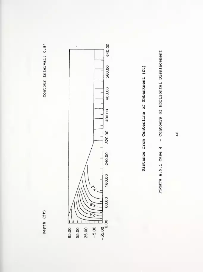
JC
aa
•PCa>
e0)
o*-N, (C+J iH<w a**
H=P QC<D HE 10
* *J
C c(0
Q Ne •Hw<W ECo
<w0)
c•H CO
iH Mu 3d) oJJ •pc c0) o ou u ^r
e 1
oM<w >*
0) <p
(0
c rO
(0 u+J
m H•H •
Q in
&fa

u3OPcoo
Pa0)
a
-Pc<D
eCU
«*•*.
P 10
<M i—
i
^ am
4-> •Hc aa)
e ^H
M (T3
C U(0 •H£ PS i-l
w <D
>4-1
4-1
<D
C w•H p.
r-l 3^CD VP cC<D ou
1
e
u «*<u
0)
0) wu (0
c Vrt)
p <Nen •
•H in
Q •
<Q)
P3CP
oooo oo
Oo oo
00mCM 1
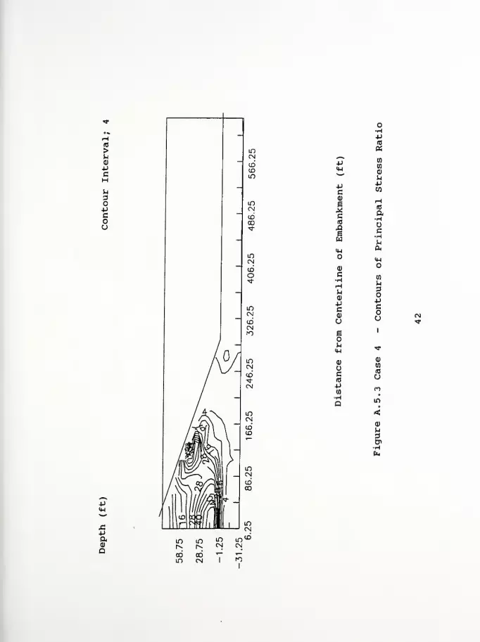
H10
>ud)
pcM
3opcou
-p
a)
a
-pc
IC(0
X!ewM-l
o
C
(1)
-Pca>
ueouiw
<D
Uc
P03
P(0
aen
w
^pen
rH(0
a•Hoc•Hua,
0-1
o
^3OPcou
Q)
W
U
a)

(0
>u0)
cHH3O-Pcou
P
pa0)
Q
>1•PQ)
IM(0
CO^-v
*J <w<W o*"
mP P.
cai +J
e£ (0
c &HIB
A He RJ
w<U J
<wQ) oC•H mrH uu 30)
4-1 PC ca) no u «
e 1
M<H *a) ai
uc (0
(0 u*J
w *H •
Q in
<0)
P.
3

Computer Program InputFigure A. 6.1 Case 5 - Contours of Horizontal DisplacementFigure A. 6. 2 Case 5 - Contours of Vertical DisplacementFigure A. 6. 3 Case 5 - Contours of Principal Stress RatioFigure A. 6. 4 Case 5 - Contours of Local Factors of Safety
State Route 1 over Ramsey Creek - Franklin County, Indiana Case 5
460 2 1 18 1
1 15 .01
0.0 .5 9.0
1 1 0.000 0.000
2 1 0.000 -7.500
7 1 0.000 -27.500
8 1 1 0.000 -35.000
9 12.500 0.000
17 25.000 0.000
337 625.000 0.000
345 1 640.000 0.000
10 12.500 -7.500
15 12.500 -27.500
16 1 12.500 -35.000
18 25.000 -7.500
338 625.000 -7.500
346 1 640.000 -7.500
351 1 640.000 -27.500
352 1 1 640.000 -35.000
19 25.000 11.500
339 625.000 -11.500
20 25.000 -15.500
340 625.000 -15.500
21 25.000 -19.500
341 625.000 -19.500
22 25.000 -23.500
342 625.000 -23.500
23 25.000 -27.500
343 625.000 -27.500
24 1 25.000 -35.000
344 1 625.000 -35.000
353 1 0.000 10.000
361 1 0.000 90.000
36? 12.500 10.000
370 12.500 90.000
371 25.000 10.000
387 265.000 10.000
388 280.000 5.000
389 250.000 15.000
390 25.000 20.000
404 235.000 20.000
405 220.000 25.000
406 25.000 30.000
418 205.000 30.000
419 190.000 35.000
420 25.000 40.000
430 173.000 40.000
431 160.000 45.000
43? 25.000 50.000
440 145.000 50.000
441 130.000 55.000
442 25.000 60.000
448 115.000 60.000
449 100.000 65.000
450 25.000 70.000
454 85.000 70.000
455 70.000 75.000
456 25.000 80.000
458 55.000 80.000
44
459 40.000 85.000
460 25.000 90.000
8
11
0. 640. -7.5 0. 0. 0.
0.
1
0. 0. -11.5 0. 125 0.0626 21
1
0. 640. -11.5 -7.51 0. 0.
0. 0. 0. -11.5 0. 120 0.0576 21
2
0. 640. -15.5 -11.51 0. 0.
0. 0. 0. -11.5 0. 120 0.0576 21
2
0. 640. -19.5 -15.51 0. 0.
0. 0. 0. -11.5 0. 120 0.0576 21
2
0. 640. -23.5 -19.51 0. 0.
0. 0. 0. -11.5 0. 120 0.0576 21
2
0. 640. -27.5 -23.51 0. 0.
0. 0. 0. -11.5 0. 120 0.0576 21,
2
0.' 640. -35.0 -27.51 0. 0.
0. 0. 0. -11.5 0. 130 0.0676 21,
3
0. 295. 0. 90. 0. 0.
0.1 0.50
2 409 4 10 8 13 4 2 16
1
300. 0.4 0.7500 21. ,720 0.230 0.039
8.0 0.01 0.000 10. 2
2
300. 0.4 0.7500 21. 0.,720 0.250 0.050
7.20 0.01 0.000 10. 2,
3
300. 0.4 0.7500 21. 0,,720 0.250 0.050
4.9 0.01 0.000 10. 2.
4
300. 0.4 0.7500 21. 0. 720 0.250 0.050
4.30 0.01 0.000 10. 2.
5
300. 0.4 0.7500 21. 0. 720 0.250 0.050
3.8 0.01 0.000 10. 2.
6
300. 0.4 0.7500 21. 0. 720 0.250 0.050
3.40 0.01 0.000 10. 2.
7
300. 0.4 0.6630 21. 0. 720 0.124 0.020
2.5 0.01 0.000 10. 2.
8
300. 0.4 0.7500 60. 0. 000 0.124 0.020
3.0
1
0.01
4 1
0.125
1 8
0.
0.
2.
9 1 2 10
43 4 1 1 0.
345 337 338 346
44 4 1 2 8 0.
10 2 3 11
86 4 1 2 0.
45
8.0
7.20
4.9
4.30
3.8
3.40
2,5
1.58
1,46
1.07
0.96
0.87
0.80
0.63
0.73
346 338 339 347
87 4 1 3 8 0.
11 3 4 12
129 4 1 3 0.
347 339 340 348
130 4 1 4 8 0.
12 4 5 13
172 4 1 4 0.
348 340 341 349
173 4 1 5 8 0.
13 5 6 14
215 4 1 5 0.
349 341 342 350
216 4 1 6 8 0.
14 6 7 15
258 4 1 6 0.
350 342 343 351
259 4 1 7 8 0.
15 7 8 16
301 4 1 7 0.
351 343 344 352
302 4 1 8 0.01
362 353 1 9
303 4 1 8 0.01
371 362 9 17
304 4 1 8 0.01
372 371 17 25
305 4 1 8 0.01
373 372 25 33
306 4 1 8 0.01
374 373 33 41
307 4 1 8 0.01
375 374 41 49
308 4 1 8 0.01
376 375 49 57
309 4 1 8 0.01
377 376 57 65
310 4 1 8 0.01
378 377 65 73
311 4 1 8 0.01
379 378 73 81
312 4 1 8 0.01
380 379 81 89
313 4 1 8 0.01
381 380 89 97
314 4 1 8 0.01
382 381 97 105
315 4 1 8 0.01
383 382 105 113
316 4 1 8 0.01
384 383 113 121
317 4 1 8 0.01
385 384 121 129
318 4 1 8 0.01
386 385 129 137
319 4 1 8 0.01
387 386 137 145
320 4 1 8 0.01
388 387 145 153
321 4 1 8 0.01
46
388 388
322 4
363 354
323 4
390 363
324 4
391 390
337 4
404 403
338 4
389 404
339 4
389 389
340 4
364 355
341 4
406 364
342 4
407 406
353 4
418 417
354 4
405 418
355 4
405 405
356 4
365 356
357 4
420 365
358 4
421 420
367 4
430 429
368 4
419 430
369 4
419 419
370 4
366 357
371 4
432 366
372 4
433 432
379 4
440 439
380 4
431 440
381 4
431 431
382 4
367 358
383 4
442 367
384 4
443 442
389 4
448 447
390 4
441 448
391 4
153
1
353
1
362
1
371
1
384
1
385
1
386
1
354
1
363
1
390
1
401
1
402
1
403
1
355
1
364
1
406
1
415
1
416
1
417
1
356
1
365
1
420
1
427
1
428
1
429
1
357
1
366
1
432
1
437
1
438
1
161
8
362
8
371
8
372
8
385
8
386
8
387
8
363
8
390
8
391
8
402
8
403
8
404
8
364
8
406
8
407
8
416
8
417
8
418
8
365
8
420
8
421
8
428
8
429
8
430
8
366
8
432
8
433
8
438
8
439
8
1
1
1
1
1
1.
1.
1.
1.
1.
1.
2.
2.
2.
2.
2.
2.
3.
3.
3.
3.
3,
3.
4.
4.
4.
4.
4.
4.
5.
5.
5.
5.
5.
5.
47
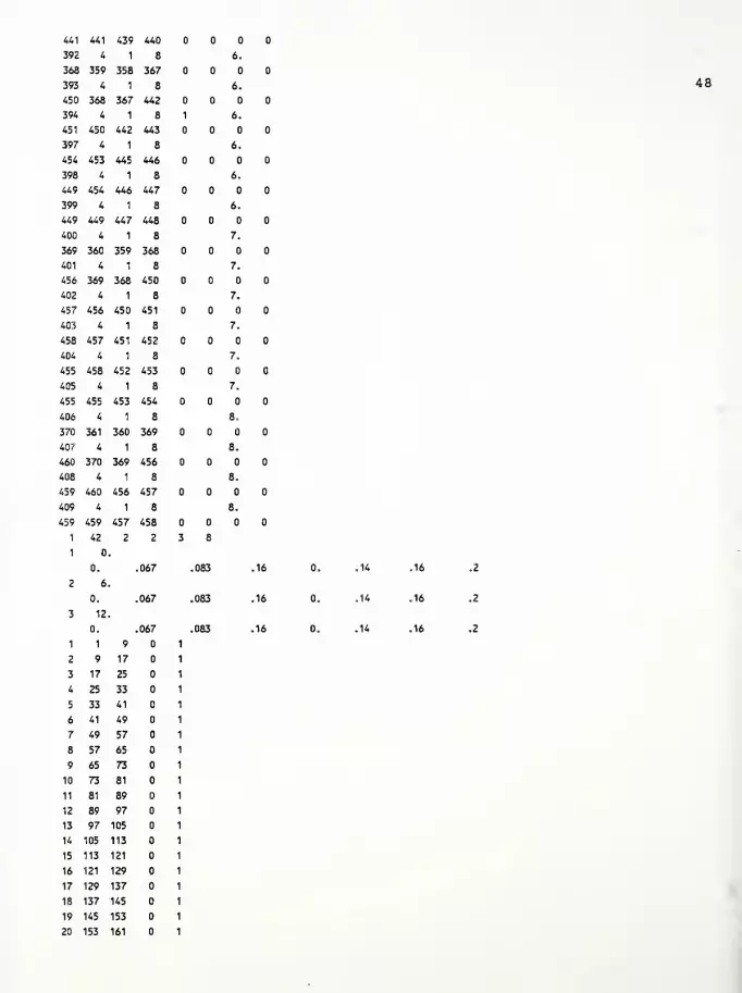
441 441 439 440
392 4 1 8 6.
368 359 358 367
393 4 1 8 6.
450 368 367 442
394 4 1 8 1 6.
451 450 442 443
397 4 1 8 6.
454 453 445 446
398 4 1 8 6.
449 454 446 447
399 4 1 8 6.
449 449 447 448
400 4 1 8 7.
369 360 359 368
401 4 1 8 7.
456 369 368 450
402 4 1 8 7.
457 456 450 451
403 4 1 8 7.
458 457 451 452
404 4 1 8 7.
455 458 452 453
405 4 1 8 7.
455 455 453 454
406 4 1 8 8,
370 361 360 369
40 r- 4 1 8 8.
460 370 369 456
408 4 1 8 8.
459 460 456 457
409 4 1 8 8.
459 459 457 458
1 42 2 2 3 8
1 0.
0. .067 083 .16 .14 .16 .2
2 6.
0. 067 083 .16 .14 .16 .2
3 12.
0. 067 083 .16 .14 .16 .2
1 1 9
2 9 17
3 17 25
4 25 33
5 33 41
6 41 49
7 49 57
8 57 65
9 65 73
10 73 81
11 81 89
12 89 97
13 97 105
14 105 113
15 113 121
16 121 129
17 129 137
18 137 145
19 145 153
20 153 161
48
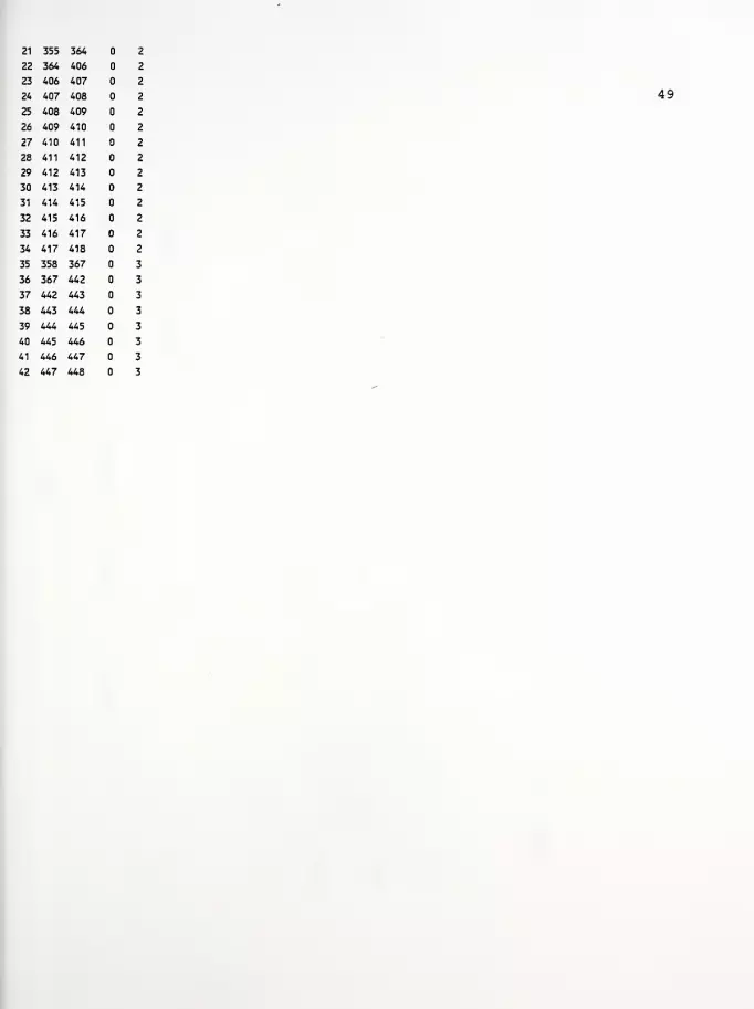
21 355 364 2
22 364 406 2
23 406 407 2
24 407 408 2
25 408 409 2
26 409 410 2
27 410 411 2
28 411 412 2
29 412 413 2
30 413 414 2
31 414 415 2
32 415 416 2
33 416 417 2
34 417 418 2
35 358 367 3
36 367 442 3
37 442 443 3
38 443 444 3
39 444 445 3
40 445 446 3
41 446 447 3
42 447 448 3
49
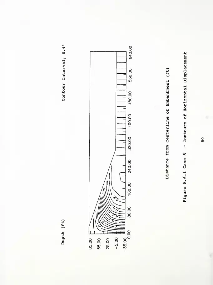
u
opcou
4J
-PaQ)
Q
ca)
sQO^ (C
4J iHIH a*^ CO
•HP QCQ) i—
1
B <C
^ PC c(0
£1 Na Hw u
M-l EC
<M0)
c-H nrH MM 3Q)
4J PC c<D oU u in
e 1
hIM in
<D 0)
mc (0
R) u4Jen iH•H •
a<
M3&
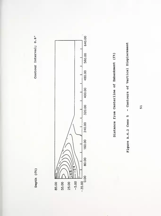
Uca)
e0)
,—
»
-P ro
M-l rH^^ a
to
4-> -Hc Q<D
s H* id
c u(0 HX! +J
h&3 <D
>IW
M-l
d)
c (0
•H urH 3(-< o0) +J*J cc oa) uo
1
e
n in
M-l
CD
a) Wu ac ufi3
+J cN
to »
H VO
a •
<a>
h3<T
+J
aCD
a

CO
4J
5aa>
a
c
e
c
ew(4-4
o
<1)
c-H,—1
a)
cQ)
Ueo
0)
uc(0
4J
4J
(0
(X
tn
0)
u4-1
Huc
14-1
o
en
opcou
0)
^4
m'
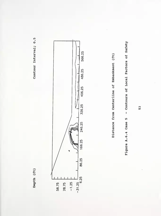
>iP0)
<HA3
COJl~*
P <H<W*~*
w4J UC oQ) pe£ <c
C faid
xt r-l
e «3
wo
<W Hi
<M<D
C•H (0
rH Hu 3<D
P Pc cQ) nO u in
E 1
MIW If)
Q) 0)
wc (0
RJ u4Jto *r•HQ
<0)
3&
+Jaa
Computer Program InputFigure A. 7.1 Case 6 - Contours of Horizontal DisplacementFigure A. 7. 2 Case 6 - Contours of Vertical DisplacementFigure A .7, 3 Case 6 - Contours of Principal Stress RatioFigure A. 7. 4 Case 6 - Contours of Local Factors of Safety
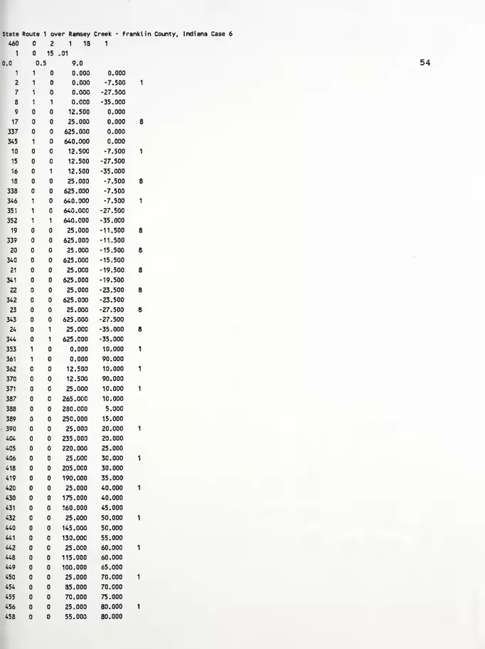
State Route 1 over Ramsey Creek - Franklin County, Indiana Case 6
460 2 1 18 1
1 15 .01
0.0 0,.5 9.0
1 1 0.000 0.000
2 1 0.000 -7.500
7 1 0.000 -27.500
8 1 1 0.000 -35.000
9 12.500 0.000
17 25.000 0.000
337 625.000 0.000
345 1 640.000 0.000
10 12.500 -7.500
15 12.500 -27.500
16 1 12.500 -35.000
18 25.000 -7.500
338 625.000 -7.500
346 1 640.000 -7.500
351 1 640.000 -27.500
352 1 1 640.000 -35.000
19 25.000 -11.500
339 625.000 -11.500
20 25.000 -15.500
340 625.000 -15.500
21 25.000 -19.500
341 625.000 -19.500
22 25.000 -23.500
342 625.000 -23.500
23 25.000 -27.500
343 625.000 -27.500
24 1 25.000 -35.000
344 1 625.000 -35.000
353 1 0.000 10.000
361 1 0.000 90.000
362 12.500 10.000
370 12.500 90.000
371 25.000 10.000
387 265.000 10.000
388 280.000 5.000
389 250.000 15.000
390 25.000 20.000
404 235.000 20.000
405 220.000 25.000
406 25.000 30.000
418 205.000 30.000
419 190.000 35.000
420 25.000 40.000
430 175.000 40.000
431 160.000 45.000
432 25.000 50.000
440 145.000 50.000
441 130.000 55.000
442 25.000 60.000
448 115.000 60.000
449 100.000 65.000
450 25.000 70.000
454 85.000 70.000
455 70.000 75.000
456 25.000 80.000
458 55.000 80.000
54
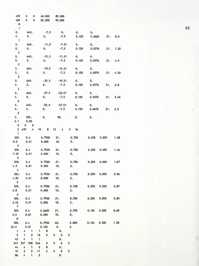
459 40.000 85.000
460 25.000 90.000
8
1
0. 640. -7.5 0. 0. 0.
0.
1
0. 0. -7.5 0. 125 0.0626 21
0. 640. -11.5 -7.51 0. 0.
0. 0. 0. -7.5 0. 120 0.0576 21
2
0. 640. -15.5 -11.51 0. 0.
0. 0. 0. -7.5 0. 120 0.0576 21
2
0. 640. -19.5 -15.51 0. 0.
0. 0. 0. -7.5 0. 120 0.0576 21
2
0. 640. -23.5 -19.51 0. 0.
0. 0. 0. -7.5 0. 120 0.0576 21
2
0. 640. -27.5 -23.51 0. 0.
0. 0. 0. -7.5 0. 120 0.0576 21
2
0. 640. -35.0 -27.51 0. 0.
0. 0. 0. -7.5 0. 130 0.0676 21.
3
0. 295. 0. 90. 0. 0.
0.1 0.50
2
1
409 4 10 8 13 4 2 16
1
300, 0.4 0.7500 21. .720 0.230 0.039
8.0 0.01 0.000 10. 2
2
300. 0.4 0.7500 21. 720 0.250 0.050
7.20 0.01 0.000 10. 2
3
300. 0.4 0.7500 21. 720 0.250 0.050
4.9 0.01 0.000 10. 2
4
300. 0.4 0.7500 21. 720 0.250 0.050
4.30 0.01 0.000 10. 2
5
300. 0.4 0.7500 21. 0. 720 0.250 0.050
3.8 0.01 0.000 10. 2.
6
300. 0.4 0.7500 21. 0. 720 0.250 0.050
3.40 0.01 0.000 10. 2.
7
300. 0.4 0.6630 21. 0. 720 0.124 0.020
2.5 0.01 0.000 10. 2.
8
300. 0.4 0.7500 60. 0. 000 0.124 0.020
20.0
1
0.01
4 1
0.125
1 8
0.
0.
2.
9 1 2 10
43 4 1 1 0.
345 337 338 346
44 4 1 2 8 0.
10 2 3 11
86 4 1 2 0.
55
8.0
7.20
4.9
4.30
3.8
3.40
2.5
1.58
1.46
1.07
0.96
0.87
0.80
0.63
1.58
346 338 339 347
87 4 1 3 8 0.
11 3 4 12
129 4 1 3 0.
347 339 340 348
130 4 1 4 8 0.
12 4 5 13
172 4 1 4 0.
348 340 341 349
173 4 1 5 8 0.
13 5 6 14
215 4 1 5 0.
349 341 342 350
216 4 1 6 8 0.
14 6 7 15
258 4 1 6 0.
350 342 343 351
259 4 1 7 8 0.
15 7 8 16
301 4 1 7 0.
351 343 344 352
302 4 1 8 0.01
362 353 1 9
303 4 1 8 0.01
371 362 9 17
304 4 1 8 0.01
372 371 17 25
305 4 1 8 0.01
373 372 25 33
306 4 1 8 0.01
374 373 33 41
307 4 1 8 0.01
375 374 41 49
308 4 1 8 0.01
376 375 49 57
309 4 1 8 0.01
377 376 57 65
310 4 1 8 0.01
378 377 65 73
311 4 1 8 0.01
379 378 73 81
312 4 1 8 0.01
380 379 81 89
313 4 1 8 0.01
381 380 89 97
314 4 1 8 0.01
382 381 97 105
315 4 1 8 0.01
383 382 105 113
316 4 1 8 0.01
384 383 113 121
317 4 1 8 0.01
385 384 121 129
318 4 1 8 0.01
386 385 129 137
319 4 1 8 0.01
387 386 137 145
320 4 1 8 0.01
388 387 145 153
321 4 1 8 0.01
56

388 388 153 161
322 4 1 8 1.
363 354 353 362
323 4 1 8 1.
390 363 362 371
324 4 1 8 1 1.
391 390 371 372
337 4 1 8 1.
404 403 384 385
338 4 1 8 1.
389 404 385 386
339 4 1 8 1.
389 389 386 387
340 4 1 8 2.
364 355 354 363
341 4 1 8 2.
406 364 363 390
342 4 1 8 1 2.
407 406 390 391
353 4 1 8 2.
418 417 401 402
354 4 1 8 2.
405 418 402 403
355 4 1 8 2.
405 405 403 404
356 4 1 8 3.
365 356 355 364
357 4 1 8 3.
420 365 364 406
358 4 1 8 1 3.
421 420 406 407
367 4 1 8 3.
430 429 415 416
368 4 1 8 3.
419 430 416 417
369 4 1 8 3.
419 419 417 418
370 4 1 8 4.
366 357 356 365
371 4 1 8 4.
432 366 365 420
372 4 1 8 1 4.
433 432 420 421
379 4 1 8 4.
440 439 427 428
380 4 1 8 4.
431 440 428 429
381 4 1 8 4.
431 431 429 430
382 4 1 8 5.
367 358 357 366
383 4 1 8 5.
442 367 366 432
384 4 1 8 1 5.
443 442 432 433
389 4 1 8 5.
448 447 437 438
390 4 1 8 5.
441 448 438 439
391 4 1 8 5.
57

441 441 439 440
392 4 1 8 6.
368 359 358 367
393 4 1 8 6.
450 368 367 442
394 4 1 8 1 6.
451 450 442 443
397 4 1 8 6.
454 453 445 446
398 4 1 8 6.
449 454 446 447
399 4 1 8 6.
449 449 447 448
400 4 1 8 7.
369 360 359 368
401 4 1 8 7.
456 369 368 450
402 4 1 8 7.
457 456 450 451
403 4 1 8 7.
458 457 451 452
404 4 1 8 7.
455 458 452 453
405 4 1 8 7.
455 455 453 454
406 4 1 8 8.
370 361 360 369
407 4 1 8 8.
460 370 369 456
408 4 1 8 8.
459 460 456 457
409 4 1 8 8.
459 459 457 458
1 20 2 2 1 8
1
0.
1 1 9
067 083 .16
2 9 17
3 17 25
4 25 33
5 33 41
6 41 49
7 49 57
8 57 65
9 65 73
10 73 81
11 81 89
12 89 97
13 97 105
14 105 113
15 113 121
16 121 129
17 129 137
18 137 145
19 145 153
20 153 161
58
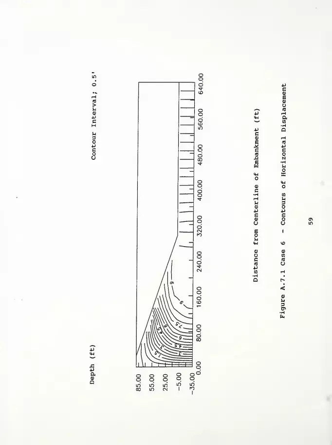
H10
>uQ)
PcHuDO+J
cou
J->
aQ)
Q
pca)
sa)
o«—
N
(C
P iH<U a^^ (0HP aca) <-\
e (0
.* •pc c(0 oja Ng Hw i-l
<w ffi
IHa> Oc•H ta
rH hu 3Q)
P PC c<D o enU u in
e 1
u<H VO
a> <u
u nc m(C u-p
HH
a•
<
M3
fa

(0
>u<D
-PCMuaoPCou
X!P&o>
D
-PC0)
e0)
«*^ u4-1 (0
H-l rH*"" aP •Hc Q<D
e rH^ IT3
c(0 •Hja -P
CD
>HH
<4-l
0)
c in
•w ^rH 3M<U -PP cC0) u Ou VD
e1
u VO<u
a)
0) wo (B
c a(0
-p <N03
•H•
Q •
<<D
u
&•Hfa
U")
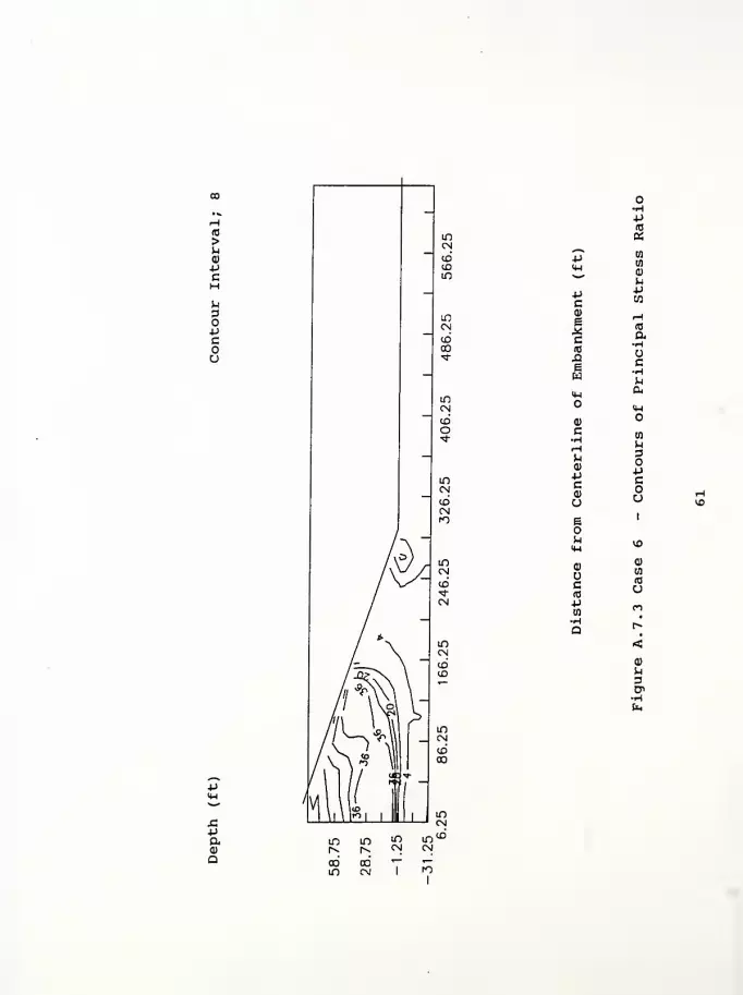
amQ
LO
too
uid
a
4J" to
to
0)
S-i
-Pc
P
0)
i
c(0
X!Ew
1-1
(0
a•H
c•H
Ip,&IM
(1)O
cHH<D
*>Ca)
a
ua
pc
u
e 1
u\o
Oc(0
0)
en
(0
u4-> (*>
•Ha r»
<<D
h3Cn

(0
>uQ)
PCH
^3OPcou
tn
>i-P<D
<M(0
w,—
V
p 4-1
<H%**1
w-P (-1
C od) pe o^ (0
c fc
A He (0
w14-1 ij
(4-1
<D
C•H (0
rH hU 30)
-P -pc c(1) fM
o o VD
e 1
M<U VD
0> 0)
wc (0
10 u-pID <r•H •
Q<
3
x:pa0)
Q

Computer Program InputFigure A. 8.1 Case 7 - Contours of Horizontal DisplacementFigure A. 8. 2 Case 7 - Contours of Vertical DisplacementFigure A. 8. 3 Case 7 - Contours of Principal Stress RatioFigure A. 8. 4 Case 7 - Contours of Local Factors of Safety
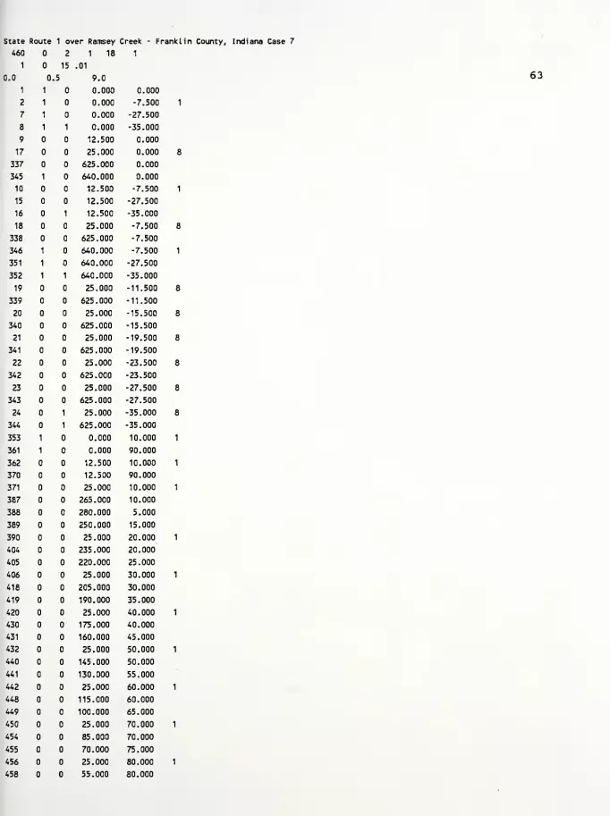
State Route 1 over Ramsey Creek - Franklin County, Indiana Case 7
63
460 2 1 18 1
1 15 .01
0.0 0,.5 9.0
1 1 0.000 0.000
2 1 0.000 -7.500
7 1 0.000 -27.500
8 1 1 0.000 -35.000
9 12.500 0.000
17 25.000 0.000
337 625.000 0.000
345 1 640.000 0.000
10 12.500 -7.500
15 12.500 -27.500
16 1 12.500 -35.000
18 25.000 -7.500
338 625.000 -7.500
346 1 640.000 -7.500
351 1 640.000 -27.500
352 1 1 640.000 -35.000
19 25.000 -11.500
339 625.000 -11.500
20 25.000 -15.500
340 625.000 -15.500
21 25.000 -19.500
341 625.000 -19.500
22 25.000 -23.500
342 625.000 -23.500
23 25.000 -27.500
343 625.000 -27.500
24 1 25.000 -35.000
344 1 625.000 -35.000
353 1 0.000 10.000
361 1 0.000 90.000
362 12.500 10.000
370 12.500 90.000
371 25.000 10.000
387 265.000 10.000
388 280.000 5.000
389 250.000 15.000
390 25.000 20.000
404 235.000 20.000
405 220.000 25.000
406 25.000 30.000
418 205.000 30.000
419 190.000 35.000
420 25.000 40.000
430 175.000 40.000
431 160.000 45.000
432 25.000 50.000
440 145.000 50.000
441 130.000 55.000
442 25.000 60.000
448 115.000 60.000
449 100.000 65.000
450 25.000 70.000
454 85.000 70.000
455 70.000 75.000
456 25.000 80.000
458 55.000 80.000

459 40.000 85.000
460 25.000 90.000
8
1
0. 640. -7.5 0. 0. 0.
0.
1
0. 0. -11.5 0. 125 0.0626 21
0. 640. -11.5 -7.51 0. 0.
0. 0. 0. -11.5 0. 120 0.0576 21
2
0. 640. -15.5 -11.51 0. 0.
0. 0. 0. -11.5 0. 120 0.0576 21
2
0. 640. -19.5 -15.51 0. 0.
0. 0. 0. -11.5 0. 120 0.0576 21
2
0. 640. -23.5 -19.51 0. 0.
0. 0. 0. -11.5 0. 120 0.0576 21,
2
0. 640. -27.5 -23.51 0. 0.
0. 0. 0. -11.5 0. 120 0.0576 21,
2
0. 640. -35.0 -27.51 0. 0.
0. 0. 0. -11.5 0. 130 0.0676 21.
3
0, 295. 0. 90. 0. 0.
0.1 0.50
2 409 4 10 8 13 4 2 16
1
300. 0.4 0.7500 21. ,720 0.230 0.039
8.0 0.01 0.000 10. 2,
2
300. 0.4 0.7500 21. 0,,720 0.250 0.050
7.20 0.01 0.000 10. 2.
3
300. 0.4 0.7500 21. 0..720 0.250 0.050
4.9 0.01 0.000 10. 2.
4
300. 0.4 0.7500 21. 0. 720 0.250 0.050
•4.30 0.01 0.000 10. 2.
5
300. 0.4 0.7500 21. 0. 720 0.250 0.050
3.8 0.01 0.000 10. 2.
6
300. 0.4 0.7500 21. 0. 720 0.250 0.050
3.40 0.01 0.000 10. 2.
7
300. 0.4 0.6630 21. 0.720 0.124 0.020
2.5 0.01 0.000 10. 2.
8
300. 0.4 0.7500 60. 0. 000 0.124 0.020
20.0
1
0.01
4 1
0.125
1 8
0.
0.
2.
9 1 2 10
43 4 1 1 0.
345 337 338 346
44 4 1 2 8 0.
10 2 3 11
86 4 1 2 0.
64
8.0
7.20
4.9
4.30
3.8
3.40
2.5
1.58
1.46
1.07
0.96
0.87
0.80
0.63
1.58
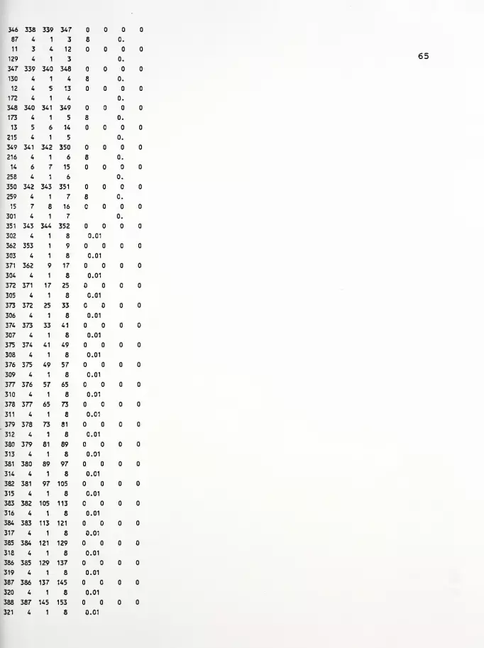
346 338
87 4
11 3
129 4
347 339
130 4
12 4
172 4
348 340
173 4
13 5
215 4
349 341
216 4
14 6
258 4
350 342
259 4
15
301
351 343
302 4
362 353
303 4
371 362
304 4
372 371
305 4
373 372
306 4
374 373
307 4
375 374
308 4
376 375
309 4
377 376
310 4
378 377
311 4
379 378
312 4
380 379
313 4
381 380
314 4
382 381
315 4
383 382
316 4
384 383
317 4
385 384
318 4
386 385
319 4
387 386
320 4
388 387
321 4
339
1
4
1
340
1
5
1
341
1
6
1
342
1
7
1
343
1
8
1
344
1
1
1
9
1
17
1
25
1
33
1
41
1
49
1
57
1
65
1
73
1
81
1
89
1
97
1
105
1
113
1
121
1
129
1
137
1
145
1
347
3
12
3
348
4
13
4
349
5
14
5
350
6
15
6
351
7
16
7
352
8
9
8
17
8
25
8
33
8
41
8
49
8
57
8
65
8
73
8
81
8
89
8
97
8
105
8
113
8
121
8
129
8
137
8
145
8
153
8
8
8
8
8
8
0.01
0.01
0.01
0.01
0.01
0.01
0.01
0.01
0.01
0.01
0.01
0.01
0.01
0.01
0.01
0.01
0.01
0.01
0.01
0.01
0.
0.
0.
0.
0.
0.
0.
0.
0.
0.
65

388 388 153 161
322 4 1 8 1.
363 354 353 362
323 4 1 8 1.
390 363 362 371
324 4 1 8 1 1.
391 390 371 372
337 4 1 8 1.
404 403 384 385
338 4 1 8 1.
389 404 385 386
339 4 1 8 1.
389 389 386 387
340 4 1 8 2.
364 355 354 363
341 4 1 8 2.
406 364 363 390
342 4 1 8 1 2.
407 406 390 391
353 4 1 8 2.
418 417 401 402
354 4 1 8 2.
405 418 402 403
355 4 1 8 2.
405 405 403 404
356 4 1 8 3.
365 356 355 364
357 4 1 8 3.
420 365 364 406
358 4 1 8 1 3.
421 420 406 407
367 4 1 8 3.
430 429 415 416
368 4 1 8 3.
419 430 416 417
369 4 1 8 3.
419 419 417 418
370 4 1 8 4.
366 357 356 365
371 4 1 8 4.
432 366 365 420
372 4 1 8 1 4.
433 432 420 421
379 4 1 8 4.
440 439 427 428
380 4 1 8 4.
431 440 428 429
381 4 1 8 4.
431 431 429 430
382 4 1 8 5.
367 358 357 366
383 4 1 8 5.
442 367 366 432
384 4 1 8 1 5.
443 442 432 433
389 4 1 8 5.
448 447 437 438
390 4 1 8 5.
441 448 438 439
391 4 1 8 5.
66

441 441 439 440
392 4 1 8 6.
368 359 358 367
393 4 1 8 6.
450 368 367 442
394 4 1 8 1 6.
451 450 442 443
397 4 1 8 6.
454 453 445 446
398 4 1 8 6.
449 454 446 447
399 4 1 8 6.
449 449 447 448
400 4 1 8 7.
369 360 359 368
401 4 1 8 7.
456 369 368 450
402 4 1 8 7.
457 456 450 451
403 4 1 8 7.
458 457 451 452
404 4 1 8 7.
455 458 452 453
405 4 1 8 7.
455 455 453 454
406 4 1 8 8.
370 361 360 369
407 4 1 8 8.
460 370 369 456
408 4 1 8 8.
459 460 456 457
409 4 1 8 8.
459 459 457 458
1 20 2 2 1 8
1
0.
1 1 9
.067 083 .16
2 9 17
3 17 25
4 25 33
5 33 41
6 41 49
7 49 57
8 57 65
9 65 73
10 73 81
11 81 89
12 89 97
13 97 105
14 105 113
15 113 121
16 121 129
17 129 137
18 137 145
19 145 153
20 153 161
67
1.68 1.92 2.4

2u<D4J
c
paoQ
4J
ea>
ga)
u»*% (0
4-1 t-i
<M a'
(0
-H4-> Qca) r-\
e (0
* Pc c(C
.0 Ng Hw<H X
<HQ) OCH WrH ku 3<D
-P 4JC ca) CO
u u vo
g 1
n<w r-
a) 0)
u uc 10
(0 UPw <H•H •
a CO
U3
m
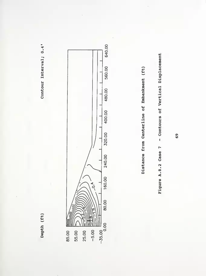
(0
>u0)
4Jc
PcQ)
ga)
«***
-P 18
<4-l rH"*' a
n+> •rH
c Q0)
s H2 (0
c(C •H,Q Pe Mw
><H
<D
C to
•H urH 3^ Od) P•P cc0) u <^
u VO
g
m r»<H
<P
0) en
(B
c UrtJp CM
(fl•
•H CO
Q<a)
3&•HEn
P
a

(0
>U0)
pc
a
-P10
a
P4-1
DO
m
pPC
pCO
e
cid
X!ew
aa•H
c•HP
(4-1A4-1
a)
c m•ri
r-l
u0)
pca)
u
p
Pc
u
e 1
14-1r»
0)
c(0
a)
to
(0
o-p
•
Q CO
<a>
p3n»

p
Pao
>1p0)
(4-1
03
CO.^^
p 14-1
14-1
*Ww
P MC o0) pe3 (0
c &H(0
X) i-H
e (0
wo
<U J<M
a)
cH (0rH ^1
M 30) oP pc ca)
u ue 1
u<w r-
<D <D
U Wc (0
(C U•ptfl "a*
i-J
a
•H
m m "3 Sf^ |«v CN CN
°° °° 7 £
Computer Program InputFigure A. 9.1 Case 8 - Contours of Horizontal DisplacementFigure A. 9. 2 Case 8 - Contours of Vertical DisplacementFigure A. 9. 3 Case 8 - Contours of Principal Stress RatioFigure A. 9. 4 Case 8 - Contours of Local Factors of Safety
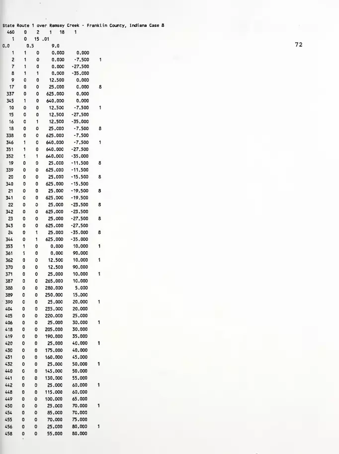
State Route 1 over Ramsey Creek - Franklin County, Indiana Case 8
72
2 1 18 1
15 .01
.5 9.0
1 0.000 0.000
1 0.000 -7.500
1 0.000 -27.500
1 1 0.000 -35.000
12.500 0.000
25.000 0.000
625.000 0.000
1 640.000 0.000
12.500 -7.500
12.500 -27.500
1 12.500 -35.000
25.000 -7.500
625.000 -7.500
1 640.000 -7.500
1 640.000 -27.500
1 1 640.000 -35.000
25.000 -11.500
625.000 -11.500
25.000 -15.500
625.000 -15.500
25.000 -19.500
625.000 -19.500
25.000 -23.500
625.000 -23.500
25.000 -27.500
625.000 -27.500
1 25.000 -35.000
1 625.000 -35.000
1 0.000 10.000
1 0.000 90.000
12.500 10.000
12.500 90.000
25.000 10.000
265.000 10.000
280.000 5.000
250.000 15.000
25.000 20.000
235.000 20.000
220.000 25.000
25.000 30.000
205.000 30.000
190.000 35.000
25.000 40.000
175.000 40.000
160.000 45.000
25.000 50.000
145.000 50.000
130.000 55.000
25.000 60.000
115.000 60.000
100.000 65.000
25.000 70.000
85.000 70.000
70.000 75.000
25.000 80.000
55.000 80.000

459
460
640.
0.
40.000
25.000
-7.5
85.000
90.000
0.
-11.5
0.
0.125
73
0.0626 21. 8.0
640.
0.
11.5 -7.51
-11.5
0.
0.120 0.0576 21. 7.20
640.
0.
15.5 -11.51
-11.5
0.
0.120 0.0576 21. 4.9
640.
0.
-19.5
0.
-15.51
-11.5
0.
0.120 0.0576 21. 4.30
640.
0.
-23.5 -19.51
-11.5
0.
0.120 0.0576 21. 3.8
640.
0.
-27.5 -23.51
-11.5
0.
0.120 0.0576 21. 3.40
0.
0.
3
0.
0.1
2
1
300.
8.0
2
300.
7.20
3
300.
4.9
4
300.
4.30
5
300.
3.8
6
300.
3.40
7
300.
2.5
8
300.
3.0
1
9
43
345
44
10
86
640.
0.
295.
0.50
409 4
0.4
0.01
0.4
0.01
0.4
0.01
0.4
0.01
0.4
0.01
0.4
0.01
0.4
0.01
0.4
0.01
4 1
1 2
4 1
337 338
4 1
2 3
4 1
-35.0
0.
-27.51
-11.5
90.
0.
0.130
10 8 13
0.7500
0.000
0.7500
0.000
0.7500
0.000
0.7500
0.000
0.7500
0.000
0.7500
0.000
0.6630
0.000
0.7500
0.125
1
10
1
346
2
11
2
21.
10.
21.
10.
21.
10.
21.
10.
21.
10.
21.
10.
21.
10.
60.
0.
0.
0.
0.
0.
0.720
2.
0.720
2.
0.720
2.
0.720
2.
0.720
2.
0.720
2.
0.720
2.
0.000
2.
0.
0.0676 21. 2.5
0.
0.230 0.039 1.58
0.250 0.050 1.46
0.250 0.050 1.07
0.250 0.050 0.96
0.250 0.050 0.87
0.250 0.050 0.80
0.124 0.020 0.63
0.124 0.020 0.73
346 338
87 4
11 3
129 4
347 339
130
12
172
339 347
1 3
4 12
1 3
340 348
1 4
348 340
173 4
341 349
13
215
349 341
216 4
14 6
258 4
350 342
259
15
301
351 343
302 4
362 353
303 4
371 362
304 4
372 371
305 4
373 372
306 4
374 373
307 4
375 374
308 4
376 375
309 4
377 376
310 4
378 377
311 4
379 378
312 4
380 379
313 4
381 380
314 4
382 381
315 4
383 382
316 4
384 383
317 4
385 384
318 4
386 385
319 4
387 386
320 4
388 387
321 4
342 350
1 6
7 15
1 6
343 351
1 7
8 16
1 7
344 352
1 8
1 9
1
9
1
17
1
25
1
33
1
41
1
49
1
57
1
65
1
73
1
81
1
89
1
8
17
8
25
8
33
8
41
8
49
8
57
8
65
8
73
8
81
8
89
8
97
8
97 105
1 8
105 113
1 8
113 121
1 8
121 129
1 8
129 137
1 8
137 145
1 8
145 153
1 8
8
8
8
8
8
0.01
0.01
0.01
0.01
0.01
0.01
0.01
0.01
0.01
0.01
0.01
0.01
0.01
0.01
0.01
0.01
0.01
0.01
0.01
0.01
0.
0.
0.
0.
0.
0.
0.
0.
0.
0.
74
388 388 153 161
322 4 1 8 1.
363 354 353 362
323 4 1 8 1.
390 363 362 371
324 4 1 8 1 1.
391 390 371 372
337 4 1 8 1.
404 403 384 385
338 4 1 8 1.
389 404 385 386
339 4 1 8 1.
389 389 386 387
340 4 1 8 2.
364 355 354 363
341 4 1 8 2.
406 364 363 390
342 4 1 8 1 2.
407 406 390 391
353 4 1 8 2.
418 417 401 402
354 4 1 8 2.
405 418 402 403
355 4 1 8 2.
405 405 403 404
356 4 1 8 3.
365 356 355 364
357 4 1 8 3.
420 365 364 406
358 4 1 8 1 3.
421 420 406 407
367 4 1 8 3.
430 429 415 416
368 4 1 8 3.
419 430 416 417
369 4 1 8 3.
419 419 417 418
370 4 1 8 4.
366 357 356 365
371 4 1 8 4.
432 366 365 420
372 4 1 8 1 4.
433 432 420 421
379 4 1 8 4.
440 439 427 428
380 4 1 8 4.
431 440 428 429
381 4 1 8 4.
431 431 429 430
382 4 1 8 5.
367 358 357 366
383 4 1 8 5.
442 367 366 432
384 4 1 8 1 5.
443 442 432 433
389 4 1 8 5.
448 447 437 438
390 4 1 8 5.
441 448 438 439
391 4 1 8 5.
75

441 441 439 440
392 4 1 8 6.
368 359 358 367
393 4 1 8 6.
450 368 367 442
394 4 1 8 1 6.
451 450 442 443
397 4 1 8 6.
454 453 445 446
398 4 1 8 6.
449 454 446 447
399 4 1 8 6.
449 449 447 448
400 4 1 8 7.
369 360 359 368
401 4 1 8 7.
456 369 368 450
402 4 1 8 7.
457 456 450 451
403 4 1 8 7.
458 457 451 452
404 4 1 8 7.
455 458 452 453
405 4 1 8 7.
455 455 453 454
406 4 1 8 8.
370 361 360 369
407 4 1 8 8.
460 370 369 456
408 4 1 8 8.
459 460 456 457
409 4 1 8 8.
459
1
1
459 457
42 2
0.
458
2 3 8
0. .067 083 .16 0. 1.68 1.92 2.4
2 6.
0. 067 083 .16 0. 1.68 1.92 2.4
3 12.
0. 067 083 .16 0. 1.68 1.92 2.4
1 1 9
2 9 17
3 17 25
4 25 33
5 33 41
6 41 49
7 49 57
8 57 65
9 65 73
10 73 81
11 81 89
12 89 97
13 97 105
14 105 113
15 113 121
16 121 129
17 129 137
18 137 145
19 145 153
20 153 161
76

21 355 364 2
22 364 406 2
23 406 407 2
24 407 408 2
25 408 409 2
26 409 410 2
27 410 411 2
28 411 412 2
29 412 413 2
30 413 414 2
31 414 415 2
32 415 416 2
33 416 417 2
34 417 418 2
35 358 367 3
36 367 442 3
37 442 443 3
38 443 444 3
39 444 445 3
40 445 446 3
41 446 447 3
42 447 448 3
77

paQ)
a
pc0)
ea)
„*** (0
p rH<W a
' to
•HP DCQ) rH
g A3
^ PC Cflj oX! Ne •rH
wH X
<Wai
cen
rH in
^ 3Q)
P pC ca) CO
u u r»
e 1
^*w 03
Q) <1>
wC id
(0 upw rH
3
ooin00
ooiri
in
ooIT)
CN
ooin
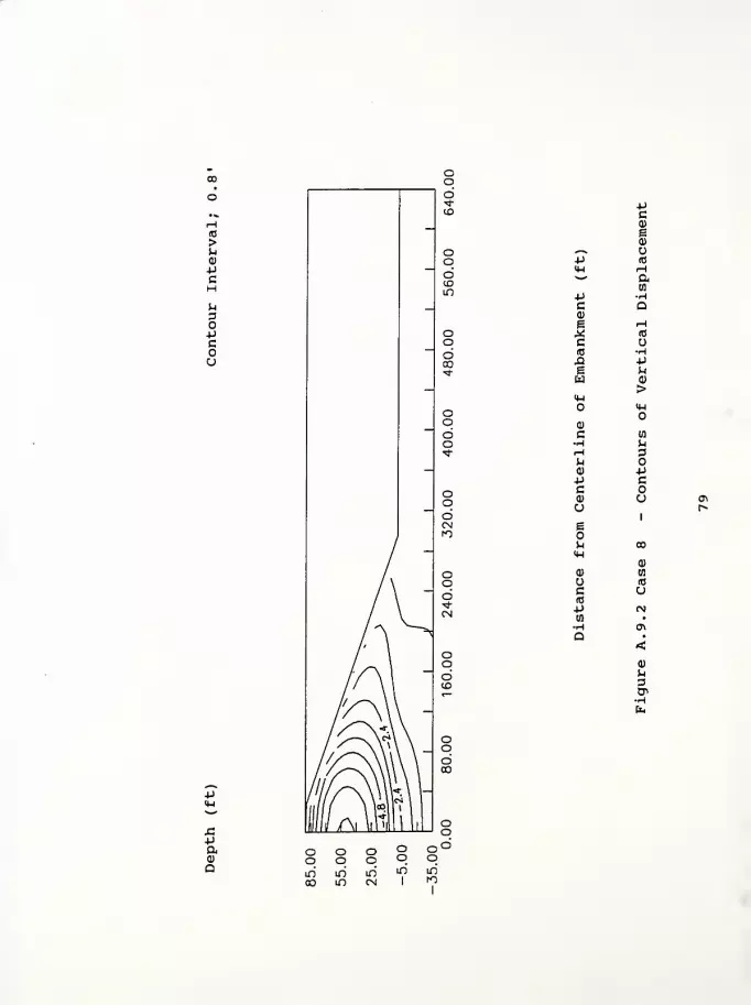
(0
>u
Pc
u3o
cou
p
pa0)
Q
pc0)
eo
^-K
p (0
<U Hw ap •Hc Q0)
e rH
* «J
c u(0 •HXI Pe uw
><M
<D
c w•H MrH 3u0) pp ccQ) u C*
u1
r»
e1
M CO<w
<D
Q) w(G
c u(0
p (N
H•
a<a>
U30>
o o o o oo o o o om LO m m mCO m CN 1
ro
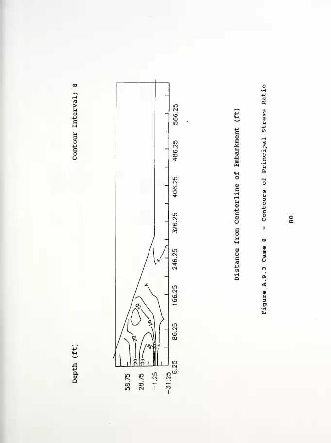
(0
>u<D
PcHU3OPcou
-Pid
a
p
M
CPCO
(1)
1c(0
X!
1
(0
a•H
cHIH cu
14-1
0)
c•H
u0)
pcQ)
U
en
OPc
u
e 1
o
H-l00
uc(0
(0
U-p nHQ <Tl
<<1>
^1
3B>
43-Paa)
a

A3
>u
4J
cH
3OPcou
P0)
4-1
«CO
,*—»,
•p (U<H o*"*
00
P MC<D -p£ o* ac &H(0
X! Hs (0
w u
4-1 JIM
Q)
C-H nrH uM 30)
-p -Pc cd) Hu o CO
e 1
uH-l co
(1) 0)
nc (0
(0 u4-*
n•H •
Q•
<(1)
M3&
p
J3Pa(D
a

Computer Program InputFigure A. 10.1 Case 9 - Contours of Horizontal DisplacementFigure A. 10. 2 Case 9 - Contours of Vertical DisplacementFigure A. 10. 3 Case 9 - Contours of Principal Stress RatioFigure A. 10. 4 Case 9 - Contours of Local Factors of Safety

State Route 1 over Ramsey Creek - Franklin County, Indiana Case 9
460 1 1 18 1
1 15 .01
0.0 .5 9.0
1 1 0.000 0.000
2 1 0.000 -7.500
7 1 0.000 -27.500
8 1 1 0.000 -35.000
9 12.500 0.000
17 25.000 0.000
337 625.000 0.000
345 1 640.000 0.000
10 12.500 -7.500
15 12.500 -27.500
16 1 12.500 -35.000
18 25.000 -7.500
338 625.000 -7.500
346 1 640.000 -7.500
351 1 640.000 -27.500
352 1 1 640.000 -35.000
19 25.000 -11.500
339 625.000 -11.500
20 25.000 -15.500
340 625.000 -15.500
21 25.000 -19.500
341 625.000 -19.500
22 25.000 -23.500
342 625.000 -23.500
23 25.000 -27.500
343 625.000 -27.500
24 1 25.000 -35.000
344 1 625.000 -35.000
353 1 0.000 10.000
361 1 0.000 90.000
362 12.500 10.000
370 12.500 90.000
371 25.000 10.000
387 265.000 10.000
388 280.000 5.000
389 250.000 15.000
390 25.000 20.000
404 235.000 20.000
405 220.000 25.000
406 25.000 30.000
418 205.000 30.000
419 190.000 35.000
420 25.000 40.000
430 175.000 40.000
431 160.000 45.000
432 25.000 50.000
440 145.000 50.000
441 130.000 55.000
442 25.000 60.000
448 115.000 60.000
449 100.000 65.000
450 25.000 70.000
454 85.000 70.000
455 70.000 75.000
456 25.000 80.000
458 55.000 80.000
82

459 40.000 85.000
460 25.000 90.000
8
1I
0. 640. -7.5 0. 0. 0.
0.
1
0. 0. -11.5 0. 125 0.0626 21
0. 640. -11.5 -7.51 0. 0.
0. 0. 0. -11.5 0. 120 0.0576 21
2
0. 640. -15.5 -11.51 0. 0.
0. 0. 0. -11.5 0. 120 0.0576 21
2
0. 640. -19.5 -15.51 0. 0.
0. 0. 0. -11.5 0. 120 0.0576 21
2
0. 640. -23.5 -19.51 0. 0.
0. 0. 0. -11.5 0. 120 0.0576 21.
2
0. 640. -27.5 -23.51 0. 0.
0. 0. 0. -11.5 0. 120 0.0576 21,
2
0. 640. -35.0 -27.51 0. 0.
0. 0. 0. -11.5 0. 130 0.0676 21.
3
0. 295. 0. 90. 0. 0.
0.1 0.50
2
1
409 4 10 8 13 4 2 16
1
300. 0.4 0.7500 21. .720 0.230 0.039
8.0 0.01 0.000 10. 2
2
300. 0.4 0.7500 21. 0..720 0.250 0.050
7.20 0.01 0.000 10. 2.
3
300. 0.4 0.7500 21. 0.,720 0.250 0.050
4.9 0.01 0.000 10. 2.
4
300. 0.4 0.7500 21. 0. 720 0.250 0.050
4.30 0.01 0.000 10. 2.
5
300. 0.4 0.7500 21. 0. 720 0.250 0.050
3.8 0.01 0.000 10. 2.
6
300. 0.4 0.7500 21. 0. 720 0.250 0.050
3.40 0.01 0.000 10. 2.
7
300. 0.4 0.6630 21. 0. 720 0.124 0.020
2.5 0.01 0.000 10. 2.
8
300. 0.4 0.7500 60. 0. 000 0.124 0.020
8.0
1
0.01
4 1
0.125
1 8
0.
0.
2.
9 1 2 10
43 4 1 1 0.
345 337 338 346
44 4 1 2 8 0.
10 2 3 11
86 4 1 2 0.
83
8.0
7.20
4.9
4.30
3.8
3.40
2.5
1.58
1.46
1.07
0.96
0.87
0.80
0.63
1.58

346 338 339 347
87 4 1 3 8 0.
11 3 4 12
129 4 1 3 0.
347 339 340 348
130 4 1 4 8 0.
12 4 5 13
172 4 1 4 0.
348 340 341 349
173 4 1 5 8 0.
13 5 6 14
215 4 1 5 0.
349 341 342 350
216 4 1 6 8 0.
14 6 7 15
258 4 1 6 0.
350 342 343 351
259 4 1 7 8 0.
15 7 8 16
301 4 1 7 0.
351 343 344 352
302 4 1 8 0.01
362 353 1 9
303 4 1 8 0.01
371 362 9 17
304 4 1 8 0.01
372 371 17 25
305 4 1 8 0.01
373 372 25 33
306 4 1 8 0.01
374 373 33 41
307 4 1 8 0.01
375 374 41 49
308 4 1 8 0.01
376 375 49 57
309 4 1 8 0.01
377 376 57 65
310 4 1 8 0.01
378 377 65 73
311 4 1 8 0.01
379 378 73 81
312 4 1 8 0.01
380 379 81 89
313 4 1 8 0.01
381 380 89 97
314 4 1 8 0.01
382 381 97 105
315 4 1 8 0.01
383 382 105 113
316 4 1 8 0.01
384 383 113 121
317 4 1 8 0.01
385 384 121 129
318 4 1 8 0.01
386 385 129 137
319 4 1 8 0.01
387 386 137 145
320 4 1 8 0.01
388 387 145 153
321 4 1 8 0.01
84
388 388 153 161
322 4 1 8 1.
363 354 353 362
323 4 1 8 1.
390 363 362 371
324 4 1 8 1 1.
391 390 371 372
337 4 1 8 1.
404 403 384 385
338 4 1 8 1.
389 404 385 386
339 4 1 8 1.
389 389 386 387
340 4 1 8 2.
364 355 354 363
341 4 1 8 2.
406 364 363 390
342 4 1 8 1 2.
407 406 390 391
353 4 1 8 2.
418 417 401 402
354 4 1 8 2.
405 418 402 403
355 4 1 8 2.
405 405 403 404
356 4 1 8 3.
365 356 355 364
357 4 1 8 3.
420 365 364 406
358 4 1 8 1 3.
421 420 406 407
367 4 1 8 3.
430 429 415 416
368 4 1 8 3.
419 430 416 417
369 4 1 8 3.
419 419 417 418
370 4 1 8 4.
366 357 356 365
371 4 1 8 4.
432 366 365 420
372 4 1 8 1 4.
433 432 420 421
379 4 1 8 4.
440 439 427 428
380 4 1 8 4.
431 440 428 429
381 4 1 8 4.
431 431 429 430
382 4 1 8 5.
367 358 357 366
383 4 1 8 5.
442 367 366 432
384 4 1 8 1 5.
443 442 432 433
389 4 1 8 5.
448 447 437 438
390 4 1 8 5.
441 448 438 439
391 4 1 8 5.
85

441 441 439 440
392 4 1 8 6.
368 359 358 367
393 4 1 8 6.
450 368 367 442
394 4 1 8 1 6.
451 450 442 443
397 4 1 8 6.
454 453 445 446
398 4 1 8 6.
449 454 446 447
399 4 1 8 6.
449 449 447 448
400 4 1 8 7.
369 360 359 368
401 4 1 8 7.
456 369 368 450
402 4 1 8 7.
457 456 450 451
403 4 1 8 7.
458 457 451 452
404 4 1 8 7.
455 458 452 453
405 4 1 8 7.
45b 455 453 454
406 4 1 8 8.
370 361 360 369
407 4 1 8 8.
460 370 369 456
408 4 1 8 8.
459 460 456 457
409 4 1 8 8.
459 459 457 458
86

•P
0>
Q
4-1
c0)
ea>
o(0
Ha03
•H
P Dcd)
e
c(0
ew
rH1C
pc
NHMO
<HX<H
0)
c•H
0)
Pca)
u
03
3
-Pc
u
e 1
u 0*
0)
c(0
d)
03
(0
O•p H-HQ O
t-l
•
<0)
u3CP
En
n o o o oo o o o i_j
m LO m m m00 LD CM I
fO
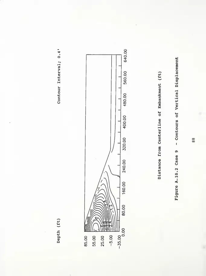
x:paa>
Q
-Pc<D
e0>
uP
r-(
ato
-pC
•HQ
0)
1c
ew
rH
o-H-pp.
a)
><4-l
Q)
C P
a)
pca)
3
pc
uu
1
eo <^
M-ia>
0)
uc(01) m*w oHa rH
<d)
P.
=3
cn
CDCO

J34->
a,<D
a
+J(0
a^ 03
4J U)
<M ai*—«» u
-pP enCID (-i
i RJ
S ac -H(0
XI ce •Hw 5-i
Oh<HO •4-1
<D
c in
•H ui-l 3h O<p -PP cc0) uu
1
e1
M C\<w
Q)
0) U)
U to
c o(0
-p ow •
•H oQ I-l
<a>
u3en
to m £> £>r^ [v- <^ ^°°
'oo V r;
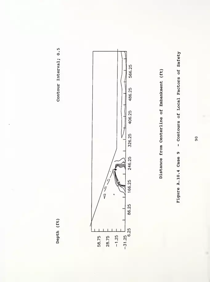
in
(0
>U<D+J
C
U
OPcou
>i-P0)
IH(0
w
PIM
IM
02
Pc(1)
1c
uo-p
(0
sw
HIB
<uJ<W
Q)
C•HHW0)
-pc
o
DO
ua
•pc
u
e 1
u 0^
c(0
d)
(fl
(0
o-p
•
Q oH
•
<<D
P
g,•Htn
o
-pIM
Pa0)
Q

Computer Program InputFigure A. 11.1 Case 10 - Contours of Horizontal DisplacementFigure A. 11. 2 Case 10 - Contours of Vertical DisplacementFigure A. 11. 3 Case 10 - Contours of Principal Stress RatioFigure A. 11. 4 Case 10 - Contours of Local Factors of Safety

State Route 1 over Ramsey Creek - Franklin County, Indiana Case 10
460 1 1 18 1
1 15 .01
0.0 .5 9.0
1 1 0.000 0.000
2 1 0.000 -7.500
7 1 0.000 -27.500
8 1 1 0.000 -35.000
9 12.500 0.000
17 25.000 0.000
337 625.000 0.000
345 1 640.000 0.000
10 12.500 -7.500
15 12.500 -27.500
16 1 12.500 -35.000
18 25.000 -7.500
338 625.000 -7.500
346 1 640.000 -7.500
351 1 640.000 -27.500
352 1 1 640.000 -35.000
19 25.000 -11.500
339 625.000 -11.500
20 25.000 -15.500
340 625.000 -15.500
21 25.000 -19.500
341 625.000 -19.500
22 25.000 -23.500
342 625.000 -23.500
23 25.000 -27.500
343 625.000 -27.500
24 1 25.000 -35.000
344 1 625.000 -35.000
353 1 0.000 10.000
361 1 0.000 90.000
362 12.500 10.000
370 12.500 90.000
371 25.000 10.000
387 265.000 10.000
388 280.000 5.000
389 250.000 15.000
390 25.000 20.000
404 235.000 20.000
405 220.000 25.000
406 25.000 30.000
418 205.000 30.000
419 190.000 35.000
420 25.000 40.000
430 175.000 40.000
431 160.000 45.000
432 25.000 50.000
440 145.000 50.000
441 130.000 55.000
442 25.000 60.000
448 115.000 60.000
449 100.000 65.000
450 25.000 70.000
454 85.000 70.000
455 70.000 75.000
456 25.000 80.000
458 55.000 80.000
91
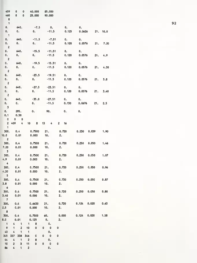
459 40.000 85.000
460 25.000 90.000
8
4
0. 640. -7.5 0. 0. 0.
0.
1
0. 0. -11.5 0. 125 0.0626 21
0. 640. -11.5 -7.51 0. 0.
0. 0. 0. -11.5 0. 120 0.0576 21
2
0. 640. -15.5 -11.51 0. 0.
0. 0. 0. -11.5 0. 120 0.0576 21
2
0. 640. -19.5 -15.51 0. 0.
0. 0. 0. -11.5 0. 120 0.0576 21,
2
0. 640. -23.5 -19.51 0. 0.
0. 0. 0. -11.5 0. 120 0.0576 21.
2
0. 640. -27.5 -23.51 0. 0.
0. 0. 0. -11.5 0. 120 0.0576 21.
2
0. 640. -35.0 -27.51 0. 0.
0. 0. 0. -11.5 0. 130 0.0676 21.
3
0. 295. 0. 90. 0. 0.
0.1 0.50
2
1
409 4 10 8 13 4 2 16
1
300. 0.4 0.7500 21. .720 0.230 0.039
10.0 0.01 0.000 10. 2
2
300. 0.4 0.7500 21. 0,.720 0.250 0.050
7.20 0.01 0.000 10. 2.
3
300. 0.4 0.7500 21. 0. 720 0.250 0.050
4.9 0.01 0.000 10. 2.
4
300. 0.4 0.7500 21. 0. 720 0.250 0.050
4.30 0.01 0.000 10. 2.
5
300. 0.4 0.7500 21. 0. 720 0.250 0.050
3.8 0.01 0.000 10. 2.
6
300. 0.4 0.7500 21. 0. 720 0.250 0.050
3.40 0.01 0.000 10. 2.
7
300. 0.4 0.6630 21. 0. 720 0.124 0.020
2.5 0.01 0.000 10. 2.
8
300. 0.4 0.7500 60. 0. 000 0.124 0.020
8.0
1
0.01
4 1
0.125
1 8
0.
0.
2.
9 1 2 10
43 4 1 1 0.
345 :337 338 346
44 4 1 2 8 0.
10 2 3 11
86 4 1 2 0.
92
10.0
7.20
4.9
4.30
3.8
3.40
2.5
1.90
1.46
1.07
0.96
0.87
0.80
0.63
1.58
346 338 339 347
87 4 1 3 8 0.
11 3 4 12
129 4 1 3 0.
347 339 340 348
130 4 1 4 8 0.
12 4 5 13
172 4 1 4 0.
343 340 341 349
173 4 1 5 8 0.
13 5 6 14
215 4 1 5 0.
349 341 342 350
216 4 1 6 8 0.
14 6 7 15
258 4 1 6 0.
350 342 343 351
259 4 1 7 8 0.
15 7 8 16
301 4 1 7 0.
351 343 344 352
302 4 1 8 0.01
362 353 1 9
303 4 1 8 0.01
371 362 9 17
304 4 1 8 0.01
372 371 17 25
305 4 1 8 0.01
373 372 25 33
306 4 1 8 0.01
374 373 33 41
307 4 1 8 0.01
375 374 41 49
308 4 1 8 0.01
376 375 49 57
309 4 1 8 0.01
377 376 57 65
310 4 1 8 0.01
378 377 65 73
311 4 1 8 0.01
379 378 73 81
312 4 1 8 0.01
380 379 81 89
313 4 1 8 0.01
381 380 89 97
314 4 1 8 0.01
382 381 97 105
315 4 1 8 0.01
383 382 105 113
316 4 1 8 0.01
384 383 113 121
317 4 1 8 0.01
385 384 121 129
318 4 1 8 0.01
386 385 129 137
319 4 1 8 0.01
387 386 137 145
320 4 1 8 0.01
388 387 145 153
321 4 1 8 0.01
93

388 388 153 161
322 4 1 8 1.
363 354 353 362
323 4 1 8 1.
390 363 362 371
324 4 1 8 1 1.
391 390 371 372
337 4 1 8 1.
404 403 384 385
338 4 1 8 1.
389 404 385 386
339 4 1 8 1.
389 389 386 387
340 4 1 8 2.
364 355 354 363
341 4 1 8 2.
406 364 363 390
342 4 1 8 1 2.
407 406 390 391
353 4 1 8 2.
418 417 401 402
354 4 1 8 2.
405 418 402 403
355 4 1 8 2.
405 405 403 404
356 4 1 8 3.
365 356 355 364
357 4 1 8 3.
420 365 364 406
358 4 1 8 1 3.
421 420 406 407
367 4 1 8 3.
430 429 415 416
368 4 1 8 3.
419 430 416 417
369 4 1 8 3.
419 419 417 418
370 4 1 8 4.
366 357 356 365
371 4 1 8 4.
432 366 365 420
372 4 1 8 1 4.
433 432 420 421
379 4 1 8 4.
440 439 427 428
380 4 1 8 4.
431 440 428 429
381 4 1 8 4.
431 431 429 430
382 4 1 8 5.
367 358 357 366
383 4 1 8 5.
442 367 366 432
384 4 1 8 1 5.
443 442 432 433
389 4 1 8 5.
448 447 437 438
390 4 1 8 5.
441 448 438 439
391 4 1 8 5.
94

441 441 439
392 4 1
368 359 358
393 4 1
450 368 367
394 4 1
451 450 442
397 4 1
454 453 445
398 4 1
449 454 446
399 4 1
449 449 447
400 4 1
369 360 359
401 4 1
456 369 368
402 4 1
457 456 450
403 4 1
458 457 451
440
8
367
8
442
8 1
443
8
446
8
447
8
448
8
368
8
450
8
451
8
452
404 1
455 458 452
405 4 1
455 455 453
406 4 1
370 361 360
407 4 1
460 370 369
408 4 1
459 460 456
409 4 1
459 459 457
453
8
454
8
369
8
456
8
457
8
458
6.
6.
6.
6.
6.
6.
7.
7.
7.
7.
7.
7.
8.
8.
8.
8.
95

43Paa)
a
PC(!)
eQJ
*,—«. Hp aM-l 05w •H
DPC Hd) (0
e P* ccid NX! He P.
w<w
a>
c 03
•H MH 3>-i oai pP cca) u VO
o1
a\
B1
M o«w H03 Q)
tn
c id
(0 up03 HH •
DH<ai
ooinm
oooo o'o
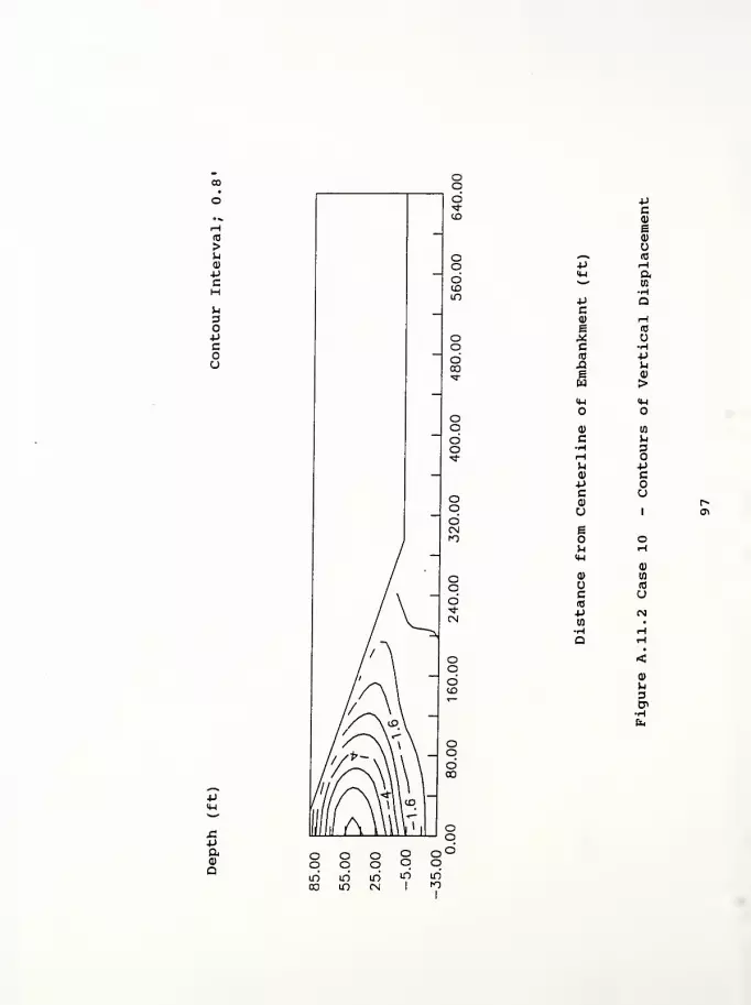
(0
>uQ)
+JCH^3
4J
Cou
paa)
a
*Jc0)
ea)
^ ITS
-p h(4-1 a^^
HP Qca) rH
e (0
M uc Hro •P£1 Jx
e (1)
w ><U IH
<D 00
C u-H 3^H
M p0) cPc u(1) r^
u i <T\
so o^ rHIH
Q) a(0
c o(0
4J <Nw •
ai
p.
3en
o o o oq q q 9in uo m' w03 m cn I
o'od
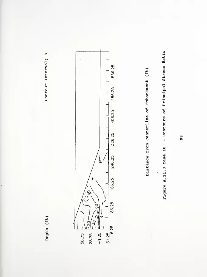
(0
>u
pcH
3OPcou
•paQ
O•H-P(0
a
pa)
upp wC<D
eXc(0
XI
£
H(0
a-H
cHu
oQ)
C•HHH<u
-pc0)
M3
Pcou co
o1
c*
e
u o
cWITS
u4J n

10
>u
4J
C
>iPa)
<H(0
w^^ IMP4-1w tn
Pc P<D ue (0
* Emc(C iH,a 10
e uWM-l
(1)
c•H
(0
P>-\ 3u<P PP cc o<D u »U 0>
e1
^ o4-1 1-1
0) <u
wc (0
(0 u*J
H •
Q 1-1
H•
<a)
p.
fa
-p14-1
X!4J
aa)
a
Computer Program InputFigure A. 12.1 Case 11 - Contours of Horizontal DisplacementFigure A. 12. 2 Case 11 - Contours of Vertical DisplacementFigure A. 12. 3 Case 11 - Contours of Principal Stress RatioFigure A. 12. 4 Case 11 - Contours of Local Factors of Safety
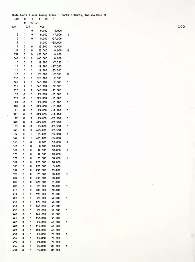
State Route 1 over Ramsey Creek - Franklin County, Indiana Case 11
460 1 1 18 1
1 15 .01
3.0 .5 9.0
1 1 0.000 0.000
2 1 0.000 -7.500
7 1 0.000 -27.500
8 1 1 0.000 -35.000
9 12.500 0.000
17 25.000 0.000
337 625.000 0.000
345 1 640.000 0.000
10 12.500 -7.500
15 12.500 -27.500
16 1 12.500 -35.000
18 25.000 -7.500
338 625.000 -7.500
346 1 640.000 -7.500
351 1 640.000 -27.500
352 1 1 640.000 -35.000
19 25.000 -11.500
339 625.000 -11.500
20 25.000 -15.500
340 625.000 -15.500
21 25.000 -19.500
341 625.000 -19.500
22 25.000 -23.500
342 625.000 -23.500
23 25.000 -27.500
343 625.000 -27.500
24 1 25.000 -35.000
344 1 625.000 -35.000
353 1 0.000 10.000
361 1 0.000 90.000
362 12.500 10.000
370 12.500 90.000
371 25.000 10.000
387 265.000 10.000
388 280.000 5.000
389 250.000 15.000
390 25.000 20.000
404 235.000 20.000
405 220.000 25.000
406 25.000 30.000
418 205.000 30.000
419 190.000 35.000
420 25.000 40.000
430 175.000 40.000
431 160.000 45.000
432 25.000 50.000
440 145.000 50.000
441 130.000 55.000
442 25.000 60.000
448 115.000 60.000
449 100.000 65.000
450 25.000 70.000
454 85.000 70.000
455 70.000 75.000
456 25.000 80.000
458 55.000 80.000
100

459
460
8
1
0.
0.
1
0.
0.
2
0.
0.
2
0.
0.
2
0.
0.
2
0.
0.
2
0.
0.
3
0.
0.1
2
1
300.
10.0
2
300.
3.00
3
300.
2.50
4
300.
'2.00
5
300.
1.50
6
300.
1.50
7
300.
1.02
8
300.
8.0
1
9
43
345
44
10
86
40.000 85.000
25.000 90.000
101
640.
0.
640.
0.
640.
0.
640.
0.
640.
0.
640.
0.
640.
0.
295.
0.50
409 4
0.4
0.01
0.4
0.01
0.4
0.01
0.4
0.01
0.4
0.01
0.4
0.01
0.4
0.01
0.4
0.01
4 1
1 2
4 1
337 338
4 1
2 3
4 1
-7.5
0.
0.
-11.5
0.
0.125
0.
0.0626 21. 10.0
-11.5
0.
-7.51
-11.5
0.
0.120
0.
0.0576 21. 3.00
-15.5
0.
-11.51
-11.5
0.
0.120
0.
0.0576 21. 2.5
-19.5
0.
-15.51
-11.5
0.
0.120
0.
0.0576 21. 2.00
-23.5
0.
-19.51
-11.5
0.
0.120
0.
0.0576 21. 1.50
-27.5
0.
-23.51
-11.5
0.
0.120
0.
0.0576 21. 1.50
-35.0
0.
0.
-27.51
-11.5
90.
0.
0.130
0.
0.
0.0676
0.
21. 1.02
8 13
0.7500
0.000
0.7500
0.000
0.7500
0.000
0.7500
0.000
0.7500
0.000
0.7500
0.000
0.6630
0.000
21.
10.
21.
10.
21.
10.
21.
10.
21.
10.
21.
10.
0.7500 60.
0.125 0.
1 8
10
1
346
2 8
11
2
0.
0.
0.
0.
2 16
0.720
2.
0.720
2.
0.720
2.
0.720
2.
0.720
2.
0.720
2.
0.720
2.
0.000
2.
0.230 0.039 1.90
0.250 0.050 0.73
0.250 0.050 0.63
0.250 0.050 0.53
0.250 0.050 0.42
0.250 0.050 0.42
0.124 0.020 0.30
0.124 0.020 1.58

346 338 339 347
87 4 1 3 8 n.
11 3 4 12
129 4 1 3 0.
347 339 340 348
130 4 1 4 8 0.
12 4 5 13
172 4 1 4 0.
348 340 341 349
173 4 1 5 8 0.
13 5 6 14
215 4 1 5 0.
349 341 342 350
216 4 1 6 8 0.
14 6 7 15
258 4 1 6 0.
350 342 343 351
259 4 1 7 8 0.
15 7 8 16
301 4 1 7 0.
351 343 344 352
302 4 1 8 0.01
362 353 1 9
303 4 1 8 0.01
371 362 9 17
304 4 1 8 0.01
372 371 17 25
305 4 1 8 0.01
373 372 25 33
306 4 1 8 0.01
374 373 33 41
307 4 1 8 0.01
375 374 41 49
308 4 1 8 0.01
376 375 49 57
309 4 1 8 0.01
377 376 57 65
310 4 1 8 0.01
378 377 65 73
311 4 1 8 0.01
379 378 73 81
312 4 1 8 0.01
380 379 81 89
313 4 1 8 0.01
381 380 89 97
314 4 1 8 0.01
382 381 97 105
315 4 1 8 0.01
383 382 105 113
316 4 1 8 0.01
384 383 113 121
317 4 1 8 0.01
385 384 121 129
318 4 1 8 0.01
386 385 129 137
319 4 1 8 0.01
387 386 137 145
320 4 1 8 0.01
388 387 145 153
321 4 1 8 0.01
102

388 388 153 161
322 4 1 8
363 354 353 362
323 4 1 8
390 363 362 371
321 4 1 8 1
391 390 371 372
337 4 1 8
404 403 384 385
338 4 1 8 1.
389 404 385 386
339 4 1 8
389 389 386 387
340 4 1 8 2.
364 355 354 363
341 4 1 8 2.
406 364 363 390
342 4 1 8 1 2.
407 406 390 391
353 4 1 8 2.
418 417 401 402
354 4 1 8 2.
405 418 402 403
355 4 1 8 2.
405 405 403 404
356 4 1 8 3.
365 356 355 364
357 4 1 8 3.
420 365 364 406
358 4 1 8 1 3.
421 420 406 407
367 4 1 8 3.
430 429 415 416
368 4 1 8 3.
419 430 416 417
369 4 1 8 3.
419 419 417 418
370 4 1 8 4.
366 357 356 365
371 4 1 8 4.
432 366 365 420
372 4 1 8 1 4.
433 432 420 421
379 4 1 8 4.
440 439 427 428
380 4 1 8 4.
431 440 428 429
381 4 1 8 4.
431 431 429 430
382 4 1 8 5.
367 358 357 366
383 4 1 8 5.
442 367 366 432
384 4 1 8 1 5.
443 442 432 433
389 4 1 8 5.
448 447 437 438
390 4 1 8 5.
441 448 438 439
391 4 1 8 5.
103
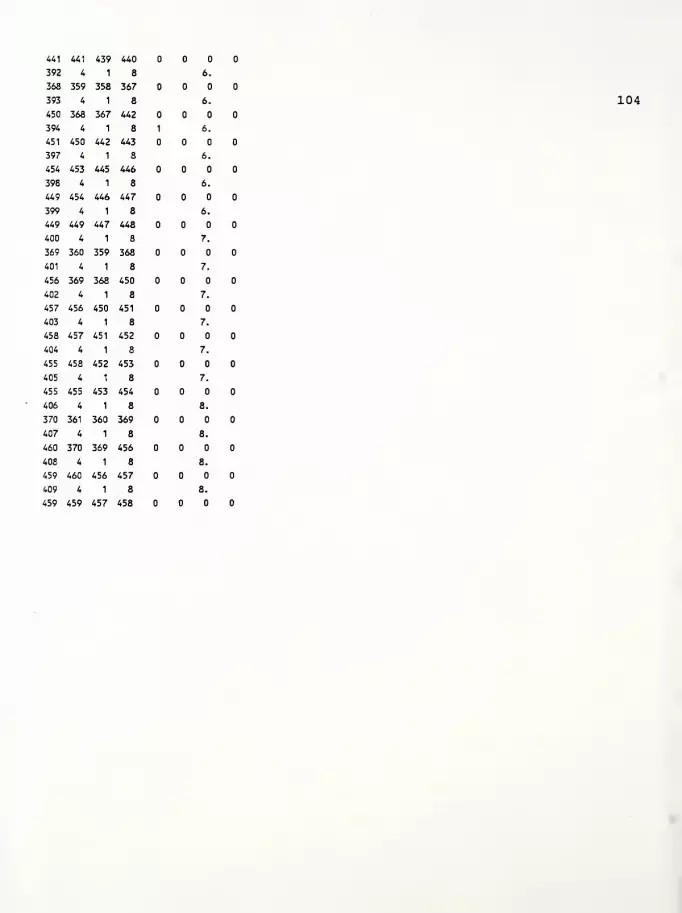
441 441 439 440
392 4 1 8 6.
363 359 358 367
393 4 1 8 6.
450 368 367 442
394 4 1 8 1 6.
451 450 442 443
397 4 1 8 6.
454 453 445 446
398 4 1 8 6.
449 454 446 447
399 4 1 8 6.
449 449 447 448
400 4 1 8 7.
369 360 359 368
401 4 1 8 7.
456 369 368 450
402 4 1 8 7.
457 456 450 451
403 4 1 8 7.
458 457 451 452
404 4 1 8 7.
455 458 452 453
405 4 1 8 7.
455 455 453 454
406 4 1 8 8.
370 361 360 369
407 4 1 8 8.
460 370 369 456
408 4 1 8 8.
459 460 456 457
409 4 1 8 8.
459 459 457 458
104
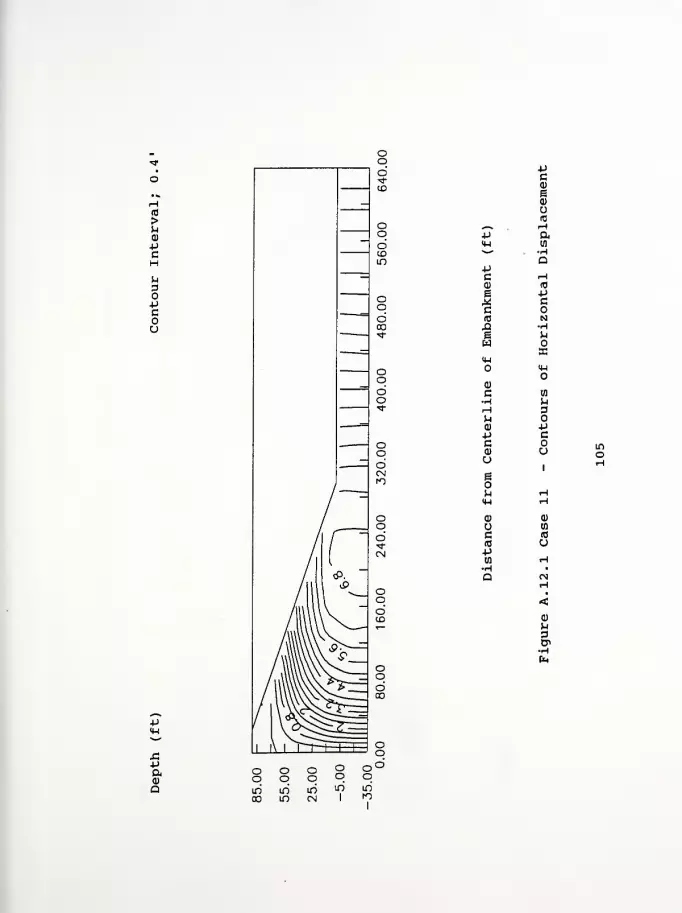
(0
>u0)
Pc
u3oPcou
SiP&a
pca)
B0>
IB
^-* Hp a<u w*^ •H
QPc H<D (0
b Pw ce(C NX2 •He uw
so<H
<w
a)
c W-H P.
rH 3^a) P-p cc oa) uu
1
s1
u <-i
<M H0) d)
Wc (0
(0 opw HH •
a Mr-l
•
<0>
p3CP
oo oo oooo oo
00min
mCN
in
1
mto

(0
>u0)
pcHu
pcou
PIH
Pc
ICIt)
H0)
4JC(I)
u
iuIH
0)
uc(0
-p
Pc01
e0)
uid
ata
(0
o•H+J
M(1)
>IHO
n
DOPcoa
(0
a
u
paQ
oo oo oooo oo
mCO m m
C\J
in1
m
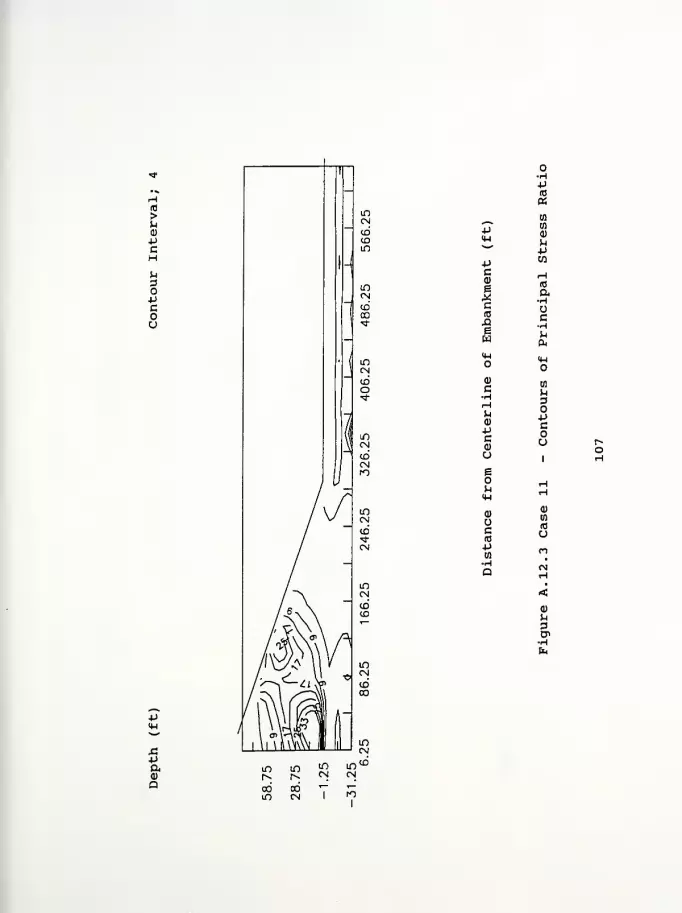
>u<D
PC
-Pa0)
Q
4->
-Pc0)
Ic
XIew
O
<D
C•H.HS^
a)
-pc<D
Ueou(w
Q)
Oc(0
-pto
•HQ
(0
a•HQc•HHcu
14-1
o
wu3opcou
a>
3
•H
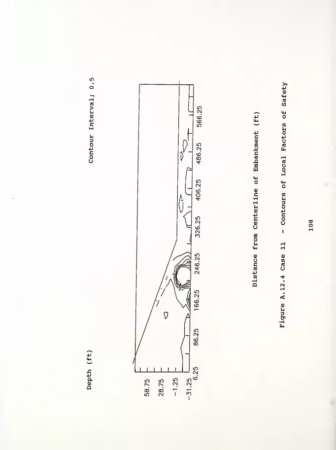
id
>pa;pc
u3o-pcou
43Paa
>P0)
H-l
IB
W^^ <4-l
-pu
en
p•p oc p(1)
e (0
* fc,
c(0 r-l
ja IT!
g UH
JM-l
<w
0)
c w•H pi-H 3P<D pP cc0) oue
1
p r-l
14-1 r-l
<D 0)
U tn
C f0
«J uPto *
p3en
ro

Computer Program InputFigure A. 13.1 Case 12 - Contours of Horizontal DisplacementFigure A. 13.2 Case 12 - Contours of Vertical DisplacementFigure A. 13. 3 Case 12 - Contours of Principal Stress RatioFigure A. 13. 4 Case 12 - Contours of Local Factors of Safety

State Route 1 over Ramsey Creek - Franklin County, Indiana Case 12
109
460 2 1 18 1
1 15 .01
0.0 0,.5 9.0
1 1 0.000 0.000
2 1 0.000 -7.500
7 1 0.000 -27.500
8 1 1 0.000 -35.000
9 12.500 0.000
17 25.000 0.000
337 625.000 0.000
345 1 640.000 0.000
10 12.500 -7.500
15 12.500 -27.500
16 1 12.500 -35.000
18 25.000 -7.500
338 625.000 -7.500
346 1 640.000 -7.500
351 1 640.000 -27.500
352 1 1 640.000 -35.000
19 25.000 -11.500
339 625.000 -11.500
20 25.000 -15.500
340 625.000 -15.500
21 25.000 -19.500
341 625.000 -19.500
22 25.000 -23.500
342 625.000 -23.500
23 25.000 -27.500
343 625.000 -27.500
24 1 25.000 -35.000
344 1 625.000 -35.000
353 1 0.000 10.000
361 1 0.000 90.000
362 12.500 10.000
370 12.500 90.000
371 25.000 10.000
387 265.000 10.000
388 280.000 5.000
389 250.000 15.000
390 25.000 20.000
404 235.000 20.000
405 220.000 25.000
406 25.000 30.000
418 205.000 30.000
419 190.000 35.000
420 25.000 40.000
430 175.000 40.000
431 160.000 45.000
432 25.000 50.000
440 145.000 50.000
441 130.000 55.000
442 25.000 60.000
448 115.000 60.000
449 100.000 65.000
450 25.000 70.000
454 85.000 70.000
455 70.000 75.000
456 25.000 80.000
458 55.000 80.000
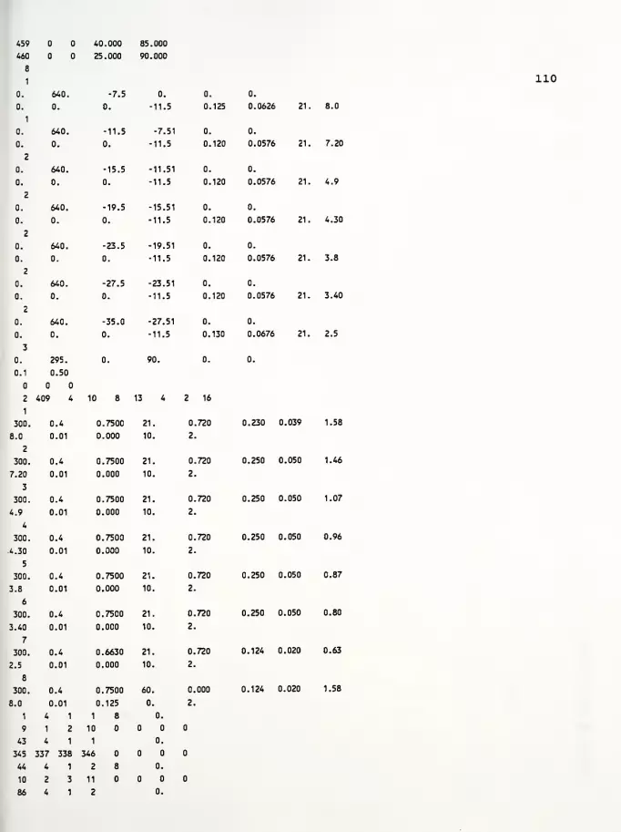
459 40.000 85.000
460 25.000 90.000
8
1I
0. 640. -7.5 0. 0. 0.
0. 0. 0. -11.5 0. 125 0.0626 21
1
0. 640. -11.5 -7.51 0. 0.
0. 0. 0. -11.5 0. 120 0.0576 21
2
0. 640. -15.5 -11.51 0. 0.
0. 0. 0. -11.5 0. 120 0.0576 21
2
0. 640. -19.5 -15.51 0. 0.
0. 0. 0. -11.5 0. 120 0.0576 21
2
0. 640. -23.5 -19.51 0. 0.
0. 0. 0. -11.5 0. 120 0.0576 21
2
0. 640. -27.5 -23.51 0. 0.
0. 0. 0. -11.5 0. 120 0.0576 21
2
0. 640. -35.0 -27.51 0. 0.
0. 0. 0. -11.5 0. 130 0.0676 21
3
0. 295. 0. 90. 0. 0.
0.1 0.50
2 409 4 10 8 13 4 2 16
1
300. 0.4 0.7500 21. 0.,720 0.230 .039
8.0 0.01 0.000 10. 2.
2
300. 0.4 0.7500 21. 0..720 0.250 .050
7.20 0.01 0.000 10. 2.
3
300. 0.4 0.7500 21. 0. 720 0.250 0..050
4.9 0.01 0.000 10. 2.
4
300. 0.4 0.7500 21. 0. 720 0.250 0,.050
.4.30 0.01 0.000 10. 2.
5
300. 0.4 0.7500 21. 0. 720 0.250 0,.050
3.8 0.01 0.000 10. 2.
6
300. 0.4 0.7500 21. 0.720 0.250 0.,050
3.40 0.01 0.000 10. 2.
7
300. 0.4 0.6630 21. 0. 720 0.124 0.,020
2.5 0.01 0.000 10. 2.
8
300. 0.4 0.7500 60. 0. 000 0.124 0.,020
8.0
1
0.01
4 1
0.125
1 8
0.
0.
2.
9 1 2 10
43 4 1 1 0.
345 337 338 346
44 4 1 2 8 0.
10 2 3 11
86 4 1 2 0.
110
8.0
7.20
4.9
4.30
3.8
3.40
2.5
1.58
1.46
1.07
0.96
0.87
0.80
0.63
1.58

346 338 339 347
87 4 1 3 8 0.
11 3 4 12
129 4 1 3 0.
347 339 340 348
130 4 1 4 8 0.
12 4 5 13
172 4 1 4 0.
348 340 341 349
173 4 1 5 8 0.
13 5 6 14
215 4 1 5 0.
349 341 342 350
216 4 1 6 8 0.
14 6 7 15
258 4 1 6 0.
350 342 343 351
259 4 1 7 8 0.
15 7 8 16
301 4 1 7 0.
351 343 344 352
302 4 1 8 0.01
362 353 1 9
303 4 1 8 0.01
371 362 9 17
304 4 1 8 0.01
372 371 17 25
305 4 1 8 0.01
373 372 25 33
306 4 1 8 0.01
374 373 33 41
307 4 1 8 0.01
375 374 41 49
308 4 1 8 0.01
376 375 49 57
309 4 1 8 0.01
377 376 57 65
310 4 1 8 0.01
378 377 65 73
311 4 1 8 0.01
379 378 73 81
312 4 1 8 0.01
380 379 81 89
313 4 1 8 0.01
381 380 89 97
314 4 1 8 0.01
382 381 97 105
315 4 1 8 0.01
383 382 105 113
316 4 1 8 0.01
384 383 113 121
317 4 1 8 0.01
385 384 121 129
318 4 1 8 0.01
386 385 129 137
319 4 1 8 0.01
387 386 137 145
320 4 1 8 0.01
388 387 145 153
321 4 1 8 0.01
111
388 388 153 161
322 4 1 8 1.
363 354 353 362
323 4 1 8 1.
390 363 362 371
324 4 1 8 1 1.
391 390 371 372
337 4 1 8 1.
404 403 384 385
338 4 1 8 1.
389 404 385 386
339 4 1 8 1.
389 389 386 387
340 4 1 8 2.
364 355 354 363
341 4 1 8 2.
406 364 363 390
342 4 1 8 1 2.
407 406 390 391
353 4 1 8 2.
418 417 401 402
354 4 1 8 2.
405 418 402 403
355 4 1 8 2.
405 405 403 404
356 4 1 8 3.
365 356 355 364
357 4 1 8 3.
420 365 364 406
358 4 1 8 1 3.
421 420 406 407
367 4 1 8 3.
430 429 415 416
368 4 1 8 3.
419 430 416 417
369 4 1 8 3.
419 419 417 418
370 4 1 8 4.
366 357 356 365
371 4 1 8 4.
432 366 365 420
372 4 1 8 1 4.
433 432 420 421
379 4 1 8 4.
440 439 427 428
380 4 1 8 4.
431 440 428 429
381 4 1 8 4.
431 431 429 430
382 4 1 8 5.
367 358 357 366
383 4 1 8 5.
442 367 366 432
384 4 1 8 1 5.
443 442 432 433
389 4 1 8 5.
448 447 437 438
390 4 1 8 5.
441 448 438 439
391 4 1 8 5.
112

441 441 439 440
392 4 1 8 6.
368 359 358 367
393 4 1 8 6.
450 368 367 442
394 4 1 8 1 6.
451 450 442 443
397 4 1 8 6.
454 453 445 446
398 4 1 8 6.
449 454 446 447
399 4 1 8 6.
449 449 447 448
400 4 1 8 7.
369 360 359 368
401 4 1 8 7.
456 369 368 450
402 4 1 8 7.
457 456 450 451
403 4 1 8 7.
458 457 451 452
404 4 1 8 7.
455 458 452 453
405 4 1 8 7.
455 455 453 454
406 4 1 8 8.
370 361 360 369
407 4 1 8 8.
460 370 369 456
408 4 1 8 8.
459 460 456 457
409 4 1 8 8.
459 459 457 458
1 20 2 2 1 8
1
0.
1 1 9
067 083 .16
2 9 17
3 17 25
4 25 33
5 33 41
6 41 49
7 49 57
8 57 65
9 65 73
10 73 81
11 81 89
12 89 97
13 97 105
14 105 113
15 113 121
16 121 129
17 129 137
18 137 145
19 145 153
20 153 161
113
1.68 1.92 2.4

(0
>uQ)
PcH
OPcou
p
a
ood<*
PcQ)
e<D
U(T3
^s rHp a<u U)«w
'
•hQ
Pc rH<D <c
e p* cc(0 NX! -He P.
wX
M-l
<w
a)
c tfl
•H i-l
rH 3P.
Q) PP cC0) uu
1
e1
P. (N<*—
1
tH
a> Q)
o Wc (0
(0 U-pw rH
•H •
Q r>H
<(1)
P3en•HCf
o o o o oo o o o oin m m m m00 m CN I
to

10
>uCD
+JCHU3OPcou
p
-paa)
a
Pc0)
Ba)
^-* «p rH<M a*-*
ra•H
P Qc0) He (0
*c H10 PX! Pe a)
w ><H 4-1
CD tn
C u•H DH OP P<1) c*JC uCD
O 1
g<N
P rH
<uCD
a) 0Q
(0
c uIQ
+1 (NW •
CD
P.
CT>
•H

>u
-pcH
3O-Pcou
s:paa)
a
pca)
c
XI
q-l
O
<u
c•H^H
<1)
Pca)
u
I
ucA3
•P
O•HP
w
Q)
P
•Huc
a,
o
en
3OPcoo
Q)
H
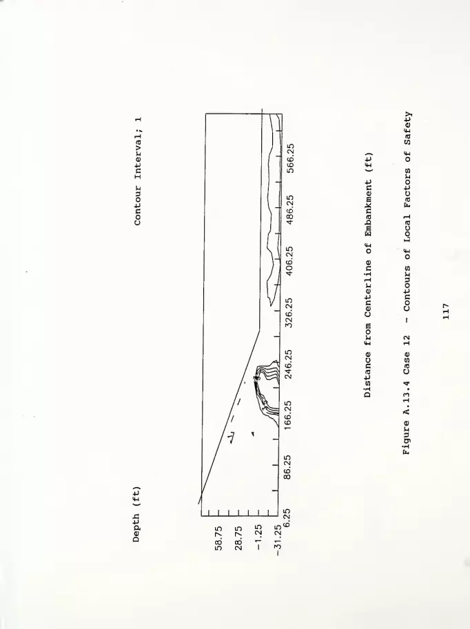
(0
>u<D
-PcHU3O-Pcoo
>ip0)
<Wro
CO
„^ (H-P<U^—
'
10
PPC 4-1
(D
E re
,2 &H
Cid HX3 IB
ew
J<H
<u
<D
C a•H uH 3M<D p-P cCd) oa
1
s1
p. OJM-l Ho 0)
to
c (0
(01 1
ut
p14-1
p.
P
H
PaQ
PO
Computer Program InputFigure A. 14.1 Case 13 - Contours of Horizontal DisplacementFigure A. 14.2 Case 13 - Contours of Vertical DisplacementFigure A. 14. 3 Case 13 - Contours of Principal Stress RatioFigure A. 14. 4 Case 13 - Contours of Local Factors of Safety

State Route 1 over Ramsey Creek - Franklin County, Indiana Case 13
460 2 1 18 1
1 15 .01
0.0 .5 9.0
1 1 0.000 0.000
2 1 0.000 -7.500
7 1 0.000 -27.500
8 1 1 0.000 -35.000
9 12.500 0.000
17 25.000 0.000
337 625.000 0.000
345 1 640.000 0.000
10 12.500 -7.500
15 12.500 -27.500
16 1 12.500 -35.000
18 25.000 -7.500
338 625.000 -7.500
346 1 640.000 -7.500
351 1 640.000 -27.500
352 1 1 640.000 -35.000
19 25.000 -11.500
339 625.000 -11.500
20 25.000 -15.500
340 625.000 -15.500
21 25.000 -19.500
341 625.000 -19.500
22 25.000 -23.500
342 625.000 -23.500
23 25.000 -27.500
343 625.000 -27.500
24 1 25.000 -35.000
344 1 625.000 -35.000
353 1 0.000 10.000
361 1 0.000 90.000
362 12.500 10.000
370 12.500 90.000
371 25.000 10.000
387 265.000 10.000
388 280.000 5.000
389 250.000 15.000
390 25.000 20.000
404 235.000 20.000
405 220.000 25.000
406 25.000 30.000
418 205.000 30.000
419 190.000 35.000
420 25.000 40.000
430 175.000 40.000
431 160.000 45.000
432 25.000 50.000
440 145.000 50.000
441 130.000 55.000
442 25.000 60.000
448 115.000 60.000
449 100.000 65.000
450 25.000 70.000
454 85.000 70.000
455 70.000 75.000
456 25.000 80.000
458 55.000 80.000
118

459 40.000 85.000
460 25.000 90.000
8
1
0. 640. -7.5 0. 0. 0.
0. 0. 0. -11.5 0. 125 0.0626 21
0. 640. -11.5 -7.51 0. 0.
0. 0. 0. -11.5 0. 120 0.0576 21
2
0. 640. -15.5 -11.51 0. 0.
0. 0. 0. -11.5 0. 120 0.0576 21
2
0. 640. -19.5 -15.51 0. 0.
0. 0. 0. -11.5 0. 120 0.0576 21
2
0. 640. -23.5 -19.51 0. 0.
0. 0. 0. -11.5 0. 120 0.0576 21,
2
0. 640. -27.5 -23.51 0. 0.
0. 0. 0. -11.5 0. 120 0.0576 21.
2
0. 640. -35.0 -27.51 0. 0.
0. 0. 0. -11.5 0. 130 0.0676 21.
3
0. 295. 0. 90. 0. 0.
0.1 0.50
2
i
409 4 10 8 13 4 2 16
1
300. 0.4 0.7500 21. 0..720 0.230 0.039
8.0 0.01 0.000 10. 2.
2
300. 0.4 0.7500 21. 0..720 0.250 0.050
7.20 0.01 0.000 10. 2.
3
300. 0.4 0.7500 21. 0.,720 0.250 0.050
4.9 0.01 0.000 10. 2.
4
300. 0.4 0.7500 21. 0. 720 0.250 0.050
4.30 0.01 0.000 10. 2.
5
300. 0.4 0.7500 21. 0. 720 0.250 0.050
3.8 0.01 0.000 10. 2.
6
300. 0.4 0.7500 21. 0. 720 0.250 0.050
3.40 0.01 0.000 10. 2.
7
300. 0.4 0.6630 21. 0. 720 0.124 0.020
2.5 0.01 0.000 10. 2.
8
300. 0.4 0.7500 60. 0. 000 0.124 0.020
8.0
1
0.01
4 1
0.125
1 8
0.
0.
2.
9 1 2 10
43 4 1 1 0.
345 337 338 346
44 4 1 2 8 0.
10 2 3 11
86 4 1 2 0.
119
8.0
7.20
4.9
4.30
3.8
3.40
2.5
1.58
1.46
1.07
0.96
0.87
0.80
0.63
1.58

346 338 339 347
87 4 1 3 8 0.
11 3 4 12
129 4 1 3 0.
347 339 340 348
130 4 1 4 8 0.
12 4 5 13
172 4 1 4 0.
348 340 341 349
173 4 1 5 8 0.
13 5 6 14
215 4 1 5 0.
349 341 342 350
216 4 1 6 8 0.
14 6 7 15
258 4 1 6 0.
350 342 343 351
259 4 1 7 8 0.
15 7 8 16
301 4 1 7 0.
351 343 344 352
302 4 1 8 0.01
362 353 1 9
303 4 1 8 0.01
371 362 9 17
304 4 1 8 0.01
372 371 17 25
305 4 1 8 0.01
373 372 25 33
306 4 1 8 0.01
374 373 33 41
307 4 1 8 0.01
375 374 41 49
308 4 1 8 0.01
376 375 49 57
309 4 1 8 0.01
377 376 57 65
310 4 1 8 0.01
378 377 65 73
311 4 1 8 0.01
379 378 73 81
312 4 1 8 0.01
380 379 81 89
313 4 1 8 0.01
381 380 89 97
314 4 1 8 0.01
382 381 97 105
315 4 1 8 0.01
383 382 105 113
316 4 1 8 0.01
384 383 113 121
317 4 1 8 0.01
385 384 121 129
318 4 1 8 0.01
386 385 129 137
319 4 1 8 0.01
387 386 137 145
320 4 1 8 0.01
388 387 145 153
321 4 1 8 0.01
120

388 388 153 161
322 4 1 8 1.
363 354 353 362
323 4 1 8 1.
390 363 362 371
324 4 1 8 1 1.
391 390 371 372
337 4 1 8 1.
404 403 384 385
338 4 1 8 1.
389 404 385 386
339 4 1 8 1.
389 389 386 387
340 4 1 8 2.
364 355 354 363
341 4 1 8 2.
406 364 363 390
342 4 1 8 1 2.
407 406 390 391
353 4 1 8 2.
418 417 401 402
354 4 1 8 2.
405 418 402 403
355 4 1 8 2.
405 405 403 404
356 4 1 8 3.
365 356 355 364
357 4 1 8 3.
420 365 364 406
358 4 1 8 1 3.
421 420 406 407
367 4 1 8 3.
430 429 415 416
368 4 1 8 3.
419 430 416 417
369 4 1 8 3.
419 419 417 418
370 4 1 8 4.
366 357 356 365
371 4 1 8 4.
432 366 365 420
372 4 1 8 1 4.
433 432 420 421
379 4 1 8 4.
440 439 427 428
380 4 1 8 4.
431 440 428 429
381 4 1 8 4.
431 431 429 430
382 4 1 8 5.
367 358 357 366
383 4 1 8 5.
442 367 366 432
384 4 1 8 1 5.
443 442 432 433
389 4 1 8 5.
448 447 437 438
390 4 1 8 5.
441 448 438 439
391 4 1 8 5.
121
441 441 439 440
392 4 1 8 6.
368 359 358 367
393 4 1 8 6.
450 368 367 442
394 4 1 8 1 6.
451 450 442 443
397 4 1 8 6.
454 453 445 446
398 4 1 8 6.
449 454 446 447
399 4 1 8 6.
449 449 447 448
400 4 1 8 7.
369 360 359 368
401 4 1 8 7.
456 369 368 450
402 4 1 8 7.
457 456 450 451
403 4 1 8 7.
458 457 451 452
404 4 1 8 7.
455 458 452 453
405 4 1 8 7.
455 455 453 454
406 4 1 8 8.
370 361 360 369
407 4 1 8 8.
460 370 369 456
408 4 1 8 8.
459 460 456 457
409 4 1 8 8.
459 459 457 458
1 20 2 2 1 8
1
0.
1 1 9
067 083 .16
2 9 17
3 17 25
4 25 33
5 33 41
6 41 49
7 49 57
8 57 65
9 65 73
10 73 81
11 81 89
12 89 97
13 97 105
14 105 113
15 113 121
16 121 129
17 129 137
18 137 145
19 145 153
20 153 161
122
.14 .16
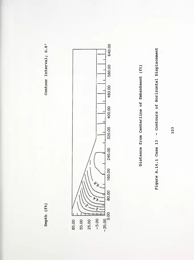
(0
>u<D
4->
cHu
o4JCou
p
5(I)
Q
PCd)
e0)
u(0
y—
V
rHp aH (0NW •H
aPc rHd) (0
e p* cckj N£i •He Mw
KM-l
<Wo
0)
c tn
•H Mr-i 3uQ) -P-P cC0) uu
1
b1
^ n<u rH
Q) a>
wC A3
(0 u-Pin rH
•H •
Q >*H
•
«a)
^3D>•Hfa
m

(0
>U0)
-pcHU3O-UCou
pc01
£
O*-s. (0
4J ^H<H aw
•H-P aC<u nH
e (0
Mc H(0 4JX! Vj
e 01
H ><W U
0) EO
c u•H 3rH
M 4J01 C*Jc
Uu
1
g mn rHIM
01
01 w(0
c u(0
p OJ
•H >*
Q rH
<<D
U3Cn
4J14-1
-pa01
Q m
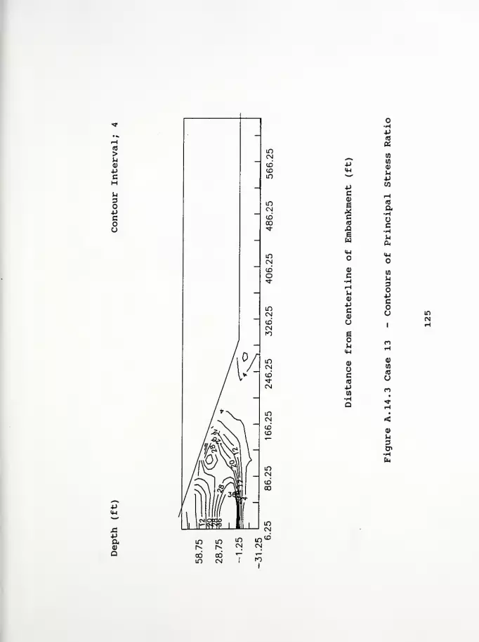
(0
>u
Pc
o•H4->
(0
«Cfl
14-1
Cfl
CD
uP
P Wc
I
cid
ew
H(0
a,HcHu
CD
C•H
0)
pc
en
U3O-Pcou
u1
e
uM-l
0)
c(Tl
cd
en
10
upCfl
•HQ
0)
3
-pamQ
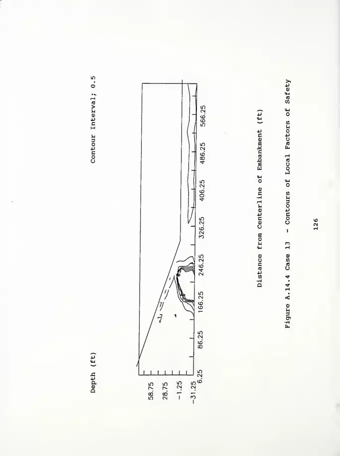
id
>uQ>
4-1
C
UDO+J
cou
-paQ
>ipQ]
<W(0
W^ <MP<W^*-^ en
hPc pa)
E (0
* fc
C(0 rHXI (0
Ew
J<Uo <H
a)
c m•H b-H 3MQ) pP cC0) uo
1
E1
u m<H H0) <D
nc (0
(0 oPW -tf
H •
a <*rH
•
<to
h3tP

Computer Program InputFigure A. 15.1 Case 14 - Contours of Horizontal DisplacementFigure A. 15.2 Case 14 - Contours of Vertical DisplacementFigure A. 15.3 Case 14 - Contours of Principal Stress RatioFigure A. 15.4 Case 14 - Contours of Local Factors of Safety
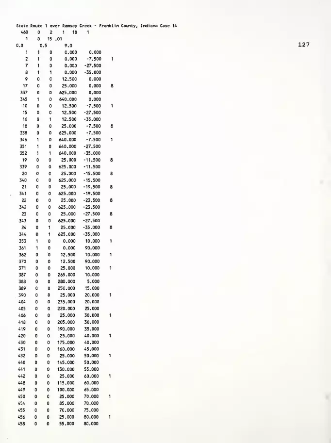
State Route 1 over Ramsey Creek - Franklin County, Indiana Case 14
127
460 2 1 18 1
1 15 .01
0.0 .5 9.0
1 1 0.000 0.000
2 1 0.000 -7.500
7 1 0.000 -27.500
8 1 1 0.000 -35.000
9 12.500 0.000
17 25.000 0.000
337 625.000 0.000
345 1 640.000 0.000
10 12.500 -7.500
15 12.500 -27.500
16 1 12.500 -35.000
18 25.000 -7.500
338 625.000 -7.500
346 1 640.000 -7.500
351 1 640.000 -27.500
352 1 1 640.000 -35.000
19 25.000 -11.500
339 625.000 -11.500
20 25.000 -15.500
340 625.000 -15.500
21 25.000 -19.500
341 625.000 -19.500
22 25.000 -23.500
342 625.000 -23.500
23 25.000 -27.500
343 625.000 -27.500
24 1 25.000 -35.000
344 1 625.000 -35.000
353 1 0.000 10.000
361 1 0.000 90.000
362 12.500 10.000
370 12.500 90.000
371 25.000 10.000
387 265.000 10.000
388 280.000 5.000
389 250.000 15.000
. 390 25.000 20.000
404 235.000 20.000
405 220.000 25.000
406 25.000 30.000
418 205.000 30.000
419 190.000 35.000
420 25.000 40.000
430 175.000 40.000
431 160.000 45.000
432 25.000 50.000
440 145.000 50.000
441 130.000 55.000
442 25.000 60.000
448 115.000 60.000
449 100.000 65.000
450 25.000 70.000
454 85.000 70.000
455 70.000 75.000
456 25.000 80.000
458 55.000 80.000

459 40.000 85.000
460 25.000 90.000
8
11
0. 640. -7.5 0. 0. 0.
0.
1
0. 0. -11.5 0. 125 0.0626 21
0. 640. -11.5 -7.51 0. 0.
0. 0. 0. -11.5 0. 120 0.0576 21
2
0. 640. -15.5 -11.51 0. 0.
0. 0. 0. -11.5 0. 120 0.0576 21
2
0. 640. -19.5 -15.51 0. 0.
0. 0. 0. -11.5 0. 120 0.0576 21
2
0. 640. -23.5 -19.51 0. 0.
0. 0. 0. -11.5 0. 120 0.0576 21,
2
0. 640. -27.5 -23.51 0. 0.
0. 0. 0. -11.5 0. 120 0.0576 21.
2
0. 640. -35.0 -27.51 0. 0.
0. 0. 0. -11.5 0. 130 0.0676 21.
3
0. 295. 0. 90. 0. 0.
0.1 0.50
2
1
409 4 10 8 13 4 2 16
300. 0.4 0.7500 21. 0..720 0.230 0.039
10.0 0.01 0.000 10. 2
2
300. 0.4 0.7500 21. 0..720 0.250 0.050
7.20 0.01 0.000 10. 2.
3
300. 0.4 0.7500 21. 0. 720 0.250 0.050
4.9 0.01 0.000 10. 2.
4
300. 0.4 0.7500 21. 0. 720 0.250 0.050
•4.30 0.01 0.000 10. 2.
5
300. 0.4 0.7500 21. 0. 720 0.250 0.050
3.8 0.01 0.000 10. 2.
6
300. 0.4 0.7500 21. 0. 720 0.250 0.050
3.40 0.01 0.000 10. 2.
7
300. 0.4 0.6630 21. 0. 720 0.124 0.020
2.5 0.01 0.000 10. 2.
8
300. 0.4 0.7500 60. 0. 000 0.124 0.020
20.0
1
0.01
4 1
0.125
1 8
0.
0.
2.
9 1 2 10
43 4 1 1 0.
345 337 338 346
44 4 1 2 8 0.
10 2 3 11
86 4 1 2 0.
128
10.0
7.20
4.9
4.30
3.8
3.40
2.5
1.90
1.46
1.07
0.96
0.87
0.80
0.63
1.58
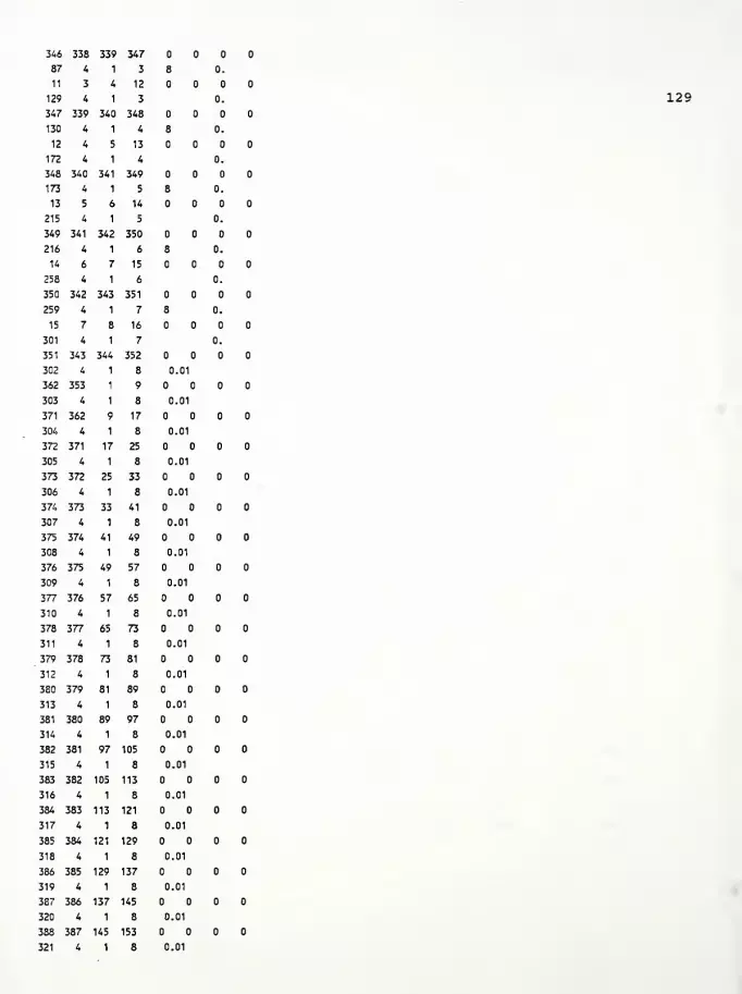
346 338 339 347
87 4 1 3 8 0.
11 3 4 12
129 4 1 3 0.
347 339 340 348
130 4 1 4 8 0.
12 4 5 13
172 4 1 4 0.
348 340 341 349
173 4 1 5 8 0.
13 5 6 14
215 4 1 5 0.
349 341 342 350
216 4 1 6 8 0.
14 6 7 15
258 4 1 6 0.
350 342 343 351
259 4 1 7 8 0.
15 7 8 16
301 4 1 7 0.
351 343 344 352
302 4 1 8 0.01
362 353 1 9
303 4 1 8 0.01
371 362 9 17
304 4 1 8 0.01
372 371 17 25
305 4 1 8 0.01
373 372 25 33
306 4 1 8 0.01
374 373 33 41
307 4 1 8 0.01
375 374 41 49
308 4 1 8 0.01
376 375 49 57
309 4 1 8 0.01
377 376 57 65
310 4 1 8 0.01
378 377 65 73
311 4 1 8 0.01
379 378 73 81
312 4 1 8 0.01
380 379 81 89
313 4 1 8 0.01
381 380 89 97
314 4 1 8 0.01
382 381 97 105
315 4 1 8 0.01
383 382 105 113
316 4 1 8 0.01
384 383 113 121
317 4 1 8 0.01
385 384 121 129
318 4 1 8 0.01
386 385 129 137
319 4 1 8 0.01
387 386 137 145
320 4 1 8 0.01
388 387 145 153
321 4 1 8 0.01
129
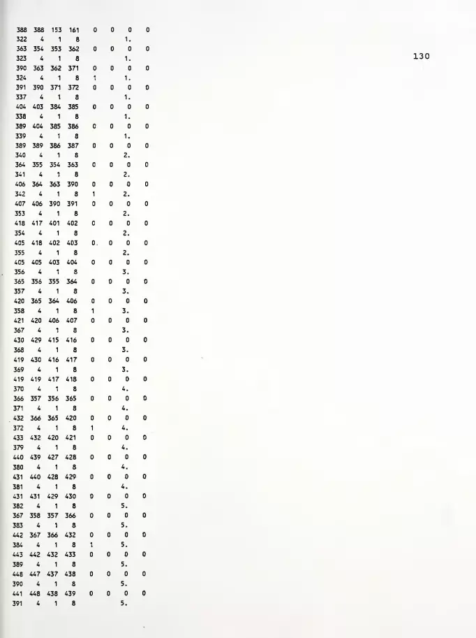
388 388 153 161
322 4 1 8 1.
363 354 353 362
323 4 1 8 1.
390 363 362 371
324 4 1 8 1 1.
391 390 371 372
337 4 1 8 1.
404 403 354 385
338 4 1 8 1.
389 404 385 386
339 4 1 8 1.
389 389 386 387
340 4 1 8 2.
364 355 354 363
341 4 1 8 2.
406 364 363 390
342 4 1 8 1 2.
407 406 390 391
353 4 1 8 2.
418 417 401 402
354 4 1 8 2.
405 418 402 403
355 4 1 8 2.
405 405 403 404
356 4 1 8 3.
365 356 355 364
357 4 1 8 3.
420 365 364 406
358 4 1 8 1 3.
421 420 406 407
367 4 1 8 3.
430 429 415 416
368 4 1 8 3.
419 430 416 417
369 4 1 8 3.
419 419 417 418
370 4 1 8 4.
366 357 356 365
371 4 1 8 4.
432 366 365 420
372 4 1 8 1 4.
433 432 420 421
379 4 1 8 4.
440 439 427 428
380 4 1 8 4.
431 440 428 429
381 4 1 8 4.
431 431 429 430
382 4 1 8 5.
367 358 357 366
383 4 1 8 5.
442 367 366 432
384 4 1 8 1 5.
443 442 432 433
389 4 1 8 5.
448 447 437 438
390 4 1 8 5.
441 448 438 439
391 4 1 8 5.
130

441 441 439 440
392 4 1 8 6.
368 359 358 367
393 4 1 8 6.
450 368 367 442
394 4 1 8 1 6.
451 450 442 443
397 4 1 8 6.
454 453 445 446
398 4 1 8 6.
449 454 446 447
399 4 1 8 6.
449 449 447 448
400 4 1 8 7.
369 360 359 368
401 4 1 8 7.
456 369 368 450
402 4 1 8 7.
457 456 450 451
403 4 1 8 7.
458 457 451 452
404 4 1 8 7.
455 458 452 453
405 4 1 8 7.
455 455 453 454
406 4 1 8 8.
370 361 360 369
407 4 1 8 8.
460 370 369 456
408 4 1 8 8.
459 460 456 457
409 4 1 8 8.
459 459 457 458
1 20 2 2 1 8
1
0.
1 1 9
067 083 .16
2 9 17
3 17 25
4 25 33
5 33 41
6 41 49
7 49 57
8 57 65
9 65 73
10 73 81
11 81 89
12 89 97
13 97 105
14 105 113
15 113 121
16 121 129
17 129 137
18 137 145
19 145 153
20 153 161
131
1.68 1.92 2.4

(0
>uQ)
PcHH3O+J
c
u
p<4-t
pa0)
a
Pc0)
s0)
uit
J** .-H
p a<H w1— •H
Q*J
C -hd) me pX cc o(0 NA •Hg= P.
tj OX
*4—
1
<w
Q)
C 10
•H u^ DP.
<P pP ccQ) uUe
1
u *<w rl
Q) <D
tfl
c (0
(0 Upw rHH •
Q inrH
<a)
u3CP
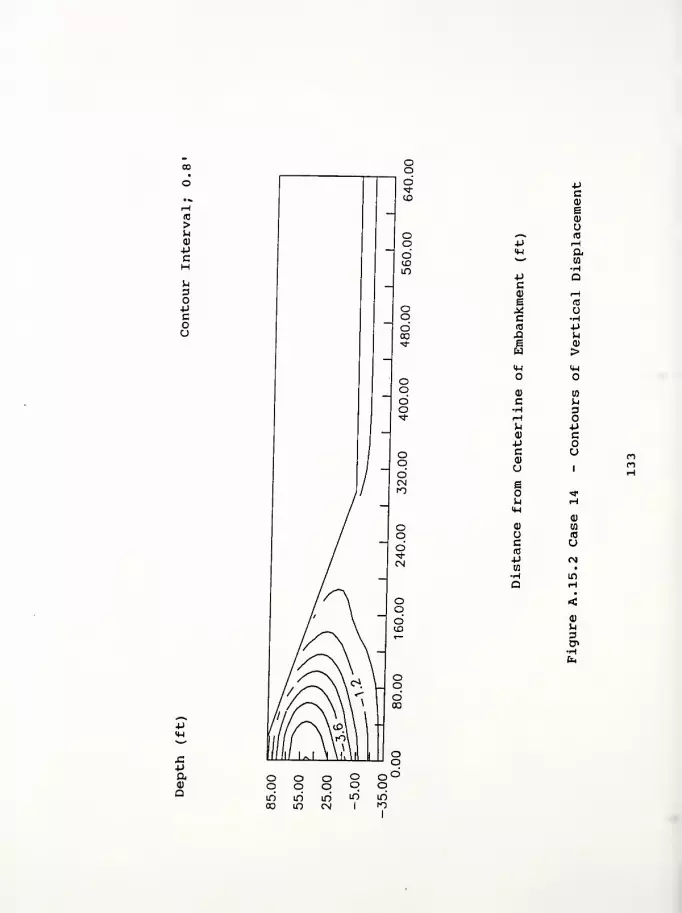
(0
>U<D
PC
-
pa0)
Q
Pin
PCa)
Ic(0
Si
(4-1
o
a)
pc<D
U
!U<u
Q)
OC(0
ptn
pc<D
e
u
•-*
a
re
u•HPi-l
>
o
w
Dopcou
.-I
0)
en
u
0)
3
•h
LO

u3O+J
cou
X-Paa>
a
-pca)
IcIB
XI
H-l
O
Q)
C•HrHuQJ
PCa)
uBO
(w
<u
oc10
p
o•H-p(0
aw01
a)
pCO
id
a-H
c•HJ-l
14-1
o
w
3opcou
3

5aa>
a
>*j0)
IM(0
w_, <Hp<H^ to
uPc P<D ue 10
* fc,
c(0 <-i
Si (0
B ua
J<U
<U
Q)
C [fl
•H hH 3P oQ) 4JP CC<D uUe
b <*
<M H<l) <u
ac (0
10 u*Jw <*
in
0)
P.
3
-H
If)'
r*j

Computer Program InputFigure A. 16.1 Case 15 - Contours of Horizontal DisplacementFigure A. 16. 2 Case 15 - Contours of Vertical DisplacementFigure A. 16. 3 Case 15 - Contours of Principal Stress RatioFigure A. 16.4 Case 15 - Contours of Local Factors of Safety
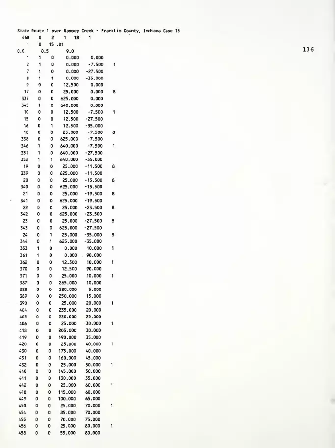
State Route 1 over Ramsey Creek - Franklin County, Indiana Case 15
136
460 2 1 18 1
1 15 .01
0.0 .5 9.0
1 1 0.000 0.000
2 1 0.000 -7.500
7 1 0.000 -27.500
8 1 1 0.000 -35.000
9 12.500 0.000
17 25.000 0.000
337 625.000 0.000
345 1 640.000 0.000
10 12.500 -7.500
15 12.500 -27.500
16 1 12.500 -35.000
18 25.000 -7.500
338 625.000 -7.500
346 1 640.000 -7.500
351 1 640.000 -27.500
352 1 1 640.000 -35.000
19 25.000 -11.500
339 625.000 -11.500
20 25.000 -15.500
340 625.000 -15.500
21 25.000 -19.500
341 625.000 -19.500
22 25.000 -23.500
342 625.000 -23.500
23 25.000 -27.500
343 625.000 -27.500
24 1 25.000 -35.000
344 1 625.000 -35.000
353 1 0.000 10.000
361 1 0.000 90.000
362 12.500 10.000
370 12.500 90.000
371 25.000 10.000
387 265.000 10.000
388 280.000 5.000
389 250.000 15.000
390 25.000 20.000
404 235.000 20.000
405 220.000 25.000
406 25.000 30.000
418 205.000 30.000
419 190.000 35.000
420 25.000 40.000
430 175.000 40.000
431 160.000 45.000
432 25.000 50.000
440 145.000 50.000
441 130.000 55.000
442 25.000 60.000
448 115.000 60.000
449 100.000 65.000
450 25.000 70.000
454 85.000 70.000
455 70.000 75.000
456 25.000 80.000
458 55.000 80.000
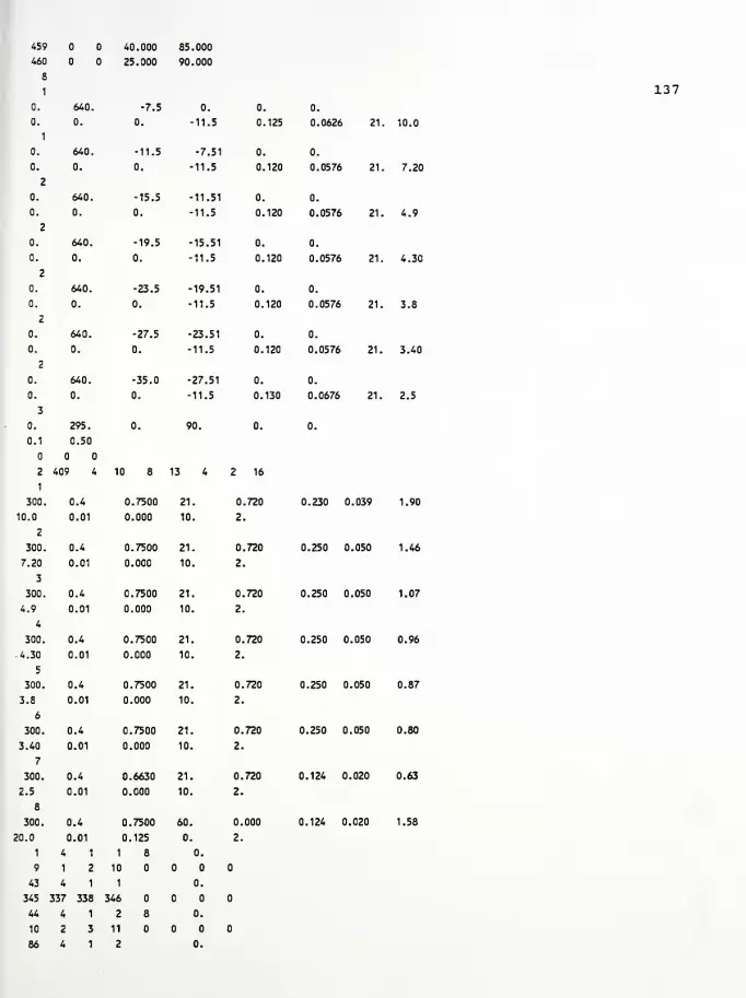
459 40.000 85.000
460 25.000 90.000
8
1
0. 640. -7.5 0. 0. 0.
0. 0. 0. -11.5 0. 125 0.0626 21
0. 640. -11.5 -7.51 0. 0.
0. 0. 0. -11.5 0. 120 0.0576 21
2
0. 640. -15.5 -11.51 0. 0.
0. 0. 0. -11.5 0. 120 0.0576 21
2
0. 640. -19.5 -15.51 0. 0.
0. 0. 0. -11.5 0. 120 0.0576 21
2
0. 640. -23.5 -19.51 0. 0.
0. 0. 0. -11.5 0. 120 0.0576 21.
2
0. 640. -27.5 -23.51 0. 0.
0. 0. 0. -11.5 0. 120 0.0576 21,
2
0. 640. -35.0 -27.51 0. 0.
0. 0. 0. -11.5 0. 130 0.0676 21.
3
0. 295. 0. 90. 0. 0.
0.1 0.50
2
1
409 4 10 8 13 4 2 16
1
300. 0.4 0.7500 21. .720 0.230 0.039
10.0 0.01 0.000 10. 2
2
300. 0.4 0.7500 21. 0..720 0.250 0.050
7.20 0.01 0.000 10. 2
3
300. 0.4 0.7500 21. 0..720 0.250 0.050
4.9 0.01 0.000 10. 2.
4
300. 0.4 0.7500 21. 0. 720 0.250 0.050
-4.30 0.01 0.000 10. 2.
5
300. 0.4 0.7500 21. 0. 720 0.250 0.050
3.8 0.01 0.000 10. 2.
6
300. 0.4 0.7500 21. 0. 720 0.250 0.050
3.40 0.01 0.000 10. 2.
7
300. 0.4 0.6630 21. 0. 720 0.124 0.020
2.5 0.01 0.000 10. 2.
8
300. 0.4 0.7500 60. 0. 000 0.124 0.020
20.0
1
0.01
4 1
0.125
1 8
0.
0.
2.
9 1 2 10
43 4 1 1 0.
345 337 338 346
44 4 1 2 8 0.
10 2 3 11
86 4 1 2 0.
137
10.0
7.20
4.9
4.30
3.8
3.40
2.5
1.90
1.46
1.07
0.96
0.87
0.80
0.63
1.58
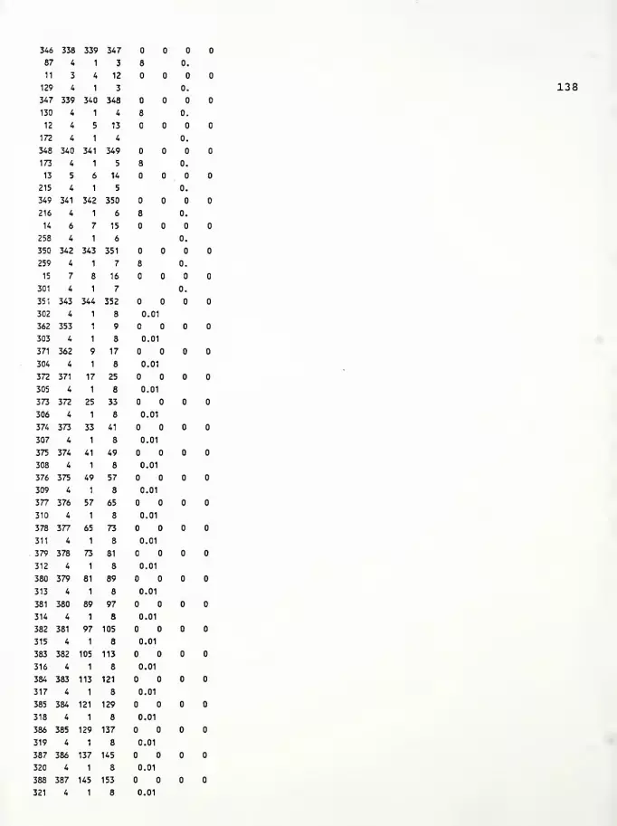
346 338 339 347
87 4 1 3 8 0.
11 3 4 12
129 4 1 3 0.
347 339 340 348
130 4 1 4 8 0.
12 4 5 13
172 4 1 4 0.
348 340 341 349
173 4 1 5 8 0.
13 5 6 14
215 4 1 5 0.
349 341 342 350
216 4 1 6 8 0.
14 6 7 15
258 4 1 6 0.
350 342 343 351
259 4 1 7 8 0.
15 7 8 16
301 4 1 7 0.
351 343 344 352
302 4 1 8 0.01
362 353 1 9
303 4 1 8 0.01
371 362 9 17
304 4 1 8 0.01
372 371 17 25
305 4 1 8 0.01
373 372 25 33
306 4 1 8 0.01
374 373 33 41
307 4 1 8 0.01
375 374 41 49
308 4 1 8 0.01
376 375 49 57
309 4 1 8 0.01
377 376 57 65
310 4 1 8 0.01
378 377 65 73
311 4 1 8 0.01
379 378 73 81
312 4 1 8 0.01
380 379 81 89
313 4 1 8 0.01
381 380 89 97
314 4 1 8 0.01
382 381 97 105
315 4 1 8 0.01
383 382 105 113
316 4 1 8 0.01
384 383 113 121
317 4 1 8 0.01
385 384 121 129
318 4 1 8 0.01
386 385 129 137
319 4 1 8 0.01
387 386 137 145
320 4 1 8 0.01
388 387 145 153
321 4 1 8 0.01
138

388 388 153 161
322 4 1 8 1.
363 354 353 362
323 4 1 8 1.
390 363 362 371
324 4 1 8 1 1.
391 390 371 372
337 4 1 8 1.
404 403 384 385
338 4 1 8 1.
389 404 385 386
339 4 1 8 1.
389 389 386 387
340 4 1 8 2.
364 355 354 363
341 4 1 8 2.
406 364 363 390
342 4 1 8 1 2.
407 406 390 391
353 4 1 8 2.
418 417 401 402
354 4 1 8 2.
405 418 402 403
355 4 1 8 2.
405 405 403 404
356 4 1 8 3.
365 356 355 364
357 4 1 8 3.
420 365 364 406
358 4 1 8 1 3.
421 420 406 407
367 4 1 8 3.
430 429 415 416
368 4 1 8 3.
419 430 416 417
369 4 1 8 3.
419 419 417 418
370 4 1 8 4.
366 357 356 365
371 4 1 8 4.
432 366 365 420
372 4 1 8 1 4.
433 432 420 421
379 4 1 8 4.
440 439 427 428
380 4 1 8 4.
431 440 428 429
381 4 1 8 4.
431 431 429 430
382 4 1 8 5.
367 358 357 366
383 4 1 8 5.
442 367 366 432
384 4 1 8 1 5.
443 442 432 433
389 4 1 8 5.
448 447 437 438
390 4 1 8 5.
441 448 438 439
391 4 1 8 5.
139

441 441 439 440
392 4 1 8 6.
368 359 358 367
393 4 1 8 6.
450 368 367 442
394 4 1 8 1 6.
451 450 442 443
397 4 1 8 6.
454 453 445 446
398 4 1 8 6.
449 454 446 447
399 4 1 8 6.
449 449 447 448
400 4 1 8 7.
369 360 359 368
401 4 1 8 7.
456 369 368 450
402 4 1 8 7.
457 456 450 451
403 4 1 8 7.
458 457 451 452
404 4 1 8 7.
455 458 452 453
405 4 1 8 7.
455 455 453 454
406 4 1 8 8.
3/0 361 360 369
407 4 1 8 8.
460 370 369 456
408 4 1 8 8.
459 460 456 457
409 4 1 8 8.
459 459 457 458
1 20 2 2 1 8
1
1
0.
1 9
.067 083 .16
2 9 17
3 17 25
4 25 33
5 33 41
6 41 49
7 49 57
8 57 65
9 65 73
10 73 81
11 81 89
12 89 97
13 97 105
14 105 113
15 113 121
16 121 129
17 129 137
18 137 145
19 145 153
20 153 161
140

(0
>U<v
pc
uoopcou
oodto
oodID
P
jC-P
oQ
pc<u
eo
(B*»>* rHp (X(W tfl
>—
'
•Ha
pC rHQ) (0
e p.* cc<c NX! •He Uw
X%4o <u
<1)
c wH MrH 3Ua> pp cca> uu
1
B1
m IDiw Ha) 0)
u wc ra
(0 up05 rH•H •
a VOrH
<<D
^3U>

u3OPcou
-paCD
a
Pc<D
B0)
O-—
^
(0
p -Hq-l aw m
•Hp Qca) r-i
e <c
X oc •H(0 PX! Pg <D
u ><w 14-1
a) wc p•H 3rH OP. -pQ) cPC(1)
uu
1 Heo inu H<w
(1)
o U5
(C
c U<B
P CNW •
VO
(1)
p3
n o o o oo o o o <_)
in in m m mCO in CN 1
1

uCD
-PC
ufl
opcou
paQ
-pca)
c
X!ew
o
CD
C•H
^<D
-PCa)
ueo
4-1
0)
oc«3
-PCO
O•H-P(0
aen
to
0)
PCO
(0
a•Huc•H
o
to
3opcoo
in
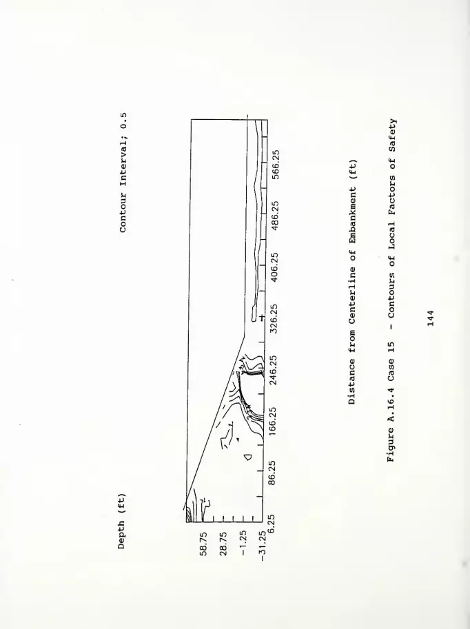
>u0)
4-1
cHU3O4->
c
u
J54->
aoa
>i4->
(1)
4-1
ia
w^ <w4J<W^ CO
M4->
c Pa) ue id
* fec(0 rH£3 ro
E Uw
J14-1
<4-l
ai
c 09
•H UrH 3MQ) 4J4J cC(1) uue
n in
<H Ha) Q)
mc (0
(0 u4JW "<*
H •
Q VDrH
•
<(1)
u3Cn

Computer Program InputFigure A. 17.1 Case 16 - Contours of Horizontal DisplacementFigure A. 17.2 Case 16 - Contours of Vertical DisplacementFigure A. 17. 3 Case 16 - Contours of Principal Stress RatioFigure A. 17. 4 Case 16 - Contours of Local Factors of Safety
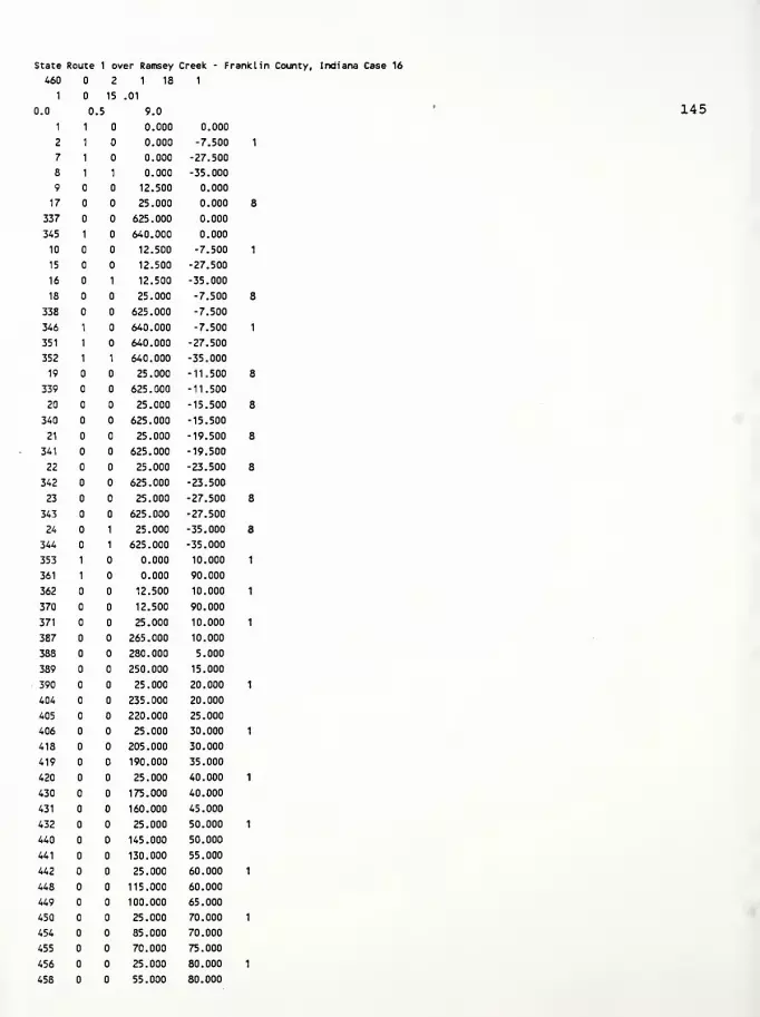
State Route 1 over Ramsey Creek - Franklin County, Indiana Case 16
460 2 1 18 1
1 15 .01
0.0 ,5 9.0
1 1 0.000 0.000
2 1 0.000 -7.500
7 1 0.000 -27.500
8 1 1 0.000 -35.000
9 12.500 0.000
17 25.000 0.000
337 625.000 0.000
345 1 640.000 0.000
10 12.500 -7.500
15 12.500 -27.500
16 1 12.500 -35.000
18 25.000 -7.500
338 625.000 -7.500
346 1 640.000 -7.500
351 1 640.000 -27.500
352 1 1 640.000 -35.000
19 25.000 -11.500
339 625.000 -11.500
20 25.000 -15.500
340 625.000 -15.500
21 25.000 -19.500
341 625.000 -19.500
22 25.000 -23.500
342 625.000 -23.500
23 25.000 -27.500
343 625.000 -27.500
24 1 25.000 -35.000
344 1 625.000 -35.000
353 1 0.000 10.000
361 1 0.000 90.000
362 12.500 10.000
370 12.500 90.000
371 25.000 10.000
387 265.000 10.000
388 280.000 5.000
389 250.000 15.000
390 25.000 20.000
404 235.000 20.000
405 220.000 25.000
406 25.000 30.000
418 205.000 30.000
419 190.000 35.000
420 25.000 40.000
430 175.000 40.000
431 160.000 45.000
432 25.000 50.000
440 145.000 50.000
441 130.000 55.000
442 25.000 60.000
448 115.000 60.000
449 100.000 65.000
450 25.000 70.000
454 85.000 70.000
455 70.000 75.000
456 25.000 80.000
458 55.000 80.000
145

459 40.000 85.000
460 25.000 90.000
8
41
0. 640. -7.5 0. 0. 0.
0. 0. 0. -11.5 0. 125 0.0626 21
0. 640. -11.5 -7.51 0. 0.
0. 0. 0. -11.5 0. 120 0.0576 21
2
0. 640. -15.5 -11.51 0. 0.
0. 0. 0. -11.5 0. 120 0.0576 21
2
0. 640. -19.5 -15.51 0. 0.
0. 0. 0. -11.5 0. 120 0.0576 21
2
0. 640. -23.5 -19.51 0. 0.
0. 0. 0. -11.5 0. 120 0.0576 21.
2
0. 640. -27.5 -23.51 0. 0.
0. 0. 0. -11.5 0. 120 0.0576 21,
2
0. 640. -35.0 -27.51 0. 0.
0. 0. 0. -11.5 0. 130 0.0676 21.
3
0. 295. 0. 90. 0. 0.
0.1 0.50
2 409 4 10 8 13 4 2 16
1
300. 0.4 0.7500 21. 0.,720 0.230 0.039
10.0 0.01 0.000 10. 2,
2
300. 0.4 0.7500 21. 0..720 0.250 0.050
3.00 0.01 0.000 10. 2.
3
300. 0.4 0.7500 21. 0. 720 0.250 0.050
2.50 0.01 0.000 10. 2.
4
300. 0.4 0.7500 21. 0.720 0.250 0.050
.2.00 0.01 0.000 10. 2.
5
300. 0.4 0.7500 21. 0. 720 0.250 0.050
1.50 0.01 0.000 10. 2.
6
300. 0.4 0.7500 21. 0. 720 0.250 0.050
1.50 0.01 0.000 10. 2.
7
300. 0.4 0.6630 21. 0. 720 0.124 0.020
1.02 0.01 0.000 10. 2.
8
300. 0.4 0.7500 60. 0. 000 0.124 0.020
8.0
1
0.01
4 1
0.125
1 8
0.
0.
2.
9 1 2 10
43 4 1 1 0.
345 337 338 346
44 4 1 2 8 0.
10 2 3 11
86 4 1 2 0.
146
10.0
3.00
2.50
2.00
1.50
1.50
1.02
1.90
0.73
0.63
0.53
0.42
0.42
0.30
1.58

346 338
87
11
129
347 339
130 4
339 347
1 3
4 12
1 3
340 348
1 4
12
172
348 340
173 4
13 5
215 4
349 341
216 4
14 6
258 4
350 342
259 4
341 349
1 5
15
301
351 343
302 4
362 353
303 4
371 362
304 4
372 371
305 4
373 372
342 350
1 6
7 15
1 6
343 351
1 7
8 16
1 7
344 352
1 8
306
374
307
4
373
4
375 374
308 4
376 375
309 4
377 376
310 4
378 377
311 4
379 378
312 4
380 379
313 4
381 380
314 4
382 381
315 4
383 382
316 4
384 383
317 4
385 384
318 4
386 385
319 4
387 386
320 4
388 387
321 4
1
1
9
1
17
1
25
1
33
1
41
1
49
1
57
1
65
1
73
1
81
1
89
1
97 105
9
8
17
8
25
8
33
8
41
8
49
8
57
8
65
8
73
8
81
8
89
8
97
8
1 8
105 113
1 8
113 121
1 8
121 129
1 8
129 137
1 8
137 145
1 8
145 153
1 8
0.01
0.01
0.01
0.01
0.01
0.01
0.01
0.01
0.01
0.01
0.01
0.01
0.01
0.01
0.01
0.01
0.01
0.01
0.01
0.01
0.
0.
0.
0.
0.
0.
0.
0.
0.
0.
147

388 388 153 161
322 4 1 8 1.
363 354 353 362
323 4 1 8 1.
390 363 362 371
324 4 1 8 1 1.
391 390 371 372
337 4 1 8 1.
404 403 384 385
338 4 1 8 1.
389 404 385 386
339 4 1 8 1.
389 389 386 387
340 4 1 8 2.
364 355 354 363
341 4 1 8 2.
406 364 363 390
342 4 1 8 1 2.
407 406' 390 391
353 4 1 8 2.
418 417 401 402
354 4 1 8 2.
405 418 402 403
355 4 1 8 2.
405 405 403 404
356 4 1 8 3.
365 356 355 364
357 4 1 8 3.
420 365 364 406
358 4 1 8 1 3.
421 420 406 407
367 4 1 8 3.
430 429 415 416
368 4 1 8 3.
419 430 416 417
369 4 1 8 3.
419 419 417 418
370 4 1 8 4.
366 357 356 365
371 4 1 8 4.
432 366 365 420
372 4 1 8 1 4.
433 432 420 421
379 4 1 8 4.
440 439 427 428
380 4 1 8 4.
431 440 428 429
381 4 1 8 4.
431 431 429 430
382 4 1 8 5.
367 358 357 366
383 4 1 8 5.
442 367 366 432
384 4 1 8 1 5.
443 442 432 433
389 4 1 8 5.
448 447 437 438
390 4 1 8 5.
441 448 438 439
391 4 1 8 5.
148
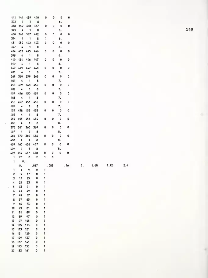
441 4A1 439 440
392 4 1 8 6.
363 359 358 367
393 4 1 8 6.
450 368 367 442
394 4 1 8 1 6.
451 450 442 443
397 4 1 8 6.
454 453 445 446
398 4 1 8 6.
449 454 446 447
399 4 1 8 6.
449 449 447 448
400 4 1 8 7.
369 360 359 368
401 4 1 8 7.
456 369 368 450
402 4 1 8 7.
45? 456 450 451
403 4 1 8 7.
45S 457 451 452
404 4 1 8 7.
455 458 452 453
405 4 1 8 7.
455 455 453 454
406 4 1 8 8.
370 361 360 369
407 4 1 8 8.
460 370 369 456
408 4 1 8 8.
459 460 456 457
409 4 1 8 8.
459 459 457 458
1 20 2 2 1 8
1
1
0.
1 9
.067 083 .16
2 9 17
3 17 25
4 25 33
5 33 41
6 41 49
7 49 57
8 57 65
9 65 73
10 73 81
11 81 89
12 89 97
13 97 105
14 105 113
15 113 121
16 121 129
17 129 137
18 137 145
19 145 153
20 153 161
149
1.68 1.92 2.4

(0
>UQ)
Pc
rH
DO4JCou
•paa)
Q
oodCD
-pca>
Eai
uid
^—
^
rHp a<4H en^^ H
O-pc rHcu rtj
e -P* cc(0 N-Q -HE uw o
X14-1
o 4H
0)
c en
•H urH 3rH
a) P•p cc o<D uUeou v£>
4-1 Ha) a)
u en
c (0
(0 u-pto rH-H •
a r»H<0)
rH
3Cn
Cn
oo oo oooo oo
moo
inm m1
in

>UQ)
+J
CHUDOPcou
PC0)
eid
>-v (0
+J H<H a
'
H+J aC0) rH
e f0
X uc H(0 +J
X! ^e a)
w ><u IM
<D uC p.H 3^H^ P<D C+J oC(1)
uu1
HID
H6
VO
^ H14-1
(1)
0) CO
u (0
c U(0
P (Nw •
(1)
p.
•H
Paa)
Q
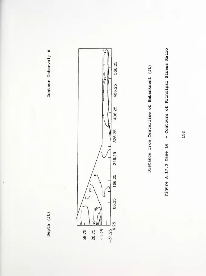
(0
>U0)
+J
c
X!P
a
p14-1
-pca>
Ic(0
.aew
o
<u
cH
0)
pc0)
uEou4-1
0)
ucId
Pw•HQ
o•Hp(0
awwa>
^1
pw
(0
aHocHM
<HO
3OPcou
m
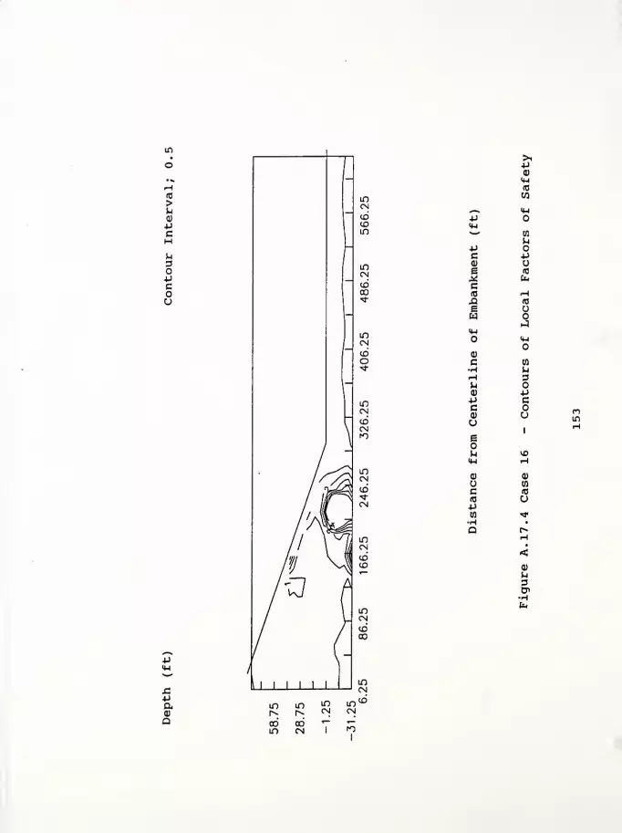
to
>ua)
4J
C
>.*J0)
4-1
aca
_^ 4-1
-p4-1
*—
'
CO
u•pC *j<D
e (0
,« hc(O Hfl 10
ew
J<U
4-1
0)
c W-H hH 3n o0) p-p ccQ) aU
i
eI
h VO4-1 Ha) 0)
tfl
c <0
(0 u+J
w *H •
Q r»rH
•
<
kl
3CT
Cu,
4J4-1
-Pama
m m'
Computer Program InputFigure A. 18.1 Case 17 - Contours of Horizontal DisplacementFigure A. 18. 2 Case 17 - Contours of Vertical DisplacementFigure A. 18. 3 Case 17 - Contours of Principal Stress RatioFigure A. 18. 4 Case 17 - Contours of Local Factors of Safety

State Route 1 over Ramsey Creek - Franklin County, Indiana Case 17
460 2 1 18 1
1 15 .01
0.0 5 9.0
1 1 0.000 0.000
2 1 0.000 -7.500
7 1 0.000 -27.500
8 1 1 0.000 -35.000
9 12.500 0.000
17 25.000 0.000
337 625.000 0.000
345 1 640.000 0.000
10 12.500 -7.500
15 12.500 -27.500
16 1 12.500 -35.000
18 25.000 -7.500
538 625.000 -7.500
346 1 640.000 -7.500
351 1 640.000 -27.500
352 1 1 640.000 -35.000
19 25.000 -11.500
339 625.000 -11.500
20 25.000 -15.500
340 625.000 -15.500
21 25.000 -19.500
34
1
625.000 -19.500
22 25.000 -23.500
342 625.000 -23.500
23 25.000 -27.500
343 625.000 -27.500
24 1 25.000 -35.000
344 1 625.000 -35.000
353 1 0.000 10.000
361 1 0.000 90.000
362 12.500 10.000
370 12.500 90.000
371 25.000 10.000
387 265.000 10.000
388 280.000 5.000
389 250.000 15.000
390 25.000 20.000
404 235.000 20.000
405 220.000 25.000
406 25.000 30.000
418 205.000 30.000
419 190.000 35.000
420 25.000 40.000
430 175.000 40.000
431 160.000 45.000
432 25.000 50.000
440 145.000 50.000
441 130.000 55.000
442 25.000 60.000
448 115.000 60.000
449 100.000 65.000
450 25.000 70.000
454 85.000 70.000
455 70.000 75.000
456 25.000 80.000
458 55.000 80.000
154
459 40.000 85.000
460 25.000 90.000
8
5
0. 640. -7.5 0. 0. 0.
0. 0. 0. -11.5 0. 125 0.0626 21
0. 640. -11.5 -7.51 0. 0.
0. 0. 0. -11.5 0. 120 0.0576 21
2
0. 640. -15.5 -11.51 0. 0.
0. 0. 0. -11.5 0. 120 0.0576 21
2
0. 640. -19.5 -15.51 0. 0.
0. 0. 0. -11.5 0. 120 0.0576 21,
2
0. 640. -23.5 -19.51 0. 0.
0. 0. 0. -11.5 0. 120 0.0576 21.
2
0. 640. -27.5 -23.51 0. 0.
0. 0. 0. -11.5 0. 120 0.0576 21.
2
0. 640. -35.0 -27.51 0. 0.
0. 0. 0. -11.5 0. 130 0.0676 21.
3
0. 295. 0. 90. 0. 0.
0.1 0.50
2
1
409 4 10 8 13 4 2 16
1
300. 0.4 0.7500 21. .720 0.230 0.039
10.0 0.01 0.000 10. 2
2
300. 0.4 0.7500 21. 0..720 0.250 0.050
3.00 0.01 0.000 10. 2.
3
300. 0.4 0.7500 21. 0..720 0.250 0.050
2.50 0.01 0.000 10. 2.
4
300. 0.4 0.7500 21. 0.,720 0.250 0.050
2.00 0.01 0.000 10. 2.
5
300. 0.4 0.7500 21. 0. 720 0.250 0.050
1.50 0.01 0.000 10. 2.
6
300. 0.4 0.7500 21. 0. 720 0.250 0.050
1.50 0.01 0.000 10. 2.
7
300. 0.4 0.6630 21. 0. 720 0.124 0.020
1.02 0.01 0.000 10. 2.
8
300. 0.4 0.7500 60. 0. 000 0.124 0.020
8.0
1
0.01
4 1
0.125
1 8
0.
0.
2.
9 1 2 10
43 4 1 1 0.
345 337 338 346
44 4 1 2 8 0.
10 2 3 11
86 4 1 2 0.
155
3.00
2.5
2.00
1.5
1.50
1.02
1.90
0.73
0.63
0.53
0.42
0.42
0.30
1.58

346 338 339 347
87 4 1 3 8 0.
11 3 4 12
129 4 1 3 0.
347 339 340 348
130 4 1 4 8 0.
12 4 5 13
172 4 1 4 0.
348 340 341 349
173 4 1 5 8 0.
13 5 6 14
215 4 1 5 0.
349 341 342 350
216 4 1 6 8 0.
14 6 7 15
258 4 1 6 0.
350 342 343 351
259 4 1 7 8 0.
15 7 8 16
301 4 1 7 0.
351 343 344 352
302 4 1 8 0.01
362 353 1 9
303 4 1 8 0.01
371 362 9 17
304 4 1 8 0.01
372 371 17 25
305 4 1 8 0.01
373 372 25 33
306 4 1 8 0.01
374 373 33 41
307 4 1 8 0.01
375 374 41 49
308 4 1 8 0.01
376 375 49 57
309 4 1 8 0.01
377 376 57 65
310 4 1 8 0.01
378 377 65 73
311 4 1 8 0.01
379 378 73 81
312 4 1 8 0.01
380 379 81 89
313 4 1 8 0.01
381 380 89 97
314 4 1 8 0.01
382 381 97 105
315 4 1 8 0.01
383 382 105 113
316 4 1 8 0.01
384 383 113 121
317 4 1 8 0.01
385 384 121 129
318 4 1 8 0.01
386 385 129 137
319 4 1 8 0.01
. 387 386 137 145
320 4 1 8 0.01
388 387 145 153
321 4 1 8 0.01
156

388 388 153 161
322 4 1 8 1.
363 354 353 362
323 4 1 8 1.
390 363 362 371
324 4 1 8 1 1.
391 390 371 372
337 4 1 8 1.
404 403 384 385
338 4 1 8 1.
389 404 385 386
339 4 1 8 1.
389 389 386 387
340 4 1 8 2.
364 355 354 363
341 4 1 8 2.
406 364 363 390
342 4 1 8 1 2.
407 406 390 391
353 4 1 8 2.
418 417 401 402
354 4 1 8 2.
405 418 402 403
355 4 1 8 2.
405 405 403 404
356 4 1 8 3.
365 356 355 364
357 4 1 8 3.
420 365 364 406
358 4 1 8 1 3.
421 420 406 407
367 4 1 8 3.
430 429 415 416
368 4 1 8 3.
419 430 416 417
369 4 1 8 3.
419 419 417 418
370 4 1 8 4.
366 357 356 365
371 4 1 8 4.
432 366 365 420
372 4 1 8 1 4.
433 432 420 421
379 4 1 8 4.
440 439 427 428
380 4 1 8 4.
431 440 428 429
381 4 1 8 4.
431 431 429 430
382 4 1 8 5.
367 358 357 366
383 4 1 8 5.
442 367 366 432
384 4 1 8 1 5.
443 442 432 433
389 4 1 8 5.
448 447 437 438
390 4 1 8 5.
441 448 438 439
391 4 1 8 5.
157
441 441 439 440
392 4 1 8 6.
368 359 358 367
393 4 1 8 6.
450 368 367 442
394 4 1 8 1 6.
451 450 442 443
397 4 1 8 6.
454 453 445 446
398 4 1 8 6.
449 454 446 447
399 4 1 8 6.
449 449 447 448
400 4 1 8 7.
369 360 359 368
401 4 1 8 7.
456 369 368 450
402 4 1 8 7.
457 456 450 451
403 4 1 8 7.
458 457 451 452
404 4 1 8 7.
455 458 452 453
405 4 1 8 7.
455 455 453 454
406 4 1 8 8.
370 361 360 369
407 4 1 8 8.
460 370 369 456
408 4 1 8 8.
459 460 456 457
409 4 1 8 8.
459 459 457 458
1 20 2 2 1 8
1
0.
1 1 9
067 083 .16
2 9 17
3 17 25
4 25 33
5 33 41
6 41 49
7 49 57
8 57 65
9 65 73
10 73 81
11 81 89
12 89 97
13 97 105
14 105 113
15 113 121
16 121 129
17 129 137
18 137 145
19 145 153
20 153 161
158
.16
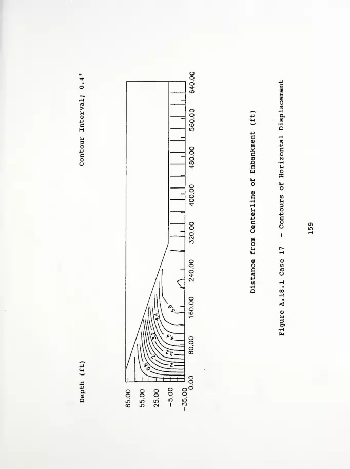
(0
>U0)
pcH
O4->
cou
P<4-l
X!PaQ)
Q
Ood -p
ca)
ea)
(0^ H•p a<w (0^ -H
Q-pc Ha) (0
e P* cc(0 NX! He Mw
X<w
<t-i
Q)
C 0)H HH 3^a) p-p cc<u oo
1
e1
M c^<w HQ) (1)
wc (d
(0 u-pm H•H •
Q 00rH
•
<a>
h3Cn
oolf>
If)
ooIf)
o'oIf)

>u0)
-pcHM3O-Pcou
X!-PQ,<D
Q
4J
-PC0)
Ic(0
XIew<4-i
o
<u
c
upc0)
aeo
H-l
(1)
c(0
•pto
-pcQ)
E0)
(0
--I
ato
(0
oHP
>
O
Wu3OPcou
a)
3
oo
OO oooo o
ID00
m1
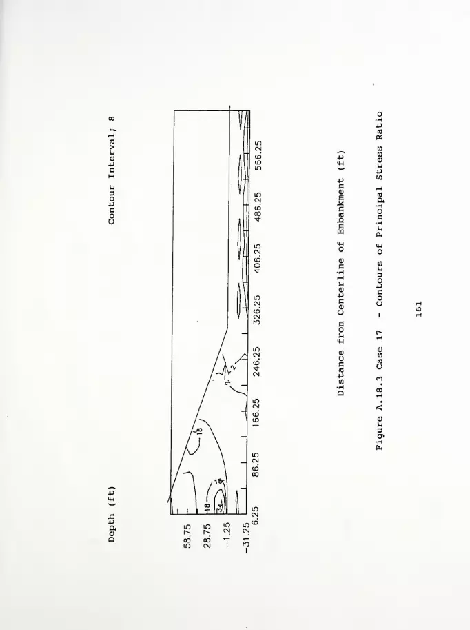
to
>uQ)
c
J5poQ
•H-P10
aw
4J wCD
+J CO
Cd)
1c(0
X!ew
to
a-H
c•H
o
C•H
u<u
+Jc0)
U3
M3OJJc
CJ
o1
eo
M-l
Uc10
(I)
(fl
(0
u•pen
n•H
a CO
•
<<D
U3CP•H6h
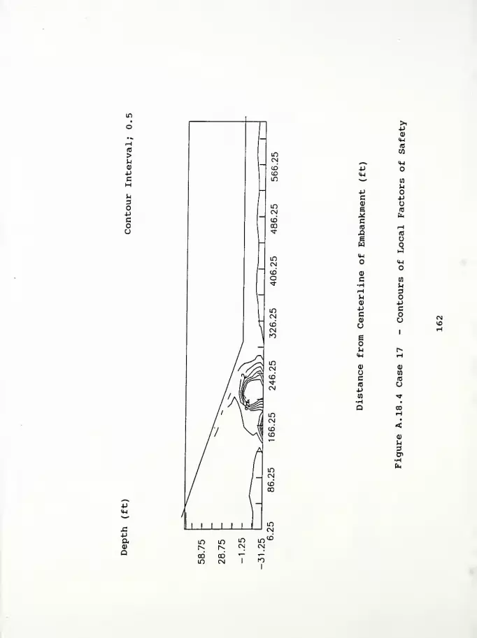
>ua)
pc
u
o-pcoo
Paa
>1p0)
(4-1
(0
w^ M-lpq-lw to
u*JC pai ue 10
a; fac(0 ^H.0 (0
e uw
J<4—
1
IJ-I
0)
c mH uH 3^(1) -P-P cB<D uUE
1
h r»<w T-i
(1) a>
U wc to
(0 upen T
0)
D
K5

Computer Program InputFigure A. 19.1 Case 18 - Contours of Horizontal DisplacementFigure A. 19. 2 Case 18 - Contours of Vertical DisplacementFigure A. 19. 3 Case 18 - Contours of Principal Stress RatioFigure A. 19.4 Case 18 - Contours of Local Factors of Safety

State Route 1 over Ramsey Creek - Franklin County, Indiana Case 18
460 1 1 18 1
1 15 .01
0.0 .5 9.0
1 1 0.000 0.000
2 1 0.000 -7.500
7 1 0.000 -27.500
8 1 1 0.000 -35.000
9 12.500 0.000
17 25.000 0.000
337 625.000 0.000
345 1 640.000 0.000
10 12.500 -7.500
15 12.500 -27.500
16 1 12.500 -35.000
18 25.000 -7.500
338 625.000 -7.500
346 1 640.000 -7.500
351 1 640.000 -27.500
352 1 1 640.000 -35.000
19 25.000 -11.500
339 625.000 -11.500
20 25.000 -15.500
340 625.000 -15.500
21 25.000 -19.500
341 625.000 -19.500
22 25.000 -23.500
342 625.000 -23.500
23 25.000 -27.500
343 625.000 -27.500
24 1 25.000 -35.000
344 1 625.000 -35.000
353 1 0.000 10.000
361 1 0.000 90.000
362 12.500 10.000
370 12.500 90.000
371 25.000 10.000
387 265.000 10.000
38S 280.000 5.000
389 250.000 15.000
390 25.000 20.000
404 235.000 20.000
405 220.000 25.000
406 25.000 30.000
418 205.000 30.000
419 190.000 35.000
420 25.000 40.000
430 175.000 40.000
431 160.000 45.000
432 25.000 50.000
440 145.000 50.000
441 130.000 55.000
442 25.000 60.000
448 115.000 60.000
449 100.000 65.000
450 25.000 70.000
454 85.000 70.000
455 70.000 75.000
456 25.000 80.000
458 55.000 80.000
163
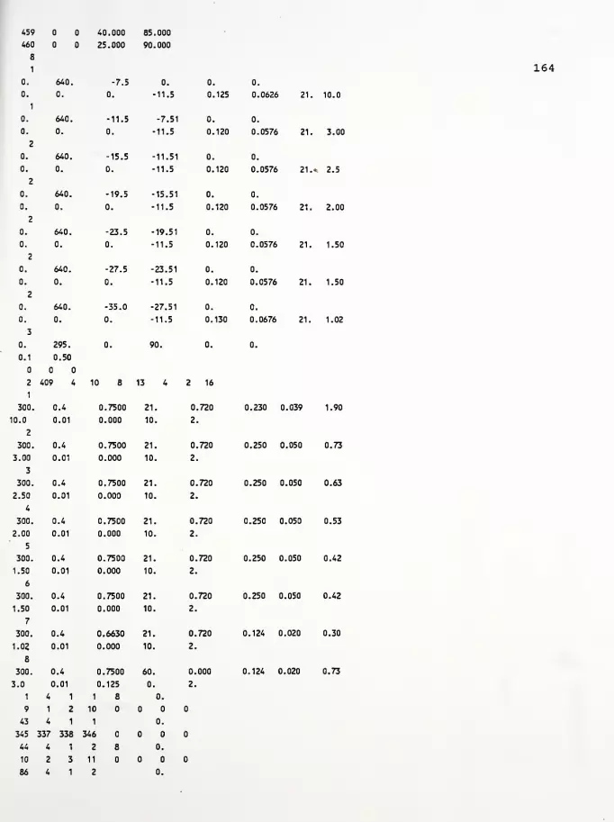
459
460
8
1
0.
0.
1
0.
0.
2
0.
0.
2
0.
0.
2
0.
0.
2
0.
0.
2
0.
0.
3
0.
0.1
2
1
300.
10.0
2
300.
3.00
3
300.
2.50
4
300.
2.00
5
300.
1.50
6
300.
1.50
7
300.
1.02
640.
0.
640.
0.
640.
0.
640.
0.
640.
0.
640.
0.
640.
0.
295.
0.50
409 4
0.4
0.01
0.4
0.01
0.4
0.01
0.4
0.01
0.4
0.01
0.4
0.01
0.4
0.01
40.000
25.000
-7.5
0.
-11.5
0.
-15.5
0.
-19.5
0.
-23.5
0.
-27.5
0.
-35.0
0.
0.
85.000
90.000
0.
-11.5
164
-7.51
11.5
-11.51
-11.5
-15.51
•11.5
-19.51
-11.5
-23.51
-11.5
-27.51
-11.5
90.
10 8 13
0.7500
0.000
0.7500
0.000
0.7500
0.000
0.7500
0.000
0.7500
0.000
0.7500
0.000
0.6630
0.000
21.
10.
21.
10.
21.
10.
21.
10.
21.
10.
21.
10.
21.
10.
0.
0.125
0.
0.120
0.
0.120
0.
0.120
0.
0.120
0.
0.120
0.
0.130
16
0.720
2.
0.720
2.
0.720
2.
0.720
2.
0.720
2.
0.720
2.
0.720
2.
0.
0.0626 21. 10.0
0.
0.0576 21. 3.00
0.
0.0576 21.* 2.5
0.
0.0576 21. 2.00
0.
0.0576 21. 1.50
0.
0.0576 21. 1.50
0.
0.0676 21. 1.02
0.
0.230 0.039 1.90
0.250 0.050 0.73
0.250 0.050 0.63
0.250 0.050 0.53
0.250 0.050 0.42
0.250 0.050 0.42
0.124 0.020 0.30
300
3.0
1
9
43
0.4
0.01
4 1
1 2 10
4 1 1
345 337 338 346
44 4 1 2
10 2 3 11
86 4 1 2
0.7500
0.125
1 8
60.
0.
0.
0.
0.
0.
0.000
2.
0.124 0.020 0.73
346 338 339 347
87 4 1 3 8 0.
11 3 4 12
129 4 1 3 0.
347 339 340 348
130 4 1 4 8 0.
12 4 5 13
172 4 1 4 0.
348 340 341 349
173 4 1 5 8 0.
13 5 6 14
215 4 1 5 0.
349 341 342 350
216 4 1 6 8 0.
14 6 7 15
258 4 1 6 0.
350 342 343 351
259 4 1 7 8 0.
15 7 8 16
301 4 1 7 0.
351 343 344 352
302 4 1 8 0.01
362 353 1 9
303 4 1 8 0.01
371 362 9 17
304 4 1 8 0.01
372 371 17 25
305 4 1 8 0.01
373 372 25 33
306 4 1 8 0.01
374 373 33 41
307 4 1 8 0.01
375 374 41 49
308 4 1 8 0.01
376 375 49 57
309 4 1 8 0.01
377 376 57 65
310 4 1 8 0.01
378 377 65 73
311 4 1 8 0.01
379 378 73 81
312 4 1 8 0.01
380 379 81 89
313 4 1 8 0.01
381 380 89 97
314 4 1 8 0.01
382 381 97 105
315 4 1 8 0.01
383 382 105 113
316 4 1 8 0.01
384 383 113 121
317 4 1 8 0.01
385 384 121 129
318 4 1 8 0.01
386 385 129 137
319 4 1 8 0.01
387 386 137 145
320 4 1 8 0.01
388 387 145 153
321 4 1 8 0.01
165

388 388 153 161
322 4 1 8 1.
363 354 353 362
323 4 1 8 1.
390 363 362 371
324 4 1 8 1 1.
391 390 371 372
337 4 1 8 1.
404 403 384 385
338 4 1 8 1.
389 404 385 386
339 4 1 8 1.
389 389 386 387
340 4 1 8 2.
364 355 354 363
341 4 1 8 2.
406 364 363 390
342 4 1 8 1 2.
407 406 390 391
353 4 1 8 2.
418 417 401 402
354 4 1 8 2.
405 418 402 403
355 4 1 8 2.
405 405 403 404
356 4 1 8 3.
365 356 355 364
357 4 1 8 3.
420 365 364 406
358 4 1 8 1 3.
421 420 406 407
367 4 1 8 3.
430 429 415 416
368 4 1 8 3.
419 430 416 417
369 4 1 8 3.
419 419 417 418
370 4 1 8 4.
366 357 356 365
371 4 1 8 4.
432 366 365 420
372 4 1 8 1 4.
433 432 420 421
379 4 1 8 4.
440 439 427 428
380 4 1 8 4.
431 440 428 429
381 4 1 8 4.
431 431 429 430
382 4 1 8 5.
367 358 357 366
383 4 1 8 5.
442 367 366 432
384 4 1 8 1 5.
443 442 432 433
389 4 1 8 5.
448 447 437 438
390 4 1 8 5.
441 448 438 439
391 4 1 8 5.
166

441 441 439 440
392 4 1 8 6.
368 359 358 367
393 4 1 8 6.
450 368 367 442
394 4 1 8 1 6.
451 450 442 443
397 4 1 8 6.
454 453 445 446
398 4 1 8 6.
449 454 446 447
399 4 1 8 6.
449 449 447 448
400 4 1 8 7.
369 360 359 368
401 4 1 8 7.
456 369 368 450
402 4 1 8 7.
457 456 450 451
403 4 1 8 7.
458 457 451 452
404 4 1 8 7.
455 458 452 453
405 4 1 8 7.
455 455 453 454
406 4 1 8 8.
370 361 360 369
407 4 1 8 8.
460 370 369 456
408 4 1 8 8.
459 460 456 457
409 4 1 8 8.
45V 459 457 458
167
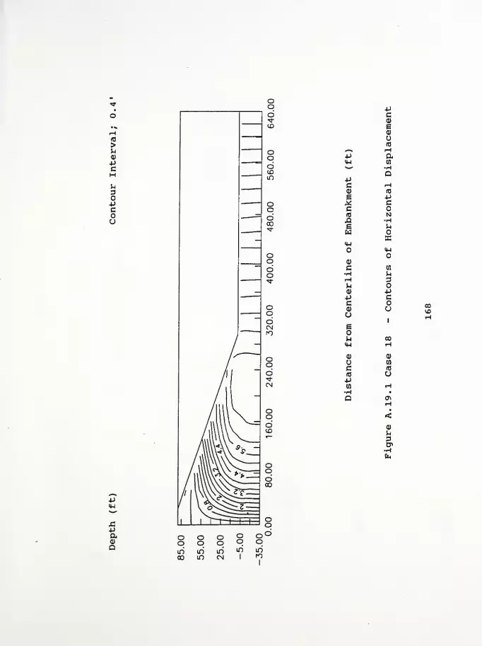
-p
-paa
Pc0)
e0)
(0
*«H rHp a<H caN.^ H
aPc H(1) (0
a pX cc(0 N.q Hg P,
wX
<Uu-t
0)
c m•H urH 3P0) P*J cc0) uu
1
e1
u CO14-1 H<P a)
u at
c (0
id upw H•H •
Q enH
•
<(V
p.
3B*
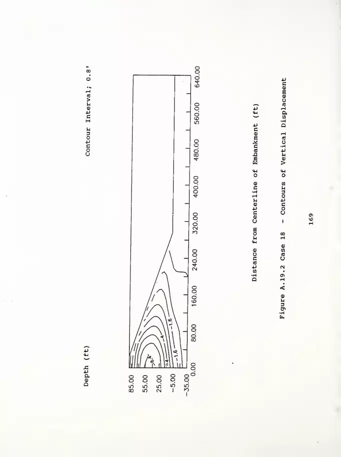
Pc0)
E0)
<—
V
(0
p rH<u a*"
•HP QC(1) rHe id
,2 uc •Hid PX! M
1 >IM (U
Q) 03
C U•H 3rHJ-l PQ) cPC0)
uo1 H
EO COP. rH
<W0)
0) wrtJ
c a(0
p (Nw •
-H OlQ rH
<0)
u3Cn
£-paa)
a
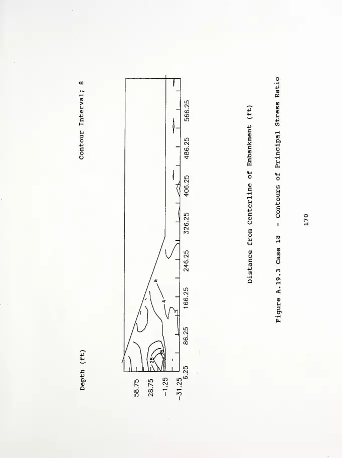
(0
>U<D
PCHu3OMCou
+Jc
Ic
-aw<wo
Q)
c
0)
PCQ)
U
i
<d
uc(04J01HQ
O•HP(0
«tn
in
a)
M+J
10
a•H
c•Hto
a*
iwo
tn
M
OPcou
sipa>
ainCM
COm00CM T
1

-Paa)
Q
>1-p<D
<Hato
^ 4-1
-p<w^—
'
10
P.+J
c P(1) ue 10
^i fc,
c(0 HJ2 10
e ow
J4-1
<H
0)
c a•H uH 3Ma) Pp cc<D uUs
1
^ co4-1 Ha> 0)
ac (0
(0 u*jw •<?
p.
3Cn

APPENDIX B
Computer disk with input data files
FOR A COPY OF THE INPUT DATA FILES,
CONTACT SCOTT LUDLOW AT PURDUE UNIVERSITY

APPENDIX C
List of References
172
LIST OF REFERENCES
Geotechnical Investigation, (1986), Project No. RS-5124(2),"Indiana State Route 1 Realignment near Cedar Grove inFranklin County, Indiana," prepared by The H.C. NuttingCompany of Cincinnati, Ohio, June 27, 1986.
Holtz, R.D., and Kovacs, W.D. (1981), An Introduction toGeotechnical Engineering . Prentice-Hall, Inc. , New Jersey, 73 3
pp.
Huang, T.K. , and Chen, W.F. (1990), "Simple Procedure forDetermining Cap-Plasticity-Model Parameters," Journal ofGeotechnical Engineering , ASCE, Vol. 116, No. 3, pp. 492-513.
Huang, T.K., and Chen, W.F. (1991), "Embankment Widening andGrade Raising on Soft Foundation Soils: Computer ProgramImplementation," Report No. CE-STR-91-3 . School of CivilEngineering, Purdue University, West Lafayette, Indiana,January, 2 44 pp.
Huang, T.K. , Chen, W.F., and Chameau, J.L. (1990), "TheApplication of Cap-Plasticity-Model to Embankment Problems,"Report No. CE-STR-90-21 , School of Civil Engineering, PurdueUniversity, West Lafayette, Indiana, 37 pp.
Humphrey, D.N. (1986), "Design of Reinforced Embankments,"Report No. JHRP-86-16 , Joint Highway Research Project, Schoolof Civil Engineering, Purdue University, West Lafayette,Indiana, October, 423 pp.
Kulhawy, F.H. , and Mayne, P.W. (1990), "Manual on EstimatingSoil Properties for Foundation Design," Research Project 1493-6, Prepared for Electric Power Research Institute, Prepared byCornell University, Geotechnical Engineering Group, Ithaca,New York, August.
Ladd, C.C., Foote, R. , Ishihara, K. , Schlosser, F. , andPoulos, H.G., (1977), "Stress-Deformation and StrengthCharacteristics," State-of-the-Art Report, Proceedings of theNinth International Conference on Soil Mechanics andFoundation Engineering , Tokyo, Vol. 2, pp. 421-494.
Ludlow, S.J., Personal data base - "Engineering Properties ofSoils,".
Ludlow, S.J., Chen, W.F., Bourdeau, P.L., and Lovell, C.W.
,
(1991) , "Embankment Widening and Grade Raising on SoftFoundation Soils: Example 1 - Indiana State Route 55 overTurkey Creek in Lake County, Indiana," Report No. FHWA/IN/JHRP
173
- 91-18 , Joint Highway Research Project, School of CivilEngineering, Purdue University, West Lafayette, Indiana,December, 56 pp.
Ludlow, S.J., Chen, W.F., Bourdeau, P.L., and Lovell, C.W.
,
(1992) , "A Sensitivity Analysis of the Parameters for a CapPlasticity Model," Report No. FHWA/JHRP/IN - 92-1 . JointHighway Research Project, School of Civil Engineering, PurdueUniversity, West Lafayette, Indiana, January, 23 pp.
Nwabuokei, S.O., (1984), "Compressibility and Shear StrengthCharacteristics of Impact Compacted Lacustrine Clay," Ph.D.Thesis, Purdue University, West Lafayette, Indiana.