Embed Size (px)
Citation preview
Missouri University of Science and Technology Missouri University of Science and Technology
Scholars' Mine Scholars' Mine
International Conference on Case Histories in Geotechnical Engineering
(1984) - First International Conference on Case Histories in Geotechnical Engineering
08 May 1984, 10:15 am - 5:00 pm
Failure of an Embankment on Soft Clay Failure of an Embankment on Soft Clay
M. K. Yegian Northeastern University, Boston, Massachusetts
Hugo Perez Lasalvia Teproy, Caracas, Venezuela
Follow this and additional works at: https://scholarsmine.mst.edu/icchge
Part of the Geotechnical Engineering Commons
Recommended Citation Recommended Citation Yegian, M. K. and Lasalvia, Hugo Perez, "Failure of an Embankment on Soft Clay" (1984). International Conference on Case Histories in Geotechnical Engineering. 15. https://scholarsmine.mst.edu/icchge/1icchge/1icchge-theme3/15
This work is licensed under a Creative Commons Attribution-Noncommercial-No Derivative Works 4.0 License.
This Article - Conference proceedings is brought to you for free and open access by Scholars' Mine. It has been accepted for inclusion in International Conference on Case Histories in Geotechnical Engineering by an authorized administrator of Scholars' Mine. This work is protected by U. S. Copyright Law. Unauthorized use including reproduction for redistribution requires the permission of the copyright holder. For more information, please contact [email protected].
Failure of an Embankment on Soft Clay M. K. Yegian
Associate Professor of Civil Engineering, Northeastern University, Boston, Massachusetts
Hugo Perez Lasalvia Teproy, Caracas, Venezuela
SYNOPSIS The failure of an embankment during its construction on soft clay foundation is investigated. Field and laboratory data are used in conventional slope stability analyses to explain the cause of the failure and to evaluate the in-situ undrained shear strength of the clay which was later used in the design of the replacement dike. The results indicate that whereas the stiff embankment having a well compacted core was initially stable on the soft clay, subsequent cracking of the core due to undrained deformations reduced the shearing resistance of the dike thus, initiating the failure. The dike was eventually reconstructed in stages allowing enough time between stages for the foundation clay to consolidate and increase its shear strength. In the new dike a granular material was used in order to provide flexibility and to prevent cracking of the dike. In addition, long berms were placed on both sides of the dike to increase its stability. Field instruments including piezometers and inclinometers were used to monitor the rate of the stage construction of the new dike.
INTRODUCTION
The site preparation for an industrial plant for producing alumina, located on the bank of the Orinoco River in Venezuela, included the construction of dikes for the purpose of creating artificial ponds where the residual material ferro-silt commonly referred to as Red Mud will be deposited. The terrain consists of two natural lagoons whose bottom elevations are about 6 meters above sea level (+6M ). Hydrological records indicate that for about 8 to 9 months of the year, the Orinoco River water elevation remains higher than +6M and can be as high as +14M. Hence, for most of the year, the lagoon area remains flooded. For this reason, dikes with crest elevations of +17M were needed to prevent the flooding of the lagoons, thus creating artificial ponds which would be dewatered and then used for depositing the Red Mud.
Two and a half months after construction had started, a large section of one of the dikes, failed by sliding into the lagoon. The height of the 400 meter long dike at the time of failure was about 7 meters, (4 meters below the final design crest elevation). The dike consisted of a well compacted clay core and shell of sand, gravel and rocks. Immediate attempts made by the contractor to reshape the dike and to continue its construction resulted in similar failures in the same zone as that of the initial failure. Following these failures, extensive field and laboratory investigations were made, including: soil boring, sampling, testing and installation and monitoring of field instruments. The information obtained from this subsurface exploration program was then utilized in geotechnical engineering analysis and the causes of the failure of the dike were identified and an alternate design and construction procedure was adopted and the
701
dike was successfully reconstructed. The scope of this paper is limited to the presentation of the results of the subsurface soil investigation and the stability analyses made to investigate the causes of the failure of the dike. In addition, a discussion is included on the final procedures adopted for the reconstruction of the dike which is now in operation.
SUBSURFACE INVESTIGATIONS
The subsurface investigations carried out after the failure of the dike consisted of: Field explorations and instrumentation and laboratory soil testing.
Field Exploration and Instrumentation.
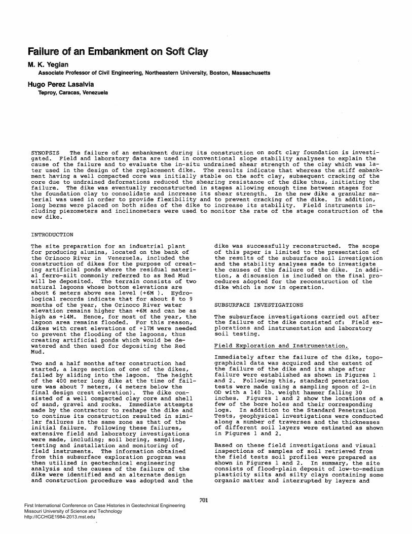
Immediately after the failure of the dike, topographical data was acquired and the extent of the failure of the dike and its shape after failure were established as shown in Figures 1 and 2. Following this, standard penetration tests were made using a sampling spoon of 2-in OD with a 140 lb. weight hammer falling 30 inches. Figures 1 and 2 show the locations of a few of the bore holes and their corresponding logs. In addition to the Standard Penetration Tests, geophysical investigations were conducted along a number of traverses and the thicknesses of different soil layers were estimated as shown in Figures 1 and 2.
Based on these field investigations and visual inspections of samples of soil retrieved from the field tests soil profiles were prepared as shown in Figures 1 and 2. In summary, the site consists of flood-plain deposit of low-to-medium plasticity silts and silty clays containing some organic matter and interrupted by layers and
First International Conference on Case Histories in Geotechnical Engineering Missouri University of Science and Technology http://ICCHGE1984-2013.mst.edu
Elevation
+18m
PRIOR TO FAILURE +16
p31 p35 +14 I I +12. I
I +10
+6
+6
+4
+2
0
-2 -4
-6
-e -10
-12m
0 5 10m
Figure 1 Cross-section of Dike Prior to and After Failure
Elevation
~ FAILURE -1 ZONE +14
+12
p21 p31 p32 p34,35 +8
+6
+4
+2
0
-2
-4
-6
-e -10m
0 50 I~Om I I
Figure 2 Subsurface Profile Along the Longitudinal Axis of Dike
702
First International Conference on Case Histories in Geotechnical Engineering Missouri University of Science and Technology http://ICCHGE1984-2013.mst.edu

pockets of peat. In many of the bore holes the clay foundation soil was so soft that the standard penetration tests could not be performed. Underlying this 14 meter thick foundation soil is a very dense silty sand.
In addition to the field explorations, piezometers and inclinometers were installed in order to evaluate the existing subsurface condition. The field instruments were monitored on a regular basis. The readings of the piezometers indicated that the excess pore pressures in the subsoil were less than anticipated based on theory and soil parameters determined in the laboratory. This indicated that the rate of consolidation of the foundation clay was larger than determined from laboratory tests on small samples. Furthermore, it was evident that the permeability of the foundation clay in the horizontal direction was larger than in the vertical direction.
Laboratory Investigations.
For purposes of laboratory studies, undisturbed soil samples were obtained using 3-inch diameter shelby tubes. The laboratory testing program included the determination of: Atterberg limits. strength tests, consolidation tests, organic content and clay mineralogy. Figure 3 summarizes the laboratory test data. Based on these tests it is concluded that the silty clay encountered in the foundation of the dike is very soft and may even be "underconsolidated" at shallow depths. The undrained shear strength of the clay normalized with respect to the vertical normal efrective stress is estimated to be about 0.25. The effective stress strength parameters of the clay are estimated to be, cohension intercept, c = 0 and friction angle, f = 26o.
SPT, BLOWS/ FT I ATTERBERG LIMITS,%
- A .C.
--- 4.0.
~ .. 10 a; - AA
E ~ ..elC
l: 1-0.. w c
ANALYSIS OF FAILED DIKE
Based on the results of these subsurface investigations and the available topographical data, stability analyses were made in order to explain the cause of the failure of the dike and to evaluate, alternate design cross sections of the dike and procedures for its safe reconstruction. The stability analyses were made using the computer program developed by Dr. Stephen Wright of the University of Texas at ~ustin.
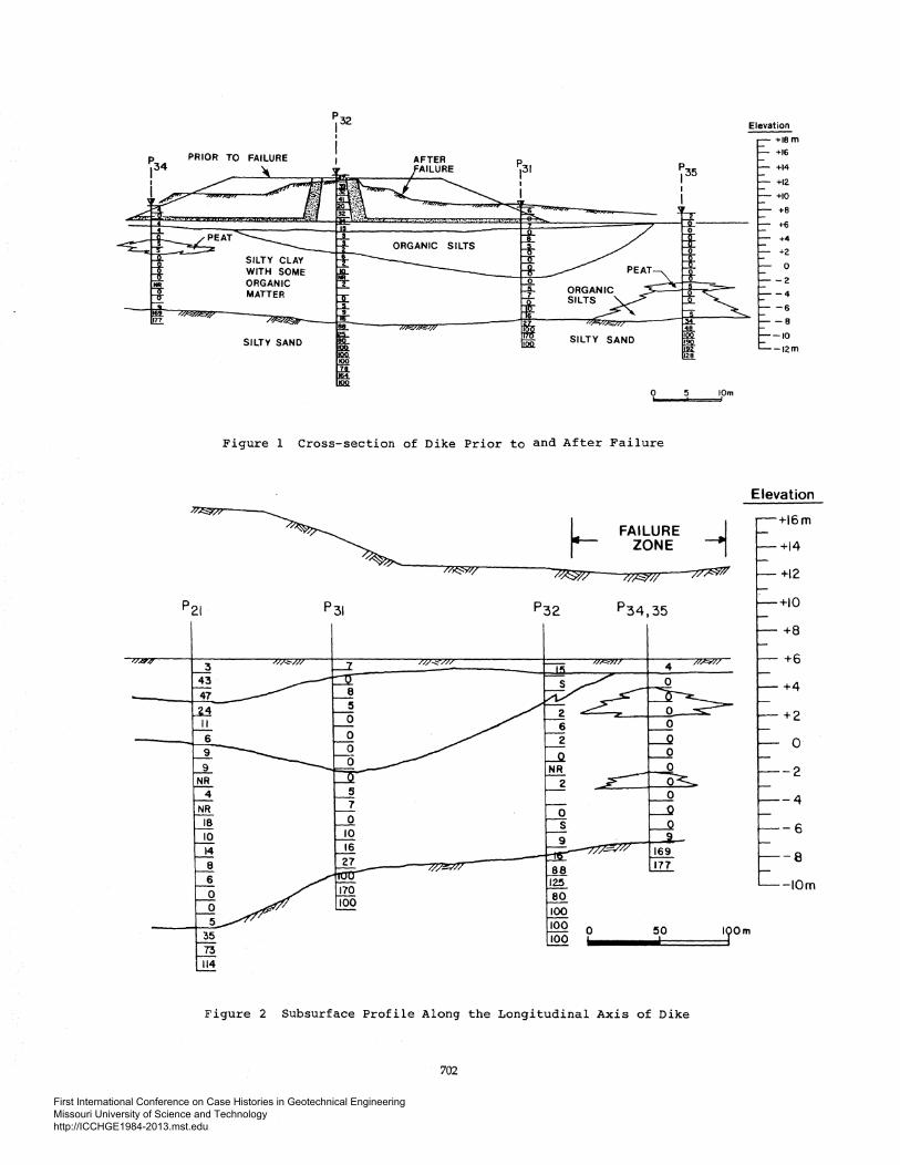
Prior to Failure.
In order to explain the cause of the failure of the dike and to evaluate the in-situ undrained shear strength of the foundation clay, total stress stability analyses were made using the original design cross section of the dike prior to the failure. Figure 4 shows the cross secttion analysed and the material properties used. In view of the fact that the dike at this stage of its construction failed, the factor of safety must have been less than unity (F.S. <1.0). Thus, in order to estimate the in-situ undrained shear strength of the clay, the factors of safety against instability were computed for different possible values of the undrained shear strength. Since the clay is normally consolidated, the undrained shear strength was assumed to increase with depth by a constant ratio of Su/crvo· The undrained strength at elevation +6M (top of the clay deposit) was assumed to be zero at the time of the failure. The field survey data taken after the failure of the dike showed the presence of tension cracks as deep as 4 to 5 meters in the core of the dike. Therefore, in the stability analyses, the presence of cracks was also considered. Figure 4 shows the results of these stability analyses. Based on these results, it is concluded that prior to the failure, when the core was intact, the stiff
Cv FTIDAY
0 • •
0 • .... 0 • 0 • ... •
Figure 3 Summary of Results from Laboratory Soil Tests
703
First International Conference on Case Histories in Geotechnical Engineering Missouri University of Science and Technology http://ICCHGE1984-2013.mst.edu
2.S ~
>- ~-1- 2.0 ~ Ill --Y., II;.
< r/)
1.5 0,0~ II;. 0 /~X TC= 5m a:
1.0 ---~c ---a TC= 3m ~ ~
.,.v 0 TC: 2m ,./ l:J. TC= Om
0.5 /)<
{29·50)
0.2 0.4 0.6 0.8 1.0 1.2 1.4
SuA
EL. +em
Figure 4 Total Stress Stability Analyses of the Dike, Prior to Failure
dike was stable and in a way floating on its large base over the saturated clay. But, as the construction of the dike proceeded, the resulting large undrained deformations initiated the cracking of the core, thus, reducing the shearing resistance of the core and ultimately causing failure. Also, since the dike did fail (F. S. < 1. 0) , from the results of the stability analyses it is concluded that the undrained shear strength ratio Su/cr vo for the clay should be less than 0.5.
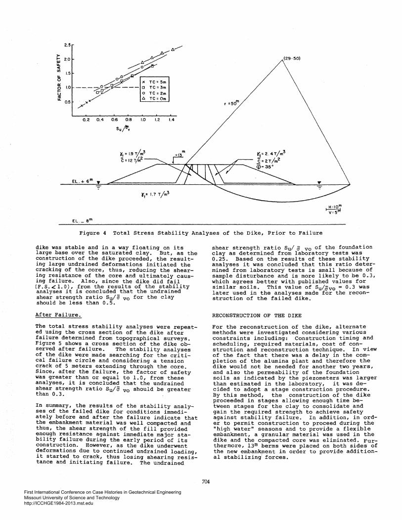
After Failure.
The total stress stability analyses were repeated using the cross section of the dike after failure determined from topographical surveys. Figure 5 shows a cross section of the dike observed after failure. The stability analyses of the dike were made searching for the critical failure circle and considering a tension crack of 5 meters extending through the core. Since, after the failure, the factor of safety was greater than or equal to 1.0, from these analyses, it is concluded that the undrained shear strength ratio Su/a vo should be greater than 0.3.
In summary, the results of the stability analyses of the failed dike for conditions immediately before and after the failure indicate that the embankment material was well compacted and thus, the shear strength of the fill provided enough resistance against immediate major stability failure during the early period of its construction. However, as the dike underwent ~eformations due to continued undrained loading, ~t started to crack, thus losing shearing resistance and initiating failure. The undrained
704
shear strength ratio Su/ ij vo of the foundation clay as determined from laboratory tests was 0.25. Based on the results of these stability analyses it was concluded that this ratio determined from laboratory tests is small because of sample disturbance and is more likely to be 0.3, which agrees better with published values for similar soils. This value of Su/avo = 0.3 was later used in the analyses made for the reconstruction of the failed dike.
RECONSTRUCTION OF THE DIKE
For the reconstruction of the dike, alternate methods were investigated considering various constraints including: Construction timing and scheduling, required materials, cost of construction and reconstruction technique. In view of the fact that there was a delay in the completion of the alumina plant and therefore the dike would not be needed for another two years, and also the permeability of the foundation soils as indicated by the piezometers was larger than estimated in the laboratory, it was decided to adopt a stage construction procedure. By this method, the construction of the dike proceeded in stages allowing enough time between stages for the clay to consolidate and gain the required strength to achieve safety against stability failure. In addition, in order to permit construction to proceed during the "high water" seasons and to provide a flexible embankment, a granular material was used in the dike and the compacted core was eliminated. Furthermore, 13m berms were placed on both sides of the new embankment in order to provide additional stabilizing· forces.
First International Conference on Case Histories in Geotechnical Engineering Missouri University of Science and Technology http://ICCHGE1984-2013.mst.edu

2.5
> .... 2.0 w L&.. <( (/)
L&.. 1.5 0 a: ~ 1.0 u <( L&..
0.5
0.2.
EL. +6m
EL. -am
0.4 0.6 0.8 1.0
Su j<f;o
t• OT/11l2, C = 2Tfm2,
9
9
1.2
Figure 5 Total Stress Stability Analyses of the Dike After Failure
In order to predict the safe height of the dike for each stage of construction and to make estimates of the required duration in time of the different stages of loading, total stress stability analyses were made. Based on these results it was concluded that the dike could be raised to a minimum required height of +14m in time for the operation of the plant. In addition, effective stress stability analyses were made to determine the limiting pore water pressures in the foundation clay below which the dike would be safe at each stage of construction.
Prior to the construction of the dike, piezometers and inclinometers were installed within cricital sections of the dike for monitoring the construction activities. Construction of the new dike started in the latter part of 1981 and by 1983 the crest elevation of the dike was brought up to +14m which was adequate for the initial phase of the operation of the plant. During each stage of construction, the piezometers were read and the data was used to monitor the rate of construction and the period between each stage. The details of the engineering analyses for the design of the new dike and the field instrument data used will be presented in a subsequent paper in the future.
705
CONCLUSIONS
The case history presented in this paper demonstrates that for embankments on soft clays, the concerns of large deformations and overall stability are interrelated. A flexible embankment having long berms is more adequate than a rigid well compacted embankment, which will invariably eventually crack if the deformations are large. The rate of construction of such an embankment is very important in controlling stability and deformations. Field instruments including piezometers and inclinometers can provide valuable information for monitoring the construction rate and identifying critical zones which would require special considerations.
The difficulties associated with the construction of embankments on soft clay foundations are well known in the geotechnical engineering profession. However, with careful field investigations, analyses and monitoring of field instruments such difficulties can be overcome and embankments can be safely constructed on soft clays.
First International Conference on Case Histories in Geotechnical Engineering Missouri University of Science and Technology http://ICCHGE1984-2013.mst.edu


