Embed Size (px)
Citation preview
En
Pa
b
a
ARRAA
KPNSEP
1
ccnfTmdfimcoeft
a
0d
Electrochimica Acta 55 (2010) 4677–4684
Contents lists available at ScienceDirect
Electrochimica Acta
journa l homepage: www.e lsev ier .com/ locate /e lec tac ta
lectrochemical performances of poly(3,4-ethylenedioxythiophene)–NiFe2O4
anocomposite as electrode for supercapacitor
intu Sena,∗, Amitabha Deb
Physics Department, Variable Energy Cyclotron Centre, 1/AF Bidhannagar, Kolkata 700064, IndiaSaha Institute of Nuclear Physics, 1/AF Bidhannagar, Kolkata 700064, India
r t i c l e i n f o
rticle history:eceived 13 January 2010eceived in revised form 23 March 2010ccepted 26 March 2010vailable online 1 April 2010
eywords:EDOTiFe2O4
upercapacitor
a b s t r a c t
Poly 3,4-ethylenedioxythiophene (PEDOT)-based NiFe2O4 conducting nanocomposites were synthesizedand their electrochemical properties were studied in order to find out their suitability as electrodematerials for supercapacitor. Nanocrystalline nickel ferrites (5–20 nm) have been synthesized by sol–gelmethod. Reverse microemulsion polymerization in n-hexane medium for PEDOT nanotube and aque-ous miceller dispersion polymerization for bulk PEDOT formation using different surfactants havebeen adopted. Structural morphology and characterization were studied using XRD, SEM, TEM and IRspectroscopy. Electrochemical performances of these electrode materials were carried out using cyclicvoltammetry at different scan rates (2–20 mV/s) and galvanostatic charge–discharge at different constantcurrent densities (0.5–10 mA/cm2) in acetonitrile solvent containing 1 M LiClO4 electrolyte. Nanocom-
lectrical double layer capacitanceseudocapacitance
posite electrode material shows high specific capacitance (251 F/g) in comparison to its constituents vizNiFe2O4 (127 F/g) and PEDOT (156 F/g) where morphology of the pore structure plays a significant roleover the total surface area. Contribution of pseudocapacitance (CFS) arising from the redox reactionsover the electrical double layer capacitance (CDL) in the composite materials have also been investigatedthrough the measurement of AC impedance in the frequency range 10 kHz–10 mHz with a potentialamplitude of 5 mV. The small attenuation (∼16%) in capacitance of PEDOT–NiFe2O4 composite over 500
hargi
continuous charging/disc. Introduction
Now a days, it has been widely accepted that electrochemicalapacitor (EC) popularly known as supercapacitor is one of the bestandidates to provide high power and long cycle life, essential forew energy devices such as hybrid electric vehicles, backup sources
or various electrical devices and uninterrupted power supplies [1].herefore, exploring new electrode materials for supercapacitor toeet the requirements of high power density and long durability
evices has become mandatory for the researchers working in theeld of energy storage device. Depending on the charge storageechanism, electrochemical capacitors are categorized as electro-
hemical double layer capacitors (EDLC) and pseudocapacitors. Therigin of capacitance in the EDLC is the charge separation at thelectrode–electrolyte interface, whereas pseudocapacitance arises
rom fast, reversible faradic redox reactions taking place on or nearhe surface of the electrode.Electronically conducting polymers (ECPs) have advantage overctive carbon, as an electrode material for supercapacitor, as
∗ Corresponding author. Fax: +91 3323346871.E-mail address: [email protected] (P. Sen).
013-4686/$ – see front matter © 2010 Elsevier Ltd. All rights reserved.oi:10.1016/j.electacta.2010.03.077
ng cycles suggests its excellent electrochemical stability.© 2010 Elsevier Ltd. All rights reserved.
they have both electrochemical double layer capacitance andpseudocapacitance arising mainly due to the fast and reversibleoxidation and reduction processes related to the �-conjugatedpolymer chain [2,3]. Among various conducting polymers, poly3,4-ethylenedioxythiophene (PEDOT) has recently attracted world-wide research interest due to its environmental stability andcontrollable electrical conductivity. However, PEDOT like otherECPs also suffers a serious problem of typical volumetric swellingand shrinkage during the insertion and ejection of counter ions[4–8]. In order to solve this problem, nanocomposite comprising ofPEDOT and inorganic transition metal oxide nanoparticles actingas filler has been considered as the electrode materials for super-capacitor where a synergistic effect of composite formation plays asignificant role to increase the capacitance value. Moreover, tran-sition metal oxides have generally been reported to be suitableas electrode material for pseudocapacitors because of their largecapacitance and fast redox kinetics [9].
Among the transition metal oxides, hydrous ruthenium dioxide
is recognized as one of the most promising candidates for elec-trode materials in electrochemical capacitors, as it can store chargesreversibly by redox reaction [10]. But the lack of abundance andthe cost of the precious metal (Ru) are the major disadvantagesfor the commercial production of RuO2. As an alternative mate-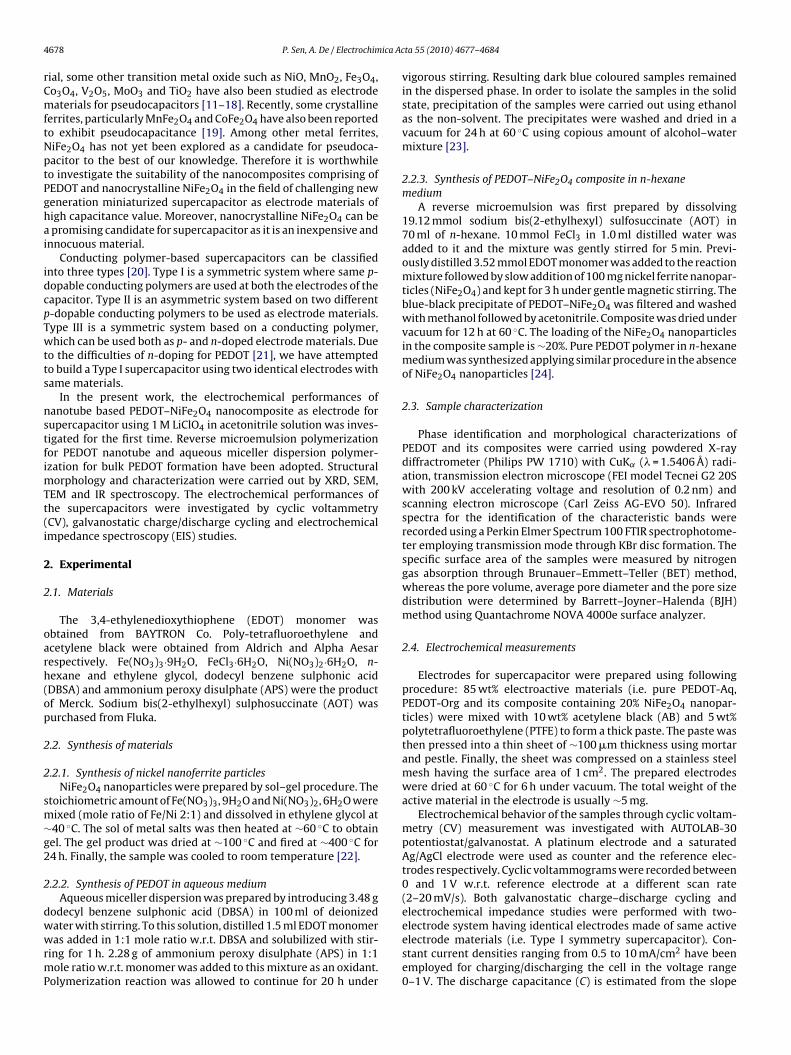
4 ica Ac
rCmftNptPghai
idcpTwtts
nstfimTt(i
2
2
oarh(op
2
2
sm∼g2
2
dwwrmP
678 P. Sen, A. De / Electrochim
ial, some other transition metal oxide such as NiO, MnO2, Fe3O4,o3O4, V2O5, MoO3 and TiO2 have also been studied as electrodeaterials for pseudocapacitors [11–18]. Recently, some crystalline
errites, particularly MnFe2O4 and CoFe2O4 have also been reportedo exhibit pseudocapacitance [19]. Among other metal ferrites,iFe2O4 has not yet been explored as a candidate for pseudoca-acitor to the best of our knowledge. Therefore it is worthwhileo investigate the suitability of the nanocomposites comprising ofEDOT and nanocrystalline NiFe2O4 in the field of challenging neweneration miniaturized supercapacitor as electrode materials ofigh capacitance value. Moreover, nanocrystalline NiFe2O4 can bepromising candidate for supercapacitor as it is an inexpensive and
nnocuous material.Conducting polymer-based supercapacitors can be classified
nto three types [20]. Type I is a symmetric system where same p-opable conducting polymers are used at both the electrodes of theapacitor. Type II is an asymmetric system based on two different-dopable conducting polymers to be used as electrode materials.ype III is a symmetric system based on a conducting polymer,hich can be used both as p- and n-doped electrode materials. Due
o the difficulties of n-doping for PEDOT [21], we have attemptedo build a Type I supercapacitor using two identical electrodes withame materials.
In the present work, the electrochemical performances ofanotube based PEDOT–NiFe2O4 nanocomposite as electrode forupercapacitor using 1 M LiClO4 in acetonitrile solution was inves-igated for the first time. Reverse microemulsion polymerizationor PEDOT nanotube and aqueous miceller dispersion polymer-zation for bulk PEDOT formation have been adopted. Structural
orphology and characterization were carried out by XRD, SEM,EM and IR spectroscopy. The electrochemical performances ofhe supercapacitors were investigated by cyclic voltammetryCV), galvanostatic charge/discharge cycling and electrochemicalmpedance spectroscopy (EIS) studies.
. Experimental
.1. Materials
The 3,4-ethylenedioxythiophene (EDOT) monomer wasbtained from BAYTRON Co. Poly-tetrafluoroethylene andcetylene black were obtained from Aldrich and Alpha Aesarespectively. Fe(NO3)3·9H2O, FeCl3·6H2O, Ni(NO3)2·6H2O, n-exane and ethylene glycol, dodecyl benzene sulphonic acidDBSA) and ammonium peroxy disulphate (APS) were the productf Merck. Sodium bis(2-ethylhexyl) sulphosuccinate (AOT) wasurchased from Fluka.
.2. Synthesis of materials
.2.1. Synthesis of nickel nanoferrite particlesNiFe2O4 nanoparticles were prepared by sol–gel procedure. The
toichiometric amount of Fe(NO3)3, 9H2O and Ni(NO3)2, 6H2O wereixed (mole ratio of Fe/Ni 2:1) and dissolved in ethylene glycol at40 ◦C. The sol of metal salts was then heated at ∼60 ◦C to obtainel. The gel product was dried at ∼100 ◦C and fired at ∼400 ◦C for4 h. Finally, the sample was cooled to room temperature [22].
.2.2. Synthesis of PEDOT in aqueous mediumAqueous miceller dispersion was prepared by introducing 3.48 g
odecyl benzene sulphonic acid (DBSA) in 100 ml of deionized
ater with stirring. To this solution, distilled 1.5 ml EDOT monomeras added in 1:1 mole ratio w.r.t. DBSA and solubilized with stir-ing for 1 h. 2.28 g of ammonium peroxy disulphate (APS) in 1:1ole ratio w.r.t. monomer was added to this mixture as an oxidant.
olymerization reaction was allowed to continue for 20 h under
ta 55 (2010) 4677–4684
vigorous stirring. Resulting dark blue coloured samples remainedin the dispersed phase. In order to isolate the samples in the solidstate, precipitation of the samples were carried out using ethanolas the non-solvent. The precipitates were washed and dried in avacuum for 24 h at 60 ◦C using copious amount of alcohol–watermixture [23].
2.2.3. Synthesis of PEDOT–NiFe2O4 composite in n-hexanemedium
A reverse microemulsion was first prepared by dissolving19.12 mmol sodium bis(2-ethylhexyl) sulfosuccinate (AOT) in70 ml of n-hexane. 10 mmol FeCl3 in 1.0 ml distilled water wasadded to it and the mixture was gently stirred for 5 min. Previ-ously distilled 3.52 mmol EDOT monomer was added to the reactionmixture followed by slow addition of 100 mg nickel ferrite nanopar-ticles (NiFe2O4) and kept for 3 h under gentle magnetic stirring. Theblue-black precipitate of PEDOT–NiFe2O4 was filtered and washedwith methanol followed by acetonitrile. Composite was dried undervacuum for 12 h at 60 ◦C. The loading of the NiFe2O4 nanoparticlesin the composite sample is ∼20%. Pure PEDOT polymer in n-hexanemedium was synthesized applying similar procedure in the absenceof NiFe2O4 nanoparticles [24].
2.3. Sample characterization
Phase identification and morphological characterizations ofPEDOT and its composites were carried using powdered X-raydiffractrometer (Philips PW 1710) with CuK˛ (� = 1.5406 Å) radi-ation, transmission electron microscope (FEI model Tecnei G2 20Swith 200 kV accelerating voltage and resolution of 0.2 nm) andscanning electron microscope (Carl Zeiss AG-EVO 50). Infraredspectra for the identification of the characteristic bands wererecorded using a Perkin Elmer Spectrum 100 FTIR spectrophotome-ter employing transmission mode through KBr disc formation. Thespecific surface area of the samples were measured by nitrogengas absorption through Brunauer–Emmett–Teller (BET) method,whereas the pore volume, average pore diameter and the pore sizedistribution were determined by Barrett–Joyner–Halenda (BJH)method using Quantachrome NOVA 4000e surface analyzer.
2.4. Electrochemical measurements
Electrodes for supercapacitor were prepared using followingprocedure: 85 wt% electroactive materials (i.e. pure PEDOT-Aq,PEDOT-Org and its composite containing 20% NiFe2O4 nanopar-ticles) were mixed with 10 wt% acetylene black (AB) and 5 wt%polytetrafluoroethylene (PTFE) to form a thick paste. The paste wasthen pressed into a thin sheet of ∼100 �m thickness using mortarand pestle. Finally, the sheet was compressed on a stainless steelmesh having the surface area of 1 cm2. The prepared electrodeswere dried at 60 ◦C for 6 h under vacuum. The total weight of theactive material in the electrode is usually ∼5 mg.
Electrochemical behavior of the samples through cyclic voltam-metry (CV) measurement was investigated with AUTOLAB-30potentiostat/galvanostat. A platinum electrode and a saturatedAg/AgCl electrode were used as counter and the reference elec-trodes respectively. Cyclic voltammograms were recorded between0 and 1 V w.r.t. reference electrode at a different scan rate(2–20 mV/s). Both galvanostatic charge–discharge cycling andelectrochemical impedance studies were performed with two-
electrode system having identical electrodes made of same activeelectrode materials (i.e. Type I symmetry supercapacitor). Con-stant current densities ranging from 0.5 to 10 mA/cm2 have beenemployed for charging/discharging the cell in the voltage range0–1 V. The discharge capacitance (C) is estimated from the slope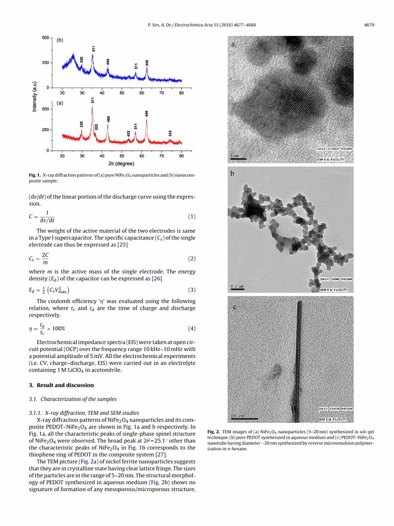
P. Sen, A. De / Electrochimica Acta 55 (2010) 4677–4684 4679
Fp
(s
C
ie
C
wd
E
rr
�
ca(c
3
3
3
pFott
toos
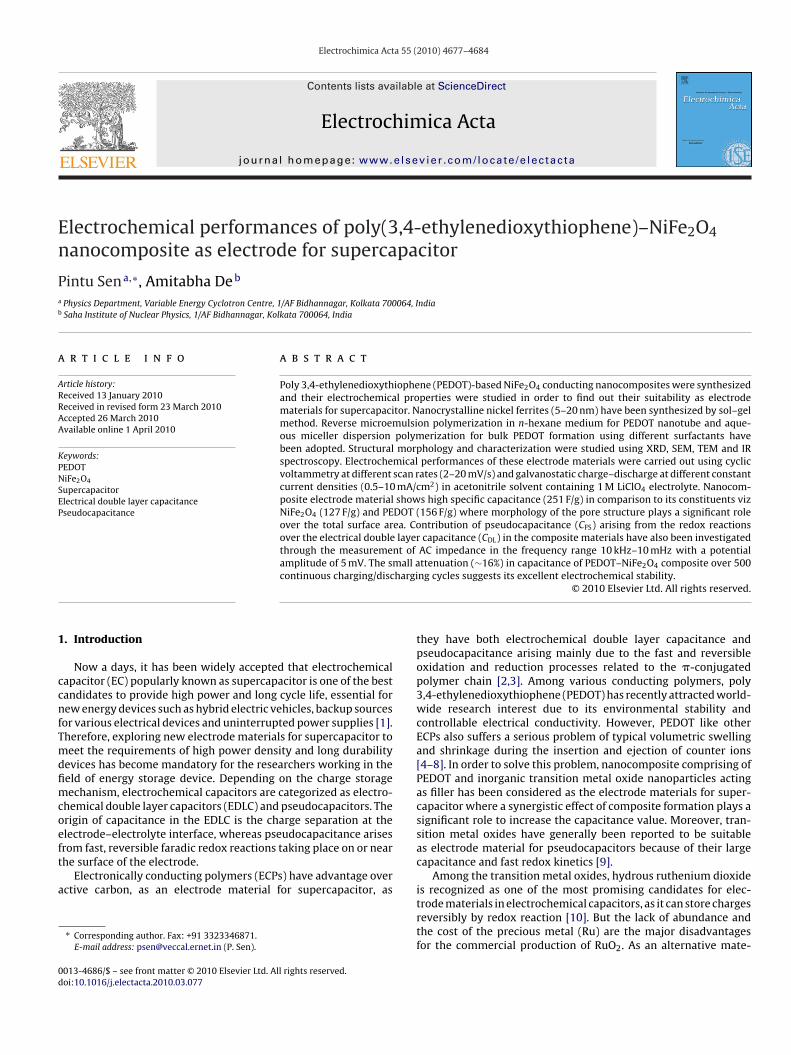
Fig. 2. TEM images of (a) NiFe2O4 nanoparticles (5–20 nm) synthesized in sol–geltechnique, (b) pure PEDOT synthesized in aqueous medium and (c) PEDOT–NiFe2O4
nanotube having diameter ∼20 nm synthesized by reverse microemulsion polymer-ization in n-hexane.
ig. 1. X-ray diffraction patterns of (a) pure NiFe2O4 nanoparticles and (b) nanocom-osite sample.
dv/dt) of the linear portion of the discharge curve using the expres-ion.
= I
dv/dt(1)
The weight of the active material of the two electrodes is samen a Type I supercapacitor. The specific capacitance (Cs) of the singlelectrode can thus be expressed as [25]
s = 2C
m(2)
here m is the active mass of the single electrode. The energyensity (Ed) of the capacitor can be expressed as [26]
d = 12
(CsV2
max
)(3)
The coulomb efficiency ‘�’ was evaluated using the followingelation, where tc and td are the time of charge and dischargeespectively.
= td
tc× 100% (4)
Electrochemical impedance spectra (EIS) were taken at open cir-uit potential (OCP) over the frequency range 10 kHz–10 mHz withpotential amplitude of 5 mV. All the electrochemical experiments
i.e. CV, charge–discharge, EIS) were carried out in an electrolyteontaining 1 M LiClO4 in acetonitrile.
. Result and discussion
.1. Characterization of the samples
.1.1. X-ray diffraction, TEM and SEM studiesX-ray diffraction patterns of NiFe2O4 nanoparticles and its com-
osite PEDOT–NiFe2O4 are shown in Fig. 1a and b respectively. Inig. 1a, all the characteristic peaks of single-phase spinel structuref NiFe2O4 were observed. The broad peak at 2� = 25.1◦ other thanhe characteristic peaks of NiFe2O4 in Fig. 1b corresponds to thehiophene ring of PEDOT in the composite system [27].
The TEM picture (Fig. 2a) of nickel ferrite nanoparticles suggestshat they are in crystalline state having clear lattice fringe. The sizesf the particles are in the range of 5–20 nm. The structural morphol-gy of PEDOT synthesized in aqueous medium (Fig. 2b) shows noignature of formation of any mesoporous/microporous structure,
4680 P. Sen, A. De / Electrochimica Acta 55 (2010) 4677–4684
Fp
wptco
3
wspaacaoC2saren
Pnoi[C
discharging at a constant rate over the voltage range of 0–1 V [1,33].Voltammetric charge (q*) is one of the important parameters to
evaluate the electrochemical active surface area of the electrode.Total surface charge (q∗
total), related to total electrochemical active
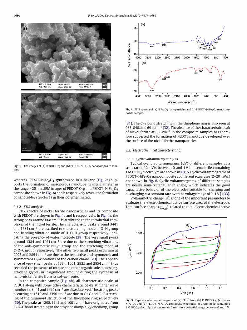
ig. 3. SEM images of (a) PEDOT-Org and (b) PEDOT–NiFe2O4 nanocomposite sam-les.
hereas PEDOT–NiFe2O4 synthesized in n-hexane (Fig. 2c) sup-orts the formation of mesoporous nanotube having diameter inhe range ∼20 nm. SEM images of PEDOT-Org and PEDOT–NiFe2O4omposite shown in Fig. 3a and b respectively reveal the formationf nanotubler structures in their polymer matrix.
.1.2. FTIR analysisFTIR spectra of nickel ferrite nanoparticles and its composite
ith PEDOT are shown in Fig. 4a and b respectively. In Fig. 4a, thetrong peak around 608 cm−1 is attributed to the tetrahedral com-lexes of the nickel ferrite. The characteristic peaks around 3441nd 1631 cm−1 are ascribed to the stretching mode of O–H groupnd bending vibration mode of H–O–H group respectively, indi-ating the presence of water molecule [28]. The very small peaksround 1384 and 1051 cm−1 are due to the stretching vibrationsf the anti-symmetric NO3
− group and the stretching mode of–O–C group respectively. The other two small peaks occurring at925 and 2854 cm−1 are due to the respective anti-symmetric andymmetric-CH2-vibrations of the carbon chains [29]. The appear-nce of very small peaks at 1384, 1051, 2925 and 2854 cm−1 thusevealed the presence of nitrate and other organic substances (e.g.thylene glycol) in insignificant amount during the synthesis ofano-nickel ferrite from its sol–gel route.
In the composite sample (Fig. 4b), all characteristic peaks ofEDOT along with some other characteristic peaks at higher wave
−1
umber i.e. 3441 and 2925 cm are also observed. The strong peaksccurring at 1519 and 1350 cm−1 are due to C = C and C–C stretch-ng of the quininoid structure of the thiophene ring respectively30]. The peaks at 1205, 1141 and 1091 cm−1 have originated from–O–C bond stretching in the ethylene dioxy (alkylenedioxy) groupFig. 4. FTIR spectra of (a) NiFe2O4 nanoparticles and (b) PEDOT–NiFe2O4 nanocom-posite sample.
[31]. The C–S bond stretching in the thiophene ring is also seen at983, 840, and 691 cm−1 [32]. The absence of the characteristic peakof nickel ferrite at 608 cm−1 in the composite samples has there-fore suggested the formation of PEDOT nanotube developed overthe surface of the nickel ferrite nanoparticles.
3.2. Electrochemical characterization
3.2.1. Cyclic voltammetry analysisTypical cyclic voltammograms (CV) of different samples at a
scan rate of 2 mV/s between 0 and 1 V in acetonitrile containing1 M LiClO4 electrolyte are shown in Fig. 5. Cyclic voltammograms ofPEDOT–NiFe2O4 nanocomposite at different scan rates (2–20 mV/s)are shown in Fig. 6. Cyclic voltammograms of different samplesare nearly semi-rectangular in shape, which indicates the goodcapacitative behavior of the electrodes suitable for charging and
Fig. 5. Typical cyclic voltammogram of (a) PEDOT-Aq, (b) PEDOT-Org, (c) nano-NiFe2O4 and (d) PEDOT–NiFe2O4 composite electrodes in acetonitrile containing1 M LiClO4 electrolyte at a scan rate 2 mV/s in a potential range between 0 and 1 V.
P. Sen, A. De / Electrochimica Acta 55 (2010) 4677–4684 4681
Fi2
scepesp
(fpfatio((i
FI
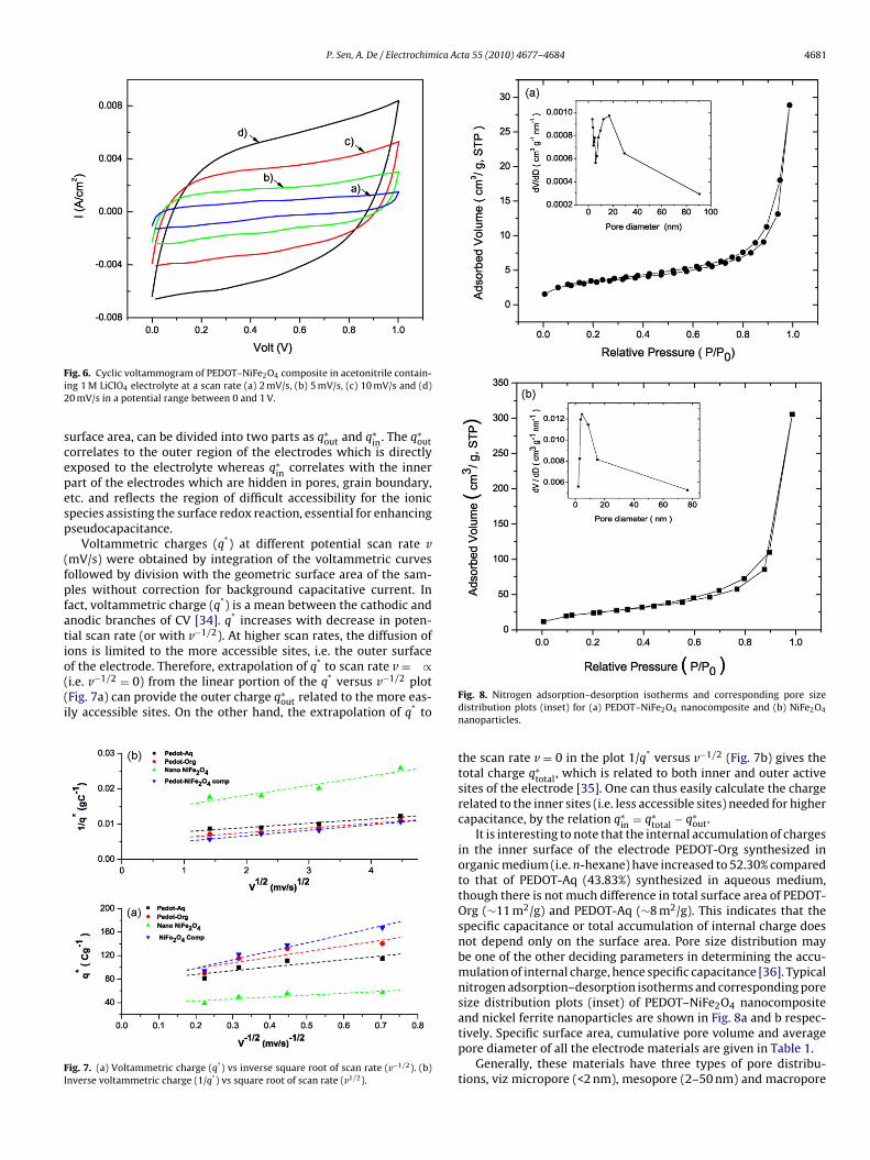
ig. 6. Cyclic voltammogram of PEDOT–NiFe2O4 composite in acetonitrile contain-ng 1 M LiClO4 electrolyte at a scan rate (a) 2 mV/s, (b) 5 mV/s, (c) 10 mV/s and (d)0 mV/s in a potential range between 0 and 1 V.
urface area, can be divided into two parts as q∗out and q∗
in. The q∗out
orrelates to the outer region of the electrodes which is directlyxposed to the electrolyte whereas q∗
in correlates with the innerart of the electrodes which are hidden in pores, grain boundary,tc. and reflects the region of difficult accessibility for the ionicpecies assisting the surface redox reaction, essential for enhancingseudocapacitance.
Voltammetric charges (q*) at different potential scan rate vmV/s) were obtained by integration of the voltammetric curvesollowed by division with the geometric surface area of the sam-les without correction for background capacitative current. Inact, voltammetric charge (q*) is a mean between the cathodic andnodic branches of CV [34]. q* increases with decrease in poten-ial scan rate (or with v−1/2). At higher scan rates, the diffusion ofons is limited to the more accessible sites, i.e. the outer surface
f the electrode. Therefore, extrapolation of q* to scan rate v = ∝i.e. v−1/2 = 0) from the linear portion of the q* versus v−1/2 plotFig. 7a) can provide the outer charge q∗out related to the more eas-ly accessible sites. On the other hand, the extrapolation of q* to
ig. 7. (a) Voltammetric charge (q*) vs inverse square root of scan rate (v−1/2). (b)nverse voltammetric charge (1/q*) vs square root of scan rate (v1/2).
Fig. 8. Nitrogen adsorption–desorption isotherms and corresponding pore sizedistribution plots (inset) for (a) PEDOT–NiFe2O4 nanocomposite and (b) NiFe2O4
nanoparticles.
the scan rate v = 0 in the plot 1/q* versus v−1/2 (Fig. 7b) gives thetotal charge q∗
total, which is related to both inner and outer activesites of the electrode [35]. One can thus easily calculate the chargerelated to the inner sites (i.e. less accessible sites) needed for highercapacitance, by the relation q∗
in = q∗total − q∗
out.It is interesting to note that the internal accumulation of charges
in the inner surface of the electrode PEDOT-Org synthesized inorganic medium (i.e. n-hexane) have increased to 52.30% comparedto that of PEDOT-Aq (43.83%) synthesized in aqueous medium,though there is not much difference in total surface area of PEDOT-Org (∼11 m2/g) and PEDOT-Aq (∼8 m2/g). This indicates that thespecific capacitance or total accumulation of internal charge doesnot depend only on the surface area. Pore size distribution maybe one of the other deciding parameters in determining the accu-mulation of internal charge, hence specific capacitance [36]. Typicalnitrogen adsorption–desorption isotherms and corresponding poresize distribution plots (inset) of PEDOT–NiFe2O4 nanocomposite
and nickel ferrite nanoparticles are shown in Fig. 8a and b respec-tively. Specific surface area, cumulative pore volume and averagepore diameter of all the electrode materials are given in Table 1.Generally, these materials have three types of pore distribu-tions, viz micropore (<2 nm), mesopore (2–50 nm) and macropore
4682 P. Sen, A. De / Electrochimica Acta 55 (2010) 4677–4684
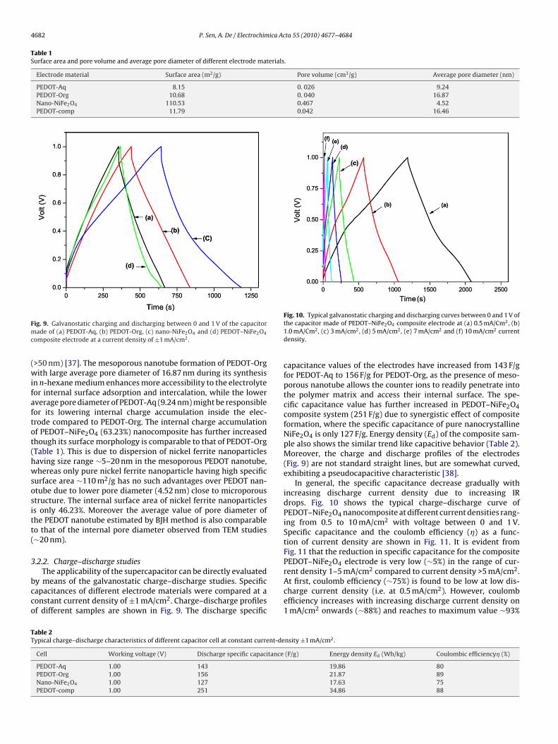
Table 1Surface area and pore volume and average pore diameter of different electrode materials.
Electrode material Surface area (m2/g) Pore volume (cm3/g) Average pore diameter (nm)
PEDOT-Aq 8.15 0. 026 9.24PEDOT-Org 10.68 0. 040 16.87Nano-NiFe2O4 110.53 0.467 4.52PEDOT-comp 11.79 0.042 16.46
Fmc
(wifaftot(hwsositt(
3
bcco
Fig. 10. Typical galvanostatic charging and discharging curves between 0 and 1 V of
TT
ig. 9. Galvanostatic charging and discharging between 0 and 1 V of the capacitorade of (a) PEDOT-Aq, (b) PEDOT-Org, (c) nano-NiFe2O4 and (d) PEDOT–NiFe2O4
omposite electrode at a current density of ±1 mA/cm2.
>50 nm) [37]. The mesoporous nanotube formation of PEDOT-Orgith large average pore diameter of 16.87 nm during its synthesis
n n-hexane medium enhances more accessibility to the electrolyteor internal surface adsorption and intercalation, while the lowerverage pore diameter of PEDOT-Aq (9.24 nm) might be responsibleor its lowering internal charge accumulation inside the elec-rode compared to PEDOT-Org. The internal charge accumulationf PEDOT–NiFe2O4 (63.23%) nanocomposite has further increasedhough its surface morphology is comparable to that of PEDOT-OrgTable 1). This is due to dispersion of nickel ferrite nanoparticlesaving size range ∼5–20 nm in the mesoporous PEDOT nanotube,hereas only pure nickel ferrite nanoparticle having high specific
urface area ∼110 m2/g has no such advantages over PEDOT nan-tube due to lower pore diameter (4.52 nm) close to microporoustructure. The internal surface area of nickel ferrite nanoparticless only 46.23%. Moreover the average value of pore diameter ofhe PEDOT nanotube estimated by BJH method is also comparableo that of the internal pore diameter observed from TEM studies∼20 nm).
.2.2. Charge–discharge studies
The applicability of the supercapacitor can be directly evaluatedy means of the galvanostatic charge–discharge studies. Specificapacitances of different electrode materials were compared at aonstant current density of ±1 mA/cm2. Charge–discharge profilesf different samples are shown in Fig. 9. The discharge specific
able 2ypical charge–discharge characteristics of different capacitor cell at constant current-de
Cell Working voltage (V) Discharge specific capacitance
PEDOT-Aq 1.00 143PEDOT-Org 1.00 156Nano-NiFe2O4 1.00 127PEDOT-comp 1.00 251
the capacitor made of PEDOT–NiFe2O4 composite electrode at (a) 0.5 mA/Cm2, (b)1.0 mA/Cm2, (c) 3 mA/cm2, (d) 5 mA/cm2, (e) 7 mA/cm2 and (f) 10 mA/cm2 currentdensity.
capacitance values of the electrodes have increased from 143 F/gfor PEDOT-Aq to 156 F/g for PEDOT-Org, as the presence of meso-porous nanotube allows the counter ions to readily penetrate intothe polymer matrix and access their internal surface. The spe-cific capacitance value has further increased in PEDOT–NiFe2O4composite system (251 F/g) due to synergistic effect of compositeformation, where the specific capacitance of pure nanocrystallineNiFe2O4 is only 127 F/g. Energy density (Ed) of the composite sam-ple also shows the similar trend like capacitive behavior (Table 2).Moreover, the charge and discharge profiles of the electrodes(Fig. 9) are not standard straight lines, but are somewhat curved,exhibiting a pseudocapacitive characteristic [38].
In general, the specific capacitance decrease gradually withincreasing discharge current density due to increasing IRdrops. Fig. 10 shows the typical charge–discharge curve ofPEDOT–NiFe2O4 nanocomposite at different current densities rang-ing from 0.5 to 10 mA/cm2 with voltage between 0 and 1 V.Specific capacitance and the coulomb efficiency (�) as a func-tion of current density are shown in Fig. 11. It is evident fromFig. 11 that the reduction in specific capacitance for the compositePEDOT–NiFe2O4 electrode is very low (∼5%) in the range of cur-rent density 1–5 mA/cm2 compared to current density >5 mA/cm2.
At first, coulomb efficiency (∼75%) is found to be low at low dis-charge current density (i.e. at 0.5 mA/cm2). However, coulombefficiency increases with increasing discharge current density on1 mA/cm2 onwards (∼88%) and reaches to maximum value ∼93%nsity ±1 mA/cm2.
(F/g) Energy density Ed (Wh/kg) Coulombic efficiency� (%)
19.86 8021.87 8917.63 7534.86 88
P. Sen, A. De / Electrochimica Acta 55 (2010) 4677–4684 4683
Fp
aicmc1fiasna
3
ncpasvef
F1
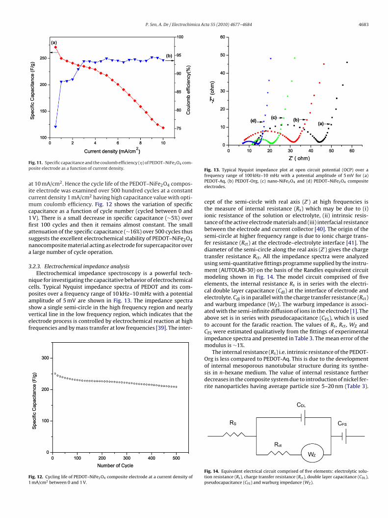
ig. 11. Specific capacitance and the coulomb efficiency (�) of PEDOT–NiFe2O4 com-osite electrode as a function of current density.
t 10 mA/cm2. Hence the cycle life of the PEDOT–NiFe2O4 compos-te electrode was examined over 500 hundred cycles at a constanturrent density 1 mA/cm2 having high capacitance value with opti-um coulomb efficiency. Fig. 12 shows the variation of specific
apacitance as a function of cycle number (cycled between 0 andV). There is a small decrease in specific capacitance (∼5%) overrst 100 cycles and then it remains almost constant. The smallttenuation of the specific capacitance (∼16%) over 500 cycles thusuggests the excellent electrochemical stability of PEDOT–NiFe2O4anocomposite material acting as electrode for supercapacitor overlarge number of cycle operation.
.2.3. Electrochemical impedance analysisElectrochemical impedance spectroscopy is a powerful tech-
ique for investigating the capacitative behavior of electrochemicalells. Typical Nyquist impedance spectra of PEDOT and its com-osites over a frequency range of 10 kHz–10 mHz with a potential
mplitude of 5 mV are shown in Fig. 13. The impedance spectrahow a single semi-circle in the high frequency region and nearlyertical line in the low frequency region, which indicates that thelectrode process is controlled by electrochemical reaction at highrequencies and by mass transfer at low frequencies [39]. The inter-ig. 12. Cycling life of PEDOT–NiFe2O4 composite electrode at a current density ofmA/cm2 between 0 and 1 V.
Fig. 13. Typical Nyquist impedance plot at open circuit potential (OCP) over afrequency range of 100 kHz–10 mHz with a potential amplitude of 5 mV for (a)PEDOT-Aq, (b) PEDOT-Org, (c) nano-NiFe2O4 and (d) PEDOT–NiFe2O4 compositeelectrodes.
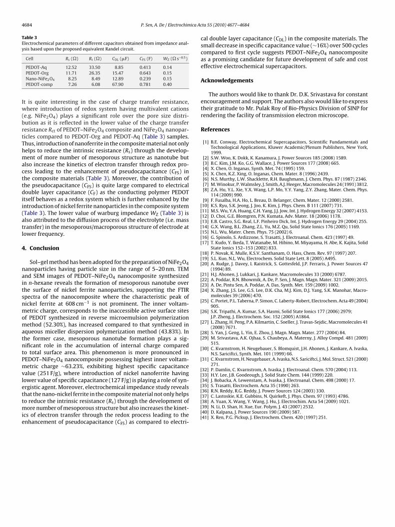
cept of the semi-circle with real axis (Z′) at high frequencies isthe measure of internal resistance (Rs) which may be due to (i)ionic resistance of the solution or electrolyte, (ii) intrinsic resis-tance of the active electrode materials and (iii) interfacial resistancebetween the electrode and current collector [40]. The origin of thesemi-circle at higher frequency range is due to ionic charge trans-fer resistance (Rct) at the electrode–electrolyte interface [41]. Thediameter of the semi-circle along the real axis (Z′) gives the chargetransfer resistance Rct. All the impedance spectra were analyzedusing semi-quantitative fittings programme supplied by the instru-ment (AUTOLAB-30) on the basis of the Randles equivalent circuitmodeling shown in Fig. 14. The model circuit comprised of fiveelements, the internal resistance Rs is in series with the electri-cal double layer capacitance (Cdl) at the interface of electrode andelectrolyte. Cdl is in parallel with the charge transfer resistance (Rct)and warburg impedance (WZ). The warburg impedance is associ-ated with the semi-infinite diffusion of ions in the electrode [1]. Theabove set is in series with pseudocapacitance (CFS), which is usedto account for the faradic reaction. The values of Rs, Rct, WZ andCFS were estimated qualitatively from the fittings of experimentalimpedance spectra and presented in Table 3. The mean error of themodulus is ∼1%.
The internal resistance (Rs) i.e. intrinsic resistance of the PEDOT-Org is less compared to PEDOT-Aq. This is due to the development
of internal mesoporous nanotubular structure during its synthe-sis in n-hexane medium. The value of internal resistance furtherdecreases in the composite system due to introduction of nickel fer-rite nanoparticles having average particle size 5–20 nm (Table 3).Fig. 14. Equivalent electrical circuit comprised of five elements: electrolytic solu-tion resistance (Rs), charge transfer resistance (Rct), double layer capacitance (CDL),pseudocapacitance (CFS) and warburg impedance (WZ).
4684 P. Sen, A. De / Electrochimica Ac
Table 3Electrochemical parameters of different capacitors obtained from impedance anal-ysis based upon the proposed equivalent Randel circuit.
Cell Rs (�) Rt (�) CDL (�F) CFS (F) WZ (� s−0.5)
Iw(brtThmacttdii(atl
4
naitsnmomatntPmvlettmie
[[[[[[[[
[[[
[[[[
[
[
[
[[
[
[
[[[[[36] R.N. Reddy, R.G. Reddy, J. Power Sources 124 (2003) 330.
PEDOT-Aq 12.52 33.50 8.85 0.413 0.14PEDOT-Org 11.71 26.35 15.47 0.643 0.15Nano-NiFe2O4 8.25 8.49 12.89 0.239 0.15PEDOT-comp 7.26 6.08 67.90 0.781 0.40
t is quite interesting in the case of charge transfer resistance,here introduction of redox system having multivalent cations
e.g. NiFe2O4) plays a significant role over the pore size distri-ution as it is reflected in the lower value of the charge transferesistance Rct of PEDOT–NiFe2O4 composite and NiFe2O4 nanopar-icles compared to PEDOT-Org and PEDOT-Aq (Table 3) samples.hus, introduction of nanoferrite in the composite material not onlyelps to reduce the intrinsic resistance (Rs) through the develop-ent of more number of mesoporous structure as nanotube but
lso increase the kinetics of electron transfer through redox pro-ess leading to the enhancement of pseudocapacitance (CFS) inhe composite materials (Table 3). Moreover, the contribution ofhe pseudocapacitance (CFS) is quite large compared to electricalouble layer capacitance (CF) as the conducting polymer PEDOT
tself behaves as a redox system which is further enhanced by thentroduction of nickel ferrite nanoparticles in the composite systemTable 3). The lower value of warburg impedance WZ (Table 3) islso attributed to the diffusion process of the electrolyte (i.e. massransfer) in the mesoporous/macroporous structure of electrode atower frequency.
. Conclusion
Sol–gel method has been adopted for the preparation of NiFe2O4anoparticles having particle size in the range of 5–20 nm. TEMnd SEM images of PEDOT–NiFe2O4 nanocomposite synthesizedn n-hexane reveals the formation of mesoporous nanotube overhe surface of nickel ferrite nanoparticles, supporting the FTIRpectra of the nanocomposite where the characteristic peak ofickel ferrite at 608 cm−1 is not prominent. The inner voltam-etric charge, corresponds to the inaccessible active surface sites
f PEDOT synthesized in reverse microemulsion polymerizationethod (52.30%), has increased compared to that synthesized in
queous miceller dispersion polymerization method (43.83%). Inhe former case, mesoporous nanotube formation plays a sig-ificant role in the accumulation of internal charge comparedo total surface area. This phenomenon is more pronounced inEDOT–NiFe2O4 nanocomposite possessing highest inner voltam-etric charge ∼63.23%, exhibiting highest specific capacitance
alue (251 F/g), where introduction of nickel nanoferrite havingower value of specific capacitance (127 F/g) is playing a role of syn-rgistic agent. Moreover, electrochemical impedance study reveals
hat the nano-nickel ferrite in the composite material not only helpso reduce the intrinsic resistance (Rs) through the development ofore number of mesoporous structure but also increases the kinet-cs of electron transfer through the redox process leading to thenhancement of pseudocapacitance (CFS) as compared to electri-
[[[[[
ta 55 (2010) 4677–4684
cal double layer capacitance (CDL) in the composite materials. Thesmall decrease in specific capacitance value (∼16%) over 500 cyclescompared to first cycle suggests PEDOT–NiFe2O4 nanocompositeas a promising candidate for future development of safe and costeffective electrochemical supercapacitors.
Acknowledgements
The authors would like to thank Dr. D.K. Srivastava for constantencouragement and support. The authors also would like to expresstheir gratitude to Mr. Pulak Roy of Bio-Physics Division of SINP forrendering the facility of transmission electron microscope.
References
[1] B.E. Conway, Electrochemical Supercapacitors, Scientific Fundamentals andTechnological Applications, Kluwer Academic/Plenum Publishers, New York,1999.
[2] S.W. Woo, K. Dokk, K. Kanamura, J. Power Sources 185 (2008) 1589.[3] B.C. Kim, J.M. Ko, G.G. Wallace, J. Power Sources 177 (2008) 665.[4] X. Chen, O. Inganas, Synth. Met. 74 (1995) 159.[5] X. Chen, K.Z. Xing, O. Inganas, Chem. Mater. 8 (1996) 2439.[6] N.S. Murthy, L.W. Shacklette, R.H. Baughmann, J. Chem. Phys. 87 (1987) 2346.[7] M. Winokur, P. Walmsley, J. Smith, A.J. Heeger, Macromolecules 24 (1991) 3812.[8] Z.A. Hu, Y.L. Xie, Y.X. Wang, L.P. Mo, Y.Y. Yang, Z.Y. Zhang, Mater. Chem. Phys.
114 (2009) 990.[9] F. Fusalba, H.A. Ho, L. Breau, D. Belanger, Chem. Mater. 12 (2000) 2581.10] K.S. Ryu, S.K. Jeong, J. Joo, K. Kim, J. Phys. Chem. B 111 (2007) 731.11] M.S. Wu, Y.A. Huang, C.H. Yang, J.J. Jow, Int. J. Hydrogen Energy 32 (2007) 4153.12] D. Choi, G.E. Blomgren, P.N. Kumata, Adv. Mater. 18 (2006) 1178.13] E.B. Castro, S.G. Real, L.F. Pinheiro Dick, Int. J. Hydrogen Energy 29 (2004) 255.14] G.X. Wang, B.L. Zhang, Z.L. Yu, M.Z. Qu, Solid State Ionics 176 (2005) 1169.15] N.L. Wu, Mater. Chem. Phys. 75 (2002) 6.16] G. Spinolo, S. Ardizzone, S. Trasatti, J. Electroanal. Chem. 423 (1997) 49.17] T. Kudo, Y. Ikeda, T. Watanabe, M. Hibino, M. Miyayama, H. Abe, K. Kajita, Solid
State Ionics 152–153 (2002) 833.18] P. Novak, K. Mulle, K.S.V. Santhanam, O. Hass, Chem. Rev. 97 (1997) 207.19] S.L. Kuo, N.L. Wu, Electrochem. Solid State Lett. 8 (2005) A495.20] A. Rudge, J. Davey, I. Raistrick, S. Gottesfeld, J.P. Ferraris, J. Power Sources 47
(1994) 89.21] H.J. Ahonen, J. Lukkari, J. Kankare, Macromolecules 33 (2000) 6787.22] A. Poddar, R.N. Bhowmik, A. De, P. Sen, J. Magn. Magn. Mater. 321 (2009) 2015.23] A. De, Pintu Sen, A. Poddar, A. Das, Synth. Met. 159 (2009) 1002.24] X. Zhang, J.S. Lee, G.S. Lee, D.K. Cha, M.J. Kim, D.J. Yang, S.K. Manohar, Macro-
molecules 39 (2006) 470.25] C. Portet, P.L. Taberna, P. Simon, C. Laberty-Robert, Electrochem. Acta 49 (2004)
905.26] S.K. Tripathi, A. Kumar, S.A. Hasmi, Solid State Ionics 177 (2006) 2979;
J.P. Zheng, J. Electrochem. Soc. 152 (2005) A1864.27] L. Zhang, H. Peng, P.A. Kilmartin, C. Soeller, J. Travas-Sejdic, Macromolecules 41
(2008) 7671.28] S. Yan, J. Geng, L. Yin, E. Zhou, J. Magn. Magn. Mater. 277 (2004) 84.29] M. Srivastava, A.K. Ojhaa, S. Chaubeya, A. Materny, J. Alloy Compd. 481 (2009)
515.30] C. Kvarnstrom, H. Neugebauer, S. Blomquist, J.H. Ahonen, J. Kankare, A. Ivaska,
N.S. Sariciftci, Synth. Met. 101 (1999) 66.31] C. Kvarnstrom, H. Neugebauer, A. Ivaska, N.S. Sariciftci, J. Mol. Struct. 521 (2000)
271.32] P. Damlin, C. Kvarnstrom, A. Ivaska, J. Electroanal. Chem. 570 (2004) 113.33] H.Y. Lee, J.B. Goodeough, J. Solid State Chem. 144 (1999) 220.34] J. Bobacka, A. Lewenstam, A. Ivaska, J. Electroanal. Chem. 498 (2000) 17.35] S. Trasatti, Electrochem. Acta 35 (1990) 263.
37] C. Lastoskie, K.E. Gubbins, N. Quirkeft, J. Phys. Chem. 97 (1993) 4786.38] A. Yuan, X. Wang, Y. Wang, J. Hu, J. Electrochim. Acta 54 (2009) 1021.39] N. Li, D. Shan, H. Xue, Eur. Polym. J. 43 (2007) 2532.40] D. Kalpana, J. Power Sources 190 (2009) 587.41] X. Ren, P.G. Pickup, J. Electrochem. Chem. 420 (1997) 251.