Embed Size (px)
Citation preview
Calgary Tel 1-403-221-8077 Fax 1-403-221-8072 E-mail: [email protected] Website: www.seal.ab.ca
ELECTRICAL SAFETY
NPC TRAINING PROGRAM
STUDENT HANDOUT
Presented by Doug Poppe

ELECTRICAL SAFETY
S.E.A.L. International I
Table of Contents
HAZARDOUS LOCATIONS.......................................................................................... 1 DEFINITION ...................................................................................................................... 1
LIMIT OF APPROACH DISTANCES .......................................................................... 2
ELECTRICAL LOCK-OUT ........................................................................................... 3 ELECTRICAL LOCK-OUT .................................................................................................. 3
ELECTROSTATIC IGNITION SOURCES.................................................................. 4 ELECTROSTATIC IGNITION SOURCES................................................................................ 4
GROUNDING AND BONDING ..................................................................................... 5 GROUNDING AND BONDING ............................................................................................. 5 BONDING ......................................................................................................................... 5 IGNITION SOURCE CONCERNS .......................................................................................... 5
AREA CLASSIFICATION APPLICATIONS............................................................... 6 CODE REFERENCES .......................................................................................................... 6
FLAMEPROOF ENCLOSURES.................................................................................... 9 HISTORY AND PRINCIPLE OF OPERATION ......................................................................... 9 FLAT OR STRAIGHT FLAMEPROOF JOINTS ........................................................................ 9
FLAMEPROOF INSTALLATIONS ............................................................................ 15 CONDUIT CONNECTED SYSTEMS.................................................................................... 15 SEALING OF CONDUITS .................................................................................................. 15
DUST-IGNITION-PROOF ENCLOSURES................................................................ 22 HISTORY AND PRINCIPLE OF OPERATION ....................................................................... 22 DUAL-RATED ENCLOSURES ........................................................................................... 22 TEMPERATURE REQUIREMENTS ..................................................................................... 22
DUST-IGNITION-PROOF INSTALLATIONS.......................................................... 23
CONDUIT-CONNECTED SYSTEMS ................................................................................... 23 SEALING OF CONDUITS .................................................................................................. 23 INSTALLATION OF DUST-TIGHT EQUIPMENT.................................................................. 26 MAINTENANCE OF DUST-TIGHT INSTALLATIONS........................................................... 27
CABLE REQUIREMENTS........................................................................................... 28
PURGED AND PRESSURIZED ENCLOSURES....................................................... 29 PRINCIPLE OF OPERATION.............................................................................................. 29 PRESSURIZING BY BLOWER............................................................................................ 31 COMPRESSED AIR SYSTEMS........................................................................................... 31 PROTECTIVE MEASURES ................................................................................................ 31
ELECTRICAL SAFETY
S.E.A.L. International II
PRESSURIZED ROOMS .................................................................................................... 32 STATIC PRESSURIZATION ............................................................................................... 32 PRESSURIZATION WITH DILUTION.................................................................................. 32 CONTINUOUS DILUTION................................................................................................. 32 GAS TURBINES............................................................................................................... 32
EXCLUSION OF EXPLOSIVE MIXTURES ............................................................. 33 PRINCIPLE OF OPERATION.............................................................................................. 33 POWDER FILLING ........................................................................................................... 33 OIL-IMMERSION............................................................................................................. 33 ENCAPSULATION............................................................................................................ 33
COMBUSTIBLE GAS DETECTION EQUIPMENT................................................. 34 DETECTION DEVICES ..................................................................................................... 34 TESTING PROCEDURES ................................................................................................... 34 ELECTROMAGNETIC STABILITY ..................................................................................... 34
FLAME ARRESTERS ................................................................................................... 35 PRINCIPLE OF OPERATION.............................................................................................. 35 FLAT PLATE ARRESTER ................................................................................................. 35 LOOSE-FITTING THREADS.............................................................................................. 35 CRIMPED RIBBON FLAME ARRESTERS ........................................................................... 36 SINTERED METAL FLAME ARRESTERS ........................................................................... 37 METAL FOAM ELEMENTS............................................................................................... 37 PRESSED METAL WIRE ELEMENTS................................................................................. 38 BAFFLE PLATE FLAME ARRESTERS................................................................................ 38 EXPANDED METAL FLAME ARRESTERS ......................................................................... 38 TESTING OF FLAME ARRESTERS..................................................................................... 39 PIPELINE FLAME ARRESTERS ......................................................................................... 40
FLAMEPROOF DIESEL VEHICLES......................................................................... 43 FLAMEPROOF REQUIREMENTS ....................................................................................... 43 EXHAUST EMISSION ....................................................................................................... 45 MAINTENANCE............................................................................................................... 48
CERTIFICATION.......................................................................................................... 49 REQUIREMENTS.............................................................................................................. 49
ASSESSMENT PROCEDURE FOR ELECTRICAL PERSONNEL ....................... 50 PROCEDURE FOR ASSESSMENT AND CERTIFICATION OF ELECTRICAL PERSONNEL ....... 50
ZONNING CODES......................................................................................................... 65

ELECTRICAL SAFETY
S.E.A.L. International 1
HHAAZZAARRDDOOUUSS LLOOCCAATTIIOONNSS
Definition
A hazardous location is normally defined as a location where fire or explosion hazards
exist due to the presence of flammable gases or vapours, flammable liquids, combustible
dusts, or ignitable fibres or flyings. Such locations are further defined in the Canadian
Electrical Code, Part I (Section 0), as places where:
• highly flammable gases, flammable volatile liquid mixtures, or other highly
flammable substances are manufactured or used, or are stored in other than
original containers;
• combustible dust or flyings are likely to be present in quantities sufficient to
produce an explosive or combustible mixture, or it is impracticable to prevent
such dust or flyings from collecting in or upon motors or other electrical
equipment in such quantities as to produce overheating through normal radiation
being prevented, or from being deposited upon incandescent lamps;
• easily ignitible fibres or materials producing combustible flyings are
manufactured, handled, or used in a free open state; or
• easily ignitible fibres or materials producing combustible flyings are stored in
bales or containers but are not manufactured or handled in a free open state.
ELECTRICAL SAFETY
S.E.A.L. International 2
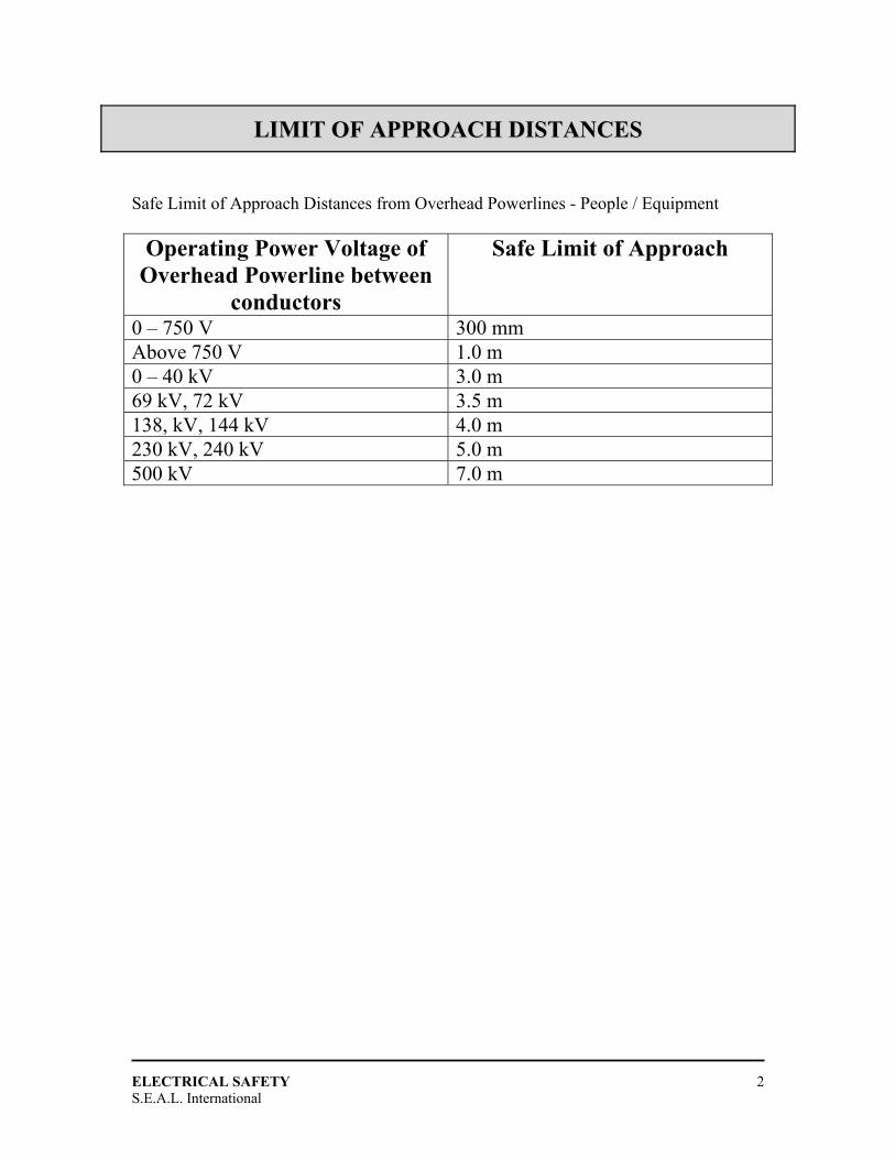
LLIIMMIITT OOFF AAPPPPRROOAACCHH DDIISSTTAANNCCEESS Safe Limit of Approach Distances from Overhead Powerlines - People / Equipment
Operating Power Voltage of Overhead Powerline between
conductors
Safe Limit of Approach
0 – 750 V 300 mm Above 750 V 1.0 m 0 – 40 kV 3.0 m 69 kV, 72 kV 3.5 m 138, kV, 144 kV 4.0 m 230 kV, 240 kV 5.0 m 500 kV 7.0 m
ELECTRICAL SAFETY
S.E.A.L. International 3
EELLEECCTTRRIICCAALL LLOOCCKK--OOUUTT
Electrical Lock-Out
• Procedures for Electricians
• Procedures for Personnel applying lock-out
• (Workshop; development of procedures)
• Procedures for lock removal
• Control / Custodian of electrical equipment
• Prevent accidental start-up of electrically energized equipment
• Prevents injury to personnel
• Prevents damage to equipment
• Should be controlled by permit system
ELECTRICAL SAFETY
S.E.A.L. International 4
EELLEECCTTRROOSSTTAATTIICC IIGGNNIITTIIOONN SSOOUURRCCEESS
Electrostatic Ignition Sources
• Filling tanks and containers
• Circulating liquids through partly filled tanks
• Road and rail transfers
• Fuelling aircraft
• Settling
• Agitation
• Passing liquid through flexible hoses
• Passing liquid through insulating pipes
• Filtering liquids
• Personnel
ELECTRICAL SAFETY
S.E.A.L. International 5
GGRROOUUNNDDIINNGG AANNDD BBOONNDDIINNGG
Grounding and Bonding
• Alternating current systems operating at 50 volts and above are required to be
grounded.
• Grounding is achieved through metal pipe systems, metal re-enforced cement
pads or a ground plate / rod.
Bonding
• Used to ensure an electrical discharge is prevented from one piece of equipment
to another.
• Ensures continuity is provided for equipment.
Ignition Source Concerns
• Electrical discharge points
• Flammable atmospheres
• Introduction of air
ELECTRICAL SAFETY
S.E.A.L. International 6
AARREEAA CCLLAASSSSIIFFIICCAATTIIOONN AAPPPPLLIICCAATTIIOONNSS
Code References
Both the Canadian Electrical Code, Part I, (CEC) and the National Electrical Code (NEC)
contain guidance for the classification of some of the more common installations. For
example, in the CEC, Part I, Section 20, and in the CEC Handbook, there are examples of
classifications for gasoline dispensing stations, garages, bulk storage plants, spray
painting installations, and aircraft hangers. Similar guidance is provided in the NEC in
Articles 511 to 516. In addition, both of these Codes now recognize the new three-Zone
system of classification. In the CEC, the three-Zone system is mandatory for all new
installations; in the NEC, the choice between using the Division system and the three-
Zone system is left open. In the United States, the two classification systems may be
used in the same installation, providing that there is no overlap between the two.
The difference between the two-Division and three-Zone systems of classification is that
the old Division 1 contained what is now classified as Zone 0 and Zone 1. For example,
the filled Canadian definition of Division 1 contains the words "continuously,
intermittently, or periodically". In Zone 0, the location is hazardous continuously, and in
Zone 1 the location is hazardous intermittently or periodically. In effect, the old Division
1 has been split into two parts. There is no real difference between Division 2 and Zone
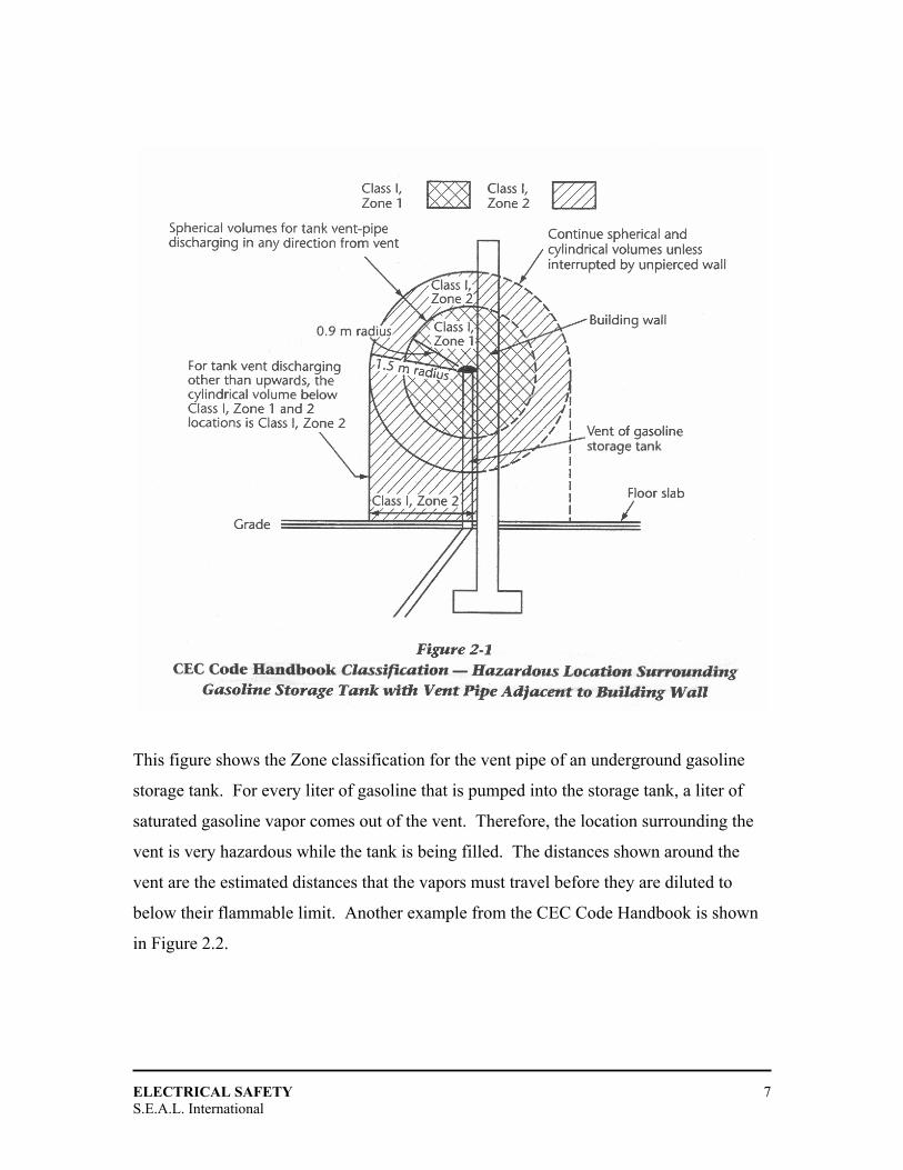
2 for Class I locations. A sample classification from the CEC Code Handbook is shown
in Figure 2-1.
ELECTRICAL SAFETY
S.E.A.L. International 7
This figure shows the Zone classification for the vent pipe of an underground gasoline
storage tank. For every liter of gasoline that is pumped into the storage tank, a liter of
saturated gasoline vapor comes out of the vent. Therefore, the location surrounding the
vent is very hazardous while the tank is being filled. The distances shown around the
vent are the estimated distances that the vapors must travel before they are diluted to
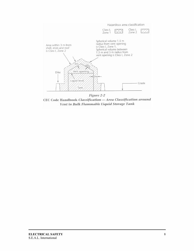
below their flammable limit. Another example from the CEC Code Handbook is shown
in Figure 2.2.
ELECTRICAL SAFETY
S.E.A.L. International 8
ELECTRICAL SAFETY
S.E.A.L. International 9
FFLLAAMMEEPPRROOOOFF EENNCCLLOOSSUURREESS
History and Principle of Operation
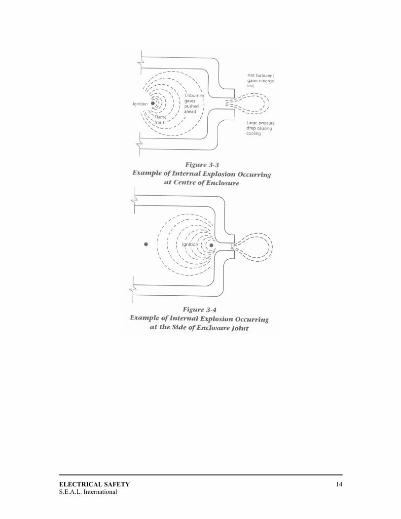
To prevent the ignition of an external explosive atmosphere, not only must the enclosure
be strong enough to withstand the internal explosion pressure but all of its openings (e.g.,
cover joints, conduit or cable entries, operating shafts) must be tight enough to cool the
hot burning gases before they can come into contact with the external atmosphere.
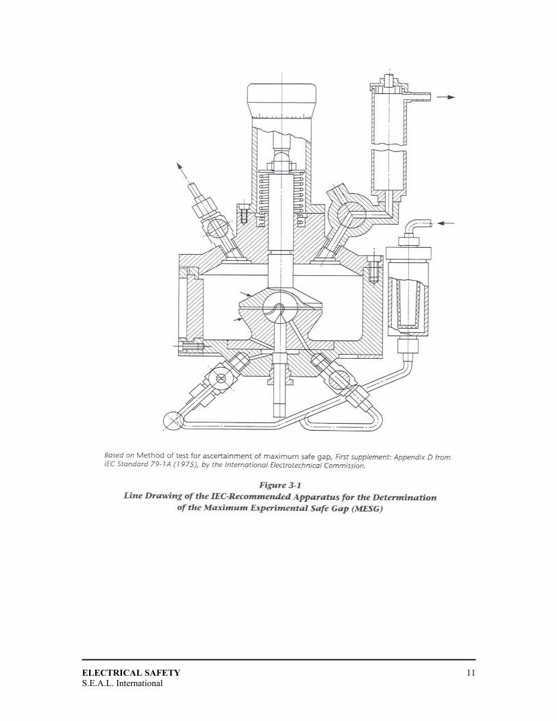
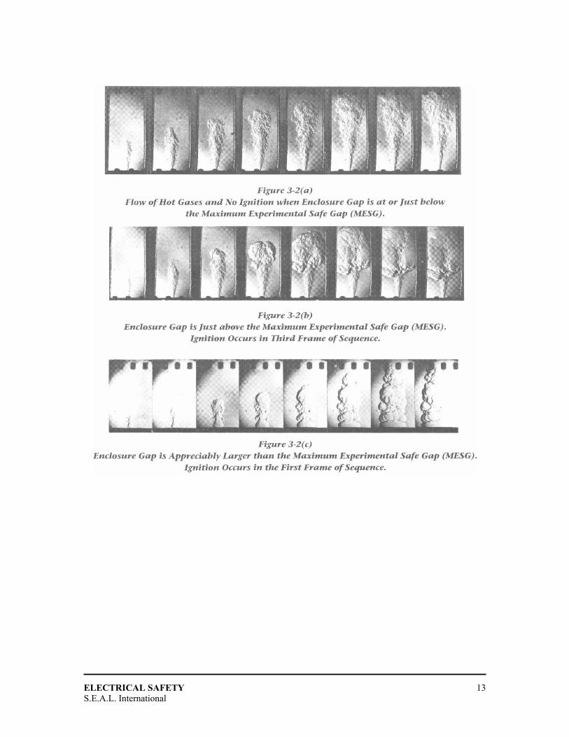
Flat or Straight Flameproof Joints
There are two essential properties of a flat or straight flameproof joint: the clearance and
the length of the path. The maximum clearance of a joint is referred to as the maximum
gap, and the length of the path (from inside the enclosure to the outside is sometimes
called the “width of joint”, because reference is usually being made to a flanged joint.
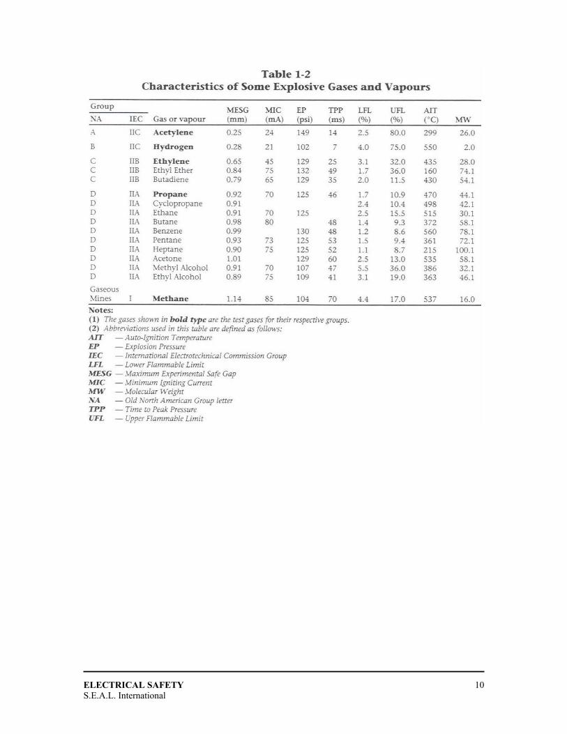
Table 1-2 shows the maximum experimental safe gap (MESG) for a number of gases and
vapours. These MESG values are one of the key factors used in classifying gases and
vapours into groups. The MESG is also used to determine the maximum gaps that can be
allowed for each group. The MESG is determined in a special experimental device such
as the one shown in figure 3-1.
ELECTRICAL SAFETY
S.E.A.L. International 10
ELECTRICAL SAFETY
S.E.A.L. International 11

ELECTRICAL SAFETY
S.E.A.L. International 12
ELECTRICAL SAFETY
S.E.A.L. International 13
ELECTRICAL SAFETY
S.E.A.L. International 14
ELECTRICAL SAFETY
S.E.A.L. International 15
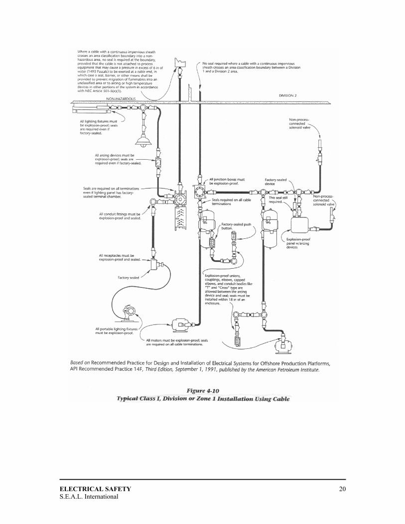
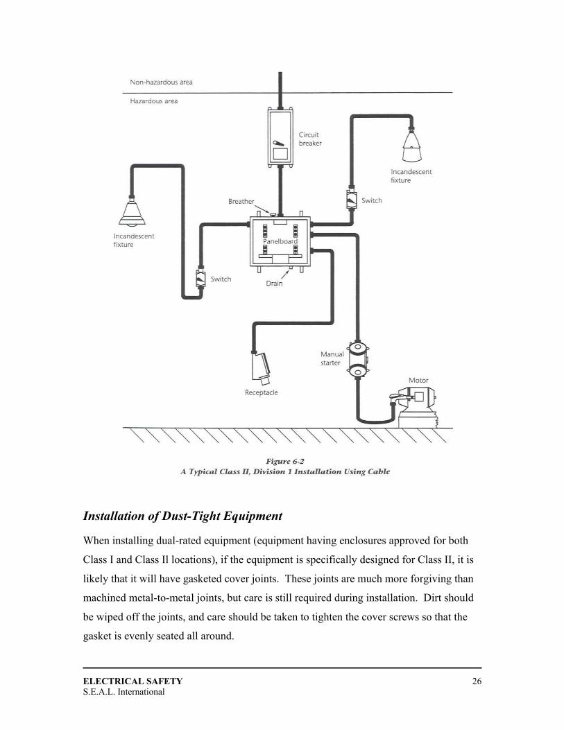
FFLLAAMMEEPPRROOOOFF IINNSSTTAALLLLAATTIIOONNSS
Conduit Connected Systems
A typical flameproof conduit installation for a Division or Zone 1 location includes rigid
threaded conduit, flameproof conduit fittings, sealing fittings, junction boxes, switches,
panelboards, motor starters, lighting fixtures, motors, and instruments. Such a system is
shown in Figure 4-1.
Sealing of Conduits
General Requirements Seals are required where the conduit system enters the hazardous location, where the
conduit enters a new Division or Zone (e.g., from Division 2 to Division 1), where the
conduit enters a device containing normally arcing parts, and where a conduit trade size 2
or larger enters any other flameproof device or box.
Seals should be installed as close as possible to the enclosure, and are required to be not
more than 450 mm from the enclosure they are intended to seal. The only way that a
saving can be made in such an installation is if two enclosures requiring seals are 900 mm
or less apart; then one seal located midway between the two enclosures will suffice.
The installation of the entire rigid conduit shown in Figure 4-1 involves considerable
time and expense. As well, many sealing fittings must be installed in the field and poured
full of sealing compound. This is because the equipment installed in such a system is
typically the direct entry type (see Chapter 3). Figure 4-1 also shows some non-
flameproof equipment (at the lower left-hand side) that does not require seals.
One reason for providing these seals is to prevent the propagation of an explosion from
one flameproof enclosure to another. If this occurs, the phenomenon known as "pressure-
piling" may raise the explosion pressure in the second enclosure to much higher values
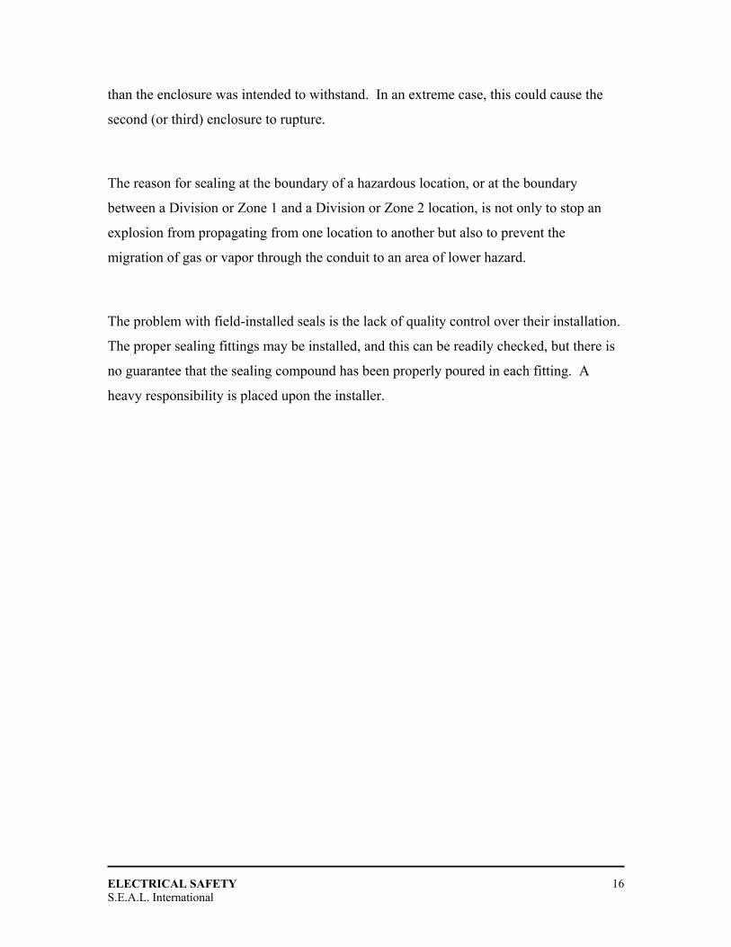
ELECTRICAL SAFETY
S.E.A.L. International 16
than the enclosure was intended to withstand. In an extreme case, this could cause the
second (or third) enclosure to rupture.
The reason for sealing at the boundary of a hazardous location, or at the boundary
between a Division or Zone 1 and a Division or Zone 2 location, is not only to stop an
explosion from propagating from one location to another but also to prevent the
migration of gas or vapor through the conduit to an area of lower hazard.
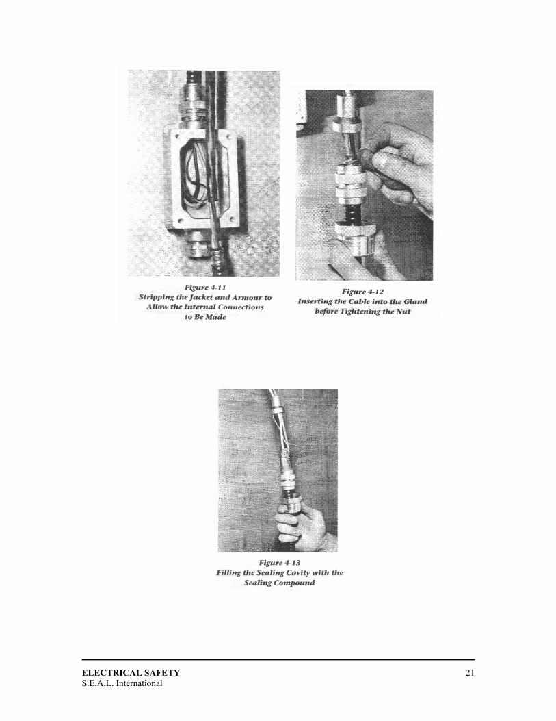
The problem with field-installed seals is the lack of quality control over their installation.
The proper sealing fittings may be installed, and this can be readily checked, but there is
no guarantee that the sealing compound has been properly poured in each fitting. A
heavy responsibility is placed upon the installer.
ELECTRICAL SAFETY
S.E.A.L. International 17
ELECTRICAL SAFETY
S.E.A.L. International 18
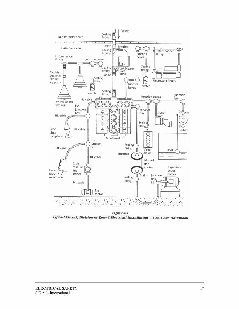
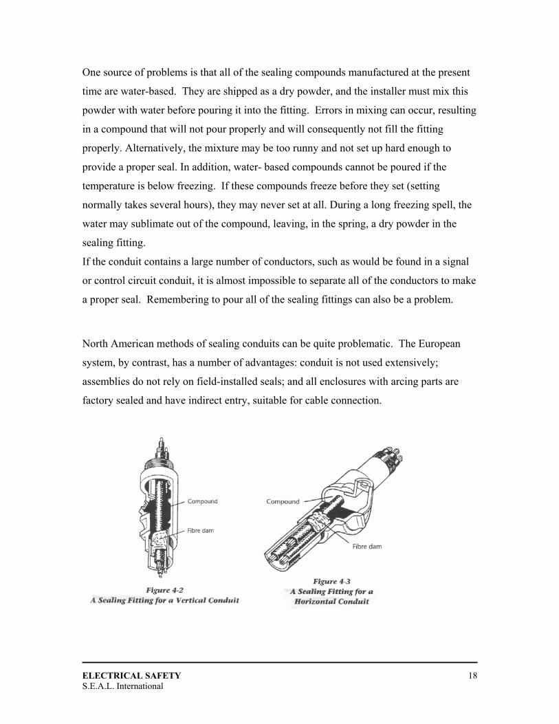
One source of problems is that all of the sealing compounds manufactured at the present
time are water-based. They are shipped as a dry powder, and the installer must mix this
powder with water before pouring it into the fitting. Errors in mixing can occur, resulting
in a compound that will not pour properly and will consequently not fill the fitting
properly. Alternatively, the mixture may be too runny and not set up hard enough to
provide a proper seal. In addition, water- based compounds cannot be poured if the
temperature is below freezing. If these compounds freeze before they set (setting
normally takes several hours), they may never set at all. During a long freezing spell, the
water may sublimate out of the compound, leaving, in the spring, a dry powder in the
sealing fitting.
If the conduit contains a large number of conductors, such as would be found in a signal
or control circuit conduit, it is almost impossible to separate all of the conductors to make
a proper seal. Remembering to pour all of the sealing fittings can also be a problem.
North American methods of sealing conduits can be quite problematic. The European
system, by contrast, has a number of advantages: conduit is not used extensively;
assemblies do not rely on field-installed seals; and all enclosures with arcing parts are
factory sealed and have indirect entry, suitable for cable connection.
ELECTRICAL SAFETY
S.E.A.L. International 19
ELECTRICAL SAFETY
S.E.A.L. International 20
ELECTRICAL SAFETY
S.E.A.L. International 21
ELECTRICAL SAFETY
S.E.A.L. International 22
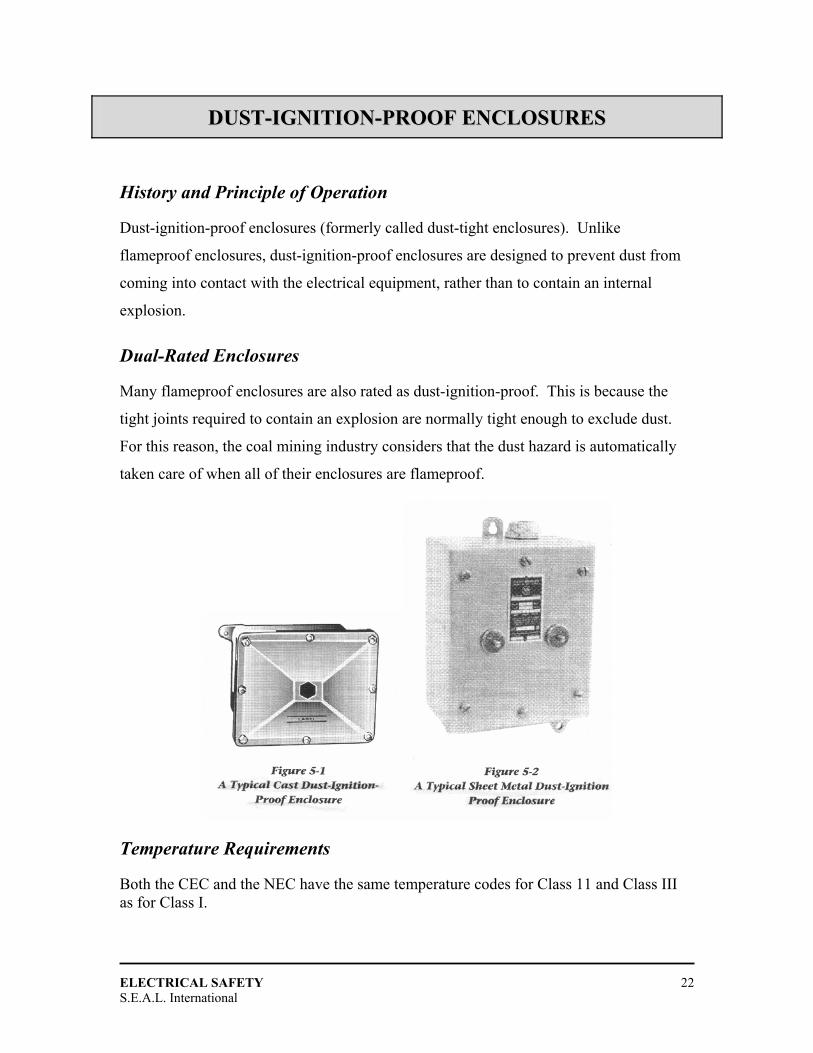
DDUUSSTT--IIGGNNIITTIIOONN--PPRROOOOFF EENNCCLLOOSSUURREESS
History and Principle of Operation
Dust-ignition-proof enclosures (formerly called dust-tight enclosures). Unlike
flameproof enclosures, dust-ignition-proof enclosures are designed to prevent dust from
coming into contact with the electrical equipment, rather than to contain an internal
explosion.
Dual-Rated Enclosures
Many flameproof enclosures are also rated as dust-ignition-proof. This is because the
tight joints required to contain an explosion are normally tight enough to exclude dust.
For this reason, the coal mining industry considers that the dust hazard is automatically
taken care of when all of their enclosures are flameproof.
Temperature Requirements
Both the CEC and the NEC have the same temperature codes for Class 11 and Class III as for Class I.

ELECTRICAL SAFETY
S.E.A.L. International 23
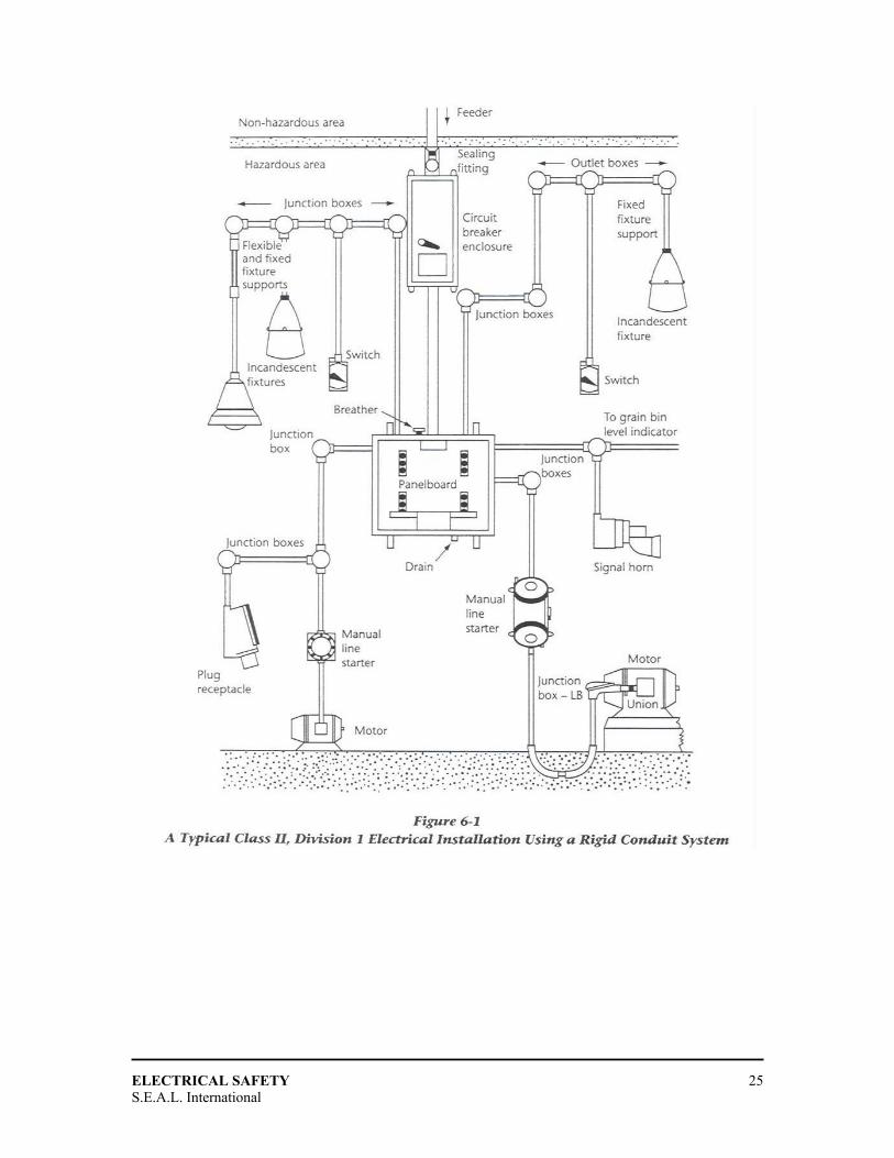
DDUUSSTT--IIGGNNIITTIIOONN--PPRROOOOFF IINNSSTTAALLLLAATTIIOONNSS
Conduit-Connected Systems
General Requirements A typical dust-ignition-proof conduit installation for a Class 11, Division 1 location
includes rigid threaded conduit and dust- ignition-proof fittings, junction boxes, switches,
panelboards, motor starters, and instruments.
Sealing of Conduits
Seals are required only between an enclosure that is required to be dust-ignition-proof
and an enclosure that is not required to be dust- ignition-proof. Therefore, no seals are
required in a Class 11, Division 1 location, since all of the enclosures in such a location
are required to be dust-ignition-proof. The only place where seals are required in a Class
11 location is in a Division 2 location in which some of the enclosures are required to be
dust-ignition- proof and some are not. Even then, both the CEC and the NEC allow a 3 m
horizontal run of conduit, or a 1.5 m vertical run (extending downward from the dust-
tight enclosure), in lieu of a sealing fitting.
The reason seals are not required in a Class II, Division 1 location is that if all of the
enclosures are dust-ignition-proof, and they are connected with rigid metal conduit, there
is no chance that dust will enter the system. Therefore, there is no concern that dust
could be transmitted to other enclosures or to non-hazardous locations. In addition, since
dust is prevented from entering the enclosures (by definition), there is no chance of an
internal explosion, which eliminates the concern about pressure piling.
In a Class II, Division 2 location, seals are more likely to be needed because boxes and
fittings that contain only wiring and connections are not required to be approved as dust-
ignition-proof. Accordingly, a seal (or the required lengths of conduit, as mentioned

ELECTRICAL SAFETY
S.E.A.L. International 24
above) must be provided between non-dust-ignition-proof boxes and fittings and dust-
ignition-proof enclosures. In addition, if the last box or fitting between the hazardous and
non-hazardous locations is not dust-ignition-proof, the required seal or length of conduit
must be provided between it and the non-hazardous location. This is to prevent the
migration of dust into the non-hazardous location. Note that, although flameproof sealing
fittings are normally used for Class II, they need not be filled with the flameproof sealing
compound. Sealing putty is acceptable, because it only needs to prevent the migration of
dust.
A typical Class 11, Division 2 installation would look very much like the one shown in
figure 6-1, except that the junction boxes could be the general-purpose type instead of
dust-ignition-proof, and the motor could be a totally enclosed type (if it were a squirrel-
cage motor). The circuit breakers, switches, starter, and lighting fixtures could be built to
enclosure 4 requirements instead of Class II dust-tight requirements.
ELECTRICAL SAFETY
S.E.A.L. International 25
ELECTRICAL SAFETY
S.E.A.L. International 26
Installation of Dust-Tight Equipment
When installing dual-rated equipment (equipment having enclosures approved for both
Class I and Class Il locations), if the equipment is specifically designed for Class II, it is
likely that it will have gasketed cover joints. These joints are much more forgiving than
machined metal-to-metal joints, but care is still required during installation. Dirt should
be wiped off the joints, and care should be taken to tighten the cover screws so that the
gasket is evenly seated all around.
ELECTRICAL SAFETY
S.E.A.L. International 27
When making conduit connections or installing cable glands, it is only necessary to have
three full threads of engagement with the hubs in the enclosures (instead of five, as for
flameproof devices). This does not mean, however, that the installer should stop turning
when three threads have been engaged. This could lead to a loose joint and a poor
bonding connection. To exclude dust, only three tapered threads are required, and as a
result most equipment designed specifically for Class II locations will be threaded to
accommodate this requirement. However, in all cases, the threaded joints should be tight.
Maintenance of Dust-Tight Installations
The maintenance of dust-ignition-proof installations is fairly simple once personnel are
familiar with the concept of excluding dust from the enclosures. As with flameproof
enclosures, the power must be turned off before an enclosure is opened, and the enclosure
must be cleaned of any accumulated dust before it is closed and the power is turned on.
The maintenance electrician must also ensure that any gaskets are in good condition, that
there are no gaps at the corner joints, and that they are properly seated. A damaged
gasket must be completely replaced by a new one obtained from the original
manufacturer. The original gasket was carefully selected and tested for dust-tightness on
that particular enclosure, and a substitute may not be as effective. If a fabricated sheet
metal enclosure is dented or distorted near the cover joint, the gasket may not seat
properly. One easy way of checking this seal is to coat the gasket or the mating surface
with a thin film of grease, close the cover, and then open it and look at the imprint of the
gasket. If the imprint is not continuous, the enclosure must be repaired or replaced.
General housekeeping in the area is very important in a Class 11 location. It can even
affect the classification of the location, if the classification was originally determined on
the basis of good cleaning practices. In addition, if equipment approved to Practice A of
IEC (International Electrotechnical Commission) Standard 61241-1-1 is being used, it is
essential that dust not be allowed to build up on electrical enclosures. Note also that
electric motors and generators approved to Practice A must have their resilient shaft seals
replaced periodically. However, IEC Standard 61241-1-1 has not yet been accepted
officially in Canada or the United States, so this is not yet a concern for North American
installations.
ELECTRICAL SAFETY
S.E.A.L. International 28
CCAABBLLEE RREEQQUUIIRREEMMEENNTTSS As well as satisfying electrical requirements, all cables for intrinsically safe circuits
should have a dielectric strength of at least 500 V rms between all conductors and
between all conductors and ground or grounded screens.
Where a screen is required to be grounded, it should be grounded only at one point,
normally at the non-hazardous end of the cable. This prevents the screen from carrying a
possibly incentive level of circulating current if there are local differences in earth
potential between one end of the circuit and the other.
Cables carrying intrinsically safe circuits should be installed in such a way that intrinsic
safety is not adversely affected by external magnetic fields caused by overhead power
lines or single-core cables carrying heavy currents. This can be accomplished by
physical separation from all power circuits, by screens, or by twisted conductors in the
intrinsically safe cables.
ELECTRICAL SAFETY
S.E.A.L. International 29
PPUURRGGEEDD AANNDD PPRREESSSSUURRIIZZEEDD EENNCCLLOOSSUURREESS
Principle of Operation
Purged and pressurized enclosures operate by removing any residual gas or vapor from
the enclosure before the power is turned on (the purge cycle) and by maintaining a
positive pressure inside the enclosure in order to prevent the entrance of gas or vapor
during operation (the pressurizing cycle). Although the purge and pressurizing medium is
normally clean air, it can also be an inert gas. Although the two words "purged" and
"pressurized" are often used interchangeably, they are actually two distinct phases of the
process; "pressurized enclosures" is the term normally used to describe the related type of
protection.
When an enclosure is de-energized for any period of time, or has been opened for
servicing, it is assumed that in a Class I location, there may be some flammable gas or
vapor in the enclosure. Therefore, before the power is turned on, all of the gas or vapor
must have been removed. For an enclosure having no pockets or dead spaces, it has been
found that four complete changes of air will ensure that the interior is free of the gas or
vapor. "Purging" is the term used to describe the process of changing the air to remove
the flammable gas or vapor from the enclosure.
To completely change the air four times, the purge air should enter at one side or corner
and exit at the other side or corner. With a lighter- than-air gas, the purge air should enter
near the bottom and the air outlet (if provided) should be near the top of the enclosure, to
take advantage of the natural buoyancy of the gas. The opposite is true of heavier-than-air
gases or vapors.
If the flow rate of the purge air is known, the time to purge the enclosure can be
calculated and the purge cycle can be controlled by a simple timing device. If the
enclosure has pockets or dead spaces that might be difficult to purge, the purging time
should be increased to ensure that these spaces are well purged. Naturally, the purging
ELECTRICAL SAFETY
S.E.A.L. International 30
time can be reduced if a deliberate outlet is provided for the purge air, allowing a greater
flow of air. If we rely on leakage through the joints in the enclosure, it may take a long
time for four volumes of air to pass through the enclosure.
The provision of a purge outlet introduces another problem. If the electrical equipment in
the enclosure should fail, there is a possibility that sparks or flames from the electrical
equipment may be transmitted through the outlet to the surrounding atmospheres. There
are two ways in which this can be prevented. The first, and best, is to pipe the purge air to
a non-hazardous location. If the hazardous location is very large, it may be more practical
to fit a spark arrester to the outlet.
A spark arrester is typically a device with a series of baffles, or some other means, to
prevent sparks and flames from being transmitted to the surrounding atmosphere. This
device does not have to be a flame arrester (see Chapter 14), because it does not have to
stop the transmission of an explosion.
Unfortunately, existing standards provide no specific requirements for spark arresters.
ISA (Instrumentation, Systems, and Automation Society) Standard 12.4 simply states that
vents must have baffles, and a non-combustible screen or filter or be provided with a hub
for an external pipe to exhaust the purge air to a safe area. IEC Standard 60079-2 states
that purge air may be released in the hazardous area if the ejection of sparks or
incandescent particles is prevented by an effective device. However, neither standard
contains any requirements or tests to evaluate the effectiveness of the spark- arresting
device.
Some time ago, asked to evaluate a purged and pressurized system for a client, the author
conducted some relevant tests at the facilities of the Canadian Explosive Atmospheres
Laboratory in Ottawa. The system had a spark arrester containing a porous metal
cylinder. The effectiveness of this device was tested, using a chemical igniter (squib) of
250 joules as a spark generator. These tests were quite successful; no sparks passed
through the porous metal cylinder. When the test was made with an explosive gas/air
mixture outside, the explosive mixture did not ignite. The squib was placed 25 mm away
ELECTRICAL SAFETY
S.E.A.L. International 31
from the opening for the spark arrester; when the cylinder was removed, a shower of
sparks was released into the atmosphere and the external mixture was ignited.
This test method was subsequently proposed to the ISA SP12.4 Subcommittee, but it was
not accepted. The subcommittee believed that the sparks from the squib were too
energetic, and therefore not representative of the majority of failures that would release
hot particles from electrical apparatus.
Pressurizing by Blower
One method of pressurizing an electrical enclosure is to locate a blower in a safe (non-
hazardous) location and pipe the air from the blower to the enclosure. This type of
installation tends to be site-specific, because each installation must be designed to take
into account the size of the pipe, the flow of air required, the distance that the clean air
must travel, the number of elbows in the system and the method of venting the purge air.
Compressed Air Systems
Where a source of clean, instrument-quality compressed air (filtered and dried) is
available, compressed air is often used for pressurizing electrical enclosures. This makes
for a relatively inexpensive installation, because it eliminates the blower and piping
necessary for blower systems. However, compressed air is relatively expensive, because
it is normally delivered at a pressure many times higher than that required for
pressurizing an enclosure.
Protective Measures
To eliminate the possibility that pressurized electrical equipment will cause an explosion
in the event of failure of the air or gas supply, certain protective measures must be
provided in the design of these systems.
ELECTRICAL SAFETY
S.E.A.L. International 32
Pressurized Rooms
Entire rooms or buildings, as well as enclosures, may be pressurized to prevent the entry
of gas, vapor, dust, fibers, or flyings.
Static Pressurization
A new technique recently introduced in IEC Standard 60079-2, called "static
pressurization", is permitted for devices where there is no continuous supply of protective
gas.
Pressurization with Dilution
A limited release of flammable gas or vapor within an electrical enclosure may be
safeguarded by means of pressurization with dilution. Sufficient protection may be
provided with an air supply if the concentration can be reduced to a level of less than
25% of the lower flammable limit.
Continuous Dilution
The foregoing requirements apply only to enclosures and rooms that are located within
hazardous locations. If there is a source of release of a gas or vapour within a room or
building, the room or building must be continuously purged with clean air in order to
dilute the gas or vapour to a value well below its explosive limit.
Gas Turbines
Stationary gas turbines are used extensively for two purposes: to pump natural gas
through pipelines over long distances and to generate electricity. In both cases, the
turbines are located in special buildings that must be specially protected against the
possibility of explosion.
ELECTRICAL SAFETY
S.E.A.L. International 33
EEXXCCLLUUSSIIOONN OOFF EEXXPPLLOOSSIIVVEE MMIIXXTTUURREESS
Principle of Operation
One way to prevent electrical equipment from causing an explosion is to fill all the voids
in the vicinity of the electrical components so that an explosive mixture of gas or air/air
cannot penetrate.
Powder Filling
Powder filling originated in France, where it has been used for many years. In 1967, IEC
Standard 79-5 established this process as an international method of protection.
Oil-Immersion
Oil-immersion has been used for many years for large, high-voltage circuit breakers. The
oil used in these devices may be ordinary petroleum oil (except for mining applications),
as long as it has a flashpoint of 200ºC or higher. The oil level must be at least 25 mm.
Encapsulation
The first standard for encapsulation was written by a CENELEC (European Committee for Electrotechnical Standardization) Committee.
ELECTRICAL SAFETY
S.E.A.L. International 34
CCOOMMBBUUSSTTIIBBLLEE GGAASS DDEETTEECCTTIIOONN EEQQUUIIPPMMEENNTT
Detection Devices
The first combustible gas detector was the flame safety lamp used in underground coal
mines. It was soon found that when methane gas was present, the flame grew larger.
Methane forms an explosive mixture at approximately 5% with air; most of these lamps
had a second mark at 25% of this value, or 1.25% methane.
Standards Development The first performance standard for combustible gas detectors was written by CSA (Canadian Standards Association).
Testing Procedures
IEC Requirements The testing requirements for combustible gas detection equipment vary from one
standard to another, but they all follow a similar pattern.
Electromagnetic Stability
A test involving exposure to an electromagnetic signal, similar to that required by the
ISA standard, was introduced.

ELECTRICAL SAFETY
S.E.A.L. International 35
FFLLAAMMEE AARRRREESSTTEERRSS
Principle of Operation
A flame arrester is a device that prevents an explosion from propagating from one
location to another. In this respect, the flame paths in a flameproof enclosure are a form
of flame arrester. However, there are many different types of flame arresters, and only a
few resemble flame paths. In spite of their variety, flame arresters all have one thing in
common: they all act to cool the flame as the hot flaming gases pass through, to prevent
transmission of the flame.
Flat Plate Arrester
This type of arrester resembles the flame path of the flat or straight flameproof joints
described in Chapter 3. One difference is that, instead of one path, a number of flat paths
are stacked on top of one other. The other difference is that the plates between each joint
are deliberately gapped to allow for the passage of gas or air through the arrester.
(Flameproof joints are normally as tight as possible, with no deliberate gap). In addition,
the arresters normally provide a flame path of 50 mm or more to qualify for the largest
possible gap. The main application of the flat plate flame arrester is for the exhaust of a
flameproof diesel engine.
Loose-Fitting Threads
A threaded joint with a large tolerance between the male and female parts of the thread
can also be used as a flame arrester. These are normally confined to breathing and
draining devices for explosion-proof (flameproof) enclosures because they somewhat
restrict the passage of gas and air.
ELECTRICAL SAFETY
S.E.A.L. International 36
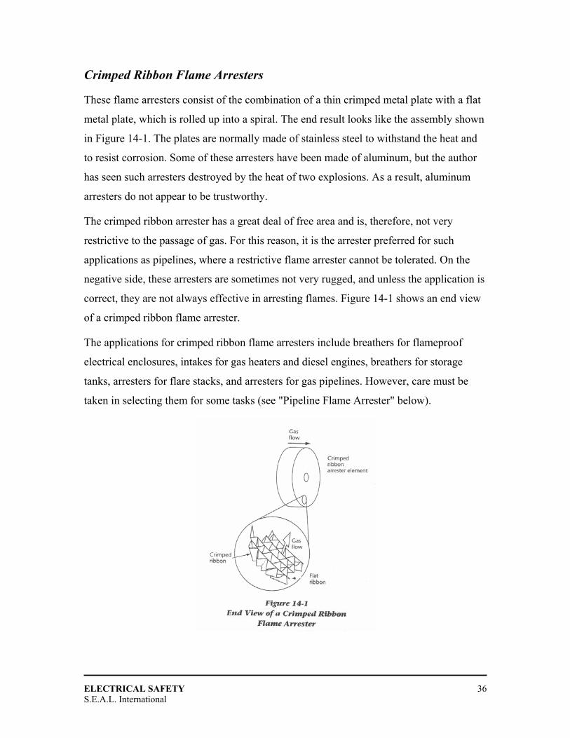
Crimped Ribbon Flame Arresters
These flame arresters consist of the combination of a thin crimped metal plate with a flat
metal plate, which is rolled up into a spiral. The end result looks like the assembly shown
in Figure 14-1. The plates are normally made of stainless steel to withstand the heat and
to resist corrosion. Some of these arresters have been made of aluminum, but the author
has seen such arresters destroyed by the heat of two explosions. As a result, aluminum
arresters do not appear to be trustworthy.
The crimped ribbon arrester has a great deal of free area and is, therefore, not very
restrictive to the passage of gas. For this reason, it is the arrester preferred for such
applications as pipelines, where a restrictive flame arrester cannot be tolerated. On the
negative side, these arresters are sometimes not very rugged, and unless the application is
correct, they are not always effective in arresting flames. Figure 14-1 shows an end view
of a crimped ribbon flame arrester.
The applications for crimped ribbon flame arresters include breathers for flameproof
electrical enclosures, intakes for gas heaters and diesel engines, breathers for storage
tanks, arresters for flare stacks, and arresters for gas pipelines. However, care must be
taken in selecting them for some tasks (see "Pipeline Flame Arrester" below).
ELECTRICAL SAFETY
S.E.A.L. International 37
Sintered Metal Flame Arresters
These are among the most effective flame arresters known. Unfortunately, they tend to be
quite restrictive to the passage of gas, so their application is limited. The elements for
these arresters are made by compressing particles of metal (normally stainless steel or
copper-tin bronze) together with an organic material. The combination is then heated
until the metal is bonded together and the filler material has been burned off. The result is
a fairly uniform porous metal, which will pass a gas but, due to the tortuous paths through
the metal, will not permit the passage of a flame.
Sintered metal can be produced in any shape or form, so it has many applications.
Flameproof enclosures have been made with large sections of the cover consisting of
sintered metal, to reduce the pressures generated during an explosion. This offers the
advantage of a much lighter enclosure, but such a design is not widely used, because the
porous metal is not very strong, and it is necessary to provide protection against impact
for these venting sections.
Applications for sintered metal flame arresters include breathing and draining devices,
diffusion heads for gas detection sensors, and venting devices for reducing the explosion
pressure in a flameproof enclosure.
Metal Foam Elements
Metal foam elements are made by coating polyurethane foam with nickel, removing the
polyurethane by heating, and converting the nickel into nickel-chrome alloy by gaseous
diffusion. After this process is complete, the foam can be made denser by compression, if
necessary. The end result is very nearly the same as a sintered metal element, and the
applications are also the same.
ELECTRICAL SAFETY
S.E.A.L. International 38
Pressed Metal Wire Elements
Pressed metal wire elements are made from stainless steel wire braid (or a similar non
corrosive wire) that is compressed in a die to form a homogeneous matrix. These
elements are normally used for breathers and drains for flameproof enclosures.
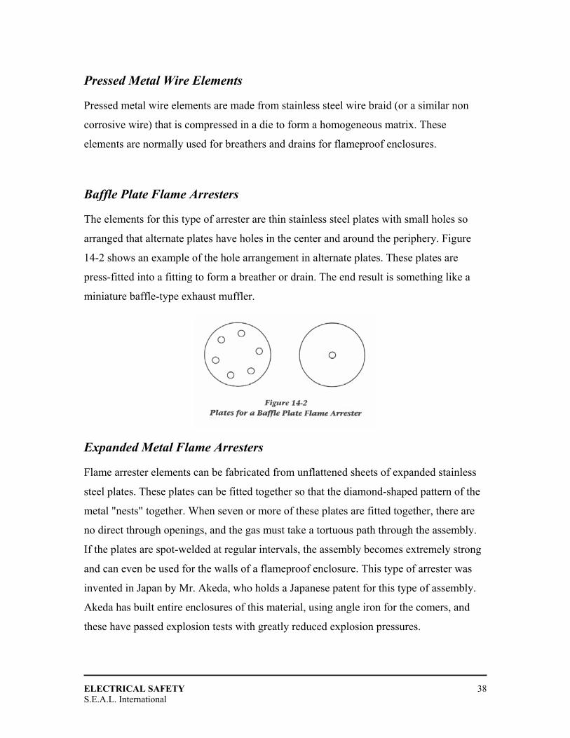
Baffle Plate Flame Arresters
The elements for this type of arrester are thin stainless steel plates with small holes so
arranged that alternate plates have holes in the center and around the periphery. Figure
14-2 shows an example of the hole arrangement in alternate plates. These plates are
press-fitted into a fitting to form a breather or drain. The end result is something like a
miniature baffle-type exhaust muffler.
Expanded Metal Flame Arresters
Flame arrester elements can be fabricated from unflattened sheets of expanded stainless
steel plates. These plates can be fitted together so that the diamond-shaped pattern of the
metal "nests" together. When seven or more of these plates are fitted together, there are
no direct through openings, and the gas must take a tortuous path through the assembly.
If the plates are spot-welded at regular intervals, the assembly becomes extremely strong
and can even be used for the walls of a flameproof enclosure. This type of arrester was
invented in Japan by Mr. Akeda, who holds a Japanese patent for this type of assembly.
Akeda has built entire enclosures of this material, using angle iron for the comers, and
these have passed explosion tests with greatly reduced explosion pressures.
ELECTRICAL SAFETY
S.E.A.L. International 39
This material can also be formed into a cylinder; it has been shown that it is resistant to
detonations in this form (see "Pipeline Flame Arresters" below).
Testing of Flame Arresters
Flame arresters intended for a specific use, such as breathing and draining of a
flameproof enclosure, are normally tested with the enclosure in which they are installed.
Similarly, an exhaust flame arrester for a flameproof diesel machine will be tested when
mounted on the exhaust conditioner (scrubber box), with a pipe leading into the box to
simulate the exhaust pipe from the engine.
However, in many cases, breathers and drains are sold separately, with a standard pipe
thread for installation in a threaded opening in the enclosure. They may actually be
installed by the user, so it is not known, when they are tested, what size or shape of
enclosure will be used. Accordingly, a special test set-up has to be designed to simulate
the worst case. In Canada, for many years, such devices were tested when mounted in the
side of a 0.3 m3 square enclosure. While this simulated a fairly large enclosure, it did not
necessarily simulate the worst case.
IEC Standard 60079-1 describes an interesting test rig for testing enclosure flame
arresters that are submitted without an enclosure. This rig simulates the worst possible
conditions to which the flame arrester may be subjected. Normally, the flame arresters for
flameproof enclosures are tested with the enclosure provided. However, they can also be
tested separately in the special test rig. This rig consists of 2 rn of boiler tube having an
inside diameter of 40 mm. and an end section, containing the test sample, 174 mm long
and 75 mm. inside diameter. The appropriate gas/air mixture is introduced into the rig,
surrounding the flame arrester, and the internal mixture is ignited at the opposite end.
There must be no transmission of the internal mixture to the external mixture through the
flame arrester. At the end of this flameproof test, if there is no ignition, the external
explosive mixture is maintained for 10 minutes to see if any continuous burning occurs
and destroys the arrester. This part of the test is necessary because after the explosion,
ELECTRICAL SAFETY
S.E.A.L. International 40
there is a slight vacuum inside the enclosure (due to the burning of the gas and oxygen),
and the external mixture can be sucked into the enclosure and bum at the flame arrester.
Pipeline Flame Arresters
Two kinds of flame arresters are used in pipelines and similar applications. The first is
the deflagration-proof arrester, which will arrest a simple explosion. This type of flame
arrester is designed to operate at a relatively low explosion pressure and is limited to
applications such as tank breathing devices and intakes for engines and fuel burning
devices.
A typical application is at the end of the breather pipe for the cargo holds of a petroleum
tanker. All of the holds are equipped with pipes that are connected to a main breather
pipe. This pipe takes the vapors from the tanks to the top of the mast so that they are not
ignited by any ignition sources on the deck of the ship. As a further precaution, the end of
the breather pipe is fitted with a flame arrester.
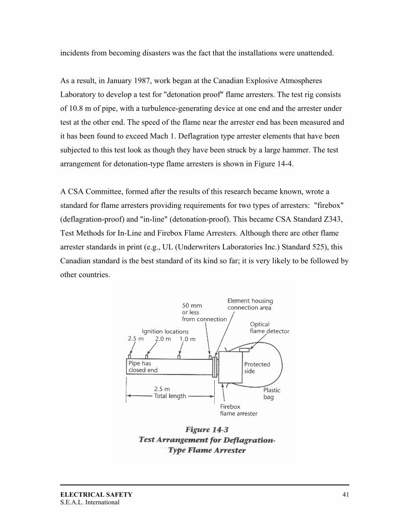
This type of arrester is tested by fitting 2.5 m of pipe, of the appropriate size, to the
arrester and igniting a gas/air mixture at the end of the pipe. The arrester passes this test if
the explosion is stopped by the arrester. Figure 14-3 shows the test set-up for this type of
flame arrester.
When this type of arrester was used in Western Canada for flares in the Alberta gas
fields, it was found that the arresters frequently plugged up due to the foreign material in
the gas. Since they were at the top of a 12 m stack, cleaning them was very difficult. As a
result, installers began mounting them in the pipe at the base of the stack.
This resulted in a series of explosions that destroyed several installations. The reason was
that if an explosion travels 12 m through a large diameter pipe, it could develop into a
detonation that will destroy a conventional flame arrester. Therefore, every flashback in a
flare stack resulted in expensive property damage. The only thing that prevented these
ELECTRICAL SAFETY
S.E.A.L. International 41
incidents from becoming disasters was the fact that the installations were unattended.
As a result, in January 1987, work began at the Canadian Explosive Atmospheres
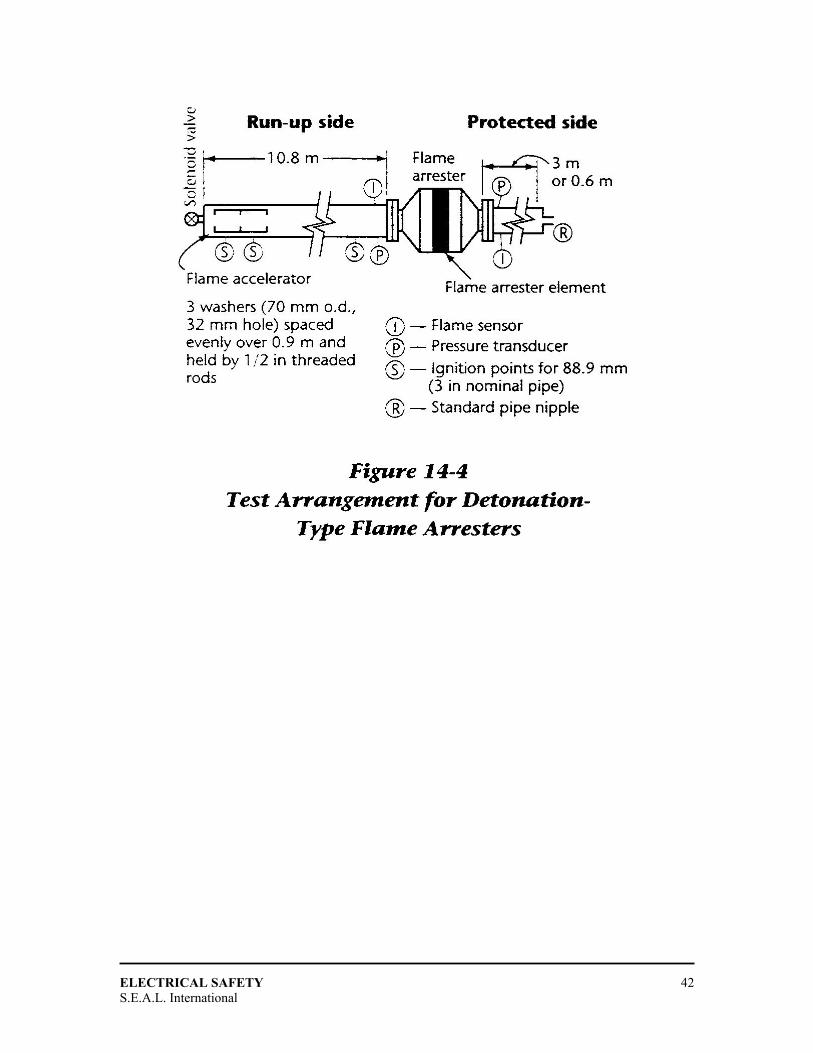
Laboratory to develop a test for "detonation proof" flame arresters. The test rig consists
of 10.8 m of pipe, with a turbulence-generating device at one end and the arrester under
test at the other end. The speed of the flame near the arrester end has been measured and
it has been found to exceed Mach 1. Deflagration type arrester elements that have been
subjected to this test look as though they have been struck by a large hammer. The test
arrangement for detonation-type flame arresters is shown in Figure 14-4.
A CSA Committee, formed after the results of this research became known, wrote a
standard for flame arresters providing requirements for two types of arresters: "firebox"
(deflagration-proof) and "in-line" (detonation-proof). This became CSA Standard Z343,
Test Methods for In-Line and Firebox Flame Arresters. Although there are other flame
arrester standards in print (e.g., UL (Underwriters Laboratories Inc.) Standard 525), this
Canadian standard is the best standard of its kind so far; it is very likely to be followed by
other countries.
ELECTRICAL SAFETY
S.E.A.L. International 42

ELECTRICAL SAFETY
S.E.A.L. International 43
FFLLAAMMEEPPRROOOOFF DDIIEESSEELL VVEEHHIICCLLEESS
Flameproof Requirements
CSA Requirements Probably the most complete set of requirements for flameproof diesel equipment is found
in CSA Standard CAN/CSA-M424.1, Flameproof Non-Rail-Bound Diesel-Powered
Machines for Use in Gassy Underground Coal Mines. This is not the only standard on
this subject: the United Kingdom has Testing Memorandum 12, and the United States has
Part 36 of the Code of Federal Regulations, Mobile Diesel-Powered Transportation
Equipment for Gassy Non-Coal Mines and Tunnels. The following requirements are from
the Canadian standard; significant differences are mentioned as required. Although the
CSA standard is only intended for rubber-tired machines, it can be used for diesel trains
as well. In addition, by changing some of the flame path requirements and the test gas,
the standard could be used for diesel machines in other hazardous locations. The
requirements are as follows:
1. Normal diesel engine design, the design of fastenings associated with the joints, and normal manufacturing tolerances and wear limits are considered to produce acceptable flameproof construction for such things as pistons, piston rings, cylinders, cylinder heads, valves, and injectors. Any other joints in the engine that connect directly or indirectly to the combustion chambers must meet acceptable flameproof requirements.
2. The engine exhaust system must prevent the transmission of the internal combustion to the external atmosphere, have a maximum surface temperature of 150ºC, and cool the exhaust gases to a temperature of 77ºC. This is normally done by having a water-cooled exhaust manifold, a water scrubber, and a flame arrester, all in series. As indicated in Chapter 14, the most popular flame arrester for diesel exhaust is the flat plate arrester. In the United States, the exhaust flame arrester may be omitted if a water scrubber is fitted that can be shown to be an effective flame arrester. However, the flame-quenching ability of a water scrubber is not relied upon in Canada or the United Kingdom, on the view that the water scrubber could run dry and the low- water shutdown controls in the scrubber might fail to operate.
ELECTRICAL SAFETY
S.E.A.L. International 44
3. Electric systems are normally included on diesel machines for lighting in the underground environment. Power for the lights is normally provided by a flameproof alternator, belt-driven from the engine shaft. All of the electric system, such as the wiring, switches, and headlights, must meet the flameproof electric standards.
4. The engine intake system must be equipped with a flame arrester and an emergency air shutoff valve. Explosions can be produced in the engine intake system either by a backfire from the cylinders or by ignition of an ingested combustible methane/air mixture. The purpose of the intake flame arrester is to prevent the transmission of such explosions to the surrounding atmosphere. The intake flame arrester may be the flat plate type or, since it is not subjected to the same abuse as the exhaust arrester, another type, such as the crimped- ribbon type. The purpose of the air shutoff valve is to provide an emergency method of shutting down the engine. Normally, a diesel engine is shut down by cutting off the supply of diesel fuel, but it has been shown that a diesel engine will continue to run without diesel fuel if there is sufficient methane present in the atmosphere. The air shutoff valve is not required in the US standard.
5. The starting system of choice for flameproof diesels is a compressed-air starter. Such systems operate from a tank of compressed air; even if the air tank is empty, the machine can be jump-started by connecting it to the compressed-air system of another machine. This starting system requires having an air compressor on board to replenish the air in the tank while running. It is also possible to use a flameproof electric starter and a suitable battery, but most jurisdictions discourage this because of the difficulty of providing a suitable flameproof system for such a high-power system, as well the potential dangers of jump-starting an electric starter in an explosive environment.
6. Each machine must be equipped with a safety shutdown system that shuts down the engine in response to signals received from sensors monitoring the engine temperature, the exhaust gas temperature, the water level in the exhaust scrubber, the methane monitor (a combustible gas detector; see Chapter 12), the fluid temperature in the torque converter, the lubricating oil pressure, and the temperature in the air compressor discharge line. Since there will be no oil pressure on start-up, an override switch must be provided for the oil pressure sensor, to allow the engine to be started.
7. The use of aluminum in locations subject to impact is severely restricted. It has been shown that aluminum and its alloys, when struck by rusty steel, produce a thermite reaction that is exothen-nic and produces incendive sparks. If aluminum
ELECTRICAL SAFETY
S.E.A.L. International 45
is used in exposed locations, it must be protected by an effective guard or be sprayed with a zinc coating 0.1 mm thick. Since there is always a lot of rusty steel in a coalmine, it is easier to restrict the use of aluminum than steel. This restriction does not exist, however, in the United States.
8. Anti-static materials must be used wherever the use of static-producing materials can generate hazardous levels of static electricity. This applies particularly to V-belts and plastic fans.
Other requirements in addition to the above flameproof requirements, are requirements
for fuel tanks and the protection of fuel lines, the machine lighting, the mandatory use of
fire- resistant hydraulic fluids, protective structures (roll-over and fall-on protection
systems), fire-resistant materials (such as conveyor belts and V-belts), and exhaust
emission treatment systems.
Exhaust Emission
When flameproof diesels are used in underground coalmines, they are not only a potential
explosion hazard but also a potential health hazard. The principal risk is lung tissue
damage resulting from exposure to acid gas (nitrogen dioxide - N02 - and sulphur dioxide
- S02). Furthermore, there is a potential for tumor production as a result of the synergistic
effect of these acid gases with the carcinogenic hydrocarbons present in minute amounts
in the diesel particulate matter (soot) in the exhaust stream. For these reasons, CSA
Standard CAN/CSA-M424.1 contains requirements for exhaust toxicity for flameproof
diesel machines.
Normal air contains about 79% nitrogen and 20.93% oxygen, the remainder being trace
gases such as carbon dioxide and other gases and vapors. Diesel exhaust contains four
major components (nitrogen, oxygen, carbon dioxide, and water vapor) which account for
more than 99% of its composition. None of these are toxic. However, the oxygen content
is reduced to approximately 6% in the diesel exhaust, which in its undiluted state is
lethal. The minimum amount of oxygen that a person requires to survive for an 8-hour
period without serious consequences is between 14 and 18%. Below 10% is life
threatening and 5-7% is lethal. Therefore it is necessary to dilute the raw exhaust gases
ELECTRICAL SAFETY
S.E.A.L. International 46
about 12:1 before ejection from the machine in order to sustain the life of the operator
and those working nearby.
It is the gases and particulates that form the remainder of the exhaust stream, however,
that pose the long-term health hazards. Threshold limit values (TLVs) for some of these
gases are measured in parts per million (ppm), so the risks involve very small traces of
these contaminants. Some of these substances can be time-weighted over an 8-hour shift
or a 40-hour week, but others, such as nitrogen dioxide, have a ceiling value that must not
be exceeded even momentarily. The contaminants are listed below, with some comments
on their occurrence, effect, and treatment.
1. Carbon monoxide (CO) occurs in all internal combustion engines as a result of incomplete combustion of the fuel. The level of CO in diesel exhaust depends partly on the design of the engine and partly on the maintenance. An indirect injection (IDI) engine will produce less CO than a direct injection (DI) engine, and a poorly maintained engine will produce more CO than one that is in top condition. Diesel engines are favored for use in underground mines because of their relatively low CO production and the relatively low flammability of the fuel. CO production for diesel engines ranges from a high of 1000 ppm to a low of 250 ppm. The TLV for CO is 25 ppm, so a 12:1 dilution ratio takes care of the better engines.
2. Nitric oxide (NO) and nitrogen dioxide (NO2) are both produced in all internal combustion engines as a result of the exposure of nitrogen to the high combustion temperatures in the cylinders. NO is usually produced in the largest quantity - as high as 1500 ppm in DI engines and 700 ppm in IDI engines. Although it is the less toxic of the two oxides, it slowly converts to N02 over a period of hours. Therefore it is important that it quickly be removed from the mine or tunnel. The TLV for NO is 25 ppm, and the TLV for N02 is 3 ppm. In addition N02 has a ceiling value that must not be exceeded, so great care must be taken to keep it to a minimum.
3. Sulphur dioxide (SO2 and sulphur trioxide (SO3) are produced whenever sulphur is present in the fuel. Therefore, the best defense against these gases is to use only low sulphur diesel fuel. Fuel with a sulphur content of 0.2% is available for use in underground mines. The TLV for S02 is 2 ppm; S03 is ten times more toxic than S02 because when S03 combines with the water vapor (H2O) in the exhaust, it forms H2SO4 (sulphuric acid), which is very hard on lung tissue. Fortunately,
ELECTRICAL SAFETY
S.E.A.L. International 47
most flameproof diesels have water scrubbers, and the sulphuric acid is readily absorbed by the water.
4. Carbon particulates (soot) are produced in greater quantities in engines that are poorly maintained. (Poor maintenance is generally the cause of the black plumes from accelerating diesel trucks on the highway.) Diesel soot is more than 95% respirable; the particles are small enough to enter the lungs but are too large to be exhaled. As a result, a substantial amount of the inhaled soot remains in the lungs. A healthy lung can dispose of a moderate amount of soot, but if soot is inhaled by a person with unhealthy lungs (e.g., a heavy smoker), tissue damage and possibly lung cancer may result. Soot contains not only carbon particles but also many other contaminants, such as S02, N02, unburned hydrocarbons, and aldehydes. Conventional water scrubbers, such as those found on many flameproof diesel machines, can remove up to 40% of the carbon particulates in the exhaust, along with the contaminants that cling to the soot.
5. Unburned hydrocarbons are usually the heavy ends of the diesel fuel that are not burned in the cylinders. They contain a number of carcinogenic compounds that can cause tumor generation after long-term exposure. Some of the hydrocarbons can be removed by scrubbers, but the best way to reduce them is to use only high-quality fuel and ensure proper fuel pump adjustment.
6. Aldehydes are trace compounds that are not present in toxic quantities in most diesel exhaust. However, they have a very objectionable smell, and their presence results in the most complaints about diesel exhaust.
The Canadian standard for flameproof diesels has a formula for calculating the Exhaust
Quality Index (EQ1); it was formulated to give designers a tool to determine how much
ventilation is required to reduce the effect of diesel exhaust to an acceptable value.
Unfortunately, this formula is machine specific and requires that an engine be tested
under a given set of load characteristics. This approach rewards low-emission machines
with a relatively low ventilation requirement.
A rather crude way of calculating the ventilation required is to use a formula based upon
the horsepower rating of the engine. For example, a typical formula requires 2.83 m3 of
ventilating air for each installed horsepower. For a 100 hp engine, then, a machine
ELECTRICAL SAFETY
S.E.A.L. International 48
requires 283 m3 of ventilating air. This approach makes no allowance for efficient
engines and exhaust treatment devices.
Maintenance
The maintenance of flameproof diesel machines is similar to the maintenance of
flameproof electrical machines. All flame paths must be checked at regular intervals and
treated with special care. In addition, exhaust flame arresters must be cleaned after every
shift to remove the soot and unburned hydrocarbons. This is normally done using a
detergent and an ultrasonic cleaning machine.
Water scrubbers must be drained, flushed, and refilled at regular intervals, and the fuel
pump must be properly adjusted to keep exhaust emissions to a minimum. Engine wear
can have a detrimental effect on the exhaust emissions, so the engine must be kept in
good condition.

ELECTRICAL SAFETY
S.E.A.L. International 49
CCEERRTTIIFFIICCAATTIIOONN
Requirements
The requirements for certification vary from country to country. Because of the many
variations, only a few examples can be provided in this chapter. To determine the
certification requirements in a given country, it is necessary to contact the authorities in
that country for specific details.

ELECTRICAL SAFETY
S.E.A.L. International 50
AASSSSEESSSSMMEENNTT PPRROOCCEEDDUURREE FFOORR EELLEECCTTRRIICCAALL PPEERRSSOONNNNEELL
Procedure For Assessment And Certification Of Electrical Personnel
Contents
1.0 PURPOSE
2.0 SCOPE
3.0 DEFINITIONS
4.0 RESPONSIBILITIES
4.1 Chief Maintenance Superintendent
4.2 Production Manager
4.3 Lead Electrical Engineer
4.4 Principal Senior Authorized Electrical Person (PSAEP)
4.5 Offshore Installation Superintendent (OIS)
5.0 RELATED DOCUMENTS
6.0 PROCEDURE
6.1 Certificate of Authorization
6.2 Personnel Duties and Roles
6.3 Minimum Training Criteria for Electrical Personnel
6.4 Assessment of Electrical Personnel
ATTACHMENTS Attachment A – Certificate of Authorization for Electrical Personnel
Attachment B – PS-1 OIS Appointment of PSAEP
NAME SIGNATURE DATE
ORIGINATOR
PRODUCTION
OFFSHORE OPERATIONS MGR.
ELECTRICAL SAFETY
S.E.A.L. International 51
1.0 PURPOSE
This procedure identifies the authorization requirements and the standards of competency to which electrical personnel are to be assessed.
2.0 SCOPE
This procedure applies to all OPQL production facilities. 3.0 DEFINITIONS
Competent Electrical Person (CEP)
- A person who has sufficient technical knowledge and experience, certified by the Lead Electrical Engineer on the recommendation of the Principal Senior Authorized Electrical Person (PSAEP) after testing.
Authorized Electrical Person (AEP)
- A competent electrical person certified by The Lead Electrical Engineer on the recommendation of the PSAEP after testing.
Senior Authorized Electrical Person (SAEP)
- A competent electrical person certified by the Production Manager / Chief Maintenance Superintendent on the recommendation of the Lead Electrical Engineer after testing.
Principal Senior Authorized Electrical Person (PSAEP)
- A Senior Authorized Electrical Person identified in writing by the Permit Authority as nominated by the Production Manager, Chief Maintenance Superintendent and Lead Electrical Engineer, and approved by the OIS to be the focal point for all electrical activities on the installation (normally the Duty Electrical Supervisor).
Temporary Competent Electrical Person (TCEP)
- A Vendor’s representative who is sufficiently knowledgeable and experienced to work on his own supply equipment as a TCEP. Should be assisted by a CEP when external interfaces are involved.

ELECTRICAL SAFETY
S.E.A.L. International 52
4.0 RESPONSIBILITIES
4.1 Chief Maintenance Superintendent
• Shall ensure all electrical personnel have been tested as per this procedure prior to
authorization.
• In conjunction with the Production Manager, shall authorize all SAEPs on the
recommendation of the Lead Electrical Engineer.
• In conjunction with the Production Manager and the Lead Electrical Engineer,
shall nominate the PSAEP.
• In conjunction with the OIS, shall appoint a PSAEP for temporary absences.
4.2 Production Manager
• Shall provide ongoing training to allow electrical personnel to maintain
competency for the level the person has been assigned, and to provide training to
allow electrical personnel to attain the next level of competency as deemed
necessary by Production Management.
• Shall liaise with the Lead Electrical Engineer and Chief Maintenance
Superintendent in nominating a PSAEP, who normally will be the electrical
supervisor.
4.3 Lead Electrical Engineer
• Shall liaise with the Production Manager and Chief Maintenance Superintendent
in nominating a PSAEP.
• Shall recommend candidates to the Production Manager / Chief Maintenance
Superintendent for authorization as SAEP.
• Shall complete the Certificate of Authorization (Attachment A) when
recommending personnel for authorization.
• Shall conduct offshore assessments for SAEPs.
ELECTRICAL SAFETY
S.E.A.L. International 53
• Shall authorize AEPs and CEPs on the recommendation of the assessing PSAEP.
• Shall conduct periodic audits on the authorization system of AEPs and CEPs.
• Shall ensure electrical personnel are tested and competent to the level of
competency for the position to which they have been assigned.
• Shall progress authorization certificates through the system.
• Shall retain one original of all certificates for authorization.
• Shall notify all persons with responsibility defined in this procedure of changes to
the register of authorized electrical persons.
4.4 Principal Senior Authorized Electrical Person (PSAEP)
• Shall test nominated AEP and CEP electrical personnel as directed by the Lead
Electrical Engineer and this procedure.
• Shall recommend electrical personnel for authorization to the Lead Electrical
Engineer.
• hall conduct assessments of SAEPs along with the Lead Electrical Engineer.
• Shall issue authorization to a TCEP for the duration of his work schedule.
4.5 Offshore Installation Superintendent (OIS) In consultation with the Chief Maintenance Superintendent shall appoint a PSAEP for
temporary absences, e.g. vacation, sickness etc. When a temporary appointment occurs,
the OIS shall verbally notify the Production Manager.
Shall identify the permanent or temporary PSAEP in writing (Attachment B) and ensure
this appointment is posted in the Permit Office on PS-1. The OIS shall distribute
Attachment B as per the distribution list on the form.
Shall formally approve the appointment of a PSAEP.
ELECTRICAL SAFETY
S.E.A.L. International 54
5.0 RELATED DOCUMENTS PRD-100 - Offshore Permit to Work System ES.E.50 - QGPC Electrical Engineering Standard 6.0 PROCEDURE 6.1 Certificate of Authorization
6.1.1 General
Prior to authorization, each Electrical Person must be examined to ensure that he has the
necessary knowledge, training and experience to undertake the responsibilities
appropriate to the level of competency authorized. The authorization is valid for one year
from date of assessment.
6.1.2 Competent Electrical Person (CEP)
Any department may nominate, in writing to the Lead Electrical Engineer, OIS or
PSAEP, a member of their department who is sufficiently knowledgeable and
experienced to perform the required duties in accordance with ‘Competent Electrical
Person’ (section 6.2.4). The PSAEP shall assess the nominated CEP as per section 6.4.1.
6.1.3 Authorized Electrical Person (AEP)
It is the responsibility of the PSAEP to prepare and train as required any CEP who is
being recommended by his line department for ‘authorized’ status. The person so
recommended must be 21 years of age and will be assessed by a PSAEP.
The examining PSAEP must then support the authorization in writing to the Lead
Electrical Engineer, having satisfied himself that the person involved is sufficiently
knowledgeable to perform the required duties as specified in section 6.2.3. The PSAEP
shall conduct the assessment as per section 6.4.2.

ELECTRICAL SAFETY
S.E.A.L. International 55
6.1.4 Senior Authorized Electrical Person (SAEP)
It is the responsibility of the PSAEP to prepare and train as required any AEP who is
being recommended by his line department for ‘senior authorized’ status. The person so
recommended must be 21 years of age and will be assessed by the Lead Electrical
Engineer and a PSAEP. The examining PSAEP shall be nominated by the Lead
Electrical Engineer.
The examining Lead Electrical Engineer must then support the authorization in writing to
the Production Manager / Chief Maintenance Superintendent, having satisfied himself
that the person involved is sufficiently knowledgeable to perform the required duties as
specified in section 6.2.2. The Lead Electrical Engineer and the PSAEP shall conduct the
assessment as per section 6.4.3.
6.1.5 Principal Senior Authorized Electrical Person (PSAEP)
This position is normally the Electrical Supervisor. It is the responsibility of the
Production Manager in conjunction with the Lead Electrical Engineer and the Chief
Maintenance Superintendent to nominate this person. The position will then be formally
approved by the OIS. The appointed person must be a SAEP.
6.1.6 Temporary Competent Electrical Person (TCEP)
This is a temporary appointment afforded to a Vendor’s Representative to permit him to
carry out specialized work on his own equipment. No testing is necessary as this person
will be suitably qualified as required by the contract agreement between the Vendor and
Occidental. The PSAEP will issue a handwritten certificate (as per Attachment A) to the
TCEP. This certificate does not require endorsement by the Lead Electrical Engineer and
the Chief Maintenance Superintendent, will only be valid for the duration of the work
schedule, and is not renewable.
ELECTRICAL SAFETY
S.E.A.L. International 56
6.2 Personnel Duties and Roles
6.2.1 Principal Senior Authorized Electrical Person (PSAEP)
The PSAEP shall ensure all authorized personnel follow the selection, training, assessment and authorization requirements as set out within this procedure.
The PSAEP shall have the following duties within this role:
• The principal authority at the installation for all matters relating to electrical
systems operation, maintenance and safety.
• Perform all duties as defined for SAEP.
• Assists Facilities Engineering and Line Management in the selection of SAEPs,
AEPs and CEPs.
• Shall ensure authorization certificates for electrical personnel are kept up to date
in conjunction with the Lead Electrical Engineer.
• Shall supervise SAEPs in performing functions as the PSAEP to gain experience.
• Shall recommend electrical personnel within his group to attend training to assist
them in carrying out their duties in a safe, efficient and effective manner, as
applicable.
• Shall issue and cancel Electrical Work Certificates, Sanction for Test and
Limitation of Access in accordance with the OPQL Permit to Work system.
• Shall ensure electrical personnel follow the requirements of the Permit to Work
system and QGPC ES.E. 50.

ELECTRICAL SAFETY
S.E.A.L. International 57
6.2.2 Senior Authorized Electrical Person
The SAEP has a senior role on the installation and shall perform the following duties:
• Responsible to PSAEP.
• Perform all duties as defined for the AEP and CEP.
• Operation of the high / low voltage generation systems.
• Switching and isolation operations on high voltage electrical equipment.
• Changing electrical protection settings on behalf of Facilities Engineering.
• Shall supervise AEPs and CEPs in performing functions at the next higher
competency level to gain experience.
• Shall assume duties of the PSAEP in his absence after temporary appointment by
the OIS.
6.2.3 Authorized Electrical Person
The AEP duties are as follows:
• Perform duties as defined for the CEP.
• Switching and isolation operations on lighting circuits.
• Switching and isolation operations on high / low voltage electrical equipment.
• Testing / fault finding on low voltage circuits associated with high voltage
electrical equipment.
• Testing / fault finding on high voltage electrical equipment as a holder of a
Sanction for Test certificate.
ELECTRICAL SAFETY
S.E.A.L. International 58
6.2.4 Competent Electrical Person
The duties of a CEP are as follows:
• Testing / fault finding on low voltage circuits.
• Work on low voltage electrical equipment.
• Work on isolated high voltage electrical equipment.
• Work on electrical equipment as a holder of an Electrical Work Certificate and
associated work permit.
• Work in the close proximity of live low voltage electrical equipment, as a holder
of a Limitation of Access Certificate and associated work permit.
6.3 Minimum Training Criteria for Electrical Personnel The training requirements of personnel will depend on which authorized level the worker has been assigned. The training will be a combination of formal and on-the-job, but the following are mandatory:
• The application of the Permit to Work system including use of work permits and
their responsibilities within the system.
• Application of the relevant sections of the Electrical Safety Rules as defined in
QGPC Engineering Standards Electrical ES.E.50. The Electrical Safety Rules
will be relevant to the position to which the electrical person has been assigned.
• Understanding of the principles of Hazardous Area Classification and the
equipment which can be installed.
• First Aid and CPR with a focus on how to remove personnel when in contact with
a live electrical source.
In addition to the above, the following requirements apply to an AEP:
• Preparation of Switching Programs for low voltage equipment.
• Switching and isolation of low voltage electrical equipment including lighting
circuits. The main operational training need is to become familiar with the
ELECTRICAL SAFETY
S.E.A.L. International 59
operation of the low voltage equipment installed on the installation’s electrical
system. This training can only be given by a SAEP.
• Where training is being conducted for work on live electrical equipment, the
trainee must be accompanied by a SAEP.
• The correct use of safety padlocks, lockout boxes, caution and danger notices, low
voltage testing equipment.
• The correct use of low voltage testing equipment for proving low voltage circuits
as dead.
• Testing / fault finding on low voltage electrical equipment.
• The application and removal of low voltage earthing devices.
6.4 Assessment of Electrical Personnel Electrical workers shall be assessed under three main categories; academic competency,
technical skill / electrical system competency and electrical safety rule competency. The
assessment process is not to fail personnel but to identify areas where improvement may
be required.
Where a practical assessment is undertaken it should not be as a training exercise. The
selected task shall be carried out with the candidate operating in the relevant role. The
Assessor(s) shall give no assistance to the candidate unless there is imminent danger to
personnel or equipment resulting from the candidate’s actions. The Lead Electrical
Engineer may adjust the testing criteria for the assessment (e.g. cannot physically
perform a blackstart). Where an assessment has been adjusted, the Lead Electrical
Engineer must identify the particulars on the Certificate of Authorization.
Depending on the level of competency, electrical workers shall be tested on the following
criteria:

ELECTRICAL SAFETY
S.E.A.L. International 60
6.4.1 Competent Electrical Person a) Academic competency Check worker’s academic qualifications and relevant experience. b) Technical skill / Electrical System competency The worker should be assessed for knowledge of the following:
• Hazardous area equipment and the rules that apply when operating or working on
such electrical equipment.
• Simple electrical terms and circuitry.
• The low voltage electrical system on the installation (general knowledge).
• The electrical equipment, which the worker will be expected to work on.
c) Electrical Safety Rule (ESR) Competency The assessor must address the following items with the worker:
• Ensure the worker is familiar with the intention and the detail of the sections of
the ESR which are relevant for a CEP. Worker should display a knowledge and
general understanding of how the rules apply in practice and for different tasks.
The ESRs to be reviewed must be relevant to the CEPs’ duties.
• The actions to be taken prior to working on a low voltage switchboard.
• The work permits and associated certificates to be used when replacing low
voltage equipment.
The worker being assessed should have a mature and methodical approach in applying his technical knowledge and experience when operating or working on electrical equipment.
ELECTRICAL SAFETY
S.E.A.L. International 61
6.4.2 Authorized Electrical Person a) Academic competency Check the worker’s academic qualifications and relevant experience. b) Technical Skill / Electrical System Competency The worker’s knowledge shall be assessed for the following:
• Design principles and operation of the primary electrical system.
• Important electrical system ratings, points of synchronization, paralleling
constraints, interlock, black start sequences and system earthing philosophy.
• Familiarity with the electrical protection systems and the ability to interpret the
significance of any relay flag indications.
• Practical understanding of the Permit to Work system and the use of work permits
and associated certificates.
• The rules to be followed when carrying out work or testing / fault finding in
hazardous areas. Does the worker have a good working knowledge regarding
electrical equipment used on the installation?
c) Electrical Safety Rule Assessment The assessor must address the following items with the worker:
• Check to ensure worker is familiar with the intention and detail of the ESRs. The
worker should also display knowledge and general understanding of how the rules
apply in practice and to different tasks.
• The steps to be taken prior to working on a low voltage switchboard.
• Which work permits and associated certificates the worker would expect the
PSAEP to issue when replacing low voltage equipment.
• The precautions the PSAEP would take prior to issuing a Sanction for Test
certificate for testing a faulted HV / LV transformer.
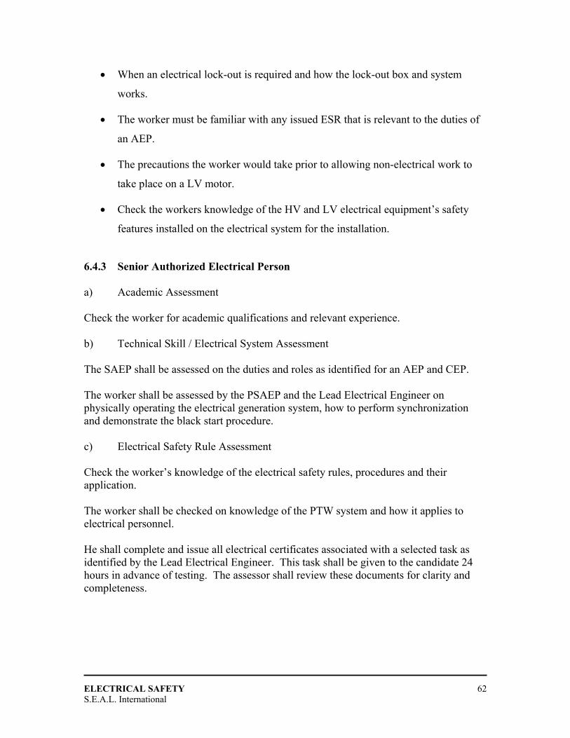
ELECTRICAL SAFETY
S.E.A.L. International 62
• When an electrical lock-out is required and how the lock-out box and system
works.
• The worker must be familiar with any issued ESR that is relevant to the duties of
an AEP.
• The precautions the worker would take prior to allowing non-electrical work to
take place on a LV motor.
• Check the workers knowledge of the HV and LV electrical equipment’s safety
features installed on the electrical system for the installation.
6.4.3 Senior Authorized Electrical Person a) Academic Assessment Check the worker for academic qualifications and relevant experience. b) Technical Skill / Electrical System Assessment The SAEP shall be assessed on the duties and roles as identified for an AEP and CEP. The worker shall be assessed by the PSAEP and the Lead Electrical Engineer on physically operating the electrical generation system, how to perform synchronization and demonstrate the black start procedure. c) Electrical Safety Rule Assessment Check the worker’s knowledge of the electrical safety rules, procedures and their application. The worker shall be checked on knowledge of the PTW system and how it applies to electrical personnel. He shall complete and issue all electrical certificates associated with a selected task as identified by the Lead Electrical Engineer. This task shall be given to the candidate 24 hours in advance of testing. The assessor shall review these documents for clarity and completeness.
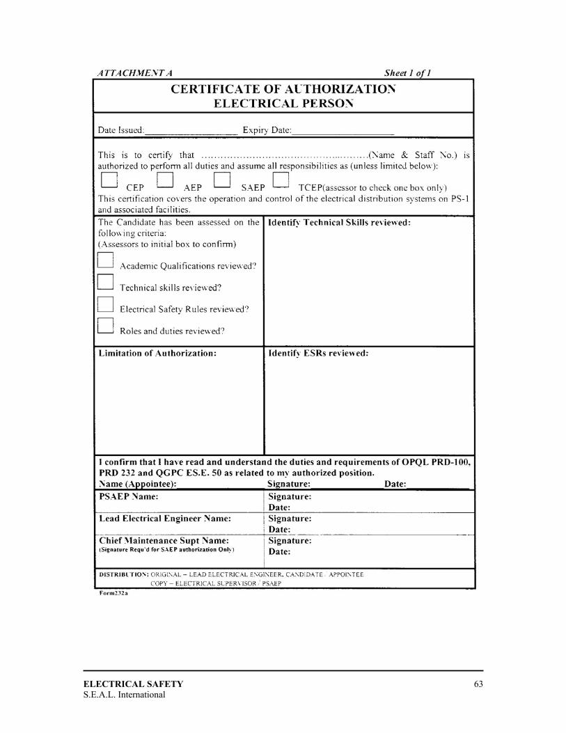
ELECTRICAL SAFETY
S.E.A.L. International 63

ELECTRICAL SAFETY
S.E.A.L. International 64
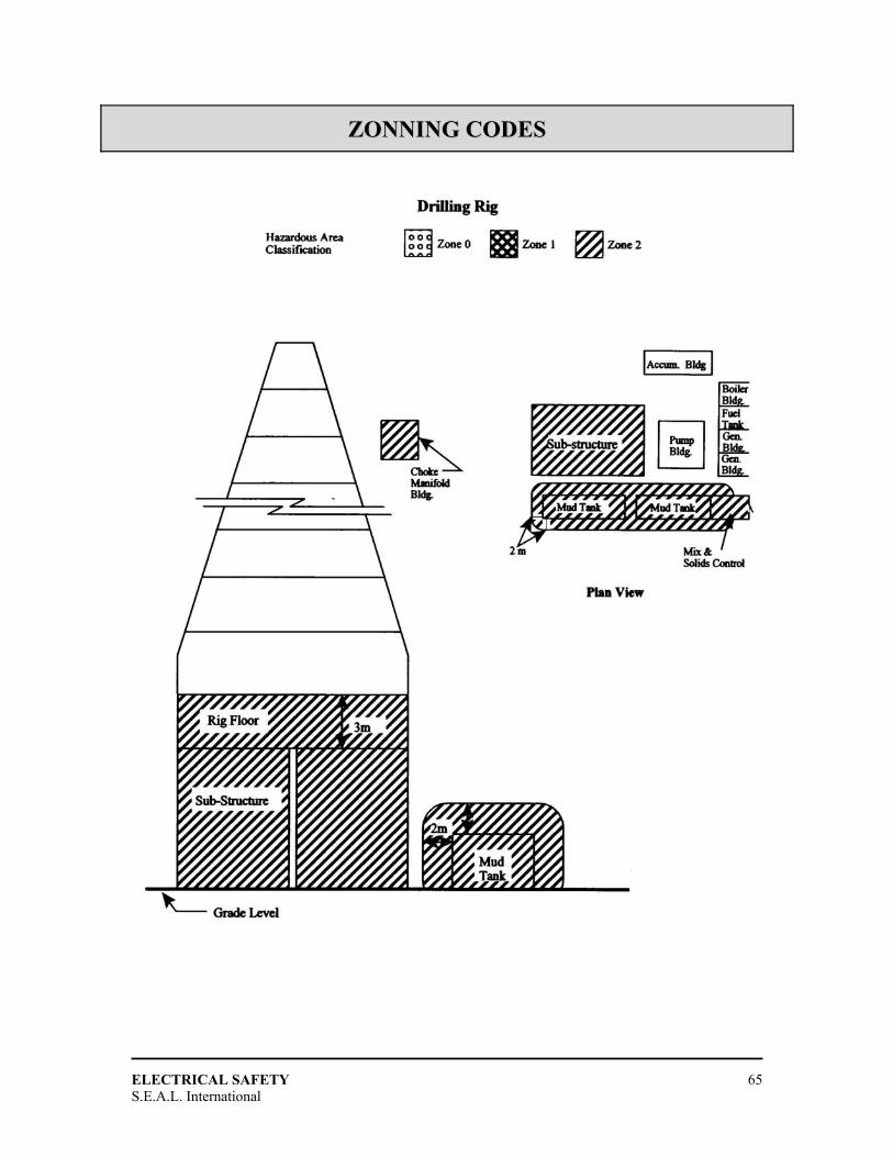
ELECTRICAL SAFETY
S.E.A.L. International 65
ZZOONNNNIINNGG CCOODDEESS
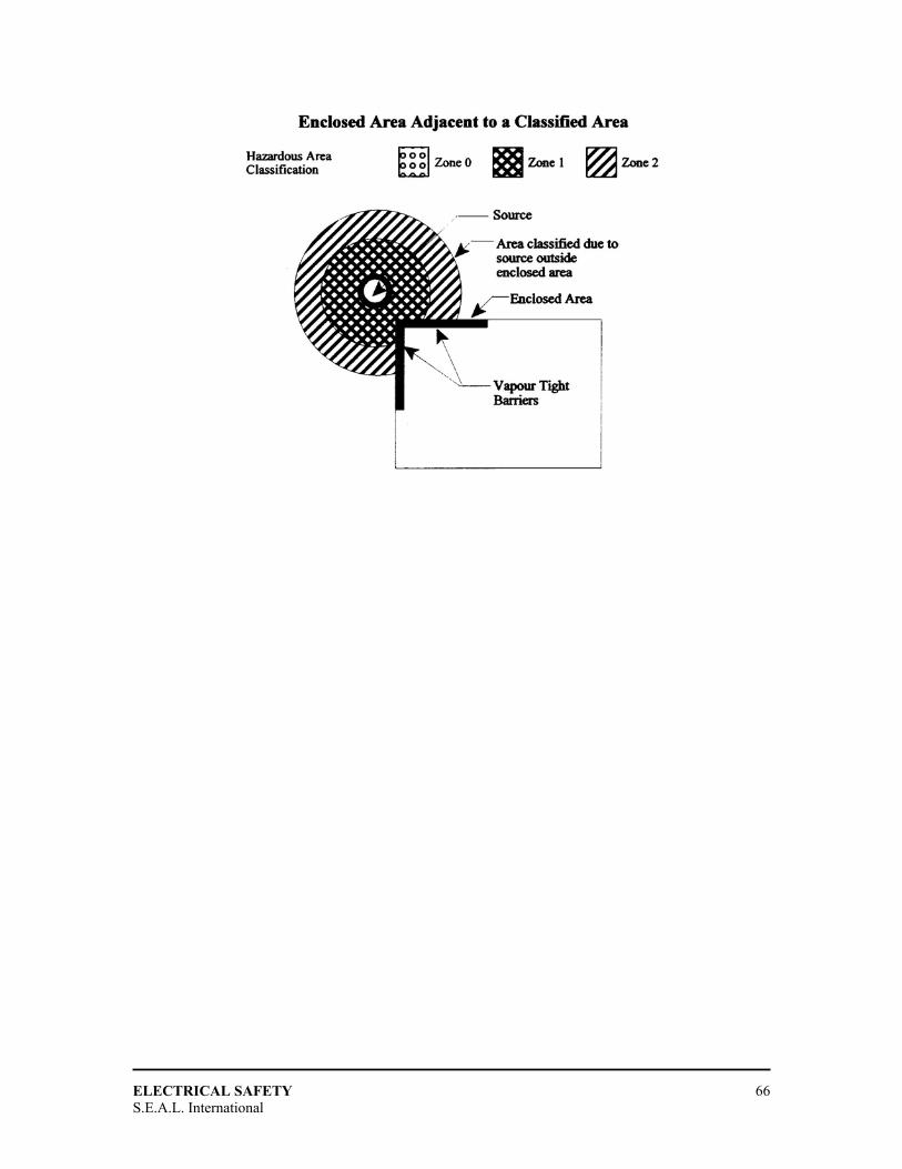
ELECTRICAL SAFETY
S.E.A.L. International 66
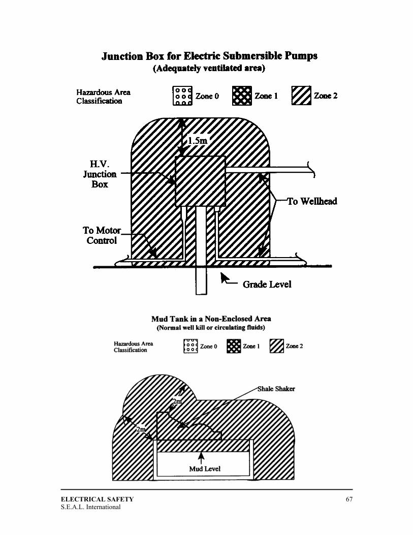
ELECTRICAL SAFETY
S.E.A.L. International 67
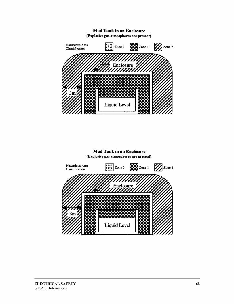
ELECTRICAL SAFETY
S.E.A.L. International 68
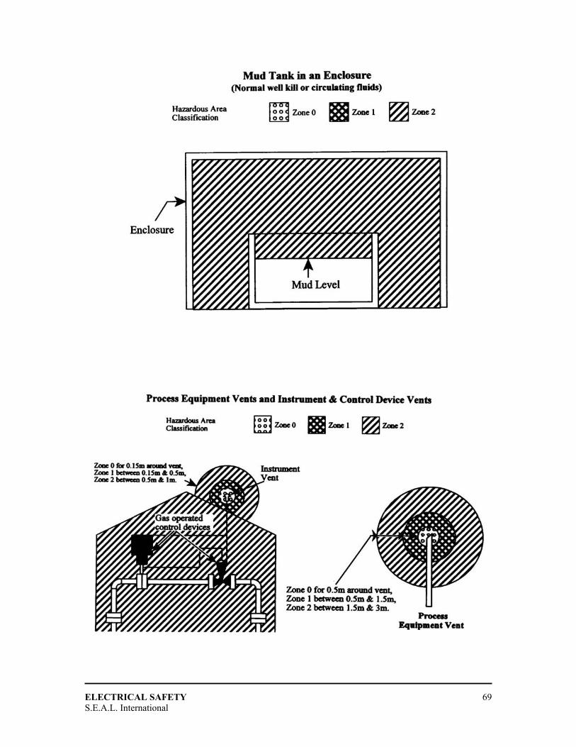
ELECTRICAL SAFETY
S.E.A.L. International 69
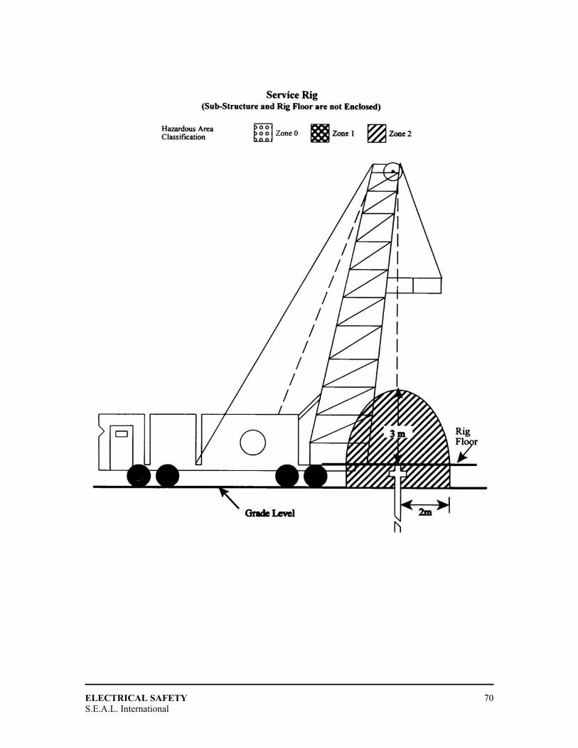
ELECTRICAL SAFETY
S.E.A.L. International 70

ELECTRICAL SAFETY
S.E.A.L. International 71

ELECTRICAL SAFETY
S.E.A.L. International 72
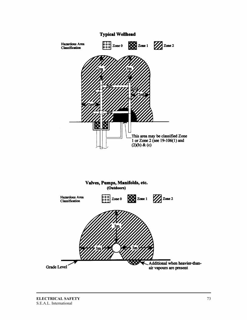
ELECTRICAL SAFETY
S.E.A.L. International 73

ELECTRICAL SAFETY
S.E.A.L. International 74


