Embed Size (px)
Citation preview

ELERING AS
SAFETY REGULATIONS REGARDING
OPERATION OF ELECTRICAL INSTALLATIONS
AND ELECTRICAL WORK SAFETY
Tallinn, 2020
3
ELERING AS
SAFETY REGULATIONS REGARDING
OPERATION OF ELECTRICAL INSTALLATIONS
AND ELECTRICAL WORK SAFETY
Tallinn, 2020

4
TABLE OF CONTENTS
TABLE OF CONTENTS ..................................................................................................................................... 4
1. PURPOSE AND SCOPE ............................................................................................................................ 6
2 FOUNDATIONAL DOCUMENTS USED .................................................................................................... 7
3 DEFINITIONS .......................................................................................................................................... 8
3.1 General definitions ........................................................................................................................ 8
3.2 Personnel, work organisation and communication ...................................................................... 9
3.3 Work zone ................................................................................................................................... 13
3.4 Work ............................................................................................................................................ 16
3.5 Protective devices ....................................................................................................................... 17
3.6 Rated (nominal) voltages ............................................................................................................ 18
4 FUNDAMENTAL PRINCIPLES ................................................................................................................ 19
4.1 Safety in operation ...................................................................................................................... 19
4.2 Requirements for personnel ....................................................................................................... 19
4.3 Organizing work .......................................................................................................................... 21
4.4 Communication (transmission of information) ........................................................................... 23
4.5 Work location .............................................................................................................................. 24
4.6 Tools, work equipment and instruments .................................................................................... 25
4.7 Personal protective equipment and their use ............................................................................ 25
4.8 Drawings and documentation ..................................................................................................... 26
4.9 Signs and notices ......................................................................................................................... 26
4.10 Conduct during emergencies ...................................................................................................... 27
5 OPERATIONAL PROCEDURES ............................................................................................................... 28
5.1 General requirements ................................................................................................................. 28
5.2 Switchings .................................................................................................................................... 28
5.3 Functional inspection procedures ............................................................................................... 29
6 WORK PROCEDURES............................................................................................................................ 32
6.1 General ........................................................................................................................................ 32
6.2 Dead work ................................................................................................................................... 35
6.3 Live work ..................................................................................................................................... 53
6.4 Work in the vicinity of energized parts ....................................................................................... 61
7 MAINTENANCE PROCEDURES ............................................................................................................. 65
7.1 General requirements ................................................................................................................. 65
7.2 Simpler maintenance work ......................................................................................................... 65
7.3 Work organization of personnel ................................................................................................. 68
7.4 Repair work ................................................................................................................................. 69
7.5 Replacement of fuses and lamps ................................................................................................ 69
7.6 Visual inspection ......................................................................................................................... 70
7.7 Temporary suspension of work ................................................................................................... 70
7.8 Completing maintenance work ................................................................................................... 70
8 WORKING IN THE PROTECTION ZONE OF THE ELECTRICAL INSTALLATION ........................................ 71
8.1 General requirements ................................................................................................................. 71

5
8.2 Applying for a permit to operate in the electrical installation protection zone ......................... 71
8.3 Organizing activities in the protection zone of an electrical installation .................................... 72
8.4 Cutting trees and brush in the protection zone of an electrical installation .............................. 72
9 ANNEXES ............................................................................................................................................. 74
10 LIST OF ABBREVIATIONS .................................................................................................................... 110
6
1. PURPOSE AND SCOPE
During the application of the Safety Regulations Regarding Operation of Electrical
Installations and Electrical Work Safety in force in Elering AS (approved on 15.06.2015), it
has become evident that the current safety regulations must be supplemented. The Safety
Regulations were updated in 2019.
The regulations instruct how to operate electrical installations in a manner which is safe for
personnel, ordinary persons, equipment and the surrounding environment.
These regulations apply to all operations performed when operating electrical installations
of Elering AS and working in or near electrical installations or in their immediate vicinity.
This includes installations operating at voltage levels from extra-low voltage to high voltage.
The term high voltage also includes those voltage levels which are commonly referred to as
medium voltage and extra-high voltage.
The aforementioned electrical installations are used for the generation, transmission,
conversion, distribution and usage of electrical energy. Some of these installations (e.g. at
construction sites) may be temporary.
These regulations prescribe the safety requirements for safe operation of and working on, at
or near electrical installations. These requirements apply to operational, work and
maintenance operations. The requirements also apply to all non-electrical work, such as
construction in the vicinity of overhead or cable lines, as well as electrical work in the
presence of electrical hazard.
The procedures stipulated in these regulations are mandatory for the employees of Elering
AS, as well as for the personnel of companies performing contractual work in the electrical
installations of Elering AS, both electrical and non-electrical work.
The best rules and operational requirements are only of use if people who operate electrical
installations and perform work on, at or in the vicinity of electrical installations are
thoroughly familiar with the requirements prescribed in these regulations as well as with all
other applicable safety requirements and comply strictly with them.
7
2 FOUNDATIONAL DOCUMENTS USED
2.1 EVS-EN 50110-1:2013 Operation of Electrical Installations
2.2 Occupational Health and Safety Act
2.3 Regulations implementing the Occupational Health and Safety Act
2.3.1 Procedure for Medical Examinations of Employees
2.3.2 Occupational Health and Safety Requirements for Construction Sites
2.3.3 Occupational Health and Safety Requirements for Workplaces
2.4 EVS-EN 50191:2010 Erection and Operation of Electrical Test Equipment
2.5 Fire Safety Act
2.6 Equipment Safety Act
2.7 Building Code
8
3 DEFINITIONS
The following definitions are used in these regulations. Terms not specified in these
regulations are included in the Electrotechnical Vocabulary of the International
Electrotechnical Commission IEC 60050 www.electropedia.org.
3.1 General definitions
3.1.1 Electrical device ( Elektriseade )
A piece of equipment designed for the production, conversion, transmission, distribution or
usage of electrical energy containing electrical or electronic components.
3.1.2 Electrical installation (Elektripaigaldis)
An electrical device or a collection of electrical devices designed for the generation,
transmission, conversion, distribution and usage of electrical energy. These also include
single cell and storage batteries, capacitors and all other sources of stored electrical energy.
The electrical installation is, e.g., an electrical power plant, electrical grid, distribution grid
area, substation, power transmission line, as well as a low voltage cabinet with outbound
feeders, electrical equipment of a production facility, electrical equipment of an office
building, etc.
3.1.3 Operation (Käit)
All activities, including work activities, necessary to enable the functioning of an electrical
installation. These include activities such as the switching, control, monitoring, inspection
and maintenance. These activities include both electrical and non-electrical work.
3.1.4 Operation plan of an electrical installation (Elektripaigaldise käidukava)
A document or set of documents specifying the order, procedures and activities required
for the continued functioning, switching, control and maintenance of the electrical
installation.
3.1.5 Safety plan (Ohutusplaan)
A written plan for the safe organizing of work in electrical installations.
3.1.6 Risk (Risk)
The probability and degree of possible injury or damage to health for a person exposed to
one or more hazards.
3.1.7 Electrical hazard (Elektriohtlikkus)
A situation of possible injury or damage to health arising due to the presence of electrical
energy in an electrical installation.
3.1.8 Electrical danger (Elektrioht)
Risk of injury (or trauma) of an electrical origin.
3.1.9 Electrical trauma (Elektritrauma)
9
Death or personal injury due to electrocution, electrical burn, electrical arcing, electrical fire
or explosion caused by any activity related to operation of an electrical installation.
3.1.10 Accident (Avarii)
An event caused by a technical fault of the electrical installation, natural forces or human
error, resulting in the loss of power to a significant portion of electricity consumers or
significant material damage or damage to the environment or a serious or fatal human
injury, or producing a significant risk of these being realized.
3.2 Personnel, work organisation and communication
3.2.1 Electrically skilled person (Elektrialaisik)
A person with sufficient education, knowledge and experience to enable them to analyse
risks and to avoid hazards related to electricity.
3.2.2 Instructed person (Ohuteadlik isik)
A person adequately instructed by electrically skilled persons to avoid hazards related to
electricity.
3.2.3 Ordinary person (Tavaisik)
A person who is neither an electrically skilled person nor an instructed person.
3.2.4 Contractor (Töövõtja)
A contract partner (legal entity) commissioned by Elering AS to perform work.
3.2.5 Maintenance Manager (Person in control of operation) (Käidukorraldaja)
A person assigned the general responsibility to ensure the safe operation of the electrical
installation by establishing appropriate regulations and general work organization. In
Elering AS, the Maintenance Manager maintenance manager is a person assigned by a
document by the head of the Grid Maintenance Department.
Pursuant to standard EVS-EN50110-1, the Maintenance Manager is the person responsible
for an electrical installation and pursuant to the Equipment Safety Act, a supervisor of use
of the equipment.
The Maintenance Manager is responsible for the safe operation of the electrical installation
during work operations (except at the work location).
It is the responsibility of the Maintenance Manager to decide how the work operations will
affect the electrical installation or a part thereof under their responsibility and how the
personnel performing the work are affected by the electrical installation. If required, some
of the duties arising from such responsibility can be delegated to other persons – e.g.,
issuing a permission to execute work to the Switching Manager for work performed based
on switching orders.
3.2.6 Electrical Work Manager (Elektritöö juht)
A person assigned the ultimate responsibility for a work operation at the work location.
Pursuant to standard EVS-EN50110-1, the Electrical Work Manager is a nominated person
in control of a work activity.
10
The Electrical Work Manager during switching operations is the Switching Operator.
3.2.7 Work Board (Töö juhatus)
The Maintenance Manager and the Electrical Work Manager of the Contractor form a Work
Board, which decides whether the work is to be performed as dead work, work in the
vicinity of energized parts, live work or as simpler maintenance work. The Work Board must
plan the work early in advance, determine the work scope and determine the measures to
be taken in order to perform the work safely.
3.2.8 Work Group Manager (Töörühma juht)
A person appointed by the Electrical Work Manager to perform the work. The Work Group
Manager is responsible for the safe performance of a specific task at the work location.
If necessary, the Electrical Work Manager may perform the tasks of the Work Group
Manager.
3.2.9 Work Executor (Töö tegija)
A person exclusively appointed by the Electrical Work Manager to directly perform the
work.
3.2.10 Work Supervisor (Töö jälgija)
A person responsible for the surveillance of electrical safety during work.
3.2.11 Switching Manager (Lülitamiste juhtija)
A person who conducts switching operations to modify the electrical state of the electrical
installation on equipment which is either energized, due to be serviced, or due to be
commissioned. In Elering AS, the Switching Manager is a dispatcher of the Energy System
Control Centre (hereinafter referred to as ESCC).
3.2.12 Switching Operator (Lülitaja)
A person directly performing the switching operations.
3.2.13 Work Group (Töö rühm)
A group of workers working at an electrical installation and consisting of two or more
workers. The Work Group Manager is a Work Group Member.
3.2.14 Work Group Member (Töörühma liige)
A person who participates in the work at the electrical installation as part of the Work
Group.
3.2.15 Notification, instruction (Teade, juhis)
A verbal or written message or instruction regarding the operation of an electrical
installation.
3.2.16 Operational log (Operatiivpäevik)
An electronic environment where significant events related to the management of the
energy system are recorded.
3.2.17 Outage order (Lülitamistaotlus)
11
A written request to modify the electrical state of electrical installations submitted to the
ESCC by the Maintenance manager By means of an outage order, the Maintenance
manager delegates the right to issue permissions to execute the work specified in the order
to the ESCC dispatcher.
The ESCC dispatcher prepares an outage order in case the customer wishes to perform
operations that require modifying the electrical state of the electrical equipment owned by
Elering AS.
In the case of emergency work, the ESCC dispatcher will, if necessary, prepare an outage
order based on the information received from the Maintenance Manager.
3.2.18 Maintenance order (Hooldustaotlus)
A written request submitted by the Maintenance Manager to the ESCC for the execution of
simpler maintenance work and work in the vicinity of energized parts.
In the case of this type of work, the Switching Manager does not perform switching
operations and the Electrical Work Manager receives the permission to perform the work
from the Maintenance Manager (Clause 7.2.3).
3.2.19 Switching order (Lülitamiskorraldus)
An instruction sent to the Switching Operator composed on the form of a switching order
detailing the modification of the electrical state of the electrical installation (switching
electrical equipment, isolation, verification of absence of voltage, earthing, short-circuiting,
marking the work location, etc.). A switching order is a permit to perform switching
operations.
3.2.20 Switching notification (Lülitamisteade)
A notification submitted after switching operations regarding the isolation, earthing, short-
circuiting and marking of work locations performed in the electrical installation as indicated
in the switching order form. The information contained in the notification is submitted by
the Switching Operator to the Switching Manager after the switching order has been
fulfilled. The switching notification is a message of the completion of the switching
operations.
3.2.21 Work operation (Töötoiming)
Any operation involving electrical or non-electrical work, which may involve electrical
danger.
3.2.22 Switchings (Lülitamised)
Switchings are operations intended to modify the electrical state of the electrical
installation. There are two types of switchings:
• For modification of the operational state of an electrical installation, to use equipment, to
switch on and off, to start and stop by means of equipment, the design of which assures
their risk-free operation as far as possible (no maintenance or repairs are performed);
• Switching off or on electrical equipment in conjunction with performing maintenance or
repairs in an electrical installation (Switching operation).
3.2.23 Switching operation (Lülitamistoiming)
12
A work operation intended to switch off or on electrical equipment in conjunction with
performing maintenance or repairs in an electrical installation.
An outage order or maintenance order is required to perform switching operations.
3.2.24 Permission to execute work (Töö sooritamisluba)
An unequivocal permission to execute the intended work. Only the Maintenance Manager
or Switching Manager may issue a permission to execute work (in the case of work to be
performed based on an outage order).
During switching operations, a switching order is considered a permission to execute work.
In the case of work performed on the basis of an outage order, this is the notice of the
isolation, earthing and short-circuiting operations in the electrical installation and marking
the work location, composed by an ESCC dispatcher on the form ANNEX 1B for the
Electrical Work Manager.
In the case of work performed on the basis of a maintenance order, including simpler
maintenance tasks, this is unequivocal permission to start work issued by the Maintenance
Manager in a verbal form or by any means enabling a written record (it may, but does not
have to be prepared on the form ANNEX 1B).
3.2.25 Energizing plan (Pingestamiskava)
An energizing plan is an accurate description of the sequence of switching and work
operations for energizing, measurement or testing of the electrical installation. The
energizing plan is a permission to execute work which includes both switching and work
operations. It is not necessary to formalize a permission to start work to fulfil the energizing
plan.
The preparation of the energizing plan is coordinated by the Maintenance Manager. The
Maintenance Manager is responsible for the safe execution of the energizing plan (general
coordinator). In the energizing plan a specific responsible person is appointed for every
work operation who is also the Electrical Work Manager for the work operation. The
energizing plan must be coordinated in advance in writing with all the responsible persons
listed in it and signed by the ESCC and Maintenance Manager. In the event of a situation
arising from the implementation of the energizing plan which makes it impossible to
continue fulfilling the energizing plan, the implementation of the energizing plan must be
suspended and the situation must be resolved separately. The implementation of the
energizing plan may be continued only after the previously occurred situation has been
resolved.
An energizing plan is submitted on the template provided in ANNEX 1C.
3.2.26 Permission to start work (Töö alustamisluba)
A direct instruction (task) composed on the basis of the form of the permission to start
work issued by the Electrical Work Manager to the Work Group Manager, Work Executor or
Work Supervisor to start work and to perform work safely after all safety measures have
been applied.
In case of simpler maintenance work, the permission to start work may also be verbal.
Only the Electrical Work Manager may issue the permission to start work.
13
If the Electrical Work Manager is also a Work Executor, then they do not need to formalize
the permission to start work for themselves. In this a case the permission to execute work
is considered to be the permission to start work.
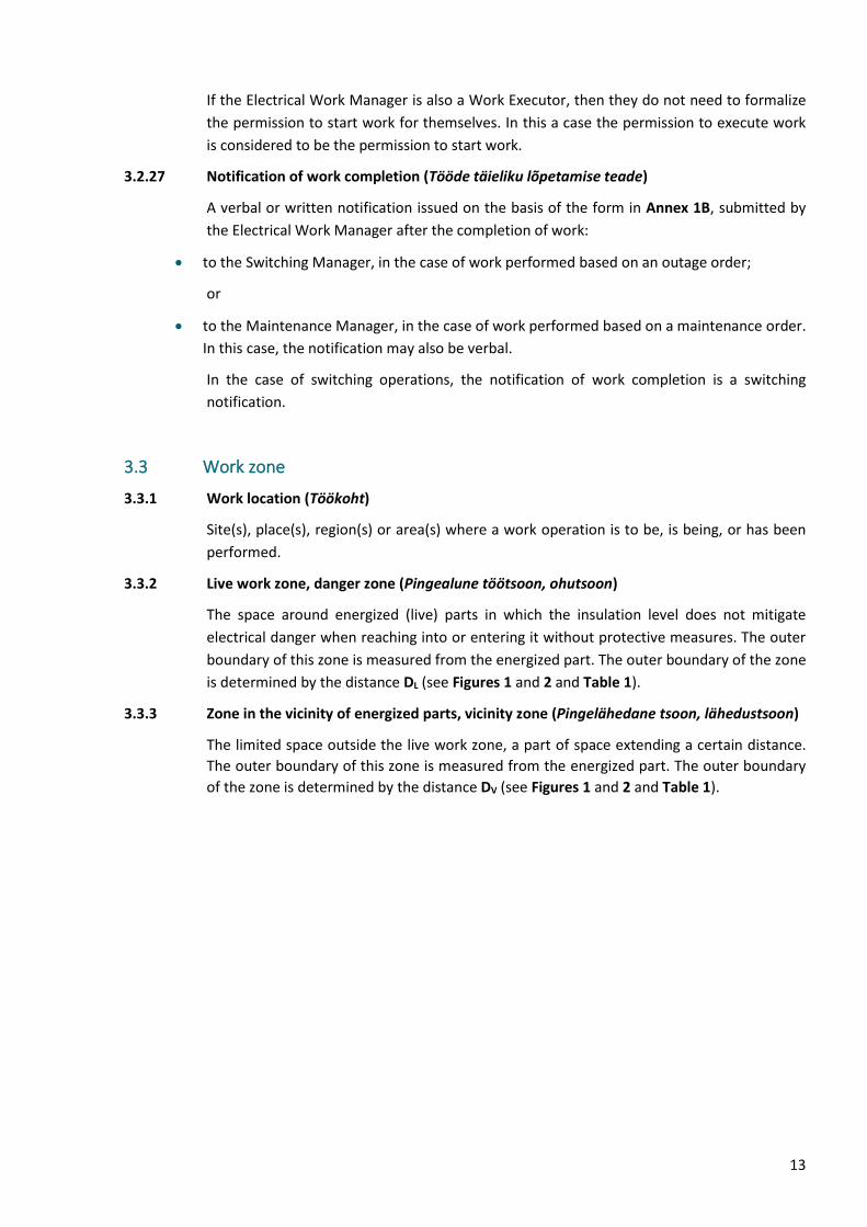
3.2.27 Notification of work completion (Tööde täieliku lõpetamise teade)
A verbal or written notification issued on the basis of the form in Annex 1B, submitted by
the Electrical Work Manager after the completion of work:
• to the Switching Manager, in the case of work performed based on an outage order;
or
• to the Maintenance Manager, in the case of work performed based on a maintenance order.
In this case, the notification may also be verbal.
In the case of switching operations, the notification of work completion is a switching
notification.
3.3 Work zone
3.3.1 Work location (Töökoht)
Site(s), place(s), region(s) or area(s) where a work operation is to be, is being, or has been
performed.
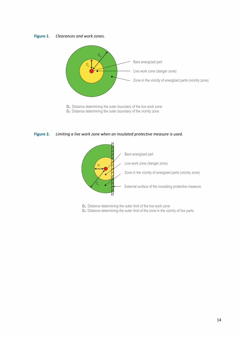
3.3.2 Live work zone, danger zone (Pingealune töötsoon, ohutsoon)
The space around energized (live) parts in which the insulation level does not mitigate
electrical danger when reaching into or entering it without protective measures. The outer
boundary of this zone is measured from the energized part. The outer boundary of the zone
is determined by the distance DL (see Figures 1 and 2 and Table 1).
3.3.3 Zone in the vicinity of energized parts, vicinity zone (Pingelähedane tsoon, lähedustsoon)
The limited space outside the live work zone, a part of space extending a certain distance.
The outer boundary of this zone is measured from the energized part. The outer boundary
of the zone is determined by the distance DV (see Figures 1 and 2 and Table 1).
14
Figure 1. Clearances and work zones.
Figure 2. Limiting a live work zone when an insulated protective measure is used.
Bare energized part
Live work zone (danger zone)
Zone in the vicinity of energized parts (vicinity zone)
DL: Distance determining the outer boundary of the live work zone Dv: Distance determining the outer boundary of the vicinity zone
Bare energized part
Live work zone (danger zone)
Zone in the vicinity of energized parts (vicinity zone)
External surface of the insulating protective measure
DL: Distance determining the outer limit of the live work zone Dv: Distance determining the outer limit of the zone in the vicinity of live parts.
15
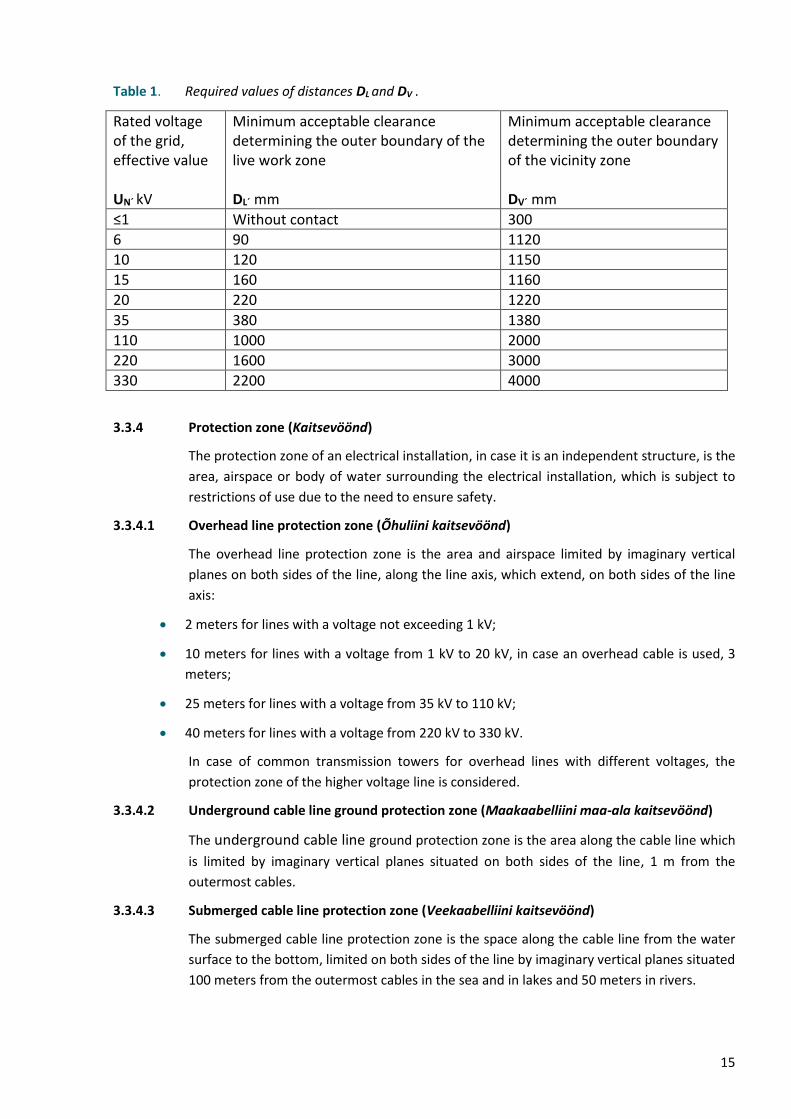
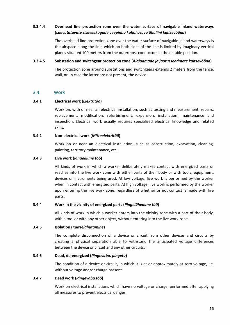
Table 1. Required values of distances DL and DV .
Rated voltage of the grid, effective value UN´ kV
Minimum acceptable clearance determining the outer boundary of the live work zone DL´ mm
Minimum acceptable clearance determining the outer boundary of the vicinity zone DV´ mm
≤1 Without contact 300
6 90 1120
10 120 1150
15 160 1160
20 220 1220
35 380 1380
110 1000 2000
220 1600 3000
330 2200 4000
3.3.4 Protection zone (Kaitsevöönd)
The protection zone of an electrical installation, in case it is an independent structure, is the
area, airspace or body of water surrounding the electrical installation, which is subject to
restrictions of use due to the need to ensure safety.
3.3.4.1 Overhead line protection zone (Õhuliini kaitsevöönd)
The overhead line protection zone is the area and airspace limited by imaginary vertical
planes on both sides of the line, along the line axis, which extend, on both sides of the line
axis:
• 2 meters for lines with a voltage not exceeding 1 kV;
• 10 meters for lines with a voltage from 1 kV to 20 kV, in case an overhead cable is used, 3
meters;
• 25 meters for lines with a voltage from 35 kV to 110 kV;
• 40 meters for lines with a voltage from 220 kV to 330 kV.
In case of common transmission towers for overhead lines with different voltages, the
protection zone of the higher voltage line is considered.
3.3.4.2 Underground cable line ground protection zone (Maakaabelliini maa-ala kaitsevöönd)
The underground cable line ground protection zone is the area along the cable line which
is limited by imaginary vertical planes situated on both sides of the line, 1 m from the
outermost cables.
3.3.4.3 Submerged cable line protection zone (Veekaabelliini kaitsevöönd)
The submerged cable line protection zone is the space along the cable line from the water
surface to the bottom, limited on both sides of the line by imaginary vertical planes situated
100 meters from the outermost cables in the sea and in lakes and 50 meters in rivers.
16
3.3.4.4 Overhead line protection zone over the water surface of navigable inland waterways
(Laevatatavate siseveekogude veepinna kohal asuva õhuliini kaitsevöönd)
The overhead line protection zone over the water surface of navigable inland waterways is
the airspace along the line, which on both sides of the line is limited by imaginary vertical
planes situated 100 meters from the outermost conductors in their stable position.
3.3.4.5 Substation and switchgear protection zone (Alajaamade ja jaotusseadmete kaitsevöönd)
The protection zone around substations and switchgears extends 2 meters from the fence,
wall, or, in case the latter are not present, the device.
3.4 Work
3.4.1 Electrical work (Elektritöö)
Work on, with or near an electrical installation, such as testing and measurement, repairs,
replacement, modification, refurbishment, expansion, installation, maintenance and
inspection. Electrical work usually requires specialized electrical knowledge and related
skills.
3.4.2 Non-electrical work (Mitteelektritöö)
Work on or near an electrical installation, such as construction, excavation, cleaning,
painting, territory maintenance, etc.
3.4.3 Live work (Pingealune töö)
All kinds of work in which a worker deliberately makes contact with energized parts or
reaches into the live work zone with either parts of their body or with tools, equipment,
devices or instruments being used. At low voltage, live work is performed by the worker
when in contact with energized parts. At high voltage, live work is performed by the worker
upon entering the live work zone, regardless of whether or not contact is made with live
parts.
3.4.4 Work in the vicinity of energized parts (Pingelähedane töö)
All kinds of work in which a worker enters into the vicinity zone with a part of their body,
with a tool or with any other object, without entering into the live work zone.
3.4.5 Isolation (Kaitselahutamine)
The complete disconnection of a device or circuit from other devices and circuits by
creating a physical separation able to withstand the anticipated voltage differences
between the device or circuit and any other circuits.
3.4.6 Dead, de-energized (Pingevaba, pingetu)
The condition of a device or circuit, in which it is at or approximately at zero voltage, i.e.
without voltage and/or charge present.
3.4.7 Dead work (Pingevaba töö)
Work on electrical installations which have no voltage or charge, performed after applying
all measures to prevent electrical danger.
17
3.4.8 Conductive part (Voolujuhtiv osa)
A conductor of electrical current or part thereof, which, in its normal operation, may be
live. Energized parts also include the neutral conductor, but not the PEN conductor.
3.5 Protective devices
3.5.1 [Protective] screen ([Kaitse]varje)
Any structure or device, insulated or not, used to prevent approach to any equipment or
installation which presents electrical danger.
3.5.2 [Protective] cover, [protective] boundary ([Kaitse]kate, [Kaitse]piire)
Any structure or part of it, which protects against direct contact from any normally
accessible direction. Solid walls, doors, grate or wire mesh boundaries with a height of at
least 1800 mm may be used as protective boundaries, which must ensure that no part of
the human body can reach the danger zone (zone in the vicinity of energized parts).
3.5.3 [Protective] barrier, ([Kaitse]tõke)
Any structure or part of it, which protects against accidental but not intentional direct
contact. Protective barriers may include e.g., covers, barrier gates, chains or ropes and
walls, doors, grates or wire mesh boundaries below 1800 mm in height, which, due to their
low height are not considered to be boundaries.
3.5.4 Insulating cover (Isoleerkate)
A rigid or flexible cover made of insulating material used to cover energized and/or de-
energized parts and/or adjacent parts in order to prevent accidental contact with these
parts.
3.5.5 Enclosure (Ümbris)
Any structure or part of it providing protection of equipment against certain external
influences and protection against direct contact from any direction.
3.5.6 Voltage detector (Pingeindikaator)
A portable instrument used to reliably detect the presence or absence of voltage and to
verify whether the installation is ready for earthing. These devices are generally of a
capacitive type or resistive type.
3.5.7 Portable equipment for earthing and short-circuiting (Kantav maandamis- ja
lühistamisseadis)
A portable device used to connect, with the help of insulating tools, to parts of an electrical
installation for the purposes of earthing and short-circuiting. This equipment includes
earthing components, short-circuiting components and one or more insulating
components, e.g., an earthing stick.
18
3.6 Rated (nominal) voltages
3.6.1 Extra-low voltage (Väikepinge)
A voltage range normally not exceeding 50 V alternating current (a.c.) or 120 V ripple-free
direct current (d.c.), whether between conductors or from conductor to earth. This includes
non-earthed and earthed protected extra-low voltage systems (SELV, PELV) and functional
extra-low voltage systems (FELV) (see European harmonisation document HD 384,4.41 S2,
section 411).
3.6.2 Low voltage (Madalpinge)
A voltage range normally not exceeding 1000 V a.c. or 1500 V d.c.
3.6.3 High voltage (Kõrgepinge)
A voltage range normally exceeding 1000 V a.c. or 1500 V d.c.
19
4 FUNDAMENTAL PRINCIPLES
4.1 Safety in operation
4.1.1 Before performing any operation on an electrical installation, an assessment of the electrical
risks will be conducted. This assessment will specify how the operation is to be performed
and which safety measures and precautions are to be implemented to ensure safety (if
necessary, a safety plan including annexes will be composed – see Annex 6).
4.1.2 The Work Board will decide on the need for and content of the safety plan when organizing
work.
4.1.3 A safety plan will be composed for the assembly/disassembly of overhead line conductors,
lightning guard wires and transmission towers and for other more complex types of work by
demand of the Maintenance Manager or when there is risk to the infrastructure or to
persons located next to or below the overhead line. The safety plan will include safety
measures to prevent the falling of the assembled/disassembled transmission tower,
conductor or guard wire to other technical structures, i.e. electrical or communication lines,
pipelines, roads or railways. The safety plan must include coordination arrangements with
the utilities operating these structures.
4.1.4 After performing the electrical work, the Contractor must verify on the basis of results from
measurements and tests, visual inspection and the documentation of the electrical device or
installation, that the electrical device, installation or electrical work performed complies
with the requirements prescribed in legislation and must confirm this compliance in written
form.
4.1.5 If the Contractor discovers that the electrical device or installation does not meet the
requirements prescribed in the legislation, the Contractor must inform this to the
Maintenance Manager.
4.2 Requirements for personnel
4.2.1 The accountability of persons for the safety of those engaged in a work operation and those
who are or may be harmed by the work operation is determined by the legislation of the
Republic of Estonia.
4.2.2 All personnel involved in a work operation on, with, or near an electrical installation must be
instructed about the safety requirements, safety regulations and company policies
applicable to their work, to an appropriate extent. These instructions will be repeated
during the course of work in case the work is long in duration or is complex. The personnel
involved in the work are obligated to comply with these requirements, regulations and
policies.
4.2.3 Instruction will be performed as follows:
• the Maintenance Manager instructs the Electrical Work Manager;
• the Electrical Work Manager instructs the Work Group Manager, Work Executor and Work
Supervisor;

20
• the Work Group Manager instructs the Work Group Members.
4.2.4 The clothing of the staff must be appropriate to the nature of the work and must have
adequate protective properties. If necessary, close-fitting clothing and additional personal
protective equipment must be used (see 4.7).
4.2.5 Before any work operation is started and during that work operation, the Electrical Work
Manager must ensure that all requirements, rules and instructions relevant to the particular
work are complied with.
4.2.6 The Electrical Work Manager must warn all personnel engaged in the work operation of all
reasonably foreseeable dangers that might not be immediately apparent to them.
4.2.7 No person will perform any work operation where technical knowledge or experience is
needed to prevent electrical danger or injury, unless that person has such technical
knowledge or experience, or is under the supervision of a person with sufficient
competence for the work undertaken.
4.2.8 Persons who are at least 18 years of age and whose competence and state of health
correspond to the work will be allowed to perform electrical work. Students and trainees in
the field of electricity who are at least 16 years of age may also be allowed to perform non-
independent work.
4.2.9 The health inspection of workers must be performed in accordance with the procedures
established in the Republic of Estonia.
4.2.10 The following criteria must be used in assessing the competence of personnel: knowledge of
electricity, experience of electrical work, comprehension of the installation to be worked on,
comprehension of the dangers which may arise during the work and the corresponding
precautions and the ability to decide at all times whether or not it is safe to continue
working.
4.2.11 Elering AS and the Contractor are responsible for the competency of their employees and
the rights assigned to them to work on electrical installations. The complexity of the work
will be assessed before the work starts, to enable the appropriate selection of electrically
skilled, instructed, or ordinary persons to perform the work.
4.2.12 The granting of the rights of a Switching Operator to employees will be in accordance with
the procedure established by Elering AS after the following conditions are fulfilled:
• completion of a training course for the high voltage equipment Switching Operator, or an
equivalent competence;
• a confirmation by the employer of the employee's competence;
• theoretical and practical instruction by Elering AS;
• traineeship for 3 months with a person possessing switching rights.
4.2.13 The granting of individual visual inspection rights to Elering AS personnel will be performed
in accordance with the procedure established by Elering AS after successfully passing an
examination.
4.2.14 The Contractor must communicate to Elering the lists of the Electrical Work Managers,
Work Group Managers and Switching Operators, confirming thereby the required
21
competence of the respective persons and the validity of the rights granted to them. Elering
maintains the right to participate in the examination board for the rights granted by the
Contractor to persons.
4.2.15 Visiting an electrical installation with restricted access
Visits to electrical installations with restricted access will be managed by the Maintenance
Manager.
4.3 Organizing work
4.3.1 Each electrical installation must be under the responsibility of a specified person.
Under normal circumstances, this person is the Maintenance Manager.
During switching operations, this person is the Switching Manager (ESCC dispatcher). During
work operations (except switching operations), this person is the Electrical Work Manager in
the part of the electrical installation included in their work scope.
4.3.2 At Elering, the persons responsible for electrical installations are the Maintenance Managers
according to the list of electrical installations approved by the head of the Grid Maintenance
Department. The ESCC dispatcher is responsible for organizing switching operations.
4.3.3 The duties of the Maintenance Manager and the Electrical Work Manager may be combined
in a single person.
4.3.4 Where two or more electrical installations are joined together (e.g. located on a common
territory), it is essential that consultations and cooperation are conducted between the
persons responsible for all such electrical installations to ensure safety.
4.3.5 Access to all places where ordinary persons might be exposed to electrical hazards must be
restricted. The method of restriction and management of access is the responsibility of the
Maintenance Manager and will comply with the legislation and regulations of the Republic
of Estonia.
4.3.6 Each work operation is the responsibility of the Electrical Work Manager. Where the work
operation is subdivided, it may be appropriate to assign a person responsible for the safety
of each subdivision, all under the responsibility and coordination of one person.
4.3.7 Prior to any rearrangements in the electrical installation operation or prior to starting work,
the Electrical Work Manager (accountable person of the Contractor) and the Maintenance
Manager will agree upon which rearrangements are necessary in the operation of the
electrical installation in order to perform the work and which operations are within the
scope of the work to be performed on, at or near the electrical installation.
4.3.8 In case the work operation is complex, the work agenda will be composed in written form.
4.3.9 The Maintenance Manager must provide the Electrical Work Manager information about
the electrical installation scheme, the specific nature of the electrical equipment, the
procedure and risks of entering the electrical installation and the means of avoiding them.
Instruction must be formalized in written form.
4.3.10 If the Contractor performing the work directly commissions part of the work via
subcontracting, the Contractor must take the necessary precautions to ensure the safety of
22
the workers of the subcontractor and arrange instruction. The Contractor must also inform
the Maintenance Manager about the subcontractors.
4.3.11 If employees of at least two distinct employers are working at the work location
simultaneously and there is no employer to organize work, the employers will enter into a
written agreement on joint activity regarding occupational health and safety and the liability
of the employers. If no agreement has been concluded, the employers will be liable for
damage, if it occurs, jointly and severally.
4.3.12 There must be arrangements in place at the work location such that any worker who
expresses suspicions regarding the safety of any order or work operation can submit their
objections immediately to the Electrical Work Manager. The Electrical Work Manager must
consider the objections and, if necessary, consult the Maintenance Manager (Work Board)
prior to reaching a conclusion.
4.3.13 In the case of switching operations performed on the devices of the electrical installation to
be maintained, the Switching Manager will ensure the following:
• the instructions given by them enable the switching operations to be performed safely (the
correct sequence of individual operations is assured),
• the operations are coordinated with other Switching Managers, as appropriate,
• the issued switching order is correct.
4.3.14 The Maintenance Manager must ensure the following:
• the electrical installations, for which they are responsible, are operated in accordance with
electrical safety requirements,
• for the electrical installation, which they are responsible for, an operation plan has been
prepared and it is complied with,
• in the event of risk to a person, property or the environment, the use and operation of the
electrical installation as well as work on the electrical installation is stopped until the
danger passes or is eliminated,
• electrical devices and installations which do not meet electrical safety requirements are not
used,
• valid documentation regarding the electrical installation is available.
4.3.15 The Electrical Work Manager must ensure the following:
• during work operations, the requirements prescribed in these regulations and in legislation
are complied with,
• the work operations are performed by persons with sufficient relevant professional
qualifications,
• persons performing work operations are adequately instructed prior to performing their
tasks for the proper completion of their tasks and informed of all the dangers present at
the work location and are instructed on how to avoid them,
23
• the measures related to emergency rescue operations and provision of first aid and
employees responsible for these are announced,
• the persons performing the work have at their disposal the required documentation and
the means necessary to perform work safely,
• the adequacy, suitability and availability of the equipment, tools and instruments at the
work location is assured,
• the required documentation is prepared and submitted in due time (if necessary, a safety
plan including annexes),
• the electrical device or installation is safe to use or perform work on after electrical work
has been performed with or on it.
4.3.16 The Work Group Manager must instruct the Work Group Members, including of any risks
not immediately observable, and ensure that all requirements, regulations and instructions
related to the work are complied with both before and during the work. The Work Group
Manager must organize the work in a manner that they can monitor the Work Group
Members, by being, as much as possible, at the location where the most dangerous work is
performed.
4.3.17 The Switching Operator must ensure the following:
• the instructions received from the Switching Manager are executed in a precise manner. In
the event of any danger (including any non-compliance of the position of any switching
device with the switching order), the Switching Operator will immediately inform the
Switching Manager thereof,
• all switching devices that have been used to isolate the electrical installation for a work
operation are secured against re-switching,
• the work location marking corresponds to the work to be performed.
4.3.18 A Work Group Member must follow the instructions of the Work Group Manager and the
requirements of safety instructions before, during and after completion of work.
4.3.19 The Work Supervisor must ensure the electrical safety of the work performed on the
electrical installation or in its protection zone. The need to appoint a Work Supervisor is
decided by the Electrical Work Manager or the Maintenance Manager.
4.3.20 When working alone, a Work Executor must comply with the instructions of the person who
issued the order and the requirements of the safety instructions before, during and upon
finishing work.
4.4 Communication (transmission of information)
4.4.1 Communication includes every possible way in which information is transmitted or
exchanged, i.e. by spoken word (including stationary and mobile telephone, personal radio,
directly from person to person, etc.), in writing (including, e.g., fax or e-mail) and visually
(including display units, warning panels, signal lights, etc.).
24
4.4.2 All information necessary for working safely, such as electric grid arrangement, the status of
switching equipment (on, off, earthed) and the positions of safety devices, must be
transmitted as a proper notification or instruction.
4.4.3 Where it is suitable to use other means of transmitting information, e.g., radio signals,
computers, signal lights, etc., such means may only be used when it is ensured that the
information transmission channel is reliable and that misunderstandings or false signal
transmissions are precluded.
4.4.4 All notifications or instructions must include the name and, if necessary, data on the
location of the person providing the information, e.g., phone or e-mail.
4.4.5 To preclude errors when information is transmitted verbally, the recipient must repeat the
information back to the informer, who must confirm it has been correctly received and
comprehended.
4.4.6 It is not permitted to relay a permission to execute work, permission to start work,
switching order or permission to re-energize an electrical installation by means of signals or
agreed time.
4.4.7 In case the personnel at the work location speaks different languages, the language that all
relevant parties understand must be agreed upon in advance, to ensure mutual
understanding.
4.4.8 All communication with the Switching Manager in the territory of the Republic of Estonia is
in Estonian.
4.4.9 It is prohibited to switch the equipment in an electrical installation, which is energized, to be
serviced and to start operation without the permission of the Switching Manager, except in
case it is performed to save human lives, to prevent injury or to prevent damage to
equipment. In these cases, the switching operations performed will be relayed to the
Switching Manager at the first possible opportunity.
4.4.10 It is prohibited to perform switchings or work based on incomprehensible information.
4.5 Work location
4.5.1 Every work location must be clearly defined and marked. Adequate working space, means
of access and lighting must be provided in all parts of an electrical installation, at or near
them, where any work operation is to be performed. If necessary, a safe access route to the
work location must be clearly marked.
4.5.2 Suitable precautions must be taken to prevent injury from other sources of danger present
at the work location, such as mechanical or pressurized systems or probability of falling
from an elevated place.
4.5.3 Objects which impede access and flammable materials will not be placed adjacent to, in or
on access routes, exit routes to and from electrical switchgear and control gear or in the
areas from where equipment is operated. Flammable materials stored next to or adjacent
to electrical installations must be kept separate from all possible sources of ignition.
25
4.6 Tools, work equipment and instruments
4.6.1 Work equipment includes personal protective equipment.
4.6.2 Tools, work equipment and instruments must comply with the requirements of relevant
Estonian, European and/or international standards, if these exist. Tools, work equipment
and instruments include the following:
• personal protective equipment (insulating footwear, gloves, overshoes; eye and face
protection; protective helmet or other protective headwear; suitable protective clothing
according to the circumstances) according to Clause 4.7,
• insulating mats, bases, platforms and stands;
• insulating flexible and rigid screens;
• insulated tools (from insulating material, as well as featuring an insulating cover material)
and insulating tools;
• operating poles and rods;
• safety locks, notices and signs;
• voltage detectors and voltage indication systems;
• cable locators;
• earthing and short-circuiting equipment;
• barriers, flags and portable warning signs.
4.6.3 Tools, work equipment and instruments must be used in accordance with the instructions
provided by the manufacturer or supplier. These instructions must be in Estonian, also in
other languages, if necessary.
4.6.4 Any tools, equipment or instruments provided for the purpose of safe operation of, or work
on, with, or near electrical installations must be suitable for that application, be maintained
in a condition suitable for use, and be used accordingly.
4.6.5 Maintaining in a condition suitable for use implies periodic visual inspections and electrical
testing, if necessary, including after repairs and/or modification to verify the electrical
integrity and mechanical properties of the tools, work equipment and instruments.
4.6.6 All special purpose tools, work equipment and instruments used during operation of or work
on, with, or near an electrical installation must be properly stored.
4.6.7 The Electrical Work Manager is responsible for the sufficient quantity, suitability and
maintenance of the tools, work equipment and instruments used at the work location.
4.7 Personal protective equipment and their use
4.7.1 Depending on the nature of the work, suitable protective clothing must be used.
4.7.2 The following personal protective equipment is required for performing work:
• a helmet with the name and/or logo of the Contractor's company or a safety hat in case the
nature of the work permits it;
26
• high visibility clothing (reflective vest or jacket or other high visibility marking along with the
name and/or logo of the Contractor's company);
• safety footwear;
• other personal protective equipment for performing special work corresponding to the
nature and risk assessment of the work (such as hearing protection, safety glasses,
protective harness, fire resistant clothing, etc.).
4.7.3 Exemptions in the use of personal protective equipment.
• The use of personal protective equipment is not mandatory at parts of the electrical
installation marked accordingly.
• When performing visual inspection in an open-access area (i.e. overhead line protection
zone), it is not mandatory to wear a helmet.
• When performing visual inspection in the territories of substations if no other work is being
performed at the same time in the electrical installation, it is not mandatory to wear safety
footwear.
• In the control rooms of the substations, it is not mandatory to wear safety footwear when
performing visual inspection and cleaning the premises, unless other work is performed
there simultaneously.
• In the control rooms of substations, wearing a helmet is not mandatory if the nature of the
work performed does not require it (e.g., installation and adjustment of relay switches and
automation systems, visual inspection, cleaning of premises).
4.7.4 Persons present in the rooms of electrical installations (excluding control panel, relay and
similar rooms), at indoor and outdoor switchgear, wells, compartments, tunnels,
construction sites and repair zones or working on electric overhead lines must wear a
protective helmet and high visibility clothing.
4.8 Drawings and documentation
4.8.1 Up-to-date and contemporary drawings, records and documentation regarding the electrical
installation must be available.
4.8.2 The Switching Manager is prohibited from performing switching in case they do not possess
valid circuit diagrams.
4.9 Signs and notices
4.9.1 When necessary, during any work or operations, adequate signs and/or notices must be
displayed to draw attention to possible hazards.
4.9.2 When operating electrical installations and in electrical installations, at or near these, the
requirements prescribed in ANNEX 11 must be followed.
27
4.10 Conduct during emergencies
4.10.1 The Electrical Work Manager or Work Group Manager will inform the ESCC dispatcher,
Maintenance Manager and their direct superior about all emergencies, work accidents and
incidents occurring in the electrical installation during work.
4.10.2 The incidents occurred performing work related to the operation of electrical installations,
which could have resulted in an accident (accident hazards) must be documented in
accordance with Annex 9 and those which did result in an accident, must be documented in
accordance with Annex 10. If possible, photographs are to be taken of the circumstances of
the incident. This applies to work performed both during and outside normal working hours.
4.10.3 Employees of a third party must additionally comply with the requirements of their own
company's notification system.
4.10.4 It is necessary to ensure that the diagrams of the electrical installation are both available
and correct.
4.10.5 In the event of a fatal accident, the Maintenance Manager, ESCC dispatcher and the direct
superior must be informed immediately. The site of the accident must be maintained
unaltered, unless it may cause further danger to employees from any company or other
persons.
4.10.6 Emergency measures may include the use of servicing personnel responsible for performing
the necessary operations to ensure the electrical safety of the accident site and to keep
third party personnel from entering the danger zone during rescue work, prior to
restoration of a state which ensures electrical safety.
4.10.7 Following an accident, the Work Group Manager must take appropriate action to ensure
safety at and around the accident site, as far as possible, to prevent further damage. This is
also necessary to investigate the causes of the accident and the nature and extent of
damage, which may be performed by their own personnel or in exceptional cases by
external investigation organisations (e.g., police).
4.10.8 Appropriate protective, first aid and fire extinguishing equipment must be provisioned.
28
5 OPERATIONAL PROCEDURES
5.1 General requirements
5.1.1 In order to avoid electrical danger to persons, suitable tools and devices must be used for
switching and operational checks. These activities must be subject to agreement with the
Maintenance Manager, or, if necessary, in case of work performed on the basis of an outage
order, with the Switching Manager.
5.1.2 The Maintenance Manager, or if necessary, in case of work performed on the basis of an
outage order, the Switching Manager, must be informed when the agreed upon operational
procedures are being initiated and when these have been completed.
5.2 Switchings
5.2.1 Switchings are an operation intended to modify the electrical state of the electrical
installation. There are two types of switchings:
• For modification of the operational state of an electrical installation, to switch on and off,
to start and stop by means of equipment, the design of which assures their risk-free
operation as far as possible (no maintenance or repairs are performed);
• Switching off or on electrical devices in conjunction with performing maintenance or repairs
in an electrical installation (switching operation).
5.2.2 Switchings may be performed locally or using remote control.
5.2.3 Switching off prior to or switching on after dead work may only be performed by electrically
skilled or instructed persons as prescribed in the regulations regarding dead work (Clause
6.2).
5.2.4 When switching high voltage disconnectors with a manually operated actuating system,
switch-disconnectors and load disconnecting switches off and on, insulating gloves must be
worn. When transferring the factory-built carriage assemblies to the control position or
operating position, insulating gloves must also be worn.
5.2.5 If an earth fault is not disconnected at an electrical installation, measures must be taken
immediately to locate the earth fault and adequate safety measures must be taken for the
protection and safety of personnel. An earth fault location must not be approached to a
proximity closer than 4 m in an indoor installation and 8 m in an outdoor installation. It is
permitted to approach the earth fault location beyond the aforementioned distances only
for switchings and rescuing a person under voltage, using equipment appropriate to the
circumstances.
5.2.6 In an emergency situation, the power supply of the equipment must be switched off
immediately, without prior authorisation. In electrical distribution installations, only
electrically skilled persons or instructed persons are allowed to perform switchings in an
emergency situation.
29
5.3 Functional inspection procedures
5.3.1 Measurement
5.3.1.1 In these regulations, measurement encompasses all activities related to measuring physical
parameters in electrical installations. Only electrically skilled or instructed persons or
ordinary persons under the immediate management and supervision of an electrically
skilled person may perform measurements.
5.3.1.2 When performing measurements in electrical installations, suitable and safe measuring
instruments must be used. These instruments must be checked before use and, if necessary,
after use.
5.3.1.3 In case there is a risk of contact with bare energized parts, the personnel performing the
measurements must use personal protective equipment and take precautions against
electric shock and the effects of short circuits and electric arcing.
5.3.1.4 If necessary, the regulations regarding dead work, live work or work in the vicinity of
energized parts are followed.
5.3.2 Testing
5.3.2.1 Testing includes all operations specified to check the operation or the electrical, mechanical
or thermal condition of an electrical installation. Testing also includes operations to verify
the effectiveness of, e.g., electrical protective and safety circuits. Testing may include
measurement, which must be performed in compliance with Clause 5.3.1.
5.3.2.2 Testing may be performed by electrically skilled or instructed persons, or ordinary persons
under the exclusive immediate management and supervision of an electrically skilled
person.
5.3.2.3 Testing in installations which have been de-energized must be performed in compliance
with the regulations regarding dead work. If it is necessary to disconnect earthing and short-
circuiting devices, suitable precautions must be taken to prevent the installation being
accidentally re-energized from any possible source of supply, and to prevent electric shock
to the personnel.
5.3.2.4 When testing under normal supply conditions, the relevant requirements regarding live
work, work in the vicinity of energized parts and dead work must be complied with.
5.3.2.5 When testing using an external source of supply, precautions must be taken to ensure that:
• the installation is isolated from any possible normal source of supply,
• the installation cannot be re-energized by any other source of supply other than the
dedicated external source of supply,
• safety measures against electrical hazards are applied during the tests to protect all
personnel present,
• at the time of testing, any other work on electrical equipment which is powered by the
external power supply is precluded,
30
• the points of disconnection and isolation have adequate insulation characteristics to
withstand simultaneous application of the test voltage on one side with operating voltage
on the other side.
5.3.2.6 Some specialized forms of electrical tests may be performed by electrically skilled persons
who have received appropriate specialized training. Additional protective precautions based
on standard EN 50191 must be implemented as necessary.
5.3.2.7 As a specific type of testing (special testing), a distinction is made to the withstand testing of
electrical devices, installations or parts thereof, which is defined as verification of their
ability to withstand any physical effect, e.g., voltage exceeding the operating voltage (proof
voltage). Testing is performed, e.g., in high voltage laboratories containing exposed
energized parts, where there is a possibility of contact.
5.3.3 Performing measurement operations and tests on electrical equipment
5.3.3.1 For the purpose of performing measurements and testing on electrical equipment, an
outage order is submitted by the Maintenance Manager, indicating the electrical device on
which measurements or tests will be performed.
5.3.3.2 In the case of an outage order for measurement and testing, all operations (switching,
equipment earthing, initiation of measurements (testing) according to the energizing plan
(see Annex 1C) and the formalizing of the notification of work completion) are executed
exclusively according to the energizing plan.
5.3.3.3 For the purposes of measurement operations and tests on electrical equipment, an
energizing plan will be composed and signed by the Maintenance Managers under whose
responsibility the electrical equipment involved in the operations is, and the plan will be
verified by ESCC accountable persons, approving it with their signature.
5.3.4 Technical inspection
5.3.4.1 The purpose of technical inspection is to ascertain whether an electrical installation is in
accordance with safety regulations and the specified technical requirements of the relevant
standards. The technical inspection may include verification of the normal state of the
installation.
5.3.4.2 New electrical installations, as well as modifications and extensions to existing installations
must be inspected prior to their commencement into operation.
5.3.4.3 Electrical installations must be inspected at suitable intervals. The purpose of periodic
inspections is to detect defects that may occur after commissioning and may impede
operation or generate hazards.
5.3.4.4 The technical inspection may include:
• visual inspection,
• measurement and/or testing in accordance with the provisions of Clause 5.3.
5.3.4.5 Technical inspection must be performed with reference to relevant electrical drawings and
technical specifications.

31
5.3.4.6 Defects which constitute immediate danger must be eliminated without delay, or
equipment containing such deficiencies must be disconnected without delay and secured
against unwanted reconnection.
5.3.4.7 Technical inspection may be performed by electrically skilled persons with experience in the
inspection of such types of installations.
5.3.4.8 Inspections must be performed with suitable tools and equipment in a manner which
precludes danger from exposed energized parts (in case these are present).
5.3.4.9 The results of a technical inspection must be recorded. Suitable corresponding remedial
measures must be applied if deficiencies are detected.
32
6 WORK PROCEDURES
6.1 General
6.1.1 General requirements
6.1.1.1 Prior to initiating any work, the nature of the work (electrical or non-electrical) must be
identified, a risk assessment performed, if necessary, a safety plan (see Annex 6) composed,
and the relevant protective measures applied.
6.1.1.2 Only the Maintenance Manager or Switching Manager (in case of work to be performed
based on an outage order) may grant the permission to execute work.
6.1.1.3 Electrical work may be one of three distinct types: dead work (see 6.2), live work (see 6.3) or
work in the vicinity of energized parts (see 6.4). All of these are based on the use of
protective measures against electric shock, the effects of short-circuits and electric arcing.
6.1.1.4 If the requirements of Clause 6.2 (dead work) or 6.4 (work in the vicinity of energized parts)
cannot be fulfilled, then the requirements of Clause 6.3 (live work) must be followed.
6.1.1.5 A sufficient level of insulation for working must be ensured by, e.g., applying solid protective
insulating accessories or maintaining sufficient clearance (see 6.3 and 6.4). Instructions
regarding the minimum acceptable clearances are provided in Table 1 (see 3.3).
6.1.1.6 The Maintenance Manager, in cooperation with the Electrical Work Manager, must submit
an outage order to the Energy System Control Centre indicating the purpose, location, time
and planned alterations to the electrical installation related to the proposed work, also the
name of the Electrical Work Manager and the scope of the isolations and earthing
operations required to perform the work safely and the list of equipment to be repaired and
removed from service. In case of complex operations and upon energizing new electrical
installations, an application must be submitted, if necessary, in conjunction with diagrams
and the exact sequence of the work operations (energizing plan).
6.1.2 Special requirements regarding induction
6.1.2.1 Conductors or conductive parts in the proximity of energized conductors may develop an
induced voltage. In addition to the following requirements regarding dead work and work in
the vicinity of energized parts, special precautions must be implemented when working on
electrical power lines affected by induction:
• earthing at adequately small intervals in order to reduce the potential difference between
conductors and earth to a safe level;
• equipotential bonding at the work location in order to avoid the possibility of workers being
influenced by an induction loop.
6.1.2.2 A line affected by induction is an overhead power line located in its full length or as
individual sections (total length of sections at least 2 km) on common transmission towers
with another 110 kV or higher voltage overhead line, or closer to its axis than:
• 100 m – for a 110 kV overhead line,
• 150 m – for a 220 kV overhead line,
33
• 200 m – for a 330 kV overhead line.
6.1.3 Special requirements regarding weather conditions
6.1.3.1 Restrictions on commencing and/or continuing work must be applied in the event of
adverse environmental conditions e.g. lightning, heavy rain, fog, and high wind speeds.
6.1.3.2 When lightning is seen, thunder is heard or in the event of detection of an approaching
lightning storm, work on conductive parts of electrical installations or equipment directly
connected to these must cease immediately to prevent danger and the person having issued
the permission to execute work (Maintenance Manager or Switching Manager) is to be
notified.
6.1.3.3 When there is poor visibility at the work location, no work operations may be started, any
work operation in progress must be temporarily suspended and the work location made
safe.
6.1.3.4 During the dark hours of the day (or night), the work sections, work locations, accesses and
passages must be illuminated. The illumination must be uniform. The lights may not dazzle
the workers.
6.1.4 Fire safety and fire fighting
6.1.4.1 During the operation of electrical installations, the possibility of fire cannot be dismissed. In
case fire breaks out, dangerous or endangered parts of the electrical installation must be
switched off, unless required to be energized for fire fighting or in case switching off might
cause other dangers.
As long as the auxiliary voltage is not completely switched-off in the burning part of the
installation, a fire extinguishing permit must not be issued or fire extinguishing must be
performed solely using CO2 extinguishers.
6.1.4.2 To fight fires in electrical installations, fire extinguishers and fire extinguishing equipment of
a type suitable for the possible hazard level of fire and of the type and size of the installation
must be kept ready and accessible.
6.1.4.3 Persons working on electrical installations must be instructed in using fire extinguishers for
fire fighting, particularly in case of energized equipment. These instructions must be
repeated at adequate intervals.
6.1.4.4 When using fire extinguishers and extinguishing systems on electrical installations, the
appropriate safety clearances must be followed (Table 1).
6.1.4.5 Personnel should be warned about poisonous substances possibly being excreted from hot
and burning materials.
6.1.4.6 Highly flammable materials and objects must be located or stored in a manner in which they
cannot readily ignite.
6.1.4.7 Work involving open flame may exclusively be performed by a person possessing a
corresponding certificate.
6.1.5 Work locations presenting risk of explosion
34
6.1.5.1 When electrical work is performed in a risk of explosion zone (EX zone), one the following
instructions must be implemented:
• to prohibit or suspend all work operations until adequate measures have been
implemented to eliminate the explosion risk, e.g., stopping leakage of flammable gases,
thorough ventilation, etc.;
• to take the appropriate measures, in accordance with the type of explosion risk, to
suppress the explosion risk, such as, e.g., by continuous monitoring of the environmental
composition and by prohibiting any source of energy likely to ignite the explosive mixture;
by continuous ventilation and monitoring of the environmental composition; by limiting the
work instruments to those intrinsically safe in terms of sparking.
6.1.6 Electric arc hazard
6.1.6.1 Persons working in the vicinity of electrical installations may be exposed to hazards caused
by an electric arc. Electric arcs are a rare occurrence. Nevertheless, reliable protection is
required, as the occurrence of an arc cannot be precluded, particularly because these can be
caused by work operations. Electric arcs are not only a result of a short circuit, but also of
disconnecting energized parts under load without special preventive measures (power lines,
cable connectors, switchgears, fuses, etc.).
6.1.6.2 The thermal impact of an electric arc depends on the electrical power (short circuit current),
which determines the energy converted in the arc (depending on the arc voltage, current
and duration), and the heat flux transmission conditions, including the exposure conditions
and distance to the arc. The mode and intensity of heat transfer is fundamentally not
specific to different voltage levels (low or high voltage). Besides the thermal impact, other
hazards must be considered:
• shock wave, airborne fragments and ejecta, which are a result of the explosive nature of
the electric arc;
• high intensities of electromagnetic radiation, particularly as ultraviolet and infrared
radiation, but also as visible light, which may lead to irreversible damage to the skin and
eyes;
• acoustic shock (loud bang);
• poisonous gases and particles which are caused by melting and vaporizing of materials
within or around the electric arc.
6.1.6.3 Suitable personal protective equipment reduces the thermal hazards posed by electric arcs
and contributes to the protection of personnel. However, it must be noted that there is no
single piece of personal protective equipment which provides one hundred per cent
protection from an electric arc.
6.1.6.4 In order to reduce or prevent the danger arising from an electric arc, risks should be
assessed prior to starting any work. General technical preventive measures must be used to
perform the planned work, e.g., hatches and doors must be opened or even removed
temporarily. As these operations may form a part of maintenance and repair work, the risks
arising from an electric arc cannot be completely obviated in the foreseeable future,
therefore appropriate protective measures must be applied.
35
6.2 Dead work
6.2.1 General requirements
6.2.1.1 This subclause deals with the essential requirements (“the five safety rules”) for ensuring
that the electrical installation at the work location is safe for the duration of the work. This
will require clearly determining the work location.
6.2.1.2 After the respective electrical devices have been identified, the following five essential
requirements (safety rules) must be fulfilled in the specified order, unless there are
influential reasons to proceed differently (e.g., switching operations are performed
remotely):
1. complete isolation;
2. securing against accidental re-connection;
3. verification of absence of voltage;
4. performing earthing and short-circuiting;
5. restricting access to adjacent energized parts.
6.2.2 Complete isolation
6.2.2.1 The part of the installation on which the work is to be performed must be isolated from all
sources of supply, e.g., the voltage and power transformers connected to the part of the
electrical equipment designated for work operations are to be disconnected also at the low
voltage side, if there is a possibility of back-transformation of voltage via reserve power
supplies, UPS equipment, reserve switching protection, temporary supply of auxiliary power
also via control, measurement or other auxiliary circuits.
6.2.2.2 The isolation must feature a clearance or an equivalent effective insulation, which ensures
that the isolation point cannot be electrically damaged, e.g.:
• the work location must be separated from operating voltage by means of a disconnecting
circuit breaker, disconnector, switch-disconnector, load disconnecting switch or by
disconnecting or disassembling busbars or conductors, by removing fuses or by any other
reliable means. The disconnector, switch-disconnector, disconnecting circuit breaker or load
disconnecting switch must feature a visible distance between contacts, a reliable
mechanical position indicator corresponding to the device standard, or another way to
verify reliably the operation of these contacts.
• in low voltage installations, the voltage must be switched off from the conductive parts on
which the work will be initiated using the isolation devices and in case there are fuses in the
circuit – by removing these;
• an isolating breaker (including disconnecting circuit breaker) establishes electrical insulation
between the disconnected poles (providing isolation);
• gas pressure must be monitored in gas-filled switching devices (including GIS equipment) –
low pressure signifies that isolation is not assured.
6.2.2.3 Cables isolated for withstand testing must also be physically disconnected from other
devices which may suffer damage due to voltage from the external power supply.
36
6.2.3 Securing against re-connection
6.2.3.1 All switching devices which were used to disconnect the electrical installation for the work
operation must be secured against re-connection. If the actuating system of the switch or
the cabinet of the actuating system of the switch can be locked, at least one of these must
be locked. In the absence of means for locking, equivalent prohibitive measures, in
accordance with established practice, must be taken in order to secure against re-
connection.
In case the Work Group Manager or Electrical Work Manager considers it necessary to
additionally install their own locks for the duration of the work, it is allowed, however, the
additional lock must be marked in a manner that the information regarding the lock
installer (name of the company, name of the lock installer and telephone number) is
indicated on the prohibitive sign or lock.
6.2.3.2 If an auxiliary power source is required for operation of the switching device, this power
source must be switched off or re-connection of the switch must be prevented by some
other means (e.g. the actuating system is locked or the use of an electrical control device is
restricted).
6.2.3.3 Prohibitive signs “Do not switch. People working”, must be installed to deter interference,
e.g. in the following places:
• on actuators and controls of disconnectors, switch-disconnectors, and load disconnecting
switches,
• on low-voltage switching devices (circuit breakers, snap-action switches, other types of
switches) which may energize the work location when switched on,
• on low voltage connections without circuit breakers or other switches, the prohibitive signs
will be installed at the bases of the removed fuses,
• on the barriers of the disconnectors operable via switching stick, in the case of single pole
disconnectors, at the actuator of each pole,
• there must be one prohibitive sign at the actuators of the disconnectors and load
disconnecting switches, using which, the overhead or cable line is switched off, regardless
of the number of Work Groups operating on the line.
6.2.3.4 Depending on the design and age of the device, risks must be assessed to determine
whether additional mechanical and/or electrical blocking measures are necessary, e.g.:
• if the earthing of a feeder is performed via the circuit breaker, switching off of the circuit
breaker must be blocked. Blocking ensures that the protection circuits do not disconnect
the earthing. If devices allow locking in the earthed position, the locks must be installed
after earthing,
• manual actuators of the switched-off disconnectors and switch-disconnectors are locked
with a mechanical lock,
• in case there is only a circuit breaker or a similarly built switching device (e.g., a load
disconnecting switch in an inert gas environment) available to isolate a 6…35 kV
connection, the manual actuators are locked with a mechanical lock in the off position, as
well as the earthing switch actuator.
37
6.2.3.5 The following measures must be taken in order to prevent accidental re-switching of
switching devices in carriage-type switchgear:
• In order to work on the carriage or in the bay of the cabinet, the carriage with the
equipment must be hauled to the repair position, the hatch of the bay behind which the
energized conductive parts are positioned, must be locked and the safety sign “Stop.
Voltage.” must be installed on the hatch.
• When operating outside the switchgear, on equipment connected to it or on outbound
overhead and cable lines, the carriage with the switch must be hauled to the inspection or
repair position. The carriage may be left in the inspection position in case it is firmly
secured in this position.
• When the carriage is hauled into the inspection or intermediate position, the sign “Do not
switch. People working.” must be installed on the carriage. When the carriage is hauled to
the repair position, the prohibitive sign is to be installed on the door of the cabinet or bay.
• In the case of remote switching devices, during work outside the assembly of switchgear,
the carriage containing the circuit breaker must be hauled to the inspection position. After
being earthed remotely or on-site, the possibility of using local control equipment must be
disrupted.
6.2.3.6 In low voltage installations without fuses in the circuit, the following are examples of means
used to eliminate accidental re-switching of switching devices:
• locking the handles or the doors of the cabinet with a lock other than the one normally
used,
• closing the switching buttons,
• placing insulating inserts between contacts,
• removing busbars or disconnecting the ends of the cable (or conductors) from the device
on which work is to be initiated,
• when switching off the voltage is accomplished using a remote switching device, it is
necessary to switch off the control circuits,
• moving the switch into the repair position.
6.2.3.7 Parts of the electrical installation which can still remain charged after complete
disconnection and isolation (e.g. capacitors and cables), must be discharged using suitable
instruments and secured against re-connection using suitable means.
6.2.4 Verification of absence of voltage
6.2.4.1 The absence of operating voltage must be verified on all phases or poles of the electrical
installation, at or as near as practicable to the work location.
6.2.4.2 The condition of parts of the installation, which have been switched off, must be verified in
accordance with the provisions of local regulations. These include, e.g., the use of voltage
detection systems built into the equipment and/or the use of externally applied voltage
detection systems.
38
6.2.4.3 Verification of absence of voltage must always be completed prior to commencement of
work. In case of using voltage detectors or externally applied voltage detection systems,
these must comply with EN 61243-1, EN 61243-2, EN 61243-3 or EN 61243-5.
6.2.4.4 Absence of voltage must be checked by means of a voltage indicator, the proper operational
condition of which must be established prior to use, either by means of a specifically
designed measuring device or by approach to adjacent indubitably energized parts.
6.2.4.5 In electrical installations (excluding overhead lines), the absence of voltage may be verified
alone. In case of overhead lines, where it is necessary to climb the tower support or use a
lift, absence of voltage is ascertained by two workers: a Switching Operator or an Electrical
Work Manager together with an instructed person.
6.2.4.6 The absence of voltage may be verified in practice by surveying the scheme:
• in the case of fog, rain and snow in outdoor switchgears, outdoor factory-built assemblies
and outdoor factory-built transformer stations and on overhead lines, in the absence of
specialized voltage indicators,
• in 220 kV…450 kV outdoor switchgears and dual circuit 220…330 kV overhead lines,
• prior to switching on the earthing switch at overhead and cable line insertions by the
Switching Manager.
6.2.4.7 The surveying of the overhead line scheme in practice includes checking the direction and
external characteristics of the line as well as labelling on the transmission towers. The
labelling must correspond to the operational notation of the lines.
6.2.4.8 If the overhead line conductors are on different horizontal planes, the absence of voltage
must be checked with the voltage indicator or stick and the earthing must be placed in the
order from down to up, starting with the lower conductors. In the case of a horizontal
arrangement of conductors, starting with the closest conductor is required.
6.2.4.9 Dual pole voltage indicators must be used to verify absence of voltage in low voltage
installations.
6.2.4.10 In low voltage installations with an earthed neutral, it is necessary to verify absence of
voltage between the phases as well as between each phase and the earthed housing of the
device or between the PEN conductor or PE conductor.
6.2.4.11 Devices signalling the off-position, blocking devices, voltmeters permanently switched on,
etc. are only complementary means to confirm the absence of voltage and only on the basis
of these readings, no conclusion may be drawn regarding the absence of voltage.
6.2.4.12 The off-position of low-voltage switchgear (automatic circuit breakers, combined switches,
closed type snap-action switches) with inaccessible contacts will be determined by checking
the absence of voltage on their terminals or on the outbound busbars, wiring or terminals of
the devices connected to them.
6.2.4.13 In the case of electrical installations connected to cables, in case the unprotected cables
cannot be reliably identified at the work location, other safety measures must be applied in
accordance with established local rules. The latter may prescribe the requirement to use
appropriate cable cutting or piercing tools.
39
6.2.4.14 If remotely controlled earthing switches are used to ensure the absence of voltage on the
electrical installation, the remote control system must indicate the state of the earthing
switch reliably.
6.2.4.15 It is permitted to earth gas insulated switchgear (GIS) and factory-built switchgear
assemblies equipped with stationary earthing knives covered with complete barriers and
without the possibility of visual inspection without prior verification of absence of voltage.
The blocking mechanism preventing false-switching must be in working order.
6.2.4.16 If, at any time, the work is interrupted or the Work Group has to leave the work location,
absence of voltage must be verified again prior to recommencement of work. However, if
the work location remains earthed and short-circuited, re-verification is not required.
6.2.5 Earthing and short-circuiting
6.2.5.1 General requirements
6.2.5.1.1 At the work location in all high and some low voltage installations (see 6.2.5.2), all parts that
are to be worked on must be earthed and short-circuited. For earthing and short-circuiting,
permanently installed earthing equipment of switchgears and overhead lines meeting the
requirements of standard EVS-EN 61219 must be preferentially used. If such equipment is
not present at or in close proximity to the disconnection site, the earthing may be
performed with portable earthing equipment which must comply with the requirements of
standard EVS-EN 61230.
6.2.5.12 If suitable remotely controlled earthing switches are used for earthing and short-circuiting
the electrical installation, the remote-control system must reliably the switching state of the
earthing switch. Prior to initiating work, it is necessary to apply measures to prevent the
accidental switch-off of the earthing switch by blocking the controls of the switch.
6.2.5.1.3 If the earthing switch can be switched on-site and if its state can be visually monitored on-
site, the earthed and short-circuited state of all the conductors of the switch must be
verified.
6.2.5.1.4 For earthing by means of portable earthing equipment, permanent earth electrodes, the
PEN conductor in the presence of duplicative earthing in the low voltage grid, the earthing
conductor of a transmission tower, the in-ground securing rods of guyed supports or similar
components are preferentially used. If a permanent earth electrode cannot be used, the
portable earthing must be connected to an electrode (rod, pipe) vertically inserted into the
earth (e.g., by concussive force) to a depth of at least 0.5 m. It is prohibited to place the
earth electrode into random dumps of soil.
6.2.5.1.5 Directly at the work location, additional earthing must be installed to the conductive parts if
they may be subject to induced voltage (potential).
6.2.5.1.6 The earthings must be installed on the conductive parts immediately after the verification of
absence of voltage. Earthing and short-circuiting equipment or devices must first be
connected to the earthing point and afterwards to the components to be earthed; this order
is reversed when removing earthing and short-circuiting equipment or devices. The portable
earthings must be attached in the installations to appropriate earth fixtures or other
suitable fixing locations for this purpose. The connection points of the earthings must be
cleaned from paint and the entire installation must withstand any possible fault currents. If
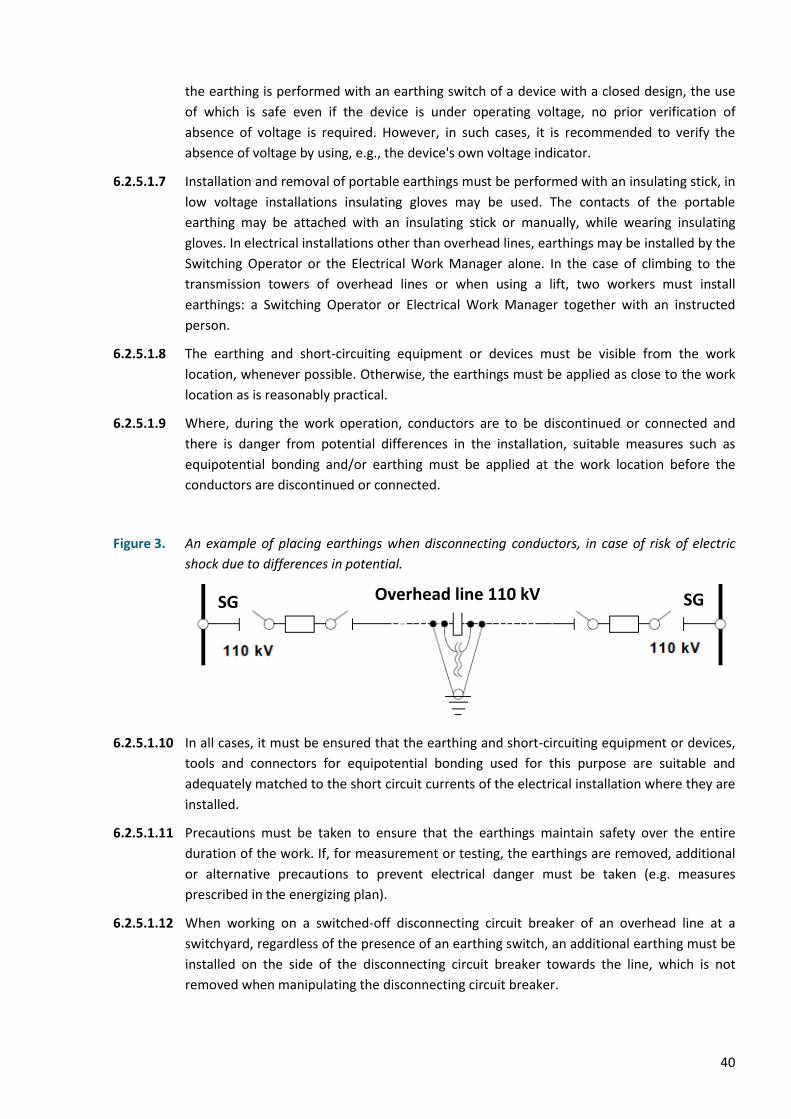
40
the earthing is performed with an earthing switch of a device with a closed design, the use
of which is safe even if the device is under operating voltage, no prior verification of
absence of voltage is required. However, in such cases, it is recommended to verify the
absence of voltage by using, e.g., the device's own voltage indicator.
6.2.5.1.7 Installation and removal of portable earthings must be performed with an insulating stick, in
low voltage installations insulating gloves may be used. The contacts of the portable
earthing may be attached with an insulating stick or manually, while wearing insulating
gloves. In electrical installations other than overhead lines, earthings may be installed by the
Switching Operator or the Electrical Work Manager alone. In the case of climbing to the
transmission towers of overhead lines or when using a lift, two workers must install
earthings: a Switching Operator or Electrical Work Manager together with an instructed
person.
6.2.5.1.8 The earthing and short-circuiting equipment or devices must be visible from the work
location, whenever possible. Otherwise, the earthings must be applied as close to the work
location as is reasonably practical.
6.2.5.1.9 Where, during the work operation, conductors are to be discontinued or connected and
there is danger from potential differences in the installation, suitable measures such as
equipotential bonding and/or earthing must be applied at the work location before the
conductors are discontinued or connected.
Figure 3. An example of placing earthings when disconnecting conductors, in case of risk of electric
shock due to differences in potential.
6.2.5.1.10 In all cases, it must be ensured that the earthing and short-circuiting equipment or devices,
tools and connectors for equipotential bonding used for this purpose are suitable and
adequately matched to the short circuit currents of the electrical installation where they are
installed.
6.2.5.1.11 Precautions must be taken to ensure that the earthings maintain safety over the entire
duration of the work. If, for measurement or testing, the earthings are removed, additional
or alternative precautions to prevent electrical danger must be taken (e.g. measures
prescribed in the energizing plan).
6.2.5.1.12 When working on a switched-off disconnecting circuit breaker of an overhead line at a
switchyard, regardless of the presence of an earthing switch, an additional earthing must be
installed on the side of the disconnecting circuit breaker towards the line, which is not
removed when manipulating the disconnecting circuit breaker.
SG Overhead line 110 kV SG
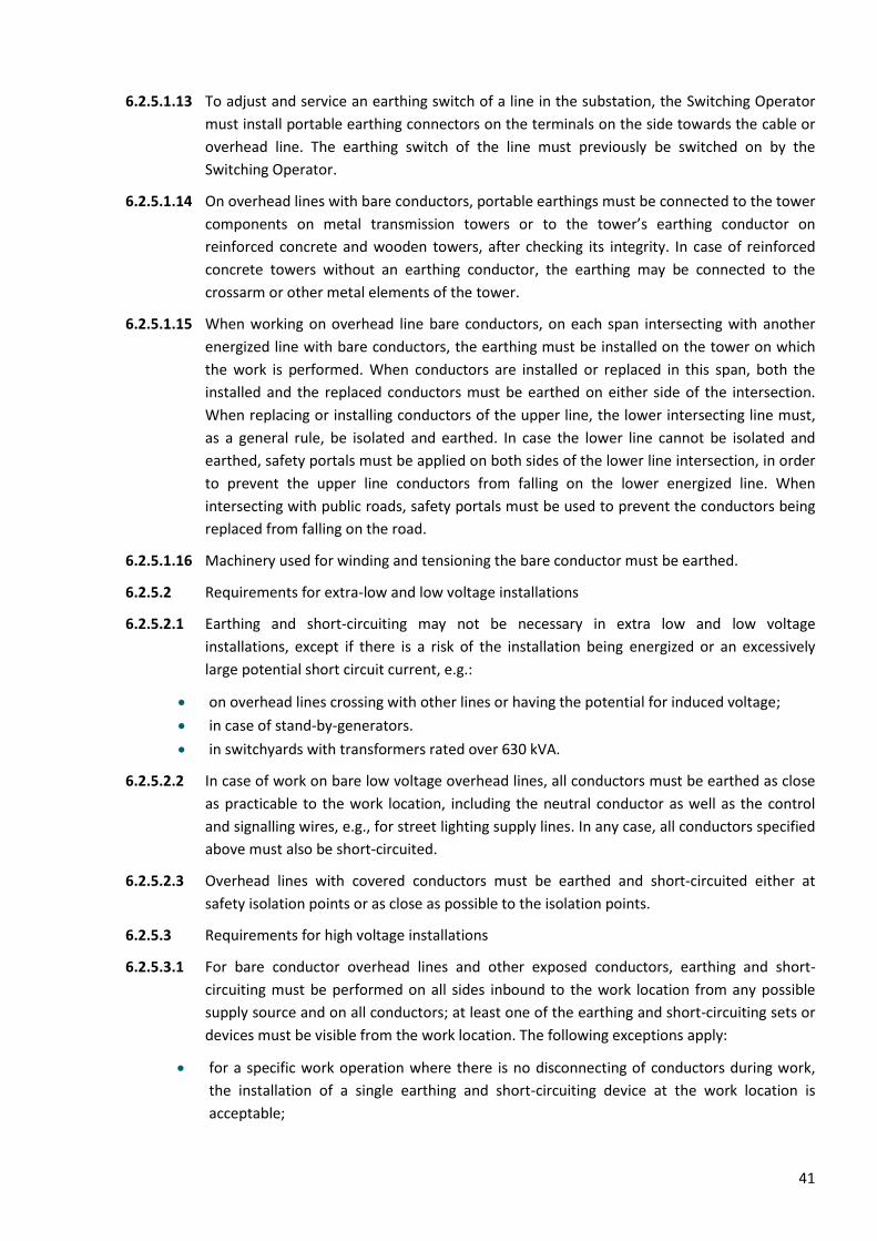
41
6.2.5.1.13 To adjust and service an earthing switch of a line in the substation, the Switching Operator
must install portable earthing connectors on the terminals on the side towards the cable or
overhead line. The earthing switch of the line must previously be switched on by the
Switching Operator.
6.2.5.1.14 On overhead lines with bare conductors, portable earthings must be connected to the tower
components on metal transmission towers or to the tower’s earthing conductor on
reinforced concrete and wooden towers, after checking its integrity. In case of reinforced
concrete towers without an earthing conductor, the earthing may be connected to the
crossarm or other metal elements of the tower.
6.2.5.1.15 When working on overhead line bare conductors, on each span intersecting with another
energized line with bare conductors, the earthing must be installed on the tower on which
the work is performed. When conductors are installed or replaced in this span, both the
installed and the replaced conductors must be earthed on either side of the intersection.
When replacing or installing conductors of the upper line, the lower intersecting line must,
as a general rule, be isolated and earthed. In case the lower line cannot be isolated and
earthed, safety portals must be applied on both sides of the lower line intersection, in order
to prevent the upper line conductors from falling on the lower energized line. When
intersecting with public roads, safety portals must be used to prevent the conductors being
replaced from falling on the road.
6.2.5.1.16 Machinery used for winding and tensioning the bare conductor must be earthed.
6.2.5.2 Requirements for extra-low and low voltage installations
6.2.5.2.1 Earthing and short-circuiting may not be necessary in extra low and low voltage
installations, except if there is a risk of the installation being energized or an excessively
large potential short circuit current, e.g.:
• on overhead lines crossing with other lines or having the potential for induced voltage;
• in case of stand-by-generators.
• in switchyards with transformers rated over 630 kVA.
6.2.5.2.2 In case of work on bare low voltage overhead lines, all conductors must be earthed as close
as practicable to the work location, including the neutral conductor as well as the control
and signalling wires, e.g., for street lighting supply lines. In any case, all conductors specified
above must also be short-circuited.
6.2.5.2.3 Overhead lines with covered conductors must be earthed and short-circuited either at
safety isolation points or as close as possible to the isolation points.
6.2.5.3 Requirements for high voltage installations
6.2.5.3.1 For bare conductor overhead lines and other exposed conductors, earthing and short-
circuiting must be performed on all sides inbound to the work location from any possible
supply source and on all conductors; at least one of the earthing and short-circuiting sets or
devices must be visible from the work location. The following exceptions apply:
• for a specific work operation where there is no disconnecting of conductors during work,
the installation of a single earthing and short-circuiting device at the work location is
acceptable;
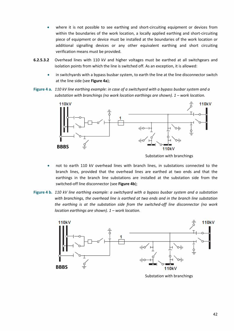
42
• where it is not possible to see earthing and short-circuiting equipment or devices from
within the boundaries of the work location, a locally applied earthing and short-circuiting
piece of equipment or device must be installed at the boundaries of the work location or
additional signalling devices or any other equivalent earthing and short circuiting
verification means must be provided.
6.2.5.3.2 Overhead lines with 110 kV and higher voltages must be earthed at all switchgears and
isolation points from which the line is switched off. As an exception, it is allowed:
• in switchyards with a bypass busbar system, to earth the line at the line disconnector switch
at the line side (see Figure 4a);
Figure 4 a. 110 kV line earthing example: in case of a switchyard with a bypass busbar system and a
substation with branchings (no work location earthings are shown). 1 – work location.
• not to earth 110 kV overhead lines with branch lines, in substations connected to the
branch lines, provided that the overhead lines are earthed at two ends and that the
earthings in the branch line substations are installed at the substation side from the
switched-off line disconnector (see Figure 4b);
Figure 4 b. 110 kV line earthing example: a switchyard with a bypass busbar system and a substation
with branchings, the overhead line is earthed at two ends and in the branch line substation
the earthing is at the substation side from the switched-off line disconnector (no work
location earthings are shown). 1 – work location.
Substation with branchings
Substation with branchings
BBBS
BBBS
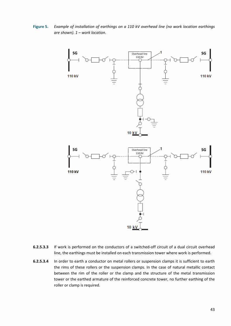
43
Figure 5. Example of installation of earthings on a 110 kV overhead line (no work location earthings
are shown). 1 – work location.
6.2.5.3.3 If work is performed on the conductors of a switched-off circuit of a dual circuit overhead
line, the earthings must be installed on each transmission tower where work is performed.
6.2.5.3.4 In order to earth a conductor on metal rollers or suspension clamps it is sufficient to earth
the rims of these rollers or the suspension clamps. In the case of natural metallic contact
between the rim of the roller or the clamp and the structure of the metal transmission
tower or the earthed armature of the reinforced concrete tower, no further earthing of the
roller or clamp is required.
Overhead line 110 KV
SG SG
Overhead line 110 KV
SG SG
44
6.2.5.3.5 When the conductors are installed in the tension span and also after the jumpers of the
assembled overhead line section are connected in tension towers, the conductors (guard
wires) must be earthed at the first tension tower (from which installation was started) and
at one of the last suspension towers.
6.2.5.3.6 It is prohibited to earth conductors (guard wires) at the last tension tower of the installed
line section or the assembled tension span in order to avoid the transfer of lightning charge
potential and other overvoltages from the completed line section conductors (guard wires)
to the next line section to be assembled.
6.2.5.3.7 Only one sub-conductor is allowed to be earthed in each phase on overhead lines with
bundled conductors. In case insulating spacers are used, all sub-conductors of the phase
must be earthed.
6.2.5.3.8 When working on a lightning guard wire insulated from the transmission tower or on the
structures of the tower, the guard wire must be earthed, if it is necessary to approach the
wire to a proximity of less than 1 m. The earthing must be installed towards the span where
the wire is insulated or on this span.
6.2.5.3.9 If work is performed on only one overhead line conductor, the short-circuiting at the work
location may be omitted if the following requirements are simultaneously fulfilled:
• all isolation points are earthed and short-circuited in accordance with Clause 6.2.5.1;
• the conductor on which the work is performed and all conductive parts within the
boundaries of the work location are connected by equipotential bonding and earthed with
appropriate devices or equipment;
• the earthed conductor, work location and the worker are further from the remaining
conductors of the same electrical circuit than distance DL (see Figures 1 and 2).
6.2.5.3.10 In the case of overhead lines with covered conductors, cables or other insulated conductors,
the earthings and short-circuitings must be attached on each side of the work location onto
bare parts of the isolation points of the installation or as close as possible to the isolation
points.
6.2.5.3.11 In case trees are removed from overhead line conductors, the work location does not have
to be fitted with an earthing if the line is not in the influence zone of lines with induced
voltage, is switched-off and earthed at supply points (substations).
6.2.5.3.12 For withstand testing, an isolated cable may be earthed only in one isolation point, provided
that the cable is also tested at that location.
6.2.6 Protection against adjacent live parts
6.2.6.1 In case there are parts of an electrical installation in the vicinity of the work location which
cannot be de-energized, special additional precautions are necessary and must be applied
before initiation of work as detailed in “work in the vicinity of energized parts” (see Clause
6.4).
6.2.6.2 In order to obviate electrical hazards in the vicinity of energized parts, protection must
generally be provided either using protective screens, barriers, enclosures or insulating
covers (see 6.4.2) provided with the warning sign “Electrical hazard”.
45
6.2.6.3 Insulating covers are placed between the switched-off and energized conductive parts, e.g.,
between the contacts of a switched-off disconnector. These insulating covers may come into
contact with the energized conductive parts.
6.2.6.4 The warning safety sign “Stop. Voltage” must be affixed to the compartments, cabinets and
panels in the vicinity of the work location.
6.2.6.5 In the case of work in outdoor switchyards, except maintenance on auxiliary circuits to be
performed on devices located at ground level and installed on foundations and separate
structures, the work location must be marked and access to adjacent energized parts must
be restricted with a rope bearing warning safety signs “Stop. Voltage” or with tape featuring
printed text “Electrical hazard”. Access to the work location is left unobstructed.
6.2.6.6 The obligative safety sign “Work here” must be installed at the work location of indoor
switchgears and in outdoor switchyards at the marked access area to the work location.
6.2.6.7 The use of structures which are not part of the work location zone is allowed for hanging the
tape and rope, provided they remain outside the designated area.
6.2.6.8 Energized line disconnector switches in an outdoor switchyard must be marked with a
warning safety tape or rope used in electrical installations.
6.2.6.9 In outdoor switchyards, highly visible safety signs “Stop. Voltage” must be installed onto the
components of the structures which may be used to access adjacent energized parts.
6.2.6.10 The obligative safety sign “Climb here” must be placed onto ladders and structures used to
climb to an elevated work location.
6.2.6.11 Onto lower parts of the structures, which are located adjacent to the structures where
climbing is permitted, the safety sign “Stop. Voltage” must be installed.
6.2.6.12 It is forbidden to remove or reposition safety signs and barriers installed during the
preparation of the work location until the work is fully completed.
6.2.7 Organising dead work
6.2.7.1 Basic requirements for dead work are fulfilled with work planning and operational
arrangements. The conceptual process of planning and performing dead work is shown in
the following Scheme 1.
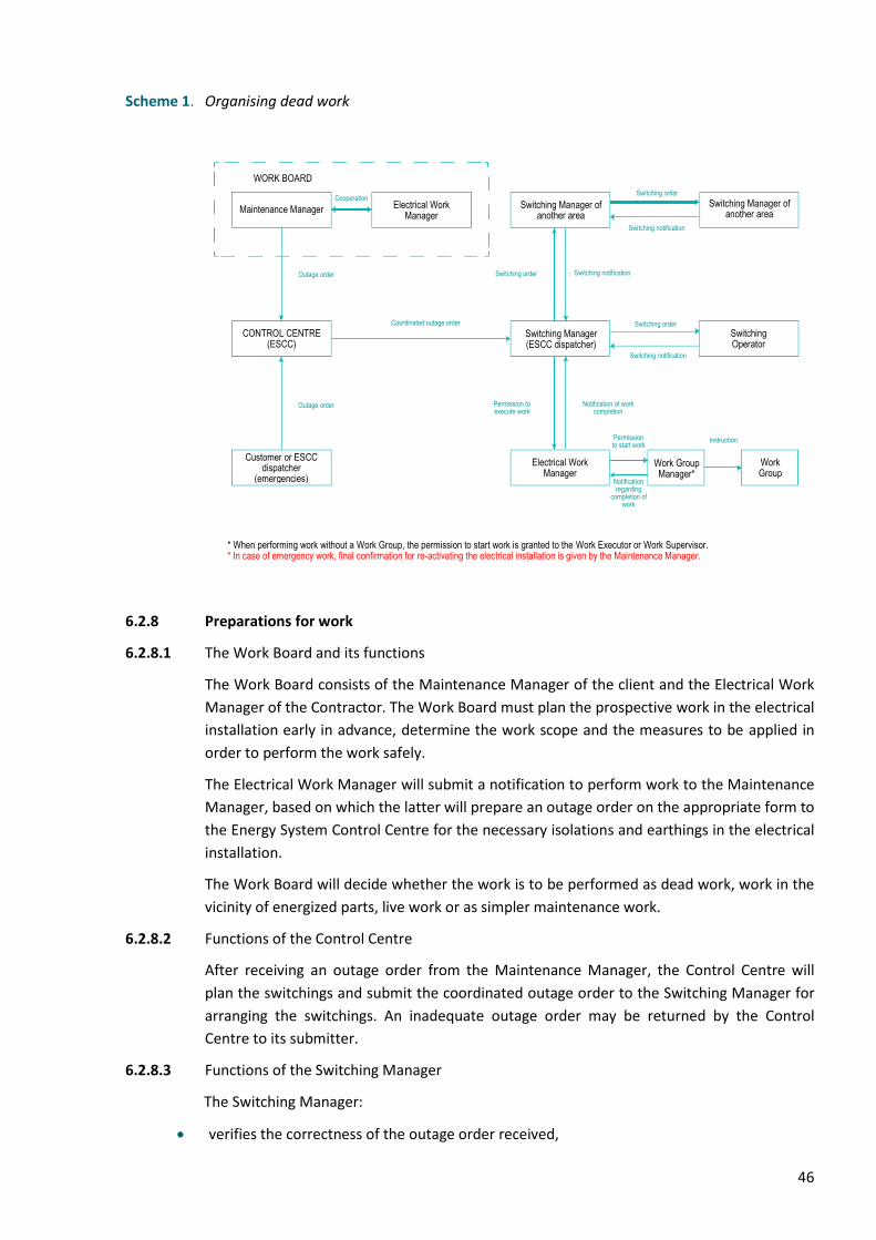
46
Scheme 1. Organising dead work
6.2.8 Preparations for work
6.2.8.1 The Work Board and its functions
The Work Board consists of the Maintenance Manager of the client and the Electrical Work
Manager of the Contractor. The Work Board must plan the prospective work in the electrical
installation early in advance, determine the work scope and the measures to be applied in
order to perform the work safely.
The Electrical Work Manager will submit a notification to perform work to the Maintenance
Manager, based on which the latter will prepare an outage order on the appropriate form to
the Energy System Control Centre for the necessary isolations and earthings in the electrical
installation.
The Work Board will decide whether the work is to be performed as dead work, work in the
vicinity of energized parts, live work or as simpler maintenance work.
6.2.8.2 Functions of the Control Centre
After receiving an outage order from the Maintenance Manager, the Control Centre will
plan the switchings and submit the coordinated outage order to the Switching Manager for
arranging the switchings. An inadequate outage order may be returned by the Control
Centre to its submitter.
6.2.8.3 Functions of the Switching Manager
The Switching Manager:
• verifies the correctness of the outage order received,
WORK BOARD
Maintenance Manager
Cooperation Switching Manager of
another area
Outage order
Coordinated outage order
Switching order Switching notification
Switching order
Switching notification
Electrical Work Manager
Switching Manager of another area
Switching order
Outage order
Switching notification
CONTROL CENTRE (ESCC)
Electrical Work Manager
Work Group Manager*
Work Group
Permission to execute work
Notification of work completion
Instruction
Notification regarding
completion of work
Permission to start work
* When performing work without a Work Group, the permission to start work is granted to the Work Executor or Work Supervisor. * In case of emergency work, final confirmation for re-activating the electrical installation is given by the Maintenance Manager.
Switching Operator
Customer or ESCC dispatcher
(emergencies)
Switching Manager (ESCC dispatcher)
47
• composes a switching order for the preparation of the work location in an electrical
installation, including the isolation and earthing operations,
• forwards the prepared switching order to the Switching Operator,
• receives a notification from the Switching Operator about the execution of the switching
order and grants the Electrical Work Manager a permission to execute work. The
permission to execute work may be submitted directly or e.g., by phone, fax or e-mail in
accordance with the procedure provided in Clauses 4.4.5 and 4.4.6.
6.2.8.4 The switching order must contain at least the following information (see Annex 1A):
• name of the company and the person who issued the order,
• date and time the switching order is issued,
• date and time the switching order is executed,
• name of the Switching Operator to whom the switching order is issued,
• purpose of the switchings,
• numerated switching and verification operations, whereas one number is allocated to one
operation,
• if appropriate, requirements for marking and restricting the work location.
Abbreviations defined in these regulations may be used to prepare the switching order.
6.2.8.5 The switching order must be prepared sufficiently early prior to the switchings. The
Switching Manager executes the switchings themselves or transmits the switching order to
the Switching Operator before the start of the switchings, coordinating, if necessary, the
remotely controlled switchings in the electrical installations with the Switching Operator.
6.2.8.6 If, due to the nature of the work, it is also necessary to perform switchings in the area of
another Switching Manager, the switchings are coordinated with the Switching Manager of
the other area. The Switching Manager of the other area will inform about the completion
of coordinated switchings.
6.2.8.7 When submitting a switching order, previously prepared switching programs or an
energizing plan may also be used.
6.2.8.8 Switching activities may also be performed without a written switching order. In this case,
the Switching Manager provides the Switching Operator instructions in the form of
individual operations and must receive a verbal notification of their execution after each
operation. Giving orders and receiving notifications about executing the orders are recorded
in the switching log by the Switching Manager.
6.2.8.9 The phone calls between the Switching Manager and Switching Operator are recorded.
6.2.9 Functions of a Switching Operator
6.2.9.1 The Switching Operator must possess a written switching order received from the Switching
Manager in person, electronically or by phone. An exception is switching performed as
single operations (Clause 6.2.8.8). In this case, the Switching Operator must report the
execution of each operation to the Switching Manager. The Switching Operator must
48
register receiving each order and the notifications of their execution, e.g., in the switching
log.
6.2.9.2 If the switching order is transmitted by phone or by electronic means, it must be formalized
in accordance with the procedure prescribed in Clauses 4.4.5 or 4.4.6.
6.2.9.3 The Switching Manager and Switching Operator must record the start time of the switchings
on their copy of the switching order prior to initiating switching operations and must sign it.
6.2.9.4 If the status of the switching devices corresponds to the switching order, the Switching
Operator will perform the switching operations specified in the switching order by verifying
that all phases of the switching devices are switched-off or switched-on, and must
accordingly mark the corresponding row of the switching order for each switching operation
performed. In the event that the actual status of the switching devices does not correspond
to the switching order, they must report this to the Switching Manager, who is obligated to
resolve the situation. The Switching Operator must verify the safety of the switching
operation to be performed.
6.2.9.5 Deviations from the switching order are acceptable only by instruction of the Switching
Manager.
6.2.9.6 If there are other persons near the device to be switched, the Switching Operator must
inform them of the switching to be performed and, if necessary, remove them from the
area.
6.2.9.7 After the switchings are completed, the Switching Operator informs the Switching Manager
that the switching order has been executed. The Switching Manager and the Switching
Operator then record the end time of the switching in the cell “Switching operations are
executed and switching notification submitted” on their copy of the switching order and
confirm it with their signature.
6.2.10 Granting the permission to execute work
The prerequisite for granting permission to execute work is receiving a switching notification
from the Switching Operator.
After the start time of the work indicated in the outage order, the Electrical Work Manager
will contact the ESCC dispatcher and ask for the permission to execute work. After the
switching notification has been submitted, the ESCC dispatcher will send the permission to
execute work to the Electrical Work Manager. After receiving the permission to execute
work the Electrical Work Manager must call the ESCC dispatcher, after which the permission
to execute work is activated.
The permission to execute work becomes a document according to which work can be
performed only after the permission to execute work has been activated.
The following actions are performed to activate the permission to execute work:
• date and time are written in the row “Permission to execute work granted/received”,
• the issuer and receiver of the permission to execute work fill out cells “PEW granted BY
WHOM” and “PEW granted TO WHOM” and confirm their copy of the document with their
signature after their name.

49
The permission to execute work and notification of work completion must be forwarded to
its recipient in writing, by telephone, by e-mail or by fax.
6.2.11 Granting the permission to start work
6.2.11.1 After obtaining the permission to execute work, the Electrical Work Manager must formalize
the permission to start work. The written permission to start work is composed in two
copies, one of which will remain with the permission issuer and the other at the work
location, in the possession of the Work Group Manager, Work Supervisor or Work Executor
appointed by the issuer of the permission to start work.
6.2.11.2 In case the Maintenance Manager or Electrical Work Manager performs the work alone, the
permission to execute work is considered to be the permission to start work.
6.2.11.3 The permission to start work may be granted to the Work Group Manager, Work Executor
or Work Supervisor only by the Electrical Work Manager and only after the requirements of
Clauses 6.2.2 through 6.2.6 have been met.
6.2.11.4 Before granting the permission to start work, the Electrical Work Manager must check the
adequacy and compliance of isolation, earthing and work location marking with the
requirements of the outage order and the work to be performed and instruct the Work
Group Manager or Work Executor. Instruction is not formalized separately. In the event that
the Work Group has questions or there is a lack of understanding, explanations must be
provided by the Electrical Work Manager.
6.2.11.5 After instruction, the Electrical Work Manager will grant permission to start work to the
person appointed the Work Group Manager by them. Both copies of the permission to start
work are signed by the issuer and recipient.
6.2.11.6 The form of the written permission to start work and the instructions on how to complete it
are provided in Annex 2.
6.2.12 Functions of a Work Group Manager
6.2.12.1 The Work Group Manager must, after obtaining permission to start work, personally review
the preparation and marking of the work location and, if necessary, install additional
portable earthings to ensure that the requirements of Clause 6.2.5.1.1 are met and that the
work location is correctly marked.
6.2.12.2 The Work Group Manager, convinced of the preparation of the work location, will instruct
the Work Group Members on the work task, boundaries of the work location, adjacent
energized parts, prove the absence of voltage by showing the installed earthings. If the
earthings are not visible from the work location, the absence of voltage must be
demonstrated by the verification of absence of voltage, but in electrical installations rated
up to 35 kV (where the construction allows) also by subsequently touching the conductive
parts with their hand.
6.2.12.3 The Work Group Manager will also instruct the Work Group Members on the technology
regarding the work, tools, devices, the use of mechanisms and lifting machines and will
verify that the instructions are properly understood. Instruction is not formalized separately.
6.2.12.4 Permission to start work for the Work Group Members is formalized by the Work Group
Manager on the permission to start work form.

50
6.2.13 Functions of the Work Group Members
6.2.13.1 The Work Group Members may not start work until they have received verbal permission
from the Work Group Manager to start the work. They must follow the instructions
provided by the Work Group Manager and in case something remains unclear, immediately
ask the Work Group Manager for explanation.
6.2.14 Functions of a Work Executor
The Work Executor may start the work after signing the permission to start work and
reviewing the work location.
6.2.15 Functions of a Work Supervisor
The Work Supervisor may start supervising the work after signing the permission to start
work and having reviewed the work location.
6.2.16 Conduct during work
6.2.16.1 Functions of a Work Group Manager
6.2.16.1.1 During work, the Work Group Manager must:
• monitor compliance with safety requirements at the work location,
• ensure the availability, good condition and correct use of protective equipment, tools and
work equipment,
• ensure the preservation of work location markings, barriers, safety signs and markings and
locking devices,
• upon leaving the work location for a short duration, appoint another person to perform the
duties of the Work Group Manager and inform the Work Group Members accordingly. If
there is no employee in the Work Group who can replace the Work Group Manager for a
short duration, the Work Group Manager must displace the Work Group from the work
location.
6.2.16.1.2 If the Work Group Manager leaves the work location for a longer period of time, they may
be replaced by the Electrical Work Manager. If the Electrical Work Manager cannot replace
the Work Group Manager, the Work Group Manager must displace the Work Group from
the work location.
6.2.16.1.3 If work is performed based on one permission to start work in several work locations in
succession, the Work Group Manager specified on the permission to start work must
relocate the Work Group Members to the next work location pursuant to the special
instructions prescribed in the permission to start work and must formalize the initiation of
the work in the permission to start work on this particular work location.
6.2.16.1.4 If the work is interrupted during the workday (for lunch, due to working conditions), the
Work Group Manager must displace the Work Group from the work location and lock the
door/gate of the switchgear area. The permission to start work remains with the Work
Group Manager. After such interruption, the Work Group Manager will allow the Work
Group to work without formalizing it in the permission to start work.
6.2.16.1.5 If the work is interrupted at the end of the workday, the Work Group Manager must
displace the Work Group from the work location. Earthings, barriers and signs are not

51
removed. The Work Group Manager must formalize the termination of work on their copy
of the permission to start work by signing it and maintains it in their possession. Upon
leaving, the Work Group Manager must lock the switchgear area.
6.2.16.1.6 In the following days, the Work Group Manager will issue repeated permissions to start
work at the prepared work location as described in the special instructions. The Work Group
Manager will formalize the initiation of work on their copy of the permission to start work.
6.2.16.1.7 On the following day, before commencing work, the Work Group Manager must verify that
the barriers and signs left in place have remained and are in order, that the earthings are
installed securely, and only then can permit the Work Group start working with the
permission to start work.
6.2.16.2 Functions of Work Group Members
Work Group Members:
• will comply with safety requirements and the instructions provided by the Work Group
Manager,
• must not come to the work location without the Work Group Manager after the work has
been suspended,
• will ask the Work Group Manager immediately for an explanation in case they do not fully
understand the safety requirements.
6.2.16.3 Function of a Work Executor
During work, actions of the Work Executor must be safe for themselves, other persons and
equipment.
6.2.16.4 Function of a Work Supervisor
The task of the Work Supervisor is to monitor the electrical safety of the work being
performed. This implies that they are not allowed to take part in the work themselves and
they must observe that workers or mechanisms are prevented from entering the zone in the
vicinity of energized parts.
6.2.17 Completion of work
6.2.17.1 Function of a Work Group Manager
The Work Group Manager:
• informs the Work Group Members about the completion of the work and arranges clearing
of the work location,
• arranges the removal of installed earthings, temporary barriers and safety signs installed by
the Work Group,
• verifies that all members of the Work Group have left the work location and informs them
of the re-energizing of equipment.
• formalizes the completion of the work on the permission to start work,
• reports the completion of work, restoring order to the work location and the removal of the
Work Group from the work location to the Electrical Work Manager.
52
6.2.17.2 Function of a Work Executor
Upon completion of the work according to the permission to start work, the Work Executor
must restore order at the work location, formalize the completion of work at the work
location and inform the issuer of the permission to start work regarding it.
6.2.17.3 Function of a Work Supervisor
Upon completion of the work according to the permission to start work, the Work
Supervisor will formalize the completion of work at the work location and inform the issuer
of the permission to start work regarding it.
6.2.17.4 Function of an Electrical Work Manager
After receiving the notification from the Work Group Manager, Work Executor or Work
Supervisor, the Electrical Work Manager must formalize the completion of the work on the
permission to start work. If the notification was transmitted by means of a communication
device, they must formalize the notification on their copy of the permission to start work.
Afterwards, the Electrical Work Manager must prepare a notification of work completion
and forward it to the ESCC dispatcher.
6.2.17.5 Submission of the notification of work completion
After the completion of the work has been formalized on the permission to start work, the
Electrical Work Manager must forward the notification of work completion to the ESCC
dispatcher either electronically or by phone. Regardless of how the notification is
transmitted, the notification becomes a document only after the following actions are
performed during the phone conversation between the Electrical Work Manager and the
ESCC dispatcher:
• date and time is entered in the row “Notification of work completion given/received:”;
• the notification number of the Contractor is written on the notification of work completion;
• the issuer of the notification of work completion and the recipient fill in the cells “Name
and signature of the recipient of the notification:” and “Name and signature of the issuer of
the notification” and confirm their copy of the document with their signature following
their name.
Sending and receiving a completed form of a notification of work completion previously
submitted does not automatically render it an organizing or notifying document.
The date and time to be written on the order and permission to execute work is provided by
the ESCC dispatcher.
53
6.2.17.6 Function of a Switching Manager
After receiving the notification of work completion from the Electrical Work Manager, the
Switching Manager will perform the switchings themselves or issue a switching order to the
Switching Operator to perform switchings. If, for executing work on one and the same
electrical installation or part thereof, e.g., overhead line or substation equipment,
permission to execute work was issued to several Electrical Work Managers, the Switching
Manager may only start re-energizing after they have received the notification of work
completion from all Electrical Work Managers who managed the work.
In the case of emergency work, final confirmation for activating an electrical installation is
provided by the Maintenance Manager.
6.2.17.7 Function of a Switching Operator
6.2.17.7.1 After receiving the switching order, except in case of work on overhead and cable lines, the
Switching Operator must review the work location to verify that all tools, equipment and
instruments have been removed from the work location.
6.2.17.7.2 Earthings installed in the electrical installation must be removed and all locks and other
equipment used to prevent unintended re-switching must also be removed from the
electrical installation. All barriers and safety signs used for the work must also be removed.
6.2.17.7.3 If even one operation reducing the safety of working at the electrical installation has been
performed, this part of the electrical installation is considered to be energized.
6.2.17.7.4 If the Switching Operator is convinced that the electrical installation is ready to be re-
energized, they will perform the switchings according to the switching order by making a
corresponding note on the row regarding each operation. After the switching order has
been completed, they will send a switching notification to the Switching Manager.
6.3 Live work
6.3.1 General requirements
6.3.1.1 Except as otherwise stipulated in this section (Clause 6.3), live work must be performed in
accordance with the requirements regarding dead work stipulated in Clause 6.2.7.
6.3.1.2 Live work is performed at high voltage (> 1 kV) only in exceptional cases and with increased
vigilance. It is necessary to submit an outage order for the execution of the live work even if
no switching is performed for executing the work. It is mandatory to prepare a safety plan to
perform the work.
6.3.1.3 These requirements might not be applied to operations such as switchings, verification of
absence of voltage, use of earthing and short-circuiting equipment, withstand testing and
operations using measuring instruments.
6.3.1.4 During live work, workers may come into contact with bare energized parts or enter the live
work zone either with their own body parts or with tools, equipment or instruments being
used. At low voltage, live work is performed by the worker when making contact with
energized parts. At high voltage, live work is performed by the worker when entering the
live work zone, regardless of whether contact is made with live parts or not.
54
6.3.1.5 The live zone (danger zone) is the space around energized parts in which the insulation level
is not assured to prevent electrical danger when reaching into or entering it without using
protective measures. The outer boundary of the zone is measured from the energized part.
The outer boundary of the work zone is denoted as the distance DL (see Figures 1 and 2 and
Table 1).
6.3.1.6 Live work procedures must only be performed after eliminating fire and explosion risks (see
6.1.4 and 6.1.5).
6.3.1.7 Care must be taken to ensure that a stable work platform is provided which leaves the
worker with both hands free.
6.3.1.8 Personnel must wear suitable and adequate personal protective equipment. They may not
wear metallic items, e.g. personal jewellery, if this is likely to cause a hazard.
6.3.1.9 For live work, protective measures to prevent electric shock and short circuit must be used.
All different potentials and voltages in the surrounding area of the work location must be
considered.
6.3.1.10 Depending on the type of work, the personnel performing live work must be either
instructed or electrically skilled, and specifically trained for the required tasks.
6.3.1.11 Live work requires the use of specific procedures as prescribed in Clause 6.3.4. Instructions
must be given to workers on how to maintain tools, equipment and instruments in good
working condition and on how to verify their condition prior to work (see 6.3.6).
6.3.1.12 Environmental conditions (see 6.3.7), such as humidity, temperature, wind, etc. which are
different from normal, may increase the risks related to work. Corresponding limitations
must be specified.
6.3.2 Training and qualification
6.3.2.1 A specific training programme must be composed to develop and maintain the capability of
electrically skilled or instructed persons to perform live work. This programme must comply
with special requirements regarding live work and constitute theoretical and practical
exercises.
6.3.2.2 These exercises must be representative of the work to be performed after training or, if
different from the work itself, must be based on the same safety principles.
6.3.2.3 Training for live work may be performed in the form of continued training at a vocational
school, in a training centre possessing the relevant training certificate or as in-house
training. In the case of in-house training, this must be performed under the management of
an electrically skilled person who has completed a live work course, assuming that this
electrically skilled person has passed at least a technical examination and has accrued
sufficient experience in managing live work.
6.3.2.4 Special training for live work is not required for some simpler types of work such as
replacing fuses, maintenance of secondary circuits, instruments, relay protection devices,
automation, telemechanics and communication equipment (see Clause 7.2.2).
6.3.2.5 Upon successful completion of the training, a training certificate must be granted to the
participant to confirm that the person is capable of performing live work according to their
training and acquired skills.
55
The certificate issued must contain at least the following information:
• the voltage level for which the training of live work was designed,
• work methods covered over the course of the training,
• content of theoretical training,
• content of practical training,
• duration of training,
• contact details of the training organizer.
6.3.2.6 The employer must possess information regarding the training on live work the employees
have completed.
6.3.3 Maintaining personal ability
6.3.3.1 The capability to perform live work safely must be maintained either by actual work or by
refresher training.
6.3.3.2 The validity of the live work certificate must be reviewed whenever necessary, according to
the level of ability of the person concerned. Where the relevant regulations or practice
require that the right to perform live work be formalized by means of a certificate to that
effect, the right to perform live work must be reviewed in the following cases:
• transfer of an employee or changes in the work organization,
• upon alterations in task allocation,
• in the event of a prolonged intermission in work,
• in the case of health-related restrictions,
• in the event of non-acceptance of the rules or procedures regarding work and inadequacy
for work,
• significant changes in installations (changes in equipment or structure),
• when work or maintenance procedures are changed.
As a good general practice, it is recommended that the right to perform live work be
reviewed annually.
6.3.4 Work methods
At present, there are three recognized work methods which depend upon the positioning of
the worker in relation to energized parts and upon the means used to prevent electric shock
and short circuit.
• Hot stick working from a safe distance – the method of live work by which the worker
remains at a specified distance from the energized parts and performs their work by means
of insulating stick(s).
• Insulating glove working – the method of live work in which the worker, whose hands are
electrically protected with insulating gloves and possibly insulating arm sleeves, performs
their work in direct mechanical contact with live parts. In low voltage installations, the use

56
of insulating gloves does not preclude the use of insulating and insulated tools and suitable
insulation of the worker from earth.
• Bare hand working – the method of live work in which the worker performs their work in
electrical contact with live parts, having previously been brought to the same potential as
the energized parts and suitably insulated from all surrounding parts as necessary.
6.3.5 Working conditions
According to the complexity of the work, the working conditions will determine the work
method to be followed in accordance with Clause 6.3.4. Based on the working conditions,
the procedures for the work are chosen, taking into account the preparation and the
specific tools and equipment to be used. The working conditions may include one or more
of the following:
• work relations between personnel involved in live work, i.e. the Maintenance Manager,
Electrical Work Manager and workers.
• measures to be taken to limit switching related overvoltages at the work location, e.g.,
blocking automatic reclosure of circuit breakers;
• specified working clearances for personnel and for conductive devices used during work.
These distances are based on phase-to-earth voltage but must also be provided for phase-
to-phase voltage and related to the required insulation level.
6.3.6 Tools, equipment and devices
6.3.6.1 In addition to the requirements stipulated in Clause 4.6, the characteristics, use, storage,
maintenance, transportation and inspection of the tools, equipment and instruments used
during live work must be specified in detail.
6.3.6.2 Tools, equipment and instruments must be clearly marked. The marking must ensure that
only the tools, equipment and instruments intended for such work are used for live work
and that the exchange of such tools is avoided.
6.3.6.3 Tools, equipment and instruments must be used in accordance with the instructions and
guidance provided by the manufacturer or supplier. These instructions must be in Estonian
and, if necessary, in other languages. The maintenance of tools, equipment and instruments
must ensure their condition is suitable for use and the tools must be used as intended.
6.3.6.4 Maintaining in a condition suitable for use implies periodic visual inspections and electrical
testing, if necessary, including after repairs and/or modifications, to verify the electrical
integrity and mechanical properties of the tools, equipment and instruments. Work
equipment includes personal protective equipment.
6.3.6.5 Work equipment for live work must be clean and dry. The Electrical Work Manager is
responsible for the sufficient quantity, suitability and good working condition of the tools,
equipment and instruments used at the work location.
6.3.6.6 The additional protective devices consisting of insulating material used for the temporary
protection (covering) of exposed energized or earthed parts must possess sufficient
durability, both electrical and mechanical.
6.3.6.7 High voltage tools and equipment must always be provided with technical passports.
57
6.3.7 Environmental conditions
6.3.7.1 Restrictions must be applied to live work in the event of adverse environmental conditions.
These restrictions are based on the reductions in insulating properties and on reduced
visibility and impaired freedom of movement of workers.
6.3.7.2 In case of outdoor work, weather conditions such as precipitation, fog and mist, lightning,
wind and temperature must be considered.
6.3.7.3 Live work must be prohibited, suspended or delayed when there is heavy rain or poor
visibility or when the workers are unable to operate their tools with ease. In case of
lightning, live work must not be started or must be suspended.
• Precipitation
Precipitation includes different types of rain, spray, drizzle, snow, hail, frost, hoarfrost or
glazed frost. Precipitation is considered insignificant if it does not impair the visibility of the
workers. Should visibility be impaired, it is considered significant. According to the voltage
level, the type of installation and the methods used, when precipitation is significant, the
work must be discontinued. It may also be necessary to discontinue work in the case of
precipitation which does not limit visibility according to the above definition, e.g., due to
deterioration of insulation.
• Fog
Fog or mist is considered thick in case visibility is reduced to a level that compromises
safety, particularly if the Electrical Work Manager cannot see the members of the group and
the live parts on which, or in the vicinity of which they should be working. Work must be
suspended under these conditions.
• Lightning
Thunderstorms occur along with lightning strikes and thunder. When at least one of the
workers sees lightning or hears thunder, work must be discontinued on bare conductors,
overhead lines and substations connected to such lines.
• Violent wind
Wind is considered violent in case it prevents the workers from using their tools with
sufficient precision; in that case, work must be discontinued. In general, wind speed should
not exceed 10 m/s.
• Temperature
The temperature is considered extra-low when it renders the use of tools difficult and it
decreases the strength of materials; in this case, work must be discontinued. Live work may
be performed if the air temperature is between -20 °C and +40 °C.
6.3.7.4 In case of indoor work, weather conditions need not be considered, provided that there are
no overvoltages likely to originate from the connected outdoor installations as a result of
these and the visibility at the work location is adequate.
6.3.7.5 Other parameters, e.g. adverse environmental pollution, particularly in the case of work on
or near high voltage installations must be considered if these reduce the insulation quality
of tools, equipment and instruments.

58
6.3.7.6 When environmental conditions require the discontinuation of work, personnel must leave
the installation in a safe manner together with all installed insulating and insulated devices
in a safe condition. They must also leave the work location in a safe manner. Prior to
resuming work, they must verify that the insulating parts are clean and intact. Where
insulating parts are required to be cleaned, the cleaning procedure must be precisely
specified and implemented.
6.3.8 Organisation of work
6.3.8.1 Preparation of work
6.3.8.1.1 If there is any doubt regarding the planned work operations, one or more preliminary
rehearsals must be performed before starting work. All electrical and other safety issues
must be carefully considered in order to prepare the work adequately.
6.3.8.1.2 In case of complex work, this preparation must be made in writing and early in advance, i.e.
a safety plan must be prepared.
6.3.8.1.3 As a general rule, live work must be performed by at least two employees who have
completed live work training, one of whom is the Electrical Work Manager and the other(s)
is (are) (a) Work Executor(s).
6.3.8.1.4 Before commencing work, it must be ascertained from where the work location can be de-
energized most quickly in the event of an accident.
6.3.8.1.5 At the work location of the Work Group there must be the necessary tools, devices,
protection and communication means provided with technological instructions (cards).
6.3.8.2 Function of the person who issued the permission to execute work (Maintenance Manager):
6.3.8.2.1 The installation or part of it in which the work is to be performed must be prepared and
maintained as required for the work. In doing so, it may become necessary to prevent the
automated recovery of the state equipment and/or to change the electrical protection
settings.
6.3.8.2.2 A location where automatic reclosing is prohibited must be clearly marked and the warning
sign “Do not switch. People working” must be installed in the correct place for the time
work is being performed.
6.3.8.3 Function of an Electrical Work Manager:
• Informs the issuer of the permission to execute work (Maintenance Manager) of the
composition of work and the location within the installation where it will be performed.
• Informs the Maintenance Manager and the ESCC dispatcher every time the work is initiated
or suspended or completed.
• Prior to work, explains to the workers the composition of the work, which safety measures
will be implemented, what are the tasks of each Work Group Member and which tools and
devices are used.
• Monitors the progress of the work and may not leave the work location, even for a short
period of time. The Electrical Work Manager may assist a Work Executor only to the extent
it does not interfere with monitoring of the work. The level of supervision must correspond
to the complexity of the work and the installation voltage level.
59
• Monitors and considers the environmental conditions during work at the work location.
• Upon completing the work, will inform the issuer of the permission to execute work
(Maintenance Manager) and ESCC dispatcher in the required manner.
• In case work has been suspended, implements adequate safety measures and notifies the
issuer of the permission to execute work (Maintenance Manager) and the ESCC dispatcher.
6.3.8.4 Only the Electrical Work Manager may give permission to start work to the Work Group.
6.3.9 Special requirements for extra-low voltage installations
In case of safety extra-low voltage installations (SELV) insulated from earth, work on live
parts is permitted without precautions against direct contact, but precautions against short
circuit must be taken. In case of earthed protective extra-low voltage system (PELV) and
functional extra-low voltage system (FELV) installations, work on live parts must be in
accordance with the requirements for low voltage installations (see 6.3.10).
6.3.10 Special requirements for low voltage installations
6.3.10.1 For low voltage installations (normally not exceeding 1000 V a.c. or 1500 V d.c.), protected
against overloads and short circuits, the only requirements are to use protective insulating
devices to prevent coming into contact with adjacent live parts, using insulated or insulating
tools and adequate personal protective equipment for workers.
6.3.10.2 Supervision is not mandatory, but when working alone, the worker must be able to consider
and avoid all risks which may present.
6.3.10.3 When the short circuit current may reach a dangerous level, the general requirements (6.3.1
through 6.3.8) must be applied.
6.3.10.4 When performing the work, priority must be given to technology which allows the energized
electrical conductors to be touched only using insulated tools and not personal protective
equipment.
6.3.11 Special requirements for high voltage installations
6.3.11.1 It must be verified that all methods and tools chosen are suitable for the installation to be
worked on.
6.3.11.2 Dielectric and mechanical properties must correspond to the standards which consider the
physical parameters of the work location.
6.3.11.3 If the dimensions of the work location do not enable the Electrical Work Manager to
perform complete supervision, they must delegate a person to assist them. Depending on
risk analysis, this assistive person must be either electrically skilled or instructed.
6.3.12 Specific work on live parts
Work such as cleaning, spraying and removal of glazed frost deposits on insulators, must be
covered by specific work instructions. The personnel performing these tasks must be either
electrically skilled or instructed.
6.3.13 Work on energized high voltage overhead lines
6.3.13.1 Work on energized overhead lines can be performed in one of two manners:
60
• without insulated protection equipment, i.e. according to the scheme “conductor-person-
insulation-earth”, where a worker is under the potential of the conductor and is insulated
from earth;
• with an insulating stick from a safe distance, i.e., according to the scheme “conductor-
insulation-person-earth”, where a worker is insulated from the conductor.
6.3.13.2 Working under the potential of the conductor is only allowed if the person is insulated from
earth, conductive clothing is used and the potentials of the conductive clothing, work
platform and the conductor have been equalized. The potentials are equalized with a special
equipotential bonding stick. Prior to commencement of lifting the worker onto the
conductor, the conductive clothing must be connected to the equipotential bonding stick
and the special booth, if used.
6.3.13.3 The distance from a person to the earthed parts and components of the equipment must be
no less than the distance DL provided in Table 1.
6.3.13.4 Specific work under the potential of the conductor must be performed on the basis of a
safety plan composed for this work.
6.3.13.5 In the case of live work where the person is insulated from the conductor, electrical
protection equipment corresponding to the voltage must be used.
6.3.13.6 When working on a platform of an insulating setup under the potential of the conductor, it
is prohibited to touch insulators in insulator chains and fixtures under a potential other than
the potential of the conductor, also to give or receive tools and equipment hand-to-hand
from personnel not located on that platform.
6.3.13.7 Prior to commencing work on insulator chains, the electrical strength of the suspension
insulators must be checked with a measuring stick and also the presence of all split pins and
locks on the fixture must be checked. In the case of tripping terminals, they must be wedged
in the tower on which the work is performed as well as in the adjacent towers, if the relief
of the line route requires it.
6.3.13.8 Workers located on insulating equipment or on crossarms are allowed to rearrange the
insulator chains and refit the fixture and individual insulators in case at least 70% of the
insulators in the insulator chain are intact.
6.3.13.9 When insulator chains are reconfigured on the crossarms of 330 kV overhead lines, the
necessary tools must be placed on and removed from the crossarms in insulating gloves and
in conductive clothing.
6.3.13.10 On 35 kV overhead lines it is allowed to touch the cap of the first insulator in case two of the
insulators in the chain are intact, on 110 kV and higher voltage overhead lines – the cap of
the first and second insulators. Insulators are counted from the direction of the crossarm.
6.3.13.11 On 35…110 kV overhead lines it is allowed to install tubular arresters under voltage when
using insulating suspended spacers, which maintain the external electrode at a specified
distance from the conductor. If the external electrode is moved closer to the conductor or
upon removing the arrester while removing the electrode, it is prohibited to be positioned
in the zone where the gases may be blown. The external electrode must be moved closer
and removed using an insulated stick.
61
6.3.13.12 It is prohibited to approach a lightning guard wire insulated from the tower closer than 1 m.
If the wire is used for defrosting, the distance of approach to the wire is determined
depending on the voltage used for defrosting.
6.3.13.13 In case of mist and fog, rain, snowfall and darkness, as well as wind complicating work on
the tower, it is prohibited to work on energized overhead lines.
6.4 Work in the vicinity of energized parts
6.4.1 General requirements
6.4.1.1 Except as otherwise provided in this section (Clause 6.4), work in the vicinity of energized
parts must be performed in accordance with the requirements stipulated in Clause 6.2.7
6.4.1.2 A maintenance order is required for execution of work in the vicinity of energized parts.
6.4.1.3 Work in the vicinity of energized parts is any work during which the worker is either in the
zone in the vicinity of energized parts or reaches into it with their body parts or using tools,
equipment or instruments, without entering into the live work zone.
6.4.1.4 The zone in the vicinity of energized parts (vicinity zone) is a limited space outside the live
work zone reaching a certain distance. The outer boundary of this zone is measured from
the live part. The distance DV applies to the outer boundary of the zone. The distance from
the live work zone boundary DL to the outer boundary of the vicinity zone depends on the
voltage of the energized part (see Figures 1 and 2 and Table 1).
6.4.1.5 Work operations in the vicinity of energized parts with rated voltages exceeding 50 V a.c. or
120 V d.c. must only be performed if safety measures ensure that live parts cannot be
touched or the live work zone cannot be reached by the worker.
6.4.1.6 In order to avoid electrical hazards in the vicinity of energized parts, protection must
generally be provided using either protective screens, barriers, enclosures or insulated
covering (see 6.4.2). If those measures cannot be implemented, protection must be
provided by maintaining a safe distance greater than DL to bare energized parts and when
necessary, providing appropriate supervision.
6.4.1.7 Care must be taken to ensure that a stable working platform is provided, which leaves the
worker with both hands free.
6.4.1.8 Before commencement of work, the Electrical Work Manager must instruct personnel,
particularly those who are not familiar with work in the vicinity of energized parts, regarding
the maintenance of safe distances, on the safety measures implemented and on the
requirement for continual awareness of safety at all times.
6.4.1.9 The boundaries of the work location must be defined precisely and clearly (see 6.4.1.8) and
attention must be drawn to possible unusual circumstances or conditions. These
instructions must be repeated at suitable intervals or after changes in working conditions.
6.4.1.10 The work location must be marked using suitable tape or rope. Adjacent live switching
panels or compartments must be distinguished using additional, clearly visible means, e.g.,
clear warning notices or signs installed on the doors.
62
6.4.1.11 A worker must ensure independently, that as a result of any movements they do not reach
into the live work zone with either their body parts, tools or instruments used. Particular
care must be taken when handling long objects, e.g., tools, cable ends, pipes, ladders, etc.
6.4.2 Protection by screens, barriers, enclosures or insulating covering
6.4.2.1 These protective measures must be selected and installed to provide sufficient protection
against the expected electrical and mechanical hazards.
6.4.2.2 When these protective measures are being installed within the live work zone, either dead
work or live work procedures must be followed.
6.4.2.3 When these protective measures are being installed outside the live work zone, they must
be installed either using dead work procedures or by using measures to prevent the
personnel installing them from entering into the live work zone. If necessary, live work
procedures must be followed.
6.4.2.4 When the above conditions are fulfilled, working in the vicinity zone can be performed
under normal circumstances by electrically skilled, instructed or ordinary persons. The
devices used for the barriers, enclosures, and insulating covering must be installed
according to regulations and kept secured during the entire work operation. If those devices
do not ensure complete protection against contact with energized parts, e.g., in low voltage
installations with a degree of ingress protection of IP2X or IPXXB or in high voltage
installations IP3X or IPXXC, then ordinary persons working near these parts must be
supervised.
6.4.3 Protection by safe distance and supervision
6.4.3.1 When protection by safe distance and supervision is used, the Electrical Work Manager
must ensure compliance with the following requirements, at a minimum:
• the safe distance not less than DL is to be maintained, taking into account the nature of the
work operation and the rated voltage of the electrical installation,
• persons whose skills and experience correspond to the nature of the work operation are to
be chosen to perform the work,
• measures are to be adopted, which, during the work operation, preclude entry into the live
work zone.
6.4.3.2 Depending on who organizes the work, the Maintenance Manager or Electrical Work
Manager must issue permission to start work so that supervision according to the skills and
experience of the workers can be arranged.
If the Work Group Members are electrically skilled persons, the permission to start work is
issued to the electrically skilled Work Group Manager, whose task it is to arrange
supervision of the Work Group Members.
If the Work Group Members are instructed persons, the permission to start work is issued to
the electrically skilled Work Supervisor, who will not participate in the work and observes
that workers are prevented from entering the live work zone.
63
Ordinary persons may be used as Work Group Members only after they have been
instructed, whereas instructing must be formalized in writing and in accordance with the
instruction procedure.
6.4.4 Construction work and other non-electrical work
6.4.4.1 Construction work in the territory of electrical installations or in the vicinity of electrical
installations, e.g., repair and construction of foundations, ducts, oil accumulation systems,
work with lifting machinery, repair of buildings, must comply with the occupational safety
requirements for construction work established by regulation of the Government of the
Republic of Estonia. For work, the construction company must compose a work safety plan,
which must include specific measures for work in and in the vicinity of the electrical
installation and which must be coordinated with the Maintenance Manager.
6.4.4.2 The Electrical Work Manager or the Maintenance Manager must always decide, with regard
to performing non-electrical work in the electrical installation, whether it is necessary to
appoint a Work Supervisor whose responsibility it is to ensure electrical safety of non-
electrical work by means of supervision.
6.4.4.3 In the case of non-electrical work, it is not required to inform the ESCC dispatcher.
6.4.4.4 In case of construction and other non-electrical work, such as:
• working on scaffolding,
• working with lifting equipment, building mechanisms and conveyors,
• construction installation work,
• transport operations,
• painting and other renovation,
• when positioning construction equipment and other equipment, the prescribed distance
from the closest conductors or bare energized parts must be assured at all times, especially
when lifting swinging loads.
6.4.4.5 The prescribed distance must be determined based on the value DV (see Table 1), by adding
a distance which takes into account:
• grid voltage,
• nature of the work,
• the equipment used,
• the fact that the workers are ordinary persons.
Utmost care must be taken to ensure that the prescribed distance referred to above is not
less than DV, and preferably exceeds it.
In the case of overhead lines, all possible deviations of the conductors and all possible
movements, changes in position, swaying, tilting and falling of the equipment used for
performing the work (see Table 2) must be considered.
Table 2. Minimum distance between the work zone of the moving machine or the machine to be
moved and the work zone of the movable equipment from the overhead line or other non-
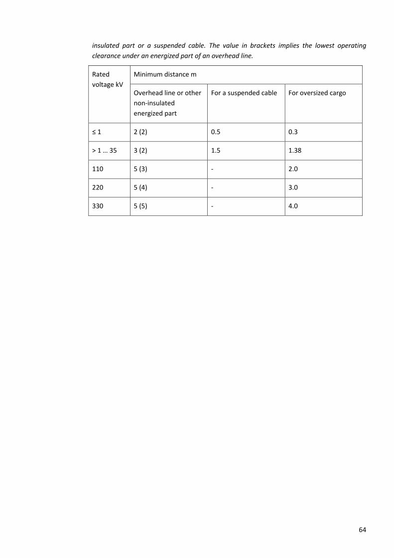
64
insulated part or a suspended cable. The value in brackets implies the lowest operating
clearance under an energized part of an overhead line.
Rated
voltage kV
Minimum distance m
Overhead line or other
non-insulated
energized part
For a suspended cable For oversized cargo
≤ 1 2 (2) 0.5 0.3
> 1 … 35 3 (2) 1.5 1.38
110 5 (3) - 2.0
220 5 (4) - 3.0
330 5 (5) - 4.0
65
7 MAINTENANCE PROCEDURES
7.1 General requirements
7.1.1 The purpose of maintenance is to keep the electrical installations in the required condition.
Maintenance may comprise “preventive maintenance”, which is performed according to the
respective regulations with the intention of preventing insulation breakdown and keeping
equipment in good condition, or “corrective maintenance” which is performed to repair or
replace a defective part.
7.1.2 There are two types of maintenance work:
• work where the risk of electric shock, short circuit or electric arcing is present and therefore
the appropriate work procedures and safety requirements for either dead work, live work
or work in the vicinity of energized parts (see Chapter 6) apply;
• simpler maintenance work (see 7.2.2), which can be performed safely without full
compliance with procedures described in Chapter 6.
7.1.3 Where necessary, the regulations regarding dead work (Clause 6.2), live work (Clause 6.3) or
work in the vicinity of energized parts (Clause 6.4) must be applied.
7.2 Simpler maintenance work
7.2.1 General requirements
7.2.1.1 Simpler maintenance work is listed in Clause 7.2.2.
7.2.1.2 In the case of simpler maintenance work, the Maintenance Manager may grant permission
to execute work verbally or in writing.
7.2.1.3 In the case of work which may result in signalling to the Energy System Control Centre but
for which the Switching Manager does not issue permission to execute work, the Electrical
Work Manager must inform the ESCC dispatcher of the commencement of work.
7.2.1.4 Some simpler maintenance tasks require a written maintenance order to be submitted to
the Energy System Control Centre, as they may reduce the reliability of the system and the
ESCC dispatcher must be kept informed (e.g., to suspend these if necessary). Such work is
listed in Clause 7.2.3.
7.2.1.5 The right to perform simpler maintenance must be exercised by the persons servicing the
electrical installation to whom this work has been appointed via a work contract, job
description or work instructions, after obtaining the permission to start work. The
commencement and completion of the work in the maintenance work list are recorded,
e.g., in the maintenance or operational log.
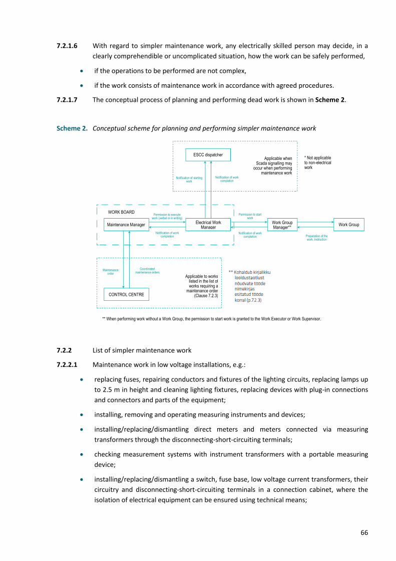
66
7.2.1.6 With regard to simpler maintenance work, any electrically skilled person may decide, in a
clearly comprehendible or uncomplicated situation, how the work can be safely performed,
• if the operations to be performed are not complex,
• if the work consists of maintenance work in accordance with agreed procedures.
7.2.1.7 The conceptual process of planning and performing dead work is shown in Scheme 2.
Scheme 2. Conceptual scheme for planning and performing simpler maintenance work
7.2.2 List of simpler maintenance work
7.2.2.1 Maintenance work in low voltage installations, e.g.:
• replacing fuses, repairing conductors and fixtures of the lighting circuits, replacing lamps up
to 2.5 m in height and cleaning lighting fixtures, replacing devices with plug-in connections
and connectors and parts of the equipment;
• installing, removing and operating measuring instruments and devices;
• installing/replacing/dismantling direct meters and meters connected via measuring
transformers through the disconnecting-short-circuiting terminals;
• checking measurement systems with instrument transformers with a portable measuring
device;
• installing/replacing/dismantling a switch, fuse base, low voltage current transformers, their
circuitry and disconnecting-short-circuiting terminals in a connection cabinet, where the
isolation of electrical equipment can be ensured using technical means;
ESCC dispatcher * Not applicable to non-electrical work
WORK BOARD
Maintenance Manager Electrical Work
Manager Work Group Manager**
Work Group
Permission to execute work (verbal or in writing)
Notification of work completion
Permission to start work
Notification of work completion Preparation of the
work, instruction
Maintenance order
Coordinated maintenance orders
CONTROL CENTRE
Applicable to works listed in the list of works requiring a
maintenance order (Clause 7.2.3)
** When performing work without a Work Group, the permission to start work is granted to the Work Executor or Work Supervisor.
Notification of starting work
Notification of work completion
Applicable when Scada signalling may
occur when performing maintenance work

67
• connecting or disconnecting the power supply cable of an electric motor or other device;
• repair of magnetic starters, contactors, snap-action switches, starting buttons and other
analogous starting and switching apparatus, if they are located outside of cabinets or
switchgear assemblies;
• repairing individual electricity consuming devices (electric motors, heaters, etc.);
• other work performed on the territory of a company, in offices and living spaces,
warehouses, workshops, etc.
7.2.2.2 Maintenance work on non-conductive parts which do not require the voltage to be switched
off, e.g.:
• work on transmission towers, if the parts of the tower are not detached and there is no
climbing beyond 3 m above the ground (to the feet of the person), work related to digging
around the support legs of the tower up to a depth of 0.5 m;
• clearing overhead line routes if there is no dangerous approach to conductors by people
and there is no risk of trees or branches falling on the conductors;
• visual inspection of electrical installations;
• visual inspection of measuring systems, recording readings;
• performing an inspection or measurement using a drone;
• sealing measurement circuits and covers;
• heating inspection, repair and assembly in a substation;
• replacement of silica gel in air filters;
• power transformer oil sampling;
• cleaning and property maintenance work, cutting grass, clearing roads and passageways
from snow in the territory of outdoor switchyards;
• cleaning control panel rooms, corridors and other service rooms, where workers or work
equipment cannot enter the vicinity zone;
• cleaning indoor switchgears, not beyond permanent barriers;
• the restoration of permanent signs and labels at a substation or on transmission towers;
• repair of fences;
• thermal inspection of electrical installations;
• painting;
• measurement of dimensions;
• maintenance work on carriage-type switchgear in the repair position.
7.2.2.3 Maintenance work in the secondary circuits of high voltage installations, when access to the
high voltage part is restricted by the construction of the equipment, secondary circuits are
protected from overloads and short circuits and the risk of unwanted switching of high
voltage switches is obviated, e.g.:
• performing measurements in secondary circuits;
• searching for and repairing malfunctions in secondary devices and circuits;
• configuration of automation devices, downloading log files, changing settings, etc.
68
• replacement of automation devices or their individual components in case of defects;
• work on carriage-type switchgear in the inspection or repair position;
• testing automation devices by injecting voltage and current into secondary circuits;
• changing electrical meters in a substation, in a metering cabinet, where there are isolation
terminals, short-circuiting terminals or a switch for isolation;
• tightening the terminal block or isolation-short-circuiting terminals of the meter when the
terminals are separated by insulating inserts.
7.2.3 List of work requiring a written maintenance order, e.g.:
• maintenance of or configuring busbar/transformer/line protection and automation, etc.;
• maintenance of the protection of the switching devices between busbars (in case the circuit
breaker CBBB or CBBS has a completely separate protection);
• if the substation is completely deprived of main and backup auxiliary power (an external
source will supply the auxiliary power system);
• if RTU setup is performed in a substation or communication channels are configured;
• maintenance or configuration of system protection equipment;
• shutting down the storage battery for maintenance;
• for changing relay protection and automation settings in several substations (one task –
temporary non-selectivity may occur);
• during maintenance of one section of the AC centre in main substations;
• during maintenance of one system of the DC centre in main substations;
• performing work in the vicinity of energized parts.
7.3 Work organization of personnel
7.3.1 All maintenance procedures to be performed must be coordinated with the Maintenance
Manager.
7.3.2 When maintenance work is performed on an electrical installation:
• the part of the installation concerned must be clearly defined;
• an Electrical Work Manager must be appointed.
7.3.3 Personnel who will perform the maintenance work must be adequately instructed or
electrically skilled, i.e. they must be competent in terms of the task to be performed. They
must be equipped with and they must use appropriate tools, measuring and testing devices
and personal protective equipment, all of which must be maintained in good condition.
7.3.4 The person who arranges the work (Electrical Work Manager or the Maintenance Manager
of the electrical installation) must record the work performed in their personal or electrical
installation maintenance log and inform the ESCC dispatcher of the commencement and
69
completion of the work. In case of non-electrical work, the ESCC dispatcher will not be
informed.
7.3.5 All necessary safety measures must be implemented, including precautions to prevent
danger to other persons and the protection of livestock and property, if necessary.
7.4 Repair work
7.4.1 Repair work may consist of the following stages:
• fault location;
• fault rectification and/or replacement of components;
• recommissioning the repaired part of the installation.
Different procedures may need to be performed at each stage of the work.
7.4.2 Special measures are implemented when locating and identifying the extent of faults with
the installation energized or during application of test voltages, pursuant to Chapter 5 or 6.
7.4.3 Elimination of faults must be performed in accordance with the regulations regarding work
procedures stipulated in Chapter 6.
7.4.4 Appropriate functional and verification tests and necessary adjustments must be performed
to ensure that the repaired parts of the installation are suitable for re-energizing.
7.5 Replacement of fuses and lamps
7.5.1 Replacement of fuses
7.5.1.1 Generally, the replacement of fuses must be performed as dead work, unless a safe
procedure is prescribed to replace them in an energized state.
7.5.1.2 Without load, fuses may be removed and reinserted live. The replacement of fuses in
auxiliary circuits and fuses and plug fuses of voltage transformers is permitted under voltage
and load.
7.5.1.3 When removing and reinserting fuses under voltage, the following must be used:
• in high voltage installations – face and eye protection along with insulated tools and gloves
specifically designed for such replacement work,
• in low voltage installations – face and eye protection along with insulated tools and gloves
specifically designed for such replacement work,
7.5.1.4 In low voltage installations, if the fuse is fitted into a device designed in a way which
protects the person against direct contact and the possible occurrence of a short circuit, the
replacement may be performed without verifying the absence of voltage by an ordinary
person.
7.5.1.5 In high voltage installations, the replacement must be performed according to the
appropriate working procedures (see Chapter 6) by an instructed or electrically skilled
person.
70
7.5.2 Replacement of lamps and accessories
7.5.2.1 The replacement of lamps and withdrawable accessories, such as starters, must be
performed in a de-energized state – but, where necessary, based on risk assessment, it may
be performed live.
7.5.2.2 In low voltage installations, these replacements may be performed live by an ordinary
person if the equipment provides protection against direct contact (minimum IP2X or
IPXXB).
7.5.2.3 In all other cases and especially in the case of high voltage installations, replacement must
be performed in accordance with repair procedures (see 7.4).
7.5.2.4 Replacement of non-withdrawable accessories must be performed in accordance with the
working procedures prescribed in Chapter 6.
7.5.2.5 Care must be taken to ascertain whether the replacement parts used are suitable for use in
the equipment being serviced.
7.6 Visual inspection
7.6.1 During visual inspection, it is prohibited to enter rooms and compartments in high voltage
electrical equipment where there is a risk of approaching the conductive parts closer than
the distance DL specified in Table 1. It is prohibited to open doors or grate covers and to
move beyond safety barriers.
7.6.2 In low voltage electrical installations, it is allowed to open the doors of cabinets, control
panels and other equipment during inspection.
7.6.3 During visual inspection, it is prohibited to perform any repairs or refurbishment, to climb
onto towers and their structural components.
7.6.4 During the inspection of an overhead line during dark periods, it is prohibited to walk under
conductors. To mark the danger areas while inspecting for damage, overhead line inspectors
must be supplied with the warning signs “Electrical hazard” or the warning notices “Stop.
Voltage”.
7.7 Temporary suspension of work
In the event of temporary suspension of maintenance work, the Electrical Work Manager
must implement all necessary measures to prevent access to bare energized parts and
unauthorised operation of the electrical installation. If necessary, the issuer of the
permission to execute work (the Maintenance Manager or Switching Manager) must be
informed of any such suspension of work.
7.8 Completing maintenance work
After the conclusion of maintenance work, the Electrical Work Manager must relinquish the
installation to the issuer of the permission to execute work (Maintenance Manager or ESCC
dispatcher), who must be informed of the post-maintenance condition of the installation.
71
8 WORKING IN THE PROTECTION ZONE OF THE ELECTRICAL
INSTALLATION
8.1 General requirements
8.1.1 In the protection zone of an electrical installation, it is prohibited to block access to the
electrical installation, to cause pollution and corrosion of the electrical installation through
activities, or to otherwise create a situation which may endanger persons, property or the
environment, to impede maintenance of the electrical installation and the preservation of
vegetation or ground in the protection zone in a state which does not endanger the
electrical installation.
8.1.2 In the protection zone of an electrical installation, the following is prohibited without
permission from the owner:
• to build, store waste, materials or substances, perform any piling, removal, mining, loading,
dredging, blasting or amelioration of ground material, light a fire, plant or cut trees;
• to anchor a watercraft in the protection zone of a submerged cable line, perform movement
with dropped anchor, chains, logs, trawls and nets, install traffic markers and buoys for
watercraft and store ice;
• to drive machinery or mechanisms having a total height above ground, with or without a
load, of more than 4.5 metres, in the protection zone of an overhead line;
• to build wire fences, establish hydration sites for animals or to hold mass-participation
events in the protection zone of a high voltage overhead line;
• to work in the protection zone of an underground cable line using impact mechanisms,
perform surface levelling, perform soil work (including soil removal) at a depth of over 0.3
metres, on ploughed land at a depth of over 0.45 metres, and store or move heavy weights.
8.1.3 Non-electrical work in the electrical installation protection zone must, if necessary, be
subject to the requirements regarding work in the vicinity of energized parts (see Clause 6.4,
more specifically Clause 6.4.4).
8.2 Applying for a permit to operate in the electrical installation protection zone
8.2.1 An entity wanting to perform the activities referred to in Clause 8.1.2 and acting on a legal
basis must submit a written application to the owner of the electrical installation at least 10
business days prior to the start of the planned activity (the application form can be found in
Annex 3).
8.2.2 The owner of the electrical installation must inform the applicant whether the application
has been accepted or rejected no later than 5 business days from the date of submission of
the application.
8.2.3 A person operating in the protection zone of an electrical installation must confirm with
their signature on the permission granted to them that they have been instructed about the
location of the electrical installation, the extent of its protection zone, the restrictions which
72
apply and the appropriate safety measures and responsibility for maintaining the functional
integrity of the electrical installation (forms for permissions for operating in the protection
zone can be found in Annexes 4 and 4A).
8.2.4 After completion of work in the protection zone of the electrical installation, the person
who has received the permission to work must inform the Maintenance Manager about the
completion of the work. If the electrical installation has been switched off to perform the
work, the notification of work completion must be formalized in writing and it must indicate
that persons have been displaced from the work location and that the electrical equipment
may be switched on.
8.3 Organizing activities in the protection zone of an electrical installation
8.3.1 A person operating in the protection zone of an electrical installation must avoid damaging
the electrical installation or the risk of damage being done. If necessary, a Work Supervisor
will be appointed by the Maintenance Manager or the Electrical Work Manager.
8.3.2 In case of damage or a risk of damage to the electrical installation, the person working in the
protection zone of the electrical installation is obligated to:
• immediately stop their activities which may result in damage to the electrical installation in
the protection zone;
• immediately inform the owner of the electrical installation of the risk of damage or actual
damage to the electrical installation;
• implement measures to prevent further damage to the electrical installation;
• in the case of a risk to third parties, inform them of the possible source of danger, e.g., to
mark the perimeter of the danger zone using warning tape, to arrange surveillance until the
representative of the owner of the electrical installation arrives, etc.
8.3.3 If, in the case of damage or risk of damage to the electrical installation, the person
performing the work is not aware of who the owner of the electrical installation to be
notified is, then the owner of the real estate must be immediately informed in the case of a
cable in the ground and the Maritime Administration must be immediately informed in the
case of a cable in a body of water. If, with the assistance of these persons and institutions,
the owner of the electrical installation cannot be identified, the Consumer Protection and
Technical Regulatory Authority must be informed regarding the cable.
8.3.4 If the owner of the electrical installation cannot be identified with the assistance of the
persons and institutions referred to in Clause 8.3.3, the work may be continued in a manner
which obviates the possibility of damage to the electrical installation.
8.4 Cutting trees and brush in the protection zone of an electrical installation
8.4.1 The owner of the electrical installation maintains the right to cut trees and brush growing in
the protection zone which endanger the electrical installation, informing the owner of the
real estate in advance.
73
8.4.2 The owner of the electrical installation maintains the right to cut trees and branches of trees
and brush which have caused a fault in the electrical installation or created a hazardous
situation, without prior notice to the owner of the real estate.
8.4.3 In the protection zone of the electrical installation, when cutting trees, branches of trees
and brush, the owner of the electrical installation is obligated, in coordination with the
owner of the real estate, to delimb, cross-cut and collect the cut trees, to collect the cutting
waste into heaps or stacks or to burn it.
8.4.4 When cutting trees and brush in densely populated areas, in addition to the provisions of
Clauses 8.4.1 through 8.4.3, the requirements stipulated in section 45 of the Nature
Conservation Act must be considered.
8.4.5 Deforestation must be performed in accordance with the procedure stipulated in the Forest
Act and other legislation established on the basis thereof.

74
9 ANNEXES
All Annexes concerning work in the electrical installations of Elering AS must be formalized
in Estonian. The provided English versions of the Annexes are only for reference. The actual
safety signs and labels used in electrical installations are always in Estonian and are also
provided for reference.

Page …. / ….. DD.MM.YYYY
Obligations of the Switching Operator not specified in the content of the switching order: verification of absence of voltage prior to earthing, locking the devices, installation of safety signs and notices, before operating CBC and DC check CB is off. Abbreviations used: switch on – ON; switch off – OFF; check ON position – CON; check off position – COFF; verify absence of voltage– VAV; check position – CP; disconnector – DC; earthing switch – ES; load disconnector – LD; isolator – I; short-circuiting switch – SCS; circuit breaker – CB; SGA circuit breaker carriage – CBC; low-voltage snap-action switch – lvss; low voltage circuit breaker – lvcb; fuse – f; carriage out to control position – CCP; carriage out to repair position – CRP; portable earthing - PE.
ANNEX 1A Page … of …
Switching order
Switching notification
Switching order (SO) No. .....................................
Form prepared by:
FROM WHOM (name):
TO WHOM (name):
Occupational safety function:
Elering AS Switching Manager
Occupational safety function:
Switching Operator
Phone No. 7155400 Phone No.
e-mail: [email protected] e-mail:
Purpose:
No. ORDER CONTENT Performed switching
operation Note
1.
2.
3.
4.
5.
6.
7.
Switching order given (date on which switchings are started): …………………………………………
time: ……………………………………… signature: ………………………………………
Switching operations are executed and switching notification submitted (date): …………………………………
time: ………………………………………… signature: …………………………………………
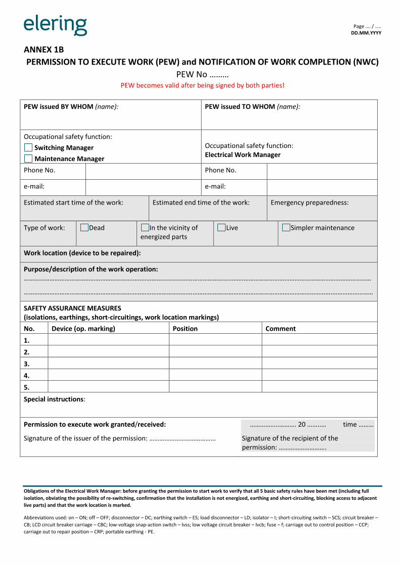
Page …. / ….. DD.MM.YYYY
Obligations of the Electrical Work Manager: before granting the permission to start work to verify that all 5 basic safety rules have been met (including full
isolation, obviating the possibility of re-switching, confirmation that the installation is not energized, earthing and short-circuiting, blocking access to adjacent
live parts) and that the work location is marked.
Abbreviations used: on – ON; off – OFF; disconnector – DC; earthing switch – ES; load disconnector – LD; isolator – I; short-circuiting switch – SCS; circuit breaker –
CB; LCD circuit breaker carriage – CBC; low-voltage snap-action switch – lvss; low voltage circuit breaker – lvcb; fuse – f; carriage out to control position – CCP;
carriage out to repair position – CRP; portable earthing - PE.
ANNEX 1B
PERMISSION TO EXECUTE WORK (PEW) and NOTIFICATION OF WORK COMPLETION (NWC)
PEW No ……… PEW becomes valid after being signed by both parties!
PEW issued BY WHOM (name):
PEW issued TO WHOM (name):
Occupational safety function:
Switching Manager
Maintenance Manager
Occupational safety function: Electrical Work Manager
Phone No. Phone No.
e-mail: e-mail:
Estimated start time of the work: Estimated end time of the work:
Emergency preparedness:
Type of work: Dead In the vicinity of energized parts
Live Simpler maintenance
Work location (device to be repaired):
Purpose/description of the work operation: ……………………………………………………………………………………………………………………………………………………………………………………
……………………………………………………………………………………………………………………………………………………………….……………………
SAFETY ASSURANCE MEASURES (isolations, earthings, short-circuitings, work location markings)
No. Device (op. marking) Position Comment
1.
2.
3.
4.
5.
Special instructions:
Permission to execute work granted/received:
Signature of the issuer of the permission: …………………………………
……………..………. 20 ……..… time ………
Signature of the recipient of the permission: ……………………….
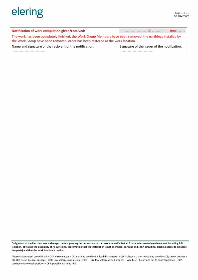
Page …. / ….. DD.MM.YYYY
Obligations of the Electrical Work Manager: before granting the permission to start work to verify that all 5 basic safety rules have been met (including full
isolation, obviating the possibility of re-switching, confirmation that the installation is not energized, earthing and short-circuiting, blocking access to adjacent
live parts) and that the work location is marked.
Abbreviations used: on – ON; off – OFF; disconnector – DC; earthing switch – ES; load disconnector – LD; isolator – I; short-circuiting switch – SCS; circuit breaker –
CB; LCD circuit breaker carriage – CBC; low-voltage snap-action switch – lvss; low voltage circuit breaker – lvcb; fuse – f; carriage out to control position – CCP;
carriage out to repair position – CRP; portable earthing - PE.
Notification of work completion given/received: ……………..………. 20 ……..… time ………
The work has been completely finished, the Work Group Members have been removed, the earthings installed by the Work Group have been removed, order has been restored at the work location.
Name and signature of the recipient of the notification: …………………………………
Signature of the issuer of the notification: …………………………………
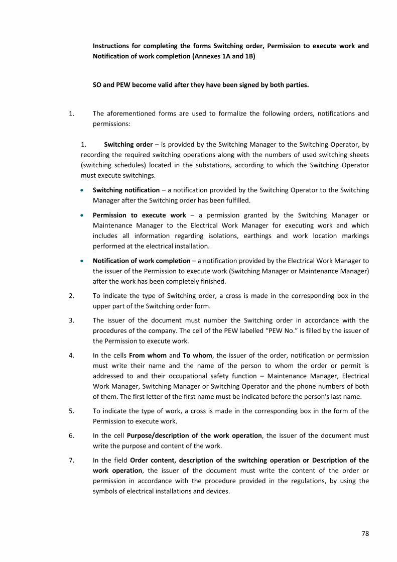
78
Instructions for completing the forms Switching order, Permission to execute work and
Notification of work completion (Annexes 1A and 1B)
SO and PEW become valid after they have been signed by both parties.
1. The aforementioned forms are used to formalize the following orders, notifications and
permissions:
1. Switching order – is provided by the Switching Manager to the Switching Operator, by
recording the required switching operations along with the numbers of used switching sheets
(switching schedules) located in the substations, according to which the Switching Operator
must execute switchings.
• Switching notification – a notification provided by the Switching Operator to the Switching
Manager after the Switching order has been fulfilled.
• Permission to execute work – a permission granted by the Switching Manager or
Maintenance Manager to the Electrical Work Manager for executing work and which
includes all information regarding isolations, earthings and work location markings
performed at the electrical installation.
• Notification of work completion – a notification provided by the Electrical Work Manager to
the issuer of the Permission to execute work (Switching Manager or Maintenance Manager)
after the work has been completely finished.
2. To indicate the type of Switching order, a cross is made in the corresponding box in the
upper part of the Switching order form.
3. The issuer of the document must number the Switching order in accordance with the
procedures of the company. The cell of the PEW labelled “PEW No.” is filled by the issuer of
the Permission to execute work.
4. In the cells From whom and To whom, the issuer of the order, notification or permission
must write their name and the name of the person to whom the order or permit is
addressed to and their occupational safety function – Maintenance Manager, Electrical
Work Manager, Switching Manager or Switching Operator and the phone numbers of both
of them. The first letter of the first name must be indicated before the person's last name.
5. To indicate the type of work, a cross is made in the corresponding box in the form of the
Permission to execute work.
6. In the cell Purpose/description of the work operation, the issuer of the document must
write the purpose and content of the work.
7. In the field Order content, description of the switching operation or Description of the
work operation, the issuer of the document must write the content of the order or
permission in accordance with the procedure provided in the regulations, by using the
symbols of electrical installations and devices.
79
8. The field Specific instructions must contain additional measures to ensure the safety of
workers or additional instructions to organize the work.
9. If there are not enough rows in the form of the order or permission, it is permitted to add
an additional form of the order or permission with the same number and signature of the
issuer of the order or permission, indicating on the upper part of the form the page number
and total number of pages.
10. The completed forms of the order or permission must be maintained for a minimum of 30
calendar days.
11. Coloured cells in the form of the Permission to execute work are generally filled in
automatically based on the outage order via Elering’s asset management software. When
filling in the form of the Permission to execute work outside of Elering's asset management
software, the issuer of the Permission to execute work also fills in the coloured cells.
12. The Permission to execute work is prepared in two copies, one of which remains with the
issuer of the permission and the other with the recipient. The Permission to execute work is
signed by the issuer of the permission and the recipient.
13. If the Permission to execute work is issued by phone and is formalized in writing, the field
Permission to execute work granted/received is filled in by the issuer of the Permission to
execute work and recipient of the Permission to execute work only in their own copy as
follows:
• The Switching Manager / Maintenance Manager fills their copy with the date and time of
the Permission to execute work notified by phone and signs the field Signature of the issuer
of the permission. The field Signature of the recipient of the permission remains empty in
the copy of the Switching Manager / Maintenance Manager.
• The Electrical Work Manager completes their copy with the date and time of the permission
to execute work notified by phone and signs the field Signature of the recipient of the
permission. The field Signature of the issuer of the permission will remain empty in the
copy of the Electrical Work Manager.
14. If the Notification of work completion is issued by phone by the Electrical Work Manager
and is completed in writing, the field Notification of work completion given/received is
filled in by the issuer of the Permission to execute work and recipient of the Permission to
execute work only in their own copy as follows:
• The Switching Manager / Maintenance Manager fills in their copy with the number of the
Notification of work completion and date and time provided to them by the Electrical Work
Manager by phone and adds their name and signature in the field Name and signature of
the recipient of the notification. The field Signature of the issuer of the notification will
remain empty in the copy of the Switching Manager / Maintenance Manager.
• The Electrical Work Manager fills in their copy with the number of the Notification of work
completion and date and time provided to the Switching Manager and adds their signature
in the field Signature of the issuer of the notification. The field Name and signature of the
recipient of the notification will remain empty in the copy of the Electrical Work Manager.
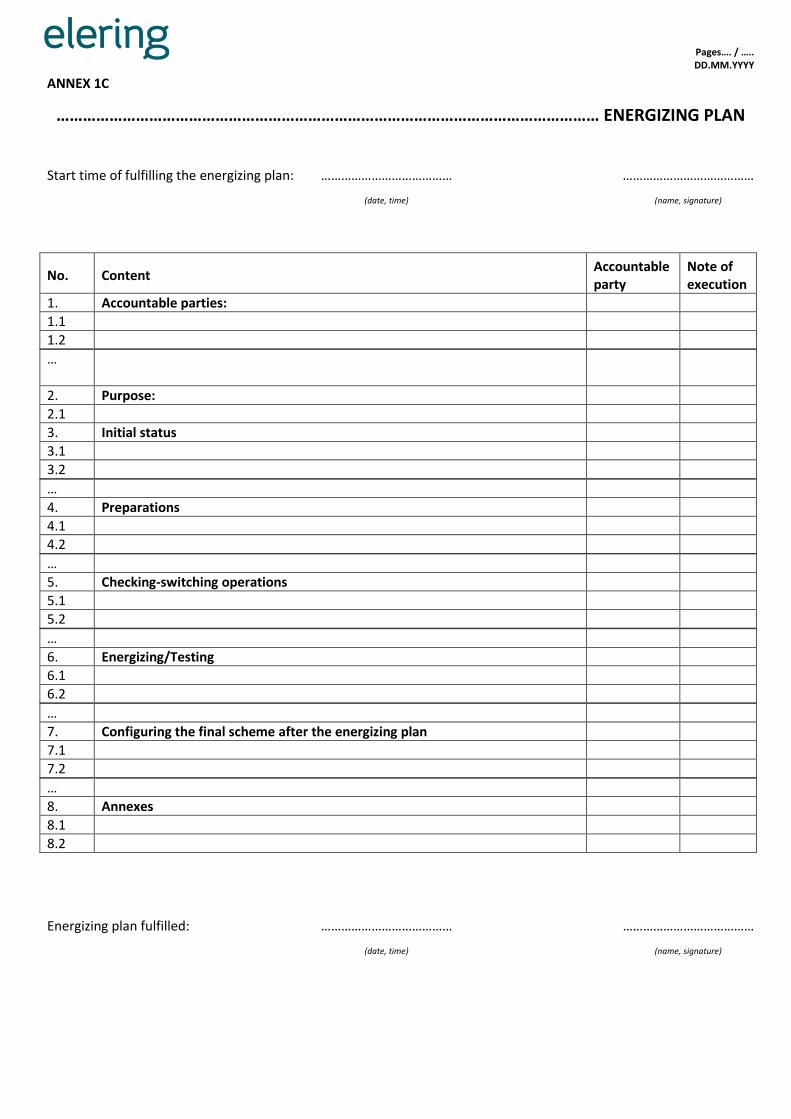
Pages…. / ….. DD.MM.YYYY
ANNEX 1C
…………………………………………………………………………………………………………… ENERGIZING PLAN
Start time of fulfilling the energizing plan: ………………………………… …………………………………
(date, time) (name, signature)
No. Content Accountable party
Note of execution
1. Accountable parties:
1.1
1.2
…
2. Purpose:
2.1
3. Initial status
3.1
3.2
…
4. Preparations
4.1
4.2
…
5. Checking-switching operations
5.1
5.2
…
6. Energizing/Testing
6.1
6.2
…
7. Configuring the final scheme after the energizing plan
7.1
7.2
…
8. Annexes
8.1
8.2
Energizing plan fulfilled: ………………………………… …………………………………
(date, time) (name, signature)
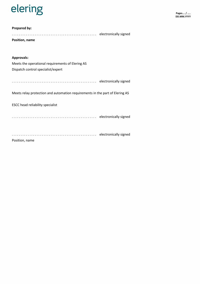
Pages…. / ….. DD.MM.YYYY
Prepared by:
. . . . . . . . . . . . . . . . . . . . . . . . . . . . . . . . . . . . . . . . . . . . . . . . electronically signed
Position, name
Approvals:
Meets the operational requirements of Elering AS
Dispatch control specialist/expert
. . . . . . . . . . . . . . . . . . . . . . . . . . . . . . . . . . . . . . . . . . . . . . . . electronically signed
Meets relay protection and automation requirements in the part of Elering AS
ESCC head reliability specialist
. . . . . . . . . . . . . . . . . . . . . . . . . . . . . . . . . . . . . . . . . . . . . . . . electronically signed
. . . . . . . . . . . . . . . . . . . . . . . . . . . . . . . . . . . . . . . . . . . . . . . . electronically signed
Position, name
82
Instructions for completion of the form Energizing plan (1C)
1. An energizing plan is generally composed by the Maintenance Manager, who coordinates it
with the ESCC, the client, as well as all other relevant parties (accountable persons) involved
in the energizing plan.
2. It is allowed to insert and delete rows in the form of the energizing plan.
3. It is also permitted to supplement the form of the energizing plan with new headings and to
delete the existing headings, if necessary (except Accountable persons, Purpose, Initial
state, Energizing/Testing).
4. Before commencing the implementation of the energizing plan, it must be approved by the
accountable persons and signed by the Maintenance Manager and the accountable
specialists of ESCC.
5. The document header is filled in with the name of the electrical installation to be energized
or tested (for which the plan is being composed).
6. In the cell “Start time of fulfilling the energizing plan”, the Maintenance Manager and
Switching Manager must write on their respective copies the date and time on which
implementation of the energizing plan is allowed to be commenced. The date and time of
commencement of the energizing plan must be agreed by the Switching Manager and the
Maintenance Manager by phone immediately prior to commencement of the energizing
plan.
7. In the cell “Name, signature” the Switching Operator and the Maintenance Manager must
write the name of both persons (i.e. both the Switching Manager and the Maintenance
Manager) in their copy and sign their copy.
8. Each operation in the energizing plan is written on a separate row. The content of the
operation is written in the column “Content”.
9. It is necessary to appoint an accountable person for each operation described in the
energizing plan. The persons accountable for the implementation of the energizing plan
must be listed together with the person's name, role, area of responsibility and phone
number in the subsection “Accountable persons” of the energizing plan and during
preparation of the energizing plan, for each row of the energizing plan, the column
“Accountable person” is filled in with the name of the person or company (or respective
abbreviation), who is responsible for fulfilling/verifying the relevant row in the energizing
plan.
10. In the column “Note of execution”, the Maintenance Manager as well as the Switching
Manager must make a note in their copy when the respective operation has been
performed during execution of the energizing plan.
11. In the subsection “Purpose”, the purpose of the operations (energizing new equipment,
testing, measuring line clearances, etc.) to be performed based on the energizing plan is
written.
12. In the subsection “Initial status”, the initial status in the electrical installation before
fulfilling the energizing plan is written.
83
13. In the subsection “Preparations”, the activities are written which must be performed before
energizing can be commenced, including the initial status of the scheme and the positions or
parameters of the switches/equipment and their desired values/positions.
14. The subsection “Checking-switching operations” is used to describe the equipment checking
operations related to the equipment to be brought into operation/test object pertaining to
the energizing plan.
15. In the subsection “Energizing/Testing”, the content of the work to be performed based on
the energizing plan is written.
16. In the subsection “Configuring the final scheme after the energizing plan”, operations are
described which are required to be performed to restore the normal scheme after
energizing.
17. In the subsection “Annexes”, the annexes pertaining to the energizing plan (schemes,
explanations, documents, etc.) are listed.
18. In the cell “Energizing plan fulfilled”, the Maintenance Manager and Switching Manager
must write, in their respective copies, the date and time on which execution of the
energizing plan is actually completed. The date and time of fulfilling the energizing plan
must be agreed by the Switching Manager and the Maintenance Manager by phone
immediately after the completion of the energizing plan.
19. In the cell “Name, signature” the Switching Manager and the Maintenance Manager must
write the name of both persons (i.e. both the Switching Manager and the Maintenance
Manager) in their copy and must sign their copy after fulfilling the energizing plan.

Pages…. / ….. DD.MM.YYYY
ANNEX 2
PERMISSION TO START WORK NO. ……………………….
FROM WHOM (name):
TO WHOM (name):
Occupational safety function: Electrical Work Manager
Occupational safety function:
To the Work Group Manager
To the Work Executor
To the Work Supervisor
Phone No. Phone No.
e-mail: e-mail:
Work Group Members
…………………………………………………………………………………………………………………………………………….….
………………………………………………………………………………………………….…………………………………………….
Type of work: Dead In the vicinity of energized parts
Live Simpler maintenance
Permission to execute work (PEW) No.
Name of the issuer of PEW and time:
Work location (device to be repaired):
Description of the work operation: …………………………………………………………………………………………………………………………………………………………………………………
…………………………………………………………………………………………………………………………………………………………….……………………
Special instructions:
…………………………………………………………………………………………………………………………………………………………………………………
…………………………………………………………………………………………………………………………………………………………….……………………
…………………………………………………………………………………………………………………………………………………………………………………
…………………………………………………………………………………………………………………………………………………………….……………………
Time allowed to start the work: Deadline for completion of the work:
MEASURES APPLIED TO PREPARE THE WORK LOCATION (INCLUDING ISOLATIONS AND
EARTHINGS)
Name of the electrical installation Isolations Earthings

Pages…. / ….. DD.MM.YYYY
The Electrical Work Manager will declare by signature that they are convinced that all 5 basic safety rules have been
fulfilled (i.e. full isolation, obviation of the possibility of re-switching, confirmation that the installation is de-
energized, earthing and short-circuiting, blocking access to adjacent energized parts) and that the work location is
marked.
Permission to start work granted/received: ………………………………………………… 20 ………. time ………
Signature of the issuer of the permission Signature of the recipient of the permission
Permission to start work extended until:
Date: Time:
Name: Signature:
DAILY COMMENCEMENT AND SUSPENSION OF WORK
Work Group Members instructed and allowed in the prepared work location
Work completed, Work Group removed from the work location
Work location name Date / time Work Group Manager (Work Executor, Work Supervisor) signature
Date / time Work Group Manager (Work Executor, Work Supervisor) signature
CHANGES IN THE COMPOSITION OF THE WORK GROUP
Included in the Work Group (name) Excluded from the Work Group (name)
Date / time Signature of the Work Group Manager
NOTIFICATION AND FORMALIZING COMPLETION OF WORK
Notification of work completion given/received: ………………………………… 20 ………. time ……… The work has been completely finished, the Work Group Members have been removed, the earthings installed by the Work Group have been removed, order has been restored at the work location.

Pages…. / ….. DD.MM.YYYY
Recipient of the notification
name and signature
Issuer of the notification
signature:

87
Instructions to complete the permission to start the work form
1. Entries in the Permission to start work form must be clearly legible. It is not allowed to fill in
the permission to start work using a pencil and to make corrections in it.
2. The Permission to start work is issued for a period not exceeding 15 calendar days, including
the day on which the work is started. The period of validity of the Permission to start work
may be extended once by 15 calendar days, starting on the day on which the work is
commenced. During an interruption in work the Permission to start work remains valid.
3. The Permission to start work must be numbered according to the procedure implemented
in the company.
4. When writing the dates, the date, month and year are written using numbers, e.g.,
01.03.2020.
5. The first name or the first letter of the first name must be indicated before the person's last
name.
6. In the Permission to start work, the symbols affixed to the electrical installations,
connections and devices must be used.
7. If there are not enough rows in the table or text of the Permission to start work, rows may
be added in the form, or if this is not possible, it is permitted to add an additional form of
the Permission to start work with the same number and signature of the issuer of the
Permission to start work in order to continue the entries.
8. In the row Company, the name of the company must be written to whom the Electrical
Work Manager issues the Permission to start work and the name of the company to whose
Work Group Manager / Work Supervisor / Work Executor the Permission to start work is
issued.
9. In the row Work Group Members, the names of the workers are listed. If machinery or self-
propelled cranes are used for the work, it must be indicated which of the members of the
Work Group is operating the machinery or is the crane driver, also the type of the self-
propelled crane or mechanism they are working with.
10. To describe the Work type, a cross is made in the relevant box – either Dead or In the
vicinity of energized parts or Live or Simpler maintenance.
11. In the row Number of the Permission to execute work, in case of work to be performed
based on an outage order, the number of the PEW granted by the Switching Manager is
written and in case of work performed based on a maintenance order or in case of simpler
maintenance work, the PEW number provided by the Maintenance Manager is written. If
PEW is issued by the Maintenance Manager verbally, it must be noted in the cell “PEW No”.
12. In the row Name of the issuer of PEW and time, it must be written by whom, at what time
and in which manner the PEW was issued.
13. In the row Work location (device to be repaired), it must be indicated in which part of the
electrical installation work is authorised under the Permission to start work.
14. In the row Description of the work operation, the name of the electrical installation and
connections where work is to be done and the content of the work must be written in an
unambiguous manner. In case of overhead lines, the name of the line, the boundaries of the
section intended for work (the number of towers on which or between which, including the
last towers, the work is to be performed, the individual spans, e.g. the span between the
terminal tower and portal support, etc.) and the content of the work must be indicated. In
the case of a multi-circuit line, the name of the circuit must also be indicated.
88
15. In the row Special instructions, the following is written, e.g.:
• additional measures to ensure the safety of workers (placing barriers, checking the absence
of hydrogen in the air of the rooms, fire safety measures, etc.);
• the work stages or individual work operations which must be performed under the
continuous supervision of the Work Group Manager;
• instructions regarding the coordination of work;
• instructions for the Work Group Manager on transferring the Work Group from one work
location to another and on allowing repeat initiation of work;
• permission to temporarily remove earthing during withstand testing or other testing (only
when working according to an energizing plan);
• permission for the Work Group Manager to operate switching devices;
• instructions regarding the need to check earthings on the overhead lines of other utilities;
• sources of danger from induced voltage;
• a note that according to PEW issued by the Maintenance Manager the Contractor (Electrical
Work Manager) will prepare the work location, isolations and earthings.
In special instructions, also the locations must be indicated where the Work Group Manager
must place earthings on overhead lines intersecting with the line to be repaired or close to
these. In case these lines are serviced by another company, then in the row Special
instructions, in the Permission to execute work, the requirement to check the earthings
placed by the personnel of that company must be indicated.
At their discretion, the issuer of the Permission to start work is allowed to indicate other
work-related instructions in the row Special instructions.
16. In the rows Time allowed to start the work and Deadline for completion of work, the dates
and times when work is started and completed on the basis of the Permission to execute
work are indicated. The time allowed for start of work cannot be earlier than the time the
Permission to start work was granted/received.
17. The isolations and earthings necessary to prepare the work location (the same as in the
outage order) must be written in the part MEASURES APPLIED TO PREPARE THE WORK
LOCATION. After the notification has been received, the isolations and earthings have been
performed during the preparation of the work location, the measures specified in Table 1
are deemed to have been complied with.
18. In the row Permission to start work granted/received, the issuer of the Permission to start
work must mark the signing date and time. In case the Permission to start work was
transmitted by radio or phone, the recipient must fill in the form of the Permission to start
work in their possession and, after verification by re-reading the contents vocally to the
issuer, must write the name, date and time of receiving it in the place of the signature of the
Permission to start work and confirm the correctness of the entries with their signature.
19. In the part DAILY COMMENCEMENT AND SUSPENSION OF WORK, the daily start and end of
the work are formalized, including the start of the work when transferred to another work
location by the Work Group Manager in their copy.
20. If a driver, operator of machinery or crane driver are included into or excluded from the
Work Group, the Work Group Manager must indicate it in the section CHANGES IN THE
COMPOSITION OF THE WORK GROUP of their copy, as well as the type of the machinery or
self-propelled crane assigned to them.
89
21. After completion of work, removal of the Work Group Members from the work location,
removal of the earthings placed by the Work Group Manager and restoring order to the
work location, the Work Group Manager or Work Executor must inform the Electrical Work
Manager and sign the relevant rows in the Permission to start work, indicating the date and
time of work completion.
22. The Permissions to start work of completed work must be maintained for 3 months.
23. The coloured cells in the form of the permission are filled in automatically via Elering's
management software (if PEW is issued through it) based on the Permission to execute
work.
24. The Permission to start work is completed in two copies, one of which remains with the
Work Group Manager and the other with the Electrical Work Manager. During execution of
the work, the Work Group Manager supplements the following parts of the Permission to
start work: DAILY COMMENCEMENT AND COMPLETION OF WORK and CHANGES IN THE
COMPOSITION OF THE WORK GROUP only in their own copy.
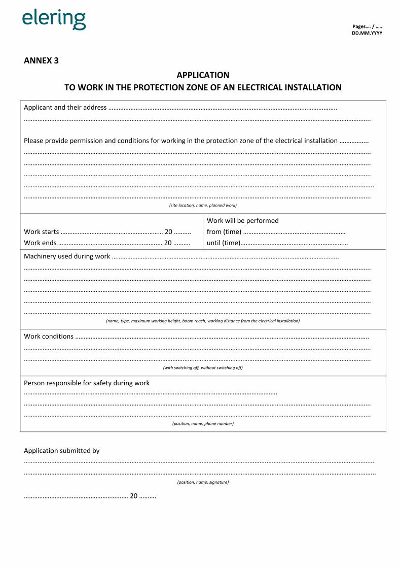
Pages…. / ….. DD.MM.YYYY
ANNEX 3
APPLICATION
TO WORK IN THE PROTECTION ZONE OF AN ELECTRICAL INSTALLATION
Applicant and their address ……………………………………………………………………………………………………………………..
…………………………………………………………………………………………………………………………………………………………………………………..
Please provide permission and conditions for working in the protection zone of the electrical installation ……………..
…………………………………………………………………………………………………………………………………………………………………………………..
…………………………………………………………………………………………………………………………………………………………………………………..
…………………………………………………………………………………………………………………………………………………………………………………..
…………………………………………………………………………………………………………………………………………………………………………………….
………………………………………………………………………………………………………………………………………………………………………………….. (site location, name, planned work)
Work starts …………………………………………………… 20 ……….
Work ends ………………………………………………….… 20 ……….
Work will be performed
from (time) ……………………………………………………
until (time)………………………………………………………
Machinery used during work …………………………………………………………………………………………………………………….
…………………………………………………………………………………………………………………………………………………………………………………..
…………………………………………………………………………………………………………………………………………………………………………………..
…………………………………………………………………………………………………………………………………………………………………………………..
…………………………………………………………………………………………………………………………………………………………………………………..
………………………………………………………………………………………………………………………………………………………………………………….. (name, type, maximum working height, boom reach, working distance from the electrical installation)
Work conditions ……………………………………………………………………………………………………………………………………………………….
…………………………………………………………………………………………………………………………………………………………………………………..
………………………………………………………………………………………………………………………………………………………………………………….. (with switching off, without switching off)
Person responsible for safety during work ………………………..…………………………………………………………………………….………………………….
…………………………………………………………………………………………………………………………………………………………………………………..
………………………………………………………………………………………………………………………………………………………………………………….. (position, name, phone number)
Application submitted by
…………………………………………………………………………………………………………………………….………………………………………………………
…………………………………………………………………………………………………………………………………………………………………………………….. (position, name, signature)
………………………………………………….… 20 ……….
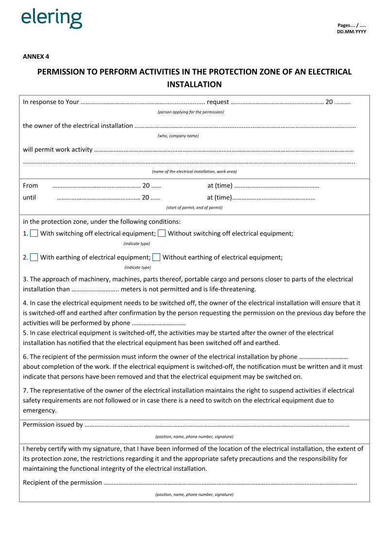
Pages…. / ….. DD.MM.YYYY
ANNEX 4
PERMISSION TO PERFORM ACTIVITIES IN THE PROTECTION ZONE OF AN ELECTRICAL
INSTALLATION
In response to Your ……………………………………………....................... request ………………………………………………… 20 ……….
(person applying for the permission)
the owner of the electrical installation …………………………………………........................…………………………………………………….
(who, company name)
will permit work activity ……………………………………………………………………………………………………………………………………………
…………………………………………………………………………………………………………………………………………………………………………………..
(name of the electrical installation, work area)
From ……………………………………………… 20 …… at (time) .……………………………………………
until …………………………………………… 20 …… at (time)……………………………………………
(start of permit, end of permit)
in the protection zone, under the following conditions:
1. With switching off electrical equipment; Without switching off electrical equipment;
(indicate type)
2. With earthing of electrical equipment; Without earthing of electrical equipment;
(indicate type)
3. The approach of machinery, machines, parts thereof, portable cargo and persons closer to parts of the electrical
installation than ……………………….. meters is not permitted and is life-threatening.
4. In case the electrical equipment needs to be switched off, the owner of the electrical installation will ensure that it
is switched-off and earthed after confirmation by the person requesting the permission on the previous day before the
activities will be performed by phone ……………………………
5. In case electrical equipment is switched-off, the activities may be started after the owner of the electrical
installation has notified that the electrical equipment has been switched off and earthed.
6. The recipient of the permission must inform the owner of the electrical installation by phone …………………………
about completion of the work. If the electrical equipment is switched-off, the notification must be written and it must
indicate that persons have been removed and that the electrical equipment may be switched on.
7. The representative of the owner of the electrical installation maintains the right to suspend activities if electrical
safety requirements are not followed or in case there is a need to switch on the electrical equipment due to
emergency.
Permission issued by ………………………………………………………………………………………………………………………………………………
(position, name, phone number, signature)
I hereby certify with my signature, that I have been informed of the location of the electrical installation, the extent of
its protection zone, the restrictions regarding it and the appropriate safety precautions and the responsibility for
maintaining the functional integrity of the electrical installation.
Recipient of the permission ………………………………………………………………………………………………………………………………………..
(position, name, phone number, signature)
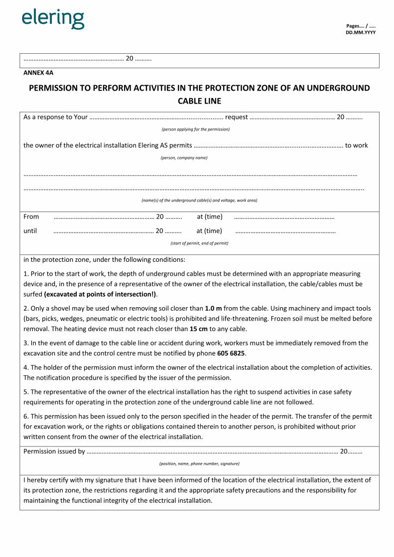
Pages…. / ….. DD.MM.YYYY
…………………………………………………… 20 ……….
ANNEX 4A
PERMISSION TO PERFORM ACTIVITIES IN THE PROTECTION ZONE OF AN UNDERGROUND
CABLE LINE
As a response to Your …………………………………………………..................... request …………………………………………… 20 ……….
(person applying for the permission)
the owner of the electrical installation Elering AS permits …………………………………………………............………………. to work
(person, company name)
……………….………………………………………………………………………………………………………………………………………………………………
…………………………………………………………………………………………………………………………………………………………………………………..
(name(s) of the underground cable(s) and voltage, work area)
From …………………………………………………… 20 ………. at (time) ……………………………………………………
until …………………………………………………… 20 ………. at (time) ……………………………………………………
(start of permit, end of permit)
in the protection zone, under the following conditions:
1. Prior to the start of work, the depth of underground cables must be determined with an appropriate measuring
device and, in the presence of a representative of the owner of the electrical installation, the cable/cables must be
surfed (excavated at points of intersection!).
2. Only a shovel may be used when removing soil closer than 1.0 m from the cable. Using machinery and impact tools
(bars, picks, wedges, pneumatic or electric tools) is prohibited and life-threatening. Frozen soil must be melted before
removal. The heating device must not reach closer than 15 cm to any cable.
3. In the event of damage to the cable line or accident during work, workers must be immediately removed from the
excavation site and the control centre must be notified by phone 605 6825.
4. The holder of the permission must inform the owner of the electrical installation about the completion of activities.
The notification procedure is specified by the issuer of the permission.
5. The representative of the owner of the electrical installation has the right to suspend activities in case safety
requirements for operating in the protection zone of the underground cable line are not followed.
6. This permission has been issued only to the person specified in the header of the permit. The transfer of the permit
for excavation work, or the rights or obligations contained therein to another person, is prohibited without prior
written consent from the owner of the electrical installation.
Permission issued by …………………………………………………………………………………………………………………………………… 20………
(position, name, phone number, signature)
I hereby certify with my signature that I have been informed of the location of the electrical installation, the extent of
its protection zone, the restrictions regarding it and the appropriate safety precautions and the responsibility for
maintaining the functional integrity of the electrical installation.

Pages…. / ….. DD.MM.YYYY
Recipient of the permission …………………………………………………………………………………………………………………….. 20……….
(position, name, phone number, signature)
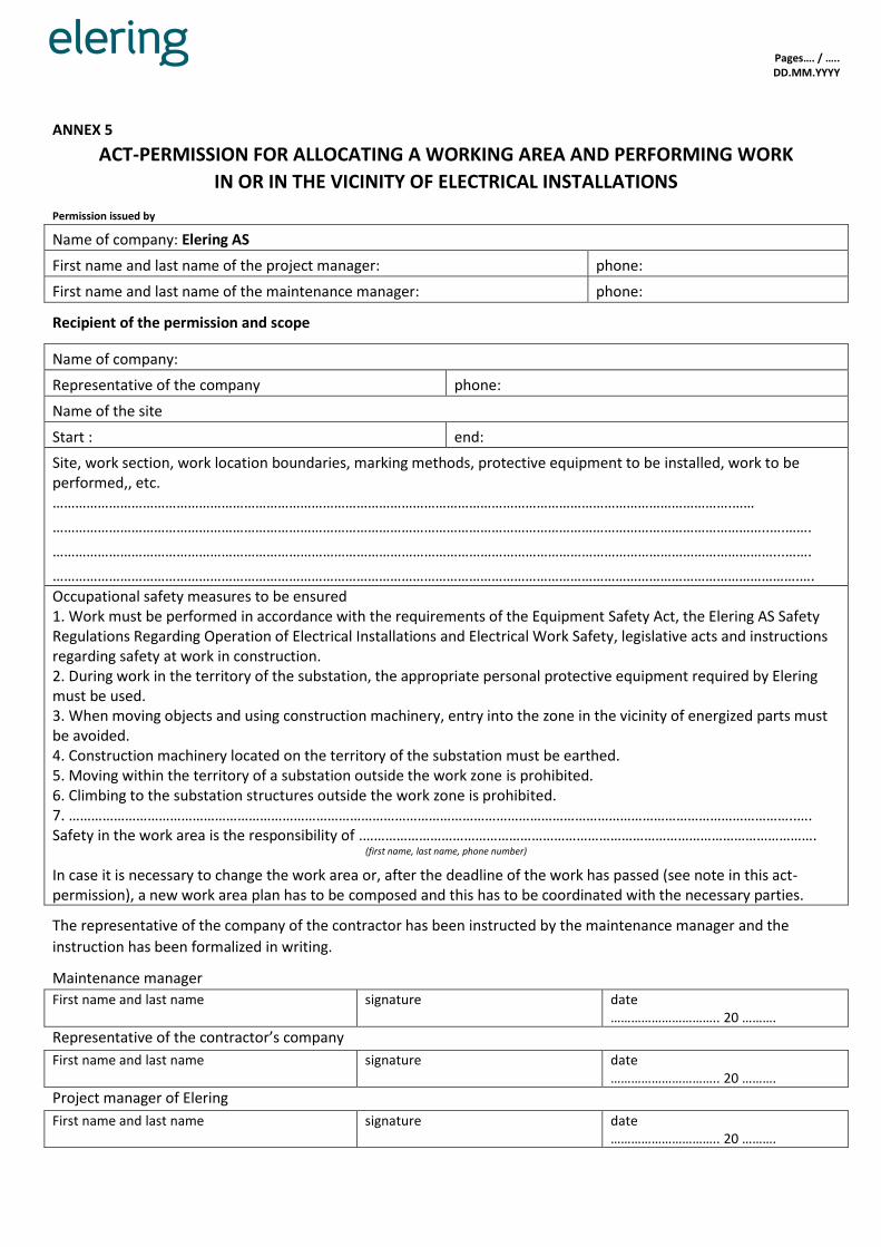
Pages…. / ….. DD.MM.YYYY
ANNEX 5
ACT-PERMISSION FOR ALLOCATING A WORKING AREA AND PERFORMING WORK
IN OR IN THE VICINITY OF ELECTRICAL INSTALLATIONS
Permission issued by
Name of company: Elering AS
First name and last name of the project manager: phone:
First name and last name of the maintenance manager: phone:
Recipient of the permission and scope
Name of company:
Representative of the company phone:
Name of the site
Start : end:
Site, work section, work location boundaries, marking methods, protective equipment to be installed, work to be performed,, etc. ……………………………………………………………………………………………………………………………………………………………….……
………………………………………………………………………………………………………………………………………………………………………..….…….
…………………………………………………………………………………………………………………………………………………………………………...…….
……………………………………………………………………………………………………………………………………………………………………………….….
Occupational safety measures to be ensured 1. Work must be performed in accordance with the requirements of the Equipment Safety Act, the Elering AS Safety Regulations Regarding Operation of Electrical Installations and Electrical Work Safety, legislative acts and instructions regarding safety at work in construction. 2. During work in the territory of the substation, the appropriate personal protective equipment required by Elering must be used. 3. When moving objects and using construction machinery, entry into the zone in the vicinity of energized parts must be avoided. 4. Construction machinery located on the territory of the substation must be earthed. 5. Moving within the territory of a substation outside the work zone is prohibited. 6. Climbing to the substation structures outside the work zone is prohibited. 7. …………………………………………………………………………………………………………………………………………………………………………..…. Safety in the work area is the responsibility of .………………………………………………………………………………………………………….
(first name, last name, phone number)
In case it is necessary to change the work area or, after the deadline of the work has passed (see note in this act-permission), a new work area plan has to be composed and this has to be coordinated with the necessary parties.
The representative of the company of the contractor has been instructed by the maintenance manager and the
instruction has been formalized in writing.
Maintenance manager
First name and last name signature date ………………………….. 20 ……….
Representative of the contractor’s company
First name and last name signature date ………………………….. 20 ……….
Project manager of Elering
First name and last name signature date ………………………….. 20 ……….

Pages…. / ….. DD.MM.YYYY
ANNEX 6
SAFETY PLAN
Name of the company performing the work:
Electrical work manager:
Name of the construction site:
Time of execution of the work:
1. Hazards to be addressed (risk of induced voltage, energized electrical devices in the vicinity, risk of fire, intersecting
communications, etc.):
………………………………………………………………………………………………………………………………………………………………………………
………………………………………………………………………………………………………………………………………………………………………………
………………………………………………………………………………………………………………………………………………………………………………
………………………………………………………………………………………………………………………………………………………………………………
………………………………………………………………………………………………………………………………………………………………………………
………………………………………………………………………………………………………………………………………………………………………………
………………………………………………………………………………………………………………………………………………………………………………
………………………………………………………………………………
2. Description of hazardous work, measures to ensure safety (description of work and measures to prevent and avoid
hazards):
………………………………………………………………………………………………………………………………………………………………………………
………………………………………………………………………………………………………………………………………………………………………………
………………………………………………………………………………………………………………………………………………………………………………
………………………………………………………………………………………………………………………………………………………………………………
………………………………………………………………………………………………………………………………………………………………………………
………………………………………………………………………………………………………………………………………………………………………………
………………………………………………………………………………………………………………………………………………………………………………
3. Measures to ensure safety
No. Tower No.
Tower type
Tower No.
Tower type
Name of the intersecting object
Owner of the intersecting object
Measures

Pages…. / ….. DD.MM.YYYY
4. Coordination of work with the owners of intersecting communications:
Name of the institution Coordinator Comment Signature or note on
coordination
5. Persons responsible for safety at work and signatures:
First name and last name
position: signature
First name and last name
position: signature
First name and last name
position: signature
First name and last name
position: signature
First name and last name
position: signature
Prepared by:
First name and last name position:
signature date
………………………………………………………….20 ………..
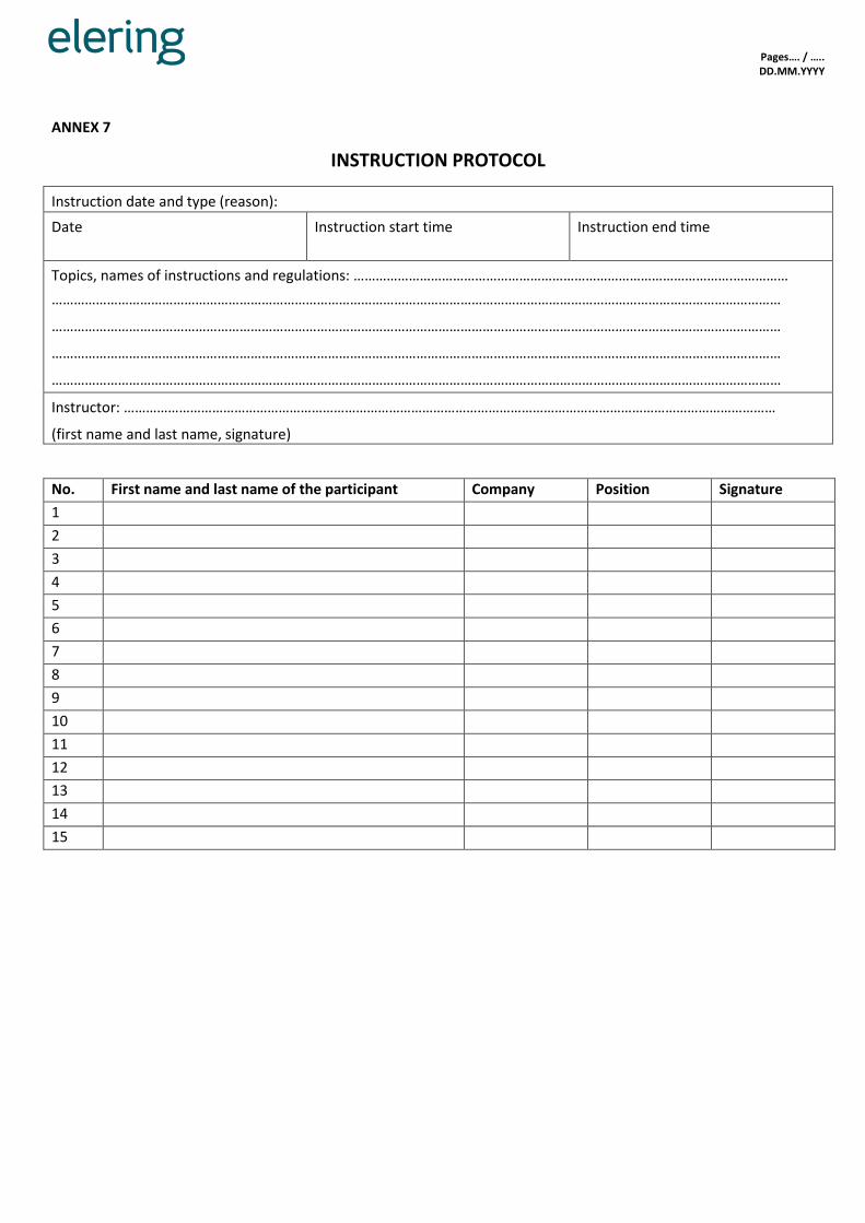
Pages…. / ….. DD.MM.YYYY
ANNEX 7
INSTRUCTION PROTOCOL
Instruction date and type (reason):
Date Instruction start time Instruction end time
Topics, names of instructions and regulations: ………………………………………………………………………………………….……………
………………………………………………………………………………………………………………………………………………………………………………
………………………………………………………………………………………………………………………………………………………………………………
………………………………………………………………………………………………………………………………………………………………………………
………………………………………………………………………………………………………………………………………………………………………………
Instructor: ……………………………………………………………………………………………………………………………………………………………
(first name and last name, signature)
No. First name and last name of the participant Company Position Signature
1
2
3
4
5
6
7
8
9
10
11
12
13
14
15

Pages…. / ….. DD.MM.YYYY
The permit must be formalized in one copy. After the permit has been signed, a photocopy must be taken of it.
ANNEX 8
FIRE EXTINGUISHING PERMIT
…………………………………………………………………………………………………………………………………………………………………………………..
(site name and address)
Place of fire extinguishing work and what is allowed to be extinguished
………………………………………………………………………………………………………………………………………………………………………………….
…………………………………………………………………………………………………………………………………………………………………………………..
…………………………………………………………………………………………………………………………………………………………………………………..
………………………………………………………………………………………………………………………………………………………………………………….
.…………………………………………………………………………………………………………………………………………………………………………………
..…………………………………………………………………………………………………………………………………………………………………………………
(names of rooms, switchgears, etc.)
Burning and other electrical equipment located in the area of the fire have been switched off
………………………………………………………………………………………………………………………………………………………………………………….
…………………………………………………………………………………………………………………………………………………………………………………..
…………………………………………………………………………………………………………………………………………………………………………………..
………………………………………………………………………………………………………………………………………………………………………………….
.…………………………………………………………………………………………………………………………………………………………………………………
..…………………………………………………………………………………………………………………………………………………………………………………
(list electrical equipment and cables still energized, their location and maximum voltage)
Permit issued by:
…………………………………………………………………………………………………………………………………………………………………………………..
(position, first name and last name, signature)
Permit issued on: ………………………………………………… 20 ………. time …………..
I received the permit:
…………………………………………………………………………………………………………………………………………………………………………………..
(position, first name and last name, signature)
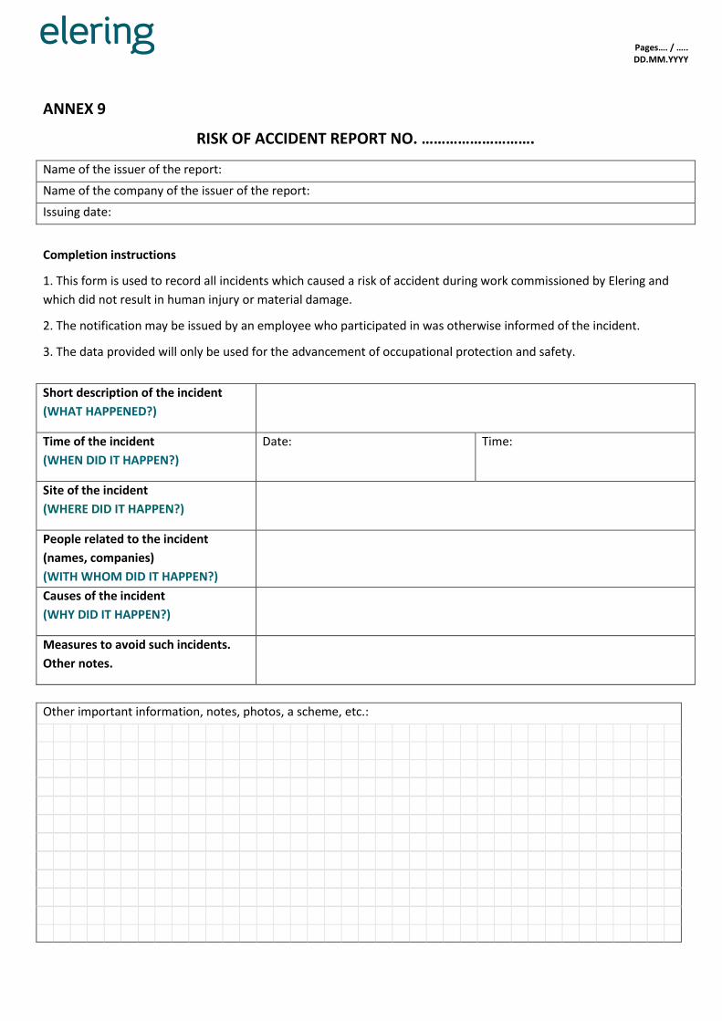
Pages…. / ….. DD.MM.YYYY
ANNEX 9
RISK OF ACCIDENT REPORT NO. ……………………….
Name of the issuer of the report:
Name of the company of the issuer of the report:
Issuing date:
Completion instructions
1. This form is used to record all incidents which caused a risk of accident during work commissioned by Elering and
which did not result in human injury or material damage.
2. The notification may be issued by an employee who participated in was otherwise informed of the incident.
3. The data provided will only be used for the advancement of occupational protection and safety.
Short description of the incident
(WHAT HAPPENED?)
Time of the incident
(WHEN DID IT HAPPEN?)
Date: Time:
Site of the incident
(WHERE DID IT HAPPEN?)
People related to the incident
(names, companies)
(WITH WHOM DID IT HAPPEN?)
Causes of the incident
(WHY DID IT HAPPEN?)
Measures to avoid such incidents.
Other notes.
Other important information, notes, photos, a scheme, etc.:

Pages…. / ….. DD.MM.YYYY
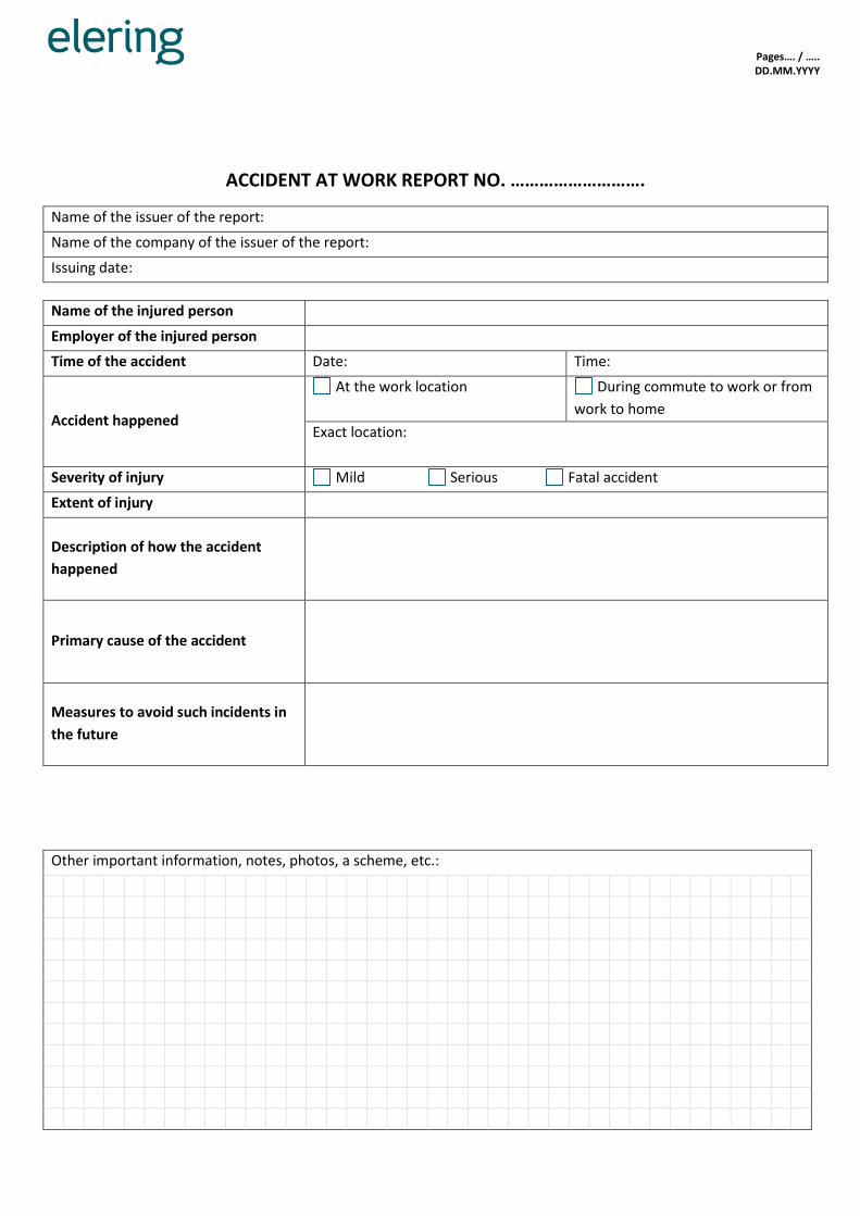
Pages…. / ….. DD.MM.YYYY
ACCIDENT AT WORK REPORT NO. ……………………….
Name of the issuer of the report:
Name of the company of the issuer of the report:
Issuing date:
Name of the injured person
Employer of the injured person
Time of the accident Date: Time:
Accident happened
At the work location During commute to work or from
work to home
Exact location:
Severity of injury Mild Serious Fatal accident
Extent of injury
Description of how the accident
happened
Primary cause of the accident
Measures to avoid such incidents in
the future
Other important information, notes, photos, a scheme, etc.:

Pages…. / ….. DD.MM.YYYY
103
ANNEX 11
SAFETY SIGNS AND SAFETY NOTICES USED WHEN OPERATING
ELECTRICAL INSTALLATIONS
1. Scope
These regulations prescribe the requirements regarding electrical safety signs and safety
notices used when operating Elering AS electrical installations and when performing work
operations on or near them.
The regulations are mandatory for the employees of Elering AS, as well as for the personnel
of companies operating under contracts in Elering AS electrical installations, with regard to
both electrical and non-electrical work.
The use of safety signs other than those referenced in these regulations are subject to the
regulation of the Minister of Social Affairs “Requirements Concerning the Provision of Safety
Signs in the Workplace”.
2. Definitions
The following definitions are used in these regulations:
2.1 Sign
A symbol, image, shape, etc., that refers to something.
2.2 Notice
A board, poster, label, etc., displaying informative text or a sign.
2.3 Safety sign
A safety sign provides specific safety-related information using a combination of a geometric
shape, colours and symbols or a pictogram. The safety signs used in the operation of
electrical installations and during electrical work are divided by their intended purpose as
prohibitive, warning and obligative signs.
2.4 Prohibitive sign
A sign with a distinguishing (pictogram) feature, representing a specific restriction. A black
symbol on a white background, red edging and a diagonal line. The red part comprises at
least 35% of the area of the sign.
2.5 Warning sign
A sign with a distinguishing (pictogram) feature, representing a specific warning. A black
edge and black arrow on a yellow background. The yellow part comprises at least 50% of the
area of the sign.
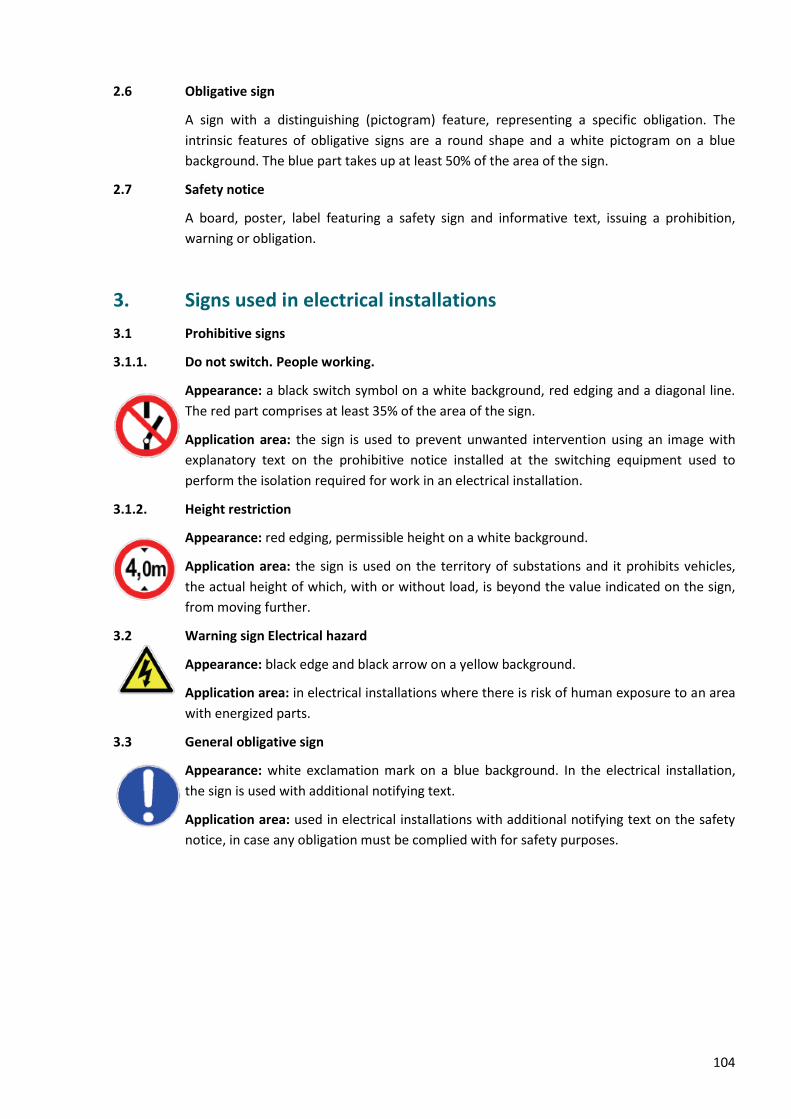
104
2.6 Obligative sign
A sign with a distinguishing (pictogram) feature, representing a specific obligation. The
intrinsic features of obligative signs are a round shape and a white pictogram on a blue
background. The blue part takes up at least 50% of the area of the sign.
2.7 Safety notice
A board, poster, label featuring a safety sign and informative text, issuing a prohibition,
warning or obligation.
3. Signs used in electrical installations
3.1 Prohibitive signs
3.1.1. Do not switch. People working.
Appearance: a black switch symbol on a white background, red edging and a diagonal line.
The red part comprises at least 35% of the area of the sign.
Application area: the sign is used to prevent unwanted intervention using an image with
explanatory text on the prohibitive notice installed at the switching equipment used to
perform the isolation required for work in an electrical installation.
3.1.2. Height restriction
Appearance: red edging, permissible height on a white background.
Application area: the sign is used on the territory of substations and it prohibits vehicles,
the actual height of which, with or without load, is beyond the value indicated on the sign,
from moving further.
3.2 Warning sign Electrical hazard
Appearance: black edge and black arrow on a yellow background.
Application area: in electrical installations where there is risk of human exposure to an area
with energized parts.
3.3 General obligative sign
Appearance: white exclamation mark on a blue background. In the electrical installation,
the sign is used with additional notifying text.
Application area: used in electrical installations with additional notifying text on the safety
notice, in case any obligation must be complied with for safety purposes.
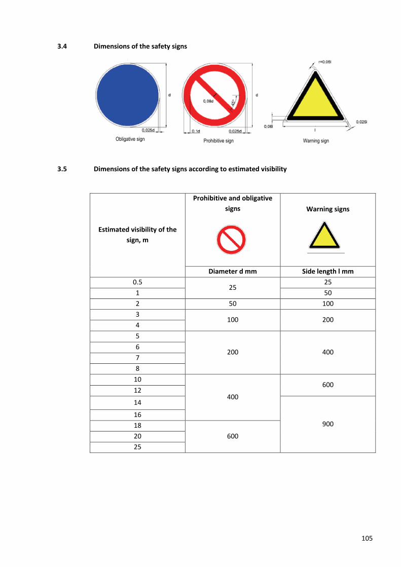
105
3.4 Dimensions of the safety signs
3.5 Dimensions of the safety signs according to estimated visibility
Estimated visibility of the
sign, m
Prohibitive and obligative
signs
Warning signs
Diameter d mm Side length l mm
0.5 25
25
1 50
2 50 100
3 100 200
4
5
200 400 6
7
8
10
400
600 12
14
900 16
18
600 20
25
Obligative sign Prohibitive sign Warning sign
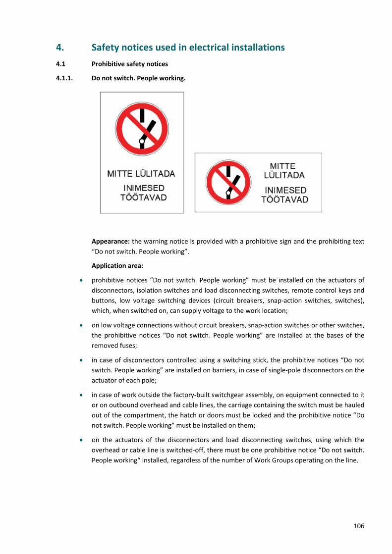
106
4. Safety notices used in electrical installations
4.1 Prohibitive safety notices
4.1.1. Do not switch. People working.
Appearance: the warning notice is provided with a prohibitive sign and the prohibiting text
“Do not switch. People working”.
Application area:
• prohibitive notices “Do not switch. People working” must be installed on the actuators of
disconnectors, isolation switches and load disconnecting switches, remote control keys and
buttons, low voltage switching devices (circuit breakers, snap-action switches, switches),
which, when switched on, can supply voltage to the work location;
• on low voltage connections without circuit breakers, snap-action switches or other switches,
the prohibitive notices “Do not switch. People working” are installed at the bases of the
removed fuses;
• in case of disconnectors controlled using a switching stick, the prohibitive notices “Do not
switch. People working” are installed on barriers, in case of single-pole disconnectors on the
actuator of each pole;
• in case of work outside the factory-built switchgear assembly, on equipment connected to it
or on outbound overhead and cable lines, the carriage containing the switch must be hauled
out of the compartment, the hatch or doors must be locked and the prohibitive notice “Do
not switch. People working” must be installed on them;
• on the actuators of the disconnectors and load disconnecting switches, using which the
overhead or cable line is switched-off, there must be one prohibitive notice “Do not switch.
People working“ installed, regardless of the number of Work Groups operating on the line.
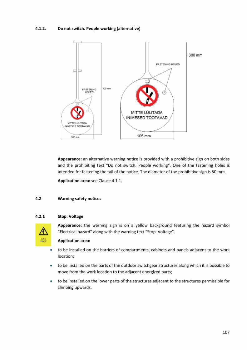
107
4.1.2. Do not switch. People working (alternative)
Appearance: an alternative warning notice is provided with a prohibitive sign on both sides
and the prohibiting text “Do not switch. People working“. One of the fastening holes is
intended for fastening the tail of the notice. The diameter of the prohibitive sign is 50 mm.
Application area: see Clause 4.1.1.
4.2 Warning safety notices
4.2.1 Stop. Voltage
Appearance: the warning sign is on a yellow background featuring the hazard symbol
“Electrical hazard” along with the warning text “Stop. Voltage”.
Application area:
• to be installed on the barriers of compartments, cabinets and panels adjacent to the work
location;
• to be installed on the parts of the outdoor switchgear structures along which it is possible to
move from the work location to the adjacent energized parts;
• to be installed on the lower parts of the structures adjacent to the structures permissible for
climbing upwards.
FASTENING HOLES
FASTENING HOLES
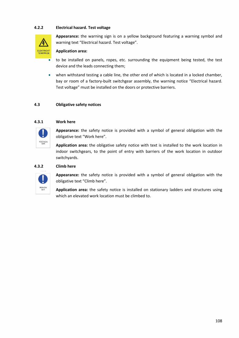
108
4.2.2 Electrical hazard. Test voltage
Appearance: the warning sign is on a yellow background featuring a warning symbol and
warning text “Electrical hazard. Test voltage”.
Application area:
• to be installed on panels, ropes, etc. surrounding the equipment being tested, the test
device and the leads connecting them;
• when withstand testing a cable line, the other end of which is located in a locked chamber,
bay or room of a factory-built switchgear assembly, the warning notice “Electrical hazard.
Test voltage” must be installed on the doors or protective barriers.
4.3 Obligative safety notices
4.3.1 Work here
Appearance: the safety notice is provided with a symbol of general obligation with the
obligative text “Work here”.
Application area: the obligative safety notice with text is installed to the work location in
indoor switchgears, to the point of entry with barriers of the work location in outdoor
switchyards.
4.3.2 Climb here
Appearance: the safety notice is provided with a symbol of general obligation with the
obligative text “Climb here”.
Application area: the safety notice is installed on stationary ladders and structures using
which an elevated work location must be climbed to.
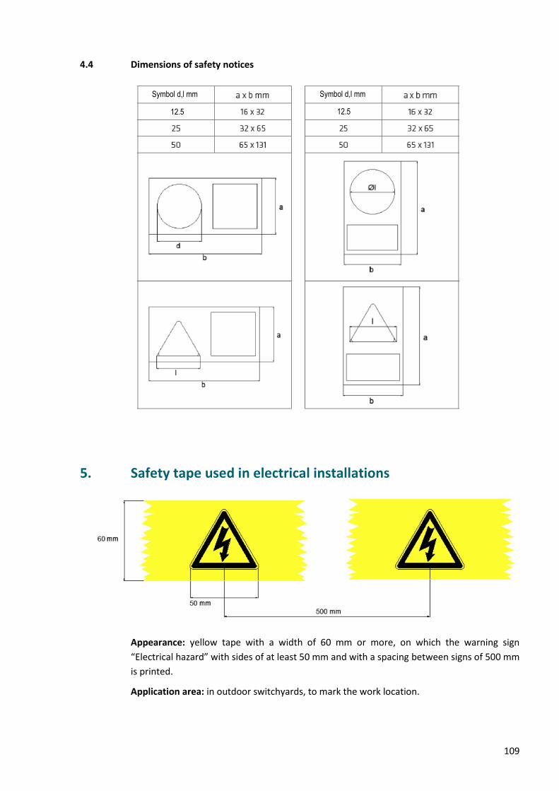
109
4.4 Dimensions of safety notices
5. Safety tape used in electrical installations
Appearance: yellow tape with a width of 60 mm or more, on which the warning sign
“Electrical hazard” with sides of at least 50 mm and with a spacing between signs of 500 mm
is printed.
Application area: in outdoor switchyards, to mark the work location.
Symbol d,l mm Symbol d,l mm
12.5 12.5
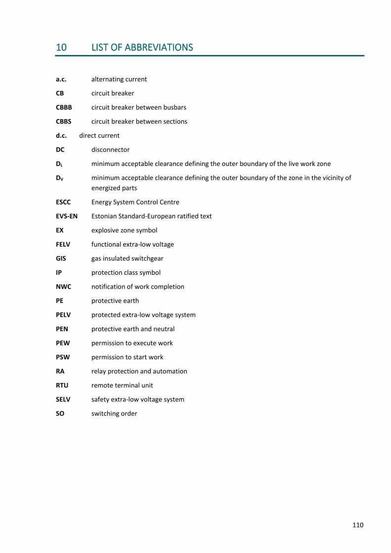
110
10 LIST OF ABBREVIATIONS
a.c. alternating current
CB circuit breaker
CBBB circuit breaker between busbars
CBBS circuit breaker between sections
d.c. direct current
DC disconnector
DL minimum acceptable clearance defining the outer boundary of the live work zone
DV minimum acceptable clearance defining the outer boundary of the zone in the vicinity of
energized parts
ESCC Energy System Control Centre
EVS-EN Estonian Standard-European ratified text
EX explosive zone symbol
FELV functional extra-low voltage
GIS gas insulated switchgear
IP protection class symbol
NWC notification of work completion
PE protective earth
PELV protected extra-low voltage system
PEN protective earth and neutral
PEW permission to execute work
PSW permission to start work
RA relay protection and automation
RTU remote terminal unit
SELV safety extra-low voltage system
SO switching order