Embed Size (px)
Citation preview
JWBS196-c01 JWBS196-Blair November 2, 2016 15:31 Printer Name: Trim: 6.125in × 9.25in
CHAPTER 1ELECTRICAL SAFETY
GOALS
� To understand the basic requirements of OSHA 1910.269 and Subpart S� To apply recommendations of NFPA 70 (National Electrical Code®) and NFPA
70E (Electrical Safety in the Workplace) for compliance with OSHA 1910 Sub-part S
� To apply recommendations of IEEE C2 (National Electrical Safety Code) forcompliance with OSHA 1910.269
� To be able to determine minimum approach distance (MAD), limited approachboundary, restricted approach boundary, and arc flash boundary for installation
� To be able to determine minimum safety clearance for electric supply stationfences
� To be able to determine the minimum illumination requirements for electricsupply station locations
� To be able to determine the proper electrical PPE (personal protective equip-ment) required for various tasks
� To be able to determine the correct classification for areas where hazardousmaterials may be present
IF ONE were to try to reduce the function of the electrical engineer in theelectric power generation industry to one sentence, it would be “to ensure the design,implementation, and operation of a SAFE and RELIABLE electrical system.” Elec-trical safety is of primary importance in the electric utility generation industry. Thegeneration industry is unique from other industrial environments. The available short-circuit fault currents can be very large since the generation source is close and cansupply a large amount of fault current. The service voltages at various pieces of equip-ment can be greater in magnitude for the larger electrical machines utilized in the gen-eration station. Combustible materials may be handled, stored, and utilized in powergeneration facilities. The above conditions require the power plant electrical engineer
Energy Production Systems Engineering: An Introduction for Electrical Engineers to Electrical PowerGeneration Facilities, Systems, and Equipment, First Edition. Thomas H. Blair.© 2017 by The Institute of Electrical and Electronics Engineers, Inc. Published 2017 by John Wiley & Sons, Inc.
1
COPYRIG
HTED M
ATERIAL
JWBS196-c01 JWBS196-Blair November 2, 2016 15:31 Printer Name: Trim: 6.125in × 9.25in
2 CHAPTER 1 ELECTRICAL SAFETY
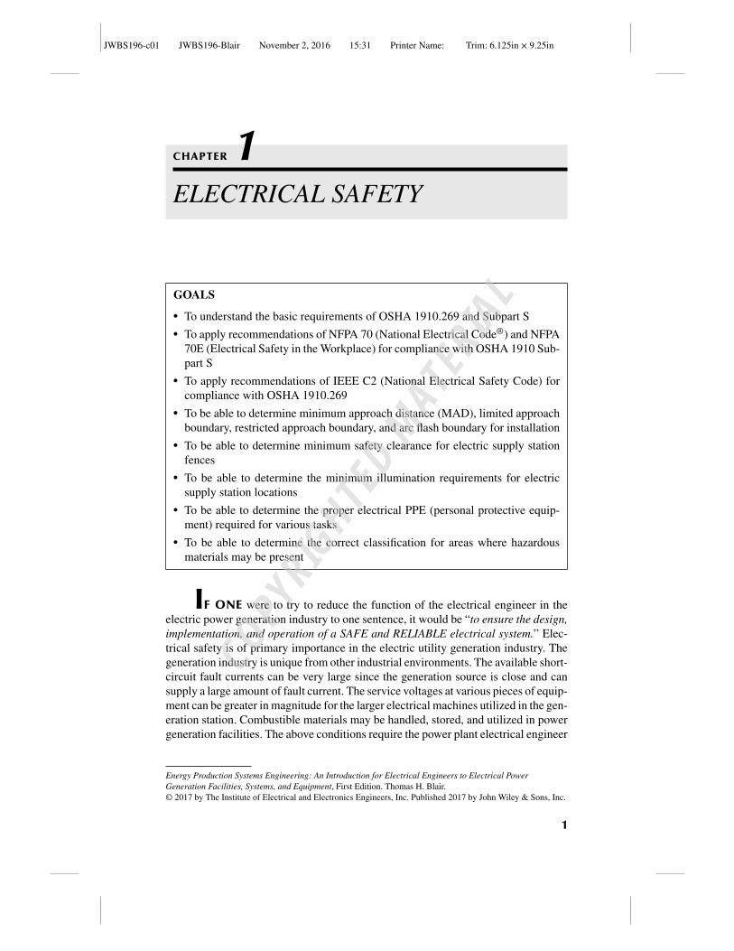
Figure 1.1 Appendix A-1 – Application of 1910.269 and 1910 Subpart S to ElectricalInstallations. Source: Reproduced with permission of U.S. Department of Labor.
to be very familiar with governmental regulations and industry standards regardingsafety requirements to ensure the safe operation of the generation facility.
OSHA (Occupational Health and Safety Administration) (osha.gov) issues reg-ulations that cover occupational health and safety. These regulations have the sameeffect as law. For general industry, which includes utilities, the applicable regulationis OSHA CFR 1910 – General Industry Standards. For general industry, electricalsafety is covered under Subpart S. However, under OSHA CFR 1910, there is a sep-arate section for special industries under Subpart R and the electric utility industryis covered under OSHA 1910.269 of Subpart R. This section covers the operationand maintenance of electric power generation systems and equipment and applies toinstallations utilized for the generation of electrical energy that are accessible onlyto qualified employees. One might think that all of the requirements for a generationfacility fall under OSHA CFR 1910.269 and not OSHA CFR 1910 Subpart S sinceOSHA CFR 1910.269 regulations were written for electric generation, transmission,and distribution systems, but that is not always the case. So how does a plant engineerknow when to apply OSHA 1910 Subpart S (general industry) or OSHA 1910 Sub-part R 269 or possibly both regulations? OSHA provides guidance with that questionin Appendix A of 1910.269.
To understand how Appendix A addresses this, we need to understand thatOSHA segregates its safety requirements into two general categories: electrical safeinstallation methods and electrical safe work practices.
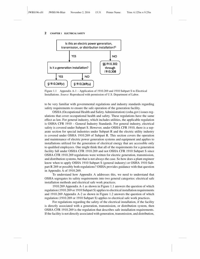
1910.269 Appendix A-1 as shown in Figure 1.1 answers the question of whichregulation (1910.269 or 1910 Subpart S) applies to electrical installation requirementsand 1910.269 Appendix A-2 as shown in Figure 1.2 answers the question of whichregulation (1910.269 or 1910 Subpart S) applies to electrical safe work practices.
For regulations regarding the safety of the electrical installation, if the facilityis directly associated with a generation, transmission, or distribution system, thenOSHA CFR 1910.269 is the regulation that describes safe installation requirements.If the facility is not directly associated with generation, transmission, and distribution,
JWBS196-c01 JWBS196-Blair November 2, 2016 15:31 Printer Name: Trim: 6.125in × 9.25in
ELECTRICAL SAFETY 3
Figure 1.2 Appendix A-2 – Application of 1910.269 and 1910 Subpart S to ElectricalSafety-Related Work Practices. Source: Reproduced with permission of U.S. Department ofLabor.
then 1910 Subpart S applies. For example, if we were to install a motor control center(MCC) in the turbine building of an electric utility generation station, then the safeinstallation regulations would be defined by 1910.269. However, if we were to installan MCC in a warehouse that is not located on the generation station facility, then thesafe installation regulations would be defined by 1910 Subpart S.
The choice of which OSHA standard to use for electrical safe work practicesdepends both on the location of the work and the qualification of the personnel per-forming the electrical work. First, we must answer the question, what defines a “qual-ified person.” OSHA defines a qualified person as one who has “received training inand has demonstrated skills and knowledge in the construction and operation of elec-tric equipment and installations and the hazards involved” (OSHA 1910.399).
For electrical safe work practice regulations, if the personnel performing thetask are not qualified, then the safe work practices of Subpart S are the regulationsthat govern the work regardless of whether the installation where the work is beingperformed is on a generation facility or not. For example, if we were to install anair compressor in a generation facility and the equipment supplier is sending a fieldengineer to assist with startup of the compressor and the field engineer is not trained
JWBS196-c01 JWBS196-Blair November 2, 2016 15:31 Printer Name: Trim: 6.125in × 9.25in
4 CHAPTER 1 ELECTRICAL SAFETY
on the electrical safe work practices of OSHA 1910.269, then the safe work prac-tices for this task must comply with OSHA Subpart S, even though this task is beingperformed at a generation facility.
However, if the personnel performing the task are qualified AND if the installa-tion is a generation facility, then the safe work practices of 1910.269 apply to the task.So for normal maintenance done at the generation station where the task is performedby station personnel that are trained according to OSHA 1910.269, the tasks are cov-ered under OSHA 1910.269. For commingled installations, the reader is directed toOSHA 1910.269, Appendix A for guidance.
As the reader can see, even though OSHA 1910.269 is written for generation,transmission, and distribution systems, there are instances where OSHA 1910 subpartS applies, so the electric utility engineer must know and understand the installationrequirements and safe work practices of both OSHA 1910 Subpart S (general indus-try) and OSHA 1910.269 (electric utilities).
So where does the electric utility engineer obtain guidance on how to complywith all of these regulations? For the safe installation requirements for general indus-try described by OSHA 1910 Subpart S (sections 302 to 308), NFPA 70® (NationalElectric Code® or NEC®) provides guidance on how to comply with these federalregulations. (NFPA 70®, National Electrical Code®, and NEC® are registered trade-marks of the National Fire Protection Association, Quincy, MA). For the safe instal-lation requirements for the electric utility industry of OSHA 1910.269, IEEE C2(National Electrical Safety Code or NESC) provides guidance on how to comply withfederal regulations at generation station installations. Specifically, IEEE C2 – Part 1describes electric supply station installation requirements, IEEE C2 – Part 2 describesoverhead line installation requirements, IEEE C2 – Part 3 describes underground lineinstallation requirements.
For the safe work practice requirements for general industry of OSHA 1910Subpart S (sections 332 to 335), NFPA 70E (Electrical Safety in the Workplace) pro-vides guidance on how to comply with federal regulations. For the safe work practicerequirements for the electric utility industry of OSHA 1910.269, IEEE C2 – Part 4 –(NESC) provides guidance on how to comply with federal regulations.
While these codes are not law or regulation, they are referenced by OSHA fed-eral regulation as methods to ensure compliance with the law. Additionally, OSHAregulation updates take many years to occur due to the process of public notifica-tion and comment before changing official regulations. However, NEC® is updatedevery 3 years, NFPA 70E is updated every 4 years, and NESC is updated every 5years. Therefore, these codes have the most up-to-date information regarding electri-cal safety. The electric generation utility engineer should have a current copy availableof all three of these standards and be familiar with the information contained within.In Chapter 1, we describe just some of the installation and safe work practice infor-mation contained in these codes. The reader is reminded to always check the latestversion of the codes for updates.
One last note of caution, the OSHA standards and associated codes are NOTdesign guides, but MINIMUM requirements. When applying these codes, remem-ber that these are the MINIMUM standards to ensure safety; but good engineeringpractice may suggest additional safety measures in some instances.
JWBS196-c01 JWBS196-Blair November 2, 2016 15:31 Printer Name: Trim: 6.125in × 9.25in
INSTALLATION SAFETY REQUIREMENTS—GENERAL INDUSTRY (NEC®) 5
INSTALLATION SAFETY REQUIREMENTS—GENERALINDUSTRY (NEC®)
Access to Working Space <600 V
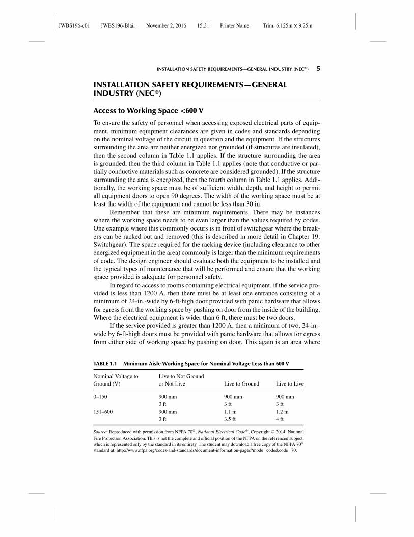
To ensure the safety of personnel when accessing exposed electrical parts of equip-ment, minimum equipment clearances are given in codes and standards dependingon the nominal voltage of the circuit in question and the equipment. If the structuressurrounding the area are neither energized nor grounded (if structures are insulated),then the second column in Table 1.1 applies. If the structure surrounding the areais grounded, then the third column in Table 1.1 applies (note that conductive or par-tially conductive materials such as concrete are considered grounded). If the structuresurrounding the area is energized, then the fourth column in Table 1.1 applies. Addi-tionally, the working space must be of sufficient width, depth, and height to permitall equipment doors to open 90 degrees. The width of the working space must be atleast the width of the equipment and cannot be less than 30 in.
Remember that these are minimum requirements. There may be instanceswhere the working space needs to be even larger than the values required by codes.One example where this commonly occurs is in front of switchgear where the break-ers can be racked out and removed (this is described in more detail in Chapter 19:Switchgear). The space required for the racking device (including clearance to otherenergized equipment in the area) commonly is larger than the minimum requirementsof code. The design engineer should evaluate both the equipment to be installed andthe typical types of maintenance that will be performed and ensure that the workingspace provided is adequate for personnel safety.
In regard to access to rooms containing electrical equipment, if the service pro-vided is less than 1200 A, then there must be at least one entrance consisting of aminimum of 24-in.-wide by 6-ft-high door provided with panic hardware that allowsfor egress from the working space by pushing on door from the inside of the building.Where the electrical equipment is wider than 6 ft, there must be two doors.
If the service provided is greater than 1200 A, then a minimum of two, 24-in.-wide by 6-ft-high doors must be provided with panic hardware that allows for egressfrom either side of working space by pushing on door. This again is an area where
TABLE 1.1 Minimum Aisle Working Space for Nominal Voltage Less than 600 V
Nominal Voltage toGround (V)
Live to Not Groundor Not Live Live to Ground Live to Live
0–150 900 mm 900 mm 900 mm3 ft 3 ft 3 ft
151–600 900 mm 1.1 m 1.2 m3 ft 3.5 ft 4 ft
Source: Reproduced with permission from NFPA 70®, National Electrical Code®, Copyright © 2014, NationalFire Protection Association. This is not the complete and official position of the NFPA on the referenced subject,which is represented only by the standard in its entirety. The student may download a free copy of the NFPA 70®
standard at: http://www.nfpa.org/codes-and-standards/document-information-pages?mode=code&code=70.
JWBS196-c01 JWBS196-Blair November 2, 2016 15:31 Printer Name: Trim: 6.125in × 9.25in
6 CHAPTER 1 ELECTRICAL SAFETY
these are minimum requirements. If, during the process of performing maintenancesuch as racking out equipment, one means of egress may become blocked, the designengineer would be justified in adding additional means of egress for personnel.
Access to Working Space >600 V
In rooms and enclosures where the voltage exceeds 600 V, NEC® requires rooms tobe locked and signage to be posted that reads,
DANGER − HIGH VOLTAGE − KEEP OUT
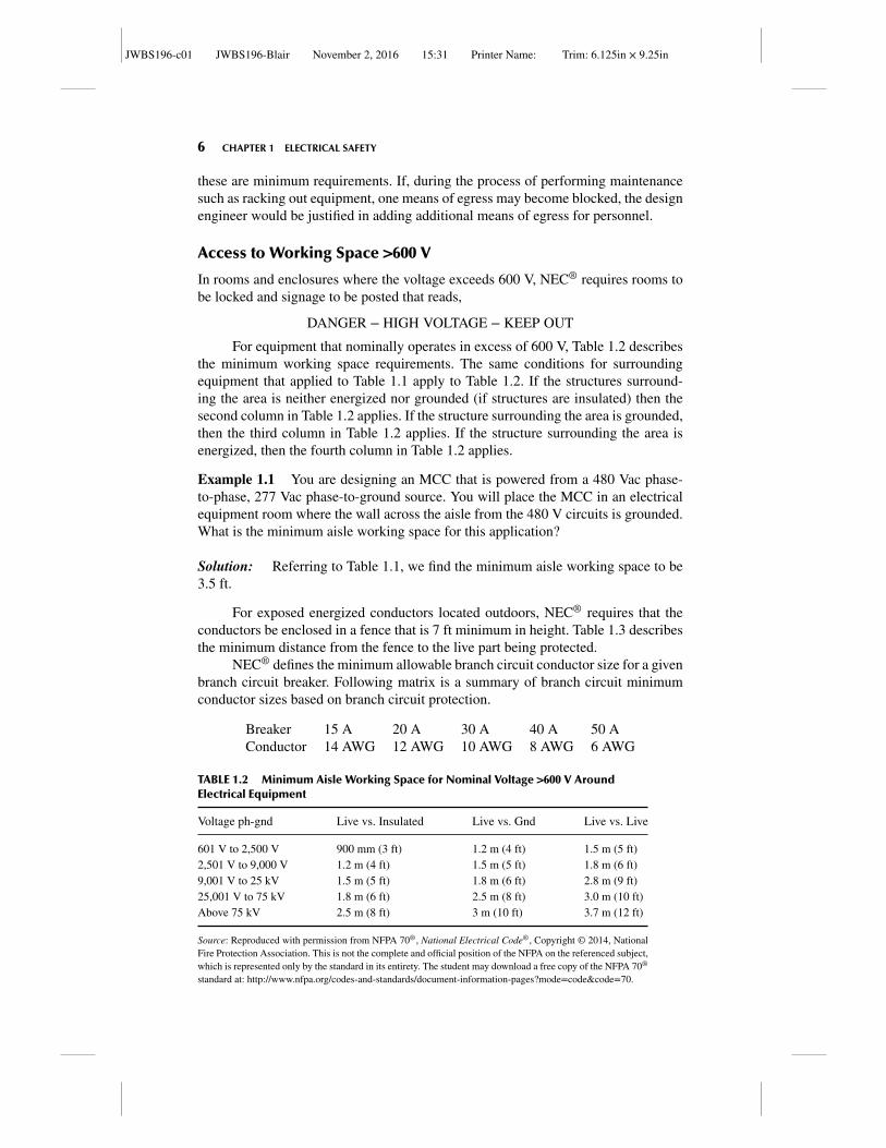
For equipment that nominally operates in excess of 600 V, Table 1.2 describesthe minimum working space requirements. The same conditions for surroundingequipment that applied to Table 1.1 apply to Table 1.2. If the structures surround-ing the area is neither energized nor grounded (if structures are insulated) then thesecond column in Table 1.2 applies. If the structure surrounding the area is grounded,then the third column in Table 1.2 applies. If the structure surrounding the area isenergized, then the fourth column in Table 1.2 applies.
Example 1.1 You are designing an MCC that is powered from a 480 Vac phase-to-phase, 277 Vac phase-to-ground source. You will place the MCC in an electricalequipment room where the wall across the aisle from the 480 V circuits is grounded.What is the minimum aisle working space for this application?
Solution: Referring to Table 1.1, we find the minimum aisle working space to be3.5 ft.
For exposed energized conductors located outdoors, NEC® requires that theconductors be enclosed in a fence that is 7 ft minimum in height. Table 1.3 describesthe minimum distance from the fence to the live part being protected.
NEC® defines the minimum allowable branch circuit conductor size for a givenbranch circuit breaker. Following matrix is a summary of branch circuit minimumconductor sizes based on branch circuit protection.
Breaker 15 A 20 A 30 A 40 A 50 AConductor 14 AWG 12 AWG 10 AWG 8 AWG 6 AWG
TABLE 1.2 Minimum Aisle Working Space for Nominal Voltage >600 V AroundElectrical Equipment
Voltage ph-gnd Live vs. Insulated Live vs. Gnd Live vs. Live
601 V to 2,500 V 900 mm (3 ft) 1.2 m (4 ft) 1.5 m (5 ft)2,501 V to 9,000 V 1.2 m (4 ft) 1.5 m (5 ft) 1.8 m (6 ft)9,001 V to 25 kV 1.5 m (5 ft) 1.8 m (6 ft) 2.8 m (9 ft)25,001 V to 75 kV 1.8 m (6 ft) 2.5 m (8 ft) 3.0 m (10 ft)Above 75 kV 2.5 m (8 ft) 3 m (10 ft) 3.7 m (12 ft)
Source: Reproduced with permission from NFPA 70®, National Electrical Code®, Copyright © 2014, NationalFire Protection Association. This is not the complete and official position of the NFPA on the referenced subject,which is represented only by the standard in its entirety. The student may download a free copy of the NFPA 70®
standard at: http://www.nfpa.org/codes-and-standards/document-information-pages?mode=code&code=70.
JWBS196-c01 JWBS196-Blair November 2, 2016 15:31 Printer Name: Trim: 6.125in × 9.25in
INSTALLATION SAFETY REQUIREMENTS—SPECIAL INDUSTRY – UTILITY (NESC) 7
TABLE 1.3 Minimum Distance from Fence to Live Parts
Minimum Distance from Fence to Live Parts
Nominal Voltage m ft
601–13,799 V 3.05 1013,800–230,000 V 4.57 15Over 230,000 V 5.49 18
Source: Reproduced with permission from NFPA 70®, National Electrical Code®, Copyright ©2014, National Fire Protection Association. This is not the complete and official position of theNFPA on the referenced subject, which is represented only by the standard in its entirety. Thestudent may download a free copy of the NFPA 70® standard at: http://www.nfpa.org/codes-and-standards/document-information-pages?mode=code&code=70.
Just to reinforce the notion that codes are not design standards, the size of theconductor recommended by NEC® is not the required conductor size, but the mini-mum allowable conductor size. For long runs where voltage drop might be an issue,the design engineer might choose to oversize the branch circuit conductor which isacceptable. Codes such as NEC® and NESC are not design guides, but only providethe minimum safety requirements for installation.
Grounding and bonding is so important that it has its own chapter and isdescribed in Chapter 21. But for safety, it is worth mentioning here that NEC®
requires the electrical distribution system to be grounded and bonded and requiresthe electrical distribution system to have one main bonding jumper between the mainsupply neutral bar and ground bar. The functions of the grounding conductor (alsoknown as neutral conductor) and bonding conductor (sometimes referred to as thegrounded conductor) are distinctly different. Downstream equipment enclosures arebonded back to the main supply ground bar via the grounded conductor and down-stream equipment neutral terminations are connected back to the main supply neutralbar via the grounding conductor. The purpose of the grounding conductor is to pro-vide a path for current to return to the source and, if there is a phase-to-neutral fault,this current will clear the upstream breaker to remove the fault from the energizedelectrical system. The purpose of the grounded conductor is not to provide a path forfault current, but to maintain electrical continuity between system ground and equip-ment enclosures in the field. This is done to minimize touch potentials during faultsto protect personnel.
INSTALLATION SAFETY REQUIREMENTS—SPECIALINDUSTRY – UTILITY (NESC)
Access to Exposed Energized Conductors Outdoor
In some areas of a generation facility, there may be exposed overhead conductors. Atypical application is where the plant interfaces with the transmission and distributionsystem. There are minimum distances that need to be maintained from the generalpublic to these exposed circuit conductors. In order to keep non-qualified personnelfrom accessing the energized circuits, NESC provides guidance on minimum fence
JWBS196-c01 JWBS196-Blair November 2, 2016 15:31 Printer Name: Trim: 6.125in × 9.25in
8 CHAPTER 1 ELECTRICAL SAFETY
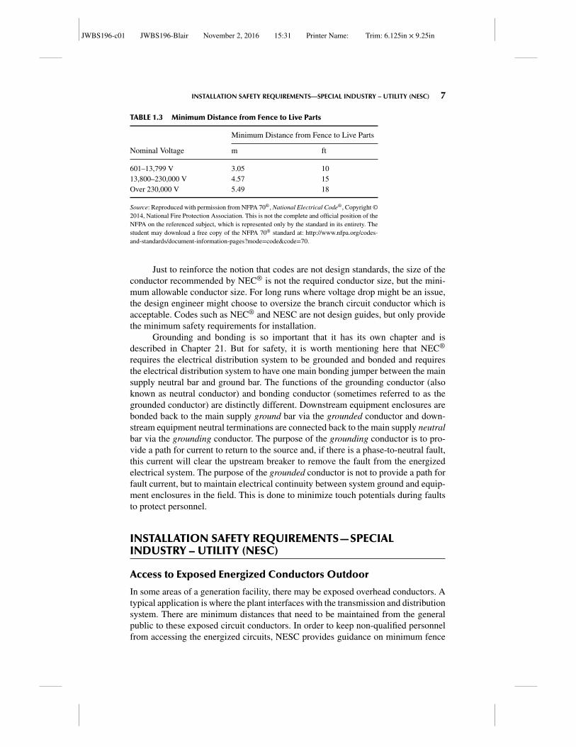
TABLE 1.4 Values of Minimum Distance from Fence to OutdoorExposed Energized Conductor for Use with NESC Figure 110-1
Dimension “R”Nominal VoltageBetween Phases (V) Typical BIL m ft
151–7,200 95 3 1013,800 110 3.1 10.123,000 150 3.1 10.334,500 200 3.2 10.646,000 250 3.3 10.969,000 350 3.5 11.6
115,000 550 4 13138,000 650 4.2 13.7161,000 750 4.4 14.3230,000 825 4.5 14.9230,000 900 4.7 15.4
Source: Reproduced with permission of IEEE.
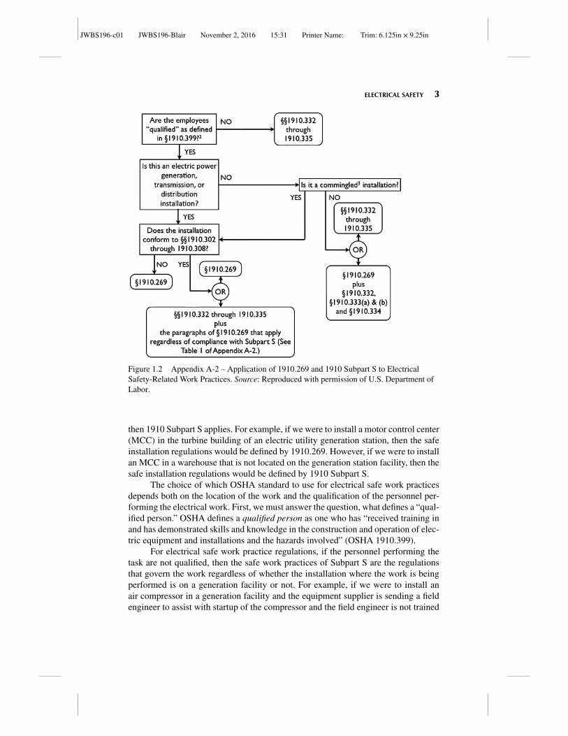
space requirements between energized conductors and the fence. This is very similarto the requirements of NEC® mentioned in Table 1.3.
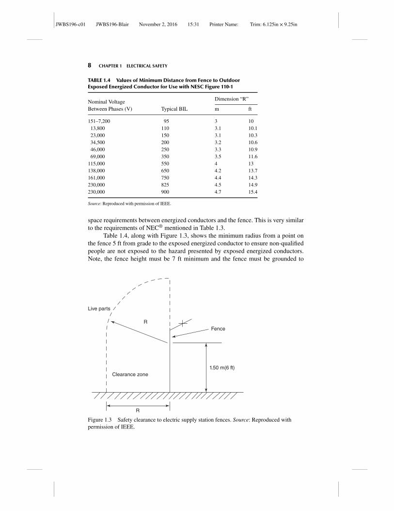
Table 1.4, along with Figure 1.3, shows the minimum radius from a point onthe fence 5 ft from grade to the exposed energized conductor to ensure non-qualifiedpeople are not exposed to the hazard presented by exposed energized conductors.Note, the fence height must be 7 ft minimum and the fence must be grounded to
Live parts
Clearance zone
FenceR
R
1.50 m(6 ft)
Figure 1.3 Safety clearance to electric supply station fences. Source: Reproduced withpermission of IEEE.
JWBS196-c01 JWBS196-Blair November 2, 2016 15:31 Printer Name: Trim: 6.125in × 9.25in
INSTALLATION SAFETY REQUIREMENTS—SPECIAL INDUSTRY – UTILITY (NESC) 9
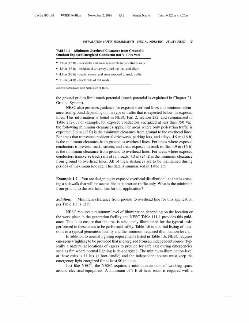
TABLE 1.5 Minimum Overhead Clearance from Ground toOutdoor Exposed Energized Conductor (for V < 750 Vac)
� 3.6 m (12 ft) – sidewalks and areas accessible to pedestrians only� 4.9 m (16 ft) – residential driveways, parking lots, and alleys� 4.9 m (16 ft) – roads, streets, and areas exposed to truck traffic� 7.3 m (24 ft) – track rails of rail roads
Source: Reproduced with permission of IEEE.
the ground grid to limit touch potential (touch potential is explained in Chapter 21:Ground System).
NESC also provides guidance for exposed overhead lines and minimum clear-ance from ground depending on the type of traffic that is expected below the exposedlines. This information is found in NESC Part 2, section 232, and summarized inTable 232-1. For example, for exposed conductors energized at less than 750 Vac,the following minimum clearances apply. For areas where only pedestrian traffic isexpected, 3.6 m (12 ft) is the minimum clearance from ground to the overhead lines.For areas that transverse residential driveways, parking lots, and alleys, 4.9 m (16 ft)is the minimum clearance from ground to overhead lines. For areas where exposedconductors transverse roads, streets, and areas exposed to truck traffic, 4.9 m (16 ft)is the minimum clearance from ground to overhead lines. For areas where exposedconductors transverse track rails of rail roads, 7.3 m (24 ft) is the minimum clearancefrom ground to overhead lines. All of these distances are to be maintained duringperiods of maximum line sag. This data is summarized in Table 1.5.
Example 1.2 You are designing an exposed overhead distribution line that is cross-ing a sidewalk that will be accessible to pedestrian traffic only. What is the minimumfrom ground to the overhead line for this application?
Solution: Minimum clearance from ground to overhead line for this applicationper Table 1.5 is 12 ft.
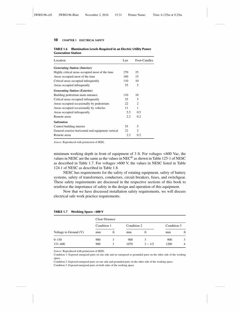
NESC requires a minimum level of illumination depending on the location orthe work place in the generation facility and NESC Table 111-1 provides this guid-ance. This is to ensure that the area is adequately illuminated for the typical tasksperformed in these areas to be performed safely. Table 1.6 is a partial listing of loca-tions in a typical generation facility and the minimum required illumination levels.
In addition to normal lighting requirements listed in Table 1.6, NESC requiresemergency lighting to be provided that is energized from an independent source (typ-ically a battery) at locations of egress to provide for safe exit during emergenciessuch as fire where normal lighting is de-energized. The minimum illumination levelat these exits is 11 lux (1 foot-candle) and the independent source must keep theemergency light energized for at least 90 minutes.
Just like NEC®, the NESC requires a minimum amount of working spacearound electrical equipment. A minimum of 7 ft of head room is required with a
JWBS196-c01 JWBS196-Blair November 2, 2016 15:31 Printer Name: Trim: 6.125in × 9.25in
10 CHAPTER 1 ELECTRICAL SAFETY
TABLE 1.6 Illumination Levels Required in an Electric Utility PowerGeneration Station
Location Lux Foot-Candles
Generating Station (Interior)Highly critical areas occupied most of the time 270 25Areas occupied most of the time 160 15Critical areas occupied infrequently 110 10Areas occupied infrequently 55 5
Generating Station (Exterior)Building pedestrian main entrance 110 10Critical areas occupied infrequently 55 5Areas occupied occasionally by pedestrians 22 2Areas occupied occasionally by vehicles 11 1Areas occupied infrequently 5.5 0.5Remote areas 2.2 0.2
SubstationControl building interior 55 5General exterior horizontal end equipment vertical 22 2Remote areas 2.2 0.2
Source: Reproduced with permission of IEEE.
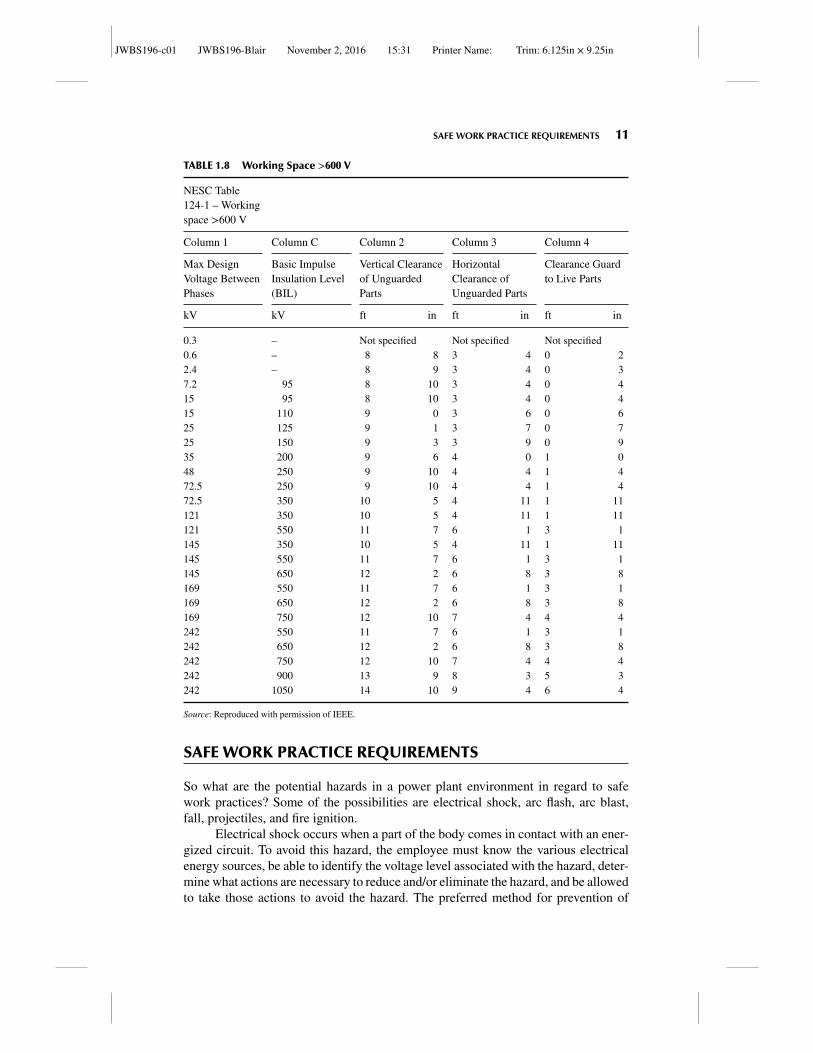
minimum working depth in front of equipment of 3 ft. For voltages <600 Vac, thevalues in NESC are the same as the values in NEC® as shown in Table 125-1 of NESCas described in Table 1.7. For voltages >600 V, the values in NESC listed in Table124.1 of NESC as described in Table 1.8.
NESC has requirements for the safety of rotating equipment, safety of batterysystems, safety of transformers, conductors, circuit breakers, fuses, and switchgear.These safety requirements are discussed in the respective sections of this book toreinforce the importance of safety in the design and operation of this equipment.
Now that we have discussed installation safety requirements, we will discusselectrical safe work practice requirements.
TABLE 1.7 Working Space <600 V
Clear Distance
Condition 1 Condition 2 Condition 3
Voltage to Ground (V) mm ft mm ft mm ft
0–150 900 3 900 3 900 3151–600 900 3 1070 3 − 1/2 1200 4
Source: Reproduced with permission of IEEE.Condition 1: Exposed energized parts on one side and no energized or grounded parts on the other side of the workingspace.Condition 2: Exposed energized parts on one side and grounded parts on the other side of the working space.Condition 3: Exposed energized parts on both sides of the working space.
JWBS196-c01 JWBS196-Blair November 2, 2016 15:31 Printer Name: Trim: 6.125in × 9.25in
SAFE WORK PRACTICE REQUIREMENTS 11
TABLE 1.8 Working Space >600 V
NESC Table124-1 – Workingspace >600 V
Column 1 Column C Column 2 Column 3 Column 4
Max DesignVoltage BetweenPhases
Basic ImpulseInsulation Level(BIL)
Vertical Clearanceof UnguardedParts
HorizontalClearance ofUnguarded Parts
Clearance Guardto Live Parts
kV kV ft in ft in ft in
0.3 – Not specified Not specified Not specified0.6 – 8 8 3 4 0 22.4 – 8 9 3 4 0 37.2 95 8 10 3 4 0 415 95 8 10 3 4 0 415 110 9 0 3 6 0 625 125 9 1 3 7 0 725 150 9 3 3 9 0 935 200 9 6 4 0 1 048 250 9 10 4 4 1 472.5 250 9 10 4 4 1 472.5 350 10 5 4 11 1 11121 350 10 5 4 11 1 11121 550 11 7 6 1 3 1145 350 10 5 4 11 1 11145 550 11 7 6 1 3 1145 650 12 2 6 8 3 8169 550 11 7 6 1 3 1169 650 12 2 6 8 3 8169 750 12 10 7 4 4 4242 550 11 7 6 1 3 1242 650 12 2 6 8 3 8242 750 12 10 7 4 4 4242 900 13 9 8 3 5 3242 1050 14 10 9 4 6 4
Source: Reproduced with permission of IEEE.
SAFE WORK PRACTICE REQUIREMENTS
So what are the potential hazards in a power plant environment in regard to safework practices? Some of the possibilities are electrical shock, arc flash, arc blast,fall, projectiles, and fire ignition.
Electrical shock occurs when a part of the body comes in contact with an ener-gized circuit. To avoid this hazard, the employee must know the various electricalenergy sources, be able to identify the voltage level associated with the hazard, deter-mine what actions are necessary to reduce and/or eliminate the hazard, and be allowedto take those actions to avoid the hazard. The preferred method for prevention of
JWBS196-c01 JWBS196-Blair November 2, 2016 15:31 Printer Name: Trim: 6.125in × 9.25in
12 CHAPTER 1 ELECTRICAL SAFETY
electrical shocks is to ensure that the circuit is de-energized by placing it in an elec-trically safe work condition prior to performing work on that circuit. If it is deter-mined that the circuit cannot be de-energized, then NFPA 70E and NESC Part 4 pro-vide guidance of procedures and equipment to be utilized when working on a systemenergized. This is known as energized electrical work.
In one recent survey of electrical workers, 97% of workers had experienced ashock at work sometime in the past and 58% were exposed to energized circuits everyday. One might think that a majority of the incidents involve younger, less experiencedworkers. However, one survey shows the following distribution of electrocutions byage.
�<20 = 10%
� 20–24 = 18%� 25–34 = 34%� 35–44 = 22%� 45–54 = 10%�>55 = 6%
As can be seen from the above data, the most likely age range is the 25–34 yearrange. Therefore, the concept that experience makes one less likely to be involvedwith an electrical contact incident is incorrect. In fact, there are more than 30,000electrical contact events that happen every year in the United States. A majority ofthese occur on system voltages less than 600 V. One may think that higher voltagesmay present higher hazards, but from a frequency of incident viewpoint, this is notthe case. The hazard exists on any energized circuit.
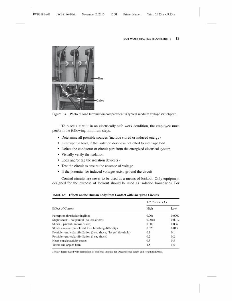
Identifying circuit parts that are “exposed live parts” may not be as straightforward as one would think. An energized uncovered bus bar in a piece of electricalequipment is an “exposed live part” for certain. However, how about the covered busshown in the photo in Figure 1.4?
The cable jacket that provides the covering on the cable has a dielectric ratingfor the voltage involved and is therefore considered insulated. However, the coveringon the bus does not have a dielectric rating and is not considered insulated and there-fore should be treated as an energized circuit until it is placed in an electrically safeworking condition.
In order to avoid electrical shock hazards, a shock hazard analysis shouldalways be performed whenever work is to be performed on or near energized electri-cal equipment. A shock hazard analysis is a procedure where the voltage level of thecircuit is determined; all potential sources supplying the circuit are determined andthen all sources are isolated by putting the circuit in an electrically safe working con-dition. The shock hazard analysis should also determine the necessary PPE requiredto safely test the circuit for the absence of voltage during the process of placing thecircuit in an electrically safe work condition.
Table 1.9 describes the effect that current passing through a body has on thebody. The higher value is for larger framed bodies and the lower value is for smallerframed bodies.
JWBS196-c01 JWBS196-Blair November 2, 2016 15:31 Printer Name: Trim: 6.125in × 9.25in
SAFE WORK PRACTICE REQUIREMENTS 13
Bus
Cable
Figure 1.4 Photo of load termination compartment in typical medium voltage switchgear.
To place a circuit in an electrically safe work condition, the employee mustperform the following minimum steps.
� Determine all possible sources (include stored or induced energy)� Interrupt the load, if the isolation device is not rated to interrupt load� Isolate the conductor or circuit part from the energized electrical system� Visually verify the isolation� Lock and/or tag the isolation device(s)� Test the circuit to ensure the absence of voltage� If the potential for induced voltages exist, ground the circuit
Control circuits are never to be used as a means of lockout. Only equipmentdesigned for the purpose of lockout should be used as isolation boundaries. For
TABLE 1.9 Effects on the Human Body from Contact with Energized Circuits
AC Current (A)
Effect of Current High Low
Perception threshold (tingling) 0.001 0.0007Slight shock – not painful (no loss of ctrl) 0.0018 0.0012Shock – painful (no loss of ctrl) 0.009 0.006Shock – severe (muscle ctrl loss, breathing difficulty) 0.023 0.015Possible ventricular fibrillation (3 sec shock, “let go” threshold) 0.1 0.1Possible ventricular fibrillation (1 sec shock) 0.2 0.2Heart muscle activity ceases 0.5 0.5Tissue and organs burn 1.5 1.5
Source: Reproduced with permission of National Institute for Occupational Safety and Health (NIOSH).
JWBS196-c01 JWBS196-Blair November 2, 2016 15:31 Printer Name: Trim: 6.125in × 9.25in
14 CHAPTER 1 ELECTRICAL SAFETY
example, a pull cord on a conveyor belt is interlocked with a contactor to de-energizethe contactor when the pull cord is activated. While the pull cord is an importantsafety interlock, it should never be used as a means for isolation for lockout. Thereason for this is that the device that isolates power (the contactor) is not locked andcould be mechanically pulled in to energize the circuit, thereby bypassing the lockingdevice and the protection of the lock.
Until all of the these steps are completed (this includes testing the circuit andgrounding the circuit if required), the circuit must be considered energized and work-ing on the circuit must be considered as energized electrical work. You may realizeat this point that the task of testing the circuit to ensure the absence of voltage aloneis considered energized electrical work and requires the proper personnel protectiveequipment (PPE) and safe work practices, since the process of testing a circuit toensure the absence of voltage may require contact with the circuit before all stepsare completed. Electrical safe work practices should be utilized when verifying theabsence of voltage. Additionally, when verifying absence of voltage, the meter beingutilized should be tested on a known source to verify it is functioning first, then testedon the circuit that is to be put in the electrically safe working condition, and then testedagain on a known source to verify if it is still functioning. This is also known as the“test the tester, test the circuit, test the tester” method. This is done to ensure theintegrity of the meter used and the validity of the absence of voltage reading. Alsoensure that the voltage meter being used is rated for the anticipated voltage level ofthe system. There have been cases where a worker obtained the incorrect meter andtested a circuit that the meter was not rated for with catastrophic results.
There are two basic methods of lockout/tagout defined by OSHA. The firstmethod known as the simple lockout method which involves only one set of circuitconductors or circuit parts. Each worker is responsible for their own isolation andlock. Under the simple lockout method, a written procedure is not required for eachlock. Alternately (and more typical in a power plant environment), the second lockoutmethod is known as the complex lockout/tagout procedure and it involves the useof a lockout procedure. This system is required to be documented. Instead of theindividual performing the work being responsible for the isolation, there are threepeople minimum involved in the isolation procedure. The first is the qualified personin charge of the lockout. The second is the operator that performs the isolation, installsthe lock, and verifies that the circuit is de-energized. The third person is the one whois working on the circuit and they are known as the affected person. This systemallows for a method to communicate the change of a lockout status to all affectedpersons.
When it is determined that work has to be performed on equipment that is notput in an electrically safe working condition, then an Electrical Safe Work Permit(ESWP) should be filled out for the task at hand. This is a very useful document, asit guides the affected employee to analyze the circuit and determine the shock andarc flash protection boundaries and the required PPE to work safely. It also forcesthe persons asking the affected employee to work a system energized to justify whythe system cannot be placed in an electrically safe work condition. Specifically, theESWP has the following items covered and should be filled out and any safety con-cerns resolved before any energized work is commenced.
JWBS196-c01 JWBS196-Blair November 2, 2016 15:31 Printer Name: Trim: 6.125in × 9.25in
ELECTRICAL PPE 15
� A description of the circuit� Justification or need to work energized� A description of the safe work practices� Results of the shock hazard analysis� Determination of shock protection boundaries� Results of the flash hazard analysis� The flash protection boundary� The necessary personal protective equipment (PPE)� Means employed to restrict access� Evidence of job briefing� Energized work approval
When working on energized circuits, select the proper equipment and PPErequired for the voltage level of the system. Do not use a 600 V-rated volt meterto test a 5000 V circuit just because you “know” it is de-energized. If during the testyou find that the equipment is not de-energized, severe injury or death can arise forthe misuse of the wrong class of meter. Also, the PPE selected should be rated forthe voltage level encountered. Details on the correct PPE to select for various typesof hazards can be found from the Occupational Safety and Health Administrationinformational booklet OSHA 3151-12R 2003.
ELECTRICAL PPE
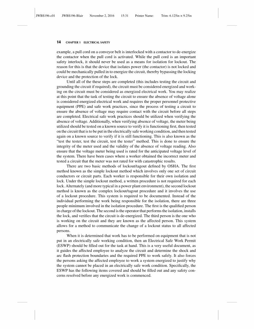
Electrical PPE can be broken down into two basic categories that are defined bythe type of hazard that the PPE is intended to protect against. The first category isshock protection PPE. The purpose of shock protection PPE is to provide an elec-trically insulating barrier between the employee and the energized part. Any part ofthe employee’s body must be protected from the hazard of electrical shock by theuse of electrical PPE when reaching into the restricted approach boundary duringelectrical energized work. Shock protection PPE includes non-conducting hard hats,non-conducting safety glasses, voltage-rated insulating gloves with leather protec-tors, and insulating sleeves for higher voltages. In addition to these items, types ofsupplemental shock protection that may be used are dielectric safety shoes, insulatedblankets, and insulating floor mats. Figure 1.5 shows the typical type of personalshock protection PPE utilized in the generation station.
The second category of electrical PPE is arc flash protection PPE. The pur-pose of arc flash protection PPE is to provide a thermally insulating barrier betweenthe employee and the energized part to reduce the thermal energy exposure of theemployee’s skin in the event of an electrical arcing event. Any part of the employee’sbody must be protected from the hazard of an electrical arc flash by the use of arcflash PPE when reaching into the arc flash boundary during electrical energized workor when the employee is interacting with the electrical equipment in a fashion that
JWBS196-c01 JWBS196-Blair November 2, 2016 15:31 Printer Name: Trim: 6.125in × 9.25in
16 CHAPTER 1 ELECTRICAL SAFETY
Figure 1.5 Photo of typical shock protection PPE. Source: Reproduced with permission ofOSHA.
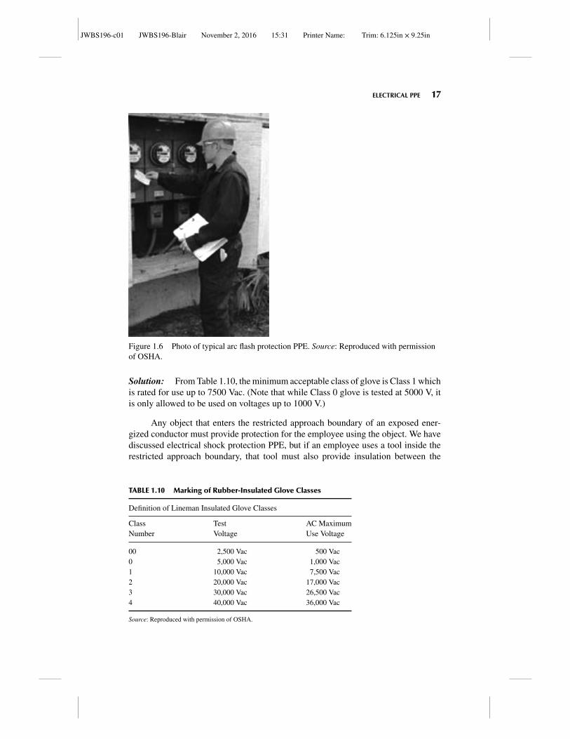
could result in an electrical arc flash. The material that forms this thermal barrier istreated to inhibit the material from igniting when exposed to elevated temperatures upto the energy values that the material is rated for. The energy value that the materialhas been tested to is known as the arc rating (AR) or arc thermal performance value(ATPV). ATPV is defined as the arc incident energy required to cause the onset ofsecond-degree burn under the material that is being tested. Arc-rated PPE should notbe confused with flame-resistant (FR) PPE. FR PPE is treated such that it does notsupport combustion once the ignition source is removed, but FR PPE is not tested forits response to electrical arcs like AR-rated PPE is. When selecting PPE for protectionagainst the hazards of electrical arcs, ensure that the PPE has an AR rating. Figure 1.6shows the type of personal arc flash protection PPE utilized in the generation station.
Arc flash protection PPE includes arc-rated (AR) shirt and pants or a full AR-rated coverall suit, AR-rated face shield and balaclava or AR-rated hood, and AR-rated gloves. For tasks that involve both electrical hazards and arc flash hazards, elec-trically rated gloves with leather protectors can be used instead of AR-rated glovesas the leather protectors provide thermal protection and the electrically rated gloveprovides the electrical protection.
Just as we stressed previously that the equipment utilized should be rated for thevoltage exposure of the task, the shock protection PPE that is utilized must be rated forthe voltage exposure of the task. For example, insulating gloves have various ratingsor classes depending on their test voltage value and maximum allowable workingvoltage level. See Table 1.10 for information on proper glove selection based on thesystem working voltage.
Example 1.3 You have been tasked to test a circuit for potential where the circuitis rated for 4160 V. What is the minimum glove class acceptable for this task?
JWBS196-c01 JWBS196-Blair November 2, 2016 15:31 Printer Name: Trim: 6.125in × 9.25in
ELECTRICAL PPE 17
Figure 1.6 Photo of typical arc flash protection PPE. Source: Reproduced with permissionof OSHA.
Solution: From Table 1.10, the minimum acceptable class of glove is Class 1 whichis rated for use up to 7500 Vac. (Note that while Class 0 glove is tested at 5000 V, itis only allowed to be used on voltages up to 1000 V.)
Any object that enters the restricted approach boundary of an exposed ener-gized conductor must provide protection for the employee using the object. We havediscussed electrical shock protection PPE, but if an employee uses a tool inside therestricted approach boundary, that tool must also provide insulation between the
TABLE 1.10 Marking of Rubber-Insulated Glove Classes
Definition of Lineman Insulated Glove Classes
Class Test AC MaximumNumber Voltage Use Voltage
00 2,500 Vac 500 Vac0 5,000 Vac 1,000 Vac1 10,000 Vac 7,500 Vac2 20,000 Vac 17,000 Vac3 30,000 Vac 26,500 Vac4 40,000 Vac 36,000 Vac
Source: Reproduced with permission of OSHA.
JWBS196-c01 JWBS196-Blair November 2, 2016 15:31 Printer Name: Trim: 6.125in × 9.25in
18 CHAPTER 1 ELECTRICAL SAFETY
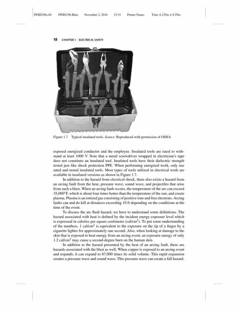
Figure 1.7 Typical insulated tools. Source: Reproduced with permission of OSHA.
exposed energized conductor and the employee. Insulated tools are rated to with-stand at least 1000 V. Note that a metal screwdriver wrapped in electrician’s tapedoes not constitute an insulated tool. Insulated tools have their dielectric strengthtested just like shock protection PPE. When performing energized work, only userated and tested insulated tools. Most types of tools utilized in electrical work areavailable in insulated versions as shown in Figure 1.7.
In addition to the hazard from electrical shock, there also exists a hazard froman arcing fault from the heat, pressure wave, sound wave, and projectiles that arisefrom such a blast. When an arcing fault occurs, the temperature of the arc can exceed35,000◦F, which is about four times hotter than the temperature of the sun, and createplasma. Plasma is an ionized gas consisting of positive ions and free electrons. Arcingfaults can and do kill at distances exceeding 10 ft depending on the conditions at thetime of the event.
To discuss the arc flash hazard, we have to understand some definitions. Thehazard associated with heat is defined by the incident energy exposure level whichis expressed in calories per square centimeter (cal/cm2). To put some understandingof the numbers, 1 cal/cm2 is equivalent to the exposure on the tip of a finger by acigarette lighter for approximately one second. Also, when looking at damage to theskin that is exposed to heat energy from an arcing event, an exposure energy of only1.2 cal/cm2 may cause a second-degree burn on the human skin.
In addition to the hazard presented by the heat of an arcing fault, there arehazards associated with the blast as well. When copper is exposed to an arcing eventand expands, it can expand to 67,000 times its solid volume. This rapid expansioncreates a pressure wave and sound wave. This pressure wave can create a fall hazard.
JWBS196-c01 JWBS196-Blair November 2, 2016 15:31 Printer Name: Trim: 6.125in × 9.25in
ELECTRICAL PPE 19
Also the pressure wave can cause internal organ damage such as collapsed lungs.The sound wave can cause the sound levels to exceed 160 dB, rupturing ear drums.Associated with the pressure wave is the shrapnel that is in the gas cloud that canleave the source of the arcing fault at speeds exceeding 700 miles/hr which is fastenough to allow shrapnel to completely penetrate the human body.
Below are some definitions specific to arc fault.
� ATPV: Maximum incident energy of a PPE system prior to break open.� Arc rating: The value attributed to materials that describe their ability to with-
stand exposure to an electrical arc discharge. The arc rating is expressed incal/cm2 and is derived from the determined value of the ATPV or energy ofbreak-open threshold (EBT) (should a material system exhibit a break-openresponse below the ATPV value). Arc rating is reported as either ATPV or EBT,whichever is the lower value.
� Flash hazard: Condition caused by the release of energy caused by an electricarc.
� Flashes protection boundary: Distance from live parts where second-degreeburns would result if an arc flash occurred. By definition, this is the distance atwhich the incident energy level is at 1.2 cal/cm2.
� Limited approach boundary: Distance from live parts where shock hazardexists.
� Restricted approach boundary: Distance beyond which only qualified per-sons may enter because it requires shock protection equipment or techniques.
� Exposed live part: Not suitably guarded, isolated, or insulated.� Working near (live parts): Any activity inside a limited approach boundary.� Working on (live parts): Any activity inside a restricted approach boundary
including coming in contact with live parts with body or equipment regardlessof PPE.
The arc flash boundary is the distance from the source of an arc where theincident energy level will be 1.2 cal/cm2, which is enough thermal energy to cause asecond-degree burn.
OSHA updated CFR 1910.269 in 2014 (the previous revision was in 1994) andadded the following regulation requiring employers to protect their employees fromthe hazards of arc flash.
1910.269 (I) (8): Protection from flames and electric arcs
(i) The employer shall assess the workplace to identify employees exposed to haz-ards from flames or from electric arcs.
(ii) For each employee exposed to hazards from electric arcs, the employer shallmake a reasonable estimate of the incident heat energy to which the employeewould be exposed.
As mentioned previously, an employee must utilize shock protection PPEwhenever they are in the restricted approach boundary (for tasks that conform to
JWBS196-c01 JWBS196-Blair November 2, 2016 15:31 Printer Name: Trim: 6.125in × 9.25in
20 CHAPTER 1 ELECTRICAL SAFETY
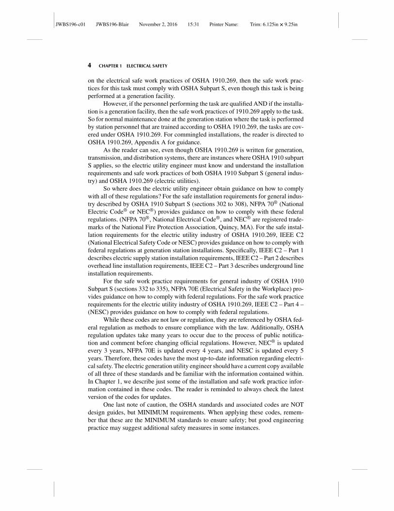
Is the employeewithin thearc flash boundary?
Arc flash PPEis not required
Arc flash PPEis required
Is the employee exposed toenergized conductorsorIs the employee interacting withequipment in such a fashion thatan arc flash may occur?
YES
YES
NO
NO
Figure 1.8 Decision matrix if a task requires arc flash PPE.
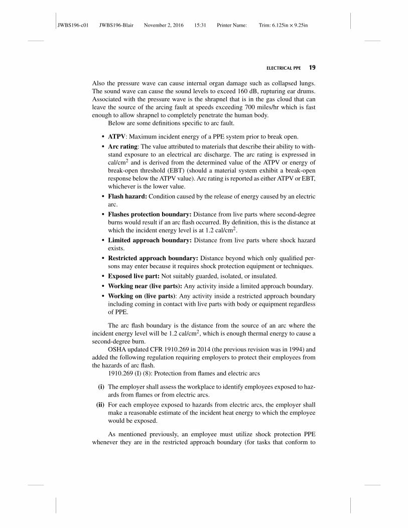
Subpart S) or whenever they are in the minimum approach distance (for tasks thatconform to Part 269). How about arc flash PPE? An employee must utilize arc flash-rated PPE whenever they are exposed to a potential arc flash. So when is that? When-ever the employee is within the arc flash boundary and if the employee is exposed toenergized conductors OR if the employee is interacting with the equipment in sucha fashion as they could be exposed to an arc flash, then the employee must utilizearc-rated PPE. The flow chart in Figure 1.8 depicts this explanation.
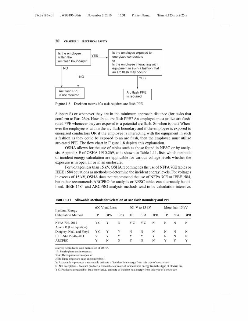
OSHA allows for the use of tables such as those found in NESC or by analy-sis. Appendix E of OSHA 1910.269, as is shown in Table 1.11, lists which methodsof incident energy calculation are applicable for various voltage levels whether theexposure is in open air or in an enclosure.
For voltages less than 15 kV, OSHA recommends the use of NFPA 70E tables orIEEE 1584 equations as methods to determine the incident energy levels. For voltagesin excess of 15 kV, OSHA does not recommend the use of NFPA 70E or IEEE1584,but rather recommends ARCPRO for analysis or NESC tables can alternately be uti-lized. IEEE 1584 and ARCPRO analysis methods tend to be calculation-intensive.
TABLE 1.11 Allowable Methods for Selection of Arc Flash Boundary and PPE
600 V and Less 601 V to 15 kV More than 15 kVIncident EnergyCalculation Method 1P 3PA 3PB 1P 3PA 3PB 1P 3PA 3PB
NFPA 70E-2012Annex D (Lee equation)
Y-C Y N Y-C Y-C N N N N
Doughty, Neal, and Floyd Y-C Y Y N N N N N NIEEE Std 1584b-2011 Y Y Y Y Y Y N N NARCPRO Y N N Y N N Y Y Y
Source: Reproduced with permission of OSHA.1P: Single-phase arc in open air.3PA: Three-phase arc in open air.3PB: Three-phase arc in an enclosure (box).Y: Acceptable – produces a reasonable estimate of incident heat energy from this type of electric arc.N: Not acceptable – does not produce a reasonable estimate of incident heat energy from this type of electric arc.Y-C: Produces a reasonable, but conservative, estimate of incident heat energy from this type of electric arc.
JWBS196-c01 JWBS196-Blair November 2, 2016 15:31 Printer Name: Trim: 6.125in × 9.25in
ARC FLASH ANALYSIS UTILIZING NFPA 70E TABLES 21
ARCPRO and IEEE 1584 analysis software takes into account many variables suchas the voltage level of the system, the gap between buses, the clearing time of thedevice, and other parameters that affect the value of the incident energy level. Dueto the complexity of these calculations, the details of these calculations are beyondthe scope of this introductory material. Normally, a computer-based software is uti-lized to obtain results (Note: IEEE provides spreadsheet along with IEEE 1584 toassist in calculations of incident energy levels). Below we will explain the use of thetable method in NFPA 70E that OSHA allows for systems less than 15 kV and wewill explain the use of the table method in NESC that OSHA allows for systems over15 kV.
ARC FLASH ANALYSIS UTILIZING NFPA 70E TABLES
The arc flash PPE category and arc flash boundary can be determined using NFPA70E Table 130.7(C)(15)(A)(b) – Arc-Flash Hazard PPE Categories for AlternatingCurrent (ac) Systems or Table 130.7(C)(15)(B) – Arc-Flash Hazard PPE Categoriesfor Direct Current (DC) Systems.
These tables break the task down to three questions: What is the type of equip-ment that the task involves? What is the maximum short-circuit current available?And what is the maximum fault clearing time? With those three pieces of information,the tables can be used to determine the arc flash PPE category (based on a workingdistance given in the table) and the arc flash boundary. Remember that if the task isbeing done outside the arc flash boundary, then arc flash PPE is not required becausethe incident energy level is less than 1.2 cal/cm2. The student can access NFPA70E® online at http://www.nfpa.org/codes-and-standards/document-information-pages?mode=code&code=70E. In NFPA 70E, Table 130.7(C)(15)(A)(b) (Arc-FlashHazard PPE Categories for Alternating Current (AC) Systems) provides guidance tothe arc flash PPE category and arc flash boundary for AC systems for various typesof equipment. Note that the short-circuit current available, the maximum clearingtime, and the working distance are all important parameters to the table. To utilize thetables, the actual short-circuit current must be equal to or less than the value given inthe table, the actual clearing time must be equal to or less than the value given in thetable, and the working distance must be equal to or greater than the value given inthe table. Similarly, for DC systems, Table 130.7(C)(15)(B) (Arc-Flash Hazard PPECategories for Direct Current (DC) Systems) provides guidance to the arc flash PPEcategory and arc flash boundary for DC systems for various types of equipment. Justas for the AC table, the short-circuit current and clearing time of the actual applica-tion must be equal to or less than the value in the table and the working distance mustbe equal to or greater than the value in the table.
Example 1.4 You have been given a task of pulling a molded case circuit breakerfrom a 120/240 Vac panel. The fault current at the panel is 10 kA and the panelis protected by a current limiting fuse, so the clearing time is 1 cycle. What is thearc flash boundary and what is the arc flash PPE required to perform the abovetask?
JWBS196-c01 JWBS196-Blair November 2, 2016 15:31 Printer Name: Trim: 6.125in × 9.25in
22 CHAPTER 1 ELECTRICAL SAFETY
Solution: To solve, the student will need to view the current NFPA 70E standardat: http://www.nfpa.org/codes-and-standards/document-information-pages?mode=code&code=70E.
From Table 130.7(C)(15)(A)(b) first row, which lists the requirements for pan-els with voltages at 240 Vac and below and short-circuit currents of 25 kA and clear-ing time less than 2 cycles, we find that the arc flash PPE required is Category 1 at adistance of 18 in. and the arc flash boundary is 19 in.
So what is arc flash PPE Category 1? NFPA 70E breaks down arc flash cate-gories into four levels based on a range of energy exposure possible. Arc flash PPECategory 1 must protect again an incident energy level of at least 4 cal/cm2. Arc flashPPE Category 2 must protect again an incident energy level of at least 8 cal/cm2.Arc flash PPE Category 3 must protect again an incident energy level of at least 25cal/cm2. Arc flash PPE Category 4 must protect again an incident energy level of atleast 40 cal/cm2. Notice that there is no category above 40 cal/cm2. This is becauseat energy levels that high, heat is not the only hazard to personnel but also hot gases,projectiles, pressure wave, and UV radiation. Due to the magnitude of these otherhazards, there is no level of PPE that can protect a person at energy levels in excessof 40 cal/cm2.
Example 1.5 A task has been assigned to remove a molded case circuit breakerfrom a 120 Vac panel where there is a maximum bolted fault value of 8 kA and theclearing time is 5 cycles; can you use the tables in NFPA 70E for the determinationof the correct arc flash PPE for this task? If you can, what is the arc flash PPE levelrequired for this task?
Solution: To solve, the student will need to view the current NFPA 70E standardat: http://www.nfpa.org/codes-and-standards/document-information-pages?mode=code&code=70E.
You could not use the table to determine the PPE, but have to perform a fullarc flash analysis. This is because the table lists only one row for 240 Vac panels andit has the limits of a maximum fault current of up to 25 kA and maximum clearingtime of up to 2 cycles. Since clearing time of this application is actually 5 cycles, thetables cannot be used and an analysis must be performed.
Example 1.6 You have been given a task of pulling a molded case circuit breakerfrom a 125 Vdc panel. The fault current at the panel is 10 kA and the panel is pro-tected by a current limiting fuse, so the clearing time is 1 cycle. What is the arc flashboundary and what is the arc flash PPE required to perform the above task?
Solution: To solve, the student will need to view the current NFPA 70E standardat: http://www.nfpa.org/codes-and-standards/document-information-pages?mode=code&code=70E.
From Table 130.7(C)(15)(B) third row, which lists the requirements for panelswith voltages between 100 Vdc and 250 Vdc and short-circuit currents between 7kA and 15 kA and clearing time less than 2 seconds, we find that the arc flash PPErequired is Category 3 at a distance of 18 in. and the arc flash boundary is 6 ft.
JWBS196-c01 JWBS196-Blair November 2, 2016 15:31 Printer Name: Trim: 6.125in × 9.25in
ARC FLASH ANALYSIS UTILIZING NFPA 70E TABLES 23
The hazard of arc flash can be minimized by proper equipment design andproper operational procedures. PPE should be a last resort to meeting the require-ments of arc flash protection. The incident energy of the arc flash hazard is primarilya function of current and time. By specifying low current let through fuses, equipmenton the downstream side of fuses can have reduced incident energy levels. Current lim-iting fuses can provide a dramatic reduction of incident energy levels if the value forarcing current is within the current limiting range of the fuse. When the fuse is appliedsuch that the arcing current is within the current limiting range of the fuse, the fusewill clear this fault current in less than one cycle. One drawback of using the current-limiting fuse is the difficulty in trying to coordinate downstream protection deviceswith the fuse. Therefore, current-limiting fuses are used only when they are the lastcircuit-protective device on the radial feeder.
Relay settings are another method of providing faster trip times for electricalequipment. The challenge for the protection engineer is to provide long enough tripsettings to allow for both normal system operations such as motor locked rotor cur-rents when starting and to allow for coordination of the protective system such that,when a fault occurs, the relays operate fast enough to provide minimum amount ofincident energy levels at the equipment where the fault occurs and still allow foracceptable coordination.
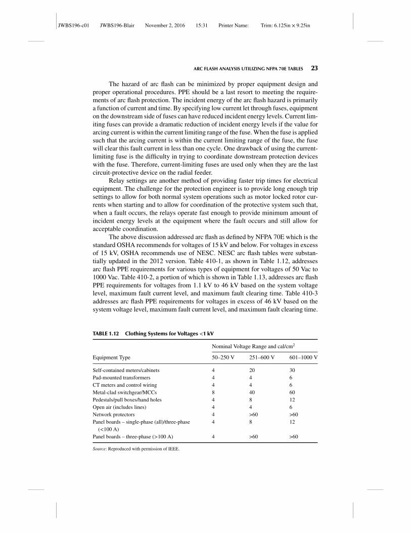
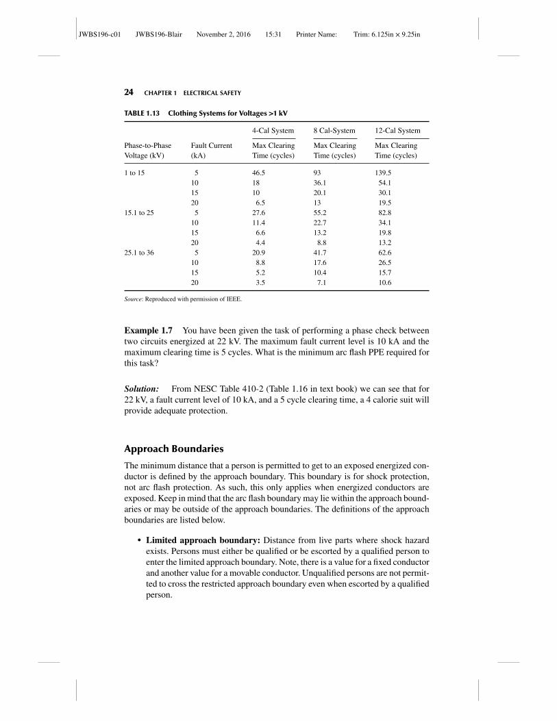
The above discussion addressed arc flash as defined by NFPA 70E which is thestandard OSHA recommends for voltages of 15 kV and below. For voltages in excessof 15 kV, OSHA recommends use of NESC. NESC arc flash tables were substan-tially updated in the 2012 version. Table 410-1, as shown in Table 1.12, addressesarc flash PPE requirements for various types of equipment for voltages of 50 Vac to1000 Vac. Table 410-2, a portion of which is shown in Table 1.13, addresses arc flashPPE requirements for voltages from 1.1 kV to 46 kV based on the system voltagelevel, maximum fault current level, and maximum fault clearing time. Table 410-3addresses arc flash PPE requirements for voltages in excess of 46 kV based on thesystem voltage level, maximum fault current level, and maximum fault clearing time.
TABLE 1.12 Clothing Systems for Voltages <1 kV
Nominal Voltage Range and cal/cm2
Equipment Type 50–250 V 251–600 V 601–1000 V
Self-contained meters/cabinets 4 20 30Pad-mounted transformers 4 4 6CT meters and control wiring 4 4 6Metal-clad switchgear/MCCs 8 40 60Pedestals/pull boxes/hand holes 4 8 12Open air (includes lines) 4 4 6Network protectors 4 >60 >60Panel boards – single-phase (all)/three-phase
(<100 A)4 8 12
Panel boards – three-phase (>100 A) 4 >60 >60
Source: Reproduced with permission of IEEE.
JWBS196-c01 JWBS196-Blair November 2, 2016 15:31 Printer Name: Trim: 6.125in × 9.25in
24 CHAPTER 1 ELECTRICAL SAFETY
TABLE 1.13 Clothing Systems for Voltages >1 kV
4-Cal System 8 Cal-System 12-Cal System
Phase-to-PhaseVoltage (kV)
Fault Current(kA)
Max ClearingTime (cycles)
Max ClearingTime (cycles)
Max ClearingTime (cycles)
1 to 15 5 46.5 93 139.510 18 36.1 54.115 10 20.1 30.120 6.5 13 19.5
15.1 to 25 5 27.6 55.2 82.810 11.4 22.7 34.115 6.6 13.2 19.820 4.4 8.8 13.2
25.1 to 36 5 20.9 41.7 62.610 8.8 17.6 26.515 5.2 10.4 15.720 3.5 7.1 10.6
Source: Reproduced with permission of IEEE.
Example 1.7 You have been given the task of performing a phase check betweentwo circuits energized at 22 kV. The maximum fault current level is 10 kA and themaximum clearing time is 5 cycles. What is the minimum arc flash PPE required forthis task?
Solution: From NESC Table 410-2 (Table 1.16 in text book) we can see that for22 kV, a fault current level of 10 kA, and a 5 cycle clearing time, a 4 calorie suit willprovide adequate protection.
Approach Boundaries
The minimum distance that a person is permitted to get to an exposed energized con-ductor is defined by the approach boundary. This boundary is for shock protection,not arc flash protection. As such, this only applies when energized conductors areexposed. Keep in mind that the arc flash boundary may lie within the approach bound-aries or may be outside of the approach boundaries. The definitions of the approachboundaries are listed below.
� Limited approach boundary: Distance from live parts where shock hazardexists. Persons must either be qualified or be escorted by a qualified person toenter the limited approach boundary. Note, there is a value for a fixed conductorand another value for a movable conductor. Unqualified persons are not permit-ted to cross the restricted approach boundary even when escorted by a qualifiedperson.
JWBS196-c01 JWBS196-Blair November 2, 2016 15:31 Printer Name: Trim: 6.125in × 9.25in
HAZARDOUS/CLASSIFIED AREAS 25
� Restricted approach boundary: A distance beyond which only qualified personsmay enter because it requires shock protection equipment or techniques. It isconsidered the same as making contact with the energized conductor. Inside therestricted approach boundary, the employee must utilize shock protection PPE,insulated tools, and safe energized electrical work practices.
Prior to the 2015 version of NFPA 70E®, there was also a “prohibited approachboundary,” but this term was removed as of the 2015 version of NFPA 70E®. The val-ues for boundary distances are given in NFPA 70E, Table 130.4 (D) (a) for AC sys-tems and Table 130.4 (D) (b) for DC systems. The student is encouraged to view thecurrent NFPA 70E standard at: http://www.nfpa.org/codes-and-standards/document-information-pages?mode=code&code=70E.
HAZARDOUS/CLASSIFIED AREAS
In environments where ignitable and/or combustible materials are stored, handled,or utilized, where the materials may be in sufficient quantities to introduce a fire orexplosion hazard, the area must be classified as to the type of hazard. Equipment uti-lized in a classified area must be rated for service in this area. The equipment must belabeled for the area classification, the gas classification group, and the operating tem-perature of the equipment. For Class I equipment, the operating temperature of theequipment must be less than the autoignition temperature of the material presentingthe hazard for that area. Additionally, threaded metallic conduit that presents a con-ductive path must be wrench tight. Equipment with conductive panels and surfacesmust have panels and surfaces solidly secured such that a good path for conduction offault current is present. Flexible metallic conduit must utilize a grounding bushing oneach side of the metallic conduit and have a bonding jumper in parallel with the flexi-ble metallic conduit to provide this path for the conduction of fault currents. The goalis to ensure that, should fault current flow in the metallic materials, there are no highimpedance connections between metallic parts that can present and arc/spark haz-ard in the hazardous environment providing an ignition source. NEC® also requiresthat any equipment utilized in a classified area be selected under the supervision ofa registered professional engineer. The process of calculations and the results of thecalculations for area classification are required to be documented.
The NESC refers the user back to the NEC® articles 500 to 517 for classifica-tion of hazardous areas but NESC provides additional requirements in section 127.For example, NESC127G prohibits gaseous hydrogen storage from being locatedbeneath electric power lines. The National Electrical Code® provides for two typesof area classification, the “Class” system and the “Zone” system. To date, a majorityof electric utility locations in the United States that require compliance with NEC®
utilize the “Class” system.Because of this, the “Class” system will be introduced first and the “Zone”
system second. However, either system, when properly administered, will satisfy therequirements of NEC®, NFPA standards, and OSHA requirements.
JWBS196-c01 JWBS196-Blair November 2, 2016 15:31 Printer Name: Trim: 6.125in × 9.25in
26 CHAPTER 1 ELECTRICAL SAFETY
CLASSIFIED AREA – “CLASS” SYSTEM
In the “Class” system, there are three classes of materials. The “class” of the system isbased on the material that poses the hazard to the area. Under the “class” designation,there is a sub-designation of division. The division of the system is based on whetherthe material is found in the area under normal operation in quantities and form suffi-cient to pose a hazard, or whether the material would only be present in an abnormalcondition. Additionally, a Division 1 area cannot be adjacent to an unclassified area.There must be a Division 2 area between the unclassified area and the Division 1. TheNEC®-defined values for the “Class” system of area classification are listed below.
� Class I location where flammable gases or vapors may be present in air to anexplosive level
– Division 1 – Flammable gases or vapors exist under normal operations orfrequently or faulty equipment operation may cause simultaneous failure ofelectrical equipment
– Division 2 – Flammable gases or vapors are used, but not normally in explo-sive concentrations or concentration prevented by positive mechanical ven-tilation or is adjacent to Class I, Division 1
� Class II location where combustible dust may be present
– Division 1 – Combustible dusts exist under normal operations or faultyequipment operation may cause simultaneous failure of electrical equipmentor where combustible dusts are electrically conductive
– Division 2 – Combustible dusts not normally in explosive concentrations orconcentration may prevent cooling of electrical equipment
� Class III location where easily ignitable fibers may be present
– Division 1 – Where fibers are produced, handled, or used
– Division 2 – Areas where stored or handled other than manufacturing process
Example 1.8 The filling station for the hydrogen storage tanks for a power genera-tion facility has been deemed as a location where, under normal operations of fillingthe storage tank with hydrogen (a flammable gas), the area will frequently contain anexplosive mixture of hydrogen when the relief value lifts. What are the correct classand division for this hazardous area classification?
Solution: This would be Class I (flammable gas or vapor), Division 1 (Flammablegases or vapors exist under normal operations or frequently).
For the “Class” system of area classification, the appropriate standards to pro-vide guidance on the classification of the locations are NEC® – National Electri-cal Code®, NFPA 497 – Classification of Flammable Liquids, Gases, or Vapors andof Hazardous (Classified) Locations for Electrical Installations in Chemical ProcessArea, and NFPA 499 – Classification of Combustible Dusts and of Hazardous (Clas-sified) Locations for Electrical Installations in Chemical Process Area.
JWBS196-c01 JWBS196-Blair November 2, 2016 15:31 Printer Name: Trim: 6.125in × 9.25in
CLASSIFIED AREA – “CLASS” SYSTEM 27
NFPA 497 provides guidance to the classification of flammable liquids, gases,and vapors. Below are some definitions that are useful to understand the applicationof classified systems.
The autoignition temperature (AIT) of a material is the minimum temperaturerequired to initiate or cause self-sustained combustion of the material independentlyof the external heating device.
The flash point of a material is the minimum temperature at which a liquid givesoff vapor in sufficient quantity to form an ignitable mixture.
A combustible liquid is any liquid that has a flash point at or above 100◦F,(37.8◦C). Combustible liquid classifications are broken down into three levels:
� Class II liquid – Any liquid that has a flash point at or above 100◦F (37.8◦C)and below 140◦F (60◦C)
� Class IIIA liquid – Any liquid that has a flash point at or above 140◦F (60◦C)and below 200◦F (93◦C)
� Class IIIB liquid – Any liquid that has a flash point at or above 200◦F (93◦C)
Combustible liquids will form an ignitable mixture only when heated above itsflash point. Flammable liquids will evaporate at a rate that depends on its volatility.The lower the flash point of a material, the greater the volatility, and the faster theevaporation.
A flammable liquid is any liquid with a flash point below 100◦F, (37.8◦C). Theirclassification is broken down into four levels:
� Class I liquid – Any liquid that has a flash point below 100◦F (37.8◦C).� Class IA liquid – Any liquid that has a flash point below 73◦F (22.8◦C) and a
boiling point below 100◦F (37.8◦C).� Class IB liquid – Any liquid that has a flash point below 73◦F (22.8◦C) and a
boiling point at or above 100◦F (37.8◦C).� Class IC liquid – Any liquid that has a flash point at or above 73◦F (22.8◦C),
but below 100◦F (37.8◦C).
The maximum experimental safe gap (MESG) is the maximum clearancebetween two parallel metal surfaces that has been found to prevent an explosionfrom being propagated from one chamber to another chamber normalized to methane.The minimum igniting current ratio (MIC ratio) is the ratio of the minimum currentrequired from an inductive spark discharge to ignite the most easily ignitable mixtureof a gas or vapor, divided by the minimum current required from an inductive sparkdischarge to ignite methane under the same conditions. A lower MIC ratio means lesscurrent is required to instigate ignition.
Combustible materials in Class I (liquids and vapors) are divided into fourgroups depending on their MESG or their MIC ratio. These groups are as follows:
� Group A – Acetylene.� Group B – Flammable gas or vapor that has either an MESG less than or equal
to 0.45 mm or an MIC ratio of 0.40 or less. A typical Class I, Group B materialis hydrogen.
JWBS196-c01 JWBS196-Blair November 2, 2016 15:31 Printer Name: Trim: 6.125in × 9.25in
28 CHAPTER 1 ELECTRICAL SAFETY
� Group C – Flammable gas or vapor that has either an MESG greater than0.45 mm and less than or equal to 0.75 mm or an MIC ratio greater than 0.40and less than 0.80. A typical Class I, Group C material is ethylene.
� Group D – Flammable gas or vapor that has either an MESG greater than0.75 mm or an MIC ratio greater than 0.80. A typical Class I, Group D materialis Propane.
The minimum ignition energy (MIE) is the minimum energy required from acapacitive spark discharge to ignite the most easily ignitable mixture of gas or vapor.
Air density is an important property as it determines if gases will settle to theground level, collect and displace air, or if the gases will tend to raise and disperse.Vapor density values less than 1.0 means the gas is lighter than air and will tend todissipate rapidly in the atmosphere. Vapor density values greater than 1.0 means thegas is heavier than air and will tend to fall to grade elevation and collect in low-lyingareas displacing air until they are force-ventilated away from the area.
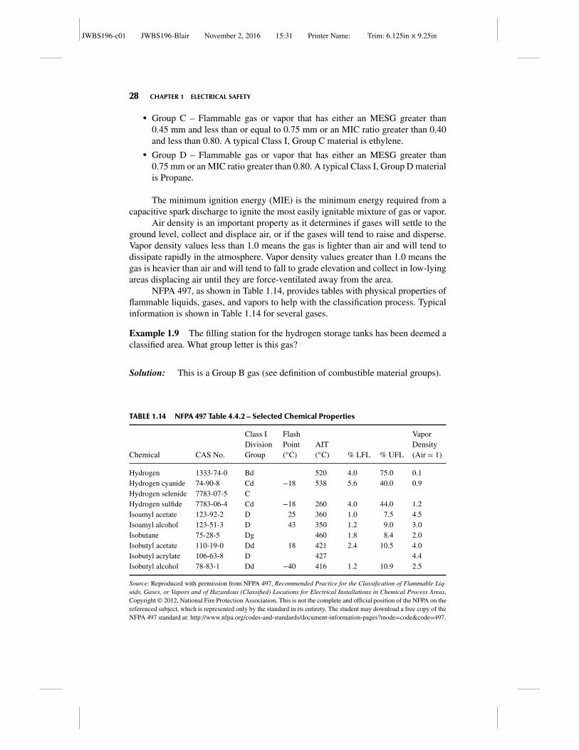
NFPA 497, as shown in Table 1.14, provides tables with physical properties offlammable liquids, gases, and vapors to help with the classification process. Typicalinformation is shown in Table 1.14 for several gases.
Example 1.9 The filling station for the hydrogen storage tanks has been deemed aclassified area. What group letter is this gas?
Solution: This is a Group B gas (see definition of combustible material groups).
TABLE 1.14 NFPA 497 Table 4.4.2 – Selected Chemical Properties
Chemical CAS No.
Class IDivisionGroup
FlashPoint(◦C)
AIT(◦C) % LFL % UFL
VaporDensity(Air = 1)
Hydrogen 1333-74-0 Bd 520 4.0 75.0 0.1Hydrogen cyanide 74-90-8 Cd −18 538 5.6 40.0 0.9Hydrogen selenide 7783-07-5 CHydrogen sulfide 7783-06-4 Cd −18 260 4.0 44.0 1.2Isoamyl acetate 123-92-2 D 25 360 1.0 7.5 4.5Isoamyl alcohol 123-51-3 D 43 350 1.2 9.0 3.0Isobutane 75-28-5 Dg 460 1.8 8.4 2.0Isobutyl acetate 110-19-0 Dd 18 421 2.4 10.5 4.0Isobutyl acrylate 106-63-8 D 427 4.4Isobutyl alcohol 78-83-1 Dd −40 416 1.2 10.9 2.5
Source: Reproduced with permission from NFPA 497, Recommended Practice for the Classification of Flammable Liq-uids, Gases, or Vapors and of Hazardous (Classified) Locations for Electrical Installations in Chemical Process Areas,Copyright © 2012, National Fire Protection Association. This is not the complete and official position of the NFPA on thereferenced subject, which is represented only by the standard in its entirety. The student may download a free copy of theNFPA 497 standard at: http://www.nfpa.org/codes-and-standards/document-information-pages?mode=code&code=497.
JWBS196-c01 JWBS196-Blair November 2, 2016 15:31 Printer Name: Trim: 6.125in × 9.25in
CLASSIFIED AREA – “CLASS” SYSTEM 29
Source
Equipmentsize
Pressure
Small/low Large/HighMedium
Division 1
Division 2
Flow rate
Grade
15 ft (4.57 m) radius
Below grade location suchas a sump of trench
Material: Flammable liquid, liquefied flammable gas, compressed flammable gas, and cryogenic liquid
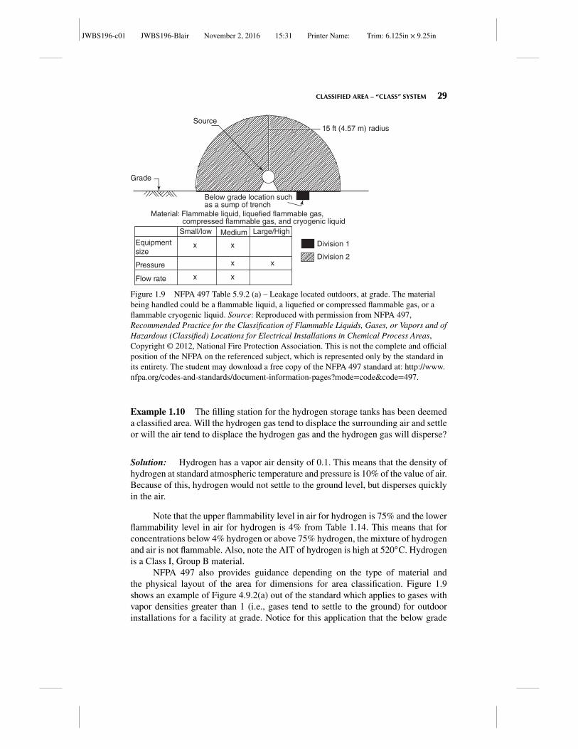
Figure 1.9 NFPA 497 Table 5.9.2 (a) – Leakage located outdoors, at grade. The materialbeing handled could be a flammable liquid, a liquefied or compressed flammable gas, or aflammable cryogenic liquid. Source: Reproduced with permission from NFPA 497,Recommended Practice for the Classification of Flammable Liquids, Gases, or Vapors and ofHazardous (Classified) Locations for Electrical Installations in Chemical Process Areas,Copyright © 2012, National Fire Protection Association. This is not the complete and officialposition of the NFPA on the referenced subject, which is represented only by the standard inits entirety. The student may download a free copy of the NFPA 497 standard at: http://www.nfpa.org/codes-and-standards/document-information-pages?mode=code&code=497.
Example 1.10 The filling station for the hydrogen storage tanks has been deemeda classified area. Will the hydrogen gas tend to displace the surrounding air and settleor will the air tend to displace the hydrogen gas and the hydrogen gas will disperse?
Solution: Hydrogen has a vapor air density of 0.1. This means that the density ofhydrogen at standard atmospheric temperature and pressure is 10% of the value of air.Because of this, hydrogen would not settle to the ground level, but disperses quicklyin the air.
Note that the upper flammability level in air for hydrogen is 75% and the lowerflammability level in air for hydrogen is 4% from Table 1.14. This means that forconcentrations below 4% hydrogen or above 75% hydrogen, the mixture of hydrogenand air is not flammable. Also, note the AIT of hydrogen is high at 520◦C. Hydrogenis a Class I, Group B material.
NFPA 497 also provides guidance depending on the type of material andthe physical layout of the area for dimensions for area classification. Figure 1.9shows an example of Figure 4.9.2(a) out of the standard which applies to gases withvapor densities greater than 1 (i.e., gases tend to settle to the ground) for outdoorinstallations for a facility at grade. Notice for this application that the below grade
JWBS196-c01 JWBS196-Blair November 2, 2016 15:31 Printer Name: Trim: 6.125in × 9.25in
30 CHAPTER 1 ELECTRICAL SAFETY
location is a Division 1 location, since gases with vapor densities greater than 1 willtend to accumulate in this location.
NFPA 499 provides guidance for the classification of combustible dusts. Bydefinition under the “Class” system, combustible dusts in sufficient quantity to presenta hazard are Class II areas. Below are some definitions that are useful to understandthe application of classified systems. Combustible dust is any finely divided solidmaterial 420 microns or less in diameter that presents a fire or explosion hazard whendispersed. Class II combustible dusts are divided into three groups as follows.
� Group E – Atmospheres containing combustible metal dusts. Typical dusts inthis group are aluminum, magnesium, or other metallic alloys.
� Group F – Atmospheres containing combustible carbonaceous dusts that havemore than 8% total trapped volatiles or that have been sensitized by other mate-rials so that they present an explosion hazard. Typical dusts in this group arecoal, carbon black, charcoal, and coke dusts.
� Group G – Atmospheres containing combustible dusts that do not fall into theGroup E or Group F designation. Typical dusts in this group are flour, grain,wood, plastic, and other similar chemicals.
Dust particles tend to settle out of the atmosphere and form a layer on equip-ment. This dust layer acts as a blanket and can reduce the heat removal efficiency ofequipment causing equipment skin temperature of operating equipment to rise to val-ues greater than design. This should be taken into account when specifying equipmentfor Class II areas. Additionally, while dusts suspended in atmosphere may present ahazard, once they drop out of the atmosphere and form layers, if left undisturbed andnot in direct contact with the ignition source, they will not present a hazard. However,if a small amount of dust is in the air and provides fuel for a small explosion, the pres-sure wave may cause the layered material to become airborne, providing substantialamount of additional fuel causing a second and oftentimes more damaging explo-sion. For this reason, good housekeeping is essential in areas classified as Class IIhazardous locations. Keeping the amount of material that has settled out on equip-ment to a minimum will help minimize the damage from any secondary explosionsthat occur due to the pressure wave displacing layered dusts.
In Class II locations, there are three common methods of ignition. The firstmethod of ignition is having combustible dusts suspended in the atmosphere and anignition source presents itself. The second method of ignition is when combustibledusts have formed a layer on electrical equipment, reducing the heat removal effi-ciency of the electrical equipment and the skin of the electrical equipment reachesthe AIT of the dust. The third method is when a Group E dust (metal dust) is presenteither layered or suspended in air and a sufficient amount of current flows through theconductive dust to cause ignition of the dust. In determining whether a Class II area isDivision 1 or Division 2, the quantity of dust, its physical and chemical properties, itsdispersion properties, and the location of walls and surfaces must all be considered.If either under normal or abnormal operation of equipment, a dust cloud may form,the area should be classified as a Division 1 area. Also if a layer forms on equipmentthat is greater than 1/8th of an inch in thickness, then this area should be classified
JWBS196-c01 JWBS196-Blair November 2, 2016 15:31 Printer Name: Trim: 6.125in × 9.25in
CLASSIFIED AREA – “CLASS” SYSTEM 31
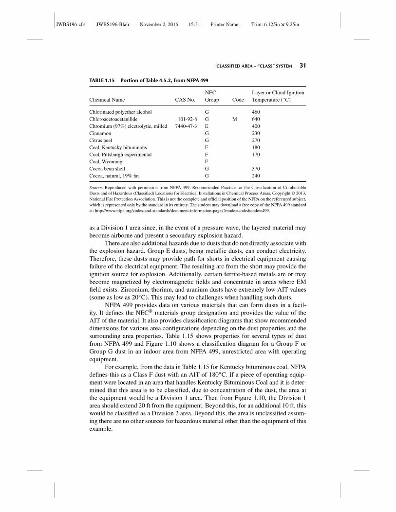
TABLE 1.15 Portion of Table 4.5.2, from NFPA 499
Chemical Name CAS No.NECGroup Code
Layer or Cloud IgnitionTemperature (◦C)
Chlorinated polyether alcohol G 460Chloroacetoacetanilide 101-92-8 G M 640Chromium (97%) electrolytic, milled 7440-47-3 E 400Cinnamon G 230Citrus peel G 270Coal, Kentucky bituminous F 180Coal, Pittsburgh experimental F 170Coal, Wyoming FCocoa bean shell G 370Cocoa, natural, 19% fat G 240
Source: Reproduced with permission from NFPA 499, Recommended Practice for the Classification of CombustibleDusts and of Hazardous (Classified) Locations for Electrical Installations in Chemical Process Areas, Copyright © 2013,National Fire Protection Association. This is not the complete and official position of the NFPA on the referenced subject,which is represented only by the standard in its entirety. The student may download a free copy of the NFPA 499 standardat: http://www.nfpa.org/codes-and-standards/document-information-pages?mode=code&code=499.
as a Division 1 area since, in the event of a pressure wave, the layered material maybecome airborne and present a secondary explosion hazard.
There are also additional hazards due to dusts that do not directly associate withthe explosion hazard. Group E dusts, being metallic dusts, can conduct electricity.Therefore, these dusts may provide path for shorts in electrical equipment causingfailure of the electrical equipment. The resulting arc from the short may provide theignition source for explosion. Additionally, certain ferrite-based metals are or maybecome magnetized by electromagnetic fields and concentrate in areas where EMfield exists. Zirconium, thorium, and uranium dusts have extremely low AIT values(some as low as 20◦C). This may lead to challenges when handling such dusts.
NFPA 499 provides data on various materials that can form dusts in a facil-ity. It defines the NEC® materials group designation and provides the value of theAIT of the material. It also provides classification diagrams that show recommendeddimensions for various area configurations depending on the dust properties and thesurrounding area properties. Table 1.15 shows properties for several types of dustfrom NFPA 499 and Figure 1.10 shows a classification diagram for a Group F orGroup G dust in an indoor area from NFPA 499, unrestricted area with operatingequipment.
For example, from the data in Table 1.15 for Kentucky bituminous coal, NFPAdefines this as a Class F dust with an AIT of 180◦C. If a piece of operating equip-ment were located in an area that handles Kentucky Bituminous Coal and it is deter-mined that this area is to be classified, due to concentration of the dust, the area atthe equipment would be a Division 1 area. Then from Figure 1.10, the Division 1area should extend 20 ft from the equipment. Beyond this, for an additional 10 ft, thiswould be classified as a Division 2 area. Beyond this, the area is unclassified assum-ing there are no other sources for hazardous material other than the equipment of thisexample.
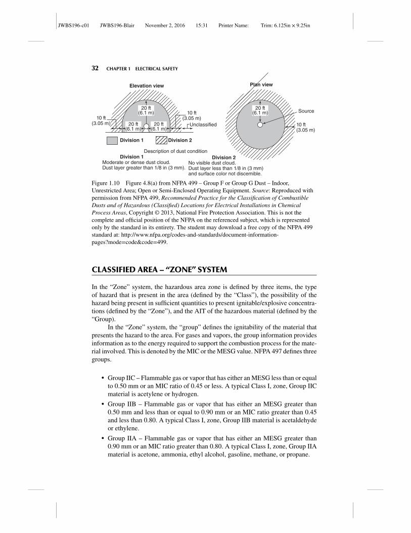
JWBS196-c01 JWBS196-Blair November 2, 2016 15:31 Printer Name: Trim: 6.125in × 9.25in
32 CHAPTER 1 ELECTRICAL SAFETY
Description of dust condition
Moderate or dense dust cloud.Dust layer greater than 1/8 in (3 mm).
No visible dust cloud.Dust layer less than 1/8 in (3 mm)and surface color not discemible.
Division 1
Division 1
Division 2
Division 2
10 ft(3.05 m)10 ft
(3.05 m) Unclassified
Elevation view
10 ft(3.05 m)
20 ft(6.1 m)
20 ft(6.1 m)
20 ft(6.1 m)
20 ft(6.1 m)
Source
Plan view
Figure 1.10 Figure 4.8(a) from NFPA 499 – Group F or Group G Dust – Indoor,Unrestricted Area; Open or Semi-Enclosed Operating Equipment. Source: Reproduced withpermission from NFPA 499, Recommended Practice for the Classification of CombustibleDusts and of Hazardous (Classified) Locations for Electrical Installations in ChemicalProcess Areas, Copyright © 2013, National Fire Protection Association. This is not thecomplete and official position of the NFPA on the referenced subject, which is representedonly by the standard in its entirety. The student may download a free copy of the NFPA 499standard at: http://www.nfpa.org/codes-and-standards/document-information-pages?mode=code&code=499.
CLASSIFIED AREA – “ZONE” SYSTEM
In the “Zone” system, the hazardous area zone is defined by three items, the typeof hazard that is present in the area (defined by the “Class”), the possibility of thehazard being present in sufficient quantities to present ignitable/explosive concentra-tions (defined by the “Zone”), and the AIT of the hazardous material (defined by the“Group).
In the “Zone” system, the “group” defines the ignitability of the material thatpresents the hazard to the area. For gases and vapors, the group information providesinformation as to the energy required to support the combustion process for the mate-rial involved. This is denoted by the MIC or the MESG value. NFPA 497 defines threegroups.
� Group IIC – Flammable gas or vapor that has either an MESG less than or equalto 0.50 mm or an MIC ratio of 0.45 or less. A typical Class I, zone, Group IICmaterial is acetylene or hydrogen.
� Group IIB – Flammable gas or vapor that has either an MESG greater than0.50 mm and less than or equal to 0.90 mm or an MIC ratio greater than 0.45and less than 0.80. A typical Class I, zone, Group IIB material is acetaldehydeor ethylene.
� Group IIA – Flammable gas or vapor that has either an MESG greater than0.90 mm or an MIC ratio greater than 0.80. A typical Class I, zone, Group IIAmaterial is acetone, ammonia, ethyl alcohol, gasoline, methane, or propane.
JWBS196-c01 JWBS196-Blair November 2, 2016 15:31 Printer Name: Trim: 6.125in × 9.25in
CLASSIFIED AREA – “ZONE” SYSTEM 33
The actual “zone” is a description of the probability of the hazardous materialbeing present in sufficient quantities to present an ignitable/explosive mixture in theenvironment. There are three zones for gases and vapors.
� A Zone 0 location is where a flammable atmosphere is highly likely to bepresent and/or may be present for long periods of time or even continuously.
� A Zone 1 location is where a flammable atmosphere is possible but not likelyand is most likely not to be present for long periods of time.
� A Zone 2 location is where a flammable atmosphere is unlikely to be presentexcept for very short periods of time. This is also used where under normalequipment operations, the flammable atmosphere is not present, but in the eventof equipment malfunction, the flammable atmosphere may become presentuntil equipment is restored.
There are also three zones for dusts and ignitable fibers.
� A Zone 20 location is an area where combustible dust or ignitable fibers andflyings are present continuously for long periods of time and in quantities suf-ficient to be hazardous.
� A Zone 21 location is an area where combustible dust or ignitable fibers andflyings are likely to exist occasionally under normal operation and in quantitiessufficient to be hazardous.
� A Zone 22 location is an area where combustible dust or ignitable fiber andflyings are not likely to occur under normal operation in quantities sufficient tobe hazardous.
As a side note, since dusts can settle on equipment and reduce the heat removalefficiency of equipment causing the equipment to run at higher temperature than nor-mal, there may be an equipment derating applied to the AIT of the material for appli-cation of equipment.
In addition to classifying the area as to the hazardous material (group) and thelikelihood of the material being present in sufficient quantities for ignitable atmo-sphere (zone) there is an additional classification for equipment temperature classesto ensure the equipment does not approach the AIT of the material presenting thehazard. Equipment rated for operation in classified areas has a rating “T-Class” todefine the maximum operating temperature of the equipment. All equipment tem-perature ratings are based on a temperature rise above a certain maximum ambienttemperatures. Unless otherwise listed by the equipment manufacturer, the basis forthe T-Class rating is with a maximum ambient temperature of 40◦C. Operation ofequipment above the maximum allowable rated ambient temperature is not allowedand the equipment must have a T rating based on actual ambient conditions. This isthe reason for “derate” when equipment is installed in areas with dusts that can coverequipment and lower the heat removal efficiency of the equipment leading to higheroperating temperatures. Below is list of the six basic values for T-Class (there areadditional T-Class ratings that some OEMs can provide).
� T1 – 450◦C� T2 – 300◦C
JWBS196-c01 JWBS196-Blair November 2, 2016 15:31 Printer Name: Trim: 6.125in × 9.25in
34 CHAPTER 1 ELECTRICAL SAFETY
� T3 – 200◦C� T4 – 135◦C� T5 – 100◦C� T6 – 85◦C
Example 1.11 A classified area will contain Kentucky bituminous coal (see Table1.15). The lighting fixtures in the room must be rated to operate at a surface temper-ature below the AIT of the coal. Assuming the maximum ambient temperature of theroom is the same as the equipment rating of 40◦C, which of the equipment T-Classeswill be acceptable?
Solution: For Kentucky Bituminous Coal, the AIT is 180◦C (From Table 1.15).For equipment to be utilized in an atmosphere that may contain this material, theequipment should have a T4, T5, or T6 rating. Equipment with a T1, T2, or T3 ratingmay result in equipment skin temperatures that exceed the AIT of the coal. If the coalis expected to cover the electrical equipment, then a derate may be applied preventingthe use of the T4 rating.
BOILER CONTROL AND BURNER MANAGEMENT
Another very important subject in power plant safety is the safe operation of boilerand combustion systems and the unique hazards these systems present. NFPA 85 –Boiler and Combustion System Hazards Code provides guidance to the safe controlof these systems to prevent hazards such as implosion or explosion. This standardaddresses the minimum requirements for combustion systems and controls. This isa critical system for safety since, under normal operation of a boiler, we intention-ally combine air, a combustible material, and an ignition source creating a hazardousatmosphere in the furnace section of the boiler. The hazardous mixture must be safetycontrolled to ensure that the conditions do not arise that can present an explosive orimplosive event.
For most boilers, the positive transient design pressure must be at least +35inches of water and the negative transient design pressure must be at least −35 inchesof water. The positive value is to ensure that the boiler remains intact during a positivepressure excursion and does not explode. The negative value is to ensure that theboiler will remain intact during a negative pressure excursion and does not implode.
NFPA 85 covers areas such as normal startup and shut down procedures aswell as procedures used in the event of a boiler trip to ensure that an explosive orimplosive condition does not occur. The details for control depend on the type ofsystem involved. Below is an introductory discussion of some of the requirementsfor NFPA 85. For more detailed information, the reader is advised to refer to thelatest copy of NFPA 85.
At minimum, there are several interlocks required to ensure proper boiler con-trols. When the control system detects a loss of flame in the burner, the system mustremove the fuel source to the burner and isolate the ignition source. This is because,
JWBS196-c01 JWBS196-Blair November 2, 2016 15:31 Printer Name: Trim: 6.125in × 9.25in
BOILER CONTROL AND BURNER MANAGEMENT 35
if the fuel being supplied to the burner system is not being combusted in the furnacesection, then the explosive mixture of air and fuel may remain in the boiler and in theduct system downstream. Any point that presents an ignition source (like the rotatingair preheater member causing a momentary spark during rotation) could lead to anexplosion of the system.
If an induced draft (ID) fan is tripped, the associated dampers to that fan shouldbe closed unless that is the last ID fan in service. Additionally, if the ID and forceddraft (FD) fans are paired, then the associated FD fan should be tripped and its asso-ciated damper closed as well. This is done to minimize the pressure transient thatmay occur if an ID fan tripped but the associated FD fan did not. If the last ID fan inservice is tripped, then the dampers should remain full open. This is to allow for theremoval of combustibles from the boiler utilizing natural ventilation and/or the ven-tilation of the associated FD fan. Also on the loss of all ID fans, the master fuel tripshould be activated to remove fuel from the burner. Additionally, if furnace pressureexceeds (either positive or negative) pressure values provided by the boiler OEM, themaster fuel trip will also be activated to safely shut the boiler down. When startingand stopping ID/FD fans, a specific sequence is required to ensure that the boiler pres-sure rating is not exceeded. First, an open-air path from suction to discharge of the airsystem must be established and verified. Since the FD fan is on the inlet side of theboiler and regulates the airflow through the boiler, and the ID fan is on the outlet sideof the boiler regulating boiler pressure, the ID fan is started first so that we are able tomaintain boiler pressure control. This is to ensure that the boiler does not experiencea positive pressure transient during startup of the associated FD fans. Once the IDfan is started, the associated FD fan is started. Dampers are partially closed duringstartup to minimize load on the motors and minimize the associated time requiredfor acceleration to speed. When shutting down an FD and ID fan train, the FD fan isstopped first, followed by the associated ID fan for the same reasons (ensure we canmaintain boiler pressure with ID fan).
The above discussion presented some of the interlocks from the air side of thecombustion equation. From the fuel side of the combustion equation, there are alsospecific responses that NFPA 85 calls out for during certain events. The primary air(PA) fan provides the transport of the fuel from the pulverizer to the combustionchamber. If the PA fan trips, the fuel valve or feeder equipment shall also be trippedthat is associated with that PA fan. For a pulverized system, failure of a pulverizershall trip the associated PA fan. Loss of coal feed to the burner must trip the associatedfeeder, unless the igniters are Class 1 igniters. The reason for the exception for Class1 igniter is the amount of energy output from the igniter is sufficient to sustain a flamein the burner area until the coal feed is reestablished. In NFPA 85, igniters are brokendown into the following classes.
� Class 1 igniter – An igniter that is applied to ignite the fuel input to a burner andsupport ignition under any burner conditions. It will provide sufficient ignitionenergy usually in excess of 10% of full-load burner output at its associatedburner to raise any combination of burner fuel–air mixtures above the minimumignition temperature.
JWBS196-c01 JWBS196-Blair November 2, 2016 15:31 Printer Name: Trim: 6.125in × 9.25in
36 CHAPTER 1 ELECTRICAL SAFETY
� Class 2 igniter – An igniter that is applied to ignite the fuel input to a burner andsupport ignition only under certain prescribed light-off conditions. It may alsobe used to support burner operations during operating conditions. The range ofignition energy is usually between 4% and 10% of full-load burner output at itsassociated burner.
� Class 3 igniter – An igniter that is applied to ignite the fuel input to a burner andsupport ignition only under certain prescribed light-off conditions. The rangeof ignition energy is usually less than 4% of full-load burner output at its asso-ciated burner.
� Class 3 special igniter – A special Class 3 high energy electrical igniter that iscapable of directly igniting the main fuel burner.
Example 1.12 An igniter for a burner is chosen such that the range of ignitionenergy is usually between 4% and 10% of full-load burner output at its associatedburner. What class of igniter is this?
Solution: This is a Class 2 igniter as defined in NFPA 85.
Once the FD and ID fans are started, the dampers and burner registers areadjusted to the purge position and airflow is adjusted to the “purge airflow” positionand the unit purge is started. The purpose of the unit purge is to purge the air insidethe boiler sufficiently to ensure that the level of combustibles is reduced to the pointwhere an explosive environment does not exist and the burners can be safely lit offby the igniters. Once the purge is complete, the air register or damper on the burneris adjusted to the “light-off” position, the ignitor valve is opened, and the source ofignition for the igniter will be energized. If a flame is not established within 10 sec-onds, the igniter valve is closed and “light off” is not reattempted until the cause forthe failure to ignite is determined and corrected. After a stable igniter flame is estab-lished in the combustion zone, the air register or damper is adjusted to its “operating”position.
The above discussion is a very brief overview of one type of boiler/burner sys-tem from NFPA 85. NFPA 85 is broken into several sections and has much moredetailed information pertaining to the control of each type of equipment. Table 1.16lists the various sections of NFPA 85 and to which type of boiler they apply.
The reader is encouraged to review in detail the requirements of the standardfor their specific system.
In summary, the primary function of an energy production systems engineer isto ensure both safety and reliability in the systems and procedures utilized in a gen-eration facility. Of these two functions, safety is paramount. This includes both safeinstallation of equipment and the utilization of safe work practices. The typical elec-tric utility generation station may contain several areas of concern such as electricalhazards, combustible atmospheres and materials, confined space requirements, slip,trips, and falls. As the safety of plant operations is improved, the reliability of thestation will benefit also.
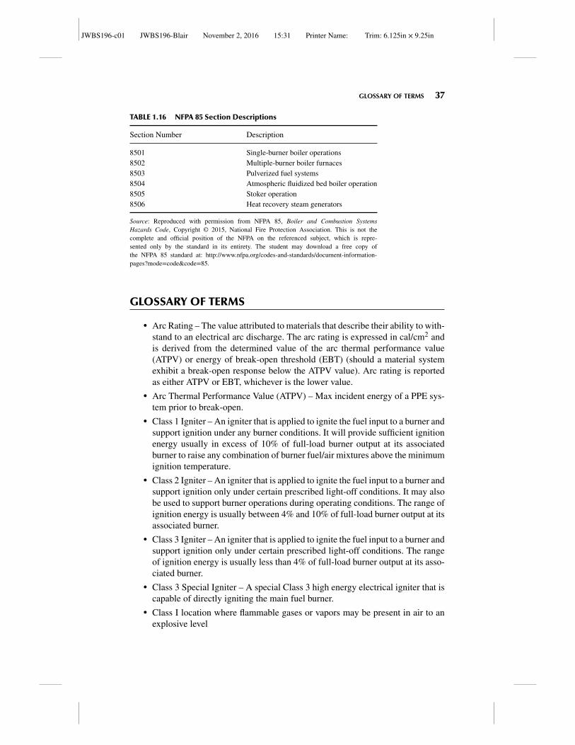
JWBS196-c01 JWBS196-Blair November 2, 2016 15:31 Printer Name: Trim: 6.125in × 9.25in
GLOSSARY OF TERMS 37
TABLE 1.16 NFPA 85 Section Descriptions
Section Number Description
8501 Single-burner boiler operations8502 Multiple-burner boiler furnaces8503 Pulverized fuel systems8504 Atmospheric fluidized bed boiler operation8505 Stoker operation8506 Heat recovery steam generators
Source: Reproduced with permission from NFPA 85, Boiler and Combustion SystemsHazards Code, Copyright © 2015, National Fire Protection Association. This is not thecomplete and official position of the NFPA on the referenced subject, which is repre-sented only by the standard in its entirety. The student may download a free copy ofthe NFPA 85 standard at: http://www.nfpa.org/codes-and-standards/document-information-pages?mode=code&code=85.
GLOSSARY OF TERMS
� Arc Rating – The value attributed to materials that describe their ability to with-stand to an electrical arc discharge. The arc rating is expressed in cal/cm2 andis derived from the determined value of the arc thermal performance value(ATPV) or energy of break-open threshold (EBT) (should a material systemexhibit a break-open response below the ATPV value). Arc rating is reportedas either ATPV or EBT, whichever is the lower value.
� Arc Thermal Performance Value (ATPV) – Max incident energy of a PPE sys-tem prior to break-open.
� Class 1 Igniter – An igniter that is applied to ignite the fuel input to a burner andsupport ignition under any burner conditions. It will provide sufficient ignitionenergy usually in excess of 10% of full-load burner output at its associatedburner to raise any combination of burner fuel/air mixtures above the minimumignition temperature.
� Class 2 Igniter – An igniter that is applied to ignite the fuel input to a burner andsupport ignition only under certain prescribed light-off conditions. It may alsobe used to support burner operations during operating conditions. The range ofignition energy is usually between 4% and 10% of full-load burner output at itsassociated burner.
� Class 3 Igniter – An igniter that is applied to ignite the fuel input to a burner andsupport ignition only under certain prescribed light-off conditions. The rangeof ignition energy is usually less than 4% of full-load burner output at its asso-ciated burner.
� Class 3 Special Igniter – A special Class 3 high energy electrical igniter that iscapable of directly igniting the main fuel burner.
� Class I location where flammable gases or vapors may be present in air to anexplosive level
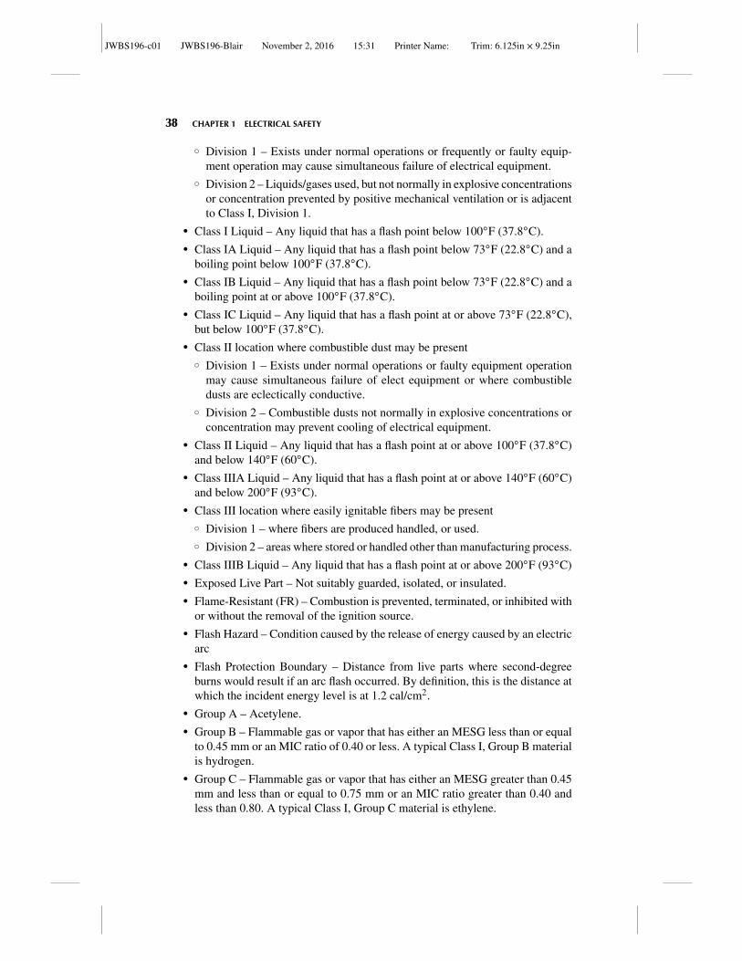
JWBS196-c01 JWBS196-Blair November 2, 2016 15:31 Printer Name: Trim: 6.125in × 9.25in
38 CHAPTER 1 ELECTRICAL SAFETY
� Division 1 – Exists under normal operations or frequently or faulty equip-ment operation may cause simultaneous failure of electrical equipment.
� Division 2 – Liquids/gases used, but not normally in explosive concentrationsor concentration prevented by positive mechanical ventilation or is adjacentto Class I, Division 1.
� Class I Liquid – Any liquid that has a flash point below 100◦F (37.8◦C).� Class IA Liquid – Any liquid that has a flash point below 73◦F (22.8◦C) and a
boiling point below 100◦F (37.8◦C).� Class IB Liquid – Any liquid that has a flash point below 73◦F (22.8◦C) and a
boiling point at or above 100◦F (37.8◦C).� Class IC Liquid – Any liquid that has a flash point at or above 73◦F (22.8◦C),
but below 100◦F (37.8◦C).� Class II location where combustible dust may be present
� Division 1 – Exists under normal operations or faulty equipment operationmay cause simultaneous failure of elect equipment or where combustibledusts are eclectically conductive.
� Division 2 – Combustible dusts not normally in explosive concentrations orconcentration may prevent cooling of electrical equipment.
� Class II Liquid – Any liquid that has a flash point at or above 100◦F (37.8◦C)and below 140◦F (60◦C).
� Class IIIA Liquid – Any liquid that has a flash point at or above 140◦F (60◦C)and below 200◦F (93◦C).
� Class III location where easily ignitable fibers may be present� Division 1 – where fibers are produced handled, or used.� Division 2 – areas where stored or handled other than manufacturing process.
� Class IIIB Liquid – Any liquid that has a flash point at or above 200◦F (93◦C)� Exposed Live Part – Not suitably guarded, isolated, or insulated.� Flame-Resistant (FR) – Combustion is prevented, terminated, or inhibited with
or without the removal of the ignition source.� Flash Hazard – Condition caused by the release of energy caused by an electric
arc� Flash Protection Boundary – Distance from live parts where second-degree
burns would result if an arc flash occurred. By definition, this is the distance atwhich the incident energy level is at 1.2 cal/cm2.
� Group A – Acetylene.� Group B – Flammable gas or vapor that has either an MESG less than or equal
to 0.45 mm or an MIC ratio of 0.40 or less. A typical Class I, Group B materialis hydrogen.
� Group C – Flammable gas or vapor that has either an MESG greater than 0.45mm and less than or equal to 0.75 mm or an MIC ratio greater than 0.40 andless than 0.80. A typical Class I, Group C material is ethylene.
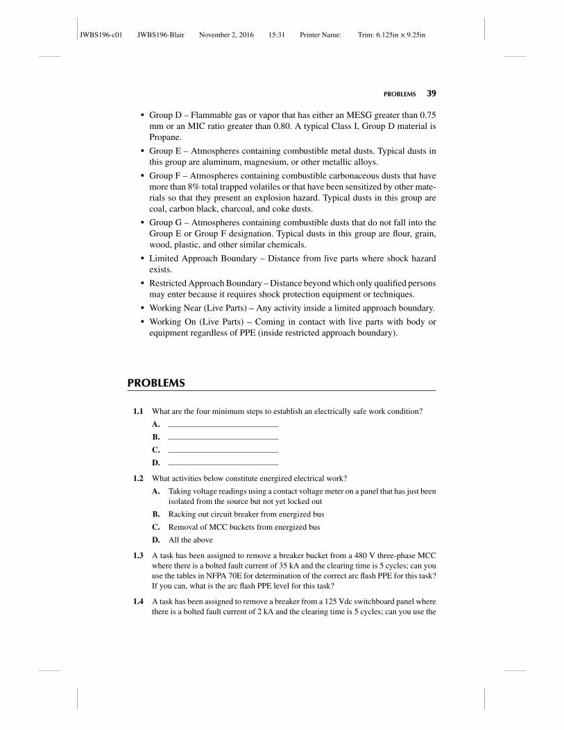
JWBS196-c01 JWBS196-Blair November 2, 2016 15:31 Printer Name: Trim: 6.125in × 9.25in
PROBLEMS 39
� Group D – Flammable gas or vapor that has either an MESG greater than 0.75mm or an MIC ratio greater than 0.80. A typical Class I, Group D material isPropane.
� Group E – Atmospheres containing combustible metal dusts. Typical dusts inthis group are aluminum, magnesium, or other metallic alloys.
� Group F – Atmospheres containing combustible carbonaceous dusts that havemore than 8% total trapped volatiles or that have been sensitized by other mate-rials so that they present an explosion hazard. Typical dusts in this group arecoal, carbon black, charcoal, and coke dusts.
� Group G – Atmospheres containing combustible dusts that do not fall into theGroup E or Group F designation. Typical dusts in this group are flour, grain,wood, plastic, and other similar chemicals.
� Limited Approach Boundary – Distance from live parts where shock hazardexists.
� Restricted Approach Boundary – Distance beyond which only qualified personsmay enter because it requires shock protection equipment or techniques.
� Working Near (Live Parts) – Any activity inside a limited approach boundary.� Working On (Live Parts) – Coming in contact with live parts with body or
equipment regardless of PPE (inside restricted approach boundary).
PROBLEMS
1.1 What are the four minimum steps to establish an electrically safe work condition?
A.
B.
C.
D.
1.2 What activities below constitute energized electrical work?
A. Taking voltage readings using a contact voltage meter on a panel that has just beenisolated from the source but not yet locked out
B. Racking out circuit breaker from energized bus
C. Removal of MCC buckets from energized bus
D. All the above
1.3 A task has been assigned to remove a breaker bucket from a 480 V three-phase MCCwhere there is a bolted fault current of 35 kA and the clearing time is 5 cycles; can youuse the tables in NFPA 70E for determination of the correct arc flash PPE for this task?If you can, what is the arc flash PPE level for this task?
1.4 A task has been assigned to remove a breaker from a 125 Vdc switchboard panel wherethere is a bolted fault current of 2 kA and the clearing time is 5 cycles; can you use the
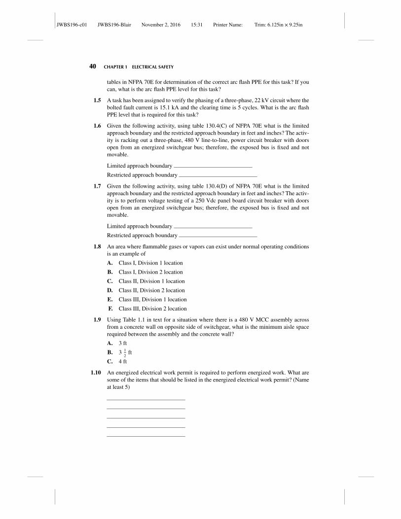
JWBS196-c01 JWBS196-Blair November 2, 2016 15:31 Printer Name: Trim: 6.125in × 9.25in
40 CHAPTER 1 ELECTRICAL SAFETY
tables in NFPA 70E for determination of the correct arc flash PPE for this task? If youcan, what is the arc flash PPE level for this task?
1.5 A task has been assigned to verify the phasing of a three-phase, 22 kV circuit where thebolted fault current is 15.1 kA and the clearing time is 5 cycles. What is the arc flashPPE level that is required for this task?
1.6 Given the following activity, using table 130.4(C) of NFPA 70E what is the limitedapproach boundary and the restricted approach boundary in feet and inches? The activ-ity is racking out a three-phase, 480 V line-to-line, power circuit breaker with doorsopen from an energized switchgear bus; therefore, the exposed bus is fixed and notmovable.
Limited approach boundary
Restricted approach boundary
1.7 Given the following activity, using table 130.4(D) of NFPA 70E what is the limitedapproach boundary and the restricted approach boundary in feet and inches? The activ-ity is to perform voltage testing of a 250 Vdc panel board circuit breaker with doorsopen from an energized switchgear bus; therefore, the exposed bus is fixed and notmovable.
Limited approach boundary
Restricted approach boundary
1.8 An area where flammable gases or vapors can exist under normal operating conditionsis an example of
A. Class I, Division 1 location
B. Class I, Division 2 location
C. Class II, Division 1 location
D. Class II, Division 2 location
E. Class III, Division 1 location
F. Class III, Division 2 location
1.9 Using Table 1.1 in text for a situation where there is a 480 V MCC assembly acrossfrom a concrete wall on opposite side of switchgear, what is the minimum aisle spacerequired between the assembly and the concrete wall?
A. 3 ft
B. 3 1
2ft
C. 4 ft
1.10 An energized electrical work permit is required to perform energized work. What aresome of the items that should be listed in the energized electrical work permit? (Nameat least 5)
JWBS196-c01 JWBS196-Blair November 2, 2016 15:31 Printer Name: Trim: 6.125in × 9.25in
RECOMMENDED READING 41
1.11 The motor controller that drives a coal pulverizer motor for a power generation facilityhas been deemed as a location where, under normal operations coal dust will not bepresent suspended in air in sufficient quantities to form an explosive concentrationsand due to housekeeping controls, the layer of dust will not be sufficient to preventcooling of the motor; however, on the failure of one of the multiple seals in the area,coal dust can become suspended in the atmosphere in quantities sufficient to form anexplosive concentration should those seals fail. What are the correct class and divisionfor this hazardous area classification?
RECOMMENDED READING
Bronze Book IEEE 739: IEEE Recommended Practice for Energy Management in Industrial and Com-mercial Facilities, Institute of Electrical and Electronics Engineers, 1996.
Brown Book IEEE 399: IEEE Recommended Practice for Industrial and Commercial Power Systems Anal-ysis, Institute of Electrical and Electronics Engineers, 1998.
Buff Book IEEE 242: IEEE Recommended Practice for Protection and Coordination of Industrial andCommercial Power Systems, Institute of Electrical and Electronics Engineers, 2001.
Department of the Army, TM 5-682, Facilities Engineering, Electrica1 Facilities Safety, November 8,1999.
Emerald Book IEEE 1100: IEEE Recommended Practice for Powering and Grounding Electronic Equip-ment, Institute of Electrical and Electronics Engineers, 2006.
Gold Book IEEE 493: IEEE Recommended Practice for the Design of Reliable Industrial and CommercialPower Systems, Institute of Electrical and Electronics Engineers, 2007.
Green Book IEEE 142: IEEE Recommended Practice for Grounding of Industrial and Commercial PowerSystems, Institute of Electrical and Electronics Engineers, 2007.
IEC 61241: Electrical Apparatus for Use in the Presence of Combustible Dust, International Electro-Technical Commission, 1994.
IEC 60079:-Electrical Apparatus for Explosive Gas Atmospheres, International Electro-Technical Com-mission, 2011.
NFPA 101: Life Safety Code Handbook, National Fire Protection Association, 2012.NFPA 20: Centrifugal Fire Pumps, National Fire Protection Association, 2013.NFPA 70®: National Electrical Code®, National Fire Protection Association, 2014.NFPA 70B: Electrical Equipment Maintenance, National Fire Protection Association, 2016.NFPA 70E: Electrical Safety Requirements for Employee Workplaces, National Fire Protection Associa-
tion, 2015.NFPA 72: National Fire Alarm Code, National Fire Protection Association, 2016.NFPA 75: Protection of Electronic Computer/Data Processing Equipment, National Fire Protection Asso-
ciation, 2013.NFPA 85: Boiler and Combustion Systems Hazards Code, National Fire Protection Association, 2015.NFPA 497: Recommended Practice for the Classification of Flammable Liquids, Gases, or Vapors and of
Hazardous (Classified) Locations for Electrical Installations in Chemical Process Areas, National FireProtection Association, 2008.
NFPA 499: Recommended Practice for the Classification of Combustible Dusts and of Hazardous (Clas-sified) Locations for Electrical Installations in Chemical Process Areas, National Fire Protection Asso-ciation, 2013.
Orange Book IEEE 446: IEEE Recommended Practice for Emergency and Standby Power Systems forIndustrial and Commercial Applications, Institute of Electrical and Electronics Engineers, 1996.
Red Book IEEE 141: IEEE Recommended Practice for Electric Power Distribution for Industrial Plants,Institute of Electrical and Electronics Engineers, 1993.

JWBS196-c01 JWBS196-Blair November 2, 2016 15:31 Printer Name: Trim: 6.125in × 9.25in
42


